
Storage Tank Presentation Temiz.pdf · CERTIFICATION PROCESS OF AN ATMOSPHERIC STORAGE TANK ......
32
CERTIFICATION PROCESS OF AN ATMOSPHERIC STORAGE TANK CERTIFICATION PROCESS OF AN ATMOSPHERIC STORAGE TANK Presented b Eser Temi Presented by Eser Temiz TÜRK LOYDU TÜRK LOYDU Industry and Certification Division 1
-
Upload
vuongkhuong -
Category
Documents
-
view
228 -
download
5
Transcript of Storage Tank Presentation Temiz.pdf · CERTIFICATION PROCESS OF AN ATMOSPHERIC STORAGE TANK ......

CERTIFICATION PROCESS OF AN ATMOSPHERIC STORAGE TANKCERTIFICATION PROCESS OF AN ATMOSPHERIC STORAGE TANK
Presented b Eser TemiPresented by Eser Temiz
TÜRK LOYDUTÜRK LOYDUIndustry and Certification Division
1

WHO WE ARE
ÜTÜRK LOYDU is an independent, impartial
classification, tifi ti dcertification, and
conformity assesment organization.
With its Marine and Industry Divisions provides wide range of services;
Classification and statutory surveys of new building and existing ships, and certification of marine materials and products.
Third party inspections, CE marking in pressure vessels, system certifications, type approvals are some of the businesses amongst the others.
2

PHASES TO CERTIFICATION;
APPROVAL OF PROJECTS AND CALCULATIONS
INSPECTION OF FABRICATION
AND CONSTRUCTION
FINAL TESTSQUALIFYING OF
WELDING PROCEDURES AND
WELDERSCALCULATIONS CONSTRUCTIONWELDERS
3
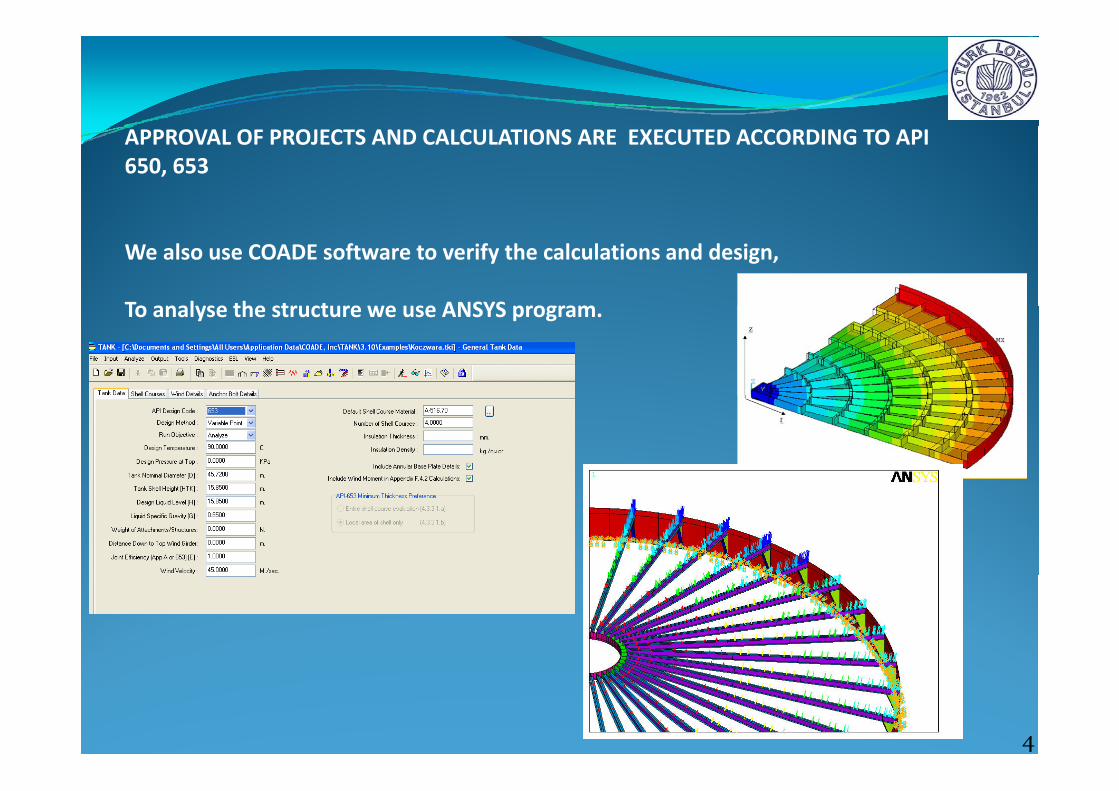
APPROVAL OF PROJECTS AND CALCULATIONS ARE EXECUTED ACCORDING TO API 650, 653
We also use COADE software to verify the calculations and design,
To analyse the structure we use ANSYS programTo analyse the structure we use ANSYS program.
4

BEFORE CONSTRUCTION OF A TANK IN THE WORKSHOP AND IN THE PLANT
EXAMINATION OF
QUALITY PLAN (ITP)
IS AN ESSENTIAL STEP NOT TO BE OVERLOOKED.
5

QUALIFICATION OF WELDING PROCEDURES
Welding procedure qualification records must meet the requirements of Section IX of the ASME Code.
Either AWS D1.1 or AWS D1.6 are also acceptable for ladder and platform assemblies, handrails, stairways, and other miscellaneous assemblies, but not their attachments to the tank.the tank.
6

QUALIFICATION OF WELDERS
The welders and welding operators must be qualified in accordance with Section IX of the ASME Code.
7

INSPECTION OF MATERIALS;
‐STEEL PLATES
PIPES‐PIPES
‐PROFILES
‐FLANGES etc.
8

MARKING
To enable the various fabricated components to be assembled together correctly on site, each part has to be marked with a unique numbering system.
Hard stamping may be used as well, but except for the plates less than 6 mm thick.
Marking also provides traceability of each piece of material.
9

AFTER FORMING OF SHELL PLATES
RADIUS OF EACH PLATE MUST BE CHECKED
NOT TO SPEND MUCH TIME DURING THIS STEP, A PREFORMED PATTERN MODEL MADE OF THIN METAL SHEET CAN BE USED.
PRIMER SHOULD BE APPLIED BEFORE TRANSPORTING THE SHEETS TO PLANT , AND INCASE OF NOT TO AFFECT THE QUALITY OF WELDS, ALL WELD FACES SHOULD BE COVERED BY PAPER TAPE PREVIOUSLY TO KEEP CLEAN FROM PAINT RESIDUECOVERED BY PAPER TAPE PREVIOUSLY TO KEEP CLEAN FROM PAINT RESIDUE.
INCASE ANY DEFORMATION MAY OCCUR DURING TRANSPORT AND STACKING, PREFORMED SHELL PLATES SHOULD BE SETTLED ON A PACKSADDLE.PREFORMED SHELL PLATES SHOULD BE SETTLED ON A PACKSADDLE.
10

CONCRETE RINGWALL, AND BOTTOM SURFACE ARE MEASURED BY MEANS OF TOTAL STATION DEVICE.
APPROPRIATENESS OF DRAIN PIPESAPPROPRIATENESS OF DRAIN PIPES
ANCHORS ARE CHECKED DIMENSIONS‐DIMENSIONS,‐MATERIAL TYPE‐LOCATION
Tensile test is required for each party of steel rods used in the concrete
11

BOTTOM PLATES ARE SETTLED ACCORDING TO PLATE ORIENTATION SCHEME IN THE APPROVED PROJECT.
BOTTOM PLATES ARE WELDED AFTER CONSTRUCTING OF COARSES
LAP WELDED BOTTOM PLATES UNDER TANK
SHELL
12

TWO TYPES OF TANK FLOORING ARE;
‐BOTTOM DOWN: Generally, bottom down is design for cone roof tanks. Centrey gof the flooring is installed with drain pit. Water in the tank is accumulated in the pit (lowest point of the bottom plate/floor).
‐BOTTOM UP:Generally, this type of design is used for floating‐roof tanks, 3 to 4 collector pits are installed, close to the shell plate. Each of the pit is provided with a water draw‐off line.
A slope of 1:120 is suitablep
13

DRAWOFF SUMPDRAWOFF SUMP
The erection procedure shall include the following steps:
(a) a hole shall be cut in the bottom plate or a sump shall be placed in the foundation before bottom placement;
(b) a neat excavation shall be made to conform to theshape of the drawoff sump, the sump shall be put in place, and the foundation shall be compacted around the sump after placement; andafter placement; and
(c) the sump shall be welded to the bottom.
14

ADJUSTMENT OF FIRST COURSE
UPRIGHTNESS, ROUNDNESS AND DIAMETER OF THE COURSE IS MEASURED MIN.AT 8 POINTS.
IT IS CONSIDERED THAT THE WELD SEAMS OF BOTTOM PLATES AND VERTICALSEAMS OF THE COARSE ARE NOT TO BE INTERSECT EACHOTHER
15

ADJUSTMENT OF SECOND COURSE
UPRIGHTNESS, AND ROUNDNESS OF THE SHELL IS MEASURED MIN. AT 8 POINTS.
THEN VERTICAL WELDS ARE EXECUTED OF THE FIRST COURSE.
16

ADJUSTMENT OF THIRD COURSEADJUSTMENT OF THIRD COURSE
UPRIGHTNESS AND ROUNDNESS OF THE SHELL IS MEASURED MIN AT 8 POINTSUPRIGHTNESS, AND ROUNDNESS OF THE SHELL IS MEASURED MIN. AT 8 POINTS.
THEN, VERTICAL AND CIRCUMFERENTIAL WELDS OF THE SECOND COURSE ARE EXECUTED.EXECUTED.
SUCH PRINCIPLE IS FOLLOWED FOR THE OTHER COURSES.
17

FOURTH
THIRD
FIRST
SECOND
COURSE
18

TYPICAL ANCHORAGE
19

TYPICAL ANCHORAGE
20

AFTER COMPLETING ALL WELDS OF THE COURSES BOTTOM PLATES ARE WELDEDAFTER COMPLETING ALL WELDS OF THE COURSES, BOTTOM PLATES ARE WELDED. THEN VACUUM TEST IS PERFORMED.
Vacuum testing is performed using a testing boxapproximately 150 mm (6 in.) wide by 750 mm (30 in.) long with a clear window in the top, which provides proper visibility to view the area under inspection.
During testing, illumination shall be adequate g g, qfor proper evaluation and interpretation of the test.
The open bottom shall be sealed against the tank surface by a suitable gasket Connectionstank surface by a suitable gasket. Connections,valves, lighting and gauges, shall be provided as required.
A soap film solution or commercial, leak detection solution, applicable to the conditions, shall be used.
21

CONSTRUCTION OF ROOFCONSTRUCTION OF ROOF
22
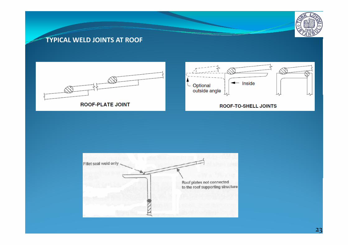
TYPICAL WELD JOINTS AT ROOFTYPICAL WELD JOINTS AT ROOF
23

NON DESTRUCTIVE EXAMINATION OF A TANKNON DESTRUCTIVE EXAMINATION OF A TANK
Complete penetration and complete fusion are required for welds joining shellComplete penetration and complete fusion are required for welds joining shell plates to shell plates.
Inspection for the quality of the welds shall be made using either the radiographicInspection for the quality of the welds shall be made using either the radiographicmethod , or alternatively, by agreement between the purchaser and the manufacturer, using the ultrasonic method. In addition to the radiographic or ultrasonic examination, these welds are also visually examined., y
In general, radiographic inspection is required for shell butt‐welds, annular plate butt‐welds, and flush type connections with butt welds.
24

TESTING OF THE SHELL
After the entire tank and roof structure is completed, the shell is tested by one of the following methods:
1‐ If water is available for testing the shell, the tank shall be filled with water as follows:
i‐to the maximum design liquid level; ii‐for a tank with a tight roof, to 50 mm above the weld connecting the roof plate or compression bar to the top angle or shell
2‐ If sufficient water to fill the tank is not available, the tank may be tested by painting ll f th j i t th i id ith hi hl t ti ilall of the joints on the inside with a highly penetrating oil
25

FIRE PROTECTION
Fire protection system shall be established according to the NFPA standards.
This system is inspected during manufacturing of the installation and after that y p g g
functions, and performance are examined.
System shall include;‐Foam based extinguishing,‐Water cooling‐Monitors‐Dike protection
26

FIRE PROTECTION
For the cooling water rates the standards do not provide cogruent values.They only prescribe minimum water flow rates
API 2030 : 4.1 liters per minute per square meterNFPA 15 : 10.5 liters / min.m2
IP 19 : 2 liters / min.m2
To be on the safe side for exposure protection we recommend and apply NFPA rate.rate.
27

CATHODIC PROTECTION
Both sacrificial anode system or impressed current system are acceptable.
The main standard for this step is API 651.p
28

EARTHING
To minimize the accumulation of electrostatic charge and prevent sparks, all metal parts of the storage installation must be bonded together and earthed.
Maximum resistance to earth of 10 ohms is recommended.
29
After completing all structure of the tank, for the surfaces of the weld seams and sides of the seams affected by heat;and sides of the seams affected by heat;
First, shotblasting then
primer paint should be applied before whole tank is painted.
30

AFTER PAINTING TANK IS READY TO BE CERTIFIEDAFTER PAINTING, TANK IS READY TO BE CERTIFIED.
31
Thanks you for your attentionThanks you for your attention
32