Storage-ring measurement of the hyperfine-induced … · rate in berylliumlike sulfur ... rates...
10
PHYSICAL REVIEW A 85, 012513 (2012) Storage-ring measurement of the hyperfine-induced 2s2 p 3 P 0 → 2s 21 S 0 transition rate in berylliumlike sulfur S. Schippers, * D. Bernhardt, and A. M ¨ uller Institut f ¨ ur Atom- und Molek ¨ ulphysik, Justus-Liebig-Universit¨ at Giessen, Leihgesterner Weg 217, D-35392 Giessen, Germany M. Lestinsky GSI Helmholtzzentrum f ¨ ur Schwerionenforschung, Planckstrasse 1, D-64291 Darmstadt, Germany M. Hahn, O. Novotn´ y, and D. W. Savin Columbia Astrophysics Laboratory, Columbia University, 550 West 120th Street, New York, New York 10027, USA M. Grieser, C. Krantz, R. Repnow, and A. Wolf Max-Planck-Institut f¨ ur Kernphysik, Saupfercheckweg 1, D-69117 Heidelberg, Germany (Received 30 November 2011; published 17 January 2012) The hyperfine-induced 2s 2p 3 P 0 → 2s 21 S 0 transition rate in Be-like sulfur was measured by monitoring the decay of isotopically pure beams of 32 S 12+ and 33 S 12+ ions in a heavy-ion storage ring. Within the 4% experimental uncertainty the experimental value of 0.096(4) s −1 agrees with the most recent theoretical results of [Cheng et al. Phys. Rev. A 77, 052504 (2008)] and [Andersson et al. Phys. Rev. A 79, 032501 (2009)]. Repeated experiments with different magnetic fields in the storage-ring bending magnets demonstrate that artificial quenching of the 2s 2p 3 P 0 state by these magnetic fields is negligible. DOI: 10.1103/PhysRevA.85.012513 PACS number(s): 32.70.Cs, 31.30.Gs, 34.80.Lx I. INTRODUCTION Hyperfine quenching in atoms and ions [1] is the shortening of excited-state lifetimes by the interaction of the electron shell with the magnetic moment of the atomic nucleus. A particularly drastic hyperfine quenching effect is observed in divalent atoms and ions (with valence shell n) where the first excited level above the ground state is the ns np 3 P 0 state. (Fig. 1). A total electronic angular momentum of J = 0 for this level makes a single-photon decay to the (ns ) 21 S 0 ground state impossible. The ns np 3 P 0 states are thus extremely long-lived considering the fact that the lifetimes associated with the two-photon E1M1 transition can be up to several months [4,5]. However, a nucleus with nonzero spin induces a mixing of the ns np 3 P 0 state with its neighboring ns np 3 P 1 state via the hyperfine interaction. This drastically increases the ns np 3 P 0 → (ns ) 21 S 0 transition rate. Such hyperfine-induced (HFI) decay rates have been calculated theoretically for beryl- liumlike (n = 2) [6–10], magnesiumlike (n = 3) [7,11–13], and zinclike (n = 4) ions [14–16]. Calculations have been carried out also for divalent heavier atoms [17,18] and singly charged ions [19], where the long isotope-dependent lifetimes are attractive systems for obtaining ultraprecise optical frequency standards [20,21]. A comprehensive review of the field, which also covers other classes of atomic systems such as He-like ions, has been published recently [1]. So far, very few experimental measurements of hyperfine- induced (HFI) decay rates for ns np 3 P 0 states in divalent ions have been performed. Experiments with singly charged In + * [email protected]; http://www.uni- giessen.de/cms/iamp and Al + ions [22,23] have used radiofrequency traps. The rates for the atomic-clock transitions 5s 5p 3 P 0 → 5s 21 S 0 in 115 In + and 3s 3p 3 P 0 → 3s 21 S 0 in 27 Al + have been measured using optical methods with uncertainties 1 of ∼4% and ∼ 7%, respectively. For Be-like N 5+ the HFI rate has been extracted from observations of a planetary nebula [24] with an uncertainty of 33%. In astrophysics HFI transitions can be used to infer isotopic abundance ratios which, in turn, provide insight into stellar nucleosynthesis [25]. A laboratory measurement [26] of a HFI transition rate in a multiply charged berylliumlike ion was carried out with Ti 18+ employing the same storage-ring technique as in the present work. The experimental value for the HFI 2s 2p 3 P 0 → 2s 21 S 0 transition rate is 0.56(3) s −1 . The only theoretical value [6], that was available at the time of the experiment, was significantly smaller (Table I). This first laboratory measurement of a HFI-induced transition rate in a Be-like ion has triggered new theoretical calculations not only for Be-like ions [8–10] but also for Mg-like ions [12,13] and Zn-like ions [15]. Table I compares the experimental HFI 2s 2p 3 P 0 → 2s 21 S 0 transition rate for Be-like 47 Ti 18+ with all presently available theoretical values. The new theoretical results agree slightly better with the experimental finding than does the older theory. In contrast to the early value, which is smaller than the experimental rate by 37%, the new ones are larger by up to 21%. The main technical difference between the old and the new calculations is the treatment of the atomic structure. Be-like ions have a rather compact electron shell where correlation effects are particularly strong. It turns out that the calculated values for the 2s 2p → 2s 2 transition rates depend sensitively 1 Throughout the paper uncertainties are quoted at a one sigma level. 012513-1 1050-2947/2012/85(1)/012513(10) ©2012 American Physical Society
-
Upload
truongliem -
Category
Documents
-
view
215 -
download
0
Transcript of Storage-ring measurement of the hyperfine-induced … · rate in berylliumlike sulfur ... rates...
PHYSICAL REVIEW A 85, 012513 (2012)
Storage-ring measurement of the hyperfine-induced 2s2 p 3P0 → 2s2 1S0 transitionrate in berylliumlike sulfur
S. Schippers,* D. Bernhardt, and A. MullerInstitut fur Atom- und Molekulphysik, Justus-Liebig-Universitat Giessen, Leihgesterner Weg 217, D-35392 Giessen, Germany
M. LestinskyGSI Helmholtzzentrum fur Schwerionenforschung, Planckstrasse 1, D-64291 Darmstadt, Germany
M. Hahn, O. Novotny, and D. W. SavinColumbia Astrophysics Laboratory, Columbia University, 550 West 120th Street, New York, New York 10027, USA
M. Grieser, C. Krantz, R. Repnow, and A. WolfMax-Planck-Institut fur Kernphysik, Saupfercheckweg 1, D-69117 Heidelberg, Germany
(Received 30 November 2011; published 17 January 2012)
The hyperfine-induced 2s 2p 3P0 → 2s2 1S0 transition rate in Be-like sulfur was measured by monitoring thedecay of isotopically pure beams of 32S12+ and 33S12+ ions in a heavy-ion storage ring. Within the 4% experimentaluncertainty the experimental value of 0.096(4) s−1 agrees with the most recent theoretical results of [Cheng et al.Phys. Rev. A 77, 052504 (2008)] and [Andersson et al. Phys. Rev. A 79, 032501 (2009)]. Repeated experimentswith different magnetic fields in the storage-ring bending magnets demonstrate that artificial quenching of the2s 2p 3P0 state by these magnetic fields is negligible.
DOI: 10.1103/PhysRevA.85.012513 PACS number(s): 32.70.Cs, 31.30.Gs, 34.80.Lx
I. INTRODUCTION
Hyperfine quenching in atoms and ions [1] is the shorteningof excited-state lifetimes by the interaction of the electronshell with the magnetic moment of the atomic nucleus. Aparticularly drastic hyperfine quenching effect is observed indivalent atoms and ions (with valence shell n) where the firstexcited level above the ground state is the ns np 3P0 state.(Fig. 1). A total electronic angular momentum of J = 0 forthis level makes a single-photon decay to the (ns)2 1S0 groundstate impossible. The ns np 3P0 states are thus extremelylong-lived considering the fact that the lifetimes associatedwith the two-photon E1M1 transition can be up to severalmonths [4,5].
However, a nucleus with nonzero spin induces a mixingof the ns np 3P0 state with its neighboring ns np 3P1 statevia the hyperfine interaction. This drastically increases thens np 3P0 → (ns)2 1S0 transition rate. Such hyperfine-induced(HFI) decay rates have been calculated theoretically for beryl-liumlike (n= 2) [6–10], magnesiumlike (n = 3) [7,11–13], andzinclike (n = 4) ions [14–16]. Calculations have been carriedout also for divalent heavier atoms [17,18] and singly chargedions [19], where the long isotope-dependent lifetimes areattractive systems for obtaining ultraprecise optical frequencystandards [20,21]. A comprehensive review of the field, whichalso covers other classes of atomic systems such as He-likeions, has been published recently [1].
So far, very few experimental measurements of hyperfine-induced (HFI) decay rates for ns np 3P0 states in divalent ionshave been performed. Experiments with singly charged In+
*[email protected]; http://www.uni-giessen.de/cms/iamp
and Al+ ions [22,23] have used radiofrequency traps. Therates for the atomic-clock transitions 5s5p 3P0 → 5s2 1S0 in115In+ and 3s3p 3P0 → 3s2 1S0 in 27Al+ have been measuredusing optical methods with uncertainties1 of ∼4% and ∼7%, respectively. For Be-like N5+ the HFI rate has beenextracted from observations of a planetary nebula [24] withan uncertainty of 33%. In astrophysics HFI transitions can beused to infer isotopic abundance ratios which, in turn, provideinsight into stellar nucleosynthesis [25].
A laboratory measurement [26] of a HFI transition rate in amultiply charged berylliumlike ion was carried out with Ti18+employing the same storage-ring technique as in the presentwork. The experimental value for the HFI 2s 2p 3P0 → 2s2 1S0
transition rate is 0.56(3) s−1. The only theoretical value [6], thatwas available at the time of the experiment, was significantlysmaller (Table I). This first laboratory measurement of aHFI-induced transition rate in a Be-like ion has triggerednew theoretical calculations not only for Be-like ions [8–10]but also for Mg-like ions [12,13] and Zn-like ions [15].Table I compares the experimental HFI 2s 2p 3P0 → 2s2 1S0
transition rate for Be-like 47Ti18+ with all presently availabletheoretical values. The new theoretical results agree slightlybetter with the experimental finding than does the older theory.In contrast to the early value, which is smaller than theexperimental rate by 37%, the new ones are larger by upto 21%.
The main technical difference between the old and the newcalculations is the treatment of the atomic structure. Be-likeions have a rather compact electron shell where correlationeffects are particularly strong. It turns out that the calculatedvalues for the 2s 2p → 2s2 transition rates depend sensitively
1Throughout the paper uncertainties are quoted at a one sigma level.
012513-11050-2947/2012/85(1)/012513(10) ©2012 American Physical Society

S. SCHIPPERS et al. PHYSICAL REVIEW A 85, 012513 (2012)
FIG. 1. Simplified level diagram for berylliumlike S12+. The levelenergies [2] are given in eV on top of the horizontal lines which arenot drawn to scale. The level lifetimes (in s) labeling the excitedlevels on the right side of the horizontal lines were calculated fromtheoretical one-photon transition rates [3] that do not account forhyperfine effects. The one-photon transitions are labeled E1 (electricdipole), M2 (magnetic quadrupole), and HFI (hyperfine induced).Numbers in square brackets denote powers of 10. In case of nonzeronuclear spin the hyperfine-induced 3P0 → 1S0 transition rate AHFI
acquires a finite value.
on the theoretical description of the atomic states (i.e., on thesize of the configuration space considered and on the inclusionof relativistic and QED effects [9]). HFI transition rates arethus excellent probes of atomic correlations.
At present, the origin for the remaining significant deviationby 18% from the experimental result is unclear. Generally, itmust be expected that the magnetic fields in the storage-ringbending magnets lead to an additional quenching of the2s 2p 3P0 state [27]. However, a recent theoretical investi-gation [28] concluded that this effect is negligible under theconditions of the Ti18+ experiment.
Here we present storage-ring measurements of the HFI2s 2p 3P0 → 2s2 1S0 transition rate in Be-like 33S12+ usingthe same experimental technique as before [26]. The aim ofthe present investigation is to enlarge the experimental database and to possibly shed some light onto the origin of thediscrepancies discussed above. In particular, measurementshave been carried out at different magnetic field strengths inorder to experimentally investigate the magnetic quenchingeffect.
TABLE I. Comparison of theoretical values for the hyperfine-induced 2s 2p 3P0 → 2s2 1S0 transition rate in Be-like Ti18+ with theonly published experimental result.
AHFI (s−1) Deviation from
Year Experiment Theory experiment Ref.
1993 0.3556 −37% [6]2007 0.56(3) [26]2008 0.6727 20% [8]2009 0.6774 21% [9]2010 0.661 18% [10]
II. EXPERIMENT
The experiment was performed using the accelerator andstorage-ring facilities of the Max-Planck-Institut fur Kern-physik (MPIK) in Heidelberg, Germany. Negatively chargedions from a sputter ionization source were injected into theMPIK tandem accelerator. In order to produce 33S beams, iso-topically enriched FeS samples with a relative 33S abundanceof 99.8% were used in the ion source. The FeS samples forthe production of 32S beams contained sulfur with a naturalisotope distribution (Table II).
Multiply charged sulfur ions were produced by electronstripping in a gas stripper located on the high-voltage terminalof the MPIK tandem accelerator and, subsequently at a higherion energy, in a 5-μg cm−2 carbon foil located behind the exitof the tandem accelerator. Because of the statistical nature ofthe electron stripping process, ions were produced in a rangeof charge states. The stripping also leads to internal excitationof the resulting ions. Most of the excited states decay rapidlyto the ground state and to long-lived excited states such as theS12+(2s 2p 3P ) states (Fig. 1) which are of particular interest inthe present work. The centroid of the charge-state distributiondepends on the ion energy which was chosen to be about56 MeV at the carbon foil. At this energy, charge state 12+ wasproduced with nearly maximum efficiency. This charge statewas selected for further beam transport by passing the beamthrough a dipole magnet which dispersed the various ion-beamcomponents according to their mass-to-charge ratios.
Isotopically pure pulses of S12+ ions were then injected intothe heavy-ion storage-ring TSR. The dipole bending magnetsof the storage ring were adjusted such that the S12+ ions werecirculating on a closed orbit. Stored S12+ ion currents wereup to 35 μA. The TSR storage ring [32] is equipped withtwo electron-beam arrangements, which are referred to as the“Cooler” and the “Target”(Fig. 2) and which can be used forelectron cooling and for electron-ion collision studies. Forthe present measurements various modes of operation wereemployed where either the Target or the Cooler was used forelectron cooling [33] and also as an electron target for electron-ion collision experiments. Details will be given below.
The electron-ion collisions that occur in the merged-beamsregions can lead to formation of S11+ ions. These recombina-tion products are less strongly deflected in the TSR dipolemagnets than the more highly charged primary ions. Thisenables the recombined S11+ ions to be easily counted withsingle-particle detectors which are positioned such that they
TABLE II. Some relevant properties of 32S12+ and 33S12+ ions.Listed are the mass number A, mass m [29] (in atomic mass units),nuclear spin I , nuclear magnetic moment μ [30] (in units of thenuclear magneton μN ), natural abundance f [31], and the lifetimeτE1M1 [4], HFI quenching not considered], due to the 2s 2p 3P0 →2s2 1S0 E1M1 two-photon decay. The uncertainties of m, μ, and f
are smaller than the respective numerical precision of the tabulatedvalues.
A m (u) I μ (μN ) f (%) τE1M1 (s)
32 31.9655 0 0 95.041 6.3×10⁶
33 32.9649 3/2 0.64382 0.749 6.3×10⁶
012513-2

STORAGE-RING MEASUREMENT OF THE HYPERFINE- . . . PHYSICAL REVIEW A 85, 012513 (2012)
FIG. 2. Sketch of the heavy-ion storage-ring TSR. The eightbending dipole magnets with 1.15-m bending radius together cover13% of the closed orbit of the ions which has a circumferenceof 55.4 m. Both the electron target (Target) and the electroncooler (Cooler) were used for the present electron-ion recombinationmeasurement. The locations of the recombination detectors areindicated by the thick curved arrows in the top left and bottom leftcorners of the ring which represent the paths of recombined ions. Thelabels PG1–PG4 denote the approximate locations of the pressuregauges that were monitored by the data acquisition system.
intercept the path of the S11+ ions (Fig. 2). A channeltron-baseddetector [34] was used behind the Cooler and a scintillationdetector [35] was employed behind the Target. Because theions moved with high velocities of 5%–10% of the speed oflight the detection efficiency was practically 100% for bothdetectors.
A. Dielectronic recombination spectra
After injection of ion pulses into the TSR and subsequentelectron cooling of the stored ion beam, the recombined S11+ion signal was recorded as a function of electron-ion collisionenergy for both 32S12+ and 33S12+ ions using well-establishedprocedures (e.g., [35–37], and references therein). Furtherdetails and comprehensive results of the S12+ recombinationmeasurements will be published elsewhere, since only a verynarrow range of electron-ion collision energies is of interestfor the present study.
Figure 3 shows recombination spectra of 32S12+ and 33S12+ions in the 0.28- to 0.49-eV energy range. In both spectra twostrong DR resonances appear at 0.315 and 0.460 eV. Thesebelong to the (2s 2p 3P ) 9l manifold of resonances associatedwith 2s → 2p excitation of S12+(2s2) ground-state ions. Themuch weaker resonance at 0.4 eV is only visible in the 32S12+spectrum. It is associated with the excitation of ions whichare initially in the practically infinitely long-lived 2s 2p 3P0
metastable excited state. The resonance appears rather weaksince only a relatively small fraction of Be-like ions were inthe 2s 2p 3P0 state. For isoelectronic Ti18+ [38] and Fe22+ [39]
FIG. 3. Measured DR spectra of 32S12+ (solid symbols, top curve,offset by +10−9 cm3 s−1) and 33S12+ (open symbols, bottom curve).For these measurements the Target was used as electron target andthe Cooler was used to continuously cool the ion beam duringrecombination data taking. The vertical arrow marks the positionof a resonance which is associated with primary ions in the 2s 2p 3P0
state (see discussion in the text).
ions stored in TSR, metastable fractions of 5% and 7%,respectively, were inferred. A similar value can be assumedhere. The lifetimes of the 2s 2p 3P1 and 2s 2p 3P2 states(Fig. 1) are orders of magnitude shorter than the 1.8-s-longtime interval that was used for electron cooling after eachinjection of new ions into the storage ring and before datataking was started. Therefore, it can be safely assumed that thefractions of primary ions in the 2s 2p 3P1 and 2s 2p 3P2 stateswere negligibly small during all measurements.
For the 33S isotope, the 3P0 resonance at 0.4 eV does notcontribute to the DR spectrum because the 2s 2p 3P0 state isquenched by hyperfine interaction. There is sufficient timefor its decay since the ions are stored for much longer thanthe longest predicted S12+(2s 2p 3P0) HFI lifetime of about28 s [6,8–10].
B. Resonance-decay curves
In order to obtain an experimental value for the HFI lifetimeof the 2s 2p 3P0 state, the decay of the 0.4-eV resonance wasmonitored as a function of storage time. To this end only oneion pulse was injected into the TSR storage ring. After a shortinitial cooling period the electron-ion collision energy in theCooler was set to 0.4 eV and the recombination signal fromthe 3P0 DR resonance was recorded for up to ∼220 s. Then,the remaining ions were kicked out of the TSR and a newion pulse was injected. This sequence was repeated for severalhours in order to reduce statistical uncertainties to a level aslow as achievable within the limited amount of available beamtime.
012513-3

S. SCHIPPERS et al. PHYSICAL REVIEW A 85, 012513 (2012)
TABLE III. Some of the experimental parameters that were usedduring the decay-curve measurements: Atomic mass number (A),magnetic field in the TSR dipoles (Bdip), ion velocity (vion), relativisticγ factor of the ions, and electron density (ne) in the Cooler at 0.4 eVelectron-ion collision energy.
Data Bdip vion ne
set A (T) (109 cm s−1) γ (107 cm−3)
A 32 0.445 1.848 1.0019 1.9333 0.442 1.783 1.0018 1.81
B 32 0.443 1.842 1.0019 1.9133 0.445 1.792 1.0018 1.81
C 32 0.870 3.598 1.0073 2.6433 0.883 3.543 1.0071 2.46
Because of a small vacuum leak in the recombinationdetector at the Target, this detector could not be used withoutcompromising the residual gas pressure in the TSR and,consequently, considerably shortening the beam lifetime.Therefore, for all resonance-decay curve measurements theCooler was used as an electron target.
As mentioned above, a change of the isotope requiredthe change of the sample in the ion source. Moreover, theaccelerator settings had to be slightly retuned. The entireprocedure for changing the isotope took 2-4 h. Therefore,isotope changes were performed only every other day.
Different data sets (labeled A, B, and C) were obtainedunder quite different experimental conditions. Data set A wasmeasured in October 2010. Data sets B and C were collectedin April 2011. Some experimental parameters are given inTable III and further details are discussed below. All measuredbeam-decay curves are displayed in Fig. 4.
1. General properties
In the decay curves in Fig. 4, a few general properties canbe observed:
(a) Substantial differences are seen between the three pairsof curves for the data sets A–C, respectively. This arisesbecause the electron-induced count rates are superimposedon backgrounds of varying sizes, which originate from chargechanging collisions of the ions with the residual gas in the TSR.In sets A and B, the relative contribution of the backgroundto the measured signal is much larger than in C. Therefore,the A and B curves are dominated by the collision-induced ionbeam loss. The electron-induced signal here represents a smallcontribution only, though it still can be analyzed as discussedbelow. In contrast, the electron-induced signal dominates forcase C.
(b) In Fig. 4(i) of data set C, the electron-induced destruc-tion of primarily the metastable S12+(2s 2p 3P0) ions leadsto a rather fast beam loss during the first ∼30 s. Later, onlythe collision-induced signal from the ground-state beam, withlonger lifetime, is left.
(c) In Fig. 4(j) of data set C, an even faster initial decay isclearly seen. This is caused by the additional, HFI radiativedecay of the metastable state, leading to a correspondingsharp decrease of the electron-induced signal, before thecollision-induced background takes over. Hence, in the
FIG. 4. (Large panels) Measured resonance-decay curves (sym-bols) and fits of Eq. (12) to the data (solid curves). (Small panels)Residuals from the fits.
comparison of Figs. 4(i) and 4(j) the HFI quenching is veryclearly visible.
(d) In the curves for data sets A and B, this behavioroccurs much less prominently because of the large background.However, small fast decay components from the HFI decaycan be seen also in Figs. 4(b) and 4(d), comparing to thecorresponding set for the even-A isotope.
Using the model given in Sec. III A, time constants for thevarious decay modes can be extracted from all three data sets.First, though, we separately specify the measuring conditionsof the sets.
2. Data set A
Data set A [Figs. 4(a) and 4(b)] was taken with the ionsstored at their injection energy of about 56 MeV. More precisevalues for the ion velocity are given in Table III. The Cooler
012513-4
STORAGE-RING MEASUREMENT OF THE HYPERFINE- . . . PHYSICAL REVIEW A 85, 012513 (2012)
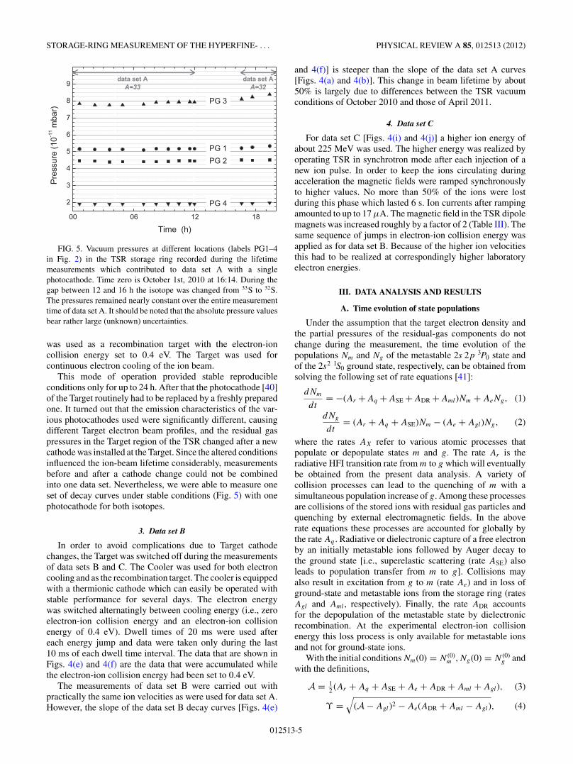
FIG. 5. Vacuum pressures at different locations (labels PG1–4in Fig. 2) in the TSR storage ring recorded during the lifetimemeasurements which contributed to data set A with a singlephotocathode. Time zero is October 1st, 2010 at 16:14. During thegap between 12 and 16 h the isotope was changed from 33S to 32S.The pressures remained nearly constant over the entire measurementtime of data set A. It should be noted that the absolute pressure valuesbear rather large (unknown) uncertainties.
was used as a recombination target with the electron-ioncollision energy set to 0.4 eV. The Target was used forcontinuous electron cooling of the ion beam.
This mode of operation provided stable reproducibleconditions only for up to 24 h. After that the photocathode [40]of the Target routinely had to be replaced by a freshly preparedone. It turned out that the emission characteristics of the var-ious photocathodes used were significantly different, causingdifferent Target electron beam profiles, and the residual gaspressures in the Target region of the TSR changed after a newcathode was installed at the Target. Since the altered conditionsinfluenced the ion-beam lifetime considerably, measurementsbefore and after a cathode change could not be combinedinto one data set. Nevertheless, we were able to measure oneset of decay curves under stable conditions (Fig. 5) with onephotocathode for both isotopes.
3. Data set B
In order to avoid complications due to Target cathodechanges, the Target was switched off during the measurementsof data sets B and C. The Cooler was used for both electroncooling and as the recombination target. The cooler is equippedwith a thermionic cathode which can easily be operated withstable performance for several days. The electron energywas switched alternatingly between cooling energy (i.e., zeroelectron-ion collision energy and an electron-ion collisionenergy of 0.4 eV). Dwell times of 20 ms were used aftereach energy jump and data were taken only during the last10 ms of each dwell time interval. The data that are shown inFigs. 4(e) and 4(f) are the data that were accumulated whilethe electron-ion collision energy had been set to 0.4 eV.
The measurements of data set B were carried out withpractically the same ion velocities as were used for data set A.However, the slope of the data set B decay curves [Figs. 4(e)
and 4(f)] is steeper than the slope of the data set A curves[Figs. 4(a) and 4(b)]. This change in beam lifetime by about50% is largely due to differences between the TSR vacuumconditions of October 2010 and those of April 2011.
4. Data set C
For data set C [Figs. 4(i) and 4(j)] a higher ion energy ofabout 225 MeV was used. The higher energy was realized byoperating TSR in synchrotron mode after each injection of anew ion pulse. In order to keep the ions circulating duringacceleration the magnetic fields were ramped synchronouslyto higher values. No more than 50% of the ions were lostduring this phase which lasted 6 s. Ion currents after rampingamounted to up to 17 μA. The magnetic field in the TSR dipolemagnets was increased roughly by a factor of 2 (Table III). Thesame sequence of jumps in electron-ion collision energy wasapplied as for data set B. Because of the higher ion velocitiesthis had to be realized at correspondingly higher laboratoryelectron energies.
III. DATA ANALYSIS AND RESULTS
A. Time evolution of state populations
Under the assumption that the target electron density andthe partial pressures of the residual-gas components do notchange during the measurement, the time evolution of thepopulations Nm and Ng of the metastable 2s 2p 3P0 state andof the 2s2 1S0 ground state, respectively, can be obtained fromsolving the following set of rate equations [41]:
dNm
dt= −(Ar + Aq + ASE + ADR + Aml)Nm + AeNg, (1)
dNg
dt= (Ar + Aq + ASE)Nm − (Ae + Agl)Ng, (2)
where the rates AX refer to various atomic processes thatpopulate or depopulate states m and g. The rate Ar is theradiative HFI transition rate from m to g which will eventuallybe obtained from the present data analysis. A variety ofcollision processes can lead to the quenching of m with asimultaneous population increase of g. Among these processesare collisions of the stored ions with residual gas particles andquenching by external electromagnetic fields. In the aboverate equations these processes are accounted for globally bythe rate Aq . Radiative or dielectronic capture of a free electronby an initially metastable ions followed by Auger decay tothe ground state [i.e., superelastic scattering (rate ASE) alsoleads to population transfer from m to g]. Collisions mayalso result in excitation from g to m (rate Ae) and in loss ofground-state and metastable ions from the storage ring (ratesAgl and Aml , respectively). Finally, the rate ADR accountsfor the depopulation of the metastable state by dielectronicrecombination. At the experimental electron-ion collisionenergy this loss process is only available for metastable ionsand not for ground-state ions.
With the initial conditions Nm(0) = N (0)m , Ng(0) = N (0)
g andwith the definitions,
A = 12 (Ar + Aq + ASE + Ae + ADR + Aml + Agl), (3)
ϒ =√
(A − Agl)2 − Ae(ADR + Aml − Agl), (4)
012513-5

S. SCHIPPERS et al. PHYSICAL REVIEW A 85, 012513 (2012)
the solutions of Eqs. (1) and (2) are [42] as follows:
Nm(t) ={
N (0)m cosh(ϒt) + [
AeN(0)g
− (A − Ae − Agl)N(0)m
] sinh(ϒt)
ϒ
}exp(−At), (5)
Ng(t) ={N (0)
g cosh(ϒt) + [(Ar + Aq + ASE)N (0)
m
+ (A − Ae − Agl)N(0)g
] sinh(ϒt)
ϒ
}exp(−At). (6)
Rewriting the hyperbolic functions as sums of two expo-nentials reveals that the time evolution of the number of storedions for both states is determined by the two time constants:
1/τm = A + ϒ, (7)
1/τg = A − ϒ, (8)
which directly reflect the effective storage lifetimes of themetastable and ground-state ions, respectively, as suggestedby the indices. As seen earlier [41], rather simple expressionsfor these time constants, are obtained in the limit Ae = 0. Inthis case, ϒ = A − Agl [Eq. (4)], and Eqs. (7) and (8) yield
1/τm = Ar + Aq + ASE + ADR + Aml, (9)
1/τg = Agl. (10)
As discussed in Sec. III C, this approximation is appropriatein our case. Moreover, it will be shown that further relationsbetween the parameters in these equations can be expectedto be approximately fulfilled, so that the radiative lifetimeAr can be found once the decay times τm and τg have beenexperimentally determined.
In the experiment, the measured count rate of recombinedions comprises contributions from both the metastable and theground state. Accordingly, it can be represented as the sum,
R(t) = −pm
dNm(t)
dt− pg
dNg(t)
dt, (11)
where pm (pg) is the probability that a metastable (ground-state) ion which is lost from the storage ring will thenbe collected by the recombination detector. This probabilityis effectively the rate of capturing an electron either fromelectron-ion recombination in the Cooler or from the residualgas in the straight section of the storage ring leading up tothe detector relative to the rate of all loss processes along theentire ring.
Since the hyperbolic functions in Eqs. (5) and (6) can beexpressed as the sums of two exponentials, the measured countrate [Eq. (11)] can also be written as
R(t) = cme−t/τm + cge−t/τg , (12)
where the coefficients,
cm = pm
2τm
[(1 + ξ )N (0)
m − Ae
ϒN (0)
g
]
+ pg
2τm
[(1 − ξ )N (0)
g − Ar + Aq + ASE
ϒN (0)
m
], (13)
cg = pm
2τg
[(1 − ξ )N (0)
m + Ae
ϒN (0)
g
]
+ pg
2τg
[(1 + ξ )N (0)
g + Ar + Aq + ASE
ϒN (0)
m
], (14)
with
ξ = A − Ae − Agl
ϒ−→Ae→ 0
1, (15)
are obtained by inserting Eqs. (5) and (6) into Eq. (11) andcomparing the resulting expression with Eq. (12). For thelifetime determination described below, the coefficients cm
and cg , obtained from fitting Eq. (12) to the data, will not befurther considered.
B. Fits to measured decay curves
The results from the fits of Eq. (12) to the measured decaycurves (i.e., the fit curves and the corresponding residuals) areincluded in Fig. 4. The best-fit values of the parameters τm, τg ,cm, and cg are given in columns 1–7 of Table IV along withtheir standard deviations. A range of initial data points wereexcluded from the fits in order to suppress the time intervalswhen the equilibrium conditions of the electron-cooled ionbeam were not yet reached. The evolution of the best fitparameters when increasingly more early-data points areexcluded from the fits is shown in Fig. 6. For data set A,stable conditions were reached only after about 7 s (8 s fordata sets B and C). Hence, data from the first 7 s (8 s) after ioninjection into the TSR were disregarded in the fits to the threedata sets, respectively.
FIG. 6. Dependence of the fit parameters τm (solid symbols) andτg (open symbols) on the time of the first data point that is used in thefit of Eq. (12) to the measured decay curves of data set A [Figs. 4(a)and 4(b)]. The arrows mark the data that were used in the calculationof τHFI. (Note that all values shown here scatter by less than theone-sigma error bars since they are statistically not independent; seetext.)
012513-6
STORAGE-RING MEASUREMENT OF THE HYPERFINE- . . . PHYSICAL REVIEW A 85, 012513 (2012)
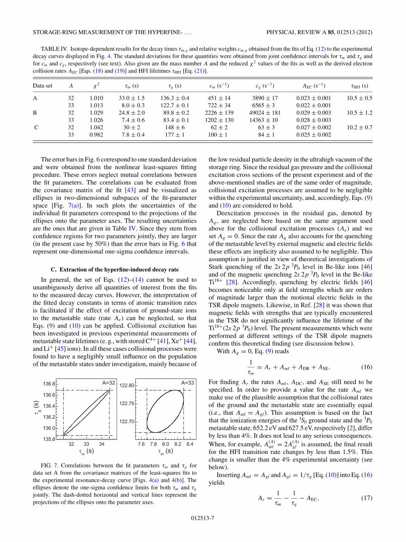
TABLE IV. Isotope-dependent results for the decay times τm,g and relative weights cm,g obtained from the fits of Eq. (12) to the experimentaldecay curves displayed in Fig. 4. The standard deviations for these quantities were obtained from joint confidence intervals for τm and τg andfor cm and cg , respectively (see text). Also given are the mass number A and the reduced χ2 values of the fits as well as the derived electroncollision rates AEC [Eqs. (18) and (19)] and HFI lifetimes τHFI [Eq. (21)].
Data set A χ 2 τm (s) τg (s) cm (s−1) cg (s−1) AEC (s−1) τHFI (s)
A 32 1.010 33.0 ± 1.5 136.3 ± 0.4 451 ± 14 3890 ± 17 0.023 ± 0.001 10.5 ± 0.533 1.013 8.0 ± 0.3 122.7 ± 0.1 722 ± 34 6565 ± 3 0.022 ± 0.001
B 32 1.029 24.8 ± 2.0 89.8 ± 0.2 2226 ± 139 49024 ± 181 0.029 ± 0.003 10.5 ± 1.233 1.026 7.4 ± 0.6 83.4 ± 0.1 1202 ± 130 14363 ± 10 0.028 ± 0.003
C 32 1.042 30 ± 2 148 ± 6 62 ± 2 63 ± 3 0.027 ± 0.002 10.2 ± 0.733 0.982 7.8 ± 0.4 177 ± 1 100 ± 1 84 ± 1 0.025 ± 0.002
The error bars in Fig. 6 correspond to one standard deviationand were obtained from the nonlinear least-squares fittingprocedure. These errors neglect mutual correlations betweenthe fit parameters. The correlations can be evaluated fromthe covariance matrix of the fit [43] and be visualized asellipses in two-dimensional subspaces of the fit-parameterspace [Fig. 7(a)]. In such plots the uncertainties of theindividual fit parameters correspond to the projections of theellipses onto the parameter axes. The resulting uncertaintiesare the ones that are given in Table IV. Since they stem fromconfidence regions for two parameters jointly, they are larger(in the present case by 50%) than the error bars in Fig. 6 thatrepresent one-dimensional one-sigma confidence intervals.
C. Extraction of the hyperfine-induced decay rate
In general, the set of Eqs. (12)–(14) cannot be used tounambiguously derive all quantities of interest from the fitsto the measured decay curves. However, the interpretation ofthe fitted decay constants in terms of atomic transition ratesis facilitated if the effect of excitation of ground-state ionsto the metastable state (rate Ae) can be neglected, so thatEqs. (9) and (10) can be applied. Collisional excitation hasbeen investigated in previous experimental measurements ofmetastable state lifetimes (e. g., with stored C4+ [41], Xe+ [44],and Li+ [45] ions). In all these cases collisional processes werefound to have a negligibly small influence on the populationof the metastable states under investigation, mainly because of
FIG. 7. Correlations between the fit parameters τm and τg fordata set A from the covariance matrices of the least-squares fits tothe experimental resonance-decay curve [Figs. 4(a) and 4(b)]. Theellipses denote the one-sigma confidence limits for both τm and τg
jointly. The dash-dotted horizontal and vertical lines represent theprojections of the ellipses onto the parameter axes.
the low residual particle density in the ultrahigh vacuum of thestorage ring. Since the residual gas pressure and the collisionalexcitation cross sections of the present experiment and of theabove-mentioned studies are of the same order of magnitude,collisional excitation processes are assumed to be negligiblewithin the experimental uncertainty, and, accordingly, Eqs. (9)and (10) are considered to hold.
Deexcitation processes in the residual gas, denoted byAq , are neglected here based on the same argument usedabove for the collisional excitation processes (Ae) and weset Aq = 0. Since the rate Aq also accounts for the quenchingof the metastable level by external magnetic and electric fieldsthese effects are implicity also assumed to be negligible. Thisassumption is justified in view of theoretical investigations ofStark quenching of the 2s 2p 3P0 level in Be-like ions [46]and of the magnetic quenching 2s 2p 3P0 level in the Be-likeTi18+ [28]. Accordingly, quenching by electric fields [46]becomes noticeable only at field strengths which are ordersof magnitude larger than the motional electric fields in theTSR dipole magnets. Likewise, in Ref. [28] it was shown thatmagnetic fields with strengths that are typically encounteredin the TSR do not significantly influence the lifetime of theTi18+(2s 2p 3P0) level. The present measurements which wereperformed at different settings of the TSR dipole magnetsconfirm this theoretical finding (see discussion below).
With Aq = 0, Eq. (9) reads
1
τm
= Ar + Aml + ADR + ASE. (16)
For finding Ar the rates Aml , ADC, and ASE still need to bespecified. In order to provide a value for the rate Aml wemake use of the plausible assumption that the collisional ratesof the ground and the metastable state are essentially equal(i.e., that Aml = Agl). This assumption is based on the factthat the ionization energies of the 1S0 ground state and the 3P0
metastable state, 652.2 eV and 627.5 eV, respectively [2], differby less than 4%. It does not lead to any serious consequences.When, for example, A
(A)ml = 2A
(A)gl is assumed, the final result
for the HFI transition rate changes by less than 1.5%. Thischange is smaller than the 4% experimental uncertainty (seebelow).
Inserting Aml = Agl and Agl = 1/τg [Eq. (10)] into Eq. (16)yields
Ar = 1
τm
− 1
τg
− AEC, (17)
012513-7
S. SCHIPPERS et al. PHYSICAL REVIEW A 85, 012513 (2012)
where the electron collision (EC) rate2 AEC = ADR + ASE
accounts for dielectronic recombination of and superelasticscattering from initially metastable ions. Exploiting the factthat there is no HFI transition for the A = 32 isotope (i.e.,A(32)
r = 0), Eq. (17) yields the EC rate for this isotope:
A(32)EC = 1
τ(32)m
− 1
τ(32)g
. (18)
The electron collision rate can be expressed as A(A)EC = n(A)
e αEC
where the rate coefficient αEC is the same for the metastableions of both isotopes. Consequently, the EC rate for the A = 33isotope is
A(33)EC = n(33)
e
n(32)e
A(32)EC = n(33)
e
n(32)e
(1
τ(32)m
− 1
τ(32)g
). (19)
In the previous experiment with Be-like Ti18+ [26] the densityratio was very close to 1 and therefore omitted from theequations. In the present measurements the ratios were 0.938,0.948, and 0.932 for data sets A, B, and C, respectively(Table III). As can be seen from the next to last column ofTable IV the rates AEC for the three experimental data setsmutually agree within 5%.
Using now Eq. (17) for the A = 33 isotope gives the2s 2p 3P0 → 2s2 1S0 transition rate in the laboratory frame:
A(33)r = 1
τ(33)m
− 1
τ(33)g
− n(33)e
n(32)e
(1
τ(32)m
− 1
τ(32)g
). (20)
Finally, the HFI transition rate is obtained from a transfor-mation into the reference frame of the moving ions [i.e.,by multiplication of A(33)
r with the Lorentz factor γ (33) =[1 − (v(33)
ion /c)2]−1/2 (c denotes the speed of light)]:
AHFI = 1
τHFI= γ (33)
[1
τ(33)m
− 1
τ(33)g
− n(33)e
n(32)e
(1
τ(32)m
− 1
τ(32)g
) ]. (21)
Results for the hyperfine-induced lifetime as derived fromthe three experimental data sets A, B, and C, are given in the lastcolumn of Table IV. This table also lists the best fit values forthe decay time constants which were used in Eq. (21) togetherwith the experimental parameters from Table III. Althoughthe three data sets were obtained under significantly differentexperimental conditions, the three experimental values for τHFI
agree with each other within the experimental uncertainties.This documents the robustness of the present experimentalapproach. The weighted mean (with the inverse squared errorsas weights) of the three experimental HFI lifetimes is τHFI =10.4 ± 0.4 s.
IV. DISCUSSION
During the measurement of data set C the magnetic fieldin the TSR bending magnets was a factor of two stronger
2In Ref. [26] the rate AEC is denoted as ADC.
as compared to the measurements of data sets A and B(Table III). At the same time, τHFI from data set C is smallerby 3% than τHFI from data sets A and B (Table IV). Thismay be an indication of a slight quenching of the 2s 2p 3P0
state in the magnetic fields of the storage-ring magnets (seealso [47]) which cover 13% of the closed orbit of the stored ions(Fig. 2). This effect is expected to increase quadratically withincreasing magnetic field strength [27]. Since the 3% change ofτHFI is smaller than the 4% experimental uncertainty, it must,however, be concluded that there is no significant influence ofthe TSR magnetic fields on the measured HFI transition ratesat the present level of experimental accuracy. This conclusionis in accord with recent theoretical results for isoelectronicTi18+ [28].
In Table V the present experimental result for the HFItransition rate AHFI = 1/τHFI = 1/10.4(4) s−1 = 0.096(4) s−1
is compared with the available theoretical results [6,8,9]. Theearly theoretical calculation by Marques et al. [6] yieldeda value that is about 60% lower than the experimentallydetermined rate. This is in contrast to the later calculationsby Cheng et al. [8] and Andersson et al. [9] which both yieldresults in very good agreement with the present experimentalvalue. As already discussed (Sec. I), the main differencebetween the early and later calculations is the treatment ofelectron-electron correlation effects. In particular, Marqueset al. [6] disregarded the mixing of the 2s 2p 1P1 level withthe 2s 2p 3P1 level. This mixing was included in the latercalculations of HFI transition rates in Be-like ions [7–10].The comparison of the available theoretical results with thepresent experimental result for 33S12+ strongly suggests thatthe additional computational effort of the later calculations isindeed required for arriving at more accurate HFI transitionrates.
Generally, the relative importance of correlation effectsdecreases with charge state. In the present context, this canbe seen from the differences between the early and the latertheoretical HFI transition rates. For the lower charged 33S12+ion the result of Marques et al. [6] deviates by 61% from theresult of Cheng et al. [8] (Table V). For the more highly charged47Ti18+ ion this difference is only 47% (Table I). In view ofthis fact, the ∼20% disagreement of the experimental resultfor 47Ti18+ with the latest theoretical calculation [8,9], whichagree well with the 33S12+ experimental value, is surprising.In the attempt to find an explanation for this disturbingdiscrepancy, the influence of external magnetic fields on thelifetime of the 47Ti18+(2s 2p 3P0) has been investigated bydetailed theoretical calculations [28]. From this study it was
TABLE V. Comparison of theoretical values for the hyperfine-induced 2s 2p 3P0 → 2s2 1S0 transition rate in Be-like S12+ with thepresent experimental result.
AHFI (s−1) Deviation from
Year Experiment Theory experiment Ref.
1993 0.036 11 −62.4% [6]2008 0.093 15 −3.0% [8]2009 0.093 55 −2.5% [9]2011 0.096(4) Present
012513-8
STORAGE-RING MEASUREMENT OF THE HYPERFINE- . . . PHYSICAL REVIEW A 85, 012513 (2012)
concluded that the magnetic fields in the TSR bending magnetsdo not influence the measured HFI lifetimes significantly. Thisis in agreement with the present experimental findings for33S12+ ions.
V. CONCLUSIONS
We have measured the hyperfine-induced 2s 2p 3P0 →2s2 1S0 transition rate in Be-like 33S12+ ions using isotopicallypure ion beams in a heavy-ion storage ring. The decay ofthe number of stored ions was monitored by employingelectron-ion recombination. In order to selectively enhancethe signal from the 2s 2p 3P0 level, the electron-ion collisionenergy was tuned to a dielectronic recombination resonanceassociated with this level.
In our present experimental work, different data sets wereobtained under substantially different conditions. Neverthe-less, the individual HFI transition rates from the differentdata sets agree with each other within the experimental
uncertainties. This demonstrates the robustness of the presentexperimental approach.
Our experimental value of 0.096(4) s−1 agrees with thelatest theoretical calculations [8,9]. No significant influence ofthe magnetic field in the storage-ring bending magnets on ourresult has been found. The origin of the discrepancy betweenour previously measured HFI rate for 47Ti18 [26] and the latestcalculations [8–10] still remains unclear.
ACKNOWLEDGMENTS
We thank the MPIK accelerator and TSR crews for theirexcellent support. Financial support by Deutsche Forschungs-gemeinschaft (DFG) Grant No. SCHI378/8-1and by the Max-Planck Society is gratefully acknowledged. M.H., O.N., andD.W.S. were financially supported in part by the NASAAstronomy and Physics Research and Analysis program andthe NASA Solar Heliospheric Physics program.
[1] W. Johnson, Can. J. Phys. 89, 429 (2011).[2] Y. Ralchenko, A. E. Kramida, J. Reader, and NIST ASD
Team, NIST Atomic Spectra Database, Version 4.1.0 ( NationalInstitute of Standards and Technology, Gaithersburg, 2011)[http://physics.nist.gov/asd].
[3] E. Landi and A. K. Bhatia, At. Data Nucl. Data Tables 94, 1(2008).
[4] R. W. Schmieder, Phys. Rev. A 7, 1458 (1973).[5] C. Laughlin, Phys. Lett. A 75, 199 (1980).[6] J. P. Marques, F. Parente, and P. Indelicato, Phys. Rev. A 47, 929
(1993).[7] T. Brage, P. G. Judge, A. Aboussaied, M. R. Godefroid,
P. Joensson, A. Ynnerman, C. F. Fischer, and D. S. Leckrone,Astrophys. J. 500, 507 (1998).
[8] K. T. Cheng, M. H. Chen, and W. R. Johnson, Phys. Rev. A 77,052504 (2008).
[9] M. Andersson, Y. Zou, R. Hutton, and T. Brage, Phys. Rev. A79, 032501 (2009).
[10] J. Li and C. Dong, Plas. Sci. Technol. 12, 364 (2010).[11] J. P. Marques, F. Parente, and P. Indelicato, At. Data Nucl. Data
Tables 55, 157 (1993).[12] H. Kang, J. Li, C. Dong, P. Jonsson, and G. Gaigalas, J. Phys. B
42, 195002 (2009).[13] M. Andersson, Y. Zou, R. Hutton, and T. Brage, J. Phys. B 43,
095001 (2010).[14] Y. Liu, R. Hutton, Y. Zou, M. Andersson, and T. Brage, J. Phys.
B 39, 3147 (2006).[15] J. P. Marques, F. Parente, and P. Indelicato, Eur. Phys. J. D 41,
457 (2007).[16] M. Chen and K. Cheng, Can. J. Phys. 89, 473 (2011).[17] S. G. Porsev and A. Derevianko, Phys. Rev. A 69, 042506
(2004).[18] R. Santra, K. V. Christ, and C. H. Greene, Phys. Rev. A 69,
042510 (2004).[19] P. Jonsson and M. Andersson, J. Phys. B 40, 2417 (2007).[20] A. D. Ludlow et al., Science 319, 1805 (2008).
[21] T. Rosenband et al., Science 319, 1808 (2008).[22] T. Becker, J. v. Zanthier, A. Y. Nevsky, C. Schwedes, M. N.
Skvortsov, H. Walther, and E. Peik, Phys. Rev. A 63, 051802(2001).
[23] T. Rosenband et al., Phys. Rev. Lett. 98, 220801 (2007).[24] T. Brage, P. G. Judge, and C. R. Proffitt, Phys. Rev. Lett. 89,
281101 (2002).[25] R. H. Rubin, G. J. Ferland, E. E. Chollet, and R. Horstmeyer,
Astrophys. J. 605, 784 (2004).[26] S. Schippers, E. W. Schmidt, D. Bernhardt, D. Yu, A. Muller,
M. Lestinsky, D. A. Orlov, M. Grieser, R. Repnow, and A. Wolf,Phys. Rev. Lett. 98, 033001 (2007).
[27] P. Balling, L. H. Andersen, T. Andersen, H. K. Haugen,P. Hvelplund, and K. Taulbjerg, Phys. Rev. Lett. 69, 1042 (1992).
[28] J. Li, C. Dong, P. Jonsson, and G. Gaigalas, Phys. Lett. A 375,914 (2011).
[29] G. Audi, A. H. Wapstra, and C. Thibault, Nucl. Phys. A 729,337 (2003).
[30] N. J. Stone, At. Data Nucl. Data Tables 90, 75 (2005).[31] J. K. Bohlke, J. R. de Laeter, P. De Bievre, H. Hidaka, H. S.
Peiser, K. J. R. Rosman, and P. D. P. Taylor, J. Phys. Chem. Ref.Data 34, 57 (2005).
[32] A. Wolf, H. Buhr, M. Grieser, R. von Hahn, M. Lestinsky,E. Lindroth, D. A. Orlov, S. Schippers, and I. F. Schneider,Hyperfine Interact. 172, 111 (2006).
[33] H. Poth, Phys. Rep. 196, 135 (1990).[34] K. Rinn, A. Muller, H. Eichenauer, and E. Salzborn, Rev. Sci.
Instrum. 53, 829 (1982).[35] M. Lestinsky et al., Astrophys. J. 698, 648 (2009).[36] E. W. Schmidt et al. Phys. Rev. A 76, 032717 (2007).[37] S. Schippers, A. Muller, G. Gwinner, J. Linkemann, A. A.
Saghiri, and A. Wolf, Astrophys. J. 555, 1027 (2001).[38] S. Schippers, E. W. Schmidt, D. Bernhardt, D. Yu, A. Muller,
M. Lestinsky, D. A. Orlov, M. Grieser, R. Repnow, and A. Wolf,J. Phys.: Conf. Ser. 58, 137 (2007).
[39] D. W. Savin et al., Astrophys. J. 642, 1275 (2006).
012513-9

S. SCHIPPERS et al. PHYSICAL REVIEW A 85, 012513 (2012)
[40] D. A. Orlov, F. Sprenger, M. Lestinsky, U. Weigel, A. S.Terekhov, D. Schwalm, and A. Wolf, J. Phys. Conf. Ser. 4,290 (2005).
[41] H. T. Schmidt et al., Phys. Rev. Lett. 72, 1616 (1994).[42] Computer code MATHEMATICA 8, Wolfram Research, Cham-
paign, IL, 2010. Depending on the sign of the radicand in Eq. (4),ϒ can be real or imaginary. In the latter case ϒ can be replacedby its imaginary part �ϒ , and the hyperbolic trigonometricfunctions in Eqs. (5) and (6) can be substituted by their ordinarytrigonometric counterparts.
[43] W. H. Press, S. A. Teukolsky, W. T. Vetterling, and B. P. Flannery,in Numerical Recipies in C++ (Cambridge University Press,New York, 2002), Chap. 15.6.
[44] S. Mannervik, J. Lidberg, L. O. Norlin, and P. Royen, Phys. Rev.A 56, R1075 (1997).
[45] A. A. Saghiri et al. Phys. Rev. A 60, R3350 (1999).[46] M. Maul, A. Schafer, and P. Indelicato, J. Phys. B 31, 2725
(1998).[47] S. Mannervik, L. Brostrom, J. Lidberg, L.-O. Norlin, and
P. Royen, Phys. Rev. Lett. 76, 3675 (1996).
012513-10


![ELECTRON CONFIGURATIONS Sulfur 1s 2 2s 2 sp 6 3s 2 3p 4 Chromium 1s 2 2s 2 2p 6 3s 2 3p 6 4s 2 3d 4 Lead (give the noble gas configuration) [Xe]6s 2 4f.](https://static.fdocuments.in/doc/165x107/56649cd75503460f9499f2eb/electron-configurations-sulfur-1s-2-2s-2-sp-6-3s-2-3p-4-chromium-1s-2-2s-2.jpg)