Storage, Maintenance and Dissemination of Massive 3D … · Storage, Maintenance and Dissemination...
36
Storage, Maintenance and Dissemination of Massive 3D City Models PhD Proposal September 12th, 2016 Kavisha PhD Candidate 2015-2019 3D geoinformation Department of Urbanism Faculty of Architecture and the Built Environment Delft University of Technology
Transcript of Storage, Maintenance and Dissemination of Massive 3D … · Storage, Maintenance and Dissemination...

Storage, Maintenance andDissemination of Massive 3D City
Models
PhD Proposal
September 12th, 2016
Kavisha
PhD Candidate
2015-2019
3D geoinformationDepartment of Urbanism
Faculty of Architecture and the Built EnvironmentDelft University of Technology
Contents
1 Introduction 31.1 Motivation . . . . . . . . . . . . . . . . . . . . . . . . . . . . . . . . . . . . . . . . . . . . . . . . 31.2 Research objectives . . . . . . . . . . . . . . . . . . . . . . . . . . . . . . . . . . . . . . . . . . . . 41.3 Scope of the research . . . . . . . . . . . . . . . . . . . . . . . . . . . . . . . . . . . . . . . . . . . 51.4 Structure of this report . . . . . . . . . . . . . . . . . . . . . . . . . . . . . . . . . . . . . . . . . 5
2 Related Work and background theory 62.1 State of art in modelling terrains . . . . . . . . . . . . . . . . . . . . . . . . . . . . . . . . . . . . 62.2 Terrain representations in memory (as TIN) . . . . . . . . . . . . . . . . . . . . . . . . . . . . . . 82.3 Terrains in CityGML . . . . . . . . . . . . . . . . . . . . . . . . . . . . . . . . . . . . . . . . . . . 10
2.3.1 TINs in CityGML . . . . . . . . . . . . . . . . . . . . . . . . . . . . . . . . . . . . . . . . 102.3.2 Grids in CityGML . . . . . . . . . . . . . . . . . . . . . . . . . . . . . . . . . . . . . . . . 12
2.4 Terrains in DBMS (as TINs) . . . . . . . . . . . . . . . . . . . . . . . . . . . . . . . . . . . . . . 122.4.1 TINs in PostgreSQL/PostGIS . . . . . . . . . . . . . . . . . . . . . . . . . . . . . . . . . . 132.4.2 TINs in Oracle . . . . . . . . . . . . . . . . . . . . . . . . . . . . . . . . . . . . . . . . . . 132.4.3 TINs in 3DCityDB . . . . . . . . . . . . . . . . . . . . . . . . . . . . . . . . . . . . . . . . 142.4.4 Other implementations . . . . . . . . . . . . . . . . . . . . . . . . . . . . . . . . . . . . . . 14
2.5 Terrain LODs . . . . . . . . . . . . . . . . . . . . . . . . . . . . . . . . . . . . . . . . . . . . . . . 14
3 Proposed PhD research 163.1 Problems in storing massive terrains . . . . . . . . . . . . . . . . . . . . . . . . . . . . . . . . . . 163.2 Research questions . . . . . . . . . . . . . . . . . . . . . . . . . . . . . . . . . . . . . . . . . . . . 173.3 Methodology . . . . . . . . . . . . . . . . . . . . . . . . . . . . . . . . . . . . . . . . . . . . . . . 17
3.3.1 Schema modelling for terrains . . . . . . . . . . . . . . . . . . . . . . . . . . . . . . . . . . 183.3.2 Database Implementation . . . . . . . . . . . . . . . . . . . . . . . . . . . . . . . . . . . . 193.3.3 Defining terrain LOD concept . . . . . . . . . . . . . . . . . . . . . . . . . . . . . . . . . . 193.3.4 Terrain visualization . . . . . . . . . . . . . . . . . . . . . . . . . . . . . . . . . . . . . . . 20
3.4 Case Studies . . . . . . . . . . . . . . . . . . . . . . . . . . . . . . . . . . . . . . . . . . . . . . . 223.5 Preliminary Results . . . . . . . . . . . . . . . . . . . . . . . . . . . . . . . . . . . . . . . . . . . 24
3.5.1 Analysis of TIN data structures . . . . . . . . . . . . . . . . . . . . . . . . . . . . . . . . . 243.5.2 CityGML extension for massive TINs . . . . . . . . . . . . . . . . . . . . . . . . . . . . . 25
4 Planning and practical aspects 284.1 Timetable . . . . . . . . . . . . . . . . . . . . . . . . . . . . . . . . . . . . . . . . . . . . . . . . . 284.2 Short term first year plan . . . . . . . . . . . . . . . . . . . . . . . . . . . . . . . . . . . . . . . . 294.3 3D4EM . . . . . . . . . . . . . . . . . . . . . . . . . . . . . . . . . . . . . . . . . . . . . . . . . . 294.4 Tools and Technical aspects . . . . . . . . . . . . . . . . . . . . . . . . . . . . . . . . . . . . . . . 294.5 Graduate School Obligations . . . . . . . . . . . . . . . . . . . . . . . . . . . . . . . . . . . . . . 294.6 Publications . . . . . . . . . . . . . . . . . . . . . . . . . . . . . . . . . . . . . . . . . . . . . . . . 30
1
Abbreviations
3D4EM 3D for Environmental Modelling.
ADE Application Domain Extension.
AHN2 Actueel Hoogtebestand Nederland (version 2).
CDT Constrained Delaunay Triangulation.
CGAL Computational Geometry Algorithms Library.
CityGML City Geography Markup Language.
DBMS Database Management System.
DCEL Doubly Connected Edge List.
DT Delaunay Triangulation.
GIS Geographic Information System.
GML Geography Markup Language.
KML Keyhole Markup Language.
LOD Level of Detail.
LR Laced Ring.
NWO Netherlands Organisation for Scientific Research.
OGC Open Geospatial Consortium.
RDBMS Relational Database Management System.
SDI Spatial Data Infrastructure.
SF Simple Feature.
SIG 3D Special Interest Group 3D.
TIFF Tagged Image File Format.
TIN Triangulated Irregular Network.
2

Chapter 1
Introduction
1.1 Motivation
A 3D city model is a digital representation of the geographical objects within a city (Stadler and Kolbe,2007). At first, 3D city models were mainly used for visualization but with the advancements in geoinformationtechnologies, they have gained importance in di↵erent applications like urban planning (Dollner et al., 2006;Kolbe et al., 2015b), 3D cadastre (Stoter et al., 2013; Cagdas, 2013; Guo et al., 2013), building rooftop solarirradiation estimation (Biljecki et al., 2015a; Eicker et al., 2014), building energy demand estimation (Kadenand Kolbe, 2014; Kruger and Kolbe, 2012), noise mapping (Stoter et al., 2008), population estimation (Biljeckiet al., 2016b), etc.; see Biljecki et al. (2015b) for an overview. It should be noticed that so far in practice, theapplications of 3D city modelling are mostly centred around the buildings; other features, e.g. terrain/relief,vegetation, roads, water bodies, bridges, are often ignored. The main focus in this research is on the terrain partof a 3D city model and particularly on its storage as a TIN (Triangulated Irregular Network) in file based systemsand DBMS. Apart from grids, TINs are considered to be one of the basic GIS structures for the representationof terrains. Practitioners often think of grids as the simplest way to represent a surface. In fact, it may be thebest model to depict the real world scenarios, but this possibility depends on the potential of the grids ratherthan their current use. Fisher (1997) pointed out several problems in using grids for the storage and analysis ofspatial data; for e.g. (i) no clarity in the representation of grid values (are they at the centre of every pixel orat the intersection of grid lines?), (ii) grid size (grids can be large for fine resoultion), (iii) loss of point valuesrepresenting valleys, ridges, etc. Although the basic advantage of using grids is that they are simple to store,TINs on the other hand also have several benefits. For instance, the local density of points in a TIN can beadjusted in accordance with the variations in the height of the original terrain e.g. areas of detailed relief canbe represented in a TIN with denser triangulation than the areas with a smooth relief (Kumler, 1994). Anotheradvantage is that the points describing valley, peaks, pits, etc can be represented at their exact location in aTIN model (Kumler, 1994)
While TINs are widely used in GIS and have several memory representation data structures (discussed inChapter 2), there are only a few options available for e�ciently storing the TINs in the database systems.Only two of the TIN data types have been implemented so far in a DBMS namely, Oracle SDO TIN (Ravadaet al., 2009) and OGC Simple Feature (SF) (OGC, 2011) in PostGIS. The 3D GIS standard CityGML (CityGeography Markup Language) allows to store terrains as TINs and grids (Groger et al., 2012). The storageas grids in CityGML is simple and is based on GML. The grids can be stored either inline as a finite numberof geometric locations (x,y) with elevation values or as as a hyperlink to the external TIFF file containing thedata (x,y,elevation). CityGML follows the OGC Simple Feature structure for the storage of TIN geometry.Although we see OGC Simple Feature as the current acceptable solution for storing 3D city objects, I say thatit is not suitable to e�ciently store massive TINs. Firstly, with massive TINs, the datasets become very large,which greatly hinders exchange and dissemination. Secondly, there is very little topological information stored,which prevents us from using the triangles for analysis. The cause of these two problems is that trianglesare represented as linear rings, which stores each triangle independently, and moreover repeats several verticesFigure 2.16. We discuss in Chapter 3 the other limitations of the current solution.
As an example, I consider 3DTOP10NL, the 3D city model of Netherlands (Kadaster, 2015), which coversthe whole country, including buildings, terrain, roads, canals, etc. (see Figure 1.1). It is constructed by addingthe third dimension from the AHN2 point cloud, obtained from airborne laser-scanners, to the objects in the 2Dtopographic map TOP10NL (Elberink et al., 2013). Its terrain is a constrained TIN with more than 1 billion
3

Figure 1.1: Snapshot of an area of 3DTOP10NL in CityGML. Notice that the terrain, roads, water courses areall triangulated, forming one large triangulation for the whole of the Netherlands.
triangles (1,156,641,666 to be exact). Storing it with the current solution of CityGML requires around 686GB of storage space for the terrain geometry. One can imagine that if all the elevation points from the pointcloud are used (around 640 billions, thus around 1.3 trillion triangles), then the file size would clearly preventsus from using the dataset in practice. Solutions that handle the issue of massive point clouds such as tilingare less viable in the case of TINs. When the dataset is too large to be processed within the available mainmemory, it is split into smaller parts (called tiles (or blocks or buckets)). The processing is done incrementallyon the generated tiles. This process of tiling (also known as blocking or bucketing) cannot be extended to TINswithout breaking its topology (Figure 1.2) unless there is addition of explicit points on the tile borders (calledSteiner points) causing changes in TIN topology (Figure 1.3). With the increasing size (in terabytes) of thesedatasets, the biggest challenge lies in their storage, management and dissemination. Keeping in view of theexisting problems, in Chapter 3 I propose a compact storage solution: an extension to GML/CityGML schemafor e�ciently storing and disseminating massive TINs. The proposed improvements over the SF structure andthe results of the first prototype implementation are also discussed.
Unsafe Triangles
Tile 1
Tile 2
Tile 3
Tile 4
Tile Boundary
Figure 1.2: Tiling of TIN
New Triangles
Tile 1
Tile 2
Tile 3
Tile 4
Tile Boundary
Steiner Points at Tile Boundary
Figure 1.3: Addition of Steiner Points
1.2 Research objectives
The goal of this research is to:
develop and prototype a robust solution for the compact and e�cient storage and dissemination of massiveterrains in the context of 3D city models.
Storing and managing massive TINs in the database is much more complicated than storing point cloudsbecause it not only requires storing the TIN geometry but also the topology. The requirement is to reduce the
4

redundancy of explicit representations while still maintaining support for updates and visualization.
1.3 Scope of the research
• I do not compare TINs with raster.
• Both file based and DBMS storage solutions are considered. Database solution is prefered due to theinherent properties of the DBMS systems like multi user support, data integrity, spatial indexes andspatial operations with other geometries (Elmasri and Navathe, 2014). However, i do not ignore file basedoutputs because they are widely used in several applications as inputs like energy analysis, landscapemodelling, etc.
• DBMS to be used for implementation is limited to open source PostgreSQL.
• CityGML/GML based solution is prefered due to its widespread acceptance in the GIS community andalso the 3DCityDB stores the 3D city models according to the CityGML/GML schema.
• The 3D webglobe being studied for 3D visualization is limited to Cesium.
• The major dissemination products will be CityGML, OBJ, 3D SHP and can also be tailored to the needsof project partners (see Section 4.3).
1.4 Structure of this report
This document comprises of four chapters:
• The current chapter introduces the motivation behind this research, the research objective and the scopeof the research.
• Chapter 2 provides a review of literature of the state of the art of modelling terrains and other conceptsrelevant to this research.
• Chapter 3 contains the proposed research e.g. research questions, methodology, and preliminary results.
• Chapter 4 provides an overview of the planning and practical aspects of the research e.g. the 4-year plan forthe research, key milestones in first year, techical aspects of the research, and graduate school obligations.
5

Chapter 2
Related Work and background theory
2.1 State of art in modelling terrains
Terrain1 (Latin Terra meaning Earth) in simple terms refers to the lay of the land described in terms ofelevation, slope or other attributes of the landscape. Modelling the terrain surface with precision has alwaysbeen a challenge for the geo-researchers. We describe terrain as a continuous coverage with elevation value(s)(can be more than one in case of 2.75D) for every direct position within its spatial domain. The terrains can berepresented in several ways. A drawing (or an art work) is perhaps the classical way of representing terrains.Such a representation though looks natural but is less accurate. Another solution can be to construct a physicalmodel of the terrain using clay, plastic or other material. However this approach is also less precise and timeconsuming. The irregular nature of the surface makes it di�cult to depict the true model of the terrain. Withthe advancements in computing technologies, more accurate representations such as DTM (Digital TerrainModel) and DSM (Digital Surface Model) have emerged. They have widespread applications like calculatingslope/aspect, area and volume, viewshed analysis, etc. Here we consider terrain as a DTM. In practice, theterms DTM and DSM are often assumed to be synonymous. But this is not the case. Before going further, theterms DTM and DSM should be clear. A DTM depicts the surface of the earth without any relief objects likevegetation, buildings, etc. on it i.e. the bare earth (Li et al., 2004) (shown in blue in Figure 2.1). In contrast,a DSM depicts the surface of the earth including the relief objects on it (shown in red in Figure 2.1).
DTM DSM
Figure 2.1: Digital Terrain Model
columns
rows
grid cell
Figure 2.2: A grid in GIS. Each cell stores a numericvalue (reflected by di↵erent colors) for a spatial at-tribute.
Over the last few decades, grids and TINs have become the two most popular models for representingterrains. A grid can be described as an array of cells arranged in rows and columns; with each cell storing anumeric value for a spatial attribute such as elevation (Childs, 2004). Each cell is referenced by its coordinatelocation (x,y). Mathematically, grids are 2.5D functional surfaces f(x, y) wherein each grid cell stores onlya single z-value (elevation here) for any location (x,y) (Childs, 2004). Thus, it is clear that in a 2.5D modelthe representation of vertical walls of objects like buildings is not possible. 3DTOP10NL terrain is modelledas one big triangulation (a TIN) with features like buildings, roads, etc. integrated in the terrain itself. Thistriangulated surface has vertical walls (see Figure 2.3) modelled by allowing each (x,y) location to have multiplez-values; this approach is referred to as 2.75D or 2.8D by Groger and Plumer (2005) but a 2.75D model not onlyhas vertical wall but also overhangs like balconies or roof overhangs. So, in this study we describe 3DTOP10NL
1https://en.wikipedia.org/wiki/Terrain
6
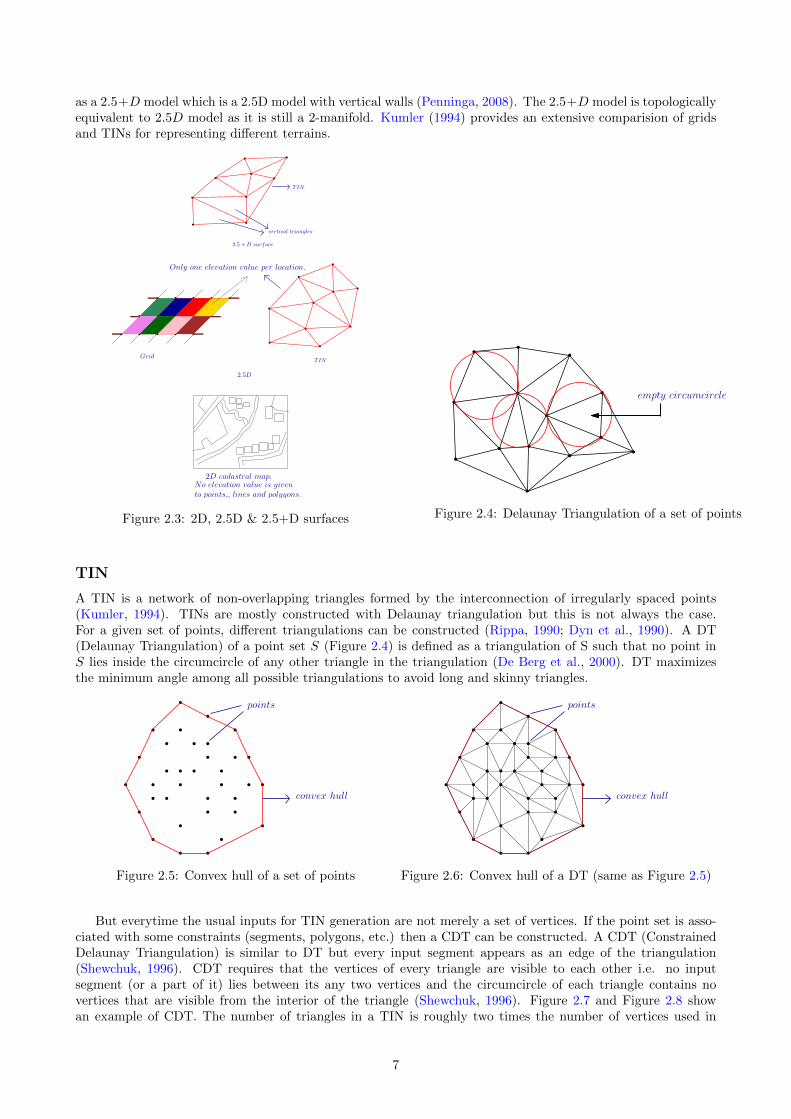
as a 2.5+D model which is a 2.5D model with vertical walls (Penninga, 2008). The 2.5+D model is topologicallyequivalent to 2.5D model as it is still a 2-manifold. Kumler (1994) provides an extensive comparision of gridsand TINs for representing di↵erent terrains.
vertical triangles
TIN
2.5D
2.5 +D surface
TIN
Grid
2D cadastral map.No elevation value is givento points,, lines and polygons.
Only one elevation value per location.
Figure 2.3: 2D, 2.5D & 2.5+D surfaces
empty circumcircle
Figure 2.4: Delaunay Triangulation of a set of points
TIN
A TIN is a network of non-overlapping triangles formed by the interconnection of irregularly spaced points(Kumler, 1994). TINs are mostly constructed with Delaunay triangulation but this is not always the case.For a given set of points, di↵erent triangulations can be constructed (Rippa, 1990; Dyn et al., 1990). A DT(Delaunay Triangulation) of a point set S (Figure 2.4) is defined as a triangulation of S such that no point inS lies inside the circumcircle of any other triangle in the triangulation (De Berg et al., 2000). DT maximizesthe minimum angle among all possible triangulations to avoid long and skinny triangles.
convex hull
points
Figure 2.5: Convex hull of a set of points
convex hull
points
Figure 2.6: Convex hull of a DT (same as Figure 2.5)
But everytime the usual inputs for TIN generation are not merely a set of vertices. If the point set is asso-ciated with some constraints (segments, polygons, etc.) then a CDT can be constructed. A CDT (ConstrainedDelaunay Triangulation) is similar to DT but every input segment appears as an edge of the triangulation(Shewchuk, 1996). CDT requires that the vertices of every triangle are visible to each other i.e. no inputsegment (or a part of it) lies between its any two vertices and the circumcircle of each triangle contains novertices that are visible from the interior of the triangle (Shewchuk, 1996). Figure 2.7 and Figure 2.8 showan example of CDT. The number of triangles in a TIN is roughly two times the number of vertices used in
7

triangulation; for instance, if we consider a dataset with n number of vertices with m number of vertices in theboundary of the convex hull, then there are (2n� 2�m) triangles in the triangulation (De Berg et al., 2000).A convex hull of a set of vertices is the smallest convex polygon which contains all the vertices of the givenset (Figure 2.5) (Worboys and Duckham, 2004). In a triangulation (or a TIN), the boundary or the polygonenclosing the triangulation of a set of vertices is the same as the convex hull of vertices alone (Figure 2.6).Experimental results of comparative analysis of the TIN data structures discussed in Section 3.5 also requiresinformation about the neighbouring points and triangles of a vertex. It is known as the degree of a vertex whichis expressed as the number of adjacent vertices from which edges are incident on that vertex (Worboys andDuckham, 2004).
Point
Predefined Edge
(Constraint)
Figure 2.7: Point set and constrained edge for CDT
Delaunay
Not Delaunay
Figure 2.8: Constrained Delaunay Triangulation ofpoint set and edge
2.2 Terrain representations in memory (as TIN)
Several data structures have been proposed for the representation and storage of TINs in memory and it is notsurprising to see that they exhibit redundancy and store a lot of information for providing direct retrieval ofthe adjacency relationships. The more complex representations of TINs take into account the attributes andconstraints associated with the connecting elements. Here we follow two assumptions namely, that the size ofthe convex hull is relatively small as compared to the total number of vertices in TIN, so there are roughly 2ntriangles and 3n edges in the TIN (De Berg et al., 2000). And, secondly, the term references in the text relatesto the integer/long integer IDs associated with the vertices/edges/triangles.
Most of the TIN data structures stores triangulations as an array of vertices or as references to the verticesforming the triangles, thereby capturing the mesh geometry. OGC Simple Feature (OGC, 2011) is a classicalexample of such data structure and is supported by almost all the spatial databases. It stores each triangle as aclosed linear ring of vertices with the repetition of first vertex as the last vertex of the ring(Figure 2.9). The sizeof the database increases considerably with the repeated storage of vertex information for each triangle and bythe creation of complex GiST spatial index (Hellerstein et al., 1995) on the triangle geoemetry (Kumar et al.,2016) We know that the average degree of a vertex in a 2D Delaunay triangulation is 6, given the vertices followPoisson distribution (Okabe et al., 2009). This suggests that on an average each vertex is stored 6+(6/3) = 8times. It does not store explicitly the adjacency relationships between the triangles, required for traversing theTIN.
(x1, y1, z1)
(x2, y2, z2) (x3, y3, z3)
< gml : triangle >< gml : exterior >< gml : LinearRing >< gml : posList > x1 y1 z1 x2 y2 z2 x3 y3 z3 x1 y1 z1 < /gml : posList >
< gml : LinearRing >< gml : exterior >
< gml : triangle >
Figure 2.9: OGC Simple Feature
T
v1
v2
v3
T v1v2 v3
Figure 2.10: Triangle
8
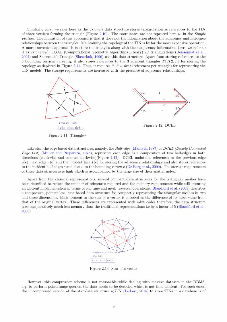
Similarly, what we refer here as the Triangle data structure stores triangulation as references to the IDs
of three vertices forming the triangle (Figure 2.10). The coordinates are not repeated here as in the SimpleFeature. The limitation of this approach is that it does not the information about the adjacency and incidencerelationships between the triangles. Maintaining the topology of the TIN is by far the most expensive operation.A more convenient approach is to store the triangles along with their adjacency information (here we refer toit as Triangle+). CGAL (Computational Geometry Algorithms Library) 2D triangulations (Boissonnat et al.,2002) and Shewchuk’s Triangle (Shewchuk, 1996) use this data structure. Apart from storing references to the3 bounding vertices v1, v2, v3, it also stores references to the 3 adjacent triangles T1, T2, T3 for storing thetopology as depicted in Figure 2.11. Thus, it requires 3+3 = 6rpt (references per triangle) for representing theTIN models. The storage requirements are increased with the presence of adjacency relationships.
T
T3
T1
T2
v1
v2
v3
T v1 v2 v3 T1 T2T3
Triangle+ table
Figure 2.11: Triangle+
Figure 2.12: DCEL
Likewise, the edge based data structures, namely, the Half-edge (Mantyla, 1987) or DCEL (Doubly ConnectedEdge List) (Muller and Preparata, 1978), represents each edge as a composition of two half-edges in bothdirections (clockwise and counter clockwise)(Figure 2.12). DCEL maintains references to the previous edgep(e), next edge n(e) and the incident face f(e) for storing the adjacency relationships and also stores referencesto the incident half edges e and e
0 and to the bounding vertex v (De Berg et al., 2000). The storage requirementsof these data structures is high which is accompanied by the large size of their spatial index.
Apart from the classical representations, several compact data structures for the triangular meshes havebeen described to reduce the number of references required and the memory requirements while still ensuringan e�cient implementation in terms of run time and mesh traversal operations. Blandford et al. (2005) describesa compressed, pointer less, star based data structure for compactly representing the triangular meshes in twoand three dimensions. Each element in the star of a vertex is encoded as the di↵erence of its label value fromthat of the original vertex. These di↵erences are represented with 4-bit codes therefore, the data structureuses comparatively much less memory than the traditional representations i.e.by a factor of 5 (Blandford et al.,2005).
star(v) = (v1, v2, v3, v4, v5, v6)
star(v)
v1
v2
v3
v4
v5
v6
Star table
v x y z star(v)
Figure 2.13: Star of a vertex
However, this compression scheme is not reasonable while dealing with massive datasets in the DBMS,e.g. to perform point/range queries, the data needs to be decoded which is not time e�cient. For such cases,the uncompressed version of the star data structure pgTIN (Ledoux, 2015) to store TINs in a database is of
9
relevance. The star of a bounding vertex star(v) is represented as an ordered list (counter-clockwise) of vertexlabels v1, v2, v3, .., vi forming the link (Figure 2.13). The triangles are computed on-the-fly. Each incidenttriangle of the bounding vertex v is represented by v and the two consecutive vertices vi in the list. On anaverage, each vertex in the star stores reference to 6 neighboring vertices (Okabe et al., 2009). The mainadvantage of the star data structure is that it does not require creation of complex spatial index like giST.The indexing is done at vertex level with a simple B-tree. The requirement for storage e�cient representationsfor triangular meshes has resulted in a number of compression methods and light weight data structures whichjust stores a set of core links from which other links can be inferred; for e.g. SQuad (Gurung et al., 2011a),Grouper (Lu↵el et al., 2014), Laced Ring (LR) (Gurung et al., 2011b), Zipper data structure (Gurung et al.,2013), and Tripod (Snoeyink and Speckmann, 1999). Table 2.1 highlights the comparison between the existingdata structures for the triangular meshes.
2.3 Terrains in CityGML
CityGML is an XML based data model for the storage and exchange of virtual 3D city models (Groger et al.,2012). It is implemented as an application schema of GML3 (Geography Markup Language version 3.1.1)and models 3D geometry along with semantics. The data model of CityGML comprises of a core module andseveral thematic extension modules like Building, Relief, Bridge, LandUse, Tunnel, Transportation,
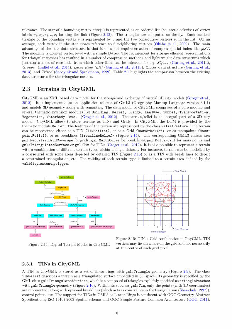
Vegetation, WaterBody, etc. (Groger et al., 2012). The terrain/relief is an integral part of a 3D citymodel. CityGML allows to store terrains as TINs and Grids. In CityGML, the DTM is provided by thethematic module Relief. The features of the terrain are represented by the class ReliefFeature. The terraincan be represented either as a TIN (TINReflief), or as a Grid (RasterRelief), or as masspoints (Mass-
pointRelief), or as breaklines (BreaklineRelief) (Figure 2.14). The corresponding GML3 classes are:gml:RectifiedGridCoverage for grids, gml:MultiCurve for break lines, gml:MultiPoint for mass points andgml:TriangulatedSurface or gml:Tin for TINs (Groger et al., 2012). It is also possible to represent a terrainwith a combination of di↵erent terrain types within a single dataset. For instance, terrain can be modelled bya coarse grid with some areas depicted by detailed TIN (Figure 2.15) or as a TIN with break lines to depicta constrained triangulation, etc. The validity of each terrain type is limited to a certain area defined by thevalidity extent polygon.
Figure 2.14: Digital Terrain Model in CityGML
TIN Relief
Grid Coveragevalidity polygon
Figure 2.15: TIN + Grid combination in CityGML. TINvertices may lie anywhere on the grid and not necessarilyat the centre of each grid pixel.
2.3.1 TINs in CityGML
A TIN in CityGML is stored as a set of linear rings with gml:Triangle geometry (Figure 2.9). The classTINRelief describes a terrain as a triangulated surface embedded in 3D space. Its geometry is specified by theGML class gml:TriangulatedSurface, which is a composed of triangles explicitly specified as trianglePatcheswith gml:Triangle geometry (Figure 2.16). Within its subclass gml:Tin, only the points (with 3D coordinates)are represented, along with optional breaklines (which acts as constraints in the triangulation (Shewchuk, 1997)),control points, etc. The support for TINs in GML3 as Linear Rings is consistent with OGC Geometry AbstractSpecifications, ISO 19107:2003 Spatial schema and OGC Simple Feature Common Architecture (OGC, 2011).
10

Data Structure Type rpt Topology Features Limitations
PostGIS SF Face based 4 X Face as linear ring of ver-tices
Vertex information redun-dancy, No topology, Largespatial index
Oracle Triangle Face based 3 X Triangle as reference to 3vertices only, Bucketing ofvertices, Block level index-ing
No topology
Triangle+ Face based 6 Triangle as reference to3 vertices only, Explicittopology storage
Triangle level indexing
DCEL Edge based 6 Triangles as reference tothe half edges
Edge information redun-dancy, Large spatial index
Star Vertex based 3 Triangles as ordered listof vertex labels and arecomputed on the fly, Ver-tex adjacency informa-tion, More compact, Nospatial indexing but sim-ple B-tree indexing at ver-tex level
No dynamic updates
SQuad Corner based 2 Triangles in pairs asquads, Uses cornerswings, Vertex order ismaintained
Degradation of spatial co-herence, Not suitable forstreaming meshes, No dy-namic updates
Grouper Corner based 2 Interleaves geometry withtopology, Spatial Coher-ance, Mesh streaming,Dynamic updation
LR Rings+Cornerbased
1 2x>SQuad, Global vertexreordering along hamilto-nian cycle
Not suitable for streamingmeshes, Rebuilding of en-tire data structure uponupdation
Zipper Rings+Cornerbased
1 4.4x>LR, Global vertexreordering and di↵erentialencoding
Rebuilding of entire datastructure upon updation
Tripod Vertex based 3 Orients and groups edgesinto 3 vertex spanningtrees
Pointer based, No dy-namic updates
Table 2.1: Existing TIN data structures
11
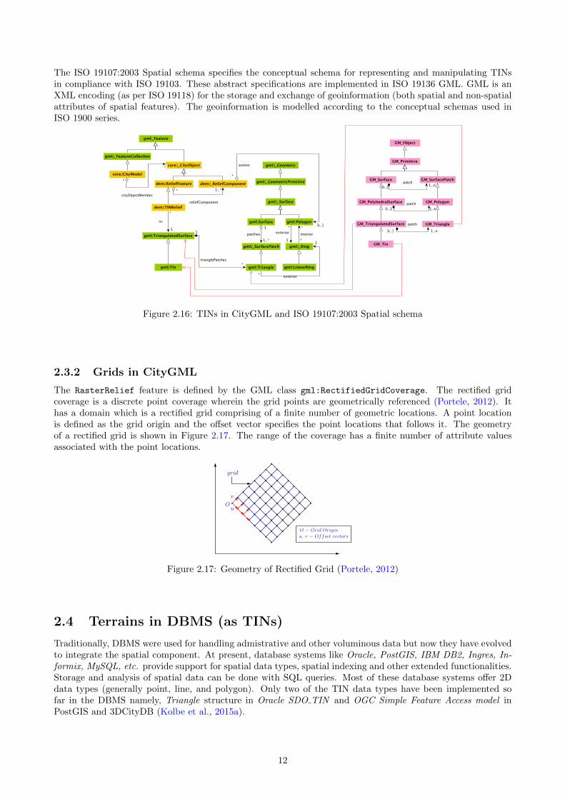
The ISO 19107:2003 Spatial schema specifies the conceptual schema for representing and manipulating TINsin compliance with ISO 19103. These abstract specifications are implemented in ISO 19136 GML. GML is anXML encoding (as per ISO 19118) for the storage and exchange of geoinformation (both spatial and non-spatialattributes of spatial features). The geoinformation is modelled according to the conceptual schemas used inISO 1900 series.
Figure 2.16: TINs in CityGML and ISO 19107:2003 Spatial schema
2.3.2 Grids in CityGML
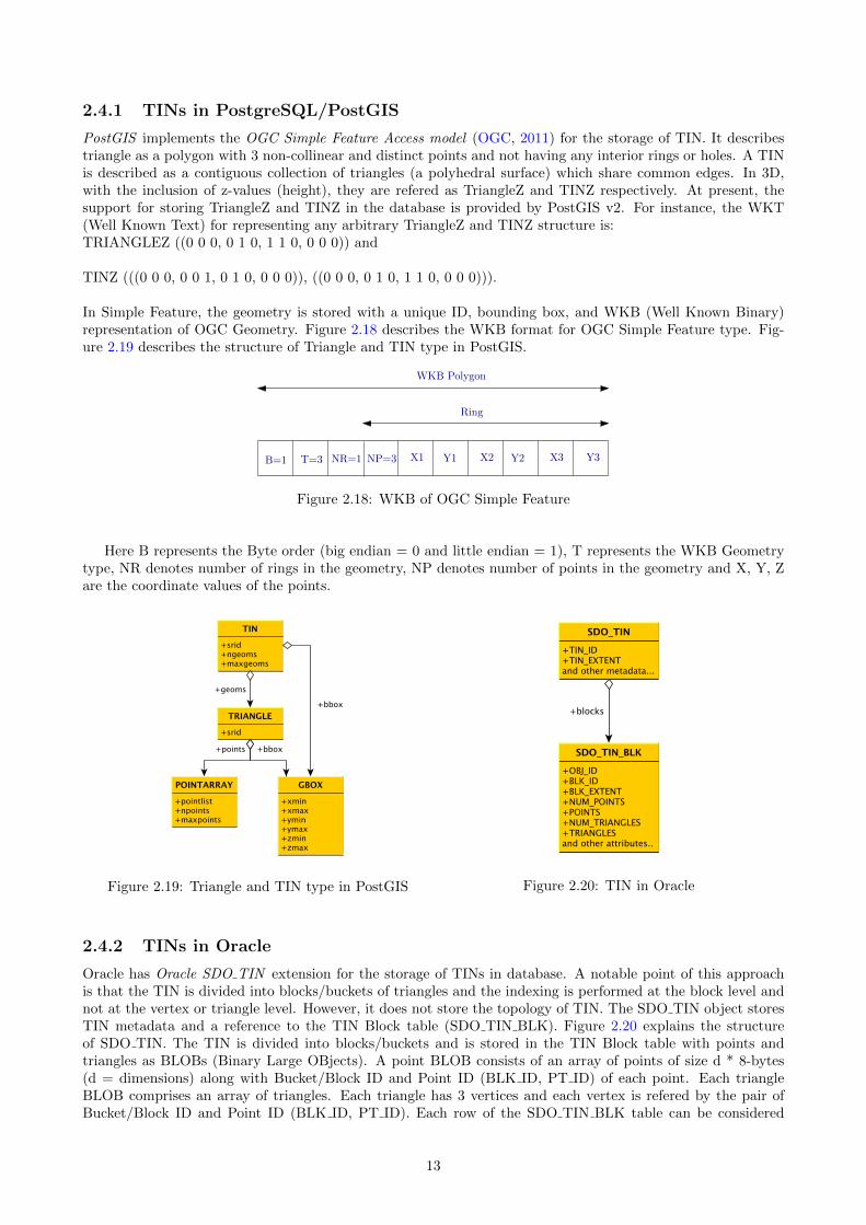
The RasterRelief feature is defined by the GML class gml:RectifiedGridCoverage. The rectified gridcoverage is a discrete point coverage wherein the grid points are geometrically referenced (Portele, 2012). Ithas a domain which is a rectified grid comprising of a finite number of geometric locations. A point locationis defined as the grid origin and the o↵set vector specifies the point locations that follows it. The geometryof a rectified grid is shown in Figure 2.17. The range of the coverage has a finite number of attribute valuesassociated with the point locations.
Ou
v
grid
O � Grid Originu, v � Offset vectors
Figure 2.17: Geometry of Rectified Grid (Portele, 2012)
2.4 Terrains in DBMS (as TINs)
Traditionally, DBMS were used for handling admistrative and other voluminous data but now they have evolvedto integrate the spatial component. At present, database systems like Oracle, PostGIS, IBM DB2, Ingres, In-formix, MySQL, etc. provide support for spatial data types, spatial indexing and other extended functionalities.Storage and analysis of spatial data can be done with SQL queries. Most of these database systems o↵er 2Ddata types (generally point, line, and polygon). Only two of the TIN data types have been implemented sofar in the DBMS namely, Triangle structure in Oracle SDO TIN and OGC Simple Feature Access model inPostGIS and 3DCityDB (Kolbe et al., 2015a).
12
2.4.1 TINs in PostgreSQL/PostGIS
PostGIS implements the OGC Simple Feature Access model (OGC, 2011) for the storage of TIN. It describestriangle as a polygon with 3 non-collinear and distinct points and not having any interior rings or holes. A TINis described as a contiguous collection of triangles (a polyhedral surface) which share common edges. In 3D,with the inclusion of z-values (height), they are refered as TriangleZ and TINZ respectively. At present, thesupport for storing TriangleZ and TINZ in the database is provided by PostGIS v2. For instance, the WKT(Well Known Text) for representing any arbitrary TriangleZ and TINZ structure is:TRIANGLEZ ((0 0 0, 0 1 0, 1 1 0, 0 0 0)) and
TINZ (((0 0 0, 0 0 1, 0 1 0, 0 0 0)), ((0 0 0, 0 1 0, 1 1 0, 0 0 0))).
In Simple Feature, the geometry is stored with a unique ID, bounding box, and WKB (Well Known Binary)representation of OGC Geometry. Figure 2.18 describes the WKB format for OGC Simple Feature type. Fig-ure 2.19 describes the structure of Triangle and TIN type in PostGIS.
WKB Polygon
Ring
B=1 T=3 NR=1 NP=3 X1 Y1 X2 Y2 X3 Y3
Figure 2.18: WKB of OGC Simple Feature
Here B represents the Byte order (big endian = 0 and little endian = 1), T represents the WKB Geometrytype, NR denotes number of rings in the geometry, NP denotes number of points in the geometry and X, Y, Zare the coordinate values of the points.
Figure 2.19: Triangle and TIN type in PostGIS Figure 2.20: TIN in Oracle
2.4.2 TINs in Oracle
Oracle has Oracle SDO TIN extension for the storage of TINs in database. A notable point of this approachis that the TIN is divided into blocks/buckets of triangles and the indexing is performed at the block level andnot at the vertex or triangle level. However, it does not store the topology of TIN. The SDO TIN object storesTIN metadata and a reference to the TIN Block table (SDO TIN BLK). Figure 2.20 explains the structureof SDO TIN. The TIN is divided into blocks/buckets and is stored in the TIN Block table with points andtriangles as BLOBs (Binary Large OBjects). A point BLOB consists of an array of points of size d * 8-bytes(d = dimensions) along with Bucket/Block ID and Point ID (BLK ID, PT ID) of each point. Each triangleBLOB comprises an array of triangles. Each triangle has 3 vertices and each vertex is refered by the pair ofBucket/Block ID and Point ID (BLK ID, PT ID). Each row of the SDO TIN BLK table can be considered
13
itself as a complete and connected bucket. Moreover, this explicit storage of block ID with each point solvesthe issue of dividing TIN with bucketing.
2.4.3 TINs in 3DCityDB
3DCityDB 2 (3D City Database) is an open source geodatabase for the storage of 3D city objects on top of aspatial RDBMS (Relational Database Management System). It stores the virtual 3D city models according tothe CityGML schema. At present, 3DCityDB has support for two databases namely, Oracle and PostGIS. Itsschema is derived by the mapping of the CityGML data model to the relational structure of a database system(Kolbe et al., 2015a). For storing the DTM, 3DCityDB has a RELIEF FEATURE table which stores a complexrelief/terrain object. It also has an attribute LOD to specify the level of detail of the relief object. The complexrelief object can have di↵erent relief components like TIN, grid/raster, etc. which are stored in their respectivetables TIN RELIEF, RASTER RELIEF, etc. Di↵erent relief compoenents within a complex relief object can existin di↵erent LODs. The LOD attribute of individual components specify their level of detail. TINs in 3DCityDBare stored in the TIN RELIEF table as triangulated surfaces (OGC Simple Feature) comprising of patches oftriangles (already explained in Section 2.3.1).
2.4.4 Other implementations
Among other implementations is the pgTIN extension for PostgreSQL (Ledoux, 2015) stores TIN as uncom-pressed stars. It only makes use of a vertex table with each row containing a vertex ID, vertex coordinates andan array of references to the vertices in the star of the vertex as explained earlier. Figure 2.21 describes thestructure of stars in a database. Triangles are computed on-the-fly using the explicitly stored topology. Thevertices in the table are indexed using a B-tree. The main limitation of the approach is that it lacks bucketing.Another implementation is the multistar approach (Pronk, 2015) which is built upon the pgTIN prototype forPostgreSQL database. It implements bucketing in the star data structure with each row of database storingmultiple vertices and stars. Only the spatial extent of each bucket is indexed.
Figure 2.21: Stars UML
2.5 Terrain LODs
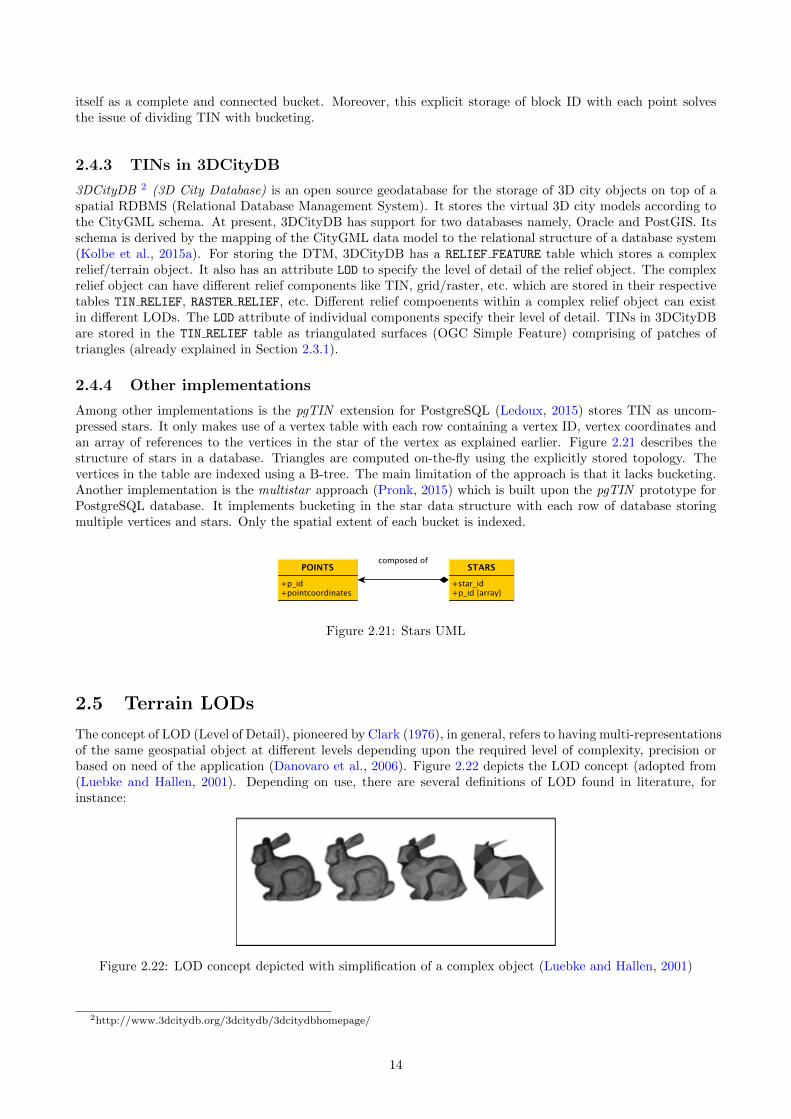
The concept of LOD (Level of Detail), pioneered by Clark (1976), in general, refers to having multi-representationsof the same geospatial object at di↵erent levels depending upon the required level of complexity, precision orbased on need of the application (Danovaro et al., 2006). Figure 2.22 depicts the LOD concept (adopted from(Luebke and Hallen, 2001). Depending on use, there are several definitions of LOD found in literature, forinstance:
Figure 2.22: LOD concept depicted with simplification of a complex object (Luebke and Hallen, 2001)
2http://www.3dcitydb.org/3dcitydb/3dcitydbhomepage/
14
• Luebke (2003) describes the LODs in the context of 3D graphics as progressively coarser versions of anobject. The concept follows a simple principle that while rendering a 3D scene, the requirement is to lessdetailed representation for small, distant or unimportant portions of the scene.
• CityGML describes LODs as a requirement to e↵ectively visualize and analyse the 3D model with regardsto di↵erent degrees of resolution (Groger et al., 2012).
• Wikipedia 3
In computer graphics, accounting for Level of detail involves decreasing the complexity of a 3Dmodel representation as it moves away from the viewer or according to other metrics such asobject importance, viewpoint-relative speed or position. Level of detail techniques increase thee�ciency of rendering by decreasing the workload on graphics pipeline stages, usually vertextransformations. The reduced visual quality of the model is often unnoticed because of the smalle↵ect on object appearance when distant or moving fast.
The LOD feature is an important characteristic of 3D city models. It enables gradual refinement of modelgeometry supplemented with required semantics. Di↵erent LODs serve di↵erent applications and provide qualityinformation of models. CityGML supports five LODs which in theory can be applied to all the urban featuresrepresented with CityGML e.g. buildings, vegetation, bridges, relief, etc. But in reality the concept is notconsistent for all the available features. The CityGML LOD concept was primarily defined for the Building
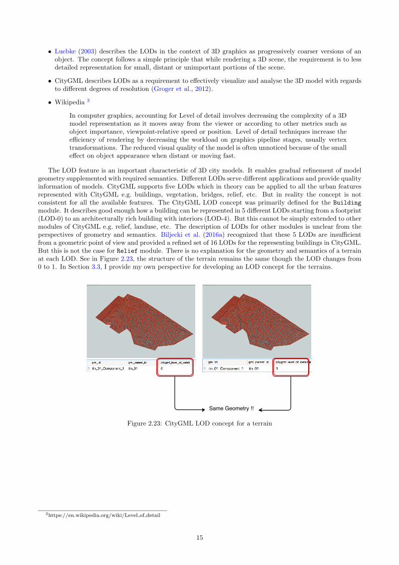
module. It describes good enough how a building can be represented in 5 di↵erent LODs starting from a footprint(LOD-0) to an architecturally rich building with interiors (LOD-4). But this cannot be simply extended to othermodules of CityGML e.g. relief, landuse, etc. The description of LODs for other modules is unclear from theperspectives of geometry and semantics. Biljecki et al. (2016a) recognized that these 5 LODs are insu�cientfrom a geometric point of view and provided a refined set of 16 LODs for the representing buildings in CityGML.But this is not the case for Relief module. There is no explanation for the geometry and semantics of a terrainat each LOD. See in Figure 2.23, the structure of the terrain remains the same though the LOD changes from0 to 1. In Section 3.3, I provide my own perspective for developing an LOD concept for the terrains.
Figure 2.23: CityGML LOD concept for a terrain
3https://en.wikipedia.org/wiki/Level of detail
15
Chapter 3
Proposed PhD research
3.1 Problems in storing massive terrains
Nowadays 3D data acquisition and processing techniques such as airborne laser scanning and multi-beamechosounding generate billions of 3D points for simply an area of few square kilometers. The TIN gener-ated from these points could be massive in size even for a small city like Delft. Based on literature review andexperiments conducted, I found that out there are several problems associated with the storage of these massivetriangulations with current storage solutions. I list them here:
1. Huge data volumes : Since every triangle is stored as a linear ring of vertices in Simple Feature structure(Figure 2.9), the size of the CityGML files is increased considerably with the repeated storage of vertexinformation. As explained in Section 2.2 that on an average each vertex is stored 6+6/3 = 8 times, whichincreases the vertex information redundancy in the CityGML datasets.
2. No referencing of triangles and their vertices : There is no referencing scheme for the vertices of a trianglein Simple Feature structure. Each of the triangle is specified with the coordinates of its vertices in fullwhich takes more space (Figure 2.9) as shown in experimental results in Section 3.5. This is also the maincause of large size of CityGML datasets, as mentioned in problem 1. There is no indexing of triangles aswell.
3. No topology : There is no storage of topological information of TIN in Simple Feature and trianglestructure. The triangles are stored individually irrespective of their neighbours. This hinders spatialanalysis greatly.
4. Badly modelled TIN geometry : The gml:TriangulatedSurface comprises of triangle patches forming theTIN. It is defined as a separate subclass of gml:Surface but it sholud have been defined as a subclass ofgml:CompositeSurface. A composite surface requires its elements to be disjoint, not to have overlappinginteriors and must be topologically connected along their boundaries. These prerequisites are fulfilled incase of TINs.
5. No specifications for terrain LODs : There is no distinction between di↵erent LODs of a terrain inCityGML at geometrical and semantic level. The CityGML 3.0 provides extended LODs for the Buildingmodule only and the LOD specifications of other modules like Relief, etc. are left out as unessential features(Lowner et al., 2013; Groger and Lowner, 2016). Giving only a gml:lod does not solve the issue if wecannot identify the di↵erence between LODs.
6. Vertical triangles are not handled : 3DTOP10NL models urban objects like buildings, roads, etc. in-tegrated in the terrain. In a way it is not completely 2.5D but a 2.75D model with vertical walls. A2.75D models is a 2-manifold surface embedded in a 3D space (Groger and Plumer, 2005). When a 2.75Dmodel is projected on a 2D surface, the vertical surfaces flatten out which distorts the geometry of themodel. There is no mechanism in CityGML to mark out these vertical surfaces so as to remove themwhile transforming from 3D to 2D.
7. No support for Tiling : The main memory of a system plays a key role in deciding the maximum size ofa dataset that can be processed (Isenburg et al., 2006). If the size of the datasets exceeds the availablememory limit then it is split into small parts (called tiles). The processing is done incrementally on thegenerated tiles. The concept of tiling the TIN cannot be extended to CityGML as there can be triangles
16

spanning across many tiles, each of which is repeated in the spanned tiles causing information redundancy(Figure 1.2).
8. Unclear TIN and Grid combination : The CityGML documentation (Groger et al., 2012) talks abouthaving a combination of multiple terrain types with in the same dataset. For instance, in Figure 2.15, theterrain is represented by a grid along with a certain area represented by a TIN. The TIN vertices maylie anywhere on the grid and not necessarily at the centre of each grid pixel. In such cases, deriving theexact value of elevation of TIN vertices from grid pixels is ambiguous.
9. Not suitable for visualization : CityGML is designed for the storage and exchange of 3D city models andnot for visualizing them. Visualizing CityGML over web requires to follow another pathway of separatingthe geometric information from semantic part in the commonly used 3D graphics formats and using themto visualize the model. This is owed to the large size and information redundancy in the CityGMLdatasets. With terrain datasets crossing the billion mark in the count of triangle geometries, the commonbottleneck of web visualization is the rate at which these triangles can be rendered over the graphicsengine.
3.2 Research questions
Based on the preliminary study and the problems identified, the main research question is:
How to e�ciently model and disseminate massive terrains in the context of 3D city models?
The accompaying research sub-questions that are related to this research are:
• What is a terrain in the context of 3D city models? Is it di↵erent from other terrains used in other fields?
• How are terrains integrated with other feature classes (like buildings, bridges, etc.) in the context of 3Dcity models?
• The concept of LODs for buildings in CityGML is well defined. But it cannot be simply applied to otherfeature classes like terrains, land use, etc. So the questions at hand are:
– what is the current school of thought for the definition of LODs for terrain in CityGML?
– how can we define our formal specifications for terrain LODs which are consistent with currentCityGML schema?
– what are the criteria for defining LODs for a terrain?
• The current CityGML Relief module is not su�cient to store massive terrain models e�ciently. How canwe create a compact representation of terrains at di↵erent levels of detail? How CityGML Relief modulecan be improved to store massive terrains in file based systems and DBMS?
• How the compact representation of terrains be visualised and disseminated over web?
3.3 Methodology
Based on the weaknesses of the current storage solution for the storage of massive terrains (as highlighted inSection 3.1), I propose a framework for:
• developing a robust schema for the compact storage of terrains in CityGML and 3DCityDB/PostGIS.• visualizing and disseminating the CityGML terrains.
Figure 3.1 gives an overview of the proposed workflow. The framework has 4 major parts:• Schema modelling for terrains• Database implementation• An LOD concept for terrains• 3D web visualization and dissemination
17
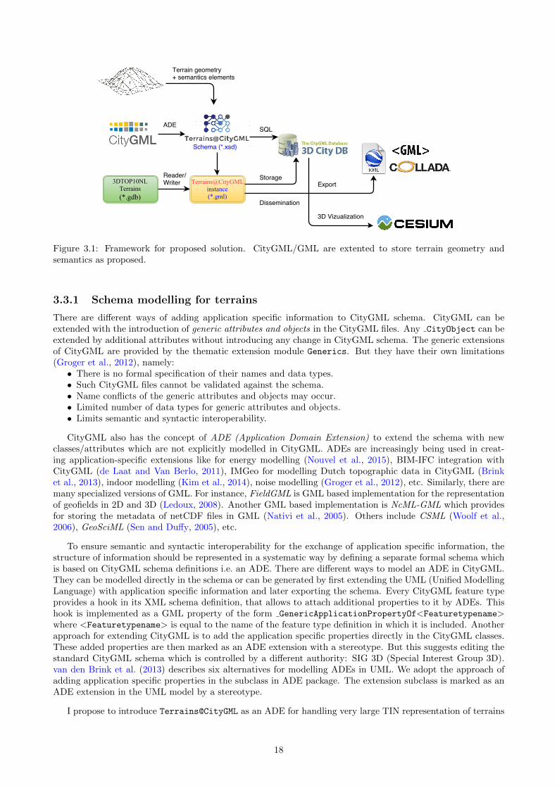
Figure 3.1: Framework for proposed solution. CityGML/GML are extented to store terrain geometry andsemantics as proposed.
3.3.1 Schema modelling for terrains
There are di↵erent ways of adding application specific information to CityGML schema. CityGML can beextended with the introduction of generic attributes and objects in the CityGML files. Any CityObject can beextended by additional attributes without introducing any change in CityGML schema. The generic extensionsof CityGML are provided by the thematic extension module Generics. But they have their own limitations(Groger et al., 2012), namely:
• There is no formal specification of their names and data types.• Such CityGML files cannot be validated against the schema.• Name conflicts of the generic attributes and objects may occur.• Limited number of data types for generic attributes and objects.• Limits semantic and syntactic interoperability.
CityGML also has the concept of ADE (Application Domain Extension) to extend the schema with newclasses/attributes which are not explicitly modelled in CityGML. ADEs are increasingly being used in creat-ing application-specific extensions like for energy modelling (Nouvel et al., 2015), BIM-IFC integration withCityGML (de Laat and Van Berlo, 2011), IMGeo for modelling Dutch topographic data in CityGML (Brinket al., 2013), indoor modelling (Kim et al., 2014), noise modelling (Groger et al., 2012), etc. Similarly, there aremany specialized versions of GML. For instance, FieldGML is GML based implementation for the representationof geofields in 2D and 3D (Ledoux, 2008). Another GML based implementation is NcML-GML which providesfor storing the metadata of netCDF files in GML (Nativi et al., 2005). Others include CSML (Woolf et al.,2006), GeoSciML (Sen and Du↵y, 2005), etc.
To ensure semantic and syntactic interoperability for the exchange of application specific information, thestructure of information should be represented in a systematic way by defining a separate formal schema whichis based on CityGML schema definitions i.e. an ADE. There are di↵erent ways to model an ADE in CityGML.They can be modelled directly in the schema or can be generated by first extending the UML (Unified ModellingLanguage) with application specific information and later exporting the schema. Every CityGML feature typeprovides a hook in its XML schema definition, that allows to attach additional properties to it by ADEs. Thishook is implemented as a GML property of the form GenericApplicationPropertyOf<Featuretypename>
where <Featuretypename> is equal to the name of the feature type definition in which it is included. Anotherapproach for extending CityGML is to add the application specific properties directly in the CityGML classes.These added properties are then marked as an ADE extension with a stereotype. But this suggests editing thestandard CityGML schema which is controlled by a di↵erent authority: SIG 3D (Special Interest Group 3D).van den Brink et al. (2013) describes six alternatives for modelling ADEs in UML. We adopt the approach ofadding application specific properties in the subclass in ADE package. The extension subclass is marked as anADE extension in the UML model by a stereotype.
I propose to introduce Terrains@CityGML as an ADE for handling very large TIN representation of terrains
18

in CityGML. The ADE will cover all the four aspects of modelling a terrain in CityGML: geometry, semantics,texture and LOD. The new geometry classes are to be added in the GML schema. The new classes and attributesfor terrain semantics and texture are to be defined in the CityGML schema. The ADE Terrains@CityGML willhave two major classes TINTerrain and StarTerrain capable of storing TINs as a collection of triangles andas a collection of stars, respectively. Correspondingly, new geometry types (Terrain Elements) for indexingvertices and triangles will be introduced in the GML schema. Terrain Elements refer to the data elementsforming the structure of terrain. They can be:
1. a set of vertices/points in 2D or 3D space.2. a set of connected triangles and their vertices in 2D or 3D space.3. a set of connected triangles, their vertices and additional constraints (breaklines) in 2D or 3D space.4. a set of vertex stars.To represent a constrained triangulation with break lines and points, ConstrainedTINTerrain, a subclass
of the TINTerrain will be defined. The vertices are to be stored as an array of coordinates of type doubleand the triangles as an array of vertex indices of type integer (VTP, 2012). The generated Terrains@CityGML
instances are required to be validated against this schema. A bucketing or a tiling scheme will be introducedfor managing the massive TINs.
3.3.2 Database Implementation
The schema of 3DCityDB is based on CityGML. Terrain@CityGML will be developed as an ADE for handlingvery large terrains in CityGML. I plan to use 3DCityDB (PostgreSQL) for the database implementation of theADE. This will involve:
1. Once the UML model is defined, the classes of the UML of the ADE will be mapped to the tables in thedatabase.
2. The data types of the attributes will be customized according to the data types of PostgreSQL.
3. The attributes of the classes will become the columns of their respective tables.
4. Abstract classes will not be mapped to tables/attributes.
5. The new classes will be added to the OBJECTCLASS meta table and the relation of each subclass to itsrespective superclass will be marked.
6. A simple B-tree index will be used.
7. SQL queries (geometric and semantic) will be implemented in the database.
8. Customized support for the import and export of terrain data will be added to the 3D City DatabaseImporter/Exporter tool.
3.3.3 Defining terrain LOD concept
In practice, the CityGML LOD concept is limited to buildings. There is no widely-accepted LOD paradigm forterrains in 3D city modelling. Here I propose to develop a LOD concept exclusively for terrains. The key tasksin this step are:
1. Investigating terrain representations and LODs in the current industry standards.
This will require contacts through surveys, questionnaires, etc. and visits to the project partner organiza-tions. This will hep to answer questions like:
• Does the organization strictly follow the standard LOD specifications or does it has its own standard?
• Does the LOD approach vary with clients’/projects’ requirements?
• What are the geometric data accuracy requirements? Are they LOD specific?
2. Investing the factors/criteria that can serve as a starting point for terrain LODs.
Based on the review of literature and discussions within the group, I highlight here the factors/criteriathat are relevant in the context of this research.
19

• Size: TINs can be potentially massive as they may represent large areas with high details. To makeTINs more manageable, one solution can be to restrict the point density (number of points per m2)required for each LOD, while staying close to the original shape of the terrain. A simplified TIN willhave just enough vertices to model the terrain as per the required level.
• Application: Using the same LOD for di↵erent applications is not justified as di↵erent applicationsrequire di↵erent features in di↵erent details. For instance, in solar potential estimation of buildingrooftops, the details such as windows and doors on walls are not relevant and be ignored.
• Pixels: Funkhouser and Sequin (1993) introduced a Benefit heuristic algorithm to predict the amountof information conveyed to the user while object rendering. It is simply an estimate of the numberof pixels covered by the object i.e.objects which appear larger to the viewer contribute more to theimage.
• Semantics: In a 3D environment, some objects might have higher semantic importance than theother objects in the scene. For instance, outer walls might be more important than interior wallswhile rendering a model.
• Distance: The distance of an object from the camera is also a significant factor in determining itsLOD. Objects which are closer to the camera might have more details than the ones which are atthe back.
• View focus: Funkhouser and Sequin (1993) Benefit algorithm also depended upon the focus criterion.It was based on the fact that objects which are there in the centre of view of the screen contributemore to the image than the ones at the periphery.
3. Defining terrain LODs within the framework of 3D city modelling. Depending upon the criteria selectedfor LODs, if possible, generating a UML model for LODs.
4. Selection of use cases for testing the e↵ects of using di↵erent LODs for di↵erent applications.
I have selected three applications for testing the e↵ects of terrain LODs: solar irradiation mapping, floodmapping and crossover of LODs (see Section 3.4). This will help in:
• knowing what feature details are required by the application
• knowing the number of LODs used for a specific application
• knowing which LOD is used for which part of the application
• knowing the quality expectations for each LOD
3.3.4 Terrain visualization
Visualization is an important and complex issue in the context of 3D city models. A large number of softwarehave been developed for the o✏ine visualization of CityGML data such as FZK Viewer, CityGML SpiderViewer,Autodesk LandXplorer, FME Data Inspector, etc. However, these software are required to be installed on theuser machine in order to work with CityGML files. The visualization of 3D city models represented withCityGML on web is still a challenging area. There are several problems associated with visualizing CityGMLdata on web. With the increasing size of datasets, CityGML files become too large and cannot be rendereddirectly over the web browser. Many di↵erent applications require visualizing the 3D city models at di↵erentLODs. There is no distinction (geometric and semantic) between the LODs of a terrain in the CityGML Relief
module. Also, sometimes the 3D data cannot be visualized as the user did not install the right browser plugins.Terrain rendering has been an open problem for quite a long time. The enormous amount of data to be fetched,the heterogeneity of data sources, the complexity of rendering are only a few parts of this challenge. The crucialthing for rendering terrains is the geometry. This answers two questions:
• What is the elevation of the points in terrain?• What is the representation used for surface geometry? A heightmap or a triangle mesh?
Lindstrom et al. (1996) first proposed the quadtree structure for rendering height maps which has beenadopted by closed source systems like Nokia maps, Apple maps, etc. for creating virtual earths and mapapplications. Popular application Google Earth rely on KML (Keyhole Markup Language) for rendering the3D city models. The main limitation of these systems is that they are not user customizable. Modern projectsare so diverse that a virtual globe engine should be as customizable as possible. The open source community
20

has good examples like World Wind (Bell et al., 2007), Cesium JS 1, OpenWebGlobe 2 or WebGLEarth 3.Terrain datasets are massive, taking up gigabytes or terabytes. E�ciently visualizing terrain with a low-levelgraphics API or with a general 3D engine involves quite a bit of work. Fortunately, Cesium has already donethe heavy lifting. Therefore, I propose to use Cesium 3D webglobe for rendering terrains over web. Cesium isan open-source JavaScript library to create 3D virtual globes as well as 2D maps on a web browser Figure 3.2.Cesium has two terrain formats: heightmaps4 and quantized mesh5. The heightmaps can be considered as auniform grid of point-height values organized in tiles. Each tile overlaps with its neighbours at the edges so asto have a seamless terrain. The quantized mesh format has similar tile structure as the heightmaps, but hereeach tile is optimised for rendering terrains at a large scale. An irregular mesh of triangles is pre rendered foreach of the tiles. It provides a better representation of terrains with less details in flat areas and more detailsfor a steep terrain. It is more memory e�cient and is rendered fast.
Figure 3.2: Cesium web globe
Both these formats require converting the terrain data to Cesium specific format glTF (GL TransmissionFormat 6) before rendering over Cesium Figure 3.3. As per the research requirements, the input for renderingshould be a well formed Terrain@CityGML file. I plan to use Cesium quantized mesh format for renderingmassive terrains without following the conversion to Cesium specific glTF. The Terrain@CityGML is already anindexed based structure and can be easily integrated in the Cesium API Figure 3.5. The open source CesiumAPI will be extended to include readers/writers for Terrain@CityGML data. Cesium Terrain Builder7, a C++library, will be used to create the terrain tiles. A Cesium Terrain server8 will be setup to host our tile-setover web. Figure 3.4 depicts the process of generating tiles for the Terrain@CityGML data. The disseminationproducts will be in CityGML, OBJ and 3D SHP formats. The export functionality for these formats will beadded to the 3DCityDB Exporter tool and an open source transformation tool for the file based outputs will
1http://cesiumjs.org/2http://www.openwebglobe.org3http://www.webglearth.org/4http://cesiumjs.org/data-and-assets/terrain/formats/heightmap-1.0.html5https://cesiumjs.org/data-and-assets/terrain/formats/quantized-mesh-1.0.html6https://github.com/KhronosGroup/glTF7https://github.com/geo-data/cesium-terrain-builder8https://github.com/geo-data/cesium-terrain-server
21

be developed.
Figure 3.3: Cesium glTF pathway (Mathew Amato, 2015)
Figure 3.4: TIN terrain as quantised mesh
Figure 3.5: A way around glTF
3.4 Case Studies
The following case studies are considered in this research but they will be later refined in consultation with thesupervisors.
22
Terrain integration with other standards
Apart from CityGML, there is one other emerging standard InfraGML9 representing terrain in its conceptualdesign. InfraGML is based on GML schema and provides support for development of land and infrastructurefacilities. The subject areas include road, rail, terrain, land parcels, drainage, water distribution systems, etc.It models terrain both as a surface with TIN geometry and as a layer with solid geometry inbetween a topand a bottom surface. CityGML models terrain as a surface only. I will work over developing a transformativemappping between CityGML and InfraGML to see where we can connect the two standards for informationexchange.
Using Terrain@GML for environmental modelling
For the application testing of Terrain@GML ADE, i have selected two applications: Flood mapping and Solarirradiation mapping. 3D data collected for flooding simulations cannot be reused for solar potential analysisbecause it requires a di↵erent format or data specification. Also the CityGML files collected by some majorcities in the Netherlands cannot easily be reused in modelling software, nor be updated or modified, and theuse of a DBMS to store them is rare. Consequently it requires considerable time and complex operations, anddomain and data-specific knowledge to prepare suitable data for input, which seriously limits 3D approaches inenvironmental modelling. I will work on creating a terrain database (with SQL queries) for the data of thesetwo applications as per the LOD requirements of the partner organizations.
Adjustment of LODs
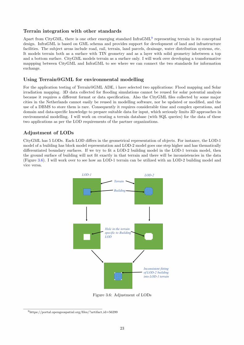
CityGML has 5 LODs. Each LOD di↵ers in the geometrical representation of objects. For instance, the LOD-1model of a building has block model representation and LOD-2 model goes one step higher and has thematicallydi↵erentiated boundary surfaces. If we try to fit a LOD-2 building model in the LOD-1 terrain model, thenthe ground surface of building will not fit exactly in that terrain and there will be inconsistencies in the data(Figure 3.6). I will work over to see how an LOD-1 terrain can be utilized with an LOD-2 building model andvice versa.
LOD-1 LOD-2
Terrain
Building
Hole in the terrain specific to Building LOD
Inconsistent fitting of LOD-2 building into LOD-1 terrain
Figure 3.6: Adjustment of LODs
9https://portal.opengeospatial.org/files/?artifact id=56299
23
3.5 Preliminary Results
3.5.1 Analysis of TIN data structures
Storage and analysis of massive TINs can be tackled in di↵erent ways. One way is to store them in file basedsystems either as point clouds (*.laz, *.xyz, etc.) or as a collection of triangles (*.obj, *.smb, etc.). But withincreasing size of the point clouds and derived TINs, the storage size and requirements are also increased. Iinvestigated the existing TIN data structures to see which of them can be implemented as DBMS solutionsfor the storage of TINs. I provide here the results10 of the prototype implementations carried out for thecomparative analysis of the TIN data structures namely, Simple Feature, Triangle, Triangle+ and Star (seeSection ??). The data structures are tested with a few real world datasets and I report on their geometry,topology, storage, indexing, and loading time in a database. The PostgresSQL/PostGIS DBMS are used forstoring the TINs. For the storage of vertex IDs and triangle IDs, 64-bit large range integers are used i.e. bigintbecause 32-bit integers limit the dataset to 232/2 (i.e. around 2 billion) IDs. The coordinates (x,y,z) of thevertices are stored in three separate columns as 64-bit double precision. The Python implementations of thedata structures are used to populate the PostgreSQL/PostGIS database. The TIN is stored in the:
1. triangle/triangle+/star based representations with B-tree index.2. PostGIS Simple Feature with GiST index.
Input Data
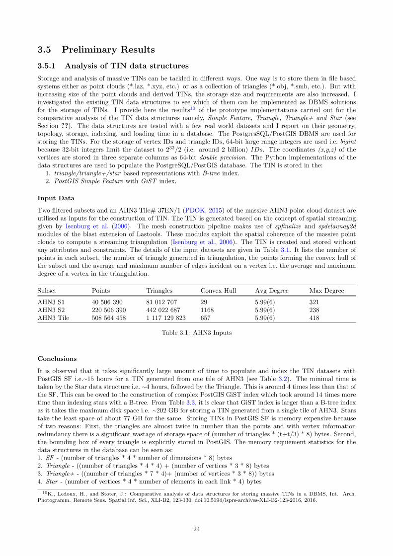
Two filtered subsets and an AHN3 Tile# 37EN/1 (PDOK, 2015) of the massive AHN3 point cloud dataset areutilised as inputs for the construction of TIN. The TIN is generated based on the concept of spatial streaminggiven by Isenburg et al. (2006). The mesh construction pipeline makes use of spfinalize and spdelaunay2dmodules of the blast extension of Lastools. These modules exploit the spatial coherence of the massive pointclouds to compute a streaming triangulation (Isenburg et al., 2006). The TIN is created and stored withoutany attributes and constraints. The details of the input datasets are given in Table 3.1. It lists the number ofpoints in each subset, the number of triangle generated in triangulation, the points forming the convex hull ofthe subset and the average and maximum number of edges incident on a vertex i.e. the average and maximumdegree of a vertex in the triangulation.
Subset Points Triangles Convex Hull Avg Degree Max Degree
AHN3 S1 40 506 390 81 012 707 29 5.99(6) 321AHN3 S2 220 506 390 442 022 687 1168 5.99(6) 238AHN3 Tile 508 564 458 1 117 129 823 657 5.99(6) 418
Table 3.1: AHN3 Inputs
Conclusions
It is observed that it takes significantly large amount of time to populate and index the TIN datasets withPostGIS SF i.e.⇠15 hours for a TIN generated from one tile of AHN3 (see Table 3.2). The minimal time istaken by the Star data structure i.e. ⇠4 hours, followed by the Triangle. This is around 4 times less than that ofthe SF. This can be owed to the construction of complex PostGIS GiST index which took around 14 times moretime than indexing stars with a B-tree. From Table 3.3, it is clear that GiST index is larger than a B-tree indexas it takes the maximum disk space i.e. ⇠202 GB for storing a TIN generated from a single tile of AHN3. Starstake the least space of about 77 GB for the same. Storing TINs in PostGIS SF is memory expensive becauseof two reasons: First, the triangles are almost twice in number than the points and with vertex informationredundancy there is a significant wastage of storage space of (number of triangles * (t+t/3) * 8) bytes. Second,the bounding box of every triangle is explicitly stored in PostGIS. The memory requiement statistics for thedata structures in the database can be seen as:1. SF - (number of triangles * 4 * number of dimensions * 8) bytes2. Triangle - ((number of triangles * 4 * 4) + (number of vertices * 3 * 8) bytes3. Triangle+ - ((number of triangles * 7 * 4)+ (number of vertices * 3 * 8)) bytes4. Star - (number of vertices * 4 * number of elements in each link * 4) bytes
10K., Ledoux, H., and Stoter, J.: Comparative analysis of data structures for storing massive TINs in a DBMS, Int. Arch.Photogramm. Remote Sens. Spatial Inf. Sci., XLI-B2, 123-130, doi:10.5194/isprs-archives-XLI-B2-123-2016, 2016.
24
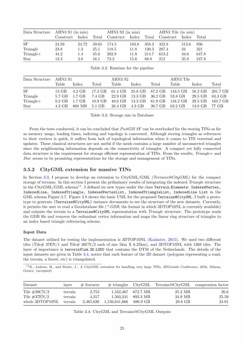
Data Structure AHN3 S1 (in min) AHN3 S2 (in min) AHN3 Tile (in min)Construct Index Total Construct Index Total Construct Index Total
SF 24.93 24.72 49.65 174.5 183.8 358.3 422.8 513.6 936Triangle 23.8 1.3 25.1 118.5 11.8 130.3 287.4 34 321Triangle+ 44.2 1.4 45.6 202.9 11.8 214.7 613.2 34.6 647.8Star 13.3 2.8 16.1 73.2 15.6 88.8 212 35.8 247.8
Table 3.2: Runtime for the pipeline
Data Structure AHN3 S1 AHN3 S2 AHN3 TileTable Index Total Table Index Total Table Index Total
SF 13 GB 4.2 GB 17.2 GB 61.4 GB 25.8 GB 87.2 GB 143.5 GB 58.2 GB 201.7 GBTriangle 5.7 GB 1.7 GB 7.4 GB 22.9 GB 13.3 GB 36.2 GB 53.8 GB 29.5 GB 83.3 GBTriangle+ 9.2 GB 1.7 GB 10.9 GB 48.6 GB 13.3 GB 61.9 GB 134.2 GB 29.5 GB 163.7 GBStar 4.3 GB 868 MB 5.1 GB 26.4 GB 4.3 GB 30.7 GB 63.2 GB 13.8 GB 77 GB
Table 3.3: Storage size in Database
From the tests conducted, it can be concluded that PostGIS SF can be overlooked for the storing TINs as faras memory usage, loading times, indexing and topology is concerned. Although storing triangles as referencesto their vertices is quick, it su↵ers from lack of topological information when it comes to TIN traversal andupdates. These classical structures are not useful if the mesh contains a large number of unconnected trianglessince the neighbouring information depends on the connectivity of triangles. A compact yet fully connecteddata structure is the requirement for storage e�cient representation of TINs. From the results, Triangle+ andStar seems to be promising representations for the storage and management of TINs.
3.5.2 CityGML extension for massive TINs
In Section 3.3, I propose to develop an extension to CityGML/GML (Terrains@CityGML) for the compactstorage of terrains. In this section I present the priliminary results of integrating the indexed Triangle structurein the CityGML/GML schema11. I defined six new types under the class Terrain Elements: IndexedVertex,IndexedLine, IndexedTriangle, IndexedVertexList, IndexedTriangleList, IndexedLine List in theGML schema Figure 3.7. Figure 3.8 shows the basic UML for the proposed Terrains@CityGML. I built a proto-type to generate (Terrains@CityGML) instance documents to see the structure of the new datasets. Currently,it permits the user to read a Geodatabase file (*.GDB, the format in which 3DTOP10NL is currently available)and outputs the terrain to a Terrains@CityGML representation with Triangle structure. The prototype readsthe GDB file and removes the redundant vertex information and maps the linear ring structure of triangles toan index based triangle referencing scheme.
Input Data
The dataset utilised for testing the implementation is 3DTOP10NL (Kadaster, 2015). We used two di↵erenttiles (Tile# 37EN/1 and Tile# 26CN/2 each of size 5km X 6.25km), and 3DTOP10NL with 1368 tiles. Thelayer of importance is terreinVlak 3D LOD0 that contains the DTM of the Netherlands. The details of theinput datasets are given in Table 3.4, notice that each feature of the 2D dataset (polygons representing a road,the terrain, a forest, etc) is triangulated.
11K., Ledoux, H., and Stoter, J.: A CityGML extension for handling very large TINs, 3DGeoinfo Conference, 2016, Athens,Greece. (accepted)
Dataset layer # features # triangles CityGML Terrains@CityGML compression factor
Tile #26CN/2 terrain 2,753 1,162,467 672.7 MB 25.2 MB 26.6Tile #37EN/2 terrain 4,317 1,503,241 893.3 MB 34.9 MB 25.59whole 3DTOP10NL terrain 2,465,626 1,156,641,666 686.9 GB 28.6 GB 24.01
Table 3.4: CityGML and Terrains@CityGML Outputs
25

Figure 3.7: TIN elements added to GML
Conclusions
With the ever increasing size of 3D terrains, the aim is to develop a compact representation for their e�cientstorage. What we have proposed seems rather simple from theoritical point of view but yet it allows to store theterrains in CityGML/GML with around 25 times less storage than the current CityGML solution (see Table 3.4).The compression factor of 25 is important because it is achieved just only with the removal of gml:LinearRing
26

Figure 3.8: Proposed basic UML of Terrains@CityGML
and inclusion of by-referencing scheme for vertices and triangles. With consecutive ordering of vertices oftriangles in the CityGML/GML instances, after the first three vertices forming the first triangle, renderingof each next triangle will only require the next vertex in order. To alleviate the bottlenecks associated withrendering massive CityGML terrains over web, we also aim to introduce the structures of tristrips (Speckmannand Snoeyink, 2001) and stars (Ledoux, 2015) in CityGML schema. Once fully formalized, the solution isexpected to have the following advantages over conventional CityGML storage of terrains (Table 3.5):
Criteria CityGML Terrains@CityGML
Size Reduction X
Data Redundancy X
Topology X
Semantics
Vertex Referencing X
Triangle Referencing X
Triangle Encoding X
Terrain LODs X
Vertical Triangles X
Tiling X
Web rendering X
Table 3.5: CityGML vs Terrains@CityGML
27

Chapter 4
Planning and practical aspects
This chapter outlines the research plan and practical aspects of the research presented in the previous chapters.
4.1 Timetable
This research will be conducted over a period of 4 years. Figure 4.1 provides an overview of the planningactivities that have been carried out and are to be done in this research. The research themes presented inFigure 4.1 are not strictly sequential, and will be investigated with a high degree of overlap in time. The planis subject to change according to the flow of the research. Several tasks and activities will be a part of thisresearch:
• Publication of research in journals and conferences.• Attending summer schools, courses, workshops, and conferences.• Continuous review of literature in order to keep the research uo to date.• Research visits, partner collaborations, and case studies.
2015-2016 2016-2017 2017-2018 2018-2019
Q2 Q3 Q4 Q1 Q2 Q3 Q4 Q1 Q2 Q3 Q4 Q1 Q2 Q3 Q4
Initial literature review
Writing proposal
GO/NO-GO
UML modelling & Schema design
Integration with databases
Data storage & validation
Visualization & dissemination
Case studies
Formalization & Writing dissertation
Figure 4.1: Planning overview
28

4.2 Short term first year plan
This section presents the proposed key events and milestones achieved in the first year of research. The firstyear besides writing proposal includes writing two general research papers and attending four events. Table 4.1enlists the key events of the first year of research.
Month Key Event
2015-09 Start of research2015-11 Preliminary results 12015-12 Writing abstract for ISPRS Congress 2016 (accepted)2016-01 Writing full paper for ISPRS Congress 2016 (accepted)2016-03 Start outlining basic schema design2016-04 Writing full paper for 3DGeoinfo 2016 (accepted)2015-05 Preliminary results 22016-06 Attend summer school on HPC and Open Drone Mapping2016-07 Paper presentation at ISPRS Congress 20162016-09 Organizing 3DViz 2016 workshop at TU Delft2016-10 Paper presentation at 3DGeoinfo 2016
Table 4.1: Key events in the first year of research
4.3 3D4EM
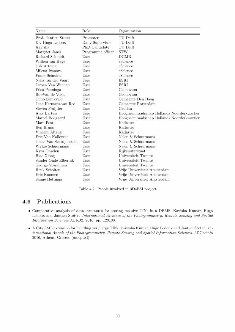
3D4EM 1 (3D for Environmental Modelling) is a STW funded research project with 14 partner organisations(universities, governement and companies) working together for the development of a nationwide 3D informationinfrastructure (an SDI (Spatial Data Infrastructure)) for integrated 3D environmental modelling. The projectis financially supported by the Dutch Technology Foundation STW, which is part of the NWO (NetherlandsOrganisation for Scientific Research), and which is partly funded by the Ministry of Economic A↵airs. 3D4EMhas three research lines. The first research line (at University of Twente, The Netherlands) is about theautomatic reconstruction of countrywide 3D city model using the available 2D data and height informationfrom the acquired point clouds. The second research line (at Delft University of Technology, The Netherlands)deals with developing a storage, maintenace and dissemination framework for the 3D city models. The thirdresearch line (at Vrije Universiteit Amsterdam, The Netherlands) deals with connecting the environmentalmonitoring applications with the appropriate 3D data from the SDI for simulations. This PhD concerns thesecond research line of the 3D4EM project. Apart from TU Delft, the other organizations/partners involvedin the project are Geonovum, Kadaster, ESRI, Universiteit Twente, Gemeente, Vrije Universiteit Amsterdam,Geodan, Rijkswaterstaat, etc. Table 4.2 lists the involved individuals and their organizations from TU Delft,STW and partner organizations.
4.4 Tools and Technical aspects
The PhD research will be actualized to a partial or full implementation in light of the scope of the results ofthe proposed work. Table 4.3 provides a list of tools, data and data formats and other techincal aspects relatedto this research. The publications and other documentation will be typeset in LATEX.
4.5 Graduate School Obligations
Along with the research, every PhD candidate has to follow the Doctoral Education (DE) programme of theuniversity’s Graduate School (GS). To complete the DE programme, it is required to earn 45 GS credits (1 GScredit = 8 hours of coursework + 4 hours of preparation/assignment) in three skills categories: Discipline-relatedskills (15 GS credits), Research skills (15 GS credits) and Transferable skills (15 GS credits). Table Table 4.4provides an overview of the planned activities for GS credits including the ones that i have already completed.
1https://www.3d4em.nl2https://github.com/tudelft3d/3dfier
29
Name Role Organization
Prof. Jantien Stoter Promoter TU DelftDr. Hugo Ledoux Daily Supervisor TU DelftKavisha PhD Candidate TU DelftMargriet Jansz Programme o�cer STWRichard Schmidt User DGMRWillem van Hage User eScienceJisk Attema User eScienceMilena Ivanova User eScienceFrank Seinstra User eScienceNiels van der Vaart User ESRIJeroen Van Winden User ESRIFriso Penninga User GeonovumRobVan de Velde User GeonovumTimo Erinkveld User Gemeente Den HaagJane Hermans-van Ree User Gemeente RotterdamSteven Fruijtier User GeodanAlex Bartels User Hoogheemraadschap Hollands NoorderkwartierMarcel Boogaard User Hoogheemraadschap Hollands NoorderkwartierMarc Post User KadasterBen Bruns User KadasterVincent Altena User KadasterEric Van Kalleveen User Nelen & SchuurmansJonas Van Schrojenstein User Nelen & SchuurmansWytze Schuurmans User Nelen & SchuurmansKyra Onselen User RijkswaterstaatBiao Xiong User Universiteit TwenteSander Oude Elberink User Universiteit TwenteGeorge Vosselman User Universiteit TwenteHenk Scholten User Vrije Universiteit AmsterdamEric Koomen User Vrije Universiteit AmsterdamSanne Hettinga User Vrije Universiteit Amsterdam
Table 4.2: People involved in 3D4EM project
4.6 Publications
• Comparative analysis of data structures for storing massive TINs in a DBMS. Kavisha Kumar, HugoLedoux and Jantien Stoter. International Archives of the Photogrammetry, Remote Sensing and SpatialInformation Sciences XLI-B2, 2016, pp. 123130.
• A CityGML extension for handling very large TINs. Kavisha Kumar, Hugo Ledoux and Jantien Stoter. In-ternational Annals of the Photogrammetry, Remote Sensing and Spatial Information Sciences. 3DGeoinfo2016, Athens, Greece. (accepted)
30

Technologies Use
ToolsEnterprise Architect For ADE modelling3DCityDB (PostgreSQL) For storing the 3D city modelsCesium 3D webglobe For 3D web visualizationFZK Viewer For o✏ine visualization of CityGML dataMeshlab For o✏ine visualization of OBJ, COLLADA, etc. dataProgramming languagesPython For loading data in the databaseC/C++ For programing the componentsLibrariesGDAL/OGR For reading and writing spatial objectsnode JS For server-side JavaScript environmentData3DTOP10NL National 3D city model of the Netherlands covering
buildings, terrains, roads, etc. The data is provided byPDOK in ESRI GDB format and by 3dfier2in OBJ format.
Data formatsGDB ESRI Geodatabase (original format of 3DTOP10NL)CityGML 3D GIS data modelOBJ 3D graphics data modelCOLLADA 3D graphics data modelglTF Cesium specific 3D data model
Table 4.3: Tools & Technical aspects
# Course Title Category Status
1 Summer school: High Performance Computing for Big Geo-Data
Discipline-related skills Completed
2 Geometric Modeling Discipline-related skills Planned3 Research Design Discipline-related skills Planned4 Organizing a 3D Visualization workshop with TU Munich. Discipline-related skills Planned
5 Basics of teaching, learning and assessment Research skills Completed6 Writing conference paper for ISPRS XXIII Congress 2016 Research skills Completed8 Addressing an International Conference at ISPRS XXIII
Congress 2016Research skills Completed
9 Writing first journal paper Research skills Planned10 Writing PhD research proposal Research skills Completed11 Teaching Assistantship in Lab, Course/Tutorial Research skills Planned12 Supervising MSc student Research skills Planned13 Poster presentation Research skills Planned
14 PhD Start-Up Transferable skills Completed15 PhD Council (Committee Member) Transferable skills In progress16 Using creativity to maximize productivity and innovation in
your PhDTransferable skills Completed
17 Conversation Skills Transferable skills Completed18 How to survive your PhD? Regain your flow! Transferable skills Completed19 Becoming a creative researcher in academia Transferable skills Completed20 E↵ective negotiation: win-win communication Transferable skills Completed21 Dutch for Foreigners:Elementary 1 Transferable skills Almost complete22 Career Development - Looking for Work in The Netherlands Transferable skills Planned23 Scientific Writing in English Transferable skills Planned
Table 4.4: Overview of GS activities
31

References
Bell, D. G., Kuehnel, F., Maxwell, C., Kim, R., Kasraie, K., Gaskins, T., Hogan, P., and Coughlan, J. (2007).NASA World Wind: Opensource GIS for mission operations. In 2007 IEEE Aerospace Conference, pages 1–9.IEEE.
Biljecki, F., Heuvelink, G. B., Ledoux, H., and Stoter, J. (2015a). Propagation of positional error in 3DGIS: estimation of the solar irradiation of building roofs. International Journal of Geographical InformationScience, 29(12):2269–2294.
Biljecki, F., Ledoux, H., and Stoter, J. (2016a). An improved LOD specification for 3D building models.Computers, Environment and Urban Systems, 59:25–37.
Biljecki, F., Ohori, K. A., Ledoux, H., Peters, R., and Stoter, J. (2016b). Population estimation using a 3D citymodel: A multi-scale country-wide study in the netherlands. PloS one, 11(6):e0156808.
Biljecki, F., Stoter, J., Ledoux, H., Zlatanova, S., and Coltekin, A. (2015b). Applications of 3D city models:State of the art review. ISPRS International Journal of Geo-Information, 4(4):2842–2889.
Blandford, D. K., Blelloch, G. E., Cardoze, D. E., and Kadow, C. (2005). Compact representations of simplicialmeshes in two and three dimensions. International Journal of Computational Geometry and Applications,15(1):3–24.
Boissonnat, J.-D., Devillers, O., Pion, S., Teillaud, M., and Yvinec, M. (2002). Triangulations in CGAL.Computational Geometry—Theory and Applications, 22:5–19.
Brink, L., Stoter, J., and Zlatanova, S. (2013). UML-based approach to developing a CityGML ApplicationDomain Extension. Transactions in GIS, 17(6):920–942.
Cagdas, V. (2013). An Application Domain Extension to CityGML for immovable property taxation: A Turkishcase study. International Journal of Applied Earth Observation and Geoinformation, 21:545–555.
Childs, C. (2004). Interpolating surfaces in ArcGIS spatial analyst. ArcUser, July-September, 3235.
Clark, J. H. (1976). Hierarchical geometric models for visible surface algorithms. Communications of the ACM,19(10):547–554.
Danovaro, E., De Floriani, L., Magillo, P., Puppo, E., and Sobrero, D. (2006). Level-of-detail for data analysisand exploration: a historical overview and some new perspectives. Computers & Graphics, 30(3):334–344.
De Berg, M., Van Kreveld, M., Overmars, M., and Schwarzkopf, O. C. (2000). Computational geometry.Springer.
de Laat, R. and Van Berlo, L. (2011). Integration of BIM and GIS: The development of the CityGML GeoBIMextension. In Advances in 3D geo-information sciences, pages 211–225. Springer.
Dollner, J., Kolbe, T. H., Liecke, F., Sgouros, T., Teichmann, K., et al. (2006). The virtual 3D city modelof berlin-managing, integrating, and communicating complex urban information. In Proceedings of the 25thUrban Data Management Symposium UDMS, volume 2006, pages 15–17.
Dyn, N., Levin, D., and Rippa, S. (1990). Data dependent triangulations for piecewise linear interpolation.IMA journal of numerical analysis, 10(1):137–154.
Eicker, U., Nouvel, R., Duminil, E., and Coors, V. (2014). Assessing passive and active solar energy resourcesin cities using 3D city models. Energy Procedia, 57:896–905.
Elberink, S. O., Stoter, J., Ledoux, H., and Commandeur, T. (2013). Generation and dissemination of a nationalvirtual 3D city and landscape model for the Netherlands. Photogrammetric engineering & remote sensing,79(2):147–158.
32

Elmasri, R. and Navathe, S. B. (2014). Fundamentals of database systems. Pearson.
Fisher, P. (1997). The pixel: a snare and a delusion. International Journal of Remote Sensing, 18(3):679–685.
Funkhouser, T. A. and Sequin, C. H. (1993). Adaptive display algorithm for interactive frame rates duringvisualization of complex virtual environments. In Proceedings of the 20th annual conference on Computergraphics and interactive techniques, pages 247–254. ACM.
Groger, G., Kolbe, T. H., Nagel, C., and Hafele, K.-H. (2012). OGC City Geography Markup Language(CityGML) Encoding Standard version 2.0.0.
Groger, G. and Lowner, M.-O. (2016). Proposal for a new LoD concept for CityGML 3.0. Technical report,CityGML OGC Work Package 03.
Groger, G. and Plumer, L. (2005). How to get 3-D for the price of 2-D? topology and consistency of 3-D urbanGIS. Geoinformatica, 9(2):139–158.
Guo, R., Li, L., Ying, S., Luo, P., He, B., and Jiang, R. (2013). Developing a 3D cadastre for the administrationof urban land use: A case study of Shenzhen, China. Computers, Environment and Urban Systems, 40:46–55.
Gurung, T., Laney, D., Lindstrom, P., and Rossignac, J. (2011a). SQuad: Compact representation for trianglemeshes. In Computer Graphics Forum, volume 30, pages 355–364. Wiley Online Library.
Gurung, T., Lu↵el, M., Lindstrom, P., and Rossignac, J. (2011b). LR: compact connectivity representation fortriangle meshes, volume 30. ACM.
Gurung, T., Lu↵el, M., Lindstrom, P., and Rossignac, J. (2013). Zipper: A compact connectivity data structurefor triangle meshes. Computer-Aided Design, 45(2):262–269.
Hellerstein, J. M., Naughton, J. F., and Pfe↵er, A. (1995). Generalized search trees for database systems. MITpress.
Isenburg, M., Liu, Y., Shewchuk, J., and Snoeyink, J. (2006). Streaming computation of Delaunay triangulations.In ACM Transactions on Graphics (TOG), volume 25, pages 1049–1056. ACM.
Kadaster (2015). 3DTOP10NL. http://arcg.is/1GKYy7E. (Last accessed: April 15, 2016).
Kaden, R. and Kolbe, T. H. (2014). Simulation-Based Total Energy Demand Estimation of Buildings usingSemantic 3D City Models. International Journal of 3-D Information Modeling, 3(2):35–53.
Kim, Y., Kang, H., and Lee, J. (2014). Developing CityGML indoor ADE to manage indoor facilities. InInnovations in 3D Geo-information sciences, pages 243–265. Springer.
Kolbe, T., Konig, G., Nagel, C., and Stadler, A. (2015a). 3D city database for CityGML. Institute for Geodesyand Geoinformation Science, Technische Universitat Berlin, page v3.
Kolbe, T. H., Burger, B., and Cantzler, B. (2015b). CityGML goes to broadway. In Photogrammetric Week,volume 15, pages 343–356.
Kruger, A. and Kolbe, T. (2012). Building analysis for urban energy planning using key indicators on virtual3d city models?the energy atlas of berlin. International Archives of the Photogrammetry, Remote Sensingand Spatial Information Sciences, 39(B2):145–150.
Kumar, K., Ledoux, H., and Stoter, J. (2016). Comparative analysis of data structures for storing massiveTINs in a DBMS. International Archives of the Photogrammetry, Remote Sensing and Spatial InformationSciences, XLI-B2:123–130.
Kumler, M. (1994). An intensive comparison of triangulated irregular networks (TINs) and digital elevationmodels (DEMs). Cartographica, 31(2):1–99.
Ledoux, H. (2008). FieldGML: An alternative representation for fields. In Headway in Spatial Data Handling,pages 385–400. Springer.
Ledoux, H. (2015). Storing and analysing massive TINs in a DBMS with a star-based data structure. TechnicalReport 2015.01, 3D geoinformation, Delft University of Technology, Delft, the Netherlands.
Li, Z., Zhu, C., and Gold, C. (2004). Digital terrain modeling: principles and methodology. CRC press.
Lindstrom, P., Koller, D., Ribarsky, W., Hodges, L. F., Faust, N., and Turner, G. A. (1996). Real-time,continuous level of detail rendering of height fields. In Proceedings of the 23rd annual conference on Computergraphics and interactive techniques, pages 109–118. ACM.
33
Lowner, M.-O., Benner, J., Groger, G., and Hafele, K.-H. (2013). New concepts for structuring 3D city models- An extended level of detail concept for CityGML buildings. In Computational Science and Its Applications–ICCSA 2013, pages 466–480. Springer.
Luebke, D. and Hallen, B. (2001). Perceptually driven simplification for interactive rendering. In RenderingTechniques 2001, pages 223–234. Springer.
Luebke, D. P. (2003). Level of detail for 3D graphics. Morgan Kaufmann.
Lu↵el, M., Gurung, T., Lindstrom, P., and Rossignac, J. (2014). Grouper: A compact, streamable trianglemesh data structure. Visualization and Computer Graphics, IEEE Transactions on, 20(1):84–98.
Mantyla, M. (1987). An Introduction to solid modeling. Computer Science Press, Inc., New York, NY, USA.
Mathew Amato (2015). Cesium and the future of 3D geospatial standards. http://cesiumjs.org/presentations/Cesium-and-the-Future-of-3D-Geospatial-Standards.pdf. JS Geo, Philadelphia. (Lastaccessed: July 10, 2016).
Muller, D. E. and Preparata, F. P. (1978). Finding the intersection of two convex polyhedra. TheoreticalComputer Science, 7:217–236.
Nativi, S., Caron, J., Davis, E., and Domenico, B. (2005). Design and implementation of netCDF markuplanguage (NcML) and its GML-based extension (NcML-GML). Computers & Geosciences, 31(9):1104–1118.
Nouvel, R., Bahu, J.-M., Kaden, R., Kaempf, J., Cipriano, P., Lauster, M., and Casper, E. (2015). Developmentof the CityGML Application Domain Extension energy for urban energy simulation. Proceedings of BuildingSimulation 2015.
OGC (2011). Opengis R� implementation specification for geographic information-simple feature access-part 1:Common architecture. OGC document version 06-103r4.
Okabe, A., Boots, B., Sugihara, K., and Chiu, S. N. (2009). Spatial tessellations: concepts and applications ofVoronoi diagrams, volume 501. John Wiley & Sons.
PDOK (2015). AHN3 downloads. https://www.pdok.nl/nl/ahn3-downloads/. (Last accessed: April 10,2016).
Penninga, F. (2008). 3D topography: a simplicial complex-based solution in a spatial DBMS. PhD thesis, TUDelft, Delft University of Technology.
Portele, C. (2012). OGC Geography Markup Language ( GML ) Extended schemas and encoding rules GMLVersion 3.3 Doc. No. 10-129r1.
Pronk, M. (2015). Storing Massive TINs in a DBMS: A comparison and a prototype implementation of themultistar approach. PhD thesis, TU Delft, Delft University of Technology.
Ravada, S., Kazar, B. M., and Kothuri, R. (2009). Query processing in 3D spatial databases: Experiences withoracle spatial 11g. In 3D Geo-Information Sciences, pages 153–173. Springer.
Rippa, S. (1990). Minimal roughness property of the Delaunay triangulation. Computer Aided GeometricDesign, 7(6):489–497.
Sen, M. and Du↵y, T. (2005). GeoSciML: development of a generic geoscience markup language. Computers &Geosciences, 31(9):1095–1103.
Shewchuk, J. R. (1996). Triangle: Engineering a 2D Quality Mesh Generator and Delaunay Triangulator.Applied Computational Geometry: Towards Geometric Engineering, 1148:203–222.
Shewchuk, J. R. (1997). Delaunay Refinement Mesh Generation. PhD thesis, School of Computer Science,Carnegie Mellon University, Pittsburg, USA.
Snoeyink, J. and Speckmann, B. (1999). Tripod: a minimalist data structure for embedded triangulations.Computational Graph Theory and Combinatorics.
Speckmann, B. and Snoeyink, J. (2001). Easy triangle strips for tin terrain models. International journal ofgeographical information science, 15(4):379–386.
Stadler, A. and Kolbe, T. H. (2007). Spatio-semantic coherence in the integration of 3D city models. InProceedings of the 5th International Symposium on Spatial Data Quality, Enschede.
Stoter, J., De Kluijver, H., and Kurakula, V. (2008). 3D noise mapping in urban areas. International Journalof Geographical Information Science, 22(8):907–924.
34

Stoter, J., Ploeger, H., and van Oosterom, P. (2013). 3D cadastre in the netherlands: Developments andinternational applicability. Computers, Environment and Urban Systems, 40:56–67.
van den Brink, L., Stoter, J., and Zlatanova, S. (2013). Establishing a national standard for 3D topographicdata compliant to CityGML. International Journal of Geographical Information Science, 27(1):92–113.
VTP (2012). ITF Format - Virtual Terrain Project. http://vterrain.org/Implementation/Formats/ITF.html. (Last accessed: July 25, 2016).
Woolf, A., Lawrence, B., Lowry, R., Kleese van Dam, K., Cramer, R., Gutierrez, M., Kondapalli, S., Latham, S.,Lowe, D., O’Neill, K., et al. (2006). Data integration with the climate science modelling language. Advancesin Geosciences, 8(8):83–90.
Worboys, M. F. and Duckham, M. (2004). GIS: a computing perspective. CRC press.
35