Storage Battery Maintenance and Principles - usbr.gov · PDF fileThis document presents...
134
U.S. Department of the Interior Bureau of Reclamation December 2016 Denver, Colorado (FIST 011) 01/06/2017 Facilities Instructions, Standards, and Techniques Volume 3-6 Storage Battery Maintenance and Principles Required periodicity is outlined in FIST 4-1B, Maintenance Scheduling for Electrical Equipment.
Transcript of Storage Battery Maintenance and Principles - usbr.gov · PDF fileThis document presents...

U.S. Department of the Interior Bureau of Reclamation December 2016 Denver, Colorado (FIST 011) 01/06/2017
Facilities Instructions, Standards, and Techniques Volume 3-6
Storage Battery Maintenance and Principles Required periodicity is outlined in FIST 4-1B, Maintenance Scheduling for Electrical Equipment.
REPORT DOCUMENTATION PAGE Form Approved
OMB No. 0704-0188 Public reporting burden for this collection of information is estimated to average 1 hour per response, including the time for reviewing instructions, searching existing data sources, gathering and maintaining the data needed, and completing and reviewing this collection of information. Send comments regarding this burden estimate or any other aspect of this collection of information, including suggestions for reducing this burden to Department of Defense, Washington Headquarters Services, Directorate for Information Operations and Reports (0704-0188), 1215 Jefferson Davis Highway, Suite 1204, Arlington, VA 22202-4302. Respondents should be aware that notwithstanding any other provision of law, no person shall be subject to any penalty for failing to comply with a collection of information if it does not display a currently valid OMB control number. PLEASE DO NOT RETURN YOUR FORM TO THE ABOVE ADDRESS.
1. REPORT DATE (DD-MM-YYYY)December 2016
2. REPORT TYPEFinal
3. DATES COVERED (From - To)Implementation Date: 6 months after publication
4. TITLE AND SUBTITLE FIST 3-6, Storage Battery Maintenance and Principles
5a. CONTRACT NUMBER
5b. GRANT NUMBER
5c. PROGRAM ELEMENT NUMBER
6. AUTHOR(S) Bureau of Reclamation Regional FIST 3-6 Team: Benjamin Cano (PN-6130) Ruben Roybal (CVO-610) Robert Gonzales Jr. (CVO-610) Dave Arend (LC-9400) Bill Heckler (CCI-200) Michael Maroncelli (GP-2020) Rick Jackson (86-51000, PRO) Nathan Myers (86-68450, TSC) Eric Vaughn (86-68430, TSC)
5d. PROJECT NUMBER
5e. TASK NUMBER
5f. WORK UNIT NUMBER
7. PERFORMING ORGANIZATION NAME(S) AND ADDRESS(ES) Hydropower Diagnostics and SCADA Group, Bureau of Reclamation Denver Federal Center P.O. Box 25007 Denver CO 80225-0007
8. PERFORMING ORGANIZATION REPORT NUMBER
FIST 3-6
9. SPONSORING / MONITORING AGENCY NAME(S) AND ADDRESS(ES) Power Resources Office Bureau of Reclamation Mail Code 86-51000 PO Box 25007 Denver CO 80225-0007
10. SPONSOR/MONITOR’S ACRONYM(S) 11. SPONSOR/MONITOR’S REPORT NUMBER(S)
12. DISTRIBUTION / AVAILABILITY STATEMENT Available from the National Technical Information Service, Operations Division, 5285 Port Royal Road, Springfield, Virginia 22161 13. SUPPLEMENTARY NOTES 14. ABSTRACT The Bureau of Reclamation operates and maintains 53 hydroelectric powerplants and many switchyards, pumping plants, and associated facilities that are important to electric power and water delivery systems. These facilities house complex electrical and mechanical equipment; and storage batteries and associated circuits play an essential role in protecting this equipment, as well as the electric power system. This document defines Reclamation practices for operating, maintaining, and testing storage batteries and associated equipment. The Institute of Electrical and Electronics Engineers and Reclamation practices are the basis of these practices. Included in this document are standards, practices, procedures, and advice on day-to-day operation, maintenance, and testing of existing storage battery systems. 15. SUBJECT TERMS 16. SECURITY CLASSIFICATION OF:
17. LIMITATION OF ABSTRACT
UL
18. NUMBER OF PAGES
124
19a. NAME OF RESPONSIBLE PERSONTechnical Services Center
a. REPORT UL
b. ABSTRACT UL
c. THIS PAGE UL
19b. TELEPHONE NUMBER (include area code) (303) 445-2300
Standard Form 298 (Rev. 8/98) Prescribed by ANSI Std. 239-18

U.S. Department of the Interior Bureau of Reclamation December 2016 Denver, Colorado (FIST 011) 01/06/2017
Facilities Instructions, Standards, and Techniques Volume 3-6
Storage Battery Maintenance and Principles Required periodicity is outlined in FIST 4-1B, Maintenance Scheduling for Electrical Equipment.

Disclaimer This written material consists of general information for internal use only by Bureau of Reclamation operations and maintenance staff. Information contained in this document regarding commercial products or firms may not be used for advertising or promotional purposes and is not to be construed as an endorsement or depreciation of any product or firm by the Bureau of Reclamation.

Preface This document presents required maintenance practices and instructions for managing, maintaining, and testing critical battery systems at Bureau of Reclamation (Reclamation) facilities operated and maintained by Reclamation staff. These required maintenance practices and instructions are intended to promote uniformity in the manner that battery systems are managed, documented, and maintained. This document was developed with input from staff in Reclamation’s Denver, regional, area, and facility offices.


FIST 3-6, Battery Storage Maintenance and Principles (FIST 011) 01/06/2017
v
Table of Contents
Page
Acronyms and Abbreviations ......................................................................................... ix
1. Introduction ..................................................................................................................1
1.1 Purpose and Scope ............................................................................................ 1 1.1.1 Reclamation Standard Practices ...................................................................2
1.2 Definitions......................................................................................................... 3 1.3 References ......................................................................................................... 3
2. Battery Safety ...............................................................................................................5
2.1 Maintenance for Battery Safety ........................................................................ 5 2.2 Introduction ....................................................................................................... 5 2.3 Explosive Hazard .............................................................................................. 5 2.4 Electrolyte Hazard ............................................................................................ 6
2.4.1 Electrolyte Neutralization for Lead-Acid Batteries .....................................6 2.4.2 Electrolyte Neutralization for Nickel Cadmium (NiCd) Batteries ..............6 2.4.3 Eyewash and Emergency Shower Systems..................................................6 2.4.4 Periodic Maintenance...................................................................................7
2.5 Flame Arrestors Purpose and Cleaning ............................................................. 7 2.5.1 Periodic Maintenance...................................................................................8
2.6 Ventilation......................................................................................................... 8 2.6.1 Non-Periodic Maintenance ........................................................................11 2.6.2 Periodic Maintenance.................................................................................11
2.7 Seismic Battery Racks .................................................................................... 11 2.8 Battery Rooms ................................................................................................ 12
2.8.1 Periodic Maintenance.................................................................................13 2.9 Safety Meetings .............................................................................................. 13
3. Vented Lead-Acid (VLA) Batteries ..........................................................................15
3.1 Maintenance for VLA Battery Systems .......................................................... 15 3.2 Purpose ............................................................................................................ 15 3.3 Background ..................................................................................................... 15
3.3.1 Full Charge.................................................................................................16 3.3.2 Appearance of Normal Cells ......................................................................16 3.3.3 Chemical Reactions ...................................................................................17 3.3.4 Self-Discharge and Effect of Impurities on Floating Voltage ...................17 3.3.5 Temperature Characteristics ......................................................................20 3.3.6 Battery Life for Different Types ................................................................24
3.4 Battery Charging and Temperature Correction ............................................... 24 3.4.1 Initial Freshening Charge ...........................................................................24 3.4.2 Float Charge ...............................................................................................25 3.4.3 Equalizing Charge ......................................................................................25

FIST 3-6, Battery Storage Maintenance and Principles (FIST 011) 01/06/2017
vi
3.4.4 Unattended Stations ...................................................................................28 3.4.5 Proper Amount of Charge ..........................................................................28 3.4.6 High-Rate Overcharging ............................................................................29 3.4.7 Low-Rate Overcharging.............................................................................29 3.4.8 Undercharging............................................................................................29 3.4.9 Over-discharge ...........................................................................................31
3.5 O&M of Vented Lead-Acid Batteries ............................................................. 31 3.5.1 Records ......................................................................................................31 3.5.2 Voltage Readings .......................................................................................32 3.5.3 Specific Gravity Readings .........................................................................33 3.5.4 Temperature Readings ...............................................................................35 3.5.5 Connection Resistance Readings ...............................................................36 3.5.6 Visual Inspections ......................................................................................40 3.5.7 Battery Troubles Summarized ...................................................................41 3.5.8 Verifying Battery Bank Continuity ............................................................46 3.5.9 Checking for Unintentional Grounds .........................................................47 3.5.10 Avoiding Surface Charge Phenomenon .....................................................47
3.6 Testing of Vented Lead-Acid Batteries .......................................................... 48 3.6.1 Acceptance Testing ....................................................................................48 3.6.2 Capacity Tests to Determine Replacement ................................................52
4. Valve-Regulated Lead-Acid (VRLA) Batteries (Gel Cells) ....................................57
4.1 Maintenance for VRLA Battery Systems ....................................................... 57 4.2 Purpose ............................................................................................................ 57 4.3 Background ..................................................................................................... 57 4.4 Battery Charging ............................................................................................. 58
4.4.1 Float Charge ...............................................................................................58 4.4.2 Equalizing Charge ......................................................................................59 4.4.3 Charger .......................................................................................................59
4.5 O&M of VRLA Batteries................................................................................ 59 4.5.1 Records ......................................................................................................60 4.5.2 Voltage Readings .......................................................................................60 4.5.3 Temperature Readings ...............................................................................61 4.5.4 Connection Resistance ...............................................................................62 4.5.5 Internal Resistance .....................................................................................62 4.5.6 Visual Inspections ......................................................................................63 4.5.7 Verifying Battery Bank Continuity ............................................................64 4.5.8 Checking for Unintentional Grounds .........................................................64
4.6 Testing of VRLA Batteries ............................................................................. 65 4.6.1 Acceptance Testing ....................................................................................65 4.6.2 Capacity Tests to Determine Replacement ................................................66
5. Vented NiCd Batteries ...............................................................................................69
5.1 Maintenance for Vented NiCd Battery Systems ............................................. 69 5.2 Purpose ............................................................................................................ 69 5.3 Background ..................................................................................................... 69
5.3.1 Full Charge.................................................................................................70 5.3.2 Chemical Reactions ...................................................................................70

FIST 3-6, Battery Storage Maintenance and Principles (FIST 011) 01/06/2017
vii
5.3.3 Temperature Characteristics ......................................................................71 5.3.4 Electrolyte ..................................................................................................71
5.4 Battery Charging ............................................................................................. 71 5.4.1 Initial Freshening Charge ...........................................................................72 5.4.2 Float Charge ...............................................................................................72 5.4.3 Equalizing Charge ......................................................................................72
5.5 O&M of NiCd Batteries .................................................................................. 72 5.5.1 Records ......................................................................................................73 5.5.2 Voltage Readings .......................................................................................74 5.5.3 Temperature Readings ...............................................................................74 5.5.4 Connection Resistance ...............................................................................75 5.5.5 Visual Inspections ......................................................................................75 5.5.6 Electrolyte ..................................................................................................76 5.5.7 Specific Gravity .........................................................................................77 5.5.8 Verifying Battery Bank Continuity ............................................................78 5.5.9 Checking for Unintentional Grounds .........................................................79
5.6 Testing of NiCd Batteries ............................................................................... 79 5.6.1 Periodic Maintenance.................................................................................81
6. Battery Charging Equipment ...................................................................................83
6.1 Purpose ............................................................................................................ 83 6.2 Types of Chargers ........................................................................................... 83 6.3 Sizing Chargers ............................................................................................... 83
6.3.1 Periodic Maintenance.................................................................................84 6.4 Troubleshooting Static Rectifier Chargers...................................................... 85
7. Automated Battery Monitoring Systems .................................................................87
7.1 Purpose ............................................................................................................ 87 7.2 Background ..................................................................................................... 87
7.2.1 Battery Monitoring Parameters ..................................................................87 7.3 O&M ............................................................................................................... 91
7.3.1 Records ......................................................................................................91 7.3.2 Maintenance ...............................................................................................91
7.4 Battery Monitoring Parameters ....................................................................... 93 7.4.1 Internal Resistance Measurements .............................................................93 7.4.2 Real-Time Measurements ..........................................................................94 7.4.3 Trend Analysis ...........................................................................................94 7.4.4 Software .....................................................................................................95
8. Battery System Design and Protection .....................................................................97
8.1 Purpose ............................................................................................................ 97 8.2 Background ..................................................................................................... 97 8.3 Stationary Battery Overcurrent Protection...................................................... 98 8.4 Battery Overvoltage and Undervoltage Protection ....................................... 100 8.5 Battery Grounds ............................................................................................ 100 8.6 Isolation of Plant Station Batteries ............................................................... 101
9. Standards ..................................................................................................................103
10. Glossary ....................................................................................................................105

FIST 3-6, Battery Storage Maintenance and Principles (FIST 011) 01/06/2017
viii
Appendix 1 – VLA Battery Room Signage Example ..................................................109
Appendix 2 – POM Forms ............................................................................................110
Table of Figures Figure 1. Percent capacity of batteries with pasted and planté type plates for various discharge rates. ...................................................................................................................18 Figure 2. Effect of concentration of electrolyte on cell capacity. .....................................19 Figure 3. Final voltage at various rates after charge is fully completed. ..........................21 Figure 4. Approximate variation of local action in lead-acid storage cells with changes in specific gravity of electrolyte and changes in temperature. ...........................................22 Figure 5. Approximate variation of capacity with respect to temperature in vented lead-acid storage batteries. .........................................................................................................23 Figure 6. Water consumption floating charge at 77 °F for lead-acid battery sizes and types. ..................................................................................................................................27 Figure 7. 60-cell, 100 ampere-hour battery water consumption due to floating at 77 °F. .... ............................................................................................................................................28 Figure 8. Typical recharge curves at constant voltages following 100% discharges. ......30 Figure 9. Placement of meter probes for connection resistance measurements. ..............39 Figure 10. Probe placement for typical battery terminal connections. .............................39 Figure 11. Typical lead-acid battery discharge curve. ......................................................54 Figure 12. Example lead-acid discharge curve showing a weaker cell. ...........................55
Table List Table 1 - Common Voltage Ranges ...................................................................................16 Table 2 - Battery Rate Correction Factors .........................................................................51 Table 3 - Battery Temperature Correction Factors ............................................................51

FIST 3-6, Battery Storage Maintenance and Principles (FIST 011) 01/06/2017
ix
Acronyms and Abbreviations AC Alternating current CO2 Carbon dioxide DC Direct current D&S Directive and Standard ft3 Cubic feet H2 Hydrogen IBC International Building Code IEEE™ Institute of Electrical and Electronics Engineers IR Infrared FIST Facilities Instructions, Standards, and Techniques µΩ Micro-ohms NEC National Electric Code NERC North American Electric Reliability Corporation NiCd Nickel Cadmium NFPA National Fire Protection Association O&M Operations and Maintenance OSHA Occupational Safety and Health Administration PVC Polyvinyl chloride % Percent RCM Reliability Centered Maintenance RM Reclamation Manual RSHS Reclamation Safety and Health Standards SCR Silicon-controlled rectifier sp. gr. Specific gravity UBC Uniform Building Code UPS Uninterrupted power supply VDC Volts direct current VPC Voltage per cell VLA Vented lead-acid VRLA Valve-regulated lead-acid WECC Western Electricity Coordinating Council


FIST 3-6, Battery Storage Maintenance and Principles (FIST 011) 01/06/2017
1
1. Introduction The Bureau of Reclamation operates and maintains 53 hydroelectric powerplants and many switchyards, pumping plants, and associated facilities in the 17 Western United States. These facilities are critical to the electric power and water delivery systems relied on by many. These facilities contain complex electrical and mechanical equipment that must be kept operational. These critical battery systems and associated circuits play an essential role in protecting these facilities and complex equipment.
1.1 Purpose and Scope
This document defines Reclamation practices for operating, maintaining, and testing battery systems and associated circuits. This document applies to larger battery systems that are used to provide critical emergency power to Reclamation facilities (powerplants, pumping plants, and communication facilities and systems). Examples would include 125 volts direct current (VDC) and 250 VDC station service battery systems, large uninterruptible power supply (UPS) battery systems, 48 VDC communication site battery systems, etc. Larger battery systems are typically rated above 24 VDC and have a capacity of 200 amp-hours or greater. Other battery systems are exempt from the requirements contained in this document. Examples of exempt batteries include those used to start equipment or vehicles, batteries in an individual computer UPS, and batteries in an individual emergency light, etc. Standards and other Facilities Instructions, Standards, and Techniques FIST volumes may apply to these battery systems. The National Fire Protection Association (NFPA), the Institute of Electrical and Electronics Engineers TM (IEEE™), and historic and current Reclamation practices are the basis of this FIST volume. Reclamation facilities following this FIST document on storage batteries and their associated equipment, including testing and maintenance, will comply with North American Electric Reliability Corporation (NERC), Western Electricity Coordinating Council (WECC), NFPA, and FIST 4-1B standards. Included in this document are standards, practices, procedures, and advice on day-to-day operation, maintenance, and testing of critical battery systems. The guidance (non-bold and bracketed) text included in this FIST should be considered for incorporation into job plans and compliance documentation. FIST volumes are Reclamation documents that describe time-based activities used in the operation and maintenance (O&M) of Reclamation facilities. FIST volumes provide instructions, practices, procedures, and techniques useful in conducting O&M (collectively called power O&M activities). FIST volume

FIST 3-6, Battery Storage Maintenance and Principles (FIST 011) 01/06/2017
2
requirements or mandatory activities not included in a Reclamation Manual (RM) under the various Directives and Standards (D&S) are to be adopted by the respective local/area office. When permissible the adoption of other techniques must be implemented via a variance. These other techniques must be consciously chosen, technically sound, effectively implemented, and properly documented. An alternative for Non-NERC qualifying facilities might include a condition-based maintenance program or a Reliability Centered Maintenance (RCM) based program that may justify longer (or shorter) time intervals. NERC qualifying facilities are required to be on a time based maintenance program.
1.1.1 Reclamation Standard Practices
As described in RM D&S FAC P14, Power Operations and Maintenance (PO&M) Technical Standards, Technical Documents define Reclamation’s PO&M requirements. Technical Documents were initially developed as guidance on how to operate and maintain equipment in safe and reliable condition based on industry standards and sound engineering practices. Technical Documents are premised on the belief there may be multiple ways to accomplish tasks and facilities have discretion as to how tasks will be accomplished based on equipment configurations and available resources. Reclamation’s regions, PRO, and the Technical Services Center (TSC) agree that when consistent Reclamation-wide practices are needed to maintain the Federal investment, they will be designated by [bold and bracketed text]. The regions, PRO, and TSC will collaborate to ensure that Reclamation-wide required PO&M practices are designated by [bold and bracketed text]. 1) Requirements in [Bold and Bracketed Text].
a) Red, bold, and bracketed text delineates mandatory power O&M requirements that Reclamation has determined must be consistent among all power facilities.
i) A senior executive (generally the regional director) must request a waiver from requirements in red, bold, and bracketed text by submitting a waiver request as required by RCD 03-03.
ii) See Reclamation Manual, Delegations of Authority, Paragraph 6.Q.(2) for delegations related to the approval of Reclamation Manual waivers.
b) [Black, bold, and bracketed text] also delineates required power O&M activities.
i) An office must request a variance from requirements in [black, bold, and bracketed text] through the regional chain of command by submitting a Variance Form (POM-300).
ii) The regional director or authorized staff determines whether to approve the request.
FIST 3-6, Battery Storage Maintenance and Principles (FIST 011) 01/06/2017
3
2) Plain Text.
a) Information in plain text (non-bold and bracketed text) includes instructions, background information, and best practices to ensure that equipment is operated and maintained in reliable condition, and must be consulted when developing job plans.
b) Regions, area offices, and facilities shall ensure that PO&M maintenance tasks and frequencies discussed in plain text are planned and executed to maintain power facilities in safe and reliable condition.
c) Regional directors have discretion to assign responsibilities for the implementation of PO&M activities described in plain text through the regional job plan approval process.
Each Reclamation power and attendant facility to which the NERC Reliability Standards apply is required to identify critical battery systems within their facility. Critical battery systems are defined as batteries, battery chargers, and non-battery based DC supplies associated with protective functions. Periodicity of maintenance within this manual is based on best practices. The required periodicity is outlined in FIST 4-1B, Maintenance Scheduling for Electrical Equipment.
1.2 Definitions Definitions are defined throughout the document. See section 10 - Glossary for additional clarification.
1.3 References
Section 9 - Standards is a list of references used to write this document. The documentation includes references to external sources that include the basis of the maintenance functions and testing techniques within this FIST volume and specific information on different types of systems typically not found within Reclamation. The use of the external documents should not be needed, but are available if supplemental resources are necessary.

FIST 3-6, Battery Storage Maintenance and Principles (FIST 011) 01/06/2017
4
Page intentionally left blank

FIST 3-6, Battery Storage Maintenance and Principles (FIST 011) 01/06/2017
5
2. Battery Safety
2.1 Maintenance for Battery Safety
These battery system maintenance or test activities will be performed within their respective interval in accordance with FIST 4-1B.
2.2 Introduction
Battery rooms have unique dangers that are not typically seen in other areas of Reclamation facilities. These include the exposure to explosive atmospheres, acids and bases, and the possibility of large fault currents. Qualified persons must comply with applicable provisions of this document, FIST 1-1, Hazardous Energy Control Program, FIST 5-14, Electrical Safety Program, and NFPA 70E, Article 320, for developing Hazardous Energy Work Permits (HEWP), safe work procedures, risk assessments and safety requirements associated with DC systems and battery rooms. Great care should be used when working in battery rooms or around battery systems. To minimize risk of injury, hazards will be discussed in this chapter, along with ways to mitigate these hazards. The Reclamation Safety and Health Standards (RSHS) Section 12.12 identifies specific requirements for battery systems; these are included within this section.
2.3 Explosive Hazard
All storage batteries give off a highly explosive mixture of hydrogen and oxygen when gassing. [Post signs with the following wording (or equivalent) at all entrances: “BATTERY ROOM – NO SMOKING OR OPEN FLAME WITHIN 25 FEET.” Signs need to be located where they are clearly visible to anyone entering the battery room area. Place sign(s) in a clearly visible location on the battery room door(s). Verify signage on doors during monthly inspection.] Reference Appendix 1 for battery room signage example. A non-metallic flashlight is desirable for battery inspection. Use only alcohol or digital thermometers when taking electrolyte temperatures. Keep all battery connections tight to and in good repair to avoid sparking. Never lay any metallic object on top of a battery. Never allow sparking near any storage battery or remove connections with current flowing. Never approach any storage battery with an open flame. The gas given off by all storage batteries on charge is an explosive mixture of hydrogen and oxygen. A 10-pound class C dry chemical fire extinguisher should be mounted just inside the battery room door. Carbon dioxide fire extinguishers are not recommended because of the potential for thermal shock to the batteries, possibly cracking the cases.

FIST 3-6, Battery Storage Maintenance and Principles (FIST 011) 01/06/2017
6
2.4 Electrolyte Hazard
When handling electrolyte, wear safety goggles, face shields, rubber aprons, and rubber gloves; avoid splashes. Face shields should not have metal reinforcing rims, which could cause a battery short if dropped. Equipment should be checked to ensure it is in good shape. Questionable equipment should be replaced. The electrolyte is injurious to skin and clothing, therefore must be handled carefully. In particular, the eyes should be guarded. If acid is splashed into the eyes or anywhere on the skin, flood with water for a minimum of 15 minutes and get medical attention. Using bicarbonate soda on the skin may aggravate the burn. If electrolyte is spilled on clothing, all clothing must be removed, and then the emergency shower should be used, allowing for water to flow for a minimum of 15 minutes to rinse away any residual acid from the skin. Failure to remove all clothing prior to using the shower can cause acid to come in contact with additional surface area of the skin, increasing the severity and size of the acid burn. Locate vented lead-acid batteries in enclosures with outside vents or in well-ventilated rooms, arranged to prevent the escape of fumes, gases, or electrolyte spray or liquid into other areas. Keep safety vent caps in place during charging, unless performing measurements. It is not recommended to mix the neutralizing solution until needed because the solution can disintegrate plastic containers.
2.4.1 Electrolyte Neutralization for Lead-Acid Batteries
For neutralizing electrolyte for lead-acid batteries, provide one gallon of water and one pound of baking soda to be used to make a soda solution. Neutralize spilled electrolyte with soda solution, rinse with water, and wipe dry. Do not allow any solution to enter the cells. Keep vent plugs tight and gas vents open. Any missing or worn vent plug gaskets should be replaced.
2.4.2 Electrolyte Neutralization for Nickel Cadmium (NiCd) Batteries
For neutralization of NiCd battery electrolyte (potassium hydroxide), keep a concentrated solution of seven ounces of boric acid powder per gallon of water available for neutralizing spills on the cells or racks. Care must be taken to prevent the solution from getting into the cells.
2.4.3 Eyewash and Emergency Shower Systems
Eyewash, face, and body spray units must be located within 25 feet of each battery room or battery system. These units can be permanently mounted and connected to the facility’s potable water system or can be of a portable pressurized or gravity type. Portable and self-contained units are recommended at sites where nuisance particles such as dust, sawdust, and smoke exist. Portable

FIST 3-6, Battery Storage Maintenance and Principles (FIST 011) 01/06/2017
7
units serve as a backup for primary eye wash systems. Monthly, verify operation of these systems before any battery maintenance is performed. Allow water to flow for a minimum of 1 minute to ensure the lines are clean and the water delivered is clear. Sealed eyewash solution should not be opened, but expiration dates should be checked and solution replaced if expired. Water temperature should be tepid (60 to 100° F).
2.4.4 Periodic Maintenance
[Verify the materials needed to mix a full gallon of neutralizing solution are available.]
[Operate the eyewash station or portable eyewash equipment, as applicable.]
[Check sealed eyewash station for proper seal and that eyewash solution has not expired.]
[Check operation and cleanliness of emergency shower.]
2.5 Flame Arrestors Purpose and Cleaning
Article 480.9(a) of the National Electric Code (NEC) requires each vented battery cell to be equipped with a flame arrestor designed to prevent destruction of the cell attributable to an ignition of gases outside the cell. Look for signs of dust, dirt, or foreign debris in the flame arrestor. Check pores to verify that they are clean and ensure the mounting brackets are not cracked or broken and that the flame arrestors fit securely in the case. The diffuser material of flame arrestors can become partially clogged from electrolyte spray if cells are overfilled with water or have been excessively overcharged. All arrestors having clogged pores should be replaced or cleaned as follows:
1. Immerse the flame arrestor several times in fresh water in a plastic bucket.
2. Eject the water after each immersion by vigorous shaking or by an air blast.
3. Properly dispose of bucket contents and refill with clean water for every 15 flame arrestors that are cleaned.
4. Do not use any cleaning or neutralizing agents in the water because any dry residue may clog the pores of the diffuser materials.

FIST 3-6, Battery Storage Maintenance and Principles (FIST 011) 01/06/2017
8
2.5.1 Periodic Maintenance
Perform visual inspection to ensure flame arrestors are properly installed and pores are clean. Replace flame arrestors as recommended by manufacturer.
2.6 Ventilation
Ventilation systems should be supervised and report to an audible and visible alarm located at a frequently attended location. [Acceptable air flow values are required to be included on the battery data form (POM 157, 158, or 159)]. An initial determination should be conducted for each battery area as to whether sufficient ventilation is being provided to ensure adequate diffusion of hydrogen gas during maximum gas generating conditions. Upon installation or modification of the battery, charging system or ventilation system airflow measurements will need to be conducted and compared to existing or newly calculated values. Perform airflow measurements annually to ensure adequate ventilation is being provided to the area. For new battery room installations or modifications to existing batteries and charging systems a required airflow determination can be made from the following data and examples:
1. When the battery is fully charged, each charging ampere supplied to the cell produces about 0.016 cubic feet of hydrogen per hour from each cell. This rate of production applies at sea level, when ambient temperature is about 77 °F and when the electrolyte is “gassing or bubbling”.
2. The number of battery cells and maximum charging rate (not float rate) obtained from specifications or field inspection. Maximum charging rate could be 110 – 120% of the charger nameplate.
3. Hydrogen gas lower explosive limit is 4% by volume. Good practice dictates a safety factor of 5, which reduces the critical concentration to 0.8 % by volume. This large safety factor is to allow for hydrogen production variations with changes in temperature, battery room elevation, and barometric pressure and also allows for deterioration in ventilation systems.
Examples of calculations for determining adequate battery room ventilation appear below.
FIST 3-6, Battery Storage Maintenance and Principles (FIST 011) 01/06/2017
9
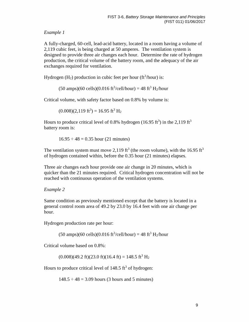
Example 1 A fully-charged, 60-cell, lead-acid battery, located in a room having a volume of 2,119 cubic feet, is being charged at 50 amperes. The ventilation system is designed to provide three air changes each hour. Determine the rate of hydrogen production, the critical volume of the battery room, and the adequacy of the air exchanges required for ventilation. Hydrogen (H2) production in cubic feet per hour (ft3/hour) is: (50 amps)(60 cells)(0.016 ft3/cell/hour) = 48 ft3 H2/hour Critical volume, with safety factor based on 0.8% by volume is: (0.008)(2,119 ft3) = 16.95 ft3 H2 Hours to produce critical level of 0.8% hydrogen (16.95 ft3) in the 2,119 ft3 battery room is: 16.95 ÷ 48 = 0.35 hour (21 minutes) The ventilation system must move 2,119 ft3 (the room volume), with the 16.95 ft3 of hydrogen contained within, before the 0.35 hour (21 minutes) elapses. Three air changes each hour provide one air change in 20 minutes, which is quicker than the 21 minutes required. Critical hydrogen concentration will not be reached with continuous operation of the ventilation systems. Example 2 Same condition as previously mentioned except that the battery is located in a general control room area of 49.2 by 23.0 by 16.4 feet with one air change per hour. Hydrogen production rate per hour: (50 amps)(60 cells)(0.016 ft3/cell/hour) = 48 ft3 H2/hour Critical volume based on 0.8%: (0.008)(49.2 ft)(23.0 ft)(16.4 ft) = 148.5 ft3 H2 Hours to produce critical level of 148.5 ft3 of hydrogen: 148.5 ÷ 48 = 3.09 hours (3 hours and 5 minutes)

FIST 3-6, Battery Storage Maintenance and Principles (FIST 011) 01/06/2017
10
Because one air change occurs per hour, the critical concentration would not be reached with continuous operation of the ventilation system and with adequate air movement over the battery to ensure diffusion of generated gases. Example 3 Same condition as Example 2. Determine fan size for room with no natural circulation. Hydrogen production in ft3/hour:
(0.016 ft3/cell/hour)(50 amps)(60 cells) = 48 ft3/hour Divide by 60 minutes per hour to change 48 ft3 per hour into cubic feet per minute: 48 ÷ 60 = 0.8 ft3/min H2 production A safety factor of 5 (0.8% by volume) is required. With 0.8 ft3/min hydrogen production, the hydrogen must never reach 0.8% of the total volume of the room. Total volume of the room is (49.2 ft)(23.0 ft)(16.4 ft) = 18,558.2 ft3: (0.008)(18,558.2 ft3) = 148.5 ft3 So the fan must clear the room before the hydrogen generation can produce 148.2 ft3 of hydrogen. This production is 0.8 ft3/min, so: 148.5 ft3 ÷ 0.8 ft3/min = 185.6 minutes to clear the room before hydrogen
volume is produced. The total room volume is 18,558.2 ft3, so: 18,558.2 ÷ 185.6 = 99.99 ft3/min fan capacity Fans are rated in hundreds of ft3/min, so at least a 100 ft3/min fan is needed. Another way to calculate this fan size would be that the fan must move 0.8% of the total volume of the room each minute. Divide the hydrogen production rate by 0.8% to give the total fan capacity: 0.8 ft3/min ÷ 0.008 = 100 ft3/min
Note: Verify ventilation system operation when charging batteries from an emergency backup generator.

FIST 3-6, Battery Storage Maintenance and Principles (FIST 011) 01/06/2017
11
2.6.1 Non-Periodic Maintenance
[Upon installation or modification of any part of the system, including battery, charger, ventilation fans, vents, or other associated equipment airflow readings must be taken and compared to the new required airflow calculations. Revise and document airflow calculations on POM Form (157, 158, or 159)]
2.6.2 Periodic Maintenance
[Verify unmonitored ventilation (airflow) devices (fans and vents) are operational.] [Verify that ventilation airflow monitoring and alarms are operational.] [Check ventilation airflow readings and compare to required airflow calculations.]
2.7 Seismic Battery Racks
[Battery racks for new or modified battery system installations must be designed for the seismic risk for the specific geographic location.] A determination of the battery location being ‘above grade’ or ‘below grade’, ‘essential’ or ‘non-essential’, and seismic risk geographic location will factor into the seismic battery rack design. Reference the International Building Code (IBC), and IEEE™ 693 as required. Consider the following mounting features:
• Restrain all cells. Provide additional (non-standard) members according to the manufacturer’s recommendations.
• Include fire retardant polyvinyl chloride (PVC) or open-cell styrene battery spacers between cells and side and end rails.
• Join battery frames securely when more than one rack section is used. If a separate section is nearby or adjacent, each rack should be joined with flexible connectors according to the manufacturer’s recommendations.
• Connect cells at different elevations of the same rack with flexible connectors.
• Securely connect rack to the structure according to the design or manufacturer’s recommendations.
Ground metal battery racks. Racks and trays should be of sufficient strength and treated with an electrolyte resistive coating.

FIST 3-6, Battery Storage Maintenance and Principles (FIST 011) 01/06/2017
12
2.8 Battery Rooms
Battery rooms in future and remodeled facilities should be designed, constructed, and maintained in accordance with the National Electrical Safety Code Section 14, Storage Batteries. The room should have a fire rating of 1 hour. Battery systems now located in control buildings or powerplants need not be placed in a separate room. However, when not located in a separate room, barriers or some type of mechanical protection must be provided to prevent inadvertent personnel or equipment contact that will result in damage. Battery location should permit comprehensive visual inspection. Periodic air flow measurements and explosion meter (total combustible gas) readings are recommended in the general battery areas to ensure adequate air movements to diffuse the generation of hydrogen gas. In future or modified installations of battery systems, a separate room and spill containment is recommended. [Install spill containment if a single-cell electrolyte volume is greater than 55 gallons or total electrolyte volume over 1,000 gallons.] Spill containment should be adequately sized to contain the electrolyte volume of one cell. Most battery rooms contain drains that lead directly into sumps or fresh water. The environmental consequences of a battery acid spill should be evaluated and proper precautions should be implemented as needed, such as adding spill containment or blocking battery room drains. To achieve the greatest results from any battery system, the environment within the battery room should be closely monitored and maintained. A battery room temperature should be maintained at a constant temperature. Ideally, batteries should be at 77 °F to supply their full capacity and achieve rated life. A battery room temperature of less than 77 °F will result in a lower capacity and temperatures above 77 °F will result in a shorter battery life. Consult manufacturer’s information for proper operating temperature of the battery. It may be advantageous to place the battery in the middle of the room to minimize temperature gradient. If a battery is placed near an external wall, in a direct line with a heating, ventilating, and air conditioning system, or in direct sunlight, care should be taken to ensure all cells are at a similar temperature throughout the year. [New battery installations or major battery modifications require concrete floors to be coated with acid-resistive paint. (Alkaline resistive paint where NiCd batteries are utilized.)] Electrical receptacles and light switches should be located outside of the battery areas. A 10-pound class C dry chemical fire extinguisher should be mounted as close as practicable to the battery room (either just inside or outside of the battery room

FIST 3-6, Battery Storage Maintenance and Principles (FIST 011) 01/06/2017
13
door). Carbon dioxide fire extinguishers are not recommended because of the potential for thermal shock to the batteries and possible cracking of the case resulting in leaking electrolyte due to the thermal shock. [Ensure egress from the battery room is clear at all times.] In addition to the above requirements, battery rooms should not be used for storage, in accordance with the NEC. Keep battery storage and charging areas free of combustible materials and scrap. Promptly clean up and dispose of acid or corrosive spills.
2.8.1 Periodic Maintenance
Perform a visual inspection of the battery and associated equipment. Check the physical condition of the equipment located within the battery room. This includes battery, battery rack, and battery room. [Perform visual inspection, including signage, checking for general cleanliness of the battery room, cabinets, availability of spill containment, neutralizing pillows, grounding straps, and other equipment located inside the battery room.]
[Perform visual inspection, including signage, checking for general cleanliness and condition of the battery, battery rack, and battery room.]
[Check for the availability of a 10-pound class C, dry chemical fire extinguisher and verify that it has been inspected and tested according to schedule.]
[Check for availability and condition of insulated tools and utensils.]
[Check the hydrometer for cleanliness and cracking of rubber parts.]
[Check the availability and condition of all safety equipment, such as gloves, aprons, face shields, goggles, etc.]
2.9 Safety Meetings
Field O&M personnel should be trained on the design and operational requirements of the battery and its ventilation system. Discussions of the design and operational requirements should be the subject of at least one toolbox meeting semi-annually. Operation of the fire extinguisher and how to read the inspection tag should also be covered.

FIST 3-6, Battery Storage Maintenance and Principles (FIST 011) 01/06/2017
14
Working with batteries can expose an employee to both potential shock and arc flash hazards. In addition, batteries can also expose an employee to chemical hazards associated with the electrolyte used in the battery. Depending on the task being performed, different personal protective equipment (PPE) requirements may apply. If all conductors and terminals are properly covered and protected on the battery system during electrolyte checks, and inadvertent contact cannot be made with exposed electrical components, chemical PPE for the potential acid exposure may suffice. If the caps and vents are installed in the battery cells during battery electrical component checks, arc flash and shock PPE may suffice. The specific tasks play an important role in the proper selection of PPE during battery maintenance.

FIST 3-6, Battery Storage Maintenance and Principles (FIST 011) 01/06/2017
15
3. Vented Lead-Acid (VLA) Batteries
3.1 Maintenance for VLA Battery Systems
These battery system maintenance or test activities will be performed within their respective interval in accordance with FIST 4-1B.
3.2 Purpose
This section describes the principles of lead-acid battery care and how to determine if the care is adequate and correct. It will also outline the duties and responsibilities for routine operation and care of vented (flooded) lead-acid batteries. One of the most important parts of battery care is a proper charging program. Keeping records for comparing physical conditions and measured data assists in determining whether the charging program is correct. Correct charging is critical for long battery life and reliable service. Additionally, this section describes cell conditions along with proper O&M procedures. These principles do not take precedence over the manufacturer’s instructions but provide explanations and details to better define a maintenance program. Finally, recommended testing procedures are outlined with examples on how to properly test a battery to determine the state-of-health of the system. This includes how to perform a battery capacity test and signs of a weak system. Document acceptable measurement ranges or percent variation for values recorded when performing maintenance activities listed below for VLA batteries.
Note: Acceptable measurement ranges can be documented on the job plans, the POM-133A form, the POM-157 form, etc.
When readings are taken, if values are outside of acceptable ranges, then corrective actions need to be performed.
3.3 Background
The station service battery along with the DC system is one of the most critical systems within a powerplant. The DC system provides power to protective relays, circuit breakers, and other critical systems in the event of an emergency to protect employees and equipment. The vented lead-acid battery is the most commonly used battery for station service within Reclamation. The battery can supply
FIST 3-6, Battery Storage Maintenance and Principles (FIST 011) 01/06/2017
16
emergency power for hours, has expected life of greater than 20 years, and is highly reliable if properly maintained.
3.3.1 Full Charge
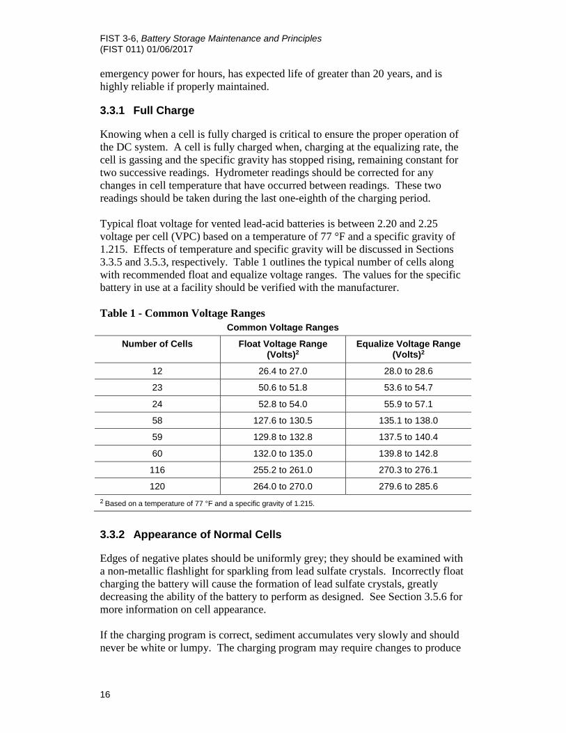
Knowing when a cell is fully charged is critical to ensure the proper operation of the DC system. A cell is fully charged when, charging at the equalizing rate, the cell is gassing and the specific gravity has stopped rising, remaining constant for two successive readings. Hydrometer readings should be corrected for any changes in cell temperature that have occurred between readings. These two readings should be taken during the last one-eighth of the charging period. Typical float voltage for vented lead-acid batteries is between 2.20 and 2.25 voltage per cell (VPC) based on a temperature of 77 °F and a specific gravity of 1.215. Effects of temperature and specific gravity will be discussed in Sections 3.3.5 and 3.5.3, respectively. Table 1 outlines the typical number of cells along with recommended float and equalize voltage ranges. The values for the specific battery in use at a facility should be verified with the manufacturer. Table 1 - Common Voltage Ranges
Common Voltage Ranges
Number of Cells Float Voltage Range (Volts)2
Equalize Voltage Range (Volts)2
12 26.4 to 27.0 28.0 to 28.6
23 50.6 to 51.8 53.6 to 54.7
24 52.8 to 54.0 55.9 to 57.1
58 127.6 to 130.5 135.1 to 138.0
59 129.8 to 132.8 137.5 to 140.4
60 132.0 to 135.0 139.8 to 142.8
116 255.2 to 261.0 270.3 to 276.1
120 264.0 to 270.0 279.6 to 285.6 2 Based on a temperature of 77 °F and a specific gravity of 1.215.
3.3.2 Appearance of Normal Cells
Edges of negative plates should be uniformly grey; they should be examined with a non-metallic flashlight for sparkling from lead sulfate crystals. Incorrectly float charging the battery will cause the formation of lead sulfate crystals, greatly decreasing the ability of the battery to perform as designed. See Section 3.5.6 for more information on cell appearance. If the charging program is correct, sediment accumulates very slowly and should never be white or lumpy. The charging program may require changes to produce

FIST 3-6, Battery Storage Maintenance and Principles (FIST 011) 01/06/2017
17
a very scanty, fine, dark brown sediment. The electrolyte should be maintained at the marked level, midway between the top of the case and the top of the plates.
3.3.3 Chemical Reactions
A fully charged cell has brown lead peroxide on positive plates and gray sponge lead on negative plates. On discharge, electric current converts active materials of positive and negative plates to lead sulfate and uses up sulfuric acid to manufacture lead sulfate. This process leaves the acid weak at the end of the discharge. Lead sulfate is white in color, but cannot be seen on plates unless the cell is over-discharged, which produces oversulfation. At first, this condition makes the plates lighter in color; and, if not corrected, the plates will appear to have white patches or white all over. Charging the cell reverses this process, converting lead sulfate in the plates to lead peroxide and sponge lead that results in the production of sulfuric acid, which restores the specific gravity to normal. Chemical reactions in a lead-acid cell are:
Battery Discharged Battery Charged (+plate) (-plate) (solution) (+plate) (-plate) (solution)
PbSO4 + PbSO4 + 2H2O PbO2 + PB + 2H2SO4 (lead sulfate) (lead sulfate) (water) (lead peroxide) (lead) (sulfuric acid)
As the charge nears completion, only a small amount of lead sulfate remains. The charging current begins to separate water into oxygen and hydrogen, which bubble to the top of the electrolyte and form a mixture of very explosive gases. Quantity of ampere-hours available from a cell decreases with an increasing rate of discharge. Available ampere-hours are much less at rapid rates of discharge (see Figure 1). Most cells are rates based on an 8-hr discharge unless noted differently. The ampere-hours also decrease for cells with weaker specific gravity (see Figure 2). It is possible to order batteries with different specific gravity; but while increasing the specific gravity will increase the capacity of the battery, it also will decrease the life of the cells.
3.3.4 Self-Discharge and Effect of Impurities on Floating Voltage
Lead-calcium and lead selenium cells have the advantage of low internal losses, which remain constant for the life of the cell. Lead-selenium cells contain a small amount of antimony and do not have antimony mitigation like lead-antimony cells. Fully charged lead-antimony cells discharge internally by an action between active material and the grid. Impurities may hasten this action and may result in visible or invisible changes on the plates, depending on the types of impurities present.

FIST 3-6, Battery Storage Maintenance and Principles (FIST 011) 01/06/2017
18
Figure 1. Percent capacity of batteries with pasted and planté type plates for various discharge rates.

FIST 3-6, Battery Storage Maintenance and Principles (FIST 011) 01/06/2017
19
Figure 2. Effect of concentration of electrolyte on cell capacity.

FIST 3-6, Battery Storage Maintenance and Principles (FIST 011) 01/06/2017
20
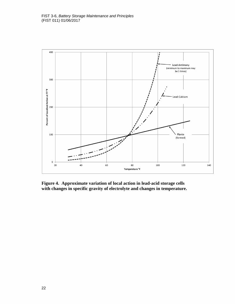
Impurities may prevent a proper floating voltage from keeping the cells fully charged and may reduce the effectiveness of an equalizing charge. A higher floating voltage may be required to maintain a full charge. The rate of self-discharge is decreased by using a lower specific gravity. The rate increases as the cell temperature rises, as may be seen on the curves of Figures 3 and 4. The charge will not be lost if a small charging current, just equal to the self-discharge rate, is given to the cell. This charge is known as a trickle charge and usually is made a little larger than necessary so as to gradually restore losses caused by small loads connected to the battery. Self-discharge increases with age to perhaps five times the initial rate. This process is believed to be caused by the antimony being deposited on the negative plates in a form that behaves as an impurity. Many batteries use calcium instead of antimony as the alloying material, which reduces the internal discharge as indicated on Figures 3 or 5.
3.3.5 Temperature Characteristics
Operating temperature greatly affects performance of storage cells. Ideal operating temperature is 77 °F; however, an acceptable range is anywhere from 60-77 °F. Capacity is greatly reduced when cold, as shown by Figure 5; but at the same time, operating temperatures over 77 °F can greatly reduce the life of the battery. The self-discharge rate is increased at warm temperatures, as shown by Figure 5. Never intentionally allow electrolyte temperature to exceed 100 °F. The temperature at which the electrolyte will freeze and burst a cell is lowered as specific gravity rises. Little danger of freezing exists if the battery is kept well charged. If charging current is kept constant, charging voltage will rise to a final value and is one indication that full charge has been reached. This final voltage increases greatly as the cell gets colder, as shown by Figure 3. For this reason, do not try to terminate an equalizing charge by an overvoltage relay. This procedure only would work correctly for one temperature. Relays are available where operating voltage varies with temperature. This charge control must be subject to the same ambient temperature as the battery. If charging voltage is held constant, final charging current increases with temperature as shown in Figure 3. This condition is needed to offset the increasing internal self-discharge current. The constant voltage charge method automatically keeps the current at the value the battery needs for replacing both the self-discharge and load discharges. Temperatures 15 °F above 77 °F will decrease battery life by approximately half.

FIST 3-6, Battery Storage Maintenance and Principles (FIST 011) 01/06/2017
21
Figure 3. Final voltage at various rates after charge is fully completed.
FIST 3-6, Battery Storage Maintenance and Principles (FIST 011) 01/06/2017
22
Figure 4. Approximate variation of local action in lead-acid storage cells with changes in specific gravity of electrolyte and changes in temperature.

FIST 3-6, Battery Storage Maintenance and Principles (FIST 011) 01/06/2017
23
Figure 5. Approximate variation of capacity with respect to temperature in vented lead-acid storage batteries.

FIST 3-6, Battery Storage Maintenance and Principles (FIST 011) 01/06/2017
24
If the ambient temperature of a battery is other than 77 °F, then the float voltage of the battery will need to be adjusted using the following equation. Adjusting the float voltage of the battery will help ensure that the cells are properly charged.
VTC = [VF + (77 – TCELL) * 0.003] * NC Where: VTC is equal to the temperature compensated float voltage. VF is the recommended float voltage at 77 °F. TCELL is the average temperature of the battery. NC is the number of cells in the battery.
3.3.6 Battery Life for Different Types
The life of various types of cells can vary markedly depending on temperature, duty cycles, service condition, and maintenance. Valve-regulated lead-acid cells have the shortest life at 5-7 years. Planté or Manchex type formed plated on light duty and floating charge have a longer life, usually 14-18 years; however, if cycle charged, they usually only last about 9 years. Pasted plate planté cells may be expected to last in excess of 25 years on float charge. Lead-calcium cells on constant float charge typically last 12-15 years. Lead-selenium cells have a longer life expectation than lead-calcium or lead-antimony. A battery is considered worn out and should be replaced when it fails to deliver 80% of its original capacity during a capacity test. Lead-selenium and lead calcium cells have a longer life expectancy than lead-antimony on a constant voltage float charge. Lead-antimony and lead-selenium cells have a high number of discharge cycles than lead-calcium. In lead-calcium cells the calcium over time may deposit on the plates, which results in plate growth and in extreme cases the plate growth may crack the container. Lead-antimony cells when continuously charged suffer from antimony-poisoning where the antimony forms discharge points on the negative plates, which increase float current and water consumption. Lead-selenium cells do not have the grid growth issue of lead-calcium or the lead-antimony cell problems
3.4 Battery Charging and Temperature Correction
3.4.1 Initial Freshening Charge
To establish a reference, give each new battery, or reinstalled battery stored for more than 3 months, an initial freshening charge. Use the equalizing voltage and times given by the manufacturer for the specific cell type, but do not exceed the maximum voltage of other loads connected to the charger. Apply this charge until each cell gasses freely and equally and specific gravity stops rising. Just before the end of the initial charge, record the voltage of each cell. About 20 minutes after the end of the charge, record the specific gravity and temperature of each cell. Correct specific gravity for temperature according to section 3.5.3. A digital

FIST 3-6, Battery Storage Maintenance and Principles (FIST 011) 01/06/2017
25
hydrometer stores the cell’s specific gravity and temperature measurements and will automatically temperature correct the specific gravity reading to 77 °F. Therefore, the use of a digital hydrometer is highly recommended. Record all values on form POM-133A and store all forms according to section 3.5.1.
3.4.2 Float Charge
The purpose of a float charge is to ensure that the battery is fully charged in the event it is needed to supply critical power to equipment at the facility. Charge batteries continuously at the float voltage recommended by the manufacturer using a constant voltage charging method. The float charge is determined by the number of cells in the string and average temperature of the battery. If the battery is at a temperature other than 77 °F, refer to Section 3.3.5 on how to adjust the float voltage based on temperature. Some chargers automatically adjust the float based on the temperature of the system (refer to the charger manufacturer for additional information). If needed, adjust the charger float voltage based on the digital meter. If needed, adjust the charger and/or bus voltmeters to agree with the digital meter. A battery is said to float when charging voltage is slightly greater than the open circuit voltage of the battery. Floating current required to keep lead-calcium cells at full charge is about one-fourth to one-third that of lead-antimony cells, but lead-calcium cells usually must be floated at a slightly higher voltage. Lead-selenium cells require voltages slightly less than those of lead-calcium. The operation of a battery by float method is based on overall voltage applied to the battery terminals. The voltmeter used must be very accurate. An inaccurate meter can result in either over or under charging and resulting problems, which reduce life and service of the battery.
3.4.3 Equalizing Charge
The purpose of the equalizing charge is to ensure that every plate in every cell is brought with certainty to a state of full charge by a slight overcharge.
Note: Do not perform equalizing charges on a routine basis.
[Apply an equalizing charge when necessary.] Consult manufacturers’ instructions for when to apply an equalizing charge. In the event that the manufacturers’ instructions contain no information on how or when to apply an equalizing charge the following list of conditions should be used. If the condition continues after an equalizing charge has been performed other corrective action should be taken.

FIST 3-6, Battery Storage Maintenance and Principles (FIST 011) 01/06/2017
26
If one of the conditions below occurs, apply an equalizing charge. Prior to performing an equalizing charge, ensure all cell electrolyte levels are at the maximum level mark.
1. Following heavy discharge.
2. Before and after performing a capacity test.
3. If specific gravity (corrected for temperature) of any cell is more than 10 points (0.010) below the full charge value while on float.
4. If the voltage of any cell is more than 0.04 volts below the average cell voltage when the battery is on float.
5. If the level in any cell(s) falls at or near the minimum fill line, requiring a large amount of distilled water to be added to restore the level to the maximum fill line.
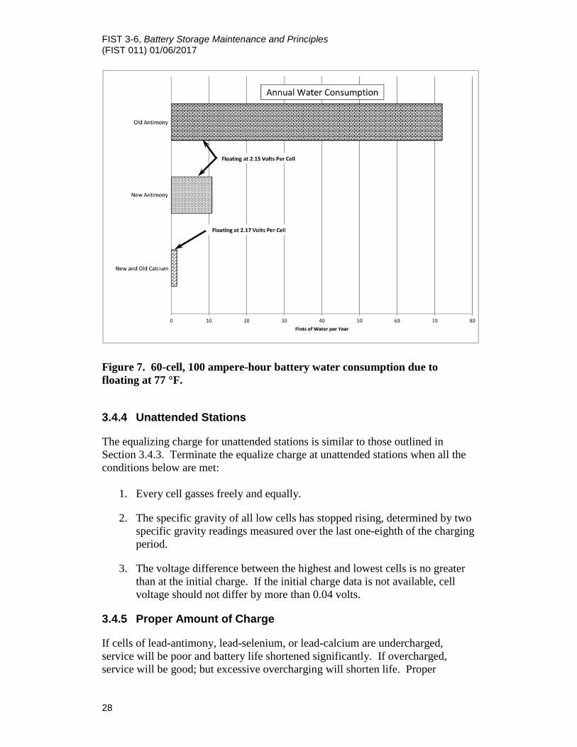
6. If too little replacement water is being added, typically indicating undercharging (see Figures 6 and 7 for typical water consumption).
During the equalize charge process, specific gravities and cell voltage readings should be taken periodically (i.e. every 2 hours or as a percentage of the overall equalize charge time). As the end of the equalizing period approaches, increase the frequency of measurements. Most manufacturers can provide recommended equalize times based on battery type and equalize voltage.
Terminate the equalizing charge when all conditions below are met:
1. Every cell gasses freely and equally.
2. The specific gravity of all low cells has stopped rising, determined by two specific gravity readings measured over the last one-eighth of the charging period.
3. The voltage difference between the highest and lowest cells is no greater than at the initial charge. If the initial charge data is not available, cell voltage should not differ by more than 0.04 volts.
Caution: Do not allow electrolyte to exceed 100 °F.
Failure to give equalizing charges when needed can greatly decrease battery capacity. The ampere-hour capacity of weak cells greatly decreases. During discharge, these cells will be exhausted well ahead of good cells and then become over-discharged (see Section 3.4.9) or over-sulfated. The plates may buckle, and

FIST 3-6, Battery Storage Maintenance and Principles (FIST 011) 01/06/2017
27
grids may crack. Continued discharge may reverse the polarity, making positive plates out of the negatives and vice versa, which will destroy the cells. If one section of the battery is warmer than the rest, these cells have a higher rate of internal self-discharge and capacity gradually falls below the others. A battery should be located so that heating or cooling does not affect a portion of the battery, which could result in decreased capacity of a section of cells.
Figure 6. Water consumption floating charge at 77 °F for lead-acid battery sizes and types.
FIST 3-6, Battery Storage Maintenance and Principles (FIST 011) 01/06/2017
28
Figure 7. 60-cell, 100 ampere-hour battery water consumption due to floating at 77 °F.
3.4.4 Unattended Stations
The equalizing charge for unattended stations is similar to those outlined in Section 3.4.3. Terminate the equalize charge at unattended stations when all the conditions below are met:
1. Every cell gasses freely and equally.
2. The specific gravity of all low cells has stopped rising, determined by two specific gravity readings measured over the last one-eighth of the charging period.
3. The voltage difference between the highest and lowest cells is no greater than at the initial charge. If the initial charge data is not available, cell voltage should not differ by more than 0.04 volts.
3.4.5 Proper Amount of Charge
If cells of lead-antimony, lead-selenium, or lead-calcium are undercharged, service will be poor and battery life shortened significantly. If overcharged, service will be good; but excessive overcharging will shorten life. Proper

FIST 3-6, Battery Storage Maintenance and Principles (FIST 011) 01/06/2017
29
charging means slight overcharging to cause the least possible sedimentation and minimal gassing. This condition requires very little makeup water. Sedimentation starts with gassing and is proportional to the total amount of gas liberated. Typical curves of recharge times after 100% discharge at the 8-hour rate are shown in Figure 8.
3.4.6 High-Rate Overcharging
After a battery is fully charged, continuing to charge at high rates can damage positive plates. Violent gassing takes place, bubbles form in the interior of the active material, and the resulting pressure forces bubbles through the porous active material. The active material restrains the bubbles sufficiently so that many particles of plate material are broken out. These particles rise with the bubbles and result in a muddy red or brown color of the electrolyte. Some of this fine sediment settles on negative plates where it short circuits. The sediment is converted to gray sponge lead and results in a growth of moss-like sediment deposited on the top edges of the negative plates. This deposit indicates that high-rate overcharging previously occurred. The battery will overheat on sustained heavy charge rates. The temperature of the cells should never intentionally be allowed to exceed 100 °F.
3.4.7 Low-Rate Overcharging
At lower rates of overcharge, bubbling is reduced, and sediment falls to the bottom of the cell. Overcharging at a very slow rate disturbs the electrolyte so little that fine brown sediment falls in a vertical line, forming tiny ridges on top of the sediment. Ridged sediment is a good indication that the recent overcharging was not at high rates. An equalization charge is a time limited low-rate overcharging event. Obviously, overcharging should be kept at a minimum, and ridges should be small.
3.4.8 Undercharging
If the battery gets too little charging, unconverted sulfate remains on the plates too long and hardens. The longer plates stay in less-than-full-charge condition, the harder the sulfate becomes, and the more difficult it is to reconvert. New sulfate is easily converted back to soft active materials by a normal charge, but a long overcharge is required to remove it after becoming hard. Sulfate accumulates unnoticed, a little on each charge, if charging is not enough to eliminate all sulfate. This residue buildup continues until a substantial portion of ampere-hour capacity is lost. The remedy is to increase charging to give a slight overcharge. This procedure must be put into practice while the battery is new and followed for the life of the battery (see also Section 3.4.5 for proper amount of charge). Prolonged undercharging also leads to large flaking on the interpolate collector bar.

FIST 3-6, Battery Storage Maintenance and Principles (FIST 011) 01/06/2017
30
Figure 8. Typical recharge curves at constant voltages following 100% discharges.

FIST 3-6, Battery Storage Maintenance and Principles (FIST 011) 01/06/2017
31
Sulfate buildup caused by undercharging is the most common cause of buckling plates and cracked grids. Sulfate takes up more room than the original material and strains the plates out of shape. The pressure of expanding active material can break separators and cause short circuits. A badly sulfated cell should be treated as described in Section 3.5.7.10. If charged at too low a rate, the hardened sulfate is thrown out of the plates and settles in white ridges on the cell bottom. At higher rates, the gassing distributes the sediment evenly without ridges. An over-sulfated cell has high internal resistance and requires extra voltage across the cell, which also causes higher temperatures to develop during charging. Buckled or cracked plates cannot be repaired by removing the sulfate, but these plates may be used as long as they retain satisfactory ampere-hour capacity. See Section 3.6.2 for capacity testing.
3.4.9 Over-discharge
The plates suffer greatly when over-discharged. VPC should not be allowed to drop below 1.75 volts. Once the cell voltage has reached 1.75 VDC, the rate of the voltage decline is very rapid and only a minimal amount of additional energy will be obtained from the battery. Specific gravity should not be allowed to decrease below the limit given by the manufacturer, which is different for various types and sizes of cells. As normal discharge proceeds, active materials are converted to normal lead sulfate, which requires only slightly more space than active materials. Over-discharge forms more lead sulfate in the pores of the active material than they are able to hold. This process may expand and bend or buckle plate, or crack grids. In some instances, sufficient pressure is created to crack or puncture separators.
3.5 O&M of Vented Lead-Acid Batteries
The regimen described below is intended to maximize performance and life expectancy. Refer to manufacturer’s data for further information.
3.5.1 Records
[Post a battery data card form POM-157 in a conspicuous location near the battery when battery is installed.] Loss of capacity over time is shown by a gradual change in specific gravity of the cells. Keeping accurate records in the battery room is important. Comparison can be made easily between current and earlier readings. A copy of forms POM-133A and POM-134A are included in the forms section, and are available on Reclamation’s Intranet site. Four POM-133A quarterly maintenance reports and one POM-134A connection resistance report are required for each battery each year. Special care is necessary to protect data sheets. Keep 1 year’s worth of records in the battery room. [Keep maintenance and connection resistance report forms in CARMA.]

FIST 3-6, Battery Storage Maintenance and Principles (FIST 011) 01/06/2017
32
While keeping quality battery records is important, trending battery data is essential to maximizing the longevity of the battery. Small changes to float voltages, specific gravity, and cell temperatures can greatly affect the performance and life of the system. Compare data collected at each maintenance interval to the baseline and previous results. Changes in data should be analyzed and corrected as soon as possible. Failure to correct issues in a timely manner may result in loss of capacity and decreased useful life of the battery. Present readings should be compared to the previous set of readings as well as to the initial set of readings taken during the commissioning to trend the battery data. Changes in readings over the life of the battery may be small, but when compared to the initial readings, the changes may be significant. These changes can yield valuable information to the overall state-of-health of the battery and can trigger maintenance activities.
Note: A change in voltage, specific gravity, or cell temperature of 5% between maintenance intervals should result in additional investigation of the battery to determine the cause of the change.
3.5.2 Voltage Readings
The voltage of individual cells, as well as the voltage of the entire battery string can yield useful information to the state-of-health of the DC system. Voltage readings should be taken in accordance with the following instructions.
3.5.2.1 Non-Periodic Maintenance
[Upon commissioning or upon complete disassembly and reassembly of battery systems measure and record the float voltage on all individual cells to the nearest 0.01 volts with a digital meter. Whenever station service transformer taps are changed measure the voltage on the battery terminals and adjust the battery charger(s) float voltage if necessary. During equalizing charge and just before terminating the equalizing charge, measure the voltages of the highest voltage cell and the lowest voltage cell of the battery to the nearest 0.01 volts with an accurate digital voltmeter. If the voltage difference between the two cells is more than that recorded for the initial charge, continue the equalizing charge.]
3.5.2.2 Periodic Maintenance
[Check the voltmeter on the distribution panel to determine if the battery is being charged at the proper float voltage.] If voltage appears to be incorrect,

FIST 3-6, Battery Storage Maintenance and Principles (FIST 011) 01/06/2017
33
verify voltage at battery terminals and adjust the battery charging voltage if necessary. [Measure and record the float voltage on all individual cells to the nearest 0.01 volts with a digital voltmeter.] Record values on form POM-133A. Compare measurements with previous readings. Measure and record the overall float voltage with charger in service across the battery terminals. Adjust the distribution and charger panel meters as necessary to match the float voltage measured across the battery terminals.
Note: Accurate voltmeters are critical for extending battery life. Provide a digital voltmeter accurate to 0.01 volts and ensure meter calibration at least once a year.
3.5.3 Specific Gravity Readings
If using a standard hydrometer, provide two hydrometers of high accuracy and sensitivity and frequently check them against each other. Non-digital hydrometers should be replaced every 2-3 years. Digital hydrometers should be calibrated annually to verify accuracy. The hydrometer must be held vertically for accurate specific gravity readings. It is highly recommended that facilities purchase and use a digital hydrometer to perform battery maintenance. Digital hydrometers are easy to use, accurate, and automatically correct for variations in electrolyte temperature. Prior to and after taking any measurements, it is recommended to rinse out the hydrometer with distilled water. During the rinsing process, ensure that the hydrometer reads 1.000, within the tolerance of the meter. Do not take readings after adding water (or acid) to the cell until the electrolyte has had time to mix thoroughly (not less than 1 hour when gassing or 2 days if not gassing for antimony cells, and several weeks for calcium cells in floating service). Use a long nozzle syringe and take samples several inches down to minimize errors. Bubbles in the electrolyte cause errors, and readings should not be taken sooner than 15 minutes after gassing has stopped. When taking measurements during an equalize charge, try to take measurements in sections of the cells with minimal bubbles. Specific gravity of electrolyte must be corrected for temperature. Subtract one point (0.001) from the specific gravity reading for each 3 °F the temperature is below 77 °F, and add one point (0.001) for each 3 °F the temperature is above 77 °F. The recommended specific gravity spread between all cells is 0.010 with all cells electrolyte level at the high level line.
𝑆𝑆𝑆𝑆.𝐺𝐺𝐺𝐺.𝐶𝐶𝐶𝐶𝐶𝐶𝐶𝐶𝐶𝐶𝐶𝐶𝐶𝐶𝐶𝐶𝐶𝐶 = 𝑆𝑆𝑆𝑆.𝐺𝐺𝐺𝐺.𝐶𝐶𝐶𝐶𝐶𝐶𝐶𝐶−(77−𝐶𝐶𝐶𝐶𝐶𝐶𝐶𝐶𝐶𝐶 )
3000
FIST 3-6, Battery Storage Maintenance and Principles (FIST 011) 01/06/2017
34
Where: SP. GR.CORRECTED is the temperature compensated specific gravity. SP. GR.CELL is the uncorrected specific gravity of the cell. TCELL is the average temperature of the cell. Specific gravity should never be adjusted until the specific gravity is established to be wrong with minimal uncertainty. If there is any question to the results indicated by the hydrometer, either compare the values to an instrument that has been recently calibrated, or send equipment out for calibration before adjusting the specific gravity of the cells. Before adjusting for low specific gravity, make sure that the specific gravity cannot be raised by equalizing (see Section 3.4.3). Continue the charge until the specific gravity shows no rise, and then charge for 3 more hours.
Note: Never make a gravity adjustment on a cell that does not gas on charge.
Before making any change to the specific gravity of a cell, it is recommended to contact the manufacturer to ensure all special procedures are followed. If specific gravity cannot be raised by equalize charge, remove some electrolyte from the cell and replace it with pure, 1.300-gravity sulfuric acid, which consists of 30% concentrated acid and 70% distilled water by volume. Recharge until all cells gas for an hour. Repeat the procedure if the gravity is still below normal. To lower the gravity, replace some of the electrolyte with distilled water. The amount of electrolyte to be replaced will depend on the overall volume of the cell.
3.5.3.1 Replacement Water A small quantity of water in the electrolyte is broken down into hydrogen and oxygen by the charging current as batteries are charged. The gases are dissipated through openings in vent plugs. The electrolyte level gradually lowers until distilled water must be added. Commercially available “de-mineralized” water has been found through testing to be equal or superior to commercial “in plant” distilled water. References throughout this document to “distilled water” do not preclude the use of “de-mineralized water”. Do not add water in excess of the maximum level mark and only add water to a fully charged battery. Never store distilled water in a metallic container. Use glass, plastic, or rubber containers. Water consumption of batteries is indicated on Figures 6 and 7. Take an average of the amount of water added over several months and compare this with the amounts given in Figure 6.
3.5.3.2 Water Replacement Rate for Lead-Antimony Cells Lead-antimony cells begin their lives with low water consumption, which increases as much as five times toward the end of their life (see Figures 6 and 7). Capped cells evaporate very little water, and loss is caused by gassing and is
FIST 3-6, Battery Storage Maintenance and Principles (FIST 011) 01/06/2017
35
proportional to the amount of charge the battery receives. Heavy gassing requires frequent additions of distilled water. The water should be added just before or at the beginning of an equalize charge so that gassing will ensure thorough mixing before specific gravity readings are taken. Proper charging minimizes distilled water replacement by limiting the amount of gas generated. This method extends the life of the battery and is much easier than overcharging and having to refill cells frequently.
3.5.3.3 Water Replacement Rate for Lead-Calcium Cells Frequent additions of distilled water in small amounts are not desirable. Water additions two or three times a year probably will be sufficient at most installations. The electrolyte in all cells should be maintained within ¼ inch below the high level mark. Calcium cells, because of greater purity of their components, require about one-tenth the water needed by equivalent size antimony cells. Minimal water consumption remains constant during the entire battery life. See Figures 6 and 7 for water consumption rate.
3.5.3.4 Water Replacement for Lead-Selenium Cells Water requirements for lead selenium are typically greater than lead calcium, especially as the battery ages but much less than lead-antimony. If several discharges are experienced, water replacement should be performed as with the lead-calcium cells in Section 3.5.3.3 above. Water consumption is low throughout the life of these cells.
3.5.3.5 Non-Periodic Maintenance
[After equalizing charge, about 15 minutes after heavy gassing stops, measure and record specific gravity readings of all cells.] Record values on form POM-133A. If two cells with the lowest specific gravity (checked over the last one-eighth of the charging period) have not stopped rising, continue the equalizing charge.
3.5.3.6 Periodic Maintenance [Measure and record specific gravity readings of all cells.] Record values on form POM-133A.
Note: All specific gravity readings must be corrected to 77 °F before recording.
3.5.4 Temperature Readings
All cells of a battery should be at the same ambient temperature. Heat sources such as sunlight, heaters, air conditioning, etc., must be designed so they do not affect the temperature of individual cells. Record the room ambient temperature before cell temperatures are taken. The most effective way to measure the cell

FIST 3-6, Battery Storage Maintenance and Principles (FIST 011) 01/06/2017
36
temperature is to use a digital hydrometer. Digital hydrometers record cell temperature while taking specific gravity readings.
Note: An infrared (IR) camera may be used for temperatures; however, the camera calibration must be checked at least once each year or in accordance with manufacturer’s recommendations.
If the temperature range of the cells exceeds 5 °F (i.e., upper rows are warmer), the room ventilation may be inadequate.
3.5.4.1 Non-Periodic Maintenance
[After equalizing charge, about 15 minutes after heavy gassing stops, take the temperature readings of every cell.] Record values on form POM-133A.
3.5.4.2 Periodic Maintenance
[Measure temperature readings of each individual cell in the system and record the results. Compare readings with the initial and all prior temperatures for trending purposes.] Record values on form POM-133A. If an IR camera is available, take the temperature of the battery connections during a capacity or discharge test (i.e., while current is flowing). If one or more of the connections are loose or dirty, their temperatures will be higher than the other connections.
3.5.5 Connection Resistance Readings
When performing connection resistance readings, a micro-ohm (µΩ) meter should be used. The leads should be connected to the terminal post of each cell and not to the connection hardware (see Figure 10). The readings typically are less than 100 µΩ and should be within a few micro-ohms of each other. If long jumpers are used, the connection resistance of these jumpers can exceed 100 µΩ. If values exceed 100 µΩ on standard length jumpers, further investigation may be warranted. A visual inspection should be performed, and past data should be inspected to determine if significant increases in connection resistance has occurred.
3.5.5.1 Method for Performing Micro-Ohm Readings The following is the recommended method for taking annual micro-ohm meter readings across battery connection. If your battery configuration contains multiple posts, consult engineering support or Technical Service Center (TSC).
Caution: Never place probes across a cell or cells (between positive and negative posts) with the meter set on ohms. The meter may be destroyed, and arcing may occur at the battery.

FIST 3-6, Battery Storage Maintenance and Principles (FIST 011) 01/06/2017
37
1. Make sure the battery is on float charge before beginning the readings. Obtain a digital micro-ohm meter, and set it to the lowest usable scale. Verify whether or not your digital micro-ohm meter contains a positive and negative current polarity switch or bipolar source that enables direct measurement. If not, micro-ohm measurements will need to be taken with positive current and negative current (polarity reversed), and the average of these measurements will be your micro-ohm reading. A digital multimeter will not provide acceptable results.
2. On cell No. 1, take the first reading between the connector lug and the first post (see Figure 9). This reading will be the resistance between the post and connector lug and will be about one-half the middle readings. Record all readings on form POM-134A.
3. Take the second reading between opposite polarity posts (no connectors) of cells No. 1 and No. 2. The following readings will be between positive and negative posts of adjacent cells. These middle readings will include the resistance of two connections (one on each post) and the intercell lead (see Figure 9). These readings will be about double the lug to post connection.
4. Take the remaining middle readings as in step 3, proceeding from cell to cell.
5. Take the last reading between the last post on the last cell and connector lug (see Figure 9).
6. If high resistance is found, take readings from each post to its connector to determine which of the two connections is bad. Mark this and all high resistance connections for later repair.
7. After readings are complete, correct the issue using the steps in Section 3.5.5.2 and retest the repaired connections. Record the resistance in the “as-left” column on form POM-134A. The “as-left” value will become the new basis micro-ohm value, as discussed in Section 3.5.5.3.
8. For long intercell jumper leads it is necessary to also record the connector lug to post resistance as in step 2. The high resistance value of long jumper leads will mask any changes in lug to post resistance.
3.5.5.2 Correcting Abnormal Micro-Ohm Readings
Compare similar connection values when taking measurements. If excessive values are discovered, the following steps should be taken to correct the problem.
1. Ensure hardware is torqued to manufacturer’s specifications. Typically, battery hardware should be retightened to 75% of the initial torque value.
FIST 3-6, Battery Storage Maintenance and Principles (FIST 011) 01/06/2017
38
2. Repeat micro-ohm measurement; if problem is not corrected, continue to step 3.
3. Prior to isolating the station batteries for any reason: Provide adequate precautions to ensure that the facility has sufficient DC capability to safely control, protect, shutdown, and isolate during an emergency condition or loss of station AC power.. If the facilities DC supply is designated as a critical station service battery system then a suitable backup battery must be provided and connected prior to isolation of the batteries.
Caution: Do not remove or make connections while current is flowing. Never remove the battery from a critical system unless a suitable backup battery is in place.
4. Disconnect charger and all loads from the battery.
5. Disassemble problem connections.
6. Carefully clean both the jumper and battery terminal using a non-conductive abrasive pad. Do not scrub hard enough to damage the lead coating on the jumpers or terminals. If jumpers are cable type with crimp lugs on each end, measure the micro-ohm resistance of the jumper from lug to lug. If the measured value is significantly higher than those taken during the initial installation (baseline measurements section 3.5.5), replace the jumper.
7. Apply No-Ox-ID grease to both the jumper and terminal.
8. Reassemble the connection and torque the hardware to manufacturer’s specifications.
9. Repeat micro-ohm measurements to verify problem has been corrected.
10. Reapply the charger and load to the battery.

FIST 3-6, Battery Storage Maintenance and Principles (FIST 011) 01/06/2017
39
Figure 9. Placement of meter probes for connection resistance measurements.
Figure 10. Probe placement for typical battery terminal connections.

FIST 3-6, Battery Storage Maintenance and Principles (FIST 011) 01/06/2017
40
3.5.5.3 Non-Periodic Maintenance
[Upon commissioning or upon complete disassembly and reassembly, using a micro-ohm meter, measure and record the resistance of each connection as a baseline (basis micro-ohms).] The POM-134A form with the recorded basis micro-ohms should be used annually. Record the readings as a baseline on form POM-134A.
3.5.5.4 Periodic Maintenance
Measure and record micro-ohm resistance values for all connections. Compare values to baseline. If any connection resistance has increased more than 20% above the basis micro-ohm reading, perform corrective actions. Corrective actions may include cleaning terminals, applying No-Ox-ID grease, re-torqueing the connections, and retest. Fill out both “as-found” and “as-left” columns on form POM-134A for any cells requiring corrective actions. When a re-torque is required, update the POM-134A form for all future readings to include the new “as-left” value as the basis micro-ohms for that connection.
3.5.6 Visual Inspections
Visual inspections are made to assess the general condition of the battery, battery room, and safety equipment. Keep the battery room or cabinet clean and well ventilated (see Section 2.6). In addition to the information below, visual inspections should include all items in Section 2, Battery Safety. Record results from visual inspection on form POM-133A. Battery connections must be clean and free of corrosion for optimal performance. The connection most likely will appear dull due to the lead coating on the bus bars and also should have a layer of No-Ox-ID grease on the terminal to protect against corrosion. Newer cells will have translucent No-Ox-ID grease that is brown in color and looks like unrefined petroleum jelly. Older cells may have a layer of red No-Ox-ID grease. Corrosion that is not cleaned off terminals periodically will spread into areas between posts and connectors. If not corrected, corrosion also can start forming in wire jumpers, which will require replacing jumpers. These conditions can develop into high-resistance connections and result in heating and wasted capacity. The battery and surrounding parts should be kept clean, dry, and free of acid. Sulfuric acid absorbs moisture, and spilled electrolyte will not dry up. If electrolyte is spilled or sprayed out of the cells on charge, neutralize with a solution of sodium bicarbonate (baking soda) (one pound sodium bicarbonate to one gallon of water), then rinse with distilled water and dry with a soft cloth. A labeled one pound box of sodium bicarbonate and one gallon of water must be kept in the battery room; however, it is not recommended to mix the solution until needed because the solution can disintegrate plastic containers, making a large mess.

FIST 3-6, Battery Storage Maintenance and Principles (FIST 011) 01/06/2017
41
Care should be taken to prevent the solution from getting into the cells. Make sure vent plugs, flame arresters, and dust caps are in place, and all components are in good condition. See Section 2.5.1 for Flame Arrester inspections and maintenance. The history of each cell is shown by the sedimentation because successive layers are laid down in colored strata. These layers can be seen edgewise against the inside of the case. Layers of fine, dark gray sediment show periods of excessive charging (current too high or charge too long). Lumpy gray layers indicate times the battery was over-discharged. These layers generally are covered by a layer of white sulfate from the following charge. A considerable amount of sediment and slivers will be found initially in Gould processed plate batteries. This condition is a normal result of the forming process. Some additional sediment and slivers will be dislodged in shipment and will accumulate at the bottom of the case of these batteries during the first few equalizing charges. With this exception, a perfectly charged battery should have nothing but fine brown sediment, free from lumps, and as scanty as possible. If some experimenting is done with the charging program, slight undercharging may result in a white sulfate layer. This layer indicates that the charging should be slightly increased. The following must be performed during a visual inspection:
• Check the electrolyte level in every cell. If necessary, correct per Section 3.5.3.
• Check every cell for electrolyte leaks and cracks in cell jars. Take corrective action if any are found.
• [Check for sulfation on the plates. Check for corrosion at terminals and connectors.]
• [Document the sedimentation found within the batteries.]
• [Check the ambient temperature.]
• Check condition of the vent plugs, flame arrestors, and dust caps.
3.5.6.1 Periodic Maintenance
Perform a visual inspection of the battery and associated equipment.
3.5.7 Battery Troubles Summarized
During routine O&M of the battery, it may become evident that the battery is not performing as expected. The following is a list of conditions and possible solutions to help resolve issues before permanent damage occurs.

FIST 3-6, Battery Storage Maintenance and Principles (FIST 011) 01/06/2017
42
3.5.7.1 Lack of Gassing Lack of gassing while on charge may indicate an internal short between plates (i.e., the cell discharges internally as fast as it is being charged.) In most instances, if the cell has an internal short, then the cell will likely need to be replaced.
3.5.7.2 Low Specific Gravity or Voltage Specific gravity or voltage of a cell lower than other cells is an indication of excessive internal losses and may result from consistent undercharging. Refer to Section 3.5.7.10 on the Elimination of Oversulfation.
3.5.7.3 Color
Color or appearance of plates or sediment different from other cells is addressed below:
1. Patches of white lead sulfate on either the positive or negative plates: Caused by standing idle or undercharging for extended period.
2. Antimony deposit dark-slate patches on negative plates (usually near the terminal): Caused by charging at too high a rate or an aged cell nearing the end of its service life.
3. Top layer of sediment white: Caused by undercharging.
4. Lumpy brown sediment: Caused by overcharging.
5. All white sediment, no visible layers: Caused by overcharging after prolonged low float voltage.
6. Large flaking on the interplate collector bar: Caused by being on float charge for extended period at insufficient float voltage without performing equalizing charging.
Often, the above problems can be resolved by correcting issues with charging. Sedimentation will remain in the bottom of the cells over their life and provide an indication of the charging history of the battery.
3.5.7.4 Plate Problems 1. Cracks on the edges of the positive plate grids.
2. Light-colored sulfating spots on edges of plates below cracks.
3. Excessive sediment in the bottom of the case.
4. “Mossing” or “treeing” on the tops of the negative plates.

FIST 3-6, Battery Storage Maintenance and Principles (FIST 011) 01/06/2017
43
3.5.7.5 Water Consumption 1. Cell uses excessive water (check Figures 6 and 7 for typical water
consumption): Caused by excess charging rates, high operating temperatures, or leaking cell.
2. Cell requires very little water: Caused by insufficient charging.
3.5.7.6 Plate Buckling Buckling of positive plates indicates excessive sulfation caused by undercharging or excessive temperature. Typically, cells with buckling plates will need to be replaced. In lead-calcium cells the calcium may deposit on the plates over time, which results in plate growth and possible plate buckling.
3.5.7.7 Failure to Supply Rated Ampere-Hour Loads
Failure to supply rates ampere-hours indicates discharged condition, excessive sulfation, or loss of active material from positive plates. Cells may be worn out, or active material may be gone from positive plates. Refer to Section 3.6.2 to perform a capacity test.
3.5.7.8 Internal Shorts The following may cause a short circuit through a separator:
1. Insufficient charging causes material in the plates to become mostly lead-sulfate. The lead sulfate expands; and if the grid does not crack to relieve the strain, the plate will become distorted. This condition is commonly known as buckling. The buckling is most pronounced at the four corners of the positive plates, where shorts are most likely to occur.
2. Impurities in the solution caused by using contaminated water or dirty utensils.
3. Excessive overcharging causes the grid to be partially converted to lead peroxide, which reduces mechanical strength and allows positive and negative plate contact.
A short in a cell can be detected by falling specific gravity and reduced cell voltage. In some cases, an orange discoloration occurs at the point of the short. If a short is longstanding, disintegration of the positive plate will occur at the point of contact with the negative because the positive plate material converts to negative.
3.5.7.9 Normal Sulfate and Oversulfation During discharge of a battery, “normal” sulfate is formed, which is required to produce current. If charging is neglected, the sulfate fills the pores of the plates and makes the active material dense and hard. The material will also appear to be

FIST 3-6, Battery Storage Maintenance and Principles (FIST 011) 01/06/2017
44
glittery when examined with a flashlight. This condition is referred to as “oversulfated”. Normal lead sulfate formed on discharge will easily reconvert with a standard charge. When a battery is oversulfated, plates are less porous than normal and absorb a charge with difficulty. With this condition, an ordinary charge will not reconvert all the sulfate to sulfuric acid, and specific gravity remains below normal. Active material of oversulfated negative plates is light in color and either hard and dense, or granular, gritty, and easily disintegrated. The negative plates require the prolonged charge, necessary to restore an oversulfated battery. An individual cell may be oversulfated by external grounding, an internal short, or drying out because of failure to add water. Prolonged low float charging may also cause oversulfation.
3.5.7.10 Elimination of Oversulfation A battery or cell that is oversulfated should be fully charged until the specific gravity stops rising. Next, the weakest cells should be discharged through a load resistor at the normal 8-hour discharge rate to a final voltage of 1.75 volts. The battery is not oversulfated if the representative cell gives normal capacity, that is, about 100% rated capacity for a fairly new battery or down to 80% of initial rated capacity for a battery nearing the end of its expected life. If the above capacity is not obtained, possible oversulfation should be treated as follows:
1. In cases where one or more individual cells have become oversulfated and the rest of the battery is in good condition, these cells should be treated separately after removing them from the circuit.
2. Recharge the removed cells at a constant current at half the 8-hour discharge rate or manufacturer recommendation. Record hydrometer readings and temperature at regular intervals (3-5 hours) during the charge to determine if rising specific gravity has peaked. Maintain electrolyte level above minimum level by adding water after each reading. Do not add water before taking readings.
3. Continue the charge, recording the readings until no further specific gravity rise has occurred in any cell for 10 hours. If the temperature reaches 100 °F, reduce the current or temporarily interrupt the charge so as to not exceed this temperature. When the specific gravity has reached maximum, terminate the charge and record the hydrometer reading of each cell.
4. The cells must be replaced if they again fail the capacity check as described in this section.

FIST 3-6, Battery Storage Maintenance and Principles (FIST 011) 01/06/2017
45
3.5.7.11 Water Treatment for Oversulfation In cases of emergency, such as plant power loss or loss of both chargers, a long discharge to the point of over-discharge may make the battery difficult to recover. Oversulfation may have occurred and prolonged charging set forth in Section 3.5.7.10 may not recover the battery.
Caution: The water treatment should only be attempted in an emergency as a last resort after prolonged charge does not restore the specific gravity.
The principle is to reduce the specific gravity in steps. First, remove a portion of the electrolyte and replace it with distilled water. Then, charge the battery after each step. As the specific gravity is reduced and the charge is applied, the sulfate is dissolved from the plates by lower specific gravity electrolyte at each step. The electrolyte becomes more and more like pure water, making it easier for the sulfate to transfer off the plates into the electrolyte. Once the sulfates have been dissolved and removed, the chemical reaction must now be reversed to bring the electrolyte back to normal specific gravity. The steps are as follows:
1. Reduce the specific gravity to approximately 1.050 to 1.100 by removing some of the electrolyte and replacing it with distilled water.
2. Charge the battery at the equalizing rate until the specific gravity of the cell stops rising for two consecutive readings. However, do not charge longer than 48 hours before the next step.
3. Again, reduce the specific gravity as in step 1 above and repeat the charge in step 2.
4. Repeat the above steps until the maximum specific gravity obtained at the end of a charge is less than 1.150.
5. Remove some of the weakened electrolyte and replacing it with 1.300 specific gravity acid. The amount to be replaced is about the same as that in step 1 above. Do not try to speed up the process by replacing more electrolyte than removed in steps 1-4.
6. Charge the battery as in step 2 above, checking the specific gravity of the cells.
7. Repeat steps 5 and 6, increasing the specific gravity until it is just below normal operating value. Record the specific gravity of all the cells on the last step.
FIST 3-6, Battery Storage Maintenance and Principles (FIST 011) 01/06/2017
46
8. Place the battery back under normal float charge and service.
9. After 1 month under normal service, the battery should be given a capacity test to see if the battery must be replaced (see Section 3.6.2).
3.5.7.12 Recommended Corrective Actions If any cells seem to be in trouble, the whole battery should be given an equalizing charge; and then specific gravity readings should be taken on all cells. If all cells gas evenly and the specific gravity of every cell is normal, all the battery needed was the charge. Otherwise, all low gravities should be recorded, and an extra thorough equalize charge, as described in Section 3.4.3, should be given. The temperature of all cells should be compared by thermometer or IR camera with the rest of the cells. Sulfated cells will run hot enough to cause damage if not corrected. Any cells that still will not gas with the extra charging should be investigated for impurities and inspected for internal short circuits. See Section 3.6 for testing. Additional information may be obtained from IEEE™ Standard 450, Maintenance, Testing, and Replacement of Vented Lead-Acid Batteries. If this standard does not help solve a problem, record the voltage and specific gravity of each cell. Also, record the electrolyte temperature and the ambient temperature; then contact the battery manufacturer for assistance.
3.5.7.13 Cell Replacement Cells in good condition of the same make, type, rating, and approximate age may replace a faulty cell. A new cell should not be installed in series with older cells except on a temporary basis. A battery may be operated without several cells by properly adjusting the float and equalizing voltages, provided minimum voltage for the system and discharge capacity requirements can be met. Typically, no less than 57 cells can be used for a 120 volt system. If the facility has spare cells, the spare cells should be maintained in a similar fashion to the cells in the main battery string. The cells should be kept on a float charge until they are needed for use. If the spare cells are dry, then electrolyte would need to be added before use and the cell would need to be charged prior to inserting the cell into the battery string.
3.5.8 Verifying Battery Bank Continuity
It is vital to verify the continuity of the battery string to ensure a battery will operate correctly during an outage. If the cell has open-circuited, internal damage has occurred to a cell. If jumpers have become damaged, it is possible that the battery would not be able to supply power to the DC loads. A clamp-on DC amp meter or battery shunt can be used to measure the current anywhere at the battery string to verify continuity. While on float charge, the battery will require some current to maintain the proper charge while accounting for internal losses with the

FIST 3-6, Battery Storage Maintenance and Principles (FIST 011) 01/06/2017
47
system. The amount of current on the DC leads at the battery terminals can range from less than an amp to several amps, depending on battery size, age, voltage, temperature, and condition. If the battery float current is too small to measure, temporarily apply an equalization charge to increase the charge current or additional maintenance should be performed to verify the condition of the battery.
Caution: Do not remove the charger from the system if the battery continuity cannot be verified as this could lead to loss of DC power for the facility.
When trended over time, a rising float current could indicate potential thermal runaway, undercharged cells, charger system malfunction, or degradation of the battery. An increase in float current over time should be investigated to ensure proper operation of the system.
3.5.8.1 Periodic Maintenance
Verify battery bank continuity.
3.5.9 Checking for Unintentional Grounds
Depending on the design of the battery system, ungrounded systems should have a ground detector installed to continuously check for unintentional grounds. If a single ground is detected, the ground detector should alarm to indicate that an unintentional ground is on the system and the ground should be immediately located and removed. Failure to remove unintentional grounds could lead to a fault condition if left on the system. If an ungrounded system does not have a ground detector installed, the design should be reviewed to determine if a ground detector can be installed. Any unintentional grounds should be removed as soon as possible. Test equipment is available, commercially or from the TSC on loan, that can locate faults on ungrounded DC circuits.
3.5.9.1 Periodic Maintenance
Verify no unintentional grounds on the battery system.
3.5.10 Avoiding Surface Charge Phenomenon
When a battery has been on float charge for a long time and is put under load with the chargers off, the voltage will drop rapidly. This drop is caused by plugging of some of the pores on the surface of the plates, which partially blocks the transfer of ions. The voltage may drop below the low-voltage alarm and trip settings. After this initial drop, the voltage usually will increase to a level above the low-voltage alarm and trip settings, and the battery will operate normally until its capacity is exhausted.

FIST 3-6, Battery Storage Maintenance and Principles (FIST 011) 01/06/2017
48
This phenomenon is known as “coup de fouet,” which roughly translates into crack the whip. When performing the commissioning battery test, recording the coup de fouet will provide valuable information on the health of the battery as the system ages.
Note: It is critical to set low voltage DC relays so that the voltage dip from the coup de fouet will not trip the DC system offline.
Prior to performing the maintenance discussed below, verify that float current is flowing on the leads at the battery terminals. If no float current is present, the battery may not have continuity and removing the charger from the system could result in loss of DC power in the facility. If the battery is exercised (partially discharged) on a routine basis, the voltage dip can be reduced. Turning off both chargers and allowing the battery to take the load for at least 15 minutes exercises the battery. The first few times this procedure is performed, disconnect the low voltage trip relay to prevent an inadvertent trip. The first time the battery is exercised, the procedure should be performed several times in succession until the voltage drop stays above the alarm setting. Always give the chargers time to reduce charging current to float value before turning off the chargers again for the next cycle. Each battery has its own characteristics, and the frequency of exercising should be adjusted so that the voltage drop does not result in a low voltage alarm. Start at a monthly cycle and experiment with increasing the time between exercises. The proper time between exercises exists when the voltage drop is just above the alarm relay setting.
3.6 Testing of Vented Lead-Acid Batteries
This section describes recommended testing procedures. Information herein consists of guidelines only and is not intended to replace manufacturer’s recommendations. Follow manufacturer’s information if a conflict between these guidelines and manufacturer’s information is encountered.
3.6.1 Acceptance Testing
[Perform acceptance testing no sooner than 1 week after the battery has had its initial freshening charge, but no later than 2 years after installation. Acceptance capacity testing procedures must be in accordance with section 3.6.2 Capacity Testing to Determine Replacement.] This test may be done at the factory before shipping, if specified. Performing the test after installation will test the full installation and find any defects caused during shipping. This test should be at least a 3-hour discharge test and should provide at least 90% of rated capacity unless 100% capacity was specified from the manufacturer. An 8-hour

FIST 3-6, Battery Storage Maintenance and Principles (FIST 011) 01/06/2017
49
discharge test for acceptance is preferred, and 90% rated capacity should be required. A plot of a typical lead-acid battery discharge curve is shown in Figure 11. When a load is placed on the battery, during the initial 15 minutes the battery cell voltage drops drastically, but then begins to recover in a healthy cell. Depending on the condition of the battery and the size of the load, as the voltage drops from 2.00 volts down to 1.75 volts, the rate of change will be fairly linear. As the cell continues to discharge and the voltage drops below 1.75 volts, the voltage of the cell will begin to fall very quickly. Typically, the length of time for a cell to drop from 2.00 volts to 1.75 volts is hours, while the length of time to drop 1.75 volts to 1.50 volts is minutes. As shown in Figure 12, if a battery contains a weak cell, the weak cell voltage will decrease at a quicker rate than a healthy cell. This figure is a good example of what will be seen when a weaker cell is present during a battery capacity test. When compared to the typical cell discharge curve, after approximately 1 hour, the voltage of Cell X begins to drop at a faster rate. After 3 hours, the voltage on Cell X is significantly lower than the typical cell voltages. At this point, it is obvious that Cell X is weaker than the typical cell and additional monitoring should be performed to ensure the voltage of the cell is above 1.75 volts. A dedicated meter may be placed on Cell X to allow the test crew to continuously monitor the cell voltage. Once Cell X reaches 1.75 volts, the test time should be noted and the cell should continue to be closely monitored. Once the cell reaches 1.50 volts, the test will need to be stopped, and the cell will need to be jumpered out of the battery string. Provisions should be made to allow for any single cell to be removed from the system. The time required to jumper the cell out of the battery and restart the test should be monitored and should not exceed 10% of the total test time, or six minutes, whichever is shorter. When calculating battery capacity, the time the battery was not under discharge will need to be subtracted from the total time of test. The test should not be stopped more than once to remove weak cells. Cells removed from the battery string should not be placed back into the battery unless required to maintain a minimum voltage level. If a cell(s) are placed back into the battery, understand the capacity of the battery is now lessened due to these limiting cell(s). If a cell(s) are removed from the battery, adjust all associated voltage levels such as float voltage, equalize voltage, and low voltage alarms. In the past, it has been recommended to utilize the rate adjustment correction factor for when performing battery capacity testing. This standard has changed and now recommends using the temperature correction factor when performing battery capacity tests with duration of longer than 1 hour. Both tests are acceptable for performing battery capacity testing and either test method can be used. However, if previous tests have been performed using the rate adjustment correction, it is recommended to continue using this method until the battery is

FIST 3-6, Battery Storage Maintenance and Principles (FIST 011) 01/06/2017
50
replaced, at which time the temperature correction factor method can then be used. The capacity equation of the battery for the given temperature correction factor is given by the following equation:
𝐶𝐶 = 𝑋𝑋𝑎𝑎 ∗ 𝐾𝐾𝑐𝑐𝑋𝑋𝑡𝑡
∗ 100
Where: C is the percent capacity at 77 °F. Xa is the actual rate used for the test. Xt is the published rating for time to specified terminal or cell/unit voltage. Kc is the temperature correction factor. Rates can be either amperes or watts. Table 2 contains the battery rate correction factors based on temperatures that would be used prior to testing to adjust the current draw of the test set for the duration of the test. Table 3 contains the battery temperature correction values that would be used at the end of the capacity test. Only one of the correction factors should be used when performing a capacity test. The battery rate correction factor should be used prior to testing to determine the actual rate of discharge, and the time of test is held constant. If the temperature correction factor is used, then the rate is held constant, but the time of test changes. The rated capacity using the battery temperature correction factor of the battery for the given temperature is given by the following equation:
𝐶𝐶 = 𝑡𝑡𝑎𝑎
𝑡𝑡𝑠𝑠 ∗ 𝐾𝐾𝐶𝐶 ∗ 100
Where: C is the percent capacity at 77 °F. ta is the actual time of test to specified voltage. ts is the rated time to specified voltage.
KT is the correction factor for the cell temperature prior to the start of test.

FIST 3-6, Battery Storage Maintenance and Principles (FIST 011) 01/06/2017
51
Table 2 - Battery Rate Correction Factors Battery Rate Correction Factors3
Initial Temperature
(°F)
Temperature Correction Factor KC
Initial Temperature
(°F)
Temperature Correction Factor KC
Initial Temperature
(°F)
Temperature Correction Factor KC
40 1.300 72 1.029 84 0.964 45 1.250 73 1.023 85 0.960 50 1.190 74 1.017 86 0.956 55 1.150 75 1.011 87 0.952 60 1.110 76 1.006 88 0.984 65 1.080 77 1.000 89 0.944 66 1.072 78 0.994 90 0.940 67 1.064 79 0.987 95 0.930 68 1.056 80 0.980 100 0.910 69 1.048 81 0.976 105 0.890 70 1.040 82 0.972 110 0.880 71 1.034 83 0.968 115 0.870
3 Values in the table are based on a specific gravity of 1.215.
Table 3 - Battery Temperature Correction Factors
Battery Temperature Correction Factors4 Initial
Temperature (°F)
Temperature Correction Factor KT
Initial Temperature
(°F)
Temperature Correction Factor KT
Initial Temperature
(°F)
Temperature Correction Factor KT
40 0.670 72 0.970 84 1.035 45 0.735 73 0.975 85 1.040 50 0.790 74 0.980 86 1.045 55 0.840 75 0.985 87 1.050 60 0.882 76 0.990 88 1.055 65 0.920 77 1.000 89 1.060 66 0.927 78 1.002 90 1.065 67 0.935 79 1.007 95 1.090 68 0.942 80 1.011 100 1.112 69 0.948 81 1.017 105 1.140 70 0.955 82 1.023 110 1.162 71 0.960 83 1.030 115 1.187
4 Values in the table are based on a specific gravity of 1.215.

FIST 3-6, Battery Storage Maintenance and Principles (FIST 011) 01/06/2017
52
3.6.2 Capacity Tests to Determine Replacement
To establish whether a vented lead-acid battery is nearing the end of its useful life, capacity test the entire battery as outlined below at 5-year intervals. This test should be repeated annually if the capacity has dropped below 90%. The battery capacity test must meet or exceed the following procedures.
Note: Per industry standards and battery manufacturers, internal resistance tests are not an acceptable substitute for capacity tests.
1. After the station service battery has been fully charged by equalizing,
return it to float service for at least 72 hours, but less than 30 days, before performing the test.
2. Check all battery connections with a micro-ohm meter to ensure connections are clean and of low resistance. If poor connections are found, fix the connection prior to beginning the test. During the test, an IR camera may be used to continuously check the connections. Temperature will be higher on poor connections. If high temperature connections are found during the test, stop the test and repair the connections before continuing.
3. Measure and record the specific gravity of all cells prior to the test.
4. Measure and record the temperature of the electrolyte of all cells to establish an average temperature. If a digital hydrometer is used, the temperature of all the cells will be recorded by the hydrometer, or an IR camera may be used; and the temperature of cell cases may be recorded.
5. Record the battery terminal float voltage using a digital multi-meter and measure the AC ripple voltage using an oscilloscope or another non-RMS measuring device. Note that most digital multi-meters measure using RMS unless otherwise indicated. A typical value of ripple voltage measured in terms of RMS voltage at the terminals should be less than 100 millivolts at 125 VDC or 200 millivolts at 250 VDC.
6. Prior to isolating the station batteries for any reason: Provide adequate precautions to ensure that the facility has sufficient DC capability to safely control, protect, shutdown, and isolate during an emergency condition or loss of station AC power.. If the facilities DC supply is designated as a critical station service battery system then the following protection must be provided prior to isolation of the batteries. Ensure that low voltage DC relays will not trip equipment offline during the capacity test.

FIST 3-6, Battery Storage Maintenance and Principles (FIST 011) 01/06/2017
53
7. Disconnect the station service battery from the DC bus and ensure that the chargers will supply the required load.
8. Record the open circuit voltage of each cell/unit prior to test.
9. Discharge the battery through a suitable resistance and an ammeter for a minimum of 3 hours at the rated discharge current. Record each cell voltage at least every half-hour during discharge.
Note: Take individual cell voltage readings between respective terminals of like polarity (positive to positive) so that the voltage drop of the intercell connectors will be included.
Watch cell voltages closely during the first 15 minutes and last hour of the test, and time the exact end point accurately. When 5% of the cells reach the minimum voltage of 1.75 VPC before the test duration has elapsed, the test should be stopped, and the ampere hour discharge should be computed. If any individual cell/module reaches 1.5 volts, then the test must be stopped, the cell/module must be removed from the battery string, and the test can be resumed. However, if one removed cell/module contains 5% or more of the total cells, the test should be stopped, and the ampere hour discharge should be computed. If the minimum voltage has not been reached, continue the test a minimum of 30 minutes past the rated test time, but preferably until 5 % of the cells reach the minimum voltage of 1.75 VPC.
Note: Consult the manufacturer and prepare to bypass cells in advance. The possibility of weak cells is high, especially as the battery ages.
10. If any cells were bypassed during the capacity test, do not reinstall them at the conclusion. Specialized conditions may exist that necessitate keeping a bad cell in operation for maintaining minimum system voltage. If it is necessary to place a bypassed cell back into the system, the capacity should then be recalculated based on the minimum terminal voltage when the cell was removed, as that cell is now the weakest link of the battery string. As well, an analysis should be performed to determine if the charger float (and possible the equalizing) voltage should be adjusted to compensate for the reduced number of cells or modules. This will help to minimize the chance of overcharging the remaining cells.

FIST 3-6, Battery Storage Maintenance and Principles (FIST 011) 01/06/2017
54
The entire battery should be replaced as soon as possible after capacity drops below 80% of the manufacturer’s rated capacity. The battery cannot be relied upon in an emergency if it has deteriorated below 80% capacity.
3.6.2.1 Periodic Maintenance
Perform battery capacity test each year if the capacity is less than 90% of the manufacturer’s rated capacity, if the present capacity has decreased by more than 10% compared to the previous test, or if the battery has reached 85% of the battery’s service life and the test indicates that the capacity is less than 100% of the manufacturer’s rated capacity. Perform battery capacity test every 2 years if the battery has reached 85% of its service life (typically 20 years), and the tests indicate that the capacity is greater than 100% of the manufacturer’s rated capacity. The battery can be tested every 2 years until the battery shows signs of deterioration. Perform battery capacity test every 5 years if the battery capacity is greater than 90% of the manufacturer’s rated capacity.
Figure 11. Typical lead-acid battery discharge curve.

FIST 3-6, Battery Storage Maintenance and Principles (FIST 011) 01/06/2017
55
Figure 12. Example lead-acid discharge curve showing a weaker cell.

FIST 3-6, Battery Storage Maintenance and Principles (FIST 011) 01/06/2017
56
Page intentionally left blank

FIST 3-6, Battery Storage Maintenance and Principles (FIST 011) 01/06/2017
57
4. Valve-Regulated Lead-Acid (VRLA) Batteries (Gel Cells)
4.1 Maintenance for VRLA Battery Systems
These battery system maintenance or test activities will be performed within their respective interval in accordance with FIST 4-1B.
4.2 Purpose
This section describes the principles of VRLA battery care and how to determine if the care is adequate and correct. It will also outline the duties and responsibilities for routine operation and care of VRLA batteries. One of the most important parts of battery care is a proper charging program. Keeping records for comparing physical conditions and measured data assists in determining whether the charging program is correct. Correct charging is critical for long battery life and reliable service. Additionally this section describes cell conditions along with proper O&M procedures. These principles do not take precedence over the manufacturer's instructions, but provide explanations and details to better define a maintenance program. Finally, recommended testing procedures are outlined with examples on how to properly test a battery to determine the state-of-health of the system. This includes how to perform a battery capacity test and signs of a weak system. Document acceptable measurement ranges or percent variation for values recorded when performing maintenance activities listed below for VRLA batteries. When readings are taken, if values are outside of acceptable ranges, then corrective actions need to be performed.
Note: Acceptable measurement ranges can be documented on the job plans, the POM-133B, the POM-158, etc.
4.3 Background
VRLA batteries are usually manufactured in multi-cell blocks (called modules), rather than single cells. These batteries are also referred to as gel cells or an absorptive glass mat cell which refers to the process by which the electrolyte is suspended in the battery. The cases are often made of acrylonitrile butadiene styrene (ABS) plastic material and do not permit visual inspection of plates or

FIST 3-6, Battery Storage Maintenance and Principles (FIST 011) 01/06/2017
58
electrolyte levels. They are called starved electrolyte or absorbed electrolyte cells and operate under a positive pressure. The hydrogen and oxygen are not expelled but recombined. Cells are sealed and require no water addition or specific gravity readings. These cells are typically lead-calcium pasted-plate type cells with the electrolyte retained in gel or fiberglass mats. These batteries normally are used for emergency lighting, telecommunications, and other UPS service. They are best applied where long, slow discharges are needed. Heavy, short discharges required for breaker operations are not recommended for this type battery. The life has been found to be 18 months to 10 years in actual service; most VRLA batteries have a maximum life of 7 years and a typical life of 5 years. While the batteries are often referred to as “sealed,” during high rate overcharging or thermal runaway the valves can vent, releasing hydrogen into the battery room. For this reason, the battery room ventilation is the same as for flooded lead-acid batteries (refer to Section 2.6). Also, once the battery vent has opened, the plates and electrolyte typically become contaminated from the outside air, and the batteries must be replaced. These cells are not flooded and do not effectively dissipate heat. This characteristic can lead to thermal runaway if ambient and battery temperatures are not carefully controlled (see Section 4.4). Events have occurred in which the battery has burst into flames. Maintaining the cells as close as possible to 77 °F is imperative. Ambient temperature should be maintained as close as possible to 72 °F. Air circulation must be sufficient to eliminate any ambient temperature differences. The maximum cell temperature spread (hottest to coldest cell) should not exceed 5 °F, and the hottest cell should not be more than 5 °F above ambient. Colder temperatures reduce capacity, and higher temperatures greatly reduce service life. About 50% of the service life will be lost for every 15 °F above 77 °F cell temperature. Do not allow sunlight or other heat sources to raise the temperature of individual cells. These cells are not recommended for station service because of these characteristics. VRLA modules typically are shipped fully charged and do not require initial charge.
4.4 Battery Charging
4.4.1 Float Charge
VRLA cells typically are floated at 2.25–2.30 VDC, depending on the manufacturer. Correct battery float voltage is critical for valve-regulated cells. The float voltage must be within the manufacturer’s recommended limits compensated for temperature. See the manufacturer’s literature for temperature compensation of float voltages.
FIST 3-6, Battery Storage Maintenance and Principles (FIST 011) 01/06/2017
59
Caution: Never exceed the maximum charging voltage recommended by the manufacturer.
When VRLA cells are operated on float at normal full charge, no net chemical reaction occurs, and almost all the overcharge energy results in heat generation. If the environment is such that the heat produced can be dissipated, no thermal runaway problem occurs. If the rate of heat generated exceeds the dissipated rate, the battery temperature rises; and more current is required to maintain the float voltage. The additional current results in more heat generation, which raises the battery temperature further, and the cycle is repeated. Thermal runaway and destruction of the battery result. Elevated ambient temperature (above 72 °F) or module and/or charger malfunction will aggravate this condition. Ventilation and temperature control is critical for VRLA cells, and the battery should reach thermal equilibrium at no more than 5 °F above ambient for the hottest cell. As cells approach full charge, battery voltage rises to approach the charger output voltage, and charging current decreases. The battery is fully charged when the charging current has not changed more than 10% for more than 3 hours. If the charging voltage has been set higher than float voltage to reduce the charging time, reduce the charging voltage to normal float value after the charging current has stabilized. If accelerated charging is performed, do not exceed manufacturer’s recommendations for voltage and time.
4.4.2 Equalizing Charge
Equalizing charge is not normally performed on VRLA cells. An equalizing charge may be necessary if a low float voltage is indicated or if a fast recharge is needed. The battery manufacturer should be consulted before proceeding if an equalizing charge is needed. The exact voltages and charge times indicated by the manufacturer must be followed carefully.
4.4.3 Charger
A VRLA cell charger must have at least two capabilities: (1) Extra electrical filtering to protect the cells from AC ripple, which may lead to thermal runaway; and (2) temperature compensation to prevent thermal runaway. Do not try to charge these cells with a charger designed for flooded lead-acid cells.
4.5 O&M of VRLA Batteries
The regimen described below is intended to maximize performance and life expectancy. Refer to manufacturer’s data for further information.

FIST 3-6, Battery Storage Maintenance and Principles (FIST 011) 01/06/2017
60
4.5.1 Records
[Post a battery data card form POM-158 in a conspicuous location near the battery when battery is installed.] Keeping accurate records in the battery room is important. Comparison can be made easily between current and earlier readings. A copy of forms POM-133B and POM-134B are included in the forms section and are available on Reclamation’s Intranet site. Four POM-133B quarterly maintenance reports and two POM-134B semi-annual connection resistance reports are required for each battery each year. Special care is necessary to protect data sheets. Keep 1 years’ worth of records in the battery room. [Keep maintenance and connection resistance report forms in CARMA.] While keeping quality battery records is important, trending battery data is essential to maximizing the longevity of the battery. Small changes to float voltages and cell temperatures can greatly affect the performance and life of the system. Compare data collected at each maintenance interval to the baseline or previous results. Changes in data should be analyzed and corrected as soon as possible. Failure to correct issues in a timely manner may result in loss of capacity and decreased useful life of the system. Present readings should be compared to the previous set of readings as well as to the initial set of readings taken during the commissioning to trend the battery data. Changes in readings over the life of the battery may be small, but when compared to the initial readings, the changes may be significant. These changes can yield valuable information to the overall state-of-health of the battery and can trigger maintenance activities. A change in voltage or cell temperature of 5% between maintenance intervals should result in additional investigation of the battery to determine the cause of the change.
4.5.2 Voltage Readings
An accurate digital voltmeter is critical for extended life of the battery (see Section 3.5.2). At a constant float voltage, the charging current will increase as the temperature of the electrolyte increases. Therefore, cells of higher temperature will indicate a lower cell voltage. See Figure 10 for proper meter probe placement. Place the probes across the posts of the cell so that the voltage drops across the intercell connections are not included.
4.5.2.1 Non-Periodic Maintenance
[Upon commissioning or upon complete disassembly and reassembly of battery systems measure and record initial voltage readings on all individual cells to the nearest 0.01 volts with a digital meter.] Record values on form POM-133B for all voltage readings.

FIST 3-6, Battery Storage Maintenance and Principles (FIST 011) 01/06/2017
61
[When taps are changed on the power or station service transformers, check the float voltage at the battery terminals and adjust if necessary.]
4.5.2.2 Periodic Maintenance
[Check the voltmeter on the panel to determine if the battery is being charged at the proper voltage.] If voltage appears to be incorrect, verify voltage at battery terminals and adjust the battery charging voltage if necessary. [Measure and record the float voltage on all individual cells to the nearest 0.01 volts with a digital voltmeter.] Record values on form POM-133B. Take the voltages while on float and compare them with previous readings. Measure and record the overall float voltage with charger in service across the battery terminals. Adjust the distribution and charger panel meters as necessary to match the float voltage measured across the battery terminals.
4.5.3 Temperature Readings
All cells of a battery should be at the same ambient temperature. Heat sources such as sunlight, heaters, air conditioning, etc., must be designed so they do not affect the temperature of individual cells. Record the room ambient temperature before cell temperatures are taken. Use a surface thermometer and take the readings on the negative posts. Accurate readings are critical for extended life and performance. Check the thermometer for accuracy at least once per year. Take all temperature readings only on float. Do not try to take post temperatures while the battery is discharging. The resistance of the connections causes errors in temperature readings. A properly adjusted IR camera also may be used for temperature readings.
Note: An IR camera may be used for temperatures; however, the camera calibration must be checked at least once each year or in accordance with manufacturer’s recommendations.
If the temperature spread of the cells exceeds 5 °F (i.e., upper rows are warmer), the room ventilation may be inadequate.
4.5.3.1 Non-Periodic Maintenance
[24 hours after installation or complete disassemble and re-assemble, with the system on a float charge and when the temperatures have stabilized, record temperatures of each individual cell.] Temperatures should be recorded on form POM-133B.
4.5.3.2 Periodic Maintenance
[Measure temperature readings of each individual cell in the system and record the results. Compare readings with the initial and all prior

FIST 3-6, Battery Storage Maintenance and Principles (FIST 011) 01/06/2017
62
temperatures for trending purposes.] The highest temperature cell typically also will have the lowest voltage. Form POM-133B should be used for recording temperatures.
4.5.4 Connection Resistance
See Section 3.5.5 for detailed instructions, and record values on POM-134B. Always use a micro-ohm meter to take measurements and not a digital multi-meter.
4.5.4.1 Non-Periodic Maintenance
[Upon commissioning or upon complete disassembly and reassembly, measure and record resistance values for each connection between the cell post and the interconnection strap on the system.] Contact the manufacturer for expected readings for specific cells. See Figure 10 for resistance probe placement. Clean, re-coat with No-Ox-ID grease, and re-torque any connection with a resistance 20% or more above the manufacturer’s recommended value or the average reading of the battery string. Use these values as a baseline and trend data over the life of the battery. During discharge, connection integrity may be checked with an IR camera. Temperature of the higher resistance connections will be noticeably higher and should be repaired.
Caution: Never place probes across a cell or cells (between positive and negative posts) with the meter set on ohms. The meter may be destroyed, and arcing may occur at the battery.
4.5.4.2 Periodic Maintenance
Measure and record micro-ohm resistance values for all connections. Compare values to baseline. If connection resistance has increased more than 20% above basis micro-ohm reading, then perform corrective actions. Corrective actions may include cleaning terminals, applying No-Ox-ID grease, re-torqueing the connections, and retest. Fill out both “as-found” and “as-left” columns on form POM-134B for any cells requiring corrective actions. When a re-torque is required, a revised POM-134B form will need to be created, where the “as-left” value will replace the previous basis micro-ohms for that connection.
4.5.5 Internal Resistance
Internal resistance is a good indication of the state of charge and substitutes for specific gravity readings taken on flooded, lead-acid type cells. Measuring the internal resistance of a module monitors the two main failure modes: grid corrosion and dry out. Internal resistance measurements are not a substitute for capacity testing. The manufacturer’s literature should list the expected values for each type of cell; but if the data is not in the manufacturer’s literature, contact the

FIST 3-6, Battery Storage Maintenance and Principles (FIST 011) 01/06/2017
63
manufacturer for this information. Based on the test equipment, values can deviate from manufacturer’s values. Collecting a baseline set of measurements and using the same test equipment will yield values that can be trended over the life of the battery and provide information pertaining to the state-of-health of the battery. This test should not be done until after the connection resistances of the cells are checked and repaired as in Section 4.5.4 above. Elevated connection resistance will appear as internal resistance and make cells appear faulty. Commercial test sets are available to measure internal resistance, which saves time and effort. The results of a commercial test set will also yield more consistent results, possibly increasing the life of the battery. If a commercial test set is not available, the following method can be used.
1. While the battery is fully charged and operating on float, check and record the voltage and current for the cell being tested.
2. Apply a nominal load across the cell.
3. Check and record the voltage and current again.
4. The internal resistance then can be calculated by dividing the change in voltage by the change in current.
5. These values should be recorded and trended over the life of the battery.
4.5.5.1 Non-Periodic Maintenance
[After installation, after the battery has reached equilibrium (1–3 days) on float, perform the internal resistance check on each cell/module and record the results as a baseline for future comparisons.] Record values on form POM-133B.
4.5.5.2 Periodic Maintenance Measure and record the internal resistance on each cell. Record values on form POM-133B. Changes in the internal resistance of 20% or greater than initial records should be considered significant. Contact the battery manufacturer and follow their recommendations.
4.5.6 Visual Inspections
Visual inspections are made to assess the general condition of the battery, mounting rack and battery room, and safety equipment. In addition to the information below, visual inspections must include all items in Section 2, Battery Safety:
• Check for electrolyte leaks and cover integrity, and take corrective action if needed.
• [Check for corrosion at terminals and connectors.

FIST 3-6, Battery Storage Maintenance and Principles (FIST 011) 01/06/2017
64
• Check the ambient temperature.]
4.5.6.1 Periodic Maintenance
Perform visual inspection of the battery and associated equipment.
4.5.7 Verifying Battery Bank Continuity
It is vital to verify the continuity of the battery string to ensure a battery will operate correctly during an outage. If the cell has open-circuited, internal damage has occurred to a cell. If jumpers have become damaged, it is possible that the battery would not be able to supply power to the DC loads. A clamp-on DC amp meter or battery shunt can be used to measure the current at the battery terminals and to verify continuity. While on float charge, the battery will require some current to maintain the proper charge while accounting for internal losses with the system. The amount of current on the DC leads at the battery terminals can range from less than an amp to several amps, depending on battery size, age, voltage, temperature, and condition. If the battery float current is too small to measure, temporarily apply an equalization charge to increase the charge current or additional maintenance should be performed to verify the condition of the battery.
Caution: Do not remove the charger from the system if the battery continuity cannot be verified as this could lead to loss of DC power for the facility.
When trended over time, a rising float current could indicate potential thermal runaway, undercharged cells, charger system malfunction, or degradation of the battery. An increase in float current over time should be investigated to ensure proper operation of the system.
4.5.7.1 Periodic Maintenance
Verify battery bank continuity.
4.5.8 Checking for Unintentional Grounds
Depending on the design of the battery system, ungrounded systems should have a ground detector installed to continuously check for unintentional grounds. If a single ground is detected, the ground detector should alarm to indicate that an unintentional ground is on the system and the ground should be immediately located and removed. Failure to remove unintentional grounds could lead to a fault condition if left on the system. If an ungrounded system does not have a ground detector installed, the design should be reviewed to determine if a ground detector can be installed. Any unintentional grounds should be removed as soon as possible. Test equipment is

FIST 3-6, Battery Storage Maintenance and Principles (FIST 011) 01/06/2017
65
available, commercially or from the TSC on loan, that can locate faults on ungrounded DC circuits.
4.5.8.1 Periodic Maintenance
Verify no unintentional grounds on the battery system.
4.6 Testing of VRLA Batteries
This section describes recommended testing procedures. Information herein consists of guidelines only and is not intended to replace manufacturer’s recommendations. Follow manufacturer’s information if a conflict between these guidelines and manufacturers information is encountered. This test should be minimum 3-hour discharge test and should provide at least 90% of rated capacity unless 100% capacity was specified from the manufacturer. Shorter testing intervals can be used depending upon battery specifications. The testing of VRLA batteries is very similar to the testing of vented lead-acid batteries. Refer to Section 3.6 for additional information on testing lead-acid batteries. Refer to Tables 4 and 5 for battery temperature correction factors. The rated capacity of the battery for the given temperature is given by the following equation:
𝐶𝐶 = 𝑡𝑡𝑎𝑎
𝑡𝑡𝑠𝑠 ∗ 𝐾𝐾𝐶𝐶 ∗ 100
Where: C is the% capacity at 77 °F. ta is the actual time of test to specified voltage. ts is the rated time to specified voltage.
KT is the correction factor, found in Table 3, for the cell temperature prior to the start of test.
4.6.1 Acceptance Testing
[Perform acceptance testing no sooner than 1 week after the battery has reached equilibrium in charge and temperature, but no later than 1- year after installation. Acceptance capacity testing procedures must be in accordance with section 4.6.2 Capacity Testing to Determine Replacement.] A minimum value of 90% of the rated capacity should be required before the new battery system is accepted. The capacity of the battery system is expected to rise over the first few years of float service.

FIST 3-6, Battery Storage Maintenance and Principles (FIST 011) 01/06/2017
66
4.6.2 Capacity Tests to Determine Replacement
To establish whether a VRLA battery is nearing the end of its useful life, capacity test the entire battery as outlined below at 1-year intervals. The battery capacity test must meet or exceed the following procedures.
Note: Per industry standards and battery manufacturers, internal resistance tests are not an acceptable substitute for capacity tests.
1. Operating temperature of the battery will greatly affect the available
capacity, and manufacturer’s data must be consulted for correction factors. Maintain accurate records of tests, including all equipment used and test results. These records can be used as a baseline for later comparisons.
2. Check all battery connections with a micro-ohm meter to ensure connections are clean and of low resistance. If poor connections are found, fix the connection prior to beginning the test. During the test, an IR camera may be used to check the connection integrity. Temperature will be higher on poor connections. If high temperature connections are found during the test, stop the test and repair the connections before continuing.
3. Measure and record the temperature of all cells to establish an average temperature. An IR camera or temperature probe may be used. Test time or current should be modified for the temperature of the cells. Refer to Tables 4 and 5 for a list of correction factors.
4. Measure and record the internal resistance of all cells/units.
5. Record the battery terminal float voltage using a digital multi-meter and measure the AC ripple voltage using an oscilloscope or another non-RMS measuring device. Note that most digital multi-meters measure using RMS unless otherwise indicated. A typical value of ripple voltage measured in terms of RMS voltage at the terminals should be less than 2% or 100 millivolts at 125 VDC or 200 millivolts at 250 VDC.
6. Prior to isolating the station batteries for any reason: Provide adequate precautions to ensure that the facility has sufficient DC capability to safely control, protect, shutdown, and isolate during an emergency condition or loss of station AC power. If the facilities DC supply is designated as a critical station service battery system then the following protection must be provided prior to isolation of the batteries. Ensure that low voltage DC relays will not trip equipment offline during the capacity test.

FIST 3-6, Battery Storage Maintenance and Principles (FIST 011) 01/06/2017
67
7. Disconnect the battery from the DC bus and ensure that the chargers will supply the required load.
8. Record the open circuit voltage of each cell/unit prior to test.
9. Discharge the battery through a suitable resistance and an ammeter for a minimum of 3 hours at the rated discharge current. Record each cell voltage at least every half-hour during discharge.
Note: Take individual cell voltage readings between respective terminals of like polarity (positive to positive) so that the voltage drop of the intercell connectors will be included.
Watch cell voltages closely during the first 15 minutes and last hour of the test, and time the exact end point accurately. When 5% of the cells reach the minimum voltage of 1.75 VPC before the test duration has elapsed, the test should be stopped, and the ampere hour discharge should be computed. If any individual cell/module reaches 1.5 volts, then the test must be stopped, the cell/module must be removed from the battery string, and the test can be resumed. However, if one removed cell/module contains 5% or more of the total cells, the test should be stopped, and the ampere hour discharge should be computed. If the minimum voltage has not been reached, continue the test a minimum of 30 minutes past the rated test time, but preferably until 5 % of the cells reach the minimum voltage of 1.75 VPC.
Note: Consult the manufacturer and prepare to bypass cells in advance. The possibility of weak cells is high, especially as the battery ages.
10. If any cells were bypassed during the capacity test, do not reinstall them at
the conclusion. Specialized conditions may exist that necessitate keeping a bad cell in operation for maintaining minimum system voltage. If it is necessary to place a bypassed cell back into the system, the capacity should then be recalculated based on the minimum terminal voltage when the cell was removed, as that cell is now the weakest link of the battery string. As well, an analysis should be performed to determine if the charger float (and possible the equalizing) voltage should be adjusted to compensate for the reduced number of cells or modules. This will help to minimize the chance of overcharging the remaining cells.
4.6.2.1 Periodic Maintenance
Every 6 months, perform a capacity test, after the battery falls below 90% of the manufacturer’s rated capacity during the annual capacity test.

FIST 3-6, Battery Storage Maintenance and Principles (FIST 011) 01/06/2017
68
Replace the battery as soon as possible after it falls below 80% of its original capacity rating. Perform battery capacity test every year if the battery capacity is greater than 90% of the manufacturer’s rated capacity.

FIST 3-6, Battery Storage Maintenance and Principles (FIST 011) 01/06/2017
69
5. Vented NiCd Batteries
5.1 Maintenance for Vented NiCd Battery Systems
These battery system maintenance or test activities will be performed within their respective interval in accordance with FIST 4-1B.
5.2 Purpose
The principles of O&M and care of NiCd batteries are different than those for lead-acid batteries. If a conflict is encountered, the manufacturer’s instructions take precedence over this manual. IEEE™ 1106, IEEE Recommended Practice for Maintenance, Testing, and Replacement of Nickel-Cadmium Batteries for Stationary Applications, may also be referenced for additional information.
NiCd cells are resilient to both overcharge and undercharge and may even be recovered if they go into polarity reversal. They may be used in a wide temperature range. High temperatures do reduce service life but not as severely as lead cells. With proper maintenance, service life may be expected to be as long as 25 years. Finally, recommended testing procedures are outlined with examples on how to properly test a battery to determine the state-of-health of the system. This includes how to perform a battery capacity test and signs of a weak system. Document acceptable measurement ranges or percent variation for values recorded when performing maintenance activities listed below for NiCd batteries.
Note: Acceptable measurement ranges can be documented on the job plans, the POM-133C, the POM-159, etc.
5.3 Background
In a NiCd cell, both positive and negative plates are similar in construction, consisting of very thin strips of perforated nickel-plated steel screen. Active materials are nickel compounds in positive plates and cadmium compounds in negative plates. The electrolyte solution is potassium hydroxide within a steel or plastic container. Positive and negative plates are separated by means of hard rubber or plastic. Sheet hard-rubber separators are used to insulate steel containers on the inside. Almost no active materials migrate from the plates, so space between the container and plates is small. Cells are mounted in insulated

FIST 3-6, Battery Storage Maintenance and Principles (FIST 011) 01/06/2017
70
trays when furnished in steel containers. Containers are separated from each other with insulated buttons to prevent shorting and to provide ventilation between cases. Vent caps are spring-loaded, so they remain closed and are only open when electrolyte is being checked.
5.3.1 Full Charge
The density of electrolyte in NiCd cells does not change appreciably with charge, so specific gravity does not indicate state of charge. This state can be estimated when the battery is on float. To hold battery voltage at 1.40 volts per cell, a fully charged battery requires about 1 milliampere (excluding load current) per ampere-hour of capacity. A fully charged 100-ampere-hour battery draws a charging current of approximately 0.1 ampere (0.001 x 100 = 0.1 ampere). The battery is not fully charged if charging current is higher. A more accurate state-of-charge determination may be made as follows. With the battery on float charge, record the ampere output of the charger and the battery terminal voltage. Record the time that the above readings were taken, then, place the charger into the high-rate charge or equalize charge position. Record both charger ampere output and battery terminal voltage again. Continue the high-rate charge until the voltage reaches the high-rate maximum voltage for the system. The state of charge then may be determined as follows:
1. The battery is fully charged if the high-rate charge voltage is reached in less than 1 minute and the current output of the charger drops to near the float current measured above.
2. The battery is in need of a charge if the high-rate charge voltage is not reached in 1 minute or less.
3. Continue the high-rate charge until the current is nearly the same as the measured float current. Record the charge on form POM-133C.
5.3.2 Chemical Reactions
Charging and discharging NiCd cells are similar to other storage cells. During discharge, nickel hydrate is removed from positive plates by the reduction of nickel hydroxide (NiOH2) and combines with the cadmium of the negative plates, forming cadmium oxide. This process is the reversible action of nickel and cadmium. On charging, the hydroxide (OH) leaves the negative plate and returns to the positive plate. The chemical reactions taking place in a storage cell are:
𝐵𝐵𝐵𝐵𝑡𝑡𝑡𝑡𝐵𝐵𝐵𝐵𝐵𝐵 𝐶𝐶ℎ𝐵𝐵𝐵𝐵𝑎𝑎𝐵𝐵𝑎𝑎 𝐵𝐵𝐵𝐵𝑡𝑡𝑡𝑡𝐵𝐵𝐵𝐵𝐵𝐵 𝐷𝐷𝐷𝐷𝐷𝐷𝐷𝐷ℎ𝐵𝐵𝐵𝐵𝑎𝑎𝐵𝐵𝑎𝑎
2𝑁𝑁𝐷𝐷𝑁𝑁𝑁𝑁𝑁𝑁 + 2𝑁𝑁2𝑁𝑁 + 𝐶𝐶𝑎𝑎 2𝑁𝑁𝐷𝐷(𝑁𝑁𝑁𝑁)2 + 𝐶𝐶𝑎𝑎(𝑁𝑁𝑁𝑁)2 The net result is the transfer of oxygen from the active material of one plate to that of the other without measurable change of the electrolyte. In the

FIST 3-6, Battery Storage Maintenance and Principles (FIST 011) 01/06/2017
71
electrochemical reaction within the battery, the electrolyte acts as a carrier for ions and does not change in concentration. Specific gravity remains the same and does not indicate the state of battery charge.
5.3.3 Temperature Characteristics
One of the main advantages of NiCd cells, when compared to lead-acid cells, is the ability of the NiCd cell to operate over a much larger temperature range with minimal effects on performance. A NiCd cell can operate over a temperature range of -58 to 140 °F without failure, but it is recommended to operate within a range from -4 to 113 °F to increase the useful life of the cells. For every 18 °F above 77 °F, the battery life is reduced by approximately 20%. The freezing point of electrolyte with a specific gravity of 1.190 is about -10 °F, at which the solution forms slush but will not freeze solid. If the battery will encounter temperatures colder than -10 °F, specific gravity is usually raised to 1.230 for protection to -40 °F. Always consult the manufacturer before attempting to change the specific gravity of electrolyte.
5.3.4 Electrolyte
The electrolyte solution in NiCd batteries consists of purified caustic potash (potassium hydroxide) and other salts in distilled water. Liquid electrolyte should be stored in a clean glass or porcelain container. The electrolyte will readily absorb carbon dioxide from air to form potassium carbonate. This process temporarily will lower battery capacity. Electrolyte must, therefore, be stored in airtight containers. The specific gravity of electrolyte does not change with state of charge, but remains almost constant on charge and discharge. The average specific gravity of a normal cell will be about 1.190 at 77 °F; however, always refer to the manufacturer’s recommended specific gravity range for servicing a battery. High concentrations are damaging because of the increased solubility of the iron electrodes, especially at higher temperatures. The proper density of the electrolyte is a compromise held within narrow limits.
5.4 Battery Charging
As with lead-acid batteries, correctly charging NiCd batteries is critical to ensure proper battery maintenance. Sustained overcharging or undercharging does not result in damage as discussed with lead-acid batteries. Overcharging will result in increased water use which will result in frequent watering, but will not degrade the internal components of the cell. Another difference with NiCd batteries is that they are not damaged by significant amounts of AC ripple on the output of the charger. The impedance of each cell is very low and nearly constant from a fully charged state to a nearly discharged state.

FIST 3-6, Battery Storage Maintenance and Principles (FIST 011) 01/06/2017
72
5.4.1 Initial Freshening Charge
An initial freshening charge should be given to compensate for self-discharge losses during shipment and storage. If the cells have been shipped filled and charged, placing the battery on float charge will probably be sufficient. If the cells were shipped discharged, they must be charged according to the manufacturer’s instructions as to voltage level and time. Inspect all cells for the proper electrolyte level and oil level before charging.
5.4.2 Float Charge
Float voltage is normally maintained at 1.40–1.42 VPC to avoid gassing. Gassing begins at about 1.47 VPC, and charging at this level should be avoided because water consumption becomes excessive. Excessive voltage variations between cells may be caused by an extremely low float voltage, which results in the battery becoming partially discharged. If this occurs, the charger voltage setting should be increased slightly to within the above limits. The charger voltmeter should be checked against a digital voltmeter at least once a year (refer to Section 3.5.2.3).
5.4.3 Equalizing Charge
An equalizing charge should not be given unless the battery has been discharged to less than 90% capacity. Smaller discharges are handled by float charging. A fully discharged NiCd battery in good condition can be fully recharged in 4 -10 hours. When an equalizing charge is necessary, 1.52 volts per cell may be used (139.84 volts on a 92-cell bank) if the charger can provide the required charging current and equipment located on the DC bus is rated above 140 volts. As the battery charges, charging current decreases and voltage stabilizes at the preset charger voltage. The charge should be continued until charging current has leveled off for two consecutive readings, 30 minutes apart. During an equalizing charge, carefully monitor electrolyte level and temperature; lower charging voltage immediately if 115 °F is reached.
5.5 O&M of NiCd Batteries
A salt formation called potassium carbonate may form on the top of the cells. This formation is noncorrosive and does not damage the battery, but it should be removed. Excessive salt formation indicates that charging may be excessive. Top hardware should be coated with No-Ox-ID grease after cleaning to keep the carbonate salts in a soft condition for easy removal. Any excess grease should be removed with a clean, non-abrasive cloth. Cells and trays must be kept clean and dry at all times. Moisture and dirt on top of and between cells permit stray intercell currents, resulting in corrosion through electrolysis. For this reason, water or electrolyte spilled on the cells or the trays

FIST 3-6, Battery Storage Maintenance and Principles (FIST 011) 01/06/2017
73
must be wiped off all surfaces. Never place or drop metal objects, such as nuts, bolts, or tools, on or between the cells. These objects may cause heavy short circuits and damage containers and cells. Small traces of sulfuric acid will damage a NiCd battery by corroding the steel plates and cell containers. To prevent contamination, never use any tools, such as hydrometers, funnels, rubber hoses, battery fillers, etc., that have ever been used for serving lead-acid batteries. Keep all vent caps closed. To prevent air from entering the cells, raise the caps only for checking the electrolyte, never for charging. Always check and service only one cell at a time. The regimen described below is intended to maximize performance and life expectancy. See the manufacturer’s data for further information.
5.5.1 Records
[Post a battery data card form POM-159 in a conspicuous location near the battery.] Loss of capacity over time is shown by a gradual change in specific gravity of the cells. Keeping accurate records in the battery room is important. Comparison can be made easily between current and earlier readings. A copy of forms POM-133C and POM-134C are included in the forms section and are available on Reclamation’s Intranet site. Four POM-133C quarterly maintenance reports and one POM-134C connection resistance report are required for each battery each year. Special care is necessary to protect data sheets. Keep 1 years’ worth of records in the battery room. [Keep maintenance and connection resistance report forms in CARMA.] While keeping quality battery records is important, trending battery data is essential to maximizing the longevity of the battery. Small changes to float voltages and cell temperatures can greatly affect the performance and life of the system. Compare data collected at each maintenance interval to the baseline or previous results. Changes in data should be analyzed and the cause corrected as soon as possible. Failure to correct issues in a timely manner may result in loss of capacity and decreased useful life of the system. Present readings should be compared to the previous set of readings as well as to the initial set of readings taken during the commissioning to trend the battery data. Changes in readings over the life of the battery may be small, but when compared to the initial readings, the changes may be significant. These changes can yield valuable information to the overall state-of-health of the battery and can trigger maintenance activities. A change in voltage or cell temperature of 5% between maintenance intervals should result in additional investigation of the battery to determine and correct the cause of the change.

FIST 3-6, Battery Storage Maintenance and Principles (FIST 011) 01/06/2017
74
5.5.2 Voltage Readings
An accurate digital voltmeter is critical for extended life of the battery (see Section 3.5.2.3). At a constant float voltage, the charging current will increase as the temperature of the electrolyte increases. Therefore, cells of higher temperature will indicate a lower cell voltage. See Figure 10 for proper meter probe placement. Place the probes across the posts of the cell so that the voltage drops across the intercell connections are not included.
5.5.2.1 Non-periodic Maintenance
[Upon commissioning of new battery systems measure and record initial voltage readings on all individual cells to the nearest 0.01 volts with a digital meter.] Record values on form POM-133C for all voltage readings. [Whenever station service transformer taps are changed measure the voltage on the battery terminals and adjust the battery charger(s) float voltage if necessary.] [During initial or equalizing charge, just before terminating the initial or equalizing charge, measure and record the voltage of each cell.]
5.5.2.2 Periodic Maintenance
[Check the voltmeter on the control panel to determine if the battery is being charged at the proper voltage.] If voltage appears to be incorrect, verify voltage at battery terminals and adjust the battery charging voltage if necessary. [Measure and record the float voltage on all individual cells to the nearest 0.01 volts with a digital voltmeter.] Record values on form POM-133C. Take the voltages while on float and compare them with previous readings. Measure and record the overall float voltage with charger in service across the battery terminals. Adjust the distribution and charger panel meters as necessary to match the float voltage measured across the battery terminals.
5.5.3 Temperature Readings
Use digital or alcohol thermometer reserved only for this type of battery. Do not use mercury thermometers, as they may break and cause sparking or an explosion. Never insert a thermometer or any tool ever used for other battery chemistries into a NiCd cell.
Note: An infrared (IR) camera may be used for temperatures; however, the camera calibration must be checked at least once each year or in accordance with manufacturer’s recommendations.

FIST 3-6, Battery Storage Maintenance and Principles (FIST 011) 01/06/2017
75
5.5.3.1 Periodic Maintenance
[Measure and record the electrolyte temperature of all cells.]
5.5.4 Connection Resistance
See Section 3.5.5 for detailed instructions, and record values on POM-134C. Always use a micro-ohm meter to take measurements and not a digital multimeter. The procedure for NiCd and VRLA batteries is the same.
5.5.4.1 Non-periodic Maintenance
[After installation or complete disassemble and re-assemble, using a micro-ohm meter, record the resistance of each connection as a baseline (Basis Micro-ohms).] Record the readings as a baseline on form POM-134C. Contact the manufacturer for expected readings for specific cells. See Figure 10 in Section 3.5.5.2 for resistance probe placement. Clean, re-coat with No-Ox-ID grease, and re-torque any connection with a resistance 20% or more above the manufacturer’s recommended value or the average reading of the battery string. Use these values as a baseline and trend data over the life of the battery. During discharge, connection integrity may be checked with an IR camera. Temperature of the higher resistance connections will be noticeably higher and should be repaired.
Caution: Never put meter leads across a cell with the function switch on ohms. This procedure will place a voltage across the meter instead of a resistance and damage the equipment.
5.5.4.2 Periodic Maintenance
Measure and record micro-ohm resistance values for all connections. Compare values to baseline. If any connection resistance has increased more than 20% above the basis micro-ohm reading, perform corrective actions. Corrective actions may include cleaning terminals, applying No-Ox-ID grease, re-torqueing the connections, and retest. Fill out both “as-found” and “as-left” columns on form POM-134C for any cells requiring corrective actions. When a re-torque is required, a revised POM-134C form will need to be completed, where the “as- left” value will replace the previous basis micro-ohms for that connection.
5.5.5 Visual Inspections
Visual inspections are made to assess the general condition of the battery, battery room, and safety equipment. Keep the battery room or cabinet clean and well ventilated (see Section 2.6). In addition to the information below, visual inspections should include all items in Section 2, Battery Safety. Record results from visual inspection on form POM-133C.

FIST 3-6, Battery Storage Maintenance and Principles (FIST 011) 01/06/2017
76
Battery connections must be clean and free of corrosion for optimal performance. The connection most likely will appear dull due to the lead coating on the bus bars and also should have a layer of No-Ox-ID grease on the terminal to protect against corrosion. Newer cells will have translucent No-Ox-ID grease that is brown in color and looks like unrefined petroleum jelly. Older cells may have a layer of red No-Ox-ID grease. Corrosion that is not cleaned off terminals periodically will spread into areas between posts and connectors. If not corrected, corrosion also can start forming in wire jumpers, which will require replacing the jumpers. These conditions can develop into high resistance connections and result in heating and wasted capacity. The battery and surrounding parts should be kept clean, dry, and free of electrolyte. If electrolyte is spilled or sprayed out of the cells on charge, neutralize with a solution of boric acid solution (seven ounces of boric acid powder to one gallon of water), then rinse with distilled water and dry with a soft cloth. A gallon neutralizing solution must be kept in the battery room. Care should be taken to prevent the solution from getting into the cells. Make sure vent plugs, flame arresters, dust caps are in place, and all components are in good condition. See Section 2.5.1 for Flame Arrester inspections and maintenance. The following must be performed during a visual inspection:
• Check for electrolyte leaks and cracks in cells and take corrective action if found.
• [Check for corrosion at terminals and connectors.
• Check the ambient temperature.]
• Check all the electrolyte levels. Correct if necessary following information in Section 5.5.6.
• [Verify that the mineral oil level is approximately one-quarter inch.]
• Check condition of the vent plugs, flame arrestors, and dust caps.
5.5.5.1 Periodic Maintenance
Perform a visual inspection of the battery and associated equipment.
5.5.6 Electrolyte
Cells lose water through natural evaporation and when gassing on equalizing charge. Always keep the plates covered with electrolyte. Serious damage will occur if the plate tops are exposed to air.

FIST 3-6, Battery Storage Maintenance and Principles (FIST 011) 01/06/2017
77
5.5.7 Specific Gravity
Specific gravity readings are only needed to determine if the electrolyte needs to be replaced. When taking a hydrometer reading, squeeze the bulb before inserting, insert the nozzle to the top of the plates, and then release the bulb. This procedure will avoid introducing air bubbles and prevent floating oil from being drawn into the barrel. The sample always should be returned to the cell from which it was taken. Wash out the hydrometer thoroughly with distilled water before and after taking one complete set of measurements. Electrolyte remaining in the hydrometer absorbs carbon dioxide from the air, forms a coating, and causes false readings. Specific gravity changes with temperature. If the electrolyte temperature is different from 77 °F, add 0.001 to the reading for every 3 °F above 77 °F. Subtract 0.001 for every 3 °F below 77 °F. Digital hydrometers will perform this adjustment automatically. Prior to and after taking any measurements, it is recommended to rinse out the hydrometer with distilled water. During the rinsing process, ensure that the hydrometer reads 1.000, within the tolerance of the meter. Do not take specific gravity readings when gas bubbles are visible in the electrolyte. False readings will result unless the bubbles are allowed to dissipate. Specific gravity readings should not be taken on cells just after adding water; the readings should be delayed until mixing has occurred. Do not try to maintain a single supply of distilled water for serving both NiCd and lead-acid batteries. Water will become contaminated with traces of sulfuric acid from the filler bulb by the transfer between lead-acid cells and the water container. A separate supply of distilled or approved mineral water, used only for NiCd batteries, is necessary. Provide a separate hydrometer that is used exclusively for testing NiCd cells.
5.5.7.1 Electrolyte Renewal
Traces of potassium hydroxide are lost with the gas while the battery is on charge, resulting in gradual lowering of specific gravity over the years. Performance deteriorates as the battery ages and cannot be restored by normal charges. When this condition occurs, check the electrolyte color by inserting a clear glass draw tube to the top of the plates. Place a thumb over the top end and partially withdraw the tube; do not totally remove the tube. This procedure avoids spills on the tops of the cells. After observing the color, release the electrolyte back into the same cell. Clear electrolyte is in good condition. Electrolyte that has absorbed small quantities of carbon dioxide from the air will appear cloudy. Impurities accidentally introduced in cells during manufacture or by addition of contaminated water also may color the electrolyte. Electrolyte that becomes colored or cloudy is contaminated with impurities and should be changed.

FIST 3-6, Battery Storage Maintenance and Principles (FIST 011) 01/06/2017
78
Electrolyte renewal also may become necessary because of overcharging and overflow of electrolyte, causing cell specific gravity to fall below manufacturer’s specified minimums. A rapid reduction in the life of the battery will follow with continued operation. The electrolyte should be changed when the specific gravity falls below 1.170. Renewal electrolyte, which is purified potassium hydroxide plus additives, is available from the battery manufacturer in dry form. The dry renewal electrolyte is mixed with distilled water in accordance with manufacturer’s instructions and allowed to cool for 24 hours. Do not substitute commercial grade potassium hydroxide. After the renewal electrolyte solution of proper specific gravity has been prepared and cooled, the change of electrolyte is made in steps as follows:
1. Discharge the battery to a voltage of 0.8 volts per cell or lower.
2. Pour the electrolyte out of the cells and rinse cells with clean distilled water.
3. Fill the cells with renewal electrolyte to the proper level. Leave about ¼ inch of space for mineral oil, if required.
4. To retard evaporation and contamination by CO2, add pure mineral oil to cells as instructed by the manufacturer (about ¼ inch). Do not overfill cells above the high level mark. Add oil as needed until about ¼ inch deep.
5. Charge the battery at the equalizing charge rate until fully charged.
5.5.8 Verifying Battery Bank Continuity
It is vital to verify the continuity of the battery string to ensure a battery will operate correctly during an outage. If a cell has open circuited, internal damage has occurred to a cell. If jumpers have become damaged, it is possible that the battery would not be able to supply power to the dc loads. A clamp-on dc amp meter or battery shunt can be used to measure the current at the battery terminals and to verify continuity. While on float charge, the battery will require some current to maintain the proper charge while accounting for internal losses with the system. The amount of current on the dc leads at the battery terminals can range from less than an amp to several amps depending on battery size, age, voltage, temperature, and condition. If the battery float current is too small to measure, temporarily apply an equalization charge to increase the charge current or additional maintenance should be performed.
Caution: Do not remove the charger from the system if the battery continuity cannot be verified as this could lead to loss of DC power for the facility.

FIST 3-6, Battery Storage Maintenance and Principles (FIST 011) 01/06/2017
79
5.5.8.1 Periodic Maintenance
Verify battery bank continuity.
5.5.9 Checking for Unintentional Grounds
Depending on the design of the battery system, ungrounded systems should have a ground detector installed to continuously check for unintentional grounds. If a single ground is detected, the ground detector should alarm to indicate that an unintentional ground is on the system and the ground should be immediately located and removed. Failure to remove unintentional grounds could lead to a fault condition if left on the system. If an ungrounded system does not have a ground detector installed, the design should be reviewed to determine if a ground detector can be installed. Any unintentional grounds should be removed as soon as possible. Test equipment is available, commercially or from the TSC on loan, that can locate faults on ungrounded DC circuits.
5.5.9.1 Periodic Maintenance
Verify no unintentional grounds on the battery system.
5.6 Testing of NiCd Batteries
To establish whether a NiCd battery is nearing the end of its useful life, capacity test the entire battery as outlined below. This test should be repeated annually if the capacity has dropped below 90%. The battery capacity test must meet or exceed the following procedures.
Note: Per industry standards and battery manufacturers, internal resistance tests are not an acceptable substitute for capacity tests.
1. [Perform acceptance testing at the service location after the battery
has been on a float charge for a minimum of 12 weeks without discharging. Acceptance capacity testing procedures must be in accordance with section 3.6.2 Capacity Testing to Determine Replacement.] The discharge rate should be constant at the full rated current for the duration of the test. See the manufacturer’s literature for this information. Most manufacturers recommend test duration of 3-8 hours for this test.
2. Check all battery connections with a micro-ohm meter to ensure connections are clean and of low resistance. If poor connections are found, fix the connection prior to beginning the test. During the test, an IR camera may be used to continuously check the connections.

FIST 3-6, Battery Storage Maintenance and Principles (FIST 011) 01/06/2017
80
Temperature will be higher on poor connections. If high temperature connections are found during the test, stop the test and repair the connections before continuing.
3. Record the battery terminal float voltage using a digital multi-meter and measure the AC ripple voltage using an oscilloscope or another non-RMS measuring device. Note that most digital multi-meters measure using RMS unless otherwise indicated. A typical value of ripple voltage measured in terms of RMS voltage at the terminals should be less than 100 millivolts at 125 VDC or 200 millivolts at 250 VDC.
4. Measure and record the temperature of all cells to establish an average temperature. An IR camera or temperature probe may be used. For temperatures between 50 to 113 °F, no correction factor is needed for the test. If the average temperature range is outside of these values, contact the manufacturer for appropriate correction factors.
5. Prior to isolating the station batteries for any reason: Provide adequate precautions to ensure that the facility has sufficient DC capability to safely control, protect, shutdown, and isolate during an emergency condition or loss of station AC power. If the facilities DC supply is designated as a critical station service battery system then the following protection must be provided prior to isolation of the batteries. Ensure that low voltage DC relays will not trip equipment offline during the capacity test.
6. Disconnect the station service battery from the DC bus and ensure that the chargers will supply the required load.
7. Record the open circuit voltage of each cell/unit prior to test.
8. Discharge the battery through a suitable resistance and an ammeter. A minimum of 3 hours is recommended for critical applications and test accuracy. For non-critical applications, it is recommended to run the test for a minimum of 1 hour. Record float voltage of each cell/unit voltage at a specified interval to provide a minimum of five data points over the range of the test. If the minimum voltage has not been reached, continue the test a minimum of 30 minutes past the rated test time, but preferably until 5% of the cells reach the minimum voltage of 1.00 VPC.
9. Maintain the discharge and record the elapsed time at the point when terminal voltage decreases to the manufacturer’s specified minimum volts per cell, usually 1.00 volt times the number of cells. If one or more cells approach polarity reversal before the specified test time, continue the test for the originally planned test time. NiCd cells are not damaged as a result of polarity reversal, so bypassing weak cells is unnecessary. If the specified terminal voltage (i.e. 1.00 VPC) is reached prior to the specified

FIST 3-6, Battery Storage Maintenance and Principles (FIST 011) 01/06/2017
81
test time, the battery fails the test. Contact the manufacturer if the battery fails the test.
10. Since no temperature correction factor will be required, except under extreme temperature conditions, battery capacity can be calculated by dividing actual time to reach specified terminal voltage by the rated time to specified terminal voltage and multiplying by 100.
𝑆𝑆𝐵𝐵𝐵𝐵𝐷𝐷𝐵𝐵𝑃𝑃𝑡𝑡 𝐶𝐶𝐵𝐵𝐶𝐶𝐵𝐵𝐷𝐷𝐷𝐷𝑡𝑡𝐵𝐵 =𝐴𝐴𝐷𝐷𝑡𝑡𝐴𝐴𝐵𝐵𝐴𝐴 𝑇𝑇𝐷𝐷𝑇𝑇𝐵𝐵𝐺𝐺𝐵𝐵𝑡𝑡𝐵𝐵𝑎𝑎 𝑇𝑇𝐷𝐷𝑇𝑇𝐵𝐵
𝑋𝑋 100
5.6.1 Periodic Maintenance
Perform battery capacity test each year if the capacity is less than 90% of the manufacturer’s rated capacity. Replace the battery as soon as possible after the capacity falls to 75%. Perform battery capacity test every 5 years if capacity is greater than 90%. A battery capacity of 90% or less than rated capacity indicates that the battery is reaching the end of its service life. A battery that falls to 90% capacity must be tested annually.

FIST 3-6, Battery Storage Maintenance and Principles (FIST 011) 01/06/2017
82
Page intentionally left blank

FIST 3-6, Battery Storage Maintenance and Principles (FIST 011) 01/06/2017
83
6. Battery Charging Equipment
6.1 Purpose
These battery system maintenance or test activities will be performed within their respective interval in accordance with FIST 4-1B. This section describes the function of battery chargers including types and sizing for battery charging systems. Each charger will have its own characteristics and the operating instructions. Maintenance intervals may be modified after consulting manufacturer’s maintenance or testing intervals.
6.2 Types of Chargers
Chargers serve two important functions. The main function is to provide DC station power and to keep the battery charged. Two main types available are silicon-controlled rectifier (SCR) and Ferroresonant chargers. The two types differ greatly. SCR chargers consist of a transformer with an SCR bridge and a filtering circuit. The output current control is accomplished by controlling the firing of the SCRs. SCR chargers are usually the cheapest type because of “off the shelf” electronics. These chargers are typically smaller and lighter than Ferroresonant chargers, but the mean time between failures tends to be about half that of other technologies. Ferroresonant chargers use a transformer specifically designed for each application. When extreme conditions occur, these transformers saturate and limit, by design, the maximum current and voltage without additional electronics. Ferroresonant chargers tend to be more durable and dependable; thus, more desirable in a powerplant environment. Chargers normally are purchased and operated in pairs to share the load. With both chargers load sharing and with all safety features activated, it is highly unlikely to have a dual charger failure; thus, leaving the plant vulnerable. However, if one charger is operating and the other charger is in standby mode, in an emergency, the charger in standby may exceed its current or voltage limits. The result may be two failed chargers. The best way to avoid this problem is to operate both chargers in parallel at all times, each supplying half the load.
6.3 Sizing Chargers
The size of the chargers is very important to the life and service of the battery. The chargers must have enough capacity to easily gas the battery under charging

FIST 3-6, Battery Storage Maintenance and Principles (FIST 011) 01/06/2017
84
conditions. Chargers with too little capacity reduce battery life. A smaller charger, though cheaper initially, can be more expensive on a long-term basis. To properly size a battery charger, the following equation should be used:
𝐴𝐴 =𝑘𝑘𝐶𝐶𝑁𝑁
+ 𝐿𝐿𝐶𝐶 Where: A is the output rating of the charger in amps.
k is the efficiency factor to return 100% of ampere-hours removed. Use 1.1 for lead acid batteries and 1.4 for NiCd batteries. C is the calculated number of ampere-hours discharged from the battery. H is the recharge time to reach approximately 95% of capacity in hours. Typically, a recharge time of 8-12 hours is recommended. It is not recommended to charge a battery with 2 chargers at a recharge time faster than 3 hours. LC is the continuous load in amperes.
In addition to properly sizing the battery charger, ensuring chargers meet minimum requirements is essential to the longevity of the battery. Battery charger output voltage should have a ripple voltage of less than 2% of the charger output for a filtered system without the battery connected. However, with a 120-130 volt battery connected to the charger, a ripple voltage value of less than 100 millivolt is recommended. High amounts of ripple on the battery charger output can result in the battery overheating, which can lead to destruction of the batteries. High levels of AC ripple may indicate a filtering capacitor problem and the charger manufacturer should be contacted for additional guidance. If a large amount of ripple is present on chargers for VRLA batteries, the system can go into thermal runaway, which can lead to the destruction of the system. High levels of AC ripple can indicate that filtering capacitors in the charger may have failed and should be replaced. Contact the charger manufacturer for additional guidance. Modern battery chargers are available with temperature compensation circuits. A temperature probe is mounted on the battery; as the temperature of the battery changes, the charger automatically adjusts the float voltage to match the respective temperature. Temperature compensation is critical for systems where the temperature of the battery can deviate more than 2 to 3 °F. The charging rate should not exceed the 3 hour discharge rate when charging. A prolonged amount of high charging current can damage the battery.
6.3.1 Periodic Maintenance
[Check the panel voltmeter to verify the correct float voltage for charging is being displayed.] If voltage appears to be incorrect, verify voltage at battery terminals and adjust the battery charging voltage if necessary.

FIST 3-6, Battery Storage Maintenance and Principles (FIST 011) 01/06/2017
85
[For parallel chargers, check that each charger will carry the total plant load.] Check the accuracy of the charger float voltage. Adjust panel meter as needed. [Ensure float and equalize settings are correctly set.] Float and equalize voltage settings are based on individual cell voltage, number of cells, temperature, and condition. If during routine maintenance a cell has been removed from the battery string, ensure float and equalize voltage settings have been properly adjusted. [Check enclosures to verify they are clean and in good physical condition.] [Check connection integrity.] [Verify and test associated alarms or settings.] [Ensure the maximum AC ripple voltage does not exceed manufacturer’s specifications.] If AC ripple is excessive, check the condition of the filter capacitors if the charger is equipped with a filtering circuit. A typical value of ripple voltage measured in terms of RMS voltage at the terminals should be less than 100 millivolts at 125 VDC and 200 millivolts at 250 VDC.
6.4 Troubleshooting Static Rectifier Chargers
A common problem is low output voltage in chargers that have copper oxide rectifiers in the control circuits. Copper oxide rectifiers (and, to a lesser degree, selenium rectifiers) have a tendency to deteriorate after long use, causing a reduction in output voltage. When this condition occurs, rectifiers should be replaced with silicon rectifiers, which have a slower aging rate. Ripple voltage can be caused by a failed SCR. An oscilloscope meter must be used to evaluate the waveform. Oscillations in output voltage can occur in some types of battery chargers during light or no-load conditions because of resonance between the battery and the charger. These oscillations can be damped out by connecting a small load resistor (about 100 watts) across the output of the charger. Always refer to the manufacturer’s service manual for detailed instructions regarding operation, maintenance, and care.

FIST 3-6, Battery Storage Maintenance and Principles (FIST 011) 01/06/2017
86
Page intentionally left blank

FIST 3-6, Battery Storage Maintenance and Principles (FIST 011) 01/06/2017
87
7. Automated Battery Monitoring Systems
7.1 Purpose
This section describes the use of automated battery monitoring systems. Required maintenance and inspections found in Sections 3, 4, or 5 not monitored by the battery monitoring system must be performed. Automated monitoring systems can be used to decrease the amount of time necessary to perform routine maintenance tasks while collecting additional data. In addition, recommendations on monitoring and trending data will be examined.
7.2 Background
The maintenance involved with stationary batteries includes visual inspections performed each shift, and additional maintenance is required monthly, quarterly, and annually depending on the type of battery system installed. Performing this maintenance is becoming increasingly difficult. Furthermore, many of these battery systems may be in unmanned locations and in sites that are difficult to access. A battery monitoring system may help to reduce much of the required manual maintenance. Stationary batteries may fail for many reasons; but, typically, it is due to a lack of maintenance. Batteries usually show signs through visual inspections and testing parameters if they are beginning to degrade. Battery monitoring can be performed manually or by an automated battery monitoring system. If performed correctly, both will yield quality results, informing the end user as to a useful state-of-health of the battery, as well as indicating changes that should be made to the system to improve battery life.
7.2.1 Battery Monitoring Parameters
The following parameters can be monitored periodically at set intervals or continuously by a battery monitoring system. These parameters also can be used in conjunction with battery manufacturer’s published data to predict estimated run time and state-of-health of the battery.
• Voltage: Cell, group of cells, string, and battery terminal voltages are measured.
• Current: Battery float, charge, and discharge currents are measured.

FIST 3-6, Battery Storage Maintenance and Principles (FIST 011) 01/06/2017
88
• AC ripple current: AC components of the battery charging current are measured.
• Temperature: Cell and ambient temperatures are measured.
• Interconnection resistance checks: Cell connection resistance is measured.
• Internal ohmic measurement checks: Internal ohmic values of cells are measured.
• Specific gravity: Specific gravity of cells is typically measured indirectly by determining the density of the electrolyte.
• Electrolyte levels: Each cell is measured for its electrolyte level.
• Coup de fouet: Initial voltage drop and recovery of the battery voltage under load is measured.
• Discharge run-time analysis: Some monitors may incorporate a run-time prediction during discharge.
• Data analysis and reporting: Systems should be capable of measuring, recording, and trending battery data over the life of the battery. Trending data over time will yield critical information to the state-of-health of a battery. Systems should be able to annunciate or alarm on out of tolerance conditions to ensure problems can be quickly resolved.
• Measurement interval: The measurement intervals are dependent on the monitoring system and may be programmable. The measurement interval may change based on the type of battery installed and criticality of the system.
A battery monitoring system can provide excellent information pertaining to the state-of-health of a battery, but it cannot replace a human when it comes to performing proper maintenance. The following steps must be taken to ensure the state-of-health of the battery system.
1. A visual inspection should be performed routinely, per maintenance interval paying close attention to the plates and sedimentation for vented lead-acid cells. Do not cover the battery visual inspection area with monitoring equipment.
2. The data collected from battery monitoring systems must be analyzed periodically, per maintenance interval to get the full benefit of this instrument.

FIST 3-6, Battery Storage Maintenance and Principles (FIST 011) 01/06/2017
89
3. If the data indicates that a problem with a battery system may exist, further investigation should be performed immediately.
4. Specifically, look for changes in values compared to baseline. A slight linear increase or decrease in values is typically a sign of normal aging. A drastic change, either linear or non-linear, may indicate an immediate problem.
5. Battery capacity testing still must be performed at the recommended maintenance intervals.
Within 7 days prior to the battery capacity test, all readings should be taken manually and then compared to the information obtained from the battery monitoring system. If the two readings are not within tolerance, then repair, adjust, or replace sensors per manufacturer’s instructions. Presently, there is no acceptable replacement for a battery capacity test. IEEE™ defines battery monitoring equipment as a permanently installed system for measuring, storing, and reporting battery operating parameters.1 When choosing a battery monitoring system, all components connected to a battery, either directly or indirectly, should be rated for the voltage of the entire battery system. A catastrophic failure of the monitor should not adversely affect the battery performance. Independent to how the maintenance is performed, records must be kept, and data must be trended and analyzed. Some benefits to acquiring an automated battery monitoring system include:
• Installing a battery monitoring system can be used to increase the reliability of the battery while decreasing, but not eliminating, maintenance costs.
• The monitor can take measurements continuously or at a regular interval without taking the system offline or during unplanned outages.
• The monitor can collect, store, report, and/or trend data; but it is still necessary to analyze the data ensuring that the intent of the maintenance is achieved.
The limitation of an automated battery monitoring system is that a trained staff member is required to have the knowledge to setup, operate, and maintain the battery monitor. The battery monitor requires that someone periodically review the data that is stored within. Failure to properly analyze the data captured by a battery monitoring system can yield permanent battery system damage, resulting
1 IEEE Std. 1491: Guide for Selection and Use of Battery Monitoring Equipment in Stationary Applications, 2012.

FIST 3-6, Battery Storage Maintenance and Principles (FIST 011) 01/06/2017
90
in reduced capacity and possibly placing employees and equipment at risk during an event. The battery monitor may allow the user to decrease the frequency of manual collection of some parameters of the battery such as voltage, current, and temperature. All battery monitors, at minimum, should monitor voltage, current, and temperature. It is recommended that all components connected either directly or indirectly to the battery, including resistors, fusing, or positive temperature coefficient devices, be rated for the full battery voltage.
• Monitoring the voltage can warn the user of either high or low string and cell voltages that could affect performance and/or service life.
• Monitoring the current can yield useful information that would indicate the state of the battery, charging or discharging, as well as the operation of the charger and cell interconnections.
• Monitoring temperature will assist in determining the correct sizing of the battery and ensure that the cells are not being damaged.
o Low temperatures reduce capacity.
o High temperatures reduce the service life. Additional features should include, but not be limited to the following:
• Secure remote communications.
• Isolation between monitor and battery.
• Internal ohmic measurement checks.
• Strap connection resistance values. There are a number of tasks performed to maintain batteries that can be provided by the battery monitoring system. The tasks that will be replaced by the battery monitoring system include tasks that involve measuring or reading battery voltages, cell temperatures, and connection resistance. There may be other tasks that may be substituted by the battery monitor if those functions are available. Battery maintenance tasks may be replaced by the battery monitoring system if the monitoring system is queried on a monthly basis. Using a battery monitoring system to automate collecting battery information allows data to be collected on all cells at a predetermined interval. This reduces the amount of time required to take measurements on all cells. The data will provide a snapshot of the entire battery several times a day instead of an annual basis allowing O&M personnel to correct problems faster than if the data was

FIST 3-6, Battery Storage Maintenance and Principles (FIST 011) 01/06/2017
91
collected annually. In addition to capturing improved data, the amount of time needed to analyze the data also is reduced. This is due to software included with battery monitoring systems that can trend data automatically and even warn users of problems that may occur between the recommended intervals. Using the battery monitor can reduce the number of hours to perform battery maintenance by up to 40% annually. Continually monitoring the battery voltage, current, and temperature is beneficial to support warranty claims on batteries that may fail prematurely due to manufacturing defects. Since the data is collected at a predetermined interval and stored in one location, gathering the battery data for the life of the battery is simplified. A battery monitoring system will reduce the amount of time required to perform battery maintenance while increasing the overall reliability of the system by shortening the intervals between tests. There are several manual maintenance tasks that will be performed on the same interval such as the visual inspection, but other intervals will be automated. The primary advantage of the battery monitor is the ability to collect data from all cells and automatically trend the data in less time than it would typically take to perform the same measurements manually.
7.3 O&M
7.3.1 Records
The use of an automated battery monitor will generate more data than taking manual readings. This data will allow the user to determine if a battery is starting to fail, or if the condition of the battery warrants additional maintenance. Typically software included with the battery monitoring system will be used to analyze and trend data over the life of the system. Alarms should be set within the software to alert the user in the event that values fall outside of normal ranges. Typically records will be kept on a computer system running specific software for the battery monitor. This data should be backed up to a separate location to ensure the data is not lost. At minimum baseline data should be printed when the system is commissioned and annually to safeguard this information in the event of computer failure.
7.3.2 Maintenance
Minimal maintenance is required to ensure the accuracy of the data to the battery monitoring system. This will ensure that battery monitor alarms are the direct result of a battery problem and not a battery monitor failure. Any abnormalities in the data should be inspected using manual battery maintenance techniques, and issues should be resolved in a timely manner.

FIST 3-6, Battery Storage Maintenance and Principles (FIST 011) 01/06/2017
92
Regular maintenance should include comparing battery float and cell voltage readings taken by the monitor to voltages taken by a voltmeter. The functions that are optional on a battery monitoring system that are being used must have periodic maintenance performed. A variance may need to be written. All annual maintenance readings should be measured manually and compared to the battery monitoring system readings. If the two readings are not within manufacturer’s tolerance, then repair, adjust, or replace sensors according to the manufacturer’s instructions.
7.3.2.1 Non-periodic Maintenance
[Compare manual readings upon commissioning to values measured by the battery monitoring equipment.] All elements of the battery monitor should be verified against manual measurements; this may include voltage, current, and temperature readings.
7.3.2.2 Periodic Maintenance
[Maintenance of a battery monitoring system must include a check of the unit for any alarm indications and that the unit has power.] If the battery monitor indicates an alarm condition, manual measurements should be taken to verify the operation of the battery monitor. [Review data recorded by the battery monitoring system] Any abnormalities in the data should be inspected using manual battery maintenance techniques, and issues should be resolved in a timely manner. [Verify monitoring system battery float voltage.] [Verify monitoring system cell voltages to manual readings at the battery cells.] [Verify monitoring system overall battery current, if applicable.] [Verify monitoring system cell connection resistance, if applicable.] [Verify monitoring system cell temperature.] [Verify monitoring system cell fluid levels, if applicable.] [Verify monitoring system cell specific gravity, if applicable.] [If your battery monitoring system includes additional functions not included in this list, manually verify.]

FIST 3-6, Battery Storage Maintenance and Principles (FIST 011) 01/06/2017
93
7.4 Battery Monitoring Parameters
To monitor the state-of-health of a battery, voltage, current, AC ripple current, temperature, intercell resistance, internal ohmic values, specific gravity, and electrolyte levels should be monitored and recorded. Monitoring the above values at a periodic or continuous interval can provide valuable information to the state-of-health of the battery. Using the data collected in conjunction with battery manufacturer’s data allow the user to predict the condition of the battery. For example, low float voltage can affect the performance and life of a battery. Low float voltages can be an indication of loss of capacity.
7.4.1 Internal Resistance Measurements
The internal resistance of a battery cell can provide valuable information to the state-of-health of a battery. This data is only valuable if you have a baseline and monitor the internal resistance over the life of the battery. The data then must be analyzed to determine if a problem exists. There are two ways that a battery monitoring system can measure the internal cell resistance of a battery. A battery monitor can use a a DC current to measure a resistance or it can use an impedance. A resistance measurement is taken by applying a temporary load across the battery terminal; the individual cell voltages and battery current are then measured, and, thus, the resistance can be calculated. This measurement is using the battery’s DC voltage. This method slightly discharges the battery, which may not be desirable. An impedance measurement is taken by injecting an AC signal into individual cells from which the impedance of the cell can be determined. Some argue that the AC method does not provide accurate results; however, when the test is performed at multiple frequencies, the results do improve. The major benefit of this method is it does not discharge the battery. Of the two methods, impedance or resistive, there is no hard evidence that one method is better than the other to perform this test. Impedance and resistance measurements yield a value that can be used to monitor the state-of-health of a battery. Documentation compiled by the Electric Power Research Institute (EPRI) concluded that either method can be implemented. For best results, observe the trend of the data collected by the battery monitor. A 25% change in the internal cell resistance measurement will indicate a possible

FIST 3-6, Battery Storage Maintenance and Principles (FIST 011) 01/06/2017
94
problem with a cell and should be investigated. In most cases, a 30-50% change in the measurement is significant and warrants replacing the cell. 2 While the internal resistance of the battery can yield information on the state-of-health of the battery, a capacity test still must be performed to determine the actual capacity of the battery.
7.4.2 Real-Time Measurements
Real-time measurements are an important factor for any battery monitoring system. Real-time measurements allow the user to determine if the battery is charging or discharging at any point in time, and this data also can provide up to the second indication of battery state-of-charge, warning of failed cells, or thermal runaway. Recording voltages real-time allows the user to perform capacity (load) testing on the cells by applying a constant current load to the battery and monitoring the voltage of each cell. This reduces the amount of equipment necessary to perform a capacity test and also reduces setup time before testing.
7.4.3 Trend Analysis
Trend analysis will greatly increase the effectiveness of the battery monitoring system to indicate the present state-of-health of the battery. Analyzing the battery trends can help to determine problems that may be developing and allow an office to plan maintenance activities or to budget for new batteries. Failing to trend data collected from the battery monitor would be equivalent to not performing maintenance on the battery system. Examples include:
• Increased float current may indicate an increase in the internal resistance or intercell connection resistances of a battery. Performing a visual or thermal imaging inspection may yield additional information. If the internal resistance is increasing, the battery may be approaching end-of-life. If the intercell connection resistance values are increased, the connections may need to be cleaned or re-torqued.
• Decreased cell voltages can indicate sulfation occurring. A reduction in cell voltage can lead to an increase of cell voltages elsewhere in the string; thus, failing good cells prematurely. If a visual inspection of the cell plates is possible, it can determined if a cell is sulfated. Corrective actions
2 IEEE Std. 1188: IEEE Recommended Practice for Maintenance, Testing, and Replacement of Valve-Regulated Lead-Acid Batteries for Stationary Applications, 2005.

FIST 3-6, Battery Storage Maintenance and Principles (FIST 011) 01/06/2017
95
can be taken to either equalize a single cell or the entire string. If equalization does not cure the problem, the cell or cells may need to be replaced.
• Analyzing temperatures over an extended period of time can allow the user to make predictions for the service life of the battery. Trending individual cell temperatures could lead to corrective actions being taken if specific cell temperatures are higher/lower than the rest of the battery string. It may be discovered that direct sunlight, proximity to heating/cooling systems, or un-insulated walls may affect ambient temperature resulting in the reduced capacity of the battery.
7.4.4 Software
Software for accessing the information provided by a manufacturer is almost as critical as the hardware. A monitor is used to ensure that the data collected is accurate. The software is used to easily view and manipulate this data, showing the user trended values that will correlate to the state-of-health of the battery cells.
• The software should be easy to use and set up.
• Macros can greatly reduce the amount of time needed to view data and determine useful results.
• Trending of data should be part of the software application and be easy to use.
Demonstrations and discussions with manufacturers and users indicate that the software with most battery monitors is well written and intuitive to use; however, an ample amount of time should be allowed to ensure that employees become familiar with its operation.

FIST 3-6, Battery Storage Maintenance and Principles (FIST 011) 01/06/2017
96
Page intentionally left blank

FIST 3-6, Battery Storage Maintenance and Principles (FIST 011) 01/06/2017
97
8. Battery System Design and Protection
8.1 Purpose This section provides guidance on the design and protection of battery systems including recommended practices for design of a battery system, providing protection to the DC system, and grounding of the DC system. This section will not include all aspects of design or protection of the DC system. IEEE™ Std. 946, IEEE™ Recommended Practice for the Design of DC Auxiliary Power Systems for Generating Stations, and IEEE™ Std. 1375, IEEE™ Guide for the Protection of Station Battery Systems, should be reviewed for additional guidance on the design and protection of DC systems.
8.2 Background
Battery systems are often considered one of the most critical systems within a powerplant. During a loss of AC power, the DC system must provide backup power to protective relays, tripping circuits, pumps, and emergency lighting. The battery systems are usually relied upon as the last source of reliable electrical power at a facility or installation. When designing a system, it is essential to take into consideration the criticality of the system. If the battery is only used to provide temporary power until a backup generator or other means of emergency power becomes available, or if the system powers non-critical equipment, then that system may not be deemed critical. However, Reclamation’s station service battery ensures the operation of equipment to protect life and equipment therefore would be deemed critical. DC systems typically have a nominal voltage of 250V, 125V, 48V, or 24V. The 250 volt and 125 volt systems are used for station service and provided power to controls, protection, and tripping equipment. The 48 volt and 24 volt systems are used for specialized instrumentation and communication. Reclamation does have systems at other voltages such as 480 volt and 388 volt primarily used for UPS and SCADA. The voltage of the system should be considered when determining the number of cells required to provide the necessary voltage and backup time required. Higher voltages will require additional cells, which will require a larger battery room. The number of cells should be determined in such a way that if it becomes necessary to electrically remove one or more cells from the system, the battery will still be able to provide the necessary voltage to operate the equipment. However using more cells will also require a higher equalize voltage; thus equipment within the facility that operates using the DC system will need to be able to tolerate the higher voltage during an equalize charge. For example, a standard 125V DC system can be comprised of 57-60 cells. If 60 cells are used, the equalize voltage on the system may be as high as 142.8 volts.

FIST 3-6, Battery Storage Maintenance and Principles (FIST 011) 01/06/2017
98
Thus, all the equipment on the DC bus would be subjected to the high voltage level during an equalize charge. If 58 cells were used, then the equalize voltage would be 138.4 volts. While this is not a drastic change, some equipment is not rated to operate at voltages above 140 volts. If the equipment is not rated to operate at the recommended equalize voltage, then either a reduced equalize voltage for a longer duration will need to be used or the total number of cells will need to be reduced.
Note: It is never acceptable to operate the battery DC load using only the charger for critical applications. If the battery is isolated from the system, the loss of AC power could leave the entire facility vulnerable and equipment may not operate as intended.
In addition to nominal system voltage, the required backup time and load requirements need to be documented to design the system for the correct backup time. An 8-hour backup time is often used at generation facilities. Depending on the load profile, different types of cells may be used. Typical lead-acid batteries are designed to discharge over an 8-hour period to supply their rated amp-hour capacity. If shorter backup times are required, UPS batteries have a greater power density and can supply large amounts of current for shorter durations. Examining both the load profile and expected duration will determine the best battery for the application. Environmental conditions may need to be considered depending on the chemistry of battery used. Lead-acid batteries are sensitive to temperature variations. If temperature variations of the battery room are greater than +/-9 °F from 77 °F, special considerations should be taken into the design. When temperatures fall below 77 °F, the battery will provide lower than expected capacity. Temperatures above 77 °F will result in an increase of chemical reactions internal to the battery, increased hydrogen generations, increased water use, and increased positive plate growth. For every 15 °F above 77 °F, the expected life of the battery will decrease by 50%. NiCad batteries are less dependent upon changes in temperature allowing them to be better suited for installations in non-environmentally controlled areas, but are typically more expensive to purchase. The ventilation of the battery room should be designed for the worst case scenario. This is true for all chemistries of batteries. Refer to Section 2.6 for ventilation requirements and calculations.
8.3 Stationary Battery Overcurrent Protection
[Connect a critical battery to the main DC bus via a disconnect switch or circuit breaker that will not trip given the worst case fault current.] Many

FIST 3-6, Battery Storage Maintenance and Principles (FIST 011) 01/06/2017
99
newer DC disconnect switches available from manufacturers come with a high instantaneous magnetic trip element. The magnetic trip element is set to protect the switch. These devices are acceptable as long as the instantaneous trip point is substantially higher than the worst case fault current so that it is guarantee not to trip. The worst case fault current is typically the short circuit ampacity rating of the battery. DC disconnect switches should be rated to break both load and fault currents. Breakers or fuses typically are not used on the main DC bus; however, branch circuits are protected with DC breakers. The primary reason for not using a main breaker or fuse is to ensure reliability of the DC system in an emergency. The introduction of main DC bus overcurrent protection in the circuit diminishes this reliability with very little gain. Battery overcurrent protection of the main DC bus is problematic in that breakers will not clear the fault quickly enough to protect downstream equipment from damage; thus, requiring fast-acting fuses. Fuses can be improperly coordinated with other protection and later might be replaced with one of incorrect rating and speed. Failure of the fuse or breaker itself due to age or poor maintenance adds another failure possibility. In any case, an additional device in the circuit is a potential point of failure. In addition, the operational time of a main bus breaker or fuse cannot be coordinated with branch circuit breakers due to high fault currents and short operating times. Thus, it is probable that a branch circuit fault would cause the main bus breaker or fuse to open. This would greatly reduce the reliability of the DC system. Faults in the bus between the battery and distribution board are possible, but are unlikely when maintenance is performed according to standards by qualified personnel. Good practices that can reduce the likelihood of faults are:
• Cover battery terminals and connectors with non-conducting protectors such as split PVC pipe or Plexiglas barriers.
• Use insulated tools in the battery room.
• Keep the battery room clear of equipment and storage materials that might come in contact with terminals, connectors, and bus.
• Restrict access to the battery room only to qualified employees.
• Be extremely cautious when performing maintenance and construction work in the vicinity of the battery and DC bus.
• Qualified employee should remove all metallic objects from their person prior to working on a battery.

FIST 3-6, Battery Storage Maintenance and Principles (FIST 011) 01/06/2017
100
In addition to ensuring that the battery is connected to the DC bus through a disconnect, not a breaker, it is critical that the entire DC protection system is correctly coordinated. This includes ensuring that the charger and all branch circuits are equipped with properly sized breakers sized in accordance with NFPA 70. In critical applications, branch breakers may be ordered without thermal tripping elements. Failure to properly coordinate the protection system will increase the possibility of misoperation.
8.4 Battery Overvoltage and Undervoltage Protection
The DC system should have low voltage alarms to warn employees if the battery is being discharged. The settings for the low voltage alarm will vary if the battery charger is equipped with a loss-of-AC alarm. If the charger does not have a loss-of-AC alarm, then the low voltage alarm should pick up when the battery charger float charge is lost, approximately 2.10 VDC per cell for lead acid batteries. This is below the nominal float voltage of a battery that is not on charge. A second alarm can be added to indicate the battery is near the end of its capacity during a discharge, about 1.90 VDC per cell for lead acid batteries. If the charger has an alarm to indicate loss-of-AC input power, then the low voltage DC alarm should be set at and approximate value to indicate the battery is near the end of its capacity during a discharge, about 1.90 VDC per cell for lead acid batteries. Battery overvoltage protection may be added to the DC system to protect against overvoltage conditions that could occur during charger malfunction. The overvoltage setting depends upon number of cells and should be set above the equalize voltage for the specific battery. The voltage sensing point should be on the load and charger side of the DC bus. If the voltage sensing point is on the battery side of the disconnect, the alarm will pick up every time battery maintenance is done on the battery.
8.5 Battery Grounds
Reclamation operates station batteries ungrounded, meaning that the positive and negative buses are intentionally left ungrounded. This allows one accidental ground to occur in the DC system without resulting in a failure. The existence of one ground poses great risk to DC system reliability. However, communication systems typically require the positive bus to be grounded and care should be taken to ensure a second ground is not introduced onto the system. If a second ground should occur while the first ground exists, battery bus voltage could collapse to the point that protective relays and trip coils might not work. Also, the second ground likely will produce high fault currents (thousands of amps) and impact battery, conductor, and personnel risk, due to the low-resistance path caused by both grounds. The reduced likelihood of fault current with ungrounded DC systems further supports Reclamation’s practice of not employing battery over-current protection on the main DC bus. The DC panel containing the main DC

FIST 3-6, Battery Storage Maintenance and Principles (FIST 011) 01/06/2017
101
battery disconnect and branch circuit breakers should be located as close to the battery as possible to limit the length of the unprotected bus. Ground fault relays are employed to alarm when a battery ground occurs to alert plant personnel to locate and clear the ground. The ground fault relay or other high-resistance ground circuit or device is necessary to prevent the battery from floating at various potentials above ground. [Find and clear this first fault in the DC circuit as soon as possible to preclude voltage collapse and high fault currents in the event of a second ground.] Test equipment is available that can locate faults on ungrounded DC circuits. Reclamation’s practice of clearing battery grounds is reaffirmed as important to DC system reliability.
8.6 Isolation of Plant Station Batteries
The DC system is considered by many experts as the most critical system in a powerplant. On occasion, the plant station battery may need to be isolated from the DC system for maintenance, replacement, or testing. On these occasions, the battery chargers are left in service and continue to supply DC power. However, chargers have no inherent energy storage; and, in the event of AC failure, the charger DC output will fail immediately, leaving the plant without power for control and protection. For example, a switchyard fault could lead to the failure of the chargers, and the plant would be left unprotected. Generator breakers would be unable to clear the fault, and the generator would pull out of step. The generators and unit transformers could be damaged. Another significant example is for plants with static excitation, as the station battery performs the main field flashing during a unit start. Most chargers will not have the current output capacity to perform this function, resulting in charger failure and loss of plant DC. [Connect an adequately sized temporary backup battery before disconnecting the plant station battery to maintain backup power to the DC system and ensure the safety of the public, employees, and the facility. Install a DC disconnect switch and connection point on the DC bus that is designed and rated for connection of a temporary backup battery.] The disconnect switch facilitates the connection of a temporary backup battery, and should be installed on the DC bus. A properly-sized, permanent, non-fusible, molded case DC disconnect should be installed on the main DC bus, typically at the main distribution panel, to allow the safe installation of a temporary backup battery. The temporary battery should be connected to the DC system through this DC disconnect. This avoids directly connecting the temporary battery to the DC bus; thus reducing the hazards associated with arc flash while connecting the backup battery. The DC disconnect must be sized to allow the manual interruption of high DC fault current that may be present while switching. A DC breaker with time delay trips should not be used because it may trip open during an emergency situation.

FIST 3-6, Battery Storage Maintenance and Principles (FIST 011) 01/06/2017
102
Instantaneous trips elements are allowed as long as they are set to insure that the breaker will not trip given the worst case fault current. It is very important that a qualified person ensures the correct polarity of the temporary battery in relationship to the DC bus before closing the DC disconnect to the temporary battery. A digital multimeter can be used to check the polarity. The temporary battery should be connected to the DC system before the plant station battery is disconnected. Connecting the batteries in parallel will ensure the system is protected at all times. Never allow a plant to be without backup DC power for any reason, even for a few seconds. After the backup battery is connected, the plant station battery may be removed from the DC bus for maintenance, replacement, or testing. In most cases, automotive-style batteries may be used as backup to the plant station battery. When sizing an automotive battery for the application, it is necessary to determine the correct ampacity and ampere-hour rating to protect the system. The following parameters need to be considered to size the temporary backup battery correctly:
• What is the maximum load current the battery must supply?
• What are the nominal and minimum voltages of the DC system?
• What is the temporary battery voltage drop at the maximum load current?
• How long does it take to shut down the facility in an orderly fashion?
• What energy in ampere-hours is required during a facility shutdown?
The answers to these questions will determine the size of the backup battery and number of individual batteries needed. The temporary backup battery should support plant DC voltage and supply enough energy to bring the facility offline safely or to return the main battery back into service, typically less than 15 minutes, and provide an adequate safety margin of at least 100%.

FIST 3-6, Battery Storage Maintenance and Principles (FIST 011) 01/06/2017
103
9. Standards Additional information on batteries can be obtained from battery suppliers and from standards as follows: 29 CFR 1926.441 – Batteries and battery charging
ANSI Z358.1-2014 - American National Standard For Emergency Eyewash And Shower Equipment
ASTM F1296 – Standard Guide for Evaluating Chemical Protective Clothing
FIST 5-14 - 2015 – Electrical Safety Program (Arc Flash)
EPRI TR-100248-R1-1997 – Stationary Battery Guide Design, Application, and Maintenance
IBC-2015 – International Building Code
IEEE C2-2012 – National Electrical Safety Code
IEEE Std. 450-2010 – IEEE Recommended Practice for Maintenance, Testing, and Replacement of Vented Lead-Acid Batteries for Stationary Application
IEEE Std. 484-2002 – IEEE Recommended Practice for Installation Design and Installation of Vented Lead-Acid Batteries for Stationary Applications
IEEE Std. 485-2010 – IEEE Recommended Practice for Sizing Large Lead Storage Batteries for Generating Stations and Substations
IEEE Std. 693-2005 – IEEE Recommended Practice for Seismic Design of Substations
IEEE Std. 946-2004 – IEEE Recommended Practice for the Design of DC Auxiliary Power Systems for Generating Stations
IEEE Std. 1106-2005 – IEEE Recommended Practice for Maintenance, Testing, and Replacement of Nickel-Cadmium Batteries for Stationary Applications
IEEE Std. 1115-2014 – IEEE Recommended Practice for Sizing Nickel-Cadmium Batteries for Stationary Applications
IEEE Std. 1184-2006 – IEEE Guide for Selection and Sizing of Batteries for Uninterruptable Power Systems
IEEE Std. 1187-2013 – IEEE Recommended Practice for Installation Design and Installation of Valve-Regulated Lead-Acid Storage Batteries for Stationary Applications

FIST 3-6, Battery Storage Maintenance and Principles (FIST 011) 01/06/2017
104
IEEE Std. 1188-2005 – IEEE Recommended Practice for Maintenance, Testing, and Replacement of Valve-Regulated Lead-Acid Batteries for Stationary Applications
IEEE Std. 1189-2007 – Guide for Selection of Valve-Regulated Lead-Acid Batteries for Stationary Applications
IEEE Std. 1375-1998 – IEEE Guide for the Protection of Stationary Battery Systems
IEEE Std. 1491-2012 – IEEE Guide for Selection and Use of Battery Monitoring Equipment in Stationary Applications
IEEE Std. 1578-2007 – IEEE Recommended Practice for Stationary Battery Electrolyte Spill Containment and Management
IEEE Std. 1657-2009 – IEEE Recommended Practice for Personnel Qualifications for Installation and Maintenance of Stationary Batteries
NEMA PE 5-1997 (R2003) – Utility Type Battery Chargers
NFPA 1-2015 – Fire Code
NFPA 70E-2015 – Standard for Electrical Safety in the Workplace
NFPA 70 (National Electric Code, NEC) – 2014
Reclamation Safety and Health Standards (RSHS) (October 2009)

FIST 3-6, Battery Storage Maintenance and Principles (FIST 011) 01/06/2017
105
10. Glossary Acceptance Test – Also known as commissioning test. A capacity test performed on a new battery to determine if the battery is within specification or manufacturer’s ratings. Ampere-Hour Capacity – The quantity of electricity measured in ampere-hours which may be delivered by a cell or battery under specified conditions. Battery – One or more electrochemical cells electrically connected, in series or parallel, to provide the required operating voltage and current levels. C Rate – The discharge or charge current in amperes, expressed in multiples of the rated capacity. For example, the C5 rate is the capacity in ampere-hours available at a 5-hour discharge rate to specific voltage. Capacity Test – A constant current or constant power discharge of a cell or battery to a specified voltage with respect to time. Coup De Fouet – A phenomenon associated with the voltage drop and then recovery in the early minutes of lead-acid battery discharge. This phenomenon is used to describe the shape of the curve when plotting voltage versus time. Cut-off Voltage – The cell or battery voltage at which time a discharge is terminated; also known as cell end voltage. Typically the cut-off voltage for lead-acid batteries is 1.75 VPC and for NiCd batteries is 1.00 VPC. Cycle – A battery discharge followed by a complete recharge. A deep, or full, cycle is described as the removal of at least 80% of the cell’s design capacity. Deep Discharge – Withdrawal of at least 80% of the rated capacity of a cell or battery. Electrolyte – A liquid or gel which provides the ion transport mechanism between the positive and negative plates of a cell. End-of-life – The point in a battery’s life cycle when it is no longer capable of fulfilling its design requirements. A stationary lead-acid battery is described to be at the end of its useful life when its capacity falls below 80% of rated capacity. Equalize Charge – An extended charge to a measured end point that is given to a storage battery to insure the complete restoration of the active materials in all plates of the cells.

FIST 3-6, Battery Storage Maintenance and Principles (FIST 011) 01/06/2017
106
Float Charge – The method of maintaining a cell or battery in a charged condition by continuous, long-term constant-voltage charging at a level to balance self-discharge. Gassing – Process in which charging electrolyzes some the water within the cell producing hydrogen and oxygen. Micro-ohm Meter – Also known as a Digital Low Resistance Ohm meter. The meter will typically have four leads, two to apply a current and two to measure the resultant voltage. A typical multimeter will not take accurate results because when performing the measurement only using two leads, the lead resistance may skew the results. If the leads are zeroed out, the results still have uncertainty and values can vary greatly. Rate Correction Factor – When performing a battery capacity test, the ambient temperature of the battery should be taken into effect. The battery rate correction factor is based on the temperature of the cell. The expected capacity of the battery is then modified by dividing rated capacity by the rate correction factor prior to discharging the battery. The discharge time will remain the same, but the discharge rate will vary. Rated Capacity – The ampere-hour capacity assigned to a storage cell by its manufacturer for a given discharge time, at a specified electrolyte temperature, and specific gravity, to a given end-of-discharge voltage. Ripple Voltage – The AC component of the DC output voltage. The value is measured using an oscilloscope on the AC setting while taking a reading across the battery terminals. Sediment – The active material that separates from the battery plates and falls to the bottom of the jar. Self-Discharge – The loss of capacity of a cell or battery due to an internal chemical action. Short-Circuit Current – The available current that can be supplied by a cell or battery when a negligible resistance connection is applied to the terminals. Specific Gravity – The specific gravity of a solution is the ratio of the weight of the solution to the weight of an equal volume of water at a specified temperature. State-of-Charge – The available capacity in a cell or battery expressed as a percentage of rated capacity.
FIST 3-6, Battery Storage Maintenance and Principles (FIST 011) 01/06/2017
107
Sulfated Cells – A condition caused by undercharging and is the most common cause of buckling plates, cracked grids, and lost capacity. If left untreated for an extended period of time, the sulfate will harden and it may not be possible to remove. Sulfation – Process occurring in lead-acid batteries when cells are undercharged for an extended period of time. Large crystals of lead sulfate grow that can interfere with the function of active materials. Temperature Correction Factor – During a capacity test, the ambient temperature of the battery must be taken into effect. A capacity test using the temperature correction factor would allow the test operator to perform the test at the rated discharge rate, and then at the end of the test, based on discharge time and temperature, the capacity of the battery can be calculated. Thermal Runaway – Thermal runaway is a condition whereby a battery on charge or discharge will overheat and destroy itself through internal heat generation caused by high overcharge or over-discharging current or other abusive conditions. Vented Cell – A cell in which the products of electrolysis and evaporation are allowed to escape into the atmosphere (also referred to as a flooded cell).

FIST 3-6, Battery Storage Maintenance and Principles (FIST 011) 01/06/2017
108

FIST 3-6, Battery Storage Maintenance and Principles (FIST 011) 01/06/2017
109
Appendix 1 – VLA Battery Room Signage Example

FIST 3-6, Battery Storage Maintenance and Principles (FIST 011) 01/06/2017
110
Appendix 2 – POM Forms (Continued next page)
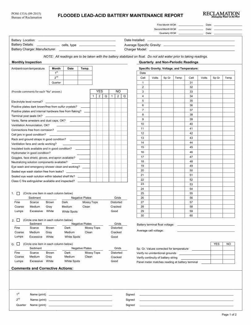
Page 1 of 2
POM-133A (09-2015)Bureau of Reclamation FLOODED LEAD-ACID BATTERY MAINTENANCE REPORT
First Month WO#: Date:
Second MonthWO#: Date:Quarterly WO#: Date:
Battery Location: Date Installed:Battery Details: cells, type Average Specific Gravity: Battery Charger, Manufacturer: Charger Model:
NOTE: All readings are to be taken with the battery stabilized on float. Do not add water prior to taking readings.
Monthly Inspection Quarterly and Non-Periodic Readings
Ambient roomtemperature. Month Date Temp. Specific Gravity, Voltage, and Temperature:1st Date
2nd Cell Volts Sp. Gr. Cell Volts Sp. Gr. Temp.
Quarter 1 312 32
(Provide comments for each “No” answer.) YES NO 3 331 2 Q 1 2 Q 4 34
Electrolyte level normal? 5 356 36Positive plates dark brown/free from sulfur crystals?7 37Positive plates and internal hardware free from flaking?8 38Terminal post seals OK?9 39Vents, flame arresters and dust caps, OK?
10 40Ventilation Annunciation, OK?11 41Connections free from corrosion?12 42Cell jars in good condition?13 43Rack and ground straps in good condition?14 44Ventilation fans and vents working?15 45Insulated tools available and in good condition?16 46Hydrometer in good condition?
Goggles, face shield, gloves, and apron available? 17 47
Neutralizing solution components available? 18 48
Eye wash and emergency shower clean and working? 19 4920 50Sealed eye wash station free from leaks?21 51Sealed eye wash solution within labeled shelf life?22 52Class C fire extinguisher available and inspected?23 5324 54
1. (Circle one item in each column below) 25 55Sediment Negative Plates Grids 26 56
Fine Scarce Brown Dark Mossy Tops Distorted 27 57Coarse Medium Gray Medium Clean Cracked 28 58Lumps Excessive White White Spots Good 29 59
30 60
2. (Circle one item in each column below) Sediment Negative Plates Grids Battery terminal float voltage:
Fine Scarce Brown Dark Mossy Tops DistortedAverage cell voltage:Coarse Medium Gray Medium Clean Cracked
Lumps Excessive White White Spots Good
Q. (Circle one item in each column below) YES NOSediment Negative Plates Grids Sp. Gr. Values corrected for temperature
Fine Scarce Brown Dark Mossy Tops Distorted Verify no unintentional groundsCoarse Medium Gray Medium Clean Cracked Verify continuity of battery stringLumps Excessive White White Spots Good Panel meter matches reading at battery terminal
Comments and Corrective Actions:
1st Name (print) Signed
2nd Name (print) Signed
Quarter Name (print) Signed
Temp.

Page 2 of 2
POM-133A (09-2015)
Bureau of Reclamation
USEFUL EQUATIONS
VTC = [VF +(77 – TCELL) * 0.003] * NC
C = ( ta
) * 100
ts * KT
Where: VTC is equal to the temperature compensated float voltage. Where: C is the percent capacity at 77 °F.
VF is the recommended float voltage at 77 °F. ta is the actual time of test to specified voltage.
TCELL is the average temperature of the battery. ts is the rated time to specified voltage.
NC is the number of cells in the battery.
KT is the correction factor for the cell temperature prior to the start of test.
SP.GR.Corrected = SP.GR.CELL – (77 – TCELL)
C = ( Xa * Kc ) * 100
3000 Xt
Where: SP. GR. Corrected is the temperature compensated SP. GR. Where: C is the percent capacity at 25 ºC.
SP. GR.CELL is the uncorrected SP. GR. of the cell. Xa is the actual rate used for the test
TCELL is the average temperature of the cell. Xt is the published rating time to specified terminal or cell/unit voltage
Kc is the temperature correction factor
(Equation provided separately for form)
Battery Rate Correction Factors
1
Initial Temperature (°F) Temperature Correction
Factor KT Initial Temperature
(°F) Temperature Correction
Factor KT Initial Temperature
(°F) Temperature Correction
Factor KT
40 1.300 72 1.029 84 0.964
45 1.250 73 1.023 85 0.960
50 1.190 74 1.017 86 0.956
55 1.150 75 1.011 87 0.952
60 1.110 76 1.006 88 0.948
65 1.080 77 1.000 89 0.944
66 1.072 78 0.994 90 0.940
67 1.064 79 0.987 95 0.930
68 1.056 80 0.980 100 0.910
69 1.048 81 0.976 105 0.890
70 1.040 82 0.972 110 0.880
71 1.034 83 0.968 115 0.870 1 Values in the table are based on a specific gravity of 1.215.
Battery Temperature Correction Factors
1
Initial Temperature (°F)
Temperature Correction Factor KT
Initial Temperature (°F)
Temperature Correction Factor KT
Initial Temperature (°F)
Temperature Correction Factor KT
40 0.670 72 0.970 84 1.035
45 0.735 73 0.975 85 1.040
50 0.790 74 0.980 86 1.045
55 0.840 75 0.985 87 1.050
60 0.882 76 0.990 88 1.055
65 0.920 77 1.000 89 1.060
66 0.927 78 1.002 90 1.065
67 0.935 79 1.007 95 1.090
68 0.942 80 1.011 100 1.112
69 0.948 81 1.017 105 1.140
70 0.955 82 1.023 110 1.162
71 0.960 83 1.030 115 1.187 1 Values in the table are based on a specific gravity of 1.215.

Page 1 of 2
POM-133B (09-2015)
Bureau of Reclamation VALVE-REGULATED LEAD-ACID BATTERY MAINTENANCE REPORT
First Month WO#: Date:
Second Month WO#:
Date:
Quarterly WO#:
Date:
Battery Location:
Date Installed:
Battery Details:
cells, type
Average Specific Gravity:
Battery Charger, Manufacturer:
Charger Model:
NOTE: All readings are to be taken with the battery stabilized on float.
Monthly Inspection
Quarterly and Non-Periodic Readings
Ambient room temperature. Month Date Temp. Voltage, Internal Resistance, and Temperature:
1st Date
2nd
Cell Volts Int. Res Temp. Cell Volts Int. Res Temp.
Quarter 1 31
2 32
(Provide comments for each “No” answer.) YES NO 3 33
1 2 Q 1 2 Q 4 34
Connections free from corrosion? 5 35
6 36 Cell jars in good condition?
7 37 Rack and ground straps in good condition?
8 38 Ventilation fans and vents working?
9 39 Ventilation Annunciation, OK?
10 40 Insulated tools available and in good condition?
11 41 Goggles, face shield, gloves, and apron available?
12 42 Neutralizing solution components available?
13 43 Eye wash and emergency shower clean and working?
14 44 Class C fire extinguisher available and inspected?
15 45 Sealed eye wash station free from leaks?
16 46
Sealed eye wash solution within labeled shelf life?
17 47
Manufacturer’s Acceptable Ranges 18 48
19 49
Cell float voltage: 20 50
Battery string float voltage: 21 51
Connection resistance:
22 52
Internal resistance: 23 53
Cell temperature: 24 54
Ambient temperature: 25 55
Corrective Actions: 26 56
27 57
28 58
29 59
30 60
Battery terminal float voltage:
Average cell voltage:
YES NO
Verify no unintentional grounds:
Verify continuity of battery string:
Panel meter matches reading at battery terminal:
Comments:
1
st Name (print)
Signed
2nd
Name (print) Signed
Quarter Name (print) Signed

Page 2 of 2
POM-133B (09-2015)
Bureau of Reclamation
USEFUL EQUATIONS
C = (
ta ) * 100
C = ( Xa * Kc
) * 100
ts * KT Xt
Where: C is the percent capacity at 77 °F. Where: C is the % capacity at 25 °C
ta is the actual time of test to specified voltage. Xa is the actual rate used for the test
ts is the rated time to specified voltage.
Xt is the published rating for time to specified terminal or
KT is the correction factor, found in Table 3, for
cell/unit voltage
the cell temperature prior to the start of test.
Kc is the temperature correction factor
Table 2. Battery Rate Correction Factors1
InitialTemperature (°F) Temperature Correction
Factor KT Initial Temperature
(°F) Temperature Correction
Factor KT Initial Temperature
(°F) Temperature Correction
Factor KT
40 1.300 72 1.029 84 0.964
45 1.250 73 1.023 85 0.960
50 1.190 74 1.017 86 0.956
55 1.150 75 1.011 87 0.952
60 1.110 76 1.006 88 0.948
65 1.080 77 1.000 89 0.944
66 1.072 78 0.994 90 0.940
67 1.064 79 0.987 95 0.930
68 1.056 80 0.980 100 0.910
69 1.048 81 0.976 105 0.890
70 1.040 82 0.972 110 0.880
71 1.034 83 0.968 115 0.870
1 Values in the table are based on a specific gravity of 1.215.
Table 3. BatteryTemperature Correction Factors
1
Initial Temperature (°F)
Temperature Correction Factor KT
Initial Temperature (°F)
Temperature Correction Factor KT
Initial Temperature (°F)
Temperature Correction Factor KT
40 0.670 72 0.970 84 1.035
45 0.735 73 0.975 85 1.040
50 0.790 74 0.980 86 1.045
55 0.840 75 0.985 87 1.050
60 0.882 76 0.990 88 1.055
65 0.920 77 1.000 89 1.060
66 0.927 78 1.002 90 1.065
67 0.935 79 1.007 95 1.090
68 0.942 80 1.011 100 1.112
69 0.948 81 1.017 105 1.140
70 0.955 82 1.023 110 1.162
71 0.960 83 1.030 115 1.187
1 Values in the table are based on a specific gravity of 1.215.

POM-133C (09-2015)
Bureau of Reclamation NICKEL CADMIUM BATTERY MAINTENANCE REPORT First Month WO#: Date:
Second Month WO#: Date:
Quarterly WO#: Date:
Battery Location: Date installed:
Battery Details: cells, type Average Specific Gravity:
Battery Charges, Manufacturer: Charger Model:
NOTE: all readings are to be taken with the battery stabilized on float.
Monthly Inspection Quantity and Non-Periodic Readings
Ambient room temperature. Month Date Temp. Voltage:
1st Date
2nd Cell Volts Cell Volts Cell Volts Cell Volts
Quarter 1 31 61 91
2 32 62 92
YES NO
3 33 63 93
(Provide comments for each “No” answer.)
1 2 Q 1 2 Q
4 34 64 94
5 35 65 95
Electrolyte level normal?
6 36 66 96
Oil depth in cells about ¼”?
7 37 67 97
Terminal posts seals OK?
8 38 68 98
Vents, flame arrestors, and dust caps OK?
9 39 69 99
Connections free from corrosion?
10 40 70 100
Cell jars in good condition?
11 41 71 101
Rack and ground straps in good condition?
12 42 72 102
Ventilation fans and vents working?
13 43 73 103
Ventilation Annunciation, OK?
14 44 74 104
Insulated tools available and in good condition?
15 45 75 105
Hydrometer in good condition?
16 46 76 106
Goggles, face shield, gloves, and apron available?
17 47 77 107
Minimum labeled 1-gallon boric acid available?
18 48 78 108
Eye wash and emergency shower clean and available?
19 49 79 109
Class C fire extinguisher available and inspected?
20 50 80 110
Sealed eye wash station free from leaks?
21 51 81 111
Sealed eye wash solution within labeled shelf life?
22 52 82 112
23 53 83 113
Manufacturer’s Acceptable Ranges:
24 54 84 114
25 55 85 115
26 56 86 116
Cell float voltage:
27 57 87 117
Battery string float voltage:
28 58 88 118
Connection resistance:
29 59 89 119
Cell temperature:
30 60 90 120
Ambient temperature:
Battery terminal float voltage:
Corrective Actions:
Average Cell voltage:
Water addition to: (circle cell numbers at right) YES NO
Date: Quantity added (total) Verify no unintentional grounds
Equalizing charge, why given: Verify continuity of battery string
Date: Voltage: Duration: Panel meter matches reading at battery terminals
Date: Voltage: Duration:
Comments:
USEFUL EQUATIONS:
Percent Capacity = Actual Time
X 100 Rated Time
1st
Name (print) Signed
2nd
Name (print) Signed
Quarter Name (print) Signed

Page 2 of 2
POM-133C (12-14)
Bureau of Reclamation
USEFUL EQUATIONS
SP.GR.Corrected = SP.GR.CELL – (77 – TCELL)
3000
Where:
SP. GR.Corrected
SP. GR.Cell is the uncorrected SP. GR. of the cell.
TCELL is the average temperature of the cell.
Percent Capacity = Actual Time X 100
Rated Time

POM-134A (12-2014)
Bureau of Reclamation
FLOODED BATTERY CONNECTION RESISTANCE ANNUAL REPORT
Date: Battery Location: Battery Type:
Note: Take the first reading between the connector (lug) and the cell post, then take readings between adjacent opposite-polarity cell posts. (Caution: not across a cell). Take the last reading between the last post and the connector lug.
Meter Probes Between
Basis Micro-Ohms
As-found Micro-ohms
As-Left Micro-ohms
Meter Probes Between
Basis Micro-Ohms
As-found Micro-ohms
As-Left Micro-ohms
Lug & No. 1 post Posts/cells 30-31 Posts/cells 1-2 Posts/cells 31-32 Posts/cells 2-3 Posts/cells 32-33 Posts/cells 3-4 Posts/cells 33-34
Posts/cells 4-5 Posts/cells 34-35 Posts/cells 5-6 Posts/cells 35-36 Posts/cells 6-7 Posts/cells 36-37 Posts/cells 7-8 Posts/cells 37-38 Posts/cells 8-9 Posts/cells 38-39 Posts/cells 9-10 Posts/cells 39-40 Posts/cells 10-11 Posts/cells 40-41 Posts/cells 11-12 Posts/cells 41-42 Posts/cells 12-13 Posts/cells 42-43 Posts/cells 13-14 Posts/cells 43-44 Posts/cells 14-15 Posts/cells 44-45 Posts/cells 15-16 Posts/cells 45-46 Posts/cells 16-17 Posts/cells 46-47 Posts/cells 17-18 Posts/cells 47-48 Posts/cells 18-19 Posts/cells 48-49 Posts/cells 19-20 Posts/cells 49-50 Posts/cells 20-21 Posts/cells 50-51 Posts/cells 21-22 Posts/cells 51-52
Posts/cells 22-23 Posts/cells 52-53 Posts/cells 23-24 Posts/cells 53-54 Posts/cells 24-25 Posts/cells 54-55 Posts/cells 25-26 Posts/cells 55-56 Posts/cells 26-27 Posts/cells 56-57 Posts/cells 27-28 Posts/cells 57-58 Posts/cells 28-29 Posts/cells 58-59 Posts/cells 29-30 Posts/cells 59-60
No. 60 post & lug
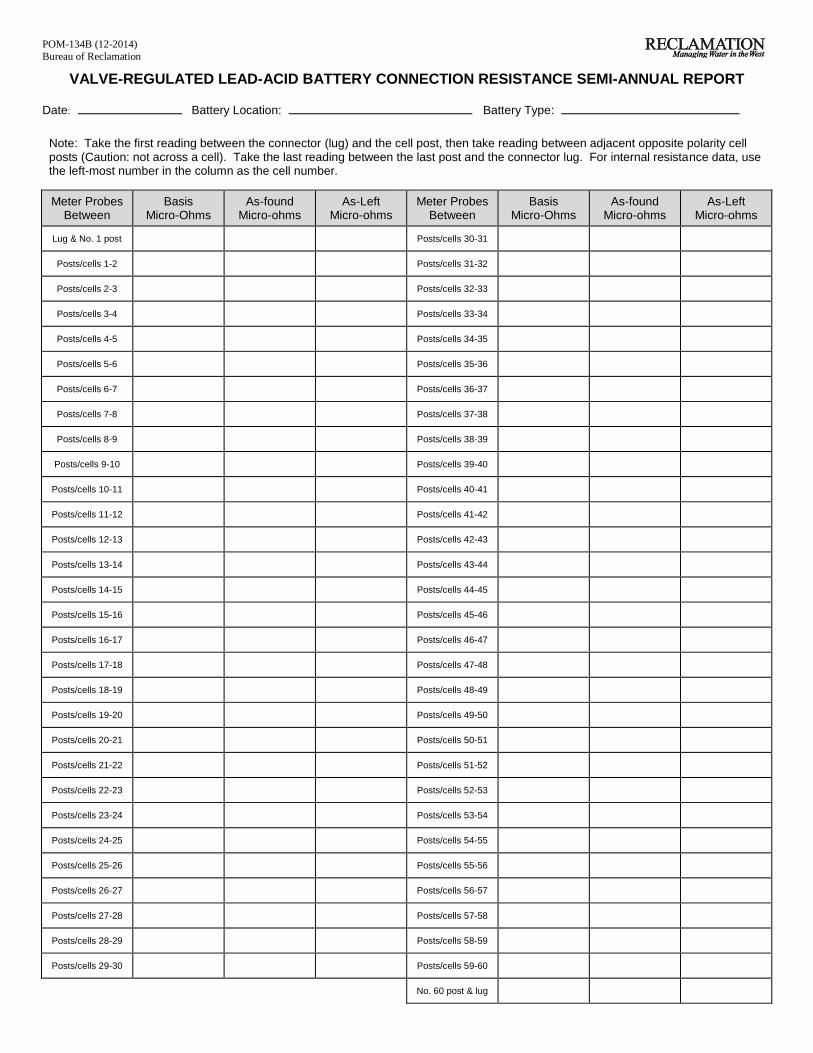
POM-134B (12-2014)
Bureau of Reclamation
VALVE-REGULATED LEAD-ACID BATTERY CONNECTION RESISTANCE SEMI-ANNUAL REPORT
Date: Battery Location: Battery Type:
Note: Take the first reading between the connector (lug) and the cell post, then take reading between adjacent opposite polarity cell posts (Caution: not across a cell). Take the last reading between the last post and the connector lug. For internal resistance data, use the left-most number in the column as the cell number.
Meter Probes Between
Basis Micro-Ohms
As-found Micro-ohms
As-Left Micro-ohms
Meter Probes Between
Basis Micro-Ohms
As-found Micro-ohms
As-Left Micro-ohms
Lug & No. 1 post Posts/cells 30-31 Posts/cells 1-2 Posts/cells 31-32 Posts/cells 2-3 Posts/cells 32-33 Posts/cells 3-4 Posts/cells 33-34
Posts/cells 4-5 Posts/cells 34-35 Posts/cells 5-6 Posts/cells 35-36 Posts/cells 6-7 Posts/cells 36-37 Posts/cells 7-8 Posts/cells 37-38 Posts/cells 8-9 Posts/cells 38-39 Posts/cells 9-10 Posts/cells 39-40 Posts/cells 10-11 Posts/cells 40-41 Posts/cells 11-12 Posts/cells 41-42 Posts/cells 12-13 Posts/cells 42-43 Posts/cells 13-14 Posts/cells 43-44 Posts/cells 14-15 Posts/cells 44-45 Posts/cells 15-16 Posts/cells 45-46 Posts/cells 16-17 Posts/cells 46-47 Posts/cells 17-18 Posts/cells 47-48 Posts/cells 18-19 Posts/cells 48-49 Posts/cells 19-20 Posts/cells 49-50 Posts/cells 20-21 Posts/cells 50-51
Posts/cells 21-22 Posts/cells 51-52 Posts/cells 22-23 Posts/cells 52-53 Posts/cells 23-24 Posts/cells 53-54 Posts/cells 24-25 Posts/cells 54-55 Posts/cells 25-26 Posts/cells 55-56 Posts/cells 26-27 Posts/cells 56-57 Posts/cells 27-28 Posts/cells 57-58 Posts/cells 28-29 Posts/cells 58-59 Posts/cells 29-30 Posts/cells 59-60
No. 60 post & lug

POM-134C (12-2014)
Bureau of Reclamation
NICKEL-CADMIUM BATTERY CONNECTION RESISTANCE ANNUAL REPORT
Date:
Battery Location:
Battery Type:
Note: Take the first reading between the connector (lug) and the cell post, then take readings between adjacent opposite polarity cell posts (Caution: not across a cell). Take the last reading between the last post and the connector lug.
Meter Probes Between
Basis Micro-Ohms
As-found Micro-Ohms
As-Left Micro-Ohms
Temp Meter Probes
Between
Basis Micro-Ohms
As-found Micro-Ohms
As-Left Micro-Ohms
Temp
Lug & No. 1 post Posts/cells 47-48
Posts/cells 1-2 Posts/cells 48-49
Posts/cells 2-3 Posts/cells 49-50
Posts/cells 3-4 Posts/cells 50-51
Posts/cells 4-5 Posts/cells 51-52
Posts/cells 5-6 Posts/cells 52-53
Posts/cells 6-7 Posts/cells 53-54
Posts/cells 7-8 Posts/cells 54-55
Posts/cells 8-9 Posts/cells 55-56
Posts/cells 9-10 Posts/cells 56-57
Posts/cells 10-11 Posts/cells 57-58
Posts/cells 11-12 Posts/cells 58-59
Posts/cells 12-13 Posts/cells 59-60
Posts/cells 13-14 Posts/cells 60-61
Posts/cells 14-15 Posts/cells 61-62
Posts/cells 15-16 Posts/cells 62-63
Posts/cells 16-17 Posts/cells 63-64
Posts/cells 17-18 Posts/cells 64-65
Posts/cells 18-19 Posts/cells 65-66
Posts/cells 19-20 Posts/cells 66-67
Posts/cells 20-21 Posts/cells 67-68
Posts/cells 21-22 Posts/cells 68-69
Posts/cells 22-23 Posts/cells 69-70
Posts/cells 23-24 Posts/cells 70-71
Posts/cells 24-25 Posts/cells 71-72
Posts/cells 25-26 Posts/cells 72-73
Posts/cells 26-27 Posts/cells 73-74
Posts/cells 27-28 Posts/cells 74-75
Posts/cells 28-29 Posts/cells 75-76
Posts/cells 29-30 Posts/cells 76-77
Posts/cells 30-31 Posts/cells 77-78
Posts/cells 31-32 Posts/cells 78-79
Posts/cells 32-33 Posts/cells 79-80
Posts/cells 33-34 Posts/cells 80-81
Posts/cells 34-35 Posts/cells 81-82
Posts/cells 35-36 Posts/cells 82-83
Posts/cells 36-37 Posts/cells 83-84
Posts/cells 37-38 Posts/cells 84-85
Posts/cells 38-39 Posts/cells 85-86
Posts/cells 39-40 Posts/cells 86-87
Posts/cells 40-41 Posts/cells 87-88
Posts/cells 41-42 Posts/cells 88-89
Posts/cells 42-43 Posts/cells 89-90
Posts/cells 43-44 Posts/cells 90-91
Posts/cells 44-45 Posts/cells 91-92
Posts/cells 45-46 Posts/cells 92-93
Posts/cells 46-47 Posts/cells 93-94
No. post & lug

POM-157 (12-2014)
Bureau of Reclamation
BATTERY DATA
VENTED LEAD-ACID STORAGE BATTERY
PROJECT FEATURE
IN SERVICE DATE MANUFACTURER
MODEL NUMBER
RATED CAPACITY (AMPERE HOURS)
TYPE: PLANTE -- LEAD-ANTIMONY -- LEAD-CALCIUM -- OTHER
(SPECIFY)
NUMBER OF CELLS
NOMINAL SPECIFIC GRAVITY AT 77 ºF
NORMAL TERMINAL FLOATING VOLTAGE AT 77 ºF
NORMAL CELL FLOATING VOLTAGE AT 77 ºF
EQUALIZING VOLTAGE AND TIME
REQUIRED AIRFLOW
REPLACEMENT WATER – USE DISTILLED ONLY

POM-158 (12-2014)
Bureau of Reclamation
BATTERY DATA
VALVE-REGULATED LEAD-ACID STORAGE BATTERY
PROJECT FEATURE
IN SERVICE DATE MANUFACTURER
MODEL NUMBER
RATED CAPACITY (AMPERE HOURS)
NUMBER OF CELLS
NORMAL TERMINAL FLOATING VOLTAGE AT 77 ºF
NORMAL CELL FLOATING VOLTAGE AT 77 ºF
REQUIRED AIRFLOW

POM-159 (09-2015)
Bureau of Reclamation
BATTERY DATA
NICKEL-CADMIUM STORAGE BATTERY
PROJECT FEATURE
IN SERVICE DATE MANUFACTURER
MODEL NUMBER
RATED CAPACITY (AMPERE HOURS)
NUMBER OF CELLS
NOMINAL SPECIFIC GRAVITY AT 77 ºF
NORMAL TERMINAL FLOATING VOLTAGE AT 77 ºF
NORMAL CELL FLOATING VOLTAGE AT 77 ºF
EQUALIZING VOLTAGE AND TIME
REQUIRED AIRFLOW
SULFURIC ACID WILL DAMAGE THIS BATTERY