STORAGE AREA NETWORK MODULE 1 STORAGE SYSTEM -...
52
STORAGE AREA NETWORK MODULE 1 STORAGE SYSTEM
Transcript of STORAGE AREA NETWORK MODULE 1 STORAGE SYSTEM -...

STORAGE AREA NETWORK
MODULE 1
STORAGE SYSTEM

STORAGE SYSTEM
Introduction to evolution of storage architecture
Key data center elements
Virtualization
Cloud computing
RAID implementation,
techniques

STORAGE AREA NETWORK:
It is a dedicated high speed network or sub network that interconnects and presents
shared pools of storage devices to multiple servers.
SANs are typically composed of hosts, switches, storage element and storage devices
that are interconnected using a variety of technologies, topologies and protocols.
STORAGE MODELS:
DAS (Direct attached storage)
NAS (Network attached Storage)
SAN (Storage area network)
DIRECT ATTACHED STORAGE:
Storage that is directly attached to a computer or a server.
Example: Internal hard drive in a laptop or desktop.
Benefits of DAS are simplicity or low cost.
We can add more direct attached storage to a laptop or desktop, we can attach a plug-
and-play external hard drive.

BENEFITS OF DAS:
Ideal for local data provisioning
Quick deployment for small environments
Simple to deploy in simple configurations
Reliability
Low capital expense
Low complexity
DISADVANTAGE OF DAS:
The storage device was directly attached to each individual server and was not shared,
thus resource utilization was not proper.
PHYSICAL ELEMENTS OF DAS:
Fig: Motherboard

Fig: Hard drive
NETWORK ATTACHED STORAGE:
File- level data access
Computer data storage server
Connected to a computer network
Providing data
FEATURES OF NAS:
File level data access.
Dedicated and High Performance.
High speed.
Single purpose file serving and storage system.
Support multiple interfaces and networks.
Cross platform support.
Centralized storage and many more..
DISADVANTAGES OF NAS:
It increases load on LAN
Slow to access
STORAGE AREA NETWORK:
Automatic backup
High data storage capacity
Reduce cost of multiple servers
Increase performance
Data sharing
Improved backup and recovery

DISADVANTAGES OF SAN:
It is very expensive
Require high level technical person
Hard to maintain
Not affordable for small business
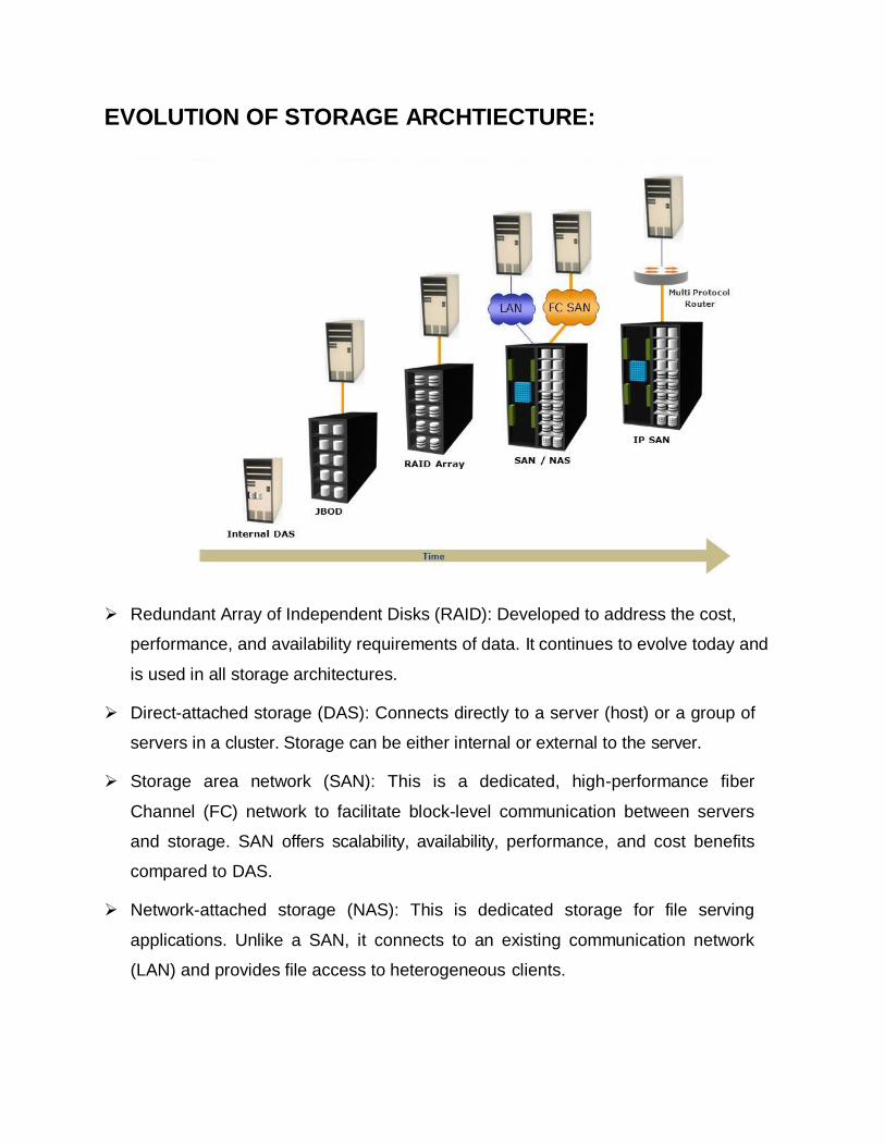
EVOLUTION OF STORAGE ARCHTIECTURE:
Redundant Array of Independent Disks (RAID): Developed to address the cost,
performance, and availability requirements of data. It continues to evolve today and
is used in all storage architectures.
Direct-attached storage (DAS): Connects directly to a server (host) or a group of
servers in a cluster. Storage can be either internal or external to the server.
Storage area network (SAN): This is a dedicated, high-performance fiber
Channel (FC) network to facilitate block-level communication between servers
and storage. SAN offers scalability, availability, performance, and cost benefits
compared to DAS.
Network-attached storage (NAS): This is dedicated storage for file serving
applications. Unlike a SAN, it connects to an existing communication network
(LAN) and provides file access to heterogeneous clients.

Internet Protocol SAN (IP-SAN): One of the latest evolutions in storage
architecture, IP-SAN provides block-level communication across (LAN or WAN)
resulting in greater consolidation and availability of data.
KEY REQUIREMENTS OF DATA CENTER ELEMENTS:
Availability: ensure accessibility.
Capacity: Data center operations require adequate resources to store and
process large amounts of data efficiently.
Security: Polices, procedures and proper integration of the data center core
elements prevent unauthorized access to information must be established.
Data integrity: ensure that data written to disk exactly as it was
received.
Performance: services all processing requests at very high speed.
Scalability: should be able to allocate additional storage on demand.
Manageability.

KEY DATA CENTER ELEMENTS:
Applications: An application is a computer program that provides the logic
for computing operations.
Database: DBMS provides a structured way to store data in logically
organized tables that are inter-related.
Server and OS: A computing platform that runs applications and database.
Network: A data path that facilitates communication between servers and storage.
Storage array: A device that stores data persistently for subsequent use.
EXAMPLE OF AN ORDER PROCESSING SYSTEM:
A customer places an order through the AUI of the order processing application
software located on the client computer.
The client connects to the server over the LAN and accesses the DBMS located on
the server to update the relevant information such as the customer name, address,
payment method, products ordered and quantity ordered.
The DBMS uses the server operating system to read and write this data to the
database located on physical disks in the storage array.

The Storage Network provides the communication link between the server and the
storage array and transports the read or write commands between them.
The storage array, after receiving the read or write commands from the server, performs
the necessary operations to store the data on physical disks.
COMPONENTS OF A STORAGE SYSTEM ENVIRONMENT:
HOST:
Applications run on hosts
Hosts can range from simple laptops to complex server clusters
Physical components of host.
CPU
Storage
Disk device and internal memory.
I/O device
Host to host communications
Network Interface Card (NIC)
Host to storage device communications
Host Bus Adapter (HBA)
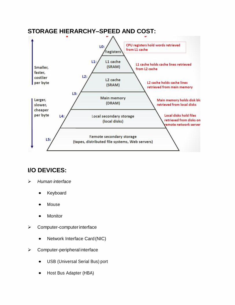
STORAGE HIERARCHY – SPEED AND COST:
I/O DEVICES:
Human interface
Keyboard
Mouse
Monitor
Computer-computer interface
Network Interface Card (NIC)
Computer-peripheral interface
USB (Universal Serial Bus) port
Host Bus Adapter (HBA)

LOGICAL COMPONENTS OF A HOST:
Application
Interface between user and the host
Three-tiered architecture
Application UI, computing logic and underlying databases
Application data access can be classifies as:
Block-level access: Data stored and retrieved in blocks, specifying
o the LBA(logical block addressing)
File-level access: Data stored and retrieved by specifying the name
o and path of files
Operating system
Resides between the applications and the hardware
Controls the environment
Monitors and responds to user action and environment.

Device Drivers
Enables operating system to recognize t h e
device(printer, a mouse or a hard drive)
Provides API to access and control devices
Hardware dependent and operating system specific
File System
File is a collection of related records or data stored a s a unit
File system is hierarchical structure of files
Examples: FAT 32, NTFS, UNIX FS and EXT2/3.
VOLUME MANAGER:
Responsible for creating and controlling host level logical storage
Physical view of storage is converted to a logical view by mapping
Logical data blocks are mapped to physical data blocks

Usually offered as a part of the operating system or as a third party host software
LVM Components:
Physical Volumes
Volume Groups
Logical Volumes
VOLUME GROUPS:
LVM manages Volume Groups as a single entity
Physical Volumes can be added and removed from a Volume Group as necessary
Physical Volumes are typically divided into contiguous equal- sized disk blocks
Application and Operating System data maintained in separate volume groups
CONNECTIVITY:
Interconnection between hosts or between a host and any other peripheral devices,
such as printers or storage devices
Physical Components of Connectivity between host and storage are:
Bus, port and cable
Bus: Collection of paths that facilitates data transmission from one part of a
computer to another such as from the cpu to the memory.
Port: specialized outlet that enables connectivity between the host and externaldevices.
Cables: connect host to internal or external devices using copper or fiber
optic media.
Physical components communicate across a bus by sending bits of data b/w
devices.
Cable

Bits are transmitted through the bus in either of the following ways:
1. serially: bits are transmitted sequentially along a single path. This
transmission can be unidirectional or bidirectional.
2. In parallel: bits are transmitted along multiple paths simultaneously. Parallel
can also be bidirectional.
Data transfer on the computer system can be classified as follows
1. system bus
2. local or i/o bus
BUS TECHNOLOGY:
System Bus – connects CPU to Memory
Local (I/O) Bus – carries data to/from peripheral devices
Bus width measured in bits
Bus speed measured in MHz
POPULAR CONNECTIVITY OPTIONS: (PCI)
It is an interconnection between CPU and attached devices
Has Plug and Play functionality
PCI is 32/64 bit
Throughput is 133 MB/sec
PCI Express

Enhanced version of PCI bus with higher throughput a n d clock speed
V1: 250MB/s
V2: 500 MB/s
V3: 1 GB/s
POPULAR CONNECTIVITY OPTIONS: (IDE/ATA)
Integrated Device Electronics (IDE) / Advanced Technology
Attachment (ATA)
Most popular interface used with modern hard disks
Good performance at low cost
Inexpensive storage interconnect
Used for internal connectivity
Serial Advanced Technology Attachment (SATA)
Serial version of the IDE /ATA specification
Hot-pluggable(ability to add and remove devices to a computer
system while the computer is running and have os automatically recognize
the change.
Enhanced version of bus provides up to 6Gb/s (revision 3.0).
POPULAR CONNECTIVITY OPTIONS: SCSI
Parallel SCSI (Small computer system interface)
Most popular hard disk interface for servers
Supports Plug and Play
Higher cost than IDE/ATA
Supports multiple simultaneous data access
Used primarily in “higher end” environments
SCSI Ultra provides data transfer speeds of 320 MB/s
Serial SCSI
Supports data transfer rate of 3 Gb/s (SAS 300)
SCSI-SMALL COMPUTER SYSTEM INTERFACE:
Most popular hard disk interface for servers
Higher cost than IDE/ATA
Supports multiple simultaneous data access
Currently both parallel and serial forms
Used primarily in “higher end” environments
STORAGE:
A storage device uses magnetic or solid state media
Disks, tapes and diskettes uses magnetic media
CD-ROM is an example of a optical media
Removable flash memory card is a example of solid state media.
Tape is are used for backup because of their relatively low cost.
Tape has the following limitations:
Random data access is slow and time consuming.
Data stored on tape cannot be accessed by multiple applications simultaneously.

OPTICAL DISK STORAGE:
Used by individuals to store photos or as backup medium on personal computer.
It have limited capacity and speed, which limits the use of optical media as a business
data storage solution.
The capability to write once and read many is one advantage of optical disk storage.
A CD-ROM is an example.
Disk drives are the most popular storage medium used in modern computers
where data can be written or retrieved quickly for a large no of simultaneous users
or application.
RAID:
Redundant array of independent disks.
A system for providing greater capacity, faster access, and security against data
corruption by spreading data across several disk drives.
Way of storing the same data in different places on multiple hard disks to protect data
in the case of a drive failure.
RAID was first defined by David Patterson in1987.
RAID array components
RAID levels
RAID implementation.

WHY RAID:
Performance limitation of disk drive
An individual drive has a certain life expectancy
Measured in MTBF (Mean Time Between Failure)
The more the number of HDDs in a storage array, the larger the probability
for disk failure. For example:
If the MTBF of a drive is 750,000 hours, and there are
100 drives in the array, then the MTBF of the array becomes
750,000 / 100, or 7,500 hours.
RAID was introduced to mitigate this problem.
RAID provides: Increase capacity, Higher availability, Increased performance.
RAID ARRAY COMPONENTS:

DATA ORGANIZATION: STRIPPING
STRIPING:
A RAID set is a group of disks.
Within each disk, a predefined number of contiguously addressable disk blocks are
defined as strips.
The set of aligned strips that spans across all the disks within the RAID set is called a
stripe.
Stripe size describes the no of blocks in a strip.
Striped RAID does not protect data unless parity or mirroring is used.
Striping means that each file is split into blocks of a certain size and those are
distributed to the various drives.
Increase performance.
Not fault tolerant

MIRRORING:
Mirroring is a technique whereby data is stored on two different HDDs,
yielding two copies of data.
In the event of one disk failure, the data is intact on the surviving HDD and the
controller continues to service the hosts data requests from the surviving disk of a
mirrored pair.
When the failed disk is replaced with a new disk, the controller copies the data from the
surviving disk of the mirrored pair.
Mirroring gives good error recovery- if data is lost, get it from the other source.
Mirroring involves duplication of data, so storage capacity needed is twice the
amount of data being stored. It is considered expensive.

ADVANTAGES AND DISADVANTAGES OF MIRRORING:
ADVANTAGES:
Data do not have to be rebuild.
Primary importance for fault tolerance.
DISADVANTAGE:
Storage capacity is only half of the total disk capacity.
PARITY:
It is a method of protecting striped data from HDD failure without the cost of
mirroring.
An additional HDD is added to the stripe width to hold parity, a mathematical
construct that allows re-creation of the missing data.
It is a redundancy check that ensure full protection of data without maintaining a full set
of duplication data.
Parity information can b be stored on separate dedicated HDDs.

The first 3 disks, contain the data. The 4th
disk stores the parity information(sum of
elements in each row).
Now if one of the disk fails the missing value can be calculated by subtracting the
sum of the rest of the elements from the parity value.
The computation of parity is represented as a simple arithmetic operation on the data.
Calculation of parity is a function of the RAID controller.
It reduces the cost associated with data protection.
Parity requires 25% extra disk space.
Parity information is generated from data on the data disk. Therefore parity is recalculated
every time there is a change in data. This recalculation is time consuming and affects
the performance of the RAID controller.

RAID LEVELS:
RAID level 0
RAID level 1
RAID level 10
RAID level 2
RAID level 3
RAID level 4
RAID level 5
KEY TERMS:
Fault tolerance: Fault tolerance is the property that enables a system to continue
operating properly in the event of the failure of (or one or more faults within) some of its
components.
Throughput: Throughput refers to how much data can be transferred from one
location to another in a given amount of time. It is used to measure the performance of
hard d drives and RAM.
Redundancy : Redundancy is a system design in which a component is duplicated
so if it fails there will be a backup.

RAID 0:
RAID 0 offers no additional fault tolerance or redundancy but is intended to
increase the throughput of the drives.
The data is saved to the disks using striping, with no mirroring or parity, distributing
all data evenly throughout the disks.
Striping means that each file is into blocks of certain size and those are distributed to
various drives.
Increases performance.
It increases speed because multiple data request probably not on the
same disk.
The failure of just one drive results in all the data in an array being
lost.
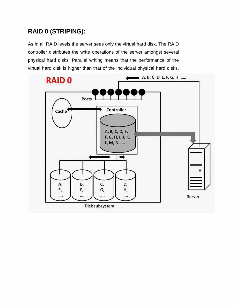
RAID 0 (STRIPING):
As in all RAID levels the server sees only the virtual hard disk. The RAID
controller distributes the write operations of the server amongst several
physical hard disks. Parallel writing means that the performance of the
virtual hard disk is higher than that of the individual physical hard disks.
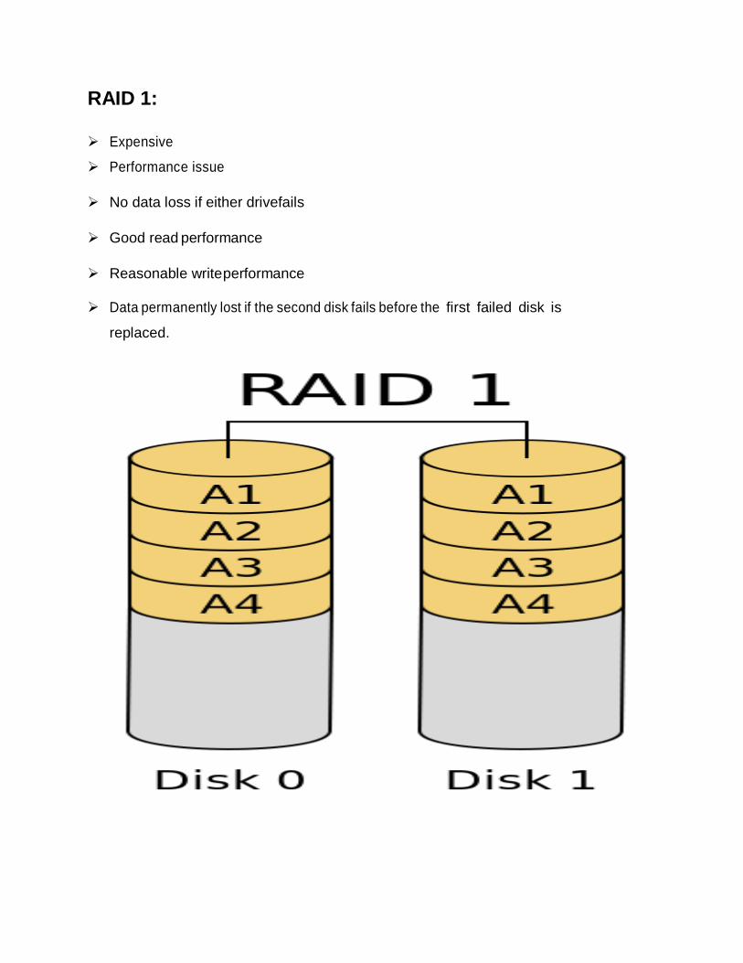
RAID 1:
Expensive
Performance issue
No data loss if either drive fails
Good read performance
Reasonable write performance
Data permanently lost if the second disk fails before the first failed disk is
replaced.

RAID 1 (MIRRORING):
The RAID controller duplicates each of the servers write operations on to
two physical hard disks. After the failure of one physical hard disk(if that
were to happen), the data can still be read from other disk.
ADVANTAGES:
Data do not have to be rebuild.
Primary importance for fault tolerance.
DISADVANTAGE:
Storage capacity is only half of the total disk capacity.

RAID 0+1 / RAID 10:
It represents two stage virtualization.
RAID 10 represents striped mirrors.
RAID (0+1) represents mirrored stripes.
Combines the idea of RAID 0 and RAID
In RAID 0+1 the failure of a physical hard disk is thus equivalent to the effective
failure of four physical hard disks. Data is lost. The restoration of data from the failed
disk is expensive.
In principle it is sometimes possible to reconstruct the data from the remaining disks, but
the RAID controllers available on the market cannot do this particularly well.

In RAID 10, after the failure of an individual physical hard disk, the additional failure of a
further physical hard disk with the exception of the corresponding mirror- can be
withstood.
RAID 10 thus has a significantly higher fault tolerance than RAID 0+1.
In RAID 10 only one physical hard drive has to be recreated. In 0+1 a virtual hard disk must
be recreated that is made up of 4 physical disks.

RAID 2:
All disks participate in the execution of every I/O request.
Data striping is used.
It stripes data at the bit level and uses hamming code for error correction.
Error correcting code is also calculated and stored with the data.
All hard disks eventually implemented hamming code error correction. This made
RAID 2 error correction redundant and unnecessarily complex.
Not implemented in practice due to high c costs and overhead.

RAID 3:
This uses byte level striping, i.e instead of striping the blocks across the disks, it
stripes the bytes across the disks.
In the below diagram B1, B2, B3 are bytes. p1, p2, p3 are parities.
Uses multiple data disks, and a dedicated disk to store parity.
Sequential read and write will have good performance.
Random read and write will have worst performance.
This is not commonly used.

RAID 4:
The idea is to replace all mirror disks of RAID 10 with a parity hard disk.
This uses block level striping.
In the below diagram B1, B2, B3 are blocks. p1, p2, p3 are parities.
Uses multiple data disks, and a dedicated disk to store parity.
Minimum of 3 disks (2 disks for data and 1 for parity)
Good random reads, as the data blocks are striped.
Bad random writes, as for every write, it has to write to the single parity disk.
It is some what similar to RAID 3 and 5, but a little different.
This is just like RAID 3 in having the dedicated parity disk, but this stripes blocks.
This is just like RAID 5 in striping the blocks across the data disks, but this has only
one parity disk.
This is not commonly used.

RAID 5:
It consists of block level striping with distributed parity.
In RAID 4, parity is written to a dedicated drive, creating a write bottleneck for the
parity disk.
In RAID 5, parity is distributed across all disks. The distribution of parity in RAID 5
overcomes the write bottleneck.
RAID 5 is preferred for messaging, data mining, medium-performance media serving and
relational database management system implementations in which database
administrators optimize data access.
Spreads data and parity among all N+1disks, rather than storing data in N disks
and parity in 1 disk.
Optimized for multi thread access.

RAID 6:
RAID 6 uses two parity stripes, the practice of dividing data across the set of hard disks or
SSDs, on each disk. It allows for two disk failures within the RAID set before any data is lost.
In a conventional RAID, data is stored in different places on multiple hard disks, thereby
increasing the aggregate mean time between failures (MTBF) and improving the fault-tolerance.
In the approach known as RAID 4, the number of bits in data blocks on multiple disks is added
up, and the total is kept on a disk called the parity disk. If a drive fails, data recovery is facilitated
by using the bits stored on the parity disk and bits remaining on the surviving drives. In RAID 5,
the parity information is stored diagonally across all the disks in the RAID set. If a single drive
fails, the original data is calculated from the parity information remaining on the surviving disks
in the set.

ADVANTAGES OF RAID:
Raid allows form of backup of the data in the storage.
It is not swappable.
Ensures data reliability, increase in performance.
Increase the parity check.
Disk stripping make multiple smaller disks looks like one large disk.
DISADVANTAGES OF RAID:
It cannot completely protect your data.
System should support RAID drives.
Difficult to configure a RAID system.
Costly, must purchase and maintain RAID controllers and dedicated hard drives.
It may slower the system performance.
RAID is not data protection, but to increase access speed.
APPLICATIONS OF RAID:
Bank
Video streaming
Application server
Photoshop image retouching station

HOT SPARES:
A hot s pares refers to a spare HDD in a RAID array that ttemporarily replaces a failed
HDD of a RAID set.
One of the following methods of data recovery is performed
If parity RAID is used, then the data is rebuilt on to the hot spare from the parity and
the data on surviving HDDs in the RAID set.
If mirroring is used, then the data from the surviving mirror is used to copy the data.
When failed HDD is replaced with a new HDD, one of the following takes place:
The hot spare replaces the new HDD permanently.
When a new HDD is added to the system, data from the hot
spare is copied to it. The hot spare returns to it s idle state, ready
to replace the next failed drive.
INTELLIGENT STORAGE SYSTEM:
Business-critical applications require high levels of performance, availability, security
and scalability. A hard disk drive is a core element of storage that governs the
performance of any storage system. Some of the older disk array technologies could
not overcome performance constraints due to the limitations of a hard disk and its
mechanical components. RAID technology made an important contribution to
enhancing storage performance and reliability, but hard disk drives even with a RAID
implementation could not meet performance requirements of today’s applications.
With advancements in technology, a new breed of storage solutions known as an
intelligent storage system has evolved. The intelligent storage systems detailed in this
chapter are the feature-rich RAID arrays that provide highly optimized I/O processing
capabilities.

These arrays have an operating environment that controls the management,
allocation, and utilization of storage resources. These storage systems are configured
with large amounts of memory called cache and use sophisticated algorithms to meet
the I/O requirements of performance- sensitive applications.
COMPONENTS OF INTELLIGENT STORAGE SYSTEM:
An intelligent storage system consists of four key components: front end,
cache, back end, and physical disks. The below figure illustrates these
components and their interconnections. An I/O request received from the
host at the front-end port is processed through cache and the back end, to
enable storage and retrieval of data from the physical disk. A read request
can be serviced directly from cache if the requested data is found in cache.
I ntelligent Storage System
Controllers
Figure: Components of an intelligent storage system
Front-End Back-End P hysical Disks
Host
Connectivity Cache
Storage
N etw ork
P ort P ort

FRONT END:
The front end provides the interface between the storage system and the
host. It consists of two components: front-end ports and front-end
controllers. The front-end ports enable hosts to connect to the intelligent
storage system. Each front-end port has processing logic that executes the
appropriate transport pro- tocol, such as SCSI, Fibre Channel, or iSCSI, for
storage connections. Redundant ports are provided on the front end for
high availability.
Front-end controllers route data to and from cache via the internal data
bus. When cache receives write data, the controller sends an
acknowledgment message back to the host. Controllers optimize I/O
processing by using command queuing algorithms.
FRONT-END COMMAND QUEUING:
Command queuing is a technique implemented on front-end controllers. It
determines the execution order of received commands and can reduce
unnecessary drive head movements and improve disk performance. When a
command is received for execution, the command queuing algorithms assigns a
tag that defines a sequence in which commands should be executed. With
command queuing, multiple commands can be executed concurrently based on
the organization of data on the disk, regardless of the order in which the
commands were received.
The most commonly used command queuing algorithms are as follows:
First In First Out (FIFO): This is the default algorithm where commands
are executed in the order in which they are received (Figure 4-2 [a]).
There is no reordering of requests for optimization; therefore, it is
inefficient in terms of performance.
Seek Time Optimization: Commands are executed based on optimizing
read/write head movements, which may result in reordering of commands.
Without seek time optimization, the commands are executed in the order

they are received. For example, as shown in Figure 4-2(a), the commands
are executed in the order A, B, C and D. The radial movement required by
the head to execute C immediately after A is less than what would be
required to execute B. With seek time optimization, the command
execution sequence would be A, C, B and D.
CACHE:
Cache is an important component that enhances the I/O performance in an
intelligent storage system. Cache is semiconductor memory where data is
placed temporarily to reduce the time required to service I/O requests from
the host. Cache improves storage system performance by isolating hosts
from the mechanical delays associated with physical disks, which are the
slowest components of an intelligent storage system. Accessing data from a
physical disk usually takes a few milliseconds because of seek times and
rotational latency. If a disk has to be accessed by the host for every I/O
operation, requests are queued, which results in a delayed response.
Accessing data from cache takes less than a millisecond. Write data is
placed in cache and then written to disk. After the data is securely placed in
cache, the host is acknowledged immediately.

STRUCTURE OF CACHE:
Cache is organized into pages or slots, which is the smallest unit of cache allocation.
The size of a cache page is configured according to the application I/O size. Cache
consists of the data store and tag RAM. The data store holds the data while tag RAM
tracks the location of the data in the data store (see Figure 4-3) and in disk. Entries in
tag RAM indicate where data is found in cache and where the data belongs on the disk.
Tag RAM includes a dirty bit flag, which indicates whether the data in cache has been
committed to the disk or not. It also contains time-based information, such as the time of
last access, which is used to identify cached information that has not been accessed for
a long period and may be freed up.
READ OPERATION WITH CACHE:
When a host issues a read request, the front-end controller accesses the tag
RAM to determine whether the required data is available in cache. If the
requested data is found in the cache, it is called a read cache hit or read hit and
data is sent directly to the host, without any disk operation. This provides a fast
response time to the host (about a millisecond). If the requested data is not
found in cache, it is called a cache miss and the data must be read from the disk.

The back-end controller accesses the appropriate disk and retrieves the
requested data. Data is then placed in cache and is finally sent to the host
through the front-end controller. Cache misses increase I/O response time.
A pre-fetch, or read-ahead, algorithm is used when read requests are sequential.
In a sequential read request, a contiguous set of associated blocks is retrieved.
Several other blocks that have not yet been requested by the host can be read
from the disk and placed into cache in advance. When the host subsequently
requests these blocks, the read operations will be read hits. This process
significantly improves the response time experienced by the host. The intelligent
storage system offers fixed and variable pre-fetch sizes. In fixed pre-fetch, the
intelligent storage system pre-fetches a fixed amount of data. It is most suitable
when I/O sizes are uniform. In variable pre-fetch, the storage system pre-fetches
an amount of data in multiples of the size of the host request. Maximum pre-fetch
limits the number of data blocks that can be pre-fetched to prevent the disks from
being rendered busy with pre-fetch at the expense of other I/O. Read
performance is measured in terms of the read hit ratio, or the hit rate, usually
expressed as a percentage. This ratio is the number of read hits with respect to
the total number of read requests. A higher read hit ratio improves the read
performance.
WRITE OPERATION WITH CACHE:
Write operations with cache provide performance advantages over writing
directly to disks. When an I/O is written to cache and acknowledged, it is
completed in far less time (from the host’s perspective) than it would take to
write directly to disk. Sequential writes also offer opportunities for optimiza-
tion because many smaller writes can be coalesced for larger transfers to
disk drives with the use of cache. A write operation with cache is
implemented in the following ways:

WRITE-BACK CACHE: Data is placed in cache and an acknowledgment
is sent to the host immediately. Later, data from several writes are
committed (de-staged) to the disk. Write response times are much faster, as
the write operations are isolated from the mechanical delays of the disk.
However, uncommitted data is at risk of loss in the event of cache failures.
WRITE-THROUGH CACHE: Data is placed in the cache and immediately writ-
ten to the disk, and an acknowledgment is sent to the host. Because data is
committed to disk as it arrives, the risks of data loss are low but write response
time is longer because of the disk operations.
Cache can be bypassed under certain conditions, such as very large size write
I/O. In this implementation, if the size of an I/O request exceeds the pre- defined
size, called write aside size, writes are sent to the disk directly to reduce the
impact of large writes consuming a large cache area. This is particularly useful in
an environment where cache resources are constrained and must be made
available for small random I/Os.
CACHE IMPLEMENTATION:
Cache can be implemented as either dedicated cache or global cache. With
dedicated cache, separate sets of memory locations are reserved for reads and
writes. In global cache, both reads and writes can use any of the available
memory addresses. Cache management is more efficient in a global cache
implementation, as only one global set of addresses has to be managed.
Global cache may allow users to specify the percentages of cache available for
reads and writes in cache management. Typically, the read cache is small, but it
should be increased if the application being used is read intensive. In other global
cache implementations, the ratio of cache available for reads versus writes is
dynamically adjusted based on the workloads.

CACHE MANAGEMENT:
Cache is a finite and expensive resource that needs proper management. Even
though intelligent storage systems can be configured with large amounts of
cache, when all cache pages are filled, some pages have to be freed up to accom-
modate new data and avoid performance degradation. Various cache manage-
ment algorithms are implemented in intelligent storage systems to proactively
maintain a set of free pages and a list of pages that can be potentially freed up
whenever required:
LEAST RECENTLY USED (LRU): An algorithm that continuously monitors data
access in cache and identifies the cache pages that have not been accessed for
a long time. LRU either frees up these pages or marks them for reuse. This
algorithm is based on the assumption that data which hasn’t been accessed for a
while will not be requested by the host. However, if a page contains write data
that has not yet been committed to disk, data will first be written to disk before
the page is reused.
MOST RECENTLY USED (MRU): An algorithm that is the converse of
LRU. In MRU, the pages that have been accessed most recently are freed
up or marked for reuse. This algorithm is based on the assumption that
recently accessed data may not be required for a while. As cache fills, the
storage system must take action to flush dirty pages (data written into the
cahce but not yet written to the disk) in order to manage its availability.
Flushing is the process of committing data from cache to the disk. On the
basis of the I/O access rate and pattern, high and low levels called
watermarks are set in cache to manage the flushing process. High
watermark (HWM) is the cache utilization level at which the storage system
starts high- speed flushing of cache data. Low watermark (LWM) is the point
at which the storage system stops the high-speed or forced flushing and
returns to idle flush behavior. The cache utilization level, as shown in Figure
4-5, drives the mode of flushing to be used.

IDLE FLUSHING: Occurs continuously, at a modest rate, when the
cache utilization level is between the high and low watermark.
HIGH WATERMARK FLUSHING: Activated when cache utilization hits the
high watermark. The storage system dedicates some additional resources to
flushing. This type of flushing has minimal impact on host I/O processing.
FORCED FLUSHING: Occurs in the event of a large I/O burst when cache
reaches 100 percent of its capacity, which significantly affects the I/O response
time. In forced flushing, dirty pages are forcibly flushed to disk.
CACHE DATA PROTECTION:
Cache is volatile memory, so a power failure or any kind of cache failure will
cause the loss of data not yet committed to the disk. This risk of losing
uncommitted data held in cache can be mitigated using cache mirroring and
cache vaulting.
CACHE MIRRORING: Each write to cache is held in two different memory
locations on two independent memory cards. In the event of a cache failure,
the write data will still be safe in the mirrored location and can be committed
to the disk. Reads are staged from the disk to the cache;therefore, in the
event of a cache failure, the data can still be accessed from the disk. As
only writes are mirrored, this method results in better utilization of the
available cache.
In cache mirroring approaches, the problem of maintaining cache coherency is
introduced. Cache coherency means that data in two different cache
locations must be identical at all times. It is the responsibility of the array
operating environment to ensure coherency.
CACHE VAULTING: Cache is exposed to the risk of uncommitted data loss due to
power failure. This problem can be addressed in various ways: power- ing the
memory with a battery until AC power is restored or using battery power to write
the cache content to the disk. In the event of extended power failure, using
batteries is not a viable option because in intelligent storage systems, large
amounts of data may need to be committed to numerous disks and batteries
may not provide power for sufficient time to write each piece of data to its intended
disk. Therefore, storage vendors use a set of physical disks to dump the contents
of cache during power failure. This is called cache vaulting and the disks are
called vault drives. When power is restored, data from these disks is written back
to write cache and then written to the intended disks.
BACK END:
The back end provides an interface between cache and the physical disks. It con-
sists of two components: back-end ports and back-end controllers. The back end
controls data transfers between cache and the physical disks. From cache, data is
sent to the back end and then routed to the destination disk. Physical disks are
connected to ports on the back end. The back end controller communicates with
the disks when performing reads and writes and also provides additional, but lim-
ited, temporary data storage. The algorithms implemented on back-end controllers
provide error detection and correction, along with RAID functionality.
For high data protection and availability, storage systems are configured with dual
controllers with multiple ports. Such configurations provide an alternate path to
physical disks in the event of a controller or port failure. This reliability is further
enhanced if the disks are also dual-ported. In that case, each disk port can connect to
a separate controller. Multiple controllers also facilitate load balancing

PHYSICAL DISK:
A physical disk stores data persistently. Disks are connected to the back-end with
either SCSI or a Fibre Channel interface (discussed in subsequent chap- ters).
An intelligent storage system enables the use of a mixture of SCSI or Fibre
Channel drives and IDE/ATA drives.
LOGICAL UNIT NUMBER:
Physical drives or groups of RAID protected drives can be logically split into
volumes known as logical volumes, commonly referred to as Logical Unit
Numbers (LUNs). The use of LUNs improves disk utilization. For example,
without the use of LUNs, a host requiring only 200 GB could be allocated
an entire 1TB physical disk. Using LUNs, only the required 200 GB would be
allocated to the host, allowing the remaining 800 GB to be allocated to other
hosts.
In the case of RAID protected drives, these logical units are slices of RAID sets
and are spread across all the physical disks belonging to that set. The logical units
can also be seen as a logical partition of a RAID set that is presented to a host
as a physical disk. For example, Figure 4-6 shows a RAID set consisting of five
disks that have been sliced, or partitioned, into several LUNs. LUNs 0 and 1 are
shown in the figure.
Front-End Back-End Physical Disk
Connectivity Cache
LUN 0 LUN 0
Storage
Network
LUN 1 LUN 1
Note how a portion of each LUN resides on each physical disk in the RAID set.
LUNs 0 and 1 are presented to hosts 1 and 2, respectively, as physical vol- umes
for storing and retrieving data. Usable capacity of the physical volumes is
determined by the RAID type of the RAID set.
The capacity of a LUN can be expanded by aggregating other LUNs with it. The
result of this aggregation is a larger capacity LUN, known as a meta- LUN. The
mapping of LUNs to their physical location on the drives is man- aged by the
operating environment of an intelligent storage system.
LUN MASKING:
LUN masking is a process that provides data access control by defining which LUNs
a host can access. LUN masking function is typically implemented at the front end
controller. This ensures that volume access by servers is controlled appropriately,
preventing unauthorized or accidental use in a distributed environment.
For example, consider a storage array with two LUNs that store data of the sales and
finance departments. Without LUN masking, both departments can easily see and
modify each other’s data, posing a high risk to data integrity and security. With
LUN masking, LUNs are accessible only to the designated hosts.
INTELLIGENT STORAGE ARRAY:
Intelligent storage systems generally fall into one of the following two
categories:
High-end storage systems
Midrange storage systems
Traditionally, high-end storage systems have been implemented with active-
active arrays, whereas midrange storage systems used typically in small- and
medium- sized enterprises have been implemented with active-passive arrays.
Active-passive arrays provide optimal storage solutions at lower costs.

Enterprises make use of this cost advantage and implement active-passive
arrays to meet specific application requirements such as performance,
availability, and scalability. The distinctions between these two
implementations are becoming increasingly insignificant.
HIGH-END STORAGE SYSTEMS:
High-end storage systems, referred to as active-active arrays, are generally
aimed at large enterprises for centralizing corporate data. These arrays are
designed with a large number of controllers and cache memory. An active-
active array implies that the host can perform I/Os to its LUNs across any of
the available paths below figure.
Figure : Active-active configuration
Active
Active
Host
LUN

To address the enterprise storage needs, these arrays provide the following
capabilities:
o Large storage capacity
Large amounts of cache to service host I/Os optimally
o Fault tolerance architecture to improve data availability
o Connectivity to mainframe computers and open systems hosts
o Availability of multiple front-end ports and interface protocols to
serve a large number of hosts
o Availability of multiple back-end Fibre Channel or SCSI RAID
controllers to manage disk processing
o Scalability to support increased connectivity, performance, and
storage capacity requirements
o Ability to handle large amounts of concurrent I/Os from a number
of servers and applications
Support for array-based local and remote replication
o In addition to these features, high-end arrays possess some unique
features and functional that are required for mission-critical
applications in large enterprises.
MIDRANGE STORAGE SYSTEM:
Midrange storage systems are also referred to as active-passive arrays and they
are best suited for small- and medium-sized enterprises. In an active-passive
array, a host can perform I/Os to a LUN only through the paths to the owning
controller of that LUN. These paths are called active paths. The other paths are
passive with respect to this LUN. As shown in Figure 4-8, the host can perform
reads or writes to the LUN only through the path to controller A, as controller A is
the owner of that LUN.

The path to controller B remains passive and no I/O activity is performed through
this path. Midrange storage systems are typically designed with two controllers,
each of which contains host interfaces, cache, RAID controllers, and disk drive
interfaces.
Figure: Active-passive configuration
Midrange arrays are designed to meet the requirements of small and medium
enterprises; therefore, they host less storage capacity and global cache
than active-active arrays. There are also fewer front-end ports for connection
to servers. However, they ensure high redundancy and high performance for
applications with predictable workloads. They also support array-based local
and remote replication.
Active
Passive
Host
LUN