
Stockman MSU/CSE Math models 3D to 2D Affine transformations in 3D; Projections 3D to 2D; Derivation...
37
Stockman MSU/CSE Math models 3D to 2D Affine transformations in 3D; Projections 3D to 2D; Derivation of camera matrix form
-
date post
22-Dec-2015 -
Category
Documents
-
view
220 -
download
0
Transcript of Stockman MSU/CSE Math models 3D to 2D Affine transformations in 3D; Projections 3D to 2D; Derivation...

Stockman MSU/CSE
Math models 3D to 2D
Affine transformations in 3D;Projections 3D to 2D;
Derivation of camera matrix form
Stockman MSU/CSE
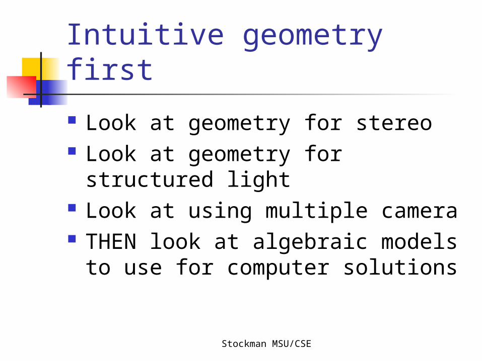
Intuitive geometry first
Look at geometry for stereo Look at geometry for structured
light Look at using multiple camera THEN look at algebraic models to
use for computer solutions
Stockman MSU/CSE
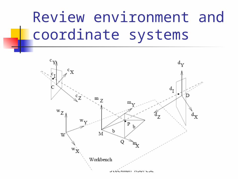
Review environment and coordinate systems
Stockman MSU/CSE
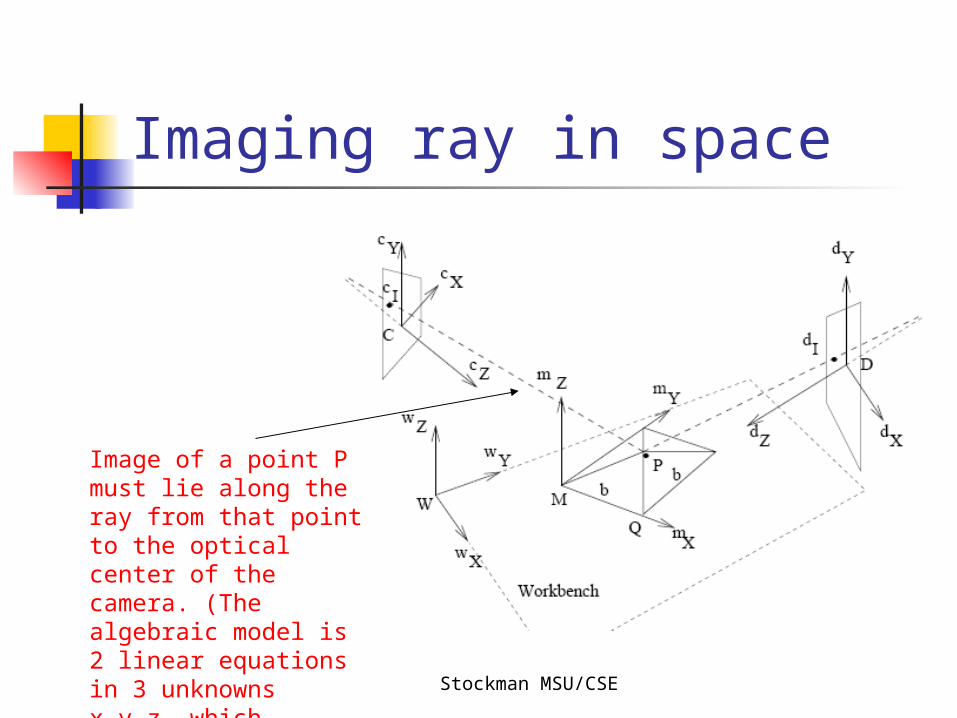
Imaging ray in space
Image of a point P must lie along the ray from that point to the optical center of the camera. (The algebraic model is 2 linear equations in 3 unknowns x,y,z, which constrain but do not uniquely solve for x,y,z.)
Stockman MSU/CSE
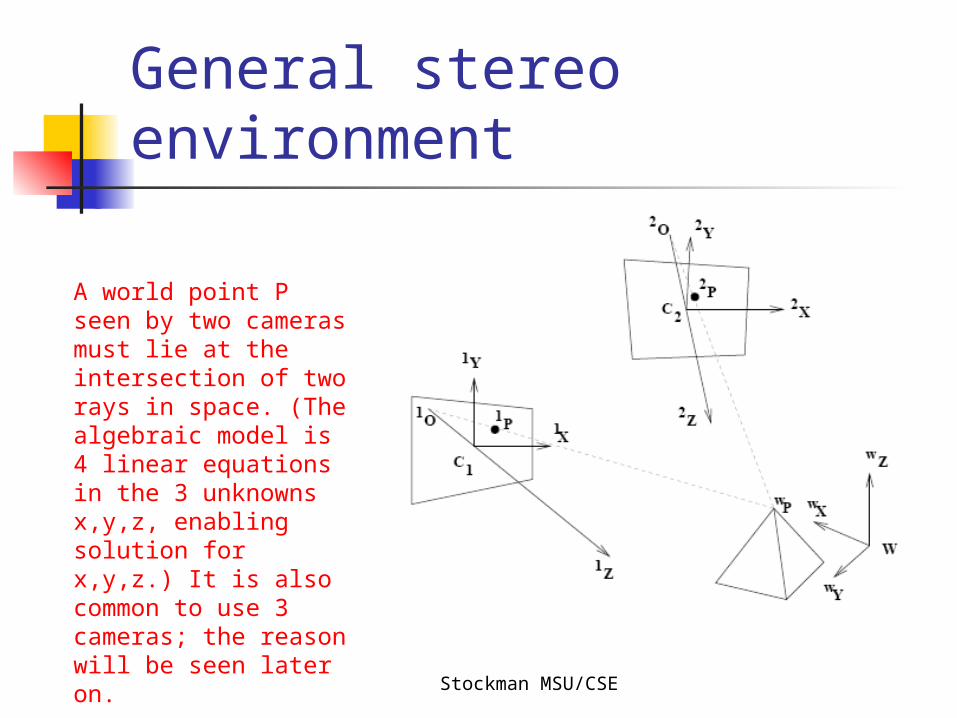
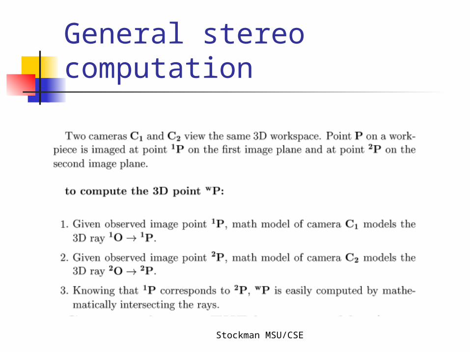
General stereo environment
A world point P seen by two cameras must lie at the intersection of two rays in space. (The algebraic model is 4 linear equations in the 3 unknowns x,y,z, enabling solution for x,y,z.) It is also common to use 3 cameras; the reason will be seen later on.
Stockman MSU/CSE
General stereo computation
Stockman MSU/CSE
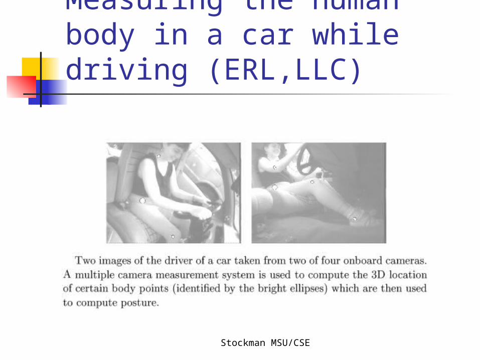
Measuring the human body in a car while driving (ERL,LLC)
Stockman MSU/CSE
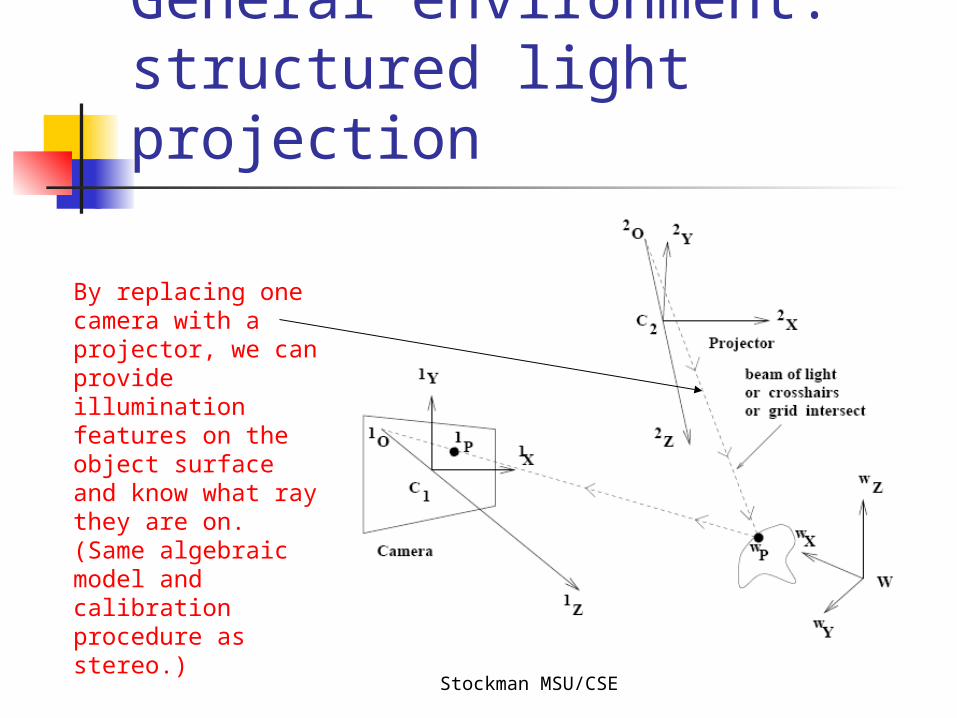
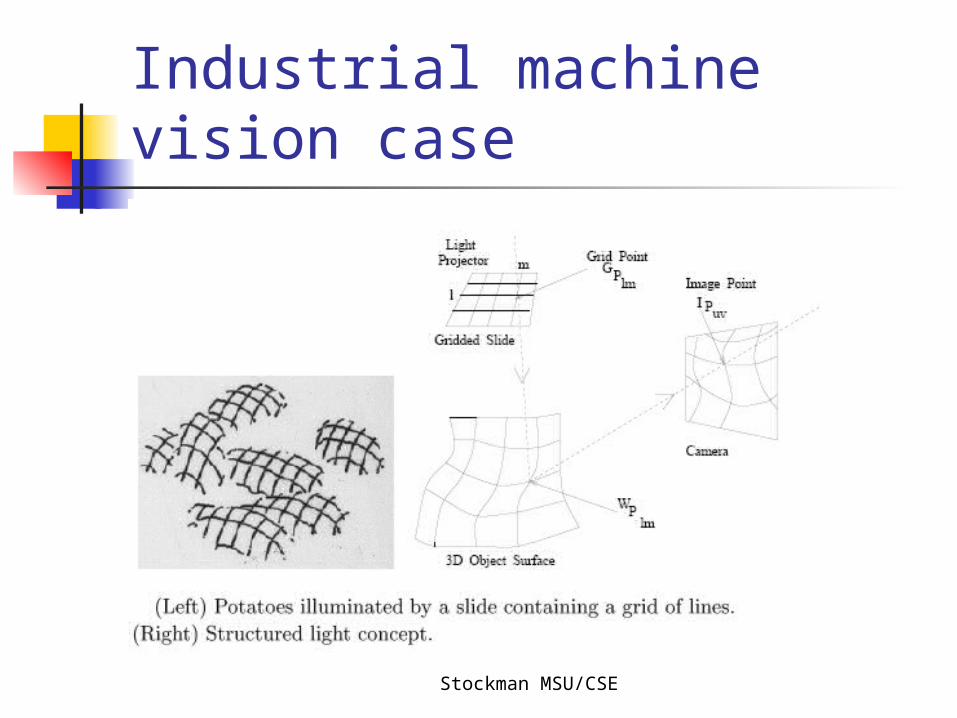
General environment: structured light projection
By replacing one camera with a projector, we can provide illumination features on the object surface and know what ray they are on. (Same algebraic model and calibration procedure as stereo.)
Stockman MSU/CSE
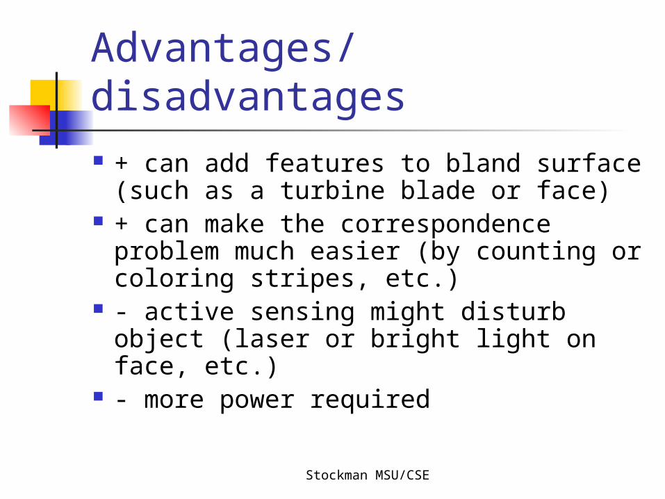
Advantages/disadvantages + can add features to bland surface
(such as a turbine blade or face) + can make the correspondence
problem much easier (by counting or coloring stripes, etc.)
- active sensing might disturb object (laser or bright light on face, etc.)
- more power required
Stockman MSU/CSE
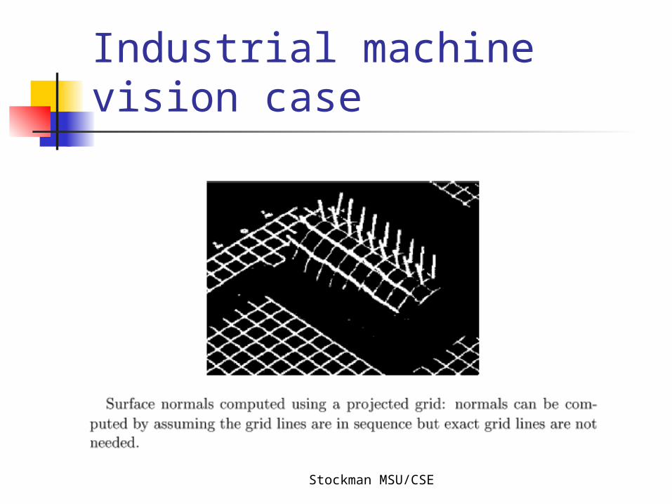
Industrial machine vision case
Stockman MSU/CSE
Industrial machine vision case
Stockman MSU/CSE
Develop algebraic model for computer’s computations
Need models for rotation, translation, scaling, projection
Stockman MSU/CSE
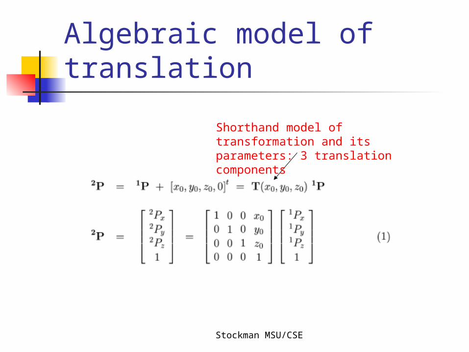
Algebraic model of translation
Shorthand model of transformation and its parameters: 3 translation components
Stockman MSU/CSE
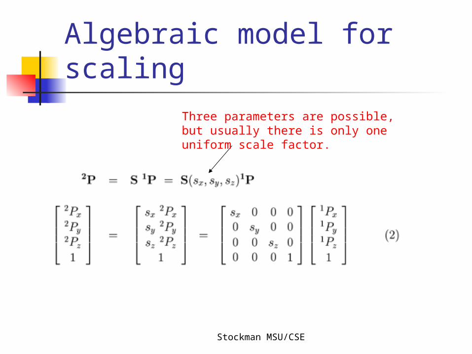
Algebraic model for scaling
Three parameters are possible, but usually there is only one uniform scale factor.
Stockman MSU/CSE
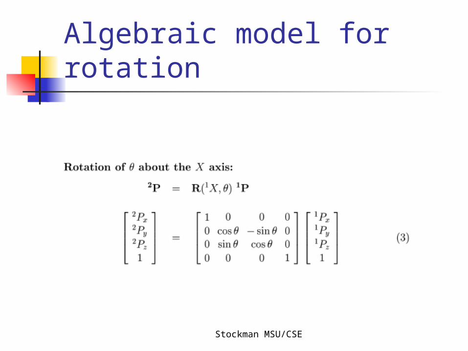
Algebraic model for rotation
Stockman MSU/CSE
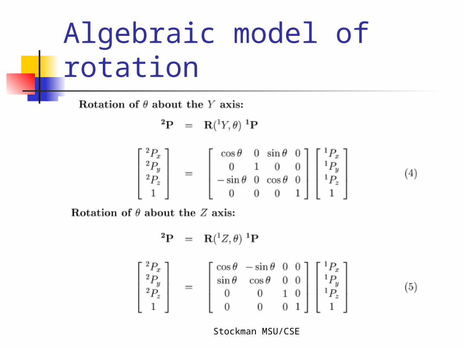
Algebraic model of rotation
Stockman MSU/CSE
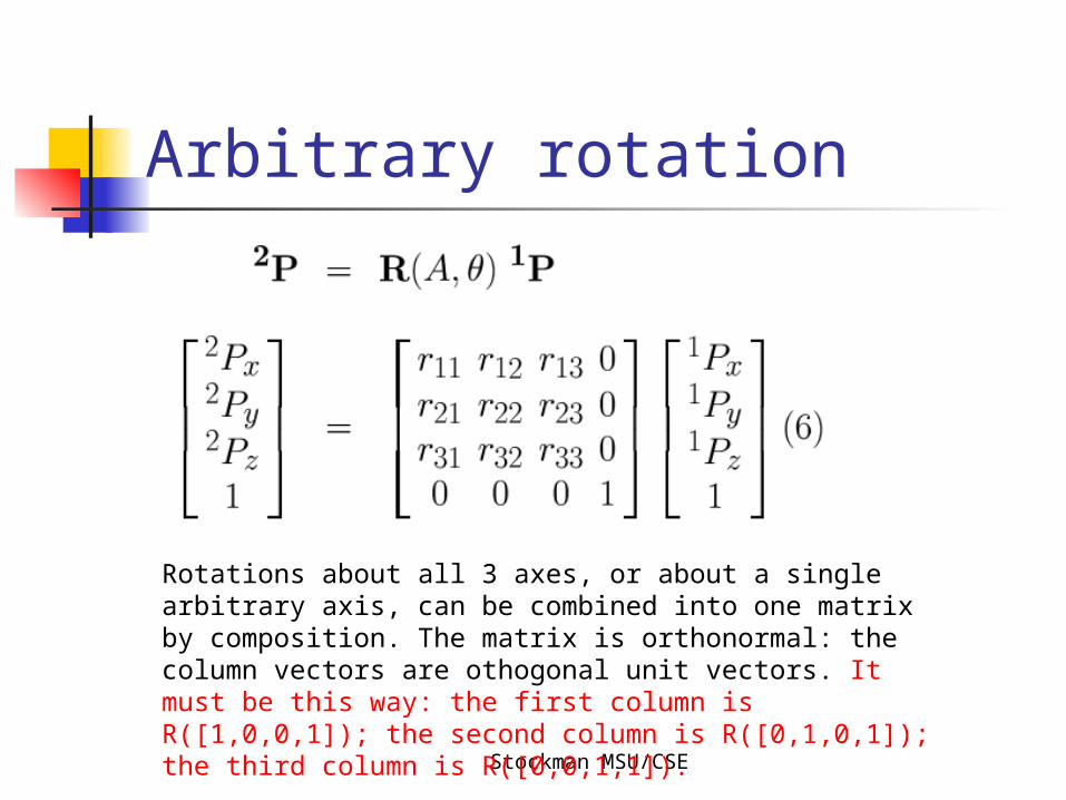
Arbitrary rotation
Rotations about all 3 axes, or about a single arbitrary axis, can be combined into one matrix by composition. The matrix is orthonormal: the column vectors are othogonal unit vectors. It must be this way: the first column is R([1,0,0,1]); the second column is R([0,1,0,1]); the third column is R([0,0,1,1]).
Stockman MSU/CSE
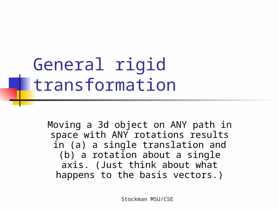
General rigid transformation
Moving a 3d object on ANY path in space with ANY rotations results in (a) a
single translation and (b) a rotation about a single axis. (Just think about what happens to the basis vectors.)
Stockman MSU/CSE
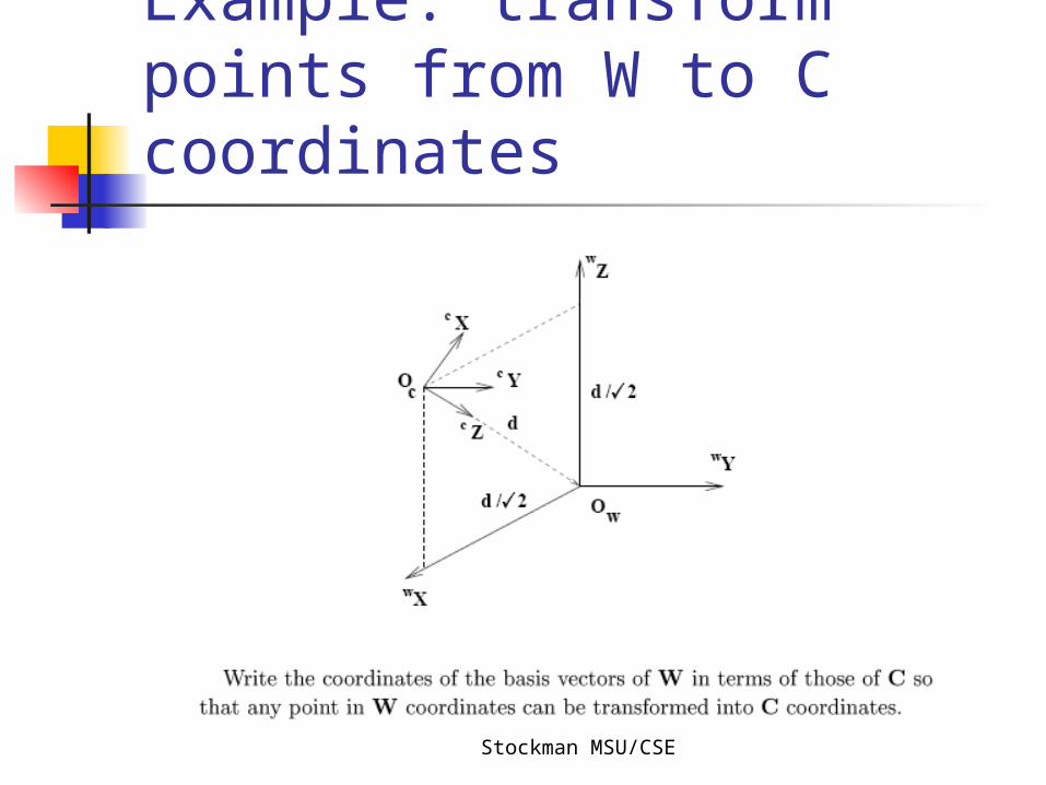
Example: transform points from W to C coordinates
Stockman MSU/CSE
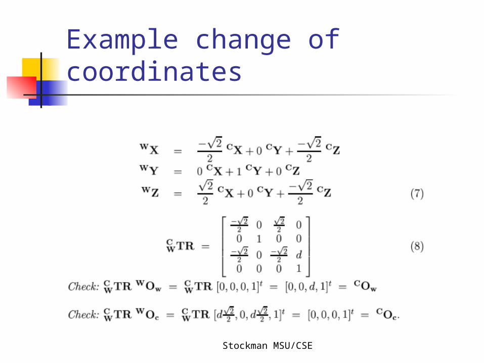
Example change of coordinates
Stockman MSU/CSE
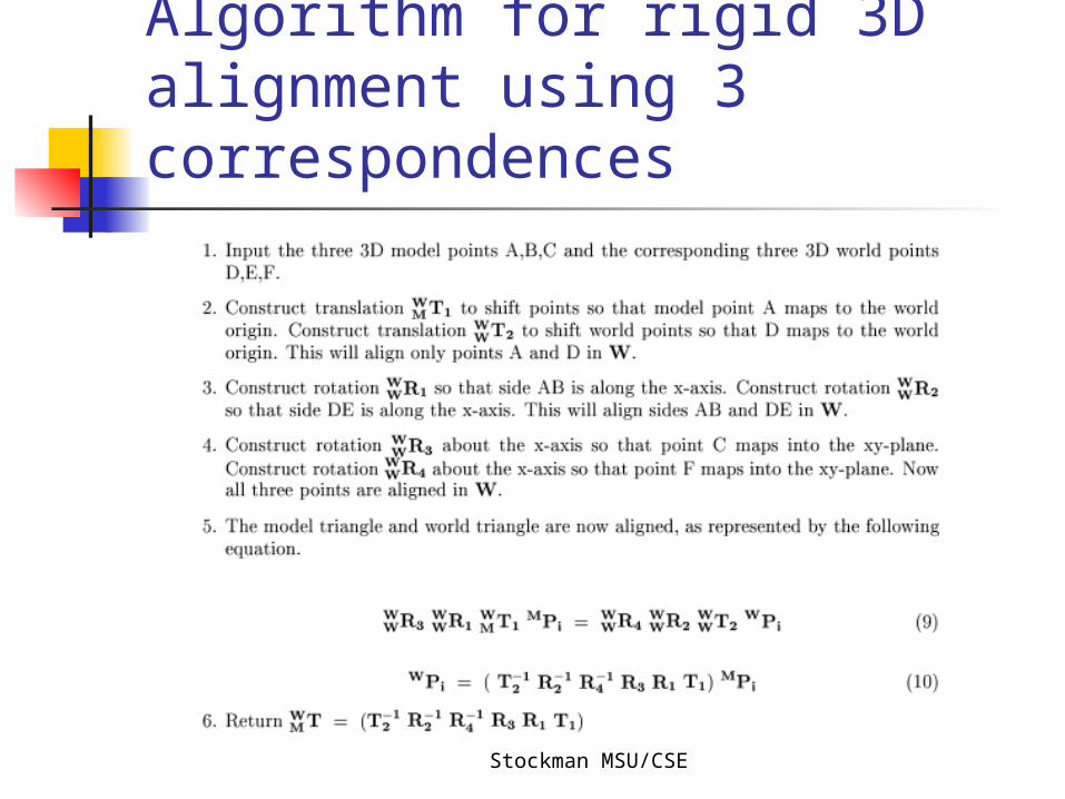
How to do rigid alignment: perhaps model to sensed data
Problem: given three matching points with coordinates in two
coordinate systems, compute the rigid transformation that maps all
points.
Stockman MSU/CSE
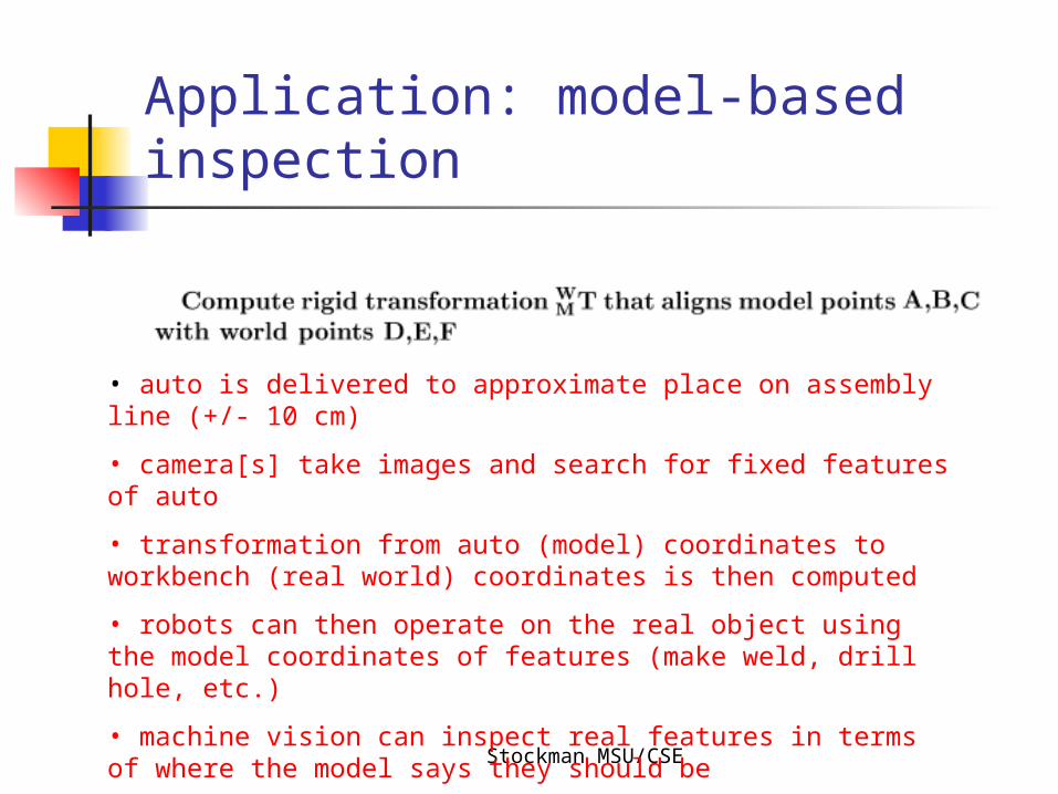
Application: model-based inspection
• auto is delivered to approximate place on assembly line (+/- 10 cm)
• camera[s] take images and search for fixed features of auto
• transformation from auto (model) coordinates to workbench (real world) coordinates is then computed
• robots can then operate on the real object using the model coordinates of features (make weld, drill hole, etc.)
• machine vision can inspect real features in terms of where the model says they should be
Stockman MSU/CSE
Algorithm for rigid 3D alignment using 3 correspondences
Stockman MSU/CSE
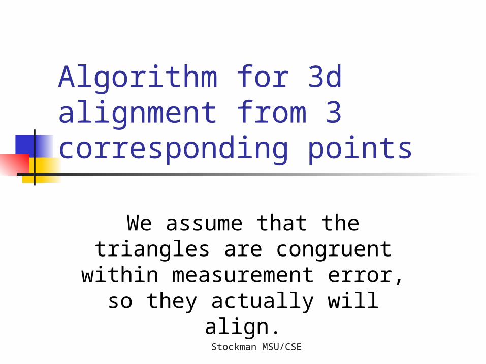
Algorithm for 3d alignment from 3 corresponding points
We assume that the triangles are congruent within
measurement error, so they actually will align.

Stockman MSU/CSE
Approach: transform both spaces until they align (I)
Translate A and D to the origin so that they align in 3D
Rotate in both spaces so that DE and AB correspond along the X axis
Stockman MSU/CSE
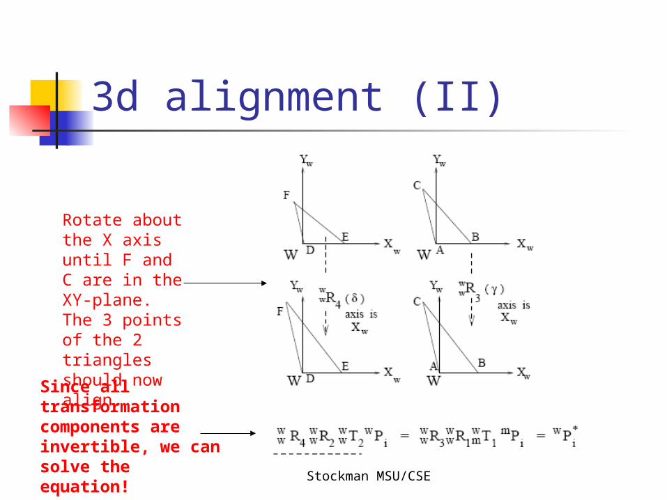
3d alignment (II)
Rotate about the X axis until F and C are in the XY-plane. The 3 points of the 2 triangles should now align.
Since all transformation components are invertible, we can solve the equation!
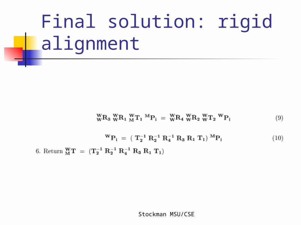
Stockman MSU/CSE
Final solution: rigid alignment
Stockman MSU/CSE
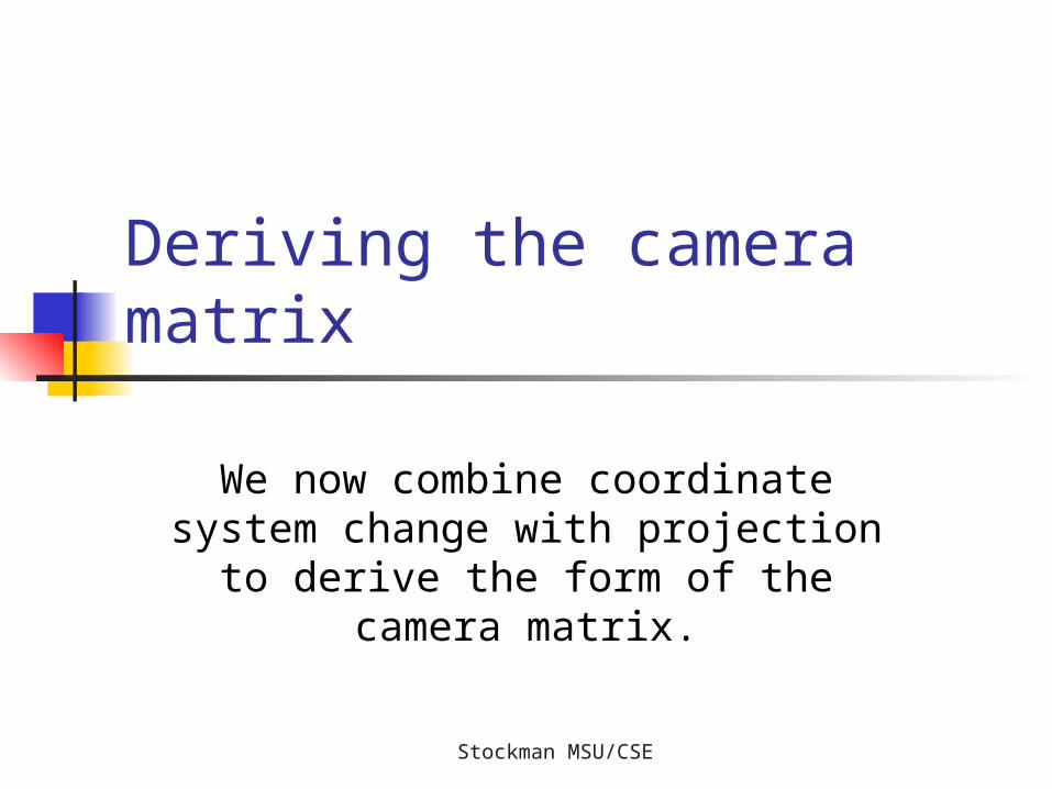
Deriving the camera matrix
We now combine coordinate system change with projection to
derive the form of the camera matrix.
Stockman MSU/CSE
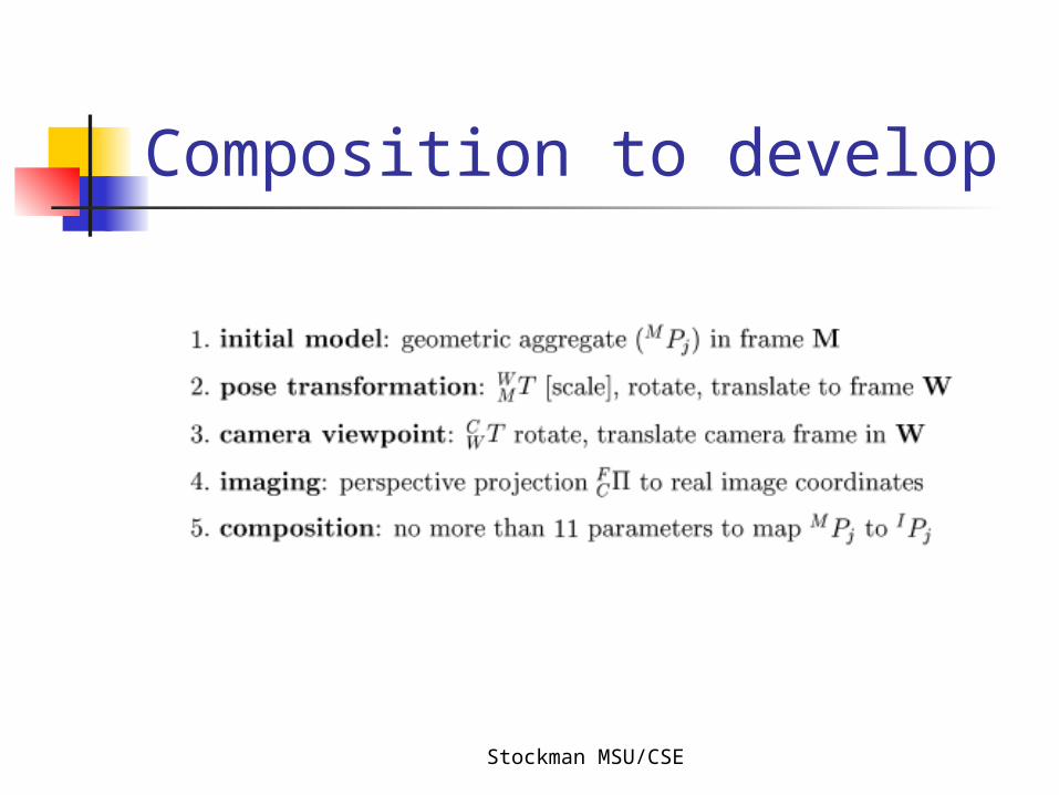
Composition to develop
Stockman MSU/CSE
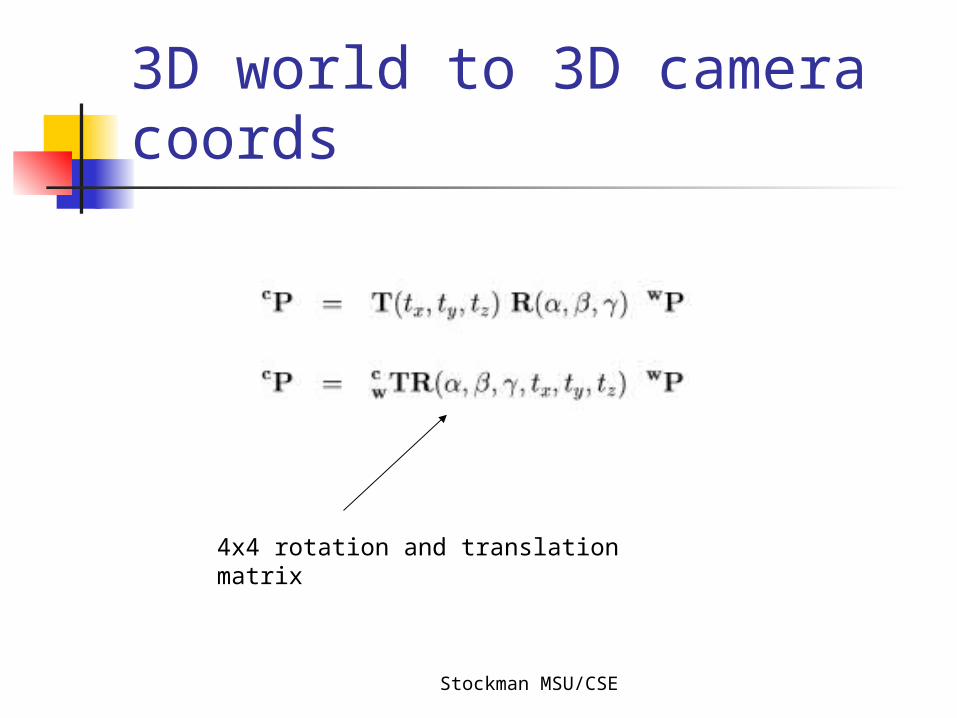
3D world to 3D camera coords
4x4 rotation and translation matrix

Stockman MSU/CSE
Projection of 3D point in camera coords to image [r,c]
We derive this form in the slides below.
We lose a dimension; the projection is not invertible.
Stockman MSU/CSE
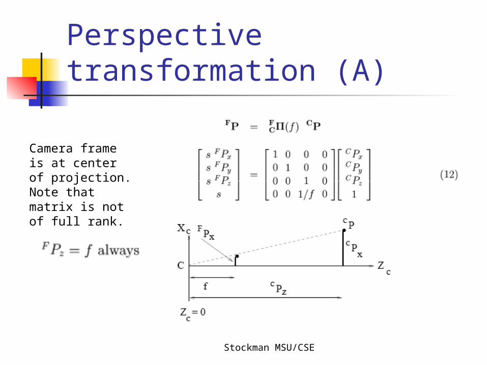
Perspective transformation (A)
Camera frame is at center of projection. Note that matrix is not of full rank.
Stockman MSU/CSE
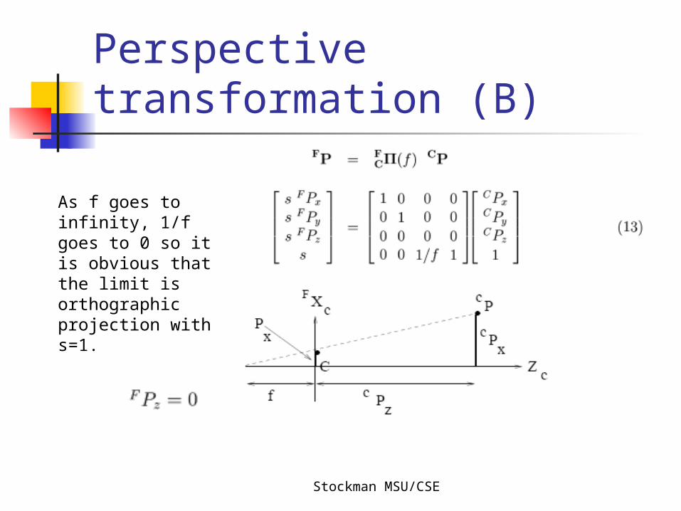
Perspective transformation (B)
As f goes to infinity, 1/f goes to 0 so it is obvious that the limit is orthographic projection with s=1.
Stockman MSU/CSE
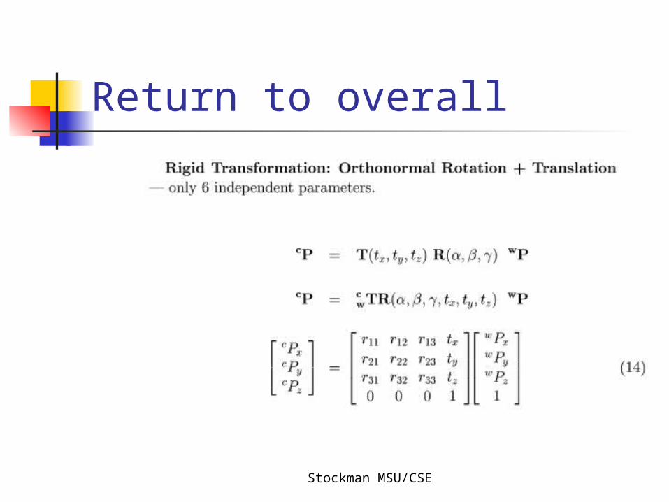
Return to overall
Stockman MSU/CSE
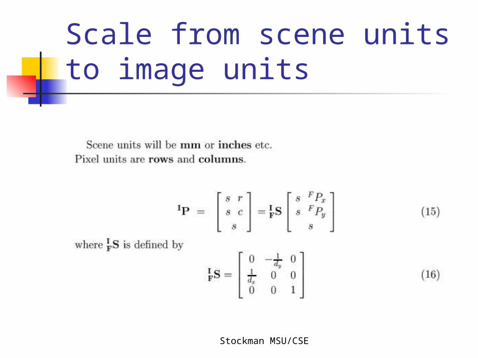
Scale from scene units to image units
Stockman MSU/CSE
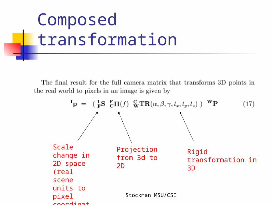
Composed transformation
Rigid transformation in 3D
Projection from 3d to 2D
Scale change in 2D space (real scene units to pixel coordinates)
Stockman MSU/CSE
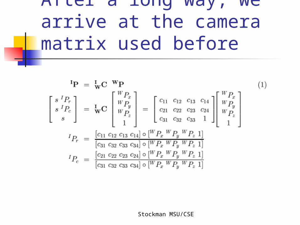
After a long way, we arrive at the camera matrix used before