STM8S DALI slave library - STMicroelectronics DALI slave library Introduction This document...
27
March 2011 Doc ID 18098 Rev 1 1/27 AN3298 Application note STM8S DALI slave library Introduction This document describes the implementation of the Digital Addressable Lighting Interface (DALI) into the STM8S 8-bit microcontroller family. The DALI slave library for STM8S microcontrollers simplifies integration of the DALI slave interface into customer applications. The implementation of DALI into STM8S, together with the various STM8S features (peripherals, computation power, communication interfaces), is mainly used in light control applications (example, electronic ballast control). The STM8S DALI slave library was tested according to the DALI specification. The DALI slave library comes with a simple application example (DALI slave device). The example was designed (and tested) for use with the following evaluation boards: ● STM8S-DISCOVERY (see UM0817, STM8S-DISCOVERY) ● DALI transceiver board (see UM1032: STEVAL-ILMOO1V1 hardware module for the STM8S-DISCOVERY interface for DALI communication). The application example controls the light of the on-board LED diode. Light intensity is controlled by the PWM method using a built-in timer. The external DALI master device must control this application example (which is the DALI slave device). The DALI master devices were tested using the ST7DALI evaluation kit (master device board and PC software) and commercial DALI controller from Osram. The user can use the provided example as a starting point for writing an application using the STM8S DALI slave library. Useful information and links about DALI interface can be found on http://www.dali-ag.org. www.st.com
Transcript of STM8S DALI slave library - STMicroelectronics DALI slave library Introduction This document...
March 2011 Doc ID 18098 Rev 1 1/27
AN3298Application note
STM8S DALI slave library
IntroductionThis document describes the implementation of the Digital Addressable Lighting Interface (DALI) into the STM8S 8-bit microcontroller family.
The DALI slave library for STM8S microcontrollers simplifies integration of the DALI slave interface into customer applications. The implementation of DALI into STM8S, together with the various STM8S features (peripherals, computation power, communication interfaces), is mainly used in light control applications (example, electronic ballast control).
The STM8S DALI slave library was tested according to the DALI specification.
The DALI slave library comes with a simple application example (DALI slave device). The example was designed (and tested) for use with the following evaluation boards:
● STM8S-DISCOVERY (see UM0817, STM8S-DISCOVERY)
● DALI transceiver board (see UM1032: STEVAL-ILMOO1V1 hardware module for the STM8S-DISCOVERY interface for DALI communication).
The application example controls the light of the on-board LED diode. Light intensity is controlled by the PWM method using a built-in timer. The external DALI master device must control this application example (which is the DALI slave device). The DALI master devices were tested using the ST7DALI evaluation kit (master device board and PC software) and commercial DALI controller from Osram.
The user can use the provided example as a starting point for writing an application using the STM8S DALI slave library.
Useful information and links about DALI interface can be found on http://www.dali-ag.org.
www.st.com
Contents AN3298
2/27 Doc ID 18098 Rev 1
Contents
1 DALI information . . . . . . . . . . . . . . . . . . . . . . . . . . . . . . . . . . . . . . . . . . . . 6
1.1 DALI standard overview . . . . . . . . . . . . . . . . . . . . . . . . . . . . . . . . . . . . . . . 6
1.1.1 DALI purpose and properties . . . . . . . . . . . . . . . . . . . . . . . . . . . . . . . . . . 6
1.1.2 DALI physical layer . . . . . . . . . . . . . . . . . . . . . . . . . . . . . . . . . . . . . . . . . 7
1.1.3 DALI stack layer . . . . . . . . . . . . . . . . . . . . . . . . . . . . . . . . . . . . . . . . . . . . 9
1.2 STM8S DALI slave library overview . . . . . . . . . . . . . . . . . . . . . . . . . . . . . . 9
2 Structure of final user application . . . . . . . . . . . . . . . . . . . . . . . . . . . . . 10
2.1 User application . . . . . . . . . . . . . . . . . . . . . . . . . . . . . . . . . . . . . . . . . . . . 10
2.2 DALI stack layer . . . . . . . . . . . . . . . . . . . . . . . . . . . . . . . . . . . . . . . . . . . . 11
2.3 I/O pin driver layer . . . . . . . . . . . . . . . . . . . . . . . . . . . . . . . . . . . . . . . . . . 12
3 Function description . . . . . . . . . . . . . . . . . . . . . . . . . . . . . . . . . . . . . . . . 14
3.1 I/O pin driver layer functions . . . . . . . . . . . . . . . . . . . . . . . . . . . . . . . . . . . 14
3.1.1 stm8_interrupt_vector.c . . . . . . . . . . . . . . . . . . . . . . . . . . . . . . . . . . . . . 14
3.1.2 stm8_it.c,stm8_it.h . . . . . . . . . . . . . . . . . . . . . . . . . . . . . . . . . . . . . . . . . . . . . . . . 14
3.1.3 DALIslave.c, DALIslave.h . . . . . . . . . . . . . . . . . . . . . . . . . . . . . . . . . . . . . . . . . . . . . . 15
3.1.4 stm8s.h, stm8s_conf.h . . . . . . . . . . . . . . . . . . . . . . . . . . . . . . . . . . . . . . . . . . . . . 16
3.2 DALI stack layer functions . . . . . . . . . . . . . . . . . . . . . . . . . . . . . . . . . . . . 17
3.2.1 dali.c, dali.h . . . . . . . . . . . . . . . . . . . . . . . . . . . . . . . . . . . . . . . . . . . . . . . . . . . 17
3.2.2 dali_cmd.c, dali_cmd.h . . . . . . . . . . . . . . . . . . . . . . . . . . . . . . . . . . . . . . . . . . . . . . . 18
3.2.3 dali_pub.c, dali_pub.h . . . . . . . . . . . . . . . . . . . . . . . . . . . . . . . . . . . . . . . . . . . . . . . 19
3.2.4 dali_reg.c, dali_reg.h . . . . . . . . . . . . . . . . . . . . . . . . . . . . . . . . . . . . . . . . . . . . . . . . 20
3.2.5 eeprom.c, eeprom.h . . . . . . . . . . . . . . . . . . . . . . . . . . . . . . . . . . . . . . . . . . . . . . . . 20
3.2.6 lite_timer_8bit.c, lite_timer_8bit.h . . . . . . . . . . . . . . . . . . . . . . . . . . . . . . . . . . . . . . . . . . . 21
3.2.7 dali_config.c, dali_config.h . . . . . . . . . . . . . . . . . . . . . . . . . . . . . . . . . . . . . . . . . . . . . . 22
AN3298 Contents
Doc ID 18098 Rev 1 3/27
4 Resources and examples . . . . . . . . . . . . . . . . . . . . . . . . . . . . . . . . . . . . 24
4.1 Typical user application flowchart . . . . . . . . . . . . . . . . . . . . . . . . . . . . . . . 24
4.2 DALI stack footprint . . . . . . . . . . . . . . . . . . . . . . . . . . . . . . . . . . . . . . . . . 25
5 Revision history . . . . . . . . . . . . . . . . . . . . . . . . . . . . . . . . . . . . . . . . . . . 26
List of tables AN3298
4/27 Doc ID 18098 Rev 1
List of tables
Table 1. Document revision history . . . . . . . . . . . . . . . . . . . . . . . . . . . . . . . . . . . . . . . . . . . . . . . . . 26
AN3298 List of figures
Doc ID 18098 Rev 1 5/27
List of figures
Figure 1. DALI wiring example. . . . . . . . . . . . . . . . . . . . . . . . . . . . . . . . . . . . . . . . . . . . . . . . . . . . . . . 7Figure 2. Example of DALI device connections . . . . . . . . . . . . . . . . . . . . . . . . . . . . . . . . . . . . . . . . . . 8Figure 3. Voltage and currents on the DALI bus . . . . . . . . . . . . . . . . . . . . . . . . . . . . . . . . . . . . . . . . . 8Figure 4. Structure of user application . . . . . . . . . . . . . . . . . . . . . . . . . . . . . . . . . . . . . . . . . . . . . . . . 10Figure 5. Structure of DALI stack layer . . . . . . . . . . . . . . . . . . . . . . . . . . . . . . . . . . . . . . . . . . . . . . . 11Figure 6. Structure of I/O pin driver layer . . . . . . . . . . . . . . . . . . . . . . . . . . . . . . . . . . . . . . . . . . . . . . 12Figure 7. Hardware for testing DALI: STM8S Discovery kit with plugged-in DALI
transceiver board . . . . . . . . . . . . . . . . . . . . . . . . . . . . . . . . . . . . . . . . . . . . . . . . . . . . . . . . 13Figure 8. Flowchart of the user application which uses the DALI slave library . . . . . . . . . . . . . . . . . 24
DALI information AN3298
6/27 Doc ID 18098 Rev 1
1 DALI information
1.1 DALI standard overviewDALI is an international standard (IEC 62386) lighting control system that provides a single interface for electronic control gears (light sources) and devices (lighting controllers).
The DALI standard enables dimmable ballasts, transformers, relay modules, emergency fittings and controllers from different manufacturers to be mixed and matched into a single control system. A DALI system provides designers, installers, building owners, facility managers and end-users a powerful and flexible digital lighting system with security of supply from many sources.
The DALI standard is overseen by the “AG-DALI” activity group which comprises engineers, manufacturers, and institutions working in the field of digital lamp/ lighting control.
More information about the DALI standard can be found in the following documents:
● IEC 62386
● NEMA STANDARD 243-2004
The following sections provide an overview of the DALI standard. They describe the basic principles of the DALI interface.
Note: To better understand the STM8S DALI slave library, a knowledge of the DALI interface specification is essential. This application note does not provide a description of this specification.
1.1.1 DALI purpose and properties
The DALI protocol was designed to control modern light sources using a computer. Functions include:
● Dimming
● On/off switching
● Grouping lights to a common control
● Scene storage and selection
The DALI design properties include:
● Simple wiring using standard electrical installation cables
● No special wiring topology (as with power electrical cables)
● Simple installation giving cable polarity independence
● Automated light source addressing
● Use of low cost microcontrollers on the light source side to minimize cost of light source
● Use of a simple protocol to control light dimming and switching.
AN3298 DALI information
Doc ID 18098 Rev 1 7/27
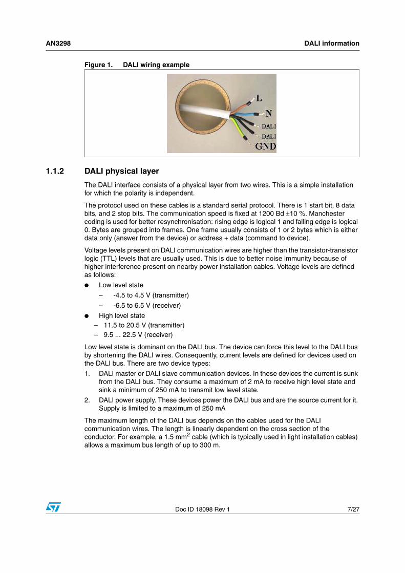
Figure 1. DALI wiring example
1.1.2 DALI physical layer
The DALI interface consists of a physical layer from two wires. This is a simple installation for which the polarity is independent.
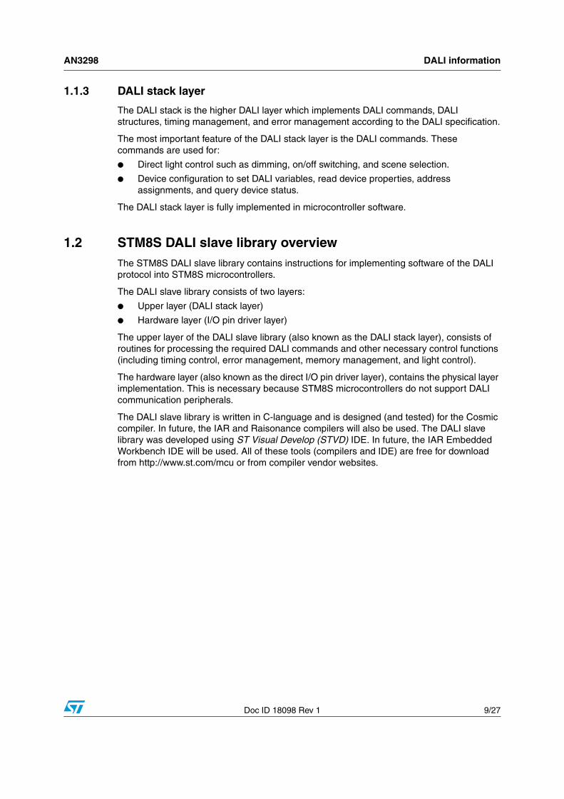
The protocol used on these cables is a standard serial protocol. There is 1 start bit, 8 data bits, and 2 stop bits. The communication speed is fixed at 1200 Bd 10 %. Manchester coding is used for better resynchronisation: rising edge is logical 1 and falling edge is logical 0. Bytes are grouped into frames. One frame usually consists of 1 or 2 bytes which is either data only (answer from the device) or address + data (command to device).
Voltage levels present on DALI communication wires are higher than the transistor-transistor logic (TTL) levels that are usually used. This is due to better noise immunity because of higher interference present on nearby power installation cables. Voltage levels are defined as follows:
● Low level state
– -4.5 to 4.5 V (transmitter)
– -6.5 to 6.5 V (receiver)
● High level state– 11.5 to 20.5 V (transmitter)– 9.5 ... 22.5 V (receiver)
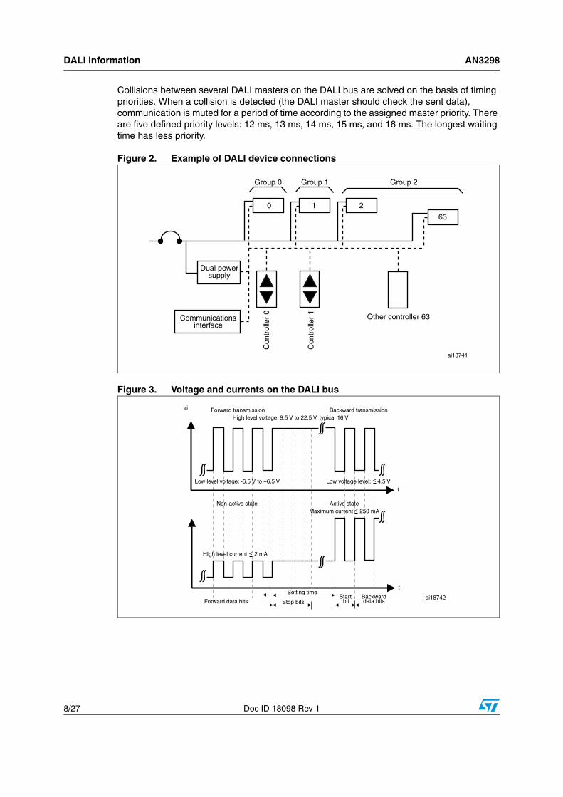
Low level state is dominant on the DALI bus. The device can force this level to the DALI bus by shortening the DALI wires. Consequently, current levels are defined for devices used on the DALI bus. There are two device types:
1. DALI master or DALI slave communication devices. In these devices the current is sunk from the DALI bus. They consume a maximum of 2 mA to receive high level state and sink a minimum of 250 mA to transmit low level state.
2. DALI power supply. These devices power the DALI bus and are the source current for it. Supply is limited to a maximum of 250 mA
The maximum length of the DALI bus depends on the cables used for the DALI communication wires. The length is linearly dependent on the cross section of the conductor. For example, a 1.5 mm2 cable (which is typically used in light installation cables) allows a maximum bus length of up to 300 m.
DALI information AN3298
8/27 Doc ID 18098 Rev 1
Collisions between several DALI masters on the DALI bus are solved on the basis of timing priorities. When a collision is detected (the DALI master should check the sent data), communication is muted for a period of time according to the assigned master priority. There are five defined priority levels: 12 ms, 13 ms, 14 ms, 15 ms, and 16 ms. The longest waiting time has less priority.
Figure 2. Example of DALI device connections
Figure 3. Voltage and currents on the DALI bus
AN3298 DALI information
Doc ID 18098 Rev 1 9/27
1.1.3 DALI stack layer
The DALI stack is the higher DALI layer which implements DALI commands, DALI structures, timing management, and error management according to the DALI specification.
The most important feature of the DALI stack layer is the DALI commands. These commands are used for:
● Direct light control such as dimming, on/off switching, and scene selection.
● Device configuration to set DALI variables, read device properties, address assignments, and query device status.
The DALI stack layer is fully implemented in microcontroller software.
1.2 STM8S DALI slave library overviewThe STM8S DALI slave library contains instructions for implementing software of the DALI protocol into STM8S microcontrollers.
The DALI slave library consists of two layers:
● Upper layer (DALI stack layer)
● Hardware layer (I/O pin driver layer)
The upper layer of the DALI slave library (also known as the DALI stack layer), consists of routines for processing the required DALI commands and other necessary control functions (including timing control, error management, memory management, and light control).
The hardware layer (also known as the direct I/O pin driver layer), contains the physical layer implementation. This is necessary because STM8S microcontrollers do not support DALI communication peripherals.
The DALI slave library is written in C-language and is designed (and tested) for the Cosmic compiler. In future, the IAR and Raisonance compilers will also be used. The DALI slave library was developed using ST Visual Develop (STVD) IDE. In future, the IAR Embedded Workbench IDE will be used. All of these tools (compilers and IDE) are free for download from http://www.st.com/mcu or from compiler vendor websites.
Structure of final user application AN3298
10/27 Doc ID 18098 Rev 1
2 Structure of final user application
The final user application uses the DALI slave library and so, consists of the following three layers:
● Main user application
● DALI stack layer
● I/O pin driver layer
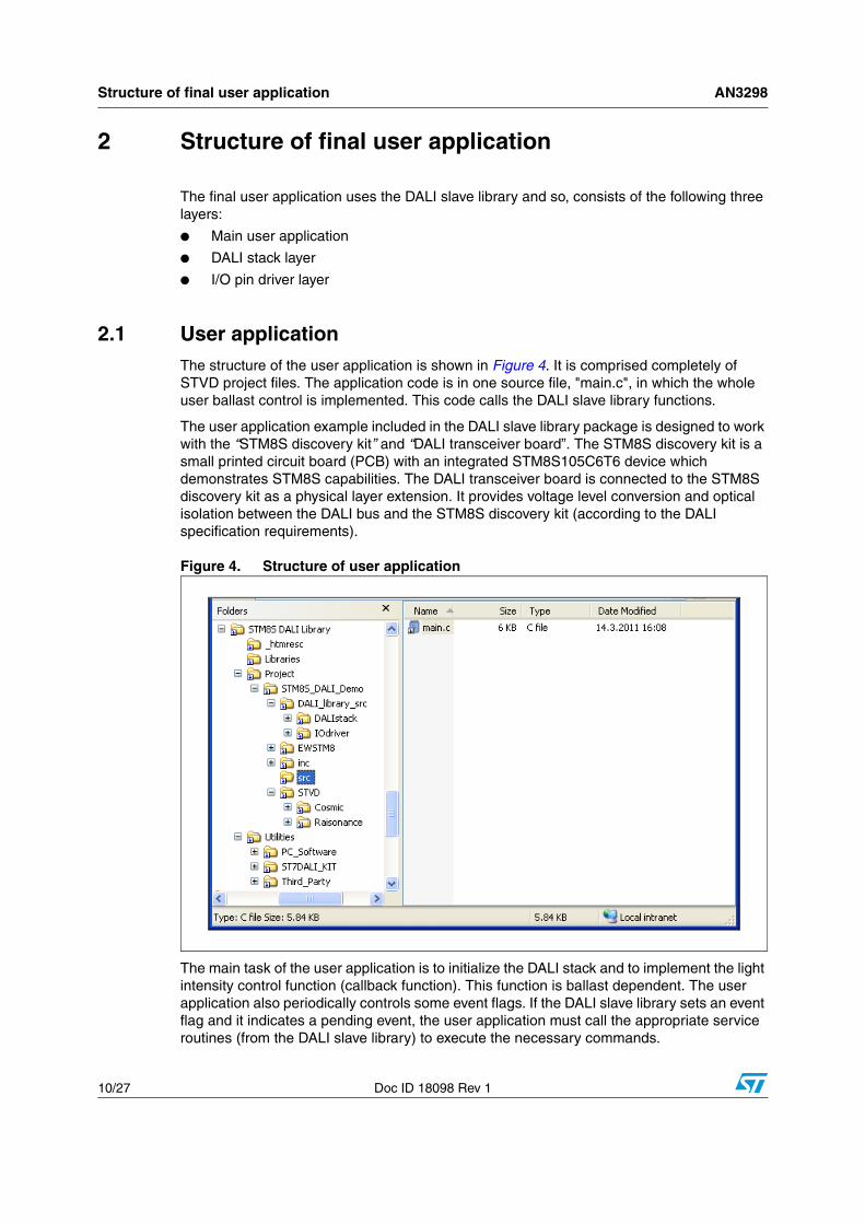
2.1 User applicationThe structure of the user application is shown in Figure 4. It is comprised completely of STVD project files. The application code is in one source file, "main.c", in which the whole user ballast control is implemented. This code calls the DALI slave library functions.
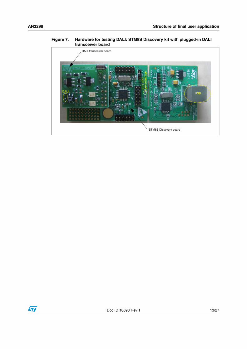
The user application example included in the DALI slave library package is designed to work with the “STM8S discovery kit” and “DALI transceiver board”. The STM8S discovery kit is a small printed circuit board (PCB) with an integrated STM8S105C6T6 device which demonstrates STM8S capabilities. The DALI transceiver board is connected to the STM8S discovery kit as a physical layer extension. It provides voltage level conversion and optical isolation between the DALI bus and the STM8S discovery kit (according to the DALI specification requirements).
Figure 4. Structure of user application
The main task of the user application is to initialize the DALI stack and to implement the light intensity control function (callback function). This function is ballast dependent. The user application also periodically controls some event flags. If the DALI slave library sets an event flag and it indicates a pending event, the user application must call the appropriate service routines (from the DALI slave library) to execute the necessary commands.
AN3298 Structure of final user application
Doc ID 18098 Rev 1 11/27
The user application example uses timer 3 to control the light intensity of the LED diode present on the STM8S discovery kit. Timer 3 generates the pulse-width modulation (PWM) for the LED diode (using the callback function). The main program loop checks event flags, executes actions for active flags, and provides power management (Low power state if the DALI bus is quiet) and error management (reports hardware errors). For all these purposes the user application calls functions from the DALI slave library.
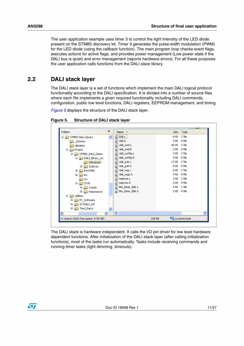
2.2 DALI stack layerThe DALI stack layer is a set of functions which implement the main DALI logical protocol functionality according to the DALI specification. It is divided into a number of source files where each file implements a given required functionality including DALI commands, configuration, public low level functions, DALI registers, EEPROM management, and timing.
Figure 5 displays the structure of the DALI stack layer.
Figure 5. Structure of DALI stack layer
The DALI stack is hardware independent. It calls the I/O pin driver for low level hardware dependent functions. After initialization of the DALI stack layer (after calling initialization functions), most of the tasks run automatically. Tasks include receiving commands and running timer tasks (light dimming, timeouts).
Structure of final user application AN3298
12/27 Doc ID 18098 Rev 1
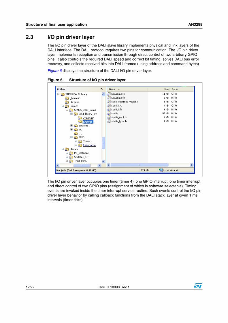
2.3 I/O pin driver layerThe I/O pin driver layer of the DALI slave library implements physical and link layers of the DALI interface. The DALI protocol requires two pins for communication. The I/O pin driver layer implements reception and transmission through direct control of two arbitrary GPIO pins. It also controls the required DALI speed and correct bit timing, solves DALI bus error recovery, and collects received bits into DALI frames (using address and command bytes).
Figure 6 displays the structure of the DALI I/O pin driver layer.
Figure 6. Structure of I/O pin driver layer
The I/O pin driver layer occupies one timer (timer 4), one GPIO interrupt, one timer interrupt, and direct control of two GPIO pins (assignment of which is software selectable). Timing events are invoked inside the timer interrupt service routine. Such events control the I/O pin driver layer behavior by calling callback functions from the DALI stack layer at given 1 ms intervals (timer ticks).
AN3298 Structure of final user application
Doc ID 18098 Rev 1 13/27
Figure 7. Hardware for testing DALI: STM8S Discovery kit with plugged-in DALItransceiver board
DALI transceiver board
STM8S Discovery board
DALI
LD1
LED
cont
rolle
d lig
ht
USB
Function description AN3298
14/27 Doc ID 18098 Rev 1
3 Function description
This section describes the most important STM8S DALI slave library functions for the user.
3.1 I/O pin driver layer functionsThe I/O pin driver layer implements hardware dependent functions (designed for use with STM8 devices and the DALI transceiver board).
3.1.1 stm8_interrupt_vector.c
This file contains the interrupt vector table. The I/O pin driver layer occupies six interrupt vectors:
EXTI_PORTx_IRQHandler (five vectors)
The EXTI_PORTx_IRQHandler set of five vectors is for all GPIO pins (where x = A, B, C, D, and E). They:
● Detect DALI RX line changes
● Allow the user to select any pin as a DALI RX line (because all GPIO vectors are occupied).
TIM4_UPD_OVF_IRQHandler
This vector is for timer 4 overflow/update. It:
● Controls the reception and transmission timing
● Produces precise timer ticks for the DALI stack layer
3.1.2 stm8_it.c,stm8_it.h
These files contain two interrupt service routines (ISR):
@interrupt void EXTI_PORTx_IRQHandler (void)
This ISR:
● Calls receiving routines if there is a voltage level change on the DALI RX pin
● Detects the start of the DALI packet. This ISR is inactive during DALI packet reception. It is activated after DALI packet reception.
AN3298 Function description
Doc ID 18098 Rev 1 15/27
@interrupt void TIM4_UPD_OVF_IRQHandler (void)
This ISR:
● Generates timer ticks for the DALI bit receive and transmit functions
● Calls, in given intervals, the transmit/receive function (sampling is eight times per DALI bit).
● Generates 1 ms timer ticks for the upper DALI layer timing by calling callback functions from the DALI stack layer.
● Checks for DALI interface failure such as loss of voltage on the DALI bus for more than 500 ms (disconnection from DALI bus).
3.1.3 DALIslave.c, DALIslave.h
These file contains the reception and transmission routines for building the DALI packet from received bits according to the DALI specification. It also contains the initialization functions of the DALI I/O pin driver layer.
The functions of these files are given below in bold.
void init_DALI(port_out,pin_out, invert_out, port_in, pin_in, invert_in, DataReceivedFunction, ErrorFunction, RTC_1ms_Function)
This set of functions:
● Initializes the DALI I/O pin driver layer
● Defines the DALI RX and DALI TX pins and their inversion. This depends on the physical connection to the DALI bus (i.e. the converter between the DALI bus and the I/O pins).
● Defines the callback functions:
– if the complete DALI packet is received (address, command/data)
– if an error occurs on the DALI bus (loss of idle voltage)
– if 1 ms callback timer ticks are generated for the DALI stack layer
● After this function is called, the I/O pin driver is able to receive DALI packets and can call upper layer callbacks. This function should be called as the last initialization function (after DALI stack initialization).
bool get_DALIIN(), bool get_DALIOUT(), void set_DALIOUT(pin_value)
This set of functions:
● Obtains/sets the logical level from/to the DALI pin (DALI Rx and DALI Tx)
● Accepts the hardware implementation of the driver (its eventual inversion)
Function description AN3298
16/27 Doc ID 18098 Rev 1
void receive_data()
This function is called from the interrupt routine when the first start bit of DALI packet occurs. It:
● Starts the receiving process
void send_data(byteToSend)
This function:
● Starts the transmission process
void receive_tick()
This function is called from timer 4 interrupt service routine when receiving has already started. It:
● Performs bit receiving from the DALI RX pin for building the DALI packet
● Checks the packet errors on the DALI bus
void send_tick(void)
This function is called from timer 4 interrupt service routine when transmitting has already started. It:
● performs transmitting of DALI packet to DALI bus (bit coding to physical layer)
void check_interface_failure(void)
This function:
● Checks the DALI bus idle voltage presence (500 ms disconnection from the DALI bus)
● Calls error callback function if an error occurs
u8 get_timer_count(void)
This function:
● Returns the current timer 4 content
● Is used for general purpose use, for example, random number generation
u8 get_flag(void)
This function:
● Returns the current DALI I/O driver state (receiving, transmitting)
3.1.4 stm8s.h, stm8s_conf.h
These files, originally present in STM8S firmware library (see www.st.com/mcu), implement the following STM8S microcontroller family hardware definitions:
● Peripheral register names
● Memory and register address mapping
● Definition of bit masks and macros
● Definition of types (peripheral structures) and fixed constants
AN3298 Function description
Doc ID 18098 Rev 1 17/27
3.2 DALI stack layer functionsThe DALI stack layer implements all DALI commands processed on the logical level according to the DALI specification.
3.2.1 dali.c, dali.h
These main files contain the most commonly used functions that are called from the user application. They contain initialization of the entire DALI slave library, DALI slave library event flag signaling, command execution calls, and reporting of user hardware error.
The functions inside these files are given below in bold.
void DALI_Init(LightControlFunction)
This function:
● Initializes the entire DALI slave library (both I/O pin driver layer and DALI stack layer and is called from the user application as the main initialization function.
● Initializes all necessary modules of the DALI slave library
● Starts execution of receiving commands from the DALI bus, timing management, callback calls, and setting of event flags.
u8 DALI_CheckAndExecuteReceivedCommand(void)
This function should be cyclically called from the main user application in the main program loop. It:
● Checks if there is a pending received DALI packet. If so, the given DALI command from the packet is executed.
● Returns the execution status
– 0 = no pending command
– 1 = pending DALI command executed
– 2 = DALI bus error present and processed
u8 DALI_CheckAndExecuteTimer(void)
This function should be cyclically called from the main user application in the main program loop at least every 1 ms. It:
● Checks if there is a pending timer flag. If so, the given timer callbacks (fading functions, timeouts, ...) are executed.
● Returns the number of pending remaining 1 ms timer cycles for a given timer task (example, number of timer cycles to finish light dimming cycle).
void DALI_halt(void)
This function contains the entry to the microcontroller Low power state (Halt mode without timer interrupt). The user must check before calling this function that there are no pending timer cycles and DALI packets.

Function description AN3298
18/27 Doc ID 18098 Rev 1
void DALI_Set_Lamp_Failure(failure)
This function:
● Sets or resets the failure state of the lighting element (for example, a damaged bulb).
u8 Get_DALI_Random(void)
This function:
● Returns a random number
● Is used for general purpose use
3.2.2 dali_cmd.c, dali_cmd.h
These files contain all DALI commands according to the DALI specification. In addition, they contain auxiliary functions for command processing such as checking command parameters and correct timing.
Many functions execute a given DALI command and other functions execute auxiliary commands. A given function is called automatically when the user calls the DALI_CheckAndExecuteReceivedCommand(void) function.
The most important functions of these files are given below in bold. For information about other functions, the user can refer inside these source files and to the DALI specification.
void DALIC_Init(void)
This function:
● Initializes the entire DALI command modules
u8 DALIC_isTalkingToMe(void)
This function:
● Detects if the received DALI packet is addressed to the device
void DALIC_ProcessCommand(void)
This function:
● Selects the correct command execution according to received data
void DALIC_Direct_Arc(val), void DALIC_Direct_Arc_NoFade(val)
This function is called from many DALI commands as a request for light intensity change. It:
● Executes the light intensity control
AN3298 Function description
Doc ID 18098 Rev 1 19/27
3.2.3 dali_pub.c, dali_pub.h
These files contain the lower level DALI stack layer functions. The user can modify some functions if required. All functions of these files are called from other DALI stack modules (mainly from the "dali_cmd.c") as requests to execute lower level commands.
The most important functions of these files are given below in bold.
void DALIP_Init(LightControlFunction)
This function:
● Initializes the public module
● Contains as an input parameter a user callback function for light control:
– it is called if there is a need to change the light level
– the user implements it (implementation is user hardware dependent)
– it has only one input parameter (unsigned int) which is the requested light level (see header file "dali_pub.h" for this function type definition).
void DALIP_Direct_Arc(u8 val)
This function is called from the "dali_cmd.c". It:
● Executes the light intensity control using a logarithmic curve
u8 DALIP_Getxxx(void), void DALIP_Setxxx(u8 val)
This set of functions:
● Reads or sets a given "xxx" DALI parameter (usually a DALI register or flag in EEPROM).
void DALIP_Off(void), void DALIP_On_And_Step_Up(void), void DALIP_Step_Down_And_Off(void), void DALIP_Recall_Max_Level(void), void DALIP_Recall_Min_Level(void), void DALIP_Up(void), void DALIP_Down(void), void DALIP_Step_Up(void), void DALIP_Step_Down(void)
This set of functions
● Implements the DALI commands for controlling light level
Function description AN3298
20/27 Doc ID 18098 Rev 1
3.2.4 dali_reg.c, dali_reg.h
These files contain the DALI register management functions. The DALI registers can be stored in RAM, EEPROM, or ROM memory (see the DALI specification definitions). The functions of these files implement automatic memory selection depending on the register index and register read and write routines.
The most important functions of these files are given below in bold.
void DALIR_Init(void)
This function:
● Initializes the DALI register module
● Clears all RAM registers
void DALIR_ResetRegs(void)
This function:
● Sets all registers to the default state (according to the DALI specification)
u8 DALIR_ReadReg(idx), void DALIR_WriteReg(idx, newval),u8 DALIR_ReadStatusBit(bit), void DALIR_WriteStatusBit(bit, val), u8 DALIR_ReadEEPROMReg(idx), void DALIR_WriteEEPROMReg(idx, val)
This set of functions:
● Is used for register reading and writing
void DALIR_DeleteShort(void)
This function:
● Clears the DALI short address (unassigned address state)
3.2.5 eeprom.c, eeprom.h
These files contain routines for the EEPROM memory read/write operations. They contain read and write functions for reading and writing rewritable nonvolatile DALI variables.
The most important functions of these files are given below in bold.
void EEPROM_Init(void)
This function:
● Initializes the EEPROM module
● Initializes EEPROM data (registers) to their default values
AN3298 Function description
Doc ID 18098 Rev 1 21/27
u8 E2_ReadMem(addr), void E2_WriteMem(addr, data), void E2_WriteBurst(addr, times, *buf)
This set of functions:
● Reads/writes to/from EEPROM data
3.2.6 lite_timer_8bit.c, lite_timer_8bit.h
These files are the timing module. They contain all virtual timers which are needed for DALI timing such as intervals for the dimming function and DALI timeouts. Reference timer ticks come from the DALI I/O pin driver layer.
The most important functions of these files are given below in bold.
void Timer_Lite_Init(void)
This function:
● Initializes the timing module
● Initializes the internal variables to their default state
void RTC_LaunchTimer(timer_value)
This function:
● Initializes a timeout for DALI command repetition
void RTC_LaunchUserTimer(TimerCount), void RTC_DoneUserTimer(void)
This set of functions:
● Dims the update intervals (start and stop)
void RTC_LaunchBigTimer(mins)
This function:
● Initializes the timeout (usually 15 minutes) - expiration of the DALI "Initialize" command
void RTC_LaunchDAPCTimer(void)
This function:
● Initializes the timeout (200 ms) - expiration of the DALI "DAPC sequence" command
void PowerOnTimerReset(void)
This function:
● Stops the power-on timeout (600 ms) which was started during power-on (using the Timer_Lite_Init() function)
Function description AN3298
22/27 Doc ID 18098 Rev 1
void Lite_timer_Interrupt(void)
This function is the main timer function servicing all timers. It:
● Is a callback function that receives 1 ms timer ticks from the DALI I/O pin driver layer
● Runs in interrupt
● Updates the timer event flag used for updating the virtual timers (1 ms each)
u8 Process_Lite_timer_IT(void)
This function is called cyclically from the user main program loop in 1 ms intervals when the timer event flag is signalled. It:
● Services timer events (if necessary)
● Calls callbacks or updates virtual timer values
3.2.7 dali_config.c, dali_config.h
These files contain the DALI stack module configurations. The user can change them according to his needs, the final ballast hardware/software implementation, the light element used, the type of light control, the STM8S pinout, and the user/device description information.
The most important variables and definitions in these files are given below in bold.
const u16 DALIP_ArcTable[]
This variable is the logarithmic table for light control. It:
● Implements the logarithmic table according to the DALI specification
● Converts 8-bit linear values to 16-bit logarithmic output for direct light power control (see the DALI specification).
const u32 DALIP_FadeTimeTable[]
This variable:
● Implements the fade time table according to the DALI specification
const u16 DALIP_FadeRateTable[]
This variable:
● Implements the fade rate table according to the DALI specification
const u8 DaliRegDefaults[]
This variable:
● Implements the default DALI register content according to the DALI specification
#define USE_ARC_TABLE
This definition:
● Enables the logarithmic table to be used instead of direct light control
AN3298 Function description
Doc ID 18098 Rev 1 23/27
#define OUT_DALI_PORT, #define OUT_DALI_PIN, #define INVERT_OUT_DALI, #define IN_DALI_PORT, #define IN_DALI_PIN, #define INVERT_IN_DALI
This set of definitions:
● Contains DALI Rx and DALI Tx signal assignments to given pins according to user requirements. The Rx pin must have interrupt capability.
● Define if a pin is inverted or not on the user hardware DALI transceiver board
#define DEVICE_TYPE
This definition:
● Defines the ballast type according to the DALI specification (see DALI specification for valid ballast type numbers).
#define DALI_VERSION_NUMBER_ROM
This definition:
● Defines the DALI version
#define PHYSICAL_MIN_LEVEL_ROM
This definition:
● Defines the minimum light level which is limited by the ballast hardware capability (according to the DALI specification).
Resources and examples AN3298
24/27 Doc ID 18098 Rev 1
4 Resources and examples
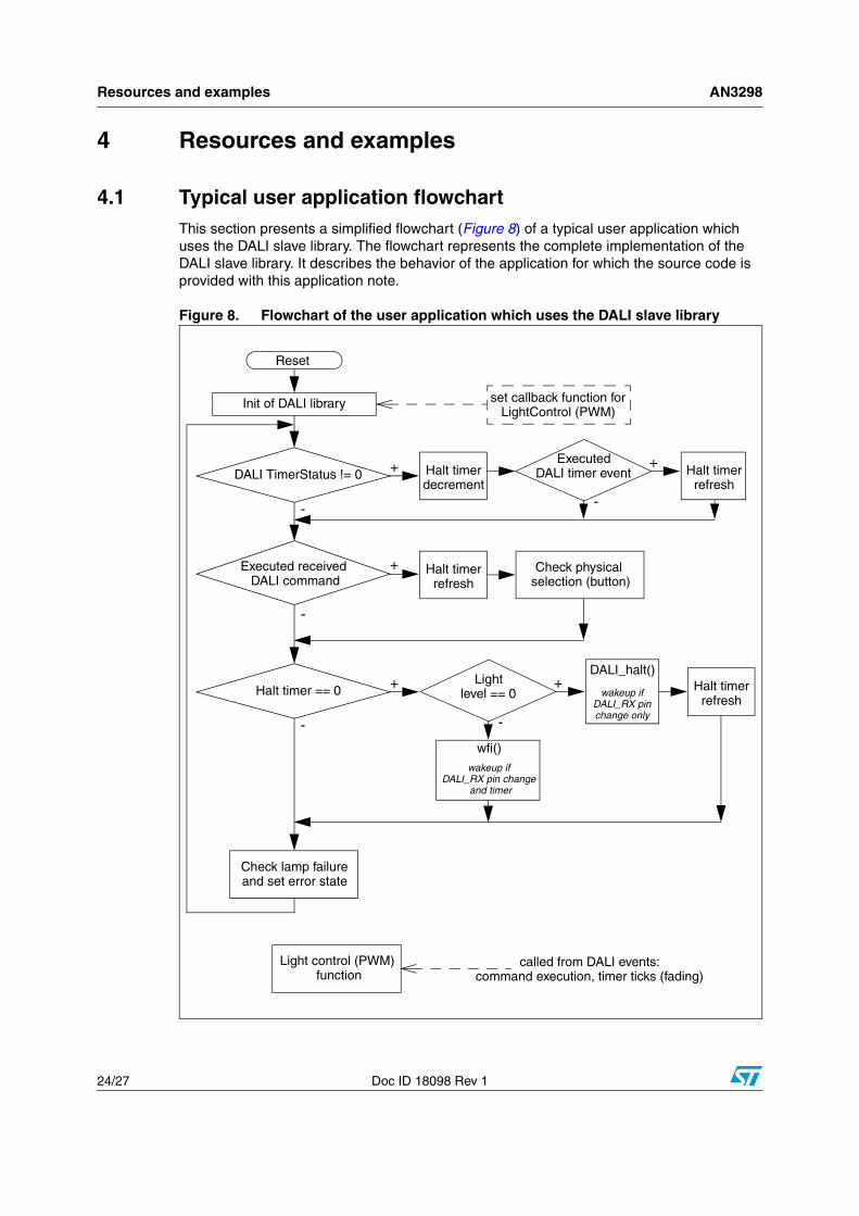
4.1 Typical user application flowchartThis section presents a simplified flowchart (Figure 8) of a typical user application which uses the DALI slave library. The flowchart represents the complete implementation of the DALI slave library. It describes the behavior of the application for which the source code is provided with this application note.
Figure 8. Flowchart of the user application which uses the DALI slave library
Reset
Init of DALI library
DALI TimerStatus != 0Executed
+
-
-
Executed received DALI command
Halt timer DALI timer eventdecrement
Halt timerrefresh
+
-
Halt timerrefresh
Check physical selection (button)
Halt timer == 0 +
-
Lightlevel == 0
DALI_halt()+
-
wfi()
Halt timerrefresh
Check lamp failureand set error state
+
set callback function forLightControl (PWM)
Light control (PWM) function
called from DALI events:command execution, timer ticks (fading)
wakeup ifDALI_RX pinchange only
wakeup ifDALI_RX pin change
and timer
AN3298 Resources and examples
Doc ID 18098 Rev 1 25/27
4.2 DALI stack footprintA simple user DALI application which uses the DALI slave library occupies the folloving memories sizes:
● Program memory size ~8500 bytes
● RAM size ~100 bytes
● EEPROM size ~190 bytes
These memory sizes are more or less the minimum sizes required for basic DALI slave implementation. Additional memory space is needed for additional user functions which, in turn, depends on the complexity of the user code. Additional functions which can be implemented include protection, current sensing, and external temperature sensor sensing.
Revision history AN3298
26/27 Doc ID 18098 Rev 1
5 Revision history
Table 1. Document revision history
Date Revision Changes
18-Mar-2011 1 Initial release
AN3298
Doc ID 18098 Rev 1 27/27
Please Read Carefully:
Information in this document is provided solely in connection with ST products. STMicroelectronics NV and its subsidiaries (“ST”) reserve theright to make changes, corrections, modifications or improvements, to this document, and the products and services described herein at anytime, without notice.
All ST products are sold pursuant to ST’s terms and conditions of sale.
Purchasers are solely responsible for the choice, selection and use of the ST products and services described herein, and ST assumes noliability whatsoever relating to the choice, selection or use of the ST products and services described herein.
No license, express or implied, by estoppel or otherwise, to any intellectual property rights is granted under this document. If any part of thisdocument refers to any third party products or services it shall not be deemed a license grant by ST for the use of such third party productsor services, or any intellectual property contained therein or considered as a warranty covering the use in any manner whatsoever of suchthird party products or services or any intellectual property contained therein.
UNLESS OTHERWISE SET FORTH IN ST’S TERMS AND CONDITIONS OF SALE ST DISCLAIMS ANY EXPRESS OR IMPLIEDWARRANTY WITH RESPECT TO THE USE AND/OR SALE OF ST PRODUCTS INCLUDING WITHOUT LIMITATION IMPLIEDWARRANTIES OF MERCHANTABILITY, FITNESS FOR A PARTICULAR PURPOSE (AND THEIR EQUIVALENTS UNDER THE LAWSOF ANY JURISDICTION), OR INFRINGEMENT OF ANY PATENT, COPYRIGHT OR OTHER INTELLECTUAL PROPERTY RIGHT.
UNLESS EXPRESSLY APPROVED IN WRITING BY AN AUTHORIZED ST REPRESENTATIVE, ST PRODUCTS ARE NOTRECOMMENDED, AUTHORIZED OR WARRANTED FOR USE IN MILITARY, AIR CRAFT, SPACE, LIFE SAVING, OR LIFE SUSTAININGAPPLICATIONS, NOR IN PRODUCTS OR SYSTEMS WHERE FAILURE OR MALFUNCTION MAY RESULT IN PERSONAL INJURY,DEATH, OR SEVERE PROPERTY OR ENVIRONMENTAL DAMAGE. ST PRODUCTS WHICH ARE NOT SPECIFIED AS "AUTOMOTIVEGRADE" MAY ONLY BE USED IN AUTOMOTIVE APPLICATIONS AT USER’S OWN RISK.
Resale of ST products with provisions different from the statements and/or technical features set forth in this document shall immediately voidany warranty granted by ST for the ST product or service described herein and shall not create or extend in any manner whatsoever, anyliability of ST.
ST and the ST logo are trademarks or registered trademarks of ST in various countries.
Information in this document supersedes and replaces all information previously supplied.
The ST logo is a registered trademark of STMicroelectronics. All other names are the property of their respective owners.
© 2011 STMicroelectronics - All rights reserved
STMicroelectronics group of companies
Australia - Belgium - Brazil - Canada - China - Czech Republic - Finland - France - Germany - Hong Kong - India - Israel - Italy - Japan - Malaysia - Malta - Morocco - Philippines - Singapore - Spain - Sweden - Switzerland - United Kingdom - United States of America
www.st.com