
STISS_ASB_RRH2_60W_21C_PowerSaving_v1.1
174
ISS Test Strategy for PowerSaving RRH60 21C iBTS (FRS 131826) Document number: UMT/BTS/DJD/044741 Document issue: V01.01/EN Document status: Approved standard Date: 11/Nov/2014 Alcatel-Lucent – Proprietary – Use pursuant to applicable agreementsPassing on or copying of this document, use and communication of its 1 contents not permitted without Alcatel·Lucent written authorization 2 3 4 5 6 7 8 9 10 11 12 13 14 15 16 17 18 19 20 21 22 23 24 Legal notice 25 26 Alcatel, Lucent, Alcatel-Lucent and the Alcatel-Lucent logo are trademarks of Alcatel-Lucent. All other 27 trademarks are the property of their respective owners 28 29 The information presented is subject to change without notice. Alcatel-Lucent assumes no responsibility for 30 inaccuracies contained herein. 31 32 Copyright © 2010 Alcatel-Lucent. All rights reserved. 33 Contains proprietary/trade secret information which is the property of Alcatel-Lucent and must not be made 34 available to, or copied or used by anyone outside Alcatel-Lucent without its written authorization. 35 Not to be used or disclosed except in accordance with applicable agreements. 36
-
Upload
gauravswami -
Category
Documents
-
view
7 -
download
2
description
hi
Transcript of STISS_ASB_RRH2_60W_21C_PowerSaving_v1.1
ISS Test Strategy for PowerSaving RRH60 21C iBTS (FRS 131826)
Document number: UMT/BTS/DJD/044741 Document issue: V01.01/EN Document status: Approved standard Date: 11/Nov/2014
Alcatel-Lucent – Proprietary – Use pursuant to applicable agreementsPassing on or copying of this document, use and communication of its 1 contents not permitted without Alcatel·Lucent written authorization 2
3
4
5
6
7
8
9
10
11
12
13
14
15
16
17
18
19
20
21
22
23
24
Legal notice 25
26
Alcatel, Lucent, Alcatel-Lucent and the Alcatel-Lucent logo are trademarks of Alcatel-Lucent. All other 27
trademarks are the property of their respective owners 28
29
The information presented is subject to change without notice. Alcatel-Lucent assumes no responsibility for 30
inaccuracies contained herein. 31
32
Copyright © 2010 Alcatel-Lucent. All rights reserved. 33
Contains proprietary/trade secret information which is the property of Alcatel-Lucent and must not be made 34
available to, or copied or used by anyone outside Alcatel-Lucent without its written authorization. 35
Not to be used or disclosed except in accordance with applicable agreements. 36

STISS ASB RRH60W 21C PowerSaving for iBTS(FRS131826)
Passing on or copying of this document, use and communication of its contents not permitted without Alcatel·Lucent written authorization
UMT/BTS/DJD/044741 01.01/EN Preliminary 24/Sep/2014 Page 2/174
PUBLICATION HISTORY 37
24/September/2014 38
Issue V01.00 / EN, Draft, created by Shen Yi 39
Modified by Shen YI base on 《STISS_for_ASB_RRH_V01.02.doc》Name are 40
changed and add cases for PowerSaving feature test. 41
42
11/November/2014 43
Issue V01.01 / EN, Approved standard, modified by Shen Yi 44
Modified by Shen YI according to the review opinions 45
46

STISS ASB RRH60W 21C PowerSaving for iBTS(FRS131826)
Passing on or copying of this document, use and communication of its contents not permitted without Alcatel·Lucent written authorization
UMT/BTS/DJD/044741 01.01/EN Preliminary 24/Sep/2014 Page 3/174
CONTENTS 47
1 INTRODUCTION ........................................................................................................................ 6 48
1.1 OBJECT ...................................................................................................................................... 6 49
1.2 SCOPE OF THIS DOCUMENT .............................................................................................................. 6 50
1.3 AUDIENCE FOR THIS DOCUMENT ........................................................................................................ 6 51
2 DOCUMENTS............................................................................................................................. 6 52
2.1 REFERENCE DOCUMENTS ...................................................................................................... 6 53
3 GENERAL TEST CONSIDERATION.............................................................................................. 7 54
3.1 IBTS CONFIGURATIONS .............................................................................................................. 7 55
3.2 TEST ENTRY AND EXIT CRITERIA .................................................................................................... 7 56
3.2.1 ENTRY CRITERIA: ........................................................................................................... 7 57
3.2.2 EXIT CRITERIA: .............................................................................................................. 7 58
3.3 TEST ENVIRONMENT .................................................................................................................. 7 59
3.4 DEFECT AND TRACKING .............................................................................................................. 9 60
3.5 FRS REQUIREMENTS AND COMPLIANCES ........................................................................................ 11 61
3.5.1 FRS REQUIREMENTS AND MAPPING ................................................................................... 11 62
3.5.2 ISS TEST COVERAGE ................................................................................................. 11 63
4 TESTS DESCRIPTION............................................................................................................... 13 64
4.1 REGRESSION TEST ................................................................................................................... 13 65
4.1.1. OAM TEST ................................................................................................................ 13 66
4.1.1.1. PM_COUNTER .................................................................................................. 13 67
4.1.1.2. OMCB OPERATION ............................................................................................... 18 68
4.1.1.3. TIL OPERATION .................................................................................................... 20 69
4.1.2. RADIO TEST .............................................................................................................. 22 70
4.1.2.1. BASIC CALL ......................................................................................................... 22 71
4.1.2.2. RADIO POWER TEST ............................................................................................. 29 72 4.1.2.3. R99 TEST ............................................................................................................ 30 73
4.1.2.4. HSUPA RESOURCE .............................................................................................. 32 74
4.1.2.5. MOBILITY TEST ..................................................................................................... 32 75
4.1.2.6. RADIATING ........................................................................................................... 35 76
4.1.3. ENDURANCE .............................................................................................................. 39 77
4.1.3.1. OAM EDURANCE .............................................................................................. 39 78
4.1.3.2. RADIO EDURANCE ........................................................................................... 42 79
4.1.4. UA6.0 FEATURE TEST ................................................................................................ 43 80
4.1.4.1. MIX MODE ........................................................................................................... 43 81
4.1.4.2. AISG-LITE ........................................................................................................... 43 82
4.1.4.3. 10/20KM FIBER .................................................................................................... 44 83
4.1.4.4. 6 CPRI LINK ....................................................................................................... 47 84 4.1.4.5. POWER POOLING .................................................................................................. 58 85
4.1.5. UA7.1 GENERAL TEST DESCRIPTION FOR FRS33519 DAISY CHAIN ................................. 61 86
4.1.5.1. LINK STATUS ........................................................................................................ 61 87
4.1.5.2. LOOP BACK .......................................................................................................... 63 88
4.1.5.3. ALARM ................................................................................................................ 64 89
4.1.5.4. PLUG IN/OUT ........................................................................................................ 65 90
4.1.5.5. SW UPGRADE ...................................................................................................... 66 91
4.1.5.6. DOWNLOAD ......................................................................................................... 69 92

STISS ASB RRH60W 21C PowerSaving for iBTS(FRS131826)
Passing on or copying of this document, use and communication of its contents not permitted without Alcatel·Lucent written authorization
UMT/BTS/DJD/044741 01.01/EN Preliminary 24/Sep/2014 Page 4/174
4.1.5.7. START-UP ............................................................................................................ 70 93
4.1.5.8. RESET................................................................................................................. 72 94
4.1.5.9. CELL PROCEDURE ................................................................................................ 76 95
4.1.5.10. RADIO FOR DAISY CHAIN ..................................................................................... 77 96
4.1.6. UA7.1 GENERAL TEST DESCRIPTION FOR FRS73695 STSRX+Y .................................... 80 97
4.1.6.1. START-UP ............................................................................................................ 80 98 4.1.6.2. PLUG IN/OUT ........................................................................................................ 82 99
4.1.6.3. RESET................................................................................................................. 84 100
4.1.6.4. OMC-B OPERATION .............................................................................................. 86 101
4.1.6.5. CELL PROCEDURE ................................................................................................ 88 102
4.1.6.6. TMA MANAGEMENT .............................................................................................. 92 103
4.1.6.7. FAULT MANAGEMENT ............................................................................................ 94 104
4.1.6.8. COMMON MEASUREMENT ...................................................................................... 95 105
4.1.6.9. DELAY MANAGEMENT ............................................................................................ 96 106
4.1.7. FRS 34454 CAPACITY LICENSE ENHANCEMENT ............................................................ 98 107
4.1.8. FRS 34396 RRH PA AUTO SWITCH OFF .................................................................. 102 108
4.1.8.1. LED FOR ASB RRH .......................................................................................... 102 109
4.1.8.2. VSWR .............................................................................................................. 103 110 4.1.8.3. SINGLE RX PORT................................................................................................ 105 111
4.1.8.4. ASB RRH EXTERNAL ALARM TEST ....................................................................... 106 112
4.1.8.5. ASB RRH INTERNAL ALARM TEST ........................................................................ 107 113
4.1.8.6. UNBLANCE RF POWER TEST ................................................................................ 158 114
4.1.8.7. AC POWER TEST ................................................................................................ 159 115
4.1.8.8. POWER CONSUMPTION TEST ................................................................................ 159 116
4.1.9. AISG FULL .............................................................................................................. 160 117
4.1.9.1. RESET............................................................................................................... 161 118
4.1.9.2. DEVICE DATA ..................................................................................................... 161 119
4.1.9.3. UPLOAD ............................................................................................................ 162 120
4.1.9.4. TILT ................................................................................................................. 163 121 4.1.9.5. TMA ................................................................................................................. 165 122
4.1.9.6. ABNORMAL CASES .............................................................................................. 167 123 4.2 POWERSAVING FEATURE......................................................................................................... 168 124
4.2.1 SETUP/DELETE ONE CELL ON 21C RRH WITH ASB PA VENDOR ........................................ 168 125
4.2.2 SETUP/DELETE TWO CELLS ON 21C RRH WITH ASB PA VENDOR ...................................... 169 126
4.2.3 SETUP/DELETE THREE CELLS ON 21C RRH WITH ASB PA VENDOR .................................... 169 127
4.2.4 SETUP/DELETE FOUR CELLS ON 21C RRH WITH ASB PA VENDOR ..................................... 170 128
4.2.5 SETUP/DELETE ONE CELL ON 21C RRH WITH GEWEI PA VENDOR ..................................... 171 129
4.2.6 SETUP/DELETE TWO CELLS ON 21C RRH WITH GEWEI PA VENDOR ................................... 171 130
4.2.7 SETUP/DELETE THREE CELLS ON 21C RRH WITH GEWEI PA VENDOR ................................. 172 131
4.2.8 SETUP/DELETE FOUR CELLS ON 21C RRH WITH GEWEI PA VENDOR................................... 173 132
5. TEST CROSS REFERENCE ................................................................................................ 174 133
6. ABBREVIATIONS ................................................................................................................ 174 134
135
136

STISS ASB RRH60W 21C PowerSaving for iBTS(FRS131826)
Passing on or copying of this document, use and communication of its contents not permitted without Alcatel·Lucent written authorization
UMT/BTS/DJD/044741 01.01/EN Preliminary 24/Sep/2014 Page 5/174
List of Figures 137
FIGURE 1: ISS TEST ENVIRONMENT FOR STAR MODE ............................................................. 8 138
FIGURE 2 ISS TEST ENVIRONMENT FOR DAISY CHAIN MODE ............................................ 9 139
FIGURE 3: STARTUP WITHOUT FIRST SCAN FAST ................. ERROR! BOOKMARK NOT 140 DEFINED. 141
FIGURE 4: AISG IN TIL ................................................ ERROR! BOOKMARK NOT DEFINED. 142 143
144
145
List of Tables 146
147
TABLE 1: REGRESSION CASE COVERAGE LIST ............................................................... 11 148
TABLE 2 : FEATURE CASE COVERAGE LIST ..................................................................... 12 149
150 151
152
153
154
155
156
157
158
159

STISS ASB RRH60W 21C PowerSaving for iBTS(FRS131826)
Passing on or copying of this document, use and communication of its contents not permitted without Alcatel·Lucent written authorization
UMT/BTS/DJD/044741 01.01/EN Preliminary 24/Sep/2014 Page 6/174
1 INTRODUCTION 160
1.1 OBJECT 161
This document mainly describes the test strategy, test cases and cases description for FRS 162
131826. 163
The purpose of this document is to describe the ISS test that should to be done in order to 164
validate ASB_RRH60W 21C used in UMTS. The test platforms are on rack (2U, 2UV2, 2UV3, 165
and V5 if it is possible) in release LR15.2. 166
167
1.2 SCOPE OF THIS DOCUMENT 168
The scope of this document is to give: 169
Test configuration, test coverage, test cases list and cases description. 170
171
1.3 AUDIENCE FOR THIS DOCUMENT 172
1. This document can be a reference for ASB_RRH60W 21C PowerSaving DEV team 173
2. This document can be a reference for ASB_RRH60W 21C PowerSaving PRI_INT team 174
3. This document can be a reference for ASB_RRH60W 21C PowerSaving ISS team 175
4. This document can be a reference for ASB_RRH60W 21C PowerSaving ST team 176
177
2 DOCUMENTS 178
2.1 REFERENCE DOCUMENTS 179
[R1] STISS_FOR_ASB_RRH_v01.02 180
[R2] FN131825&131826_Power_saving_for_RRH60_21C&RRH2x60 181
[R3] HLD_LLD_PowerSaving_131825_131826 182
[R4] UMT/BTS/DD/021952 CPRI Radio Module Management v1.6 183
[R5] ARD546 RF Transceiver Unit External Software Description v4.5 184
[R6] UMT/BTS/DD/00371 UMTS OMC-B / NodeB Interface Data Model 185
[R7] UMT/BTS/DD/0260 iBTS Alarm Dictionary 186
[R8] UMT/BTS/DD/0420 iBTS Observation SFS 187
[R9] BTS/DD/025375V05 STSRx+y RRH supported functional specification 188
v01.05 189
190

STISS ASB RRH60W 21C PowerSaving for iBTS(FRS131826)
Passing on or copying of this document, use and communication of its contents not permitted without Alcatel·Lucent written authorization
UMT/BTS/DJD/044741 01.01/EN Preliminary 24/Sep/2014 Page 7/174
3 GENERAL TEST CONSIDERATION 191
3.1 IBTS CONFIGURATIONS 192
All configurations include STSR1/2/3, STSR1+1/2+1/2+2 in star and daisy chain mode. 193
194
3.2 TEST ENTRY AND EXIT CRITERIA 195
3.2.1 Entry Criteria: 196
Global Pre-integration gives the GREEN flag 197
Basic Pre-Init testing (GA testing) are completed. 198
All test tools (including Lamp, Lamp, TM500, UE, and so on) should be ready and work 199
well 200
3.2.2 Exit Criteria: 201
100% of identified tests executed with >85% pass rate at TCFP without critical CR 202
>95% pass rate at DR4 without critical CR 203
Any failed test cases documented via CR 204
ISS Test Report- identifies feature testing done and any problems found 205
206
3.3 TEST ENVIRONMENT 207
In this section, it describes the configuration of test environment. 208
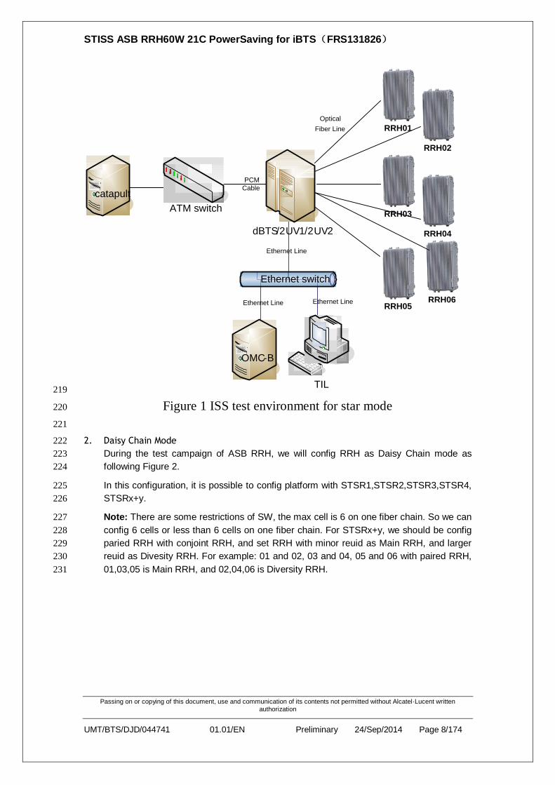
1. Star Mode 209
During the test campaign of ASB RRH, we will config RRH as Star mode as following 210
figure 1. 211
In this configuration, it is possible to config platform with STSR1, STSR2, STSR3, STSR4, 212
STSR x+y. 213
Note: There are some restrictions of SW, the max cell is 12 on BTS. So we can config 12 214
cells or less than 12 cells on BTS. For STSRx+y, we should be config paried RRH as 215
following configuration: 01 and 04, 02 and 05, 03 and 06 with paired RRH, 01,02,03 is 216
Main RRH, and 04,05,06 is Diversity RRH. 217
218
STISS ASB RRH60W 21C PowerSaving for iBTS(FRS131826)
Passing on or copying of this document, use and communication of its contents not permitted without Alcatel·Lucent written authorization
UMT/BTS/DJD/044741 01.01/EN Preliminary 24/Sep/2014 Page 8/174
Ethernet Line
Ethernet Line Ethernet Line
ATM switch
catapult
dBTS/2UV1/2UV2
Ethernet switch
TIL
OMC-B
PCM
Cable
RRH01
RRH02
RRH03
RRH04
RRH05
Optical
Fiber Line
RRH06
219
Figure 1 ISS test environment for star mode 220
221
2. Daisy Chain Mode 222
During the test campaign of ASB RRH, we will config RRH as Daisy Chain mode as 223
following Figure 2. 224
In this configuration, it is possible to config platform with STSR1,STSR2,STSR3,STSR4, 225
STSRx+y. 226
Note: There are some restrictions of SW, the max cell is 6 on one fiber chain. So we can 227
config 6 cells or less than 6 cells on one fiber chain. For STSRx+y, we should be config 228
paried RRH with conjoint RRH, and set RRH with minor reuid as Main RRH, and larger 229
reuid as Divesity RRH. For example: 01 and 02, 03 and 04, 05 and 06 with paired RRH, 230
01,03,05 is Main RRH, and 02,04,06 is Diversity RRH. 231

STISS ASB RRH60W 21C PowerSaving for iBTS(FRS131826)
Passing on or copying of this document, use and communication of its contents not permitted without Alcatel·Lucent written authorization
UMT/BTS/DJD/044741 01.01/EN Preliminary 24/Sep/2014 Page 9/174
Ethernet Line
Ethernet Line Ethernet Line
ATM switch
catapult
dBTS/2UV1/2UV2
Ethernet switch
TIL
OMC-B
PCM
Cable
RRH01
RRH02
RRH03
RRH04
RRH05
Optical Fiber Line
RRH06
232
Figure 2 ISS test environment for daisy chain mode 233
234
Hardware Requirement: 235
1) D2UV2/3 and V5 if available 236
2) ASB_RRH60W 21C with ASB and Gewei PA,Others vendors’ RE 237
3) AISG Full 2.0:Dual TMA AISG2.0,Single RET AISG2.0,Multi RET AISG2.0,ETC 238
4) RNC simulator :①Lamp or Lamp 239
5) UE simulator:①TM500 or data card 240
6) WMS (OMCB) server 241
7) Performance Spectrum Analyser 242
Software Requirement: 243
1) Test platform 2UV2/3/5 package(included ASB_RRH2X60W_850/1900/2100 244
package,TIL,etc ) 245
2) Lamp scripts(for auto case test) 246
Link Setup: 247
1) CPRI LINK BETWEEN ASB_RRH60W 21C AND D2U 248
2) CPRI LINK BETWEEN ASB_RRH60W 21C AND other REs 249
3) Ethernet cable between TIL and D2U 250
4) RF cable between TwinRRH and UE/UE simulator 251
5) Backhaul cable between D2U and RNC simulator 252
253
3.4 DEFECT AND TRACKING 254
The following rules will be adopted for feature ASB RRH 60 21C test progress tracking: 255
Weekly project synchronization meeting 256
Daily testing synchronization meeting 257
STISS ASB RRH60W 21C PowerSaving for iBTS(FRS131826)
Passing on or copying of this document, use and communication of its contents not permitted without Alcatel·Lucent written authorization
UMT/BTS/DJD/044741 01.01/EN Preliminary 24/Sep/2014 Page 10/174
Test case execution progress daily check via Quality Center. 258
DCT will be used as defect tracking tool259

STISS ASB RRH60W 21C PowerSaving for iBTS(FRS131826)
Passing on or copying of this document, use and communication of its contents not permitted without Alcatel·Lucent written authorization
UMT/BTS/DJD/044741 01.01/EN Preliminary 24/Sep/2014 Page 11/174
3.5 FRS REQUIREMENTS AND COMPLIANCES 260
3.5.1 FRS requirements and mapping 261
262
3.5.2 ISS TEST COVERAGE 263
1. regression coverage: 264
Basic functions
AISG 21
26% BASIC RADIO CALL 3
Specific functions
COMMEN MEASUREMENT 2
32%
FAULT MANAGEMENT 3
FUNCTIONMODE MANAGEMENT 4
OAM 4
RADIO MOBILITY 3
DOWNLOAD PHASE 3 8
LONG FIBER 2
TMA 3
V7 features
CAPACITY LICENSE IMPROVEMENT 2
42%
DAISY CHAIN 20
STSR X+Y 15
SUM 90 100%
Table 1: regression case coverage list 265
266

STISS ASB RRH60W 21C PowerSaving for iBTS(FRS131826)
Passing on or copying of this document, use and communication of its contents not permitted without Alcatel·Lucent written authorization
UMT/BTS/DJD/044741 01.01/EN Preliminary 24/Sep/2014 Page 12/174
267
2. feature coverage: 268
AISG 21 13.3%
ALARM 35 22.2%
FAULT MANAGEMENT 3 1.9%
BASIC RADIO 3 1.9%
MOBILITY 2 1.2%
RADIATING 3 1.9%
RADIO POWER 1 0.6%
MIX MODE 1 0.6%
LONG FIBER 2 1.2%
6 CPRI LINK 5 3.1%
POWER POOLING 2 1.2%
DAISY CHAIN 20 12.7%
STSRX+Y 15 9.5%
CAPACITY LICENSE 2 1.2%
PA AUTO SWITCH OFF 1 0.6%
LED FOR ASB RRH 2 1.2%
VSWR 5 3.1%
SINGLE RX PORT 2 1.2%
EXTERNAL ALARM 1 0.6%
UNBLANCE RF POWER 1 0.6%
AC POWER 3 1.9%
PM COUNTER 5 3.1%
OAM 4 2.5%
POWER SAVING 8 5%
STABILITY 10 7.4%
Total 157 100%
Table 2 : feature case coverage list 269
270
271
272

STISS ASB RRH60W 21C PowerSaving for iBTS(FRS131826)
Passing on or copying of this document, use and communication of its contents not permitted without Alcatel·Lucent written authorization
UMT/BTS/DJD/044741 01.01/EN Preliminary 24/Sep/2014 Page 13/174
4 TESTS DESCRIPTION 273
4.1 Regression Test 274
4.1.1. OAM TEST 275
4.1.1.1. PM_COUNTER 276
Test label 1:PM_COUNTER_10201_RADIO_WBAND_RX_MAIN_PWR 277
Purpose: 278
The purpose of this test is to check the management of RadioWBandRxMainPwr counters 279
Requirement: 280
Platform configuration applicable 281
Lamp connection 282
At least 2 RRH/TRDU connections 283
Discussion: 284
This load counter is used to measure the min/max/avg of the WideBand received power per sector per 285
frequency at the Rx Main Channelizer as detected by RRH/TRDU. The values are shown in 10^-12 286
mW. 287
Procedure: 288
Step1:connecte NodeB to OMC-B, make sure ASU connected 289
Step2:setup 1 cell 290
Step3:in PM menu, activate the fastclock for pm file generation, PMFastclock a, check Result1&2 291
Step4:delete this cell, setup 1 cell on the other RRH/TRDU, check Result3 292
Expectable results: 293
Result1:check that the min/max/avg values shown by counter #10201 under PM>display 294
Result2:the values are shown in 10-12 mW, and as same as what is reported from RRH/TRDU 295
Result3:after cell setupcell deletioncell setup, the counter could collect and report continuously 296
297
STISS ASB RRH60W 21C PowerSaving for iBTS(FRS131826)
Passing on or copying of this document, use and communication of its contents not permitted without Alcatel·Lucent written authorization
UMT/BTS/DJD/044741 01.01/EN Preliminary 24/Sep/2014 Page 14/174
298
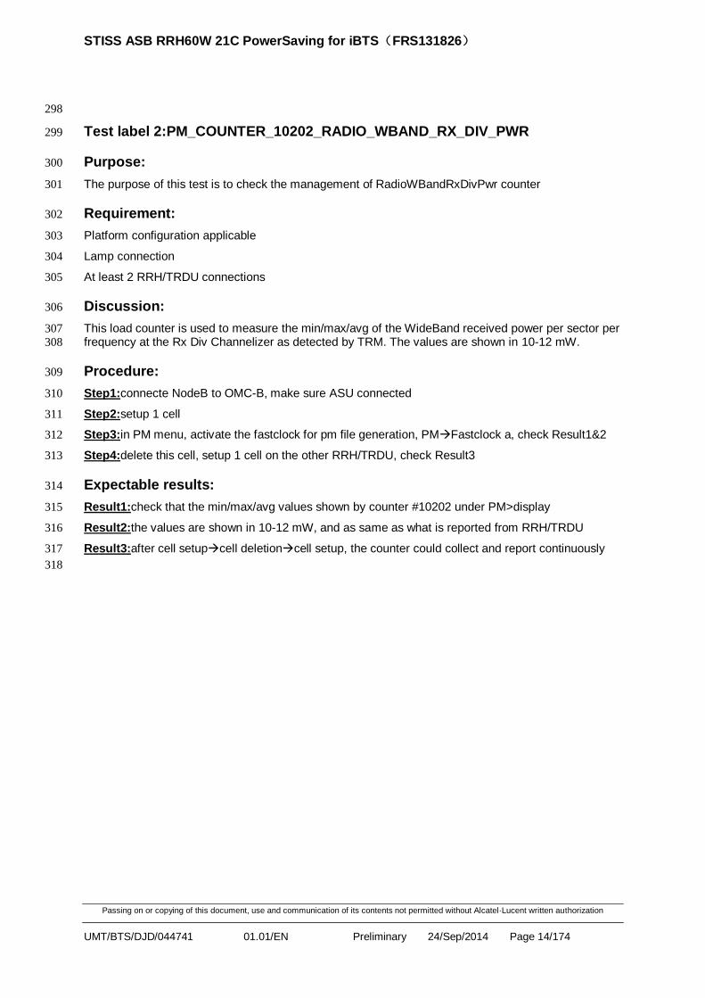
Test label 2:PM_COUNTER_10202_RADIO_WBAND_RX_DIV_PWR 299
Purpose: 300
The purpose of this test is to check the management of RadioWBandRxDivPwr counter 301
Requirement: 302
Platform configuration applicable 303
Lamp connection 304
At least 2 RRH/TRDU connections 305
Discussion: 306
This load counter is used to measure the min/max/avg of the WideBand received power per sector per 307
frequency at the Rx Div Channelizer as detected by TRM. The values are shown in 10-12 mW. 308
Procedure: 309
Step1:connecte NodeB to OMC-B, make sure ASU connected 310
Step2:setup 1 cell 311
Step3:in PM menu, activate the fastclock for pm file generation, PMFastclock a, check Result1&2 312
Step4:delete this cell, setup 1 cell on the other RRH/TRDU, check Result3 313
Expectable results: 314
Result1:check that the min/max/avg values shown by counter #10202 under PM>display 315
Result2:the values are shown in 10-12 mW, and as same as what is reported from RRH/TRDU 316
Result3:after cell setupcell deletioncell setup, the counter could collect and report continuously 317
318

STISS ASB RRH60W 21C PowerSaving for iBTS(FRS131826)
Passing on or copying of this document, use and communication of its contents not permitted without Alcatel·Lucent written authorization
UMT/BTS/DJD/044741 01.01/EN Preliminary 24/Sep/2014 Page 15/174
References : 319
Test label 1:PM_COUNTER_10204_MCPA_PWR 320
Purpose: 321
The purpose of this test is to check the management of MCPAPwr counter 322
Requirement: 323
Platform configuration applicable 324
Lamp connection 325
At least 2 RRH/TRDU connections 326
Discussion: 327
This load counter is used to measure the min/max/avg of the output MCPA Power detected by 328 RRH/TRDU. The values are shown in mW. 329
Procedure: 330
Step1:connecte NodeB to OMC-B, make sure ASU connected 331
Step2:setup 1 cell 332
Step3:in PM menu, activate the fastclock for pm file generation, PMFastclock a, check Result1&2 333
Step4:delete this cell, setup 1 cell on the other RRH/TRDU, check Result3 334
Expectable results: 335
Result1:check that the min/max/avg values shown by counter #10204 under PM>display 336
Result2:the values are shown in mW. In cpri mode, RRH/TRDU won’t report PA power to Rack2u. Now 337
the implemetion is that min/max value=0, avg/evt=
ncell
cell
Txpower0 /frequency number 338
Result3:after cell setupcell deletioncell setup, the counter could collect and report continuously the 339
occurence of ./Board/RRH or ./Board/TRDU should be equal to physical number of RRH/TRDU when 340 its status is L3_connected && Unlocked && SoftStateOk, nothing with cell setup and cell deletion 341
RRH/TRDU object identifier should be correct in pm files 342
343

STISS ASB RRH60W 21C PowerSaving for iBTS(FRS131826)
Passing on or copying of this document, use and communication of its contents not permitted without Alcatel·Lucent written authorization
UMT/BTS/DJD/044741 01.01/EN Preliminary 24/Sep/2014 Page 16/174
344
Test label 4:PM_COUNTER_10205_RADIO_TX_CARRIER_PWR 345
Purpose: 346
The purpose of this test is to check the management of the RadioTxCarrierPwr counter 347
Requirement: 348
Platform configuration applicable 349
Lamp connection 350
At least 2 RRH/TRDU connections 351
Discussion: 352
This load counter is used to measure the min/max/avg of the total transmitted power per sector per 353
frequency at the Tx channelizer as detected by RRH/TRDU. The values are shown in mW. 354
Procedure: 355
Step1:connecte NodeB to OMC-B, make sure ASU connected 356
Step2:setup 1 cell 357
Step3:in PM menu, activate the fastclock for pm file generation, PMFastclock a, check result1&2 358
Step4:delete this cell, setup 1 cell on the other RRH/TRDU, check result3 359
Expectable results: 360
Result1:check that the min/max/avg values shown by counter #10205 under PM>display 361
Result2:the values are shown in mW, and as same as what is reported from RRH/TRDU 362
counter #10205 screening 0 is correspond to maxpower, counter #10205 screening 1 is correspond to 363
current tx power. Basic check:all the observed max powers have to be geater than the used powers 364
Result3:after cell setupcell deletioncell setup, the counter could collect and report continuously 365
366
Test label 5:PM_COUNTER_10403_CPU_Load 367
Purpose: 368
The purpose of this test is to check the CPU load counter. 369
Requirement: 370
Platform configuration applicable 371
Lamp connection 372
At least 2 RRH/TRDU connections 373
Discussion: 374
This load counter is used to measure the min/max/avg of the output CPU load detected by RRH/TRDU. 375
The values are shown in percentage. 376
Procedure: 377
Step1:connecte NodeB to OMC-B, make sure ASU connected 378
Step2:setup 1 cell 379

STISS ASB RRH60W 21C PowerSaving for iBTS(FRS131826)
Passing on or copying of this document, use and communication of its contents not permitted without Alcatel·Lucent written authorization
UMT/BTS/DJD/044741 01.01/EN Preliminary 24/Sep/2014 Page 17/174
Step3:in PM menu, activate the fastclock for pm file generation, PMFastclock a, 380
Step4:delete this cell, setup 1 cell on the other RRH, 381
Expectable results: 382
- The values are shown in percentage as same as that reported from RRH/TRDU. And the cpu load 383
should not be very high, about 50-60% 384
- After cell setupcell deletioncell setup, the counter could collect and 385
report continuously 386
- the occurence of ./Board/RRH or ./Board/TRDU should be equal to physical number of 387 RRH/TRDU when its status is L3_connected && Unlocked && SoftStateOk, nothing with cell setup 388
and cell deletion 389
- RRH/TRDU object identifier should be correct in pm files. 390
391

STISS ASB RRH60W 21C PowerSaving for iBTS(FRS131826)
Passing on or copying of this document, use and communication of its contents not permitted without Alcatel·Lucent written authorization
UMT/BTS/DJD/044741 01.01/EN Preliminary 24/Sep/2014 Page 18/174
392
4.1.1.2. OMCB OPERATION 393
Test label 6:OAM_OMCB_BTS_LOCK_UNLOCK 394
Purpose: 395
Check BTS will under control of OMCB when unlock BTS while BTS will out of control of OMB when 396
lock BTS 397
Requirement: 398
The NodeB is connected to the lamp and configured 399
Procedure: 400
Step1:lock the BTS 401
Step2:unlock the BTS 402
Step3:lock BTS in OMCB and restart the BTS 403
Expectable results: 404
Result1:Check BTS could be unlocked from OMCB 405
When BTS is unlock, BTS could be controlled from OMCB(SW upgrade, 406
Equipment Monitor, etc.) 407
In emo->bts, show OMCB connection 408
Check on lamp, all local cells status won’t be impacted 409
Result2:Check BTS could be locked from OMCB 410
When BTS is lock, BTS could not be controlled from OMCB(SW upgrade, 411
Equipment Monitor, etc.) 412
In emo->bts, show OMCB disconnection 413
Check on lamp, all local cells status won’t be impacted 414
Result3:After BTS startup, the BTS is keeping locked. 415
416

STISS ASB RRH60W 21C PowerSaving for iBTS(FRS131826)
Passing on or copying of this document, use and communication of its contents not permitted without Alcatel·Lucent written authorization
UMT/BTS/DJD/044741 01.01/EN Preliminary 24/Sep/2014 Page 19/174
Test label 7:OAM_OMCB_RRH_LOCK_UNLOCK 417
Purpose: 418
Check the cell(s) are correctly configured when RRH (in STSR-1) is locked and unlocked 419
Requirement: 420
The NodeB is connected to the lamp and configured 421
Procedure: 422
Step1:lock the RRH, check result1 423
Step2:unlock the RRH, check result2 424
Step3:send commands from lamp in order to configure the Cells, Fach and Rach channels, check 425
result3 426
Step4:send a Radio Link Setup command, check result4 427
Step5:lock the RRH and restart the NodeB, check result5 428
Expectable results: 429
Result1:check that all the local cells are disabled (Audit Response message raised to the lamp 430
including all the local cells to delete) 431
Check RRH administrative state on CCM menu 432
Check RRH object appears as locked on the OMC-B 433
Result2:when RRH is up, check that all the local cells are enabled (RSI message raised to the lamp 434
including the local cells to add) 435
Check RRH object appears as unlocked on the OMC-B 436
Check RRH administrative state on CCM menu 437
Result3:check cell setup response, Fachsetup response and Rachsetup response are successful. 438
Result4:check Radio Link setup response message is raised to the lamp 439
Result5:when NodeB is up, check the RRH remains locked (no local cell enabled raised to the lamp) 440
441

STISS ASB RRH60W 21C PowerSaving for iBTS(FRS131826)
Passing on or copying of this document, use and communication of its contents not permitted without Alcatel·Lucent written authorization
UMT/BTS/DJD/044741 01.01/EN Preliminary 24/Sep/2014 Page 20/174
442
4.1.1.3. TIL OPERATION 443
Test label 8: OAM_TIL_UPGRADE 444
Purpose: 445
Check the TIL restarts correctly after an upgrade 446
Requirement: 447
TIL connection 448
Procedure: 449
Step1:connect TIL download a new s/w to NodeB 450
Step2:once download is completed, give activation and reset from TIL, then check result1&2 451
Expectable results: 452
Result1:check whether NodeB comes up properly with the new upgraded load 453
Result2:connect to TIL and check the board states 454
455
Test label 2:OAM_TIL_RESET_RRH 456
Purpose: 457
Check Reset command for RRH from TIL 458
Requirement: 459
TIL connection 460
Lamp connection 461
Procedure: 462
Step1:On TIL, send a reset to the RRH on the CxOIM. 463
464
Step 2:On TIL, send a reset to the RRH on the RRH display 465

STISS ASB RRH60W 21C PowerSaving for iBTS(FRS131826)
Passing on or copying of this document, use and communication of its contents not permitted without Alcatel·Lucent written authorization
UMT/BTS/DJD/044741 01.01/EN Preliminary 24/Sep/2014 Page 21/174
466
Step 3:Repeat this action several times 467
Expectable results: 468
Result1:RRH chould be reset and up normally, check that all the local cells are enabled (Audit 469
response message raised to the lamp including the local cells to add). 470
Result2:RRH chould be reset and up normally, check that all the local cells are enabled (Audit 471
response message raised to the lamp including the local cells to add). 472
Result3:BTS should work stable afer repeat RRH reset 473
474

STISS ASB RRH60W 21C PowerSaving for iBTS(FRS131826)
Passing on or copying of this document, use and communication of its contents not permitted without Alcatel·Lucent written authorization
UMT/BTS/DJD/044741 01.01/EN Preliminary 24/Sep/2014 Page 22/174
475
Test label 9:OAM_TIL_SNAPSHOT 476
Purpose: 477
Check SnapShot information provided by TIL 478
Requirement: 479
Platform configuration applicable 480
TIL connection 481
Procedure: 482
Step1:TILRight Click RRH/TRDUSnapShot, check result1 483
484
Expectable results: 485
Result1:check that the RRH/TRDU SnapShot displayed is full and correct 486
4.1.2. RADIO TEST 487
4.1.2.1. BASIC CALL 488
Test label 10:R99_Call 489
Purpose: 490
Check that the NodeB can correctly communicate with a TM500 on both UL and DL for a designated 491 Radio Bearer 492
Requirement: 493
RNC simulator (lamp) 494
Platform configuration applicable 495
Test mobile (TM500) 496
The radio configuration is STSRx+y in star/chain mode or STSRz in daisy chain mode 497
Procedure: 498
Step1:send a CELL SETUP REQUEST from lamp, check Result1 499

STISS ASB RRH60W 21C PowerSaving for iBTS(FRS131826)
Passing on or copying of this document, use and communication of its contents not permitted without Alcatel·Lucent written authorization
UMT/BTS/DJD/044741 01.01/EN Preliminary 24/Sep/2014 Page 23/174
Step2:establish a radio link (AMR_12k2, ps32k, ps64k, ps128k and ps384k) each cell on the NodeB 500
and on the TM500, check Result2 501
Step3:generate AAL2 traffic and check the BLER value, on Uplink and Downlink, Check Result3 502
Expected results: 503
Result1:lamp receive a CELL SETUP RESPONSE 504
Result2:radio link setup response received by both lamp and TM500 505
Result3:BLER value on both UL and DL should be inferior to 0.1% 506
(The below is an example of Lamp command and TM500 script by manual test) 507
AMR_12k2
Lamp TM500
cellset 0
fachset 0
rachset 0
rlset 0 1 amr_12k2_6
cellsearch
UBI_SETUP_BCH_SC1
UBI_SETUP_AMR_12K2_6TFC_OVSF65_SC1
test 1
//check Bler on capa
UBI_CLEARSTATS
GETSTATS_CELL
GETSTATS_DCH
508
PS_32k
Lamp TM500
cellset 0
fachset 0
rachset 0
rlset 0 1 ps_32k_10
cellsearch
UBI_SETUP_BCH_SC1
UBI_SETUP_PS_32K_10TFC_OVSF5_SC1
test 1
//check Bler on capa
UBI_CLEARSTATS
GETSTATS_CELL
GETSTATS_DCH

STISS ASB RRH60W 21C PowerSaving for iBTS(FRS131826)
Passing on or copying of this document, use and communication of its contents not permitted without Alcatel·Lucent written authorization
UMT/BTS/DJD/044741 01.01/EN Preliminary 24/Sep/2014 Page 24/174
509
PS_64k
Lamp TM500
cellset 0
fachset 0
rachset 0
rlset 0 1 ps_64k_10
cellsearch
UBI_SETUP_BCH_SC1
UBI_SETUP_PS_64K_10TFC_OVSF5_SC1
test 1
//check Bler on capa
UBI_CLEARSTATS
GETSTATS_CELL
GETSTATS_DCH
510
PS_128k
Lamp TM500
cellset 0
fachset 0
rachset 0
rlset 0 1 ps_128k_10
cellsearch
UBI_SETUP_BCH_SC1
UBI_SETUP_PS_128K_10TFC_OVSF5_SC1
test 1
//check Bler on capa
UBI_CLEARSTATS
GETSTATS_CELL
GETSTATS_DCH
511
PS_384k
Lamp TM500
cellset 0
fachset 0
rachset 0

STISS ASB RRH60W 21C PowerSaving for iBTS(FRS131826)
Passing on or copying of this document, use and communication of its contents not permitted without Alcatel·Lucent written authorization
UMT/BTS/DJD/044741 01.01/EN Preliminary 24/Sep/2014 Page 25/174
rlset 0 1 ps_384k_12 initialsir=150
cellsearch
UBI_SETUP_BCH_SC1
UBI_SETUP_PS_384K_12TFC_OVSF5_SC1
test 1
//check Bler on capa
UBI_CLEARSTATS
GETSTATS_CELL
GETSTATS_DCH
512
513

STISS ASB RRH60W 21C PowerSaving for iBTS(FRS131826)
Passing on or copying of this document, use and communication of its contents not permitted without Alcatel·Lucent written authorization
UMT/BTS/DJD/044741 01.01/EN Preliminary 24/Sep/2014 Page 26/174
514
Test label 11:HSDPA_Call 515
Purpose: 516
Check that the NodeB can correctly communicate with a TM500 on both UL and DL for an hsdpa128 517
Requirement: 518
RNC simulator (lamp) 519
Platform configuration applicable 520
Test mobile (TM500) 521
The radio configuration is STSRx+y in star/chain mode or STSRz in daisy chain mode 522
Procedure: 523
Step1:send a CELL SETUP REQUEST from lamp, check Result1 524
Step2:establish a radio link respectively (hsdpa128) on each cell of HSDPA activation and on the 525
TM500, check Result2 526
Step3:generate AAL2 traffic and check the BLER value, on Uplink and Downlink, check Result3 527
Expected results: 528
Result1:lamp receive a CELL SETUP RESPONSE 529
Result2:radio link setup response received by both lamp and TM500 530
Result3:BLER value on both UL and DL should be inferior to 0.1% 531
(The below is an example of Lamp command and TM500 script by manual test) 532
HSDPA
Lamp TM500
cellset 0
fachset 0
rachset 0
physcrec 0
rlset 0 1 hsdpa128
cellsearch
UBI_SETUP_BCH_SC1
UBI_SETUP_HSDPA_ASSOCIATED_DCH_UL128_OVSF65_SC1
FORCE_NACK_9ACK_CQI
UBI_SETUP_HSDPA_RL_L1_SC1_CAT12
test 1 mode=1 capareq=1 delay=100
//check Bler on capa
//check DL rate by TM500
UBI_CLEARSTATS
GETSTATS_CELL

STISS ASB RRH60W 21C PowerSaving for iBTS(FRS131826)
Passing on or copying of this document, use and communication of its contents not permitted without Alcatel·Lucent written authorization
UMT/BTS/DJD/044741 01.01/EN Preliminary 24/Sep/2014 Page 27/174
GETSTATS_DCH
GETSTATS_HSDPA
533
534

STISS ASB RRH60W 21C PowerSaving for iBTS(FRS131826)
Passing on or copying of this document, use and communication of its contents not permitted without Alcatel·Lucent written authorization
UMT/BTS/DJD/044741 01.01/EN Preliminary 24/Sep/2014 Page 28/174
535
Test label 12:HSUPA_Call 536
Purpose: 537
Check that the NodeB can correctly communicate with a TM500 on both UL and DL for an hsdpa_edch 538
Requirement: 539
RNC simulator (lamp) 540
Platform configuration applicable 541
Test mobile (TM500) 542
The radio configuration is STSRx+y in star/chain mode or STSRz in daisy chain mode 543
Procedure: 544
Step1:send a CELL SETUP REQUEST from lamp, check Result1 545
Step2:establish a radio link respectively (hsdpa_edch) on each cell of HSUPA activation and on the 546
TM500, check Result2 547
Step3:generate AAL2 traffic and check the BLER value, on Uplink and Downlink, check Result3 548
Expectable results: 549
Result1:lamp receive a CELL SETUP RESPONSE 550
Result2:radio link setup response received by both lamp and TM500 551
Result3:BLER value on both UL and DL should be inferior to 0.1% 552
(The below is an example of Lamp command and TM500 script by manual test) 553
HSUPA ( L1)
Lamp TM500
cellset 0
fachset 0
rachset 0
physcrec 0 type=full
rlset 0 1 hsdpa_edch
cellsearch
UBI_SETUP_BCH_SC1
UBI_SETUP_SRB_3K4_OVSF65_SC1
UBI_SETUP_HSDPA_EDCH_PN_ALL_N_TABLE_1_SC1_n1
test 1 mode=1 edch_mode=1
//check Bler on capa
//check DL and UL rate by TM500
UBI_CLEARSTATS
GETSTATS_CELL

STISS ASB RRH60W 21C PowerSaving for iBTS(FRS131826)
Passing on or copying of this document, use and communication of its contents not permitted without Alcatel·Lucent written authorization
UMT/BTS/DJD/044741 01.01/EN Preliminary 24/Sep/2014 Page 29/174
GETSTATS_DCH
GETSTATS_HSDPA
GETSTATS_HSUPA
554
HSUPA ( L2)
Lamp TM500
cellset 0
fachset 0
rachset 0
physcrec 0 type=full
rlset 0 1 hsdpa_edch
cellsearch
L2_SETUP_BCH_10612_9662_SC1
L2_SETUP_DCH_SC1
L2_SETUP_HSDPA_SC1
L2_SETUP_EDCH_SC1
test 1 mode=1 edch_mode=1
L2_config_MAC_e
L2_SI_0_20
L2_SI_0_97
//check Bler on capa
//check DL and UL rate by TM500
555
4.1.2.2. RADIO POWER TEST 556
STISS ASB RRH60W 21C PowerSaving for iBTS(FRS131826)
Passing on or copying of this document, use and communication of its contents not permitted without Alcatel·Lucent written authorization
UMT/BTS/DJD/044741 01.01/EN Preliminary 24/Sep/2014 Page 30/174
Test label 13:Radio_RSSI_Verification 557
Purpose: 558
The goal of this test case is to verify the RSSI reported at RRH/TRDU side is as expected at any case 559
Requirements: 560
1. Platform configuration applicable: 561
2. The BTS is connected to the lamp and configured 562
Procedure: 563
Step1:Thanks to Lamp, cellset without any signal injection, then Start the common measurement with 564
the command: 565
Startcmeas cellid measurementid 566
Step2:Check RTWP reported on RRH/TRDU side and Lamp side 567
Step3:Disconnect one antenna connection. Thanks to Lamp, cellset without any signal injection, then 568
Start the common measurement with the command: 569
Startcmeas cellid measurementid 570
Step4:Check RTWP reported on RRH/TRDU side and Lamp side 571
Expectable results: 572
Step2:the RTWP reported should around -106dbm 573
Step4:the RTWP reported on the broken antenna should 0dbm 574
4.1.2.3. R99 TEST 575
Test label 14:RADIO_DCH_PS_1_NIGHT 576
Purpose: 577
Check a DCH Packet Switch (PS) call during 1 night. 578
Requirement: 579
1. A RNC simulator (Lamp) to send the NBAP procedures to the NodeB. 580
2. A UE simulator (Ubinetics TM500). 581
Test inputs: 582
CPRI Interface type:Electric / Optic 583
CEM type:xCEM only / iCEM only / xCEM iCEM mix 584
RF Configuration:STSR1 / STSR2 / STSR3 585
Frequency:B / M / T 586
Bearer:ex:PS_64K_10 587
Cell:0 / 1 / 2 … 588
The UL & DL SIR targets should relate to good radio conditions, ex:5 dB in DL / 10 dB in UL. 589
Only one cell need to be up. 590
Setup the PS call as described in [R12] (PS_64K_10 tab for instance). 591
All the NBAP messages should be processed successfully by the NodeB. 592
The DL BLER should be equal to 0 on the UE simulator. 593

STISS ASB RRH60W 21C PowerSaving for iBTS(FRS131826)
Passing on or copying of this document, use and communication of its contents not permitted without Alcatel·Lucent written authorization
UMT/BTS/DJD/044741 01.01/EN Preliminary 24/Sep/2014 Page 31/174
The UL BLER should be equal to 0 on the RNC simulator. 594
The NodeB debug information should be consistent (cap > ctx). 595
The call must be checked during 1 night (the AAL2 traffic should not be disrupted during the 596
night). 597
No alarm should be raised on the NodeB. 598
599

STISS ASB RRH60W 21C PowerSaving for iBTS(FRS131826)
Passing on or copying of this document, use and communication of its contents not permitted without Alcatel·Lucent written authorization
UMT/BTS/DJD/044741 01.01/EN Preliminary 24/Sep/2014 Page 32/174
. 600
4.1.2.4. HSUPA RESOURCE 601
Test label 15:RADIO_HSUPA_1_NIGHT 602
603
Purpose: 604
Check a HSUPA call. 605
Requirement: 606
1. A RNC simulator (Lamp) to send the NBAP procedures to the NodeB. 607
2. A UE simulator (Ubinetics TM500). 608
609
Test inputs: 610
CPRI Interface type:Electric / Optic 611
CEM type:xCEM only / iCEM only / xCEM iCEM mix 612
RF Configuration:STSR1 / STSR2 / STSR3 613
Frequency:B / M / T 614
Cell:0 / 1 / 2 … 615
616
The UL & DL SRB SIR targets should relate to good radio conditions, ex:5 dB in DL / 10 dB in UL. 617
Only one cell need to be up. 618
A HSDPA UE category 12 will be simulated. 619
The default values for the HSDPA parameters will be applied in the NodeB MIB (DLU), except the 620
hsdpaCqiBlerAdjustmentAlgorithm that will be turned off (0). 621
The default values for the EDCH parameters will be applied in the NodeB MIB (DLU). 622
Procedure : 623
Setup the HSUPA call as described in [R12] (HSUPA_L1L2 tab). 624
625
All the NBAP messages should be processed successfully by the NodeB. 626
The DL DCH SRB & HS-DSCH BLER should be equal to 0 on the UE simulator. 627
The UL PS SRB & EDCH BLER should be equal to 0 on the RNC simulator. 628
The NodeB debug information should be consistent (cap > ctx). 629
The UE simulator debug information should be consistent (MACESND logging window -> PDU 630 size, PDU Txed/ACK/NACK, BLER). 631
The call must be checked during 1 night (the AAL2 traffic should not be disrupted during the 632
night). 633
No alarm should be raised on the NodeB. 634
4.1.2.5. MOBILITY TEST 635
636

STISS ASB RRH60W 21C PowerSaving for iBTS(FRS131826)
Passing on or copying of this document, use and communication of its contents not permitted without Alcatel·Lucent written authorization
UMT/BTS/DJD/044741 01.01/EN Preliminary 24/Sep/2014 Page 33/174
637
Test label 16:Mobility_Softer_HO_HSDPA_to_R99 638
Purpose: 639
Check that a complete procedure of softer handover from a cell supporting HSDPA service to a cell 640
supporting only R99 is successfully 641
Requirement: 642
Platform configuration applicable 643
Lamp connection 644
TM500 connection 645
The radio configuration in Daisy chain mode or STSRx+y mode or both mixed mode 646
Make sure two cells which will do the softer handover have the same frequency 647
Procedure: 648
Step1:setup a RL on cell1 with HSDPA and synchronize the UE with it 649
Step2:the mobile should synchronize on this RL 650
Step3:add RL2 (DCH leg on the target cell) which is identical to the ADCH link 651
Step4:perform a SRLR procedure that will delete the HS-DSCH on the source cell and modify 652
associated parts of both legs to DCH 653
Step5:delete initial leg 654
Expectable results: 655
Result1:all these procedures must be successful and the RL established in DCH on the target cell 656
657

STISS ASB RRH60W 21C PowerSaving for iBTS(FRS131826)
Passing on or copying of this document, use and communication of its contents not permitted without Alcatel·Lucent written authorization
UMT/BTS/DJD/044741 01.01/EN Preliminary 24/Sep/2014 Page 34/174
658
Test label 17:Mobility_Softer_HO_R99_to_HSDPA 659
Purpose: 660
Check that a complete procedure of softer handover from a cell in R99 to a cell supporting HSDPA is 661
successfully 662
Requirement: 663
Platform configuration applicable 664
Lamp connection 665
TM500 connection 666
The radio configuration in Daisy chain mode or STSRx+y mode or both mixed mode 667
Make sure two cells which will do the softer handover have the same frequency 668
Procedure: 669
Step1:setup a RL on cell1 in DCH and synchronize the UE with it 670
Step2:the mobile should synchronize on this RL 671
Step3:add a leg, to the initial DCH bearer, on the target cell 672
Step4:perform a SRLR procedure that will reconfigure initial leg to an ADCH and the target leg to 673
HSDPA, adding the HSDSCH part 674
Step5:delete the initial leg 675
Expectable results: 676
Result1:all these procedures must be successful and the RL established in HSDPA on the target cell 677
678
STISS ASB RRH60W 21C PowerSaving for iBTS(FRS131826)
Passing on or copying of this document, use and communication of its contents not permitted without Alcatel·Lucent written authorization
UMT/BTS/DJD/044741 01.01/EN Preliminary 24/Sep/2014 Page 35/174
679
4.1.2.6. RADIATING 680
Test label 18:RADIATING_RADIATING_ON_ONE_CELL 681
Purpose: 682
Check the radiating user interface on TIL displays and works correctly 683
Requirement: 684
1. Platform configuration applicable: 685
2. TIL connection 686
3. Spectrum analyzer connection at antenna output 687
4. The TIL is started and the BTS is not built. 688
Procedure: 689
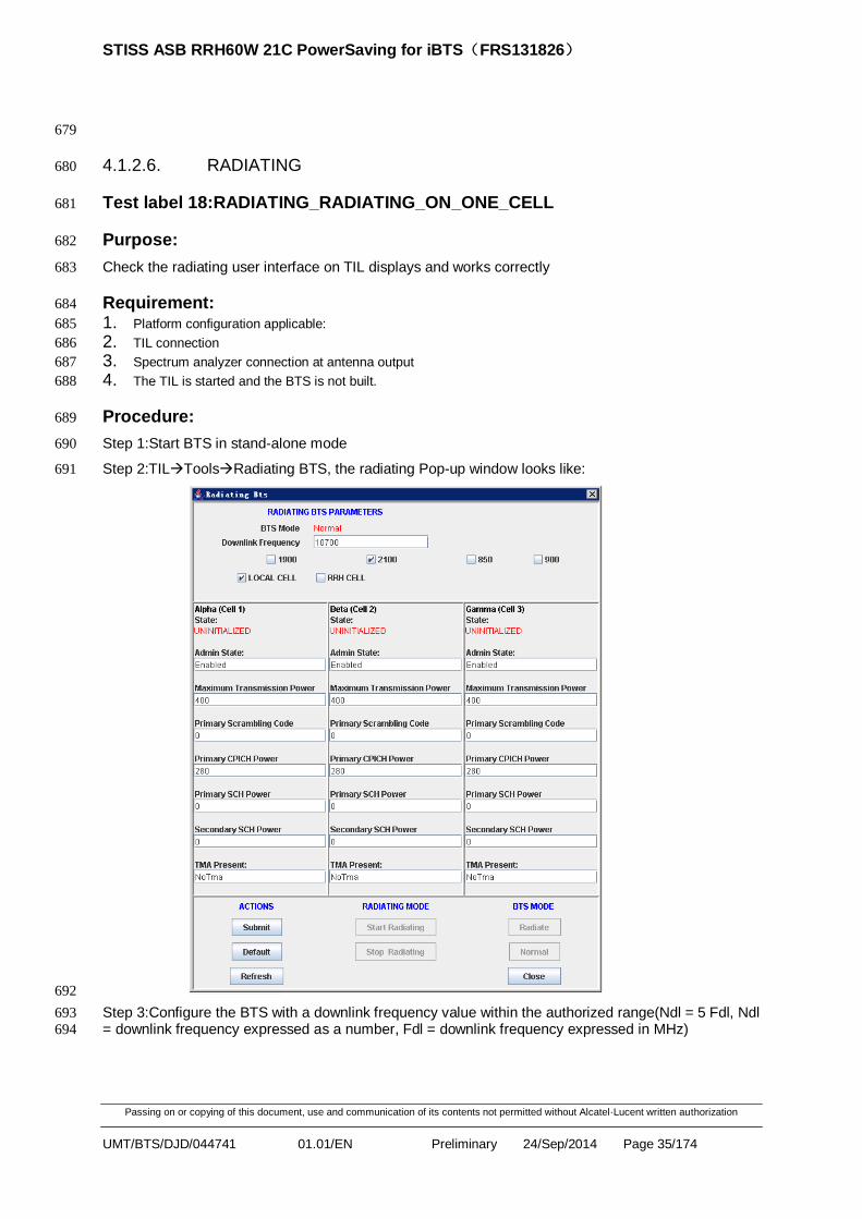
Step 1:Start BTS in stand-alone mode 690
Step 2:TILToolsRadiating BTS, the radiating Pop-up window looks like: 691
692
Step 3:Configure the BTS with a downlink frequency value within the authorized range(Ndl = 5 Fdl, Ndl 693
= downlink frequency expressed as a number, Fdl = downlink frequency expressed in MHz) 694

STISS ASB RRH60W 21C PowerSaving for iBTS(FRS131826)
Passing on or copying of this document, use and communication of its contents not permitted without Alcatel·Lucent written authorization
UMT/BTS/DJD/044741 01.01/EN Preliminary 24/Sep/2014 Page 36/174
BAND Carrier frequency (FUL) range [MHz]
Carrier frequency (FDL) range [MHz]
FUL_low FUL_high FDL_low FDL_high
I 1922.4 1977.6 2112.4 2167.6
II 1852.4 1907.6 1932.4 1987.6
IV 1712.4 1752.6 2112.4 2152.6
V 826.4 846.6 871.4 891.6
Step 4:RRH/TRDU cell selected 695
Step 5:Configure Max Trasmission Power, Primary Scrambling Code, Primary CPICH code, Priamry 696
SCH Power, Secondary SCH Power as the authorized range 697
Step 6:Activate radiating mode with all only 1 cell enabled. 698
Expectable results: 699
Check that the BTS resets in stand-alone mode when radiating mode is activated;; 700
Check Downlink Frequency, Max Trasmission Power, Primary Scrambling Code, Primary CPICH code, 701
Priamry SCH Power, Secondary SCH Power field could be edited 702
Check that RRH/TRDU cell could radiating successfully after activating radiating 703
Verify that the resulting spectrum corresponds to expected frequency and power levels displays 704
correctly on spectrum analyzer. 705
STISS ASB RRH60W 21C PowerSaving for iBTS(FRS131826)
Passing on or copying of this document, use and communication of its contents not permitted without Alcatel·Lucent written authorization
UMT/BTS/DJD/044741 01.01/EN Preliminary 24/Sep/2014 Page 37/174
706
Test label 19:RADIATING_UPPER_LIMIT_OF_DOWNLINK _FREQUENCY 707
Purpose: 708
Radiate the BTS in STSR1 configuration with upper limit of downlink frequency. 709
Requirement: 710 1. Platform configuration applicable: 711 2. TIL connection 712 3. BTS is in STSR configuration 713 - Spectrum analyzer connection at antenna output 714
Procedure: 715
Step 1:The TIL is started and the BTS is starting in stand-alone mode and not built. 716
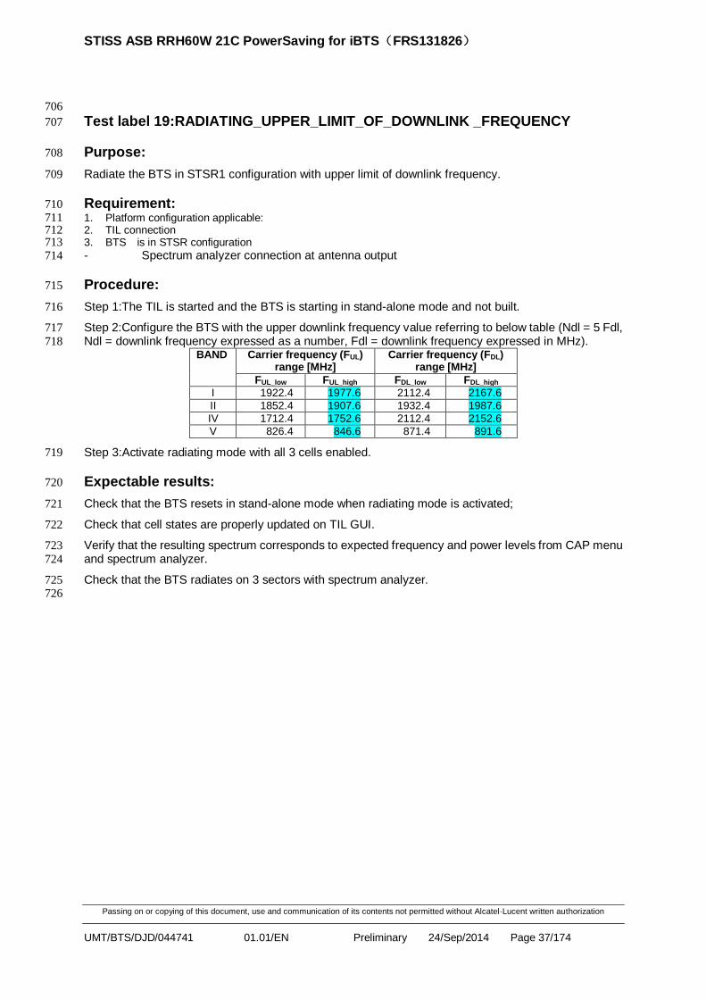
Step 2:Configure the BTS with the upper downlink frequency value referring to below table (Ndl = 5 Fdl, 717
Ndl = downlink frequency expressed as a number, Fdl = downlink frequency expressed in MHz). 718 BAND Carrier frequency (FUL)
range [MHz] Carrier frequency (FDL)
range [MHz]
FUL_low FUL_high FDL_low FDL_high
I 1922.4 1977.6 2112.4 2167.6
II 1852.4 1907.6 1932.4 1987.6
IV 1712.4 1752.6 2112.4 2152.6
V 826.4 846.6 871.4 891.6
Step 3:Activate radiating mode with all 3 cells enabled. 719
Expectable results: 720
Check that the BTS resets in stand-alone mode when radiating mode is activated; 721
Check that cell states are properly updated on TIL GUI. 722
Verify that the resulting spectrum corresponds to expected frequency and power levels from CAP menu 723
and spectrum analyzer. 724
Check that the BTS radiates on 3 sectors with spectrum analyzer. 725 726

STISS ASB RRH60W 21C PowerSaving for iBTS(FRS131826)
Passing on or copying of this document, use and communication of its contents not permitted without Alcatel·Lucent written authorization
UMT/BTS/DJD/044741 01.01/EN Preliminary 24/Sep/2014 Page 38/174
Test label 20:RADIATING_LOWER LIMIT_OF_DOWNLINK_FREQUENCY 727
Purpose: 728
Radiate the BTS in STSR1 configuration with lower limit of downlink frequency. 729
Requirement: 730 4. Platform configuration applicable: 731 5. TIL connection 732 6. BTS is in STSR configuration 733 - Spectrum analyzer connection at antenna output 734
Procedure: 735
Step 1:The TIL is started and the BTS is starting in stand-alone mode and not built. 736
Step 2:Configure the BTS with the lower downlink frequency value referring to below table (Ndl = 5 Fdl, 737
Ndl = downlink frequency expressed as a number, Fdl = downlink frequency expressed in MHz). 738 BAND Carrier frequency (FUL)
range [MHz] Carrier frequency (FDL)
range [MHz]
FUL_low FUL_high FDL_low FDL_high
I 1922.4 1977.6 2112.4 2167.6
II 1852.4 1907.6 1932.4 1987.6
IV 1712.4 1752.6 2112.4 2152.6
V 826.4 846.6 871.4 891.6
Step 3:Activate radiating mode with all 3 cells enabled. 739
Expectable results: 740
Check that the BTS resets in stand-alone mode when radiating mode is activated; 741
Check that cell states are properly updated on TIL GUI. 742
Verify that the resulting spectrum corresponds to expected frequency and power levels from CAP menu 743
and spectrum analyzer. 744
Check that the BTS radiates on 3 sectors with spectrum analyzer. 745
STISS ASB RRH60W 21C PowerSaving for iBTS(FRS131826)
Passing on or copying of this document, use and communication of its contents not permitted without Alcatel·Lucent written authorization
UMT/BTS/DJD/044741 01.01/EN Preliminary 24/Sep/2014 Page 39/174
746
Test label 21:Radio_RSSI_Verification 747
Purpose: 748
The goal of this test case is to verify the RSSI reported at RRH/TRDU side is as expected at any case 749
Requirement: 750
Platform configuration applicable 751
NodeB is connected to the lamp and configured 752
Procedure: 753
Step1:thanks to Lamp, cellset without any signal injection, then Start the common measurement with 754
the command:Startcmeas cellid measurementid, check result1 755
Expectable results: 756
Result1:check RTWP reported on RRH/TRDU side and Lamp side, the RTWP 757
reported should around -106dbm 758
759
4.1.3. ENDURANCE 760
4.1.3.1. OAM EDURANCE 761
Test label 22:ENDURANCE_POWER_ON/OFF_BTS 762
Purpose: 763
The purpose of this test is to check the robustness of the power off/on procedure of the BTS. 764
Requirements 765
1. Platform configuration applicable: 766
2. OMC-B connection 767
3. Lamp connection 768
Step 1: Power on Rack2u. 769
Step 2: Check AuditRequest and AuditResponse from Lamp. 770
Step 3: Power off Rack2u. 771
Step 4: Repeat Step 1 and Step 3 10 times. 772
Time duration without problem in hour Occurrences 773 774

STISS ASB RRH60W 21C PowerSaving for iBTS(FRS131826)
Passing on or copying of this document, use and communication of its contents not permitted without Alcatel·Lucent written authorization
UMT/BTS/DJD/044741 01.01/EN Preliminary 24/Sep/2014 Page 40/174
Test label 23:ENDURANCE_RESET_xCCMU BTS 775
Purpose: 776
The purpose of this test is to check the robustness of the reset procedure of the BTS. 777
Requirements 778
1. Platform configuration applicable: 779
2. OMC-B connection 780
3. Lamp connection 781
4. Boards are unlocked with no alarm present. 782
The BTS is already downloaded in correct load and built. 783
Reset the BTS in the loop for ‘n’ times and check whether BTS comes up fine and that radio resources 784
can be setup. 785
Lamp script name is ISS_signal.d and WAFIT script name is 02F. 786
From WAFIT, launch the corresponding script (WAFIT_KPI_MAIN_SCRIPT.pl). 787
Time duration without problem in hour Occurrences 788 789

STISS ASB RRH60W 21C PowerSaving for iBTS(FRS131826)
Passing on or copying of this document, use and communication of its contents not permitted without Alcatel·Lucent written authorization
UMT/BTS/DJD/044741 01.01/EN Preliminary 24/Sep/2014 Page 41/174
Test label 24:ENDURANCE_SLAVE_RESET_RRH BTS 790
Purpose: 791
The purpose of this test is to check the robustness of the reset procedure of the slave RRH. 792
Requirements 793
1. Platform configuration applicable: 794
2. OMC-B connection 795
3. Lamp connection 796
4. Boards are unlocked with no alarm present. 797
The BTS is already downloaded in correct load and built. 798
Reset the slave RRH in the loop for ‘n’ times and check whether slave comes up fine and that radio 799
resources can be setup. 800
Lamp script name is ISS_signal.d and WAFIT script name is 03D. 801
From WAFIT, launch the corresponding script (WAFIT_KPI_MAIN_SCRIPT.pl,). 802
Time duration without problem in hour Occurrences 803
Test label 25:ENDURANCE_DOWNLOAD_BTS 804
Purpose: 805
Purpose of the test is to test the stability of the BTS with continuous download of correct load. 806
Requirements 807
1. Platform configuration applicable: 808
2. OMC-B connection 809
3. Lamp connection 810
4. Boards are unlocked with no alarm present. 811
5. Generate a V5edX load where the TOKEN TYP is set to FFS in the FILE0. 812
6. Generate a V5edY load where the TOKEN TYP is set to FFS in the FILE0. 813
7. Generate a V5edZ load where the TOKEN TYP is set to FFS in the FILE0. 814
The BTS is already downloaded in correct load and built. 815
Script has to Upgrade and activation: 816
from V5edX to V5edY 817
from V5edY to V5edZ 818
from V5edZ to V5edX 819
Lamp script name is ISS_signal.d and WAFIT script name is 04D. 820
From WAFIT, launch the corresponding script(WAFIT_KPI_MAIN_SCRIPT.pl,). 821
Time duration without problem in hour Occurrences 822
(* When the BTS restarts, the bootl3 detects that data partition is using FFS. This partition is formatted 823
in FFS. The content present in data partition is temporarily duplicated in RAM, before to be copy back 824
into data partition.) 825
826

STISS ASB RRH60W 21C PowerSaving for iBTS(FRS131826)
Passing on or copying of this document, use and communication of its contents not permitted without Alcatel·Lucent written authorization
UMT/BTS/DJD/044741 01.01/EN Preliminary 24/Sep/2014 Page 42/174
4.1.3.2. RADIO EDURANCE 827
Test label 26:Nuscm DCH 828
Purpose: 829
Purpose of this test is to test the stability of BTS with the NUSCM command by setting the level 5 using 830
the lamp 831
Requirements 832
1. Platform configuration applicable: 833
2. Lamp connection 834
3. Boards are unlocked with no alarm present 835
From Lamp, use the ISS signal script and run the nuscm command for the level 5 836
Ensure that nuscm endurance run for at least 2 hours without any traps or abnormal behaviors on the 837
BTS 838 839

STISS ASB RRH60W 21C PowerSaving for iBTS(FRS131826)
Passing on or copying of this document, use and communication of its contents not permitted without Alcatel·Lucent written authorization
UMT/BTS/DJD/044741 01.01/EN Preliminary 24/Sep/2014 Page 43/174
Test label 27:ENDURO DCH 840
Purpose: 841
Purpose of this test is to test the stability of BTS with the ENDURO command by setting the level 5 842
using the lamp 843
Requirements 844
1. Platform configuration applicable: 845
2. Lamp connection 846
3. Boards are unlocked with no alarm present 847
From Lamp, use the ISS signal script and run the enduro command for the level 5 848
Ensure that enduro endurance run for at least 2 hours without any traps or abnormal behaviors on the 849
BTS 850
4.1.4. UA6.0 FEATURE TEST 851
4.1.4.1. MIX MODE 852
Test label 28:OAM_START_UP_WITH_Mix_RRH 853
Purpose: 854
Check the NodeB starts correctly after power on for both Rack2U and ASB RRH, inhouse 855
RRH(2100MHz),TRDU,Adrew RRH 856
Requirement: 857
NodeB is connected to the lamp and configured 858
NodeB is connected to the OMC-B 859
Procedure: 860
Step1:execute a Switch-off / Switch-on both RACK2U and ASB RRH, inhouse RRH(2100MHz), 861
TRDU,Adrew RRH,check result1 862
Step2:when Audit procedure is done, send commands from lamp in order to configure the Cells, Rach 863
and Fach channels on every RRH, check result2 864
Step3:send a Radio Link Setup command and every RRH, check result3 865
Step4:Make call on every RRH, check result4 866
Expectable results: 867
Result1:when the NodeB is up, check the connection with OMC-B and lamp is done correctly 868
Result2:check cell setup response, Fachsetup response and Rachsetup response are successful 869
Result3:check Radio Link setup response message is raised to the lamp 870
Result4:check the call service work smoothly on every RRH. 871
872
4.1.4.2. AISG-LITE 873
Test label 874
29:AISG_TMA_START-UP_WITH-TMA-CONFIGURATION_BUT-NO-TMA 875

STISS ASB RRH60W 21C PowerSaving for iBTS(FRS131826)
Passing on or copying of this document, use and communication of its contents not permitted without Alcatel·Lucent written authorization
UMT/BTS/DJD/044741 01.01/EN Preliminary 24/Sep/2014 Page 44/174
Purpose: 876
Check the alarm about TMA. 877
Requirement: 878
Platform configuration applicable 879
OMC-B connection 880
TMA and RRH is suited. 881
Procedure: 882
Step1:Rack2u+RRH/TRDU connection without TMA 883
Step2:Configure TMA access in DLU, then reset the rack2u. 884
TmaAccessType :tmaUmtsOnly. 885
Check Result1. 886
4.1.4.3. 10/20KM FIBER 887
Test label 30:10KM_Fiber_For_CPRI_RRH_With_iCEMu 888
Purpose: 889
Check Rach Access and call setup could be successful with 10KM fiber connection 890
Requirement: 891
Platform configuration applicable 892
Lamp connection 893
TM500 connection 894
Procedure: 895
Step1:calculate the acceptable value of chip delay with 10km fiber, and assuming the propagation 896
speed over the fiber is 1.5 times slower than in the air. Formula as follows: 897
Chip delay * 260.42ns* (3*10-4
/1.5 km/ns) =10 km 898
Tc = 260.42 ns(1/3.84Mchips/s)、C = 3*10-4
km/ns(velocity of light) 899
So, the values of chip delay around 192 chips 900
Step2:cell setup, fach setup, rach setup on Lamp 901
Step3:on TM500, set the parameter of setcellpathdelay x to the propagation delay near 192 chips on 902
script and then trigger the UL rach access 903
Step4:on Lamp side, type the command “rachtest” to accept the PRACH message part. Check Result1 904

STISS ASB RRH60W 21C PowerSaving for iBTS(FRS131826)
Passing on or copying of this document, use and communication of its contents not permitted without Alcatel·Lucent written authorization
UMT/BTS/DJD/044741 01.01/EN Preliminary 24/Sep/2014 Page 45/174
CATAPULT UBINETICS
cellset 0
fachset 0
rachset 0
UBI_SETUP_BCH_SC1.txt
+Check stats on CCB 0
IN SYNC INDICATION
UBI_RACH_ACCESS.txt
Setup cell on cata
Setup cell on ubi
Setup RACH on ubi
Enter RACH test mode on CATA
rachtest
Delete RACH on UBI
UBI_DELETE_RACH.txt
RACH test procedure
Send RACH procedure on UBI
«CELL 0 RACH MESSAGE OK »
905
Step5:if Rach access is successful. And then setup a RL with the propagation delay received in 906
PRACH message part. Such as:rlset 0 1 amr_12k2_6 propdelay = 64 (In case of 20km fiber, propdelay 907
is 128), check Result 2 908
Expectable results: 909
Result1:lamp part could receive and show PRACH message part with propagation 910
delay around x/6 911
Result2:basic call could be made successfully 912
913

STISS ASB RRH60W 21C PowerSaving for iBTS(FRS131826)
Passing on or copying of this document, use and communication of its contents not permitted without Alcatel·Lucent written authorization
UMT/BTS/DJD/044741 01.01/EN Preliminary 24/Sep/2014 Page 46/174
Test label 31:20KM_Fiber_For_CPRI_RRH_With_xCEMu 914
Purpose: 915
Check Rach Access and call setup could be successful with 20KM fiber connection on one chain. 916
Requirement: 917
Platform configuration applicable; 918
Lamp connection; 919
TM500 connection; 920
Make sure the radio configuration in daisy chain mode, and the distance between dBTS and the last 921 RRH is 20km. 922
Procedure: 923
Step1:Calculate the acceptable value of chip delay with 20km fiber, and assuming the propagation 924
speed over the fiber is 1.5 times slower than in the air; 925
Formula as follows: 926
Chip delay * 260.42ns* (3*10-4
/1.5 km/ns) = 20 km 927
Tc = 260.42 ns(1/3.84Mchips/s)、C = 3*10-4
km/ns(velocity of light) 928
So, the values of chip delay around 384 chips. 929
Step2:Cell setup, FACH setup, RACH setup on Lamp; 930
Step3:On TM500, set the parameter of setcellpathdelay x to the propagation delay near 384 chips on 931
script and then trigger the UL RACH access; 932
Step4:On Lamp side, type the command “rachtest” to accept the PRACH message part. Check 933
Result1; 934
CATAPULT UBINETICS
cellset 0
fachset 0
rachset 0
UBI_SETUP_BCH_SC1.txt
+Check stats on CCB 0
IN SYNC INDICATION
UBI_RACH_ACCESS.txt
Setup cell on cata
Setup cell on ubi
Setup RACH on ubi
Enter RACH test mode on CATA
rachtest
Delete RACH on UBI
UBI_DELETE_RACH.txt
RACH test procedure
Send RACH procedure on UBI
«CELL 0 RACH MESSAGE OK »
935

STISS ASB RRH60W 21C PowerSaving for iBTS(FRS131826)
Passing on or copying of this document, use and communication of its contents not permitted without Alcatel·Lucent written authorization
UMT/BTS/DJD/044741 01.01/EN Preliminary 24/Sep/2014 Page 47/174
Step5:If Rach access is successful. And then setup a RL with the propagation delay received in 936
PRACH message part. Such as:rlset 0 1 amr_12k2_6 propdelay = 128 (In case of 10km fiber, 937
propdelay is round 64), check Result 2. 938
Expectable results: 939
Result1:Lamp part could receive and show PRACH message part with propagation delay; 940
Result2:Basic call could be made successfully. 941
942
4.1.4.4. 6 CPRI LINK 943
Test label 32:OAM_6_CPRI_LINK_I&C_PARAMETERS 944
Purpose: 945
The purpose of this test is to check that whether I &C RRH/TRDU type chould be changed and 946
displayed correctly on TIL according to ccm board type 947
Requirement: 948
Platform configuration applicable 949
TIL connection 950
Suppose 6 RRH/TRDU connected 951
Procedure: 952
Case1:xCCMU 1W+CPRI RRH/TRDU 953
Step1:open TIL, click the I&C menu 954
Step2:select “Display I&C parameters” menuclick RRH/TRDU Tab, check the RRH/TRDU type 955
display correctly 956
Step3:select “Change I&C parameters” menuclick RRH/TRDU Tab, change the RRH/TRDU type to 957
HSSL, reset rack2u 958
Step4:select “Change I&C parameters” menuclick RRH/TRDU Tab, change the RRH/TRDU type to 959
CPRI, reset rack2u 960
Step5:set up a basic call 961
Case2:xCCMU 0D+CPRI RRH/TRDU 962
Step1:open TIL, click the I&C menu 963
Step2:select “Display I&C parameters” menuclick RRH/TRDU Tab, check the RRH/TRDU type 964
display correctly 965
Step3:select “Change I&C parameters” menuclick RRH/TRDU Tab, change the RRH/TRDU type to 966
HSSL, reset rack2u 967
Step4:select “Change I&C parameters” menuclick RRH/TRDU Tab, change the RRH/TRDU type to 968
CPRI, reset rack2u 969
Step5:set up a basic call 970
Expectable results: 971
According to different hardware version for XCCMu, the mapping relation between I&C parameter and 972
link mode as following: 973
1W (old HW version):If the parameter value is 0, means link mode in optical 5, 6 is HSSL mode, else is 974
CPRI mode 975

STISS ASB RRH60W 21C PowerSaving for iBTS(FRS131826)
Passing on or copying of this document, use and communication of its contents not permitted without Alcatel·Lucent written authorization
UMT/BTS/DJD/044741 01.01/EN Preliminary 24/Sep/2014 Page 48/174
0D (new HW version):If the parameter value is 0, means link mode in optical 4, 5, 6 is HSSL mode, else 976
is CPRI mode 977
So 978
Case1:xCCMU 1W+CPRI RRH/TRDU 979
Result1:RRH/TRDU type shows CPRI correctly 980
Result2:RRH/TRDU type parameter can be changed to HSSL, and after rack2u reset and up, CPRI 981
RRH/TRDU on optical link 5, 6 can not be up normally, but CPRI RRH/TRDU on optical link 1,2,3,4 982
should be up normally 983
Result3:RRH/TRDU type parameter can be changed to CPRI, and after rack2u reset and up, all 6 984
CPRI RRH/TRDU can be up normally 985
Result4:the basic call is successful 986
Case2:xCCMU 0D+CPRI RRH/TRDU 987
Result1:RRH/TRDU type shows CPRI correctly 988
Result2:RRH/TRDU type parameter can be changed to HSSL, and after rack2u reset and up, CPRI 989
RRH/TRDU on optical link 4, 5, 6 can not be up normally, but CPRI RRH/TRDU on optical link 1, 2, 3 990
should be up normally 991
Result3:RRH/TRDU type parameter can be changed to CPRI, and after rack2u reset and up, all 6 992
CPRI RRH/TRDU can be up normally 993
Result4:the basic call is successful 994
STISS ASB RRH60W 21C PowerSaving for iBTS(FRS131826)
Passing on or copying of this document, use and communication of its contents not permitted without Alcatel·Lucent written authorization
UMT/BTS/DJD/044741 01.01/EN Preliminary 24/Sep/2014 Page 49/174
Test label 995
33:OAM_6_CPRI_LINK_DLU_CHECK_MAX_6_SECTORS_SUPPORTED 996
Purpose: 997
Configure file is checked during startup to make sure that max 6 sectors are supported 998
Requirement: 999
Platform configuration applicable: 1000
OMC-B connection 1001
Procedure: 1002
Step1:configure DLU like 1003
### Start Section - BTS Sector 1004
nbSector:7 1005
Sector [0]: 1006
AntennaAccessInstance :0 1007
AntennaConnection :11/1011 1008
… 1009
Sector [5]: 1010
AntennaAccessInstance :0 1011
AntennaConnection :61/1061 1012
### Start Section - RRH 1013
nbRemoteRadioHead:7 1014
RemoteRadioHead [0]: 1015
remoteRadioHeadInstance :11/1011 1016
… 1017
RemoteRadioHead [5]: 1018
remoteRadioHeadInstance :61/1061 1019
Step2:reset the Rack2U, check result1. 1020
Step3:change the nbSector to 6, nbRemoteRadioHead to 6 like: 1021
### Start Section - BTS Sector 1022
nbSector:6 1023
### Start Section - RRH 1024
nbRemoteRadioHead:6 1025
Step4:reset the Rack2U, check result2 1026
Step5:set up a basic call, check result3 1027
Expectable results: 1028
Result1:after Rack2u startup, BTS will be in BULD KO state, type emo->ala>chk, error information will 1029
show for reason that max 6 remote sectors supported 1030

STISS ASB RRH60W 21C PowerSaving for iBTS(FRS131826)
Passing on or copying of this document, use and communication of its contents not permitted without Alcatel·Lucent written authorization
UMT/BTS/DJD/044741 01.01/EN Preliminary 24/Sep/2014 Page 50/174
Result2:new antennaAccessInstance 41, 51, 61 or 1041, 1051, 1061 could be accepted, cofigure file is 1031
built. If 6 RRHs/TRDUs connected, all local cell status should be enabled 1032
Result3:the basic call is successful 1033
1034

STISS ASB RRH60W 21C PowerSaving for iBTS(FRS131826)
Passing on or copying of this document, use and communication of its contents not permitted without Alcatel·Lucent written authorization
UMT/BTS/DJD/044741 01.01/EN Preliminary 24/Sep/2014 Page 51/174
1035
Test label 34:OAM_6_CPRI_LINK_DLU_CHECK_Max_12_CELLS_SUPPORTED 1036
Purpose: 1037
Configure file is checked during startup to make sure that max 12 cells are supported 1038
Requirements: 1039
Platform configuration applicable 1040
OMC-B connection 1041
Procedure: 1042
Step1:configure DLU like: 1043
6 sectors: 1044
### Start Section - BTS Sector 1045
nbSector:6 1046
Sector [0]: 1047
AntennaAccessInstance :0 1048
AntennaConnection :11/1011 1049
… 1050
Sector [5]: 1051
AntennaAccessInstance :0 1052
AntennaConnection :61/1041 1053
### Start Section - RRH 1054
nbRemoteRadioHead:6 1055
remoteRadioHead [0]: 1056
remoteRadioHeadInstance :11/1011 1057
… 1058
remoteRadioHead [5]: 1059
remoteRadioHeadInstance:61/1061 1060
13 cells: 1061
### Start Section - BTS Cell 1062
nbBtsCell:13 1063
btsCell [0]: 1064
LocalCellId :191 1065
… 1066
btsCell [12]: 1067
LocalCellId :303 1068
Step2:reset the Rack2U, check result1 1069
Step3:change the remove btscell [12] configuration, like 1070
### Start Section - BTS Cell 1071

STISS ASB RRH60W 21C PowerSaving for iBTS(FRS131826)
Passing on or copying of this document, use and communication of its contents not permitted without Alcatel·Lucent written authorization
UMT/BTS/DJD/044741 01.01/EN Preliminary 24/Sep/2014 Page 52/174
nbBtsCell:12 1072
btsCell [12]: 1073
LocalCellId :303 1074
Step4:reset the Rack2U, check result2 1075
Step5:set up a basic call, check result3 1076
Expectable results: 1077
Result1:after Rack2u startup, cofigure file is not built, type emo->ala>chk, error information will show 1078
for reason that max 12 cells supported with 6 sectors 1079
Result2:cofigure file is built without error. If 6 RRHs/TRDUs connected, all local cell status should be 1080
enabled 1081
Result3:the basic call is successful1082
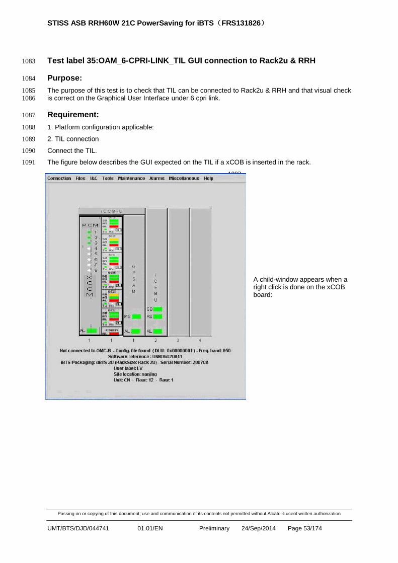
STISS ASB RRH60W 21C PowerSaving for iBTS(FRS131826)
Passing on or copying of this document, use and communication of its contents not permitted without Alcatel·Lucent written authorization
UMT/BTS/DJD/044741 01.01/EN Preliminary 24/Sep/2014 Page 53/174
Test label 35:OAM_6-CPRI-LINK_TIL GUI connection to Rack2u & RRH 1083
Purpose: 1084
The purpose of this test is to check that TIL can be connected to Rack2u & RRH and that visual check 1085
is correct on the Graphical User Interface under 6 cpri link. 1086
Requirement: 1087
1. Platform configuration applicable: 1088
2. TIL connection 1089
Connect the TIL. 1090
The figure below describes the GUI expected on the TIL if a xCOB is inserted in the rack. 1091
1092
1093
1094
1095
1096
1097
1098
1099
1100
A child-window appears when a 1101 right click is done on the xCOB 1102
board: 1103

STISS ASB RRH60W 21C PowerSaving for iBTS(FRS131826)
Passing on or copying of this document, use and communication of its contents not permitted without Alcatel·Lucent written authorization
UMT/BTS/DJD/044741 01.01/EN Preliminary 24/Sep/2014 Page 54/174
1104
This window presents the same information for Optical interfaces and all RRHs on the link (only one for 1105
star configuration). Contextual menus are available when clicking on those objects: 1106
For the optical interface, interface is provided to 1107
- require the display of alarms detected on the xCOB board, 1108
- require the hard reset of all RRHs on the link 1109
- disable optical transmission (and re-enable it) 1110
For the RRH, interface is similar to the information available in contextual menus for FTR boards. 1111
xCOB POPUP MENUS: 1112
- Alarms 1113
Display the xCOB alarms 1114
- Stop all Tx emission 1115
, OI2 ,OI3,OI4,OI5,OI6 are powered off (the popup menu command becomes 1116
Run all Tx emission) 1117
- Reset 1118
1119
OPTICAL INTERFACE POPUP MENUS: 1120
- Return to main GUI 1121
Return to the main GUI window 1122

STISS ASB RRH60W 21C PowerSaving for iBTS(FRS131826)
Passing on or copying of this document, use and communication of its contents not permitted without Alcatel·Lucent written authorization
UMT/BTS/DJD/044741 01.01/EN Preliminary 24/Sep/2014 Page 55/174
- RRH alarms 1123
1124
its RRH number) 1125
- Stop Tx emission 1126
x is powered off (the popup menu command becomes Run Tx emission) 1127
- Reset all RRH 1128
1129
RRH POPUP MENUS: 1130
- Marking 1131
Software versions for active FFS and passive FFS 1132
- BIST results 1133
1134
- Alarms 1135
1136
- Display alarms mask 1137
1138
- Reset 1139
1140
Expectable results: 1141
TIL: 1142
TIL is connected. 1143
Digital shelf is correctly displayed (slots and board types) 1144
No transparent message is rejected (no popup window) 1145
Software Reference is correct 1146
PCM Led state is correct 1147
For each optical interface, the GUI presents 1148
- The standby status of the RRH on the link 1149
- Green if RRH is providing service 1150
- Orange if RRH in cold-standby 1151
- The administrative state 1152
- Green:unlocked 1153
- Orange:Locked 1154
- The alarm status 1155
- Green:No alarm 1156
- White:No RRH connected:(no light on optical link) 1157
- Black:RRH Bists KO:RRH not running 1158
- Red:Major alarm preventing service has been sent to the BTS. 1159
-Tx and Rx status of link: 1160
STISS ASB RRH60W 21C PowerSaving for iBTS(FRS131826)
Passing on or copying of this document, use and communication of its contents not permitted without Alcatel·Lucent written authorization
UMT/BTS/DJD/044741 01.01/EN Preliminary 24/Sep/2014 Page 56/174
- Green:ON:Laser is powered. 1161
- White:OFF:Laser is unpowered 1162
-3 LEDs managed on RRH 1163
LED display should match the actual status on RRH 1164
- Number of RRH on the link (1 on the picture) is not required for star configurations. 1165
For xCOB board, the GUI presents 1166
-- The standby status of the xCOB on the link 1167
- Green if xCOB is providing service 1168
- Orange if xCOB in cold-standby 1169
- The administrative state 1170
- Green:xCOB unlocked 1171
- Orange:xCOB Locked 1172
- Alarm status 1173
- Green:OK:xCOB is ok 1174
- Red:Alarm:xCOB is in alarm 1175
-Tx and Rx status of link: 1176
- Green:ON:Laser is powered. 1177
- White:OFF:Laser is unpowered 1178
OMC-B: 1179
OMC-B connection state is correct 1180
Site Data display is correct1181

STISS ASB RRH60W 21C PowerSaving for iBTS(FRS131826)
Passing on or copying of this document, use and communication of its contents not permitted without Alcatel·Lucent written authorization
UMT/BTS/DJD/024788 V01.01/EN Standard 04/12/2014 Page 57/174
Test label 36:OAM_6-CPRI-LINK_OMCB GUI connection to RRH 1182
Purpose: 1183
The purpose of this test is to check that Rack2U & RRH visual display correctly on the OMCB 1184
Graphical User Interface under 6 cpri link. 1185
Requirements: 1186
1. Platform configuration applicable: 1187
2. OMC-B connection 1188
Procedure: 1189
Step1:Open OMCBEquipment Monitor 1190
Expectable results: 1191
The visual display of Rack2U & RRH on OMCB should like: 1192
1193

STISS ASB RRH60W 21C PowerSaving for iBTS(FRS131826)
Passing on or copying of this document, use and communication of its contents not permitted without Alcatel·Lucent written authorization
UMT/BTS/DJD/024788 V01.01/EN Standard 04/12/2014 Page 58/174
1194
4.1.4.5. POWER POOLING 1195
Test label 1196
37:POWER_POOLING_CHANGE_THE_POWER_OF_EACH_FREQUENCY 1197
Purpose: 1198
Check the PA allows some overbooking of the power of the carrier where HSDPA/E-DCH is 1199
deployed over the carrier where legacy R99 is deployed 1200
1201
Requirement: 1202
Platform configuration applicable 1203
Lamp is connected 1204
Spectrum analyzer connection at antenna output 1205
UDT script for TM1 1206
Configuration: 1207
Currently only support STSR-2 with only maximum 1 carrier per PA with HSDPA activated 1208
Both cells are mapped on xCEMu 1209
Set paPoolingActivation=True 1210
Set paRatio=80(HSDPA cell) and paRatio=50(R99 cell). Sum(paRatio)<=130 1211
Procedure: 1212
Step1:setup both HSDPA cell and R99 cell with Lamp, check result1 1213
Step2:run TM1 scripts for 2 cells with UDT, check result2 1214
F1 m
ax p
ow
er
Power
not used
Maxim
um
PA
Pow
er
Maxim
um
pow
er
F2 m
ax p
ow
er
Static power sharing Dynamic Power pooling
R99
HSDPA
R99
HSDPA
R99 &
G
BR
R99 &
G
BR
F2 m
ax p
ow
er
F1 m
ax p
ow
er
STISS ASB RRH60W 21C PowerSaving for iBTS(FRS131826)
Passing on or copying of this document, use and communication of its contents not permitted without Alcatel·Lucent written authorization
UMT/BTS/DJD/024788 V01.01/EN Standard 04/12/2014 Page 59/174
Step3:remove the R99 cell with Reproxy commands since Lamp is no more available 1215
CellDelete Linkid, Reuid, LocalCellId 1216
Linkid :1 to 6 1217
Reuid :1 to 1 1218
LocalCellId :must be already configured by cell mapping 1219
Check result3 1220
Step4:remove the HSDPA cell and Setup the R99 cell with Reproxy commands 1221
CellMappingFlex & CellConfig, take care of following parameters 1222
Carrier 1:Tx Main=0 Tx Div=0xFF Rx Main=0 Rx Div=1 1223
Carrier 2:Tx Main=1 Tx Div=0xFF Rx Main=2 Rx Div=3 1224
Check result4 1225
Expectable results: 1226
Result1:check HSDPA cell is setup with CPICH/MaxPower=35.1/45.1 dBm, and R99 cell is 1227
setup with CPICH/MaxPower=33.0/43.0 dBm. Although MaxPower together is greater than 1228
46.0 dBm, no alarm reported and both cell established successfully 1229
Result2:check UDT script is running successfully. Then check the total power of both HSDPA 1230
cell and R99 cell. HSDPA cell should be 43.9 dBm, and R99 cell should be 41.9 dBm 1231
Result3:check the R99 cell is removed, and total power of HSDPA cell changes to 45.1dBm 1232
dynamically 1233
Result4:check the HSDPA cell is removed, and total power of R99 cell changes to 43.0 dBm 1234
dynamically 1235
1236
STISS ASB RRH60W 21C PowerSaving for iBTS(FRS131826)
Passing on or copying of this document, use and communication of its contents not permitted without Alcatel·Lucent written authorization
UMT/BTS/DJD/024788 V01.01/EN Standard 04/12/2014 Page 60/174
Test label 38:POWER_POOLING_HSDPA_on_2_Carriers 1237
Purpose: 1238
Power polling is failed with HSDPA on both 2 carriers 1239 Requirement: 1240
STSR2 1241
2UV2P2+6*RRH/2UV2P2+6*TRDU 1242
The two cells can be setup 1243 Procedure: 1244
Step1:Step1:change the parameter paPoolingActivation=True;configure to STSR2 in DLU; 1245
Step2:HSDPA enabled in both carriers; reset 2u 1246
Expected results: 1247
Result1:D2U can not startup normally, have alarm about Papooling 1248
NodeB will send an alarm INVALID_CONFIGURATION_DATA to OMCB. 1249
1250

STISS ASB RRH60W 21C PowerSaving for iBTS(FRS131826)
Passing on or copying of this document, use and communication of its contents not permitted without Alcatel·Lucent written authorization
UMT/BTS/DJD/024788 V01.01/EN Standard 04/12/2014 Page 61/174
1251
4.1.5. UA7.1 GENERAL TEST DESCRIPTION FOR FRS33519 DAISY 1252
CHAIN 1253
4.1.5.1. LINK STATUS 1254
Test label 39:Daisy_Chain_Link_Status_With_RRH_Plugin 1255
Purpose: 1256
This test is to check the message exchange between new RRH and Reproxy when it is 1257
plugged into the chain as the last RRH 1258
Requirement: 1259
Platform configuration applicable 1260
D2U and 1 RRH connected to NodeB 1261
Procedure: 1262
Step1:NodeB and the first RRH startup successfully 1263
Step2:open terminal tool, telnet to CCM board.Open the trace "/lib_cpri/oem_lib_cpri> Trace" 1264
Step3:plug in a new RRH to daisy chain as the last one 1265
Step4:check the RE messges in CCM traces, check Result 1~4 1266
Expectable results: 1267
Result1:after step4, RE_GetAlarm_Indication (Alarm Master Port=OFF) can be seen in CCM 1268
traces and this alarm should be listed on the "/emo/alarm> GlobalAlarms" 1269
Result2:check that the Reuid in RE_GetAlarm_Indication message from first RRH should be 1270
correct 1271
Result3:within 100 seconds, RE_GetAlarm_Report (Alarm Master Port=ON) for the last RRH 1272
can be seen soon from. Or last RRH startup failed 1273
Result4:check that the Reuid in RE_GetAlarm_Report message from last RRH should be 1274
correct 1275
1276

STISS ASB RRH60W 21C PowerSaving for iBTS(FRS131826)
Passing on or copying of this document, use and communication of its contents not permitted without Alcatel·Lucent written authorization
UMT/BTS/DJD/024788 V01.01/EN Standard 04/12/2014 Page 62/174
1277
Test label 40:Daisy_Chain_Link_Status_With_RRH_Plugout 1278
Purpose: 1279
This test is to check the message exchange between last RRH and Reproxy when it is plugged 1280
out from the fiber chain 1281
Requirement: 1282
Platform configuration applicable 1283
D2U and n (2=<n<=6) RRHs in one fiber chain connected 1284
Procedure: 1285
Step1:NodeB and the RRHs startup successfully 1286
Step2:open terminal tool, telnet to CCM board. Open trace 1287
Step3:plugout an RRHn from daisy chain 1288
Step4:check the RE messges in CCM traces 1289
Expectable results: 1290
Result1:after plugout RRHn, RE_GetAlarm_Indication (Alarm Master Port=ON) can be seen 1291
in CCM traces 1292
Result2:check that the Reuid in RE_GetAlarm_Indication message should be the one of RRH 1293
(n-1) 1294
1295

STISS ASB RRH60W 21C PowerSaving for iBTS(FRS131826)
Passing on or copying of this document, use and communication of its contents not permitted without Alcatel·Lucent written authorization
UMT/BTS/DJD/024788 V01.01/EN Standard 04/12/2014 Page 63/174
1296
4.1.5.2. LOOP BACK 1297
Test label 41:Daisy_Chain_RRH_Loop_Back_Test 1298
Purpose: 1299
This test is to validate the digital transmission on RRH in Loopback mode after connecting the 1300
NodeB to the RRHs 1301
Requirement: 1302
Platform configuration applicable 1303
D2U and all RRHs in Daisy Chain work smoothly 1304
TIL connected 1305
NodeB not in service, no cell configured 1306
Lamp is connected 1307
TM500 is connected 1308
Procedure: 1309
Step1:open TIL, select one RRH in one fiber chain, send a “cpri loopback test” (loopback in 1310
RRH) command, check Result1 1311
Step2:redo the test steps on the other RRHs in the same chain 1312
Step3:after loopback test, reset the NodeB to the normal status 1313
Step4:setup cell and call via lamp and TM500, check Result2 1314
Expectable results: 1315
Result1:all “No error” results are shown on TIL terminal 1316
Result2:NodeB startup successfully, cell configuration and call setup is successful now 1317
1318

STISS ASB RRH60W 21C PowerSaving for iBTS(FRS131826)
Passing on or copying of this document, use and communication of its contents not permitted without Alcatel·Lucent written authorization
UMT/BTS/DJD/024788 V01.01/EN Standard 04/12/2014 Page 64/174
1319
4.1.5.3. ALARM 1320
Test label 42:Daisy_Chain_Alarm_of_RRH_Master_Link_Error 1321
Purpose: 1322
This test is to check the Master link error alarm when RRH L1/L2 error is detected on RRH 1323
master port. If RRH to be tested is the last one in fiber chain, no Master link error reported 1324
Requirement: 1325
Platform configuration applicable 1326
D2U and n RRHs in Daisy Chain work smoothly 1327
TIL connected 1328
OMCB connected 1329
Procedure: 1330
Step1:NodeB and all Daisy chain RRHs startup successfully 1331
Step2:plug out fiber from master port of RRHn (RRHn is not the last one in this chain) in the 1332
fiber chain 1333
Step3:check downstream RRHs status and the result from bci command, TIL and OMC-B, 1334
check Result1~Result4 1335
Step4:plug in fiber to this RRHn, check TIL, OMC-B and NodeB status, and check Result5 1336
Step5:trigger any other alarms, check Result6 1337
Expectable results: 1338
Result1:the Master Link Error alarm from RRHn is shown with the bci command “emo/alarm> 1339
GlobalAlarms” 1340
Result2:alarm is shown in TIL terminal with “link error daisy chain segment alarm description” 1341
Result3:alarm is shown in OMCB with “link error daisy chain segment alarm description” 1342
Result4:all the downstream RRHs will be reset, RRH objects in TIL and OMC-B will be 1343
deleted 1344
Result5:all RRH objects plugged in will be created in TIL and OMC-B, NodeB will work 1345
smoothly 1346
Result6:all alarms will be displayed in TIL and OMC-B 1347
1348

STISS ASB RRH60W 21C PowerSaving for iBTS(FRS131826)
Passing on or copying of this document, use and communication of its contents not permitted without Alcatel·Lucent written authorization
UMT/BTS/DJD/024788 V01.01/EN Standard 04/12/2014 Page 65/174
1349
4.1.5.4. PLUG IN/OUT 1350
Test label 43:Daisy_Chain_RRH_Plug-out_and_Plug-in 1351
Purpose: 1352
Check the cells are correctly configured when RRHx in the chain is plugged out/plugged in at 1353
any time 1354
Requirement: 1355
Platform configuration applicable 1356
D2U and all RRHs in Daisy Chain work smoothly 1357
OMCB is connected to the NodeB 1358
Lamp is connected to NodeB 1359
TM500 is connected to NodeB 1360
Procedure: 1361
Step1:plug-out the optical fiber of RRHx(x = 1… n, 1<n<=6), type “auditrequest” on lamp then 1362
check Result1 1363
Step2:after 3 Mins, plug-in the optical fiber of RRHx, check Result2 1364
Step3:Setup cells and make calls on RRHx or its downstream RRHs. Check Result3 1365
Step4:repeat step1 ~ step3 with Next RRHx+1, till to the last RRHn in the chain. Check 1366
Result4 1367
Expectable results: 1368
Result1: 1369
Audit Response message raised to the lamp excludes cells of all downstream RRHx 1370
and itself 1371
Check RRHx object and the downstream RRH objects don’t appear any more on the 1372
OMC-B 1373
Result2: 1374
RRHx and all its downstream RRHs in this chain will reset 1375
Type “auditrequest” on lamp then check Audit Response message raised to the lamp 1376
includes cells of all downstream RRHx and itself 1377
Check RRHx object and the following RRHs’ objects appear again on the OMC-B 1378
Result3:Cell setup and call are both OK 1379
Result4:same expected results as Result1~ Resul3 1380
1381

STISS ASB RRH60W 21C PowerSaving for iBTS(FRS131826)
Passing on or copying of this document, use and communication of its contents not permitted without Alcatel·Lucent written authorization
UMT/BTS/DJD/024788 V01.01/EN Standard 04/12/2014 Page 66/174
1382
4.1.5.5. SW UPGRADE 1383
Test label 44:Daisy_Chain_SW_Upgrade_On_RRH_Not_Need 1384
Purpose: 1385
Check RRHs in the same chain with correct version, no need to update SW, these RRHs will 1386
startup successfully and twice reset will not happen 1387
Requirement: 1388
Platform configuration applicable 1389
NodeB and all RRHs in Daisy Chain work smoothly 1390
OMC-B is connected to the NodeB 1391
Procedure: 1392
Step1:NodeB in power off status with the correct NodeB package 1393
Step2:ensure all RRHs with correct SW version, that is consistant with NodeB package 1394
Step3:plug all RRHs in NodeB with Daisy Chain mode, then power on NodeB and to observe 1395
the status of all RRHs. check Result1 1396
Step4:setup cells and voice call in these RRHs in the same chain. Check Result2 1397
Expectable results: 1398
Result1:all RRHs in this chain will do nothing. RRHs Reset will not happen 1399
Result2:cell setup successfully and call will be successful also 1400
1401

STISS ASB RRH60W 21C PowerSaving for iBTS(FRS131826)
Passing on or copying of this document, use and communication of its contents not permitted without Alcatel·Lucent written authorization
UMT/BTS/DJD/024788 V01.01/EN Standard 04/12/2014 Page 67/174
1402
Test label 45:Daisy_Chain_SW_Upgrade_Downstream_RRH 1403
Purpose: 1404
Check the daisy chain RRH2 upgrade scenario when RRH1 has the correct SW version but 1405
RRh2 has outdated SW version 1406
Check DWL procedure is OK when pluging in RRH3 during RRH2 is downloading 1407
Requirement: 1408
Platform configuration applicable 1409
D2U and 2 RRHs in Daisy Chain work smoothly 1410
RRH1 has correct SW version with NodeB package, but RRH2 has outdated one 1411
RRH3 has outdated SW version 1412
Procedure: 1413
Step1:power on NodeB and all RRHs 1414
Step2:check RRH1 status, check Result1 1415
Step3:check the status of RRH2 and its SW version, check Result2&3 1416
Step4:repeat Step1, and plug in RRH3 during RRH2 is downloading, check Result4 1417
Expectable results: 1418
Result1:NodeB and RRH1 work smoothly 1419
Result2:after RRH2 startup, it will download the correct SW version 1420
Result3:RRH2 reset again and till startup successfully. Its SW version is the same as RRH1 1421
Result4:after download is finished, RRH2 and RRH3 reset once, and it with correct SW 1422
version after startup 1423
1424

STISS ASB RRH60W 21C PowerSaving for iBTS(FRS131826)
Passing on or copying of this document, use and communication of its contents not permitted without Alcatel·Lucent written authorization
UMT/BTS/DJD/024788 V01.01/EN Standard 04/12/2014 Page 68/174
1425
Test label 46:Daisy_Chain_SW_Upgrade_by_OMC-B 1426
Purpose: 1427
Check the daisy chain RRH upgrade scenario that requested by OMC-B 1428
Requirement: 1429
Platform configuration applicable 1430
D2U and at least 2 RRHs in Daisy Chain work smoothly 1431
OMC-B is connected to the NodeB 1432
Prepare two different NodeB loads that it include different RRH SW version 1433
Procedure: 1434
Step1:NodeB and RRHs in Daisy Chain mode work smoothly with SW version A, check 1435
Result1 1436
Step2:download SW version B to NodeB via OMCB 1437
Step3:after NodeB re-startup and NodeB work smoothly, check Result2 1438
Expectable results: 1439
Result1:NodeB and all RRHs work smoothly in Daisy Chain with SW version A 1440
Result2:NodeB and all RRHs work smoothly in Daisy Chain with SW version B 1441
1442

STISS ASB RRH60W 21C PowerSaving for iBTS(FRS131826)
Passing on or copying of this document, use and communication of its contents not permitted without Alcatel·Lucent written authorization
UMT/BTS/DJD/024788 V01.01/EN Standard 04/12/2014 Page 69/174
1443
4.1.5.6. DOWNLOAD 1444
Test label 47:Daisy_Chain_PowerOff_PowerOn_Platform_During_RRH_Download 1445
Purpose: 1446
Check the impact that power off the platform when downloading SW for a new plug-in RRH 1447
Requirement: 1448
Platform configuration applicable 1449
D2U and all RRHs in Daisy Chain work smoothly 1450
OMCB is connected to the NodeB 1451
Procedure: 1452
Step1:plug-in the optical fiber of RRHx(x = 2…n, 2<n<=6), check Result1 1453
Step2:in the download procedure, power off the platform 1454
Step3:power on the platform and check Result2 1455
Expectable results: 1456
Result1:D2U and all other RRHs in Daisy Chain are not impact 1457
Download SW for the new plug-in RRH automatically 1458
Result2:all RRHs will reset and download SW for RRHx uccessfully 1459
1460

STISS ASB RRH60W 21C PowerSaving for iBTS(FRS131826)
Passing on or copying of this document, use and communication of its contents not permitted without Alcatel·Lucent written authorization
UMT/BTS/DJD/024788 V01.01/EN Standard 04/12/2014 Page 70/174
1461
4.1.5.7. START-UP 1462
Test label 48:Daisy_Chain_RRH_Power_ON_Power_OFF 1463
Purpose: 1464
Check the impact for downstream RRHs after RRH (n-1) Power on/Power off and not any 1465
impact for upstream RRHs 1466
Requirement: 1467
Platform configuration applicable 1468
More than 2 RRHs connect to single fiber chain 1469
D2U and all RRHs in Daisy Chain work smoothly 1470
Procedure: 1471
Step1:power off RRH (n-1), not the 1st RRH and not the last one, then check Result1 1472
Expectable results: 1473
Result1:after step1, RRH (n) will reset autonomously in 5 seconds, and every 5 seconds later, 1474
the next RRH will reset automonously. This action will repeat to the last RRH 1475
1476

STISS ASB RRH60W 21C PowerSaving for iBTS(FRS131826)
Passing on or copying of this document, use and communication of its contents not permitted without Alcatel·Lucent written authorization
UMT/BTS/DJD/024788 V01.01/EN Standard 04/12/2014 Page 71/174
1477
Test label 49:Daisy_Chain_in_Physical_But_not_Configured_in_DLU 1478
Purpose: 1479
It is configured as normal mode in DLU; add new RRH downstream doesn’t impact the call 1480
Requirement: 1481
Platform configuration applicable 1482
NodeB is configured as normal mode 1483
Procedure: 1484
Step1:power on NodeB, check Result1 1485
Step2:setup cell in one RRH from lamp, check Result2 1486
Step3:setup a call in this cell from lamp, check Result3 1487
Step4:add a downstream RRH to this RRH (master port for RRH11 is enable), check Result4 1488
Step4:delete this call and cell 1489
Expectable results: 1490
Result1:NodeB is start up successfully 1491
Result2:make sure the cell setup is OK 1492
Result3:make sure this call can be setup successfully 1493
Result4:call is still on going 1494
1495
STISS ASB RRH60W 21C PowerSaving for iBTS(FRS131826)
Passing on or copying of this document, use and communication of its contents not permitted without Alcatel·Lucent written authorization
UMT/BTS/DJD/024788 V01.01/EN Standard 04/12/2014 Page 72/174
1496
4.1.5.8. RESET 1497
Test label 50:Daisy_Chain_Reset_RRH_By_L1_Reset 1498
Purpose: 1499
Check after RRH (n) reset by CPRI_L1_Reset, RRH (n) and all the downstream RRHs should 1500
be reset. And all upsteam RRHs are not impact 1501
Requirement: 1502
Platform configuration applicable 1503
More than 2 RRH connect to the single fiber chain 1504
D2U and all RRH in Daisy Chain work smoothly 1505
Procedure: 1506
Step1:reset RRH1 by CPRI_L1_Reset via bci command “/pltf/cpri> ResetRE”, then give 1507
related link ID 1508
Step2:when all RRHs startup normally, check Result1 1509
Step3:reset RRH (n) which is not 1st RRH and not last one by Re_Reset_Request 1510
(REid=Next_re) via bci command “/reproxy/HardResetNextRE”, then give related ID. Check 1511
Result2 1512
Expectable results: 1513
Result1:all RRHs will reset in the chain 1514
Result2:the RRH (n) and all downstream RRHs will reset, and all upstream RRHs are not 1515
impact 1516
1517
STISS ASB RRH60W 21C PowerSaving for iBTS(FRS131826)
Passing on or copying of this document, use and communication of its contents not permitted without Alcatel·Lucent written authorization
UMT/BTS/DJD/024788 V01.01/EN Standard 04/12/2014 Page 73/174
1518
Test label 51:Daisy_Chain_Reset_RRH_due_to_Lock/Unlock_by_OMC-B 1519
Purpose: 1520
Check RRH (n) will reset after lock/unlock RRH (n) by OMC-B 1521
Requirement: 1522
Platform configuration applicable 1523
More than 2 RRH connect to the single fiber chain 1524
D2U NodeB and all RRH in Daisy Chain work smoothly and connect to OMC-B 1525
Procedure: 1526
Step1:lock RRH (n) by OMC-B 1527
Step2:unlock RRH (n) by OMC-B, check Result1 1528
Expectable results: 1529
Result1:after step 2, RRH (n) will reset, but no any impact tofor other RRH (Include upstream 1530
RRHs and downstream RRHs) in the chain 1531
1532

STISS ASB RRH60W 21C PowerSaving for iBTS(FRS131826)
Passing on or copying of this document, use and communication of its contents not permitted without Alcatel·Lucent written authorization
UMT/BTS/DJD/024788 V01.01/EN Standard 04/12/2014 Page 74/174
1533
Test label 52:Daisy_Chain_Reset_BTS 1534
Purpose: 1535
Check RRH can be re-startup normally after NodeB reset 1536
Requirement: 1537
Platform configuration applicable 1538
More than 2 RRH connect to the single fiber chain 1539
D2U and all RRH in Daisy Chain work smoothly 1540
Procedure: 1541
Step1:reset NodeB via telnet tool/ or OMC-B/ or TIL, check Result1 1542
Expectable results: 1543
Result1:all RRH in the chain will reset, the platform will startup smoothly, including NodeB and 1544
all RRHs in the chain 1545
1546

STISS ASB RRH60W 21C PowerSaving for iBTS(FRS131826)
Passing on or copying of this document, use and communication of its contents not permitted without Alcatel·Lucent written authorization
UMT/BTS/DJD/024788 V01.01/EN Standard 04/12/2014 Page 75/174
1547
Test label 53:Daisy_Chain_Reset_RRH_by_TIL 1548
Purpose: 1549
Check Reset RRH by TIL 1550
Requirement: 1551
Platform configuration applicable 1552
More than 2 RRH connect to the single fiber chain 1553
D2U and all RRH in Daisy Chain work smoothly 1554
TIL is connected normally 1555
Procedure: 1556
Step1:reset RRH by TIL, check Result1&2 1557
Expectable results: 1558
Result1:after step 1, the RRH will be reset, and it can be startup normally 1559
Result2:this RRH reset will not impact any other RRH in same fiber chain, including 1560
downstream RRHs and upstream RRHs 1561
1562

STISS ASB RRH60W 21C PowerSaving for iBTS(FRS131826)
Passing on or copying of this document, use and communication of its contents not permitted without Alcatel·Lucent written authorization
UMT/BTS/DJD/024788 V01.01/EN Standard 04/12/2014 Page 76/174
1563
4.1.5.9. CELL PROCEDURE 1564
Test label 54:Daisy_Chain_Cell_Setup 1565
Purpose: 1566
The purpose of this test is to check that whether NodeB can setup the cell successfully on 1567
RRHs which are on the same or different chain 1568
Requirement: 1569
Platform configuration applicable 1570
More than 2 RRH connect to the single fiber chain 1571
Procedure: 1572
Step1:setup cells in each RRH from lamp. Check Result1&2&3 1573
Step2:delete cells 1574
Expectable results: 1575
Result1:info of “CELL SETUP RESPONSE” can be received in lamp 1576
Result2:type in “cap/ctx/cell/Detail” on CCM, check whether includes the info of cells which is 1577
created by lamp, and other cells information is OK 1578
Result3:after cell is setup successfully, check the Tx frequency and channel power indicated 1579
in PSA are consistent with the ones in lamp 1580
1581

STISS ASB RRH60W 21C PowerSaving for iBTS(FRS131826)
Passing on or copying of this document, use and communication of its contents not permitted without Alcatel·Lucent written authorization
UMT/BTS/DJD/024788 V01.01/EN Standard 04/12/2014 Page 77/174
1582
Test label 55:Daisy_Chain_Cell_Delete 1583
Purpose: 1584
The purpose of this test is to check that whether NodeB can delete the cell correctly on RRHs 1585
which are on the same or different chain 1586
Requirement: 1587
Platform configuration applicable 1588
More than 2 RRH connect to the single fiber chain. 1589
Procedure: 1590
Step1:setup cells in each RRH from lamp. Make sure the cell setup successfully. Check 1591
Result 1 1592
For example:cellset 0 and 1, cell 0 on one RRH, cell 1 on another RRH 1593
Step2:delete cell 0, check Result 2&3 1594
Step3:delete cell 1, check Result 2&4 1595
Expectable results: 1596
Result1:after cell is setup successfully, check the Tx frequency and channel power indicated 1597
in PSA are consistent with the ones in lamp 1598
Result2:info of “CELL DELETE RESPONSE” can be received in lamp 1599
Result3:type in “cap/ctx/cell/Detail” on CCM, just the info of cell 1 is still reserved 1600
Result4:type in “cap/ctx/cell/Detail” on CCM, no any cell info is reserved 1601
4.1.5.10. RADIO FOR DAISY CHAIN 1602
Test label 56:Daisy_Chain_PlugIn_PlugOut_RRH_During_Call 1603
Purpose: 1604
Check that the plug-in and plug-out activities of a new RRH (with different load) will not impact 1605
to the existing calls 1606
Requirement: 1607
Platform configuration applicable 1608
D2U and all RRHs in Daisy Chain work smoothly 1609
OMC-B is connected to the NodeB 1610
Lamp is connected to NodeB 1611
TM500 is connected to NodeB 1612
Procedure: 1613
Step1:setup cells and make a call on RRHx(x = 1 …, n, 1<n<=6) 1614
Step2:plug-in the optical fiber of a new RRH (with different load), check Result1 1615
Step3:after 3 minutes, plug-out the optical fiber of a new RRH (with different load), check 1616
Result2 1617

STISS ASB RRH60W 21C PowerSaving for iBTS(FRS131826)
Passing on or copying of this document, use and communication of its contents not permitted without Alcatel·Lucent written authorization
UMT/BTS/DJD/024788 V01.01/EN Standard 04/12/2014 Page 78/174
Step4:repeat step1 ~ step3 with Next RRHx+1, till to the last RRHn in the chain. Check 1618
Result3 1619
Expectable results: 1620
Result1: 1621
Check RRHx object appear correctly on the OMC-B 1622
Cell setup and call are both OK 1623
Result2: 1624
Check RRHx object disappears on the OMC-B 1625
Cell setup and call are both OK 1626
Result3:same expected results as Result1~ Resul2 1627
1628
STISS ASB RRH60W 21C PowerSaving for iBTS(FRS131826)
Passing on or copying of this document, use and communication of its contents not permitted without Alcatel·Lucent written authorization
UMT/BTS/DJD/024788 V01.01/EN Standard 04/12/2014 Page 79/174
1629
Test label 57:Daisy_Chain_Reset_Upstream_RRH_During_Call 1630
Purpose: 1631
Check that the call is still successful when SW reset the upstream RRH. 1632
Requirement: 1633
1. Platform configuration applicable; 1634
2. NodeB and RRHs (More than 2 RRHs) on the Daisy Chain are working smoothly, for 1635
example, RRH1 is upstream RRH and RRH2 is downstream RRH on the same chain. 1636
Procedure: 1637
Step 1:NodeB and all RRHs are start-up with the correct NodeB package; 1638
Step 2:Do an AMR call on RRH2, check Result 1; 1639
Step 3:SW reset RRH1 via TIL or OMCB, check Result 2. 1640
Expectable Results: 1641
Result 1:The amr call is OK; 1642
Result 2:RRH1 will be OK after SW reset, and the amr call on RRH2 is still running 1643
successfully. 1644
1645

STISS ASB RRH60W 21C PowerSaving for iBTS(FRS131826)
Passing on or copying of this document, use and communication of its contents not permitted without Alcatel·Lucent written authorization
UMT/BTS/DJD/024788 V01.01/EN Standard 04/12/2014 Page 80/174
1646
4.1.6. UA7.1 GENERAL TEST DESCRIPTION FOR FRS73695 STSRX+Y 1647
4.1.6.1. START-UP 1648
Test label 58:STSRx+y_Startup_In_Normal_Mode 1649
Purpose: 1650
The purpose of this test is to check that NodeB with STSRx+y configuration in normal mode 1651
can be startup successfully 1652
Requirement: 1653
Platform configuration applicable 1654
NodeB is configured as STSRx+y either in daisy chain or in star mode 1655
STSR1+1, 2+1, 2+2 are supported 1656
Procedure: 1657
Step1:power on NodeB with all of RRHs, open the CCM trace, and check Result1&2 1658
Expectable results: 1659
Result1:telnet to CCM board: 1660
type “emo/bts”, check that “MIBState” is Build, “CheckDLU” is OK. Tx and Rx path are 1661
all enable 1662
type “emo/data/cfiledump”, check AntennaConnectionId for both RRH should be the 1663
same as in DLU 1664
Result2:after NodeB startup successfully, cell and basic call should be setup successfully 1665
1666

STISS ASB RRH60W 21C PowerSaving for iBTS(FRS131826)
Passing on or copying of this document, use and communication of its contents not permitted without Alcatel·Lucent written authorization
UMT/BTS/DJD/024788 V01.01/EN Standard 04/12/2014 Page 81/174
1667
Test label 59:STSRx+y_Startup_In_Degrade_Mode 1668
Purpose: 1669
The purpose of this test is to check that NodeB with STSRx+y configuration in degrade mode 1670
can be startup successfully 1671
Requirement: 1672
Platform configuration applicable 1673
NodeB is configured as STSRx+y either in daisy chain or in star mode 1674
STSR1+1, 2+1, 2+2 are supported 1675
Procedure: 1676
Step1:power on NodeB with main RRH, open the CCM trace, and check Result1&2&4 1677
Step2:power on NodeB with div RRH, and check Result3 1678
Expectable results: 1679
Result1:telnet to CCM board: 1680
type “emo/bts”, check that “MIBState” is Build, “CheckDLU” is OK 1681
type “emo/data/cfiledump”, check AntennaConnectionId for both RRH should be the 1682
same as in DLU 1683
Result2:after NodeB startup successfully: 1684
star mode:Tx and Rx path for main RRH are enable 1685
daisy chain mode:upstream RRHs of this main RRH are startup successfully, and 1686
downstream RRHs are not startup 1687
Result3:after NodeB startup successfully: 1688
star mode:Tx and Rx path for div RRH are enable 1689
daisy chain mode:only Tx and Rx path for the upstream RRHs are enable, no this 1690
paired RRH 1691
Result4:cells and basic call should be setup successfully 1692
1693

STISS ASB RRH60W 21C PowerSaving for iBTS(FRS131826)
Passing on or copying of this document, use and communication of its contents not permitted without Alcatel·Lucent written authorization
UMT/BTS/DJD/024788 V01.01/EN Standard 04/12/2014 Page 82/174
1694
4.1.6.2. PLUG IN/OUT 1695
Test label 60: STSRx+y_RRH_Plugout_Plugin 1696
Purpose: 1697
The purpose of this test is to check the correct configuration when plug out/in main or div RRH 1698
at any time 1699
Requirement: 1700
Platform configuration applicable 1701
NodeB is configured as STSRx+y either in daisy chain or in star mode 1702
STSR1+1, 2+1, 2+2 are supported 1703
Procedure: 1704
Step1:power on NodeB with both main and div RRH. Check Result1&4 1705
Step2:plug out any RRH in the paired RRH. Check Result2&4 1706
Step3:plug in this RRH. Check Result3&4 1707
Expectable results: 1708
Result1:telnet to CCM board: 1709
type “emo/bts”, check that “MIBState” is Build, “CheckDLU” is OK. Tx and Rx path are 1710
all enable 1711
type “emo/data/cfiledump”, check AntennaConnectionId for both RRH should be the 1712
same as in DLU 1713
Result2:check the Tx and Rx path by typing “emo/bts” on CCM, the behaviour is different 1714
according to the topology: 1715
star mode:if plug out the main RRH, only Tx and Rx path for div RRH are enable; if 1716 plug out div RRH, only Tx and Rx path for main RRH are enable 1717
daisy chain mode:if plug out the main RRH, only Tx and Rx path for the upstream 1718
RRHs are enable; if plug out div RRH, Tx and Rx path for main RRH and upstream 1719
RRHs are enable 1720
Result3:after RRH startup successfully, check Tx and Rx path of all the RRHs are all enable 1721
Result4:after NodeB startup successfully, cell and basic call should be setup successfully 1722
1723

STISS ASB RRH60W 21C PowerSaving for iBTS(FRS131826)
Passing on or copying of this document, use and communication of its contents not permitted without Alcatel·Lucent written authorization
UMT/BTS/DJD/024788 V01.01/EN Standard 04/12/2014 Page 83/174
1724
Test label 61: STSRx+y_Plugin_RRH_With_Different_Load 1725
Purpose: 1726
The purpose of this test is to check the correct configuration when plug in div/main RRH with 1727
different load 1728
Requirement: 1729
Platform configuration applicable 1730
NodeB is configured as STSRx+y either in daisy chain mode or in star mode 1731
STSR1+1, 2+1, 2+2 are supported 1732
Procedure: 1733
Step1:main or div RRH in the paired RRH is plugged in, and the other is not 1734
Step2:power on NodeB. Check Result1&2&4 1735
Step3:plug in the other RRH with different load. Check Result3&4 1736
Expectable results: 1737
Result1:telnet to CCM board: 1738
type “emo/bts”, check that “MIBState” is Build, “CheckDLU” is OK 1739
type “emo/data/cfiledump”, check AntennaConnectionId for both RRH should be the 1740 same as in DLU 1741
Result2:check the Tx and Rx path by typing “emo/bts” on CCM, the behavior is different 1742
according to the topology: 1743
star mode:if div RRH is plug in and main RRH is not, only Tx and Rx path for div RRH 1744
are enable; if main RRH is plug in and div RRH is not, only Tx and Rx path for main 1745
RRH are enable 1746
daisy chain mode:if main RRH is not plug in, only Tx and Rx path for the upstream 1747
RRHs are enable; if div RRH is not plug in, Tx and Rx path for main RRH and 1748
upstream RRHs are enable 1749
Result3:when plugging-in the RRH with different load: 1750
star mode:this RRH will upgrade to the same load with the RRH which is already 1751 plug-in, after this RRH reset, Tx and Rx path of all the RRHs are all enable 1752
daisy chain mode:this RRH and the downstream RRHs will upgrade and reset, then 1753
all the Tx and Rx path are enable 1754
Result4:after NodeB startup successfully, cell and basic call should be setup successfully 1755
1756

STISS ASB RRH60W 21C PowerSaving for iBTS(FRS131826)
Passing on or copying of this document, use and communication of its contents not permitted without Alcatel·Lucent written authorization
UMT/BTS/DJD/024788 V01.01/EN Standard 04/12/2014 Page 84/174
1757
4.1.6.3. RESET 1758
Test label 62: STSRx+y_RRH_Reset_By_OMC-B 1759
Purpose: 1760
Check the RRH can startup correctly when reset by OMC-B 1761
Requirement: 1762
Platform configuration applicable 1763
NodeB is configured as STSRx+y either in daisy chain or in star mode 1764
STSR1+1, 2+1, 2+2 are supported 1765
Procedure: 1766
Step1:power on NodeB with both main and div RRH. Check Result1&5 1767
Step2:reset main RRH from OMC-B. Check Result2&4&5 1768
Step3:reset div RRH from OMC-B. Check Result3&4&5 1769
Expectable results: 1770
Result1:telnet to CCM board: 1771
type “emo/bts”, check that “MIBState” is Build, “CheckDLU” is OK. Tx and Rx path are 1772
all enable 1773
type “emo/data/cfiledump”, check AntennaConnectionId for both RRH should be the 1774
same as in DLU 1775
Result2:check the Tx and Rx path by typing “emo/bts” on CCM, when main RRH is resetting, 1776
Tx and Rx path for main RRH are disable; after main RRH startup successfully, Tx and Rx 1777
path of main RRH are enable 1778
Result3:check the Tx and Rx path by typing “emo/bts” on CCM, when div RRH is resetting, Tx 1779
and Rx path for div RRH are disabled; after div RRH startup successfully, Tx and Rx path of 1780
div RRH are enable 1781
Result4:if it is in daisy chain mode, this RRH reset will not impact any other RRH in same fiber 1782
chain, including downstream RRHs and upstream RRHs. If in star mode, this RRH reset will 1783
not impact any other RRH 1784
Result5:after NodeB startup successfully, cell and basic call should be setup successfully 1785
1786

STISS ASB RRH60W 21C PowerSaving for iBTS(FRS131826)
Passing on or copying of this document, use and communication of its contents not permitted without Alcatel·Lucent written authorization
UMT/BTS/DJD/024788 V01.01/EN Standard 04/12/2014 Page 85/174
1787
Test label 63: STSRx+y_RRH_Reset_By_TIL 1788
Purpose: 1789
Check the RRH can startup correctly when reset by TIL 1790
Requirement: 1791
Platform configuration applicable 1792
NodeB is configured as STSRx+y either in daisy chain or in star mode 1793
STSR1+1, 2+1, 2+2 are supported 1794
Procedure: 1795
Step1:power on NodeB with both main and div RRH. Check Result1&4 1796
Step2:reset main RRH from TIL. Check Result2&4&5 1797
Step3:reset div RRH from TIL. Check Result3&4&5 1798
Expectable results: 1799
Result1:telnet to CCM board: 1800
type “emo/bts”, check that “MIBState” is Build, “CheckDLU” is OK. Tx and Rx path are 1801
all enable 1802
type “emo/data/cfiledump”, check AntennaConnectionId for both RRH should be the 1803 same as in DLU 1804
Result2:check the Tx and Rx path by typing “emo/bts” on CCM, when main RRH is resetting, 1805
Tx and Rx path for main RRH are disable; after main RRH startup successfully, Tx and Rx 1806
path of main RRH are enable 1807
Result3:check the Tx and Rx path by typing “emo/bts” on CCM, when div RRH is resetting, Tx 1808
and Rx path for div RRH are disabled; after div RRH startup successfully, Tx and Rx path of 1809
div RRH are enable 1810
Result4:if it is in daisy chain mode, this RRH reset will not impact any other RRH in same fiber 1811
chain, including downstream RRHs and upstream RRHs. If in star mode, this RRH reset will 1812
not impact any other RRH 1813
Result5:after NodeB startup successfully, cell and basic call should be setup successfully 1814
1815

STISS ASB RRH60W 21C PowerSaving for iBTS(FRS131826)
Passing on or copying of this document, use and communication of its contents not permitted without Alcatel·Lucent written authorization
UMT/BTS/DJD/024788 V01.01/EN Standard 04/12/2014 Page 86/174
1816
4.1.6.4. OMC-B OPERATION 1817
Test label 64: STSRx+y_OMC-B_DLU_Check 1818
Purpose: 1819
Check that if antennaConnectionId of any one RRH is not null, antennaConnectionId of all 1820
others should not be null 1821
Check whether a RemoteRadioHead instance is in an AntennaAccess 1822
Check the maximum number of RemoteRadioHeads within a sector 1823
If 2 RRH have the same antennaConnectionId, the rxCabling type of corresponding 1824
AntennaAccess should be set as mainAndDiversityInput 1825
Requirement: 1826
Platform configuration applicable 1827
NodeB is configured as STSRx+y either in daisy chain or in star mode 1828
STSR1+1, 2+1, 2+2 are supported 1829
Procedure: 1830
Step1:power on NodeB with both main and div RRH. Check Result1 1831
Step2:after NodeB get a full starup, through OMC-B, antennaConnectionId in one RRH has a 1832
correct value and in other RRH does not present, then rebuild. Check Result2 1833
Step3:after NodeB get a full starup, through OMC-B, antennaConnectionId in one RRH has a 1834
special value which does not in any AntennaAccess, then rebuild. Check Result3 1835
Step4:after NodeB get a full starup, through OMC-B, antennaConnectionId in three RRH has 1836
the same value, then rebuild. Check Result4 1837
Step5:after NodeB get a full starup, through OMC-B, rxCabling in AntennaAccess is set to 1838
“mainInputOnly”, then rebuild. Check Result5 1839
Expectable results: 1840
Result1:telnet to CCM board: 1841
type “emo/bts”, check that “MIBState” is Build, “CheckDLU” is OK. Tx and Rx path are 1842
all enable 1843
type “emo/data/cfiledump”, check AntennaConnectionId for both RRH should be the 1844
same as in DLU 1845
Result2: 1846
In xCCM, typing “/emo/alarm/ChkConfigFile”, report an alarm INVALID CONFIGURATION 1847 DATA with manufacture information of alarm “Not Exist Antenna Connection”. Rebuild failed 1848
Typing “/emo/Iconfig”, MIBState is “Build KO”, and DLUCheck is “KO” 1849
In OMC-B, there is the alarm "INVALID CONFIGURATION DATA", in Addtional Test there is 1850 the alarm description “Not Exist Antenna Connection”. 1851
Result3: 1852
In xCCM, typing “/emo/alarm/ChkConfigFile”,report an alarm INVALID CONFIGURATION 1853 DATA with manufacture information “RRH Not Present In Antenna Access”. Rebuild 1854
failed.Report “RRH Not Present In NodeBCell” at the same time. 1855

STISS ASB RRH60W 21C PowerSaving for iBTS(FRS131826)
Passing on or copying of this document, use and communication of its contents not permitted without Alcatel·Lucent written authorization
UMT/BTS/DJD/024788 V01.01/EN Standard 04/12/2014 Page 87/174
Typing “/emo/Iconfig”, MIBState is “Build KO”, and DLUCheck is “KO”. 1856
In OMC-B, there is the alarm "INVALID CONFIGURATION DATA", in Addtional Test there is 1857 the alarm description “RRH Not Present In Antenna Access”. 1858
Result4: 1859
In xCCM, typing “/emo/alarm/ChkConfigFile”, report an alarm CONFIGURATION FILE 1860 INCONSISTENT WITH HARDWARE with manufacture information “Too many RRH in 1861 AntennaAccess“. Rebuild failed. 1862
Typing “/emo/Iconfig”, MIBState is “Build KO”, and DLUCheck is “KO”. 1863
In OMC-B, there is the alarm " CONFIGURATION FILE INCONSISTENT WITH HARDWARE ", 1864 in Addtional Test there is the alarm description “Too many RRH in AntennaAccess”. 1865
Result5: 1866
In xCCM, typing “/emo/alarm/ChkConfigFile”,report an alarm INVALID CONFIGURATION 1867 DATA “RxCabling type out of range“. Rebuild failed. 1868
Typing “/emo/Iconfig”, MIBState is “Build KO”, and DLUCheck is “KO”. 1869
In OMC-B, there is the alarm " INVALID CONFIGURATION DATA ", in Addtional Test there is 1870 the alarm description “RxCabling type out of range”. 1871
1872

STISS ASB RRH60W 21C PowerSaving for iBTS(FRS131826)
Passing on or copying of this document, use and communication of its contents not permitted without Alcatel·Lucent written authorization
UMT/BTS/DJD/024788 V01.01/EN Standard 04/12/2014 Page 88/174
1873
4.1.6.5. CELL PROCEDURE 1874
Test label 65: STSRx+y_Cell_Setup_In_Normal_Mode 1875
Purpose: 1876
Check that cell setup scenario is correct in STSRx+y normal mode 1877
Requirement: 1878
Platform configuration applicable 1879
NodeB is configured as STSRx+y either in daisy chain or in star mode 1880
STSR1+1, 2+1, 2+2 are supported 1881
Procedure: 1882
Step1:power on NodeB with both of main and div RRH. Check Result1 1883
Step2:setup cells in main and div RRH from lamp, for example cell1 in main RRH and cell7 in 1884
div RRH. Check Result2&3&4 1885
Step3:delete cells 1886
Step4:re-do step2 and step3. 1887
Expectable results: 1888
Result1:telnet to CCM board: 1889
type “emo/bts”, check that “MIBState” is Build, “CheckDLU” is OK. Tx and Rx path are 1890
all enable 1891
type “emo/data/cfiledump”, check AntennaConnectionId for both RRH should be the 1892
same as in DLU 1893
Result2:“CELL SETUP RESPONSE” can be received in lamp 1894
Result3:after cells setup successfully, telnet to main and div RRH, use commands 1895
“fcpcTipTxFreqDataShow” and “fcpcTipRxFreqDataShow”, check: 1896
in main RRH, for cell1, both Tx and Rx carrier are exist; for cell7, only Rx carrier is 1897
exist 1898
in div RRH, for cell7, both Tx and Rx carrier are exist; for cell1, only Rx carrier is exist 1899
Result4:after cell is setup successfully, check the Tx frequency and channel power indicated 1900
in PSA are consistent with the ones in lamp 1901
1902

STISS ASB RRH60W 21C PowerSaving for iBTS(FRS131826)
Passing on or copying of this document, use and communication of its contents not permitted without Alcatel·Lucent written authorization
UMT/BTS/DJD/024788 V01.01/EN Standard 04/12/2014 Page 89/174
1903
Test label 66: STSRx+y_Cell_Setup_In_Degrade_Mode 1904
Purpose: 1905
Check that cell setup scenario is correct in STSRx+y degrade mode 1906
Requirement: 1907
Platform configuration applicable 1908
NodeB is configured as STSRx+y either in daisy chain or in star mode 1909
If in daisy chain mode, do not plug out main RRH in any paired RRH 1910
STSR1+1, 2+1, 2+2 are supported 1911
Procedure: 1912
Step1:power on NodeB with one RRH (RRH1) of any paired RRH (RRH1+RRH2), meet 1913
requirement3. Check Result1 1914
Step2:setup cell in RRH1 from lamp, check Result2&4 1915
Step3:power on RRH2, check Result3&4 1916
Step4:delete cell 1917
Expectable results: 1918
Result1:telnet to CCM board: 1919
type “emo/bts”, check that “MIBState” is Build, “CheckDLU” is OK. Tx and Rx path of 1920
RRH1 are enable 1921
type “emo/data/cfiledump”, check AntennaConnectionId for both RRH should be the 1922
same as in DLU 1923
Result2:“CELL SETUP RESPONSE” can be received in lamp 1924
Result3:after RRH2 startup successfully, telnet to this RRH, use commands 1925
“fcpcTipTxFreqDataShow” and “fcpcTipRxFreqDataShow”, check no Tx carrier but only Rx 1926
carrier for this cell is exist in RRH2 1927
Result4:after cell is setup successfully, check the Tx frequency and channel power indicated 1928
in PSA are consistent with the ones in lamp 1929
1930

STISS ASB RRH60W 21C PowerSaving for iBTS(FRS131826)
Passing on or copying of this document, use and communication of its contents not permitted without Alcatel·Lucent written authorization
UMT/BTS/DJD/024788 V01.01/EN Standard 04/12/2014 Page 90/174
1931
Test label 67: STSRx+y_Cell_Delete_In_Normal_Mode 1932
Purpose: 1933
Check that cell delete scenario is correct when STSRx+y configuration in normal mode 1934
Requirement: 1935
Platform configuration applicable 1936
NodeB is configured as STSRx+y either in daisy chain or in star mode 1937
STSR1+1, 2+1, 2+2 are supported 1938
Procedure: 1939
Step1:power on NodeB with both main and div RRH. Check Result1 1940
Step2:setup cells in main and div RRH respectively from lamp, for example cell1 in main RRH 1941
and cell7 in div RRH. Check Result2 1942
Step3:delete cell1 from lamp, check Result3&4 1943
Step4:delete cell7 from lamp, check Result3&5 1944
Expected results: 1945
Result1:telnet to CCM board: 1946
type “emo/bts”, check that “MIBState” is Build, “CheckDLU” is OK. Tx and Rx path are 1947 all enable 1948
type “emo/data/cfiledump”, check AntennaConnectionId for both RRH should be the 1949
same as in DLU 1950
Result2:make sure the cell setup is OK 1951
Result3:“CELL DELETE RESPONSE” can be received in lamp 1952
Result4:after cell1 is deleted successfully, telnet to main and div RRH, and use commands 1953
“fcpcTipTxFreqDataShow” and “fcpcTipRxFreqDataShow” to check: 1954
in main RRH, only Rx carrier for cell7 is exist, no other carrier information 1955
in div RRH, only Tx and Rx carrier info for cell7 are exist, no carrier info for cell1 1956
Result5:after cell7 is deleted successfully, telnet to main and div RRH, use commands 1957
“fcpcTipTxFreqDataShow” and “fcpcTipRxFreqDataShow” to check no carrier info exist on 1958 both paired RRH 1959
1960
STISS ASB RRH60W 21C PowerSaving for iBTS(FRS131826)
Passing on or copying of this document, use and communication of its contents not permitted without Alcatel·Lucent written authorization
UMT/BTS/DJD/024788 V01.01/EN Standard 04/12/2014 Page 91/174
1961
Test label 68: STSRx+y_Cell_Delete_By_RRH_Reset 1962
Purpose: 1963
Check cells can be deleted when Tx path of this cell is disable 1964
Requirement: 1965
Platform configuration applicable 1966
NodeB is configured as STSRx+y either in daisy chain or in star mode 1967
STSR1+1, 2+1, 2+2 are supported 1968
Procedure: 1969
Step1:power on NodeB with both main and div RRH. Check Result1 1970
Step2:setup cells in main and div RRH from lamp, for example cell1 in main RRH and cell7 in 1971
div RRH. Check Result2 1972
Step3:reset main RRH from TIL, check Result3&4&5. (Note:reset div RRH could have the 1973
similar result as main RRH.) 1974
Step4:delete cells 1975
Expectable results: 1976
Result1:telnet to CCM board: 1977
type “emo/bts”, check that “MIBState” is Build, “CheckDLU” is OK. Tx and Rx path are 1978
all enable 1979
type “emo/data/cfiledump”, check AntennaConnectionId for both RRH should be the 1980
same as in DLU 1981
Result2:make sure the cell setup is OK 1982
Result3:after main RRH is startup successfully, telnet to main and div RRH, and use 1983
commands “fcpcTipTxFreqDataShow” and “fcpcTipRxFreqDataShow” to check: 1984
in main RRH, only Rx carrier for cell7 is exist, no other carrier information 1985
in div RRH, only Tx and Rx carrier info for cell7 are exist, no carrier info for cell1 1986
Result4:after NodeB startup successfully, basic call can be setup in cell7 successfully 1987
Result5:if in daisy chain mode, this RRH reset will not impact any other RRH in same fiber 1988
chain, including downstream RRHs and upstream RRHs 1989
1990

STISS ASB RRH60W 21C PowerSaving for iBTS(FRS131826)
Passing on or copying of this document, use and communication of its contents not permitted without Alcatel·Lucent written authorization
UMT/BTS/DJD/024788 V01.01/EN Standard 04/12/2014 Page 92/174
1991
4.1.6.6. TMA MANAGEMENT 1992
Test label 69: STSRx+y_TMA_Startup 1993
Purpose: 1994
Check the correct behaviour with/without TMA equipment and with/without TMA configuration 1995
Requirement: 1996
Platform configuration applicable 1997
NodeB is configured as STSRx+y either in daisy chain or in star mode 1998
STSR1+1, 2+1, 2+2 are supported 1999
Procedure: 2000
Step1:NodeB+RRH/TRDU connection without TMA 2001
Step2:configure TMA access in DLU by OMC-B, for example, TMA configured in 2002
AntennaConnection11 2003
Sector [0]: 2004
AntennaAccessInstance :0 2005
AntennaConnection :11 2006
TmaAccessType :1 2007
Step3:reset NodeB. Check Result1&2 2008
Step4:TMA equipment is connected to the RRH 2009
Step5:configure TMA access in DLU by OMC-B, for example, TMA configured in 2010
AntennaConnection11 2011
Sector [0]: 2012
AntennaAccessInstance :0 2013
AntennaConnection :11 2014
TmaAccessType :1 2015
Step6:power on this RRH and reset NodeB. Check Result3&4&5 2016
Step7:configure no TMA access in DLU by OMC-B, for example, TMA hasn’t been configured 2017
in AntennaConnection11 2018
Sector [0]: 2019
AntennaAccessInstance :0 2020
AntennaConnection :11 2021
TmaAccessType :0 2022
Step8:reset NodeB. Check Result4&5 2023
Expectable results: 2024
Result1:after NodeB is starting up, TMA alarm on main RRH will be reported to TIL and 2025
OMC-B, and no TMA alarm in div RRH. 2026

STISS ASB RRH60W 21C PowerSaving for iBTS(FRS131826)
Passing on or copying of this document, use and communication of its contents not permitted without Alcatel·Lucent written authorization
UMT/BTS/DJD/024788 V01.01/EN Standard 04/12/2014 Page 93/174
Result2:telnet to CCM, type “emo/bts”, check that local cells configured in 2027
AntennaConnection11 are enabled, because only Rx path on mian RRH have been impacted. 2028
Result3: 2029
In CCM trace, check “TmaAccessReq”, if using inhouse RRH, main RRH is in TMA Umts 2030
mode and div RRH is in TMA Mix mode; if using TRDU, both main and div RRH are in TMA 2031
Umts mode 2032
In lamp, typing “auditrequest”, the maxpower for cells in this antennaAccess is decreased. The 2033
descreased value is 3.5 dB which means 35 should be descreased from original value. For 2034
example, the maxpower is 430 without TMA, and it changed to 395 with TMA. 2035
Result4:check NodeB could startup normally without alarm and error. Telnet to CCM, type 2036
“emo/bts”, check that local cells configured in AntennaConnection11 are enabled 2037
Result5:after NodeB startup successfully, basic call can be setup successfully 2038
2039

STISS ASB RRH60W 21C PowerSaving for iBTS(FRS131826)
Passing on or copying of this document, use and communication of its contents not permitted without Alcatel·Lucent written authorization
UMT/BTS/DJD/024788 V01.01/EN Standard 04/12/2014 Page 94/174
2040
4.1.6.7. FAULT MANAGEMENT 2041
Test label 70: STSRx+y_Fault_Management_VSWR 2042
Purpose: 2043
Check VSWR alarm in STSRx+y mode 2044
Requirement: 2045
Platform configuration applicable 2046
NodeB is configured as STSRx+y either in daisy chain or in star mode 2047
STSR1+1, 2+1, 2+2 are supported 2048
Procedure: 2049
Step1:power on NodeB with both main and div RRH 2050
Step2:RRH-ih:run the OCI tool for main RRH 2051
Step3: 2052
RRH-ih:click the mode to ON, select the alarm “Tx VSWR Level 2 Alarm”, check Result1 2053
Step4:RRH-ih:stop other alarms, click the mode to ON, select the alarm “Tx VSWR Alarm”, 2054
check Result2 2055
Step5:RRH-ih:run the OCI tool for div RRH 2056
Step6:RRH-ih:stop other alarms, click the mode to ON, select the alarm “Tx VSWR Level 2 2057
Alarm”, check Result3 2058
Step7:RRH-ih:stop other alarms, click the mode to ON, select the alarm “Tx VSWR Alarm”, 2059
check Result5 2060
Note, refer to the latest TRDU alarm document for TRDU VSWR alarm 2061
Expectable results: 2062
Result1:in OMC-B, “VSWR LEVEL Main” is reported; 2063
From CCM trace, type “/emo/alarm> GlobalAlarms”, and “RRH VSWR MAIN” can be found for 2064
main RRH; 2065
In TIL, “VSWR Level 3 MAIN <TX VSWR Level2 Alarm>” is reported in this mian RRH 2066
Result2:From CCM trace, type “/emo/alarm> GlobalAlarms”, and “RRH VSWR MAIN” can be 2067
found for main RRH; 2068
In TIL, “VSWR Level 2 MAIN <TX VSWR Alarm>” is reported in this mian RRH 2069
Result3:in OMC-B, “VSWR LEVEL Div” is reported; 2070
From CCM trace, type “/emo/alarm> GlobalAlarms”, and “RRH VSWR DIV” can be found for 2071
main RRH; 2072
In TIL, “VSWR Level 3 DIV <TX VSWR Level2 Alarm>” is reported in this div RRH. 2073
Result5:From CCM trace, type “/emo/alarm> GlobalAlarms”, and “RRH VSWR DIV” can be 2074
found for main RRH; 2075
In TIL, “VSWR Level 2 DIV <TX VSWR Alarm>” is reported in this div RRH. 2076
2077

STISS ASB RRH60W 21C PowerSaving for iBTS(FRS131826)
Passing on or copying of this document, use and communication of its contents not permitted without Alcatel·Lucent written authorization
UMT/BTS/DJD/024788 V01.01/EN Standard 04/12/2014 Page 95/174
2078
4.1.6.8. COMMON MEASUREMENT 2079
Test label 71: STSRx+y_Common_Measurement_Normal_Mode 2080
Purpose: 2081
Test the stability of NodeB with the startcmeas command including all measurement types 2082
Requirement: 2083
RNC Simulator (Lamp) 2084
The radio configuration is STSRx+y in star or chain mode 2085
Procedure: 2086
Step1:power on NodeB and paired RRHs 2087
Step2:set up cell and start common measurement for both transmit carrier power and receive 2088
carrier power, keep this test continuously running at least 12 hours without any traps or 2089
abnormal behaviors on the NodeB, check Result1 2090
Expectable results: 2091
Result1:value in lamp (RTWP, TCP) should be correct from beginning to ending 2092
If value of “Received Total Wide-band Power” (RTWP) is between 60 and 65, the test 2093
result is acceptable. If it is too high or too low, the test result is abnormal. 2094
(RTWP(dBm)=RTWP value * 0.1 + (-112) ) 2095
Transmit carrier power(TCP) =10[cpICH(dBm)-cell(dBm)] (dBm=10log(mw)) 2096
For example:cellset 0 330 430 9640 10590 2097
Cell (dBm) =4.3, cpICH (dBm) =3.3, TCP =10-1 =10% 2098
2099

STISS ASB RRH60W 21C PowerSaving for iBTS(FRS131826)
Passing on or copying of this document, use and communication of its contents not permitted without Alcatel·Lucent written authorization
UMT/BTS/DJD/024788 V01.01/EN Standard 04/12/2014 Page 96/174
2100
4.1.6.9. DELAY MANAGEMENT 2101
Test label 72: STSRx+y_Total_Delay_Management_Normal_Mode 2102
Purpose: 2103
Test whether the delay management of NodeB is correct in STSRx+y normal mode. 2104
Requirement: 2105
RNC Simulator (Lamp) 2106
The radio configuration in STSRx+y 2107
The paired RRHs in star or chain mode 2108
Both main RRH and div RRH exist in the sector 2109
Procedure: 2110
Step1:reset the NodeB 2111
Step2:when NodeB starts up, check result1 2112
Step3:watch the delay value in the menu (bci/emo/bts), check result2 2113
Expectable results: 2114
Result1:type” bci/emo/bts”, check that local cell‘s operational state changes to ok 2115
Result2:the delay value should be changed, but the local cell’s operational state is still ok 2116
2117
DL delay value =Ccm+Trm+RFoutput to Antenna 2118

STISS ASB RRH60W 21C PowerSaving for iBTS(FRS131826)
Passing on or copying of this document, use and communication of its contents not permitted without Alcatel·Lucent written authorization
UMT/BTS/DJD/024788 V01.01/EN Standard 04/12/2014 Page 97/174
UL delay value is an alignment of main and div Rx delay, it nearly equal to 1792. 2119
2120

STISS ASB RRH60W 21C PowerSaving for iBTS(FRS131826)
Passing on or copying of this document, use and communication of its contents not permitted without Alcatel·Lucent written authorization
UMT/BTS/DJD/024788 V01.01/EN Standard 04/12/2014 Page 98/174
2121
4.1.7. FRS 34454 CAPACITY LICENSE ENHANCEMENT 2122
NOTE:In following test cases, we will encounter some cases that NOT have enough capacity 2123
license. In this condition, it will follow these rules to confirm which cell is enabled. 2124
Sort BTS Cells: 2125
First => the BTS Cell supporting the higher LCG priority 2126
Second, for the same LCG priority => BTS Cell belonging to the sector supporting the most 2127
frequencies 2128
Third, for the same LCG priority, the same frequencies rank in their sector => sort by LCG Id 2129
Fourth, for the same LCG, the same frequencies rank in their sector => sort by Local CellId 2130
Test label 73: Capacity_Licensing_rrhCarrierCapacityLicensing_Increase 2131
Purpose: 2132
Verify the 2nd
carrier Capacity License usage when the license is increased 2133
Requirement: 2134
NodeB is startup 2135
STSRx+y, Daisy Chain, Star mode are supported 2136
Config 3 RRHs on DLU, with 2nd carrier on every RRH 2137
rrhCarrierCapacityLicensing = 0 2138
rrhCarrierCapacityLicensing is determined by the number of RRHs 2139
All LCG prority is same. 2140
Procedure: 2141
Take 3RRHs for example 2142
Step1:NodeB startup with 3 Sectors, check Result1 2143
Step2:set online rrhCarrierCapacityLicensing = 1, check Result2 2144
Step3:set online rrhCarrierCapacityLicensing = 2, check Result3 2145
Step4:set online rrhCarrierCapacityLicensing = 3, check Result4 2146
Step5:set online rrhCarrierCapacityLicensing = 5, check Result5 2147
Step6:verify counter 10215, check Result6 2148
Expectable results: 2149
Result1:check that all the cells on 2nd
carrier are disabled 2150
rrhCarrierHwCapacity = 3, rrhCarrierSwCapacity = 0. Check it from Dynamic Data of Capacity 2151
from OMC-B 2152
2153
RRHSecondCarriersCapacity (10215) counter is non-zero 2154

STISS ASB RRH60W 21C PowerSaving for iBTS(FRS131826)
Passing on or copying of this document, use and communication of its contents not permitted without Alcatel·Lucent written authorization
UMT/BTS/DJD/024788 V01.01/EN Standard 04/12/2014 Page 99/174
Result2:check that cells on two 2nd
carrier are disabled, 2155
The Cell is enabled that the Cell ID is min in 2nd
carrier. 2156
rrhCarrierHwCapacity = 3, rrhCarrierSwCapacity = 1. Check it from Dynamic Data of Capacity 2157
from OMC-B 2158
2159
RRHSecondCarriersCapacity (10215) counter is non-zero 2160
Result3:check that cells on one 2nd
carrier are disabled 2161
rrhCarrierHwCapacity = 3, rrhCarrierSwCapacity = 2. Check it from Dynamic Data of Capacity 2162
from OMC-B 2163
2164
RRHSecondCarriersCapacity (10215) counter is non-zero 2165
Result4:check that cells on all 2nd
carriers are enabled 2166
rrhCarrierHwCapacity = 3, rrhCarrierSwCapacity = 3. Check it from Dynamic Data of Capacity 2167
from OMC-B 2168
No Alarm on OMC-B about Capacitylicense 2169
RRHSecondCarriersCapacity (10215) counter is non-zero 2170
Result5:check that there is no change; cells on all 2nd
carriers are enabled 2171
rrhCarrierHwCapacity = 3, rrhCarrierSwCapacity = 3. Check it from Dynamic Data of Capacity 2172 from OMC-B 2173
No Alarm on OMC-B about Capacitylicense 2174
RRHSecondCarriersCapacity(10215) counter is non-zero 2175
Result6:using the menu RTC => PM => FastClock:A => Display in a telnet console, check that 2176
the 2177
RRHSecondCarriersCapacity (10215) counter is non-zero 2178
2179
STISS ASB RRH60W 21C PowerSaving for iBTS(FRS131826)
Passing on or copying of this document, use and communication of its contents not permitted without Alcatel·Lucent written authorization
UMT/BTS/DJD/024788 V01.01/EN Standard 04/12/2014 Page 100/174
2180
Test label 2181
74:Capacity_Licensing_rrhCarrierCapacityLicensing_Decrease 2182
Purpose: 2183
Verify the 2nd
Carrier Capacity License when the license is decreased 2184
Requirement: 2185
NodeB is startup 2186
STSRx+y, Daisy Chain, Star mode are supported 2187
Config 3 RRHs on DLU, with 2nd carrier on every RRH 2188
rrhCarrierCapacityLicensing = infinite 2189
rrhCarrierCapacityLicensing is determined by the number of RRHs 2190
Procedure: 2191
Take 3 RRHs for example. 2192
Step1:NodeB startups with 3 sectors successfully, check Result1, 2193
Step2:set online rrhCarrierCapacityLicensing = 5, check Result2 2194
Step3:set online rrhCarrierCapacityLicensing = 3, check Result3 2195
Step4:set online rrhCarrierCapacityLicensing = 1, check Result4 2196
Step5:set online rrhCarrierCapacityLicensing = 0, check Result5 2197
Step6:verify counter 10215, check Result6 2198
Expectable results: 2199
Result1:check that all the cells are enabled 2200
rrhCarrierHwCapacity = 3, rrhCarrierSwCapacity = 3, Check it from Dynamic Data of Capacity 2201
from OMC-B 2202
RRHSecondCarriersCapacity (10215) counter is non-zero 2203
Result2:check that there is no change and NodeB does not reset 2204
Result3:check that there is no change and NodeB does not reset 2205
Result4:the NodeB should reset. Check that two cells on 2nd
carrier are disabled 2206
rrhCarrierHwCapacity = 3, rrhCarrierSwCapacity = 1, Check it from Dynamic Data of Capacity 2207
from OMC-B 2208
2209
RRHSecondCarriersCapacity (10215) counter is non-zero 2210
Result5:the NodeB should reset. Check that all the cells on all 2nd carrier are disabled 2211
rrhCarrierHwCapacity = 3, rrhCarrierSwCapacity = 0, Check it from Dynamic Data of Capacity 2212
from OMC-B 2213
2214
RRHSecondCarriersCapacity(10215) counter is non-zero 2215
Result6:using the menu RTC => PM => FastClock:A => Display in a telnet console, check that 2216
the 2217

STISS ASB RRH60W 21C PowerSaving for iBTS(FRS131826)
Passing on or copying of this document, use and communication of its contents not permitted without Alcatel·Lucent written authorization
UMT/BTS/DJD/024788 V01.01/EN Standard 04/12/2014 Page 101/174
RRHSecondCarriersCapacity(10215) counter is non-zero 2218
2219

STISS ASB RRH60W 21C PowerSaving for iBTS(FRS131826)
Passing on or copying of this document, use and communication of its contents not permitted without Alcatel·Lucent written authorization
UMT/BTS/DJD/024788 V01.01/EN Standard 04/12/2014 Page 102/174
2220
4.1.8. FRS 34396 RRH PA AUTO SWITCH OFF 2221
Test label 75: STSRx+y_PA_Auto_Switch_Off 2222
Purpose: 2223
Check the functionality of FRS 34396 2224
Requirement: 2225
Platform:2UV2 rack + xCCM-U + xCEM-U 2226
Procedure: 2227
Step1:configure NodeB and RRH in STSRx+y mode 2228
Step2:NodeB and RRH are working properly 2229
Step3:setup one or more cells on both of the Main RRH and Diversity RRH 2230
Step4:delete cells on either of the Main RRH or Diversity RRh only 2231
Step5:check the following result 2232
Expectable results: 2233
Result1:while all cells in one RRH were deleted, this RRH would be powered off automatically 2234
Result2:the delay time that RRH power off after cell delete is more than 120s 2235
Result3:compare the power when cell set up with the power RRH power off 2236
2237
4.1.8.1. LED FOR ASB RRH 2238
Test label 76: ASB RRH LED turn On/Off 2239
Purpose: 2240
Check to turn on/off led. 2241
Requirement: 2242
The TIL is started, 2243
NodeB is connected. 2244
Procedure: 2245
On TIL, turn on/off led via RRH or NodeB(OP: It decides by the RRH and NodeB architecture.). 2246
Expectable results: 2247
After turn off led, no led displayed on Til. 2248
After turn on led, the led information should be display correctly 2249
2250
Test label 77: Get_LED_status_from_RRH 2251
Purpose: 2252
Check LED status of ASB RRH via telnet to ASB RRH from Ethernet port. 2253
Check LED status of ASB RRH via telnet to ASB RRH from D2U. 2254
Requirement: 2255

STISS ASB RRH60W 21C PowerSaving for iBTS(FRS131826)
Passing on or copying of this document, use and communication of its contents not permitted without Alcatel·Lucent written authorization
UMT/BTS/DJD/024788 V01.01/EN Standard 04/12/2014 Page 103/174
NodeB is connected, ASB RRH work smoothly. 2256
Procedure: 2257
1. Startup platform, ensure D2U and RRH work smoothly; 2258
2. Telnet to RRH via Ethernet port to check the LED status with command of 2259
“ledTipMlDisplayState”, Check Result1; 2260
3. Telnet to RRH via D2U to check the LED status with command of 2261
“ledTipMlDisplayState”, Check Result1; 2262
Expectable results: 2263
Result1: The LED status should be correct with current RRH status. 2264
Note: The LED status information please refer to document of “ARD_0546” 2265
2266
4.1.8.2. VSWR 2267
Test label 78: VSWR_Measurement_every_2s_on_ASB_RRH 2268
Purpose: 2269
Check the VSWR measurement report from RRH. 2270
Requirement: 2271
NodeB is connected, ASB RRH work smoothly. 2272
Procedure: 2273
1. Startup platform, ensure D2U and RRH work smoothly; 2274
2. Telnet to RRH via Ethernet port or D2U to check the LED status with command of 2275
“ledTipMlDisplayState”, Check Result1; 2276
Expectable results: 2277
Result1: From the trace of RRH, the VSWR measurement report should 2278
be report every 2s. 2279
2280
Test label 79:VSWR_ alarm_Transmit_to_D2U_in_10s 2281
Purpose: 2282
Check the VSWR alarm report to D2U in 10s. 2283
Requirement: 2284
NodeB is connected, ASB RRH work smoothly. 2285
Procedure: 2286
1. Startup platform, ensure D2U and RRH work smoothly; 2287
2. Trigger VSWR alarm and check it from D2U, Check Result1; 2288
Expectable results: 2289
Result1: From the trace of RRH and trace of D2U, the VSWR alarm report 2290
D2U within 10s. 2291
2292

STISS ASB RRH60W 21C PowerSaving for iBTS(FRS131826)
Passing on or copying of this document, use and communication of its contents not permitted without Alcatel·Lucent written authorization
UMT/BTS/DJD/024788 V01.01/EN Standard 04/12/2014 Page 104/174
Test label 80: Call_service_after_Tx_RF_Port_Open_Test 2293
Purpose: 2294
Check RRH work smoothly after Tx RF port open. 2295
Requirements: 2296
1. Platform configuration applicable: 2297
2. TIL connection 2298
3. OMCB connection 2299
4. Lamp connection and configured 2300
Procedure: 2301
Step1:Tx/Rx RF port open; 2302
Step2:Cell setup at lamp and keep it 3Mins; 2303
Step3:Cell delete; 2304
Step4: Connect radio cable to TM500; 2305
Step5: Make Basic call. Check Result1; 2306
Expectable results: 2307
Result1: Basic Call service work smoothly; 2308
2309
Test label 81: TX-VSWR_Level 2-alarm_RRH 2310
Purpose: 2311
Check TX VSWR level 2 alarm will report if RRH with 4db attenuation and short cut connector 2312
at the antenna 2313
Requirements: 2314
1. Platform configuration applicable: 2315
2. TIL connection 2316
3. OMCB connection 2317
4. Lamp connection and configured 2318
Procedure: 2319
Step1:Add 4db attenuation and short cut connector at the RRH antenna 2320
Step2:Cell setup at lamp 2321
Step3:Wait for several minutes 2322
Expectable results: 2323
Cell setup should be successful 2324
After several minutes VSWR level 2 medium alarm will report to TIL and OMCB, RRH in 2325
degrade status 2326
Cell still is up, and it won’t be impacted 2327
VSWR measurement values display on OCI(ASB RRH local maintence tool) should be 2328
correctly 2329
STISS ASB RRH60W 21C PowerSaving for iBTS(FRS131826)
Passing on or copying of this document, use and communication of its contents not permitted without Alcatel·Lucent written authorization
UMT/BTS/DJD/024788 V01.01/EN Standard 04/12/2014 Page 105/174
2330
Test label 82: TX-VSWR_Level 3-alarm_RRH 2331
Purpose: 2332
Check TX VSWR level 3 alarm will report if RRH with 1db attenuation and short cut connector 2333
at the antenna 2334
Requirements: 2335
1. Platform configuration applicable: 2336
2. TIL connection 2337
3. OMCB connection 2338
4. Lamp connection and configured 2339
Procedure: 2340
Step1:Add 1db attenuation and short cut connector at the RRH antenna 2341
Step2:Cell setup at lamp 2342
Step3:Wait for several minutes 2343
Expectable results: 2344
Cell setup should be successful 2345
After several minutes VSWR level 3 major alarm will report to TIL and OMCB, RRH in broken 2346 status 2347
Cell will be down (RSI will send to lamp to indicate the impacted cell) 2348
VSWR measurement values display on OCI(ASB RRH local maintence tool) should be 2349
correctly 2350
2351
4.1.8.3. SINGLE RX PORT 2352
Test label 83: Call_service_on_Single_Rx_port_only 2353
Purpose: 2354
Check call service with single Rx port only; 2355
Requirements: 2356
1. Platform configuration applicable: 2357
2. TIL connection 2358
3. OMCB connection 2359
4. Lamp connection and configured 2360
5. Disconnect Rx RF port between RRH and TM500 2361
Procedure: 2362
Step1:Basic call service on single Rx port only, check Result1: 2363
2364
Test label 84: 2365
Mobility_Softer_HO_HSDPA_to_R99_on_Single_Rx_port_only 2366
Purpose: 2367

STISS ASB RRH60W 21C PowerSaving for iBTS(FRS131826)
Passing on or copying of this document, use and communication of its contents not permitted without Alcatel·Lucent written authorization
UMT/BTS/DJD/024788 V01.01/EN Standard 04/12/2014 Page 106/174
Check that a complete procedure of softer handover from a cell supporting HSDPA service to 2368
a cell supporting only R99 is successfully 2369
Requirement: 2370
Platform configuration applicable 2371
Lamp connection 2372
TM500 connection 2373
The radio configuration in Daisy chain mode or STSRx+y mode or both mixed mode 2374
Make sure two cells which will do the softer handover have the same frequency 2375
Disconnect Rx RF port between RRH and TM500 2376
Procedure: 2377
Step1:setup a RL on cell1 with HSDPA and synchronize the UE with it 2378
Step2:the mobile should synchronize on this RL 2379
Step3:add RL2 (DCH leg on the target cell) which is identical to the ADCH link 2380
Step4:perform a SRLR procedure that will delete the HS-DSCH on the source cell and modify 2381
associated parts of both legs to DCH 2382
Step5:delete initial leg 2383
2384
4.1.8.4. ASB RRH EXTERNAL ALARM TEST 2385
In this section, it describe all external alarm that simulate it with external alarm board. For ASB 2386
RRH, maybe we need . 2387
2388
Test label 85: External Alarms_ASB RRH 2389
Purpose: 2390
Check that the External Alarms can be reported to TIL and OMCB correctly. 2391
Requirement: 2392 Platform configuration applicable: 2393 TIL connection 2394
OMCB connection 2395
External Alarm Board 2396
Procedure: 2397
Step 1: Connect the External Alarm Board with RRH. 2398
Step 2: Enable External Alarm Mask from TIL 2399

STISS ASB RRH60W 21C PowerSaving for iBTS(FRS131826)
Passing on or copying of this document, use and communication of its contents not permitted without Alcatel·Lucent written authorization
UMT/BTS/DJD/024788 V01.01/EN Standard 04/12/2014 Page 107/174
2400
Step 3: Press the button for each different External Alarm on external alarm board. 2401
Step 4: Check the alarm information from TIL and OMCB. 2402
Step 5: Reset Rack2u 2403
Step 6: Check the alarm information from TIL and OMCB. 2404
Expectable results: 2405
Step 4: All the 6 External Alarms can be displayed in TIL corresponding to the External alarm 2406
board. External alarms will report to OMCB correctly also. 2407
Step 6: After rack2u reset, external alarm still report to OMCB and TIL correctly 2408
4.1.8.5. ASB RRH INTERNAL ALARM TEST 2409
In this section, it describe all internal alarm that simulate it with OCI tools. For ASB RRH, 2410
maybe no OCI tools to trigger these alarms. We can trigger it with command of ASB RRH. 2411
2412
Test label 86: ASB RRH_Internal-Alarm-Family 2413
Purpose: 2414
Check all ASB RRH internal alarm 2415
Requirement: 2416 Platform configuration applicable: 2417 TIL connection 2418
OMCB connection 2419
OCI Tool 2420
Procedure&Expected Results: 2421
Refer to test label 2422
Slave Link Low Optical Signal Level_ASB RRH
Slave Link Loss of Framing (LOF) _ASB RRH
Slave Link Loss of Signal (LOS) _ASB RRH
Slave Link Port Transceiver Failure_ASB RRH
Slave Link Remote Alarm Indication (RAI) _ASB RRH
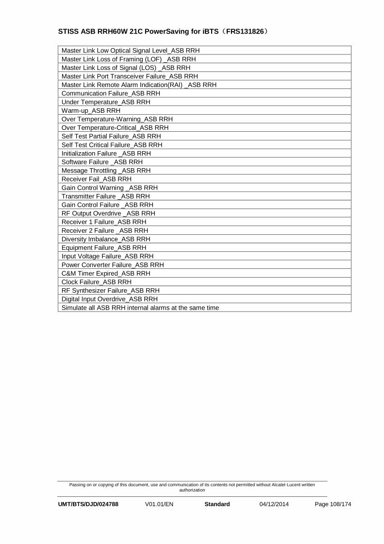
STISS ASB RRH60W 21C PowerSaving for iBTS(FRS131826)
Passing on or copying of this document, use and communication of its contents not permitted without Alcatel·Lucent written authorization
UMT/BTS/DJD/024788 V01.01/EN Standard 04/12/2014 Page 108/174
Master Link Low Optical Signal Level_ASB RRH
Master Link Loss of Framing (LOF) _ASB RRH
Master Link Loss of Signal (LOS) _ASB RRH
Master Link Port Transceiver Failure_ASB RRH
Master Link Remote Alarm Indication(RAI) _ASB RRH
Communication Failure_ASB RRH
Under Temperature_ASB RRH
Warm-up_ASB RRH
Over Temperature-Warning_ASB RRH
Over Temperature-Critical_ASB RRH
Self Test Partial Failure_ASB RRH
Self Test Critical Failure_ASB RRH
Initialization Failure _ASB RRH
Software Failure _ASB RRH
Message Throttling _ASB RRH
Receiver Fail_ASB RRH
Gain Control Warning _ASB RRH
Transmitter Failure _ASB RRH
Gain Control Failure _ASB RRH
RF Output Overdrive _ASB RRH
Receiver 1 Failure_ASB RRH
Receiver 2 Failure _ASB RRH
Diversity Imbalance_ASB RRH
Equipment Failure_ASB RRH
Input Voltage Failure_ASB RRH
Power Converter Failure_ASB RRH
C&M Timer Expired_ASB RRH
Clock Failure_ASB RRH
RF Synthesizer Failure_ASB RRH
Digital Input Overdrive_ASB RRH
Simulate all ASB RRH internal alarms at the same time

STISS V5.5 Test Specification
Passing on or copying of this document, use and communication of its contents not permitted without Alcatel·Lucent written authorization
UMT/BTS/DJD/024788 V01.01/EN Standard 04/12/2014 Page 109/174
2423
Test label 87: Slave Link Low Optical Signal Level_ASB RRH 2424
Purpose: 2425
This test is to report alarm when received optical signal on the slave (upstream) 2426
link port is unexpectedly low, though communication is still possible. 2427
Requirement: 2428 Platform configuration applicable: 2429 TIL connection 2430
OMCB connection 2431
OCI Tool 2432
Run the OCI tool; 2433
Select the related alarm Slave Link Low Optical Signal Level in the RRH/Procedures, 2434
Click the mode to ON; 2435
Then check the result from RTC and TIL and OMC-B 2436
The below figure is the OCI alarm figure. 2437
2438
See the expected alarm from the RTC tool. 2439
No alarm report to TIL 2440
No alarm report to OMCB 2441
Check LED flashing on RRH is Flash Yellow, Flash Green 2442
Check LED display on TIL is Flash Yellow, Flash Green 2443 ASSOCIATED CRPI GENERIC ALARM
Alarm Id Alarm Type Alarm Severity alarm informantion
LED exptected
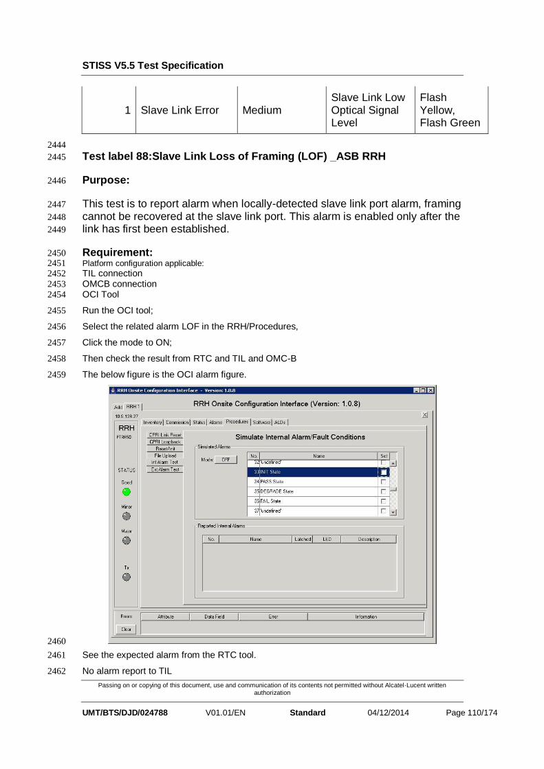
STISS V5.5 Test Specification
Passing on or copying of this document, use and communication of its contents not permitted without Alcatel·Lucent written authorization
UMT/BTS/DJD/024788 V01.01/EN Standard 04/12/2014 Page 110/174
1 Slave Link Error Medium Slave Link Low Optical Signal Level
Flash Yellow, Flash Green
2444
Test label 88:Slave Link Loss of Framing (LOF) _ASB RRH 2445
Purpose: 2446
This test is to report alarm when locally-detected slave link port alarm, framing 2447
cannot be recovered at the slave link port. This alarm is enabled only after the 2448
link has first been established. 2449
Requirement: 2450 Platform configuration applicable: 2451 TIL connection 2452
OMCB connection 2453
OCI Tool 2454
Run the OCI tool; 2455
Select the related alarm LOF in the RRH/Procedures, 2456
Click the mode to ON; 2457
Then check the result from RTC and TIL and OMC-B 2458
The below figure is the OCI alarm figure. 2459
2460
See the expected alarm from the RTC tool. 2461
No alarm report to TIL 2462

STISS V5.5 Test Specification
Passing on or copying of this document, use and communication of its contents not permitted without Alcatel·Lucent written authorization
UMT/BTS/DJD/024788 V01.01/EN Standard 04/12/2014 Page 111/174
No alarm report to OMCB 2463
Check LED flashing on RRH is Flash Yellow, Flash Green 2464
Check LED display on TIL is Flash Yellow, Flash Green 2465 ASSOCIATED CRPI GENERIC ALARM
Alarm Id Alarm Type Alarm Severity alarm informantion
LED exptected
2 Slave Link Error Major Slave Link Loss of Framing (LOF)
Flash Yellow, Flash Green

STISS V5.5 Test Specification
Passing on or copying of this document, use and communication of its contents not permitted without Alcatel·Lucent written authorization
UMT/BTS/DJD/024788 V01.01/EN Standard 04/12/2014 Page 112/174
Test label 89: Slave Link Loss of Signal (LOS) _ASB RRH 2466
Purpose: 2467
This test is to report alarm when locally-detected slave link port alarm, no 2468
signal is detected at the slave link port. This alarm is enabled only after the link 2469
has first been established. 2470
Requirement: 2471 Platform configuration applicable: 2472 TIL connection 2473
OMCB connection 2474
OCI Tool 2475
Run the OCI tool; 2476
Select the related alarm LOS in the RRH/Procedures, 2477
Click the mode to ON; 2478
Then check the result from RTC and TIL and OMC-B 2479
The below figure is the OCI alarm figure. 2480
2481
See the expected alarm from the RTC tool. 2482
No alarm report to TIL 2483
No alarm report to OMCB 2484
Check LED flashing on RRH is Flash Yellow, Flash Green 2485

STISS V5.5 Test Specification
Passing on or copying of this document, use and communication of its contents not permitted without Alcatel·Lucent written authorization
UMT/BTS/DJD/024788 V01.01/EN Standard 04/12/2014 Page 113/174
Check LED display on TIL is Flash Yellow, Flash Green 2486 ASSOCIATED CRPI GENERIC ALARM
Alarm Id Alarm Type Alarm Severity alarm informantion
LED exptected
3 Slave Link Error Major Slave Link Loss of Signal (LOS)
Flash Yellow, Flash Green
2487
Test label 90:Slave Link Port Transceiver Failure_ASB RRH 2488
Purpose: 2489
This test is to report alarm when slave link optical transceiver has failed and 2490
communication to the REC is probably not available 2491
Requirement: 2492 Platform configuration applicable: 2493 TIL connection 2494
OMCB connection 2495
OCI Tool 2496
Run the OCI tool; 2497
Select the related alarm Slave Link Port Transceiver Failure in the RRH/Procedures, 2498
Click the mode to ON; 2499
Then check the result from RTC and TIL and OMC-B 2500
The below figure is the OCI alarm figure. 2501

STISS V5.5 Test Specification
Passing on or copying of this document, use and communication of its contents not permitted without Alcatel·Lucent written authorization
UMT/BTS/DJD/024788 V01.01/EN Standard 04/12/2014 Page 114/174
2502
See the expected alarm from the RTC tool. 2503
No alarm report to TIL 2504
No alarm report to OMCB 2505
Check LED flashing on RRH is RED 2506
Check LED display on TIL is RED 2507 ASSOCIATED CRPI GENERIC ALARM
Alarm Id Alarm Type Alarm Severity alarm informantion
LED exptected
4 Slave Link Error Major Slave Link Port Transceiver Failur
Red
2508

STISS V5.5 Test Specification
Passing on or copying of this document, use and communication of its contents not permitted without Alcatel·Lucent written authorization
UMT/BTS/DJD/024788 V01.01/EN Standard 04/12/2014 Page 115/174
Test label 91:Slave Link Remote Alarm Indication (RAI) _ASB RRH 2509
Purpose: 2510
This test is to report alarm when one or more of the incoming slave link LOS, 2511
LOF, or RAI bits is set. 2512
Requirement: 2513 Platform configuration applicable: 2514 TIL connection 2515
OMCB connection 2516
OCI Tool 2517
Run the OCI tool; 2518
Select the related alarm Slave Link Remote Alarm Indication (RAI) in the RRH/Procedures, 2519
Click the mode to ON; 2520
Then check the result from RTC and TIL and OMC-B 2521
The below figure is the OCI alarm figure. 2522
2523
See the expected alarm from the RTC tool. 2524
No alarm report to TIL 2525
No alarm report to OMCB 2526
Check LED flashing on RRH is Flash Yellow, Flash Green 2527
Check LED display on TIL is Flash Yellow, Flash Green 2528 ASSOCIATED CRPI GENERIC ALARM

STISS V5.5 Test Specification
Passing on or copying of this document, use and communication of its contents not permitted without Alcatel·Lucent written authorization
UMT/BTS/DJD/024788 V01.01/EN Standard 04/12/2014 Page 116/174
Alarm Id Alarm Type Alarm Severity alarm informantion
LED exptected
6 Slave Link Error Major Slave Link RemoteAlarm Indication (RAI)
Flash Yellow, Flash Green
2529
Test label 92: Master Link Low Optical Signal Level_ASB RRH 2530
Purpose: 2531
This test is to report alarm when received optical signal on the slave (upstream) 2532
link port is unexpectedly low, though communication is still possible. 2533
Requirement: 2534 Platform configuration applicable: 2535 TIL connection 2536
OMCB connection 2537
OCI Tool 2538
Run the OCI tool; 2539
Select the related alarm Master Link Low Optical Signal Level in the RRH/Procedures, 2540
Click the mode to ON; 2541
Then check the result from RTC and TIL and OMC-B 2542
The below figure is the OCI alarm figure. 2543

STISS V5.5 Test Specification
Passing on or copying of this document, use and communication of its contents not permitted without Alcatel·Lucent written authorization
UMT/BTS/DJD/024788 V01.01/EN Standard 04/12/2014 Page 117/174
2544
See the expected alarm from the RTC tool. 2545
No alarm report to TIL 2546
No alarm report to OMCB 2547
Check LED flashing on RRH is Flash Yellow, Flash Green 2548
Check LED display on TIL is Flash Yellow, Flash Green 2549 ASSOCIATED CRPI GENERIC ALARM
Alarm Id Alarm Type Alarm Severity alarm informantion
LED exptected
9 Master Link Error Medium Master Link Low Optical Signal Level
Flash Yellow, Flash Green
2550

STISS V5.5 Test Specification
Passing on or copying of this document, use and communication of its contents not permitted without Alcatel·Lucent written authorization
UMT/BTS/DJD/024788 V01.01/EN Standard 04/12/2014 Page 118/174
Test label 93: Master Link Loss of Framing (LOF) _ASB RRH 2551
Purpose: 2552
This test is to report alarm when locally-detected master link port alarm, 2553
framing cannot be recovered at the master link port. This alarm is enabled only 2554
after the link has first been established. 2555
Requirement: 2556 Platform configuration applicable: 2557 TIL connection 2558
OMCB connection 2559
OCI Tool 2560
Run the OCI tool; 2561
Select the related alarm LOF in the RRH/Procedures, 2562
Click the mode to ON; 2563
Then check the result from RTC and TIL and OMC-B 2564
The below figure is the OCI alarm figure. 2565
2566
See the expected alarm from the RTC tool. 2567
No alarm report to TIL 2568
No alarm report to OMCB 2569
Check LED flashing on RRH is Flash Yellow, Flash Green 2570
Check LED display on TIL is Flash Yellow, Flash Green 2571 ASSOCIATED CRPI GENERIC ALARM
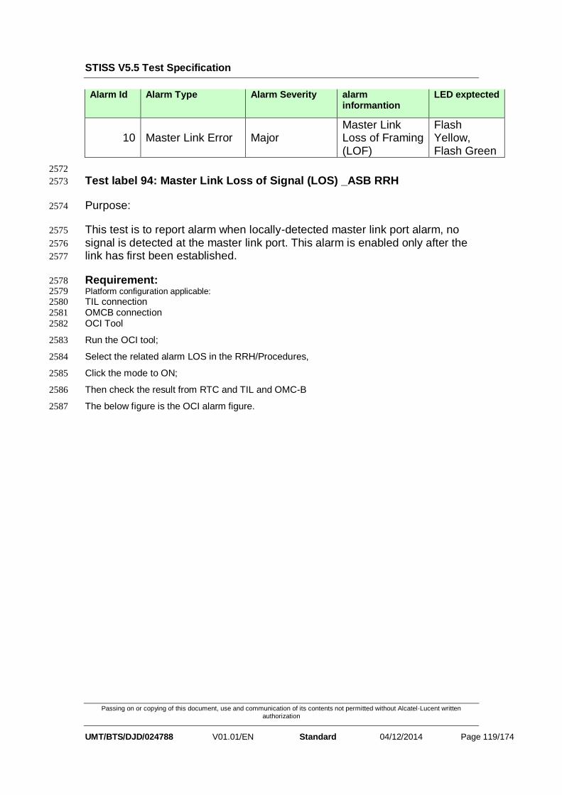
STISS V5.5 Test Specification
Passing on or copying of this document, use and communication of its contents not permitted without Alcatel·Lucent written authorization
UMT/BTS/DJD/024788 V01.01/EN Standard 04/12/2014 Page 119/174
Alarm Id Alarm Type Alarm Severity alarm informantion
LED exptected
10 Master Link Error Major Master Link Loss of Framing (LOF)
Flash Yellow, Flash Green
2572
Test label 94: Master Link Loss of Signal (LOS) _ASB RRH 2573
Purpose: 2574
This test is to report alarm when locally-detected master link port alarm, no 2575
signal is detected at the master link port. This alarm is enabled only after the 2576
link has first been established. 2577
Requirement: 2578 Platform configuration applicable: 2579 TIL connection 2580
OMCB connection 2581
OCI Tool 2582
Run the OCI tool; 2583
Select the related alarm LOS in the RRH/Procedures, 2584
Click the mode to ON; 2585
Then check the result from RTC and TIL and OMC-B 2586
The below figure is the OCI alarm figure. 2587

STISS V5.5 Test Specification
Passing on or copying of this document, use and communication of its contents not permitted without Alcatel·Lucent written authorization
UMT/BTS/DJD/024788 V01.01/EN Standard 04/12/2014 Page 120/174
2588
See the expected alarm from the RTC tool. 2589
No alarm report to TIL 2590
No alarm report to OMCB 2591
Check LED flashing on RRH is Flash Yellow, Flash Green 2592
Check LED display on TIL is Flash Yellow, Flash Green 2593 ASSOCIATED CRPI GENERIC ALARM
Alarm Id Alarm Type Alarm Severity alarm informantion
LED exptected
11 Master Link Error Major Master Link Loss of Signal (LOS)
Flash Yellow, Flash Green
2594

STISS V5.5 Test Specification
Passing on or copying of this document, use and communication of its contents not permitted without Alcatel·Lucent written authorization
UMT/BTS/DJD/024788 V01.01/EN Standard 04/12/2014 Page 121/174
Test label 95: Master Link Port Transceiver Failure_ASB RRH 2595
Purpose: 2596
This test is to report alarm when master link optical transceiver has failed and 2597
communication to the REC is probably not available 2598
Requirement: 2599 Platform configuration applicable: 2600 TIL connection 2601
OMCB connection 2602
OCI Tool 2603
Run the OCI tool; 2604
Select the related alarm Master Link Port Transceiver Failure in the RRH/Procedures, 2605
Click the mode to ON; 2606
Then check the result from RTC and TIL and OMC-B 2607
The below figure is the OCI alarm figure. 2608
2609
See the expected alarm from the RTC tool. 2610
No alarm report to TIL 2611
No alarm report to OMCB 2612
Check LED flashing on RRH is RED 2613

STISS V5.5 Test Specification
Passing on or copying of this document, use and communication of its contents not permitted without Alcatel·Lucent written authorization
UMT/BTS/DJD/024788 V01.01/EN Standard 04/12/2014 Page 122/174
Check LED display on TIL is RED 2614 ASSOCIATED CRPI GENERIC ALARM
Alarm Id Alarm Type Alarm Severity alarm informantion
LED exptected
12 Master Link Error Major
Master Link Port Transceiver Failure
Red
2615

STISS V5.5 Test Specification
Passing on or copying of this document, use and communication of its contents not permitted without Alcatel·Lucent written authorization
UMT/BTS/DJD/024788 V01.01/EN Standard 04/12/2014 Page 123/174
Test label 96: Master Link Remote Alarm Indication(RAI) _ASB RRH 2616
Purpose: 2617
This test is to report alarm when one or more of the incoming slave link LOS, 2618
LOF, or RAI bits is set. 2619
Requirement: 2620 Platform configuration applicable: 2621 TIL connection 2622
OMCB connection 2623
OCI Tool 2624
Run the OCI tool; 2625
Select the related alarm Master Link Remote Alarm Indication (RAI) in the RRH/Procedures, 2626
Click the mode to ON; 2627
Then check the result from RTC and TIL and OMC-B 2628
The below figure is the OCI alarm figure. 2629
2630
See the expected alarm from the RTC tool. 2631
No alarm report to TIL 2632
No alarm report to OMCB 2633
Check LED flashing on RRH is Flash Yellow, Flash Green 2634
Check LED display on TIL is Flash Yellow, Flash Green 2635 ASSOCIATED CRPI GENERIC ALARM
Alarm Id Alarm Type Alarm Severity alarm informantion
LED exptected

STISS V5.5 Test Specification
Passing on or copying of this document, use and communication of its contents not permitted without Alcatel·Lucent written authorization
UMT/BTS/DJD/024788 V01.01/EN Standard 04/12/2014 Page 124/174
14 Master Link Error Major Master Link Remote Alarm Indication (RAI)
Flash Yellow, Flash Green
2636
Test label 97: Communication Failure_ASB RRH 2637
Purpose: 2638
This test is to report alarm when there have been no management messages 2639
received in the past 30 seconds, or there is no active C&M TCP connection. 2640
Requirement: 2641 Platform configuration applicable: 2642 TIL connection 2643
OMCB connection 2644
OCI Tool 2645
Run the OCI tool; 2646
Select the related alarm Communication Failure in the RRH/Procedures, 2647
Click the mode to ON; 2648
Then check the result from RTC and TIL and OMC-B 2649
The below figure is the OCI alarm figure. 2650
2651

STISS V5.5 Test Specification
Passing on or copying of this document, use and communication of its contents not permitted without Alcatel·Lucent written authorization
UMT/BTS/DJD/024788 V01.01/EN Standard 04/12/2014 Page 125/174
See the expected alarm from the RTC tool. 2652
No alarm report to TIL 2653
No alarm report to OMCB 2654
Check LED flashing on RRH is Flash Yellow, Flash Green 2655
Check LED display on TIL is Flash Yellow, Flash Green 2656 ASSOCIATED CRPI GENERIC ALARM
Alarm Id Alarm Type Alarm Severity alarm informantion
LED exptected
17 Communication Error
Medium Communication Failure
Flash Yellow, Flash Green
2657

STISS V5.5 Test Specification
Passing on or copying of this document, use and communication of its contents not permitted without Alcatel·Lucent written authorization
UMT/BTS/DJD/024788 V01.01/EN Standard 04/12/2014 Page 126/174
Test label 98: Under Temperature_ASB RRH 2658
Purpose: 2659
The RRH is report alarm when below its normal operating temperature but still 2660
capable of transmitting. 2661
Requirement: 2662 Platform configuration applicable: 2663 TIL connection 2664
OMCB connection 2665
OCI Tool 2666
Run the OCI tool; 2667
Select the related alarm Under Temperature in the RRH/Procedures, 2668
Click the mode to ON; 2669
Then check the result from RTC and TIL and OMC-B 2670
The below figure is the OCI alarm figure. 2671
2672
See the expected alarm from the RTC tool. 2673
No alarm report to TIL 2674
No alarm report to OMCB 2675
Check LED flashing on RRH is Green, Flash RED 2676
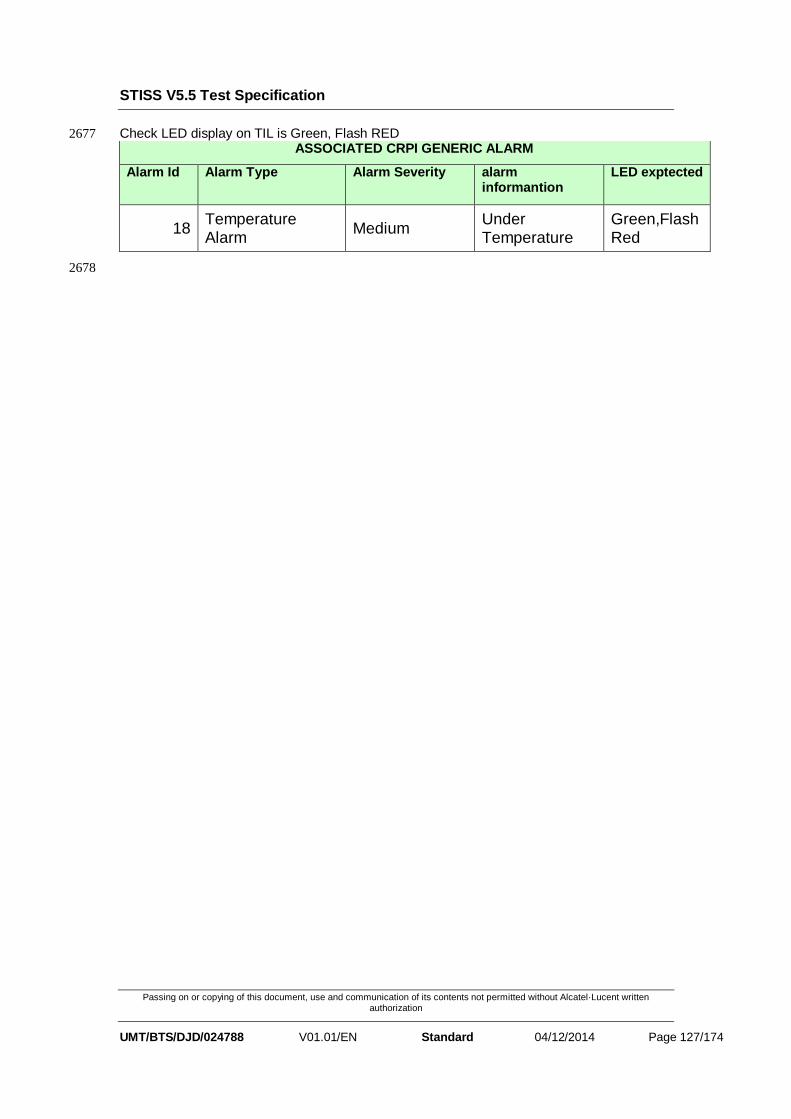
STISS V5.5 Test Specification
Passing on or copying of this document, use and communication of its contents not permitted without Alcatel·Lucent written authorization
UMT/BTS/DJD/024788 V01.01/EN Standard 04/12/2014 Page 127/174
Check LED display on TIL is Green, Flash RED 2677 ASSOCIATED CRPI GENERIC ALARM
Alarm Id Alarm Type Alarm Severity alarm informantion
LED exptected
18 Temperature Alarm
Medium Under Temperature
Green,Flash Red
2678

STISS V5.5 Test Specification
Passing on or copying of this document, use and communication of its contents not permitted without Alcatel·Lucent written authorization
UMT/BTS/DJD/024788 V01.01/EN Standard 04/12/2014 Page 128/174
Test label 99: Warm-up_ASB RRH 2679
Purpose: 2680
The RRH is report alarm when below its normal operating temperature but still 2681
capable of transmitting. 2682
Requirement: 2683 Platform configuration applicable: 2684 TIL connection 2685
OMCB connection 2686
OCI Tool 2687
Run the OCI tool; 2688
Select the related alarm Warm-Up in the RRH/Procedures, 2689
Click the mode to ON; 2690
Then check the result from RTC and TIL and OMC-B 2691
The below figure is the OCI alarm figure. 2692
2693
See the expected alarm from the RTC tool. 2694
No alarm report to TIL 2695
No alarm report to OMCB 2696
Check LED flashing on RRH is Flash RED 2697
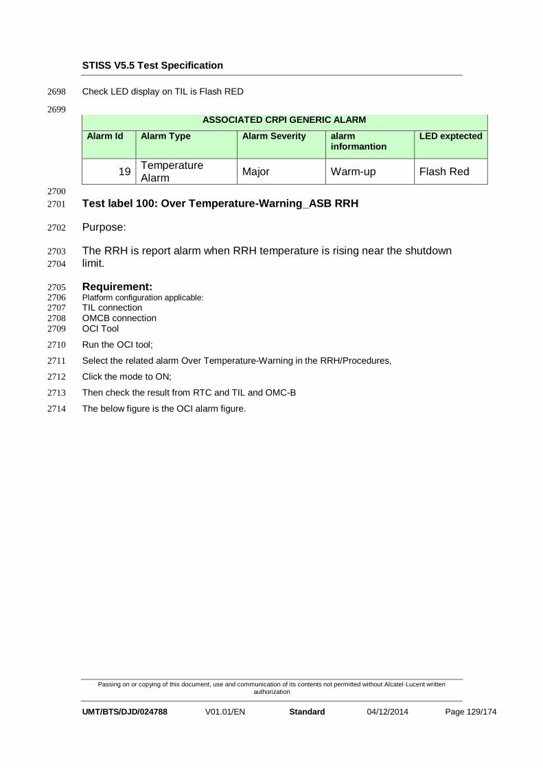
STISS V5.5 Test Specification
Passing on or copying of this document, use and communication of its contents not permitted without Alcatel·Lucent written authorization
UMT/BTS/DJD/024788 V01.01/EN Standard 04/12/2014 Page 129/174
Check LED display on TIL is Flash RED 2698
2699
ASSOCIATED CRPI GENERIC ALARM
Alarm Id Alarm Type Alarm Severity alarm informantion
LED exptected
19 Temperature Alarm
Major Warm-up Flash Red
2700
Test label 100: Over Temperature-Warning_ASB RRH 2701
Purpose: 2702
The RRH is report alarm when RRH temperature is rising near the shutdown 2703
limit. 2704
Requirement: 2705 Platform configuration applicable: 2706 TIL connection 2707
OMCB connection 2708
OCI Tool 2709
Run the OCI tool; 2710
Select the related alarm Over Temperature-Warning in the RRH/Procedures, 2711
Click the mode to ON; 2712
Then check the result from RTC and TIL and OMC-B 2713
The below figure is the OCI alarm figure. 2714

STISS V5.5 Test Specification
Passing on or copying of this document, use and communication of its contents not permitted without Alcatel·Lucent written authorization
UMT/BTS/DJD/024788 V01.01/EN Standard 04/12/2014 Page 130/174
2715
See the expected alarm from the RTC tool. 2716
See the expected alarm from the TIL tool. 2717
See the expected alarm from the OMC-B. 2718
Check LED flashing on RRH is Green,Flash Red 2719
Check LED display on TIL is Green,Flash Red 2720 ASSOCIATED CRPI GENERIC ALARM
Alarm Id Alarm Type Alarm Severity alarm informantion LED exptected
20 Temperature Alarm
Medium Over Temperature-Warning
Green,Flash Red
2721

STISS V5.5 Test Specification
Passing on or copying of this document, use and communication of its contents not permitted without Alcatel·Lucent written authorization
UMT/BTS/DJD/024788 V01.01/EN Standard 04/12/2014 Page 131/174
Test label 101: Over Temperature-Critical_ASB RRH 2722
Purpose: 2723
The RRH is report alarm when the RRH temperature is above operating range, 2724
and the transmitter has shut down to attempt to reduce the temperature. 2725
Requirement: 2726 Platform configuration applicable: 2727 TIL connection 2728
OMCB connection 2729
OCI Tool 2730
Run the OCI tool; 2731
Select the related alarm Over Temperature-Critical in the RRH/Procedures, 2732
Click the mode to ON; 2733
Then check the result from RTC and TIL and OMC-B 2734
The below figure is the OCI alarm figure. 2735
2736
See the expected alarm from the RTC tool. 2737
See the expected alarm from the TIL tool 2738
See the expected alarm from the OMC-B 2739
Check LED flashing on RRH is Flash Red 2740

STISS V5.5 Test Specification
Passing on or copying of this document, use and communication of its contents not permitted without Alcatel·Lucent written authorization
UMT/BTS/DJD/024788 V01.01/EN Standard 04/12/2014 Page 132/174
Check LED display on TIL is Flash Red 2741 ASSOCIATED CRPI GENERIC ALARM
Alarm Id Alarm Type Alarm Severity alarm informantion LED exptected
21 Temperature Alarm
Major Over Temperature-Critical
Flash Red
2742
Test label 102: Self Test Partial Failure_ASB RRH 2743
Purpose: 2744
The RRH is report alarm when at least one failure was detected during power 2745
on self test, but the unit may still be functional, though in a degraded state. 2746
Requirement: 2747 Platform configuration applicable: 2748 TIL connection 2749
OMCB connection 2750
OCI Tool 2751
Run the OCI tool; 2752
Select the related alarm Self Test Partial Failure in the RRH/Procedures, 2753
Click the mode to ON; 2754
Then check the result from RTC and TIL and OMC-B 2755
The below figure is the OCI alarm figure. 2756

STISS V5.5 Test Specification
Passing on or copying of this document, use and communication of its contents not permitted without Alcatel·Lucent written authorization
UMT/BTS/DJD/024788 V01.01/EN Standard 04/12/2014 Page 133/174
2757
See the expected alarm from the RTC tool. 2758
No alarm report to TIL 2759
No alarm report to OMCB 2760
Check LED flashing on RRH is Green, RED 2761
Check LED display on TIL is Green, RED 2762 ASSOCIATED CRPI GENERIC ALARM
Alarm Id Alarm Type Alarm Severity alarm informantion
LED exptected
24 Self Test Failure Medium Self Test Partial Failure
Red,Green
2763
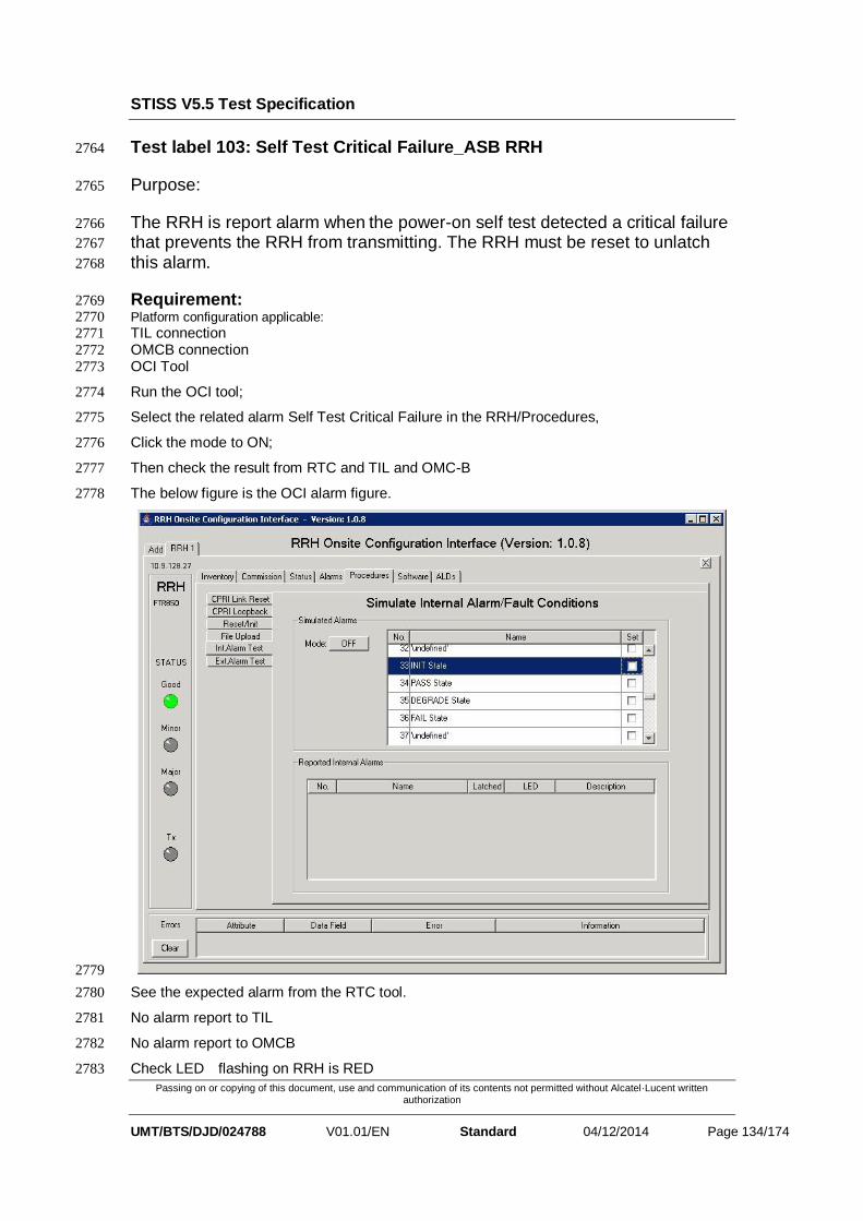
STISS V5.5 Test Specification
Passing on or copying of this document, use and communication of its contents not permitted without Alcatel·Lucent written authorization
UMT/BTS/DJD/024788 V01.01/EN Standard 04/12/2014 Page 134/174
Test label 103: Self Test Critical Failure_ASB RRH 2764
Purpose: 2765
The RRH is report alarm when the power-on self test detected a critical failure 2766
that prevents the RRH from transmitting. The RRH must be reset to unlatch 2767
this alarm. 2768
Requirement: 2769 Platform configuration applicable: 2770 TIL connection 2771
OMCB connection 2772
OCI Tool 2773
Run the OCI tool; 2774
Select the related alarm Self Test Critical Failure in the RRH/Procedures, 2775
Click the mode to ON; 2776
Then check the result from RTC and TIL and OMC-B 2777
The below figure is the OCI alarm figure. 2778
2779
See the expected alarm from the RTC tool. 2780
No alarm report to TIL 2781
No alarm report to OMCB 2782
Check LED flashing on RRH is RED 2783

STISS V5.5 Test Specification
Passing on or copying of this document, use and communication of its contents not permitted without Alcatel·Lucent written authorization
UMT/BTS/DJD/024788 V01.01/EN Standard 04/12/2014 Page 135/174
Check LED display on TIL is RED 2784 ASSOCIATED CRPI GENERIC ALARM
Alarm Id Alarm Type Alarm Severity alarm informantion
LED exptected
25 Self Test Failure Major Self Test Critical Failure
Red
2785
Test label 104: Initialization Failure _ASB RRH 2786
Purpose: 2787
The RRH is report alarm when FPGA download failures, or PLLs are not 2788
locked. Note that this is evaluated during initialization and the unit is never 2789
enabled. The RRH must be reset to unlatch this alarm. 2790
Requirement: 2791 Platform configuration applicable: 2792
TIL connection 2793 OMCB connection 2794
OCI Tool 2795
Run the OCI tool; 2796
Select the related alarm Initialization Failure in the RRH/Procedures, 2797
Click the mode to ON; 2798
Then check the result from RTC and TIL and OMC-B 2799
The below figure is the OCI alarm figure. 2800
2801
See the expected alarm from the RTC tool. 2802

STISS V5.5 Test Specification
Passing on or copying of this document, use and communication of its contents not permitted without Alcatel·Lucent written authorization
UMT/BTS/DJD/024788 V01.01/EN Standard 04/12/2014 Page 136/174
See the expected alarm from the TIL tool. 2803
See the expected alarm from the OMCB tool 2804
Check LED flashing on RRH is RED 2805
Check LED display on TIL is RED 2806 ASSOCIATED CRPI GENERIC ALARM
Alarm Id Alarm Type Alarm Severity alarm informantion
LED exptected
26 PLL Failure Major Initialization Failure
Red
2807
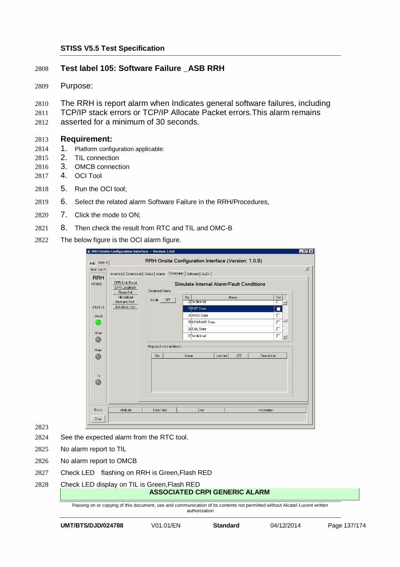
STISS V5.5 Test Specification
Passing on or copying of this document, use and communication of its contents not permitted without Alcatel·Lucent written authorization
UMT/BTS/DJD/024788 V01.01/EN Standard 04/12/2014 Page 137/174
Test label 105: Software Failure _ASB RRH 2808
Purpose: 2809
The RRH is report alarm when Indicates general software failures, including 2810
TCP/IP stack errors or TCP/IP Allocate Packet errors.This alarm remains 2811
asserted for a minimum of 30 seconds. 2812
Requirement: 2813
1. Platform configuration applicable: 2814
2. TIL connection 2815
3. OMCB connection 2816
4. OCI Tool 2817
5. Run the OCI tool; 2818
6. Select the related alarm Software Failure in the RRH/Procedures, 2819
7. Click the mode to ON; 2820
8. Then check the result from RTC and TIL and OMC-B 2821
The below figure is the OCI alarm figure. 2822
2823
See the expected alarm from the RTC tool. 2824
No alarm report to TIL 2825
No alarm report to OMCB 2826
Check LED flashing on RRH is Green,Flash RED 2827
Check LED display on TIL is Green,Flash RED 2828 ASSOCIATED CRPI GENERIC ALARM

STISS V5.5 Test Specification
Passing on or copying of this document, use and communication of its contents not permitted without Alcatel·Lucent written authorization
UMT/BTS/DJD/024788 V01.01/EN Standard 04/12/2014 Page 138/174
Alarm Id Alarm Type Alarm Severity alarm informantion
LED exptected
27 Software Failure Minor Software Failure
Green,Flash Red
2829
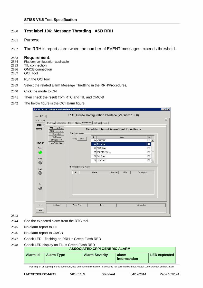
STISS V5.5 Test Specification
Passing on or copying of this document, use and communication of its contents not permitted without Alcatel·Lucent written authorization
UMT/BTS/DJD/044741 V01.01/EN Standard 04/12/2014 Page 139/174
Test label 106: Message Throttling _ASB RRH 2830
Purpose: 2831
The RRH is report alarm when the number of EVENT messages exceeds threshold. 2832
Requirement: 2833 Platform configuration applicable: 2834 TIL connection 2835
OMCB connection 2836
OCI Tool 2837
Run the OCI tool; 2838
Select the related alarm Message Throttling in the RRH/Procedures, 2839
Click the mode to ON; 2840
Then check the result from RTC and TIL and OMC-B 2841
The below figure is the OCI alarm figure. 2842
2843
See the expected alarm from the RTC tool. 2844
No alarm report to TIL 2845
No alarm report to OMCB 2846
Check LED flashing on RRH is Green,Flash RED 2847
Check LED display on TIL is Green,Flash RED 2848 ASSOCIATED CRPI GENERIC ALARM
Alarm Id Alarm Type Alarm Severity alarm informantion
LED exptected

STISS V5.5 Test Specification
Passing on or copying of this document, use and communication of its contents not permitted without Alcatel·Lucent written authorization
UMT/BTS/DJD/044741 V01.01/EN Standard 04/12/2014 Page 140/174
28 Communication Error
Minor Message Throttling
Green,Flash Red
2849
Test label 107: Receiver Fail_ASB RRH 2850
Purpose: 2851
The RRH is report alarm when any error is dectected on the Radio Receiver 2852
side(channelizer,synthetiser..) 2853
Requirement: 2854 Platform configuration applicable: 2855 TIL connection 2856
OMCB connection 2857
OCI Tool 2858
Run the OCI tool; 2859
Select the related alarm Receiver Fail in the RRH/Procedures, 2860
Click the mode to ON; 2861
Then check the result from RTC and TIL and OMC-B 2862
The below figure is the OCI alarm figure. 2863
2864
See the expected alarm from the RTC tool. 2865
See the expected alarm from the TIL tool. 2866
See the expected alarm from the OMCB tool 2867
Check LED flashing on RRH is RED 2868

STISS V5.5 Test Specification
Passing on or copying of this document, use and communication of its contents not permitted without Alcatel·Lucent written authorization
UMT/BTS/DJD/044741 V01.01/EN Standard 04/12/2014 Page 141/174
Check LED display on TIL is RED 2869 ASSOCIATED CRPI GENERIC ALARM
Alarm Id Alarm Type Alarm Severity alarm informantion
LED exptected
31 Rx Path Failure Major Receiver Fail Red
2870
Test label 108: Gain Control Warning _ASB RRH 2871
Purpose: 2872
The RRH is report alarm of Gain control error 2873
Requirement: 2874 Platform configuration applicable: 2875 TIL connection 2876
OMCB connection 2877
OCI Tool 2878
Run the OCI tool; 2879
Select the related alarm Gain Control Warning in the RRH/Procedures, 2880
Click the mode to ON; 2881
Then check the result from RTC and TIL and OMC-B 2882
The below figure is the OCI alarm figure. 2883
2884
See the expected alarm from the RTC tool. 2885
No alarm report to TIL 2886

STISS V5.5 Test Specification
Passing on or copying of this document, use and communication of its contents not permitted without Alcatel·Lucent written authorization
UMT/BTS/DJD/044741 V01.01/EN Standard 04/12/2014 Page 142/174
No alarm report to OMCB 2887
Check LED flashing on RRH is Flash Green,Flash RED 2888
Check LED display on TIL is Flash Green,Flash RED 2889 ASSOCIATED CRPI GENERIC ALARM
Alarm Id Alarm Type Alarm Severity alarm informantion
LED exptected
32 Gain Control Alarm
Medium Gain Control Warning
Flash Red,Flash Green
2890
Test label 109: Transmitter Failure _ASB RRH 2891
Purpose: 2892
The RRH is report alarm when any error is dectected on the Radio Transmitter side 2893
Requirement: 2894 Platform configuration applicable: 2895 TIL connection 2896
OMCB connection 2897
OCI Tool 2898
Run the OCI tool; 2899
Select the related alarm Transmitter Fail in the RRH/Procedures, 2900
Click the mode to ON; 2901
Then check the result from RTC and TIL and OMC-B 2902
The below figure is the OCI alarm figure. 2903
2904

STISS V5.5 Test Specification
Passing on or copying of this document, use and communication of its contents not permitted without Alcatel·Lucent written authorization
UMT/BTS/DJD/044741 V01.01/EN Standard 04/12/2014 Page 143/174
See the expected alarm from the RTC tool. 2905
See the expected alarm from the TIL tool. 2906
See the expected alarm from the OMCB tool 2907
Check LED flashing on RRH is RED 2908
Check LED display on TIL is RED 2909 ASSOCIATED CRPI GENERIC ALARM
Alarm Id Alarm Type Alarm Severity alarm informantion
LED exptected
33 Tx Path Failure Major Transmitter Failure
Red
2910
Test label 110: Gain Control Failure _ASB RRH 2911
Purpose: 2912
The RRH is report alarm of Gain control error 2913
Requirement: 2914 Platform configuration applicable: 2915 TIL connection 2916
OMCB connection 2917
OCI Tool 2918
Run the OCI tool; 2919
Select the related alarm Gain Control Failure in the RRH/Procedures, 2920
Click the mode to ON; 2921
Then check the result from RTC and TIL and OMC-B 2922
The below figure is the OCI alarm figure. 2923

STISS V5.5 Test Specification
Passing on or copying of this document, use and communication of its contents not permitted without Alcatel·Lucent written authorization
UMT/BTS/DJD/044741 V01.01/EN Standard 04/12/2014 Page 144/174
2924
See the expected alarm from the RTC tool. 2925
See the expected alarm from the TIL tool. 2926
See the expected alarm from the OMCB tool 2927
Check LED flashing on RRH is RED 2928
Check LED display on TIL is RED 2929
2930 ASSOCIATED CRPI GENERIC ALARM
Alarm Id Alarm Type Alarm Severity alarm informantion
LED exptected
34 Gain Control Alarm
Major Gain Control Failure
Red
2931
Test label 111: RF Output Overdrive _ASB RRH 2932
Purpose: 2933
The RRH is report alarm of RF output overdrive 2934
Requirement: 2935 Platform configuration applicable: 2936 TIL connection 2937
OMCB connection 2938
OCI Tool 2939
Run the OCI tool; 2940
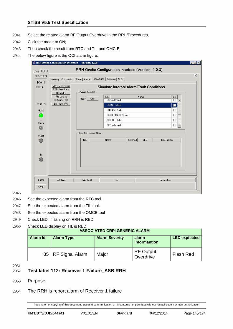
STISS V5.5 Test Specification
Passing on or copying of this document, use and communication of its contents not permitted without Alcatel·Lucent written authorization
UMT/BTS/DJD/044741 V01.01/EN Standard 04/12/2014 Page 145/174
Select the related alarm RF Output Overdrive in the RRH/Procedures, 2941
Click the mode to ON; 2942
Then check the result from RTC and TIL and OMC-B 2943
The below figure is the OCI alarm figure. 2944
2945
See the expected alarm from the RTC tool. 2946
See the expected alarm from the TIL tool. 2947
See the expected alarm from the OMCB tool 2948
Check LED flashing on RRH is RED 2949
Check LED display on TIL is RED 2950 ASSOCIATED CRPI GENERIC ALARM
Alarm Id Alarm Type Alarm Severity alarm informantion
LED exptected
35 RF Signal Alarm Major RF Output Overdrive
Flash Red
2951
Test label 112: Receiver 1 Failure_ASB RRH 2952
Purpose: 2953
The RRH is report alarm of Receiver 1 failure 2954

STISS V5.5 Test Specification
Passing on or copying of this document, use and communication of its contents not permitted without Alcatel·Lucent written authorization
UMT/BTS/DJD/044741 V01.01/EN Standard 04/12/2014 Page 146/174
Requirement: 2955 Platform configuration applicable: 2956 TIL connection 2957
OMCB connection 2958
OCI Tool 2959
Run the OCI tool; 2960
Select the related alarm Receiver 1 Failure in the RRH/Procedures, 2961
Click the mode to ON; 2962
Then check the result from RTC and TIL and OMC-B 2963
The below figure is the OCI alarm figure. 2964
2965
See the expected alarm from the RTC tool. 2966
No alarm report to TIL 2967
No alarm report to OMCB 2968
Check LED flashing on RRH is Green, RED 2969
Check LED display on TIL is Green, RED 2970
2971 ASSOCIATED CRPI GENERIC ALARM
Alarm Id Alarm Type Alarm Severity alarm informantion
LED exptected
36 Rx Path Failure Medium Receiver 1 Failure
Red,Green

STISS V5.5 Test Specification
Passing on or copying of this document, use and communication of its contents not permitted without Alcatel·Lucent written authorization
UMT/BTS/DJD/044741 V01.01/EN Standard 04/12/2014 Page 147/174
2972
Test label 113: Receiver 2 Failure _ASB RRH 2973
Purpose: 2974
The RRH is report alarm of Receiver 2 failure 2975
Requirement: 2976 Platform configuration applicable: 2977 TIL connection 2978
OMCB connection 2979
OCI Tool 2980
Run the OCI tool; 2981
Select the related alarm Receiver 2 Failure in the RRH/Procedures, 2982
Click the mode to ON; 2983
Then check the result from RTC and TIL and OMC-B 2984
The below figure is the OCI alarm figure. 2985
2986
See the expected alarm from the RTC tool. 2987
No alarm report to TIL 2988
No alarm report to OMCB 2989
Check LED flashing on RRH is Green, RED 2990

STISS V5.5 Test Specification
Passing on or copying of this document, use and communication of its contents not permitted without Alcatel·Lucent written authorization
UMT/BTS/DJD/044741 V01.01/EN Standard 04/12/2014 Page 148/174
Check LED display on TIL is Green, RED 2991 ASSOCIATED CRPI GENERIC ALARM
Alarm Id Alarm Type Alarm Severity alarm informantion
LED exptected
37 Rx Path Failure Medium Receiver 2 Failure
Red,Green
2992
Test label 114: Diversity Imbalance_ASB RRH 2993
Purpose: 2994
The RRH is report alarm of low rssi 2995
Requirement: 2996 Platform configuration applicable: 2997 TIL connection 2998
OMCB connection 2999
OCI Tool 3000
Run the OCI tool; 3001
Select the related alarm Diversity Imbalance in the RRH/Procedures, 3002
Click the mode to ON; 3003
Then check the result from RTC and TIL and OMC-B 3004
The below figure is the OCI alarm figure. 3005
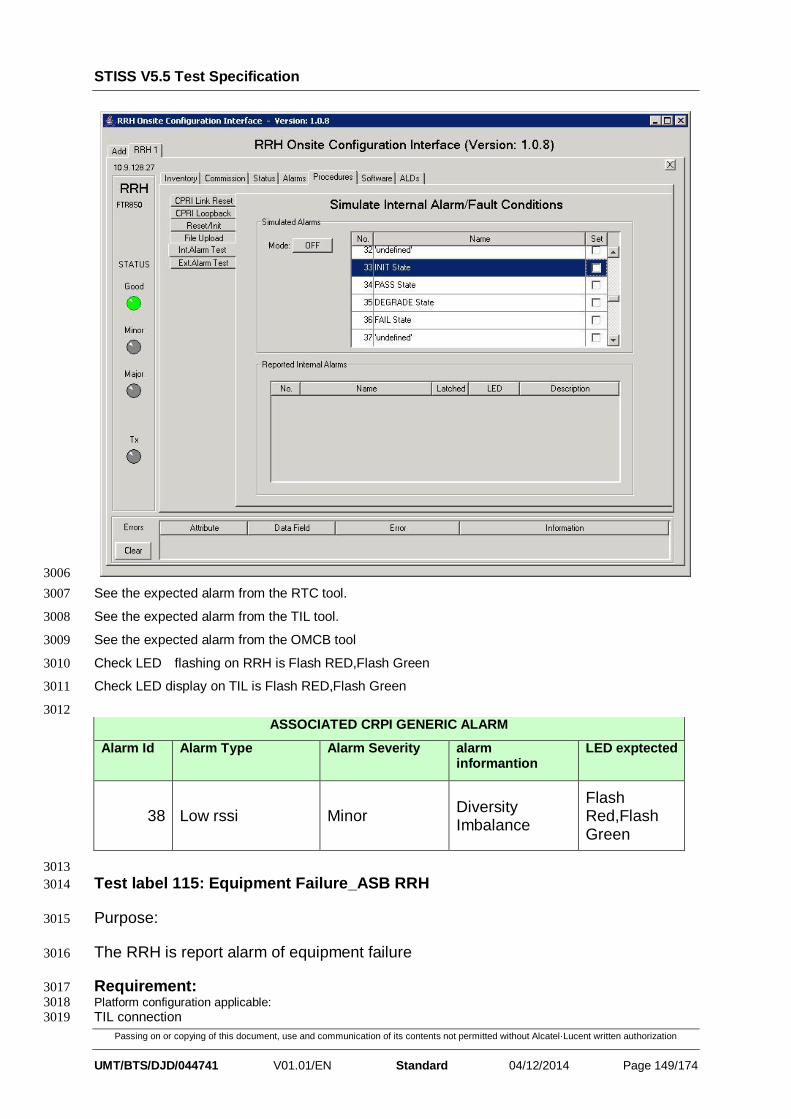
STISS V5.5 Test Specification
Passing on or copying of this document, use and communication of its contents not permitted without Alcatel·Lucent written authorization
UMT/BTS/DJD/044741 V01.01/EN Standard 04/12/2014 Page 149/174
3006
See the expected alarm from the RTC tool. 3007
See the expected alarm from the TIL tool. 3008
See the expected alarm from the OMCB tool 3009
Check LED flashing on RRH is Flash RED,Flash Green 3010
Check LED display on TIL is Flash RED,Flash Green 3011
3012 ASSOCIATED CRPI GENERIC ALARM
Alarm Id Alarm Type Alarm Severity alarm informantion
LED exptected
38 Low rssi Minor Diversity Imbalance
Flash Red,Flash Green
3013
Test label 115: Equipment Failure_ASB RRH 3014
Purpose: 3015
The RRH is report alarm of equipment failure 3016
Requirement: 3017 Platform configuration applicable: 3018 TIL connection 3019

STISS V5.5 Test Specification
Passing on or copying of this document, use and communication of its contents not permitted without Alcatel·Lucent written authorization
UMT/BTS/DJD/044741 V01.01/EN Standard 04/12/2014 Page 150/174
OMCB connection 3020
OCI Tool 3021
Run the OCI tool; 3022
Select the related alarm equipment failure in the RRH/Procedures, 3023
Click the mode to ON; 3024
Then check the result from RTC and TIL and OMC-B 3025
The below figure is the OCI alarm figure. 3026
3027
See the expected alarm from the RTC tool. 3028
See the expected alarm from the TIL tool. 3029
See the expected alarm from the OMCB tool 3030
Check LED flashing on RRH is RED 3031
Check LED display on TIL is RED 3032
3033 ASSOCIATED CRPI GENERIC ALARM
Alarm Id Alarm Type Alarm Severity alarm informantion
LED exptected
40 Hareware Failure Major Equipment Failure
Red

STISS V5.5 Test Specification
Passing on or copying of this document, use and communication of its contents not permitted without Alcatel·Lucent written authorization
UMT/BTS/DJD/044741 V01.01/EN Standard 04/12/2014 Page 151/174
3034
Test label 116: Input Voltage Failure_ASB RRH 3035
Purpose: 3036
The RRH is report alarm of Input Voltage Failure 3037
Requirement: 3038 Platform configuration applicable: 3039 TIL connection 3040
OMCB connection 3041
OCI Tool 3042
Run the OCI tool; 3043
Select the related alarm Input Voltage Failure in the RRH/Procedures, 3044
Click the mode to ON; 3045
Then check the result from RTC and TIL and OMC-B 3046
The below figure is the OCI alarm figure. 3047
3048
See the expected alarm from the RTC tool. 3049
See the expected alarm from the TIL tool. 3050
See the expected alarm from the OMCB tool 3051
Check LED flashing on RRH is Flash RED 3052

STISS V5.5 Test Specification
Passing on or copying of this document, use and communication of its contents not permitted without Alcatel·Lucent written authorization
UMT/BTS/DJD/044741 V01.01/EN Standard 04/12/2014 Page 152/174
Check LED display on TIL is Flash RED 3053 ASSOCIATED CRPI GENERIC ALARM
Alarm Id Alarm Type Alarm Severity alarm informantion
LED exptected
41 DC Voltage Alarm Major Input Voltage Failure
Flash Red
3054
Test label 117: Power Converter Failure_ASB RRH 3055
Purpose: 3056
The RRH is report alarm of Power Converter Failure 3057
Requirement: 3058 Platform configuration applicable: 3059 TIL connection 3060
OMCB connection 3061
OCI Tool 3062
Run the OCI tool; 3063
Select the related alarm Power Converter Failure in the RRH/Procedures, 3064
Click the mode to ON; 3065
Then check the result from RTC and TIL and OMC-B 3066
The below figure is the OCI alarm figure. 3067
3068

STISS V5.5 Test Specification
Passing on or copying of this document, use and communication of its contents not permitted without Alcatel·Lucent written authorization
UMT/BTS/DJD/044741 V01.01/EN Standard 04/12/2014 Page 153/174
See the expected alarm from the RTC tool. 3069
See the expected alarm from the TIL tool. 3070
See the expected alarm from the OMCB tool 3071
Check LED flashing on RRH is RED 3072
Check LED display on TIL is RED 3073 ASSOCIATED CRPI GENERIC ALARM
Alarm Id Alarm Type Alarm Severity alarm informantion
LED exptected
42 DC Voltage Alarm Major Power Converter Failure
Red
3074
Test label 118: C&M Timer Expired_ASB RRH 3075
Purpose: 3076
The RRH is report alarm of C&M Timer Expired 3077
Requirement: 3078 Platform configuration applicable: 3079
TIL connection 3080 OMCB connection 3081
OCI Tool 3082
Run the OCI tool; 3083
Select the related alarm C&M Timer Expired in the RRH/Procedures, 3084
Click the mode to ON; 3085
Then check the result from RTC and TIL and OMC-B 3086
The below figure is the OCI alarm figure. 3087

STISS V5.5 Test Specification
Passing on or copying of this document, use and communication of its contents not permitted without Alcatel·Lucent written authorization
UMT/BTS/DJD/044741 V01.01/EN Standard 04/12/2014 Page 154/174
3088
See the expected alarm from the RTC tool. 3089
No alarm report to TIL 3090
No alarm report to OMCB 3091
Check LED flashing on RRH is RED 3092
Check LED display on TIL is RED 3093 ASSOCIATED CRPI GENERIC ALARM
Alarm Id Alarm Type Alarm Severity alarm informantion
LED exptected
44 Software Failure Major C&M Timer Expired
Red
3094
Test label 119: Clock Failure_ASB RRH 3095
Purpose: 3096
The RRH is report alarm of Clock Failure 3097
Requirement: 3098 Platform configuration applicable: 3099 TIL connection 3100
OMCB connection 3101
OCI Tool 3102
Run the OCI tool; 3103

STISS V5.5 Test Specification
Passing on or copying of this document, use and communication of its contents not permitted without Alcatel·Lucent written authorization
UMT/BTS/DJD/044741 V01.01/EN Standard 04/12/2014 Page 155/174
Select the related alarm Clock Failure in the RRH/Procedures, 3104
Click the mode to ON; 3105
Then check the result from RTC and TIL and OMC-B 3106
The below figure is the OCI alarm figure. 3107
3108
See the expected alarm from the RTC tool. 3109
See the expected alarm from the TIL tool. 3110
See the expected alarm from the OMCB tool 3111
Check LED flashing on RRH is Flash RED 3112
Check LED display on TIL is Flash RED 3113
3114 ASSOCIATED CRPI GENERIC ALARM
Alarm Id Alarm Type Alarm Severity alarm informantion
LED exptected
47 PLL Failure Major Clock Failure Flash Red
3115
Test label 120: RF Synthesizer Failure_ASB RRH 3116
Purpose: 3117
The RRH is report alarm of RF Synthesizer Failure 3118

STISS V5.5 Test Specification
Passing on or copying of this document, use and communication of its contents not permitted without Alcatel·Lucent written authorization
UMT/BTS/DJD/044741 V01.01/EN Standard 04/12/2014 Page 156/174
Requirement: 3119 Platform configuration applicable: 3120 TIL connection 3121
OMCB connection 3122
OCI Tool 3123
Run the OCI tool; 3124
Select the related alarm RF Synthesizer Failure in the RRH/Procedures, 3125
Click the mode to ON; 3126
Then check the result from RTC and TIL and OMC-B 3127
The below figure is the OCI alarm figure. 3128
3129
See the expected alarm from the RTC tool. 3130
See the expected alarm from the TIL tool. 3131
See the expected alarm from the OMCB tool 3132
Check LED flashing on RRH is Flash RED 3133
Check LED display on TIL is Flash RED 3134 ASSOCIATED CRPI GENERIC ALARM
Alarm Id Alarm Type Alarm Severity alarm informantion
LED exptected
48 PLL Failure Major RF Synthesizer Failure
Flash Red
3135
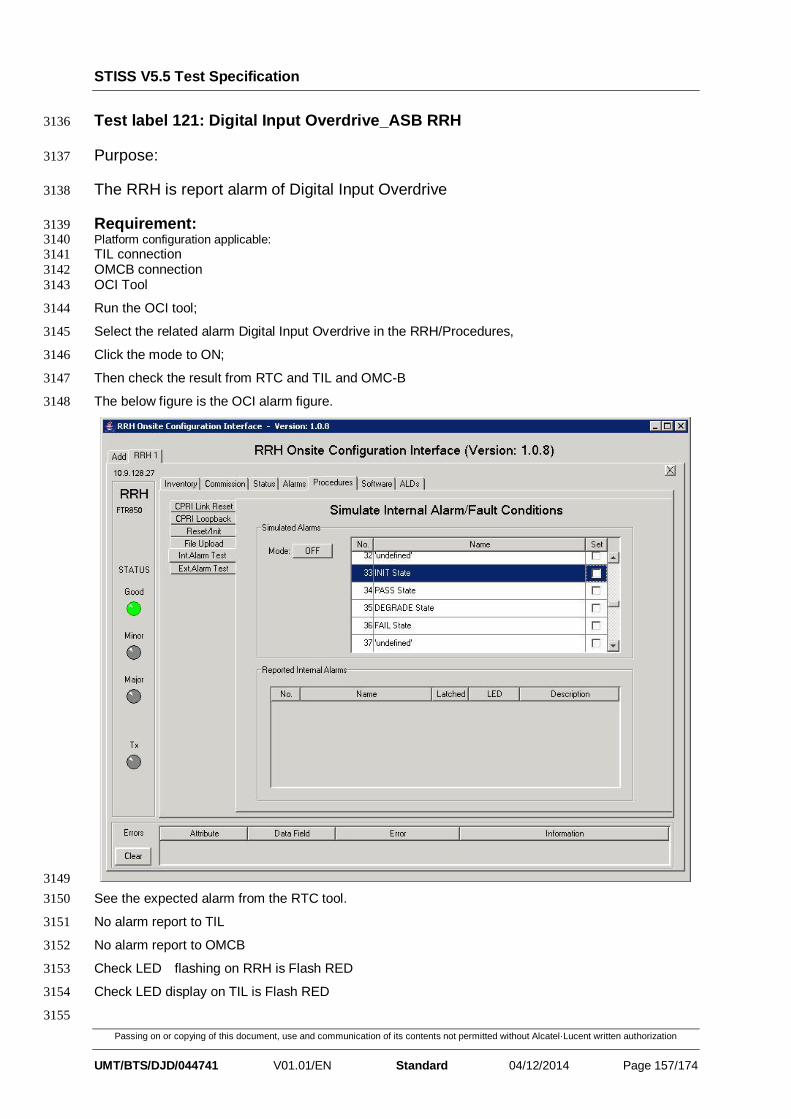
STISS V5.5 Test Specification
Passing on or copying of this document, use and communication of its contents not permitted without Alcatel·Lucent written authorization
UMT/BTS/DJD/044741 V01.01/EN Standard 04/12/2014 Page 157/174
Test label 121: Digital Input Overdrive_ASB RRH 3136
Purpose: 3137
The RRH is report alarm of Digital Input Overdrive 3138
Requirement: 3139 Platform configuration applicable: 3140 TIL connection 3141
OMCB connection 3142
OCI Tool 3143
Run the OCI tool; 3144
Select the related alarm Digital Input Overdrive in the RRH/Procedures, 3145
Click the mode to ON; 3146
Then check the result from RTC and TIL and OMC-B 3147
The below figure is the OCI alarm figure. 3148
3149
See the expected alarm from the RTC tool. 3150
No alarm report to TIL 3151
No alarm report to OMCB 3152
Check LED flashing on RRH is Flash RED 3153
Check LED display on TIL is Flash RED 3154
3155
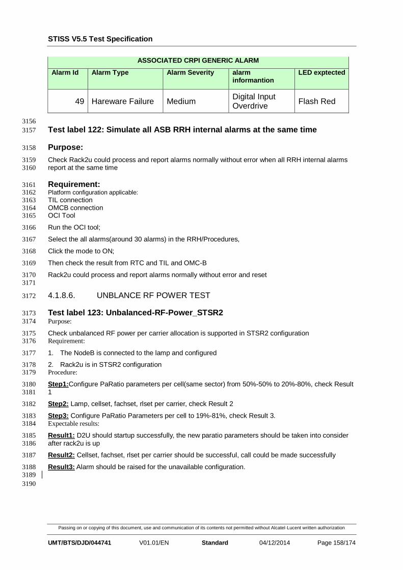
STISS V5.5 Test Specification
Passing on or copying of this document, use and communication of its contents not permitted without Alcatel·Lucent written authorization
UMT/BTS/DJD/044741 V01.01/EN Standard 04/12/2014 Page 158/174
ASSOCIATED CRPI GENERIC ALARM
Alarm Id Alarm Type Alarm Severity alarm informantion
LED exptected
49 Hareware Failure Medium Digital Input Overdrive
Flash Red
3156
Test label 122: Simulate all ASB RRH internal alarms at the same time 3157
Purpose: 3158
Check Rack2u could process and report alarms normally without error when all RRH internal alarms 3159
report at the same time 3160
Requirement: 3161 Platform configuration applicable: 3162
TIL connection 3163
OMCB connection 3164 OCI Tool 3165
Run the OCI tool; 3166
Select the all alarms(around 30 alarms) in the RRH/Procedures, 3167
Click the mode to ON; 3168
Then check the result from RTC and TIL and OMC-B 3169
Rack2u could process and report alarms normally without error and reset 3170
3171
4.1.8.6. UNBLANCE RF POWER TEST 3172
Test label 123: Unbalanced-RF-Power_STSR2 3173
Purpose: 3174
Check unbalanced RF power per carrier allocation is supported in STSR2 configuration 3175 Requirement: 3176
1. The NodeB is connected to the lamp and configured 3177
2. Rack2u is in STSR2 configuration 3178 Procedure: 3179
Step1:Configure PaRatio parameters per cell(same sector) from 50%-50% to 20%-80%, check Result 3180
1 3181
Step2: Lamp, cellset, fachset, rlset per carrier, check Result 2 3182
Step3: Configure PaRatio Parameters per cell to 19%-81%, check Result 3. 3183
Expectable results: 3184
Result1: D2U should startup successfully, the new paratio parameters should be taken into consider 3185
after rack2u is up 3186
Result2: Cellset, fachset, rlset per carrier should be successful, call could be made successfully 3187
Result3: Alarm should be raised for the unavailable configuration. 3188
3189
3190

STISS V5.5 Test Specification
Passing on or copying of this document, use and communication of its contents not permitted without Alcatel·Lucent written authorization
UMT/BTS/DJD/044741 V01.01/EN Standard 04/12/2014 Page 159/174
3191
4.1.8.7. AC POWER TEST 3192
Test label 124: AC_Power_Voltage_Out_Of_Range 3193
Purpose: 3194
Check RRH behavior while the AC power is abnormal. 3195 Requirement: 3196
1. Platform configuration applicable 3197
3198 Procedure: 3199
Step1: Power up RRH with AC power 3200
Step2: Set AC voltage to 170V, check Result 1 3201
Step3: Set AC voltage to 176V, check Result 2 3202
Step4: Set AC voltage to 270V, check Result 1 3203
Step5: Set AC voltage to 264V, check Result 2 3204
Expectable results: 3205
Result1: RRH shutdown automatically 3206
Result2: RRH re-start automatically 3207
4.1.8.8. POWER CONSUMPTION TEST 3208
Test label 125: Power_Consumption_Without_ALD 3209
Purpose: 3210
Typical power consumption shall be less than as shown in the table below. Percentages are different 3211
RF output levels relative to the max 60W. No more than 8% is allowed for the AC version than DC 3212
version. 3213
Percentage DC Power Consumption AC Power Consumption
20%(12W) 135W 145.8W
50%(30W) 185W 199.8W
100%(60W) 260W 280.8W Requirement: 3214
1. Platform configuration applicable 3215
2. Lamp is connected to NodeB 3216 Procedure: 3217
Step1: Configure platform with DC power, STSR1, max power 60W 3218
Step2: Setup cell and radiolinks to make RF output reach 20%(12W), check Result 1 3219
Step3: Setup cell and radiolinks to make RF output reach 50%(30W), check Result 2 3220
Step4: Make RF full output 100% with UDT scripts, check Result 3 3221
Step5: Configure platform with AC power, STSR1, max power 60W, repeat step 2~step 4 3222
Expectable results: 3223
Result1: RRH power consumption should be no more than Row 2 in the table. 3224
Result2: RRH power consumption should be no more than Row 3 in the table. 3225
Result3: RRH power consumption should be no more than Row 4 in the table. 3226
3227 3228

STISS V5.5 Test Specification
Passing on or copying of this document, use and communication of its contents not permitted without Alcatel·Lucent written authorization
UMT/BTS/DJD/044741 V01.01/EN Standard 04/12/2014 Page 160/174
Test label 126: Power_Consumption_With_ALD 3229
Purpose: 3230
Check the maxium DC power consumption including ALDs connected. 3231 Requirement: 3232
1. Platform configuration applicable 3233
2. Lamp is connected to NodeB 3234
3. ALDs(RET+TMA) are connected to RRH. 3235 Procedure: 3236
Step1: Configure platform with DC power, STSR4, max power 15W for each carrier. 3237
Step2: Make RF full output 100% with UDT scripts, check Result 1 3238
Expectable results: 3239
Result1: RRH power consumption should be no more than 300W. 3240
4.1.9. AISG FULL 3241
Test label 127: AISG_OMCB_aisgScan_With_RET 3242
Purpose: 3243
Check AISG scan information is correct when doing OMC-B aisgScan. 3244
Requirement: 3245
1, Platform is available 3246
2, RET is available 3247
3, TIL is connected 3248
4, OMC-B is connected 3249
Procedure: 3250
Step1: NodeB startup with RET connected to RRH, check Result1. 3251
Step2: open OMC-B and do bus scan, check Result2. 3252
Result: 3253
Result1: NodeB startup successfully. 3254
Result2: RET can be scanned and the information is correct.(check the info is 3255
consistent to TIL) 3256
3257
Test label 128: AISG_OMCB_aisgScan_With_TMA 3258
Purpose: 3259
Check AISG scan information is correct when doing OMC-B aisgScan. 3260
Requirement: 3261
1, Platform is available 3262
2, TMA is available 3263
3, TIL is connected 3264
4, OMC-B is connected 3265

STISS V5.5 Test Specification
Passing on or copying of this document, use and communication of its contents not permitted without Alcatel·Lucent written authorization
UMT/BTS/DJD/044741 V01.01/EN Standard 04/12/2014 Page 161/174
Procedure: 3266
Step1: NodeB startup with TMA connected to RRH, check Result1. 3267
Step2: open OMC-B and do bus scan, check Result2. 3268
Result: 3269
Result1: NodeB startup successfully. 3270
Result2: TMA can be scanned and the information is correct (check the info is 3271
consistent to TIL). 3272
3273
3274
4.1.9.1. RESET 3275
Test label 129: AISG_OMCB_aisgDeviceReset 3276
Purpose: 3277
Check device can be reset by OMC-B successfully. (aisgDeviceReset?) 3278
Requirement: 3279
1, Platform is available 3280
2, RET and TMA are available 3281
3, TIL is connected 3282
4, OMC-B is connected 3283
Procedure: 3284
Step1: Reset Aisg including TMA and RET device from OMCB. 3285
Result: 3286
Result1: Aisg devices reset successfully and power on normally. 3287
3288
4.1.9.2. DEVICE DATA 3289
Test label 130: AISG_TIL_Set_One_DeviceData_For_RET 3290
Purpose: 3291
Check device data for RET can be set successfully. 3292
Requirement: 3293
1, Platform is available 3294
2, RET is available 3295
3, TIL is connected 3296
Procedure: 3297
Step1: NodeB startup with RET connected to RRH, check Result1. 3298
Step2: open TIL and set device data for RET, check Result2. 3299

STISS V5.5 Test Specification
Passing on or copying of this document, use and communication of its contents not permitted without Alcatel·Lucent written authorization
UMT/BTS/DJD/044741 V01.01/EN Standard 04/12/2014 Page 162/174
Result: 3300
Result1: NodeB startup successfully. 3301
Result2: device data for RET can be set successfully. 3302
3303
Test label 131: AISG_TIL_Set_One_DeviceData_For_TMA 3304
Purpose: 3305
Check device data for TMA can be set successfully. 3306
Requirement: 3307
1, Platform is available 3308
2, TMA is available 3309
3, TIL is connected 3310
Procedure: 3311
Step1: NodeB startup with TMA connected to RRH, check Result1. 3312
Step2: open TIL and set device data for TMA, check Result2. 3313
Result: 3314
Result1: NodeB startup successfully. 3315
Result2: device data for TMA can be set successfully. 3316
3317
4.1.9.3. UPLOAD 3318
Test label 132: AISG_TIL_Upload_Configure_File_To_RRH 3319
Purpose: 3320
Check the configure file upload to the RRH from TIL would be supported. 3321
Requirement: 3322
1, Platform is available 3323
2, RET and TMA are available 3324
3, TIL is connected 3325
4, OMC-B is connected 3326
Procedure: 3327
Step1: NodeB startup with RET and TMA connected to RRH, check Result1. 3328
Step2: open TIL and trigger configure file upload. 3329
Step3: fill the username, password, file needs to be uploaded, as well as the remote 3330
directory, select upload, check Result2. 3331
Step4: get RET and TMA info from TIL, check Result3. 3332
Step5: get RET and TMA info from OMC-B, check Result4. 3333

STISS V5.5 Test Specification
Passing on or copying of this document, use and communication of its contents not permitted without Alcatel·Lucent written authorization
UMT/BTS/DJD/044741 V01.01/EN Standard 04/12/2014 Page 163/174
Result: 3334
Result1: NodeB startup successfully. 3335
Result2: configure file can be uploaded successfully. 3336
Result3: the info got form TIL is consistent with the configure file which has been 3337
uploaded. 3338
Result4: the info got form OMC-B is consistent with the configure file which has been 3339
uploaded. 3340
3341
4.1.9.4. TILT 3342
Test label 133: AISG_TIL_Set_Tilt 3343
Purpose: 3344
Verify the tilt can be set by TIL. 3345
Requirement: 3346
1, Platform is available 3347
2, RET is available 3348
3, TIL is connected 3349
4, OMC-B is connected 3350
Procedure: 3351
Step1: NodeB startup with RET connected to RRH. 3352
Step2: open TIL, double click RRH, right click and select “AISG” -> ”Set Tilt”, set the 3353
value beyond the range, check Result1. 3354
Step3: redo step2 to set tilt in the range, check Result2. 3355
Step4: open OMC-B to get Tilt, check Result3. 3356
Result: 3357
Result1: it is failed to set tilt and some alarm will be reported. 3358
Result2: it is successful to set tilt. 3359
Result3: The Tilt value is consistent with the value which has been set in TIL. 3360
3361
Test label 134: AISG_TIL_Calibrate_Tilt 3362
Purpose: 3363
Verify the tilt can be calibrated correctly by TIL. 3364
Requirement: 3365
1, Platform is available 3366
2, RET is available 3367
3, TIL is connected 3368
STISS V5.5 Test Specification
Passing on or copying of this document, use and communication of its contents not permitted without Alcatel·Lucent written authorization
UMT/BTS/DJD/044741 V01.01/EN Standard 04/12/2014 Page 164/174
4, OMC-B is connected 3369
Procedure: 3370
Step1: NodeB startup with RET connected to RRH. 3371
Step2: open TIL, double click RRH, right click and select “AISG” -> ”Calibrate Tilt”, 3372
check Result1. 3373
Step3: open OMC-B and get AISG Tilt, check Result2. 3374
Result: 3375
Result1: Tilt can be calibrated correctly. 3376
Result2: The Tilt value is consistent with the value which has been calibrated in TIL. 3377
3378
Test label 135: AISG_OMCB_aisgTILT 3379
Purpose: 3380
Check aisgTilt by OMC-B. 3381
Requirement: 3382
1, Platform is available 3383
2, RET is available 3384
3, OMC-B is connected 3385
Procedure: 3386
Step1: NodeB startup with RET connected to RRH. 3387
Step2: get Tilt from OCM-B, check Result1. 3388
Result: 3389
Result1: Tilt value can be got correctly. 3390
3391
Test label 136: AISG_OMCB_aisgSetTILT 3392
Purpose: 3393
Check AISG TILT can be set by OMCB successfully. 3394
Requirement: 3395
1, Platform is available 3396
2, RET is available 3397
3, OMC-B is connected 3398
Procedure: 3399
Step1: NodeB startup with RET connected to RRH. 3400
Step2: open OMC-B and set AISG Tilt, check Result1. 3401
Step3: get Tilt from OMC-B, check Result2. 3402
Result: 3403

STISS V5.5 Test Specification
Passing on or copying of this document, use and communication of its contents not permitted without Alcatel·Lucent written authorization
UMT/BTS/DJD/044741 V01.01/EN Standard 04/12/2014 Page 165/174
Result1: Tile can be set successfully. 3404
Result2: the Tilt value get from OMC-B is correct. 3405
3406
Test label 137: AISG_OMCB_aisgDeviceCalibrate 3407
Purpose: 3408
Check Tilt can be calibrated by OMC-B correctly. 3409
Requirement: 3410
1, Platform is available 3411
2, RET is available 3412
3, TIL is connected 3413
4, OMC-B is connected 3414
Procedure: 3415
Step1: NodeB startup with RET connected to RRH, check Result1. 3416
Step2: open OMC-B and calibrate Tilt, check Result2. 3417
Step3: get Tilt from OMC-B, check Result3. 3418
Result: 3419
Result1: NodeB startup successfully. 3420
Result2: Tilt can be calibrated successfully. 3421
Result3: The Tilt value is consistent with the value which has been calibrated. 3422
3423
4.1.9.5. TMA 3424
Test label 138: AISG_TIL_Set_TMA_Gain 3425
Purpose: 3426
Verify the TMA mode and gain can be set by TIL. 3427
Requirement: 3428
1, Platform is available 3429
2, TMA is available 3430
3, TIL is connected 3431
4, OMC-B is connected 3432
Procedure: 3433
Step1: NodeB startup with TMA connected to RRH. 3434
Step2: open TIL, double click RRH, right click and select “AISG” -> ”Get/Set TMA Gain”, 3435
select “Reload” to set the TMA parameters, check Result1. 3436
Step3: open OMC-B and get TMA gain, check Result2. 3437
STISS V5.5 Test Specification
Passing on or copying of this document, use and communication of its contents not permitted without Alcatel·Lucent written authorization
UMT/BTS/DJD/044741 V01.01/EN Standard 04/12/2014 Page 166/174
Step4: redo step2~3 if more than one TMA exist. 3438
Result: 3439
Result1: TMA gain can be set correctly. 3440
Result2: The TMA gain got form OMC-B is consistent with the value set in TIL. 3441
3442
Test label 139: AISG_OMCB_aisgSetTMAGain 3443
Purpose: 3444
Check TMA gain can be set successfully by OMC-B. 3445
Requirement: 3446
1, Platform is available 3447
2, TMA is available 3448
3, TIL is connected 3449
4, OMC-B is connected 3450
Procedure: 3451
Step1: NodeB startup with TMA connected to RRH. 3452
Step2: open OMC-B and set TMA gain, check Result1. 3453
Step3: open TIL and get TMA gain, check Result2. 3454
Result: 3455
Result1: TMA gain can be set correctly. 3456
Result2: The TMA gain got form TIL is consistent with the value set in OMC-B. 3457
3458
Test label 140: AISG_OMCB_aisgSetTMAMode 3459
Purpose: 3460
Check TMA mode can be set successfully by OMC-B. 3461
Requirement: 3462
1, Platform is available 3463
2, RET and TMA are available 3464
3, TIL is connected 3465
4, OMC-B is connected 3466
Procedure: 3467
Step1: NodeB startup with TMA connected to RRH. 3468
Step2: open OMC-B and set TMA mode, check Result1. 3469
Step3: get TMA mode from OMC-B, check Result2. 3470
Result: 3471

STISS V5.5 Test Specification
Passing on or copying of this document, use and communication of its contents not permitted without Alcatel·Lucent written authorization
UMT/BTS/DJD/044741 V01.01/EN Standard 04/12/2014 Page 167/174
Result1: TMA mode can be set correctly. 3472
Result2: the TMA mode got from OMC-B is the value which has been set. 3473
3474
4.1.9.6. ABNORMAL CASES 3475
Test label 141: AISG_ALD_Hot_Plugout 3476
Purpose: 3477
Check ALD info does not change after hot plug out before scan. 3478
Requirement: 3479
1, Platform is available 3480
2, ALD are available 3481
3, TIL is connected 3482
4, OMC-B is connected 3483
Procedure: 3484
Step1: NodeB startup with ALD connected to RRH. 3485
Step2: hot plug out ALD. 3486
Step3: open TIL/OMC-B, get inventory/device data/Tilt info/TMA info, check Result1. 3487
Step4: open TIL/OMC-B, set Tilt/TMA info, check Result2. 3488
Step5: open TIL, double click RRH, right click and select “AISG” -> ”Scan bus”, check 3489
Result3. 3490
Step6: open TIL/OMC-B, get inventory/device data/Tilt info/TMA info, check Result4. 3491
Step7: open TIL/OMC-B, set Tilt/TMA info, check Result5. 3492
Result: 3493
Result1: the info for the ALD which has been plugged out still exists. 3494
Result2: error will be reported. 3495
Result3: scan info is correct and no info for the ALD which has been plugged out. 3496
Result4: no info for the ALD which has been plugged out. 3497
Result5: Tilt/TMA info can be set successfully. 3498
3499
Test label 142: AISG_ALD_Hot_Plugin 3500
Purpose: 3501
Check ALD info does not change after hot plug in before scan. 3502
Requirement: 3503
1, Platform is available 3504
2, ALD are available 3505

STISS V5.5 Test Specification
Passing on or copying of this document, use and communication of its contents not permitted without Alcatel·Lucent written authorization
UMT/BTS/DJD/044741 V01.01/EN Standard 04/12/2014 Page 168/174
3, TIL is connected 3506
4, OMC-B is connected 3507
Procedure: 3508
Step1: NodeB startup with ALD connected to RRH. 3509
Step2: hot plug in ALD. 3510
Step3: open TIL/OMC-B, get inventory/device data/Tilt info/TMA info, check Result1. 3511
Step4: open TIL/OMC-B, set Tilt/TMA info, check Result2. 3512
Step5: open TIL, double click RRH, right click and select “AISG” -> ”Scan bus”, check 3513
Result3. 3514
Step6: open TIL/OMC-B, get inventory/device data/Tilt info/TMA info, check Result4. 3515
Step7: open TIL/OMC-B, set Tilt/TMA info, check Result5. 3516
Result: 3517
Result1: no info for the ALD which has been plugged in. 3518
Result2: error will be reported. 3519
Result3: scan info includes the info for the ALD which has been plugged in. 3520
Result4: the info for the ALD which has been plugged in is correct. 3521
Result5: Tilt/TMA info can be set successfully. 3522
3523
3524
3525
4.2 PowerSaving Feature 3526
4.2.1 Setup/Delete One Cell On 21C RRH With ASB PA Vendor 3527
Test Label: 143 SETUP/DELETE ONE CELL ON 21C RRH WITH ASB PA VENDOR 3528
Purpose: 3529
3530
Checking setup/delete one cell with different power on 21C RRH with ASB PA Vendor. 3531
3532
Requirement: 3533
Platform: 2UV2/3 rack + x/eCCM-U + x/eCEM-U 3534
Lamp and omcb connection 3535
Procedure: 3536
3537
Configure cell parameter as below: 3538
In DLU file: paRatio=100 maxRrhPowerAmplification=fullMode 3539
In Lamp file: configure MAXDLPOWER (unit=0.1dBm) as 3540
300(1W)/369(5W)/400(10W)/417(15W)/430(20W)/444(28W)/447(30W)/454(35W)/460(3541
40W)/465(45W)/469(50W)/471(52W)/477(60W) respectively. 3542

STISS V5.5 Test Specification
Passing on or copying of this document, use and communication of its contents not permitted without Alcatel·Lucent written authorization
UMT/BTS/DJD/044741 V01.01/EN Standard 04/12/2014 Page 169/174
1. Setup the cell and make a R99 call on this cell. Check result 1. 3543
2. Delete the cell.check result 2. 3544
Result: 3545
1. Cell is setup successfully and the call is normal. Check output power through PSA, it 3546
is the same value as configured above. 3547
2. Cell is delete and no power output anymore. 3548
3549
4.2.2 Setup/Delete Two Cells On 21C RRH With ASB PA Vendor 3550
Test Label: 144 SETUP/DELETE TWO CELLS ON 21C RRH WITH ASB PA VENDOR 3551
Purpose: 3552
3553
Checking setup/delete two cells with different power on 21C RRH with ASB PA vendor. 3554
3555
Requirement: 3556
Platform: 2UV2/3 rack + x/eCCM-U + x/eCEM-U 3557
Lamp and omcb connection 3558
Procedure: 3559
Configure cell parameter as below: 3560
In DLU file: paRatio=50 maxRrhPowerAmplification=fullMode 3561
In Lamp file: For 2 cell, configure (cell1, cell2) MAXDLPOWER (unit=0.1dBm) as (300, 3562
400)/(400, 400)/(417, 430)/(430, 430)/(447, 447) respectively. 3563
3564
1. Setup the cell and make a R99 call on cell1. Check result 1. 3565
2. Delete the cell2.check result 2. 3566
3. Make R99 call on cell1. Check result 3. 3567
4. Delete cell1. Check result 4. 3568
3569
Result: 3570
1. Cell is setup successfully and the call is normal. Check output power through PSA, it 3571
is the same value as configured above. 3572
2. Cell2 is deleted and cell1 is normal. 3573
3. Call on cell1 is normal.Check output power, it is same as cell1 configured. 3574
4. No cell exists and no power output. 3575
4.2.3 Setup/Delete Three Cells on 21C RRH With ASB PA Vendor 3576
Test Label: 145 SETUP/DELETE THREE CELLS ON 21C RRH WITH ASB PA VENDOR 3577
Purpose: 3578
3579
Checking setup/delete three cells with different power on 21C RRH with ASB PA vendor. 3580

STISS V5.5 Test Specification
Passing on or copying of this document, use and communication of its contents not permitted without Alcatel·Lucent written authorization
UMT/BTS/DJD/044741 V01.01/EN Standard 04/12/2014 Page 170/174
3581
Requirement: 3582
Platform: 2UV2/3 rack + x/eCCM-U + x/eCEM-U 3583
Lamp and omcb connection 3584
Procedure: 3585
Configure cell parameter as below: 3586
In DLU file: paRatio=33 maxRrhPowerAmplification=fullMode 3587
In Lamp file: For 3 cell, configure (cell1, cell2, cell3) MAXDLPOWER (unit=0.1dBm) as 3588
(300, 400, 400)/(400,400,400)/(417, 430, 430)/(430, 430,430) respectively. 3589
1. Setup the cell and make a R99 call on cell1. Check result 1. 3590
2. Delete the cell2/cell3.check result 2. 3591
3. Make R99 call on cell1.check result 3. 3592
4. Delete cell1. Check result 4. 3593
Result: 3594
1. Cell is setup successfully and the call is normal. Check output power through PSA, it 3595
is the same value as configured above. 3596
2. Cell2/cell3 is deleted and cell1 is normal. 3597
3. Call on cell1 is normal.Check output power, it is same as cell1 configured. 3598
4. No cell exists and no power output. 3599
a 3600
4.2.4 Setup/Delete Four Cells on 21C RRH With ASB PA Vendor 3601
Test Label: 146 SETUP/DELETE THREE CELLS ON 21C RRH WITH ASB PA VENDOR 3602
3603
Purpose: 3604
3605
Checking setup/delete four cells with different power on 21C RRH with ASB PA vendor. 3606
3607
Requirement: 3608
Platform: 2UV2/3 rack + x/eCCM-U + x/eCEM-U 3609
Lamp and omcb connection 3610
Procedure: 3611
Configure cell parameter as below: 3612
In DLU file: paRatio=33 maxRrhPowerAmplification=fullMode 3613
In Lamp file: For 4 cell, configure (cell1, cell2, cell3, cell4) MAXDLPOWER 3614
(unit=0.1dBm) as 3615
(300,400,400,400)/(400,400,400,400)/(418,430,430,418)/(439,430,439,430) 3616
respectively. 3617
1. Setup the cell and make a R99 call on cell1. Check result 1. 3618
2. Delete the cell2/cell3/cell4.check result 2. 3619

STISS V5.5 Test Specification
Passing on or copying of this document, use and communication of its contents not permitted without Alcatel·Lucent written authorization
UMT/BTS/DJD/044741 V01.01/EN Standard 04/12/2014 Page 171/174
3. Make R99 call on cell1.check result 3. 3620
4. Delete cell1. Check result 4. 3621
Result: 3622
1. Cell is setup successfully and the call is normal. Check output power through PSA, it 3623
is the same value as configured above. 3624
2. Cell2/cell3/cell4 is deleted and cell1 is normal. 3625
3. Call on cell1 is normal.Check output power, it is same as cell1 configured. 3626
4. No cell exists and no power output. 3627
3628
3629
4.2.5 Setup/Delete One Cell On 21C RRH With Gewei PA Vendor 3630
Test Label: 143 SETUP/DELETE ONE CELL ON 21C RRH WITH GEWEI PA VENDOR 3631
Purpose: 3632
3633
Checking setup/delete one cell with different power on 21C RRH with Gewei PA Vendor. 3634
3635
Requirement: 3636
Platform: 2UV2/3 rack + x/eCCM-U + x/eCEM-U 3637
Lamp and omcb connection 3638
Procedure: 3639
3640
Configure cell parameter as below: 3641
In DLU file: paRatio=100 maxRrhPowerAmplification=fullMode 3642
In Lamp file: configure MAXDLPOWER (unit=0.1dBm) as 3643
300(1W)/369(5W)/400(10W)/417(15W)/430(20W)/444(28W)/447(30W)/454(35W)/460(3644
40W)/465(45W)/469(50W)/471(52W)/477(60W) respectively. 3645
1. Setup the cell and make a R99 call on this cell. Check result 1. 3646
2. Delete the cell.check result 2. 3647
Result: 3648
1. Cell is setup successfully and the call is normal. Check output power through PSA, it 3649
is the same value as configured above. 3650
2. Cell is delete and no power output anymore. 3651
3652
4.2.6 Setup/Delete Two Cells On 21C RRH With Gewei PA Vendor 3653
Test Label: 144 SETUP/DELETE TWO CELLS ON 21C RRH WITH GEWEI PA VENDOR 3654
Purpose: 3655
3656
Checking setup/delete two cells with different power on 21C RRH with Gewei PA vendor. 3657
3658

STISS V5.5 Test Specification
Passing on or copying of this document, use and communication of its contents not permitted without Alcatel·Lucent written authorization
UMT/BTS/DJD/044741 V01.01/EN Standard 04/12/2014 Page 172/174
Requirement: 3659
Platform: 2UV2/3 rack + x/eCCM-U + x/eCEM-U 3660
Lamp and omcb connection 3661
Procedure: 3662
Configure cell parameter as below: 3663
In DLU file: paRatio=50 maxRrhPowerAmplification=fullMode 3664
In Lamp file: For 2 cell, configure (cell1, cell2) MAXDLPOWER (unit=0.1dBm) as (300, 3665
400)/(400, 400)/(417, 430)/(430, 430)/(447, 447) respectively. 3666
3667
1. Setup the cell and make a R99 call on cell1. Check result 1. 3668
2. Delete the cell2.check result 2. 3669
3. Make R99 call on cell1. Check result 3. 3670
4. Delete cell1. Check result 4. 3671
3672
Result: 3673
1. Cell is setup successfully and the call is normal. Check output power through PSA, it 3674
is the same value as configured above. 3675
2. Cell2 is deleted and cell1 is normal. 3676
3. Call on cell1 is normal.Check output power, it is same as cell1 configured. 3677
4. No cell exists and no power output. 3678
4.2.7 Setup/Delete Three Cells on 21C RRH With Gewei PA Vendor 3679
Test Label: 145 SETUP/DELETE THREE CELLS ON 21C RRH WITH GEWEI PA VENDOR 3680
Purpose: 3681
3682
Checking setup/delete three cells with different power on 21C RRH with Gewei PA vendor. 3683
3684
Requirement: 3685
Platform: 2UV2/3 rack + x/eCCM-U + x/eCEM-U 3686
Lamp and omcb connection 3687
Procedure: 3688
Configure cell parameter as below: 3689
In DLU file: paRatio=33 maxRrhPowerAmplification=fullMode 3690
In Lamp file: For 3 cell, configure (cell1, cell2, cell3) MAXDLPOWER (unit=0.1dBm) as 3691
(300, 400, 400)/(400,400,400)/(417, 430, 430)/(430, 430,430) respectively. 3692
1. Setup the cell and make a R99 call on cell1. Check result 1. 3693
2. Delete the cell2/cell3.check result 2. 3694
3. Make R99 call on cell1.check result 3. 3695
4. Delete cell1. Check result 4. 3696

STISS V5.5 Test Specification
Passing on or copying of this document, use and communication of its contents not permitted without Alcatel·Lucent written authorization
UMT/BTS/DJD/044741 V01.01/EN Standard 04/12/2014 Page 173/174
Result: 3697
1. Cell is setup successfully and the call is normal. Check output power through PSA, it 3698
is the same value as configured above. 3699
2. Cell2/cell3 is deleted and cell1 is normal. 3700
3. Call on cell1 is normal.Check output power, it is same as cell1 configured. 3701
4. No cell exists and no power output. 3702
a 3703
4.2.8 Setup/Delete Four Cells on 21C RRH With Gewei PA Vendor 3704
Test Label: 146 SETUP/DELETE THREE CELLS ON 21C RRH WITH GEWEI PA VENDOR 3705
3706
Purpose: 3707
3708
Checking setup/delete four cells with different power on 21C RRH with Gewei PA vendor. 3709
3710
Requirement: 3711
Platform: 2UV2/3 rack + x/eCCM-U + x/eCEM-U 3712
Lamp and omcb connection 3713
Procedure: 3714
Configure cell parameter as below: 3715
In DLU file: paRatio=33 maxRrhPowerAmplification=fullMode 3716
In Lamp file: For 4 cell, configure (cell1, cell2, cell3, cell4) MAXDLPOWER 3717
(unit=0.1dBm) as 3718
(300,400,400,400)/(400,400,400,400)/(418,430,430,418)/(439,430,439,430) 3719
respectively. 3720
1. Setup the cell and make a R99 call on cell1. Check result 1. 3721
2. Delete the cell2/cell3/cell4.check result 2. 3722
3. Make R99 call on cell1.check result 3. 3723
4. Delete cell1. Check result 4. 3724
Result: 3725
1. Cell is setup successfully and the call is normal. Check output power through PSA, it 3726
is the same value as configured above. 3727
2. Cell2/cell3/cell4 is deleted and cell1 is normal. 3728
3. Call on cell1 is normal.Check output power, it is same as cell1 configured. 3729
4. No cell exists and no power output. 3730
3731
3732
3733
3734

STISS ASB RRH2X60W PowerSaving(FRS131825)
UMT/BTS/DJD/044741 01.01/EN Preliminary 30/Nov/2013 Page 174/174
5. TEST CROSS REFERENCE 3735
6. ABBREVIATIONS 3736
ATM Asynchronous Transfer Mode 3737
AWS Advanced Wireless Spectrum 3738
BTS Base Transceiver Station 3739
CCM Core Controller Module 3740
CEM Channel Element Module 3741
CPRI Common public Radio Interface 3742
CTCH Common Traffic Channel 3743
DCH Dedicated Channel 3744
FACH Forward Access Channel 3745
GUI Graphical User Interface 3746
HSDPA High Speed Downlink Packet Access 3747
HSUPA High Speed Uplink Packet Access 3748
NBAP Node B Application Part 3749
NodeB Base Transceiver Station 3750
OAM Operation and Maintenance 3751
OMC-B Operations and Management Console for Node B 3752
PCH Paging Channel 3753
PCM Pulse Code Modulation 3754
RF Radio Frequency 3755
RNC Radio Network Controller 3756
RRH Remote Radio Head 3757
SHO Soft Handover 3758
SrHO Softer Handover 3759
STSR Sectorized Transmit Sectorized Receive 3760
TIL Local installation terminal 3761
TRDU Transmit Receive Duplexer Unit 3762
END OF DOCUMENT 3763


