STIHL FW 20 Gebrauchsanleitung FW 20 Instruction Manual ... maintenance, repair and storage of your...
19
STIH) STIHL FW 20 Instruction Manual Notice d’emploi Instrucciones de servicio Naputak za korišcenje Skötselanvisning Käyttöohje Istruzioni d’uso Betjeningsvejledning Bruksanvisning Návod k použití Használati utasítás Instruções de serviço Návod na obsluhu Handleiding Èíñòðóêöèÿ ïî ýêñïëóàòàöèè Lietoðanas instrukcija ²íñòðóêö³ÿ ç åêñïëóàòàö³¿ ïäçãßåò ÷ñÞóçò Instrukcja u¿ytkowania Kasutusjuhend Eksploatavimo instrukcija Èíñòðóêöèÿ çà óïîòðåáà Navodilih za uporabo Gebrauchsanleitung
Transcript of STIHL FW 20 Gebrauchsanleitung FW 20 Instruction Manual ... maintenance, repair and storage of your...

STIH)
STIHL FW 20Instruction ManualNotice d’emploiInstrucciones de servicioNaputak za korišcenjeSkötselanvisningKäyttöohjeIstruzioni d’usoBetjeningsvejledningBruksanvisningNávod k použitíHasználati utasításInstruções de serviçoNávod na obsluhuHandleidingÈíñòðóêöèÿ ïî ýêñïëóàòàöèèLietoðanas instrukcija²íñòðóêö³ÿ ç åêñïëóàòàö³¿ïäçãßåò ÷ñÞóçò
Instrukcja u¿ytkowania
KasutusjuhendEksploatavimo instrukcijaÈíñòðóêöèÿ çà óïîòðåáàNavodilih za uporabo
Gebrauchsanleitung
BA_U1_99_01.fm Seite 0 Freitag, 12. November 2004 10:10 10

9
EnglishBA
_SE_
174_
002_
01_0
2.fm
Prin
ted
on c
hlor
ine-
free
pape
r. Pr
intin
g in
ks c
onta
in v
eget
able
oils
; pap
er c
an b
e re
cycl
ed.
© A
ND
REA
S ST
IHL
AG &
Co.
KG,
200
4 y
Cont
Guide tSafety AssemOperatSpecialMainten
e d in
uctions
es arked
edure
re that ay r in the
nual
FW 20
0458
379
992
1 A.
M2,
5. L
4. T
. Prin
ted
in G
erm
an
STIHl
: A bullet marks a step or procwithout direct reference to anillustration.
A description of a step or procedurefers directly to an illustration mcontain item numbers that appeaillustration.Example:
Loosen the screw (1) Lever (2) ...
ents
o Using this Manual .............. 9Precautions ......................... 10bling the unit ........................ 12ing elements ........................ 14 accessories ........................ 15ance and Repairs ............... 16
PictogramsAll the pictograms attached to thmachine are shown and explainethis manual.
The operating and handling instrare supported by illustrations.
Symbols in textThe individual steps or procedurdescribed in the manual may be min different ways:
Guide to Using this Ma

10
English
FW 20
In additthis mathat reqparagrasymbol
Waaccser
Cadamind
Noforimpstain b
Noordenv
smust rking cut-off
you nd and ing and e nd cut-off reless l may
achine ual. Be off e anuals.
u how ith
safety ances.
ion to the operating instructions, nual may contain paragraphs uire your special attention. Such phs are marked with the s described below:
rning where there is a risk of an ident or personal injury or ious damage to property.
ution where there is a risk of aging the machine or its
ividual components.
te or hint which is not essential using the machine, but may rove the operator’s under-
nding of the situation and result etter use of the machine.
te or hint on correct procedure in er to avoid damage to the ironment.
Equipment and featuresThis instruction manual may refer to several models with different features. Components that are not installed on all models and related applications are marked with an asterisk (*). Such components may be available as special accessories from your STIHL dealer.
Engineering improvementsSTIHL’s philosophy is to continually improve all of its products. As a result, engineering changes and improvements are made from time to time. If the operating characteristics or the appearance of your machine differ from those described in this manual, please contact your STIHL dealer for assistance.
Therefore some changes, modifications and improvements may not be covered in this manual.
Special precautionbe taken when wowith the combinedmachine and cart.
It is important thatread, fully understaobserve the followsafety precautionswarnings. Read thowner's manuals a
safety instructions of your TS 700machine and cart periodically. Caor improper use of any power toocause serious or fatal injury.
Do not lend or rent your cut-off mand cart without the Owner's Mansure that anyone using your cut-machine and cart understands thinformation contained in these m
Have your STIHL dealer show yoto operate your cut-off machine wcart. Observe all applicable localregulations, standards and ordin
Safety Precautions

11FW 20
English
! WMinors cut-off especianot be off macoff mac
The caFor pardefinitiocontrol"
!WNever many waSTIHL for usemachinAlthougattachmpowerhfact, be
cannot ng the cart.
le fuel. other and mage. ling ke or el. For uel" of ff
arning !should never be allowed to use a machine and cart. Bystanders, lly children, and animals should
allowed in the area where a cut-hine is in use. Never let the cut-hine run unattended.
rt ts of the cart, illustrations and ns of the parts see "Parts and .
arning !odify a cut-off machine or cart in
y. Only attachments supplied by or expressly approved by STIHL with the specific STIHL cut-off e model and cart are authorized. h certain unauthorized ents are usable with a STIHL ead and cart, their use may, in extremely dangerous.
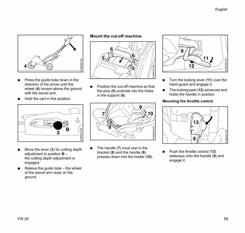
Mounting the cut-off machine
!Warning !To reduce the risk of injury from loss of control and subsequent wheel shatter the cart has been approved by STIHL only for use with the STIHL TS 700 cut-off machine model. Other cut-off machines must not be mounted on the cart.
For assembly, follow the procedure described at the appropriate sections of your owner's manuals.
Before operation of your cut-off machine and cart, be sure that the cart and cut-off machine are in good working order. Check correct functioning of the operating elements (e.g. throttle control, cutting depth adjustment and follow the appropriate chapters in the Owner's Manuals).
FuelingThe cart must be parked so that ittip over or roll away when refuelicut-off machine mounted on the
!Warning !Gasoline is an extremely flammabIf spilled or ignited by a spark or ignition source, it can cause fire serious burn injury or property daUse extreme caution when handgasoline or fuel mix. Do not smobring any fire or flame near the fufueling instructions see chapter "Fthe owner's manual of your cut-omachine.

12
English
FW 20
DuringSweepas debrabrasivfrictionathe engcutting in a stra
!WIf the caabrasivthe cut for the surface
!WTo reduand cutsubseqnot wor
ition
kwise orking
depth
is
work debris from the path of the wheel is may cause flexing of the e wheel. This could result in high l forces and thus greatly reduce ine power available for the actual work. Always use the cart to cut ight line.
arning !rt is pushed over objects, the
e wheel may become wedged in and shatter! Always clear a path cart and never work on uneven s.
arning !ce the risk of injury from a cart -off machine tipping over and uently causing wheel damage do k on uneven surfaces.
!Warning !Use of this product can generate dust, mists and fumes containing chemicals known to cause serious or fatal injury or illness. Control dust, mists and fumes at the source where possible. A water attachment kit is available for your cart and cut-off machine and should be used for dust suppression when wet cutting is feasible. When the inhalation of dust, mists and fumes cannot be eliminated, the operator and any bystanders should always wear a respirator approved by NIOSH / MSHA for the material being cut. See also the safety precautions on dust, mists and fumes in the Owner's Manual of the cut-off machine.
For information on transporting, maintenance, repair and storage of your cut- off machine, see specific sections of your cut-off machine manual.
Move cart into working pos
: Turn star handle (1) anticlocand move guide tube (2) to wposition A.
: Tighten star handle down in clockwise direction.
: Steady the guide tube.: Move the lever (3) for cutting
adjustment to position A – the cutting depth adjustmentreleased.
Assembling the unit
13FW 20
English
: Predirewhwit
: Ho
: Moadjtheeng
: Reof tgro
ver the
es and
) and
ss the guide tube down in the ction of the arrow until the
eel (4) hovers above the ground h the swivel arm.ld the cart in this position.
ve the lever (3) for cutting depth ustment to position B – cutting depth adjustment is aged.
lieve the guide tube – the wheel he swivel arm rests on the und.
Mount the cut-off machine
: Position the cut-off machine so that the pins (5) protrude into the holes in the support (6).
: The handle (7) must rest in the bracket (8) and the handle (9) presses down into the holder (10).
: Turn the locking lever (11) ohand guard and engage it.
: The locking pawl (12) advancholds the handle in position.
Mounting the throttle control
: Push the throttle control (13)sideways onto the handle (9engage it.

14
English
FW 20
Dismo: Pre
loclev
: Rehan
: Dis
TranspThe stathe guidcompac
and to
rk with
unting the cut-off machiness down the locking pawl on the king lever and turn the locking er away from the hand guard.move the throttle control from the dle.mount the cut-off machine.
ortr handle can be unscrewed and e tube swung forwards for t transport.
Cutting depth adjustment
: The cutting depth adjustment is actuated via the lever (1).
Lever positionA Cutting depth adjustment releasedB Cutting depth adjustment engaged
Position A – release –to set the required cutting depth enter the cut.
Position B – engage –to fix the set cutting depth and woa uniform cutting depth.
Operating elements

15FW 20
English
ReleasIf the cureleaseit can scombin
Thbe adjswmu
: To adjwredow
e with combination wrenchtting depth adjustment cannot be d via the lever on the guide tube, till be released with the ation wrench.
e combination wrench can only used to release the cutting depth ustment when the engine is itched off – do not touch the hot ffler!
release the cutting depth ustment, insert the combination nch (2) in the hole (3) and press n in the direction of the arrow.
Throttle controlTo start the cut-off machine, refer to "Starting / stopping the engine" in the user manual for the cut-off machine.
The throttle is not actuated via the handle on the cut-off machine, but via the throttle control on the guide tube.
For this purpose:: Press down and hold the locking
button (1).: Pull the throttle control (2) until it
contacts the guide tube – full throttle position
The speed of the cut-off machine depends on the distance between throttle control and guide tube.
When the throttle control is released completely (no-load setting), the locking button must be pressed again before the throttle control can be actuated.
Cutting direction indicator set
Water tank set
Pressurized water tank set
Special accessories
16
English
FW 20
The usonly thedescribwork mauthori
Warranaccepteperformdealer uparts.
Originathe STIlogo anThe symparts.
Main
er of this unit should carry out maintenance operations
ed in this manual. Other repair ay be performed only by an zed STIHL dealer.
ty claims following repairs can be d only if the repair has been ed by an authorized STIHL sing original STIHL replacement
l STlHL parts can be identified by HL part number, the STIHl d the STlHL parts symbol (. bol may appear alone on small
tenance and Repairs

25FW 20
español / EE.UUBA
_SE_
174_
002_
03_0
2.fm
Impr
eso
en p
apel
sin
clo
ro.
Las
tinta
s co
ntie
nen
acei
tes
vege
tale
s,el
pap
el e
s re
cicl
able
.©
AN
DR
EAS
STIH
L AG
& C
o. K
G, 2
004
0458
379
992
1 A.
M2,
5. L
4. T
. Prin
ted
in G
erm
any
STIHl
Contenido
Notas referentes a estas instrucciones de servicio ................ 25Para su seguridad .......................... 26Completar la máquina .................... 28Elementos de mando ..................... 30Accesorios especiales .................... 31Informaciones para la reparación ... 32
Símbolos gráficosTodos los símbolos gráficos que se pueden ver en el motoimplemento están explicados en estas instrucciones de servicio.
El manejo correcto está descrito y explicado adicionalmente con ilustraciones.
Marcación de los párrafos de textoLos pasos de manejo descritos pueden tener distintas marcaciones:
: Paso de manejo que no tiene relación directa con la ilustración
Paso de manejo que tiene relación directa con la ilustración situada por encima o al margen del texto con referencia a un número de posición.Ejemplo:
Aflojar el1 = tornillo2 = Palanca ...
Notas referentes a estas instrucciones de servicio
26
español / EE.UU
FW 20
Estas instrucciones de servicio pueden contener, además de la descripción del manejo, párrafos de texto con un significado adicional. Estos párrafos están marcados con uno de los símbolos descritos a continuación:
Advertencia de peligro de accidente y de riesgo de lesiones para personas y advertencia de graves daños materiales.
Advertencia de daños o deterioros del motoimplemento o de los diferentes componentes.
Advertencia que no es realmente necesaria para el manejo del motoimplemento pero, sin embargo, puede facilitar tanto la comprensión del texto como la utilización del motoimplemento.
Advertencia para evitar daños ecológicos.
Volumen de suministro / equipamientoEstas instrucciones de servicio se refieren a modelos que se entregan en distintas versiones. Piezas que no están montadas en todos los modelos y las respectivas aplicaciones resultantes están marcadas con *. Las piezas no contenidas en el volumen de suministro y marcadas con * están disponibles como accesorios especiales en la tienda de su distribuidor STIHL.
Perfeccionamiento técnicoSTIHL trabaja constantemente en el desarrollo de todos sus moto-implementos. Nos reservamos el derecho de introducir modificaciones referentes al diseño, la técnica y al equipamiento.
Por esta razón no se puede hacer valer ningún derecho en base de los datos y las ilustraciones incluidos en estas instrucciones de servicio.
Será necesario observar medidas de seguridad especiales al trabajar con la combinación del tren de guía / tronzadora.
Leer atentamente las indicaciones de seguridad siguientes y tenerlas en cuenta. Leer de vez en cuando las Instrucciones de servicio y las
indicaciones referentes a la seguridad de la TS 700 y del tren de guía. El uso negligente o erróneo de una máquina a motor puede originar lesiones graves o mortales.
No prestar o alquilar la tronzadora y el tren de guía jamás sin las Instrucciones de servicio. Todo usuario de la tronzadora y del tren de guía tiene que observar las indicaciones que figuran en las Instrucciones de servicio.
Hacer que el vendedor de productos STIHL le muestre cómo manejar de forma segura la tronzadora y el tren de guía.
Observar las normas de seguridad específicas del país, de p. ej., las Asociaciones Profesionales del ramo, organismos sociales y autoridades competentes para asuntos de prevención de accidentes en el trabajo.
Para su seguridad

27FW 20
español / EE.UU
! Atención:Los menores de edad no deberán trabajar con la tronzadora y el tren de guía. No permitir que se acerquen niños, espectadores ni animales. No dejar nunca la tronzadora en marcha sin vigilarla.
Tren de guíaPara los componentes del tren de guía, las ilustraciones y definiciones, véase el catálogo “Componentes importantes”.
!Atención:No modificar nunca la tronzadora ni el tren de guía. Emplear únicamente dispositivos de acople suministrados o expresamente autorizados por STIHL para acoplarlos a esta tronzadora y al tren de guía. Aun cuando determinados dispositivos de acople no autorizados se puedan emplear con la unidad de motor STIHL y el tren de guía, puede resultar peligrosa su utilización.
Montar la tronzadora
!Atención:Para el acople en el tren de guía, sólo se autoriza la tronzadora STIHL TS 700. El montaje de otras tronzadoras no se admite – peligro de accidente por rotura del disco en caso de perderse el control.
Al efectuar el ensamblaje, tener en cuenta el correspondiente capítulo de las Instrucciones de servicio.
Comprobar el tren de guía y la tronzadora antes y después del acople en cuanto a estado de funcionamiento seguro. Para el funcionamiento de los elementos de mando (p. ej., el accionamiento del gas, la regulación de la profundidad de corte) – tener en cuenta el capítulo correspondiente de las Instrucciones de servicio.
Repostar combustiblePara repostar combustible en la tronzadora montada en el tren de guía, éste deberá encontrarse asegurado contra vuelcos y contra el deslizamiento.
!Atención:La gasolina es extremadamente fácil de inflamar. En el caso de que se derrame o de que se encienda por una chispa u otra fuente de encendido, pueden producirse incendios, quemaduras graves o daños materiales. Poner especial atención al manipular con gasolina o mezcla de combustible. Guardar distancia de fuego abierto. No fumar. Los detalles sobre el repostaje se encuentran en el correspondiente capítulo de las Instrucciones de servicio de la tronzadora.
28
español / EE.UU
FW 20
Durante el trabajoQuitar los objetos del recorrido a cortar ya que pueden ladear el disco. Ello podría originar altas fuerzas de fricción disminuyendo por lo tanto la potencia de motor disponible para efectuar el corte. Emplear el tren de guía únicamente para cortes rectos.
!Atención:Si se empuja el tren de guía sobre objetos, puede ladearse el disco en el corte – ¡peligro de rotura!Despejar el sector de trabajo – no trabajar sobre una base desnivelada.
!Atención:No trabajar sobre superficies desniveladas con la tronzadora montada en el tren de guía – éste puede volcar y romperse el disco – ¡peligro de lesiones!
!Atención:El uso de la máquina puede producir polvo, niebla y vapores, los cuales pueden contener sustancias químicas de las que se sabe que pueden provocar lesiones o enfermedades serias. El polvo, la niebla y los vapores se deben evitar en lo posible en su lugar de origen. Para el tren de guía y la tronzadora se dispone de un empalme de agua que se debería utilizar para aglutinar el polvo, si resulta posible cortar en mojado. Si no se puede evitar la inhalación de polvos, nieblas y vapores tóxicos, el operario y aquellos que estén cerca de él deberían ponerse un protector para la respiración de NIOSH/MSHA apropiado para el material a cortar. Tener en cuenta las indicaciones referentes a la seguridad sobre polvos, nieblas y vapores que figuran también en las Instrucciones de servicio de la tronzadora.
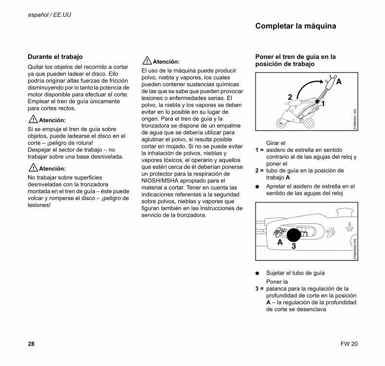
Poner el tren de guía en la posición de trabajo
Girar el1 = asidero de estrella en sentido
contrario al de las agujas del reloj y poner el
2 = tubo de guía en la posición de trabajo A
: Apretar el asidero de estrella en el sentido de las agujas del reloj
: Sujetar el tubo de guíaPoner la
3 = palanca para la regulación de la profundidad de corte en la posición A – la regulación de la profundidad de corte se desenclava
Completar la máquina

29FW 20
español / EE.UU
: Oprimir el tubo de guía hacia abajo, en el sentido de la flecha, hasta que la
4 = rueda del brazo oscilante esté suspendida sobre el suelo
: Sujetar el tren de guía en esta posición
Poner la 3 = palanca para la regulación de la
profundidad de corte en la posición B – la regulación de la profundidad de corte se enclava
: Descargar el tubo de guía – la rueda del brazo oscilante se apoya sobre el suelo
Montar la tronzadora
Aplicar la tronzadora, de manera que los
5= pernos penetren en los taladros del 6= apoyo
El 7= asidero tubular debe descansar en
el 8= estribo de retención y poner la 9= empuñadura en el10= soporte oprimiéndola hacia abajo
Girar la11= palanca de enclavamiento sobre el
protector salvamanos y encastrarlaEl
12= trinquete de bloqueo sale y la empuñadura queda fijada
Montaje del acelerador
Insertar el13= acelerador desde el lado en la 9= empuñadura y encastrarlo

30
español / EE.UU
FW 20
Desmontar la tronzadora: Introducir el trinquete de bloqueo en
la palanca de enclavamiento oprimiéndolo y apartar dicha palanca del protector salvamanos girándola
: Quitar el acelerador de la empuñadura
: Quitar la tronzadora
TransportePara ahorrar espacio en el transporte, se puede aflojar el asidero de estrella y plegar el tren de guía hacia delante.
Regulación de la profundidad de corte
La regulación de la profundidad de corte se acciona con la
1 = palanca
Posiciones de la palancaA Regulación de la profundidad de
corte, desenclavadaB Regulación de la profundidad de
corte, enclavada
Posición A – desenclavar –Para ajustar la profundidad de corte deseada y para penetrar en el corte
Posición B – enclavar –para fijar la profundidad de corte ajustada y para trabajar con una profundidad de corte homogénea
Elementos de mando

31FW 20
español / EE.UU
Desenclavamiento con la llave universalSi no resulta posible efectuar el desenclavamiento mediante la palanca en el tubo de guía, se puede desenclavar la regulación de la profundidad de corte con la llave universal.
El desenclavamiento con la llave universal sólo se deberá efectuar estando desconectado el motor – no tocar el silenciador caliente
Para el desenclavamiento, insertar la
2 = llave universal en el 3 = taladro y oprimirla hacia abajo en el
sentido de la flecha
Accionamiento del gasPara arrancar la tronzadora, véase “Arrancar/parar el motor” en las Instrucciones de servicio de la tronzadora.
El accionamiento del gas no se efectúa por medio de la empuñadura de la tronzadora, sino con el acelerador del tubo de guía.
Para ello, oprimir el1 = botón de bloqueo y mantenerlo
Tirar del2 = acelerador hasta que tope en el
tubo de guía – posición de pleno gas
El número de revoluciones de la tronzadora está en función de la distancia del acelerador respecto al tubo de guía.
Si se suelta por completo el acelerador (posición de ralentí), habrá que oprimir el botón de bloqueo para volver a dar gas.
Juego indicador del sentido de corte
Juego depósito de agua
Juego depósito de agua a presión
Accesorios especiales

32
español / EE.UU
FW 20
El usuario del motoimplemento debe efectuar únicamente aquellos trabajos de mantenimiento y de cuidado que se hayan descrito en estas instrucciones de servicio. Reparaciones más amplias deberán ser efectuadas únicamente por los talleres autorizados STIHL.
El derecho de garantía después de una reparación prevalece únicamente si los trabajos fueron realizados por un taller autorizado STIHL utilizando piezas de repuesto originales de STIHL.
Las piezas originales de repuesto STIHL se reconocen por el N.° de Referencia STIHL, por el logotipo STIHl y a veces por el símbolo para piezas de repuesto STIHL (. En piezas pequeñas, este símbolo también puede ir solo, sin logotipo.
Informaciones para la reparación

D Gebrauchsanleitung1 - 8
G Instruction Manual9 - 16
F Notice d’emploi17 - 24
E Instrucciones de servicio25 - 32
h Naputak za korišcenje33 - 40
S Skötselanvisning41 - 48
f Käyttöohje49 - 56
I Istruzioni d’uso57 - 64
d Betjeningsvejledning65 - 72
N Bruksanvisning73 - 80
c Návod k použití81 - 88
H Használati utasítás89 - 96
P Instruções de serviço97 - 104
s Návod na obsluhu105 - 112
n Handleiding113 - 120
R Èíñòðóêöèÿ ïî ýêñïëóàòàöèè121 - 128
L Lietoðanas instrukcija129 - 136
u ²íñòðóêö³ÿ ç åêñïëóàòàö³¿137 - 144
g ïäçãßåò ÷ñÞóçò145 - 152
J153 - 160
p Instrukcja u¿ytkowania161 - 168
e Kasutusjuhend169 - 176
l Eksploatavimo instrukcija177 - 184
B Èíñòðóêöèÿ çà óïîòðåáà185 - 192
y Navodilih za uporabo193 - 200
BA_U2_99_01.fm Seite 1 Donnerstag, 11. November 2004 7:48 07
Verwendete Distiller 5.0.x Joboptions
Dieser Report wurde automatisch mit Hilfe der Adobe Acrobat Distiller Erweiterung "Distiller Secrets v1.0.4" der IMPRESSED GmbH erstellt. Sie koennen diese Startup-Datei für die Distiller Versionen 4.0.5 und 5.0.x kostenlos unter http://www.impressed.de herunterladen. ALLGEMEIN ---------------------------------------- Dateioptionen: Kompatibilität: PDF 1.4 Für schnelle Web-Anzeige optimieren: Ja Piktogramme einbetten: Ja Seiten automatisch drehen: Zusammen pro Datei Seiten von: 1 Seiten bis: Alle Seiten Bund: Links Auflösung: [ 600 600 ] dpi Papierformat: [ 652 624 ] Punkt KOMPRIMIERUNG ---------------------------------------- Farbbilder: Downsampling: Ja Berechnungsmethode: Bikubische Neuberechnung Downsample-Auflösung: 600 dpi Downsampling für Bilder über: 600 dpi Komprimieren: Ja Automatische Bestimmung der Komprimierungsart: Ja JPEG-Qualität: Mittel Bitanzahl pro Pixel: Wie Original Bit Graustufenbilder: Downsampling: Ja Berechnungsmethode: Bikubische Neuberechnung Downsample-Auflösung: 600 dpi Downsampling für Bilder über: 600 dpi Komprimieren: Ja Automatische Bestimmung der Komprimierungsart: Ja JPEG-Qualität: Hoch Bitanzahl pro Pixel: Wie Original Bit Schwarzweiß-Bilder: Downsampling: Ja Berechnungsmethode: Bikubische Neuberechnung Downsample-Auflösung: 600 dpi Downsampling für Bilder über: 600 dpi Komprimieren: Ja Komprimierungsart: CCITT CCITT-Gruppe: 4 Graustufen glätten: Nein Text und Vektorgrafiken komprimieren: Ja SCHRIFTEN ---------------------------------------- Alle Schriften einbetten: Ja Untergruppen aller eingebetteten Schriften: Nein Wenn Einbetten fehlschlägt: Warnen und weiter Einbetten: Immer einbetten: [ ] Nie einbetten: [ ] FARBE(N) ---------------------------------------- Farbmanagement: Farbumrechnungsmethode: Alle Farben zu sRGB konvertieren Methode: Standard Arbeitsbereiche: Graustufen ICC-Profil: None RGB ICC-Profil: sRGB IEC61966-2.1 CMYK ICC-Profil: U.S. Web Coated (SWOP) v2 Geräteabhängige Daten: Einstellungen für Überdrucken beibehalten: Nein Unterfarbreduktion und Schwarzaufbau beibehalten: Nein Transferfunktionen: Beibehalten Rastereinstellungen beibehalten: Nein ERWEITERT ---------------------------------------- Optionen: Prolog/Epilog verwenden: Nein PostScript-Datei darf Einstellungen überschreiben: Ja Level 2 copypage-Semantik beibehalten: Ja Portable Job Ticket in PDF-Datei speichern: Nein Illustrator-Überdruckmodus: Ja Farbverläufe zu weichen Nuancen konvertieren: Ja ASCII-Format: Nein Document Structuring Conventions (DSC): DSC-Kommentare verarbeiten: Ja DSC-Warnungen protokollieren: Nein Für EPS-Dateien Seitengröße ändern und Grafiken zentrieren: Ja EPS-Info von DSC beibehalten: Nein OPI-Kommentare beibehalten: Nein Dokumentinfo von DSC beibehalten: Ja ANDERE ---------------------------------------- Distiller-Kern Version: 5000 ZIP-Komprimierung verwenden: Ja Optimierungen deaktivieren: Nein Bildspeicher: 524288 Byte Farbbilder glätten: Nein Graustufenbilder glätten: Nein Bilder (< 257 Farben) in indizierten Farbraum konvertieren: Ja sRGB ICC-Profil: sRGB IEC61966-2.1 ENDE DES REPORTS ---------------------------------------- IMPRESSED GmbH Bahrenfelder Chaussee 49 22761 Hamburg, Germany Tel. +49 40 897189-0 Fax +49 40 897189-71 Email: [email protected] Web: www.impressed.de
Adobe Acrobat Distiller 5.0.x Joboption Datei
<< /ColorSettingsFile () /AntiAliasMonoImages false /CannotEmbedFontPolicy /Warning /ParseDSCComments true /DoThumbnails true /CompressPages true /CalRGBProfile (sRGB IEC61966-2.1) /MaxSubsetPct 100 /EncodeColorImages true /GrayImageFilter /DCTEncode /Optimize true /ParseDSCCommentsForDocInfo true /EmitDSCWarnings false /CalGrayProfile (None) /NeverEmbed [ ] /GrayImageDownsampleThreshold 1.0 /UsePrologue false /GrayImageDict << /QFactor 0.9 /Blend 1 /HSamples [ 2 1 1 2 ] /VSamples [ 2 1 1 2 ] >> /AutoFilterColorImages true /sRGBProfile (sRGB IEC61966-2.1) /ColorImageDepth -1 /PreserveOverprintSettings false /AutoRotatePages /All /UCRandBGInfo /Remove /EmbedAllFonts true /CompatibilityLevel 1.4 /StartPage 1 /AntiAliasColorImages false /CreateJobTicket false /ConvertImagesToIndexed true /ColorImageDownsampleType /Bicubic /ColorImageDownsampleThreshold 1.0 /MonoImageDownsampleType /Bicubic /DetectBlends true /GrayImageDownsampleType /Bicubic /PreserveEPSInfo false /GrayACSImageDict << /VSamples [ 1 1 1 1 ] /QFactor 0.4 /Blend 1 /HSamples [ 1 1 1 1 ] /ColorTransform 1 >> /ColorACSImageDict << /VSamples [ 2 1 1 2 ] /QFactor 0.76 /Blend 1 /HSamples [ 2 1 1 2 ] /ColorTransform 1 >> /PreserveCopyPage true /EncodeMonoImages true /ColorConversionStrategy /sRGB /PreserveOPIComments false /AntiAliasGrayImages false /GrayImageDepth -1 /ColorImageResolution 600 /EndPage -1 /AutoPositionEPSFiles true /MonoImageDepth -1 /TransferFunctionInfo /Preserve /EncodeGrayImages true /DownsampleGrayImages true /DownsampleMonoImages true /DownsampleColorImages true /MonoImageDownsampleThreshold 1.0 /MonoImageDict << /K -1 >> /Binding /Left /CalCMYKProfile (U.S. Web Coated (SWOP) v2) /MonoImageResolution 600 /AutoFilterGrayImages true /AlwaysEmbed [ ] /ImageMemory 524288 /SubsetFonts false /DefaultRenderingIntent /Default /OPM 1 /MonoImageFilter /CCITTFaxEncode /GrayImageResolution 600 /ColorImageFilter /DCTEncode /PreserveHalftoneInfo false /ColorImageDict << /QFactor 0.9 /Blend 1 /HSamples [ 2 1 1 2 ] /VSamples [ 2 1 1 2 ] >> /ASCII85EncodePages false /LockDistillerParams false >> setdistillerparams << /PageSize [ 595.276 841.890 ] /HWResolution [ 600 600 ] >> setpagedevice

0458 379 9921 A
INT 1
BA_U4_99_01.fm Seite 1 Donnerstag, 11. November 2004 7:46 07