Stiffness degradation in cross-ply laminates damaged by transverse
17
Stiffness degradation in cross-ply laminates damaged by transverse cracking and splitting M. Kashtalyan, C. Soutis * Department of Aeronautics, Imperial College of Science, Technology and Medicine, Prince Consort Road, London SW7 2BY, UK Received 15 March 1999; received in revised form 30 July 1999; accepted 1 September 1999 Abstract In contrast to the few existing theoretical models (Highsmith and Reifsnide r, ASTM STP 1986;907:233– 251; Hashin, Trans ASME J Appl Mech 1987;54:872–879; Daniel and Tsai, Comp Eng 1991;1(6):355–362; Tsai and Daniel, Int J Solid Structures 1992;29(24)3251–3267; Henaff-Gardin et al., Comp Structures 1996;36:113–130; 1996;36:131–140), based on the consideration of a repeated laminate element defined by the intersecting pairs of transverse cracks and splits, the new approach for evaluating the stiffness degradation in [0 m /90 n ] s laminates due to matrix cracking both in the 90 (transverse cracking) and 0 (splitting) plies employs the Equivalent Constraint Model (Fan and Zhang, Composites Science and Technology 1993;47:291–298). It also uses an improved 2-D shear lag analysis (Zhang et al., Composites 1992;23(5):291–298; 1992;23(5):299–304) for determination of stress field in the cracked or split lamina and In-situ Damage Effective Functions for description of stiffness degradation. Reduced stiffness properties of the damaged lamina are found to depend explicitly upon the crack density of that lamina and implicitly upon the crack density of the neighbouring lamina. Theoretical predictions for carbon and glass fibre reinforced plastic cross-ply laminates with matrix cracking in the 90 ply reve aled significa nt reduc tion in the Poisson’s ratio and shear modulus due to additional damage (splitting) in the 0 ply. 2000 Elsevier Science Ltd. All rights reserved. Keywords: Cross-ply composite laminates 1. Introduction Mat rix cra cki ng has long been rec ogni sed as the firs t damage mode observed in composite laminates under static and fatigue tensile loading. It does not nece ssari ly resul t in the immediate catastrophic failure of the laminate and there- fore can be tolerated. However, its presence causes stiffness red uct ion and can be detrimenta l to the stren gth of the laminate. It also triggers the development of other harmful res in-d omi nated damage mod es, such as edg e and loc al delami nati ons, which can cause fibre-brea kag e in the primary load-bearing plies. Since the early 1970s transverse cracking in composite laminates has been the subject of extensive research, both theoretical and experimental. A number of theories have appeared in an attempt to predict initiation of transverse cracking and describe its effect on the stiffness properties of the laminate, among them theories based on the self- consistent me thod [1], va ria tiona l pr inci pl es [2,3], con tinu um damage mec han ics [4, 5], shear lag [6–11], approximate elasticity theory solutions [12] and stress trans- fer mechanics [13,14]. Most of the models developed were confin ed, howe ver, to cross -ply lamin ates under uniax ial tensile loading. More recently, the focus of investigation into stiffness reduction due to matrix cracking has shifted towa rds transverse cr acki ng in un balanced m 90 n s laminates under general in-plane loading [15–18], matrix cracki ng in the of f-axis pl ies [19], mu lti laye r ma tr ix cracki ng of angl e- pl y an d qu asi-isotr op ic lami nates [20–22], and tra nsvers e cra cki ng int era cti ng with edg e and local delaminations [23–27]. Shear-lag-based models remain the most commonly used ones for calculating the reduced stiffness properties of trans- versally cracked composites. They are being modified and generalised to enable better description of wider classes of laminates. Thus, the modified 1-D shear-lag approach [28], su it able for cr oss- pl y lami na tes of various st ac kin g seq uences, is bas ed on the assumptio n that lon gitu din al dis pla cement is ind epe nde nt of the 0 ply thickness and width and is a power function of the thickness co-ordinate and indeterminate function of the length co-ordinate in the 90 pi les . Whi le in mos t of exi sti ng she ar- lag mod els Composites: Part A 31 (2000) 335–351 JCOMA 631 1359-835X/00/$ - see front matter 2000 Elsevier Science Ltd. All rights reserved. PII: S1359-835X(99)00077-9 www.elsevier.com/locate/compositesa * Correspond ing author. Tel.: 44-0171-59 4-5070; fax: 44-0171-584- 8120. E-mail address: [email protected] (C. Soutis).
-
Upload
luis-huayaney -
Category
Documents
-
view
218 -
download
0
Transcript of Stiffness degradation in cross-ply laminates damaged by transverse
7/23/2019 Stiffness degradation in cross-ply laminates damaged by transverse
http://slidepdf.com/reader/full/stiffness-degradation-in-cross-ply-laminates-damaged-by-transverse 1/17
Stiffness degradation in cross-ply laminates damaged by transversecracking and splitting
M. Kashtalyan, C. Soutis*
Department of Aeronautics, Imperial College of Science, Technology and Medicine, Prince Consort Road, London SW7 2BY, UK
Received 15 March 1999; received in revised form 30 July 1999; accepted 1 September 1999
Abstract
In contrast to the few existing theoretical models (Highsmith and Reifsnider, ASTM STP 1986;907:233– 251; Hashin, Trans ASME J Appl
Mech 1987;54:872–879; Daniel and Tsai, Comp Eng 1991;1(6):355–362; Tsai and Daniel, Int J Solid Structures 1992;29(24)3251–3267;Henaff-Gardin et al., Comp Structures 1996;36:113–130; 1996;36:131–140), based on the consideration of a repeated laminate element
defined by the intersecting pairs of transverse cracks and splits, the new approach for evaluating the stiffness degradation in [0m /90n]slaminates due to matrix cracking both in the 90 (transverse cracking) and 0 (splitting) plies employs the Equivalent Constraint Model
(Fan and Zhang, Composites Science and Technology 1993;47:291–298). It also uses an improved 2-D shear lag analysis (Zhang et al.,
Composites 1992;23(5):291–298; 1992;23(5):299–304) for determination of stress field in the cracked or split lamina and In-situ Damage
Effective Functions for description of stiffness degradation. Reduced stiffness properties of the damaged lamina are found to depend
explicitly upon the crack density of that lamina and implicitly upon the crack density of the neighbouring lamina. Theoretical predictions
for carbon and glass fibre reinforced plastic cross-ply laminates with matrix cracking in the 90 ply revealed significant reduction in the
Poisson’s ratio and shear modulus due to additional damage (splitting) in the 0 ply. 2000 Elsevier Science Ltd. All rights reserved.
Keywords: Cross-ply composite laminates
1. Introduction
Matrix cracking has long been recognised as the first
damage mode observed in composite laminates under static
and fatigue tensile loading. It does not necessarily result in
the immediate catastrophic failure of the laminate and there-
fore can be tolerated. However, its presence causes stiffness
reduction and can be detrimental to the strength of the
laminate. It also triggers the development of other harmful
resin-dominated damage modes, such as edge and local
delaminations, which can cause fibre-breakage in the
primary load-bearing plies.Since the early 1970s transverse cracking in composite
laminates has been the subject of extensive research, both
theoretical and experimental. A number of theories have
appeared in an attempt to predict initiation of transverse
cracking and describe its effect on the stiffness properties
of the laminate, among them theories based on the self-
consistent method [1], variational principles [2,3],
continuum damage mechanics [4,5], shear lag [6–11],
approximate elasticity theory solutions [12] and stress trans-
fer mechanics [13,14]. Most of the models developed were
confined, however, to cross-ply laminates under uniaxial
tensile loading. More recently, the focus of investigation
into stiffness reduction due to matrix cracking has shifted
towards transverse cracking in unbalanced m 90ns
laminates under general in-plane loading [15–18], matrix
cracking in the off-axis plies [19], multilayer matrix
cracking of angle-ply and quasi-isotropic laminates
[20–22], and transverse cracking interacting with edge
and local delaminations [23–27].Shear-lag-based models remain the most commonly used
ones for calculating the reduced stiffness properties of trans-
versally cracked composites. They are being modified and
generalised to enable better description of wider classes of
laminates. Thus, the modified 1-D shear-lag approach [28],
suitable for cross-ply laminates of various stacking
sequences, is based on the assumption that longitudinal
displacement is independent of the 0 ply thickness and
width and is a power function of the thickness co-ordinate
and indeterminate function of the length co-ordinate in the
90 piles. While in most of existing shear-lag models
Composites: Part A 31 (2000) 335–351
JCOMA 631
1359-835X/00/$ - see front matter 2000 Elsevier Science Ltd. All rights reserved.
PII: S1359-835X(99)00077-9
www.elsevier.com/locate/compositesa
* Corresponding author. Tel.: 44-0171-594-5070; fax: 44-0171-584-
8120.
E-mail address: [email protected] (C. Soutis).

7/23/2019 Stiffness degradation in cross-ply laminates damaged by transverse
http://slidepdf.com/reader/full/stiffness-degradation-in-cross-ply-laminates-damaged-by-transverse 2/17
longitudinal displacement of the 90 piles in a linear or
parabolic function of the thickness co-ordinate, in Ref.
[28] the exponent in power function was taken equal to
1.1, the value thought to be reasonable for many laminates.
The generalised shear-lag approach [29], aimed at better
description of laminates with thick 0 layers, assumes an
indeterminate variation of the longitudinal displacement
across the thickness of 0 layer, which is then chosenempirically, by best fitting finite element results, and proved
to be an exponential function of cracking density in the 90
ply. The modified shear-lag model [30] assumes existence
of a thin interlaminar adhesive layer between neighbouring
layers, able to transfer not only interlaminar shear stress but
also interlaminar normal stress.
When a cross-ply laminate is subjected to biaxial tensile
loading (Fig. 1), matrix cracking may occur both in the
90 (transverse cracking) and in the 0 piles (splitting).
Transverse cracking and splitting in CFRP cross-ply lami-
nates may also be observed under uniaxial tension [31].
Interestingly, multilayer matrix cracking of cross-ply lami-nates (i.e. transverse cracking combined with splitting) has
been the subject of a very small number of studies. The
reason for this lies perhaps in the problem itself, which is
mathematically more complex than that with just one
cracked ply, due to complicated interaction between two
damage modes. Highsmith and Reifsnider [32] were appar-
ently the first who examined cross-ply laminates damaged
by matrix cracking and splitting. Their study was concerned
with evaluation of stresses and involved extensive numer-
ical analysis. Hashin [2] treated the problem of stiffness
reduction and stress analysis of orthogonally cracked
cross-ply laminates under uniaxial tension by the variational
method based on the principle of minimum complementaryenergy. He obtained a strict lower bound for the Young’s
modulus and an approximate value of Poisson’s ratio.
Hashin’s analysis revealed an increase in Poisson’s ratio
with increasing cracking and splitting density in orthogon-
ally cracked laminates with thin 90 layer. Reduction of the
Young’s modulus proved to occur mainly due to transverse
cracking, with splitting having an insignificant effect.
Experimental data and theoretical predictions of axial stiff-
ness reduction due to cracks in both layers were obtained by
Daniel and Tsai [33], who later also predicted and verified
experimentally the reduction of shear modulus due to
transverse cracking and splitting [34]. A finite difference
iteration method was used to solve a system of governing
equations that involves only in-plane displacements in both
layers. Although the interlaminar-shear-analysis, from
which a system of governing equations were derived
based on equilibrium, continuity and boundary conditions,
did not start with a usual assumption of the classical shear
lag approach that the interlaminar shear stresses are propor-
tional to the displacement different between two layers, it
has shown agreement with this assumption. The initial value
for the iterative procedure, provided by superposition of
solutions for a single set of cracks, was thought to be
more than adequate for calculation of shear modulus reac-
tion, with the difference between initial and final value less
than 1%. Experimental results for graphite/epoxy cross-ply
laminates appear to be in a good agreement with the analy-
tical predictions. Henaff-Gardin et al. [35,36] examined
cross-ply composite laminates, damaged by doubly periodic
matrix cracking (i.e. transverse and longitudinal, or split-
ting), both under general in-plane and thermal biaxial load-ing. They assumed that the in-plane displacements in each
lamina vary parabolically through the lamina thickness in
the direction normal to the crack plane and are constant in
the other direction. While evaluating elastic constants of the
damaged laminate, it was further assumed that the elastic
constants of a cracked lamina depend only on the crack
spacing in that lamina, but not on the crack density in the
adjacent piles. Stresses in the direction perpendicular to
the crack plane were found to be almost independent of
the other in-plane co-ordinate. This observation was made
earlier by Highsmith and Reifsnider [32] in their experimen-
tal work and used as a basic assumption by Hashin [2].It appears therefore that at present there are few theore-
tical models that can predict reduction of all in-plane elastic
properties ( E, G, v) of cross-ply laminates due to transverse
cracking and splitting under general in-plane loading. None
of the existing models seems to be simple enough to allow
any feasible generalisation, with a purpose to describe, for
instance, delaminations growing from the crack/split tips.
The objective of the present investigation is to evaluate
efficiently the reduced stiffness properties of [0m /90n]scross-ply laminates damaged by transverse cracking and
splitting.
2. Theoretical modelling
In the current model, transverse cracks and splits in a
[0m /90n]s laminate are assumed to be spaced uniformly and
to span the full thickness and width of the 90 and 0 plies.
The assumption of the uniform spacing, crucial for theore-
tical modelling as it allows to solve the problem via analysis
of a representative element, was shown by many researches
to be justified from an engineering point of view. A
schematic of the cross-ply laminate containing bi-direc-
tional cracks is shown in Fig. 1. Spacings between splits
M. Kashtalyan, C. Soutis / Composites: Part A 31 (2000) 335– 351336
Fig. 1. Cross-ply laminate damaged by transverse cracking and splitting.

7/23/2019 Stiffness degradation in cross-ply laminates damaged by transverse
http://slidepdf.com/reader/full/stiffness-degradation-in-cross-ply-laminates-damaged-by-transverse 3/17
and transverse crack are denoted, respectively, 2s1 and 2s2.
A global set of Cartesian co-ordinates with the origin in the
centre of the laminate is introduced, with the x1-axis coin-
ciding with the fibre direction in the 90 lamina (ply group),
the x2-axis parallel to the fibre direction in the 0 lamina and
the x3-axis is directed through the laminate thickness. The
laminate is subjected to biaxial tension ( 11 and 12) andshear loading 12
2.1. Application of the Equivalent Constraint Model
In contrast to the existing analytical models [32–36],
based on consideration of a repeated laminate element
defined by the intersecting pairs of transverse cracks and
splits, the present model uses a different approach and
employs the Equivalent Constraint Model (ECM) of the
damaged lamina [37]. It is now increasingly accepted that
a crack lamina behaves within a laminate in a different
manner compared to an infinite effective medium containing
many cracks. In Ref. [1], while evaluating stiffness and
compliance changes of a cracked laminate, it was suggested
to replace a cracked lamina with an effective medium
containing many cracks, following an assumption that inter-
action between the cracked lamina and the neighbouringlayers is limited to the vicinity of the crack tip and, there-
fore, has minor effect of the lamina stiffness. It was revealed
in Ref. [12] that the laminate-independent approach [1]
resulted in significant overestimation of the changes in
damaged lamina compliances. The stiffness of the damaged
lamina was clearly shown to be strongly influenced by the
laminate in which it is contained. In order to take into
account the effect of the in-situ constraint on the stiffness
of a particular cracked lamina, in Ref. [37] the ECM of the
damaged lamina was introduced. In the ECM (Fig. 2), all the
laminae below and above the damaged lamina under consid-
eration are replaced with homogeneous layers (I and II)having the equivalent constraining effect. The in-plane stiff-
ness properties of the equivalent constraining layers can be
calculated from the laminated plate theory, provided stres-
ses and strains in them are known. Although theoretically
the ECM does not impose any restrictions onto the laminate
lay-up, it may be less efficient if the equivalently constrain-
ing layers are anisotropic. Besides that, in its present form
the model does not reflect hierarchical constraining mechan-
isms, which may be acting in a multi-directional composite
laminate.
Thus, instead of considering the damaged laminate
configuration shown on Fig. 1, the following two equivalent
constraint models (ECMs) will be analysed. In ECM1 (Fig.3(a)), the 0 lamina (layer 1) contains damage explicitly,
while the 90 lamina (layer 2), damaged by transverse
cracking, is replaced with the homogeneous layer with
reduced stiffness properties. Likewise, in ECM2 (Fig.
3(b)), the 90 lamina (layer 2) is damaged explicitly,
while the split 0 lamina is replaced with the homogeneous
layer with reduced stiffness. ECM1 and ECM2 represent
two particular cases of the general model (i.e. ECMk , 1 k
N where 2 N is the number of piles in the laminate) shown
on Fig. 2(b), namely when the k th layer is either central or
outer ply. All the quantities associated with the 0 lamina
M. Kashtalyan, C. Soutis / Composites: Part A 31 (2000) 335– 351 337
Fig. 2. Equivalent constraint model (ECM) of a damaged lamina: (a) initial laminate; (b) ECMk .
Fig. 3. Representative segments of the two equivalent constraint models of
a laminate damaged by transverse cracking and splitting: (a) ECM1, (b)
ECM2.

7/23/2019 Stiffness degradation in cross-ply laminates damaged by transverse
http://slidepdf.com/reader/full/stiffness-degradation-in-cross-ply-laminates-damaged-by-transverse 4/17
(layer 1) will be henceforth denoted by a sub- or superscript
(1) and those associated with the 90 lamina (layer 2) with a
sub- or superscript (2).
The purpose of the analysis of the ECM (i.e. ECM1 if
1 and ECM2 if 2) to determine the reduced stiff-
ness properties of the th layer damaged by transverse
cracking or splitting. Since the reduced elastic properties
of the equivalently constraining layer , used in
the analysis of the ECM , are determined from the analysis
of the ECM , the problems for ECM1 and ECM2 are inter-
related. In the absence of splitting, the analysis of ECM2
coincides with that performed earlier in Ref. [6].
2.2. Stress analysis of the ECM
Due to periodicity of the damage configuration in the
ECM , only their representative segments (Fig. 3), contain-
ing either two pairs of splits or a single pair of transverse
cracks, need to be considered. As the representative
segments are symmetric with respect to the mid-plane andtheir material and geometry are noteworthy uniform in
direction perpendicular to the x0 x3 plane, the analysis
can be further restricted to one-quarter of the representative
segments.
The three-dimensional stress field in the ECM is
assumed to comply with the equilibrium equations
x j
k ij 0 i 1 2 3 k 1 2 1 2 1
where k ij denotes stress components in the k th layer of
the ECM . It is assumed that the equivalent constraining
lamina(e) in the ECM are homogeneous orthotropic, and
the constitutive equations for both layers can be written as
{ } C
{ } { } C
{ }
1 2 2
where C
denotes the stiffness matrix of the explicitly
damaged th layer, (a circumflex (^) is used for represent-
ing the elastic properties of the undamaged material), and
C
denotes the stiffness matrix of the homoge-
neous orthotropic material of the equivalent constraining
th layer. The equilibrium equations, Eq. (1), and constitu-
tive equations, Eq. (2), can be averaged across the layer
thickness and the width of ECM as indicated below
f k
1
2whk
h
w
f k d x3 d x 3
in order to make a transition to the in-plane microstresses
and microstrains. The equilibrium equations in terms of
microstresses become
d
d x
k j 1
k
j
hk
0
1 2 j 1 2 k 1 2
4
where k ij are the in-plane microstress in the k th layer of
the ECM and
j are the interface shear stresses at the
(0/90) interface of the EMC in the jth direction. The
in-plane microstresses are related to the total stresses ij
applied to the laminate by the following equilibrium
equations:
1ij
2ij 1 ij i j 1 2 h1 h2 5
The constitutive equations in terms of microstresses and
microstrains are
1
2
6
Q
11Q
12 0
Q12
Q22 0
0 0 Q
66
1
2
6
1
2
6
Q 11
Q 12 0
Q 12
Q 22 0
0 0 Q 66
1
2
6
1 2
6
where the components of the in-plane stiffness matrix are
related to the elastic moduli of the orthotropic material as
Q
ij C
ij
C
i3C
j3
C
33
Q ij C
ij
C i3 C
j3
C 33
7
In doing so, it is assumed that k 3 0 k 1 2 The in-
plane constitutive equations can also be written in the inverse
form as
1
2
6
S
11S
12 0
S 12
S 22 0
0 0 S
66
1
2
6
1
2
6
S 11 S
12 0
S 12 S
22 0
0 0 S 66
1
2
6
1
2
8
The boundary conditions on the stress-free crack/split
surfaces are
ij 0 i j 1 2 9
To determine the in-plane microstresses from the equili-
brium equations, Eq. (4), the interface shear stresses
j
have to be expressed in terms of the in-plane displacements
uk
j j 1 2 This can be done by averaging the out-of-
plane constitutive equations across the lamina thickness and
making an assumption about the variation of either the out-
of-plane shear stresses or the in-plane displacements. Here,
M. Kashtalyan, C. Soutis / Composites: Part A 31 (2000) 335– 351338

7/23/2019 Stiffness degradation in cross-ply laminates damaged by transverse
http://slidepdf.com/reader/full/stiffness-degradation-in-cross-ply-laminates-damaged-by-transverse 5/17
it is assumed that the out-of-plane shear stresses k
j3 j
1 2 vary linearly with x3, which corresponds to a parabolic
variation of the in-plane displacements. Besides that, it is
assumed that in the 0-lamina linear variation of out-of-
plane shear stresses 1
j3 j 1 2 is restricted to the region
of the shear layer. The thickness of the shear layer depends
on the cracked layer thickness and must be roughly propor-tional to it. For laminates with thick 0-layer this appears to
offer a more reasonable description of the cracked laminate
behaviour. For such laminates it was shown [29], by means
of a finite element (FE) analysis, that the assumption of
parabolic variation of the in-plane displacement across the
thickness of the whole 0-layer provides a very poor approx-
imation to the distribution of the longitudinal stress across
the laminate thickness. This approximation becomes even
poorer as the transverse crack density increases. Thus, the
out-of-plane shear stresses are assumed to vary as follows
(Fig. 4):
1
j3
j
hs
h2 hs x3 h2 x3 h2 hs
2
j3
j
h2
x3 x3 h2 j 1 2
10
After some mathematical calculations and equation rearran-
gements (see Appendix A.1), the interface shear stresses are
obtained as
j K
j u1
j u2
j 11
where the shear lag parameters K j are functions of ply
properties
K j 3 G
1 j3
G2
j3
h2 G
1 j3 1 1 2 h1
G2
j3
hs h1 hs mst j 1 2
12
Here, Gk j3 k 1 2 are the out-of-plane shear moduli of the
k th layer, hs is the thickness of the shear layer, ms is the
number of plies in the shear layer ms hs t and t is the
ply thickness, Fig. 4. The presence of aligned microcracks
does not affect the value of the out-of-plane shear moduli
(this fact is emphasised by marking them with a circumflex
(^)), therefore, they are the same for ECM1 and ECM2.
When the thickness of the shear layer is equal to the outer
layer thickness, i.e. when hs h1 or 1 Eq. (12) is
reduced to the expression derived in Ref. [12].
The equilibrium equations, Eq. (4), along with expres-
sions for the interface shear stresses, Eq. (10), the laminate
equilibrium equations, Eq. (6), and constitutive equations,
Eq. (8), provide a full set of equations, which are required
for determining the in-plane microstresses
j j 1 2
in the representative segment of the EMC . For instance,
11
11 can be found from the following set of eight equations
with respect to eight variables
d 11
11
d x1
11
h1
0 13a
11 K 1 u
111 u
121 13b
1 11
11 2 12
11 11 13c
1 11
22 2 12
22 22 13d
d u111
d x1
112
S 111
S 112
S 112
S 122
1111
11
22
13e f
d u121
d x1
122
S 211 S
212
S 212 S
222
1211
1222 13g h
After some rearrangement, this and other similar sets of
equations can be reduced to the single differential equations
d2
d x L
1
11 11
22 22 0
1 2
14a
d2
12
d x L
2
12
12 12 0 14b
where L1 L
1
11
22 and
12 are the laminate
constants depending on the layer compliances S
ij
S ij shear lag parameters K j and the layer thick-
ness ratio h1 h2 In detail, they are presented in
Appendix A.2. Given the boundary conditions, Eq. (9),
at the crack/split surfaces, solutions to Eq. (14) are
1
L
1
1 cosh
L
1
x
cosh
L
1
s
11 11
22 22
15a
M. Kashtalyan, C. Soutis / Composites: Part A 31 (2000) 335– 351 339
Fig. 4. Variation of out-of-plane stresses in the improved 2-D shear lag
analysis.

7/23/2019 Stiffness degradation in cross-ply laminates damaged by transverse
http://slidepdf.com/reader/full/stiffness-degradation-in-cross-ply-laminates-damaged-by-transverse 6/17
12 1
L
2
1 cosh
L
2
x
cosh
L
2
s
12 12 15b
Once the in-plane microstresses, Eq. (15), in the expli-
citly damaged th layer of the ECM are known, the
laminate macrostresses can be found as
j 1
2s
su
s
j d x 16
2.3. Reduced stiffness properties of a cracked/split layer
The reduced stiffness properties of the layer , damaged
by transverse cracking or splitting, can be determined by
applying the laminate plate theory to the ECM after repla-
cing the explicitly damaged layer with an equivalent homo-
geneous one. The constitutive equations for the
homogeneous layer equivalent to the explicitly damaged
th layer are
{ } Q
{ } 17
where the macrostrains are assumed to be
j
j j 1
2s
su
s
j d x
j 1 2 6
18
The in-plane reduced stiffness matrix [Q( )] of the homo-
geneous layer equivalent to the th layer of the ECM is
related to the in-plane stiffness matrix Q
of the unda-
maged layer via the In-situ Damage Effective Functions
(IDEFs)
22
66 as
Q
Q
R
11
22Q
12
22 0
Q12
22
R22
22 0
0 0 Q
66
66
19a
R111 Q
111 R
122
Q112
2
Q111
R211
Q212
2
Q222
R222 Q
222
19b
The concept of the IDEFs
22
66 was introduced in Ref.
[37] on the basis of results acquired by the general theory of inhomogeneous media [1,38]. It was proved [38], by means
of the self-consistent method, that the tensor of elastic
compliance {S } of a linearly elastic brittle anisotropic
solid containing microcracks can be represented as a sum
of two tensors: the tensor of elastic compliance tensor { S } of
an undamaged solid and the tensor of additional
compliances {W }, dependent on the configuration and
distribution of microcracks. For a unidirectional fibrous
composite regarded as an effective homogenous orthotropic
medium and aligned microcracks regarded as elliptic
cylindrical cavities, the tensor of additional compliances
{W } was found to have only three non-zero components
[1]. The number of non-zero additional compliances was
assumed to be further reduced to two if the cracked material
were loaded only in the plane parallel to the fibres [37]. In
the co-ordinate system chosen as shown in Fig. 1, these non-
zero additional compliances due to matrix cracking (in the
Voigt notations) will be W 1
11
0 W 1
66
0 for the layer 1
(fibres directed along the x2-axis) and W 222 0 W 2
66 0
for the layer 2 (fibres directed along the x1-axis). Inversion
of the in-plane compliance matrix S
S
W
and subsequent extraction of the stiffness matrix of the
undamaged material Q
yields the in-plane stiffness
Q
in the form given by Eq. (19), if the following
notations are introduced
22
W
Q
1 W
Q
66 W
66Q
66
1 W
66Q
66
1 2
20
From Eq. (19) and the constitutive equations for the th
layer of the ECM , Eq. (17), the IDEFs 22
66 can be
expressed as
122 1
11
1
Q111
111 Q
112
112
222 1
222
Q212 22
1 Q222 22
2
66 1
6
Q
66
6
21
On substituting macrostresses, calculated from Eqs. (15)
and (16), and macrostrains, calculated from Eqs. (8), (15)
and (18), into Eq. (21), the closed from expressions for
IDEFs are obtained. They represent IDEFs as functions of
damage parameters Dmc h S associated with trans-
verse cracking/splitting, the layer compliances S
ij S ij
shear lag parameters K j and the layer thickness
ratio , i.e.
qq Dmc S
ij S
ij K j 22
In detail, the closed form expressions for the IDEFs for the
th layer of the ECM are
22 1
1 D
mc
1
tanh
1
Dmc
1 1
Dmc
1
tanh
1
Dmc
66 1
1 D
mc
2
tanh
2
Dmc
1
2
Dmc
2
tanh
2
Dmc
1 2
23
M. Kashtalyan, C. Soutis / Composites: Part A 31 (2000) 335– 351340

7/23/2019 Stiffness degradation in cross-ply laminates damaged by transverse
http://slidepdf.com/reader/full/stiffness-degradation-in-cross-ply-laminates-damaged-by-transverse 7/17
M. Kashtalyan, C. Soutis / Composites: Part A 31 (2000) 335– 351 341
T a b l e 1
Y o u n g ’ s m o d u l u s r e d u c t i o n r a t i o f o r t r a n s v e r s a l l y c r a c k e d l a m i n a t e s
D a m a g e
p a r a m e t e r D m c 2
D m c 1
0
G F R P [ 0 / 9 0 ] s
G F R P
[ 0 / 9 0
3 ] s
C F R P [ 0 / 9 0 ] s
R e f . [ 2 ]
E C M / 2 - D
s h e a r l a g
a p p r o a c h
R e f s .
[ 3 5 , 3
9 ]
R e f . [ 2 ]
E C M / 2 - D
s h e a r l a g
a p p r o a c h
R e f s .
[ 3 5 , 3
9 ]
R e f .
[ 2 ]
E C M / 2 - D
s h e a r l a g
a p p r o a c h
R e f s .
[ 3 5
, 3 9 ]
0 . 0
2
0 . 9
9 0
0 . 9
9 2
0 . 9
9 9
0 . 9
8 0
0 . 9
8 5
0 . 9
9 9
0 . 9
9 9
0 . 9
9 9
0 . 9
9 9
0 . 0
5
0 . 9
7 6
0 . 9
8 1
0 . 9
9 3
0 . 9
5 1
0 . 9
6 3
0 . 9
8 1
0 . 9
9 7
0 . 9
9 8
0 . 9
9 9
0 . 1
0 . 9
5 3
0 . 9
6 3
0 . 9
8 0
0 . 9
0 7
0 . 9
2 9
0 . 9
5 2
0 . 9
9 4
0 . 9
9 5
0 . 9
9 8
0 . 2
0 . 9
1 0
0 . 9
2 8
0 . 9
5 7
0 . 8
3 0
0 . 8
6 7
0 . 8
9 9
0 . 9
8 9
0 . 9
9 1
0 . 9
9 5
0 . 3
3
0 . 8
5 9
0 . 8
8 9
0 . 9
2 8
0 . 7
4 5
0 . 7
9 9
0 . 8
3 7
0 . 9
8 2
0 . 9
8 6
0 . 9
9 1
0 . 5
0 . 8
1 3
0 . 8
5 1
0 . 8
9 4
0 . 6
6 1
0 . 7
2 7
0 . 7
7 0
0 . 9
7 5
0 . 9
8 0
0 . 9
8 6
1 . 0
0 . 7
7 5
0 . 8
0 1
0 . 8
3 2
0 . 5
4 8
0 . 6
1 3
0 . 6
3 7
0 . 9
7 1
0 . 9
7 4
0 . 9
7 8
2 . 0
0 . 7
7 0
0 . 7
8 0
0 . 7
9 5
0 . 5
2 4
0 . 5
5 3
0 . 5
7 1
0 . 9
7 0
0 . 9
7 1
0 . 9
7 3

7/23/2019 Stiffness degradation in cross-ply laminates damaged by transverse
http://slidepdf.com/reader/full/stiffness-degradation-in-cross-ply-laminates-damaged-by-transverse 8/17
M. Kashtalyan, C. Soutis / Composites: Part A 31 (2000) 335– 351342
T a b l e 2
Y o u n g ’ s m o d u l u s r e d u c t i o n r a t i o f o r t r a n s v e r s a l l y c r a c k e d a n d s p l i t l a m i n a t e s
D a m a g e
p a r a m e t e r
D m c 2
D m c 1
0
G F R P [ 0 / 9 0 ] s
G F R P [ 0 / 9 0
3 ] s
C F R P [ 0 / 9 0 ] s
R e f . [ 2 ]
E C M / 2 - D
s h e a r l a g
a p p r o a c h
R e f s .
[ 3 5 , 3
9 ]
R e f
. [ 2 ]
E C M / 2 - D
s h e a r l a g
a p p r o a c h
R e f s .
[ 3 5 , 3 9
]
R e f . [ 2 ]
E C M / 2 - D
s h e a r l a g
a p p r o a c h
R e f s .
[ 3 5 , 3
9 ]
0 . 0
2
0 . 9
9 0
0 . 9
9 2
0 . 9
9 9
0 . 9 8 0
0 . 9
8 5
0 . 9
9 9
0 . 9
9 9
0 . 9
9 9
0 . 9
9 9
0 . 0
5
0 . 9
7 5
0 . 9
8 0
0 . 9
9 3
0 . 9 5 1
0 . 9
6 2
0 . 9
8 1
0 . 9
9 7
0 . 9
9 7
0 . 9
9 9
0 . 1
0 . 9
5 1
0 . 9
6 1
0 . 9
8 0
0 . 9 0 6
0 . 9
2 7
0 . 9
5 2
0 . 9
9 4
0 . 9
9 5
0 . 9
9 7
0 . 2
0 . 9
0 7
0 . 9
2 5
0 . 9
5 7
0 . 8 2 9
0 . 8
6 3
0 . 8
9 7
0 . 9
8 8
0 . 9
9 0
0 . 9
9 4
0 . 3
3
0 . 8
5 3
0 . 8
8 2
0 . 9
2 8
0 . 7 4 3
0 . 7
9 2
0 . 8
3 5
0 . 9
8 2
0 . 9
8 4
0 . 9
9 0
0 . 5
0 . 8
0 4
0 . 8
4 1
0 . 8
9 4
0 . 6 5 8
0 . 7
1 8
0 . 7
6 6
0 . 9
8 1
0 . 9
7 9
0 . 9
8 6
1 . 0
0 . 7
6 2
0 . 7
8 7
0 . 8
3 2
0 . 5 4 2
0 . 6
0 2
0 . 6
3 9
0 . 9
7 4
0 . 9
7 2
0 . 9
7 7
2 . 0
0 . 7
5 7
0 . 7
6 5
0 . 7
9 5
0 . 5 1 6
0 . 5
4 1
0 . 5
5 9
0 . 9
6 8
0 . 9
6 9
0 . 9
7 1

7/23/2019 Stiffness degradation in cross-ply laminates damaged by transverse
http://slidepdf.com/reader/full/stiffness-degradation-in-cross-ply-laminates-damaged-by-transverse 9/17
where the constants
1
1 i 1 2 (Appendix A.3)
depend solely on the layer compliance S
ij S ij
shear lag parameters K j and the layer thickness ratio .
The modified compliances S ij of the equivalently
constraining th layer of the ECM are determined from
the analysis of the ECM and therefore are functions of the
IDEFs
22
66
Thus, the IDEFs for the th layer depend
implicitly on the damage parameters Dmc h s
associated with the layer .
The IDEFs for both layers form a system of simultaneous
nonlinear algebraic equations
1qq 1
qq Dmc1 S
1ij S
2ij D
mc2 S
2ij 2
2qq 2
qq Dmc2 S
2ij S
1ij D
mc1 S
1ij 1
q 2 6
24
This system is solved computationally by a direct iterative
procedure, carried out in such a way that the newly calcu-
lated IDEFs qq are used to evaluate the reduced stiffness
of the equivalently constrained th layer repeatedly until
the difference between two iterative steps meets the
prescribed accuracy. As a result, all four IDEFs k qq q
2 6 k 1 2 are determined as functions of damage para-
meters Dmc1 D
mc2 If interaction between damage modes in
different laminae are neglected, IDEFs associated with the
th layer will depend only on damaged parameters for that
layer.
3. Verification of the model
Before predicting the reduced elastic properties of cross-
ply laminates damaged by transverse cracking and splitting
using the new ECM/2-D shear lag approach, testing it
against other recent theoretical models and experimental
data seems to be worthwhile. As mentioned in Section 1,
there are few theoretical models, which can describe the
stiffness loss in cross-ply laminates due to matrix cracking
both in the 90 and 0 piles [32–36].
Tables 1 and 2 show Young’s modulus reduction inGFRP and CFRP laminates considered earlier in Ref. [2].
Table 1 contains data for laminates damaged by transverse
cracking without splitting, while Table 2 for laminates
damaged by transverse cracking and splitting. The material
properties used are given in Table 3. Since Hashin evaluates
Young’s modulus of a cracked laminate on the basis of the
principle of minimum complementary energy, his predic-
tions are supposed to provide the rigorous lower bound for
the reduced Young’s modulus value. It may be seen that the
present ECM/2-D shear lag approach delivers results, which
not only comply with this expectation, but also are closer to
the lower bound than the results [39] based on the model by
Henaff-Gardin et al. [35]. Predictions for CFRP system are
the closest ones, while for GFRP results for the [0/90]s,
laminate are closer than those for the lay-up with a thicker
90 layer, i.e. for [0/903]s.
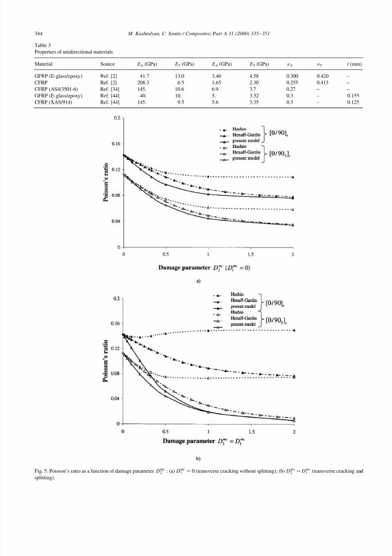
However, the situation is quite different for the Poisson’s
ratio. For transverse cracking without splitting (Fig. 5(a)),
the ECM/2-D shear lag approach predicts much greater
reduction in Poisson’s ratio than Hashin’s calculations.
This prediction is similar to that in Ref. [39] based on the
model in Ref. [35], though for small values of damage
parameter the results of model [35] are close to those in
Ref. [2]. For transverse cracking and splitting (Fig.
5(b)), Hashin predicts an increase of Poisson’s ratio
for a [0/90]s lay-up and asymptotic decrease to some
non-zero value for a [0/903]s lay-up, while, according to
ECM/2-D shear lag approach predictions, the Poisson’s
ratio should decrease almost to zero. The model [35]
predicts decrease in the Poisson’s ratio, yet the asymp-
totic value appears to be dependent upon the lay-up: non-zerofor the [0/90]s laminate and zero for the [0/90]s laminate
[39].
The Poisson’s ratio reduction due to transverse cracking
predicted by the present model has been also compared with
some other, recently developed, theories [40,41]. The prop-
erties of unidirectional material (E-glass/epoxy [2]) used for
comparison were taken from Table 3, and the ply thickness
was 0.203 mm. The theory of Pagano and Schoeppner [41]
employs the variational theorem by Reissner [42] to predict
the stress fields in flat laminates. McCartney’s theory [40] is
based on the generalised plane strain model of stress trans-
fer, which has been shown to lead to the stationary values of the Reissner energy functional. It also uses an assumption
that the direct stresses in the 0 and 90 piles are independent
of the through-thickness co-ordinate [40]. The comparison
of results for [0/90]s GFRP laminate [41,43], which was
considered earlier in Refs. [2,32], reveals an excellent
agreement between all three models (Fig. 6). Together
with Fig. 5(a), it indicates that the source of discrepancy
between the present ECM/2-D shear lag approach and
Hashin’s model is presumably in the latter rather than in
the former one. Indeed, let us consider Eq. (60) in Ref. [2]
for the case of transverse cracking only. Then function is
equal to zero and the rest of the equation yields that the
reduction of the Poisson’s ratio is proportional to thereduction in the Young’s modulus, which is obviously
incorrect.
As far as reduction of shear modulus is concerned, the
present model can be compared to those of Tsai and Daniel
[34], who especially developed it for the description of the
cracked cross-ply laminates under shear loading, and
Henaff-Gardin et al. [35]. It is worth noting that the model
of Tsai and Daniel [34] and the present ECM/2-D shear lag
approach yield exactly the same analytical expression for
the shear modulus reduction ratio due to transverse crack-
ing, if the thickness of the shear layer in the ECM/2-D shear
M. Kashtalyan, C. Soutis / Composites: Part A 31 (2000) 335– 351 343
7/23/2019 Stiffness degradation in cross-ply laminates damaged by transverse
http://slidepdf.com/reader/full/stiffness-degradation-in-cross-ply-laminates-damaged-by-transverse 10/17
M. Kashtalyan, C. Soutis / Composites: Part A 31 (2000) 335– 351344
Table 3
Properties of unidirectional materials
Material Source E A (GPa) E T (GPa) E A (GPa) E T (GPa) A T t (mm)
GFRP (E-glass/epoxy) Ref. [2] 41.7 13.0 3.40 4.58 0.300 0.420 –
CFRP Ref. [2] 208.3 6.5 1.65 2.30 0.255 0.413 –
CFRP (AS4/3501-6) Ref. [34] 145. 10.6 6.9 3.7 0.27 – –
GFRP (E-glass/epoxy) Ref. [44] 40. 10. 5. 3.52 0.3 – 0.155CFRP (XAS/914) Ref. [44] 145. 9.5 5.6 3.35 0.3 – 0.125
Fig. 5. Poisson’s ratio as a function of damage parameter Dmc2 (a) D
mc1 0 (transverse cracking without splitting); (b) D
mc2 D
mc1 (transverse cracking and
splitting).

7/23/2019 Stiffness degradation in cross-ply laminates damaged by transverse
http://slidepdf.com/reader/full/stiffness-degradation-in-cross-ply-laminates-damaged-by-transverse 11/17
lag approach is taken equal to that of the 0 lamina, i.e. if
hs h1 In notations of the present paper this expression is
G GA
GA
1 D
mc2
222
tanh 22
2
Dmc2
1
25
For transverse cracking combined with splitting, Tsai and
Daniel [34] suggested a semi-empirical expression for the
shear modulus reduction ratio based on the “superposition”
of solutions for a single set of cracks as
G 1 D
mc1
112
tanh 11
2
Dmc1
1
Dmc2
222
tanh 22
2
Dmc2
1
26
In fact, it was obtained from Eq. (25) by adding one
more term to the expression within the brackets. Then
Tsai and Daniel calculated the shear modulus reduction
ratio from the work done by the external shear loading.The shear stresses along the boundary of the block (i.e.
the laminate element between two transverse and two
longitudinal cracks) were obtained by the finite differ-
ence iteration procedure, used to solve the general
system of governing equations of the interlaminar-
shear–stress analysis. The value of the shear modulus
reduction ration obtained by the finite difference itera-
tion appeared to be within 1% of the value given by Eq.
(26). The present ECM/2-D shear lag model, if the
interaction between transverse cracks and splits is
neglected and the shear layer has the thickness of the
0 lamina, yields an expression
G
1
Dmc1
112
Dmc2
222
tanh11
2
Dmc1
tanh22
2
Dmc2
×
1
Dmc1
112
tanh11
2
Dmc1
1
Dmc2
222
tanh22
2
Dmc2
D
mc1
112
Dmc2
222
tanh
112
Dmc1 tanh
222
Dmc2
1
27
It may be seen from Eqs. (26) and (27) that the two
expressions differ by the underlined terms and G G
In absence of splitting Dmc1 0 they are both reduced
to Eq. (25).
Predictions, based on the semi-empirical expression,
Eq. (26), the ECM/2-D shear lag approach (with the shear
layer having the thickness of one ply and neglecting the
interaction between transverse cracks and splits), Eq. (27),
and Henaff-Gardin et al. [35,39] are presented in Fig. 7 for a
AS4/3506-1 [03 /903]s laminate. Elastic properties of the
unidirectional material are given in Table 3. When Dmc1 0(splitting without transverse cracking), the results differ due
to the fact that in the ECM/2-D shear lag model the shear
layer (Fig. 4) is assumed to be of one ply thickness. In most
cases, predictions by Tsai and Daniel are within 10% of
those by the ECM/2-D shear lag approach. However, in
some cases the error of the semi-empirical expression [34]
can be as big as 20%. Predictions based on Henaff-Gardin et
al. [35] model appear to be in better agreement with those of
the ECM/2-D shear lag approach. The same slope of the
corresponding curves is particularly noticeable. Limited
experimental data acquired by Tsai and Daniel [34] are in
M. Kashtalyan, C. Soutis / Composites: Part A 31 (2000) 335– 351 345
Fig. 6. Poisson’s ratio reduction ratio as a function of transverse cracking density C 2 2s21 for transversally cracked [0/903]s GFRP laminate.

7/23/2019 Stiffness degradation in cross-ply laminates damaged by transverse
http://slidepdf.com/reader/full/stiffness-degradation-in-cross-ply-laminates-damaged-by-transverse 12/17
an acceptable agreement with all predictions. Yet, further
experimental work is needed to validate the analytical
models.
4. Prediction of stiffness degradation
All results on the loss of stiffness in graphite/epoxy and
glass/epoxy [0m /90n]s cross-ply laminates due to transversecracks and splitting in this section were obtained taking into
account the interaction between transverse cracks and splits.
Up to 12 iterations were required to solve a system of simul-
taneous non-linear algebraic equations, Eq. (24), with the
accuracy of 109. The number of iterations increased with
increasing crack/splitting density. Two lay-ups were
analysed: [0/90]s and [0/903]s. The properties of unidirec-
tional materials [44] used in the analysis are given in Table
1.
Fig. 8(a) shows reduction in the axial modulus, shear
modulus and Poisson’s ratio in a CFRP [0/90], laminate
with and without splitting as a function of transverse
crack density. Splitting density is taken as C 1 2s11 10 cracks/cm. It may be seen that the axial modulus of the
transversally cracked and split laminate is almost the same
as that of the laminate damaged by transverse cracking only.
As one would expect, splitting does not affect its value.
However, it causes further reduction in the shear modulus
and Poisson’s ratio, by 15–18% and 21–22%, respectively,
for a given splitting density. The effect of splitting, more
pronounced on the Poisson’s ratio than on the shear
modulus, slightly increases with an increase in transverse
cracking density. Fig. 8(b) shows analogous predictions
for a CFRP [0/903]s laminate. Splitting density is again
C 1 2s11
10 cracks/cm. Additional reduction in the
shear modulus and Poisson’s ratio due to splitting about 10
and 11%, for a given splitting density.
Predictions for GFRP [0/90]s and [0/903]s laminates are
shown in Fig. 9(a) and (b), respectively. Again, there is
almost no further reduction in the Young’s modulus value
due to splitting, although reduction due to transverse crack-
ing in GFRP laminates is greater that in CFRP ones. As far
as shear modulus and Poisson’s ratio are concerned, reduc-tion in their values due to splitting is approximately the
same, respectively, 17– 22% and 18–23% in [0/90]s and
10–15% and 11–14% in [0/903]s for a given splitting
density. The effect of splitting is also observed to increase
with an increase in the transverse cracking density.
Fig. 10(a) and (b) illustrate reduction in the axial, trans-
verse and shear moduli of CFRP and GFRP [0/90]s lami-
nates when the extent of damage, described by the damage
parameter Dmci hi si is the same in both layers. Such
situation appears when a laminate is subjected to biaxial
loading with the biaxiality ratio close to 1. Results for trans-
versally cracked and split Dmc2 D
mcl laminates are shown
in comparison with the data for laminates, which containdamage in the 90 layer only D
mc2 0 The maximum
value of damage parameter corresponds to crack density
of 37.8 cracks/cm in CFRP and 32.3 cracks/cm in GFRP
laminates.
5. Conclusions
While stiffness loss due to matrix cracking in the 90 plies
of cross-ply [0m /90n]s laminates has been the subject of
numerous studies in the literature, matrix cracking occurring
M. Kashtalyan, C. Soutis / Composites: Part A 31 (2000) 335– 351346
Fig. 7. Shear modulus reduction ratio as a function of damage parameter Dmc2 D
mc1 for transversally cracked and split [03 /903]s CFRP laminate.

7/23/2019 Stiffness degradation in cross-ply laminates damaged by transverse
http://slidepdf.com/reader/full/stiffness-degradation-in-cross-ply-laminates-damaged-by-transverse 13/17
both in the 90 (transverse cracking) and 0 (splitting) plies
has received considerably less attention. Existing theoretical
models [32–36], on the one hand, do not describe reductionof all stiffness components, and on the other hand, appear to
be complicated enough to allow any further extension or
generalisation, with the aim to involve into consideration
other damage modes, e.g. local delaminations that grow
from the crack/split tips. The new approach, developed to
overcome the above-mentioned limitations, is based on the
Equivalent Constraint Model (ECM) of the damaged
lamina. In the ECM, only one damaged layer contains
damage explicitly, while all neighbouring layers, damaged
or undamaged, are replaced with two (one) homogeneous
orthotropic layers with reduced stiffness properties. An
improved 2-D shear lag analysis is then performed to deter-
mine the in-plane microstresses in the explicitly damaged
layers of the two ECMs, which are considered instead of theoriginal one. Closed form expressions are obtained for the
IDEFs, which characterise reduced stiffness properties of
the damaged layers. IDEFs for a given layer are represented
as explicit functions of the damage parameters (relative
crack/split density) associated with that layer and implicit
functions of the damage parameters associated with the
neighbouring plies. Thus, interaction between all damage
modes is taken into account in the new approach.
The new ECM/2-D shear lag based approach is in an
excellent agreement with the models [2,35] as far as axial
stiffness reduction of the transversally cracked and split
M. Kashtalyan, C. Soutis / Composites: Part A 31 (2000) 335– 351 347
Fig. 8. Elastic moduli reduction ratios as functions of transverse crack density C 2 2s21 (cm1) for transversally cracked CFRP laminates with (solid lines)
and without (hatched lines) splitting: (a) [0/90]s; (b) [0/903]s. Splitting density 10 cm1.

7/23/2019 Stiffness degradation in cross-ply laminates damaged by transverse
http://slidepdf.com/reader/full/stiffness-degradation-in-cross-ply-laminates-damaged-by-transverse 14/17
laminate is concerned. For the Poisson’s ratio, significant
qualitative and quantitative scattering of predictions isobserved, the source of which appears to lie in the Hashin’s
approach. Comparison with estimations [34,35] of the shear
modulus reduction in transversally cracked and split lami-
nates shows that all three models predict the same trend,
although some quantitative discrepancy (10–20%) between
the present approach and that in Ref. [34] is noticeable.
The effects of transverse cracking and splitting on the
axial, transverse and shear moduli as well as Poisson’s
ratio of typical CFRP and GFRP laminates were examined
on the basis of the new ECM/2-D shear lag approach. The
axial modulus value has appeared to be almost not
affected by splitting. The effect of splitting on the Poisson’s
ratio is more pronounced than on the shear modulus, and itslightly increases with an increase in the transverse
cracking density. For [0/90]s laminates, transversally
cracked and split under biaxial loading, the total reduction
in the transverse modulus is slightly larger than in the axial
one.
Acknowledgements
Financial support of this research by the Royal Society,
UK, Engineering and Physical Sciences Research Council
M. Kashtalyan, C. Soutis / Composites: Part A 31 (2000) 335– 351348
Fig. 9. Elastic moduli reduction ratios as functions of transverse crack density C 2 2s21 (cm1) for transversally cracked GFRP laminates with (solid lines)
and without (hatched lines) splitting: (a) [0/90]s; (b) [0/903]s. Splitting density 10 cm1.

7/23/2019 Stiffness degradation in cross-ply laminates damaged by transverse
http://slidepdf.com/reader/full/stiffness-degradation-in-cross-ply-laminates-damaged-by-transverse 15/17
(EPSRC/GR/L51348) and Ministry of Defence is gratefully
acknowledged. The authors would like to thank Professor
Glyn Davies, Imperial College of Science, Technology and
Medicine, London, UK, Professor Paul Smith, University of
Surrey, Guilford, UK, and Dr Neil McCartney, National
Physical Laboratory, Teddington, UK, for helpful discus-
sions. Also our special thanks to Dr McCartney and Dr
Catherine Henaff-Gardin, ENSMA, Futuroscope, France,
for providing numerical results of their models for compar-
ison purposes.
Appendix A
A.1. Derivation of shear lag parameters
Assuming that uk 3 x1 u
k 3 x2 0 k 1 2
the out-of-plane constitutive equations are
k
j3 u
k j
x3
1
Gk
j3
k
j3 k 1 2 A1
M. Kashtalyan, C. Soutis / Composites: Part A 31 (2000) 335– 351 349
Fig. 10. Elastic moduli reduction ratios as functions of damage parameter Dmc2 for transversally cracked [0/90]s laminates with (solid lines, Dmc
1 Dmc2 ) and
without (hatched lines, Dmc1 0) splitting: (a) CFRP; (b) GFRP.

7/23/2019 Stiffness degradation in cross-ply laminates damaged by transverse
http://slidepdf.com/reader/full/stiffness-degradation-in-cross-ply-laminates-damaged-by-transverse 16/17
where Gk
j3 are the out-of-plane shear moduli of the k th
layers. As was already noted, these elastic constants are
not undergoing reduction due to matrix cracking. For the
inner layer, substitution of Eq. (10) into Eq. (A1) and
repeated integration with respect to x3 across the layer
thickness yields
u2
j u2
j x3h2
j h2
3 G2
j3
A2
For the outer layer, substitution of Eq. (10) into Eq. (A1) and
integrating with respect to x3 across the thickness of the
shear layer (Fig. 4) leads to
ul
j ul
j x3h2
j
hs G
2 j3
h2 hs x3 h2
x23 h
22 2 h2 x3 h2 hs
A3
Integrating Eq. (A3) across the thickness of the shear layeragain yields
ul
j ul
j x3h2
j hs
3Gl
j3
j 1 2 A4
where ul
j are the displacements averaged across the thick-
ness of the shear layer. In the part of the outer layer h2
hs x3 h2 h7 free from the out-of-plane shear, Fig. 4,
the displacements ul
j are constant across the thickness and
can be found from Eq. (A3) by putting x3 h2 hs as
u
l
j ul
j x3h2
j hs
2Gl
j3A5
The displacements, averaged across the whole thickness of
the outer (constraining) layer are then
ul
j 1
hl
hs ul
j h1 hs ul
j A6
Finally, the continuity of displacements at the interface due
to the perfect bonding between the layers in the considered
region should be taken into account, i.e.
ul
j x3h2 u
l j x3h2
A7
Combining Eqs. (A2), (A4)–(A7) together yields Eq. (11)for the interface shear stresses
j with the shear lag
parameter K j given by Eq. (12).
A.2. Laminate constants
L11
K 1
h1
S 111 b1
S 112 S
211 b1S
212
L12
K 2
h1
S 166 S
266
111
K 1
h1
1 S 211 b1S
212
1
22 K 1
h1
1 S 212 b1S
222
1
12
K 2
h11 S
2
66
L21
K 2
h1
S 122 a1S
112 S
222 a1
S 212
L22
K 1
h1
S 166 S
266
2
11 K 2
h1
1 S 112 a1S
111
2
22 K 2
h1
1 S 122 a1S
112
112
K 1
h1
1 S 166
a1 S
112 S
212
S 111 S
211
b1 S
112 S
212
S 122 S
222
h1
h2
K 1, K 2 are the shear lag parameters, Eq. (12).
A.3. Laminate constants
k 1 hk
L
k 1
k 1 2 k
2 hk
L
k 2
k 1 2
11 Q
111 S
211 b1S
212 Q
112 S
212 b1S
222
21
1
Q
222 S
122 a1S
112 Q
212 S
112 a1S
111
12 Q1
66 S 266 2
2 1
Q
266 S
166
References
[1] Dvorak GJ, Laws N, Hejazi M. Analysis of progressive matrix crack-
ing in composite laminates I. Thermoelastic properties of a ply with
cracks. Journal of Composite Materials 1985;19:216–34.
[2] Hashin Z. Analysis of orthogonally cracked laminates under tension.
Transations of the ASME: Journal of Applied Mechanics
1987;54:872–9.
[3] Hashin Z. Analysis of cracked laminate: a variational approach.
Mechanics of Materials 1985;4:121–36.
[4] Talreja R. Transverse cracking and stiffness reduction in composite
laminates. Journal of Composite Materials 1985;19:355–75.
[5] Talreja R. Transverse cracking and stiffness reduction in cross-ply
laminates of different matrix toughness. Journal of Composite
Materials 1992;26(11):1644–63.
M. Kashtalyan, C. Soutis / Composites: Part A 31 (2000) 335– 351350

7/23/2019 Stiffness degradation in cross-ply laminates damaged by transverse
http://slidepdf.com/reader/full/stiffness-degradation-in-cross-ply-laminates-damaged-by-transverse 17/17
[6] Zhang J, Fan J, Soutis C. Analysis of multiple matrix cracking in
^ m 90ns composites laminates Part 1: in-plane stiffness properties.
Composites 1992;23(5):291–8.
[7] Zhang J, Fan J, Soutis C. Analysis of multiple matrix cracking in
^ m 90ns composite laminates Part 2: development of transverse
ply cracks. Composites 1992;23(5):299–304.
[8] Highsmith AL, Reifsnider KL. Stiffness reduction mechanisms in
composite laminates. ASTM STP 1982;115:103–17.
[9] Ogin SL, Smith PA, Beaumont PWR. Matrix cracking and stiffnessreduction during the fatigue of a (0/90)s GFRP laminates. Composites
Science and Technology 1985;22:23–31.
[10] Han YM, Hahn HT. Ply cracking and property degradations of
symmetric balanced laminates under general in-plane loading.
Composites Science and Technology 1989;35:377–97.
[11] Lee JW, Daniel IM. Progressive cracking of crossply composite lami-
nates. Journal of Composite Materials 1990;24:1225–43.
[12] Nuismer RJ, Tan SC. Constitutive relations of a cracked composite
lamina. Journal of Composite Materials 1988;22:306–21.
[13] McCartney LN. Theory of stress transfer in a 0–90–0 cross-ply
laminate containing a parallel array of transverse cracks. Journal of
Mechanics and Physics of Solids 1992;40(1):27–68.
[14] McCartney LN. The prediction of cracking in biaxially loaded cross-
ply laminates having brittle matrices. Composites 1993;24(2):84–92.
[15] McCartney LN. Stress transfer mechanics for ply cracks in generalsymmetric laminates. NPL Report CMT(A)50, 1996.
[16] Yu H, Xingguo W, Zhengneng L, Qingzhi H. Property degradation of
anisotropic composite laminates with matrix scracking. Part 1: devel-
opment of constitutive relations for ( m /90n)s cracked laminates by
stiffness partition. Journal of Reinforced Plastics and Composites
1996;15(11):149–1160.
[17] Hua Y, Wang X, Li Z, He Q. Property degradation of anisotropic
laminates with matrix cracking. Part 2: determination of resolved
stiffness and numerical study of stiffness degradation. Journal of
Reinforced Plastics and Composites 1997;16(5):478–86.
[18] Zhang J, Herrmann KP. Application of the laminate plate theory to the
analysis of symmetric laminates containing a cracked mid-layer.
Computational Materials Science 1998;13(1–3):195–210.
[19] McCartney LN. Stress transfer mechanics for angle-ply laminates. In:
Proceedings of the Seventh ECCM-7. London, vol. 2, 1996. p. 235–40.
[20] Adolfsson E, Gudmundson P. Matrix crack induced stiffness reduc-
tion in 0m 90n p qs M composite laminates. Composite
Engineering 1995;5(1):107–23.
[21] Tong J, Guild FJ, Ogin SL, Smith PA. On matrix crack growth in
quasi-isotropic laminates— I. Experimental investigation. Compo-
sites Science and Technology 1997;57(11):1527–35.
[22] Tong J, Guild FJ, Ogin SL, Smith PA. On matrix crack growth in
quasi-isotropic laminates—II. Finite element analysis. Composites
Science and Technology 1997;57(11):1527–35.
[23] Lu TJ, Chow CL. Constitutive theory of matrix cracking and interply
delamination in orthotropic laminated composites. Journal of Rein-
forced Plastics and Composites 1992;11(5):494–536.
[24] Zhang J, Soutis C, Fan J. Effects of matrix cracking and hygrothermal
stresses on the strain energy release rate for edge delamination in
composite laminates. Composites 1994;25(1):27–35.
[25] Zhang J, Soutis C, Fan J. Stain energy release rate associated with
local delamination in cracked composite laminates. Composites
1994;25(9):851–62.
[26] Xu LY. Interaction between matrix cracking and edge delamination in
composite laminates. Composites Science and Technology
1994;50(4):469–78.
[27] Zhang J, Fan J, Herrmann KP. Delaminations induced by constrained
transverse cracking in symmetric composite laminates. International
Journal of Solids and Structures 1999;36:813–46.
[28] Xu LY. Influence of stacking sequence on the transverse matrix crack-ing in continuous fiber crossply laminates. Journal of Composite
Materials 1995;29(10):1337–58.
[29] Berthelot JM. Analysis of the transverse cracking of cross-ply lami-
nates: a generalised approach. Journal of Composite Materials
1997;31(18):1780–805.
[30] Zhang C, Zhu T. On inter-relationships of elastic moduli and strains in
cross-ply laminated composites. Composites Sciences and Tech-
nology 1996;56(2):135–46.
[31] Gyekenyesi A, Hemann J, Binienda W. Crack development in carbon
polyimide cross-ply laminates under uni-axial tension. SAMPE Jour-
nal 1994;30(3):17–28.
[32] Highsmith AL, Reifsnider KL. Internal load distribution effects
during fatigue loading of composite laminates. ASTM STP
1986;907:233–51.
[33] Daniel IM, Tsai CL. Analytical/experimental study of cracking incomposite laminates under biaxial loading. Composite Engineering
1991;1(6):355–62.
[34] Tsai CL, Daniel IM. Behavior of cracked cross-ply composite lami-
nate under shear loading. International Journal of Solids and Struc-
tures 1992;29(24):3251–67.
[35] Henaff-Gardin C, Lafarie-Frenot MC, Gamby D. Doubly period
matrix cracking in composite laminates Part 1: general in-plane load-
ing. Composite Structures 1996;36:113–30.
[36] Henaff-Gardin C, Lafarie-Frenot MC, Gamby D. Doubly period
matrix cracking in composite laminates Part 2: thermal biaxial load-
ing. Composite Structures 1996;36:131–40.
[37] Fan J, Zhang J. In-situ damage evolution and micro/macro transition
for laminated composites. Composites Science and Technology
1993;47:107–18.
[38] Horii H, Nemat-Nasser S. Overall moduli of solids with microcracks:load induced anisotropy. Journal of Mechanics and Physics of Solids
1983;31(2):155–71.
[39] Henaff-Gardin C. Private communiation, 1998–1999.
[40] McCartney LN. A recursive method of calculating stress transfer in
multiple-ply cross-ply laminates subject to biaxial loading. NPL
Report DMM(A)150, 1995.
[41] Pagano NJ, Schoeppner GA. Some transverse cracking problems in
cross-ply laminates. CTP AIAA/ASME/ASCE/AHS/ASC Structures,
Structural Dynamics and Materials Conference 1997, vol. 3, 1998. p.
2032–40.
[42] Reissner E. On a variational theorem in elasticity. Journal of Mathe-
matical Physics 1950;29:90–5.
[43] Mccartney LN. Private communication, 1998.
[44] Smith PA, Wood JR. Poisson’s ratio as a damage parameter in the
static tensile loading of simple cross-ply laminates. Composites
Science and Technology 1990;38:85–93.
M. Kashtalyan, C. Soutis / Composites: Part A 31 (2000) 335– 351 351