Steven Yeip Brad Donohoo 435.757.8144 801.686.2732 · PDF fileIncluded is the final report...
117
Steven Yeip [email protected] 435.757.8144 Jake Erramouspe [email protected] 435.650.4473 Brad Donohoo [email protected] 801.686.2732 Jake Child [email protected] 801.628.5543 May 6, 2010 Dr. Donald Cripps Department of Electrical and Computer Engineering Utah State University Dear Dr. Cripps, Included is the final report detailing the engineering design of the Home Automation System. This system has been designed to efficiently combine a number of separate automation systems. Examples of the separate systems include: automatic sprinklers, home security, and automatic lights. Currently all of these systems exist as separate entities. At times these systems can be robust and confusing to set up and operate. Our project will include all three systems packaged into one easy-to-operate system. This project is a prototype design that will allow the user to control the home from an easy-to-use graphical user interface. In order to add more functionality we will add the ability to control various aspects and receive updates using the SMS text messaging system from a cellular phone. This capability will allow the system to be monitored at any moment in time, giving the user full control even while away from the home.
Transcript of Steven Yeip Brad Donohoo 435.757.8144 801.686.2732 · PDF fileIncluded is the final report...
Steven Yeip [email protected] 435.757.8144 Jake Erramouspe [email protected] 435.650.4473
Brad Donohoo [email protected] 801.686.2732 Jake Child [email protected] 801.628.5543
May 6, 2010 Dr. Donald Cripps Department of Electrical and Computer Engineering Utah State University Dear Dr. Cripps,
Included is the final report detailing the engineering design of the Home Automation
System. This system has been designed to efficiently combine a number of separate
automation systems. Examples of the separate systems include: automatic sprinklers,
home security, and automatic lights. Currently all of these systems exist as separate
entities. At times these systems can be robust and confusing to set up and operate.
Our project will include all three systems packaged into one easy-to-operate system.
This project is a prototype design that will allow the user to control the home from an
easy-to-use graphical user interface. In order to add more functionality we will add the
ability to control various aspects and receive updates using the SMS text messaging
system from a cellular phone. This capability will allow the system to be monitored at
any moment in time, giving the user full control even while away from the home.

The attached report details the background for needing a cohesive home automation
system. It also addresses the global, economic, and engineering impact of
implementing such a system. The design is detailed, along with technical block
diagrams and explanations, to fully explain our engineering approach as well as the
system’s capabilities and limitations.
The final sections of the report consist of relevant project management information such
as personnel, budget, and timelines. The project costs have been kept to a minimum –
well within the previously established budget. Project timelines have also been followed
with exactness and we are proud to announce successful project completion on May 6,
2010.
We are confident that this report will clearly explain the project and its specifics. As
always, please feel free to contact us with any further questions after your review of this
report. We look forward to demonstrating the system prototype for you today, May 6,
2010.
Sincerely, Steven Yeip Jake Erramouspe
Brad Donohoo Jake Child
Senior Design Project for
Home Automation System
ECE 5770 / ECE 4850
May 6, 2010
Steven Yeip
Jake Erramouspe
Brad Donohoo
Jake Child
Instructor Approval Dr. Paul A. Wheeler Department of Electrical and Computer Engineering Utah State University
Date
Supervisor Approval Dr. Donald Cripps Department of Electrical and Computer Engineering Utah State University
Date

Acknowledgments
Every engineering project is the result of contributions from the project’s team
members as well as individuals whose guidance and consulting were influential
and necessary through the design process. The Home Automation System has
the following individuals to thank for its successful completion and functionality:
Dr. Paul A. Wheeler for his technical design review and counsel
Dr. Donald Cripps for his project guidance and review
Laura Vernon for her communication editing and review

Table of Contents
Table of Figures
1
Abstract 2
Introduction Problem Statement Solution Summary Engineering Impact Future Possibilities
3
Problem Analysis General Project Specifications Security System Specifications Watering System Specifications Light System Specifications Graphical User Interface Specifications Cell Phone Access Capability Specifications
7
Decision Analysis General Project Considerations Security System Considerations Watering System Considerations Light System Considerations Graphical User Interface Considerations Cell Phone Access Capability Considerations
10
Solution Description General Problem Solution Security System Solution Watering System Solution Light System Solution
13
Testing
37
Reflections Technical Challenges
40
Project Management Personnel Costs Timeline
42
Conclusion
47
Appendices 48

1
Table of Figures
Figure 1. C8051F020 Development Kit 14
Figure 2. C8051F020 MCU Schematic
15
Figure 3. HAS Communication Protocol
16
Figure 4. Electronic Door Lock
17
Figure 5. H-Bridge Circuit Schematic
19
Figure 6. Door Lock Logic Truth Table
20
Figure 7. 10-Digit Keypad
22
Figure 8. Arduino Development Board
23
Figure 9. Automatic Sprinkler Vale
30
Figure 10. Photocell
33
Figure 11. Photocell Circuit
33
Figure 12. Gantt Chart
45
Figure 13. Pert Chart
46

2
Abstract
The Home Automation System combines several different common systems in a
normal home. The system will control and maintain a home security system, a
lighting system, and a lawn watering system. The system may be controlled
using a centralized user interface as well as remotely; using text messages or
emails sent from a cell phone.

3
Introduction
The average house has several different types of systems. Normally, there is an
electrical system, a heating and cooling system, a security system, a computer
network, and potentially a sprinkler system. Each has its own controller that
allows the homeowner to maintain and control the various parts. These
controllers are usually separate and can only be accessed from inside the home.
Separate controllers have the potential to cause problems for the homeowner if
something was left on or unlocked and the homeowner was not able to get home
quickly. The homeowner must either leave the item switched on, leave the home
unprotected or he/she has to call someone and have that person go and check
the house. The homeowner also must monitor each system individually and
make sure that each system has been configured correctly. By having each
system separate, new controls must be learned for proper management.
The purpose of this project is to create a prototype system that will allow the
control of some of these different household systems from one central location.
These systems may also be controlled from anywhere in the world using a cell
phone and text messages. The homeowner will be able to send a message to
the system and receive an update of the current status or send a command to
the system. The central control system in the home will be controlled by a
computer with an easy-to-use graphical user interface. This project prototype will
be called the Home Automation System (HAS).

4
Problem Statement
There currently exist multiple home automation systems that complete individual
tasks, but because they are not combined into one unit they can be expensive
and a hassle to use efficiently. Also, many systems have no way of notifying the
homeowner about events while he/she is away from the home.
Solution Summary
To solve these problems, we will combine the most common home systems into
one easy-to-use package that may be controlled or monitored from a remote
place (if the homeowner desires). This project will combine three major systems:
a security system, an automatic lawn sprinkler system, and an automatic light
system.
The system must:
1. Lock doors when the owner leaves home
2. Sound an alarm if a door/window is opened while alarm is set
3. Turn on the water system at a set date/time
4. Turn off water system at a set date/time
5. Turn off lights when no one is in a room
6. Send updates to owner’s cell phone
7. Receive commands from the owner’s cell phone

5
In order to achieve the intended function of this system based on the
requirements above, the project is designed around the following basic
objectives:
1. Implement a Home Automation System that will provide automation of
three distinct tasks:
a. Home security
b. Lawn watering
c. Turning lights on/off
2. Facilitate uncomplicated control of the Home Automation System through
creation of a graphical user interface
3. Allow the homeowner to receive updates about the Home Automation
System’s status and control the system while away
The prototype must be able to demonstrate successful functionality of each of the
design objectives. To accomplish this, the system has been broken into several
key deliverables. These deliverables include the three sub-systems of the Home
Automation System, a graphical user interface, and cell phone access capability.
1. Security System: Monitors windows and doors and sets off an alarm
when armed.
2. Lawn Sprinkler System: Waters lawn only at specific times of the day and
only when needed.
3. Automatic Lights System: Monitors movement in a room and turns lights
on/off accordingly.
4. Graphical User Interface: Facilitates control of all three sub-systems.
5. Cell phone Access Capability: Allows the homeowner to control/monitor
the system while away from the home.
6
Engineering Impact
The Home Automation System will have a globally beneficial impact because it
can be used anywhere to enhance home security, help conserve water, and save
energy. The security sub-system will keep intruders out of homes and will help
keep the homeowners, their families, and their property safe from harm. The
lawn sprinkler subsystem will help conserve water by watering only at the most
beneficial times, and only when the lawn needs it. The sprinklers will
automatically turn off during the hottest times of the day, preventing the water
from being evaporated. The automatic lights system will save electricity, and
ultimately the environment, by automatically turning off the lights in a room when
movement has not been sensed for a configurable amount of time.
Future Possibilities
Later applications of this system may include a greater number of systems, such
as automatic temperature control or entertainment. Adding greater functionality
to existing systems is also a possibility. A few examples of this would be using
moisture sensors to determine watering times or adding more cell phone control
capability. Finally, wireless connectivity could be implemented to allow greater
freedom in component placement. Beyond the functionality of this first prototype,
the possibilities of expansion are limitless.

7
Problem Analysis
The Home Automation System successfully implements three common home
systems along with a graphical user interface and cell phone text message
capability to fulfill the basic project objectives. The three common systems are
the security system, lawn watering system, and automatic lights system. The
following sections outline the specifications for each of these deliverables.
General Project Specifications
In our prototype design, we are using a C8051F020 microcontroller to control the
three systems and relay information to the CPU with the graphical user interface
installed. This microcontroller was programmed using the C programming
language.
Security System Specifications
The security system must automatically lock/unlock doors, check for open doors
and windows, and sound an alarm when a door or window is open while the
system is armed. To lock/unlock a door, a signal must be sent from the
microcontroller to an electronic deadbolt installed in the door. Manual operation
on the deadbolt must be maintained. Magnetic sensors must be installed in the
windows and doors to detect a break-in. Upon detecting a break-in, an alarm
must sound from a speaker installed on the main microcontroller. The security
system must also contain an arbitrary number of sub-control panels, which may

8
be placed throughout the house. These sub-control panels each consist of a
keypad and a microcontroller. The homeowner must be able to arm and disarm
the system by entering a 4-digit code on one of these keypads.
Watering System Specifications
The lawn sprinkler system will consist of a network of tubes and automatic
valves. The automatic valves control the water flow, and must be opened/closed
upon receiving signals from the microcontroller.
Lights System Specifications
The automatic lights system must use light detectors to determine if a light in a
room is on or off. The light detectors will be photocells, and will be connected to
the microcontrollers on each of the sub-control panels. Each microcontroller will
send signals to the main microcontroller, telling it if their particular room’s light is
on or off. The homeowner must be able to turn any room’s lights on or off
remotely. However, manual light control by use of a switch must still be
available.
Graphical User Interface Specifications
The GUI must be able to control various settings for each sub-system. For the
security system, the GUI must allow the homeowner to arm/disarm the system,
manually lock/unlock doors, change the keypad code, and manually disable the

9
alarm if it has been triggered. For the lawn sprinkler system, sprinklers must be
able to be manually turned on/off, and automatic watering start and stop times
must be able to be set. For the automatic lights system, lights must be able to be
manually turned on/off, and the amount of time to wait before automatic shutoff
must be configurable.
Cell Phone Access Capability Specifications
To implement cell phone control and monitoring for the Home Automation
System, the SMS (Short Message Service) text messaging system is utilized.
This is an optional feature for our system, because the homeowner may not have
a cell phone, or may not have access to this service. However, the SMS text
messaging system is a common feature that is offered with most cell phone plans
today. In order for the system to receive text messages from the homeowner’s
cell phone, the homeowner will need to have a valid e-mail address. Text
messages must be received on a personal computer in the home as an e-mail,
which will be parsed and received as a command. Each text message sent to
the system must contain a valid 4-digit code in order for the command to be
processed. For example, the homeowner may send a text containing the word
“arm”, and the code “1234”. The system will receive the e-mail and respond
accordingly by arming the security system. Status updates are sent to the
homeowner’s cell phone in a similar fashion. Security measures must be taken
so that the system will not be able to be remotely accessed by anybody.

10
Decision Analysis
In our preliminary design research, we came across some alternate design
options and had to make decisions according to what would suit our project best.
Due to the prototype nature of the project, most decisions were made in order to
create a demonstration that would be as simple and clear as possible to illustrate
the engineering idea. The technology being created to fulfill our prototype Home
Automation System objectives may later be easily implemented on other
hardware and using other techniques. This project satisfies the creation of a
platform upon which more future technological designs may be based.
General Project Considerations
One of the general project decisions we had to make concerned whether or not
to use a real-time system for our main microcontroller; we concluded that this
was not needed. The microcontroller only sends out various signals and does
not run any long processes.
Security System Considerations
For the security system, we had to choose between making it a distributed
system or a centralized system. We chose the distributed system, meaning that
we will have numerous sub-control panels throughout the house (in addition to

11
the main graphical user interface). These sub-control panels will be in the form
of numeric keypads with microcontrollers, and will allow the homeowner to
arm/disarm the system by entering a 4-digit code.
Keypads may be placed in any room of the house. The data from the keypad
needs to be transmitted back to the main controller so that the password can be
checked and then either accepted or rejected. This could potentially involve a
large amount of wires being run from several different keypads to the main
controller. Another solution would be to process the keys pressed at the keypad
using another microcontroller, determine if the password is correct, then transmit
the arm or disarm signal back to the controller. This would save a lot of trouble in
having to run wires everywhere. When transmitting the data back to the
controller, it’s possible to do it wirelessly or to run wires to each microcontroller in
each room. If the signal was done wirelessly, there are some issues that must
be dealt with. There is the possibility of someone intercepting the signal and
sending a signal to the controller to disarm the system. There is also the
obstacle of having to transmit between rooms and from different floors in a
house. We decided to transmit the signal using wires that are run from the main
controller to each room.

12
Watering System Considerations
For the watering system, we considered using a moisture sensor to determine
what areas of the lawn needed watering. We decided against this, and
determined that implementing a watering schedule by allowing the homeowner to
set start and stop times would be sufficient.
Lights System Considerations
There are a few different ways that the light system could have been completed.
The basic way is to have some type of light sensor or photo resister that would
be able to sense light changes in a room. When a light changes, the data must
be sent back to the main microcontroller to update the system. This presents the
problem of how to run wire to each room in the house from the main
microcontroller. The decision was made to put the light sensor on the same
microcontroller as the keypad so it would eliminate the need for more wires to be
run.
Graphical User Interface Considerations
We had to decide on a programming language to use for creating the graphical
user interface. We had originally planned to use C++, but changed to C# after
discovering a few features that would allow easier implementation of the
graphical user interface. For instance, it is easier to send/receive emails using
the program (which is a crucial part of the text message system control). Also,
13
ways of writing to the serial port (to communicate with the microcontroller) have
been implemented in previous projects using C#.
Cell Phone Access Capability Considerations
To implement the text messaging feature, we considered using a computer
program that would help manage texts but decided that would be too expensive
and beyond the scope of the project. Instead, we discovered that we can send
text messages by using a email server. We chose this path because sending
emails in C# is very simple. It is done by setting up an SMTP server to send
emails and a POP3 server to receive emails.
Solution Description
By using two separate microcontrollers (programmed in C), a graphical user
interface (programmed in C#), and some simple circuitry, we were able to satisfy
the previously stated project requirements.
General Problem Solution
In order to control each of the Home Automation System’s sub-systems, a Silicon
Laboratories C8051F020 Development Kit was used (see Figure 1).

14
Figure 1. C8051F020 Development Kit
This Development Kit includes the C8051F020 Target/Prototyping PCB, a CD-
ROM containing the Silicon Laboratories Integrated Development Environment
(IDE), and a few other tools that assist in programming the board.
The C8051F020 device is fully integrated mixed-signal System-on-a-Chip MCU
with 64 digital I/O pins. A schematic of the MCU is shown below in Figure 2.
Highlighted features are listed below:
• High-Speed pipelined 8051-compatible CIP-51 microcontroller core (up to 25 MIPS)
• In-system, full-speed, non-intrusive debug interface (on-chip) • True 12-bit 100 ksps 8-channel ADC with PGA and analog multiplexer • True 8-bit ADC 500 ksps 8-channel ADC with PGA and analog multiplexer • Two 12-bit DACs with programmable update scheduling • 64k bytes of in-system programmable FLASH memory • 4352 (4096 + 256) bytes of on-chip RAM

15
• External Data Memory Interface with 64k byte address space • SPI, SMBus/I2C, and (2) UART serial interfaces implemented in hardware • Five general purpose 16-bit Timers • Programmable Counter/Timer Array with five capture/compare modules • On-chip Watchdog Timer, VDD Monitor, and Temperature Sensor • On-board JTAG debug circuitry allows non-intrusive (uses no on-chip
resources), full speed, in-circuit debugging using the production MCU installed in the final application.
Figure 2. C8051F020 MCU Schematic

16
The C8051F020 microcontroller uses two separate UARTs to communicate with
the sub-control panels and the CPU with the graphical user interface installed.
To be able to send data back and forth between the C8051F020 microcontroller,
the sub-control panels, the graphical user interface, we had to develop a
communication protocol. We determined that each message sent would begin
with an 8-bit status/command word, which tells the recipient about a status
change or gives them an action to complete. This word is then followed by an
arbitrary number of data bytes that tell the recipient how to compete the action.
The most significant bit of the status/command word tells the recipient whether
the message is a status or a command. The next three bits tell what system
(security, watering, or light) the action will involve, and the least-significant four
bits tell what operation to complete. A graphic detailing this protocol is shown
below in Figure 3.
Figure 3. HAS Communication Protocol

17
Security System Solution
We had to purchase an electronic dead bolt lock to demonstrate the system’s
door locking and unlocking functionality. The electronic dead bolt we purchased
contains a 10-digit keypad with lock and unlock buttons. It requires a 4-digit code
to unlock. Because the electronic dead bolt did not come with any
documentation, we were forced to tear it apart and manually trace its onboard
circuitry in order to figure out how to lock and unlock it ourselves. Figure 4
shows the electronic door lock with its circuitry exposed. A lab book page
showing the electronic lock circuitry is shown in Figure 5.
Figure 4. Electronic Door Lock

18
Figure 5. Electronic Lock Circuitry Drawings
19
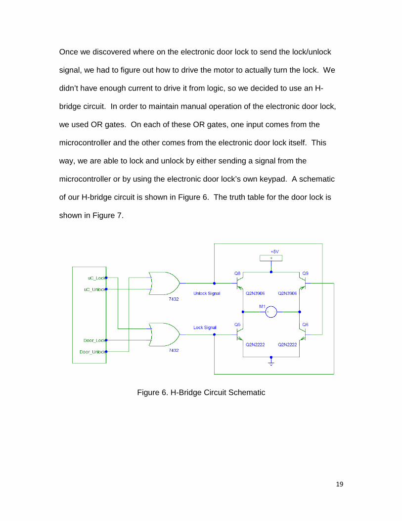
Once we discovered where on the electronic door lock to send the lock/unlock
signal, we had to figure out how to drive the motor to actually turn the lock. We
didn’t have enough current to drive it from logic, so we decided to use an H-
bridge circuit. In order to maintain manual operation of the electronic door lock,
we used OR gates. On each of these OR gates, one input comes from the
microcontroller and the other comes from the electronic door lock itself. This
way, we are able to lock and unlock by either sending a signal from the
microcontroller or by using the electronic door lock’s own keypad. A schematic
of our H-bridge circuit is shown in Figure 6. The truth table for the door lock is
shown in Figure 7.
Figure 6. H-Bridge Circuit Schematic

20
Figure 7. Door Lock Logic Truth Table
To lock and unlock the door by sending a signal from the microcontroller, the
correct signal must be held high to keep the motor turning. So, we timed how
long the electronic door lock took to fully lock and unlock and determined that it
took approximately 0.7 seconds. After the microcontroller receives the
appropriate control word, it looks for a data byte that tells it whether to lock or
unlock the door. Then, the microcontroller sends the door lock (connected to
port 0, pins 4 and 5) the signal for 700 milliseconds. We were able to time this
on the microcontroller by using timer 3; set up to fire an interrupt every 50
milliseconds. Within the timer 3 ISR, a variable is incremented, and that variable
is checked in the main program to determine how long to send the signal. After
the signal is sent, the microcontroller sends a status update the CPU with the
graphical user interface, telling it whether the door is locked or unlocked.

21
The security system may be armed or disarmed by using the graphical user
interface or by using the sub-control panels. When the appropriate control word
is received by the C8051F020 microcontroller, the microcontroller checks for a
data byte telling it whether to arm or disarm the system. Once the data byte is
received, a Boolean variable is set accordingly, and status updates are sent back
to the CPU and to the sub-control panels notifying them of the change.
The homeowner will be able to arm and disarm the security system from the sub-
control panels placed in specific rooms throughout the house. This will be done
using a 10-digit keypad (shown in Figure 8) that will allow the homeowner to
enter in a password to set the system. The 10-digit keypad has the numbers 0-9
along with the # and * symbols. The keypad has 14 outputs that can be used to
determine which key is pressed. The first pin is the common pin and it can be
connected to ground or a voltage source. When a button is pressed it will
connect one of the pins to the common first pin. That will allow the
microcontroller to sense which button was pressed. The system will be
programmed to accept a 4 digit password and then the # signal to set the
system. Another microprocessor will accept the keys entered and determine if
the password is correct and then send the needed information back to the main
microcontroller.

22
Figure 8. 10-Digit Keypad
The microprocessor that will be accepting the password is an ATmega328 that
has been placed on the Arduino Duemilanove prototyping board as shown in
Figure 8. By using the prototyping board we were able to quickly build a working
prototype for testing. The Arduino Development Board has 14 digital input/output
pins, 6 analog input pins, a USB connection, a power jack, and a reset button.
The USB connection allowed for easy programming of the chip and the power
jack allows for portability.

23
Figure 8. Arduino Development Board
For the keypad we used the digital input/output pins 2 through 12 for the inputs
from the keypad. When the microcontroller is setup, each of the digital input
pints is tied to a pull-up resister on the prototype board. This is done using the
code shown in Code Sample 1.
for(int thisButton = 1; thisButton < buttonCount; thisButton++)
{
pinMode(buttonPins[thisButton], INPUT);
digitalWrite(buttonPins[thisButton],HIGH);
}
Code Sample 1
Each input pin will now float high. As a result, the first pin on the keypad will be
tied to ground so that when a button is pressed, the microcontroller will know
because one of the inputs will go low. When a button is pressed, the
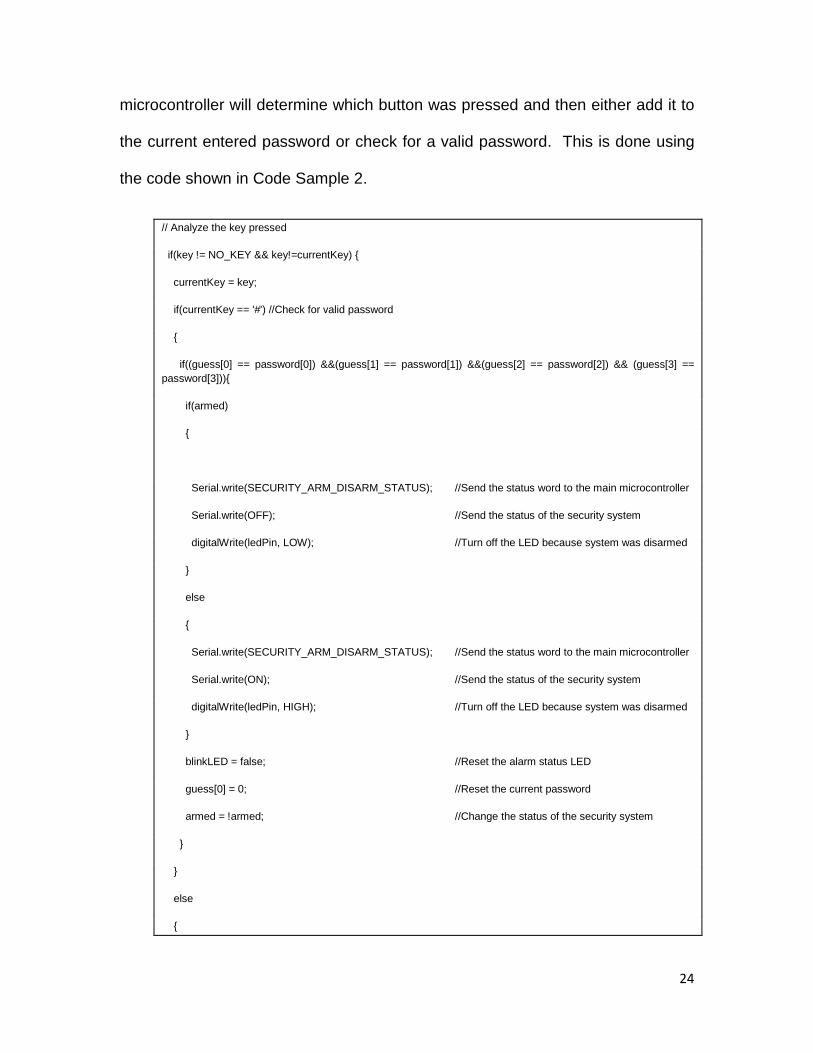
24
microcontroller will determine which button was pressed and then either add it to
the current entered password or check for a valid password. This is done using
the code shown in Code Sample 2.
// Analyze the key pressed
if(key != NO_KEY && key!=currentKey) {
currentKey = key;
if(currentKey == '#') //Check for valid password
{
if((guess[0] == password[0]) &&(guess[1] == password[1]) &&(guess[2] == password[2]) && (guess[3] == password[3])){
if(armed)
{
Serial.write(SECURITY_ARM_DISARM_STATUS); //Send the status word to the main microcontroller
Serial.write(OFF); //Send the status of the security system
digitalWrite(ledPin, LOW); //Turn off the LED because system was disarmed
}
else
{
Serial.write(SECURITY_ARM_DISARM_STATUS); //Send the status word to the main microcontroller
Serial.write(ON); //Send the status of the security system
digitalWrite(ledPin, HIGH); //Turn off the LED because system was disarmed
}
blinkLED = false; //Reset the alarm status LED
guess[0] = 0; //Reset the current password
armed = !armed; //Change the status of the security system
}
}
else
{
25
guess[0] = guess[1];
guess[1] = guess[2];
guess[2] = guess[3];
guess[3] = currentKey;
}
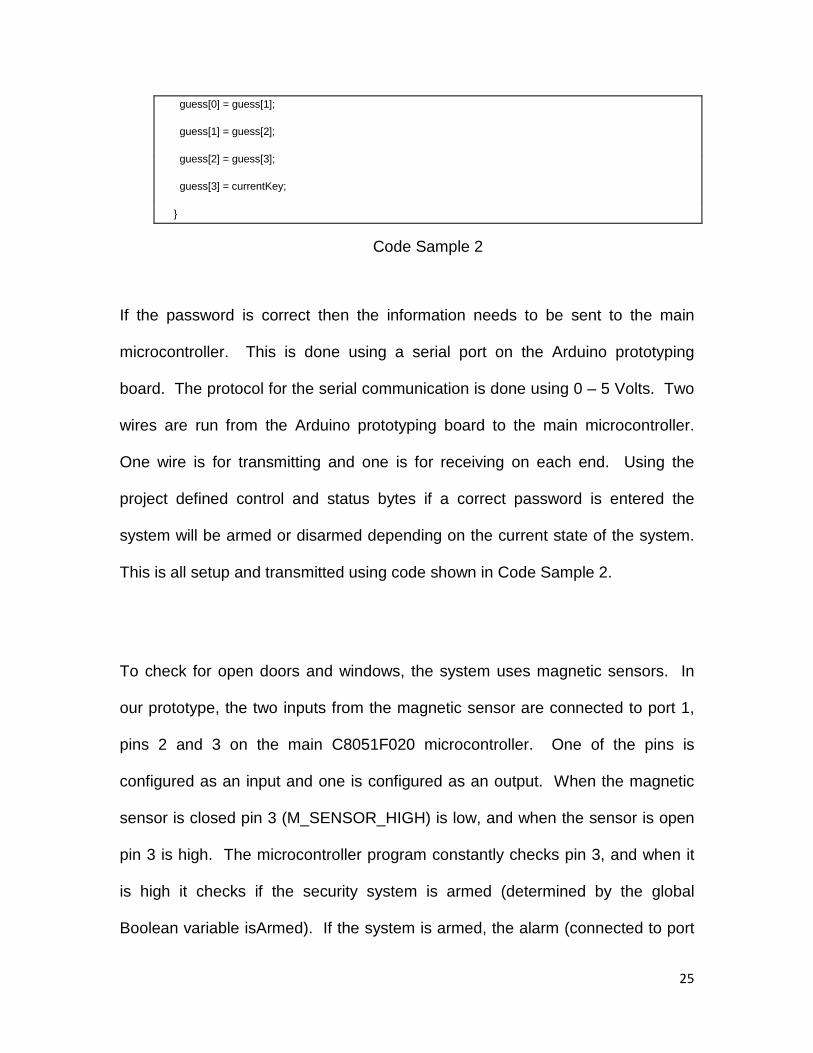
Code Sample 2
If the password is correct then the information needs to be sent to the main
microcontroller. This is done using a serial port on the Arduino prototyping
board. The protocol for the serial communication is done using 0 – 5 Volts. Two
wires are run from the Arduino prototyping board to the main microcontroller.
One wire is for transmitting and one is for receiving on each end. Using the
project defined control and status bytes if a correct password is entered the
system will be armed or disarmed depending on the current state of the system.
This is all setup and transmitted using code shown in Code Sample 2.
To check for open doors and windows, the system uses magnetic sensors. In
our prototype, the two inputs from the magnetic sensor are connected to port 1,
pins 2 and 3 on the main C8051F020 microcontroller. One of the pins is
configured as an input and one is configured as an output. When the magnetic
sensor is closed pin 3 (M_SENSOR_HIGH) is low, and when the sensor is open
pin 3 is high. The microcontroller program constantly checks pin 3, and when it
is high it checks if the security system is armed (determined by the global
Boolean variable isArmed). If the system is armed, the alarm (connected to port

26
3, pin 0) is sounded by sending it a logic high, and status updates are sent to the
sub-control panels and CPU to notify them of the intruder. The C code is shown
in Code Sample 3.
if (M_SENSOR_HIGH == 1) // 0 means the sensors are touching
{
if (isArmed == 1)
{
if (alarmSignalSent == 0)
{
ALARM = 1;
// send status update to GUI
SBUF0 = 0x83;
while (!(SCON0 & 0x2)); // wait until byte is sent
SCON0 &= 0xFD; // clear flag
SBUF0 = 0xFF; // alarm ON
while (!(SCON0 & 0x2)); // wait until byte is sent
SCON0 &= 0xFD; // clear flag
// send status update to other microcontroller
SBUF1 = 0x83;
while (!(SCON1 & 0x2)); // wait until byte is sent
SCON1 &= 0xFD; // clear flag
SBUF1 = 0xFF; // alarm ON
while (!(SCON1 & 0x2)); // wait until byte is sent
SCON1 &= 0xFD; // clear flag
alarmSignalSent = 1;
}

27
}
}
Code Sample 3
To set a new password, the C8051F020 microcontroller must receive the
appropriate control word from the CPU with the graphical user interface. Once
this control word is received, the microcontroller looks for four data bytes that tell
it what the new keycode password is. The password is sent in order with the
most significant numbers first. For example, if the new password was 4-2-5-3,
the microcontroller would receive a 4, then 2, then 5 and finally 3. These
numbers are stored in global variables. When the new password has been
received, the microcontroller sends it in the same fashion as it was received to
the sub-control panels. However, because we received so many errors in our
testing of this feature, we have implemented an error-checking algorithm to
ensure the password is sent properly. Each time the microcontroller sends a
byte, the Arduino prototyping board on the sub-control panel sends the byte back
to confirm that it was received properly. If the microcontroller does not receive
the expected byte, it continues to attempt transmission until it is successful. An
example of this error checking algorithm is shown in Code Sample 4.
//Send first number
dataByte = 0x55;
while(dataByte != codeNum1)
{
SBUF1 = codeNum1; // MSB is set to indicate status
while (!(SCON1 & 0x2)); // wait until byte is sent
SCON1 &= 0xFD; // clear flag

28
// check for garbage
while (!(SCON1 & 0x1)); // wait until byte is ready
dataByte = SBUF1;
SCON1 &= 0xFE; // clear flag
}
Code Sample 4
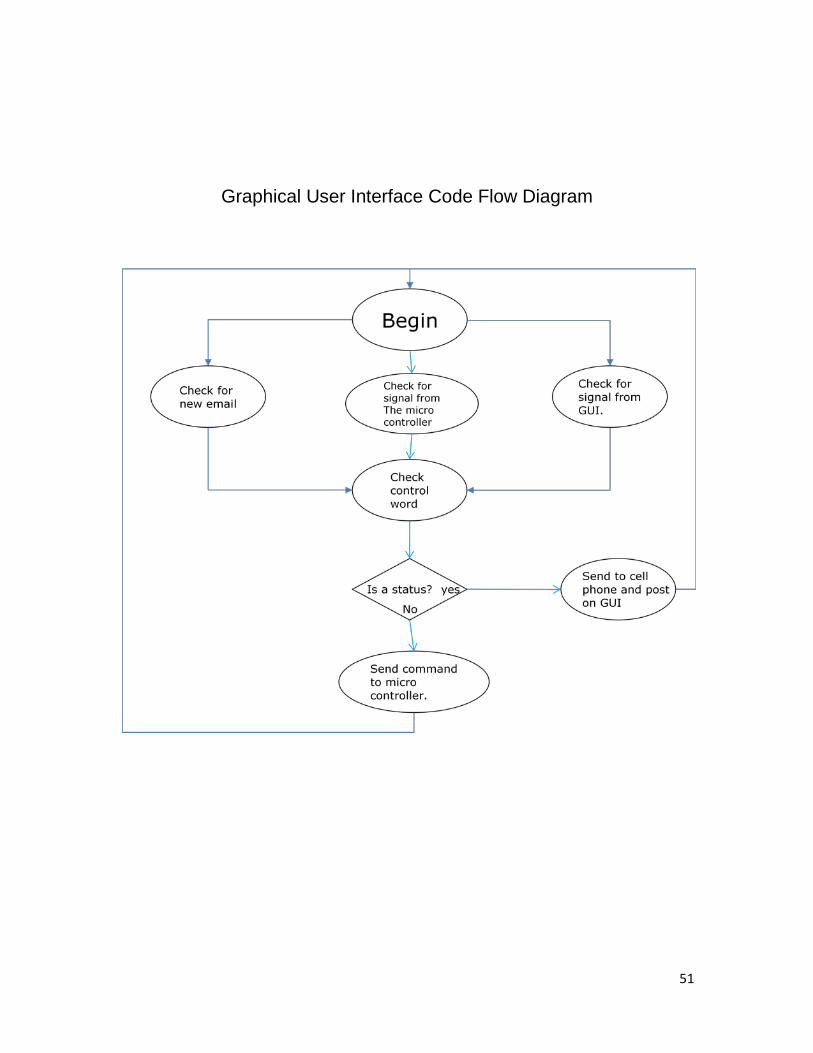
Since the security system is the biggest part of the system, it also is the biggest
part of the GUI. The GUI system is mainly comprised of three main threads. One
thread is constantly checking for input from a text message. One thread handles
any input from the microcontroller. The last thread handles any input from the
GUI form. This allows the GUI to be very responsive and handle any input
received at any time. The security part of the system is comprised of three
different subsystems. One part is the keypad on the Arduino board, another part
is the door, and the third is the alarm. The Arduino board can arm and disarm
the system from the keypad. The GUI can change the keypad password. This is
done by sending an appropriate control word to the microcontroller, then sending
it 4 bytes. These 4 bytes represent the 4 digits of the password.
The next section of the security system handles the door locking and unlocking.
The GUI keeps track of the current state of the door lock. Using the protocol like
the rest of the system, the GUI can lock and unlock the door and receive the
status of the door lock. The homeowner may also control the door lock from a
cell phone.

29
The third final part of the security system is the alarm. This is mainly handled by
the microcontroller. When the microcontroller determines that the alarm should
be sounded, it sends a message to the GUI. The GUI then shows a message
that the alarm has been set off and sends a text message to the homeowner. The
GUI then enables a button that allows the user to turn off the alarm.
Another section of the GUI controls what phone number the text messages go to
on the options page of the GUI. A user may specify the number and the service
provider of the cell phone. This information is stored in an xml file so it may be
saved to the computer.
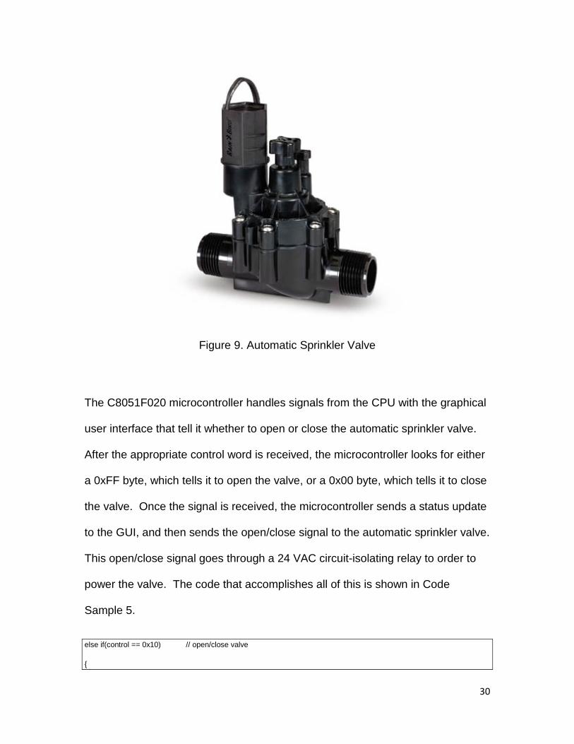
Watering System Solution
To control water flow in this system, our prototype uses an automatic sprinkler
valve like the one shown in Figure 9.
30
Figure 9. Automatic Sprinkler Valve
The C8051F020 microcontroller handles signals from the CPU with the graphical
user interface that tell it whether to open or close the automatic sprinkler valve.
After the appropriate control word is received, the microcontroller looks for either
a 0xFF byte, which tells it to open the valve, or a 0x00 byte, which tells it to close
the valve. Once the signal is received, the microcontroller sends a status update
to the GUI, and then sends the open/close signal to the automatic sprinkler valve.
This open/close signal goes through a 24 VAC circuit-isolating relay to order to
power the valve. The code that accomplishes all of this is shown in Code
Sample 5.
else if(control == 0x10) // open/close valve
{
31
// get "on/off" byte
while (!(SCON0 & 0x1)); // wait until byte is ready
SCON0 &= 0xFE; // clear flag
dataByte = SBUF0;
if (dataByte) // close valve
{
VALVE = 0;
// send status update to GUI
SBUF0 = 0x90; // MSB is set to indicate status
while (!(SCON0 & 0x2)); // wait until byte is sent
SCON0 &= 0xFD; // clear flag
SBUF0 = 0x0; // close
while (!(SCON0 & 0x2)); // wait until byte is sent
SCON0 &= 0xFD; // clear flag
}
else // open valve
{
VALVE = 1;
// send status update to GUI
SBUF0 = 0x90; // MSB is set to indicate status
while (!(SCON0 & 0x2)); // wait until byte is sent
SCON0 &= 0xFD; // clear flag
SBUF0 = 0xFF; // open
while (!(SCON0 & 0x2)); // wait until byte is sent
SCON0 &= 0xFD; // clear flag
}
}

32
Code Sample 5
The GUI interface allows the homeowner to directly interact with the
sprinkler system. Different zones can be set up; each zone has the option
to have a start time and a duration time. When a signal is received from
the microcontroller the GUI is always looking for a control byte that
corresponds to the sprinkler system. When it is received, the GUI program
then looks for a data byte, which will let it know if the sprinkler has been
turned on or off (0xFF corresponds to ‘on’, 0x00 corresponds to ‘off).
When the on/off button on the GUI is selected it then sends the correct
control word to let the microcontroller know which zone’s sprinklers will be
triggered, followed by the “on/off” data byte. The automatic sprinkler works
similarly. Every second the GUI checks the current time and compares it
to the time stored in the settings. If these two times are equal then the
program checks to make sure the zone’s current status is off. If it is the
sprinklers will be turned on. After the appropriate amount of time has
elapsed, a signal is sent to the microcontroller to turn the sprinklers off. All
the settings for the sprinkler system are stored in the saved xml file.
Lights System Solution
The light sensing will be done using a simple photocell and a simple circuit
connected to the Arduino prototyping board. The photocell is shown in Figure
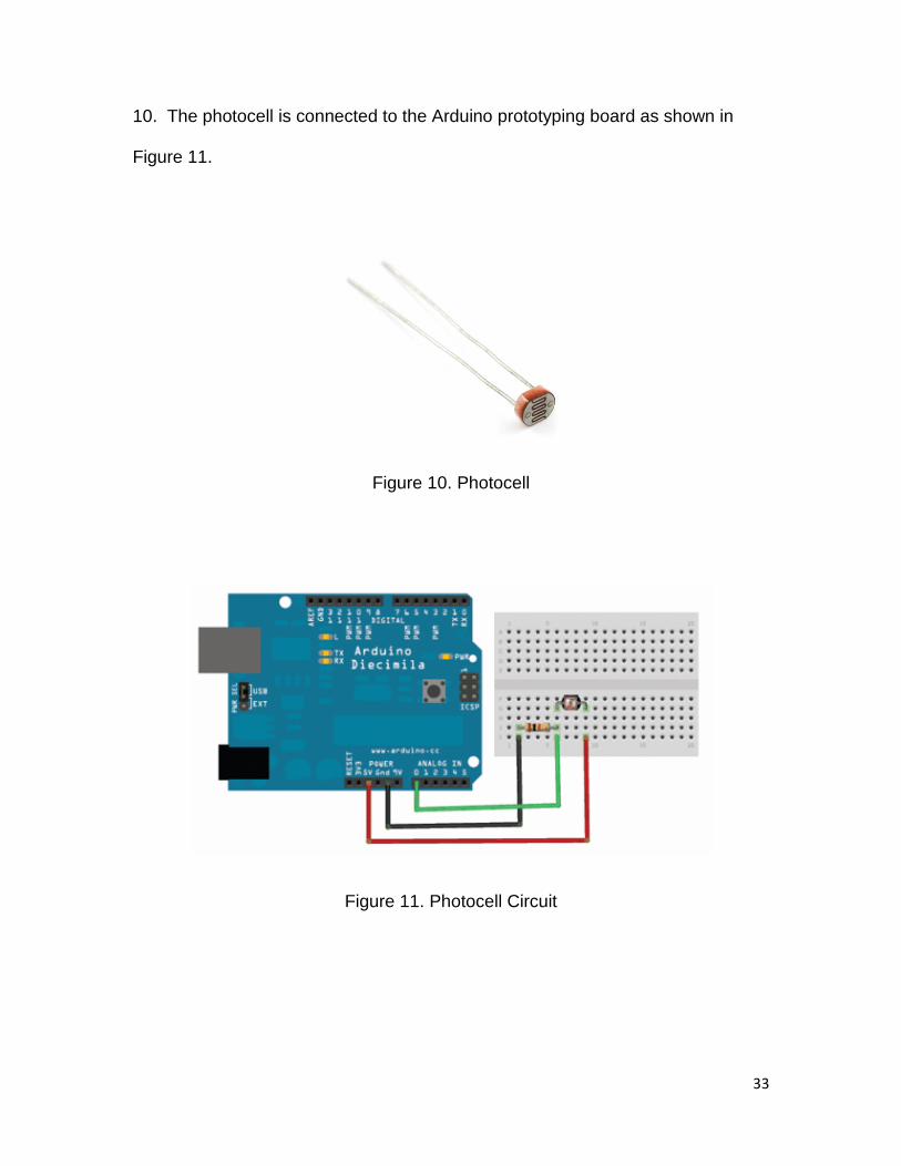
33
10. The photocell is connected to the Arduino prototyping board as shown in
Figure 11.
Figure 10. Photocell
Figure 11. Photocell Circuit
34
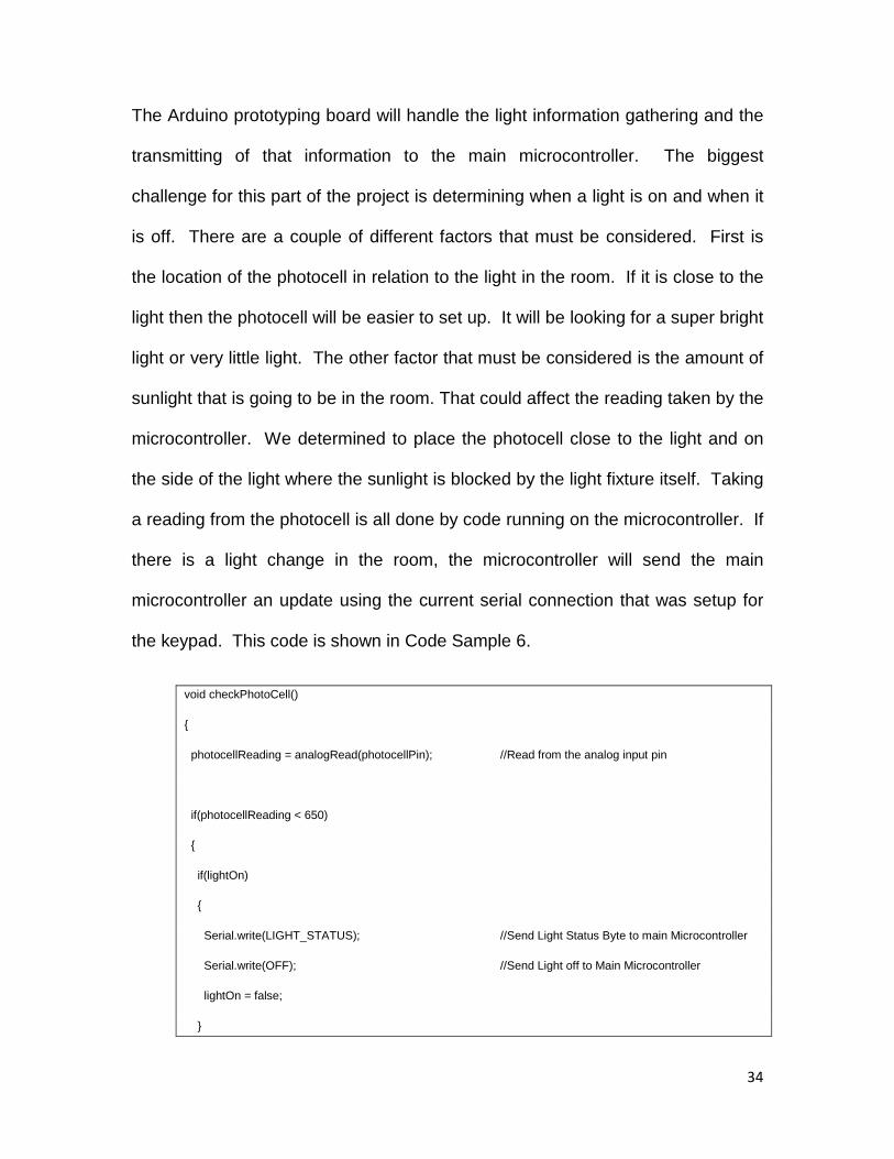
The Arduino prototyping board will handle the light information gathering and the
transmitting of that information to the main microcontroller. The biggest
challenge for this part of the project is determining when a light is on and when it
is off. There are a couple of different factors that must be considered. First is
the location of the photocell in relation to the light in the room. If it is close to the
light then the photocell will be easier to set up. It will be looking for a super bright
light or very little light. The other factor that must be considered is the amount of
sunlight that is going to be in the room. That could affect the reading taken by the
microcontroller. We determined to place the photocell close to the light and on
the side of the light where the sunlight is blocked by the light fixture itself. Taking
a reading from the photocell is all done by code running on the microcontroller. If
there is a light change in the room, the microcontroller will send the main
microcontroller an update using the current serial connection that was setup for
the keypad. This code is shown in Code Sample 6.
void checkPhotoCell()
{
photocellReading = analogRead(photocellPin); //Read from the analog input pin
if(photocellReading < 650)
{
if(lightOn)
{
Serial.write(LIGHT_STATUS); //Send Light Status Byte to main Microcontroller
Serial.write(OFF); //Send Light off to Main Microcontroller
lightOn = false;
}

35
}
else
{
if(!lightOn)
{
Serial.write(LIGHT_STATUS); //Send Light Status Byte to main microcontroller
Serial.write(ON); //Send light on to main microcontroller
lightOn = true;
}
}
}
Code Sample 6
When the main C8051F020 microcontroller receives an update about the lights
from the Arduino board, it must determine whether to turn the light on or off. It
uses the light switch status (on or off) with the incoming signal to determine this.
If the light switch is off, the light stays off no matter what the signal is. However,
if the light switch is on, the signal is able to turn the light on or off. After the
microcontroller determines whether to turn the light on or off, a status update is
sent to the CPU with the graphical user interface. The C code that accomplishes
all of this is shown below in Code Sample 7. In the code, the LIGHT_INPUT
variable refers to the light switch status (wired to port 1, pin 4), and the
LIGHT_OUTPUT variable refers to the light itself (whether it is on or off). The
light is wired to port 1, pin 5 and the signal from the microcontroller passes
through a relay circuit in order to power the light bulb.
// get "on/off" byte

36
while (!(SCON1 & 0x1)); // wait until byte is ready
SCON1 &= 0xFE; // clear flag
dataByte = SBUF1;
dataByte = (dataByte & 0xFE);
if (dataByte) // mc light signal on
{
lightOn = 1;
}
else
{
lightOn = 0;
}
if (LIGHT_INPUT == 1 && lightOn == 1)
{
LIGHT_OUTPUT = 1;
// send status update to GUI
SBUF0 = 0xA0; // MSB is set to indicate status
while (!(SCON0 & 0x2)); // wait until byte is sent
SCON0 &= 0xFD; // clear flag
SBUF0 = 0xFF; // light on
while (!(SCON0 & 0x2)); // wait until byte is sent
SCON0 &= 0xFD; // clear flag
}
else
{
LIGHT_OUTPUT = 0;
// send status update to GUI

37
SBUF0 = 0xA0; // MSB is set to indicate status
while (!(SCON0 & 0x2)); // wait until byte is sent
SCON0 &= 0xFD; // clear flag
SBUF0 = 0x0; // light off
while (!(SCON0 & 0x2)); // wait until byte is sent
SCON0 &= 0xFD; // clear flag
}
Code Sample 7
The GUI handles the light system similarly to the way it handles the sprinkler
system. There are three different methods for turning on/off the lights: Using the
light switch, using the button on the GUI or sending a message from a cell
phone. The feature that differs from the sprinkler system is the ability to turn the
light off from the main switch. The GUI must know when the light switch is on or
off. The micro controller receives a signal directly from the light switch and lets
the GUI know the switch’s status, which is then displayed the GUI. The status of
the lights is saved in to the settings xml file.
Testing
In order to make testing as effective as possible, we decided to test each
individual section separately before we interfaced them all together. This allowed
us to find any bugs we had with ease.
The security system was the biggest of all three systems. We decided to finish
this section first and test it. As mentioned before, this system consists of an

38
electronic door lock, a keypad run by a microcontroller, and a magnetic sensor
that will set off an alarm if triggered while the system is armed. Because there
are a lot of components to this system, it was important that we test each part
individually before we tested them all together. First we tested the door lock.
The lock needed to maintain its original operation and also needed to work with
our system. We connected the door lock and the GUI (using a serial cable) to
the C8051F020 microcontroller. Using this configuration, we performed tests to
make sure that the door could be unlocked both by a signal from the GUI and
from the electronic door lock. At times the keypad would not work. We fiddled
around with the electronics and realized that one of the chips in our door lock
circuitry had come loose. We secured the chip and retested the lock
successfully.
After we were sure everything worked as planned we moved on to the keypad
(which is controlled by the Arduino micro controller). This keypad allows the
homeowner to arm and disarm the system from different locations other then the
central unit. The testing of the keypad was done in two separate parts. The first
part was to test the keypad alone on the Arduino board. We wanted the keypad
to accept a 4 digit key code and, when the correct code is typed in, to arm and
disarm the system. To test this we turned on an LED on the board when the
system was armed. After all the testing on the Arduino board was finished, we
hooked the system to the main micro controller and started testing the
communication between the two systems. This part of the testing proved to be a

39
little more difficult. We started testing by having the microcontroller send a 4 digit
key code to the Arduino board using the protocol we had previously come up
with. The Arduino was programmed to take the code, store it, and use it later to
compare if any code was typed in. After testing we found some bugs in both
sides of the code where the serial communication was off and not all the data
was being transferred correctly. Most of our problems spawned from bad
communication. The separate programs were not accepting and receiving
signals at the correct times. After some fixes and code changes we got the main
microcontroller and the Arduino to communicate correctly.
The last section of the security system that we tested was the GUI. We needed to
make sure that the communication between the GUI and the rest of the security
system was working correctly. The GUI acts as the central command. This
allows a user to control all parts of the system, so this was a very important part
to test. The first test we performed was to make sure that the main
microcontroller could receive all commands from the computer over the serial
port. We tested this by setting breakpoints in the microcontroller code and
seeing when bytes were being received. We found a few minor bugs that dealt
with timing and making sure we were sending and receiving the right amount of
bytes. After all these separate pieces were tested successfully we hooked the
GUI up to the main microcontroller and the main microcontroller up to the Arduino
board. We ran all the same tests that we ran on the separate systems, making
sure that we could set a new keycode password, disarm and arm the system,
40
turn off the alarm after it had been sounded, and lock and unlock the doors all
from the GUI. All these tests passed, which was mainly due to the fact that they
were all tested separately first.
The remaining systems left to test were the sprinkler and light system. These
systems were a lot easier to test since all of the communication had already been
tested. We hooked up the systems to the micro controller and ensured these
systems acted as planned. All of the tests passed successfully.
Reflections
The Home Automation System is a state of the art system that combines existing
home automation systems into one, simplified system. After the testing of the
system we discovered its possibilities. One of its major advantages is
expandability. Although our current system only demonstrates three systems, it
is capable of handling more. We felt that the three systems we chose for this
project successfully demonstrated its capabilities.
Technical Challenges
During the creation of our project we ran into a few different technical problems.
The first problem we ran into with the automatic door lock. We used an already
manufactured automatic door lock which came with no documentation. In order
for it to work with our system we had to take it apart and learn how it worked.
The biggest problem was that it needed to work like it was designed as well. To

41
overcome this challenge we designed a circuit to allow the lock to accept a signal
from our microcontroller as well a signal from the keypad on the lock itself.
The next challenge we encountered was with the serial communication between
the main microcontroller board and the Arduino micro controller. We ran into a
problem when we were trying to send multiple bytes at once. The bytes that we
sent and the bytes that we received were different. The hard part about solving
this problem was that the Arduino board didn't have a way to debug or set
breakpoints in the code, so we had a hard time knowing what bytes it was
actually receiving. We overcame this challenge by tracing our code on both
sides and making sure that the boards were communicating properly. After going
through our code we discovered a few bugs, fixed them, and re-tested our code.
After doing this we came up code that worked.
Another problem we encountered concerned how we were going to demonstrate
the project. We needed a way to demonstrate the operation of all the systems in
an easy and efficient way. We decided to build a mock display that includes a
door that on which we mounted the electronic door lock and the magnetic sensor,
and a wall with a light switch and light socket. To demonstrate the sprinkler
system we connected the sprinkler valve to PVC pipes between two buckets.
One of these buckets holds water, and when the valve is opened, the water
drains into the other (empty) bucket. We feel that this system will clearly
demonstrate all the systems in a clear and efficient way.
42
Project Management
The Home Automation System required some careful planning and designing to
be able to complete the project on time. The different interfaces for each
individual system had to be taken into account and considered as the Home
Automation System was planned out. Each team member was required to put
for their best effort to be able to complete the project according to the
requirements set forth.
Personnel
This project was created by team members Jake Erramouspe, Steven Yeip, Brad
Donohoo, and Jacob Child. As a team we were all involved in the planning,
design and implementation of the Home Automation System. Each member of
the team was able to contribute a specific part to the project according to their set
of skills. Jake Erramouspe took the role of the lead electrical engineer. He was
able to oversee and contribute to the design and implementation of the circuits
that were built for the project. He supervised the use of different types of
interfacing from the sensors and relays to the computers and microcontrollers.
Brad Donohoo was able to lead out in the design and creation of the
documentation for the project. He was able to maintain and control each of the
documents that were created by the team. Brad was also able to design and
implement most of the code for the 8051 microcontroller. Steven Yeip took the

43
lead in the design and implementation of the GUI. He was also a part of the
system design and documentation team. Jacob Child was the designer and
implementer of the remote keypad control system. He was the programmer for
the Arduino microcontroller. He also took the lead in the design and
implementation of the display for the final project presentation.
Brad, Jacob and Steven are using the HAS as their senior design project at Utah
State University in the Electrical and Computer Engineering Department. Well
over 300 hours have been spent in the design, implementation, testing, and
presenting of this project.
Costs
The project started with a budget of $800 dollars for all material and software
costs. Both the C8051F020 microcontroller and the Arduino board were donated
by members of the group. There were several purchases that needed to be
made for the project. The breakout is as follows
• H-bridge chip: $4.88 • Light sensing light switch $15.97 • Automatic sprinkler valve: $7.73 • 12-button keypad: $6.00 • Electronic dead bolt: $33.95 • Misc. circuit items: $10.00 • Total Cost: 78.53

44
This puts our remaining budget at $721.47. We spent a little less than $100
dollars, which is well under the $800 budget we had at the beginning of the
project. A lot of the supplies we used like wires, computers, the main
microcontroller board, and the final display parts were donated. The team
members made these donations from their personal stock. This helped to keep
the cost of the project to a minimum.
Timeline
To keep track of the project schedule, a Gantt chart and Pert chart were used.
These charts were also used to help divide up the different tasks involved in the
project. The Gantt chart is most helpful for seeing each project broken down into
a schedule. Each piece of each system is listed along with a proposed time to
complete. The team was able to stay fairly close to the schedule depicted in the
Gantt chart. The Pert chart shows the systems as a whole and their schedules.
The Pert chart corresponds directly with the Gantt chart. The charts are shown
below in Figures 12 and 13.

45
Figure 12. Gantt Chart

46
Figure 13. Pert Chart

47
Conclusion
This report was created to explain the details of the engineering design and creation of
the Home Automation System. The Home Automation System is an efficient way to
unify several different systems that would be in a normal home. By combining the
several different systems into one system, it allows the homeowner to monitor and
control each system from a single location. The system also allows for remote
monitoring and controlling of each system from a cell phone using text messages. By
allowing control from a remote location, the homeowner may be notified of any activity
at their house and can even control some aspects of the system’s functionality.
This project shows how easy it can be to unify different systems and how inexpensive it
can be. This is important for the general public as the population increases, the need to
conserve energy will also increase. The Home Automation System can help to conserve
electricity and water usage as it allows the user to turn lights and water off if they are
away and they aren’t needed. Security is also becoming an issue in the world. By
combining a security system with a remote monitoring system, the homeowner can be
notified of events that happen when they are away. By integrating these energy saving
ideas with a security system into one project, the perception of the common
homeowner will be changed for the better.

48
Appendix A: Code Flow Diagrams
49
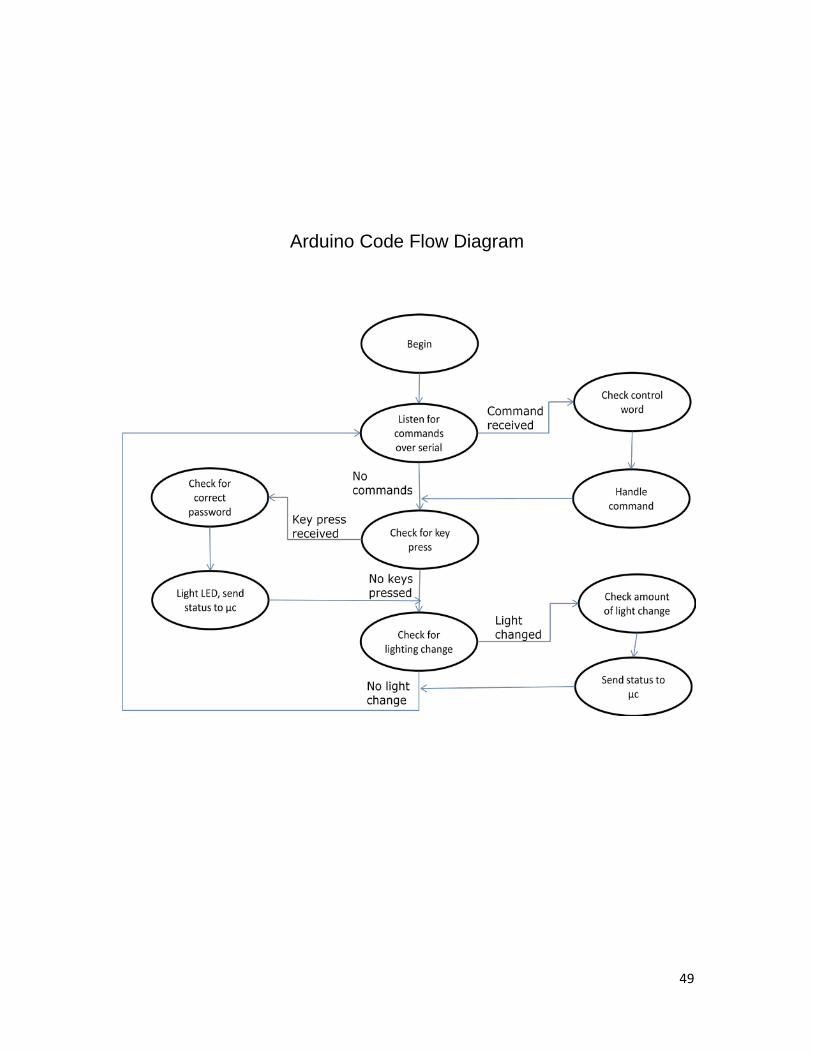
Arduino Code Flow Diagram
50
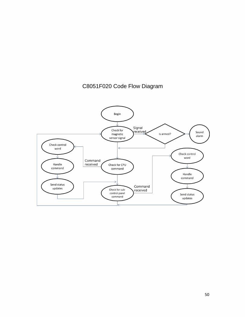
C8051F020 Code Flow Diagram
51
Graphical User Interface Code Flow Diagram

52
Appendix B: Program Code
53
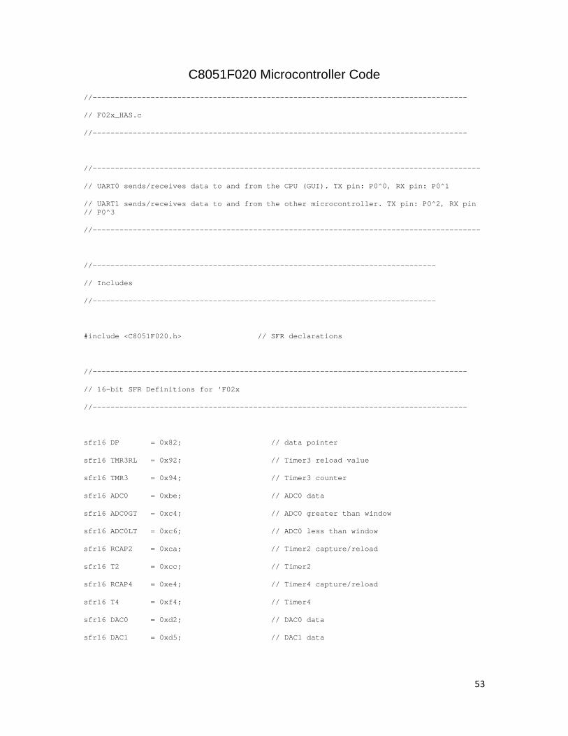
C8051F020 Microcontroller Code //------------------------------------------------------------------------------------
// F02x_HAS.c
//------------------------------------------------------------------------------------
//---------------------------------------------------------------------------------------
// UART0 sends/receives data to and from the CPU (GUI). TX pin: P0^0, RX pin: P0^1
// UART1 sends/receives data to and from the other microcontroller. TX pin: P0^2, RX pin // P0^3
//---------------------------------------------------------------------------------------
//-----------------------------------------------------------------------------
// Includes
//-----------------------------------------------------------------------------
#include <C8051F020.h> // SFR declarations
//------------------------------------------------------------------------------------
// 16-bit SFR Definitions for 'F02x
//------------------------------------------------------------------------------------
sfr16 DP = 0x82; // data pointer
sfr16 TMR3RL = 0x92; // Timer3 reload value
sfr16 TMR3 = 0x94; // Timer3 counter
sfr16 ADC0 = 0xbe; // ADC0 data
sfr16 ADC0GT = 0xc4; // ADC0 greater than window
sfr16 ADC0LT = 0xc6; // ADC0 less than window
sfr16 RCAP2 = 0xca; // Timer2 capture/reload
sfr16 T2 = 0xcc; // Timer2
sfr16 RCAP4 = 0xe4; // Timer4 capture/reload
sfr16 T4 = 0xf4; // Timer4
sfr16 DAC0 = 0xd2; // DAC0 data
sfr16 DAC1 = 0xd5; // DAC1 data

54
//-----------------------------------------------------------------------------
// Global Constants
//-----------------------------------------------------------------------------
#define BAUDRATE 9600 // Baud rate of UART in bps
#define ESYSCLK (22118400L)
#define SYSCLK 16000000/8 // SYSCLK in Hz (16 MHz internal
// oscillator / 8)
// the internal oscillator has a
// tolerance of +/- 20%
#define TIMER_PRESCALER 12 // Based on TMR3CN settings
#define ISR_RATE 54 // This is 50 milliseconds
// ratio 1.08 (ex. 100 milliseconds = 108)
// There are SYSCLK/TIMER_PRESCALER timer ticks per second, so
// SYSCLK/TIMER_PRESCALER/1000 timer ticks per millisecond.
#define TIMER_TICKS_PER_MS SYSCLK/TIMER_PRESCALER/1000
// Note: ISR_RATE*TIMER_TICKS_PER_MS should not exceed 65535 (0xFFFF)
// for the 16-bit timer
#define AUX1 TIMER_TICKS_PER_MS*ISR_RATE
#define AUX2 -AUX1
#define TIMER3_RELOAD AUX2 // Reload value for Timer3
sbit LED = P1^6; // green LED: '1' = ON; '0' = OFF
sbit LOCK = P0^4; // Port 0 pin 4
sbit UNLOCK = P0^5; // Port 0 pin 5
55
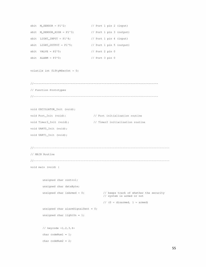
sbit M_SENSOR = P1^2; // Port 1 pin 2 (input)
sbit M_SENSOR_HIGH = P1^3; // Port 1 pin 3 (output)
sbit LIGHT_INPUT = P1^4; // Port 1 pin 4 (input)
sbit LIGHT_OUTPUT = P1^5; // Port 1 pin 5 (output)
sbit VALVE = P2^0; // Port 2 pin 0
sbit ALARM = P3^0; // Port 3 pin 0
volatile int fiftyMSecCnt = 0;
//-----------------------------------------------------------------------------
// Function Prototypes
//-----------------------------------------------------------------------------
void OSCILLATOR_Init (void);
void Port_Init (void); // Port initialization routine
void Timer3_Init (void); // Timer2 initialization routine
void UART0_Init (void);
void UART1_Init (void);
//------------------------------------------------------------------------------------
// MAIN Routine
//------------------------------------------------------------------------------------
void main (void) {
unsigned char control;
unsigned char dataByte;
unsigned char isArmed = 0; // keeps track of whether the security // system is armed or not
// (0 = disarmed, 1 = armed)
unsigned char alarmSignalSent = 0;
unsigned char lightOn = 1;
// keycode <1,2,3,4>
char codeNum1 = 1;
char codeNum2 = 2;

56
char codeNum3 = 3;
char codeNum4 = 4;
// disable watchdog timer
WDTCN = 0xde;
WDTCN = 0xad;
OSCILLATOR_Init (); // Initialize oscillator
UART0_Init (); // Initialize UART0
UART1_Init (); // Initialize UART1
Timer3_Init (); // Initialize Timer3
Port_Init (); // Initialize ports
EA = 1; // enable global interrupts
ALARM = 0;
M_SENSOR_HIGH = 1;
VALVE = 0;
LIGHT_OUTPUT = 0;
while(1)
{
/*
* From magnetic sensor
*/
if (M_SENSOR_HIGH == 1) // 0 means the sensors are touching
{
if (isArmed == 1)
{
if (alarmSignalSent == 0)
{
ALARM = 1;
// send status update to GUI

57
SBUF0 = 0x83;
while (!(SCON0 & 0x2)); // wait until byte is sent
SCON0 &= 0xFD; // clear flag
SBUF0 = 0xFF; // alarm ON
while (!(SCON0 & 0x2)); // wait until byte is sent
SCON0 &= 0xFD; // clear flag
// send status update to other microcontroller
SBUF1 = 0x83;
while (!(SCON1 & 0x2)); // wait until byte is sent
SCON1 &= 0xFD; // clear flag
SBUF1 = 0xFF; // alarm ON
while (!(SCON1 & 0x2)); // wait until byte is sent
SCON1 &= 0xFD; // clear flag
alarmSignalSent = 1;
}
}
}
/*
* From CPU
*/
if(SCON0 & 0x1)
{
// get "control" byte
SCON0 &= 0xFE; // clear interrupt flag
control = SBUF0;
if(control == 0x00) // lock/unlock
{
// get "on/off" byte

58
while (!(SCON0 & 0x1)); // wait until byte is ready
SCON0 &= 0xFE; // clear flag
dataByte = SBUF0;
if (dataByte) // lock
{
UNLOCK = 0;
LOCK = 1;
// time for approx. 700 ms
fiftyMSecCnt = 0;
while (fiftyMSecCnt < 150);
UNLOCK = 0;
LOCK = 0;
// send status update to GUI
SBUF0 = 0x80; // MSB is set to indicate status
while (!(SCON0 & 0x2)); // wait until byte is sent
SCON0 &= 0xFD; // clear flag
// send "on/off" byte to GUI
SBUF0 = 0xFF; // lock
while (!(SCON0 & 0x2)); // wait until byte is sent
SCON0 &= 0xFD; // clear flag
}
else // unlock
{
LOCK = 0;
UNLOCK = 1;
// time for approx. 700 ms
fiftyMSecCnt = 0;

59
while (fiftyMSecCnt < 150);
UNLOCK = 0;
LOCK = 0;
// send status update to GUI
SBUF0 = 0x80; // MSB is set to indicate status
while (!(SCON0 & 0x2)); // wait until byte is sent
SCON0 &= 0xFD; // clear flag
// send "on/off" byte to GUI
SBUF0 = 0x00; // unlock
while (!(SCON0 & 0x2)); // wait until byte is sent
SCON0 &= 0xFD; // clear flag
}
}
else if(control == 0x01) // arm/disarm
{
// get "on/off" byte
while (!(SCON0 & 0x1)); // wait until byte is ready
SCON0 &= 0xFE; // clear flag
dataByte = SBUF0;
if (dataByte) // arm
{
isArmed = 1;
// send status update to GUI
SBUF0 = 0x81; // MSB is set to indicate status
while (!(SCON0 & 0x2)); // wait until byte is sent
SCON0 &= 0xFD; // clear flag

60
// send "on/off" byte to GUI
SBUF0 = 0xFF; // arm
while (!(SCON0 & 0x2)); // wait until byte is sent
SCON0 &= 0xFD; // clear flag
dataByte = 0x55;
while(dataByte != 0x81)
{
SBUF1 = 0x81; // MSB is set to indicate // status
while (!(SCON1 & 0x2)); // wait until byte is sent
SCON1 &= 0xFD; // clear flag
// check for garbage
while (!(SCON1 & 0x1)); // wait until byte is ready
SCON1 &= 0xFE; // clear flag
dataByte = SBUF1;
}
dataByte = 0x55;
while(dataByte != 0xFF)
{
SBUF1 = 0xFF; // arm
while (!(SCON1 & 0x2)); // wait until byte is sent
SCON1 &= 0xFD; // clear flag
// check for garbage
while (!(SCON1 & 0x1)); // wait until byte is ready
SCON1 &= 0xFE; // clear flag
dataByte = SBUF1;
}
}

61
else // disarm
{
isArmed = 0;
ALARM = 0;
alarmSignalSent = 0;
// send status update to GUI
SBUF0 = 0x81; // MSB is set to indicate status
while (!(SCON0 & 0x2)); // wait until byte is sent
SCON0 &= 0xFD; // clear flag
// send "on/off" byte to GUI
SBUF0 = 0x0; // disarm
while (!(SCON0 & 0x2)); // wait until byte is sent
SCON0 &= 0xFD; // clear flag
dataByte = 0x55;
while(dataByte != 0x81)
{
SBUF1 = 0x81; // MSB is set to indicate status
while (!(SCON1 & 0x2)); // wait until byte is sent
SCON1 &= 0xFD; // clear flag
// check for garbage
while (!(SCON1 & 0x1)); // wait until byte is ready
SCON1 &= 0xFE; // clear flag
dataByte = SBUF1;
}
dataByte = 85;
while(dataByte != 0x01)
{
SBUF1 = 0x01; // disarm

62
while (!(SCON1 & 0x2)); // wait until byte is sent
SCON1 &= 0xFD; // clear flag
// check for garbage
while (!(SCON1 & 0x1)); // wait until byte is ready
SCON1 &= 0xFE; // clear flag
dataByte = SBUF1;
}
}
}
else if(control == 0x02) // set new keycode
{
// get keycode bytes in order (most significant first)
while (!(SCON0 & 0x1)); // wait until byte is ready
codeNum1 = SBUF0;
SCON0 &= 0xFE; // clear interrupt flag
while (!(SCON0 & 0x1)); // wait until byte is ready
codeNum2 = SBUF0;
SCON0 &= 0xFE; // clear interrupt flag
while (!(SCON0 & 0x1)); // wait until byte is ready
codeNum3 = SBUF0;
SCON0 &= 0xFE; // clear interrupt flag
while (!(SCON0 & 0x1)); // wait until byte is ready
codeNum4 = SBUF0;
SCON0 &= 0xFE; // clear interrupt flag
/*
* Send new keycode to other microcontroller
63
*/
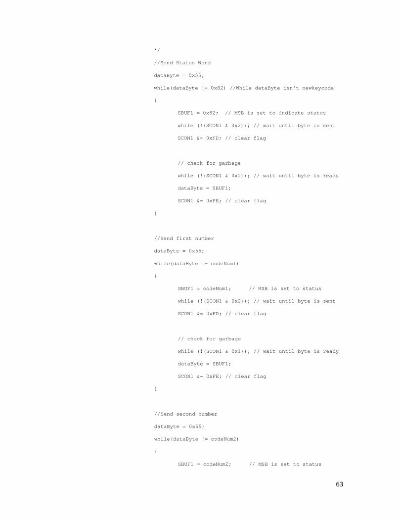
//Send Status Word
dataByte = 0x55;
while(dataByte != 0x82) //While dataByte isn't newkeycode
{
SBUF1 = 0x82; // MSB is set to indicate status
while (!(SCON1 & 0x2)); // wait until byte is sent
SCON1 &= 0xFD; // clear flag
// check for garbage
while (!(SCON1 & 0x1)); // wait until byte is ready
dataByte = SBUF1;
SCON1 &= 0xFE; // clear flag
}
//Send first number
dataByte = 0x55;
while(dataByte != codeNum1)
{
SBUF1 = codeNum1; // MSB is set to status
while (!(SCON1 & 0x2)); // wait until byte is sent
SCON1 &= 0xFD; // clear flag
// check for garbage
while (!(SCON1 & 0x1)); // wait until byte is ready
dataByte = SBUF1;
SCON1 &= 0xFE; // clear flag
}
//Send second number
dataByte = 0x55;
while(dataByte != codeNum2)
{
SBUF1 = codeNum2; // MSB is set to status

64
while (!(SCON1 & 0x2)); // wait until byte is sent
SCON1 &= 0xFD; // clear flag
// check for garbage
while (!(SCON1 & 0x1)); // wait until byte is ready
dataByte = SBUF1;
SCON1 &= 0xFE; // clear flag
}
//Send third number
dataByte = 0x55;
while(dataByte != codeNum3)
{
SBUF1 = codeNum3; // MSB is set to status
while (!(SCON1 & 0x2)); // wait until byte is sent
SCON1 &= 0xFD; // clear flag
// check for garbage
while (!(SCON1 & 0x1)); // wait until byte is ready
dataByte = SBUF1;
SCON1 &= 0xFE; // clear flag
}
//Send fourth number
dataByte = 0x55;
while(dataByte != codeNum4)
{
SBUF1 = codeNum4; // MSB is set to status
while (!(SCON1 & 0x2)); // wait until byte is sent
SCON1 &= 0xFD; // clear flag
// check for garbage
while (!(SCON1 & 0x1)); // wait until byte is ready
dataByte = SBUF1;
65
SCON1 &= 0xFE; // clear flag
}
}
else if(control == 0x03)
{
// get "on/off" byte
while (!(SCON0 & 0x1)); // wait until byte is ready
SCON0 &= 0xFE; // clear flag
dataByte = SBUF0;
if (dataByte)
{
ALARM = 1;
// send status update to GUI
SBUF0 = 0x83;
while (!(SCON0 & 0x2)); // wait until byte is sent
SCON0 &= 0xFD; // clear flag
SBUF0 = 0xFF; // alarm ON
while (!(SCON0 & 0x2)); // wait until byte is sent
SCON0 &= 0xFD; // clear flag
// send status update to other microcontroller
SBUF1 = 0x83;
while (!(SCON1 & 0x2)); // wait until byte is sent
SCON1 &= 0xFD; // clear flag
SBUF1 = 0xFF; // alarm ON
while (!(SCON1 & 0x2)); // wait until byte is sent
SCON1 &= 0xFD; // clear flag

66
alarmSignalSent = 1;
}
else
{
ALARM = 0;
// send status update to GUI
SBUF0 = 0x83;
while (!(SCON0 & 0x2)); // wait until byte is sent
SCON0 &= 0xFD; // clear flag
SBUF0 = 0; // alarm OFF
while (!(SCON0 & 0x2)); // wait until byte is sent
SCON0 &= 0xFD; // clear flag
// send status update to other microcontroller
SBUF1 = 0x83;
while (!(SCON1 & 0x2)); // wait until byte is sent
SCON1 &= 0xFD; // clear flag
SBUF1 = 0; // alarm OFF
while (!(SCON1 & 0x2)); // wait until byte is sent
SCON1 &= 0xFD; // clear flag
alarmSignalSent = 0;
}
}
else if(control == 0x10) // open/close valve
{
// get "on/off" byte
while (!(SCON0 & 0x1)); // wait until byte is ready
SCON0 &= 0xFE; // clear flag
67
dataByte = SBUF0;
if (dataByte) // open valve
{
VALVE = 1;
// send status update to GUI
SBUF0 = 0x90; // MSB is set to indicate status
while (!(SCON0 & 0x2)); // wait until byte is sent
SCON0 &= 0xFD; // clear flag
SBUF0 = 0xFF; // open
while (!(SCON0 & 0x2)); // wait until byte is sent
SCON0 &= 0xFD; // clear flag
}
else // close valve
{
VALVE = 0;
// send status update to GUI
SBUF0 = 0x90; // MSB is set to indicate status
while (!(SCON0 & 0x2)); // wait until byte is sent
SCON0 &= 0xFD; // clear flag
SBUF0 = 0x00; // close
while (!(SCON0 & 0x2)); // wait until byte is sent
SCON0 &= 0xFD; // clear flag
}
}
else if(control == 0x20) // turn light on/off
{
// get "on/off" byte
while (!(SCON0 & 0x1)); // wait until byte is ready

68
SCON0 &= 0xFE; // clear flag
dataByte = SBUF0;
if (dataByte) // mc light signal on
{
lightOn = 1;
}
else
{
lightOn = 0;
}
if (LIGHT_INPUT == 1 && lightOn == 1)
{
LIGHT_OUTPUT = 1;
// send status update to GUI
SBUF0 = 0xA0; // MSB is set to indicate status
while (!(SCON0 & 0x2)); // wait until byte is sent
SCON0 &= 0xFD; // clear flag
SBUF0 = 0xFF; // light on
while (!(SCON0 & 0x2)); // wait until byte is sent
SCON0 &= 0xFD; // clear flag
}
else
{
LIGHT_OUTPUT = 0;
// send status update to GUI
SBUF0 = 0xA0; // MSB is set to indicate status
while (!(SCON0 & 0x2)); // wait until byte is sent
SCON0 &= 0xFD; // clear flag

69
SBUF0 = 0x0; // light off
while (!(SCON0 & 0x2)); // wait until byte is sent
SCON0 &= 0xFD; // clear flag
}
}
control = 0xFF;
dataByte = 0xFF;
}
/*
* From other microcontroller
*/
if(SCON1 &0x1)
{
// get "control" byte
control = SBUF1;
SCON1 &= 0xFE; // clear interrupt flag
if(control == 0x81) // arm/disarm
{
// get "on/off" byte
while (!(SCON1 & 0x1)); // wait until byte is ready
dataByte = SBUF1;
SCON1 &= 0xFE; // clear flag
dataByte = (dataByte & 0xFE);
if (dataByte) // arm
{
isArmed = 1;
// send status update to GUI

70
SBUF0 = 0x81; // MSB is set to indicate status
while (!(SCON0 & 0x2)); // wait until byte is sent
SCON0 &= 0xFD; // clear flag
// send "on/off" byte to GUI
SBUF0 = 0xFF; // arm
while (!(SCON0 & 0x2)); // wait until byte is sent
SCON0 &= 0xFD; // clear flag
}
else // disarm
{
isArmed = 0;
ALARM = 0;
alarmSignalSent = 0;
// send status update to GUI
SBUF0 = 0x81; // MSB is set to indicate status
while (!(SCON0 & 0x2)); // wait until byte is sent
SCON0 &= 0xFD; // clear flag
// send "on/off" byte to GUI
SBUF0 = 0x0; // disarm
while (!(SCON0 & 0x2)); // wait until byte is sent
SCON0 &= 0xFD; // clear flag
}
}
else if (control == 0xA0) // light on/off
{
// get "on/off" byte
while (!(SCON1 & 0x1)); // wait until byte is ready
SCON1 &= 0xFE; // clear flag
dataByte = SBUF1;
71
dataByte = (dataByte & 0xFE);
if (dataByte) // mc light signal on
{
lightOn = 1;
}
else
{
lightOn = 0;
}
if (LIGHT_INPUT == 1 && lightOn == 1)
{
LIGHT_OUTPUT = 1;
// send status update to GUI
SBUF0 = 0xA0; // MSB is set to indicate status
while (!(SCON0 & 0x2)); // wait until byte is sent
SCON0 &= 0xFD; // clear flag
SBUF0 = 0xFF; // light on
while (!(SCON0 & 0x2)); // wait until byte is sent
SCON0 &= 0xFD; // clear flag
}
else
{
LIGHT_OUTPUT = 0;
// send status update to GUI
SBUF0 = 0xA0; // MSB is set to indicate status
while (!(SCON0 & 0x2)); // wait until byte is sent
SCON0 &= 0xFD; // clear flag

72
SBUF0 = 0x0; // light off
while (!(SCON0 & 0x2)); // wait until byte is sent
SCON0 &= 0xFD; // clear flag
}
}
control = 0xFF;
dataByte = 0xFF;
}
if (LIGHT_INPUT == 1 && lightOn == 1)
{
// only send status update to GUI once when changed
if (LIGHT_OUTPUT == 0)
{
// send status update to GUI
SBUF0 = 0xA0; // MSB is set to indicate status
while (!(SCON0 & 0x2)); // wait until byte is sent
SCON0 &= 0xFD; // clear flag
SBUF0 = 0xFF; // light on
while (!(SCON0 & 0x2)); // wait until byte is sent
SCON0 &= 0xFD; // clear flag
LIGHT_OUTPUT = 1;
}
}
else
{
// only send status update to GUI once when changed
if (LIGHT_OUTPUT == 1)
{
// send status update to GUI
SBUF0 = 0xA0; // MSB is set to indicate status
while (!(SCON0 & 0x2)); // wait until byte is sent

73
SCON0 &= 0xFD; // clear flag
SBUF0 = 0x0; // light off
while (!(SCON0 & 0x2)); // wait until byte is sent
SCON0 &= 0xFD; // clear flag
LIGHT_OUTPUT = 0;
}
}
}
}
//------------------------------------------------------------------------------------
// PORT_Init
//------------------------------------------------------------------------------------
//
// Configure the Crossbar and GPIO ports
//
void Port_Init (void)
{
XBR2 = 0x44; //01000100 // Enable crossbar, weak pull-ups and uart 1
XBR0 = 0x04; //00000100 // Enable uart 0
P0MDOUT |= 0x3C; //00111100 // enable P0.2 (transmit)
// enable P0.3 (receive)
// enable P0.4 (lock)
// enable P0.5 (unlock)
P1MDOUT |= 0x6B; //01101000 // enable P1.2 as open-drain input (M_SENSOR)
// enable P1.3 as push_pull output (M_SENSOR_HIGH)
// enable P1.4 as open-drain input (light input)
// enable P1.5 as push_pull output (light output)
// enable P1.6 as push-pull output (LED)
P2MDOUT |= 0x01; //00000001 // enable P2.0 (valve)
P3MDOUT |= 0x01; //00000001 // enable P3.0 (alarm)

74
P1MDIN |= 0x14; //00010100 // enable P1.2 as input (M_SENSOR)
// enable P1.4 as input (light input)
P1 = 0x00;
}
//-----------------------------------------------------------------------------
// Timer3_Init
//-----------------------------------------------------------------------------
//
// Return Value : None
// Parameters : None
//
// This function configures Timer3 as a 16-bit reload timer, interrupt enabled.
// Using the SYSCLK at 16MHz/8 with a 1:12 prescaler.
//
// Note: The Timer3 uses a 1:12 prescaler. If this setting changes, the
// TIMER_PRESCALER constant must also be changed.
//-----------------------------------------------------------------------------
void Timer3_Init(void)
{
TMR3RL = TIMER3_RELOAD; // Timer3 reload value
TMR3 = TMR3RL; // Initialize the timer
TMR3CN = 0x04; // Timer3 uses SYSCLK/12
EIE2 |= 0x01; // Timer3 interrupt enabled
}
//-----------------------------------------------------------------------------
// Interrupt Service Routines
//-----------------------------------------------------------------------------

75
//-----------------------------------------------------------------------------
// Timer3_ISR
//-----------------------------------------------------------------------------
//
// Here we process the Timer3 interrupt
//
//-----------------------------------------------------------------------------
void Timer3_ISR (void) interrupt 14
{
fiftyMSecCnt++;
TMR3CN &= ~0x80; // Reset Interrupt
}
//-----------------------------------------------------------------------------
// OSCILLATOR_Init
//-----------------------------------------------------------------------------
//
// Return Value : None
// Parameters : None
//
// This function initializes the system clock to use the external 22.1184MHz
// crystal.
//
//-----------------------------------------------------------------------------
void OSCILLATOR_Init (void)
{
int i; // Software timer
OSCICN |= 0x80; // Enable the missing clock detector
// Initialize external crystal oscillator to use 22.1184 MHz crystal
76
OSCXCN = 0x67; // Enable external crystal osc.
for (i=0; i < 256; i++); // Wait at least 1ms
while (!(OSCXCN & 0x80)); // Wait for crystal osc to settle
OSCICN |= 0x08; // Select external clock source
OSCICN &= ~0x04; // Disable the internal osc.
}
//-----------------------------------------------------------------------------
// UART0_Init Variable baud rate, Timer 2, 8-N-1
//-----------------------------------------------------------------------------
//
// Return Value : None
// Parameters : None
//
// Configure UART0 for operation at <baudrate> 8-N-1 using Timer2 as
// baud rate source.
//
//-----------------------------------------------------------------------------
void UART0_Init (void)
{
CKCON |= 0x20; // Timer2 uses the system clock
T2CON = 0x34; // Timer2 used for TX and RX, enabled
RCAP2 = 65536 - (ESYSCLK/32/BAUDRATE);
T2 = RCAP2;
SCON0 = 0x50; // 8-bit variable baud rate;
// 9th bit ignored; RX enabled
// clear all flags
}
//-----------------------------------------------------------------------------
// UART1_Init

77
//-----------------------------------------------------------------------------
//
// Return Value : None
// Parameters : None
//
// Configure the UART1 using Timer4
//-----------------------------------------------------------------------------
void UART1_Init (void)
{
CKCON |= 0x40; // Timer4 uses the system clock
T4CON = 0x34; // Timer4 used for TX and RX, enabled
RCAP4 = 65536 - (ESYSCLK/32/BAUDRATE);
T4 = RCAP4;
SCON1 = 0x50; // 8-bit variable baud rate;
// 9th bit ignored; RX enabled
// clear all flags
}
//-----------------------------------------------------------------------------
// End Of File
//-----------------------------------------------------------------------------

78
GUI Code
using System; using System.Collections.Generic; using System.ComponentModel; using System.Data; using System.Drawing; using System.Linq; using System.Text; using System.Windows.Forms; using System.Xml; using OpenPOP.POP3; using System.Net.Mail; using System.Net; using System.Threading; namespace HAS { public partial class Form1 : Form { public SmtpClient mailClient; static public XmlDocument settings = new XmlDocument(); static public string currentWaterZone = string.Empty; static public string currentRoom = string.Empty; static public string filePath = "Settings.xml"; public delegate void AddStatus(string system, string message, string area); public delegate void ArmButton(); public delegate void WaterButton(); public delegate void LightsButton(); public delegate void LockButton(); public delegate void AutoWater(); public delegate void AutoDoor(); public delegate void AutoLight(); public delegate void AutoArm(); public AutoWater autoWaterDelegate; public AutoDoor autoDoorDelegate; public AutoLight autoLightDelegate; public AutoArm autoArmDelegate; public WaterButton waterButtonDelegate; public ArmButton armButtonDelegate; public AddStatus statusDelegate; public LightsButton lightButtonDelegate; public LockButton lockButtonDelegate; public bool autoOff = false; public bool autoOn = false; public string textAddress; public string KEYCODE; public bool permission = true; public bool changed = false; public Form1() { InitializeComponent(); statusDelegate = new AddStatus(RecordStatus);

79
armButtonDelegate = new ArmButton(ArmDisarmUpdate); waterButtonDelegate = new WaterButton(WaterStatusChange); lightButtonDelegate = new LightsButton(LightStatusChange); lockButtonDelegate = new LockButton(LockUpdate); autoWaterDelegate = new AutoWater(AutoWaterChange); autoDoorDelegate = new AutoDoor(AutoDoorChange); autoLightDelegate = new AutoLight(AutoLightChange); autoArmDelegate = new AutoArm(AutoArmChange); mailClient = new SmtpClient("smtp.gmail.com"); } private void Form1_Load(object sender, EventArgs e) { updateZones(); updateRooms(); microPort.Open(); bindProviderComboBox(); portThread.RunWorkerAsync(); emailThread.RunWorkerAsync(); backgroundWorker1.RunWorkerAsync(); string providerString = settings.SelectSingleNode("//Text/Provider").InnerText; textAddress = settings.SelectSingleNode("//Text/Number").InnerText + settings.SelectSingleNode("//Providers/Provider[@Name='" + providerString + "']").Attributes["Code"].Value; mailClient.Credentials = new NetworkCredential("usuhomesystem", "haspassword"); mailClient.EnableSsl = true; } private void bindProviderComboBox() { string phoneNumber = settings.SelectSingleNode("//Text/Number").InnerText; string phoneProvider = settings.SelectSingleNode("//Text/Provider").InnerText; tbCellPhoneNumber.Text = phoneNumber; XmlNodeList providers = settings.SelectNodes("//Providers/Provider"); foreach (XmlNode provider in providers) { cbProviders.Items.Add(provider.Attributes["Name"].InnerText); } cbProviders.Text = phoneProvider; } private void updateRooms() {

80
lvLight.Items.Clear(); settings.Load(filePath); //tbKeycode.Text = settings.SelectSingleNode("//KeyCode").InnerText; //tbStartTime.Text = settings.SelectSingleNode("//StartTime").InnerText; //tbDuration.Text = settings.SelectSingleNode("//Duration").InnerText; //cbDelayTime.SelectedItem = settings.SelectSingleNode("//DelayTime").InnerText; lblDoorStatus.Text = settings.SelectSingleNode("//DoorStatus").InnerText; XmlNodeList lightRooms = settings.SelectNodes("//Room"); foreach (XmlNode room in lightRooms) { ListViewItem lvi = new ListViewItem(room.Attributes["Name"].Value); lvi.SubItems.Add(room.ChildNodes[1].InnerText); lvi.SubItems.Add(room.ChildNodes[0].InnerText); lvLight.Items.Add(lvi); } } private void deleteZone(string zone) { XmlNode zoneNode = settings.SelectSingleNode("//Zone[@Name='" + zone + "']"); XmlNode water = settings.SelectSingleNode("//Water"); water.RemoveChild(zoneNode); Thread.BeginCriticalRegion(); settings.Save(filePath); Thread.EndCriticalRegion(); } private void deleteRoom(string room) { XmlNode roomNode = settings.SelectSingleNode("//Room[@Name='" + room + "']"); XmlNode lights = settings.SelectSingleNode("//Lights"); lights.RemoveChild(roomNode); Thread.BeginCriticalRegion(); settings.Save(filePath); Thread.EndCriticalRegion(); } private void updateZones() { lvWater.Items.Clear(); settings.Load(filePath); tbKeyCode.Text = KEYCODE = settings.SelectSingleNode("//KeyCode").InnerText; //tbStartTime.Text = settings.SelectSingleNode("//StartTime").InnerText; //tbDuration.Text = settings.SelectSingleNode("//Duration").InnerText; //cbDelayTime.SelectedItem = settings.SelectSingleNode("//DelayTime").InnerText;

81
lblDoorStatus.Text = settings.SelectSingleNode("//DoorStatus").InnerText; XmlNodeList waterZones = settings.SelectNodes("//Zone"); foreach (XmlNode zone in waterZones) { ListViewItem lvi = new ListViewItem(zone.Attributes["Name"].Value); lvi.SubItems.Add(zone.ChildNodes[2].InnerText); lvi.SubItems.Add(zone.ChildNodes[0].InnerText); lvi.SubItems.Add(zone.ChildNodes[1].InnerText); lvWater.Items.Add(lvi); } } private void bttnDoor_Click(object sender, EventArgs e) { string doorStatus = settings.SelectSingleNode("//DoorStatus").InnerText; if (doorStatus.Equals("Unlocked")) { DoorLockUnlock(255); } lblDoorStatus.Text = doorStatus; //settings.SelectSingleNode("//DoorStatus").InnerText = doorStatus; //settings.Save(filePath); } private void sendTextStatus(string message) { //mailClient.Send(new MailMessage("[email protected]", textAddress, "Status update", message)); } private void AutoArmChange() { string systemStatus = settings.SelectSingleNode("//SystemStatus").InnerText; if (systemStatus.Equals("Armed")) { //systemStatus = "Disarmed"; ArmDisarmSystem(0); } else if (systemStatus.Equals("Disarmed"))

82
{ //systemStatus = "Armed"; ArmDisarmSystem(255); } } private void bttnSystem_Click(object sender, EventArgs e) { string systemStatus = settings.SelectSingleNode("//SystemStatus").InnerText; string keycode = settings.SelectSingleNode("//KeyCode").InnerText; if (systemStatus.Equals("Armed")) { //systemStatus = "Disarmed"; ArmDisarmSystem(0); } else if (systemStatus.Equals("Disarmed")) { //systemStatus = "Armed"; ArmDisarmSystem(255); } //lblSystemStatus.Text = systemStatus; //settings.SelectSingleNode("//SystemStatus").InnerText = systemStatus; //settings.Save(filePath); } public void ArmDisarmUpdate() { string systemStatus = settings.SelectSingleNode("//SystemStatus").InnerText; string keycode = settings.SelectSingleNode("//KeyCode").InnerText; //if (systemStatus.Equals("Armed")) //{ // systemStatus = "Disarmed"; //} //else if (systemStatus.Equals("Disarmed")) //{ // systemStatus = "Armed"; //} lblSystemStatus.Text = systemStatus; //settings.SelectSingleNode("//SystemStatus").InnerText = systemStatus; //settings.Save(filePath); // RecordStatus("Security","The system is now " + systemStatus,""); //sendTextStatus("The security system is now " + systemStatus);

83
} public void LockUpdate() { string doorStatus = settings.SelectSingleNode("//DoorStatus").InnerText; //if (doorStatus.Equals("Locked")) //{ // doorStatus = "Unlocked"; //} //else if (doorStatus.Equals("Unlocked")) //{ // doorStatus = "Locked"; //} lblDoorStatus.Text = doorStatus; //settings.SelectSingleNode("//DoorStatus").InnerText = doorStatus; //settings.Save(filePath); } private void ArmDisarmSystem(int command) { byte[] controlData = new byte[2]; controlData[0] = (byte)1;//1 for the command of security system arm/disarm controlData[1] = (byte)command;//status 255 arm 0 disarm if (!microPort.IsOpen) microPort.Open(); microPort.Write(controlData, 0, 2); } private void DoorLockUnlock(int status) { byte[] controlData = new byte[2]; // [0] is the control // [1] is the data controlData[0] = (byte)0; controlData[1] = (byte)status; if (!microPort.IsOpen) microPort.Open(); microPort.Write(controlData, 0, 2); } private void DisableAlarm() { byte[] controlData = new byte[2]; controlData[0] = (byte)3; controlData[1] = (byte)0; if (!microPort.IsOpen) microPort.Open(); microPort.Write(controlData, 0, 2);

84
} private void LightsOffOn(int status,byte room) { byte[] controlData = new byte[3]; // [0] is the control // [1] status (on/off) // [2] which room controlData[0] = (byte)32; controlData[1] = (byte)status; /*TODO: grab a value from the xml of what the value of the room is */ //controlData[2] = room; if (!microPort.IsOpen) microPort.Open(); microPort.Write(controlData, 0, 2); } private void WaterOffOn(int status,byte zone) { byte[] controlData = new byte[3]; //[0] is the control byte //[1] is the data byte //[2] is the zone controlData[0] = (byte)16; controlData[1] = (byte)status; // controlData[2] = zone; if (!microPort.IsOpen) microPort.Open(); microPort.Write(controlData, 0,2); // RecordStatus("Water", "Water is turned on/off", zone.ToString()); } private void listView1_SelectedIndexChanged(object sender, EventArgs e) { bttnWaterOnOff.Enabled = true; bttnEditZone.Enabled = true; bttnDeleteZone.Enabled = true; //if (lvWater.SelectedItems.Count > 0) currentWaterZone = lvWater.Items[0].Text; } private void pbNewZone_Click(object sender, EventArgs e) { currentWaterZone = string.Empty; WaterSettings ws = new WaterSettings(); ws.Show(); } private void textBox1_KeyDown(object sender, KeyEventArgs e)

85
{ if (e.KeyData == Keys.Enter) { updateZones(); //textBox1.Visible = false; } } private void AutoDoorChange() { string doorStatus = settings.SelectSingleNode("//DoorStatus").InnerText; if (doorStatus.Equals("Unlocked")) { DoorLockUnlock(255); } else if (doorStatus.Equals("Locked")) { DoorLockUnlock(0); } //lblDoorStatus.Text = doorStatus; } private void AutoLightChange() { byte room = 0; string zoneName = lvLight.Items[0].Text; XmlNode zone = settings.SelectSingleNode("//Room[@Name='" + zoneName + "']"); XmlNode status = zone.ChildNodes[1]; room = Convert.ToByte(zone.Attributes["Id"].InnerText); string systemStatus = status.InnerText; if (systemStatus.Equals("On")) { // systemStatus = "Off"; LightsOffOn(0, room); } else if (systemStatus.Equals("Off")) { //systemStatus = "On"; LightsOffOn(255, room); } } private void AutoWaterChange() { byte zoneByte = 0; //if (lvWater.SelectedItems.Count > 0) //{ string zoneName = lvWater.Items[0].Text; XmlNode zone = settings.SelectSingleNode("//Zone[@Name='" + zoneName + "']"); XmlNode status = zone.ChildNodes[2];

86
zoneByte = Convert.ToByte(zone.Attributes["Id"].InnerText); string systemStatus = status.InnerText; if (systemStatus.Equals("On")) { // systemStatus = "Off"; WaterOffOn(0, zoneByte); //status.InnerText = "Off"; } else if (systemStatus.Equals("Off")) { // systemStatus = "On"; WaterOffOn(255, zoneByte); //status.InnerText = "On"; } //settings.Save(filePath); //} } private void bttnWaterOnOff_Click(object sender, EventArgs e) { byte zoneByte = 0; if (lvWater.SelectedItems.Count > 0) { string zoneName = lvWater.SelectedItems[0].Text; XmlNode zone = settings.SelectSingleNode("//Zone[@Name='" + zoneName + "']"); XmlNode status = zone.ChildNodes[2]; zoneByte = Convert.ToByte(zone.Attributes["Id"].InnerText); string systemStatus = status.InnerText; if (systemStatus.Equals("On")) { // systemStatus = "Off"; WaterOffOn(0, zoneByte); } else if (systemStatus.Equals("Off")) { // systemStatus = "On"; WaterOffOn(255, zoneByte); } // status.InnerText = systemStatus; // settings.Save(filePath); // updateZones(); // disableWaterBttns(); } } private void WaterStatusChange() {

87
byte zoneByte = 0; string zoneName = lvWater.Items[0].Text; XmlNode zone = settings.SelectSingleNode("//Zone[@Name='" + zoneName + "']"); XmlNode status = zone.ChildNodes[2]; zoneByte = Convert.ToByte(zone.Attributes["Id"].InnerText); string systemStatus = status.InnerText; //if (systemStatus.Equals("On")) //{ // systemStatus = "Off"; //} //else if (systemStatus.Equals("Off")) //{ // systemStatus = "On"; //} //status.InnerText = systemStatus; //settings.Save(filePath); updateZones(); // RecordStatus("Sprinkler", "Sprinklers are now " + systemStatus, ""); // sendTextStatus("The sprinklers are now " + systemStatus); } private void bttnEditZone_Click(object sender, EventArgs e) { if (lvWater.SelectedItems.Count > 0) { WaterSettings ws = new WaterSettings(); disableWaterBttns(); // this.Enabled = false; ws.Show(); } changed = true; } private void bttnDeleteZone_Click(object sender, EventArgs e) { if (lvWater.SelectedItems.Count > 0) { deleteZone(lvWater.SelectedItems[0].Text); updateZones(); disableWaterBttns(); } } private void disableWaterBttns() { bttnWaterOnOff.Enabled = false; bttnEditZone.Enabled = false;
88
bttnDeleteZone.Enabled = false; } private void bttnRoomOnOff_Click(object sender, EventArgs e) { byte room = 0; if (lvLight.SelectedItems.Count > 0) { string zoneName = lvLight.SelectedItems[0].Text; XmlNode zone = settings.SelectSingleNode("//Room[@Name='" + zoneName + "']"); XmlNode status = zone.ChildNodes[1]; room = Convert.ToByte(zone.Attributes["Id"].InnerText); string systemStatus = status.InnerText; if (systemStatus.Equals("On")) { // systemStatus = "Off"; LightsOffOn(0, room); } else if (systemStatus.Equals("Off")) { //systemStatus = "On"; LightsOffOn(255, room); } //status.InnerText = systemStatus; //settings.Save(filePath); //updateRooms(); //disableLightBttns(); } } private void LightStatusChange() { byte room = 0; string falseStatus; if (lvLight.SelectedItems.Count > 0) { string zoneName = lvLight.SelectedItems[0].Text; XmlNode zone = settings.SelectSingleNode("//Room[@Name='" + zoneName + "']"); XmlNode status = zone.ChildNodes[1]; room = Convert.ToByte(zone.Attributes["Id"].InnerText); string systemStatus = status.InnerText; status.InnerText = systemStatus; Thread.BeginCriticalRegion(); settings.Save(filePath); Thread.EndCriticalRegion(); updateRooms(); disableLightBttns(); // RecordStatus("Lights", "System is now " + systemStatus, "");
89
// sendTextStatus("The lights are now " + systemStatus); } else { string zoneName = lvLight.Items[0].Text; XmlNode zone = settings.SelectSingleNode("//Room[@Name='" + zoneName + "']"); XmlNode status = zone.ChildNodes[1]; room = Convert.ToByte(zone.Attributes["Id"].InnerText); string systemStatus = status.InnerText; //if (systemStatus.Equals("On")) //{ // systemStatus = "Off"; //} //else if (systemStatus.Equals("Off")) //{ // systemStatus = "On"; //} status.InnerText = systemStatus; //settings.Save(filePath); updateRooms(); disableLightBttns(); } } private void disableLightBttns() { bttnRoomDelete.Enabled = false; bttnRoomOnOff.Enabled = false; bttnRoomEdit.Enabled = false; } private void bttnRoomDelete_Click(object sender, EventArgs e) { if (lvLight.Items.Count > 0) { deleteRoom(lvLight.SelectedItems[0].Text); updateRooms(); disableLightBttns(); } } private void lvLight_SelectedIndexChanged(object sender, EventArgs e) { if (lvLight.SelectedItems.Count > 0) { currentRoom = lvLight.SelectedItems[0].Text; bttnRoomOnOff.Enabled = true; bttnRoomEdit.Enabled = true; bttnRoomDelete.Enabled = true; } }

90
private void bttnRoomEdit_Click(object sender, EventArgs e) { LightSettings form = new LightSettings(); disableLightBttns(); // this.Enabled = false; form.Show(); } private void Form1_EnabledChanged(object sender, EventArgs e) { updateRooms(); updateZones(); } private void pictureBox1_Click(object sender, EventArgs e) { currentRoom = string.Empty; disableLightBttns(); LightSettings ls = new LightSettings(); ls.Show(); } //private void portThread_DoWork(object sender, DoWorkEventArgs e) //{ // string status = string.Empty; // int controlByte; // int dataByte; // int[] keycode = new int[4]; // int systemByte; // string message; // int zone; // Form1 mainForm = new Form1(); // while (true) // { // controlByte = (byte)microPort.ReadByte(); // if (controlByte == 144) // { // //watering system // dataByte = microPort.ReadByte(); // zone = microPort.ReadByte(); // if (dataByte == 255) // status = "On"; // else if (dataByte == 0) // status = "Off"; // // mainForm.Invoke(mainForm.statusDelegate); // //RecordStatus("SPRINKLER", "Water is turned " + status, zone.ToString()); // } // if(controlByte == 160) // { // //light system // dataByte = microPort.ReadByte();

91
// zone = microPort.ReadByte(); // if (dataByte == 255) // status = "On"; // else if (dataByte == 0) // status = "Off"; // RecordStatus("LIGHTS", "Lights are turned " + status, zone.ToString()); // } // if (controlByte == 129) // { // //security system // dataByte = microPort.ReadByte(); // zone = microPort.ReadByte(); // if (dataByte == 255) // status = "ARMED"; // else if (dataByte == 0) // status = "DISARMED"; // bttnSystem_Click(this, new EventArgs()); // RecordStatus("Security","The system is now " + status,"All"); // } // } //} private POPClient connectPOP3() { POPClient popClient = new POPClient(); popClient.Connect("pop.gmail.com", 995, true); popClient.Authenticate("usuhomesystem", "haspassword",AuthenticationMethod.TRYBOTH); if (popClient.Connected) { // tbStatus.Invoke(new UpdateTextBoxCallback(UpdateTextBox), new object[] { "Connected to pop.gmail.com " }); } return popClient; } private void emailThread_DoWork(object sender, DoWorkEventArgs e) { POPClient pClient = connectPOP3(); string body; string keycode; string systemStatus; string startTime = settings.SelectSingleNode("//Zone/StartTime").InnerText; double duration = Convert.ToDouble(settings.SelectSingleNode("//Zone/Duration").InnerText.Replace("min", ""));
92
while (true) { if (changed) { startTime = settings.SelectSingleNode("//Zone/StartTime").InnerText; duration = Convert.ToDouble(settings.SelectSingleNode("//Zone/Duration").InnerText.Replace("min", "")); changed = false; } if (startTime.Equals(DateTime.Now.ToShortTimeString()) && settings.SelectSingleNode("//Zone[@Id='1']/Status").InnerText == "Off") { if (!autoOn) { this.Invoke(autoWaterDelegate); autoOn = true; autoOff = false; } } if(DateTime.Now.ToShortTimeString().Equals(Convert.ToDateTime(startTime).AddMinutes(duration).ToShortTimeString())&& settings.SelectSingleNode("//Zone[@Id='1']/Status").InnerText == "On") { if (!autoOff) { this.Invoke(autoWaterDelegate); autoOn = true; autoOn = false; } } if (pClient.Connected) { if (pClient.GetMessageCount() > 0) { for (int i = 1; i <= pClient.GetMessageCount(); i++) { OpenPOP.MIMEParser.Message msg = pClient.GetMessage(i, false); // tbStatus.Invoke(new UpdateTextBoxCallback(UpdateTextBox), new object[] { "Reading email: " + msg.Subject }); //tbStatus.Text += "Reading email: " + msg.Subject + "\n"; //tbStatus.Text += " " + msg.RawMessage + "\n"; if (msg.Attachments.Count == 0) body = msg.RawMessageBody; else body = ((OpenPOP.MIMEParser.Attachment)msg.Attachments[0]).RawAttachment;

93
//tbStatus.Invoke(new UpdateTextBoxCallback(UpdateTextBox), new object[] { " " + body }); //Check to see if the value key code is contained in the email keycode = body.Substring(0,4); body = body.Substring(4); if (keycode.Equals(KEYCODE)) { if (body.ToLower().Contains("unlock") || body.ToLower().Contains("unlock\r\n.")) { if (settings.SelectSingleNode("//DoorStatus").InnerText == "Locked") { //Thread.BeginCriticalRegion(); //settings.SelectSingleNode("//DoorStatus").InnerText = "Unlocked"; //settings.Save(filePath); //Thread.EndCriticalRegion(); this.Invoke(autoDoorDelegate); } } else if (body.ToLower().Contains("lock\r\n.") || body.ToLower().Contains("lock")) { if (settings.SelectSingleNode("//DoorStatus").InnerText == "Unlocked") { //Thread.BeginCriticalRegion(); //settings.SelectSingleNode("//DoorStatus").InnerText = "Locked"; //settings.Save(filePath); //Thread.EndCriticalRegion(); this.Invoke(autoDoorDelegate); } } else if (body.ToLower().Contains("disarm") || body.ToLower().Contains("disarm\r\n.")) { if (settings.SelectSingleNode("//SystemStatus").InnerText == "Armed") { //Thread.BeginCriticalRegion(); //settings.SelectSingleNode("//SystemStatus").InnerText = "Disarmed"; //settings.Save(filePath); //Thread.EndCriticalRegion(); this.Invoke(autoArmDelegate);

94
} } else if (body.ToLower().Contains("arm") || body.ToLower().Contains("arm\r\n.")) { if (settings.SelectSingleNode("//SystemStatus").InnerText == "Disarmed") { //Thread.BeginCriticalRegion(); //settings.SelectSingleNode("//SystemStatus").InnerText = "Armed"; //settings.Save(filePath); //Thread.EndCriticalRegion(); this.Invoke(autoArmDelegate); } } else if (body.ToLower().Contains("light off") || body.ToLower().Contains("light off\r\n.")) { if (settings.SelectSingleNode("//Room[@Id='4']/Status").InnerText == "On") { //Thread.BeginCriticalRegion(); //settings.SelectSingleNode("//Room[@Id='4']/Status").InnerText = "Off"; //settings.Save(filePath); //Thread.EndCriticalRegion(); this.Invoke(autoLightDelegate); } } else if (body.ToLower().Contains("light on") || body.ToLower().Contains("light on\r\n.")) { if (settings.SelectSingleNode("//Room[@Id='4']/Status").InnerText == "Off") { //Thread.BeginCriticalRegion(); //settings.SelectSingleNode("//Room[@Id='4']/Status").InnerText = "On"; //settings.Save(filePath); //Thread.EndCriticalRegion(); this.Invoke(autoLightDelegate); } } else if (body.ToLower().Contains("water on") || body.ToLower().Contains("water on\r\n.")) {

95
if (settings.SelectSingleNode("//Zone[@Id='1']/Status").InnerText == "Off") { //Thread.BeginCriticalRegion(); //settings.SelectSingleNode("//Zone[@Id='1']/Status").InnerText = "On"; //settings.Save(filePath); //Thread.EndCriticalRegion(); this.Invoke(autoWaterDelegate); } } else if (body.ToLower().Contains("water off") || body.ToLower().Contains("water off\r\n.")) { if (settings.SelectSingleNode("//Zone[@Id='1']/Status").InnerText == "On") { //Thread.BeginCriticalRegion(); //settings.SelectSingleNode("//Zone[@Id='1']/Status").InnerText = "Off"; //settings.Save(filePath); //Thread.EndCriticalRegion(); this.Invoke(autoWaterDelegate); //bttnWaterOnOff_Click(this, new EventArgs()); } } } } } else { // tbStatus.Text += "\n No emails to read.\n"; } } else { // tbStatus.Text += "CANNOT READ EMAILS, SERVER DISCONNECTED\n"; } pClient.Disconnect(); Thread.Sleep(1000); pClient = connectPOP3(); } } private void RecordStatus(string system, string message, string area ) {

96
if (message.Equals("ALARM!!!!!!")) bttnAlarmOff.Enabled = true; // It's on a different thread, so use Invoke. rtbStatus.AppendText(DateTime.Now.ToShortDateString() + " " + DateTime.Now.ToShortTimeString() + " " + system + "......."+ message + " " + area + "\n"); } private void bttnSaveKeycode_Click(object sender, EventArgs e) { string keycode = tbKeyCode.Text; byte[] controlData= new byte[5]; controlData[0] = 2; controlData[1] = Convert.ToByte(keycode.Substring(0, 1));//digit one of keycode controlData[2] = Convert.ToByte(keycode.Substring(1, 1));//digit two of keycode controlData[3] = Convert.ToByte(keycode.Substring(2, 1));//digit three of keycode controlData[4] = Convert.ToByte(keycode.Substring(3, 1));//digit four of keycode microPort.Write(controlData, 0, 5); RecordStatus("Security", "Keycode has been changed", ""); sendTextStatus("Keycode has been changed"); } private void backgroundWorker1_DoWork(object sender, DoWorkEventArgs e) { string status = string.Empty; int controlByte; int dataByte; int[] keycode = new int[4]; int systemByte; string message; int zone; string[] parameters = new string[3]; Form1 mainForm = new Form1(); while (true) { controlByte = (byte)microPort.ReadByte(); if (controlByte == 131) { //ALARM IS SET dataByte = microPort.ReadByte(); if (dataByte == 255) { parameters[0] = "Security"; parameters[1] = "ALARM!!!!!!";

97
parameters[2] = ""; this.Invoke(this.statusDelegate, parameters); sendTextStatus("ALARM!!! THERE IS AN INTRUDER"); } } if (controlByte == 144) { //watering system dataByte = microPort.ReadByte(); //zone = microPort.ReadByte(); if (dataByte == 255) status = "On"; else if (dataByte == 0) status = "Off"; parameters[0] = "Watering"; parameters[1] = "The system is now " + status; parameters[2] = ""; XmlNode zoneNode = settings.SelectSingleNode("//Zone[@Name='Front Yard']"); XmlNode statusNode = zoneNode.ChildNodes[2]; statusNode.InnerText = status; Thread.BeginCriticalRegion(); settings.Save(filePath); Thread.EndCriticalRegion(); this.Invoke(this.waterButtonDelegate); this.Invoke(this.statusDelegate, parameters); sendTextStatus("The sprinklers are now " + status); } if (controlByte == 160) { //light system dataByte = microPort.ReadByte(); //zone = microPort.ReadByte(); if (dataByte == 255) { status = "On"; } else if (dataByte == 0) { status = "Off"; } XmlNode zoneNode = settings.SelectSingleNode("//Room[@Name='Living Room']"); XmlNode statusNode = zoneNode.ChildNodes[1]; statusNode.InnerText = status; Thread.BeginCriticalRegion(); settings.Save(filePath); Thread.EndCriticalRegion();

98
this.Invoke(this.lightButtonDelegate); parameters[0] = "Lights"; parameters[1] = "The system is now " + status; parameters[2] = ""; this.Invoke(this.statusDelegate, parameters); sendTextStatus("The lights are now " + status); } if (controlByte == 129) { //security system dataByte = microPort.ReadByte(); //zone = microPort.ReadByte(); if (dataByte == 255) status = "Armed"; else if (dataByte == 0) status = "Disarmed"; Thread.BeginCriticalRegion(); XmlNode zoneNode = settings.SelectSingleNode("//SystemStatus"); zoneNode.InnerText = status; settings.Save(filePath); Thread.EndCriticalRegion(); this.Invoke(this.armButtonDelegate); parameters[0]="Security"; parameters[1] ="The system is now " + status; parameters[2] = ""; this.Invoke(this.statusDelegate,parameters); sendTextStatus("The security system is now " + status); } if (controlByte == 128) { dataByte = microPort.ReadByte(); if (dataByte == 255) status = "Locked"; else if (dataByte == 0) status = "Unlocked"; Thread.BeginCriticalRegion(); XmlNode zoneNode = settings.SelectSingleNode("//DoorStatus"); zoneNode.InnerText = status; settings.Save(filePath); Thread.EndCriticalRegion(); this.Invoke(this.lockButtonDelegate); parameters[0] = "Security"; parameters[1] = "The door is now " + status; parameters[2] = ""; this.Invoke(this.statusDelegate, parameters); sendTextStatus("The door is now " + status); }

99
} } private void bttnSave_Click(object sender, EventArgs e) { string providerString = settings.SelectSingleNode("//Text/Provider").InnerText; textAddress = settings.SelectSingleNode("//Text/Number").InnerText + settings.SelectSingleNode("//Providers/Provider[@Name='" + providerString + "']").Attributes["Code"].Value; settings.SelectSingleNode("//Text/Provider").InnerText = cbProviders.Text; settings.SelectSingleNode("//Text/Number").InnerText = tbCellPhoneNumber.Text; Thread.BeginCriticalRegion(); settings.Save(filePath); Thread.EndCriticalRegion(); } private void bttnAlarmOff_Click(object sender, EventArgs e) { DisableAlarm(); bttnAlarmOff.Enabled = false; } private void button1_Click(object sender, EventArgs e) { string doorStatus = settings.SelectSingleNode("//DoorStatus").InnerText; if (doorStatus.Equals("Locked")) { DoorLockUnlock(0); } //if(lblSystemStatus.Text.Equals("Armed")) //{ // bttnSystem_Click(this, new EventArgs()); //} } } }

100
Settings XML
<Settings>
<System>
<SystemStatus>Disarmed</SystemStatus>
</System>
<Security>
<KeyCode>7689</KeyCode>
<DoorStatus>Locked</DoorStatus>
</Security>
<Water>
<Zone Name="Front Yard" Id ="1">
<StartTime>5:00 am</StartTime>
<Duration>20 min</Duration>
<Status>Off</Status>
</Zone>
<Zone Name="Back Yard" Id="2">
<StartTime>4:00 pm</StartTime>
<Duration>30 min</Duration>
<Status>On</Status>
</Zone>
<Zone Name="Yellow" Id="3">
<StartTime>12:00 pm</StartTime>
<Duration>15 min</Duration>
<Status>Off</Status>
</Zone>
</Water>
<Lights>

101
<Room Name="Living Room" Id="4">
<DelayTime>2 minutes</DelayTime>
<Status>Off</Status>
</Room>
<Room Name="Bedroom" Id ="5">
<DelayTime>3 minutes</DelayTime>
<Status>Off</Status>
</Room>
</Lights>
</Settings>

102
Arduino Code
#include <ctype.h>
#define KEY_RELEASED NO_KEY
const char NO_KEY = '\0';
const int PASSWORD_LENGTH = 4;
const unsigned char LIGHT_STATUS = 160;
const unsigned char SECURITY_ARM_DISARM_CONTROL = 1;
const unsigned char SECURITY_ARM_DISARM_STATUS = 129;
const unsigned char SECURITY_KEYCODE_CONTROL = 2;
const unsigned char SECURITY_KEYCODE_STATUS = 130;
const unsigned char SECURITY_ALARM_STATUS = 131;
const unsigned char GARBAGE_RECEIVED = 85;
const unsigned char ON = 255;
const unsigned char OFF = 1;
char keys[] = {'*','7','4','1','0','8','5','2','#','9','6','3'};
byte buttonPins[] = {13,12,11,10,9,8,7,6,5,4,3,2};
int ledPin = 13;
int buttonCount = 12;
char currentKey;
unsigned long lastUpdate;
unsigned int debounceTime;
unsigned int holdTime;
bool armed;

103
bool lightOn = true;
bool blinkLED = false;
char password[] = {'1', '2', '3', '4'};
char guess[PASSWORD_LENGTH];
unsigned char buffer[8];
char inputData;
int photocellPin = 0;
int photocellReading;
//Sets up the board for all of the inputs and outputs
void setup()
Serial.begin(9600);
lastUpdate = 0;
debounceTime = 175;
holdTime = 1000;
for(int thisButton = 1; thisButton < buttonCount; thisButton++) {
pinMode(buttonPins[thisButton], INPUT);
digitalWrite(buttonPins[thisButton],HIGH);
}
pinMode(ledPin, OUTPUT);
}
//The main loop of the program
// 1. Check for key press
// 2. Check the photocell reading for a light change

104
// 3. Check the serial connection for a control or status word
void loop()
{
getKey(); // Watches for keypad input
checkPhotoCell(); // Reads the photocell
checkSerial(); // Watches for commands coming in from the serial port
//handleAlarm(); // Makes the LED blink if alarm has been triggered
}
//Handles the alarm status word. Blinks the led if the alarm has been set.
void handleAlarm()
{
if(blinkLED)
{
digitalWrite(ledPin, HIGH);
delay(500);
digitalWrite(ledPin, LOW);
delay(500);
}
}
//Reads the photocell and checks to see if the light has changed enough to be
// changed on or off
void checkPhotoCell()
{
photocellReading = analogRead(photocellPin);
//Serial.print("Analog Reading = ");
//Serial.println(photocellReading);

105
if(photocellReading < 650)
{
if(lightOn)
{
Serial.write(LIGHT_STATUS);
Serial.write(OFF);
lightOn = false;
}
}
else
{
if(!lightOn)
{
Serial.write(LIGHT_STATUS);
Serial.write(ON);
lightOn = true;
}
}
}
//Checks the serial port for any control words or status words from the
// main microcontroller
void checkSerial()
{
if(Serial.available() > 0)
{
unsigned char command;
int bufferIndex = 0;
command = Serial.read();
106
///////////////////////////////////////////////////////////
/////////////////////// Arm/Disarm ////////////////////////
///////////////////////////////////////////////////////////
if((command == SECURITY_ARM_DISARM_CONTROL) || (command == SECURITY_ARM_DISARM_STATUS ))
{
Serial.write(SECURITY_ARM_DISARM_STATUS);
while(1)
{
while(1)
{
if(Serial.available() > 0)
{
buffer[0] = Serial.read();
break;
}
}
if(buffer[0] == ON)
{
digitalWrite(ledPin, HIGH);
blinkLED = false;
armed = true;
Serial.write(ON);
break;
}
else if(buffer[0] = OFF)
{
digitalWrite(ledPin, LOW);
blinkLED = false;
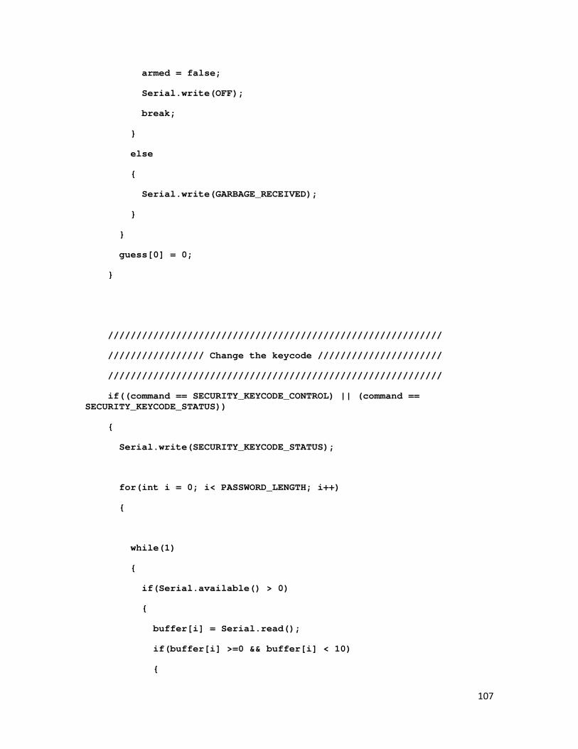
107
armed = false;
Serial.write(OFF);
break;
}
else
{
Serial.write(GARBAGE_RECEIVED);
}
}
guess[0] = 0;
}
///////////////////////////////////////////////////////////
///////////////// Change the keycode //////////////////////
///////////////////////////////////////////////////////////
if((command == SECURITY_KEYCODE_CONTROL) || (command == SECURITY_KEYCODE_STATUS))
{
Serial.write(SECURITY_KEYCODE_STATUS);
for(int i = 0; i< PASSWORD_LENGTH; i++)
{
while(1)
{
if(Serial.available() > 0)
{
buffer[i] = Serial.read();
if(buffer[i] >=0 && buffer[i] < 10)
{

108
Serial.write(buffer[i]);
bufferIndex++;
break;
}
else
{
Serial.write(GARBAGE_RECEIVED);
//Serial.println(buffer[bufferIndex], DEC);
}
}
}
}
for(int i =0; i < PASSWORD_LENGTH; i++)
{
password[i] = buffer[i] + 48;
//Serial.print(password[i],DEC);
}
}
///////////////////////////////////////////////////////////
////////////// Change the alarm status ////////////////////
///////////////////////////////////////////////////////////
else if((command == SECURITY_ALARM_STATUS) || (command == SECURITY_ALARM_STATUS))
{
Serial.write(SECURITY_ALARM_STATUS);
while(1)
{
if(Serial.available() > 0)

109
{
buffer[0] = Serial.read();
break;
}
}
if(buffer[0] == ON)
{
blinkLED = true;
Serial.write(ON);
}
else
{
blinkLED = false;
Serial.write(OFF);
}
}
else
{
Serial.write(GARBAGE_RECEIVED);
}
}
}
//Checks for a keypress and determines which key was pressed.
//Also checks to see if a valid password has been entered.
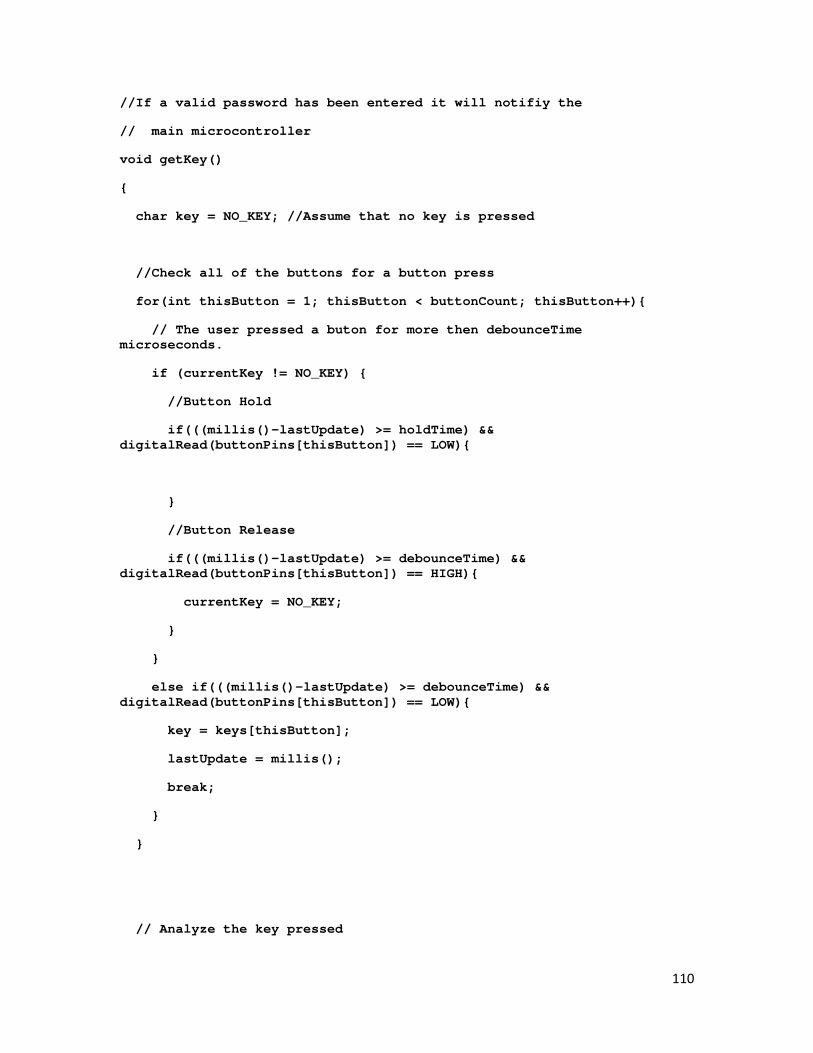
110
//If a valid password has been entered it will notifiy the
// main microcontroller
void getKey()
{
char key = NO_KEY; //Assume that no key is pressed
//Check all of the buttons for a button press
for(int thisButton = 1; thisButton < buttonCount; thisButton++){
// The user pressed a buton for more then debounceTime microseconds.
if (currentKey != NO_KEY) {
//Button Hold
if(((millis()-lastUpdate) >= holdTime) && digitalRead(buttonPins[thisButton]) == LOW){
}
//Button Release
if(((millis()-lastUpdate) >= debounceTime) && digitalRead(buttonPins[thisButton]) == HIGH){
currentKey = NO_KEY;
}
}
else if(((millis()-lastUpdate) >= debounceTime) && digitalRead(buttonPins[thisButton]) == LOW){
key = keys[thisButton];
lastUpdate = millis();
break;
}
}
// Analyze the key pressed
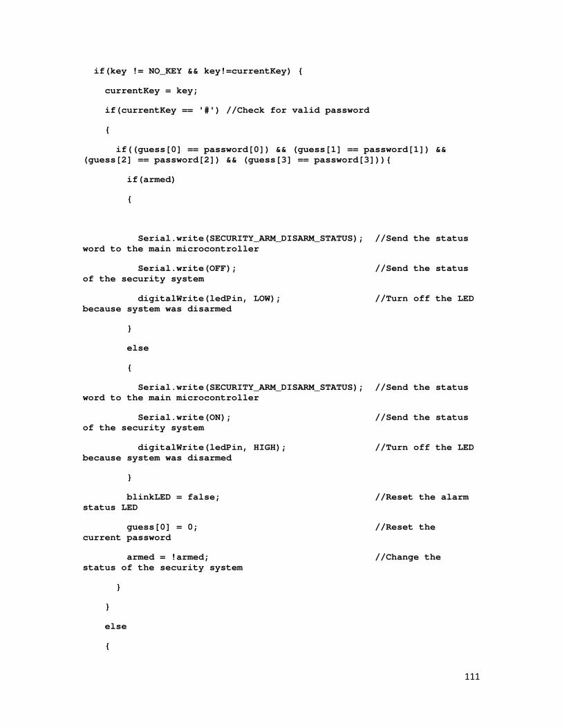
111
if(key != NO_KEY && key!=currentKey) {
currentKey = key;
if(currentKey == '#') //Check for valid password
{
if((guess[0] == password[0]) && (guess[1] == password[1]) && (guess[2] == password[2]) && (guess[3] == password[3])){
if(armed)
{
Serial.write(SECURITY_ARM_DISARM_STATUS); //Send the status word to the main microcontroller
Serial.write(OFF); //Send the status of the security system
digitalWrite(ledPin, LOW); //Turn off the LED because system was disarmed
}
else
{
Serial.write(SECURITY_ARM_DISARM_STATUS); //Send the status word to the main microcontroller
Serial.write(ON); //Send the status of the security system
digitalWrite(ledPin, HIGH); //Turn off the LED because system was disarmed
}
blinkLED = false; //Reset the alarm status LED
guess[0] = 0; //Reset the current password
armed = !armed; //Change the status of the security system
}
}
else
{
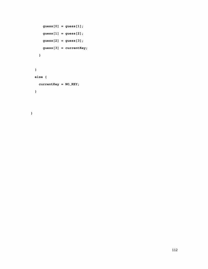
112
guess[0] = guess[1];
guess[1] = guess[2];
guess[2] = guess[3];
guess[3] = currentKey;
}
}
else {
currentKey = NO_KEY;
}
}