Module 2 Section Ⅰ Section Ⅰ Step 1 Step 1 Step 2 Step 2 Step 3 Step 3 Step 4 Step 4 Step 5 Step 5.
Upload
alguien1972Category
view
20download
4
39
FUNDAMENTALS OF PHOTONICS
Module 1.2
Light Sources and Laser Safety Fred Seeber Camden County College Blackwood, New Jersey
This module addresses various nonlaser light sources, such as incandescent lamps, fluorescent discharge lamps, high-intensity discharge lamps, flashlamps, arc lamps, and LEDs. It will also discuss in detail laser safety including the human eye, laser hazards, laser safety controls, maximum permissible exposure, laser safety glasses, and laser accidents. The laboratory experience at the end of the module will enhance your ability to understand the dangers associated with lasers, with small and large beam diameters, and with constant power levels.
Prerequisites Before you work through this module, you should have completed Module 1-1, Nature and Properties of Light. You should also have a working knowledge of intermediate algebra.

F U N D A M E N T A L S O F P H O T O N I C S
40
Objectives Upon completion of this module, you should be able to:
1. Define the following properties of laser light: a. Monochromaticity b. Directionality c. Coherence
2. Distinguish between the different types of nonlaser light sources and identify their characteristics.
3. Recognize and avoid various nonbeam hazards, such as electrical and chemical hazards.
4. Label a diagram of the human eye. State the function of each part shown.
5. Match the parts of the eye with the spectral regions to which they are most vulnerable.
6. Given the basic information required, calculate retinal spot size and retinal irradiance.
7. Describe the following laser classifications, based upon the potential hazards:
a. Class 1 laser
b. Class 2 laser
c. Class 3a laser
d. Class 3b laser
e. Class 4 laser
8. Define maximum permissible exposure. State why it’s important.
9. Describe three general types of laser hazard controls.
10. Describe laser-hazard warning signs.
11. Describe the most frequent causes of laser accidents.
12. List five laser safety precautions applicable to all types of lasers.

L I G H T S O U R C E S A N D L A S E R S A F E T Y
41
Scenario—Laser Safety in a Medical Environment Joan recently graduated from a two-year photonics program at her local community college. She accepted a job at City Hospital in Philadelphia as a laser technician.
City Hospital uses CO2, argon, and Nd:YAG lasers for its surgical procedures. Joan soon discovered that her responsibilities would also include being laser safety officer (LSO). Joan recalled the discussions she had in school about laser safety and the laser safety concepts she learned. Because being a laser safety officer is a major responsibility and critical to the well-being of both the staff and the patients, the hospital and Joan realized more training would be necessary. The hospital sponsored Joan’s attendance at a five-day course on medical laser safety given by the Laser Institute of America in Orlando, Florida. At this course the duties of a laser safety officer were discussed, including such topics as safety education, laser hazards and controls, personal protection, medical surveillance, and more. As Joan begins her duties as LSO, she realizes how important laser safety is for all in the medical working environment. Good luck, Joan, as a photonics technician and laser safety officer.
Opening Demonstration Note: The following demonstration will provide a view of some of the concepts you will encounter in this module.
Factors that result in the absorption of laser light. In a room or laboratory with reduced ambient light (light already in room), set up a demonstration as seen in Figure D-1 using a laser pointer (laser diode), red and blue plastic or glass filters, and a piece of white cardboard or paper.
Figure D-1
1. Laser Beam Absorption as a Function of Filter Thickness. Attach a laser pointer to an ordinary test-tube holder and lab stand similar to those found in most general science laboratories. (Note: A class 2 HeNe laser can be used instead of a laser pointer. Modify mounting of laser accordingly.)

F U N D A M E N T A L S O F P H O T O N I C S
42
Point the laser beam at a piece of white paper or cardboard taped to a wall or a textbook to be used as a stand. Turn on the laser pointer and visually notice the intensity of light on the white paper. Starting with the red filters, hold one thickness in front of the beam exit. Observe whether any decrease in intensity occurs. Repeat with two, three, and up to six equal thicknesses of red filter material and observe light intensity on the white paper as filter thickness increases. What do you notice? Does the intensity with each added thickness decrease in a linear fashion? More slowly than linear? More rapidly than linear?
2. Laser Beam Absorption as a Function of Filter Color. Substitute blue filters in this section of the demonstration for the red filters used in step 1. Start with one blue thickness and increase to two and three equal thicknesses. If you find complete extinction after three blue filters, what can you conclude about the role filter color plays in beam absorption?
As you proceed through this module—and also later modules—you will discover that absorption of a laser beam depends on a number of different factors. These are especially important in the design of laser safety goggles.
Basic Concepts
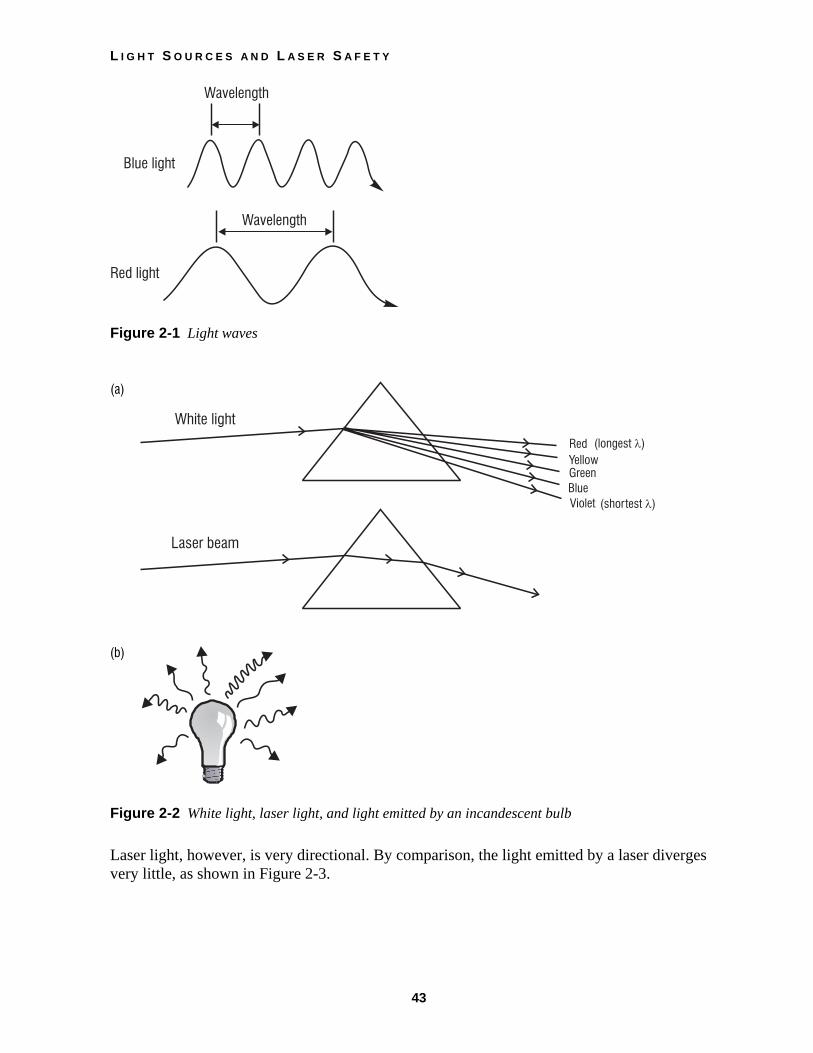
1. NONLASER LIGHT SOURCES As discussed in Module 1-1, Nature and Properties of Light, light can be understood as consisting of waves traveling through space. Light occurs in different wavelengths, just as waves on the ocean vary in length. Wavelength is the distance between peaks on a light wave, as represented in Figure 2-1. The color of light depends on its wavelength. Violet light has the shortest wavelength of all visible colors, and red light has the longest, as seen in Figure 2-2a. White light is a combination of all visible colors or wavelengths.
Laser light, unlike ordinary light, is unique in that it usually consists of only a single color of light. The wavelengths of this single color, while not perfectly uniform in length, occur within a very narrow range. Monochromaticity is the laser light’s property of containing only one color.
The light from an ordinary source like a light bulb radiates away from the source in all directions, as shown in Figure 2-2b. This spreading or divergence of ordinary light is what makes it so useful for lighting homes and workplaces.
L I G H T S O U R C E S A N D L A S E R S A F E T Y
43
Figure 2-1 Light waves
(a)
(b)
Figure 2-2 White light, laser light, and light emitted by an incandescent bulb
Laser light, however, is very directional. By comparison, the light emitted by a laser diverges very little, as shown in Figure 2-3.

F U N D A M E N T A L S O F P H O T O N I C S
44
Figure 2-3 Concentrated directionality of laser light
Noncoherent light waves produced by ordinary sources don’t form an orderly pattern. They combine in a random fashion and don’t produce a wave larger than any of the single various waves, as seen in Figure 2-4a. Such light is said to be incoherent. By contrast, the waves produced by a laser travel through space in step with one another. They’re said to be “in phase” or coherent. When all the separate waves in the beam remain in step with one another, as in Figure 2-4b, the result is a wave much stronger than that of any single wave. A very intense, coherent beam is generated.
(a) Incoherent light (b) Coherent light
Figure 2-4 Adding coherent and incoherent light waves
The following nonlaser light sources will be discussed:
1. Incandescent sources
2. Fluorescent-low pressure discharge lamps
3. High-intensity and -pressure discharge lamps (HID)
4. Flashlamps and arc lamps
5. Light-emitting diodes (LED)

L I G H T S O U R C E S A N D L A S E R S A F E T Y
45
A. Incandescent Sources Incandescent sources are similar to but not exactly as intense as blackbody radiators. A blackbody radiator is considered to be an almost perfect emitter. The first incandescent lamps in the nineteenth century were carbon-, iron-, osmium-, or tantanum-filament lamps. However, in spite of its low ductility tungsten has replaced all these filament materials because of its low vapor pressure, high melting point (3655 K), and strength. Today tungsten is typically alloyed with metals such as thorium and rhenium.
Most modern incandescent lamps are filled with gas to increase the lifetime of the filament. These fill gases are generally mixtures of argon and nitrogen, with high percentages of argon for low-voltage lamps and very high percentages of nitrogen for high-voltage projection lamps. Occasionally krypton is added for still greater lifetime. None of these gases appreciably influences the spectral quality of the incandescent source. However, the tungsten-halogen-type lamp has become increasingly common. Tungsten-halogen lamps contain a small amount of a halogen, such as bromine, chlorine, or iodine. The halogen teams with the tungsten to create a regenerative cycle—particles of tungsten thrown off by the filament combine with the halogen to form a gas that is attracted to the hot filament and attaches to the filament. However, the lost particles of tungsten do not redeposit in exactly the same place, so the filament is modified, spotting and eventually failing as before. The important feature of the tungsten-halogen lamps is that the particles of tungsten collected by the filament are prevented from depositing on the glass. Thus, the lamps do not form a black coating on the inner surface.
Halogen lamps are hot, and they must run hot to keep the regenerating cycle going—nothing less than 500 degrees F will do. For comparison, a 100-watt household lamp is never hotter than about 450 degrees, meaning that this temperature is too low for a halogen lamp. Ordinary glass does not stand the higher temperature needed, so all halogens are made of special heat-resistant glass or of quartz. In fact, the halogen lamp is now perhaps better known as a quartz lamp.
Lamp filaments made of tungsten wire are sometimes used in a straight length but more often formed into a coil, or a coiled coil, Figure 2-5. This drawing shows the various common filament styles. The better (and more expensive) filaments have close-spaced coils to secure a bright, uniform light. Less expensive are the wide-spaced filaments, and these are entirely practical for many applications, such as slide projectors.
Figure 2-5 Types of incandescent filaments. Filaments are arranged upon support structures within the bulb in a variety of ways. The filament itself may be either straight (s), coiled (c), or coiled coil (cc).
F U N D A M E N T A L S O F P H O T O N I C S
46
A high-intensity lamp uses a low-voltage automotive 6- or 12-volt bulb. Low-voltage lamps can be used on standard household current by using a small and inexpensive transformer to reduce the usual 110 volts to the required level. With the transformer concealed, the end product is useful for spotlighting.
B. Fluorescent Light Sources Fluorescent light sources are low-pressure discharge lamps with a fluorescent phosphor. Most fluorescent lights consist of mercury discharge lamps that emit 90% of their energy at 253.7-nm wavelength. These ultraviolet photons can excite a number of phosphors, producing a range of wavelengths from infrared to ultraviolet. Visible wavelengths are characterized as white, warm white, cool white, etc. Fluorescent lamps can have either cold or hot cathode electrodes. Cold electrodes are used when a rapid start is necessary. Hot cathode electrodes give greater luminous efficiency and because of this most lamps today use hot cathode electrodes. The luminous efficiency of a fluorescent lamp increases with its length. For example, an 80-inch lamp is 40% more efficient than a 15-inch lamp. The output of a fluorescent lamp is also a function of the type of ballast used. The two common types of ballast are the rapid-start and the preheat ballast. Most of today’s lamps operate with rapid-start ballasts. However, research has suggested that the preheat ballast may yield up to 20% higher light output as compared to the rapid-start type. Lamp life could also be significantly affected by the choice of ballast.
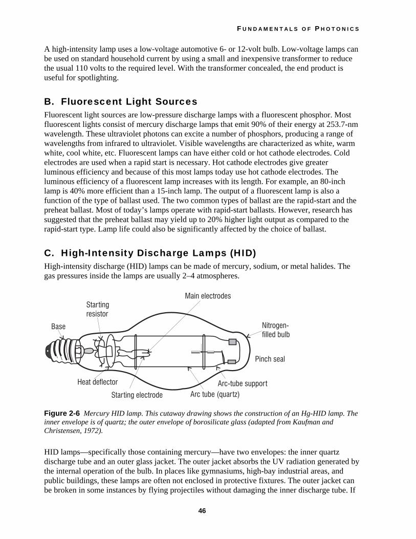
C. High-Intensity Discharge Lamps (HID) High-intensity discharge (HID) lamps can be made of mercury, sodium, or metal halides. The gas pressures inside the lamps are usually 2–4 atmospheres.
Figure 2-6 Mercury HID lamp. This cutaway drawing shows the construction of an Hg-HID lamp. The inner envelope is of quartz; the outer envelope of borosilicate glass (adapted from Kaufman and Christensen, 1972).
HID lamps—specifically those containing mercury—have two envelopes: the inner quartz discharge tube and an outer glass jacket. The outer jacket absorbs the UV radiation generated by the internal operation of the bulb. In places like gymnasiums, high-bay industrial areas, and public buildings, these lamps are often not enclosed in protective fixtures. The outer jacket can be broken in some instances by flying projectiles without damaging the inner discharge tube. If

L I G H T S O U R C E S A N D L A S E R S A F E T Y
47
the lamp does not extinguish, substantial levels of UV radiation will be emitted to the outside. An HID lamp can cause serious skin burn and eye inflammation from shortwave ultraviolet radiation if the outer envelope of the lamp is broken or punctured. Lamps that will automatically extinguish when the outer envelopes are broken or punctured are commercially available.
D. Flashlamps and Arc Lamps Flashlamp and arc lamps are high-intensity discharge devices commonly used in photography and laser technology and usually contain gases such as xenon and krypton. The flash or arc is initiated by a high voltage across the discharge tube, which in turn ionizes the gas and produces a high-intensity light with output peaks in both the visible and infrared regions of the electromagnetic spectrum. See Figure 2-7.
Figure 2-7 Diagram of a gas arc lamp with water jacket for cooling
The quartz tube is usually 1.5 mm in thickness with a metal electrode at each end. Water jackets are provided for cooling purposes.
E. Light-Emitting Diodes (LED) Light-emitting diodes are semiconductor devices that are directly modulated by varying input current. They are usually made of aluminum-gallium-arsenide (AlGaAs). However, other dopants maybe added to vary wavelength. LEDs are common in fiber-optic communication, pocket calculators, and other visual displays. These devices can emit light in both the visible and infrared regions of the spectrum. Unlike a semiconductor laser (a laser pointer for example), a light-emitting diode spews light in all directions and has low irradiance. Power from LEDs generally is in the microwatt range up to maybe a few milliwatts. LEDs are small in size, low temperature, rugged, and inexpensive devices. They operate with pn junctions (see Figures 2-8a and 2-8b). In a pn junction, two slabs are put together with the n material having an excess of electrons and the p material having a deficiency of electrons or an excess of holes. Each time an electron falls into a hole (recombination), a photon of light is emitted (see Figure 2-8c). The emitted photons produce an incoherent beam of light. When current flows across a pn junction, free electrons from the n-type material are forced to combine with holes in the p-type material and release energy. The entire device is no larger than a grain of sand.

F U N D A M E N T A L S O F P H O T O N I C S
48
(a) pn junction (b) Movement across junction
(c) Photon generation
Figure 2-8 Simplified theory of LED operation
II. CONCEPTS OF LASER SAFETY The use of lasers by industry and by the academic community continues to increase. Many educational institutions are using a wide variety of lasers in many different ways. Traditional disciplines in universities, colleges and high schools, such as biology, chemistry, and physics, now recognize the laser as an essential teaching element. Unique environments associated with educational institutions (such as civil engineering, earth and planetary sciences, and biomedical research) have also incorporated lasers into their educational processes. The objective of this section is to provide reasonable and adequate guidance for the safe use of lasers by evaluating and minimizing hazards associated with laser radiation in educational and workplace environments. The hazard evaluation procedure used is based on the ability of the laser beam to cause biological damage to the eye or skin during intended use, and is related to the classification of the laser or laser system from Class 1, considered to be nonhazardous, to Class 4, very hazardous. Lasers or laser systems are certified by the manufacturer for the specific hazard class in accordance with the Federal Laser Product Performance Standard.
A. Eye Hazards The eye is the part of the body most vulnerable to laser hazards. Changes to the eye can occur at much lower laser power levels than changes to the skin. And, eye injuries are generally far more serious than injuries to the skin.
The human eye is a complex optical system. It is designed to transmit, focus, and detect light. The normal human eye is roughly the shape of a slightly elongated sphere. It’s about the size of a quarter (25 mm, or about 1 inch) in diameter. The outer white layer of the eye is called the

L I G H T S O U R C E S A N D L A S E R S A F E T Y
49
sclera. The sclera—with the aid of the internal fluids (vitreous humor and aqueous humor)—helps to maintain the shape of the eye.
Light passes into the front portion of the eye through the cornea. The light that enters is focused to a spot on the back of the eye, the retina. There it forms an image on cells especially designed for light detection. Sensitive nerve cells relay the optical image—in the form of electrical signals—to the brain for interpretation. Figure 2-9 shows the essential parts of the human eye. The light irradiance of the image formed on the retina is 100,000 times greater than the light irradiance at the front of the eye. It is this considerable optical gain that creates an eye hazard when stray laser beams enter the eye.
Figure 2-9 Schematic diagram of the eye
The cornea is the outermost, transparent layer. It covers the front of the eye. The cornea can withstand dust, sand, and other assaults from the environment. That’s partly because corneal cells replace themselves in about 48 hours. Thus, mild injuries to the cornea are healed quickly.
The aqueous humor is a liquid (mostly water) between the cornea and the lens. The water in the aqueous humor absorbs heat, so it protects the internal portion of the eye from thermal (heat) radiation. The index of refraction is approximately 1.33, same as water.
The lens of the eye is a flexible tissue that changes shape. In conjunction with the cornea, the lens focuses light on the back of the eye. When the lens changes shape, its focal length changes. This lets the eye focus on both near and far objects.
The iris controls the amount of light that enters the eye. The iris is the pigmented or colored part of the eye. It responds to light intensity by adjusting its size. The change in iris size adjusts pupil size and controls the amount of light admitted to the eye.
The pupil is the opening in the center of the iris through which light passes. The size of a pupil changes from about 2 mm to 7 mm, according to the brightness of light in the environment. The

F U N D A M E N T A L S O F P H O T O N I C S
50
darker the environment, the larger the pupil. A fully dilated pupil (expanded to admit the greatest amount of light) is considered to be about 7 mm.
The vitreous humor is a colorless gel that fills the large area at the center of the eyeball. The vitreous humor helps to maintain the shape of the eye.
The retina is the light-sensitive layer located at the back of the eye. Think of it as a sort of viewing screen on which the lens of the eye focuses an image. The retina contains two types of photoreceptor (light-receiving) cells: rods and cones. These cells convert the optical image produced by the lens into electrical signals. The signals then are transmitted to the brain. The fovea is the most sensitive, central part of the retina. It’s the area responsible for the most detailed vision. A foveal lesion caused by laser radiation is a worst-case scenario for vision. The optic nerve carries electrical impulses from the retina to the brain.
B. Absorption of Radiation by the Eye Certain areas of the eye absorb more light in one spectral region than in other regions. Absorption of laser radiation above a certain level leads to tissue injury. Figure 2-10 shows some absorption characteristics of the eye for different electromagnetic radiation wavelengths. Shorter wavelengths of ultraviolet (UV-C and most UV-B), which range from 315 nm to 280 nm for UV-B and 280 nm to 100 nm for UV-C, are absorbed primarily in the cornea (see Figure 2-10a). Longer wavelengths of ultraviolet light (UV-A), which range from 400 nm to 315 nm, are absorbed principally in the lens of the eyeball (see Figure 2-10b).
Radiation in the visible and IR-A (400 nm to 1400 nm—Figure 2-10c) is the most hazardous and is transmitted by the optical components of the eye. It eventually reaches the retina, where most of the radiation is absorbed in the retinal pigment epithelium and in the choroid, which is a dark brown layer with exceptionally large blood vessels and high blood flow rate. Some infrared radiation in the IR-A, which ranges from 700 nm to 1400 nm, and IR-B, which ranges from 1400 nm to 3000 nm, is absorbed by the lens. Far-infrared radiation, which ranges from 3000 nm to 1 mm, is absorbed primarily by the cornea. Table 2-1 identifies different wavelength regions coded by symbols from IR to UV.
Table 2-1
Laser Wavelength Regions IR-C = 1 mm to 1400 nm IR-B = 3000 nm to 1400 nm IR-A = 1400 nm to 700 nm Visible light = 700 nm to 400 nm UV-A = 400 nm to 315 nm UV-B = 315 nm to 280 nm UV-C = 280 nm to 100 nm

L I G H T S O U R C E S A N D L A S E R S A F E T Y
51
(a)
(b)
(c)
Figure 2-10 Absorption characteristics of the eye for different wavelengths
F U N D A M E N T A L S O F P H O T O N I C S
52
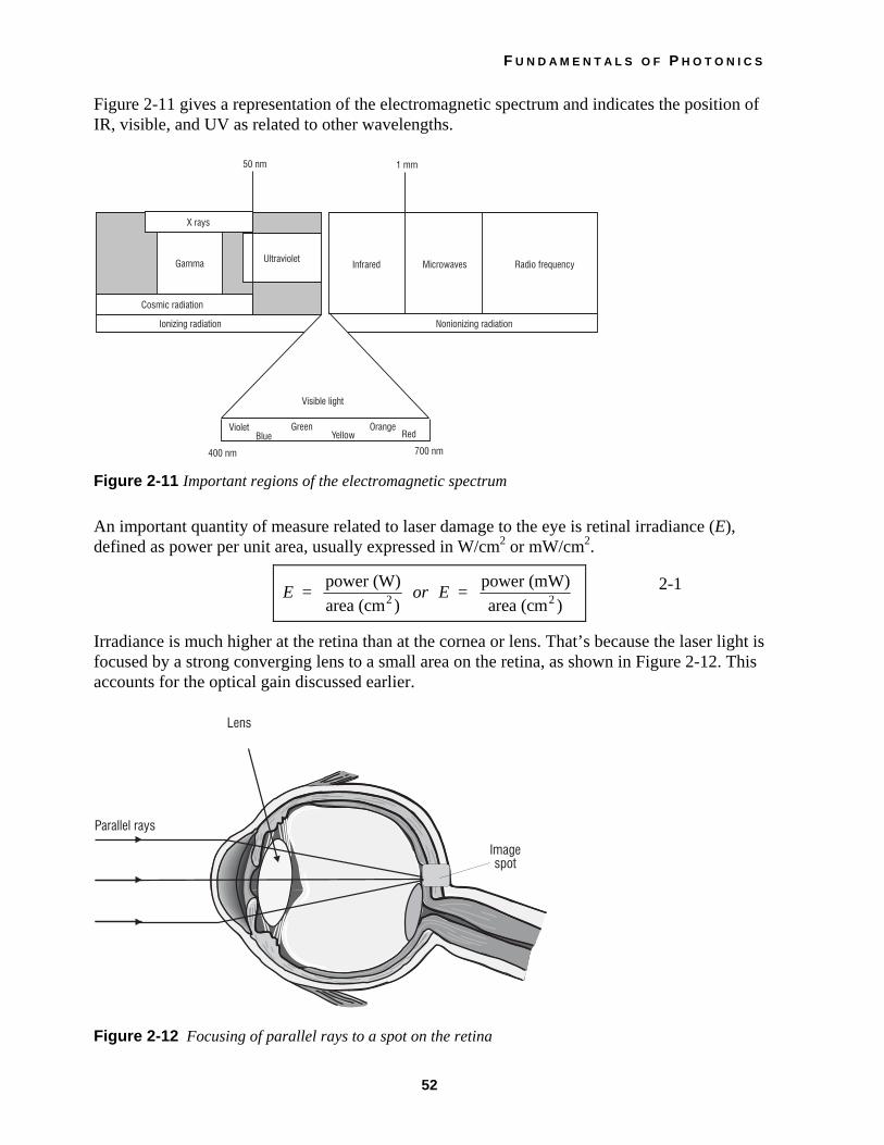
Figure 2-11 gives a representation of the electromagnetic spectrum and indicates the position of IR, visible, and UV as related to other wavelengths.
Figure 2-11 Important regions of the electromagnetic spectrum
An important quantity of measure related to laser damage to the eye is retinal irradiance (E), defined as power per unit area, usually expressed in W/cm2 or mW/cm2.
E = power (W)area (cm )2 or E = power (mW)
area (cm )2 2-1
Irradiance is much higher at the retina than at the cornea or lens. That’s because the laser light is focused by a strong converging lens to a small area on the retina, as shown in Figure 2-12. This accounts for the optical gain discussed earlier.
Figure 2-12 Focusing of parallel rays to a spot on the retina

L I G H T S O U R C E S A N D L A S E R S A F E T Y
53
The reduced size of the irradiated area means higher values of irradiance. In the condition called intrabeam viewing, shown in Figure 2-13, the focusing of the incident beam causes a tremendous increase of irradiance. Example 1 takes you through the calculation of the irradiance at the retina.
Figure 2-13 Intrabeam viewing conditions
Example 1
Irradiance of a Focused Laser Pointer Beam on the Retina
A laser pointer produces a 2-mW beam. The beam enters the eye and is focused by the cornea and lens to a spot on the retina 16 µm in diameter.
Given: P = 2 mW
Retinal spot diameter = 16 µm
Find: The irradiance on the retina, assuming that all of the 2 mW of power is focused on the retina.
Solution: Area of spot:
A = πd2
4
A = 314 1 6 10
4
2. .( ) × –3 cmd i
A = 2 × 10⁻⁶ cm2
Irradiance:
E = PA
E = 2 10
2 10×
×
–3
–6W
cm2
E = 1000 W/cm2

F U N D A M E N T A L S O F P H O T O N I C S
54
Example 2
A 1-mW HeNe laser beam with a divergence of 0.5 mrad enters the eye. Find the irradiance on the retina if the focal length of the eye, from cornea to retina, is equal to f = 1.7 cm.
Given: P = 1 mW
θ = 0.5 mrad
f = focal length of eye focusing system (1.7 cm)
Solution: The solution of this problem requires three steps:
1. Calculate focal spot diameter. (Note: Laser propagation theory shows that, when a laser beam of divergence θ is focused by a lens of focal length f to a spot of diameter d, the spot diameter d is given by d = f θ.)
d = f θ
d = (1.7 cm) (0.5 × 10⁻³ rad)
d = 8.5 × 10⁻⁴ cm
2. Calculate the area of the spot.
A = πd2
4
A = π( . –48 5 10
4× cm)2
A = 5.7 × 10⁻⁷ cm2
3. Calculate the retinal irradiance.
E = PowerArea
E = 1 10×
×
–3 W5.7 10 m–7 2
E = 1.75 × 10³ W/cm2
C. The Skin The risk of skin injury by lasers might seem to be greater than the risk of eye damage because we have so much more skin tissue than eye tissue. In fact, potential risks to the skin are considered secondary to risks to the eyes. This is because skin injuries don’t often have the dire consequences (such as partial loss of vision) that eye injuries do. Skin injuries may affect only the external dead layer of the skin cells; and even more penetrating damage usually will heal eventually. Large-area exposures that can lead to serious skin infections and other complications are not commonly associated with laser use because the beam is relatively small.

L I G H T S O U R C E S A N D L A S E R S A F E T Y
55
Laser radiation can affect the skin thermally or photochemically. To understand the effects of optical radiation on the skin, some knowledge of the anatomy of the skin is helpful.
Skin consists of two main layers: the epidermis (surface layer) and the dermis (the underlying layer). The layers are shown in the greatly enlarged diagram in Figure 2-14.
Figure 2-14 Anatomy of the skin
The outermost layer of the epidermis is the stratum corneum. It consists mainly of dead cells. The stratum corneum gives protection against water loss, abrasion, dust, air, and radiant energy. This layer of dead cells is about 8 µm to 20 µm thick.
In the layer of the epidermis just below the stratum corneum, there are specialized cells that produce melanin pigment granules. Once produced, these granules migrate throughout the epidermis. They help to protect the dermis against harmful ultraviolet radiation. As they absorb radiation, they darken. So they’re responsible for the skin’s color change during suntanning. The entire epidermis averages about 0.1 mm in thickness.
The dermis is the site of many specialized cells and glands. It contains mostly connective tissue that gives elasticity and support to the skin. The dermis also has numerous blood vessels, nerve cells, sweat glands, and hair follicles. Sweat glands have an essential role in regulating body temperature. Sweat allows for evaporative cooling of the body and, in this way, gets rid of excess heat. Nerve cells include heat sensors, cold sensors, pain sensors, and tactile (touch) sensors. Blood vessels allow for the maintenance of healthy tissue and play an important role in heat regulation.
The skin reflects most visible and IR-A (near-infrared) radiation. The epidermis is highly absorbing at UV-B and UV-C wavelengths and at IR-B and IR-C wavelengths. The skin is less

F U N D A M E N T A L S O F P H O T O N I C S
56
sensitive to UV-A than to UV-B or UV-C. The melanin granules of the epidermis absorb much of the ultraviolet radiation incident upon the skin and, as mentioned, thus protect the dermis from harmful UV. However, with enough power and duration, the incident radiation of any wavelength in the optical spectrum can penetrate the protective filter of the epidermis and cause deep internal injury.
Ultraviolet radiation in the UV-B and UV-C regions causes reddening (sunburn) and eventual tanning—known as erythema—of the skin. Erythema is a photochemical occurrence. Chronic exposures to UV are known to accelerate aging of the skin. They increase the risk of skin cancer. We don’t know the precise wavelength range that may lead to the occurrence of cancer, but UV-B has been implicated by some studies.
Laser-induced thermal change to the skin is most pronounced at far-infrared wavelengths such as are produced by CO2 lasers. Thermal damage also can be caused by visible and near-infrared wavelengths, but at higher irradiance values than for far-infrared laser beams.
The pain from thermal injury to the skin by most lasers is enough to alert the user to move out of the beam path. However, a number of high-power visible and IR lasers now are used. They are capable of producing significant burns to the skin in much less than one second. And users are unable to move out of the beam path before serious injury occurs.
D. Laser Safety Standards and Safety Classifications The primary laser safety standard in use today is the ANSI (American National Standards Institute) Z-136.1. A new laser safety standard for educational institutions ANSI A-136.5 should be available in fall 1999. Both standards can be obtained from the Laser Institute of America in Orlando, Florida. ANSI is a nonprofit organization for which expert volunteers participate on committees to set standards in various fields. In 1969, ANSI addressed the issue of laser safety at the request of the U.S. Department of Labor. The resulting standard (ANSI Z-136), issued in October 1973, was directed primarily to users: operators, technicians, laser safety officers safety engineers, and research personnel. The standard was rewritten in 1980 and 1986 and revised in 1993. It provides guidance for the safe use of lasers and laser systems by defining control measures for each of the four broad laser classifications. However, technical information on measurements, calculations, and biological effects also are provided for those who want to carry out their own measurements and calculations.
LASER HAZARD CLASSIFICATIONS The most important criterion you will use in applying laser safety control measures is the hazard classification designated by manufacturers on the equipment labels. Certain controls are required for each class (except Class 1) listed below:
Class 1 (exempt lasers) cannot, under normal operating conditions, emit a hazardous level of optical radiation. Included in this category is laboratory equipment using lasers with all beam paths and reflections enclosed.
Class 2, or low-power visible laser device of 1 milliwatt, does not have enough output power to injure a person accidentally, but may injure the eye when stared at for a long period. A “caution” label must be on the device. Many HeNe lasers are Class 2 but not all. These lasers are used for alignment procedures and optical experiments.

L I G H T S O U R C E S A N D L A S E R S A F E T Y
57
Class 3a lasers—rated in power from 1 milliwatt to 5 milliwatts—cannot injure a normal person when viewed with the unaided eye but may cause injury when the energy is collected and put into the eye as with binoculars. Most laser pointers fall into this category. A danger or caution sign must label the device, depending on its irradiance.
Class 3b lasers from 5 milliwatts to 500 milliwatts can produce eye injury when viewed without eye protection. This class of laser requires a danger label and could have dangerous specular reflections. Eye protection is required.
Class 4 lasers above 500 milliwatts in power can injure you if viewed directly or by viewing both the specular and diffuse reflections of the beam. A danger sign will label this laser. These lasers can also present a fire hazard. Eye and skin protection is required.
TYPES OF CONTROLS: ENGINEERING, ADMINISTRATIVE, PERSONAL PROTECTIVE The hazards posed by Class 3b and Class 4 lasers require systematically applied controls to prevent skin and eye injuries. First, we will examine the types of controls available. Control measures may be broken down into three main types: engineering controls, administrative controls, and personal protective equipment.
Engineering controls involve design features or devices applied to the laser, laser beam, or laser environment that restrict exposure or reduce irradiance. Such controls include beam shutters, beam attenuators, remote firing and monitoring systems, and the protective housing placed entirely around some laser systems.
Administrative control measures involve procedures and information rather than devices or mechanical systems. Some important administrative controls are posting of warning signs and labels, establishment of standard operating procedures (SOP), and safety training.
Personal protective equipment is worn by personnel using the laser or in the vicinity of the laser. It includes protective eyewear, gloves, and special clothing. Table 2-2 lists some of the more commonly used control measures for Class 3b and Class 4 lasers and laser systems.

F U N D A M E N T A L S O F P H O T O N I C S
58
Table 2-2. Control Measures for Class 3b and Class 4 Lasers
Engineering Controls Administrative and Procedural Controls
Personal Protective Equipment
Protective housing and service panel
Interlocks on the protective housing
Door interlocks and remote-control connector
Beam attenuators and beam shutters
Key switch or padlock
Filtered viewing optics and windows
Emission delay
Warning lights, emission indicators
Beam enclosure
Controlled beam path
Laser controlled area
Beamstops
Remote firing and/or monitoring
Laser safety officer
Standard operating procedures
Limitations on use by class
Entry limitations for visitors
Education and training
Maintenance and service manuals
Marking of protective devices
Warning signs and labels
Eyewear
Clothing
Gloves
* David Sliney and Myron Wolbarsht, Safety with Lasers and Other Optical Sources: A Comprehensive Handbook (New York: Plenum Press, 1980), p. 512.
MAXIMUM PERMISSIBLE EXPOSURE (MPE) How much exposure to laser light is hazardous? To answer this question, you have to take into account the output characteristics of the laser. Those characteristics include wavelength, output energy and power, size of the irradiated area, and duration of exposure. If you’re using a pulsed laser, you also must consider the pulse repetition rate.
Sensitivity to a given wavelength varies significantly from person to person. Maximum permissible exposure (MPE) limits indicate the greatest exposure that most individuals can tolerate without sustaining injury.
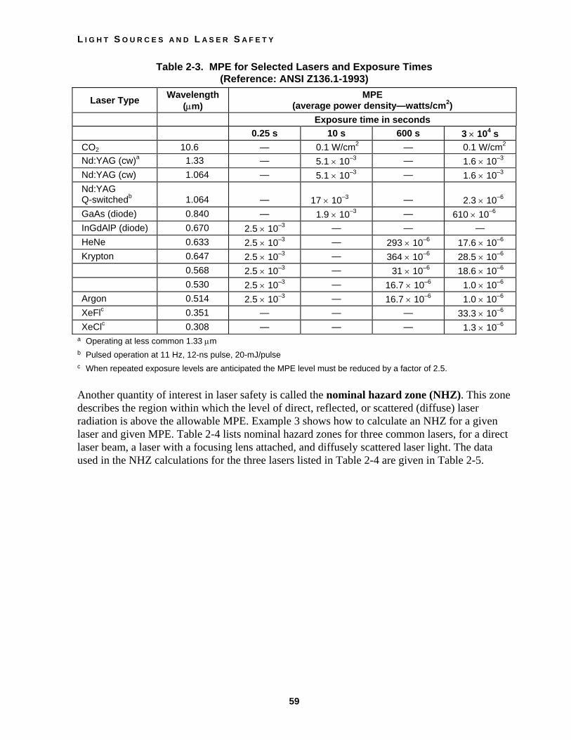
An MPE is usually expressed in terms of the allowable exposure time (in seconds) for a given irradiance (in watts/cm2) at a particular wavelength. Table 2-3 gives the maximum permissible exposure for the eye for a variety of lasers operating at different irradiance levels. For example, Table 2-3 indicates that, for an argon laser operating at 0.514 µm, the MPE is 2.5 × 10⁻³ W/cm2 for an exposure time of 0.25 second, 16.7 × 10⁻⁶ W/cm2 for an exposure time of 600 seconds, and 1 × 10⁻⁶ W/cm2 for an exposure time of 3 × 10⁴ seconds. MPEs are useful for determining optical densities for eyewear or windows.
L I G H T S O U R C E S A N D L A S E R S A F E T Y
59
Table 2-3. MPE for Selected Lasers and Exposure Times (Reference: ANSI Z136.1-1993)
Laser Type Wavelength (µm)
MPE (average power density—watts/cm2)
Exposure time in seconds 0.25 s 10 s 600 s 3 × 10⁴ s
CO2 10.6 — 0.1 W/cm2 — 0.1 W/cm2 Nd:YAG (cw)a 1.33 — 5.1 × 10⁻³ — 1.6 × 10⁻³ Nd:YAG (cw) 1.064 — 5.1 × 10⁻³ — 1.6 × 10⁻³ Nd:YAG Q-switchedb
1.064
—
17 × 10–3
—
2.3 × 10⁻⁶
GaAs (diode) 0.840 — 1.9 × 10⁻³ — 610 × 10–6 InGdAlP (diode) 0.670 2.5 × 10⁻³ — — — HeNe 0.633 2.5 × 10⁻³ — 293 × 10–6 17.6 × 10⁻⁶ Krypton 0.647 2.5 × 10⁻³ — 364 × 10–6 28.5 × 10⁻⁶ 0.568 2.5 × 10⁻³ — 31 × 10–6 18.6 × 10⁻⁶ 0.530 2.5 × 10⁻³ — 16.7 × 10⁻⁶ 1.0 × 10⁻⁶ Argon 0.514 2.5 × 10⁻³ — 16.7 × 10⁻⁶ 1.0 × 10⁻⁶ XeFlc 0.351 — — — 33.3 × 10⁻⁶ XeClc 0.308 — — — 1.3 × 10⁻⁶
a Operating at less common 1.33 µm b Pulsed operation at 11 Hz, 12-ns pulse, 20-mJ/pulse c When repeated exposure levels are anticipated the MPE level must be reduced by a factor of 2.5. Another quantity of interest in laser safety is called the nominal hazard zone (NHZ). This zone describes the region within which the level of direct, reflected, or scattered (diffuse) laser radiation is above the allowable MPE. Example 3 shows how to calculate an NHZ for a given laser and given MPE. Table 2-4 lists nominal hazard zones for three common lasers, for a direct laser beam, a laser with a focusing lens attached, and diffusely scattered laser light. The data used in the NHZ calculations for the three lasers listed in Table 2-4 are given in Table 2-5.

F U N D A M E N T A L S O F P H O T O N I C S
60
Example 3
Nominal Hazard Zone Calculation
A CO2 laser with a power P of 500 W and exit beam diameter b out of the laser of 3 cm is focused by a convex lens of focal length f0 = 20 cm. Determine the nominal hazard zone (NHZ) from the focal point of lens. (Note: From laser safety theory, it is shown that the NHZ for a laser of given
power and exit beam diameter is given by the formula NHZ MPE)=fb
P01
24π(e j .
Given: P = 1000 W (power)
f0 = 20 cm (focal length of lens)
b = 3 cm (beam diameter at exit)
MPE = 0.1 W/cm2 (refer to Table 2-3 or Table 2-5)
NHZ = fb
P0 4π MPE
NHZ = 203 314
4 5000 1
•
•. ( . )
NHZ = (6.67) (79.8) = 532 cm
NHZ = 5.32 m
Note that this value agrees with the entry in Table 2-4 for a CO2 laser with an exposure duration of either 8 h or 10 s, with a lens-on-laser.
Table 2-4. Nominal Hazard Zones (NHZ) for Various Lasers Laser Exposure Nominal Hazard Distance (m) Type Duration Direct Lens-on-Laser Diffuse
Nd:YAG 8 h 10 s
1410 790
11.4 6.4
1.4 0.8
CO2 8 h 10 s
399 399
5.3 5.3
0.4 0.4
Argon 8 h 0.25 s
25,200 505
1700 33.6
12.6 0.25

L I G H T S O U R C E S A N D L A S E R S A F E T Y
61
Table 2-5. Laser Criteria Used for NHZ Calculations Laser Parameter Nd:YAG CO2 Argon
Wavelength, λ (µm) 1.064 10.6 0.488, 0.514 Beam power, P (W) 100 500 5.0 Beam divergence, φ (mrad) 2.0 2.0 1.0 beam size at aperture, a (mm) 2.0 20.0 2.0 Beam size at lens, b (mm) 6.3 30.0 3.0 Lens focal length, fo (mm) 25.4 200 200 MPE, 8 hours (µW/cm2) 1.6 × 10³ 1.0 × 10⁵ 1.0 MPE, 10 s (µW/cm2) 5.1 × 10³ 1.0 × 10⁵ — MPE, 0.25 s (µW/cm2) — — 2.5 × 10³
ABSORPTION, LAMBERT’S LAW, AND OPTICAL DENSITY In general, when a light beam is transmitted through a transparent material, some of the light energy is absorbed and the beam intensity decreases continuously. The absorption may be minimal, as in air, or considerable, as in a dark piece of glass. In each case, the absorption process removes energy from the beam and converts it to thermal energy of the transparent medium—by increasing the kinetic energy of the atoms and molecules.
If a beam of irradiance E0 watts/cm2 is incident on a slab of material medium as shown in Figure 2-15, the beam irradiance decreases to a value Ex watts/cm2 after passing through a thickness x of the transparent medium. The value of irradiance Ex is given by Lambert’s law.
Figure 2-15 Absorption of light in transparent materials
Ex = E0e–σλx 2-2
where Ex is the irradiance after traveling through a thickness x
E0 is the irradiance incident on the absorber
σλ is the absorption coefficient
x is the absorbing thickness of the absorbing medium
e is the Naperian logarithmic base

F U N D A M E N T A L S O F P H O T O N I C S
62
The absorption coefficient σλ is a property of the absorbing medium and the wavelength of the light. For eye filters (used in laser safety goggles) where the absorption coefficient for the filter is known and the filter thickness is predetermined, the product σλx is replaced by a quantity called the optical density, described by the symbol OD. In that case, with the base 10 replacing the base e, Lambert’s law takes the form
Ex = E010–OD 2-3
And since the transmission of light through an absorber is defined as the ratio of Ex/E0, we can rewrite Equation 2-3 in a form used commonly with optical filters
T = 10–OD 2-4
where OD = optical density
T = transmission
Note that, since OD = σλx, the optical density itself is a wavelength-dependent quantity. Optical density is usually labeled on the temple of the goggles or on the filter itself. Thus, if the OD of a filter is known, the transmission through the filter can be calculated from Equation 2-4. For example, laser safety eyewear with an OD = 3 has a transmission T of 10–3 or 0.1%. Table 2-6 below gives transmission values for a range of OD values.
Table 2-6. Transmission at Various OD Values OD Transmission %Transmission 0 1 1.0 100% 1 10–1 0.1 10% 2 10–2 0.01 1% 3 10–3 0.001 0.1% 4 10–4 0.0001 0.01% 5 10–5 0.00001 0.001% 6 10–6 0.000001 0.0001% 7 10–7 0.0000001 0.00001%
Suppose the maximum permissible exposure (MPE) for a given laser beam of exit irradiance E0 is known. Then a filter must be used to reduce the incident irradiance (in W/cm2) to the permissible irradiance (in W/cm2). See Figure 2-16.
Figure 2-16 Using an optical filter to reduce beam irradiance

L I G H T S O U R C E S A N D L A S E R S A F E T Y
63
If we replace Ex in Equation 2-3 with MPE, we get MPE = E010–OD or, equivalently, 10+OD = E0/MPE. Solving the last expression for OD gives another useful equation.
OD = log10
E0
MPEFHIK
2-5
Example 4 involves a sample calculation for the minimum optical density (OD) required for a specified laser power and recommended MPE.
Example 4
An Nd:YAG laser with a power of 40 watts is projected onto a fully dilated human eye pupil of 7-mm diameter. The eye is exposed for a duration of 10 seconds. Calculate the minimum optical density OD of a laser safety goggle needed to protect the eye from damage. Refer to Table 2-3 for the appropriate maximum permissible exposure (MPE).
Given:
• Nd:YAG
• λ = 1064 nm
• t = 10 s
• Eye diameter = 7 mm
• MPE = 0.0051 W/cm2 (See Table 2-3 for Nd:YAG, 1.064 µm, 10-second exposure.)
• P = 40 W
• Area of pupil = πD2
4314 0 7 0 38= =
( . )( . . cm)4
cm2
2
Solution:
Using Eq 2-5, where OD = log100E
MPELNMOQP and E0 = P/A, we get:
OD = log.10
400 0051
W / 0.38 cm W / cm
2
2LNM
OQP
OD = log ,10 20 640
OD = 4.3
The required optical density for the laser safety goggles would be 4.3 or larger.
Laser safety eyewear is required for Class 3b and Class 4 lasers and laser systems. Eyewear should be comfortable and in good condition, not scratched or discolored. Some filters may be clear and others tinted, depending on the laser wavelength.
LASER SAFETY SIGNS The most common signs used for lasers and laser systems are the DANGER, CAUTION, and NOTICE signs. See Figure 2-17 below.

F U N D A M E N T A L S O F P H O T O N I C S
64
Laser Area Signs are used to mark the area designated a laser hazard zone. The signs vary according to the classification of the laser or laser system. The signal word “CAUTION” is used on all signs associated with Class 2 lasers and laser systems and Class 3a lasers and laser systems that do not exceed the appropriate MPE for irradiance.
The signal word “DANGER” is used with all signs associated with all other Class 3a, and all Class 3b and Class 4 lasers and laser systems.
Temporary Laser Controlled Area Signs are posted outside a temporary laser controlled area when the laser system is being serviced. The signal word “NOTICE” is used for this type of sign. The area outside the temporary area remains Class 1, while the area within is either Class 3b or Class 4.
All signs and labels shall be conspicuously displayed in locations where they will best serve to warn onlookers.
Figure 2-17 Laser area warning signs for lasers
Caution signs are used for a Class 2 laser and some Class 3a lasers, depending on their irradiance. Danger signs are used on some Class 3a, Class 3b, and Class 4 lasers and laser systems. A notice sign is used for a temporary laser controlled area while service or repair is being done.
LASER ACCIDENTS Most laser accidents occur because adequate control measures are not in place: for example, doing alignment procedures without laser safety eyewear or wearing the wrong eyewear for the laser used. Below is a chart that summarizes the causes of most accidents using lasers. See Figure 2-18.

L I G H T S O U R C E S A N D L A S E R S A F E T Y
65
������������������������������������������������������������
������������������������������������������������������������������������������������������������������������������������
���
���
Figure 2-18 Causes of most laser accidents
As in all aspects of laboratory, field, classroom, or industrial safety, the best measures are a positive attitude and common sense. The following list of precautions is not all-inclusive for every application, although it does represent a comprehensive collection of thoughts from a number of people who are experienced in the safe use of lasers.
SAFETY RULES FOR ALL LASERS, REGARDLESS OF OUTPUT POWER LEVEL
1. Avoid looking directly into any laser beam or at its reflection.
2. Remove all unnecessary specular (shiny) reflecting surfaces from the work area.
3. Operate lasers in well-defined areas to which access can be controlled. The area should be posted with appropriate signs to alert persons passing by the area that a potential hazard exists.
4. The laser system should be operated only by or under the direct supervision of a person knowledgeable of the hazards and control methods for both beam and nonbeam conditions. This individual is usually the laser safety officer (LSO) who is designated by the administration of the company, hospital, or educational institution. The LSO shall have the authority and the responsibility to effect monitoring and enforce the control of laser hazards and to achieve the knowledgeable control of laser hazards.
5. Any accident should immediately be reported to the responsible medical authority. If there is an accidental exposure to the eye, the services of an ophthalmologist should be sought.

F U N D A M E N T A L S O F P H O T O N I C S
66
NONBEAM HAZARDS There are four well-known nonbeam potential hazards associated with the use of lasers and laser systems. 1. Fire hazard 2 Explosion hazard 3. Electrical hazard 4. Chemical hazard
FIRE HAZARD
Class 4 laser systems represent a fire hazard. Enclosure of Class 4 laser beams can result in potential fire hazards if enclosure materials are likely to be exposed to irradiances exceeding 10 W/cm2 or beam powers exceeding 0.5 W. The use of flame-retardant materials is advisable and necessary.
EXPLOSION HAZARD
High-pressure arc lamps, filament lamps, and capacitor banks in laser equipment shall be enclosed in housings that can withstand the maximum explosive pressure resulting from component disintegration. The laser target and elements of the optical train that may shatter during laser operation shall also be enclosed or equivalently protected to prevent injury to operators and observers. Explosive reactions of chemical laser reactants or other laser gases may be a concern in some cases.
ELECTRICAL HAZARD
The use of lasers or laser systems can present an electric shock hazard. This may occur from contact with exposed utility power use, device control, and power-supply conductors operating at potentials of 50 volts and above. These exposures can occur during laser setup or installation, maintenance, and service, where equipment protective covers are often removed to allow access to active components as required for those activities. Those exposed can be equipment installers, users, technicians, and uninformed members of the public, such as passersby.
The following potential problems have frequently been identified during laser facility audits. 1. Uncovered electrical terminals 2. Improperly insulated electrical terminals 3. Hidden “power-up” warning lights 4. Lack of personnel trained in current cardiopulmonary resuscitation practices, or lack of
refresher training 5. “Buddy system” not being practiced during maintenance and service 6. Non earth-grounded or improperly grounded laser equipment 7. Non-adherence to the OSHA lock-out standard (29 CFR 1910.147) 8. Excessive wires and cables on floor that create fall or slip hazards

L I G H T S O U R C E S A N D L A S E R S A F E T Y
67
CHEMICAL HAZARDS
Dye lasers use a complex fluorescent organic compound that, when in solution with certain solvents, forms a lasing medium for dye lasers. Certain dyes are highly toxic or carcinogenic. Since these dyes frequently have to be changed, special care must be taken when handling, preparing solutions, and operating dye lasers.
The use of dimethylsulfoxide (DMSO) as a solvent for cyanine dyes in dye lasers should be discontinued if possible. DMSO aids in the transport of dyes into the skin. If another solvent cannot be found, low-permeability gloves should be worn by personnel any time a situation arises where contact with the solvent may occur.
Laboratory
Irradiance As discussed in the text, irradiance is defined as power per unit area and one of the most important concepts in regard to laser safety.
Equipment List The following equipment is needed to complete this laboratory:
HeNe laser (Class 2 or 1 mW)
Photoelectric power meter
Diverging lens
Neutral-density filter, OD = 2.0 (1% transmission)
Sheet of graph paper with millimeter divisions or a metric ruler. A calibrated aperture can also be used to determine beam diameter. This could be a simple hole in an aluminum sheet in the range of 2-6 mm.
Procedure In this laboratory exercise, you will use an optical power meter to determine the power and irradiance of laser light. The power and area of a HeNe laser beam will be expanded with a diverging lens, and the irradiance will be determined at several distances. You will prepare a graph of irradiance-versus-distance from the lens.
A. Power and Irradiance of a HeNe Laser Beam 1. Observing laser safety procedures, turn on HeNe Class 2 laser.
2. Position the sensor head of the photoelectric power meter about 10 cm from the output aperture of the laser. Turn on the power meter to a full-scale range. Measure the laser beam power and record in Lab Table 1.

F U N D A M E N T A L S O F P H O T O N I C S
68
3. Place a neutral-density (ND) filter in the beam path to reduce its intensity. Note: Do not handle the ND filter with your fingers since its surface is delicate. Use lens tissue and handle it by the edges only!
4. To the right of the ND filter, position a piece of graph paper (10 cm from output aperture of laser) so that the laser beam is incident upon it, or place a nonreflecting meter ruler as vertical as possible. If you use an aperture, you may place that aperture 10–20 cm from the laser.
5. Calculate and record the area of the beam and the irradiance of the beam in Lab Table l.
B. Irradiance of a Diverging Beam 1. Observing all safety precautions, turn on the laser.
2. Place a diverging lens in the laser beam about 10 cm from the laser output aperture, as illustrated in Figure L-1. Be careful of reflections off the lens when inserting the lens in the beam. Be sure that neither reflections nor the expanded laser beam enters the eye directly.
Figure L-I
3. Measure the power of the expanded beam at four distances from the diverging lens, as indicated in Figure L-1. The beam should be larger than the detector at the nearest point, and all measurements should be made on the center of the beam. Record distances and corresponding powers in Lab Table 2.
4. Calculate the irradiance at each point by dividing the power detected by the receiving area on the detector or the area of the opening of an ambient light shade if one is used.
5. Draw a graph of irradiance-versus-distance from the diverging lens.
6. Select a fifth distance beyond the fourth measurement. Use your graph to predict the irradiance of the expanded beam distance. Measure the power at the fifth distance, calculate the irradiance, and compare the calculated value with your predicted value.
7. Describe the effect a diverging lens has on the irradiance of a laser beam.

L I G H T S O U R C E S A N D L A S E R S A F E T Y
69
Lab Table 1
Power and Irradiance of a HeNe Laser Beam
Laser power using photoelectric power meter:
P = _______________ mW
Beam diameter: d = _______________ mm = __________________ cm
Beam area: A = πd2
4
A = _______________ cm2
Irradiance: E = PA
E = _______________ mW/cm2
Lab Table 2
Data Table Irradiance of a Diverging Beam
Detector area: A = __________
Position Distance
(cm) Power (mW)
Irradiance (mW/cm2)
1 2 3 4
Other Resources The Laser Institute of America located in Orlando, Florida, provides many resources on laser safety. These resources include laser hazard software packages, laser safety guides for eyewear protection, all of the ANSI (American National Standards Institute) safety standards, and laser safety reference guides for all environments in which lasers are used.

F U N D A M E N T A L S O F P H O T O N I C S
70
References 1. American National Standard for the Safe Use of Lasers Z-136.1, New York, New York,
1993. 2. Center for Occupational Research and Development. Introduction to Lasers, Waco,
Texas, 1990.
3. Engineering Technology, Inc. Laser Safety, Waco, Texas, 1993.
4. Killen, Harold B. Fiber-Optics Communications, Prentice Hall, Englewood Cliffs, New Jersey, 1991.
5. Lacy, Edward A. Fiber-Optics, Prentice Hall, Englewood Cliffs, New Jersey, 1986.
6. Popular Optics Library. Popular Optics, Edmund Scientific No. 9445, Barrington, New Jersey, April 1997.
7. Rockwell, R. James, Laser Accidents: “Are they all reported and what can be learned from them?” Journal of Laser Applications, Oct. 1989.
8. Seeber, F. P., “Laser Practices and Problems in Educational Institutions,” Proceedings, International Laser Safety Conference, Cincinnati, Ohio, 1992.
9. Seeber, F. P., “Now Is the Time for the Safe Use of Lasers in Educational Institutions,” International Laser Safety Conference, Orlando, Florida, 1999.
10. Sliney, D. H., and M. Wolbarsht. Safety with Lasers and Other Optical Sources, New York: Plenum Press, 1980.
11. Sliney, D. H., and Stephen L. Trokel., Medical Lasers and Their Safe Use, Springer Verlag, 1993.
Problem Exercises 1. Explain the difference between incandescent and fluorescent light sources. 2. Define coherence and monochromaticity. 3. Calculate the irradiance of a laser beam in watts/cm2 if the power of the laser beam is 500
milliwatts and the diameter of laser beam is 2 mm. 4. Which laser wavelengths are hazards for the following? a. cornea of the eye b. retina of the eye 5. Give the power levels for Classes 2, 3a, 3b, and 4 laser safety classifications. 6. Explain when to use a: a. caution sign b. danger sign c. notice sign

L I G H T S O U R C E S A N D L A S E R S A F E T Y
71
7. Calculate the transmission for the following optical densities: a. OD = 2 b. OD = 5 c. OD = 6 d. OD = 8 8. Explain the difference between engineering controls, administrative controls, and
personal protective equipment in regard to control measures. 9. Explain the role of the laser safety officer (LSO) in an industrial environment. 10. Identify the maximum intrabeam permissible exposure (MPE) for the eye: a. CO2 laser for 10 seconds b. HeNe laser for 0.25 second c. Argon laser for 600 seconds d. XeCl laser for 30,000 seconds 11. Calculate the minimum optical density for protective eyewear using an argon laser of
wavelength 0.514 µm, for a given exposure time of 0.25 second, a power of 5 watts, and a worst-case scenario of a dilated eye of 7-mm pupil diameter
12. List the three major causes of laser accidents. 13. Discuss the nonbeam hazards described in this module and suggest procedures and
controls to reduce or eliminate them. 14. An argon laser with a power of 15 W and a beam diameter out of the laser of 4 mm is
focused for 10 minutes by a converging lens of focal length 15 cm. Determine the NHZ measured from the focal point of the lens.
15. A laser delivers an irradiance of 105 W/cm2 in a certain target area. If you are working in
this area and the MPE for this laser is given by Table 2-3 to be 0.005 W/cm2, what is the minimum OD for the laser goggles you should be wearing?

F U N D A M E N T A L S O F P H O T O N I C S
72