Steering for general automobile
37
Steering System
-
Upload
sgrsoni45 -
Category
Automotive
-
view
1.256 -
download
3
Transcript of Steering for general automobile

Steering System

STEERING SYSTEM
• Steering is the term applied to the collection of components, linkages, etc. which allow a vehicle to move in the desired direction
• An automobile is steered with the help of steering gears and linkages, which transfer the motion of the hand operated steering wheel to the front wheels

FUNCTIONS OF STEERING SYSTEMS
• It helps in turning the wheels to left or right
• It converts the rotary movement of the steering wheel into an angular turn of the front wheels.
• It multiplies the effort of the driver by leverage in order to reduce the effort to turn the wheels.
• It absorbs a major part of the road shocks thereby preventing
them to get transmitted to the hands of the driver

Ackerman Principle
Since the steering linkage is shorter than the axle, the inner wheel is turned through a larger angle.
When a vehicle travels in a curved path, its wheels should describe circles around the same centre, otherwise they will slide and cause excessive tyre wear. The steering mechanism ensures that when the vehicle turns left or right, the inner wheel is turned through a larger angle to prevent tyre wear

Steering System
• When the driver turns the steering wheel, the front wheels move and the car turns the corner. For this simple function, many things have to be taken into consideration. For example –
• Effect of road surface irregularities
• Tyre behaviour under cornering stress
• An efficient mechanical system to give easy turning of the steering wheel
• No (or very little) difference between empty and fully loaded vehicle
• Effect of accelerating or braking when the wheels are turned
• The front wheels should have a natural tendency to return to the straight ahead position and stay there

Requirements of steering Mechanism:
• It must satisfy Ackerman condition
• Irregularities in the road surface must be damped. However, such damping must not cause the driver to lose contact with the road.
• When the steering wheel is released, the wheels must return automatically to the straight-ahead position and must remain stable in this position.
• The steering should have as low ratio as possible in order to obtain ease of handling. Steering effort depends not only on the steering ratio but also on front suspension load, turning circle, suspension geometry, properties of the tyre tread and road surface.
• Steering ratio is the ratio of angle of turn of steering wheel to the road wheels. A higher ratio means that steering wheel has to turn more to get the wheels to turn a given angle. However, less effort is required because of the higher gear ratio.
• Generally, lighter, sportier cars have lower steering ratios than larger cars and trucks. Lower ratio gives the steering a quicker response which is desirable. Smaller cars are light therefore even with the lower ratio, the effort required to turn the steering wheel is not excessive.

Components • Steering Wheel – Driver input device.
• Steering Column – Shaft connecting the steering wheel to the steering box or steering rack.
• Steering Box – Provides steering gear ratio.
• Steering gearbox is connected to the Pitman Arm (drop arm)
• Pitman Arm is connected to the Drag Link
• Drag Link is connected to the Steering Arm
• Steering Arm is connected to the Steering Knuckle
• Steering Knuckle is mounted to the axle
• Track rod/Tie rod – Rod which connects left and right wheels. The steering rack is also the track rod.
• Tie rod end – Ball joint to allow steering and suspension movement.

COMPONENTS OF A CONVENTIONAL STEERING SYSTEM

Steering gears are enclosed in a box, called the steering gear box
Types:
• Worm and wheel steering gear
• Worm and sector steering gear
• Cam and lever / peg steering gear
• Recirculating ball steering gear
• Rack and pinion steering gear.
Steering Gear Box

WORM AND WHEEL STEERING GEAR
• Worm wheel is carried in bearings in a cast iron case.
• Worm wheel is connected to a drop arm.
• The worm which is keyed on to steering shaft meshes with the worm wheel.
• Steering wheel is mounted at the upper end of the steering shaft.
• When driver rotates the steering wheel, drop arm moves in backward or forward direction.
• This results in motion of the stub axles.

WORM AND SECTOR STEERING GEAR
• The end of steering shaft has a worm gear attached to it. • It meshes directly with a sector gear (section of a full gear wheel). • When the steering wheel is turned, the shaft turns the worm gear, and the
sector gear pivots around its axis as its teeth are moved along the worm gear. • The box is sealed and filled with grease. • Worm wheel is not essential as it is having only partial rotation. Hence in this
type only a sector of wheel is used instead of worm wheel.

CAM AND LEVER STEERING GEAR
• A helical groove is formed at the bottom end of the steering wheel shaft. • Helical groove engages the projected pin of the drop arm spindle lever. • Drop-arm is made rigid with the lever by a splined spindle. • The to and fro motion is obtained at the drop-arm when the steering wheel
shaft is turned. This motion results the turning of the stub axles. • Projected pin may be in the form of a roller. Pin may be one or two in number,
accordingly they are referred as cam and single lever or double lever steering gear mechanism

RECIRCULATING BALL TYPE STEERING GEAR

RECIRCULATING BALL TYPE STEERING GEAR
• It consists of a worm at the end of steering rod. • A nut is mounted on the worm with two sets of balls in the grooves of the
worm, in between the nut and the worm. The balls reduce the friction during the movement of the nut on the worm.
• The nut has a number of teeth on outside, which mesh with the teeth on a worm wheel sector, on which drop arm is mounted.
• When the steering wheel is turned, the balls in the worm roll in the grooves and cause the nut to travel along the length of the worm. The balls are recirculated through the guides.
• Movement of the nut causes the wheel sector to turn and actuate the link rod through the drop arm, resulting in the desired steering of the wheels
• End play of the worm can be adjusted by means of the adjuster nut provided.
• To compensate for the wear of the teeth on the nut and the worm, the two have to be brought closer. To achieve this, the teeth on the nut are made tapered

• Till 1980s, the recirculating ball steering gear was the dominant system.
• Introduction of front-wheel-drive passenger cars led to rack and pinion steering.
• Rack and pinion systems weigh less and use fewer parts.
• Also, the size and cost of rack and pinion systems is less.
• Today, most passenger cars and light trucks are equipped with rack and pinion steering.

RACK-AND-PINION STEERING
On most cars, it takes three to four complete revolutions of the steering wheel to make the wheels turn from lock to lock (from far left to far right).
Working
• The pinion gear is attached to the steering shaft.
• When we turn the steering wheel, the pinion rotates and moves the rack.
• Rack-and-pinion gear set is enclosed in a metal tube, with ends of the rack protruding from the tube.
• A tie rod is connected to each end of the rack.
• The tie rod at each end of the rack is connected to the steering arm

RACK-AND-PINION STEERING

Steering wheel
• Attaches to steering column and shaft by 1 or more fasteners, mostly single nut in the centre
• Have an interference fit on the shaft. Needs a puller to remove
• Contains horn. May also contain airbag assembly, radio controls etc

Steering Column • Contains and supports steering shaft
• Shaft is supported by bearings at top and bottom of column
• Steering wheel is splined to steering shaft located in center of steering column
• May have a tilt mechanism which allows the driver to adjust steering wheel angle
• May be designed to collapse during front impact – has plastic or soft metal rivets that are easily damaged or broken from improper use or removal
• Houses ignition switch

Collapsible Steering Column

Pitman (Drop) Arm
• Attached to the steering gear

Idler Arm
Holds one side of the steering linkage

Steering linkage
Linkages between wheels and steering gear
• Tie rods
• Steering arms
• Steering knuckles
• Ball joints

Steering Arm
• Tie-rods attach to front wheels at steering arms
– Steering arm is attached to steering knuckle

copyright 2011 - eric jaromin
Steering arms

Steering knuckle

Ball joints
• Allow suspension movement up and down, as well as turning movement
• Wear items – need replacement periodically

Tie rod end

Ball joints

Tie Rods
• Tie rods are attached to pivot points on each front wheel
• Allows for suspension movement
• Used to adjust TOE of the car – tires face in / \ or out \ / when driving straight

Tie Rod End
• Attached to the tie-rod. These pivot as the rack is extended or retracted when the vehicle is negotiating turns.
• Allows toe-in or toe-out to be adjusted to the manufacturer's specifications.

POWER STEERING
Power steering has two types of device for steering effort • Hydraulic device utilizing engine power. • Electric motor. For the former, the engine is used to drive a pump. For the latter, an independent electric motor runs the pump. Both develop fluid pressure, and this pressure acts on a piston within the power cylinder so that the pinion assists the rack effort. The amount of this assistance depends on the extent of pressure acting on the piston. Therefore, if more steering force is required, the pressure must be raised. The variation in the fluid pressure is accomplished by a control valve which is linked to the steering main shaft.

HYDRAULIC POWER STEERING (HPS) is a hydraulic system for reducing the steering effort on vehicles by using hydraulic pressure to assist in turning the wheels. It is intended to provide for easier driving direction control of the car while preserving feedback and stability Steering booster is arranged so that should the booster fail, the steering will continue to work (although the wheel will feel heavier). The working liquid, also called "hydraulic fluid" or "oil", is the medium by which pressure is transmitted. Common working liquids are based on mineral oil. For pressure restriction in the pump there is a restrictive valve, which is adjusted on different cars in a range from 7 to 13 MPa.

The rack has a slightly different design. Part of the rack contains a cylinder with a piston in the middle. The piston is connected to the rack. There are two fluid ports, one on either side of the piston. Supplying higher-pressure fluid to one side of the piston forces the piston to move which in turn moves the rack providing power assist.
POWER RACK-AND-PINION STEERING

POWER STEERING
ELECTRIC POWER STEERING (EPS OR EPAS) • Uses an electric motor to reduce effort by providing steering assist
to the driver. • Sensors detect the motion and torque of the steering column, and
a computer module applies assistive torque via an electric motor coupled directly to either the steering gear or steering column.
• This allows varying amounts of assistance to be applied depending on driving conditions.
• The system allows for achieving an ideal blend of ride, handling, and steering for each vehicle. In the event of component failure, mechanical linkage serves as a back-up
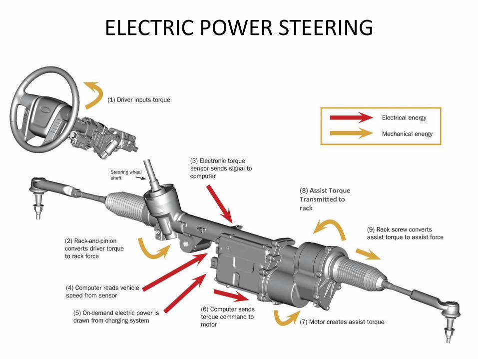
ELECTRIC POWER STEERING
(8) Assist Torque Transmitted to rack

HYDRAULIC vs. ELECTRIC POWER STEERING
• Electric Power Steering gives better response at different speeds as compared to Hydraulic Power Steering
• Hydraulic Power Steering System is complicated compared with Electric Power Steering
• Hydraulic Power Steering System weighs more than Electric Power Steering
• Hydraulic Power Steering uses hydraulic fluids for operation whereas there is no such fluid needed for Electric Power Steering, thus Electric Power Steering needs less maintenance compared to hydraulic power steering.
• Electric Power Steering is less prone to problems and faults and are more durable as compared to Hydraulic power steering.
• Hydraulic power steering gets power from engine, so it reduces the fuel efficiency of the engine. Electric power steering consumes power from battery which is also charged by engine, but it consumes less power compared to Hydraulic power steering. So a car having Electric power steering will give more mileage than one with Hydraulic power steering.