Steel Ss41p Jis g3101
7
Particle Accelerators 1975, Vol. 6, pp.123-129 © Gordon and Breach, Science Publishers Ltd. Printed in the United·Kingdom DESIGN OF EARTHQUAKE-PROOF STRUCTURE FOR KEK LINEAR ACCELERATOR TANK S. INAGAKI, J. TANAKA, H. BABA, S. OKUMURA, S. IKEDA,t R. FUJITA,t J. KISAKlt AND Y. IINOt National Laboratoryfor High Energy Physics, Oho-machi, lsukuba-gun, Ibaraki-ken, Japan (Received September 20, 1974) In order to avoid the· stress due to thermal expansion and to avoid resonance with an earthquake, the KEK proton linear accelerator tank has as supports a so-called soft-structure. In this paper we describe the design of the support, i.e. the idea of the structure, the calculation of the mechanical features (the natural frequency, the endurable acceleration etc.) and experimental results with a brief comment on the damping factor. 1 INTRODUCTION The KEKlinac tank is one cavity consisting of six unit tanks and the total length is 15.5 m. Normally the linac is operated at a temperature of(27 ± l)OC. However, when the machine is shut down and the air conditioning is stopped, the expansion or the contraction for the whole length will amount to se·veral millimeters in a bad case. Further, taking into account frequent earthquakes in Japan, one of the authors (J. Tanaka) proposed to design an earth- quake-proof structure for the KEK linac supports. The degree of the damage due to quakes mainly depends upon the acceleration of the ground and the resonances of the machine with the vibration. It also depends upon other unknown factors as the velocity, the amplitude of the displacement and the duration of the vibration. In the design of the sup- port, we take the former two factors into con- sideration. In Japan the earthquake intensity scale is class- ified into eight ranks and is called J.M.A. (Japan Meteorological Agency) seismic scale. For a tremor of the largest degree,.the acceleration of the ground exceeds 400 cm/sec 2 (Ref. 1). It is characterized by the following phenomena: destruction of more than 30 % of buildings, landslides, crumbling of moun- tain sides and. changes of geographical features (dislocations, upheavals, subsidences etc.) in a wide area. Therefore we intended to make supports tMitsubishi Heavy Industry Company, Oe-machi, Minato-ku, Nagoya-shi, Japan. 123 which can endure an acceleration of 0.5 gt in the horizontal plane. Secondly through Fourier-analysis of micro- tremors of the ground, the power spectra in the KEK building sites were obtained. It was shown that the natural frequency at the building site ranges from 2.5 Hz to to Hz. 2 ,3t Therefore re- sonance will be avoided, if the natural frequency of the supports is below 2 Hz. 2 STRUCTURE OF THE SUPPORT Figure 1 shows the whole view of the KEK linac tank and Figure 2, the side view of the first unit tank. It is around three tons in weight, and is mounted on two supports. The support consists of a steel plate and two preloaded U-shaped steel springs (Figure 3). The former has the role of spring action in the longitudinal direction and the latter, the transverse direction.§ The plate is 1.2 cm in thickness, 78 cm in height and 75 cm in width, having a rectangular hole of 50 cm x 45 cm. The principle to determine the dimensions . of the plate is as follows. First, the height is uniquely determined from the beam line t g stands for the acceleration of gravity. + The first and the second dominant mode are 5.89 Hz and 3.71 Hz respectively. In the general, the frequency of earthquake in Japan lies between 2 and 20 Hz. § We use the term "longitudinal" in the sense of beam direc- tion and "transverse", perpendicular to the beam direction in the horizontal plane.
-
Upload
mahmoudallam3 -
Category
Documents
-
view
406 -
download
6
description
Good understanding for the design porous of Japanese material SS41 and 400
Transcript of Steel Ss41p Jis g3101

Particle Accelerators1975, Vol. 6, pp.123-129
© Gordon and Breach, Science Publishers Ltd.Printed in the United· Kingdom
DESIGN OF EARTHQUAKE-PROOF STRUCTURE FORKEK LINEAR ACCELERATOR TANK
S. INAGAKI, J. TANAKA, H. BABA, S. OKUMURA, S. IKEDA,t R. FUJITA,tJ. KISAKlt AND Y. IINOt
National Laboratory for High Energy Physics, Oho-machi, lsukuba-gun, Ibaraki-ken, Japan
(Received September 20, 1974)
In order to avoid the· stress due to thermal expansion and to avoid resonance with an earthquake, the KEK protonlinear accelerator tank has as supports a so-called soft-structure.
In this paper we describe the design of the support, i.e. the idea of the structure, the calculation of the mechanicalfeatures (the natural frequency, the endurable acceleration etc.) and experimental results with a brief comment on thedamping factor.
1 INTRODUCTION
The KEKlinac tank is one cavity consisting of sixunit tanks and the total length is 15.5 m. Normallythe linac is operated at a temperature of(27 ± l)OC.However, when the machine is shut down and theair conditioning is stopped, the expansion or thecontraction for the whole length will amount tose·veral millimeters in a bad case. Further, takinginto account frequent earthquakes in Japan, one ofthe authors (J. Tanaka) proposed to design an earthquake-proof structure for the KEK linac supports.
The degree of the damage due to quakes mainlydepends upon the acceleration of the ground andthe resonances of the machine with the vibration.It also depends upon other unknown factors as thevelocity, the amplitude of the displacement and theduration of the vibration. In the design of the support, we take the former two factors into consideration.
In Japan the earthquake intensity scale is classified into eight ranks and is called J.M.A. (JapanMeteorological Agency) seismic scale. For a tremorof the largest degree,.the acceleration of the groundexceeds 400 cm/sec2 (Ref. 1). It is characterized bythe following phenomena: destruction ofmore than30 %of buildings, landslides, crumbling of mountain sides and. changes of geographical features(dislocations, upheavals, subsidences etc.) in a widearea. Therefore we intended to make supports
tMitsubishi Heavy Industry Company, Oe-machi,Minato-ku, Nagoya-shi, Japan.
123
which can endure an acceleration of 0.5 gt in thehorizontal plane.
Secondly through Fourier-analysis of microtremors of the ground, the power spectra in theKEK building sites were obtained. It was shownthat the natural frequency at the building siteranges from 2.5 Hz to to Hz.2 ,3t Therefore resonance will be avoided, if the natural frequencyof the supports is below 2 Hz.
2 STRUCTURE OF THE SUPPORT
Figure 1 shows the whole view of the KEK linactank and Figure 2, the side view of the first unittank. It is around three tons in weight, and ismounted on two supports. The support consists ofa steel plate and two preloaded U-shaped steelsprings (Figure 3). The former has the role ofspring action in the longitudinal direction and thelatter, the transverse direction.§
The plate is 1.2 cm in thickness, 78 cm in heightand 75 cm in width, having a rectangular hole of50 cm x 45 cm. The principle to determine thedimensions .of the plate is as follows. First, theheight is uniquely determined from the beam line
t g stands for the acceleration of gravity.+The first and the second dominant mode are 5.89 Hz and
3.71 Hz respectively. In the general, the frequency ofearthquakein Japan lies between 2 and 20 Hz.
§ We use the term "longitudinal" in the sense of beam direction and "transverse", perpendicular to the beam direction inthe horizontal plane.

124 s. INAGAKI et af.
FIGURE 1 Whole view of KEK linac tank.
and the diameter of the cavity. The thickness handthe width b are determined to reduce the naturalfrequency below 2 Hz, to endure longitudinalacceleration of more than 0.5 g and to make thebuckling load larger than the weight of the tank.The structure is shown in Figure 4. The springplate is indicated by CD. The height of the cavitycan be finely adjusted with four screws (J).t
The U-shaped spring ® is 3 cm in thickness,3.2 cm in width and 47.4 cm in length. It is alsodesigned to have a natural frequency of 2 Hz. Inorder to reduce the frictional force an assembly ofneedle bearings ® and a guiding plate C@) isinserted between the legs of the tank ~ and theadjusting screws (J). A pair of mating blocks @having a groove in the transverse direction isattached to the legs and the upper end of the springplate. Each mating block has a pin hole (J), towhich each end of the U-shaped spring is fixed.So as not to fail in exact repositioning, the Ushaped spring is pretensioned to 28 kgjmm2 by the
t The method to set up the unit-tanks (and the drift tubes)on the beam-line will be reported elsewhere. We merely mentionhere that the tanks are well aligned if the screws can be rotatedwith the effective up and down movement of ±5 mm.
FIGURE 2 Side view of the first unit-tank.

EARTHQUAKE-PROOF LINAC TANK STRUCTURE 125
FIGURE 3 Structure of the Support I.
screws ®. This strength corresponds to a transverse acceleration of 0.2 g. The spring has onlyleftward restoring force in the case of Figure 4;spring action occurs for a stretching force whichexceeds the preset value, but does not for any compressive force owing to the clearance of a trackshaped hole·®. Therefore it can be said that forthe transverse direction, the support is a rigidstructure below the acceleration of 0.2 g, but becomes a soft structure above that value (Figure 5}.
FIGURE 4 Structure of the Support II.
Displacement
FIGURE 5 Acceleration-displacement diagram for the transverse movement.
-leftward
3 PROPERTIES IN THE LONGITUDINALDIRECTION
As two guiding blocks are bolted on the upper endof the support and- two anchor bolts are buried atthe lower end ofthe su.pport, we can take the bound...ary condition as follows. The upper end of theplate is free for displacement but restricted inrotation, meanwhile the lower end is fixed both fordisplacement and rotation. Let the x-axis be
" ---- 0"
","/,
/,,~,
/
Q2g rightward
Acceleration

126 s. INAGAKI et al.
x x
p
y
FIGURE 6 Coordinate of a plate spring.
vertical and the Y-axis along the longitudinaldirection (Figure 6). Then
y= 0,oY-=0 at x = 0 (1a)ox
Fs = 0,oY-=0 at x = 1 (1b)ox
y
( YV2 -yJ
FIGURE 7 Flexible pillar model.
Then, Eq. (2) becomes
a2
y (1 )(a2 Y) (1':)EI~ + m - - x -2 - P -..!:. - Y = 0uX 2 ot x=l 2 .
(6)
where
(8)
(9)
(7)
~ (mw 2
) ([P)y = -"2 P + 1 cos ..j Ei x
y = C1 COs(~x) + C2 Sin(j~ x)
{mw
2 (1 ) 1}+ P 2- x +2 ~.
Using the boundary condition (1), we can determineC 1 and C2 to get
the general solution of which is given
As the time variation is independent of the positionY can be written as follows. '
Y = y(x)cos(wt).
From Eqs. (6) and (7), we get
a2y {2(1) P}EI ax2 + Py = mw 2 - x + i ~,
(2)
(3)a3 y ay
Fs = E1 -;-3 + P-,ux ax
where P is the weight of the tank.
3.1 Natural Frequency
We consider the restoring force due to the deflection of the elastic plate. Let the mass on theupper end be m, and assume the mass of the platebe negligible. The bending moment exerting at anypoint (x, Y) is due to the load P and the force ofinertia F (Figure 7), being expressed as follows.
M = FG -x) + p(i - y). (4)
Fs is given by
in which the displacement Y is a function of x andt, and Fs means the shearing force. If we denoteYoung's modulus by E and the geometricalmoment of inertia by 1, then the bending momentM can be expressed as follows:
M = El a2y
ox2
(5) {mw2 (I ) 1}+--~-x+-1':P 2 2 ,. (10)
EARTHQUAKE-PROOF LINAC TANK STRUCTURE 127
(14)
(15)
Putting y = yzl2 at x = 1/2, we get the naturalfrequency f
1 fP 1 . (11)
j= 2nymi j~f}tan(~.D - 1
Taking It = 78 cm, E =-2.09 x 10⁶ kg cm- 2,
P = 1.5 X 10³ kg and I = 4.32 cm4 t, we get
f = 1.88 Hz.
If the denominator in Eq. (11) becomes infinite,the natural frequency f goes to zero. The load Pc atwhich this condition is satisfied is called the Euler'scritical buckling load; the lowest mode of which isgiven by
(13)
With the same values as those in the precedingsection, Pc is evaluated to be 1.47 x 10⁴ kg.Therefore the safety factor becomes 9.8.
3.2 Longitudinal Critical Force
Due to the vibration of the ground, a forced oscillation is induced to the tank. In this section, however,we suppose a static model. At the initial time whenthe ground moves in one direction suddenly, thetank is left at the original position due to inertia.We assume that the period of the vibration is longenough and do not consider the subsequent reversemovement of the ground. If the acceleration of theground is very large, the bending stress at somecross section of the support exceeds the yieldstrength of the material used. We call the forcecorresponding to this acceleration the criticalforce. The actual acceleration which the supportcan endure will be much larger than that calculatedhere, because the tensile strength is about twotimes larger than the yield strength.
The maximum bending stress (Jmax at an arbitrarycross section of a beam is given as follows.
M M(Jmax = T e = Z'
where e is the maximum distance from the neutralaxis and Z, the modulus of section. It is given by
1 bh3/12 bh2
Z=e=hj2=6·
The bending moment M takes the largest value atx = 0 and x = 1, neglecting the second term inEq. (4). Then Eq. (14) becomes
3Fl(Jmax = bh2 • (16)
Using the minimum yield strengtht of SS41P,(Jmax = 25 kg/mm2
, we get
F = (Jmax3~ bh2
= 4.62 X 10² kg,
which corresponds to a horizontal acceleration of0.31 g.t It can easily be shown that the deflectionis 2.0 cm for this acceleration.
4 PROPERTIES IN THE TRANSVERSEDIRECTION
4.1 Natural Frequency
We use a simple pendulum model for the calculation of natural frequency.
j=~ fk. (17)2n~m
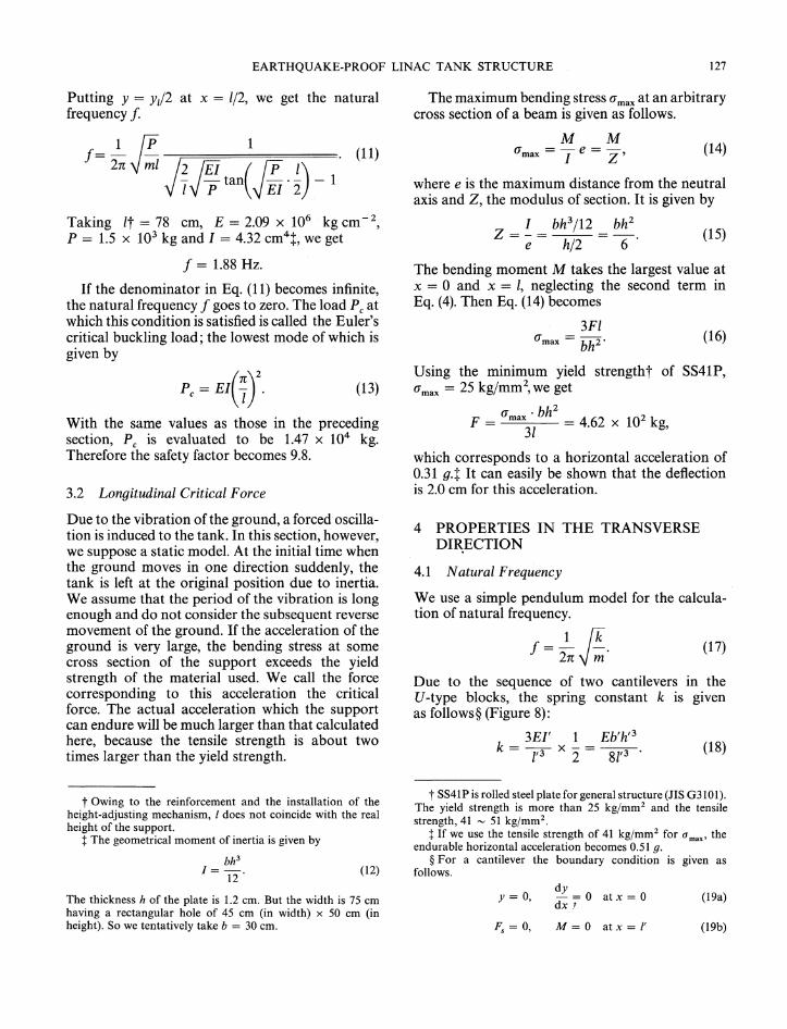
Due to the sequence of two cantilevers in theU-type blocks, the spring constant k is givenas follows § (Figure 8):
3E1' 1 Eb'h,3k = 7 x "2 = 8f3. (18)
t Owing to the reinforcement and the installation of theheight-adjusting mechanism, I does not coincide with the realheight of the support.
t The geometrical moment of inertia is given by
bh3
1=-.12
(12)
t SS41P is rolled steel plate for general structure (JIS G3101).The yield strength is more than 25 kg/mm2 and the tensilestrength, 41 ~ 51 kg/mm2
•
t If we use the tensile strength of 41 kgjmm2 for (j max' theendurable horizontal acceleration becomes 0.51 g.
§ For a cantilever the boundary condition is given asfollows.
The thickness h of the plate is 1.2 cm. But the width is 75 cmhaving a rectangular hole of 45 cm (in width) x 50 cm (inheight). So we tentatively take b = 30 cm.
y = 0,dy
atx = 0-=0dx .?
Fs = 0, M= 0 atx = l'
(19a)
(19b)
128 s. INAGAKI et aJ.
x
y
FIGURE 8 Coordinate of a U-shaped spring.
5 EXPERIMENTAL RESULTS
When a concentrated load F' is exerted on the oneend of a cantilever, the cross section of which isrectangular, the maximum bending stress ·aritax isgiven by Eq. (20).
4.2 Transverse Critical Force
Just as in Sec. 3.3, the maximum transverseacceleration can be obtained by substituting theyield strength or the tensile strength for uritaxin Eq. (20). From this we get 0.36 g and 0.5 grespectively.
Corresponding to the pretensioned force F' = 0.2my, we decided to make uritax = 28 kgjmm2
,
which is about half of the yield strength of S45C.tSubstituting f = 2 Hz into Eqs. (17), (18) and (20),we get relations between h', l' and h'. Using h' = 3cm for the thickness of the spring, we get h' = 3.2cm and l' = 47.4 cm. Therefore the deflection b ofthe spring, which we give, corresponding to theinitial pretension, is given by
F'b = k = 6.25 mm.
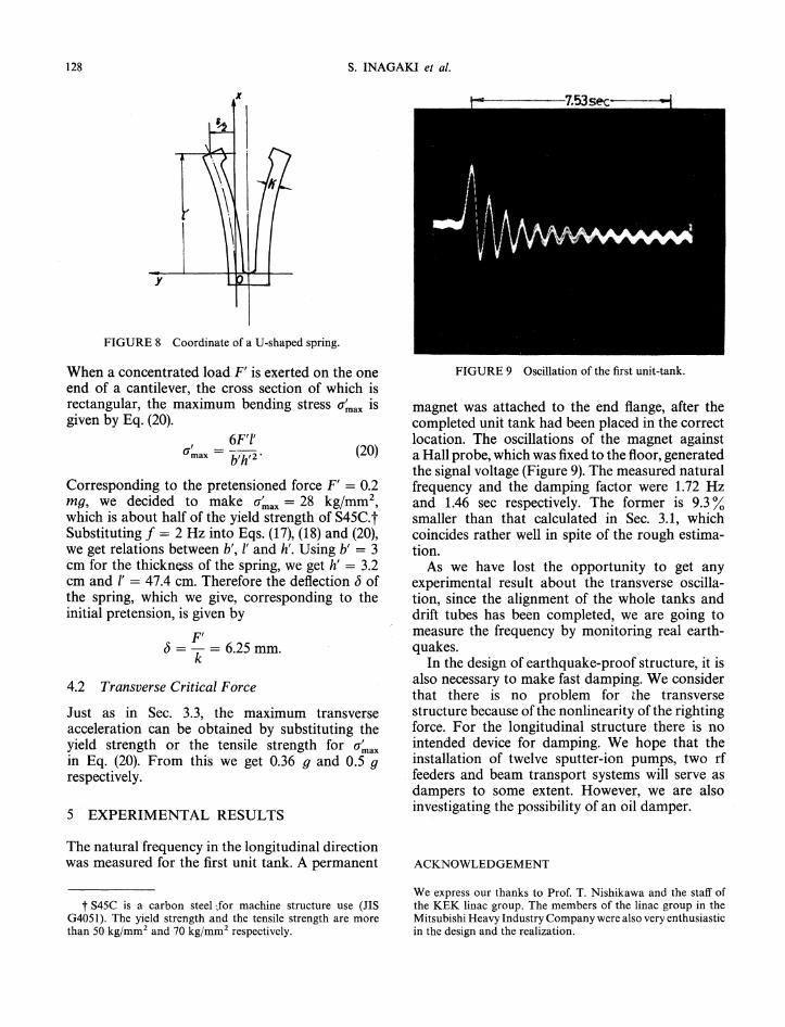
FIGURE 9 Oscillation of the first unit-tank.
magnet was attached to the end flange, after thecompleted unit tank had been placed in the correctlocation. The oscillations of the magnet againsta Hall probe, which was fixed to the floor, generatedthe signal voltage (Figure 9). The measured naturalfrequency and the damping factor were 1.72 Hzand 1.46 sec respectively. The former is 9.3 %smaller than that calculated in Sec. 3.1, whichcoincides rather well in spite of the rough estimation.
As we have lost the opportunity to get anyexperimental result about the transverse- oscillation, since the alignment of the whole tanks anddrift tubes has been completed, we are going tomeasure the frequency by monitoring real earthquakes.
In the design of earthquake-proof structure, it isalso necessary to make fast damping. We considerthat there is no problem for the transversestructure because of the nonlinearjty of the rightingforce. For the longitudinal structure there is nointended device for damping. We hope that theinstallation of twelve sputter-ion pumps, two rffeeders and beam transport systems will serve asdampers to some extent. However, we are alsoinvestigating the possibility of an oil damper.
(20)6F'I'
uritax = llh'2·
The natural frequency in the longitudinal directionwas measured for the first unit tank. A permanent ACKNOWLEDGEMENT
t S45C is a carbon steel Jor machine structure use (JISG4051). The yield strength and the tensile strength are morethan 50 kg/mm2 and 70 kg/mo12 respectively.
We express our thanks to Prof. T. Nishikawa and the staff ofthe KEK linac group. The members of the linac group in theMitsubishi Heavy Industry Company were also very enthusiasticin the design and the realization.

EARTHQUAKE-PROOF LINAC TANK STRUCTURE 129
REFERENCES
1. A. Odaka, S. Nasu, M. Takeuchi, J. Sakurai and S. Tani,Earthquake- and Wind-Proof Structure, Kashima Pub. Co.,p. 24 (1972) (in Japanese).
2. T. Itoh, H. Watanabe and H. Yanohara, Measurement and
Analysis of the Oscillation at National Laboratory for HighEnergy Physics, Research Reports of Shimizu ConstructionCompany, Oct. 20 (1972) (in Japanese).
3. S. Inagaki, J. Tanaka, H. Baba, S. Ikeda, R. Fujita, J. Kisaki,and Y. lino, Earthquake-proof Structure of KEK Linear
Accelerator Tank, KEK PREPRINT-l (1974).