Steel Spotlight City tower gets on top of neighbours · The steel frame and steel core ... was...
5
cnplus.co.uk cnplus.co.uk 11 April 2014 | 23 22 | 11 April 2014 Aldgate in the London borough of Tower Hamlets lies just east of the City of London. It is a transitional area between the capital’s financial district and a neighbourhood now famous for Brick Lane’s Bangladeshi cuisine, trendy bars and the Whitechapel Art Gallery. To meet the local council’s needs for housing growth and the City’s needs for more commercial space, Tower Hamlets created a masterplan in 2007 to safeguard areas and provide a framework for residential, commercial, cultural and educational development. At the junction of Leman Street and Whitechapel High Street, a new £78m 18-storey building is being built to herald Aldgate’s new Commercial Quarter. Called Aldgate Tower, the building is made up of 16 storeys of offices with two plant levels on top. Its steel-framed structure is complete and operations are now focused on fitting out and City tower gets on top of neighbours A lightweight structural solution was critical for London’s new 18-storey Aldgate Tower being built on an existing occupied three-storey basement The steel frame and steel core tower have been built on an existing three-storey basement Roof steelwork under construction at the beginning of this year Project Aldgate Tower, London Main client Aldgate Tower Developments Architect Wilkinson Eyre Architects Main contractor Brookfield Multiplex Project manager Ftsquared Structural engineer Arup Steelwork contractor Severfield-Watson Structures “Arup redesigned the building with a steel core and frame and doubled its height” GEORGE AMY, BROOKFIELD MULTIPLEX In 2007, extra basement columns and piles were installed on the site ready to receive a new steel-framed structure, but by 2013 developer Aldgate Tower Developments expressed a preference for an alternative core plan to gain more floor area. This meant many of the existing basement columns would no longer line up with the new superstructure core columns. “Installing a 1,500 mm-deep transfer structure [acting also as the steel core base] allowed us to offset the columns for the new core arrangement from the basement columns,” explains Arup associate director Ben Tricklebank. ALTERNATIVE PLANS Working next to and on top of RBS and adjacent to Aldgate East Tube station and busy roads, contractor Brookfield Multiplex was stuck for anywhere to offload or store materials. “With the new building taking up the entire site’s footprint, we have had to take over two-thirds of neighbouring Braham Street Park for deliveries,” says Brookfield Multiplex project manager George Amy. The contractor will reinstate the park after Aldgate Tower is complete. During steelwork erection, the park was used for 750-tonne and 1,200-tonne mobile cranes that could not have been supported by the existing triple basement. EXTREMELY TIGHT SITE cladding. The developer for the project is Aldgate Tower Developments and Brookfield Multiplex is the main contractor. Structural engineer is Arup and Severfield-Watson Structures is the steelwork contractor. A steel frame with a central braced steel core to accommodate lifts, stairs and washrooms was designed to keep the building weight low. This was essential, since the structure is supported by an existing three-storey reinforced concrete basement constructed in the early 1980s. It is made up of a perimeter diaphragm wall, raft slab at basement three (B3) level and large diameter piles outside of the basement footprint. The basement was originally designed to support two separate buildings. Until now, only half the plot had been developed. A nine-storey office block leased by banking group RBS occupies phase one and Aldgate Tower is being built on phase two of the plot. However, few construction projects in central London are straightforward and the challenge for Aldgate Tower was that RBS would continue to use the lower two levels of basement (B2 and B3) beneath phase two while Aldgate Tower was being built above. Emergency logistics A further logistical challenge on the current build are the three emergency exits from RBS’s basement levels which emerge at B1 level under Aldgate Tower and a service road for RBS at ground level (see box). “The basement structure had originally been designed for a nine-storey reinforced concrete-framed building,” says Brookfield Multiplex project manager George Amy. “Arup redesigned the building with a steel core and frame [with composite floors] and managed to double the height of the building.” Construction of Aldgate Tower on phase two of the site began in January 2013. A steel-framed transfer structure was the first to be erected to provide the base for the new building’s steel core and to transfer this load to existing reinforced concrete basement columns (see box). This operation first required the existing ground floor slab directly below the core to be broken out to accommodate the steel core base – a 9 m by 20 m rectangular frame made up of two 47-tonne and two 30-tonne, 1.5 m-deep steel plate girders. These members were The trusses sit on a plant- mezzanine level between ground and first floor and had to be erected overnight to prevent disruption to RBS. These substantial trusses support significant plant loads on the mezzanine level, including 2 m-deep water tanks that Arup associate director Ben Tricklebank says are the equivalent of five floors of imposed office loading. Overnight installation was developed as a more cost-effective alternative to building a crash deck over the road and installing the trusses during the day, he adds. Steel columns on the perimeter of the building sit on top of the existing concrete substructure layout where possible. Where other design features (such as the column-free ground-floor reception area or service road) interrupt this rhythm, columns are cranked, or offset via transfer beams. To maintain constant floor- to-ceiling heights, beams are made up of thicker plate sections (up to 100 mm thick), such as over the double-height reception area. Reaching outer space To gain more floor space above first-floor level, transfer trusses or beams are used to step the building out 1.5 m compared with the ground-floor floorplate. “A lot of finite element analysis was carried out to check the diaphragm wall and raft could support the new loading arrangements of the steel building,” Mr Tricklebank says. On the Whitechapel High Street elevation where the double- height main entrance area is located, the offset transfer structure is a 1,250 mm-deep beam. On other elevations, where there is a mezzanine level, trusses make up the transfer system. Supporting the upper floors are 750 mm-deep Fabsec beams spanning up to 18 m between the core and perimeter columns. “Services run through openings in the beams creating a very efficient slim structure,” Mr Amy says. Each of the steel decking and lightweight concrete office floors are broadly similar and the entire steel frame was erected using two tower cranes in just six months. Intumescent coating for fire protection is applied only to primary beams, with secondary beams requiring no treatment. Severfield-Watson also installed all the steel stairs on the project. Aldgate Tower’s first tenants are expected to move in from Q3 2014 and the building will be completed by December. 1.5 m Step out of the building on first floor With so much of the building using steel and incorporating offsite fabrication, it made sense to optimise prefabrication on the project. “Where possible, vertical services risers are prefabricated so they can be slotted in using a tower crane,” says Brookfield Multiplex project manager George Amy. “The toilets also arrive on site in modules. It wasn’t so much for programming advantage as for the quality of finish. But inevitably you reduce installation time and waste, and increase safety by having fewer site-based operations. “Steel has allowed us to build a very efficient building. The pieces arrive in kit-form, ready to go up and all with a consistent high quality.” PREFABRICATION OFFERS QUALITY BENEFITS PROJECT REPORT RUBY KITCHING Steel Spotlight Produced in association with fabricated in Severfield-Watson’s Bolton workshop. Accommodating the steel core base between B1 and ground floor level required four existing concrete columns that terminated under the ground floor slab to be broken down to just above B1 level. Strengthening reinforcement was then added before being built back up again in concrete. The new steel core base connects to these strengthened columns. Following construction of the steel core base, the ground-floor slab was reinstated and the braced steel core erected above. Steel columns could not be placed along RBS’s service road, which crosses the site at ground- floor level. Since this route had to be operational throughout the build, Arup designed four one- storey-high prefabricated trusses to span the road and transfer load to columns either side of it.
Transcript of Steel Spotlight City tower gets on top of neighbours · The steel frame and steel core ... was...

cnplus.co.ukcnplus.co.uk 11 April 2014 | 2322 | 11 April 2014
Aldgate in the London borough of Tower Hamlets lies just east of the City of London. It is a transitional area between the capital’s financial district and a neighbourhood now famous for Brick Lane’s Bangladeshi cuisine, trendy bars and the Whitechapel Art Gallery.
To meet the local council’s needs for housing growth and the City’s needs for more commercial space, Tower Hamlets created a masterplan in 2007 to safeguard areas and provide a framework for residential, commercial, cultural and educational development.
At the junction of Leman Street and Whitechapel High Street, a new £78m 18-storey building is being built to herald Aldgate’s new Commercial Quarter.
Called Aldgate Tower, the building is made up of 16 storeys of offices with two plant levels on top. Its steel-framed structure is complete and operations are now focused on fitting out and
City tower gets on top of neighboursA lightweight structural solution was critical for London’s new 18-storey Aldgate Tower being built on an existing occupied three-storey basement
The steel frame and steel core tower have been built on an existing three-storey basement
Roof steelwork under construction at the beginning of this year
Project Aldgate Tower, London
Main client Aldgate Tower Developments
Architect Wilkinson Eyre Architects
Main contractor Brookfield Multiplex
Project manager Ftsquared
Structural engineer Arup
Steelwork contractor Severfield-Watson Structures
“Arup redesigned the building with a steel core and frame and doubled its height”GEORGE AMY, BROOKFIELD MULTIPLEX
In 2007, extra basement columns and piles were installed on the site ready to receive a new steel-framed structure, but by 2013 developer Aldgate Tower Developments expressed a preference for an alternative core plan to gain more floor area.
This meant many of the existing basement columns would no longer line up with the new superstructure core columns.
“Installing a 1,500 mm-deep transfer structure [acting also as the steel core base] allowed us to offset the columns for the new core arrangement from the basement columns,” explains Arup associate director Ben Tricklebank.
ALTERNATIVE PLANS
Working next to and on top of RBS and adjacent to Aldgate East Tube station and busy roads, contractor Brookfield Multiplex was stuck for anywhere to offload or store materials. “With the new building taking up the entire site’s footprint, we have had to take over two-thirds of neighbouring Braham Street Park for deliveries,” says Brookfield Multiplex project manager George Amy. The contractor will reinstate the park after Aldgate Tower is complete.
During steelwork erection, the park was used for 750-tonne and 1,200-tonne mobile cranes that could not have been supported by the existing triple basement.
EXTREMELY TIGHT SITE
cladding. The developer for the project is Aldgate Tower Developments and Brookfield Multiplex is the main contractor. Structural engineer is Arup and Severfield-Watson Structures is the steelwork contractor.
A steel frame with a central braced steel core to accommodate lifts, stairs and washrooms was designed to keep the building weight low. This was essential, since the structure is supported by an existing three-storey reinforced concrete basement constructed in the early 1980s.
It is made up of a perimeter diaphragm wall, raft slab at basement three (B3) level and large diameter piles outside of the basement footprint.
The basement was originally designed to support two separate buildings. Until now, only half the plot had been developed.
A nine-storey office block leased by banking group RBS occupies phase one and Aldgate Tower is being built on phase two of the plot. However, few construction projects in central London are straightforward and the challenge for Aldgate Tower was that RBS would continue to use the lower two levels of basement (B2 and B3) beneath phase two while Aldgate Tower was being built above.
Emergency logisticsA further logistical challenge on the current build are the three emergency exits from RBS’s basement levels which emerge at B1 level under Aldgate Tower and a service road for RBS at ground level (see box).
“The basement structure had originally been
designed for a nine-storey reinforced concrete-framed building,” says Brookfield
Multiplex project manager George Amy.
“Arup redesigned the building with a steel core and
frame [with composite floors] and managed to double the height of the building.”
Construction of Aldgate Tower on phase two of the site began in January 2013. A steel-framed transfer structure was the first to be erected to provide the base for the new building’s steel core and to transfer this load to existing reinforced concrete basement columns (see box).
This operation first required the existing ground floor slab directly below the core to be broken out to accommodate the steel core base – a 9 m by 20 m rectangular frame made up of two 47-tonne and two 30-tonne, 1.5 m-deep steel plate girders. These members were
The trusses sit on a plant-mezzanine level between ground and first floor and had to be erected overnight to prevent disruption to RBS. These substantial trusses support significant plant loads on the mezzanine level, including 2 m-deep water tanks that Arup associate director Ben Tricklebank says are the equivalent of five floors of imposed office loading.
Overnight installation was
developed as a more cost-effective alternative to building a crash deck over the road and installing the trusses during the day, he adds.
Steel columns on the perimeter of the building sit on top of the existing concrete substructure layout where possible. Where other design features (such as the column-free ground-floor reception area or service road) interrupt this rhythm, columns
are cranked, or offset via transfer beams. To maintain constant floor- to-ceiling heights, beams are made up of thicker plate sections (up to 100 mm thick), such as over the double-height reception area.
Reaching outer spaceTo gain more floor space above first-floor level, transfer trusses or beams are used to step the building out 1.5 m compared with the ground-floor floorplate.
“A lot of finite element analysis was carried out to check the diaphragm wall and raft could support the new loading arrangements of the steel building,” Mr Tricklebank says.
On the Whitechapel High Street elevation where the double-height main entrance area is located, the offset transfer structure is a 1,250 mm-deep beam. On other elevations, where there is a mezzanine level, trusses make up the transfer system.
Supporting the upper floors are 750 mm-deep Fabsec beams spanning up to 18 m between the core and perimeter columns. “Services run through openings in the beams creating a very efficient slim structure,” Mr Amy says.
Each of the steel decking and lightweight concrete office floors are broadly similar and the entire steel frame was erected using two tower cranes in just six months.
Intumescent coating for fire protection is applied only to primary beams, with secondary beams requiring no treatment. Severfield-Watson also installed all the steel stairs on the project.
Aldgate Tower’s first tenants are expected to move in from Q3 2014 and the building will be completed by December.
1.5 mStep out of the
building on first floor
With so much of the building using steel and incorporating offsite fabrication, it made sense to optimise prefabrication on the project.
“Where possible, vertical services risers are prefabricated so they can be slotted in using a tower crane,” says Brookfield Multiplex project manager George Amy.
“The toilets also arrive on site in
modules. It wasn’t so much for programming advantage as for the quality of finish. But inevitably you reduce installation time and waste, and increase safety by having fewer site-based operations.
“Steel has allowed us to build a very efficient building. The pieces arrive in kit-form, ready to go up and all with a consistent high quality.”
PREFABRICATION OFFERS QUALITY BENEFITS
PROJECT REPORTRUBY KITCHING
Steel SpotlightProduced in association with
fabricated in Severfield-Watson’s Bolton workshop.
Accommodating the steel core base between B1 and ground floor level required four existing concrete columns that terminated under the ground floor slab to be broken down to just above B1 level. Strengthening reinforcement was then added before being built back up again in concrete. The new steel core base connects to these strengthened columns.
Following construction of the steel core base, the ground-floor slab was reinstated and the braced steel core erected above.
Steel columns could not be placed along RBS’s service road, which crosses the site at ground-floor level. Since this route had to be operational throughout the build, Arup designed four one-storey-high prefabricated trusses to span the road and transfer load to columns either side of it.

cnplus.co.ukcnplus.co.uk 11 April 2014 | 2524 | 11 April 2014
Sea views and sand dunes don’t usually go hand in hand with lecture theatres and laboratories, but students at Swansea University’s new Bay Campus will be able to experience these contrasting features from September next year.
In fact, when Richard Powell, construction project manager for developer St Modwen, describes the site, he could be reading from a holiday brochure: “The beautiful Mumbles coastline to one side, sand dunes fronting your accommodation and access to the beach along a new purpose-built promenade, really make this a wonderful location”.
This is a world away from when the site was owned by BP and was used to store oil and pump it to a refinery about 4 km away at Coed Darcy. St Modwen purchased the site in 2007 and, from 2011, headed up the colossal clean-up job prior to construction commencing in 2013.
The £450m Bay Campus development is located along the A483 Fabian Way, a strategic route
From BP depot to Bayside campusA 26 ha former BP depot on the coast is being completely transformed into a new science and innovation campus for Swansea University
Bay Campus’ academic buildings will be steel-framed to meet the
demanding construction programme
Project Swansea University, Bay Campus
Main client Swansea University
Developer St Modwen
Concept architect Porphyrios Associates/ Hopkins Architects
Main contractor Vinci Construction
Structural engineer Rodgers Leask, Bay Associates
Steelwork contractor Caunton Engineering
“A steel frame offered us the flexibility that we needed for the design”RICHARD POWELL, ST MODWEN
The Bay Campus project will spawn regeneration beyond the campus and Swansea Bay.
Over a 10-year period, the entire development will bring an economic impact in excess of £3bn, according to Swansea University.
About 4,000 direct jobs will be supported during this period. It is anticipated that the construction process will bring more than £430m of economic activity, with £390m of this being within Wales.
WIDER REGENERATION
into Swansea city centre from the east. Seven new steel-framed mixed-use buildings make up the first phase of the Bay campus development.
Steelwork contractor Caunton Engineering and main contractor Vinci Construction finished erecting five of these buildings in December 2013. Work is now focused on cladding and fit-out.
The buildings under construction are the Great Hall, Manufacturing Facility, Management School, Library and Institute of Materials.
Two other three-storey steel buildings known as the Innovation Hub and Energy
on ground conditions and building loads. One of the most prominent buildings will be the 26 m-tall braced-steel, two-storey Great Hall. At ground floor, this building will accommodate lecture theatres, while an assembly hall will occupy the first floor. The steel frame will be clad with reconstituted stone.
Cladding panels weigh about 10 tonnes each and are hung from heavy-duty brackets bolted to perimeter columns.
To stabilise the structure, full height cross bracing and moment frames have been integrated into the building’s end bays. Forming the assembly hall’s 21 m-wide column-free space is a series of Vierendeel trusses. The roof trusses also support plant.
Controlling lateral deflection in this building was particularly challenging given the potential for high winds from the sea.
Added complexity“In addition to this, the building’s column-free spaces and height combine to present a complex design,” explains Caunton Engineering senior structural engineer Matthew Shimwell.
“The joints between the stone panels could accommodate only a few millimetres deflection under lateral load, which resulted in the building having to be designed to very small deflection limits.”
The three-storey, 95 m-long and 87 m-wide Manufacturing Facility is another prominent building on the site and will be used by local businesses. “The name of the building doesn’t do it justice; it will house many different disciplines, from nanotechnology to sports science, and be available for both academic and industrial use,” Mr Powell explains.
The two halves of this building
are connected by a 9.5 m-wide internal ‘street’, which will be glazed at either end and covered by a tensile fabric roof. Each building is structurally connected by footbridges which span over the street and fabricated box sections across the end bays.
“The bridges bring the two parts of the building together, but controlling differential movement [across the buildings], which could potentially damage the tensile roof, was a challenge,” Mr Shimwell admits.
Throughout the steel programme, Caunton Engineering has had one erection gang working sequentially around the site, a plan that has worked well with Vinci’s overall works.
“This was one of the reasons we contracted a steelwork company that could do a design-and-build job,” explains Vinci Construction Project Director Jerry Williams.
“They’ve been able to do one structure straight after another seamlessly and without any design or erection hold-ups.”
£450mTotal value of the
Bay Campus scheme
Steel SpotlightProduced in association with
n The Institute of Structural Materials – a 72 m-long by 26 m- wide portal frame with a 10 m- wide lean-to structure positioned along either side.
This building will provide a large testing facility for existing materials that are used in the aerospace and aero-engine industries. “A large open column-free space was required for this building’s research area and a steel portal frame offered the quickest and most economical solution,” says Vinci Construction
project director Jerry Williams.n The School of Management – a 53 m-long by 38 m-wide four-storey braced steel-frame structure built around a central full height atrium.
Classroom sizes vary across different floors, so column locations do not always line up through the building. A series of transfer structures located in corridors connects out-of-line columns.n The Library – the main single-storey building which extends around an open quadrangle.
DEVELOPMENT OVERVIEW
PROJECT REPORTRUBY KITCHING
BAY CAMPUS - SWANSEA UNIVERSITY
School of management
Temporarycar park
Residential
Phase 2A
TenantPlace
InnovationHub
GowerSquare
MargamSquare
Coastal revetmentBeach
Mean high water
Great Hall
Library
Institute of StructuralMaterials
Manufacturing facility
0 100M
Safety Research Institute have been built by the university’s framework contractor Leadbitter.
“The academic spaces have a multitude of different functions and spatial requirements, so a steel frame offered us the flexibility we needed for the design - efficiently and cost effectively,” Mr Powell says.
Weather resilientLocated on the coast and subject to seawater spray and high winds, steel also offered what he describes as a robust frame to withstand the weather and one which could accommodate different façade details. With just a two-and-a-half-year construction
programme, speed of construction was
also essential.Since many of the
academic buildings will also house laboratories, having an open steel frame which could be divided in many ways to suit future needs was also attractive for the university, he explains.
“A lot of time was spent making each design work for current and
future intended use – these buildings will be here for the next 100 years at least.”
The buildings sit on either pad foundations or piles, depending

cnplus.co.ukcnplus.co.uk 11 April 2014 | 2726 | 11 April 2014
The concept of thermal mass involves using the fabric of a building to absorb, store and release heat energy so that the energy usually required to cool a building is reduced. For many buildings, this can mean that they will never need air conditioning systems, or their reliance on artificial cooling will be minimal.
Either way, the result is lower carbon emissions and a cost saving for the building owner.
This concept is generally well understood by the industry, but there are still some common misunderstandings over how to maximise the potential of thermal mass.
“Historically, it has been assumed that you need a heavy building to take advantage of thermal mass, but the fact is that any framing material can utilise thermal mass,” says British Constructional Steelwork Association sustainability manager John Dowling.
The benefits of thermal massMore and more buildings are being designed to use thermal mass as part of their cooling strategy to reduce energy bills and lower emissions
An economic structural frame which could contribute to an Excellent BREAM rating as well as accommodate future layout changes were the main reasons for using steel in Winchester University’s St Alphege Learning and Teaching Building.
As with all academic buildings, a tight programme – commission to completion in just 18 months – also meant that using a steel frame with non-load-bearing blockwork walls ensured the two-storey building could be delivered on time. Using block work walls allows the university to move partitions in the future, while including exposed 12 m-span precast planks for all floors and the roof has
enabled the building to use its thermal mass as part of its cooling strategy.
The exposed concrete is able to absorb and store heat generated in the day from students and computers, keeping the internal temperature at a more comfortable level. Rather than using passive overnight cooling to purge this heat, as at Outwood Academy, St Alphege used integral water pipes as part of the building’s cooling and heating strategy. Main contractor Geoffrey Osborne, Design Engine Architects, structural engineer Heyne Tillett Steel and steelwork contractor Snashall Steel Fabrications completed the building in 2013.
ST. ALPHEGE LEARNING AND TEACHING BUILDING, WINCHESTER UNIVERSITY
Known also as One Angel Square, this £100m building was the first in the UK to be awarded a BREEAM Outstanding rating. Completed in 2013, the project team included main contractor Bam Construction, structural engineer Buro Happold, architect 3DReid and steelwork contractor Fisher Engineering.
Steel beams spanning 16.5 m allow the office floors to be open plan, while a large central atrium allows daylight to penetrate the floorplates and warm air to be extracted. Contributing to the 16-storey building’s environmental credentials is the thermal mass of precast floor slabs with exposed soffits within a steel-frame structure. Chilled beams (filled with water) in the floor extract stored heat energy in the precast slabs.
CO-OP GROUP HEAD OFFICE, MANCHESTER
This means the advantages of thermal mass can be just as effective in steel-framed buildings as in concrete ones, with steel
structures also benefiting from speedy construction methods, lighter weight and smaller foundations.
Most commonly, thermal mass is mobilised in the exposed concrete soffits of floor slabs in non-domestic buildings, as seen in the office floors of the Redcar Leisure and Community Heart building (see p28).
Increasingly, however, schools, universities, commercial developments and health centres are also benefiting from thermal mass (see boxes).
To highlight the use of thermal mass in lightweight construction, steel manufacturer Tata Steel and the BCSA have published a guide called Steel construction – Thermal mass which can be downloaded for free from steelconstruction.info.
This 20-page guide includes 10 case studies and gives details of
Steel SpotlightProduced in association with
This secondary school on the outskirts of Doncaster was designed as a steel-framed structure by CPMG Architects and structural engineer Alan Wood & Partners. Built by Wates Construction, the brief required a robust frame for the school’s students which would be quick to erect.
The ‘E’-shaped building is made up of two and three-storey blocks constructed using a braced steel frame and precast concrete floor slabs with exposed soffits in most teaching areas. The thermal mass of the precast planks form part of the building’s cooling strategy to keep temperatures below 25 deg C during the day. Passive cooling at night
allows the building to cool down.A steel frame was ideal for
accommodating regular classroom layouts, double-height areas and long-spanning halls. Steelwork contractor Atlas Ward erected the structure in just three months and the whole build was completed in 52 weeks.
OUTWOOD ACADEMY, ADWICK
THERMAL MASSRUBY KITCHING
This £19m new-build primary care centre is a combination of health and social care facilities linked to an existing sports and leisure facility.
Client Sunderland Teaching Primary Care Trust also specified that the building should be low carbon, resulting in it being the first UK health building to achieve a BREEAM Outstanding rating.
Structural engineer Cundall, architect P&HS Architects, main contractor Willmott Dixon and steelwork contractor Hambleton Steel worked on a structure, which could help cut energy consumption.
This included using a steel frame and precast slabs with exposed soffits. The slabs’ thermal mass help
keep the building a comfortable temperature (below 25 deg C). A plenum beneath the ground floor also passively pre-cools air in the summer and warms it in winter, while a thermal wall along the spine of the building circulates the air from the plenum throughout the internal space. It was completed in 2011.
HOUGHTON-LE-SPRING PRIMARY CARE CENTRE
TEM
PER
ATU
RE
(˚C)
DAY
Internal temperaturewith high thermal mass
Peak temperaturedelayed by up to 6 hrs Up to 6 - 8 °C difference
between peak externaland internal temperature
Internal temperaturewith low thermal mass
External temperature
15
30
NIGHT DAY
25
20
how different structural solutions and building types have made effective use of thermal mass.
It explains, for example, that it is most effectively used by building types which are used by day and are vacant at night.
This allows the fabric of the
building to absorb heat during working hours, helping to maintain a comfortable temperature for occupants.
The temperature in the building peaks much later in the day (see graph), when the building is likely to be either lightly occupied or unoccupied.
At night, when external air temperatures drop, natural ventilation is used to purge the stored heat energy from the building fabric so the process can be repeated the following day.
In some situations, mechanical ventilation and water cooling may also be used to extract this heat from the building fabric.
“For designers, it is important to understand that designing for thermal mass doesn’t mean it will completely dictate the structural solution – any framing material can utilise thermal mass,” Mr Dowling says.
The guide also states that only 75 to 100 mm of concrete is required in the build-up of a typical floor for the whole building to benefit from thermal mass – a fact commonly agreed by the concrete and steel advisory bodies as well as the Chartered Institution of Building Services Engineers and research body Building Research Establishment.
The guide says: “Based on a 24-hour cycle of heating and cooling, heat energy can only penetrate up to around 100 mm into the exposed building element and… that designing thicker floors specifically to utilise thermal mass offers little benefit.”
The floor slab of standard steel-framed buildings typically contains at least 100 mm thickness of concrete, so steel-framed buildings are able to benefit from thermal mass as well as concrete-framed ones.
THERMAL MASS AND TEMPERATURE

cnplus.co.ukcnplus.co.uk 11 April 2014 | 2928 | 11 April 2014
Redcar town centre is undergoing a £75m regeneration which will include a new £31m civic building called the Redcar Leisure and Community Heart.
The development, which features a leisure centre, car park and business centre, is nearing completion. For structural engineer Buro Happold, the challenge has been to design an efficient structural frame which can accommodate all these uses.
The building is 120 m long and has had to be split into structurally separate blocks to reduce the effects of thermal expansion across the building and to aid a simpler lateral bracing system.
A braced steel frame was deemed the only viable structural solution for the project due to the variety of occupancy across the development. As such, to span the 20 m-wide pool hall while supporting ductwork, long spanning Fabsec cellular beams are used. For the sports hall, 35 m- long trusses are most appropriate and for architectural quality, exposed circular hollow sections are used in the entrance foyer.
In the business centre, the most economic and sustainable design for office floors comprises Slimflor
Steel broadens civic opportunitiesChoosing a steel-framed structure for a new civic building in Redcar has meant that many more facilities can be accommodated
Circular openings over the pool areas rise above roof deck level
Steel was used for its long span qualities, ability to accommodate services and to
provide elegant architectural detail
Project Redcar Leisure and Community Heart
Main client Redcar & Cleveland Borough Council
Architect S & P Architects
Main contractor Willmott Dixon
Structural engineer Buro Happold
Steelwork contractor Hambleton Steel
“Working on three buildings meant we had to co-ordinate many interfaces very carefully”GLYN JONES, WILLMOTT DIXON
The superstructure for the Redcar Leisure and Community Heart sits on a basement car park. The basement is made up of a contiguous piled wall and reinforced basement slab.
Due to the high water table in the area, this slab is tied down using a system of tension piles, ground beams and pile caps. Initially, basement columns were designed to be concrete, but it soon emerged that there would be insufficient parking spaces, so slimmer steel columns were chosen.
“Structurally, you have a building from the ground up which isn’t rectilinear, has curves and which doesn’t match with the [regular grid] space of the car park below,” explains Buro Happold associate director Colin Riches. This meant various load transfer techniques had to be used to marry up out-of-line columns.
He explains that, where possible, steel transfer beams on the underside of the ground floor were avoided, as this would require the basement to be excavated deeper to
accommodate the same headroom. Moreover, there would be a
greater effect from uplift due to the high water table if the basement floor had to be lowered. Instead, transfer beams were introduced to the underside of the first floor.
Steelwork contractor Hambleton Steel arrived on site soon after the basement walls and piles had been installed and fixed the steel basement columns to the basement slab. It was also responsible for erecting the building’s steel-framed service cores, precast stairs, precast planks in the business centre and steel decking elsewhere.
Hambleton Steel operations director Mike Dixon says co-ordinating work around other trades while completing steel connections to the underside of the ground-floor slab was challenging. “We had just 2.2 m headroom and our MEWPs are about 2 m tall,” he says. “The work had to be strictly sequenced around other contractors on site so that our MEWPs did not get boxed in.”
BASEMENT POSES WATER TABLE CHALLENGES
beams with precast planks.“The building’s inconsistency is
its consistent characteristic,” explains Buro Happold associate director Colin Riches. “But this is to be expected from so many different uses and layouts”.
The “inconsistency” across floors is also coupled with skewed corners and curved walls - even the roof steelwork is pitched to create the exact fall required for the roof cladding. Building information modelling has aided the team’s understanding of the building.
“Working on essentially three different buildings – the leisure centre, the business centre and the debating chamber – meant we had to co-ordinate many interfaces
very carefully,” says Willmott Dixon
construction manager Glyn Jones. “We have
been working for many months with the stakeholders to ensure the finished product exceeds everyone’s expectations.”
Pool beamsLong-spanning steel beams were ideal for the pool hall which includes a six-lane, 25 m-long pool, training pool and leisure pool.
“Fabsec beams over the pool area were adopted for two reasons,” Mr Riches says. “First, we felt that this was the most economical way of spanning approximately 20 m, as the thickness of the top and bottom flanges and web could be adjusted to suit the span required.
“Secondly, it was relatively easy to introduce web openings to the beams to allow the ductwork (including a large central duct) to
roof deck and finishes, to form the circular ‘turret’ through the roof.”
Stingent criteria Three steel trusses span the 35 m- wide sports hall, with the central roof truss over it designed to support a moveable partition to allow the area to be divided into smaller halls, including for use as a number of dance studios, which has meant that a separate dance studio did not have to be built.
“The truss had to be designed with some stringent deflection criteria to ensure the moveable
partition could be operated with relative ease,” Mr Riches says.
As two of the trusses will always be exposed, Buro Happold worked closely with Hambleton Steel and architect S & P to ensure the splice connections were discreet. “On Hambleton’s advice, we revised the size of some of the diagonal members on the exposed trusses, which were fabricated from rectangular hollow and square hollow sections,” Mr Riches says.
“The diagonal members were sufficiently large to accommodate the forces anticipated, but they were considerably smaller than the top and bottom chords of the truss, which meant there was the possibility of these ‘punching’ through the wall of the SHS members forming the top and bottom chords of the truss.”
Elsewhere in the building, the curved corners of the debating chamber have been framed using
steel beams and columns, while the more regular layout for the adjacent business centre office block uses Slimflor beams and precast planks.“The use of precast floors to the upper floors was proposed primarily to allow the use of exposed concrete as thermal mass to aid the cooling of the office units,” Mr Riches says.
“From a purely structural perspective, the use of Slimflor beams allowed us to achieve a
relatively slim floor construction.”Much of the steel for the
project has been sourced from Tata Steel’s Teesside Beam Mill at Lackenby, to the delight of Redcar cabinet member for economic development Mark Hannon.
“It’s fantastic to see Teesside steel being delivered to a site that is integral to the regeneration of the borough,” he says. “I am really enjoying watching this ambitious development taking shape.”
Steel SpotlightProduced in association with
120mLength of the
whole building
PROJECT REPORTRUBY KITCHING
pass through in a very elegant and efficient way.”
Circular lightwells in the pool hall roof allow light to enter and are made from rectangular hollow section circular beams. These were shaped by steel-bending firms Angle Ring and Barnshaw Section Benders and were challenging to detail since they are also tilted in their final state, taking the form of an inclined ellipse.
“The circular openings were framed out with orthogonal steel elements (at the level of the main supporting roof beams), and the circular opening formed with secondary curved ring beams at this level,” Mr Riches explains.
“While the ring beams are curved, they are supported at quadrant points, so they don’t twist too much. Secondary posts were then added on top of these ring beams to support another ring beam above the level of the
The new leisure centre, debating chamber and business centre offices
11 April 2014 | 31cnplus.co.uk30 | 11 April 2014 cnplus.co.uk
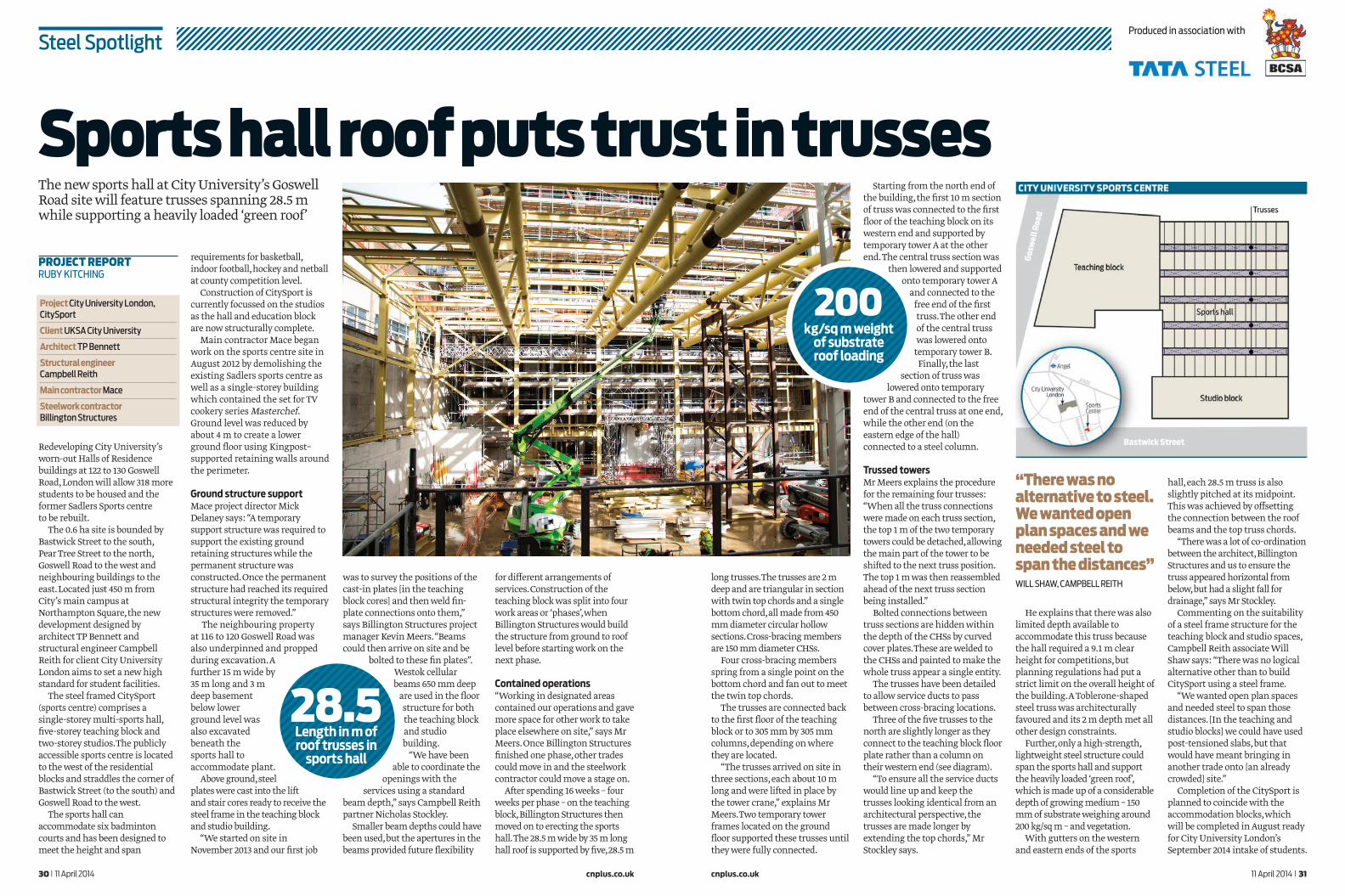
Redeveloping City University’s worn-out Halls of Residence buildings at 122 to 130 Goswell Road, London will allow 318 more students to be housed and the former Sadlers Sports centre to be rebuilt.
The 0.6 ha site is bounded by Bastwick Street to the south, Pear Tree Street to the north, Goswell Road to the west and neighbouring buildings to the east. Located just 450 m from City’s main campus at Northampton Square, the new development designed by architect TP Bennett and structural engineer Campbell Reith for client City University London aims to set a new high standard for student facilities.
The steel framed CitySport (sports centre) comprises a single-storey multi-sports hall, five-storey teaching block and two-storey studios. The publicly accessible sports centre is located to the west of the residential blocks and straddles the corner of Bastwick Street (to the south) and Goswell Road to the west.
The sports hall can accommodate six badminton courts and has been designed to meet the height and span
Sports hall roof puts trust in trussesThe new sports hall at City University’s Goswell Road site will feature trusses spanning 28.5 m while supporting a heavily loaded ‘green roof’
“There was no alternative to steel. We wanted open plan spaces and we needed steel to span the distances”WILL SHAW, CAMPBELL REITH
requirements for basketball, indoor football, hockey and netball at county competition level.
Construction of CitySport is currently focussed on the studios as the hall and education block are now structurally complete.
Main contractor Mace began work on the sports centre site in August 2012 by demolishing the existing Sadlers sports centre as well as a single-storey building which contained the set for TV cookery series Masterchef. Ground level was reduced by about 4 m to create a lower ground floor using Kingpost–supported retaining walls around the perimeter.
Ground structure supportMace project director Mick Delaney says: “A temporary support structure was required to support the existing ground retaining structures while the permanent structure was constructed. Once the permanent structure had reached its required structural integrity the temporary structures were removed.”
The neighbouring property at 116 to 120 Goswell Road was also underpinned and propped during excavation. A further 15 m wide by 35 m long and 3 m deep basement below lower ground level was also excavated beneath the sports hall to accommodate plant.
Above ground, steel plates were cast into the lift and stair cores ready to receive the steel frame in the teaching block and studio building.
“We started on site in November 2013 and our first job
was to survey the positions of the cast-in plates [in the teaching block cores] and then weld fin-plate connections onto them,” says Billington Structures project manager Kevin Meers. “Beams could then arrive on site and be
bolted to these fin plates”. Westok cellular beams 650 mm deep
are used in the floor structure for both the teaching block and studio building.
“We have been able to coordinate the
openings with the services using a standard
beam depth,” says Campbell Reith partner Nicholas Stockley.
Smaller beam depths could have been used, but the apertures in the beams provided future flexibility
for different arrangements of services. Construction of the teaching block was split into four work areas or ‘phases’, when Billington Structures would build the structure from ground to roof level before starting work on the next phase.
Contained operations“Working in designated areas contained our operations and gave more space for other work to take place elsewhere on site,” says Mr Meers. Once Billington Structures finished one phase, other trades could move in and the steelwork contractor could move a stage on.
After spending 16 weeks – four weeks per phase – on the teaching block, Billington Structures then moved on to erecting the sports hall. The 28.5 m wide by 35 m long hall roof is supported by five, 28.5 m
Steel SpotlightProduced in association with
200kg/sq m weight
of substrate roof loading
28.5Length in m of roof trusses in
sports hall
long trusses. The trusses are 2 m deep and are triangular in section with twin top chords and a single bottom chord, all made from 450 mm diameter circular hollow sections. Cross-bracing members are 150 mm diameter CHSs.
Four cross-bracing members spring from a single point on the bottom chord and fan out to meet the twin top chords.
The trusses are connected back to the first floor of the teaching block or to 305 mm by 305 mm columns, depending on where they are located.
“The trusses arrived on site in three sections, each about 10 m long and were lifted in place by the tower crane,” explains Mr Meers. Two temporary tower frames located on the ground floor supported these trusses until they were fully connected.
Starting from the north end of the building, the first 10 m section of truss was connected to the first floor of the teaching block on its western end and supported by temporary tower A at the other end. The central truss section was
then lowered and supported onto temporary tower A
and connected to the free end of the first truss. The other end of the central truss was lowered onto
temporary tower B. Finally, the last
section of truss was lowered onto temporary
tower B and connected to the free end of the central truss at one end, while the other end (on the eastern edge of the hall) connected to a steel column.
Trussed towersMr Meers explains the procedure for the remaining four trusses: “When all the truss connections were made on each truss section, the top 1 m of the two temporary towers could be detached, allowing the main part of the tower to be shifted to the next truss position. The top 1 m was then reassembled ahead of the next truss section being installed.”
Bolted connections between truss sections are hidden within the depth of the CHSs by curved cover plates. These are welded to the CHSs and painted to make the whole truss appear a single entity.
The trusses have been detailed to allow service ducts to pass between cross-bracing locations.
Three of the five trusses to the north are slightly longer as they connect to the teaching block floor plate rather than a column on their western end (see diagram).
“To ensure all the service ducts would line up and keep the trusses looking identical from an architectural perspective, the trusses are made longer by extending the top chords,” Mr Stockley says.
He explains that there was also limited depth available to accommodate this truss because the hall required a 9.1 m clear height for competitions, but planning regulations had put a strict limit on the overall height of the building. A Toblerone-shaped steel truss was architecturally favoured and its 2 m depth met all other design constraints.
Further, only a high-strength, lightweight steel structure could span the sports hall and support the heavily loaded ‘green roof’, which is made up of a considerable depth of growing medium – 150 mm of substrate weighing around 200 kg/sq m – and vegetation.
With gutters on the western and eastern ends of the sports
hall, each 28.5 m truss is also slightly pitched at its midpoint. This was achieved by offsetting the connection between the roof beams and the top truss chords.
“There was a lot of co-ordination between the architect, Billington Structures and us to ensure the truss appeared horizontal from below, but had a slight fall for drainage,” says Mr Stockley.
Commenting on the suitability of a steel frame structure for the teaching block and studio spaces, Campbell Reith associate Will Shaw says: “There was no logical alternative other than to build CitySport using a steel frame.
“We wanted open plan spaces and needed steel to span those distances. [In the teaching and studio blocks] we could have used post-tensioned slabs, but that would have meant bringing in another trade onto [an already crowded] site.”
Completion of the CitySport is planned to coincide with the accommodation blocks, which will be completed in August ready for City University London’s September 2014 intake of students.
Project City University London, CitySport
Client UKSA City University
Architect TP Bennett
Structural engineer Campbell Reith
Main contractor Mace
Steelwork contractor Billington Structures
PROJECT REPORTRUBY KITCHING