Steel In Construction : Paddington Trainshed & Broadgate Exchange … · 2014-08-19 · Steel In...
12
4CSS584 Building Technology 2 Steel In Construction : Paddington Trainshed & Broadgate Exchange House Mark Lomas w10711488
Transcript of Steel In Construction : Paddington Trainshed & Broadgate Exchange … · 2014-08-19 · Steel In...
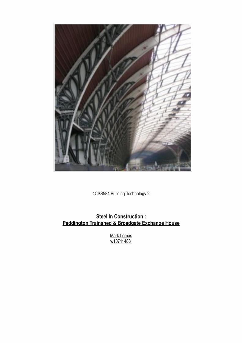
4CSS584 Building Technology 2
Steel In Construction :Paddington Trainshed & Broadgate Exchange House
Mark Lomasw10711488
Mark Lomas w10711488 Iron & Steel in Construction
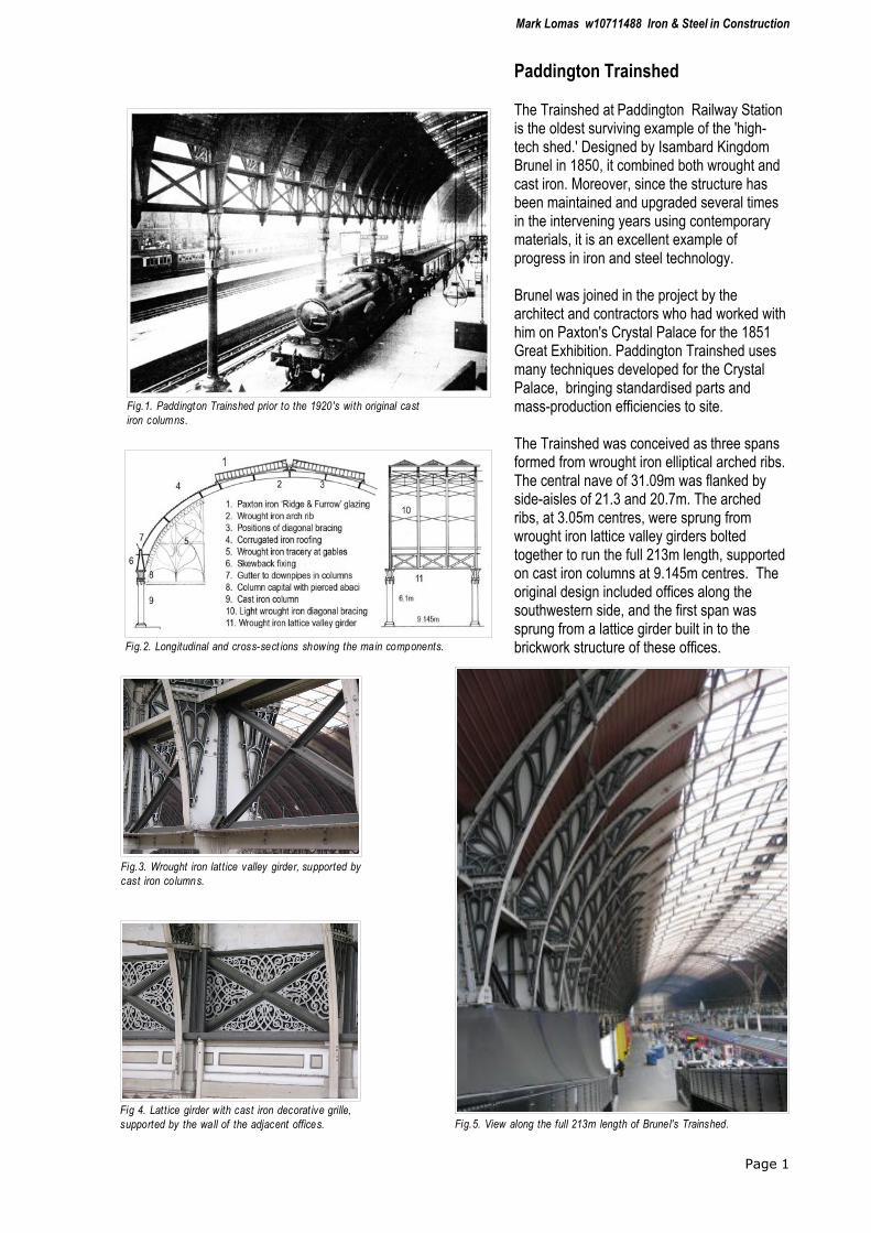
Paddington Trainshed
The Trainshed at Paddington Railway Station is the oldest surviving example of the 'high-tech shed.' Designed by Isambard Kingdom Brunel in 1850, it combined both wrought and cast iron. Moreover, since the structure has been maintained and upgraded several times in the intervening years using contemporary materials, it is an excellent example of progress in iron and steel technology.
Brunel was joined in the project by the architect and contractors who had worked with him on Paxton's Crystal Palace for the 1851 Great Exhibition. Paddington Trainshed uses many techniques developed for the Crystal Palace, bringing standardised parts and mass-production efficiencies to site.
The Trainshed was conceived as three spans formed from wrought iron elliptical arched ribs. The central nave of 31.09m was flanked by side-aisles of 21.3 and 20.7m. The arched ribs, at 3.05m centres, were sprung from wrought iron lattice valley girders bolted together to run the full 213m length, supported on cast iron columns at 9.145m centres. The original design included offices along the southwestern side, and the first span was sprung from a lattice girder built in to the brickwork structure of these offices.
Page 1
Fig.1. Paddington Trainshed prior to the 1920's with original cast
iron columns.
Fig.2. Longitudinal and cross-sect ions showing the main components.
Fig.3. Wrought iron lattice valley girder, supported by
cast iron columns.
Fig 4. Lattice girder with cast iron decorat ive grille,
supported by the wall of the adjacent offices. Fig.5. View along the full 213m length of Brunel's Trainshed.

Mark Lomas w10711488 Iron & Steel in Construction
Page 2
Fig 6. Detail of Rib to Column Joint. 1:10 sc ale.
Those arch ribs coinciding with columns were bolted to an iron
'skewback' cast ing (with oak packing to ease adjustment during
construction), and the two ribs between centres were seated on the
lattice valley girders. Rainwater was collected in the valleys between
spans, and the hollow cast iron columns acted as downpipes for
disposal to underground drains.
Fig 7. Skew Joint photograph.
Mark Lomas w10711488 Iron & Steel in Construction
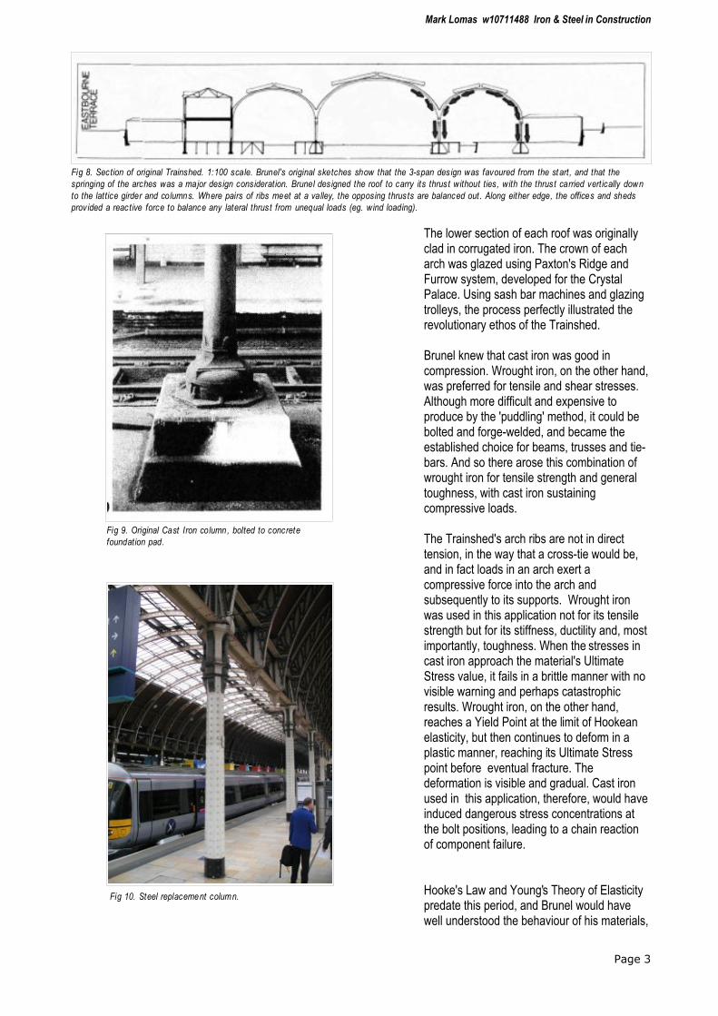
The lower section of each roof was originally clad in corrugated iron. The crown of each arch was glazed using Paxton's Ridge and Furrow system, developed for the Crystal Palace. Using sash bar machines and glazing trolleys, the process perfectly illustrated the revolutionary ethos of the Trainshed.
Brunel knew that cast iron was good in compression. Wrought iron, on the other hand, was preferred for tensile and shear stresses. Although more difficult and expensive to produce by the 'puddling' method, it could be bolted and forge-welded, and became the established choice for beams, trusses and tie-bars. And so there arose this combination of wrought iron for tensile strength and general toughness, with cast iron sustaining compressive loads.
The Trainshed's arch ribs are not in direct tension, in the way that a cross-tie would be, and in fact loads in an arch exert a compressive force into the arch and subsequently to its supports. Wrought iron was used in this application not for its tensile strength but for its stiffness, ductility and, most importantly, toughness. When the stresses in cast iron approach the material's Ultimate Stress value, it fails in a brittle manner with no visible warning and perhaps catastrophic results. Wrought iron, on the other hand, reaches a Yield Point at the limit of Hookean elasticity, but then continues to deform in a plastic manner, reaching its Ultimate Stress point before eventual fracture. The deformation is visible and gradual. Cast iron used in this application, therefore, would have induced dangerous stress concentrations at the bolt positions, leading to a chain reaction of component failure.
Hooke's Law and Young's Theory of Elasticity predate this period, and Brunel would have well understood the behaviour of his materials,
Page 3
Fig 8. Section of original Trainshed. 1:100 scale. Brunel's original sketches show that the 3-span des ign was favoured from the start, and that the
springing of the arches was a major des ign consideration. Brunel des igned the roof to carry its thrust without ties, with the thrust carried vertically down
to the lattice girder and columns. Where pairs of ribs meet at a valley, the opposing thrusts are balanced out . Along either edge, the offices and sheds
prov ided a reactive force to balance any lateral thrust from unequal loads (eg. wind loading).
Fig 9. Original Cast Iron column, bolted to concrete
foundation pad.
Fig 10. Steel replacement column.
Mark Lomas w10711488 Iron & Steel in Construction
even without the advanced computer calculations available to the engineers of Exchange House. He was recorded as commissioning sample structural elements (eg. for his proposed Dome for the Great Exhibition, unbuilt), and his instinctive understanding of his materials was due as much to empirical observation, testing and experience as to calculation and theory.
The Trainshed has been adapted and renovated at various points in its lifetime, and these works highlight the long-term properties of the original materials. In 1909-15, a fourth span was added at the northeastern side of the station, with arch ribs and lattice girder made from mild steel. The wider span imposed a lateral thrust on Brunel's arches, with movements of up to 125mm at the columns, and so the new span had to be stabilised with cross-ties. The cast iron columns were found to be cracking and so in the 1920's all the cast iron columns were replaced with steel. In the 1990's renovations, the decorative cast iron capitals were found to be concealing corrosion of the columns. The difficulty of removing the capitals meant that they were all replaced with new castings.
Page 4
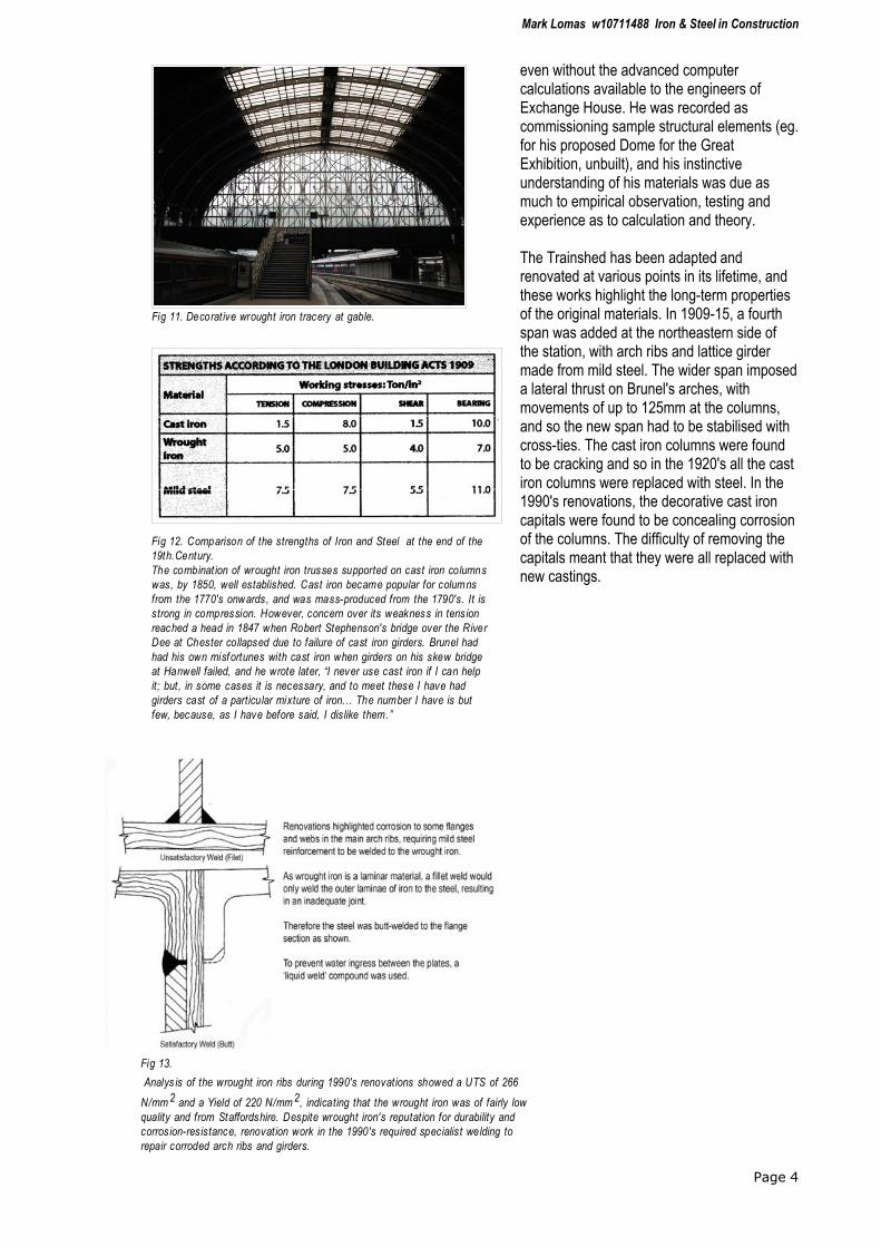
Fig 12. Comparison of the strengths of Iron and Steel at the end of the
19th.Century.
The combinat ion of wrought iron trusses supported on cast iron columns
was, by 1850, well established. Cast iron became popular for columns
from the 1770's onwards, and was mass-produced from the 1790's. It is
strong in compression. However, concern over its weakness in tens ion
reached a head in 1847 when Robert Stephenson's bridge over the River
Dee at Chester collapsed due to failure of cast iron girders. Brunel had
had his own misfortunes with cast iron when girders on his skew bridge
at Hanwell failed, and he wrote later, “I never use cast iron if I can help
it; but, in some cases it is necessary, and to meet these I have had
girders cast of a particular mixture of iron. .. The number I have is but
few, because, as I have before said, I dislike them.”
Fig 13.
Analys is of the wrought iron ribs during 1990's renovations showed a UTS of 266
N/mm 2 and a Yield of 220 N/mm 2, indicating that the wrought iron was of fairly low
quality and from Staffordshire. Despite wrought iron's reputation for durability and
corros ion-resistance, renovation work in the 1990's required specialis t welding to
repair corroded arch ribs and girders.
Fig 11. Decorative wrought iron tracery at gable.

Mark Lomas w10711488 Iron & Steel in Construction
Broadgate Exchange House
Broadgate Exchange House owes much to the legacy of Brunel and Paddington Trainshed. Clear spanning 78m over the tracks from adjacent Liverpool Street Station, it proudly sports its 'structure as architecture' with an 'independence of meretricious and adventitious ornament' which would have pleased Brunel.
All loads from the 10-storey office block are transmitted via four segmented, tied, parabolic arches to eight hand-mined pile foundations at either side of the railway tracks. Iyengar states that, “The functional hierarchy of the arch system was expressed in layering components on the system to depict clear channels of load flow.” This is achieved by making the two outermost arches an external feature, and leaving the internal arches visible from the atria. Fire engineering calculations meant that the separation of 2m between the main structural framework and the smooth wall facade added further clarity to this concept.
A parabolic arch is the most efficient shape for transmitting uniform loads by axial compression. By making the parabolic arch resemble the bending moment diagram of the load that it supports, the bending moment is eliminated, and the compressive load is carried efficiently within the shape of the arch.
Page 5
Fig 14. Broadgate Exchange House. Railway sym bolism is evident
in arch, tie members and in the functionality and materiality. Brunel
would, no doubt, have appreciated the advances that modern steel
allows engineers and des igners.
Fig 15. A parabolic arch resembles the
shape of a chain suspended from two side-
supports. A building simi lar to this example
(Federal Reserve Bank, Minneapolis) was
considered, but was rejected due to the
complex and costly erection sequence
required above the rail tracks at Broadgate.
Fig 16. Ident ification of major st ructural components. Main
elevation. 1:1000 scale.
Mark Lomas w10711488 Iron & Steel in Construction
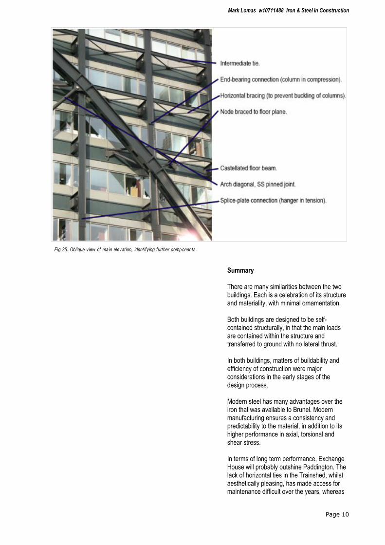
The main structure comprises the 4 tied parabolic arches creating 3 bays of 18.5, 15 and 18.5m. On the longer sides the arches support columns at nodes. These nodes were set out to correspond in most cases with separate floor levels, and consist of a joint between two arch segments with the column passing through the node. Each node is also braced diagonally in plane with the floor slabs by a pair of 150mm diameter pipe sections (see Fig.18).
Above the nodes (ie. above the arch), the columns are in compression, and are spliced together with end-bearing plates. To resist buckling loads, these upper columns are braced at each floor by a pair of horizontal bracing rods. Below the nodes, the joints are in tension and are joined with splice-plates bolted to the webs. Since the hangers here are in tension, buckling is not an issue and the bracing rods are omitted.
Composite floor trusses at 3m centres form the floor framing, and alternate floor trusses (ie. at the 6m column spacing) extend through the
Page 6
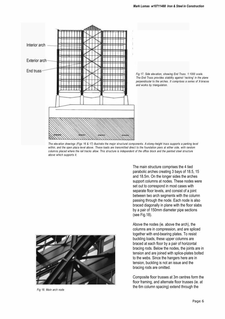
Fig 17. Side elevation, showing End Truss. 1:1000 scale.
The End Truss prov ides stability against 'racking' in the plane
perpendicular to the arches. It comprises a series of X-braces
and works by triangulation.
The elevation drawings (Figs 16 & 17) illustrate the major st ructural components. A storey-height truss supports a parking level
within, and the open plaza level above. These loads are transmitted direc t to the foundation piers at either side, with random
columns placed where the rail tracks allow. This st ructure is independent of the office block and the painted steel st ructure
above which supports it.
Fig 18. Main arch node

Mark Lomas w10711488 Iron & Steel in Construction
curtain wall and connect into the columns. Perpendicular spandrel beams at the wall plane act both as floor girders and intermediate ties.
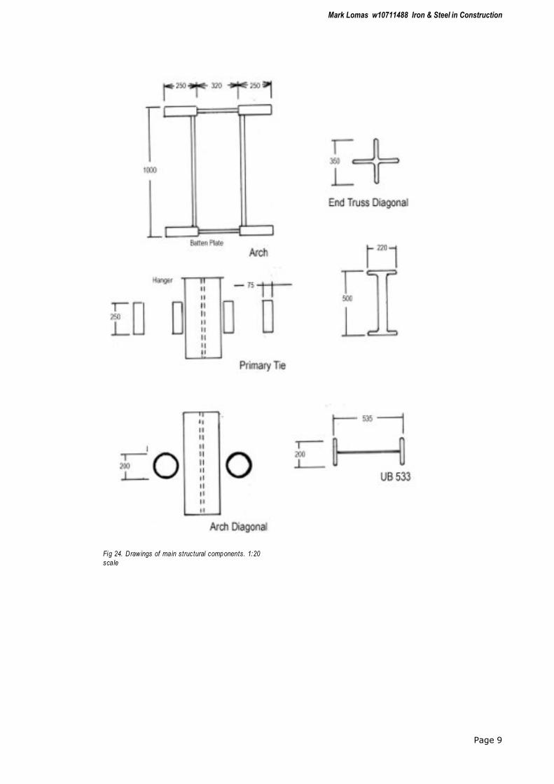
The arch segments are formed from back-to-back builtup channel sections 320mm apart , connected with batten plates to create openings for the columns to pass through at nodes, and to increase the moment of inertia. The arches are in compression, and so their inplane buckling strength is increased by pairs of 200mm fascia arch diagonals connecting the 6th. floor nodes back to the centre of the primary horizontal tie.
The horizontal ties (Fig.20) connect the main bearing nodes at either side, and are in tension. The primary tie is below the first floor level, in order to articulate it visually, with the secondary tie above supporting the first floor framing. The primary tie consists of 4 parallel plates joined with 3 stainless steel shear pins at each joint. The secondary tie is shaped like an I-beam, with similar pinned joints.
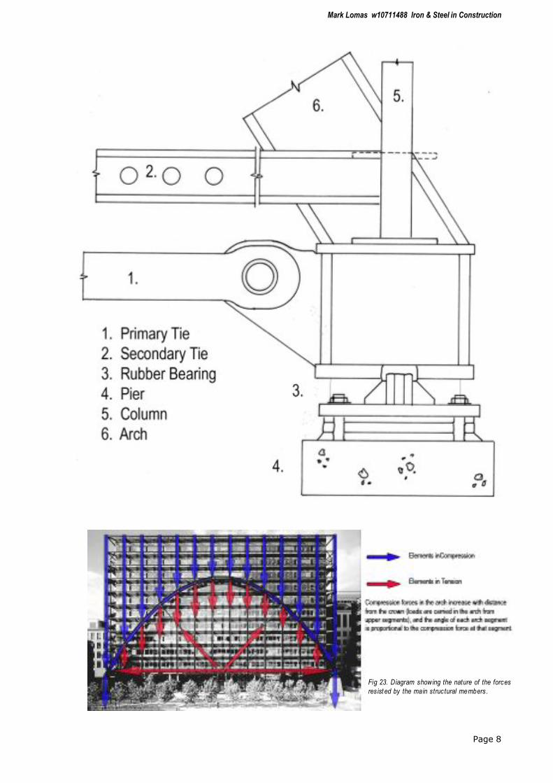
These ties join the ends of the parabolic arches at the main bearing joints which sit on the foundations (Figs 21 & 22). The main loading from the arches imposes an outward thrust, and the ties provide a reaction to this thrust, containing the forces within the shape of the arches. Because the secondary ties are subject to thermal growth and tie stretch, the first floor slab was poured last, after the structure had settled to its own self-loading, and differential movement was avoided by separating the slab from the interior tie by removing the shear studs that would normally tie these elements together. The main bearing nodes are designed to allow for this movement in the ties.
Page 7
Fig 19. Rear detail of main arch node, showing horizontal
diagonal brac ing.
Fig 20. Primary and secondary horizontal tie members
prov ide a tens ion reaction to the lateral outwards thrust at
the base of the arches.
Fig 21. Main end bearing node.
Mark Lomas w10711488 Iron & Steel in Construction
Page 8
Fig 23. Diagram showing the nature of the forces
resist ed by the main structural members.
Mark Lomas w10711488 Iron & Steel in Construction
Page 9
Fig 24. Drawings of main structural components. 1:20
scale
Mark Lomas w10711488 Iron & Steel in Construction
Summary
There are many similarities between the two buildings. Each is a celebration of its structure and materiality, with minimal ornamentation.
Both buildings are designed to be self-contained structurally, in that the main loads are contained within the structure and transferred to ground with no lateral thrust.
In both buildings, matters of buildability and efficiency of construction were major considerations in the early stages of the design process.
Modern steel has many advantages over the iron that was available to Brunel. Modern manufacturing ensures a consistency and predictability to the material, in addition to its higher performance in axial, torsional and shear stress.
In terms of long term performance, Exchange House will probably outshine Paddington. The lack of horizontal ties in the Trainshed, whilst aesthetically pleasing, has made access for maintenance difficult over the years, whereas
Page 10
Fig 25. Oblique view of main elevation, ident ifying further components.
Mark Lomas w10711488 Iron & Steel in Construction
Exchange House benefits from modern paint treatments, and includes measures to shed water away from points where it might cause deterioration. The newer structure can be inspected safely from within the building, whilst much of the deterioration in the Trainshed went unnoticed for many years due to difficulty of access for inspection.
From Rolt\s depiction of Brunel, one suspects that this Master of Iron would have been delighted by the achievements of Exchange House, and somewhat envious of the possibilities that modern steel provides.
Page 11
Bibliography :
Connell, G.S., (1993) The Restoration of Brunel's Paddington Station Roof. Proc.Instn Civ.Engnrs – Civil
Engineering. Feb 93, 93 10-18 Paper 10084, 10-18.
Thorne R., (1985) Masters of Building – Paddington Station. Architects Journal. 13 November 1985, 44-58.
Richardson, C., (2005) An Iron Will. Building Conservation Directory 2005, 52-55.
Rabenek, A., (1990) Broadgate and the Beaux Arts. Architects Journal. 24 October 1990, 37-51.
Iyengar, H., (1993) Broadgate Exchange House: Structural Systems. The Structural Engineer, Vol 71, No.9, 4
May 1993, 149-159
Rolt, L.T.C., (1957) Isambard Kingdom Brunel. 1986 Ed. UK: Penguin Books.
Gere, J.M. & Timoshenko, S.P. (1999) Mechanics of Materials 4th Ed., UK: Stanley Thornes Publishing Ltd.
Garrison, P.. (2005) Basic Structures for Architects & Engineers. UK : Blackwell Publishing.
Alexander, W.,& Street, A. (1944) Metals in the Service of Man. 1951 Ed. UK : Pelican Books.
Gordon, J.E., (1978) Structures – Or Why Things Don't Fall Down. UK : Penguin Books.
Gordon, J.E., (1968) The New Science of Strong Materials. 1991 Ed. UK : Penguin Books.
Cowan, H.J., (1971) Architectural Structures – An Introduction to Structural Mechanics. 1976 Ed. UK : Pitman