Steel Girders
152
Inspection and Maintenance of Steel Girders
-
Upload
selva651950 -
Category
Documents
-
view
333 -
download
38
description
Inspection and maintenance of Steel Girders
Transcript of Steel Girders

Inspection and Maintenanceof
Steel Girders

Inspection and Maintenanceof
Steel Girders
July 2006
INDIAN RAILWAYS INSTITUTE OF CIVIL ENGINEERING,PUNE - 411001

PREFACE TO THE SECOND EDITION
The book “Inspection and Maintenance of Steel Girders” was firstpublished in 1998. It was very popular among the field engineersand became out of stock in due course of time.
Therefore, the second revised and enlarged edition has beenbrought out to fulfill the continuous demand for the book. Interaliaa new chapter on steel channel sleeper has been added whichincorporates details about fixing and inspection of channelsleepers on the steel girder bridges.
Although every effort has been made to bring out latest andpresent the book in error free manner, yet if there is anysuggestion or discrepancy, kindly do write to us.
Shiv KumarDirectorIRICEN
( i )

ACKNOWLEDGEMENT TO THE SECOND EDITION
The first edition of the book published in December 1998 wasvery popular among the field engineers as all aspects concerninginspection, maintenance and understanding of steel girderbridges were well documented in the book. In this book onechapter was devoted on “Bearing for Steel Girder of TrackBridges”. In the meantime, a separate publication exclusively forbridge bearing was available. Its revised and enlarged edition hasbeen published recently. During last 5 years, need has arisen foruse of steel channel sleepers on Girder Bridges in place ofBridge Timbers, due to scarcity of wooden sleepers. Differentdrawings have been issued by RDSO for channel sleepers.
Keeping in view above, in this 2nd and revised edition, chapter onbearing has been deleted and in place of this a new chapter onsteel channel sleeper has been added.
Efforts have been made to make the book more useful for thefield engineers. In this effort, the IRICEN faculty and staff havecontributed immensely, notably among them are Mrs. GayatriNayak and Mr. Sunil Pophale. I am grateful to Shri. N. L.Nadgouda, Retired Associate Professor / IRICEN who hascontributed immensely in updating and adding new chapter onSteel Channel Sleepers in this book. I am also grateful to Shri.A. K. Gupta, Professor / Track–1 for proof checking and valuablesuggestions.
Above all, the author is grateful to Shri. Shiv Kumar, DirectorIRICEN for his encouragement and guidance in bringing out thepublication.
R. K. YadavProfessor / Track–2
IRICEN
( ii )

ACKNOWLEDGEMENT TO THE FIRST EDITION
While covering the subject of steel girders for railway bridgesduring various courses at IRICEN, the absence of a documentcovering their technical details including those of inspections andmaintenance was acutely felt.
This IRICEN publication is a result of the desire to fill the gapand produce a documentation which would be useful to the CivilEngineers on Indian Railways as more than 90% of long spantrack bridges are of steel superstructure.
I would be failing in my duty if I do not acknowledge the supportof Shri K. T. Wazalwar, Retired Dy.CE (Bridges), CentralRailway, Shri V. P. Sambrani, Ex-Professor Bridges/IRICEN andDr. V. Balakrishnan, Ex-Dean/IRICEN. Shri Anil Padmane was ofimmense help in preparation of drawings.
Above all the author is grateful to Shri Vinod Kumar, Director,IRICEN for his encouragement and advice for improving thedocument.
N.L.NadgoudaAssociate Professor
IRICEN – PUNE
( iii )

FOREWORD TO THE FIRST EDITION
Steel Girder Bridges are of great importance to the railwayengineers who are engaged in their design, construction andmaintenance. A majority of these engineers are concernedwith their inspection and maintenance. Trainee officers haveoften expressed the need for a comprehensive documentationcovering these aspects and better understanding of the steelgirder bridges. It is hoped that this book will fulfil this need anddisseminate the knowledge and experience on this subject tothe field officials.
This book has been prepared by Shri N. L. Nadgouda,Associate Professor of this Institute. If there are any suggestionsfor improving the book or if any error/ discrepancy is noticed inits contents, kindly write to the undersigned.
Vinod KumarDirector
IRICEN-PuneDec.’98
( iv )

PREFACE TO THE FIRST EDITION
With such a colossal numbers of railway steel girder bridges onthe Indian Railways and that too with so many varieties in allrespects, it is imperative to have a detailed and exhaustivetechnical knowledge about these structures. Such knowledgewill enable purposeful inspection and follow up action to ensuremaximum possible life of these costly assets.
To impart this detailed knowledge about the railway steel girderbridges to the railway engineers, efforts have been made in thisbook to enable them to know and become fully conversant withvarious aspects of inspection, maintenance and repairs of thesestructures. Various directives / instructions issued from time totime as well as the provisions contained in the Indian RailwaysBridge Manual, 1998, have been kept in view while compiling thisbook.
It is hoped that this compact literature which will serve tosupplement the Lecture Notes for officers attending courses atIRICEN, will also immensely benefit the concerned railwayengineers in the field.
( v )

INDEX
Page No.Chapter
1. INTRODUCTION 1
1.1 Types of steel girders
1.2 Classification of steel bridges
1.2.1 According to function1.2.2 According to form1.2.3 According to the level of the floor carrying the
track1.2.4 According to structural characteristics1.2.5 According to type of service1.2.6 According to type of construction1.2.7 According to railway gauge1.2.8 According to standard of loading
2. STEEL GIRDERS OF RAILWAY BRIDGES 16
2.1 Loads
2.1.1 Dead load2.1.2 Live load2.1.3 Impact effect2.1.4 Force due to curvature and eccentricity of track2.1.5 Temperature effect2.1.6 Frictional resistance of expansion bearings2.1.7 Longitudinal force2.1.8 Racking force2.1.9 Wind pressure effect2.1.10 Forces and effects due to earthquake2.1.11 Erection stresses2.1.12 Loads for road over bridges (ROB)
2.2 Codes and specifications
2.3 Types of standard steel girders for track bridge
( vi )

2.3.1 Solid web plate girder - deck type2.3.1.1 Rivetted plate girder - deck type2.3.1.2 Welded plate girder - deck type2.3.1.3 Composite girder of RCC
slab and steel girder2.3.2 Open web steel girders - Truss type with
rivetted construction2.3.2.1 Open web through girder -
standard span2.3.2.2 Main components of open web
through spans2.3.2.3 Open web deck type span -
underslung
2.4 Road OverBridges (ROBs)
2.4.1 Deck type ROB2.4.2 Semi-through type ROB2.4.3 Bearings of ROB2.4.4 Expansion Joint
2.5 Foot OverBridges (FOBs)
2.5.1 Beam type FOB2.5.2 Portal type FOB2.5.3 Truss type FOB
2.5.3.1 Pin connected triangulated girders2.5.3.2 Lattice type truss2.5.3.3 N-type truss
2.5.4 Quadricon type2.5.5 Procedure for erection of open web steel girder
for track bridge as prestressed (predeformed)girder
3 STEEL CHANNEL SLEEPERS 75
3.1 Introduction3.2 Sleeper Location3.3 Specification of steel for sleepers3.4 Size and details of sleeper
( vii )

3.5 Fabrication of Channel Sleepers3.6 Inspection3.7 Fixing of steel channel sleeper on steel girders
4. INSPECTION OF STEEL GIRDER 92
4.1 Objectives of inspection
4.2 Types of inspection of steel girders
4.3 Inspection of steel girders - Rivetted construction
4.3.1 Loss of camber4.3.2 Distortion4.3.3 Loose rivets
4.3.3.1 Testing of loose rivets4.3.4 Corrosion4.3.5 Fatigue cracks
4.4 Inspection of welded girder
4.4.1 History of welded girder4.4.2 Frequency of inspection4.4.3 Equipment for inspection4.4.4 Method of inspection
4.5 Action to be taken when a crack is detectedor suspected during inspection
4.5.1 Repair of cracks (Temporary)4.5.2 Dye penetrant inspection during field
inspection
ANNEXURE 4/1/1Inspection Proforma of Steel Girder
(Track Bridge)
5. MAINTENANCE OF STEEL GIRDERS 120
5.1 Main items of maintenance of steel superstructures
( viii )

5.1.1 Foot OverBridges5.1.2 Road OverBridges5.1.3 Track Bridges
5.2 Inspection of steel girder
5.3 Cleaning and greasing of bearings
5.4 Protective painting of steel girder
5.4.1 Metallising5.4.2 Epoxy painting
5.4.2.1 Scheme of epoxy based paint5.4.3 Oil painting
5.5 Replacement of loose rivets
5.6 Repairs to welded joint
5.7 Strengthening of steel girder5.7.1 Common methods of strengthening
5.8 Replacement of corroded rivets
5.9 Conclusion
( ix )

( x )
LIST OF ABREVIATIONS
BB&CI Rly Bombay Baroda and Central India Railway
BBJ & Co Braith Waite Burn and Jessop Company
BFR Bogie Flat type for Rails
BG Broad Gauge
BGBL Broad Gauge Branch Line
BGML Broad Gauge Main Line
BN Rly Bengal Nagpur Railway
CBE Chief Bridge Engineer
CDA Coefficient of Dynamic Augment
CECRI Central Electro Chemical Research Institute
DA Dynamic Augment
DFT Dry Film Thickness
DL Dead Load
DPT Dye Penetration Test
EI Rly East Indian Railway
EUDL Equivalent Uniformly Distributed Load
FOB Foot Over Bridge
GIP Rly Great Indian Peninsular Railway
HML Heavy Mineral Loading
HSFG High Strength Friction Grip
IRBM Indian Railway Bridge Manual
IRC Indian Road Congress
IRS Indian Railway Standard
IS Indian Standard
JE Junior Engineer
km Kilometre
kN Kilo Newton
kmph kilometer per hour
LG Light Gauge

( xi )
LL Live Load
m Metre
MBG Modified Broad Gauge
MG Meter Gauge
MGML Metre Gauge Main Line
mm Millimetre
MMAW Manual Metal Arc Welding
MMG Modified Metre Gauge
MS Mild Steel
MSM Rly Madras Southern Maratha Railway
NDT Non Destructive Testing
NG Narrow Gauge
ODC Over Dimensional Consignment
PSC Pre-stressed Concrete
PTFE Poly Tetra Fluoro Ethylene
RBG Revised Broad Gauge
RCC Reinforced Cement Concrete
RDSO Research Design & Standards Organisation
RH Girder Restricted Height Girder
RL Rail Level
Rly Railway
ROB Road Over Bridge
RSJ Rolled Steel Joint
RUB Road Under Bridge
SAW Submerged Arc Welding
SBC Substructure Bridge Code
SE Section Engineer
t tonnes
USFD Ultra Sonic Flaw Detection
WDM Water Bound Macadam

1
CHAPTER - 1
INTRODUCTION
Ever since the 1st railway train was hauled in April 1853 by asteam engine over a stretch of 33 Km track between BombayVictoria Terminus to Thane, Railways in India have never lookedback and have continued with their achievements withaccelerated pace. As on date we have about 63,465 route km ofrailway track network throughout the length and breadth of thecountry.
Building of a railway track over various stretches of landcris-crossing different cities, districts and states all over,necessarily involves tremendous earthwork, rock cuttings,tunneling and bridging. Out of these vital prerequisites, bridging isthe most intricate and multifaceted constituent in the railwaytrack requiring a precise and exhaustive exercise in its planningand execution, considering its probable repercussions on theentire railway system for long years.
Number of bridges on Indian Railways as on date are to the tuneof about 1.21 lakhs belonging to the various types and lengthsand in different categories.
With the inception of railway transport system in India therailway traffic was handled by different companies such as GIPRly., BN Rly., El Rly., MSM Rly., BB & Cl Rly., etc. In addition,various princely states formed their own railway network with theavailable technical know-how and resources as obtained in thosedays. Hence each system followed its own gauge and standard.However, as far as the type of gauge is concerned we had onlyfour types of gauge namely, B.G., M.G., N.G. and L.G. But thecriteria for bridges adopted was different depending on thetechnology and material as obtained in those days.
But all the same a sort of similarity appears to have beenmaintained in designing and construction of these bridges, maybe by interaction between various construction agencies at

2
various places and locations throughout the country.
Broadly speaking, the bridges in the early days of the railwaysystem were mostly based on steel structures shipped fromBritish Railways to India and after cannibalising in railwayworkshops and placing them in the track as super-structures forwhich suitable substructures out of stone or brick masonry piersand abutments or steel piles for piers and abutments wereconstructed. As the loads to be hauled initially were quite low,the sizes of substructures and girders were also less massive.
The bridge superstructures in the form of steel girders are either(1) beam type -(plate girders) or (2) truss type (open web). Themetal used in the fabrication of these girders was mostly wroughtiron based on the technology as obtained in those days. Thisperiod is roundabout earlier to 1885. These girders were eitherfabricated in England or released from British Railways andtransported to India by ship and after due modifications in railwayworkshops in India were placed in track. Since these wereshipped from England to India, the despatch list accompanyingthe material was named as “Shipping list”. This nomenclatureholds good even today for despatch list of materialaccompanying the girders from railway workshops to varioussites.
Some of the early workshops known as Girder FabricationWorkshops were established at Manmad and Mugalsarai. Thetranshipped girders and structures were strengthened/modified inthese workshops to suit the extant loading standard anddimensions and put in the road wherever needed.
As the steel technology developed over the years and as therailways began expanding in a big way especially afterindependence in 1947, a dire need was felt to undertakefabrication of these girders on a huge scale during thesuccessive five year plans for various new construction lines aswell as for regirdering programmes. With this in view thefabrication of these steel girders was undertaken in railwayworkshops at Manmad, Mugalsarai and other railway workshops.

3
After 1960 these workshops started fabricating open web girdersalso. As on date railway workshops fabricate girders of spansranging from 9.15m length to 76.2m length, (9.15, 12.2, 18.3,24.4m spans being plate girders and 30.5m, 45.7m, 61.0m and76.2m spans being open web through girders and also 30.5munderslung deck girders).
In addition a few spans of 91.4m and 122.2m have beenfabricated and erected by M/s. BBJ & Co. of Calcutta. CivilEngineering Workshop Manmad had also fabricated 3 nos.122.2m welded open web through spans, for Konkan RailwayCorporation in the year 1995.
After 1980 welded construction is being adopted for fabrication ofplate girders (open deck), open web girders and compositegirders (ballasted deck) of track bridge. Steel being an idealmetal for fabrication of railway bridge girders due to its tensileand compressive strengths being more or less equal, it isextensively used for railway bridge girders. Moreover before finalfailure, it generally gives sufficient warning to the maintenanceengineer in the form of loss of camber, thus avoiding suddenfailure.
1.1 TYPES OF STEEL GIRDERS
In the early days, the railway track bridge- steel girders were ofthe following types :
1) Duplicated channels with longitudinal sleepers to carrythe track.
2) Duplicated beams with cross sleepers to carry the track.3) Wide flange beam girders.4) Fish belly type girders, single or duplicated, called
beams of uniform strength.5) Pin connected triangulated type--Single or duplicated.6) ‘N’ type open web deck girders7) Whipple through girders8) Howe type through truss9) Pratt type through truss10) Camel back truss11) Baltimore through truss

4
1676
250
1676
300
1676
1200
Fig. 1.1 DUPLICATE CHANNEL GIRDER(FOR SPAN UPTO 2.4 m)
Fig. 1.3 WIDE FLANGE BEAM GIRDER
Fig. 1.2 DUPLICATE BEAM WITH CROSS SLEEPERS(FOR SPAN UPTO 3.6 m)

5
ELE
VA
TIO
N
FIG
. 1.
4 F
ISH
BE
LL
Y G
IRD
ER
S (
SIN
GL
E O
R D
UP
LIC
AT
E)
SE
CT
ION
X-X
(S
ING
LE)
SE
CT
ION
X-X
(D
UP
LIC
AT
E)
X X

6
Fig. 1.5 PIN CONNECTED TRIANGULATED TRUSS
Fig. 1.6 ‘N’ TYPE TRUSS
Fig. 1.7 WHIPPLE TRUSS
Fig. 1.8 HOWE TRUSS
Fig. 1.9 PRATT TRUSS

7
Fig. 1.10 CAMEL BACK TRUSS
Fig. 1.11 BALTIMORE TRUSS
Fig. 1.12 WARREN TRUSS
THROUGH TRUSS PONY TRUSS
Fig. 1.14
DECK TRUSS
Fig. 1.13 K TRUSS

8
12) Warren truss13) K - truss14) Through/ Pony/ Deck truss
Fig. 1.1 to 1.14 show some non-standard steel girders.
1.2 CLASSIFICATION OF STEEL BRIDGESAfter 1960, railway track bridge girders were standardizedas plate girders ranging from 9.2m to 30.5m spans decktype and warren type trusses for 30.5m to 76.2m forthrough spans and 30.5m underslung spans. Detailsof drawings for these standard girders are as per Table1.1 to 1.5 and configurations of Broad Gauge girders areshown in Fig. 1.15.
Railway bridge steel girders are classified as follows :
1.2.1 According to function(a) Track bridges (for rail vehicles/rolling stock)
i) Over rivers/nullahs/canalsii) Over valleys (viaducts)iii) Over railway tracks (flyover)iv) Over the road (Road under bridge)
(b) Road over bridge : Over railway tracks (Road passing on top)(c) Rail cum road bridge : (Over river) may have common
deck or separate deck(d) Foot over bridge (FOB) : On station platforms/across
yards(e) Pipeline Bridge - For pipelines crossing the railway
tracks.
1.2.2 According to form(a) Steel plate girders (Deck type)(b) Steel composite girders (for ballasted deck)(c) Steel open web truss girders (through or underslung
spans)

9
1.2.3 According to the level of the floor carrying the track(a) Deck type - Track carried on top booms/flanges(b) Semi-through type (non-standard) - Track carried by
rail bearers and cross-girders without top bracingsystem.
(c) Through type - Track carried by rail bearers and crossgirder with top bracing system.
1.2.4 According to structural characteristic(a) Simply supported(b) Continuous
1.2.5 According to type of service(a) Permanent (standard spans)(b) Temporary (RH girders/relieving girders and Calendar
Hamilton Girders)
1.2.6 According to type of construction(a) Rivetted(b) Welded(c) Pin connected (non-standard)
1.2.7 According to railway gauge(a) Broad Gauge (B.G.) 1676 mm(b) Metre Gauge (M.G.) 1000 mm(c) Narrow Gauge (N.G.) 762 mm(d) Light Gauge (L.G.) 610 mm
1.2.8 According to standard of loading(a) For Broad Gauge
1) BGML (Main Line) standard2) BGBL (Branch Line) standard3) RBG (Revised Broad Gauge) of 1975 standard4) MBG (Modified Broad Gauge) of 1987 standard5) HML (Heavy Mineral) standard
(b) For Metre Gauge1) MGML (Main Line) standard2) MMG (Modified Metre Gauge) of 1988 standard

10
TAB
LE 1
.1R
.B.G
. Pla
te G
ird
er R
ivet
ted
Typ
e (B
.G.)
All
dim
ensi
on
s in
mm
SN
No
rma
lTy
pe o
fD
raw
ing
Cen
ter
ofO
vera
llC
ente
rC
ente
rD
epth
Dis
tan
ceD
ista
nce
clea
rgi
rder
nu
mb
er
be
ari
ng
len
gth
of p
iers
of g
irder
sat
cen
ter
be
twe
en
be
twe
en
spa
nof
spa
nof
spa
nR
ail
leve
lR
.L. t
oto
top
ofbo
ttom
ab
utm
en
tof
gird
er a
tD
1ce
nter
D
2
12
34
56
78
91
011
19
.15
mP
late
gird
erB
A 1
1072
10
00
01
02
00
10
30
01
85
01
06
21
42
41
33
6
21
2.2
mP
late
gird
erB
A 1
1073
13
10
01
33
00
13
40
01
85
01
31
21
67
41
58
5
31
8.3
mP
late
gird
erB
A 1
1074
19
40
01
96
50
19
80
01
83
01
87
62
27
02
18
8
42
4.4
mP
late
gird
erB
A 1
1075
25
60
02
60
50
26
20
01
98
02
10
42
48
42
41
6
53
0.5
mP
late
gird
erB
A 1
1076
31
90
03
24
50
32
60
02
30
02
58
83
13
52
97
7

11
TAB
LE 1
.2M
BG
Pla
te G
ird
er W
eld
ed T
ype
(B.G
.) (W
ith
inte
rmed
iate
sti
ffen
er, b
raci
ng
s, s
plic
e jo
int r
ivet
ted
)A
ll d
imen
sio
ns
in m
mS
NN
orm
al
Type
of
Dra
win
gC
ente
r of
Ove
rall
Cen
ter
Cen
ter
Dep
thD
ista
nce
Dis
tan
cecl
ear
gird
ern
um
be
rb
ea
rin
gle
ng
thof
pie
rsof
gird
ers
at c
ente
rb
etw
ee
nb
etw
ee
nsp
an
of s
pan
of s
pan
Rai
l le
vel
R.L
. to
to to
p of
bott
oma
bu
tme
nt
of g
irder
at
D1
cent
er
D2
12
34
56
78
91
011
11
2.2
mP
late
gird
erR
DS
O-B
13
10
01
33
00
13
40
01
85
01
31
21
67
41
58
51
52
8
21
8.3
mP
late
gird
erR
DS
O-B
19
40
01
96
50
19
80
01
83
01
87
62
27
02
18
81
52
9
3.2
4.4
mP
late
gird
erR
DS
O-B
25
60
02
60
50
26
20
01
98
02
10
42
48
42
41
61
55
5
H.M
. Loa
ding
(B.G
.)
1.2
4.4
mP
late
gird
erB
A 1
6001
25
60
02
60
50
26
20
01
98
02
10
42
48
42
41
6

12
TAB
LE 1
.3O
pen
Web
Gir
der
(B.G
.) R
ivet
ted
typ
e R
.B.G
. Sta
nd
ard
(Su
itab
le fo
r M.B
.G. L
oad
ing
)A
ll d
imen
sio
ns
in m
m
SN
No
rma
lTy
pe o
fD
raw
ing
Cen
ter
ofO
vera
llC
ente
rC
ente
rD
epth
Dis
tan
ceD
ista
nce
clea
rgi
rder
nu
mb
er
be
ari
ng
len
gth
of p
iers
of g
irder
sat
cen
ter
be
twe
en
be
twe
en
spa
nof
spa
nof
spa
nR
ail
leve
lR
.L. t
oto
top
ofbo
ttom
ab
utm
en
tof
gird
er a
tD
1ce
nter
D
2
12
34
56
78
91
011
13
0.5
mO
pen
Web
BA
-113
413
19
26
32
46
03
26
00
51
80
76
71
15
49
12
32
Thr
ough
23
0.5
mO
pen
Web
BA
114
013
19
00
32
45
03
26
00
23
00
49
59
15
58
53
32
unde
r sl
ug
34
5.7
mO
pen
Web
BA
113
614
72
40
47
85
04
81
50
51
80
77
63
16
03
12
97
Thr
ough
46
1.0
mO
pen
Web
BA
113
216
30
00
63
70
06
40
00
55
00
96
05
20
82
17
77
Thr
ough
57
6.2
mO
pen
Web
BA
111
517
88
00
79
60
07
99
00
55
00
112
40
21
02
17
77
Thr
ough

13
TAB
LE 1
.4O
pen
web
(B.G
.) W
eld
ed ty
pe
M.B
.G. L
oad
ing
All
dim
ensi
on
s in
mm
SN
No
rma
lTy
pe o
fD
raw
ing
Cen
ter
ofO
vera
llC
ente
rC
ente
rD
epth
Dis
tan
ceD
ista
nce
clea
rgi
rder
nu
mb
er
be
ari
ng
len
gth
of p
iers
of g
irder
at c
ente
rb
etw
ee
nb
etw
ee
nsp
an
of s
pan
of s
pan
Rai
l le
vel
R.L
. to
to to
p of
bott
om a
butm
ent
of g
irder
at
D1
cent
er
D2
12
34
56
78
91
011
13
0.5
mO
pen
Web
BA
-114
613
19
26
32
46
03
26
00
51
80
76
71
15
49
12
32
Thr
ough
24
5.7
mO
pen
Web
BA
-114
814
72
40
47
85
04
81
50
51
80
77
63
16
03
12
97
Thr
ough
36
1.0
mO
pen
Web
BA
-115
816
30
00
63
70
06
40
00
55
00
96
05
20
82
17
77
Thr
ough
Pro
visi
onal
47
6.2
mO
pen
Web
BA
-116
017
88
00
79
60
07
99
00
55
00
112
40
21
02
17
77
Thr
ough
Pro
visi
onal

14
TAB
LE 1
.5O
pen
Web
(B.G
.)Wel
ded
typ
e H
M-L
oad
ig
All
dim
ensi
on
s in
mm
SN
No
rma
lTy
pe o
fD
raw
ing
Cen
ter
ofO
vera
llC
ente
rC
ente
rD
epth
Dis
tan
ceD
ista
nce
clea
rgi
rder
nu
mb
er
be
ari
ng
len
gth
of p
iers
of g
irder
sat
cen
ter
be
twe
en
be
twe
en
spa
nof
spa
nof
spa
nR
ail
leve
lR
.L. t
oto
top
ofbo
ttom
ab
utm
en
tof
gird
er a
tD
1ce
nter
D
2
12
34
56
78
91
011
13
0.5
mO
pen
Web
BA
-115
213
19
26
32
46
03
26
00
51
80
76
71
15
49
12
32
Thr
ough
24
5.7
mO
pen
Web
BA
-115
014
72
40
47
85
04
81
50
51
80
77
63
16
03
12
97
Thr
ough
36
1.0
mO
pen
Web
BA
-115
516
30
00
63
70
06
40
00
55
00
96
05
20
82
17
77
Thr
ough

15
(a)
PL
AT
E G
IRD
ER
(D
EC
K S
PA
NS
)
SP
AN
VA
RIE
S F
rom
9.2
to
24.4
m.
(b)
OP
EN
WE
B G
IRD
ER
(T
HR
OU
GH
SP
AN
S)
ELE
VA
TIO
N
CR
OS
S S
EC
TIO
N
CR
OS
S S
EC
TIO
N
(c)
OP
EN
WE
B G
IRD
ER
(U
ND
ER
SL
UN
G S
PA
NS
)
SP
AN
VA
RIE
S 3
0.5
m a
nd a
bove
ELE
VA
TIO
N
SP
AN
OF
30.
5 m
ELE
VA
TIO
N
CR
OS
S S
EC
TIO
NC
OM
PO
SIT
E G
IRD
ER
AB
UT
.
AB
UT
. AB
UT
.
CR
OS
S S
EC
TIO
NA
BU
T.
AB
UT
.
AB
UT
.
Fig
. 1.
15 S
TA
ND
AR
D T
RA
CK
BR
IDG
E S
TE
EL
GIR
DE
RS
(B
.G.)

16
CHAPTER - 2
STEEL GIRDERS OF RAILWAY BRIDGES
Most of steel girder bridges built and put in service prior to 1950are of non-standard type and spans. These bridges form a vitalbut vulnerable link in a railway system. Damage to a bridge maytake a long time for repairs and in that case financialrepercussions will be quite severe on account of high cost ofrepairs and interruption to traffic. Hence it is very essential toknow the loading mechanism, structural behaviour and defectslikely to develop during service so as to take timely action bymaintenance officials.
Steel girders put in track prior to 1905 and steel rolled prior to1895 are considered as early steel girders. There was no strictcontrol on sulphur and phosphorous content during the steelmanufacturing process at that time. These girders are prone tocracks/fractures and sudden failure due to brittleness.
2.1 LOADS : For the purpose of computing stresses insteel girder of track bridge during design, following loads areconsidered as stipulated in Bridge Rules.
2.1.1 Dead Load : Consists of the portion of weight ofsuperstructure and fixed load coming on them as self weight.
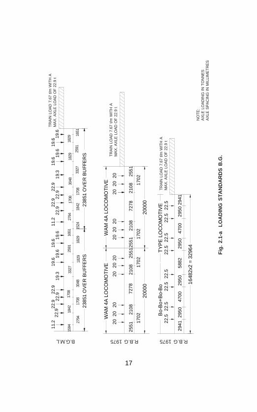
2.1.2 Live Load : Railway track bridge steel girders aredesigned to one of the following loading standards. Fig. 2.1 a & bindicate loading details.
Broad Gauge (1676 mm)1) BGML - (Broad Gauge Main Line) 1926 : Prior to 1975
all steel girders on main line were designed for BGMLstandard which caters for maximum axle load of 22.9tonnes for locomotive with trailing load of 7.67 tonnes/permetre. (BGBL was adopted for branch lines)
2) RBG - (Revised Broad Gauge) 1975 : The bridge loadingwas revised in 1975 (considering the new types of
17
11.
22
2.9
22.
92
2.9
19.
61
9.6
22.
91
1.2
22.
91
9.6
19.
62
2.9
19.
31
9.6
19.
62
2.9
22.
91
9.6
19.
31
9.6
2385
1 O
VE
R B
UFF
ER
S23
851
OV
ER
BU
FFE
RS
TR
AIN
LO
AD
7.6
7 t/m
WIT
H A
MA
X.
AX
LE L
OA
D O
F 2
2.9
t
1594
1842
1708
3327
2591
1651
2794
1708
3048
1829
1829
2794
1708
3048
1829
1829
1524
1842
1708
3327
2591
1651
B.G.M.L
Bo-
Bo+
Bo-
Bo
22.5
22.5
22.5
22.5
22.5
22.5
22.5
22.5
1648
2x2
= 32
964
TY
PE
LO
CO
MO
TIV
E
WA
M 4
A L
OC
OM
OT
IVE
WA
M 4
A L
OC
OM
OT
IVE
2020
2020
2020
2020
2020
2020
2551
2108
7278
2108
2551
2551
2108
7278
2108
2551
1702
1702
1702
1702
2000
020
000
2941
2950
4700
2950
5882
2950
4700
2950
2941
R.B.G 1975R.B.G 1975
TR
AIN
LO
AD
7.6
7 t/m
WIT
H A
MA
X.
AX
LE L
OA
D O
F 2
2.9
t
TR
AIN
LO
AD
7.6
7 t/m
WIT
H A
MA
X.
AX
LE L
OA
D O
F 2
2.9
t
Fig
. 2.
1-a
LO
AD
ING
ST
AN
DA
RD
S B
.G.
NO
TE
:A
XLE
LO
AD
ING
IN
TO
NN
ES
AX
LE S
PA
CIN
G I
N M
ILLI
ME
TR
ES

18
2525
2525
2525
2525
2525
2525
1950
019
500
2970
2050
1950
1950
2970
2050
5560
2050
5560
2050
2970
1950
1950
2970
TR
AIN
LO
AD
8.2
5 t/m
WIT
H A
MA
X. A
XLE
LO
AD
OF
25.
0 t
3030
3030
3030
3030
3030
3030
2311
2200
7500
2200
4622
2200
7500
2200
2311
2200
2200
2200
2200
2092
220
922
TR
AIN
LO
AD
12
t/mW
ITH
A M
AX
. AX
LE L
OA
D O
F 3
0.0
t
2 E
LEC
TR
IC L
OC
OM
OTI
VE
S (W
AG
6c T
YP
E)
3030
3030
3030
3030
3030
3030
2471
1900
6590
1900
4942
1900
6590
1900
2471
1900
1900
1900
1900
1913
219
132
TR
AIN
LO
AD
12
t/mW
ITH
A M
AX
. AX
LE L
OA
D O
F 3
0.0
t
2 D
IES
EL
LOC
OM
OT
IVE
S (W
DG
2 T
YP
E)
M.B.G.1987 H.M.L. H.M.L.
Fig
. 2.
1-b
L
OA
DIN
G S
TA
ND
AR
DS
B.G
.
NO
TE
:A
XLE
LO
AD
ING
IN
TO
NN
ES
AX
LE S
PA
CIN
G I
N M
ILLI
ME
TR
ES

19
locomotives) and RBG loading was evolved which catersfor a maximum axle load of 22.5 tonnes (220.6 kN) forlocomotives with trailing load of 7.67 tonnes/metre (75.2kN/m) on track with the maximum axle load ot 22.9tonnes (224 kN) for wagons.
3) MBG - 1987 (Modified Broad Gauge) : With theanticipated growth in traffic by the turn of the centuryand consequent, use of heavier and more powerfullocomotives, loading was modified during 1987 and MBGloading was evolved which caters for maximum axle loadof 25 tonnes (245 kN) for the locomotive with trailing loadof 8.25 tonnes/metre (80.9 kN/m) on both sides oflocomotives.
4) HML - (Heavy Mineral Loading) : The locomotives with amaximum axle load of 30.0 t (294.2 kN) and a train loadof 12.0 t/m (117.7 kN/m) to be adopted for bridges onidentified routes as and when approved by RailwayBoard.
B) Metre Gauge (1000 mm)1) MGML - 1929 : Maximum axle load of 13.2 tonnes
(129.4 kN) for locomotives with trailing load of 3.87tonnes/m (37.95 kN/m) following the locomotives.
For simplicity of calculations, the Equivalent Uniformly DistributedLoads (EUDL) have been worked out for various spans upto 130metres and the same have been tabulated in Indian RailwayBridge Rules. The EUDL have been listed separately for arrivingat the maximum bending moment and the shear for simplysupported spans. For design of footpath or F.O.B., live loadincluding impact is specified as 4.8 kN/m2 (490 kg/m2) offoot path area. Table 2.1 shows comparative statement of BGML/RBG/MBG/HM loading with EUDLs and longitudinal forces forguidance.
In general Ioading standard adopted for new track bridges isMBG.

20
Spa
nB
GM
L E
UD
LsR
BG
EU
DLs
MB
G E
UD
LsH
M E
UD
LsLo
ngitu
dina
l For
ces
(t)
(t)
(t)
(t)
(t)
(m
)B
MS
hear
BM
She
arB
MS
hear
BM
She
arB
GM
LR
BG
MB
GH
M
6.5
89.3
110.
282
.396
.889
.310
4.4
109.
912
9.5
25.6
22.5
33.3
33.3
1314
7.2
163.
712
9.7
145.
315
0.4
170.
317
7.4
201.
735
.537
.550
.060
.0
2020
2.7
222.
417
7.1
199.
120
0.3
221.
126
1.8
286.
241
.650
.075
.075
.0
3028
0.0
302.
325
2.0
273.
327
8.1
305.
736
9.9
404.
247
.665
.010
0.0
100.
0
4539
9.5
430.
136
0.85
389.
539
4.85
430.
654
0.1
580.
556
.375
.45
100.
012
0.0
6051
4.8
552.
847
0.9
503.
751
5.1
555.
072
0.0
758.
364
.496
.211
6.2
135.
0
7562
8.0
672.
058
4.0
618.
863
4.3
679.
190
0.0
934.
571
.211
9.1
140.
913
5.0
9074
2.0
789.
869
8.0
734.
175
3.7
803.
110
80.0
1112
.477
.214
6.6
165.
714
7.1
120
973.
010
25.3
926.
796
4.4
1001
.410
50.9
1440
.014
70.6
88.5
187.
821
5.2
195.
4
TA
BL
E 2
.1C
OM
PAR
AT
IVE
STA
TE
ME
NT
OF
BE
ND
ING
MO
ME
NT,
SH
EA
R A
ND
LO
NG
ITU
DIN
AL
FO
RC
ES

21
2.1.3 Impact effectIn railway track bridges, this is defined as “Dynamic Augment”.
The Co-efficient of Dynamic Augment =L 6
8 0.15
++ subject to
maximum value of 1, where L is loaded length in metre. It isconsidered in addition to the live load being equivalent to theCDA multiplied by live load which gives maximum force (bendingand shear) in the member under consideration for speed upto160 kmph on BG and 100 kmph on MG.
2.1.4 Forces due to curvature and eccentricity of trackWhere a track (or tracks) on bridge is curved, allowance forcentrifugal action of moving load as well as effect of eccentricityof track (curved) over girders (straight) shall be included indesigning a member, all tracks on the structure being consideredas fully occupied.
2.1.5 Temperature effectWhen any portion of the structure is not free to expand orcontract under variation of temperature, allowance shall be madefor the stresses resulting from this condition.
2.1.6 Frictional resistance of expansion bearingsWhere the frictional resistance of expansion bearings has to betaken into account, the co-efficient shall be assumed as per typeof bearings provided. The value of the co-efficients can be takenas given in Clause 2.7.1 of Bridge Rules.
2.1.7 Longitudinal ForceWhere a structure carries railway track, provision shall be madefor longitudinal loads arising from any one or more of thefollowing :
a) The tractive effort of driving wheels of locomotivesdepending on traction characteristics of locomotive.
b) The braking force resulting from the application ofbrakes to all braked wheels with 13.46% of wagon axleload for air brake and 10% of axle load for vaccumbrake stock.
c) Resistance to the movement of the bearings due tochange of temperature.

22
2.1.8 Racking forceLateral bracings of the loaded deck of the railway track steelgirder shall be designed to resist racking force (force caused bynosing and swinging effect of moving load over the rails), inaddition to the wind and centrifugal force.
2.1.9 Wind pressure effectThis is caused by the wind on the girder as well as on the bodyof moving stock and is a transverse load.
2.1.10 Forces and effects due to earthquakeEarthquake shocks cause movement of ground on whichthe structure is situated. This ground movement causes vibrationof structure. The seismic forces need not be considered forrailway bridge located in Zones I, II and III and bridges of overalllength less than 60 m or spans less than 15 m in Zone IV(Zones indicated in IS - 1893).
2.1.11 Erection stressesAllowance shall be made in design for stresses set up in anymember during erection. Such stresses may be of differentnature from those which the member will be subjected to duringactual service (tension instead of compression or vice-versa).These depend on launching scheme. Hence temporarystrengthening has to be made if required for the schemeadopted.
2.1.12 Loads for road bridges (ROB)Road Bridges shall be designed to following loading standard.Accordingly they are designed to carry any one of the loading,namely :
IRC Class “AA” LoadingIRC Class “A” LoadingIRC Class “B” Loading
2.2 CODES AND SPECIFICATIONSSteel girders (superstructure) are designed, fabricated, erectedand maintained in accordance with following codes andspecifications.

23
BE
AR
ING
CLE
AR
SP
AN
610
0B
OT
TO
M F
LAN
GE
PLA
TE
310
x20x
7090
CE
NT
RE
S O
F B
EA
RIN
G 6
910
OV
ER
ALL
LE
NG
TH
709
0
BE
AR
ING
AN
GLE
CLE
AT
CR
OS
S S
EC
TIO
N
Fig
. 2.
2 R
.B.G
. S
TA
ND
AR
D 6
.1m
. sp
an
TOP
FLA
NG
E P
LATE
310
x20x
7090
CR
OS
S F
RA
ME
MA
DE
UP
OF
WE
B P
LAT
E &
AN
GLE
S
BE
AR
ING
STI
FFE
NE
RA
NG
LE
SE
CIO
NA
L E
LE
VA
TIO
N
LAT
ER
AL
BR
AC
ING
PL
AN
NO
TE:
ALL
DIM
EN
SIO
NS
AR
E I
NM
ILLM
ETR
ES
.
RS
J 60
0x21
0

24
a) IRS - Steel Bridge Code - 1977 for design of steel andwrought iron bridges carrying rail, road andpedestrian traffic (mostly rivetted girder)
b) IRS - Welded Bridge Code 2001 for metal arc welding inmild steel bridges carrying rail, rail cum road orpedestrian traffic (for welded girder only). This codeincorporates submerged arc welding.
c) IRS - Specification B1-2001 for fabrication, erection andmaintenance of steel girders and turn-tables.
2.2.1 Steel
As stipulated in Clause 8 of IRS B1 – 2001 structural steel usedfor steel girders and steel structure in Indian Railways as follows:
2.2.1.1 I.S-2062 Grade ‘A’ as rolled semi killed or killed shall beused for foot over bridges and other structures (whether rivetted /welded fabrication) subjected to non-critical loading.
2.2.1.2 IS-2062 Grade ‘B’ fully killed and normalized / controlcooled where service temperature does not fall below 0° C shallbe used for welded/rivetted girders subjected to railway loading.Plates less than 12mm thick need not be normalized / controlled– cooled. (Note: Steel girders of track bridges up to 76.2mspans are fabricated with this steel).
2.2.1.3 IS-2062 Grade ‘C’ fully killed and normalized / controlcooled ensuring impact properties at (-) 20°C or (-) 40°C shallbe used for sub zero temperature areas for welded / rivettedgirders subjected to railway loading.
Note: Rolled section like angles, channels, I - section etc.confirming to IS-2062 Grade ‘A’ may be used in structure ofrivetted girder subjected to railway loading till such time rolledsections confirming to IS-2062 grade ‘B’ or ‘C’ are not availablein market.
2.2.1.4 High tensile steel shall comply in all respect with therequirement of IS-8500 (equalant of old IS- 961) presently usedfor spans 91.5m and 122.2 m span (rivetted truss).
25
2.2.1.5 Steel for rivets shall comply with the requirement ofIS:1148 for hot rolled rivet bars for structural steel confirming to2062 Grade B and IS-1149 for high tensile steel girder.
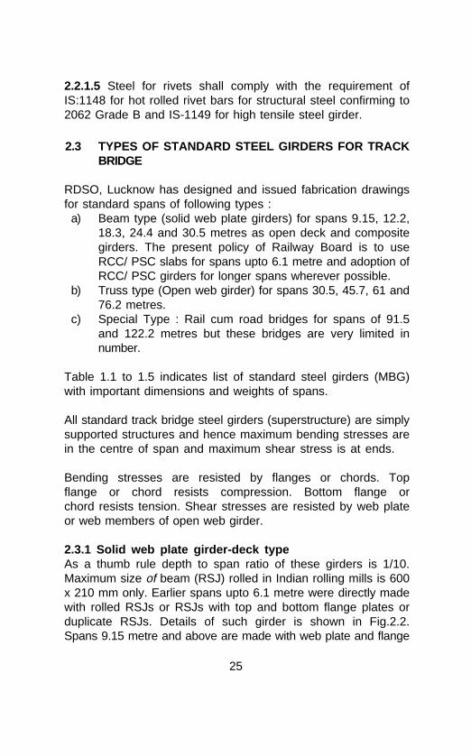
2.3 TYPES OF STANDARD STEEL GIRDERS FOR TRACKBRIDGE
RDSO, Lucknow has designed and issued fabrication drawingsfor standard spans of following types :
a) Beam type (solid web plate girders) for spans 9.15, 12.2,18.3, 24.4 and 30.5 metres as open deck and compositegirders. The present policy of Railway Board is to useRCC/ PSC slabs for spans upto 6.1 metre and adoption ofRCC/ PSC girders for longer spans wherever possible.
b) Truss type (Open web girder) for spans 30.5, 45.7, 61 and76.2 metres.
c) Special Type : Rail cum road bridges for spans of 91.5and 122.2 metres but these bridges are very limited innumber.
Table 1.1 to 1.5 indicates list of standard steel girders (MBG)with important dimensions and weights of spans.
All standard track bridge steel girders (superstructure) are simplysupported structures and hence maximum bending stresses arein the centre of span and maximum shear stress is at ends.
Bending stresses are resisted by flanges or chords. Topflange or chord resists compression. Bottom flange orchord resists tension. Shear stresses are resisted by web plateor web members of open web girder.
2.3.1 Solid web plate girder-deck typeAs a thumb rule depth to span ratio of these girders is 1/10.Maximum size of beam (RSJ) rolled in Indian rolling mills is 600x 210 mm only. Earlier spans upto 6.1 metre were directly madewith rolled RSJs or RSJs with top and bottom flange plates orduplicate RSJs. Details of such girder is shown in Fig.2.2.Spans 9.15 metre and above are made with web plate and flange

26
plates to form built up beam or I-section. Plate girders are furthergrouped according to the type of construction of beam orI-section as under;a) Rivetted plate girder (Open deck)b) Welded plate girder (Open deck)c) Welded composite girder (Ballasted deck)
All built up plate girders (solid web) upto spans 35 metres (115')need not be cambered as per Steel Bridge Code Clause 4.16.1.All standard plate girder spans are less than 35 metres, hencethe question of camber does not arise.
Standard plate girders are used as deck type where sleepers areresting on top flanges.
2.3.1.1 Rivetted plate girder-deck typeOn date 98% of steel plate girder bridges are of rivettedconstructions for spans 9.15, 12.2. 18.3, 24.4 and 30.5 metres(30.5 metre plate girders are very few owing to fabricationproblem and also being uneconomical).
Following are the components of plate girder (rivetted)a) Built-up I-Section (including stiffeners)b) Cross framesc) Top lateral bracingsd) Bottom lateral bracings (provided for spans 24.4 metres
and above)e) Bearings.
Main component - Builtup I-sectionTop flange (Compression member) is made up of flange angles,flange plates and web plate (portion between flange angles). Topflange resists bending compression stresses and gross area isconsidered as a cross section. Flange angles are essentiallyrequired to connect web and flange for rivetted construction. Tocater for higher bending stress in middle portion of span,additional flange plates are provided over first top flange platewhich is provided throughout the length of span for sleeperseating.
27
12
32
3
4C
LEA
R S
PA
N 1
8300
4
CE
NT
RE
OF
BE
AR
ING
S 1
9400
GU
SS
ET
PLA
TE
ST
OP
LA
TE
RA
L B
RA
CIN
G
1st B
OT
TO
M F
LAN
GE
PLA
TE
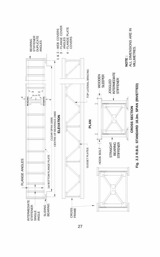
Fig
. 2.
3 R
.B.G
. S
TA
ND
AR
D 1
8.3m
. S
PA
N (
RIV
ET
TE
D)
INT
ER
ME
DIA
TE
ST
IFF
EN
ER
SIN
GLE
AN
GLE SLI
DIN
GB
EA
RIN
G
CR
OS
SF
RA
ME
HO
OK
BO
LT
STR
AIG
HT
BE
AR
ING
STI
FFE
NE
R
WO
OD
EN
SLE
EP
ER
JOG
GLE
DIN
TER
ME
DIA
TES
TIFF
EN
ER
NO
TE :
ALL
DIM
EN
SIO
NS
AR
E I
NM
ILLI
ME
TRE
S.
PL
AN
FLA
NG
E A
NG
LES
1 &
2-
WE
B C
OV
ER
S3
-F
LAN
GE
CO
VE
RA
NG
LES
4-
FLA
NG
E P
LAT
EC
OV
ER
S
BE
AR
ING
ST
IFF
EN
ER
DU
PLI
CA
TE
AN
GLE
S
EL
EV
AT
ION
CR
OS
S S
EC
TIO
N

28
Bottom flange (tension member) construction is similar to topflange. Bottom flange resists bending tensile stresses and netarea is considered for a cross section. Greater cross section isrequired in the middle portion of the span which is provided withadditional flange plates.Web is made up with 3/8" or 10 mm thick plate for full lengthand depth of beam section. Web plate is stiffened againstbuckling with stiffener angles. Web resists shear stress which ismaximum at the end of beam, hence closer pitches of rivets andcloser interval between two intermediate stiffeners than in middleportion are provided. The load on the entire span is transferredthrough bearings to bed block and in turn to substructure. Hencebearings stiffeners are provided with 2 angles back to back oneither side of web plate over the bearing. Bearing stiffeners arestraight and outstanding leg is snug fitting between top andbottom flange. Packing plate is provided between web andstiffener connecting leg equal to flange angle thickness.Intermediate stiffeners are single angle on either side of web andoutstanding leg is snug fitting between top and bottom flanges.Intermediate stiffeners are either straight with packing plate orjoggled without packing plates. Outstanding leg of stiffener actslike a strut between top and bottom flange to resist web bucklingcaused by cross bending of sleeper and top flange.
Secondary Members :Cross frame consists of angle section for horizontal anddiagonal members connected with gussets to stiffener legs forlateral rigidity. Top lateral bracings consist of angles connectingdiagonally (in horizontal plane) to top flanges to reduce theunsupported length of compression flange to resist buckling.Bottom lateral bracings consist of angle connected to bottomflange for spans 24.4 metre and above. All these cross frames,top lateral and bottom lateral bracings are for lateral rigidity andare secondary members.
Centralised articulated (sliding type) bearings are provided withsteel base plates which are anchored to bed blocks with anchorbolts.
Wooden channel sleepers with pad plates are provided on topflanges to support track and anchored with hook bolts. Notchesare required on bottom face of wooden sleeper to accommodate

29
rivet heads, hence this poses a problem for frequent painting ofsleeper seats which are more prone to corrosion due to steel incontact with wood/steel and abrasion of sleepers.
Rivetted deck type plate girders are strong and sturdy, andsimple for fabrication and launching. All standard spans aregenerally fabricated in engineering workshop of each zonalrailways and transported to site for launching. To facilitatetransportation from workshop to site of bridge, spans 9.15 m and12.2 m are fabricated as complete span. 18.3 metres span isprovided with one central joint in I-section, i.e. four numbers ofI-sections are fabricated for one span, 24.4 metres and 30.5metre spans are provided with two joints in I-section, i.e. sixnumbers of I-sections are fabricated for one span. The maximum13.5 metre long component can be loaded in a BFR. Therefore,splice material such as cover flange plates, cover flange angles,cover web plates are required to be assembled with the ‘I’-section to form span at site with field rivets for spans 18.3metres and above.
Steel used for existing rivetted plate girders is to conform to IS2062 Grade A 1992 (old IS 226) and rivet steel conforming to IS1148. Fig. 2.3 indicates the details of a rivetted girder.
NOTE : Semi through non-standard plate girders are similar todeck type (mentioned above) except that the sleepers are restingon floor system consisting of stringer and cross girders but nobracings are provided to top flanges of girder.
2.3.1.2 Welded plate girder-deck type :On Indian Railways, majority of steel girders are of plate girdertype. Till 1980, these plate girders were fabricated as rivettedgirders. The rivetted construction tends to make the structureheavy and costly, besides posing maintenance problems due torivet heads on top flange plates which leads to heavy corrosion.During 1980-82, with proven welding technology for fabrication ofdynamic structures and availability of indigenous automaticwelding equipments and consumables for sound welding, thefabrication of welded girders has been taken up for railway trackbridges. RDSO, Lucknow has issued standard welded plate

30
girder drawings for spans of 12.2, 18.3 and 24.4 metres for BGand 6.1, 9.2, 12.2, 18.3, 24.4 and 30.5 metres for MG.
Advantage of welded girdera) Welded girder with rivetted intermediate stiffeners result
in saving of steel upto 25%.b) Welded girder eliminates the need of rolled sections of
non-standard sizes and shapes. Also due to non-availability of particular rolled section using highersection leading to uneconomical construction is avoided.
c) Eliminates drilling of holes and hence gross areabecomes net area for tension members (Bottom Flange).
d) Welded girder eliminates cumbersome connections andwater pockets.
e) Welded girder requires less maintenance due toelimination of rivet heads on top flange thereby facilitatingthe painting of sleeper seats frequently thus reducingmaintenance and repairs cost.
f) Aesthetic superiority and higher production rates withlesser input are added advantages.
Components of welded girderFollowing are the components (similar to rivetted girder)
a) Welded I-sections (including welded or rivettedintermediate stiffeners)
b) Cross framesc) Top lateral bracingsd) Bottom lateral bracings for spans 24.4 metre and abovee) Bearings
Main components are welded I-sections which are simiilar torivetted plate girders except the following :
i) Web and flange connection is provided with continuousfillet weld (instead of flange angles with rivettedconnections)
ii) Earlier stiffeners were made up of plates instead of anglesections and are welded with fillet weld to the web butnow revised drawings are followed for welded girders withrevitted angle striffeners for intermediate stiffeners.

31
1) Top flange plate is made with one flange plate andrequires increase in cross section in middle portion ofspan, which is met with by increasing the width of flangeplate to cater for bending (compression) stresses.Sometimes due to non-availability of full length of flangeplates, "Butt" welding is provided with double "V" groove.Full penetration weld on both sides of plate is provided atjunction to increase in width of flange plate.
2) Bottom flange plate is made with one flange plate similarto top flange but it is a tension member.To avoid stress concentration resulting in crack initiationduring service, at the junction of different widths of topand bottom flange plates, (at butt weld) 1:5 side slopeis provided. Butt weld in flange plates should be avoidedby arranging longer plates for economical fabrication andmaintenance during service life, if possible.
3) Web plate is made with 10 mm thick plate for full lengthand depth of girder. Sometimes due to non-availability offull length of plate, square butt weld on both sides ofweb plate is provided. Web plate is stiffened with platestiffeners. Bearing stiffeners consist of 2 numbers platestiffeners on either side of web over the bearings, and iswelded with continuous fillet welding to web, top andbottom flanges. Intermediate stiffeners are also providedwith plate stiffeners on either side of web plate atstaggered locations to avoid cruciform welding. Weldedbridge code clause No. 5.3.2.1 stipulates that filtet weldsat right angles to the line of principal stress in platesubjected to tension shall be avoided in dynamicallyloaded structures, hence intermediate stiffeners arewelded to web plate and top flange plate with continuousfillet weld and stiffener is terminated 50 mm short ofbottom flange fillet weld (tension flange). This type ofdetailing leads to classification of welded girder in “F”class under fatigue consideration reducing permissiblestress to a very low value resulting in increased crosssection of structure. To achieve economical welded

32
girders these are provided with rivetted intermediatestiffener (angles section with rivetted connections) whichclassify welded girders in class “D” under fatigueconsideration with higher permissible stress than Class“F”.
RDSO, Lucknow has issued welded girder drawings with(i) Intermediate stiffener welded, and (ii) Intermediate stiffenerrivetted. Presently welded girders are fabricated with intermediaterivetted angle stiffener.
In welded girders, connections made during fabrication inworkshop are only welded. Remaining all connections at site,such as cross frames, top lateral bracings and splice materialfor 18.3 metre span and above are provided with rivettedconnections only. No field welding is permitted on welded girdersof track bridge without prior approval of competent authority evenfor repairs.
Cross frames, top and bottom lateral bracings are similar torivetted girder with rivetted connection for site joints.
Centralised articulated bearings (sliding type) are provided towelded girders similar to rivetted girders.
Welded connections are strong enough to resist the static loadsbut are prone to failure under dynamic loading due to fluctuationof stresses causing crack initiation. Welded plate girder of trackbridge therefore requires careful design and detailing. Fatiguestrength of welded structure depends upon the constructiondetails.
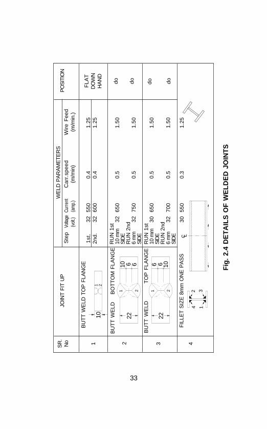
In general, welded girders are provided with following weldedjoints :
1) Butt Weld :a) double “V” groove - For top & bottom flangeb) square - For web plates
33
101 2
110 6 6
2
22
2
22
1
1066
Fig
. 2.
4 D
ET
AIL
S O
F W
EL
DE
D J
OIN
TS
WE
LD P
AR
AM
ETE
RS
Ste
pVo
ltage
Cur
rent
Car
r.sp
eed
Wire
Fee
d
(
volt.)
(a
mp.
)(m
/min
)(m
/min
.)
PO
SIT
ION
FLA
TD
OW
NH
AN
D
do dodo do
1st
.32
550
0.4
1.25
2nd.
3260
00.
41.
25
RU
N 1
st10
mm
3265
00.
51.
50SI
DE
RU
N 2
nd6
mm
3275
00.
51.
50SI
DE
RU
N 1
st10
mm
3065
00.
51.
50SI
DE
RU
N 2
nd6
mm
3270
00.
51.
50SI
DE
3055
00.
31.
25
SR
.N
o 1 2 3 4
FIL
LET
SIZ
E 8
mm
ON
E P
AS
S
BU
TT
WE
LD
T
OP
FLA
NG
E
BU
TT
WE
LD
B
OT
TO
M F
LAN
GE
JOIN
T FI
T U
P
BU
TT
WE
LD T
OP
FLA
NG
E
C L
14
32

34
2) Fillet Weld :a) “T” fillet (continuous) - For top & bottom flange
connections to web plateb) Side fillet (continuous)- All stiffeners and bearings.
Fig. 2.4 shows details of welded joints with weld parametersused for welded girder. Butt welds provided in top and bottomflange plates and web plates are to resist the same stress asparent metal and hence these welds are to be testedradiographicaily during fabrication. Welded Bridge Code clauseNo. 5.2 & 5.3 stipulates that “all butt welds in dynamic structureare examined radiographicaily or by any other equally effectivemethod”. Fillet welds connecting top and bottom flanges to web,resist shear stress (resultant of horizontal and vertical shear) andhence full penetration continuous fillet weld is required.
Steel used for welded plate girders for built up I-section withwelded connections should conform to IS 2062 Grade ‘B’ -1992fully killed and normalised (old IS 2062) duly tested. Steel usedfor members like intermediate stiffeners cross-frames, lateralbracings, splice material with rivetted connections shouldconform to IS 2062 Grade ‘A’ -1992 (Old IS 226) and rivet steelto IS 1148.
Fig. 2.5 and 2.6 show the details of welded plate girders (withwelded intermediate stiffeners and rivetted intermediatestiffeners).
2.3.1.3 Composite girder of RCC slab and steel girderFor high speed trains and increased volume of traffic,strong track structure with concrete sleepers is essential foreconomical maintenance. Such track structure on bridges ispossible only with ballasted deck provided on composite girders.
Following are the advantages of composite girders :a) Ballasted deck with PSC sleepers provides similar track
structure on bridge as on the approach which results inbetter maintainability and greater riding comfort.

35
1676
Fig
. 2.
5 R
.B.G
. S
TA
ND
AR
D 2
4.4
m S
PA
N (
WE
LD
ED
) P
LA
TE
GIR
DE
R
TO
P F
LAN
GE
WE
B P
LAT
ES
PLI
CE
MA
TER
IAL
1 &
2 W
EB
CO
VE
R3
FLA
NG
E C
OV
ER
INTE
RM
ED
IATE
STI
FFE
NE
R(W
ELD
ED
)
50m
m
TO
P L
AT
ER
AL
BR
AC
ING
S
DO
UB
LE ‘V
’ BU
TT
WE
LDIN
TO
P &
BO
TT
OM
FLA
NG
E
‘T’ F
LLE
T W
ELD
FO
R W
EB
&F
LAN
GE
C
ON
BE
CT
ION
BE
AR
ING
ST
IFF
EN
ER
S
CR
OS
S F
RA
ME
CR
OS
S F
RA
ME
SLI
DIN
GB
EA
RIN
G
BO
TT
OM
FLA
NG
E
CLE
AR
SP
AN
244
00m
m
1 22
3
3
EL
EV
AT
ION
PL
AN
CR
OS
S S
EC
TIO
N
�
CE
NT
RE
OF
BE
AR
ING
256
00 m
mO
VE
RA
LL L
EN
GT
H 2
6050
mm

36
167
6
Fig
. 2.
6 M
.B.G
. S
TA
ND
AR
D (
WE
LD
ED
) 12
.2m
PL
AT
E G
IRD
ER
WIT
H R
IVE
TT
ED
BR
AC
ING
& I
NT
ER
ME
DIA
TE
AN
GL
E S
TIF
FE
NE
R
BE
AR
ING
STI
FFE
NE
RW
ELD
ED
CR
OS
SFR
AM
E
CR
OS
SFR
AM
E
INTE
RM
ED
IATE
AN
GLE
(STI
FFE
NE
R (
RIV
ETT
ED
)T
OP
FLA
NG
EW
EB
PLA
TE
SLI
DIN
GB
EA
RIN
G
BO
TTO
MF
LAN
GE
TO
P L
AT
ER
AL
BR
AC
ING
DO
UB
LE ‘V
’ BU
TT
WE
LD I
N T
OP
& B
OT
TO
M F
LAN
GE
‘T’ F
ILE
T W
ELD
FO
R W
EB
& F
LAN
GE
CO
NN
EC
TIO
N
INTE
RM
ED
IATE
RIV
ETT
ED
STI
FFE
NE
RC
RO
SS
SE
CT
ION
PLA
N
EL
EV
AT
ION
CLE
AR
SP
AN
- 1
2200
mm
CE
NT
RE
OF
BE
AR
ING
S 1
3100
mm
OV
ER
ALL
LE
NG
TH
133
00 m
m
37
b) Superelevation for curved track can be provided withgreater ease, being ballasted deck.
c) Machines can be deployed for maintenance of track orbridges.
d) Use of other type of sleepers, become possible aswooden sleepers is a scarce commodity now on IndianRailways,
e) Concrete is rich in compressive strength and steel isrich in tensile strength. Composite girder consistingof RCC deck with steel beams would be generallyeconomical for spans ranging from 9.15 to 24.4 metres.However, the actual choice depends on site conditions.
f) Less maintenance cost due to slab deck being of RCC.RDSO, Lucknow has designed and issued compositegirder drawings for use on zonal railways for spans 9.15,12.2, 18.3, 20 and 24.4 metres for BG and 12.2 metresfor MG with welded construction.
Composite girders consist of the following components:A) RCC deck (Cast in situ at the site of bridge) with shear
connectors embedded in the slab.(Presently channel shear connectors are used anddepending on availability of stud welding gun, use of studshear connectors can be adopted)
B) Steel beams with shear connectors welded on top flange(Fabricated in workshop).
C) Cross framesD) Bearings
Details :a) The RCC deck is cast in situ after launching
steel girders on substructure. Shear connectors areprovided on top flange plates of steel beams withchannel sections welded all round with side fillet welds.Shear connectors are required to make cast in situ RCCslab and steel girder act together under load. Drawingsare available for channel shear connectors as well asstud shear connectors.
38
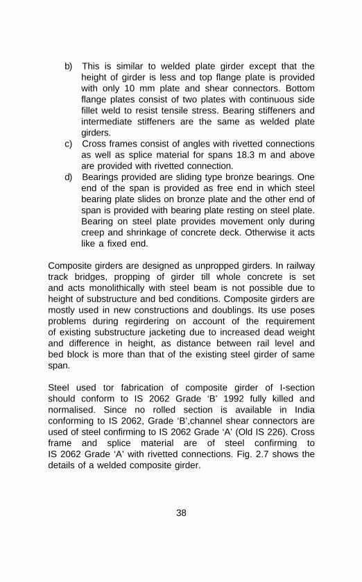
b) This is similar to welded plate girder except that theheight of girder is less and top flange plate is providedwith only 10 mm plate and shear connectors. Bottomflange plates consist of two plates with continuous sidefillet weld to resist tensile stress. Bearing stiffeners andintermediate stiffeners are the same as welded plategirders.
c) Cross frames consist of angles with rivetted connectionsas well as splice material for spans 18.3 m and aboveare provided with rivetted connection.
d) Bearings provided are sliding type bronze bearings. Oneend of the span is provided as free end in which steelbearing plate slides on bronze plate and the other end ofspan is provided with bearing plate resting on steel plate.Bearing on steel plate provides movement only duringcreep and shrinkage of concrete deck. Otherwise it actslike a fixed end.
Composite girders are designed as unpropped girders. In railwaytrack bridges, propping of girder till whole concrete is setand acts monolithically with steel beam is not possible due toheight of substructure and bed conditions. Composite girders aremostly used in new constructions and doublings. Its use posesproblems during regirdering on account of the requirementof existing substructure jacketing due to increased dead weightand difference in height, as distance between rail level andbed block is more than that of the existing steel girder of samespan.
Steel used tor fabrication of composite girder of I-sectionshould conform to IS 2062 Grade ‘B’ 1992 fully killed andnormalised. Since no rolled section is available in Indiaconforming to IS 2062, Grade ‘B’,channel shear connectors areused of steel confirming to IS 2062 Grade ‘A’ (Old IS 226). Crossframe and splice material are of steel confirming toIS 2062 Grade ‘A’ with rivetted connections. Fig. 2.7 shows thedetails of a welded composite girder.

39
1676
4265
645
100
1600
1142.51142.5 1980
BOTTOM FLANGE COVER 400x25x3029
1st BOTTOM FLANGE PLATE 400x18x9625 1st BOTTOM FLANGE PLATE 400x18x9625
18.3m CLEAR SPAN
2nd BOTTOM FLANGE PLATE 2nd BOTTOM FLANGE PLATE 2nd BOTTOM FLANGE PLATE
32
1
2
3
Fig. 2.7 COMPOSITE GIRDER M.B.G. 18.3 m SPAN (WELDED)
SECTION
TOPFLANGE
PLATE
WEB
BOTTOMFLANGEPLATES
CHANNELSHEARCONNECTOR
INTERMEDIATESTIFFENER
ELEVATION
(All dimensions are in mm.)
1. WEB COVER BOTH SIDE 3. COVER ANGLE
2. SPLICE PLATE 4. COVER FLANGE PLATE

40
2.3.2 Open web steel girders - Truss type with rivettedconstruction/welded constructionMostly all spans of 30.5 metres and above are of openweb steel girders in railway track bridges. Open webgirders are used as (a) deck type (underslung of 30.5metres span as standard girder and above that, spans areof nonstandard design) (b) Semi through (non-standard)(c) through standard spans of 30.5, 45.7, 61.0 and 76.2metres.
Mostly open web type girders are used for track bridgesover valleys and large rivers on account of economy in cost.This is achieved due to low depth of bottom of girder from the raillevel (for through girder bridges). Presently steel used isconforming to IS 2062 Grade ‘B’ (old IS 2062-’A’) for rolledsections and rivet steel conforming to IS 1148 for spans of 30.5,45.7, 61.0 and 76.2 metres. Steel used for rail cum road/railbridges truss with rivetted construction of for spans 91.5 and122.2 metres is conforming to IS - 8500 (old IS 961) for rolledsections. For welded floor systems such as cross girders andstringers steel is conforming to IS 2062 Grade ‘B’ and rivet steelconfirming to IS - 1149.
Nonstandard open web girders are of many types as indicated inFig. 1.5 to 1.13.
Warren truss (triangulated truss) with vertical members at everypanel point is used as standard through and deck typegirder for track bridges. Figure No.2.8 indicates types oftruss.
Design of open web girder for primary and secondarystresses is as stipulated in the Indian Railways Steel BridgeCode Clauses 3.3.1 and 3.3.2.
Clause 3.3.1 The primary stresses in the design of triangulatedstructures are defined as axial stresses in members calculatedon the assumption that -

41
CONFIGURATION
6 @ 5321 = 31926
7315
CLEAR SPAN
30.5m THROUGH
30.5m UNDER SLUNG
4600
10 @ 3190 = 31900
7315
47.5m THROUGH
8 @ 5905 = 47240
9000
61.0m THROUGH
8 @ 7875 = 63000
10 @ 7880 = 78800
1050
0
76.2m THROUGH
Fig. 2.8 CONFIGURATIONS OF BROAD GAUGESTANDARD OPEN WEB GIRDERS
cL
cL
cL
cL
cL
(All dimensions are in mm)

42
a) All members are straight and free to rotate at the joints.b) All joints lie at the intersection of centroidal axes of the
members.c) All loads including the weight of the members are
applied at the joints.
Clause 3.3.2 Secondary stresses - In practice the assumptionsmade in Clause 3.3.1 are not realised and consequentlymembers are subjected not only to axial stresses but also tobending and shear stresses. These stresses are defined assecondary stresses, and fall into two groups :
a) Stresses which are the result of eccentricity ofconnections and of off-joint loading generally e.g. loadsrolling direct on chords, self weight of members and windloads on members.
b) Stresses which are the result of elastic deformation ofthe structure and the rigidity of the joints. These areknown as deformation stresses.
Girders are designed, fabricated and erected in such a manneras to minimise secondary stresses as far as possible.
In nonprestressed girders, deformation stresses mentioned inClause 3.3.2 (b) of Steel Bridge Code shall in the absence ofcalculations be assumed to be not less than 16.67% of the deadload and live load stresses including impact. Now with computeraided design (CAD) it is possible to calculate all stresses by“3D” analysis with the end conditions defined.
In case of prestressed open web girders deformationstresses may be ignored, hence as per Steel Bridge Codeclause No.3.3.9 all open web girders for railway trackbridges of span 30.5 m and above shall be prestressed forachieving saving of steel due to ignoring deformation stresses.Since the method adopted on Indian Railways is holding goodwith economical maintenance, therefore, it is continued till date.Rules for prestressing are given in Appendix “A” of Steel bridgecode. In actual sense it is predeforming of members to ensurethat under full load (i.e. Dead Load + Live load + Impact) the

43
members along their centrodial axis are of nominal lengths(without any deformation).
Method of fabrication and erection for achieving prestressing in theopen web girder is as under :
I. During Fabrication :
(a) Marking and drilling of holes in the main gusset plates ofeach panel points of top and bottom chord, is to be doneon nominal layout as per details of joints indicated infabrication drawing so as to preserve the intersectionangles of nominal profile (uncambered profile)corresponding to fully loaded state of truss.
(b) Length of all members of truss are to be fabricated tocamber lengths as indicated in camber sheet of fabricationdrawing, with the group of connection holes at both endsdrilled through holes of main gussets which are drilled onnominal layout. For this purpose, hole drilling jig is to bemanufactured for each member with the distance betweenthe group of end holes altered by the amount of camberallowance, i.e. difference between nominal length andcamber length.
(c) Bottom chords camber length are same as nominal lengthto facilitate the fabrication of stringer.
II. During erection (assembly) at site:
The work is to be done in successive stages so as to prestress(predeform) the members of truss, that is to say members oferected truss in the unloaded state is a reverse way to whatwould have happened to them under full load if the truss weredesigned and erected without prestressing. Assembly procedurein stages to be adopted for site assembly is mentioned in para2.6. Fig. 2.22 indicates the stages of erection for prestressing.
Track structure over the stringers or top chord isprovided with the same thickness of sleeper throughout thelength of span hence track will have the same camber profile oftruss during unloaded state.

44
5905
NO
MIN
AL
U2
5905
NO
MIN
AL
U3
U4
7316 WITH CAMBER7315 NOMINAL
5905
NO
MIN
AL
9401
NOMIN
AL
9403
.5 W
ITH CAMBER
7316.5 WITH CAMBER5910
.5 W
ITH
CA
MB
ER
5905
NO
MIN
AL
L3
5905
WIT
H C
AM
BE
R
5905
NO
MIN
AL
9401
NOMIN
AL
9408
.5 W
ITH CAMBER
7318 WITH CAMBER
7315 NOMINAL
9410
NOMIN
AL
7316.5 WITH CAMBER
9400
WITH C
ANBER
7315 NOMINAL
9401
NOMIN
AL
9408.5 WITH CAMBER
U1
5905
NO
MIN
AL
NO
TE
: A
ll di
men
sion
s ar
e in
mm
21
37
50
53
Fig
. 2.
9 C
AM
BE
R D
IGR
AM
OF
45.
7 M
SP
AN
L 4 L
259
05 W
ITH
CA
MB
ER
L1
5905
WIT
H C
AM
BE
R L
059
05 W
ITH
CA
MB
ER
5910
.5 W
ITH
CA
MB
ER
5910
.5 W
ITH
CA
MB
ER
7315 NOMINAL
5905
NO
MIN
AL
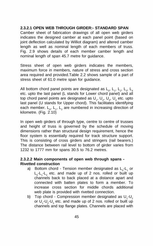
45
2.3.2.1 OPEN WEB THROUGH GIRDER:- STANDARD SPANCamber sheet of fabrication drawings of all open web girdersindicates the designed camber at each panel point (based onjoint deflection calculated by Williot diagram) and altered camberlength as well as nominal length of each members of truss.Fig. 2.9 shows details of each member camber length andnominal length of span 45.7 metre for guidance.
Stress sheet of open web girders indicates the members,maximum force in members, nature of stress and cross sectionarea required and provided.Table 2.2 shows sample of a part ofstress sheet of 61.0 metre span for guidance.
All bottom chord panel points are designated as L0, L
1, L
2, L
3, L
4
etc. upto the last panel (L stands for Lower chord panel) and alltop chord panel points are designated as U
1, U
2, U
3, U
4 etc. upto
last panel (U stands for Upper chord). This facilitates identifyingeach member. L
0, L
1, L
2 are numbered in increasing direction of
kilometre. (Fig. 2.10)
In open web girders of through type, centre to centre of trussesand height of truss is governed by the schedule of movingdimensions rather than structural design requirement, hence thefloor system is essentially required for track structure support.This is consisting of cross girders and stringers (rail bearers.)The distance between rail level to bottom of girder varies from1232 to 1777 mm for spans 30.5 to 76.2 metres.
2.3.2.2 Main components of open web through spans -Rivetted construction
a) Bottom chord - Tension member designated as L0-L
1 or
L0-L
1-L
2 etc. and made up of 2 nos. rolled or built up
channels back to back placed at a distance apart andconnected with batten plates to form a member. Toincrease cross section for middle chords additionalweb plate is provided with rivetted connection.
b) Top chord - Compression member designated as U1-U
2
or U1-U
2-U
3 etc. and made up of 2 nos. rolled or built up
channels and top flange plates. Channels are placed with

46
Tab
le 2
.2 S
TR
ES
S S
HE
ET
MAXIMUMMEMBER FORCE IN SECTION PROVIDED
TONNES (IN MILLIMETRES)
L0 - L
1+ 180.0 4 ANGLES 150 x 115 x 10
2 SIDE PLATES 630 x 8
L1 - L
2+ 180.0 4 ANGLES 150 x 115 x 10
2 SIDE PLATES 630 x 10
L2 - L3 + 420.16
L3 - L
4+ 420.16
L4 - L
5+ 500.65 4 ANGLES 150 x 115 x 10
4 SIDE PLATES 630 x 16
U1 - U
2- 321.35
U2 - U
3- 321.35
U3 - U
4- 480.90
U4 - U
5- 480.90
L0 - U1 - 311.20-13.70
U1 - L
2+ 251.74 4 ANGLES 100 x 100 x 10
2 SIDE PLATES 500 x 12
L2 - U
3- 193.40 4 ANGLES 100 x 100 x 10
2 SIDE PLATES 400 x 12
U3 - L
4- 3.26 4 ANGLES 75 x 75 x 10
+ 139.48 2 SIDE PLATES 350 x 12
L4 - U
5+ 44.63 4 ANGLES 75 x 75 x 10
- 89.87 2 SIDE PLATES 300 x 8
+ 85.154 ANGLES 75 x 75 x 10
- 6.90 WEB PLATES 370 x 18
4 ANGLES 150 x 115 x 102 SIDE PLATES 630 x 162 SIDE PLATES 630 x 104 ANGLES 150 x 115 x 102 SIDE PLATES 630 x 162 SIDE PLATES 630 x 12
4 ANGLES 150 x 115 x 102 SIDE PLATES 630 x 101 TOP PLATE 660 x 8
4 ANGLES 150 x 115 x 102 SIDE PLATES 630 x 102 ADDL. PLATES 330 x 101 TOP PLATE 660 x 12
4 ANGLES 150 x 115 x 102 SIDE PLATES 630 x 102 ADDL. PLATES 330 x 101 TOP PLATE 660 x 12
U1 - L
1
U3 - L3
U5 - L5
U2 - L2
U4 - L
4
630
630
630
630
630
630
630
630
500
400
350
300
370
408
402
370
402
370
370
370
258
400
410
414
440
440

47
OF SPAN
10 @ 3190 = 31900
(a) 30.5m SPAN UNDERSLUNG TYPE(BA - 11401)
8 @ 5905 = 47240
4600
7315
(b) 47.5m SPAN THROUGH TYPE(BA - 11361)
Note: All dimensions are in millimetres
Fig. 2.10 NUMBERING OF PANEL POINTS
OF SPAN
U0 U1 U2 U3U4 U5
U6 U7 U8U9 U10
U1 U2 U3 U4 U5 U6 U7
L1 L2 L3 L4 L5 L6 L7 L8 L9
L1 L2 L3 L4 L5 L6 L7 L8L0
cL
cL

48
distance apart back to back and top flange plates areconnected to top leg of channels with rivetsand bottom legs of channels are connected with battenplates and lacing to form members. Diaphragms areprovided in the webs with rivetted connections. Toincrease the cross section for middle chords additionalside plates as well as increased thickness of top flangeplates are provided with rivetted connection.
c) End Rakers - Inclined members at either end of thetruss, i.e. L
0-U
1 are called as end raker. It is a
compression member and heaviest member of truss.Form of this member is the same as that of top chords.This member in addition, transfers racking force andwind force, etc. to bearings.
d) Diagonals - All intermediate inclined web members arecalled diagonal members. First diagonal member U
1-L
2 is
tension member and second diagonal member L2-U
3 is
compression member. Further, alternately the membersare compression and tension upto the centre of span.Also these members experience some amount ofopposite nature of stress (compression member will havetensile stress and vice-versa) as per occupation of loadon span. Hence these members are also called asreversible stress members. These members consist ofchannels either rolled or built-up face to face, kept apartand connected with batten plates and lacing with rivets.
e) Vertical members - All vertical standing web membersare called vertical members. Members connecting oddnumber panel points (i.e. L
1-U
1) are tension members
and members connecting even number panel points i.e.U
2-L
2 are called redundant members as they carry only
dead load stresses and provide rigidity to truss andreduce unsupported length of top chord. These membersare made up of web plates and 4 nos. of angles withrivetted connections to form I-sections as components.
Following are the members of floor system of through span:
1) Cross girders - Each panel point of bottom chords of both

49
trusses are connected by cross beams called crossgirders. This member is built up I-section like plate girder,with web plate, top and bottom flange angles and flangeplates with angle stiffeners of rivetted connection. Oneither end of cross girder, angle cleats are provided forconnection with main truss panel points (bottom chord).Both the end cross girders are provided with additionalstiffeners and pad plates for lifting the girders by jacks formaintenance work. Remaining cross girders are calledintermediate cross girders.
2) Rail bearers or stringers - Between two cross girders oneset of built-up I-section-like plate girder is provided calledrail bearer or stringer. Both ends of stringer are connectedto cross girder web by stiffener with rivets. Only 3rd railbearers from either ends for span 61.0 and 76.2 metresare connected one end to cross girder with rivet and otherend is resting on brackets provided in web of cross girderto act like free end to avoid distortion of bottom chordunder load. Stringers consist of web plate and flangeangles with rivetted connection to form I-section asmembers. Cross frame or diaphragm with lateral bracingare provided to stringers for lateral rigidity. Sleepers reston top flange stringers and are anchored with hook bolts.
Secondary members :
Secodary members are those which can be replaced bythemselves individually. Following are the secondary members ofopen web through spans:
(a) Bottom lateral bracings(b) Top lateral bracings(c) Sway bracings and knee sway(d) Portal bracings and knee portal(e) Corner brackets(f) End stools and end bracket(g) Main gussets(h) Bearings

50
Bottom lateral bracings are made up of 2 angles built in starshape with batten plates (rivetted connections). These areprovided in each panel (below rail bearer) and diagonallyconnected to bottom chord panel points with lateral bracinggussets. These bracings are connected with hanger plates tobottom flanges of rail bearers to transfer the longitudinal forces tobottom chord panel points.
Top lateral bracings are made up of 2 angles built up in starshape with batten plates or light frame shape and these areprovided in each panel (between sway bracings) and diagonallyconnected to top chords with top lateral gusset plates to resistwind force as well as for lateral rigidity.
Sway bracings are made up like light frames with top and bottomflange angles with lacings and batten plates in webs with rivettedconstructions. These are provided in webs of top chords atintermediate panel points for lateral rigidity. One strut is providedbetween bottom flange of sway connected to the vertical and iscalled knee sway bracing.
Portal bracings are made up of beam type or frame type andconnected at either end panel points partially to top chord andpartially to end raker. Knee portal struts or frames are connectedto end rakers.
Corner brackets are made up of web plates and angle cleatsconnected to top flanges of cross girders at ends andcorresponding vertical members at intermediate panel points forlateral rigidity as well as to avoid tensile forces coming in rivets,connecting cross girders to panel points near top flanges.
End stools made up of web plates and angle cleats are providedto end panel point of bottom chords in line with the cross girderand forms diaphragm to afford rigidity at L
0 panel point in lieu of
vertical member.
End brackets made up of web plates and angle cleats areprovided to end cross girders in line with the stringers to one end
51
of a span in multiple span bridge or at both ends in single spanbridge. This ensures proper sleeper spacing.
Main gussets are made up of 20 mm thick plates for connectingmembers at every panel point of top and bottom chords.
Bearings of open web through spans are provided with one endas free end for expansion and these bearings are called asrocker and roller bearings. Other end of span is provided withfixed end bearings called as rocker bearings with grillage.Bearings are connected with turned bolts between saddle plateand bottom chord at either end. All shop rivets in main truss andfloor members are of 20 mm dia. driven in 21.5 mm dia holes. Allfield rivets of trusses are of 22 mm dia. driven in 23.5 mm dia.holes. Fig. 2.11 & 2.12 show the details of open web throughspan.
2.3.2.3 Open web deck type span-underslung
Standard span is 30.5 metres and spans above 30.5 m arenonstandard spans. These spans are also of rivetted constructionand fabricated as prestressed open web girders. Trusses are ininverted shape and are below the track structure. Sleepers aredirectly resting on top chords and hence no floor system likecross girders and stringers is required. Centre to centre of thetrusses is 2300 mm and truss height is as per designrequirement. Therefore underslung girder span of 30.5 metresrequires 30% less steel than 30.5 metres through span. Thesespans are used for bridges over valleys and viaducts wherewaterway is not the criterion, thus achieving economical bridgeconstruction.
Camber and stress sheets are provided in the set of drawingsindicating camber at each panel point and cambered length ofeach member to be fabricated.
Following are the main components of underslung open webgirder.

52
5180
DIAGONAL VERTICAL TOP CHORDGUSSETPLATE
ENDRAKER
7315
BOTTOM CHORD
KNEE PORTAL
TOP PLAN
8 @ 5905 = 47240
ELEVATION
SWAY BRACINGSTOP LATERALBRACING
PORTAL
BOTTOM PLAN
Note: All dimensions are in millimetres
Fig. 2.11 MAIN ELEMENTS OF OPEN WEB GIRDER
STRINGER BOTTOM CHORD CROSSGIRDER
STRINGERBRACINGBOTTOM LATERAL BRACING
5180

53
Fig
. 2.
12
R.B
.G.
ST
AN
DA
RD
45.
7m S
PA
N O
F O
PE
N W
EB
GIR
DE
R (
TH
RO
UG
H)
END
BR
AC
KE
T
PO
RT
AL
SW
AY
KNEE
SW
AY
CO
RN
ER
BR
AC
KE
T
HA
LF
SE
CT
ION
TO
P L
AT
ER
AL
BR
AC
ING
CR
OS
SG
IRD
ER
SE
CT
ION
AL
PL
AN
L 0L 1
L 2L 3
L 4
EL
EV
AT
ION
EN
DR
AK
ER
U1
U2
U3
U4
STR
ING
ER
BO
TT
OM
LA
TE
RA
LB
RA
CIN
G

54
(a) Top chord compression members designated as U0-U
1,
U2-U3, etc. Construction is similar to top chord ofthrough span
(b) Bottom chord tension members designated as L1-L
2,
L2-L
3, etc. Construction is similar to bottom chord of
through span.
(c) End diagonal tension members designated as UO-L
1 or
L9-U
10. These members consist of 2 rolled channels back
to back placed apart connected with batten plates toform members like bottom chord of through span.
(d) Intermediate diagonal members are alternatelycompression and tension like through span and are alsoreversible stress members. Members are made up ofrolled channels similar to diagonals of through spanswith battens/lacings connected to channel top & bottomlegs with rivets.
(e) Vertical members are compression members provided atonly odd number panel points as U
1-L
1, U
3-L
3, U
5-L
5, etc
These are built up I-sections similar to through typegirder.
Secondary members are as follows:
(i) Top lateral bracings(ii) Bottom lateral bracings(iii) Cross beams(iv) Cross frames (Sway bracing)(v) Bearings
Top lateral bracings are provided diagonally (in horizontal plane)between top chord panel points. These consist of double anglesand gusset plates (star shape).
Cross beams (diaphragms) are provided at every panel point oftop chord. Intermediate members consist of single rolled

55
channels and end members at panel point U0 and U
10 are
provided like beams made up of 2 rolled channel back to backwith stiffeners to facilitate the lifting of girder by jacks duringmaintenance work.
Cross frames (sway bracings) : These are provided betweenverticals and end diagonals and consist of angles for horizontaland diagonals (in two panels).
Bottom lateral bracings are provided diagonally to bottom chord.Underslung girders are provided with sliding type bronzebearings. One end of span is free end and knuckle plate slidesover bronze plate provided on base plate. Other end of span isfixed end and knuckle plate is rivetted to base plate. Rotarymovement is provided on either end with chamfered bearings overknuckle plate. These bronze bearings need not be greased butcleaned once in 3 years to avoid damage to smooth surface ofbronze plates.
For underslung girders also structural steel used is the same asthrough spans conforming to IS 2062 Grade ‘B’ for rolledsections and rivet steel is IS 1148.
Sleepers are directly resting on top chords of the girders andhence called deck type. Fig. 2.13 indicates details of underslunggirder.
2.4 ROAD OVER BRIDGES (ROBs)
As the name implies, the structure crossing the railway trackand carrying road way above is called a Road Over Bridge. Theportion of this ROB structure within the Railways jurisdiction isalmost invariably constructed and maintained by the Railwayadministration, the remaining portion being left to the custody ofState Govt. or local body as the case may be.
In the olden days Road Over Bridges were constructed with steelgirders over which the roadway passes. However as the concretetechnology developed, the construction of ROBs has beenswitched over to RCC & PSC girders thereby resulting in savingin maintenance expenditure.

56
U0
U1
U2
U3
U4
U5
U9
U10
L1
L2
L3
L4
L5
L9
SW
AY
BR
AC
ING
VE
RT
ICA
L
TO
P C
HO
RD
BO
TT
OM
CH
OR
D
EN
D
DIA
GO
NA
LD
IAG
ON
AL
TO
P C
HO
RD
CR
OS
S B
EA
M
SE
CTI
ON
ELE
VATI
ON
Fig
. 2.
13
R.B
.G.
STA
ND
AR
D 3
0.5m
SPA
N
(Un
der
sl
un
g
typ
e)

57
Following types of steel girders have been used for ROBs onIndian Railways:
1) Deck Type
Main girders are of steel and road deck is of R.C.C. forming amonolithic composite structure. The R.C.C. road deck is on thetop flanges of girders with suitable effective anchorage. Fig. 2.14shows details.
2) Semi-through type
a) Main girders are of steel plate girder, placed at adequatedistance apart, connected by cross girders and roadbearers with jack arches on road bearers carrying therequisite road way. Fig. 2.15 shows details.
b) Main girders with cross girders and road bearers andsteel troughs over these cross-girders and road bearersfilled with road material and forming the roadway.Fig. 2.16 shows details.
c) Main girders with cross girders and road bearers overwhich concrete slab rests, forming the road way portion.Fig. 2.17 shows details.
3) Through type
Steel girders of through type with the floor system(cross-girders and road bearers) carrying the concreteroad slab forming the road way.
2.4.1 Deck type ROB
Generally, the main steel girders of these ROBs are plate girdersidentical to track bridge girders and designed to carry IRCloading. However, since the road vehicles run on rubber tyredwheels, the ROB structure suffers quite a low impact due to airwheels. These girders are therefore designed with much lessdynamic loading.
However after year 1950 or so the ROBs constructed are mostlyof deck type with 4 or 6 nos. of longitudinal steel girders
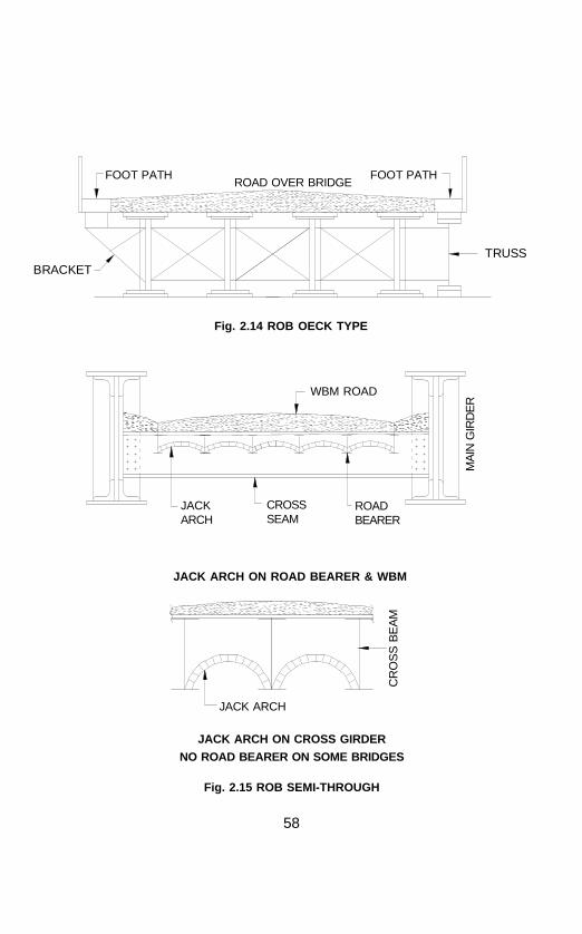
58
FOOT PATH
BRACKET
FOOT PATH
TRUSS
ROAD OVER BRIDGE
Fig. 2.14 ROB OECK TYPE
WBM ROAD
MA
IN G
IRD
ER
JACKARCH
CROSSSEAM
ROADBEARER
JACK ARCH ON ROAD BEARER & WBM
CR
OS
S B
EA
M
JACK ARCH
JACK ARCH ON CROSS GIRDER
NO ROAD BEARER ON SOME BRIDGES
Fig. 2.15 ROB SEMI-THROUGH
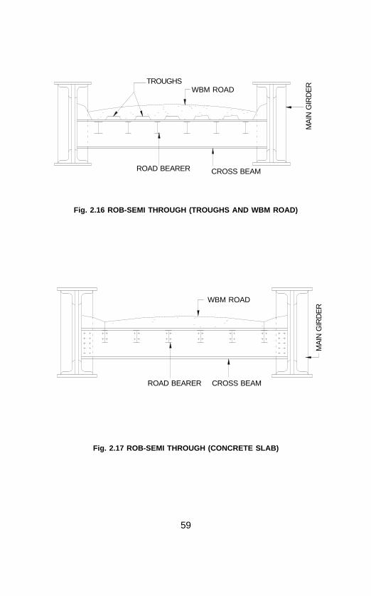
59
CROSS BEAM
WBM ROAD
ROAD BEARER
Fig. 2.16 ROB-SEMI THROUGH (TROUGHS AND WBM ROAD)
MA
IN G
IRD
ER
CROSS BEAM
ROAD BEARER
Fig. 2.17 ROB-SEMI THROUGH (CONCRETE SLAB)
TROUGHS
MA
IN G
IRD
ER
WBM ROAD

60
depending on the width of the road and the road concrete slabcast on the top of these girders. Footpath is provided onbrackets fitted to outer-most girders outside or a truss isprovided to support foot-path.
2.4.2 Semi-through type ROB
Earlier ROBs were mostly semi through type provided with jackarches supported on cross-girders or road bearers, and evenwater bound macadam road was made on this. On some ROBssteel troughs have also been provided over cross-girders and roadbearers to carry the macadam road.
2.4.3 Bearings of ROB
All plate girders of ROBs whether deck type or semi throughtype are provided with phosphor bronze bearings since it is notfeasible to lift these girders periodically for greasing.
Through type ROB girders are provided with rocker and rollertype bearings.
2.4.4 Expansion Joint
Expansion joint is provided at either end of the approaches onsingle span and at either end of the girder for multiple spanbridge. But it is observed that, over the years these expansionjoints get jammed by asphalt due to frequent road surfacemaintenance. Thus new designs of expansion joints are beingevolved.
With the past experience, it is observed that the rivets in ROBgirders seldom get loosened but corrosion does occur on rivetheads due to accumulation of water and muck. Hencesystematic and effecitve painting is a must to keep the girdersfunctioning for long years as designed (70 to 80 years).
Kerb bent plates are generally provided to main plate girdersalong the inner side of the road to prevent the road vehicles

61
hitting the main girders.
Most of the ROB plate girders are of rivetted construction and nocamber is provided to these girders.
2.5 FOOT OVER BRIDGES (FOBs)
The foot over bridge steel girders are the light structuresspanning on the railway stations from platform to platform forfacilitating the commuters to cross over from one platform toanother. These consist of main girders and staircase stringers,providing ramps or steps for the passengers to climb up from andstep down to the platforms either for alighting or for entraining.
FOB’s old steel girders are in the form of either lattice throughgirders or ‘N’ type through girders or pin connected triangulatedWarren girders, etc. The main girders support the road path forpassengers to walk. This road path rests on the floor beamsconnected to main girders horizontally leaving a gap of about 50mm between the road edge and the innermost members (bottomflanges) of the main girders to avoid accumulation of muck andwater and thus prevent corrosion and to ensure effectiveminimum maintenance.
The staircases are made up of stringers and risers with anglesand plates for supporting in situ cast RCC steps or pre-cast RCCsteps. To avoid steep climbing, the staircase is generally madein two flights with an intermediate landing. This relieves thepassengers of strenuous climb to a great extent.
Theses girders are fabricated in lengths commensurate with theno. of tracks to cross in the station yard. These were fabricatedas rivetted construction prior to year 1970 and subsequent toyear 1970, welded construction has been resorted to. These arepredominantly statically loaded structures and hence the camberprovided is for dead load + 75% of live load without impact. Itsdeflection under designed load should not exceed L/325 whereL is the length of the girder. For plate girders upto 35 m lengthspan (115’-0"), no camber has to be provided as per Steel Bridge

62
Code clause no.4.16.1 but all truss type girders are provided withcamber and fabricated on camber layout. Hence called camberedtruss (whereas trusses for track bridges are not only camberedtrusses but are prestressed girders which provide camber also).Steel used for these girders conforms to IS-2062 Grade ‘A’ forboth rivetted and welded construction.
In the olden days the girders were made to rest on masonry sub-structure and the staircases were in the form of ramps or steelstanchions with risers and steps made of cast iron treadsperforated to avoid corrosion and to reduce weight.
Presently the girders are fitted to RSJ columns on the platformto which the staircase stringers are also attached. The steelcolumns are located on the platforms on sound foundations, carebeing taken to avoid infringement to moving dimensions. Mostlypre-cast slabs of RCC are used for main floor as well as stepsfor staircase stringers. To avoid wear and tear of the edges of thesteps, nosing angles are fitted to the edges of these steps thusprolonging its life and obviating escapable maintenance.
No moving bearings are provided to these griders (girders arebolted to the columns) hence no greasing is necessary. It hasbeen experienced that the occurrence of loose rivets or weldcracks in these girders and staircases is almost nil. Otheraspects of inspection and maintenance are namely floor slab,staircase steps, roof sheeting and protection frames in electrifiedareas. These are maintained by SE/JE Works concerned. (Fig.2.18 indicate typical F.O.B.)
2.5.1 Beam Type FOBIn this type RSJs or welded built up I-girders are used as superstructure with portal frames erected on brackets connected tothe outside of outer girder for hand railing and roof cover. R.C.C.deck is cast in situ or pre-cast slabs fixed on top flanges ofgirders without shear connectors. Stiffeners are provided tobeam. Main girders rest on cap beams of columns. Fig. 2.19shows details.

63
(c) CROSS SECTION OF FOOT OVER BRIDGE(NEW TYPE)
Fig. 2.18 FOOT OVER BRIDGE ‘N’ TYPE TRUSS
(b) CROSS SECTION(OLD TYPE)
(a) ELEVATION

64
2.5.2 Portal type FOBThis is a portal rigid frame type structure in which the maingirders are spliced to columns to form one unit. Other items aresame as mentioned in para 2.5.1. Fig. 2.19 shows details.
2.5.3 Truss type FOB
2.5.3.1 Pin connected triangulated girders
These are mostly wrought iron girders released from BritishRailways track bridges and used on Indian Railways as FOBs. Inthese pin connected girders some alterations had to be made soas to use these girders as FOB girders. Accordingly hangerplates are connected at each pin joint of bottom chord and floorbeams are connected to these hanger plates. The floor beams inturn carry the floor slab either cast in situ or precast R.C.C.segments. The main girder ends are provided with steel bracketwith pins to rest on masonry sub-structure or on column caps.Roof trusses provided to these girders act as top bracings withraker brackets (Fig. 2.20 shows details).
2.5.3.2 Lattice type truss
These girders are formed by top and bottom flanges out ofangles back to back and M.S. flats diagonals in the shape ofdiamond openings for web. Floor beams are fitted to bottomflanges from underneath, below the stiffener at each panel point.Earlier these girders were designed for wooden floors which werelater on replaced with concrete slab deck. This change has over-stressed some of the girders which lost their camber due toincresed dead load and had to be subsequently strengthened.These types of FOB girders are now obsolete. (Fig. 2.21 showsdetails).
2.5.3.3 ‘N’Type truss
These FOB girders consist of ‘N’ type trusses made of top andbottom flanges out of angles back to back with gussets in-between these angles to which verticals and diagonals arewelded, forming an ‘N’ truss. Floor beams were directly attached

65
ELEVATION
CROSS SECTION
(a) FOOT OVER BRIDGE - BEAM TYPE (WELDED CONSTRUCTION)
ELEVATION
CROSS SECTION
(b) FOOT OVER BRIDGE - PORTAL TYPE
Fig. 2.19

66
ELEVATION
Fig. 2.21 FOOT OVER BRIDGE -LATTICE TYPE (OLD)
ELEVATION
CROSS SECTION
Fig. 2.20 FOOT OVER BRIDGE - PIN CONNECTED (OLD)
CROSS SECTION

67
to the bottom of bottom flanges by bolts and the concrete slabrests on the floor beams as well as bottom flanges of maingirders directly. This arrangement posed a maintenance problembecause due to stagnation of rainwater at the junction of floorbeams and main girders heavy corrosion is caused. Thisarrangement was therefore modified by protruding the maingussets down below the bottom flanges of main girders and floorbeams are connected to these gussets by bolts and theconcrete slab is resting on these floor beams only, thus leavingthe main girders unaffected. This arrangement has reduced themaintenance work to a great extent and the correspondingexpenditure. The cavities formed in the stringer channels and thecolumns base should be filled with concrete to avoid wateraccumulation and subsequent corrosion. The sub-structure in thistype of FOB is made of steel columns (R.S.J’s) called towercolumns (consists of four nos. for main column at ends and twonos. for intermediate column) duly braced with angle bracingsand firmly bolted/rivetted. The main girders are connected tothese columns at top to give adequate clearance from rail level tobottom of the girders as per provision of schedule of dimension.
The main girders are bolted to main column with adequate no. ofbolts in addition to resting on brackets attached to the columns.(Resting the girders on these brackets on columns will relievethe tension on the bolts connecting girders to columns to a greatextent). Rakers are provided to the truss girders at everyalternate vertical from outside to afford sufficient lateral stabilityto the trusses. Bottom lateral bracings are provided between floorbeams and bottom booms of main girders for lateral rigidity. Rooftruss is fitted to every panel point of top boom which acts as topbracings and the roof sheeting is provided to these trusses byfixing runner angles. Fig. 2.18 shows details.
The length of FOB girders depends upon the no. of tracks to becovered plus minimum moving dimensions from the nearest trackto the nearest columns. Similarly the height of FOB girders fromR.L. is guided by shedule of moving dimensions including thosein electrified areas. The widths of the FOBs are 2.4 metres, 3.6metres, 4.8 metres depending on the density of commuter traffic.

68
The modified ‘N’ type FOB truss retains the accessibility of allthe steel work which would certainly make it possible for thesestructures to be inspected and maintained by SE/JE Works.Since FOBs are located on the station platforms, no trolly isrequired and the lOW can easily maintain these structures.
2.5.4 Quadricon type FOB
Quadricon FOB girders (patented) are in the form of triangulatedspan and connections at joints are made by Quadricon patentmale and female connections with centre bolts. It is a unit typeconstruction. To the male and female component like diagonalsand top and bottom members are welded forming a triangulatedgirder. This facilitates adoption of incremental launching in situover the tracks without interfering with the traffic. At oneapproach half the span is erected and from there, further erectionproceeds panel by panel, as joints being connected by malesand females with centre bolts. Members are quite light in weightand can be manually handled. In this type of girder no repairsare generally needed.
2.5.5 Fabrication and erection of FOB
Important aspect to be considered for fabrication and erection ofFOBs are –
i) Fabrication for welded beam or truss type steel girdershall be confirming to IRS – B1 – 2001 and weldedbridge code – 2001 provisions.
ii) Truss type girder are provided with camber hencefabrication has to be carried out on camber profilethrough jig and fixture.
iii) Since truss is designed as uniformally distributedloaded truss, pre cast slabs are to be laid starting fromboth ends towards centre to avoid buckling due toconcentrated load (if loaded in centre of span leads toaccident).
iv) If RSJ columns are used with end bolted connection of

69
truss to top, first ensure straightness of columns. Aftererection of columns check with plumb for verticality andcentre to centre distance of columns before erectingboth trusses.
v) After erection of both trusses provide floor beams, endraker, bottom lateral bracing roof truss (if it is there)and tighten all bolted connections.
vi) Check the verticality of columns with plumb andcamber of truss. Then grout the anchor bolts aftertightening all bolts connections to truss and bracings.
vii) When anchor bolts are set, start laying of pre cast slabfrom both ends of spans towards centre.
2.6 PROCEDURE FOR ERECTION OF OPEN WEB STEEL GIRDERFOR TRACK BRIDGES AS ‘PRESTRESSED’ (PREDEFORMED)GIRDER
To ensure truss under full load (DL + LL + DA) to remain innominal profile, following procedure is to be adopted for erection(assembly) at site.
This procedure will however not apply in case, erection of girderis carried out by cantilever method, since members undergoreverse stress during erection, i.e. top chord which is designedas compression member is under tension and bottom chorddesigned as tension member is under compression. Duringcantilever erection, position of joint holes should not be disturbedby reaming. After erection of each member, flairing of connectionholes by drifting and rivetting of joints is done simultaneously, toachieve camber as well as prestressing.
2.6.1 Erection stages
(i) Erect assembly platforms 600 mm high below eachbottom panel point of both trusses over well compactedground to avoid settlement during erection.
(ii) Place camber jack (screw jack) over platform belowevery bottom panel joint of both trusses in such a way

70
that all jacks are in run out condition except centre jackie. at least 15 mm more than the amount of loweringrequired to provide design camber, stipulated in cambersheet at every panel point. Ensure top of all camberjacks in one level.
(iii) Place all bottom chords of both trusses over camberjacks as well as cross girder, rail bearer, bottom lateralbracing fixed in position, in one level condition with min.40% black bolts and 10% drifts. This will not pose anyproblem for erection as camber lengths of bottom chordsare same as nominal lengths. Rivet all panel point, rivetsconnected to bottom chord & main gusset. Duringrivetting ensure one level by frequent checking withdumpy level and staff. Details indicated in Stage I ofFig. 2.22.
Erect all web members i.e. vertical & diagonal exceptend rakers (End Post) of both trusses & rivet the bottomconnection with gusset of panel points of bottom chord.Since holes drilled on member connecting gusset as wellas panel points gussets are marked and drilled onnominal layout it will not pose any problem in fairingholes for rivetting. Top of web members should beprovided with wire rope guys for stability. On the otherend (top connection) of web members, i.e. diagonal &vertical erected should be connected with temporarygusset drilled with camber profile holes or providepermanent gussets (holes drilled on nominal layout) oftop chord panel point with undersize bolts temporarily.Check to ensure that the bottom chord is in one level.Details as per Stage II of Fig. 2.22.
Provide camber to all panel points of bottom chord asgiven in camber sheet by lowering the jacks belowrespective panel point. For this operation it is easy tolower the jack than lifting hence keeping centre jackwithout disturbing, lower other jacks (lowering ismaximum at ends). Check the camber readings and

71
adjust for correctness. Details as per Stage III ofFig. 2.22.
All top chord & web memebrs are to be elasticallystrained into position by external force so that as manyholes as possible are fair or the top chord should beerected piece by piece working symmetrically startingfrom centre outwards & fair the holes with gusset byusing split drift in number of holes and hammering with1 kg hammer simultaneously to strain the member underclose expert supervision. (If temporary gussets are used,these should be replaced by permanent gusset beforedrifting). Ensure maximum number of holes are driftedsimultaneously. The effect of drifting being checked byobservation of adjacent unfilled holes. Complete theerection of top chord. Details at Stage IV & V ofFig. 2.22.
Either side end post shall be erected at last. The upperend of end post connection should be made first & driftthe lower connection holes last and rivet all top chordpanel points after erection of sway bracing, top lateraland portal bracings. Details as shown in Stage VI ofFig. 2.22.
After entire rivetting of joints, support the span at endson bearings by removing all intermediate supports.Check dead load camber, which will indicate thereduction of camber proportionate to dead load. Deadload camber of each span should be recorded in camberregister to compare the camber recorded duringmaintenance inspection. Table 2.3 shows dead loadcamber and design camber of 30.5, 45.7, 61 and 76.2 mstandard through spans.
NOTES
1) During service if a web member is damaged by externalhitting or snapping of web member resulting in loss ofcamber at any panel points, the rectification of damaged

72
Fig. 2.22 ERECTION OF OPEN WEB GIRDER45.7m STANDARD SPAN
(NOMINAL PROFILEUNDER LOAD)
PERMANENT GUSSETS
JACKSTEMPORATY GUSSETS
TEMPORATY GUSSETS
PERMANENT GUSSETSTOP CHORD
TEMPORATY GUSSETS
JACKS
JACKS
JACKS
STAGE-I
STAGE-II
STAGE-III
STAGE-IV
STAGE-V
STAGE-VI
LC
�

73
web member or replacement of web member with correctcamber as original, is only possible by supporting allpanel points and cutting of all panel joint rivets and againerecting in same sequence as mentioned above forprestressing. This will require closure of line for longerperiod or taking out span from the road with provision oftemporary girder and crib. It will be economical toreplace the girder with new one and use the reclaimedgirder for branch line. However, if camber is not affectedand only web members are damaged, the members canbe rectified or replaced one by one with procedureensuring that no loss of camber occurs duringrectification or replacement of the member.
2) Camber in steel truss girder is provided upward amountbeing equal to deflection of girder under design loadduring fabrication and erection so that girder under fullload, truss shall be in horizontal plane (nominal shape).The girder is laid out and fabricated to cambered profile.Such girder will get deformation stresses under load.Such type of cambered steel truss girders are used forFOB on Indian Railways.
3) Steel truss of foot overbridge is fabricated on camberlayout as cambered truss but no prestressing isrequired. Hence above procedure should not be used.
4) Prestressing of open web steel girder of track bridge ispredeforming of members during fabrication and erectionof girder to ensure girder under full design load shall bein nominal shape to minimise deformation stresses.When correctly erected, such predeformed girder getsdead load camber.
5) As per Steel Bridge Code [Clause No.4.17] forpermanent installation other than foot over bridges, theratio of deflection to length of girder shall not exceedL/600.

74
TA
BL
E
2.3
DE
SIG
N A
ND
DE
AD
LO
AD
CA
MB
ER
OF
RB
G/M
BG
TH
RO
UG
H S
PA
N S
TE
EL
GIR
DE
R
SP
AN
LOA
DIN
GL0
L1L2
L3L4
L5R
EM
AR
K30
.5 m
A0
15.5
22.9
26.8
--
MB
G
B0
13.3
519
.70
23.0
--
45.7
mA
023
.040
.055
.057
.0-
MB
G
B0
18.0
031
.30
43.0
044
.5-
61.0
mA
029
50.8
6874
.45
-R
BG
B0
21.3
537
.45
50.1
554
.85
-
76.2
3 m
A0
34.2
64.2
90.6
104.
611
2.5
RB
G
B0
23.6
544
.35
62.6
072
.30
77.7
5
A:-
DE
SIG
N C
AM
BE
R V
AL
UE
AS
PER
CA
MB
ER
SH
EE
T O
F FA
BR
ICA
TIO
ND
RA
WIN
G
B:-
DE
AD
LO
AD
CA
MB
ER
VA
LU
E A
FTE
R E
RE
CT
ION
& S
UPP
OR
TIN
GSP
AN
ON
BE
AR
ING
S A
FTE
R R
EM
OV
ING
IN
TE
RM
ED
IAT
E S
UPP
OR
TS.
All
dim
ensi
ons
are
in m
m.

75
4700
300
CHAPTER - 3
STEEL CHANNEL SLEEPERS
3.1 INTRODUCTIONTrack structure on bridges is different from that onembankment. On Indian Railways track structure beingused on different type of bridges are as under-
3.1.1 Ballasted Deck Bridge
Rails, fittings and sleeper used on bridges with ballasteddeck are similar to the track structure on approach andembankment except additional provision of guard rails toprevent over turning of derailed rolling stock. This type ofdeck can be used over masonry arch bridge, RCC/PSCslab and box, composite girder, PSC girder/PSC boxgirder only. (In olden days ballasted deck was used onvery few bridges of steel girder by providing steeltroughs. Such steel trough ballasted deck pose problem
Fig. 3.1 BALLASTED DECK BRIDGE

76
for maintenance as well as repairs to corrosion effectedmembers hence this system of floor was discontinuedduring 1940-1950. Track structures is same as onapproaches with minimum ballast cushion of 300 mmbelow sleeper. The details of ballasted track structure issame as stipulated in para 263 of Indian RailwayPermanent Way Manual.
3.1.2 Open Deck Bridge
From the Inception of Railway in India, wooden sleepersare being used to support rails on steel girders. Spacebetween two sleepers is open hence called open deck.Wooden sleepers derives many advantages over othertypes of sleepers, in track structure on bridges over steelgirder, on account of lighter weight for handling onbridges, easy in machining (including at site) forplacements, minimum simple fittings to hold the rails aswell as in maintenance repairs. Wooden sleepers offergreater resilience hence no rubber pad is used like incase of steel channel sleepers.
Fig. 3.2 OPEN DECK BRIDGE
BridgeTimber

77
On open deck steel girders the independent movementof rail and girder is required hence rail free fastening arerequired. Same is provided with rail screw/dog spikesand canted bearing plates over wooden sleepers (bridgetimbers).
Due to scarcity of wood and restriction to use woodensleeper on Indian Railways, steel channel sleepers wereintroduced as substitute to bridge timbers during 1992 asper RDSO, drawing No.RDSO–B-1636 and B-1636/1.Subsequently to minimize number of fittings and ease infabrication and maintenance, revised drawing were issuedby RDSO drawing No. B-1636/R
2 and B-1636/1/R
2 for
steel channel sleepers of 150x75mm size. Additionaldrawing No. B-1636/2 has also been issued withincreased height of channel sleepers i.e. size 175x75mmto avoid thicker packing plates over top flange plate ofplate girders of 12.2m, 18.3m and 24.4m spans.
3.2 SLEEPER LOCATION
Steel channel sleeper will directly rest on top of steelgirder depending upon the type of the deck as below:
3.2.1 Deck type
(Plate girder and under slung open web girder). For plategirders, whether it is welded type or riveted type steelgirder, sleeper will rest on top flange plate (crosswise) ofboth girders, and for open web (under slung) deck typesteel girder of 30.5m span on top boom of both trusses.
3.2.2 Through type
For open web steel girder (either rivetted or welded type)of span 30.5m, 45.7m, 61.0m and 76.2m including non-standard steel girder of any span, sleeper will rest on topflange plate of stringer / rail bearer on flooring system ofthrough span.

78
3.3 SPECIFICATION OF STEEL FOR SLEEPERS
Steel channel sleeper is part of dynamic structure(critical loadings) which support directly rails of track ongirders hence steel is used as follows:
3.3.1 Bridges located where service temperature does not fallbelow 0°C, steel used shall confirm to IS-2062 grade ‘B’fully killed.
Note: Till such time rolled channel not available of steelto IS-2062 grade “B” steel confirming to IS-2062 ‘A’ fullykilled can be used.
3.3.2 Bridges located in below sub zero temperature areas,steel shall be confirming to IS-2062 grade “C” fully killed.
Note: Steel used for fabrication should be tested one andmust have mill test certificate clearly indicating thespecification and fully killed. Fabricator should maintainthe record of steel used with cast mark for verification ifrequired at later date.
3.3.3 Rolled section should be within the rolling tolerances andsurface defects prescribed in IS-1852.
3.4 SIZE AND LENGTH OF SLEEPER
There are two type of steel channel sleepers in use -(1) 150 x 230mm size of cross section(2) 175 x 230mm size of cross-section.
3.4.1 Cross section of sleeper will be 150 x 230mm afterfabrication (if rolled channel used is ISMC 150 x 75) asper Drawing No. B-1636/R
2 & B-1636/1-R
2) Fig. 3.3.
3.4.2 Cross section of sleeper will be 175 x 230mm afterfabrication (if rolled channel used is ISMC-175 x 75mm)as per Drawing No.B-1636/2.
3.4.3 Length of steel channel sleeper depends on the type ofsteel girder bridges which is as follows:

79230
ELE
VA
TIO
N
CE
NT
ER
S O
F G
IRD
ER
OV
ER
ALL
LE
NG
TH
OF
SLE
EP
ER
150
ELA
ST
OM
ER
IC P
AD
Fig
. 3.
3 S
TE
EL
CH
AN
NE
L S
LE
EP
ER
B.G
.
PL
AN
EL
EV
AT
ION

80
AB
A
Fig
. 3.
4 T
OP
FL
AN
GE
OF
ST
AN
DA
RD
PL
AT
E G
IRD
ER
(W
EL
DE
D T
YP
E)
B.G
.
End
por
tion
Cen
tral
por
tion
End
por
tion

81
3.4.3.1 Standard plate girder rivetted type (B.G.)
Span 24.4m 18.3m 12.2m
Sleeper Length 2550mm 2440mm 2440mm
3.4.3.2 Standard plate girder welded type (B.G.)
The top flange plate of welded girder has different widthat either end and middle portion of girder as shown inFig. 3.4. Therefore, length of sleepers on A and Blocation are of different length:
Span 24.4m 18.3m 12.2m
Sleeper length A 2565mm 2440mm 2440mm
B 2725mm 2535mm 2475mm
3.4.3.3 Standard Open Web Steel Girder through Spaneither rivetted type or welded type (B.G.)
Steel channel sleeper rest on floor system i.e. railbearer/stinger, the length of sleeper is same for allspans.
Span 30.5m 45.7m 61.0m 76.2m
Sleeper Length 2440mm 2440mm 2440mm 2440mm
3.4.3.4 Standard Open web (under slung) deck type 30.5mspan
RDSO, Lucknow has not issued any drawing for steelchannel sleeper for B.G. Presently Zonal Railways usesthe wooden sleeper or the steel channel sleeper as perChief Bridge Engineer’s drawing of their zonal Railways.

82
3.4.3.5 For non-standard Span
Length of sleeper is as below:
Length of sleeper = Center to center length of girders + Flange width + 200/300mm
3.4.4 Details of steel channel sleeper
Shape of sleeper is made by 2 ISMC 150 x 75mm or175 x 75mm, which are kept back-to-back 80mm apartto make width of 230mm. Both channels are connectedin web by ‘T’ and plate type diaphragms with fillet weld.‘T’ shape diaphragms are connected below ‘T’ head boltconnecting rail clips. In case of loosening of nut, bolt willrest on ‘T’ diaphragm, so that clip will be in position aswell as prevent falling down of bolt. Canted bearingplates for rail seat are connected to top flange of bothchannel with rivets. Stiffener plate are provided belowthe rail seat with fillet weld in web between top andbottom flange of both channels as well as in the middleof sleepers. Details are shown in Fig. 3.5 (a) and 3.5 (b).
3.4.5 Fittings
3.4.5.1 Bolt
‘T’ head bolts with spring washers and nuts are used toclamp the clip to canted bearing plate to hold rails. ‘T’head will facilitate insertion of bolt from top and viceversa removal of the same.
3.4.5.2 Clips
Either side of rail clips are provided and tightened with‘T’ head bolts to keep the rail in position i.e. clip preventlateral movement and uplift of rail but it will allow rail tomove longitudinally to facilitate free movement of rail andgirder as rail free fasteners. Grooved rubber pads areplaced below the rail on canted bearing plates. Guardrails are also anchored with either side (crosswise) bybolt and clip to sleeper top flange.

83
23015
0
80
STIFF. PLATE 65x10
TOP PLATE 80x12x250ISMC 150x75 @ 16.4kg/m
7575PLATE 80x10x120
TIGHT FIT
75
230
175
ISMC 175x75 @ 19.1kg/m
TIGHT FIT
7580DIAPH. 80x10x120
STIFF. PLATE 65x10
TOP PLATE 80x12x250
3.4.5.3 Hook Bolts
Hook bolts are of two types.(1) Straight lip(2) Tapered lip
Fig. 3.5 (a) SECTION OF CHANNEL SLEEPER (150 X 230 mm)
Fig. 3.5 (B) SECTION OF CHANNEL SLEEPER (175 X 230 mm)

84
Hook bolts are provided to outer edge of top flange plateon either side of girder to anchor the sleeper with thegirder.
Note: Plate girder whether rivetted or welded typerequires straight lip hook bolts. Stinger/rail bearer ofthrough type open web girder requires taper lip to ensurefull grip to rolled angle. Square cross section ofhook bolt near the head will prevent the turning of hookbolts during service ensuring lip of hook bolt in properposition.
3.4.5.4 Elastomeric Pad
Elastomeric/rubber pad between bottom of steel channelsleeper and flange of girder, is essential to prevent crossbending of flange plate causing initiation of cracks in filletweld or root of rolled angle under load. Sleepers aremade up of steel, which is elastic material and causecross bending under each axle passing. Thickness ofelastomeric pad is minimum 12mm or as stipulated indrawing.
3.5 FABRICATION OF CHANNEL SLEEPERS
Fabrication of steel channel sleeper is simple andrequired very simple infrastructure hence it can befabricated in civil engineers workshop of zonal railways orby trade. Guide lines issued by RDSO for fabrication ofsteel channel sleepers vide Report No. 135-45 revised inMay 2004 should be followed strictly for fabrication ofthese sleepers.
Steel channel sleeper is part of dynamic loaded trackbridge and support the rail to transfer the load from railto steel girder hence considering safety aspect,following precautions shall be taken during fabrication toavoid fatigue failure of weld or cracks in steel of HAZ(heat affected zone).

85
3.5.1 Precautions
a) All steel section used in fabrication must have milltest certificate clearly indicating the steelspecification conforming to IS-2062 grade ‘B’ or ‘C’fully killed.
b) All steel plates and rolled section should be straightand free from twist before cutting for fabrication.
c) Oxy-acetylene gas cutting by mechanically controlledtorch shall be used and cut edges to be ground.Profile of plate stiffener shall match with the profile ofinner web and flange plate of both ISMC for snug fitto avoid cracking of weld or root of ISMC below railseat.
d) Welding position shall be flat position (down handwelding) either by MMAW or CO
2 welding process as
well as welding is carried out only by the qualifiedwelders.
e) Electrodes shall confirm to IRS-M-28 of class A-2 orC-1 and wire for C0
2 welding shall confirm to
specification of class-1 of IRS-M-46-2001. PreferablyCO2 welding shall be used for fabrication.
g) Welding procedures requires approval and testing asper Clause-19 of Welded Bridge Code-2001 andrecord of fabrication and test qualification shall bemaintained in proforma as stipulated in appendix-V ofIRS serial B1 – 2001.
h) Before welding, all mill scale and dust adjoining weldface shall be removed and surface shall be cleanedand to avoid cracking of weld during service.
i) Bearing plates and supporting rails are connected tosleeper by rivet hence drilling of holes in sleeper after

86
manufacture and in bearing plate shall be by drillingjig to ensure accuracy in rail gauge and alignment ofrails on bridge. Rivets shall be driven with properheating for the full length of shank to minimizeloosening of rivets during service and reducemaintenance cost.
j) Entire surface of sleeper shall be grit blast cleanedbefore hot dip galvanizing as per IS-2629.
k) Zinc coating weight / thickness is most importantfactor from corrosion prevention point of view sincesleeper is in vulnerable location and affected bydisposal of passenger carriage and droppingchemicals and salts from goods wagon. Hencenominal coating weight 610grams/m2 (85-86 micronsthickness) for long life of 15 to 20 years and 750grams / m2 (105 micron) for severe corrosion locationof bridge has to be ensured.
3.6 INSPECTION
To ensure minimum maintenance and safety of public,fabrication shall be in Civil Engineering Workshop ofZonal Railways or from trades who produce satisfactoryevidence of his ability as stipulated in Clause-21 ofWelded Bridge Code 2001.
3.6.1 Inspection shall be in accordance with Clause No.28, 29,30, 31, 32 and 33 of Welded Bridge Code of 2001 sothat cost of maintenance and repairs will be minimized.
3.7 FIXING OF STEEL CHANNEL SLEEPER ON STEELGIRDERS
Arrangement of fixing of steel channel sleeper, dependson type of steel girder, is as follows:
1) Plate Girder
(a) Rivetted type
(b) Welded Type

87
2) Open Web through Steel Girder
Steel plate girders of span 12.2m, 18.3m & 24.4m span(either welded construction or rivetted construction) arenot provided with camber as stipulated in steel bridgecode. Therefore rail levels on plate girder as well as onentire bridge has to be in one level.
In welded plate girder same thickness of top flange plateis provided through out the length of girder in differentwidth as stipulated in para 3.4.3.2 Where as on rivetedplate girder 1st flange plate is provided on entire length ofgirder. 2nd and 3rd flange plate is provided to requiredlength depending upon the cross section required fordifferent length of span. Therefore, top flange plate ofriveted girder is not in one level through out the girder asshown in Fig. 3.6.
To keep rail in one level different thickness of steelpacking plates are required on splice plate, on 1st flangeplate, 2nd and 3rd flange plates.
SE/JE Bridge has to work out the thickness of steelpacking plate by drawing full scale top flange plate ontemplate floor of workshop and mark the sleeper positionto ascertain different thickness of packing platesrequired. To minimize the thickness of packing plate,provide 150x230mm size sleeper with 16mm steelpacking to accommodate the rivet heads on splice plate,so that steel sleeper rest on packing plate instead of onrivet head to avoid rocking of sleeper under running oftrains.
Height of rivet head is 14 or 15mm i.e. 0.7 x d where dis diameter of rivet.
On 3rd flange plate provide 150x230mm size sleeper withincreased thickness of steel packing plate to ensure thetop of the all sleepers are in one level. On 2nd and 1st

88
FIR
ST
FLA
NG
E P
LAT
E
SE
CO
ND
FLA
NG
E P
LA
TE
TH
IRD
FLA
NG
E P
LAT
E
SP
LIC
E P
LAT
E
Fig
. 3.
6 D
ET
AIL
S O
F T
OP
FL
AN
GE
PL
AT
E O
F R
IVE
TT
ED
PL
AT
E G
IRD
ER
18.
3 M
SP
AN
(B
.G.)
C L

89
flange plate provide 175x230mm sleeper with requiredsteel packing to ensure that all sleepers top in one levelon entire span.
Accordingly the different thickness of packing plates anddifferent size of sleepers are to be worked out on onespan and same will be fabricated.
Note: Welded plate girder top flange plate is in one levelhence the packing plate and size of sleeper can beworked out without layout.
3.7.1 Fixing steel channel sleeper on plate girder(rivetted span)
a) Cleaning of top flange plate with wire brush and applyof one coat of cover paint on entire top flange plate.
b) Mark the sleeper position on the top flange plate ofentire span/bridge.
c) Place 150x230mm size sleeper with rubber pad andsteel packing on splice plate and ensure all sleeperon in one level.
d) Place the 150x230mm size sleeper with rubber andsteel packing on 3rd flange plate ensure level of allsleepers (including over splice plate) in one level.
e) Place the 175 x 230mm size sleeper with rubberpacking and steel packing on 2nd and 1st flange plateand ensure all sleeper on entire span in one level.
f) Sleeper center shall concide with the center line ofgirder to ensure alignment of rail gauge face.
g) After ensuring all sleepers are in one level andcocentric to the span, sleepers to be anchored with
90
the hook bolt to girder on either side and nuts aretightened and again check the level of all sleepers tobe in one level.
h) Place the rail with the rubber pad on rail seat and fixthe ‘T’ head bolt with clips on either side and tighten.Check the alignment and levels of both the rails onspan/bridge.
3.7.2 Fixing of Steel Channel Sleeper on Plate GirderWelded Type
a) Clean the top flange plate with wire brush and provideone cover coat paint and mark the sleeper position.
b) Where (if exists) splice plate and rivet heads of toplateral bracing system is there, provide 150x230mmsize sleepers with rubber and steel packing toaccommodate rivet heads and ensure that all are inone level. Also center of sleeper should concide withcenter of span to ensure gauge face alignment of rail.
c) Remaining portion depending upon the width of theflange plate provide 175x230mm size sleeper withrubber pad and steel packing plate and ensuresleepers center conside with span center to ensurealignment of gauge face.
d) Check that all the sleepers on entire span are in onelevel.
e) Fix the sleeper to the girder with the help of hookbolt on either side and tighten the nuts. Place railand rubber pad on rail seat and anchor the rail withthe help of clips and ‘T’ head bolt after ensuringalignment, level, gauge and tighten the nuts.

91
3.7.3 Fixing of steel channel sleeper on open web steelgirder (through type BG)
As per steel bridge code all open web steel girder spansare to be fabricated with camber and prestreessed.Therefore same thickness of steel packing plate toaccommodate rivet heads are required on entire spanand use of 150x230x2440mm size channel sleepers arerequired. The rail profile will be similar to camber profileof span to ensure rail in level under passage of train.
Note: So far RDSO Lucknow has not issued anydrawing for steel channel sleeper for 30.5m under slung(deck) open web steel girder.
3.7.3.1 After cleaning with wire brush, provide one cover coatpaint on top flange plate of stringer (rail bearer). Markthe location of channel sleeper with prescribed spacingon entire span/bridge.
3.7.3.2 Place the steel packing plate on marked position toaccommodate the rivet heads. Place the rubber pad onthe steel packing.
3.7.3.3 Steel channel sleeper of size 150 x 230 x 2440mm areplaced on packing plate ensuring that center of sleeperand center of stringer concides to ensure alignment ofrail gauge face.
3.7.3.4 Provide hook bolts on either side to anchor sleeper toflange plate of stringer and tighten the nut.
3.7.3.5 Place the rubber pad on bearing plate and fix the railwith the help of ‘T’ bolt and clips on either side andtighten the nuts ensuring alignment and gauge.
3.7.3.6 Rail level on each span will coincide to camber profile ofspan.

92
CHAPTER - 4
INSPECTION OF STEEL GIRDER
4.0 Bridge steel superstructure are expensive assets andinvolve heavy investment. Hence they must be managedwell to give maximum service. Bridges should live theirfull designed life with minimum maintenance cost. Toensure this, a good bridge management system isessential to watch the bridge structure periodically duringservice. Inspection is a vital link in the chain of bettermanagement.
4.1 OBJECTIVES OF INSPECTION
The bridge inspection is done to ensure safety andserviceability. The purposes of inspection of a bridge canbe identified as follows:
(a) to ensure that the bridge is structurally sound andsafe and fit for its designed use. This relates tothe gradual deterioration of the bridge with time or toan accidental occurrence such as impact oroverloading.
(b) to identify actual and potential sources of trouble atthe earliest possible stage.
(c) to record systematically and periodically the conditionof the structure. This enables the management toidentify any significant structural changes anddefects.
(d) to provide necessary information, on which decisioncan be taken for carrying out maintenance repairs,strengthening or replacement of the structure.
4.2 TYPES OF INSPECTION OF STEEL GIRDERS
(a) Routine or general inspection
This consists of broad general visual inspection by Asst.

93
Engineer once a year after monsoon.
(b) Detailed Technical lnspection
During this inspection thorough examination of each andevery component of the superstructure is carried out withthe help of equipment covering all points of a preparedcheck-list (Inspection Proforma). This inspection is doneby the Section Engineer Bridges once in 5 years.Inspection Proforma is placed at annexure 4.1.
4.3 INSPECTION OF STEEL GIRDER-RIVETTEDCONSTRUCTION
The following aspects should be noted while inspectingrivetted construction.
4.3.1 Loss of Camber
All standard plate girders are of less than 35 metrespan, hence camber is not provided. All open webgirders of railway track bridges are pre-stressed. Deadload camber recorded after assembly and erectionshould be retained during the service life of girder if thereis no distress. Therefore, during technical inspection,first, camber is checked at every panel point of bottomchords of both truss with the help of dumpy level orprecision level, which will facilitate the inspection officialsto understand the structural condition. As far as possiblecamber observations are required to be taken at theambient temperature mentioned in the stress sheet.
Foot overbridge truss type girders are fabricated ascambered girder (unprestressed). Camber recorded atcentre of span during inspection should be comparedwith the initial dead load camber as recorded in theCamber Register and camber recorded during the lastinspection to detect any loss of dead load camber insteel truss or sagging of plate girder. Details of deadload camber is given in Table 2.3 for open web throughstandard track bridge girders for guidance.
94
In plate girders, levels have to be recorded on top flangeplate to ascertain that there is no sagging of girder whenrecorded levels are compared with last inspectionrecorded levels. In foot over bridge truss type girder,camber is to be recorded at midpoint of truss andcompared with dead load camber in register as well ascamber recorded during last inspection to ascertain anyloss of camber. In open web through span girders,camber is to be recorded at every panel point of bottomchords of both trusses of span and compared with deadload camber in register as well as camber recordedduring last inspection to ascertain any loss of camber. Inopen web deck type (underslung) girder camber is to berecorded at every panel point of top chords of bothtrusses of span and compared with dead load camber inregister as well as camber recorded during lastinspection to ascertain any loss of camber. Goodpractice is to draw dead load camber, last inspectioncamber readings and present recorded readings of eachpanel points on graph paper with different colour for eachgirder of bridge to ascertain any loss of camber whichwill be a permanent record.
If there is no loss of camber when compared to deadload, camber recorded in bridge register or the lastinspection report, it will assure inspecting official that nointernal structural change is taking place and structure isnot distressed.
Loss of camber in a girder can be due to :
i) Heavy overstressing of girder or component due toloss of cross section on account of corrosion orincreased load than the designed load or due tofatigue of the structure.
ii) Overstressing of joint rivets i.e. in open web girder atany panel point.

95
iii) Play between holes and rivet shank on account ofelongation of holes or crushing of rivet shanks.
If any loss of camber is noticed during inspection, as afirst step, 30 kmph speed restriction is to be imposedand following investigation is to be carried out:
1. Girder should be thoroughly inspected to establishthe cause by critically checking for loose rivets atpanel joints or at splices. Also all members shouldbe thoroughly inspected for distortion or deformation.
2. Stress reading of critical members under maximumload should also be taken either by Faraday PalmerStress Recorder or strain gauge methods to check ifany member is over-stressed. Check whetherbearings are frozen.
After investigation, speed restriction should be relaxedwith the approval of Chief Bridge Engineer. Loss ofcamber and other details of investigation report should berecorded in bridge register for future guidance.
Based on the investigation, proposal should be made toreplace all the loose rivets of panel joints, with oversizerivets or for strengthening of members with the approvalof Chief Bridge Engineer as a special work.
4.3.2 Distortion
In plate girders following members are likely to showdistortion:
i) Top flange plate being a member carryingcompressive stresses.
ii) Web plate near the bearings due to heavyconcentration of stress.

96
iii) Cross frame angles and top lateral bracing anglesdue to excessive lateral vibration
In open web girders the following members are likely toshow distortion.
i) Top chord members carrying compressive stresses ifnot sufficiently restrained.
ii) Diagonal web members particularly if they are madeup of flats and most likely at mid-span due to stressreversal and vibration during passage of train.
iii) Bottom chord members which carry tension andlongitudinal forces if not properly braced. The mostlikely location is near the bearings in case of frozenbearings.
iv) Top lateral and portal bracings are likely to distortdue to excessive lateral forces.
Distortion is also possible when longitudinal rnovement ofgirders due to temperature variation is arrested onaccount of frozen bearings.
Distortion can be checked visually as well as by a pianowire stretched between panel points over the members orby special distance gauges.
Sometimes web member i.e. diagonal, vertical and endrakers in through girder bridges are hit by moving loadsdue to shifting of load in wagons, particularlyoverdimensioned consignment (ODC). Hence, thesemembers should be checked at 1.2 meters above raillevel for any damage.
If distortion is noticed, cause of distortion is to beascertained. First, if it is due to frozen bearing, correctivemeasure should be taken immediately to restore themobility of bearings. Further, strengthening the membersas well as providing lateral restraint by providingadditional lacings, battens and diaphragms should be

97
contemplated. If lateral bracings and cross frame of plategirders are showing signs of distortion, they should bereplaced by higher section angles.
4.3.3 Loose Rivets
It is experienced in the past that no loose rivets arenoticed in steel girders of foot over-bridges and road overbridges. Rivets may get loose only when girders haveoutlived their design life or overstressed. Rivets of steelgirder of track bridges tend to become loose after 40 to50 years of service life. Earlier to this, only if rivets werenot driven properly during fabrication and erection, thesehave to be replaced.
The rivets in steel girders of track bridges fall in thefollowing 3 groups:
a) First group called as stitch rivets are driven to form amember. These rivets are driven in workshop andmostly do not become loose in service life of girderupto 80 to 100 years. 75% of total rivets in steelgirders fall in this category. (Diameter of rivets is20mm and hole diameter is 21.5mm).
b) Second group are rivets at joints connectingmembers. [These are also called as field rivets]These rivets transfer the load from member to joint.They are driven at site with hand-driven pneumatichammer and hence tend to become loose after 40 to50 years. (Diameter of rivets is 22mm and hole is23.5mm). All joints are provided with 10% extra rivetsin design stage. The rivets which transfer load fromcomponent to component are very important forchecking.
c) Third group rivets connecting top and bottom lateralbracings including sway and portal bracings tend tobecome loose on account of vibrations. If found loosethey should be replaced.

98
The present practice in some of the zonal railways is totest all the rivets falling in above 3 groups in steel girdersduring 5 years technical inspection, carried out by SE/JEBridges. It is observed that testing of rivets by rivethammer chips off the paint film, making rivet head steelexposed to environment leading to corrosion of rivetheads. Therefore, during technical inspection, the criticallocations, where rivets are to be tested, are mentionedbelow in detail, as well as in Bridge Manual Chapter XI.This will reduce the rivet testing work of bridge branchand reduction of cost in maintenance on account ofreduction in replacement of corroded head rivets. Whengirders are old and certification of higher speeds ofexisting girders is required, all rivets can be testedbefore the full painting of girders so that corrosion of rivethead is avoided.
Critical locations for testing loose rivets are as follows:
a) In plate girder/composite girder:
i) Rivets connecting web plate to flange angle of topand bottom flanges particularly at the ends ofgirder i.e. upto 1/12 of span from either endsupport and below the sleepers for top flangeplate.
ii) Bearing stiffener rivets.
iii) Splice rivets of flanges.
iv) Bracing and cross-frame connections.
b) For open web girders:
i) Rivets connecting rail bearers (stringers) to crossgirders in case of through span.
ii) Rivets connecting cross girder to panel pointgussets.
iii) Rivets connection at all panel points with maingussets to truss components of top chord andbottom chord (field connections).

99
iv) Rivets connecting bottom lateral bracings to endcross girders as well as top lateral bracings andportal bracings.
Note: Rivets listed in item (i) and (ii) of open web girdersare subjected to direct shear and sometimes inducetension due to excessive deflection of rail bearers andcross girders. Hence any loose rivets noticed in thesejoints should be replaced to avoid overstressing of otherrivets or shearing of rivet heads.
For loose rivets at field joints careful observation shouldbe made and decision should be taken for replacement.If there are only one or two slightly finger loose rivets atany staggered location or less than 10% in a particularconnection, it should be allowed to remain underobservation with white paint mark for identification. Ifmore rivets are loose at one location, they should bereplaced to avoid overstressing of other rivets. This needscareful understanding and good experience anddiscretion.
Rivets connecting bracings are prone to become looseon account of vibrations and these are secondarymembers which do not affect the strength of plate girderor truss but require replacement when found loose.
Many times rivets replaced on account of corrodedheads are due to bad maintenance and not due tostructural defects. Rivets should be replaced only withpneumatic hand driven rivet hammer which works atcompressed air pressure of 6.5 to 7.6 kg/ cm2. No handrivetting is permitted on main member of steel girder.
Maintaining proper record of loose rivets in group 2 & 3,particularly of open web girder, will help in assessingstructural condition in future inspection. Therefore,proforma shown in Fig. 4.1 may be used for properrecord. One form will be required for each span. This willbuild the history of girder and help the ADEN forNumerical Rating during his annual inspection.

100
4.3.3.1 Testing of loose rivets
Rivets which are driven at site and rivets which aresubjected to heavy vibrations like bracings, foot-path,trolley refuge etc. are prone to get loose. Corrosionaround the rivet will indicate the looseness of rivet. Dueto vibration of loose rivet, paint film gets broken andcorrosion sets in. To test rivets at any critical locationsmentioned above or sample testing, both hands arerequired to be free. Therefore, proper staging is essential.Left hand index finger is placed on one side of rivet headas shown in Fig.4.2. Then strike the rivet head on theopposite side with testing hammer, which is a lighthammer weighing 110 gms with handle 300 mm long. Ifthe rivet is loose, vibration movement is felt by the lefthand index finger. This requires a little experience. Theloose rivets are marked with white paint and entered inloose rivets proforma. Depending upon number of looserivets and their location it will be programmed forreplacement or kept under observation.
4.3.4 Corrosion
Corrosion of steel members is one of the major factorscausing considerable damage to the steel work. Steelstructures are sensitive to the atmospheric conditions.Corrosion eats up the steel section and reduces itsstructural capacity. If not attended to in time, it mayresult in -a) need for heavy repairs in the form of strengthening;b) need for replacement of the structure.
Hence it is an important item of inspection, to keepmaintenance expenditure minimum. A paint film isprovided over steel work as an inhibitor of corrosion. Withthe passage of time, due to extreme heat and cold orabrasions by sleepers or due to stagnation of water, thisprotective paint film starts scaling off and graduallyexposes the original steel surface to the atmosphere.

101
Fig. 4.1
Fig
. 4.
1 R
EC
OR
DIN
G O
F L
OO
SE
RIV
ET
S

102
Fig
. 4.
2 T
ES
TIN
G
RIV
ET
FO
R L
OO
SE
NE
SS

103
There are certain locations in girders, which are moreprone to corrosion than the other areas. These are asfollows:
1. Where steel comes in contact with wood.
2. Formation of water pockets on account ofconstruction features.
3. Places where dust can accumulate.
4. The presence of moisture near drainage system,particularly with concrete deck composite girders,road over bridge girder, etc.
5. Locations where there is a direct impact of waterrepeatedly.
Therefore, special attention should be given duringinspection to the portions of steel work where corrosionis likely to be more prevalent. Such locations are:
1. Sleeper seats - Top flanges of plate girders andunderslung girders or top flanges of rail bearers(stringers) in through spans.
2. Steel affected by fumes of diesel loco like webmembers of truss of through girder.
3. Water pockets due to construction features - openweb span bottom chord panel points form pockets forstagnation of rainwater, and in plate girders behindbent stiffeners.
4. Steel work in the vicinity of bearings.
5. Troughing of ballasted deck.
6. Top lateral bracings and portal bracings of throughspans.
7. Parts of the bridge steel work exposed to sea breezeand salt water spray.
8. Interface between steel and concrete in compositegirder and ROB girder.

104
9. Underside of road over bridges and web plates nearroad deck level of ROB semi through girder.
10.Base of columns, seating of wooden floor in FOBs aswell as staircase steps.
Railway bridge girder painting consists of minimum (a)primer coat (b) cover coat. Therfore, first paint film toscale is cover coat. Hence only cover coat is repaintedwith patch painting in certain locations which will proveto be economical as surface preparation for only covercoat painting is easy rather than unnecessarily scalingdown the good and compact base coat which willincrease the cost of painting as well as wastage of paint.Therefore, the inspecting officials should clearly indicatethe following during inspection:
i) Major portion of steel work requires only cover coatpainting and at some locations patch painting.
ii) Steel girder requires complete painting.
iii) Only patch painting.
iv) Paint in good condition, hence no painting isrequired.
This will help in planning for painting, preparation oftender schedule and providing funds for maintenancepainting.
It is needless to say that bridge steel girder’seconomical service life is mainly dictated by properinspection and maintenance painting.
4.3.5 Fatigue Cracks
Fatigue is the tendency of metal to fail at lower stresslevel when subjected to cyclic loading than whensubjected to static loading. Fatigue failures are morecommon where stress concentration due to sharpcorners and abrupt change of cross section exist.

105
Fatigue is becoming important because of growingvolume of traffic at greater speeds and higher axle loads.
Fatigue failure in the form of cracking of steel section isa major cause in Railway track bridges on account ofrepeated stresses. Following are critical locations ofcracking;
i) Ends of diagonal members near middle of the spandue to reversal of stresses.
ii) Sharp edges at cut notch in stringer flanges atconnections with cross girders.
iii) Top flange plates or flange angles of plate girders orrail bearers especially below the sleepers.
iv) Roots of channel and angles on account of rollingdefects.
v) Corrosion pits at any location in tension member.Joints where heavy shear is transmitted.
To arrest the crack propagation, a hole should be drilledat the end of the crack in plate and cover material isprovided with rivets. The usual inspection for thedetection of fatigue cracking are done with magnifyingglass or tapping rivet testing hammer to detect bymetallic sound. It is very easy to detect cracks duringscraping for full painting of girder.
4.4 INSPECTION OF WELDED GIRDERS
4.4.1 History of welded girders
On Indian Railways welded track bridge girders aremanufactured since 1980. Following are the details ofdrawings and spans used as track bridges:
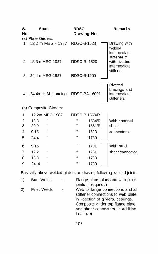
106
S. Span RDSO RemarksNo. Drawing No.(a) Plate Girders:1 12.2 m MBG - 1987 RDSO-B-1528 Drawing with
weldedintermediatestiffener &
2 18.3m MBG-1987 RDSO-B~1529 with rivettedintermediatestiffener
3 24.4m MBG-1987 RDSO-B-1555
Rivettedbracings and
4. 24.4m H.M. Loading RDSO-BA-16001 intermediatestiffeners
(b) Composite Girders:
1 12.2m MBG-1987 RDSO-B-1569/R
2 18.3 ’’ ’’ 1534/R With channel3 20.0 ’’ ’’ 1581/R shear
4 9.15 ’’ ’’ 1623 connectors.
5 24.4 ’’ ’’ 1730
6 9.15 ’’ ’’ 1701 With stud
7 12.2 ‘‘ ‘‘ 1731 shear connector
8 18.3 ‘‘ ‘‘ 1738
9 24..4 ’’ ’’ 1730
Basically above welded girders are having following welded joints:
1) Butt Welds - Flange plate joints and web platejoints (if required)
2) Fillet Welds - Web to flange connections and allstiffener connections to web platein I-section of girders, bearings.Composite girder top flange plateand shear connectors (in additionto above)

107
Since all welded plate girder spans are less than 35m,no camber is provided in welded plate girders. Footoverbridge welded truss is fabricated as cambered girder(unprestressed)
All welds carried out in workshop are by submerged arcwelding (SAW) which is a fully automatic process andproduces sound weld. Only at some locations whereSAW is not feasible welding is done by manual metalarc welding (MMAW) or CO2 welding. All railwayworkshops have trained staff and all fabricated girdersare inspected by RDSO before despatch from workshopto ensure quality control and economical service life.
Plate girders are provided with centralised articulatedbearings and composite girders are provided with Bronzebearings.
4.4.2 Frequency of inspection
All welded plate girders and composite girders areinspected as per provision in Chaper XI of IRBM. Hencelevel of inspection, items of inspection are the same asthose of rivetted girder. Following are the additionalmanual provisions regarding welded girder inspection.
(1) SE/JE Bridges shall inspect all welded girder bridgesirrespective of length of span once in 3 years.
(2) A detailed inspection of every welded girder bridgeshould be done by SE/JE Bridges after one year ofits laying in the track and permitting traffic on thebridge.
(3) In case of important or special type of welded girderbridges, suitable schedule of inspection should belaid down by CBEs of Zonal Railways.
4.4.3 Equipment for Inspection
Welded joints are strong enough like parent metal instatic structure like FOB girder, but in dynamic structurewelded joint is prone to fatigue-failure due to repeated

108
loading particularly in stress concentration locations, andwedge action for initiation of crack due to bending actionof member. Therefore, inspecting official should have fullknowledge of the structural behaviour and loadingmechanism of welded girder. To ensure properinspection, access to various locations in a bridge girderis a prerequisite. Therefore, suitable ladders andscaffoldings or platforms shall be arranged as per siteconditions.
Following equipment should be available duringinspection of welded girders:(1) Steel scale and steel tape(2) Rivet testing hammer(3) Magnifying glass(4) Hand scraper(5) Flash light (if required)(6) Mirror(7) Straight edge(8) Feeler gauge(9) Calipers (inside & outside)(10) Pocket knife(11) Wire brush(12) Dye penetrant inspection kit(13) Permanent magnet (Yoke type) for magnetic
particle test.
4.4.4 Method of Inspection:
All items like recording of levels of top flange to detectany sag, corrosion of steel, condition of paint, excessivedeflection, distortion of any member, condition ofbearings, testing of rivetted connection of bracings andsplices (if any), track structure on bridges, are similar tothose of rivetted girders including damage due to externalhitting during erection. These should be thoroughlychecked.
All welds should be inspected visually to detect anycrack in the weld or heat affected zone of parent metal.

109
Any crack will show sign of corrosion around it (as thepaint film is broken along the crack). Visual inspectionincludes using powerful magnifying glass. Mirror may beused to reflect the light on the particular location.
The following locations are to be observed especially todetect cracks during inspection:
(1) All butt joints in flange plates, particularly tensionflanges.
(2) All discontinuities of weld edges such as ends ofgirders, adjoining cope holes in web, intermediatestiffener bottom ends of fillet welds near tensionflange.
(3) Welds near the rivetted splice joints
(4) Intersecting welds (crossing one weld over the otherweld)
(5) Any locations where weld repairs are already doneduring fabrication.
(6) In composite girders, any crack in top flange nearshear connectors or cracks in adjoining concreteslab.
(7) In composite girders any vertical separation of topflange of girder and slab.
For above locations, in addition to visual inspection, non-destructive tests like dye-penetration test or magneticparticle examination test should be used to locate anyfine crack in surface which cannot be detected by visualinspection.
Fig. 4.3 & 4.4 show cracks found at end of stiffener inwelded girder.
Inspection proforma will be the same as that prescribedin IRBM and if required a sketch or photograph indicatingthe location of crack as well as length and width ofcrack may be enclosed.

110
WEB STIFFENER
WEB
CRACK
FLANGEFLANGE
CRACK
STIFFENERSTIFFENER
CROSS SECTION ELEVATION
WEB STIFFENER
WEB
CRACK
STIFFENERSTIFFENER
CRACK
FLANGEFLANGE
CROSS SECTION ELEVATION
(B) CRACKS AT END OF STIFFENER INTO WELD
Fig. 4.3 CRACKS FOUND AT END OF STIFFENERS
(A) CRACKS AT END OF STIFFENER WELDS & WEB

111
A
B
ST
OO
LF
IXE
D E
ND
'T'
DC
Fig
. 4.
4 C
RA
CK
S I
N T
HE
FL
OO
R S
YS
TE
M O
F O
PE
N W
EB
GIR
DE
R
JUN
CT
ION
OF
FIX
ED
& F
RE
E E
ND
S O
FS
TRIN
GE
RS
LEG
EN
D :
CR
AC
K L
OC
AT
ION
S S
HO
WN
__
A C
RO
SS
GIR
DE
R (
WE
B)
C.
G.
B S
TO
OL
(TO
P P
LAT
E)
SC
ST
RIN
GE
R (
BO
TT
OM
FLA
NG
E)
S.T
.D
FIX
ED
EN
D ‘T
’ (W
EB
) F
.T.
PL
AN
EL
EV
AT
ION

112
4.5 ACTION TO BE TAKEN WHEN A CRACK ISDETECTED OR SUSPECTED DURING INSPECTION
Following action should be taken on detection of acrack or suspected crack:
i) Location should be marked distinctly with paint as aneasy indication for reference and subsequentinspection. Ends of crack should also be accuratelymarked to monitor crack propagation.
ii) Length and orientation of crack should be recorded.Sketch should be prepared indicating the location anddetails of crack. If necessary photographs may betaken.
iii) If necessary, crack should be examined in detailusing non-destructive testing methods like Ultrasonic(USFD) test to know the depth of crack.
iv) If more identical details exist on the girder. theseshould also be inspected in detail.
v) Significance and severity of crack should be studiedwith reference to the load carrying capacity of thegirder.
vi) The crack and girder should be kept underobservation depending on the severity of crack andfrequency of inspection suitably increased.
vii) If a crack is suspected at any location, paint filmshould be removed and detailed examination carriedout using magnifying glass or dye penetrant testingor ultrasonic testing as necessary.
4.5.1 Repair of Crack (Temporary)
The method of repair of crack should be decided basedon the location and severity of damage due to the crackbut temporary measure to arrest the further growth ofcrack is to be taken first.

113
a) If the crack in a component is propagating in adirection perpendicular to the stress in a member,22.0 mm dia hole may be drilled at crack ends toarrest the crack propagation. The edge of holesshould be placed at visible ends of the crack. Afterthe holes are drilled it should be checked that cracktips have been removed and do not pass through thehole. After checking the hole, high tensile bolts orturned bolt of 22 mm dia should be provided in thehole and fully tightened. This will generally betemporary repair. Any reduction in strength of girderdue to the crack and drilling of holes should be givendue consideration.
b) If crack is in a fillet weld connecting web to flange(top or bottom) clamp is to be provided as temporarymeasure to arrest further growth of crack.
c) If crack is in fillet weld of stiffener, temporary woodenstiffener is to be provided by the side of stiffener toarrest the growth of crack.
d) If crack is in butt weld of flange plates, either sidecover plate with 10% increased thickness is to beprovided and clamping to be done with U clamps astemporary measure to arrest the growth of crack.
e) Record in Inspection note and Bridge Register:
The observations during inspection should berecorded in detail in the bridge inspection register foreach crack in welded girder.
1. Details of cracks, i.e. size, location, orientation,crack propagation details, etc. should berecorded in the bridge register.
2. Full details of temporary repairs measuresundertaken for the cracks should also berecorded in the bridge inspection register.

114
4.5.2 Dye Penetrant Inspection During Field InspectionDye penetrant inspection is simple and low cost nondestructive (NDT) inspection method for detecting minutediscontinuities open to the surface such as fine cracks.Method is based on the ability of certain liquids to enterinto fine cracks and crevices by capillary action and staythere when excess is removed. Hence this method maybe used during regular inspection.
Equipment: Dye penetrant inspection kit consists of
- Dye penetrant- Developer- Cleaner- Clean cloth or absorbent paper- Penetrant and developer application equipment.
Dye penetrant inspection is carried out in followingssteps:
i) Cleaning of surface to remove any dirt, rust or paint,etc. Surface should be thoroughly cleaned to enabledye penetrant to enter into the crack by cleaner.
ii) Application of dye penetrant to the area to beinspected. Dye penetrant may be applied by sprayingor brushing.
iii) Allowing sufficient time for penetrant to enter into thecrack.
iv) Removal of excess dye penetrant -- Most excess isfirst wiped off with clean cloth or absorbent paper,followed by wiping with clean cloth or absorbentpaper dampened with cleaner.
v) Application of developer, which is dry powderabsorbent material, by dusting. Result is blottingaction, which withdraws dye penetrant from thecrack. Allow sufficient time for dye penetrant to bloton the developer. By chemical action white colour ofdeveloper turns to red if crackexists.

115
vi) Examination of surface -- Crack is indicated bypresence of red indications against white backgroundof developer.
vii) Final cleaning after inspection.

116
Annexure 4.1Inspection proforma of steel girder (track bridge)
(1) Name of the Inspector .. .. ..........................
(2) Date of Inspection .. .. ..........................
(3) Section .. .. ..........................
(4) ADEN’s Sub - Division .. .. ..........................
(5) kms/TP .. .. ..........................
(6) Bridge No. .. .. ..........................
(7) Name of the Bridge .. .. ..........................
(8) Between Stations .. .. ..........................
(9) No.of spans .. .. ..........................
(10) Clear span square/skew .. .. ..........................
(11) Effective span .. .. ..........................
(12) Overall length of span .. .. ..........................
(13) Whether bridge is skewor on curve .. .. ..........................
(14) Speed restrictions if anyand its reason .. .. ..........................
(15) Type of girder .. .. ..........................
(16) No.of girders per span .. .. ..........................
(17) No. of tracks on bridge .. .. ..........................
(18) Standard of loading .. .. ..........................
(19) When put into road .. .. ..........................
(20) When strengthened/regirdered and Drg.No. .. .. ..........................
(21) Drg.No.for steel workin girders .. .. ..........................
(22) Type of steel .. .. ..........................

117
(23) Camber of span
(a) As per Camber register ...........................................
(b) At the time of last inspection ..................................
(c) At the time of present inspection ..........................
(d) Method of measurement .......................................
(24) Loss of Camber of each spanat the time of inspection .. ... ....................................
(25) The clear height between Road/Rail level to bottom mostmember of girder (for RUB & flyover)
(a) Actual .. .. ......................................
(b) Minimum required .. .. ......................................
(c) Infringement .. .. ....................................
(26) Type and condition of piersand abutments .. .. ....................................
(27) Type and size of bed blocks ....................................
(28) Condition of bed blocks .. .. ....................................
(29) Type of bearing .. .. ....................................
(30) No.of anchor bolts on eachbed plate .. .. ....................................
(31) Condition of anchor bolts .. ....................................
(32) Type of pads below bed plate ....................................
(33) No. of trolly refuges on bridgeand how many required .. ... ....................................
(a) Infringement if any afterplacing the trolly ....................................
(b) No.of man refuges on bridge.And how many required ....................................
(c) Footpath provided on which sideUp/Down/Both sides/Not at all ....................................

118
(34) Defective Rivets
Locations Cracked Loose Corroded TotalNos.
(a) Boom/flanges ........... ........... ............ ............(b) Web member/web ........... ........... ............ ............(c) Main joints ........... ........... ............ ............(d) Cross girders ........... ............ ............ ............(e) Stringers ........... ............ ............ ............(f) Bracings &
Foot-path ........... .......... ............ ............(g) Base plate ........... .......... .......... ............
(For details see proforma of loose rivets)
(35) Damage of members of span such as buckling, crack,distortion etc.................................................................
(36) Date of last painting (a) Complete........ (b) Patch..........
(37) Condition of paint .. ... ........................
(38) Date of cleaning & greasing of
bearings and present condition .............................
(39) Condition of cylinders / trestles .............................
(40) Movement of girders (if any) .. .............................
(41) Condition of bridge .. .. .............................
(42) General remarks .. .. .............................
(43) Classification of defects into those requiring action by(a) SE/JE Bridges .. .. .............................
(b) Division .. .. .............................
(c) Dy.CE (Bridge) .. .. .............................

119
Railway
No. .................. Date........... Office of SE/JE Bridge...........
Copy forwarded to :(1) Dy.CE,(Bridge) ......................................(2) Sr.DEN/DEN ......................................(3) SEN/ADEN ......................................(4) SE/JE P. Way ......................................(5) SE/JE Work ......................................
SE/JE Bridges Signature .................................

120
CHAPTER - 5
MAINTENANCE OF STEEL GIRDERS
Steel girders not properly provided with protective painting resultsin setting of heavy corrosion to members, causing reduction oflife, uneconomical strengthening and sometimes leading toreplacement of superstructure. The adages “Prevention is betterthan cure” and “A stitch in time saves nine” are eminently truefor steel superstructure. Otherwise steel is a good structuralmaterial and steel superstructures are strong, sturdy and timetested for more than 100 years on Indian Railways. Consideringall these aspects, it is essential for the maintenance engineersto provide planned and systematic maintenance during its servicelife.
Inspection of bridges is also a part of maintenance work. Theperiodical maintenance and repairs based on the inspectionreport will deliver more benefit and prove economical to prolongthe steel superstructure’s life. Indian Railways adoptedsystematic routine inspection and maintenance of bridgestructures in the past, but due to increased workload of trackstructure, and number of bridges increasing on account ofdoubling and construction of new lines, maintenance of bridgeshas suffered a setback. Also traffic density is increasing alongwith increased speeds of trains and higher loading standards.Hence all the more need for systematic maintenance.
5.1 MAIN ITEMS OF MAINTENANCE OF STEELSUPERSTRUCTURE
a) Inspection and recordingb) Cleaning and greasing of bearingsc) Protective painting system to steel structured) Replacement of loose rivets or repairs to weldse) Strengthening of steel superstructuref) Replacement of corroded rivets.
5.1.1 Foot over bridges
Steel girders used for foot overbridges are statically
121
loaded structures. No bearing is povided and hence theprime maintenance required is systematic protectivepainting. The steel girders are easily accessible forinspection but prone to corrosion on account of roughpublic use and formation of water pockets, particularly,at bases of columns, staircase stringers, etc. Pocketscan be filled with concrete or bitumen-mixed sand toavoid water stagnation. There are very remote chances ofthe rivets becoming loose even after 80 to 90 years ofservice life. FOBs constructed after 1970 are of weldedconstruction and welded joints are generally holding goodwithout any defects.
5.1.2 Road over-bridges
Old steel girders used for road bridges are mostly withthe same design loading criteria of track bridges andhence lot of reserve strength is available as highwayloading standard is lower than railway loading. Alsorubber tyred wheels of road vehicles cause less impact.These girders are provided with bronze bearings. Henceperiodical greasing of bearings is not required exceptperiodical cleaning and painting to avoid corrosion onaccount of muck accumulation but no lifting of girder isinvolved. Proper protective painting is a majormaintenance work. To avoid sagging of girder one shouldensure that no dead load is increased on account ofadditional road metal used during repairs of road surfacecarried out by road authority. This aspect should bechecked during inspection. In past, rivets have beenfound to be corroded, rather than loose. After 1975 mostof the ROBs are constructed with RCC deck with PSCgirders. Maintenance-free elastomeric bearings areprovided. Hence except inspection and ensuring no lossof camber, no maintenance is required, if the initialquality of construction is good.
5.1.3 Track bridges
Steel girders used for track bridges are dynamicallyloaded structures. There is a constant, albeitimperceptible movement taking place in bridge girders

122
and hence bearings are provided to take care of thesemovements. Therefore all items of maintenancementioned in Para 5.1 are applicable to steel girders oftrack bridge.
5.2 INSPECTION OF STEEL GIRDER
It is also a part of maintenance work. Steel girders usedfor foot over-bridges and road over-bridges do not showmuch structural distress during inspection for reasonsmentioned above. Steel girders used for track bridgesrequire critical “crow eye” inspection. It is also essentialto maintain systematic recording of inspection notes tobuild past history. The inspection equipments have beendealt with in-detail in the Indian Railway Bridge Manual1998.
5.3 CLEANING AND GREASING OF BEARINGS
All the steel girders of track bridges are presentlyprovided with metal bearings. Steel bearing plates orsteel rollers normally move on steel base plates. Toavoid ill effects and provide movement to steel girdersperiodical greasing is essential.
All standard deck type plate girders are provided withcentralised articulated bearings. Both ends are free andneed greasing between sliding parts of both ends.
All open web through spans are provided with rockersand rocker cum roller bearings and need greasingbetween roller and base plate of free end and betweencurved knuckle slab and saddle block of both ends.
Composite girders and open web underslung girders areprovided with bronze bearings. Steel bearing plate orknuckle plate will slide on bronze plates which has lowfriction. Hence no greasing is required. Periodicalcleaning of base plates around bearings is essential toavoid damage of smooth bronze surface by theaccumulation of dust and sand particles. No lifting, ofgirders is involved. Girders above 76.2 metre spans areprovided with oil bath bearings and hence no greasing isrequired.

123
5.4 PROTECTIVE PAINTING OF STEEL GIRDERS
On Indian Railways a major part of expenditure onmaintenance of steel girders is spent on painting of steelgirders. In reality, experience gained during the past 100years is that proper protective painting along withgreasing of bearings are the only factors for economicalservice life of steel girders. The steel rolled prior to 1975has more corrosion resistance than the steel rolled after1975. This is noticed in present railway girders. The newgirders provided during doubling of lines have morecorrosion problems than old girders. Corrosion is morewhere steel comes in contact with wood and waterstagnation in pockets formed on account of structuralform. For this reason plate girder has less corrosionproblem than open web girder.
Steel girder bridges situated in the following locations areprone to severe corrosion:
1) Where humidity in atmosphere is more than 80%
2) Coastal areas
3) Bridges across creeks
4) Bridges surrounded by chemical industry
5) Bridges near metropolitan city on account of publicnuisance.
In addition to above, type of traffic carried on bridges i.e.salt, fish, manure and chemicals also cause severecorrosion.
Maintenance engineer has to adopt proper paintingscheme during maintenance as stipulated in IRS-B1-2001 depending upon the location of bridges.

124
5.4.1 Metallising
Protective coating by metallising with sprayed aluminiumto 150 micron thickness is to be provided as given in theAppendix VI of IRS-B 1-2001 followed by oil painting overmetallised component as per schedule given below:
(i) One coat of etch primer to IS 5666 - 1970
(ii) One coat of zinc chrome primer to IS 104 - 1979
(iii) Two coats of aluminium paint to IS 2339 - 1963
In steel girder following members are to be provided withthe above protection.
(1) Floor system (cross girders and rail bearers) ofopen web through girders in all cases
(2) Top flange plates of plate girders and underslung girders in all cases.
(3) Top bracing system of open web through spans(i.e. top laterals, sways, portal bracings) inelectrified section, as it is difficult to get powerblock for frequent oil painting.
(4) Entire Steel girders, subjected to salt spraysuch as in the close vicinity of the sea and/orover creeks, as well as in industrial, suburban orcoastal areas which are prone to severecorrosive environment.
Metallising protection will be more effective andeconomical if carried out in workshop during fabricationof new girders. Site metallising is not found effective asper the experience gained in the past and hence itshould be planned during fabrication in workshop andmetallised components handled properly during loading,unloading, while transporting from workshop to site anderection at site. Life of metallising if done in workshop

125
with sand/grit blasting and touching up of coveraluminium oil paint whenever required will be 25 to 30years.
5.4.2 Epoxy painting
Epoxy paints have good adhesion and abrasion power.Epoxy based paints can be used in lieu of metallising inthe field for existing girders.
5.4.2.1 Scheme of epoxy based paint
a) Surface preparation-
i) Remove oil/grease from metal surface by usingpetroleum hydro-carbon solvent to IS: 1745.
ii) Prepare the surface by sand or grit blasting or wirebrushes operated by pneumatic power or electricityto near white metallic surface.
b) Epoxy painting-
i) Primer coat
Apply by brush two coats of epoxy zinc phosphateprimer to RDSO specification No. M&C/PCN-102/86,to 60 microns minimum thickness (DFT)
ii) Intermediate coat
Apply by brush one coat of micaceous iron oxidepaint to RDSO specification No. M&C/PCN-103/86 to100 microns thickness (DFT).
iii) Finishing coat
Apply by brush two coats of polyurethane aluminiumfinishing to RDSO specification No. M&C/PCN-110/88 for coastal locations or polyurethane red oxide toRDSO specification No. M&C/PCN-109/88 for otherlocations to 40 microns thickness (DFT).
Use of epoxy painting system for railway girders hasbeen introduced recently. Real benefit of epoxypainting can be achieved with longer life of paint thanfrequent oil painting which is more costly for

126
maintenance of steel girders on existing bridges. Life ofepoxy painting is 12 to 15 years if correct epoxyscheme is selected.
5.4.3 Oil Painting
(a) For locations where corrosion is not severefollowing painting scheme should be applied
i) Primer coat
One heavy coat of ready mixed paint red leadprimer to IS : 102 - 1962
orOne coat of ready mixed paint zinc chromateprimer to IS : 104 - 1979, followed by one coatof ready mixed paint red oxide zinc chromeprimer to IS : 2074 - 1992
ii) Finishing coat
Two finishing coats of red oxide paint to IS-123
(b) For locations where corrosion is severe-
To avoid frequent painting metallising or epoxypainting for existing girders is recommended but when thereare no facilities available for the same, protective coating byoil painting with following painting scheme should be applied.
i) Primer coat
Two coats of ready mixed paint red lead priming toIS 102 - 1962
or
One coat of ready mixed paint zinc crome primimgto IS 104 - followed by one coat of zinc crome red oxideprimimg to IS 2074.
ii) Finishing coat
Two coats of aluminium paint to IS : 2339 - 1963In the past all steel girders of track bridges and ROBs were

127
painted with oil painting scheme, consisting of primer coatas red lead IS :1 02 - 1962 and two cover coats of red oxidepaint conforming to IS : 123 - 1962 and foot overbridgeswere painted with one coat of red lead as base and twocoats of aluminium paint confirming to IS : 2339 - 1963 asfinish coats
The trial has been conducted for four types of combinationof base and finish oil painting coats on Indian Railways. Outof the four combinations, one type i.e. Red lead (IS : 102) asbase coat and Aluminium (IS : 2339) as finish coat (twocoats) is found more durable and has longer life than theother three combinations.
In open web through type steel girders of track bridges, it isvery difficult and costly to provide proper stagings for surfacepreparation and application of paint under traffic for qualitypaint work. Open web truss span has more water stagnationpockets than plate girder on account of form of membersand joints. Any structural repairs or strengthening of openweb steel girder is very difficult and costly under traffic. Owingto these problems it is recommended to provide the followingpainting scheme for steel girders of open web through typetrack bridge in all locations to derive prolonged paint life foreconomical maintenance. Surface preparation of the steelto receive the paint should be as prescribed in item 217para 1 of Indian Railway Bridge Manual 1998.
(A) For truss members:
a) Base coat -
One coat of ready mixed red lead IS : 102 -1962 (where corrosion is not severe).
orTwo coats of ready mixed red lead IS : 102 -1962 (where corrosion is severe).
b) Finish coat
Two coats of aluminium IS : 2339 - 1963.

128
B) All floor systems and top bracing systems in electrifiedarea with epoxy painting.
C) Plate Girders
Plate girders of track bridges have less water stagnationpocket and 80% steel surface is in vertical positionhence these girders are not prone to corrosion excepttop flange plates (below sleeper). Also provision ofstagings for quality painting work is easy under traffic onaccount of steel surface being below the rail level.Painting with any scheme mentioned above can beadopted for locations depending on the severity ofcorrosion.
During service life of steel girders, it is observed that atfirst the deterioration takes place of the finish coat ofpaint. Hence, if finish coat is only painted over intactbase coat it will derive maximum saving in expenditurethan full painting. Present practice of painting steelgirders in yearly cycle basis should be modified andpainting should be carried out on condition basis, as perinspection report.
The frequency of painting of steel girders in foreigncountries is about 20 to 25 years or even longer withappropriate painting scheme with quality painting work.Hence if correct system is adopted with quality paintingunder supervision of SE/JE Bridges who has skill ofclimbing structures, it is possible to save lot ofexpenditure presently being incurred on Indian Railwaysfor maintenance of steel girders. Elcometers which arenow available can be used to measure paint filmthickness (DFT).
All steel girders of railway bridges are fabricated inrailway workshop. The construction engineer places thework order for fabrication of girders without stipulating thepainting scheme to be adopted depending upon thelocation of bridge. Engineer in charge of workshop willprovide conventional oil painting with red lead or zinc

129
chromate as base coat and red oxide as cover coat. Themember painted with above scheme cannot be changedat site if girders are located in location where corrosionis severe. Hence it is essential that the scheme ofpainting depending upon the location of these girderbridges should be mentioned in work order. Correctscheme of painting in workshop will help in economicalmaintenance of steel girders at a later period duringservice.
5.5 REPLACEMENT OF LOOSE RIVETS
5.5.1 Following tools and plants are required for replacement ofloose rivets at site
a) Air compressorb) Pipeline with connections (for long bridges, air
receiver is required to maintain the air pressure)c) Hand pneumatic rivet hammerd) Pneumatic dolly or Holder ong) Hand dollyf) Rivet heating forgeg) Rivet tongh) Charcoali) Proper staging as working platform.
5.5.2 Replacement of Loose Rivets
For replacing loose rivets, existing rivet head is to be cutand rivet is to be punched out. For this either handchisel and hand hammer or pneumatic operated rivetcutting machine called "Buster machine” is used. Rivetbuster cuts the head in shear imparting a very heavyshock to adjoining rivets in group, resulting in looseningof sound adjoining rivets. Therefore only when a fewrivets at staggered locations in any joint of open webgirder are required to be replaced, it is a commonpractice to drill the rivet out and cut so that it will avoidloosening of adjoining rivets. If 70 to 80% of rivets in onejoint or entire joint rivets require replacement, rivets willbe cut by buster for speedy work. One should ensurethat in any joint of open web girder not more than 10%

130
rivets are cut at one time. When rivet head is cut itshould be punched out immediately and turned boltshould be provided in each hole of cut rivet. Under nocircumstances blank hole in joint is permitted when trainis running on bridge. To ensure these precautions whenmore number of rivets in joints are to be replaced cautionorder is issued, protection is provided to stop train ifrequired. It should be ensured that all joint holes shouldbe provided with rivets or turned bolts while train ispassing on the bridge. For replacement of rivets otherthan joints including bracings connections, it is notnecessary to issue caution order. At locations wherereplacing of rivets is not possible, loose rivet should bereplaced with proper size turned bolt and threads burred.The guidelines mentioned in the item 215 para 3 ofIndian Railway Bridge Manual 1998 for replacement ofloose rivets in plate girder should be followed.
Following points should be kept in mind while driving rivetfor replacement at site:
1) Proper staging for rivetter and dollyman is provided towork free with both hands.
2) 6.5 to 7.6 kg/cm2 air pressure at rivetting machineshould be ensured.
3) Rivet shank should be heated uniformly from tip to topto cherry red colour for quality rivetting work.
4) Dolly or holderon should be placed properly to hold theother head in proper tight position or otherwise it is thetendency of the rivet to work back while driving theother end for forming head.
5) While driving rivets, rivetter should ensure first tosqueeze rivet for filling of the cavity in hole and thenform the head, by delivering quick hard blows fortightness of rivets.
6) The length of rivet shank may be worked out by theformula-

131
L = G + 1.5 D + 1 mm for every 4 mm of grip where L is Length of rivet shank in mm
G is Length of grip (joint thickness) in mmD is Diameter of rivet in mm
7) Rivet should be driven within 20-30 seconds of the rivetleaving the heating forge fire and not after it has beenallowed to remain in open space.
8) Rivet hammer must be held straight while driving rivetto ensure coaxial rivet head.
9) Rivets steel should conform to IS : 1148 - 1982.
10) In a joint when only a few rivets are replaced it is veryessential that all remaining rivets are checked fortightness by SE/JE Bridges. If any are found loosethey should also be replaced.
11) After completion of replacement of rivets when rivethead is cooled, a base coat paint is provided on thesame day and cover coat later on.
12) Rivets should not be replaced in rainy or foggy weatheror during early morning hours.
Entry to be made in bridge register as well as in rivetproforma to maintain record for future reference.
5.6 REPAIRS TO WELDED JOINTS
All foot over-bridge steel girders of beam or truss typeare welded construction since 1975 onwards but thisgirder being statically loaded structure, no weld cracksare reported so far, except corrosion to weld. Hence norepairs are required for F.O.B. girder frequently.
The use of welded girder has started recently from 1980for track bridges on Indian Railways. Track bridge plategirders, either open deck or composite, are fabricated aswelded girders. These girders are of beam type(I-Section). Weld joint in plate girders are as follows-

132
a) Butt joint
b) Fillet Weld joint
The strength of all butt joints is equal to parent metal ofsteel at those locations and hence radiography test isconducted during fabrication. Therefore, there are remotechances that defect may develop in these welded jointsat an early stage.
Crack may exist in fillet weld at the critical locationmentioned in para 4.4.4. Initiation and propogation ofcracks in welded girder is on account of fatigue or stressconcentration or inherent defects which exist duringfabrication. Any defects which exist during fabrication willreveal it self within one year of its service life and henceit is essential to check all the welded joints in girder bydye penetration test (DPT) after one year of service.
Fatigue cracks develop in steel girders during servicedue to repeated loading and its magnitude depends onthe magnitude of stress variation, frequency of stressapplication, type of connection and wedging action dueto bending of structure.
Welds are more sensitive to repeated stresses and oncecracks occur, they can grow fast and hence weld crackgrowth is to be prevented.
Repairs or retrofit scheme should be decided by designengineer or Chief Bridge Engineer for permanent repairsand hence maintenance engineer should submit report ofsuch defects with sketch or photograph to the ChiefBridge Engineer immediately with provision of temporarymeasures stated in para 4.5.1 to arrest the crackpropagation of welded girder of track bridge. The methodof repairs of crack should be decided based on thelocation and severity of the crack. Permanent measuremay consist of the cracked member being retrofitted withrivetted or bolted splice or where feasible the entiremember may be replaced.

133
Field welding of welded girder of track bridge should notbe undertaken for repairs of weld cracks unless they areof minor significance. The repairs of weld cracks can beundertaken if they are of minor significance with theapproval of Bridge Engineer. The repair should be doneby trained welder under expert supervision of reputedagency and the repaired portions examined by nondestructive testing.
If the crack is in butt weld or ‘T’ fillet weld connectingflange and web, girder should be taken out byintroducing temporary girder for repairs of weld in downhand position. Such defects are very less in early stageof girder.
Repairs of weld joints of foot over bridge steel girder canbe undertaken by qualified and tested welder under closesupervision of experienced official to ensure that duringrepairs of cracked weld no member should be distorteddue to application of excessive heat. Defective weldshould be gouged out first and welding done with propermanipulation of electrode for homogeneity. Peening ofweld is preferable for repairs of weld joint.
5.7 STRENGTHENING OF STEEL GIRDERS
These works are carried out only when steel girders areshowing signs of distress during service life or whenheavier loads are to be permitted than the designed loador speeds are to be increased. Strengthening is alsorequired due to external hit damages of component or onaccount of accidents on steel girders or loss of crosssection due to heavy corrosion.
All the strengthening works of open Web girder are verycostly under traffic and therefore, they should beundertaken with careful check of design and planning forexecution with the approval of Chief Bridge Engineer.
5.7.1 Common methods of strengthening
I) Steel girder of track bridge

134
a) Rectification measures for loss of camber inopen web girder of track bridge is to beundertaken as prescribed in item 212 para 3 ofIndian Railway Bridge Manual 1998.
b) Replacement of very loose rivets on account ofoblonged holes by larger diameter rivets.
c) Replacement/strengthening of floor system onaccount of heavy corrosion and loss of steelsection i.e. stringers and cross girders ofthrough spans and top flange plates ofunderslung and plate girders.
d) Provision of cover angles and cover plates overthe cracked members.
If heavy repairs are required to plate girders orstrengthening of main truss of open web girders, it willbe difficult to carry it out under traffic, hence spans areto be taken outside slewed with introduction of temporarygirders for economical repairs.
If girder is quite old and residual life is only 10 years it isbetter to replace the old steel girder with new girder.Considering scrap value of old girder, replacement will bemore economical than strengthening of existing girderunder traffic.
Fig. 5.1 indicates some of the strengthening methods.
II) Road overbridge steel girder
Strengthening of web plates of plate girder of RoadOver Bridge over corroded portion can be repairedwith additional cover plates with rivetted joint. Ifpossible, flange plate can be replaced with newflange plate or providing additional flange plate withrivetted joint. Stiffeners and footpath brackets can bereplaced or repaired with cover plate with weld jointsunder close supervision by qualified welder to ensurethat no distortion of member takes place duringwelding.

135
++
++ +
++
++
++
++ +
COVER PLATE
CORROSION
CRACK STOPING HOLE
CRACK
CORNER BRACKET
COVER PLATE
WEB PLATE OF STRINGER
WEB PLATE OF FLOOR BEAM
COVER ANGLEFLANGEOF FLOOR BEAM
CORROSION HOLE
CORROSION
FLANGEOF STRINGER
Fig. 5.1 PROVISION OF COVER ANGLE FOR STRENGTHENING
REPAIRS OF WEB PLATE
CRACK REPAIRS METHOD
STRENGTHENING OF CROSS GIRDER

136
CR
OS
S
GIR
DE
R
150X
150X
10LO
NG
TH
IS H
OLE
TO
BE
DR
ILLE
D F
RO
M F
RE
EE
ND
SID
E
'T' F
LAN
GE
PLA
TE
200X
12T
HX
1150
LO
NG
PR
O.P
AC
KIN
G
PLA
TE
12
TH
.'T
' WE
B P
LAT
EP
L.12
TH
.
PR
O.A
NG
LE 1
50X
75X
10
PR
O.A
NG
LE 1
50X
75X
10
RIB
PLA
TE
150
X20
370
40
55
55
40
55
55
6020
16
80 22
20
60
CR
AC
K
125
125
PA
CK
ING
10m
m
PR
OP
. A
NG
LE
Fig
. 5.
2 S
TR
EN
GT
HIN
G O
F W
EB
OF
CR
OS
S G
IRD
ER
OV
ER
TH
E C
RA
CK
S
VIE
W O
F F
IXE
D E
ND
VIE
W O
F FR
EE
EN
D

137
III) Foot over bridge steel girder
Strengthening of foot over bridge main girder-columnsand staircase stringer can be undertaken byreplacing member with new one or additional coverplate or angle with weld joints under closesupervision by qualified and tested welder to ensurethat no distortion of member takes place duringwelding. If floor beams or bottom lateral bracings arecorroded or perforated, they can be replaced withnew one instead of repairing them.
5.8 REPLACEMENT OF CORRODED RIVETS
This work is necessitated on account of badmaintenance. Therefore, it is not a structural defect.Rivets are designed for shear stress and 25 to 30% lossof head section will not reduce the strength of rivets. Butif the locations of rivets are such that it also cater fortensile stress on account of deflection of member, lossof head of rivet should not be permitted. Apart from this,once corrosion is set in the form of pits, it will continueto corrode even after careful painting. Hence corrodedrivets will be required to be replaced. This is a verycostly work and maintenance engineer should ensurethat this work is reduced to minimum. Procedure forreplacement is the same as that of replacement of looserivets mentioned in Para 5.5.
5.9 CONCLUSIONS
Following steps are required to be taken for economicalmaintenance
1. All sliding bearing provided to existing plate girders(rivetted or welded) to be converted to bronze bearingor PTFE bearings in consultation and with theaporoval of RDSO so that periodical greasing can beavoided to reduce maintenance cost. Provision of 6mm thick rubber pad (elastomeric) between baseplate and bed block which will ensure perfect level ofbase plate and dampen the impact effect. This will

138
also reduce the repairs cost of bed block andsubstructure. Provision of oil bath bearings to allopen web girder through span of 30.5 metres andabove to reduce maintenance cost.
2. Proper painting scheme may be adopted inconsultation with CECRI Karaikudi for agressivelycorrosive environment. Painting of open web throughsteel girders should be done under the supervision ofBridge branch (which has the skill of climbing onbridge structure to ensure quality of painting workand making provision of staging for inspection).
All bracings and stiffener rivets to be replaced byHSFG Bolt.
3. All new construction of bridges upto 30.5 metresspan with PSC girder or composite girder to provideballasted deck, which will reduce the maintenance oftrack structure and bridge structure.
4. All regirdering of existing steel girders may beproposed as follows
a) Span upto 6.1 metre steel girder with PSC slab.(Board’s orders already exist).
b) Span 9.15 and 12.2 metre steel girder with PSCgirder cast in railway workshop for quality ofconcrete work.
c) Span 18.3. 24.4 and 30.5 metre steel girder withcomposite girder (steel girder fabricated inworkshop and RCC deck cast at site on stagingfor regirdering with scheme of ‘‘Slew in & SlewOut” method).
Items 3 & 4 particularly on trunk route wilI prove moreeconomical on account of ballasted deck with machinemaintenance.