Steel City Hangers, Clamps & Fasteners Hangers,...
38
Steel City ® Hangers, Clamps & Fasteners In this section... Steel City ® Hangers, Clamps & Fasteners Overview ................................................................... B-222–B-223 Beam and Purlin Clamps............................................ B-224–B-229 Hangers ..................................................................... B-230–B-231 Conduit and Cable Supports ....................................... B-232–B-240 Stud Wall/Drywall Supports, Clips and Brackets ........ B-241–B-247 Acoustical Tee Supports, Clips and Brackets .............. B-248–B-251 Low-Voltage/Datacom Hooks, Hangers and Brackets................................................ B-252–B-256 Fastener Accessories and Hardware .......................... B-257–B-258
Transcript of Steel City Hangers, Clamps & Fasteners Hangers,...

Steel City ® Hangers, Clamps & Fasteners
In this section...
Steel City® Hangers, Clamps & Fasteners
Overview ................................................................... B-222–B-223
Beam and Purlin Clamps ............................................ B-224–B-229
Hangers ..................................................................... B-230–B-231
Conduit and Cable Supports ....................................... B-232–B-240
Stud Wall/Drywall Supports, Clips and Brackets ........ B-241–B-247
Acoustical Tee Supports, Clips and Brackets .............. B-248–B-251
Low-Voltage/Datacom Hooks, Hangers and Brackets ................................................ B-252–B-256
Fastener Accessories and Hardware .......................... B-257–B-258
www.tnb.comUnited StatesTel: 901.252.8000 800.816.7809Fax: 901.252.1354
Technical ServicesTel: 888.862.3289
B-222
Met
al F
ram
ing
& C
able
Tra
y —
Ste
el C
ity® H
ange
rs, C
lam
ps &
Fas
tene
rs
Overview
Materials:
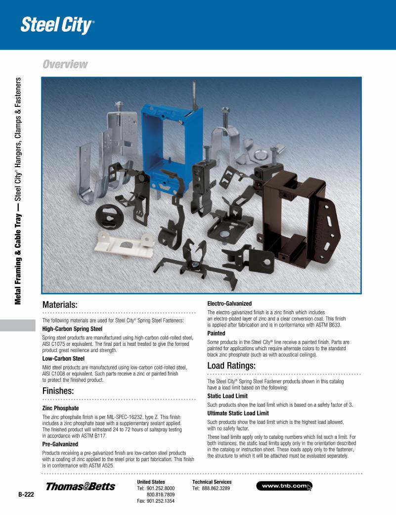
The following materials are used for Steel City® Spring Steel Fasteners:
High-Carbon Spring SteelSpring steel products are manufactured using high-carbon cold-rolled steel, AISI C1075 or equivalent. The final part is heat treated to give the formed product great resilience and strength.
Low-Carbon SteelMild steel products are manufactured using low-carbon cold-rolled steel, AISI C1008 or equivalent. Such parts receive a zinc or painted finish to protect the finished product.
Finishes:
Zinc PhosphateThe zinc phosphate finish is per MIL-SPEC-16232, type Z. This finish includes a zinc phosphate base with a supplementary sealant applied. The finished product will withstand 24 to 72 hours of saltspray testing in accordance with ASTM B117.
Pre-GalvanizedProducts receiving a pre-galvanized finish are low-carbon steel products with a coating of zinc applied to the steel prior to part fabrication. This finish is in conformance with ASTM A525.
Electro-GalvanizedThe electro-galvanized finish is a zinc finish which includes an electro-plated layer of zinc and a clear conversion coat. This finish is applied after fabrication and is in conformance with ASTM B633.
PaintedSome products in the Steel City® line receive a painted finish. Parts are painted for applications which require alternate colors to the standard black zinc phosphate (such as with acoustical ceilings).
Load Ratings:
The Steel City® Spring Steel Fastener products shown in this catalog have a load limit based on the following:
Static Load Limit Such products show the load limit which is based on a safety factor of 3.
Ultimate Static Load LimitSuch products show the load limit which is the highest load allowed, with no safety factor.
These load limits apply only to catalog numbers which list such a limit. For both instances, the static load limits apply only in the orientation described in the catalog or instruction sheet. These loads apply only to the fastener, the structure to which it will be attached must be evaluated separately.
United StatesTel: 901.252.8000 800.816.7809Fax: 901.252.1354
Technical ServicesTel: 888.862.3289www.tnb.com
B-223
Metal Fram
ing & Cable Tray —
Steel City® Hangers, Clam
ps & Fasteners
Overview
Individual Part Numbering SystemSSF - H A 1/4 T
1 2 3 4 5
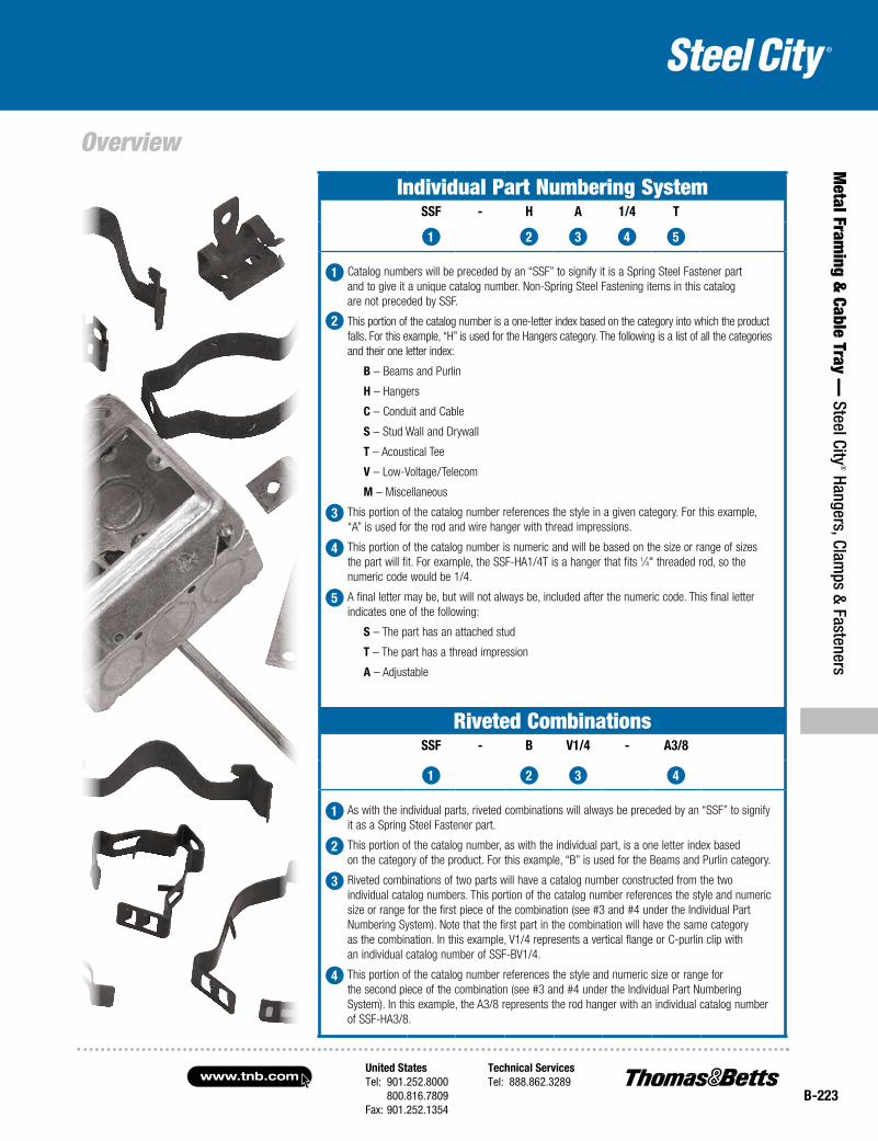
1 Catalog numbers will be preceded by an “SSF” to signify it is a Spring Steel Fastener part and to give it a unique catalog number. Non-Spring Steel Fastening items in this catalog are not preceded by SSF.
2 This portion of the catalog number is a one-letter index based on the category into which the product falls. For this example, “H” is used for the Hangers category. The following is a list of all the categories and their one letter index:
B – Beams and Purlin
H – Hangers
C – Conduit and Cable
S – Stud Wall and Drywall
T – Acoustical Tee
V – Low-Voltage/Telecom
M – Miscellaneous
3 This portion of the catalog number references the style in a given category. For this example, “A” is used for the rod and wire hanger with thread impressions.
4 This portion of the catalog number is numeric and will be based on the size or range of sizes the part will fit. For example, the SSF-HA1/4T is a hanger that fits 1⁄4" threaded rod, so the numeric code would be 1/4.
5 A final letter may be, but will not always be, included after the numeric code. This final letter indicates one of the following:
S – The part has an attached stud
T – The part has a thread impression
A – Adjustable
Riveted CombinationsSSF - B V1/4 - A3/8
1 2 3 4
1 As with the individual parts, riveted combinations will always be preceded by an “SSF” to signify it as a Spring Steel Fastener part.
2 This portion of the catalog number, as with the individual part, is a one letter index based on the category of the product. For this example, “B” is used for the Beams and Purlin category.
3 Riveted combinations of two parts will have a catalog number constructed from the two individual catalog numbers. This portion of the catalog number references the style and numeric size or range for the first piece of the combination (see #3 and #4 under the Individual Part Numbering System). Note that the first part in the combination will have the same category as the combination. In this example, V1/4 represents a vertical flange or C-purlin clip with an individual catalog number of SSF-BV1/4.
4 This portion of the catalog number references the style and numeric size or range for the second piece of the combination (see #3 and #4 under the Individual Part Numbering System). In this example, the A3/8 represents the rod hanger with an individual catalog number of SSF-HA3/8.
www.tnb.comUnited StatesTel: 901.252.8000 800.816.7809Fax: 901.252.1354
Technical ServicesTel: 888.862.3289
B-224
Met
al F
ram
ing
& C
able
Tra
y —
Ste
el C
ity® H
ange
rs, C
lam
ps &
Fas
tene
rs
Beam and Purlin Clamps
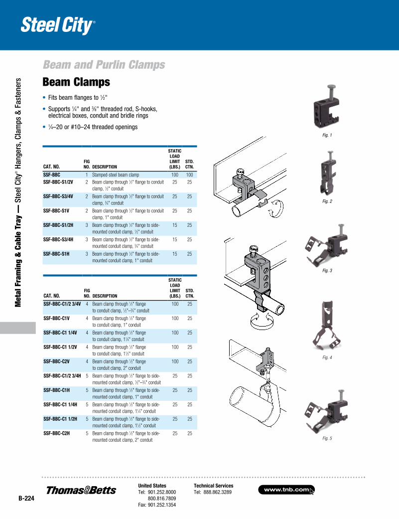
Fig. 1
Fig. 2
Fig. 3
Cat. No.fig No. DesCriptioN
statiC loaD limit (lBs.)
stD. CtN.
ssf-BBC 1 Stamped-steel beam clamp 100 100ssf-BBC-s1/2V 2 Beam clamp through 1⁄2" flange to conduit
clamp, 1⁄2" conduit25 25
ssf-BBC-s3/4V 2 Beam clamp through 1⁄2" flange to conduit clamp, 3⁄4" conduit
25 25
ssf-BBC-s1V 2 Beam clamp through 1⁄2" flange to conduit clamp, 1" conduit
25 25
ssf-BBC-s1/2H 3 Beam clamp through 1⁄2" flange to side-mounted conduit clamp, 1⁄2" conduit
15 25
ssf-BBC-s3/4H 3 Beam clamp through 1⁄2" flange to side-mounted conduit clamp, 3⁄4" conduit
15 25
ssf-BBC-s1H 3 Beam clamp through 1⁄2" flange to side-mounted conduit clamp, 1" conduit
15 25
Fig. 4
Fig. 5
Cat. No.fig No. DesCriptioN
statiC loaD limit (lBs.)
stD. CtN.
ssf-BBC-C1/2 3/4V 4 Beam clamp through 1⁄2" flange to conduit clamp, 1⁄2"–3⁄4" conduit
100 25
ssf-BBC-C1V 4 Beam clamp through 1⁄2" flange to conduit clamp, 1" conduit
100 25
ssf-BBC-C1 1/4V 4 Beam clamp through 1⁄2" flange to conduit clamp, 11⁄4" conduit
100 25
ssf-BBC-C1 1/2V 4 Beam clamp through 1⁄2" flange to conduit clamp, 11⁄2" conduit
100 25
ssf-BBC-C2V 4 Beam clamp through 1⁄2" flange to conduit clamp, 2" conduit
100 25
ssf-BBC-C1/2 3/4H 5 Beam clamp through 1⁄2" flange to side-mounted conduit clamp, 1⁄2"–3⁄4" conduit
25 25
ssf-BBC-C1H 5 Beam clamp through 1⁄2" flange to side-mounted conduit clamp, 1" conduit
25 25
ssf-BBC-C1 1/4H 5 Beam clamp through 1⁄2" flange to side-mounted conduit clamp, 11⁄4" conduit
25 25
ssf-BBC-C1 1/2H 5 Beam clamp through 1⁄2" flange to side-mounted conduit clamp, 11⁄2" conduit
25 25
ssf-BBC-C2H 5 Beam clamp through 1⁄2" flange to side-mounted conduit clamp, 2" conduit
25 25
Beam Clamps• Fits beam flanges to 1⁄2"
• Supports 1⁄4" and 3⁄8" threaded rod, S-hooks, electrical boxes, conduit and bridle rings
• 1⁄4–20 or #10–24 threaded openings
United StatesTel: 901.252.8000 800.816.7809Fax: 901.252.1354
Technical ServicesTel: 888.862.3289www.tnb.com
B-225
Metal Fram
ing & Cable Tray —
Steel City® Hangers, Clam
ps & Fasteners
Beam and Purlin Clamps
Cat. No.fig. No.
o.D. of CoNDuit or pipe (iN.)
om. CoNDuit or pipe size (iN.)
stD. CtN.
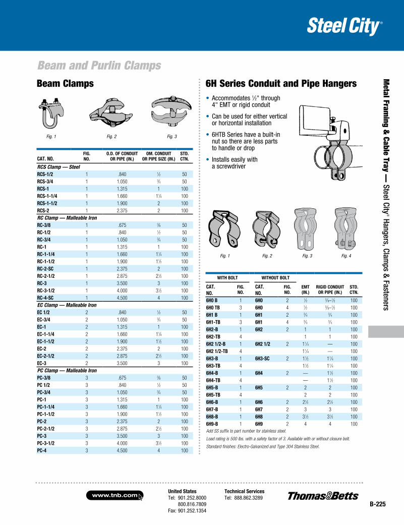
RCS Clamp — SteelrCs-1/2 1 .840 1⁄2 50rCs-3/4 1 1.050 3⁄4 50rCs-1 1 1.315 1 100rCs-1-1/4 1 1.660 11⁄4 100rCs-1-1/2 1 1.900 2 100rCs-2 1 2.375 2 100RC Clamp — Malleable IronrC-3/8 1 .675 3⁄8 50rC-1/2 1 .840 1⁄2 50rC-3/4 1 1.050 3⁄4 50rC-1 1 1.315 1 100rC-1-1/4 1 1.660 11⁄4 100rC-1-1/2 1 1.900 11⁄2 100rC-2-sC 1 2.375 2 100rC-2-1/2 1 2.875 21⁄2 100rC-3 1 3.500 3 100rC-3-1/2 1 4.000 31⁄2 100rC-4-sC 1 4.500 4 100EC Clamp — Malleable IroneC 1/2 2 .840 1⁄2 50eC-3/4 2 1.050 3⁄4 50eC-1 2 1.315 1 100eC-1-1/4 2 1.660 11⁄4 100eC-1-1/2 2 1.900 11⁄2 100eC-2 2 2.375 2 100eC-2-1/2 2 2.875 21⁄2 100eC-3 2 3.500 3 100PC Clamp — Malleable Iron pC-3/8 3 .675 3⁄8 50pC 1/2 3 .840 1⁄2 50pC-3/4 3 1.050 3⁄4 50pC-1 3 1.315 1 100pC-1-1/4 3 1.660 11⁄4 100pC-1-1/2 3 1.900 11⁄2 100pC-2 3 2.375 2 100pC-2-1/2 3 2.875 21⁄2 100pC-3 3 3.500 3 100pC-3-1/2 3 4.000 31⁄2 100pC-4 3 4.500 4 100
Fig. 1 Fig. 2 Fig. 3
• Accommodates 1⁄2" through 4" EMT or rigid conduit
• Can be used for either vertical or horizontal installation
• 6HTB Series have a built-in nut so there are less parts to handle or drop
• Installs easily with a screwdriver
Fig. 2Fig. 1
witH Bolt witHout Bolt
emt (iN.)
rigiD CoNDuit or pipe (iN.)
stD.CtN.
Cat. No.
fig. No.
Cat. No.
fig. No.
6H0 B 1 6H0 2 1⁄2 3⁄8–1⁄2 1006H0 tB 3 6H0 4 1⁄2 3⁄8–1⁄2 1006H1 B 1 6H1 2 3⁄4 3⁄4 1006H1-tB 3 6H1 4 3⁄4 3⁄4 1006H2-B 1 6H2 2 1 1 1006H2-tB 4 1 1 1006H2 1/2-B 1 6H2 1/2 2 11⁄4 — 1006H2 1/2-tB 4 11⁄4 — 1006H3-B 1 6H3-sC 2 11⁄2 11⁄4 1006H3-tB 4 11⁄2 11⁄4 1006H4-B 1 6H4 2 — 11⁄2 1006H4-tB 4 — 11⁄2 1006H5-B 1 6H5 2 2 2 1006H5-tB 4 2 2 1006H6-B 1 6H6 2 21⁄2 21⁄2 1006H7-B 1 6H7 2 3 3 1006H8-B 1 6H8 2 31⁄2 31⁄2 1006H9-B 1 6H9 2 4 4 100Add SS suffix to part number for stainless steel.
Load rating is 500 lbs. with a safety factor of 3. Available with or without closure bolt.
Standard finishes: Electro-Galvanized and Type 304 Stainless Steel.
Fig. 3 Fig. 4
Beam Clamps 6H Series Conduit and Pipe Hangers
www.tnb.comUnited StatesTel: 901.252.8000 800.816.7809Fax: 901.252.1354
Technical ServicesTel: 888.862.3289
B-226
Beam and Purlin Clamps
Met
al F
ram
ing
& C
able
Tra
y —
Ste
el C
ity® H
ange
rs, C
lam
ps &
Fas
tene
rs
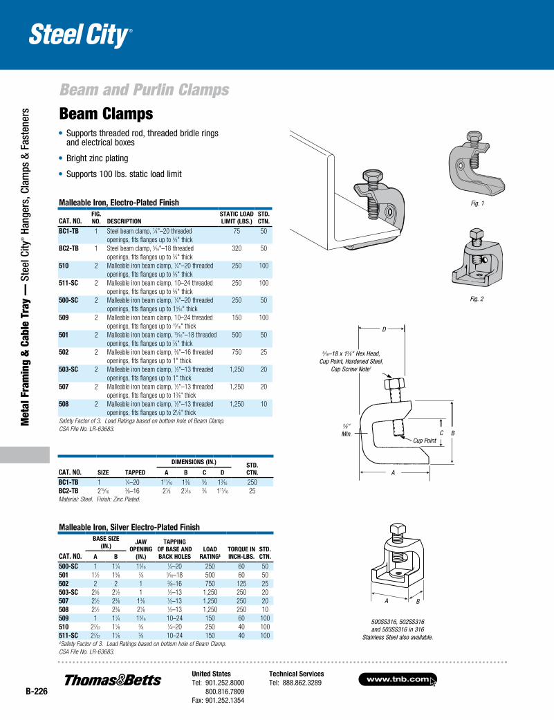
Malleable Iron, Electro-Plated Finish
Cat. No.FIg. No. DEsCrIPtIoN
statIC LoaD LIMIt (LBs.)
stD. CtN.
BC1-tB 1 Steel beam clamp, 1⁄4"–20 threaded 75 50openings, fits flanges up to 5⁄8" thick
BC2-tB 1 Steel beam clamp, 5⁄16"–18 threaded 320 50openings, fits flanges up to 3⁄4" thick
510 2 Malleable iron beam clamp, 1⁄4"–20 threaded 250 100openings, fits flanges up to 5⁄8" thick
511-sC 2 Malleable iron beam clamp, 10–24 threaded 250 100openings, fits flanges up to 5⁄8" thick
500-sC 2 Malleable iron beam clamp, 1⁄4"–20 threaded 250 50openings, fits flanges up to 15⁄16" thick
509 2 Malleable iron beam clamp, 10–24 threaded 150 100openings, fits flanges up to 15⁄16" thick
501 2 Malleable iron beam clamp, 15⁄16"–18 threaded 500 50openings, fits flanges up to 7⁄8" thick
502 2 Malleable iron beam clamp, 3⁄8"–16 threaded 750 25openings, fits flanges up to 1" thick
503-sC 2 Malleable iron beam clamp, 1⁄2"–13 threaded 1,250 20openings, fits flanges up to 1" thick
507 2 Malleable iron beam clamp, 1⁄2"–13 threaded 1,250 20openings, fits flanges up to 13⁄8" thick
508 2 Malleable iron beam clamp, 1⁄2"–13 threaded 1,250 10openings, fits flanges up to 21⁄8" thick
Safety Factor of 3. Load Ratings based on bottom hole of Beam Clamp.CSA File No. LR-63683.
• Supports threaded rod, threaded bridle rings and electrical boxes
• Bright zinc plating
• Supports 100 lbs. static load limit
Beam Clamps
Cat. No. sIzE taPPED
DIMENsIoNs (IN.) stD. CtN.a B C D
BC1-tB 1 1⁄4–20 111⁄16 13⁄8 5⁄8 13⁄16 250BC2-tB 215⁄16
3⁄8–16 21⁄8 21⁄163⁄4 111⁄16 25
Material: Steel. Finish: Zinc Plated.
Malleable Iron, silver Electro-Plated Finish
Cat. No.
BasE sIzE (IN.)
Jaw oPENINg
(IN.)
taPPINg oF BasE aND BaCk HoLEs
LoaD
ratINg‡torquE IN INCH-LBs.
stD. CtN.a B
500-sC 1 11⁄4 15⁄161⁄4–20 250 60 50
501 11⁄2 15⁄8 7⁄8 5⁄16–18 500 60 50502 2 2 1 3⁄8–16 750 125 25503-sC 25⁄8 21⁄2 1 1⁄2–13 1,250 250 20507 21⁄2 23⁄8 13⁄8 1⁄2–13 1,250 250 20508 21⁄2 23⁄8 21⁄8 1⁄2–13 1,250 250 10509 1 11⁄4 15⁄16 10–24 150 60 100510 27⁄32 11⁄8 5⁄8 1⁄4–20 250 40 100511-sC 27⁄32 11⁄8 5⁄8 10–24 150 40 100‡Safety Factor of 3. Load Ratings based on bottom hole of Beam Clamp.CSA File No. LR-63683.
Fig. 1
Fig. 2
DD
BC
A
3⁄8"Min.
Cup Point
5⁄16–18 x 13⁄8" Hex Head, Cup Point, Hardened Steel,
Cap Screw Note1
500SS316, 502SS316 and 503SS316 in 316
Stainless Steel also available.
A B
United StatesTel: 901.252.8000 800.816.7809Fax: 901.252.1354
Technical ServicesTel: 888.862.3289www.tnb.com
B-227
Beam and Purlin Clamps
Metal Fram
ing & Cable Tray —
Steel City® Hangers, Clam
ps & Fasteners
Cat. No.FIg. No. DEsCrIPtIoN
statIC LoaD LIMIt (LBs.)
stD. CtN.
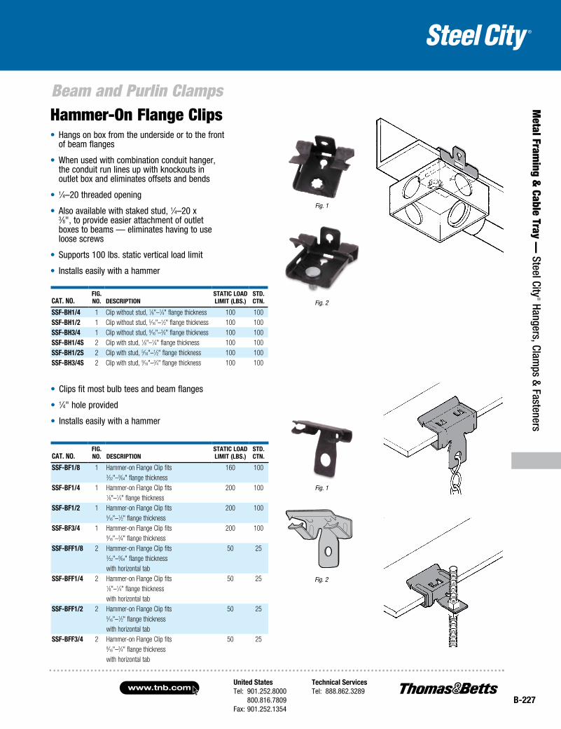
ssF-BH1/4 1 Clip without stud, 1⁄8"–1⁄4" flange thickness 100 100ssF-BH1/2 1 Clip without stud, 5⁄16"–1⁄2" flange thickness 100 100ssF-BH3/4 1 Clip without stud, 9⁄16"–3⁄4" flange thickness 100 100ssF-BH1/4s 2 Clip with stud, 1⁄8"–1⁄4" flange thickness 100 100ssF-BH1/2s 2 Clip with stud, 5⁄16"–1⁄2" flange thickness 100 100ssF-BH3/4s 2 Clip with stud, 9⁄16"–3⁄4" flange thickness 100 100
• Clips fit most bulb tees and beam flanges
• 1⁄4" hole provided
• Installs easily with a hammer
Hammer-On Flange Clips• Hangs on box from the underside or to the front
of beam flanges
• When used with combination conduit hanger, the conduit run lines up with knockouts in outlet box and eliminates offsets and bends
• 1⁄4–20 threaded opening
• Also available with staked stud, 1⁄4–20 x 3⁄8", to provide easier attachment of outlet boxes to beams — eliminates having to use loose screws
• Supports 100 lbs. static vertical load limit
• Installs easily with a hammer
Cat. No.FIg. No. DEsCrIPtIoN
statIC LoaD LIMIt (LBs.)
stD. CtN.
ssF-BF1/8 1 Hammer-on Flange Clip fits 160 1003⁄32"–9⁄64" flange thickness
ssF-BF1/4 1 Hammer-on Flange Clip fits 200 1001⁄8"–1⁄4" flange thickness
ssF-BF1/2 1 Hammer-on Flange Clip fits 200 1005⁄16"–1⁄2" flange thickness
ssF-BF3/4 1 Hammer-on Flange Clip fits 200 1009⁄16"–3⁄4" flange thickness
ssF-BFF1/8 2 Hammer-on Flange Clip fits 50 253⁄32"–9⁄64" flange thicknesswith horizontal tab
ssF-BFF1/4 2 Hammer-on Flange Clip fits 50 251⁄8"–1⁄4" flange thicknesswith horizontal tab
ssF-BFF1/2 2 Hammer-on Flange Clip fits 50 255⁄16"–1⁄2" flange thicknesswith horizontal tab
ssF-BFF3/4 2 Hammer-on Flange Clip fits 50 259⁄16"–3⁄4" flange thickness with horizontal tab
Fig. 2
Fig. 1
Fig. 1
Fig. 2
www.tnb.comUnited StatesTel: 901.252.8000 800.816.7809Fax: 901.252.1354
Technical ServicesTel: 888.862.3289
B-228
Beam and Purlin Clamps
Met
al F
ram
ing
& C
able
Tra
y —
Ste
el C
ity® H
ange
rs, C
lam
ps &
Fas
tene
rs
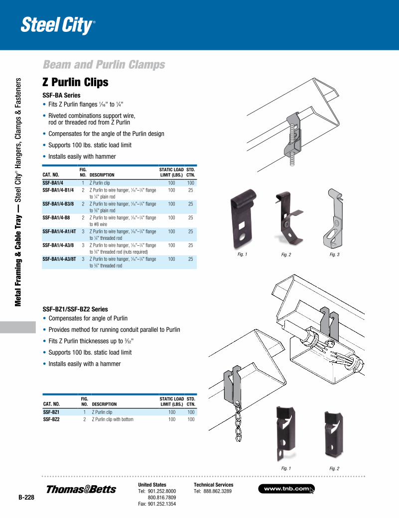
SSF-BA Series• Fits Z Purlin flanges 1⁄16" to 1⁄4"
• Riveted combinations support wire, rod or threaded rod from Z Purlin
• Compensates for the angle of the Purlin design
• Supports 100 lbs. static load limit
• Installs easily with hammer
CAt. No.Fig. No. DeSCriptioN
StAtiC LoAD Limit (LBS.)
StD. CtN.
SSF-BA1/4 1 Z Purlin clip 100 100SSF-BA1/4-B1/4 2 Z Purlin to wire hanger, 1⁄16"–1⁄4" flange
to 1⁄4" plain rod100 25
SSF-BA1/4-B3/8 2 Z Purlin to wire hanger, 1⁄16"–1⁄4" flange to 3⁄8" plain rod
100 25
SSF-BA1/4-B8 2 Z Purlin to wire hanger, 1⁄16"–1⁄4" flange to #8 wire
100 25
SSF-BA1/4-A1/4t 3 Z Purlin to wire hanger, 1⁄16"–1⁄4" flange to 1⁄4" threaded rod
100 25
SSF-BA1/4-A3/8 3 Z Purlin to wire hanger, 1⁄16"–1⁄4" flange to 3⁄8" threaded rod (nuts required)
100 25
SSF-BA1/4-A3/8t 3 Z Purlin to wire hanger, 1⁄16"–1⁄4" flange to 3⁄8" threaded rod
100 25
Z Purlin Clips
CAt. No.Fig. No. DeSCriptioN
StAtiC LoAD Limit (LBS.)
StD. CtN.
SSF-BZ1 1 Z Purlin clip 100 100SSF-BZ2 2 Z Purlin clip with bottom 100 100
SSF-BZ1/SSF-BZ2 Series• Compensates for angle of Purlin
• Provides method for running conduit parallel to Purlin
• Fits Z Purlin thicknesses up to 3⁄32"
• Supports 100 lbs. static load limit
• Installs easily with a hammer
Fig. 1 Fig. 2 Fig. 3
Fig. 1 Fig. 2
United StatesTel: 901.252.8000 800.816.7809Fax: 901.252.1354
Technical ServicesTel: 888.862.3289www.tnb.com
B-229
Beam and Purlin Clamps
Metal Fram
ing & Cable Tray —
Steel City® Hangers, Clam
ps & Fasteners
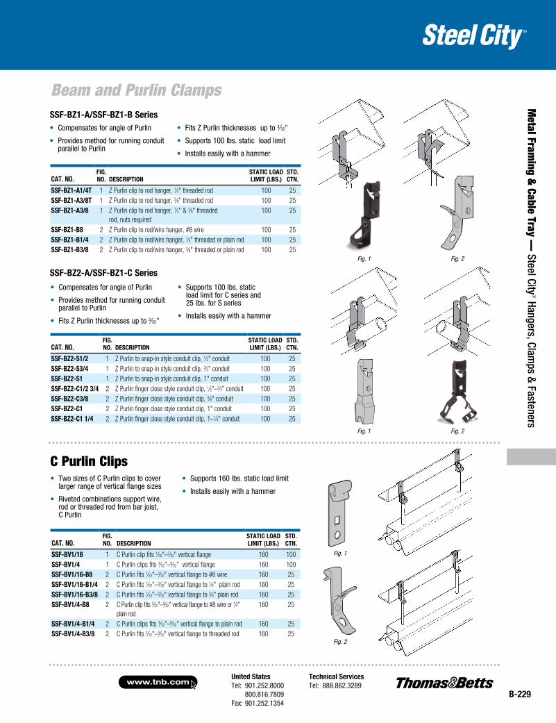
• Compensates for angle of Purlin
• Provides method for running conduit parallel to Purlin
• Fits Z Purlin thicknesses up to 3⁄32"
• Supports 100 lbs. static load limit
• Installs easily with a hammer
CAt. No.Fig. No. DeSCriptioN
StAtiC LoAD Limit (LBS.)
StD. CtN.
SSF-BZ1-A1/4t 1 Z Purlin clip to rod hanger, 1⁄4" threaded rod 100 25SSF-BZ1-A3/8t 1 Z Purlin clip to rod hanger, 3⁄8" threaded rod 100 25SSF-BZ1-A3/8 1 Z Purlin clip to rod hanger, 1⁄4" & 3⁄8" threaded
rod, nuts required100 25
SSF-BZ1-B8 2 Z Purlin clip to rod/wire hanger, #8 wire 100 25SSF-BZ1-B1/4 2 Z Purlin clip to rod/wire hanger, 1⁄4" threaded or plain rod 100 25SSF-BZ1-B3/8 2 Z Purlin clip to rod/wire hanger, 3⁄8" threaded or plain rod 100 25
• Compensates for angle of Purlin
• Provides method for running conduit parallel to Purlin
• Fits Z Purlin thicknesses up to 3⁄32"
• Supports 100 lbs. static load limit for C series and 25 lbs. for S series
• Installs easily with a hammer
CAt. No.Fig. No. DeSCriptioN
StAtiC LoAD Limit (LBS.)
StD. CtN.
SSF-BZ2-S1/2 1 Z Purlin to snap-in style conduit clip, 1⁄2" conduit 100 25SSF-BZ2-S3/4 1 Z Purlin to snap-in style conduit clip, 3⁄4" conduit 100 25SSF-BZ2-S1 1 Z Purlin to snap-in style conduit clip, 1" conduit 100 25SSF-BZ2-C1/2 3/4 2 Z Purlin finger close style conduit clip, 1⁄2"–3⁄4" conduit 100 25SSF-BZ2-C3/8 2 Z Purlin finger close style conduit clip, 3⁄8" conduit 100 25SSF-BZ2-C1 2 Z Purlin finger close style conduit clip, 1" conduit 100 25SSF-BZ2-C1 1/4 2 Z Purlin finger close style conduit clip, 1–1⁄4" conduit 100 25
CAt. No.Fig. No. DeSCriptioN
StAtiC LoAD Limit (LBS.)
StD. CtN.
SSF-BV1/16 1 C Purlin clip fits 1⁄32"–3⁄32" vertical flange 160 100SSF-BV1/4 1 C Purlin clips fits 3⁄32"–9⁄32" vertical flange 160 100SSF-BV1/16-B8 2 C Purlin fits 1⁄32"–3⁄32" vertical flange to #8 wire 160 25SSF-BV1/16-B1/4 2 C Purlin fits 1⁄32"–3⁄32" vertical flange to 1⁄4" plain rod 160 25SSF-BV1/16-B3/8 2 C Purlin fits 1⁄32"–3⁄32" vertical flange to 3⁄8" plain rod 160 25SSF-BV1/4-B8 2 C Purlin clip fits 3⁄32"–9⁄32" vertical flange to #8 wire or 1⁄4"
plain rod160 25
SSF-BV1/4-B1/4 2 C Purlin clips fits 3⁄32"–9⁄32" vertical flange to plain rod 160 25SSF-BV1/4-B3/8 2 C Purlin fits 3⁄32"–9⁄32" vertical flange to threaded rod 160 25
• Two sizes of C Purlin clips to cover larger range of vertical flange sizes
• Riveted combinations support wire, rod or threaded rod from bar joist, C Purlin
• Supports 160 lbs. static load limit
• Installs easily with a hammer
C Purlin Clips
Fig. 1
Fig. 2
Fig. 1
Fig. 2
Fig. 1 Fig. 2
SSF-BZ1-A/SSF-BZ1-B Series
SSF-BZ2-A/SSF-BZ1-C Series
www.tnb.comUnited StatesTel: 901.252.8000 800.816.7809Fax: 901.252.1354
Technical ServicesTel: 888.862.3289
B-230
Met
al F
ram
ing
& C
able
Tra
y —
Ste
el C
ity® H
ange
rs, C
lam
ps &
Fas
tene
rs
Hangers
Fig. 1
Fig. 2
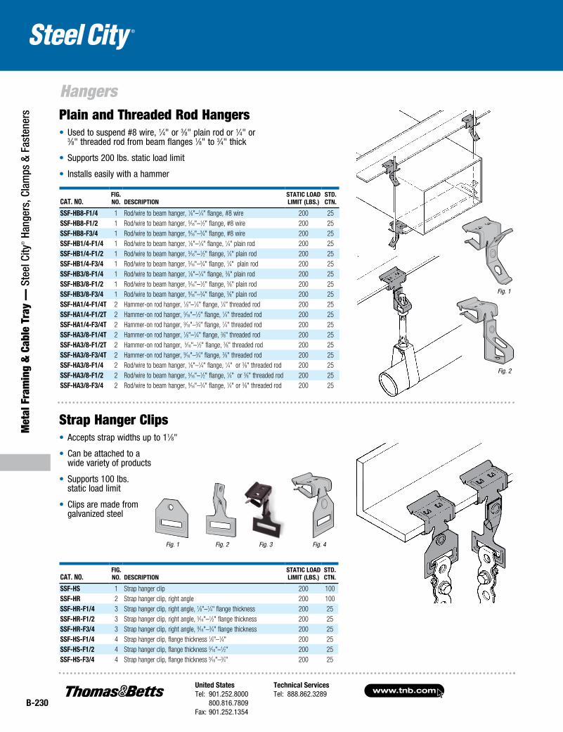
Cat. No.Fig. No. DesCriptioN
statiC LoaDLimit (LBs.)
stD.CtN.
ssF-HB8-F1/4 1 Rod/wire to beam hanger, 1⁄8"–1⁄4" flange, #8 wire 200 25ssF-HB8-F1/2 1 Rod/wire to beam hanger, 5⁄16"–1⁄2" flange, #8 wire 200 25ssF-HB8-F3/4 1 Rod/wire to beam hanger, 9⁄16"–3⁄4" flange, #8 wire 200 25ssF-HB1/4-F1/4 1 Rod/wire to beam hanger, 1⁄8"–1⁄4" flange, 1⁄4" plain rod 200 25ssF-HB1/4-F1/2 1 Rod/wire to beam hanger, 5⁄16"–1⁄2" flange, 1⁄4" plain rod 200 25ssF-HB1/4-F3/4 1 Rod/wire to beam hanger, 5⁄16"–3⁄4" flange, 1⁄4" plain rod 200 25ssF-HB3/8-F1/4 1 Rod/wire to beam hanger, 1⁄8"–1⁄4" flange, 3⁄8" plain rod 200 25ssF-HB3/8-F1/2 1 Rod/wire to beam hanger, 5⁄16"–1⁄2" flange, 3⁄8" plain rod 200 25ssF-HB3/8-F3/4 1 Rod/wire to beam hanger, 9⁄16"–3⁄4" flange, 3⁄8" plain rod 200 25ssF-Ha1/4-F1/4t 2 Hammer-on rod hanger, 1⁄8"–1⁄4" flange, 1⁄4" threaded rod 200 25ssF-Ha1/4-F1/2t 2 Hammer-on rod hanger, 5⁄16"–1⁄2" flange, 1⁄4" threaded rod 200 25ssF-Ha1/4-F3/4t 2 Hammer-on rod hanger, 9⁄16"–3⁄4" flange, 1⁄4" threaded rod 200 25ssF-Ha3/8-F1/4t 2 Hammer-on rod hanger, 1⁄8"–1⁄4" flange, 3⁄8" threaded rod 200 25 ssF-Ha3/8-F1/2t 2 Hammer-on rod hanger, 5⁄16"–1⁄2" flange, 3⁄8" threaded rod 200 25ssF-Ha3/8-F3/4t 2 Hammer-on rod hanger, 9⁄16"–3⁄4" flange, 3⁄8" threaded rod 200 25ssF-Ha3/8-F1/4 2 Rod/wire to beam hanger, 1⁄8"–1⁄4" flange, 1⁄4" or 3⁄8" threaded rod 200 25ssF-Ha3/8-F1/2 2 Rod/wire to beam hanger, 5⁄16"–1⁄2" flange, 1⁄4" or 3⁄8" threaded rod 200 25ssF-Ha3/8-F3/4 2 Rod/wire to beam hanger, 9⁄16"–3⁄4" flange, 1⁄4" or 3⁄8" threaded rod 200 25
Fig. 3 Fig. 4Fig. 1 Fig. 2
Cat. No.Fig. No. DesCriptioN
statiC LoaDLimit (LBs.)
stD.CtN.
ssF-Hs 1 Strap hanger clip 200 100ssF-Hr 2 Strap hanger clip, right angle 200 100ssF-Hr-F1/4 3 Strap hanger clip, right angle, 1⁄8"–1⁄4" flange thickness 200 25ssF-Hr-F1/2 3 Strap hanger clip, right angle, 5⁄16"–1⁄2" flange thickness 200 25ssF-Hr-F3/4 3 Strap hanger clip, right angle, 9⁄16"–3⁄4" flange thickness 200 25ssF-Hs-F1/4 4 Strap hanger clip, flange thickness 1⁄8"–1⁄4" 200 25ssF-Hs-F1/2 4 Strap hanger clip, flange thickness 5⁄16"–1⁄2" 200 25ssF-Hs-F3/4 4 Strap hanger clip, flange thickness 5⁄16"–3⁄4" 200 25
Strap Hanger Clips• Accepts strap widths up to 11⁄8"
• Can be attached to a wide variety of products
• Supports 100 lbs. static load limit
• Clips are made from galvanized steel
Plain and Threaded Rod Hangers• Used to suspend #8 wire, 1⁄4" or 3⁄8" plain rod or 1⁄4" or
3⁄8" threaded rod from beam flanges 1⁄8" to 3⁄4" thick
• Supports 200 lbs. static load limit
• Installs easily with a hammer
United StatesTel: 901.252.8000 800.816.7809Fax: 901.252.1354
Technical ServicesTel: 888.862.3289www.tnb.com
B-231
Metal Fram
ing & Cable Tray —
Steel City® Hangers, Clam
ps & Fasteners
Hangers
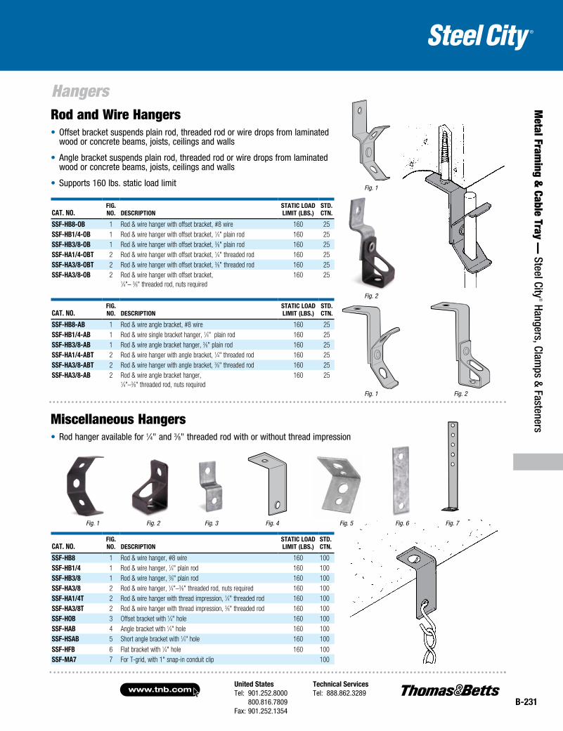
Cat. No.Fig. No. DesCriptioN
statiC LoaDLimit (LBs.)
stD.CtN.
ssF-HB8-oB 1 Rod & wire hanger with offset bracket, #8 wire 160 25ssF-HB1/4-oB 1 Rod & wire hanger with offset bracket, 1⁄4" plain rod 160 25ssF-HB3/8-oB 1 Rod & wire hanger with offset bracket, 3⁄8" plain rod 160 25ssF-Ha1/4-oBt 2 Rod & wire hanger with offset bracket, 1⁄4" threaded rod 160 25ssF-Ha3/8-oBt 2 Rod & wire hanger with offset bracket, 3⁄8" threaded rod 160 25ssF-Ha3/8-oB 2 Rod & wire hanger with offset bracket,
1⁄4"– 3⁄8" threaded rod, nuts required160 25
Fig. 1 Fig. 2
Fig. 3 Fig. 4
Cat. No.Fig. No. DesCriptioN
statiC LoaDLimit (LBs.)
stD. CtN.
ssF-HB8 1 Rod & wire hanger, #8 wire 160 100ssF-HB1/4 1 Rod & wire hanger, 1⁄4" plain rod 160 100ssF-HB3/8 1 Rod & wire hanger, 3⁄8" plain rod 160 100ssF-Ha3/8 2 Rod & wire hanger, 1⁄4"–3⁄8" threaded rod, nuts required 160 100ssF-Ha1/4t 2 Rod & wire hanger with thread impression, 1⁄4" threaded rod 160 100ssF-Ha3/8t 2 Rod & wire hanger with thread impression, 3⁄8" threaded rod 160 100ssF-HoB 3 Offset bracket with 1⁄4" hole 160 100ssF-HaB 4 Angle bracket with 1⁄4" hole 160 100ssF-HsaB 5 Short angle bracket with 1⁄4" hole 160 100ssF-HFB 6 Flat bracket with 1⁄4" hole 160 100ssF-ma7 7 For T-grid, with 1" snap-in conduit clip 100
Fig. 5 Fig. 7Fig. 6
Rod and Wire Hangers• Offset bracket suspends plain rod, threaded rod or wire drops from laminated
wood or concrete beams, joists, ceilings and walls
• Angle bracket suspends plain rod, threaded rod or wire drops from laminated wood or concrete beams, joists, ceilings and walls
• Supports 160 lbs. static load limit Fig. 1
Fig. 2
Cat. No.Fig. No. DesCriptioN
statiC LoaDLimit (LBs.)
stD.CtN.
ssF-HB8-aB 1 Rod & wire angle bracket, #8 wire 160 25ssF-HB1/4-aB 1 Rod & wire single bracket hanger, 1⁄4" plain rod 160 25ssF-HB3/8-aB 1 Rod & wire angle bracket hanger, 3⁄8" plain rod 160 25ssF-Ha1/4-aBt 2 Rod & wire hanger with angle bracket, 1⁄4" threaded rod 160 25ssF-Ha3/8-aBt 2 Rod & wire hanger with angle bracket, 3⁄8" threaded rod 160 25ssF-Ha3/8-aB 2 Rod & wire angle bracket hanger,
1⁄4"–3⁄8" threaded rod, nuts required 160 25
Fig. 2Fig. 1
Miscellaneous Hangers• Rod hanger available for 1⁄4" and 3⁄8" threaded rod with or without thread impression
www.tnb.comUnited StatesTel: 901.252.8000 800.816.7809Fax: 901.252.1354
Technical ServicesTel: 888.862.3289
B-232
Met
al F
ram
ing
& C
able
Tra
y —
Ste
el C
ity® H
ange
rs, C
lam
ps &
Fas
tene
rs
Conduit and Cable Supports
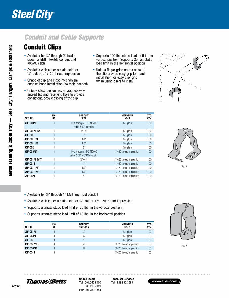
• Available for 3⁄8" through 2" trade sizes for EMT, flexible conduit and MC/AC cable
• Available with either a plain hole for 1⁄4" bolt or a 1⁄4–20 thread impression
• Shape of clip and clasp mechanism enables hand installation (no tools needed)
• Unique clasp design has an aggressively angled tab and receiving hole to provide consistent, easy clasping of the clip
• Supports 100 lbs. static load limit in the vertical position. Supports 25 lbs. static load limit in the horizontal position
• Unique finger grips on the ends of the clip provide easy grip for hand installation, or easy plier grip when using pliers to install
Cat. No.Fig.No.
CoNduitSize
MouNtiNgHole
Std. CtN.
SSF-CC3/8 1 14-2 through 12-3 MC/AC cable & 3⁄8" conduits
9⁄32" plain 100
SSF-CC1/2 3/4 1 1⁄2"–3⁄4" 9⁄32" plain 100SSF-CC1 1 1" 9⁄32" plain 100SSF-CC1 1/4 1 11⁄4" 9⁄32" plain 100SSF-CC1 1/2 1 11⁄2" 9⁄32" plain 100SSF-CC2 1 2" 9⁄32" plain 100SSF-CC3/8t 1 14-2 through 12-3 MC/AC
cable & 3⁄8" MC/AC conduits
1⁄4–20 thread impression 100
SSF-CC1/2 3/4t 1 1⁄2"–3⁄4" 1⁄4–20 thread impression 100SSF-CC1t 1 1" 1⁄4–20 thread impression 100SSF-CC1 1/4t 1 11⁄4" 1⁄4–20 thread impression 100SSF-CC1 1/2t 1 11⁄2" 1⁄4–20 thread impression 100SSF-CC2t 1 2" 1⁄4–20 thread impression 100
Fig. 1
• Available for 1⁄2" through 1" EMT and rigid conduit
• Available with either a plain hole for 1⁄4" bolt or a 1⁄4 –20 thread impression
• Supports ultimate static load limit of 25 lbs. in the vertical position.
• Supports ultimate static load limit of 15 lbs. in the horizontal position
Fig. 1
Cat. No.Fig.No.
CoNduitSize (iN.)
MouNtiNgHole
Std. CtN.
SSF-CS1/2 1 1⁄2 9⁄32" plain 100SSF-CS3/4 1 3⁄4 9⁄32" plain 100SSF-CS1 1 1 9⁄32" plain 100SSF-CS1/2t 1 1⁄2 1⁄4–20 thread impression 100SSF-CS3/4t 1 3⁄4 1⁄4–20 thread impression 100SSF-CS1t 1 1 1⁄4–20 thread impression 100
Conduit Clips
United StatesTel: 901.252.8000 800.816.7809Fax: 901.252.1354
Technical ServicesTel: 888.862.3289www.tnb.com
B-233
Metal Fram
ing & Cable Tray —
Steel City® Hangers, Clam
ps & Fasteners
Conduit and Cable Supports
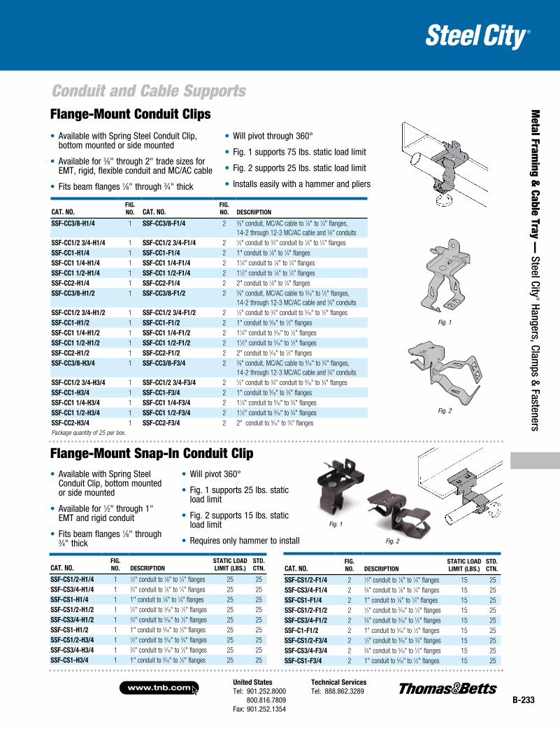
Cat. No.Fig. No. deSCriptioN
StatiC load liMit (lBS.)
Std. CtN.
SSF-CS1/2-F1/4 2 1⁄2" conduit to 1⁄8" to 1⁄4" flanges 15 25SSF-CS3/4-F1/4 2 3⁄4" conduit to 1⁄8" to 1⁄4" flanges 15 25SSF-CS1-F1/4 2 1" conduit to 1⁄8" to 1⁄4" flanges 15 25SSF-CS1/2-F1/2 2 1⁄2" conduit to 5⁄16" to 1⁄2" flanges 15 25SSF-CS3/4-F1/2 2 3⁄4" conduit to 5⁄16" to 1⁄2" flanges 15 25SSF-C1-F1/2 2 1" conduit to 5⁄16" to 1⁄2" flanges 15 25SSF-CS1/2-F3/4 2 1⁄2" conduit to 9⁄16" to 3⁄4" flanges 15 25SSF-CS3/4-F3/4 2 3⁄4" conduit to 5⁄16" to 1⁄2" flanges 15 25SSF-CS1-F3/4 2 1" conduit to 5⁄16" to 1⁄2" flanges 15 25
Cat. No.Fig. No. Cat. No.
Fig. No. deSCriptioN
SSF-CC3/8-H1/4 1 SSF-CC3/8-F1/4 2 3⁄8" conduit, MC/AC cable to 1⁄8" to 1⁄4" flanges, 14-2 through 12-3 MC/AC cable and 3⁄8" conduits
SSF-CC1/2 3/4-H1/4 1 SSF-CC1/2 3/4-F1/4 2 1⁄2" conduit to 3⁄4" conduit to 1⁄8" to 1⁄4" flangesSSF-CC1-H1/4 1 SSF-CC1-F1/4 2 1" conduit to 1⁄8" to 1⁄4" flangesSSF-CC1 1/4-H1/4 1 SSF-CC1 1/4-F1/4 2 11⁄4" conduit to 1⁄8" to 1⁄4" flangesSSF-CC1 1/2-H1/4 1 SSF-CC1 1/2-F1/4 2 11⁄2" conduit to 1⁄8" to 1⁄4" flangesSSF-CC2-H1/4 1 SSF-CC2-F1/4 2 2" conduit to 1⁄8" to 1⁄4" flangesSSF-CC3/8-H1/2 1 SSF-CC3/8-F1/2 2 3⁄8" conduit, MC/AC cable to 5⁄16" to 1⁄2" flanges,
14-2 through 12-3 MC/AC cable and 3⁄8" conduitsSSF-CC1/2 3/4-H1/2 1 SSF-CC1/2 3/4-F1/2 2 1⁄2" conduit to 3⁄4" conduit to 5⁄16" to 1⁄2" flangesSSF-CC1-H1/2 1 SSF-CC1-F1/2 2 1" conduit to 5⁄16" to 1⁄2" flangesSSF-CC1 1/4-H1/2 1 SSF-CC1 1/4-F1/2 2 11⁄4" conduit to 5⁄16" to 1⁄2" flangesSSF-CC1 1/2-H1/2 1 SSF-CC1 1/2-F1/2 2 11⁄2" conduit to 5⁄16" to 1⁄2" flangesSSF-CC2-H1/2 1 SSF-CC2-F1/2 2 2" conduit to 5⁄16" to 1⁄2" flangesSSF-CC3/8-H3/4 1 SSF-CC3/8-F3/4 2 3⁄8" conduit, MC/AC cable to 9⁄16" to 3⁄4" flanges,
14-2 through 12-3 MC/AC cable and 3⁄8" conduitsSSF-CC1/2 3/4-H3/4 1 SSF-CC1/2 3/4-F3/4 2 1⁄2" conduit to 3⁄4" conduit to 9⁄16" to 3⁄4" flangesSSF-CC1-H3/4 1 SSF-CC1-F3/4 2 1" conduit to 9⁄16" to 3⁄4" flangesSSF-CC1 1/4-H3/4 1 SSF-CC1 1/4-F3/4 2 11⁄4" conduit to 9⁄16" to 3⁄4" flangesSSF-CC1 1/2-H3/4 1 SSF-CC1 1/2-F3/4 2 11⁄2" conduit to 9⁄16" to 3⁄4" flangesSSF-CC2-H3/4 1 SSF-CC2-F3/4 2 2" conduit to 9⁄16" to 3⁄4" flangesPackage quantity of 25 per box.
Fig. 1
Fig. 2
• Available with Spring Steel Conduit Clip, bottom mounted or side mounted
• Available for 3⁄8" through 2" trade sizes for EMT, rigid, flexible conduit and MC/AC cable
• Fits beam flanges 1⁄8" through 3⁄4" thick
• Will pivot through 360°
• Fig. 1 supports 75 lbs. static load limit
• Fig. 2 supports 25 lbs. static load limit
• Installs easily with a hammer and pliers
• Available with Spring Steel Conduit Clip, bottom mounted or side mounted
• Available for 1⁄2" through 1" EMT and rigid conduit
• Fits beam flanges 1⁄8" through 3⁄4" thick
• Will pivot 360°
• Fig. 1 supports 25 lbs. static load limit
• Fig. 2 supports 15 lbs. static load limit
• Requires only hammer to install
Flange-Mount Conduit Clips
Cat. No.Fig. No. deSCriptioN
StatiC load liMit (lBS.)
Std. CtN.
SSF-CS1/2-H1/4 1 1⁄2" conduit to 1⁄8" to 1⁄4" flanges 25 25SSF-CS3/4-H1/4 1 3⁄4" conduit to 1⁄8" to 1⁄4" flanges 25 25SSF-CS1-H1/4 1 1" conduit to 1⁄8" to 1⁄4" flanges 25 25SSF-CS1/2-H1/2 1 1⁄2" conduit to 5⁄16" to 1⁄2" flanges 25 25SSF-CS3/4-H1/2 1 3⁄4" conduit to 5⁄16" to 1⁄2" flanges 25 25SSF-CS1-H1/2 1 1" conduit to 5⁄16" to 1⁄2" flanges 25 25SSF-CS1/2-H3/4 1 1⁄2" conduit to 9⁄16" to 3⁄4" flanges 25 25SSF-CS3/4-H3/4 1 3⁄4" conduit to 5⁄16" to 1⁄2" flanges 25 25SSF-CS1-H3/4 1 1" conduit to 5⁄16" to 1⁄2" flanges 25 25
Flange-Mount Snap-In Conduit Clip
Fig. 1
Fig. 2
www.tnb.comUnited StatesTel: 901.252.8000 800.816.7809Fax: 901.252.1354
Technical ServicesTel: 888.862.3289
B-234
Conduit and Cable Supports
Met
al F
ram
ing
& C
able
Tra
y —
Ste
el C
ity® H
ange
rs, C
lam
ps &
Fas
tene
rs
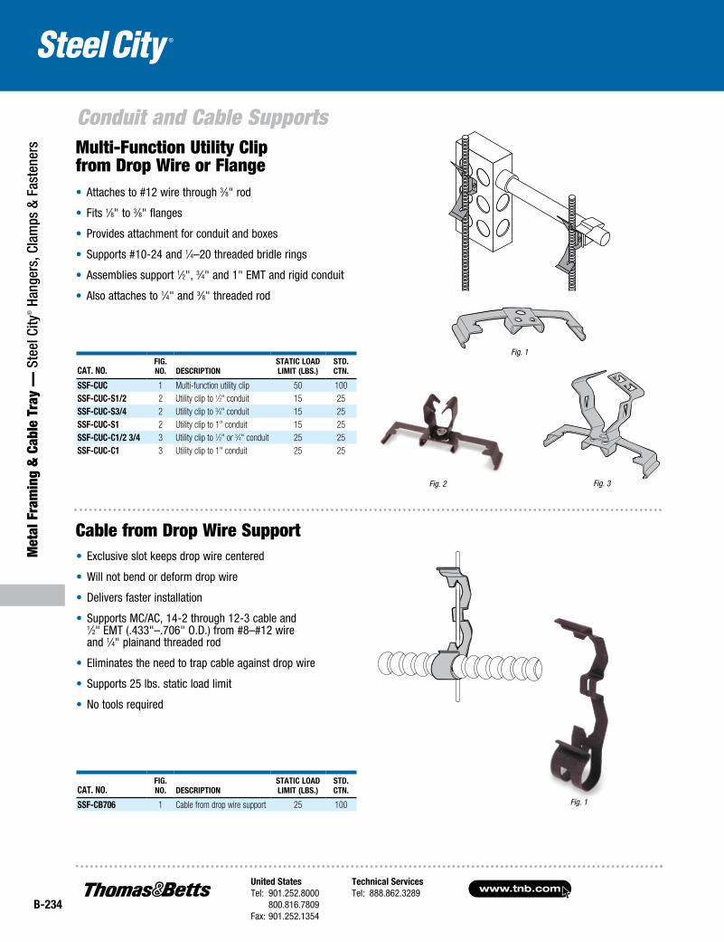
• Attaches to #12 wire through 3⁄8" rod
• Fits 1⁄8" to 3⁄8" flanges
• Provides attachment for conduit and boxes
• Supports #10-24 and 1⁄4–20 threaded bridle rings
• Assemblies support 1⁄2", 3⁄4" and 1" EMT and rigid conduit
• Also attaches to 1⁄4" and 3⁄8" threaded rod
Cat. No.Fig.No. DesCriptioN
statiC LoaDLimit (LBs.)
stD.CtN.
ssF-CUC 1 Multi-function utility clip 50 100ssF-CUC-s1/2 2 Utility clip to 1⁄2" conduit 15 25ssF-CUC-s3/4 2 Utility clip to 3⁄4" conduit 15 25ssF-CUC-s1 2 Utility clip to 1" conduit 15 25ssF-CUC-C1/2 3/4 3 Utility clip to 1⁄2" or 3⁄4" conduit 25 25ssF-CUC-C1 3 Utility clip to 1" conduit 25 25
Cat. No.Fig.No. DesCriptioN
statiC LoaDLimit (LBs.)
stD.CtN.
ssF-CB706 1 Cable from drop wire support 25 100
Fig. 2 Fig. 3
Fig. 1
• Exclusive slot keeps drop wire centered
• Will not bend or deform drop wire
• Delivers faster installation
• Supports MC/AC, 14-2 through 12-3 cable and 1⁄2" EMT (.433"–.706" O.D.) from #8–#12 wire and 1⁄4" plainand threaded rod
• Eliminates the need to trap cable against drop wire
• Supports 25 lbs. static load limit
• No tools required
Multi-Function Utility Clip from Drop Wire or Flange
Cable from Drop Wire Support
Fig. 1
United StatesTel: 901.252.8000 800.816.7809Fax: 901.252.1354
Technical ServicesTel: 888.862.3289www.tnb.com
B-235
Conduit and Cable Supports
Metal Fram
ing & Cable Tray —
Steel City® Hangers, Clam
ps & Fasteners
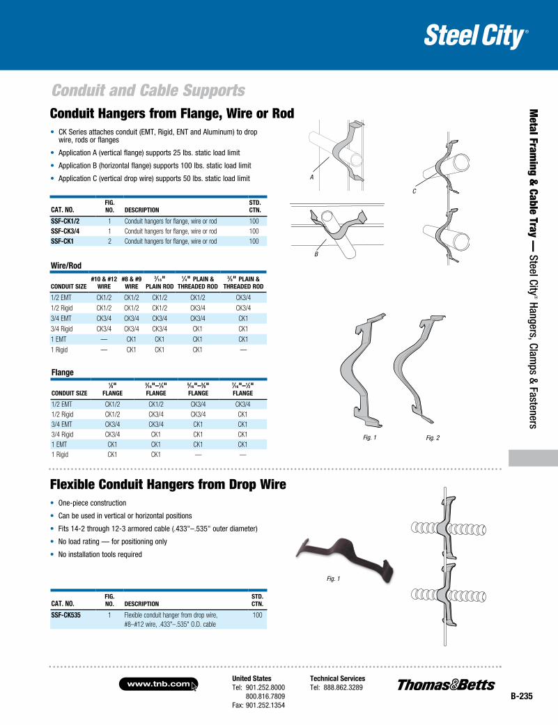
• CK Series attaches conduit (EMT, Rigid, ENT and Aluminum) to drop wire, rods or flanges
• Application A (vertical flange) supports 25 lbs. static load limit
• Application B (horizontal flange) supports 100 lbs. static load limit
• Application C (vertical drop wire) supports 50 lbs. static load limit
Fig. 1
Wire/rod
CoNDUit size#10 & #12
Wire#8 & #9
Wire
3⁄16" pLaiN roD
1⁄4" pLaiN & threaDeD roD
3⁄8" pLaiN & threaDeD roD
1/2 EMT CK1/2 CK1/2 CK1/2 CK1/2 CK3/41/2 Rigid CK1/2 CK1/2 CK1/2 CK3/4 CK3/43/4 EMT CK3/4 CK3/4 CK3/4 CK3/4 CK13/4 Rigid CK3/4 CK3/4 CK3/4 CK1 CK11 EMT — CK1 CK1 CK1 CK11 Rigid — CK1 CK1 CK1 —
Fig. 2
Cat. No.Fig. No. DesCriptioN
stD. CtN.
ssF-CK1/2 1 Conduit hangers for flange, wire or rod 100ssF-CK3/4 1 Conduit hangers for flange, wire or rod 100ssF-CK1 2 Conduit hangers for flange, wire or rod 100
C
B
A
Flange
CoNDUit size
1⁄8" FLaNge
3⁄16"–1⁄4" FLaNge
5⁄16"–3⁄8" FLaNge
7⁄16"–1⁄2" FLaNge
1/2 EMT CK1/2 CK1/2 CK3/4 CK3/41/2 Rigid CK1/2 CK3/4 CK3/4 CK13/4 EMT CK3/4 CK3/4 CK1 CK13/4 Rigid CK3/4 CK1 CK1 CK11 EMT CK1 CK1 CK1 CK11 Rigid CK1 CK1 — —
Fig. 1
Cat. No.Fig. No. DesCriptioN
stD. CtN.
ssF-CK535 1 Flexible conduit hanger from drop wire, #8–#12 wire, .433"–.535" O.D. cable
100
• One-piece construction
• Can be used in vertical or horizontal positions
• Fits 14-2 through 12-3 armored cable (.433"–.535" outer diameter)
• No load rating — for positioning only
• No installation tools required
Conduit Hangers from Flange, Wire or Rod
Flexible Conduit Hangers from Drop Wire

www.tnb.comUnited StatesTel: 901.252.8000 800.816.7809Fax: 901.252.1354
Technical ServicesTel: 888.862.3289
B-236
Conduit and Cable Supports
Met
al F
ram
ing
& C
able
Tra
y —
Ste
el C
ity® H
ange
rs, C
lam
ps &
Fas
tene
rs
• Supports cable from 1⁄16"–1⁄2" flange
• Works with MC and AC cable dimensions .178" to 1.250"
• Snaps easily onto flange
• Cable snaps right into fastener
• No load rating — for positioning only
• Installs easily with a hammer
Fig. 1
Cat. No.Fig. No.
CaBle o.D. (iN.)
FlaNge thiCkNess (iN.)
stD. CtN.
ssF-Ces218 1 .178–.218 1⁄16–3⁄16 100ssF-Ces281 1 .218–.276 1⁄16–3⁄16 100ssF-Ces375 1 .312–.375 1⁄16–3⁄16 100ssF-Ces437 1 .375–.437 1⁄16–3⁄16 100ssF-Ces562 1 .468–.562 1⁄16–3⁄16 100ssF-Ces718 1 .600–.718 1⁄16–3⁄16 100ssF-Ces937 1 .750–.937 1⁄16–3⁄16 100ssF-Ces1250 1 .968–1.250 1⁄16–3⁄16 100ssF-CeM218 1 .178–.218 3⁄16–9⁄32 100ssF-CeM281 1 .218–.276 3⁄16–9⁄32 100ssF-CeM375 1 .312–.375 3⁄16–9⁄32 100ssF-CeM437 1 .375–.437 3⁄16–9⁄32 100ssF-CeM562 1 .468–.562 3⁄16–9⁄32 100ssF-CeM718 1 .600–.718 3⁄16–9⁄32 100ssF-CeM937 1 .750–.937 3⁄16–9⁄32 100ssF-CeM1250 1 .968–1.250 3⁄16–9⁄32 100ssF-Cel218 1 .178–.218 5⁄16–1⁄2 100ssF-Cel281 1 .218–.276 5⁄16–1⁄2 100ssF-Cel375 1 .312–.375 5⁄16–1⁄2 100ssF-Cel437 1 .375–.437 5⁄16–1⁄2 100ssF-Cel562 1 .468–.562 5⁄16–1⁄2 100ssF-Cel718 1 .600–.718 5⁄16–1⁄2 100ssF-Cel937 1 .750–.937 5⁄16–1⁄2 100ssF-Cel1250 1 .968–1.250 5⁄16–1⁄2 100ssF-CF1/8 2 .200–.468 1⁄8–1⁄4 100ssF-CF3/8 2 .276–.600 5⁄16–7⁄16 100ssF-CaXl1 3 Snap clip adapter 1⁄2–5⁄8 100ssF-CaXl2 3 Snap clip adapter 5⁄8–3⁄4 100
Fig. 3
Fig. 1
• Provides quick attachment for MC or AC to metal stud
• No load rating — for positioning only
• No tools required
Cat. No.Fig. No. DesCriptioN
stD. CtN.
ssF-CM535 1 MC/AC cable to metal stud clip, 14-2 through 12-3 cable (.433"–.535" O.D.)
100
Cable Snap Clip
Flexible Conduit to Metal Stud
Fig. 2
United StatesTel: 901.252.8000 800.816.7809Fax: 901.252.1354
Technical ServicesTel: 888.862.3289www.tnb.com
B-237
Conduit and Cable Supports
Metal Fram
ing & Cable Tray —
Steel City® Hangers, Clam
ps & Fasteners
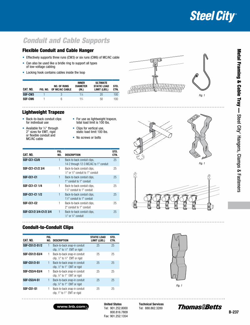
Cat. No. Fig. No.No. oF ruNs
oF MC/aC CaBle
iNNer DiaMeter
(iN.)
ultiMate statiC loaD liMit (lBs.)
stD. CtN.
ssF-CW3 1 3 11⁄8 20 100ssF-CW6 1 6 13⁄4 50 100
Fig. 1
• Effectively supports three runs (CW3) or six runs (CW6) of MC/AC cable
• Can also be used like a bridle ring to support all types of low-voltage cabling
• Locking hook contains cables inside the loop
Cat. No.Fig. No. DesCriptioN
stD. CtN.
ssF-CC1-C3/8 1 Back-to-back conduit clips, 14-2 through 12-3 MC/AC to 1" conduit
25
ssF-CC1-C1/2 3/4 1 Back-to-back conduit clips, 1⁄2" or 3⁄4" conduit to 1" conduit
25
ssF-CC1-C1 1 Back-to-back conduit clips, 1" conduit to 1" conduit
25
ssF-CC1-C1 1/4 1 Back-to-back conduit clips, 11⁄4" conduit to 1" conduit
25
ssF-CC1-C1 1/2 1 Back-to-back conduit clips, 11⁄2" conduit to 1" conduit
25
ssF-CC1-C2 1 Back-to-back conduit clips, 2" conduit to 1" conduit
25
ssF-CC1/2 3/4-C1/2 3/4 1 Back-to-back conduit clips, 1⁄2" or 3⁄4" conduit
25
Fig. 1
• Back-to-back conduit clips for individual use
• Available for 3⁄8" through 2" sizes for EMT, rigid or flexible conduit and MC/AC cable
• For use as lightweight trapeze, total load limit is 100 lbs.
• Clips for vertical use, static load limit 100 lbs.
• No screws or bolts
Fig. 1
Cat. No.Fig. No. DesCriptioN
statiC loaD liMit (lBs.)
stD. CtN.
ssF-Cs1/2-s1/2 1 Back-to-back snap-in conduit clip, 1⁄2" to 1⁄2" EMT or rigid
25 25
ssF-Cs1/2-s3/4 1 Back-to-back snap-in conduit clip, 1⁄2" to 3⁄4" EMT or rigid
25 25
ssF-Cs1/2-s1 1 Back-to-back snap-in conduit clip, 1⁄2" to 1" EMT or rigid
25 25
ssF-Cs3/4-s3/4 1 Back-to-back snap-in conduit clip, 3⁄4" to 1" EMT or rigid
25 25
ssF-Cs3/4-s1 1 Back-to-back snap-in conduit clip, 3⁄4" to 1" EMT or rigid
25 25
ssF-Cs1-s1 1 Back-to-back snap-in conduit clip, 1" to 1" EMT or rigid
25 25
Flexible Conduit and Cable Hanger
Lightweight Trapeze
Conduit-to-Conduit Clips
www.tnb.comUnited StatesTel: 901.252.8000 800.816.7809Fax: 901.252.1354
Technical ServicesTel: 888.862.3289
B-238
Conduit and Cable Supports
Met
al F
ram
ing
& C
able
Tra
y —
Ste
el C
ity® H
ange
rs, C
lam
ps &
Fas
tene
rs
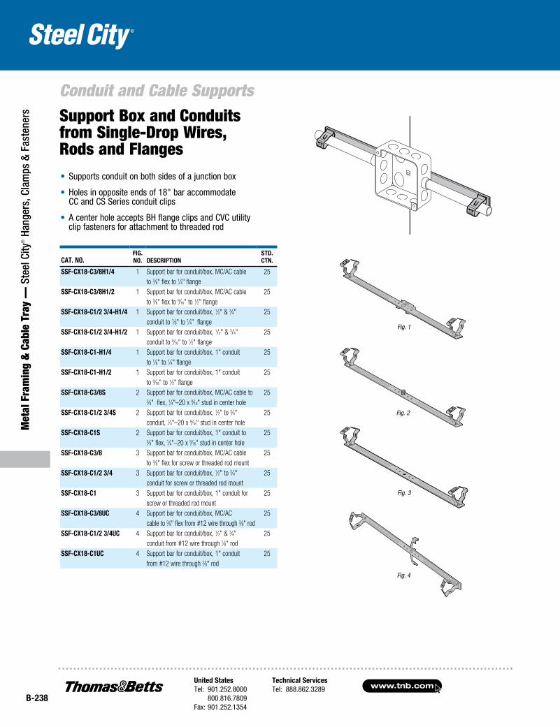
Cat. No.Fig. No. DesCriptioN
stD. CtN.
ssF-CX18-C3/8H1/4 1 Support bar for conduit/box, MC/AC cable 25to 3⁄8" flex to 1⁄4" flange
ssF-CX18-C3/8H1/2 1 Support bar for conduit/box, MC/AC cable 25to 3⁄8" flex to 9⁄16" to 1⁄2" flange
ssF-CX18-C1/2 3/4-H1/4 1 Support bar for conduit/box, 1⁄2" & 3⁄4" 25conduit to 1⁄8" to 1⁄4" flange
ssF-CX18-C1/2 3/4-H1/2 1 Support bar for conduit/box, 1/2" & 3/4" 25conduit to 9⁄16" to 1⁄2" flange
ssF-CX18-C1-H1/4 1 Support bar for conduit/box, 1" conduit 25to 1⁄8" to 1⁄4" flange
ssF-CX18-C1-H1/2 1 Support bar for conduit/box, 1" conduit 25to 9⁄16" to 1⁄2" flange
ssF-CX18-C3/8s 2 Support bar for conduit/box, MC/AC cable to 253⁄8" flex, 1⁄4"–20 x 9⁄16" stud in center hole
ssF-CX18-C1/2 3/4s 2 Support bar for conduit/box, 1⁄2" to 3⁄4" 25conduit, 1⁄4"–20 x 9⁄16" stud in center hole
ssF-CX18-C1s 2 Support bar for conduit/box, 1" conduit to 253⁄8" flex, 1⁄4"–20 x 9⁄16" stud in center hole
ssF-CX18-C3/8 3 Support bar for conduit/box, MC/AC cable 25to 3⁄8" flex for screw or threaded rod mount
ssF-CX18-C1/2 3/4 3 Support bar for conduit/box, 1⁄2" to 3⁄4" 25conduit for screw or threaded rod mount
ssF-CX18-C1 3 Support bar for conduit/box, 1" conduit for 25screw or threaded rod mount
ssF-CX18-C3/8UC 4 Support bar for conduit/box, MC/AC 25cable to 3⁄8" flex from #12 wire through 3⁄8" rod
ssF-CX18-C1/2 3/4UC 4 Support bar for conduit/box, 1⁄2" & 3⁄4" 25conduit from #12 wire through 1⁄8" rod
ssF-CX18-C1UC 4 Support bar for conduit/box, 1" conduit 25from #12 wire through 3⁄8" rod
• Supports conduit on both sides of a junction box
• Holes in opposite ends of 18" bar accommodate CC and CS Series conduit clips
• A center hole accepts BH flange clips and CVC utility clip fasteners for attachment to threaded rod
Support Box and Conduits from Single-Drop Wires, Rods and Flanges
Fig. 1
Fig. 2
Fig. 3
Fig. 4
United StatesTel: 901.252.8000 800.816.7809Fax: 901.252.1354
Technical ServicesTel: 888.862.3289www.tnb.com
B-239
Conduit and Cable Supports
Metal Fram
ing & Cable Tray —
Steel City® Hangers, Clam
ps & Fasteners
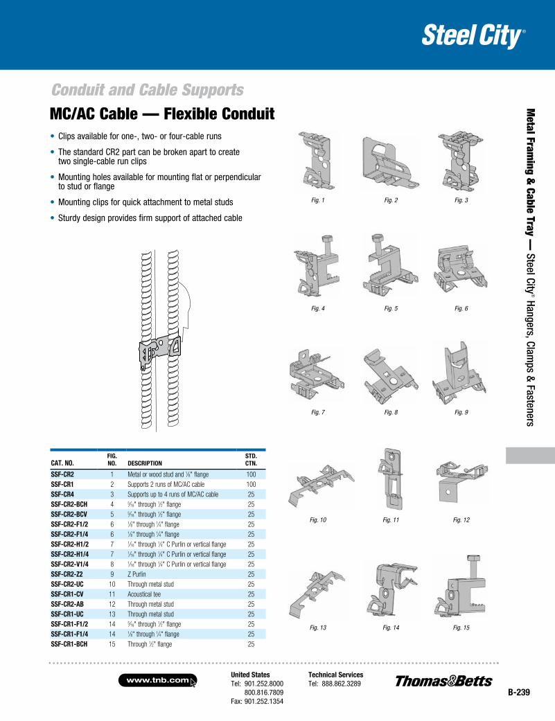
• Clips available for one-, two- or four-cable runs
• The standard CR2 part can be broken apart to create two single-cable run clips
• Mounting holes available for mounting flat or perpendicular to stud or flange
• Mounting clips for quick attachment to metal studs
• Sturdy design provides firm support of attached cable
Cat. No.Fig. No. DesCriptioN
stD. CtN.
ssF-Cr2 1 Metal or wood stud and 1⁄8" flange 100ssF-Cr1 2 Supports 2 runs of MC/AC cable 100ssF-Cr4 3 Supports up to 4 runs of MC/AC cable 25ssF-Cr2-BCH 4 5⁄16" through 1⁄2" flange 25ssF-Cr2-BCV 5 5⁄16" through 1⁄2" flange 25ssF-Cr2-F1/2 6 1⁄8" through 1⁄4" flange 25ssF-Cr2-F1/4 6 1⁄8" through 1⁄4" flange 25ssF-Cr2-H1/2 7 1⁄16" through 1⁄4" C Purlin or vertical flange 25ssF-Cr2-H1/4 7 1⁄16" through 1⁄4" C Purlin or vertical flange 25ssF-Cr2-V1/4 8 1⁄16" through 1⁄4" C Purlin or vertical flange 25ssF-Cr2-Z2 9 Z Purlin 25ssF-Cr2-UC 10 Through metal stud 25ssF-Cr1-CV 11 Acoustical tee 25ssF-Cr2-aB 12 Through metal stud 25ssF-Cr1-UC 13 Through metal stud 25ssF-Cr1-F1/2 14 5⁄16" through 1⁄2" flange 25ssF-Cr1-F1/4 14 1⁄8" through 1⁄4" flange 25ssF-Cr1-BCH 15 Through 1⁄2" flange 25
MC/AC Cable — Flexible Conduit
Fig. 2
Fig. 5 Fig. 6
Fig. 7 Fig. 8
Fig. 3
Fig. 4
Fig. 1
Fig. 9
Fig. 13 Fig. 14 Fig. 15
Fig. 11 Fig. 12Fig. 10
www.tnb.comUnited StatesTel: 901.252.8000 800.816.7809Fax: 901.252.1354
Technical ServicesTel: 888.862.3289
B-240
Met
al F
ram
ing
& C
able
Tra
y —
Ste
el C
ity® H
ange
rs, C
lam
ps &
Fas
tene
rs
Conduit and Cable Supports
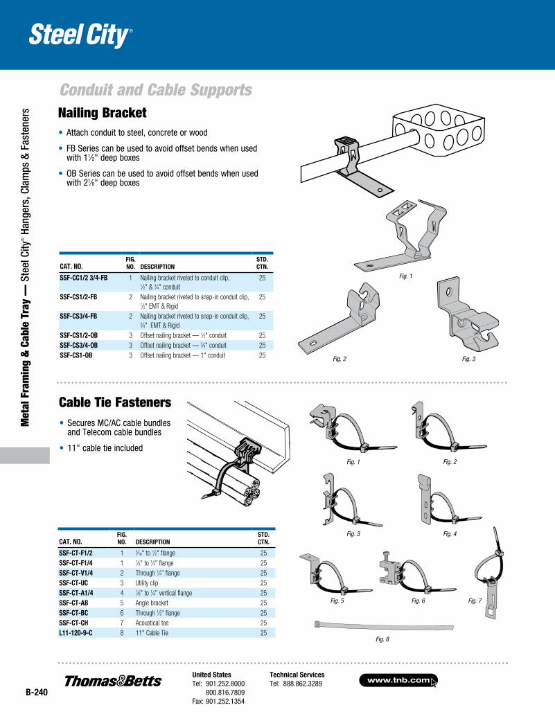
Cat. No.Fig. No. DesCriptioN
stD. CtN.
ssF-CC1/2 3/4-FB 1 Nailing bracket riveted to conduit clip, 1⁄2" & 3⁄4" conduit
25
ssF-Cs1/2-FB 2 Nailing bracket riveted to snap-in conduit clip, 1⁄2" EMT & Rigid
25
ssF-Cs3/4-FB 2 Nailing bracket riveted to snap-in conduit clip, 3⁄4" EMT & Rigid
25
ssF-Cs1/2-oB 3 Offset nailing bracket — 1⁄2" conduit 25ssF-Cs3/4-oB 3 Offset nailing bracket — 3⁄4" conduit 25ssF-Cs1-oB 3 Offset nailing bracket — 1" conduit 25 Fig. 3Fig. 2
Fig. 1
• Attach conduit to steel, concrete or wood
• FB Series can be used to avoid offset bends when used with 11⁄2" deep boxes
• OB Series can be used to avoid offset bends when used with 21⁄8" deep boxes
Nailing Bracket
Fig. 8
Cat. No.Fig. No. DesCriptioN
stD. CtN.
ssF-Ct-F1/2 1 5⁄16" to 1⁄2" flange 25ssF-Ct-F1/4 1 1⁄8" to 1⁄4" flange 25ssF-Ct-V1/4 2 Through 1⁄4" flange 25ssF-Ct-UC 3 Utility clip 25ssF-Ct-a1/4 4 1⁄8" to 1⁄4" vertical flange 25ssF-Ct-aB 5 Angle bracket 25ssF-Ct-BC 6 Through 1⁄2" flange 25ssF-Ct-CH 7 Acoustical tee 25L11-120-9-C 8 11" Cable Tie 25
Fig. 2
Fig. 3 Fig. 4
Fig. 7Fig. 5 Fig. 6
Fig. 1
• Secures MC/AC cable bundles and Telecom cable bundles
• 11" cable tie included
Cable Tie Fasteners

United StatesTel: 901.252.8000 800.816.7809Fax: 901.252.1354
Technical ServicesTel: 888.862.3289www.tnb.com
B-241
Metal Fram
ing & Cable Tray —
Steel City® Hangers, Clam
ps & Fasteners
Stud Wall/Drywall Supports, Clips and Brackets
Cat. No.Fig. No. DesCriptioN
stD. CtN.
ssF-sC6 1 Non-metallic sheathed MC/AC cable to stud clip 100
• Supports up to four runs of MC and AC cable and up to six runs of non-metallic sheathed cable
• Installs with nails, staples or sheet metal screws
• Complies with NEC® Section 300.4 for all wood and metal studs
• Made with high-strength plastic
Cable Support
Fig. 1
CaBLe type CaBLe sizeMax. Qty./ FasteNer
Non-Metallic Sheathed Cable
14-2, 12-2, 10-2, 14-3, 12-3 and 10-3 with ground
6
Non-Metallic 8-2 and 6-2 with ground 4Metallic Clad (MC) Cable
14-2, 12-2, 10-2, 14-3, 12-3, 10-3, 14-4, 12-4 and 10-4 with ground
4
Armored Cable (AC) 14-4, 12-2, 10-2, 8-2, 14-3, 12-3, 10-3, 14-4, 12-4 and 10-4 with ground
4
Flexible Conduit (BX) 5⁄16, 3⁄8 4
Fig. 1
• Supports 1⁄2" and 3⁄4" EMT conduit and MC/AC cable
• Works with wood or metal stud
• Preset bend provides alignment with knockouts for 11⁄2" deep boxes or 21⁄8" deep boxes
Cat. No.Fig. No. DesCriptioN
stD. CtN.
ssF-ss1/2 3/4 1 1⁄2" and 3⁄4" EMT conduit and MC/AC to 100metal or wood stud, for 11⁄2" deep box
ssF-ss1/2 3/4D 1 1⁄2" and 3⁄4" EMT conduit, and MC/AC to 100metal or wood stud, for 21⁄8" deep box
Screw-On Conduit Support
NEC and National Electrical Code are registered trademarks of the National Fire Protection Association, Inc.
www.tnb.comUnited StatesTel: 901.252.8000 800.816.7809Fax: 901.252.1354
Technical ServicesTel: 888.862.3289
B-242
Met
al F
ram
ing
& C
able
Tra
y —
Ste
el C
ity® H
ange
rs, C
lam
ps &
Fas
tene
rs
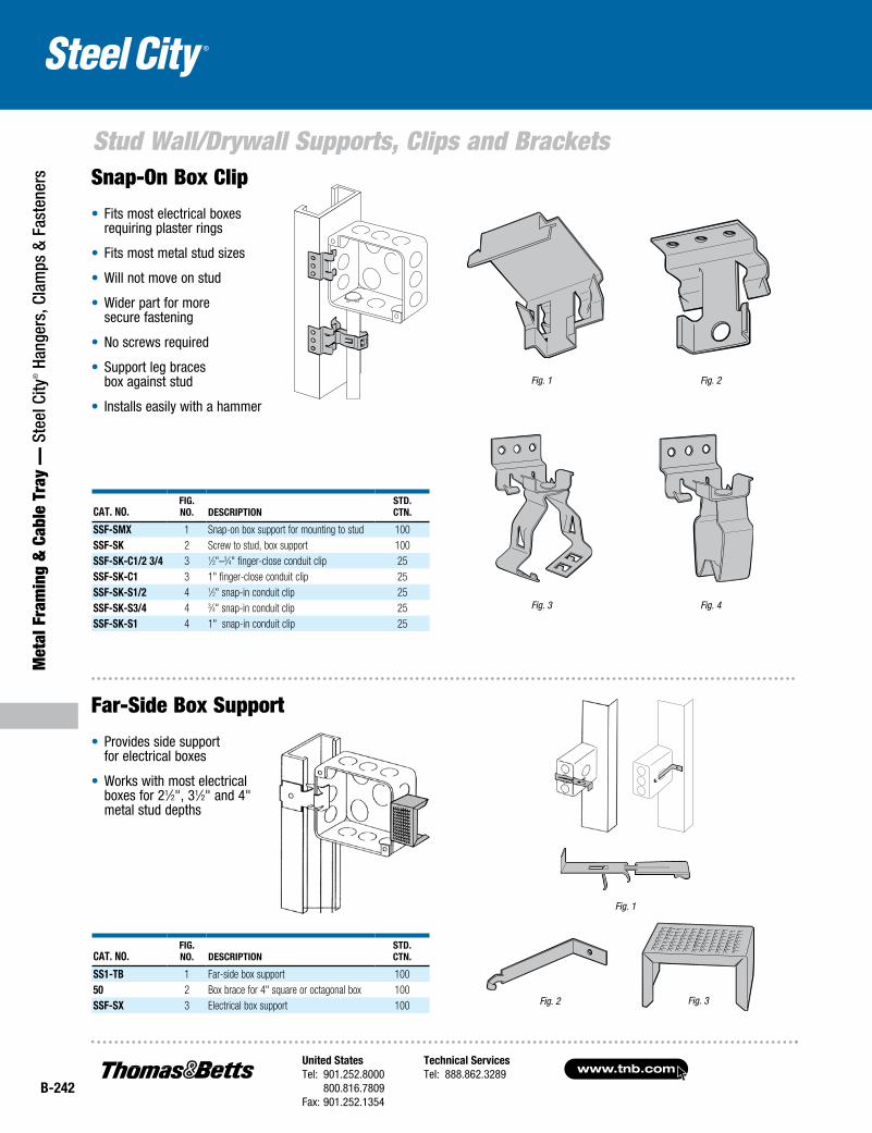
Stud Wall/Drywall Supports, Clips and BracketsSnap-On Box Clip
• Fits most electrical boxes requiring plaster rings
• Fits most metal stud sizes
• Will not move on stud
• Wider part for more secure fastening
• No screws required
• Support leg braces box against stud
• Installs easily with a hammer
Cat. No.Fig. No. DesCriptioN
stD. CtN.
ssF-sMX 1 Snap-on box support for mounting to stud 100ssF-sK 2 Screw to stud, box support 100ssF-sK-C1/2 3/4 3 1⁄2"–3⁄4" finger-close conduit clip 25ssF-sK-C1 3 1" finger-close conduit clip 25ssF-sK-s1/2 4 1⁄2" snap-in conduit clip 25ssF-sK-s3/4 4 3⁄4" snap-in conduit clip 25ssF-sK-s1 4 1" snap-in conduit clip 25
Cat. No.Fig. No. DesCriptioN
stD. CtN.
ss1-tB 1 Far-side box support 10050 2 Box brace for 4" square or octagonal box 100ssF-sX 3 Electrical box support 100
Fig. 1
Fig. 3 Fig. 4
Fig. 2
Fig. 1
Fig. 2 Fig. 3
Far-Side Box Support
• Provides side support for electrical boxes
• Works with most electrical boxes for 21⁄2", 31⁄2" and 4" metal stud depths
United StatesTel: 901.252.8000 800.816.7809Fax: 901.252.1354
Technical ServicesTel: 888.862.3289www.tnb.com
B-243
Metal Fram
ing & Cable Tray —
Steel City® Hangers, Clam
ps & Fasteners
Stud Wall/Drywall Supports, Clips and Brackets
Cat. No.Fig. No. DesCriptioN
stD. CtN.
ssF-sFa 1 Snap-on box support for mounting to stud, adjustable
25
ssF-sF0 2 Snap-on box support for mounting to stud, riveted for flush-to-stud face
25
ssF-sF1/4 2 Snap-on box support for mounting to stud, riveted for 1⁄4" drywall
25
ssF-sF3/8 2 Snap-on box support for mounting to stud, riveted for 3⁄8" drywall
25
ssF-sF1/2 2 Snap-on box support for mounting to stud, riveted for 1⁄2" drywall
25
ssF-sF5/8 2 Snap-on box support for mounting to stud, riveted for 5⁄8" drywall
25
ssF-sF3/4 2 Snap-on box support for mounting to stud, riveted for 3⁄4" drywall
25
ssF-sFt 3 Snap-on box support for mounting to stud with 1⁄4"–20 thread impression
25
ssF-sF-s1/2 4 Snap-on stud, push-in conduit clip, 1⁄2" conduit 25ssF-sF-s3/4 4 Snap-on stud, push-in conduit clip, 3⁄4" conduit 25ssF-sF-s1 4 Snap-on stud, push-in conduit clip, 1" conduit 25ssF-sF-C3/8 5 Snap-on stud, conduit support clip, 3⁄8" conduit
or MC/AC cable25
ssF-sF-C1/2 3/4 5 Snap-on stud, conduit support clip, 1⁄2"–3⁄4" conduit 25ssF-sF-C1 5 Snap-on stud, conduit support clip, 1" conduit 25
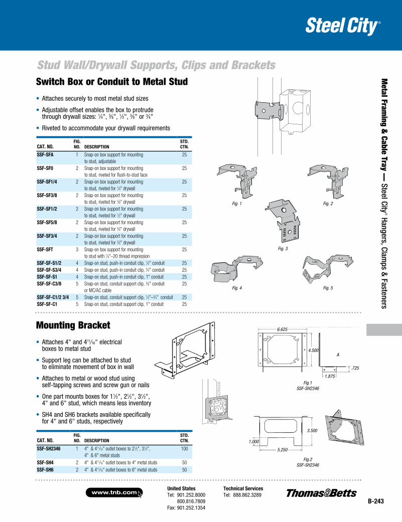
Switch Box or Conduit to Metal Stud
• Attaches securely to most metal stud sizes
• Adjustable offset enables the box to protrude through drywall sizes: 1⁄4", 3⁄8", 1⁄2", 5⁄8" or 3⁄4"
• Riveted to accommodate your drywall requirements
Cat. No.Fig. No. DesCriptioN
stD. CtN.
ssF-sH2346 1 4" & 411⁄16" outlet boxes to 21⁄2", 31⁄2", 4" & 6" metal studs
100
ssF-sH4 2 4" & 411⁄16" outlet boxes to 4" metal studs 50ssF-sH6 2 4" & 411⁄16" outlet boxes to 6" metal studs 50
Mounting Bracket
• Attaches 4" and 411⁄16" electrical boxes to metal stud
• Support leg can be attached to stud to eliminate movement of box in wall
• Attaches to metal or wood stud using self-tapping screws and screw gun or nails
• One part mounts boxes for 11⁄2", 21⁄2", 31⁄2", 4" and 6" stud, which means less inventory
• SH4 and SH6 brackets available specifically for 4" and 6" studs, respectively
Fig. 2
Fig. 3
Fig. 1
Fig. 5Fig. 4
Fig.1SSF-SH2346
5.250
1.000
3.500
6.625
4.500A
.725
1.875
Fig.2SSF-SH2346
www.tnb.comUnited StatesTel: 901.252.8000 800.816.7809Fax: 901.252.1354
Technical ServicesTel: 888.862.3289
B-244
Stud Wall/Drywall Supports, Clips and Brackets
Met
al F
ram
ing
& C
able
Tra
y —
Ste
el C
ity® H
ange
rs, C
lam
ps &
Fas
tene
rs
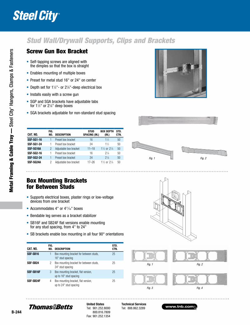
Cat. No.fig. No. DesCriptioN
stuD spaCiNg (iN.)
Box Depth (iN.)
stD. CtN.
ssf-sg1-16 1 Preset box bracket 16 11⁄2 50ssf-sg1-24 1 Preset box bracket 24 11⁄2 50ssf-sg16a 2 Adjustable box bracket 11–18 11⁄2 or 21⁄8 50ssf-sg2-16 1 Preset box bracket 16 21⁄8 50ssf-sg2-24 1 Preset box bracket 24 21⁄8 50ssf-sg24a 2 Adjustable box bracket 17–26 11⁄2 or 21⁄8 50
Cat. No.fig. No. DesCriptioN
stD. CtN.
ssf-sB16 1 Box mounting bracket for between studs, 16" stud spacing
25
ssf-sB24 2 Box mounting bracket for between studs, 24" stud spacing
25
ssf-sB16f 3 Box mounting bracket, flat version, up to 16" stud spacing
25
ssf-sB24f 4 Box mounting bracket, flat version, up to 24" stud spacing
25
Screw Gun Box Bracket
• Self-tapping screws are aligned with the dimples so that the box is straight
• Enables mounting of multiple boxes
• Preset for metal stud 16" or 24" on center
• Depth set for 11⁄2"- or 21⁄8"-deep electrical box
• Installs easily with a screw gun
• SGP and SGA brackets have adjustable tabs for 11⁄2" or 21⁄8" deep boxes
• SGA brackets adjustable for non-standard stud spacing
Box Mounting Brackets for Between Studs
• Supports electrical boxes, plaster rings or low-voltage devices from one bracket
• Accommodates 4" or 411⁄16" boxes
• Bendable leg serves as a bracket stabilizer
• SB16F and SB24F flat versions enable mounting for any stud spacing, from 4" to 24"
• SB brackets enable box mounting in all four 90° orientations
Fig. 2Fig. 1
Fig. 1 Fig. 2
Fig. 3 Fig. 4
United StatesTel: 901.252.8000 800.816.7809Fax: 901.252.1354
Technical ServicesTel: 888.862.3289www.tnb.com
B-245
Stud Wall/Drywall Supports, Clips and Brackets
Metal Fram
ing & Cable Tray —
Steel City® Hangers, Clam
ps & Fasteners
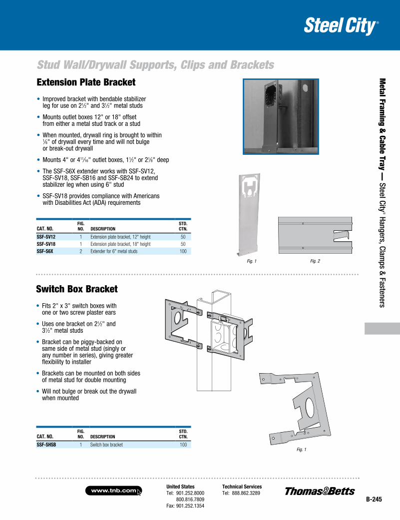
Extension Plate Bracket
• Improved bracket with bendable stabilizer leg for use on 21⁄2" and 31⁄2" metal studs
• Mounts outlet boxes 12" or 18" offset from either a metal stud track or a stud
• When mounted, drywall ring is brought to within 1⁄6" of drywall every time and will not bulge or break-out drywall
• Mounts 4" or 411⁄16" outlet boxes, 11⁄2" or 21⁄8" deep
• The SSF-S6X extender works with SSF-SV12, SSF-SV18, SSF-SB16 and SSF-SB24 to extend stabilizer leg when using 6" stud
• SSF-SV18 provides compliance with Americans with Disabilities Act (ADA) requirements
Cat. No.fig. No. DesCriptioN
stD. CtN.
ssf-sV12 1 Extension plate bracket, 12" height 50ssf-sV18 1 Extension plate bracket, 18" height 50ssf-s6x 2 Extender for 6" metal studs 100
Fig. 2
Cat. No.fig. No. DesCriptioN
stD.CtN.
ssf-shsB 1 Switch box bracket 100Fig. 1
Switch Box Bracket
• Fits 2" x 3" switch boxes with one or two screw plaster ears
• Uses one bracket on 21⁄2" and 31⁄2" metal studs
• Bracket can be piggy-backed on same side of metal stud (singly or any number in series), giving greater flexibility to installer
• Brackets can be mounted on both sides of metal stud for double mounting
• Will not bulge or break out the drywall when mounted
Fig. 1
www.tnb.comUnited StatesTel: 901.252.8000 800.816.7809Fax: 901.252.1354
Technical ServicesTel: 888.862.3289
B-246
Stud Wall/Drywall Supports, Clips and Brackets
Met
al F
ram
ing
& C
able
Tra
y —
Ste
el C
ity® H
ange
rs, C
lam
ps &
Fas
tene
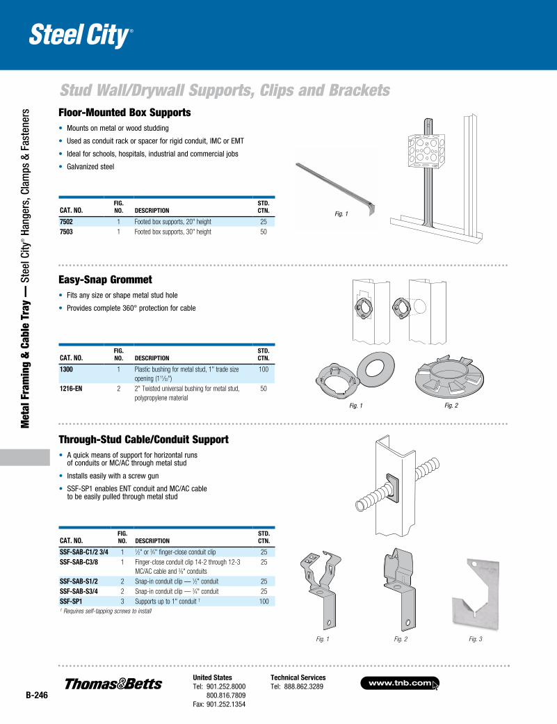
rs Floor-Mounted Box Supports• Mounts on metal or wood studding
• Used as conduit rack or spacer for rigid conduit, IMC or EMT
• Ideal for schools, hospitals, industrial and commercial jobs
• Galvanized steel
Cat. No.fig. No. DesCriptioN
stD. CtN.
7502 1 Footed box supports, 20" height 257503 1 Footed box supports, 30" height 50
Easy-Snap Grommet• Fits any size or shape metal stud hole
• Provides complete 360° protection for cable
Fig. 2Fig. 1
Through-Stud Cable/Conduit Support• A quick means of support for horizontal runs
of conduits or MC/AC through metal stud
• Installs easily with a screw gun
• SSF-SP1 enables ENT conduit and MC/AC cable to be easily pulled through metal stud
Fig. 1 Fig. 2 Fig. 3
Fig. 1
Cat. No.fig. No. DesCriptioN
stD. CtN.
1300 1 Plastic bushing for metal stud, 1" trade size opening (111⁄32")
100
1216-eN 2 2" Twisted universal bushing for metal stud, polypropylene material
50
Cat. No.fig. No. DesCriptioN
stD. CtN.
ssf-saB-C1/2 3/4 1 1⁄2" or 3⁄4" finger-close conduit clip 25ssf-saB-C3/8 1 Finger-close conduit clip 14-2 through 12-3
MC/AC cable and 3⁄8" conduits25
ssf-saB-s1/2 2 Snap-in conduit clip — 1⁄2" conduit 25ssf-saB-s3/4 2 Snap-in conduit clip — 3⁄4" conduit 25ssf-sp1 3 Supports up to 1" conduit † 100† Requires self-tapping screws to install
United StatesTel: 901.252.8000 800.816.7809Fax: 901.252.1354
Technical ServicesTel: 888.862.3289www.tnb.com
B-247
Stud Wall/Drywall Supports, Clips and Brackets
Metal Fram
ing & Cable Tray —
Steel City® Hangers, Clam
ps & Fasteners
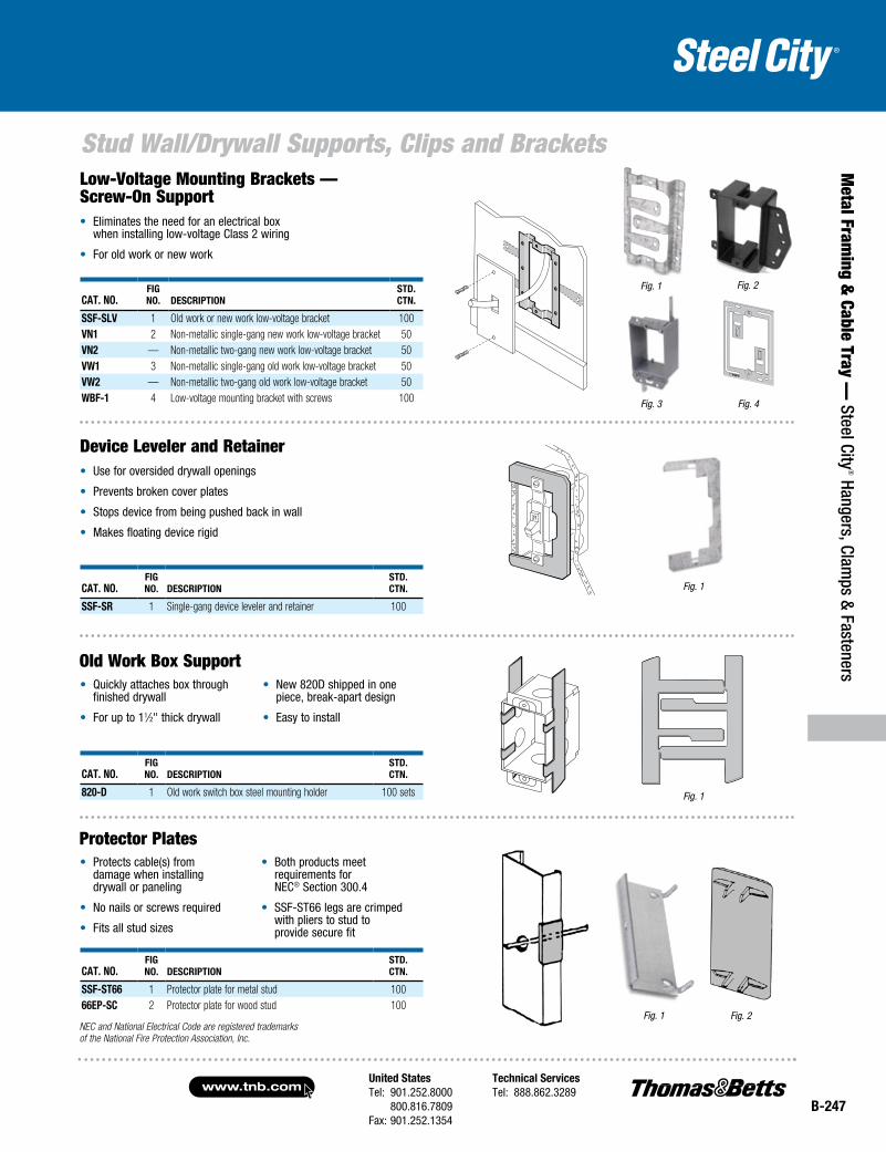
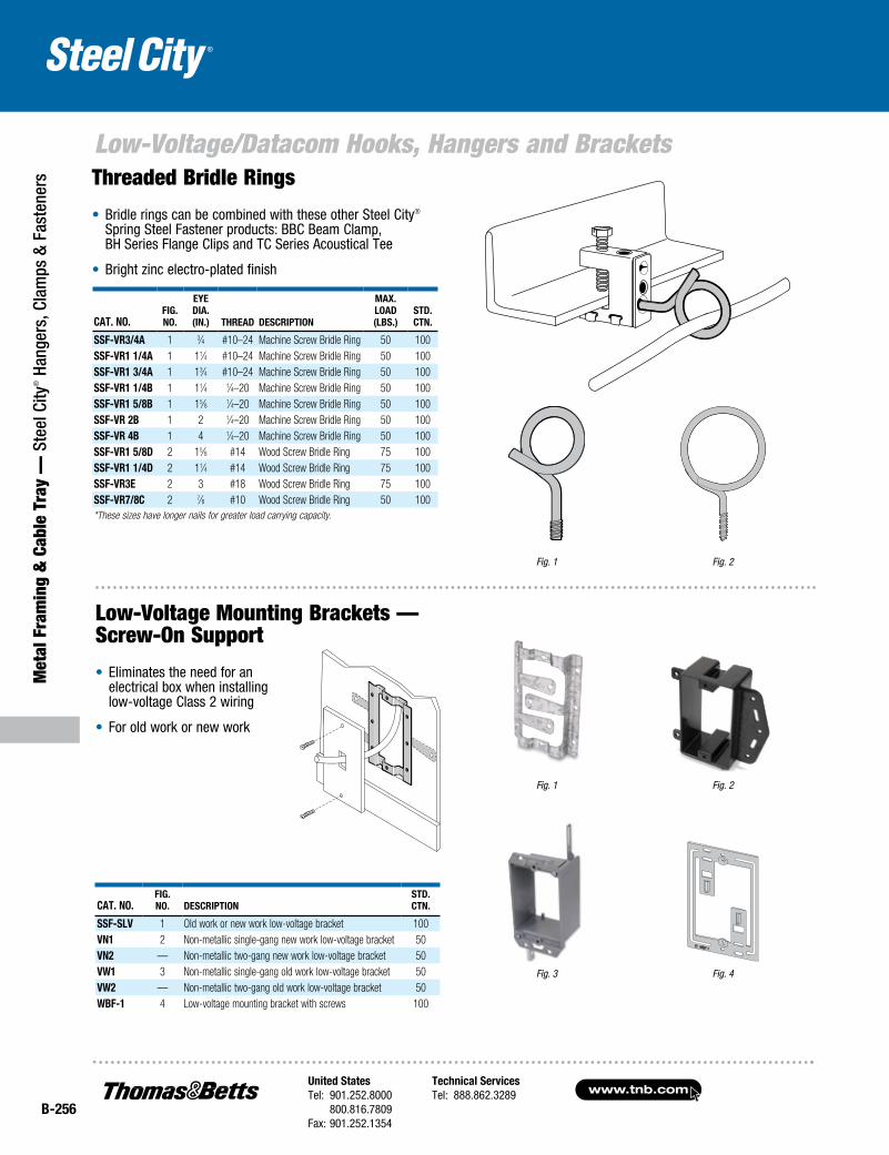
Low-Voltage Mounting Brackets — Screw-On Support• Eliminates the need for an electrical box
when installing low-voltage Class 2 wiring
• For old work or new work
Fig. 1 Fig. 2
Fig. 3 Fig. 4
Cat. No.fig No. DesCriptioN
stD. CtN.
ssf-sLV 1 Old work or new work low-voltage bracket 100VN1 2 Non-metallic single-gang new work low-voltage bracket 50VN2 — Non-metallic two-gang new work low-voltage bracket 50VW1 3 Non-metallic single-gang old work low-voltage bracket 50VW2 — Non-metallic two-gang old work low-voltage bracket 50WBf-1 4 Low-voltage mounting bracket with screws 100
Fig. 1
• Quickly attaches box through finished drywall
• For up to 11⁄2" thick drywall
• New 820D shipped in one piece, break-apart design
• Easy to install
Fig. 1Cat. No.fig No. DesCriptioN
stD. CtN.
ssf-sr 1 Single-gang device leveler and retainer 100
• Protects cable(s) from damage when installing drywall or paneling
• No nails or screws required
• Fits all stud sizes
• Both products meet requirements for NEC® Section 300.4
• SSF-ST66 legs are crimped with pliers to stud to provide secure fit
Fig. 2Fig. 1
Device Leveler and Retainer• Use for oversided drywall openings
• Prevents broken cover plates
• Stops device from being pushed back in wall
• Makes floating device rigid
Old Work Box Support
Protector Plates
Cat. No.fig No. DesCriptioN
stD. CtN.
820-D 1 Old work switch box steel mounting holder 100 sets
Cat. No.fig No. DesCriptioN
stD. CtN.
ssf-st66 1 Protector plate for metal stud 10066ep-sC 2 Protector plate for wood stud 100
NEC and National Electrical Code are registered trademarks of the National Fire Protection Association, Inc.
www.tnb.comUnited StatesTel: 901.252.8000 800.816.7809Fax: 901.252.1354
Technical ServicesTel: 888.862.3289
B-248
Met
al F
ram
ing
& C
able
Tra
y —
Ste
el C
ity® H
ange
rs, C
lam
ps &
Fas
tene
rs
Acoustical Tee Supports, Clips and Brackets
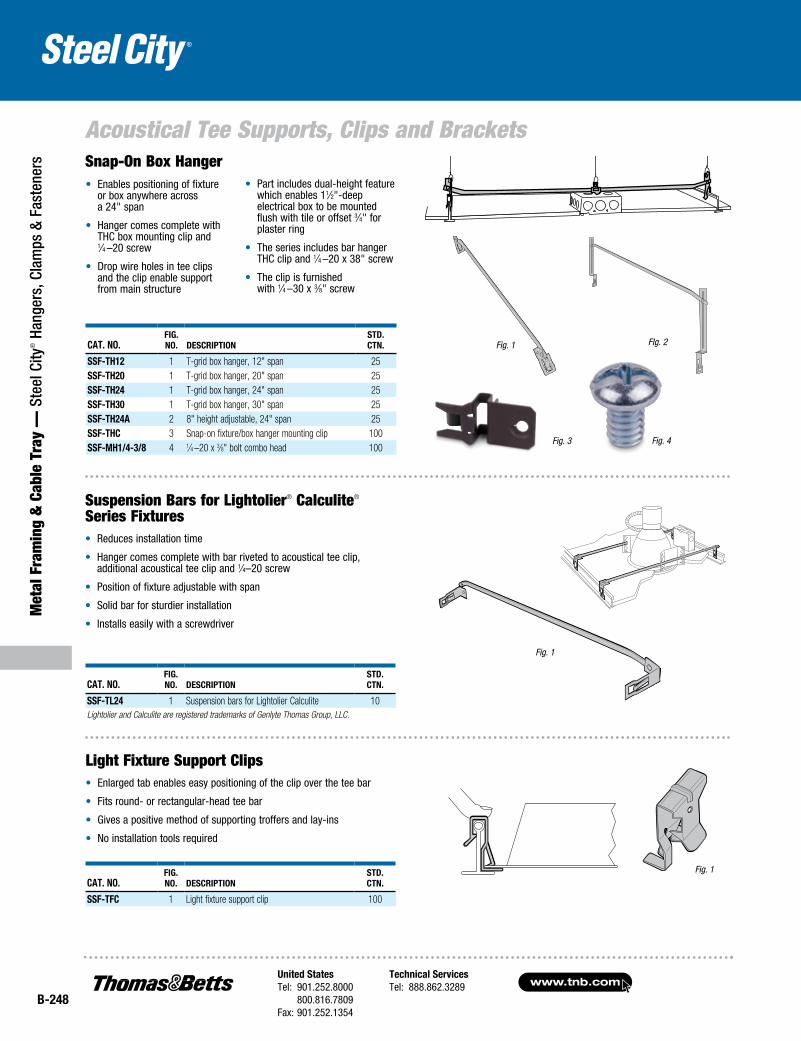
Cat. No.fig. No. DesCriptioN
stD. CtN.
ssf-tH12 1 T-grid box hanger, 12" span 25ssf-tH20 1 T-grid box hanger, 20" span 25ssf-tH24 1 T-grid box hanger, 24" span 25ssf-tH30 1 T-grid box hanger, 30" span 25ssf-tH24a 2 8" height adjustable, 24" span 25ssf-tHC 3 Snap-on fixture/box hanger mounting clip 100ssf-MH1/4-3/8 4 1⁄4 –20 x 3⁄8" bolt combo head 100
Fig. 1 FIg. 2
Fig. 3 Fig. 4
• Enables positioning of fixture or box anywhere across a 24" span
• Hanger comes complete with THC box mounting clip and 1⁄4 –20 screw
• Drop wire holes in tee clips and the clip enable support from main structure
• Part includes dual-height feature which enables 11⁄2"-deep electrical box to be mounted flush with tile or offset 3⁄4" for plaster ring
• The series includes bar hanger THC clip and 1⁄4 –20 x 38" screw
• The clip is furnished with 1⁄4 –30 x 3⁄8" screw
Cat. No.fig. No. DesCriptioN
stD. CtN.
ssf-tL24 1 Suspension bars for Lightolier Calculite 10Lightolier and Calculite are registered trademarks of Genlyte Thomas Group, LLC.
Fig. 1
Suspension Bars for Lightolier® Calculite® Series Fixtures• Reduces installation time
• Hanger comes complete with bar riveted to acoustical tee clip, additional acoustical tee clip and 1⁄4–20 screw
• Position of fixture adjustable with span
• Solid bar for sturdier installation
• Installs easily with a screwdriver
Fig. 1
Light Fixture Support Clips• Enlarged tab enables easy positioning of the clip over the tee bar
• Fits round- or rectangular-head tee bar
• Gives a positive method of supporting troffers and lay-ins
• No installation tools required
Snap-On Box Hanger
Cat. No.fig. No. DesCriptioN
stD. CtN.
ssf-tfC 1 Light fixture support clip 100
United StatesTel: 901.252.8000 800.816.7809Fax: 901.252.1354
Technical ServicesTel: 888.862.3289www.tnb.com
B-249
Metal Fram
ing & Cable Tray —
Steel City® Hangers, Clam
ps & Fasteners
Acoustical Tee Supports, Clips and Brackets
Fig. 1
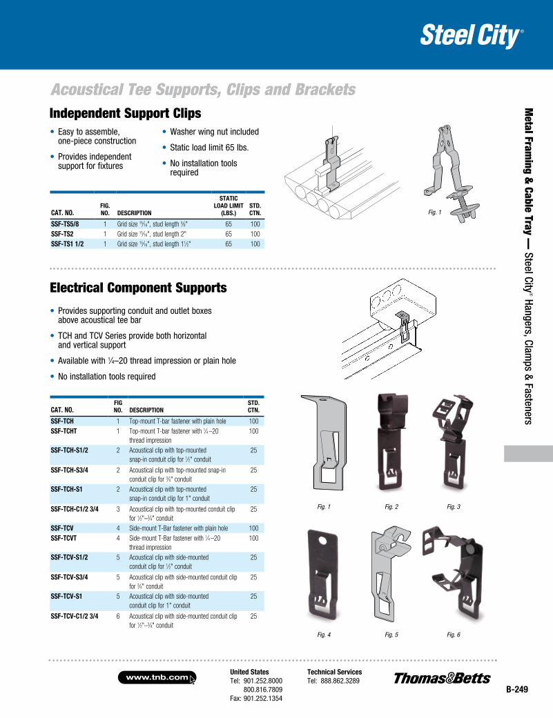
• Easy to assemble, one-piece construction
• Provides independent support for fixtures
• Washer wing nut included
• Static load limit 65 lbs.
• No installation tools required
Cat. No.fig. No. DesCriptioN
statiC LoaD LiMit
(LBs.)stD.CtN.
ssf-ts5/8 1 Grid size 15⁄16", stud length 5⁄8" 65 100ssf-ts2 1 Grid size 15⁄16", stud length 2" 65 100ssf-ts1 1/2 1 Grid size 15⁄16", stud length 11⁄2" 65 100
Fig. 4 Fig. 5 Fig. 6
Electrical Component Supports
• Provides supporting conduit and outlet boxes above acoustical tee bar
• TCH and TCV Series provide both horizontal and vertical support
• Available with 1⁄4–20 thread impression or plain hole
• No installation tools required
Fig. 1 Fig. 2 Fig. 3
Cat. No.fig No. DesCriptioN
stD. CtN.
ssf-tCH 1 Top-mount T-bar fastener with plain hole 100ssf-tCHt 1 Top-mount T-bar fastener with 1⁄4 –20
thread impression100
ssf-tCH-s1/2 2 Acoustical clip with top-mounted snap-in conduit clip for 1⁄2" conduit
25
ssf-tCH-s3/4 2 Acoustical clip with top-mounted snap-in conduit clip for 3⁄4" conduit
25
ssf-tCH-s1 2 Acoustical clip with top-mounted snap-in conduit clip for 1" conduit
25
ssf-tCH-C1/2 3/4 3 Acoustical clip with top-mounted conduit clip for 1⁄2"–3⁄4" conduit
25
ssf-tCV 4 Side-mount T-Bar fastener with plain hole 100ssf-tCVt 4 Side-mount T-Bar fastener with 1⁄4 –20
thread impression100
ssf-tCV-s1/2 5 Acoustical clip with side-mounted conduit clip for 1⁄2" conduit
25
ssf-tCV-s3/4 5 Acoustical clip with side-mounted conduit clip for 3⁄4" conduit
25
ssf-tCV-s1 5 Acoustical clip with side-mounted conduit clip for 1" conduit
25
ssf-tCV-C1/2 3/4 6 Acoustical clip with side-mounted conduit clip for 1⁄2"–3⁄4" conduit
25
Independent Support Clips
www.tnb.comUnited StatesTel: 901.252.8000 800.816.7809Fax: 901.252.1354
Technical ServicesTel: 888.862.3289
B-250
Acoustical Tee Supports, Clips and Brackets
Met
al F
ram
ing
& C
able
Tra
y —
Ste
el C
ity® H
ange
rs, C
lam
ps &
Fas
tene
rs
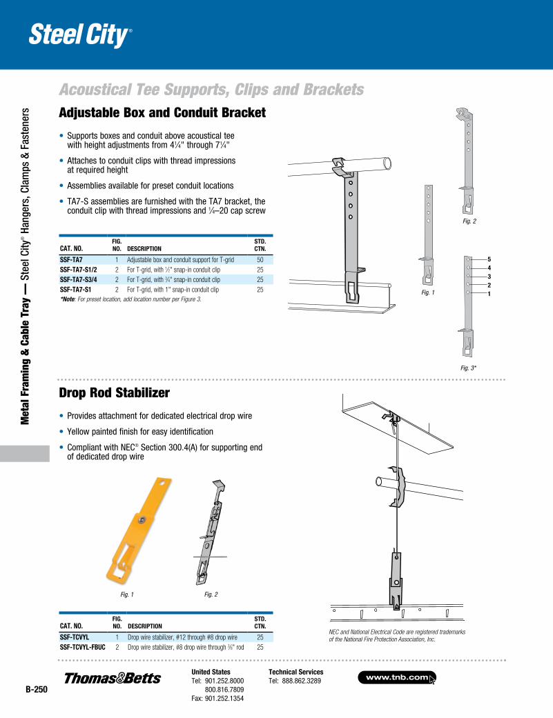
Cat. No.Fig. No. DesCriptioN
stD. CtN.
ssF-ta7 1 Adjustable box and conduit support for T-grid 50ssF-ta7-s1/2 2 For T-grid, with 1⁄2" snap-in conduit clip 25ssF-ta7-s3/4 2 For T-grid, with 3⁄4" snap-in conduit clip 25ssF-ta7-s1 2 For T-grid, with 1" snap-in conduit clip 25*Note: For preset location, add location number per Figure 3.
Adjustable Box and Conduit Bracket
• Supports boxes and conduit above acoustical tee with height adjustments from 41⁄4" through 71⁄4"
• Attaches to conduit clips with thread impressions at required height
• Assemblies available for preset conduit locations
• TA7-S assemblies are furnished with the TA7 bracket, the conduit clip with thread impressions and 1⁄4–20 cap screw
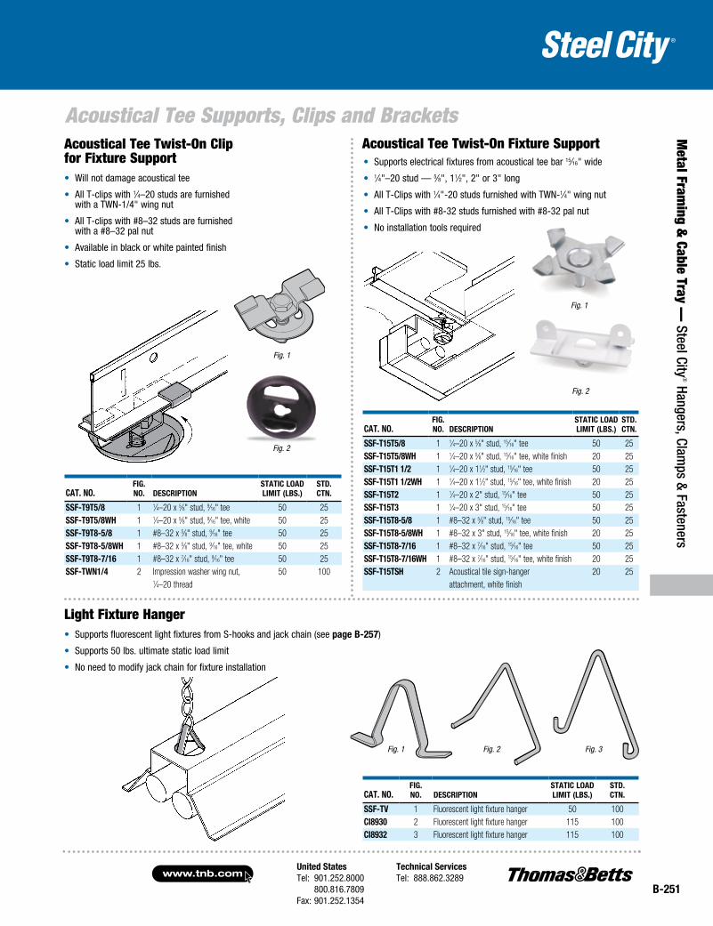
Cat. No.Fig. No. DesCriptioN
stD. CtN.
ssF-tCVYL 1 Drop wire stabilizer, #12 through #8 drop wire 25ssF-tCVYL-FBUC 2 Drop wire stabilizer, #8 drop wire through 3⁄8" rod 25
Fig. 1
Drop Rod Stabilizer
• Provides attachment for dedicated electrical drop wire
• Yellow painted finish for easy identification
• Compliant with NEC® Section 300.4(A) for supporting end of dedicated drop wire
Fig. 2
Fig. 2
Fig. 1
Fig. 3*
54321
NEC and National Electrical Code are registered trademarks of the National Fire Protection Association, Inc.
United StatesTel: 901.252.8000 800.816.7809Fax: 901.252.1354
Technical ServicesTel: 888.862.3289www.tnb.com
B-251
Acoustical Tee Supports, Clips and Brackets
Metal Fram
ing & Cable Tray —
Steel City® Hangers, Clam
ps & Fasteners
Cat. No.Fig. No. DesCriptioN
statiC LoaD Limit (LBs.)
stD. CtN.
ssF-t9t5/8 1 1⁄4–20 x 5⁄8" stud, 9⁄16" tee 50 25ssF-t9t5/8WH 1 1⁄4–20 x 5⁄8" stud, 9⁄16" tee, white 50 25ssF-t9t8-5/8 1 #8–32 x 5⁄8" stud, 9⁄16" tee 50 25ssF-t9t8-5/8WH 1 #8–32 x 5⁄8" stud, 9⁄16" tee, white 50 25ssF-t9t8-7/16 1 #8–32 x 7⁄16" stud, 9⁄16" tee 50 25ssF-tWN1/4 2 Impression washer wing nut, 50 100
1⁄4–20 thread
Fig. 2
Fig. 1
Acoustical Tee Twist-On Clip for Fixture Support• Will not damage acoustical tee
• All T-clips with 1⁄4–20 studs are furnished with a TWN-1/4" wing nut
• All T-clips with #8–32 studs are furnished with a #8–32 pal nut
• Available in black or white painted finish
• Static load limit 25 lbs.
Fig. 1
Fig. 2
Light Fixture Hanger• Supports fluorescent light fixtures from S-hooks and jack chain (see page B-257)
• Supports 50 lbs. ultimate static load limit
• No need to modify jack chain for fixture installation
Acoustical Tee Twist-On Fixture Support• Supports electrical fixtures from acoustical tee bar 15⁄16" wide
• 1⁄4"–20 stud — 5⁄8", 11⁄2", 2" or 3" long
• All T-Clips with 1⁄4"-20 studs furnished with TWN-1⁄4" wing nut
• All T-Clips with #8-32 studs furnished with #8-32 pal nut
• No installation tools required
Cat. No.Fig. No. DesCriptioN
statiC LoaD Limit (LBs.)
stD. CtN.
ssF-t15t5/8 1 1⁄4–20 x 5⁄8" stud, 15⁄16" tee 50 25ssF-t15t5/8WH 1 1⁄4–20 x 5⁄8" stud, 15⁄16" tee, white finish 20 25ssF-t15t1 1/2 1 1⁄4–20 x 11⁄2" stud, 15⁄16" tee 50 25ssF-t15t1 1/2WH 1 1⁄4–20 x 11⁄2" stud, 15⁄16" tee, white finish 20 25ssF-t15t2 1 1⁄4–20 x 2" stud, 15⁄16" tee 50 25ssF-t15t3 1 1⁄4–20 x 3" stud, 15⁄16" tee 50 25ssF-t15t8-5/8 1 #8–32 x 5⁄8" stud, 15⁄16" tee 50 25ssF-t15t8-5/8WH 1 #8–32 x 3" stud, 15⁄16" tee, white finish 20 25ssF-t15t8-7/16 1 #8–32 x 7⁄16" stud, 15⁄16" tee 50 25ssF-t15t8-7/16WH 1 #8–32 x 7⁄16" stud, 15⁄16" tee, white finish 20 25ssF-t15tsH 2 Acoustical tile sign-hanger 20 25
attachment, white finish
Cat. No.Fig. No. DesCriptioN
statiC LoaD Limit (LBs.)
stD. CtN.
ssF-tV 1 Fluorescent light fixture hanger 50 100Ci8930 2 Fluorescent light fixture hanger 115 100Ci8932 3 Fluorescent light fixture hanger 115 100
Fig. 1 Fig. 2 Fig. 3
www.tnb.comUnited StatesTel: 901.252.8000 800.816.7809Fax: 901.252.1354
Technical ServicesTel: 888.862.3289
B-252
Met
al F
ram
ing
& C
able
Tra
y —
Ste
el C
ity® H
ange
rs, C
lam
ps &
Fas
tene
rs
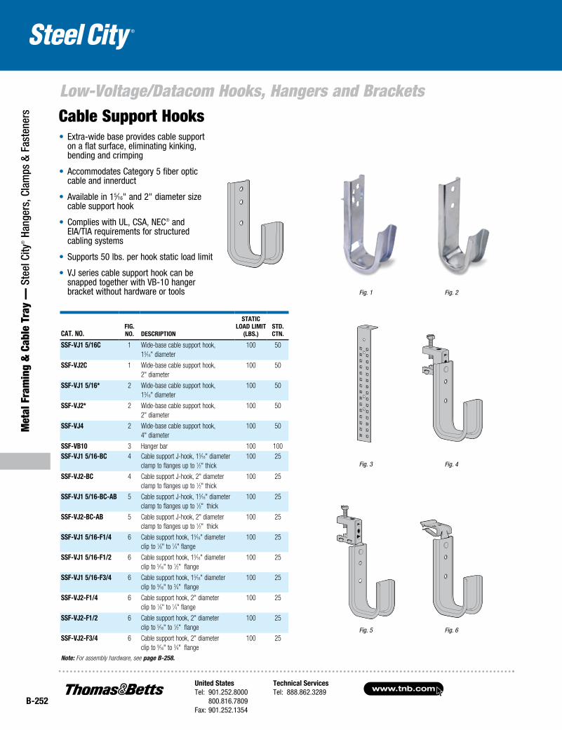
Low-Voltage/Datacom Hooks, Hangers and Brackets
Cat. No.Fig. No. DesCriptioN
statiC LoaD Limit
(LBs.)stD. CtN.
ssF-VJ1 5/16C 1 Wide-base cable support hook, 15⁄16" diameter
100 50
ssF-VJ2C 1 Wide-base cable support hook, 2" diameter
100 50
ssF-VJ1 5/16* 2 Wide-base cable support hook, 15⁄16" diameter
100 50
ssF-VJ2* 2 Wide-base cable support hook, 2" diameter
100 50
ssF-VJ4 2 Wide-base cable support hook, 4" diameter
100 50
ssF-VB10 3 Hanger bar 100 100ssF-VJ1 5/16-BC 4 Cable support J-hook, 15⁄16" diameter
clamp to flanges up to 1⁄2" thick100 25
ssF-VJ2-BC 4 Cable support J-hook, 2" diameter clamp to flanges up to 1⁄2" thick
100 25
ssF-VJ1 5/16-BC-aB 5 Cable support J-hook, 15⁄16" diameter clamp to flanges up to 1⁄2" thick
100 25
ssF-VJ2-BC-aB 5 Cable support J-hook, 2" diameter clamp to flanges up to 1⁄2" thick
100 25
ssF-VJ1 5/16-F1/4 6 Cable support hook, 15⁄16" diameter clip to 1⁄8" to 1⁄4" flange
100 25
ssF-VJ1 5/16-F1/2 6 Cable support hook, 15⁄16" diameter clip to 5⁄16" to 1⁄2" flange
100 25
ssF-VJ1 5/16-F3/4 6 Cable support hook, 15⁄16" diameter clip to 9⁄16" to 3⁄4" flange
100 25
ssF-VJ2-F1/4 6 Cable support hook, 2" diameter clip to 1⁄8" to 1⁄4" flange
100 25
ssF-VJ2-F1/2 6 Cable support hook, 2" diameter clip to 5⁄16" to 1⁄2" flange
100 25
ssF-VJ2-F3/4 6 Cable support hook, 2" diameterclip to 9⁄16" to 3⁄4" flange
100 25
Note: For assembly hardware, see page B-258.
Cable Support Hooks• Extra-wide base provides cable support
on a flat surface, eliminating kinking, bending and crimping
• Accommodates Category 5 fiber optic cable and innerduct
• Available in 15⁄16" and 2" diameter size cable support hook
• Complies with UL, CSA, NEC® and EIA/TIA requirements for structured cabling systems
• Supports 50 lbs. per hook static load limit
• VJ series cable support hook can be snapped together with VB-10 hanger bracket without hardware or tools
Fig. 4
Fig. 5 Fig. 6
Fig. 1
Fig. 3
Fig. 2
United StatesTel: 901.252.8000 800.816.7809Fax: 901.252.1354
Technical ServicesTel: 888.862.3289www.tnb.com
B-253
Metal Fram
ing & Cable Tray —
Steel City® Hangers, Clam
ps & Fasteners
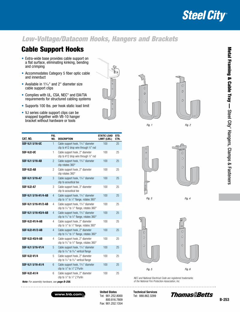
Low-Voltage/Datacom Hooks, Hangers and Brackets
• Extra-wide base provides cable support on a flat surface, eliminating kinking, bending and crimping
• Accommodates Category 5 fiber optic cable and innerduct
• Available in 15⁄16" and 2" diameter size cable support clips
• Complies with UL, CSA, NEC® and EIA/TIA requirements for structured cabling systems
• Supports 100 lbs. per hook static load limit
• VJ series cable support clips can be snapped together with VB-10 hanger bracket without hardware or tools
Cable Support Hooks
Cat. No.Fig. No. DesCriptioN
statiC LoaD Limit (LBs.)
stD. CtN.
ssF-VJ1 5/16-UC 1 Cable support hook, 15⁄16" diameterclip to #12 drop wire through 3⁄8" rod
100 25
ssF-VJ2-UC 1 Cable support hook, 2" diameterclip to #12 drop wire through 3⁄8" rod
100 25
ssF-VJ1 5/16-aB 2 Cable support hook, 15⁄16" diameterclip rotates 360°
100 25
ssF-VJ2-aB 2 Cable support hook, 2" diameter clip rotates 360°
100 25
ssF-VJ1 5/16-a7 3 Cable support hook, 15⁄16" diameterclip to acoustical tee
100 25
ssF-VJ2-a7 3 Cable support hook, 3" diameter clip to acoustical tee
100 25
ssF-VJ1 5/16-H1/4-aB 4 Cable support hook, 15⁄16" diameterclip to 1⁄8" to 1⁄4" flange, rotates 360°
100 25
ssF-VJ1 5/16-H1/2-aB 4 Cable support hook, 15⁄16" diameterclip to 5⁄16" to 1⁄2" flange, rotates 360°
100 25
ssF-VJ1 5/16-H3/4-aB 4 Cable support hook, 15⁄16" diameterclip to 9⁄16" to 3⁄4" flange, rotates 360°
100 25
ssF-VJ2-H1/4-aB 4 Cable support hook, 2" diameterclip to 1⁄8" to 1⁄4" flange, rotates 360°
100 25
ssF-VJ2-H1/2-aB 4 Cable support hook, 2" diameterclip to 5⁄16" to 1⁄2" flange, rotates 360°
100 25
ssF-VJ2-H3/4-aB 4 Cable support hook, 2" diameterclip to 9⁄16" to 3⁄4" flange, rotates 360°
100 25
ssF-VJ1 5/16-V1/4 5 Cable support hook, 15⁄16" diameterclip to 3⁄32" to 9⁄32" vertical flange
100 25
ssF-VJ2-V1/4 5 Cable support hook, 2" diameterclip to 3⁄32" to 9⁄32" vertical flange
100 25
ssF-VJ1 5/16-a1/4 6 Cable support hook, 15⁄16" diameterclip to 1⁄6" to 1⁄4" Z Purlin
100 25
ssF-VJ2-a1/4 6 Cable support hook, 2" diameterclip to 1⁄6" to 1⁄4" Z Purlin
100 25
Note: For assembly hardware, see page B-258.
Fig. 4
Fig. 5 Fig. 6
Fig. 1 Fig. 2
Fig. 3
NEC and National Electrical Code are registered trademarks of the National Fire Protection Association, Inc.
www.tnb.comUnited StatesTel: 901.252.8000 800.816.7809Fax: 901.252.1354
Technical ServicesTel: 888.862.3289
B-254
Low-Voltage/Datacom Hooks, Hangers and Brackets
Met
al F
ram
ing
& C
able
Tra
y —
Ste
el C
ity® H
ange
rs, C
lam
ps &
Fas
tene
rs
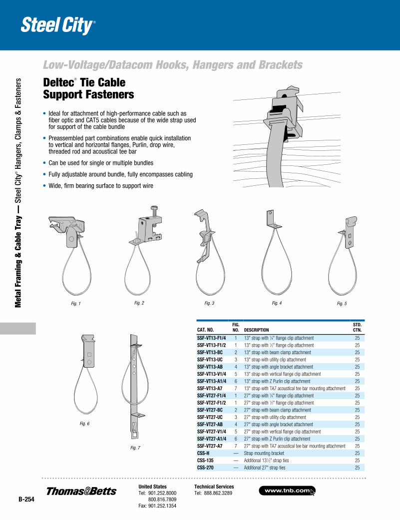
Fig. 2Fig. 1
• Ideal for attachment of high-performance cable such as fiber optic and CAT5 cables because of the wide strap used for support of the cable bundle
• Preassembled part combinations enable quick installation to vertical and horizontal flanges, Purlin, drop wire, threaded rod and acoustical tee bar
• Can be used for single or multiple bundles
• Fully adjustable around bundle, fully encompasses cabling
• Wide, firm bearing surface to support wire
Cat. No.fig. No. DesCriptioN
stD. CtN.
ssf-Vt13-f1/4 1 13" strap with 1⁄4" flange clip attachment 25ssf-Vt13-f1/2 1 13" strap with 1⁄2" flange clip attachment 25ssf-Vt13-BC 2 13" strap with beam clamp attachment 25ssf-Vt13-UC 3 13" strap with utility clip attachment 25ssf-Vt13-aB 4 13" strap with angle bracket attachment 25ssf-Vt13-V1/4 5 13" strap with vertical flange clip attachment 25ssf-Vt13-a1/4 6 13" strap with Z Purlin clip attachment 25ssf-Vt13-a7 7 13" strap with TA7 acoustical tee bar mounting attachment 25ssf-Vt27-f1/4 1 27" strap with 1⁄4" flange clip attachment 25ssf-Vt27-f1/2 1 27" strap with 1⁄2" flange clip attachment 25ssf-Vt27-BC 2 27" strap with beam clamp attachment 25ssf-Vt27-UC 3 27" strap with utility clip attachment 25ssf-Vt27-aB 4 27" strap with angle bracket attachment 25ssf-Vt27-V1/4 5 27" strap with vertical flange clip attachment 25ssf-Vt27-a1/4 6 27" strap with Z Purlin clip attachment 25ssf-Vt27-a7 7 27" strap with TA7 acoustical tee bar mounting attachment 25Css-H — Strap mounting bracket 25Css-135 — Additional 131⁄2" strap ties 25Css-270 — Additional 27" strap ties 25
Fig. 3 Fig. 4
Fig. 6
Fig. 5
Deltec® Tie Cable Support Fasteners
Fig. 7
United StatesTel: 901.252.8000 800.816.7809Fax: 901.252.1354
Technical ServicesTel: 888.862.3289www.tnb.com
B-255
Low-Voltage/Datacom Hooks, Hangers and Brackets
Metal Fram
ing & Cable Tray —
Steel City® Hangers, Clam
ps & Fasteners
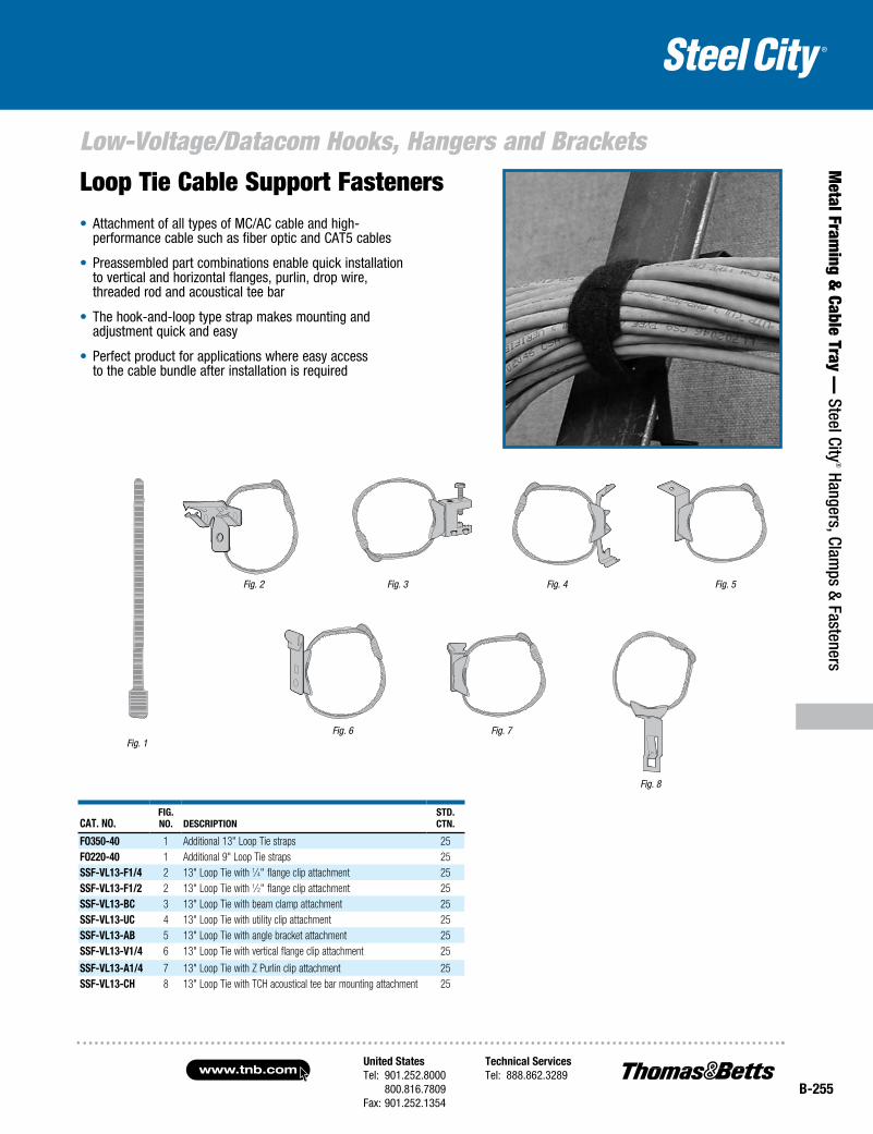
Fig. 2
Fig. 1
• Attachment of all types of MC/AC cable and high-performance cable such as fiber optic and CAT5 cables
• Preassembled part combinations enable quick installation to vertical and horizontal flanges, purlin, drop wire, threaded rod and acoustical tee bar
• The hook-and-loop type strap makes mounting and adjustment quick and easy
• Perfect product for applications where easy access to the cable bundle after installation is required
Cat. No.fig. No. DesCriptioN
stD. CtN.
fo350-40 1 Additional 13" Loop Tie straps 25fo220-40 1 Additional 9" Loop Tie straps 25ssf-VL13-f1/4 2 13" Loop Tie with 1⁄4" flange clip attachment 25ssf-VL13-f1/2 2 13" Loop Tie with 1⁄2" flange clip attachment 25ssf-VL13-BC 3 13" Loop Tie with beam clamp attachment 25ssf-VL13-UC 4 13" Loop Tie with utility clip attachment 25ssf-VL13-aB 5 13" Loop Tie with angle bracket attachment 25ssf-VL13-V1/4 6 13" Loop Tie with vertical flange clip attachment 25
ssf-VL13-a1/4 7 13" Loop Tie with Z Purlin clip attachment 25ssf-VL13-CH 8 13" Loop Tie with TCH acoustical tee bar mounting attachment 25
Fig. 3 Fig. 4
Fig. 6 Fig. 7
Fig. 5
Fig. 8
Loop Tie Cable Support Fasteners
www.tnb.comUnited StatesTel: 901.252.8000 800.816.7809Fax: 901.252.1354
Technical ServicesTel: 888.862.3289
B-256
Met
al F
ram
ing
& C
able
Tra
y —
Ste
el C
ity® H
ange
rs, C
lam
ps &
Fas
tene
rs
Low-Voltage/Datacom Hooks, Hangers and BracketsThreaded Bridle Rings
• Bridle rings can be combined with these other Steel City® Spring Steel Fastener products: BBC Beam Clamp, BH Series Flange Clips and TC Series Acoustical Tee
• Bright zinc electro-plated finish
Cat. No.Fig. No.
EyE Dia. (iN.) thrEaD DESCriPtioN
Max. LoaD (LBS.)
StD. CtN.
SSF-Vr3/4a 1 3⁄4 #10–24 Machine Screw Bridle Ring 50 100SSF-Vr1 1/4a 1 11⁄4 #10–24 Machine Screw Bridle Ring 50 100SSF-Vr1 3/4a 1 13⁄4 #10–24 Machine Screw Bridle Ring 50 100SSF-Vr1 1/4B 1 11⁄4 1⁄4–20 Machine Screw Bridle Ring 50 100SSF-Vr1 5/8B 1 15⁄8 1⁄4–20 Machine Screw Bridle Ring 50 100SSF-Vr 2B 1 2 1⁄4–20 Machine Screw Bridle Ring 50 100SSF-Vr 4B 1 4 1⁄4–20 Machine Screw Bridle Ring 50 100SSF-Vr1 5/8D 2 15⁄8 #14 Wood Screw Bridle Ring 75 100SSF-Vr1 1/4D 2 11⁄4 #14 Wood Screw Bridle Ring 75 100SSF-Vr3E 2 3 #18 Wood Screw Bridle Ring 75 100SSF-Vr7/8C 2 7⁄8 #10 Wood Screw Bridle Ring 50 100*These sizes have longer nails for greater load carrying capacity.
Low-Voltage Mounting Brackets — Screw-On Support
• Eliminates the need for an electrical box when installing low-voltage Class 2 wiring
• For old work or new work
Cat. No.Fig. No. DESCriPtioN
StD. CtN.
SSF-SLV 1 Old work or new work low-voltage bracket 100VN1 2 Non-metallic single-gang new work low-voltage bracket 50VN2 — Non-metallic two-gang new work low-voltage bracket 50VW1 3 Non-metallic single-gang old work low-voltage bracket 50VW2 — Non-metallic two-gang old work low-voltage bracket 50WBF-1 4 Low-voltage mounting bracket with screws 100
Fig. 2Fig. 1
Fig. 1 Fig. 2
Fig. 3 Fig. 4
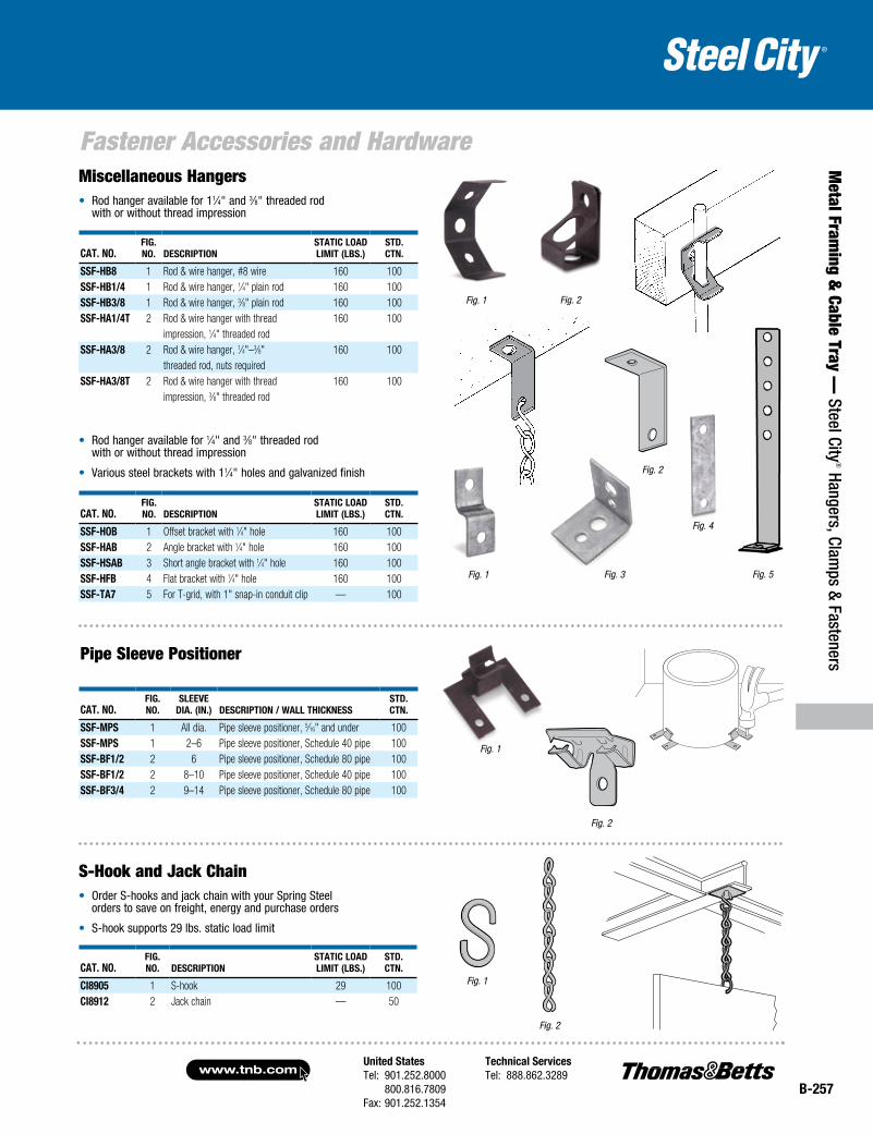
United StatesTel: 901.252.8000 800.816.7809Fax: 901.252.1354
Technical ServicesTel: 888.862.3289www.tnb.com
B-257
Metal Fram
ing & Cable Tray —
Steel City® Hangers, Clam
ps & Fasteners
Fastener Accessories and HardwareMiscellaneous Hangers• Rod hanger available for 11⁄4" and 3⁄8" threaded rod
with or without thread impression
• Rod hanger available for 1⁄4" and 3⁄8" threaded rod with or without thread impression
• Various steel brackets with 11⁄4" holes and galvanized finish
Cat. No.Fig. No. DESCriPtioN
StatiC LoaD LiMit (LBS.)
StD. CtN.
SSF-hB8 1 Rod & wire hanger, #8 wire 160 100SSF-hB1/4 1 Rod & wire hanger, 1⁄4" plain rod 160 100SSF-hB3/8 1 Rod & wire hanger, 3⁄8" plain rod 160 100SSF-ha1/4t 2 Rod & wire hanger with thread 160 100
impression, 1⁄4" threaded rodSSF-ha3/8 2 Rod & wire hanger, 1⁄4"–3⁄8" 160 100
threaded rod, nuts requiredSSF-ha3/8t 2 Rod & wire hanger with thread 160 100
impression, 3⁄8" threaded rod
Cat. No.Fig. No. DESCriPtioN
StatiC LoaD LiMit (LBS.)
StD. CtN.
SSF-hoB 1 Offset bracket with 1⁄4" hole 160 100SSF-haB 2 Angle bracket with 1⁄4" hole 160 100SSF-hSaB 3 Short angle bracket with 1⁄4" hole 160 100SSF-hFB 4 Flat bracket with 1⁄4" hole 160 100SSF-ta7 5 For T-grid, with 1" snap-in conduit clip — 100
Pipe Sleeve Positioner
Cat. No.Fig. No.
SLEEVE Dia. (iN.) DESCriPtioN / WaLL thiCkNESS
StD. CtN.
SSF-MPS 1 All dia. Pipe sleeve positioner, 5⁄16" and under 100SSF-MPS 1 2–6 Pipe sleeve positioner, Schedule 40 pipe 100SSF-BF1/2 2 6 Pipe sleeve positioner, Schedule 80 pipe 100SSF-BF1/2 2 8–10 Pipe sleeve positioner, Schedule 40 pipe 100SSF-BF3/4 2 9–14 Pipe sleeve positioner, Schedule 80 pipe 100
S-Hook and Jack Chain• Order S-hooks and jack chain with your Spring Steel
orders to save on freight, energy and purchase orders
• S-hook supports 29 lbs. static load limit
Cat. No.Fig. No. DESCriPtioN
StatiC LoaD LiMit (LBS.)
StD. CtN.
Ci8905 1 S-hook 29 100Ci8912 2 Jack chain — 50
Fig. 2Fig. 1
Fig. 1 Fig. 3 Fig. 5
Fig. 4
Fig. 2
Fig. 1
Fig. 2
Fig. 1
Fig. 2
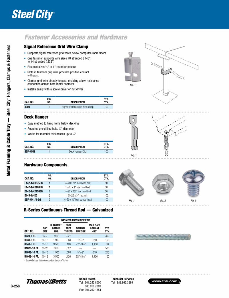
www.tnb.comUnited StatesTel: 901.252.8000 800.816.7809Fax: 901.252.1354
Technical ServicesTel: 888.862.3289
B-258
Met
al F
ram
ing
& C
able
Tra
y —
Ste
el C
ity® H
ange
rs, C
lam
ps &
Fas
tene
rs
Fastener Accessories and HardwareSignal Reference Grid Wire Clamp• Supports signal reference grid wires below computer-room floors
• One fastener supports wire sizes #8 stranded (.146") to #4 stranded (.232")
• Fits post sizes 3⁄4" to 1" round or square
• Slots in fastener grip wire provides positive contact with post
• Clamps grid wire directly to post, enabling a low-resistance connection across bare metal contacts
• Installs easily with a screw driver or nut driver
Cat. No.Fig. No. DesCriptioN
stD. CtN.
3900 1 Signal reference grid wire clamp 100
Cat. No.Fig. No. DesCriptioN
stD. CtN.
ssF-MNH 1 Deck Hanger Clip 100
Cat. No.Fig. No. DesCriptioN
stD. CtN.
e142-1/4x075eg 1 1⁄4–20 x 3⁄4" hex head bolt 50e142-1/4x100eg 1 1⁄4–20 x 1" hex head bolt 50e142-1/4x150eg 1 1⁄4–20 x 11⁄2" hex head bolt 50e145-1/4eg 2 1⁄4–20 x 1⁄4" hex nut 100ssF-MH1/4-3/8 3 1⁄4–20 x 3⁄8" bolt combo head 100
Fig. 1
Deck Hanger• Easy method to hang items below decking
• Requires pre-drilled hole, 1⁄4" diameter
• Works for material thicknesses up to 1⁄8"
Hardware Components
Fig. 1
Fig. 1 Fig. 2 Fig. 3
R-Series Continuous Thread Rod — Galvanized
Data For pressure pipiNg
Cat. No.roD size
ultiMate ‡ loaD iN
lBs.
root area
tHreaDNoMiNal pipe size
Max. saFe loaD at
450°stD. CtN.
r628-6 Ft. 1⁄4–20 900 .027 — — 300r638-6 Ft. 3⁄8–16 1,900 .068 3⁄4"–2" 610 150r648-6 Ft. 1⁄2–13 3,500 .126 21⁄2"–31⁄2" 1,130 60r1028-10 Ft. 1⁄4–20 900 .027 — — 500r1038-10 Ft. 3⁄8–16 1,900 .068 3⁄4"–2" 610 250r1048-10 Ft. 1⁄2–13 3,500 .126 21⁄2"–31⁄2" 1,130 100‡ Load Ratings based on safely factor of three.