Steel balcony connections to concrete slabs using ...
20
OISD Technology Department of Architecture, School of the Built Environment, Oxford Brookes University, Gipsy Lane Campus Oxford OX3 0BP Phone: +44 (0) 1865 483208, Fax +44 (0) 1865 483298, Email [email protected] http://www.brookes.ac.uk/schools/be/oisd/act/technology/index.html! Report 120927SCH Steel balcony connections to concrete slabs using different connection methods Client Schock Ltd. Oxford 27th th September 2012 (updated December 2012) Authors C C Kendrick and Xiaoxin Wang
Transcript of Steel balcony connections to concrete slabs using ...
OISD Technology Department of Architecture, School of the Built Environment, Oxford Brookes University, Gipsy Lane Campus Oxford OX3 0BP
Phone: +44 (0) 1865 483208, Fax +44 (0) 1865 483298, Email [email protected] http://www.brookes.ac.uk/schools/be/oisd/act/technology/index.html!
Report 120927SCH
Steel balcony connections to concrete slabs using different connection methods
Client
Schock Ltd.
Oxford 27thth September 2012 (updated December 2012)
Authors C C Kendrick and Xiaoxin Wang
803513/02.2013/GB/130047
Steel balcony connections to concrete slabs using different connection methods 1
1. Objective
The aims of this investigation were:
a) To determine the heat loss, minimum surface temperature and hence temperature factor (fRSi) resulting from use of Schock Isokorb Type KS14 units connecting a steel balcony support to a concrete floor slab.
b) To compare the calculated performance with that of structurally equivalent solutions such as with of no thermal isolation, and thermal break pads between a welded endplate and the concrete slab.
Calculation was by means of three-dimensional finite difference analysis using SOLIDO software from Physibel.
2. Description
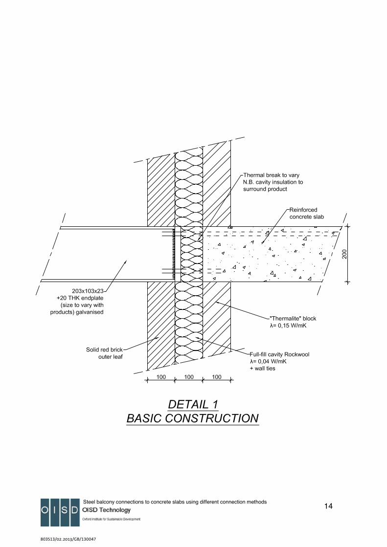
Four situations were modelled, connecting a steel balcony support bracket to a 200mm intermediate floor slab in masonry wall construction:
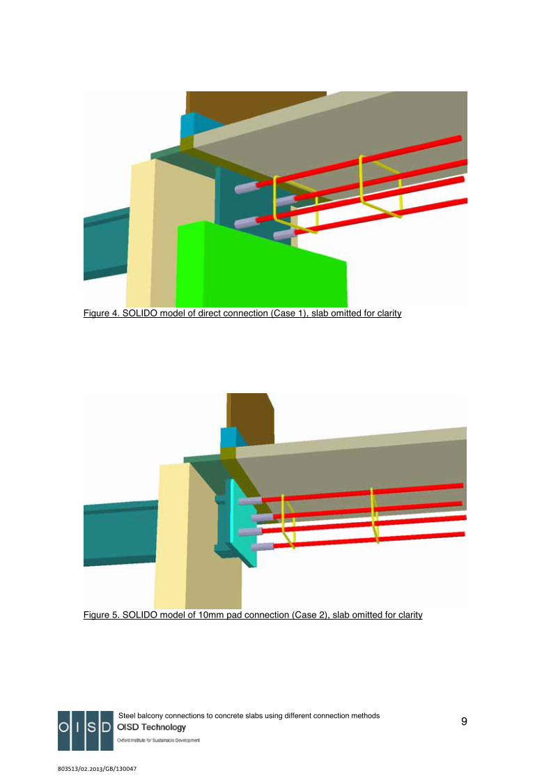
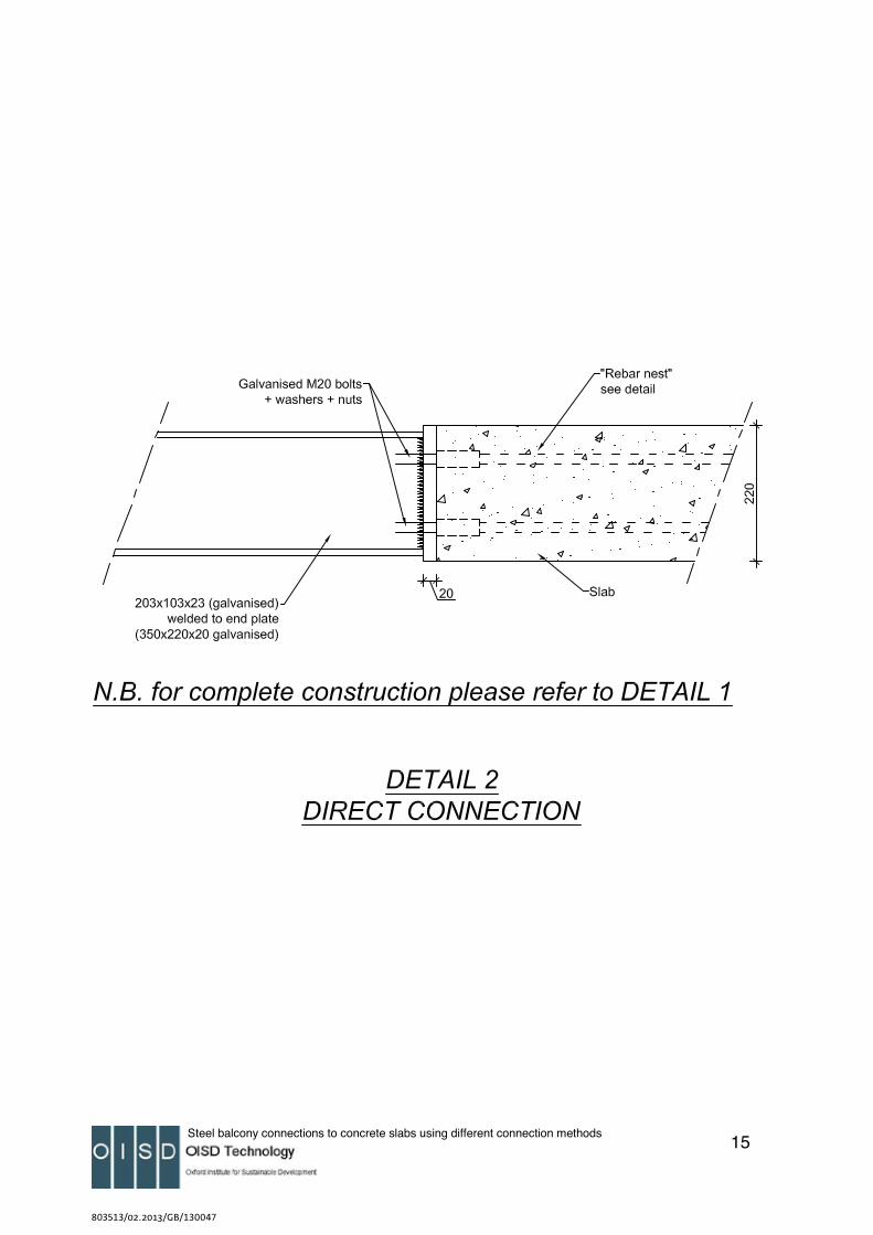
• Case 1. Direct connection of balcony support bracket to concrete floor slab
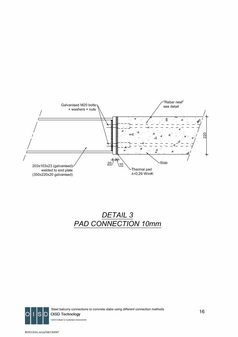
• Case 2. 10mm ‘thermal pad’ using welded endplate on balcony support bracket
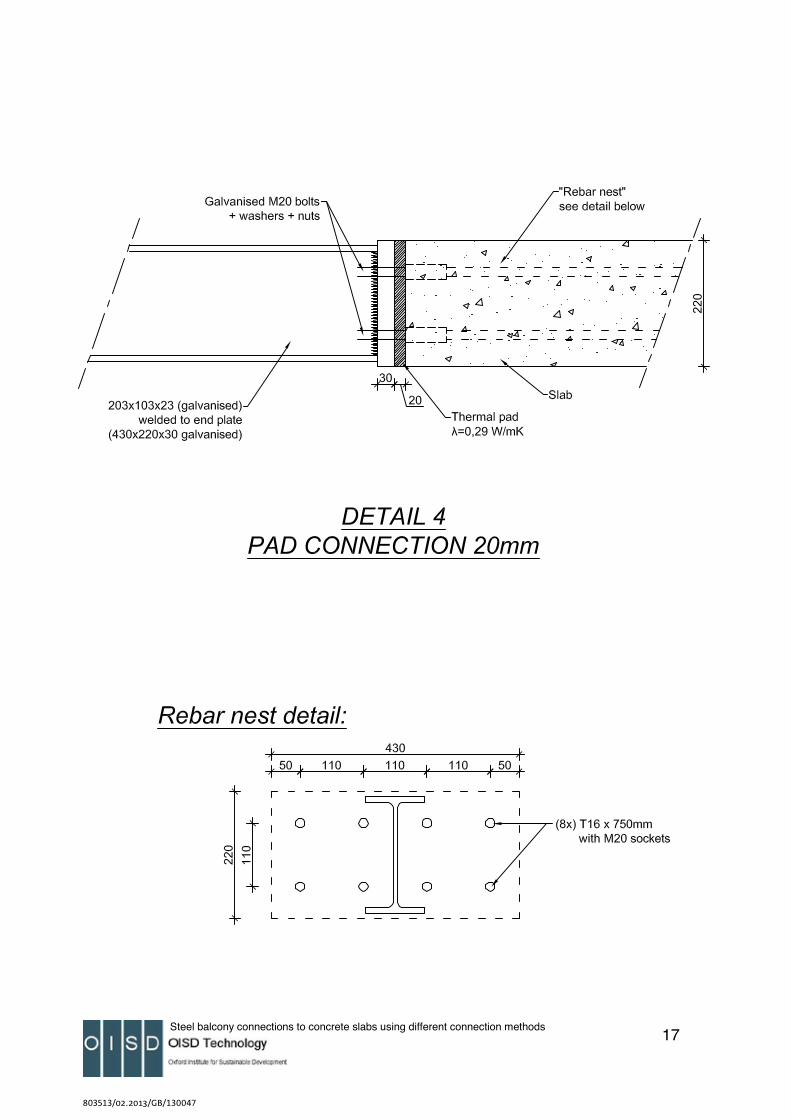
• Case 3. 20mm ‘thermal pad’ using welded endplate on balcony support bracket
• Case 4. KS14 unit connecting balcony support bracket to concrete slab
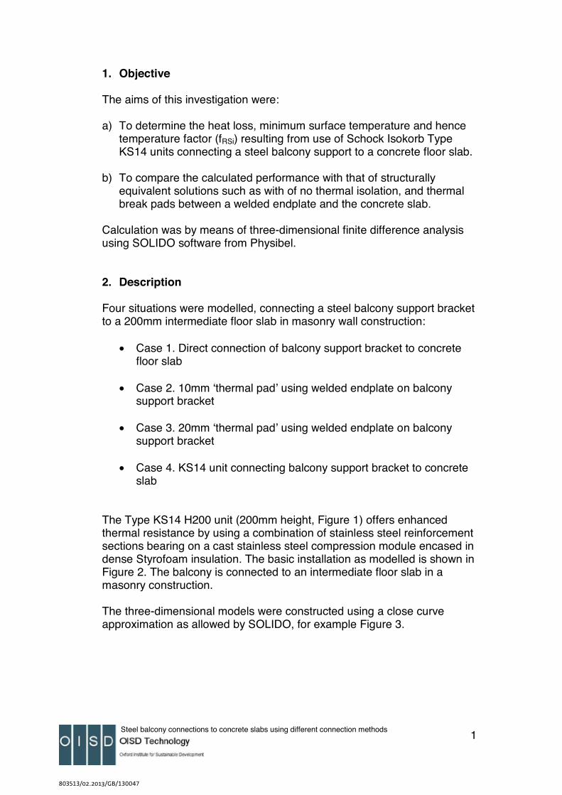
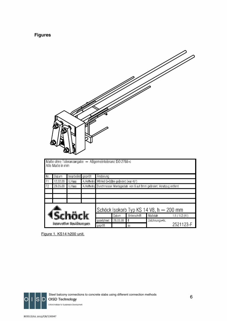
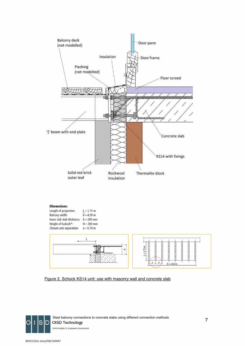
The Type KS14 H200 unit (200mm height, Figure 1) offers enhanced thermal resistance by using a combination of stainless steel reinforcement sections bearing on a cast stainless steel compression module encased in dense Styrofoam insulation. The basic installation as modelled is shown in Figure 2. The balcony is connected to an intermediate floor slab in a masonry construction.
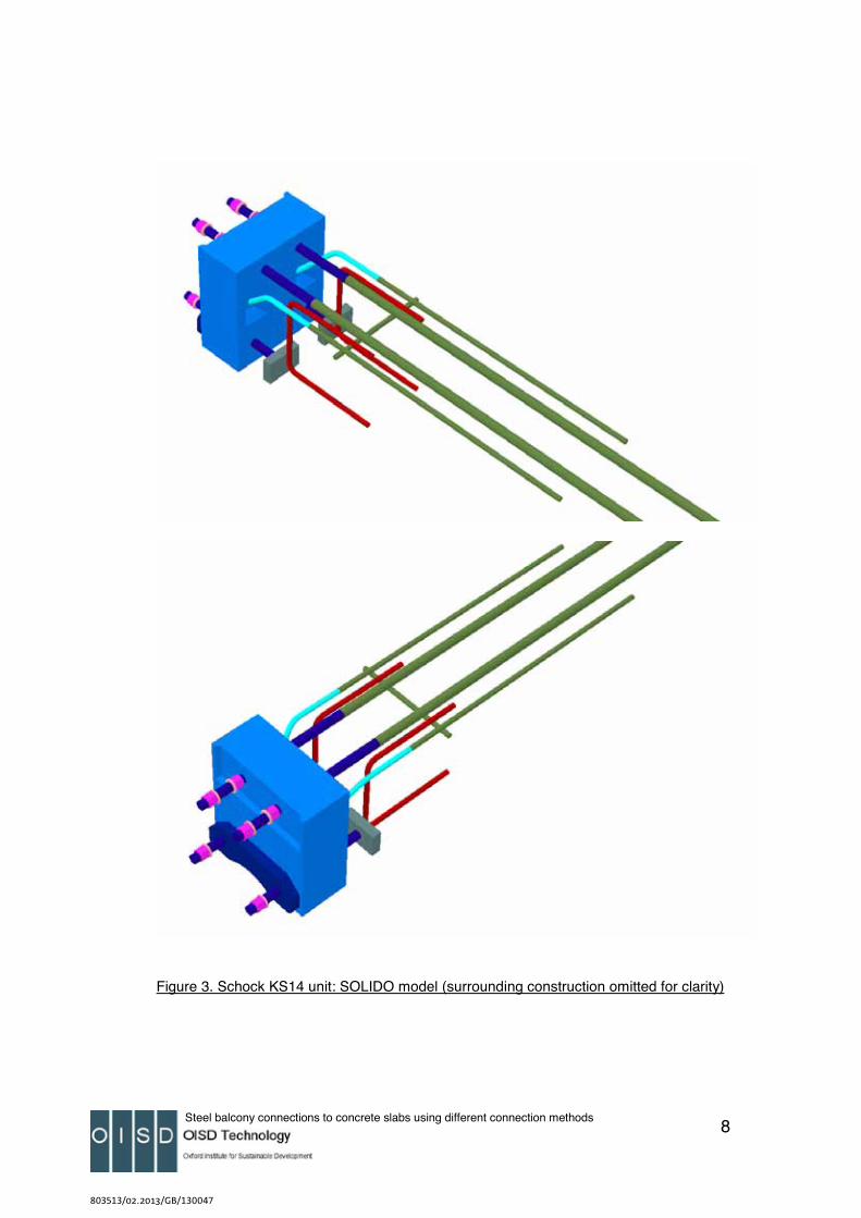
The three-dimensional models were constructed using a close curve approximation as allowed by SOLIDO, for example Figure 3.
803513/02.2013/GB/130047
Steel balcony connections to concrete slabs using different connection methods 2
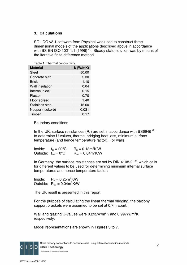
3. Calculations
SOLIDO v3.1 software from Physibel was used to construct three dimensional models of the applications described above in accordance with BS EN ISO 10211:1 (1996) (1). Steady state solution was by means of the iterative finite difference method.
Table 1. Thermal conductivity Material k (W/mK)Steel 50.00Concrete slab 2.30Brick 1.10Wall insulation 0.04Internal block 0.15Plaster 0.70Floor screed 1.40Stainless steel 15.00Neopor (Isokorb) 0.031Timber 0.17
Boundary conditions
In the UK, surface resistances (Rs) are set in accordance with BS6946 (2)
to determine U-values, thermal bridging heat loss, minimum surface temperature (and hence temperature factor). For walls:
Inside: tai = 20ºC Rsi = 0.13m2K/W Outside: tae = 0ºC Rso = 0.04m2K/W
In Germany, the surface resistances are set by DIN 4108-2 (3), which calls for different values to be used for determining minimum internal surface temperatures and hence temperature factor:
Inside: Rsi = 0.25m2K/W Outside: Rso = 0.04m2K/W
The UK result is presented in this report.
For the purpose of calculating the linear thermal bridging, the balcony support brackets were assumed to be set at 0.7m apart.
Wall and glazing U-values were 0.292W/m2K and 0.997W/m2K respectively.
Model representations are shown in Figures 3 to 7.
803513/02.2013/GB/130047
Steel balcony connections to concrete slabs using different connection methods 3
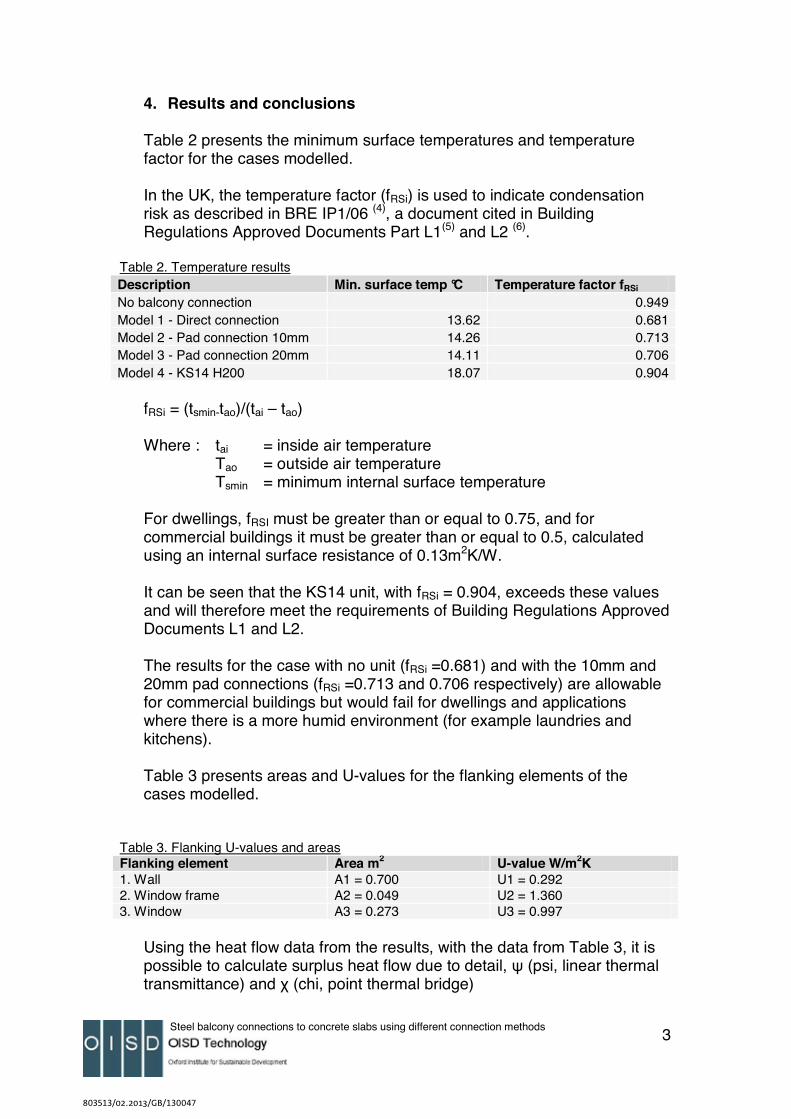
4. Results and conclusions
Table 2 presents the minimum surface temperatures and temperature factor for the cases modelled.
In the UK, the temperature factor (fRSi) is used to indicate condensation risk as described in BRE IP1/06 (4), a document cited in Building Regulations Approved Documents Part L1(5) and L2 (6).
Table 2. Temperature resultsDescription Min. surface temp °C Temperature factor fRSi
No balcony connection 0.949Model 1 - Direct connection 13.62 0.681Model 2 - Pad connection 10mm 14.26 0.713Model 3 - Pad connection 20mm 14.11 0.706Model 4 - KS14 H200 18.07 0.904
fRSi = (tsmin-tao)/(tai – tao)
Where : tai = inside air temperature Tao = outside air temperature Tsmin = minimum internal surface temperature
For dwellings, fRSI must be greater than or equal to 0.75, and for commercial buildings it must be greater than or equal to 0.5, calculated using an internal surface resistance of 0.13m2K/W.
It can be seen that the KS14 unit, with fRSi = 0.904, exceeds these values and will therefore meet the requirements of Building Regulations Approved Documents L1 and L2.
The results for the case with no unit (fRSi =0.681) and with the 10mm and 20mm pad connections (fRSi =0.713 and 0.706 respectively) are allowable for commercial buildings but would fail for dwellings and applications where there is a more humid environment (for example laundries and kitchens).
Table 3 presents areas and U-values for the flanking elements of the cases modelled.
Table 3. Flanking U-values and areasFlanking element Area m2 U-value W/m2K 1. Wall A1 = 0.700 U1 = 0.292 2. Window frame A2 = 0.049 U2 = 1.360 3. Window A3 = 0.273 U3 = 0.997
Using the heat flow data from the results, with the data from Table 3, it is possible to calculate surplus heat flow due to detail, ψ (psi, linear thermal transmittance) and χ (chi, point thermal bridge)
803513/02.2013/GB/130047
Steel balcony connections to concrete slabs using different connection methods 4
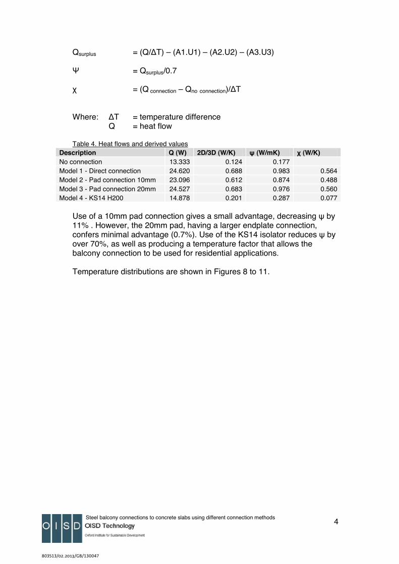
Qsurplus = (Q/T) – (A1.U1) – (A2.U2) – (A3.U3)
Ψ = Qsurplus/0.7
χ = (Q connection – Qno connection)/T
Where: T = temperature difference Q = heat flow
Table 4. Heat flows and derived valuesDescription Q (W) 2D/3D (W/K) ψ (W/mK) χ (W/K) No connection 13.333 0.124 0.177Model 1 - Direct connection 24.620 0.688 0.983 0.564Model 2 - Pad connection 10mm 23.096 0.612 0.874 0.488Model 3 - Pad connection 20mm 24.527 0.683 0.976 0.560Model 4 - KS14 H200 14.878 0.201 0.287 0.077
Use of a 10mm pad connection gives a small advantage, decreasing ψ by 11% . However, the 20mm pad, having a larger endplate connection, confers minimal advantage (0.7%). Use of the KS14 isolator reduces ψ by over 70%, as well as producing a temperature factor that allows the balcony connection to be used for residential applications.
Temperature distributions are shown in Figures 8 to 11.
803513/02.2013/GB/130047
Steel balcony connections to concrete slabs using different connection methods 5
References
1) BS EN ISO 10211-1:1996, Thermal Bridges in Building Construction – Heat flows and Surface Temperatures, General Calculation Methods BSI, 1996
2) BS6946:1997, Building Components and Building Elements – Thermal Resistance and Thermal Transmittance – Calculation method, BSI 1997
3) DIN4108-2:2003-07: Warmeschutz und Energie-Einsparung in Gebauden – Teil 2: Mindestanforderungen an den Warmeschutz. Beuth Verlag, Berlin
4) Ward T, Assessing the effects of thermal bridging at junctions and around openings, BRE IP1/06, Building Research Establishment 2006
5) Building Regulations Part L, Conservation of Fuel and Power, Approved Document L1, Conservation of Power in New Dwellings, April 2006
6) Building Regulations Part L, Conservation of Fuel and Power, Approved Document L2, Conservation of Power in New Buildings other than Dwellings, April 2006
803513/02.2013/GB/130047
Steel balcony connections to concrete slabs using different connection methods 6
Figures
Figure 1. KS14 h200 unit.
803513/02.2013/GB/130047
Steel balcony connections to concrete slabs using different connection methods 7
Figure 2. Schock KS14 unit: use with masonry wall and concrete slab
803513/02.2013/GB/130047
Steel balcony connections to concrete slabs using different connection methods 8
Figure 3. Schock KS14 unit: SOLIDO model (surrounding construction omitted for clarity)
803513/02.2013/GB/130047
Steel balcony connections to concrete slabs using different connection methods 9
Figure 4. SOLIDO model of direct connection (Case 1), slab omitted for clarity
Figure 5. SOLIDO model of 10mm pad connection (Case 2), slab omitted for clarity
803513/02.2013/GB/130047
Steel balcony connections to concrete slabs using different connection methods 10
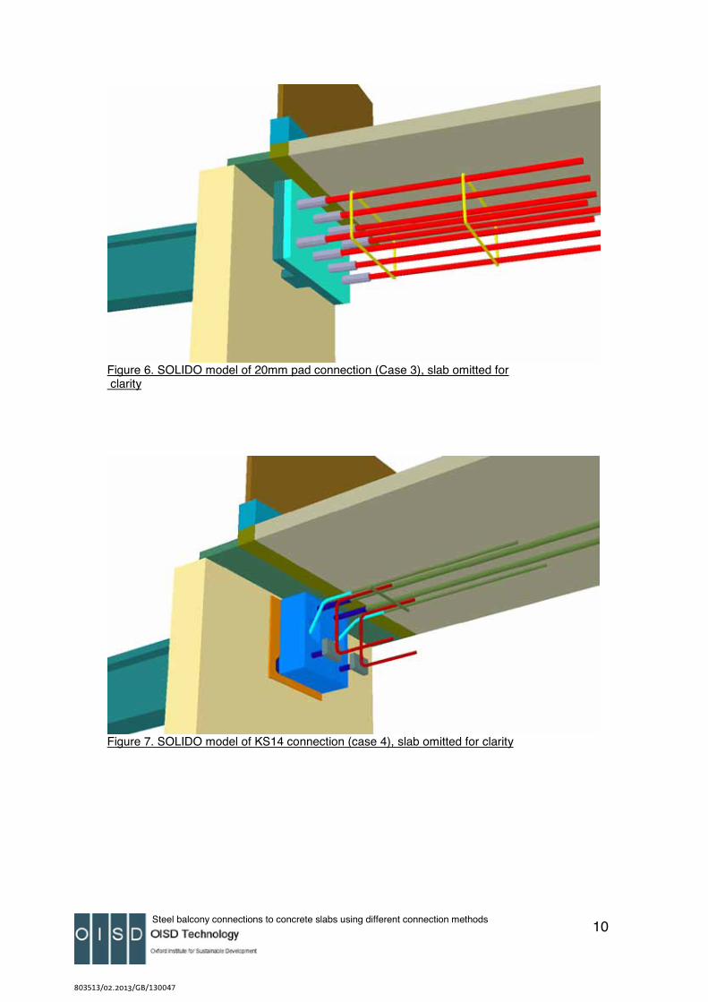
Figure 6. SOLIDO model of 20mm pad connection (Case 3), slab omitted for clarity
Figure 7. SOLIDO model of KS14 connection (case 4), slab omitted for clarity
803513/02.2013/GB/130047
Steel balcony connections to concrete slabs using different connection methods 11
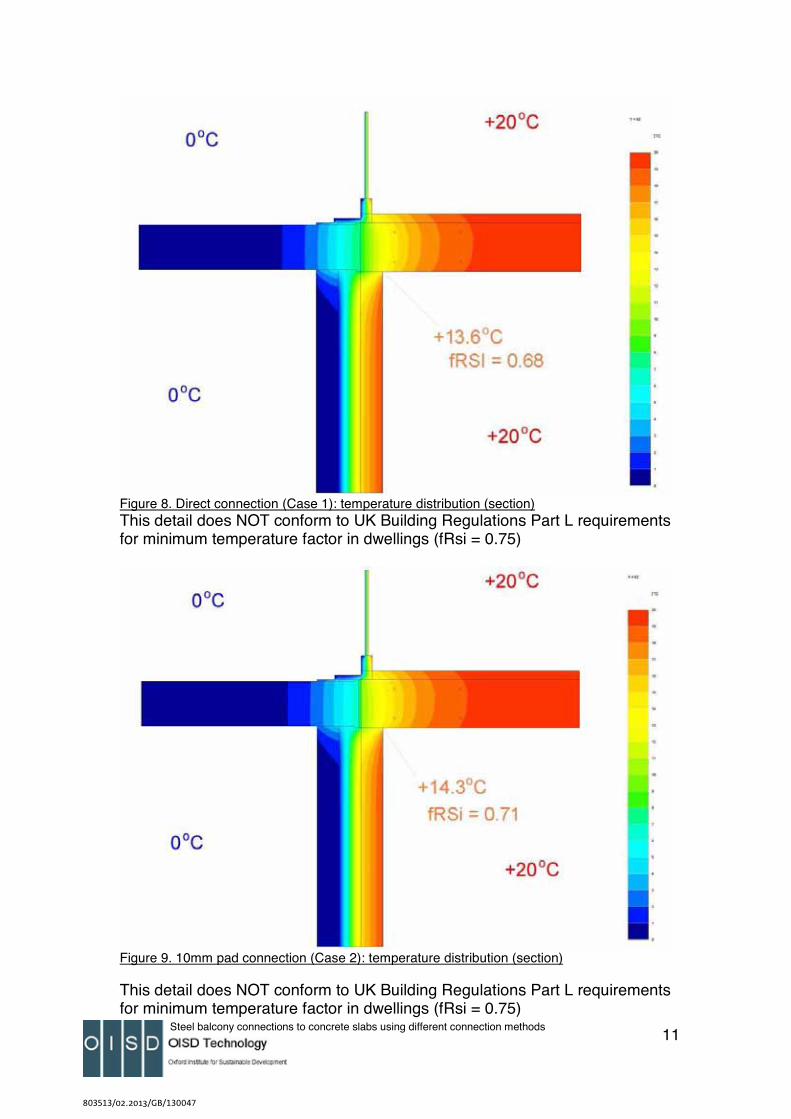
Figure 8. Direct connection (Case 1): temperature distribution (section)This detail does NOT conform to UK Building Regulations Part L requirements for minimum temperature factor in dwellings (fRsi = 0.75)
Figure 9. 10mm pad connection (Case 2): temperature distribution (section)
This detail does NOT conform to UK Building Regulations Part L requirements for minimum temperature factor in dwellings (fRsi = 0.75)
803513/02.2013/GB/130047
Steel balcony connections to concrete slabs using different connection methods 12
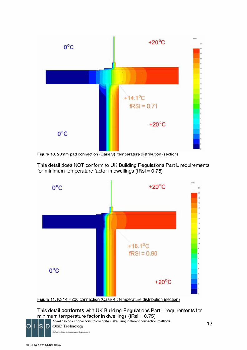
Figure 10. 20mm pad connection (Case 3): temperature distribution (section)
This detail does NOT conform to UK Building Regulations Part L requirements for minimum temperature factor in dwellings (fRsi = 0.75)
Figure 11. KS14 H200 connection (Case 4): temperature distribution (section)
This detail conforms with UK Building Regulations Part L requirements for minimum temperature factor in dwellings (fRsi = 0.75)
803513/02.2013/GB/130047
Thermal Performance of Steel Balcony Connection to Concrete Slab using KS14 Connection 13
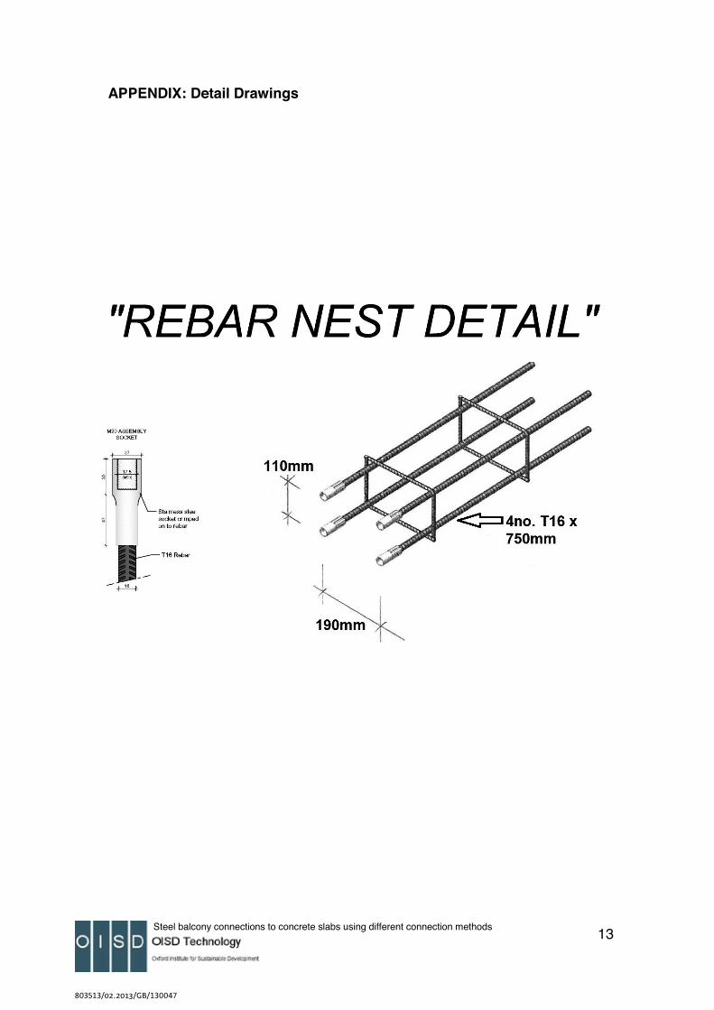
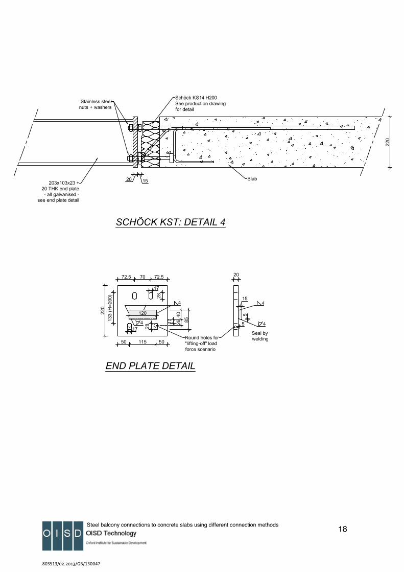
APPENDIX: Detail Drawings
Steel balcony connections to concrete slabs using different connection methods 1
1. Objective
The aims of this investigation were:
a) To determine the heat loss, minimum surface temperature and hence temperature factor (fRSi) resulting from use of Schock Isokorb Type KS14 units connecting a steel balcony support to a concrete floor slab.
b) To compare the calculated performance with that of structurally equivalent solutions such as with of no thermal isolation, and thermal break pads between a welded endplate and the concrete slab.
Calculation was by means of three-dimensional finite difference analysis using SOLIDO software from Physibel.
2. Description
Four situations were modelled, connecting a steel balcony support bracket to a 200mm intermediate floor slab in masonry wall construction:
• Case 1. Direct connection of balcony support bracket to concrete floor slab
• Case 2. 10mm ‘thermal pad’ using welded endplate on balcony support bracket
• Case 3. 20mm ‘thermal pad’ using welded endplate on balcony support bracket
• Case 4. KS14 unit connecting balcony support bracket to concrete slab
The Type KS14 H200 unit (200mm height, Figure 1) offers enhanced thermal resistance by using a combination of stainless steel reinforcement sections bearing on a cast stainless steel compression module encased in dense Styrofoam insulation. The basic installation as modelled is shown in Figure 2. The balcony is connected to an intermediate floor slab in a masonry construction.
The three-dimensional models were constructed using a close curve approximation as allowed by SOLIDO, for example Figure 3.
803513/02.2013/GB/130047
Steel balcony connections to concrete slabs using different connection methods 1
1. Objective
The aims of this investigation were:
a) To determine the heat loss, minimum surface temperature and hence temperature factor (fRSi) resulting from use of Schock Isokorb Type KS14 units connecting a steel balcony support to a concrete floor slab.
b) To compare the calculated performance with that of structurally equivalent solutions such as with of no thermal isolation, and thermal break pads between a welded endplate and the concrete slab.
Calculation was by means of three-dimensional finite difference analysis using SOLIDO software from Physibel.
2. Description
Four situations were modelled, connecting a steel balcony support bracket to a 200mm intermediate floor slab in masonry wall construction:
• Case 1. Direct connection of balcony support bracket to concrete floor slab
• Case 2. 10mm ‘thermal pad’ using welded endplate on balcony support bracket
• Case 3. 20mm ‘thermal pad’ using welded endplate on balcony support bracket
• Case 4. KS14 unit connecting balcony support bracket to concrete slab
The Type KS14 H200 unit (200mm height, Figure 1) offers enhanced thermal resistance by using a combination of stainless steel reinforcement sections bearing on a cast stainless steel compression module encased in dense Styrofoam insulation. The basic installation as modelled is shown in Figure 2. The balcony is connected to an intermediate floor slab in a masonry construction.
The three-dimensional models were constructed using a close curve approximation as allowed by SOLIDO, for example Figure 3.
14
803513/02.2013/GB/130047
Steel balcony connections to concrete slabs using different connection methods 1
1. Objective
The aims of this investigation were:
a) To determine the heat loss, minimum surface temperature and hence temperature factor (fRSi) resulting from use of Schock Isokorb Type KS14 units connecting a steel balcony support to a concrete floor slab.
b) To compare the calculated performance with that of structurally equivalent solutions such as with of no thermal isolation, and thermal break pads between a welded endplate and the concrete slab.
Calculation was by means of three-dimensional finite difference analysis using SOLIDO software from Physibel.
2. Description
Four situations were modelled, connecting a steel balcony support bracket to a 200mm intermediate floor slab in masonry wall construction:
• Case 1. Direct connection of balcony support bracket to concrete floor slab
• Case 2. 10mm ‘thermal pad’ using welded endplate on balcony support bracket
• Case 3. 20mm ‘thermal pad’ using welded endplate on balcony support bracket
• Case 4. KS14 unit connecting balcony support bracket to concrete slab
The Type KS14 H200 unit (200mm height, Figure 1) offers enhanced thermal resistance by using a combination of stainless steel reinforcement sections bearing on a cast stainless steel compression module encased in dense Styrofoam insulation. The basic installation as modelled is shown in Figure 2. The balcony is connected to an intermediate floor slab in a masonry construction.
The three-dimensional models were constructed using a close curve approximation as allowed by SOLIDO, for example Figure 3.
15
803513/02.2013/GB/130047
Steel balcony connections to concrete slabs using different connection methods 1
1. Objective
The aims of this investigation were:
a) To determine the heat loss, minimum surface temperature and hence temperature factor (fRSi) resulting from use of Schock Isokorb Type KS14 units connecting a steel balcony support to a concrete floor slab.
b) To compare the calculated performance with that of structurally equivalent solutions such as with of no thermal isolation, and thermal break pads between a welded endplate and the concrete slab.
Calculation was by means of three-dimensional finite difference analysis using SOLIDO software from Physibel.
2. Description
Four situations were modelled, connecting a steel balcony support bracket to a 200mm intermediate floor slab in masonry wall construction:
• Case 1. Direct connection of balcony support bracket to concrete floor slab
• Case 2. 10mm ‘thermal pad’ using welded endplate on balcony support bracket
• Case 3. 20mm ‘thermal pad’ using welded endplate on balcony support bracket
• Case 4. KS14 unit connecting balcony support bracket to concrete slab
The Type KS14 H200 unit (200mm height, Figure 1) offers enhanced thermal resistance by using a combination of stainless steel reinforcement sections bearing on a cast stainless steel compression module encased in dense Styrofoam insulation. The basic installation as modelled is shown in Figure 2. The balcony is connected to an intermediate floor slab in a masonry construction.
The three-dimensional models were constructed using a close curve approximation as allowed by SOLIDO, for example Figure 3.
16
803513/02.2013/GB/130047
Steel balcony connections to concrete slabs using different connection methods 1
1. Objective
The aims of this investigation were:
a) To determine the heat loss, minimum surface temperature and hence temperature factor (fRSi) resulting from use of Schock Isokorb Type KS14 units connecting a steel balcony support to a concrete floor slab.
b) To compare the calculated performance with that of structurally equivalent solutions such as with of no thermal isolation, and thermal break pads between a welded endplate and the concrete slab.
Calculation was by means of three-dimensional finite difference analysis using SOLIDO software from Physibel.
2. Description
Four situations were modelled, connecting a steel balcony support bracket to a 200mm intermediate floor slab in masonry wall construction:
• Case 1. Direct connection of balcony support bracket to concrete floor slab
• Case 2. 10mm ‘thermal pad’ using welded endplate on balcony support bracket
• Case 3. 20mm ‘thermal pad’ using welded endplate on balcony support bracket
• Case 4. KS14 unit connecting balcony support bracket to concrete slab
The Type KS14 H200 unit (200mm height, Figure 1) offers enhanced thermal resistance by using a combination of stainless steel reinforcement sections bearing on a cast stainless steel compression module encased in dense Styrofoam insulation. The basic installation as modelled is shown in Figure 2. The balcony is connected to an intermediate floor slab in a masonry construction.
The three-dimensional models were constructed using a close curve approximation as allowed by SOLIDO, for example Figure 3.
17
803513/02.2013/GB/130047
Steel balcony connections to concrete slabs using different connection methods 1
1. Objective
The aims of this investigation were:
a) To determine the heat loss, minimum surface temperature and hence temperature factor (fRSi) resulting from use of Schock Isokorb Type KS14 units connecting a steel balcony support to a concrete floor slab.
b) To compare the calculated performance with that of structurally equivalent solutions such as with of no thermal isolation, and thermal break pads between a welded endplate and the concrete slab.
Calculation was by means of three-dimensional finite difference analysis using SOLIDO software from Physibel.
2. Description
Four situations were modelled, connecting a steel balcony support bracket to a 200mm intermediate floor slab in masonry wall construction:
• Case 1. Direct connection of balcony support bracket to concrete floor slab
• Case 2. 10mm ‘thermal pad’ using welded endplate on balcony support bracket
• Case 3. 20mm ‘thermal pad’ using welded endplate on balcony support bracket
• Case 4. KS14 unit connecting balcony support bracket to concrete slab
The Type KS14 H200 unit (200mm height, Figure 1) offers enhanced thermal resistance by using a combination of stainless steel reinforcement sections bearing on a cast stainless steel compression module encased in dense Styrofoam insulation. The basic installation as modelled is shown in Figure 2. The balcony is connected to an intermediate floor slab in a masonry construction.
The three-dimensional models were constructed using a close curve approximation as allowed by SOLIDO, for example Figure 3.
18

803513/02.2013/GB/130047
Steel balcony connections to concrete slabs using different connection methods 1
1. Objective
The aims of this investigation were:
a) To determine the heat loss, minimum surface temperature and hence temperature factor (fRSi) resulting from use of Schock Isokorb Type KS14 units connecting a steel balcony support to a concrete floor slab.
b) To compare the calculated performance with that of structurally equivalent solutions such as with of no thermal isolation, and thermal break pads between a welded endplate and the concrete slab.
Calculation was by means of three-dimensional finite difference analysis using SOLIDO software from Physibel.
2. Description
Four situations were modelled, connecting a steel balcony support bracket to a 200mm intermediate floor slab in masonry wall construction:
• Case 1. Direct connection of balcony support bracket to concrete floor slab
• Case 2. 10mm ‘thermal pad’ using welded endplate on balcony support bracket
• Case 3. 20mm ‘thermal pad’ using welded endplate on balcony support bracket
• Case 4. KS14 unit connecting balcony support bracket to concrete slab
The Type KS14 H200 unit (200mm height, Figure 1) offers enhanced thermal resistance by using a combination of stainless steel reinforcement sections bearing on a cast stainless steel compression module encased in dense Styrofoam insulation. The basic installation as modelled is shown in Figure 2. The balcony is connected to an intermediate floor slab in a masonry construction.
The three-dimensional models were constructed using a close curve approximation as allowed by SOLIDO, for example Figure 3.