steaM seQuencIng control For steaM HeatIng...
28
R • InstallatIon and operatIon InstructIons Manual • user operatIons Manual sQ-elite-8s & sQ-elite-eXt steaM seQuencIng control For steaM HeatIng systeMs WarnIng the sQ-elite is strictly an operating control. It cannot be used as a limit control. all boilers must have all safety and limit controls required by code. It is the responsibility of the installer to verify that all the safety and limits are working properly before the sQ-elite is installed. this control must be installed by a licensed electrician. SQ-Elite-8S SEQUENCING CONTROL SYS AUX OUT PWR L N 1 2 SYS 3 AUX OUT 5 Stage A 7 Stage B 9 Stage C 11 13 Stage E 15 Stage F 17 Stage D 6 8 10 12 14 16 18 RS485 13PSI 35F <AB> CD EF GH HI LO -- OFF 4 Stage G 19 Stage H 21 Aux liary Input2 27 29 31 33 35 Outdoor Temp 20 22 28 30 32 34 36 Stage E Stage F Stage G Stage H Stage A Stage B Stage C Stage D 25 26 System 4 20mA + 37 38 PROVE PROGRAM RUN 23 24 COMB AIR COMB. AIR ENCLOSED ENERGY MANAGEMENT EQU PMENT LISTED 99RA C US INPUT RATINGS 120VAC 60Hz, 12VA MAX Use Copper Conductors Only. CAUTION: Risk of Electric Shock. SENSORS MUST BE GOLD SERIES OUTPUT RATING: 2A, 120VAC. MAXIMUM 15A TOTAL FOR ALL CIRCUITS DO NOT APPLY ANY VOLTAGE TO INPUT TERMINALS SHUTDOWN /TSTAT /SETBACK Auxiliary Input1 Aux liary Input3
Transcript of steaM seQuencIng control For steaM HeatIng...

R
• InstallatIon and operatIon InstructIons Manual• user operatIons Manual
sQ-elite-8s & sQ-elite-eXtsteaM seQuencIng control
For steaM HeatIng systeMs
WarnIngthe sQ-elite is strictly an operating control. It cannot be used as a limit control. all boilers must have all safety and limit controls required by code. It is the responsibility of the installer to verify that all the safety and limits are working properly before the sQ-elite is installed.
this control must be installed by a licensed electrician.
SQ-Elite-8SSEQUENCING CONTROL
SYS
AUX OUT
PWR
L N1 2
SYS
3
AUXOUT
5
Stage A
7
Stage B
9
Stage C
11 13
Stage E
15
Stage F
17
Stage D
6 8 10 12 14 16 18
RS485
13PSI 35F
<AB> CD EF GH
HI LO -- OFF
4
Stage G
19
Stage H
21
Aux liaryInput2
27 29 31 33 35
OutdoorTemp
20 22 28 30 32 34 36
Stage E
Stage F
Stage G
Stage H
Stage A
Stage B
Stage C
Stage D
25 26
System4 20mA+
37 38
PROVE
PROGRAM RUN
23 24
COMBAIR
COMB. AIR
ENCLOSEDENERGY
MANAGEMENTEQU PMENT
LISTED99RA
C US
INPUT RATINGS 120VAC 60Hz, 12VA MAX
Use Copper Conductors Only.CAUTION: Risk of Electric Shock.
SENSORS MUST BE GOLD SERIES
OUTPUT RATING: 2A, 120VAC.MAXIMUM 15A TOTAL FOR ALL CIRCUITS
DO NOT APPLY ANY VOLTAGETO INPUT TERMINALS
SHUTDOWN/TSTAT
/SETBACK
AuxiliaryInput1
Aux liaryInput3

2 Heat-Timer Corp.
contentssQ-elIte-8s layout . . . . . . . . . . . . . .3sQ-elIte-8s overvIeW. . . . . . . . . . . . .4understandIng operatIon concept . . .5
PID Operation . . . . . . . . . . . . . . . . . . . 5OSS Operation. . . . . . . . . . . . . . . . . . . 5
InItIal setup . . . . . . . . . . . . . . . . . .6Selecting the System Features . . . . . . . . . . . 6
InstallatIon . . . . . . . . . . . . . . . . . .7Mounting the Enclosure . . . . . . . . . . . . . . . 7Install the Sensors . . . . . . . . . . . . . . . . . . 8
System Pressure Sensor Installation . . . . . . . 8Outdoor Sensor Installation . . . . . . . . . . . . 8
Wiring . . . . . . . . . . . . . . . . . . . . . . . . 9Wiring the Power (Terminals 1, 2) . . . . . . . . . 9
Wiring the Inputs . . . . . . . . . . . . . . . . . . . 9System Pressure Sensor Wiring (Terminals 25, 26) 9Outdoor Sensor Wiring (Terminals 29, 30). . . . . 9Wiring the Shutdown (Terminals 35, 36) . . . . . . 9Wiring the T-STAT (Terminals 35, 36) . . . . . . . 10Wiring the Setback (Terminals 35, 36) . . . . . . . 10Wiring the Prove (Terminals 37, 38) . . . . . . . . 10
Wiring the Outputs . . . . . . . . . . . . . . . . . . 10Wiring the System Output (Terminals 19, 20) . . . 10Wiring the Combustion Air Damper (Terminals 23, 24) .10Wiring the Stages (Terminals 3 to 17) . . . . . . . 11Connecting to the SQ-Elite-EXT Panels and 4-20mA EMS Interface . . . . . . . . . . . . . . . . . . . 11Selecting the SQ-Elite-EXT Panel Letter . . . . . 11
Installer Menu seQuence . . . . . . . . 12startup settIngs . . . . . . . . . . . . . . 14
Program Change Settings . . . . . . . . . . . . . 14Startup Sequence . . . . . . . . . . . . . . . . . 14Control Mode . . . . . . . . . . . . . . . . . . . 14Sensor Type . . . . . . . . . . . . . . . . . . . . 14Display Standard. . . . . . . . . . . . . . . . . . 14Setting the 4mA and 20mA Set Points (Available in 4-20mA EMS only) . . . . . . . . . . . . . . . . . 14Combustion Air Damper Output . . . . . . . . . . 15External Input Mode . . . . . . . . . . . . . . . . 15Burner Type . . . . . . . . . . . . . . . . . . . . 15Total Boilers . . . . . . . . . . . . . . . . . . . . 15Staging. . . . . . . . . . . . . . . . . . . . . . . 15
Sequence . . . . . . . . . . . . . . . . . . . . . 16Control Logic. . . . . . . . . . . . . . . . . . . . 16Sensor Fault . . . . . . . . . . . . . . . . . . . . 16
Setting the Control to Factory Defaults . . . . . . . 16Operating Settings . . . . . . . . . . . . . . . . . . 17
Program Change Settings . . . . . . . . . . . . . 17Season. . . . . . . . . . . . . . . . . . . . . . . 17Set Point (Not Adjustable in EMS Mode) . . . . . 17Outdoor Cutoff Temperature . . . . . . . . . . . . 17
System Settings . . . . . . . . . . . . . . . . . . . 17Program Change Settings . . . . . . . . . . . . . 18
Stage Settings . . . . . . . . . . . . . . . . . . . . 18Reaction Time . . . . . . . . . . . . . . . . . . . 18Purge Delay . . . . . . . . . . . . . . . . . . . . 18Minimum Runtime . . . . . . . . . . . . . . . . . 18Standby Delay . . . . . . . . . . . . . . . . . . . 18Last Stage Hold . . . . . . . . . . . . . . . . . . 19
Lead Settings . . . . . . . . . . . . . . . . . . . . 19Lead Boiler. . . . . . . . . . . . . . . . . . . . . 20Rotate Mode . . . . . . . . . . . . . . . . . . . . 20
Setback Schedule . . . . . . . . . . . . . . . . . . 20Setback . . . . . . . . . . . . . . . . . . . . . . 20Day/Night Schedules . . . . . . . . . . . . . . . 21Set Present Time . . . . . . . . . . . . . . . . . 21
Combustion Air Damper Operation . . . . . . . . . 21Run-On . . . . . . . . . . . . . . . . . . . . . . 21System Exercise . . . . . . . . . . . . . . . . . . 21
Maintenance . . . . . . . . . . . . . . . . . . . . . 21System & Outdoor Sensor Trim . . . . . . . . . . 22
History . . . . . . . . . . . . . . . . . . . . . . . . 22Configuration. . . . . . . . . . . . . . . . . . . . 22Display . . . . . . . . . . . . . . . . . . . . . . . 22
Boiler Settings . . . . . . . . . . . . . . . . . . . . 23Mode . . . . . . . . . . . . . . . . . . . . . . . . 23Runtime . . . . . . . . . . . . . . . . . . . . . . 24Pressure Transducer Default Settings and Ranges 24
troublesHootIng. . . . . . . . . . . . . . 25user Menu seQuence. . . . . . . . . . . . 26
Program Change Settings . . . . . . . . . . . . . 26Season. . . . . . . . . . . . . . . . . . . . . . . 26Set Point (Not Adjustable in EMS Mode) . . . . . 27Outdoor Cutoff Temperature . . . . . . . . . . . . 27Setback . . . . . . . . . . . . . . . . . . . . . . 27Day/Night Schedules . . . . . . . . . . . . . . . 27
specIFIcatIons . . . . . . . . . . . . . . . . 28

SQ-Elite-8S & SQ-Elite-EXT Installation Manual 3
SEQUENCING CONTROL
SYS
AUX OUT
PWR
L N1 2
SYS
3
AUXOUT
5
Stage A
7
Stage B
9
Stage C
11 13
Stage E
15
Stage F
17
Stage D
6 8 10 12 14 16 18
RS485
4
Stage G
19
Stage H
21
AuxiliaryInput2
27 29 31 33 35
OutdoorTemp
20 22 28 30 32 34 36
Stage E
Stage F
Stage G
Stage H
Stage A
Stage B
Stage C
Stage D
25 26
System4 20mA+
37 38
PROVE
PROGRAM RUN
23 24
COMB.AIR
COMB. AIR
ENCLOSEDENERGY
MANAGEMENTEQUIPMENT
LISTED99RA
C US
INPUT RATINGS 120VAC 60Hz 12VA MAX
Use Copper Conductors Only.CAUTION: Risk of Electric Shock.
SENSORS MUST BE GOLD SERIES
OUTPUT RATING: 2A, 120VAC.MAXIMUM 15A TOTAL FOR ALL CIRCUITS
DO NOT APPLY ANY VOLTAGETO INPUT TERMINALS
SHUTDOWN/TSTAT
SETBACK
AuxiliaryInput1
AuxiliaryInput3
Connect to Extension panels toadd additional stages or connect
to 4-20mA EMS Interface forexternal set point.
When connecting Pressure Sensors,Polarity is observed. However, when connecting
Temperature Sensors, no Polarity is observed. Prove terminals must be connected for
SQ-Elite-8S to operate stages.
Button function is presented onbottom row of the display.LEDs indicate
associated relay’s status
Program Switch to restrict accessto function changes. This Switch is
covered with Enclosure Wiring Cover.
System Output controls system components.Comb. Air relay is
controlled when configured.
Output Relays to manage the stages.
13PSI 35F
<AB> CD EF GH
HI LO -- OFF
SQ-Elite-8S
sQ-elIte-8s layout

4 Heat-Timer Corp.
sQ-elIte-8s overvIeWseQuences up to 8 stagesThe SQ-Elite-8S is the perfect control whenever multiple boilers are required for steam heating applications. The SQ-Elite-8S controls the stages to maintain a precise system set point.
pId or over-sIzed-systeM (oss) logIc The SQ-Elite-8S’s control PID algorithm allows it to look at the rate of change in the system. If the system oscillation is minimal, the SQ-Elite-8S will make slow and gradual output adjustments. If the load is changing quickly, the SQ-Elite-8S can be set to OSS sequencing where it will react based on load changes. Therefore, the SQ-Elite adapts to specific system requirements and minimizes oscillation around the set point.
dIgItal dIsplay oF all systeM settIngsThe SQ-Elite-8S’s alphanumeric digital display names each system parameter in simple English and shows its precise value. The easy to follow menu system allows users to quickly make changes to any system setting without having to learn any specialized codes or key commands.
autoMatIc rotatIon aMong stagesRotating the lead stage on a call for output promotes even wear on each boiler. The SQ-Elite has three modes of rotation: Manual, FOFO (First-On/First-Off), or Time. The Time option rotates the lead stage every selected, period from every hour to every 41 days.
standby boIler optIonAny of the SQ-Elite-8S heating boilers can be set as a Standby boiler with an adjustable Standby delay. Assigning a specific boiler to work in standby mode will remove it from the rotation sequence. In this mode, the boiler will be used as a backup in large demand periods where the primary boilers will not suffice.
systeM and coMbustIon aIr daMper outputs WItH prove InputThese outputs work with the control logic to operate system and a combustion air damper relays. In addition, a System PROVE input can be wired in to check the status of either of the components energized by the outputs before the stages can be activated.
norMal (lo/HI/lo/HI) or parallel (lo/lo/HI/HI) seQuencIngThe SQ-Elite-8S can sequence boilers as needed. For boilers where higher efficiency is achieved using lower firing stages, the SQ-Elite-8S offers the Parallel Sequencing option. It sequences all the low firing stages of all boilers set to Auto before bringing on the higher firing stages. For other types of heating boilers, using the Normal Sequencing option brings on the lower firing stage followed by the higher one of the same boiler. That will be repeated for each of the lag boilers.
MultIple or sIngle stagIngUnlike many boilers where, to fire a multi-stage boiler both low and high stage relays must be energized, some other equipment require that the operation of the higher stages turn off the lower operating stages. This can be achieved by selecting Single from the Startup Staging menu.
add up to 16 stagesAs a stand-alone, the SQ-Elite-8S is designed to control eight stages. However, it has the capability of expanding its control to two SQ-Elite-EXT extension panels each with eight stages. Thus, the SQ-Elite-8S can control a total of up to 24 stages.
setback scHedule or eXternal sIgnalRegardless of the type of applications, Setback is an energy saving feature. The SQ-Elite-8S offers a built-in day/night schedule for the setback period. On the other hand, if external scheduling is to be used, the Setback can be activated using an external signal by shorting the SETBACK input terminals.

SQ-Elite-8S & SQ-Elite-EXT Installation Manual 5
understandIng operatIon conceptThe SQ-Elite-8S has multiple operating modes that satisfy most steam systems. It can sequence stages to achieve an adjustable Set Point. Moreover, when used with the 4-20mA EMS Interface (HT# 926741-00) it can accept a 4-20mA signal as a set point. The 4-20mA EMS Interface must be purchased separately. This gives the SQ-Elite-8S the capability of being controlled remotely.
pId operatIonPID control logic is primarily used for building heating. The logic will utilize two primary settings to add or subtract stages. The Reaction Time is used to turn on/energize stages. On the other hand, the Minimum Runtime is used to turn off/de-energize stages. On a call for heat, by either closing the TSTAT input or opening the SHUTDOWN input, and when the outdoor temperature is below the Outdoor Cutoff, the SQ-Elite-8S will turn on/energize the Lead Boiler's lowest firing stage to start the Purge Delay. After the elapse of the purge period, the SQ-Elite-8S will start calculating the Reaction Period. If after a full Reaction Time the control logic foresees additional stages are needed, the SQ-Elite-8S will energize the following stage. If that stage was another boiler, that boiler has to go through a full Purge Delay before starting to calculate the Reaction Time for that stage. Otherwise, if the next stage was the higher firing stage on the same boiler, the Reaction Time will start from the moment the higher firing stage relay is energized.
When the SQ-Elite-8S PID logic foresees that the system will overshoot, regardless of the current system and target values, it will make sure that the last stage turned on/energized elapsed a full Minimum Runtime before it is turned off/de-energized. Except for the lead stage, no additional stages will be turned off/de-energized until another full Minimum Runtime is elapsed. On the other hand, if the last stage is a lead stage, it will remain energized until the system reading exceeds the target set point by the Last Stage Hold value in addition to satisfying the Minimum Runtime condition. That is, if the Set Point was 10 PSI and the Last Stage Hold was set to 2 PSI, the lead stage will remain energized until the system reaches 12 PSI and a full Minimum Runtime elapses. This is useful in protecting the lead stages from short cycling.
oss operatIonOSS is used in fast reacting application as in process applications, where maintaining a set point is critical. The OSS utilizes the Throttle setting, as a mean to calculate the number of stages the SQ-Elite-8S shall have on at any point. For every Throttle Range below the set point an additional stage shall be turned on/energized. That is, if the set point was 50 Psi and the Throttle setting was 5 Psi, if the System dropped below 45 Psi (50 Psi - 5 Psi), the lead stage will energize. With further decrease in the system value to 40 Psi (50 Psi - 5 Psi - 5 Psi), the second stage will energize.
As the system pressure rises towards the set point, stages will turn off. Using the previous example, when the system rise to 45 Psi boiler B will de-energize leaving only boiler A on. Boiler A will remain on until the system rises a one full Throttle range above the set point. This will leave the lead boiler A on until the pressure rises to 55 Psi then turn off/de-energize.
set point = 50 psi throttle = 5 psi boilers (a, b, c, d, e, and F) lead stage =<a>Falling pressure rising pressure
systempressure
throttle ranges stages turned on stages on stages turned off stages on
55 Psi -1 ---- None A None50 Psi 0 ---- None ---- A45 Psi 1 A A B A
41 - 44 Psi 1 ---- A ---- A + B40 Psi 2 B A + B C A + B35 Psi 3 C A + B +C D A + B +C30 Psi 4 D A + B +C + D E A + B +C + D25 Psi 5 E A + B +C + D + E F A + B +C + D + E20 Psi 6 F A + B +C + D + E + F ---- A + B +C + D + E + F15 Psi 7 ---- A + B +C + D + E + F ---- A + B +C + D + E + F

6 Heat-Timer Corp.Make sure you Have tHe rIgHt controlIf you need the SQ-Elite to do additional tasks that either are not listed or do not know how to set them, contact Heat-Timer Corp. Sales Department either by Phone (973)575-4004, Fax (973) 575-4052, or by E-mail [email protected].
InItIal setupHaving an Initial Setup Program will ease the setting of the SQ-Elite-8S and will provide the opportunity to utilize many of the energy saving features available in the control and give more comfortable heat when needed.
The program should consist of the following:
• Selecting the features that your system can utilize• Installation: Install the Control and sensors and its components• Setting the System Startup• Setting the System Settings• Setting the Stages
selectIng tHe systeM FeaturesThe SQ-Elite-8S has been designed with Steam heating as the primary purpose. With this in mind, many of the SQ-Elite-8S features can be utilized to ease, enhance, and improve your system performance. Some of these features are listed in this section.
set poInt or eXternal 4-20Ma set poInt• The SQ-Elite-8S can control the System Pressure either by maintaining an adjustable Set Point or by using an optional 4-20mA EMS
Interface (HT# 926741-00). The SQ-Elite-8S can receive an external Set Point as a 4 - 20mA signal from an EMS system using the 4-20mA EMS Interface.
pId or oss control logIc• The SQ-Elite-8S's PID can be used for applications where system reaction is slow and requires a long period to achieve or measure
the results. However, OSS can be used for applications where the load changes frequently and the sequencing must match the load and its immediate change.
nuMber oF stages• The SQ-Elite-8S can be configured to control up to eight stages. It can control up to 24 stages by adding a maximum of two SQ-
Elite-EXT Extension Panels, each with eight stages.
control coMbustIon aIr daMper• The Combustion Air Damper output can control the equipment while utilizing the PROVE input to check the status on the Combustion
Air Damper End Switch or any other device before any stage is energized.
autoMatIc rotatIon aMong boIlers• Rotating the lead boiler to be activated on a call for output promotes even wear on all boilers. The SQ-Elite-8S has three modes of
rotation: Manual, First-On-First-Off, or Timed Rotation. This option automatically rotates boilers every selected period from one hour to every 41(999 hours) days.
setback or day/nIgHt scHedulIngTwo Setback modes are available for the SQ-Elite-8S:• The Day/Night Scheduling provides an adjustable time-based schedule for the Setback.• The Setback mode uses an external signal to switch the operation of the SQ-Elite in and out of setback mode.

SQ-Elite-8S & SQ-Elite-EXT Installation Manual 7
InstallatIonEach of the SQ-Elite and SQ-Elite-EXT consists of three primary enclosure components. • TheEnclosureDisplayModule: contains the display, buttons, LEDs, and electric wiring terminals. It has two screws to hold
it to the base. A program configuration switch, used to adjust SQ-Elite settings, is placed above the terminals. This switch is enclosed with the Enclosure Wiring Cover for security. The wiring terminals are of the plug-in type to ease installation and removal.
• TheEnclosureBase: contains the holes to mount and hold the control against the wall or any flat surface. All other enclosure components mount on the base. The bottom section of the Enclosure Base contains the wiring chamber with knockouts on the bottom to ease installation.
• TheEnclosureWiringCover: seals the wires from the external environment. It has two screws to hold it to the base and a hole to secure a lock on the wiring enclosure. A plastic web that separates the wiring chamber into high and low volt sections has been provided.
MountIng tHe enclosure• Select a location near the equipment to be controlled.• The surface should be flat and sufficiently wide and strong to hold the SQ-
Elite or the SQ-Elite-EXT.• Keep the control away from extreme heat, cold, or humidity. Ambient
operating temperature is from 20 to 120°F. • Remove the Enclosure Wiring Cover from the control enclosure by
removing the two bottom screws.• Remove the Enclosure Display Module by removing the middle screws.• Screw the Enclosure Base to the surface through the upper and lower
mounting holes on the back of the enclosure.• Replace the Enclosure Display Module and replace the middle screws.• Do not replace the enclosure wiring cover until all wiring is done.• When purchasing a padlock for the enclosure, the maximum shank diameter
should not exceed ¼"
Mounting Base
Display Mounting Screws Wiring Cover Mounting Screws
Enclosure Display Module
Enclosure Wiring Cover Enclosure Base
Hole for optional Padlock (not supplied)

8 Heat-Timer Corp.
Install tHe sensors
systeM pressure sensor InstallatIon
locatIng tHe systeM pressure sensor• Install the System Pressure/Vacuum transducer approximately 10' feet past the
last boiler on the common supply header but before any takeoffs.• When installing the pressure transducer, use a threaded Brass Isolation Tube
(¼" Brass Pigtail) to attach to the steam header.• The Red and Black wires can be extended up to 500' using shielded
2-conductor cable. The ground, shield, and reference tube on the transducer are not used.
• Do not run sensor wires in conduit with line voltage wiring. Class 1 voltage must use a different knockout and conduit from class 2 voltage.
Lo HiU
S g s
Lo Hi
t g
27 29 31 3328 30 3225 26
AuxiliaryInput2
OutdoorTemp
System4 20mA+
Auxi iaryInput1
AuIn
Cut the Green,White, and ClearTube
Connectto 1/4" pigtail
BLA
CK
RE
D
Tran
sduc
er4-
20m
A
alertIf the System Sensor cannot sense the correct system pressure being supplied to the building, the SQ-Elite-8S will not provide comfortable heat levels. Be sure that it is located on the main supply header before any takeoffs.
outdoor sensor InstallatIon• Only use the Heat-Timer sensor (purchased separately HT# 904220-00).• Locate the sensor in the shade on the north side of the building. The sensor
should never be in direct sunlight.• Be sure the location is away from doors, windows, exhaust fans, vents, or
other possible heat sources.• The sensor should be mounted approximately 10' feet above ground level.• Adhere the Outdoor Label provided to the back of the sensor base.• Use the Enclosure Base bottom knockout for the conduit. Use the locknut to
hold the conduit and enclosure base together. Screw the cover to the base.• If screws are used to affix the enclosure to the wall, make sure to seal around
the sensor and wall except from the bottom.• The sensor wires can be extended up to 500' using shielded 2-conductor cable
(#18/2). Do not ground the shield at the sensor but at the control using the terminal marked with an “O”.
• Do not run sensor wires in conduit with line voltage wiring.
WarnIngthe sQ-elite-8s is an operating control only. all equipment must have all safety and limit controls required by code. It is the responsibility of the installer to verify that all the safety limits are working properly before the sQ-elite-8s is installed.
alertdetermining the proper location for the outdoor sensor is very important. the sQ-elite-8s will base its operation on the outdoor temperature information it receives from this location. If the sensor is in the sun, or covered with ice, its reading will be different from the actual outdoor temperature.
Sys n orIn Wel
OutdoorSensorsnap-inlocation
Shieldnot connected
Conduit
Outdoor Label on back of Sensor
Outdoor Sensor
Mountingscrewslocation
Seal around sensor and wall
Outdoordrip-hole

SQ-Elite-8S & SQ-Elite-EXT Installation Manual 9
WIrIngWIrIng tHe poWer (terMInals 1, 2)• Bring the 120VAC 60Hz power wires through the bottom Knockout of the enclosure.• Class 1 voltage wiring must use a different knockout and conduit from any Class 2 voltage wiring.• Connect the hot line to terminal marked L.• Connect the neutral line to the terminal marked N.
WarnIngclass 1 voltage wiring must use a different knockout and conduit from any class 2 voltage wiring. Heat-timer recommends installing a surge suppressor on the power source to the sQ-elite.
Line
Neu
tral
120VACPower Source
PWR
L N1 2
ACPower Source
Sen
sor S
h
Ou
r S
2 3
7
9
3
15
7
8 10 12 1 184
19
21 320 2 23 24
27 29 31 328 30 3225 26
Aux liaryInput2
OutdooTemp
Sys em4 20mA+
AuxiliaryInpu 1
Cut the Green,White, and ClearTube
Connectto 1/4" pigtail
BLA
CK
RE
D
Tran
sduc
er4-
20m
A
WIrIng tHe InputssysteM pressure sensor WIrIng (terMInals 25, 26)• The SQ-Elite-8S is designed to be connected to a Heat-Timer Pressure or Vacuum sensor
located on the common header. Contact the factory for pressure sensor options.• Pressure sensor wires can be extended up to 500’ by splicing shielded
2-conductor cable (Belden #8760 or equivalent). • Connect the Red wire to terminal 25 (+) and connect the Black wire to terminal 26 (-).
WarnIngconnect the temperature sensor shield at the control to terminal 30 marked with "o". do not connect the shield at the sensor end.
outdoor sensor WIrIng (terMInals 29, 30)• Whether in Set Point or EMS 4-20mA modes, the outdoor sensor can be used as an Outdoor Cutoff. The
SQ-Elite will disable all boilers when the outdoor temperature is above the adjustable Outdoor Cutoff temperature. This feature will automatically be activated when an outdoor sensor is connected.
• For an outdoor sensor use a Heat-Timer outdoor sensor (HT #904220-00).• The sensor wires can be extended up to 500’ using shielded 2-conductor cable (Belden #8760 or equivalent).• Temperature sensors have no polarity. Connect the wires from the outdoor sensor
to the SQ-Elite terminals marked OUTDOOR TEMP - 29, 30.• Connect the shield to the circled terminal 30 with one of the sensor
wires. Do not connect the shield at the sensor end.
Lie
eut
l
120VAC
Sen
sor S
hile
d
Out
door
Sen
sor
Lo H
g
g
Au li
put2O oT mp
ys em
+
Au ilpu 1
L N1 2 3 5
St g
1 3
15
6 8 0 2 14 16 18
19
27 29 3120 22 28 30 322
Aux liaryInput2
OutdooTemp
AuxiliaryInpu 1
9 33
utdoor
AUTION Risk of El ric S c
V
WIrIng tHe sHutdoWn (terMInals 35, 36)• This feature will only be available when Shutdown is selected as the External Input Mode option from the
Startup menu on page 15.• This feature can be used whenever it is desirable to turn off the SQ-Elite-8S stage outputs from a remote
location, another controller (i.e. EMS input), or a switch.• When the Shutdown is enabled by closing a dry contact, all active stages will immediately turn off. The System
and Comb. Air relays will remain energized for the Run-On delay period and then turn off.• The Shutdown signal must be a dry contact input. No voltage can be placed across the SHUTDOWN terminals.• Bring the two wires from the dry contact to the terminals marked SHUTDOWN- 35,36.• When Shutdown is selected, Setback will be available using the programmed Day/Night schedule.
Li el
120VACw
Shu
tdow
nD
ry C
onta
ct
Lo iUnit1
Stag s
o HiUnit2
StagesAir
Lo HiU it1
S g
Lo HiUni
PW
L N S ag A S ag B S ag C S ge S age tag D S ag G tag H
RA R
SYS OUTS
20mA+ AIR
o p n n yCAU ION R sk f Ele
SEN ORS MU
at Cnt
R
L N S ag A S g S g C S age E Stag age D S a e G Stag H SYSAUXOUT 2 m
MB
Use Copper Co CAUT ON: isk
AuxI p
L N1 2 5
g A g B
9
St g
1 13
5
1
6 8 10 12 14 16 184
9
2 33 3520 2 34 362 2 37 3823 24
PROVE
SHUTDOWN/TSTAT
SETBACK
AuxiliaryInput3
u e
D
an 4-2
Lo Hii
tag s
o Hi
Stag s
3 5
1 13
15
7
6 8 10 12 14 1 84
19
21 27 2920 22 28 35 2 823 24
S D

10 Heat-Timer Corp.
WIrIng tHe t-stat (terMInals 35, 36)• This feature can be used whenever it is desirable to switch the SQ-Elite-8S to operate from a remote location
(i.e. EMS input or thermostat). It will only be available when Tstat is selected as the External Input Mode option from the Startup menu on page 15.
• When the Tstat is enabled by closing a dry contact, the SQ-Elite 8S will activate the heating logic.• The Tstat signal must be a dry contact only. No voltage can be placed across the TSTAT terminals.• Bring the two wires from the dry contact to the terminals marked TSTAT- 35,36.• When Tstat is selected, Setback will be available using the programmed Day/Night schedule.
Lo HiUnit1
o iUn t2
L N1 2 3 5
St g
7
9
11 3
5
0 12 4 16 184
9
21 27 33 3520 22 2 2 34 362 2 37 3823 24
y
PROVE
SHUTDOWNTSTAT
/SETBACK
AuxiliaryInput3
T-S
tat
Dry
Con
tact
WIrIng tHe setback (terMInals 35, 36)• This feature will only be available when Setback is selected as the External Input Mode option from the Startup
menu on page 15.• It can be used when it is desirable to switch the SQ-Elite-8S to operate in Setback from a remote location (i.e.
EMS input or external time clock). No Day/Night scheduling options will be available with this feature.• When the Setback is enabled by closing a dry contact, the Target will be reduced by the Setback value. • The Setback signal must be a dry contact only. No voltage can be placed across the SETBACK terminals.• Bring the two wires from the dry contact to the terminals marked SETBACK- 35,36.
Lo Hni 1
Lo HiUnit2
N2 3 5
S A S age
9
11 13
15
1
8 0 12 4 18
9
1 2 29 33 3520 22 28 2 34 362 6 37 3823 24
y
PROVE
SHUTDOWNTSTAT
/SETBACK
AuxiliaryInput3
Set
back
Dry
Con
tact
WIrIng tHe prove (terMInals 37, 38)• The Prove feature is provided to check system component operation before energizing the stages. It can be
used to check on the Combustion Air Damper by connecting it to the end switch of the damper. In this case, the Comb. Air Output option must be activated from the Startup Menu on page 15.
• If the Comb. Air Damper Output option was not activated, the PROVE input can be used to check on the System Output. A typical use of this feature is to check for system components before energizing any stage.
• If the PROVE input is open on a call, the SQ-Elite-8S will enable only the System and Comb. Air Output relays. All stage outputs will be off.
• A factory-installed jumper provides the System Prove signal. Do not remove the jumper unless it will be replaced by a Prove signal.
• Bring the two wires from the prove dry contact source to the terminals marked PROVE - 37 38 No voltage can be placed across the PROVE terminals
Le
eut
12 VACP r
S
O
Pro
veD
ry C
onta
ct
S
Pump
P R
L N1 2 3 5
S g A
7
Stage B
9
11 13
15
7
6 8 10 12 4 16 18
RS485
4
19
21 27 2920 22 28 3 3626 37 38
PROVE
23 2
Use Copp Conduct rs Only.UTI N
L N1
SYSTEM
3
DHUMP
5
S a e S age B tag C
11 13
S ge
5
S age Ftage D
6 8 0 12 1 1 184
S age G S ge H
2120 22 2
2 24
C MAIR
DO N T APPLY AN OLTAGE
ta
t
DOWNAT
BACK
CAUTION: Risk of lectr c Shock
S
N
WarnIngThe PROVE input cannot be used as a safety limit. All equipment must have its own certified limit and safety controls as required by local codes. No boiler stage will start unless Prove terminals are shorted. DO NOT remove the PROVE jumper supplied unless replacing it with a Prove signal.
WIrIng tHe outputsWIrIng tHe systeM output (terMInals 19, 20)• The System output relay will energize whenever the outdoor temperature drops below the Outdoor Cutoff or
whenever a stage output is active. If no outdoor sensor is connected and the last boiler relay has de-energized, the System relay will remain energized for a period set by the Run-On then de-energize.
• No stage outputs will be activated until the PROVE input is shorted.• The System output has one Normally Open (N.O.) dry contact relay. It does not source any power.• Class 1 voltages must enter the enclosure through a different opening from any Class 2 voltage wiring
Le
eul
1 2 3
DHWPUMP A
7
S B S ge
11
S D
6 8 10 12
21 22 23 24
COMBAIR
L N St g A B C St e Stage FSt D S ge G ta
R
1
7
9
11
6 8 10 14
OUTPUT RATI G: 6 AMP RESIS I E
Use Copper Conductor o e
MP
210 2
23A
Stages
Comb.Air
Damper
LN
LN
WIrIng tHe coMbustIon aIr daMper (terMInals 23, 24)• The SQ-Elite can control the Combustion Air Damper when the Comb. Air Output option is activated in the
Startup Menu on page 15. In this scenario, the PROVE input will be used to check on the Combustion Air Damper status.
• The SQ-Elite will energize the Combustion Air Damper relay whenever there is a call to energize any of the boiler stages.
• The Combustion Air output has one Normally Open (N.O.) dry contact relay. It does not source any power.• Class 1 voltages must enter the enclosure through a different opening from any Class 2 voltage wiring.
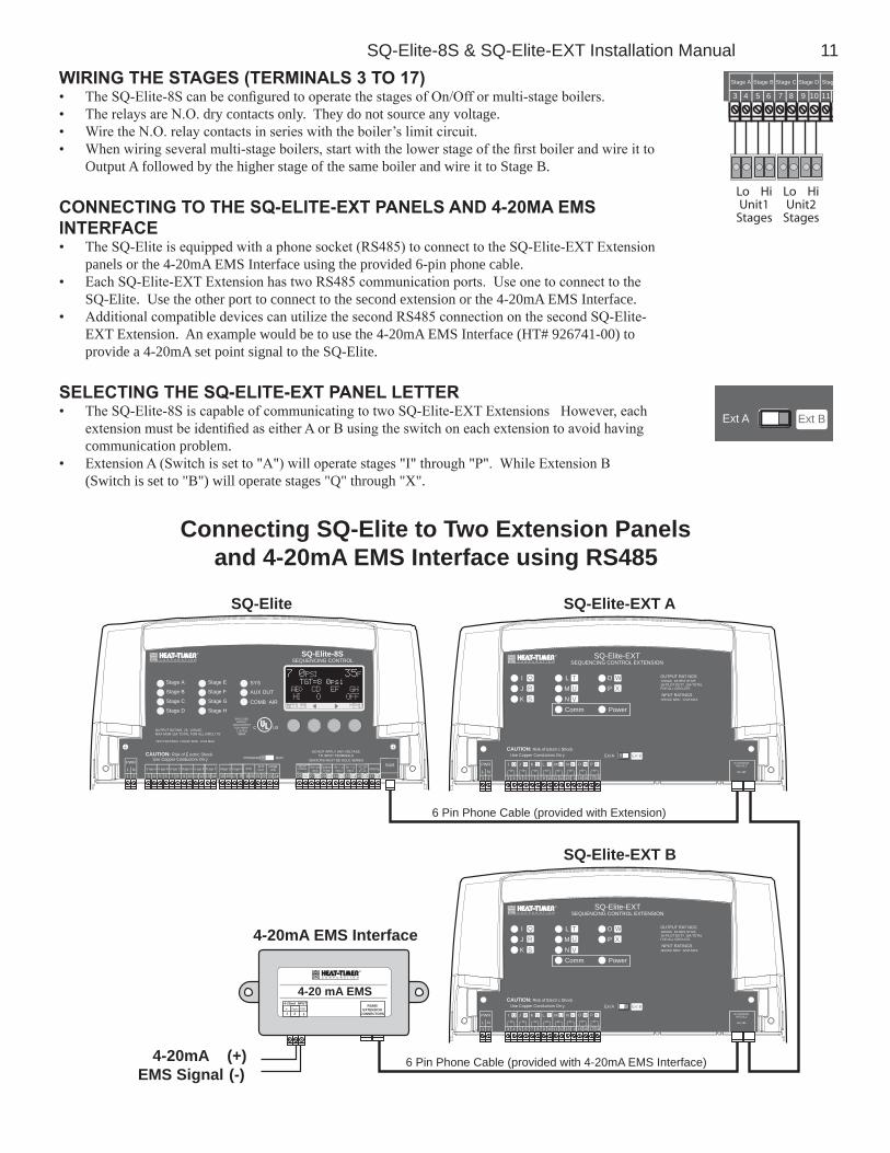
SQ-Elite-8S & SQ-Elite-EXT Installation Manual 11WIrIng tHe stages (terMInals 3 to 17)• The SQ-Elite-8S can be configured to operate the stages of On/Off or multi-stage boilers.• The relays are N.O. dry contacts only. They do not source any voltage.• Wire the N.O. relay contacts in series with the boiler’s limit circuit.• When wiring several multi-stage boilers, start with the lower stage of the first boiler and wire it to
Output A followed by the higher stage of the same boiler and wire it to Stage B.
Con
3 5
Stage A
7
Stage B
9
Stage C
11
Stag Stage D
6 8 104
Lo HiUnit1
Stages
Lo HiUnit2
StagesconnectIng to tHe sQ-elIte-eXt panels and 4-20Ma eMs InterFace• The SQ-Elite is equipped with a phone socket (RS485) to connect to the SQ-Elite-EXT Extension
panels or the 4-20mA EMS Interface using the provided 6-pin phone cable.• Each SQ-Elite-EXT Extension has two RS485 communication ports. Use one to connect to the
SQ-Elite. Use the other port to connect to the second extension or the 4-20mA EMS Interface.• Additional compatible devices can utilize the second RS485 connection on the second SQ-Elite-
EXT Extension. An example would be to use the 4-20mA EMS Interface (HT# 926741-00) to provide a 4-20mA set point signal to the SQ-Elite.
selectIng tHe sQ-elIte-eXt panel letter• The SQ-Elite-8S is capable of communicating to two SQ-Elite-EXT Extensions However, each
extension must be identified as either A or B using the switch on each extension to avoid having communication problem.
• Extension A (Switch is set to "A") will operate stages "I" through "P". While Extension B (Switch is set to "B") will operate stages "Q" through "X".
O
C
L1
Ext A
Ext B
C
W
U e opper Cond c or Only
I
K
Q
S
ION
terfa
Connecting SQ-Elite to Two Extension Panelsand 4-20mA EMS Interface using RS485
SQ-Elite
SQ-Elite-8SSEQUENCING CONTROL
PWR
L N1 2 3 5
S age A
7
S age B
9
S age C
11 13
S age E
15
S age F
17
Stage D
6 8 10 12 14 16 8
RS485
4
Stage G
9
S age H
21 27 29 31 33 3520 22 28 30 32 34 36
Stage E
Stage F
Stage G
Stage H
Stage A
Stage B
Stage C
Stage D
25 26 37 38
PROVE
PROGRAM RUN
23 24
ENCLOSEDENERGY
MANAGEMENTEQU PMENT
L STED99RA
C US
SQ-Elite-EXTSEQUENCING CONTROL EXTENSION
OP
Power
CAUTION: Risk of Electr c Shock
PWR
L N1 2
I
3 4
J
5 6
K
7 8
L
9 10
M
11 12
EXTENSIONMODULE
RS 485
Ext A
NPUT RATINGS115VAC 60Hz 12VA MAX
OUTPUT RAT NGS120VAC 6A RES STIVE1A PILOT DUTY 15A TOTALFOR ALL CIRCUITS
Ext B
LMNComm
TUV
WX
N
13 4
Q S UR T V
SQ-Elite-EXT A
Use Copper Conductors On y
IJK
QRS
O
15 16
P
17 18
W X
OP
Power
CAUTION: Risk of Electr c Shock
PWR
L N1 2
I
3 4
J
5 6
K
7 8
L
9 10
M
11 12
EXTENSIONMODULE
RS 485
Ext A
NPUT RATINGS115VAC 60Hz 12VA MAX
OUTPUT RAT NGS120VAC 6A RES STIVE1A PILOT DUTY 15A TOTALFOR ALL CIRCUITS
Ext B
LMNComm
TUV
WX
N
13 4
Q S UR T V
SQ-Elite-EXT B
Use Copper Conductors On y
IJK
QRS
O
15 16
P
17 18
W X
4-20 mA EMS4-20mA NPUT+ Signa GND
1 2 3
RS485EXTENSION
CONNECTORS
4-20mA EMS Interface
4-20mAEMS Signal
(+)(-)
6 Pin Phone Cable (provided with Extension)
6 Pin Phone Cable (provided with 4-20mA EMS Interface)
SQ-Elite-EXTSEQUENCING CONTROL EXTENSION
7 0PSI 35F TGT=8 0psi
AB> CD EF GH
HI O OFF
SYS
AUX OUT
COMB AIR
NPUT RATINGS 120VAC 60Hz 12VA MAX
Use Copper Conductors On yCAUTION: Risk of E ectric Shock
SENSORS MUST BE GOLD SERIES
OUTPUT RATING 2A 120VACMAX MUM 15A TOTAL FOR ALL CIRCU TS
DO NOT APPLY ANY VOLTAGETO INPUT TERMINALS
SYSAUXOUT
Au i i ryInpu 2
OutdoorTemp
Sys em4 20mA+ -
COMBAIR
HUT OWNTS AT
SET ACK
Aux l arynput1
Au i i ryInpu 3
12 Heat-Timer Corp.
---- MAINTENANCE ----
Unit F
Present Time 12:30P
<Sensor Trim>
<Histories>
<Configuration>
BACK SELECT
------ SETTINGS ------
Season Winter
Set Point 9 psi
EMS SetPoint 9 psi
<System Settings>
<Maintenance>
<System Startup>
BACK SELECT
Installer Menu seQuence-- CONTROL MODE ---
Set Point
EMS 4-20mA
BACK SAVE
-DISPLAY STANDARD -
English
Metric
BACK SAVE
EMS 4mA SET POINT
0 psi
[ ]
BACK SAVE
EMS 20mA SET POINT
30 psi
[ ]
BACK SAVE
-COMB. AIR OUTPUT-
No
Yes
BACK SAVE
-- EXTERNAL INPUT -
Shutdown
Tstat
Setback
BACK SAVE
--- BURNER TYPE ----
On/Off
2-Stage
3-Stage
4-Stage
BACK SAVE
-- TOTAL BOILERS --
8
[ ]
BACK SAVE
------ STAGING ------
Multiple Outputs
Single Output
BACK SAVE
------ SEQUENCE -------
Lo/Hi/Lo/Hi
Lo/Lo/Hi/Hi
BACK SAVE
--- CONTROL LOGIC---
PID
OSS
BACK SAVE
--- SENSOR FAULT ---
Stages On
Stages Off
BACK SAVE
ARE YOU SURE?
No
Yes
BACK SAVE
eMs set poInt
--- SENSOR TRIM ----
Sys Trim +0.0 psi
Outdoor Trim +0 F
BACK SELECT
Sys=10 psi 10:00AM
BACK NEXT
alert• To access Installer Menu, hold down
the Menu button for over three seconds.
• To be able to change the SQ-Elite settings the Program/Run Switch must be set to Program.
startup
MaIntenance
SQ-Elite-8S V1.00
Pressure 30psi
EMS 4-20mA, Shtdown
0psi - 30psi
BACK NEXT
--- SENSOR TYPE ---
Pressure 15psi
Pressure 30psi
Pressure 100psi
Pressure 200psi
Pressure 300psi
Pressure 0.250MPa
Pressure 0.600MPa
Pressure 1.000MPa
Pressure 1.600MPa
Vacuum 3in/762mm
BACK SAVE
----- BOILER AB -----
Mode Auto
Runtime 58Hrs
<Prev Boiler>
<Next Boiler>
BACK SAVE
- BOILER AB MODE -
Auto
Standby
Off
On
BACK SAVE
BOILER AB Runtime
58hrs
BACK CLEAR OK
boIler Menu
8.5 psi 45 FTGT=9.0 psi
ABC <DEF>
---- LO
Boiler Menu
SQ-Elite-8S & SQ-Elite-EXT Installation Manual 13
----- SETTINGS ------
Season Winter
Set Point 9.0psi
EMS Set Point 9.0psi
<System Settings>
<Maintenance>
<System Startup>
BACK SELECT
---- SEASON ---
Winter
Summer
BACK SAVE
----- SET POINT -----
10.0 psi
[ ]
BACK SAVE
-- EMS SET POINT --
10.0 psi
BACK SAVE
- SYSTEM EXERCISE -
Off
On
BACK SAVE
set poInt
------- RUN-ON -------
2min
[ ]
BACK SAVE
- STAGE SETTINGS -
Reaction Time 1min
Purge Delay 0.0min
Min Runtime 2min
Standby Delay 10min
Lst Stge Hold 5.0psi
Throttle 2.0psi
<Lead Settings>
BACK SELECT
-- REACTION TIME --
2min
[ ]
BACK SAVE
--- PURGE DELAY ----
0.0min
[ ]
BACK SAVE
- MINIMUM Runtime
2min
[ ]
BACK SAVE
-- STANDBY DELAY --
10min
[ ]
BACK SAVE
LAST STAGE HOLD
0.0 psi
[ ]
BACK SAVE
-- LEAD BOILER --
AB
CD
BACK SELECT
AUTO ROTATE PERIOD
24hrs
[ ]
BACK SAVE
- THROTTLE RANGE -
2.0 psi
[ ]
BACK SAVE
stage settIngs
SETBACK SCHEDULE
Setback 0.0psi
Present Time **:**
Day Schdul 7:00Am
Night Schdul 7:00Pm
------ SETBACK -------
0.0 psi
[ ]
BACK SAVE
- NIGHT SCHEDULE --
07:**Pm
BACK SAVE
-- DAY SCHEDULE ----
07:**Am
BACK SAVE
- SET PRESENT TIME
**:**
BACK SAVE
scHedules
BACK SELECT
- OUTDOOR CUTOFF -
70 F
[ ]
BACK SAVE
-- LEAD ROTATION --
Time
Manual
FOFO
BACK SELECT
-- LEAD SETTINGS --
Lead Boiler AB
Rotate Mode Time
BACK SELECT
lead & rotatIon
8.5 psi 45 FTGT=9.0 psi
ABC <EFG>
---- LO
Boiler Menu
- SYSTEM SETTINGS -
<Stage Settings>
<Setback Schedule>
Setback 0.0psi
Run-On 2min
Sys Exercise Off
BACK SELECT
systeM settIngs

14 Heat-Timer Corp.
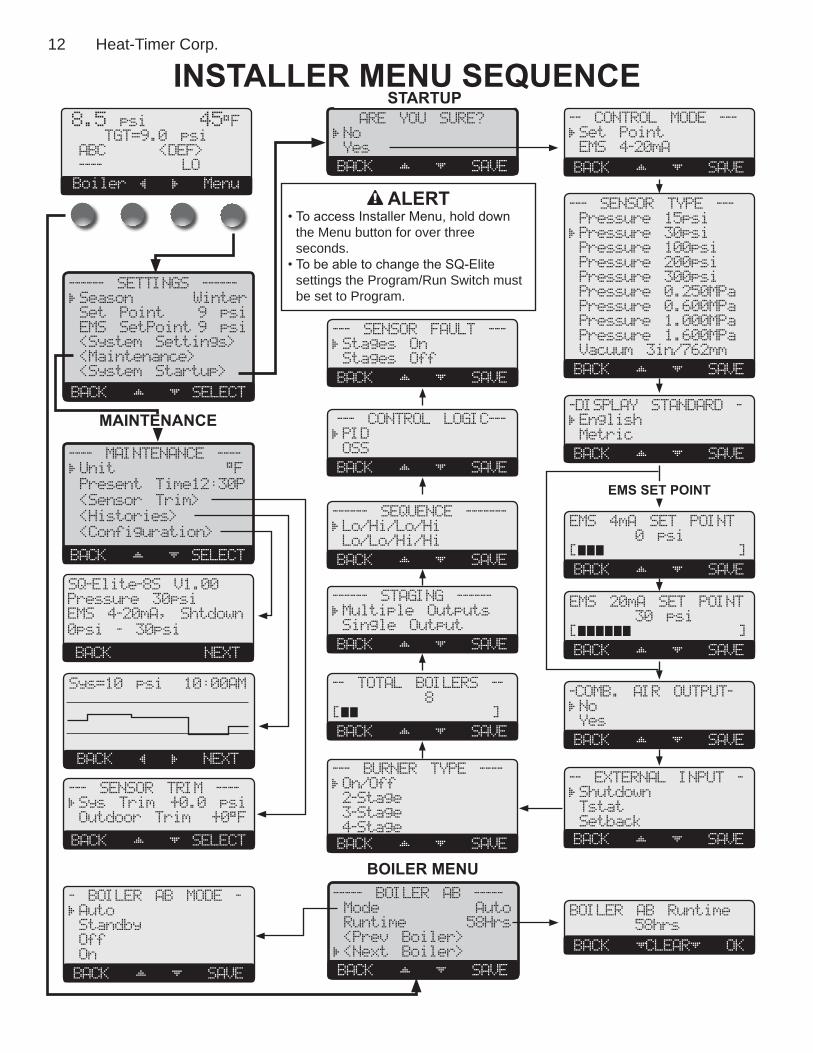
startup settIngsCan be accessed by holding down the Menu button for over three seconds.
prograM cHange settIngsTo be able to change the SQ-Elite settings the Program/Run Switch must be set to Program. The switch is located under the Enclosure Wiring Cover for security. The Enclosure Wiring Cover can be securely closed using a padlock.
1
Use C pper Co AUTION: R s
PROGRAM RUN
startup seQuenceHold Button: MENU/<System Startup>• When powered, the SQ-Elite performs a self-test on its components. After the self-test
diagnostics have been successfully completed, the SQ-Elite will initialize the panel. • On the first power up, the System Startup screen will appear after the initialization is
complete. If it does not, the SQ-Elite has already been configured.
ARE YOU SURE?
No
Yes
BACK SAVE
• The System Startup menu sets the main parameters as the type of sensor, the sequencing mode, and many other parameters described in this section.
• Before entering the Startup menu, several warnings will alert you to the consequences of making Startup changes.
control ModeSetPoint,EMS4-20mA Default:SetPointHold Button: MENU/<System Startup>/..../Control Mode• Set Point mode does not require an outdoor sensor. If an outdoor sensor is connected
in Set Point mode it will be used only as an Outdoor Cutoff point. That is, to turn the stages, system, and Comb. Air relays off.
• The EMS 4-20mA option allows the SQ-Elite-8S to receive an external set point from an EMS/BMS system. This option requires the use of the 4-20mA EMS Interface (HT# 926741-00).
• You must select the 4mA (min) and 20 mA (max) Set Points in the following screens.
--- CONTROL MODE ---
Set Point
EMS 4-20mA
BACK SAVE
--- SENSOR TYPE ---
Pressure 15psi
Pressure 30psi
Pressure 100psi
Pressure 200psi
Pressure 300psi
Pressure 0.250MPa
Pressure 0.600MPa
Pressure 1.000MPa
Pressure 1.600MPa
Vacuum 3in/762mm
BACK SAVE
sensor typePressure15Psi,30Psi,100Psi,200Psi,300Psi,0.25MPa,0.6Mpa,1MPa,1.6MPa,Vacuum3in,762mm Default:30psiHold Button: MENU/<System Startup>/..../Sensor Type• The SQ-Elite-8S can accept a variety of pressure or vacuum transducers. This option
will allow the SQ-Elite-8S to utilize the proper sensor data based on the Sensor Type selected.
dIsplay standardEnglish,metric Default:EnglishHold Button: MENU/<System Startup>/..../Display Standard• The SQ-Elite-8S can control boilers in steam heating environment. It gives the user the
capability of displaying pressure and temperature information in either of the standards.
-DISPLAY STANDARD-
English
Metric
BACK SAVE
settIng tHe 4Ma and 20Ma set poInts (avaIlable In 4-20Ma eMs only)Hold Button: MENU/<System Startup>/..../EMS 4mA Set Point/EMS 20mA Set Point• If EMS 4-20mA is selected from the Control Mode Menu as the pressure set point
source, the user must purchase a Heat-Timer 4-20mA EMS Interface (HT# 926741-00) to accept the 4-20mA signal and transmit it to the SQ-Elite-8S.
• In addition, the user will need to set the pressure range parameters in the Startup Menu. First, set the pressure reading at 4mA, then the set it at 20mA.
• The SQ-Elite-8S will only read the pressure range between 2.4mA and 21.6mA based on the 4mA and 20mA settings entered.
• To shutdown the control using the EMS signal, send a signal that is above or below the 2-22mA range. The display will show the message "Shutdown by EMS" and all stages will de-energize. However, the System and Comb. Air relays will continue for the Run-On delay period then de-energize.
EMS 4mA SET POINT
0psi
[ ]
BACK SAVE
EMS 20mA SET POINT
100psi
[ ]
BACK SAVE
alertA good practice after performing any Startup menu modifications is to check all operating settings and adjustments to match the new settings.
SQ-Elite-8S & SQ-Elite-EXT Installation Manual 15
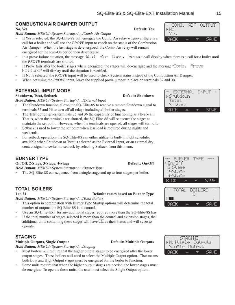
coMbustIon aIr daMper outputNo,Yes Default:YesHold Button: MENU/<System Startup>/..../Comb. Air Output• If Yes is selected, the SQ-Elite-8S will energize the Comb. Air relay whenever there is a
call for a boiler and will use the PROVE input to check on the status of the Combustion Air Damper. When the last stage is de-energized, the Comb. Air relay will remain energized for the Run-On period then de-energize.
- COMB. AIR OUTPUT-
No
Yes
BACK SAVE
• In a prove failure situation, the message "Wait for Comb. Prove" will display when there is a call for a boiler until the PROVE terminals are shorted.
• If Prove fails after the boiler stages where energized, the stages will de-energize and the message "Comb. Prove Failure" will display until the situation is rectified.
• If No is selected, the PROVE input will be used to check System status instead of the Combustion Air Damper.• When not using the PROVE input, leave the supplied prove jumper in place on terminals 37 and 38.
eXternal Input ModeShutdown,Tstat,Setback Default:ShutdownHold Button: MENU/<System Startup>/..../External Input• The Shutdown function allows the SQ-Elite-8S to receive a remote Shutdown signal to
terminals 35 and 36 to turn off all relays including all boiler stages.• The Tstat option gives terminals 35 and 36 the capability of functioning as a heat-call.
That is, when the terminals are shorted, the SQ-Elite-8S will sequence the stages to maintain the set point. However, when the terminals are opened, all stages will turn off.
• Setback is used to lower the set point when less load is required during nights and weekends.
• For setback operation, the SQ-Elite-8S can either utilize its built-in night schedule, available when Shutdown or Tstat is selected as the External Input, or an external dry contact signal to switch to setback by selecting Setback from this menu.
-- EXTERNAL INPUT -
Shutdown
Tstat
Setback
BACK SAVE
burner typeOn/Off,2-Stage,3-Stage,4-Stage Default:On/OffHold Button: MENU/<System Startup>/..../Burner Type• The SQ-Elite-8S can sequence from a single stage and up to four stages per boiler.
--- BURNER TYPE ----
On/Off
2-Stage
3-Stage
4-Stage
BACK SAVE
total boIlers1to24 Default:variesbasedonBurnerTypeHold Button: MENU/<System Startup>/..../Total Boilers• This option in combination with Burner Type Startup options will determine the total
number of outputs the SQ-Elite-8S is to control.• Use an SQ-Elite-EXT for any additional stages required more than the SQ-Elite-8S has.• If the total number of stages selected is more than the control and extension stages, the
additional units containing these stages will have CE as their status and will seize to operate.
-- TOTAL BOILERS --
8
[ ]
BACK SAVE
stagIngMultipleOutputs,SingleOutput Default:MultipleOutputsHold Button: MENU/<System Startup>/..../Staging• Most boilers will require that the higher output stages to be energized after the lower
output stages. These boilers will need to select the Multiple Output option. That means both Low and High Output stages must be energized for the boiler to function.
• Some units require that when the higher output stages are needed, the lower stages must de-energize. To operate these units, the user must select the Single Output option.
------ STAGING ------
Multiple Outputs
Single Output
BACK SAVE

16 Heat-Timer Corp.
seQuenceLo/Hi/Lo/Hi,Lo/Lo/Hi/Hi Default:Lo/Hi/Lo/HiHold Button: MENU/<System Startup>/..../Sequencing• During low load conditions, some boilers run more efficient when the lower stages are
energized alone than with the higher stages. These types of boilers should select Lo/Lo/Hi/Hi. Then, the SQ-Elite-8S will sequence the lower stages of all Automatic boilers before sequencing the higher stages.
------ SEQUENCE -------
Lo/Hi/Lo/Hi
Lo/Lo/Hi/Hi
BACK SAVE
• For the rest of the boiler types, the Lo/Hi/Lo/Hi should allow the staging of the lower stage of the lead boiler followed by the higher stage of the same boiler. Then when more stages are needed, it will fire the lower stage of the lag boiler followed by the higher stage of the lag boiler.
control logIcPID,OSS(Over-Sized-System) Default:PIDHold Button: MENU/<System Startup>/..../Sequencing• The PID option allows the SQ-Elite-8S to sequence stages based on the Reaction Time
and the Boiler Minimum Run Time. The PID relies on the rate of change in the system pressure. The PID logarithmic calculations foresee changes and sequence stages based on those changes. It is the most efficient operation for most heating applications.
--- CONTROL LOGIC---
PID
OSS
BACK SAVE
• The Oversize option sequence stages based on how many Throttling ranges (differentials) is the system pressure away from the set point. At one Throttling range below the Set Point, only one stage will be on. For each additional Throttling range below the Set Point, an additional stage will be activated. The last stage on will be allowed to exceed the Set Point by one full Throttling range before turning off that stage. This helps to prevent the last stage from short cycling. See Throttle Range.
When PID is selected, the following are the settings that directly affect this mode of operation:• Reaction Time SELECT Settings/System Settings/Stage Settings/Reaction Time• Purge Delay SELECT Settings/System Settings/Stage Settings/Purge Delay• Minimum Run Time SELECT Settings/System Settings/Stage Settings/Min Runtime• Standby Delay SELECT Settings/System Settings/Stage Settings/Standby Delay• Last Stage Hold SELECT Settings/System Settings/Stage Settings/Last Stage Hold
When Oversize (OSS) is selected, the following is the setting that directly affects this mode of operation:• Throttle SELECT Settings/System Settings/Stage Settings/Throttle
sensor FaultStagesOn,StagesOff Default:StagesOnHold Button: MENU/<System Startup>/..../Sensor Fault• The Sensor Fault will determine the operating status of all output stages that are set to
Auto or Standby when a sensor reads Short or Open.
--- SENSOR FAULT ---
Stages On
Stages Off
BACK SAVE
• The Shutdown or Tstat activation will take precedence over the Sensor Fault status. That means, if Stages On is selected and the Shutdown was active, all stages will be Off on a sensor fault.
• When Stages-On is selected, the SQ-Elite-8S will turn all stages On when the System sensor reads Short or Open.• When Stages-Off is selected, the SQ-Elite-8S will turn all stages Off when the System sensor reads Short or Open.• The Outdoor Sensor Short or Open status will not affect the stages operation.
settIng tHe control to Factory deFaultsTo Reset the SQ-Elite-8S control to its original factory defaults, follow the following steps:• Power down the control.• Hold down the two right most buttons while powering the control back up until the To-tal Clear Started screen appears. The Display will direct you to the Startup menu after the defaults are loaded to program the control.
TOTAL CLEAR STARTED
Release buttons
and
Please Wait
NOTE: After resetting the control to the original factory defaults, the user must go through all control settings.
IMportantAfter performing a total reset, do not turn off power to the control until all Startup settings have been made. Otherwise, the next power-up will be set to many Startup factory settings that might not fit your application.

SQ-Elite-8S & SQ-Elite-EXT Installation Manual 17
operatIng settIngsCan be accessed by holding down the Menu button for over three seconds.
prograM cHange settIngsTo be able to change the SQ-Elite-8S settings the Program/Run Switch must be set to Program. The switch is located under the Enclosure Wiring Cover for security The Enclosure Wiring Cover can be securely closed using a padlock.
P R
L
S S B C
PROGRAM RUN
EN LOSED
seasonWinter,Summer Default:WinterButton: MENU/Season• The SQ-Elite-8S will turn all boiler relays off when it is in Summer setting. The
Message Display Line will read Summer to show status.• When in Winter, the SQ-Elite-8S will activate the System relay whenever the Outdoor
temperature falls to or below the Outdoor Cutoff setting. In addition, it will begin heating whenever the System pressure falls below the Set Point. The Message Display Line will not display any season information.
• When the season is over, it is a good practice to switch the SQ-Elite-8S Season setting to Summer to turn off all heating instead of turning off the control. This will preserve the battery life.
alertDO NOT turn power off to the SQ-Elite when in off-season. If you do so, the battery will run down and have to be replaced. Instead, switch to Summer.
---- SEASON ---
Winter
Summer
BACK SAVE
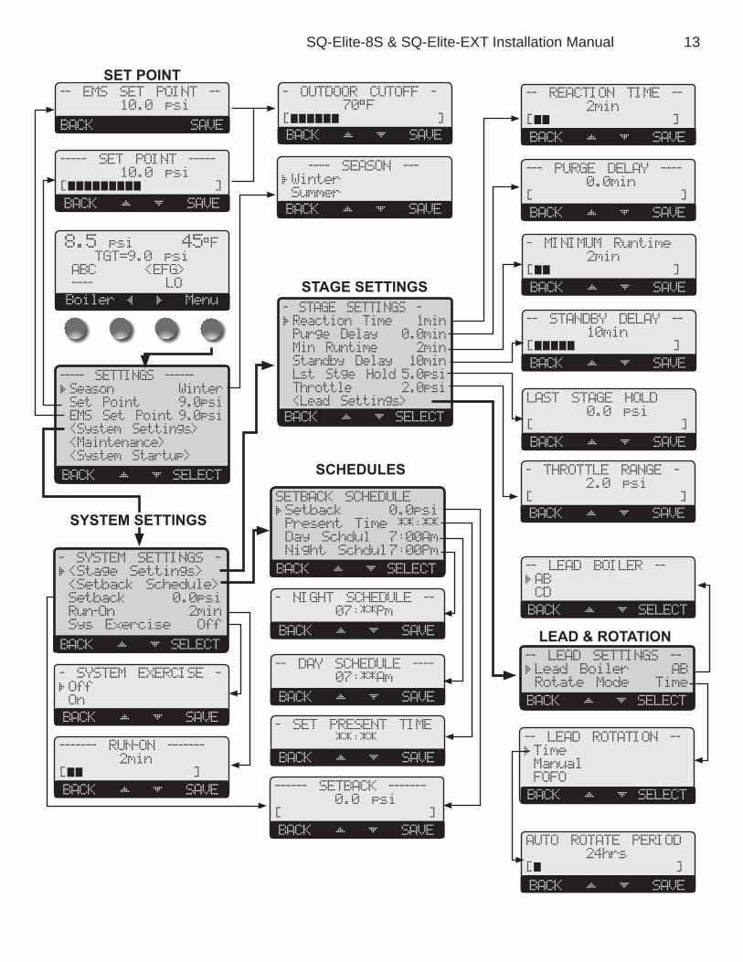
set poInt (not adjustable In eMs Mode)SeepressureTransducerDefaultSettingsandRangesTableButton: MENU/Set Point InSetPointorEMS4-20mA• The Set point is the pressure value the SQ-Elite-8S will use to control the system.• The SQ-Elite-8S will add, subtract, or hold the stages of the heating boilers to maintain
the system pressure around the Set point.
----- SET POINT -----
12.0psi
[ ]
BACK SAVE
• The system can be expected to oscillate around the set point. The amount of oscillation depends on the System Settings and Stage Settings.
• If an Outdoor Sensor was connected, pressing the SAVE button will switch to the Outdoor Cutoff setting option.• If the EMS Mode was Enabled, the Set Point will be set by the EMS/BMS system and will be available as read only.• Any value below the 2mA or above 22mA will indicate a "Shutdown by EMS" message on the Message Line.
outdoor cutoFF teMperatureAdjustableOff,20ºF/-7ºC-100ºF/38ºC,On Default:70ºF/21ºCButton: MENU/Set Point/Outdoor Cutoff inSetPoint• In Set Point mode, if the outdoor sensor is installed, the Outdoor Cutoff screen will
automatically appear after the pressure Set Point has been selected.
- OUTDOOR CUTOFF --
70 F
[ ]
BACK SAVE
• When the outdoor temperature falls to the adjustable Outdoor Cutoff temperature, the SQ-Elite-8S will control and sequence the boiler stages to hold the set point.
• When the outdoor temperature rises to the Outdoor Cutoff plus a 2°F differential, the SQ-Elite-8S will turn all boilers off. The System and Comb. Air relays that were energized will remain energized for the Run-On delay then de-energize.
• The Outdoor Cutoff can be set to ON or OFF. In the ON position, the System Relay will run regardless of the Outdoor temperature and the burner stages will be active to hold the set point.
• In the OFF position, the System Relay will always be off and all stages will be off as well.
systeM settIngsHold Button: MENU/<System Settings>The System Settings menu provides access to adjusting and fine-tuning the heating system for enhanced comfort and better fuel savings. The SQ-Elite-8S behaves differently based on the selected Control Modes (see Startup Settings on page 14).
- SYSTEM SETTINGS -
<Stage Settings>
<Setback Schedule>
Setback 0.0Psi
Run-On 2min
System Exercise Off
BACK SELECT

18 Heat-Timer Corp.
prograM cHange settIngsTo be able to change the SQ-Elite-8S settings the Program/Run Switch must be set to Program. The switch is located under the Enclosure Wiring Cover for security. The Enclosure Wiring Cover can be securely closed using a padlock.
PWR
L N1
Stag A St ge B g C
PROGRAM RUN
stage settIngsHold Button: MENU/<System Settings>/<Stage Settings>
-- STAGE SETTINGS --
Reaction Time 1min
Purge Delay 0.0min
Min Runtime 2min
Standby Delay 10min
Lst Stge Hld 5.0psi
Throttle 2psi
<Lead Settings>
BACK SELECT
-- REACTION TIME --
2min
[
BACK SAVE
reactIon tIMeAdjustablefrom1to10minutes Default:2minutesHold Button: MENU/<System Settings>/<Stage Settings>/Reaction TimeinPIDLogiconly• Available in PID Control Logic only (See PID Operation on page 5).• It is the amount of time it takes a single stage to affect the system.• After the SQ-Elite turns on a stage trying to meet a set point, it will not turn on another
stage until the Reaction Time has elapsed. Then, it will recalculate if a stage is need.• To determine the optimum time, in a heating system start with a hot system. Then, turn
on a single stage and calculate how long it takes until the system begins to respond to that stage. That period should be set as the Reaction Time.
purge delayAdjustablefrom0.0to10.0minutes Default:2.0minutesHold Button: MENU/<System Settings>/<Stage Settings>/Purge DelayinPIDLogiconly• Available in PID Control Logic only (See PID Operation on page 5).• Most large boilers must go through a purge cycle before they are brought on line.
--- PURGE DELAY ----
0.0min
[ ]
BACK SAVE
• When the SQ-Elite-8S activates a stage (the lowest stage on a boiler), it does not start to calculate its output until the Purge Delay is over. This allows the boiler to fully come on line and to begin producing output.
• The Purge Delay helps prevent short cycling of a newly activated boiler. Once the lowest boiler stage is activated, it MUST run through the entire Purge Delay period.
• The minimum Purge Delay setting MUST be set to the time required by the boiler's manufacturer specification.
MInIMuM runtIMeAdjustablefrom1to60minutes Default:2minutesHold Button: MENU/<System Settings>/<Stage Settings>/Min RuntimeinPIDLogiconly• Available in PID Control Logic only (See PID Operation on page 5).• This is the minimum amount of time any stage will run.• For the lowest stage of a boiler, the Minimum Runtime starts after the purge cycle.
- MINIMUM Runtime -
2min
[
BACK SAVE
• This timer does not apply to the last stage online. The Last Stage Hold applies in that case.• Initially, set the Minimum Runtime to half the Reaction Time.• If System tends to overshoot, reduce the Minimum Runtime. If boilers tend to short cycle, increase Minimum Runtime.
standby delayAdjustablefrom1to60minutes Default:10minutesHold Button: MENU/<System Settings>/<Stage Settings>/Standby DelayinPIDLogiconly• Available in PID Control Logic only (See PID Operation on page 5).• Standby boilers are used as a backup for extreme load conditions only. A standby boiler
can never be a Lead Stage. The Standby Delay only applies to boilers in Standby Mode.• A Standby unit can only be activated after all the units in Auto Mode have run at high
fire for the full Standby Delay.
-- STANDBY DELAY --
10min
[
BACK SAVE
• The full Standby Delay must always elapse regardless of what happens to system pressure. Therefore, a shorter Standby Delay will result in smoother set point operation in extreme conditions. However, longer Standby Delays may prevent a Standby boiler from starting if the other boilers can eventually meet the load, or if the load decreases.
• When more than one boiler is set as a Standby boiler, remember that it will be added to the Reaction Time for the first stage on the first Standby boiler only. The following stages and boiler start time will rely on Pre-Purge and Reaction Time only.

SQ-Elite-8S & SQ-Elite-EXT Installation Manual 19
last stage HoldSeepressureTransducerDefaultSettingsandRangesTableHold Button: MENU/<System Settings>/<Stage Settings>/Last Stge HoldinPIDLogiconly• Available in PID Control Logic only (See PID Operation on page 5).• The Last Stage Hold prevents short cycling of the Lead Stage during low load conditions
where the system might have a load that is significantly less than the output of one stage.
LAST STAGE HOLD
0 PSI
[ ]
BACK SAVE
When the SQ-Elite-8S brings on the Lead Stage, the Set Point is quickly exceeded, and the Lead Stage is turned off.• To prolong the run time during this type of condition, use the Last Stage Hold setting.• The SQ-Elite will allow the system pressure to exceed the Set Point by the Last-Stage-Hold value, before the Lead Stage is
turned off.• For example, with a Set Point of 8 Psi and a Last Stage Hold setting of 2 Psi, the Lead Stage boiler will remain on, at low fire,
until the system reaches 10 Psi. During that period, the display will show "Hold Until 10 Psi" then, the lead stage will turn off
tHrottle rangeSeepressureTransducerDefaultSettingsandRangesTableHold Button: MENU/<System Settings>/<Stage Settings>/Throttle inOSSLogiconly• Available in OSS Control Logic only (See OSS Operation on page 5).• The Throttling Range sets a pressure band around the Set Point that controls when stages
will be turned on or off.
-- THROTTLE RANGE --
2PSI
[ ]
BACK SAVE
• For example, in the OSS Control Mode, no stages will be activated until the pressure falls one full Throttling Range below the Set Point. A second stage will be activated when the pressure falls to two full Throttling Ranges below the Set Point, and so on, with one extra stage being turned on for every throttling range below the Set Point the System pressure reaches.
• Stages will be turned off as the pressure rises toward the Set Point using one full throttling range as a differential between stages.
• The last stage to be turned off will be allowed to exceed the Set Point by a full throttling range before it is turned off. This helps prevent the last stage from short cycling when the load is low or when the stage is oversized.
set point = 50 psi throttle = 5 psi boilers (a, b, c, d, e, and F) lead stage =<a>
Falling pressure rising pressuresystem
pressurethrottle ranges stages turned on stages on stages turned off stages on
55 Psi -1 ---- None A None50 Psi 0 ---- None ---- A45 Psi 1 A A ---- A
41 - 44 Psi 1 ---- A ---- A40 Psi 2 B A + B B A + B35 Psi 3 C A + B +C C A + B +C30 Psi 4 D A + B +C + D D A + B +C + D25 Psi 5 E A + B +C + D + E E A + B +C + D + E20 Psi 6 F A + B +C + D + E + F F A + B +C + D + E + F15 Psi 7 ---- A + B +C + D + E + F ---- A + B +C + D + E + F
lead settIngsHold Button: MENU/<System Settings>/<Stage Settings>/<Lead Settings>The lead menu is to help in selecting the Lead boiler and the type of rotation appropriate for the system.
-- LEAD SETTINGS --
Lead Boiler AB
Rotate Mode Time
BACK SELECT

20 Heat-Timer Corp.
lead boIlerDependingonthenumberofstages Default:ThefirstsetofstagesHold Button: MENU/<System Settings>/<Stage Settings>/<Lead Setting>/Rotate Mode• The Lead Boiler’s lowest stage will always be the first stage brought on when there is a
call for output. As more output is needed, additional Stages are added.• The Lead Boiler is always shown on the main display in brackets.• In a 2-Stage system (see Burner Type in the Startup section on page 15), the display will
show the two Lead Boiler stages bracketed <AB>. In a 3-Stage system, the display will show the three Lead Boiler stages bracketed <ABC>, and so on.
• The Lead Boiler can be rotated based on the Rotation Mode selected. (See next setting)
-- LEAD BOILER --
AB
CD
EF
BACK SELECT
rotate ModeAdjustableTime(from1hrto999hrs),Manual,FOFO Default:Time(24Hours)Hold Button: MENU/<System Settings>/<Stage Settings>/<Lead Setting>/Rotate Mode• The Lead Boiler is the first boiler brought on when output is required.• The Lead Boiler can be rotated automatically, manually, or based on First-On/First-Off
(FOFO). The automatic rotation is recommended for most applications. • The current Lead Boiler is shown in brackets on the main display.• Only boilers that are set to Auto Mode can be Lead. Therefore, not all the boilers may
be available when manually selecting a new Lead Boiler.• If Time is selected, a second screen will allow the adjustment of the Auto Rotate Period.
If 24 Hours (default setting) was selected, the first rotation will take effect after 12 hours if the Time was not set. However, if the Time was set, the rotation will always take place at 2:00AM. The following rotations will take place every 24 hours thereafter.
• If Time Rotation was set to other than 24 hours, the rotation timer will start from the moment the setting is changed.
• If First-On/First-Off (FOFO) is selected, the concept will follow this example; if A is the lead, the starting sequence of boilers will be A, B, then C. When the de-energizing of the stages starts, it will turn off A, B, Then C. Then stage D will be the new lead for the next load.
setback scHeduleButton: MENU/<System Settings>/<Stage Settings>/<Setback Schedule>
-- LEAD ROTATION --
Time
Manual
FOFO
BACK SELECT
If Time Rotation is selectedAUTO ROTATE PERIOD
24hrs
[ ]
BACK SAVE
SETBACK SCHEDULE
Setback 0psi
Present Time **:**
Day Schdule 7:00Am
Night Schdul 7:00Pm
BACK SELECT
setbackSeepressureTransducerDefaultSettingsandRangesTableButton: MENU/<System Settings>/<Setback Schedule>/Setback inDay/NightScheduleButton: MENU/<System Settings>/Setback inExternalSignal• The Setback feature can be used to provide the SQ-Elite-8S with a lower Set Point
when less load is required during the night or on the weekends when the building is not occupied, but heat is still required.
------ SETBACK -------
0psi
[ ]
BACK SAVE
• The new Set Point will appear on the main display indicating this condition "Setback to 5 Psi".• For example, if the pressure set point is 8 Psi and the Setback is 3 Psi, then when in Setback, the SQ-Elite-8S will hold a Set
Point of 5 Psi.
avoiding conflicting boiler limits• The pressure limits set on the boilers MUST be set considerably higher than the SQ-
Elite’s Set Point for the reasons detailed below.• The SQ-Elite sensor is located in a common header some distance from the boilers.• As the pressure rises in the header and before reaching the sensor location, energy is
dissipated. Therefore, the pressure in the header could be lower than that registered by the boiler sensors.
• In addition to the normal drop experienced between the boiler’s pressure and that read
WarnIngThe temperature limits set on the boilers must be higher than the SQ-Elite Set Point. Read the section at left for details that will prevent erratic system operation.

SQ-Elite-8S & SQ-Elite-EXT Installation Manual 21
by the SQ-Elite sensor, the Last Stage Hold setting must be accounted for. The boiler limit must be set above the Set Point PLUS the Last Stage Hold PLUS the normal drop experienced in the piping.
• Using the previous example of a 2 Psi Last Stage Hold with a 8 Psi Set Point, the boilers’ limits must be set enough over 10 Psi to prevent the boilers’ internal limits being reached. In this situation, the boiler high limit should be set at approximately 12 Psi to prevent the difference in boiler pressure vs. header pressure causing erratic operation.
day/nIgHt scHedulesButton: MENU/<System Settings>/<Setback Schedule>/Day Schedules• The SQ-Elite has two levels of heat. The Day level is used when a building is occupied
and people are active.• The Night (Setback) level is used when a building is not occupied, or when people are
sleeping. This setting reduces the set point by the Setback setting. If the Day calculated pressure was 8 Psi and the Setback was 3 Psi, the Night Schedule will run at (8 Psi - 3Psi) = 5 Psi.
-- DAY SCHEDULE ----
07:**Am
BACK SAVE
-- NIGHT SCHEDULE --
10:**Pm
BACK SAVE
set present tIMeButton: MENU/<System Settings>/<Setback Schedule>/Present TimeButton: MENU/<Maintenance>/Present Time• The Time is used for Day/Night Schedule and History graph.• Adjust the time by selecting Time from the menu and then scrolling through the hours
followed by the minutes. If hours are to be set to PM, scroll through the AM hours to reach the PM hours.
- SET PRESENT TIME
**:**
BACK SAVE
alertRemember that the battery is the backup for the Time. If no power is supplied to the SQ-Elite, the battery will die in three months and time clock values will be lost and will need to be reset.
coMbustIon aIr daMper operatIonThe SQ-Elite-8S controls multiple relays each controlling different types of equipment. In addition to the control of the boilers, it can control a combustion air damper. See Comb. Air Damper 15.
run-onAdjustablefrom0to60minutes Default:2minutesHold Button: MENU/<System Settings>/Run-On• The Run-On applies to the System and Comb. Air relays. For the System relay, it is used
to dissipate the excess energy from the boilers.• For a combustion air damper, it brings in enough fresh air for the next boiler fire up.• The Run-On time should be set based on the size and type of the equipment.
------- RUN-ON -------
2min
[
BACK SAVE
systeM eXercIseAdjustableOff,On Default:OffHold Button: MENU/<System Settings>/System Exercise• The SQ-Elite-8S provides an option to exercise the System relay for 10 seconds when
not used for seven days.
- SYSTEM EXERCISE -
Off
On
BACK SAVE
MaIntenanceHold Button: MENU/<Maintenance>The Maintenance menu gives access to sensor trimming. In addition, you will have access to view the Startup configuration settings as well as sensor histories
alertTo be able to change the SQ-Elite settings the Program/Run Switch must be set to Program. The switch is located under the Enclosure Wiring Cover for security. The Enclosure Wiring Cover can be securely closed using a padlock.
---- MAINTENANCE ----
Standard English
Present Time 12:30P
<Sensor Trim>
<Histories>
<Configuration>
BACK SELECT

22 Heat-Timer Corp.
systeM & outdoor sensor trIMOutdoorAdjustable-20°F/-10°Cto+20°F/+10°C Default:0°F/0°CSystemadjustmentis10%oftheselectedSensorTyperange.Hold Button: MENU/<Maintenance>/Outdoor Trim• The Heat-Timer pressure and thermistor type sensors are very accurate, and normally
require no calibration. However, sometimes it may be desirable to make small adjustments to the displayed value.
• Do not use the Trim setting to make the Outdoor sensor match the one reported on the radio or TV. Outdoor temperature can vary widely over a broadcast range.
--- SENSOR TRIM ----
System Trim +0.0psi
Outdoor Trim +0 F
BACK SELECT
HIstoryHold Button: MENU/<Histories>The SQ-Elite provides users with a graphical history of the System and Outdoor values for the previous 24 hours. The values are sampled every 12 minutes. That is, readings of pressure and temperatures are recorded and stored every 12 minutes for the last 24 hours.• To view the values of specific period, use the two middle buttons to scroll to that time
and read the upper left temperature.• The first screen will be the System Pressure History. By clicking on the Next button,
you will be able to view the Outdoor Temperature History.
Sys=12psi 10:00AM
BACK NEXT
SQ-Elite-8S V1.00
Pressure 30psi
EMS 4-20mA, Shtdown
0psi - 30psi
BACK NEXT
8 X On/Off
PID,Fault Stgs Off
Comb. Air
BACK NEXT
conFIguratIonHold Button: MENU/<Maintenance>/<Configuration>• This menu option provides a consolidated view of the Startup settings.• Additional control settings will be available by selecting the NEXT option.
dIsplayThe SQ-Elite-8S display layout provides a variety of information that gives an immediate picture of the operation status. The display shows four heating boilers at a time. The two middle buttons scrolls the screen to view additional boilers. Moreover, all the information is brightly displayed. It can be viewed in brightly or dimly lit rooms.• The buttons' functionality changes based on the screen and menu level. The buttons' functionality is displayed on a dark background on the screen's bottom line.• Horizontal arrows are to scroll through the available stages.• Vertical arrows are to scroll through the menu functions
when in menus or to change values of settings when in its specific screen.
• The second line from the top is the Message Display Line. In normal operation it displays the Target Set Point. However, that will be replaced by a message indicating an important status. See Display Messages on next page.
• Pressing the MENU button fast displays the User Menu.• Pressing and holding the MENU button for more than 3
seconds displays the Installer Menu.• Pressing the BOILER button fast displays the Boiler Menu.• Pressing and holding the BOILER button for more than 3
seconds displays the Display Contrast Menu.
8 F
K
HI
M N
o r T
y L
s nd eir
nct on
Outdoor TempSystem Pressure
Message Display Line
Units and their Status
Button functionsButton
------ CONTRAST -------
18
[ ]
BACK SAVE
dIsplay output statusThe SQ-Elite status gives immediate access to each Boiler status. The following list shows all possible boiler status:• <AB> This is a two-stage boiler AB. It is the Lead in sequencing. (Brackets indicate Lead Stage).• --- The boiler is de-energized. The Boiler Mode is set to Auto.• STB The boiler is de-energized. The Boiler Mode is set to Standby.• LO The lowest stage is active. Available in multi-stage boilers only. The Boiler Mode is set to either Auto or Standby.• HI The highest stage is active. The Boiler Mode is set to either Auto or Standby.• MED The middle stage is active. Available in Three-stage boilers only. The Boiler Mode is set to either Auto or Standby.
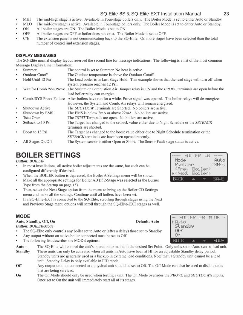
SQ-Elite-8S & SQ-Elite-EXT Installation Manual 23• MHI The mid-high stage is active. Available in Four-stage boilers only. The Boiler Mode is set to either Auto or Standby.• MLO The mid-low stage is active. Available in Four-stage boilers only. The Boiler Mode is set to either Auto or Standby.• ON All boiler stages are ON. The Boiler Mode is set to ON• OFF All boiler stages are OFF or boiler does not exist. The Boiler Mode is set to OFF.• C/E The extension panel is not communicating back to the SQ-Elite. Or, more stages have been selected than the total
number of control and extension stages.
dIsplay MessagesThe SQ-Elite normal display layout reserved the second line for message indications. The following is a list of the most common Message Display Line information:• Summer The control is set to Summer. No heat is active.• Outdoor Cutoff The Outdoor temperature is above the Outdoor Cutoff.• Hold Until 12 Psi The Lead boiler is in Last Stage Hold. This example shows that the lead stage will turn off when
system pressure reaches 12 Psi.• Wait for Comb./Sys Prove The System or Combustion Air Damper relay is ON and the PROVE terminals are open before the
lead boiler relay can energize.• Comb./SYS Prove Failure After boilers have run for a while, Prove signal was opened. The boiler relays will de-energize.
However, the System and Comb. Air relays will remain energized.• Shutdown Active The SHUTDOW Terminals are Shorted. No boilers are active.• Shutdown by EMS The EMS is below 2mA or above 22mA. No boilers are active.• Tstat Open The TSTAT Terminals are open. No boilers are active.• Setback to 10 Psi The Target has changed to the setback value either due to Night Schedule or the SETBACK
terminals are shorted.• Boost to 13 Psi The Target has changed to the boost value either due to Night Schedule termination or the
SETBACK terminals are have been opened recently.• All Stages On/Off The System sensor is either Open or Short. The Sensor Fault stage status is active.
boIler settIngsButton: BOILER/• In most installations, all active boiler adjustments are the same, but each can be
configured differently if desired.• When the BOILER button is depressed, the Boiler A Settings menu will be shown.• Make all the appropriate settings for Boiler AB (if 2-Stage was selected as the Burner
Type from the Startup on page 15).• Then, select the Next Stage option from the menu to bring up the Boiler CD Settings
menu and make all the settings. Continue until all boilers have been set.• If a SQ-Elite-EXT is connected to the SQ-Elite, scrolling through stages using the Next
and Previous Stage menu options will scroll through the SQ-Elite-EXT stages as well.
----- BOILER AB -----
Mode Auto
Runtime 58Hrs
<Prev Boiler>
<Next Boiler>
BACK SAVE
ModeAuto,Standby,Off,On Default:AutoButton: BOILER/Mode• The SQ-Elite only controls any boiler set to Auto or (after a delay) those set to Standby. • Any output without an active boiler connected must be set to Off. • The following list describes the MODE options:
-- BOILER AB MODE -
Auto
Standby
Off
On
BACK SAVE
Auto - The SQ-Elite will control the unit’s operation to maintain the desired Set Point. Only units set to Auto can be lead unit.Standby These units can only be activated when all units in Auto have been at HI for an adjustable Standby delay period.
Standby units are generally used as a backup in extreme load conditions. Note that, a Standby unit cannot be a lead unit. Standby Delay is only available in PID mode.
Off Any output unit not connected to a physical unit should be set to Off. The Off Mode can also be used to disable units that are being serviced.
On The On Mode should only be used when testing a unit. The On Mode overrides the PROVE and SHUTDOWN inputs. Once set to On the unit will immediately start all of its stages.

24 Heat-Timer Corp.
runtIMeClearButton: BOILER/Runtime• The Runtime provides an accumulative hourly run for the selected boiler.• The Runtime for a specific boiler can be reset to zero by pressing the middle two buttons
together.
BOILER AB Runtime
58hrs
BACK CLEAR OK
pressure transducer deFault settIngs and ranges
transducer set poInt setback last stage Hold tHrottleMIn MaX deFault MIn MaX deFault MIn MaX deFault MIn MaX deFault
15 psI 0 15 5 0 5 0 0 3 1.5 0.25 3 0.530 psI 0 30 10 0 10 0 0 6 3 0.5 6 1100 psI 0 100 30 0 30 0 0 20 10 1 20 2200 psI 0 200 60 0 60 0 0 40 20 2 40 4300 psI 0 300 80 0 90 0 0 60 30 3 60 60.250Mpa 0 0.25 0.1 0 0.1 0 0 0.05 0.025 0.002 0.05 0.0050.600Mpa 0 0.6 0.2 0 0.2 0 0 0.12 0.06 0.006 0.12 0.0121.000Mpa 0 1 0.3 0 0.3 0 0 0.2 0.1 0.01 0.2 0.021.600Mpa 0 1.6 0.5 0 0.5 0 0 0.32 0.16 0.015 0.32 0.0330In 0 30 10 0 10 0 0 6 3 0.5 6 1762MM 0 760 250 250 0 0 150 80 10 150 30
Note: All Pressure and Vacuum trim ranges are approximately 10% of the Set Point Range. The factory default for any trim value is 0.
Shu
tdow
nD
ry C
onta
ct
Unit1Lo
SEQUENCING CONTROL
PWR
L N1 2 3 5
Stage A
7
Stage B
9
Stage C
11 13
Stage E
15
Stage F
17
Stage D
6 8 10 12 14 16 18
RS485
4
Stage G
19
Stage H
21 27 29 31 33 3520 22 28 30 32 34 36
Stage E
Stage F
Stage G
Stage H
Stage A
Stage B
Stage C
Stage D
25 26 37 38
PROVE
PROGRAM RUN
23 24
ENCLOSEDENERGY
MANAGEMENTEQUIPMENT
LISTED99RA
Unit2Lo
Sen
sor S
hile
dO
utdo
or S
enso
rUnit3Lo
Unit4Lo
L
N Pro
veD
ry C
onta
ct
Unit1Hi
Unit2Hi
Unit3Hi
Unit4Hi
SYS
AUX OUT
SYSAUXOUT
Auxil aryInput2
OutdoorTemp
System4 20mA+
COMB.AIR
COMB. AIR
INPUT RATINGS: 120VAC 60Hz, 12VA MAX
Use Copper Conductors Only.CAUTION: Risk of Electric Shock.
SENSORS MUST BE GOLD SERIES
OUTPUT RATING: 2A, 120VAC.MAXIMUM 15A TOTAL FOR ALL CIRCUITS
DO NOT APPLY ANY VOLTAGETO INPUT TERMINALS
SHUTDOWNTSTAT
/SETBACK
AuxiliaryInput1
AuxiliaryInput3
RE
D
BLA
CK
Tran
sduc
er4-
20m
A
Comb.Air
Damper
13PSI 35F
<AB> CD EF GH
HI LO -- OFF
SQ-Elite-8S
C US
LN
Four 2-stage boilers Wiring diagram

SQ-Elite-8S & SQ-Elite-EXT Installation Manual 25
troublesHootIngsensor Inputsdisplay shows sensor open or sHort When OPEN, Check the sensor is connected and the wires are continuous to the SQ-Elite.
Finally follow the procedure for Incorrect Temperature or Pressure Display. When SHORT Remove the wires from the sensor terminals. The display should change to read OPEN. If it does not, the SQ-Elite may be damaged.
display shows an Incorrect temperature Remove the wires from the sensor terminals. The display should change to read OPEN. If it
does not, the SQ-Elite-8S may be damaged. Take an ohm reading across the detached sensor wires. The ohm reading should correspond to the Temperature sensor Table. If it does not, the sensor may be damaged.
display shows an Incorrect pressure If the reading is a specified amount above or below the actual pressure adjust it using the
System Trim. If reading is SHORT, remove the wires from the sensor terminals. The display should change to read OPEN. If it does not, the SQ-Elite-8S may be damaged.
control operatIontoo Much HeatCheck if the control has any of the following:• BoilerModeSettings- The SQ-Elite will only sequence boilers their mode is set to Auto or
Standby. Make sure non of the boilers have their Mode set to ON.• ControlSettings- The Last Stage Hold will allow only the Lead boiler to exceed the set point.
If the setting is too high, and only the Lead boiler is on, the system can overshoot. Reduce the Last Stage Hold setting.
too little HeatCheck if the control has any of the following:• SetbackandDay/NightSchedule- If reduced heat occurs only during specific hours, check the Day/Night Schedule and the
Setbackvalue.• BoilerModeSettings- The SQ-Elite-8S will only control boilers their mode is set to Auto or Standby. Check if any boilers have
their Mode set to Manual, Off, or Standby.
boilers are short-cycling• MinimumRuntime- Increase the Minimum Runtime only if all boilers tend to short-cycle.• LastStageHold- Increase the Last Stage Hold only if the lead boiler tends to short-cycle.
system is overshooting or oscillating• ReactionTimeandMinimumRuntime- If the system is overshooting, increase the Reaction Time. This will allow the stages
enough time to respond before bringing on another stage. However, if the system was oscillating, increase the Reaction Time and the Minimum Runtime.
• PIDvsOSS- If the application the system is used on requires fast response that the normal PID mode cannot provide, try using the OSS mode and adjust the Throttle Range according to the system requirements.
temperature sensor tableteMperature (in degrees °F)
value(in ohms)
-30 117720
-20 82823
-10 59076
0 42683
10 31215
20 23089
25 19939
30 17264
35 14985
40 13040
45 11374
50 9944
55 8714
60 7653
70 5941
80 4649
90 3667
100 2914
110 2332
120 1879
130 1524

26 Heat-Timer Corp.
8.0 psi 45 FTGT=9.0 psi
ABC <DEF >
---- LO
Boiler Menu
user Menu seQuence
------ SETTINGS ------
Season Winter
Set Point 9.0 psi
EMS StPont 9.0 psi
Outdoor Cutoff 70 F
Setback 2.0psi
BACK SELECT---- SEASON ---
Winter
Summer
BACK SAVE
----- SET POINT - --
9.0 psi
[ ]
BACK SAVE
---- SETBACK -------
2.0 psi
[ ]
BACK SAVE
- OUTDOOR CUTOFF -
70 F
[ ]
BACK SAVE
Operating users have a simplified menu that can be accessed by clicking the Menu button. Installer menu will have the same settings in addition to Startup and more advanced operation settings. The installer menu can be access by holding down the Menu button for three seconds or more.
prograM cHange settIngsTo be able to change the SQ-Elite-8S settings the Program/Run Switch must be set to Program. The switch is located under the Enclosure Wiring Cover for security The Enclosure Wiring Cover can be securely closed using a padlock.
I15V C 60Hz 12VA MA
P R
L
S S B C
PROGRAM RUN
MANAGEME TEQUIPMEN
LI T D99RA
C
seasonButton: MENU/WinterWinter,Summer Default:Winter• The SQ-Elite-8S will turn all boiler relays off when it is in Summer setting. The
Message Display Line will display Summer to show status.
---- SEASON ---
Winter
Summer
BACK SAVE
• When in Winter, the SQ-Elite-8S will activate the System relay whenever the Outdoor temperature falls to or below the Outdoor Cutoff setting. In addition, it will begin heating whenever the System pressure falls below the Set Point. The Message Display Line will not display any season information.
alertDO NOT turn power off to the SQ-Elite when in off-season or season is over. If you do so, the battery will run down and will have to be replaced. Instead, switch to Summer or Winter.
-- EMS SET POINT --
9.0 psi
BACK SAVE
- NIGHT SCHEDULE --
07:**Pm
BACK SAVE
-- DAY SCHEDULE ----
07:**Am
BACK SAVE

SQ-Elite-8S & SQ-Elite-EXT Installation Manual 27
set poInt (not adjustable In eMs Mode)ForrangesandDefaults,seeSetPointTableButton: MENU/Set Point InSetPointorEMS4-20mA• The Set point is the pressure value the SQ-Elite-8S will use to control the system.• The SQ-Elite-8S will add, subtract, or hold the stages of the heating boilers to maintain
the system pressure around the Set point.• If the EMS Mode was Enabled, the Set Point will be set by the EMS/BMS system and
will be available as read only.
----- SET POINT -----
10.0 psi
[ ]
BACK SAVE
outdoor cutoFF teMperatureAdjustableOff,20ºF/-7ºC-100ºF/38ºC,On Default:70ºF/21ºCButton: MENU/Outdoor Cutoff inSetPoint• When the outdoor temperature falls to the adjustable Outdoor Cutoff temperature, the
SQ-Elite-8S will control and sequence the boiler stages to hold the set point.
- OUTDOOR CUTOFF -
70 F
[ ]
BACK SAVE
• When the outdoor temperature rises to the Outdoor Cutoff plus a 2°F differential, the SQ-Elite-8S will turn all boilers off. The System and Comb. Air relays that were energized will remain energized for the Run-On delay.
• The Outdoor Cutoff can be set to ON or OFF. In the ON position, the System Relay will run regardless of the Outdoor temperature and the burner stages will be active to hold the set point.
• In the OFF position, the System Relay will always be off and all stages will be off as well.
setbackAdjustable0°F/0°Cto80°F/44°C Default:0°F/0°CButton: MENU/Setback• The Setback feature can be used to provide the SQ-Elite-8S with a lower Set Point
when less load is required during the night or on the weekends when the building is not occupied, but heat is still required.
---- SETBACK -------
0.0 psi
[ ]
BACK SAVE
• The new Set Point will appear on the main display indicating this condition "Setback to 5 Psi".• For example, if the pressure set point is 8 Psi and the Setback is 3 Psi, then when in Setback, the SQ-Elite-8S will hold a Set
Point of 5 Psi.
day/nIgHt scHedulesButton: MENU/<System Settings>/<Setback Schedule>/Day Schedules• The SQ-Elite has two levels of heat. The Day level is used when a building is occupied
and people are active.• The Night (Setback) level is used when a building is not occupied, or when people are
sleeping. This setting reduces the set point by the Setback setting. If the Day calculated pressure was 8 Psi and the Setback was 3 Psi, the Night Schedule will run at (8 Psi - 3Psi) = 5 Psi.
-- DAY SCHEDULE ----
07:**Am
BACK SAVE
-- NIGHT SCHEDULE -
10:**Pm
BACK SAVE

C O R P O R A T I O N
R
20 new dutch lane, Fairfield, nj 07004 973-575-4004 • Fax 973-575-4052 • http://www.heat-timer.com
059076-00 Rev.B
specIFIcatIonsVoltageInput: . . . . . . . . . . . . . . . . . . . . . . . . . . . . . . . . . . . . . . . . . . . . . . . . . . . 120 VAC 60 HzPowerConsumption: . . . . . . . . . . . . . . . . . . . . . . . . . . . . . . . . . . . . . . . . . . . . . . . . . . 12 VA MaxOperatingTemperature: . . . . . . . . . . . . . . . . . . . . . . . . . . . . . . . . . . . . . . . 20°F/-7°C to 120°F/49°COperatingHumidity: . . . . . . . . . . . . . . . . . . . . . . . . . . . . . . . . . . . . . . . . . . . . . . . . . 20% to 80%Dimensions: . . . . . . . . . . . . . . . . . . . . . . . . . . . . . . . . . . . . . . . . . . . . . . . . . . . 11"W x 9" H x 3 ¾Weight: . . . . . . . . . . . . . . . . . . . . . . . . . . . . . . . . . . . . . . . . . . . . . . . . . . . . . . . . . . 2.5 pounds
SQ-Elite Specifications:LeadStageRotation: . . . . . . . . . . . . . . . . . . . . . . . Time ( 1 to 999 Hours (41 days)), Manual, First-On/First-OffSQ-Elite-8SOutputsandLEDs: . . . . . . . . . . . . . . . . . 10 N.O. S.P.S.T (8 Stages, 1 System, 1 Combustion Air)SQ-Elite-8SInputs: . . . . . . . . . . . . . . . .1 System (pressure), 1 Outdoor, Ext Shutdown, Ext Tstat, Ext Setback, ProveStageModes: . . . . . . . . . . . . . . . . . . . . . . . . . . . . . . . . . . . . . . . . . . . . . . . . Auto, Standby, Off, OnStandbyTime(PIDonly): . . . . . . . . . . . . . . . . . . . . . . . . . . . . . . . . . . . . . . . . . . . . 1 to 60 minutesOutputBuilt-inRelayRatings: . . . . . . . . . . . . . . . . . 2 Amp inductive (Maximum of 1/4 HP) at 120 VAC 60 HzAdd-OnSQ-Elite-EXTPanels: . . . . . . . . . . . . . . . . . . . . . . . . . . up two SQ-Elite-EXT Panels using RS485PressureDisplay: . . . . . . . . . . . . . . . . . . . . . . . . . . . . . . . . . . . . PSI, MPa, Vacuum Inches, Vacuum mmTemperatureDisplay: . . . . . . . . . . . . . . . . . . . . . . . . . . . . . . . . . . . . . . . . . . . Fahrenheit or Celsius.Display: . . . . . . . . . . . . . . . . . . . . . . . . . . . . . . . . . . . . . Graphical Alphanumeric (7 rows x 21 char. each)TemperatureSensorRanges: . . . . . . . . . . . . . . . . . . . . . . . . . . . . . . . . . . . . . . . . . . -35°F to 250°FOutdoorCutoffRange: . . . . . . . . . . . . . . . . . . . . . . . . . . . 20°F/-17°C to 100°F/38°C, ON and OFFSetPoint: . . . . . . . . . . . . . . . . . . . . . . . . . . . . . . . . . . . . . . . Varies ( See Set Point Table)ExternalSetPoint: . . . . . . . . . . . . . . . . . . . . . . . . . . . . . . . . . . Varies ( See Set Point Table)ReactionTime(PIDonly): . . . . . . . . . . . . . . . . . . . . . . . . . . . . . . . . . . . . 1 to 10 minutesMinimumRun-Time(PIDonly): . . . . . . . . . . . . . . . . . . . . . . . . . . . . . . . . . 0 to 60 minutesPurgeDelay(PIDonly): . . . . . . . . . . . . . . . . . . . . . . . . . . . . . . . . . . . . . . . . . . . 0.0 to 10.0 minutesLastStageHold(PIDonly): . . . . . . . . . . . . . . . . . . . . . . . . . . . . . . . . . . . Varies ( See Set Point Table)ThrottleRange(OSSonly): . . . . . . . . . . . . . . . . . . . . . . . . . . . . . . Varies ( See Set Point Table)Run-On: . . . . . . . . . . . . . . . . . . . . . . . . . . . . . . . . . . . . . . . . . . . . . . . . . . . . . . . 0 to 60 minutesSystemExercise: . . . . . . . . . . . . . . . . . . . . . . . . . . . . . . . . . . . . . . . . . . . . . . . . . . . . . Yes or NoSchedules: . . . . . . . . . . . . . . . . . . . . . . . . . . . . . . . . . . . . . . . 1 Day and 1 Night (Setback) settings per dayNightSetback: . . . . . . . . . . . . . . . . . . . . . . . . . . . . . . . . . . . . . . . . . . . . . . . . 0°F/0°C to 80°F/44°CPowerBackup: . . . . . . . .Lithium coin battery, 100 days minimum 5 year replacement (Maintains Clock in power outages).ExternalInputs: . . . . . . . . . . . . . Shutdown Input, Tstat Input, Setback Input and/or PROVE input. (Dry Contacts Only)Season: . . . . . . . . . . . . . . . . . . . . . . . . . . . . . . . . . . . . . . . . . . . . . . . . . . . . . . Winter and Summer.
SQ-Elite-EXT Specifications:ExtensionNumbering: . . . . . . . . . . . . . . . . . . . . . . . . . . . . . . . . . . . . . . . . . . . Toggle Switch A or BLED: . . . 1 Power (Dual Color Green (A)/Red (B)), 1 Communication, 8 Stage Output relays (Dual Color Green (A)/Red (B))StageOutputs: . . . . . . . . . . . . . . . . . . . . . . . . . . . . . . . . . . . . . . . . . . . . . . . . . . . 8 N.O. S.P.S.T.OutputBuilt-inRelayRatings: . . . . . . . . . . . . . . . . . 2 Amp inductive (Maximum of 1/4 HP) at 120 VAC 60 HzConnectiontoSQ-EliteandanotherSQ-Elite-EXT: . . . . . . . . . . . . . . . . . . . . . . . . . . . . Two RS485