
Steam Methane Reformation Testing for Air-Independent ... · PDF fileSteam Methane Reformation...
20
Steam Methane Reformation Testing for Air-Independent Solid Oxide Fuel Cell Systems Kamwana N. Mwara NASA Johnson Space Center Fuel Cell Seminar 2015 Recently, NASA has been looking into utilizing landers that can be propelled by LOX-CH4, to be used for long duration missions. Using landers that utilize such propellants, also provides the opportunity to use solid oxide fuel cells as a power option, especially since they are able to process methane into a reactant through fuel reformation. One type of reformation, called steam methane reformation, is a process to reform methane into a hydrogen-rich product by reacting methane and steam (fuel cell exhaust) over a catalyst. A steam methane reformation system could potentially use the fuel cell’s own exhaust to create a reactant stream that is hydrogen-rich, and requires less internal reforming of the incoming methane. Also, steam reformation may hold some advantages over other types of reforming, such as partial oxidation (PROX) reformation. Steam reformation does not require oxygen, while up to 25% can be lost in PROX reformation due to unusable CO2 reformation. NASA’s Johnson Space Center has conducted various phases of steam methane reformation testing, as a viable solution for in-space reformation. This has included using two different types of catalysts, developing a custom reformer, and optimizing the test system to find the optimal performance parameters and operating conditions. https://ntrs.nasa.gov/search.jsp?R=20150021134 2018-05-15T18:47:16+00:00Z
Transcript of Steam Methane Reformation Testing for Air-Independent ... · PDF fileSteam Methane Reformation...

Steam Methane Reformation Testing for Air-Independent Solid Oxide Fuel Cell Systems
Kamwana N. Mwara
NASA Johnson Space Center
Fuel Cell Seminar 2015
Recently, NASA has been looking into utilizing landers that can be propelled by LOX-CH4, to be used for
long duration missions. Using landers that utilize such propellants, also provides the opportunity to use
solid oxide fuel cells as a power option, especially since they are able to process methane into a reactant
through fuel reformation. One type of reformation, called steam methane reformation, is a process to
reform methane into a hydrogen-rich product by reacting methane and steam (fuel cell exhaust) over a
catalyst. A steam methane reformation system could potentially use the fuel cell’s own exhaust to
create a reactant stream that is hydrogen-rich, and requires less internal reforming of the incoming
methane. Also, steam reformation may hold some advantages over other types of reforming, such as
partial oxidation (PROX) reformation. Steam reformation does not require oxygen, while up to 25% can
be lost in PROX reformation due to unusable CO2 reformation. NASA’s Johnson Space Center has
conducted various phases of steam methane reformation testing, as a viable solution for in-space
reformation. This has included using two different types of catalysts, developing a custom reformer,
and optimizing the test system to find the optimal performance parameters and operating conditions.
https://ntrs.nasa.gov/search.jsp?R=20150021134 2018-05-15T18:47:16+00:00Z

2015 Fuel Cell Seminar
Kamwana N. Mwara/NASA JSC
Steam Methane Reformation Testing for Air-Independent Solid Oxide Fuel
Cell Systems
1Kamwana N. Mwara/NASA JSC 281.244.2776 [email protected] 2015 Fuel Cell Seminar, Los Angeles CA

Abigail C. Ryan/NASA JSC 281.483.3260 [email protected] 2014 Fuel Cell Seminar, Los Angeles CA2
Fuel Cells at NASA
• Gemini, Apollo, and Space Shuttle used fuel cells as main power source for vehicle and water source for life support and thermal
PEM (Gemini) and Alkaline (Apollo, Shuttle) fuel cells were used
Ideal for short (less than 3 weeks) missions when the complete mission load of O2 and H2 can be launched with the vehicle
• New missions that might require long-duration stays in orbit or at a habitat, cannot rely on the availability of pure reactants and should aim to be sun-independent – a problem for which Solid Oxide Fuel Cells might be the answer
Abigail C. Ryan/NASA JSC 281.483.3260 [email protected] 2014 Fuel Cell Seminar, Los Angeles CA
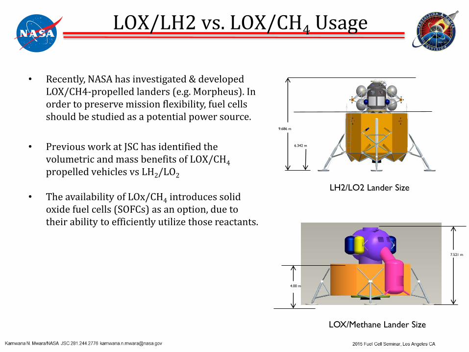
• Recently, NASA has investigated & developed LOX/CH4-propelled landers (e.g. Morpheus). In order to preserve mission flexibility, fuel cells should be studied as a potential power source.
• Previous work at JSC has identified the volumetric and mass benefits of LOX/CH4
propelled vehicles vs LH2/LO2
• The availability of LOx/CH4 introduces solid oxide fuel cells (SOFCs) as an option, due to their ability to efficiently utilize those reactants.
9.686 m
6.342 m
4.00 m
7.521 m
LOX/Methane Lander Size
LH2/LO2 Lander Size
LOX/LH2 vs. LOX/CH4 Usage

Abigail C. Ryan/NASA JSC 281.483.3260 [email protected] 2014 Fuel Cell Seminar, Los Angeles CA
• SOFCs allow internal reforming to convert CH4 into H2 for fuel
• Some external reforming of the fuel stream is optimal
• Utilizing an external steam methane reformer (SMR) would be the first step to creating a more efficient SOFC system
Steam Reforming Introduction
Predicted typical output gas
concentrations:
~48% H2
~27% CH4
~22% CO
~3% CO2
SMR Primary Chemical Reactions
FUEL FOR SOFC
5
SMR – Phase 1
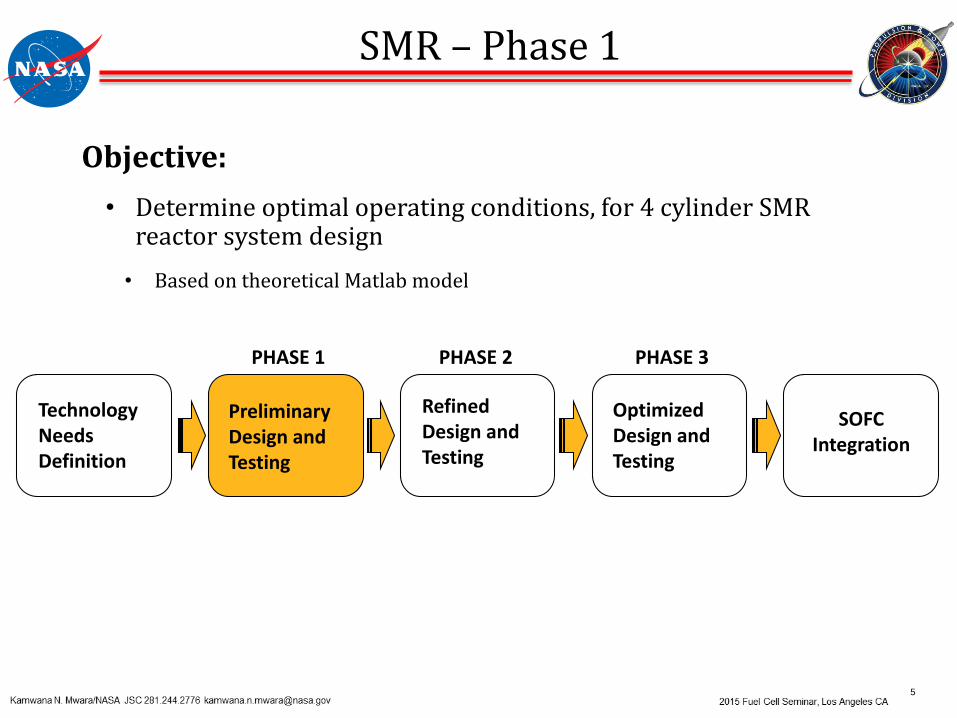
Objective:
• Determine optimal operating conditions, for 4 cylinder SMR reactor system design
• Based on theoretical Matlab model
Technology Needs Definition
Preliminary Design and Testing
Refined Design and Testing
Optimized Design and Testing
SOFC Integration
PHASE 1 PHASE 2 PHASE 3

6
System Layout Catalyst
Reasons for selection:
• Low cost
• Reasonably good efficiency
Nickel Oxide Catalyst
SMR – Phase 1
Hot Flow Test (With Preheating of Gases)
Test #
CH₄ Mass
Flow Rate
[g/min]
H₂O Mass Flow
Rate
[g/min]
Steam to
Methane
Ratio
[mol/mol]
SMR
Temperature
[˚F]
System
Pressure
[psia]
1 0.982 1.2 1 1020 14.7
2 0.982 2.3 2 1020 14.7
3 0.982 3.3 3 1020 14.7

7
SMR – Phase 1
Generated H2 production, and also high build-up of upstream pressure
High Pressure Point
High Pressure Point

18
Test results: • Initial production of Hydrogen
• Carbon deposition blockage in the catalyst bed
Conclusions:• Use of a kiln to produce steam
• No steam flow regulation (steam-to-methane ratio)
• Catalyst was not reduced:
𝑁𝑖𝑂 + 𝐻2 ↔ 𝑁𝑖 + 𝐻2𝑂
Phase 2 recommendations:
• Use syringe pumps to regulate water flow
• Use a separate heater to generate steam
• Reduce catalyst
SMR – Phase 1

9
SMR – Phase 2
Objective:
• Determine optimal operating conditions, for 1 cylinder SMR reactor system design
• Based on updated theoretical Matlab model
• Incorporate recommendations from Phase 1 test results
Technology Needs Definition
Preliminary Design and Testing
Refined Design and Testing
Optimized Design and Testing
SOFC Integration
PHASE 1 PHASE 2 PHASE 3

10
System Layout
SMR – Phase 2
Improvements
Before After
Passive Water Control• Tubes filled with H2O and
heated; no control over amount of steam generation and delivery
Active water control• Syringe pumps deliver
specific flow rate of H2O to steam generator
Steam generator & reformer placed in kiln
Separate tube furnaces for steam generator and reformer
• Better heating control
Catalyst was not reduced Catalyst reduced by hydrogen, before test runs
Four tube reactor design One tube reactor design
Hot Flow Test (With Preheating of Gases)
Test #
CH₄ Mass
Flow Rate
[g/min]
H₂O Mass Flow
Rate
[g/min]
Steam to
Methane
Ratio
[mol/mol]
SMR
Temperature
[˚F]
System
Pressure
[psia]
1 1.637 5.516 3 930 14.7
2 1.637 6.435 3.5 930 14.7
3 1.637 7.354 4 930 14.7

11
SMR – Phase 2
Observed temperature and pressure transients – Affected H2 production at certain points

12
Test Results:
• Higher overall amount of hydrogen being produced
• Carbon deposition still being generated, though at lower rate
Conclusions:
• Catalyst was not sufficiently reduced
• Need to increase thermal mass to heat up fluids to design temperatures
• Need to minimize hotspots that promote carbon deposition
• Essential to maintain consistent heating profile for input stream going into the reactor
Recommendations:
• Conduct one more round of testing, with system modifications
SMR – Phase 2
Carbon deposition in test system

13
SMR – Phase 3
Objective:
• Determine optimal operating conditions, for 1 cylinder SMR reactor design
• Based on updated theoretical Matlab model
• Incorporate recommendations from Phase 2 test results
Technology Needs Definition
Preliminary Design and Testing
Refined Design and Testing
Optimized Design and Testing
SOFC Integration
PHASE 1 PHASE 2 PHASE 3
14
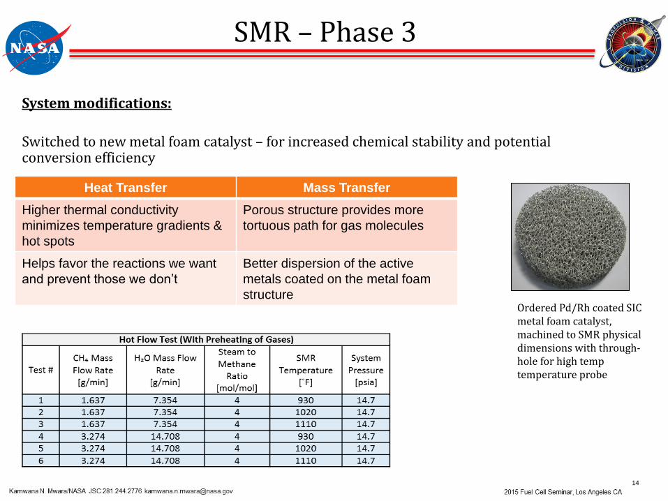
Ordered Pd/Rh coated SIC metal foam catalyst, machined to SMR physical dimensions with through-hole for high temp temperature probe
System modifications:
Switched to new metal foam catalyst – for increased chemical stability and potential conversion efficiency
SMR – Phase 3
Heat Transfer Mass Transfer
Higher thermal conductivity
minimizes temperature gradients &
hot spots
Porous structure provides more
tortuous path for gas molecules
Helps favor the reactions we want
and prevent those we don’t
Better dispersion of the active
metals coated on the metal foam
structure

15
SMR – Phase 3
System modifications:
• Installed 3-way valve downstream of steam generator, to help avoid T and P transients (circled in green)
• Installed heating tape between steam generator and reactor, to maintain consistent heating profile (circled in red)

16
SMR - Phase 3
Initial test run – steadier temperature and pressure rates

17
SMR - Phase 3
Final test run – steady pressure flow, fluctuating H2 production

18
SMR - Phase 3 & Test Summary
Testing Results:
• Test prematurely ended due to leaking relief valve
• Eliminated carbon deposition
• Similar H2 conversion rates to Phase 2
Conclusions/Lessons Learned:• Ensure relief valve has captured venting
• When possible, run higher flow rates through new catalyst to determine whether conversion efficiency increases
• Potentially better to use Coriolis flow controller instead of syringe pumps
SMR Overall Test Summary

19
SMR – Future Plans
Future System Integration Path
Planned Activities Time Period
Integrated test with SOFC FY’16
Integrated test with SOFC, In-Situ Resource Utilization (ISRU), and LOX/CH4 Cryogenic Fluid Management (CFM)
-Feed CH4 from boiloff
FY’16