Steam Jet Ejectors
18
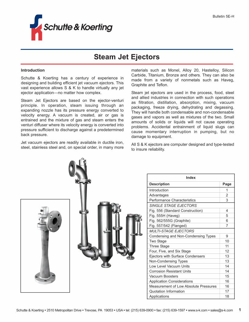
Schutte & Koerting • 2510 Metropolitan Drive • Trevose, PA 19053 • USA • tel: (215) 639-0900 • fax: (215) 639-1597 • www.s-k.com • [email protected] 1 Steam Jet Ejectors Bulletin 5E-H Introduction Schutte & Koerting has a century of experience in designing and building efficient jet vacuum ejectors. This vast experience allows S & K to handle virtually any jet ejector application—no matter how complex. Steam Jet Ejectors are based on the ejector-venturi principle. In operation, steam issuing through an expanding nozzle has its pressure energy converted to velocity energy. A vacuum is created, air or gas is entrained and the mixture of gas and steam enters the venturi diffuser where its velocity energy is converted into pressure sufficient to discharge against a predetermined back pressure. Jet vacuum ejectors are readily available in ductile iron, steel, stainless steel and, on special order, in many more Index Description Page Introduction 1 Advantages 2 Performance Characteristics 3 SINGLE STAGE EJECTORS Fig. 556 (Standard Construction) 4 Fig. 555H (Haveg) 5 Fig. 562/555G (Graphite) 6 Fig. 557/542 (Flanged) 7 MULTI-STAGE EJECTORS Condensing and Non-Condensing Types 9 Two Stage 10 Three Stage 11 Four, Five, and Six Stage 12 Ejectors with Surface Condensers 13 Non-Condensing Types 13 Low Level Vacuum Units 14 Corrosion Resistant Units 14 Vacuum Boosters 15 Application Considerations 16 Measurement of Low Absolute Pressures 16 Quotation Information 17 Applications 18 materials such as Monel, Alloy 20, Hastelloy, Silicon Carbide, Titanium, Bronze and others. They can also be made from a variety of nonmetals such as Haveg, Graphite and Teflon. Steam jet ejectors are used in the process, food, steel and allied industries in connection with such operations as filtration, distillation, absorption, mixing, vacuum packaging, freeze drying, dehydrating and degassing. They will handle both condensable and non-condensable gases and vapors as well as mixtures of the two. Small amounts of solids or liquids will not cause operating problems. Accidental entrainment of liquid slugs can cause momentary interruption in pumping, but no damage to equipment. All S & K ejectors are computer designed and type-tested to insure reliability.
-
Upload
sukalyan-ghosh -
Category
Documents
-
view
233 -
download
8
description
Steam Jet Ejectors
Transcript of Steam Jet Ejectors
Schutte & Koerting • 2510 Metropolitan Drive • Trevose, PA 19053 • USA • tel: (215) 639-0900 • fax: (215) 639-1597 • www.s-k.com • [email protected] 1
Steam Jet Ejectors
Bulletin 5E-H
Introduction
Schutte & Koerting has a century of experience in
designing and building efficient jet vacuum ejectors. This
vast experience allows S & K to handle virtually any jet
ejector application—no matter how complex.
Steam Jet Ejectors are based on the ejector-venturi
principle. In operation, steam issuing through an
expanding nozzle has its pressure energy converted to
velocity energy. A vacuum is created, air or gas is
entrained and the mixture of gas and steam enters the
venturi diffuser where its velocity energy is converted into
pressure sufficient to discharge against a predetermined
back pressure.
Jet vacuum ejectors are readily available in ductile iron,
steel, stainless steel and, on special order, in many more
Index
Description Page
Introduction 1
Advantages 2
Performance Characteristics 3
SINGLE STAGE EJECTORS
Fig. 556 (Standard Construction) 4
Fig. 555H (Haveg) 5
Fig. 562/555G (Graphite) 6
Fig. 557/542 (Flanged) 7
MULTI-STAGE EJECTORS
Condensing and Non-Condensing Types 9
Two Stage 10
Three Stage 11
Four, Five, and Six Stage 12
Ejectors with Surface Condensers 13
Non-Condensing Types 13
Low Level Vacuum Units 14
Corrosion Resistant Units 14
Vacuum Boosters 15
Application Considerations 16
Measurement of Low Absolute Pressures 16
Quotation Information 17
Applications 18
materials such as Monel, Alloy 20, Hastelloy, Silicon
Carbide, Titanium, Bronze and others. They can also be
made from a variety of nonmetals such as Haveg,
Graphite and Teflon.
Steam jet ejectors are used in the process, food, steel
and allied industries in connection with such operations
as filtration, distillation, absorption, mixing, vacuum
packaging, freeze drying, dehydrating and degassing.
They will handle both condensable and non-condensable
gases and vapors as well as mixtures of the two. Small
amounts of solids or liquids will not cause operating
problems. Accidental entrainment of liquid slugs can
cause momentary interruption in pumping, but no
damage to equipment.
All S & K ejectors are computer designed and type-tested
to insure reliability.
Schutte & Koerting • 2510 Metropolitan Drive • Trevose, PA 19053 • USA • tel: (215) 639-0900 • fax: (215) 639-1597 • www.s-k.com • [email protected]
Steam Jet Ejectors Bulletin 5E-H
advantages
The principal advantages of steam jet ejectors over other
types of vacuum producing units are...
low CoSt. Pumps of the ejector type are small in relation
to the work they do and their cost is low in comparison
with other types of equipment.
No moVIng PartS. These units have no moving parts to
adjust or repair.
SImPlE, ComPaCt ConStruCtIon. Nothing could be
simpler than a jet vacuum ejector. It consists of an
expanding nozzle, a body, and a venturi (or diffuser).
rElIabIlIty. Because of their inherent simplicity, these
pumps are reliable. Maintenance requirements are
simple and are easily accomplished.
CorroSIon/EroSIon rESIStanCE. Units can be made in
practically any workable material to provide utmost
resistance to corrosion and erosion. Standard models are
supplied in a choice of materials as indicated in this
bulletin.
EaSy InStallatIon. Relatively light in weight, jet ejectors
are easy to install, require no foundations. Even multi-
stage units are readily adaptable to existing conditions.
HIgH VaCuum PErformanCE. Steam jet ejectors can
handle air or other gases at suction pressures as low as
three microns Hg. abs.
Schutte & Koerting • 2510 Metropolitan Drive • Trevose, PA 19053 • USA • tel: (215) 639-0900 • fax: (215) 639-1597 • www.s-k.com • [email protected] 3
Bulletin 5E-HSteam Jet Ejectors
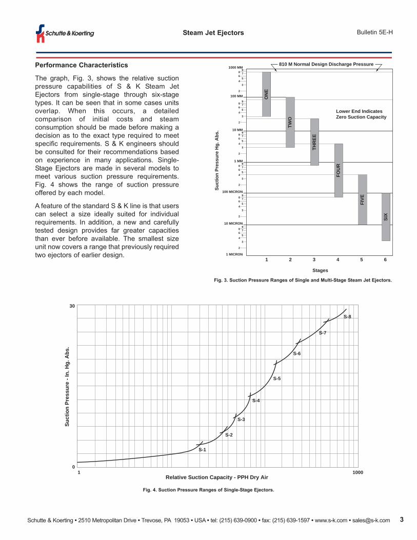
fig. 3. Suction Pressure ranges of Single and multi-Stage Steam Jet Ejectors.
fig. 4. Suction Pressure ranges of Single-Stage Ejectors.
Performance Characteristics
The graph, Fig. 3, shows the relative suction
pressure capabilities of S & K Steam Jet
Ejectors from single-stage through six-stage
types. It can be seen that in some cases units
overlap. When this occurs, a detailed
comparison of initial costs and steam
consumption should be made before making a
decision as to the exact type required to meet
specific requirements. S & K engineers should
be consulted for their recommendations based
on experience in many applications. Single-
Stage Ejectors are made in several models to
meet various suction pressure requirements.
Fig. 4 shows the range of suction pressure
offered by each model.
A feature of the standard S & K line is that users
can select a size ideally suited for individual
requirements. In addition, a new and carefully
tested design provides far greater capacities
than ever before available. The smallest size
unit now covers a range that previously required
two ejectors of earlier design.
98 76
54
3
2
98 76
54
3
2
98 76
54
3
2
98 76
54
3
2
98 76
54
3
2
98 76
54
3
2
1000 MM
100 MM
100 MICRON
10 MICRON
1 MICRON
10 MM
1 MM
1 2 3 4 5 6
810 M Normal Design Discharge Pressure
Lower End IndicatesZero Suction Capacity
Stages
Suct
ion
Pres
sure
Hg.
Abs
.
ON
E
TWO
THR
EE
FIVE
FOU
R
SIX
Relative Suction Capacity - PPH Dry Air
Suct
ion
Pres
sure
- In
. Hg.
Abs
.
01 1000
30
S-8
S-7
S-6
S-5
S-4
S-3
S-2
S-1
Schutte & Koerting • 2510 Metropolitan Drive • Trevose, PA 19053 • USA • tel: (215) 639-0900 • fax: (215) 639-1597 • www.s-k.com • [email protected]
Steam Jet Ejectors Bulletin 5E-H
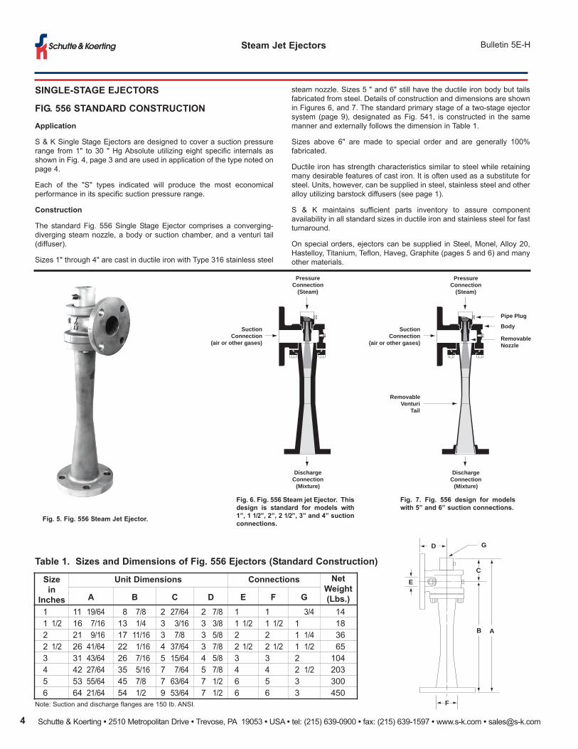
SInglE-StagE EJECtorS
fIg. 556 StanDarD ConStruCtIon
application
S & K Single Stage Ejectors are designed to cover a suction pressure
range from 1" to 30 " Hg Absolute utilizing eight specific internals as
shown in Fig. 4, page 3 and are used in application of the type noted on
page 4.
Each of the "S" types indicated will produce the most economical
performance in its specific suction pressure range.
Construction
The standard Fig. 556 Single Stage Ejector comprises a converging-
diverging steam nozzle, a body or suction chamber, and a venturi tail
(diffuser).
Sizes 1" through 4" are cast in ductile iron with Type 316 stainless steel
fig. 5. fig. 556 Steam Jet Ejector.
fig. 6. fig. 556 Steam jet Ejector. this
design is standard for models with
1”, 1 1/2”, 2”, 2 1/2”, 3” and 4” suction
connections.
fig. 7. fig. 556 design for models
with 5” and 6” suction connections.
Size
in
Inches
unit Dimensions Connections net
weight
(lbs.)a b C D E f g
1 11 19/64 8 7/8 2 27/64 2 7/8 1 1 3/4 14
1 1/2 16 7/16 13 1/4 3 3/16 3 3/8 1 1/2 1 1/2 1 18
2 21 9/16 17 11/16 3 7/8 3 5/8 2 2 1 1/4 36
2 1/2 26 41/64 22 1/16 4 37/64 3 7/8 2 1/2 2 1/2 1 1/2 65
3 31 43/64 26 7/16 5 15/64 4 5/8 3 3 2 104
4 42 27/64 35 5/16 7 7/64 5 7/8 4 4 2 1/2 203
5 53 55/64 45 7/8 7 63/64 7 1/2 6 5 3 300
6 64 21/64 54 1/2 9 53/64 7 1/2 6 6 3 450
steam nozzle. Sizes 5 " and 6" still have the ductile iron body but tails
fabricated from steel. Details of construction and dimensions are shown
in Figures 6, and 7. The standard primary stage of a two-stage ejector
system (page 9), designated as Fig. 541, is constructed in the same
manner and externally follows the dimension in Table 1.
Sizes above 6" are made to special order and are generally 100%
fabricated.
Ductile iron has strength characteristics similar to steel while retaining
many desirable features of cast iron. It is often used as a substitute for
steel. Units, however, can be supplied in steel, stainless steel and other
alloy utilizing barstock diffusers (see page 1).
S & K maintains sufficient parts inventory to assure component
availability in all standard sizes in ductile iron and stainless steel for fast
turnaround.
On special orders, ejectors can be supplied in Steel, Monel, Alloy 20,
Hastelloy, Titanium, Teflon, Haveg, Graphite (pages 5 and 6) and many
other materials.
table 1. Sizes and Dimensions of fig. 556 Ejectors (Standard Construction)
Note: Suction and discharge flanges are 150 Ib. ANSI.
D G
E
C
B A
F
PressureConnection
(Steam)
SuctionConnection
(air or other gases)
DischargeConnection
(Mixture)
PressureConnection
(Steam)
SuctionConnection
(air or other gases)
DischargeConnection
(Mixture)
Pipe Plug
Body
RemovableNozzle
RemovableVenturi
Tail

Schutte & Koerting • 2510 Metropolitan Drive • Trevose, PA 19053 • USA • tel: (215) 639-0900 • fax: (215) 639-1597 • www.s-k.com • [email protected] 5
Bulletin 5E-HSteam Jet Ejectors
SInglE-StagE EJECtorS
fIg. 555H HaVEg ConStruCtIon
application
Designed for handling many solvents, as well
as acids and corrosive vapors, Fig. 555H
Steam Jet Ejectors are made from Haveg of
various types. Haveg resists rapid temperature
change and can be used continuously with
temperatures as high as 265° F. It is durable
and has excellent resistance to corrosion.
Construction
The standard unit is constructed of Haveg 61
with a graphite nozzle. Haveg 61 is a furfuryl
alcohol-formaldehyde resin with a non-
asbestos silicate filler and is used for body and
diffuser. A high grade of impervious Graphite is
used for the steam nozzle. Special applications
may require a different grade of Haveg
material.
The Fig. 555H Ejector has a one-piece molded
Haveg body and diffuser - eliminating a joint
between these parts, a steel steam chest and
a steam nozzle of Graphite. The bolts holding
the steam chest extend the full length of the
exhauster and fasten to the exhaust pipe. This
holds the body and diffuser in compression and
eliminates any tendency of the diffuser to break
away from the body.
Dimensions and sizes of 1” to 4” Fig. 555H
Haveg Ejectors are shown below. Haveg is a
plastic material which has been subjected to
thermal processing and pressure. Jet ejectors
made from this material in the grades available
are tough and durable and are resistant to
many acids, bases, and salts.
fig. 9. fig. 555H Haveg Ejector.
fig. 10. fig. 555H Steam Jet Ejector made of
Haveg. nozzles are interchangeable with
those used in the type 562 Ejector
described on page 6.
table 2. Sizes and Dimensions of fig. 555H Ejector (Haveg Construction)
Size
no.
(Inches)
Connections Dimensions approx.
Shipping
wgt. (lbs.)Suction DischargeSteam
InletE f g H
1 1 1/2 1 1/2 1/2 17 1/4 4 13 1/4 4 18
1 1/2 1 1/2 2 1/2 17 1/4 2 1/2 13 1/4 4 18
2 2 2 1/2 3/4 22 5/16 3 17 11/16 4 1/2 27
2 1/2 2 1/2 3 3/4 27 5/16 3 1/2 22 1/16 5 38
3 3 3 1 32 4 1/4 26 7/16 5 1/2 51
4 4 3 1 1/4 43 7/16 5 1/4 35 5/16 6 1/2 76
5 5 4 1 1/4
ON APPLICATION6 6 5 3
8 8 6 3
G
E
F
H
PressureConnection
(steam)
SuctionConnection
(air or other gases)
Tie Bolts
Removable Nozzle
Body and VenturiTail Piece(one piece construction)
DischargeConnection
(mixture)
Schutte & Koerting • 2510 Metropolitan Drive • Trevose, PA 19053 • USA • tel: (215) 639-0900 • fax: (215) 639-1597 • www.s-k.com • [email protected]
Steam Jet Ejectors Bulletin 5E-H
SInglE-StagE EJECtorS
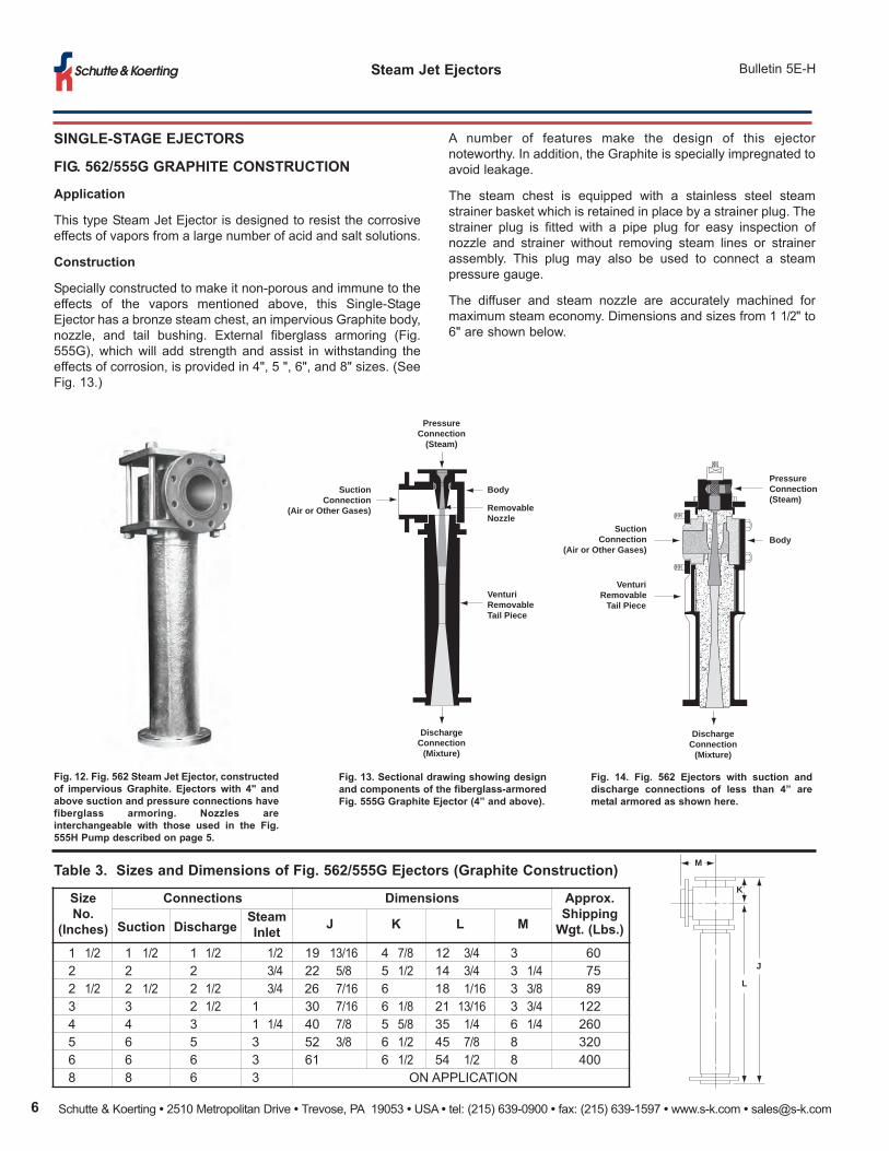
fIg. 562/555g graPHItE ConStruCtIon
application
This type Steam Jet Ejector is designed to resist the corrosive
effects of vapors from a large number of acid and salt solutions.
Construction
Specially constructed to make it non-porous and immune to the
effects of the vapors mentioned above, this Single-Stage
Ejector has a bronze steam chest, an impervious Graphite body,
nozzle, and tail bushing. External fiberglass armoring (Fig.
555G), which will add strength and assist in withstanding the
effects of corrosion, is provided in 4", 5 ", 6", and 8" sizes. (See
Fig. 13.)
fig. 12. fig. 562 Steam Jet Ejector, constructed
of impervious graphite. Ejectors with 4" and
above suction and pressure connections have
fiberglass armoring. nozzles are
interchangeable with those used in the fig.
555H Pump described on page 5.
fig. 13. Sectional drawing showing design
and components of the fiberglass-armored
fig. 555g graphite Ejector (4” and above).
fig. 14. fig. 562 Ejectors with suction and
discharge connections of less than 4” are
metal armored as shown here.
table 3. Sizes and Dimensions of fig. 562/555g Ejectors (graphite Construction)
Size
no.
(Inches)
Connections Dimensions approx.
Shipping
wgt. (lbs.)Suction DischargeSteam
InletJ K l m
1 1/2 1 1/2 1 1/2 1/2 19 13/16 4 7/8 12 3/4 3 60
2 2 2 3/4 22 5/8 5 1/2 14 3/4 3 1/4 75
2 1/2 2 1/2 2 1/2 3/4 26 7/16 6 18 1/16 3 3/8 89
3 3 2 1/2 1 30 7/16 6 1/8 21 13/16 3 3/4 122
4 4 3 1 1/4 40 7/8 5 5/8 35 1/4 6 1/4 260
5 6 5 3 52 3/8 6 1/2 45 7/8 8 320
6 6 6 3 61 6 1/2 54 1/2 8 400
8 8 6 3 ON APPLICATION
M
K
L
J
PressureConnection(Steam)
BodySuction
Connection(Air or Other Gases)
VenturiRemovable
Tail Piece
DischargeConnection
(Mixture)
PressureConnection
(Steam)
SuctionConnection
(Air or Other Gases)
Body
RemovableNozzle
VenturiRemovableTail Piece
DischargeConnection
(Mixture)
A number of features make the design of this ejector
noteworthy. In addition, the Graphite is specially impregnated to
avoid leakage.
The steam chest is equipped with a stainless steel steam
strainer basket which is retained in place by a strainer plug. The
strainer plug is fitted with a pipe plug for easy inspection of
nozzle and strainer without removing steam lines or strainer
assembly. This plug may also be used to connect a steam
pressure gauge.
The diffuser and steam nozzle are accurately machined for
maximum steam economy. Dimensions and sizes from 1 1/2" to
6" are shown below.
Schutte & Koerting • 2510 Metropolitan Drive • Trevose, PA 19053 • USA • tel: (215) 639-0900 • fax: (215) 639-1597 • www.s-k.com • [email protected] 7
Bulletin 5E-HSteam Jet Ejectors
SInglE-StagE EJECtorS
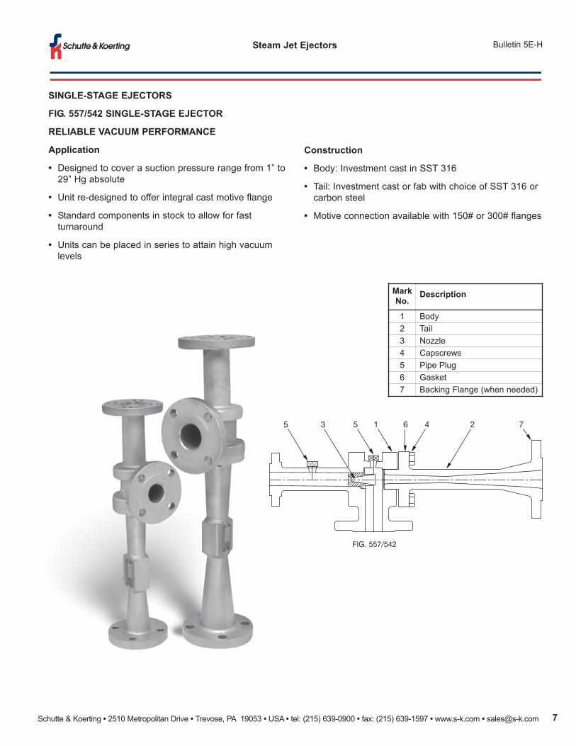
fIg. 557/542 SInglE-StagE EJECtor
rElIablE VaCuum PErformanCE
application
• Designed to cover a suction pressure range from 1” to
29” Hg absolute
• Unit re-designed to offer integral cast motive flange
• Standard components in stock to allow for fast
turnaround
• Units can be placed in series to attain high vacuum
levels
Construction
• Body: Investment cast in SST 316
• Tail: Investment cast or fab with choice of SST 316 or
carbon steel
• Motive connection available with 150# or 300# flanges
FIG. 557/542
5 3 5 1 6 4 2 7
mark
no.Description
1 Body
2 Tail
3 Nozzle
4 Capscrews
5 Pipe Plug
6 Gasket
7 Backing Flange (when needed)
Schutte & Koerting • 2510 Metropolitan Drive • Trevose, PA 19053 • USA • tel: (215) 639-0900 • fax: (215) 639-1597 • www.s-k.com • [email protected]
Steam Jet Ejectors Bulletin 5E-H
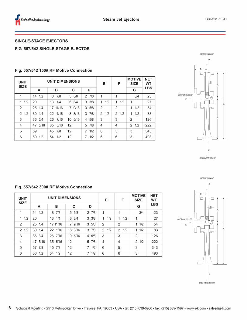
unIt
SIZE
unIt DImEnSIonSE f
motIVE
SIZE
nEt
wt
lbSa b C D g
1 14 1/2 8 7/8 5 5/8 2 7/8 1 1 3/4 23
1 1/2 20 13 1/4 6 3/4 3 3/8 1 1/2 1 1/2 1 27
2 25 1/4 17 11/16 7 9/16 3 5/8 2 2 1 1/2 54
2 1/2 30 1/4 22 1/16 8 3/16 3 7/8 2 1/2 2 1/2 1 1/2 83
3 36 3/4 26 7/16 10 5/16 4 5/8 3 3 2 126
4 47 5/16 35 5/16 12 5 7/8 4 4 2 1/2 222
5 59 45 7/8 12 7 1/2 6 5 3 343
6 69 1/2 54 1/2 12 7 1/2 6 6 3 493
fig. 557/542 150# rf motive Connection
fig. 557/542 300# rf motive Connection
D
E
C
DISCHARGE 150 # RF
SUCTION 150 # RF
MOTIVE 150 # RF
F
G
B
A
D
E
C
DISCHARGE 150 # RF
SUCTION 150 # RF
MOTIVE 300 # RF
F
G
B
A
unIt
SIZE
unIt DImEnSIonSE f
motIVE
SIZE
nEt
wt
lbSa b C D g
1 14 1/2 8 7/8 5 5/8 2 7/8 1 1 3/4 23
1 1/2 20 13 1/4 6 3/4 3 3/8 1 1/2 1 1/2 1 27
2 25 1/4 17 11/16 7 9/16 3 5/8 2 2 1 1/2 54
2 1/2 30 1/4 22 1/16 8 3/16 3 7/8 2 1/2 2 1/2 1 1/2 83
3 36 3/4 26 7/16 10 5/16 4 5/8 3 3 2 126
4 47 5/16 35 5/16 12 5 7/8 4 4 2 1/2 222
5 57 7/8 45 7/8 12 7 1/2 6 5 3 343
6 66 1/2 54 1/2 12 7 1/2 6 6 3 493
SInglE-StagE EJECtorS
fIg. 557/542 SInglE-StagE EJECtor
Schutte & Koerting • 2510 Metropolitan Drive • Trevose, PA 19053 • USA • tel: (215) 639-0900 • fax: (215) 639-1597 • www.s-k.com • [email protected] 9
Bulletin 5E-HSteam Jet Ejectors
multI-StagE EJECtorS
Staging of ejectors becomes necessary for economical
operation as the required absolute suction pressure
decreases (see Fig. 3, page 3).
Based upon the use of auxiliary equipment, two and
three-stage ejectors can be either condensing or non-
condensing types. Four, five and six-stage units can also
be non-condensing, but usually are condensing types.
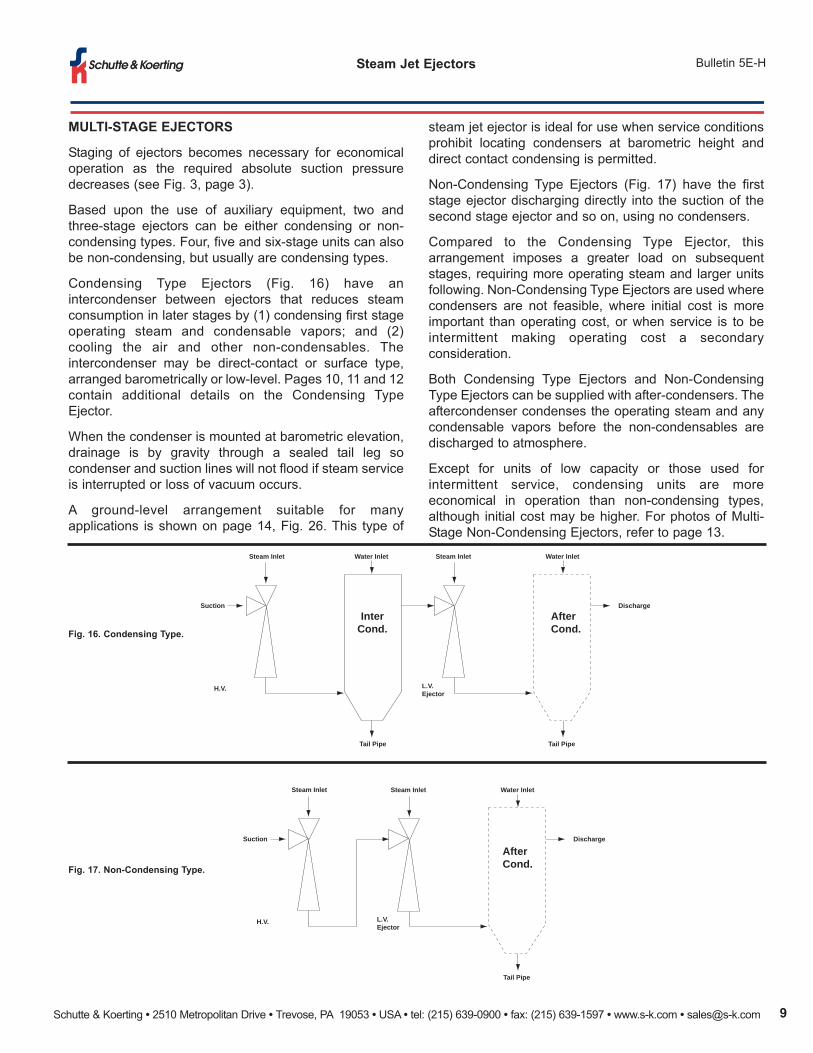
Condensing Type Ejectors (Fig. 16) have an
intercondenser between ejectors that reduces steam
consumption in later stages by (1) condensing first stage
operating steam and condensable vapors; and (2)
cooling the air and other non-condensables. The
intercondenser may be direct-contact or surface type,
arranged barometrically or low-level. Pages 10, 11 and 12
contain additional details on the Condensing Type
Ejector.
When the condenser is mounted at barometric elevation,
drainage is by gravity through a sealed tail leg so
condenser and suction lines will not flood if steam service
is interrupted or loss of vacuum occurs.
A ground-level arrangement suitable for many
applications is shown on page 14, Fig. 26. This type of
fig. 16. Condensing type.
fig. 17. non-Condensing type.
steam jet ejector is ideal for use when service conditions
prohibit locating condensers at barometric height and
direct contact condensing is permitted.
Non-Condensing Type Ejectors (Fig. 17) have the first
stage ejector discharging directly into the suction of the
second stage ejector and so on, using no condensers.
Compared to the Condensing Type Ejector, this
arrangement imposes a greater load on subsequent
stages, requiring more operating steam and larger units
following. Non-Condensing Type Ejectors are used where
condensers are not feasible, where initial cost is more
important than operating cost, or when service is to be
intermittent making operating cost a secondary
consideration.
Both Condensing Type Ejectors and Non-Condensing
Type Ejectors can be supplied with after-condensers. The
aftercondenser condenses the operating steam and any
condensable vapors before the non-condensables are
discharged to atmosphere.
Except for units of low capacity or those used for
intermittent service, condensing units are more
economical in operation than non-condensing types,
although initial cost may be higher. For photos of Multi-
Stage Non-Condensing Ejectors, refer to page 13.
Steam Inlet
Suction
H.V. Ejector
Tail Pipe
Water Inlet Steam Inlet
L.V.Ejector
Tail Pipe
Water Inlet
Discharge
AfterCond.
InterCond.
Steam Inlet
Suction
H.V. Ejector
Steam Inlet
L.V.Ejector
Tail Pipe
Water Inlet
Discharge
AfterCond.

Schutte & Koerting • 2510 Metropolitan Drive • Trevose, PA 19053 • USA • tel: (215) 639-0900 • fax: (215) 639-1597 • www.s-k.com • [email protected]
Steam Jet Ejectors Bulletin 5E-H
multI-StagE EJECtorS
two-StagE EJECtorS
application
Two-Stage Steam Jet Ejectors have the same general
field of application as the single stage units. They handle
both condensable and non-condensable gases or vapors,
as well as mixtures of the two. The general operating
range is between 5" Hg. abs. and 3 mm Hg. abs.
Depending on conditions, however, a single-stage unit
may be more economical at the top of the range and a
three-stage unit near the bottom.
operation
In the two-stage assemblies, the suction mixture enters
the body of the primary stage, or High Vacuum (H.V.)
Ejector, Fig. 541, and is compressed from the required
suction to an intermediate pressure less than
atmospheric. The secondary stage or Low Vacuum (L.V.)
Ejector, Fig. 556 compresses from this point to
atmosphere, or to a point where it is desired to utilize the
ejector discharge.
Exact value of the intermediate pressure varies with the
operating conditions and the type of two-stage assembly.
The units have been designed for optimum inter-stage
pressure.
In condensing units, the inter-condenser functions as
previously described. This reduces the load on the low
vacuum ejector and reduces steam consumption. The
intercondenser may be a direct-contact barometric type,
a low level type, or surface type. These are discussed in
more detail on pages 12, 13 and 14.
In small size units, and where cooling water is not
economically available, the intercondenser may be
eliminated, resulting in a two-stage non-condensing unit.
When the suction load contains a large amount of
condensable vapors, it is sometimes possible to use a
surface or direct-contact pre-condenser, or pre-cooler to
reduce the load on the first stage ejector (Fig. 18). Also, if
it is objectionable to discharge the low vacuum exhauster
directly to atmosphere, an aftercondenser can be used to
condense the steam and other condensables, as well as
Iower the noise level. Direct-Contact Condensers for this
function are described in Bulletin 5AA.
Non-condensing two-stage units can be used when
conditions warrant this type of arrangement. A typical
arrangement is shown on page 13.
fIg. 18. five two-Stage Steam Jet Ejectors equipped with pre-condensers
are shown installed on the roof of a chemical plant. tailpipes on
condensers are offset downward at a 45 degree angle to allow free flow of
discharge water.
fig. 19. the two-Stage non-Condensing
Ejectors shown here are made of Haveg. the
piston-operated shut-off valve shown in the
suction line permits operation of the pump
from a central control panel.
Schutte & Koerting • 2510 Metropolitan Drive • Trevose, PA 19053 • USA • tel: (215) 639-0900 • fax: (215) 639-1597 • www.s-k.com • [email protected] 11
Bulletin 5E-HSteam Jet Ejectors
multI-StagE EJECtorS
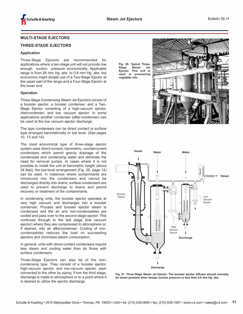
tHrEE-StagE EJECtorS
application
Three-Stage Ejectors are recommended for
applications where a two-stage unit will not provide low
enough suction pressure economically. Applicable
range is from 26 mm Hg. abs. to 0.8 mm Hg. abs. but
economics might dictate use of a Two-Stage Ejector at
the upper part of the range and a Four-Stage Ejector at
the lower end.
operation
Three-Stage Condensing Steam Jet Ejectors consist of
a booster ejector, a booster condenser, and a Two-
Stage Ejector consisting of a high-vacuum ejector,
intercondenser, and low vacuum ejector. In some
applications another condenser (after-condenser) can
be used at the low vacuum ejector discharge.
The type condensers can be direct contact or surface
type arranged barometrically or low level. (See pages
10, 13 and 14).
The most economical type of three-stage ejector
system uses direct-contact, barometric, countercurrent
condensers which permit gravity drainage of the
condensate and condensing water and eliminate the
need for removal pumps. In cases where it is not
possible to install the unit at barometric height (about
34 feet), the low-level arrangement (Fig. 26, page 14)
can be used. In instances where contaminants are
introduced into the condensers and cannot be
discharged directly into drains, surface condensers are
used to prevent discharge to drains and permit
recovery or treatment of the contaminants.
In condensing units, the booster ejector operates at
very high vacuum and discharges into a booster
condenser. Process and booster ejector steam is
condensed and the air and non-condensables are
cooled and pass over to the second stage ejector. This
continues through to the last stage (low vacuum
ejector) where they are compressed to atmosphere or,
if desired, into an aftercondenser. Cooling of non-
condensables reduces the load on succeeding
ejectors and minimizes steam consumption.
In general, units with direct-contact condensers require
less steam and cooling water than do those with
surface condensers.
Three-Stage Ejectors can also be of the non-
condensing type. They consist of a booster ejector,
high-vacuum ejector, and low-vacuum ejector, each
connected to the other by piping. From the third stage,
discharge is made to atmosphere or to a point where it
is desired to utilize the ejector discharge.
fig. 20. typical three-
Stage Steam Jet
Ejector. this unit is
used in processing
vegetable oils.
fig. 21. three-Stage Steam Jet Ejector. the booster ejector diffuser should normally
be steam jacketed when design suction pressure is less than 4.6 mm Hg. abs.
Bar
omet
ricC
onde
nser
Bar
omet
ricC
onde
nser
HighVacuumEjector
LowVacuumEjector
Ste
amS
epar
ator
BoosterEjector
Steam Water Water
Discharge
Discharge
Steam
Schutte & Koerting • 2510 Metropolitan Drive • Trevose, PA 19053 • USA • tel: (215) 639-0900 • fax: (215) 639-1597 • www.s-k.com • [email protected]
Steam Jet Ejectors Bulletin 5E-H
multI-StagE EJECtorS
four, fIVE, anD SIX-StagE EJECtorS
application
Multi-Stage Ejectors have applications similar to those
described on page 1 of this bulletin. These units are used
for applications where required suction pressures are
beyond the range of the ejectors previously described.
Generally, suction pressure ranges are as follows (note
overlap in bar chart. Fig. 3, page 3):
Four-Stage Ejectors—4 mm Hg. abs.
to 75 microns Hg. abs.
Five-Stage Ejectors—0.4 mm Hg. abs.
to 10 microns Hg. abs.
Six-Stage Ejectors—100 microns Hg. abs.
to 3 microns Hg. abs.
four-StagE EJECtorS
The four-stage unit consists of (1) a primary booster
ejector; (2) a secondary booster ejector; (3) a high
vacuum ejector; (4) a low vacuum ejector; and (5) usually
two condensers—one after the secondary booster ejector
and the other between the high vacuum and low vacuum
ejectors. The condenser between the high and low
vacuum ejectors is sometimes omitted, depending upon
application requirements. Direct contact or surface
condensers, arranged barometrically or at ground level,
can be used. The four-stage is similar to the three-stage
unit except that another booster ejector is added. In the
four-stage, the primary booster is steam-jacketed to
prevent build-up of ice on the diffuser internal bore.
In operation, the booster ejectors operate in series and
discharge into a booster condenser, which removes the
operating steam and condensable gases. From this point
operation is similar to the two-stage ejector.
Final selection and arrangement of four-stage units will
depend upon specific requirements.
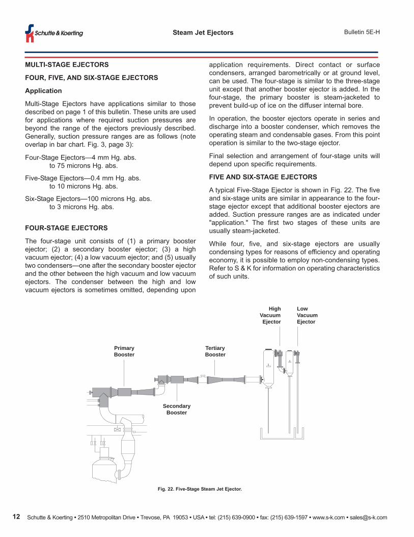
fIVE anD SIX-StagE EJECtorS
A typical Five-Stage Ejector is shown in Fig. 22. The five
and six-stage units are similar in appearance to the four-
stage ejector except that additional booster ejectors are
added. Suction pressure ranges are as indicated under
"application." The first two stages of these units are
usually steam-jacketed.
While four, five, and six-stage ejectors are usually
condensing types for reasons of efficiency and operating
economy, it is possible to employ non-condensing types.
Refer to S & K for information on operating characteristics
of such units.
fig. 22. five-Stage Steam Jet Ejector.
HighVacuumEjector
LowVacuumEjector
TertiaryBooster
PrimaryBooster
SecondaryBooster
Schutte & Koerting • 2510 Metropolitan Drive • Trevose, PA 19053 • USA • tel: (215) 639-0900 • fax: (215) 639-1597 • www.s-k.com • [email protected] 13
Bulletin 5E-HSteam Jet Ejectors
multI-StagE EJECtorS
EJECtorS wItH SurfaCE ConDEnSErS
Disposal of contaminated water is of growing concern in
process operations, particularly in the chemical industry. Where
an ejector system is drawing in contaminants, a condenser that
discharges directly to the drain may not be used. In these
applications, ejectors using surface condensers are being
utilized more. The surface condenser prevents discharge to the
drain and permits recovery or treatment of undesirable wastes.
A steam jet system with surface condensers normally requires
more motive steam and condensing water than one with direct-
contact condensers. This is the most expensive type of multi-
non-ConDEnSIng EJECtorS
Shown are several examples of multi-stage non-
condensing ejectors. This arrangement is generally
utilized in situations where a barometric leg or cooling
water is not readily available for an inter-condenser. They
also can be furnished in Haveg or Graphite construction
for corrosive applications. Non-condensing ejectors
provide the lowest initial capital equipment investment for
multi-stage systems.
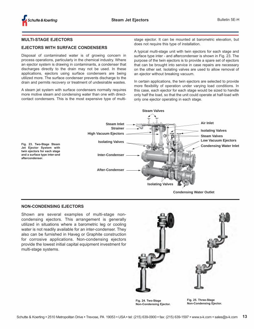
fig. 23. two-Stage Steam
Jet Ejector System with
twin ejectors for each stage
and a surface type inter-and
aftercondenser.
fig. 24. two-Stage
non-Condensing Ejector.
fig. 25. three-Stage
non-Condensing Ejector.
Steam InletStrainer
High Vacuum Ejectors
Isolating Valves
Inter-Condenser
After-Condenser
Isolating Valves
Condensing Water Outlet
Condensing Water InletLow Vacuum EjectorsSteam ValvesIsolating Valves
Air Inlet
Steam Valves
stage ejector. It can be mounted at barometric elevation, but
does not require this type of installation.
A typical multi-stage unit with twin ejectors for each stage and
surface type inter - and aftercondenser is shown in Fig. 23. The
purpose of the twin ejectors is to provide a spare set of ejectors
that can be brought into service in case repairs are necessary
on the other set. Isolating valves are used to allow removal of
an ejector without breaking vacuum.
In certain applications, the twin ejectors are selected to provide
more flexibility of operation under varying load conditions. In
this case, each ejector for each stage would be sized to handle
only half the load, so that the unit could operate at half-load with
only one ejector operating in each stage.

Schutte & Koerting • 2510 Metropolitan Drive • Trevose, PA 19053 • USA • tel: (215) 639-0900 • fax: (215) 639-1597 • www.s-k.com • [email protected]
Steam Jet Ejectors Bulletin 5E-H
multI-StagE EJECtorS
low-lEVEl EJECtor SyStEmS
application
Low-Level Ejector Systems have applications
similar to those described on page 13. In cases
where it is not possible to install the condensing
portion at barometric height (34 feet), special
designs can be used for "direct-contact" (Fig.
26) and "shell and tube" (Fig. 27) type low-level
units. These units can be supplied as two-stage
through four-stage systems ready for operation
at job site simply by providing steam, water and
electrical connections.
operation
DIRECT CONTACT LOW-LEVEL ARRANGEMENT
This type uses a direct contact condenser with
an integral reservoir and a float-operated water
control valve to maintain a constant operating
head above the condensate removal pump.
Since heat is introduced by the process, it is
necessary to maintain proper condensing water
temperature by providing appropriate bleed and
make-up water.
SHELL AND TUBE LOW-LEVEL ARRANGEMENT
Standard shell and tube heat exchanger and a
pump operated water jet ejector are installed
below the exchanger to remove condensate.
The condensate removal system does not need
make-up cooling water after initial operation.
The steam jets supplied on both low-level types
are the same as supplied for barometric
installations.
fig. 26. four-Stage low-level Steam Jet
Ejector with an integral reservoir, a water
removal pump and level control.
fig. 27. two-Stage low-level arrangement
with shell and tube heat exchanger.
fig. 28. with available head room at an
absolute minimum, S & K engineered this
three-stage low-level, condensing unit to
eliminate the need for a barometric leg.
fig. 29. Standard Haveg Construction
with interconnecting tee and target
plate to take steam impingement.
CorroSIon rESIStant multI-StagE
EJECtorS
Selection of suitable materials for the
specific pumping application is an
important consideration. To insure
minimum maintenance and replacement
costs, Multi-Stage Steam Jet Ejectors are
available in many corrosion resistant
materials. Figures 29 and 30 show units
made of Haveg and Graphite. See page 2
for other special materials. Condensers are
frequently made of polyester fiberglass or
steel with neoprene lining.
fig. 30. Standard graphite Construction
(Haveg Intercondenser).
Schutte & Koerting • 2510 Metropolitan Drive • Trevose, PA 19053 • USA • tel: (215) 639-0900 • fax: (215) 639-1597 • www.s-k.com • [email protected] 15
Bulletin 5E-HSteam Jet Ejectors
multI-StagE EJECtorS
StEam JEt VaCuum booStErS
application
If large condensable vapor loads must be handled, such as
those from an evaporator or crystallizer, it is normally done with
a condenser followed by a single-stage or two-stage ejector.
The condenser condenses the vapor and the secondary unit
removes the saturated non-condensables and maintains the
vacuum.
The vacuum obtainable in a condenser is limited by the vapor
pressure of the injection water. If a higher vacuum is desired, a
Steam Jet Booster is provided to increase the vacuum to the
desired point. Boosters like this are used in multi-stage units.
The booster ejectors are large in proportion to the other ejectors
because of the magnitude of the vapor load they handle.
The function of the Steam Jet Vacuum Booster is to compress
the condensable and non-condensable vapors from the suction
vacuum to the intermediate vacuum maintained in the
condenser.
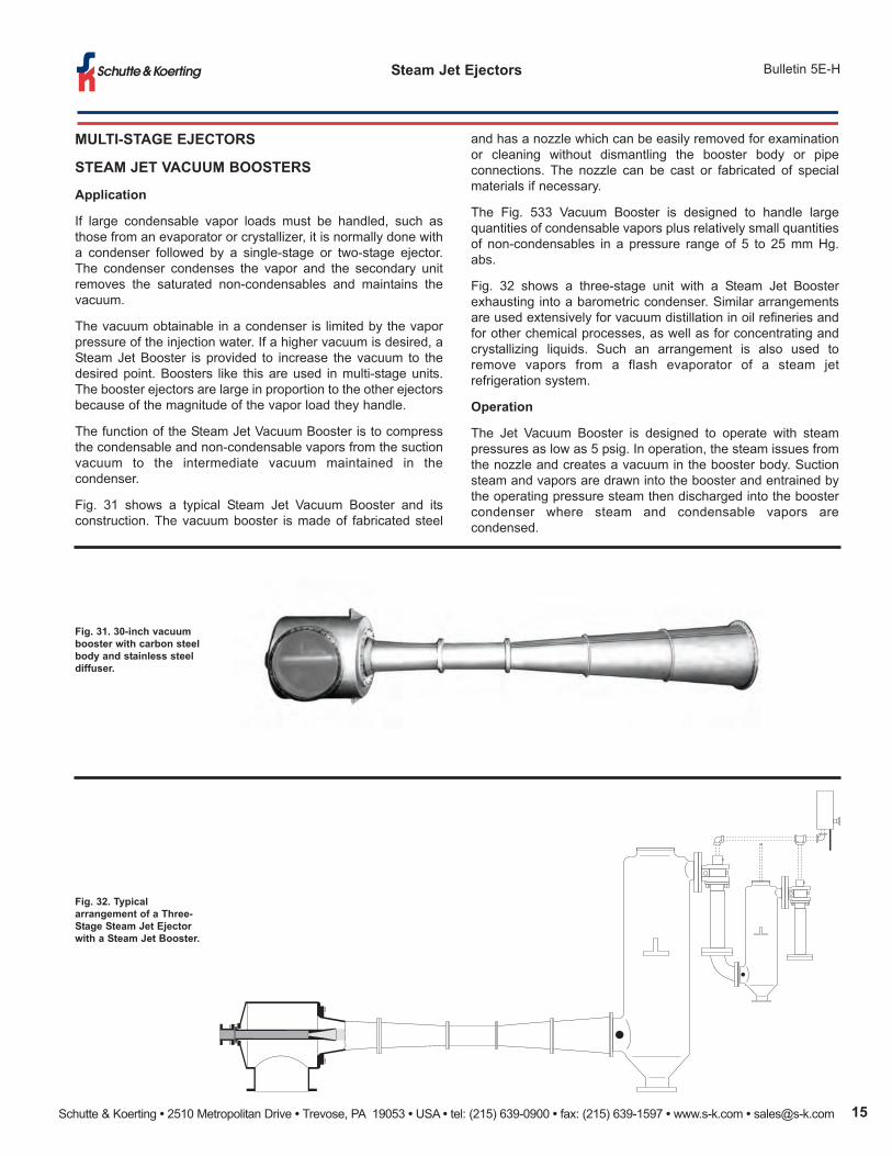
Fig. 31 shows a typical Steam Jet Vacuum Booster and its
construction. The vacuum booster is made of fabricated steel
fig. 31. 30-inch vacuum
booster with carbon steel
body and stainless steel
diffuser.
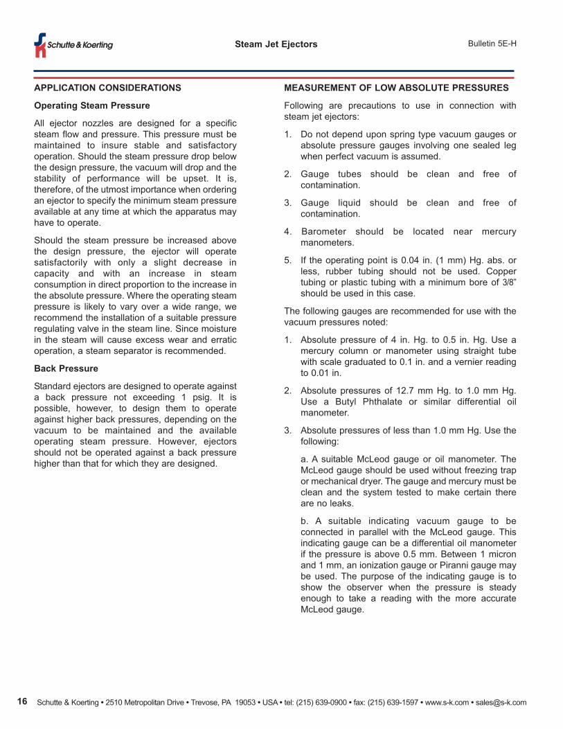
fig. 32. typical
arrangement of a three-
Stage Steam Jet Ejector
with a Steam Jet booster.
and has a nozzle which can be easily removed for examination
or cleaning without dismantling the booster body or pipe
connections. The nozzle can be cast or fabricated of special
materials if necessary.
The Fig. 533 Vacuum Booster is designed to handle large
quantities of condensable vapors plus relatively small quantities
of non-condensables in a pressure range of 5 to 25 mm Hg.
abs.
Fig. 32 shows a three-stage unit with a Steam Jet Booster
exhausting into a barometric condenser. Similar arrangements
are used extensively for vacuum distillation in oil refineries and
for other chemical processes, as well as for concentrating and
crystallizing liquids. Such an arrangement is also used to
remove vapors from a flash evaporator of a steam jet
refrigeration system.
operation
The Jet Vacuum Booster is designed to operate with steam
pressures as low as 5 psig. In operation, the steam issues from
the nozzle and creates a vacuum in the booster body. Suction
steam and vapors are drawn into the booster and entrained by
the operating pressure steam then discharged into the booster
condenser where steam and condensable vapors are
condensed.
Schutte & Koerting • 2510 Metropolitan Drive • Trevose, PA 19053 • USA • tel: (215) 639-0900 • fax: (215) 639-1597 • www.s-k.com • [email protected]
Steam Jet Ejectors Bulletin 5E-H
aPPlICatIon ConSIDEratIonS
operating Steam Pressure
All ejector nozzles are designed for a specific
steam flow and pressure. This pressure must be
maintained to insure stable and satisfactory
operation. Should the steam pressure drop below
the design pressure, the vacuum will drop and the
stability of performance will be upset. It is,
therefore, of the utmost importance when ordering
an ejector to specify the minimum steam pressure
available at any time at which the apparatus may
have to operate.
Should the steam pressure be increased above
the design pressure, the ejector will operate
satisfactorily with only a slight decrease in
capacity and with an increase in steam
consumption in direct proportion to the increase in
the absolute pressure. Where the operating steam
pressure is likely to vary over a wide range, we
recommend the installation of a suitable pressure
regulating valve in the steam line. Since moisture
in the steam will cause excess wear and erratic
operation, a steam separator is recommended.
back Pressure
Standard ejectors are designed to operate against
a back pressure not exceeding 1 psig. It is
possible, however, to design them to operate
against higher back pressures, depending on the
vacuum to be maintained and the available
operating steam pressure. However, ejectors
should not be operated against a back pressure
higher than that for which they are designed.
mEaSurEmEnt of low abSolutE PrESSurES
Following are precautions to use in connection with
steam jet ejectors:
1. Do not depend upon spring type vacuum gauges or
absolute pressure gauges involving one sealed leg
when perfect vacuum is assumed.
2. Gauge tubes should be clean and free of
contamination.
3. Gauge liquid should be clean and free of
contamination.
4. Barometer should be located near mercury
manometers.
5. If the operating point is 0.04 in. (1 mm) Hg. abs. or
less, rubber tubing should not be used. Copper
tubing or plastic tubing with a minimum bore of 3/8”
should be used in this case.
The following gauges are recommended for use with the
vacuum pressures noted:
1. Absolute pressure of 4 in. Hg. to 0.5 in. Hg. Use a
mercury column or manometer using straight tube
with scale graduated to 0.1 in. and a vernier reading
to 0.01 in.
2. Absolute pressures of 12.7 mm Hg. to 1.0 mm Hg.
Use a Butyl Phthalate or similar differential oil
manometer.
3. Absolute pressures of less than 1.0 mm Hg. Use the
following:
a. A suitable McLeod gauge or oil manometer. The
McLeod gauge should be used without freezing trap
or mechanical dryer. The gauge and mercury must be
clean and the system tested to make certain there
are no leaks.
b. A suitable indicating vacuum gauge to be
connected in parallel with the McLeod gauge. This
indicating gauge can be a differential oil manometer
if the pressure is above 0.5 mm. Between 1 micron
and 1 mm, an ionization gauge or Piranni gauge may
be used. The purpose of the indicating gauge is to
show the observer when the pressure is steady
enough to take a reading with the more accurate
McLeod gauge.
Schutte & Koerting • 2510 Metropolitan Drive • Trevose, PA 19053 • USA • tel: (215) 639-0900 • fax: (215) 639-1597 • www.s-k.com • [email protected] 17
Bulletin 5E-HSteam Jet Ejectors
Data rEQuIrED for QuotatIon
In order to select the type, size, and capacity of exhauster to meet
specific requirements, the following information should be supplied
with inquiries:
1. If multi-stage unit, specify type of unit desired (condensing
or non-condensing).
2. Fluid to be handled in Ib. per hour or standard cfm. If other
than air or water vapor, the molecular weight and specific
heat should be given. Vapor pressure of condensables
other than water vapor is also required.
3. Materials of construction required. If this is in doubt, an
analysis of the suction fluid should be presented to aid in
making the proper selection.
4. Temperature of suction fluid at exhauster inlet.
5. Pressure desired at ejector suction, in inches, millimeters,
or microns of mercury absolute.
6. Minimum pressure of operating steam stating whether
steam is dry, saturated or superheated, giving degree of
superheat, if any.
7. Maximum temperature of water available and minimum
pressure of condenser inlet.
8. State whether final stage ejector is to operate against
atmospheric pressure or a higher back pressure, and if
so, what pressure.
9. Normal barometer reading at installation.
10. Type of condenser desired—direct contact or surface type
(if required).
11. Type of installation desired-barometric or low level. If low
level, state electrical code the removal pump must meet.
Schutte & Koerting • 2510 Metropolitan Drive • Trevose, PA 19053 • USA • tel: (215) 639-0900 • fax: (215) 639-1597 • www.s-k.com • [email protected]
Steam Jet Ejectors Bulletin 5E-H
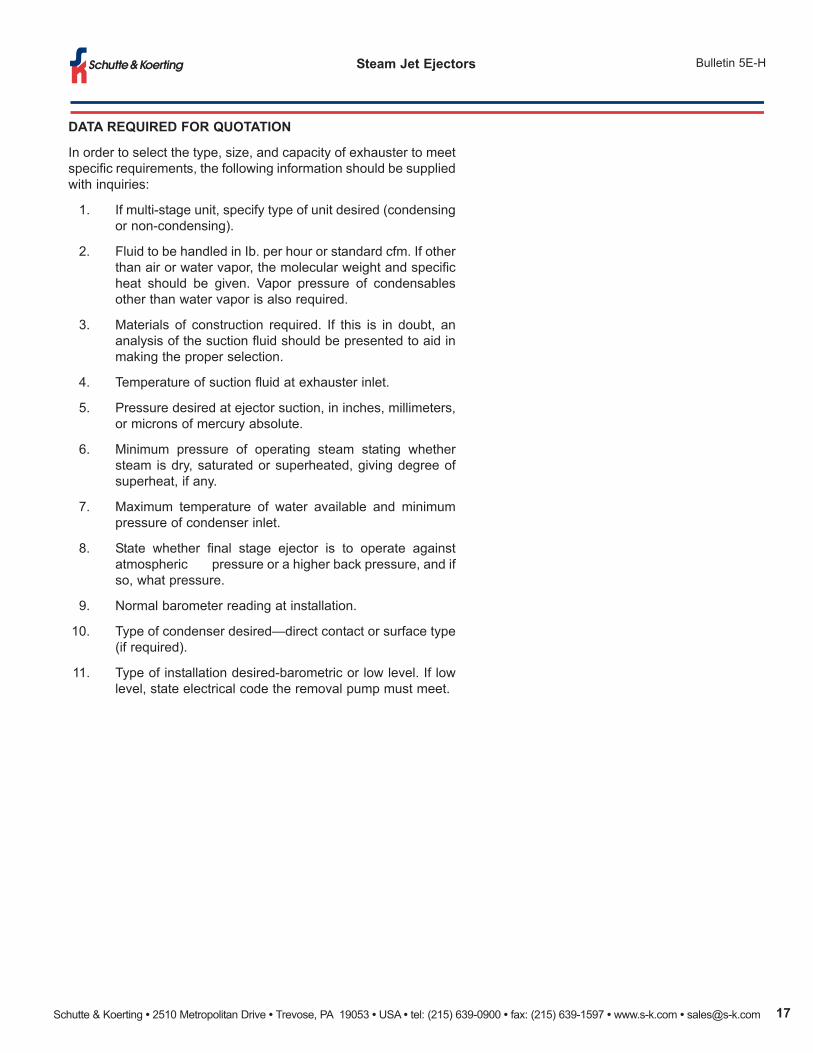
fig. 33. these two steam jet ejectors serve as part of the pressure recovery system at the u.S. army's
high energy laser system test facility in white Sands, new mexico. they are each 97 feet long with 96
inch diameter end-suction connections, and are among the largest ever manufactured anywhere.
Each ejector handles a large quantity of low molecular weight gas at 120 torr using the equivalent of
1.044 million pounds of steam per hour at 150 psig during the 14-second cycle.
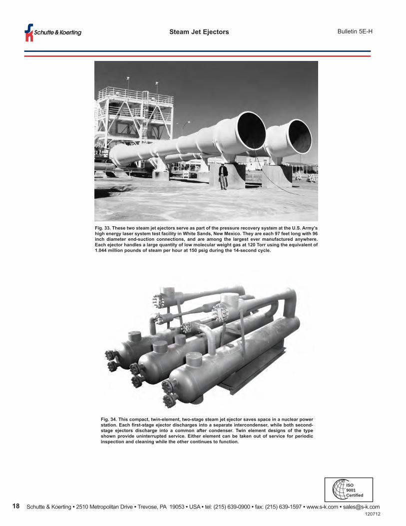
fig. 34. this compact, twin-element, two-stage steam jet ejector saves space in a nuclear power
station. Each first-stage ejector discharges into a separate intercondenser, while both second-
stage ejectors discharge into a common after condenser. twin element designs of the type
shown provide uninterrupted service. Either element can be taken out of service for periodic
inspection and cleaning while the other continues to function.
120712
ISO9001Certified