Steam Jet Ejectors - Schutte & Koerting · Steam Jet Ejectors Bulletin 5E-H SINGLE-STAGE EJECTORS...
19
Schutte & Koerting • 2510 Metropolitan Drive • Trevose, PA 19053 • USA • tel: (215) 639-0900 • fax: (215) 639-1597 • www.s-k.com • [email protected] 1 Steam Jet Ejectors Bulletin 5E-H Introduction Schutte & Koerting has a century of experience in designing and building efficient jet vacuum ejectors. This vast experience allows S & K to handle virtually any jet ejector application—no matter how complex. Steam Jet Ejectors are based on the ejector-venturi principle. In operation, steam issuing through an expanding nozzle has its pressure energy converted to velocity energy. A vacuum is created, air or gas is entrained and the mixture of gas and steam enters the venturi diffuser where its velocity energy is converted into pressure sufficient to discharge against a predetermined back pressure. Jet vacuum ejectors are readily available in ductile iron, steel, stainless steel and, on special order, in many more Index Description Page Introduction 1 Advantages 2 Performance Characteristics 3 SINGLE STAGE EJECTORS Fig. 556 (Standard Construction) 4 Fig. 556 Tefzel-Line Ejector 5 Fig. 555H (Haveg) 6 Fig. 562/555G (Graphite) 7 Fig. 557/542 (Flanged) 8 MULTI-STAGE EJECTORS Condensing and Non-Condensing Types 10 Two Stage 11 Three Stage 12 Four, Five, and Six Stage 13 Ejectors with Surface Condensers 14 Non-Condensing Types 14 Low Level Vacuum Units 15 Corrosion Resistant Units 15 Vacuum Boosters 16 Application Considerations 17 Measurement of Low Absolute Pressures 17 Quotation Information 18 Applications 19 materials such as Monel, Alloy 20, Hastelloy, Silicon Carbide, Titanium, Bronze and others. They can also be made from a variety of nonmetals such as Haveg, Graphite and Teflon. Steam jet ejectors are used in the process, food, steel and allied industries in connection with such operations as filtration, distillation, absorption, mixing, vacuum packaging, freeze drying, dehydrating and degassing. They will handle both condensable and non-condensable gases and vapors as well as mixtures of the two. Small amounts of solids or liquids will not cause operating problems. Accidental entrainment of liquid slugs can cause momentary interruption in pumping, but no damage to equipment. All S & K ejectors are computer designed and type-tested to insure reliability.
Transcript of Steam Jet Ejectors - Schutte & Koerting · Steam Jet Ejectors Bulletin 5E-H SINGLE-STAGE EJECTORS...
Schutte & Koerting • 2510 Metropolitan Drive • Trevose, PA 19053 • USA • tel: (215) 639-0900 • fax: (215) 639-1597 • www.s-k.com • [email protected] 1
Steam Jet Ejectors
Bulletin 5E-H
Introduction
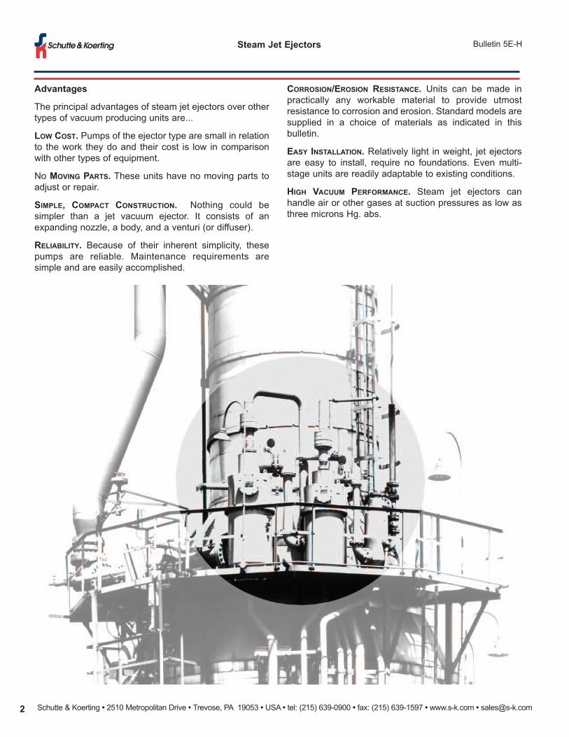
Schutte & Koerting has a century of experience indesigning and building efficient jet vacuum ejectors. Thisvast experience allows S & K to handle virtually any jetejector application—no matter how complex.
Steam Jet Ejectors are based on the ejector-venturiprinciple. In operation, steam issuing through anexpanding nozzle has its pressure energy converted tovelocity energy. A vacuum is created, air or gas isentrained and the mixture of gas and steam enters theventuri diffuser where its velocity energy is converted intopressure sufficient to discharge against a predeterminedback pressure.
Jet vacuum ejectors are readily available in ductile iron,steel, stainless steel and, on special order, in many more
Index
Description PageIntroduction 1Advantages 2Performance Characteristics 3SINGLE STAGE EJECTORSFig. 556 (Standard Construction) 4Fig. 556 Tefzel-Line Ejector 5Fig. 555H (Haveg) 6Fig. 562/555G (Graphite) 7Fig. 557/542 (Flanged) 8MULTI-STAGE EJECTORSCondensing and Non-Condensing Types 10Two Stage 11Three Stage 12Four, Five, and Six Stage 13Ejectors with Surface Condensers 14Non-Condensing Types 14Low Level Vacuum Units 15Corrosion Resistant Units 15Vacuum Boosters 16Application Considerations 17Measurement of Low Absolute Pressures 17Quotation Information 18Applications 19
materials such as Monel, Alloy 20, Hastelloy, SiliconCarbide, Titanium, Bronze and others. They can also bemade from a variety of nonmetals such as Haveg,Graphite and Teflon.
Steam jet ejectors are used in the process, food, steeland allied industries in connection with such operationsas filtration, distillation, absorption, mixing, vacuumpackaging, freeze drying, dehydrating and degassing.They will handle both condensable and non-condensablegases and vapors as well as mixtures of the two. Smallamounts of solids or liquids will not cause operatingproblems. Accidental entrainment of liquid slugs cancause momentary interruption in pumping, but nodamage to equipment.
All S & K ejectors are computer designed and type-testedto insure reliability.
Schutte & Koerting • 2510 Metropolitan Drive • Trevose, PA 19053 • USA • tel: (215) 639-0900 • fax: (215) 639-1597 • www.s-k.com • [email protected]
Steam Jet Ejectors Bulletin 5E-H
Advantages
The principal advantages of steam jet ejectors over othertypes of vacuum producing units are...
LOW COST. Pumps of the ejector type are small in relationto the work they do and their cost is low in comparisonwith other types of equipment.
No MOVING PARTS. These units have no moving parts toadjust or repair.
SIMPLE, COMPACT CONSTRUCTION. Nothing could besimpler than a jet vacuum ejector. It consists of anexpanding nozzle, a body, and a venturi (or diffuser).
RELIABILITY. Because of their inherent simplicity, thesepumps are reliable. Maintenance requirements aresimple and are easily accomplished.
CORROSION/EROSION RESISTANCE. Units can be made inpractically any workable material to provide utmostresistance to corrosion and erosion. Standard models aresupplied in a choice of materials as indicated in thisbulletin.
EASY INSTALLATION. Relatively light in weight, jet ejectorsare easy to install, require no foundations. Even multi-stage units are readily adaptable to existing conditions.
HIGH VACUUM PERFORMANCE. Steam jet ejectors canhandle air or other gases at suction pressures as low asthree microns Hg. abs.
Schutte & Koerting • 2510 Metropolitan Drive • Trevose, PA 19053 • USA • tel: (215) 639-0900 • fax: (215) 639-1597 • www.s-k.com • [email protected] 3
Bulletin 5E-HSteam Jet Ejectors
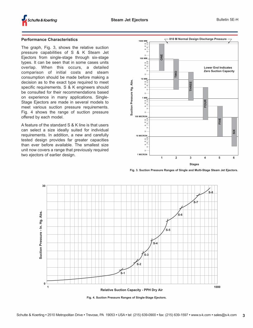
Fig. 3. Suction Pressure Ranges of Single and Multi-Stage Steam Jet Ejectors.
Fig. 4. Suction Pressure Ranges of Single-Stage Ejectors.
Performance Characteristics
The graph, Fig. 3, shows the relative suctionpressure capabilities of S & K Steam JetEjectors from single-stage through six-stagetypes. It can be seen that in some cases unitsoverlap. When this occurs, a detailedcomparison of initial costs and steamconsumption should be made before making adecision as to the exact type required to meetspecific requirements. S & K engineers shouldbe consulted for their recommendations basedon experience in many applications. Single-Stage Ejectors are made in several models tomeet various suction pressure requirements.Fig. 4 shows the range of suction pressureoffered by each model.
A feature of the standard S & K line is that userscan select a size ideally suited for individualrequirements. In addition, a new and carefullytested design provides far greater capacitiesthan ever before available. The smallest sizeunit now covers a range that previously requiredtwo ejectors of earlier design.
98 76
54
3
2
98 76
54
3
2
98 76
54
3
2
98 76
54
3
2
98 76
54
3
2
98 76
54
3
2
1000 MM
100 MM
100 MICRON
10 MICRON
1 MICRON
10 MM
1 MM
1 2 3 4 5 6
810 M Normal Design Discharge Pressure
Lower End IndicatesZero Suction Capacity
Stages
Suct
ion
Pres
sure
Hg.
Abs
.
ON
E
TWO
THR
EE
FIVE
FOU
R
SIX
Relative Suction Capacity - PPH Dry Air
Suct
ion
Pres
sure
- In
. Hg.
Abs
.
01 1000
30
S-8
S-7
S-6
S-5
S-4
S-3
S-2
S-1
Schutte & Koerting • 2510 Metropolitan Drive • Trevose, PA 19053 • USA • tel: (215) 639-0900 • fax: (215) 639-1597 • www.s-k.com • [email protected]
Steam Jet Ejectors Bulletin 5E-H
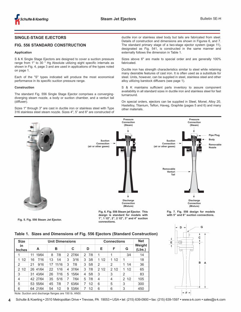
SINGLE-STAGE EJECTORS
FIG. 556 STANDARD CONSTRUCTION
Application
S & K Single Stage Ejectors are designed to cover a suction pressurerange from 1" to 30 " Hg Absolute utilizing eight specific internals asshown in Fig. 4, page 3 and are used in applications of the types notedon page 1.
Each of the "S" types indicated will produce the most economicalperformance in its specific suction pressure range.
Construction
The standard Fig. 556 Single Stage Ejector comprises a converging-diverging steam nozzle, a body or suction chamber, and a venturi tail(diffuser).
Sizes 1" through 3" are cast in ductile iron or stainless steel with Type316 stainless steel steam nozzle. Sizes 4", 5” and 6" are constructed of
Fig. 5. Fig. 556 Steam Jet Ejector.
Fig. 6. Fig. 556 Steam jet Ejector. Thisdesign is standard for models with1”, 1 1/2”, 2”, 2 1/2”, 3” and 4” suctionconnections.
Fig. 7. Fig. 556 design for modelswith 5” and 6” suction connections.
Sizein
Inches
Unit Dimensions Connections NetWeight(Lbs.)A B C D E F G
1 11 19/64 8 7/8 2 27/64 2 7/8 1 1 3/4 14 1 1/2 16 7/16 13 1/4 3 3/16 3 3/8 1 1/2 1 1/2 1 18 2 21 9/16 17 11/16 3 7/8 3 5/8 2 2 1 1/4 36 2 1/2 26 41/64 22 1/16 4 37/64 3 7/8 2 1/2 2 1/2 1 1/2 65 3 31 43/64 26 7/16 5 15/64 4 5/8 3 3 2 83 4 42 27/64 35 5/16 7 7/64 5 7/8 4 4 2 1/2 105 5 53 55/64 45 7/8 7 63/64 7 1/2 6 5 3 300 6 64 21/64 54 1/2 9 53/64 7 1/2 6 6 3 450
ductile iron or stainless steel body but tails are fabricated from steel.Details of construction and dimensions are shown in Figures 6, and 7.The standard primary stage of a two-stage ejector system (page 11),designated as Fig. 541, is constructed in the same manner andexternally follows the dimension in Table 1.
Sizes above 6" are made to special order and are generally 100%fabricated.
Ductile iron has strength characteristics similar to steel while retainingmany desirable features of cast iron. It is often used as a substitute forsteel. Units, however, can be supplied in steel, stainless steel and otheralloy utilizing barstock diffusers (see page 1).
S & K maintains sufficient parts inventory to assure componentavailability in all standard sizes in ductile iron and stainless steel for fastturnaround.
On special orders, ejectors can be supplied in Steel, Monel, Alloy 20,Hastelloy, Titanium, Teflon, Haveg, Graphite (pages 5 and 6) and manyother materials.
Table 1. Sizes and Dimensions of Fig. 556 Ejectors (Standard Construction)
Note: Suction and discharge flanges are 150 Ib. ANSI.
D G
E
C
B A
F
PressureConnection
(Steam)
SuctionConnection
(air or other gases)
DischargeConnection
(Mixture)
PressureConnection
(Steam)
SuctionConnection
(air or other gases)
DischargeConnection
(Mixture)
Pipe Plug
Body
RemovableNozzle
RemovableVenturi
Tail
Schutte & Koerting • 2510 Metropolitan Drive • Trevose, PA 19053 • USA • tel: (215) 639-0900 • fax: (215) 639-1597 • www.s-k.com • [email protected] 5
Bulletin 5E-HSteam Jet Ejectors
SINGLE-STAGE EJECTORS
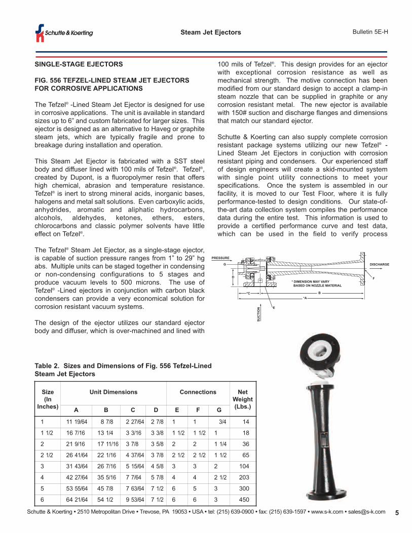
FIG. 556 TEFZEL-LINED STEAM JET EJECTORSFOR CORROSIVE APPLICATIONS
The Tefzel® -Lined Steam Jet Ejector is designed for usein corrosive applications. The unit is available in standardsizes up to 6” and custom fabricated for larger sizes. Thisejector is designed as an alternative to Haveg or graphitesteam jets, which are typically fragile and prone tobreakage during installation and operation.
This Steam Jet Ejector is fabricated with a SST steelbody and diffuser lined with 100 mils of Tefzel®. Tefzel®,created by Dupont, is a fluoropolymer resin that offershigh chemical, abrasion and temperature resistance.Tefzel® is inert to strong mineral acids, inorganic bases,halogens and metal salt solutions. Even carboxylic acids,anhydrides, aromatic and aliphatic hydrocarbons,alcohols, aldehydes, ketones, ethers, esters,chlorocarbons and classic polymer solvents have littleeffect on Tefzel®.
The Tefzel® Steam Jet Ejector, as a single-stage ejector,is capable of suction pressure ranges from 1” to 29” hgabs. Multiple units can be staged together in condensingor non-condensing configurations to 5 stages andproduce vacuum levels to 500 microns. The use ofTefzel® -Lined ejectors in conjunction with carbon blackcondensers can provide a very economical solution forcorrosion resistant vacuum systems.
The design of the ejector utilizes our standard ejectorbody and diffuser, which is over-machined and lined with
100 mils of Tefzel®. This design provides for an ejectorwith exceptional corrosion resistance as well asmechanical strength. The motive connection has beenmodified from our standard design to accept a clamp-insteam nozzle that can be supplied in graphite or anycorrosion resistant metal. The new ejector is availablewith 150# suction and discharge flanges and dimensionsthat match our standard ejector.
Schutte & Koerting can also supply complete corrosionresistant package systems utilizing our new Tefzel® -Lined Steam Jet Ejectors in conjuction with corrosionresistant piping and condensers. Our experienced staffof design engineers will create a skid-mounted systemwith single point utility connections to meet yourspecifications. Once the system is assembled in ourfacility, it is moved to our Test Floor, where it is fullyperformance-tested to design conditions. Our state-of-the-art data collection system compiles the performancedata during the entire test. This information is used toprovide a certified performance curve and test data,which can be used in the field to verify process
G
D
*C
E
B*A
F* DIMENSION MAY VARY BASED ON NOZZLE MATERIAL
SUC
TIO
NPRESSURE
DISCHARGE
Size(In
Inches)
Unit Dimensions Connections NetWeight(Lbs.)A B C D E F G
1 11 19/64 8 7/8 2 27/64 2 7/8 1 1 3/4 14
1 1/2 16 7/16 13 1/4 3 3/16 3 3/8 1 1/2 1 1/2 1 18
2 21 9/16 17 11/16 3 7/8 3 5/8 2 2 1 1/4 36
2 1/2 26 41/64 22 1/16 4 37/64 3 7/8 2 1/2 2 1/2 1 1/2 65
3 31 43/64 26 7/16 5 15/64 4 5/8 3 3 2 104
4 42 27/64 35 5/16 7 7/64 5 7/8 4 4 2 1/2 203
5 53 55/64 45 7/8 7 63/64 7 1/2 6 5 3 300
6 64 21/64 54 1/2 9 53/64 7 1/2 6 6 3 450
Table 2. Sizes and Dimensions of Fig. 556 Tefzel-LinedSteam Jet Ejectors
Schutte & Koerting • 2510 Metropolitan Drive • Trevose, PA 19053 • USA • tel: (215) 639-0900 • fax: (215) 639-1597 • www.s-k.com • [email protected]
Steam Jet Ejectors Bulletin 5E-H
SINGLE-STAGE EJECTORS
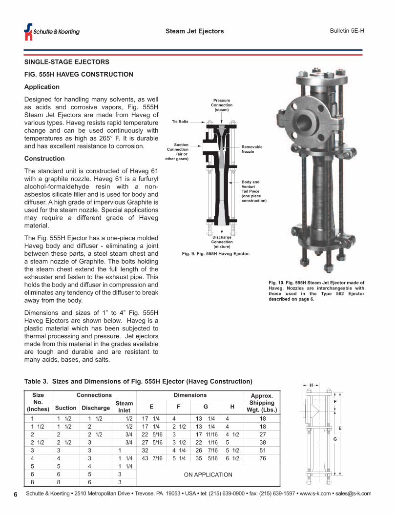
FIG. 555H HAVEG CONSTRUCTION
Application
Designed for handling many solvents, as wellas acids and corrosive vapors, Fig. 555HSteam Jet Ejectors are made from Haveg ofvarious types. Haveg resists rapid temperaturechange and can be used continuously withtemperatures as high as 265° F. It is durableand has excellent resistance to corrosion.
Construction
The standard unit is constructed of Haveg 61with a graphite nozzle. Haveg 61 is a furfurylalcohol-formaldehyde resin with a non-asbestos silicate filler and is used for body anddiffuser. A high grade of impervious Graphite isused for the steam nozzle. Special applicationsmay require a different grade of Havegmaterial.
The Fig. 555H Ejector has a one-piece moldedHaveg body and diffuser - eliminating a jointbetween these parts, a steel steam chest anda steam nozzle of Graphite. The bolts holdingthe steam chest extend the full length of theexhauster and fasten to the exhaust pipe. Thisholds the body and diffuser in compression andeliminates any tendency of the diffuser to breakaway from the body.
Dimensions and sizes of 1” to 4” Fig. 555HHaveg Ejectors are shown below. Haveg is aplastic material which has been subjected tothermal processing and pressure. Jet ejectorsmade from this material in the grades availableare tough and durable and are resistant tomany acids, bases, and salts.
Fig. 9. Fig. 555H Haveg Ejector.
Fig. 10. Fig. 555H Steam Jet Ejector made ofHaveg. Nozzles are interchangeable withthose used in the Type 562 Ejectordescribed on page 6.
Table 3. Sizes and Dimensions of Fig. 555H Ejector (Haveg Construction)
SizeNo.
(Inches)
Connections Dimensions Approx.ShippingWgt. (Lbs.)Suction Discharge
SteamInlet E F G H
1 1 1/2 1 1/2 1/2 17 1/4 4 13 1/4 4 18 1 1/2 1 1/2 2 1/2 17 1/4 2 1/2 13 1/4 4 18 2 2 2 1/2 3/4 22 5/16 3 17 11/16 4 1/2 27 2 1/2 2 1/2 3 3/4 27 5/16 3 1/2 22 1/16 5 38 3 3 3 1 32 4 1/4 26 7/16 5 1/2 51 4 4 3 1 1/4 43 7/16 5 1/4 35 5/16 6 1/2 76 5 5 4 1 1/4
ON APPLICATION 6 6 5 3 8 8 6 3
G
E
F
H
PressureConnection
(steam)
SuctionConnection
(air or other gases)
Tie Bolts
Removable Nozzle
Body and VenturiTail Piece(one piece construction)
DischargeConnection
(mixture)
Schutte & Koerting • 2510 Metropolitan Drive • Trevose, PA 19053 • USA • tel: (215) 639-0900 • fax: (215) 639-1597 • www.s-k.com • [email protected] 7
Bulletin 5E-HSteam Jet Ejectors
SINGLE-STAGE EJECTORS
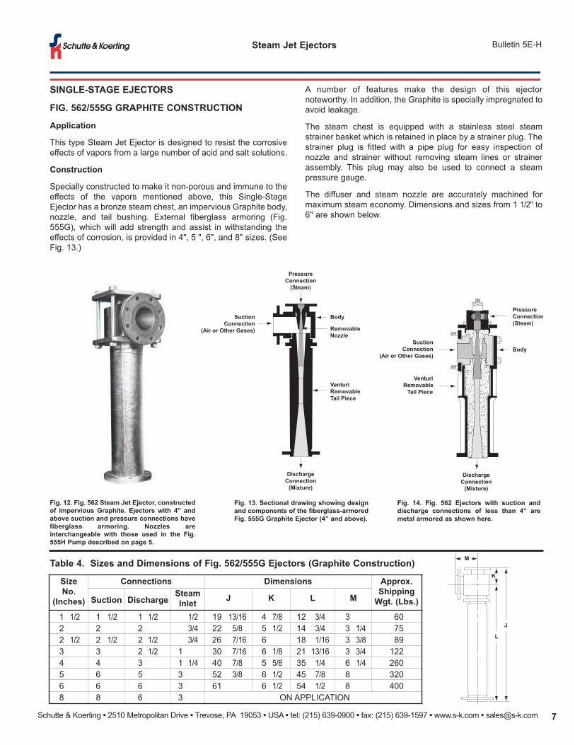
FIG. 562/555G GRAPHITE CONSTRUCTION
Application
This type Steam Jet Ejector is designed to resist the corrosiveeffects of vapors from a large number of acid and salt solutions.
Construction
Specially constructed to make it non-porous and immune to theeffects of the vapors mentioned above, this Single-StageEjector has a bronze steam chest, an impervious Graphite body,nozzle, and tail bushing. External fiberglass armoring (Fig.555G), which will add strength and assist in withstanding theeffects of corrosion, is provided in 4", 5 ", 6", and 8" sizes. (SeeFig. 13.)
Fig. 12. Fig. 562 Steam Jet Ejector, constructedof impervious Graphite. Ejectors with 4" andabove suction and pressure connections havefiberglass armoring. Nozzles areinterchangeable with those used in the Fig.555H Pump described on page 5.
Fig. 13. Sectional drawing showing designand components of the fiberglass-armoredFig. 555G Graphite Ejector (4” and above).
Fig. 14. Fig. 562 Ejectors with suction anddischarge connections of less than 4” aremetal armored as shown here.
Table 4. Sizes and Dimensions of Fig. 562/555G Ejectors (Graphite Construction)
SizeNo.
(Inches)
Connections Dimensions Approx.ShippingWgt. (Lbs.)Suction Discharge
SteamInlet J K L M
1 1/2 1 1/2 1 1/2 1/2 19 13/16 4 7/8 12 3/4 3 60 2 2 2 3/4 22 5/8 5 1/2 14 3/4 3 1/4 75 2 1/2 2 1/2 2 1/2 3/4 26 7/16 6 18 1/16 3 3/8 89 3 3 2 1/2 1 30 7/16 6 1/8 21 13/16 3 3/4 122 4 4 3 1 1/4 40 7/8 5 5/8 35 1/4 6 1/4 260 5 6 5 3 52 3/8 6 1/2 45 7/8 8 320 6 6 6 3 61 6 1/2 54 1/2 8 400 8 8 6 3 ON APPLICATION
M
K
L
J
PressureConnection(Steam)
BodySuction
Connection(Air or Other Gases)
VenturiRemovable
Tail Piece
DischargeConnection
(Mixture)
PressureConnection
(Steam)
SuctionConnection
(Air or Other Gases)
Body
RemovableNozzle
VenturiRemovableTail Piece
DischargeConnection
(Mixture)
A number of features make the design of this ejectornoteworthy. In addition, the Graphite is specially impregnated toavoid leakage.
The steam chest is equipped with a stainless steel steamstrainer basket which is retained in place by a strainer plug. Thestrainer plug is fitted with a pipe plug for easy inspection ofnozzle and strainer without removing steam lines or strainerassembly. This plug may also be used to connect a steampressure gauge.
The diffuser and steam nozzle are accurately machined formaximum steam economy. Dimensions and sizes from 1 1/2" to6" are shown below.
Schutte & Koerting • 2510 Metropolitan Drive • Trevose, PA 19053 • USA • tel: (215) 639-0900 • fax: (215) 639-1597 • www.s-k.com • [email protected]
Steam Jet Ejectors Bulletin 5E-H
SINGLE-STAGE EJECTORS
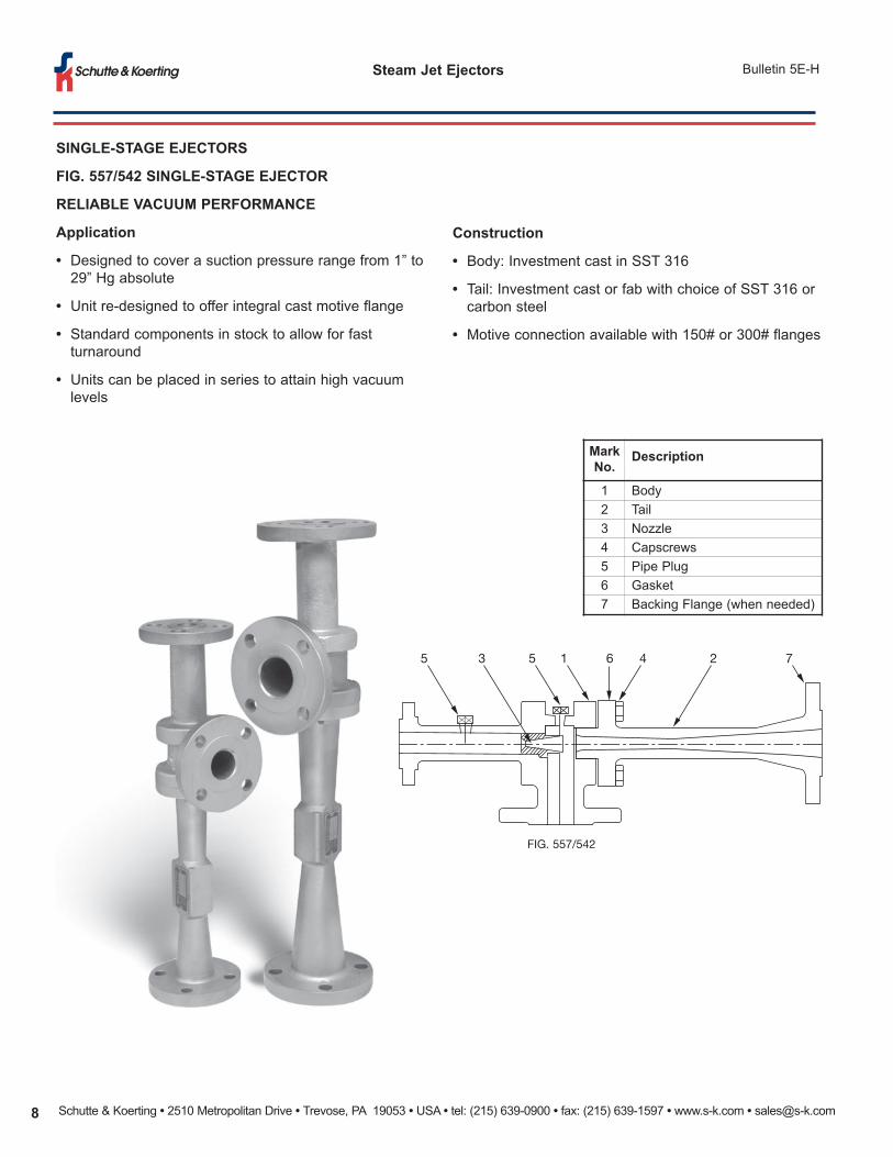
FIG. 557/542 SINGLE-STAGE EJECTOR
RELIABLE VACUUM PERFORMANCE
Application
• Designed to cover a suction pressure range from 1” to29” Hg absolute
• Unit re-designed to offer integral cast motive flange
• Standard components in stock to allow for fastturnaround
• Units can be placed in series to attain high vacuumlevels
Construction
• Body: Investment cast in SST 316
• Tail: Investment cast or fab with choice of SST 316 orcarbon steel
• Motive connection available with 150# or 300# flanges
FIG. 557/542
5 3 5 1 6 4 2 7
MarkNo.
Description
1 Body2 Tail3 Nozzle4 Capscrews5 Pipe Plug6 Gasket7 Backing Flange (when needed)
Schutte & Koerting • 2510 Metropolitan Drive • Trevose, PA 19053 • USA • tel: (215) 639-0900 • fax: (215) 639-1597 • www.s-k.com • [email protected] 9
Bulletin 5E-HSteam Jet Ejectors
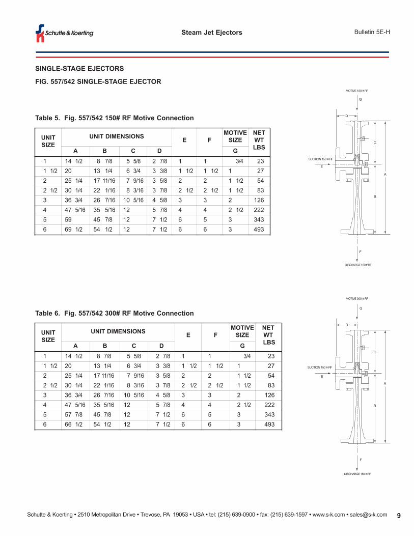
UNITSIZE
UNIT DIMENSIONS E FMOTIVESIZE
NET WT LBSA B C D G
1 14 1/2 8 7/8 5 5/8 2 7/8 1 1 3/4 23 1 1/2 20 13 1/4 6 3/4 3 3/8 1 1/2 1 1/2 1 27 2 25 1/4 17 11/16 7 9/16 3 5/8 2 2 1 1/2 54 2 1/2 30 1/4 22 1/16 8 3/16 3 7/8 2 1/2 2 1/2 1 1/2 83 3 36 3/4 26 7/16 10 5/16 4 5/8 3 3 2 126 4 47 5/16 35 5/16 12 5 7/8 4 4 2 1/2 222 5 59 45 7/8 12 7 1/2 6 5 3 343 6 69 1/2 54 1/2 12 7 1/2 6 6 3 493
Table 5. Fig. 557/542 150# RF Motive Connection
Table 6. Fig. 557/542 300# RF Motive Connection
D
E
C
DISCHARGE 150 # RF
SUCTION 150 # RF
MOTIVE 150 # RF
F
G
B
A
D
E
C
DISCHARGE 150 # RF
SUCTION 150 # RF
MOTIVE 300 # RF
F
G
B
A
UNITSIZE
UNIT DIMENSIONS E FMOTIVESIZE
NET WTLBSA B C D G
1 14 1/2 8 7/8 5 5/8 2 7/8 1 1 3/4 23 1 1/2 20 13 1/4 6 3/4 3 3/8 1 1/2 1 1/2 1 27 2 25 1/4 17 11/16 7 9/16 3 5/8 2 2 1 1/2 54 2 1/2 30 1/4 22 1/16 8 3/16 3 7/8 2 1/2 2 1/2 1 1/2 83 3 36 3/4 26 7/16 10 5/16 4 5/8 3 3 2 126 4 47 5/16 35 5/16 12 5 7/8 4 4 2 1/2 222 5 57 7/8 45 7/8 12 7 1/2 6 5 3 343 6 66 1/2 54 1/2 12 7 1/2 6 6 3 493
SINGLE-STAGE EJECTORS
FIG. 557/542 SINGLE-STAGE EJECTOR
Schutte & Koerting • 2510 Metropolitan Drive • Trevose, PA 19053 • USA • tel: (215) 639-0900 • fax: (215) 639-1597 • www.s-k.com • [email protected]
Steam Jet Ejectors Bulletin 5E-H
MULTI-STAGE EJECTORS
Staging of ejectors becomes necessary for economicaloperation as the required absolute suction pressuredecreases (see Fig. 3, page 3).
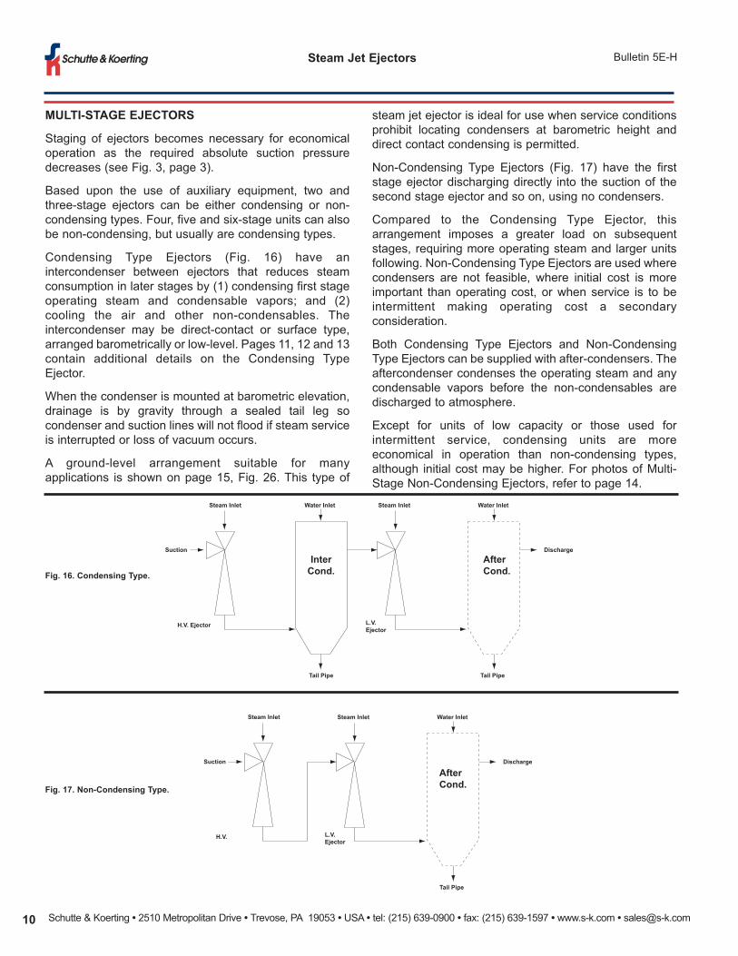
Based upon the use of auxiliary equipment, two andthree-stage ejectors can be either condensing or non-condensing types. Four, five and six-stage units can alsobe non-condensing, but usually are condensing types.
Condensing Type Ejectors (Fig. 16) have anintercondenser between ejectors that reduces steamconsumption in later stages by (1) condensing first stageoperating steam and condensable vapors; and (2)cooling the air and other non-condensables. Theintercondenser may be direct-contact or surface type,arranged barometrically or low-level. Pages 11, 12 and 13contain additional details on the Condensing TypeEjector.
When the condenser is mounted at barometric elevation,drainage is by gravity through a sealed tail leg socondenser and suction lines will not flood if steam serviceis interrupted or loss of vacuum occurs.
A ground-level arrangement suitable for manyapplications is shown on page 15, Fig. 26. This type of
Fig. 16. Condensing Type.
Fig. 17. Non-Condensing Type.
steam jet ejector is ideal for use when service conditionsprohibit locating condensers at barometric height anddirect contact condensing is permitted.
Non-Condensing Type Ejectors (Fig. 17) have the firststage ejector discharging directly into the suction of thesecond stage ejector and so on, using no condensers.
Compared to the Condensing Type Ejector, thisarrangement imposes a greater load on subsequentstages, requiring more operating steam and larger unitsfollowing. Non-Condensing Type Ejectors are used wherecondensers are not feasible, where initial cost is moreimportant than operating cost, or when service is to beintermittent making operating cost a secondaryconsideration.
Both Condensing Type Ejectors and Non-CondensingType Ejectors can be supplied with after-condensers. Theaftercondenser condenses the operating steam and anycondensable vapors before the non-condensables aredischarged to atmosphere.
Except for units of low capacity or those used forintermittent service, condensing units are moreeconomical in operation than non-condensing types,although initial cost may be higher. For photos of Multi-Stage Non-Condensing Ejectors, refer to page 14.
Steam Inlet
Suction
H.V. Ejector
Tail Pipe
Water Inlet Steam Inlet
L.V.Ejector
Tail Pipe
Water Inlet
Discharge
AfterCond.
InterCond.
Steam Inlet
Suction
H.V. Ejector
Steam Inlet
L.V.Ejector
Tail Pipe
Water Inlet
Discharge
AfterCond.
Schutte & Koerting • 2510 Metropolitan Drive • Trevose, PA 19053 • USA • tel: (215) 639-0900 • fax: (215) 639-1597 • www.s-k.com • [email protected] 11
Bulletin 5E-HSteam Jet Ejectors
MULTI-STAGE EJECTORS
TWO-STAGE EJECTORS
Application
Two-Stage Steam Jet Ejectors have the same generalfield of application as the single stage units. They handleboth condensable and non-condensable gases or vapors,as well as mixtures of the two. The general operatingrange is between 5" Hg. abs. and 3 mm Hg. abs.Depending on conditions, however, a single-stage unitmay be more economical at the top of the range and athree-stage unit near the bottom.
Operation
In the two-stage assemblies, the suction mixture entersthe body of the primary stage, or High Vacuum (H.V.)Ejector, Fig. 541, and is compressed from the requiredsuction to an intermediate pressure less thanatmospheric. The secondary stage or Low Vacuum (L.V.)Ejector, Fig. 556 compresses from this point toatmosphere, or to a point where it is desired to utilize theejector discharge.
Exact value of the intermediate pressure varies with theoperating conditions and the type of two-stage assembly.The units have been designed for optimum inter-stagepressure.
In condensing units, the inter-condenser functions aspreviously described. This reduces the load on the lowvacuum ejector and reduces steam consumption. Theintercondenser may be a direct-contact barometric type,a low level type, or surface type. These are discussed inmore detail on pages 13, 14 and 15.
In small size units, and where cooling water is noteconomically available, the intercondenser may beeliminated, resulting in a two-stage non-condensing unit.
When the suction load contains a large amount ofcondensable vapors, it is sometimes possible to use asurface or direct-contact pre-condenser, or pre-cooler toreduce the load on the first stage ejector (Fig. 18). Also,if it is objectionable to discharge the low vacuumexhauster directly to atmosphere, an aftercondenser canbe used to condense the steam and other condensables,as well as Iower the noise level. Direct-ContactCondensers for this function are described in Bulletin5AA.
Non-condensing two-stage units can be used whenconditions warrant this type of arrangement. A typical
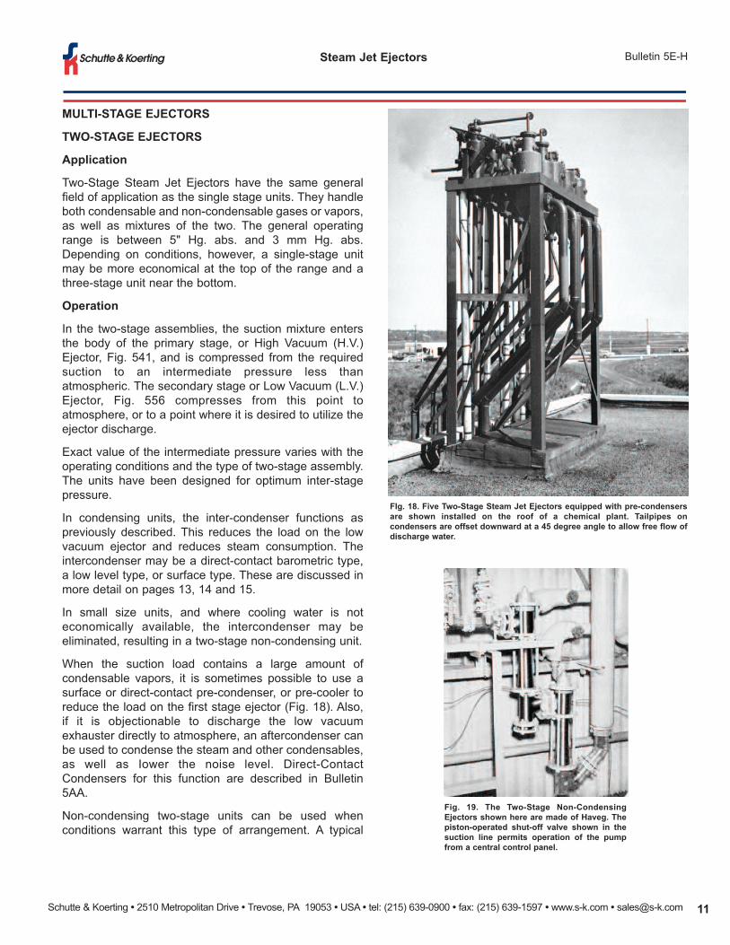
FIg. 18. Five Two-Stage Steam Jet Ejectors equipped with pre-condensersare shown installed on the roof of a chemical plant. Tailpipes oncondensers are offset downward at a 45 degree angle to allow free flow ofdischarge water.
Fig. 19. The Two-Stage Non-CondensingEjectors shown here are made of Haveg. Thepiston-operated shut-off valve shown in thesuction line permits operation of the pumpfrom a central control panel.
Schutte & Koerting • 2510 Metropolitan Drive • Trevose, PA 19053 • USA • tel: (215) 639-0900 • fax: (215) 639-1597 • www.s-k.com • [email protected]
Steam Jet Ejectors Bulletin 5E-H
MULTI-STAGE EJECTORS
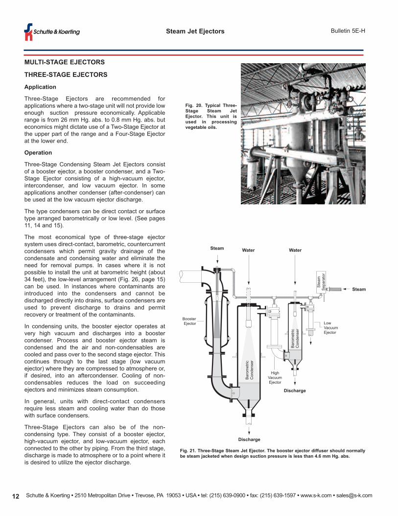
THREE-STAGE EJECTORS
Application
Three-Stage Ejectors are recommended forapplications where a two-stage unit will not provide lowenough suction pressure economically. Applicablerange is from 26 mm Hg. abs. to 0.8 mm Hg. abs. buteconomics might dictate use of a Two-Stage Ejector atthe upper part of the range and a Four-Stage Ejectorat the lower end.
Operation
Three-Stage Condensing Steam Jet Ejectors consistof a booster ejector, a booster condenser, and a Two-Stage Ejector consisting of a high-vacuum ejector,intercondenser, and low vacuum ejector. In someapplications another condenser (after-condenser) canbe used at the low vacuum ejector discharge.
The type condensers can be direct contact or surfacetype arranged barometrically or low level. (See pages11, 14 and 15).
The most economical type of three-stage ejectorsystem uses direct-contact, barometric, countercurrentcondensers which permit gravity drainage of thecondensate and condensing water and eliminate theneed for removal pumps. In cases where it is notpossible to install the unit at barometric height (about34 feet), the low-level arrangement (Fig. 26, page 15)can be used. In instances where contaminants areintroduced into the condensers and cannot bedischarged directly into drains, surface condensers areused to prevent discharge to drains and permitrecovery or treatment of the contaminants.
In condensing units, the booster ejector operates atvery high vacuum and discharges into a boostercondenser. Process and booster ejector steam iscondensed and the air and non-condensables arecooled and pass over to the second stage ejector. Thiscontinues through to the last stage (low vacuumejector) where they are compressed to atmosphere or,if desired, into an aftercondenser. Cooling of non-condensables reduces the load on succeedingejectors and minimizes steam consumption.
In general, units with direct-contact condensersrequire less steam and cooling water than do thosewith surface condensers.
Three-Stage Ejectors can also be of the non-condensing type. They consist of a booster ejector,high-vacuum ejector, and low-vacuum ejector, eachconnected to the other by piping. From the third stage,discharge is made to atmosphere or to a point where itis desired to utilize the ejector discharge.
Fig. 20. Typical Three-Stage Steam JetEjector. This unit isused in processingvegetable oils.
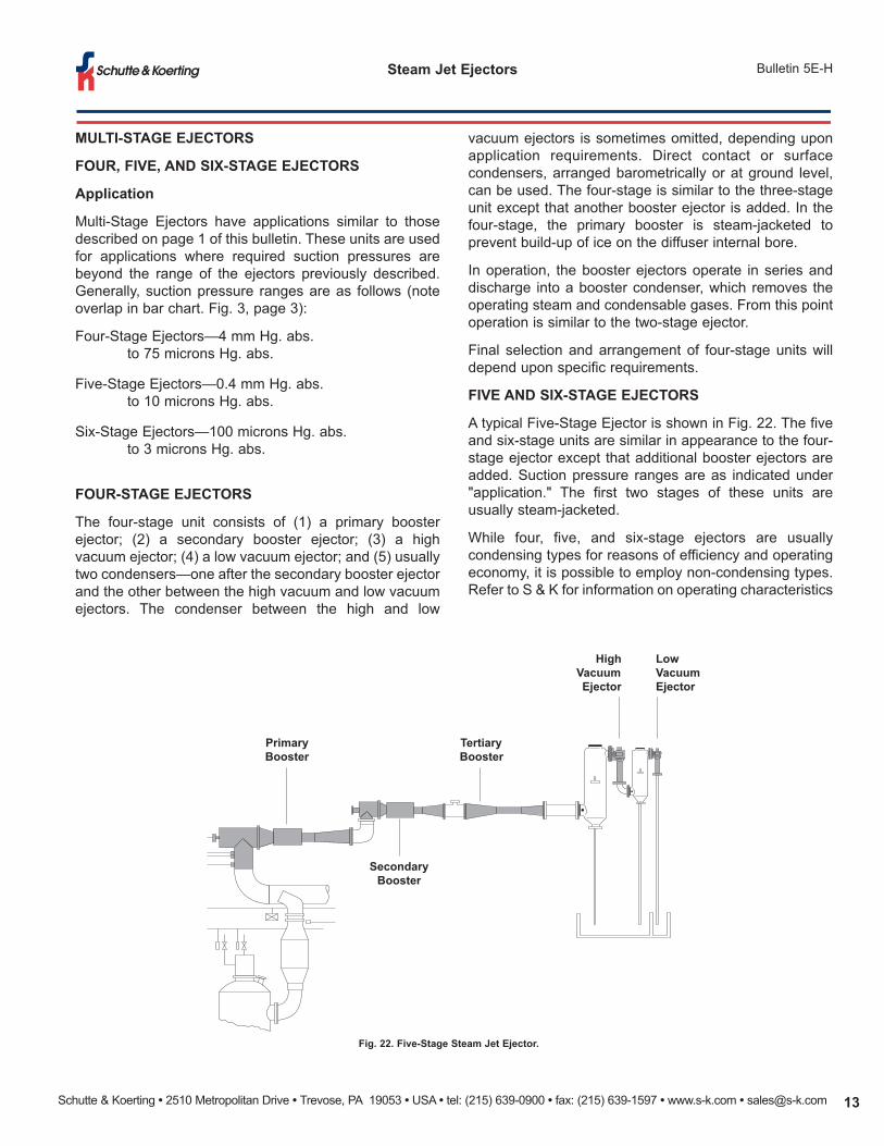
Fig. 21. Three-Stage Steam Jet Ejector. The booster ejector diffuser should normallybe steam jacketed when design suction pressure is less than 4.6 mm Hg. abs.
Barometric
Condenser
Barometric
Condenser
HighVacuumEjector
LowVacuumEjector
Steam
Separator
BoosterEjector
Steam Water Water
Discharge
Discharge
Steam
Schutte & Koerting • 2510 Metropolitan Drive • Trevose, PA 19053 • USA • tel: (215) 639-0900 • fax: (215) 639-1597 • www.s-k.com • [email protected] 13
Bulletin 5E-HSteam Jet Ejectors
MULTI-STAGE EJECTORS
FOUR, FIVE, AND SIX-STAGE EJECTORS
Application
Multi-Stage Ejectors have applications similar to thosedescribed on page 1 of this bulletin. These units are usedfor applications where required suction pressures arebeyond the range of the ejectors previously described.Generally, suction pressure ranges are as follows (noteoverlap in bar chart. Fig. 3, page 3):
Four-Stage Ejectors—4 mm Hg. abs.to 75 microns Hg. abs.
Five-Stage Ejectors—0.4 mm Hg. abs.to 10 microns Hg. abs.
Six-Stage Ejectors—100 microns Hg. abs. to 3 microns Hg. abs.
FOUR-STAGE EJECTORS
The four-stage unit consists of (1) a primary boosterejector; (2) a secondary booster ejector; (3) a highvacuum ejector; (4) a low vacuum ejector; and (5) usuallytwo condensers—one after the secondary booster ejectorand the other between the high vacuum and low vacuumejectors. The condenser between the high and low
vacuum ejectors is sometimes omitted, depending uponapplication requirements. Direct contact or surfacecondensers, arranged barometrically or at ground level,can be used. The four-stage is similar to the three-stageunit except that another booster ejector is added. In thefour-stage, the primary booster is steam-jacketed toprevent build-up of ice on the diffuser internal bore.
In operation, the booster ejectors operate in series anddischarge into a booster condenser, which removes theoperating steam and condensable gases. From this pointoperation is similar to the two-stage ejector.
Final selection and arrangement of four-stage units willdepend upon specific requirements.
FIVE AND SIX-STAGE EJECTORS
A typical Five-Stage Ejector is shown in Fig. 22. The fiveand six-stage units are similar in appearance to the four-stage ejector except that additional booster ejectors areadded. Suction pressure ranges are as indicated under"application." The first two stages of these units areusually steam-jacketed.
While four, five, and six-stage ejectors are usuallycondensing types for reasons of efficiency and operatingeconomy, it is possible to employ non-condensing types.Refer to S & K for information on operating characteristics
Fig. 22. Five-Stage Steam Jet Ejector.
HighVacuumEjector
LowVacuumEjector
TertiaryBooster
PrimaryBooster
SecondaryBooster
Schutte & Koerting • 2510 Metropolitan Drive • Trevose, PA 19053 • USA • tel: (215) 639-0900 • fax: (215) 639-1597 • www.s-k.com • [email protected]
Steam Jet Ejectors Bulletin 5E-H
MULTI-STAGE EJECTORS
EJECTORS WITH SURFACE CONDENSERS
Disposal of contaminated water is of growing concern inprocess operations, particularly in the chemical industry. Wherean ejector system is drawing in contaminants, a condenser thatdischarges directly to the drain may not be used. In theseapplications, ejectors using surface condensers are beingutilized more. The surface condenser prevents discharge to thedrain and permits recovery or treatment of undesirable wastes.
A steam jet system with surface condensers normally requiresmore motive steam and condensing water than one with direct-contact condensers. This is the most expensive type of multi-
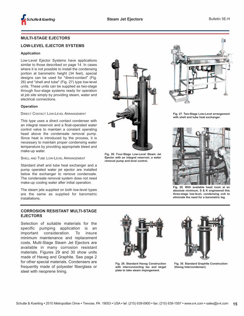
NON-CONDENSING EJECTORS
Shown are several examples of multi-stage non-condensing ejectors. This arrangement is generallyutilized in situations where a barometric leg or coolingwater is not readily available for an inter-condenser. Theyalso can be furnished in Haveg or Graphite constructionfor corrosive applications. Non-condensing ejectorsprovide the lowest initial capital equipment investment formulti-stage systems.
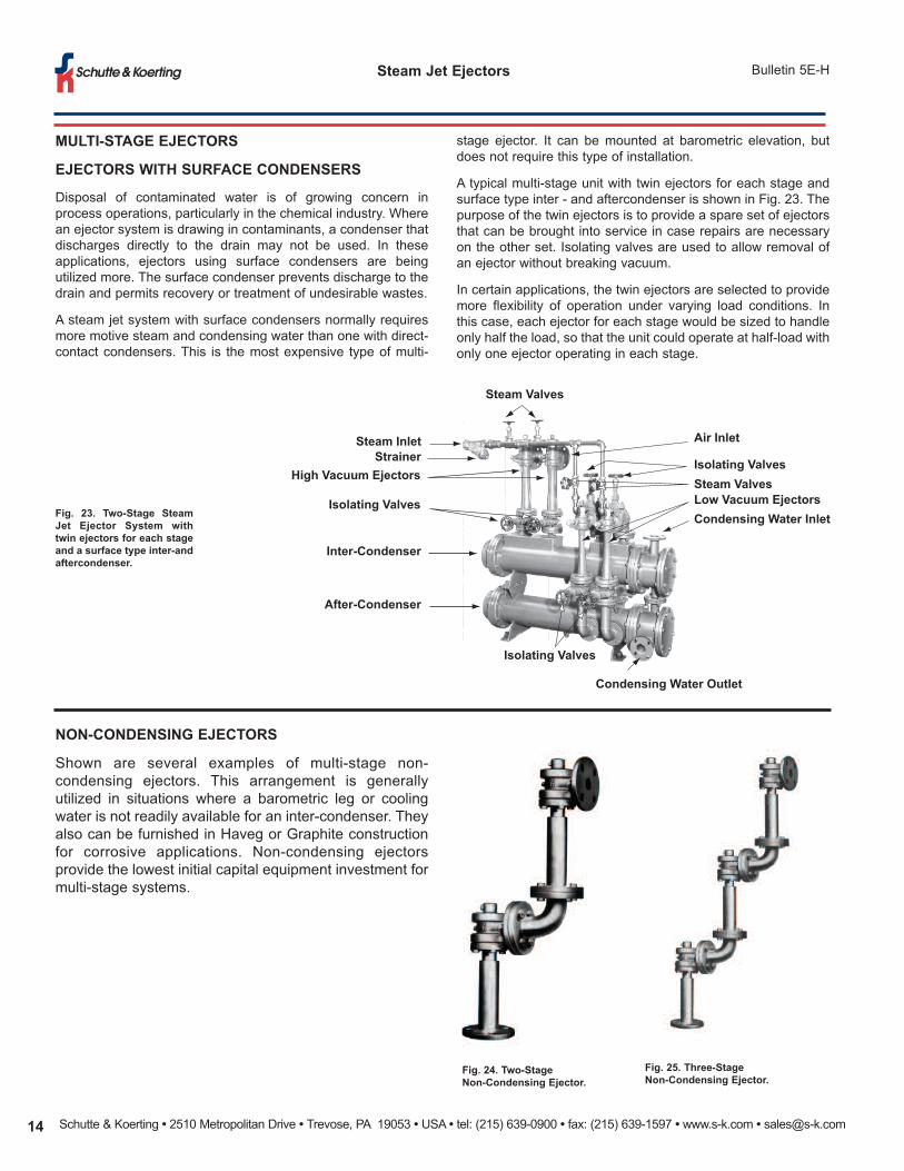
Fig. 23. Two-Stage SteamJet Ejector System withtwin ejectors for each stageand a surface type inter-andaftercondenser.
Fig. 24. Two-Stage Non-Condensing Ejector.
Fig. 25. Three-Stage Non-Condensing Ejector.
Steam InletStrainer
High Vacuum Ejectors
Isolating Valves
Inter-Condenser
After-Condenser
Isolating Valves
Condensing Water Outlet
Condensing Water InletLow Vacuum EjectorsSteam ValvesIsolating Valves
Air Inlet
Steam Valves
stage ejector. It can be mounted at barometric elevation, butdoes not require this type of installation.
A typical multi-stage unit with twin ejectors for each stage andsurface type inter - and aftercondenser is shown in Fig. 23. Thepurpose of the twin ejectors is to provide a spare set of ejectorsthat can be brought into service in case repairs are necessaryon the other set. Isolating valves are used to allow removal ofan ejector without breaking vacuum.
In certain applications, the twin ejectors are selected to providemore flexibility of operation under varying load conditions. Inthis case, each ejector for each stage would be sized to handleonly half the load, so that the unit could operate at half-load withonly one ejector operating in each stage.
Schutte & Koerting • 2510 Metropolitan Drive • Trevose, PA 19053 • USA • tel: (215) 639-0900 • fax: (215) 639-1597 • www.s-k.com • [email protected] 15
Bulletin 5E-HSteam Jet Ejectors
MULTI-STAGE EJECTORS
LOW-LEVEL EJECTOR SYSTEMS
Application
Low-Level Ejector Systems have applicationssimilar to those described on page 14. In caseswhere it is not possible to install the condensingportion at barometric height (34 feet), specialdesigns can be used for "direct-contact" (Fig.26) and "shell and tube" (Fig. 27) type low-levelunits. These units can be supplied as two-stagethrough four-stage systems ready for operationat job site simply by providing steam, water andelectrical connections.
Operation
DIRECT CONTACT LOW-LEVEL ARRANGEMENT
This type uses a direct contact condenser withan integral reservoir and a float-operated watercontrol valve to maintain a constant operatinghead above the condensate removal pump.Since heat is introduced by the process, it isnecessary to maintain proper condensing watertemperature by providing appropriate bleed andmake-up water.
SHELL AND TUBE LOW-LEVEL ARRANGEMENT
Standard shell and tube heat exchanger and apump operated water jet ejector are installedbelow the exchanger to remove condensate.The condensate removal system does not needmake-up cooling water after initial operation.
The steam jets supplied on both low-level typesare the same as supplied for barometricinstallations.
Fig. 26. Four-Stage Low-Level Steam JetEjector with an integral reservoir, a waterremoval pump and level control.
Fig. 27. Two-Stage Low-Level arrangementwith shell and tube heat exchanger.
Fig. 28. With available head room at anabsolute minimum, S & K engineered thisthree-stage low-level, condensing unit toeliminate the need for a barometric leg.
Fig. 29. Standard Haveg Constructionwith interconnecting tee and targetplate to take steam impingement.
CORROSION RESISTANT MULTI-STAGEEJECTORS
Selection of suitable materials for thespecific pumping application is animportant consideration. To insureminimum maintenance and replacementcosts, Multi-Stage Steam Jet Ejectors areavailable in many corrosion resistantmaterials. Figures 29 and 30 show unitsmade of Haveg and Graphite. See page 2for other special materials. Condensers arefrequently made of polyester fiberglass orsteel with neoprene lining.
Fig. 30. Standard Graphite Construction(Haveg Intercondenser).
Schutte & Koerting • 2510 Metropolitan Drive • Trevose, PA 19053 • USA • tel: (215) 639-0900 • fax: (215) 639-1597 • www.s-k.com • [email protected]
Steam Jet Ejectors Bulletin 5E-H
MULTI-STAGE EJECTORS
STEAM JET VACUUM BOOSTERS
Application
If large condensable vapor loads must be handled, such asthose from an evaporator or crystallizer, it is normally done witha condenser followed by a single-stage or two-stage ejector.The condenser condenses the vapor and the secondary unitremoves the saturated non-condensables and maintains thevacuum.
The vacuum obtainable in a condenser is limited by the vaporpressure of the injection water. If a higher vacuum is desired, aSteam Jet Booster is provided to increase the vacuum to thedesired point. Boosters like this are used in multi-stage units.The booster ejectors are large in proportion to the other ejectorsbecause of the magnitude of the vapor load they handle.
The function of the Steam Jet Vacuum Booster is to compressthe condensable and non-condensable vapors from the suctionvacuum to the intermediate vacuum maintained in thecondenser.
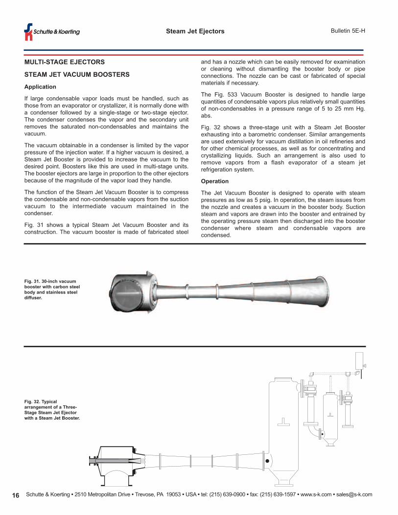
Fig. 31 shows a typical Steam Jet Vacuum Booster and itsconstruction. The vacuum booster is made of fabricated steel
Fig. 31. 30-inch vacuumbooster with carbon steelbody and stainless steeldiffuser.
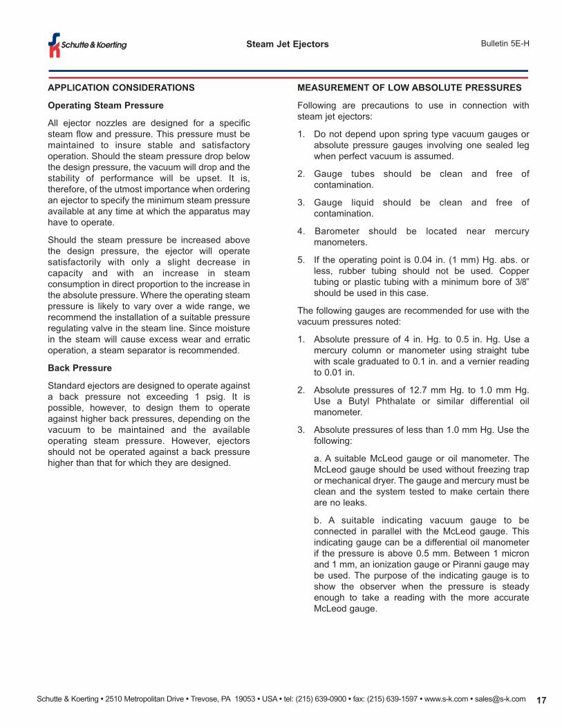
Fig. 32. Typicalarrangement of a Three-Stage Steam Jet Ejectorwith a Steam Jet Booster.
and has a nozzle which can be easily removed for examinationor cleaning without dismantling the booster body or pipeconnections. The nozzle can be cast or fabricated of specialmaterials if necessary.
The Fig. 533 Vacuum Booster is designed to handle largequantities of condensable vapors plus relatively small quantitiesof non-condensables in a pressure range of 5 to 25 mm Hg.abs.
Fig. 32 shows a three-stage unit with a Steam Jet Boosterexhausting into a barometric condenser. Similar arrangementsare used extensively for vacuum distillation in oil refineries andfor other chemical processes, as well as for concentrating andcrystallizing liquids. Such an arrangement is also used toremove vapors from a flash evaporator of a steam jetrefrigeration system.
Operation
The Jet Vacuum Booster is designed to operate with steampressures as low as 5 psig. In operation, the steam issues fromthe nozzle and creates a vacuum in the booster body. Suctionsteam and vapors are drawn into the booster and entrained bythe operating pressure steam then discharged into the boostercondenser where steam and condensable vapors arecondensed.
Schutte & Koerting • 2510 Metropolitan Drive • Trevose, PA 19053 • USA • tel: (215) 639-0900 • fax: (215) 639-1597 • www.s-k.com • [email protected] 17
Bulletin 5E-HSteam Jet Ejectors
APPLICATION CONSIDERATIONS
Operating Steam Pressure
All ejector nozzles are designed for a specificsteam flow and pressure. This pressure must bemaintained to insure stable and satisfactoryoperation. Should the steam pressure drop belowthe design pressure, the vacuum will drop and thestability of performance will be upset. It is,therefore, of the utmost importance when orderingan ejector to specify the minimum steam pressureavailable at any time at which the apparatus mayhave to operate.
Should the steam pressure be increased abovethe design pressure, the ejector will operatesatisfactorily with only a slight decrease incapacity and with an increase in steamconsumption in direct proportion to the increase inthe absolute pressure. Where the operating steampressure is likely to vary over a wide range, werecommend the installation of a suitable pressureregulating valve in the steam line. Since moisturein the steam will cause excess wear and erraticoperation, a steam separator is recommended.
Back Pressure
Standard ejectors are designed to operate againsta back pressure not exceeding 1 psig. It ispossible, however, to design them to operateagainst higher back pressures, depending on thevacuum to be maintained and the availableoperating steam pressure. However, ejectorsshould not be operated against a back pressurehigher than that for which they are designed.
MEASUREMENT OF LOW ABSOLUTE PRESSURES
Following are precautions to use in connection withsteam jet ejectors:
1. Do not depend upon spring type vacuum gauges orabsolute pressure gauges involving one sealed legwhen perfect vacuum is assumed.
2. Gauge tubes should be clean and free ofcontamination.
3. Gauge liquid should be clean and free ofcontamination.
4. Barometer should be located near mercurymanometers.
5. If the operating point is 0.04 in. (1 mm) Hg. abs. orless, rubber tubing should not be used. Coppertubing or plastic tubing with a minimum bore of 3/8”should be used in this case.
The following gauges are recommended for use with thevacuum pressures noted:
1. Absolute pressure of 4 in. Hg. to 0.5 in. Hg. Use amercury column or manometer using straight tubewith scale graduated to 0.1 in. and a vernier readingto 0.01 in.
2. Absolute pressures of 12.7 mm Hg. to 1.0 mm Hg.Use a Butyl Phthalate or similar differential oilmanometer.
3. Absolute pressures of less than 1.0 mm Hg. Use thefollowing:
a. A suitable McLeod gauge or oil manometer. TheMcLeod gauge should be used without freezing trapor mechanical dryer. The gauge and mercury must beclean and the system tested to make certain thereare no leaks.
b. A suitable indicating vacuum gauge to beconnected in parallel with the McLeod gauge. Thisindicating gauge can be a differential oil manometerif the pressure is above 0.5 mm. Between 1 micronand 1 mm, an ionization gauge or Piranni gauge maybe used. The purpose of the indicating gauge is toshow the observer when the pressure is steadyenough to take a reading with the more accurateMcLeod gauge.
Schutte & Koerting • 2510 Metropolitan Drive • Trevose, PA 19053 • USA • tel: (215) 639-0900 • fax: (215) 639-1597 • www.s-k.com • [email protected]
Steam Jet Ejectors Bulletin 5E-H
DATA REQUIRED FOR QUOTATION
In order to select the type, size, and capacity of exhauster to meetspecific requirements, the following information should be suppliedwith inquiries:
1. If multi-stage unit, specify type of unit desired (condensingor non-condensing).
2. Fluid to be handled in Ib. per hour or standard cfm. If otherthan air or water vapor, the molecular weight and specificheat should be given. Vapor pressure of condensablesother than water vapor is also required.
3. Materials of construction required. If this is in doubt, ananalysis of the suction fluid should be presented to aid inmaking the proper selection.
4. Temperature of suction fluid at exhauster inlet.
5. Pressure desired at ejector suction, in inches, millimeters,or microns of mercury absolute.
6. Minimum pressure of operating steam stating whethersteam is dry, saturated or superheated, giving degree ofsuperheat, if any.
7. Maximum temperature of water available and minimumpressure of condenser inlet.
8. State whether final stage ejector is to operate againstatmospheric pressure or a higher back pressure, and ifso, what pressure.
9. Normal barometer reading at installation.
10. Type of condenser desired—direct contact or surface type(if required).
11. Type of installation desired-barometric or low level. If lowlevel, state electrical code the removal pump must meet.
Schutte & Koerting • 2510 Metropolitan Drive • Trevose, PA 19053 • USA • tel: (215) 639-0900 • fax: (215) 639-1597 • www.s-k.com • [email protected] 19
Bulletin 5E-HSteam Jet Ejectors
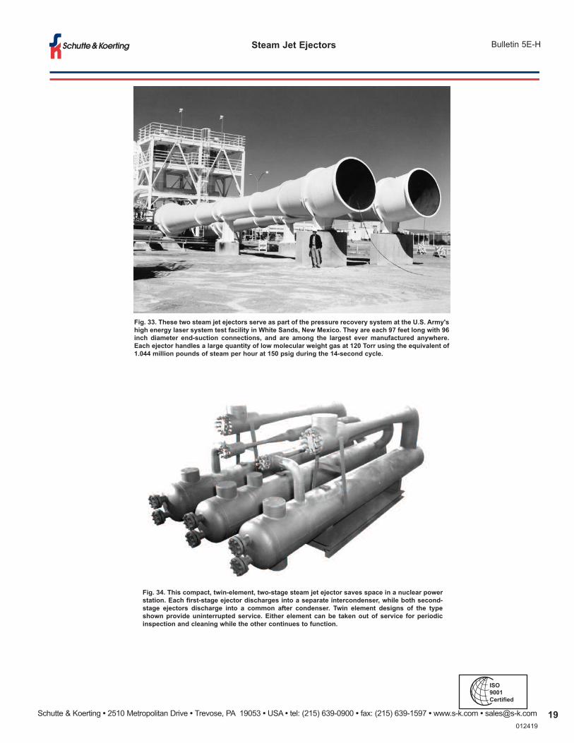
Fig. 33. These two steam jet ejectors serve as part of the pressure recovery system at the U.S. Army'shigh energy laser system test facility in White Sands, New Mexico. They are each 97 feet long with 96inch diameter end-suction connections, and are among the largest ever manufactured anywhere.Each ejector handles a large quantity of low molecular weight gas at 120 Torr using the equivalent of1.044 million pounds of steam per hour at 150 psig during the 14-second cycle.
Fig. 34. This compact, twin-element, two-stage steam jet ejector saves space in a nuclear powerstation. Each first-stage ejector discharges into a separate intercondenser, while both second-stage ejectors discharge into a common after condenser. Twin element designs of the typeshown provide uninterrupted service. Either element can be taken out of service for periodicinspection and cleaning while the other continues to function.
012419
ISO9001Certified