Steam Condensation in the Presence of a …cdn.intechweb.org/pdfs/19411.pdf · Steam Condensation...
17
7 Steam Condensation in the Presence of a Noncondensable Gas in a Horizontal Tube Kwon-Yeong Lee and Moo Hwan Kim Korea Atomic Energy Research Institute / Pohang University of Science and Technology, Republic of Korea 1. Introduction Perhaps the most common flow configuration in which a convective condensation occurs is a flow in a horizontal circular tube. This configuration is encountered in air-conditioning and refrigeration condensers as well as condensers in Rankine power cycles. Although a convective condensation is also sometimes contrived to occur in a co-current vertical downward flow, a horizontal flow is often preferred because the flow can be repeatedly passed through the heat exchanger core in a serpentine fashion without trapping liquid or vapor in the return bends. (Carey, 1992) Horizontal heat exchangers are also widely used in the nuclear industry. Recently, a horizontal heat exchanger design has been proposed for a passive containment cooling system (PCCS) of future light water reactors. Current PCCS designs typically employ a vertical condenser. The horizontal design is proposed because horizontal heat exchangers have a potentially higher heat removal capability than vertical heat exchangers. (Wu & Vierow, 2006b) As well as, horizontal heat exchangers have less tube fouling, higher structural earthquake resistance which will improve the reliability of the safety system, and a large economic benefit because the shorter coolant pool allows for reduction in the containment height and volume. In spite of these advantages, there is a lack of mechanistic understanding of the heat transfer and fluid flow phenomena occurring in the heat exchanger tubes. This is mainly due to the fact that the phenomena are more complicated compared to the case of vertical heat exchangers. In vertical tubes the phenomena is mainly laminar or turbulent film condensation, whereas in horizontal tubes, the phenomena is complicated by strong asymmetry and flow regime transitions, which causes transitions in heat and mass transfer mechanisms. There is also the need for mechanistic analysis tools that can assess condenser performance. (Wu, 2005) There were many investigations for the condensation phenomena inside horizontal tubes to study the horizontal heat exchangers. However, almost all of them obtained tube section- averaged data without a noncondensable gas. Recently, Wu and Vierow (2006a, 2006b) studied experimentally the condensation of steam in a horizontal heat exchanger with air present, as shown in Fig. 1. In order to measure the condenser tube inner surface temperatures and to calculate the local heat fluxes, they developed an innovative thermocouple design that allowed for nonintrusive measurements. The experimental results show that the top of the condenser tube is a much better heat transfer surface. At any tube www.intechopen.com
-
Upload
nguyendieu -
Category
Documents
-
view
220 -
download
2
Transcript of Steam Condensation in the Presence of a …cdn.intechweb.org/pdfs/19411.pdf · Steam Condensation...

7
Steam Condensation in the Presence of a Noncondensable Gas in a Horizontal Tube
Kwon-Yeong Lee and Moo Hwan Kim Korea Atomic Energy Research Institute / Pohang University of Science and Technology,
Republic of Korea
1. Introduction
Perhaps the most common flow configuration in which a convective condensation occurs is a flow in a horizontal circular tube. This configuration is encountered in air-conditioning and refrigeration condensers as well as condensers in Rankine power cycles. Although a convective condensation is also sometimes contrived to occur in a co-current vertical downward flow, a horizontal flow is often preferred because the flow can be repeatedly passed through the heat exchanger core in a serpentine fashion without trapping liquid or vapor in the return bends. (Carey, 1992) Horizontal heat exchangers are also widely used in the nuclear industry. Recently, a horizontal heat exchanger design has been proposed for a passive containment cooling system (PCCS) of future light water reactors. Current PCCS designs typically employ a vertical condenser. The horizontal design is proposed because horizontal heat exchangers have a potentially higher heat removal capability than vertical heat exchangers. (Wu & Vierow, 2006b) As well as, horizontal heat exchangers have less tube fouling, higher structural earthquake resistance which will improve the reliability of the safety system, and a large economic benefit because the shorter coolant pool allows for reduction in the containment height and volume. In spite of these advantages, there is a lack of mechanistic understanding of the heat transfer and fluid flow phenomena occurring in the heat exchanger tubes. This is mainly due to the fact that the phenomena are more complicated compared to the case of vertical heat exchangers. In vertical tubes the phenomena is mainly laminar or turbulent film condensation, whereas in horizontal tubes, the phenomena is complicated by strong asymmetry and flow regime transitions, which causes transitions in heat and mass transfer mechanisms. There is also the need for mechanistic analysis tools that can assess condenser performance. (Wu, 2005) There were many investigations for the condensation phenomena inside horizontal tubes to study the horizontal heat exchangers. However, almost all of them obtained tube section-averaged data without a noncondensable gas. Recently, Wu and Vierow (2006a, 2006b) studied experimentally the condensation of steam in a horizontal heat exchanger with air present, as shown in Fig. 1. In order to measure the condenser tube inner surface temperatures and to calculate the local heat fluxes, they developed an innovative thermocouple design that allowed for nonintrusive measurements. The experimental results show that the top of the condenser tube is a much better heat transfer surface. At any tube
www.intechopen.com
Evaporation, Condensation and Heat Transfer
154
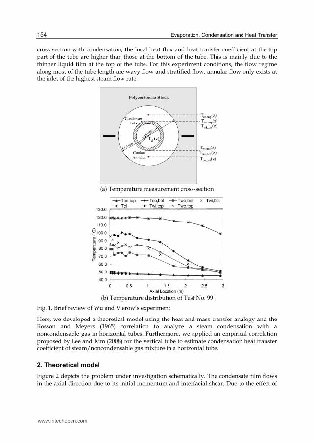
cross section with condensation, the local heat flux and heat transfer coefficient at the top part of the tube are higher than those at the bottom of the tube. This is mainly due to the thinner liquid film at the top of the tube. For this experiment conditions, the flow regime along most of the tube length are wavy flow and stratified flow, annular flow only exists at the inlet of the highest steam flow rate.
(a) Temperature measurement cross-section
(b) Temperature distribution of Test No. 99
Fig. 1. Brief review of Wu and Vierow’s experiment
Here, we developed a theoretical model using the heat and mass transfer analogy and the Rosson and Meyers (1965) correlation to analyze a steam condensation with a noncondensable gas in horizontal tubes. Furthermore, we applied an empirical correlation proposed by Lee and Kim (2008) for the vertical tube to estimate condensation heat transfer coefficient of steam/noncondensable gas mixture in a horizontal tube.
2. Theoretical model
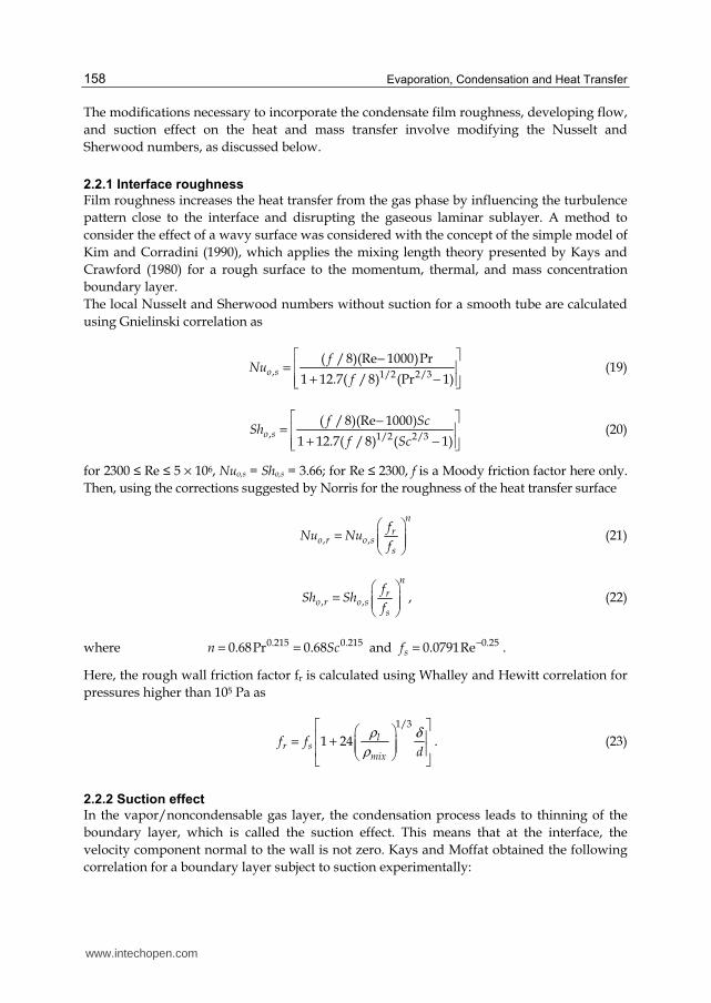
Figure 2 depicts the problem under investigation schematically. The condensate film flows in the axial direction due to its initial momentum and interfacial shear. Due to the effect of
www.intechopen.com

Steam Condensation in the Presence of a Noncondensable Gas in a Horizontal Tube
155
gravity, the condensate film on the tube inner surface may run down the periphery of the tube and accumulate in the bottom of the tube. Since the liquid layer acts as a resistance to heat and mass transfer, it is important to know the two-phase geometric configuration in the tube cross section.
Fig. 2. Horizontal co-current annular flow with condensation
It is assumed that the vapor entering the tube is saturated. The inside wall temperatures of the tube are Tw,top and Tw,bot, which are lower than the saturation temperature of the vapor. Therefore, condensation takes place on the wall surface. The vapor/noncondensable gas mixture has a given inlet bulk temperature Tb, and a corresponding inlet concentration of the noncondensable gas Wnc,b at the given pressure. At the liquid/gas interface, the temperatures Ti,top and Ti,bot, and the noncondensable gas mass fraction Wnc,i,top and Wnc,i,bot are unknown and must be determined from the analysis. The analysis of steam condensation in the presence of a noncondensable gas typically involves the heat balance at the liquid/gas interface. However, separate models for the condensate film and vapor/noncondensable gas mixture are linked and solved simultaneously for the heat and mass transfer rates. The heat transfer through the vapor/noncondensable gas mixture boundary layer consists of the sensible heat transfer and the latent heat transfer given up by the condensing vapor, and it must equal that from the condensate film to the tube wall. Therefore, we get
( ) ( )( )f i w c s b ih T T h h T T− = + −
(1)
where hf is the film heat transfer coefficient, hc and hs are the condensation and sensible heat transfer coefficients in the gas mixture respectively. Then, the total heat transfer coefficient htot is given by
11 1
totf c s
hh h h
−⎡ ⎤⎢ ⎥= ++⎢ ⎥⎣ ⎦
. (2)
To get the cross section-averaged heat transfer coefficient, a parameter β was defined as the fraction of the perimeter over which film condensation occurred, and correlated as a function of the liquid and vapor Reynolds numbers and also the ratio of gravitational force to the viscous force. The following correlations for β were suggested by Wu (2005) based on Rosson and Meyers (1965).
www.intechopen.com

Evaporation, Condensation and Heat Transfer
156
0.10.27 Remixβ = for
0.6 0.55Re Re
6.4 10mix l
Ga< × (3)
51.74 10
Re Remix l
Gaβ
−×= for
0.6 0.55Re Re
6.4 10mix l
Ga> × (4)
Then, the circumferentially averaged heat flux can be calculated as
" " "(1 )tot top botq q qβ β= + −
(5)
Here, the heat fluxes at the top and bottom of the horizontal tube are defined as
", ,( )top tot top b w topq h T T= − (6)
", ,( )bot tot bot b w botq h T T= − (7)
2.1 Condensate flow For stratified flow with higher vapor velocity, the vapor shear will affect the drain of the liquid and also change the mode of heat transfer at the bottom of the tube through the liquid pool from conduction to forced convection. Rosson and Meyers (1965) measured a single point value of the heat transfer coefficient for stratified, wavy and slug flows for methanol and acetone at atmospheric pressure. By rotating the condenser tube, they measured the variation of the heat transfer coefficient continuously decreased from the top of the tube to the bottom of the tube. They proposed different heat transfer correlations for top and bottom side of the tube. For top side of the tube, the heat transfer is similar to that of Nusselt but the effect of vapor shear is included:
1/43 1
0.12 ( )0.31Re
( )l l v l lv
top mixl i w
g k hh
T T d
ρ ρ ρ
µ
⎡ ⎤−= ⎢ ⎥
−⎢ ⎥⎣ ⎦ . (8)
Here, the Remix represents the effect of vapor shear. For the bottom of the tube, no noticeable dependency of the Nu on the temperature was observed. The heat transfer coefficient depended on the vapor and liquid flow rate. The von Karman analogy between momentum transfer and heat transfer was used to predict the heat transfer coefficient.
, 8Re
55 ln(5Pr 1)
Pr
l vt llbot
kh
d
Φ= ⋅
+ +
. (9)
Here the parameter Φ is the two-phase multiplier for viscous laminar liquid flow and turbulent vapor flow, as presented by the Martinelli parameter with C=12.
1/2
2
11l
C
X X
⎛ ⎞Φ = + +⎜ ⎟⎝ ⎠ (10)
www.intechopen.com

Steam Condensation in the Presence of a Noncondensable Gas in a Horizontal Tube
157
where we used Martinelli correlation as
0.5 0.1 0.91v l
ttl v
xX
x
ρ µ
ρ µ
⎛ ⎞ ⎛ ⎞ −⎛ ⎞= ⎜ ⎟ ⎜ ⎟ ⎜ ⎟⎜ ⎟ ⎜ ⎟ ⎝ ⎠⎝ ⎠ ⎝ ⎠ (11)
2.2 Vapor/noncondensable gas mixture flow
In this study, a stratification of the noncondensable gas concentration in the gas phase was assumed to be negligible, so the heat and mass transfer mechanism at everywhere inside the horizontal tube can be considered same. And the heat and mass transfer analogy was used to analysis steam condensation with noncondensable air in horizontal tubes. Therefore, the sensible and latent heat transfer rates can be calculated simultaneously. The sensible heat transfer coefficient can be expressed as
mixs mix
i
kh Nu
d= (12)
and the condensation (or latent) heat transfer coefficient can be defined as
"
( )
cond fgc
b i
m ih
T T=
−. (13)
To find "condm , the mass balance at the interface is calculated to yield the following equation:
" ", ( )v
cond v i tot i
i
Wm D W m
yρ
⎡ ⎤∂= − +⎢ ⎥
∂⎣ ⎦ . (14)
As the condensate surface is impermeable to the noncondensable gases, we can think
", ( )nc
nc i tot i
i
WD W m
yρ⎡ ⎤∂
=⎢ ⎥∂⎣ ⎦ . (15)
Also, as the sum of vapor and noncondensable gas mass fractions is unit, we can derive
nc vW W
y y
∂ ∂= −
∂ ∂. (16)
Solving for "totm$ from Eq. (15) and substituting it in Eq. (14) together with Eq. (16), Eq. (14)
can be simplified as
, ,"
, ,
( )( ( / ))
1 (1 )
v b v iv icond m
v i v i
W WD W ym h
W W
ρ −− ∂ ∂= =
− −, (17)
where hm is the mass transfer coefficient. Eq. (17) can be recast as
"
,
, ,( )
nc icondmix
nc i nc b
Wm dSh
D W Wρ=
−. (18)
www.intechopen.com
Evaporation, Condensation and Heat Transfer
158
The modifications necessary to incorporate the condensate film roughness, developing flow,
and suction effect on the heat and mass transfer involve modifying the Nusselt and
Sherwood numbers, as discussed below.
2.2.1 Interface roughness
Film roughness increases the heat transfer from the gas phase by influencing the turbulence
pattern close to the interface and disrupting the gaseous laminar sublayer. A method to
consider the effect of a wavy surface was considered with the concept of the simple model of
Kim and Corradini (1990), which applies the mixing length theory presented by Kays and
Crawford (1980) for a rough surface to the momentum, thermal, and mass concentration
boundary layer.
The local Nusselt and Sherwood numbers without suction for a smooth tube are calculated
using Gnielinski correlation as
, 1/2 2/3
( /8)(Re 1000)Pr
1 12.7( /8) (Pr 1)o s
fNu
f
⎡ ⎤−= ⎢ ⎥
+ −⎢ ⎥⎣ ⎦ (19)
, 1/2 2/3
( /8)(Re 1000)
1 12.7( /8) ( 1)o s
f ScSh
f Sc
⎡ ⎤−= ⎢ ⎥
+ −⎢ ⎥⎣ ⎦ (20)
for 2300 ≤ Re ≤ 5 × 10⁶, Nuo,s = Sho,s = 3.66; for Re ≤ 2300, f is a Moody friction factor here only.
Then, using the corrections suggested by Norris for the roughness of the heat transfer surface
, ,
n
ro r o s
s
fNu Nu
f
⎛ ⎞= ⎜ ⎟⎜ ⎟⎝ ⎠ (21)
, ,
n
ro r o s
s
fSh Sh
f
⎛ ⎞= ⎜ ⎟⎜ ⎟⎝ ⎠ , (22)
where 0.215 0.2150.68Pr 0.68n Sc= = and 0.250.0791Resf−= .
Here, the rough wall friction factor fr is calculated using Whalley and Hewitt correlation for
pressures higher than 105 Pa as
1/3
1 24 lr s
mix
f fd
ρ δ
ρ
⎡ ⎤⎛ ⎞⎢ ⎥= + ⎜ ⎟⎜ ⎟⎢ ⎥⎝ ⎠⎣ ⎦. (23)
2.2.2 Suction effect
In the vapor/noncondensable gas layer, the condensation process leads to thinning of the
boundary layer, which is called the suction effect. This means that at the interface, the
velocity component normal to the wall is not zero. Kays and Moffat obtained the following
correlation for a boundary layer subject to suction experimentally:
www.intechopen.com

Steam Condensation in the Presence of a Noncondensable Gas in a Horizontal Tube
159
1
ln h
o h
BSt
St B
⎛ ⎞+= ⎜ ⎟⎜ ⎟⎝ ⎠ , (24)
where /h condB m G St∞′′= is called the suction parameter. We defined St as Stanton number with suction and Sto as Stanton number without suction. This equation can be recast as
1 1"
",
Re Prexp 1
Re Pr
cond xx
o x cond x
m GNu
G Nu m
− −∞
∞
⎡ ⎤⎛ ⎞ ⎡ ⎤⎢ ⎥⎜ ⎟= − ⎢ ⎥⎜ ⎟⎢ ⎥ ⎢ ⎥⎣ ⎦⎝ ⎠⎣ ⎦. (25)
Using the analogy between heat and mass transfer, Eq. (25) can be written as
1 1"
",
Reexp 1
Re
cond xx
o x cond x
m Sc GSh
G Sh m Sc
− −∞
∞
⎡ ⎤⎛ ⎞ ⎡ ⎤⎢ ⎥⎜ ⎟= − ⎢ ⎥⎜ ⎟⎢ ⎥ ⎢ ⎥⎣ ⎦⎝ ⎠⎣ ⎦. (26)
Combining Eqs. (18) and (26), we get "condm as follows:
," Re (1 )ln 1
Re
o x xcond
x
G Sh ScDm
Sc G d
ρ ω∞
∞
⎡ ⎤−⎧ ⎫= +⎨ ⎬⎢ ⎥⎩ ⎭⎣ ⎦ , (27)
where ω is the ratio of the noncondensable gas mass fraction in the bulk to that at the liquid/gas interface. And the noncondensable gas mass fractions in the bulk and the interface are given by the Gibbs-Dalton ideal gas mixture equation.
2.2.3 Developing flow As most of the heat transfer takes place in the first part of the condenser tube, it may be important to consider the developing flow effect in the heat and mass transfer model. Therefore, the suggestion of Reynolds et al. (1969) is adopted for the thermal entrance zone, and is given by
4 3/2
,0.8(1 7 10 Re )
1/
o t oNu Nux d
−⎡ ⎤+ ×= +⎢ ⎥⎢ ⎥⎣ ⎦ (28)
4 3/2
,0.8(1 7 10 Re )
1/
o t oSh Shx d
−⎡ ⎤+ ×= +⎢ ⎥⎢ ⎥⎣ ⎦ . (29)
2.3 Calculation procedure The calculation commences at the tube inlet for which the inlet mixture temperature, inlet steam flow rate, inlet noncondensable gas flow rate, and total pressure are given. Here, the pressure drop through the condenser tube is assumed to be negligible. The inner wall temperature profiles on top and bottom of a horizontal tube are given as boundary conditions. The heat fluxes through the liquid film and mixture boundary layer are calculated separately with an assumed interface temperature. Iteration is needed to get reasonable heat transfer coefficients of hf, hc, and hs by modifying the interface temperature until the heat fluxes converge within a specified accuracy. The condensing tube is divided
www.intechopen.com

Evaporation, Condensation and Heat Transfer
160
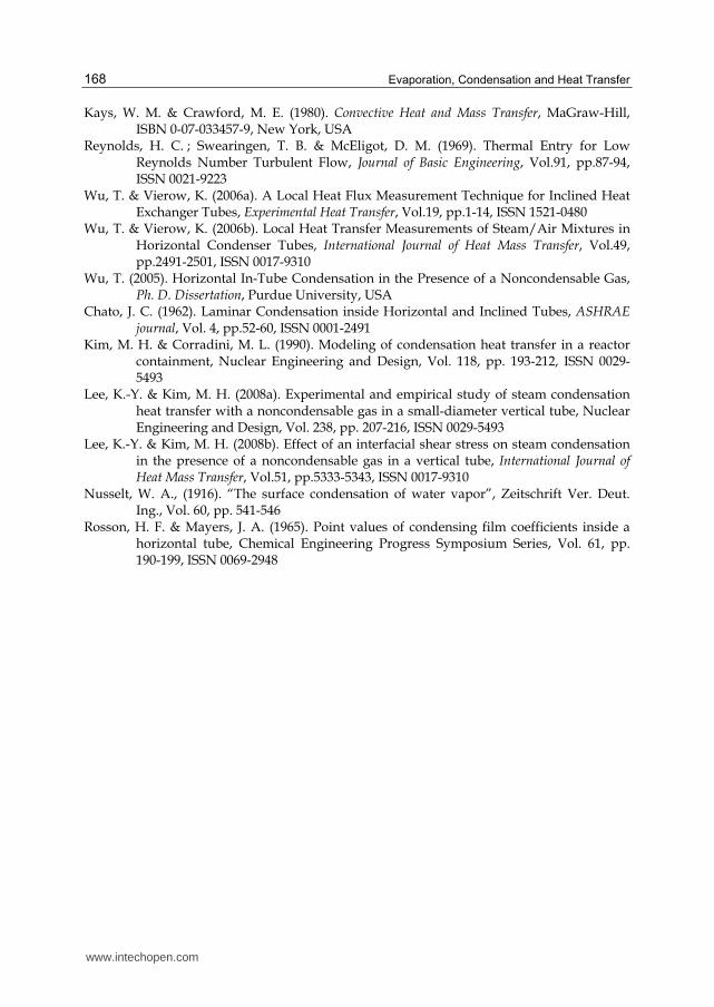
into axial control volumes of a specific size of 1 mm. The calculation procedure at each axial location of the tube is explained in Fig. 3.
Start
Input data I.C. & B.C.
Initial properties at each node
Initial guess of interfacial properties
Physical properties(Liquid & Mixture)
Film HTC, mixture flow rate
fs -> fr -> Nuo,x ; Sho,x -> Nuo,r ; Sho,r
-> Nuo,t ; Sho,t -> m”cond -> Nux
( ) ( )f i w cond fg s b ih T T m H h T T′′− = + −
Last node or Re < 0 ?
End
No
NoYes
Yes
Node size = 1-mm
No
Top Bottom
Fig. 3. Calculation procedure
2.4 Results and discussions Figures 4-6 present the modelling results for Test No. 99. In this experimental case the inlet mixture Reynolds number was 42,102, inlet air mass fraction was 5.1 %, and the system pressure was 0.202 MPa. Figure 4 shows the distribution of the calculated local temperatures. Even though the bottom wall temperature is lower than the top wall temperature, the interface temperature at bottom is higher than that at top. Therefore, the temperature gradient through the liquid pool at the bottom side is larger than that through the liquid film at the top side. The reason is a thickness of the condensate film.
0.0 0.5 1.0 1.5 2.0 2.5 3.040
60
80
100
120
140
160
Test No. 99
Inlet mixture Re = 42102
Inlet mass fraction of air = 5.1 %
Pressure = 0.202 MPa
Theoretical model:
Tb
Tw,top
Ti,top
Tw,bot
Ti,bot
Axial location (m)
Tem
peratu
re (
oC
)
Exp. data:
Tb
Tw,top
Tw,bot
Fig. 4. Calculated temperature distribution for Test No. 99
www.intechopen.com

Steam Condensation in the Presence of a Noncondensable Gas in a Horizontal Tube
161
Figure 5 shows the variation in the condensate film, condensation, and sensible heat
transfer coefficients, as well as the total heat transfer coefficient. The sensible heat transfer
coefficient is negligibly small. At the bottom of the horizontal tube, the condensation
resistance defined as 1/hc is much smaller that the film resistance defined as 1/hf. This
means that the film acts in a dominant role for heat transfer. So, it is very important to use
elaborate film heat transfer models for the bottom side. At the top of it, the film heat
transfer coefficient is large and comparative with the condensation heat transfer
coefficient. Therefore, we should carefully consider the model for the
steam/noncondensable gas mixture boundary layer for the top side. From this figure, we
can see that the theoretical model slightly underestimates the experimental data at the top
of the tube and over-predicts the data at the bottom of it.
0.0 0.5 1.0 1.5 2.0 2.50
5
10
15
20Test No. 99 : Top of tube
Inlet mixture Re = 42102
Inlet mass fraction of air = 5.1 %
Pressure = 0.202 MPa
Hea
t tr
an
sfer
coef
ficie
nt
(KW
/m2K
)
Axial location (m)
hfilm
hc
hs
htot
Exp. data
0.0 0.5 1.0 1.5 2.0 2.50
5
10
15
20Test No. 99 : Bottom of tube
Inlet mixture Re = 42102
Inlet mass fraction of air = 5.1 %
Pressure = 0.202 MPa
Hea
t tr
an
sfer
coef
fici
en
t (K
W/m
2K
)
Axial location (m)
hfilm
hc
hs
htot
Exp. data
Fig. 5. Comparison of experimental HTCs with theoretical model for Test No. 99
Figure 6 presents that the heat fluxes at the top and at the bottom of the tube are similar to
each other. The reason is that even though the heat transfer coefficients at the top are larger
than those of the bottom, the temperature gradients are smaller at the top as explained in
Fig. 4.
www.intechopen.com

Evaporation, Condensation and Heat Transfer
162
0.0 0.5 1.0 1.5 2.0 2.5 3.00
100
200
300
400
500
Test No. 99
Inlet mixture Re = 42102
Inlet mass fraction of air = 5.1 %
Pressure = 0.202 MPa
Heat
flu
x (
KW
/m2)
Axial location (m)
Theoretical model of Top
Theoretical model of Bottom
Exp. data of Top
Exp. data of Bottom
Fig. 6. Comparison of experimental Heat Flux with theoretical model for Test No. 99
0.0 0.5 1.0 1.5 2.0 2.5 3.00
5
10
15
20
Test No. 9
Inlet mixture Re = 49679
Inlet mass fraction of air = 15.3 %
Pressure = 0.116 MPa
Hea
t tr
an
sfer
coef
ficie
nt
(KW
/m2K
)
Axial location (m)
Theoretical model of Top
Theoretical model of Bottom
Exp. data of Top
Exp. data of Bottom
Fig. 7. Comparison of experimental HTCs with theoretical model for Test No. 9
0.0 0.5 1.0 1.5 2.0 2.5 3.00
100
200
300
400
500
Test No. 9
Inlet mixture Re = 49679
Inlet mass fraction of air = 15.3 %
Pressure = 0.116 MPa
Heat
flu
x (
KW
/m2)
Axial location (m)
Theoretical model of Top
Theoretical model of Bottom
Exp. data of Top
Exp. data of Bottom
Fig. 8. Comparison of experimental Heat Flux with theoretical model for Test No. 9
The modelling results for the Test No. 9 are shown in Figs. 7 and 8. Here, the inlet mixture Reynolds number was 49.679, inlet air mass fraction was 15.3 %, and the system pressure
www.intechopen.com

Steam Condensation in the Presence of a Noncondensable Gas in a Horizontal Tube
163
was 0.116 MPa. Comparing with Test No. 99, the heat transfer coefficients and the heat fluxes are decreased since the noncondensable gas effect by air is stronger. The general trends for the heat transfer coefficient and heat flux are similar with the Test No. 99. So, we can say that the developed theoretical model may be used to predict the steam condensation heat transfer coefficients in the presence of noncondensable gas inside horizontal tubes. Figure 9 shows that a steam flow rate of Test No. 9 is well estimated, but that of Test No. 99 has some discrepancy between experimental data and modelling results. Specially, we can see almost all steam was condensed inside tube in experiment, but the steam still remains at the end of the tube in modelling due to under-estimated heat flux.
0.0 0.5 1.0 1.5 2.0 2.5 3.00.000
0.002
0.004
0.006
0.008
0.010
0.012
Ste
am
flo
w r
ate
(k
g/s
)
Axial location (m)
Theoretical model of Test No. 9
Theoretical model of Test No. 99
Exp. data of Test No. 9
Exp. data of Test No. 99
Fig. 9. Comparison of Steam flow rate for Test No. 9 and 99
Figures 10 and 11 present the modelling results for Test No. 45 which had higher inlet mixture Reynolds number comparing with Test No. 9. The inlet mixture Reynolds number was 175,956, inlet air mass fraction was 15.4 %, and the system pressure was 0.401 MPa. The heat transfer coefficients and heat fluxes are increased because the interfacial shear stress is stronger in Test No. 45. We can guess that the estimated steam flow rate will be rapidly decreased than the measured data because the heat fluxes are larger in the theoretical model at the top. This will be shown in Fig. 14.
0.0 0.5 1.0 1.5 2.0 2.5 3.00
5
10
15
20
Test No. 45
Inlet mixture Re = 175956
Inlet mass fraction of air = 15.4 %
Pressure = 0.401 MPa
Hea
t tr
an
sfer
coef
ficie
nt
(KW
/m2K
)
Axial location (m)
Theoretical model of Top
Theoretical model of Bottom
Exp. data of Top
Exp. data of Bottom
Fig. 10. Comparison of experimental HTCs with theoretical model for Test No. 45
www.intechopen.com

Evaporation, Condensation and Heat Transfer
164
0.0 0.5 1.0 1.5 2.0 2.5 3.00
100
200
300
400
500
Test No. 45
Inlet mixture Re = 175956
Inlet mass fraction of air = 15.4 %
Pressure = 0.401 MPa
Heat
flu
x (
KW
/m2)
Axial location (m)
Theoretical model of Top
Theoretical model of Bottom
Exp. data of Top
Exp. data of Bottom
Fig. 11. Comparison of experimental Heat Flux with theoretical model for Test No. 45
2.5 Empirical correlation
Lee and Kim (2008a) proposed a new empirical correlation to estimate the condensation
heat transfer coefficients of steam/noncondensable gas mixture in vertical tube. They
found that the interfacial shear stress increases as the condenser tube diameter decreases
for the same mixture Reynolds number and the condensation heat transfer coefficients
also increase due to the interfacial shear stress. Because the effect of the interfacial shear
stress was not sufficiently considered in previous empirical correlations using the
Reynolds number, they could not estimate well various experimental data obtained from
different condenser tube diameter. On the other hand, Lee and Kim (2008a) used the
dimensionless shear stress and noncondensable gas mass fraction to develop a new
correlation. They showed that the new correlation could predict the experimental data
well with 17.5 ~ 27.5 % standard deviations irrespective of the condenser tube diameter as
shown in Fig. 12.
0.1 1 10 1000.1
1
10
100
Simple model using
Lee and Kim's correlation
Data:
Siddique et al.
Kuhn et al.
Lee and Kim
HT
Cs
from
mod
el (
KW
/m2K
)
HTCs from experiement ( KW/m2K)
Fig. 12. Comparison of experimental HTCs with empirical correlation for vertical tubes
www.intechopen.com

Steam Condensation in the Presence of a Noncondensable Gas in a Horizontal Tube
165
Their correlation is shown as
* 0.3124 0.402
exp, / (1 0.964 )mix pure mix ncf h h Wτ= = − (30)
for *0.06 46.65mixτ< < and 0.038 0.814ncW< < . Here, the dimensionless shear stress is
defined as
2* 1 / 2 mix mixmixmix
f f
u f
g L g L
ρττ
ρ ρ
⋅= =
(31)
where Re /mix mix mix mixu dµ ρ= , ( )1/3
2 /fL gν= , and 1/40.079Remixf −= for Remix > 2300 or
16 /Remixf = for Remix < 2300. And they used Nusselt theory (1916) to calculate hpure for the
vertical tube.
In this study, we should keep in mind that the problem geometry is not a vertical tube but a
horizontal tube, and the heat and mass transfer mechanism in the gas phase at everywhere
inside the horizontal tube is already assumed same. Therefore, degradation factor will be
same regardless of top or bottom. On the other hand, the film heat transfer mechanism at
the top side is definitely different with that at the bottom side. At the top side, the
condensate film is thin due to the effect of gravity and Chato (1962) correlation will be
proper to describe the pure steam condensation heat transfer. At the bottom side, however,
the condensate film becomes thick following the axial direction like the condensation
phenomena on vertical wall. So, Nusselt theory will be proper to calculate the pure steam
condensation heat transfer coefficient at the bottom side. Chato correlation for the top and
Nusselt theory for the bottom are given by
1/43 '
,( )
0.725( )
l l v l lvpure top Chato
l sat w
g k hh h
T T D
ρ ρ ρ
µ
⎡ ⎤−= = ⎢ ⎥
−⎢ ⎥⎣ ⎦ (32)
1/43 '
,( )
4 ( )l l v l lv
pure bot Nusseltl sat w
g k hh h
T T x
ρ ρ ρ
µ
⎡ ⎤−= = ⎢ ⎥
−⎢ ⎥⎣ ⎦ . (33)
The calculated heat transfer coefficient hexp,mix from Eq. (30) is the total heat transfer
coefficient htot in Eq. (2).
Figure 13 shows that the predictions using the Lee and Kim’s empirical correlation are very
similar with the results from theoretical model except the bottom of Test No. 45. But, if we
see Fig. 14, the shapes of steam flow rate are almost same between the theoretical model and
the empirical model. So, we suggest the Lee and Kim’s correlation to calculate the
condensation heat transfer coefficients of steam/noncondensable gas mixture irrespective of
not only the condenser tube diameter, but also orientation.
www.intechopen.com

Evaporation, Condensation and Heat Transfer
166
0.0 0.5 1.0 1.5 2.0 2.5 3.00
5
10
15
20
Test No. 99
Inlet mixture Re = 42102
Inlet mass fraction of air = 5.1 %
Pressure = 0.202 MPa
Heat
tran
sfer c
oeff
icie
nt
(KW
/m2K
)
Axial location (m)
Exp. data (Top of tube)
Theoretical model
Chato + Lee & Kim factor
0.0 0.5 1.0 1.5 2.0 2.5 3.00
5
10
15
20
Test No. 99
Inlet mixture Re = 42102
Inlet mass fraction of air = 5.1 %
Pressure = 0.202 MPa
Heat
tran
sfer c
oeff
icie
nt
(KW
/m2K
)
Axial location (m)
Exp. data (Bottom of tube)
Theoretical model
Nusselt + Lee & Kim factor
0.0 0.5 1.0 1.5 2.0 2.5 3.00
5
10
15
20
Test No. 9
Inlet mixture Re = 49679
Inlet mass fraction of air = 15.3 %
Pressure = 0.116 MPa
Heat
tran
sfer c
oeff
icie
nt
(KW
/m2K
)
Axial location (m)
Exp. data (Top of tube)
Theoretical model
Chato + Lee & Kim factor
0.0 0.5 1.0 1.5 2.0 2.5 3.00
5
10
15
20
Test No. 9
Inlet mixture Re = 49679
Inlet mass fraction of air = 15.3 %
Pressure = 0.116 MPa
Heat
tran
sfer c
oeff
icie
nt
(KW
/m2K
)
Axial location (m)
Exp. data (Bottom of tube)
Theoretical model
Nusselt + Lee & Kim factor
0.0 0.5 1.0 1.5 2.0 2.5 3.00
5
10
15
20
Test No. 45
Inlet mixture Re = 175956
Inlet mass fraction of air = 15.4 %
Pressure = 0.401 MPa
Heat
tran
sfer c
oeff
icie
nt
(KW
/m2K
)
Axial location (m)
Exp. data (Top of tube)
Theoretical model
Chato + Lee & Kim factor
0.0 0.5 1.0 1.5 2.0 2.5 3.00
5
10
15
20
Test No. 45
Inlet mixture Re = 175956
Inlet mass fraction of air = 15.4 %
Pressure = 0.401 MPa
Heat
tran
sfer c
oeff
icie
nt
(KW
/m2K
)
Axial location (m)
Exp. data (Bottom of tube)
Theoretical model
Nusselt + Lee & Kim factor
Fig. 13. Comparison of experimental HTCs and Heat Flux with empirical correlation for Test No. 9, 99 and 45
www.intechopen.com

Steam Condensation in the Presence of a Noncondensable Gas in a Horizontal Tube
167
0.0 0.5 1.0 1.5 2.0 2.5 3.00.00
0.01
0.02
0.03
0.04
0.05
Test No. 45
Inlet mixture Re = 175956
Inlet mass fraction of air = 15.4 %
Pressure = 0.401 MPa
Ste
am
flo
w r
ate
(k
g/s
)
Axial location (m)
Exp. data
Theoretical model
Emphirical correlation
Fig. 14. Comparison of steam flow rate for Test No. 45
3. Conclusion
A theoretical model is developed to investigate a steam condensation with a noncondensable gas in a horizontal tube using the heat and mass analogy. The total heat transfer coefficient is given by the film, condensation and sensible heat transfer coefficients. For stratified flow with high vapor velocity, the vapor shear will affect the drain of the liquid and also change the mode of heat transfer at the bottom of the tube through the liquid pool from conduction to forced convection. The film heat transfer coefficients of the upper and lower sides of the tube were calculated separately from Rosson and Meyers (1965) correlation. The heat and mass analogy was used to analysis the steam/noncondensable gas mixture boundary layer. Here, the Nusselt and Sherwood numbers in the gas phase were modified to incorporate the effects of condensate film roughness, suction, and developing flow. The theoretical model slightly underestimated the experimental heat transfer coefficients at the top of the tube. On the other hand, the model slightly over-predicted the data at the bottom of it. And the heat fluxes at the upper and lower sides of the tube were similar to each other. Generally speaking, the model predictions showed a good agreement with experimental data. The new empirical correlation proposed by Lee and Kim (2008) for the vertical tube was applied to the condensation of steam/noncondensable mixture in a horizontal tube. Nusselt theory and Chato correlation were used to calculate the heat transfer coefficients at top and bottom of the horizontal tube, respectively. The predictions of the new empirical correlation were good and very similar with the theoretical model.
4. Acknowledgment
This work has been carried out under the support from the Project of Power Industry Research and Development Fund given by the Ministry of Knowledge Economy.
5. References
Carey, Van P. (1992). Liquid-Vapor Phase-Change Phenomena, Taylor & Francis, ISBN 0-56032-074-5, Hebron KY, USA
www.intechopen.com
Evaporation, Condensation and Heat Transfer
168
Kays, W. M. & Crawford, M. E. (1980). Convective Heat and Mass Transfer, MaGraw-Hill, ISBN 0-07-033457-9, New York, USA
Reynolds, H. C. ; Swearingen, T. B. & McEligot, D. M. (1969). Thermal Entry for Low Reynolds Number Turbulent Flow, Journal of Basic Engineering, Vol.91, pp.87-94, ISSN 0021-9223
Wu, T. & Vierow, K. (2006a). A Local Heat Flux Measurement Technique for Inclined Heat Exchanger Tubes, Experimental Heat Transfer, Vol.19, pp.1-14, ISSN 1521-0480
Wu, T. & Vierow, K. (2006b). Local Heat Transfer Measurements of Steam/Air Mixtures in Horizontal Condenser Tubes, International Journal of Heat Mass Transfer, Vol.49, pp.2491-2501, ISSN 0017-9310
Wu, T. (2005). Horizontal In-Tube Condensation in the Presence of a Noncondensable Gas, Ph. D. Dissertation, Purdue University, USA
Chato, J. C. (1962). Laminar Condensation inside Horizontal and Inclined Tubes, ASHRAE journal, Vol. 4, pp.52-60, ISSN 0001-2491
Kim, M. H. & Corradini, M. L. (1990). Modeling of condensation heat transfer in a reactor containment, Nuclear Engineering and Design, Vol. 118, pp. 193-212, ISSN 0029-5493
Lee, K.-Y. & Kim, M. H. (2008a). Experimental and empirical study of steam condensation heat transfer with a noncondensable gas in a small-diameter vertical tube, Nuclear Engineering and Design, Vol. 238, pp. 207-216, ISSN 0029-5493
Lee, K.-Y. & Kim, M. H. (2008b). Effect of an interfacial shear stress on steam condensation in the presence of a noncondensable gas in a vertical tube, International Journal of Heat Mass Transfer, Vol.51, pp.5333-5343, ISSN 0017-9310
Nusselt, W. A., (1916). “The surface condensation of water vapor”, Zeitschrift Ver. Deut. Ing., Vol. 60, pp. 541-546
Rosson, H. F. & Mayers, J. A. (1965). Point values of condensing film coefficients inside a horizontal tube, Chemical Engineering Progress Symposium Series, Vol. 61, pp. 190-199, ISSN 0069-2948
www.intechopen.com

Evaporation, Condensation and Heat transferEdited by Dr. Amimul Ahsan
ISBN 978-953-307-583-9Hard cover, 582 pagesPublisher InTechPublished online 12, September, 2011Published in print edition September, 2011
InTech EuropeUniversity Campus STeP Ri Slavka Krautzeka 83/A 51000 Rijeka, Croatia Phone: +385 (51) 770 447 Fax: +385 (51) 686 166www.intechopen.com
InTech ChinaUnit 405, Office Block, Hotel Equatorial Shanghai No.65, Yan An Road (West), Shanghai, 200040, China
Phone: +86-21-62489820 Fax: +86-21-62489821
The theoretical analysis and modeling of heat and mass transfer rates produced in evaporation andcondensation processes are significant issues in a design of wide range of industrial processes and devices.This book includes 25 advanced and revised contributions, and it covers mainly (1) evaporation and boiling,(2) condensation and cooling, (3) heat transfer and exchanger, and (4) fluid and flow. The readers of this bookwill appreciate the current issues of modeling on evaporation, water vapor condensation, heat transfer andexchanger, and on fluid flow in different aspects. The approaches would be applicable in various industrialpurposes as well. The advanced idea and information described here will be fruitful for the readers to find asustainable solution in an industrialized society.
How to referenceIn order to correctly reference this scholarly work, feel free to copy and paste the following:
Kwon-Yeong Lee and Moo Hwan Kim (2011). Steam Condensation in the Presence of a Noncondensable Gasin a Horizontal Tube, Evaporation, Condensation and Heat transfer, Dr. Amimul Ahsan (Ed.), ISBN: 978-953-307-583-9, InTech, Available from: http://www.intechopen.com/books/evaporation-condensation-and-heat-transfer/steam-condensation-in-the-presence-of-a-noncondensable-gas-in-a-horizontal-tube