Stay Linked.user.Guide.rev.10.0.0
101
Wireless Terminal Emulation Advanced Terminal Session Management (ATSM) Wireless Device Management Stay-Linked Administrator User’s Guide
Transcript of Stay Linked.user.Guide.rev.10.0.0

Wireless Terminal Emulation
Advanced Terminal Session Management (ATSM)
Wireless Device Management
Stay-Linked Administrator
User’s Guide

Stay-Linked Administrator User Guide Page 1 Rev. 10.0.0 Dated: 04/27/10

Stay-Linked Administrator User Guide Page 2 Rev. 10.0.0 Dated: 04/27/10
Table of Contents
1 STAY-LINKED SYSTEM OVERVIEW .........................................................................................6 1.1 Stay-Linked Features ...............................................................................................................6 1.2 Stay-Linked Application Components.....................................................................................6 1.2.1 The Stay-Linked Server Application................................................................................6 1.2.2 The Stay-Linked Thin-Client Application........................................................................7 1.2.3 The Stay-Linked Administrator Application....................................................................7
2 GETTING STARTED........................................................................................................................8 2.1 Install the Stay-Linked Server on your Host Platform.............................................................8 2.2 Install, Connect and Configure the Stay-Linked Administrator ..............................................8 2.3 Install the Stay-Linked Client Software onto your Wireless Devices .....................................8
3 USING THE STAY-LINKED ADMINISTRATOR......................................................................10 3.1 Running the Administrator for the First Time .......................................................................10 3.1.1 The Administrator Splash Screen...................................................................................10 3.1.2 Connecting to the Stay-Linked Server ...........................................................................11 3.1.3 Retrieving the Server Serial Number .............................................................................12 3.1.4 Installing the License Key ..............................................................................................12 3.2 Administrator Quick Tour......................................................................................................14 3.2.1 The Administrator Screen...............................................................................................14 3.2.2 The Administrator Menus...............................................................................................15 3.2.3 Administrator Options ....................................................................................................15 3.3 Server Administration ............................................................................................................16 3.3.1 Defining Servers to the Administrator ...........................................................................16 3.3.2 Logging On and Logging Off of a Server ......................................................................16 3.3.3 Quick Connect to a server ..............................................................................................17 3.3.4 Maintaining Server Licenses ..........................................................................................17 3.3.5 Viewing Server Alerts ....................................................................................................18 3.3.6 Maintaining Server Settings ...........................................................................................19 3.3.7 Terminating a Running Stay-Linked Server...................................................................22 3.4 Telnet Host Administration....................................................................................................23 3.4.1 Maintaining Host Groups ...............................................................................................23 3.4.2 Maintaining Host Settings ..............................................................................................25 3.5 Device Group Administration................................................................................................31 3.5.1 Managing Device Groups...............................................................................................31
Stay-Linked Administrator User Guide Page 3 Rev. 10.0.0 Dated: 04/27/10
3.5.2 Maintaining Device Group Settings ...............................................................................32 3.5.3 Managing Barcodes ........................................................................................................36 3.5.4 Managing Program Calls ................................................................................................39 3.5.5 Managing Printing ..........................................................................................................40 3.5.6 Managing Startup Scripts................................................................................................42 3.5.7 Managing Alternate Keyboard Maps..............................................................................43 3.6 Managing Keyboard Maps .....................................................................................................44 3.6.1 Managing Keyboard Maps..............................................................................................44 3.6.2 Editing a Keyboard Map.................................................................................................47 3.7 Maintaining Tap Spot Definitions..........................................................................................49 3.7.1 Selecting an Emulation Type..........................................................................................49 3.7.2 Tap Spot Maintenance ....................................................................................................50 3.8 Client Administration .............................................................................................................52 3.8.1 Managing Client Settings (ATSM)................................................................................52 3.8.2 Managing Client Configuration File Deployment (ATSM) ..........................................55 3.8.3 Managing Client Deployment (ATSM).........................................................................58 3.9 Managing Session Partnerships..............................................................................................61 3.10 Scan2Command and Scan2Configure Profiles ......................................................................63 3.10.1 Scan2Command Profiles.................................................................................................63 3.10.2 Scan2Configure Profiles .................................................................................................63 3.11 Connections List and Session Management...........................................................................67 3.11.1 Selecting a Connection List Group Option.....................................................................67 3.11.2 The Connections List ......................................................................................................67 3.11.3 The Connections List Menu............................................................................................69 3.11.4 Connections Menu ..........................................................................................................70 3.11.5 Connections Menu – Details...........................................................................................71 3.11.6 Connections Menu – File (ATSM) ................................................................................71 3.11.7 Connections Menu – Commands (ATSM) ....................................................................73 3.11.8 Connections Menu – Scanner (ATSM) .........................................................................76 3.11.9 Connections Menu – Diagnostics (ATSM) ...................................................................76 3.11.10 Connections Menu – View (ATSM)..............................................................................76 3.11.11 Connections Menu – Monitor Session (ATSM) ............................................................77 3.11.12 Connections Menu – Share Session (ATSM) ................................................................77 3.11.13 Connections Menu – Take Control (ATSM) .................................................................78 3.11.14 Connections Menu – Transfer Session (ATSM) ...........................................................78 3.11.15 Connections Menu – Disconnect Device........................................................................78 3.11.16 Connections Menu – Terminate Session ........................................................................79 3.11.17 Connections Menu – Launch Athena..............................................................................79 3.11.18 Connections Menu – Manage Device.............................................................................79 3.12 Administrator Management....................................................................................................79 3.12.1 Administrator Management Overview ...........................................................................79 3.12.2 The ‘administrator’ Master User ID ...............................................................................80
Stay-Linked Administrator User Guide Page 4 Rev. 10.0.0 Dated: 04/27/10
3.12.3 List Users........................................................................................................................81 3.12.4 Creating a User ID..........................................................................................................82 3.12.5 Editing a User ID............................................................................................................83 3.12.6 Changing User ID Permissions.......................................................................................85 3.12.7 View and change the Allowed Origin IPs ......................................................................86 3.12.8 View and change the Connection Filters........................................................................87 3.12.9 Deleting a User ID..........................................................................................................89 3.12.10 Enabling and Disabling a User ID..................................................................................89 3.12.11 Setting a User ID to Expired ..........................................................................................89 3.12.12 Changing the Password for a User ID ............................................................................89 3.12.13 List Groups .....................................................................................................................90 3.12.14 Creating a Group ............................................................................................................90 3.12.15 Editing a Group ..............................................................................................................91 3.12.16 Deleting a Group ............................................................................................................91 3.12.17 Change Settings ..............................................................................................................92 3.12.18 Maximum Log On Attempts Allowed............................................................................92 3.12.19 Action to take for Failed Log On ...................................................................................93 3.12.20 Password Expiration Interval .........................................................................................93 3.12.21 Minimum Password Length............................................................................................94 3.12.22 Maximum Password Length...........................................................................................94 3.12.23 Require Digit in Password..............................................................................................94
4 APPENDIX.......................................................................................................................................96 4.1 Special Scripting Mnemonics ................................................................................................96 4.2 Troubleshooting .....................................................................................................................98

Stay-Linked Administrator User Guide Page 5 Rev. 10.0.0 Dated: 04/27/10

Stay-Linked Administrator User Guide Page 6 Rev. 10.0.0 Dated: 04/27/10
1 Stay-Linked System Overview
Stay-Linked™, from evolveIT, Inc., is a software product that provides a complete solution for managing your wireless terminals and their host Telnet and SSH sessions. This section describes the features and architecture of the Stay-Linked product.
1.1 Stay-Linked Features Stay-Linked, with its Client2Host™ architecture, eliminates all of the typical challenges associated with deploying a wireless terminal solution in your enterprise by providing: • Reliable host-based preservation of wireless user application screens/sessions. • Centralized wireless session/client configuration, monitoring and control. • Secure end-to-end wireless data transmission between clients and the application host. • Programmable Host API provides control over session and device from host application.
1.2 Stay-Linked Application Components There are three basic components that make up the Stay-Linked system: the host-based server application, which initiates and preserves all wireless terminal user sessions on the application host computer; the thin client application that resides on the various wireless devices; and a Windows-based administrator console that provides centralized visibility, configuration, and management of all connected devices.
1.2.1 The Stay-Linked Server Application The Stay-Linked server is a Java application that runs on the application host computer or on a separate computer connected to the host computer(s). The server listens for connection requests from devices running the Stay-Linked thin client application and initiates the appropriate 5250, 3270, VT100/220/420 telnet sessions or SSH sessions on the requested host. The Stay-Linked server also supports ‘Device Management Only’ connections.
The server preserves the telnet session at the host computer, sending screen updates to the device and forwarding key strokes and scans from the device to the session. The server also detects special application extension (API) screens ands processes the requested functions (see the Host API Guide).
The Stay-Linked Server runs natively on a wide variety of reliable host computing platforms:
• IBM AS/400 – iSeries – i5 – System i – IBM i (OS/400, i5/OS, IBM i) • IBM RS/6000 – pSeries – p5 – System p (AIX) • HP9000 (HP-UX) • Sun Solaris • SCO OpenServer, OpenUnix & UnixWare • Linux (x86) • Windows 7/Vista/XP/2K/NT • Apple Mac OS X
The installation of the Stay-Linked server application is described in section 2 of this user guide.

Stay-Linked Administrator User Guide Page 7 Rev. 10.0.0 Dated: 04/27/10
1.2.2 The Stay-Linked Thin-Client Application A Stay-Linked thin-client application is installed on each device that will connect to the host computer. Since each device type is somewhat unique, the client applications are written for specific devices or families of devices. The ultra-thin client software installs quickly and provides the local support for display, keystrokes, scanning, radio communications, and diagnostics.
Upon startup, the client requests a session from the Stay-Linked server application. The client sends key strokes and scans to the server and receives screen updates back from the server. In addition, many diagnostic utilities are included with the client application to help identify various problems with the device and wireless network.
Stay-Linked thin-client applications are available for RF/Wireless 802.11a/b/g and Cellular network devices from Motorola (Symbol), Intermec, DataLogic (PSC), HHP, Teklogix and others, running DOS, PocketPC/Windows Mobile, and Windows CE/CE.Net operating systems.
Client applications are also available for legacy TMA/2.4GHz- 900MHz Telxon devices and for wired or wireless Windows devices and desktops or laptops.
The installation of the Stay-Linked thin-client application is described in general in section 2 of this user guide and in more detail in the various device-specific client support guides. Stay-Linked client application features and functions are described in detail in the various OS-specific client user guides.
1.2.3 The Stay-Linked Administrator Application The Stay-Linked administrator provides centralized device and session management. This powerful application can be installed on one or more Windows PCs and enables administrators to:
• View and sign on to one or more Stay-Linked servers • Set up properties for one or more telnet hosts • Set up properties for one or more device groups • Manage keyboard maps, tap spots and client settings • View and control connected Stay-Linked devices • Send messages, files, and remote commands to devices • Prepare and deploy client software updates to devices • Create partnerships between two or more devices to share the same terminal session • View, share, transfer or completely take over device sessions • Troubleshoot device and network problems • NEW! Build and print ‘Scan2Configure’ and ‘Scan2Command’ profiles that allow you to
configure and control the Stay-Linked Client software by scanning barcodes. • NEW! Interactive Device Management for PPC/CE devices provides Device Info, Processes,
Applications, File System, Device Registry, Network Statistics and Device Remote Control • NEW! Software Provisioning support for deploying 3rd-party software applications to your
PPC/CE devices. • NEW! Manage and control the users that are allowed to run the Stay-Linked Administrator.
The installation of the Stay-Linked administrator application is described in section 2 of this user guide. The entire set of Stay-Linked administrator features and functions are described in detail in section 3 of this user guide.

Stay-Linked Administrator User Guide Page 8 Rev. 10.0.0 Dated: 04/27/10
2 Getting Started
This section contains an overview of the basic steps required to get your Stay-Linked Wireless Terminal Session Management Solution operational. Detailed administrator and server installation, upgrade, and uninstall instructions are contained in the various platform-specific installation guides. After completing the basic steps described below, you will be able to take advantage of the reliable wireless terminal emulation and centralized management features that are provided by the Stay-Linked Terminal Session Management and Device Management solution.
2.1 Install the Stay-Linked Server on your Host Platform • Download and review the appropriate Stay-Linked Installation Guide • Review and meet the software and hardware requirements • Download the appropriate Stay-Linked Server setup program • Install the Stay-Linked Server program • Configure any platform-specific settings • Configure the server to start automatically when the host system is restarted • Start the Stay-Linked Server
2.2 Install, Connect and Configure the Stay-Linked Administrator • Review the Stay-Linked Administrator section of the Installation Guide • Review the Stay-Linked Administrator section of this User Guide • Select a non-dedicated PC to be used for managing your Stay-Linked Server • Download the Stay-Linked Administrator setup program • Install the Stay-Linked Administrator onto the selected PC • Start the Stay-Linked Administrator • Add a Stay-Linked Server entry to the Administrator and connect to the Stay-Linked Server • Install your evaluation or permanent license key • Add Keyboard Maps for your Wireless Devices • Review and manage Telnet Hosts, Device Groups and Tap Spots and other settings • Enable the Device Management Service on your selected PPC/CE devices
2.3 Install the Stay-Linked Client Software onto your Wireless Devices • Download the appropriate Stay-Linked Client Software for your Wireless Devices • Download and review the Stay-Linked User Guide for the specific device • Install the Stay-Linked Client Software onto the device • Configure the Radio and Network settings for the device and verify connectivity • Configure the Client Settings, pointing the client to the IP address of the Stay-Linked Server • Connect the client to the Stay-Linked Server and go to work

Stay-Linked Administrator User Guide Page 9 Rev. 10.0.0 Dated: 04/27/10

Stay-Linked Administrator User Guide Page 10 Rev. 10.0.0 Dated: 04/27/10
3 Using the Stay-Linked Administrator
This section describes the Stay-Linked Administrator application, which provides centralized management of your Stay-Linked servers, hosts, and wireless devices. The section begins by walking you through your first use of the administrator, connecting to your Stay-Linked server, retrieving the server serial number, and installing the license key. After that, the various functions of the administrator are described.
3.1 Running the Administrator for the First Time This section walks you through your first use of the administrator: the splash screen, connecting to your Stay-Linked server, retrieving the server serial number, and installing the license key.
3.1.1 The Administrator Splash Screen When the Stay-Linked Administrator is executed, you will see the following splash screen for a few moments.
Stay-Linked Administrator User Guide Page 11 Rev. 10.0.0 Dated: 04/27/10
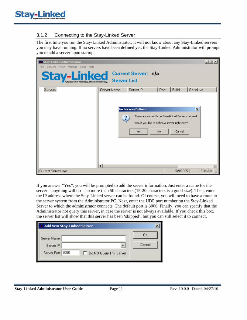
3.1.2 Connecting to the Stay-Linked Server The first time you run the Stay-Linked Administrator, it will not know about any Stay-Linked servers you may have running. If no servers have been defined yet, the Stay-Linked Administrator will prompt you to add a server upon startup.
If you answer “Yes”, you will be prompted to add the server information. Just enter a name for the server – anything will do – no more than 50 characters (15-20 characters is a good size). Then, enter the IP address where the Stay-Linked server can be found. Of course, you will need to have a route to the server system from the Administrator PC. Next, enter the UDP port number on the Stay-Linked Server to which the administrator connects. The default port is 3006. Finally, you can specify that the Administrator not query this server, in case the server is not always available. If you check this box, the server list will show that this server has been ‘skipped’, but you can still select it to connect.

Stay-Linked Administrator User Guide Page 12 Rev. 10.0.0 Dated: 04/27/10
3.1.3 Retrieving the Server Serial Number Once you have added the server definition, the server will appear on the Administrator console. If the IP address you provided is correct and the Stay-Linked server is currently running, you will see the server build and serial numbers in the Server List panel. Provide the serial number to the Stay-Linked customer service team to obtain your free evaluation license key.
This is the serial number you need to provide.
Then click on this name to log in to the server and enter the license key.
3.1.4 Installing the License Key To install your license key, you must first log in to the server. This is done by clicking on the server name. The following dialog box will appear.
Enter the default User ID “administrator” and the default Password ‘esp’ for your server. Click OK.
Detailed information about Stay-Linked Administrator User Management can be found in Section 3.12 of this guide.

Stay-Linked Administrator User Guide Page 13 Rev. 10.0.0 Dated: 04/27/10
After logging in to the Stay-Linked server, you will see a list of available functions appear. Use the right mouse button and click on the Server Licenses function. A small menu will appear. Select the Add function from the menu to enter your license key.
Fill-in the appropriate client quantities and then cut-and-paste your license key into the text box.
Click ‘Validate’ and then click ‘Install License Key’ to complete this step.
Stay-Linked Administrator User Guide Page 14 Rev. 10.0.0 Dated: 04/27/10
3.2 Administrator Quick Tour This section provides a quick overview of the new Stay-Linked Administrator user interface.
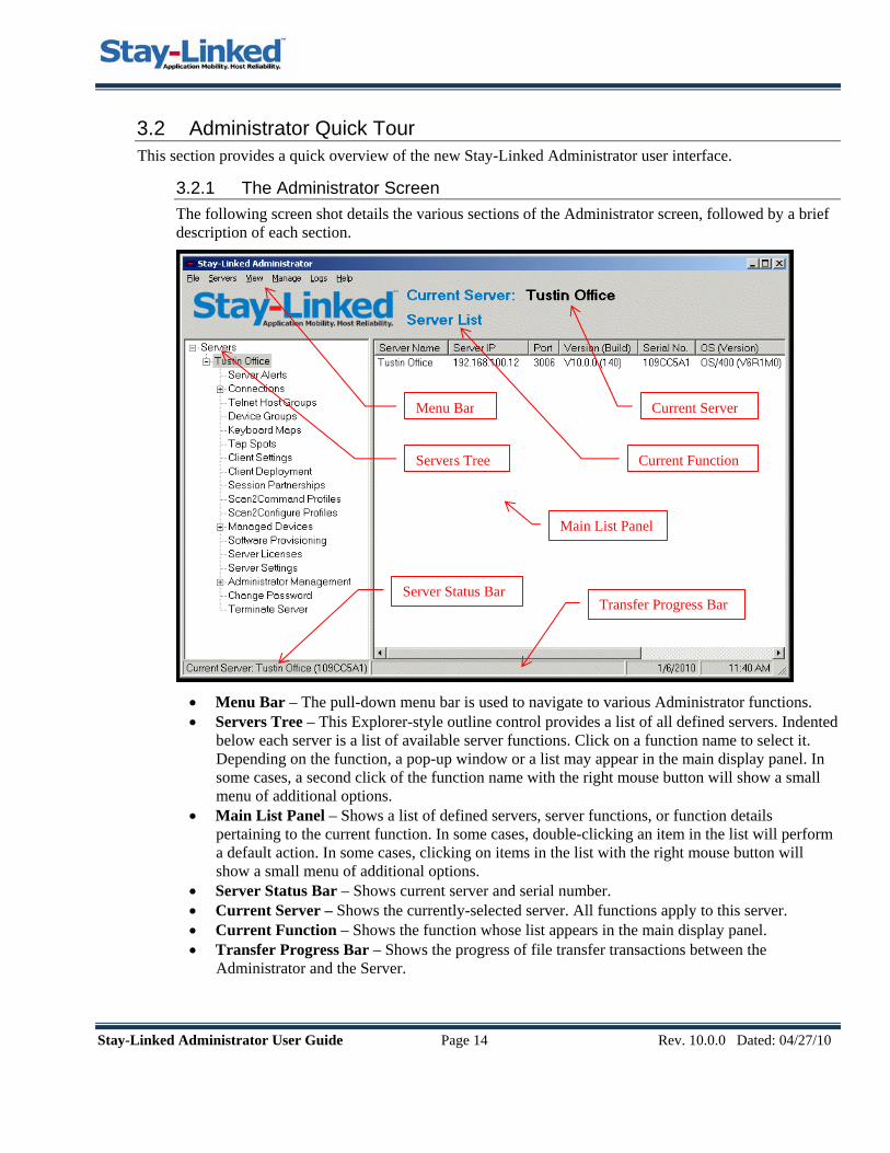
3.2.1 The Administrator Screen The following screen shot details the various sections of the Administrator screen, followed by a brief description of each section.
Menu Bar
Servers Tree
Current Server
Current Function
Main List Panel
Transfer Progress Bar Server Status Bar
• Menu Bar – The pull-down menu bar is used to navigate to various Administrator functions. • Servers Tree – This Explorer-style outline control provides a list of all defined servers. Indented
below each server is a list of available server functions. Click on a function name to select it. Depending on the function, a pop-up window or a list may appear in the main display panel. In some cases, a second click of the function name with the right mouse button will show a small menu of additional options.
• Main List Panel – Shows a list of defined servers, server functions, or function details pertaining to the current function. In some cases, double-clicking an item in the list will perform a default action. In some cases, clicking on items in the list with the right mouse button will show a small menu of additional options.
• Server Status Bar – Shows current server and serial number. • Current Server – Shows the currently-selected server. All functions apply to this server. • Current Function – Shows the function whose list appears in the main display panel. • Transfer Progress Bar – Shows the progress of file transfer transactions between the
Administrator and the Server.
Stay-Linked Administrator User Guide Page 15 Rev. 10.0.0 Dated: 04/27/10
3.2.2 The Administrator Menus The following screen shot details the various sections of the Administrator screen, followed by a brief description of each section.
• File Menu – Allows you to set Administrator Options and to Exit the program. • Servers Menu – Allows you to Add, Edit, and Delete server definitions for this Administrator.
Also provides a method to Log On and Log Off of a server. All of the Server menu options refer to the currently selected server with the exception of the Add option.
• View Menu – Provides an option to refresh the List that appears in the main display panel. Another option let’s you toggle the Server Tree view on and off. Other options provide a means for forcing the main display panel to Display the Server List or Display Connection Groups. This is needed at the menu level when the server tree is not being displayed.
• Manage Menu – Provides a list of all the server functions. These functions are available from the server tree (when visible) and from the main display panel when the Manage Server list is displayed. The Manage menu option provides an alternate method of selecting these functions when the server tree is not being displayed. The selected function will apply to the currently selected server. Note: The available options depend upon Administrator User permissions.
• Logs Menu – Provides a list of various server logs. The selected log will be retrieved from the current server. These logs provide various types of details about the server and are a valuable tool for diagnosing the overall health of the server and any issues that may be occurring. Note: This Logs menu is visible only if Administrator User permissions allow.
• Help Menu – Provides access to standard application help features. A link to the Stay-Linked web site and application version information is also provided within this menu option.
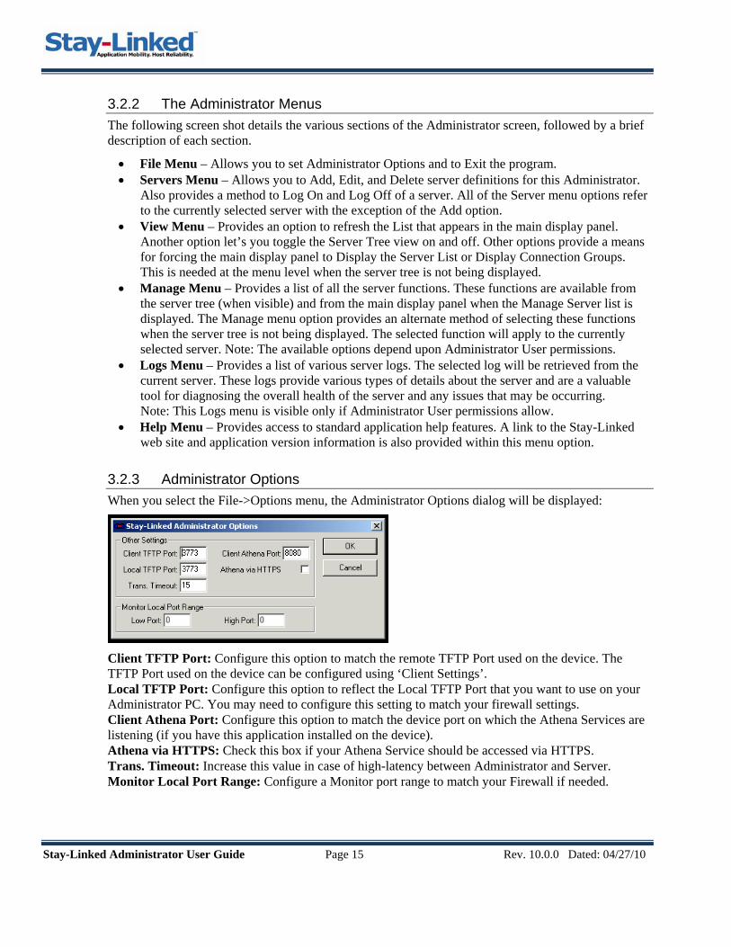
3.2.3 Administrator Options When you select the File->Options menu, the Administrator Options dialog will be displayed:
Client TFTP Port: Configure this option to match the remote TFTP Port used on the device. The TFTP Port used on the device can be configured using ‘Client Settings’. Local TFTP Port: Configure this option to reflect the Local TFTP Port that you want to use on your Administrator PC. You may need to configure this setting to match your firewall settings. Client Athena Port: Configure this option to match the device port on which the Athena Services are listening (if you have this application installed on the device). Athena via HTTPS: Check this box if your Athena Service should be accessed via HTTPS. Trans. Timeout: Increase this value in case of high-latency between Administrator and Server. Monitor Local Port Range: Configure a Monitor port range to match your Firewall if needed.

Stay-Linked Administrator User Guide Page 16 Rev. 10.0.0 Dated: 04/27/10
3.3 Server Administration This section describes the various means provided to administer Stay-Linked servers. One or more servers can be defined for each instance of the administrator application. The level of access to the server is controlled by Administrator user IDs and passwords that are defined on each server.
3.3.1 Defining Servers to the Administrator From the Servers menu, you can Add, Edit (change the name), or Delete server definitions for this administrator (note: this has no effect on the server itself). You can ‘Quick Connect’ to a server temporarily. You can also log on or log off of a server.
3.3.2 Logging On and Logging Off of a Server Each time you start the Administrator, the list of defined servers will appear in the server tree. The first time you select a server from this list, you will be asked to log on to that server. You will enter your administrator user ID and password for the selected server and will be provided the level of access defined for that specific user ID on that server. The default user ID for each server is ‘administrator’ and the default password is ‘esp’. The ‘administrator’ user ID has full access to all of the functions of the Stay-Linked Administrator and Server.
You can log off of a server by clicking the right mouse button over the server name and selecting the Log Off option. You will need to log back on again if you want to perform any administration. You will also need to log back on to a server if the server has been restarted since the time you logged on.
Detailed information about Stay-Linked Administrator User Management can be found in Section 3.12 of this guide.
Stay-Linked Administrator User Guide Page 17 Rev. 10.0.0 Dated: 04/27/10
3.3.3 Quick Connect to a server In an Enterprise environment, you might be charged with managing dozens or even hundreds of Stay-Linked Servers distributed across your wide-area network. You could add each server to the administrator where they will be always available for selection. Or, you can simply ‘Quick Connect’ to a server when needed and the server will remain in the servers list until you exit the Stay-Linked Administrator. When you restart the Administrator, that server will no longer be in the list.
3.3.4 Maintaining Server Licenses At least one license must be installed before any clients will be able to start sessions on the Stay-Linked Server.
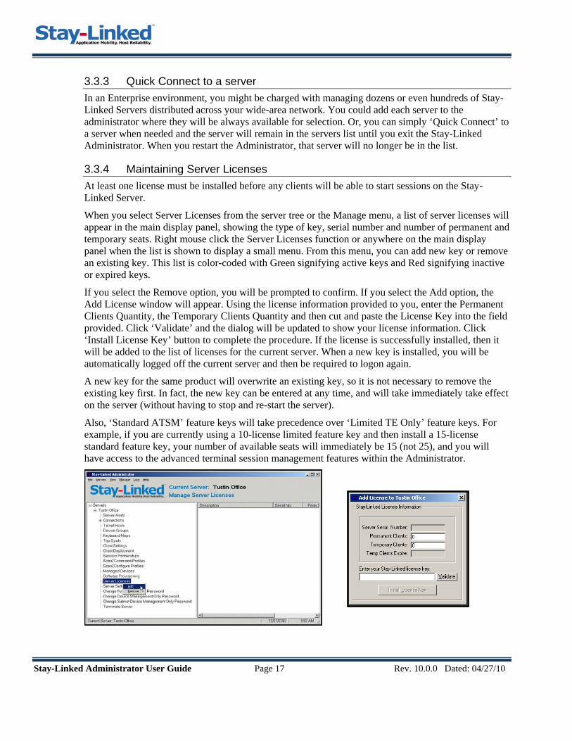
When you select Server Licenses from the server tree or the Manage menu, a list of server licenses will appear in the main display panel, showing the type of key, serial number and number of permanent and temporary seats. Right mouse click the Server Licenses function or anywhere on the main display panel when the list is shown to display a small menu. From this menu, you can add new key or remove an existing key. This list is color-coded with Green signifying active keys and Red signifying inactive or expired keys.
If you select the Remove option, you will be prompted to confirm. If you select the Add option, the Add License window will appear. Using the license information provided to you, enter the Permanent Clients Quantity, the Temporary Clients Quantity and then cut and paste the License Key into the field provided. Click ‘Validate’ and the dialog will be updated to show your license information. Click ‘Install License Key’ button to complete the procedure. If the license is successfully installed, then it will be added to the list of licenses for the current server. When a new key is installed, you will be automatically logged off the current server and then be required to logon again.
A new key for the same product will overwrite an existing key, so it is not necessary to remove the existing key first. In fact, the new key can be entered at any time, and will take immediately take effect on the server (without having to stop and re-start the server).
Also, ‘Standard ATSM’ feature keys will take precedence over ‘Limited TE Only’ feature keys. For example, if you are currently using a 10-license limited feature key and then install a 15-license standard feature key, your number of available seats will immediately be 15 (not 25), and you will have access to the advanced terminal session management features within the Administrator.

Stay-Linked Administrator User Guide Page 18 Rev. 10.0.0 Dated: 04/27/10
3.3.5 Viewing Server Alerts The Stay-Linked Server records information regarding server status and important events that occur during server operation. When you select Server Alerts from the server tree or the Manage menu, the Server Alerts list will appear in the main display panel.
The Server Alerts are classified as one of three levels, Information, Warning and Critical. Each Alert records the Alert Level, Alert Date/Time and the Alert Message. You may view more details of a selected alert by double-clicking or selecting the Alerts-Details menu option. The Details will usually recommend actions that can be taken to resolve Warning or Critical alert conditions. Clicking the right mouse button over an alert line will cause a small menu to appear with the following options:
Details– This menu option displays the details of the selected alert item.
Clear Alerts: Select this option to clear the Server Alert Log that is stored on the server. Refresh: This menu option reloads the Server Alert dialog with the most recent alerts.

Stay-Linked Administrator User Guide Page 19 Rev. 10.0.0 Dated: 04/27/10
3.3.6 Maintaining Server Settings When you select Server Settings from the server tree, the Manage Server list or the Manage menu, a window will appear that shows the current server settings and allows you to make changes.
Log File Settings – These options are used to control the server logs. The server logs are used by technical support to analyze connectivity issues. This option should be set to ‘No Logging’ unless otherwise directed by technical support. The Max Log Size feature controls the size of the log files. If desired, you can control the devices that generate logs by specifying a low and high IP range.
Server Statistics Settings: These options are used to control the server statistics. The server logs are used by technical support to analyze connectivity and performance issues. The Interval should be set to ‘0’ (off) unless otherwise directed by technical support. The Max Stats Size option controls the maximum size of the server statistics file.
Firewall Settings: If your devices are connecting to the Stay-Linked server through a firewall, then you may need to restrict the ports that are assigned to devices and configure a server that is running behind one-to-one NAT.
Use Fixed Port Range: You may enable this option and then specify a range of ports that the server should use for device connections. You will need to ensure that you specify a range that is large enough to accommodate the number of licenses that you are running. When there are no further open ports available, then devices will no longer be able to connect to the server.

Stay-Linked Administrator User Guide Page 20 Rev. 10.0.0 Dated: 04/27/10
Configure One-to-One NAT: If your server is behind One-to-One NAT (Static NAT), then you will need to use the ‘Configure One-to-One NAT’ dialog to specify the server’s mapped external IP and its physical internal IP address.
Client Dynamic NAT Settings: If your devices are running Dynamic NAT behind a NAT Server, then you can configure the Stay-Linked Server to support this network architecture.
Enable Server-Side Support for Client Dynamic NAT: Select this option to have the Stay-Linked Server identify and handle ‘port re-assignment’ events. These events are generated by the NAT server when the port assignment cross-reference times-out due to inactivity. Typically, additional traffic from the device will be re-assigned to a different port by the NAT server. This setting will allow the server to identify these port re-assignments and handle them appropriately.
Use Public IP for Device Group Selection: This option only applies when the ‘Server-side Support for Client Dynamic NAT’ option is enabled. This option will cause the ‘Public IP’ of the NAT Server to be used for selecting Device Groups, rather than using the private, internal IP of the device itself.
One Session per IP: This option determines how existing sessions are handled when a device connects to the server. Check this option to ensure that each device consumes only one session. This option prevents duplicate sessions for a single IP. This option only applies to devices running against single session licenses. This option is automatically disabled and locked when the ‘Server-side Support for Client Dynamic NAT’ option is enabled.
Include Reconnections in Server Alerts: Check this option to cause client reconnections to be included in the Server Alerts log. Although clients reconnecting to existing sessions are normal and a major feature of the product, excessive reconnections could indicate issues with device hardware or software, or possible operational difficulties.
Enable Orphan Detection: Check this option to enable the server to identify devices that have lost their ‘Session ID’ values. The server will then detect and reconnect devices to any session that has been orphaned for that device based upon MAC address only. This setting will typically apply to devices that store their ‘Session ID’ values in volatile memory on the device where it can easily be lost if the battery is removed for too long, or if the battery is exhausted. This setting is only available if the server is running ‘single session’ licensing only and is not running any ‘dual session’ licenses.
Enable Device Identification: This option will enable the collection of User Identification information for each device. The Device Identification can be used to assist with Asset Management or for other purposes. When a device creates a new connection, you will be prompted to enter an ID value that will be visible on the Connection List and in the Device Identification Log file.
JRE Encoding: Select the code page for Java string encoding used by the server. Generally, this value should be set to ‘*default’. This value may need to be set to match the code page of the machine upon which the server is running. If the session screens on the devices are not displaying the expected characters, then you might need to adjust this value. For instance, in order to properly render VT line-draw characters, we recommend setting this value to ‘cp437’.

Stay-Linked Administrator User Guide Page 21 Rev. 10.0.0 Dated: 04/27/10
Encryption: Select whether to enable encryption for all Stay-Linked sessions.
• None – No Stay-Linked packets will be encrypted. • Level 1 – Stay-Linked data transferred between the Stay-linked Thin-Client and the Stay-Linked
Server will be encoded using a proprietary 64-bit encryption scheme. • Blowfish– Stay-Linked data transferred between the Stay-linked Thin-Client and the Server will
be encoded using the Blowfish/CBC/PKCS5Padding encryption algorithm.
(See Secure Communications Guide for details about Encrypted connections)
Using Blowfish Encryption: Blowfish encryption provides a very high level of data security for the Stay-Linked packets that are transmitted between the Stay-Linked Thin-Client and the Stay-Linked Server. Stay-Linked Blowfish encryption is available only for PPC/WM/CE/CE.Net devices that are running a Stay-Linked Client of at least Version 9.1.0. Blowfish encryption is not available for any DOS devices. When you select ‘Blowfish’ as the Stay-Linked Encryption option, you are presented with the following dialog:
Key 1, Key 2, Key 3 and Key 4: You may specify one to four blowfish keys. Each key can be from 8 characters to 56 characters in length. The keys are case sensitive. The Encryption capabilities of the Java Runtime used by the server will determine the maximum key length that can be used. If the Java Runtime does not support a key of the length that you have entered, that key will be automatically trimmed until it can be used. The server will only use Key 1 unless you specify a ‘Key Rotation Interval’.

Stay-Linked Administrator User Guide Page 22 Rev. 10.0.0 Dated: 04/27/10
Allow Unencrypted Sessions: This option will determine whether sessions will be allowed for clients that do not support Blowfish encryption. If you have a mix of DOS and PPC devices and you want them all to be able to run sessions, and you want to use Blowfish encryption for the PPC devices, then you must check this option to allow the unencrypted sessions from the DOS devices. In this case, the DOS devices will utilize the ‘Level 1’ encryption instead of the Blowfish encryption. If you want to restrict your server to allow sessions only for devices that support Blowfish encryption, then uncheck this option. In this case, any unsupported device that tries to start a session will get a ‘Device Not Allowed’ message displayed when a session is started. Those devices that do not support Blowfish encryption will not be able to run any sessions.
Key Rotation Interval (mins): If you enter more than one Blowfish key, then you may have the Stay-Linked Server automatically rotate between those keys at your specified interval in minutes. The valid range for the Key Rotation Interval in 5 minutes to 1440 minutes. The Stay-Linked Client and Server will automatically rotate between keys at each rotation interval during the entire duration of the Stay-Linked session.
3.3.7 Terminating a Running Stay-Linked Server The Terminate Server option is used to disconnect all client sessions and terminate the server jobs. On the iSeries platform, the server subsystem is not terminated by this command, but all subsystem jobs are terminated. All client sessions will be sent a terminate message. Those devices that are asleep at this moment will not receive the terminate message. Upon waking, these devices will go to a [Session Ended] state if the Stay-Linked Server is running or they will go into a [Linking] state if the Stay-Linked Server is not running.
When you select Terminate Server from the server tree or the Manage menu, you will be prompted for, and must enter your password in order to terminate the server.

Stay-Linked Administrator User Guide Page 23 Rev. 10.0.0 Dated: 04/27/10
3.4 Telnet Host Administration This section describes the various means provided to group and define your Telnet hosts that will be accessed from each Stay-Linked server. You can define one or more Telnet hosts per server to which your wireless users will connect. Telnet Hosts are organized into ‘Host Groups’ that can be assigned to ‘Device Groups’, allowing you to control what Telnet hosts are available to specific devices. Various host groups can be created to provide multiple configurations of hosts, as required by your architecture. When more than one host is defined for a host group, the list of hosts will appear as a menu on the wireless device when a new session is started and the user will be able to select the Telnet host to which they’d like to connect. In the following example, you can see the mandatory ‘Default’ host group, plus we have defined a few additional host groups. The ‘Default’ host group may be changed, but not deleted.
3.4.1 Maintaining Host Groups When you select Telnet Hosts from the server tree or the Manage menu, the Telnet Host Groups list will appear in the main display panel. Each Stay-Linked server will have a Default host group, and you can add other host groups as required. Clicking the right mouse button in a blank area or on a host group will cause a small menu to appear with options to Add, Edit, or Delete a host group.
When you select the Delete option, you are prompted for confirmation. If you select the Add or Edit options, the following window will appear where you can enter/edit the host group definition.

Stay-Linked Adm
The host group has a ‘Group Name’ plus two additional options. These options will only affect host groups that contain more than one host entry. If there is more than one host entry, a user creating a new connection will be presented with a menu on the device screen from which they can select the desired host. If the menu is displayed, you can control these two options:
• Use ‘Group Name’ as Menu Title: Check this option to have the ‘Host Group Name’ displayed as the title of the host selection menu on the device screen. If this option is not checked, then the menu title will default to ‘Select a Host’.
• Display ‘Quit’ on the Host Menu: Check this option to include a ‘Quit Stay-Linked’ option on the host selection menu. The ‘Quit Stay-Linked’ menu option enables you to cancel the connection and return to the main Stay-Linked Client Menu on the device, without connecting to a Telnet Host.
For the host group, you may also add, edit, copy, paste, delete and change the order of the Host entries using the “Hosts” menu or by clicking with the right mouse button in the host list.
Copy and Paste for Host Entries: These options provide a convenient method to copy a pre-configured Telnet Host Entry from one Host Group and paste it into the same or another Host Group.
The two additional options are not available for the ‘Default’ Host Group. If you want to take advantage of the Use ‘Group Name’ as Menu Title option or the Display ‘Quit’ on the HostMenu option, then you will have to add a new Host Group where these options will be available. You can then use the ‘Device Group’ feature to make your new Host Group available to your devices.inistrator User Guide Page 24 Rev. 10.0.0 Dated: 04/27/10
Stay-Linked Administrator User Guide Page 25 Rev. 10.0.0 Dated: 04/27/10
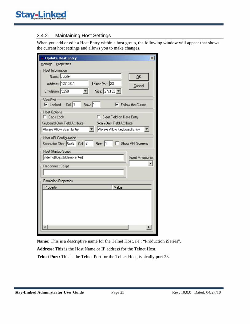
3.4.2 Maintaining Host Settings When you add or edit a Host Entry within a host group, the following window will appear that shows the current host settings and allows you to make changes.
Name: This is a descriptive name for the Telnet Host, i.e.: “Production iSeries”.
Address: This is the Host Name or IP address for the Telnet Host.
Telnet Port: This is the Telnet Port for the Telnet Host, typically port 23.

Stay-Linked Administrator User Guide Page 26 Rev. 10.0.0 Dated: 04/27/10
Emulation: Select the type of client emulation to use when connecting to the Telnet Host.
• 5250, 3270 or many VT emulations, including SSHv2, to choose from. (See Secure Communications Guide for details about SSL-Telnet and SSH connections)
• SHARE-IP, SHARE-ID or SHARE-MAC: These SHARE options will enable a device to share a session with another Stay-Linked device that has already established a terminal session. The one requirement for ‘Sharing’ a session is to identify the device that is running a session that you want to share. The server will prompt the user for this identification value, depending upon the SHARE-type selected here. The user will be required to scan or type the target device’s MAC Address, IP Address or Device ID. Once this value is provided, then the server will look for a running session that matches the value provided. If a session is not found, then the user will be notified and will be prompted to re-enter the identifier. If an active session is found, then the device will be connected to that session and begin sharing the terminal session with the original device. The original device still ‘owns’ the session and this device is only sharing the session. Both devices can type or scan into the session and both devices will see screen updates to the session. When the device is done sharing the session, the user should select to ‘Exit’ the session. The owner device will still have control of the session and will be able to continue processing.
• PGMCALL: The PGMCALL emulation type enables the Stay-Linked Server to cause the device to run a program that is installed locally on the device. So, if you select this Host Menu option, rather than connecting to a telnet session, the specified program will be run locally on the device. When you select PGMCALL, only two other settings are used by the system. The ‘Name’ entry will contain the description of the program call that will be displayed on the host menu on the device. The ‘Address’ entry will be used to enter the name of the program to be called on the device. Example: Emulation: PGMCALL, Description: Print a Label, Address: PRINTLBL.EXE For some DOS devices with limited RAM, you can cause the Stay-Linked Client to be removed from memory before running the local program. Just enclose the program name in square brackets []. The square brackets will notify the Stay-Linked Client that you want to use the entire available RAM to run the local program. In this case, the Stay-Linked Client will exit, the local program will run, and when complete, the Stay-Linked Client will automatically restart.
• DMONLY: The DMONLY emulation type enables the Stay-Linked Server to cause the device to run a Device Management Only session. There will be no Telnet or SSH access provided in this Device Management Only session. The client software will behave much differently on the device when the client is running a Device Management Only session.
Size: You can select the size of the Telnet Session Screen. This value refers to the ‘telnet session screen’ that resides on the Stay-Linked server, not the size of the device view port. The available values depend upon the type of client emulation selected.
ViewPort: These settings describe how to handle the device view port for the Telnet Host. For example, a small wireless device might have a screen that can support 20 columns and 15 rows. The Telnet host is putting out 80 columns and 24 rows. The view port then is that part of the full screen that is displayed on the small device screen.
• Locked: Check this box and set the Col and Row for the upper-left corner of the locked view port.
• Follow the Cursor: Check this box to ensure that the view port on the device will follow the cursor if the application positions the cursor outside of the current view port.
Caps Lock: Check this box to force all keyboard entry to this Telnet Host to be capitalized.

Stay-Linked Administrator User Guide Page 27 Rev. 10.0.0 Dated: 04/27/10
Clear Field on Data Entry: For 5250 and 3270 hosts, check this box to cause the current field to be cleared when data is typed into the first position of, or when a barcode is scanned into the field.
Keyboard-Only Field Attribute: For 5250 and 3270 hosts, select the field attribute that will designate a ‘keyboard-only’ field. All fields that match the selected attribute will allow only keyboard data to be entered into the field. Scanner data will not be allowed into these fields.
Scan-Only Field Attribute: For 5250 and 3270 hosts, select the field attribute that will designate a ‘scan-only’ field. All fields that match the selected attribute will allow only barcode scans to be entered into the field. Keyboard entry will not be allowed into these fields. This attribute must be different from the Keyboard-Only Field Attribute.
Host API Configuration: These options control the behavior of the Stay-Linked Host APIs.
• Separator Char: You can specify the hexadecimal value of the displayable character that will be used as the separator within the Host API data on the screen. (default is 0x7E for tilde, ~)
• Col and Row: Allows you to specify the column and row where your end-user applications will display Stay-Linked Host API data. The column and row should reflect the screen position of the first separator character in the API command specification. The default Host API location is column 2 and row 1.
• Show API Screens: You can use this checkbox to select whether or not to show the screen containing the Host API data to the user on the device.
Host Startup Script: You may define a startup script for this Telnet Host. The startup script will be processed only when a new session is established. The script will not be run when a device reconnects to an existing session. The script will always be processed against the first host screen that is presented to the device, typically a logon screen. The script can be up to 255 characters in length. The script can contain any combination of characters and emulation mnemonic keywords. Emulation mnemonic keywords are contained within square brackets []. You can select mnemonic keywords from the ‘Insert mnemonic’ drop-down list, causing the selected mnemonic to be automatically inserted at the current cursor location within the script textbox. Syntax errors in the script will not cause errors, but could cause some part of your script to be ignored by the emulation host.
• Startup Script example: myuserid[fldexit]mypasswd[enter] The example 5250 Startup Script above is designed to be processed against a 5250 logon screen. The user profile ‘myuserid’ will be automatically typed into the first field on the screen and then the ‘Field Exit’ mnemonic will be processed, moving the cursor to the next field on the logon screen. Then, the password ‘mypasswd’ will be typed into the current field and the ‘Enter’ key mnemonic will be processed. This script would cause a user to be automatically signed onto the target AS/400 Telnet host.
Reconnect Script: You may define a reconnect script for this Telnet Host. The reconnect script will be processed only when a device reconnects to an existing session, or when a device switches between dual sessions. The reconnect script is most valuable for voice-enabled sessions and can be used to notify the application that it should repeat the last Text-to-Speech instructions and the last Voice Rules instructions.
Stay-Linked Administrator User Guide Page 28 Rev. 10.0.0 Dated: 04/27/10
Emulation Properties: Depending upon the emulation, you will have additional properties available that can be used to adjust the behavior and settings of the Telnet Client. A list will appear at the bottom of the Host Properties window showing all of the emulation properties that have already been defined for this host and their values.
You can right-click within the list area or use the Properties menu to add, edit and delete the Emulation Properties for this Telnet host. These properties include: • Host Backup 1&2 Name/IP – Determines the 1st and 2nd backup host IPs or hostnames. • Host Backup 1&2 Port – Determines the 1st and 2nd backup host port numbers. • Telnet Session Inactivity Timeout – Specifies the number of seconds of inactivity before the
Telnet Session is automatically terminated (60 to 2073600 seconds). • Telnet Session Inactivity Script – You can enter a script that will be run before the session is
terminated because of a Telnet Session Inactivity Timeout event. • Connection Timeout – Determines the number of seconds to wait before trying a backup host. • Connect to Last Backup Host without Timeout - Determines whether to timeout when
attempting to connect to the last Backup Host. • Host Code Page – Determines the language (Code Page) supported by the host telnet server. • Host Code Page Unicode Processing – Specifies whether the selected Host Code Page requires
Unicode character processing. • Convert 5250 Column Separators – Determines if 5250 Column Separator attributes will be
converted to the selected alternate attribute for display. • Convert 5250 High Intensity – Determines if 5250 Column Separator attributes will be
converted to the selected alternate attribute for display. • Auto-Field Exit on CHECK(FE) Fields – Set this value to True to cause Stay-Linked to insert
a Field Exit when you press Enter on a CHECK(FE) field, except when the cursor is in the first position of the field. (5250 Only)
• New Line Behavior – Determines the behavior of the new line operation. (VT only) • Back Space Behavior – Determines the behavior of the backspace operation. (VT only) • Cursor Movement Behavior – Determines the behavior of cursor movement. (VT only) • Keypad Behavior – Determines the behavior of the keypad. (VT only) • Local Echo Behavior – Determines the behavior of local keyboard echo. (VT only) • Autowrap Behavior – Determines the behavior of autowrap. (VT only) • Answer Back Message – Message sent to the host in response to the x05 command. (VT only) • Terminal ID - An ASCII value passed to the host machine to represent the VT terminal type
symbolically. This value is usually referenced in the ‘termcap’ file on the VT telnet host. • VT ESC Sequence Processing – Select ‘Raw’ if your VT Telnet Server requires ESC sequences
to be delivered from the client in a single packet only. • SSL Session - To request an encrypted session, set this property to True. • SSL Client Certificate Provided - Determines whether the client has a certificate. • SSL Client Certificate URL - URL of the client certificate. • SSL Client Certificate Password - Password of the client certificate. • SSL CustomizedCAs.p12 Alternate File – Fully qualified path and name of the alternate
CustomizedCAs.p12 file. • SSL CustomizedCAs.p12 Alternate Password – Password for the alternate
CustomizedCAs.p12 file. • Enhanced TN Session - Determines whether the session will use enhanced Telnet negotiation
features. (3270 Only)
Stay-Linked Administrator User Guide Page 29 Rev. 10.0.0 Dated: 04/27/10
• Session LU Name - Must be a valid LU name of or LU pool name. (Requires 'Enhanced TN Session' enabled)
The Telnet Session Inactivity Timeout setting can be used to force old, unused sessions to be ended, but the Stay-Linked Server has no idea if it is safe to terminate these sessions. It would be safest to use your Telnet Server or end-user application to terminate sessions, if possible. You can also specify a Telnet Session Inactivity Script that will be run before the session is terminated because of a Session Inactivity Timeout event.
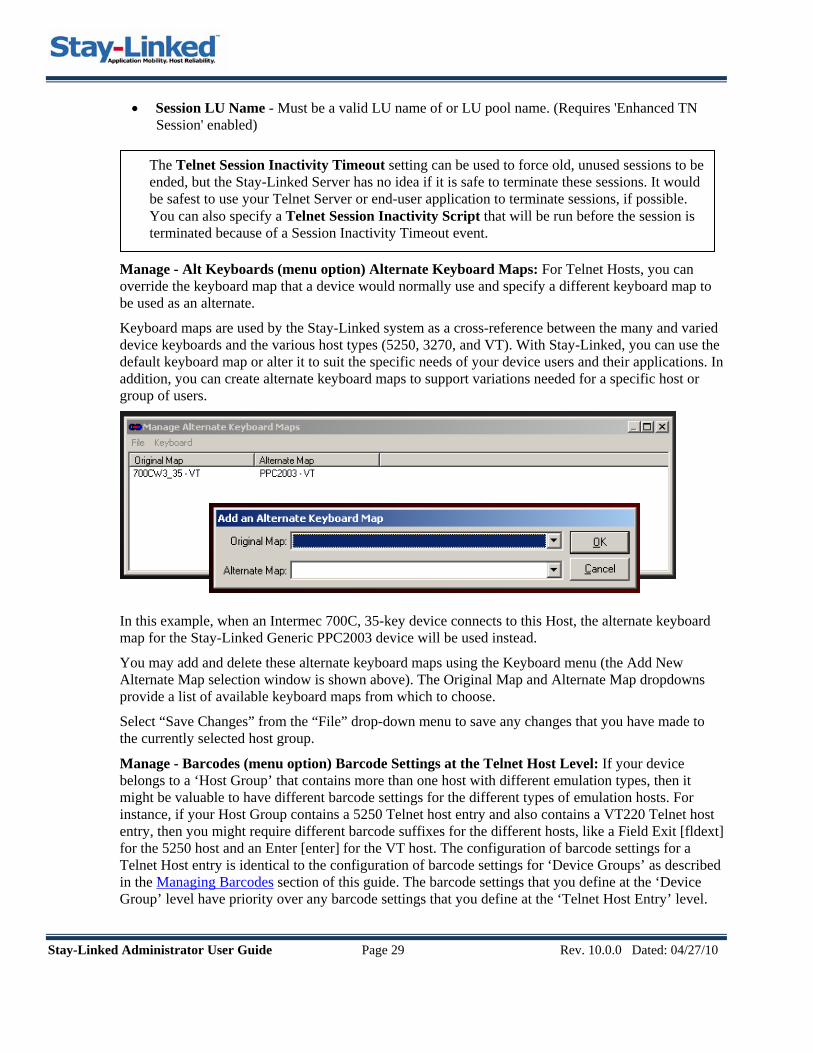
Manage - Alt Keyboards (menu option) Alternate Keyboard Maps: For Telnet Hosts, you can override the keyboard map that a device would normally use and specify a different keyboard map to be used as an alternate.
Keyboard maps are used by the Stay-Linked system as a cross-reference between the many and varied device keyboards and the various host types (5250, 3270, and VT). With Stay-Linked, you can use the default keyboard map or alter it to suit the specific needs of your device users and their applications. In addition, you can create alternate keyboard maps to support variations needed for a specific host or group of users.
In this example, when an Intermec 700C, 35-key device connects to this Host, the alternate keyboard map for the Stay-Linked Generic PPC2003 device will be used instead.
You may add and delete these alternate keyboard maps using the Keyboard menu (the Add New Alternate Map selection window is shown above). The Original Map and Alternate Map dropdowns provide a list of available keyboard maps from which to choose.
Select “Save Changes” from the “File” drop-down menu to save any changes that you have made to the currently selected host group.
Manage - Barcodes (menu option) Barcode Settings at the Telnet Host Level: If your device belongs to a ‘Host Group’ that contains more than one host with different emulation types, then it might be valuable to have different barcode settings for the different types of emulation hosts. For instance, if your Host Group contains a 5250 Telnet host entry and also contains a VT220 Telnet host entry, then you might require different barcode suffixes for the different hosts, like a Field Exit [fldext] for the 5250 host and an Enter [enter] for the VT host. The configuration of barcode settings for a Telnet Host entry is identical to the configuration of barcode settings for ‘Device Groups’ as described in the Managing Barcodes section of this guide. The barcode settings that you define at the ‘Device Group’ level have priority over any barcode settings that you define at the ‘Telnet Host Entry’ level.
Stay-Linked Administrator User Guide Page 30 Rev. 10.0.0 Dated: 04/27/10
Manage – Screen Recognition (menu option): For telnet hosts, you can define screens to be recognized and actions to take for those recognized screens. You can grab ‘Variables’ from the screen text that can be used as arguments in ‘Host APIs’ or ‘Auto-Response’ associated with the recognized screen. You can specify ‘Host APIs’ to be processed when the screen is recognized. You can specify ‘Auto-Response’ scripts to be processed when the screen is recognized. And, you can design a ‘reformatted’ version of the recognized screen to be displayed on device screens with smaller or different display sizes. The ‘Screen Recognition’ feature is licensed separately from and in addition to TE licensing. The details of the ‘Screen Recognition’ feature are described in the ‘Stay-Linked Screen Recognition and Reformatting User Guide’.
Stay-Linked Administrator User Guide Page 31 Rev. 10.0.0 Dated: 04/27/10
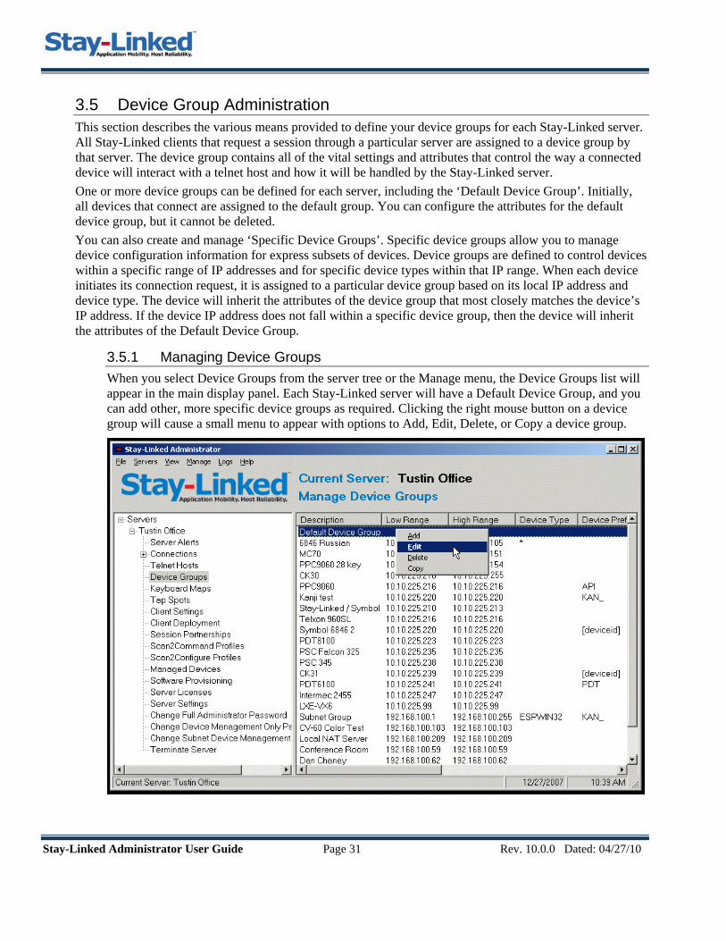
3.5 Device Group Administration This section describes the various means provided to define your device groups for each Stay-Linked server. All Stay-Linked clients that request a session through a particular server are assigned to a device group by that server. The device group contains all of the vital settings and attributes that control the way a connected device will interact with a telnet host and how it will be handled by the Stay-Linked server. One or more device groups can be defined for each server, including the ‘Default Device Group’. Initially, all devices that connect are assigned to the default group. You can configure the attributes for the default device group, but it cannot be deleted. You can also create and manage ‘Specific Device Groups’. Specific device groups allow you to manage device configuration information for express subsets of devices. Device groups are defined to control devices within a specific range of IP addresses and for specific device types within that IP range. When each device initiates its connection request, it is assigned to a particular device group based on its local IP address and device type. The device will inherit the attributes of the device group that most closely matches the device’s IP address. If the device IP address does not fall within a specific device group, then the device will inherit the attributes of the Default Device Group.
3.5.1 Managing Device Groups When you select Device Groups from the server tree or the Manage menu, the Device Groups list will appear in the main display panel. Each Stay-Linked server will have a Default Device Group, and you can add other, more specific device groups as required. Clicking the right mouse button on a device group will cause a small menu to appear with options to Add, Edit, Delete, or Copy a device group.

Stay-Linked Administrator User Guide Page 32 Rev. 10.0.0 Dated: 04/27/10
3.5.2 Maintaining Device Group Settings When you add, edit, or copy a device group, the following window will appear that shows the current device group settings and allows you to make changes.
Group Description: This is a descriptive name for the Device Group, i.e.: “Shipping Department”.
Group IP Address Range: This is the range of device IP addresses for this group.
Device Type: This is the device type filter for this group. The combination of IP Range and Device Type are used to determine which devices will be a member of this device group. Leave this value blank to include all device types in this device group.
Host Group: This is the Host Group that defines which emulation hosts will be available to devices in this group. If the selected host group is not available at the time a device connects, then the device will automatically use the ‘Default’ host group. A special host group named ‘Device Management Only’ is also available for selection. This host group will cause the device to run a Device Management Only session. There will be no Telnet or SSH access provided in this Device Management Only session. The client software will behave much differently on the device when the client is running a Device Management Only session.
Allow Connections: This checkbox provides the administrator with the ability to determine which devices can establish sessions. This checkbox must be checked in order for devices belonging to this device group to be able to connect to a telnet session.
Stay-Linked Administrator User Guide Page 33 Rev. 10.0.0 Dated: 04/27/10
Allow Dual Sessions: This checkbox provides the ability to control which devices will be allowed to run Dual Sessions. This option will only have an effect if a Dual Session License is installed.
Display 5250/3270 OIA Area: Make sure that this checkbox is selected if you wish for the devices in this group to display the Operator Indicator Area at the bottom of the screen when running 5250 or 3270 sessions. The OIA looks like this: [ ][ ][ ][ ] and notifies you of Input Inhibit, Keyboard Lock, Message Waiting and Insert status. If all indicators were displayed, the area would look like this: [INH][LCK][MSG][INS].
Debug OIA: This option provides an enhanced OIA at the bottom of the device display that shows the standard OIA indicators as well as alpha/numeric field attributes, view port origin and the current cursor position. The fully-populated Debug OIA looks like this: [ILM^A 01/001 01/001] The Debug OIA generates much more network traffic as it is updated every time the cursor is moved, so it should only be used to setup attributes like ‘Viewport Locking’ and Font Size settings.
Allow Color: For devices that are capable of displaying color screens, use this checkbox to control which devices will be allowed to display color.
Auto Add DM: Check this box to cause all DM-capable devices in this group to be automatically added to the Device Management database. Devices in this group will be added to the DM database only if the server is licensed for DM and if there are DM seats available to be issued to the device.
Keyboard Timeout: This value defines how many seconds of inactivity will pass before the device goes into sleep mode. A value of zero will cause the device to never timeout.
Backlight Timeout: Defines the number of seconds that the backlight will stay lit between keystrokes or scans on the device. A value of zero will cause the backlight to never timeout.
Device Name Prefix: The 5250 device descriptions for all RF devices falling within this device group IP address range will get this prefix. For each RF device in this device group, the name of the device description on the iSeries will be this Device Name Prefix followed by a unique suffix calculated based upon the IP address of the connecting device and the Suffix Octets and Decimal Suffix settings. If you leave this field blank, then device naming will not be enabled for this device group. If you wish to create a device name with no prefix, use the reserved prefix ‘NULL’ which will cause the system to generate a device name using only the suffix. The device name prefix can be any length up to 10 characters. If your configuration will cause a device name to be generated that is longer than 10 characters, you will be notified and a corrective measure will be suggested.
If you wish to manage your device names at the individual device, then you can specify [deviceid] as the Device Name Prefix and this will cause the client software to retrieve either the ‘Device Name’ from the PPC/CE.Net operating system, or use the ‘device_id’ client setting from the client INI file, and use that identifier as the entire ‘Device Name’.
Suffix Octets: The maximum size of the device suffix is 6 characters. This setting allows you to control the size of the device name suffix. If you select Decimal Suffix, then each decimal octet will require 3 positions and you can select 1 or two octets. If you de-select Decimal Suffix, then each octet will require 2 positions and you can select from 1 to 3 octets. You may select 0 octets only if the Low and High IP Address Range for the group are the same IP address.
Decimal Suffix: This option allows you to specify whether to use decimal or hexadecimal values to build the device name suffix.

Stay-Linked Administrator User Guide Page 34 Rev. 10.0.0 Dated: 04/27/10
Device Naming Examples: • Device Name Prefix = SHP_
Suffix Octets = 3 Decimal Suffix = Unchecked RF device IP 192.168.100.25 will be converted to iSeries Device Name SHP_A86419.
• Device Name Prefix = SHP_ Suffix Octets = 2 Decimal Suffix = Checked RF device IP 192.168.100.25 will be converted to iSeries Device Name SHP_100025.
• Device Name Prefix = SHP_ Suffix Octets = 1 Decimal Suffix = Checked RF device IP 192.168.100.25 will be converted to iSeries Device Name SHP_025.
• Device Name Prefix = DEVICE0001 Suffix Octets = 0 Group IP Low Range = 192.168.100.25 Group IP High Range = 192.168.100.25 RF device IP 192.168.100.25 will be converted to iSeries Device Name DEVICE0001.
• Device Name Prefix = NULL Suffix Octets = 1 Decimal Suffix = Checked RF device IP 192.168.100.25 will be converted to iSeries Device Name 025.
• Device Name Prefix = [deviceid] PPC/CE.Net Device Name = WHSDEV1 RF device IP 192.168.100.25 will use iSeries Device Name WHSDEV1.
VT Alarm ID Column: For VT sessions, you can specify the column where the VT Alarm ID Character will be found.
Row: For VT sessions, you can specify the row where the VT Alarm ID Character will be found.
VT Alarm ID Char: For VT sessions, you can specify a character, which when found in the location defined by the VT Alarm ID Column and Row, will cause the Alarm to be sounded on the device as specified in the ‘Handle Alarms’ setting.
Hide ID: For VT sessions, this setting will cause the VT Alarm ID Character to be hidden (non-visible) on the device.
Handle BELs & Alarms: You may select which type of audible indicator will be used when a 5250 display contains the ALARM DDS keyword or a VT BEL or VT Alarm ID is encountered. The options are None, Short Beep, Long Beep, Double Beep or Vibrate.
Handle 5250 Messages: You may select the method that will be used to display messages that appear on the message line 24 of the 5250 screen. • Snap-To Message: This method emulates IBM’s Wireless Connect behavior causing the device
window to snap down to the lower-left corner of the 5250 screen, allowing you to see the message. This method requires that you send a [RESET] key if the 5250 session keyboard becomes locked.

Stay-Linked Administrator User Guide Page 35 Rev. 10.0.0 Dated: 04/27/10
• Pop-Up Message: This method causes a pop-up message to be displayed that contains the entire text of the message. This method will automatically send a [RESET] key to unlock the 5250 keyboard when appropriate.
• Take No Action: Select this option if you want no action taken when messages appear.
Popup Msg. Location: You may select the area on the device screen where system messages will be displayed. The choices are ‘Top’, ‘Center’ or ‘Bottom’ of the device screen. The default is to have system messages displayed at the ‘Top’ of the device screen.
Message Notification: You may select which type of audible indicator will be used when a new message appears on the message line. The options are None, Short Beep, Long Beep, Double Beep or Vibrate.
Manage Barcodes: Click this button to access a dialog that will allow you to configure barcode types for this device group.
Manage Program Calls: Click this button to access a dialog that will allow you to configure client-side program calls for this device group.
Manage Printing: Click this button to access a dialog that will allow you to configure client-side printing options for this device group.
Manage Startup Scripts: Click this button to access a dialog that will allow you to configure session start-up scripting options for this device group.
Manage Alt. Keyboards: Click this button to access a dialog that will allow you to assign alternate keyboard maps to be used by devices that are members of this group.

Stay-Linked Administrator User Guide Page 36 Rev. 10.0.0 Dated: 04/27/10
3.5.3 Managing Barcodes For each device group, you may control the manner in which barcodes are scanned for that device group. The following window is presented when you click on the Manage Barcodes button on the Update Device Group window. The window contains some device group level barcode settings and a list of specific barcodes defined for this device group.
Enable Undefined Barcodes: This option works in conjunction with the list of barcode types that are configured for this device group. Check this box if you want to allow the device to scan barcode types that are not specifically configured for this device group.
Append Field Exit to Short Scan (5250): For 5250 sessions, select this option to cause a FieldExit to be automatically appended to barcodes that are shorter than the field into which they are being scanned. This option is often used to enhance scanning into display fields that cause an automatic end-of-record advance via the CHECK(ER) display attribute. (This setting has no effect for 3270 or VT).
Append Enter on Last Field (5250 & 3270): For 5250 and 3270 sessions, select this option to cause an Enter to be automatically appended to barcodes that are scanned into the last field on the current application screen. (This setting has no effect for VT).
Barcode Scan Prefix: This feature provides for the definition of characters to be inserted as a prefix to the scanned data. Select from the Drop-down list, or key in your prefix characters. This setting will affect all barcode symbologies unless a specific prefix is defined for a specific symbology.
Barcode Scan Suffix: This feature provides for the definition of characters to be inserted as a suffix to the scanned data. Select from the Drop-down list, or key in your suffix characters. This setting will affect all barcode symbologies unless a specific suffix is defined for a specific symbology.
You may add, edit, and delete Barcode Type entries using the “Barcode” menu or by right clicking on a specific Barcode Type entry in the list. When adding or editing barcode types for this device group, the following window will be displayed.
Stay-Linked Administrator User Guide Page 37 Rev. 10.0.0 Dated: 04/27/10
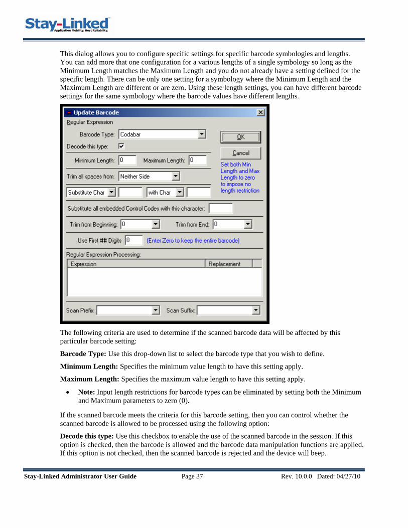
This dialog allows you to configure specific settings for specific barcode symbologies and lengths. You can add more that one configuration for a various lengths of a single symbology so long as the Minimum Length matches the Maximum Length and you do not already have a setting defined for the specific length. There can be only one setting for a symbology where the Minimum Length and the Maximum Length are different or are zero. Using these length settings, you can have different barcode settings for the same symbology where the barcode values have different lengths.
The following criteria are used to determine if the scanned barcode data will be affected by this particular barcode setting:
Barcode Type: Use this drop-down list to select the barcode type that you wish to define.
Minimum Length: Specifies the minimum value length to have this setting apply.
Maximum Length: Specifies the maximum value length to have this setting apply.
• Note: Input length restrictions for barcode types can be eliminated by setting both the Minimum and Maximum parameters to zero (0).
If the scanned barcode meets the criteria for this barcode setting, then you can control whether the scanned barcode is allowed to be processed using the following option:
Decode this type: Use this checkbox to enable the use of the scanned barcode in the session. If this option is checked, then the barcode is allowed and the barcode data manipulation functions are applied. If this option is not checked, then the scanned barcode is rejected and the device will beep.

Stay-Linked Administrator User Guide Page 38 Rev. 10.0.0 Dated: 04/27/10
For scanned barcodes that meet the criteria defining this barcode setting, the following barcode data manipulation functions will be applied in dialog order, from the top down:
1) Trim all spaces from 2) Substitutions 3) Substitute embedded Control Codes 4) Trim from Beginning/End 5) Use First ### digits 6) Regular Expressions 7) Adding Scan Prefix and Suffix.
Trim all spaces from: This option determines how leading and trailing spaces in the barcode data will be handled. You can select to have spaces trimmed from neither side, the left side, the right side or both sides of the barcode data.
Substitute: This option allows you to specify a character or string within the barcode data to be replaced by a different character or string. Single character substitutions must be represented in the hexadecimal (0x00) format to differentiate them from string substitutions. To remove data, use [null] as the substitution string value or use 0x00 as the substitution character value.
Substitute all embedded Control Codes with this character: This option allows you to specify a character to be used as a substitute for all control codes that are embedded in the barcode data. Control Codes are defined as characters with values less than 0x20. This substitution character must be represented in the hexadecimal (0x00) format.
Trim from Beginning: Specifies the number of characters to trim from the beginning of the scanned data. Type in the number of characters to trim, or select the option to trim ‘to fit field’ which will trim characters from the beginning when the barcode data is longer than the field length.
Trim from End: Specifies the number of characters to trim from the end of the scanned data. Type in the number of characters to trim, or select the option to trim ‘to fit field’ which will trim characters from the end when the barcode data is longer than the field length.
Use First ## Digits: Specifies the number of characters from the beginning of the scanned data to use. This value is evaluated after the ‘Trim’ attributes have been applied. Set this value to Zero (0) to cause all of the remaining barcode data to be used.
Regular Expression Processing: Provides the ability to use sophisticated ‘Regular Expression Processing’ to manipulate barcode data. You can enter one or more ‘Expressions’ that are evaluated against the barcode data. If an expression matches the scanned barcode data, then the ‘Substitution’ will be processed against the barcode data. Regular Expression Processing for barcode data is covered in detail in the ‘Stay-Linked Regular Expression User Guide’.
Scan Prefix: Specifies the characters to be inserted as a prefix to the scanned data. Select from the Drop-down list, or key in your prefix characters. This setting will override the device group level setting for this specific barcode symbology.
Scan Suffix: Specifies the characters to be inserted as a suffix to the scanned data. Select from the Drop-down list, or key in your suffix characters. This setting will override the device group level setting for this specific barcode symbology.

Stay-Linked Administrator User Guide Page 39 Rev. 10.0.0 Dated: 04/27/10
3.5.4 Managing Program Calls For each device group, you may define up to three client-side program calls that can be mapped to specific keys on your device keyboard. The following window is presented when you click on the Manage Program Calls button on the Update Device Group window. The programs that are defined in this dialog must be installed on the individual devices. These program calls are often used for printing barcodes and other functions that must be processed on the device.
User Message: This parameter allows you to display a message on the device screen during the time that the client-side program is running. If you leave this parameter blank, then no message is displayed.
Screen Dump File: This parameter gives you the option of dumping an image of the entire current 5250 screen to a text file on the read/write drive on the device. The file will be written to the device before the client-side program is called. Do not specify a drive letter with the file name, as the Stay-Linked client determines what drive is available for writing, depending upon the device make and model. If you leave this parameter blank, then no screen image is written to the device.
Command/Program: This parameter specifies the DOS command or client-side program that is to be called. If the program does not exist, no action will be taken and no error message is displayed. When the program has completed it’s processing, the session continues normally.
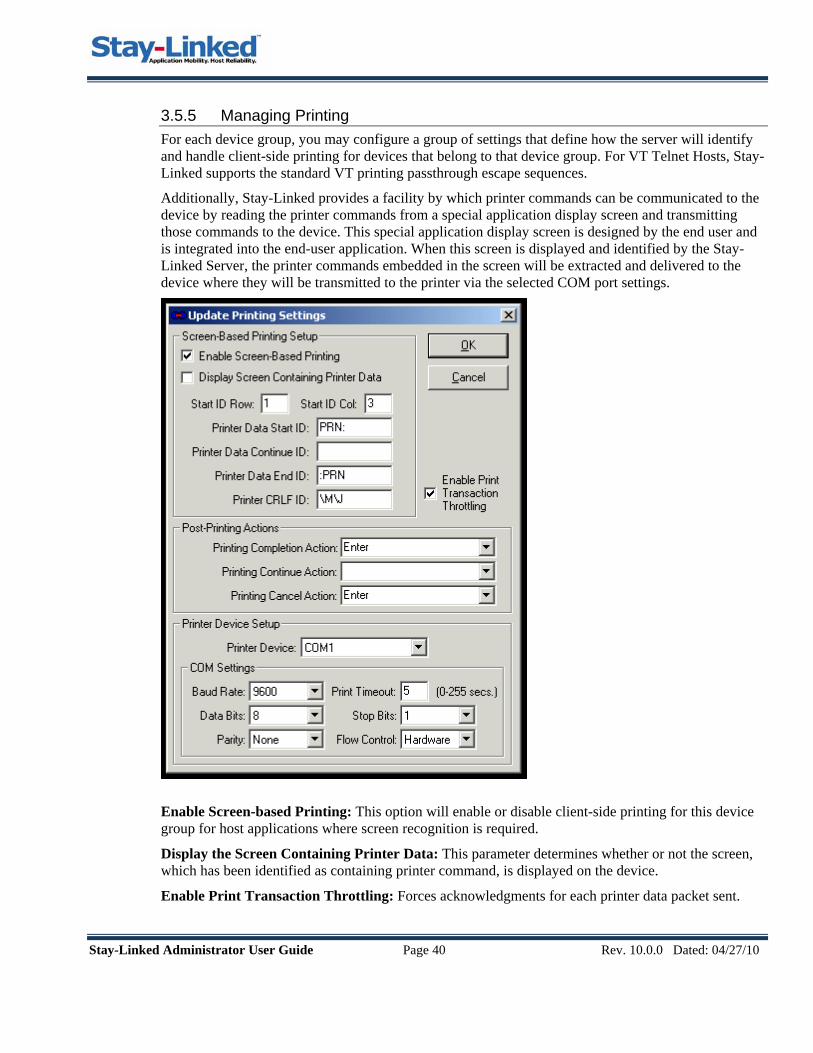
Stay-Linked Administrator User Guide Page 40 Rev. 10.0.0 Dated: 04/27/10
3.5.5 Managing Printing For each device group, you may configure a group of settings that define how the server will identify and handle client-side printing for devices that belong to that device group. For VT Telnet Hosts, Stay-Linked supports the standard VT printing passthrough escape sequences.
Additionally, Stay-Linked provides a facility by which printer commands can be communicated to the device by reading the printer commands from a special application display screen and transmitting those commands to the device. This special application display screen is designed by the end user and is integrated into the end-user application. When this screen is displayed and identified by the Stay-Linked Server, the printer commands embedded in the screen will be extracted and delivered to the device where they will be transmitted to the printer via the selected COM port settings.
Enable Screen-based Printing: This option will enable or disable client-side printing for this device group for host applications where screen recognition is required.
Display the Screen Containing Printer Data: This parameter determines whether or not the screen, which has been identified as containing printer command, is displayed on the device.
Enable Print Transaction Throttling: Forces acknowledgments for each printer data packet sent.

Stay-Linked Administrator User Guide Page 41 Rev. 10.0.0 Dated: 04/27/10
Start ID Row: This option defines the display row where the server will look for the Print Data Start ID and the Print Data Continue ID.
Start ID Column: This option defines the display column where the server will look for the Print Data Start ID and the Print Data Continue ID. This value is not included in the extracted printer data.
Print Data Start ID: This option describes the string of characters, than when found at the Start ID Column and Row, identifies this screen as containing a new set of printer commands.
Print Data Continue ID: This option describes the string of characters that will notify the Stay-Linked Server that more printing data is to be expected on subsequent screens. This ID should be used at the end of a screen when there will be more data displayed on the next screen. This ID should also be positioned at the Start ID Column and Row of the next screen that contains additional printer commands. This ID would be used when the printing commands are too complex to fit on a single application display screen.
Print Data End ID: This option describes the string of characters that will identify the end of the printer commands. When this ID is encountered, all of the collected printer data will be transmitted to the device. This value is not included in the extracted printer data.
Print CRLF ID: This option describes the string of characters that will identify the CRLF indicators on this screen. The CRLF indicators that are found in the extracted printer data will be replaced with an actual carriage return/line feed sequence when that data is transmitted to the device.
Printing Completion Action: This option controls how the server will respond when the printer attached to the device has successfully processed the printer commands. The action defined here will be sent to the printing command screen. For instance, if the printer completes printing, the Enter key can be sent to the screen to cause the printer command screen to be dismissed.
Printing Continue Action: This option controls how the server will respond when the a screen of printer data is ended with a Printing Continue ID. This action would be used to trigger the display of the next screen that contains the additional printer commands.
Printing Cancel Action: This option controls how the server will respond when the printer attached to the device fails to process the printer commands. If you cancel the printing operation on the device, then this action will be sent to the printing command screen. For instance, if you cancel printing, the F12 key can be sent to the screen to cause the printer command screen to be dismissed. The value selected for these three actions will depend upon how the end user application has been programmed.
Printer Device: Currently, Stay-Linked devices support COM communication with printer devices. In the near future, support will be provided for Wireless, Bluetooth and other communication protocols.
Baud Rate: This option describes the Baud Rate of the printer connected to the device.
Data Bits: This option describes the Data Bits setting of the printer connected to the device.
Parity: This option describes the Parity setting of the printer connected to the device.
Print Timeout: This option defines how long the Stay-Linked client will wait for responses from the attached printer device.
Stop Bits: This option describes the Stop Bits setting of the printer connected to the device.
Flow Control: This option describes the Flow Control setting of the printer connected to the device.
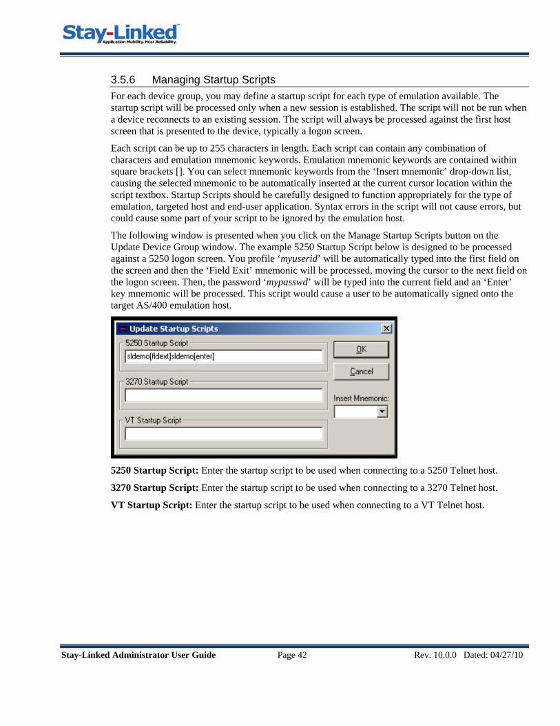
Stay-Linked Administrator User Guide Page 42 Rev. 10.0.0 Dated: 04/27/10
3.5.6 Managing Startup Scripts For each device group, you may define a startup script for each type of emulation available. The startup script will be processed only when a new session is established. The script will not be run when a device reconnects to an existing session. The script will always be processed against the first host screen that is presented to the device, typically a logon screen.
Each script can be up to 255 characters in length. Each script can contain any combination of characters and emulation mnemonic keywords. Emulation mnemonic keywords are contained within square brackets []. You can select mnemonic keywords from the ‘Insert mnemonic’ drop-down list, causing the selected mnemonic to be automatically inserted at the current cursor location within the script textbox. Startup Scripts should be carefully designed to function appropriately for the type of emulation, targeted host and end-user application. Syntax errors in the script will not cause errors, but could cause some part of your script to be ignored by the emulation host.
The following window is presented when you click on the Manage Startup Scripts button on the Update Device Group window. The example 5250 Startup Script below is designed to be processed against a 5250 logon screen. You profile ‘myuserid’ will be automatically typed into the first field on the screen and then the ‘Field Exit’ mnemonic will be processed, moving the cursor to the next field on the logon screen. Then, the password ‘mypasswd’ will be typed into the current field and an ‘Enter’ key mnemonic will be processed. This script would cause a user to be automatically signed onto the target AS/400 emulation host.
5250 Startup Script: Enter the startup script to be used when connecting to a 5250 Telnet host.
3270 Startup Script: Enter the startup script to be used when connecting to a 3270 Telnet host.
VT Startup Script: Enter the startup script to be used when connecting to a VT Telnet host.

Stay-Linked Administrator User Guide Page 43 Rev. 10.0.0 Dated: 04/27/10
3.5.7 Managing Alternate Keyboard Maps For each device group, you can override the keyboard map that a device would normally use and specify a different keyboard map to be used as an alternate.
Keyboard maps are used by the Stay-Linked system as a cross-reference between the many and varied device keyboards and the various host types (5250, 3270, and VT). With Stay-Linked, you can use the default keyboard map or alter it to suit the specific needs of your device users and their applications. In addition, you can create alternate keyboard maps to support variations needed for a specific group of devices.
The following window is presented when you click on the Manage Alt. Keyboards button on the Update Device Group window.
In this example, when an Intermec 700C, 35-key device connects to this Host, the alternate keyboard map for the Stay-Linked Generic PPC2003 device will be used instead.
You may add and delete these alternate keyboard maps using the Keyboard menu (the Add New Alternate Map selection window is shown above). The Original Map and Alternate Map dropdowns provide a list of available keyboard maps from which to choose.
Select “Save Changes” from the “File” drop-down menu to save any changes that you have made to the currently selected device group.

Stay-Linked Administrator User Guide Page 44 Rev. 10.0.0 Dated: 04/27/10
3.6 Managing Keyboard Maps This section describes the methods provided to specify and tailor the keyboard maps used by the devices that connect to the server. Keyboard maps are used by the Stay-Linked system as a cross-reference between the many and varied device keyboards and the various host types (5250, 3270, and VT). With Stay-Linked, you can use the default keyboard map or alter it to suit the specific needs of your device users and their applications. In addition, you can create alternate keyboard maps to support variations needed for a specific host or group of devices.
3.6.1 Managing Keyboard Maps When you select Keyboard Maps from the server tree or the Manage menu, the Keyboard Maps list will appear in the main display panel, showing all of the keyboard maps that are currently installed for the selected server and available for use by devices upon connection. Typically, this list should contain maps only for those devices that are in use at your installation. Other keyboard maps should be removed from this list as a security measure.
Only devices that have a keyboard map listed in this dialog will be able to connect to the Stay-Linked Server.
Clicking the right mouse button on a device group will cause a small menu to appear with options to Add, Edit, Delete, Copy, or Create a keyboard map.
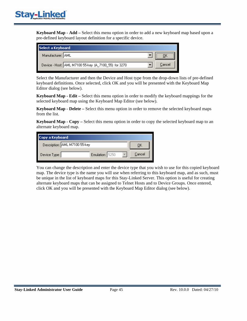
Stay-Linked Administrator User Guide Page 45 Rev. 10.0.0 Dated: 04/27/10
Keyboard Map - Add – Select this menu option in order to add a new keyboard map based upon a pre-defined keyboard layout definition for a specific device.
Select the Manufacturer and then the Device and Host type from the drop-down lists of pre-defined keyboard definitions. Once selected, click OK and you will be presented with the Keyboard Map Editor dialog (see below).
Keyboard Map - Edit – Select this menu option in order to modify the keyboard mappings for the selected keyboard map using the Keyboard Map Editor (see below).
Keyboard Map - Delete – Select this menu option in order to remove the selected keyboard maps from the list.
Keyboard Map - Copy – Select this menu option in order to copy the selected keyboard map to an alternate keyboard map.
You can change the description and enter the device type that you wish to use for this copied keyboard map. The device type is the name you will use when referring to this keyboard map, and as such, must be unique in the list of keyboard maps for this Stay-Linked Server. This option is useful for creating alternate keyboard maps that can be assigned to Telnet Hosts and to Device Groups. Once entered, click OK and you will be presented with the Keyboard Map Editor dialog (see below).
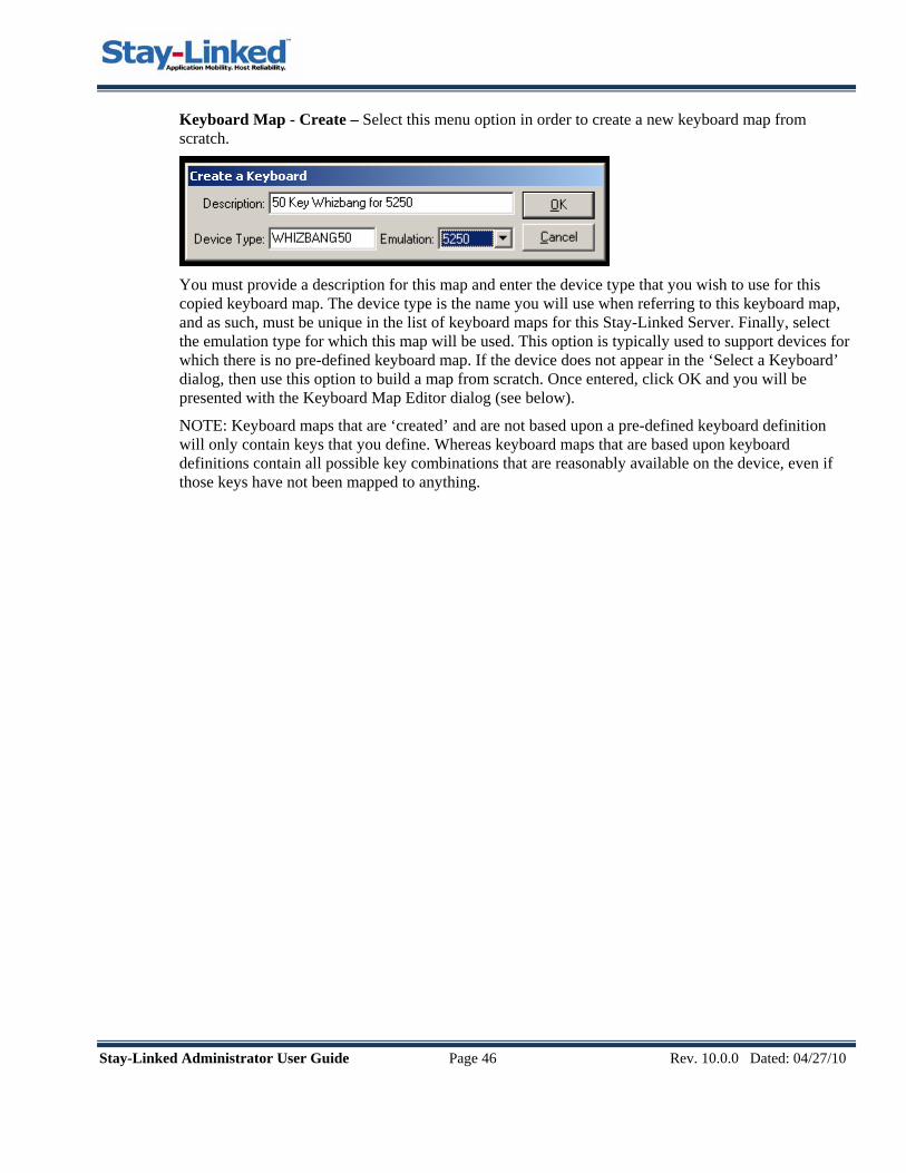
Stay-Linked Administrator User Guide Page 46 Rev. 10.0.0 Dated: 04/27/10
Keyboard Map - Create – Select this menu option in order to create a new keyboard map from scratch.
You must provide a description for this map and enter the device type that you wish to use for this copied keyboard map. The device type is the name you will use when referring to this keyboard map, and as such, must be unique in the list of keyboard maps for this Stay-Linked Server. Finally, select the emulation type for which this map will be used. This option is typically used to support devices for which there is no pre-defined keyboard map. If the device does not appear in the ‘Select a Keyboard’ dialog, then use this option to build a map from scratch. Once entered, click OK and you will be presented with the Keyboard Map Editor dialog (see below).
NOTE: Keyboard maps that are ‘created’ and are not based upon a pre-defined keyboard definition will only contain keys that you define. Whereas keyboard maps that are based upon keyboard definitions contain all possible key combinations that are reasonably available on the device, even if those keys have not been mapped to anything.

Stay-Linked Administrator User Guide Page 47 Rev. 10.0.0 Dated: 04/27/10
3.6.2 Editing a Keyboard Map Whether you choose to add, edit, copy, or create a Keyboard Map, the following Keyboard Map Editor dialog will be used to map the model-specific RF device keys to emulation mnemonics, scripts, letters, text or combinations of these. You may right-click on a key map entry to bring up a Key Map context menu.
From the File Menu: • Save Changes: Select this menu option to save the current keyboard mappings. • Load Defaults: Select this menu option to load the default keyboard map for this Device Type
and Emulation. • Print Keyboard: Use this button to send a hard copy of the current keyboard map to the default
printer. • Exit: Select this menu option to close this dialog.
From the KeyMap Menu (or right mouse click within the list): • Add: Select this menu option to add a key map entry for a key code that is not defined in the
keyboard definition. • Edit: Select this menu option to update the selected key map entry. • Clear: Select this menu option to clear/remove the mapping for the selected key.
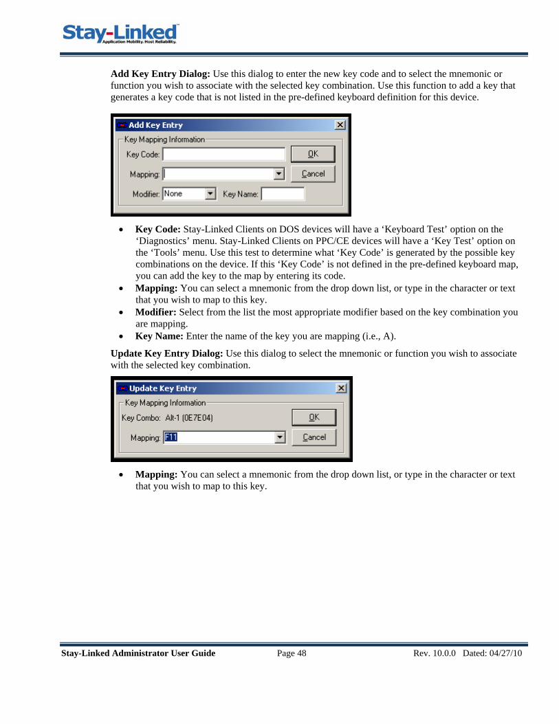
Stay-Linked Administrator User Guide Page 48 Rev. 10.0.0 Dated: 04/27/10
Add Key Entry Dialog: Use this dialog to enter the new key code and to select the mnemonic or function you wish to associate with the selected key combination. Use this function to add a key that generates a key code that is not listed in the pre-defined keyboard definition for this device.
• Key Code: Stay-Linked Clients on DOS devices will have a ‘Keyboard Test’ option on the
‘Diagnostics’ menu. Stay-Linked Clients on PPC/CE devices will have a ‘Key Test’ option on the ‘Tools’ menu. Use this test to determine what ‘Key Code’ is generated by the possible key combinations on the device. If this ‘Key Code’ is not defined in the pre-defined keyboard map, you can add the key to the map by entering its code.
• Mapping: You can select a mnemonic from the drop down list, or type in the character or text that you wish to map to this key.
• Modifier: Select from the list the most appropriate modifier based on the key combination you are mapping.
• Key Name: Enter the name of the key you are mapping (i.e., A).
Update Key Entry Dialog: Use this dialog to select the mnemonic or function you wish to associate with the selected key combination.
• Mapping: You can select a mnemonic from the drop down list, or type in the character or text
that you wish to map to this key.
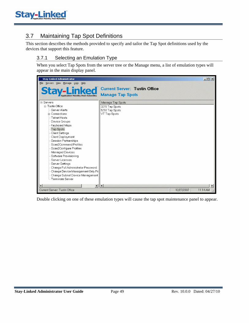
Stay-Linked Administrator User Guide Page 49 Rev. 10.0.0 Dated: 04/27/10
3.7 Maintaining Tap Spot Definitions This section describes the methods provided to specify and tailor the Tap Spot definitions used by the devices that support this feature.
3.7.1 Selecting an Emulation Type When you select Tap Spots from the server tree or the Manage menu, a list of emulation types will appear in the main display panel.
Double clicking on one of these emulation types will cause the tap spot maintenance panel to appear.
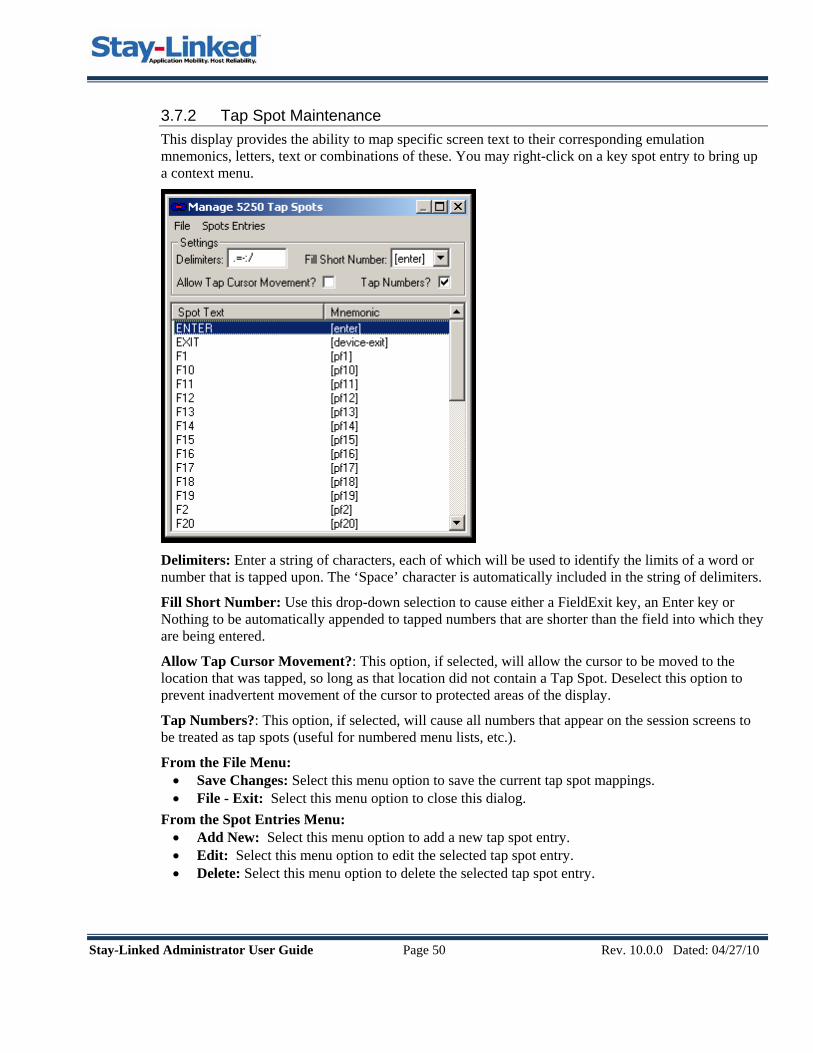
Stay-Linked Administrator User Guide Page 50 Rev. 10.0.0 Dated: 04/27/10
3.7.2 Tap Spot Maintenance This display provides the ability to map specific screen text to their corresponding emulation mnemonics, letters, text or combinations of these. You may right-click on a key spot entry to bring up a context menu.
Delimiters: Enter a string of characters, each of which will be used to identify the limits of a word or number that is tapped upon. The ‘Space’ character is automatically included in the string of delimiters.
Fill Short Number: Use this drop-down selection to cause either a FieldExit key, an Enter key or Nothing to be automatically appended to tapped numbers that are shorter than the field into which they are being entered.
Allow Tap Cursor Movement?: This option, if selected, will allow the cursor to be moved to the location that was tapped, so long as that location did not contain a Tap Spot. Deselect this option to prevent inadvertent movement of the cursor to protected areas of the display.
Tap Numbers?: This option, if selected, will cause all numbers that appear on the session screens to be treated as tap spots (useful for numbered menu lists, etc.).
From the File Menu: • Save Changes: Select this menu option to save the current tap spot mappings. • File - Exit: Select this menu option to close this dialog.
From the Spot Entries Menu: • Add New: Select this menu option to add a new tap spot entry. • Edit: Select this menu option to edit the selected tap spot entry. • Delete: Select this menu option to delete the selected tap spot entry.

Stay-Linked Administrator User Guide Page 51 Rev. 10.0.0 Dated: 04/27/10
Add Tap Spot Entry Dialog: Use this dialog to enter a new tap spot entry to the list and its associated mnemonic/text.
• Spot Text: Enter the text, as it will appear on the screen, which you wish to make tap sensitive.
The text can only be entered in upper case and the match is not case sensitive. The text on the screen must appear between two delimiters.
• Mapping: You can select a mnemonic from the drop down list, or type in the character or text that you wish to map to this key.
Update Tap Spot Dialog: Use this dialog to select the mnemonic/text you wish to associate with the selected Tap Spot Text.
• Mapping: You can select a mnemonic from the drop down list, or type in the character or text
that you wish to map to this key.
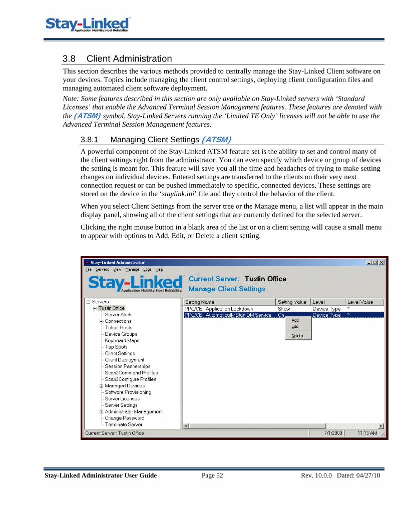
Stay-Linked Administrator User Guide Page 52 Rev. 10.0.0 Dated: 04/27/10
3.8 Client Administration This section describes the various methods provided to centrally manage the Stay-Linked Client software on your devices. Topics include managing the client control settings, deploying client configuration files and managing automated client software deployment. Note: Some features described in this section are only available on Stay-Linked servers with ‘Standard Licenses’ that enable the Advanced Terminal Session Management features. These features are denoted with the (ATSM) symbol. Stay-Linked Servers running the ‘Limited TE Only’ licenses will not be able to use the Advanced Terminal Session Management features.
3.8.1 Managing Client Settings (ATSM) A powerful component of the Stay-Linked ATSM feature set is the ability to set and control many of the client settings right from the administrator. You can even specify which device or group of devices the setting is meant for. This feature will save you all the time and headaches of trying to make setting changes on individual devices. Entered settings are transferred to the clients on their very next connection request or can be pushed immediately to specific, connected devices. These settings are stored on the device in the ‘staylink.ini’ file and they control the behavior of the client.
When you select Client Settings from the server tree or the Manage menu, a list will appear in the main display panel, showing all of the client settings that are currently defined for the selected server.
Clicking the right mouse button in a blank area of the list or on a client setting will cause a small menu to appear with options to Add, Edit, or Delete a client setting.
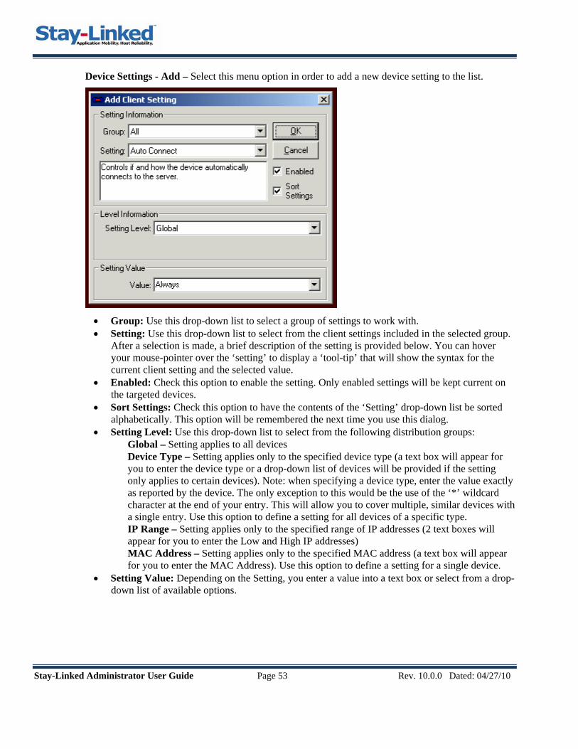
Stay-Linked Administrator User Guide Page 53 Rev. 10.0.0 Dated: 04/27/10
Device Settings - Add – Select this menu option in order to add a new device setting to the list.
• Group: Use this drop-down list to select a group of settings to work with. • Setting: Use this drop-down list to select from the client settings included in the selected group.
After a selection is made, a brief description of the setting is provided below. You can hover your mouse-pointer over the ‘setting’ to display a ‘tool-tip’ that will show the syntax for the current client setting and the selected value.
• Enabled: Check this option to enable the setting. Only enabled settings will be kept current on the targeted devices.
• Sort Settings: Check this option to have the contents of the ‘Setting’ drop-down list be sorted alphabetically. This option will be remembered the next time you use this dialog.
• Setting Level: Use this drop-down list to select from the following distribution groups: Global – Setting applies to all devices Device Type – Setting applies only to the specified device type (a text box will appear for
you to enter the device type or a drop-down list of devices will be provided if the setting only applies to certain devices). Note: when specifying a device type, enter the value exactly as reported by the device. The only exception to this would be the use of the ‘*’ wildcard character at the end of your entry. This will allow you to cover multiple, similar devices with a single entry. Use this option to define a setting for all devices of a specific type.
IP Range – Setting applies only to the specified range of IP addresses (2 text boxes will appear for you to enter the Low and High IP addresses)
MAC Address – Setting applies only to the specified MAC address (a text box will appear for you to enter the MAC Address). Use this option to define a setting for a single device.
• Setting Value: Depending on the Setting, you enter a value into a text box or select from a drop-down list of available options.

Stay-Linked Administrator User Guide Page 54 Rev. 10.0.0 Dated: 04/27/10
Device Settings - Edit – Select this menu option to update an existing device setting on the list.
• Setting: Displays the current setting and a description below. You can hover your mouse-pointer
over the ‘setting’ to display a ‘tool-tip’ that will show the syntax for the current client setting and the selected value.
• Enabled: Check this option to enable the setting. Only enabled settings will be kept current on the targeted devices.
• Setting Level: Use this drop-down list to select from the following distribution groups: Global – Setting applies to all devices Device Type – Setting applies only to the specified device type (a text box will appear for
you to enter the device type or a drop-down list of devices will be provided if the setting only applies to certain devices). Note: when specifying a device type, enter the value exactly as reported by the device. The only exception to this would be the use of the ‘*’ wildcard character at the end of your entry. This will allow you to cover multiple, similar devices with a single entry. Use this option to define a setting for all devices of a specific type.
IP Range – Setting applies only to the specified range of IP addresses (2 text boxes will appear for you to enter the Low and High IP addresses)
MAC Address – Setting applies only to the specified MAC address (a text box will appear for you to enter the MAC Address). Use this option to define a setting for a single device.
• Setting Value: Depending on the Setting, you enter a value into a text box or select from a drop-down list of available options.

Stay-Linked Administrator User Guide Page 55 Rev. 10.0.0 Dated: 04/27/10
3.8.2 Managing Client Configuration File Deployment (ATSM) The Stay-Linked Client Software determines most of it’s behavior by using settings from the ‘staylink.ini’ file. The previous section of this document describes how to centrally manage the settings that are stored in this file. There are, however, additional configuration files that might be used by the Stay-Linked Client Software to control other aspects of the behavior of the device or the client software. Here is a list of some of these files:
EXTKEYS.INI – Configures the tap-able button bar that can be displayed on PPC/CE devices.
SCANNER.INI – Configures the OEM scanner engine on devices that have no native user interface.
LOCALE.INI – Provides localization support for alternate language fonts on PPC/CE devices.
SERVERS.INI – Provides access to multiple and/or backup Stay-Linked Servers from a client.
COLORS.INI – Configures alternate host foreground/background color mapping on the devices.
These configuration files can also be managed centrally from the Stay-Linked Administrator in a manner that is very similar to the management of the individual device settings. You can use the ‘Device Settings’ management feature to deploy various versions of these files to specific devices. Clicking the right mouse button in a blank area of the ‘Device Settings’ list or on a device setting will cause a small menu to appear. Select the ‘Add’ option and then in the ‘Setting’ drop-down list, find and select the ‘All – Configuration File Transfer’ device setting. The following dialog will be displayed:
• Enabled: Check this option to enable the setting. Only enabled settings will be kept current on
the targeted devices. • Setting Level: Use this drop-down list to select from the following distribution groups:

Stay-Linked Administrator User Guide Page 56 Rev. 10.0.0 Dated: 04/27/10
Global – Setting applies to all devices Device Type – Setting applies only to the specified device type (a text box will appear for
you to enter the device type or a drop-down list of devices will be provided if the setting only applies to certain devices). Note: when specifying a device type, enter the value exactly as reported by the device. The only exception to this would be the use of the ‘*’ wildcard character at the end of your entry. This will allow you to cover multiple, similar devices with a single entry. Use this option to define a setting for all devices of a specific type.
IP Range – Setting applies only to the specified range of IP addresses (2 text boxes will appear for you to enter the Low and High IP addresses)
MAC Address – Setting applies only to the specified MAC address (a text box will appear for you to enter the MAC Address). Use this option to define a setting for a single device.
• Import File Name: Use the ‘browse’ button to the right of this textbox to locate and select the configuration (.INI) file that you wish to transfer for this entry. This file will be transferred to the server and stored there to be deployed to devices that are selected for this setting.
• Server File Name: Enter a unique file name to be used for this file when it is stored on the server. All of the files selected for ‘Configuration File Transfer’ settings will be stored in a single folder on the Stay-Linked Server machine at ‘..\stay-linked\deploy\files’. Each of these files must have a unique file name in this folder on the server.
• Device File Name: Enter the name of this file as it should be stored on the device. You should provide a path as part of the name only if the file is not one that is recognized by and managed by the Stay-Linked Client on the device. The files listed at the top of this section are automatically handled by the Stay-Linked Client and so only that name needs to be specified for this value.

Stay-Linked Administrator User Guide Page 57 Rev. 10.0.0 Dated: 04/27/10
Client Configuration File Deployment Example:
This example shows the dialog for sending a ‘locale.ini’ file to devices that are of a specific device type, in this case Symbol PDT9000 devices.
• Import File Name: The original ‘locale.ini’ file was located on the Administrator PC in the ‘c:\localize’ folder with the name ‘locale_greek.ini’. This file will be transferred to the server.
• Server File Name: The unique file name to be used for this file when it is stored on the server has been entered as ‘locale_greek_pdt9000.ini’. Since all of the files selected for ‘Configuration File Transfer’ settings will be stored in a single folder on the Stay-Linked Server machine, each of these files must have a unique file name in this folder on the server. The files are stored on the Stay-Linked Server at ‘..\stay-linked\deploy\files’.
• Device File Name: The name of this file as it will be stored on the device is ‘locale.ini’. The ‘locale.ini’ is a special configuration file that is recognized and managed by the Stay-Linked Client. In this case, it is not necessary to provide a path for the file on the device.
After configuring the dialog for ‘Add Device Setting’, press the OK button to validate the dialog. Once validated, the file will be transferred from the Administrator to the Stay-Linked Server where it will be stored for deployment to qualifying devices. When a Stay-Linked device creates a new connection to the Stay-Linked Server, and both ‘Configuration File Deployment Settings’ and ‘Device Settings’ are to be sent to the device, first the ‘Configuration Files’ will be transferred to the device and then immediately the ‘Device Settings’ will be sent to the device. The Stay-Linked Client will restart automatically after receiving these files and settings and then, upon connection, those settings will take effect immediately.
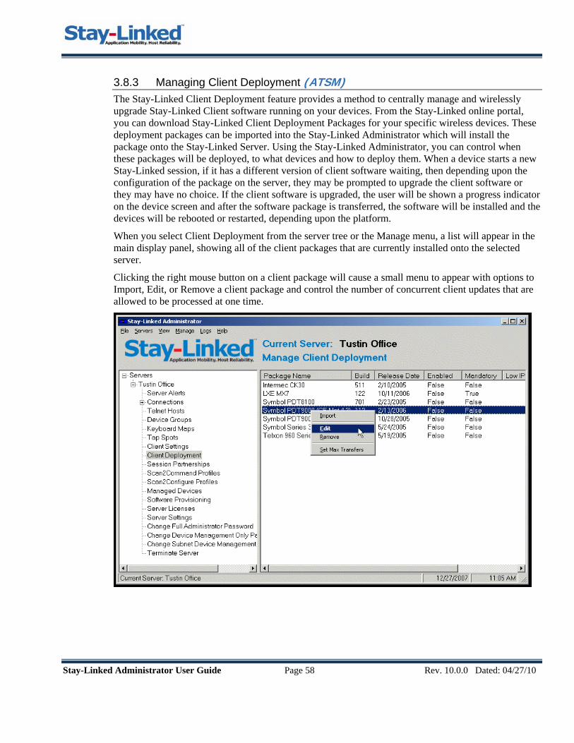
Stay-Linked Administrator User Guide Page 58 Rev. 10.0.0 Dated: 04/27/10
3.8.3 Managing Client Deployment (ATSM) The Stay-Linked Client Deployment feature provides a method to centrally manage and wirelessly upgrade Stay-Linked Client software running on your devices. From the Stay-Linked online portal, you can download Stay-Linked Client Deployment Packages for your specific wireless devices. These deployment packages can be imported into the Stay-Linked Administrator which will install the package onto the Stay-Linked Server. Using the Stay-Linked Administrator, you can control when these packages will be deployed, to what devices and how to deploy them. When a device starts a new Stay-Linked session, if it has a different version of client software waiting, then depending upon the configuration of the package on the server, they may be prompted to upgrade the client software or they may have no choice. If the client software is upgraded, the user will be shown a progress indicator on the device screen and after the software package is transferred, the software will be installed and the devices will be rebooted or restarted, depending upon the platform.
When you select Client Deployment from the server tree or the Manage menu, a list will appear in the main display panel, showing all of the client packages that are currently installed onto the selected server.
Clicking the right mouse button on a client package will cause a small menu to appear with options to Import, Edit, or Remove a client package and control the number of concurrent client updates that are allowed to be processed at one time.

Stay-Linked Administrator User Guide Page 59 Rev. 10.0.0 Dated: 04/27/10
When you select the Import option from the menu, the following window will appear:
• Package File: Type or browse for the client deployment package file name (with the .sdp
extension) that you wish to import. Client deployment package files are available on the Stay-Linked portal site.
• Verify: Click on this button to verify the deployment file and contents. If the file is a valid deployment package, the Package information will be displayed in the window and the ‘Verify’ button will transform into an ‘Install’ button.
• Install: Click this button to install the package onto the Stay-Linked server. By default, when a new package is installed, it will be disabled until it has been manually reviewed and enabled.
When you select the Edit option from the menu, the following window will appear:

Stay-Linked Administrator User Guide Page 60 Rev. 10.0.0 Dated: 04/27/10
• Package Enabled: Use this check box to indicate that this deployment package is enabled and should be transferred to the appropriate client devices.
• Mandatory Update: Use this check box to indicate that this deployment package is mandatory and that the client will not be allowed to connect to the Stay-Linked server until the update has been accomplished. If this check box is not selected, the user will be given a choice to update now or to update later.
• Deployment Address Range: Enter the range of device IP addresses that will affected by this client deployment package.
• Package Devices: Displays a list of device types to which this client deployment package will be applied. This list is predefined and is not managed by the administrator. The client software in the package is designed for the device types that appear in this list.
• Add Custom Device Type: This right-click menu option for the Package Devices listing will allow you to add a custom device type to the list of devices that will be upgraded using this deployment package. You must make sure that any device types added here are compatible with this deployment package.
• Delete: This right-click menu option for the Package Devices listing will allow you to delete a device type from the list of devices that will be upgraded using this deployment package.
When you select the Remove option from the menu, you will be prompted to have the client deployment package removed from the list of packages. This option does not physically remove the client package from the server. This option only removes the entry from the list of deployment packages, making it no longer be available for deployment. You may re-import the package again in order to make it available to devices.
When you select the Set Max Transfers option from the menu, you will be prompted for the number of concurrent transfers that you wish to allow from this server to the devices. This feature provides you with control over the bandwidth that will be available for client software updates. If a device starts a new session, is eligible for a client software update, but there are already the maximum allowed number of transfers in process, then the user at the device will be notified and given the choice to try the upgrade again or to start a session using their current client software.

Stay-Linked Administrator User Guide Page 61 Rev. 10.0.0 Dated: 04/27/10
3.9 Managing Session Partnerships Session Partnerships are a powerful feature that is exclusive to the Stay-Linked Advanced Terminal Session Management solution (ATSM). Using the Session Partnerships feature, it is now possible to create a partnership between two wireless terminal devices which will enable these two devices to share the same telnet session. When partner devices are sharing a telnet session, both devices will see the same application screens and will be able to cooperatively enter data into the shared telnet session. A practical application for this feature would be for a forklift-based warehouse worker. Typically, with a vehicle-mount terminal, the user must use a ‘dumb’ scanner that is tethered to the VMU (Vehicle-Mounted Unit). Even if the ‘dumb’ scanner is wireless, there will still be no user interface visible on the scanner gun to show the user the current context of his terminal session. Rather than having this user remain tethered to his VMU, you can instead create a partnership between his VMU and a handheld RF terminal device. Now, the forklift user can see a screen on his VMU, and when necessary, the user can leave the forklift carrying a hand-held terminal that is sharing the same telnet session. After doing some remote data entry with the hand-held terminal, the user can return to the forklift where is VMU will be displaying the same application screen as the partner hand-held terminal. The screen on the VMU and on the partnered hand-held device will remain synchronized at all times because they are sharing the same telnet session. This section describes the configuration and usage of the Session Partnership feature. When you select Session Partnerships from the server tree or the Manage menu, a list of current session partnerships will appear in the main display panel. Clicking the right mouse button on a partnership will cause a small menu to appear with options to Add, Edit, and Delete a session partnership.
Session Partnerships - Add – Select this menu option in order to add a session partnership.
Session Partnerships - Edit – Select this menu option in order to modify the attributes of the selected partnership.
Session Partnerships - Delete – Select this menu option in order to remove the selected partnership from the list.

Stay-Linked Administrator User Guide Page 62 Rev. 10.0.0 Dated: 04/27/10
Description – Enter a meaningful description of the session partnership. Partnership Enabled – Check this box to make the partnership active. Partnership Optional – Check this box to make the partnership optional. When selected, the device joining an existing session started by the partner will be prompted to join the session or not. If this option is not selected, the device will join an existing partner session immediately and automatically. Partner One/Two MAC – Enter the 12-digit MAC address of one of the partner devices. A partner MAC address can only appear as a partner once in the system. Partner One/Two Allow Printing – Only one of the partner devices is allowed to process client printing instructions from the telnet session. Select this option to have the partner respond to printing instructions. Partner One/Two Allow Host API – Only one of the partner devices is allowed to process Host API instructions from the telnet session. Select this option to have the partner respond to Host API instructions. Running Partner Sessions Following is an example of the operation of a Session Partnership between a Vehicle-Mount Unit (VMU) on a forklift and a Hand-Held Terminal. In this case, the partnership was created with the ‘Optional’ selection and the VMU was selected to ‘Allow Printing’ and also to ‘Allow Host APIs’. The warehouse user grabs the hand-held terminal that is partnered with his VMU and heads to the forklift. Once at the forklift, the VMU is powered on and a Stay-Linked Session is created. The user logs onto the host and is presented with the application ‘Picking Menu’. Now, the user grabs the hand-held terminal and powers it up. The hand-held creates a Stay-Linked Session. The Stay-Linked Server recognizes the session partnership and determines that a session is already started for one of the partners. Since the partnership is optional, the hand-held terminal displays a message allowing the user to either ‘Join’ or ‘Skip’ the partner session. In this case, the user selects to join the partner session and the current session screen is displayed immediately. Now, the user holsters the hand-held terminal and, using the VMU, determines the first picking location. Upon driving to the location, the user retrieves the item from an upper rack and scans the location with the VMU tethered long-range scanner. The system shows the user the next item to pick, which turns out to be a small item just one rack over and at knee height. So, the user exits the forklift, walks over to the next rack and locates the item. The user grabs the hand-held terminal from the holster and scans the location tag into the current partnered session screen. The user can see on the hand-held screen that the third item to pick is one shelf up, so he grabs that item and scans the location from the rack using the hand-held. Since item four is on the next aisle, the user holsters the hand-held and returns to the forklift with items two and three. Now the user can drive to the next aisle and continue picking the order, using the tethered scanner or the partnered hand-held terminal as desired. Upon completion of the shift, the user terminates the session on the VMU which automatically terminates the partner session on the hand-held terminal.

Stay-Linked Administrator User Guide Page 63 Rev. 10.0.0 Dated: 04/27/10
3.10 Scan2Command and Scan2Configure Profiles The Scan2Command and Scan2Configure Profiles management options, introduced with Version 9.0.0 of Stay-Linked, provides a method by which you can design and print sheets of barcodes that can be scanned by devices running the Stay-Linked client. These barcode sheets can be used both to configure the client software and also to command the client or the telnet sessions.
3.10.1 Scan2Command Profiles The Scan2Command Profiles will provide barcode sheets that can contain any Stay-Linked mnemonic or other client commands or scripts to be executed on the device or in the Telnet Session. There are three types of values that can be represented in a Scan2Command Profile.
• Mnemonics – These values, when scanned, will command the telnet session to take some action, like press Enter, or press a Function Key, etc.
• Client Commands – These values, when scanned, will instruct the Stay-Linked Client software to take some action locally on the device. Examples are, toggle the SIP, switch sessions, switch font sizes, exit the session, etc.
• Scripts - These values, when scanned, will command the telnet session to follow a script of instructions. An example would be a single barcode that the user can scan to log onto the Telnet Server. Here is a sample logon script for a 5250 session: [clear]myuserid[fldext]mypassword[enter] Here is a sample logon script for a VT session: myuserid[enter][delay]mypassword[enter]
3.10.2 Scan2Configure Profiles The Scan2Configure Profiles will provide barcode sheets that can contain one or more ‘Client Settings’ that will be used to configure the behavior of the Stay-Linked Client on the device. These barcode sheets can be printed using 1D symbologies where each client setting is represented in a single barcode. Or, you can print the Scan2Configure profile sheet using 2D symbologies where all of the client settings are combined into one (or more) 2D barcodes images that can be scanned to configure the device. The Scan2Configure profile sheets are typically scanned using the client-side ‘Scan Test’ user interface, or they can be scanned while running a Stay-Linked Session. The Scan2Configure profiles can also include an optional ‘Restart Client’ post-config command that will be acted upon after all of the client settings have been processed, causing all of the new settings to be loaded on startup.

Stay-Linked Administrator User Guide Page 64 Rev. 10.0.0 Dated: 04/27/10
This section describes the configuration and usage of the Scan2Command and Scan2Configure features. When you select one of these options from the server tree or the Manage menu, a list of current profiles will appear in the main display panel. Clicking the right mouse button on a profile will cause a small menu to appear with options to Add, Edit, and Delete a profile.
Scan2Command/Scan2Configure - Add – Select this menu option in order to add a new profile. Scan2Command/Scan2Configure - Edit – Select this menu option in order to modify the contents and attributes of the selected profile. You can also use this option to print an existing profile. Scan2Command/Scan2Configure - Delete – Select this menu option in order to remove the selected profile from the list.

Stay-Linked Administrator User Guide Page 65 Rev. 10.0.0 Dated: 04/27/10
When you ‘Add’ or ‘Edit’ a profile, you will be presented with the Profile dialog:
Profile Name: This text box is used to enter the unique name for this Scan2Command or Scan2Congfigure Profile. Symbology: Select from this list the symbology to be used for printing the profile barcode sheet. You can select from the following symbologies: Code 39 Full ASCII (1D), Code 128 (1D), PDF417 (2D), QRCode (2D) or DataMatrix (2D).
Symbology Notes: If you select Code 39 Full ASCII, then you must ensure that your scanners are configured to read Code 39 Full ASCII. If you select a 2D symbology for your Scan2Congfigure profiles, this will cause the client settings to be combined into one (or more) 2D barcode images.
From the File Menu: • Save Changes: Select this menu option to save the current profile. • Print: Select this menu option to print the current profile. • Print Preview: Select this menu option to preview the printed current profile. • Settings – Barcode Delimiter: Select this menu option to change the delimiter used to identify a
Scan2Command or Scan2Configure barcode to the Stay-Linked Client software. • Settings – Barcode Spacing: Select this menu option to change the vertical spacing between printed
barcodes. From the Commands/Settings Menu: • Add New: Select this menu option to add a new command or setting. • Add Post-Config Command: Select this menu option to add a post-configuration command. This
option is only available for Scan2Configure profiles. • Edit: Select this menu option to edit the selected command or setting. • Delete: Select this menu option to delete the selected command or setting. • Move Up: Select this menu option to move the selected command or setting up in the list. • Move Down: Select this menu option to move the selected command or setting down in the list.

Stay-Linked Administrator User Guide Page 66 Rev. 10.0.0 Dated: 04/27/10
If you select to Add or Edit a Scan2Command Command entry, you will be presented with a dialog similar to this:
• Command: You can select a command from the drop down list, or directly type in a command or
script to be encoded into the barcode. • Caption: Type in a meaningful caption that will be printed below the barcode image.
If you select to Add or Edit a Scan2Configure Setting entry, you will be presented with a dialog similar to this:
• Setting: In Add mode, you can select a client setting from this drop-down list. • Setting Value: Depending on the selected Client Setting, you enter a value into a text box or select
from a drop-down list of available values. • Barcode Caption: Type in a meaningful caption that will be printed below the barcode image. • Print ID: Check this box if you would like to have the ‘Setting ID’ encoded into the barcode data
rather than having the ‘Setting Name’ encoded into the barcode data. The ‘Setting ID’ is a three digit numeric value that will create a smaller barcode that if you encode the ‘Setting Name’.

Stay-Linked Administrator User Guide Page 67 Rev. 10.0.0 Dated: 04/27/10
3.11 Connections List and Session Management This section describes the various methods provided to centrally manage your client sessions. Topics include selecting and viewing a list of connected sessions. Note: Some features described in this section are only available on Stay-Linked servers with ‘Standard Licenses’ that enable the Advanced Terminal Session Management features. These features are denoted with the (ATSM) symbol.
3.11.1 Selecting a Connection List Group Option When you select Connections from the server tree or the Manage menu, a list of connection group options will appear in the main display panel. Also, if you expand the Connections branch of the server tree (by clicking on the ‘+‘ sign), the list of connection group options will appear in the server tree, indented below the Connections branch.
These group options allow you to subset your list of connections by device IP address subnet, by device type, or by device group. You can also view all connections without grouping. If you select a group option, a list of groups will appear in the main display panel. The list will contain all the groups that currently have a session connection. For example, you may have 10 device groups defined, but only two of them currently have a device with a connected session, so only those two groups appear in the list.
Select a group by double clicking on the group name in the list. A list of connections that belong to the selected group will appear in the main display panel.
3.11.2 The Connections List After selecting your connections group, a list of the currently running sessions is displayed. The list contains many columns of useful information about the session and the device. You can also double click on a specific session in the list to view the details in a separate window.

Stay-Linked Administrator User Guide Page 68 Rev. 10.0.0 Dated: 04/27/10
The information displayed in the columns of the list and in the Connection Details list includes the following:
• Session ID – A unique identifier for the session. • Device Type – The code that identifies the specific type of the device. • Device Name – The Device Name that has been assigned to the device in the Device Group.
Often used for the 5250 Device Description (*DEVD) name associated with the device. This value will be displayed as ‘{Automatic}’ if the device is not assigned a device name.
• MAC Address – The hardware address of the network interface contained in the device. • IP Address – The IP address assigned to the TCP/IP stack in the device. If the device is running
behind a NAT server, then this value will reflect the PublicIP – PrivateIP. • Session Started – This is the date and time when the session was established. • Last Activity – This is the date and time of the last activity on the device, keystrokes, etc. • Session Status – The status of the Stay-Linked session. The status text is color-coded to display
in ‘black’ if the device is likely powered-on and available. The status text will be displayed in ‘blue’ if the device is likely powered-off and unavailable.
• Client Version – Identifies the version and build of the Stay-Linked Client software that is running on the device.
• User ID – Identifies the user of the device. The contents of this column depend upon the ‘Device Identification’ setting for the Stay-Linked Server. If ‘Device Identification’ is enabled, then this column will display the value that the user provided when the connection was established. Otherwise, this column will always display ‘[unidentified]’.
• Device Mgmt. – Identifies the status of ‘Device Management’ software that might be running on the device. As of v9.0.0, Stay-Linked can be either loosely or tightly integrated with the Athena Client by Odyssey Software. In the future, Stay-Linked may integrate with other popular Device Management solutions.
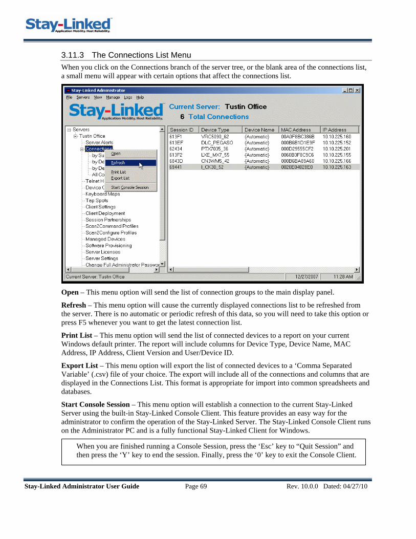
Stay-Linked Adm
3.11.3 The Connections List Menu When you click on the Connections branch of the server tree, or the blank area of the connections list, a small menu will appear with certain options that affect the connections list.
Open – This menu option will send the list of connection groups to the main display panel.
Refresh – This menu option will cause the currently displayed connections list to be refreshed from the server. There is no automatic or periodic refresh of this data, so you will need to take this option or press F5 whenever you want to get the latest connection list.
Print List – This menu option will send the list of connected devices to a report on your current Windows default printer. The report will include columns for Device Type, Device Name, MAC Address, IP Address, Client Version and User/Device ID.
Export List – This menu option will export the list of connected devices to a ‘Comma Separated Variable’ (.csv) file of your choice. The export will include all of the connections and columns that are displayed in the Connections List. This format is appropriate for import into common spreadsheets and databases.
Start Console Session – This menu option will establish a connection to the current Stay-Linked Server using the built-in Stay-Linked Console Client. This feature provides an easy way for the administrator to confirm the operation of the Stay-Linked Server. The Stay-Linked Console Client runs on the Administrator PC and is a fully functional Stay-Linked Client for Windows.
When you are finished running a Console Session, press the ‘Esc’ key to “Quit Session” and then press the ‘Y’ key to end the session. Finally, press the ‘0’ key to exit the Console Client.
inistrator User Guide Page 69 Rev. 10.0.0 Dated: 04/27/10

Stay-Linked Administrator User Guide Page 70 Rev. 10.0.0 Dated: 04/27/10
3.11.4 Connections Menu When you view the connections list in the main display panel of the Administrator, the Connections menu is available by clicking the right mouse button over the specified connection in the connections list. Some menu options will function over multiple selections, which means you can highlight multiple connections in the list and then right mouse click. The Commands, Diagnostics, Device Disconnect and Session Terminate menu options will then process all of the selected connections.

Stay-Linked Administrator User Guide Page 71 Rev. 10.0.0 Dated: 04/27/10
3.11.5 Connections Menu – Details The first item in the connections menu is the Details window. Select this option to open a window showing details about a particular connection. As noted above, this is the default menu option, which means you can open the Details window by double-clicking a connection list entry. You may open multiple Detail windows at one time as desired.
Details Tab: This tab displays information about the device, connection and session.
User Variables Tab: This tab will display any defined ‘User Variables’ that have been User Variables are implemented using Host APIs and Screen Recognition features. * You can right-click on Session ID, Device Type, Device Name and MAC Address to copy the values to the clipboard.
3.11.6 Connections Menu – File (ATSM) Select this option to send a file to the client or receive a file from the client. There are two methods available for sending and receiving files – Reliable Protocol and TFTP Protocol.
File: Send to Device: Reliable – This panel allows the administrator to send files to the device using the Stay-Linked Reliable protocol. The files will be stored on the writable media on the device. NOTE: This option is also available using ‘drag-and-drop’ from Windows Explorer.

Stay-Linked Administrator User Guide Page 72 Rev. 10.0.0 Dated: 04/27/10
• Local File to Send: This is the full path to the file that will be sent to the device. You may use the Browse button to locate this file.
• Remote File Name: This is the name of the file that will be stored on the device. You can include the file path. The path must exist on the device and be writable on the device.
• Send File Button: Click this button to send the file to the device. • Close Button: Use this button to close the ‘Transfer File to Device’ dialog.
File: Send to Device: TFTP – This panel allows the administrator to send files to the device using the TFTP protocol. The files will be stored on the writable media on the device.
• Device IP Address: This is the IP address of the currently selected device and may be manually
changed to another IP if desired. • Port: This is the port on the device that is used for the file transfer function. The default port is
3773. • Local File to Send: This is the full path to the file that will be sent to the device. You may use
the Browse button to locate this file. • Remote File Name: This is the name of the file that will be stored on the device. You may
include the file path. The path must exist on the device and be writable on the device. • Send File/Receive File Options: This option allows you to toggle between Send and Receive
modes. • Send File Button: Click this button to send the file to the device. • Close Button: Use this button to close the ‘Send File to Device’ dialog.
File: Receive from Device: Reliable – This panel allows the administrator to receive files from the device using the Stay-Linked Reliable protocol. The files will be retrieved from the writable media on the device.
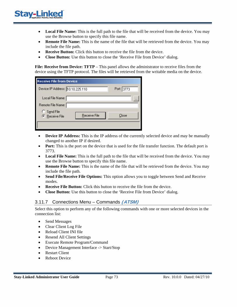
Stay-Linked Administrator User Guide Page 73 Rev. 10.0.0 Dated: 04/27/10
• Local File Name: This is the full path to the file that will be received from the device. You may use the Browse button to specify this file name.
• Remote File Name: This is the name of the file that will be retrieved from the device. You may include the file path.
• Receive Button: Click this button to receive the file from the device. • Close Button: Use this button to close the ‘Receive File from Device’ dialog.
File: Receive from Device: TFTP – This panel allows the administrator to receive files from the device using the TFTP protocol. The files will be retrieved from the writable media on the device.
• Device IP Address: This is the IP address of the currently selected device and may be manually
changed to another IP if desired. • Port: This is the port on the device that is used for the file transfer function. The default port is
3773. • Local File Name: This is the full path to the file that will be received from the device. You may
use the Browse button to specify this file name. • Remote File Name: This is the name of the file that will be retrieved from the device. You may
include the file path. • Send File/Receive File Options: This option allows you to toggle between Send and Receive
modes. • Receive File Button: Click this button to receive the file from the device. • Close Button: Use this button to close the ‘Receive File from Device’ dialog.
3.11.7 Connections Menu – Commands (ATSM) Select this option to perform any of the following commands with one or more selected devices in the connection list:
• Send Messages • Clear Client Log File • Reload Client INI file • Resend All Client Settings • Execute Remote Program/Command • Device Management Interface -> Start/Stop • Restart Client • Reboot Device

Stay-Linked Administrator User Guide Page 74 Rev. 10.0.0 Dated: 04/27/10
Commands: Send Message – This panel allows the administrator to send administrative messages to the selected devices. The message will appear on the device screen and you will be required to press a specific key combination to answer the message and proceed. A typical use for this feature is to notify a device user that a software update is about to be installed.
• Reboot device after message: This option allows the administrator to have the device
automatically reboot after the device user answers the message. After rebooting, the device will automatically reconnect to the same session and display the same screen and cursor to the device user. You can seamlessly continue the previous task after the reboot and reconnect is completed.
• Restart client after message: This option allows the administrator to have the client software automatically restart after the device user answers the message. After restarting, the device will automatically reconnect to the same session and display the same screen and cursor to the device user. You can seamlessly continue the previous task after the restart and reconnect is completed.
• Message Text Box: Type your message into this text box. • Send Button: Click this button to send the message to the device. • Cancel Button: Use this button to close the ‘Send Administrator Message’ dialog.
Commands: Clear Client Log File – This command causes the log file on the client to be cleared. The client log file is named staylink.log and is stored on the device’s writable media. Stay-Linked Support generally uses the client log file for debugging and problem analysis.
Commands: Reload Client Settings – This command causes the client software to reload its operating parameters from the Client Configuration file. The Client Configuration file is named staylink.ini and is stored on the device’s writable media.
Commands: Resend All Client Settings – This command causes the server to send all active client settings to the client device, replacing any previous values found there. This is an override to the existing “smart” client settings update that occurs during the device connection request. This command will not trigger a transmission of any ‘Configuration File Transfer’ client settings.
Commands: Execute Remote Program/Command – This command allows you to specify a command to run locally on the device. The command can call a program that is installed on the device
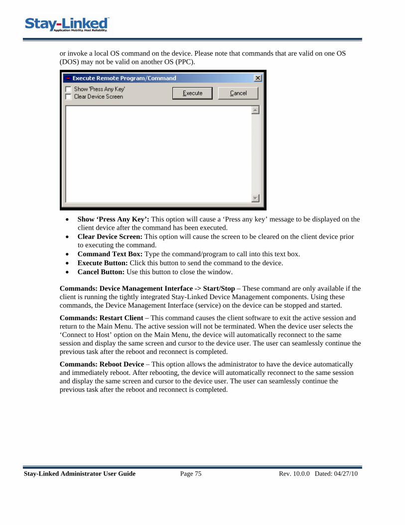
Stay-Linked Administrator User Guide Page 75 Rev. 10.0.0 Dated: 04/27/10
or invoke a local OS command on the device. Please note that commands that are valid on one OS (DOS) may not be valid on another OS (PPC).
• Show ‘Press Any Key’: This option will cause a ‘Press any key’ message to be displayed on the
client device after the command has been executed. • Clear Device Screen: This option will cause the screen to be cleared on the client device prior
to executing the command. • Command Text Box: Type the command/program to call into this text box. • Execute Button: Click this button to send the command to the device. • Cancel Button: Use this button to close the window.
Commands: Device Management Interface -> Start/Stop – These command are only available if the client is running the tightly integrated Stay-Linked Device Management components. Using these commands, the Device Management Interface (service) on the device can be stopped and started.
Commands: Restart Client – This command causes the client software to exit the active session and return to the Main Menu. The active session will not be terminated. When the device user selects the ‘Connect to Host’ option on the Main Menu, the device will automatically reconnect to the same session and display the same screen and cursor to the device user. The user can seamlessly continue the previous task after the reboot and reconnect is completed.
Commands: Reboot Device – This option allows the administrator to have the device automatically and immediately reboot. After rebooting, the device will automatically reconnect to the same session and display the same screen and cursor to the device user. The user can seamlessly continue the previous task after the reboot and reconnect is completed.

Stay-Linked Administrator User Guide Page 76 Rev. 10.0.0 Dated: 04/27/10
3.11.8 Connections Menu – Scanner (ATSM) Select this option to initiate any of the following scanner laser functions on one or more selected devices in the connection list (only applies to devices that support soft-scan laser functions):
• Trigger a Soft Scan • Disable Scanner Laser • Enable Scanner Laser
3.11.9 Connections Menu – Diagnostics (ATSM) Select this option to initiate any of the following diagnostic utilities on one or more selected devices in the connection list:
• Radio Stats • Echo Test
3.11.10 Connections Menu – View (ATSM) View: Radio Config – This option allows the administrator to view the contents of the Radio Configuration file. The Radio Configuration file is named pkt.ini and is stored on the device’s writable media. Some devices do not utilize a pkt.ini file and in this case, you will get a ‘File Not Found’ message when you try to view the file.
View: Network Config – This option allows the administrator to view the contents of the Network Configuration file. The Network Configuration file is named net.cfg and is stored on the device’s writable media. Some devices do not utilize a net.cfg file and in this case, you will get a ‘File Not Found’ message when you try to view the file.
View: Client INI File – This option allows the administrator to view the contents of the Client Configuration file. The Client Configuration file is named staylink.ini and is stored on the device’s writable media.
View: Remote File – This option allows the administrator to view the contents of a specified file on the client device.
• Remote File: Type the file name that you wish to view into this text box. • OK Button: Click this button to send the request to the device. • Cancel Button: Use this button to close the window.
View: Client, Session, Protocol, and IP Traffic Logs – (normally hidden, invoked by Stay-Linked technical support). These options allow the administrator to view the contents of the specified log file from the client device or from the server.

Stay-Linked Administrator User Guide Page 77 Rev. 10.0.0 Dated: 04/27/10
View: Session Screen Dump – This option allows the administrator to view a special ‘Screen Dump’ text file that is generated by the Stay-Linked Server and reflects the current status of the session screen for the selected device. This screen dump file is useful for screen localization efforts, especially for foreign language font glyph support.
View: Device Screen Capture – This option is only available if the client is running the tightly integrated Stay-Linked Device Management components. This option allows the administrator to capture an image of the device screen in the JPEG file format. The screen will be displayed in the application that is currently associated with the JPG file extension.
View: Export Screen Map – This option is only available if the server is licensed for Screen Recognition. This feature will generate a screen map of the current session telnet screen. The screen map is used for Screen Recognition and Screen Reformatting ‘Designer’ feature.
3.11.11 Connections Menu – Monitor Session (ATSM) This feature provides the administrator with the ability to view and monitor the selected device session in a window on the PC. This option behaves as a toggle, turning the monitor feature on and off, depending upon the current monitor state. Devices that are currently being monitored will have a checkmark on the Monitor menu option. When you start the monitor, you will be prompted to confirm and then the monitor window is displayed and the current screen from the device will be shown:
This monitor window will be updated in real time as the device is utilized. You may monitor more than one device at a time, depending upon the available space on your desktop. In order to terminate a monitor session, find the device in the connection list and select the ‘Monitor’ menu option again to toggle this feature off. The monitor window on your PC will close automatically. Or, just click on the [X] in the Monitor Window to close the monitor session.
3.11.12 Connections Menu – Share Session (ATSM) This feature provides the administrator with the ability to collaborate with you who started the selected device session. Sharing requires that a free seat be available on the server. The shared session will be displayed in a window on the PC.:
As the administrator, you are able to type into this window and run the session. The original user will see your changes on the device. If you types on the device, you will see those changes in your share window. You may share more than one device at a time, depending upon the available space on your desktop and available licensed seats installed on the server. In order to exit a shared session, press the ‘Esc’ key and you will be prompted to ‘EXIT SESSION? (Y)es or (N)o’ . Press ‘Y’ to quit the session. The original user will be able to continue.

Stay-Linked Administrator User Guide Page 78 Rev. 10.0.0 Dated: 04/27/10
3.11.13 Connections Menu – Take Control (ATSM) This feature provides the administrator with the ability to take control of the selected device session in a window on the PC and finish the processing that was begun on the device. When you select to Take Control, you will be prompted to confirm and then the session window is displayed and the current screen from the session will be shown:
You can now type and control the session as if you had started the session yourself. The Take Control function is not reversible. Once you take control of a session, the device will not be able to regain control of that session. The device might be able to start a new session. This feature is especially useful to complete sessions after a device has been disabled.
3.11.14 Connections Menu – Transfer Session (ATSM) This feature provides the administrator with the ability to transfer a session from one device to another. This feature is especially useful when a device has become disabled while it was in the middle of an important operation. In this case, the session that was associated with the damaged device can be transferred to an operational device, at which point the important operation can be completed using the target device. When you select this option, you will be presented with a dialog that will ask for the target device to which the session will be transferred. This device must already be connected to the Stay-Linked server:
Enter a valid session ID and, if verified, the session will be transferred to the target device.
3.11.15 Connections Menu – Disconnect Device After a confirmation, this option will send a directive to the device(s) to disconnect from the session and return to the main screen. The session stays alive on the server waiting for the device to reconnect. This option will cause a device that is running in the ‘Always Auto-Connect’ mode to exit back to the main screen.

Stay-Linked Administrator User Guide Page 79 Rev. 10.0.0 Dated: 04/27/10
3.11.16 Connections Menu – Terminate Session After a confirmation, this option will send a directive to the server to immediately terminate the selected device connection(s).
3.11.17 Connections Menu – Launch Athena If the stand-alone Odyssey Athena Device Management software is installed and detected on the device, then this option will be available to launch a Web Browser session and connect to the device management HTTP server that is running on the device. (Requires a special Athena Add-on License).
3.11.18 Connections Menu – Manage Device If the tightly-integrated Stay-Linked Device Management software is installed and detected on the device, then this option will be available to access all of the interactive device management options provided by the Stay-Linked Device Management feature set. Please review the ‘Stay-Linked Device Management User Guide’ for full details of these interactive features.
3.12 Administrator Management This section describes Administrator Management, introduced with Version 9.1.0 of Stay-Linked. This feature enables the management of the User IDs that are used to control access to the Stay-Linked Server using the Stay-Linked Administrator software.
3.12.1 Administrator Management Overview Following are the primary features of Administrator Management:
• A User ID and password is required to access a server. • Each Stay-Linked Server manages its own database of User IDs that have access to that server. • Each User ID describes the in high detail the features of the Administrator that the User ID is
permitted to access on that server. • Each User ID can describe the subsets of devices that are available to be managed on the server. • Each User ID can be restricted to specific PCs allowed to access the server by origination IP
address. • User IDs and Passwords are case-sensitive. • Groups can be defined to describe common sets of permissions available for use in the
Administrator. • User IDs can be assigned to a Group and will inherit the available Administrator permissions
defined for that Group. • Administrator Management Settings control the usage properties of User IDs. • User IDs can become disabled if there are too many unsuccessful attempts to log on. • Passwords for User IDs can be expired at a specified interval, requiring the user to set a new
password the next time they log on. • Attributes can be set to control the creation of passwords.

Stay-Linked Adm
3.12.2 The ‘administrator’ Master User ID Every Stay-Linked Server has an ‘administrator’ User ID defined. This is the master User ID for each server and this User ID has permissions to access all of the features and functions of the Administrator for this server. The default password for the ‘administrator’ User ID is ‘esp’. This password can be changed to control access to this User ID. The ‘administrator’ User ID cannot be deleted.
•
• • •
IMPORTANT: It is recommended that you create at least one additional User ID with ‘Administrator Management’ permissions. This way, if the master ‘administrator’ User ID becomes disabled, or you cannot remember the password, there will be a way to reset the master ‘administrator’ User ID. If, however, the master ‘administrator’ User ID becomes disabled or otherwise cannot be accessed, there isa way to reset it. You will need to create an empty file named ‘resetadmin.xml’ and place that file onto the server in the ‘..\stay-linked\config’ folder. Then, the next time the Stay-Linked Server process is started, the master ’administrator’ User ID will be reset to its default state. The ‘administrator’ User ID will be re-enabled and the password will be reset to ‘esp’. However, a server process restart is required.
inistrator User Guide Page 80 Rev. 10.0.0 Dated: 04/27/10
The Administrator Management functions are divided into three groups of configuration settings: List Users – Display and edit User IDs that are allowed to manage this server. List Groups – Display and edit Groups that predefine groups of permissions for this server. Change Settings – Display and edit settings that control the Administrator Management functions.

Stay-Linked Administrator User Guide Page 81 Rev. 10.0.0 Dated: 04/27/10
3.12.3 List Users When you select ‘List Users’ from the server tree or the Manage menu, a list of User IDs will appear in the main display panel. Each Stay-Linked server will have a default ‘administrator’ User ID, and you can add other User IDs as required.
User ID: This column displays the User IDs that have been defined on this server.
User Type: There are two types of users. There will be only one ‘Administrator’ type user with the User ID of ‘administrator’. All other User IDs that you defined will be of type ‘User’.
Description: This is a free-form description that you can enter to help identify a user.
User Group: This column displays the group that the User ID belongs to. If the User ID does not belong to a group, then this column will display the special value of ‘*NONE’.
User Status: This column displays the status of the current user as either ‘Enabled’, ‘Disabled’ or ‘Expired’.
Expire Date: This column displays the date that the password will expire for the User ID. If the Password Expiration Interval setting is set to zero, then this column will display ‘n/a’.
Clicking the right mouse button in a blank area or on a User ID will cause a small menu to appear with options you can perform.
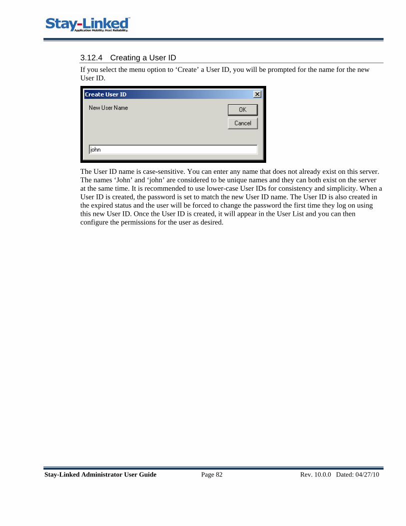
Stay-Linked Administrator User Guide Page 82 Rev. 10.0.0 Dated: 04/27/10
3.12.4 Creating a User ID If you select the menu option to ‘Create’ a User ID, you will be prompted for the name for the new User ID.
The User ID name is case-sensitive. You can enter any name that does not already exist on this server. The names ‘John’ and ‘john’ are considered to be unique names and they can both exist on the server at the same time. It is recommended to use lower-case User IDs for consistency and simplicity. When a User ID is created, the password is set to match the new User ID name. The User ID is also created in the expired status and the user will be forced to change the password the first time they log on using this new User ID. Once the User ID is created, it will appear in the User List and you can then configure the permissions for the user as desired.

Stay-Linked Administrator User Guide Page 83 Rev. 10.0.0 Dated: 04/27/10
3.12.5 Editing a User ID If you double-click on, or select the menu option to ‘Edit’, the selected User ID, you will be presented with this dialog:
From this dialog, you can perform these functions:
• Update the User Description. You can enter a description to help identify the user. • Assign the User ID to an existing Group. If assigned to a Group, the User ID will adopt the
permissions assigned to that Group. You can then override individual permissions for this User ID as desired.
• Change User ID Permissions. The permissions list enumerates the various available Modules and Functions that can be individually controlled by setting these permissions.
• View and change the Allowed Origin IPs. This feature provides the ability to restrict access to this server for a given User ID by the origination IP address of the Administrator PC.
• View and change the Connection Filters. This feature provides control over the connections that this User ID can view and manage in the Administrator Connections List.
• Save Changes. Select the ‘Save Changes’ option from the File menu to save your changes to this User ID.

Stay-Linked
The various elements of this dialog are:
User ID – The User ID that is being edited.
User Status – The current status of this User ID. Enabled – The user ID is active and available to be logged on. Disabled - The User ID is not available to be logged on. A User ID can become disabled by manually changing the status, or if the system is configured to disable the User ID after too many failed logon attempts. Expired – The password for this User ID is expired. The next time a user attempts to log on with this User ID, they will be prompted to change their password. A User ID can be manually expired or the system can be configured to automatically expire the password at a specified interval.
Description – The description for the User ID that is being edited.
User Group – The Group to which this User ID is a member. If the User ID is not a member of a Group, then the value will be *NONE. If the User ID is assigned to a Group, then the User IDs permissions will be adopted from that Group. When you select a Group from the drop-down list, you will be warned that all of the permissions will be changed to match the selected Group permissions.
Expire Date – The date that the User ID will expire and require the user to enter a new password. If this value is displaying ‘n/a’, then this means that the server is configured to never expire User IDs.
Permissions List – This list contains all of the modules and functions that can be controlled using permissions. The list displays these columns:
Module – The module in the Administrator to which the permissions apply. Function – The specific function within the module to which the permission applies. Setting – The configurable setting that controls the effective permission for this module/function. Value – The effective permission for this module/function based upon the selected setting.
If the User ID has any ‘Connection Filters’ defined, then there will be no ‘Connection List’ module functions displayed in this ‘User Information’ permissions list. Instead, you will select the ‘Connection Filters’ option from the ‘View’ menu to access the ‘Connection Filters’ that have been defined for this User ID. When you edit a ‘Connection Filter’, you can configure the permissions that will apply for the ‘Connection List’ module for the Connections to which the user is allowed access according to that Connection Filter.
Administrator User Guide Page 84 Rev. 10.0.0 Dated: 04/27/10
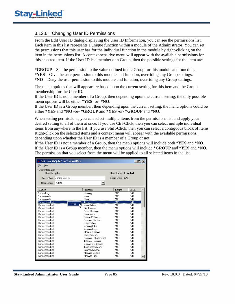
Stay-Linked Administrator User Guide Page 85 Rev. 10.0.0 Dated: 04/27/10
3.12.6 Changing User ID Permissions From the Edit User ID dialog displaying the User ID Information, you can see the permissions list. Each item in this list represents a unique function within a module of the Administrator. You can set the permissions that this user has for the individual function in the module by right-clicking on the item in the permissions list. A context-sensitive menu will appear with the available permissions for this selected item. If the User ID is a member of a Group, then the possible settings for the item are: *GROUP – Set the permission to the value defined in the Group for this module and function. *YES – Give the user permission to this module and function, overriding any Group settings. *NO – Deny the user permission to this module and function, overriding any Group settings.
The menu options that will appear are based upon the current setting for this item and the Group membership for the User ID. If the User ID is not a member of a Group, then depending upon the current setting, the only possible menu options will be either *YES -or- *NO. If the User ID is a Group member, then depending upon the current setting, the menu options could be either *YES and *NO -or- *GROUP and *YES -or- *GROUP and *NO.
When setting permissions, you can select multiple items from the permissions list and apply your desired setting to all of them at once. If you use Ctrl-Click, then you can select multiple individual items from anywhere in the list. If you use Shift-Click, then you can select a contiguous block of items. Right-click on the selected items and a context menu will appear with the available permissions, depending upon whether the User ID is a member of a Group or not. If the User ID is not a member of a Group, then the menu options will include both *YES and *NO. If the User ID is a Group member, then the menu options will include *GROUP and *YES and *NO. The permission that you select from the menu will be applied to all selected items in the list.

Stay-Linked Administrator User Guide Page 86 Rev. 10.0.0 Dated: 04/27/10
3.12.7 View and change the Allowed Origin IPs For each User ID, you can control which Administrator PCs can be used to manage the server. You can specify a list of Allowed Origin IPs for the Administrator PCs that can be used to manage the server and this User ID will only be able to sign on to the server from one of those PCs. If you do not specify one or more Allowed Origin IPs, then the user will not be restricted and can sign on from any Administrator PC.
To view and change the Allowed Origin IPs, select the ‘Allowed Origin IPs’ option from the ‘View’ menu. Clicking the right mouse button in a blank area or on a Origin IP will cause a small menu to appear with options you can perform.
You can Add and Delete Allowed Origin IPs from the list.
Add – Select this menu option to add a new Allowed Origin IP for this User ID. You will be presented with a dialog into which you can type the Allowed Origin IP address:
Delete – Select this menu option to delete the currently selected Allowed Origin IP. You will be prompted to delete the Allowed Origin IP.

Stay-Linked Administrator User Guide Page 87 Rev. 10.0.0 Dated: 04/27/10
3.12.8 View and change the Connection Filters For each User ID, you can control which connections can be viewed and managed from the Administrator Connections list. There are two types of Connection Filters that you can create a to determine which connections will be visible in the Connection List and what management options will be available for those connections.
by Device Group – This connection filter type selects connections based upon the ‘Device Group’ to which the connection belongs.
by IP Range – This connection filter type selects connections based upon the device’s local IP address being contained in the IP range defined for the connection filter.
To view and change the Connection Filters, select the ‘Connection Filters’ option from the ‘View’ menu. Clicking the right mouse button in a blank area or on a Connection Filter will cause a small menu to appear with options you can perform.
Delete – Select this menu option to delete the currently selected Connection Filter. You will be prompted to delete the Connection Filter.
Edit – Select this menu option to edit the currently selected Connection Filter. You will be presented with the Edit dialog where you can change the Filter Type if desired. You can also use this dialog to change permissions for the various connection list functions.

Stay-Linked Administrator User Guide Page 88 Rev. 10.0.0 Dated: 04/27/10
Add – Select this menu option to add a new Connection Filter for this User ID. You will be presented with a dialog into which you can configure the Connection Filter options:
On the Add Connection Filter dialog, you can select your desired Filter Type as either ‘by Device Group’ or ‘by IP Range’. Depending upon your selection, the dialog will change to enable configuration of the Connection Filter for that Filter Type.
by Device Group – This option allows this User ID to access connections based upon the ‘Device Group’ to which the connection belongs. The dialog will provide a ‘Device Group’ drop-down list from which you can select the desired ‘Device Group’ for this connection filter.
by IP Address – This option allows this User ID to access connections based upon the device’s local IP address being contained in the IP range defined for this connection filter. This dialog will provide a ‘Low IP’ and a ‘High IP’ text box where you can enter the desired IP Range for this connection filter.
Changing Permissions – The permissions list will contain all of the possible functions that are available from the Connections List. You can set the permissions that this user has for the individual function by right-clicking on the item in the permissions list. A context-sensitive menu will appear with the available permissions for this selected item. Depending upon the current setting, the only possible menu option will be either *YES -or- *NO.
When setting permissions, you can select multiple items from the permissions list and apply your desired setting to all of them at once. If you use Ctrl-Click, then you can select multiple individual items from anywhere in the list. If you use Shift-Click, then you can select a contiguous block of items. Right-click on the selected items and a context menu will appear with the available permissions, both *YES and *NO. The permission that you select from the menu will be applied to all selected items in the list.
Select the ‘Save Changes’ option from the File menu to save your changes to this User ID.

Stay-Linked Administrator User Guide Page 89 Rev. 10.0.0 Dated: 04/27/10
3.12.9 Deleting a User ID If you select the menu option to ‘Delete’ a User ID, you will be prompted to delete the User ID.
Click ‘Yes’ to delete the User ID from the system.
3.12.10 Enabling and Disabling a User ID Each User ID will be in one of the three valid statuses, either ‘Enabled’, ‘Disabled’ or ‘Expired’. Depending upon the User ID’s current status, the menu will display either a ‘Enable’ option or a ‘Disable’ option.
If you select the ‘Disable’ menu option, then the User ID will be disabled and will not be available for use until you manually ‘enable’ the User ID.
If you select the ‘Enable’ menu option, then the User ID will be enabled and if the User ID was expired, the ‘password last changed’ date will be reset so that the User ID is no longer expired.
3.12.11 Setting a User ID to Expired You can use the ‘Set to Expired’ menu option to force a user to change their password the next time they successfully log on to the server. This is a common option to use after manually changing the password for a User ID. If the User ID has been disabled, then this menu option will not be available.
3.12.12 Changing the Password for a User ID If you select the menu option to ‘Change Password’, you will be prompted for a New Password:
Type in the ‘New Password’ and then retype the password into the ‘Confirm New Password’.
The password that you enter must validate against any password configuration settings that may be in effect on this server, like ‘Minimum Password Length’, ‘Maximum Password Length’ or ‘Require Digits in Password’.

Stay-Linked Administrator User Guide Page 90 Rev. 10.0.0 Dated: 04/27/10
3.12.13 List Groups When you select ‘List Groups’ from the server tree or the Manage menu, a list of Groups will appear in the main display panel. You can create Groups to help you manage pre-defined sets of permissions that can be adopted by selected User IDs.
Clicking the right mouse button in a blank area or on a Group will cause a small menu to appear with options you can perform.
3.12.14 Creating a Group If you select the menu option to ‘Create’ a Group, you will be prompted for the name for the new Group.
The Group name is case-sensitive. You can enter any Group name that does not already exist on this server. The names ‘Warehouse’ and ‘warehouse’ are considered to be unique Group names and they can both exist on the server at the same time. Once the Group is created, it will appear in the Group List and you can then configure the permissions for the Group as desired.

Stay-Linked Administrator User Guide Page 91 Rev. 10.0.0 Dated: 04/27/10
3.12.15 Editing a Group If you double-click on, or select the menu option to ‘Edit’, the selected Group, you will be presented with this dialog:
The Group Permissions List will contain all of the possible module functions that are available to be pre-configured for a Group. You can set the permissions that this Group has for the individual function by right-clicking on the item in the permissions list. A context-sensitive menu will appear with the available permissions for this selected item. Depending upon the current setting, the only possible menu option will be either *YES -or- *NO.
When setting permissions, you can select multiple items from the permissions list and apply your desired setting to all of them at once. If you use Ctrl-Click, then you can select multiple individual items from anywhere in the list. If you use Shift-Click, then you can select a contiguous block of items. Right-click on the selected items and a context menu will appear with the available permissions, both *YES and *NO. The permission that you select from the menu will be applied to all selected items in the list.
Select the ‘Save Changes’ option from the File menu to save your changes to this Group.
3.12.16 Deleting a Group If you select the menu option to ‘Delete’ a Group, you will be prompted to delete the Group.
Click ‘Yes’ to delete the Group from the system.
If the Group is assigned to any User ID, you will not be allowed to delete the Group.

Stay-Linked Administrator User Guide Page 92 Rev. 10.0.0 Dated: 04/27/10
3.12.17 Change Settings When you select ‘Change Settings’ from the server tree or the Manage menu, a list of Settings will appear in the main display panel. The various Settings can be configured to control the options available for Administrator Management features.
You must double-click on one of the settings in the list in order to make changes to that setting.
3.12.18 Maximum Log On Attempts Allowed If you double-click on this option, you can define the maximum Log On attempts allowed before the system will perform the ‘Action to take for Failed Log On’ function.
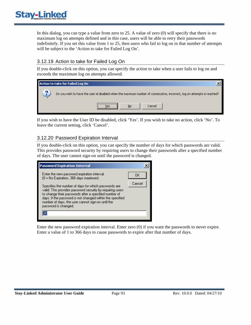
Stay-Linked Administrator User Guide Page 93 Rev. 10.0.0 Dated: 04/27/10
In this dialog, you can type a value from zero to 25. A value of zero (0) will specify that there is no maximum log on attempts defined and in this case, users will be able to retry their passwords indefinitely. If you set this value from 1 to 25, then users who fail to log on in that number of attempts will be subject to the ‘Action to take for Failed Log On’.
3.12.19 Action to take for Failed Log On If you double-click on this option, you can specify the action to take when a user fails to log on and exceeds the maximum log on attempts allowed.
If you wish to have the User ID be disabled, click ‘Yes’. If you wish to take no action, click ‘No’. To leave the current setting, click ‘Cancel’.
3.12.20 Password Expiration Interval If you double-click on this option, you can specify the number of days for which passwords are valid. This provides password security by requiring users to change their passwords after a specified number of days. The user cannot sign-on until the password is changed.
Enter the new password expiration interval. Enter zero (0) if you want the passwords to never expire. Enter a value of 1 to 366 days to cause passwords to expire after that number of days.

Stay-Linked Administrator User Guide Page 94 Rev. 10.0.0 Dated: 04/27/10
3.12.21 Minimum Password Length If you double-click on this option, you can specify the minimum number of characters in a password.
Enter a value between 1 and 50 and then press OK. To leave the current setting. press Cancel.
3.12.22 Maximum Password Length If you double-click on this option, you can specify the maximum number of characters in a password.
Enter a value between 1 and 50 and then press OK. To leave the current setting. press Cancel.
3.12.23 Require Digit in Password If you double-click on this option, you can specify whether one or more numeric digit be included in any new password.
If you wish to require digits in passwords, click ‘Yes’. If not, click ‘No’. To leave the current setting, click ‘Cancel’.

Stay-Linked Administrator User Guide Page 95 Rev. 10.0.0 Dated: 04/27/10

Stay-Linked Administrator User Guide Page 96 Rev. 10.0.0 Dated: 04/27/10
4 Appendix
4.1 Special Scripting Mnemonics Here are some special scripting mnemonics that are available for use:
[devicename] – This script mnemonic is used to substitute the device name into the script.
[deviceip] – This script mnemonic is used to substitute the device IP into the script.
[devicemac] – This script mnemonic is used to substitute the device MAC address into the script.
[hex ######] – This script mnemonic is used to substitute Hexadecimal values into the script.
[uni ####] – This script mnemonic is used to substitute Unicode values into the script.
[var ##] – This script mnemonic is used to substitute ‘User Defined Variables’ into the script.
[delay] – This script mnemonic is used to insert a 1/10 second delay into the startup script.
[long_delay] – This script mnemonic is used to insert a 1 second delay into the startup script.
[userid] – This script mnemonic is used to insert ‘device identifier’ value into the startup script.
[deviceid] – This script mnemonic is used to insert the PPC/CE.Net Device Name into the script. For all Version 9.1 clients, you can specify a ‘Device ID’ value in the Stay-Linked Client’s configuration dialog. Or, you can use ‘Client Settings’ to assign a ‘Device ID’ value to individual devices. For older PPC/CE clients, you can specify the ‘Device ID’ in the operating system configuration. For CE.Net devices, this value is configured at the ‘Start – Settings - Control Panel - System - Device Name Tab – Device Name’ dialog. For PPC devices, this value is configured at the ‘Start – Settings – System Tab – About – Device ID Tab – Device Name’ dialog. For DOS devices, this value is managed using the Device Settings file (STAYLINK.INI) and the ‘device_id’ setting.
[devicetype] – This script mnemonic is used to insert the Stay-Linked Client Device Type value into the script.
Examples:
• The mnemonic [hex 0D] will insert an ASCII CR (Carriage Return) into the script. • If you need to include any square brackets in your script, you should include two of them. • The mnemonic [hex 1B5B5B32347E] is the equivalent of ‘ESC[24~’ or the VT F12 key. • This script ‘[hex 1B][[24~’ is also the equivalent of ‘ESC[24~’ or the VT F12 key.
These special scripting mnemonics are available for the following Stay-Linked Features:
• VT Telnet Host Property – ANSWER BACK MESSAGE [devicename], [deviceip], [devicemac], [hex ##], [uni ####], [userid], [deviceid], [devicetype]
• Telnet Host and Device Group Startup Scripts [devicename], [deviceip], [devicemac], [hex ##], [uni ####], [var ##], [delay], [long_delay], [userid] , [deviceid] , [devicetype]
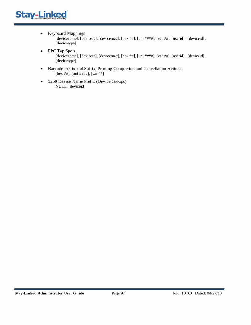
Stay-Linked Administrator User Guide Page 97 Rev. 10.0.0 Dated: 04/27/10
• Keyboard Mappings [devicename], [deviceip], [devicemac], [hex ##], [uni ####], [var ##], [userid] , [deviceid] , [devicetype]
• PPC Tap Spots [devicename], [deviceip], [devicemac], [hex ##], [uni ####], [var ##], [userid] , [deviceid] , [devicetype]
• Barcode Prefix and Suffix, Printing Completion and Cancellation Actions [hex ##], [uni ####], [var ##]
• 5250 Device Name Prefix (Device Groups) NULL, [deviceid]

Stay-Linked Administrator User Guide Page 98 Rev. 10.0.0 Dated: 04/27/10
4.2 Troubleshooting The following possible errors messages may appear on the device screen after establishing a connection to the Stay-Linked server. Most of these errors refer to configuration issues and are simple to resolve.
eSP Error ID: Error Message Text Possible Causes and Solutions
eSP0001 No Hosts Defined No Host defined in the Stay-Linked Administrator. Use the Stay-Linked Administrator to define Telnet hosts.
eSP0002 Host Not Responding Bad Host address or port. Confirm the Host address and Telnet port information in the Telnet Host configuration.
Host might be unreachable on the network. Confirm that the Telnet Host is currently available on the network.
eSP0003 No Keymap Found The Device Type is not cross referenced to a keyboard map for this Host Emulation.
Use the Stay-Linked Administrator to add a keyboard map for this Device Type and Host Emulation combination.
Possible unknown Device Type.
eSP0004 Bad License Key Authentication Error Admin. Config. Error No TE Seats Available No Dual Seats Remain
Use the Stay-Linked Administrator to review the license information.
Does the key refer to the correct Server Serial Number? For iSeries Platforms, the STAYLINKED user profile might be disabled or have no password.
Review the STAYLINKED user profile.
eSP0005 WSID Not Available The 5250 session is unable to allocate the specific device description. The device description on the AS/400 does not exist or is not varied on. Or, the device description has no interactive subsystem in which to run.
eSP0006 Device Not Allowed The device is assigned to a device group that is set to not allow connections.
See ‘Manage Device Groups’.
eSP0007 Client Not Compatible The old eSP-Link Client installed on the device is not compatible with the new Stay-Linked Server.
Please upgrade the Client software on the device to the latest Stay-Linked build, which is available on the http://www.stay-linked.com web site.
eSP0008 Could not get device config.
The server was unable to communicate with the device to retrieve the device configuration.
Probable network traffic problems. Simply re-attempt the connection.
eSP0009 2 Sessions Disallowed The device is a member of a Device Group that does not allow dual sessions.
Review the device group settings for this device.

Stay-Linked Administrator User Guide Page 99 Rev. 10.0.0 Dated: 04/27/10
eSP0010 Unable to connect to Shared Session.
The server was unable to connect to the shared session. Simply re-attempt the connection.
eSP0011 Various SSH Errors Bad SSH User/Password SSH Password Expired Unsupported Authentication SSH Disconnected
eSP0012 SSH Not Supported SSH Support for Stay-Linked requires at least Java JRE 1.4.2-06 and the latest Stay-Linked Support JAR files.
eSP0013 SSH Logon Cancelled The user cancelled the SSH logon prompt screens.
eSP0014 Various SSL Errors Server Cert. Not Trusted Client Cert. Not Provided Client Cert. Not Found Client Cert. Bad Password
eSP0015 Device Not DM Capable The device is not capable of running a DM Only session. You must install the Stay-Linked Device Management Components onto the device to make it capable.

Stay-Linked Administrator User Guide Page 100 Rev. 10.0.0 Dated: 04/27/10
For further information or technical assistance, please contact your Stay-Linked Certified Partner or you may contact us directly…
15991 Red Hill Avenue
Suite 210 Tustin, CA 92780
714.918.7700 ( main line ) 714.918-7817 ( tech support )
http://www.stay-linked.com/mailto:[email protected]
This product includes software developed by the Apache Software Foundation (http://www.apache.org/).