Status of the Prototype HyspIRI Thermal Infrared Radiometer (PHyTIR… · ·...
35
National Aeronautics and Space Administration Status of the Prototype HyspIRI Thermal Infrared Radiometer (PHyTIR) for the HyspIRI TIR Instrument Concept Presented at: 2012 HyspIRI Workshop Washington, DC USA. Simon Hook & The HyspIRI/HyTES/PHyTIR Team(s) Organization: NASA/Jet Propulsion Laboratory © 2012 California Institute of Technology. Jet Propulsion Laboratory, California Institute of Technology. Government sponsorship acknowledged. 10/18/2012
Transcript of Status of the Prototype HyspIRI Thermal Infrared Radiometer (PHyTIR… · ·...

National Aeronautics and Space Administration
Status of the Prototype HyspIRI Thermal Infrared Radiometer (PHyTIR) for the HyspIRI
TIR Instrument Concept
Presented at:
2012 HyspIRI Workshop
Washington, DC USA.
Simon Hook & The HyspIRI/HyTES/PHyTIR Team(s)
Organization: NASA/Jet Propulsion Laboratory
© 2012 California Institute of Technology. Jet Propulsion Laboratory, California Institute
of Technology. Government sponsorship acknowledged.
10/18/2012
National Aeronautics and Space Administration
• Introduction
• Goals and Objectives
• Design Approach
• Summary and Next Steps
Outline
10/18/2012

National Aeronautics and Space Administration
Science Questions: TQ1. Volcanoes/Earthquakes – How can we help predict and mitigate earthquake and volcanic hazards
through detection of transient thermal phenomena? • TQ2. Wildfires – What is the impact of global biomass burning on the terrestrial biosphere
and atmosphere, and how is this impact changing over time? • TQ3. Water Use and Availability – How is consumptive use of global freshwater supplies responding to changes
in climate and demand, and what are the implications for sustainable management of water resources?
• TQ4. Urbanization/Human – How does urbanization affect the local, regional and global environment?
Can we characterize this effect to help mitigate its impact on human health and welfare?
• TQ5. Earth surface composition and change – What is the composition and temperature of the exposed surface of the
Earth? How do these factors change over time and affect land use and habitability?
Measurement:
• 7 bands between 7.5-12 µm and 1 band at 4 µm
• 60 m resolution, 5 days revisit
• Global land and shallow water
Volcanoes
Urbanization
Water Use and Availability
Surface
Temperature Evapotranspiration
Andean volcano heats up
0
0.1
0.2
0.3
0.4
0.5
0.6
0.7
0.8
0.9
1
3.00 4.00 5.00 6.00 7.00 8.00 9.00 10.00 11.00 12.00 13.00
Wavelength (um)
Rela
tive S
pectr
al R
esp
on
se
H1 (m21)
H2 (m28)
H3 (a10)
H4 (a11)
H5 (a12)
H6
H7
H8 (m32)
HyspIRI-TIR Quad Chart
Multispectral Scanner
Schedule: 4 year phase A-D,
3 years operations
High Heritage
10/18/2012

National Aeronautics and Space Administration
HyspIRI, HyTES and PHyTIR
Prototype HyspIRI
Thermal Infrared
Radiometer
(PHyTIR)
Hyperspectral Infrared
Imager (HyspIRI)
Hyperspectral
Thermal Emission
Spectrometer
(HyTES)
Science Risk Reduction Engineering Risk Reduction
VSWIR
TIR
10/18/2012

National Aeronautics and Space Administration
HyspIRI, HyTES and PHyTIR
Airborne Name TIMS MASTER QWEST HyTES
First Year of Operation 1980 1998 2008 2012
Number of TIR Bands 6 10 56 256
Spaceborne Name ASTER Landsat 8 (LDCM) PHyTIR HyspIRI-TIR
First Year of Operation 1999 2013 2014 2020
Number of TIR Bands 5 2 8 8
Swath Width 60 km 185 km 600 km 600 km
Pixel Size 90m 100 m 60 m 60 m
Airborne
Instruments
Spaceborne
Instruments
(incl. lab
prototypes)
10/18/2012

National Aeronautics and Space Administration HyspIRI-TIR Science Measurement Requirements
PARAMETER BASELINE SCIENCE REQUIREMENT
Ground Resolution (m) 60 <100
Revisit (days) 5 <6
Noise equivalent delta temperature (K) 0.2 <0.3
Absolute accuracy (K) 0.5 <1
Saturation – low temperature bands (K) 500 >400
Saturation – high temperature band (K) 1200 >1100
Overpass time (hh:mm) 10:30am 10-3pm
Nighttime imaging Yes Required
Number of Bands (spectral range: 3 – 12 µm)
8 >=8
Coverage Land and coastal regions
Land and coastal regions
Data latency 2 days < 1 week
10/18/2012

National Aeronautics and Space Administration
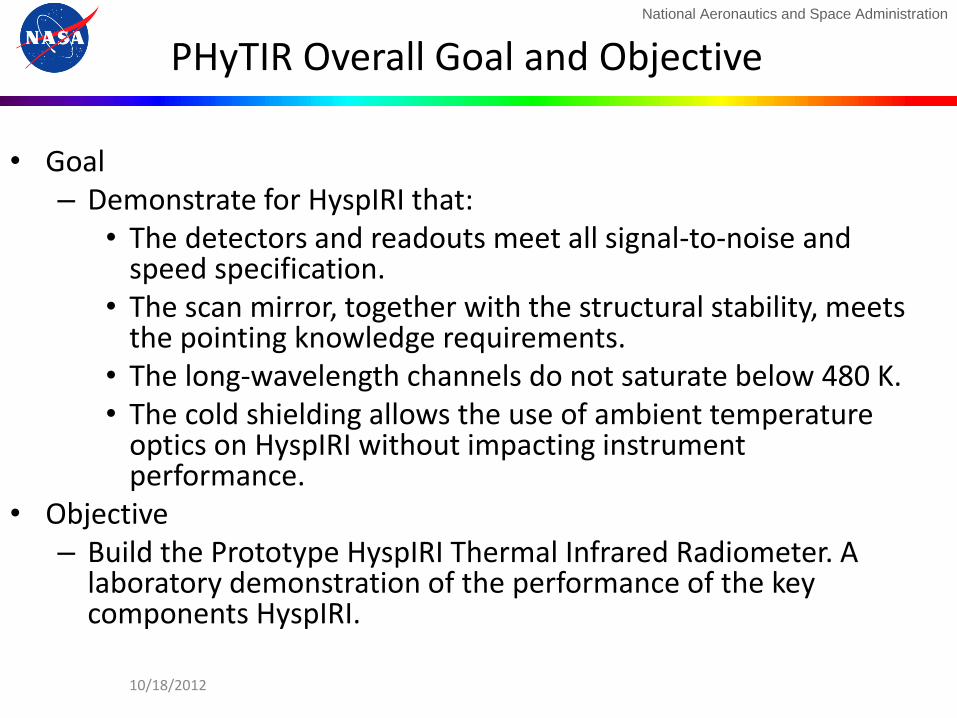
PHyTIR Overall Goal and Objective
• Goal – Demonstrate for HyspIRI that:
• The detectors and readouts meet all signal-to-noise and speed specification.
• The scan mirror, together with the structural stability, meets the pointing knowledge requirements.
• The long-wavelength channels do not saturate below 480 K. • The cold shielding allows the use of ambient temperature
optics on HyspIRI without impacting instrument performance.
• Objective – Build the Prototype HyspIRI Thermal Infrared Radiometer. A
laboratory demonstration of the performance of the key components HyspIRI.
10/18/2012
National Aeronautics and Space Administration
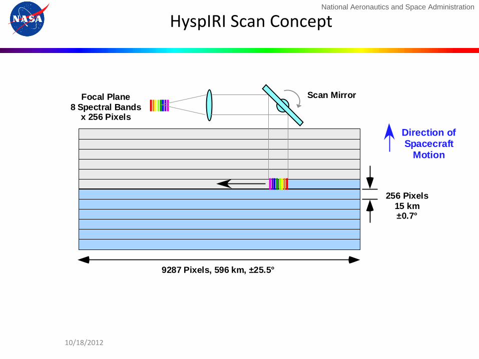
Direction ofSpacecraft
Motion
256 Pixels15 km±0.7°
9287 Pixels, 596 km, ±25.5°
Scan MirrorFocal Plane8 Spectral Bands
x 256 Pixels
HyspIRI Scan Concept
10/18/2012
National Aeronautics and Space Administration
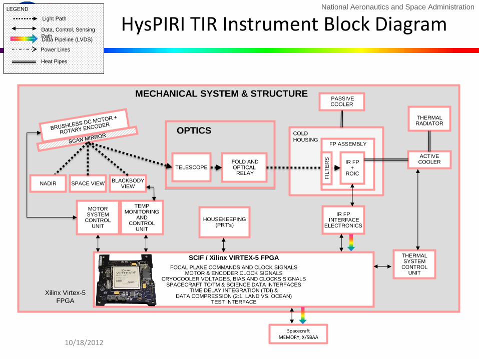
HysPIRI TIR Instrument Block Diagram
THERMAL RADIATOR
SCIF / Xilinx VIRTEX-5 FPGA
FOCAL PLANE COMMANDS AND CLOCK SIGNALS MOTOR & ENCODER CLOCK SIGNALS
CRYOCOOLER VOLTAGES, BIAS AND CLOCKS SIGNALS SPACECRAFT TC/TM & SCIENCE DATA INTERFACES
TIME DELAY INTEGRATION (TDI) & DATA COMPRESSION (2:1, LAND VS. OCEAN)
TEST INTERFACE
FP ASSEMBLY
THERMAL SYSTEM
CONTROL UNIT
TELESCOPE
FOLD AND OPTICAL RELAY
IR FP +
ROIC
IR FP INTERFACE
ELECTRONICS
MOTOR SYSTEM
CONTROL UNIT
BLACKBODY VIEW
TEMP MONITORING
AND CONTROL
UNIT
OPTICS
MECHANICAL SYSTEM & STRUCTURE PASSIVE COOLER
HOUSEKEEPING (PRT’s)
SPACE VIEW NADIR
FIL
TE
RS
COLD
HOUSING
Spacecraft MEMORY, X/SBAA
LEGEND
Data Pipeline (LVDS)
Data, Control, Sensing
Path
Light Path
Power Lines
Heat Pipes
Xilinx Virtex-5
FPGA
ACTIVE COOLER
10/18/2012
National Aeronautics and Space Administration
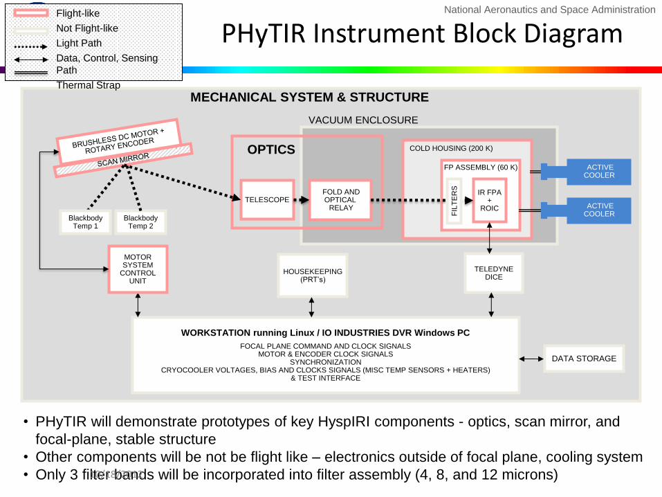
PHyTIR Instrument Block Diagram
WORKSTATION running Linux / IO INDUSTRIES DVR Windows PC
FOCAL PLANE COMMAND AND CLOCK SIGNALS MOTOR & ENCODER CLOCK SIGNALS
SYNCHRONIZATION CRYOCOOLER VOLTAGES, BIAS AND CLOCKS SIGNALS (MISC TEMP SENSORS + HEATERS)
& TEST INTERFACE
FP ASSEMBLY (60 K)
TELESCOPE
FOLD AND OPTICAL RELAY
IR FPA +
ROIC
MOTOR SYSTEM
CONTROL UNIT
OPTICS
MECHANICAL SYSTEM & STRUCTURE
HOUSEKEEPING (PRT’s)
Blackbody Temp 2
Blackbody Temp 1
FIL
TE
RS
COLD HOUSING (200 K)
DATA STORAGE
Flight-like
Not Flight-like
Light Path
Data, Control, Sensing
Path
Thermal Strap
VACUUM ENCLOSURE
TELEDYNE DICE
ACTIVE COOLER
ACTIVE COOLER
• PHyTIR will demonstrate prototypes of key HyspIRI components - optics, scan mirror, and
focal-plane, stable structure
• Other components will be not be flight like – electronics outside of focal plane, cooling system
• Only 3 filter bands will be incorporated into filter assembly (4, 8, and 12 microns) 10/18/2012
National Aeronautics and Space Administration
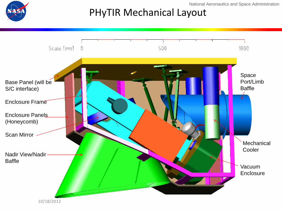
PHyTIR Mechanical Layout
Base Panel (will be
S/C interface)
Enclosure Frame
Enclosure Panels
(Honeycomb)
Scan Mirror
Nadir View/Nadir
Baffle
Space
Port/Limb
Baffle
Vacuum
Enclosure
Mechanical
Cooler
10/18/2012
National Aeronautics and Space Administration
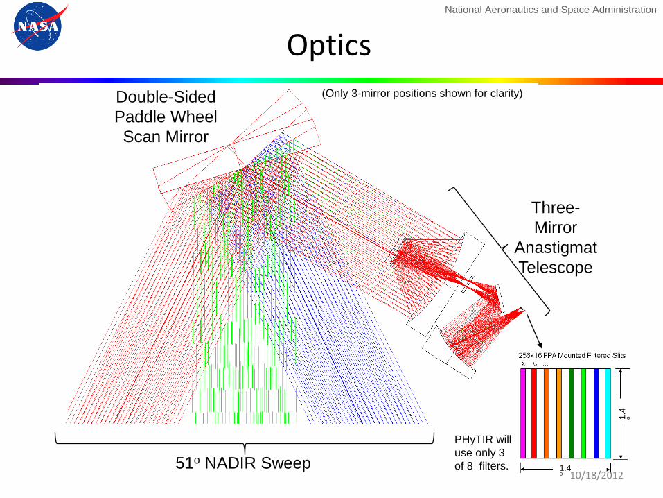
51o NADIR Sweep
Double-Sided
Paddle Wheel
Scan Mirror
Three-
Mirror
Anastigmat
Telescope
Optics
PHyTIR will
use only 3
of 8 filters.
(Only 3-mirror positions shown for clarity)
1.4
o
1.4o 10/18/2012
National Aeronautics and Space Administration
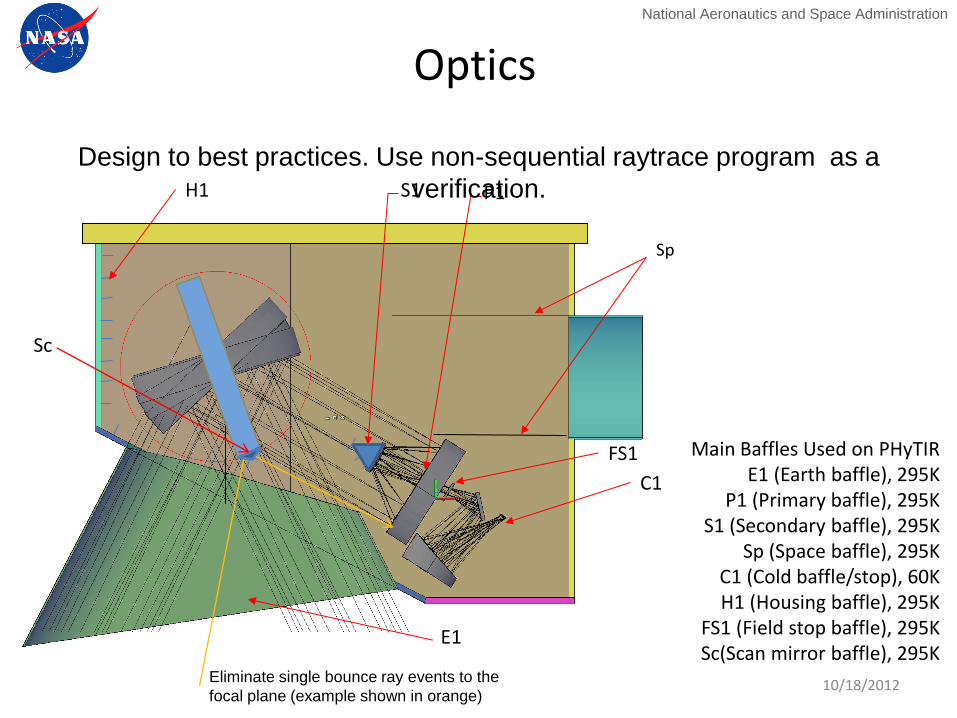
Sp
P1
C1
Main Baffles Used on PHyTIR E1 (Earth baffle), 295K
P1 (Primary baffle), 295K S1 (Secondary baffle), 295K
Sp (Space baffle), 295K C1 (Cold baffle/stop), 60K H1 (Housing baffle), 295K
FS1 (Field stop baffle), 295K Sc(Scan mirror baffle), 295K
S1
E1
H1
FS1
Optics
Design to best practices. Use non-sequential raytrace program as a
verification.
Eliminate single bounce ray events to the
focal plane (example shown in orange)
Sc
10/18/2012
National Aeronautics and Space Administration
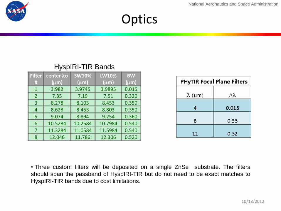
• Three custom filters will be deposited on a single ZnSe substrate. The filters
should span the passband of HyspIRI-TIR but do not need to be exact matches to
HyspIRI-TIR bands due to cost limitations.
Filter #
center lo (mm)
SW10% (mm)
LW10% (mm)
BW (mm)
1 3.982 3.9745 3.9895 0.015 2 7.35 7.19 7.51 0.320
3 8.278 8.103 8.453 0.350 4 8.628 8.453 8.803 0.350
5 9.074 8.894 9.254 0.360
6 10.5284 10.2584 10.7984 0.540 7 11.3284 11.0584 11.5984 0.540
8 12.046 11.786 12.306 0.520
HyspIRI-TIR Bands
Optics
10/18/2012
National Aeronautics and Space Administration
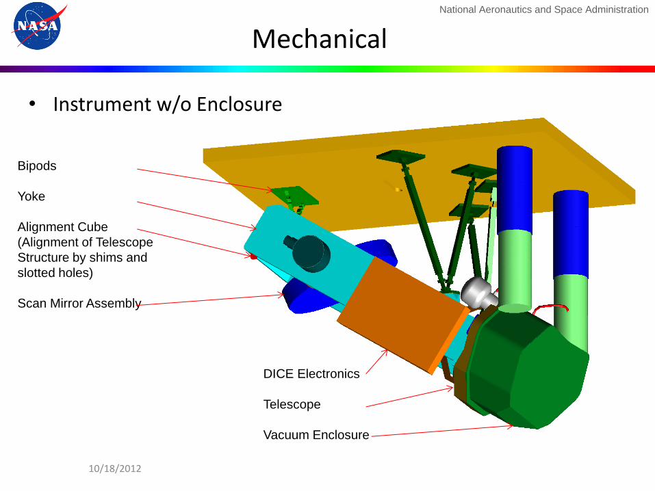
Mechanical
Bipods
Yoke
Alignment Cube
(Alignment of Telescope
Structure by shims and
slotted holes)
Scan Mirror Assembly
DICE Electronics
Telescope
Vacuum Enclosure
• Instrument w/o Enclosure
10/18/2012

National Aeronautics and Space Administration
Mechanical
M2
M1
Housekeeping
connector
Vacuum feed
through
Bulkhead
Vacuum side of
telescope
FP electr. connector
10/18/2012
Scan Mirror
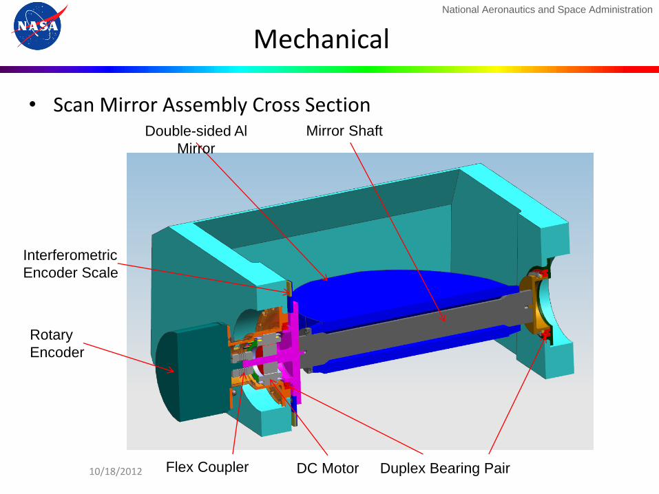
National Aeronautics and Space Administration
Mirror Shaft Double-sided Al
Mirror
Rotary
Encoder
Flex Coupler DC Motor Duplex Bearing Pair
• Scan Mirror Assembly Cross Section
Mechanical
Interferometric
Encoder Scale
10/18/2012
National Aeronautics and Space Administration
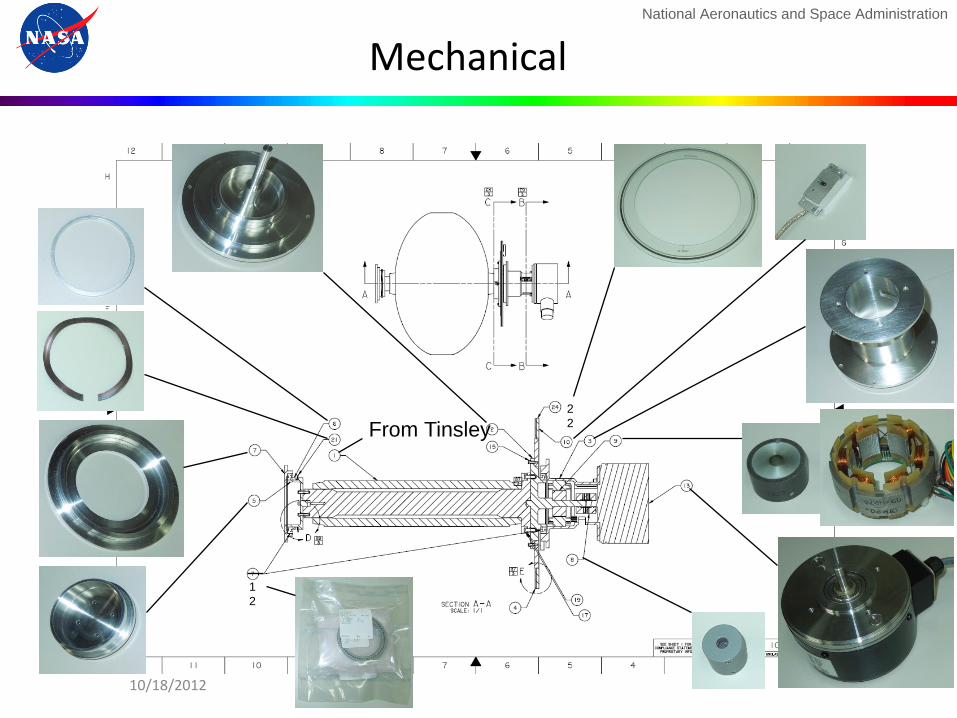
Mechanical
1
2
2
2 From Tinsley
10/18/2012

National Aeronautics and Space Administration
Mechanical
• The Cryocoolers
Cryocooler (for 200degK)
Cryocooler (for 60degK)
Cold Housing
(top removed to show inside)
Vacuum Housing
(top removed to show inside)
Bulkhead
Model: Thales Cooler LPT9310
10/18/2012
National Aeronautics and Space Administration
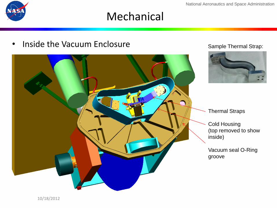
Mechanical
• Inside the Vacuum Enclosure
Thermal Straps
Cold Housing
(top removed to show
inside)
Vacuum seal O-Ring
groove
Sample Thermal Strap:
10/18/2012

National Aeronautics and Space Administration
Mechanical
• The FP Assembly
FP Electr. Board
FP Mounting Structure
FP Frame
Focal Plane & Filter
6 dof FP Mount
(Moore Mount)
Mounting Flexures
(Th. isolators)
FP Front Side (FP Baffle not shown) FP Backside (FP Baffle on
Backside)
21 10/18/2012
National Aeronautics and Space Administration
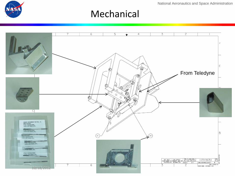
Mechanical
From Teledyne
10/18/2012

National Aeronautics and Space Administration
Cooling
Wall (left) and top (right) of
200 K baffle in place.
Vacuum cover (not shown)
encloses cold stage and
mirrors.
Lower stage of 200 K baffle supports FPA
structure, intercepts conducted loads
Baffle is cooled by RH cold tip
FPA is cooled by LH cold tip via strap
Bulkhead with cryocooler cold tips:
FPA stage shown for orientation
10/18/2012
National Aeronautics and Space Administration
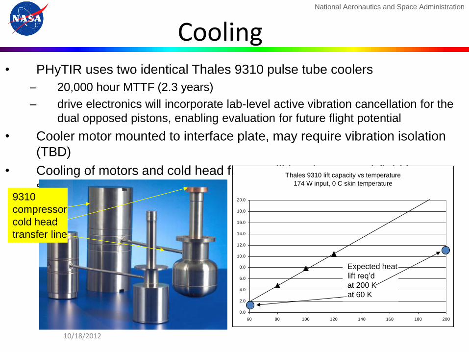
Cooling • PHyTIR uses two identical Thales 9310 pulse tube coolers
– 20,000 hour MTTF (2.3 years)
– drive electronics will incorporate lab-level active vibration cancellation for the
dual opposed pistons, enabling evaluation for future flight potential
• Cooler motor mounted to interface plate, may require vibration isolation
(TBD)
• Cooling of motors and cold head flange will be via pumped-fluid loop,
simulating heat pipes for HyspIRI 9310
compressor
cold head
transfer line
Thales 9310 lift capacity vs temperature
174 W input, 0 C skin temperature
0.0
2.0
4.0
6.0
8.0
10.0
12.0
14.0
16.0
18.0
20.0
60 80 100 120 140 160 180 200
Expected heat
lift req’d
at 200 K
at 60 K
10/18/2012

National Aeronautics and Space Administration
Focal Plane Concept
• MCT Detector Array – 256 elements cross-sweep
• 1 Bandgap to Cover Full Spectral Range
• ≥ 4 Detector Columns per Spectral Channel to Allow
Time Delay and Integration (TDI)
• CMOS Read-Out
Integrated Circuit (ROIC)
• 32 Analog Output Lines to
Enable Necessary Pixel
Read Rate
• Butcher-Block Filter Assembly
• Baffles to Prevent Crosstalk Between
Spectral Channels
• HyspIRI will have 8 filters, PhyTIR
demonstration will have 3 filters
• 60 K Cold Tip of Cryocooler
• Teledyne under contract to provide focal planes. Contract for external readout
electronics in place.
• Digitization in off-chip ADCs
• TDI performed after digitization
10/18/2012
National Aeronautics and Space Administration
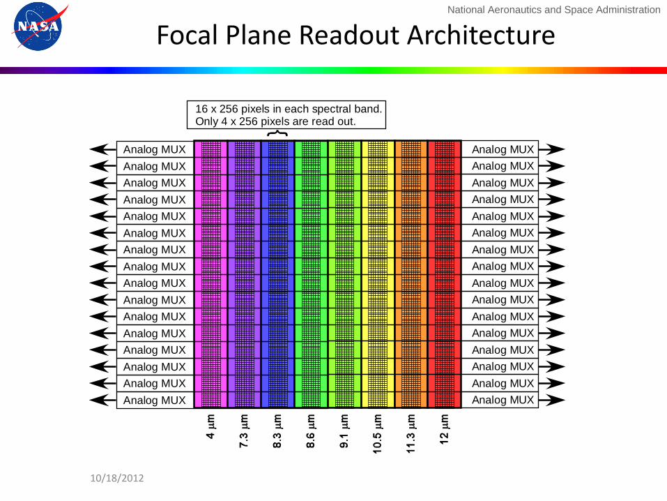
Focal Plane Readout Architecture
Analog MUX
Analog MUX
Analog MUX
Analog MUX
Analog MUX
Analog MUX
Analog MUX
Analog MUX
Analog MUX
Analog MUX
Analog MUX
Analog MUX
Analog MUX
Analog MUX
Analog MUX
Analog MUX
Analog MUX
Analog MUX
Analog MUX
Analog MUX
Analog MUX
Analog MUX
Analog MUX
Analog MUX
Analog MUX
Analog MUX
Analog MUX
Analog MUX
Analog MUX
Analog MUX
Analog MUX
Analog MUX
16 x 256 pixels in each spectral band.Only 4 x 256 pixels are read out.
10/18/2012
National Aeronautics and Space Administration
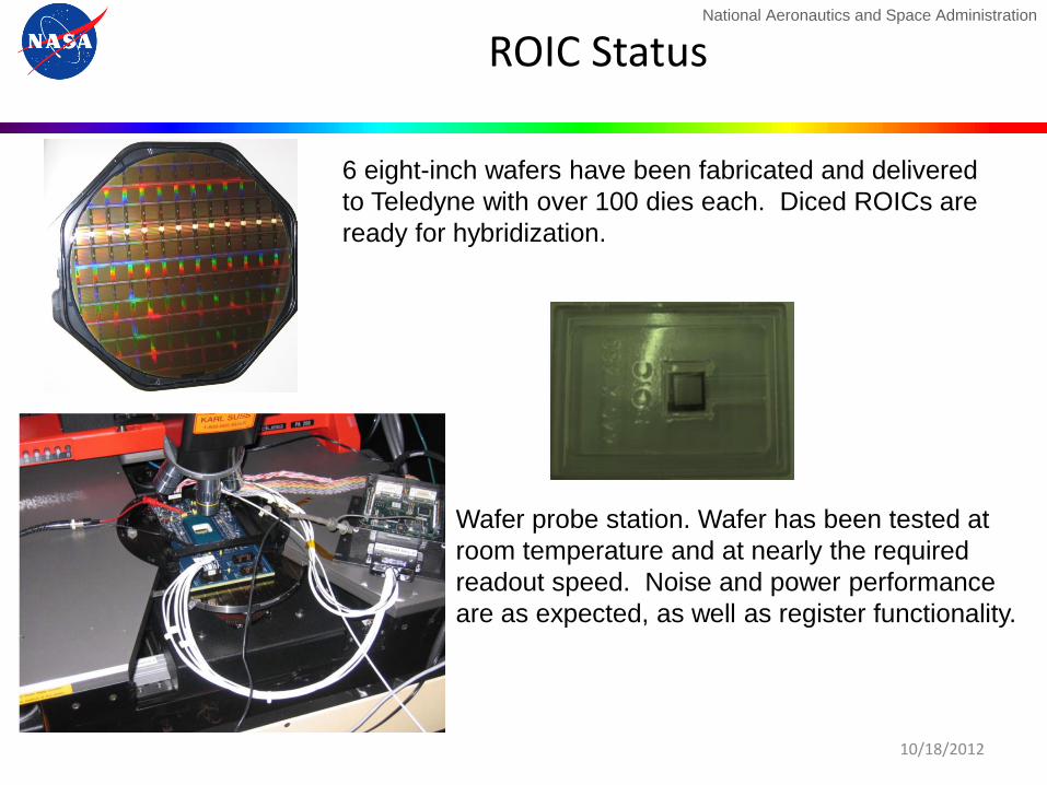
ROIC Status
Wafer probe station. Wafer has been tested at
room temperature and at nearly the required
readout speed. Noise and power performance
are as expected, as well as register functionality.
6 eight-inch wafers have been fabricated and delivered
to Teledyne with over 100 dies each. Diced ROICs are
ready for hybridization.
10/18/2012
National Aeronautics and Space Administration
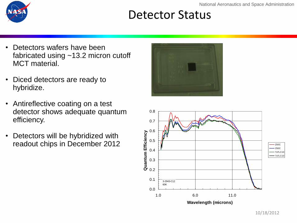
Detector Status
• Detectors wafers have been fabricated using ~13.2 micron cutoff MCT material.
• Diced detectors are ready to
hybridize. • Antireflective coating on a test
detector shows adequate quantum efficiency.
• Detectors will be hybridized with readout chips in December 2012
10/18/2012
0.0
0.1
0.2
0.3
0.4
0.5
0.6
0.7
0.8
1.0 6.0 11.0
Wavelength (microns)
Qu
an
tum
Eff
icie
nc
y250C
250C
7x7LC10
7x7LC10
3-2943-C12
60K
National Aeronautics and Space Administration
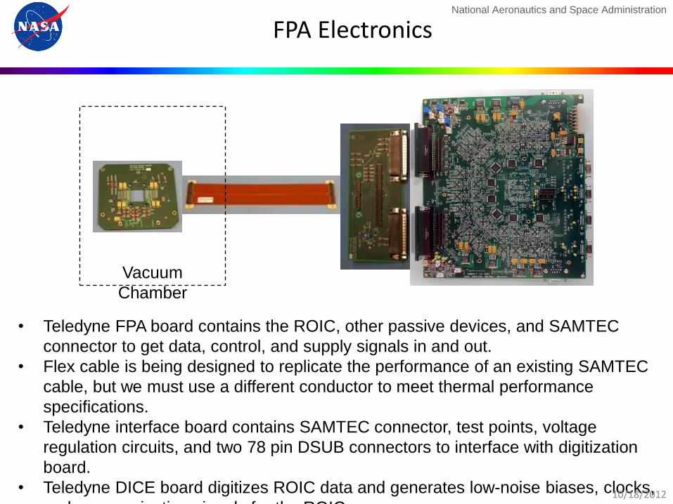
FPA Electronics
• Teledyne FPA board contains the ROIC, other passive devices, and SAMTEC
connector to get data, control, and supply signals in and out.
• Flex cable is being designed to replicate the performance of an existing SAMTEC
cable, but we must use a different conductor to meet thermal performance
specifications.
• Teledyne interface board contains SAMTEC connector, test points, voltage
regulation circuits, and two 78 pin DSUB connectors to interface with digitization
board.
• Teledyne DICE board digitizes ROIC data and generates low-noise biases, clocks,
and communication signals for the ROIC.
Vacuum
Chamber
10/18/2012

National Aeronautics and Space Administration
Performance
10/18/2012
0.0
0.1
0.2
0.3
0.4
0.5
0.6
0.7
0.8
0.9
1.0
200 300 400 500
NE
TD
(K
)
Scene Temperature (K)
Noise-Equivalent Temperature Difference with TDI
4 microns
8 microns
12 microns
National Aeronautics and Space Administration
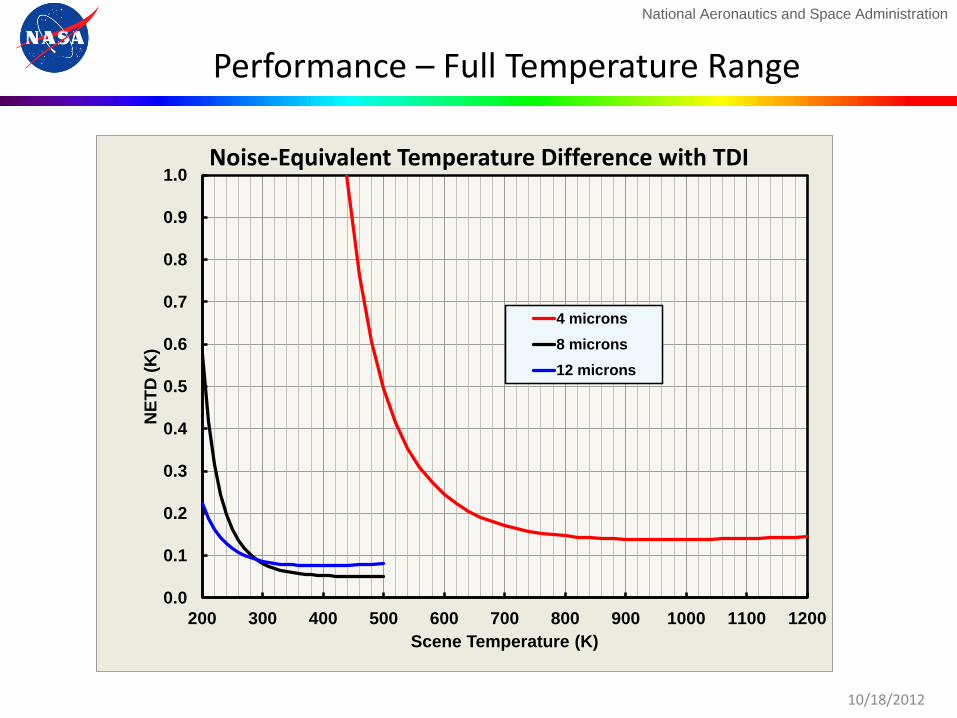
Performance – Full Temperature Range
10/18/2012
0.0
0.1
0.2
0.3
0.4
0.5
0.6
0.7
0.8
0.9
1.0
200 300 400 500 600 700 800 900 1000 1100 1200
NE
TD
(K
)
Scene Temperature (K)
Noise-Equivalent Temperature Difference with TDI
4 microns
8 microns
12 microns
National Aeronautics and Space Administration
PHyTIR Overall Goal and Objective
• Goal – Demonstrate for HyspIRI that:
• The detectors and readouts meet all signal-to-noise and speed specification.
• The scan mirror, together with the structural stability, meets the pointing knowledge requirements.
• The long-wavelength channels do not saturate below 480 K. • The cold shielding allows the use of ambient temperature
optics on HyspIRI without impacting instrument performance.
• Objective – Build the Prototype HyspIRI Thermal Infrared Radiometer. A
laboratory demonstration of the performance of the key components HyspIRI.
10/18/2012
National Aeronautics and Space Administration
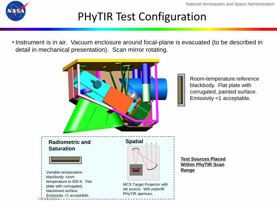
PHyTIR Test Configuration
Room-temperature reference
blackbody. Flat plate with
corrugated, painted surface.
Emissivity <1 acceptable.
• Instrument is in air. Vacuum enclosure around focal-plane is evacuated (to be described in
detail in mechanical presentation). Scan mirror rotating.
Variable-temperature
blackbody: room
temperature to 500 K. Flat
plate with corrugated,
blackened surface.
Emissivity <1 acceptable.
MCS Target Projector with
slit source. Will underfill
PHyTIR aperture.
Test Sources Placed
Within PhyTIR Scan
Range
Radiometric and
Saturation
Spatial
10/18/2012
National Aeronautics and Space Administration
Summary and Next Steps
• PHyTIR will reduce the risk associated with key aspects of the HyspIRI-TIR performance (signal to noise, pointing, saturation, shielding
• PHyTIR is on track with all the large procurements in place and delivery of the first detectors expected in December. Key components are already being assembled e.g. scan mirror.
• Next steps will be to assemble the instrument and start testing in mid 2012
10/18/2012

National Aeronautics and Space Administration
Backup
10/18/2012