Stationary rail lubrication systems for tram and metro ...
12
Stationary rail lubrication systems for tram and metro rail infrastructure Systems for the supply of greases and friction modifiers to rail
Transcript of Stationary rail lubrication systems for tram and metro ...

Stationary rail lubrication systems for tram and metro rail infrastructureSystems for the supply of greases and friction modifiers to rail
Why rail lubrication?
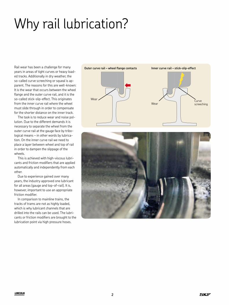
Rail wear has been a challenge for many years in areas of tight curves or heavy load-ed tracks. Additionally in dry weather, the so-called curve screeching or squeal is ap-parent. The reasons for this are well-known: It is the wear that occurs between the wheel flange and the outer curve rail, and it is the so-called stick-slip-effect. This originates from the inner curve rail where the wheel must slide through in order to compensate for the shorter distance on the inner track.
The task is to reduce wear and noise pol-lution. Due to the different demands it is necessary to separate the wheel from the outer curve rail at the gauge face by tribo-logical means – in other words by lubrica-tion. On the inner curve rail we need to place a layer between wheel and top of rail in order to dampen the slippage of the wheels.
This is achieved with high-viscous lubri-cants and friction modifiers that are applied automatically and independently from each other.
Due to experience gained over many years, the industry approved one lubricant for all areas (gauge and top-of-rail). It is, however, important to use an appropriate friction modifier.
In comparison to mainline trains, the tracks of trams are not as highly loaded, which is why lubricant channels that are drilled into the rails can be used. The lubri-cants or friction modifiers are brought to the lubrication point via high pressure hoses.
Outer curve rail – wheel flange contacts Inner curve rail – stick-slip-effect
WearCurve screeching
Wear
2

Differentiation overview
Other systemsLincoln systems with SSV divider block
Lincoln Competitor
Manufacturer of centralized, automatic lubrication systems and their main components (pumps, metering devices, applicators) for over 100 years.
Often manufacturers of rail lubrication systems consisting of purchased components
Belongs to the worldwide operating SKF Group with partners, subsidiaries and service locations on all continents in over 130 countries.
Often only small, regionally operating companies that were founded by railway and rail construction companies.
Products and systems can handle and manage reliable and long-term fluids with solid particles, as well as high-viscous lubricants. Components have been developed and optimized for this.
Cannot handle “true” friction modifiers and usually have to buy standard off-the-shelf components.
In-house production of high pressure pumps – up to 350 bar – provide flexibility in the layout of multi-track systems, and provide reassurance in ambient conditions.
Use pressure bottles and pumps up to 250 bar – often only 100 bar (gear pumps).
Prevention of uncontrolled lubricant delivry due to the progressive divider technology.
Different pipe lengths and outlet channels might result in over or under lubrication.
3
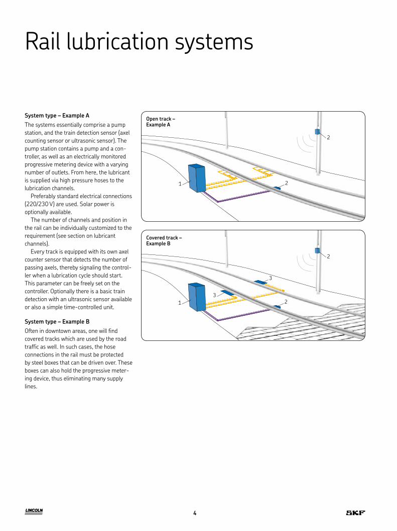
System type – Example AThe systems essentially comprise a pump station, and the train detection sensor (axel counting sensor or ultrasonic sensor). The pump station contains a pump and a con-troller, as well as an electrically monitored progressive metering device with a varying number of outlets. From here, the lubricant is supplied via high pressure hoses to the lubrication channels.
Preferably standard electrical connections (220/230 V) are used. Solar power is optionally available.
The number of channels and position in the rail can be individually customized to the requirement (see section on lubricant channels).
Every track is equipped with its own axel counter sensor that detects the number of passing axels, thereby signaling the control-ler when a lubrication cycle should start. This parameter can be freely set on the controller. Optionally there is a basic train detection with an ultrasonic sensor available or also a simple time-controlled unit.
System type – Example BOften in downtown areas, one will find covered tracks which are used by the road traffic as well. In such cases, the hose connections in the rail must be protected by steel boxes that can be driven over. These boxes can also hold the progressive meter-ing device, thus eliminating many supply lines.
Rail lubrication systems
Open track –Example A
1 2
2
Covered track –Example B
13
2
2
3
4
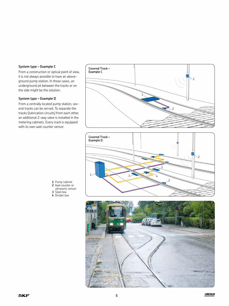
System type – Example CFrom a construction or optical point of view, it is not always possible to have an above-ground pump station. In those cases, an underground pit between the tracks or on the side might be the solution.
System type – Example DFrom a centrally located pump station, sev-eral tracks can be served. To separate the tracks (lubrication circuits) from each other, an additional 2-way valve is installed in the metering cabinets. Every track is equipped with its own axel counter sensor.
1 Pump cabinet2 Axel counter or
ultrasonic sensor3 Steel box4 Divider box
Covered Track –Example C
1
2
2
Covered Track –Example D
1
2
2
3 4
3
5
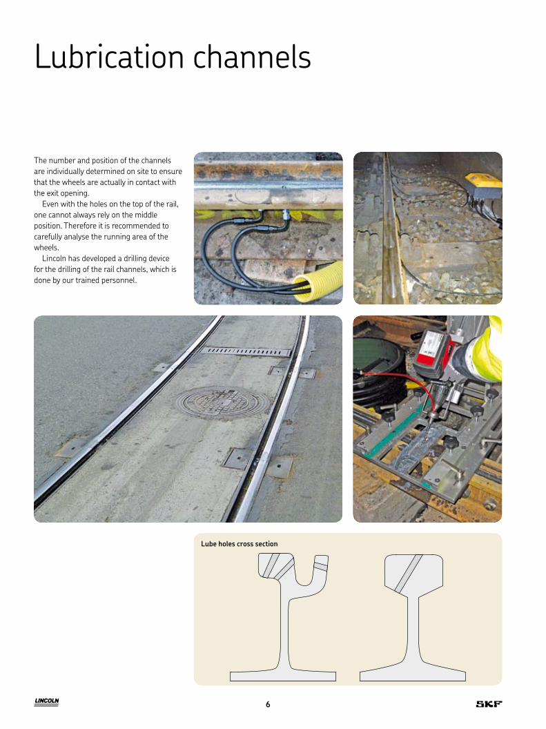
The number and position of the channels are individually determined on site to ensure that the wheels are actually in contact with the exit opening.
Even with the holes on the top of the rail, one cannot always rely on the middle position. Therefore it is recommended to carefully analyse the running area of the wheels.
Lincoln has developed a drilling device for the drilling of the rail channels, which is done by our trained personnel.
Lubrication channels
Lube holes cross section
6
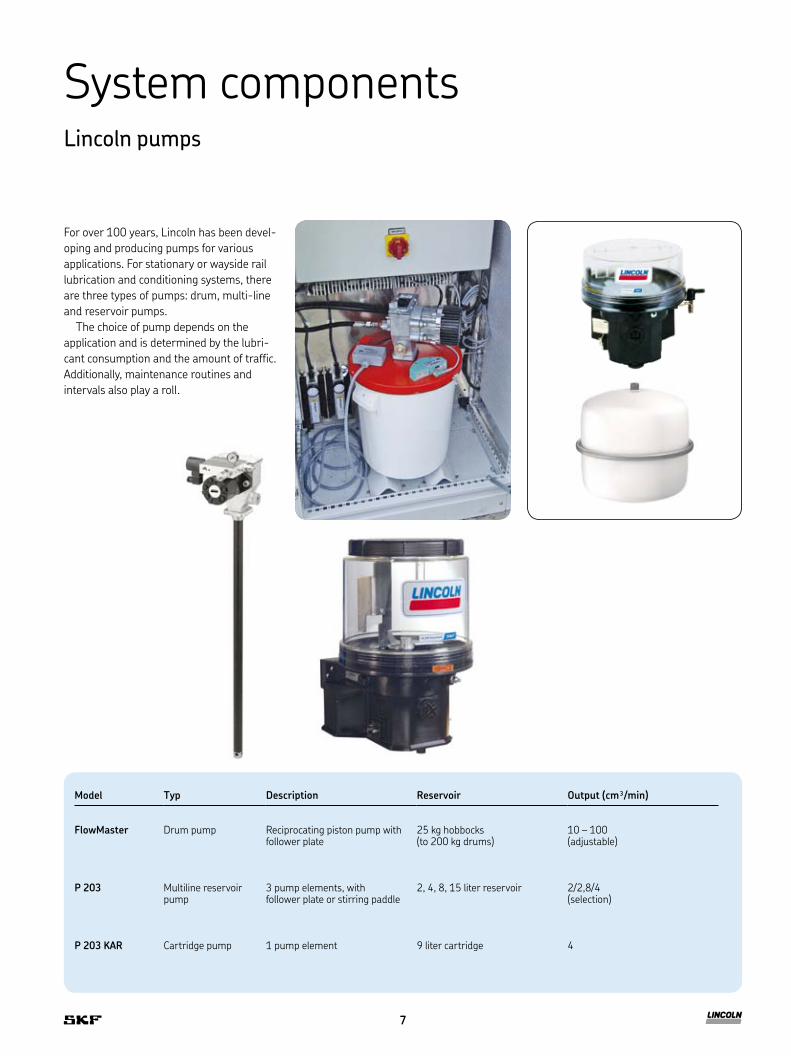
System componentsLincoln pumps
For over 100 years, Lincoln has been devel-oping and producing pumps for various applications. For stationary or wayside rail lubrication and conditioning systems, there are three types of pumps: drum, multi-line and reservoir pumps.
The choice of pump depends on the application and is determined by the lubri-cant consumption and the amount of traffic. Additionally, maintenance routines and intervals also play a roll.
Model Typ Description Reservoir Output (cm³/min)
FlowMaster Drum pump Reciprocating piston pump with follower plate
25 kg hobbocks (to 200 kg drums)
10 – 100 (adjustable)
P 203 Multiline reservoir pump
3 pump elements, with follower plate or stirring paddle
2, 4, 8, 15 liter reservoir 2/2,8/4 (selection)
P 203 KAR Cartridge pump 1 pump element 9 liter cartridge 4
7

Metering devices
SSV progressive metering devices are piston metering devices that progressively divide the supplied lubricant to the connected lube points. In doing so, 0,2 cm³ of lubricant is delivered per outlet and piston stroke.
Outlets can be combined to a single outlet in order to increase the lubricant amount.
In the event of a blockage in a lubrication circuit, the electrical monitoring (piston
detector) will detect the failure and send a signal to the controller.
For applications with true friction modi-fiers (metal pastes), Lincoln developed the SSV-T that, when compared to standard metering devices, can better handle the abrasive effect of the medium.
Piston detector
8
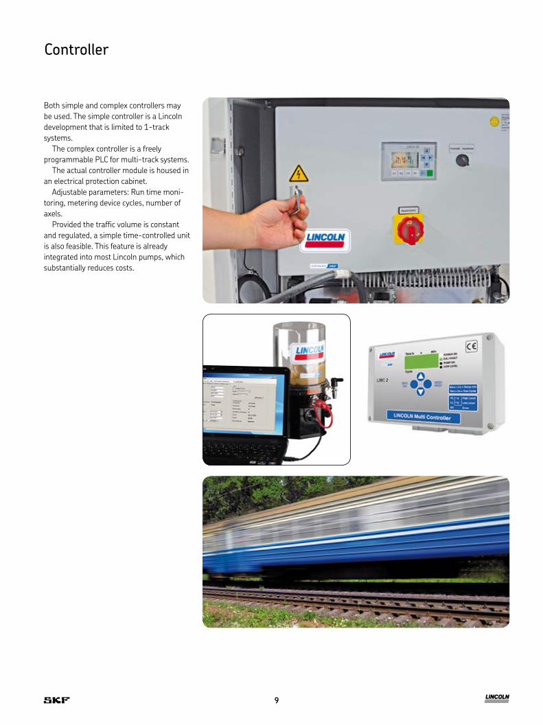
Both simple and complex controllers may be used. The simple controller is a Lincoln development that is limited to 1-track systems.
The complex controller is a freely programmable PLC for multi-track systems.
The actual controller module is housed in an electrical protection cabinet.
Adjustable parameters: Run time moni-toring, metering device cycles, number of axels.
Provided the traffic volume is constant and regulated, a simple time-controlled unit is also feasible. This feature is already integrated into most Lincoln pumps, which substantially reduces costs.
Controller
9

Accessories and optional equipment• Cabinet heater• Rain sensor• Pump station door sensor• External signal lamp for displaying
failures• Solar unit with battery storage• Remote monitoring
– Fault and low-level by SMS text messaging
– Status monitoring by WEB systems
10

Metering device cabinet
Axel counter sensor
Axel counter sensor
Outdoor pump cabinet 800 x 500 x 1200 mm with suitable concrete slab
11
Bearings and unitsSeals Lubrication
systems
Mechatronics Services
The Power of Knowledge Engineering
Drawing on five areas of competence and application-specific expertise amassed over more than 100 years, SKF brings innovative solutions to OEMs and production facilities in every major industry world-wide. These five competence areas include bearings and units, seals, lubrication systems, mechatronics (combining mechanics and electronics into intelligent systems), and a wide range of services, from 3-D computer modelling to advanced condition monitoring and reliability and asset management systems. A global presence provides SKF customers uniform quality standards and worldwide product availability.
! Important information on product usageAll products from SKF may be used only for their intended purpose as described in this
brochure and in any instructions. If operating instructions are supplied with the products, they must be read and followed.
Not all lubricants are suitable for use in centralized lubrication systems. SKF does offer an inspection service to test customer supplied lubricant to determine if it can be used in a central-ized system. SKF lubrication systems or their components are not approved for use with gases, liquefied gases, pressurized gases in solution and fluids with a vapor pressure exceeding normal atmospheric pressure (1 013 mbar) by more than 0,5 bar at their maximum permissible temperature.
Hazardous materials of any kind, especially the materials classified as hazardous by European Community Directive EC 67/548/EEC, Article 2, Par. 2, may only be used to fill SKF centralized lubrication systems and components and delivered and/or distributed with the same after consulting with and receiving written approval from SKF.
PUB LS/P2 13205 EN · September 2012 · FORM W-203-EN-0912
® SKF is a registered trademark of the SKF Group.
® Lincoln and FlowMaster are registered trademarks of Lincoln Industrial Corp.
© SKF Group 2012 The contents of this publication are the copyright of the publisher and may not be reproduced (even extracts) unless prior written per- mission is granted. Every care has been taken to ensure the accuracy of the information contained in this publication but no liability can be accepted for any loss or damage whether direct, indirect or consequential arising out of the use of the information contained herein.
Certain image(s) used under license from Shutterstock.com
lincolnindustrial.de skf.com/lubrication
Lincoln GmbH Heinrich-Hertz-Str. 2–8 69190 Walldorf Germany
Tel. +49 (0)6227 33-0 Fax +49 (0)6227 33-259
This brochure was presented to you by: