Clyde Gateway - Rutherglen Station Access and Environment Study

A documentation paper issued by: Siemens AG. ©Siemens AG 2015. All rights reserved.
Configuration and operation manual
Document version: 1.44 (19.08.2015)
Station Gateway

A documentation paper issued by: Siemens AG. ©Siemens AG 2012-2014. All rights reserved.
Documentation | Station Gateway 2
Document History
Version Description of Rev. Date Prepared
1.23 Adapted documentation to StationGateway
29.11.2012 P.Hensel
1.24 Minor changes 30.11.2012 P.Hensel
1.25 Minor changes 06.12.2012 P.Hensel
1.26 Minor changes 13.12.2012 C. Elsner
1.27 Added Command Configuration inPCS7 blocks
09.01.2013 P. Hensel
1.28 Added time settings 16.04.2013 P. Hensel
1.32 Added SNTP routing 09.12.2013 V. Sharipov
1.33 Added TrgOp 04.03.2014 D. Khaev
1.39 Time Settings Proposal changed 25.03.2014 P. Hensel
1.44 StatCon Configuration Tool 25.03.2015 P. Hensel

A documentation paper issued by: Siemens AG. ©Siemens AG 2012-2014. All rights reserved.
Documentation | Station Gateway 3
Table of Contents
1 OVERVIEW 6
1.1 Configuration 7
1.2 Redundancy 7
1.3 Environment in PCS7 8
2 HARDWARE 9
2.1 Interfaces and fitting dimensions 9
2.2 General Technical Data 12
2.3 Power supply 12
2.4 Interruption of the power supply 12
2.5 LED Assignment 13
3 NETWORKLAYOUT 14
3.1 Redundancy Configuration with module EM-PC (recommended) 163.1.1 Shell commands (if StatCon is not used) 17
3.2 Redundancy Configuration without module EM-PC 193.2.1 Shell commands (if StatCon is not used) 20
4 CONFIGURATION 22
4.1 Communication settings 224.1.1 Configuration via StatCon Tool(recommended) 224.1.2 Configuration via linux shell 234.1.3 Default IP addresses 244.1.4 Trigger options 244.1.5 Second S7 Ethernet interface 26
4.2 Configuration of S7-Connections 284.2.1 Settings in NetPro 284.2.2 Redundancy 31
4.3 Time settings 32
4.4 SNTP Routing 33
A documentation paper issued by: Siemens AG. ©Siemens AG 2012-2014. All rights reserved.
Documentation | Station Gateway 4
4.5 IP forwarding 35
4.6 PCS7 Engineering 374.6.1 Engineering of the function block I61_LINK 37
5 PCS7DEVICEDRIVERBLOCKS 41
5.1 IP and IED_NAME 42
5.2 Configuring IEC Addresses 425.2.1 Exchange of the character $ in CFC with the character § 42
5.3 IEC 61850 Reporting 43
5.4 MSG_EVID_XX, Alarming Concept 44
5.5 EXT_SYSTEM_ACTIVE, Forwarding of alarms 47
5.6 Cyclic Data 485.6.1 SCAN_SEC 48
5.7 Loading the object parameters (addresses) into the Station Gateway 48
5.8 Structured In- and Outputs 49
5.9 Display of cyclic transferred data in outputs 49
5.10 Quality indication of transferred process data 49
5.11 Commands 505.11.1 Select before operate 505.11.2 Command configuration 51
5.12 ° Outputs for the indication of errors 525.12.1 ERR, ERR_DEV, ERR_CONN 525.12.2 HEALTH_CM1/2 525.12.3 DIAG_CM1/2 525.12.4 ERR_RED, ERR_REDC, ERR_REDD and ERR_REDS 525.12.5 STAT_CM1 and STAT_CM2 53
5.13 IO-Overview of I61_GEN 55
6 APPENDIX 60
6.1 Connecting a Remote Terminal 60
6.2 Reading the software version in the Station Gateway 60

A documentation paper issued by: Siemens AG. ©Siemens AG 2012-2014. All rights reserved.
Documentation | Station Gateway 5
6.3 General console commands 61
6.4 Firmware Update 62
6.5 How to get logs and config files via ftp 62
6.6 Troubleshooting 63
6.7 Error Codes of Function Block Outputs DIAG_CM1/2 64

A documentation paper issued by: Siemens AG. ©Siemens AG 2012-2014. All rights reserved.
Documentation | Station Gateway 6
1 Overview
The Station Gateway connects IEC 61850 devices from different vendors to the PCS7 system.
There are two basic interfaces: The IEC 61850 interface is connected to the Ethernet networkwith the protection relays using the protocol IEC 61850. The S7-Interface is connected to thePCS7 Controllers via the PCS7 plant bus Industrial Ethernet. On both Ethernet networks the IPprotocol is used with fixed IP addresses for the communication partners.
Note: For IEC 61850 communication, MMS telegrams based on TCP/IP stack are used. TheStation Gateway does not support IEC 61850 GOOSE or Sampled Values. So there are nospecial Ethernet switches required for the communication of the Gateway.
Image 1: Overview Station Gateway
The following transfer procedures are supported:
- Messages/Alarms with timestamp via IEC61850 reportingThe Station Gateway buffers messages with timestamp from the protection relays andtransfers them via a PCS7 Controller to the alarm system of the PCS 7 Operator Station.This is done by the SFB ALARM_8P.
- Cyclic DataDifferent types of data are transferred cyclically from the protection relays to outputs ofspecial function blocks in a PCS7 automation station. The data types in PCS7 are:BOOL, REAL, INT, DINT(or bit string with 32 bits). The scan time is one second orgreater.

A documentation paper issued by: Siemens AG. ©Siemens AG 2012-2014. All rights reserved.
Documentation | Station Gateway 7
- CommandsBinary commands are transferred from inputs of special function blocks in a PCS7automation station to the designated protection relays.
1.1 ProductMLFBs
This document applies to the following products:
Product description MLFB
Station Gateway (single device) 9AE4100-1EC00
Station Gateway (redundant pair) 9AE4100-1EC10
1.2 Configuration
The configuration for the Station Gateway contains only the local IP addresses of the StationGateway itself in the connected networks and some IEC specific settings.
These communication settings of the Station Gateway can be configured either via the StatConconfiguration tool or via linux command shell.
After the IP configuration which requires a restart, the Station Gateway can operate online,while new connections between protection relays and PCS7 are added and established. Allspecific parameters for the communication between the protection relays and PCS7 are locatedin the PCS7 automation system. They are configured and saved in the PCS7 engineeringsystem and can be changed there easily.
1.3 Redundancy
In redundant mode, the gateways are working as two IEC 61850 clients with separateconnections. The function block for a protection relay in the PCS7 station automaticallycoordinates the redundant Station Gateways. To setup a redundancy connection, each StationGateway needs to know its partners IP address. If a redundant Station Gateway pair is ordered,the Extension Module EM-PC (2x) is included in the package.
A separate network connection via the EM-PC is recommended for redundancy.
A documentation paper issued by: Siemens AG. ©Siemens AG 2012-2014. All rights reserved.
Documentation | Station Gateway 8
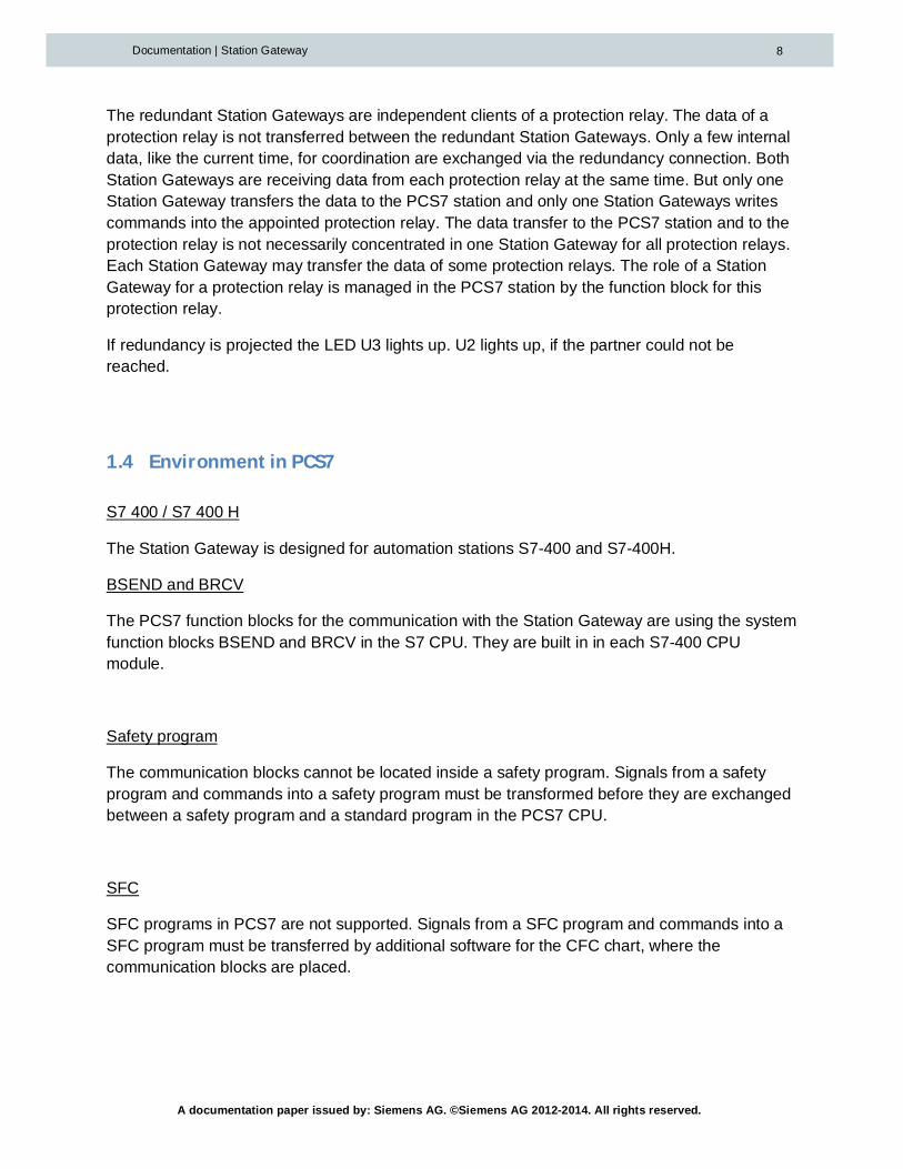
The redundant Station Gateways are independent clients of a protection relay. The data of aprotection relay is not transferred between the redundant Station Gateways. Only a few internaldata, like the current time, for coordination are exchanged via the redundancy connection. BothStation Gateways are receiving data from each protection relay at the same time. But only oneStation Gateway transfers the data to the PCS7 station and only one Station Gateways writescommands into the appointed protection relay. The data transfer to the PCS7 station and to theprotection relay is not necessarily concentrated in one Station Gateway for all protection relays.Each Station Gateway may transfer the data of some protection relays. The role of a StationGateway for a protection relay is managed in the PCS7 station by the function block for thisprotection relay.
If redundancy is projected the LED U3 lights up. U2 lights up, if the partner could not bereached.
1.4 EnvironmentinPCS7
S7 400 / S7 400 H
The Station Gateway is designed for automation stations S7-400 and S7-400H.
BSEND and BRCV
The PCS7 function blocks for the communication with the Station Gateway are using the systemfunction blocks BSEND and BRCV in the S7 CPU. They are built in in each S7-400 CPUmodule.
Safety program
The communication blocks cannot be located inside a safety program. Signals from a safetyprogram and commands into a safety program must be transformed before they are exchangedbetween a safety program and a standard program in the PCS7 CPU.
SFC
SFC programs in PCS7 are not supported. Signals from a SFC program and commands into aSFC program must be transferred by additional software for the CFC chart, where thecommunication blocks are placed.

A documentation paper issued by: Siemens AG. ©Siemens AG 2012-2014. All rights reserved.
Documentation | Station Gateway 9
2 Hardware
2.1 Interfacesandfittingdimensions
Image 2: Front view of main module
Dimensions
Width: 160mm
Height: 125mm
Depth 115mm

A documentation paper issued by: Siemens AG. ©Siemens AG 2012-2014. All rights reserved.
Documentation | Station Gateway 10
Interfaces
No Element
1 LED display
2 Slot fort the Multi Media Card, including the ejector (not used)
3 Mode selector switch (not used)
4 MAC address of the standard Ethernet controller (X2 IEC Interface)
5 USB 2.0 ports
6 Power supply connection
7 Product variant identification (N/A)
8 Ethernet Connection 1 (lower port not in use, upper port used for connection to S7network)
9 Ethernet Connection 2 (used for IEC-Connections)

A documentation paper issued by: Siemens AG. ©Siemens AG 2012-2014. All rights reserved.
Documentation | Station Gateway 11
The redundant Station Gateway pair comes with EM-PC Extension modules, which have to beplugged in on the left side of the EC31.
Dimensions:
Width: 80mm
Height: 125mm
Depth 115mm

A documentation paper issued by: Siemens AG. ©Siemens AG 2012-2014. All rights reserved.
Documentation | Station Gateway 12
Interfaces:
No Element
1 COM Port (not in use)
2 Slot for SD card (not in use)
3 Slot for CF card (not in use)
4 USB 2.0 ports
5 Gigabit LAN port (used for redundancy)
6 DVI-port (can be used for local console)
2.2 GeneralTechnicalData
The general technical data of the base hardware EC31 are also valid for the Station Gateway.
Please refer to the corresponding information provided in the equipment manual for the EC 31devices.
In deviation to S7-300 the Station gateway can only operate from 0-50°C and only in horizontalmounting position.
For additional information refer to the S7-mEC operation manual.
2.3 Powersupply
A power supply from 20,4V to 28,8V is possible, 24V are recommended. Power losses shorterthan 5ms can be sustained.
2.4 Interruptionofthepowersupply
The flash memory is write-protected during normal operation. The write-protection is onlytemporarily disabled while the configuration. The write protection ensures that after switching offthe power supply, the Station Gateway will properly restart again with untouched system data.

A documentation paper issued by: Siemens AG. ©Siemens AG 2012-2014. All rights reserved.
Documentation | Station Gateway 13
2.5 LEDAssignment
LED Action Description
RUN green continuous lighting Gateway up and running
RUN green flashing Command flash viaSTEP7 (N/A)
STOP green flashing Command flash viaSTEP7 (N/A)
DC5V Not used
SF red continuous lighting Critical Configuration error
BF1 red continuous lighting No S7 Connections active
BF2 red continuous lighting One or more IEDs couldnot be reached
BF2 Red flashing One or more IEDs areinitiated
U1 Not used
U2 red continuous lighting No connection toredundancy partner
U3 Yellow continuous lighting Redundancy configured
U3 Dark No Redundancy projected
U4 Green flashing Gateway is booting
Note: The LEDs do not change while the Gateway is shutting down!
A documentation paper issued by: Siemens AG. ©Siemens AG 2012-2014. All rights reserved.
Documentation | Station Gateway 14
3 NetworkLayout
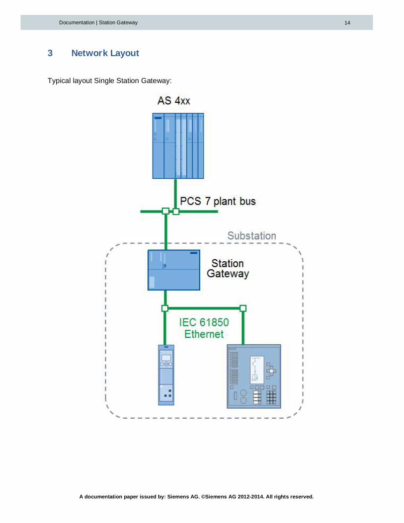
Typical layout Single Station Gateway:

A documentation paper issued by: Siemens AG. ©Siemens AG 2012-2014. All rights reserved.
Documentation | Station Gateway 15
Typical layout redundant Station Gateway pair:
Note: Station Gateway works properly only with setting Auto Negotiation on the switch or othernetwork communication device.

A documentation paper issued by: Siemens AG. ©Siemens AG 2012-2014. All rights reserved.
Documentation | Station Gateway 16
3.1 RedundancyConfigurationwithmoduleEM-PC(recommended)

A documentation paper issued by: Siemens AG. ©Siemens AG 2012-2014. All rights reserved.
Documentation | Station Gateway 17
3.1.1 Shellcommands(ifStatConisnotused)
Station Gateway 1
login as: [email protected]'s password: configLinux debianmec 2.6.32-5-686 #1 SMP Sun Sep 23 09:49:36 UTC 2012 i686
The programs included with the Debian GNU/Linux system are free software;the exact distribution terms for each program are described in theindividual files in /usr/share/doc/*/copyright.
Debian GNU/Linux comes with ABSOLUTELY NO WARRANTY, to the extentpermitted by applicable law.config@debianmec:~$ sudo config.shPlease enter new ip for IEC-port!140.80.159.47Please enter subnet mask for IEC-port!255.255.0.0Please enter gateway for IEC-Port! (press enter for none)
Please enter new IP for S7-port!192.168.50.3Please enter subnet mask for S7-port!255.255.255.0Please enter gateway for S7-Port! (press enter for none)
Set trigger options? (Say no if you don't know what is it) y/NNIs redundancy needed? y/NyPlease enter new IP for redundancy Port!10.10.12.1Please enter Redundancy-IP for partner Gateway!10.10.12.2#############################################################################Station Gateway is rebooted! Press Ctrl+C to break the reboot or ENTER toreboot...#############################################################################

A documentation paper issued by: Siemens AG. ©Siemens AG 2012-2014. All rights reserved.
Documentation | Station Gateway 18
Station Gateway 2
login as: [email protected]'s password: configLinux debianmec 2.6.32-5-686 #1 SMP Sun Sep 23 09:49:36 UTC 2012 i686
The programs included with the Debian GNU/Linux system are free software;the exact distribution terms for each program are described in theindividual files in /usr/share/doc/*/copyright.
Debian GNU/Linux comes with ABSOLUTELY NO WARRANTY, to the extentpermitted by applicable law.config@debianmec:~$ sudo config.shPlease enter new ip for IEC-port!140.80.159.48Please enter subnet mask for IEC-port!255.255.0.0Please enter gateway for IEC-Port! (press enter for none)
Please enter new IP for S7-port!192.168.50.4Please enter subnet mask for S7-port!255.255.255.0Please enter gateway for S7-Port! (press enter for none)
Set trigger options? (Say no if you don't know what is it) y/NNIs redundancy needed? y/NyPlease enter new IP for redundancy Port (or type enter for connection via S7)!10.10.12.2Please enter Redundancy-IP for partner Gateway!10.10.12.1#############################################################################Station Gateway is rebooted! Press Ctrl+C to break the reboot or ENTER toreboot...#############################################################################

A documentation paper issued by: Siemens AG. ©Siemens AG 2012-2014. All rights reserved.
Documentation | Station Gateway 19
3.2 RedundancyConfigurationwithoutmoduleEM-PC
In this configuration, the redundancy is handled via the S7-Port. So the own Redundancy IPaddress has to be left blank.
Station Gateway 2
Station Bus
Station Gateway 1
Process Bus
S7-Port192.168.50.3
S7-400H192.168.50.1192.168.50.2
ENGINEERINGSTATION
192.168.50.5
SIPROTEC140.80.159.13
IEC-Port140.80.159.47
S7-Port192.168.50.4
IEC-Port140.80.159.48
SIPROTEC140.80.159.14

A documentation paper issued by: Siemens AG. ©Siemens AG 2012-2014. All rights reserved.
Documentation | Station Gateway 20
3.2.1 Shellcommands(ifStatConisnotused)
Station Gateway 1
login as: [email protected]'s password: configLinux debianmec 2.6.32-5-686 #1 SMP Sun Sep 23 09:49:36 UTC 2012 i686
The programs included with the Debian GNU/Linux system are free software;the exact distribution terms for each program are described in theindividual files in /usr/share/doc/*/copyright.
Debian GNU/Linux comes with ABSOLUTELY NO WARRANTY, to the extentpermitted by applicable law.config@debianmec:~$ sudo config.shPlease enter new ip for IEC-port!140.80.159.47Please enter subnet mask for IEC-port!255.255.0.0Please enter gateway for IEC-Port! (press enter for none)
Please enter new IP for S7-port!192.168.50.3Please enter subnet mask for S7-port!255.255.255.0Please enter gateway for S7-Port! (press enter for none)
Set trigger options? (Say no if you don't know what is it) y/NNIs redundancy needed? y/NyPlease enter new IP for redundancy Port (or type enter for connection via S7)!
Please enter Redundancy-IP for partner Gateway!192.168.50.4#############################################################################Station Gateway is rebooted! Press Ctrl+C to break the reboot or ENTER toreboot...#############################################################################
A documentation paper issued by: Siemens AG. ©Siemens AG 2012-2014. All rights reserved.
Documentation | Station Gateway 21
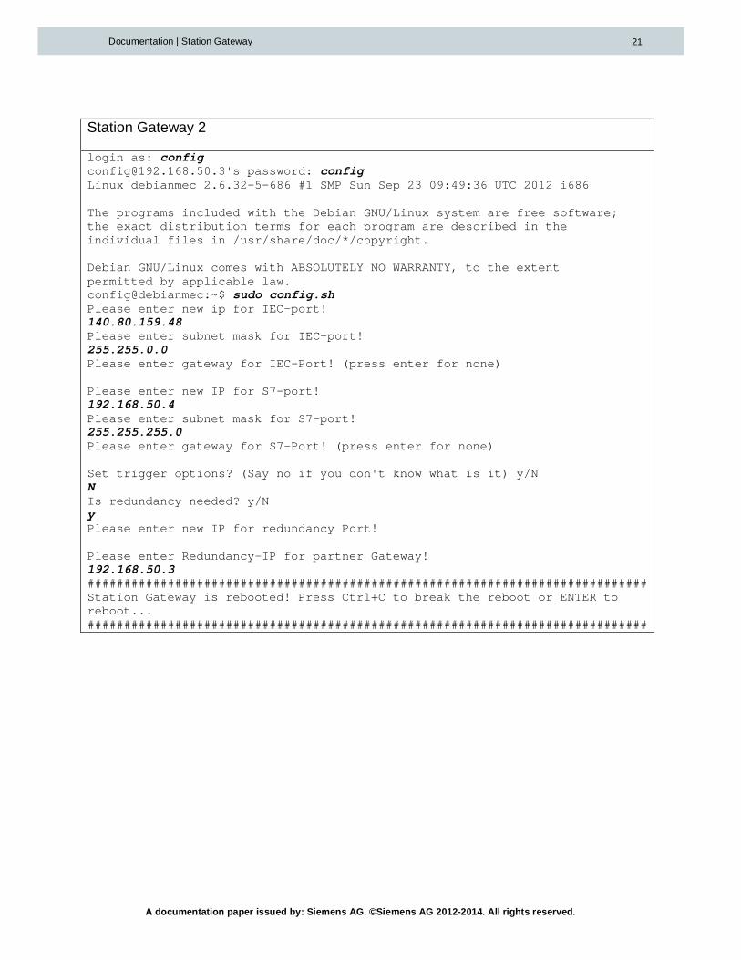
Station Gateway 2
login as: [email protected]'s password: configLinux debianmec 2.6.32-5-686 #1 SMP Sun Sep 23 09:49:36 UTC 2012 i686
The programs included with the Debian GNU/Linux system are free software;the exact distribution terms for each program are described in theindividual files in /usr/share/doc/*/copyright.
Debian GNU/Linux comes with ABSOLUTELY NO WARRANTY, to the extentpermitted by applicable law.config@debianmec:~$ sudo config.shPlease enter new ip for IEC-port!140.80.159.48Please enter subnet mask for IEC-port!255.255.0.0Please enter gateway for IEC-Port! (press enter for none)
Please enter new IP for S7-port!192.168.50.4Please enter subnet mask for S7-port!255.255.255.0Please enter gateway for S7-Port! (press enter for none)
Set trigger options? (Say no if you don't know what is it) y/NNIs redundancy needed? y/NyPlease enter new IP for redundancy Port!
Please enter Redundancy-IP for partner Gateway!192.168.50.3#############################################################################Station Gateway is rebooted! Press Ctrl+C to break the reboot or ENTER toreboot...#############################################################################

A documentation paper issued by: Siemens AG. ©Siemens AG 2012-2014. All rights reserved.
Documentation | Station Gateway 22
4 Configuration
4.1 Communicationsettings
The configuration of all basic communication settings can be done either with the StatConConfiguration Tool (recommended) or via linux shell commands.
4.1.1 ConfigurationviaStatConTool(recommended)
The first step is to assign the IP-address of the S7-interface. This can be done via“Online”/”Accessible devices”. After this, this IP address can be used for downloading the othersettings.
Image 3: Accessible devices
The settings of the Station Gateway can be configured within the property window of theGateway device. The general handling of the StatCon Tool is described in the separate StatConmanual.

A documentation paper issued by: Siemens AG. ©Siemens AG 2012-2014. All rights reserved.
Documentation | Station Gateway 23
Image 4: Station Gateway property window
After configuration, all settings have to be downloaded to the Gateway.
4.1.2 Configurationvialinuxshell
There are two ways to access the Station Gateway with shell commands, which can be used toset the parameters in the configuration file.
1. Local display and keyboard plugged in the EM PC (only redundant Station Gateway).Note: the display has to be plugged in before power on!
2. Remote access via SSH (e.g. PuTTY) to any of the Station Gateways IP addresses.

A documentation paper issued by: Siemens AG. ©Siemens AG 2012-2014. All rights reserved.
Documentation | Station Gateway 24
If no EM-PC is available and the current IP-address of the Station Gateway is unknown or hasto be changed to reach the device, the IP-address of the S7-Interface can also be changed viaSTEP 7 or StatCon Tool.To do so, open “Edit Ethernet Node...” in SIMATIC Manager. Browse for your Station gateway(STA_GATEXX_XX) and change the IP address.Afterwards you can connect via ssh using the configured address.
If a local display or a Remote Terminal is connected you are prompted to log into the StationGateway. The Login name and the associated password both are "config“.
Gateway login: config
Password: config (The password does not appear on the screen)
To change the configuration, the command “sudo config.sh” has to be used.The script will ask for new IP addresses and subnet masks for the IEC and S7-Ports and theredundancy port if applicable.The default gateway should be left blank.
If the interfaces are connected to physically separated networks, it is necessary to assign IPaddresses in different subnets to each interface.
Examples can be found in the appendix.
4.1.3 DefaultIPaddresses
The default IP-addresses are:
Interface IP-Address (single orfirst redundant)
IP-Address (secondredundant)
Subnet mask
X1 (S7-Port) 192.168.50.3 192.168.50.4 255.255.255.0
X2 (IEC-Port) 140.80.159.47 140.80.159.48 255.255.0.0
X1 P1 PN EM-PC(Redundancy Port)
10.10.12.1 10.10.12.2 255.0.0.0
4.1.4 Triggeroptions
If you use IEC devices with limited support of trigger options (e.g. ABB REF615 does notsupport trigger option “data-update”) you can specify the trigger options in StatCon or with theshell command configuration script. If the Shell is used,all settings must be done anew.

A documentation paper issued by: Siemens AG. ©Siemens AG 2012-2014. All rights reserved.
Documentation | Station Gateway 25
Example StatCon:
Image 5: Trigger options StatCon
Example Shell:
Following commands should be executed on Station Gateway
login as: [email protected]'s password: configLinux debianmec 2.6.32-5-686 #1 SMP Sun Sep 23 09:49:36 UTC 2012 i686
The programs included with the Debian GNU/Linux system are free software;the exact distribution terms for each program are described in theindividual files in /usr/share/doc/*/copyright.
Debian GNU/Linux comes with ABSOLUTELY NO WARRANTY, to the extentpermitted by applicable law.config@debianmec:~$ sudo config.shPlease enter new ip for IEC-port!

A documentation paper issued by: Siemens AG. ©Siemens AG 2012-2014. All rights reserved.
Documentation | Station Gateway 26
140.80.159.48Please enter subnet mask for IEC-port!255.255.0.0Please enter gateway for IEC-Port! (press enter for none)
Please enter new IP for S7-port!192.168.50.4Please enter subnet mask for S7-port!255.255.255.0Please enter gateway for S7-Port! (press enter for none)
Set trigger options? (Say no if you don't know what is it) y/NYPlease enter hex trigger options (0x7C - all options, 0x6C - without data-update):0x6cIs redundancy needed? y/NNIs EM PC installed? y/NN#############################################################################Station Gateway is rebooted! Press Ctrl+C to break the reboot or ENTER toreboot...#############################################################################
You can use following combination of bits to define the trigger options:
Value Name0x80 reserved0x40 data-change0x20 quality-change0x10 data-update0x08 integrity0x04 general interrogation
E.g. trigger options without data-update have value 0x6c.
4.1.5 SecondS7Ethernetinterface
You can use Expansion Module EM-PC (MLFB - 6ES7677-1DD50-2AA0) to enable second S7interface on the Station Gateway.
To setup IP address for this interface you should execute configuration script:
Following commands should be executed on Station Gateway
login as: [email protected]'s password: configLinux debianmec 2.6.32-5-686 #1 SMP Sun Sep 23 09:49:36 UTC 2012 i686

A documentation paper issued by: Siemens AG. ©Siemens AG 2012-2014. All rights reserved.
Documentation | Station Gateway 27
The programs included with the Debian GNU/Linux system are free software;the exact distribution terms for each program are described in theindividual files in /usr/share/doc/*/copyright.
Debian GNU/Linux comes with ABSOLUTELY NO WARRANTY, to the extentpermitted by applicable law.config@debianmec:~$ sudo config.shPlease enter new ip for IEC-port!140.80.159.48Please enter subnet mask for IEC-port!255.255.0.0Please enter gateway for IEC-Port! (press enter for none)
Please enter new IP for S7-port!192.168.50.4Please enter subnet mask for S7-port!255.255.255.0Please enter gateway for S7-Port! (press enter for none)
Set trigger options? (Say no if you don't know what is it) y/NNIs redundancy needed? y/NNIs EM PC installed? y/NYPlease enter new IP for the second S7-Interface:192.168.60.4Please enter subnet mask for the second S7-Interface:255.255.255.0Please enter default gateway for the second S7-Interface (leave empty ifnone):
Gateway is not used for the second S7-Interface#############################################################################Station Gateway is rebooted! Press Ctrl+C to break the reboot or ENTER toreboot...#############################################################################

A documentation paper issued by: Siemens AG. ©Siemens AG 2012-2014. All rights reserved.
Documentation | Station Gateway 28
4.2 ConfigurationofS7-Connections
4.2.1 SettingsinNetPro
The communication partners (CPU and Station Gateway) are participants of the commonEthernet network and have fixed IP addresses.
In the Station Gateway only the IP address must be defined for the communication with the S7CPU. All other communication parameters for a S7 connection are engineered in the PCS7system, especially in the PCS7 software tool NetPro. The PCS7 station establishes an S7connection to the Station Gateway.
Then the function block I61_LINK starts the communication sending a BSEND telegram. Thefunction block I61_LINK uses the S7 connections engineered with NetPro.
PCS7 station
I61_LINK
CONN_ID1
CONN_ID2
CONN_ID3
CONN_ID4
S7 connection 1
S7 connection 2
S7 connection 3
S7 connection 4
StationGateway
StationGateway
Industrial Ethernet

A documentation paper issued by: Siemens AG. ©Siemens AG 2012-2014. All rights reserved.
Documentation | Station Gateway 29
The complete engineering of a connection between the PCS7 station and the Station Gatewayis located in the PCS7 software tool NetPro. Only the corresponding IP address of the StationGateway must be entered in NetPro as the end point of a S7 connection.
Fixed parameters
- S7 connection
- unspecified partner
- active role in the PCS7 station
- TCP/IP used
Specific parameters
- Via a CP443-1 card of the PCS7 Station
- IP address of the used Station Gatewayinterface
Arbitrary parameters (set by NetPro automatically)
- RTSAP and LTSAP
The Station Gatewayaccepts each requestfor a connection fromthe PCS7 station.The Station Gatewayneeds no connectionparameters fromPCS7.
The Parameters in PCS7 NetPro
for each connection to a Station Gateway

A documentation paper issued by: Siemens AG. ©Siemens AG 2012-2014. All rights reserved.
Documentation | Station Gateway 30
Image 6 : Parameter for a connection to the Station Gateway in the engineering tool NetPro

A documentation paper issued by: Siemens AG. ©Siemens AG 2012-2014. All rights reserved.
Documentation | Station Gateway 31
4.2.2 Redundancy
The function blocks are running in single and in redundant systems according to the redundancyfunctions of the host system PCS7. The function block I61_LINK manages the redundantcommunication with up to four S7 connections. Each S7 connection is engineered as a singleconnection. All S7 connections together constitute a redundant connection. For a redundantStation Gateway pair at least two S7 connections with one I61_LINK block must be engineered.
Several redundancy configurations are possible.
Each S7 connection is watched with live sign telegrams from both systems. One S7 connectionis sufficient for the complete data transfer in both directions. If two S7 connections are available,one S7 connection (via one CP443-1 card) is dedicated for sending data only and the other S7connection (via the other CP443-1 card) for receiving data only.
The data transfer is switched over to another S7 connection to the same Station Gateway, aftera data package is not acknowledged by the receiver.
CPU2
CPU1
CPU 2
CPU 2
CPU 1
SGSGB
SGA
SGB
SGA
SG B
SGA
CPUCPU 1

A documentation paper issued by: Siemens AG. ©Siemens AG 2012-2014. All rights reserved.
Documentation | Station Gateway 32
4.3 Timesettings
Siemens Siprotec devices can be configured to use the local time on the display. However, thetimestamps sent via IEC 61850 are UTC time. Since the standard time setting of a PCS 7 PLCis also UTC time, no changes have to be made in this case.
However, if the protection devices are sending the IEC 61850 time stamps in local time format,we recommend the following settings in the PCS 7 system:
Configure the S7-400 Controller to run also in local time zone:
Adjust the settings in WinCC (Computer/Properties/Parameters):

A documentation paper issued by: Siemens AG. ©Siemens AG 2012-2014. All rights reserved.
Documentation | Station Gateway 33
With these settings, the messages created in the PLC and in the SIPROTEC are displayed withthe correct timestamp in WinCC alarm display.
4.4 SNTPRouting
It is possible to allow time synchronization of protection devices with any SNTP server throughthe Station Gateway. This can be configured via StatCon or via shell commands.
Note: The system time of the Station Gateway cannot be synchronized. However, this time isnot used since the timestamps from the IEC 61850 devices are used.
Example StatCon:
Image 7: SNTP settings StatCon
Example Shell commands:
Following commands should be executed on Station Gateway (the commands itself ismarked bold)
To show possible options
config@debianmec:~$ sudo SNTP_routeusage: sudo SNTP_route ip_address_sntp_server
ip_address_sntp_server = time synchronization with respective SNTPserver
NONE = disable time synchronization
To enable SNTP routing
config@debianmec:~$ sudo SNTP_route <IP-Adress of SNTP server>SNTP IP-forwarding has been enabled
To disable SNTP routing
config@debianmec:~$ sudo SNTP_route NONESNTP IP-forwarding has been disabled
A documentation paper issued by: Siemens AG. ©Siemens AG 2012-2014. All rights reserved.
Documentation | Station Gateway 34
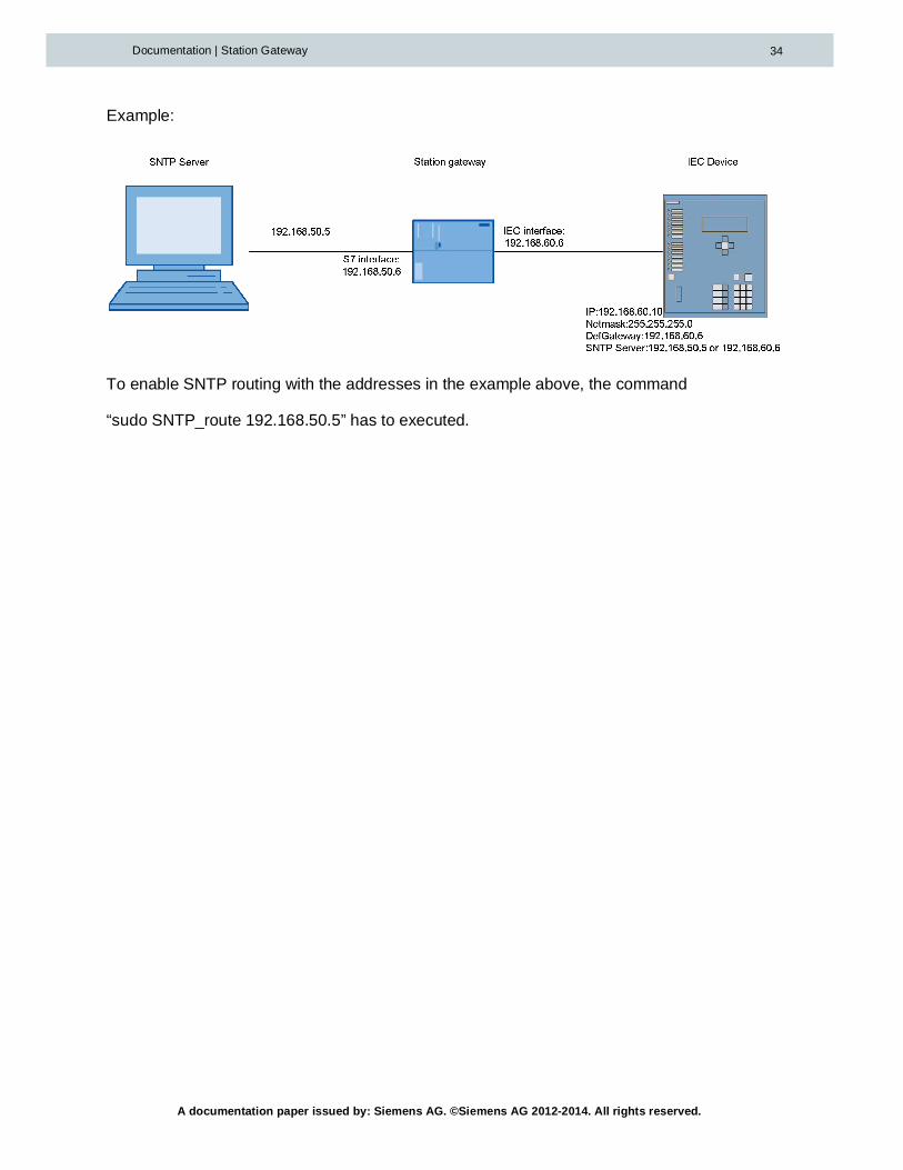
Example:
To enable SNTP routing with the addresses in the example above, the command
“sudo SNTP_route 192.168.50.5” has to executed.
A documentation paper issued by: Siemens AG. ©Siemens AG 2012-2014. All rights reserved.
Documentation | Station Gateway 35
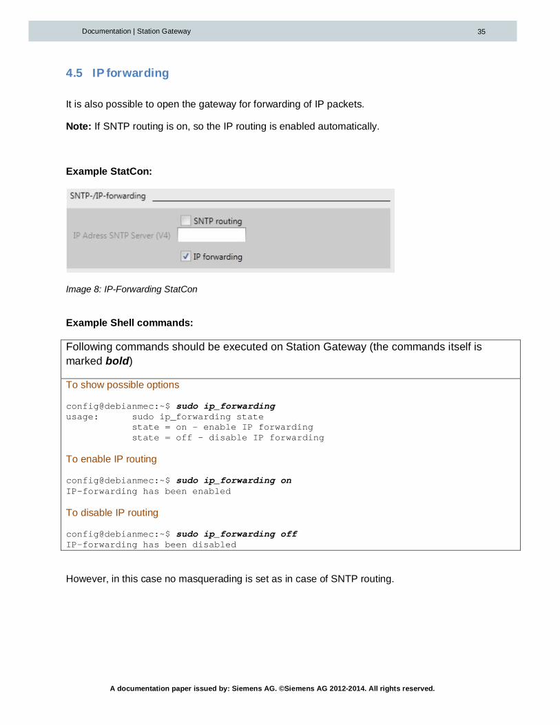
4.5 IPforwarding
It is also possible to open the gateway for forwarding of IP packets.
Note: If SNTP routing is on, so the IP routing is enabled automatically.
Example StatCon:
Image 8: IP-Forwarding StatCon
Example Shell commands:
Following commands should be executed on Station Gateway (the commands itself ismarked bold)
To show possible options
config@debianmec:~$ sudo ip_forwardingusage: sudo ip_forwarding state
state = on - enable IP forwardingstate = off - disable IP forwarding
To enable IP routing
config@debianmec:~$ sudo ip_forwarding onIP-forwarding has been enabled
To disable IP routing
config@debianmec:~$ sudo ip_forwarding offIP-forwarding has been disabled
However, in this case no masquerading is set as in case of SNTP routing.

A documentation paper issued by: Siemens AG. ©Siemens AG 2012-2014. All rights reserved.
Documentation | Station Gateway 36

A documentation paper issued by: Siemens AG. ©Siemens AG 2012-2014. All rights reserved.
Documentation | Station Gateway 37
4.6 PCS7Engineering
In the program of the S7-PLC, the blocks of the SG_LINK library have to be configured. Thefollowing image shows the principle of the layout:
The block I61_LINK has to be configured once per Station Gateway/Station Gateway pair. Forevery IEC 61850 device, a device driver block has to be configured and connected to theI61_LINk block via the “CONNECT” structure.
4.6.1 EngineeringofthefunctionblockI61_LINK
The S7 function blocks I61_LINK is the gate to the Station Gateway for the specific functionblocks. It coordinates and executes the data exchange between the PCS7 function blocks andthe Station Gateway. The inputs CONN_IDx contain the ID of the used S7 connections.
Note: The I61_LINK block needs a S7 connection exclusively only for itself. Therefore an ID ofa S7 connection can be used only once in an input CONN_IDx.
A documentation paper issued by: Siemens AG. ©Siemens AG 2012-2014. All rights reserved.
Documentation | Station Gateway 38
The specific PCS7 function blocks are connected with a Station Gateway by binding the inputelement CONNECT to the output element CONNECT in the I61_LINK block. In the configurationprogram CFC, the connection is graphically established by mouse-clicking on the output and theinput.
The I61_LINK accepts 100 connected function blocks. The cycle time for the cyclic operation inthe S7 CPU should be shorter than 1 second. The connected function blocks may run in aslower cycle as the I61_LINK block.
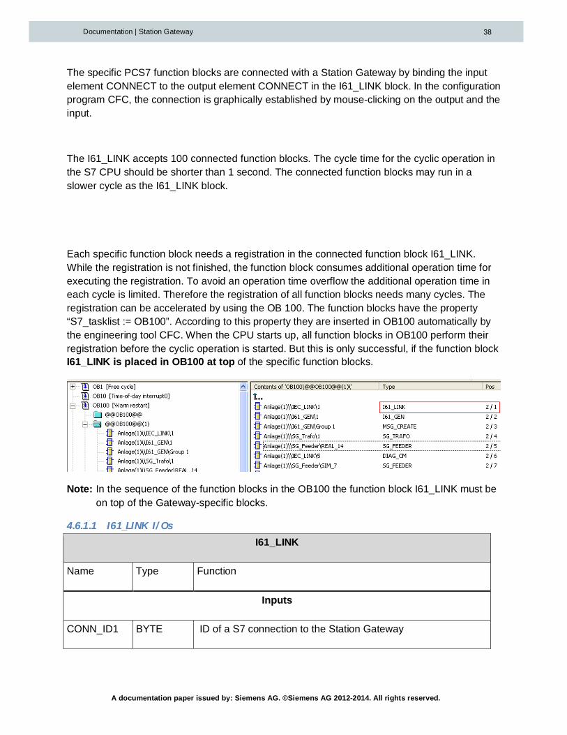
Each specific function block needs a registration in the connected function block I61_LINK.While the registration is not finished, the function block consumes additional operation time forexecuting the registration. To avoid an operation time overflow the additional operation time ineach cycle is limited. Therefore the registration of all function blocks needs many cycles. Theregistration can be accelerated by using the OB 100. The function blocks have the property“S7_tasklist := OB100”. According to this property they are inserted in OB100 automatically bythe engineering tool CFC. When the CPU starts up, all function blocks in OB100 perform theirregistration before the cyclic operation is started. But this is only successful, if the function blockI61_LINK is placed in OB100 at top of the specific function blocks.
Note: In the sequence of the function blocks in the OB100 the function block I61_LINK must beon top of the Gateway-specific blocks.
4.6.1.1 I61_LINKI/OsI61_LINK
Name Type Function
Inputs
CONN_ID1 BYTE ID of a S7 connection to the Station Gateway

A documentation paper issued by: Siemens AG. ©Siemens AG 2012-2014. All rights reserved.
Documentation | Station Gateway 39
CONN_ID2 BYTE ID of a S7 connection to the Station Gateway
CONN_ID3 BYTE ID of a S7 connection to the Station Gateway
CONN_ID4 BYTE ID of a S7 connection to the Station Gateway
Outputs
CON_ERR BOOL
RED_ERR BOOL
STAT1 STRING[4] Status of the S7 connection with the ID CONN_ID1
STAT2 STRING[4] Status of the S7 connection with the ID CONN_ID2
STAT3 STRING[4] Status of the S7 connection with the ID CONN_ID3
STAT4 STRING[4] Status of the S7 connection with the ID CONN_ID4
A_CON_1 BOOL Alarm: S7 connection with the ID CONN_ID1 failed
A_CON_2 BOOL Alarm: S7 connection with the ID CONN_ID2 failed
A_CON_3 BOOL Alarm: S7 connection with the ID CONN_ID3 failed
A_CON_4 BOOL Alarm: S7 connection with the ID CONN_ID4 failed
REDS_ERR BOOL Redundancy connection between the CM via serial cable failed
CONNECT DWORD Connecting point for up to 100 function blocks, which transferdata of a specified IEC61850 device
BLOCKS INT Number of the connected function blocks at CONNECT

A documentation paper issued by: Siemens AG. ©Siemens AG 2012-2014. All rights reserved.
Documentation | Station Gateway 40
4.6.1.2 CodeforthestatusoftheS7connections
The string outputs STAT1, STA2, STA3 and STAT4 display the actual status of the S7connections, that are entered in the inputs CONN_ID1, CONN_ID2, CONN_ID3 andCONN_ID4. A connection fault is displayed with a negative number. The error free states aredisplayed with several symbols. Example: A1>
Symbol inSTATn
Meaning
X or Y Connection established to one (X) or two (X and Y) CM without a fixed role.
1 Connection via the Ethernet CP (CP443-1) with the lower IP address
2 Connection via the Ethernet CP (CP443-1) with the higher IP address
> Connection is used for sending data only
< Connection is used for receiving data only
* Connection is used for sending and receiving data
-- No connection has been configured (CONN_IDx = 0)
-"Number“ Error code
Error codesSTATn
Meaning
-11 Error indication from the BSEND function
-12 Timeout while sending to the CM
-13 Error indication from the BRCV function
-14 Timeout while receiving from the CM
-20 … -29 CM not accepting the I61_LINK
-30 Configuration of the redundant connections to the CM is inconsistent
-50 CM not responding
-51... - 69 Formal error in the data telegram from the CM

A documentation paper issued by: Siemens AG. ©Siemens AG 2012-2014. All rights reserved.
Documentation | Station Gateway 41
5 PCS7Devicedriverblocks
The function blocks in PCS7 for the communication with protection relays are designed for CFCcharts, but can also be engineered in the software tool KOP/AWL/FUP.
For the communication via the Station Gateway the function blocks need a connection of theirinput CONNECT with the output CONNECT of the I61_LINK block.
The following table gives an overview of the block types:
Block name FB Number Description
I61_LINK FB900 Link block to manage the communication to theStation Gateway module
I61_COMM FB901 Data exchange with a protection relay via IEC61850 –called within the device specific blocks
I61_GEN FB902 Generic device driver block for data exchange with aIEC61850 device
DIAG_CM FB903Block for diagnosis and alarming of the StationGateway module (connections, device status,redundancy)
MSG_CREATE FB904Dummy/Example block for creating a MSG_EV_IDtype “alarm_t” for calling the ALARM_8P in thedevice driver.
I61_XXX FB905…. Device specific driver blocks for connectingIEC61850 devices
SG_FEEDER FB2540 Driver block to connect the technological blockPC_FEEDER of the PowerControl Library
SG_TRAFO FB2542 Driver block to connect the technological blockPC_TRAFO of the PowerControl Library
SG_SYNC FB2543 Driver block to connect the technological blockPC_SYNC of the PowerControl Library
SG_LINE FB2544 Driver block to connect the technological blockPC_LINE of the PowerControl Library

A documentation paper issued by: Siemens AG. ©Siemens AG 2012-2014. All rights reserved.
Documentation | Station Gateway 42
5.1 IPandIED_NAME
A protection relay is addressed by its IP address (input IP). The IED Name of the protectionrelay is used to confirm the addressing. If the parameterized name in the input IED_NAME doesnot match the name of the addressed protection relay, no communication is performed.
Important note: Do not use leading nulls in the IP addresses. E.g. 192.168.05.1 or010.020.030.1 is invalid.
5.2 ConfiguringIECAddresses
The IEC 61850 address of each transferred object is parameterized in a STRING[66] input. Theinputs are bundled in structures that contain the addresses of a definite data type:
Input structure DescriptionBOOL_DEF Definition of cyclic binary valuesREAL_DEF Definition of cyclic real valuesBS32_DEF Definition of cyclic Bitstring32 or DINT valuesINT_DEF Definition of cyclic integer valuesBCMD_DEF Definition of binary command objectsBMSG_DEF Definition of message/alarm objects
For each transferred object, that is defined in a STRING[66] input, the function block containsdesignated outputs with status information about the object.
The objects defined in BMSG_DEF are created in the dataset for the buffered reporting.
5.2.1 Exchangeofthecharacter$inCFCwiththecharacter§
The addresses of an IEC61850 device are located in STRING inputs of the assigned functionblock. The symbol $ is often used in such addresses. This symbol must be replaced by § in theaddress strings of the function blocks, because $ is not an accepted symbol in the engineeringtool CFC.
Example:
original address IEC 61850 MEAS/MMXU1$MX$A$phsA$cVal$mag$f
address string in PCS7 MEAS/MMXU1§MX§A§phsA§cVal§mag§f
A documentation paper issued by: Siemens AG. ©Siemens AG 2012-2014. All rights reserved.
Documentation | Station Gateway 43
5.3 IEC61850Reporting
The Station Gateway uses the buffered/unbuffered reporting functionality of IEC61850. Thisensures that all changes of messages and alarms are received, even if there were more thanone changes of the signal in one cycle.
Another big advantage of the reporting functionality is that the timestamps displayed in WinCCare exactly the timestamps of the IEC61850 device.
Every configured message/alarm is connected with an Alarm_8P call which transfers theinformation to WinCC.
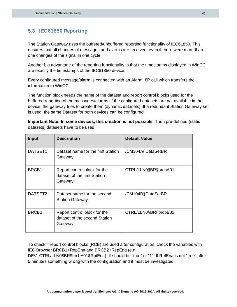
The function block needs the name of the dataset and report control blocks used for thebuffered reporting of the messages/alarms. If the configured datasets are not available in thedevice, the gateway tries to create them (dynamic datasets). If a redundant Station Gateway setis used, the same Dataset for both devices can be configured
Important Note: In some devices, this creation is not possible. Then pre-defined (staticdatasets) datasets have to be used.
Input Description Default Value
DATSET1 Dataset name for the first StationGateway
/CM104A§DataSetBR
BRCB1 Report control block for thedataset of the first StationGateway
CTRL/LLN0§BR§brcbA01
DATSET2 Dataset name for the secondStation Gateway
/CM104B§DataSetBR
BRCB2 Report control block for thedataset of the second StationGateway
CTRL/LLN0§BR§brcbB01
To check if report control blocks (RCB) are used after configuration, check the variables withIEC Browser BRCB1+RepEna and BRCB2+RepEna (e.g.DEV_CTRL/LLN0$BR$brcbA01$RptEna). It should be “true” or “1”. If RptEna is not “true” after5 minutes something wrong with the configuration and it must be investigated.

A documentation paper issued by: Siemens AG. ©Siemens AG 2012-2014. All rights reserved.
Documentation | Station Gateway 44
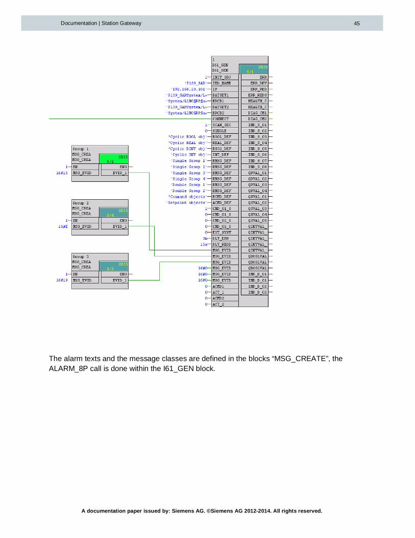
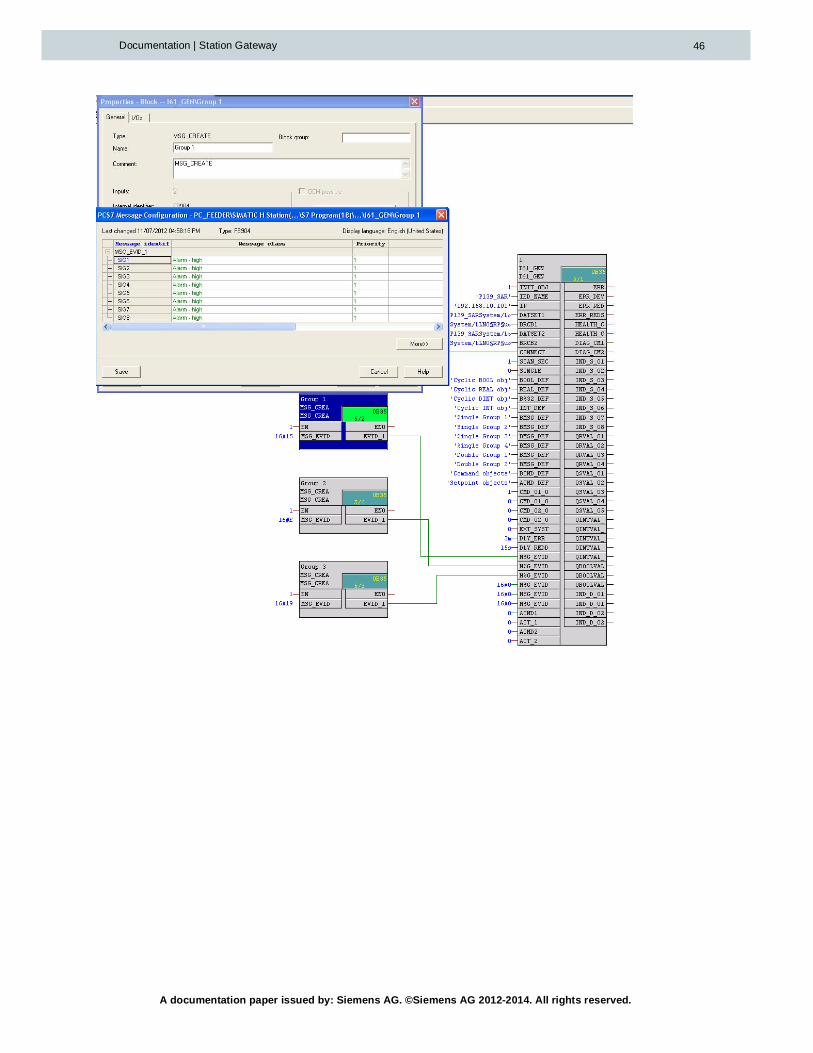
5.4 MSG_EVID_XX,AlarmingConcept
The I61_XX blocks have a special alarming concept that allows the user to assign differentalarms of one device to different technological blocks/objects.
The Messages configured in “BMSG_DEF_XX” inputs are connected to ALARM_8P calls insidethe block. With this mechanism, the signals and the timestamps from the device are transferredto WinCC.
The ALARM_8P blocks use the values from the inputs MSG_EVID_XX as Message Event ID´s.So the alarms can be grouped, and the messages and message classes can be configured atthe blocks where the Message Event Id´s are created.
For creation of the Message Event IDs and configuring the alarms, the block MSG_CREATEcan be used. There has to be one instance per alarm group.
It is also possible to use custom blocks for creating the MSG_EV_IDs. Therefore the blockshave to have the following input parameter in scl source code:
The following drawing shows the mechanism in detail:
A documentation paper issued by: Siemens AG. ©Siemens AG 2012-2014. All rights reserved.
Documentation | Station Gateway 45
The alarm texts and the message classes are defined in the blocks “MSG_CREATE”, theALARM_8P call is done within the I61_GEN block.
A documentation paper issued by: Siemens AG. ©Siemens AG 2012-2014. All rights reserved.
Documentation | Station Gateway 46

A documentation paper issued by: Siemens AG. ©Siemens AG 2012-2014. All rights reserved.
Documentation | Station Gateway 47
5.5 EXT_SYSTEM_ACTIVE,Forwardingofalarms
If the alarms should be forwarded to a foreign, non-WinCC system, the Gateway should notbuffer the alarms when WinCC is down.
The Input "EXT_SYSTEM_ACTIVE" indicates if the foreign system for receiving alarms isactive.
The Outputs ALM_GRP_XXX(type UDT_ALM_GRP) are used to forward the alarms to the othersystem.
The following logic is used for the acknowledgment/buffering of the alarms:
StatusWinCC
Status Foreign system(EXT_SYSTEM_ACTIVE)
Behavior
Active True Alarms are acknowledged in the StationGateway as soon as they are transferred toWinCC. Then the next alarm appears in theOutputs ALM_GRP_XXX.
Not active True Alarms are acknowledged after one cycle,no buffering in the Station Gateway.
Active False Alarms are acknowledged in the StationGateway as soon as they are transferredto WinCC. Then the next alarm appears inthe Outputs ALM_GRP_XXX.
Not active False Station Gateway buffers the alarms untileither WinCC or the other system is onlineagain.
A documentation paper issued by: Siemens AG. ©Siemens AG 2012-2014. All rights reserved.
Documentation | Station Gateway 48
5.6 CyclicData
The following Data types can be configured for cyclic reading:
- BOOL- REAL- INT- DINT
Cyclic data comes without timestamp and is polled every cycle configured in “SCAN_SEC”.
5.6.1 SCAN_SEC
The Station Gateway cyclically reads the objects that are addressed in the structuresBOOL_DEF, REAL_DEF, DINT_DEF and INT_DEF. All defined objects are polled with thesame scan time. The common scan time can be set with the parameter SCAN_SEC in steps ofone second. The parameter SCAN_SEC is transferred into the Station Gateway when the objectparameters (all addresses) are loaded. After changing the parameter SCAN_SEC it is requiredto load the Station Gateway again. The communication with the protection relay is stoppedduring loading.
5.7 Loadingtheobjectparameters(addresses)intotheStationGateway
All specific parameters for the communication between the protection relay and the functionblock are located in the inputs of the device driver blocks.
After changing the new object parameters are not jet active in the CM. It is necessary todownload them into the Station Gateway. The download is started by rising edge of the inputINIT_OBJ.
Additionally the download of the object parameters is started automatically:
- after the restart of a Station Gateway- after the restart of the PCS 7 controller- after a communication interrupt of more than 3 minutes
The download of the object parameters can be suppressed with INIT_OBJ=0. During onlineoperation the input INIT_OBJ must remain the value 1. The value 0 is allowed only whilechanging the address inputs or temporarily for creating a rising edge to start the download.
The download may need some seconds up to a minute, depending from the number of loadingfunction blocks.
A documentation paper issued by: Siemens AG. ©Siemens AG 2012-2014. All rights reserved.
Documentation | Station Gateway 49
During initialization, no process data is transferred between the function block and the StationGateway. The Station Gateway will continue storing messages with timestamp (bufferedreports) of the protection relay and will send them to PCS7 after the download and initializing isfinished.
If only one Station Gateway of a redundant pair is switched off and on, only this StationGateway will be initialized with the object parameters, while the other Station Gatewaycontinues the communication with the protection relay.
5.8 StructuredIn-andOutputs
The Inputs and the Outputs of the device specific driver blocks are APL-structures, so theycontain the value and the quality code of the signal.
Inputs are only valid for the block if the quality code is 0x80.
5.9 Displayofcyclictransferreddatainoutputs
For each cyclic transferred data from the protection relay a group of output structures isprovided in the function block. This output structures contain the process value and a qualitybyte.
5.10 Qualityindicationoftransferredprocessdata
For each IEC 61850 address parameter STRING[66] there is a quality indication “.St” within thestructure of the specific output. The quality is of data type byte and can have the followingvalues:
Quality Code Meaning
16#14 Invalid(indication from IED invalid)
16#80 Valid
16#60 simulated
16#18 IEC 61850 address not supported by the connected device
16#00 not used, no actualization

A documentation paper issued by: Siemens AG. ©Siemens AG 2012-2014. All rights reserved.
Documentation | Station Gateway 50
16#08 No Connection to IED or to Station Gateway
Table: Quality indication in the function blocks
5.11 Commands
The IEC addresses of Binary commands are configured on the input “BCMD_DEF”:
A typical IEC address example for a switch command is:
'CTRL/Q0CSWI1§CO§Pos§Oper§ctlVal'
5.11.1 Selectbeforeoperate
If the control mode of the command is “select before operate”, the address of the SBOw§ctlValhas to be configured. The Station Gateway then uses the Select before operate mechanismautomatically.
Example:
'CTRL/Q0CSWI1§CO§Pos§SBOw§ctlVal'

A documentation paper issued by: Siemens AG. ©Siemens AG 2012-2014. All rights reserved.
Documentation | Station Gateway 51
5.11.2 Commandconfiguration
The IEC protocol provides 3 additional configuration bits which are sent with the command (seealso IEC61850 documentation)
- Check interlocking: If this bit is set, the IEC device checks the local interlocks beforeprocessing the command
- Synchrocheck: If this bit is set, the IEC device performs a synchrocheck beforeprocessing the command
- Test: If this bit is set, the IEC device performs only a test of the command
These bits can be configured in the Station Gateway per configured command on the Input“CMD_CONF”:
There is a byte for each command. The byte has the following allocation:
Bit 0(0x01): Check Interlocking
Bit 1(0x02): Synchrocheck
Bit 3(0x04): Test
E.g. 0x03 for interlocking and Synchrocheck

A documentation paper issued by: Siemens AG. ©Siemens AG 2012-2014. All rights reserved.
Documentation | Station Gateway 52
5.12 °Outputsfortheindicationoferrors
The individual function blocks do not watch the S7 connections to the Station Gateway. Theerror indication for the S7 connections is done by the I61_LINK block. The individual functionblocks that are placed behind the I61_LINK block, watch the data exchange with the StationGateway, regardless of the number of S7 connections used by the function block I61_LINK.
5.12.1 ERR,ERR_DEV,ERR_CONN
The output ERR is set, if the data exchange with the protection relay fails completely. Theoutput ERR is zero(“OK” in CFC), if the data exchange with the protection relay is working via atleast one S7 connection and one CM.
The output ERR_CONN is set, if no CM is reachable. The output ERR_DEV is set, if noreachable Station Gateway can exchange data with the designated protection relay.
5.12.2 HEALTH_CM1/2
The Outputs HEALTH_CM1/2 display the value of the IEC AddressCTRL/LLN0$ST$Health$stVal, which is the global status of the device. HEALTH_CM1 comesfrom the first Station Gateway, HEALTH_CM2 from the second.
0(“N/A” in CFC) -> Undefined
1(“OK” in CFC) -> OK
2 -> Warning3 -> Error255 -> No Connection to the device
5.12.3 DIAG_CM1/2
The DIAG Outputs display the status of the buffered reporting for the Boolean values and thealarms. If the reporting is set up successfully and the communication is running, the CFC shows“OK” on these outputs. If not, there is a hexadecimal error code. The explanation of the differenterror codes is done in the appendix of this document.
5.12.4 ERR_RED,ERR_REDC,ERR_REDDandERR_REDS
The output ERR_RED indicates a loss of redundancy. Not each loss of a S7 connection, whichis indicated by the function block I61_LINK, causes an error indication in the specific functionblock. The output ERR_RED is the sum of ERR_REDC, ERR_REDD and ERR_REDS. In thecase of a non-redundant configuration ERR_RED is always true.

A documentation paper issued by: Siemens AG. ©Siemens AG 2012-2014. All rights reserved.
Documentation | Station Gateway 53
ERR_REDC is set, if not both redundant Station Gateway have a valid connection with thefunction block. ERR_REDD is set, if one Station Gateway indicates an error of the dataexchange with the designated protection relay. ERR_REDS is set, if one Station Gateway haslost its connection to the redundant Station Gateway via Ethernet.
Error name Description
ERR_RED Is 1 if ERR_REDC or ERR_REDD or ERR_REDS are not zero
ERR_REDC One Station Gateway is not connected with AS/CPU
ERR_REDD Protection relay is not connected with one or both Station Gateways
ERR_REDS No redundancy connection between Station Gateways
5.12.5 STAT_CM1andSTAT_CM2
The outputs STAT_CM1 and STAT_CM2 show a reason for an error indicated by ERR_REDC =1 or ERR_CONN = 1. The value 0 means no error. In a non-redundant configurationERR_REDC will always be set. In this case only ERR_CONN and STAT_CM1 are relevant.
STAT_CMx Meaning
-1 initial value, no operation in the PCS7 station
0 no error
1 No connected data block at the input CONNECT
2 Input CONNECT is not connected with a I61_LINK block
3 Too many blocks connected with one I61_LINK block
4 No connection with a Station Gateway
6 Error while sending to a Station Gateway
7 Error while receiving from a Station Gateway
10 Waiting for the start of the communication with a Station Gateway
11, 12 Error during loading of IED_NAME or IP
14, 15 Error during loading of the object parameter
16, 17 Error during loading of message object parameter

A documentation paper issued by: Siemens AG. ©Siemens AG 2012-2014. All rights reserved.
Documentation | Station Gateway 54
18, 19 Error during loading of REAL object parameter
20, 21 Error during loading of BS32 object parameter
22, 23 Error during loading of binary command object parameter
24, 25 Error during loading of analog command object parameter
Table: Indications of STAT_CM1 and STAT_CM2 in the function block

A documentation paper issued by: Siemens AG. ©Siemens AG 2012-2014. All rights reserved.
Documentation | Station Gateway 55
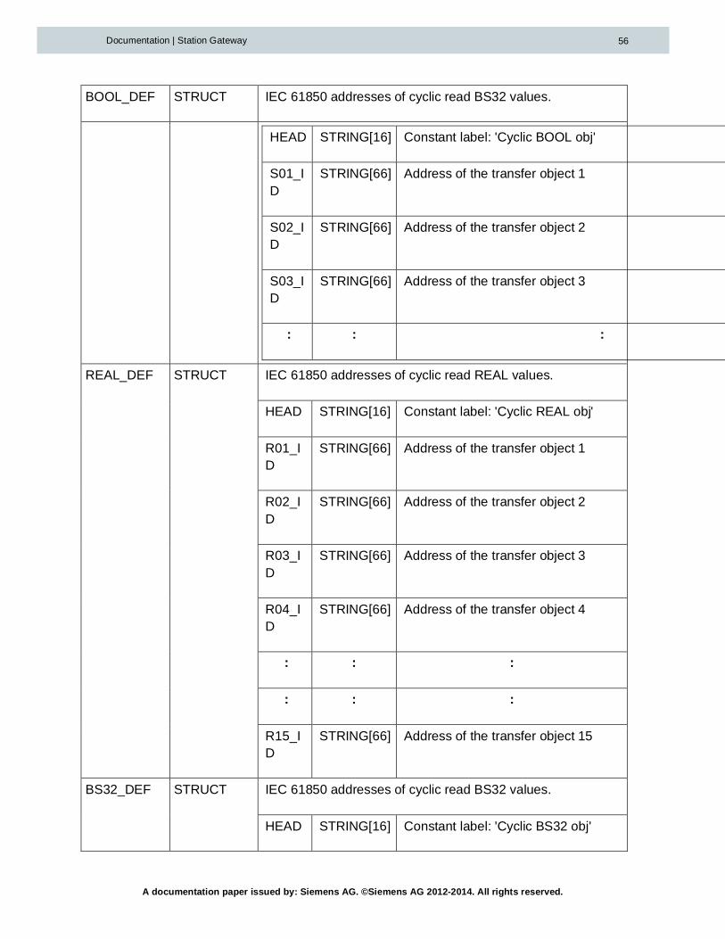
5.13 IO-OverviewofI61_GEN
I61_GEN
Name Type Function
Inputs
INIT_OBJ BOOL Start loading the parameters for the transfer objects (IEC61850 addresses) to the Station Gateway when changingfrom 0 to 1.
INIT_OBJ must be set to 1 during online operation.
IED_NAME STRING[30] Name of the protection relay in the IEC 61850 protocol.
IP STRING[15] IP address of the protection relay.
Example: 192.168.11.12
DATSET1 STRING[66] Data set name for buffered reports in the protection relay
used by Station Gateway 1
BRCB1 STRING[66] Path name for buffered reports in the protection relay
used by Station Gateway 1
DATSET2 STRING[66] Data set name for buffered reports in the protection relay
used by Station Gateway 2
BRCB2 STRING[66] Path name for buffered reports in the protection relay
used by Station Gateway 2
CONNECT ANY Connection with the output CONNECT of a I61_LINK block
SCAN_SEC INT Scan time in seconds for reading the cyclic values
EXT_SYSTEM_ACTIVE
BOOL Indicates if the foreign system for receiving alarms is active
A documentation paper issued by: Siemens AG. ©Siemens AG 2012-2014. All rights reserved.
Documentation | Station Gateway 56
BOOL_DEF STRUCT IEC 61850 addresses of cyclic read BS32 values.
HEAD STRING[16] Constant label: 'Cyclic BOOL obj'
S01_ID
STRING[66] Address of the transfer object 1
S02_ID
STRING[66] Address of the transfer object 2
S03_ID
STRING[66] Address of the transfer object 3
: : :
REAL_DEF STRUCT IEC 61850 addresses of cyclic read REAL values.
HEAD STRING[16] Constant label: 'Cyclic REAL obj'
R01_ID
STRING[66] Address of the transfer object 1
R02_ID
STRING[66] Address of the transfer object 2
R03_ID
STRING[66] Address of the transfer object 3
R04_ID
STRING[66] Address of the transfer object 4
: : :
: : :
R15_ID
STRING[66] Address of the transfer object 15
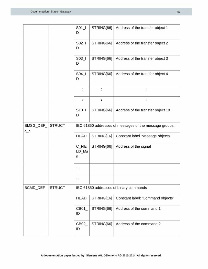
BS32_DEF STRUCT IEC 61850 addresses of cyclic read BS32 values.
HEAD STRING[16] Constant label: 'Cyclic BS32 obj'
A documentation paper issued by: Siemens AG. ©Siemens AG 2012-2014. All rights reserved.
Documentation | Station Gateway 57
S01_ID
STRING[66] Address of the transfer object 1
S02_ID
STRING[66] Address of the transfer object 2
S03_ID
STRING[66] Address of the transfer object 3
S04_ID
STRING[66] Address of the transfer object 4
: : :
: : :
S10_ID
STRING[66] Address of the transfer object 10
BMSG_DEF_x_x
STRUCT IEC 61850 addresses of messages of the message groups.
HEAD STRING[16] Constant label 'Message objects'
C_FIELD_Man
STRING[66] Address of the signal
…
…
BCMD_DEF STRUCT IEC 61850 addresses of binary commands
HEAD STRING[16] Constant label: 'Command objects'
CB01_ID
STRING[66] Address of the command 1
CB02_ID
STRING[66] Address of the command 2

A documentation paper issued by: Siemens AG. ©Siemens AG 2012-2014. All rights reserved.
Documentation | Station Gateway 58
CB03_ID
STRING[66] Address of the command 3
CB04_ID
STRING[66] Address of the command 4
CMD1_ON BOOL Activation command address CB01_ID with value 1
CMD1_OFF BOOL Activation command address CB01_ID with value 0
: : :
: : :
CMD4_ON BOOL Activation command address CB04_ID with value 1
CMD4_OFF BOOL Activation command address CB04_ID with value 0
Outputs
ERROR BOOL 1 = no communication with the protection relay
ERROR := ERR_DEV or ERR_CON
ERR_DEV BOOL 1 = no answer or no life signal from the protection relay
ERR_CONN BOOL 1 = no communication with a Station Gateway
ERR_RED BOOL 1 = redundancy not available
ERR_RED := ERR_REDC or ERR_REDD or ERR_REDS
ERR_REDC BOOL 1 = the communication with at least one Station Gateway isdisturbed
ERR_REDD BOOL 1 = at least one Station Gateway is not connected with theprotection relay
ERR_REDS BOOL 1 = the link between the redundant Station Gateways isdisturbed
OBJ_CM1 BOOL 1 = parameters loaded into the first connected Station

A documentation paper issued by: Siemens AG. ©Siemens AG 2012-2014. All rights reserved.
Documentation | Station Gateway 59
Gateway
OBJ_CM2 BOOL 1 = parameters loaded into the second connected StationGateway
STAT_CM1 INT Error code in the case of a communication errors, 0= no error
STAT_CM2 INT Error code in the case of a communication errors, 0= no error
STAT_DEV INT status of the IEC61850 device, 1 = o.k.
HEALTH_CM1
INT Health of device from CM1
HEALTH_CM2
INT Health of device from CM2
DIAG_CM1 BYTE Error Code buffered reporing CM1
DIAG_CM2 BYTE Error Code buffered reporing CM2
RTCM_01 WORD Time counter from the CM in steps of 0,01 seconds.
RACT_01 WORD Time counter from the function block in steps of 3 seconds.
RQLY_01 BYTE Quality code for the process value of the address R01_ID
RBAD_01 BOOL Indication: value good =0 or bad=1
RVAL_01 REAL Process value of the address R01_ID
ALM_GRP_XXX
STRUCT Outputs for forwarding the alarms to a foreign system
A documentation paper issued by: Siemens AG. ©Siemens AG 2012-2014. All rights reserved.
Documentation | Station Gateway 60
6 Appendix
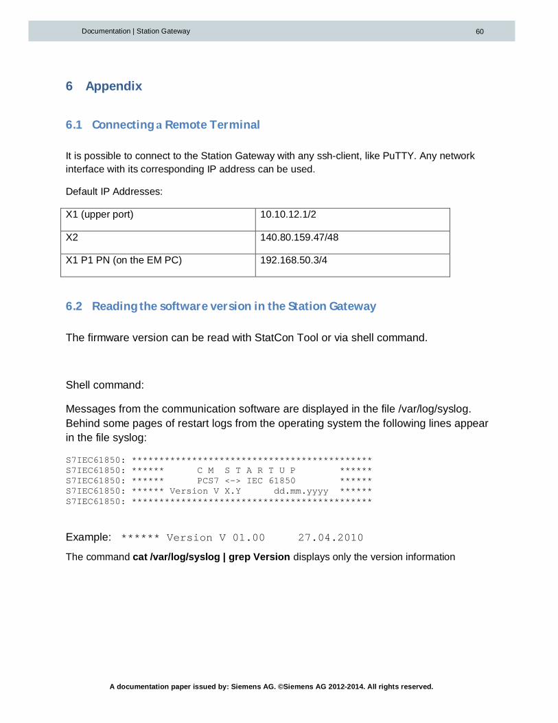
6.1 ConnectingaRemoteTerminal
It is possible to connect to the Station Gateway with any ssh-client, like PuTTY. Any networkinterface with its corresponding IP address can be used.
Default IP Addresses:
X1 (upper port) 10.10.12.1/2
X2 140.80.159.47/48
X1 P1 PN (on the EM PC) 192.168.50.3/4
6.2 ReadingthesoftwareversionintheStationGateway
The firmware version can be read with StatCon Tool or via shell command.
Shell command:
Messages from the communication software are displayed in the file /var/log/syslog.Behind some pages of restart logs from the operating system the following lines appearin the file syslog:
S7IEC61850: ********************************************S7IEC61850: ****** C M S T A R T U P ******S7IEC61850: ****** PCS7 <-> IEC 61850 ******S7IEC61850: ****** Version V X.Y dd.mm.yyyy ******S7IEC61850: ********************************************
Example: ****** Version V 01.00 27.04.2010
The command cat /var/log/syslog | grep Version displays only the version information

A documentation paper issued by: Siemens AG. ©Siemens AG 2012-2014. All rights reserved.
Documentation | Station Gateway 61
6.3 Generalconsolecommands
The local monitor provides several consoles in parallel. The key combination "Alt“ +"Fx“, x=1,2..5, can be used to switch from one console to another. The console 8 ("Alt“+"F8“) is used to display operation messages.
Tail -f /var/log/syslog : Display of logging.
Cat /var/log/syslog | grep Version : Display version information
cat /etc/S7_Gtw.conf : Display of network settings
cd /name : Change directory: Absolute address including path.
cd name : Change directory: Directory under the working directory.
cp file1 file2 : Copy file1 to file2
df -h : Display free memory
ls : Display all file names in the directory without attributes
ls -l : Display all files in the directory including attributes
ls -l S7* : Display the files with “Gt” at the beginning of their name
top : Display processes and resources. Terminated by „q“.
pwd : Display the actual working directory
rm file1 : Remove “file1”
logout : End of the session started with login “username”
date –s h:m:s : Set Time h:min:sec
date –s “M/D/Y h:m:s“: Set Date and Time
/sbin/ifconfig : Display current network settings
To restart the Station Gateway, either switch the power off and on, or log in to theStation Gateway and type sudo reboot.

A documentation paper issued by: Siemens AG. ©Siemens AG 2012-2014. All rights reserved.
Documentation | Station Gateway 62
6.4 FirmwareUpdate
The easiest way to update the firmware is using the “Online and diagnostics” tab of StatConTool. There the button “Update firmware” can be used.
How to install updates via USB
1. Copy SGupdateX.XX.tgz on any USB flash drive
2. Connect the flash drive to the Station Gateway
3. login either per ssh or locally with user “config”, password “config”
4. execute “sg_setup X.XX usb”
5. wait for the Station Gateway to reboot
How to install updates via FTP
1. Login via FTP user config password config
2. Transfer SGupdateX.XX.tgz to configs home directory
3. login either per ssh or remote
4. execute “sg_setup X.XX”
5. wait for the Station Gateway to reboot
6.5 Howtogetlogsandconfigfilesviaftp
The easiest way to update the firmware is using the “Online and diagnostics” tab of StatConTool. There the button “Create diagnose ZIP” can be used.
The Station Gateway provides an ftp server to download logs and config files.
You can connect to any of the Gateways IP addresses via any ftp client (e.g. FileZilla).
The login is password protected, the login name is config with password config

A documentation paper issued by: Siemens AG. ©Siemens AG 2012-2014. All rights reserved.
Documentation | Station Gateway 63
The relevant config file is /etc/S7_Gtw.conf.
The relevant log is /var/log/syslog.
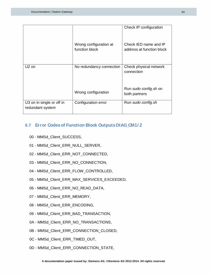
6.6 Troubleshooting
If more than one red LED is on, the one first mentioned here should be dealt with first!
Behavior Possible cause Solution
SF is on EM PC not installed
Critical configuration error
Install the provided EM PC
run sudo setup.sh andrestart the Gateway
run sudo config.sh
BF1 is on CPU is not running
CPU cannot be reached
Put CPU in Run
Check physical networkconnection
Check IP addresses
Check NetProconfiguration
BF2 is on IED cannot be reached Check physical networkconnection
A documentation paper issued by: Siemens AG. ©Siemens AG 2012-2014. All rights reserved.
Documentation | Station Gateway 64
Wrong configuration atfunction block
Check IP configuration
Check IED name and IPaddress at function block
U2 on No redundancy connection
Wrong configuration
Check physical networkconnection
Run sudo config.sh onboth partners
U3 on in single or off inredundant system
Configuration error Run sudo config.sh
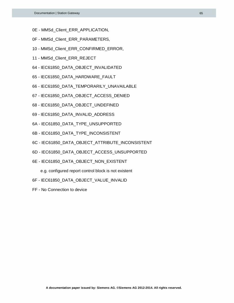
6.7 ErrorCodesofFunctionBlockOutputsDIAG_CM1/2
00 - MMSd_Client_SUCCESS,
01 - MMSd_Client_ERR_NULL_SERVER,
02 - MMSd_Client_ERR_NOT_CONNECTED,
03 - MMSd_Client_ERR_NO_CONNECTION,
04 - MMSd_Client_ERR_FLOW_CONTROLLED,
05 - MMSd_Client_ERR_MAX_SERVICES_EXCEEDED,
06 - MMSd_Client_ERR_NO_READ_DATA,
07 - MMSd_Client_ERR_MEMORY,
08 - MMSd_Client_ERR_ENCODING,
09 - MMSd_Client_ERR_BAD_TRANSACTION,
0A - MMSd_Client_ERR_NO_TRANSACTIONS,
0B - MMSd_Client_ERR_CONNECTION_CLOSED,
0C - MMSd_Client_ERR_TIMED_OUT,
0D - MMSd_Client_ERR_CONNECTION_STATE,
A documentation paper issued by: Siemens AG. ©Siemens AG 2012-2014. All rights reserved.
Documentation | Station Gateway 65
0E - MMSd_Client_ERR_APPLICATION,
0F - MMSd_Client_ERR_PARAMETERS,
10 - MMSd_Client_ERR_CONFIRMED_ERROR,
11 - MMSd_Client_ERR_REJECT
64 - IEC61850_DATA_OBJECT_INVALIDATED
65 - IEC61850_DATA_HARDWARE_FAULT
66 - IEC61850_DATA_TEMPORARILY_UNAVAILABLE
67 - IEC61850_DATA_OBJECT_ACCESS_DENIED
68 - IEC61850_DATA_OBJECT_UNDEFINED
69 - IEC61850_DATA_INVALID_ADDRESS
6A - IEC61850_DATA_TYPE_UNSUPPORTED
6B - IEC61850_DATA_TYPE_INCONSISTENT
6C - IEC61850_DATA_OBJECT_ATTRIBUTE_INCONSISTENT
6D - IEC61850_DATA_OBJECT_ACCESS_UNSUPPORTED
6E - IEC61850_DATA_OBJECT_NON_EXISTENT
e.g. configured report control block is not existent
6F - IEC61850_DATA_OBJECT_VALUE_INVALID
FF - No Connection to device