STATIC-SYNCHRONOUS COMPENSATORS and …pribeiro/misc/Papers...
8
STATIC-SYNCHRONOUS COMPENSATORS and SUPERCONDUCTING MAGNETIC ENERGY STORAGE SYSTEMS in controlling power system dynamics. BY A.B. ARSOY, Y. LIU, P.F. RIBEIRO, & F. WANG UPERCONDUCTING MAGNETIC energy storage (SMES) systems for power utility applications have received consider- able attention due to their characteristics, such as rapid response (milliseconds), high power (multimegawatts), high efficiency, and four-quadrant con- trol. SMES systems can provide improved system reliability, dynamic stability, enhanced power quality, and area protec- tion [1]-[7], as its potential applications are summarized in Fig. 1 [7]. The squared area indicates the possible cost-effec- tiveness of SMES applications. Advances in both supercon- ducting technologies and the necessary power electronics interface have made SMES a viable technology that can offer flexible, reliable, and fast-acting power compensation. A SMES coil requires an ac/dc power conversion unit to be connected to an ac system. This unit could be either a current source inverter (CSI) or a voltage source inverter (VSI) to- gether with a dc-dc chopper. A static-synchronous compensa- tor (StatCom), based on a self-commutated VSI, could be a power conversion unit for SMES. Currently, there are StatCom controllers installed in two substations: one at the Sullivan substation of the Tennessee Valley Authority (TVA) and the other at the Inez substation of American Electric Power (AEP) [9], [10], to provide reactive power/voltage control and transient stability enhancement. A StatCom, however, can only absorb/inject reactive power and, consequently, is limited in the degree of free- dom and sustained action in which it can help the power grid. The addition of energy storage allows the StatCom to inject and/or absorb active and reactive power simulta- neously, providing additional benefits and improvements in the system. The voltage source inverter front-end of a StatCom can be easily interconnected with an energy stor- age source, such as a SMES coil via a dc-dc chopper. As expected and demonstrated in the past [3], the mod- ulation of real power can have a more significant influence on damping power swings than reactive power alone [11]. Even without much energy storage, static compensators with the ability to control both reactive and real power can enhance the performance of a transmission grid. The work described here intends to model and simulate the dynamics of the integration of a ±160-Mvar StatCom and a 100-MJ SMES coil (96-MW peak power and 24-kV dc interface) that has been designed for a utility applica- tion. In this article, modeling and control schemes utilized for the StatCom-SMES are described first. Then, the 21 1077-2618/03/$17.00©2003 IEEE IEEE INDUSTRY APPLICATIONS MAGAZINE • MAR|APR 2003 • WWW.IEEE.ORG/IAS S
Transcript of STATIC-SYNCHRONOUS COMPENSATORS and …pribeiro/misc/Papers...
STATIC-SYNCHRONOUS COMPENSATORS andSUPERCONDUCTING MAGNETIC ENERGY STORAGE
SYSTEMS in controlling power system dynamics.
B Y A . B . A R S O Y , Y . L I U ,
P . F . R I B E I R O , & F . WA N G
UPERCONDUCTING MAGNETIC
energy storage (SMES) systems for power
utility applications have received consider-
able attention due to their characteristics,
such as rapid response (milliseconds), high power
(multimegawatts), high efficiency, and four-quadrant con-
trol. SMES systems can provide improved system reliability,
dynamic stability, enhanced power quality, and area protec-
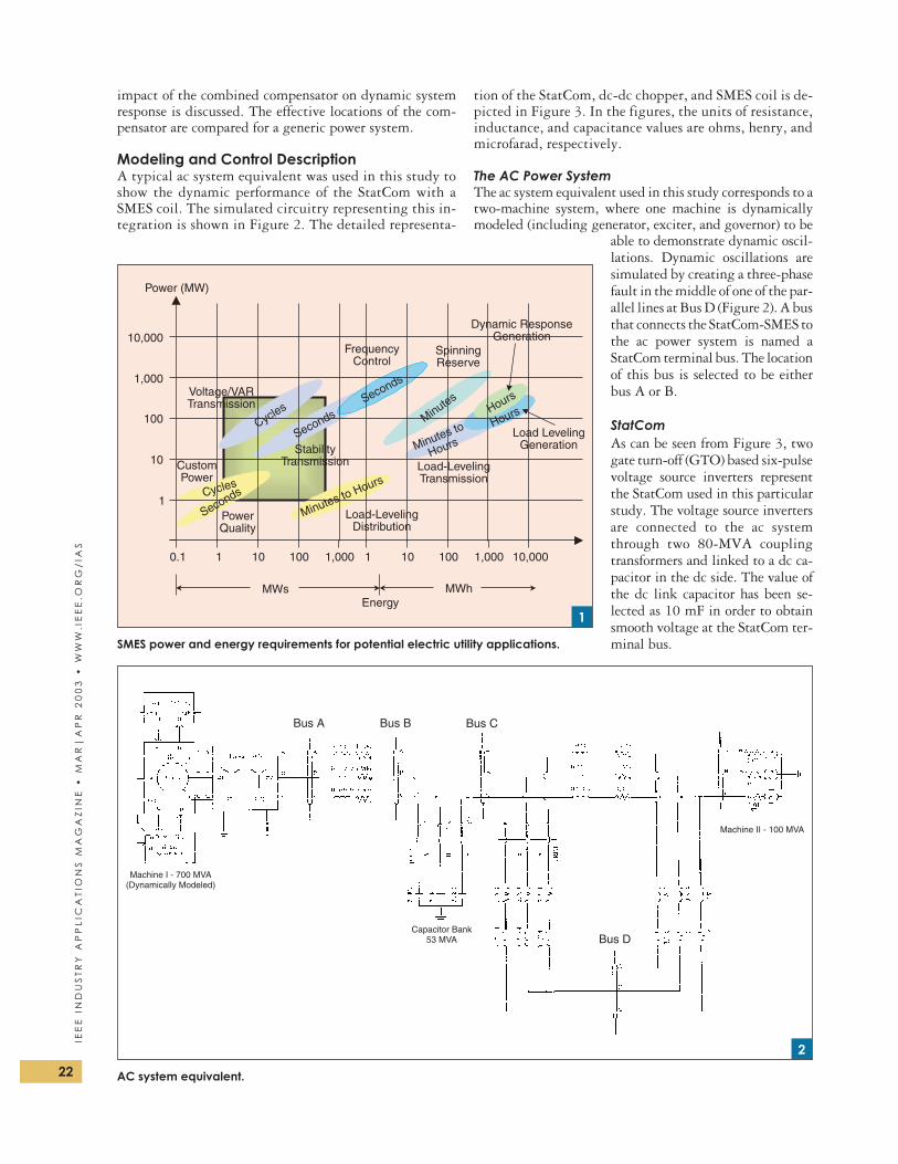
tion [1]-[7], as its potential applications are summarized in
Fig. 1 [7]. The squared area indicates the possible cost-effec-
tiveness of SMES applications. Advances in both supercon-
ducting technologies and the necessary power electronics
interface have made SMES a viable technology that can offer
flexible, reliable, and fast-acting power compensation.
A SMES coil requires an ac/dc power conversion unit to be
connected to an ac system. This unit could be either a current
source inverter (CSI) or a voltage source inverter (VSI) to-
gether with a dc-dc chopper. A static-synchronous compensa-
tor (StatCom), based on a self-commutated VSI, could be a
power conversion unit for SMES. Currently, there are
StatCom controllers installed in two substations: one at the
Sullivan substation of the Tennessee Valley Authority (TVA)
and the other at the Inez substation of American Electric
Power (AEP) [9], [10], to provide reactive power/voltage
control and transient stability enhancement.
A StatCom, however, can only absorb/inject reactive
power and, consequently, is limited in the degree of free-
dom and sustained action in which it can help the power
grid. The addition of energy storage allows the StatCom to
inject and/or absorb active and reactive power simulta-
neously, providing additional benefits and improvements
in the system. The voltage source inverter front-end of a
StatCom can be easily interconnected with an energy stor-
age source, such as a SMES coil via a dc-dc chopper.
As expected and demonstrated in the past [3], the mod-
ulation of real power can have a more significant influence
on damping power swings than reactive power alone [11].
Even without much energy storage, static compensators
with the ability to control both reactive and real power can
enhance the performance of a transmission grid.
The work described here intends to model and simulate
the dynamics of the integration of a ±160-Mvar StatCom
and a 100-MJ SMES coil (96-MW peak power and 24-kV
dc interface) that has been designed for a utility applica-
tion. In this article, modeling and control schemes utilized
for the StatCom-SMES are described first. Then, the21
1077-2618/03/$17.00©2003 IEEE
IEE
EIN
DU
ST
RY
AP
PL
ICA
TIO
NS
MA
GA
ZIN
E•
MA
R|
AP
R2
00
3•
WW
W.IE
EE
.OR
G/
IAS
S
impact of the combined compensator on dynamic systemresponse is discussed. The effective locations of the com-pensator are compared for a generic power system.
Modeling and Control DescriptionA typical ac system equivalent was used in this study toshow the dynamic performance of the StatCom with aSMES coil. The simulated circuitry representing this in-tegration is shown in Figure 2. The detailed representa-
tion of the StatCom, dc-dc chopper, and SMES coil is de-picted in Figure 3. In the figures, the units of resistance,inductance, and capacitance values are ohms, henry, andmicrofarad, respectively.
The AC Power SystemThe ac system equivalent used in this study corresponds to atwo-machine system, where one machine is dynamicallymodeled (including generator, exciter, and governor) to be
able to demonstrate dynamic oscil-lations. Dynamic oscillations aresimulated by creating a three-phasefault in the middle of one of the par-allel lines at Bus D (Figure 2). A busthat connects the StatCom-SMES tothe ac power system is named aStatCom terminal bus. The locationof this bus is selected to be eitherbus A or B.
StatComAs can be seen from Figure 3, twogate turn-off (GTO) based six-pulsevoltage source inverters representthe StatCom used in this particularstudy. The voltage source invertersare connected to the ac systemthrough two 80-MVA couplingtransformers and linked to a dc ca-pacitor in the dc side. The value ofthe dc link capacitor has been se-lected as 10 mF in order to obtainsmooth voltage at the StatCom ter-minal bus.
22
IEE
EIN
DU
ST
RY
AP
PL
ICA
TIO
NS
MA
GA
ZIN
E•
MA
R|
AP
R2
00
3•
WW
W.I
EE
E.O
RG
/IA
S
Power (MW)
10,000
1,000
100
10
1
0.1 1 10 100 1,000 1 10 100 1,000 10,000
MWhMWsEnergy
Dynamic ResponseGeneration
Load LevelingGeneration
Load-LevelingDistribution
Load-LevelingTransmission
PowerQuality
CustomPower
Voltage/VARTransmission
FrequencyControl
SpinningReserve
StabilityTransmission
Seconds
MinutesHours
Minutes to Hours
Cycles
Cycles
SecondsSeconds
Minutes to
Hours
Hours
SMES power and energy requirements for potential electric utility applications.
1
Machine I - 700 MVA(Dynamically Modeled)
Capacitor Bank53 MVA
Machine II - 100 MVA
Bus A Bus B Bus C
Bus D
AC system equivalent.
2
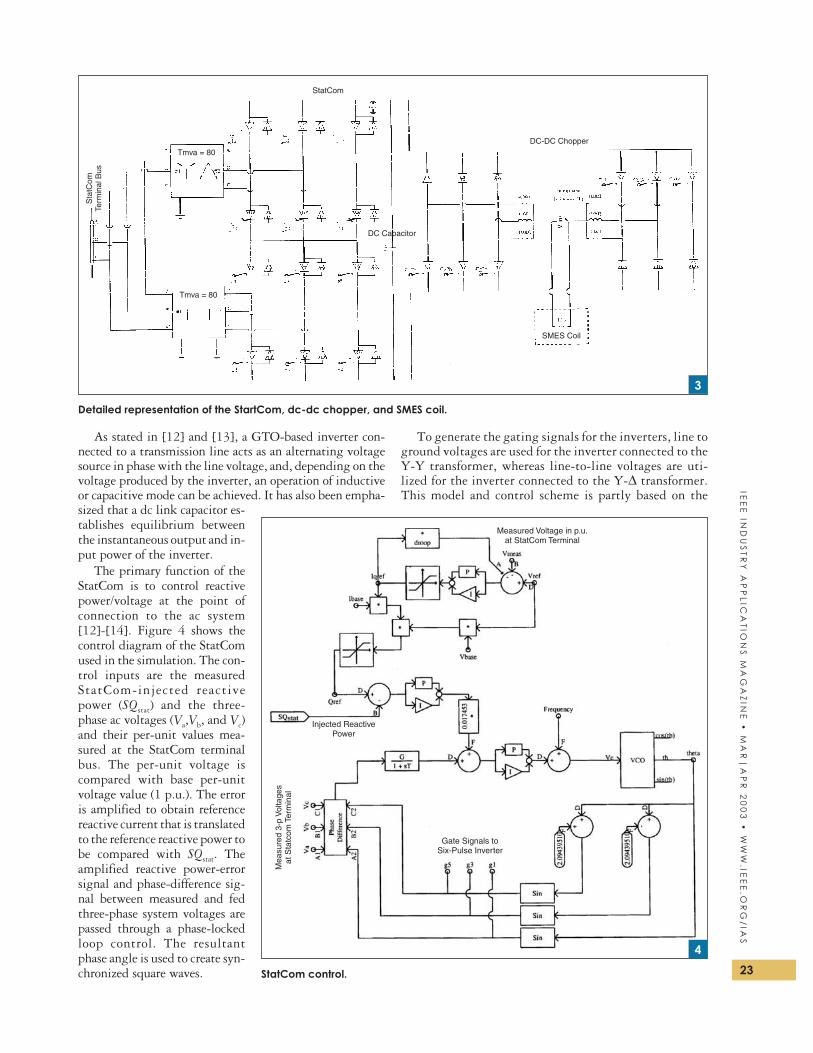
As stated in [12] and [13], a GTO-based inverter con-nected to a transmission line acts as an alternating voltagesource in phase with the line voltage, and, depending on thevoltage produced by the inverter, an operation of inductiveor capacitive mode can be achieved. It has also been empha-sized that a dc link capacitor es-tablishes equilibrium betweenthe instantaneous output and in-put power of the inverter.
The primary function of theStatCom is to control reactivepower/voltage at the point ofconnection to the ac system[12]-[14]. Figure 4 shows thecontrol diagram of the StatComused in the simulation. The con-trol inputs are the measuredStatCom-injected reactivepower (SQstat) and the three-phase ac voltages (Va,Vb, and Vc)and their per-unit values mea-sured at the StatCom terminalbus. The per-unit voltage iscompared with base per-unitvoltage value (1 p.u.). The erroris amplified to obtain referencereactive current that is translatedto the reference reactive power tobe compared with SQstat. Theamplified reactive power-errorsignal and phase-difference sig-nal between measured and fedthree-phase system voltages arepassed through a phase-lockedloop control. The resultantphase angle is used to create syn-chronized square waves.
To generate the gating signals for the inverters, line toground voltages are used for the inverter connected to theY-Y transformer, whereas line-to-line voltages are uti-lized for the inverter connected to the Y-∆ transformer.This model and control scheme is partly based on the
23
IEE
EIN
DU
ST
RY
AP
PL
ICA
TIO
NS
MA
GA
ZIN
E•
MA
R|
AP
R2
00
3•
WW
W.IE
EE
.OR
G/
IAS
Sta
tCom
Term
inal
Bus
StatCom
DC-DC Chopper
SMES Coil
Tmva = 80
Tmva = 80
DC Capacitor
Detailed representation of the StartCom, dc-dc chopper, and SMES coil.
3
Measured Voltage in p.u.at StatCom Terminal
Gate Signals toSix-Pulse Inverter
Mea
sure
d3-
pV
olta
ges
atS
tatc
omTe
rmin
al
Injected ReactivePower
StatCom control.
4
example case given in the EMTDC/PSCAD simulation package, thoughsome modifications have been made tomeet the system characteristics. Thesemodifications include change in trans-former ratings and dc capacitor rating,tuning in control parameters and add-ing voltage loop control to obtain refer-ence reactive power. It should be notedthat StatCom control does not make useof signals, such as deviation in speed orpower to damp oscillations, rather itmaintains a desired voltage level at theterminal bus to which the StatCom isconnected.
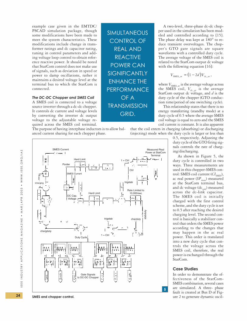
The DC-DC Chopper and SMES CoilA SMES coil is connected to a voltagesource inverter through a dc-dc chopper.It controls dc current and voltage levelsby converting the inverter dc outputvoltage to the adjustable voltage re-quired across the SMES coil terminal.The purpose of having interphase inductors is to allow bal-anced current sharing for each chopper phase.
A two-level, three-phase dc-dc chop-per used in the simulation has been mod-eled and controlled according to [15].The phase delay was kept at 180° to re-duce transient overvoltages. The chop-per’s GTO gate signals are squarewaveforms with a controlled duty cycle.The average voltage of the SMES coil isrelated to the StatCom output dc voltagewith the following equation [16]:
( )V d VSMES_av dc_av= −1 2 ,
where VSMES_av is the average voltage acrossthe SMES coil, Vdc_av is the averageStatCom output dc voltage, and d is theduty cycle of the chopper (GTO conduc-tion time/period of one switching cycle).
This relationship states that there is noenergy transferring (standby mode) at aduty cycle of 0.5 where the average SMEScoil voltage is equal to zero and the SMEScoil current is constant. It is also apparent
that the coil enters in charging (absorbing) or discharging(injecting) mode when the duty cycle is larger or less than
0.5, respectively. Adjusting theduty cycle of the GTO firing sig-nals controls the rate of charg-ing/discharging.
As shown in Figure 5, theduty cycle is controlled in twoways. Three measurements areused in this chopper-SMES con-trol: SMES coil current (CISMES),ac real power (SPmeas) measuredat the StatCom terminal bus,and dc voltage (dcvolt) measuredacross the dc-link capacitor.The SMES coil is initiallycharged with the first controlscheme, and the duty cycle is setto 0.5 after reaching the desiredcharging level. The second con-trol is basically a stabilizer con-trol that orders the SMES poweraccording to the changes thatmay happen in the ac realpower. This order is translatedinto a new duty cycle that con-trols the voltage across theSMES coil, therefore, the realpower is exchanged through theStatCom.
Case StudiesIn order to demonstrate the ef-fectiveness of the StatCom-SMES combination, several casesare simulated. A three- phasefault is created at Bus D of Fig-ure 2 to generate dynamic oscil-24
IEE
EIN
DU
ST
RY
AP
PL
ICA
TIO
NS
MA
GA
ZIN
E•
MA
R|
AP
R2
00
3•
WW
W.I
EE
E.O
RG
/IA
S
SIMULTANEOUSCONTROL OF
REAL ANDREACTIVE
POWER CANSIGNIFICANTLYENHANCE THE
PERFORMANCEOF A
TRANSMISSIONGRID.
SMES Current Measured RealPower at StatCom
Terminal
DC Cap.Voltage
Rate Limited to10,000/sec
Gate Signalsto DC-DC Chopper
Icharging
chargduty
Duty Cycle1 = Ctrl
1 = Ctrl
trigstab
trigstab
charduty stab
duty
Ctrl
Hard Limit
Hard Limit
Porder
SMES Current
SMES and chopper control.
5
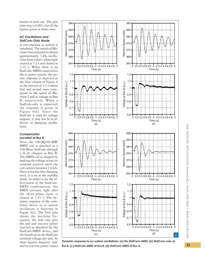
lations in each case. The plottime step is 0.001 s for all thefigures given in these cases.
AC Oscillations andStatCom-Only ModeA two-machine ac system issimulated. The inertia of Ma-chine I was adjusted to obtainapproximately 3-Hz oscilla-tions from a three- phase faultcreated at 3.1 s and cleared at3.25 s. When there is noStatCom- SMES connected tothe ac power system, the sys-tem response is depicted inthe first column of Figure 6in the interval of 3-5 s wherefirst and second rows corre-spond to the speed of Ma-chine I and ac voltage at BusB, respectively. When aStatCom-only is connected,the response is given inFigure 6(b) . Since theStatCom is used for voltagesupport, it may not be as ef-fective in damping oscilla-tions.
CompensatorLocated at Bus BNow, the 100-MJ/96-MWSMES coil is attached to a160-Mvar StatCom througha dc-dc chopper at Bus B.The SMES coil is charged bymaking the voltage across itsterminal positive until thecoil current becomes 3.6 kA.Once it reaches this charginglevel, it is set at the standbymode. In order to see the ef-fectiveness of the StatCom-SMES combination, theSMES activates right afterthe three-phase fault iscleared at 3.25 s. The dy-namic response of the com-bined device to ac systemoscillation is depicted inFigure 6(c). The first plotshows the machine fre-quency, the next two givethe real and reactive powerinjected or absorbed by theStatCom-SMES device, andthe fourth gives the StatComterminal voltage per unit. Inthese figures, negative, real,and/or reactive power values 25
IEE
EIN
DU
ST
RY
AP
PL
ICA
TIO
NS
MA
GA
ZIN
E•
MA
R|
AP
R2
00
3•
WW
W.IE
EE
.OR
G/
IAS
Mac
hine
Spe
ed(r
ad/s
)
388
384
380
376
372
368
3643 3.2 3.4 3.6 3.8 4 4.2 4.4 4.6 4.8 5
Time (s)
Mac
hine
Spe
ed(r
ad/s
)
388
384
380
376
372
368
3643 3.2 3.4 3.6 3.8 4 4.2 4.4 4.6 4.8 5
Time (s)V
olta
geat
Bus
B(p
.u.)
1.2
1.1
1
0.9
0.8
0.7
0.63 3.2 3.4 3.6 3.8 4 4.2 4.4 4.6 4.8 5
Time (s)3 3.2 3.4 3.6 3.8 4 4.2 4.4 4.6 4.8 5
Time (s)(a) (b)
Mac
hine
Spe
ed(r
ad/s
)
388
384
380
376
372
368
3643 3.2 3.4 3.6 3.8 4 4.2 4.4 4.6 4.8 5
Time (s)
Mac
hine
Spe
ed(r
ad/s
)
388
384
380
376
372
368
3643 3.2 3.4 3.6 3.8 4 4.2 4.4 4.6 4.8 5
Time (s)
3 3.2 3.4 3.6 3.8 4 4.2 4.4 4.6 4.8 5Time (s)
3 3.2 3.4 3.6 3.8 4 4.2 4.4 4.6 4.8 5Time (s)
(c) (d)
Vol
tage
atB
usB
(p.u
.)
Vol
tage
atB
usB
(p.u
.)
Vol
tage
atB
usB
(p.u
.)
1.2
1.1
1
0.9
0.8
0.7
0.6
1.2
1.1
1
0.9
0.8
0.7
0.6
1.2
1.1
1
0.9
0.8
0.7
0.6
Dynamic response to ac system oscillations. (a) No StatCom-SMES. (b) StatCom-only at
Bus B. (c) StatCom-SMES at Bus B. (d) StatCom-SMES at Bus A.
6
26
IEE
EIN
DU
ST
RY
AP
PL
ICA
TIO
NS
MA
GA
ZIN
E•
MA
R|
AP
R2
00
3•
WW
W.I
EE
E.O
RG
/IA
S
Sta
tCom
Rea
l Pow
er(M
W)
100
50
0
−50
−1003 3.2 3.4 3.6 3.8 4 4.2 4.4 4.6 4.8 5
Time (s)3 3.2 3.4 3.6 3.8 4 4.2 4.4 4.6 4.8 5
Time (s)
3 3.2 3.4 3.6 3.8 4 4.2 4.4 4.6 4.8 5Time (s)
3 3.2 3.4 3.6 3.8 4 4.2 4.4 4.6 4.8 5Time (s)
(a) (b)
Sta
tCom
Rea
lPow
er(M
W)
100
50
0
−50
−100
Sta
tCom
Rea
ctiv
eP
ower
(MV
AR
)
200
100
0
−100
−200
Sta
tCom
Rea
ctiv
eP
ower
(MV
AR
)200
100
0
−100
−200
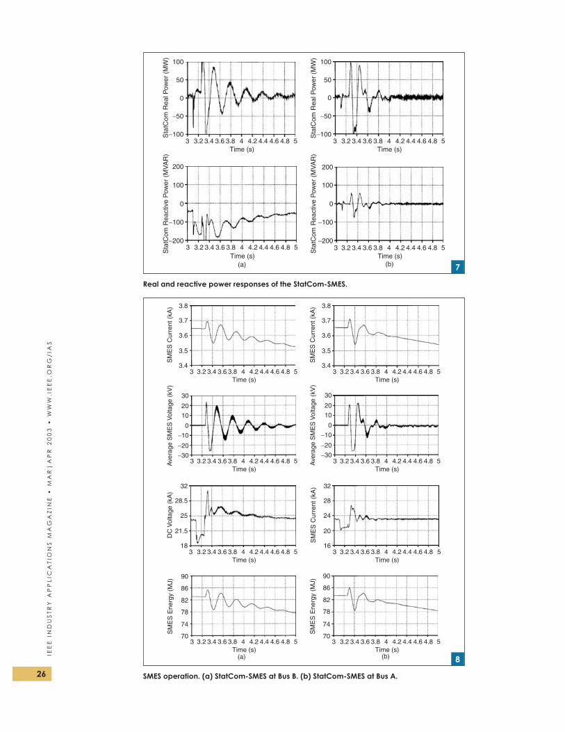
Real and reactive power responses of the StatCom-SMES.
7
SM
ES
Cur
rent
(kA
) 3.8
3.7
3.6
3.5
3.43 3.2 3.4 3.6 3.8 4 4.2 4.4 4.6 4.8 5
Time (s)
SM
ES
Cur
rent
(kA
) 3.8
3.7
3.6
3.5
3.43 3.2 3.4 3.6 3.8 4 4.2 4.4 4.6 4.8 5
Time (s)
3 3.2 3.4 3.6 3.8 4 4.2 4.4 4.6 4.8 5Time (s)
3 3.2 3.4 3.6 3.8 4 4.2 4.4 4.6 4.8 5Time (s)
3 3.2 3.4 3.6 3.8 4 4.2 4.4 4.6 4.8 5Time (s)
3 3.2 3.4 3.6 3.8 4 4.2 4.4 4.6 4.8 5Time (s)
3 3.2 3.4 3.6 3.8 4 4.2 4.4 4.6 4.8 5Time (s)
3 3.2 3.4 3.6 3.8 4 4.2 4.4 4.6 4.8 5Time (s)
Ave
rage
SM
ES
Vol
tage
(kV
)
30
20
10
0
−10
DC
Vol
tage
(kA
)
32
28.5
25
21.5
18
SM
ES
Cur
rent
(kA
) 32
28
24
20
16
−20
−30
Ave
rage
SM
ES
Vol
tage
(kV
)
30
20
10
0
−10
−20
−30
SM
ES
Ene
rgy
(MJ)
90
86
82
78
74
70
SM
ES
Ene
rgy
(MJ)
90
86
82
78
74
70
(a) (b)
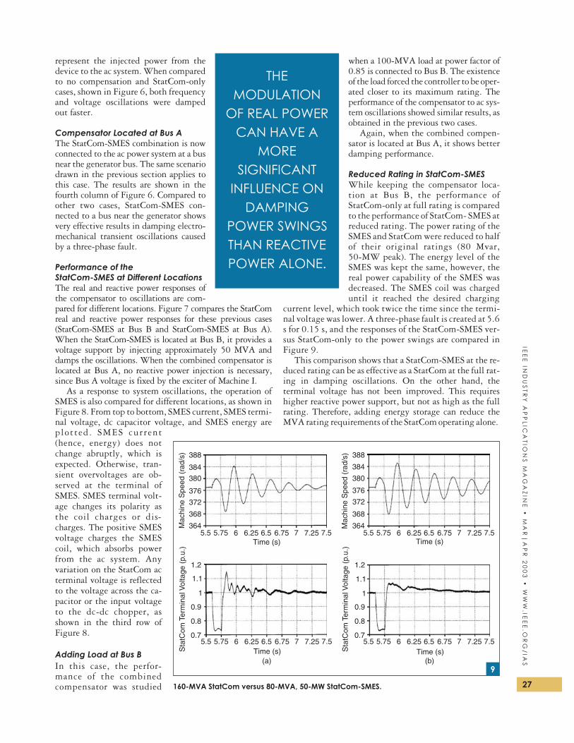
SMES operation. (a) StatCom-SMES at Bus B. (b) StatCom-SMES at Bus A.
8
represent the injected power from thedevice to the ac system. When comparedto no compensation and StatCom-onlycases, shown in Figure 6, both frequencyand voltage oscillations were dampedout faster.
Compensator Located at Bus AThe StatCom-SMES combination is nowconnected to the ac power system at a busnear the generator bus. The same scenariodrawn in the previous section applies tothis case. The results are shown in thefourth column of Figure 6. Compared toother two cases, StatCom-SMES con-nected to a bus near the generator showsvery effective results in damping electro-mechanical transient oscillations causedby a three-phase fault.
Performance of theStatCom-SMES at Different LocationsThe real and reactive power responses ofthe compensator to oscillations are com-pared for different locations. Figure 7 compares the StatComreal and reactive power responses for these previous cases(StatCom-SMES at Bus B and StatCom-SMES at Bus A).When the StatCom-SMES is located at Bus B, it provides avoltage support by injecting approximately 50 MVA anddamps the oscillations. When the combined compensator islocated at Bus A, no reactive power injection is necessary,since Bus A voltage is fixed by the exciter of Machine I.
As a response to system oscillations, the operation ofSMES is also compared for different locations, as shown inFigure 8. From top to bottom, SMES current, SMES termi-nal voltage, dc capacitor voltage, and SMES energy areplotted. SMES current(hence, energy) does notchange abruptly, which isexpected. Otherwise, tran-sient overvoltages are ob-served at the terminal ofSMES. SMES terminal volt-age changes its polarity asthe coil charges or dis-charges. The positive SMESvoltage charges the SMEScoil, which absorbs powerfrom the ac system. Anyvariation on the StatCom acterminal voltage is reflectedto the voltage across the ca-pacitor or the input voltageto the dc-dc chopper, asshown in the third row ofFigure 8.
Adding Load at Bus BIn this case, the perfor-mance of the combinedcompensator was studied
when a 100-MVA load at power factor of0.85 is connected to Bus B. The existenceof the load forced the controller to be oper-ated closer to its maximum rating. Theperformance of the compensator to ac sys-tem oscillations showed similar results, asobtained in the previous two cases.
Again, when the combined compen-sator is located at Bus A, it shows betterdamping performance.
Reduced Rating in StatCom-SMESWhile keeping the compensator loca-tion at Bus B, the performance ofStatCom-only at full rating is comparedto the performance of StatCom- SMES atreduced rating. The power rating of theSMES and StatCom were reduced to halfof their original ratings (80 Mvar,50-MW peak). The energy level of theSMES was kept the same, however, thereal power capability of the SMES wasdecreased. The SMES coil was chargeduntil it reached the desired charging
current level, which took twice the time since the termi-nal voltage was lower. A three-phase fault is created at 5.6s for 0.15 s, and the responses of the StatCom-SMES ver-sus StatCom-only to the power swings are compared inFigure 9.
This comparison shows that a StatCom-SMES at the re-duced rating can be as effective as a StatCom at the full rat-ing in damping oscillations. On the other hand, theterminal voltage has not been improved. This requireshigher reactive power support, but not as high as the fullrating. Therefore, adding energy storage can reduce theMVA rating requirements of the StatCom operating alone.
27
IEE
EIN
DU
ST
RY
AP
PL
ICA
TIO
NS
MA
GA
ZIN
E•
MA
R|
AP
R2
00
3•
WW
W.IE
EE
.OR
G/
IAS
THEMODULATION
OF REAL POWERCAN HAVE A
MORESIGNIFICANT
INFLUENCE ONDAMPING
POWER SWINGSTHAN REACTIVEPOWER ALONE.
Mac
hine
Spe
ed(r
ad/s
) 388
384
380
376
372
368
3645.5 5.75 6 6.25 6.5 6.75 7 7.25 7.5
Time (s)
Mac
hine
Spe
ed(r
ad/s
) 388
384
380
376
372
368
364
Time (s)
Time (s) Time (s)(a) (b)
Sta
tCom
Term
inal
Vol
tage
(p.u
.)
1.2
1.1
1
0.9
0.8
0.7
1.2
1.1
1
0.9
0.8
0.7
Sta
tCom
Term
inal
Vol
tage
(p.u
.)
5.5 5.75 6 6.25 6.5 6.75 7 7.25 7.5
5.5 5.75 6 6.25 6.5 6.75 7 7.25 7.55.5 5.75 6 6.25 6.5 6.75 7 7.25 7.5
160-MVA StatCom versus 80-MVA, 50-MW StatCom-SMES.
9
Real Power Versus ReactivePower in Damping OscillationsLow-frequency oscillations following disturbances inthe ac system can be damped by either reactive power orreal power injection/absorption. However, the reactivepower injected to the system is dependent on theStatCom terminal voltage. On the other hand, the SMESis ordered according to the variation of the real powerflow in the system. Damping power oscillations withreal power is more effective than reactive power since itdoes not effect the voltage quality of the system. Betterdamping dynamic performance may be obtained ifSMES is connected to the ac system through a series-connected voltage source inverter (static synchronous se-ries compensator) [11] rather than a shunt-connectedvoltage source inverter. However, this is not a justifiablesolution since it involves more cost.
ConclusionThis article presents the modeling and control of the inte-gration of a StatCom with SMES and its dynamic responseto system oscillations caused by a three-phase fault. It hasbeen shown that the StatCom-SMES combination can bevery effective in damping power system oscillations. Add-ing energy storage enhances the performance of a StatComand possibly reduces the MVA ratings requirements of theStatCom operating alone. This is important for a cost/ben-efit analysis of installing flexible ac transmission systemcontrollers on utility systems.
It should be noted that, in this study, the StatCom pro-vides a real power flow path for SMES, but the SMES con-troller is independent of the StatCom controller. While theStatCom is ordered to absorb or inject reactive power, theSMES is ordered to absorb/inject real power.
It was also observed that the location where the com-bined compensator is connected is important for improve-ment of overall system dynamic performance. Althoughthe use of a reactive power controller seems more effectivein a load area, as stated in [11], this simulation study showsthat a StatCom with real power capability can damp thepower system oscillations more effectively, thereby stabi-lizing the system faster if the StatCom-SMES controller islocated near a generation area rather than a load area.
AcknowledgmentsThis work is partly supported by the National ScienceFoundat ion, Department of Energy (GrantDE-FG36-94GO10011) and BWX Technologies, Inc.—Naval Nuclear Fuel Division. Any opinions, findings, con-clusions, or recommendations expressed herein are those ofthe authors and do not necessarily reflect the views of thesponsoring organizations.
References[1] W.V. Hassenzahl, “Superconducting magnetic energy storage,”
Proc. IEEE, vol. 71, pp. 1089-1098, Sept. 1983.
[2] Y. Mitani, K. Tsuji, and Y Murakami, “Application of supercon-
ducting magnetic energy storage to improve power system dy-
namic performance,” IEEE Trans. Power Syst., vol. 3, pp.
1418-1425, Nov. 1988.
[3] J.D. Rogers, R.I. Schermer, R.L. Miler, and J.F. Hauer, “30 MJ super-
conducting magnetic energy storage system for electric utility
transmission stabilization,” Proc. IEEE, vol. 71, pp. 1099-1107,
Sept. 1983.
[4] S. Bonerjee, J.K. Chatterjee, and S.C. Triphathy, “Application of
magnetic energy storage unit as load frequency stabilizer,” IEEE
Trans. Energy Conversion, vol. 5, pp. 46-51, Mar. 1990.
[5] R.H. Lasseter and S.G. Jalali, “Dynamic response of power condi-
tioning systems for superconductive magnetic energy storage,”
IEEE Trans. Energy Conversion, vol. 6, pp. 388-393, Sept. 1991.
[6] S.F. Kral, M. Aslam, P.F. Ribeiro, X. Huang, and M. Xu, “Supercon-
ducting power delivery systems for transmission and distribution
applications,” presented at the 57th American Power Conference,
Chicago, IL, 1995.
[7] R.F. Giese, “Progress toward high temperature superconducting
magnetic energy storage (SMES)—A second look,” Argonne Na-
tional Laboratory, Argonne, IL, 1998.
[8] V. Karasik, K. Dixon, C. Weber, B. Batchelder, and P. Ribeiro,
“SMES for power utility applications: A review of technical and cost
considerations,” IEEE Trans. Appl. Superconduct., vol. 9, pp.
541-546, June 1999.
[9] N.G. Hingorani and L. Gyugyi, Understanding Concepts and Technol-
ogy of Flexible AC Transmission Systems. Piscataway, NJ: IEEE
Press, 2000.
[10] C. Schauder, E. Stacey, M. Lund, L. Gyugyi, L. Kovalsky, A. Keri, A.
Mehraban, and A. Edris, “AEP UPFC project: Installation, commis-
sioning and operation of the 160MVA StatCom (Phase I),” IEEE
Trans. Power Delivery, vol. 13, pp. 1530-1535, Oct. 1998.
[11] E. Larsen, N. Miller, S. Nilsson, and S. Lindgren, “Benefits of
GTO-based compensation systems for electric utility applications,”
IEEE Trans. Power Delivery, vol. 7, pp. 2056-2062, Oct. 1992.
[12] K.K. Sen, “STATCOM-STATic synchronous COMpensator: The-
ory, modeling and applications,” IEEE Trans. Power Delivery, vol.
2, pp. 1177-1183, Feb. 1999.
[13] L. Gyugyi, “Dynamic compensation of ac transmission lines by
solid-state synchronous voltage sources,” IEEE Trans. Power Deliv-
ery, vol. 9, pp. 904-911, Apr. 1994.
[14] K.V. Patil, J. Senthil, J. Jiang, and R.M. Mathur, “Application of
statcom for damping torsional oscillations in series compensated ac
systems,” IEEE Trans. Energy Conversion, vol. 13, pp. 237-243,
Sept. 1998.
[15] A.B. Arsoy, Z. Wang, Y.Liu, and P.F. Ribeiro, “Transient model-
ing and simulation of a SMES coil and its power electronics inter-
face,” IEEE Trans. Appl. Superconduct., vol. 9, pp. 4715-4724, Dec.
1999.
[16] D. Hassan, R.M. Bucci, and K.T. Swe, “400MW SMES power con-
ditioning system development and simulation,” IEEE Trans. Power
Electron., vol.8, pp.237-249, July 1993.
A.B. Arsoy ([email protected]) is with Kocaeli University in IzmitKocaeli, Turkey. Y. Liu ([email protected]) is with Virginia Tech inBlacksburg, Virginia, USA. P.F. Ribeiro ([email protected]) is with Calvin College in Grand Rapids, Michigan,USA. F. Wang ([email protected]) is with GE Industrial Sys-tems in Salem, Virginia, USA. This article first appeared in itsoriginal format at the 2000 IEEE IAS Annual Meeting.28
IEE
EIN
DU
ST
RY
AP
PL
ICA
TIO
NS
MA
GA
ZIN
E•
MA
R|
AP
R2
00
3•
WW
W.I
EE
E.O
RG
/IA
S
![WCE 2017, July 5-7, 2017, London, U.K. Rail Power ... · speed and high power railways systems, ... (SVCs) or static synchronous compensators (STATCOMs) [5]. The main disadvantage](https://static.fdocuments.in/doc/165x107/5ae268ea7f8b9a7b218be9ee/wce-2017-july-5-7-2017-london-uk-rail-power-and-high-power-railways-systems.jpg)


![Rail Power Conditioner Based on Indirect AC/DC/AC … · speed and high power railways systems, ... or static synchronous compensators (STATCOMs) [5]. The main disadvantage of SVCs](https://static.fdocuments.in/doc/165x107/5ae271257f8b9a5d648cb0f1/rail-power-conditioner-based-on-indirect-acdcac-and-high-power-railways-systems.jpg)