Static and Dynamic Analysis of the Roll Cage for an All-Terrain Vehicle
9
Imperial Journal of Interdisciplinary Research (IJIR) Vol-2, Issue-6, 2016 ISSN: 2454-1362, http://www.onlinejournal.in Imperial Journal of Interdisciplinary Research (IJIR) Page 43 Static and Dynamic Analysis of the Roll Cage for an All-Terrain Vehicle Bharat Kumar Sati 1 , Prashi Upreti 2 , Anirudh Tripathi 3 & Shankar Batra 4 1,3,4 Department of Industrial and Production Engineering, College of Technology Pantnagar 2 Department of Mechanical Engineering, College of Technology Pantnagar Abstract: A roll cage is a skeleton of an All-Terrain Vehicle (ATV). The roll cage forms a structural base and a 3-D shell around the driver. The objective of the study is to analyze and optimize the roll cage designed under a set of particular rules given by Society of Automotive Engineers (SAE). This paper outlines static and dynamic analysis of the roll cage of ATV. Static analysis of the roll cage is done using ANSYS Static Structural for different collisions like front, side, rear and roll over. Dynamic analysis of different crash conditions like head-on, front, side, rear and roll over of the roll cage is done using ANSYS Explicit Dynamic. The main objective of analysis is to obtain optimum factor of safety which ensures that the roll cage of ATV will be safe in all conditions. 1. Introduction The roll- cage is a structure to protect the driver and to support all control systems like suspension, steering, and the engine. The design factor contains safety, easy manufacturing, durability & maintenance of the frame and a compact, lightweight & ergonomic design. The roll cage is designed under the guidelines of BAJA SAE rulebook. The objective of BAJA SAE competition is to design and fabricate an All Terrain Vehicle. It is very important to check all failure modes of roll cage. Aru et al., 2014 [1], Noorbhasha, N., 2010 [2] and Raina et al., 2015 [3] have done static analysis for predicting failure modes of roll cage. Noorbhasha , N., 2010 [2] have also done dynamic analysis for frontal impact for validating the results of static analysis. Noorbhasha, N., 2010 [2] and Raina et al., 2015 [2] have used grid independency for selection of mesh size during analysis. This research discusses about static analysis of all possible impact cases during event site. As static analysis is done using theoretically calculated value of forces by assuming impact time, so to validate results of static analysis, dynamic analysis is also done in this research for all possible impact cases. In dynamic analysis there is no need to take any assumptions which means that results of dynamic analysis are more accurate and better than results of static analysis. Also optimum mesh size is taken for all analysis in this research. Mesh size is selected by checking the independency of mesh size for results. 2. Dimensions The roll cage must ensure enough clearances from members for free movement of the driver. In order to reduce the weight two members with different cross sections are used to construct the roll-cage. The diameter of the primary member is 1.25” (inch) and thickness is 0.065” (inch) and that of the secondary members is 1’’ (inch) and thickness is kept 0.065” (inch). Attributes Values Length x Width x Height Vehicle: 81”x60”x61” Roll cage: 72.125”x31.25”x50.25” Weight of the vehicle (including the driver) 300 kg Weight of the roll- cage 31 kg Wheelbase 59” Track-width 50” Ground Clearance 12” Table 1. Dimensions of the roll-cage 3. Material properties ERW2 steel pipes are used for the roll-cage fabrication. It was selected because of its high yield strength. In addition to this, its easy availability and low cost compared to other materials also make it to select over other. S. no Property value 1. Composition C, Fe, Mn, S, P, Si, Al 2. Density(g/cm^3) 7.85
-
Upload
trinhtuong -
Category
Documents
-
view
280 -
download
8
Transcript of Static and Dynamic Analysis of the Roll Cage for an All-Terrain Vehicle
Imperial Journal of Interdisciplinary Research (IJIR) Vol-2, Issue-6, 2016 ISSN: 2454-1362, http://www.onlinejournal.in
Imperial Journal of Interdisciplinary Research (IJIR) Page 43
Static and Dynamic Analysis of the Roll Cage for an All-Terrain Vehicle
Bharat Kumar Sati1, Prashi Upreti2, Anirudh Tripathi3 &
Shankar Batra4 1,3,4Department of Industrial and Production Engineering, College of Technology Pantnagar
2Department of Mechanical Engineering, College of Technology Pantnagar
Abstract: A roll cage is a skeleton of an All-Terrain Vehicle (ATV). The roll cage forms a structural base and a 3-D shell around the driver. The objective of the study is to analyze and optimize the roll cage designed under a set of particular rules given by Society of Automotive Engineers (SAE). This paper outlines static and dynamic analysis of the roll cage of ATV. Static analysis of the roll cage is done using ANSYS Static Structural for different collisions like front, side, rear and roll over. Dynamic analysis of different crash conditions like head-on, front, side, rear and roll over of the roll cage is done using ANSYS Explicit Dynamic. The main objective of analysis is to obtain optimum factor of safety which ensures that the roll cage of ATV will be safe in all conditions. 1. Introduction The roll- cage is a structure to protect the driver and to support all control systems like suspension, steering, and the engine. The design factor contains safety, easy manufacturing, durability & maintenance of the frame and a compact, lightweight & ergonomic design. The roll cage is designed under the guidelines of BAJA SAE rulebook. The objective of BAJA SAE competition is to design and fabricate an All Terrain Vehicle. It is very important to check all failure modes of roll cage. Aru et al., 2014 [1], Noorbhasha, N., 2010 [2] and Raina et al., 2015 [3] have done static analysis for predicting failure modes of roll cage. Noorbhasha , N., 2010 [2] have also done dynamic analysis for frontal impact for validating the results of static analysis. Noorbhasha, N., 2010 [2] and Raina et al., 2015 [2] have used grid independency for selection of mesh size during analysis. This research discusses about static analysis of all possible impact cases during event site. As static analysis is done using theoretically calculated value of forces by assuming impact time, so to validate results of static analysis, dynamic analysis is also done in this research for all possible impact cases. In dynamic
analysis there is no need to take any assumptions which means that results of dynamic analysis are more accurate and better than results of static analysis. Also optimum mesh size is taken for all analysis in this research. Mesh size is selected by checking the independency of mesh size for results. 2. Dimensions The roll cage must ensure enough clearances from members for free movement of the driver. In order to reduce the weight two members with different cross sections are used to construct the roll-cage. The diameter of the primary member is 1.25” (inch) and thickness is 0.065” (inch) and that of the secondary members is 1’’ (inch) and thickness is kept 0.065” (inch).
Attributes Values Length x Width x
Height Vehicle: 81”x60”x61”
Roll cage: 72.125”x31.25”x50.25” Weight of the
vehicle (including the driver)
300 kg
Weight of the roll-cage
31 kg
Wheelbase 59” Track-width 50”
Ground Clearance 12”
Table 1. Dimensions of the roll-cage 3. Material properties ERW2 steel pipes are used for the roll-cage fabrication. It was selected because of its high yield strength. In addition to this, its easy availability and low cost compared to other materials also make it to select over other. S. no Property value
1. Composition C, Fe, Mn, S, P, Si, Al
2. Density(g/cm^3) 7.85

Imperial Journal of Interdisciplinary Research (IJIR) Vol-2, Issue-6, 2016 ISSN: 2454-1362, http://www.onlinejournal.in
Imperial Journal of Interdisciplinary Research (IJIR) Page 44
3. Yield strength, σyt (MPa)
407
4. Ultimate tensile strength(MPa)
470
5. Modulus of elasticity(GPa)
205
6. Poisson’s ratio 0.29 Table 2. Properties of ERW2 steel
4. 2-D views of roll cage and ATV 4.1 Front views
Figure 1. Front view of Roll cage
Figure 2. Front view of ATV 4.2 Side views
Figure 3. Side view of Roll cage
Figure 4. Side view of ATV 4.3 Top views
Figure 5. Top view of Roll cage
Figure 6. Top view of ATV 4.3 Isometric views
Figure 7. Isometric view of Roll cage

Imperial Journal of Interdisciplinary Research (IJIR) Vol-2, Issue-6, 2016 ISSN: 2454-1362, http://www.onlinejournal.in
Imperial Journal of Interdisciplinary Research (IJIR) Page 45
Figure 8. Isometric view of ATV
5. Possible conditions at event site ATV can face various conditions at event site like front impact, side impact, rear impact, roll over impact and head-on collision. All conditions with maximum possible velocity are describes as follows.
Figure 9. Front impact condition
Figure 10. Rear impact condition
Figure 11. Side impact condition
Figure 12. Rollover condition
Figure 13. Head-on collision condition 6. Mesh size selection for analysis Mesh size is calculated by checking the mesh independency. As per earlier studies [3] static analysis of front impact with force value 20000 N is carried out for various mesh size from 15 mm to 1 mm and then a graph is plotted between deformation and mesh size.

Imperial Journal of Interdisciplinary Research (IJIR) Vol-2, Issue-6, 2016 ISSN: 2454-1362, http://www.onlinejournal.in
Imperial Journal of Interdisciplinary Research (IJIR) Page 46
Graph 1. Deformation vs. Mesh size
Figure 14. Roll cage meshing (4 mm) Hence a mesh size of 4 mm is selected, as the deformation becomes constant (= 4.270 mm). It means that there will be negligible changes in accuracy of results on further reduction in mesh size. 7. Finite element analysis Using the solid modeling in CATIA V5 and Finite Element Analysis (FEA) in ANSYS 14.5 roll cage is designed and optimized to maximize strength and minimize weight. Static analysis is carried out for all cases front impact, rear impact, side impact and roll over impact and dynamic analysis is carried out for head-on collision, front impact, rear impact, side impact and roll over impact. 7.1 Static analysis In static analysis ATV is considered in static state and maximum possible force is applied to roll cage with suitable constraints as per different conditions. Static analysis is done in ANSYS Static Structural. As per earlier studies [1] impact time of roll cage in case of impact with rigid body (wall, floor etc.) is taken as 0.13 sec, while that in case of impact with a deformable object (another ATV), impact time is taken as 0.30 sec.
7.2 Dynamic analysis In dynamic analysis ATV is considered to be in state of motion and it is given maximum possible velocity and allows hitting the wall, ATV as per corresponding different impact cases. Dynamic analysis is done in ANSYS Explicit Dynamic. 8. Impact force calculation & analysis images in case of Static analysis 8.1. Front impact During front impact, the ATV may hit a tree, another ATV or a wall. Time of impact will be greater for deformable bodies as compare to that of rigid bodies so impact force in the case of wall will be more than that in case of another ATV or tree. Impact time in case of impact with wall is taken as 0.13 seconds. For analysis, ATV is considered to be in static state and force corresponding to velocity 60 km/h with impact time 0.13 seconds is applied to front part of the roll cage of ATV keeping rear suspension members fixed. Calculations: Weight of the ATV, M =300 kg Initial velocity before impact, vinitial = 16.67 m/s Final velocity after impact, vfinal will be zero. Impact time = 0.13 seconds Work done = change in kinetic energies As per earlier studies [3] From work energy principal, Work done = change in kinetic energies W = (0.5 × M × vfinal
2 - 0.5 × M × vinitial2)
│W│ = │- 0.5 × M × vinitial2│ =│- 0.5 × 300 × 16.672│ = 41666.67 Nm Now, Work done = force × displacement= F × s ……... (1) s = impact time × vmaximum = 0.13 ×16.67 = 2.1671 m So, from (1) we get, F = W/ s = 41666.67 / 2.1671 = 19,226.925 ≈ 20,000 N

Imperial Journal of Interdisciplinary Research (IJIR) Vol-2, Issue-6, 2016 ISSN: 2454-1362, http://www.onlinejournal.in
Imperial Journal of Interdisciplinary Research (IJIR) Page 47
Figure 15. Analysis Condition
Figure 16. von-Mises stress for front impact 8.2. Rear impact In actual condition during rear impact, another ATV is going to hit ATV on its rear part. As the ATV is a deformable body so the impact time is taken as 0.30 seconds. For analysis, ATV is considered to be in static state and force corresponding to velocity 60 km/h with impact time 0.30 seconds is applied to rear part of the roll cage of ATV keeping front suspension members fixed. Calculations:
From work energy principal, Work done = change in kinetic energies W = (0.5×M×vfinal
2 - 0.5×M×vinitial2)
│W│ = │- 0.5×M×vinitial2│= -0.5*300*16.672
= 41666.67 Nm Now, Work done = force × displacement= F × s s = impact time × vmaximum = 0.30 × 16.67 = 5.001 m So, from (1) we get,
F = W/ s = 41666.67 / 5.001 = 8331.67 ≈ 9,000 N
Figure 17. Analysis Condition
Figure 18.von-Mises stress for rear impact 8.3. Side impact During side impact another ATV will hit ATV on side and as ATV is deformable body, so the impact time is taken as 0.30 seconds. For analysis, ATV is considered to be in static state and force corresponding to velocity 60 km/h with impact time 0.30 seconds is applied to side of the roll cage of ATV keeping suspension members of other side fixed. Calculations: From work energy principal, Work done = change in kinetic energies W = (0.5 × M × vfinal
2 - 0.5 × M × vinitial2)
│W│ = │- 0.5×M×vinitial2│ =│- 0.5 × 300 × 16.672│ = 41666.67 Nm Now,

Imperial Journal of Interdisciplinary Research (IJIR) Vol-2, Issue-6, 2016 ISSN: 2454-1362, http://www.onlinejournal.in
Imperial Journal of Interdisciplinary Research (IJIR) Page 48
Work done = force × displacement= F × s s = impact time × vmaximum = 0.30 × 16.67 = 5.001 m So, from (1) we get, F = W/ s = 41666.67 / 5.001 = 8331.67 ≈ 9,000 N
Figure 19. Analysis Condition
Figure 20. von-Mises stress for side impact
8.4. Roll over In roll over impact, ATV is considered to be dropped on its roof on road or ground from a height of 10 feet.10 feet for the drop height is selected because it is sufficiently greater than anything expected at the event site. Since road and ground are non-deformable bodies, so impact time is taken as 0.13 seconds. For analysis, ATV is considered to be in static state and force corresponding to the calculated velocity 27.83 km/h for 10 feet with impact time 0.13 seconds is applied to top of the roll cage of ATV keeping bottom members fixed. Calculations:
Impact time = 0.13 s
During the fall, the whole potential changes into kinetic energy, M × g × h = 0.5 × M × v2 v = √ (2 × g × h) = √ (2 × 9.81 × 3.048) = 7.73 m/sec (or 27.83 km/h) Now from work energy principal Work done = change in kinetic energies │W│ = │- 0.5 × M × vinitial
2│ =│- 0.5 × 300 × 7.732│ = 8962.935 Nm Now, Work done = force × displacement= F × s s = impact time × vmaximum = 0.13 × 7.73 = 1.0049 m
Figure 21. Analysis Condition
Figure 22. von-Mises stress for roll over impact 9. Analysis conditions & analysis images in case of Dynamic analysis 9.1 Head on collision Head on collision of two similar ATV will be the worst condition at event site for ATVs. In head on collision two similar ATVs are allows hitting each other with maximum possible velocity. For
Imperial Journal of Interdisciplinary Research (IJIR) Vol-2, Issue-6, 2016 ISSN: 2454-1362, http://www.onlinejournal.in
Imperial Journal of Interdisciplinary Research (IJIR) Page 49
analysis roll cage of two Similar ATVs are allows hitting each other with velocity 60 km/h.
Figure 23. Analysis Condition
Figure 24. von-Mises stress for head-on collision
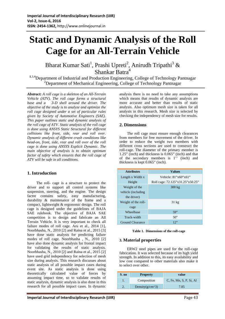
9.2. Front impact
For worst condition in front impact ATV is assumed to hit a wall at velocity of 60 km/h. Hitting a wall will give maximum possible stress as wall is non-deformable body and impact time will smaller. For analysis the roll cage of ATV is given velocity 60 km/h and allows hitting wall.
Figure 25. Analysis Condition
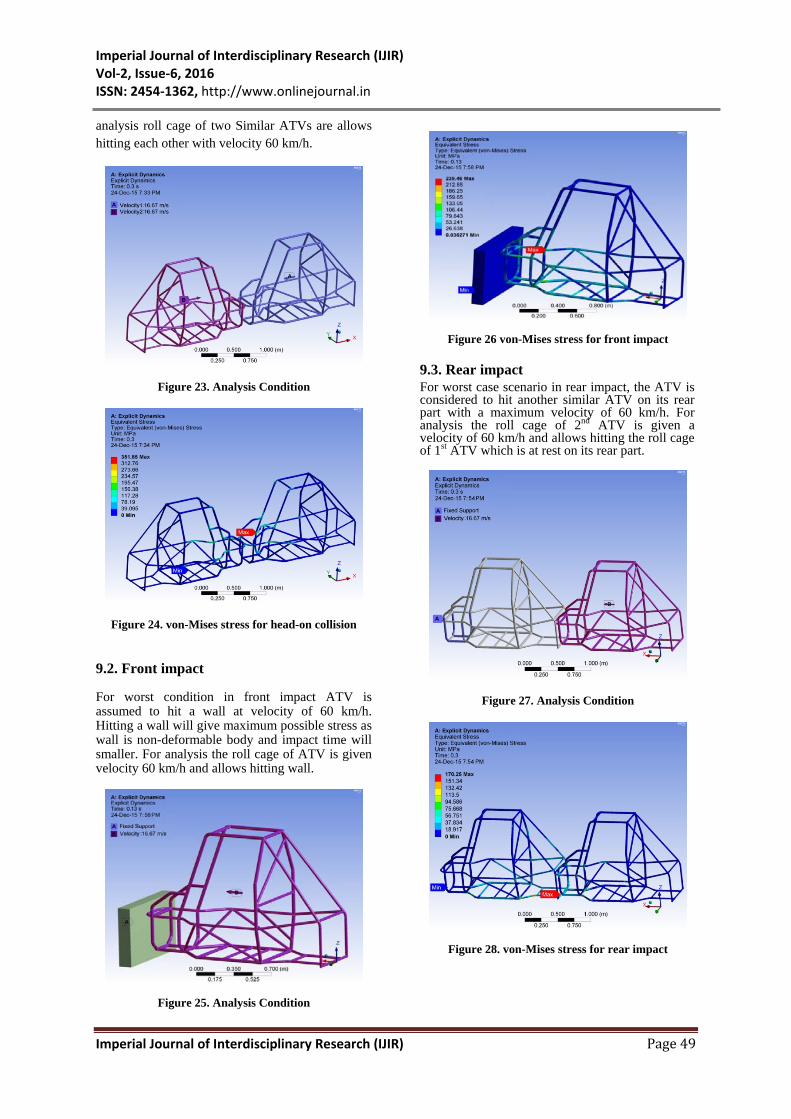
Figure 26 von-Mises stress for front impact 9.3. Rear impact For worst case scenario in rear impact, the ATV is considered to hit another similar ATV on its rear part with a maximum velocity of 60 km/h. For analysis the roll cage of 2nd ATV is given a velocity of 60 km/h and allows hitting the roll cage of 1st ATV which is at rest on its rear part.
Figure 27. Analysis Condition
Figure 28. von-Mises stress for rear impact

Imperial Journal of Interdisciplinary Research (IJIR) Vol-2, Issue-6, 2016 ISSN: 2454-1362, http://www.onlinejournal.in
Imperial Journal of Interdisciplinary Research (IJIR) Page 50
9.4. Side impact For worst case scenario in case of side impact, the one ATV is considered to be in rest and impact is subjected on its side by a similar ATV having a velocity of 60 km/h. For analysis the roll cage of ATV is given velocity 60 km/h and allows hitting the roll cage of 2nd ATV which is at rest on its side.
Figure 29. Analysis Condition
Figure 30. von-Mises stress for side impact 9.5. Roll over impact In roll over impact, ATV is considered to be dropped on its roof on road or ground with a velocity of 7.73 m/sec. For analysis the roll cage of ATV is given a velocity of 7.73 m/sec and allows hitting wall on its roof.
Figure 31. Analysis Condition
Figure 32. von-Mises stress for roll over impact 10. Summary of results 10.1. Static analysis Force
applied (N)
Maximum stress (Mpa)
Maximum Deformation
(mm)
Factor of
safety Front 20000 273.61 4.270 1.49 Rear 9000 197.14 2.613 2.06 Side 9000 221.04 5.997 1.84 Roll over
9000 166.77 1.765 2.44
Table 3. Results of static analysis

Imperial Journal of Interdisciplinary Research (IJIR) Vol-2, Issue-6, 2016 ISSN: 2454-1362, http://www.onlinejournal.in
Imperial Journal of Interdisciplinary Research (IJIR) Page 51
10.2. Dynamic analysis
Relative
Velocity
(m/sec)
Maximum stress (Mpa)
Maximum Deformatio
n (mm)
Factor of
safety
Head-on
120 351.85 5.354 1.16
Front 60 239.46 4.249 1.70 Rear 60 170.25 2.481 2.39 Side 60 180.85 5.341 2.25 Roll over
27.83 153.43 1.653 2.65
Table 4. Results of dynamic analysis
11. Conclusion
This study explores concepts of static analysis, dynamic analysis and selection of mesh size in finite element analysis. The main objective of the study was to obtain optimum factor of safety in all impact cases. During the study roll cage of All Terrain Vehicle was analyzed & optimized and optimum factor of safety is obtained in all possible impact cases at event site in static as well as in dynamic analysis which ensures that the roll cage of ATV will be safe in all conditions. Greater values of factor of safety for different cases in
dynamic analysis ensure the enhancement in results which is important.
12. References
[1] Aru, S., Jadhav, P., Jadhav, V., Kumar, A. and Angane, P. ‘DESIGN, ANALYSIS AND OPTIMIZATION OF A MULTI- TUBULAR SPACE FRAME’, International Journal of Mechanical and Production Engineering Research and Development (IJMPERD) ISSN(P): 2249-6890; ISSN(E): 2249-8001 Vol. 4, Issue 4, Aug 2014, 37-48© TJPRC Pvt. Ltd. [2] Noorbhasha, N. "Computational analysis for improved design of an SAE BAJA frame structure" .UNLV Theses, Dissertations, Professional Papers, and Capstones. Paper 736, 12-2010.
[3] Raina, D., Gupta, R. D. and Phanden, R.K. ‘Design and Development for Roll Cage of All- Terrain Vehicle’, International Journal for Technological Research in Engineering (IJTRE) Volume 2, Issue 7, March-2015 ISSN: 2347-4718
[4] 2015 Collegiate Design Series Baja SAEINDIA® Rules http://www.bajasaeindia.org/pdf/2015_Baja%20SAE%20India%20Rules.pdf