Statfjord A PP&A PAF 14.06 - norskoljeoggass.no€¢ Pull conductor, 20” and even ... • Stand...
16
Statfjord A PP&A PAF 14.06.2012 Tore Weltzin, Department Leader Statfjord Classification: Internal 2012-02-24
Transcript of Statfjord A PP&A PAF 14.06 - norskoljeoggass.no€¢ Pull conductor, 20” and even ... • Stand...
Statfjord A PP&A PAF 14.06.2012
Tore Weltzin, Department Leader Statfjord Classification: Internal 2012-02-24
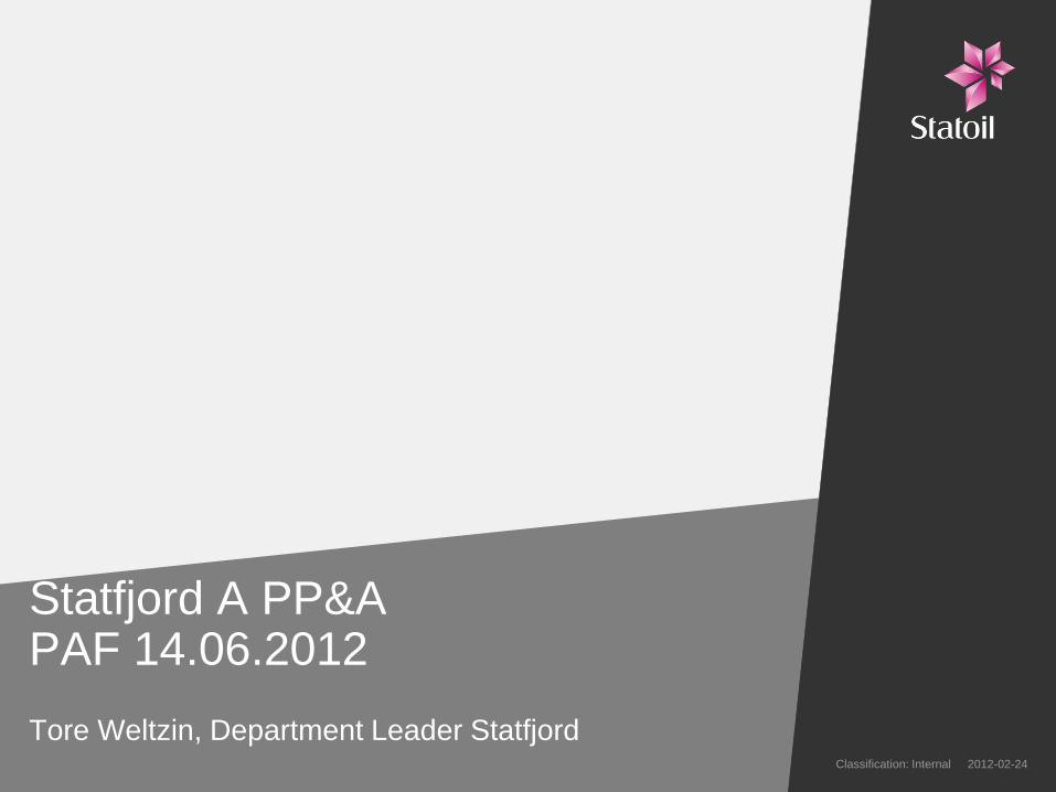
Statfjord A
Classification: Internal 2012-02-24 2
SFA PP&A - Barrier philosophy
Classification: Internal 2012-02-24 3
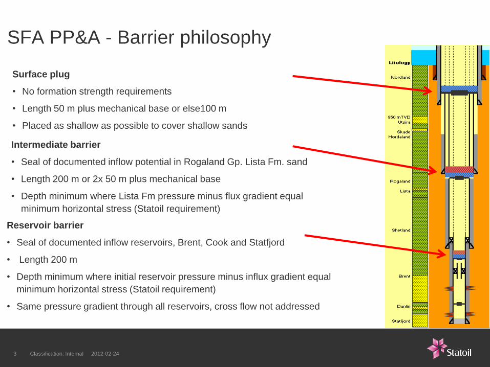
Surface plug
• No formation strength requirements
• Length 50 m plus mechanical base or else100 m
• Placed as shallow as possible to cover shallow sands
Intermediate barrier
• Seal of documented inflow potential in Rogaland Gp. Lista Fm. sand
• Length 200 m or 2x 50 m plus mechanical base
• Depth minimum where Lista Fm pressure minus flux gradient equal
minimum horizontal stress (Statoil requirement)
Reservoir barrier
• Seal of documented inflow reservoirs, Brent, Cook and Statfjord
• Length 200 m
• Depth minimum where initial reservoir pressure minus influx gradient equal
minimum horizontal stress (Statoil requirement)
• Same pressure gradient through all reservoirs, cross flow not addressed
SFA PP&A Design Examples
Classification: Internal 2012-02-24 4
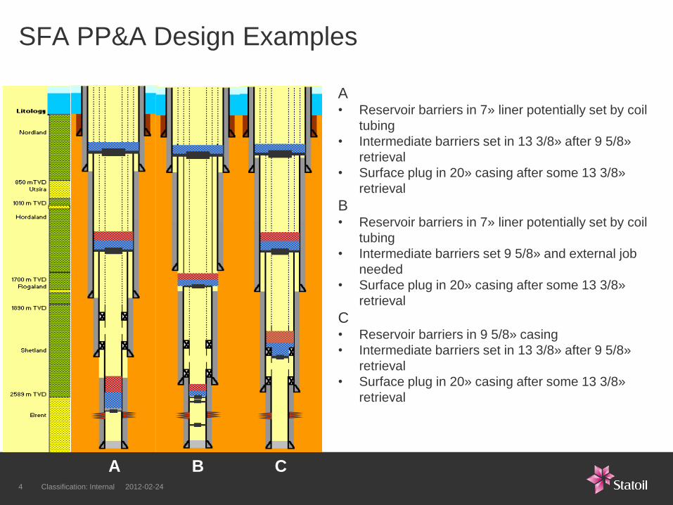
A
• Reservoir barriers in 7» liner potentially set by coil
tubing
• Intermediate barriers set in 13 3/8» after 9 5/8»
retrieval
• Surface plug in 20» casing after some 13 3/8»
retrieval
B
• Reservoir barriers in 7» liner potentially set by coil
tubing
• Intermediate barriers set 9 5/8» and external job
needed
• Surface plug in 20» casing after some 13 3/8»
retrieval
C • Reservoir barriers in 9 5/8» casing
• Intermediate barriers set in 13 3/8» after 9 5/8»
retrieval
• Surface plug in 20» casing after some 13 3/8»
retrieval
A B C
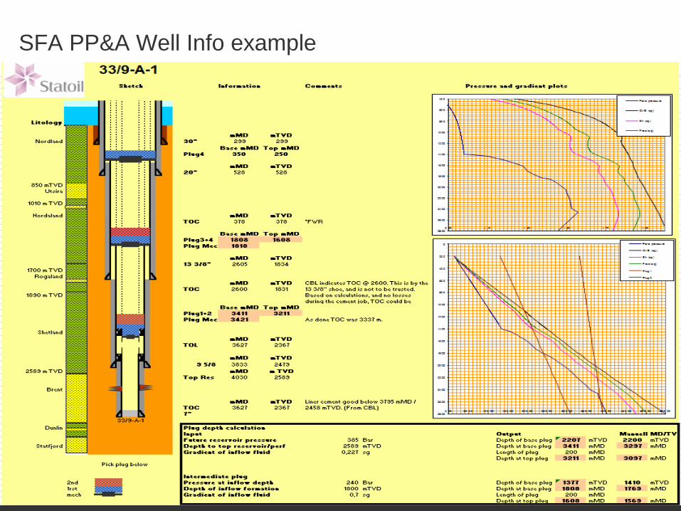
SFA PP&A Well Info example
Classification: Internal 2012-02-24 5
SFA PP&A Scope, schedule and cost (1)
Classification: Internal 2012-02-24 6
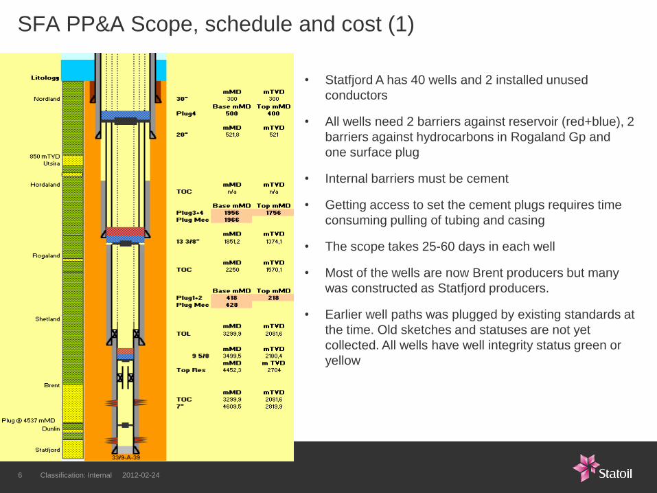
• Statfjord A has 40 wells and 2 installed unused
conductors
• All wells need 2 barriers against reservoir (red+blue), 2
barriers against hydrocarbons in Rogaland Gp and
one surface plug
• Internal barriers must be cement
• Getting access to set the cement plugs requires time
consuming pulling of tubing and casing
• The scope takes 25-60 days in each well
• Most of the wells are now Brent producers but many
was constructed as Statfjord producers.
• Earlier well paths was plugged by existing standards at
the time. Old sketches and statuses are not yet
collected. All wells have well integrity status green or
yellow
SFA PP&A Scope, schedule and cost (2)
Classification: Internal 2012-02-24 7
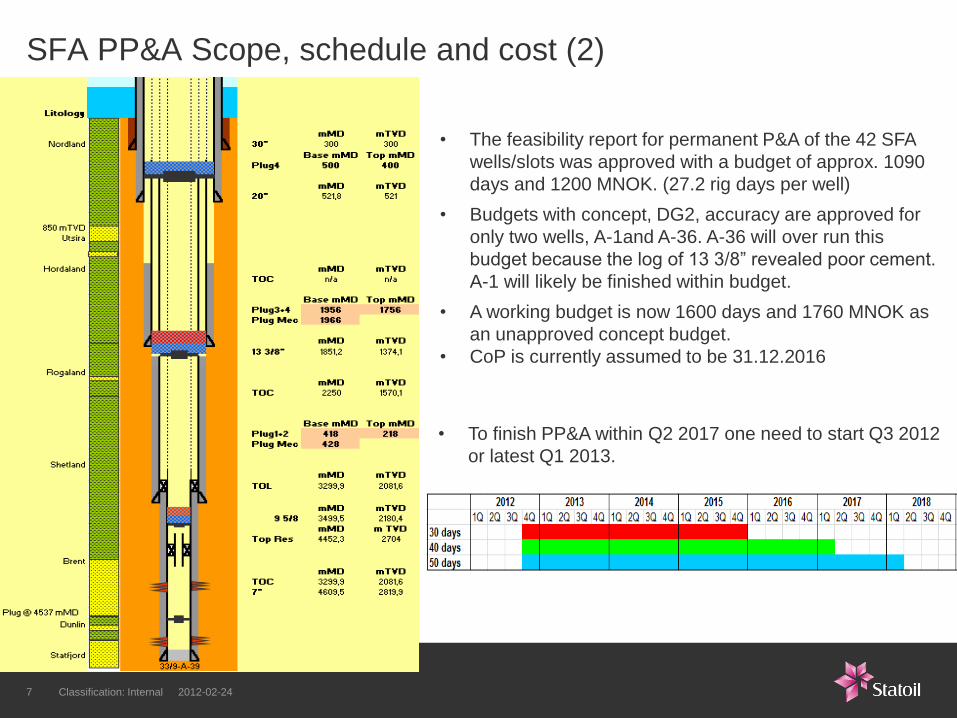
• The feasibility report for permanent P&A of the 42 SFA
wells/slots was approved with a budget of approx. 1090
days and 1200 MNOK. (27.2 rig days per well)
• Budgets with concept, DG2, accuracy are approved for
only two wells, A-1and A-36. A-36 will over run this
budget because the log of 13 3/8” revealed poor cement.
A-1 will likely be finished within budget.
• A working budget is now 1600 days and 1760 MNOK as
an unapproved concept budget.
• CoP is currently assumed to be 31.12.2016
• To finish PP&A within Q2 2017 one need to start Q3 2012
or latest Q1 2013.
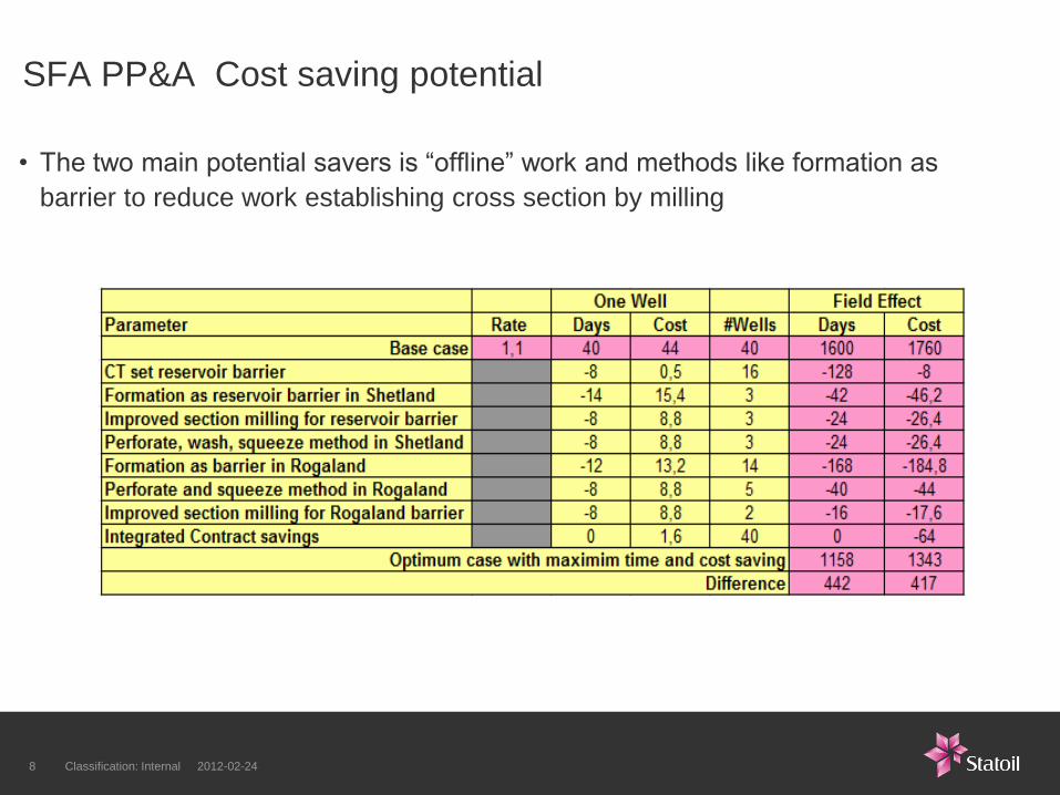
• The two main potential savers is “offline” work and methods like formation as
barrier to reduce work establishing cross section by milling
SFA PP&A Cost saving potential
Classification: Internal 2012-02-24 8
Additional project focus points
• Cost increase after cease of production since D&W inflects prolonged cessation project time
• Adequately resourcing the planning of the P&A campaign is critical. This will minimize the number of rig
days lost to down hole surprises and will reduce the risk of re-abandonments.
• Availability of platform resources will also have a large impact on P&A costs. The NPV impact of denying
bed space to P&A crews (both rig and wire line) must be understood allocating this bed space to other
users. Bed space is not currently a constraint.
SFA PP&A – Cost risk focus points
Classification: Internal 2012-02-24 9
SFA PP&A designs and plan - Challenges
Classification: Internal 2012-02-24 10
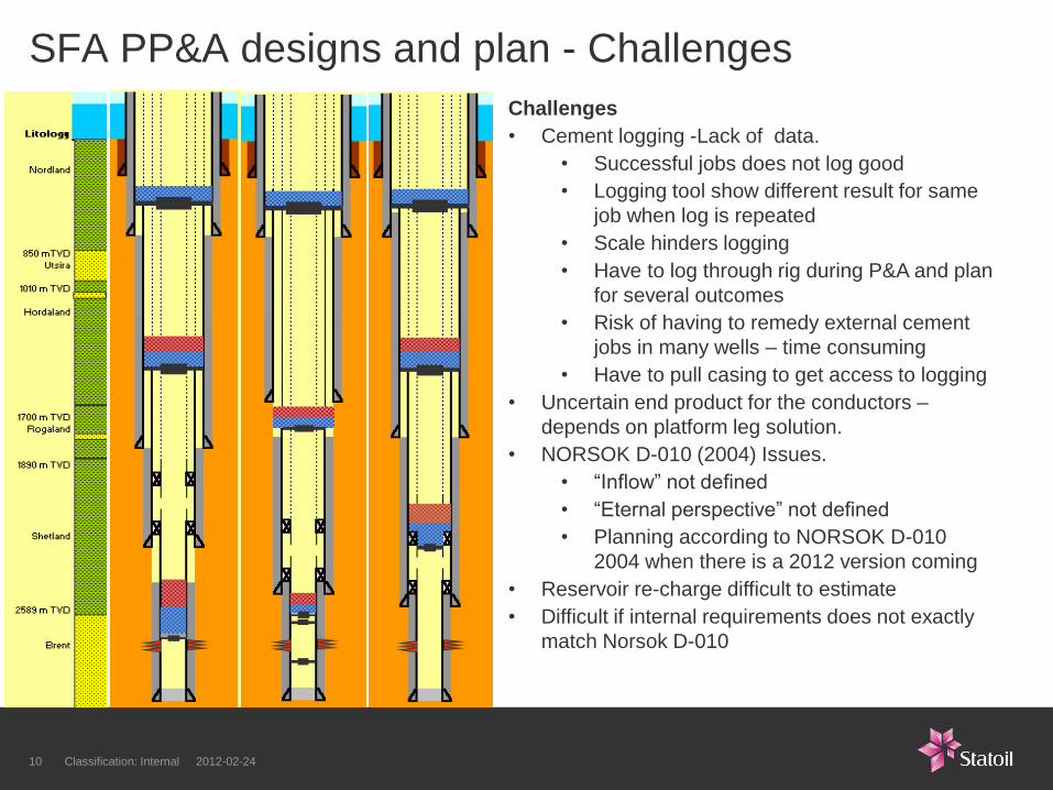
Challenges
• Cement logging -Lack of data.
• Successful jobs does not log good
• Logging tool show different result for same
job when log is repeated
• Scale hinders logging
• Have to log through rig during P&A and plan
for several outcomes
• Risk of having to remedy external cement
jobs in many wells – time consuming
• Have to pull casing to get access to logging
• Uncertain end product for the conductors –
depends on platform leg solution.
• NORSOK D-010 (2004) Issues.
• “Inflow” not defined
• “Eternal perspective” not defined
• Planning according to NORSOK D-010
2004 when there is a 2012 version coming
• Reservoir re-charge difficult to estimate
• Difficult if internal requirements does not exactly
match Norsok D-010
SFA PP&A designs and plan - opportunities
Classification: Internal 2012-02-24 11
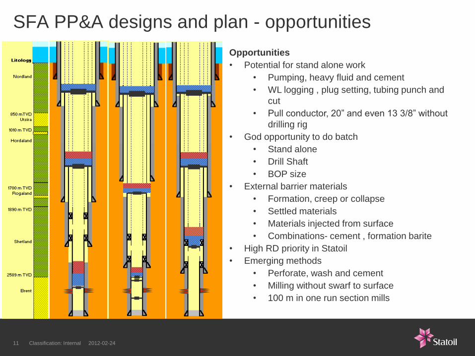
Opportunities
• Potential for stand alone work
• Pumping, heavy fluid and cement
• WL logging , plug setting, tubing punch and
cut
• Pull conductor, 20” and even 13 3/8” without
drilling rig
• God opportunity to do batch
• Stand alone
• Drill Shaft
• BOP size
• External barrier materials
• Formation, creep or collapse
• Settled materials
• Materials injected from surface
• Combinations- cement , formation barite
• High RD priority in Statoil
• Emerging methods
• Perforate, wash and cement
• Milling without swarf to surface
• 100 m in one run section mills
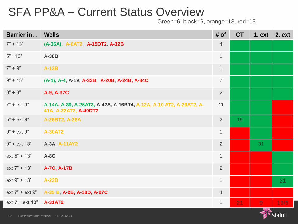
SFA PP&A – Current Status Overview Green=6, black=6, orange=13, red=15
Classification: Internal 2012-02-24 12
Barrier in… Wells # of CT 1. ext 2. ext
7” + 13” (A-36A), A-6AT2, A-15DT2, A-32B 4
5”+ 13” A-38B 1
7” + 9” A-13B 1
9” + 13” (A-1), A-4, A-19, A-33B, A-20B, A-24B, A-34C 7
9” + 9” A-9, A-37C 2
7” + ext 9” A-14A, A-39, A-25AT3, A-42A, A-16BT4, A-12A, A-10 AT2, A-29AT2, A-
41A, A-22AT2, A-40DT2
11
5” + ext 9” A-26BT2, A-28A 2 19
9” + ext 9” A-30AT2 1
9” + ext 13” A-3A, A-11AY2 2 31
ext 5” + 13” A-8C 1
ext 7” + 13” A-7C, A-17B 2
ext 9” + 13” A-23B 1 21
ext 7” + ext 9” A-35 B, A-2B, A-18D, A-27C 4
ext 7 + ext 13” A-31AT2 1 21 9 19/5
13 - Classification: Internal 2011-09-21
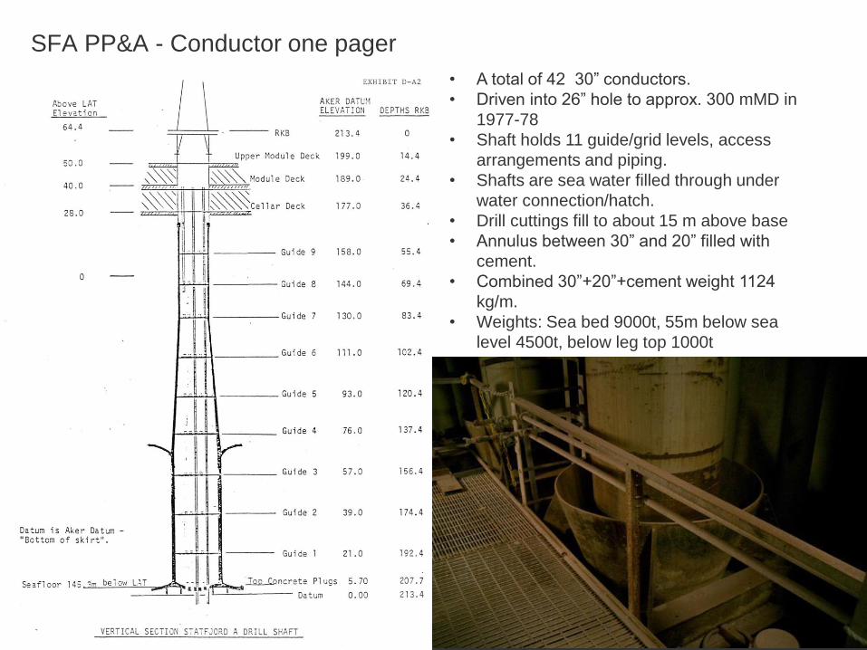
SFA PP&A - Conductor one pager
• A total of 42 30” conductors.
• Driven into 26” hole to approx. 300 mMD in
1977-78
• Shaft holds 11 guide/grid levels, access
arrangements and piping.
• Shafts are sea water filled through under
water connection/hatch.
• Drill cuttings fill to about 15 m above base
• Annulus between 30” and 20” filled with
cement.
• Combined 30”+20”+cement weight 1124
kg/m.
• Weights: Sea bed 9000t, 55m below sea
level 4500t, below leg top 1000t
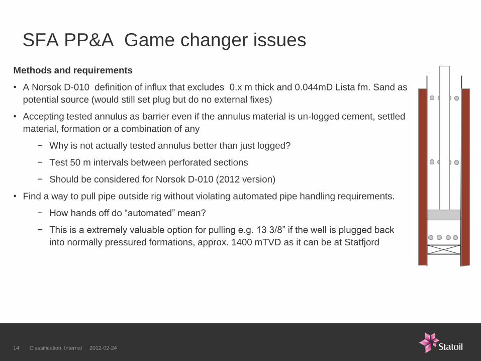
Methods and requirements
• A Norsok D-010 definition of influx that excludes 0.x m thick and 0.044mD Lista fm. Sand as
potential source (would still set plug but do no external fixes)
• Accepting tested annulus as barrier even if the annulus material is un-logged cement, settled
material, formation or a combination of any
− Why is not actually tested annulus better than just logged?
− Test 50 m intervals between perforated sections
− Should be considered for Norsok D-010 (2012 version)
• Find a way to pull pipe outside rig without violating automated pipe handling requirements.
− How hands off do “automated” mean?
− This is a extremely valuable option for pulling e.g. 13 3/8” if the well is plugged back
into normally pressured formations, approx. 1400 mTVD as it can be at Statfjord
SFA PP&A Game changer issues
Classification: Internal 2012-02-24 14
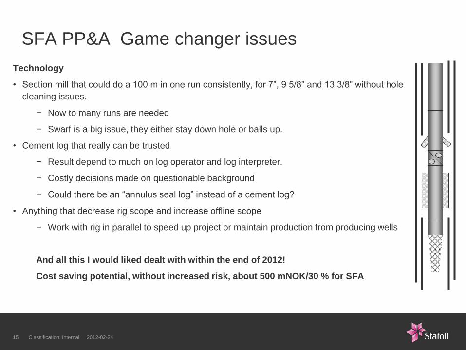
Technology
• Section mill that could do a 100 m in one run consistently, for 7”, 9 5/8” and 13 3/8” without hole
cleaning issues.
− Now to many runs are needed
− Swarf is a big issue, they either stay down hole or balls up.
• Cement log that really can be trusted
− Result depend to much on log operator and log interpreter.
− Costly decisions made on questionable background
− Could there be an “annulus seal log” instead of a cement log?
• Anything that decrease rig scope and increase offline scope
− Work with rig in parallel to speed up project or maintain production from producing wells
And all this I would liked dealt with within the end of 2012!
Cost saving potential, without increased risk, about 500 mNOK/30 % for SFA
SFA PP&A Game changer issues
Classification: Internal 2012-02-24 15

Thank You
Classification: Internal 2012-02-24 16


![CHAPTER 14 Defaults; Acceleration; Consequences§ 14.06 Late Charges on Acceleration § 14.07 Interest After Acceleration and After Judgment [1] General Rule [2] Interest After Judgment](https://static.fdocuments.in/doc/165x107/5f31e2c2cce2fc18fe3367cf/chapter-14-defaults-acceleration-1406-late-charges-on-acceleration-1407.jpg)