Statement of Basis - US EPA · Statement of Basis ... entering the deethanizer. The deethanizer...
54
Transcript of Statement of Basis - US EPA · Statement of Basis ... entering the deethanizer. The deethanizer...


Statement of Basis Draft Greenhouse Gas Prevention of Significant Deterioration Preconstruction Permit for
Formosa Plastics Corporation, Point Comfort, Texas Olefins 3 Expansion
Permit Number: PSD-TX-1383-GHG
June 2014
This document serves as the statement of basis for the above-referenced draft permit, as required by 40 CFR § 124.7. This document sets forth the legal and factual basis for the draft permit conditions and provides references to the statutory or regulatory provisions, including provisions under 40 CFR § 52.21, that will apply if the permit is finalized. This document is intended for use by all parties interested in the permit. I. Executive Summary
On December 11, 2012, Formosa Plastics Corporation, Texas (Formosa) submitted to EPA Region 6 a Prevention of Significant Deterioration (PSD) permit application for greenhouse gas (GHG) emissions for the proposed Olefins 3 Expansion project portion of the overall 2012 Expansion Project at Formosa’s Point Comfort, Calhoun County, Texas chemical plant complex. On May 16, 2013, Formosa submitted a revised permit application. In connection with the same proposed project, Formosa submitted a PSD NSR permit application for non-GHG pollutants to the Texas Commission on Environmental Quality (TCEQ) on December 21, 2012 and a revised permit application on June 5, 2013. For the Olefins 3 Expansion project at the Point Comfort chemical complex, Formosa proposes to construct a new olefins production unit and a propane dehydrogenation (PDH) unit. After reviewing the application, EPA Region 6 has prepared the following Statement of Basis (SOB) and draft air permit to authorize construction of air emission sources at the Formosa Point Comfort chemical complex. This SOB documents the information and analysis EPA used to support the decisions EPA made in drafting the air permit. It includes a description of the proposed facility, the applicable air permit requirements, and an analysis showing how the applicant complied with the requirements. EPA Region 6 concludes that Formosa’s application is complete and provides the necessary information to demonstrate that the proposed project meets the applicable air permit regulations. EPA's conclusions rely upon information provided in the permit application, supplemental information requested by EPA and provided by Formosa, and EPA's own technical analysis. EPA is making all this information available as part of the public record.

2
II. Applicant Formosa Plastics Corporation, Texas 201 Formosa Drive P.O. Box 700 Point Comfort, TX 77978 Physical Address: 201 Formosa Drive Point Comfort, TX 77978 Contact: Randy Smith, Vice President General Manager Formosa Plastics Corporation, Texas (361) 987-7000 III. Permitting Authority On May 3, 2011, EPA published a federal implementation plan that makes EPA Region 6 the PSD permitting authority for the pollutant GHGs. 75 FR 25178 (promulgating 40 CFR § 52.2305). The GHG PSD Permitting Authority for the State of Texas is: EPA, Region 6 1445 Ross Avenue Dallas, TX 75202 The EPA, Region 6 Permit Writer is: Erica Le Doux Environmental Engineer Air Permitting Section (6PD-R) U.S. EPA, Region 6 1445 Ross Avenue, Suite 1200 Dallas, TX 75202 (214) 665-7265

3
IV. Facility Location The Formosa Plastic Corporation, Texas chemical complex is located in Point Comfort, Calhoun County, Texas. The geographic coordinates for this facility are as follows: Latitude: 28º 41’ 20” North Longitude: 96º 32’ 50” West Calhoun County is currently designated attainment for all pollutants. The nearest Class 1 area is Big Bend National Park, which is located over 500 miles from the site. The figure below illustrates the facility location for this draft permit. Figure 1. Formosa Plastics Corporation, Texas Point Comfort Olefins 3 Expansion Location

4
V. Applicability of Prevention of Significant Deterioration (PSD) Regulations EPA concludes Formosa’s application is subject to PSD review for the pollutant GHGs, because the project would lead to an emissions increase of 75,000 TPY CO2e as described at 40 CFR § 52.21(b)(49)(iv)(b) and an emissions increase greater than zero TPY on a mass basis as described at 40 CFR § 52.21(b)(23)(ii) (Formosa calculated a CO2e emissions increase of 2,625,842 TPY for the proposed project). EPA Region 6 implements a GHG PSD FIP for Texas under the provisions of 40 CFR § 52.21 (except paragraph (a)(1)). See 40 CFR § 52.2305. As the permitting authority for regulated NSR pollutants that trigger PSD (other than GHGs), TCEQ has determined that the proposed project is subject to PSD review for non-GHG pollutants, including VOC, CO, NO2, CO, and PM/PM10/PM2.5. At this time, TCEQ has not issued a PSD permit for the non-GHG pollutants. Accordingly, under the circumstances of this project, TCEQ will issue the non-GHG portion of the PSD permit and EPA will issue the GHG portion.1 EPA Region 6 applies the policies and practices reflected in EPA’s PSD and Title V Permitting Guidance for Greenhouse Gases (March 2011). Consistent with that guidance, we have not required the applicant to model or conduct ambient monitoring for GHGs, nor have we required any assessment of impacts of GHGs in the context of the additional impacts analysis or Class I area provisions of 40 CFR § 52.21(o) and (p), respectively. Instead, EPA has determined that compliance with BACT is the best technique that can be employed at present to satisfy additional impacts analysis and Class I area requirements of the rules as they relate to GHGs. We note again, however, that the proposed project has regulated NSR pollutants that are non-GHG pollutants, which will be addressed by the PSD permit to be issued by TCEQ. VI. Project Description The proposed GHG PSD permit, if finalized, will authorize Formosa to construct and operate a new olefins production unit and a PDH unit as part of the Olefins 3 Expansion project. The new plant will be located at the existing Point Comfort complex located in Calhoun County, Texas. The Olefins 3 Expansion project at the Point Comfort chemical complex proposes to construct a new olefins production unit consisting of fourteen ethylene pyrolysis furnaces, recovery equipment, refrigeration, utilities, cooling, and treatment systems. The major pieces of recovery equipment include a quench tower, cracked gas compression, caustic wash tower, refrigeration systems, deethanizer, demethanizer, ethylene fractionator, depropanizer, debutanizer. In addition, the Olefins 3 Expansion project includes a cooling tower and a flare system (two low pressure steam-assisted ground flares and a two-staged air-assisted elevated flare). The Olefins Expansion
1 See EPA, Question and Answer Document: Issuing Permits for Sources with Dual PSD Permitting Authorities, April 19, 2011, http://www.epa.gov/nsr/ghgdocs/ghgissuedualpermitting.pdf

5
project will also involve the construction of a PDH unit that will include a depropanizer tower, four PDH reactors, heat recovery system, compression, refrigeration and chilling train, deethanizer, propylene fractionators, four steam boilers, and cooling tower. Olefins 3 Unit The Olefins 3 plant will be designed with a production capacity of approximately 1,750,000 short TPY of high purity ethylene product. The produced ethylene will be transported by pipeline and used internally at an existing Formosa plant or sold to other markets. Fresh imported ethane feed received from outside battery limits (OSBL) is combined with recycle ethane from the ethylene fractionator. The combined stream is superheated (with quench water) prior to entering the ethane feed saturator. In the saturator, the ethane feed is saturated with water by humidification, and the humidified ethane feed from the saturator is superheated in a low pressure (LP) steam heated exchanger. The heated ethane/steam mixture is then fed to the fourteen pyrolysis furnaces (OL3-FUR1 through OL3-FUR14). The feed stream is further preheated in the convection section of each furnace before entering the radiant coils where the thermal cracking of the feed occurs. The radiant heat in the furnace will be provided by fuel gas fired hearth (floor fired) and wall burners. The combustion product stream from the fuel gas firing is routed through the convection section in the upper part of the furnace where the feed is preheated. The combustion products will be routed through a selective catalytic reduction (SCR) unit for NOx control before being released to the atmosphere. The product stream (cracked gas) from the furnace radiant coils is routed through heat exchangers where heat is recovered by boiler feed water to produce superheated high pressure (SHP) steam. The product stream from the furnace is sent to the quench tower. During the cracking process in the furnace, ethylene is produced along with a number of other hydrocarbon products (cracked gas). The cracked gas from the furnaces is cooled and partially condensed by direct countercurrent contact with re-circulating water in the quench tower. The overhead vapor leaving the process water stripper is sent back to the quench water tower where it is reprocessed. The acid gases continue to be carried through the process until they are removed in the caustic/water wash tower. The quench tower overhead vapors are compressed in a steam turbine-driven centrifugal process gas compressor with inter-stage cooling provided by cooling water. Charge gas from the caustic/water wash tower overhead is sent through a drier feed knockout drum for moisture removal and then to the charge gas driers where the process gas is dried in a molecular sieve drying system. The vapor from the charge gas driers is cooled (by propylene refrigerant) before entering the deethanizer. The deethanizer column is heated with recovered energy from low pressure steam. The deethanizer tower produces a vapor overhead. This overhead is sent to the

6
acetylene converter (ACU). The bottoms stream from the deethanizer is sent to the depropanizer for additional processing. The ACU employs a catalyst to convert acetylene to ethylene by selective hydrogenation. The outlet of the acetylene converter, which is rich in hydrogen, methane, ethylene, and ethane, is further processed in the demethanizer tower. In the demethanizer, methane and hydrogen are separated as overheads that are routed to the fuel gas system. This overhead stream is high in hydrogen content. Some amount of the hydrogen is recovered in a pressure swing absorption (PSA) system, while the remainder of the hydrogen and hydrocarbons are used as fuel gas for the pyrolysis furnaces. The demethanizer bottoms proceed to the ethylene fractionator for product recovery. The ethylene fractionator bottoms stream (composed primarily of ethane) is recycled and combined with the fresh ethane feed from outside battery limits before the feed saturator. As previously mentioned, the bottoms from the deethanizer are routed to the depropanizer. The overhead stream from the depropanizer contains methyl acetylene (MA) and propadiene (PD) that are removed by selective hydrogenation to propylene and propane in a single-bed reactor called the MAPD converter. The MAPD catalyst must be periodically regenerated as polymer accumulates on the catalyst surface during normal operation (OL3-MAPD). The bottoms product from the depropanizer flows to the debutanizer where the overhead product is separated for export. The debutanizer bottoms/pygas product is also exported after cooling with cooling water. The temperatures in the radiant coils of the furnaces (OL3-FUR1 through OL3-FUR14), which are required to accomplish the thermal cracking of the feed, result in coke accumulation in the tube side of the coils. As the coke accumulates, it decreases the heat transfer in the tube and interferes with the efficiency of the furnace operation. Then, the furnace is “decoked”, i.e., the coke is removed from the tubes to restore efficient furnace operation. Furnaces are decoked in a staggered cycle; so, while the decoking process is occurring in some furnaces, others may be concurrently operated in the thermal cracking mode of operation. Propane Dehydrogenation (PDH) Unit The PDH unit will be designed to produce 725,000 short TPY of polymer-grade propylene product by the dehydrogenation of propane. Fresh propane feed is vaporized with recovered heat from the reactor effluent stream and routed to the depropanizer tower. Recycle propane from the propylene fractionator is sent as reflux to the depropanizer tower. In the depropanizer tower, fresh propane feed and recycled propane are purified before the propane feed enters the reactors (PDH-REAC1 through PDH-REAC4). The reactors are fired using fuel gas and are equipped with SCR units for NOx emission control. Fresh propane feed and propane recycle are routed to the depropanizer column where C4s and heavier compounds (also referred to as naphtha) are separated from the C3 compounds and are

7
drawn off as naphtha product. The overheads from the depropanizer tower, C3 compounds, are diluted with saturated medium pressure steam before being routed to the reactor to minimize fouling of the reactor catalyst. The dilution steam is supplied by the steam boilers (OL3-BOIL1 through OL3-BOIL4). Each steam boiler is equipped with an SCR unit for NOX emission control. In the reactor reaction section, the dehydrogenation of propane to propylene takes place. This is performed through four reaction trains. Dehydrogenation is a strongly endothermic reaction in which propane is converted to propylene. Lower hydrocarbons like ethane, ethylene and methane are also formed in parallel side reactions. Dehydration of propane also promotes hydrolysis and thus the formation of minor amounts of carbon dioxide. Other minor reactions that occur as a result of thermal cracking also promote the formation of small amounts of coke. This requires regular regeneration of the catalyst to burn off the coke deposits. The catalyst regeneration is accomplished using a mixture of steam and air, and the resulting regeneration off-gas is routed to the combustion section of the PDH reactor to destroy any residual hydrocarbons. The hot reactor effluent process gas contains the desired propylene product, steam, hydrogen and unconverted propane with a small amount of other products of side reactions. The effluent stream from the reaction trains is cooled by routing it through a series of heat exchangers (for heat recovery) throughout the PDH unit. Through this heat recovery process, steam and traces of heavier hydrocarbon by-products are condensed from the reactor effluent gas. The cooled process gas stream is routed through a series of condensate knockout drums to remove the condensed steam before being routed to the inlet of the process gas compressor. After the reactors, the remainder of the PDH process is the propylene purification process. These steps require higher operating pressure; therefore, the process gas is compressed before entering the CO2 removal system. In the PDH process, CO2 is formed due to the hydrolysis reaction and reconversion of coke lay-down on the catalyst (caused by thermal cracking). Therefore, CO2 is present in the process gas and must be removed from the propylene product. For this purpose, an absorption process for sour gas removal is used, which selectively absorbs CO2 contained in the process gas. The majority of the CO2 and small of amounts of hydrocarbon resulting from the regeneration of the absorbent are mixed with the plant fuel gas and used as fuel for the reactors. The rich solvent from the bottom of the absorber column is sent to the solvent flash drum. Flash gas from this solvent flash drum, containing any remaining CO2 and light hydrocarbons, is routed back to the cooled process gas stream at the inlet to the condensate knockout drums for recycle. Solvent flash drum bottoms are routed to the solvent system stripper for processing and reuse in the CO2 removal system. The process gas from the CO2 removal system flows through a flash drum that allows the hydrogen and methane to be separated from the heavier components. The overhead stream from the flash drum, consisting mainly of hydrogen, methane, and small amounts of C2+

8
hydrocarbons, flows through process gas driers employing molecular sieves to remove traces of water which could result in freezing and plugging of the cold box. The bottom of the flash drum (mostly C3+ compounds) is routed to the deethanizer tower. From the process gas driers, the process gas will flow, after additional chilling, to the cold box. The cold boxes separate non-condensable process gas components, such as hydrogen and methane, from a propane and propylene-containing liquid phase. The heavier hydrocarbon phase (C2 and C3+ compounds) will be condensed while the hydrogen and methane remain in the gas phase. The gas phase, which is extremely cold, serves as refrigerant media in cold boxes. By heat exchange with the cold box, feed gas is warmed and sent on to the expander. Mechanical energy recovery is available at the coupling of the expander and is used for generation of electric power that is charged into the electrical power grid. Due to the polytropic expansion, the expanded gas cools down and supplies the main portion of the cryogenic energy required in the cold boxes. From the expander, the gas phase is sent to the fuel gas header. The heavier hydrocarbons such as ethane, ethylene, unconverted propane, and propylene from the cold box section will combine with the bottoms of the flash drum and continue on to the deethanizer for distillation. The lighter overheads of the deethanizer will be routed to the fuel gas system via the cold box expander, while the heavier bottoms components, including propane and propylene, will continue on to the propylene fractionator. In the propylene fractionator, propylene is obtained as overhead product. The bottoms stream, which consists mainly of unconverted propane and traces of heavier boiling components, is recycled and sent to the front end of the plant (depropanizer tower). Process Condensate Stripper In the process condensate stripper, organic compounds are removed from the aqueous process condensate. The vent gases leaving the stripper are routed to the fuel gas header. The stripper bottoms are reused as boiler feed water to produce dilution steam within the PDH unit. The blowdown from the steam generators is routed to the complex wastewater treatment plant. Combustion Device Fuels for Olefins 3 Plant The fourteen furnaces that are proposed for the Olefins 3 plant will be capable of firing a variety of fuels. The furnaces are fired with natural gas as a startup fuel and Olefins 3 fuel gas as the primary fuel. The Olefins 3 fuel gas mixing drum combines the following streams:
Off-gas from dryer regeneration: Deethanizer overhead that is a hydrogen-rich gas Off-gas from chilling train: Demethanizer overhead that is methane-rich PSA offgas: Hydrogen Natural gas: Primarily methane

9
Combustion Device Fuels for PDH Plant The four PDH reactors will also be capable of using a variety of fuels. The PDH reactors are fired with natural gas as a startup fuel and PDH unit fuel gas as the primary fuel. The PDH fuel gas mixing drum combines the following streams:
Off-gas from the absorbent regeneration: Off-gas will contain mainly CO2 and small of amounts of hydrocarbon.
Gas phase from the expander: The gas phase contains non-condensable process gas components, such as hydrogen and methane. Also, the lighter components in the deethanizer overhead stream will be routed to the fuel gas system via the coldbox expander.
Process condensate stripper vent gas: The vent gases leaving the stripper are routed to the fuel gas system
Natural gas: Primarily methane In addition to using this fuel gas for combustion in the PDH reactors, the fuel gas is used for pressure control for the pressurized vessels and regeneration gas for the drying beds. Steam Boilers Four steam boilers (OL3-BOIL1 through OL3-BOIL4) will generate steam for use throughout the Olefins 3 Expansion. The combustion products will be routed through a SCR system before being released to the atmosphere. The steam boilers combust fuel gas generated from the Olefins 3 and PDH units combined with natural gas import. Natural gas will be used as a startup fuel. Natural Gas/Fuel Gas Piping Natural gas is delivered to the site via pipeline and is fired as a start-up fuel in Olefins 3 and PDH plant combustion sources. Natural gas is also used as a start-up fuel in the steam boilers. Once the units are in normal operation as lesser amount of natural gas is imported and mixed with hydrogen-rich process gas to create a fuel gas mixture that is used as the primary combustion fuel in Olefins 3 plant combustion units and the steam boilers. During normal operation, the PDH plant is nearly self-sufficient in regards to fuel, as it generates enough fuel gas to fire the reactors. Flare Systems The Olefins 3 plant elevated flare system (OL3-FLRA and OL3-FLRB) is designed to provide safe control for PDH unit vent gas streams that cannot be recycled in the process or routed to the fuel gas system.

10
Two low pressure/ground flares (OL3-LPFLR1 and OL3-LPFLR2) will control breathing losses from existing API product tanks, spent caustic tanks, spent caustic oxidation unit, and the wash oil chemical tank.
Emergency Generator Engines In the event of a power outage, an emergency generator (OL3-GEN) will supply power to operate valves and other critical equipment in the Olefins 3 unit and a second emergency generator (PDH-GEN) will supply power to operate valves and other critical equipment in the PDH unit. VII. General Format of the BACT Analysis The BACT analyses for this draft permit were conducted by following the “top-down” BACT approach outlined in EPA’s PSD and Title V Permitting Guidance for Greenhouse Gases (March 2011). The five steps in the “top-down” BACT process are listed below.
(1) Identify all potentially available control options; (2) Eliminate technically infeasible control options; (3) Rank remaining control technologies; (4) Evaluate the most effective controls and document the results; and (5) Select BACT.
As part of the PSD review, Formosa provided in the GHG permit application a 5-step top-down BACT analysis for the Olefins 3 Expansion project. EPA has reviewed Formosa’s BACT analysis, which has been incorporated into this SOB, and also provides its own analysis in setting forth BACT for this proposed permit. EPA’s BACT analysis is provided below. VIII. Applicable Emission Units and BACT Discussion The majority of the contribution of GHGs associated with the project is from combustion sources (i.e., pyrolysis furnaces, furnace decoking, PDH reactors, steam boilers, flares, and emergency engine testing). The site has some fugitive emissions from piping components that contribute an insignificant amount of GHGs. These stationary combustion sources primarily emit carbon dioxide (CO2) and small amounts of nitrous oxide (N2O) and methane (CH4). The following devices are subject to this GHG PSD permit:
Steam Cracking Furnaces (EPNs: OL3-FUR1, OL3-FUR2, OL3-FUR3, OL3-FUR4, OL3-FUR5, OL3-FUR6, OL3-FUR7, OL3-FUR8, OL3-FUR9, OL3-FUR10, OL3-FUR11, OL3-FUR12, OL3-FUR13, and OL3-FUR14);
Decoke Drum Vents (EPNs: OL3-DK1 and OL3-DK2);

11
Steam Boilers (EPNs: OL3-BOIL1, OL3-BOIL2, OL3-BOIL3 and OL3-BOIL4); PDH Reactors (EPNs: PDH-REAC1, PDH-REAC2, PDH-REAC3 and PDH-REAC4) MAPD regeneration (OL3-MAPD); Flare Systems (EPNs: OL3-FLRA and OL3-FLRB and OL3-LPFLR1 and OL3-
LPFLR2); Engines (EPNs: OL3-GEN and PDH-GEN); Equipment Fugitives (EPNs: OL3-FUG and PDH-FUG); and Maintenance, startup and shutdown (MSS) activities (EPNs: OL3-MSS and PDH-MSS)
IX. Pyrolysis Cracking Furnaces (EPNs: OL3-FUR1, OL3-FUR2, OL3-FUR3, OL3-
FUR4, OL3-FUR5, OL3-FUR6, OL3-FUR7, OL3-FUR8, OL3-FUR9, OL3-FUR10, OL3-FUR11, OL3-FUR12, OL3-FUR13, and OL3-FUR14)
The Olefins 3 unit consists of fourteen identical pyrolysis cracking furnaces (EPNs: OL3-FUR1, OL3-FUR2, OL3-FUR3, OL3-FUR4, OL3-FUR5, OL3-FUR6, OL3-FUR7, OL3-FUR8, OL3-FUR9, OL3-FUR10, OL3-FUR11, OL3-FUR12, OL3-FUR13, and OL3-FUR14). The furnaces are equipped with Ultra LoNOx® burners, Lean Premix Wall burners and SCR systems to control NOx emissions.2 Furnace fuel is natural gas or hydrogen-rich gas at a maximum firing rate of 220 MMBtu/hr. The hydrogen-rich gas will be from the dryer regeneration system (deethanizer overhead), methane-rich off gas from the chilling train (demethanizer overhead) and pressure swing adsorption (PSA) off-gas. Normal operation involves natural gas and/or process-related fuel firing in the furnaces and the control of NOx emissions using SCR. Three additional scenarios are described in Section X that pertain to furnace maintenance, start-up, and shutdown (MSS) activities. The only exception is that some of the produced hydrogen will be used in the facilities’ hydrogenation processes instead of being used as fuel. Step 1 – Identification of Potential Control Technologies for GHGs Low Carbon Fuels – Fuels vary in the amount of carbon per Btu, which in turn affects the
quantity of CO2 emissions generated per unit of heat input. Typically, gaseous fuels such as natural gas or hydrogen-rich plant tail gas contain less carbon, and thus lower CO2 potential to emit, than liquid or solid fuels such as diesel or coal. Formosa proposes to use natural gas for startup and fuel gas for primary operation.
Furnace excess air control – Monitoring of oxygen in the flue gas adjustment of inlet air flow will assist in maximizing thermal efficiency. The furnaces will be equipped with oxygen
2 Formosa provided additional details on burner selection for the ethylene furnaces along with manufacturer data at http://www.epa.gov/earth1r6/6pd/air/pd-r/ghg/formosa-olefins-expansion-response080913.pdf

12
analyzers in both the stack and the arch (between the radiant and convection sections). Typically, excess oxygen levels of 3 to 5 percent are optimal for a good combustion profile.
Good Operating and Maintenance Practices – Good combustion practices include appropriate maintenance of equipment and operating within the recommended combustion air and fuel ranges of the equipment as specified by its design, with the assistance of oxygen trim control.
Energy Efficient Design – Formosa selected an energy efficient proprietary design for its pyrolysis cracking furnaces. To maximize thermal efficiency, the pyrolysis cracking furnaces will be equipped with heat recovery systems to produce steam from waste heat for use throughout the plant.3
Carbon Capture and Storage – CCS is an available add-on control technology that is applicable for all of the site’s combustion units.
Step 2 – Elimination of Technically Infeasible Alternatives Carbon Capture and Sequestration (CCS) EPA generally considers a technology to be technically feasible if it: (1) has been demonstrated and operated successfully on the same type of source under review, or (2) is available and applicable to the source type under review. PSD and Title V Permitting Guidance for Greenhouse Gases (March 2011), pg. 33. CO2 capture technologies, including post-combustion capture, have not been demonstrated in practice on an olefins cracking furnace. Moreover, while CO2 capture technologies may be commercially available generally, we believe that there is insufficient information at this time to conclude that CO2 capture is applicable to sources that have low concentration CO2 streams, such as cracking furnaces.4 As a result, EPA believes that CCS is technically infeasible for the ethane cracking units and can be eliminated as BACT. Nevertheless, because Formosa has provided a cost analysis of CCS with its permit application, we have decided to also evaluate CCS through Step 4 of the BACT analysis. In regards to the remaining control options, EPA finds that all are technically feasible. Step 3 – Ranking of Remaining Technologies Based on Effectiveness
CO2 capture and storage (up to 90%) Low-Carbon Fuel (approximately 40%)
3 Formosa provided a summary of the design strategy used during equipment selection and the design attributes, http://www.epa.gov/earth1r6/6pd/air/pd-r/ghg/formosa-olefins-expansion-response080913.pdf 4 FPC TX provided a revised BACT analysis in response to EPA’s request for detailed CCS cost analysis April 14, 2014. http://www.epa.gov/earth1r6/6pd/air/pd-r/ghg/formosa-olefins-expansion-appendix-c-bact-analysis041414.pdf On page 15 of the submittal, Table 6-2 entitled, “Candidate CCS Source Exhaust Stream CO2 Concentrations and Flow Rates, by Unit Type” indicates the CO2 concentration in the flue gas of the furnaces is only about 6.18% volume.

13
Furnace excess air control Energy Efficient Design Good Operating and Maintenance Practices
CO2 capture and storage is capable of achieving 90% reduction of produced CO2 emissions and thus considered to be the most effective control method. The use of low-carbon fuels, furnace excess air control, energy efficient design, and good combustion practices are all considered effective and have a range of efficiency improvements that cannot be directly quantified; therefore, the above ranking is approximate only. These technologies all may be used concurrently (including, at least in theory, in conjunction with CCS). The estimated efficiencies were obtained from Energy Efficiency Improvement and Cost Saving Opportunities for the Petrochemical Industry: An ENERGY STAR Guide for Energy and Plant Managers (Environmental Energy Technologies Division, University of California, sponsored by USEPA, June 2008). This report addressed improvements to existing energy systems as well as efficiencies associated with new equipment. Step 4 – Evaluation of Control Technologies in Order of Most Effective to Least Effective, with Consideration of Economic, Energy, and Environmental Impacts Carbon Capture and Sequestration Even though CCS was determined to be technically infeasible at Step 2, the applicant provided additional evidence that supports the rejection of CCS as BACT in Step 4. CO2 emissions from the cracking furnaces could theoretically be absorbed in a conventional amine solvent. The CO2 could then be concentrated in an amine regenerator vent stream, dried, compressed and routed to oil production facilities using CO2 for enhanced oil recovery (EOR) or stored in geologic formations. Capital costs associated with CCS fall into two primary areas – CO2 Capture and Compression Equipment and CO2 Transport. The capture and compression equipment associated with CCS would have cost impacts based on the installation of the additional process equipment (e.g., amine units, cryogenic units, dehydration units, and compression facilities), while transport costs are associated with construction of a pipeline to transport the captured CO2. Formosa conducted an analysis of the capital cost impact of CCS on all three proposed projects using project specific data along with the data provided by the Report of the Interagency Task Force on Carbon Capture and Storage (August 2010). The estimated capital cost for post-combustion CO2 capture and compression equipment was estimated to be $905 million. For transportation costs, Formosa estimated they would need to construct a CO2 pipeline approximately 439 miles long and 20-inch diameter to reach a geological storage site and estimated the capital cost for the pipeline at $604 million. Formosa estimated that geologic storage costs would result in an initial capital cost of
14
$11 million. The total capital cost for CCS with geologic storage would be $1.52 billion. Formosa also provided a cost analysis for CCS with an enhanced oil recovery (EOR) end user. The pipeline needed for EOR is estimated to be approximately 10 miles. Formosa estimated the cost of a 10-mile pipeline would be $20 million. Formosa assumed the cost for capture and compression to remain the same. The total capital for CCS with EOR would be $925 million. Formosa has estimated that the Olefins 3 expansion project would contribute 66% of the CO2 flow rate to the CCS system. Therefore, it can be assumed that to capture only the CO2 from the Olefins 3 Expansion project the cost would be 66% of the total CCS costs identified in the paragraph above. This equates to a capital cost of $610.5 million for CCS for the Olefins 3 Expansion project only. Formosa provided a capital cost for all three projects to be $2.0 billion. It is estimated that the capital cost for the Olefins 3 Expansion project to be approximately 1.3 billion. CCS would increase the capital cost of this project by almost 50%. Based on these costs, Formosa maintains that CCS is not economically feasible. In preparing this proposed permit, EPA Region 6 evaluated Formosa’s CCS cost estimate and compared it to the cost of CCS for other similar cracking furnace projects that have undergone permitting. We note that both Occidental Chemical Corporation (OxyChem) in Gregory, Texas and Dow Chemical Company (Dow) in Freeport, Texas each proposed projects for cracking furnaces that are similar to that proposed by Formosa and those applications included CCS cost estimates can be compared with than those provided by Formosa. While the CCS costs estimates for these other projects appear to be lower than those for the Formosa project, the Formosa project is much larger than these facilities and includes additional equipment and processes. Specifically, OxyChem’s permit authorizes the construction of 5 ethane cracking furnaces and Dow’s permit authorizes the construction of 8 cracking furnaces, while this proposed Formosa project includes 14 furnaces. In the case of the OxyChem permit, the applicant estimated that the capital costs for post-combustion capture and compression equipment (without pipeline cost) to be $241,100,000. For the Dow proposed permit, the applicant provided a cost analysis for post-combustion capture and compression of the CO2 to be $367,800,000 (without pipeline cost). OxyChem’s and Dow’s capital costs per furnace for post-combustion capture and compression equipment is calculated to be $48.22 and 45.98 million, respectively. Formosa’s capital costs per furnace for post-combustion capture and compression equipment is estimated to be $42.66 million. Therefore, the CCS cost estimate for the Olefins 3 Expansion project correlates with other similar facilities for the scale of the project. Furthermore, EPA notes the recovery and purification of CO2 from the cracking furnaces would necessitate significant additional processing, including energy, and environmental/air quality penalties, to achieve the necessary CO2 concentration for effective sequestration. The additional process equipment required to separate, cool, and compress the CO2 would require a significant additional power expenditure. This equipment would include amine scrubber vessels, CO2

15
strippers, amine transfer pumps, flue gas fans, an amine storage tank, and CO2 gas compressors. For example, operation of carbon capture equipment at a typical natural gas fired combined cycle plant is estimated to reduce the net energy efficiency of the plant from approximately 50% (based on the fuel higher heating value (HHV)) to approximately 42.7% (based on fuel HHV).5 To provide the amount of reliable electricity needed to power a capture system, Formosa would need to significantly expand the scope of the utility plant expansion proposed with this project to install one or more additional electric generating units, which are sources of conventional (non-GHG) and GHG air pollutants themselves. To put these additional power requirements in perspective, gas-fired electric generating units typically emit more than 100,000 tons CO2e/yr and would themselves, require a PSD permit for GHGs in addition to non-GHG pollutants. CCS Conclusion: EPA concludes that CCS should be eliminated under Step 4 for this project as economically prohibitive, based on a capital cost increase of at least 50% for CCS control, as well as the potential energy and environmental impacts that could result from decreases in net power output or increases in air pollution emissions due the additional power requirements for CCS equipment. Low-Carbon Fuel The use of hydrogen-rich low-carbon fuel is economically and environmentally practicable for the proposed project. Furnace excess air control Excess air control using stack gas oxygen monitors and good operating and maintenance practices are considered good engineering practices and have been included with the proposed furnace design. Implementing these design elements and operational parameter monitoring is effective at minimizing formation of CO2 in the ethane cracking furnaces, but the effects are not directly quantifiable. There are no economic, energy, or environmental impacts associated with this control option that would justify its elimination. Energy Efficient Design The use of an energy efficient furnace and unit design is economically and environmentally practicable for the proposed project6. By optimizing energy efficiency, the project requires less fuel than comparable less-efficient operations, resulting in cost savings. Further, reduction in fuel 5 US Department of Energy, National Energy Technology Laboratory, “Costs and Performance Baseline For Fossil Energy Plants, Volume 1 - Bituminous Coal and Natural Gas to Energy”, Revision 2, November 2010 6 A detailed diagram for the cracking furnaces is available at http://www.epa.gov/earth1r6/6pd/air/pd-r/ghg/formosa-olefins-expansion-furnace-detail.pdf

16
consumption corresponding to energy efficient design reduces emissions of other combustion products such as NOx, CO, VOC, PM10, and SO2, providing environmental benefits as well. Specific technologies utilized by the furnaces include the following:
Feed Preheating – By preheating the ethane/steam feed mixture in the convection section prior to cracking, less fuel firing is required to initiate the cracking process. Formosa estimates that approximately 48 MMBtu/hr of thermal energy will be recovered by implementing this option.
Economizer – Use of heat exchangers to recover heat from the exhaust gas to preheat incoming steam drum feedwater will maximize thermal efficiency. Formosa estimates that approximately 25 MMBtu/hr of thermal energy will be recovered by implementing this option.
Steam drum – Use of heat exchangers (quench exchangers) to recover heat from the radiant section flue gas and generate high pressure steam. This heat recovery creates beneficial steam that can be used to create mechanical energy in other equipment. Formosa estimates that approximately 32 MMBtu/hr of thermal energy will be recovered by implementing this option.
Condensate recovery – Return of hot condensate for use as feedwater to the steam drum. Use of hot condensate as feedwater results in less heat required to produce steam, thus improving thermal efficiency. Formosa estimates that approximately 11 MMBtu/hr of thermal energy will be recovered by implementing this option.
Additional boiler feed water (BFW) coil bank in convection section – Conventional furnace designs include a single BFW preheat section in the upper portion of the convection section to recover waste heat from flue gases leaving the radiant section. The convection section of the Olefins 3 furnaces have been designed with an additional bank of BFW coils/tube to provide maximum heat recovery from the flue gases. As the furnace gets older and efficiency (due to coil fouling) becomes an issue, this design option ensures continued heat recovery and efficiency greater than conventional industrial furnaces. Formosa estimates that including this design option will achieve an additional 5 MMBtu/hr (approximately) of heat recovery.
Lower BFW supply temperature - The BFW temperature being supplied to the BFW coils will enter the heat recovery section at a temperature of approximately 160° F to ensure maximum heat absorption.
Good Operating and Maintenance Practices Good operation and maintenance practices for the steam cracking furnaces extend the performance of the combustion equipment, which reduces fuel gas usage and subsequent GHG emissions. Operating and maintenance practices have a significant impact on performance, including its efficiency, reliability, and operating costs.

17
Step 5 – Selection of BACT To date, other similar facilities with a GHG BACT limit are summarized in the following table:
Company / Location
Process Descriptio
n Control Device BACT Emission Limit
/ Requirements Year
Issued Reference
BASF FINA Petrochemicals LP, NAFTA Region Olefins Complex; Port Arthur, TX
Ethylene Production
Energy Efficiency/ Good Design & Combustion Practices
GHG BACT for furnace limit flue gas exhaust temperature ≤ 309oF on 365-day average, rolling average. Each furnace limited to a maximum firing rate of 498 MMBtu/hr
2012 PSD-TX-903-GHG
Williams Olefins LLC, Geismar Ethylene Plant; Geismar, LA
Ethylene Production
Energy Efficiency Low-emitting Feedstocks Lower-Carbon Fuels
Cracking heaters to meet a thermal efficiency of 92.5%, Ethane/Propane to be used as feedstock. Fuel gas containing 25% volume hydrogen on an annual basis.
2012 PSD-LA-759
Equistar Chemicals, LP; Channelview, TX
Ethylene Production
Low NOx burners; Low carbon fuels; Energy efficient design; Good combustion practices
Furnace gas exhaust temperature ≤408°F on a 365-day rolling average. Maintain a minimum thermal efficiency of 89.5% on a 12-month rolling average. Each furnace limited to a maximum firing rate of 640 MMBtu/hr
2013 PSD-TX-1272-GHG
Equistar Chemicals, LP; LaPorte Complex; LaPorte, TX
Ethylene Production
Low carbon fuels; Energy efficient design; Good combustion practices
Furnace gas exhaust temperature ≤302°F or a 365-day rolling average. Maintain a minimum thermal efficiency of 91% on a 12-month rolling average. Each furnace limited to a maximum firing rate of 600 MMBtu/hr
2013 PSD-TX-752-GHG
INEOS Olefins & Polymers U.S.A.,
Ethylene Production Energy Efficiency
GHG BACT for furnace limit flue gas exhaust temperature ≤
2012 PSD-TX-97769-GHG

18
Company / Location
Process Descriptio
n Control Device BACT Emission Limit
/ Requirements Year
Issued Reference
Chocolate Bayou Plant; Alvin, TX
Good Design & Combustion Practices
340 oF on a 365-day rolling average. Fuel will have ≤ 0.71 lbs carbon per lb of fuel (CC) on a 365-day rolling average. 0.85 lbs GHG/lbs of ethylene on a 365-day rolling average. Each furnace limited to a maximum firing rate of 495 MMBtu/hr
Chevron Phillips Chemical Company, Cedar Bayou Plant; Baytown, TX
Ethylene Production
Energy Efficiency Good Design & Combustion Practices
GHG BACT for furnace limit flue gas exhaust temperature ≤ 350 oF. on a 12-month rolling average. Each furnace limited to a maximum firing rate of 500 MMBtu/hr
2013 PSD-TX-748-GHG
ExxonMobil Chemical Company Baytown Olefins Plant; Baytown, TX
Ethylene Production
Low carbon fuels; Energy efficient design; Good combustion practices
Furnace gas exhaust temperature ≤340°F on a 365-day rolling average. Each furnace limited to a maximum firing rate of 515 MMBtu/hr.
2014 PSD-TX-102982-GHG
Occidental Chemical Corporation, Ingleside Chemical Plant, Gregory, TX
Ethylene Production
Low carbon fuels; Energy efficient design; Good combustion practices
Furnace gas exhaust temperature ≤340°F on a 12-month rolling average. Each furnace limited to a maximum firing rate of 275 MMBtu/hr.
2014 PSD-TX-1338-GHG
Formosa will only utilize ethane as a feedstock to produce ethylene, making the facility similar to INEOS, Williams Olefins, and ExxonMobil in the table above. Formosa is proposing that BACT be based on furnace flue gas exhaust temperature of ≤ 290°F on a 365-day rolling average. This temperature is comparable to the other Olefins Plants in the table above that will only use ethane as a feed. Based on the maximum proposed firing rate for the operation of 14 furnaces at 26.98 X 10⁶ MMBtu/yr (220 MMBtu/hr x 14 furnaces x 8,760 hr/yr) and the annual ethylene production of 1,750,000 tons/yr, this yields a specific energy consumption (SEC) value of 15.40 MMBtu/ton ethylene, which is less than Exxon Mobil’s SEC of 17.2 MMBtu/ton ethylene and Occidental’s 16.1 MMBtu/ton ethylene. This indicates that Formosa is more efficient since it requires less energy to produce a ton of ethylene. Formosa proposes a numerical

19
energy efficiency-based BACT limit for maximum exhaust gas temperature, as this is a direct indicator of energy-efficiency. Formosa proposes that, for purposes of an enforceable BACT limitation, a numerical energy efficiency-based BACT limit for maximum exhaust gas temperature of 290 ºF on a 365-day rolling average basis. To ensure efficient operation and compliance with BACT, Formosa will monitor the furnaces’ flue gas and exhaust temperature in accordance with permit conditions. EPA reviewed the Formosa proposal and concurs that the following operating and maintenance practices should be proposed as BACT to maximize ethylene and propylene yield by improving furnace efficiency.
Firing hydrogen-rich (low carbon) fuel gas as the primary fuel. Oxygen trim control – Monitoring oxygen concentration in the flue gas adjustment of
inlet air flow will assist in maximizing thermal efficiency. The furnaces will be equipped with oxygen analyzers in both the stack and the arch (between the radiant and convection sections). Typically, excess oxygen levels of 3 to 5 percent are optimal for a good combustion profile. The furnace combustion system features air adjustment dampers at the burners and an adjustment damper at the furnace draft fan. Both damper systems are designed for both automatic and manual (operator) control capability.
Periodic decoking of radiant section heat transfer surfaces to remove coke formation in furnace’s radiant coils will improve heat transfer through the tube walls and improve thermal efficiency.
Periodic furnace tune-up – Each furnace will receive periodic inspection and maintenance (no less than once every 24 months) to maintain optimal thermal efficiency.
BACT Limits and Compliance: By implementing the operational and maintenance practices above results in an annual emission limit of 104,579 tons/yr of CO2e for each furnace. In addition to meeting the quantified emission limit, EPA is proposing that Formosa will demonstrate compliance with energy efficient operations by continuously monitoring the exhaust stack temperature of each furnace. The maximum stack exit temperature of 290oF on a 365-day, rolling average basis will be calculated daily for each furnace. Formosa will demonstrate compliance with the CO2e emission limit for the furnaces using the site specific fuel analysis for fuel gas utilizing an on-line gas composition analyzer and the emission factors for natural gas from 40 CFR Part 98, Subpart C, Table C-1. The equation for estimating CO2 emissions, as specified in 40 CFR § 98.33(a)(3)(iii), is as follows:
𝐶𝑂2 = 44
12∗ 𝐹𝑢𝑒𝑙 ∗ 𝐶𝐶 ∗
𝑀𝑊
𝑀𝑉𝐶∗ 0.001 ∗ 1.102311

20
Where: CO2 = Annual CO2 mass emissions from combustion of gaseous fuels (short tons)
Fuel = Annual volume of the gaseous fuels combusted (scf). The volume of fuel combusted must be measured directly, using fuel flow meters calibrated according to 40 CFR § 98.3(i). CC = Annual average carbon content of the gaseous fuels (kg C per kg of fuel). The annual average carbon content shall be determined using the same procedures as specified for HHV at 40 CFR § 98.33(a)(2)(ii). MW = Annual average molecular weight of the gaseous fuels (kg/kg-mole). The annual average molecular weight shall be determined using the same procedure as specified for HHV at 40 CFR § 98.33(a)(2)(ii). MVC = Molar volume conversion factor at standard conditions, as defined in 40 CFR § 98.6. 44/12 = Ratio of molecular weights, CO2 to carbon. 0.001 = Conversion of kg to metric tons. 1.102311 = Conversion of metric tons to short tons.
The proposed permit also includes an alternative compliance demonstration method, in which Formosa may install, calibrate, and operate a continuous emissions monitoring systems (CEMS) for CO2 and volumetric stack gas flow monitoring system with an automated data acquisition and handling system for measuring and recording CO2 emissions. The CO2 CEMS will be operated as in 40 CFR Part 60, Appendix B, Specification 3 and meet the quality assurance procedures of 40 CFR Part 60, Appendix F. The emission limits associated with CH4 and N2O are calculated based on emission factors provided in 40 CFR Part 98, Subpart C, Table C-2, site specific analysis of fuel gas, and the actual heat input (HHV). However, the emission limit is for all GHG emissions from the furnaces and is met by aggregating total emissions. To calculate the CO2e emissions, the draft permit requires calculation of the emissions based on the procedures and Global Warming Potentials (GWP) contained in the Greenhouse Gas Regulations, 40 CFR Part 98, Subpart A, Table A-1. Records of the calculations are required to be kept to demonstrate compliance with the CO2e emission limit on a 12-month average, rolling monthly. An initial stack test demonstration will be required for CO2 emissions from at least 7 of the 14 emission units to verify that the CO2e limit will be met. The stack test will also monitor the exhaust stack temperature to ensure compliance with the BACT limit of 290oF on a 365-day rolling average. An initial stack test demonstration for CH4 and N2O emissions is not required because the CH4 and N2O emission are less than 0.11% of the total CO2e emissions from the furnaces and are considered a de minimis in comparison to the CO2 emissions.
21
Additionally, the CO2e emission limit is based on firing OL3 hydrogen-rich fuel gas 6,260 hours per year plus firing natural gas for 2,500 hours per year. This is based on a worst case scenario. X. Decoking Activities (EPNs: OL3-DK1 and OL3-DK2)
The pyrolysis furnaces mentioned above have three additional scenarios that can be described as follows:
Furnace Cold Start-up - When the furnaces are starting up after a complete plant shutdown, there is no process generated fuel gas available and pipeline supplied natural gas is fired in the furnaces.
Hot Steam Standby - Hot steam standby mode of operation is established immediately after a furnace has completed a steam decoke. During hot steam standby, the furnace has steam flowing through the tubes, minimum firing rate on the firebox, and the furnace discharge is routed to the quench tower. This operation mode is maintained until the furnace is placed back in the normal operation mode.
Steam Decoking - Due to the high furnace tube temperatures during normal operations, coke deposits build up on the furnace tube walls. To maintain efficient furnace operation, this coke must be removed periodically using a steam decoking process.
The proposed pyrolysis furnaces will require periodic decoking to remove coke deposits from the furnace tubes. Coke buildup is inherent in olefin productions. Removal of coke at optimal periods maintains the furnace at efficient ethane-to-ethylene conversion rates without increasing energy (fuel) demand. Decoking too early is unnecessary and results in excess shutdown/start-up cycles. Decoking too late results in fouled furnace tubes that reduce conversion rates and increases heat demand. The GHG emissions consist of CO2 that is produced from combustion of the coke build up on the coils. GHG emissions from this operation are very low, less than 0.012% of the GHG emissions attributable to the project. Step 1 – Identification of Potential Control Technologies
Low coking design and operation – Proper furnace coil design and using anti-coking
agents during normal operation will tend to reduce coke formation and minimize CO2 formation.
Good operating practices – Periodic visual inspections of the furnace and monitoring of the furnace stack temperature to determine when decoking is needed.
A detailed analysis under Steps 2 through 4 is not necessary because the applicant has selected both available control option.

22
Step 5 – Selection of BACT Minimizing the formation of coke on the furnace tubes through proper furnace design and operation and good operating practices is BACT for GHG emissions. Formosa proposes a numeric BACT limit of 168 decoking events per rolling 12-month period (for all 14 Olefins 3 furnaces). This proposed permit limit does not include decoking events related to emergency shutdowns or unforeseen, unplanned maintenance events. Formosa proposes to monitor the frequency of decoking events using operational records.
In order to meet BACT the decoking process shall involve the following steps: the furnace is taken out of normal operation by removing the hydrocarbon feed; steam is added to the furnace tubes to purge hydrocarbons to the process equipment
downstream and after the hydrocarbons are removed, steam is rerouted to the decoke drum;
air is injected into the steam going through the tubes of the furnace to enhance the burning effect and loosening of coke inside of the tubes;
the steam / air decoking continues until all of the coke is removed and the tubes are clean again so they can be used efficiently to crack hydrocarbons when put back into service;
once the tubes are clean, the air is stopped and the steam continues to purge out the oxygen before the furnace is put back in normal operation; and
the effluent from the decoking process, consisting of mainly steam and air, is directed to one of two solid separators called decoke drums (OL3-DK1 and OL3-DK2).
XI. Steam Boilers (EPN: OL3-BOIL1, OL3-BOIL2, OL3-BOIL3 and OL3-BOIL4) The four steam boilers will generate steam for use throughout the Olefins Expansion. The combustion products will be routed through a SCR system before being released into the atmosphere. The four boilers will each have a maximum firing rate of 431 MMBtu/hr. Step 1 – Identification of Potential Control Technologies Carbon Capture and Storage (CCS) Use of Low Carbon Fuel Energy Efficient Design Use of Good Operating and Maintenance Practices
Step 2 – Elimination of Technically Infeasible Alternatives Carbon Capture and Storage

23
This add-on control technology was discussed in detail above in section IX and was eliminated based on the technical infeasibility due to the low CO2 concentrations in the exhaust stream, as well as economic, environmental, and energy impacts. For similar reasons, CCS can be eliminated as BACT for the steam boilers.7 CCS will not be considered further in this analysis. All other control technologies are considered technically feasible. Step 3 – Ranking of Remaining Technologies Based on Effectiveness Since the remaining technically feasible processes, practices, and designs in Step 1 are being proposed for the steam boilers, a ranking of the control technologies is not necessary. Step 4 – Evaluation of Control Technologies in Order of Most Effective to Least Effective, with Consideration of Economic, Energy, and Environmental Impacts Low Carbon Fuel The use of hydrogen-rich low-carbon fuel is economically and environmentally practicable for the proposed project. Use of fuel gas, because of its rich hydrogen content (average of 58 mol%), contains less carbon than natural gas. Natural gas is delivered to the site via pipeline and is fired as a start-up fuel for the Olefins 3 combustion units and steam boilers. Once the combustion units and steam boilers are in normal operation as lesser amount of natural gas is imported and mixed with hydrogen-rich process gas to create a fuel gas mixture which is used as the primary combustion fuel. Gas will be metered and piped to the cracking furnaces, steam boilers and PDH reactors. Energy Efficient Design
Use of an Economizer - Use of a heat exchanger to recover heat from the exhaust gas to preheat incoming boiler feedwater will maximize thermal efficiency. Flue gas leaving the boiler has a considerable amount of energy. Use of an economizer downstream of the boiler to convert the energy in the flue gas to preheat the feedwater entering the boiler will increase boiler efficiency 4 – 5 %. This results in a fuel saving of 109,000 MMBtu/yr or a GHG reduction of 45,000 TPY CO2e per boiler.
Condensate Recovery - Return hot condensate for use as boiler feedwater reducing preheated feedwater required and thus improving thermal efficiency. By returning hot condensate as boiler
7 FPC TX provided a revised BACT analysis in response to EPA’s request for detailed CCS cost analysis April 14, 2014. http://www.epa.gov/earth1r6/6pd/air/pd-r/ghg/formosa-olefins-expansion-appendix-c-bact-analysis041414.pdf On page 15 of the submittal, Table 6-2 entitled, “Candidate CCS Source Exhaust Stream CO2 Concentrations and Flow Rates, by Unit Type” indicates the CO2 concentration in the exhaust stream of the boilers is only about 4.9% volume.
24
feedwater, the feedwater contains more energy when it enters the boiler requiring less fuel to be burned to change the water into steam.
Good Operating and Maintenance Practices
Oxygen Trim Control - Monitoring of oxygen concentration in the flue gas is conducted, and the inlet air flow is adjusted to maximize thermal efficiency. The burner efficiency requires a designed amount of excess air to thoroughly combust all of the fuel. Any amount of air used above this design value is a heat loss of energy that goes up the stack. For every 10% of excess air used above design values, the boiler will require 1% more fuel to be burned to make the same amount of steam flow. Oxygen trim allows the design excess air levels to be maintained at all times and minimizes fuel usage. For example, a fluctuation of 5% of additional excess air would require an additional 10,950 MMBtu/yr per boiler, or additional emissions of 4,580 TPY CO2e per boiler (41,220 TPY total).
Periodic Visual Inspections- The boilers are subject to 40 CFR Part 63, Subpart DDDDD, which requires annual tune-ups. These annual tune-ups will provide efficient operation of the boiler and will include:
Burner inspection and cleaning or replacement of components as necessary; Inspection of flame pattern and burner adjustments as necessary to optimize the flame
pattern; Inspection of the system controlling fuel air ratio; Optimize total emission of carbon monoxide (CO); and Measure the concentrations of CO and O2 in the exhaust prior to and following all
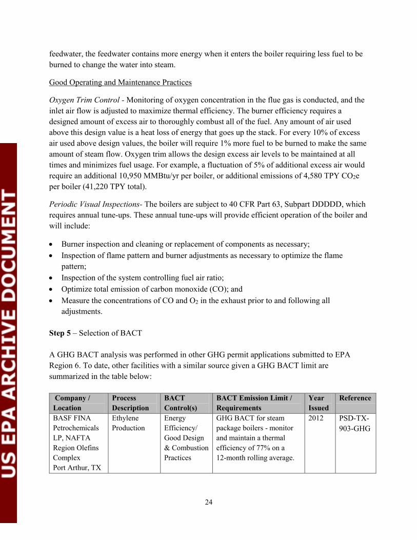
adjustments. Step 5 – Selection of BACT A GHG BACT analysis was performed in other GHG permit applications submitted to EPA Region 6. To date, other facilities with a similar source given a GHG BACT limit are summarized in the table below:
Company / Location
Process Description
BACT Control(s)
BACT Emission Limit / Requirements
Year Issued
Reference
BASF FINA Petrochemicals LP, NAFTA Region Olefins Complex Port Arthur, TX
Ethylene Production
Energy Efficiency/ Good Design & Combustion Practices
GHG BACT for steam package boilers - monitor and maintain a thermal efficiency of 77% on a 12-month rolling average.
2012 PSD-TX-903-GHG

25
Company / Location
Process Description
BACT Control(s)
BACT Emission Limit / Requirements
Year Issued
Reference
Each boiler limited to a maximum firing rate of 425.4 MMBtu/hr
Chevron Phillips Chemical Company, Cedar Bayou Plant Baytown, TX
Ethylene Production
Energy Efficiency/ Good Design & Combustion Practices
GHG BACT for the VHP boiler - monitor and maintain a thermal efficiency of 77% on a 12 - month rolling average. VHP boiler limited to a maximum firing rate of 500 MMBtu/hr
2012 PSD-TX-748-GHG
ExxonMobil, Mont Blevieu Plastics Plant Baytown, TX
Polyethylene Production
Energy Efficiency/ Good Design & Combustion Practices
GHG BACT for the boilers - monitor and maintain a thermal efficiency of 77% on a 12-month rolling average. Each boiler limited to a maximum firing rate of 98 MMBtu/hr
2013 PSD-TX-103048-GHG
Formosa proposes the selection of all available energy-efficient design options and operational/maintenance practices presented in Step 1 as BACT for the steam boilers. Since the proposed energy efficiency design options are not independent features but are interdependent and represent an integrated energy efficiency strategy, Formosa is proposing a BACT limit for each boiler which takes into consideration the operation, variability and interaction of all these energy efficient features in combination. A holistic BACT limit which accounts for the ultimate performance of the entire unit was chosen, rather than individual independent subsystem performance. Otherwise, monitoring and maintaining energy efficiency would be un-necessarily complex because the interdependent nature of operating parameters means that one parameter cannot necessarily be controlled independently without affecting the other operating parameters. Formosa proposes a numerical energy efficiency-based BACT limit of 78% minimum thermal efficiency per boiler on a rolling 12-month averagebasis.
EPA reviewed Formosa’s proposal and selects the following operating and maintenance practices to ensure efficient operation and compliance with BACT: Low Carbon Fuels – Use a hydrogen-rich (low-carbon) fuel gas, where practicable, as
compared to firing of natural gas. Good Combustion Practices and Maintenance – The use of good combustion practices
includes periodic tune-ups and maintaining the recommended combustion air and fuel ranges

26
of the equipment as specified by its design, with the assistance oxygen trim control. These practices will include:
o Boiler inspection to occur, at a minimum, of annually. Inspection will include: Checking the integrity of burner components (tips, tiles, surrounds); Inspecting burner spuds for potential fouling; Inspecting burner air doors and lubrication; Inspecting all burners before closing main door to check for potential debris; Inspecting combustion air ducting and dampers; and Checking burner spud/orifice sizes.
o Records will be maintained for any maintenance activity completed on the burners. The burners are to be inspected during routine scheduled maintenance periods.
Energy Efficient Operation – The boiler will produce steam for use throughout the plant. Specific technologies utilized will include the following:
o Feedwater Preheat - Use of heat exchangers/economizers to preheat incoming feedwater to minimize fuel usage in the firebox.
o Condensate Recovery - Use of condensate as boiler feedwater. BACT Limits and Compliance:
By implementing the operational measures above, Formosa will meet an emission limit for the boilers of 204,907 TPY CO2e for each boiler. In addition to meeting the quantified emission limit, by selecting each of these energy efficiency-related design options and operational and maintenance practices, each of Formosa’s boilers are expected to have a minimum thermal efficiency of 78% (for the life of the boiler) as calculated on a rolling 12-month basis using the following equation:
𝐵𝑜𝑖𝑙𝑒𝑟 𝐸𝑓𝑓𝑖𝑐𝑖𝑒𝑛𝑐𝑦 = (𝑠𝑡𝑒𝑎𝑚 𝑓𝑙𝑜𝑤 𝑟𝑎𝑡𝑒∗𝑠𝑡𝑒𝑎𝑚 𝑒𝑛𝑡ℎ𝑎𝑙𝑝𝑦)−(𝑓𝑒𝑒𝑑𝑤𝑎𝑡𝑒𝑟 𝑓𝑙𝑜𝑤𝑟𝑎𝑡𝑒−𝑓𝑒𝑒𝑑𝑤𝑎𝑡𝑒𝑟 𝑒𝑡ℎ𝑎𝑙𝑝𝑦)
𝐹𝑢𝑒𝑙 𝑓𝑖𝑟𝑖𝑛𝑔 𝑟𝑎𝑡𝑒∗𝐺𝑟𝑜𝑠𝑠 𝐶𝑎𝑙𝑜𝑟𝑖𝑓𝑖𝑐 𝑉𝑎𝑙𝑢𝑒 (𝐺𝐶𝑉)∗ 100
Formosa will demonstrate compliance with the CO2 emission limit for the boiler using the emission factors for gaseous fuels from 40 CFR Part 98, Subpart C, Table C-1. Equation C-5 for estimating CO2 emissions as specified in 40 CFR § 98.33(a)(3)(iii) is as follows:
𝐶𝑂2 = 44
12∗ 𝐹𝑢𝑒𝑙 ∗ 𝐶𝐶 ∗
𝑀𝑊
𝑀𝑉𝐶∗ 0.001 ∗ 1.102311
Where: CO2 = Annual CO2 mass emissions from combustion of gaseous fuels (short tons)
Fuel = Annual volume of the gaseous fuel combusted (scf). The volume of fuel combusted must be measured directly, using fuel flow meters calibrated according to 40 CFR § 98.3(i).

27
CC = Annual average carbon content of the gaseous fuel (kg C per kg of fuel). The annual average carbon content shall be determined using the same procedures as specified for HHV at 40 CFR § 98.33(a)(2)(ii). MW = Annual average molecular weight of the gaseous fuel (kg/kg-mole). The annual average molecular weight shall be determined using the same procedure as specified for HHV at 40 CFR § 98.33(a)(2)(ii). MVC = Molar volume conversion factor at standard conditions, as defined in 40 CFR § 98.6. 44/12 = Ratio of molecular weights, CO2 to carbon. 0.001 = Conversion of kg to metric tons. 1.102311 = Conversion of metric tons to short tons.
The proposed permit also includes an alternative compliance demonstration method, in which Formosa may install, calibrate, and operate a CO2 CEMS and volumetric stack gas flow monitoring system with an automated data acquisition and handling system for measuring and recording CO2 emissions. Additionally, the CO2e emission limit is based on firing OL3 hydrogen-rich fuel gas 6,260 hours per year plus firing natural gas heat for 2,500 hours per year. This is based on a worst case scenario. The emission limits associated with CH4 and N2O are calculated based on emission factors provided in 40 CFR Part 98, Table C-2, site specific analysis of process fuel gas, and the actual heat input (HHV). To calculate the CO2e emissions, the draft permit requires calculation of the emissions based on the procedures and Global Warming Potentials (GWP) contained in the GHG Regulations, 40 CFR Part 98, Subpart A, Table A-1. Records of the calculations would be required to be kept to demonstrate compliance with the emission limits on a 12-month average, rolling monthly.
XII. PDH Reactors (EPN: PDH-REAC1, PDH-REAC2, PDH-REAC3 and PDH-REAC4) The four PDH reactors will each have maximum firing rate of 191 MMBtu/hr. .In the PDH process, CO2 is formed due to the hydrolysis reaction and reconversion of coke laydown on the catalyst (caused by thermal cracking). Therefore, CO2 is present in the process gas and must be removed from the propylene product. For this purpose, an absorption process for sour gas removal is used, which selectively absorbs CO2 contained in the product gas. The majority of the CO2 and small of amounts of hydrocarbons resulting from the regeneration of the absorbent are mixed with the plant fuel gas and used as fuel for the reactors. The rich solvent from the bottom of the absorber column is sent to the solvent flash drum. Flash gas from this drum, containing any remaining CO2 and light hydrocarbons, is routed back to the cooled process gas stream for

28
recycle. Solvent flash drum bottoms are routed to the solvent system stripper for processing and reuse.8 Step 1 – Identification of Potential Control Technologies Carbon Capture and Storage (CCS) Use of Low Carbon Fuel Energy Efficient Design Use of Good Operating and Maintenance Practices
Step 2 – Elimination of Technically Infeasible Alternatives Capture Capture and Storage This add-on control technology was discussed in detail above in section IX and eliminated based on the technical infeasibility due to the low CO2 concentrations in the exhaust gas, as well as economic, environmental, and energy impacts. For similar reasons, CCS can be eliminated as BACT for the PDH Reactors.9 CCS will not be considered further in this analysis. All other control technologies are considered technically feasible. Step 3 – Ranking of Remaining Technologies Based on Effectiveness Since the remaining technically feasible processes, practices, and designs in Step 1 are being proposed for the PDH Reactors, a ranking of the control technologies is not necessary. Step 4 – Evaluation of Control Technologies in Order of Most Effective to Least Effective, with Consideration of Economic, Energy, and Environmental Impacts Low Carbon Fuel Fuels vary in the amount of carbon per Btu, which in turn affects the quantity of CO2 emissions generated per unit of heat input. Typically, gaseous fuels such as natural gas or hydrogen-rich plant tail gas contain less carbon, and thus lower CO2 potential to emit, than liquid or solid fuels such as diesel or coal. Formosa proposes to use natural gas and fuel gas for operation. 8 Formosa provided a document that evaluated environmental issues related to the PDH process chosen. http://www.epa.gov/earth1r6/6pd/air/pd-r/ghg/formosa-olefins-expansion-reponse-pdh-reactor-catalyst040914.pdf 9 FPC TX provided a revised BACT analysis in response to EPA’s request for detailed CCS cost analysis April 14, 2014. http://www.epa.gov/earth1r6/6pd/air/pd-r/ghg/formosa-olefins-expansion-appendix-c-bact-analysis041414.pdf On page 15 of the submittal, Table 6-2 entitled, “Candidate CCS Source Exhaust Stream CO2 Concentrations and Flow Rates, by Unit Type” indicates the CO2 concentration in the exhaust stream from the PDH reactors is 4.6% volume

29
Energy Efficient Design
By optimizing energy efficiency, the project requires less fuel than comparable less-efficient operations, resulting in reduced emissions of combustion products such as GHGs, NOx, CO VOC, PM10, and SO2. To minimize the energy consumption, the reactor furnace is intentionally designed to maximize the energy efficiency in the various components since 35-40% of the energy consumption is for direct heating requirements in the reactor furnace. The furnace design of the reactor will maximize thermal efficiency as described below. Reactor design will incorporate the latest improvement in heat transfer and fluid flow to maximize the energy efficiency and recovery. There are no known negative economic, energy, or environmental impacts associated with an energy efficient design.
Radiant Section The dehydrogenation process is highly endothermic, so heat must be added to allow dehydrogenation reaction to be continued. The catalyst filled process tubes are arranged in rows, heat is provided by top fired burners arranged in burner rows between the tube rows to distribute the radiant heat as uniformly as possible. This minimizes coke build-up inside the tubes to the largest possible extent. The nature of the dehydrogenation reaction is such that its thermodynamic equilibrium is favored by increasing temperature and decreasing partial pressure. The hot firebox radiates heat to the relatively cold radiant tubes for dehydrogenation. A combination of high temperature brick and ceramic fiber insulation of sufficient thickness will be used along the walls of the firebox to reduce heat loss and to maximize reflection of radiant heat back to the tubes. Burners High efficiency, low-NOx burners will be installed in the reactor box. Burners will be designed to operate with minimum excess air to maintain high combustion efficiency. The reactor will be equipped with an oxygen analyzer to provide data used in the control of the combustion process. The burners will be designed to operate under the range of fuel gases combusted in the plant including natural gas and plant produced fuel gases. Convection Section In the convection section the heat transfer occurs primarily by convection with hot flue gases transferring heat to the convection tubes which are located horizontally and/or vertically in the convection section. The convection section is located beside the reactor furnace box having an offset with respect to the reactor box using a transition duct to homogenize the flue gases. Fan An induced draft fan will be installed on the top of the convection section to pull flue gas upward through the convection section. The damper will be installed and operated on the fan

30
outlet to maintain a draft that produces minimum infiltration of tramp air and provides control of oxygen levels that maximize combustion efficiency in the combustion section of the furnaces.
The PDH reactors will be designed to maximize energy efficiency. 10 Specific design elements include: Feed Preheating – By selecting feed stream preheating, Formosa is able to recover approximately 27 MMBtu/hr of potential waste heat per reactor.
Steam Drum – Use of heat exchangers to recover heat from the radiant section flue gas and generate medium pressure steam. This heat recovery creates beneficial steam that is required as dilution steam in the reactors. Formosa estimates approximately 21.75 MMBtu/hr of waste heat is recovered per reactor
Use of an Economizer - Use of a heat exchanger to recover heat from the exhaust gas to preheat incoming steam drum feedwater will maximize thermal efficiency. Formosa estimates approximately 7 MMBtu/hr waste heat recovered per reactor.
Steam drum blowdown heat recovery – Pressurized hot blowdown from all steam drums, having a temperature of approximately 380°F, is combined and flashed. The generated steam is used for heating in process condensate stripper. Remaining liquid is used to preheat fresh make-up water in a heat exchanger prior to discharge. Formosa estimates approximately 1.8 MMBtu/hr of waste heat is recovered per reactor.
Condensate Recovery - Process condensate collected in the PDH process after heat recovery contains hydrocarbons that have to be stripped off. This is done in condensate stripper within the PDH unit. Heat for the stripper is provided by hot process gas leaving the reactor and by steam generated in the flash of the steam drum blowdown as described above. Instead of sending the stripped condensate for disposal, it is used as boiler feed water for PDH dilution steam generation directly without cooling; therefore, no extra preheating is necessary. Formosa estimates approximately 41.5 MMBtu/hr of additional waste heat is recovered. Good Operating and Maintenance Practices There are no known negative economic, energy, or environmental impacts associated with good operating and maintenance practices. Oxygen Trim Control - Monitoring oxygen concentration in the flue gas and adjustment of inlet air flow will help maximize thermal efficiency. The reactors will be equipped with an oxygen 10 A detailed diagram of the PDH Reactors is available at http://www.epa.gov/earth1r6/6pd/air/pd-r/ghg/formosa-olefins-expansion-detail-pdh-reactor.pdf

31
analyzer in the stack. Typically, excess oxygen levels of 3 to 5 % are optimal for a good combustion profile. The combustion system features air adjustment dampers at the burners and is designed for both automatic and manual (operator) control capability. Periodic Tune-up- The reactors are subject to 40 CFR Part 63, Subpart DDDDD, which requires annual tune-up. These annual tune-ups will provide efficient operation of the boiler and will include:
Burner inspection and cleaning or replacement of components as necessary; Inspection of flame pattern and burner adjustments as necessary to optimize the flame
pattern; Inspection of the system controlling fuel air ratio; Optimize total emission of CO; and Measure the concentrations of CO and O2 in the exhaust prior to and following all
adjustments.
Burner routine inspection and maintenance – The reactors burners will be visually inspected daily and cleaned at least annually in accordance with a preventative maintenance schedule. In order to maintain the combustion efficiency of the burners, maintenance of the burners without necessity of reactor operation interruption is possible due to comparably high number of burners along with easy access on top of the reactor. Routine burner maintenance is expected to minimize dirt deposits that could reduce burner efficiency by as much as 5%. Step 5 – Selection of BACT A GHG BACT analysis was performed by other GHG permit applications submitted to EPA Region 6. To date, other facilities with a similar source given a GHG BACT limit are summarized in the table below:
Company / Location
Process Description
BACT Control(s)
BACT Emission Limit / Requirements
Year Issued
Reference
Occidental Chemical Corporation, Ingleside Chemical Plant, Gregory, TX
Ethylene Production
Low carbon fuels; Energy efficient design; Good combustion practices
Furnace gas exhaust temperature ≤340°F on a 12-month rolling average. .39 ton CO2e/ton ethylene produced Each furnace limited to a maximum firing rate of 275 MMBtu/hr
2014 PSD-TX-1338-GHG

32
Company / Location
Process Description
BACT Control(s)
BACT Emission Limit / Requirements
Year Issued
Reference
INEOS Olefins & Polymers U.S.A., Chocolate Bayou Plant; Alvin, TX
Ethylene Production
Energy Efficiency Good Design & Combustion Practices
GHG BACT for furnace limit flue gas exhaust temperature ≤ 340 oF. on a 365-day rolling average. Fuel will have ≤ 0.71 lbs carbon per lb of fuel (CC); on a 365-day rolling average. 0.85 lbs CO2e/lb of ethylene on a 365-day rolling average. Each furnace limited to a maximum firing rate of 495 MMBtu/hr
2012 PSD-TX-97769-GHG
Formosa proposes the selection of all available energy-efficient design options and operational/maintenance practices presented in Step 1 as BACT for the PDH reactors. Since the proposed energy efficiency design options, described above, are not independent features but are interdependent and represent an integrated energy efficiency strategy, Formosa is proposing a BACT limit for each reactor which takes into consideration the operation, variability and interaction of all these energy efficient features in combination. A holistic BACT limit that accounts for the ultimate performance of the entire unit was chosen, rather than individual independent subsystem performance. Otherwise, monitoring and maintaining energy efficiency would be unnecessarily complex because the interdependent nature of operating parameters means that one parameter cannot necessarily be controlled independently without affecting the other operating parameters. After reviewing Formosa’s submissions, EPA proposes a BACT limit of 0.393 pounds of CO2e per pound of total propylene produced for the group of PDH reactors on a 12-month rolling average basis. The proposed BACT output limit was calculated as follows: lb CO2e/lb propylene = [PDH Reactor Group GHG emissions (TPY CO2e)]/[TPYpropylene produced] = [235,513 (TPY CO2e)] / [600,000 total TPY propylene] = 0.393 lb CO2e/lb total propylene produced This limit was calculated based on the total PDH reactor GHG annual emissions provided in the Formosa permit application calculations and the total annual propylene production expected from the PDH reactors. The total expected production rate can generally be expected to decline over the life of the plant as equipment ages and is subject to wear and fouling. In addition,
33
throughout the life of a catalyst, catalytic performance and corresponding product yield is expected to decline. At the same time, there would not necessarily be a corresponding reduction in the required heat input to maintain reaction temperature for that reduced production rate. Therefore, although the maximum production rate expected and requested in the permit application is 725,000 short tons per year of propylene, as the plant and catalyst ages, the maximum production rate actually achieved may be expected to drop as low as 600,000 TPY. Therefore, 600,000 TPY is used as the estimated maximum production rate over the life of the plant and is the basis of the output limit proposed above. EPA reviewed Formosa’s proposal and the following specific operating practices are proposed for the PDH reactors to assure this level of thermal efficiency: Low Carbon Fuels – Consume pipeline quality natural gas or PDH fuel gas with lower
carbon content than natural gas as a fuel to the PDH reactors. Good Combustion Practices and Maintenance – The use of good combustion practices
includes periodic tune-ups and maintaining the recommended combustion air and fuel ranges of the equipment as specified by its design, with the assistance of oxygen trim control. These practices will include:
o Reactor inspection to occur, at a minimum, annually. Inspection will include: Checking the integrity of burner components (tips, tiles, surrounds); Inspecting burner spuds for potential fouling; Inspecting burner air doors and lubrication; Inspecting all burners before closing main door to check for potential debris; Inspecting combustion air ducting and dampers; and Checking burner spud/orifice sizes.
o Records will be maintained for any maintenance activity completed on the burners. The burners are to be inspected during routine scheduled maintenance periods.
Energy Efficient Operation – The reactors will produce steam for use within the PDH unit. Specific technologies utilized will include the following:
o Feedwater Preheat - Use of heat exchangers/economizers to preheat incoming feedwater to minimize fuel usage in the firebox.
o Condensate Recovery - Use of condensate as boiler feedwater. o Steam drum blowdown recovery – Used for heating and make-up water.
BACT Limits and Compliance:
By implementing the operational measures above, Formosa will meet an emission limit for the PDH reactors of 58,878 TPY CO2e for each PDH reactor. In addition to meeting the quantified emission limit, EPA is proposing that Formosa will demonstrate compliance with energy efficient operations by continuously monitoring the exhaust stack temperature of each furnace.
34
The maximum stack exit temperature of 340oF on a 365-day rolling average basis will be calculated daily for each reactor. In addition to a BACT limit of 0.393 pounds of CO2e per pound of total propylene produced for the group of PDH reactors on a 12-month rolling average basis. Formosa will demonstrate compliance with the CO2e emission limit for the reactors using the site specific fuel analysis for fuel gas utilizing an on-line gas composition analyzer and the emission factors for natural gas from 40 CFR Part 98, Subpart C, Table C-1. The equation for estimating CO2 emissions as specified in 40 CFR § 98.33(a)(3)(iii) is as follows:
𝐶𝑂2 = 44
12∗ 𝐹𝑢𝑒𝑙 ∗ 𝐶𝐶 ∗
𝑀𝑊
𝑀𝑉𝐶∗ 0.001 ∗ 1.102311
Where: CO2 = Annual CO2 mass emissions from combustion of gaseous fuels (short tons)
Fuel = Annual volume of the gaseous fuels combusted (scf). The volume of fuel combusted must be measured directly, using fuel flow meters calibrated according to 40 CFR § 98.3(i). CC = Annual average carbon content of the gaseous fuels (kg C per kg of fuel). The annual average carbon content shall be determined using the same procedures as specified for HHV at 40 CFR § 98.33(a)(2)(ii). MW = Annual average molecular weight of the gaseous fuels (kg/kg-mole). The annual average molecular weight shall be determined using the same procedure as specified for HHV at 40 CFR § 98.33(a)(2)(ii). MVC = Molar volume conversion factor at standard conditions, as defined in 40 CFR § 98.6. 44/12 = Ratio of molecular weights, CO2 to carbon. 0.001 = Conversion of kg to metric tons. 1.102311 = Conversion of metric tons to short tons.
The proposed permit also includes an alternative compliance demonstration method, in which Formosa may install, calibrate, and operate a CO2 CEMS and volumetric stack gas flow monitoring system with an automated data acquisition and handling system for measuring and recording CO2 emissions. The emission limits associated with CH4 and N2O are calculated based on emission factors provided in 40 CFR Part 98, Subpart C, Table C-2, site specific analysis of fuel gas, and the actual heat input (HHV). However, the emission limit is for all GHG emissions from the reactor and is met by aggregating total emissions. To calculate the CO2e emissions, the draft permit requires calculation of the emissions based on the procedures and Global Warming Potentials (GWP) contained in the GHG Regulations, 40 CFR Part 98, Subpart A, Table A-1. Records of the calculations would be required to be kept to demonstrate compliance with the CO2e emission limit on a 12-month average, rolling monthly.

35
An initial stack test demonstration will be required for CO2 emissions from the emission units to verify that the CO2e limit will be met. The stack test will also monitor the exhaust stack temperature to ensure compliance with the BACT limit of 340oF on a 365-day rolling average. An initial stack test demonstration for CH4 and N2O emissions are not required because the CH4 and N2O emission are less than 0.19% of the total CO2e emissions from the reactors and are considered a de minimis level in comparison to the CO2 emissions. Additionally, the CO2e emission limit is based on firing PDH hydrogen-rich fuel for 6,860 hours per year plus firing natural gas for 1,900 hours per year. This is based on a worst case scenario. XIII. MAPD Regeneration Vent(EPN: OL3-MAPD)
The methyl acetylene (MA) and propadiene (PD) contained in the depropanizer overhead are removed by selective hydrogenation to propylene and propane in a single-bed reactor called the MAPD converter. The MAPD catalyst must be periodically regenerated as polymer accumulates on the catalyst surface during normal operation. Periodic regeneration (a few regeneration cycles/year) of the MAPD converter catalyst results in emissions of CO2 via the regeneration vent. The MAPD regeneration vent’s CO2e emissions (estimated at approximately 33 TPY) represent less than 0.001% of the project’s GHG emissions; therefore, this sources is an inherently low-emitting GHG emission source. Step 1 – Identification of Potential Control Technologies Proper reactor design with good operating practices: Formosa has evaluated work and operational practices and will follow the standard operating procedure (SOP) currently used for a similar unit during periods of MAPD catalyst regeneration. The SOP will be the following and will be maintained at the site prior to the unit commencing operation:
The MAPD Reactor shall be operated such that the frequency of MAPD catalyst regeneration and polymer formation will be minimized.
The reactor shall be fed a C3/C4 distillate and a purified hydrogen stream to minimize contaminants and catalyst fouling and polymer formation.
Reactor temperatures, pressures, and hydrogen concentrations shall be maintained within recommended levels.
Permittee must record the time, date, and duration of each MSS event. Permittee shall limit the total MAPD regeneration period to a maximum of 100 hours per
year. Formosa will meet BACT for the MAPD unit regeneration vent by following the SOP during regeneration periods.

36
Formosa will utilize the control option identified in Step 1; therefore, a detailed analysis under Steps 2 through 4 is not necessary. Step 5 – Selection of BACT A proper MAPD reactor design with good operating practices will minimize polymer formation and is considered BACT for the MAPD regeneration vents. The reactor will be fed the overhead stream from the depropanizer containing C3 compounds and a purified hydrogen stream from the PSA unit to minimize contaminants and fouling. The reactor temperature, pressure and hydrogen concentration will be maintained within recommended levels. The annual emissions are estimated to be 33 TPY of CO2e. These emissions are based on regenerating the MAPD reactor three times a year. XIV. Elevated and Low Pressure Flare Operation (EPNs: OL3-FLRA, OL3-FLRB, OL3-
LPFLR1 and OL3-LPFLR2) The elevated flare system (FIN/EPNs OL3-FLRA, OL3-FLRB) is a two stage flare system designed to provide safe control for vent gas streams that cannot be recycled in the process or routed to the fuel gas system. Waste gases generated during normal operation and routine maintenance will be routed to the first stage flare tip (EPN OL3-FLRA) and the second stage tip will not be operated at that time. The second stage flare tip (EPN OL3-FLRB) is designed to manage additional high volume flows from certain startup and shutdown waste gas streams and during emergency scenarios. Both 1st and 2nd stage flare tips are designed with natural gas pilots. The two stage design allows the more routine and smaller flows to be handled in a flare tip sized and designed for those rates and the more intermittent and large flows to be handled in a flare tip sized for those flows. This design was intended to address the low velocity, low-Btu flare operation concerns raised recently by the TCEQ with a flare tip size which is better matched to the potential expected flows. The two low pressure flares (EPNs OL3-LPFLR1, OL3-LPFLR2) are being designed as enclosed flares. Flare gas recovery is already incorporated into the current plant design such that the off-gas generated in the process is captured upstream of the flare gas header. These off-gases are recovered for use in the plant fuel gas system or recycled for reprocessing in the plant. The gases that are unable to be recovered have variable compositions of inerts (N2, etc) and highly variable flow (often produced from maintenance degassing or a short duration of high flows, such as startup shutdown activities) such that a flare gas recovery system cannot practically be designed to handle them. Step 1 – Identification of Potential Control Technologies
37
Minimization of waste gas to flare – Formosa is designing the Olefins 3 plant and PDH unit with fuel gas systems that will provide beneficial reuse of hydrocarbon-containing streams that would otherwise be routed to a flare for control. By incorporating fuel gas system design into the inherent process function, Formosa’s selected design will minimize the amount of process waste gas that could potentially be flared.
Good Flare Design, Operation and Maintenance Practices – Good flare design ensures that the design hydrocarbon destruction and removal efficiency (DRE) is achieved under real world operating conditions. Specifically, the flare tips are being designed to accommodate maximum design waste gas flow rates and achieve optimal combustion profile at the flare tip (e.g., optimal air and waste gas mixing) to ensure at least 98% destruction (weight percent) of VOCs and 99% destruction of methane.
A detailed analysis under Steps 2 through 4 is not necessary because the applicant will utilize all available control option. Step 5 – Selection of BACT Formosa proposes the selection of all available design and operational elements that minimize GHG emissions presented in Step 1 as BACT for the elevated and low pressure flares. Since the proposed design and operating elements, described in Step 1 above, are not independent features but are interdependent and represent an integrated energy efficiency strategy, Formosa is proposing a BACT limit for each flare which takes into consideration the operation, variability and interaction of all these features in combination. A holistic BACT limit which accounts for the ultimate performance of the entire unit was chosen, rather than individual independent subsystem performance. Otherwise, monitoring and maintaining energy efficiency would be unnecessarily complex because the interdependent nature of operating parameters means that one parameter cannot necessarily be controlled independently without affecting the other operating parameters. EPA has reviewed and concurs with Formosa that minimization of waste gas along with the use of good flare design and best operational and maintenance practices are BACT. Therefore, Formosa shall design, build operate and maintain their flare systems (OL3-FLRA, OL3-FLRB OL3-LPFLR1 and OL3-LPFLR2) in accordance with 40 CFR § 60.18. This will ensure the flare systems achieve at least a 98% DRE for VOCs and a 99% DRE for methane. Included within this practice, Formosa shall:
Continuously monitor and record the pressure of the flare system header; Continuously monitor and record the waste gas flow at the flare headers;

38
Determine composition of the waste gas on an hourly basis by use of a composition analyzer or equivalent at the flare headers and record the heating value of the flare system header;
Calibrate the composition analyzer to identify at least 95% of the compounds in the waste gas;
Continuously monitor and meter supplemental natural gas to maintain a minimum heating value, consistent with 40 CFR § 60.18, routed to the flare system to ensure the intermittent stream is combustible and necessary for flame stability; and
Continuously monitor for the presence of a pilot flame with a thermocouple of other approved device.
Formosa shall ensure the flow meters and analyzers used for flare compliance are operational at least 95% of the time when waste gas is being sent to the flare systems, averaged over a running 12-month period. Formosa shall calibrate flow meters biannually, and the composition analyzer shall have a single point calibration check weekly when the flares are receiving waste gas.
Using these operating practices above will result in an emission limit for the elevated flare system of 85,452 TPY CO2e and 9,856 TPY CO2e for the low pressure flares. Formosa will demonstrate compliance with the CO2e emission limit using the emission factors for natural gas from 40 CFR Part 98, Subpart C, Table C-1, and the site specific fuel analysis for waste gas. The equation for estimating CO2 emissions as specified in 40 CFR § 98.253(b)(1)(ii)(A) is as follows:
𝐶𝑂2 = 𝐷𝑅𝐸 × 0.001 × (∑ [44
12× (𝐹𝑙𝑎𝑟𝑒)𝑝 ×
(𝑀𝑊)𝑝
𝑀𝑉𝐶× (𝐶𝐶)𝑝]
𝑛
𝑝=1
) ∗ 1.102311
Where:
CO2 = Annual CO2 emissions for a specific fuel type (short tons/year). DRE = Assumed combustion efficiency of the flare. 0.001 = Unit conversion factor (metric tons per kilogram, mt/kg). n = Number of measurement periods. The minimum value for n is 52 (for weekly measurements); the maximum value for n is 366 (for daily measurements during a leap year). p = Measurement period index. 44 = Molecular weight of CO2 (kg/kg-mole). 12 = Atomic weight of C (kg/kg-mole). (Flare)p = Volume of flare gas combusted during the measurement period (standard cubic feet per period, scf/period). If a mass flow meter is used, measure flare gas flow rate in kg/period and replace the term “(MW)p/MVC” with “1”.

39
(MW)p = Average molecular weight of the flare gas combusted during measurement period (kg/kg-mole). If measurements are taken more frequently than daily, use the arithmetic average of measurement values within the day to calculate a daily average. MVC = Molar volume conversion factor (849.5 scf/kg-mole). (CC)p = Average carbon content of the flare gas combusted during measurement period (kg C per kg flare gas ). If measurements are taken more frequently than daily, use the arithmetic average of measurement values within the day to calculate a daily average. 1.102311 = Conversion of metric tons to short tons.
The GHG mass emission limits in TPY associated with CH4 and N2O are calculated based on emission factors provided in 40 CFR Part 98, Subpart C, Table C-2 using the GWPs site specific analysis of waste gas, and the actual heat input (HHV). XV. Emergency Generator Engines (EPNs: OL3-GEN and PDH-GEN) Formosa will install two diesel-fired emergency generator engines. The engines will each be rated at 676 horsepower and each have a design maximum heat input of 5.48 MMBtu/hr. The generator engines are designed to use diesel fuel, stored in onsite tanks, so that emergency power is available for safe shutdown of the facility in the event of a power outage that may also include natural gas supply curtailments. The CO2e emissions from the emergency generator engines result from the combustion of diesel fuel and account for less than 0.01% of the total project emissions. Step 1 – Identification of Potential Control Technologies Low Carbon Fuels – Use of fuels containing lower concentrations of carbon generate less
CO2, than other higher-carbon fuels. Typically, gaseous fuels such as natural gas contain less carbon, and thus lower CO2 potential, than liquid or solid fuels such as diesel or coal.
Good Operating and Maintenance Practices – Good operating and maintenance practices include appropriate maintenance of equipment and operating within the recommended air to fuel ratio recommended by the manufacturer.
Step 2 – Elimination of Technically Infeasible Alternatives Low Carbon Fuels – The purpose of the engines is to provide a power source during
emergencies, which include site power outages and natural disasters, such as hurricanes. As such, the power source must be available during emergencies. Electricity is not a source that is available during a power outage, which is the specific event for which the backup generators are designed to operate. Natural gas supply may be curtailed during an emergency such as a hurricane; thereby not providing fuel to the engines during the specific event for

40
which the backup generators are designed to operate. The engines must be powered by a liquid fuel that can be stored in a tank and supplied to the engines on demand, such as motor gasoline or diesel. Therefore, Formosa proposes to use diesel fuel for the emergency generator engines, since non-volatile fuel must be used for emergency operations. The use of low-carbon fuel is considered technically infeasible for emergency generator operation and is not considered further for this analysis.
Good Operating Combustion Practices and Maintenance – Is considered technically feasible. Step 3 – Ranking of Remaining Technologies Based on Effectiveness Only one option, good operation and maintenance practices, has been identified for controlling GHG emissions from engines; therefore, ranking by effectiveness is not applicable. Step 4 – Evaluation of Control Technologies in Order of Most Effective to Least Effective, with Consideration of Economic, Energy, and Environmental Impacts The single option for control of CO2 from engines is to follow good operating and maintenance practices. There are no known negative economic, energy, or environmental impacts associated with this option. Step 5 – Selection of BACT The following specific BACT practices are proposed for the engines: Good operation and maintenance practices for compression ignition engines include appropriate maintenance of equipment, periodic testing conducted weekly, and operating within the recommended air to fuel ratio, as specified by its design. Compliance with 40 CFR Part 60, Subpart IIII will inherently demonstrate use of efficient engines and limiting the engines to a non-emergency use of 100 hours or less is considered BACT.
Using the operating and maintenance practices identified above results in a BACT limit of 447 TPY CO2e total for each engines. Formosa will demonstrate compliance with the CO2 emission limit using the emission factors for diesel fuel from 40 CFR Part 98, Subpart C, Table C-1. The equation for estimating CO2 emissions as specified in 40 CFR § 98.33(a)(3)(ii) is as follows:
𝐶𝑂2 = 44
12∗ 𝐹𝑢𝑒𝑙 ∗ 𝐶𝐶 ∗ 0.001 ∗ 1.102311
Where: CO2 = Annual CO2 mass emissions from combustion of diesel fuel (short tons)
41
Fuel = Annual volume of the liquid fuel combusted (gallons). The volume of fuel combusted must be measured directly, using fuel flow meters calibrated according to 40 CFR § 98.3(i). CC = Annual average carbon content of the liquid fuel (kg C per kg of fuel). The annual average carbon content shall be determined using the same procedures as specified for HHV at 40 CFR § 98.33(a)(2)(ii). 44/12 = Ratio of molecular weights, CO2 to carbon. 0.001 = Conversion of kg to metric tons. 1.102311 = Conversion of metric tons to short tons.
The emission limits associated with CH4 and N2O are calculated based on emission factors provided in 40 CFR Part 98, Subpart C, Table C-2. XVI. Equipment Fugitives (EPN: OL3-FUG and PDH-FUG) The proposed project will include new piping components for movement of fuel and liquid raw materials, intermediates, and feed stocks. These components are potential sources of GHG emissions due to emissions from rotary shaft seals, connection interfaces, valves stems, and similar points. GHGs from piping component fugitives are mainly generated from fuel gas and natural gas lines for the proposed project, but may contain trace amounts of methane. Step 1 – Identification of Potential Control Technologies The following available control technologies for fugitive piping components emitting GHGs (those in natural gas and fuel gas service) were identified:
Installation of leakless technology components to eliminate fugitive emission sources. Implementing leak detection and repair (LDAR) programs (those used for VOC
components) in accordance with applicable state and federal air regulations. Implement alternative monitoring using a remote sensing technology such as infrared
camera monitoring. Implementing an audio/visual/olfactory (AVO) monitoring program typically used for
non-VOC compounds. Step 2 – Elimination of Technically Infeasible Alternatives All the available options are considered technically feasible and have been used in industry as described below.
42
Step 3 – Ranking of Remaining Technologies Based on Effectiveness Leakless technologies are nearly 100% effective in eliminating fugitive emissions from the specific interface where installed. However, leak interfaces remain even with leakless technology components in place. In addition, the sealing mechanism, such as a bellows, is not repairable online and may leak in the event of a failure until the next unit shutdown. Because of their high cost, these specialty components are, in practice, selectively applied only as absolutely necessary to toxic or hazardous components. This is the most effective control. LDAR programs are typically used to control VOC emissions and can achieve up to 97% control of VOC emissions. Although, not specifically designed GHG emissions, they can be used to control methane emissions. Monitors typically used for Method 21 instrument monitoring cannot detect CO2 leaks. Instrumented monitoring can identify leaking CH4, making possible the identification of components requiring repair. Method 21 instrument monitoring has historically been used to identify leaks in need of repair. This is the second most effective control. Remote sensing using an infrared imaging has proven effective for identification of leaks, especially on larger pipeline-sized lines and for components in difficult to monitor areas. Instrument LDAR programs and the alternative work practice of remote sensing using an infrared camera have been determined by EPA to be equivalent methods of piping fugitive controls.11 Although, remote sensing using infrared imaging has been accepted by EPA as an acceptable alternative to Method 21 instrument monitoring and leak detection effectiveness is expected to be comparable, it has not been quantified. Therefore, this is the third most effective control technology. AVO monitoring methods are also capable of detecting leaks from piping components as leaks can be detected by sound (audio) and sight. AVO programs are commonly used in industry and has been implemented historically at the Formosa Point Comfort plant. AVO detections can be performed frequently, with less additional manpower and equipment than Method 21 instrument or remote sensing monitoring since it does not require a specialized piece of monitoring equipment. As-observed AVO methods are generally somewhat less effective than instrument LDAR and remote sensing because they are not conducted at specific intervals. This method cannot generally identify leaks at as low a leak rate as instrumented reading can identify. This method, due to frequency of observation, is effective for identification of larger leaks. AVO observation is a very effective method for identifying and correcting leaks in natural gas systems utilizing odorized pipeline natural gas. Due to the pressured and other physical properties of plant fuel gas, AVO observations of potential fugitive leaks are likewise moderately effective.
Step 4 – Evaluation of Control Technologies in Order of Most Effective to Least Effective, with Consideration of Economic, Energy, and Environmental Impacts 11 73 FR 78199-78219 (December 22, 2008).

43
The use of leakless components, instrument LDAR and/or remote sensing of piping fugitive emission in natural gas or fuel gas service may be somewhat more effective than as-observed AVO methods, but the incremental GHG emissions controlled by implementation of the TCEQ 28 LAER LDAR program or a comparable remote sensing program is considered a de minimis level in comparison to the total project’s proposed CO2e emissions. Given that GHG fugitives are conservatively estimated to comprise less than 0.001% CO2e emissions from the facility, there is, in any case, a negligible difference in emissions between the considered control alternatives. Accordingly, given the costs of installing leakless technology (which is estimated to be 3 to 10 times higher than comparable high quality valves) or implementing 28LAER or a comparable remote sensing program when not otherwise required, these methods are not economically practicable for GHG control from components in natural gas or fuel gas service. AVO monitoring is expected to be effective in finding leaks and can be implemented at the greatest frequency and lowest cost due to being incorporated into routine operations. Step 5 – Selection of BACT
Based on the economic impracticability of instrument monitoring and remote sensing for fuel gas and natural gas piping components, Formosa proposes to incorporate as-observed AVO as BACT for the piping components associated with this project in fuel gas and natural gas service. The proposed permit contains a condition to implement an AVO program on a weekly basis. For the GHG fugitive emission sources in this plant that are in natural gas service, Formosa is proposing:
Implementation of an AVO monitoring program for equipment in natural gas and fuel gas service.
o Perform the AVO monitoring on a weekly basis; and o Maintain a written log of weekly inspections identifying the operating area
inspected, the date inspected, the fuel gas and natural gas equipment inspected (valves, lines, flanges, etc), whether any leaks were identified by visual, audible or olfactory inspections, and corrective actions/repairs taken.
For leaks identified, immediately following detection of the leak, plant personnel will take the following action:
o Tag the leaking equipment; and o Commence repair or replacement of the leaking component as soon as practicable,
but no later than 15 days after detection.
Process lines in VOC service will incorporate the TCEQ 28VHP leak detection and repair (LDAR) and a quarterly connector monitoring program (equivalent to the TCEQ 28LAER) for fugitive emissions control in the TCEQ permit 107518/PSDTX1383. EPA concurs with
44
Formosa’s assessment that using the TCEQ 28VHP12 LDAR program is an appropriate control of GHG emissions. LDAR programs would not normally be considered for control of GHG emissions alone due to the negligible amount of GHG emissions from fugitive sources, and although the existing LDAR program is being imposed in this instance, it is imposed as a work practice. See 40 CFR § 51.166(b)(12) (technological and economic limitations make measurement methodology infeasible under the circumstances here). XVII. Maintenance, Startup and Shutdown (MSS) Activities (EPN: OL3-MSS and PDH-
MSS)
The Olefins 3 plant will emit GHGs as a result of periodic and routine planned MSS activities. These activities will result in the following types of GHG emissions: Products of combustion from the elevated flare from degassing of hydrocarbon
containing process equipment; Process equipment to the flare header; Fraction of un-combusted methane and CO2 from degassing of process vessels with
methane-containing process streams to the elevated flare header; and Fugitive emissions of GHG from opening of process equipment to atmosphere (after
degassing) for process streams containing GHGs (methane, CO2), and fugitive emissions from opening of fuel gas lines.
Step 1 – Identification of Potential Control Technologies Formosa will be required to perform the following procedures (to satisfy BACT for MSS activities) when preparing to open process equipment to the atmosphere:
Remove and recover liquid and vapor to the maximum extent practicable; Depressurize equipment in VOC service to the elevated flare; If necessary, purge with nitrogen (to the flare) to reduce the amount of process material
remaining in the equipment; and, then Open equipment to atmosphere for maintenance, after equipment is purging is completed.
Routing these MSS gas streams to the flare also reduces the amount of methane that would otherwise be emitted directly to the atmosphere. The flare is subject to a separate BACT limit including flare design and good operation and maintenance practices.
12 The boilerplate special conditions for the TCEQ 28VHP LDAR program can be found at http://www.tceq.state.tx.us/assets/public/permitting/air/Guidance/NewSourceReview/bpc_rev28vhp.pdf. These conditions are included in the TCEQ issued NSR permit.

45
A detailed analysis under Steps 2 through 4 is not necessary because the applicant has selected the only available control option. Step 5 – Selection of BACT For MSS activities, Formosa will be required to remove liquid, depressurize equipment to the elevated flare, and purge with nitrogen (to the flare) before opening equipment to the atmosphere for maintenance. Following these procedures will also satisfy BACT for GHG emissions from MSS activities. XVIII. Endangered Species Act Pursuant to Section 7(a)(2) of the Endangered Species Act (ESA) (16 U.S.C. § 1536) and its implementing regulations at 50 CFR Part 402, EPA is required to insure that any action authorized, funded, or carried out by EPA is not likely to jeopardize the continued existence of any federally-listed endangered or threatened species or result in the destruction or adverse modification of such species’ designated critical habitat. To meet the requirements of Section 7, EPA is relying on a Biological Assessment (BA) dated February 14, 2014, prepared by the applicant, and reviewed and adopted by EPA. Further, EPA designated Formosa Plastics Corporation (“Formosa”) and its consultant, Zephyr Environmental Corporation (“Zephyr”), as non-federal representatives for purposes of preparation of the BA and for conducting informal consultation. Formosa’s expansion project is comprised of three separate sub-projects: an Olefins Expansion project involving the construction of a new olefins cracking unit, identified as Olefins 3 unit, and a propane dehydrogenation unit; a new low density polyethylene plant; and a utilities project involving the construction of two new natural gas-fired combined cycle combustion turbines. Formosa has submitted three (3) GHG (Greenhouse Gas) permit applications for each project; however, for Section 7 ESA purposes, EPA is relying on a Biological Assessment that includes the collective emissions from all three projects and their impacts to endangered species. The biological assessment performed for Formosa projects included in its field survey the physical land area where the new Formosa facilities will be built within Formosa’s existing chemical complex. A draft BA has identified twenty-one (21) species as endangered or threatened in Calhoun and Jackson County, Texas by the U.S. Fish and Wildlife Service (USFWS), National Marine Fisheries Service (NMFS) and the Texas Parks and Wildlife Department (TPWD) and is listed in the table below:

46
Federally Listed Species for Calhoun and Jackson Counties by the U.S. Fish and Wildlife Service (USFWS), National Marine Fisheries Service (NMFS), and the Texas Parks and Wildlife Department (TPWD)
Scientific Name
Birds Eskimo curlew Numenius borealis Interior least tern Sterna antillarum alhalassos Northern aplomado falcon Falco femoralis septentrionalis Piping Plover Charadrius melodus Whooping crane Grus americanus Mammals Jaguarundi Herpailurus yagourondi Louisiana black bear Urus americanus luteolus Ocelot Leopardus pardalis Red wolf Canis rufus West Indian manatee Trichechus manatus Reptiles Hawksbill Sea Turtle Eretmochelys imbricate Green Sea Turtle Chelonia mydas Kemp’s Ridley Sea Turtle Lepidochelys kempii Leatherback Sea Turtle Dermochelys coriacea Loggerhead Sea Turtle Caretta caretta Fish Smalltooth Sawfish Pristis pectinata Whales Blue whale Balaenoptera musculus Fin whale Balaenoptera physalus Humpback whale Megaptera novaengliae Sei whale Balaenoptera borealis Sperm whale Physeter macrocephalus
EPA has determined that issuance of the proposed permit to Formosa for the expansion project will have no effect on fifteen (15) of the twenty-one (21) federally-listed species, specifically the Northern aplomado falcon (Falco femoralis septentrionalis), red wolf (Canis rufus), Louisiana black bear (Urus americanus luteolus), jaguarundi (Herpailurus yagouaroundi cacomitli), ocelot (Leopardus pardalis), eskimo curlew (Numenius borealis), West Indian manatee (Trichechus manatus), smalltooth sawfish (Pristis pectinata), hawksbill sea turtle (Eretmochelys imbricate), blue whale (Balaenoptera musculus), finback whale (Balaenoptera physalus), humpback whale (Megaptera novaeangliae), sei whale (Balaenoptera borealis), sperm whale (Physeter macrocephalus) and leatherback sea turtle (Dermochelys coriacea). These species are either thought to be extirpated from these counties or Texas or not present in the action area.

47
Three (3) of the twenty-one (21) federally-listed species are species that may be present in the Action Area and are under the jurisdiction of USFWS. As a result of this potential occurrence and based on the information provided in the draft BA, the issuance of the permit may affect, but is not likely to adversely affect the following species:
Interior least tern (Sterna antillarum alhalassos) Piping plover (Charadrius melodus) Whooping crane (Grus americana)
On April 16, 2014, EPA submitted the final draft BA to the Southwest Region, Corpus Christi, Texas Ecological Services Field Office of the USFWS for its concurrence that issuance of the permit may affect, but is not likely to adversely affect these six federally-listed species. Three (3) of the twenty-three federally-listed species identified are marine species that may be present in the Action Area and are under the jurisdiction of NOAA. As a result of this potential occurrence and based on the information provided in the draft BA, the issuance of the permit may affect, but is not likely to adversely affect the following species:
green sea turtle (Chelonia mydas) Kemp’s ridley sea turtle (Lepidochelys kempii) loggerhead sea turtle (Caretta caretta)
On February 14, 2014, EPA submitted the final draft BA to the NOAA Southeast Regional Office, Protected Resources Division of NMFS for its concurrence that issuance of the permit may affect, but is not likely to adversely affect these three federally-listed species. NOAA provided concurrence and agreed with EPA’s determinations on May 23, 2014. Any interested party is welcome to bring particular concerns or information to our attention regarding this project’s potential effect on listed species. The final draft BA can be found at EPA’s Region 6 Air Permits website at http://yosemite.epa.gov/r6/Apermit.nsf/AirP. XIX. Magnuson-Stevens Fishery Conservation and Management Act The 1996 Essential Fish Habitat (EFH) amendments to the Magnuson-Stevens Fishery Conservation and Management Act (Magnuson-Stevens Act) set forth a mandate for the National Oceanic Atmospheric Administration’s National Marine Fisheries Service (NMFS), regional fishery management councils, and other federal agencies to identify and protect important marine and anadromous fish habitat. To meet the requirements of the Magnuson-Stevens Act, EPA is relying on an EFH assessment prepared by Zephyr on behalf of Formosa and reviewed and adopted by EPA. The EFH assessment looks at the total emissions and impacts from all three projects on marine and fish habitats.

48
The facility is affects tidally influenced portions of the Lavaca Bay, Keller Bay, and Carancahua Bay that adjoins to the Corpus Christi Bay leading to the Gulf of Mexico. These tidally influenced portions have been identified as potential habitats of postlarval, juvenile, subadult or adult stages of red drum (Sciaenops ocellatus), shrimp (4 species), and reef fish (43 species) and the stone crab (Menippe mercenaria). The EFH information was obtained from the NMFS’s website (http://www.habitat.noaa.gov/protection/efh/efhmapper/index.html). Based on the information provided in the EFH Assessment, EPA concludes that the proposed PSD permit allowing Formosa’s three expansion projects will have no adverse impacts on listed marine and fish habitats. The assessment’s analysis, which is consistent with the analysis used in the BA discussed above, shows the projects’ construction and operation will have no adverse effect on EFH. Any interested party is welcome to bring particular concerns or information to our attention regarding this project’s potential effect on listed species. The final essential fish habitat report can be found at EPA’s Region 6 Air Permits website at: http://yosemite.epa.gov/r6/Apermit.nsf/AirP. XX. National Historic Preservation Act (NHPA) Section 106 of the NHPA requires EPA to consider the effects of this permit action on properties eligible or potentially eligible for inclusion in the National Register of Historic Places. To make this determination, EPA relied on a cultural resources report dated January 10, 2014 prepared by Horizon Environmental Services, Inc. (“Horizon”) on behalf of Formosa’s consultant, Zephyr, and reviewed and adopted by the EPA. For purposes of the NHPA review, the Area of Potential Effect (APE) was determined to be approximately 372 acres of land that contains the construction footprint of the three projects. Horizon performed a field survey of the property and a desktop review on the archaeological background and historical records within a 1-mile radius of the APE. Based on the results of the field survey, including shovel tests, no archaeological resources or historic structures were found within the APE. Based on the desktop review for the site, no cultural resource sites were identified within a 1-mile radius of the APE. Based upon the information provided in the cultural resources report, EPA Region 6 determines that because no historic properties are located within the APE of the facility site and a potential for the location of archaeological resources is low within the construction footprint itself, issuance of the permit to Formosa will not affect properties on or potentially eligible for listing on the National Register.

49
On February 24, 2014, EPA sent letters to Indian tribes identified by the Texas Historical Commission as having historical interests in Texas to inquire if any of the tribes have historical interest in the particular location of the project and to inquire whether any of the tribes wished to consult with EPA in the Section 106 process. EPA received no requests from any tribe to consult on this proposed permit. EPA will provide a copy of the report to the State Historic Preservation Officer for consultation and concurrence with its determination. Any interested party is welcome to bring particular concerns or information to our attention regarding this project’s potential effect on historic properties. A copy of the report may be found at http://yosemite.epa.gov/r6/Apermit.nsf/AirP. XXI. Environmental Justice (EJ) Executive Order (EO) 12898 (59 FR 7629 (Feb. 16, 1994)) establishes federal executive branch policy on environmental justice. Based on this Executive Order, the EPA’s Environmental Appeals Board (EAB) has held that environmental justice issues must be considered in connection with the issuance of federal Prevention of Significant Deterioration (PSD) permits issued by EPA Regional Offices [See, e.g., In re Prairie State Generating Company, 13 E.A.D. 1, 123 (EAB 2006); In re Knauf Fiber Glass, Gmbh, 8 E.A.D. 121, 174-75 (EAB 1999)]. This permitting action, if finalized, authorizes emissions of GHG, controlled by what we have determined is the Best Available Control Technology for those emissions. It does not select environmental controls for any other pollutants. Unlike the criteria pollutants for which EPA has historically issued PSD permits, there is no National Ambient Air Quality Standard (NAAQS) for GHGs. The global climate-change inducing effects of GHG emissions, according to the “Endangerment and Cause or Contribute Finding”, are far-reaching and multi-dimensional (75 FR 66497). Climate change modeling and evaluations of risks and impacts are typically conducted for changes in emissions that are orders of magnitude larger than the emissions from individual projects that might be analyzed in PSD permit reviews. Quantifying the exact impacts attributable to a specific GHG source obtaining a permit in specific places and points would not be possible [PSD and Title V Permitting Guidance for GHGs at 48]. Thus, we conclude it would not be meaningful to evaluate impacts of GHG emissions on a local community in the context of a single permit. Accordingly, we have determined an environmental justice analysis is not necessary for the permitting record. XXII. Conclusion and Proposed Action Based on the information supplied by Formosa, EPA’s review of the analyses contained the TCEQ NSR Permit Application and the GHG PSD Permit Application, and EPA’s independent evaluation of the information contained in our Administrative Record, EPA has determined that the proposed facility would employ BACT for GHGs under the terms contained in the draft permit. Therefore, EPA is proposing to issue Formosa a PSD permit for GHGs for the facility,

50
subject to the PSD permit conditions specified therein. This permit is subject to review and comments. A final decision on issuance of the permit will be made by EPA after considering comments received during the public comment period.

51
APPENDIX Annual Facility Emission Limits
Annual emissions, in TPY on a 12-month total, rolling monthly, shall not exceed the following:
Facility Emission Limits
FIN EPN Description GHG Mass Basis
TPY CO2e1,2 BACT
Requirements
TPY1
OL3-FUR1 OL3-FUR2 OL3-FUR3 OL3-FUR4 OL3-FUR5 OL3-FUR6 OL3-FUR7 OL3-FUR8 OL3-FUR9 OL3-FUR10 OL3-FUR11 OL3-FUR12 OL3-FUR13 OL3-FUR14
OL3-FUR1 OL3-FUR2 OL3-FUR3 OL3-FUR4 OL3-FUR5 OL3-FUR6 OL3-FUR7 OL3-FUR8 OL3-FUR9 OL3-FUR10 OL3-FUR11 OL3-FUR12 OL3-FUR13 OL3-FUR14
Pyrolysis Cracking Furnaces
CO2 1,462,4473
1,464,1123
Furnace Gas Exhaust Temperature ≤ 290oF on a 365-day rolling average basis for each Pyrolysis cracking furnace. Maximum heat input rate of 220 MMBtu/hr. See permit conditions III.A.1.
CH4 29.73
N2O 33
OL3-BOIL1 OL3-BOIL2 OL3-BOIL3 OL3-BOIL4
OL3-BOIL1 OL3-BOIL2 OL3-BOIL3 OL3-BOIL4
Steam Boilers
CO2 818,7134
819,6294
Minimum boiler efficiency of 78% on a 12-month rolling average. Maximum heat input rate of 431 MMBtu/hr. Proper furnace design and operation. See permit conditions III.A.2
CH4 16.674
N2O 1.74
PDH-REAC1 PDH-REAC2 PDH-REAC3 PDH-REAC4
PDH-REAC1 PDH-REAC2 PDH-REAC3 PDH-REAC4
PDH Reactors
CO2 235,1055
235,5135
.393 lbs CO2e/lb propylene, Maximum heat input rate of 191 MMBtu/hr. Use of Good Combustion Practices. See permit condition III.A.3.
CH4 7.45
N2O .755
OL3-FLRA/FLRB
OL3-FLRA/FLRB
Elevated flare; 1st stage and 2nd stage
CO2 75,8266
84,4526 Use of Good Operating and Maintenance
CH4 3596
N2O 2.186

52
FIN EPN Description GHG Mass Basis
TPY CO2e1,2 BACT
Requirements
TPY1
Practices. See permit condition III.A.4.
OL3- LPFLR1 OL3- LPFLR1 Low pressure flare
CO2 9,156
9,856
Use of Good Operating and Maintenance Practices. See permit condition III.A.4.
CH4 27
N2O .09
OL3-LPFLR2 OL3-LPFLR2 Low pressure flare
CO2 9,156
9,856
Use of Good Operating and Maintenance Practices. See permit condition III.A.4.
CH4 27
N2O .09
OL3-FUG OL3-FUG Olefins 3 Fugitives
CO2 No Numerical
Limit Established7 No Numerical
Limit Established7
Implementation of an effective LDAR program. See permit conditions III.A.7.
CH4 No Numerical
Limit Established
PDH-FUG PDH-FUG PDH Fugitives
CO2 No Numerical
Limit Established8 No Numerical
Limit Established8
See permit conditions III.A.7.
CH4 No Numerical
Limit Established8
OL3-DK1 OL3-DK2
OL3-DK1 OL3-DK2
Decoking drum
CO2 3299 3299 See permit conditions III.A.1. j., k., and l.
OL3-MAPD OL3-MAPD MAPD Regenerator
CO2 No Numerical
Limit Established 10
No Numerical Limit
Established 10
See permit conditions III.A.4.
PDH-MSSVO PDH-MSSVO PDH MSS Vessel opening
CO2e No Numerical
Limit Established11
No Numerical Limit
Established11
See permit conditions III.A.8.
OL3-MSSVO OL3-MSSVO Olefins 3 MSS Vessel opening
CO2e No Numerical
Limit Established12
No Numerical Limit
Established12
See permit conditions III.A.8.
OL3-GEN OL3- GEN Emergency generator engine
CO2 447
448 See permit conditions III.A.6.
CH4 No Numerical
Limit Established13
N2O No Numerical
Limit Established13
PDH-GEN PDH-GEN CO2 44714 447

53
FIN EPN Description GHG Mass Basis
TPY CO2e1,2 BACT
Requirements
TPY1
Emergency generator engine
CH4 No Numerical
Limit Established14 See permit
conditions III.A.6. N2O
No Numerical Limit
Established14
Totals15 CO2 2,611,625
2,625,842
CH4 472
N2O 8
1. The TPY emission limits specified in this table are not to be exceeded for this facility and include emissions from the facility during all operations and include MSS activities.
2. Global Warming Potentials (GWP): CO2 = 1; CH4 = 25; N2O = 298 3. The GHG Mass Basis TPY limit and the CO2e TPY limit for the pyrolysis cracking furnaces applies for all
fourteen furnaces combined. Each furnace cannot exceed the following limits: 104,461 TPY CO2, 2.12 TPY CH4, 0.22 TPY N2O, and 104,579 TPY CO2e.
4. The GHG Mass Basis TPY limit and the CO2e TPY limit for the steam boilers is for all four boilers combined. Each boiler cannot exceed the following limits: 204,678 TPY CO2, 4.2 TPY CH4, 0.42 TPY N2O, and 204,907.26 TPY CO2e.
5. The GHG Mass Basis TPY limit and the CO2e TPY limit for the PDH reactors is for all four reactors combined. Each PDH reactor cannot exceed the following limits: 58,776 TPY CO2, 1.8 TPY CH4, 0.19 TPY N2O, and 58,878 TPY CO2e.
6. The flare emissions include MSS Emissions from Olefins3 plant, MSS emissions from the PDH plant, and pilot gas firing. Emissions due to Pilot Gas are included.
7. Fugitive emissions for Olefins are estimated to be .25 TPY CO2, 4.58 TPY CH4, and 115 TPY CO2e. The emission limit will be a design/work practice standard/SOP as specified in the permit.
8. Fugitive emissions for PDH are estimated to be 0.25 TPY CO2, 0.92 TPY CH4, and 23.17 TPY CO2e. The emission limit will be a design/work practice standard/SOP as specified in the permit.
9. The GHG Mass Basis TPY limit and the CO2e TPY limit for the furnace decoke vents is for both furnaces decoke vents combined.
10. Emissions from the C3/C4 Hydrogenation Reactor Regeneration Vent are estimated at 33 TPY of CO2e. The emission limit will be a design/work practice standard/SOP as specified in the permit.
11. The MSS CO2e emissions to the atmosphere from equipment openings for the Olefins plant is not to exceed 55 TPY. The emission limit will be a design/work practice standard/SOP as specified in the permit.
12. The MMS CO2e emissions limit to the atmosphere from equipment openings for the PDH plant is not to exceed 9 TPY. The emission limit will be a design/work practice standard/SOP as specified in the permit.
13. Emergency generator emissions from the Olefins plant is estimated to be 446 TPY CO2, 0.018 TPY CH4, 0.004 TPY N2O, and 448 TPY CO2e. The emission limit will be a design/work practice standard/SOP as specified in the permit.
14. Emergency generator emissions from the PDH plant is estimated to be 446 TPY CO2, 0.022 TPY CH4, and 447 TPY CO2e. The emission limit will be a design/work practice standard/SOP as specified in the permit.
15. Total emissions include the potential to emit (PTE) for fugitive emissions. Totals are given for informational purposes only and do not constitute emission limits.