STATE OF NEW JERSEY DEPARTMENT OF ENVIRONMENTAL …
93
ENVIRONMENTAL ENGINEERS, SCIENTISTS & PLANNERS 17-17 Route 208 North, Fair Lawn, NJ 07410 STATE OF NEW JERSEY DEPARTMENT OF ENVIRONMENTAL PROTECTION DIVISION OF SCIENCE, RESEARCH, AND TECHNOLOGY EVALUATION AND ASSESSMENT OF ARSENIC REMOVAL TECHNOLOGIES FOR NEW JERSEY DRINKING WATER February 21, 2003
Transcript of STATE OF NEW JERSEY DEPARTMENT OF ENVIRONMENTAL …

ENVIRONMENTAL ENGINEERS, SCIENTISTS & PLANNERS17-17 Route 208 North, Fair Lawn, NJ 07410
STATE OF NEW JERSEYDEPARTMENT OF ENVIRONMENTAL PROTECTION
DIVISION OF SCIENCE, RESEARCH, AND TECHNOLOGY
EVALUATION AND ASSESSMENT OF ARSENIC REMOVALTECHNOLOGIES FOR NEW JERSEY DRINKING WATER
February 21, 2003

2
TABLE OF CONTENTS
Page NumberEXECUTIVE SUMMARY ............................................................................................................. 31. INTRODUCTION ................................................................................................................... 6
1.1 . Purpose ......................................................................................................................... 61.2 . Background .................................................................................................................. 61.3 . Scope ............................................................................................................................ 7
2. ARSENIC OCCURRENCE IN NEW JERSEY...................................................................... 83. ARSENIC TREATMENT TECHNOLOGIES...................................................................... 16
3.1. Arsenic Chemistry...................................................................................................... 163.2. Treatment Logistics.................................................................................................... 173.3. Ion Exchange.............................................................................................................. 183.4. Activated Alumina ..................................................................................................... 263.5. Granular Ferric Hydroxide Adsorption ...................................................................... 373.6. Coagulation/Filtration ................................................................................................ 423.7. Coagulation/Microfiltration........................................................................................ 453.8. Other Treatment Technologies................................................................................... 49
4. TECHNOLOGY FEASIBILITY FOR NEW JERSEY......................................................... 504.1. Impacted Systems Water Quality ............................................................................... 504.2. Ion Exchange.............................................................................................................. 564.3. Activated Alumina Adsorption .................................................................................. 564.4. Granular Ferric Hydroxide Adsorption ...................................................................... 574.5. Coagulation/Filtration ................................................................................................ 584.6. Coagulation/Microfiltration........................................................................................ 594.7. Treatment Technologies Strengths and Weaknesses.................................................. 594.8. Residuals Handling and Disposal............................................................................... 634.9. Arsenic Treatment Selection ...................................................................................... 654.10. Arsenic Treatment Costs ............................................................................................ 69
5. REFERENCES ...................................................................................................................... 72APPENDIX A: Community Water Supplies ................................................................................. 77APPENDIX B: Non-Community Water Supplies ......................................................................... 79APPENDIX C: Representative Data Illustrating Arsenic Removal Performance ......................... 83APPENDIX D: References – Ion Exchange .................................................................................. 90APPENDIX E: References – Activated Alumina .......................................................................... 91APPENDIX F: References – Granular Ferric Hydroxide .............................................................. 92APPENDIX G: References – Coagulation/Filtration..................................................................... 93

3
EXECUTIVE SUMMARY
GENERAL
To protect human health, the United States Environmental Protection Agency (EPA) recentlylowered the drinking water standard for arsenic to 10 µg/L; it had previously been 50 µg/L. Thisnew MCL (Maximum Contaminant Level) took effect on February 22, 2002, and public watersystems have until January 2006 to comply.
On January 22, 2002, the New Jersey Department of Environmental Protection (NJDEP) issued aproposed regulation that would lower the New Jersey standard for arsenic to 10 µg/L and requirecompliance with this more stringent standard within 14 months of when the rule becameeffective. In addition, the rule included provisions for lowering the MCL yet further, as therevised standard does not meet the New Jersey goal of a one-in-one-million cancer risk. To thisend, NJDEP commissioned the study presented herein, which was aimed at evaluating currentarsenic removal technologies and establishing whether it is feasible to lower arsenic levels inNew Jersey waters to below 10 µg/L. No fieldwork or laboratory analyses were included in thisstudy. Rather, the evaluation was based on a comprehensive literature review. It should bementioned that there have not been many pilot- or full-scale studies of arsenic removal in NewJersey. For this reason, the assessment considered national (including NJ-specific research) andinternational studies, as well as pilot/demonstration results, in the context of New Jersey waterquality parameters and other relevant New Jersey issues.
BACKGROUND WATER QUALITY OF IMPACTED SYSTEMS IN NEW JERSEY
As part of this project, water quality information from the NJDEP Safe Drinking Water Act(SDWA) database and New Jersey Geological Society (NJGS) records was used to establish thegeographical distribution of impacted systems (i.e., with arsenic levels of 3 µg/L or higher) inNew Jersey. Wherever possible, water quality data specific to these utilities was considered. Incases where system-specific data was unavailable, the average water quality parameters for theappropriate physiographic region of the state were used instead.
There are 44 Community Water Systems (CWSs) in New Jersey with arsenic concentrations at orabove 3 µg/L, and the majority of these produce more than 0.5 million gallons per day (mgd).There are 147 Non-transient, Non-Community Water Systems (NCWSs) with arsenicconcentrations that equal or exceed 3 µg/L.
Notably, the average water quality characteristics of these systems do not preclude anyestablished arsenic treatment technologies. In particular, background ion concentrations (e.g.,phosphate, silica, sulfate) are generally below the levels that might cause interference. However,there are a few cases where the levels are such that certain technologies may be less suitable thanothers. For example, several of the impacted waters exhibit sulfate concentrations above 100mg/L, the threshold level at which ion exchange treatment becomes cost prohibitive.
4
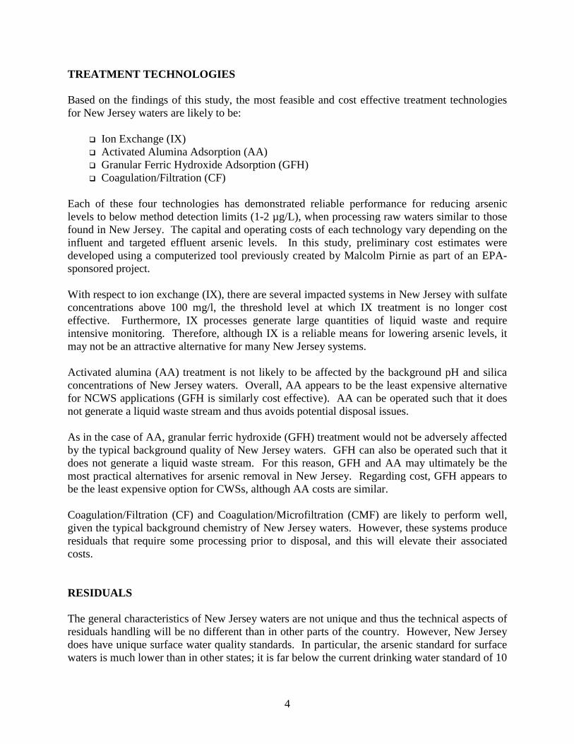
TREATMENT TECHNOLOGIES
Based on the findings of this study, the most feasible and cost effective treatment technologiesfor New Jersey waters are likely to be:
! Ion Exchange (IX)! Activated Alumina Adsorption (AA)! Granular Ferric Hydroxide Adsorption (GFH)! Coagulation/Filtration (CF)
Each of these four technologies has demonstrated reliable performance for reducing arseniclevels to below method detection limits (1-2 µg/L), when processing raw waters similar to thosefound in New Jersey. The capital and operating costs of each technology vary depending on theinfluent and targeted effluent arsenic levels. In this study, preliminary cost estimates weredeveloped using a computerized tool previously created by Malcolm Pirnie as part of an EPA-sponsored project.
With respect to ion exchange (IX), there are several impacted systems in New Jersey with sulfateconcentrations above 100 mg/l, the threshold level at which IX treatment is no longer costeffective. Furthermore, IX processes generate large quantities of liquid waste and requireintensive monitoring. Therefore, although IX is a reliable means for lowering arsenic levels, itmay not be an attractive alternative for many New Jersey systems.
Activated alumina (AA) treatment is not likely to be affected by the background pH and silicaconcentrations of New Jersey waters. Overall, AA appears to be the least expensive alternativefor NCWS applications (GFH is similarly cost effective). AA can be operated such that it doesnot generate a liquid waste stream and thus avoids potential disposal issues.
As in the case of AA, granular ferric hydroxide (GFH) treatment would not be adversely affectedby the typical background quality of New Jersey waters. GFH can also be operated such that itdoes not generate a liquid waste stream. For this reason, GFH and AA may ultimately be themost practical alternatives for arsenic removal in New Jersey. Regarding cost, GFH appears tobe the least expensive option for CWSs, although AA costs are similar.
Coagulation/Filtration (CF) and Coagulation/Microfiltration (CMF) are likely to perform well,given the typical background chemistry of New Jersey waters. However, these systems produceresiduals that require some processing prior to disposal, and this will elevate their associatedcosts.
RESIDUALS
The general characteristics of New Jersey waters are not unique and thus the technical aspects ofresiduals handling will be no different than in other parts of the country. However, New Jerseydoes have unique surface water quality standards. In particular, the arsenic standard for surfacewaters is much lower than in other states; it is far below the current drinking water standard of 10

5
µg/L. Consequently, a wastewater treatment plant that accepts liquid residuals from an arsenictreatment system will almost certainly produce an effluent that exceeds the surface waterrequirement. This is true whether the drinking water standard is 10, 7, 5, or 3 µg/L. To date, thishas not been a critical issue because relatively few drinking water systems have targeted arsenicremoval. It is important to realize that some wastewater plants are currently receiving municipalsewage with a background arsenic level that exceeds the surface water standard.
Although this is not a true technical issue, it must still be addressed, even for the current MCL of10 µg/l to be cost effective. If there is no change in the existing surface water standard, manywastewater plants will not be able to accept liquid residuals from arsenic treatment systems,thereby eliminating certain technologies as practical alternatives.
CONCLUSIONS
In conclusion, the general water chemistry of the impacted systems in New Jersey is such thatany of the four above-listed treatment technologies could reliably reduce arsenic concentrationsto 7, 5 or even 3 µg/L. The overall treatment cost will increase as the target level decreases.This information is based on a significant number of studies, although there are only a few full-scale systems operating in this country and even fewer pilot studies specific to New Jersey.
Overall, GFH and AA appear to be the most practical and economical alternatives for arsenicremoval in New Jersey.
There is a significant regulatory issue associated with the disposal of arsenic-laden wastestreams, and this is directly tied to the stringent surface water quality parameters that wastewaterplants must currently meet. The issue exists whether the drinking water standard is 10 µg/L orsome lower concentration; it will ultimately affect the feasibility and relative cost of arsenictreatment efforts in New Jersey.

6
1. INTRODUCTION
1.1. PURPOSE
To protect human health, the United States Environmental Protection Agency (EPA) lowered the
primary drinking water standard for arsenic from 50 µg/L to 10 µg/L. All community and non-
community water systems (CWSs, NCWSs) are required to comply with this revised standard by
January of 2006. Due to the perceived health benefits of reduced arsenic ingestion, the State of
New Jersey (NJ) is requiring compliance within 14 months of when the rule becomes effective.
Furthermore, NJ is considering whether to lower the arsenic standard to below 10 µg/L. For this
reason, the NJ Department of Environmental Protection Agency (DEP) initiated the work
presented herein, so as to identify arsenic removal technologies that can treat the impacted
waters in NJ and achieve target concentrations of 7 µg/L, 5 µg/L and 3 µg/L.
1.2. BACKGROUND
A crucial step in deciding whether to lower the NJ arsenic standard is the identification and
evaluation of alternatives for arsenic removal. Chapter 2 summarizes arsenic occurrence in NJ
and indicates that all of the affected supplies utilize groundwater exclusively. There are several
technologies currently in use for removing arsenic from groundwater. Some of these
technologies have proven to be successful in pilot and full-scale systems and are therefore
referred to as “established technologies.” These include:
! Ion exchange (IX)
! Adsorption by
o Activated alumina (AA)
o Granular ferric hydroxide (GFH)
! Coagulation/filtration (CF) followed by
o High-rate media filters or
o Low-pressure membrane filters
! Nanofiltration (NF) or reverse osmosis (RO)

7
Additionally, due to recent advances in science and the regulatory-driven need for arsenic
treatment, new technologies are being developed that will ultimately improve the economics of
arsenic removal from potable waters. These emerging technologies include:
! Hybrid arsenic selective adsorbents
! Nanomaterials technology based adsorbents
! Magnetic ion-exchange (MIEX ) resins
! Hydrous iron oxide particles (HIOPs)
! Sand-ballasted coagulation sedimentation (Actiflo™ process)
! Immersed membranes in combination with adsorbents and
! Microsand-assisted oxidation adsorption (Metclean )
Chapter 3 presents a detailed discussion of these established and emerging technologies.
1.3. SCOPE
The overall scope of this study was to identify, review, and critique treatment technologies that
NJ water purveyors could implement to lower the arsenic levels of impacted waters to below 7,
5, or 3 µg/L. Arsenic removal technologies were evaluated in terms of:
! Arsenic removal efficiency (as it relates to NJ water quality)
! Technology status (pilot and full-scale observations)
! Process reliability
! Residuals handling issues
No fieldwork or laboratory analyses were conducted as part of this project. The technology
assessments were based entirely on existing literature. NJ-specific conclusions were developed
by evaluating these published results (which in most cases were generated outside of NJ) in
terms of NJ water quality. To this end, a comprehensive list of arsenic-containing water supplies
and their associated water quality characteristics was compiled using data from the NJDEP Safe
Drinking Water Act (SDWA) database and from U.S. Geological Survey (USGS) reports on
groundwater quality across the state (see Appendices A and B).

8
2. ARSENIC OCCURRENCE IN NEW JERSEY
On January 22, 2002, the NJDEP issued a proposed regulation that would lower the NJ drinking
water standard for arsenic to 10 µg/L. The proposal also indicated that the NJDEP would
investigate further reductions in the arsenic standard, since 10 µg/L does not correspond to the
one-in-one-million cancer risk goal identified in the NJ Safe Drinking Water Act (SDWA).
Unfortunately, the arsenic concentration corresponding to such a risk is estimated to be 0.003
µg/L or 3 parts per trillion. As this is currently an unrealistic regulatory standard, the NJDEP is
seeking to find the lowest achievable level. The cancer risk corresponding to an arsenic
concentration of 10 µg/L is approximately 3-4 in 1,000.
According to NJDEP SDWA databases, there are 44 CWSs in NJ with arsenic concentrations at
or above 3 µg/L. These are listed in Table 2-1, which also indicates that a majority of these
systems can be classified as “very large”, providing more than 0.5 million gallons per day
(mgd).1 Figure 2-1 shows the locations of these CWSs, illustrating that the arsenic-laden water
supplies are found throughout NJ. Figure 2-1 also identifies the five physiographic provinces of
NJ, as established by the U.S. Geological Survey (USGS). Each province has a unique geology
that influences the groundwater characteristics of the area, including background arsenic levels.
Table 2-2 shows the relative distribution of arsenic-containing community water supplies with
respect to these geological boundaries.
Table 2-3 lists the non-transient, NCWSs with arsenic concentrations in excess of 3 µg/L.2 There
are a total of 147, and they include schools, professional buildings, shopping plazas, and other
public places. Although daily demand data is not readily available, the majority of these systems
probably supply between 50,000 and 500,000 gallons per day (gpd) (typical range for schools,
professional buildings, etc.). Figure 2-2 shows that they are concentrated in and around the
Piedmont region of New Jersey, and this is further illustrated in Table 2-2. Interestingly, there is
a slightly different distribution for NCWSs than was observed for CWSs.
1 Water quality data for community water supplies can be found in Appendix A2 Water quality data for non-transient, non-community water supplies can be found in Appendix B

9
Figure 2-1. Community Water Supplies Having at Least One Source Water With ArsenicConcentrations of 3 µg/L or Higher
Arsenic = 3.0-5.0 ppb (10 systems)
Arsenic = 5.1-7.0 ppb (13 systems)
Arsenic = 7.1-10.0 ppb (13 systems)
Arsenic >10 ppb (8 systems)
Valley
and R
idge
Highlands
Piedmont
Inner Coastal Plain
Outer Coastal Plain
Arsenic = 3.0-5.0 ppb (10 systems)
Arsenic = 5.1-7.0 ppb (13 systems)
Arsenic = 7.1-10.0 ppb (13 systems)
Arsenic >10 ppb (8 systems)
Valley
and R
idge
Highlands
Piedmont
Inner Coastal Plain
Outer Coastal Plain

10
Figure 2-2. Non-Transient, Non-Community Water Supplies Having at Least One SourceWater with Arsenic Concentrations of 3 µg/L or Higher
Highlands
Piedmont
Inner Coasta
l Plain
Outer Coastal Plain
Highlands
Piedmont
Inner Coasta
l Plain
Outer Coastal Plain
33Vall
ey an
d Ridg
e
* Locations with multiple supplies are marked by a number
Arsenic = 3.0-5.0 ppb (46 systems)
Arsenic = 5.1-7.0 ppb (34 systems)
Arsenic = 7.1-10.0 ppb (35 systems)
Arsenic >10 ppb (33 systems)
22
33
22
22
22 22
33 2244 88
33 22
22
22
22
88 7766 55
33
22

11
Table 2-1. Community Water Supplies in NJ That Have at Least One Source Water withArsenic Concentrations Above 3 µg/L
10 Systems with Arsenic = 3.0-5.0 µg/L
System Name Municipality System SizeMiddlesex W. Co. Woodbridge Twp. Very LargeMontague Water Co. Montague Twp. Very LargeMount Holly Water Company Mount Holly Twp. Very LargeNJ American W Co Western Div. Palmyra Boro Very LargeTuckerton Water & Sewer Dept Tuckerton Boro Very LargeWest Deptford Twp. Water Dept West Deptford Twp. Very LargeBogerts Ranch Estates In Mahwah Twp. LargeNorms Dale Mobile Home Park Egg Harbor Twp. LargeSage Investment Corporation Egg Harbor Twp. LargeRosemont Water Department Delaware Twp. Small
13 Systems with Arsenic = 5.1-7.0 µg/L
System Name Municipality System SizeAllendale Water Dept Allendale Boro Very LargeClinton W Dept Clinton Town Very LargeElizabethtown Water Co. Elizabeth City Very LargeHo Ho Kus Water Dept Hohokus Boro Very LargeLongport Water Department Longport Boro Very LargeMonroe Twp Mua Monroe Twp. Very LargePemberton Twp Dept Main Pemberton Twp. Very LargePennington W Dept Pennington Boro Very LargeRidgewood Water Dept Ridgewood Twp. Very LargeWaldwick Water Dept Waldwick Boro Very LargeAllenwood Mobile Estates Tabernacle Twp. LargeMilford W Dept Milford Boro LargeOakview Leisure Village Shamong Twp. Large
13 Systems with Arsenic = 7.1-10.0 µg/L
System Name Municipality System SizeBellmawr Water Dept Jackson Twp. Very LargeElmer Boro W Dept Monroe Twp. Very LargeFlemington Water Dept Bellmawr Boro Very LargeHopewell Boro W DeptMontclair Water Bureau
Hopewell BoroFlemington Boro
Very LargeVery Large
Ramsey Water Dept Hardyston Twp. Very LargeHardyston Twp Mua Indian Field Hopewell Boro LargeRocky Hill W Dept Frenchtown Boro LargeStillwater Water District Montclair Town LargeVernon w Co. Wall Twp. LargeVincentown Water Company Jackson Twp. LargeGarden State Mobile Home Elmer Boro N/AJackson Colonial Arms Ap Lawrence Twp. N/A

12
8 Systems with Arsenic > 10.0 µg/L
System Name Municipality System sizeColonial Estates Rocky Hill Boro Very LargeHopewell Boro W Dept Southampton Twp. Very LargeLawrenceville W Co Vernon Twp. Very LargeMahwah Water Department Ramsey Boro Very LargeOcean Twp Mua Pebble Bea Jackson Twp. Very LargeSeaside Heights Water Dept Seaside Heights Boro Very LargeFrenchtown Water Dept Still water Twp. LargeNaval Air Eng. Station Lakehrs Ocean Twp. Large
Table 2-2. Percent Distribution of Arsenic-Containing Water Supplies Across NJ
Physiographic Province
System TypeValley and
Ridge Highlands PiedmontInner Coastal
PlainOuter Coastal
PlainCWS 9.3 4.7 39.5 6.3 30.2
NCWS 1.4 8.8 63.5 9.5 16.9
Table 2-3. Non-transient, Non-Community Water Supplies in NJ That Have at Least OneSource Water with Arsenic Concentrations Above 3 µg/L
46 Systems with Arsenic = 3.0-5.0 µg/L
System Name Municipality System SizeCurtis Specialty Papers Milford Boro Very LargeEl Dupont Denemours & Co Greenwich Twp. Very LargeLakehurst Naval Air Eng. Jackson Twp. Very LargeBarley Sheaf School Raritan Twp. LargeAlexandria Middle School Alexandria Twp. N/AAll Day Learning Center Hillsborough Twp. N/AAllentown Caging Equipment Upper Freehold Twp. N/AApplied Water Management Hillsborough Twp. N/ABasking Ridge Wk Ctr/Bell Atl Harding Twp N/ABear Tavern School Hopewell Twp. N/AChildren’s Express Lawrence Twp. N/AClinton Twp Munic Bldg Clinton Twp. N/AFlemington Outlet Center Raritan Twp. N/AGarvey Conveyers Winslow Twp. N/AHarris Steel/Beam Ship South Plainfield Boro N/AHopewell Munic Services Hopewell Twp. N/AHunterdon County Democra Raritan Twp. N/AHunterdon Med Ctr-Well # Raritan Twp. N/AHunterdon Med Ctr-Well # Raritan Twp. N/A

13
Irwin Lincoln Mercury Ca Freehold Twp. N/AJackson Outlet Village Jackson Twp. N/AKinder Care Burlington Twp. N/ALake Nelson School Piscataway Twp. N/ALaneco of Whitehouse Readington Twp. N/ALiberty Court Condo Assn Raritan Twp N/AMerrill Lynch Hopewell Twp. N/AMigrant Day Camp Hamilton Twp. N/AMinalex Corp Readinton Twp. N/AMont. Pre-Sch Cnt Raritan Twp. N/AP Jax Inc. Union Twp. N/APark Meadows Industrial East Hanover Twp. N/APennington Happy School Hopewell Twp. N/APennington Office Park-B Hopewell Twp. N/APennington Shop-Rite Hopewell Twp. N/AQuick Check Corp Readington Twp. N/ARambling Pines Day Camp East Amwell Twp. N/AReadington Farms Readington Twp. N/ARoute 31 Associates Clinton Twp. N/ARt 31 Professional Bldg Hopewell Twp. N/ASimone Investment Group L.L.C. Lawrence Twp. N/ASpeedway Plaza / W. Horv Raritan Twp. N/ASwitlik Elementary School Jackson Twp. N/ATimberlane Junior High School Hoopewell Twp. N/AVictaulic Inc. Franklin Twp. N/AWatchung Hill High School Warren Twp. N/AWhitehouse School Readington Twp. N/A
34 Systems with Arsenic = 5.1-7.0 µg/L
System Name Municipality System SizeFerro Corporation Logan Twp. Very LargeLegends Resort & Conference Vernon Twp. Very LargeUS Bronze Powders Raritan Twp. LargeQuality Partition Mfg Kingwood Twp. SmallB&T Development Raritan Twp. N/ACamelot Nursery School Hopewell Twp. N/ACenter For Ed Adv (Furn. Raritan Twp. N/AChildren’s Workshop Hillsborough Twp. N/ACross Roads Christian Academy Franklin Twp. N/ADarts Mill Day Care Center Readington Twp. N/AEducational Testing Services Lawrence Twp. N/AFirst Fidelity Bank Off Colts Neck Twp. N/AFlemington Circle Buick Raritan Twp. N/AGiant Steps Nursery School Harrison Twp. N/AHealth Products Research Readington Twp. N/AHillsborough & Three Bridges Hillsborough Twp. N/ALogan Generating Plant Logan Twp. N/AMaur Riv Twp Bd of Ed Le Maurice River Twp. N/AOcean County Utilities Stafford Twp. N/AOlde Towne Sq Condo Assoc. Medford Twp. N/APenn Partnership Parsons Hopewell Twp. N/APowerco Union Twp. N/AReadington Mun Readington Twp. N/ASalem Industrial Park Readington Twp. N/ASalem Square Readington Twp. N/ASouth Jersey Gas Co. Egg Harbor Twp. N/A

14
Stage Depot Hopewell Twp. N/AStage II Motel & Prof Bldg Hopewell Twp. N/ATekni-Plex Inc. Raritan Twp. N/AThree Bridges School Readington Twp. N/ATranscontinental Gas Pipeline Branchberg Twp. N/AVillage Montessori School Raritan Twp. N/AWaterford Elementary Waterford Twp. N/AYale Materials Handling Raritan Twp. N/A
34 Systems with Arsenic = 7.1-10.0 µg/L
System Name Municipality System Size3M Mining Company Montgomery Twp. Very LargeValley View Manor Alexandria Twp. Small84 Components Pennington Boro N/AAlbert Elias Residential Group East Amwell Twp. N/AB & B Poultry Co., Inc. Pittsgrove Twp. N/ABishop & Bishop (Well #2 Readington Twp. N/ABristol Myers, Squibb Co Well Hopewell Twp. N/ACondit Ford Hampton Twp. N/ACountry Mile Village Harding Twp. N/ADel Rilo’s Deli & Bake Shoppe Kingwood Twp. N/ADelaware Valley Regional Alexandria Twp. N/AGPU Energy Howell Twp. N/AHarris Structural Stl Co Piscataway Twp. N/AHarrisonville School South Harrison Twp. N/AInductotherm Corp Willingboro Twp. N/AJackson Memorial High School Jackson Twp. N/AJames Toyota Raritan Twp. N/ALester D Wilson School Alexandria Twp. N/AMing Dynasty Buffet Stafford Twp. N/ANaval Air Eng Ctr/Well 4 Jackson Twp. N/AOak Crest Country Day School Franklin Twp. N/AOcean County Utilities Berkeley Twp. N/APassaic County Golf Course Wayne Twp. N/APineland Learning Center Deerfield Twp. N/APrinceton Elks 2129 Montgomery Twp. N/ARCN Residential Comm Network Hillsborough Twp. N/ARobert D Reynolds School Upper Saddle River N/ASimsy’s Pub Chesilhurst Boro N/ATeddy & Me Daycare Morris Twp. N/AThe Pennington School Pennington Boro N/ATownsend Property Trust L P Hopewell Twp. N/ATruckstops of America Knowlton Twp. N/AUnion Twp School Union Twp. N/AWilson Color-Admin Well Branchburg Twp. N/A
33 Systems with Arsenic > 10.0 µg/L
System Name Municipality System SizeSeabrook Brothers and So Upper Deerfield Twp. Very LargeCumberland Regional High Upper Deerfield Twp. LargeLittle Sisters of the Poor Totowa Boro MediumSeabrook House Upper Deerfield Twp. SmallAMI Branchburg Twp. N/AARC/Hunterdon Adult Trai Kingwood Twp. N/AArthur P Schalick High School Pittsgrove Twp. N/ABreen Color West Amwell Twp. N/A

15
Discovery Years Vernon Twp. N/AEast Amwell Twp. East Amwell Twp. N/AEsc School Tewksbury Twp. N/AFountain of Life Center Florence Twp. N/AGloucester Co Day Training Monroe Twp. N/AHarding Township Harding Twp. N/AHaworth Swim Club Haworth Boro N/AHigh Road Career Center Franklin Twp. N/AHigh Road Upper School Franklin Twp. N/AHunterdon Hills Playhouse Union Twp. N/AKooltronic, Inc. Hopewell Twp. N/ALawrence Day School Lawrence Twp. N/ALower Alloways Creek School Lower Alloways Cr. N/AMahwah BPOE Mahwah Twp. N/APennington Office Park Hopewell Twp. N/APhillips Barber Health Lambertville City N/ASalerno Duane of Sussex Inc. Hampton Twp. N/ASaturn of Freehold Freehold Twp. N/AThe Manor West Orange Town N/AToddler Village @ Stony Brook Hopewell Twp. N/AWaldorf School of Prince Montgomery Twp. N/AWilson Color – Main Well Branchburg Twp. N/AWilson Color – R & D Wel Branchburg Twp. N/AWoodfern School Hillsborough Twp. N/AWoodland Country Day School Stow Creek Twp. N/A
As previously mentioned in Section 1, the water quality characteristics for the above-listed
systems were gathered from the NJDEP SDWA databases and from USGS reports regarding
groundwater quality in each physiographic province. A summary of these characteristics and a
discussion of their relevance to arsenic treatment in NJ are presented in Section 4.1.

16
3. ARSENIC TREATMENT TECHNOLOGIES
As discussed in Chapter 1, there are several established techniques for removing arsenic from
groundwater. Importantly, all of these techniques could effectively lower arsenic levels in NJ
groundwater to below the detection limit (1-2 µg/L) (see Chapter 4). This chapter reviews these
treatment methods, focusing on:
! Water quality characteristics that impact treatment efficiency
! Operational considerations
! Design parameters
! Residuals generation and disposal
Wherever possible, pilot- and full-scale observations were emphasized, although bench-scale
results are also included. NJ-specific considerations are discussed in Chapter 4.
Note that the technologies summarized in this chapter are not the only alternatives for removing
arsenic from water. Other technologies exist, but have not yet been tested in pilot- and/or full-
scale systems. Also, although reverse osmosis (RO) is currently used for a wide range of full-
scale applications, including arsenic treatment, it was not evaluated herein. RO uses high-
pressure membrane-based technology that generates a considerable volume of liquid waste
(brine). As much as 15% of the feed water becomes a brine stream that contains high
concentrations of salts (making it corrosive) and arsenic (potentially causing it to be classified as
hazardous). For this reason it was decided that RO would not be a practical solution for treating
arsenic-containing groundwater in NJ.
3.1. ARSENIC CHEMISTRY
Arsenic is a metal commonly found in rocks and soil, usually as part of the mineral arsenopyrite
(FeSAs). Through erosion and dissolution, arsenic can enter natural ground and surface waters.
Once dissolved, it can take many forms, both organic and inorganic. The organic form of arsenic
usually occurs in seafood and is of relatively low toxicity. Inorganic arsenic occurs in water and
is reported to be highly toxic.

17
The valence state and corresponding species of inorganic arsenic depend on the oxidation-
reduction (redox) conditions and pH of the surrounding water. Generally speaking, the reduced,
trivalent form of arsenic [Arsenite – As(III)] is found only in groundwaters, where anaerobic
conditions prevail. In contrast, the oxidized, pentavalent form [Arsenate – As(V)] is observed in
both groundwater and surface supplies. Either oxidation state can exist in different forms,
depending on pH, and these are listed in Table 3-1.
Table 3-1. Aqueous Forms of Inorganic Arsenic
Arsenite – As(III) H4AsO3+, H3AsO3, H2AsO3
-, HAsO32-, AsO3
3-
Arsenate – As(V) H3AsO4, H2AsO4-, HAsO4
2-, AsO43-
Notably, arsenite will appear as a neutral species (H3AsO3) at any pH less than 9. In contrast, the
neutral form of arsenate (H3AsO4) is only present at pH < 3. This has important implications for
determining appropriate treatment technologies, as certain removal techniques rely on
electrostatic attractions between arsenic and charged surfaces. These techniques, which include
ion exchange, adsorption, and precipitation, are usually far more effective for removing arsenate
as compared to arsenite.
Finally, although arsenic found in natural waters is typically dissolved, some research indicates
that it can also appear as a particulate. An EPA report entitled Arsenic Removal from Drinking
Water by Iron Removal Plants (EPA/600/R-00/086) explains that there have been cases where
particulate arsenic accounts for 17-50% of the total arsenic concentration. This mostly occurs in
surface waters, and is therefore not likely to affect arsenic treatment in New Jersey.3
3.2. TREATMENT LOGISTICS
As previously mentioned, the treatment technologies described below can lower arsenic
concentrations to below the method detection limits of 1 or 2 µg/L. Consequently, water
suppliers may prefer to treat a portion of the arsenic-laden influent stream and blend it with
3 Arsenic occurrence in New Jersey is limited to groundwater supplies

18
untreated water to achieve the target arsenic concentration. This “split-stream” approach can
reduce treatment costs but may not be feasible if the arsenic standard is much below 10 µg/L.
The next several sections present technologies that are suitable for treating New Jersey
groundwaters. Each technology is characterized in terms of its operational requirements, as
determined in bench-, pilot-, and/or full-scale studies.
3.3. ION EXCHANGE
3.3.1. Process Description
Ion exchange (IX) is a physical/chemical process by which ions at a solid/water interface are
exchanged for ions in the surrounding bulk water. The solid phase is normally a synthetic resin
that preferentially adsorbs the contaminant(s) of concern. Prior to treatment, the resin is
saturated with inert ions, usually chloride. During treatment, feed water is continuously passed
through a packed bed comprised of this resin (usually in the form of beads) in either a downflow
or upflow mode. The bed becomes exhausted when all available adsorption sites on the resin
beads have been filled by contaminant ions. At this point, the bed can be regenerated by rinsing
with a concentrated solution of inert ions of the type initially adsorbed to the resin. The number
of bed volumes (BVs) that can be processed prior to exhaustion varies with resin type and
influent water quality. It can vary between 300 and 60,000 BVs. In most cases, complete
regeneration can be accomplished with only 1 to 5 BVs of regenerant followed by 2 to 20 BVs of
rinse water.
Some important considerations regarding the applicability of IX for removing arsenic include
water quality parameters such as pH, competing ions, alkalinity, influent arsenic concentration,
and the ratio of arsenite (As III) to arsenate (As V). Other factors include the resin type, affinity
of the resin for the contaminant, spent regenerant and resin disposal requirements, secondary
water quality effects, and design operating parameters.

19
3.3.2. Water Quality Impacts
The following water quality parameters affect the performance of IX processes for arsenicremoval.
! pH
! Competing ions
! Dissolved organic carbon (DOC)
! Secondary effects (caused by the treatment)
! Resin fouling
pH. The speciation of inorganic arsenic is a function of pH. If arsenic is present in groundwaters
as As(III), it will normally be in a neutral form. The IX system is much more efficient at
removing charged species as compared to uncharged species. Thus, IX is generally not effective
for removing As(III) from natural waters. When arsenic is present in the form of As(V), the
divalent HAsO42- ion is preferentially removed over the monovalent H2AsO4
- ion. Therefore, a
slightly basic pH is preferable for arsenic treatment using IX.
Competing Ions. Competition from background ions for IX sites can greatly affect the
efficiency and economics of IX systems. The levels of these background ions may in fact
determine the applicability of IX at a particular site. Typically, strong-base anion exchange
resins are used in arsenic removal. The order of exchange for most strong-base resins is given
below, with the adsorption preference being greatest for the constituents on the far left (AWWA,
2000).
HCrO4- > CrO4
2- > ClO4- > SeO4
2- > SO42- > NO3
- > Br- > (HPO42-, HAsO4
2-, SeO32-, CO3
2-) >
CN- > NO2- > Cl- > (H2PO4-, H2AsO4
-, HCO3-) > OH- > CH3COO- > F-
Although strong base anionic resins have a relatively high affinity for arsenic in the arsenate
form (HAsO42-), studies have shown that high total dissolved solids (TDS) (> 500 mg/L) and
sulfate levels (> 100 mg/L) can greatly reduce IX efficiency and cause short run lengths
(AWWA, 2000). Recently, novel IX processes have been proposed and are currently under
investigation. These processes involve the use of multiple IX columns in series with successive

20
regeneration of the columns, and are specifically designed for high sulfate waters (Benjamin et
al., 2001).
Competitive adsorption can cause arsenic levels in the treated water to exceed the influent
arsenic concentration. For example, if a resin prefers sulfate to arsenate, the sulfate ions may
displace previously adsorbed arsenate ions. This is often referred to as chromatographic peaking.
Because of this, the bed must be monitored and regenerated in advance of any expected peaking.
DOC. Natural waters sometimes contain significant amounts of dissolved organic carbon
(DOC). The presence of DOC can affect adsorption systems by complexing with the targeted
contaminants or by competing for adsorption sites. Batch tests have indicated that the adsorption
capacity of IX for As(V) is dramatically reduced when the DOC concentration increases from 0
mg/L to 4 mg/L (AWWARF, 1999). However, another study found that the adsorption capacity
of IX for arsenic was independent of the DOC concentrations (Vagliasindi and Benjamin, 1998).
Secondary Effects. Chloride-containing (chloride-form) resins are often used for arsenic
removal. As arsenic is adsorbed onto the resin, chloride ions are released. Consequently, the
chloride concentration of the product water will increase, which in turn increases its corrosivity.
Chlorides increase the potential for iron corrosion and can therefore increase the potential for red
water problems. In situations where chlorides pose a problem, demineralization, blending, or
alternate treatment techniques may be required.
IX can reduce pH by removing bicarbonate ions, which may increase the corrosivity of the
treated water. This occurs primarily at the beginning of an IX treatment cycle. The reduction in
pH can be minimized by recycling the regeneration brine (that contains a high bicarbonate
concentration) (Chwirka et al, 2000). In some situations, pH re-stabilization may be necessary to
prevent disturbances in the distribution system. pH re-stabilization can be accomplished by
adding an alkali (such as sodium hydroxide) to the IX effluent.
Resin Fouling. In the absence of adequate pre-treatment, IX resin beads may become fouled.
Generally, fouling is caused by mineral precipitates (e.g., calcium or iron) or by particulates in

21
the feed stream (Malcolm Pirnie, 1993a). If scaling is a problem, sequestering agents can be
used to lower the scale-forming potential of the feed water. If suspended solids are present,
filtration upstream of the IX columns may be necessary.
3.3.3. Operational Considerations
The following operational issues affect the efficiency and overall performance of IX treatment.
! Pre-chlorination
! Resin type
! Process configuration
! Empty bed contact time
! Regeneration
! Regenerant re-use
Pre-chlorination. As previously discussed, IX resins can be effective for removing arsenate (As
V) but are not effective for removing arsenite (As III). Thus, As(III) must be converted to As(V)
for efficient arsenic removal. There are many oxidants that can accomplish this. One in
particular that has been evaluated for arsenic removal by IX is chlorine. Tests conducted with
Lake Washington water indicated that the effluent arsenic concentration from an IX column
rapidly reached the influent concentration when the water had not been chlorinated (Vagliasindi
and Benjamin, 2001). Even if arsenic is initially present in the As(V) form, occasionally it is
possible for As(V) to revert back to As(III). Chlorination has been shown to preserve arsenic in
the As(V) form (AWWARF, 1999).
While chlorine may be an effective means of preserving arsenic in the As(V) form, it should be
noted that some resins are not chlorine tolerant. In some cases, the reaction of chlorine with the
resin may produce nitroso-dimethylamine (NDMA), which is thought to have adverse health
effects and is currently under investigation as a possible carcinogen. Potassium permanganate
can also be used as an alternative pre-oxidant to convert As(III) to As(V). However, it may be
possible for adsorbed As(V) to revert back to As(III) if anaerobic conditions develop in the IX
media.

22
Resin Type. As stated earlier, strong-base resins are typically used for arsenic removal by IX.
These resins, however, tend to preferentially adsorb ions such as sulfate and chloride rather than
arsenate. This selective adsorption of other ions can result in chromatographic peaking if the
beds are not monitored adequately. One study indicated that the removal of As(V) did not differ
significantly among five different IX resins after their exchange capacity was taken into account
(Clifford and Lin, 1986). When removing both nitrate and arsenic, nitrate-selective resins should
be avoided because studies have indicated that the run lengths to arsenic breakthrough are higher
for conventional resins than for nitrate-selective resins.
Process Configuration. While arsenic leakage sometimes occurs in IX columns, proper
configuration of an IX system can prevent this as well as improve arsenic removal and help
minimize regeneration frequency. In some situations, special operating methods may be needed
to achieve low arsenic levels consistently. To prevent arsenic peaking, frequent regeneration is
required. Another approach to avoiding sudden breakthrough is to operate several IX columns in
series (Kwan et al., 2001).
Empty Bed Contact Time. Few studies have been performed to test the effect of empty bed
contact time (EBCT) on IX performance. Clifford and Lin (1986) reduced EBCT from 5
minutes to 1.4 minutes in a Hanford, CA study and found no significant reduction in arsenic
removal performance. In another study, four IX columns were run with EBCTs varying between
2.5 and 15 minutes (Amy et al., 1999). Data from this study indicated that the effect of EBCT on
arsenic breakthrough was negligible. The advantage of shorter EBCT is reduced capital cost.
However, the disadvantage of the shorter EBCT is increased regeneration frequency.
Regeneration. With chloride-form resins, concentrated NaCl solution is typically used as the
regenerant. Only a few BVs of regenerant are usually required to replenish the resin, depending
on the solution strength.
Regenerant Re-use. Spent regenerant will usually have high concentrations of arsenic and other
sorbed contaminants. However, it may be reused many times. The arsenic level in the
regenerant need not be lowered prior to reuse, although the chloride concentration must be

23
replenished. In a field study, an IX column was regenerated 18 times using recycled regenerant
that was replenished with NaCl after each cycle to maintain the chloride concentration at 1 M
(Clifford et al., 1998). Chloride addition is essential to maintain the effectiveness of the spent
regenerant.
3.3.4. Design Parameters
The IX run lengths are about 1,500 BVs at a sulfate concentration of 20 mg/L and 700 BVs at a
sulfate concentration of 50 mg/L (Clifford et al., 1995). If Fe(III) particulates or other suspended
solids are present, they should be removed prior to the IX process for reasons previously
discussed. Although a slightly basic pH is preferable for IX treatment, pH adjustment is not
essential as long as the arsenic is in its oxidized (As(V)) form. If As(III) is present, it should be
converted to As(V) via oxidants such as chlorine and potassium permanganate.
Typically, a 0.5 M NaCl solution is sufficient for regeneration and can be used at least 20 times
before it must be treated to remove arsenic and other ions. One method for removing arsenic
from the regenerant is to precipitate Fe(OH)3•As or Al(OH)3•As, and this is accomplished by
adding iron and/or aluminum coagulants. If treating the regenerant is not a feasible alternative,
the brine can be used for a single regeneration and then discharged to a public sewer. In general,
the arsenic concentration in a regenerant that is used only once should be low enough so that a
typical wastewater plant would accept it. Although many design parameters should be tailored
to the specific treatment situation, Table 3-2 provides a useful starting point for IX design.
Table 3-2. Typical Design/Operating Parameters and Options for Ion Exchange Systems
EBCT of 2.5 minutes
Run length of 700 BVs with 20 mg/L SO42- and 1500 BVs with 50 mg/L SO4
2-
Depth-to-diameter ratio of resin bed between 0.2:1 to 2:1
Regenerant concentration of 0.5 M NaCl
Regenerant surface loading velocity greater than 2 cm/min

24
3.3.5. Residuals Handling and Disposal
The primary source of residuals from an IX system is the regeneration process. With time, the
efficiency of an IX resin is reduced as exchange sites are depleted. A typical regeneration
requires 2.8 BVs of brine and 1.2 BVs of rinse water. Therefore, 4 to 5 BVs of residual liquid
waste are produced per regeneration cycle (Amy et al., 2000).
Spent regenerant that cannot be reused must be treated and/or disposed of appropriately. This
can be an expensive part of the IX process and must be given careful consideration. Spent brine
can be disposed of either directly to a surface water source, or indirectly to a sanitary sewer,
depending on contaminant levels. If the brine is used once, it can most likely be discharged to a
publicly owned treatment works (POTW). However, if the brine is used to regenerate the IX
columns several times, then some form of treatment may be necessary due to high arsenic
concentrations in the brine and/or high total dissolved solids.
A recent EPA study (EPA, 2000) determined that arsenic concentrations in spent brine solutions
range from 1.83 to 38.5 mg/L (average: 16.5 mg/L). Liquid residuals generated during the other
steps of the regeneration process (i.e., backwash, slow rinse, and fast rinse) contained much
lower arsenic concentrations (0.0594, 1.332, and 0.108 mg/L, respectively). These waste
streams are often combined so as to reduce the relatively high arsenic levels in the brine wastes.
Clifford and Lin (1995) and Clifford (1999) have shown that arsenic levels in spent regenerant
solutions can be reduced substantially via precipitation with iron and aluminum coagulants. In
one case, a 99.5 percent arsenic removal rate was observed following the addition of ferric
chloride to a regenerant solution containing 3.5 mg/L arsenic (Clifford, 1999). The ferric
chloride dosage in this experiment corresponded to an Fe:As molar ratio of 20:1 (Clifford, 1999).
In general, sludges generated during the treatment of spent brine solutions have passed TCLP
tests, usually with less than 1.5 mg/L As(V) in the leachate. These dried sludges can therefore be
disposed of in municipal landfills. The re-use of decontaminated regenerant has not yet been
evaluated, but appears to be a potential option.

25
3.3.6. Process Schematic and Layout
A typical process schematic for an IX system is shown in Figure 3-1. The process schematic
shows the operation of three vessels in parallel. IX systems are typically operated in parallel
arrangement. The process schematic also shows the unit processes that are applicable for
handling the spent regenerant (brine) stream. The layout for a 1 mgd, IX treatment system is
shown in Figure 3-2. As shown by this figure, approximately 2,500 square feet of land area is
required to install the various unit processes associated with treatment and residuals handling for
a 1 mgd IX treatment system.
Figure 3-1. Process Flow Schematic for IX Treatment System

26
Figure 3-2. Site Layout for IX Treatment of 1 mgd Capacity
3.4. ACTIVATED ALUMINA
3.4.1. Process Description
Contaminant removal by AA is a physical/chemical process by which aqueous anions are
adsorbed to an oxidized surface. AA, comprised of aluminum trioxide (Al2O3), is a porous,
granular material with a high adsorptive capacity for negatively charged ions such as arsenic.
AA media typically has a mesh size of 28 by 48 (0.3 to 0.6 millimeters in diameter) and is
prepared by dehydrating Al(OH)3 over a heat range of 300 to 600 oC (Clifford and Lin, 1995). It
is produced by several manufacturers and is available in a variety of grades (relating to purity).
AA is used in packed beds to remove dissolved contaminants such as arsenic, fluoride, selenium,
silica, and humic (organic) materials (Clifford, 1999). The target ions are captured as they are
exchanged with surface hydroxides on the alumina. When adsorption sites on the AA surface
become filled, contaminant removal ceases and the bed must be regenerated. Regeneration is

27
accomplished through a sequence of rinsing with a regenerant solution, flushing with water, and
neutralizing with acid. The regenerant is a strong base, usually sodium hydroxide; the
neutralizer is a strong acid such as sulfuric acid. The AA process can also be operated on a
throwaway basis wherein the spent AA media is discarded to a landfill and replaced with fresh
material.
Many vendors have developed proprietary mixtures of AA with iron, manganese or other trace
substances. Recent tests of these modified AA medias indicate that their adsorption capacity is
similar to unmodified AA in the pH range of 7 – 8, but higher when the pH is reduced to 6.5
(NCS, 2000; Norton, et al., 2001). Treatment with AA or iron/manganese-modified AA is
optimal at a pH of 5.5-6.0, at which the adsorption capacity can be as high as 500 to 1000
micrograms (µg) of arsenic per gram (g) of AA (Chowdhury et al., 2002). Adsorption capacities
at higher pHs are considerably lower (Hathaway and Rubel, 1987; Clifford and Lin, 1995).
Numerous studies have shown that AA is a reliable technique for arsenic removal. Notably,
factors such as pH, arsenic oxidation state, competing ions, EBCT, and regeneration have
significant effect on the removal efficiency
3.4.2. Water Quality Impacts
The following are the water quality-related issues that effect the use of AA for arsenic removal.! pH
! Arsenic oxidation state
! Competing ions
! Silica
! Fluoride
! Other ions
! Secondary effects (caused by AA treatment)
pH. Feed water pH has a significant effect on arsenic removal by AA. Unused AA is mildly
basic due to the presence of excess hydroxides on its surfaces. When the media is acidified,
hydrogen ions react with some of these attached hydroxies to yield water molecules, which then

28
surround the alumina. The anions released by the acid (chloride if the acid is HCl) are
incorporated in the AA solid as counter ions. As the arsenic-laden water passes through an AA
contactor, the adsorbed anions (chlorides) are displaced by arsenic (Trussel, et. al., 1980).
Importantly, AA can also adsorb cations, but only if the pH is above the isoelectric point of that
material. The isoelectric point, or pH of zero-point-of-charge (pHzpc), is defined as the pH at
which the net surface charge of a solid substance is zero. Above this pH, the surface is
negatively charged (hence allowing for cation adsorption) whereas it carries a positive charge at
lower pH. For AA, the isoelectric point is between 8.2 and 9.2, depending on media purity. AA
has a higher pHzpc than most oxide minerals and therefore adsorbs anions in a broader pH range
than the other materials.
Previous studies have indicated that the optimum pH for arsenic removal by AA is in the range
of 5.5 to 6.0 (Rosenblum and Clifford, 1984). The primary benefit of acidifying the pH is that
AA column runs are 5 to 20 times longer than when the pH is neutral or basic (Trussel, et. al.,
1980, Simms and Azizian, 1997, NCS, 2000, Norton, et al., 2001; Chowdhury et al., 2002).
Hathaway and Rubel (1987) found that AA adsorbed about 35 µg-As/g-AA when treating raw
water with a pH of 9, whereas the adsorption capacity increased to 1050 µg-As/g-AA when the
pH was lowered to 5.5.
Arsenic Oxidation State. In studies conducted with two column runs at pH 6, the influent for
one of the columns contained 0.1 mg/L As(V) whereas the other contained 0.1 mg/L As(III). In
the case where As(V) was present, the column processed about 23,400 BVs before the effluent
arsenic levels reached 0.05 mg/L. The other column exhibited As(III) breakthrough almost
immediately and treated only 300 BVs before the effluent arsenic concentration reached 0.05
mg/L (AWWARF Report, 2002).
Competing Ions. As in the case of IX processes, AA performance can be affected by competing
ions (AWWA, 1990). The molecular structure of the AA surface is selective for fluoride,
selenium, and silica species. As indicated by the general selectivity sequence shown below

29
(Clifford and Lin, 1995), AA preferentially adsorbs monovalent H2AsO4- [As(V)] over neutral
H3AsO3 [As(III)]:
OH- > H2AsO4- > Si(OH)3O- > F- > HSeO3
- > TOC > SO42- > H3AsO3
Silica. Some researchers have reported that silica can cause chromatographic peaking when the
pH is above 8 (Clifford et al. 1998). This is tied to the fact that the pKa (dissociation constant)
for silicic acid is 9.5. Since silica is often present at much higher concentrations than arsenic,
silica ions can compete for AA adsorption sites even though arsenic is more strongly adsorbed.
Simms and Azizian (1997) confirmed this when they observed that AA media rapidly became
saturated with silicate in the presence of arsenic. Furthermore, no desorption of silicate was
observed after saturation. Additional studies have further reinforced that silica is a significant
concern in AA systems (NCS 2000, Norton et al., 2001; Chowdhury et al., 2002).
Fluoride. Fluoride will be removed to a limited extent in AA systems. At higher levels, it may
impact arsenic uptake, since fluoride will compete for adsorption sites. Recent studies conducted
in Albuquerque, New Mexico and Phoenix, Arizona, established that fluoride levels in the range
of 0.4 to 1.5 mg/L did not impact arsenic treatment significantly (Clifford, 1999 and NCS, 2000).
Generally, the fluoride level must exceed 2 mg/L before it becomes a potential source of
interference for arsenic treatment.
Other Ions. Several studies have illustrated the effects of other background ions on arsenic
removal by AA. Benjamin et al. (1998) observed little effect by either sulfate or chloride at low
(< 100 mg/L) concentrations. However, Clifford and Lin (1986) found that sulfate and total
dissolved solids (TDS) at higher concentrations (360 mg/L and 1000 mg/L, respectively) had
significant effect on adsorption, effectively decreasing the adsorption of As onto AA by
approximately 50 percent.
Secondary Effects. AA processes will cause changes in treated water quality (EPA, 1994).
Because these systems normally operate at low pH, caustic addition may be needed to raise the
pH to a level appropriate for the distribution system.

30
3.4.3. Operational Considerations
The following operational issues impact the efficiency and performance of AA with respect to
arsenic removal.
! Iron and manganese
! Empty bed contact time
! Regeneration
! Media fouling
! Series vs. parallel arrangement of adsorption vessels
! Other issues
Iron and Manganese. Unlike the anionic constituents described above, cationic iron and
manganese do not compete for exchange and adsorption sites on the AA treatment media.
However, arsenate may attach to oxidized iron and manganese, thereby affecting removal
efficiency and/or plugging the AA column (if particle sizes are large enough). Iron and
manganese concentrations of 0.5 mg/L and 0.05 mg/L, respectively, may impact AA systems,
particularly if sufficient oxidation occurs prior to the treatment system. Dissolved (reduced) iron
and manganese will pass through the contactor without affecting removal efficiency.
Empty Bed Contact Time. EBCT is also an important factor affecting arsenic removal. EBCT
determines how long the feed water is contacted with the AA media. Studies conducted in
Albuquerque, New Mexico; Fallon, Nevada; and with Salt and Verde River Waters in Phoenix
evaluated EBCTs between 1.5 to 10 minutes. These studies and the studies in Tucson, Arizona
and Scottsdale, Arizona indicate that the optimum EBCT for AA is around 5 minutes (Norton, et
al., 2001; Chowdhury et al., 2002).
Selection of an operating EBCT represents a compromise between improved arsenic removal
rates versus the added cost of extra AA and a bigger reactor vessel. The EBCT selection should
provide for sufficient run length prior to media exhaustion. It is suggested that for throwaway
systems, there should be at least 3 months of operation between media replacements so as to
reduce disposal costs. Typically, an AA treatment system utilizes two contactors, each with an
EBCT of 5 to 7 minutes. Such a system, operating at pH 6, will typically process between

31
10,000 and 25,000 BVs before its media becomes exhausted (this equates to about 30 to 90 days
of continuous operation).
Regeneration. Regeneration of AA beds is usually accomplished using a strong base solution
such as concentrated NaOH (4% NaOH). Following this, the AA medium must be neutralized
with a strong acid, typically 2 percent sulfuric acid. Clifford and Lin (1986) found that 50 to 70
percent of the arsenic in spent AA columns was removed during regeneration. Other researchers
have documented the difficult regeneration of AA used for arsenic removal. Regeneration also
affects successive bed life and efficiency. Bed life is shortened and adsorption efficiency is
decreased by regeneration. Benjamin, et al., (1998) found that arsenic breakthrough patterns
from the AA columns using regenerated media were qualitatively similar to those using fresh
media, but the removal efficiency declined slightly after each regeneration. The regeneration
process may reduce the bed life by 10 to 15 percent after each regeneration.
Media Fouling. AA media is susceptible to fouling. Fouling reduces the number of adsorption
sites and thus decreases removal effectiveness. To prevent fouling of the AA media with
particulates, the raw water may need to be filtered prior to the AA treatment. A cartridge filter or
strainer with a pore size between 20 and 500 micron (µm) may be used to remove particulate
matter. Two screeners or cartridge filters in parallel will ensure continuous operation during
replacement or maintenance.
Series versus Parallel Arrangement of Adsorption Vessels. AA beds may be operated in
series or parallel. Series operation increases removal and helps prevent leakage, but limits
throughput (leakage simply refers to elevated levels of arsenic in the treated waters). Parallel
operation on the other hand increases throughput, but does not improve treated water quality
(AWWA, 1990). When operated in series, a “merry-go-round” configuration is often used. This
configuration uses three beds: two in production and one in regeneration mode at a given time.
When exchange capacity of the first bed in series is exhausted, the first bed is removed from
service to be regenerated. The second bed in series then becomes the first and a fresh
regenerated bed is brought on-line to become the second.

32
Other Issues. Degradation of AA media must also be considered. Alumina tends to dissolve
over successive regeneration cycles due to the strong base/strong acid that are used. Strong acid
and strong base are handled on a frequent basis for pH adjustment and regeneration purposes and
can present a safety hazard. An operator must be capable of handling these chemicals.
3.4.4. Design Parameters
The removal of arsenic by AA depends primarily on pH. The AA utilization and arsenic
removal rates decrease rapidly as pH increases from 6.0 to 9.0. The optimal pH range for arsenic
removal using AA is typically reported to be 6.0 or less (Chwirka, 2000; Rosenblum and
Clifford, 1984). Therefore, a process decision must be made as to which of the following is
preferable: a) acidifying the influent water or b) replacing the media on a frequent basis.
Adjusting pH can be challenging when confronted with high ambient pH and/or high levels of
alkalinity. Table 3-3 provides typical design parameters for AA systems targeting arsenic.
Table 3-3. AA Design Parameters
FeedwaterpH EBCT (min) Anticipated Bed Life (Bvs)
< 6.0 3-5 6,000-20,000
6.0-8.0 5-7 1,000-10,000
>8.0 7-10 <1,500
Other design recommendations include (Clifford, 1999; Chwirka, 2000; Chowdhury et al.,
2002):
Media bed depth – 3 to 5 feet
Bed approach velocity – 4 to 8 gal/min-ft2
Particle size – 28 by 48 mesh size
If the AA media is regenerated then the design considerations for regeneration will include:
Regenerant concentration – 0.25 N to 1.0 N NaOH

33
Regenerant volume – 4 to 5 bed volumes
Acid rinse – 0.4 N H2SO4
Acid rinse volume – 1.5 to 4 bed volumes
3.4.5. Residuals Handling and Disposal
AA with On-Site Regeneration. Once the AA has reached its adsorptive capacity (exhaustion),
the media can be regenerated for a subsequent column run. Regeneration of AA is accomplished
by a series of steps: (1) backwashing with raw water; (2) regenerating with a base, typically
caustic soda; (3) neutralizing with acid, typically sulfuric acid; and (4) rinsing with raw water.
Conventional AA requires regeneration once every one to three months, depending on the
operating frequency of the well and the influent water quality (NCS, 2000; Norton, et al., 2001).
To regenerate AA, a dilute caustic soda solution (0.25-1.0 N) is passed through the bed in a
downflow mode. It takes approximately 2,000 pounds of pure caustic soda to regenerate a 1
million gallon per day (MGD) facility (NCS, 2000). Following regeneration, dilute sulfuric acid
(pH 4.0) is required to re-acidify the bed. A small portion (approximately 2 percent) of the AA
media is dissolved during regeneration due to the elevated pH conditions (Chwirka, et al., 2000).
The liquid waste stream produced by regeneration and media re-acidification is likely to be
classified as a hazardous waste, since it will probably have arsenic concentrations exceeding 5
mg/L. Typical residuals handling requirements for AA system include an arsenic precipitation
basin for regenerant waste and acid rinse waste, sulfuric acid facilities to precipitate arsenic from
the spent regenerant (arsenic will adsorb to aluminum hydroxide precipitate at a pH of
approximately 6.0), and solar drying beds to dewater underflow solids from the precipitation
basin. Recovered water from the precipitation basin may be discharged to a sanitary sewer
(where allowed) or it may have to be evaporated in brine lagoons (where direct sewer disposal is
not allowed due to high TDS levels).
Disposable AA. AA can also be used as a disposable media. Under this option, the media
would be replaced upon exhaustion. This option is especially attractive when run lengths of
several months to more than one year are possible. A small concrete staging area would be

34
required to stockpile media used prior to landfill disposal. The exhausted media is expected to
pass the TCLP test and be classified as a non-hazardous waste (Amy et al., 2000; Chowdhury et
al., 2002). Systems that operate on a throwaway basis will not face the disposal issues associated
with concentrated brine wastes.
3.4.6. Process Schematic and Layout
Figures 3-3 and 3-4 show the process schematics for AA treatment with one and multiple trains,
respectively.
Figure 3-3. Process Flow Schematic for AA Treatment with Single Train

35
Figure 3-4. Process Flow Schematic for AA Treatment with Multiple Trains
Typically, one AA treatment train is used for treating flows up to 1 mgd capacity. For large
systems (e.g., 5 mgd), multiple trains as shown in Figure 3-4 are used. The process schematics
shown in Figures 3-3 and 3-4 illustrate the AA treatment in series mode with a redundant vessel.
In this mode, the roughing vessel and polishing vessel are operated in series and when the media
in the roughing vessel is exhausted, the flow is switched to make the polishing vessel the
roughing vessel and the redundant vessel the polishing vessel. As shown in the process
schematics, a typical AA treatment system will have a strainer to remove particulates and well
debris, followed by an acid addition step (if the raw water pH is basic).
Figures 3-5 and 3-6 illustrate the layouts for 1 mgd and 5 mgd AA treatment systems. A 1 mgd
AA treatment system would need about 2,000 square feet of area while a 5 mgd AA plant would
need about 6,000 square feet of area.
36
Figure 3-5. Site Layout for 1 mgd AA Treatment Plant
Figure 3-6. Site Layout for 5 mgd AA Treatment System

37
3.5. GRANULAR FERRIC HYDROXIDE
3.5.1. Process Description
GFH is an iron based media adsorbent developed at the Technical University of Berlin in 1994
(Driehaus, 2000). GFH is employed in fixed-bed pressure vessels, similar to IX and/or AA
systems, and is currently being used for arsenic treatment at several locations throughout Europe
(GEH Wasserchemie, 2001). It should be noted that there are other iron-based media that have
also been employed for arsenic removal. These include:
! An iron-based media developed by Bayer AG (Europe) and Severn Trent (UK). This media
is being used for arsenic treatment at locations in the United Kingdom (Selvin et al., 2001);
! G2 media developed by ADI group (Canada) and reportedly being employed at locations
across North America and Japan.
Except for the Bayer product, the other media could be considered a modified adsorbant that
relies on iron for enhanced performance. Conversely, GFH and the Bayer media are primarily
comprised of granular iron oxide. The remainder of this section primarily addresses the use of
GFH (GEH Wasserchemie, 2001), however, the commentary may also apply to other iron-based
media (Selvin, et al., 2001).
GFH is a weakly crystalline-ferric oxyhydroxide (FeOOH), produced by conditioning a
previously-compacted, iron hydroxide slurry (Jekel and Seith, 2000). The chemical composition
of GFH is 52 to 57 percent FeOOH and 43 to 48 percent water (Jekel and Seith, 2000). Its
physical properties are summarized in Table 2-3. Under certain water quality conditions, GFH
has been shown to process more than 100,000 BVs of water prior to regeneration/replacement
(Driehaus et al., 1998 and Simms et al., 2000). Its adsorption capacity for arsenic is reported to
be as high as 45 mg-As/g-GFH (GEH, 2001). Presently, there are a number of full-scale plants
in Germany and England that use GFH adsorption processes for arsenic removal (Driehaus et al.,
1998, Simms et al., 2000 and Selvin et al., 2000). The GFH media is NSF 61 certified for use in
potable water applications (Norton, et al., 2001, Chowdhury et al., 2002).

38
Table 3-4. Physical Properties of GFH Media
Physical Properties Reported Values*
Iron density, kg/L 0.38
Grain density, kg/L 1.59
Packing density, kg/L 1.22-1.29
Grain size, mm 0.32-2.0 (5% < 0.32 mm; 5-10%, >2 mm)
Particle porosity, % 72-77
Bed porosity, % 22-28
Specific surface, m2/g 250-300
Source: Driehaus et al., 1998; Jekel and Seith, 2000.
3.5.2. Water Quality ImpactsThe following water quality-related issues affect the use of GFH for arsenic removal.
! pH
! Arsenic oxidation state
! Competing ions
pH. The arsenic adsorption capacity of GFH is affected by pH (Jekel and Seith, 2000, Norton, et
al., 2001, Chowdhury et al., 2002). Driehaus et al. (1998) report that in batch tests, a two-fold
reduction of arsenic uptake occurred when the pH was raised from 6 to 8. The following field
studies (pilot-scale and larger) also document pH effects:
Scottsdale, Arizona. For a pilot system treating 2 gpm well water (EBCT = 12.5 minutes) at a
pH of 9 (source water pH), arsenic breakthrough was observed after 2,700 bed volumes. Fifty
percent breakthrough occurred after 3,500 BVs. The pH was then decreased to between 7 and 8
and the treated water arsenic level decreased significantly (Norton, et al., 2001, Chowdhury et
al., 2002).

39
Tucson, Arizona. For a pilot system treating 5 gpm well water (EBCT = 5 minutes) at a pH of
7.2-7.5, there was no arsenic breakthrough (0 percent of an average influent arsenic
concentration of 15 µg/L) until 26,000 BVs had been processed (Norton et al., 2001, Chowdhury
et al., 2002). Treated water arsenic concentrations remained below 10 µg/L until 96,000 BVs.
Germany. For a full-scale system treating well water at a rate of 233.4 gpm (EBCT = 5.7
minutes), 30 percent breakthrough occurred at 60,000 BVs (pH = 7.9). Treated water arsenic
concentrations dropped to 10 percent of the influent concentration when the pH was lowered to
7.0 (Jekel and Seith, 2000).
Arsenic Oxidation State. GFH media does not appear to be highly selective for As(V) as
compared to As(III) (GEH Wasserchemie 2000; Selvin et al., 2000). Simms (2000) suggested
that the granular iron media has an oxidizing effect on As(III), so pre-oxidation may not be
necessary.
Competing Ions. Anions including silica, phosphate, sulfate, and fluoride are also adsorbed by
GFH (Driehaus et al., 1998 Norton et al., 2001, Chowdhury et al., 2002). As with other
adsorptive technologies, competitive adsorption can reduce arsenic uptake. Among the
competing ions, phosphate appears to have the greatest impact on the arsenic removal
performance of GFH (Jekel 2001).
3.5.3. Operational Considerations
The following operational issues impact the efficiency and performance of GFH treatment for
arsenic removal.
! Empty bed contact time
! Regeneration
! Media fouling
! Other issues
Empty Bed Contact Time. The EBCTs reported for GFH systems are typically shorter than
those for AA systems. A pilot system in England effectively removed arsenic while operating

40
with an EBCT of merely 3 minutes (Selvin et al., 2000), and there is a full-scale prototype, also
in England, that is currently operating with the same EBCT (Simms, 2000). A review of 17 full-
scale and pilot-scale systems (0.7 gpm to 700 gpm) in Germany indicate that the average design
EBCT for these systems is 4.7 minutes. However, because they often process water at rates that
are far below their design flow, the average actual EBCT is 12.5 minutes. Pilot studies in
Arizona showed effective arsenic removal by GFH at EBCTs between 5-12.5 minutes (Norton et
al., 2001, Chowdhury et al., 2002).
Regeneration. Facilities using GFH are not currently regenerating their media (Jekel 2001).
Regeneration has been suggested but is not recommended (Driehaus et al., 1998). Upon
exhaustion, the media is being disposed of according to local regulations. The spent media
exhibits a low water content and therefore does not require significant dewatering (other than
gravity drainage) prior to disposal. The strong affinity of arsenic to the GFH media suggests that
the mildly acidic TCLP analysis will not cause significant arsenic elution. In one TCLP study,
the spent GFH media produced a leachate containing less then 5 µg/g of arsenic (Selvin et al.,
2000).
Media Fouling. GFH systems can become fouled if there is a significant concentration of
suspended solids in the feed water. Over time, these particulates coat the GFH granules and
thereby prevent arsenic removal. This can be avoided by installing a pre-filter upstream of the
contactor. Backwashing at regular intervals may also be an option (Selvin et al., 2000).
Other Issues. Some of the considerations for GFH treatment include: a) the need to keep GFH
media continuously wet (prior to and during use) and b) the relatively fragile nature of the
material.
3.5.4. Design Parameters
The use of iron-based media such as GFH to remove arsenic from water supplies appears to be a
promising alternative. The technology is gaining acceptance in Europe and is being used in
place of other technologies such as AA. This is due in part to longer treatment runs, less
sensitivity to pH (although the process is more effective at lower pH values), reported removal of
41
both As(III) and As(V) species, and more manageable residuals (that do not require extensive
dewatering).
There are approximately 17 plants in Germany that currently use the GFH media (US Filter-
GEH, 2001). Some of these plants have reported operational lifetimes of more than 3 years
(240,000 BVs) when they operate intermittently at a low pH. On average, these plants operate
for about 12 to 14 hours per day. This intermittent operation apparently improves the GFH
performance by allowing for more complete diffusion of arsenic into the pore structure (Jekel,
2001).
The design parameters of Table 3-5 were developed based on the operational data of existing
plants in Europe and pilot systems in the U.S.
Table 3-5. GFH Design Parameters
Feedwater pH EBCT (min) Anticipated Bed Life (BVs)
6.5-7 3-10 110,000
7-7.5 3-10 75,000
Other design recommendations include (GEH Wasserchemie, 2001; Jekel, 2001; Selvin et al.,
2000):
Media bed depth – 2 to 5 feet
Bed approach velocity – 5 to 8 gal/min-ft2
Particle size – 0.32 to 2 mm
Tolerable headloss – 1 psi/ft
3.5.5 Residuals Handling and Disposal
Disposal options for GFH media are assumed to be similar to those for AA media, namely
landfill disposal as a non-hazardous solid waste. After exhaustion, the media would likely go
through some sort of preliminary draining to minimize free liquids. This drainage is assumed to
42
occur within the treatment vessel or during post treatment. The GFH media would be subject to
local disposal regulations in addition to national standards, including the TCLP test. The strong
adsorption of the arsenic on the GFH media suggests that the media would not release arsenic. In
TCLP tests of spent GFH media, the resultant leachate contained less then 5 µg/g of arsenic
(Selvin, et al., 2000, Norton et al., 2001).
3.5.6 Process Schematic and Layout
The process schematics and footprints for GFH adsorption systems will be similar to those
shown for AA adsorption.
3.6. COAGULATION/FILTRATION
3.6.1. Process Description
Coagulation/filtration systems are available as package systems and therefore can be used for
wellhead treatment. The filtration can be accomplished using either high-rate media filters or
low-pressure membrane filters. This section focuses on coagulation followed by high-rate media
filtration and the next section discusses coagulation-assisted membrane filtration.
Removal of arsenic by coagulation/filtration (CF) can be achieved via two mechanisms:
adsorption and occlusion/co-precipitation. Adsorption during coagulation occurs when dissolved
contaminants attach themselves to particles resulting from the precipitation of metal hydroxides
(formed from coagulants such as aluminum sulfate, ferric chloride, and ferric sulfate).
Occlusion/co-precipitation occurs when a dissolved species adsorbs to the surface of a growing
particle and is then entrapped by continued agglomeration (Benefield and Morgan, 1999). In
other words, the conditions that control nucleation and growth of metal hydroxide precipitates
might affect the efficiency and degree of arsenic removal during coagulation.
3.6.2. Water Quality Impacts
The following water quality-related issues affect arsenic removal by coagulation/filtration.

43
! Arsenic oxidation state
! Initial arsenic concentration
! Co-occurring solutes
Arsenic Oxidation State. Coagulation with metal salts is more effective at removing As(V)
than As(III). Therefore, in cases where As(III) is present, it is useful to precede coagulation with
and oxidation step that converts As(III) to As(V).
Initial Arsenic Concentration. Studies have shown that in precipitative processes, arsenic
removal efficiency is often independent of the initial arsenic concentration, particularly at the
levels normally found in drinking water supplies (Cheng et al., 1994; Hering, 1997).
Co-occurring Solutes. Background ions and dissolved organic matter can affect arsenic
adsorption and therefore may impact arsenic removal during coagulation. Hering et al. (1996)
and Hering and Elimelech (1996) investigated the effects of sulfate and natural organic matter on
As(III) and As(V) removal during coagulation with ferric chloride (4.9 mg/L). The results
indicated that As(III) removal is more sensitive to changes in background levels of sulfate and/or
natural organic matter. In general, As(V) removal efficiencies were unaffected by changes in
background water quality at any pH below 8. Conversely, As(III) removal declined with
increasing levels of sulfate and/or organic matter in a wide range of pH values.
3.6.3. Operational Considerations
The following operational issues impact the efficiency and performance of coagulation/filtration
treatment of arsenic.
! Coagulant type
! Coagulant dosage
! Coagulation pH
Coagulant Type. On a molar basis, alum and iron salts provide about the same level of arsenic
removal (Edwards, 1994). However, on a weight basis iron salts are superior (Sorg and

44
Logdsdon, 1978; Chen et al., 1994; Scott et al., 1995). Also, iron salts are effective in a wider
pH range than alum.
Based on experimental data found in the literature and on the results of batch coagulation
experiments, Edwards (1994) determined that on a molar basis (moles of iron vs. moles of
aluminum), iron and aluminum coagulants are equally effective for removing As(V) at pH values
below 7.5. However, the use of an iron-based coagulant is advantageous above pH 7.5 because
of its lower solubility under basic conditions.
Effect of Coagulant Dosage. Studies have indicated that coagulant dose can affect arsenic
removal (Kommineni et al., 2002; Cheng et al., 1994; Edwards, 1994; Gulledge and O’Conner,
1973). In general, as coagulant dosages are increased, removal efficiencies also increase.
Hering et al. (1996) observed that coagulant dose had a pronounced effect on the removal of both
As(III) and As(V). Under comparable conditions, As(V) was more efficiently removed than
As(III). Notably, at ferric chloride dosages above 5 mg/L, residual As(V) levels were below
detection limits (the initial arsenic concentration was 9 and 20 µg/L).
Coagulation pH. Several studies have reported that pH can influence the arsenic removal rates
achieved by coagulation processes. Sorg and Logsdon (1978) noted that As(V) removal with
alum coagulation is most effective in the pH range of 5 to 7, and that ferric coagulation is most
effective in the slightly broader pH range of 5 to 8. Sorg and Logsdon (1978) indicated that
As(V) removal by coagulation with iron salts is not pH-dependent in the pH range of 5.5 to 8.5.
They also stated that As(V) removal using alum begins to decline significantly above pH 7.
3.6.4. Design Parameters
Robinson (2001) reported on the experience of a 9 mgd facility in Kokomo (Indiana) that treats
arsenic-contaminated groundwater (arsenic concentration > 0.9 mg/L). At this facility, raw
water is aerated to remove hydrogen sulfide and to partially oxidize arsenic, manganese, and
iron. This is followed by chemical oxidation with potassium permanganate and chlorine. Ferric
sulfate or ferric chloride (2-4 mg/L) is then added, in addition to an anionic polymer (0.25
mg/L). Filtration is accomplished by means of high rate, dual media gravity filters. Overall, the

45
arsenic concentration in the finished water is 98 percent lower than the influent level. Due to
high levels of arsenic in the sludge produced at this facility, special residuals handling is
required. The sludge is conditioned with an inorganic polymer, pressed to approximately 30
percent dry solids, tested for toxicity, and disposed as special waste in a sanitary landfill.
3.6.5. Residuals Handling and Disposal
As discussed above, the primary residual waste generated by coagulation/filtration methods is an
arsenic-laden sludge mostly comprised of metal hydroxides. Depending on TCLP tests, this
material may or may not be categorized as a hazardous waste. Based on previous findings, it is
likely that in most cases, these residuals will be suitable for sanitary landfills. Depending on the
quantity of solids generated during treatment, yet another disposal option may be to discharge
the suspended floc (i.e., from a filter backwash cycle) to a sanitary sewer.
3.6.6. Process Schematic and Layout
The process schematic for coagulation-assisted, high-rate media filtration will be similar to the
coagulation-assisted microfiltration. The footprint for coagulation/filtration will be slightly
larger than the footprint of the coagulation/microfiltration system. Refer to the next section for
the process schematic and footprint of a coagulation/microfiltration system.
3.7. COAGULATION/MICROFILTRATION
3.7.1. Process Description
The ability of microfiltration (MF) to remove arsenic is highly dependent on the size distribution
of arsenic-bearing particles in the source water. Typical MF pore sizes are too large to
substantially remove dissolved or colloidal arsenic. Therefore, MF alone is not a viable
technique for arsenic removal for groundwaters. Coagulation microfiltration (CMF) processes
are modified coagulation/filtration processes in which MF or ultrafiltration (UF) are used in
place of a conventional granular media filter. Depending upon the source water quality, MF or
UF may be used in either a direct filtration (coagulation, flocculation, membrane filtration) or
more conventional (coagulation, flocculation, sedimentation, membrane filtration) application.
CMF is capable of removing smaller particle floc which results in decreased coagulant dosage

46
and increased plant capacity. Source waters with high As(III) concentrations may require pre-
oxidation with chlorine, permanganate or ozone to convert As(III) to As(V).
Vickers et al. (1997) and Kommineni et al. (2001) reported that CMF exhibited excellent arsenic
removal capabilities. This report is corroborated by pilot studies conducted by Clifford (1999),
which found that CMF could reduce arsenic levels to less than 2 µg/L in waters with a pH
between 6 and 7, even when the influent concentration of Fe(III) is approximately 2.5 mg/L.
These studies also found that the same level of arsenic removal could be achieved when source
water sulfate and silica levels were high. Kommineni et al. (2001) conducted pilot-scale
evaluations with CMF for the removal of arsenic from both groundwater and surface water
sources. Preliminary test results are summarized in Table 3-6.
Table 3-6. Summary of Coagulation Assisted Membrane Processes Removal Capabilities
MembraneType
NominalPore Size
(µµµµm)
SourceWaterType
SourceWater
Turbidity(NTU)
Coagulant(FeCl3)Dose
(mg/L)
Influent AsConcentration
(µµµµg/L)
Final AsConcentration
(µµµµg/L)
UF 0.035 Surface 20 - 3000 5 - 200 1.3 - 6.7 <1*
UF 0.01 Surface 20 - 3000 5 - 200 1.3 - 6.7 <1
MF 0.1 Surface 20 - 3000 5 - 200 1.3 - 6.7 <1
MF 0.2 Surface 20 - 3000 5 – 200 1.3 - 6.7 <1
MF 0.2 Ground NA 0.6 - 1.4 10 - 20 < 2 - 6**
NA: Not Available; * Method detection limit was 1 µg/L; ** Method detection limit in this case was 2 (µg/L)
Coagulant doses for the surface water tests presented in Table 3-6 varied significantly due to
seasonal fluctuation in source water turbidity. However, in all cases finished water turbidities
remained below 0.1 NTU. The ground water source used in these experiments was of high
quality and coagulant was added solely for the purpose of arsenic removal.

47
Chwirka et al. (2000) evaluated CMF for removal of arsenic from a groundwater with an average
source water arsenic concentration of 52 µg/L. The average source water alkalinity was 164
mg/L (as CaCO3), sulfate was 55 mg/L, silica was 29 mg/L, and pH was 8.5. When sufficient
ferric chloride (5 - 22 mg/L) was added to reduce the pH to 7.3, coagulation assisted
microfiltration consistently reduced the arsenic concentration to less than 2 µg/L. The pH
adjustment was necessary to minimize the silica interference with the coagulation process, which
is nearly eliminated at pH less than 7.
3.7.2. Residuals Handling and Disposal
Residuals generated by CMF processes consist of a backwash stream containing dilute ferric or
aluminum hydroxide precipitate depending on the type of coagulant utilized. The solids content
of the backwash from CMF processes was found to be less than 0.5 percent in one study
(Clifford et al., 1997).
Disposal options for arsenic-laden CMF residuals are largely dependent on the total
concentration of arsenic and of suspended solids in the residual stream. If the residuals exceed
the allowable NPDES limits, then disposal by direct discharge to surface water is not acceptable.
Indirect discharge may be an option depending on local POTW limits. If these two alternatives
are not available then further treatment to remove arsenic from the liquid residuals or to
concentrate the residuals into solid form for land disposal may be necessary.
3.7.3. Process Schematic and Layout
Figure 3-7 shows the process flow schematic for CMF. This figure shows two parallel MF
trains that are fed with coagulated water. The process schematic also illustrates the various unit
processes associated with handling the backwash water.
Figure 3-8 shows the layout for a 1 mgd CMF treatment plant. Approximately, 4,000 square feet
of area is required to install the various unit processes associated with a 1 mgd CMF treatment
system.

48
Figure 3-7. Process Flow Schematic for CMF Treatment System
Figure 3-8. Site Layout for 1 mgd CMF Treatment System

49
3.8. OTHER TREATMENT TECHNOLOGIES
There are a number of processes that are emerging as promising technologies for arsenic
removal. However, at present there is very little information regarding the full-scale
applicability of these methods, and so they could not be evaluated in the context of this report.
These include:
! Magnetic ion-exchange (MIEX®) resin
! Hydrous iron oxide particles (HIOPs)
! Sand-ballasted coagulation sedimentation (Actiflo™ process)
! Immersed membranes in combination with adsorbents
! Microsand-assisted oxidation adsorption (Metclean )
! Nanomaterials based adsorbents
! Hybrid selective adsorbents
There are reports that discuss bench- and pilot-scale testing of the above-listed technologies, but
they generally suggest that these processes are not well understood and that further investigations
are required (Sinha et al., 2001; Chowdhury et al., 2002b; Galeziewski et al., 2002; Smith and
Edwards, 2002).
Centralized treatment is not always a feasible alternative, especially in areas where each home
has a private well or where large-scale treatment costs are prohibitive. In these instances, point-
of-use (POU) or point-of-entry (POE) treatments are often preferable. In general, they are easy
to install and operate. Unfortunately, there is very little information available regarding the
efficiency and operability of these systems. Among the most promising under-the-sink (POU)
treatment alternatives for arsenic removal are AA and GFH (Kommineni et al., 2002). This
report addresses AA and GFH but does not discuss them in the context of POU/POE
applications.

50
4. TECHNOLOGY FEASIBILITY FOR NEW JERSEY
A review of the various arsenic removal technologies that have been proven to work in pilot- and
full-scale studies is presented in Chapter 3. This chapter discusses the specific applicability of
each technology for NJ systems. The arsenic removal technologies are reviewed in terms of
their…
! Suitability for NJ waters
! Technology Status
! Arsenic removal efficiency
! Reliability (for consistently removing arsenic)
! Monitoring requirements
! Operational and maintenance requirements
! Residual handling and disposal issues
! Estimated costs
4.1. BACKGROUND WATER QUALITY
Tables 4-1 and 4-2 present the average water quality characteristics for the NJ water supplies that
contain elevated levels of arsenic. Values for arsenic, alkalinity, hardness, pH, and sulfate were
derived from the NJDEP Safe Drinking Water Act (SDWA) database. In other words, these
results are specific to the systems listed in Tables 1-1 and 1-2. The data for iron, manganese,
phosphate, silica, and total dissolved solids (TDS) were taken from U.S. Geological Survey
(USGS) reports that address ground water quality in each of the five physiographic provinces of
the state. As such, these numbers reflect the quality of both arsenic-containing and arsenic-free
ground waters. The water chemistry summarized in Tables 4-1 and 4-2 does not disqualify any
of the treatment techniques discussed in Chapter 3. In particular, the concentrations of
background ions (e.g., phosphate, silica, sulfate) are (in most cases) well below the levels at
which interference is likely.
Table 4-3 lists various water quality parameters that can impact the performance of arsenic
treatment technologies. Concentration ranges relevant to NJ waters are displayed in the first

51
column. Notably, certain source waters in NJ exhibit sulfate concentrations in excess of 100
mg/L (Table 4-3) and this may preclude IX treatment at these locations. However, the other
water quality parameters are all well within the operational limits for each technology. It is
important to mention that RO treatment was not included in this analysis because of the
inefficiencies and rigorous disposal requirements associated with this approach (see Section 4.7).
Table 4-1. Average Water Quality Characteristics for Impacted CWSs (As > 3 µg/L)
Water QualityParameter
Valley& Ridge Highlands Piedmont
InnerCoastalPlain
OuterCoastalPlain
Arsenic (µg/L) 8.6 7.2 9.4 5.4 7.9Alkalinity(mg/L as CaCO3)
180 N/A 132 87 55
Chloride (mg/L) 34 N/A 57 19 30Hardness(mg/L as CaCO3)
175 N/A 236 102 51
pH 7.3 N/A 7.7 7.0 7.1Sulfate (mg/L) 51 32 63 35 12Iron (mg/L) 0.005 0.007 0.016 1 0.056Manganese (mg/L) 0.006 0.002 0.011 0.077 0.018Nitrate (mg/L) 0.28 0.19 0.41 0.6 3.1Phosphate (mg/L) <0.01 0.01 0.03 0.06 <0.01Silica (mg/L) 11 22 24 9 8TDS (mg/L) 314 135 313 136 45N/A – not available
52
Table 4-2. Average Water Quality Characteristics for Impacted NCWSs (As > 3 µg/L)
Water QualityParameter
Valley& Ridge Highlands Piedmont
InnerCoastalPlain
OuterCoastalPlain
Arsenic (µg/L) 11.0 8.2 7.8 10.1 8.1Alkalinity(mg/L as CaCO3)
N/A N/A 138 80 65
Chloride (mg/L) N/A N/A 47 90 18Hardness(mg/L as CaCO3)
N/A N/A 266 183 57
pH N/A N/A 7.3 6.9 7.0Sulfate (mg/L) 37 92 118 16 12Iron (mg/L) 0.005 0.007 0.016 1 0.056Manganese (mg/L) 0.006 0.002 0.011 0.077 0.018Nitrate (mg/L) 0.28 0.19 0.41 0.6 3.1Phosphate (mg/L) <0.01 0.01 0.03 0.06 <0.01Silica (mg/L) 11 22 24 9 8TDS (mg/L) 314 135 313 136 45N/A – not available
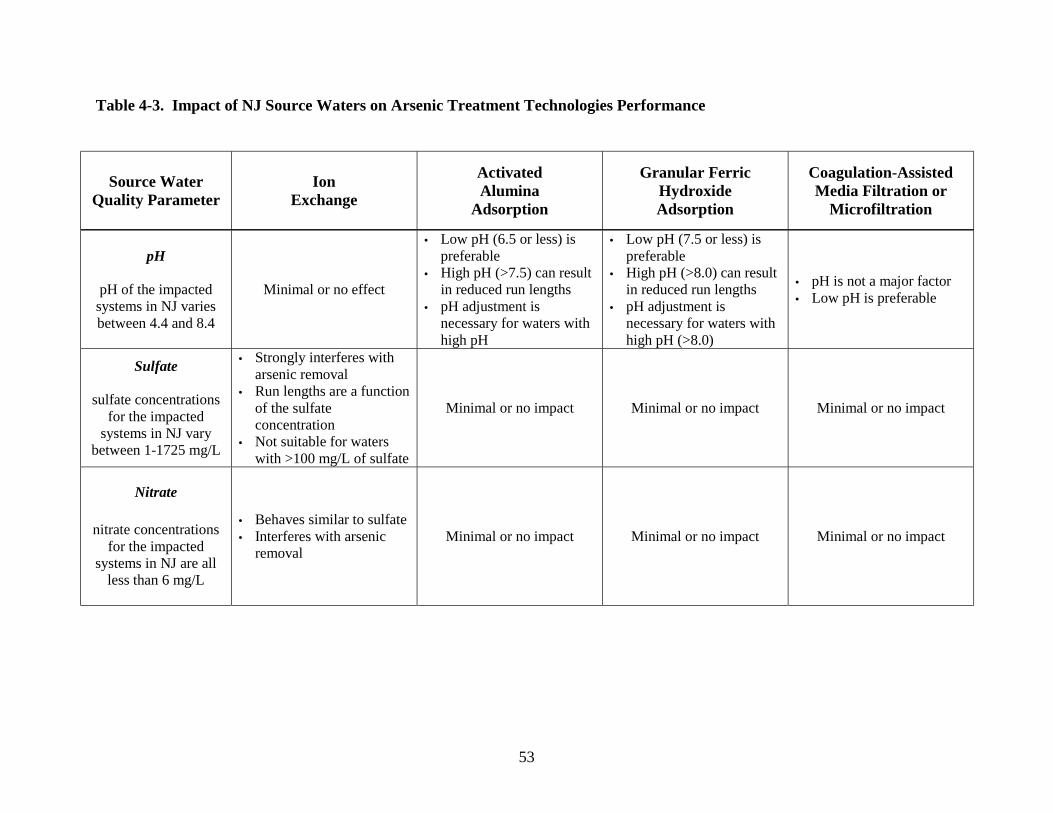
53
Table 4-3. Impact of NJ Source Waters on Arsenic Treatment Technologies Performance
Source WaterQuality Parameter
IonExchange
ActivatedAlumina
Adsorption
Granular FerricHydroxideAdsorption
Coagulation-AssistedMedia Filtration or
Microfiltration
pH
pH of the impactedsystems in NJ variesbetween 4.4 and 8.4
Minimal or no effect
• Low pH (6.5 or less) ispreferable
• High pH (>7.5) can resultin reduced run lengths
• pH adjustment isnecessary for waters withhigh pH
• Low pH (7.5 or less) ispreferable
• High pH (>8.0) can resultin reduced run lengths
• pH adjustment isnecessary for waters withhigh pH (>8.0)
• pH is not a major factor• Low pH is preferable
Sulfate
sulfate concentrationsfor the impacted
systems in NJ varybetween 1-1725 mg/L
• Strongly interferes witharsenic removal
• Run lengths are a functionof the sulfateconcentration
• Not suitable for waterswith >100 mg/L of sulfate
Minimal or no impact Minimal or no impact Minimal or no impact
Nitrate
nitrate concentrationsfor the impacted
systems in NJ are allless than 6 mg/L
• Behaves similar to sulfate• Interferes with arsenic
removalMinimal or no impact Minimal or no impact Minimal or no impact

54
Table 4-3. Impact of NJ Source Waters on Arsenic Treatment Technologies Performance (continued)
Source WaterQuality Parameter
IonExchange
ActivatedAlumina
Adsorption
Granular FerricHydroxideAdsorption
Coagulation-AssistedMedia Filtration or
MicrofiltrationSilica
silica concentrationsfor the impacted
systems in NJ varybetween 8-24 mg/L
Minimal or no impact
• At concentrations >50mg/L and in waters withhigh pH (>7.5) willcompete with arsenic
• Minimal or no impact atlow (<50 mg/L)concentrations
• At concentrations >50mg/L and in waters withhigh pH (>7.5) willcompete with arsenic
• Minimal or no impact atlow (<50 mg/L)concentrations
• High silica concentrations(>50 mg/L) may foul themicrofiltrationmembranes
• No impact at low silicaconcentrations
Phosphate
phosphateconcentrations for theimpacted systems in
NJ vary between 0.01-0.06 mg/L
Minimal or no impact Minimal or no impact
• Strongly impacts the runlengths for arsenicremoval at highphosphate concentrations(>0.25 mg/L)
• No impact at lowconcentrations (<0.25mg/L)
Minimal or no impact
Iron
iron concentrations forthe impacted systemsin NJ vary between
0.005-1.0 mg/L
• High concentrations• (>1 mg/L) of iron may
plug the media• Oxidation for iron
removal may be necessaryfor waters with high ironconcentrations (>1 mg/L)
• High concentrations• (>1 mg/L) of iron may
plug the media• Pre-oxidation for iron
removal may benecessary for waters withhigh iron concentrations(>1 mg/L)
• High concentrations• (>1 mg/L) of iron may
plug the media• Pre-oxidation for iron
removal may benecessary for waters withhigh iron concentrations(>1 mg/L)
• Iron may enhancecoagulation process andimprove arsenic removal

55
Table 4-3. Impact of NJ Source Waters on Arsenic Treatment Technologies Performance (continued)
Source WaterQuality Parameter
IonExchange
ActivatedAlumina
Adsorption
Granular FerricHydroxideAdsorption
Coagulation-AssistedMedia Filtration or
Microfiltration
Manganese
manganeseconcentrations for theimpacted systems in
NJ vary between0.002-0.077 mg/L
• High concentrations(>0.5 mg/L) ofmanganese may plug themedia
• Oxidation for manganeseremoval may be necessaryfor waters with highmanganese concentrations(>0.5 mg/L)
• High concentrations(>0.5 mg/L) ofmanganese may plug themedia
• Oxidation for manganeseremoval may be necessaryfor waters with highmanganese concentrations(>0.5 mg/L)
• High concentrations(>0.5 mg/L) ofmanganese may plug themedia
• Oxidation for manganeseremoval may be necessaryfor waters with highmanganese concentrations(>0.5 mg/L)
Minimal or no impact
TDS
TDS for the impactedsystems in NJ vary
between 26-478 mg/L
Treatment efficiency isreduced if TDSconcentration in thesource water exceeds2,000 mg/L
Minimal or no impact Minimal or no impact Minimal or no impact

56
4.2. ION EXCHANGE
IX systems that utilize strongly basic, anionic resins are a proven technology for arsenic removal.
Previous studies indicate that IX processes can consistently and reliably reduce arsenic
concentrations in groundwater to below 3 µg/L. Data (in graphical form) from several
representative studies is included in Appendix C, and the accompanying summary reports
(conference proceedings) can be found in Appendix D.
Arsenic removal via IX is generally not affected by varying pH in the range of 6.5 to 9.
However, co-occurring solutes such as sulfates can significantly impact the IX performance.
Pilot- and full-scale studies have shown that IX treatment may not be viable for waters with
sulfate concentrations above 100 mg/L. There are only a few impacted systems in NJ with
sulfate concentrations above 100 mg/L; meaning IX would be a feasible treatment alternative at
most locations.
Nitrate is similar to sulfate in its effect on IX treatment. As indicated in Table 4-3, nitrate levels
in NJ waters that contain arsenic are well below the corresponding sulfate concentrations, and so
nitrate is not likely to impact IX treatment efficiency.
IX treatment can have significant operational requirements and may generate large quantities of
liquid residuals if the media requires frequent regeneration. Also, intensive monitoring may
necessary to detect chromatographic peaking (premature arsenic breakthrough) in areas where
background ion concentrations are significant. For these reasons IX treatment, although a
feasible alternative, may not be the best option for most NJ systems.
4.3. ACTIVATED ALUMINA ADSORPTION
AA adsorption is easy to implement and has proven to be an economical alternative for removing
arsenic from groundwaters. Numerous studies, some of which are identified in Chapter 3, have
demonstrated that AA treatment can consistently and reliably lower arsenic concentrations to
below 3 µg/L. Data (in graphical form) from several representative studies is included in

57
Appendix C; the accompanying summary reports (conference proceedings) can be found in
Appendix E.
The bed life of an AA system is a function of pH, where performance improves as pH decreases.
The pH in most NJ waters (that contain arsenic) is fairly low, meaning that pH adjustment prior
to AA treatment is probably not necessary. In those cases where pH adjustment is required, it
can be achieved using acid or carbon dioxide. Regarding interferences, the most significant
interfering contaminant for AA treatment is silica. Silica concentrations in NJ groundwater are
generally below 50 mg/L, and these levels are not likely to affect AA performance.
If an AA system is operated in a disposable mode (to avoid using costly/hazardous regenerant
solutions) it will generate both a liquid and a solid residual, namely backwash water and spent
media. In general, spent AA media will pass TCLP tests and therefore not be classified as
hazardous. The backwash water primarily contains suspended grit and sediment and does not
have elevated levels of arsenic. Thus, it can simply be filtered and then processed along with the
incoming raw water. In other words, an AA system can be arranged so it does not generate
liquid wastes. As discussed elsewhere, this has important ramifications in NJ.
4.4. GRANULAR FERRIC HYDROXIDE ADSORPTION
Arsenic removal via GFH is currently being implemented in full-scale treatment plants
throughout Germany and the United Kingdom. GFH treatment is also being utilized in the
United States, where it can be purchased through US Filter. The NJ-American Water Company
is currently pilot-testing GFH media for arsenic removal at its Race Street well, located in
Frenchtown, NJ. The well has an average flow rate of 70 gpm and an arsenic concentration of 13
µg/L. A GFH system was chosen for this pilot test because it does generate wastewater (see
below) and the spent GFH media will pass TCLP tests (and therefore not be classified as
hazardous). A variety of sources (including the aforementioned pilot study) indicate that GFH
systems can consistently and reliably lower arsenic concentrations to below 3 µg/L. Data (in
graphical form) from several representative studies is included in Appendix C, and the
accompanying summary reports (conference proceedings) can be found in Appendix F.

58
GFH performance increases with decreasing pH. Although some impacted waters in NJ exhibit
a pH above 8.0 (sufficient to shorten GFH run lengths significantly), pH adjustment is not
difficult or expensive to implement. The most important interfering contaminant for GFH
treatment is phosphate. The phosphate concentrations in NJ waters are well below 0.25 mg/L,
the threshold limit above which phosphate interference becomes considerable.
Like most adsorption process, GFH treatment is economical and easy to implement. Spent GFH
media will usually pass TCLP tests and can therefore be disposed of in non-hazardous landfills.
Furthermore, GFH treatment can be operated so it does not produce a wastewater stream (in the
same fashion as for AA treatment) and thereby avoids potential conflicts with POTW effluent
discharge limits and surface water quality standards.
4.5. COAGULATION/FILTRATION
CF processes can effectively lower arsenic concentrations to below 3 µg/L, and if the
coagulation step is properly “tuned,” this level of performance can be sustained. In general,
higher coagulant dosages will yield higher arsenic removal rates, although pH adjustment is also
important. Data illustrating the performance of coagulation-based systems is included in
Appendix C, and the accompany summary reports can be found in Appendix G.
Unlike IX, AA and GFH, the CF process is relatively insensitive to co-occurring contaminants.
Previous studies have shown that CF treatment is particularly effective for waters with high
concentrations of interfering ions.
Coagulation/filtration processes will generate residuals (including a liquid waste stream) that
may require some processing prior to disposal. As noted for other treatments that produce liquid
residuals, the inability of a POTW to accept such a waste and still meet their effluent discharge
limits (based on surface water quality standards) may render this technology infeasible. Even
though the costs for large-scale CF may be higher than for adsorptive processes, it provides the
added benefit of improved finished water quality (due to the filtration step). In addition,
coagulation-assisted, high-rate media filtration systems are now available in packages suitable

59
for implementation at wellheads. For example, the FerriMetTM system available through
Hydroglobe recently underwent field tests in Hopewell, NJ, where it processed arsenic-laden
groundwater for several days (at a rate of ∼ 3 gpm) and consistently achieved effluent arsenic
levels of below 5 µg/L (see Appendices C and G).
4.6. COAGULATION/MICROFILTRATION
CMF is yet another proven technology for arsenic removal. As with the other technologies,
previous research has demonstrated its capability to lower arsenic levels in drinking water to
below 3 µg/L (see Appendices C and G).
As in the case of CF treatment, CMF is a useful approach to treating waters with high
background concentrations of competing ions. Some of the larger NJ systems may choose CMF
for the additional water quality benefits afforded by the membrane filtration step.
Backwash water from CMF processes can usually be discharged to a public sewer after the
suspended solids have been removed. CMF treatment operations would require trained
personnel and therefore may not be a feasible alternative for small CWSs and NCWSs (due to
limited resources).
4.7. TREATMENT TECHNOLOGY STRENGTHS AND WEAKNESSES
Table 4-4 summarizes the advantages and disadvantages of each of the four established arsenic
treatment technologies that were considered most feasible for NJ waters. Each treatment
technology has its own strengths and limitations. The advantages and disadvantages presented in
this table are general in nature and not specific to NJ waters. We have purposely not eliminated
advantages/disadvantages that would appear irrelevant based on the generalized NJ water quality
data, as some systems fall outside this general range. The treatment technologies that have fewer
drawbacks and more advantages are the ones that are likely to be selected by the impacted NJ
CWSs and NCWSs. As science progresses, newer technologies will be developed that could be
more efficient at removing arsenic than the ones that currently exist.

60
Table 4-4. Arsenic Treatment Technologies – Advantages and Disadvantages
TreatmentTechnology
Advantages Disadvantages
IonExchange
• Established treatment for arsenicremoval (NSF-certified resinsavailable)
• Performs well in a wide pH range (6.5-9.0), so pH adjustment is generallyunnecessary
• Applicable for small POU and POEsystems
• Available as packaged treatmentsystems for wellhead application
• Large volumes of sodium chloridesalt solution are required forregeneration
• Co-occurring solutes like sulfateand nitrate can significantly impacttreatment performance
• Achievable run lengths are afunction of sulfate concentrationsin the source waters
• Labor- and chemical-intensiveprocess
• Monitoring for chromatographicpeaking of arsenic is necessary
• Large volumes of spent regenerantsolution with relatively highconcentrations (0.5-5 mg/L) ofarsenic
• Chemicals used to treat spentregenerant will produce sludge(disposal issue)

61
Table 4-4. Arsenic Treatment Technologies – Advantages and Disadvantages (continued)
ActivatedAluminaAdsorption
• Economical alternative• Simple to install and operate• A variety of media types/brands are
available• Negligible water loss, less than one
percent.• Can be used with or without on-site
regeneration• If used without on-site regeneration,
the only liquid waste stream is thebackwash water that contains little orno arsenic (can be disposed of in asewer or storm drain)
• “Throwaway” mode of operationrequires a minimal footprint
• Available as package treatmentsystems
• Applicable for small POU and POEsystems
• Minimal or no interference from TDS,sulfate and nitrate in source waters
• Can also remove fluoride• NSF-certified media are available
• May require pre-and post- pHadjustment
• High source water pH (>7.5) mayreduce run lengths
• Interference from co-occurringions (i.e., silica) may reducearsenic adsorption capacity
• Regeneration may produce aliquid stream with highconcentrations of arsenic andaluminum
• Regenerated media exhibits alower adsorption capacity thannew media
• For some systems, re-fluoridationof finished water may be required
GranularFerricHydroxideAdsorption
• Economical alternative• Simple to install and operate• Negligible water loss, less than one
percent• pH adjustment not necessary if
ambient pH < 8• Longer run lengths and less
operational attention than AA• Smaller footprints• Available as package treatment
systems• Applicable for small POU and POE
systems• Minimal or no interference from TDS,
sulfate and nitrate• NSF-certified media are available
• High pH (>8.0) may reduce runlengths
• May require pre-and post-pHadjustment
• Presence of phosphate in sourcewaters at concentrations above0.25 mg/L can interfere witharsenic removal
• Occasional release of iron finesinto the finished water may occur
• Needs frequent backwashing ifthe source water has lot of silt anddebris

62
Table 4-4. Arsenic Treatment Technologies – Advantages and Disadvantages (continued)
CoagulationFiltration orMicrofiltration
• Less interference from co-occurringions
• Provides additional benefit offiltration for turbidity or microbialremoval; useful for low qualitygroundwaters or for groundwatersthat are under the influence ofsurface water
• Can be tailored to achieve anytargeted arsenic removal byadjusting the coagulant dosage
• Water loss from backwashing is low,between 2-5%; can be furtherminimized by using backwash waterrecovery systems
• Available as fully-automatedpackage treatment systems
• Cost effective for large (i.e., 5 mgdor larger), centralized groundwatertreatment facilities impacted bysurface waters
• Installation and operation costscould be high
• Coagulant must be compatiblewith the membrane or media
• Backwash water will containsolids (floc particles) high inarsenic concentrations; may needsome processing for solidsseparation
• Backwash water loss of 2-5%could be too high for somelocations

63
4.8. RESIDUALS HANDLING AND DISPOSAL
All arsenic treatment technologies generate liquid and/or solid residuals, as discussed in Chapter
3. The residuals handling and disposal options will vary from technology to technology. For
example, the backwash water from adsorption processes will be non-hazardous and may be
blended back into the feed after cartridge or bag filtration. Alternatively, liquid wastes produced
during regeneration in IX systems are likely to be characterized as hazardous unless a
precipitation step is also included in the treatment process. Precipitation serves to bind the
soluble arsenic into an insoluble precipitate. Reject streams from NF and RO will have elevated
concentrations of arsenic and other salts. Disposal of liquid waste streams from arsenic
treatment facilities to a public sewer will be regulated by local industrial pretreatment
requirements. Solid wastes generated from coagulation processes or the exhausted adsorption
media are likely to be characterized as non-hazardous materials and could be sent to non-
hazardous landfills.
With increasingly stringent regulations governing the discharge and disposal of waste materials,
residuals management is now a critical consideration in choosing an appropriate treatment
technology. Table 4-5 summarizes the types of residuals produced by the various arsenic
treatment technologies. It also includes possible disposal methods for the liquid and solid
residuals generated by each process.
With regard to solid residuals, the appropriate disposal method is determined by the relative
toxicity of the waste material. As indicated in the previous sections, many studies of arsenic
technologies have not included toxicity testing of treatment residuals. Hence there is relatively
little information on the matter. However, the limited work that has been completed appears to
be promising. For example, Norton et al. (2001) and Chowdhury et al. (2002) have indicated
that spent AA and GFH are not likely to exceed typical toxicity (TCLP) limits for municipal
landfills. We also understand that the preliminary data from the NJ-American, Frenchtown study
with GFH indicates that the spent media will pass the TCLP test for disposal without
classification as a hazardous waste. In addition, during the NJCAT verification of the FerriMet

64
treatment system, it was determined that the ferric hydroxide sludge generated during this
process contained 8,300 mg As/kg dry solids, a value below the standard for a hazardous waste.
Table 4-5. Summary of Arsenic Treatment Residuals Management and Disposal Methods
Treatment Technology Form ofResidual
Type ofResidual Possible Disposal Methods
LiquidSpent
RegenerationStream
Sanitary SewerDirect DischargeEvaporation PondsIon Exchange
Solid Spent ResinLandfillHazardous Waste LandfillReturn to Vendor
Liquid BackwashWater
Sanitary SewerDirect DischargeEvaporation PondsActivated Alumina
AdsorptionSolid Spent Alumina Landfill
Hazardous Waste Landfill
Liquid BackwashWater
Sanitary SewerDirect DischargeEvaporation PondsGranular Ferric
Hydroxide AdsorptionSolid Spent Media Landfill
Hazardous Waste Landfill
Liquid FilterBackwash
Sanitary SewerDirect DischargeEvaporation PondsCoagulation/
FiltrationSolid Sludge
Sanitary SewerLand ApplicationLandfillHazardous Waste Landfill
Liquid MF Backwash
Sanitary SewerDirect DischargeEvaporation PondsCoagulation/
MicrofiltrationSolid Sludge
Sanitary SewerLand ApplicationLandfillHazardous Waste Landfill
The regulatory issues associated with liquid residuals may prove to be more challenging than
those for solid wastes. Ultimately, whether liquid wastes are discharged directly to the
environment or to a sanitary sewer, the Clean Water Act is a primary consideration. Direct
discharge of pollutants to surface waters is prohibited except in compliance with a National

65
Pollutant Discharge Elimination System (NPDES) permit. It is conceivable that an NPDES
permit would allow for the discharge of a liquid residual that contained arsenic. However, the
limits identified in the permit would reflect state regulations concerning pollutant concentrations
in surface waters. Notably, the regulated limit for arsenic in NJ waters is well below that of
other states (Table 4-6). In fact, it is highly unlikely that an arsenic treatment system or a
wastewater plant will generate discharge water that complies with this standard. For one thing,
influent wastewater sometimes exhibits arsenic concentrations that are similar to levels in the
local aquifer (especially in areas where aquifers are the primary source of drinking water). Since
wastewater plants do not normally achieve significant arsenic removal, it may be that wastewater
plants throughout NJ are currently generating treated effluent that exceeds the surface water
standard for arsenic. Clearly, a problem arises when an arsenic treatment system discharges to a
public sewer and the associated wastewater plant is then required to monitor for arsenic. As
such, this issue must be carefully addressed before attempting to implement large-scale arsenic
treatment efforts in NJ.
Table 4-6. Arsenic Standards for Surface Waters
State Arsenic Standard (µg/L)
New Jersey 0.017
New York 25
Arizona 50
4.9. ARSENIC TREATMENT SELECTION
Selection of the right treatment technology for arsenic removal for a specific water system
should be based on careful consideration of many factors including:
! Water quality (pH, arsenic and co-occurring ion concentrations)
! System capacity
! Site constraints (availability of land, power and sewer connection)

66
! Residuals handling preferences
! Existing treatment system
! Qualitative decision drivers (ease of implementation, public acceptance)
! Costs
Smaller systems in NJ with less operator experience and fewer economical resources will likely
choose arsenic treatment technologies that require less operational assistance and chemical
addition such as the disposable adsorptive media (e.g., AA or GFH) processes. For many small
utilities, disposable media may present the least cost option. Choosing an adsorptive media
process with no (on-site) regeneration eliminates the need for the utility to handle hazardous
chemicals that are used in regeneration and also eliminates complicated requirements for
disposal of the spent regenerant solution. The achievable run lengths with the adsorptive media
are a function of the water quality including feed water pH and the concentrations of interfering
ions such as silica, fluoride and phosphate. Adjustment of pH may be necessary for waters with
high pH. Secondary affects like pH reduction that result in higher TDS in the finished water
must be considered for systems that currently are facing corrosion control or other water quality
issues. Also, systems with high levels of co-occurring contaminants such as fluoride, silica,
phosphate and chloride must consider the possible interferences of these ions with the adsorption
processes. In addition to the spent media, adsorption processes also produces a small backwash
water stream, as the media need to be occasionally backwashed to prevent excessive head loss
development. Disposable media systems are simple to operate, have smaller footprint, and can
be cost-effective. Proper pilot testing is necessary to understand the operational and design
parameters and the impact of water quality on the achievable run lengths.
Larger systems in NJ with more experienced operators and greater resources are better suited for
more complex treatment systems that include the use of hazardous chemicals for altering water
quality during treatment (e.g., pH reduction to achieve greater adsorption capacity) or in the
regeneration of spent media. These systems are also more likely to invest in technologies such
as coagulation/filtration and are more prepared to deal with residuals from this type of treatment
process. The larger systems typically have skilled staff to handle processes such as
coagulation/filtration. In coagulation/filtration processes, ferric or alum coagulant is added to the
67
feed water and the coagulated water is filtered using high-rate media filters or low-pressure
membrane filters such as MF or UF. These processes have the added benefits of turbidity
removal and provide microbial barrier. Coagulation-assisted filtration processes can be cost-
effective for centralized groundwater treatment, especially for source waters that contain a
number of co-occurring, interfering ions.
For both small and large systems in NJ, the selection of an arsenic treatment process would be
governed by site-specific factors like availability of land, sewer/storm drain access and
neighborhood preferences. Each impacted CWS and NCWS can use the recommendations of
this report as a general guidance. However, independent evaluations should be performed using
site-specific constraints to identify the treatment technology most suitable for those conditions.
Table 4-7 compares the four most promising treatment technologies in terms of qualitative and
quantitative selection drivers. The arsenic treatment technologies are ranked 1 through 4 for
each decision driver (i.e., ease of implementation). The basis for the ranking of each parameter
is shown in the right-most column. A higher rank (i.e., 4) indicates that the technology is more
suitable for implementation. This type of analysis has to be performed for each impacted
system, accounting for the utility preferences and site constraints. The analysis shown in Table
4-7 is purely for illustration purposes.

68
Table 4-7. Illustration of Arsenic Treatment Technology Ranking Based on Various Decision Drivers
Decision Driver IonExchange
ActivatedAlumina
Adsorption
GranularFerric
HydroxideAdsorption
CoagulationFiltration or
MicrofiltrationScoring Basis
Ease ofImplementation 2 4 4 2 • High score for technologies that are easy to install and operate
• Low score for cumbersome technologies
Labor Required 1 3 4 2 • High score for technologies that can be automated• Low score for labor-intensive technologies
Process Reliability 1 4 4 4
• High score for processes that have less interference from sourcewater quality
• Low score for processes that are highly impacted by Co-occurringions
MechanicalReliability 1 4 4 2 • High score for sturdier processes
• Low score for processes with more moving partsPositive System
WaterQuality Impacts
1 3 2 4• High score for technologies that help in complying with other
regulations• Low score for technologies that provide no additional benefit
Negative SystemWater
Quality Impacts1 3 3 4
• High score for processes that do not effect the water qualityadversely
• Low score for processes that may degrade the treated water quality
Public Acceptance 1 4 4 2
• High score for technologies that have minimal impact on theneighborhood
• Low score for technologies that have lots of interference withneighborhood activities
Process Flexibility 1 3 3 4 • High score for processes that can be readily upgraded or modified• Low score for processes that are difficult to expand
Costs 1 4 4 2 • High score for low cost technologies• Low score for high cost technologies
ResidualsHandling 1 4 4 1 • High score for technologies that produce little or no waste stream
Cumulative Score 11 36 36 27 • High scoring technologies are more preferable

69
4.10. ARSENIC TREATMENT COSTS
Malcolm Pirnie has developed a computerized tool that is capable of generating cost estimates
for various arsenic treatment technologies. These estimates include values for initial capital
investment as well as long-term operational/maintenance costs. Because the operation of many
arsenic treatment systems is heavily influenced by background water quality, the tool requires
detailed information on the chemical composition of the water(s) in question. In this report, five
generic waters were developed for the purpose of generating cost estimates. Each of the waters
listed represents a specific circumstance that applies to New Jersey.
! NCWS (Low Arsenic): represents an “average” non-community water supply with a low
level of arsenic (low relative to other non-community supplies in New Jersey)
! NCWS (High Arsenic): represents an “average” non-community water supply with a
high level of arsenic (high relative to other non-community supplies in New Jersey)
! CWS (Low Arsenic): represents an “average” community water supply with a low level
of arsenic (low relative to other community supplies in New Jersey)
! CWS (High Arsenic): represents an “average” community water supply with a high
level of arsenic (high relative to other community supplies in New Jersey)
! CWS (Low Silica/TDS, Low Arsenic): represents an “average” community supply with
a low level of arsenic and low levels of silica and total dissolved solids
Again, these generic systems were designed to reflect some of the more common conditions
(pertaining to arsenic-laden water supplies) found throughout New Jersey. The cost analyses for
the generic impacted waters of Table 4-8 are shown in Table 4-9. It should be noted that these
estimates were developed for a target effluent arsenic concentration of 3 µg/L, and that costs
would be less if the target were 5 µg/L or 7 µg/L.
Notably, Table 4-9 indicates that AA is the least expensive alternative for NCWSs while GFH is
the least expensive option for CWSs. The table clearly shows that this difference is linked to
operations and maintenance (O&M) costs rather than capital expenses. Capital costs for these
two treatments are relatively similar, but the associated O&M costs vary considerably. In

70
general, capital costs are defined by the system capacity and O&M costs are defined by water
quality (i.e., media changeout frequency, backwash frequency, etc.). Simply put, the water
quality defined for NCWSs favors AA treatment whereas the water quality defined for CWSs
favors GFH treatment. Again, these generic water supplies are meant to represent average
NCWSs and CWSs. In reality, there will undoubtedly be NCWSs that favor GFH and CWSs
that favor AA. The table also shows the impact of silica and TDS on the operating costs
associated for AA and GFH.
Table 4-8. Generic NJ Impacted Water Supplies Used in Cost Analysis
NCWSLow
Arsenic
NCWSHigh
Arsenic
NCWSHigh
ArsenicLow Flow
CWSLow
Arsenic
CWSHigh
Arsenic
CWSHigh
ArsenicLow Flow
CWSLow
ArsenicLow
Silica/TDSDesign Capacity
(mgd) 0.1 0.1 0.01 2.5 2.5 0.5 2.5
System Size Large Large Small VeryLarge
VeryLarge Large Very Large
Arsenic (µg/L) 7 15 15 7 15 15 7
Alkalinity(mg/L as CaCO3)
120 120 120 110 110 110 110
Chloride (mg/L) 40.0 40.0 40.0 30.0 30.0 30.0 30.0
Hardness(mg/L as CaCO3)
200 200 200 160 160 160 160
pH 7.2 7.2 7.2 7.5 7.5 7.5 7.5
Sulfate (mg/L) 65.0 65.0 65.0 35.0 35.0 35.0 35.0
Iron (mg/L) 0.03 0.03 0.03 0.03 0.03 0.03 0.03
Manganese(mg/L) 0.02 0.02 0.02 0.02 0.02 0.02 0.02
Phosphate(mg/L) 0.04 0.04 0.04 0.04 0.04 0.04 0.04
Silica (mg/L) 25 25 25 25 25 25 8
TDS (mg/L) 300 300 300 300 300 300 65

71
Table 4-9. Cost Evaluations for Generic Impacted Water Supplies of NJ (20-yearamortization period, 7% interest rate used in calculating total cost)
Preferred Technologies Capital Cost($)
O&M Cost($/1000 gal)
Total Cost($/1000 gal)
NCWS (Low Arsenic)
Disposable AA 143,000 0.50 0.87Disposable GFH 158,000 1.45 1.86
CMF 1,010,000 4.05 6.66IX Not Feasible∗ Not Feasible Not Feasible
NCWS (High Arsenic)
Disposable AA 143,000 1.02 1.39Disposable GFH 157,000 3.10 3.51
CMF 1,010,000 4.05 6.66IX Not Feasible Not Feasible Not Feasible
NCWS (High Arsenic, Low Flow)
Disposable AA 47,000 4.93 6.14Disposable GFH 38,000 6.03 6.99
CMF 150,000 8.22 12.05IX Not Feasible Not Feasible Not Feasible
CWS (Low Arsenic)
Disposable GFH 1,420,000 0.19 0.34Disposable AA 1,510,000 0.38 0.54
CMF 4,790,000 0.74 1.23IX 989,000 0.21 0.31
CWS (High Arsenic)
Disposable GFH 1,420,000 0.40 0.54Disposable AA 1,510,000 0.77 0.93
CMF 4,790,000 0.74 1.23IX 989,000 0.21 0.31
CWS (High Arsenic, Low Flow)
Disposable GFH 360,000 0.73 0.92Disposable AA 428,000 0.79 1.01
CMF 2,130,000 1.28 2.37IX 570,000 0.24 0.53
CWS (Low Silica/TDS, Low Arsenic)
Disposable GFH 1,290,000 0.17 0.31Disposable AA 1,380,000 0.34 0.49
CMF 4,520,000 0.69 1.16IX 943,000 0.19 0.29
∗ IX treatment is not cost-effective at high sulfate concentrations (> 50 mg/L)

72
5. REFERENCES
Amy, G.L., M. Edwards, M. Benjamin, K. Carlson, J. Chwirka, P. Brandhuber, L. McNeill and F. Vagliasindi (1999). Arsenic Treatability Options and Evaluation of Residuals Management Issues, AWWARF. Denver, CO.
AWWA (1990). Water Quality and Treatment - A Handbook of Community Water Systems, McGraw-Hill Publishing Company, New York.
AWWA (2000). Water Quality and Treatment - A Handbook of Community Water Supplies. Fifth Edition. McGraw-Hill Publishing Company, New York.
AwwaRF (1999). Arsenic Treatability Options and Evaluation of Residuals Management Issues. Amy G. L., M. Edwards, P. Brandhuber, L. McNeill, M. Benjamin, F. Vagliasindi, K. Carlson, and J. Chwirka. Denver, Colorado.
AwwaRF (2002). Implementation of Arsenic Treatment Systems, Process Selection (Part 1).Zaid Chowdhury, Sunil Kommineni, Ramesh Narasimhan, John Brereton, Gary Amy andShahnawaz Sinha, Denver, Colorado.
Benefield L.R. and J.M. Morgan (1999). Chemical Precipitation, Chapter in Water Quality and Treatment, 5th Edition, American Water Works Association, McGraw-Hill, New York.
Benjamin, M. M., R.S. Sletten, R.P. Bailey and T. Bennett (1998). Sorption of Arsenic by Various Adsorbents, AWWA Inorganic Contaminants Workshop, San Antonio, TX, February 23-24, 1998.
Benjamin, M.M., J. Kim, P. Kwan, and Y. Chang (2001). A Novel Ion Exchange Process, AWWA Annual Conference Proceedings, Washington D.C., June 17-21, 2001.
Chen, S.L., S.R. Dzeng, and M. Yang (1994). Arsenic Species in Groundwaters of the BlackfootDisease Area, Taiwan, Environmental Science and Technology, 28:5:877.
Cheng, R.C., S. Liang, H-C Wang, and J. Beuhler (1994). Enhanced Coagulation for Arsenic Removal, J. AWWA, 9:79-90.
Chowdhury, Z.K., S.N. Kommineni, Y. Chang, and T.R. Lindley (2002a). “AdsorptionTreatment for Arsenic Removal: Design, Operation and Costs,” AWWA Proceedings,Water Quality Technology Conference, Seattle, WA, November.
Chowdhury, Z.K., S.N. Kommineni , and Y. Chang (2002b). “Comparison of Innovative Technologies for Arsenic Removal,” presented at the 2002 Inorganic Contaminants Workshop, SanDiego CA, February 3-5.

73
Chwirka, J.D., Thomson, B.M., and Stomp III, J.M. (2000). Removing Arsenic from Groundwater, J. AWWA, 92:3:79-88.
Clifford, Dennis, 1999. Presentation at Arsenic Technical Work Group, Washington, D.C.
Clifford, D.A. and C.C. Lin (1986). Arsenic Removal From Groundwater in Hanford, California- A Preliminary Report, University of Houston, Department of Civil/Environmental Engineering. Cited in: AWWA (1990). Water Quality and Treatment - A Handbook of Community Water Systems, McGraw-Hill Publishing Company, New York.
Clifford, D.A. and C.C. Lin (1995). Ion Exchange, Activated Alumina, and Membrane Processes for Arsenic Removal from Groundwater, Proceedings of the 45th Annual Environmental Engineering Conference, University of Kansas, February 1995.
Clifford, D.A., G. Ghurye et al. (1997). Final Report: Phases 1 & 2 City of Albuquerque ArsenicStudy Field Studies on Arsenic Removal in Albuquerque, New Mexico using the University of Houston/EPA Mobile Drinking Water Treatment Research Facility. Houston, TX: University of Houston, December 1997.
Clifford, D.A., G. Ghurye and A. Tripp (1998). Arsenic Removal by Ion Exchange With and Without Brine Reuse, AWWA Inorganic Contaminants Workshop, San Antonio, TX, February 23-24, 1998.
Clifford, D.A., G. Ghurye et al. (1998). Final Report: Phase 3 City of Albuquerque Arsenic Study Field Studies on Arsenic Removal in Albuquerque, New Mexico using the University of Houston/EPA Mobile Drinking Water Treatment Research Facility. Houston, TX: University of Houston, August 1998.
Driehaus, W., M. Jekel and U. Hildebrandt (1998). Granular Ferric Hydroxide - A New Adsorbent for the Removal of Arsenic from Natural Water, J. Water SRT - Aqua, 47:1:30-35.
Driehaus, W. (2000). Arsenic Removal from Drinking Water: The GEH Process. 2000 AWWA Inorganic Contaminants Workshop, Albuquerque, NM.
Edwards, M.A. (1994). Chemistry of Arsenic Removal During Coagulation and Fe-Mn Oxidation, J. AWWA, 85:9:64-77.
EPA (1994). Review of the Draft Drinking Water Criteria Document on Inorganic Arsenic, EPASAB-DWC-94-004.
EPA (2000a). Arsenic Removal from Drinking Water by Coagulation/Filtration and Lime Softening Plants. Prepared by Battelle under contract 68-C7-0008 for EPA ORD. June 2000.
EPA (2000b). Arsenic Removal from Drinking Water by Iron Removal Plants. Prepared by Battelle under contract 68-C7-0008 for EPA ORD. August 2000.

74
EPA (2000c). Arsenic Removal from Drinking Water by Ion Exchange and Activated Alumina Plants. Prepared by Battelle under contract 68-C7-0008 for EPA ORD. October 2000.
EPA (2000d). Treatment of Arsenic Residuals from Drinking Water Removal Processes, EPA 600-R-01-033. Prepared by Michael MacPhee, Gail Charles, and David Cornwell under contract 8C-R613-NTSA.
Galeziewski, T.M., P. Kwan , S.N. Kommineni , A.D. Dotson , and B. Johnson (2002). "Three New Arsenic Removal Technologies: How to Design Them and How Much They Will Cost," Proceedings, Annual Conference of the American Water Works Association, NewOrleans LA, June 18.
GEH Wasserchemie-US Filter, (2000). Granular Ferric Hydroxide-For Removal of Arsenic, Phosphate, Heavy Metals and DOM. Product Catalog.
GEH Wasserchemie-US Filter, (2001). Granular Ferric Hydroxide-For Removal of Arsenic, Phosphate, Heavy Metals and DOM. Product Catalog.
Gulledge, J.H. and J.T. O’Connor (1973). Removal of Arsenic (V) From Water by Adsorption on Aluminum and Ferric Hydroxides, J. AWWA, 8:548-552.
Hathaway, S.W. and F. Rubel, Jr. (1987). Removing Arsenic From Drinking Water, J. AWWA,79:8:61-65.
Hering, J.G. and M. Elimelech (1996). Arsenic Removal by Enhanced Coagulation and Membrane Processes, AWWA, Denver.
Hering, J.G., P. Chen, J.A. Wilkie, M. Elimelech, and S. Liang (1996). Arsenic Removal by Ferric Chloride, J. AWWA, 88:4:155-167.
Hering, J.G., P-Y. Chen, J.A. Wilkie and M. Elimelech (1997). Arsenic Removal From DrinkingWater During Coagulation, J. Env. Engineering, 123:8:800-807.
Jekel M. and R. Seith (2000). “Comparison of Conventional and New Techniques for the Removal of Arsenic in a Full Scale Water Treatment Plant, Water Supply, 18:1, 628-631.
Jekel M., (2001). Personal Communication with Prof. Martin Jekel of Technical University of Berlin, Department of Water Quality Control, Secr. KF-4, Berlin, Germany.
Kommineni, S.N., Y. Chang, Z.K. Chowdhury, G. Amy, S.H. Reiber, P. Kwan, and B. Johnson (2001). AWWA Proceedings, Water Quality Technology Conference, Nashville, TN, October.

75
Kommineni, S.N., R. Narasimhan, and H. Durbin (2002). "Point-of-Use/Point-of-Entry Treatment for Arsenic Removal: Operational Issues and Costs," Proceedings, Water Quality Technology Conference of the American Water Works Association, Seattle WA, November.
Kwan , P., S.M. Miller, S.A. Perry, and S.N. Kommineni (2001). "Sodium-Free Ion Exchange: Pilot Testing Innovative Ion Exchange Processes for Arsenic Removal," Proceedings, National Conference of the American Water Works Association, Washington DC, May.
Malcolm Pirnie, Inc. (1993). Treatment and Occurrence of Arsenic in Potable Water Supplies, USEPA, September 1993.
NRC, National Research Council (1999). Arsenic in Drinking Water. National Academy Press,Washington, DC
NCS (2000). Draft Final Report, Arsenic Study for Ground and Surface Water, City of Phoenix, AZ.
Norton, M.V., Y. Chang, T.M. Galeziewski, S.N. Kommineni, and Z.K. Chowdhury (2001). "Throw-Away Iron and Aluminum Sorbents Versus Conventional Activated Alumina for Arsenic Removal -- Pilot Testing Results," Proceedings, National Conference of the American Water Works Association, Washington DC, May.
Robinson J. (2001). Arsenic Removal - Case Study of a Full Scale Coagulation/Filtration Plant, Proceedings of the 2001 AWWA National Conference, Washington, DC.
Rosenblum, E.R. and D.A. Clifford (1984). The Equilibrium Arsenic Capacity of Activated Alumina, PB 84/10 527, NTIS, Springfield.
Scott, K., J. Green, H.D. Do, and S.J. McLean (1995). Arsenic Removal by Coagulation,J. AWWA, 87:4:114-126.
Selvin N., G. Messham, J. Simms, I. Pearson, and J. Hall (2000). The Development of Granular Ferric Media - Arsenic Removal and Additional Uses in Water Treatment. Proceedings of the AWWA Water Quality Technology Conference, Salt Lake City, Utah.
Selvin N., Messham G., Simms J., Dennis R. and Wilde D. (2001). Further Development ofGranular Ferric Media - The Arsenic Removal Technology. American Water WorksAssociation Annual Conference Proceedings, Washington D.C.
Simms, J. and F. Azizian (1997). Pilot Plant Trials on the Removal of Arsenic from Potable Water Using Activated Alumina, Proceedings AWWA Water Quality Technology Conference, November 9-12, 1997.

76
Simms, J., J. Upton, and J. Barnes (2000). Arsenic Removal Studies and the Design of a 20,000 m3 Per Day Plant in the UK, AWWA Inorganic Contaminants Workshop, Albuquerque, NM, February 27-29, 2000.
Sinha, S., Lee, N., Yoon, Y., Amy, G., Kommineni, S. N. and Chowdhury, Z. K., 2001. ArsenicRemoval through Innovative Adsorbents and Coupled Adsorbent-Membrane System:Bench-Scale Studies. AWWA Water Quality Technology Conference Proceedings,Nashville, TN, November 11-14.
Smith, S. and Edwards, M., (2002). Bench-Scale Evaluation of Innovative Arsenic RemovalProcesses, J. AWWA, 94:9:78-87.
Sorg, T.J. and G.S. Logsdon (1978). Treatment Technology to Meet the Interim Primary Drinking Water Regulations for Inorganics: Part 2, J. AWWA, 7:379-392.
Trussell et al. (1980). Selenium Removal from Groundwater using Activated Alumina, EPA Municipal Environmental Research Laboratory Report No. 600/2-80-153, August 1980.
Vagliasindi, F.G.A. and M.M. Benjamin (1998). Arsenic Removal in Fresh and NOM-Preloaded Ion Exchange Packed Bed Adsorption Reactors, Water Science Technology, 38:6:337-343.
Vagliasindi, F.G.A. and Benjamin, M.M. (2001). Redox Reactions of Arsenic in As-spiked LakeWater and Their Effects on As Adsorption, Journal of Water Supply: Research andTechnology-AQUA, 50.4:173-186.
Vickers, J.C., A. Braghetta, and R.A. Hawkins (1997). Bench Scale Evaluation of Microfilitration for Removal of Particles and Natural Organic Matter, Proceedings Membrane Technology Conference, February 23-26, 1997, New Orleans, LA.

77
APPENDIX A
COMMUNITY WATER SUPPLIES IN NEW JERSEY WITH ARSENIC LEVELSGREATER THAN OR EQUAL TO 3 PARTS PER BILLION

78

79
APPENDIX B
NON-TRANSIENT, NON-COMMUNITY WATER SUPPLIES IN NEW JERSEY WITHARSENIC LEVELS GREATER THAN OR EQUAL TO THREE PARTS PER BILLION

80

81
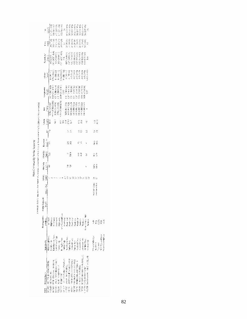
82

83
APPENDIX C
REPRESENTATIVE DATA ILLUSTRATING THE ARSENIC REMOVALPERFORMANCE OF VARIOUS TREATMENT TECHNOLOGIES

84
Conventional ion exchange: pilot-scale (∼∼∼∼ 20 gpm) – Tucson, AZ (Kwan et al.)
Conventional ion exchange: bench-scale (Chang)

85
Conventional ion exchange: full-scale (NCWS) – New England area (Wang et al.)

86
Granular ferric hydroxide/activated alumina: pilot-scale (∼∼∼∼ 20 gpm) – Tucson, AZ(Galeziewski et al.)
Granular ferric hydroxide/activated alumina: pilot-scale (∼∼∼∼ 10 gpm) – Nottingham, England(Selvin et al.)

87
Granular ferric hydroxide: pilot scale system (∼∼∼∼ 10 gpm) – Nottingham, England (Barnes et al.)
Granular ferric hydroxide: full-scale (0.1 MGD) – Wildeck, Germany (Driehaus)

88
Granular ferric hydroxide: full-scale (0.3 MGD) – Stadtoldendorf, Germany (Jekel & Seith)
Microsand-assisted coagulation/settling: pilot-scale (∼∼∼∼ 20 gpm) – Tucson, AZ (Chowdhury et al.)

89
Coagulation/media filtration: pilot-scale (∼∼∼∼ 20 gpm) – Tucson, AZ (Kommineni et al.)

90
APPENDIX D
REFERENCES – ION EXCHANGE

91
APPENDIX E
REFERENCES – ACTIVATED ALUMINA(see also Wang et al. in Appendix D)

92
APPENDIX F
REFERENCES – GRANULAR FERRIC HYDROXIDE(see also Galeziewski et al. and Selvin et al. in Appendix E)

93
APPENDIX G
REFERENCES – COAGULATION/FILTRATION