STATE OF KANSAS CONSTRUCTION PROJECT NO. A-013555 …
55
STATE OF KANSAS CONSTRUCTION PROJECT NO. A-013555 ADDENDUM NO. 5 February 26, 2021 ISSUED BY: ISSUED FOR ARCHITECT/ENGINEER Department of Administration Office of Facilities and Property Management Design, Construction & Compliance 700 SW Harrison St., Suite 1200 Topeka, Kansas 66603-3929 Ross & Baruzzini 5350 W. 94 th Terrace, Suite 102 Prairie Village, Kansas 66207 Contact: Dan Phelan Phone Number: (913) 708-3442 E-Mail: [email protected] NOTICE ALL BIDDERS FOR THE: Adjutant General’s Department Nickell Hall Barracks Salina ERCIP Photovoltaic Solar Power & Water Reduction Salina, Kansas You are instructed to read and to note the following described changes, corrections, clarifications, omissions, deletions, additions, approvals and statements pertinent to the Contract Bid and Construction Documents. The Addendum No. 5 is a part of the Contract Bid and Construction Documents and shall govern in the performance of the Work. Article 5-1, General Updates: (Attachments) A. A pre-bid conference was held on Wednesday, February 17, 2021 at 10:00 A.M. at the Building 365 Auditorium, 2929 Scanlan Avenue, Salina, Kansas. The meeting agenda and roster are attached for reference. Article 5-2, Bidder’s Questions: (Attachments) A. Are Davis-Bacon wages applicable to this project? a. No, they are not. B. Will this project be taxable as a remodel project? a. This is being confirmed with KS OFPM and will be clarified in a future Addendum. C. For Building 320 Nickell Barracks, does the Owner have backstock wall tile for use in ADA restrooms? a. This is being confirmed with the KSARNG Salina Complex Facilities Team and will be clarified in a future Addendum. D. Specifications, Section 011000-Summary, 1.6 Access to Site, item B.3. – This item states purchasing parking permits will be required. Can you confirm this requirement, and if parking permits are required how much do they cost? a. No parking permits are required. Section 011000 has been updated to reflect this information. E. Specifications, Section 011000-Summary, 1.7 Coordination with Occupants, item A – This item mentions doing work being done to the Fire Sprinkler system. Please confirm if any work is being down in this project to the fire sprinkler system. a. This project includes no fire sprinkler work. Section 01100 has been updated to reflect this information. F. Engine Generator Specification 263213-2.2.B references "seismic event". Does the generator set need to be seismic certified. a. Yes, Division 20 specification section 200800 is added in this Addendum. G. Engine Generator Specification 263213-2.9.F.p references temperature relays. The C13 - 400kW standby generator does not have the option for temperature relays, will this be acceptable? a. Yes, refer to Addendum herein for removal of this requirement. H. Engine Generator Specification 263213-3.2.A.2 references "independent testing organization". Standard manufacturer testing is conducted by our factory trained technicians rather than hiring someone not as familiar or trained in performing the testing as outlined by the manufacturer. Will this be acceptable?
Transcript of STATE OF KANSAS CONSTRUCTION PROJECT NO. A-013555 …
STATE OF KANSAS CONSTRUCTION PROJECT NO. A-013555 ADDENDUM NO. 5 February 26, 2021 ISSUED BY:
ISSUED FOR ARCHITECT/ENGINEER
Department of Administration Office of Facilities and Property Management Design, Construction & Compliance 700 SW Harrison St., Suite 1200 Topeka, Kansas 66603-3929
Ross & Baruzzini 5350 W. 94th Terrace, Suite 102 Prairie Village, Kansas 66207 Contact: Dan Phelan Phone Number: (913) 708-3442 E-Mail: [email protected]
NOTICE ALL BIDDERS FOR THE: Adjutant General’s Department Nickell Hall Barracks Salina ERCIP Photovoltaic Solar Power & Water Reduction Salina, Kansas You are instructed to read and to note the following described changes, corrections, clarifications, omissions, deletions, additions, approvals and statements pertinent to the Contract Bid and Construction Documents. The Addendum No. 5 is a part of the Contract Bid and Construction Documents and shall govern in the performance of the Work. Article 5-1, General Updates: (Attachments)
A. A pre-bid conference was held on Wednesday, February 17, 2021 at 10:00 A.M. at the Building 365 Auditorium, 2929 Scanlan Avenue, Salina, Kansas. The meeting agenda and roster are attached for reference.
Article 5-2, Bidder’s Questions: (Attachments)
A. Are Davis-Bacon wages applicable to this project? a. No, they are not.
B. Will this project be taxable as a remodel project? a. This is being confirmed with KS OFPM and will be clarified in a future Addendum.
C. For Building 320 Nickell Barracks, does the Owner have backstock wall tile for use in ADA restrooms? a. This is being confirmed with the KSARNG Salina Complex Facilities Team and will be clarified in a
future Addendum. D. Specifications, Section 011000-Summary, 1.6 Access to Site, item B.3. – This item states purchasing
parking permits will be required. Can you confirm this requirement, and if parking permits are required how much do they cost?
a. No parking permits are required. Section 011000 has been updated to reflect this information. E. Specifications, Section 011000-Summary, 1.7 Coordination with Occupants, item A – This item mentions
doing work being done to the Fire Sprinkler system. Please confirm if any work is being down in this project to the fire sprinkler system.
a. This project includes no fire sprinkler work. Section 01100 has been updated to reflect this information.
F. Engine Generator Specification 263213-2.2.B references "seismic event". Does the generator set need to be seismic certified.
a. Yes, Division 20 specification section 200800 is added in this Addendum. G. Engine Generator Specification 263213-2.9.F.p references temperature relays. The C13 - 400kW
standby generator does not have the option for temperature relays, will this be acceptable? a. Yes, refer to Addendum herein for removal of this requirement.
H. Engine Generator Specification 263213-3.2.A.2 references "independent testing organization". Standard manufacturer testing is conducted by our factory trained technicians rather than hiring someone not as familiar or trained in performing the testing as outlined by the manufacturer. Will this be acceptable?

Form 315 A-013555
July 2018 Add 5, Pg. 2
a. Yes, refer to Addendum herein adding in this option as an alternate to an independent testing
organization. I. Engine Generator Specification 263213-3.2.A.3, 9, 10, 11, 12, 13, 14, 15, 16 - References rigorous and
extensive testing on a standby generator set. This will add a rather large increase in the price of the generator set. Foley has supplied and tested various units to military locations throughout the state of Kansas including Army National Guard locations. The manufacturers recommended testing has always been accepted which did not include any of the additional testing as listed in the specifications. Will this be acceptable?
a. Refer to Addendum herein for modifications to the testing requirements. J. The question was asked if the temporary generator is provided by the Guard or the Contractor.
a. As shown on E701, the generator is provided by the Contractor. Please also note Sheet ES401, Keyed Note 1 that indicates the Contractor shall provide temporary UPS Backup with the temporary generator for maintaining the IT room equipment. The equipment in the IT Room can not lose power at any time as it serves critical KSARNG infrastructure.
K. The question was asked if new building transformer secondary conductors are new or re-used. a. The Utility Transformer secondary is completely new as indicated on E701. The New 500kVA,
dry-type transformer TX-SWBD-MSBD requires new secondary conductors with partial new conduits to existing conduits as shown on E701 and called out in Keyed Note 3.
L. The question was asked how much is concrete-encased. Just under the parking lot or more?. a. The drawings do not call out for concrete-encased duct banks. Specifications call out for
concrete-encased only for conduits serving systems over 600V. Existing utility duct bank shall maintain any concrete-encasement if existing in process of cutting back to new utility transformer pad. Detail 4/E501 has been modified in this Addendum to clarify the requirements.
M. A comment was made that the spans for the PV array are not close enough. Approximately 13' is shown and need a maximum of 10'.
a. Refer to structural and electrical drawing modifications within this Addendum for addressing this. N. Is the Owner responsible for any Evergy fees that may or may not occur?
a. Per the Instructions to Bidders paragraph 1.4.B, all fees shall be included in the bid and Evergy will have fees for the modifications required by this project. Refer to E701 modifications within this Addendum for additional Evergy contact info for obtaining these costs.
O. Can we assume the contractor will be required to provide temporary chain link construction fencing to encompass the construction are within the parking lot? Reference attached C-102-Fencing.
a. Construction fencing requirements will be clarified in a future Addendum. P. On sheet C102, note #8 are the notes in the middle of the parking lot a mistake?
a. Note callouts on plan have been updated within this Addendum. The notes in the parking lot should be referencing pavement markings.
Q. On sheet S101 the framing plan shows HSS 16x8x3/8”, however section 2 and section 3 indicate HSS 16x8x1/2”. Please clarify which is accurate?
a. The sections, which indicate HSS16x8x1/2, are correct. Plan callouts have been corrected within this Addendum.
R. We would like confirmation the duct bank installation is only within the parking lot area or is it all conduits? a. To clarify what is believed to be the intent of this question – underground ducts and duct banks
are required, but do not require concrete encasement. Underground ducts shall be ganged into duct banks to minimize saw-cuts in areas where pavement will not be replaced in the parking lot and within grass and landscaped areas around the building. Refer to concrete-encasement question and response above and modifications to Detail 4/E501 contained within this Addendum.
S. Alternate #4 – please provide basis of design shower surround make/model to be provided by contractor? a. This will be clarified in a future Addendum.
T. Alternate #5 – please provide clarifications as to which rooms in each building are considered Public? a. Only the restrooms not associated with living quarters in Building 320 Nickell Barracks are
considered Public. U. Alternate #6 – please provide information on the owner provided vanity and confirm the lavatory is part of
the vanity assembly, or provide basis of design data for drop in lavatory to be provided by contractor? a. Lavatory is not part of vanity. Refer to Plumbing Fixture Schedule on sheet P000. Provide Kohler
Serif Drop-in or equal. Additional information about the vanity will be provided in a future Addendum.
V. Alternate #8 – please provide basis of design shower valve make/model information to be provided by contractor?
Form 315 A-013555
July 2018 Add 5, Pg. 3
a. Refer to Plumbing Fixture Schedule on P000 for shower information. Provide Speakman CPT-T
Sentinel Mark-II Thermostatic Valve with CPT-3001 Sentinel Shower Valve trim, or approved equal.
W. Sheet P112 – Top triangle room not numbered; confirm fixture is mislabeled and should be EWC-1? a. Concur, drawing P112 will be updated to indicate EWC-1.
X. In regards to Alternate #4 – the “Keyed Note” #3 on Sheet P108 is confusing. The note reads totally different from the same keyed note #3 on Sheets P109 thru P111. The note on Sheet P108 makes it sound like the raising of the heads on this sheet are to be included in the Base Bid. Please clarify.
a. Shower rough-in to remain as Alternate #4. Key Note #3 on Sheet P108 will be updated to read EXISTING SHOWER HEAD TO BE REMOVED. EXISTING SHOWER BASIN AND PLUMBING ROUGH-IN TO REMAIN.
Y. In regards to Alternate #6 – who installs the new vanity assemblies that will be provided? Does GC install or does owner install.
a. This will be clarified in a future Addendum. Z. In locations where the water closet or urinal existing water/waste rough in does not allow for the proper
distance above flood level rim of the fixture to the critical level of the flush valve vacuum breaker, will the rough in have to be adjusted or leave as is?
a. This will be clarified in a future Addendum. AA. If answer to above (Question AA) would be to require adjustment, in my opinion this should be handled as
a per unit cost unless someone wants to go around and figure out how many times it is an issue. I did see some that are not correct in the walk through yesterday.
a. This will be clarified in a future Addendum. BB. The attached picture is the bolt pattern for one of the water closets in I believe building 465. While the
plumbing fixture schedule does call for a wall hung water closet I do not believe the model listed (for that point most wall hung water closets) will not bolt to the existing carrier serving existing water closets. Will there be a revised water closet model # provided to match up with existing carriers?
a. Existing carrier in wall to remain. Provide American Standard Rapidway 3-Bolt Elongated Flushometer toilet 1.6 GPF or approved equal.
The following four (4) questions (CC – GG) pertain to making the connections in a manner that may allow for easier fabrication and transportation of the solar PV array canopy structure, plus help keep all parts small enough to be hot dipped galvanized:
CC. My question is about the connection between the Rafter tube HSS 16x8 where it connects to the wide flange Beam W24x94. It shows a ½ cap plate but does not have any detail. Can this connect be a bolted plate connection?
a. This will be clarified in a future Addendum. DD. The connection for the HSS 7x5 Struts - can the connection for them to the beam and the Rafter tube be
welded clip? a. This will be clarified in a future Addendum.
EE. The purlin tubing HSS 8x8 can the connection to the rafter tube HSS16x8 for them be welded clip? a. This will be clarified in a future Addendum.
FF. Can the caps on the ends of the rafter tube be mechanically fastened? a. This will be clarified in a future Addendum.
GG. We have come across another quick question regarding the snow load. Section 26 31 00, para 2.5.H states a snow load requirement for 30 pounds per square foot. The zip code area for the project falls under a 20lb per square foot classification rating.
a. Refer to specification 263100 clarifications below within this Addendum for revised snow and wind loading.
Form 315 A-013555
July 2018 Add 5, Pg. 4
Article 5-3, Project Manual Updates:
A. Remove Buy American Act in its entirety from all specifications: a. SECTION 012500 – SUBSTITUTION PROCEDURES b. SECTION 013200 – CONSTRUCTION PROGRESS DOCUMENTATION c. SECTION 013300 – SUBMITTAL PROCEDURES d. SECTION 015000 – TEMPORARY FACILITIES AND CONTROLS e. SECTION 016000 – PRODUCT REQUIREMENTS f. SECTION 017300 – EXECUTION g. SECTION 017700 – CLOSEOUT PROCEDURES h. SECTION 017823 – OPERATION AND MAINTENANCE DATA i. SECTION 017839 – PROJECT RECORD DOCUMENTS j. SECTION 017900 – DEMONSTRATION AND TRAINING k. SECTION 033000 – CAST-IN-PLACE CONCRETE l. SECTION 051200 – STRUCTURAL STEEL FRAMING m. SECTION 224300 – PLUMBING FIXTURES n. SECTION 260500 – COMMON WORK RESULTS FOR ELECTRICAL o. SECTION 260519 – CONDUCTORS AND CABLES p. SECTION 260526 – GROUNDING AND BONDING q. SECTION 260529 – HANGERS AND SUPPORTS r. SECTION 260533 – RACEWAYS s. SECTION 260534 – BOXES, CABINETS, AND ENCLOSURES t. SECTION 260543 – UNDERGROUND DUCTS AND RACEWAYS u. SECTION 260553 – IDENTIFICATION FOR ELECTRICAL SYSTEMS v. SECTION 260573 – POWER SYSTEM STUDIES w. SECTION 260600 – ELECTRICAL DEMOLITION x. SECTION 262300 – LOW-VOLTAGE TRANSFORMERS y. SECTION 262413 – SWITCHBOARDS z. SECTION 262416 – PANELBOARDS aa. SECTION 262726 – WIRING DEVICES5 bb. SECTION 262813 – FUSES cc. SECTION 262816 – ENCLOSED SWITCHES dd. SECTION 263100 – PHOTOVOLTAIC COLLECTORS ee. SECTION 263213 – ENGINE GENERATORS ff. SECTION 263713 – LOW VOLTAGE MICROGRID ENERGY MANAGEMENT SYSTEMS (MEMS) gg. SECTION 264313 – SURGE PROTECTION DEVICES hh. SECTION 265100 – LIGHTING ii. SECTION 270500 – COMMON WORK RESULTS FOR COMMUNICATIONS jj. SECTION 270810 – VERIFICATION TESTING OF STRUCTURED CABLING kk. SECTION 271513 – COMMUNICATIONS COPPER HORIZONTAL CABLING ll. SECTION 311000 – SITE CLEARING mm. SECTION 312000 – EARTH MOVING nn. SECTION 321313 – CONCRETE PAVING oo. SECTION 322216 – ASPHALT PAVING pp. SECTION 323113 – CHAIN LINK FENCES AND GATES
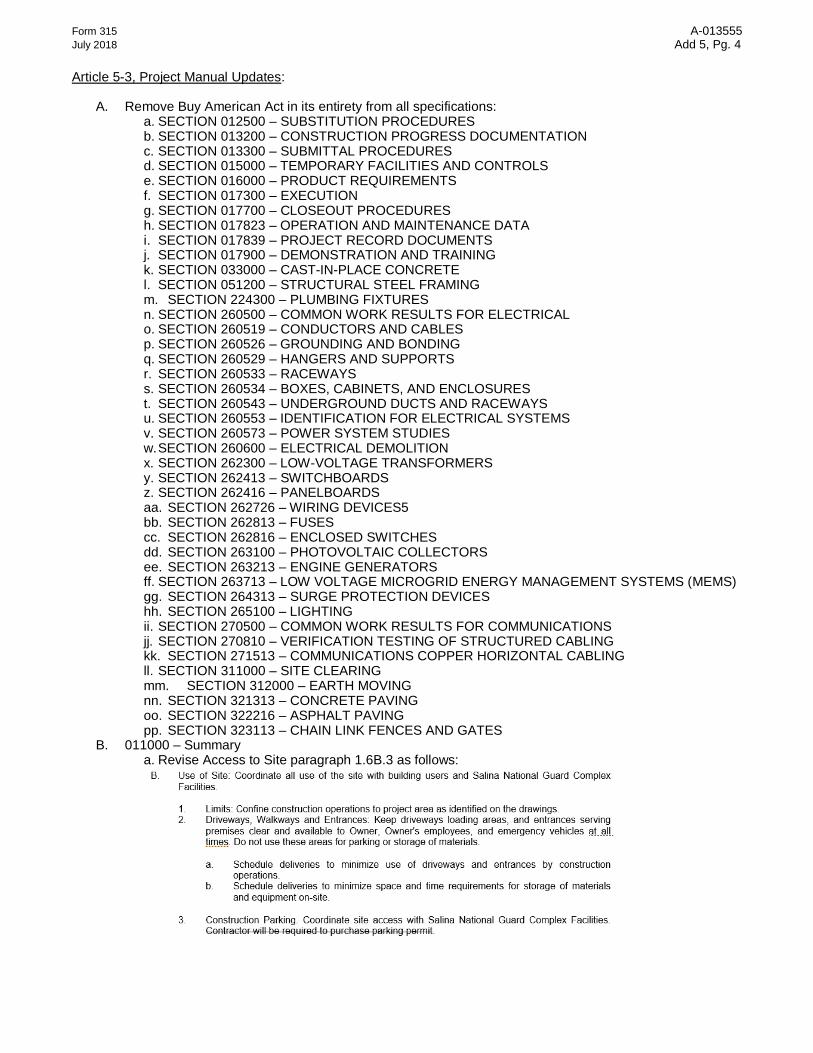
B. 011000 – Summary a. Revise Access to Site paragraph 1.6B.3 as follows:

Form 315 A-013555
July 2018 Add 5, Pg. 5
b. Revise Coordination with Occupants paragraph 1.7A as follows:
c. Revise Phased Construction paragraphs 1.5A.1 and 1.5A.3 as follows:

Form 315 A-013555
July 2018 Add 5, Pg. 6
C. 200800 Seismic Protection
a. Specification section issued in its entirety. Refer to attachments. D. 263100 Photovoltaic Collectors
a. Add manufacturer to list in 2.1.A for Photovoltaic Modules as follows:
b. Revise wind and snow loading in under paragraph 2.5 ARRAY FRAMING AND SUPPORT
STRUCTURE as follows:
E. 263213 Engine Generators
a. Remove paragraph 2.9.F.p.
b. Revise and omit sub-paragraphs of 3.2.A as follows:
Form 315 A-013555
July 2018 Add 5, Pg. 7
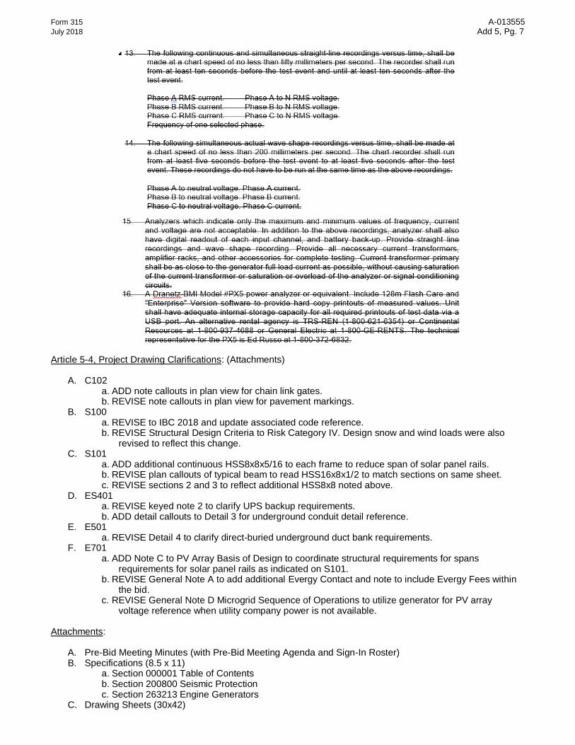
Article 5-4, Project Drawing Clarifications: (Attachments)
A. C102 a. ADD note callouts in plan view for chain link gates. b. REVISE note callouts in plan view for pavement markings.
B. S100 a. REVISE to IBC 2018 and update associated code reference. b. REVISE Structural Design Criteria to Risk Category IV. Design snow and wind loads were also
revised to reflect this change. C. S101
a. ADD additional continuous HSS8x8x5/16 to each frame to reduce span of solar panel rails. b. REVISE plan callouts of typical beam to read HSS16x8x1/2 to match sections on same sheet. c. REVISE sections 2 and 3 to reflect additional HSS8x8 noted above.
D. ES401 a. REVISE keyed note 2 to clarify UPS backup requirements. b. ADD detail callouts to Detail 3 for underground conduit detail reference.
E. E501 a. REVISE Detail 4 to clarify direct-buried underground duct bank requirements.
F. E701 a. ADD Note C to PV Array Basis of Design to coordinate structural requirements for spans
requirements for solar panel rails as indicated on S101. b. REVISE General Note A to add additional Evergy Contact and note to include Evergy Fees within
the bid. c. REVISE General Note D Microgrid Sequence of Operations to utilize generator for PV array
voltage reference when utility company power is not available. Attachments:
A. Pre-Bid Meeting Minutes (with Pre-Bid Meeting Agenda and Sign-In Roster) B. Specifications (8.5 x 11)
a. Section 000001 Table of Contents b. Section 200800 Seismic Protection c. Section 263213 Engine Generators
C. Drawing Sheets (30x42)

Form 315 A-013555
July 2018 Add 5, Pg. 8
a. C102 b. S100 c. S101 d. ES401 e. E501 f. E701
*** RECEIPT OF THIS ADDENDUM IS TO BE ACKNOWLEDGED ON THE FORM OF BID - DOCUMENT C*** DESIGN, CONSTRUCTION & COMPLIANCE

5350 W. 94th Terrace, Suite 102 | Prairie Village, KS 66207
P: 913-258-5026
rossbar.com
MEETING MINUTES
PROJECT:
Adjutant General’s Department
Nickell Hall Barracks
Salina ERCIP Photovoltaic Solar Power & Water Reduction
SUBJECT: Pre Bid Meeting
PROJECT NO: A-013555 (State of KS AGD); 2297-01 (R&B)
MEETING DATE: February 17, 2021
MEETING
LOCATION:
2929 Scanlan Avenue – Bldg 365
Salina, KS
ISSUE DATE: February 26, 2021
BY: Dan Phelan, Ross & Baruzzini (R&B)
PARTICIPANTS: See attached Meeting Roster
CC: Participants; Central File
The following minutes express our understanding of the items discussed. Please respond in writing within five days of receipt if any changes are required.
Items indicate with asterisks ** affect the critical path for the project and require immediate attention.
1. General Project Discussion
a. Dan Phelan, Marlene Conaway, and Captain Billings provided an overview of the project scope,
schedule, and general terms and conditions. Refer to the attached Pre-Bid Meeting Agenda.
b. Marlene confirmed the vetting process, which includes background checks, for all workers on
site.
c. Parking was discussed. Captain Billings confirmed that the Bldg 320 Nickell Hall parking lot
cannot be out of service for the entire construction duration. Restrictions will be clarified via
Addendum.
d. All site area disturbed as a result of work associated with this project shall be returned to its
original condition prior to the start of the project before substantial completion.
e. Contractors are required to provide their own dumpsters. Recycling requirements will be
clarified via Addendum.
f. The Owner reserves first salvage rights for all equipment and components removed as part of
this project.
2. The following questions were raised during the Pre-Bid Meeting and Walk Through of the various
buildings associated with the scope of work, many of which will be answered in forthcoming
addendums. Answers provided during the meeting are noted below.
Pre-Bid Meeting Minutes
02/26/2021
2 J:\Kansas City\2297-01\2 Design\A Correspondence\1 Meeting Minutes\2021-02-17 Pre Bid
Meeting\2021-02-26 Pre Bid Meeting Minutes.docx
a. Will this project be taxable as a remodel project? R&B to confirm with KS OFPM.
b. Are Davis-Bacon Wages applicable to this project? No, they do not. This is clarified with
Addendum 05.
c. Is the contractor required to provide temporary power? Yes, per the Drawings.
d. Is the span between the solar panel rails correct at 13-ft? R&B will confirm.
e. What version of the Buy American Act applies to this project? Following the meeting it was
confirmed that the Buy American Act does not apply to this project. This is clarified with
Addendum 05.
f. For Bldg 320 Nickell Barracks, does the Owner have backstock wall tile for use in ADA restrooms?
R&B will confirm with the KSARNG.
3. Attachments – the following attachments are included to supplement these meeting minutes:
a. Pre-Bid Meeting Roster
b. Pre-Bid Meeting Agenda

5350 W. 94th Terrace, Suite 102 | Prairie Village, KS 66207
P: 913-258-5026
rossbar.com
Pre-Bid Meeting Agenda
MEETING NAME: A-013555 Adjutant General’s Department
Nickell Hall Barracks
Salina ERCIP Photovoltaic Solar Power & Water Reduction
Pre-Bid Meeting
MEETING DATE(S): Wednesday, February 17, 2021
MEETING TIME: 10:00 A.M.
MEETING
LOCATION:
2929 Scanlan Avenue – Bldg 365
Salina, KS
BY: Dan Phelan
CC: Participants
Central File
1. Project Introduction:
Project Name: Adjutant General’s Department, Nickell Hall Barracks, Salina ERCIP Photovoltaic Solar
Power & Water Reduction
Buildings Involved:
- 03400-00219 Classroom
- 03400-00320 Nickell Hall Barracks
- 03400-00321 Building
- 03100-00450 Academy Building
- 04300-00460 Headquarters Building
- 03400-00465 Barracks
- 03400-00558 RTMS
Project Number: A-013555
2. Team Introduction:
Dan Phelan, Ross & Baruzzini – Project Manager
Jeff Wheeler, Ross & Baruzzini – Lead Electrical Engineer
Marlene Conaway, KS Army National Guard – Construction Project Manager
Pass around sign-in sheets for attendee sign-in
3. Project Description:
General: Installation of a parking lot canopy solar photovoltaic (PV) array and emergency generator at
Building 320 – Nickell Barracks, along with the replacement of plumbing fixtures within multiple
buildings on the Salina National Guard Complex.

A-013555
Pre-Bid Meeting Agenda
February 17, 2021
2
Civil: Pavement removal and repair to support installation of new solar photovoltaic canopy structure in
parking lot adjacent to Building 320 Nickell Barracks. New electrical equipment pads along with
associated site grading work to prep for installation of pads.
Structural: Installation of new solar photovoltaic canopy structure which includes new spread footings
in the parking lot adjacent to Building 320 Nickell Barracks.
Plumbing: Selectively remove and replace existing plumbing fixtures (water closets and flush valves,
urinals and flush valves, sink faucets, lavatory faucets, shower heads, and electric water coolers with
bottle fillers throughout seven (7) buildings noted above on the Salina National Guard Complex.
Electrical: Install a new canopy mounted solar photovoltaic array system in the parking lot adjacent to
Building 320 – Nickell Barracks. Install a new 400KW diesel generator to serve Bldg 320 Nickell Barracks.
4. Schedule:
• All questions must be submitted by February 26, 2021
• Date for last Addendum: March 4, 2021
• Bids due: March 11, 2021 by 2:00 P.M.
• Anticipated Notice to Proceed: April 8, 2021
• Anticipated Construction Commencement Date: April 15, 2021
• Substantial Completion shall be met on: April 15, 2022
• Final Completion shall be met on: April 29, 2022
5. Instructions to Bidders:
• All bids are opened by Procurement and Contracts, Department of Administration
• Questions concerning bid bonds, performance bonds, public works bonds, insurance, etc. are
to be directed to Purchases at (785) 296-0408.
• Bid Form:
o Base Bid: See Project Description above.
o Alternate No. 1: Solar Photovoltaic (PV) Array Zone C – West Section Installation � Base Bid: Provide and install entire Solar PV Array C spanning eleven (11) parking
canopy bays, along with associated PV modules, components and accessories, and canopy light fixtures.
� Alternate: Provide and install only center section of Solar PV Array C, spanning four (4) parking canopy bays, along with associated PV modules, components and accessories, and canopy light fixtures. Inclusion of Additive Alternate 1 should be considered before Alternates 2 and 3 due to the closer proximity to Nickell Hall Barracks.
o Alternate No. 2: Solar PV Array Zone C – Center Section Installation � Base Bid: Provide and install entire Solar PV Array C spanning eleven (11) parking
canopy bays, along with associated PV modules, components and accessories, and canopy light fixtures.
� Alternate: Provide and install only center section of Solar PV Array C, spanning three (3) parking canopy bays, along with associated PV modules, components and accessories, and canopy light fixtures. Inclusion of Additive Alternate 2 should be considered after inclusion of Alternate 1 and before inclusion of Alternate 3;

A-013555
Pre-Bid Meeting Agenda
February 17, 2021
3
however, Alternate 2 may be selected as a stand-alone option with respect to Additive Alternates 1 through 3.
o Alternate No. 3: Solar PV Array Zone C – East Section Installation � Base Bid: Provide and install entire Solar PV Array C spanning eleven (11) parking
canopy bays, along with associated PV modules, components and accessories, and canopy light fixtures.
� Alternate: Provide and install only center section of Solar PV Array C, spanning four (4) parking canopy bays, along with associated PV modules, components and accessories, and canopy light fixtures. Inclusion of Additive Alternate 3 should be considered after inclusion of Alternate 1 and Alternate 2; however, Alternate 3 may be selected as a stand-alone option with respect to Additive Alternates 1 through 3.
o Alternate No. 4: Increase Shower Head Height – Building 320 Nickell Barracks � Base Bid: Replace shower heads within all dorm bathrooms. � Alternate: Replace shower heads while increasing the installed height. Work shall
include increasing piping in wall, followed by patching, repairing, and painting wall to restore original finish. Existing molded shower surrounds shall be replaced with new.
o Alternate No. 5: Public Restroom Lavatory Replacement – Various Buildings � Base Bid: Replace only the faucets at public restroom lavatories. � Alternate: Replace faucets and provide new wall-hung lavatory, along with new
pipe connections, P-trap, pipe escutcheons, ADA covers, and grid strainer. See Drawings for fixture count.
o Alternate No. 6: Vanity and Sink Replacement – Building 320 Nickell Barracks � Base Bid: Replace only the faucets at each vanity lavatory within all dorm
bathrooms. � Alternate: Replace faucets and provide new drop-in lavatory, along with new pipe
connections, P-trap, pipe escutcheons, and pop-up strainer. Additionally, new vanity assemblies will be provided. See Drawings for fixture count.
o Alternate No. 7: Install Bird Deterrent Hardware on PV Array Structure – Building 320 Nickell Barracks
� Base Bid: No bird deterrent hardware on PV Array Structure � Alternate: Provide and install pre-fabricated bird repellent spikes to the top edge of
the solar panels to prevent birds from roosting atop the panels. See Drawings for locations.
o Alternate No. 8: Increase Shower Head Height – Building 558 RTSM � Base Bid: Replace shower heads within facility. � Alternate: Replace shower heads while increasing the installed height. Work shall
include replacement of shower valves and increasing piping in wall, followed by patching, repairing, and painting wall to restore original finish.
o Unit Prices: None.
o Allowances: None.
o Sub-contractors required to be listed: Mechanical Contractor, Electrical Contractor,
Structural, Civil
o Time to Completion: 365 calendar days following issuance of Notice to Proceed.

A-013555
Pre-Bid Meeting Agenda
February 17, 2021
4
• Substitutions: All requests to approve equivalent products must be submitted to the Engineer no
later than 10 days before the bid date, meaning March 1, 2021. All approvals will be released via
addendum.
• Taxes:
o This project has been determined by the Kansas Department of Revenue to be subject to
Kansas sales tax. The cost of said Tax must be INCLUDED IN all Bid and Contract prices.
Sales tax includes all applicable state, county, and city sales taxes. Refer to Form of Bid and
Supplemental General Conditions, Document E, for instructions on paying the tax.
• Bonding Requirements:
o Bid Bond: 5% of the base bid, payable to State of Kansas, via certified check or cashier’s
check.
o Performance Bond: 100% of the Contract price furnished to the Owner by the Contractor
when the Contract is executed.
o Public Works Bond: 100% of the Contract price furnished to the Owner by the Contractor
when the Contract is executed.
o See General Conditions for more information.
• Insurance Requirements:
o Contractor and all subcontractors shall not commence work under this Contract until all
required insurance has been obtained and approved by the Owner.
o Worker’s compensation, commercial general liability, automobile liability insurance, and all
risk installation floater insurance is required.
o Note additional requirements in Supplemental General Conditions.
• Liquidated Damages:
o Rate of $250 per day between the adjusted contract completion date and the date of
substantial completion of the project.
• Weather Day Data: Refer to Supplemental General Conditions for number of assumed weather days.
• Final Addendum: March 4, 2021
Key Elements of Scope of Work:
• General:
o Products furnished within the limits of this contract are subject to the requirements of the
Buy American Act under provisions of the prime contract.
o Nickell Hall Access Opportunities and Restrictions:
� Facility is normally shut down for 12 days during the holiday season. Coordinate
days with Owner.
� Facility is 100% occupied between June and August each year, allowing no ability
for utility shutdowns during this time window.
• Electrical:
o The project will require relocation of the Evergy service feed to the building to integrate
the new service switchboard. Specific downtimes are indicated on the Drawings and
temporary power in the form of generator and UPS power will be required for both the
service and telecom room depending on outage length required. Coordination with both
Evergy and the Owner for cutover and downtimes are required.
A-013555
Pre-Bid Meeting Agenda
February 17, 2021
5
o The new switchboard will require integration with microgrid controls to integrate normal
utility service and photovoltaic array with generator backup. Generator operation will
require an open transition to the utility.
o The photovoltaic array has basis-of-design requirements shown on the
Drawings. Modifications to this system shall provide a fully integrated and operational
system that work with the carport structural system that has been designed.
o Portions of the existing site lighting will be re-used with new components and integrated
into existing site lighting controls for the site pole lighting along the perimeter of the
parking lot
o New carport canopy parking lot lighting with motion and ambient light sensor controls
will be required.
o Communications cables and pathways will be required for remote monitoring of the new
digital metering within the electrical distribution system and photovoltaic array inverters.
Corrections, Clarifications, and Additions:
• Notes and Attendee List from the Pre-bid Meeting will be incorporated into forthcoming
Addendum 4.
• Forthcoming update to Front End specifications to confirm access to Nickell Hall during holiday
season as well as restricted access to Nickell Hall during summer months.
6. Discussion and Questions:
• General Question & Answer session.
• Scheduled jobsite tour immediately following meeting. Tour sequence is as follows:
1. Bldg 320 Nickell Barracks
a. Main Parking Lot
b. Back Utility Yard
c. Main Electrical Room
d. Main Telecom Room
e. Restroom in Typical Living Quarters
2. Bldg 450 Academy Building – Typical restroom
3. Bldg 465 Barracks – Typical restroom
4. Bldg 460 Headquarters Building – Typical restroom
5. Bldg 558 RTMS – Typical restroom
6. Bldg 321 – Typical restroom
7. Bldg 219 Classroom – Typical restroom

A-013555
Pre-Bid Meeting Agenda
February 17, 2021
6
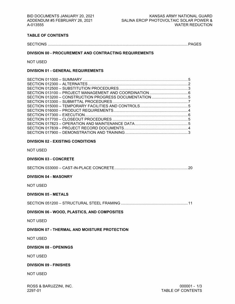
BID DOCUMENTS JANUARY 20, 2021 KANSAS ARMY NATIONAL GUARD ADDENDUM #5 FEBRUARY 26, 2021 SALINA ERCIP PHOTOVOLTAIC SOLAR POWER & A-013555 WATER REDUCTION
ROSS & BARUZZINI, INC. 000001 - 1/3 2297-01 TABLE OF CONTENTS
TABLE OF CONTENTS SECTIONS .................................................................................................................................... PAGES DIVISION 00 - PROCUREMENT AND CONTRACTING REQUIREMENTS NOT USED DIVISION 01 - GENERAL REQUIREMENTS SECTION 011000 – SUMMARY ................................................................................................... 5 SECTION 012300 – ALTERNATES .............................................................................................. 2 SECTION 012500 – SUBSTITUTION PROCEDURES ................................................................. 3 SECTION 013100 – PROJECT MANAGEMENT AND COORDINATION .................................... 6 SECTION 013200 – CONSTRUCTION PROGRESS DOCUMENTATION .................................. 5 SECTION 013300 – SUBMITTAL PROCEDURES ....................................................................... 7 SECTION 015000 – TEMPORARY FACILITIES AND CONTROLS ............................................. 5 SECTION 016000 – PRODUCT REQUIREMENTS ...................................................................... 4 SECTION 017300 – EXECUTION ................................................................................................. 6 SECTION 017700 – CLOSEOUT PROCEDURES ....................................................................... 5 SECTION 017823 – OPERATION AND MAINTENANCE DATA .................................................. 5 SECTION 017839 – PROJECT RECORD DOCUMENTS ............................................................ 4 SECTION 017900 – DEMONSTRATION AND TRAINING ........................................................... 3 DIVISION 02 - EXISTING CONDITIONS NOT USED DIVISION 03 - CONCRETE SECTION 033000 – CAST-IN-PLACE CONCRETE ..................................................................... 20 DIVISION 04 - MASONRY NOT USED DIVISION 05 - METALS SECTION 051200 – STRUCTURAL STEEL FRAMING ............................................................... 11 DIVISION 06 - WOOD, PLASTICS, AND COMPOSITES NOT USED DIVISION 07 - THERMAL AND MOISTURE PROTECTION NOT USED DIVISION 08 - OPENINGS NOT USED DIVISION 09 - FINISHES NOT USED

BID DOCUMENTS JANUARY 20, 2021 KANSAS ARMY NATIONAL GUARD ADDENDUM #5 FEBRUARY 26, 2021 SALINA ERCIP PHOTOVOLTAIC SOLAR POWER & A-013555 WATER REDUCTION
ROSS & BARUZZINI, INC. 000001 - 2/3 2297-01 TABLE OF CONTENTS
DIVISION 10 - SPECIALTIES NOT USED DIVISION 11 - EQUIPMENT NOT USED DIVISION 12 - FURNISHINGS NOT USED DIVISION 13 - SPECIAL CONSTRUCTION NOT USED DIVISION 14 - CONVEYING EQUIPMENT NOT USED DIVISION 20 – SEISMIC PROTECTION SECTION 200800 – SEISMIC PROTECTION .............................................................................. 13 DIVISION 21 - FIRE SUPPRESSION NOT USED DIVISION 22 - PLUMBING SECTION 220500 – BASIC PLUMBING MATERIALS AND METHODS ...................................... 14 SECTION 224300 – PLUMBING FIXTURES ................................................................................ 5 DIVISION 23 - HEATING, VENTILATING, AND AIR- CONDITIONING (HVAC) NOT USED DIVISION 25 - INTEGRATED AUTOMATION NOT USED DIVISION 26 - ELECTRICAL SECTION 260500 – COMMON WORK RESULTS FOR ELECTRICAL ....................................... 19 SECTION 260519 – CONDUCTORS AND CABLES .................................................................... 7 SECTION 260526 – GROUNDING AND BONDING ..................................................................... 5 SECTION 260529 – HANGERS AND SUPPORTS ...................................................................... 5 SECTION 260533 – RACEWAYS ................................................................................................. 9 SECTION 260534 – BOXES, CABINETS, AND ENCLOSURES.................................................. 5 SECTION 260543 – UNDERGROUND DUCTS AND RACEWAYS ............................................. 9 SECTION 260553 – IDENTIFICATION FOR ELECTRICAL SYSTEMS ....................................... 8 SECTION 260573 – POWER SYSTEM STUDIES ....................................................................... 4 SECTION 260600 – ELECTRICAL DEMOLITION ........................................................................ 3 SECTION 262300 – LOW-VOLTAGE TRANSFORMERS ............................................................ 4

BID DOCUMENTS JANUARY 20, 2021 KANSAS ARMY NATIONAL GUARD ADDENDUM #5 FEBRUARY 26, 2021 SALINA ERCIP PHOTOVOLTAIC SOLAR POWER & A-013555 WATER REDUCTION
ROSS & BARUZZINI, INC. 000001 - 3/3 2297-01 TABLE OF CONTENTS
SECTION 262413 – SWITCHBOARDS ........................................................................................ 8 SECTION 262416 – PANELBOARDS ........................................................................................... 7 SECTION 262726 – WIRING DEVICES ....................................................................................... 5 SECTION 262813 – FUSES .......................................................................................................... 2 SECTION 262816 – ENCLOSED SWITCHES .............................................................................. 3 SECTION 263100 – PHOTOVOLTAIC COLLECTORS ................................................................ 9 SECTION 263213 – ENGINE GENERATORS.............................................................................. 16 SECTION 263713 – LOW VOLTAGE MICROGRID ENERGY MANAGEMENT SYSTEMS (MEMS)//////////// ............... 9 SECTION 264313 – SURGE PROTECTION DEVICES ............................................................... 8 SECTION 265100 – LIGHTING ..................................................................................................... 5 DIVISION 27 - COMMUNICATIONS SECTION 270500 – COMMON WORK RESULTS FOR COMMUNICATIONS ........................... 9 SECTION 270810 – VERIFICATION TESTING OF STRUCTURED CABLING ........................... 4 SECTION 271513 – COMMUNICATIONS COPPER HORIZONTAL CABLING .......................... 7 DIVISION 28 THROUGH 30 NOT USED DIVISION 31 – EARTHWORK SECTION 311000 – SITE CLEARING .......................................................................................... 5 SECTION 312000 – EARTH MOVING .......................................................................................... 10 DIVISION 32 – EXTERIOR IMPROVEMENTS SECTION 321313 – CONCRETE PAVING ................................................................................... 11 SECTION 322216 – ASPHALT PAVING ....................................................................................... 7 SECTION 323113 – CHAIN LINK FENCES AND GATES ............................................................ 4

THIS PAGE LEFT INTENTIONALLY BLANK

BID DOCUMENTS JANUARY 20, 2021 KANSAS ARMY NATIONAL GUARD
ADDENDUM #5 FEBRUARY 26, 2021 SALINA ERCIP PHOTOVOLTAIC SOLAR POWER &
A-013555 WATER REDUCTION
ROSS & BARUZZINI, INC. 200800 - 1/13
2297-01 SEISMIC PROTECTION
SECTION 200800 - SEISMIC PROTECTION
PART 1 - GENERAL
1.1 RELATED DOCUMENTS
A. Drawings and general provisions of the Contract, including General and Supplementary
Conditions and Division 01 Specification Sections, apply to the work of this Section.
1.2 APPLICABILITY
A. Seismic supports and restraints shall be provided for all Life Safety and Hazardous or
Flammable systems. The following are defined as Life Safety and Hazardous or Flammable:
1. Communication systems.
2. Any system or component containing hazardous or flammable materials.
B. In addition to the above, seismic supports and restraints shall be provided for all of the
following systems:
1. Electrical transformers and generators.
2. Reciprocating or rotating equipment or any equipment with moving parts.
3. Electrical panelboards.
4. Lighting fixtures.
1.3 EXEMPTIONS
A. The following mechanical and electrical components are exempt from the requirements of this
Section:
1. MEP components that were existing prior to beginning of construction of this project and
which are not disturbed during the course of this work, are exempt.
2. Piping and conduit are exempt if the entire run is suspended from hangers 12-inches or
less in length from the top of the pipe to the supporting structure, and if the hangers are
sufficient to avoid significant bending of the hangers and their connections.
3. Piping and conduit constructed of steel, copper, ductile iron, aluminum, or plastic, of
nominal diameter 1-inch and smaller, are exempt.
B. There are no further exemptions allowed for Life Safety and Hazardous or Flammable
components or systems as defined in the “Applicability” subsection above.
C. For other than Life Safety and Hazardous or Flammable systems, the following mechanical and
electrical components are exempt from the requirements of this Section:
1. If not part of Life Safety and Hazardous or Flammable systems, MEP components
weighing less than 20 pounds are exempt if flexible connections are provided between
the components and associated ducts, pipes, or conduit.
2. If not part of Life Safety and Hazardous or Flammable systems, MEP components
weighing less than 400 pounds are exempt if flexible connections are provided between

BID DOCUMENTS JANUARY 20, 2021 KANSAS ARMY NATIONAL GUARD
ADDENDUM #5 FEBRUARY 26, 2021 SALINA ERCIP PHOTOVOLTAIC SOLAR POWER &
A-013555 WATER REDUCTION
ROSS & BARUZZINI, INC. 200800 - 2/13
2297-01 SEISMIC PROTECTION
the components and associated ducts, pipes, or conduit, and if the component is mounted
at 48 inches or less above finished floor level.
3. If not part of Life Safety and Hazardous or Flammable systems, piping or conduit
constructed of steel, copper, ductile iron, aluminum, or plastic, of nominal diameter 3-
inch and smaller, is exempt.
4. If not part of Life Safety and Hazardous or Flammable systems, electrical conduits, cable
trays, and bus ducts are exempt provided that none of the following apply:
a. Supports are cantilevered up from the floor.
b. Supports are constructed as rigid welded frames.
c. Supports include bracing to limit deflection.
d. Attachments into concrete utilize nonexpanding inserts, shot pins or cast iron
embedments or attachments utilizing spot welds, plug welds, or minimum size
welds (as defined in AISC LRFD).
D. Any otherwise-exempt MEP component, whose failure in an earthquake would potentially
damage a non-exempt component, is non-exempt. Example: An exempt storm drain pipe
mounted above a non-exempt natural-gas pipe could fall and rupture the gas pipe. Therefore, the
storm drain pipe must be treated as non-exempt.
1.4 SUMMARY
A. Description of Work: The purpose of this section is to define seismic restraint requirements for
mechanical and electrical systems, equipment and devices, hereinafter referred to as
components. This section also covers the design and installation of suspended acoustical ceiling
and raised floor systems.
B. This Section does not specify seismic force resisting systems for building structures and
structural elements, which are addressed in Divisions 03 through 06.
C. The requirements for seismic protection specified herein are in addition to any requirements for
support and/or seismic protection specified in other sections of these specifications.
D. The Contractor shall be responsible for developing details to provide proper support of
equipment and devices in accordance with the requirements specified herein.
E. The Contractor shall not proceed with installation of equipment nor seismic protection system
until all applicable submittals required by this section have been completed.
F. This section includes the following:
1. Applicable Code.
2. Project-specific Code Coefficients
3. Rigid Support Items.
4. Non-rigid Support Items.
5. Sway Braces.
6. Anchors, Bolts and Clamps.
7. Restraining Cables.
8. Seismic Snubbers.

BID DOCUMENTS JANUARY 20, 2021 KANSAS ARMY NATIONAL GUARD
ADDENDUM #5 FEBRUARY 26, 2021 SALINA ERCIP PHOTOVOLTAIC SOLAR POWER &
A-013555 WATER REDUCTION
ROSS & BARUZZINI, INC. 200800 - 3/13
2297-01 SEISMIC PROTECTION
9. Installation Requirements.
G. Related sections: The following sections contain requirements that relate to this section:
1. Division 05 Section “Metal Fabrications” for materials to anchor equipment piping to
building structure.
2. Division 26 Section “Common Work Results for Electrical” for general electrical
requirements.
3. All Division 21 to 28 Sections for mechanical and electrical equipment and systems
requiring seismic protection.
1.5 DEFINITIONS
A. Terminology used in this section is defined in ASCE/SEI 7-16: Minimum Design Loads for
Buildings and Other Structures, as issued by the American Society of Civil Engineers, 2016;
Reston, Virginia.
B. OSHPD: Office of Statewide Health Planning & Development for the State of California.
1.6 PERFORMANCE REQUIREMENTS
A. This facility is designated as Seismic Occupancy Category IV.
B. The spectral response acceleration at short periods, Ss, shall be taken as 0.098g.
C. The spectral response acceleration at one-second period, S1, shall be taken as 0.048g.
D. This facility site is designated as Site Class Definition D.
E. The Site Coefficients, Fa shall be taken as 1.6 and Fv shall be taken as 2.4.
F. SDS, the Five-Percent damped design spectral response acceleration at short periods, shall be
taken as SDS = 0.105.
G. SDI, the Five-Percent damped design spectral response acceleration at one-second period, shall
be taken as SDI = 0.077.
H. This facility is designated as Seismic Design Category C.
I. The horizontal seismic force on a given component shall be noted as Fp. The seismic force Fp
shall be applied at the center of gravity, independently longitudinally and laterally in
combination with service loads associated with the component. The following equation shall be
utilized individually on every component to determine Fp:
1. Fp = 1.6 x SDS x Ip x Wp where
a. Ip = Component Importance Factor.
b. Wp = Component Operating Weight in pounds.

BID DOCUMENTS JANUARY 20, 2021 KANSAS ARMY NATIONAL GUARD
ADDENDUM #5 FEBRUARY 26, 2021 SALINA ERCIP PHOTOVOLTAIC SOLAR POWER &
A-013555 WATER REDUCTION
ROSS & BARUZZINI, INC. 200800 - 4/13
2297-01 SEISMIC PROTECTION
2. In lieu of the above equation, a much more detailed calculation involving Equation
13.3-1 of ASCE 7-16 and its related Tables, which may yield somewhat lower results for
Fp, may be utilized. If this option is selected, complete details of all such calculations
shall be submitted as required under “Submittals” below.
J. The vertical seismic force on a given component shall be taken as 0.2 x SDS x Wp and shall be
determined individually for every component. This vertical force shall be applied at the center
of gravity of the component, in either vertical direction, and shall be considered concurrent with
the horizontal force determined above.
1.7 SUBMITTALS
A. The Engineer shall receive one copy of all submittal data supplied to the Owner as required in
this specification. It is the responsibility of the Contractor to provide seismic protection as
outlined herein. Receipt by the Engineer of a copy of the submittals is to verify conformance to
the submittal requirements set forth in this specification section. It is not an admission by the
Engineer as to the accuracy or completeness of the calculations submitted and equipment
proposed.
B. Prior to installation of equipment and devices requiring seismic restraints, the Contractor shall
submit required documentation and details at the shop drawing review stage to the Owner.
Submit the following in accordance with conditions of contract and Division 01 specification
sections.
C. Product data: Include installation details and instructions for each type of seismic support and
restraint. Submit equipment support and restraint schedule showing size, location, and features
for each required support and restraint.
D. Product certificates: Signed by the manufacturer of seismic supports and restraints certifying
that their products meet the specified requirements.
E. Shop Drawings: Calculations and Drawings signed and sealed by a qualified professional
engineer registered to practice in the State of Kansas, shall be provided for the installation
details of each piece of equipment. Include the following:
1. Design Calculations: Calculate requirements for selecting seismic restraints. Exception:
Certified and stamped calculations are not required for seismic-restrained systems which
have been pre-approved by OSHPD or comply with ANSI/SMACNA Standard 001-2008
Seismic Restraint Manual; Guidelines for Mechanical Systems, as issued by the Sheet
Metal and Air Conditioning Contractors National Association, Inc., 2008; Chantilly,
Virginia; Third Edition; except where more stringent requirements are described herein.
A signed letter on Contractor’s letterhead shall be provided as part of the submittal
process stating which approved systems are being utilized.
2. Seismic-Restraint Details: Detail fabrication and attachment of seismic restraints and
snubbers. Show anchorage details and indicate quantity, diameter, and depth of
penetration of anchors.
3. Assembly-type shop drawings: For each type of seismic support and restraint, indicate
dimensions, weights, required clearances, and methods of assembly of components.
Submittal Drawings shall indicate in complete detail size, type, material grade, locations

BID DOCUMENTS JANUARY 20, 2021 KANSAS ARMY NATIONAL GUARD
ADDENDUM #5 FEBRUARY 26, 2021 SALINA ERCIP PHOTOVOLTAIC SOLAR POWER &
A-013555 WATER REDUCTION
ROSS & BARUZZINI, INC. 200800 - 5/13
2297-01 SEISMIC PROTECTION
and dimensions; and shall show construction details, reinforcement, anchorage and
installation with relation to the building construction. Submittals shall include, but not be
limited to sway braces, flexible couplings or joints, resilient type vibration devices, and
anchorage of concrete equipment pads to structure.
4. Where seismic anchors and braces for one component must unavoidably be attached to
two or more elements of a structure subject to differential movement, such as a wall and a
floor or two different floors, submit sealed calculations for relative displacements;
including selection of sufficient flexible fittings to accommodate the relative
displacement. Examples subject to relative displacement include vertical pipe or conduit
risers; or a pump anchored to a floor and rigidly connected to piping anchored to the roof
structure above.
F. Welder certificates: Signed by Contractor certifying that welders comply with requirements
specified under “Quality Assurance” Article.
G. Maintenance data: For seismic supports and restraints for inclusion in Operating and
Maintenance Manual specified in Division 01, Division 23 Section “Basic Mechanical
Requirements” and Division 26 Section “Common Work Results for Electrical.”
H. Manufacturer Seismic Qualification Certification: Submit certification that all specified
equipment will withstand seismic forces identified in “Performance Requirements” Article
above. Include the following:
1. Basis for Certification: Indicate whether withstand certification is based on actual test of
assembled components or on calculations. The term “withstand” means “the unit will
remain in place without separation of any parts from the device when subjected to the
seismic forces specified and the unit will be fully operational after the seismic event.”
2. Dimensioned Outline Drawings of Equipment Unit: Identify center of gravity and locate
and describe mounting and anchorage provisions.
3. Detailed description of equipment anchorage devices on which the certification is based
and their installation requirements.
I. Contractor’s Acknowledgement of Seismic Responsibility: Submit written contractor’s
statement of responsibility prior to commencement of the work, acknowledging an awareness of
the seismic restraint requirements of the project, that control will be exercised to obtain
conformance with the Construction Documents, listing procedures for exercising control over
the seismic restraint installation, and identifying the responsible person(s) within their
organization.
1.8 QUALITY ASSURANCE
A. Seismic-restraint devices shall have horizontal and vertical load testing and analysis performed
according to OSHPD and shall bear anchorage preapproval “R” number, from OSHPD or
another agency acceptable to authorities having jurisdiction, showing maximum seismic-
restraint ratings. Ratings based on independent testing are preferred to ratings based on
calculations. If preapproved ratings are not available, submittals based on independent testing
are preferred. Calculations (including combining shear and tensile loads) to support seismic-
restraint designs must be signed and sealed by a qualified professional engineer. Testing and
BID DOCUMENTS JANUARY 20, 2021 KANSAS ARMY NATIONAL GUARD
ADDENDUM #5 FEBRUARY 26, 2021 SALINA ERCIP PHOTOVOLTAIC SOLAR POWER &
A-013555 WATER REDUCTION
ROSS & BARUZZINI, INC. 200800 - 6/13
2297-01 SEISMIC PROTECTION
calculations must include both shear and tensile loads and one test or analysis at 45 degrees to
the weakest mode.
B. Qualify welding processes and welding operators in accordance with AWS D1.1 “Structural
Welding Code – Steel.” Certify that each welder has satisfactorily passed AWS qualification
tests for welding processes involved and, if pertinent, has undergone recertification.
1.9 REFERENCES
A. Regulatory Requirements: Comply with applicable codes pertaining to product materials and
installation of seismic supports and restraints.
B. Referenced Codes and Standards: All work provided under this section shall comply with the
requirements specified herein, and additionally as provided in the following Codes and
Standards. In all cases where conflicting requirements are provided within these specifications,
Codes and Standards, the most stringent requirement shall apply.
C. IBC 2018: Comply with the International Building Code Sections 1613 and 1705.
D. ASCE/SEI 7-16: Comply with Minimum Design Loads for Buildings and Other Structures, as
issued by the American Society of Civil Engineers, 2010; Reston, Virginia.
E. UL and FM Compliance: Seismic supports and restraints shall be listed and labeled by UL and
FM where used for fire protection piping systems.
F. ANSI Standards and ASTM Publications: Seismic supports and restraints shall comply with
American National Standards Institute, Inc. (ANSI) and the American Society for Testing and
Materials (ASTM) Publications.
1. B18.2.1-1981 Square and Hex Bolts and Screws Inch Series
2. B18.2.2-1972 Square and Hex Nuts (R1983)
3. A36-84a Structural Steel
4. A307-86a Carbon Steel Bolts and Studs, 60,000 psi Tensile Strength
5. A325-86a High-Strength Bolts for Structural Steel Joints
6. A501-84 Hot-Formed Welded and Seamless Carbon Steel Structural Tubing
7. A576-87 Steel Bars, Carbon, Hot-Wrought, Special Quality
8. E80-96 Application of Ceiling Suspension (R1984) Systems for Acoustical Tile
and Lay-In Panels in Areas Requiring Seismic Restraints.
G. Federal Specification: Seismic supports and restraints shall comply with Federal Specification
RR-W-410D for Wire Rope and Strand.
1.10 COORDINATION
A. Coordinate size and location of concrete bases. Cast anchor-bolt inserts into base. Concrete,
reinforcement, and formwork requirements are specified in Division 03.

BID DOCUMENTS JANUARY 20, 2021 KANSAS ARMY NATIONAL GUARD
ADDENDUM #5 FEBRUARY 26, 2021 SALINA ERCIP PHOTOVOLTAIC SOLAR POWER &
A-013555 WATER REDUCTION
ROSS & BARUZZINI, INC. 200800 - 7/13
2297-01 SEISMIC PROTECTION
1.11 EXTRA MATERIALS
A. Furnish extra replacement neoprene inserts for all snubbers, which match products installed and
that are packaged with protective covering for storage and identified with labels describing
contents.
PART 2 - PRODUCTS
2.1 MANUFACTURERS
A. Manufacturers: Subject to compliance with requirements, provide products by one of the
following:
1. California Dynamics Corp.
2. Eaton; Cooper, B-Line, and Tolco brands.
3. Kinetics Noise Control, Inc.
4. Loos & Co., Inc.
5. Mason Industries, Inc.
6. Unistrut Corp.; division of Tyco International, Ltd.
7. Vibration Eliminator Co., Inc.
8. Vibro-Acoustics, Inc.
9. The VMC Group; Amber/Booth, Korfund, and VMC brands.
B. All seismic restraint devices of any one general group; raceways or suspended equipment, or
switchgear or other floor mounted equipment, etc., shall be provided by a single manufacturer.
2.2 MATERIALS
A. Steel Plates, Shapes, and Bars: ASTM A36.
B. Bolts and Nuts: Square and hex bolts and nuts, ANSI B18.2.1 and B18.2.2, SAE Grade 5, and
ASTM A307 or A325. Underground bolts shall be galvanized.
C. Bushings for Floor-Mounted Equipment Anchor Bolts: Neoprene bushings designed for rigid
equipment mountings, and matched to type and size of anchor bolts and studs.
D. Bushing Assemblies for Wall-Mounted Equipment Anchorage: Assemblies of neoprene
elements and steel sleeves designed for rigid equipment mountings, and matched to type and
size of attachment devices used.
E. Resilient Isolation Washers and Bushings: One-piece, molded, oil- and water-resistant
neoprene, with a flat washer face.
F. Mechanical Anchor Bolts: Drilled-in and stud-wedge or female-wedge type in zinc-coated steel
for interior applications and stainless steel for exterior applications. Select anchor bolts with
strength required for anchor and as tested according to ASTM E488. Minimum length of eight
times diameter.
G. Adhesive Anchor Bolts: Drilled-in and capsule anchor system containing polyvinyl or urethane
methacrylate-based resin and accelerator, or injected polymer or hybrid mortar adhesive.

BID DOCUMENTS JANUARY 20, 2021 KANSAS ARMY NATIONAL GUARD
ADDENDUM #5 FEBRUARY 26, 2021 SALINA ERCIP PHOTOVOLTAIC SOLAR POWER &
A-013555 WATER REDUCTION
ROSS & BARUZZINI, INC. 200800 - 8/13
2297-01 SEISMIC PROTECTION
Provide anchor bolts and hardware with zinc-coated steel for interior applications and stainless
steel for exterior applications. Select anchor bolts with strength required for anchor and as
tested according to ASTM E488.
H. Sway Brace: Material used for members listed in Table I of this specification, except for pipes,
shall be structural steel conforming with ASTM A36. Steel pipes shall conform to ASTM A501.
Note additional exception below.
1. Contractor’s Option: In lieu of utilizing angles, rods, bars or pipes as noted in Table I,
U-channel systems consisting of channels, fittings and accessories may be utilized. The
u-channel system shall be manufactured as a complete system by one supplier and listed
by the manufacturer for use in seismic restraint application. The system shall have the
approval of OSHPD. The equipment shall provide multi-directional bracing of electrical
conduit, cable tray and mechanical piping/ductwork systems.
TABLE I
MAXIMUM LENGTH AND ALLOWABLE CONCENTRIC LOADS FOR SWAY BRACES
Allowable
Concentric
Maximum Load*
Type Size (inches) Length* (kips)
Angles 1½ x 1½ x ¼ 4'-10" 3.4
2 x 2 x ¼ 6'-6" 4.6
2½ x 2½ x ¼ 8'-2" 5.9
3 x 3 x ¼ 9'-10" 7.1
Rods 3/4 3'-1" 2.2
7/8 3'-7" 3.0
Pipes (40S) 1 6'-9" 2.4
1¼ 8'-8" 3.3
1½ 10'-1" 3.9
2 12'-9" 5.3
2½ 15'-4" 8.4
3 19'-0" 11.0
*Based on the slenderness ratio of 1/r = 200, and load applied concentrically to brace. The
tabulated load values include a 33% stress increase as permitted for seismic loads. For non-
concentric loading, allowable brace load is to be determined per the AISC Specification for
Structural Steel Buildings / ASD 1989.
I. Hanger Rod Stiffener: Steel tube or steel slotted-support-system sleeve with internally bolted
connections to hanger rod. Reinforcing steel angle clamped to hanger rod is also acceptable.

BID DOCUMENTS JANUARY 20, 2021 KANSAS ARMY NATIONAL GUARD
ADDENDUM #5 FEBRUARY 26, 2021 SALINA ERCIP PHOTOVOLTAIC SOLAR POWER &
A-013555 WATER REDUCTION
ROSS & BARUZZINI, INC. 200800 - 9/13
2297-01 SEISMIC PROTECTION
J. Restraining Cables: ASTM A603 galvanized steel aircraft cables of minimum diameter 1/8-
inch, with end connections made of steel assemblies that swivel to final installation angle and
utilize two clamping bolts for cable engagement. Cables shall conform to Fed. Spec RR-W-410
as follows:
1. Less than 1/8-inch diameter Not Permitted
2. 1/8 to 5/32 inch diameter Type V, Class 1
3. 3/16 inch to 5/16 diameter Type V, Class 2
4. 1/4 inch to 5/8 diameter Type I, Class 2
K. Resilient Isolation Washers and Bushings: 1-piece, molded, bridge-bearing neoprene complying
with AASHTO M 251 and having a durometer of 50, plus or minus 5, with a flat washer face.
L. Seismic Snubbers: Factory fabricated using welded structural-steel shapes and plates, anchor
bolts, and replaceable resilient isolation washers and bushings.
1. Anchor bolts for attaching to concrete shall be seismic-rated, drill-in, and stud-wedge or
female-wedge type.
2. Resilient Isolation Washers and Bushings: Oil- and water-resistant neoprene.
3. Maximum ¼-inch (6-mm) air gap, and minimum ¼-inch- (6-mm-) thick resilient cushion.
M. Channel Support System: MFMA-3, shop- or field-fabricated support assembly made of slotted
steel channels with accessories for attachment to braced component at one end and to building
structure at the other end and other matching components and with corrosion-resistant coating;
and rated in tension, compression, and torsion forces.
N. Flexible Couplings: Flexible couplings shall have same pressure ratings as adjoining pipe.
O. Cement Grout: Portland cement (ASTM C150, Type I or Type III) and clean uniformly graded,
natural sand (ASTM C404, Size No. 2). Mix ratio shall be 1.0 part cement to 3.0 parts sand, by
volume, with minimum amount of water required for placement and hydration.
P. Non-shrink, Nonmetallic Grout: ASTM C1107, Grade B.
1. Characteristics: Post-hardening, volume-adjusting, dry, hydraulic-cement grout, non-
staining, noncorrosive, nongaseous, and recommended for interior and exterior
applications.
2. Design Mix: 5000-psig (34.5-MPa), 28-day compressive strength.
3. Packaging: Premixed and factory packaged.
Q. Galvanizing Repair Paint: High-zinc-dust-content paint, with dry film containing not less than
94 percent zinc dust by weight.
PART 3 - EXECUTION
3.1 EXAMINATION
A. Examine areas and equipment to receive seismic-control devices for compliance with
requirements, installation tolerances, and other conditions affecting performance. Examine
roughing-in of reinforcement and cast-in-place anchors to verify actual locations before
BID DOCUMENTS JANUARY 20, 2021 KANSAS ARMY NATIONAL GUARD
ADDENDUM #5 FEBRUARY 26, 2021 SALINA ERCIP PHOTOVOLTAIC SOLAR POWER &
A-013555 WATER REDUCTION
ROSS & BARUZZINI, INC. 200800 - 10/13
2297-01 SEISMIC PROTECTION
installation. Examine substrates and conditions under which seismic supports and restraints are
to be installed.
B. Proceed with installation only after unsatisfactory conditions have been corrected.
3.2 SEISMIC PROTECTION, GENERAL
A. Attachments and supports for mechanical and electrical systems and components shall be
designed to resist the seismic forces specified herein.
B. Electrical systems and components shall be designed by their manufacturer to consider dynamic
effects of the equipment and its contents. Design, selection, and installation of seismic bracing
for Electrical systems and components shall account for interaction between equipment and
supporting structures, and the effect imposed by attached utility or service lines, and shall
ensure that impact between components is avoided during a seismic event.
C. Anchorage: Install seismic supports and restraints complete with necessary inserts, bolts, rods,
nuts, washers, and other accessories.
1. Friction resulting from gravity loads shall not be considered to provide resistance to
seismic loads.
2. All bolts, including fasteners and anchor bolts, used for attachment of anchors to
components and to structure shall be sized for the seismic forces described in Part I but
shall not be less than ½-inch diameter in any case.
3. Powder-driven fasteners and shot pins shall not be permitted in tension load applications.
4. Expansion anchors, other than undercut expansion anchors, shall not be permitted to
anchor non-vibration isolated equipment rated over 10 horsepower.
5. Anchorage Embedment Depth: Not less than eight times the anchorage diameter.
6. Anchorage Edge Distance: Place anchorage not less than ten times the anchorage
diameter from edge of concrete housekeeping pad.
D. Base-Mounted Equipment: Anchor equipment to concrete base according to supported
equipment manufacturer's written instructions for seismic forces at Project site.
1. Concrete equipment pads shall be anchored to the supporting structure as required to
resist the seismic loads specified herein. Anchorage shall adequately distribute loads to
the elements of the supporting structure; coordinate with building structural engineer if
required. Anchorage devices may consist of either cast-in-place or drilled-in and epoxy
grouted reinforcing steel dowels. Unless otherwise indicated, install dowel rods to
connect concrete base to concrete floor on 18-inch (450-mm) centers around the full
perimeter of the base.
2. All floor or pad mounted equipment shall be anchored with cast-in-place anchor bolts,
expansion bolts or epoxy bolts. For vibratory equipment, the nuts shall be secured against
loosening by either installing double nuts, tack welding single nut to bolt or scoring bolt
threads.
3. Install epoxy-coated anchor bolts for supported equipment that extend through concrete
base and anchor into structural concrete floor.
4. Place and secure anchorage devices. Use Setting Drawings, templates, diagrams,
instructions, and directions furnished with items to be embedded.

BID DOCUMENTS JANUARY 20, 2021 KANSAS ARMY NATIONAL GUARD
ADDENDUM #5 FEBRUARY 26, 2021 SALINA ERCIP PHOTOVOLTAIC SOLAR POWER &
A-013555 WATER REDUCTION
ROSS & BARUZZINI, INC. 200800 - 11/13
2297-01 SEISMIC PROTECTION
5. Install anchor bolts to elevations required for proper attachment to supported equipment.
6. Install anchor bolts according to anchor-bolt manufacturer's written instructions.
7. Cast-in-place concrete materials and placement requirements are specified in Division 03.
E. Resilient Vibration Isolation Devices: Selection of anchor bolts for vibration isolation devices
and/or snubbers to equipment base and foundations shall follow the same procedure as for base-
mounted equipment in subsection above, except that the seismic force found in Part 1 shall be
doubled for the purpose of selecting isolation devices, anchorage, and snubbers.
1. Vibration Isolation Devices are suitable for seismic restraint provided the vertical and
horizontal seismic forces are within the limits designed into the device.
2. Resilient and Spring-Type Vibration Devices: Vibration isolation devices shall be
selected so that the maximum movement of equipment from the static deflection point
shall be 0.5 inches.
3. Multi-directional Seismic Snubbers: If vibration isolators are required, then multi-
directional seismic snubbers employing elastomeric pads shall be installed on all
vibration isolated equipment. These snubbers shall provide 0.25-inches free vertical and
horizontal movement from the static deflection point. Locate snubbers as close as
possible to vibration isolators and bolt to equipment base and supporting structure.
Snubber medium shall consist of viscoelastic or other impact-limiting material arranged
around a flanged steel trunnion so both horizontal and vertical overturning forces are
resisted by the snubber medium.
4. Install resilient bolt isolation washers on equipment anchor bolts.
5. Do not short-circuit vibration isolation device with rigid connection directly to structure.
F. Equipment Sway Bracing: Required for all items supported from overhead structures. Braces
shall consist of angles, rods, bars, pipes, cables, or factory fabricated U-channel systems and
secured at both ends with not less than ½-inch bolts. Braces shall conform to Table 1, or as
recommended by U-channel systems fabricator. Bracing shall be provided in two planes of
directions, 90 degrees apart, for each item of equipment. Details of all equipment bracing shall
be submitted.
1. In lieu of bracing with vertical supports, these items may be supported with hangers
inclined at 45 degrees directed up and radially away from equipment and oriented
symmetrically in 90-degree intervals on the horizontal plane, bisecting the angles of each
corner of the equipment, provided that supporting members are properly sized to support
operating weight of equipment when hangers are inclined at a 45-degree angle.
2. Exception: Components mounted in line with duct systems and which weigh less than 75
pounds, do not require dedicated equipment sway bracing. Instead, such components
shall be considered a part of the duct system itself and braced as such.
3.3 ELECTRICAL EQUIPMENT
A. Electrical Equipment Bases: Oversized washers and/or reinforcing stiffeners extending to the
equipment wall are required at bolted connections through the base, for any equipment bases
not designed to transfer seismic loads.

BID DOCUMENTS JANUARY 20, 2021 KANSAS ARMY NATIONAL GUARD
ADDENDUM #5 FEBRUARY 26, 2021 SALINA ERCIP PHOTOVOLTAIC SOLAR POWER &
A-013555 WATER REDUCTION
ROSS & BARUZZINI, INC. 200800 - 12/13
2297-01 SEISMIC PROTECTION
B. Batteries on racks shall be treated with wrap-around restraints designed to hold batteries in
place; with spacers between cells and restraints to prevent damage to cases. Battery racks
themselves shall be designed to accommodate the seismic load specified in Part 1.
C. Internal coils of dry type transformers shall be positively attached to their supporting structure
within the transformer.
D. Slide-out components in electrical control panels, computer equipment, etc. shall have a
latching mechanism to hold contents in place.
E. Cutouts in the lower shear panel of electrical cabinets are prohibited, unless one of the
following exceptions is met:
1. Factory cutouts made by the manufacturer.
2. Cutouts supported by an analysis demonstrating that remaining cabinet strength is
sufficient.
F. Attachment of additional external items to electrical equipment is prohibited, unless one of the
following exceptions is met:
1. Items weighing less than 100 pounds.
2. Items provided by the electrical equipment manufacturer.
3. Items shown by analysis demonstrating their effects are supported by the design.
3.4 LIGHTING FIXTURES
A. Lighting fixture supports shall be malleable iron unless specified to be of a higher quality (such
as stainless steel, etc.) in other sections of these specifications.
B. A supporting assembly that is intended to be mounted on an outlet box shall be designed to
accommodate mounting features on 4-inch boxes, 3-inch plaster rings, and fixture studs.
C. Wall-mounted emergency light unit shall be secured in a manner to hold the unit in place during
a seismic disturbance.
3.5 SEISMIC RELATIVE DISPLACEMENT
A. Do not attach seismic anchorage or bracing for any one component to two or more elements of a
structure subject to differential movement, such as a wall and a floor or two different floors. Do
not attach seismic anchorage or bracing for any one component to two or more separate
structures or structural systems.
B. Piping, conduit, ductwork, cable tray, etc. shall be designed to accommodate differential
movement between components and structures when attached to structures that could displace
relative to each other and where the components cross a seismic isolation interface. Examples
include vertical pipe or conduit risers; or a pump anchored to a floor and rigidly connected to
piping anchored to the roof structure above. Furnish and install sufficient flexible fittings to
accommodate the relative displacement.
BID DOCUMENTS JANUARY 20, 2021 KANSAS ARMY NATIONAL GUARD
ADDENDUM #5 FEBRUARY 26, 2021 SALINA ERCIP PHOTOVOLTAIC SOLAR POWER &
A-013555 WATER REDUCTION
ROSS & BARUZZINI, INC. 200800 - 13/13
2297-01 SEISMIC PROTECTION
3.6 ADJUSTING
A. Adjustment: Adjust supports and restraints to distribute loads equally on attachments. Adjust
snubbers according to manufacturer’s written recommendations. Adjust seismic restraints to
permit free movement of equipment within normal mode of operation.
B. Torque anchor bolts according to equipment manufacturer’s written recommendations to resist
seismic forces.
3.7 CLEANING
A. After completing equipment installation, inspect seismic-control devices. Remove paint
splatters and other spots, dirt, and debris.
B. Paint Touch-Up: Immediately after installation of equipment, devices and seismic protection
system; clean field welds, bolted connections, and abraded areas of shop paint. Apply paint to
exposed areas per requirements in Division 09 painting sections.
C. Galvanizing Touch-Up: Immediately after installation of equipment, devices and seismic
protection system; clean field welds, bolted connections, and abraded areas of galvanizing.
Apply galvanizing repair paint to comply with ASTM A780.
3.8 FIELD QUALITY CONTROL
A. Review: Engage an authorized representative of the seismic restraint vendor to perform the
following field quality control review:
1. Examine all mechanical and electrical systems and equipment to confirm all seismic-
restraint systems are installed properly and in compliance with these specifications and
the submittals.
2. Examine all seismic restraints and seismic snubbers for minimum clearances.
3. Examine all cable bracing systems for proper installation, angle of slope, and tension or
slack.
B. Report: Submit a certification report of the authorized representative of the seismic restraint
vendor to verify the above review and to include the following:
1. Certify that all seismic-restraint systems are installed properly and in compliance with
these specifications and the submittals.
2. Identify those areas that require corrective measures or certify that no corrective
measures are necessary.
3. Any changes to the originally submitted seismic restraint designs, such as those due to
field coordination, shall be clearly defined and detailed in the report.
END OF SECTION 200800

BID DOCUMENTS JANUARY 20, 2021 KANSAS ARMY NATIONAL GUARD ADDENDUM #5 FEBRUARY 26, 2021 SALINA ERCIP PHOTOVOLTAIC SOLAR POWER & A-013555 WATER REDUCTION
ROSS & BARUZZINI, INC. 263213 - 1/16 2297-01 ENGINE GENERATORS
SECTION 263213 - ENGINE GENERATORS
PART 1 - GENERAL
1.1 RELATED DOCUMENTS
A. Drawings and general provisions of the Contract, including General and Supplementary Conditions and Division 01 Specification Sections, apply to this Section.
1.2 REFERENCES
A. ANSI/NEMA 250 - Enclosures for Electrical Equipment (1000 Volts Maximum)
B. ANSI/NEMA MG 1 - Motors and Generators
C. ANSI/NFPA 70 - National Electrical Code
D. ANSI/NEMA AB 1 - Molded Case Circuit Breakers
E. NFPA 37 – Installation and Use of Stationary Combustion Engines and Gas Turbines
F. NFPA 110 – Emergency and Standby Power Systems
G. Environmental Protection Agency EPA Emission Standards for Compressed Ignition Engines
1.3 SYSTEM DESCRIPTION
A. Engine generator system to provide source of emergency and standby power.
B. System Capacity: 400 KW/500 KVA at an elevation of 1,000 feet above sea level, and ambient temperature between -20 degrees F and 110 degrees F; standby rating using engine-mounted radiator.
C. Operation: In accordance with ANSI/NFPA 99 Functional Description.
1.4 SUBMITTALS
A. General: Submit the following according to Conditions of Contract and Division 01 Specification Sections.
B. To be Submitted before Equipment Order:
1. Product data for products specified in this Section. Include data on features, components, ratings, and performance. Data shall include weights, fuel consumption rates, ventilation and combustion air requirements, exhaust flow data, cooling system data and engine and generator data. Include dimensioned outline plan and elevation drawings of engine generator set and other system components.
2. Shop Drawings: Detail fabrication, piping, wiring, and installation of the field-installed portions of the system. Include general arrangement drawings showing locations of auxiliary components in relation to the engine generator set and duct, piping, and wiring connections between the generator set and the auxiliary equipment. Show connections, mounting, and support provisions and access and working space requirements. Submit all pertinent construction details for weatherproof enclosures.

BID DOCUMENTS JANUARY 20, 2021 KANSAS ARMY NATIONAL GUARD ADDENDUM #5 FEBRUARY 26, 2021 SALINA ERCIP PHOTOVOLTAIC SOLAR POWER & A-013555 WATER REDUCTION
ROSS & BARUZZINI, INC. 263213 - 2/16 2297-01 ENGINE GENERATORS
3. Wiring Diagrams for System: Show power and control connections and distinguish between factory-installed and field-installed wiring. [Provide schematic and connection diagrams for all wiring required to day tank control panel.] Terminals for field wiring the system controls and between equipment shall be labeled in a consistent point to point manner by the manufacturer.
4. Dimensioned Outline Drawings of Equipment Unit: Identify center of gravity and locate and describe mounting and anchorage provisions.
5. Detailed description of equipment anchorage devices on which the certification is based and their installation requirements.
C. Certified Summary of Prototype Unit Test Report: Submit certified copies of actual prototype unit test report.
D. Submit certificates for compliance with EPA Emissions Standards for Compressed Ignition Engines.
E. Certification of Torsional Vibration Compatibility: Conform to NFPA 110.
F. To be Submitted After Equipment Order:
1. Factory Test Reports: Provide for units to be shipped for this Project showing evidence of compliance with specified factory test requirements.
2. Maintenance data for system and components for inclusion in Operating and Maintenance Manual specified in Division 01. Include the following:
a. Lists: Tools, test equipment, spare parts, and replacement items. Include part and drawing numbers, current unit prices, and source of supply.
b. Detailed Operating Instructions: Cover operation under both normal and abnormal conditions.
G. Field Test Report: Record of tests specified in Part 3.
1.5 WARRANTY
A. The complete electrical power system (generator, weatherproof enclosure, engine, controls, associated switchgear and accessories) shall be warranted by the manufacturer against defects in materials and workmanship for a period of five (5) years from the date of Substantial Completion. Coverage shall include parts, travel expenses and labor to remove and install the necessary parts and equipment.
1.6 MAINTENANCE SERVICE
A. Initial Maintenance Service: Beginning at Substantial Completion, provide 12 months’ full maintenance by skilled employees of the manufacturer’s designated service organization. Include quarterly exercising to check for proper starting, load transfer, and running under load. Include routine preventive maintenance as recommended by manufacturer and adjusting as required for proper operation. Provide parts and supplies same as those used in the manufacture and installation of original equipment.
1.7 QUALITY ASSURANCE
A. Manufacturer Qualifications: Firms experienced in manufacturing equipment of the types and capacities indicated that have a record of successful in-service performance.

BID DOCUMENTS JANUARY 20, 2021 KANSAS ARMY NATIONAL GUARD ADDENDUM #5 FEBRUARY 26, 2021 SALINA ERCIP PHOTOVOLTAIC SOLAR POWER & A-013555 WATER REDUCTION
ROSS & BARUZZINI, INC. 263213 - 3/16 2297-01 ENGINE GENERATORS
B. Manufacturer’s Service Personnel: Service personnel shall be factory trained and certified in the maintenance of the specified equipment.
1. Emergency Service: System manufacturer shall maintain a service center capable of providing training, parts, and emergency maintenance and repairs at the Project site within a time period of less than 4 hours from time of notification, 365 days per year.
C. Electrical Items and Components shall be listed (or recognized) by Underwriters Laboratories, Inc.
D. Non-Electrical Components shall be listed (or recognized) by Underwriters Laboratories, Inc. or other applicable Nationally Recognized Testing Laboratory.
E. Engine Exhaust Emissions: Comply with applicable Federal, State, and local government requirements.
F. Single-Source Responsibility: Unit shall be a representative product built from components that have proven compatibility and reliability and are coordinated to operate as a unit as evidenced by records of prototype testing.
1.8 NOISE EMISSION
A. Comply with applicable state and local government requirements for maximum noise level at adjacent property boundaries due to sound emitted by generator set including engine, engine exhaust, engine cooling-air intake and discharge, and other components of installation.
1.9 DELIVERY, STORAGE, AND HANDLING
A. Deliver engine generator set and system components to their final locations in protective wrappings, containers, and other protection that will exclude dirt and moisture and prevent damage from construction operations. Remove protection only after equipment is made safe from such hazards.
1.10 EXTRA MATERIALS
A. Furnish extra materials matching products installed, as described below, packaged with protective covering for storage, and identified with labels describing contents. Deliver extra materials to the Owner.
1. Fuses: 1 for every 10 of each type and rating, but not less than 2 of each. 2. Pilot Lights: 1 for every 3 of each type used, but not less than 2 of each. 3. Filters: 1 set each of lubricating oil, fuel, and combustion air filters.
1.11 COORDINATION
A. Coordinate size and location of concrete bases for engine generators. Concrete, reinforcement, and formwork requirements are specified in Division 03.
B. Provide generator electronic CAD drawings to Coordinating Contractor for inclusion into composite coordination drawings. Show generator, fuel system components, battery system components, and exhaust system in 1/4 inch scale plan of room.
BID DOCUMENTS JANUARY 20, 2021 KANSAS ARMY NATIONAL GUARD ADDENDUM #5 FEBRUARY 26, 2021 SALINA ERCIP PHOTOVOLTAIC SOLAR POWER & A-013555 WATER REDUCTION
ROSS & BARUZZINI, INC. 263213 - 4/16 2297-01 ENGINE GENERATORS
PART 2 - PRODUCTS
Products furnished within the limits of this specification are subject to the requirements of the Buy American Act under provisions of the prime contract.
2.1 MANUFACTURERS
A. Engine Generator Set Manufacturers: Subject to compliance with requirements, provide completely assembled engine-generator units by one of the following engine generator set manufacturers:
1. Caterpillar, Inc. 2. Cummins Power Generation. 3. Kohler Company. 4. MTU On Site Energy. 5. AKSA.
2.2 ENGINE-GENERATOR SET
A. Factory-assembled and -tested, engine-generator set.
B. Fabricate engine-generator set mounting frame and attachment of components to resist generator-set movement during a seismic event when generator-set mounting frame is anchored to building structure.
C. Nameplates: For each major system component to identify manufacturer's name and address, and model and serial number of component.
2.3 SYSTEM SERVICE CONDITIONS
A. Environmental Conditions: Engine-generator system shall withstand the following environmental conditions without mechanical or electrical damage or degradation of performance capability:
1. Ambient Temperature: Minus 20 degrees F to plus 120 degrees F. 2. Relative Humidity: 0 to 95 percent. 3. Altitude: Sea level to project location elevation.
2.4 ENGINE
A. Type: Water-cooled in-line or V-type, diesel electric ignition internal combustion engine.
B. Rating: Sufficient to operate at 100 percent load for 24 hours at specified elevation and ambient limits.
C. Fuel: No. 2 fuel oil.
D. Rated Engine Speed: 1800 rpm.
E. Maximum Piston Speed for Four-Cycle Engines: 2250 fpm (11.4 m/s).
F. Lubrication System: The following items are mounted on engine or skid:

BID DOCUMENTS JANUARY 20, 2021 KANSAS ARMY NATIONAL GUARD ADDENDUM #5 FEBRUARY 26, 2021 SALINA ERCIP PHOTOVOLTAIC SOLAR POWER & A-013555 WATER REDUCTION
ROSS & BARUZZINI, INC. 263213 - 5/16 2297-01 ENGINE GENERATORS
1. Filter and Strainer: Rated to remove 90 percent of particles 5 micrometers and smaller while passing full flow.
2. Thermostatic Control Valve: Control flow in system to maintain optimum oil temperature. Unit shall be capable of full flow and is designed to be fail-safe.
3. Crankcase Drain: Arranged for complete gravity drainage to an easily removable container with no disassembly and without use of pumps, siphons, special tools, or appliances.
G. Engine Fuel System: 1. Main Fuel Pump: Mounted on engine. 2. Relief-Bypass Valve: Automatically regulates pressure in fuel line and returns excess fuel
to source. 3. Carburetor.
a. Secondary Gas Regulators: One for each fuel type. b. Fuel-Shutoff Solenoid Valves: One for each fuel source. c. Flexible Fuel Connectors: One for each fuel source.
H. Engine Fuel Supply System: Comply with UL 142 fuel oil tank.
1. Base-Mounted Fuel Tank: UL listed fuel tank with capacity as indicated on drawings. Integral rupture basin with leak detection. Provide fueling port with an overfill prevention type receptacle and lockable cap for exterior units. The tank shall include structural steel supports for top mounted engine generator set. Furnish complete with flexible fuel line connectors lockable cover, and analog level gauge. Furnish complete with float switches to indicate low fuel level 25 percent. The footprint of the base-mounted fuel tank shall not exceed the footprint of the generator frame for interior applications or the footprint of the enclosure for exterior installations.
I. Engine Jacket Heater: Thermal circulation type water heater with integral thermostatic control, sized to maintain engine jacket water at 90 degrees F, and suitable for operation on 208/120-1Ø volts AC. The minimum wattage of the heater shall be watts or as recommended by the manufacturer.
J. Governor: Adjustable isochronous, with speed sensing.
K. Cooling System: Closed loop, liquid cooled, with radiator factory mounted on engine-generator-set mounting frame and integral engine-driven coolant pump.
1. Coolant: Solution of 50 percent ethylene-glycol-based antifreeze and 50 percent water, with anticorrosion additives as recommended by engine manufacturer.
2. Size of Radiator: Non-ferrous metal construction sized to contain expansion of total system coolant from cold start to 110 percent load condition.
3. Expansion Tank: Constructed of welded steel plate and rated to withstand maximum closed-loop coolant system pressure for engine used. Equip with gage glass and petcock.
4. Temperature Control: Self-contained, thermostatic-control valve modulates coolant flow automatically to maintain optimum constant coolant temperature as recommended by engine manufacturer.
L. Muffler/Silencer: Sized as recommended by engine manufacturer and selected with exhaust piping system to not exceed engine manufacturer's engine backpressure requirements.
1. Critical Type:

BID DOCUMENTS JANUARY 20, 2021 KANSAS ARMY NATIONAL GUARD ADDENDUM #5 FEBRUARY 26, 2021 SALINA ERCIP PHOTOVOLTAIC SOLAR POWER & A-013555 WATER REDUCTION
ROSS & BARUZZINI, INC. 263213 - 6/16 2297-01 ENGINE GENERATORS
a. Minimum sound attenuation of 25 dB at 500 Hz. b. Sound level measured at a distance of 25 feet (8 m) from exhaust discharge after
installation is complete shall be 78 dBA or less.
M. Air-Intake Filter: Heavy-Duty, engine-mounted air cleaner with replaceable dry-filter element and "blocked filter" indicator.
N. Starting System: DC starting system with positive engagement, number and voltage of starter motors in accordance with manufacturer's instructions. Include remote starting control circuit, with MANUAL-OFF-REMOTE selector switch on engine-generator control panel. Provide the following accessories:
1. Battery: Voltage to match starter and cranking cycle of three times without recharging. Provide with acid resistant battery tray.
2. Battery Cable: Size as recommended by engine manufacturer. Include required interconnecting conductors and connection accessories.
3. Battery-Charging Alternator: Factory mounted on engine with solid-state voltage regulation and 35-A minimum continuous rating.
4. Battery Charger: Current-limiting, automatic-equalizing and float-charging type. Unit shall comply with UL 1236 and include the following features:
a. Operation: Equalizing-charging rate of 10 A shall be initiated automatically after battery has lost charge until an adjustable equalizing voltage is achieved at battery terminals. Unit shall then be automatically switched to a lower float-charging mode and shall continue to operate in that mode until battery is discharged again.
b. Automatic Temperature Compensation: Adjust float and equalize voltages for variations in ambient temperature from minus 40 degrees C to plus 60 degrees C to prevent overcharging at high temperatures and undercharging at low temperatures.
c. Automatic Voltage Regulation: Maintain constant output voltage regardless of input voltage variations up to plus or minus 10 percent.
d. Ammeter and Voltmeter: Flush mounted in door. Meters shall indicate charging rates.
e. Safety Functions: Sense abnormally low battery voltage and close contacts providing low battery voltage indication on control and monitoring panel. Sense high battery voltage and loss of ac input or dc output of battery charger. Either condition shall close contacts that provide a battery-charger malfunction indication at system control and monitoring panel.
f. Enclosure and Mounting: NEMA 250, Type 1, wall-mounted cabinet.
2.5 ENGINE GENERATOR SYSTEM
A. General: System shall be a coordinated assembly of compatible components.
B. Ratings: Voltage and frequency ratings of the system shall be as indicated on the drawings. Standby power rating of the engine-generator system shall be as indicated on the drawings per manufacturer. Generator shall be rated at a 0.80 lagging to 0.80 leading power factor.
C. System Output Configuration: 3 phase, 4 wire.
D. The generator will be a non-separately derived system.
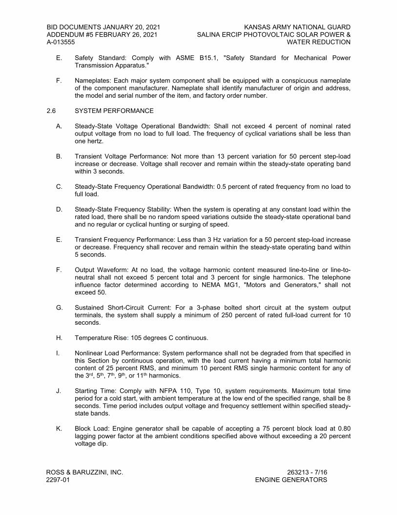
BID DOCUMENTS JANUARY 20, 2021 KANSAS ARMY NATIONAL GUARD ADDENDUM #5 FEBRUARY 26, 2021 SALINA ERCIP PHOTOVOLTAIC SOLAR POWER & A-013555 WATER REDUCTION
ROSS & BARUZZINI, INC. 263213 - 7/16 2297-01 ENGINE GENERATORS
E. Safety Standard: Comply with ASME B15.1, "Safety Standard for Mechanical Power Transmission Apparatus."
F. Nameplates: Each major system component shall be equipped with a conspicuous nameplate of the component manufacturer. Nameplate shall identify manufacturer of origin and address, the model and serial number of the item, and factory order number.
2.6 SYSTEM PERFORMANCE
A. Steady-State Voltage Operational Bandwidth: Shall not exceed 4 percent of nominal rated output voltage from no load to full load. The frequency of cyclical variations shall be less than one hertz.
B. Transient Voltage Performance: Not more than 13 percent variation for 50 percent step-load increase or decrease. Voltage shall recover and remain within the steady-state operating band within 3 seconds.
C. Steady-State Frequency Operational Bandwidth: 0.5 percent of rated frequency from no load to full load.
D. Steady-State Frequency Stability: When the system is operating at any constant load within the rated load, there shall be no random speed variations outside the steady-state operational band and no regular or cyclical hunting or surging of speed.
E. Transient Frequency Performance: Less than 3 Hz variation for a 50 percent step-load increase or decrease. Frequency shall recover and remain within the steady-state operating band within 5 seconds.
F. Output Waveform: At no load, the voltage harmonic content measured line-to-line or line-to-neutral shall not exceed 5 percent total and 3 percent for single harmonics. The telephone influence factor determined according to NEMA MG1, "Motors and Generators," shall not exceed 50.
G. Sustained Short-Circuit Current: For a 3-phase bolted short circuit at the system output terminals, the system shall supply a minimum of 250 percent of rated full-load current for 10 seconds.
H. Temperature Rise: 105 degrees C continuous.
I. Nonlinear Load Performance: System performance shall not be degraded from that specified in this Section by continuous operation, with the load current having a minimum total harmonic content of 25 percent RMS, and minimum 10 percent RMS single harmonic content for any of the 3rd, 5th, 7th, 9th, or 11th harmonics.
J. Starting Time: Comply with NFPA 110, Type 10, system requirements. Maximum total time period for a cold start, with ambient temperature at the low end of the specified range, shall be 8 seconds. Time period includes output voltage and frequency settlement within specified steady-state bands.
K. Block Load: Engine generator shall be capable of accepting a 75 percent block load at 0.80 lagging power factor at the ambient conditions specified above without exceeding a 20 percent voltage dip.

BID DOCUMENTS JANUARY 20, 2021 KANSAS ARMY NATIONAL GUARD ADDENDUM #5 FEBRUARY 26, 2021 SALINA ERCIP PHOTOVOLTAIC SOLAR POWER & A-013555 WATER REDUCTION
ROSS & BARUZZINI, INC. 263213 - 8/16 2297-01 ENGINE GENERATORS
2.7 ENGINE GENERATOR SET
A. Power Output Rating: Nominal ratings as indicated per manufacturer on the drawings, with capacity as required to operate as a unit as evidenced by records of prototype testing.
B. Skid: Heavy duty steel base to maintain alignment of the mounted components without dependence on a concrete foundation. Skid shall be free from sharp edges and corners. Lifting attachments shall be arranged to facilitate lifting with slings without damaging any components.
2.8 CONTROL AND MONITORING
A. Configuration: Operating and safety indications, protective devices, engine gages, basic system controls, and other indicated components shall be grouped in a combination control and power panel. Panel shall be mounted on the generator set unless otherwise indicated. Control and monitoring section of panel shall be isolated from power sections by steel barriers.
B. Ground Fault: Provide ground fault sensing at the generator. The sensor shall be located ahead of the generator service disconnect. Provide a ground fault indication on the engine-generator control panel. Provide an instruction nameplate at the control panel.
1. Instruction nameplate: Provide operational instructions for a ground fault indication as approved by the local Authority Having Jurisdiction.
2.9 Generator Circuit Breaker: Molded or insulated case, service-rated electronic trip type; 100 percent rated breaker complying with NEMA AB1 and UL 489.
A. Tripping Characteristic: Designed specifically for generator protection.
B. Trip Rating: Matched to generator rating.
C. Shunt Trip: Connected to trip breaker when generator is shut down by other protective devices.
D. Mounting: Provide freestanding enclosure or mount integrally with control and monitoring panel.
E. Generator Protector: Microprocessor-based unit shall continuously monitor current level in each phase of generator output, integrate generator heating effect over time, and predict when thermal damage of alternator will occur. When signaled by generator protector or other generator-set protective devices, a shunt-trip device in the generator circuit breaker shall open the circuit breaker to disconnect the generator from load circuits. Protector shall perform the following functions:
1. Initiates a generator overload alarm when generator has operated at an overload equivalent to 110 percent of full-rated load for 60 seconds. Indication for this alarm is integrated with other generator-set malfunction alarms.
2. Under single or three-phase fault conditions, regulates generator to 300 percent of rated full-load current for up to 10 seconds.
3. As overcurrent heating effect on the generator approaches the thermal damage point of the unit, protector switches the excitation system off, opens the generator circuit breaker, and shuts down the generator set.
4. Senses clearing of a fault by other overcurrent devices and controls recovery of rated voltage to avoid overshoot.
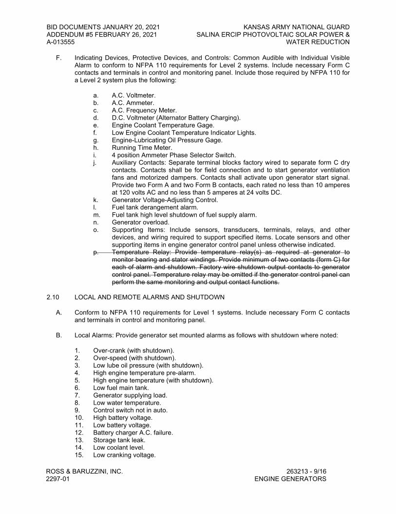
BID DOCUMENTS JANUARY 20, 2021 KANSAS ARMY NATIONAL GUARD ADDENDUM #5 FEBRUARY 26, 2021 SALINA ERCIP PHOTOVOLTAIC SOLAR POWER & A-013555 WATER REDUCTION
ROSS & BARUZZINI, INC. 263213 - 9/16 2297-01 ENGINE GENERATORS
F. Indicating Devices, Protective Devices, and Controls: Common Audible with Individual Visible Alarm to conform to NFPA 110 requirements for Level 2 systems. Include necessary Form C contacts and terminals in control and monitoring panel. Include those required by NFPA 110 for a Level 2 system plus the following:
a. A.C. Voltmeter. b. A.C. Ammeter. c. A.C. Frequency Meter. d. D.C. Voltmeter (Alternator Battery Charging). e. Engine Coolant Temperature Gage. f. Low Engine Coolant Temperature Indicator Lights. g. Engine-Lubricating Oil Pressure Gage. h. Running Time Meter. i. 4 position Ammeter Phase Selector Switch. j. Auxiliary Contacts: Separate terminal blocks factory wired to separate form C dry
contacts. Contacts shall be for field connection and to start generator ventilation fans and motorized dampers. Contacts shall activate upon generator start signal. Provide two Form A and two Form B contacts, each rated no less than 10 amperes at 120 volts AC and no less than 5 amperes at 24 volts DC.
k. Generator Voltage-Adjusting Control. l. Fuel tank derangement alarm. m. Fuel tank high level shutdown of fuel supply alarm. n. Generator overload. o. Supporting Items: Include sensors, transducers, terminals, relays, and other
devices, and wiring required to support specified items. Locate sensors and other supporting items in engine generator control panel unless otherwise indicated.
p. Temperature Relay: Provide temperature relay(s) as required at generator to monitor bearing and stator windings. Provide minimum of two contacts (form C) for each of alarm and shutdown. Factory wire shutdown output contacts to generator control panel. Temperature relay may be omitted if the generator control panel can perform the same monitoring and output contact functions.
2.10 LOCAL AND REMOTE ALARMS AND SHUTDOWN
A. Conform to NFPA 110 requirements for Level 1 systems. Include necessary Form C contacts and terminals in control and monitoring panel.
B. Local Alarms: Provide generator set mounted alarms as follows with shutdown where noted:
1. Over-crank (with shutdown). 2. Over-speed (with shutdown). 3. Low lube oil pressure (with shutdown). 4. High engine temperature pre-alarm. 5. High engine temperature (with shutdown). 6. Low fuel main tank. 7. Generator supplying load. 8. Low water temperature. 9. Control switch not in auto. 10. High battery voltage. 11. Low battery voltage. 12. Battery charger A.C. failure. 13. Storage tank leak. 14. Low coolant level. 15. Low cranking voltage.

BID DOCUMENTS JANUARY 20, 2021 KANSAS ARMY NATIONAL GUARD ADDENDUM #5 FEBRUARY 26, 2021 SALINA ERCIP PHOTOVOLTAIC SOLAR POWER & A-013555 WATER REDUCTION
ROSS & BARUZZINI, INC. 263213 - 10/16 2297-01 ENGINE GENERATORS
C. The above alarms shall be by individually identified visual indications plus a common audible alarm.
D. There shall be a lamp test switch to test all of the above lamps.
E. The remote emergency stop switch shall also shut the unit down.
F. Remote Alarms:
1. Provide a remote generator alarm annunciator for the generator powered from the generator battery, with an individually identified visual indication for any of the following conditions:
a. Over-crank (with shutdown). b. Over-speed (with shutdown). c. Low lube oil pressure (with shutdown). d. High engine temperature pre-alarm. e. High engine temperature (with shutdown). f. Low fuel main tank. g. Low water temperature. h. Control switch not in auto. i. High battery voltage. j. Low battery voltage. k. Battery charger A.C. failure. l. Storage tank leak. m. Low coolant level. n. Low cranking voltage.
2. In addition, a common audible alarm shall sound at the remote annunciator when any of the conditions above is activated. The audible alarm shall be silenceable, but must have a resound feature which will require the restoration of the silence switch to its normal position when the alarm condition has been corrected.
3. The remote annunciator shall also include a lamp test switch.
G. Remote Emergency Stop Switch: Wall-mounted red 2-1/4 inch jumbo mushroom head pushbutton type similar to Allen-Bradley Bulletin 800H with 800T-N247R head. Pushbutton shall be protected from accidental operation with clear cover. The manufacturer shall provide automatic monitoring of the emergency stop switch. Placing this switch in the “Generator Powered Off” status shall initiate a visual and audible alarm at each generator annunciator panel. Provide lamencoid nameplate reading: "Generator Emergency Shutdown."
H. Connection to Building Automation System: A separate terminal block, factory wired to Form C dry contacts, for each alarm and status indication. Provide individual terminal points for each of the annunciator alarms and pre-alarms. Provide an additional terminal point to combine all of the generator alarms under a single terminal point. Provide a permanent label for each terminal point. Each terminal will provide a binary output for the building automation system to read.
2.11 GENERATOR, EXCITER, AND VOLTAGE REGULATOR
A. Comply with NEMA MG 1, "Motors and Generators," and specified performance requirements.
B. Rating: As indicated on the drawings, at 0.8 power factor, 60 Hertz at RPM to match engine rating.

BID DOCUMENTS JANUARY 20, 2021 KANSAS ARMY NATIONAL GUARD ADDENDUM #5 FEBRUARY 26, 2021 SALINA ERCIP PHOTOVOLTAIC SOLAR POWER & A-013555 WATER REDUCTION
ROSS & BARUZZINI, INC. 263213 - 11/16 2297-01 ENGINE GENERATORS
C. Electrical Insulation: All windings shall be Class H insulation applied under a vacuum pressure impregnation (VPI) cycle.
D. Temperature Rise: 105 degrees C continuous.
E. Windings: Two-thirds pitch stator winding and fully linked amortisseur winding.
F. The AC generator shall be re-connectible brushless synchronous, four pole generator with brushless exciter and PMG alternator excitation.
G. Enclosure: ANSI/NEMA MG1, open drip-proof.
H. A permanent magnet generator (PMG) shall provide excitation power to the automatic voltage regulator for immunity from voltage distortion caused by non-linear SCR controlled loads on the generator. The PMG shall sustain main field excitation power for optimum motor starting and to sustain short circuit current as described above under "System Performance."
I. The automatic voltage regulator shall be temperature compensated solid-state design. The voltage regulator shall be equipped with three-phase RMS sensing. The regulator shall control buildup of AC generator voltage to provide a linear rise and limit overshoot. Overvoltage protection shall sense the AC generator output voltage and in the event of regulator failure or loss of reference, shut down regulator output on a sustained overvoltage of one (1) second duration. Overexcitation protection shall sense regulator output and shut down regulator output if overloads exceed ten (10) seconds duration. Both overvoltage and overexcitation protection shutdowns shall be latched, requiring the AC generator to be stopped for reset.
1. The maximum voltage drop shall be 28 percent. 2. Voltage regulation +/-1 percent from no load to full load. Include manual controls to adjust
voltage drop +/-5 percent voltage level, and voltage gain.
J. The regulator shall include an under frequency rolloff torque-matching characteristic, which shall reduce output voltage in proportion to frequency below a threshold of 58-59 HZ. The torque-matching characteristic shall include differential rate of frequency change compensation to use maximum available engine torque and provide optimal transient load response. Regulators which use a fixed volts-per-hertz characteristic are not acceptable.
2.12 OUTDOOR GENERATOR SET ENCLOSURE
A. Provide a prefabricated or pre-engineered, tier 1 sound-attenuated, weatherproof enclosure over unit with the following features:
1. Construction: Reinforced galvanized-steel, metal-clad, integral structural-steel-framed building anchored to a concrete foundation. Structural design and anchorage to comply with ASCE 7 for wind loads up to 100 mph.
2. Hinged doors on opposite sides with cylinder type locks keyed alike. 3. Mount control panel and circuit breaker on inside of housing in such a fashion as to
enable opening of the disconnect door and easy access. 4. Provide louvers in sides and end to allow for engine and generator cooling with screen
and filters to allow proper air flow while at the same time preventing dust, bird and rodent entry.
5. Muffler shall be mounted within the enclosure, stack configuration.

BID DOCUMENTS JANUARY 20, 2021 KANSAS ARMY NATIONAL GUARD ADDENDUM #5 FEBRUARY 26, 2021 SALINA ERCIP PHOTOVOLTAIC SOLAR POWER & A-013555 WATER REDUCTION
ROSS & BARUZZINI, INC. 263213 - 12/16 2297-01 ENGINE GENERATORS
6. Thermal Insulation: Manufacturer’s standard materials and thickness selected in coordination with space heater to maintain winter interior temperature within operating limits as required by engine-generator-set components.
7. Fuel Tank Vent: Provide vent piping from the fuel tank to the exterior of the enclosure.
B. Engine Cooling Airflow through Enclosure: Maintain temperature rise of system components within required limits when unit operates at 110 percent of rated load for 2 hours with ambient temperature at top of range specified in system service conditions.
2.13 VIBRATION ISOLATION DEVICES
A. Restrained Spring Isolators: Freestanding, steel, open-spring isolators with seismic restraint.
1. Housing: Steel with resilient vertical-limit stops to prevent spring extension due to wind loads or if weight is removed; factory-drilled baseplate bonded to 1/4-inch- (6-mm-) thick, elastomeric isolator pad attached to baseplate underside; and adjustable equipment mounting and leveling bolt that acts as blocking during installation.
2. Outside Spring Diameter: Not less than 80 percent of compressed height of the spring at rated load.
3. Minimum Additional Travel: 50 percent of required deflection at rated load. 4. Lateral Stiffness: More than 80 percent of rated vertical stiffness. 5. Overload Capacity: Support 200 percent of rated load, fully compressed, without
deformation or failure.
2.14 PROTOTYPE TESTING
A. Performed on a separate engine generator set at 80 percent lagging power factor using the same engine model, constructed of identical or equivalent components and equipped with identical or equivalent accessories.
1. Load bank test using full load at 80 percent p.f. for 30 minutes.
B. Tests: Conform to those required for Level 1 energy converters in NFPA 110.
C. Seismic Shock Test per NFPA 110.
1. Components and Accessories: Items furnished with installed unit that are not identical to those on tested prototype shall have been acceptably tested to demonstrate compatibility and reliability.
2. Submit evidence of torsional vibration capability in accord with NFPA. 3. Submit the above with shop drawings.
PART 3 - EXECUTION
3.1 INSTALLATION
A. Anchor the generator set on concrete slab or on separate concrete base for outdoor units. Comply with Division 03 for concrete, Division 20 for seismic anchoring and to manufacturer’s recommendations.
B. Maintain minimum working space around components according to NEC Article 110.
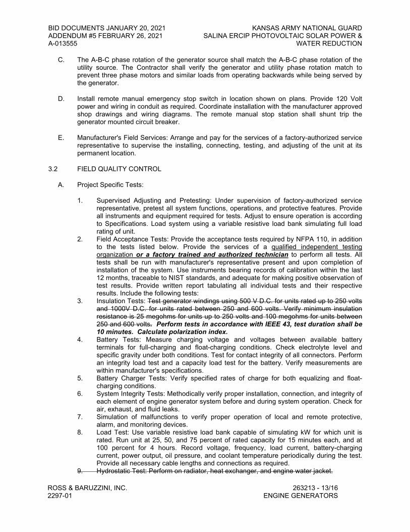
BID DOCUMENTS JANUARY 20, 2021 KANSAS ARMY NATIONAL GUARD ADDENDUM #5 FEBRUARY 26, 2021 SALINA ERCIP PHOTOVOLTAIC SOLAR POWER & A-013555 WATER REDUCTION
ROSS & BARUZZINI, INC. 263213 - 13/16 2297-01 ENGINE GENERATORS
C. The A-B-C phase rotation of the generator source shall match the A-B-C phase rotation of the utility source. The Contractor shall verify the generator and utility phase rotation match to prevent three phase motors and similar loads from operating backwards while being served by the generator.
D. Install remote manual emergency stop switch in location shown on plans. Provide 120 Volt power and wiring in conduit as required. Coordinate installation with the manufacturer approved shop drawings and wiring diagrams. The remote manual stop station shall shunt trip the generator mounted circuit breaker.
E. Manufacturer's Field Services: Arrange and pay for the services of a factory-authorized service representative to supervise the installing, connecting, testing, and adjusting of the unit at its permanent location.
3.2 FIELD QUALITY CONTROL
A. Project Specific Tests:
1. Supervised Adjusting and Pretesting: Under supervision of factory-authorized service representative, pretest all system functions, operations, and protective features. Provide all instruments and equipment required for tests. Adjust to ensure operation is according to Specifications. Load system using a variable resistive load bank simulating full load rating of unit.
2. Field Acceptance Tests: Provide the acceptance tests required by NFPA 110, in addition to the tests listed below. Provide the services of a qualified independent testing organization or a factory trained and authorized technician to perform all tests. All tests shall be run with manufacturer's representative present and upon completion of installation of the system. Use instruments bearing records of calibration within the last 12 months, traceable to NIST standards, and adequate for making positive observation of test results. Provide written report tabulating all individual tests and their respective results. Include the following tests:
3. Insulation Tests: Test generator windings using 500 V D.C. for units rated up to 250 volts and 1000V D.C. for units rated between 250 and 600 volts. Verify minimum insulation resistance is 25 megohms for units up to 250 volts and 100 megohms for units between 250 and 600 volts. Perform tests in accordance with IEEE 43, test duration shall be 10 minutes. Calculate polarization index.
4. Battery Tests: Measure charging voltage and voltages between available battery terminals for full-charging and float-charging conditions. Check electrolyte level and specific gravity under both conditions. Test for contact integrity of all connectors. Perform an integrity load test and a capacity load test for the battery. Verify measurements are within manufacturer's specifications.
5. Battery Charger Tests: Verify specified rates of charge for both equalizing and float-charging conditions.
6. System Integrity Tests: Methodically verify proper installation, connection, and integrity of each element of engine generator system before and during system operation. Check for air, exhaust, and fluid leaks.
7. Simulation of malfunctions to verify proper operation of local and remote protective, alarm, and monitoring devices.
8. Load Test: Use variable resistive load bank capable of simulating kW for which unit is rated. Run unit at 25, 50, and 75 percent of rated capacity for 15 minutes each, and at 100 percent for 4 hours. Record voltage, frequency, load current, battery-charging current, power output, oil pressure, and coolant temperature periodically during the test. Provide all necessary cable lengths and connections as required.
9. Hydrostatic Test: Perform on radiator, heat exchanger, and engine water jacket.

BID DOCUMENTS JANUARY 20, 2021 KANSAS ARMY NATIONAL GUARD ADDENDUM #5 FEBRUARY 26, 2021 SALINA ERCIP PHOTOVOLTAIC SOLAR POWER & A-013555 WATER REDUCTION
ROSS & BARUZZINI, INC. 263213 - 14/16 2297-01 ENGINE GENERATORS
10. Voltage and Frequency Transient Stability Tests: Provide chart recorder to measure voltage, current and frequency transients for 50-percent and 75-percent step-load increases and decreases to verify that performance is as specified in the “System Performance” of this specification.
11. Vibration Baseline Test: Measure amplitude for nominal frequency and for frequencies 5, 10, 15, and 20 percent above and below nominal at each main bearing cap. Vibration levels not exceeding those specified in NEMA MG1, "Motors and Generators," are acceptable. This test is only required in the field when it is necessary to disassemble and re-assemble the engine generator unit after it has been vibration baseline tested at the factory.
12. Exhaust System Back-Pressure Test: Use a manometer with a scale exceeding 40 inches of water. Connect to the exhaust line close to the engine exhaust manifold. Verify that back pressure at full-rated load is within manufacturer's published allowable limits for the engine.
13. The following continuous and simultaneous straight-line recordings versus time, shall be made at a chart speed of no less than fifty millimeters per second. The recorder shall run from at least ten seconds before the test event and until at least ten seconds after the test event.
Phase A RMS current. Phase A to N RMS voltage. Phase B RMS current. Phase B to N RMS voltage. Phase C RMS current. Phase C to N RMS voltage. Frequency of one selected phase.
14. The following simultaneous actual wave shape recordings versus time, shall be made at a chart speed of no less than 200 millimeters per second. The chart recorder shall run from at least five seconds before the test event to at least five seconds after the test event. These recordings do not have to be run at the same time as the above recordings.
Phase A to neutral voltage. Phase A current. Phase B to neutral voltage. Phase B current. Phase C to neutral voltage. Phase C current.
15. Analyzers which indicate only the maximum and minimum values of frequency, current and voltage are not acceptable. In addition to the above recordings, analyzer shall also have digital readout of each input channel, and battery back-up. Provide straight line recordings and wave shape recording. Provide all necessary current transformers, amplifier racks, and other accessories for complete testing. Current transformer primary shall be as close to the generator full load current as possible, without causing saturation of the current transformer or saturation or overload of the analyzer or signal conditioning circuits.
16. A Dranetz-BMI Model #PX5 power analyzer or equivalent. Include 128m Flash Care and "Enterprise" Version software to provide hard copy printouts of measured values. Unit shall have adequate internal storage capacity for all required printouts of test data via a USB port. An alternative rental agency is TRS-REN (1-800-621-6354) or Continental Resources at 1-800-937-4688 or General Electric at 1-800-GE-RENTS. The technical representative for the PX5 is Ed Russo at 1-800-372-6832.
17. All of the above testing shall be scheduled with the Owner and Engineer. Submit test results to Engineer within two weeks of testing.
18. Retest: Correct deficiencies identified by tests and observations and retest until specified requirements are met.
19. In addition, manufacturer shall submit written verification that unit complies with NFPA 110 and that unit performs satisfactorily after installation.

BID DOCUMENTS JANUARY 20, 2021 KANSAS ARMY NATIONAL GUARD ADDENDUM #5 FEBRUARY 26, 2021 SALINA ERCIP PHOTOVOLTAIC SOLAR POWER & A-013555 WATER REDUCTION
ROSS & BARUZZINI, INC. 263213 - 15/16 2297-01 ENGINE GENERATORS
3.3 CONNECTIONS
A. Conduit Connections: All power and control wiring connections to the generator control panel and electrical accessories shall be made with a minimum of 18 inch liquid-tight steel conduit.
3.4 DEMONSTRATION
A. Training: Arrange and pay for the services of a factory-authorized service representative to demonstrate adjustment, operation, and maintenance of the system and to train Owner's personnel.
B. Conduct a minimum of 8 hours of training as specified under Instructions to Owner's Employees in the “Project Closeout” section of these Specifications.
C. Schedule training with at least 7-day advance notice.
3.5 DOCUMENTATION REQUIREMENTS
A. A complete set of "Operations and Maintenance Manuals" shall be furnished for the generator system, including the following:
1. Equipment outline, showing front and side plan views, electrical power one-line diagram, conduit entrances, and equipment ratings.
2. Schematic drawings. 3. Wiring diagrams. 4. Interconnection wiring diagram, showing all field interconnections among generator sets,
circuit breakers and relays, and other remote devices, battery charger and all fuel tanks. 5. Materials list, cross-referenced to schematics for component identification. 6. Narrative sequence of operation description, detailing all possible operating modes. 7. Ladder diagram and program listing for programmable controller with each logic rung
purpose clearly defined, including identification of inputs and outputs. 8. Test Data per Factory and Field Testing. 9. All equipment drawings shall specifically show the interface between the generator,
control and monitoring equipment, and remote devices. Standard or typical drawings are not acceptable.
B. Provide one set each of complete documents to the Engineer and Owner in three-ring binders. This is in addition to submittal requirements of Division 01.
3.6 IDENTIFICATION
A. Identify system components according to Division 26 Section "Electrical Identification."
B. Install permanent sign at building’s utility power service disconnect indicating the type and location of the emergency power source.
If removal of a grounding or bonding connection in the normal power source equipment interrupts the grounding electrode conductor connection to the alternate power source grounded conductor, install a permanent sign at the normal power source equipment stating: WARNING - SHOCK HAZARD EXISTS IF GROUNDING ELECTRODE CONDUCTOR OR BONDING JUMPER CONNECTION IN THIS EQUIPMENT IS REMOVED WHILE ALTERNATE SOURCE(S) IS ENERGIZED.

BID DOCUMENTS JANUARY 20, 2021 KANSAS ARMY NATIONAL GUARD ADDENDUM #5 FEBRUARY 26, 2021 SALINA ERCIP PHOTOVOLTAIC SOLAR POWER & A-013555 WATER REDUCTION
ROSS & BARUZZINI, INC. 263213 - 16/16 2297-01 ENGINE GENERATORS
3.7 CLEANING
A. Upon completion of installation, inspect system components. Remove paint splatters and other spots, dirt, and debris. Touch up scratches and mars of finish to match original finish. Clean components internally using methods and materials recommended by manufacturer.
END OF SECTION 263213

ONE
WAY
B
C
D
E
F
6 5 4 3 2 1
A-013555
Original Size: 1 1/2"
Drawing may have been reduced
0" 1"
Revisions
No. Date Description
789
A
ROSS AND BARUZZINI PROJECT #
THE SEAL AND SIGNATURE APPLY ONLY TO THE
DOCUMENT TO WHICH THEY ARE AFFIXED, AND
EXPRESSLY DISCLAIM ANY RESPONSIBILITY FOR
ALL OTHER PLANS, SPECIFICATIONS, ESTIMATES,
REPORTS, OR OTHER DOCUMENTS OR
INSTRUMENTS RELATING TO OR INTENDED TO BE
USED FOR ANY PART OR PARTS OF THE
ARCHITECTURAL OR ENGINEERING PROJECT.
DR
AW
N B
Y:
CH
EC
KE
DB
Y:
BU
ILD
ING
NU
MB
ER:
320
DA
TE
:
De
pa
rtm
ent of A
dm
inistra
tion
Office of F
acilitie
s &
P
ro
perty M
an
ag
em
ent
De
sign
, C
onstru
ction
, &
C
om
plian
ce
700 S
W H
arriso
n, S
uite 12
00
Top
eka, K
an
sas 666
03
-392
9
Ph
on
e: 78
5-2
96-8
89
9
Fax: 7
85
-29
6-34
56
Plumbing and Electrical Engineers5350 W. 94th Terrace, Suite 102Prairie Village, KS 66207
ROSS & BARUZZINI, INC.
(913) 258-5026
2297-01
Kan
sas
Arm
y N
atio
nal G
uard
Salin
a ER
CIP
Pho
tovo
ltaic
Sola
r Pow
er &
Wat
er R
educ
tion
Nic
kell
Hal
l Bar
rack
s29
30 S
canl
an A
venu
e, S
alin
a, K
S 67
401
1/20
/21
BIDDOCUMENTSUBMITTAL
Civil Engineering and Surveying7101 College Blvd.Overland Park, KS 66210www.ibhc.com (913) 663-1900
B
S
N
D
E
CI
P
R
O
A
S
E
O
F
S
I
K
L
S
NA
N
E
A
22713
C
R
E
I
L
N
ES
Y
E
E
N
I
G
R
D
R
1 2/26/21 Addendum #5
N
00
01 CONCRETE ELECTRICAL EQUIPMENT PAD. SEE STRUCTURAL PLANS
02 OVERLAY OF EXISTING ASPHALT PAVEMENT
03 FULL DEPTH ASPHALT PAVEMENT PATCH (SEE DETAIL 005/C104)
04 SALVAGED WHEEL STOP (SEE DETAIL 023/C104)
05 7' MECHANICAL PAD CHAIN LINK FENCE
06 CONCRETE SIDEWALK REPLACEMENT (SEE DETAIL 014/C104)
07 LEAD FREE, WATER-BORNE EMULSION BASED WHITE TRAFFIC PAINT FOR PARKING LOT STRIPING
08 CHAIN LINK FENCE GATE
09 FULL DEPTH ASPHALT PAVEMENT (SEE DETAIL 005/C104)
10 DO NOT ENTER SIGN
CONSTRUCTION NOTES
SITE LEGEND
ASPHALT PAVEMENT OVERLAY
FULL DEPTH ASPHALT PAVEMENT
CONCRETE PAD
EXISTING BUILDING
01
02
04
C102
SITE PLAN
05
06
06
06
02
02
03
03
03
03
CONCRETE SIDEWALK
07
07
01
05
ZONE C: ALTERNATE 1
ZONE C: ALTERNATE 2ZONE C: ALTERNATE 3
07
07
07
04
09
09
W SCHILLING RD.
SC
AN
LA
N A
VE
.
EXISTING BUILDING
07
10
41.70'
10'
10'
22.82'
21.3
3'
08
08
07
07
07
07
07
1
1
1
02/25/2021

S100
FOUNDATION
PLAN
EA
OR
MH
B
C
D
E
F
6 5 4 3 2 1
A-013555
Original Size: 1 1/2"
Drawing may have been reduced
0" 1"
Revisions
No. Date Description
789
A
ROSS AND BARUZZINI PROJECT #
THE SEAL AND SIGNATURE APPLY ONLY TO THE
DOCUMENT TO WHICH THEY ARE AFFIXED, AND
EXPRESSLY DISCLAIM ANY RESPONSIBILITY FOR
ALL OTHER PLANS, SPECIFICATIONS, ESTIMATES,
REPORTS, OR OTHER DOCUMENTS OR
INSTRUMENTS RELATING TO OR INTENDED TO BE
USED FOR ANY PART OR PARTS OF THE
ARCHITECTURAL OR ENGINEERING PROJECT.
DR
AW
N B
Y:
CH
EC
KE
D B
Y:
BU
IL
DIN
G N
UM
BE
R: 3
20
DA
TE
:
De
pa
rtm
en
t o
f A
dm
in
istra
tio
n
Office
o
f F
acilitie
s &
P
ro
pe
rty M
an
ag
em
en
t
De
sig
n, C
on
stru
ctio
n, &
C
om
plia
nce
70
0 S
W H
arriso
n, S
uite
1
20
0
To
pe
ka
, K
an
sa
s 6
66
03
-3
92
9
Ph
on
e: 7
85
-2
96
-8
89
9
Fa
x: 7
85
-2
96
-3
45
6
Plumbing and Electrical Engineers
5350 W. 94th Terrace, Suite 102
Prairie Village, KS 66207
ROSS & BARUZZINI, INC.
(913) 258-5026
2297-01
Kan
sas A
rm
y N
atio
nal G
uard
Sa
lin
a E
RC
IP
P
ho
to
vo
lta
ic
So
la
r P
ow
er &
W
ate
r R
ed
uc
tio
n
Nic
ke
ll H
all B
arra
ck
s
29
30
S
ca
nla
n A
ve
nu
e, S
alin
a, K
S 6
74
01
01
/2
0/2
1
BID DOCUMENT
SUBMITTAL
Civil Engineering and Surveying
7101 College Blvd.
Overland Park, KS 66210
www.ibhc.com
(913) 663-1900
NOT FOR
CONSTRUCTION
1 2/26/21 Addendum #5
NOT FOR
CONSTRUCTION

B
C
D
E
F
6 5 4 3 2 1
A-013555
Original Size: 1 1/2"
Drawing may have been reduced
0" 1"
Revisions
No. Date Description
789
A
ROSS AND BARUZZINI PROJECT #
THE SEAL AND SIGNATURE APPLY ONLY TO THE
DOCUMENT TO WHICH THEY ARE AFFIXED, AND
EXPRESSLY DISCLAIM ANY RESPONSIBILITY FOR
ALL OTHER PLANS, SPECIFICATIONS, ESTIMATES,
REPORTS, OR OTHER DOCUMENTS OR
INSTRUMENTS RELATING TO OR INTENDED TO BE
USED FOR ANY PART OR PARTS OF THE
ARCHITECTURAL OR ENGINEERING PROJECT.
DR
AW
N B
Y:
CH
EC
KE
D B
Y:
BU
IL
DIN
G N
UM
BE
R: 3
20
DA
TE
:
De
pa
rtm
en
t o
f A
dm
in
istra
tio
n
Office
o
f F
acilitie
s &
P
ro
pe
rty M
an
ag
em
en
t
De
sig
n, C
on
stru
ctio
n, &
C
om
plia
nce
70
0 S
W H
arriso
n, S
uite
1
20
0
To
pe
ka
, K
an
sa
s 6
66
03
-3
92
9
Ph
on
e: 7
85
-2
96
-8
89
9
Fa
x: 7
85
-2
96
-3
45
6
Plumbing and Electrical Engineers
5350 W. 94th Terrace, Suite 102
Prairie Village, KS 66207
ROSS & BARUZZINI, INC.
(913) 258-5026
2297-01
Kan
sas A
rm
y N
atio
nal G
uard
Sa
lin
a E
RC
IP
P
ho
to
vo
lta
ic
So
la
r P
ow
er &
W
ate
r R
ed
uc
tio
n
Nic
ke
ll H
all B
arra
ck
s
29
30
S
ca
nla
n A
ve
nu
e, S
alin
a, K
S 6
74
01
01
/2
0/2
1
BID DOCUMENT
SUBMITTAL
Civil Engineering and Surveying
7101 College Blvd.
Overland Park, KS 66210
www.ibhc.com
(913) 663-1900
NOT FOR
CONSTRUCTION
1 2/26/21 Addendum #5
S101
FRAMING PLAN
EA
OR
MH
NOT FOR
CONSTRUCTION
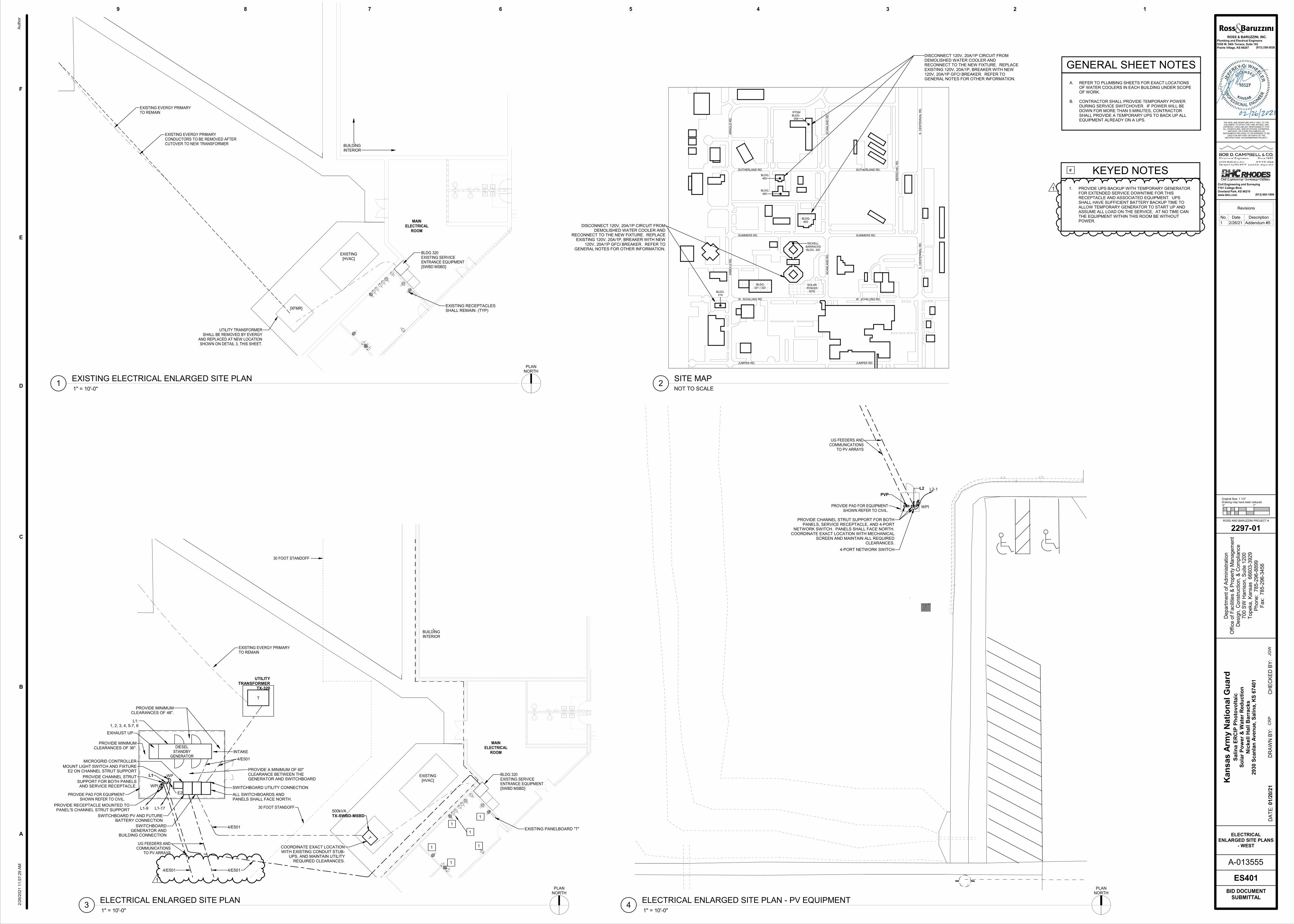
20691257.22UE
20681257.12UE
20671257.04UE
20661256.64UE
20651255.34WL
20641255.92WL1
20631255.78WL WL1 -B
20591256.49UE
20581256.05WL
20541256.14UE -B
20111255.47EC
T
T
20691257.22UE
20681257.12UE
20671257.04UE
20661256.64UE
20651255.34WL
20641255.92WL1
20631255.78WL WL1 -B
20591256.49UE
20581256.05WL
20541256.14UE -B
20111255.47EC
25261254.28HC
25251254.39HC
24041254.34EA TOE -B
24011254.25EA
24001254.13FL EA
23961253.99FL
23951254.14EA
23941254.08EA
23931253.85FL
23871255.75WA
23861255.20TOP SW1
23851255.36TOP
23811255.48TOP
23801255.65WA
23791255.98WA
23781255.77TOP
23771255.99WA
23761256.33WA
23731256.10TOP
23721256.23WA
23711256.57WA
23701256.53WA
23691256.86WA
23681256.31TOP2367
1256.42TOP -PT
23661256.74WA -PT
23631256.70WA
23621256.33TOP
23611256.36TOP -PT -PC
23601256.71WA -PT -PC
23571256.72WA
23561256.22TOP
23551256.09TOP -PC
23541256.74WA -PC23531256.39WA
23501256.40WA23491256.07WA
23481255.81TOP
23471255.54TOP
23461256.10WA23451255.76WA
23421255.72WA
23411255.38WA
23401255.23TOP
23391254.70TOP
23381255.39WA -B /FRONT FACE 9IN WIDE BLOCK WALL
23371254.70TOP
23341253.65FL
23331254.10EA
23321254.08EA
23311253.58FL
23261253.41FL
23251254.12EA
23241254.16EA -B
23231253.26FL -B
23211254.47TOP1
23201253.24TOE1
23191253.37TOE
23181254.41TOP
23131254.72TOP1
23121253.34TOE1
23111253.55TOE
23101254.77TOP
23091254.87TOP
23081253.31TOE
23061253.81TOE1
23051254.84TOP1
23041254.80TOP1
23031252.93TOE1
23021253.40TOE
23011254.50TOP
23001253.96TOP
22991252.54TOE
22981252.57TOE
22971252.04TOE12296
1251.97TOE1
22951252.48TOE1
22941255.04TOP1
22931254.99TOP1
22881252.38TOE1
22871252.74TOE
22861254.39TOP
22771254.37TOP
22761252.71TOE
22751252.77TOE1
22701252.75TOE1
22691252.89TOE
22681254.40TOP
2264
1255.65TD7
7"
22591254.44TOP
22581252.84TOE
22571252.80TOE1
22521252.74TOE1
22511252.75TOE
22501254.64TOP
22361254.66TOP
22351252.76TOE
22341252.84TOE1
13031251.72RC24
13021252.06FL1
12811252.96FL1
12801253.33FL1
12731254.55RIE
12721254.55RIE
12711254.60UP OU
12691254.71EC -E SW1
12681253.50EC
12671253.47EC
12661254.68EC
12621253.23FL -E
12611254.19EA1 -E
12591253.28HD8 FL1
12581253.23HD8 FL1
12571253.28FL FL1 -B
12551254.14EA1
12541254.20EA1 SW1 -B
12121254.79EC SW -B
12111254.79EA1 EC -B
PROVIDE PAD FOR EQUIPMENT SHOWN REFER TO CIVIL.
30 FOOT STANDOFF
DIESEL STANDBY
GENERATOR
30 FOOT STANDOFF
UG FEEDERS AND COMMUNICATIONS
TO PV ARRAYS
MAIN
ELECTRICAL
ROOM
BUILDINGINTERIOR
TX-SWBD-MSBD
UTILITY
TRANSFORMERTX-320
EXISTING EVERGY PRIMARY TO REMAIN
500kVA
BLDG 320EXISTING SERVICE ENTRANCE EQUIPMENT[SWBD MSBD]
EXISTING [HVAC]
L1
L1:1, 2, 3, 4, 5-7, 6
COORDINATE EXACT LOCATION WITH EXISTING CONDUIT STUB-
UPS, AND MAINTAIN UTILITY REQUIRED CLEARANCES.
MICROGRID CONTROLLER
SWITCHBOARD UTILITY CONNECTION
SWITCHBOARD GENERATOR AND
BUILDING CONNECTION
SWITCHBOARD PV AND FUTURE BATTERY CONNECTION
ALL SWITCHBOARDS AND PANELS SHALL FACE NORTH.
PROVIDE CHANNEL STRUT SUPPORT FOR BOTH PANELS AND SERVICE RECEPTACLE.
PROVIDE MINIMUM CLEARANCES OF 48".
PROVIDE MINIMUM CLEARANCES OF 36".
PROVIDE A MINIMUM OF 60" CLEARANCE BETWEEN THE GENERATOR AND SWITCHBOARD
EXHAUST UP
INTAKE
WPI
PROVIDE RECEPTACLE MOUNTED TO PANEL'S CHANNEL STRUT SUPPORT L1-9
E2
WP
MOUNT LIGHT SWITCH AND FIXTURE E2 ON CHANNEL STRUT SUPPORT
L1-17
1
1
1
1
1
1EXISTING PANELBOARD "T"
4/E501
4/E501
4/E5014/E501
1
BLDG 320EXISTING SERVICE ENTRANCE EQUIPMENT[SWBD MSBD]
UTILITY TRANSFORMERSHALL BE REMOVED BY EVERGY
AND REPLACED AT NEW LOCATION SHOWN ON DETAIL 3, THIS SHEET.
EXISTING EVERGY PRIMARY CONDUCTORS TO BE REMOVED AFTER CUTOVER TO NEW TRANSFORMER
MAIN
ELECTRICAL
ROOM
EXISTING [HVAC]
BUILDINGINTERIOR
EXISTING EVERGY PRIMARY TO REMAIN
[XFMR]EXISTING RECEPTACLES SHALL REMAIN. (TYP)
PVP
L2
WPI
L2-1
PROVIDE CHANNEL STRUT SUPPORT FOR BOTH PANELS, SERVICE RECEPTACLE, AND 4-PORT
NETWORK SWITCH. PANELS SHALL FACE NORTH. COORDINATE EXACT LOCATION WITH MECHANICAL
SCREEN AND MAINTAIN ALL REQUIRED CLEARANCES.
UG FEEDERS AND COMMUNICATIONS
TO PV ARRAYS
4-PORT NETWORK SWITCH
PROVIDE PAD FOR EQUIPMENT SHOWN REFER TO CIVIL.
W. SCHILLING RD. W. SCHILLING RD.
JUMPER RD. JUMPER RD.
SUMMERS RD. SUMMERS RD.
SUTHERLAND RD. SUTHERLAND RD.
AR
NO
LD
RD
. A
RN
OLD
RD
.
S.
CE
NT
EN
NIA
L R
D.
S.
CE
NT
EN
NIA
L R
D.
SC
AN
LA
ND
RD
. S
CA
NLA
ND
RD
.
BE
RS
CH
EL R
D.
BLDG. 219
BLDG. 321 / 322
NICKELLBARRACKSBLDG. 320
BLDG. 450
BLDG. 465
BLDG. 460
RTSM BLDG.
558
SOLAR POWER
SITE
DISCONNECT 120V, 20A/1P CIRCUIT FROM DEMOLISHED WATER COOLER AND RECONNECT TO THE NEW FIXTURE. REPLACE EXISTING 120V, 20A/1P, BREAKER WITH NEW 120V, 20A/1P GFCI BREAKER. REFER TO GENERAL NOTES FOR OTHER INFORMATION.
DISCONNECT 120V, 20A/1P CIRCUIT FROM DEMOLISHED WATER COOLER AND
RECONNECT TO THE NEW FIXTURE. REPLACE EXISTING 120V, 20A/1P, BREAKER WITH NEW
120V, 20A/1P GFCI BREAKER. REFER TO GENERAL NOTES FOR OTHER INFORMATION.
B
C
D
E
F
6 5 4 3 2 1
A-013555
Original Size: 1 1/2"Drawing may have been reduced0" 1"
789
A
ROSS AND BARUZZINI PROJECT #
THE SEAL AND SIGNATURE APPLY ONLY TO THE DOCUMENT TO WHICH THEY ARE AFFIXED, AND
EXPRESSLY DISCLAIM ANY RESPONSIBILITY FOR ALL OTHER PLANS, SPECIFICATIONS, ESTIMATES,
REPORTS, OR OTHER DOCUMENTS OR INSTRUMENTS RELATING TO OR INTENDED TO BE
USED FOR ANY PART OR PARTS OF THE ARCHITECTURAL OR ENGINEERING PROJECT.
DR
AW
N B
Y:
CH
EC
KE
D B
Y:
DA
TE
:
Depart
ment
of
Adm
inis
tration
Off
ice o
f F
acili
ties &
Pro
pert
y M
anagem
ent
Desig
n,
Constr
uction,
& C
om
plia
nce
700 S
W H
arr
ison,
Suite 1
200
Topeka,
Kansas
66603-3
929
Phone:
785-2
96-8
899
Fax:
785-2
96-3
456
Plumbing and Electrical Engineers
5350 W. 94th Terrace, Suite 102
Prairie Village, KS 66207
ROSS & BARUZZINI, INC.
(913) 258-5026
2297-01
Kan
sas
Arm
y N
ati
on
al
Gu
ard
Sali
na E
RC
IP P
ho
tovo
ltaic
S
ola
r P
ow
er
& W
ate
r R
ed
ucti
on
Nic
kell
Hall
Barr
acks
2930 S
can
lan
Aven
ue,
Sali
na,
KS
67401
01/2
0/2
1
BID DOCUMENT SUBMITTAL
Civil Engineering and Surveying
7101 College Blvd.
Overland Park, KS 66210
www.ibhc.com (913) 663-1900
CR
PJG
W
2/2
6/2
02
1 1
1:5
7:2
9 A
M
ES401
ELECTRICAL
ENLARGED SITE PLANS- WEST
Auth
or
1" = 10'-0"3
ELECTRICAL ENLARGED SITE PLAN
PLAN NORTH
1" = 10'-0"1
EXISTING ELECTRICAL ENLARGED SITE PLAN
PLAN NORTH
1" = 10'-0"4
ELECTRICAL ENLARGED SITE PLAN - PV EQUIPMENT
PLAN NORTH
NOT TO SCALE2
SITE MAP
A. REFER TO PLUMBING SHEETS FOR EXACT LOCATIONS OF WATER COOLERS IN EACH BUILDING UNDER SCOPE OF WORK.
B. CONTRACTOR SHALL PROVIDE TEMPORARY POWER DURING SERVICE SWITCHOVER. IF POWER WILL BE DOWN FOR MORE THAN 5 MINUTES, CONTRACTOR SHALL PROVIDE A TEMPORARY UPS TO BACK UP ALL EQUIPMENT ALREADY ON A UPS.
GENERAL SHEET NOTES
KEYED NOTES#
1. PROVIDE UPS BACKUP WITH TEMPORARY GENERATOR FOR EXTENDED SERVICE DOWNTIME FOR THIS RECEPTACLE AND ASSOCIATED EQUIPMENT. UPS SHALL HAVE SUFFICIENT BATTERY BACKUP TIME TO ALLOW TEMPORARY GENERATOR TO START UP AND ASSUME ALL LOAD ON THE SERVICE. AT NO TIME CAN THE EQUIPMENT WITHIN THIS ROOM BE WITHOUT POWER.
Revisions
No. Date Description
1 2/26/21 Addendum #5
1
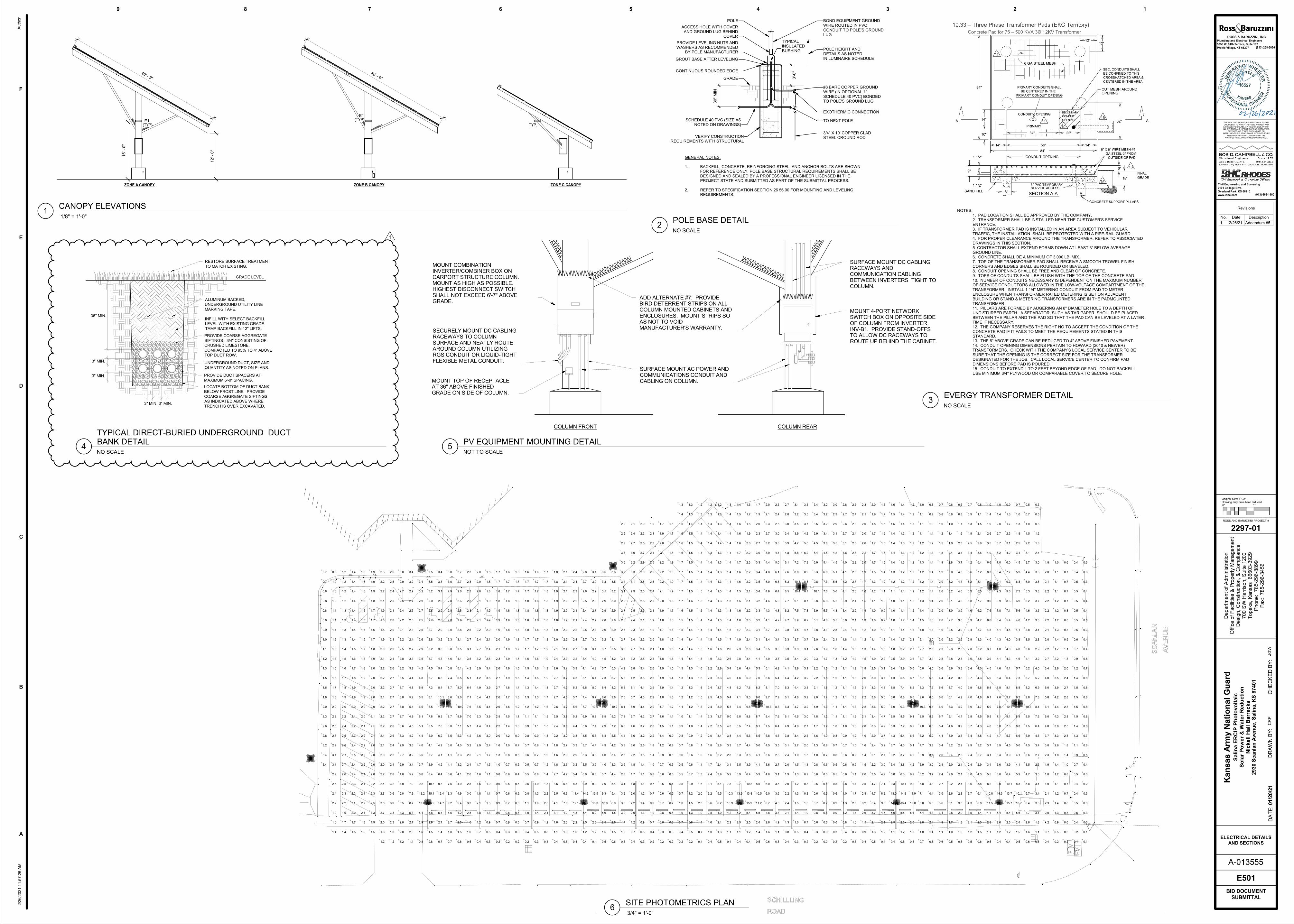
3" MIN.3" MIN.
3" MIN.
3" MIN.
36" MIN.
GRADE LEVEL
PROVIDE COARSE AGGREGATE
SIFTINGS - 3/4" CONSISTING OF
CRUSHED LIMESTONE,
COMPACTED TO 95% TO 4" ABOVE
TOP DUCT ROW.
PROVIDE DUCT SPACERS AT
MAXIMUM 5'-0" SPACING.
LOCATE BOTTOM OF DUCT BANK
BELOW FROST LINE. PROVIDE
COARSE AGGREGATE SIFTINGS
AS INDICATED ABOVE WHERE
TRENCH IS OVER EXCAVATED.
INFILL WITH SELECT BACKFILL
LEVEL WITH EXISTING GRADE.
TAMP BACKFILL IN 12" LIFTS.
RESTORE SURFACE TREATMENT
TO MATCH EXISTING.
ALUMINUM BACKED,
UNDERGROUND UTILITY LINE
MARKING TAPE.
UNDERGROUND DUCT, SIZE AND
QUANTITY AS NOTED ON PLANS.
0.1 0.1
0.1
5.5
5.0
5.1
8.7
7.9
7.0
5.2
5.1
5.2
5.1
13.9
13.2
9.2
6.0
5.1
6.1
6.5
6.5
5.9
5.8
16.9
15.1
10.3
6.4
5.0
6.5
7.8
8.5
8.1
7.3
5.7
5.4
14.7
13.4
9.8
6.4
6.2
7.8
9.3
10.4
10.1
8.4
6.8
5.4
5.6
9.2
8.3
7.5
5.6
5.0
6.5
8.0
8.7
8.4
8.6
8.7
7.4
5.8
5.4
5.3
7.1
8.9
10.0
9.6
8.0
6.5
5.1
5.7
7.0
7.6
7.1
6.4
5.1
5.3
5.5
5.4
7.0
6.3
5.8
12.1
11.4
8.3
5.4
5.2
5.6
5.7
5.2
5.4
15.9
14.6
9.9
6.0
5.6
6.9
7.7
7.4
6.6
5.1
5.2
15.3
13.5
9.9
6.3
5.6
7.4
8.9
10.0
9.7
8.0
6.4
5.6
10.0
9.3
7.9
5.7
6.4
7.9
8.5
8.0
8.6
8.4
7.3
5.7
6.0
5.4
5.4
5.5
7.2
9.2
10.2
9.8
8.2
6.7
5.3
6.0
7.2
8.1
7.6
6.8
5.3
5.7
5.9
5.7
5.1
6.2
5.5
5.4
10.9
10.3
7.8
5.2
5.0
5.3
5.4
5.2
15.4
13.9
9.7
5.9
5.5
6.8
7.4
7.1
6.2
5.4
15.9
13.8
10.2
6.4
5.6
7.4
8.8
9.8
9.3
7.6
5.9
5.5
11.2
10.5
8.5
5.9
5.0
6.5
8.1
8.7
8.8
9.0
8.2
7.0
5.3
6.7
6.0
6.0
5.8
7.5
9.4
10.3
9.7
8.1
6.6
5.1
5.0
6.4
7.6
8.5
7.9
7.0
5.4
5.9
6.4
6.5
6.1
5.0
6.1
6.3
6.1
5.3
6.2
7.7
8.5
8.3
7.6
6.1
5.9
7.5
9.1
10.4
10.3
8.8
7.2
5.8
6.2
7.8
8.7
8.7
8.8
8.9
7.8
6.2
5.0
5.1
6.9
8.8
10.1
9.8
8.3
6.9
5.4
5.5
6.9
7.6
7.3
6.8
5.4
5.2
5.6
5.5
5.1
5.4 9.3
8.8
7.1
5.0
5.0
5.0
14.5
13.0
9.3
5.8
5.3
6.5
7.0
6.8
5.8
5.5
16.4
14.8
10.4
6.3
5.4
7.2
8.5
9.3
8.8
7.4
5.5
5.4
13.0
11.9
9.2
6.2
5.1
6.6
8.2
9.1
9.8
9.5
8.2
6.7
5.0
5.4
8.0
7.1
6.8
5.2
6.2
7.8
9.5
10.3
9.6
8.3
6.7
5.0
5.0
5.0
6.8
8.2
9.1
8.5
7.3
5.5
5.4
6.7
6.9
6.6
5.6
5.1
5.3
5.1
5.8
6.3
6.2
5.6
6.8
6.1
5.8
6.2
7.7
8.5
8.1
7.2
5.4
11.5
10.8
8.2
5.5
5.5
5.9
6.1
5.5
6.0
7.6
9.0
10.1
9.9
8.3
6.6
5.4
15.6
14.3
9.9
6.0
5.8
7.1
7.8
7.6
6.8
5.4
5.1
6.4
7.8
8.9
9.3
9.1
8.4
7.0
5.2
5.4
15.7
13.7
10.1
6.4
5.7
7.6
9.1
10.1
9.7
8.1
6.4
5.1
5.4
7.1
8.6
9.6
9.2
7.7
6.0
5.6
10.7
10.1
8.3
5.9
5.0
6.6
8.3
8.9
9.1
9.2
8.5
7.3
5.7
5.6
6.9
7.3
6.8
5.9
6.4
5.7
5.8
5.9
7.5
9.5
10.3
9.8
8.2
6.7
5.2
5.2
5.3
5.0
6.4
7.6
8.4
7.8
6.9
5.2
6.0
6.1
5.8
5.0
3.4
3.4
3.2
2.8
2.6
2.3
2.0
1.8
1.6
1.5
1.3
1.2
1.1
1.0
0.9
0.9
0.8
0.8
0.8
0.7
0.7
1.4
1.6
1.9
2.2
2.4
2.6
2.9
3.1
3.1
2.9
2.7
2.5
2.2
2.0
1.8
1.7
1.6
1.5
1.3
1.3
1.2
1.1
1.1
1.1
1.0
1.0
1.0
0.9
1.4
1.7
1.9
2.2
2.3
2.5
2.6
2.7
2.7
2.6
2.5
2.4
2.2
2.0
1.9
1.8
1.7
1.6
1.5
1.4
1.3
1.3
1.3
1.3
1.2
1.2
1.2
1.2
1.5
1.7
2.0
2.1
2.2
2.3
2.4
2.4
2.5
2.4
2.3
2.2
2.1
2.0
1.9
1.9
1.8
1.7
1.6
1.5
1.4
1.4
1.4
1.4
1.4
1.4
1.4
1.4
1.5
1.8
2.1
2.2
2.1
2.1
2.1
2.2
2.2
2.2
2.2
2.1
2.0
2.0
1.9
1.9
1.9
1.8
1.8
1.7
1.5
1.5
1.5
1.6
1.6
1.6
1.6
1.6
1.5
1.9
2.3
2.5
2.3
2.2
2.0
2.0
2.0
2.0
2.1
2.1
2.1
2.0
2.0
2.0
2.0
2.0
1.9
1.8
1.7
1.6
1.7
1.7
1.8
1.9
1.9
1.9
1.2
1.6
2.0
2.7
3.0
2.8
2.4
2.2
2.0
2.0
2.1
2.1
2.2
2.2
2.2
2.1
2.2
2.2
2.2
2.1
2.0
1.9
1.8
1.8
1.9
2.1
2.2
2.2
2.3
1.2
1.8
2.3
3.3
3.9
3.6
3.2
2.8
2.4
2.2
2.4
2.6
2.6
2.7
2.7
2.7
2.7
2.7
2.6
2.4
2.2
2.1
2.0
2.0
2.1
2.3
2.4
2.5
2.6
1.2
2.0
2.8
4.3
4.9
4.0
2.9
2.7
2.9
3.3
3.6
3.7
3.8
3.8
3.7
3.5
3.2
2.8
2.5
2.2
2.1
2.2
2.4
2.5
2.7
2.9
3.0
1.1
2.0
2.7
3.4
3.2
3.6
4.2
4.5
4.9
4.8
4.4
3.9
3.3
2.7
2.4
2.3
2.3
2.5
2.7
2.9
3.2
3.4
0.8
1.6
2.9
3.7
3.5
4.0
4.4
4.8
4.2
3.5
2.9
2.6
2.5
2.5
2.7
2.9
3.2
3.4
3.5
0.8
1.5
2.9
3.9
3.7
4.1
4.5
3.7
3.2
2.8
2.7
2.7
2.8
3.0
3.2
3.5
3.5
0.7
1.4
2.7
4.2
4.1
4.9
4.3
3.6
3.2
2.9
2.8
2.9
2.9
3.1
3.3
3.4
0.7
1.8
2.7
4.1
4.1
4.6
3.8
3.3
3.0
2.8
2.8
2.8
2.9
3.0
3.0
0.6
1.5
2.5
4.2
4.9
4.9
4.1
3.2
3.3
4.0
4.1
3.5
3.1
2.8
2.6
2.6
2.6
2.6
2.7
2.7
0.5
1.0
1.6
2.8
3.3
3.0
2.8
2.6
2.4
2.5
3.2
4.2
4.2
3.5
3.1
2.7
2.5
2.3
2.3
2.3
2.3
2.3
2.3
0.4
0.7
1.2
1.8
2.1
1.8
1.6
1.6
1.7
2.1
2.9
3.6
4.4
4.9
4.2
3.9
3.2
2.7
2.4
2.2
2.1
2.1
2.1
2.0
2.0
2.0
0.3
0.5
0.9
1.3
1.3
1.1
1.0
1.1
1.3
1.7
2.4
3.0
3.4
3.9
4.1
4.1
3.9
3.8
3.4
2.8
2.4
2.1
2.0
1.9
1.9
1.9
1.8
1.8
1.8
0.2
0.4
0.7
0.9
0.9
0.7
0.6
0.8
1.0
1.3
1.6
2.0
2.2
2.5
2.6
2.6
2.7
2.7
2.6
2.3
2.1
2.0
1.9
1.9
1.9
1.8
1.8
1.7
1.7
0.2
0.3
0.6
0.8
0.7
0.6
0.5
0.6
0.7
0.8
1.0
1.2
1.4
1.5
1.6
1.7
1.8
1.9
1.9
1.9
1.9
1.9
1.8
1.9
1.8
1.8
1.7
1.7
1.6
0.2
0.3
0.6
0.8
0.8
0.6
0.5
0.4
0.5
0.6
0.7
0.9
1.0
1.1
1.2
1.3
1.4
1.5
1.6
1.7
1.7
1.8
1.8
1.8
1.8
1.8
1.7
1.7
1.6
0.2
0.4
0.7
1.0
1.1
0.8
0.6
0.5
0.5
0.6
0.7
0.8
0.9
1.1
1.2
1.3
1.3
1.4
1.5
1.6
1.7
1.7
1.8
1.8
1.8
1.8
1.7
1.7
1.6
0.3
0.5
0.9
1.4
1.6
1.3
1.0
0.8
0.7
0.7
0.8
0.9
1.1
1.1
1.2
1.3
1.4
1.5
1.6
1.6
1.7
1.7
1.8
1.8
1.8
1.8
1.7
1.7
1.6
0.4
0.8
1.2
2.1
2.5
2.2
1.8
1.4
1.2
1.0
1.1
1.3
1.5
1.5
1.6
1.7
1.8
1.9
1.9
1.9
1.9
1.8
1.8
1.8
1.8
1.8
1.8
1.7
1.7
0.4
1.1
1.8
3.1
4.1
3.5
3.5
2.7
1.8
1.6
1.8
2.2
2.4
2.5
2.6
2.7
2.7
2.7
2.6
2.4
2.1
2.0
1.9
1.8
1.9
1.9
1.9
1.8
1.8
0.5
1.3
2.0
4.2
4.2
2.6
2.3
2.7
3.2
3.6
3.9
4.2
4.3
4.0
3.7
3.4
2.9
2.4
2.2
2.0
1.9
2.0
2.0
2.1
2.1
2.1
0.4
1.0
2.2
4.3
3.2
2.9
3.3
3.8
4.4
4.3
3.9
3.2
2.7
2.4
2.2
2.1
2.1
2.2
2.3
2.4
2.4
0.4
1.2
2.5
3.5
3.3
3.7
4.5
4.1
3.4
3.0
2.7
2.5
2.4
2.4
2.5
2.6
2.7
2.8
0.4
1.2
2.5
3.9
3.8
4.4
4.9
4.0
3.4
3.0
2.8
2.7
2.7
2.8
2.9
3.0
3.1
0.5
1.5
2.5
4.0
4.0
4.9
4.5
3.7
3.2
2.9
2.8
2.9
2.9
3.1
3.3
3.5
0.6
1.5
2.6
4.5
4.4
3.3
3.4
4.2
4.2
3.5
3.1
2.9
2.8
2.9
3.0
3.2
3.5
3.6
0.5
1.0
1.7
3.0
3.6
3.2
3.1
2.8
2.5
2.6
3.3
4.4
4.2
3.5
3.0
2.7
2.6
2.6
2.7
2.9
3.1
3.4
3.6
3.5
3.3
2.9
2.5
2.2
0.4
0.7
1.2
2.0
2.2
2.0
1.8
1.7
1.8
2.2
3.0
3.6
4.6
4.2
3.8
3.2
2.7
2.4
2.3
2.4
2.5
2.7
2.9
3.1
3.3
3.2
3.0
2.7
2.4
2.1
0.3
0.5
0.9
1.3
1.4
1.2
1.1
1.1
1.4
1.8
2.5
3.2
3.7
4.2
4.4
4.3
4.1
3.8
3.4
2.8
2.4
2.2
2.1
2.1
2.3
2.5
2.6
2.8
2.9
2.9
2.7
2.5
2.3
2.0
0.2
0.4
0.7
1.0
0.9
0.7
0.7
0.8
1.0
1.4
1.8
2.2
2.5
2.7
2.9
2.9
2.9
2.8
2.6
2.3
2.1
2.0
1.9
1.9
2.1
2.3
2.4
2.5
2.5
2.5
2.4
2.3
2.1
1.9
0.2
0.3
0.6
0.8
0.7
0.6
0.5
0.6
0.7
0.9
1.2
1.4
1.5
1.6
1.7
1.8
1.9
1.9
1.9
1.8
1.8
1.8
1.7
1.8
1.9
2.0
2.1
2.2
2.2
2.2
2.1
2.0
1.9
1.7
0.2
0.3
0.6
0.8
0.7
0.5
0.4
0.5
0.5
0.6
0.8
0.9
1.1
1.1
1.2
1.3
1.4
1.4
1.5
1.5
1.5
1.5
1.6
1.6
1.7
1.8
1.9
1.9
1.9
1.9
1.8
1.8
1.7
1.6
0.2
0.4
0.7
1.0
1.0
0.7
0.5
0.5
0.5
0.6
0.7
0.8
0.9
1.0
1.1
1.2
1.2
1.3
1.3
1.4
1.4
1.4
1.5
1.5
1.6
1.7
1.7
1.7
1.7
1.7
1.6
1.6
1.6
1.5
1.4
1.3
0.2
0.5
0.8
1.3
1.5
1.2
0.9
0.7
0.6
0.6
0.8
0.9
1.0
1.1
1.2
1.2
1.3
1.3
1.3
1.4
1.4
1.4
1.4
1.5
1.5
1.6
1.5
1.5
1.5
1.5
1.5
1.5
1.5
1.4
1.3
1.3
0.4
0.7
1.1
1.9
2.3
2.0
1.6
1.3
1.1
1.0
1.1
1.2
1.4
1.4
1.5
1.5
1.6
1.6
1.6
1.5
1.5
1.4
1.4
1.4
1.5
1.5
1.5
1.4
1.4
1.4
1.4
1.4
1.4
1.4
1.3
1.2
0.4
1.0
1.6
2.8
3.6
3.2
3.1
2.4
1.7
1.6
1.8
2.0
2.2
2.3
2.4
2.5
2.4
2.3
2.2
1.9
1.6
1.5
1.4
1.4
1.4
1.4
1.4
1.4
1.4
1.4
1.3
1.4
1.4
1.4
1.3
1.2
0.5
1.3
2.1
4.0
3.9
2.4
2.2
2.6
3.1
3.5
3.7
3.9
4.0
3.7
3.3
2.9
2.3
1.8
1.5
1.4
1.3
1.3
1.3
1.3
1.3
1.3
1.3
1.3
1.4
1.4
1.3
1.3
1.2
0.4
1.1
2.2
4.2
3.1
2.8
3.3
3.8
4.3
4.8
4.0
3.4
2.6
2.0
1.7
1.5
1.4
1.3
1.3
1.4
1.4
1.4
1.4
1.4
1.4
1.4
1.4
1.4
1.3
0.4
1.1
2.5
3.5
3.3
3.7
4.4
4.6
3.6
2.8
2.3
1.9
1.7
1.6
1.6
1.5
1.5
1.6
1.6
1.7
1.7
1.6
1.6
1.6
1.5
1.4
0.4
1.2
2.5
3.9
3.8
4.4
4.4
3.4
2.8
2.4
2.3
2.3
2.2
2.1
2.1
2.2
2.2
2.3
2.2
2.0
1.9
1.8
1.7
1.6
0.5
1.4
2.4
4.1
4.1
4.1
3.4
3.1
3.1
3.2
3.3
3.2
3.4
3.5
3.4
3.3
3.0
2.7
2.3
2.0
1.9
1.7
0.6
1.6
2.6
4.8
4.8
3.6
3.6
4.5
4.0
3.5
3.4
3.7
4.1
4.3
4.6
4.9
4.8
4.4
3.9
3.2
2.7
2.3
2.1
2.0
0.5
1.1
1.9
3.3
4.0
3.6
3.5
3.1
2.7
2.8
3.5
4.6
4.2
3.5
3.3
3.4
3.8
4.2
4.8
4.4
3.6
3.0
2.6
2.4
2.3
0.4
0.8
1.3
2.1
2.4
2.2
2.0
1.9
2.0
2.4
3.1
3.8
4.9
4.4
4.1
3.5
3.3
3.3
3.8
4.7
4.8
3.9
3.4
3.0
2.8
2.7
0.3
0.5
1.0
1.4
1.5
1.3
1.2
1.3
1.5
1.9
2.7
3.4
4.0
4.5
4.7
4.6
4.4
4.2
3.9
3.4
3.3
3.7
4.5
4.7
3.9
3.5
3.2
3.1
0.2
0.4
0.7
1.0
1.0
0.8
0.8
0.9
1.1
1.5
2.0
2.5
2.7
3.0
3.2
3.2
3.3
3.2
3.1
3.0
3.1
3.7
4.7
4.2
3.7
3.5
3.3
0.2
0.3
0.6
0.8
0.7
0.6
0.5
0.6
0.8
1.0
1.3
1.6
1.7
1.8
1.9
2.0
2.1
2.2
2.2
2.3
2.6
3.0
3.8
4.5
3.9
3.5
3.4
3.4
0.2
0.3
0.6
0.8
0.7
0.5
0.4
0.5
0.6
0.7
0.8
1.0
1.2
1.2
1.3
1.4
1.5
1.5
1.5
1.7
1.9
2.4
3.1
4.0
4.5
3.8
3.4
3.2
3.2
3.2
0.2
0.3
0.6
0.9
0.9
0.6
0.5
0.5
0.5
0.6
0.7
0.8
1.0
1.1
1.1
1.2
1.2
1.2
1.2
1.3
1.6
2.1
2.8
3.5
4.3
4.5
4.2
3.5
3.1
2.9
2.9
3.0
0.2
0.4
0.8
1.2
1.3
1.0
0.8
0.6
0.6
0.6
0.7
0.9
1.0
1.1
1.1
1.1
1.1
1.1
1.1
1.2
1.4
1.8
2.4
3.0
3.4
3.9
4.1
4.2
4.1
4.0
3.6
3.1
2.7
2.6
2.7
2.8
0.3
0.7
1.0
1.7
2.0
1.7
1.4
1.1
0.9
0.9
1.0
1.2
1.3
1.3
1.3
1.3
1.3
1.3
1.2
1.2
1.3
1.4
1.7
2.1
2.2
2.4
2.6
2.7
2.8
2.9
2.8
2.6
2.4
2.3
2.4
2.5
0.4
0.9
1.5
2.6
3.2
2.8
2.5
2.0
1.5
1.4
1.6
1.9
2.0
2.1
2.2
2.2
2.1
2.0
1.8
1.5
1.3
1.2
1.2
1.3
1.4
1.5
1.6
1.7
1.9
2.0
2.1
2.0
2.0
2.0
2.1
2.3
0.5
1.3
2.1
3.7
4.7
4.7
3.5
2.2
2.1
2.4
2.9
3.3
3.4
3.6
3.6
3.3
3.0
2.5
1.9
1.4
1.1
1.0
1.0
1.0
1.1
1.2
1.3
1.5
1.7
1.7
1.7
1.7
1.8
1.9
2.0
0.4
1.2
2.1
4.5
4.9
3.0
2.7
3.2
3.7
4.2
4.7
4.5
3.7
3.1
2.2
1.6
1.2
1.0
0.9
0.9
1.0
1.1
1.2
1.4
1.5
1.5
1.5
1.6
1.6
1.7
1.8
0.4
1.1
2.5
3.4
3.2
3.7
4.3
4.3
3.4
2.5
1.8
1.4
1.1
1.0
1.0
1.0
1.1
1.2
1.3
1.4
1.4
1.4
1.4
1.5
1.5
1.6
0.5
1.2
2.6
3.8
3.7
4.3
3.9
2.9
2.2
1.7
1.4
1.2
1.1
1.1
1.1
1.2
1.2
1.3
1.3
1.3
1.3
1.4
1.4
1.4
0.5
1.3
2.5
4.2
4.2
3.6
2.7
2.1
1.6
1.4
1.2
1.2
1.2
1.2
1.2
1.2
1.2
1.2
1.2
1.3
1.2
1.2
0.7
1.8
2.8
3.9
3.9
4.7
3.7
2.7
2.1
1.8
1.5
1.4
1.3
1.2
1.2
1.2
1.3
1.2
1.2
1.1
1.1
1.1
1.0
0.6
1.4
2.4
4.1
4.4
4.3
3.7
3.0
3.1
3.8
4.0
3.1
2.5
2.0
1.8
1.6
1.5
1.4
1.4
1.4
1.4
1.4
1.3
1.2
1.1
1.0
0.9
0.8
0.6
1.1
1.9
3.1
3.6
3.0
2.7
2.4
2.4
2.6
3.4
4.1
4.4
3.6
2.8
2.3
2.0
1.9
2.0
2.0
2.0
2.0
2.0
1.9
1.9
1.8
1.5
1.2
1.0
0.8
0.7
0.5
1.0
1.7
2.8
3.1
2.6
2.2
2.0
2.0
2.4
3.2
3.9
4.6
4.7
4.2
3.6
2.8
2.3
2.2
2.5
2.7
3.0
3.1
3.2
3.2
3.0
2.8
2.4
1.9
1.4
1.0
0.8
0.6
0.5
1.0
1.8
2.9
3.3
2.8
2.4
2.1
2.1
2.3
2.9
3.5
3.9
4.1
4.2
4.2
4.0
3.8
3.3
2.8
2.5
2.5
3.0
3.6
3.9
4.3
4.6
4.7
4.3
3.7
3.1
2.3
1.6
1.1
0.8
0.6
0.5
1.2
2.1
3.5
4.3
3.7
3.6
3.0
2.4
2.4
2.9
3.4
3.7
3.8
3.9
4.0
3.9
3.7
3.4
3.0
2.8
2.9
3.4
3.9
4.6
4.2
3.4
2.5
1.8
1.3
0.9
0.7
0.6
1.5
2.3
4.4
4.3
2.9
2.7
3.2
3.8
4.3
4.5
4.7
4.8
4.6
4.3
4.0
3.5
3.2
3.3
3.7
4.7
3.8
2.8
2.1
1.5
1.1
0.8
0.5
1.1
2.3
4.4
3.4
3.1
3.7
4.2
4.8
4.9
4.5
3.9
3.7
4.0
4.8
4.9
3.5
2.6
1.9
1.4
1.0
0.4
1.2
2.6
3.6
3.4
3.9
4.7
4.6
4.1
4.0
4.3
3.7
2.7
2.0
1.4
1.0
0.4
1.2
2.6
3.9
3.9
4.5
4.3
4.0
4.0
4.5
4.2
3.1
2.3
1.7
1.3
0.9
0.5
1.5
2.4
4.1
4.1
4.6
4.0
3.8
4.1
4.6
4.5
3.4
2.5
1.8
1.3
1.0
0.7
0.6
1.6
2.6
4.7
4.7
3.5
3.6
4.5
4.1
3.6
3.5
3.8
4.2
4.6
4.4
3.7
3.1
2.2
1.5
1.0
0.7
0.5
0.5
1.1
1.8
3.1
3.8
3.4
3.4
3.0
2.6
2.7
3.4
4.6
4.0
3.2
2.9
2.8
3.1
3.3
3.5
3.7
3.8
3.6
3.3
3.0
2.4
1.8
1.2
0.8
0.5
0.3
0.4
0.7
1.2
2.0
2.3
2.1
1.9
1.8
1.9
2.3
3.0
3.7
4.8
4.0
3.4
2.7
2.2
2.0
2.1
2.2
2.2
2.2
2.2
2.1
2.0
1.8
0.2
0.5
0.9
1.3
1.4
1.2
1.1
1.2
1.4
1.8
2.6
3.3
3.8
4.3
4.4
4.2
3.9
3.5
2.9
2.2
1.7
1.4
1.3
1.2
1.2
1.2
1.1
1.1
1.1
1.0
0.2
0.3
0.6
0.8
0.8
0.7
0.7
0.8
1.0
1.4
1.8
2.3
2.5
2.8
2.8
2.8
2.7
2.4
2.0
1.5
1.1
0.9
0.8
0.8
0.8
0.7
0.7
0.7
0.7
0.6
0.2
0.4
0.5
0.5
0.4
0.4
0.5
0.7
0.9
1.1
1.3
1.4
1.5
1.5
1.5
1.5
1.4
1.2
0.9
0.7
0.6
0.5
0.5
0.5
0.5
0.5
0.5
0.4
0.4
0.3
0.3
0.3
0.3
0.2
0.3
0.4
0.5
0.6
0.7
0.8
0.8
0.8
0.8
0.8
0.8
0.7
0.5
0.4
0.4
0.3
0.3
0.4
0.4
0.4
0.3
0.3
0.3
MOUNT COMBINATIONINVERTER/COMBINER BOX ONCARPORT STRUCTURE COLUMN.MOUNT AS HIGH AS POSSIBLE.HIGHEST DISCONNECT SWITCHSHALL NOT EXCEED 6'-7" ABOVEGRADE.
MOUNT TOP OF RECEPTACLEAT 36" ABOVE FINISHEDGRADE ON SIDE OF COLUMN.
SURFACE MOUNT AC POWER ANDCOMMUNICATIONS CONDUIT ANDCABLING ON COLUMN.
ADD ALTERNATE #7: PROVIDEBIRD DETERRENT STRIPS ON ALLCOLUMN MOUNTED CABINETS ANDENCLOSURES. MOUNT STRIPS SOAS NOT TO VOIDMANUFACTURER'S WARRANTY.
MOUNT 4-PORT NETWORKSWITCH BOX ON OPPOSITE SIDEOF COLUMN FROM INVERTERINV-B1. PROVIDE STAND-OFFSTO ALLOW DC RACEWAYS TOROUTE UP BEHIND THE CABINET.
SECURELY MOUNT DC CABLINGRACEWAYS TO COLUMNSURFACE AND NEATLY ROUTEAROUND COLUMN UTILIZINGRGS CONDUIT OR LIQUID-TIGHTFLEXIBLE METAL CONDUIT.
SURFACE MOUNT DC CABLINGRACEWAYS ANDCOMMUNICATION CABLINGBETWEEN INVERTERS TIGHT TOCOLUMN.
COLUMN FRONT COLUMN REAR
40' - 9"
40' - 9"
TYP.1
5' -
0"
(TYP)
(TYP)E1
ZONE A CANOPY ZONE B CANOPY ZONE C CANOPY
12
' -
0"
E1
CONTINUOUS ROUNDED EDGE
SCHEDULE 40 PVC (SIZE AS NOTED ON DRAWINGS)
EXOTHERMIC CONNECTION
GROUT BASE AFTER LEVELING
TO NEXT POLE
PROVIDE LEVELING NUTS AND WASHERS AS RECOMMENDED
BY POLE MANUFACTURER
ACCESS HOLE WITH COVERAND GROUND LUG BEHIND
COVER
BOND EQUIPMENT GROUNDWIRE ROUTED IN PVC CONDUIT TO POLE'S GROUND LUG
GRADE
TYPICALINSULATEDBUSHING
POLE
POLE HEIGHT ANDDETAILS AS NOTEDIN LUMINAIRE SCHEDULE
#8 BARE COPPER GROUNDWIRE (IN OPTIONAL 1"SCHEDULE 40 PVC) BONDEDTO POLE'S GROUND LUG
3/4" X 10' COPPER CLADSTEEL CROUND ROD
30"
MIN
VERIFY CONSTRUCTION REQUIREMENTS WITH STRUCTURAL
3'-0
"
GENERAL NOTES:
1. BACKFILL, CONCRETE, REINFORCING STEEL, AND ANCHOR BOLTS ARE SHOWN FOR REFERENCE ONLY. POLE BASE STRUCTURAL REQUIREMENTS SHALL BE DESIGNED AND SEALED BY A PROFESSIONAL ENGINEER LICENSED IN THE PROJECT STATE AND SUBMITTED AS PART OF THE SUBMITTAL PROCESS.
2. REFER TO SPECIFICATION SECTION 26 56 00 FOR MOUNTING AND LEVELING REQUIREMENTS.
NOTES:1. PAD LOCATION SHALL BE APPROVED BY THE COMPANY.2. TRANSFORMER SHALL BE INSTALLED NEAR THE CUSTOMER'S SERVICE ENTRANCE.3. IF TRANSFORMER PAD IS INSTALLED IN AN AREA SUBJECT TO VEHICULAR TRAFFIC, THE INSTALLATION SHALL BE PROTECTED WITH A PIPE-RAIL GUARD.4. FOR PROPER CLEARANCE AROUND THE TRANSFORMER, REFER TO ASSOCIATED DRAWINGS IN THIS SECTION.5. CONTRACTOR SHALL EXTEND FORMS DOWN AT LEAST 3" BELOW AVERAGE GROUND LINE.6. CONCRETE SHALL BE A MINIMUM OF 3,000 LB. MIX.7. TOP OF THE TRANSFORMER PAD SHALL RECEIVE A SMOOTH TROWEL FINISH. CORNERS AND EDGES SHALL BE ROUNDED OR BEVELED.8. CONDUIT OPENING SHALL BE FREE AND CLEAR OF CONCRETE.9. TOPS OF CONDUITS SHALL BE FLUSH WITH THE TOP OF THE CONCRETE PAD.10. NUMBER OF CONDUITS NECESSARY IS DEPENDENT ON THE MAXIMUM NUMBER OF SERVICE CONDUCTORS ALLOWED IN THE LOW-VOLTAGE COMPARTMENT OF THE TRANSFORMER. INSTALL 1 1/4" METERING CONDUIT FROM PAD TO METER ENCLOSURE WHEN TRANSFORMER RATED METERING IS SET ON ADJACENT BUILDING OR STAND & METERING TRANSFORMERS ARE IN THE PADMOUNTED TRANSFORMER..11. PILLARS ARE FORMED BY AUGERING AN 8" DIAMETER HOLE TO A DEPTH OF UNDISTURBED EARTH. A SEPARATOR, SUCH AS TAR PAPER, SHOULD BE PLACED BETWEEN THE PILLAR AND THE PAD SO THAT THE PAD CAN BE LEVELED AT A LATER TIME IF NECESSARY.12. THE COMPANY RESERVES THE RIGHT NO TO ACCEPT THE CONDITION OF THE CONCRETE PAD IF IT FAILS TO MEET THE REQUIREMENTS STATED IN THIS STANDARD.13. THE 6" ABOVE GRADE CAN BE REDUCED TO 4" ABOVE FINISHED PAVEMENT.14. CONDUIT OPENING DIMENSIONS PERTAIN TO HOWARD (2010 & NEWER) TRANSFORMERS. CHECK WITH THE COMPANY'S LOCAL SERVICE CENTER TO BE SURE THAT THE OPENING IS THE CORRECT SIZE FOR THE TRANSFORMER DESIGNATED FOR THE JOB. CALL LOCAL SERVICE CENTER TO CONFIRM PAD DIMENSIONS BEFORE PAD IS POURED.15. CONDUIT TO EXTEND 1 TO 2 FEET BEYOND EDGE OF PAD. DO NOT BACKFILL. USE MINIMUM 3/4" PLYWOOD OR COMPARABLE COVER TO SECURE HOLE.
B
C
D
E
F
6 5 4 3 2 1
A-013555
Original Size: 1 1/2"Drawing may have been reduced0" 1"
789
A
ROSS AND BARUZZINI PROJECT #
THE SEAL AND SIGNATURE APPLY ONLY TO THE DOCUMENT TO WHICH THEY ARE AFFIXED, AND
EXPRESSLY DISCLAIM ANY RESPONSIBILITY FOR ALL OTHER PLANS, SPECIFICATIONS, ESTIMATES,
REPORTS, OR OTHER DOCUMENTS OR INSTRUMENTS RELATING TO OR INTENDED TO BE
USED FOR ANY PART OR PARTS OF THE ARCHITECTURAL OR ENGINEERING PROJECT.
DR
AW
N B
Y:
CH
EC
KE
D B
Y:
DA
TE
:
Depart
ment
of
Adm
inis
tration
Off
ice o
f F
acili
ties &
Pro
pert
y M
anagem
ent
Desig
n,
Constr
uction,
& C
om
plia
nce
700 S
W H
arr
ison,
Suite 1
200
Topeka,
Kansas
66603-3
929
Phone:
785-2
96-8
899
Fax:
785-2
96-3
456
Plumbing and Electrical Engineers
5350 W. 94th Terrace, Suite 102
Prairie Village, KS 66207
ROSS & BARUZZINI, INC.
(913) 258-5026
2297-01
Kan
sas
Arm
y N
ati
on
al
Gu
ard
Sali
na E
RC
IP P
ho
tovo
ltaic
S
ola
r P
ow
er
& W
ate
r R
ed
ucti
on
Nic
kell
Hall
Barr
acks
2930 S
can
lan
Aven
ue,
Sali
na,
KS
67401
01/2
0/2
1
BID DOCUMENT SUBMITTAL
Civil Engineering and Surveying
7101 College Blvd.
Overland Park, KS 66210
www.ibhc.com (913) 663-1900
CR
PJG
W
2/2
6/2
02
1 1
1:5
7:2
6 A
M
E501
ELECTRICAL DETAILSAND SECTIONS
Auth
or
1/8" = 1'-0"1
CANOPY ELEVATIONS
NO SCALE2
POLE BASE DETAIL
NO SCALE3
EVERGY TRANSFORMER DETAIL
NO SCALE4
TYPICAL DIRECT-BURIED UNDERGROUND DUCTBANK DETAIL
3/4" = 1'-0"6
SITE PHOTOMETRICS PLAN
NOT TO SCALE5
PV EQUIPMENT MOUNTING DETAIL
Revisions
No. Date Description
1 2/26/21 Addendum #5
1

CONTROL
PANELE/G
MBDM
SPD
N
G
N
G
M
POTENTIAL FUTUREPV SYSTEM BATTERY
STORAGE(NOT IN CONTRACT)
1ELECTRICAL ONE-LINE DIAGRAMNO SCALE
TX-UTIL-320
500KVA
PAD-MTD XFMR
12.47KV-
480Y/277V
3PH, 4W
(NEW)
TO CONCRETE-ENCASED
RODS
ELECTRODE (UFER)
TO GROUND
MBJ
EBJ
MBDM
G1
50
G3
00
800AF
800AT
3P
N.C.
800AF
800AT
3P600AF
600AT
3P
N.O.
800AF
800AT
3P
FUTURE
600AF
600AT
3P
N.C.
M
80
0/N
/-
SWBD B320 (NEW)GENERATOR YARDNEMA 3R ENCLOSURE
800 AMPS480Y/277V, 3PH, 4W
M
MM
GENERATOR #1 (NEW)400KW/500KVA
OPTIONAL STANDBY
480Y/277V
3PH, 4W
TIER 2 SOUND ENCL.
24 HOUR RUNTIME
SUB-BASE DIESEL
FUEL TANK
800AF
800AT
3P
80
0/-
/G
60
0/N
/G
60
0/N
/G
+ - + -
G
+ -
GG
+ - + -
G
+ -
GG
STRING B25STRING B24
+ - + -
G
+ -
GG
STRING B2360KW MULTI-MODEINVERTER INV-A1WITH INTEGRAL
SOLAR DC COMBINERBOX AND AC & DCDISCONNECTS IN
NEMA 4X ENCLOSURE
REFER TO SPECIFICATION SECTION263100 FOR PV MODULE DC WIRINGREQUIREMENTS. (TYPICAL)
600AF
600AT
3P
15AF TYP.G
+-+-+-
+
395W PV MODULE(TYPICAL FOR SYSTEM)
100AF
60AT
3P
100AF
90AT
3P
N.C.
100A
90
/N/G
PANELBOARD PVP (NEW)SITE ELECTRICAL PAD NEMA 3R ENCLOSURE
600 AMPS 480Y/277V, 3PH, 4W
MICROGRID
CTRL-UTILITY
MICROGRID
CTRL-PV ARRAY
MICROGRID
CTRL-GENSET
TX-UTIL-B320
500KVA
PAD-MTD XFMR
12.47KV-
208Y/120V
3PH, 4W
(DEMO)
TX-SWBD-MSBD
500KVA
480V-
208Y/120V
3PH, 4W
(NEW)
T1
60
0/N
/G
G4
00
0
FU
TU
RE
+++
+++
+
+++
+
+++
+
4 3 2 1
DC
100ASAC
G
3P
1 2 15 1 2 15 1 2 15
G GGG GG
STRING A1STRING A2
G GG
STRING A3
G GG
STRING B20
G GG
STRING B21
1 2 16+ -
G GG
STRING B22
1 2 16 1 2 16 1 2 16 1 2 16 1 2 16
+-+-+-+-+-+-
+ - + - + - + - + - + - + - + - + - + - + - + - + - + - + - + - + -
Z1
----
----
----
----
+ - + -
G
+ -
GG
+ - + -
G
+ -
GG
STRING A12STRING A11
+ - + -
G
+ -
GG
STRING A1060KW MULTI-MODEINVERTER INV-A2WITH INTEGRAL
SOLAR DC COMBINERBOX AND AC & DCDISCONNECTS IN
NEMA 4X ENCLOSURE
15AF TYP.G
+-+-+-
+
100A
+++
+++
+
+++
+
+++
+
DC
100ASAC
G
3P
1 2 16 1 2 16 1 2 16
G GGG GG
STRING A4STRING A5
G GG
STRING A6
G GG
STRING A7
G GG
STRING A8
1 2 16+ -
G GG
STRING A9
1 2 16 1 2 16 1 2 16 1 2 16 1 2 16
+-+-+-+-+-+-
+ - + - + - + - + - + - + - + - + - + - + - + - + - + - + - + - + -
----
----
----
----
Z2
Z3
Z4
Z1
Z2
Z3
Z4
+ - + -
G
+ -
GG
+ - + -
G
+ -
GG
STRING B1STRING C8
+ - + -
G
+ -
GG
STRING C760KW MULTI-MODEINVERTER INV-B1WITH INTEGRAL
SOLAR DC COMBINERBOX AND AC & DCDISCONNECTS IN
NEMA 4X ENCLOSURE
15AF TYP.G
+-+-+-
+
100A
+++
+++
+
+++
+
+++
+
DC
100ASAC
G
3P
1 2 16 1 2 16 1 2 15
G GGG GG
STRING C1STRING C2
G GG
STRING C3
G GG
STRING C4
G GG
STRING C5
1 2 16+ -
G GG
STRING C6
1 2 16 1 2 16 1 2 16 1 2 16 1 2 16
+-+-+-+-+-+-
+ - + - + - + - + - + - + - + - + - + - + - + - + - + - + - + - + -
----
----
----
----
Z1
Z2
Z3
Z4
+ - + -
G
+ -
GG
+ - + -
G
+ -
GG
STRING B10STRING B9
+ - + -
G
+ -
GG
STRING B860KW MULTI-MODEINVERTER INV-B2WITH INTEGRAL
SOLAR DC COMBINERBOX AND AC & DCDISCONNECTS IN
NEMA 4X ENCLOSURE
15AF TYP.G
+-+-+-
+
100A
+++
+++
+
+++
+
+++
+
DC
100ASAC
G
3P
1 2 15 1 2 15 1 2 15
G GGG GG
STRING B2STRING B3
G GG
STRING B4
G GG
STRING B5
G GG
STRING B6
1 2 15+ -
G GG
STRING B7
1 2 15 1 2 15 1 2 15 1 2 15 1 2 15
+-+-+-+-+-+-
+ - + - + - + - + - + - + - + - + - + - + - + - + - + - + - + - + -
----
----
----
----
Z1
Z2
Z3
Z4
+ - + -
G
+ -
GG
+ - + -
G
+ -
GG
STRING B19STRING B18
+ - + -
G
+ -
GG
STRING B1760KW MULTI-MODEINVERTER INV-B3WITH INTEGRAL
SOLAR DC COMBINERBOX AND AC & DCDISCONNECTS IN
NEMA 4X ENCLOSURE
15AF TYP.G
+-+-+-
+
100A
+++
+++
+
+++
+
+++
+
DC
100ASAC
G
3P
1 2 15 1 2 15 1 2 15
G GGG GG
STRING B11STRING B12
G GG
STRING B13
G GG
STRING B14
G GG
STRING B15
1 2 15+ -
G GG
STRING B16
1 2 15 1 2 15 1 2 15 1 2 15 1 2 15
+-+-+-+-+-+-
+ - + - + - + - + - + - + - + - + - + - + - + - + - + - + - + - + -
----
----
----
----
Z1
Z2
Z3
Z4
+ - + -
G
+ -
GG
+ - + -
G
+ -
GG
STRING B34STRING B33
+ - + -
G
+ -
GG
STRING 3260KW MULTI-MODEINVERTER INV-B4WITH INTEGRAL
SOLAR DC COMBINERBOX AND AC & DCDISCONNECTS IN
NEMA 4X ENCLOSURE
15AF TYP.G
+-+-+-
+
100A
+++
+++
+
+++
+
+++
+
DC
100ASAC
G
3P
1 2 15 1 2 15 1 2 15
G GGG GG
STRING B26STRING B27
G GG
STRING B28
G GG
STRING B29
G GG
STRING B30
1 2 15+ -
G GG
STRING B31
1 2 15 1 2 15 1 2 15 1 2 15 1 2 15
+-+-+-+-+-+-
+ - + - + - + - + - + - + - + - + - + - + - + - + - + - + - + - + -
----
----
----
----
Z1
Z2
Z3
Z4+ - + -
G
+ -
GG
+ - + -
G
+ -
GG
STRING C18 STRING C19
+ - + -
G
+ -
GG
STRING C2060KW MULTI-MODEINVERTER INV-C2WITH INTEGRAL
SOLAR DC COMBINERBOX AND AC & DCDISCONNECTS IN
NEMA 4X ENCLOSURE
15AF TYP.G
+-+-+-
+
100A
+++
+++
+
+++
+
+++
+
DC
100ASAC
G
3P
1 2 161 2 161 2 16
G GG G GG
STRING C15 STRING C16
G GG
STRING C17
1 2 161 2 161 2 16
+-+-+-+-+-+-
+ - + - + -+ - + - + -+ - + - + -
----
----
----
----
Z1
Z2
Z3
Z4
800AF
800AT
3P
(EXST)
SWBD MSBD (EXISTING)MAIN ELECTRICAL ROOMNEMA 1 ENCLOSURE
3,000 AMPS208Y/120V, 3PH, 4W 3000AS
1600AF
3P
MBDM
100AF
90AT
3P
90
/N/G
100AF
90AT
3P
90
/N/G
100AF
90AT
3P
90
/N/G
100AF
90AT
3P
90
/N/G
100AF
90AT
3P
90
/N/G
100AF
90AT
3P
90
/N/G
100AF
90AT
3P
90
/N/G
+ - + -
G
+ -
GG
+ - + -
G
+ -
GG
STRING C12 STRING C13
+ - + -
G
+ -
GG
STRING C1460KW MULTI-MODEINVERTER INV-C1WITH INTEGRAL
SOLAR DC COMBINERBOX AND AC & DCDISCONNECTS IN
NEMA 4X ENCLOSURE
15AF TYP.G
+-+-+-
+
100A
+++
+++
+
+++
+
+++
+
DC
100ASAC
G
3P
1 2 161 2 161 2 16
G GG G GG
STRING C9 STRING C10
G GG
STRING C11
1 2 161 2 161 2 16
+-+-+-+-+-+-
+ - + - + -+ - + - + -+ - + - + -
----
----
----
----
Z1
Z2
Z3
Z4
100AF
60AT
3P
(NEW)
TO GROUND BAR AT
TO WATER SERVICE
TO STRUCTURAL STEEL
TO CONCRETE-ENCASED
TO ABOVE GROUND
RODS
MAIN TEL. BOARD (TTB)
ELECTRODE (UFER)
METAL PIPING
TO GROUND
DEMO
EBJ
ET
R
DE
MO
ET
R
ET
R
ET
R
ET
R
ET
R
60
/N/G
PNLBD L1
GENERATOR
YARD
(NEW)
60
/N/G
PNLBD L2
SITE
ELECTRICAL
PAD
(NEW)
TO EXISTING LOADS (TYP.)
DE
MO
UTIL
SPD
600AS
3P
NEMA 3R
(NEW)
GE
N-R
A
SPD
SPD
SPD
SPD
SPD
SPD SPD
SPD
60
0/N
/G
13300 FCA
0.57% CVD
65 FEET
11040 FCA
0.24% CVD
65 FEET
9380 FCA
0.84% CVD
230 FEET
11800 FCA
0.09% CVD
35 FEET
5520 FCA
2.28% CVD
300 FEET
2450 FCA
1.51% CVD
140 FEET
1000 FCA
1.77% CVD
230 FEET
PROVIDE 4-PORT NETWORKSWITCH IN LOCKABLE NEMA 3R
VENTED ENCLOSURE WITH120V GFCI, WR, DUPLEX
RECEPTACLE, 50 TO 200WHEATER AND VENTILATION
FAN. SET THERMOSTATS FOR40F- HEATER OPERATION AND
70F+ FAN OPERATION.MOUNT TO ZONE B CANOPYOPPOSITE SIDE OF POST TO
INVERTER INV-B1.
SH-CAT6 SH-CAT6
5520 FCA
2.81% CVD
410 FEET
5520 FCA
1.49% CVD
135 FEET
5520 FCA
1.63% CVD
165 FEET
5520 FCA
2.52% CVD
350 FEET
5520 FCA
2.73% CVD
395 FEET
5520 FCA
2.16% CVD
275 FEET
5520 FCA
1.87% CVD
215 FEET
SH
-CA
T6
SH
-CA
T6
SH
-CA
T6
SH
-CA
T6
SH
-CA
T6
120V
EUH
PROVIDE 4-PORT NETWORKSWITCH IN LOCKABLE NEMA 3R
VENTED ENCLOSURE WITH120V GFCI, WR, DUPLEX
RECEPTACLE, 50 TO 200WHEATER AND VENTILATION
FAN. SET THERMOSTATS FOR40F- HEATER OPERATION AND
70F+ FAN OPERATION.MOUNT TO CHANNEL STRUT
ADJACENT TO PANELBOARD L2.
FANSH-CAT6
SH-CAT6
120V
EUH
FAN
TO MAIN IT ROOM IN BLDG320, LOCATED ADJACENT TOELECTRICAL ROOM.PROVIDE CAT6TERMINATION AT PATCHPANEL.
120V
ETHERNET
SWITCH
GE
NC
TR
L
SH
-CA
T6
SH
-CA
T6
TO NETWORK SWITCHADJACENT TO INV-B1
TO NETWORK SWITCHADJACENT TO INV-B1
TO MAIN IT ROOM IN BLDG320, LOCATED ADJACENT TOELECTRICAL ROOM.PROVIDE CAT6TERMINATION AT PATCHPANEL.
PROVIDE CONTROL WIRINGBETWEEN MICROGRIDCONTROLLERS IN CONDUIT PERMANUFACTURER'SRECOMMENDATION. (TYPICAL)
PROVIDE NEMA 3R ENCLOSURES FORMICROGRID CONTROLLERS ANDETHERNET SWITCH EQUIPMENT PERMANUFACTURER'S RECOMMENDATIONS.MOUNT ON CHANNEL STRUT RACKADJACENT TO NEW SWITCHBOARD.
TO GENERATOR REMOTEANNUNCIATOR. LOCATE INELECTRICAL ROOM IN BLDG 320.
INV-A1 ZONE 1 (Z1)INV-A1 ZONE 2 (Z2)
INV-A1 ZONE 3 (Z3)
INV-A2 ZONE 1 (Z1)INV-A2 ZONE 2 (Z2)
INV-A2 ZONE 3 (Z3)
INV-B1 ZONE 1 (Z2)INV-B1 ZONE 2 (Z2)
INV-B1 ZONE 3 (Z3)
INV-B2 ZONE 1 (Z1)INV-B2 ZONE 2 (Z2)
INV-B2 ZONE 3 (Z3)
INV-B3 ZONE 1 (Z1)INV-B3 ZONE 2 (Z2)
INV-B3 ZONE 3 (Z3)
INV-B4 ZONE 1 (Z1)INV-B4 ZONE 2 (Z2)
INV-B4 ZONE 3 (Z3)
C1-INV ZONE 1 (Z1)
C1-INV ZONE 2 (Z2)
C2-INV ZONE 1 (Z1)
C2-INV ZONE 2 (Z2)
SH
-CA
T6
TO INVERTERSINV-A1 AND INV-B1.
SH-CAT6
TO MAIN ITROOM IN BLDG320, LOCATEDADJACENT TOELECTRICALROOM.PROVIDE CAT6TERMINATIONAT PATCHPANEL.
ELECTRICAL KEYED NOTES
1. PROVIDE NEW 1,600A FUSE AT EXISTING SWITCHBOARD MAIN FUSE AND NEW HOUSING
AS REQUIRED.
2. CUT BACK EXISTING PRIMARY SERVICE TO LOCATION SHOWN ON THE PLANS AND
ROUTE TO NEW UTILITY TRANSFORMER PAD. COORDINATE WORK REQUIREMENTS WITH
THE UTILITY COMPANY PRIOR TO OUTAGE. PROVIDE A MINIMUM OF 2-WEEKS NOTICE TO
THE KS ARNG PRIOR TO BUILDING OUTAGE. PROVIDE TEMPORARY POWER DURING
CUT-OVER. OWNER HAS RECOMMENDED SWITCHOVER TO OCCUR BETWEEN
SEPTEMBER 29TH THROUGH OCTOBER 4TH.
3. UTILIZE EXISTING BUILDING SWITCHBOARD UNDERGROUND CONDUITS FOR NEW
TRANSFORMER SECONDARY FEED. CAP UNUSED CONDUITS AT PAD AND WITHIN
EXISTING SWITCHBOARD.
4. CONTRACTOR MAY TIE INTO EXISTING SPARE BREAKER FOR TEMPORARY POWER.
CONTRACTOR SHALL PROVIDE TEMPORARY POWER TO THE BUILDING FOR EXTENDED
OUTAGES DURING THE UTILITY TRANSFORMER SWITCH OVER.
GENERAL NOTES
A. COORDINATE ALL UTILITY TRANSFORMER AND PRIMARY SERVICE WORK WITH RUSS
COBB AT EVERGY AT 785.575.1215 AND MARILYN CONNELLY AT 785.452.0803 AND INCLUDE
COSTS OF EVERGY FEES WITHIN THE BID.
B. PRELIMINARY FAULT CURRENT AMPS (FCA) AND CUMULATIVE VOLTAGE DROP (CVD)
CALCULATIONS ARE SHOWN. BUILDING TRANSFORMER IMPEDANCE OF 5.0% WITH AN
INFINITE PRIMARY HAS BEEN UTILIZED FOR PRELIMINARY FAULT CURRENT
CALCULATIONS. ADJUST FOR ACTUAL TRANSFORMER PROVIDED BY THE UTILITY
COMPANY. FEEDER AND BRANCH CIRCUIT LENGTHS SHOWN ARE FOR CALCULATION
PURPOSES ONLY AND NOT TO BE USED FOR BIDDING PURPOSES. FIELD VERIFY EXACT
ROUTINGS AND REQUIRED LENGTHS AND FURNISH TO ENGINEER FOR COMPLETION OF
POWER SYSTEM FAULT CURRENT & ARC-FLASH STUDIES. REFER TO SPECIFICATION
SECTION 260573 FOR ADDITIONAL REQUIREMENTS FOR POWER SYSTEM STUDIES.
C. PROVIDE AIC RATINGS OF ALL NEW EQUIPMENT AT A MINIMUM OF FCA + 10%, FULLY
RATED.
D. PROVIDE MICROGRID CONTROLLERS AND ALL ACCESSORIES REQUIRED TO CONTROL
CIRCUIT BREAKERS IN SWBD-B320. CONFIGURE MICROGRID SEQUENCE OF CONTROLS
AS FOLLOWS:
1. MAIN, BUILDING 320 OUTPUT, AND PV ARRAY CIRCUIT BREAKERS SHALL NORMALLY
BE CLOSED AND ALLOW PV GENERATION TO FEED BUILDING LOAD OR BACK TO UTILITY
GRID.
2. LOSS OF UTILITY POWER SHALL OPEN MAIN CIRCUIT BREAKER AND ALLOW PV
ARRAY TO SERVE BUILDING LOAD IN CONJUNCTION WITH THE GENERATOR. GENERATOR
SHALL START AND SYNCHRONIZE WITH THE PV ARRAY AND GENERATOR AND PV ARRAY
CIRCUIT BREAKERS SHALL CLOSE TO SERVE BUILDING LOAD IN CONJUNCTION WITH THE
PV ARRAY. MINIMUM GENERATOR LOADING SHALL BE 150KW. IF GENERATOR LOADING
IS LESS THEN 150KW, PV ARRAY CIRCUIT BREAKER SHALL OPEN AND ALLOW
GENERATOR TO CARRY THE FULL BUILDING LOAD. AT NO TIME SHALL CIRCUIT
BREAKERS BE CLOSED IN ANY CONFIGURATION TO ALLOW GENERATOR TO RUN IN
PARALLEL WITH THE UTILITY COMPANY.
3. WHEN UTILITY COMPANY POWER IS AVAILABLE, CIRCUIT BREAKERS SHALL RESET TO
NORMAL OPERATING CONDITIONS. GENERATOR BREAKER AND MAIN CIRCUIT BREAKER
SHALL BE CONFIGURED TO MAINTAIN AN OPEN TRANSITION BETWEEN THE GENERATOR
AND UTILITY.
#
3
2
PV ARRAY BASIS OF DESIGN
A. THE BASIS OF DESIGN OF THE PHOTOVOLTAIC (PV) ARRAY IS
A 400KW DC RATED SYSTEM WITH PV MODULES AND PV
INVERTERS DISTRIBUTED ACROSS A CARPORT SHADE
STRUCTURE SYSTEM. ANY MODIFICATIONS TO THE BASIS OF
DESIGN SHALL MEET THE SYSTEM RATING AND UTILIZE THE
CARPORT SHADE STRUCTURE AS SHOWN ON THESE
DOCUMENTS AND INCLUDE ALL MODIFICATIONS REQUIRED
TO TIE INTO THE NEW BUILDING DISTRIBUTION
SWITCHBOARD AND DISTRIBUTION PANELBOARDS WITH
MICROGRID CONTROLLERS TO SUPPLY NORMAL POWER, PV
ARRAY POWER, AND STANDBY GENERATOR POWER AS
INDICATED IN THE GENERAL NOTES ON THIS DRAWING.
B. THE PV ARRAY BASIS OF DESIGN INCLUDES THE FOLLOWING
EQUIPMENT:
1. PV INVERTER: YASKAWA SOLECTRIA XGI 1000,
PREMIUM 3-PHASE TRANSFORMERLESS COMMERCIAL
STRING INVERTER WITH INTEGRAL COMBINER BOX AND AC
AND DC DISCONNECT SWITCHES.
2. PV MODULE: LG NEON2 395 WATT LG395N2W-A5 72-CELL
SOLAR MODULE.
C. CARPORT PV ARRAY STRUCTURE HAS BEEN DESIGNED TO
ALLOW MINIMUM SPANS OF 10'-0" FOR ATTACHMENT OF PV
ARRAY FRAME RAILS. COORDINATE WITH STRUCTURAL
STEEL CONTRACTOR FOR PV ARRAY SYSTEM FRAME RAILS
REQUIRING SPANS LESS THEN 10'-0" TO PROVIDE PROPER
SUPPORT. ENSURE COST OF ADDITIONAL STRUCTURAL
TUBES REQUIRED FOR LESSER SPACING IS INCLUDED IN THE
BID. REFER TO STRUCTURAL DRAWINGS FOR ADDITIONAL
INFORMATION.
###/#/#
PROVIDE 120V, GFCI, WRRECEPTACLE IN ENCLOSUREFOR ETHERNET SWITCH POWER.
M
UTILITY PV SYSTEM METERWITH GENERATION PLAQUE;COORDINATE LOCATION WITHUTILITY COMPANY.
INV-B1 ZONE 4 (Z4)
1
TEMPORARY GENERATOR
CONTROL
PANELE/G
4
CONTRACTOR PROVIDED
CONTRACTOR IS RESPONSIBLE FORPRIMARY CONDUIT MODIFICATIONS.
CONTRACTOR IS RESPONSIBLE FORUTILITY TRANSFORMER PAD. PADSHALL BE INSTALLED PER EVERGY'SREQUIREMENTS.
BI-DIRECTIONAL METER
1
1
1
B
C
D
E
F
6 5 4 3 2 1
A-013555
Original Size: 1 1/2"Drawing may have been reduced0" 1"
789
A
ROSS AND BARUZZINI PROJECT #
THE SEAL AND SIGNATURE APPLY ONLY TO THE DOCUMENT TO WHICH THEY ARE AFFIXED, AND
EXPRESSLY DISCLAIM ANY RESPONSIBILITY FOR ALL OTHER PLANS, SPECIFICATIONS, ESTIMATES,
REPORTS, OR OTHER DOCUMENTS OR INSTRUMENTS RELATING TO OR INTENDED TO BE
USED FOR ANY PART OR PARTS OF THE ARCHITECTURAL OR ENGINEERING PROJECT.
DR
AW
N B
Y:
CH
EC
KE
D B
Y:
DA
TE
:
Depart
ment
of
Adm
inis
tration
Off
ice o
f F
acili
ties &
Pro
pert
y M
anagem
ent
Desig
n,
Constr
uction,
& C
om
plia
nce
700 S
W H
arr
ison,
Suite 1
200
Topeka,
Kansas
66603-3
929
Phone:
785-2
96-8
899
Fax:
785-2
96-3
456
Plumbing and Electrical Engineers
5350 W. 94th Terrace, Suite 102
Prairie Village, KS 66207
ROSS & BARUZZINI, INC.
(913) 258-5026
2297-01
Kan
sas
Arm
y N
ati
on
al
Gu
ard
Sali
na E
RC
IP P
ho
tovo
ltaic
S
ola
r P
ow
er
& W
ate
r R
ed
ucti
on
Nic
kell
Hall
Barr
acks
2930 S
can
lan
Aven
ue,
Sali
na,
KS
67401
01/2
0/2
1
BID DOCUMENT SUBMITTAL
Civil Engineering and Surveying
7101 College Blvd.
Overland Park, KS 66210
www.ibhc.com (913) 663-1900
CR
PJG
W
2/2
6/2
02
1 1
1:5
7:2
6 A
M
E701
ELECTRICAL RISERDIAGRAM
BB
PROVIDE PERMANENT LABEL READING "PV SYSTEM DISCONNECT"
Revisions
No. Date Description
1 2/26/21 Addendum #5