Stat Fax 1904 Manual
39
Rev. H page 1 1. Introduction 1.1 Applications 1.1.1 Intended Uses Stat Fax ® 1904 Plus is a compact, microprocessor-controlled, general-purpose bichromatic photometer system with six filters and 37½C incubation. The standard diameter for the round tubes used with the instrument is 12mm. The instrument can be used to measure absorbances or concentrations based on standard points or rates of change, as described in this manual. FOR PROFESSIONAL USE. 1.1.2 Summary of the Instrument The primary function of Stat Fax ® 1904 Plus is to read and calculate the results of both endpoint and kinetic colorimetric assays. Any test procedure that calls for absorbance reading at or near one of the available wavelengths can be performed with this instrument. Additionally, the most commonly applied data reduction formulae are pre-programmed to further facilitate laboratory testing. These programs include rate calculation and single- and multipoint standardization. Through the alphanumeric display, the instrument prompts the operator to read the tubes in the appropriate sequence. It then performs the necessary calculations and prints out test results. In addition to the six primary filter choices, the operator may select a differential wavelength for bichromatic reading in any operating mode. This corrects for imperfections in the test tubes and often removes the effects of unwanted turbidity. Each mode of operation is self-prompting, to reduce error and simplify operation. In all modes the instrument will reference air, request and read the blank tube, and then read and print automatically whenever a tube is inserted. In the Absorbance Mode, the instrument reads and prints differential absorbances using operator selected filters. In the Factor Mode, the absor- bances are multiplied by the operator-entered factor and then reported as concentrations. The Standard Mode calculates concentrations according to Beer’s Law based on a single standard reading. The Multipoint % Abs Mode reports the sample absorbances as percent of the first standard in a multipoint curve. The Programmable Mode, or Multipoint Mode, calculates concentrations according to Beer’s Law, based on the point-to-point connection of multiple (up to 7) standard points. Sample blanking is available in all modes except Absorbance Mode and Rate Mode. The Rate Mode determines the average change in absorbance per minute and then either multiplies it by the operator-entered rate factor or bases the concentration on a previously read standard. Intermediate absorbance readings of the kinetic assay may be plotted on the internal graphics printer to verify linearity of the reaction. The Rate Mode includes a “Batch” option that permits kinetic assays to be run simultaneously as well as consecutively.
-
Upload
genaro-hidalgo -
Category
Documents
-
view
6.260 -
download
1.085
Transcript of Stat Fax 1904 Manual
Rev. H page 1
1. Introduction
1.1 Applications1.1.1 Intended Uses
Stat Fax® 1904 Plus is a compact, microprocessor-controlled, general-purpose bichromaticphotometer system with six filters and 37½C incubation. The standard diameter for the roundtubes used with the instrument is 12mm. The instrument can be used to measure absorbances orconcentrations based on standard points or rates of change, as described in this manual. FORPROFESSIONAL USE.
1.1.2 Summary of the Instrument
The primary function of Stat Fax® 1904 Plus is to read and calculate the results of both endpointand kinetic colorimetric assays. Any test procedure that calls for absorbance reading at or nearone of the available wavelengths can be performed with this instrument. Additionally, the mostcommonly applied data reduction formulae are pre-programmed to further facilitate laboratorytesting. These programs include rate calculation and single- and multipoint standardization.Through the alphanumeric display, the instrument prompts the operator to read the tubes in theappropriate sequence. It then performs the necessary calculations and prints out test results.
In addition to the six primary filter choices, the operator may select a differential wavelength forbichromatic reading in any operating mode. This corrects for imperfections in the test tubes andoften removes the effects of unwanted turbidity.
Each mode of operation is self-prompting, to reduce error and simplify operation. In all modesthe instrument will reference air, request and read the blank tube, and then read and printautomatically whenever a tube is inserted. In the Absorbance Mode, the instrument reads andprints differential absorbances using operator selected filters. In the Factor Mode, the absor-bances are multiplied by the operator-entered factor and then reported as concentrations. TheStandard Mode calculates concentrations according to Beer’s Law based on a single standardreading. The Multipoint % Abs Mode reports the sample absorbances as percent of the firststandard in a multipoint curve. The Programmable Mode, or Multipoint Mode , calculatesconcentrations according to Beer’s Law, based on the point-to-point connection of multiple (upto 7) standard points. Sample blanking is available in all modes except Absorbance Mode andRate Mode. The Rate Mode determines the average change in absorbance per minute and theneither multiplies it by the operator-entered rate factor or bases the concentration on a previouslyread standard. Intermediate absorbance readings of the kinetic assay may be plotted on theinternal graphics printer to verify linearity of the reaction. The Rate Mode includes a “Batch”option that permits kinetic assays to be run simultaneously as well as consecutively.
Rev. Hpage 2
Stat Fax® 1904 Plus includes non-volatile memory, a feature that allows test parameters andstandard curves to be stored for rapid future recall. The names of 30 of the most common assaysare stored in the first 30 test positions, which enables the user to program his or her assays' testparameters under the appropriate names. In addition, other tests can be stored by number in a“User Menu” (and named via the keypad) with a capacity of 69 total tests.
Stat Fax® 1904 Plus also contains a 37½C incubation block with 12 stations. The incubator willaccommodate 12 mm diameter round test tubes (size may be specified at time of purchase). Asimilar self-monitoring incubation system is built into the read well for temperature controlledabsorbance reading at 37½C This is often essential to the precision of rate determinations.
Stat Fax® 1904 Plus offers quick, accurate, reproducible results; maintenance-free, easyoperation; versatility, and economy. Stable factory calibration, a durable design, and a timedlamp saver feature further assure the continuous reliability of Stat Fax® 1904 Plus.
1.2 General Safety SummaryReview the following safety precautions to avoid injury and prevent damage to this product orany products connected to it. To avoid potential hazards, use this product only as specified.
Warning: Only qualified personnel should perform serviceprocedures.
1.2.1 To Avoid Fire or Personal Injury
• Use Proper Power Cord. Use only the power cord specified for this product and certified for thecountry of use.
• Ground the Product. This product is grounded through the grounding conductor of the powercord. To avoid electric shock, the grounding conductor must be connected to earth ground.
• Observe All Terminal Ratings. To avoid fire or shock hazard, observe all ratings and markingson the product. Consult this manual for further ratings information before making connections tothe product.
• Do Not Operate Without Covers. Do not operate this product with covers or panels removed.
• Use Proper Fuse. Use only the fuse type and rating specified for this product.
• Avoid Exposed Circuitry. Do not touch exposed connections and components when power ispresent.
• Do Not Operate With Suspected Failures. If you suspect there is damage to this product, haveit inspected by qualified service personnel.
Rev. H page 3• Provide Proper Ventilation. Refer to the installation instructions for details on installing the
product so it has proper ventilation.
• Do Not Operate in Wet/Damp Conditions.
• Do Not Operate in an Explosive Atmosphere.
• Keep Product Surfaces Clean and Dry.
1.2.2 Safety Terms and Symbols
Terms in This Manual. These terms may appear in this manual:
Warning: Warning statements identify conditions or practices that couldresult in injury or loss of life.
Caution: Caution statements identify conditions or practices that couldresult in damage to this product or other property.
Terms on the Product. These terms may appear on the product:
DANGER indicates an injury hazard immediately accessible as you read the marking.
WARNING indicates an injury hazard not immediately accessible as you read the marking.
CAUTION indicates a hazard to property including the product.
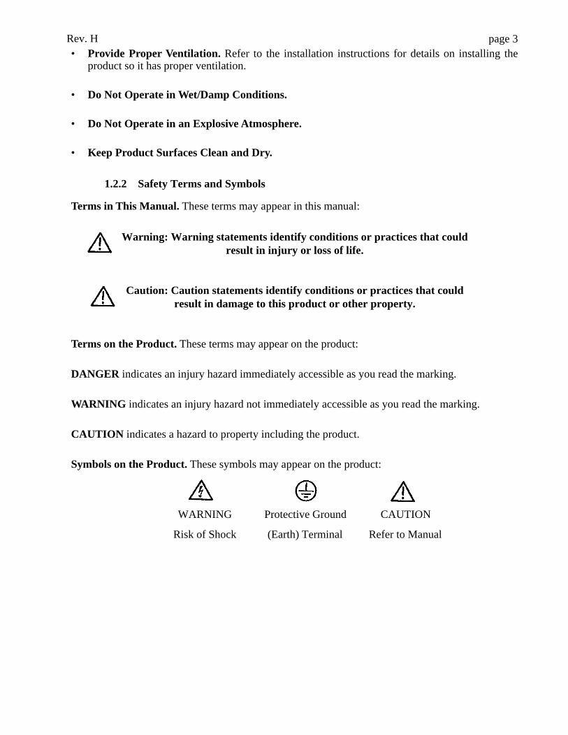
Symbols on the Product. These symbols may appear on the product:
WARNING Protective Ground CAUTION
Risk of Shock (Earth) Terminal Refer to Manual
Rev. Hpage 4
1.3 Installation1.3.1 General Installation
Carefully unpack the instrument, removing it from its plastic bag. Report any damage to yourfreight carrier at once.
Note: Retain the original packing material for future use in theevent that the instrument is shipped to another location or
returned for service.
Place the instrument on a flat working surface capable of safely supporting the weight of theinstrument (approximately 10 lbs). A clearance of at least 3 inches around the instrument isrequired to assure optimal ventilation. The instrument is recommended for operation within anambient temperature range of 18-35½C and humidity of less than 85%.
Look at the rear panel of the instrument to check that the power switch is in the Off (0) position.
1.3.2 Power Requirements
Locate the voltage select switch on the bottom of the instrument. This is a 2-position slide switchthat configures the instrument to accept either 230V or 115V input.
Warning: To prevent permanent damage to the instrument, thisswitch must be set for the appropriate input voltage before
powering up.
When you can see the 230V label, the instrument is set for 230V input. If you plug the instrumentinto a 115V power supply while 230V is selected, the instrument will have insufficient operatingpower.
To select 115V input, insert a straight screwdriver (or similar instrument) into the slot on theswitch and slide the switch into its alternate position. Upon sliding the switch, you will see the115V label appear.
Warning: If the instrument is configured to accept 115V and you plug it in to a 230V power supply, the fuse will blow and
permanent damage to the electronics may result.
The third prong of the AC power plug must be connected to a suitable ground. The circuit usedshould be substantially free of large voltage transients (Kilovolt amp loads), such as large pumps,large centrifuges, refrigerators, freezers, air conditioners, large autoclaves, ovens, and dryers.The instrument may fail to operate normally if the power supply is interrupted. If this occurs, turnthe instrument off for a moment. When you turn it back on, it will resume normal operation.However, since memory will have been lost, you will need to re-enter the calibrators and storedfactors. (see section 3.1)
Rev. H page 5
1.3.3 Electrical Setup and Safety Information
Note: See section 1.4 for additional Safety Information.
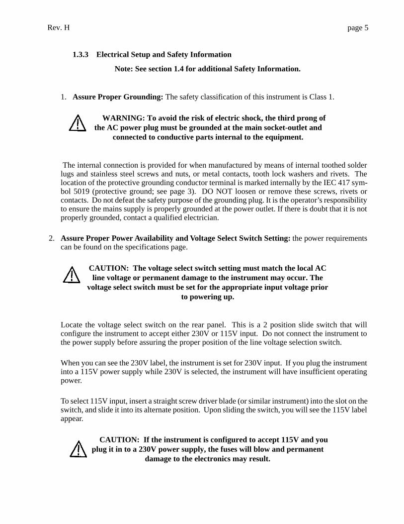
1. Assure Proper Grounding: The safety classification of this instrument is Class 1.
WARNING: To avoid the risk of electric shock, the third prong ofthe AC power plug must be grounded at the main socket-outlet and
connected to conductive parts internal to the equipment.
The internal connection is provided for when manufactured by means of internal toothed solderlugs and stainless steel screws and nuts, or metal contacts, tooth lock washers and rivets. Thelocation of the protective grounding conductor terminal is marked internally by the IEC 417 sym-bol 5019 (protective ground; see page 3). DO NOT loosen or remove these screws, rivets orcontacts. Do not defeat the safety purpose of the grounding plug. It is the operator’s responsibilityto ensure the mains supply is properly grounded at the power outlet. If there is doubt that it is notproperly grounded, contact a qualified electrician.
2. Assure Proper Power Availability and Voltage Select Switch Setting: the power requirementscan be found on the specifications page.
CAUTION: The voltage select switch setting must match the local ACline voltage or permanent damage to the instrument may occur. The
voltage select switch must be set for the appropriate input voltage priorto powering up.
Locate the voltage select switch on the rear panel. This is a 2 position slide switch that willconfigure the instrument to accept either 230V or 115V input. Do not connect the instrument tothe power supply before assuring the proper position of the line voltage selection switch.
When you can see the 230V label, the instrument is set for 230V input. If you plug the instrumentinto a 115V power supply while 230V is selected, the instrument will have insufficient operatingpower.
To select 115V input, insert a straight screw driver blade (or similar instrument) into the slot on theswitch, and slide it into its alternate position. Upon sliding the switch, you will see the 115V labelappear.
CAUTION: If the instrument is configured to accept 115V and youplug it in to a 230V power supply, the fuses will blow and permanent
damage to the electronics may result.
Rev. Hpage 6
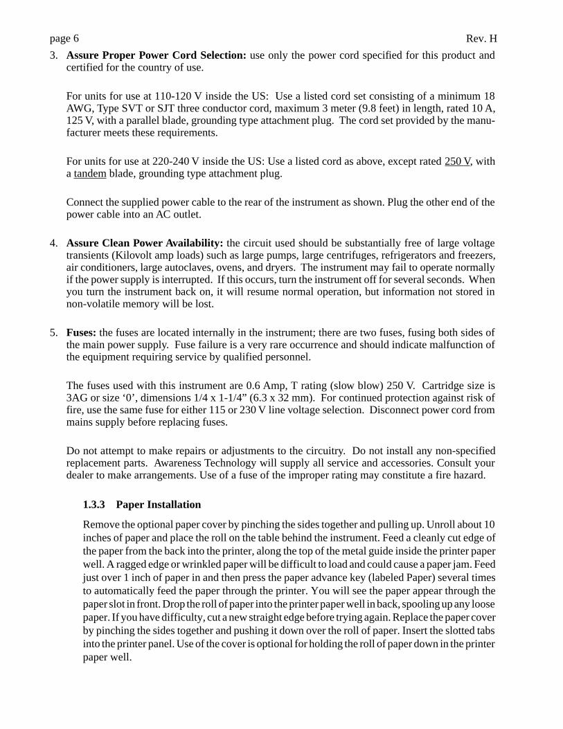
3. Assure Proper Power Cord Selection: use only the power cord specified for this product andcertified for the country of use.
For units for use at 110-120 V inside the US: Use a listed cord set consisting of a minimum 18AWG, Type SVT or SJT three conductor cord, maximum 3 meter (9.8 feet) in length, rated 10 A,125 V, with a parallel blade, grounding type attachment plug. The cord set provided by the manu-facturer meets these requirements.
For units for use at 220-240 V inside the US: Use a listed cord as above, except rated 250 V, witha tandem blade, grounding type attachment plug.
Connect the supplied power cable to the rear of the instrument as shown. Plug the other end of thepower cable into an AC outlet.
4. Assure Clean Power Availability: the circuit used should be substantially free of large voltagetransients (Kilovolt amp loads) such as large pumps, large centrifuges, refrigerators and freezers,air conditioners, large autoclaves, ovens, and dryers. The instrument may fail to operate normallyif the power supply is interrupted. If this occurs, turn the instrument off for several seconds. Whenyou turn the instrument back on, it will resume normal operation, but information not stored innon-volatile memory will be lost.
5. Fuses: the fuses are located internally in the instrument; there are two fuses, fusing both sides ofthe main power supply. Fuse failure is a very rare occurrence and should indicate malfunction ofthe equipment requiring service by qualified personnel.
The fuses used with this instrument are 0.6 Amp, T rating (slow blow) 250 V. Cartridge size is3AG or size ‘0’, dimensions 1/4 x 1-1/4” (6.3 x 32 mm). For continued protection against risk offire, use the same fuse for either 115 or 230 V line voltage selection. Disconnect power cord frommains supply before replacing fuses.
Do not attempt to make repairs or adjustments to the circuitry. Do not install any non-specifiedreplacement parts. Awareness Technology will supply all service and accessories. Consult yourdealer to make arrangements. Use of a fuse of the improper rating may constitute a fire hazard.
1.3.3 Paper Installation
Remove the optional paper cover by pinching the sides together and pulling up. Unroll about 10inches of paper and place the roll on the table behind the instrument. Feed a cleanly cut edge ofthe paper from the back into the printer, along the top of the metal guide inside the printer paperwell. A ragged edge or wrinkled paper will be difficult to load and could cause a paper jam. Feedjust over 1 inch of paper in and then press the paper advance key (labeled Paper) several timesto automatically feed the paper through the printer. You will see the paper appear through thepaper slot in front. Drop the roll of paper into the printer paper well in back, spooling up any loosepaper. If you have difficulty, cut a new straight edge before trying again. Replace the paper coverby pinching the sides together and pushing it down over the roll of paper. Insert the slotted tabsinto the printer panel. Use of the cover is optional for holding the roll of paper down in the printerpaper well.
Rev. H page 71.3.4 Checkout Procedure
Perform the following checkout procedure after installation. If any portion of this procedure doesnot check out properly, contact your dealer to arrange for assistance.
Turn the power switch on. The printer should print “Stat Fax 1904Plus :mX,” where m indicatesMosquito™ aspiration flowcell capability and X is the software revision level, then “01/01/9913:37,” representing the date and the time. The display shows “STAT FAX 1904P” momen-tarily, then “B ##.# H C ##.# H.” B and C indicate the block and cell (read well) temperatures,and H indicates that the heater is on. Listen for the fan. Look into the tube well for light comingfrom the optical system.
1.4 Principle of OperationLight energy from the halogen lamp is focused by a lens, directed through an aperture, and thenpassed horizontally through the sample. A continuously rotating wheel positions the filters so thatreadings can be taken very quickly at 2 wavelengths. (Using bichromatic differential absorbancevalues corrects for optical imperfections in the tubes.) A photodetector converts transmitted lightenergy into electrical signals, which are amplified and interpreted.
Rev. Hpage 8
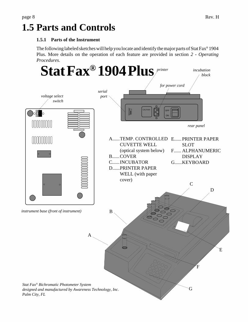
1.5 Parts and Controls1.5.1 Parts of the Instrument
The following labeled sketches will help you locate and identify the major parts of Stat Fax® 1904Plus. More details on the operation of each feature are provided in section 2 - OperatingProcedures.
OFF
ON
CAUTION
rear panel
incubationblock
for power cord
printer
Stat Fax® Bichromatic Photometer Systemdesigned and manufactured by Awareness Technology, Inc.Palm City, FL
voltage selectswitch
instrument base (front of instrument)
C
G
E
F
A
D
B
A......TEMP. CONTROLLEDCUVETTE WELL(optical system below)
B......COVERC......INCUBATORD......PRINTER PAPER
WELL (with papercover)
E...... PRINTER PAPERSLOT
F...... ALPHANUMERICDISPLAY
G......KEYBOARD
Stat Fax® 1904 Plusserial
port
Rev. H page 9.1
Pressing the BLANK key causes automatic blanking of the next tube read
7 8 9
2 3
4 5 6
1
ABS STND FAC ALT
PGM
RATE
%ABS
FILT TEMP
BLANK AUX
Enter
Paper
Clear
0 Lamp
YES
NO
Stat Fax
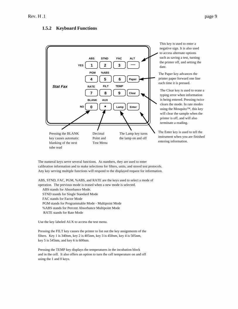
This key is used to enter a negative sign. It is also used to access alternate options such as saving a test, turning the printer off, and setting the date.
The Paper key advances the printer paper forward one line each time it is pressed.
The Clear key is used to erase a typing error when information is being entered. Pressing twice clears the mode. In rate modes using the Mosquito™, this key will clear the sample when the printer is off, and will also terminate a reading.
The Enter key is used to tell the instrument when you are finished entering information.
Decimal Point and Test Menu
The Lamp key turns the lamp on and off
The numeral keys serve several functions. As numbers, they are used to enter calibration information and to make selections for filters, units, and stored test protocols. Any key serving multiple functions will respond to the displayed request for information. ABS, STND, FAC, PGM, %ABS, and RATE are the keys used to select a mode of operation. The previous mode is erased when a new mode is selected. ABS stands for Absorbance Mode. STND stands for Single Standard Mode FAC stands for Factor Mode PGM stands for Programmable Mode - Multipoint Mode %ABS stands for Percent Absorbance Multipoint Mode RATE stands for Rate Mode Use the key labeled AUX to access the test menu. Pressing the FILT key causes the printer to list out the key assignments of the filters. Key 1 is 340nm, key 2 is 405nm, key 3 is 450nm, key 4 is 505nm, key 5 is 545nm, and key 6 is 600nm. Pressing the TEMP key displays the temperatures in the incubation block and in the cell. It also offers an option to turn the cell temperature on and off using the 1 and 0 keys.
1.5.2 Keyboard Functions
Rev. Hpage 10
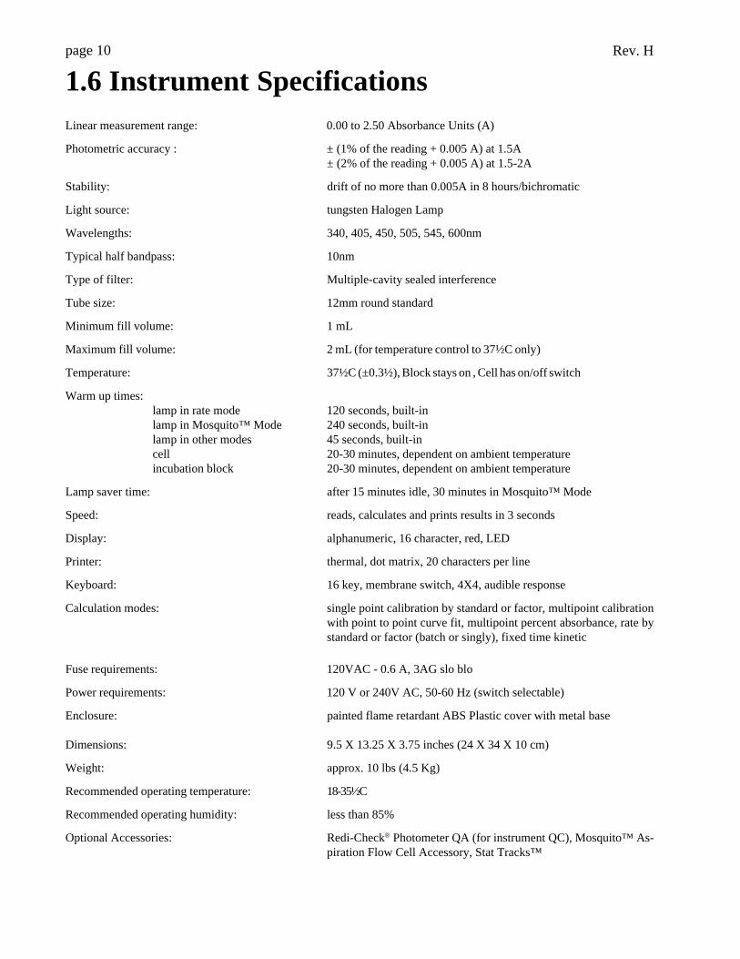
1.6 Instrument SpecificationsLinear measurement range: 0.00 to 2.50 Absorbance Units (A)
Photometric accuracy : ± (1% of the reading + 0.005 A) at 1.5A± (2% of the reading + 0.005 A) at 1.5-2A
Stability: drift of no more than 0.005A in 8 hours/bichromatic
Light source: tungsten Halogen Lamp
Wavelengths: 340, 405, 450, 505, 545, 600nm
Typical half bandpass: 10nm
Type of filter: Multiple-cavity sealed interference
Tube size: 12mm round standard
Minimum fill volume: 1 mL
Maximum fill volume: 2 mL (for temperature control to 37½C only)
Temperature: 37½C (±0.3½), Block stays on , Cell has on/off switch
Warm up times:lamp in rate mode 120 seconds, built-inlamp in Mosquito™ Mode 240 seconds, built-inlamp in other modes 45 seconds, built-incell 20-30 minutes, dependent on ambient temperatureincubation block 20-30 minutes, dependent on ambient temperature
Lamp saver time: after 15 minutes idle, 30 minutes in Mosquito™ Mode
Speed: reads, calculates and prints results in 3 seconds
Display: alphanumeric, 16 character, red, LED
Printer: thermal, dot matrix, 20 characters per line
Keyboard: 16 key, membrane switch, 4X4, audible response
Calculation modes: single point calibration by standard or factor, multipoint calibrationwith point to point curve fit, multipoint percent absorbance, rate bystandard or factor (batch or singly), fixed time kinetic
Fuse requirements: 120VAC - 0.6 A, 3AG slo blo
Power requirements: 120 V or 240V AC, 50-60 Hz (switch selectable)
Enclosure: painted flame retardant ABS Plastic cover with metal base
Dimensions: 9.5 X 13.25 X 3.75 inches (24 X 34 X 10 cm)
Weight: approx. 10 lbs (4.5 Kg)
Recommended operating temperature: 18-35½C
Recommended operating humidity: less than 85%
Optional Accessories: Redi-Check® Photometer QA (for instrument QC), Mosquito™ As-piration Flow Cell Accessory, Stat Tracks™
Rev. H page 11
2. Operating Procedures
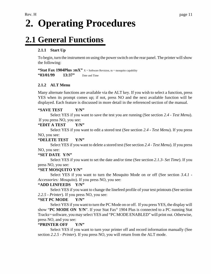
2.1 General Functions2.1.1 Start Up
To begin, turn the instrument on using the power switch on the rear panel. The printer will showthe following:
“Stat Fax 1904Plus :mX” X = Software Revision, m = mosquito capability
“03/01/99 13:37” Date and Time
2.1.2 ALT Menu
Many alternate functions are available via the ALT key. If you wish to select a function, pressYES when its prompt comes up; if not, press NO and the next available function will bedisplayed. Each feature is discussed in more detail in the referenced section of the manual.
“SAVE TEST Y/N”Select YES if you want to save the test you are running (See section 2.4 - Test Menu).
If you press NO, you see:“EDIT A TEST Y/N”
Select YES if you want to edit a stored test (See section 2.4 - Test Menu). If you pressNO, you see:“DELETE TEST Y/N”
Select YES if you want to delete a stored test (See section 2.4 - Test Menu). If you pressNO, you see:“SET DATE Y/N”
Select YES if you want to set the date and/or time (See section 2.1.3- Set Time). If youpress NO, you see:“SET MOSQUITO Y/N”
Select YES if you want to turn the Mosquito Mode on or off (See section 3.4.1 -Accessories: Mosquito). If you press NO, you see:“ADD LINFEEDS Y/N”
Select YES if you want to change the linefeed profile of your test printouts (See section2.2.5 - Printer). If you press NO, you see:“SET PC MODE Y/N”
Select YES if you want to turn the PC Mode on or off. If you press YES, the display willshow “PC MODE ON Y/N”. If your Stat Fax® 1904 Plus is connected to a PC running StatTracksTM software, you may select YES and “PC MODE ENABLED” will print out. Otherwise,press NO, and you see:“PRINTER OFF Y/N”
Select YES if you want to turn your printer off and record information manually (Seesection 2.2.5 - Printer). If you press NO, you will return from the ALT mode.
Rev. Hpage 12
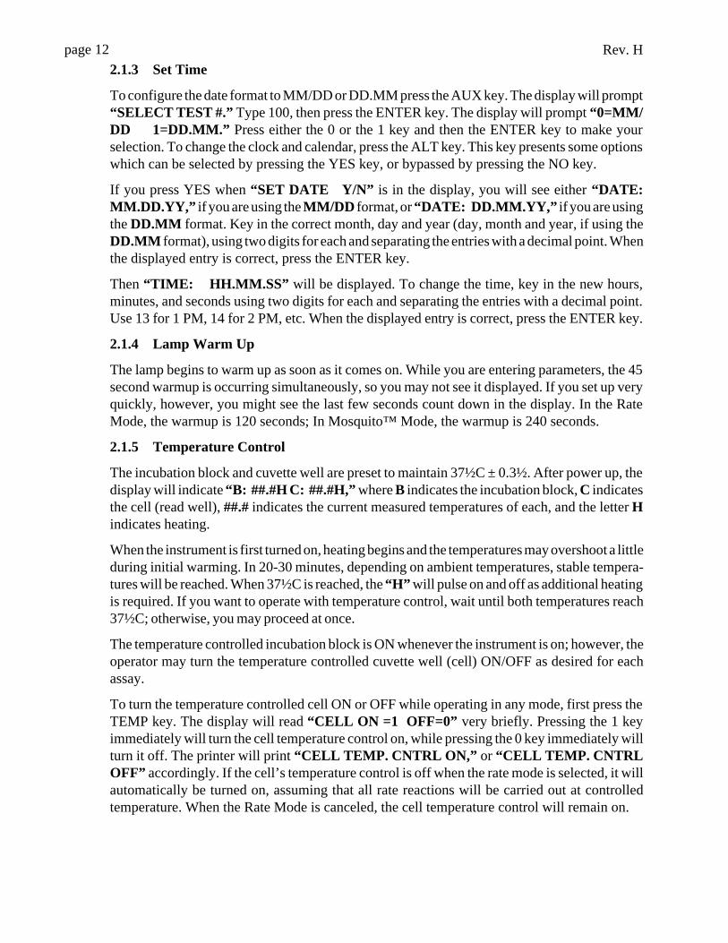
2.1.3 Set Time
To configure the date format to MM/DD or DD.MM press the AUX key. The display will prompt“SELECT TEST #.” Type 100, then press the ENTER key. The display will prompt “0=MM/DD 1=DD.MM.” Press either the 0 or the 1 key and then the ENTER key to make yourselection. To change the clock and calendar, press the ALT key. This key presents some optionswhich can be selected by pressing the YES key, or bypassed by pressing the NO key.
If you press YES when “SET DATE Y/N” is in the display, you will see either “DATE:MM.DD.YY,” if you are using the MM/DD format, or “DATE: DD.MM.YY,” if you are usingthe DD.MM format. Key in the correct month, day and year (day, month and year, if using theDD.MM format), using two digits for each and separating the entries with a decimal point. Whenthe displayed entry is correct, press the ENTER key.
Then “TIME: HH.MM.SS” will be displayed. To change the time, key in the new hours,minutes, and seconds using two digits for each and separating the entries with a decimal point.Use 13 for 1 PM, 14 for 2 PM, etc. When the displayed entry is correct, press the ENTER key.
2.1.4 Lamp Warm Up
The lamp begins to warm up as soon as it comes on. While you are entering parameters, the 45second warmup is occurring simultaneously, so you may not see it displayed. If you set up veryquickly, however, you might see the last few seconds count down in the display. In the RateMode, the warmup is 120 seconds; In Mosquito™ Mode, the warmup is 240 seconds.
2.1.5 Temperature Control
The incubation block and cuvette well are preset to maintain 37½C ± 0.3½. After power up, thedisplay will indicate “B: ##.#H C: ##.#H,” where B indicates the incubation block, C indicatesthe cell (read well), ##.# indicates the current measured temperatures of each, and the letter Hindicates heating.
When the instrument is first turned on, heating begins and the temperatures may overshoot a littleduring initial warming. In 20-30 minutes, depending on ambient temperatures, stable tempera-tures will be reached. When 37½C is reached, the “H” will pulse on and off as additional heatingis required. If you want to operate with temperature control, wait until both temperatures reach37½C; otherwise, you may proceed at once.
The temperature controlled incubation block is ON whenever the instrument is on; however, theoperator may turn the temperature controlled cuvette well (cell) ON/OFF as desired for eachassay.
To turn the temperature controlled cell ON or OFF while operating in any mode, first press theTEMP key. The display will read “CELL ON =1 OFF=0” very briefly. Pressing the 1 keyimmediately will turn the cell temperature control on, while pressing the 0 key immediately willturn it off. The printer will print “CELL TEMP. CNTRL ON,” or “CELL TEMP. CNTRLOFF” accordingly. If the cell’s temperature control is off when the rate mode is selected, it willautomatically be turned on, assuming that all rate reactions will be carried out at controlledtemperature. When the Rate Mode is canceled, the cell temperature control will remain on.
Rev. H page 13
To check the temperatures while operating in any mode, press the TEMP key. The display willshow “CELL ON =1 OFF=0” very briefly and then display the block and cell temperatures forabout 15 seconds before returning to the previous mode of operation.
Note: 37½C is attainable in the incubation block for volumes of2mL or less; temperature controlled assays should therefore use
volumes equal to or below 2mL to achieve 37½C.
2.1.6 Selecting a Mode
Press a mode key to select the desired automatic calculations:
Absorbance Mode ABS key (1)
Standard Mode STND key (2)
Factor Mode FAC key (3)
Programmable Mode PGM key (4)
Multipoint % Mode %ABS key (5)
Rate Mode RATE key (7)
The mode designations are located above the number keys. The printer will print the name of themode you have selected, and the display will indicate your next instruction. Before readingbegins in each mode, the instrument will momentarily reference air. After that, it will recognizethe insertion of a tube and read automatically.
To cancel a mode of operation at any time, press the CLEAR key twice.
2.1.7 Filter Selection
When you select a mode, the printer prints the date, time, and mode selected. The display willshow “SELECT FILTER .” Each available filter has been assigned to a number key as follows:
key 1 is 340nm key 2 is 405nm key 3 is 450nm
key 4 is 505nm key 5 is 545nm key 6 is 600nm
To print the filter list press the FILT (Filter) key. Select the key for the wavelength at which youwould like to read, and then press the ENTER key.
Next the display will show “SELECT DIFF FILT.” This instrument operates with a bichro-matic differential wavelength as selected by the operator. The absorbance reading at thedifferential wavelength will be subtracted from the absorbance reading at the operating (firstselected) wavelength . If you do not want a differential reading, choose the 0 (zero) key for NODIFFERENTIAL. After pressing the key for the desired differential wavelength, press theENTER key. The selected wavelengths will be printed. See the section 2.2.1 - BichromaticOperation for a detailed discussion of bichromatic differential operation.
Rev. Hpage 14
Some glass test tubes have high absorbances at 340nm, which could cause a reduction in theprecision and accuracy of your assay. When using this wavelength, you should determine if yourtest tubes absorb at 340nm. In order to test your tubes, press the ABS key, then select 340-600nm(primary filter = 340, differential filter = 600). Fill a tube with at least 1 ml of deionized water.Insert the tube at the prompt “READ BLANK TUBE.” The printed absorbance must be less than0.400 to maintain precision and accuracy.
2.2 General Operation2.2.1 Bichromatic Differential Operation
The option to operate this instrument using differential absorbance readings is available for everymode. The absorbance readings at the differential wavelength are subtracted from the absorbancereadings at the operating (primary) wavelength. Use of the bichromatic differential absorbancegenerally increases precision, since the element of variation caused by imperfections indisposable glass and plastic test tubes is removed from the results.
Whenever possible, differential reading is recommended becauseprecision is significantly improved. This is particularly noticeablewhen using plastic tubes or glass tubes with optical imperfections
and non-uniform wall thicknesses.
In order to preserve sensitivity, it is important not to choose a differential wavelength where thechromophore being assayed exhibits substantial absorbance. To test your chromophore, read adarkly colored solution in the absorbance mode at the operating wavelength with no differentialfilter, and again at the operating wavelength with the differential filter selection. If the twoabsorbance readings are within 10% of each other, then bichromatic differential reading isbeneficial. If the difference between the absorbance readings with and without a differentialwavelength is greater than 25%, then the chromophore is absorbing at or near the differentialwavelength and bichromatic reading at this wavelength is probably not desirable.
If no bichromatic wavelength is selected, exercise every measure to enhance repeatability.Choose a better quality reading vessel and wipe fingerprints from each tube before reading. Markeach tube for uniform orientation when multiple readings are desired. Determine the acceptabil-ity of the precision by reading the same tube several times and observing the variation of thereadings. Depending on the precision requirements of your assay, monochromatic reading mayor may not be acceptable with certain plastic tubes.
TIPS FOR TUBE READING:
• Wipe any dust, moisture, or fingerprints from the tubes beforeusing.
• Do not read tubes that contain bubbles or condensation.
• Use a blank material with absorbance of less than 0.400A.
• Use the same type and size of tube for the blank as you use forthe samples.
Rev. H page 15
2.2.2 Blanking
During normal operation of this instrument in every mode, operator prompting via the displaywill indicate when to read the blank tube. The blank tube’s absorbance is read and printed relativeto air and then subtracted from each specimen (also read relative to air). Since the blank’sabsorbance relative to air is printed, the user will be able to evaluate the suitability of a blankbefore using it. For example, users can determine whether or not their test tubes absorb at 340nm.
Whenever additional blanking is desired, use the BLANK key. To select blanking, in any mode,first press the BLANK key, then insert the blank tube. Automatic blanking will occur. The letter“B” will be printed adjacent to the sample number to indicate that blanking has occurred.
Automatic blanking for each sample may be selected during entry of parameters in the Standard,Factor, Multipoint, or Multipoint % Abs modes. After filter selection, the display prompts“SAMPLE BLANK Y/N” . Answer YES if blanking for every sample is desired. When runningthe test, “READ BLANK TUBE” will be prompted before each standard and sample.
2.2.3 Unit of Measurement Codes (Unit Code)
25 unit of measurement designations plus a blank selection are stored for labeling the concen-tration column. These are listed below.
00 Conc 13 umo/L01 g/L 14 nmo/L02 g/dL 15 ukat/L03 mg/L 16 U/L04 mg/dL 17 IU/L05 ug/dL 18 IU/mL06 ug/mL 19 mIU/mL07 ng/dL 20 uIU/mL08 ng/mL 21 %09 mEq/L 22 %UPT10 mEq/dL 23 ug%11 umL/L 24 uU/L12 mmo/L 25
When the display prompts “KEY UNIT CODE,” you can press 99 to see the list printed.Otherwise, select the unit by its numerical designation and press ENTER. You will see theselected unit displayed. If you made a mistake, press CLEAR and choose again. If the displayedunits are correct, press the ENTER key to confirm. If no units labeling is desired, use the 25 keyfor none and then press ENTER.
2.2.4 Ranges
Immediately after setting the unit code, the instrument will prompt “SET RANGES Y/N.” Ifyou do not want ranges, press NO to go on. To set the normal range and the linear range of anassay, press YES.
The reader will first ask for the low end of the normal range by displaying “KEY LOWNORMAL.” Type in the cutoff and press ENTER. The display will then prompt “KEY HIGHNORMAL.” Type in the upper cutoff and press ENTER. The display will then prompt “KEYLO LINEARITY.” If the assay is linear for only a certain group of values, this feature can label
Rev. Hpage 16
any concentrations outside of the linear range. Type in the low limit and press ENTER. See“KEY HI LINEARITY.” Type in the upper limit of linearity and press ENTER. Any of therange options may be bypassed by pressing ENTER when the instrument is prompting for therange value.
After this, each specimen concentration will be compared to these ranges. If the specimenconcentration is greater than the normal range it will be labeled “H” for high. Likewise, if it islower than the normal range it will be labeled “L” for Low. The “H” and “L” labels will appearunder the heading “i,” which stands for Interpretation. This column immediately follows theconcentration column on the printout. If linear ranges are entered, the calculated concentrationis compared to these limits. The letter “R” will be printed in the interpretation column shouldany value fall outside of the linear range. When tests are stored, the normal and linear ranges arealso stored for future use.
2.2.5 Printer
The printer automatically provides a permanent record of the modes, filters, and calibrators used,as well as test results.
The paper may be advanced at any time by pressing the Paper key. Each time the key is pressed,the paper will advance one line. This key is used to feed paper during installation and to allowextra spacing between data as required by the operator.
The printer can be configured to add extra spacing automatically. Press the ALT key andanswer NO until “ADD LINFEEDS Y/N” is displayed. Press YES. The display will show“ALL LINES Y/N” . If extra spacing between every line is desired, press YES. Press NO andthe display will show “RESULTS ONLY Y/N” . If spacing between sample results only isdesired, press YES. Press NO to return the printer configuration to add no extra spaces. Note that"Results Only" is not offered in Rate modes, and will print without linefeeds.
Your printer requires a good quality thermal paper with a 2.281 (2-9/32) inch width. Thepaper recommended for use with your instrument is available from your dealer. To install a newroll of paper, follow the instructions given under the section 1.2.3 - Paper Installation.
To conserve printer paper, you can turn off the printer when you do not need a printedreport. Use the ALT key to access this feature. Press NO until you see the question “PRINTEROFF Y/N.” Pressing YES will turn the printer off, and “***PRINTER OFF***” will beprinted. Pressing NO will turn the printer on and “*** PRINTER ON ***” will be printed.
2.2.6 Lamp Saver Feature
To prolong the lamp life, the instrument is pre-programmed to turn off the lamp automaticallyafter about 15 minutes of idle time (30 minutes in Mosquito mode). To turn the lamp back on,either insert the next tube or press the LAMP key. You will see “LAMP WARM UP XX” inthe display, where XX represents the warm up countdown. When in tube mode (non-Mosquitomode), there is a 45 second warm up, except in rate mode, which is 120 seconds. The Mosquitorequires a 240 second lamp warmup. You will hear a double beep when the lamp is ready. Toturn off the lamp without turning off the instrument, use the lamp key. Selecting a new mode ofoperation will also cause the lamp to turn on and warm up at the appropriate time.
Whenever the lamp is on, you will be able to see light coming from the read well. Lampreplacement is indicated when the lamp fails to light.
Rev. H page 17
2.2.7 Flags and Error Messages
Flags are printed messages used to alert the operator when certain limitations are approached.After printing the warnings, the instrument will continue to perform normally. This instrumentemploys the following flags:
“****” is printed in the concentration field in the event that an absorbance is greater than 2.5A.To obtain an accurate absorbance and concentration value for such a sample, further dilution maybe required. EXCEPTION: in the Rate by Standard mode, a standard with an absorbance greaterthan 2.5A will cancel the test.
“>10**6” is printed whenever a calculated factor or result is greater than 6 digits and thus cannot be properly printed in the 6 digit field.
“—CURVE INVALID !! -” is printed in the Programmable Mode when a curve cannot bedrawn between standard points. An “X” will be printed after the standard point which makes thecurve invalid. If this occurs, ensure that your standards were read in decreasing or increasingorder of absorbance, decreasing for multipoint % Abs mode and increasing for multipoint mode.No interpretation will occur with an invalid curve.
“Plot Unavailable” is printed if Rate mode Lag and Read times are not evenly divisible by 5,or if total time is greater than 1200 seconds (20 minutes).
“ Int Data Unavailable” is printed if Rate mode Read time is not evenly divisible by 30.
Error messages are printed or appear on the display when the instrument fails to operate. Thesemessages help the operator locate the cause of the failure. Appropriate responses to thesemessages are discussed in the Troubleshooting section of this manual. This instrument employsthe following error messages:
“MEMORY ERROR” is printed when an error occurs in recalling a test. This feature assuresthat the recalled values are the same as those that were stored.
“Stack Underflow” is printed when the instrument attempts to store data at a location which mayoverwrite previously stored data. The mode will cancel, and subsequent data will be stored at asafe location in memory.
“LAMP FAILURE” is printed when the lamp fails to illuminate sufficiently during an airreference period (between tubes and prior to reading the blank). This message will only printonce until the mode is canceled.
“PRNTER PAPER JAM” is displayed when the printer paper path is obstructed.
“FILTER WHEEL ERR” is printed when there is a mechanical problem with the instrument.If this occurs, turn the unit off and then on again. If this fails to clear the problem return the unitfor service.
“CANCELED” is printed immediately following every filter wheel error to indicate that the testhas been terminated.
“DO TEMP SET TEST 210” is printed when the factory set temperature adjustments have beenlost from non-volatile memory. See the section 3.1 - Restoring Electronic Calibration.
“DO ABS SET TEST 212” is printed when the factory set absorbance gain calibration has beenlost from non-volatile memory. See the section 3.1 - Restoring Electronic Calibration.
Rev. Hpage 182.2.8 Calibration and Linearity
Every instrument is calibrated during manufacturing, using standards that are traceableto the NIST, and is tested to verify its linearity to 2A. No calibration adjustment is accessible tothe operator, since the preset calibration is very stable. Absolute calibration can be verified withthe use of NIST filters, or by periodic comparison to a reference instrument that is known to becalibrated to NIST filters. Calibration may also be confirmed using a calibration check set suchas REDI-CHECK®, obtainable from your dealer.
Since most lab test results are based upon standards rather than upon absolute absorbances, thelinearity of the instrument is the more critical indicator of instrument performance. A reductionin linearity with age may be indicative of filter deterioration. In this event, filter replacement isrequired for continued reliable operation.
A periodic verification of instrument linearity is advisable. This can also be done using REDI-CHECK®. Further information about REDI-CHECK® is available from Awareness Technology.Telephone: (561) 283-6540, Fax: (561) 283-8020.
The best way to assure quality instrument performance is to include a sufficient number ofcontrols in each assay to cover the entire operational range.
2.3 Modes of OperationThe modes of operation are used to select different methods of data reduction for calculatingsample answers. Some of the features which are common to multiple operating modes arediscussed in section 2.2, General Operation. These include Bichromatic Operation, Blankingand Sample Blanking, Unit Codes, and Ranges. Some functions may also be different in theMosquito mode; see section 3.4.1, or the Mosquito Owner’s Manual, for additional information.In addition, sample printouts are found in section 3.5.
2.3.1 Absorbance Mode
This mode will read and print sample absorbances at user selected wavelengths. To operate theunit in absorbance mode, press the ABS key. The printer prints the date, time, and mode ofoperation: “ABSORBANCE.” The display will show “SELECT FILTER.” Select thewavelengths by pressing the appropriate key for each wavelength followed by the ENTER key.
The selected wavelengths will be printed, as well as the headings “S#” for sample number and“Abs” for absorbance. The lamp will also come on and warm up.
The display will then momentarily indicate “REFERENCING AIR.” During the referencingperiod, do not insert a tube or press a key. After referencing air, the instrument will be able todetect when tubes are inserted for the automatic triggering of future reading, calculating, andprinting.
The display will then show “READ BLANK TUBE.” Insert the blank tube and the absorbanceof the tube referenced to air will be displayed and printed. This value will be subtracted fromsubsequent readings. The printed “B#” indicates that this is the blank. It is very important to usethe same type and size tube for the blank as will be used for the samples.
When you remove the blank tube, the display will prompt “READ SAMPLE.” One by one,insert each sample tube and see the differential absorbance results printed and displayed.
Rev. H page 19
Fifteen minutes after reading the last sample, the lamp saver feature will automatically turn offthe lamp. To continue reading, either press the lamp key or place a tube in the well. The 45 secondlamp warm up will occur, and then operation will resume where it left off. In Mosquito™ Mode,lamp timeout is 30 minutes and lamp warmup is 240 seconds.
If re-blanking is desired at any time during operation, press the BLANK key and then insert theblank tube.
2.3.2 Single Standard Mode
This mode will read and print sample concentrations. A single standard material of knownconcentration is used to calibrate the instrument so that concentrations of unknown samples canbe calculated according to Beer's Law. The bichromatic absorbances at the selected wavelengthswill be read, printed, and used in the concentration calculations. The calibration factor (standardconcentration/standard absorbance) will be printed for future use.
To operate the unit in single standard mode, press the STND key. The printer prints the date, time,and mode of operation: “STANDARD.” The display will show “SELECT FILTER.” Select thewavelengths by pressing the appropriate key for each wavelength followed by the ENTER key.The selected wavelengths will be printed. The display will prompt “SAMPLE BLANK Y/N ”.Press YES if each sample requires a separate blank reading. “Sample Blank Mode” will print.Press NO if only an initial blank is desired.
The display will show “KEY VALUE OF S#1.” Type the concentration value assigned to yourstandard material. Then press the ENTER key. The printer will print “STANDARD #1=XXXX,” where XXXX is the standard value you have entered.
Note: The instrument accepts standard values of six or fewerdigits, and accepts up to 2 digits after the decimal point if the
value is less than 1000.
The display prompts “KEY UNIT CODE” ; see section 2.2.3-Unit of Measurement Codes. Thedisplay then prompts “SET RANGES Y/N” ; see section 2.2.4-Ranges. The instrument thenprints the column headings.
The display will momentarily indicate “REFERENCING AIR.” During the referencing period,do not insert a tube or press a key. After referencing air, the instrument will be able to detect whentubes are inserted for the automatic triggering of future reading, calculating, and printing.
The display will then prompt “READ BLANK TUBE.” Insert the blank tube and the printer willprint the tube’s absorbance referenced to air.
Remove the blank tube, and the display will prompt “READ STANDARD.” Insert the standardtube. It will be read, and the absorbance and concentration values will be printed. The calculatedfactor will print on the next line. “S1” indicates that this is the standard tube. See the sampleprinter output for this mode. When you remove the standard tube, the instrument will prompt“READ SAMPLE.” One by one, insert each sample tube and see the results printed anddisplayed. The concentration units for sample results will always be the same as the concentrationunits of the standard.
In the event that the absorbance reading of the standard is greater than 2.5 A, the printer anddisplay will indicate “*******” in the concentration (units) column. See section 2.2.7 - Flags andError Messages.
Rev. Hpage 20
If a sample has an absorbance reading greater than 2.5A, the printer will print the absorbancereading, and the concentration (units) column will show “*******” . See section 2.2.7 - Flagsand Error Messages.
2.3.3 Factor Mode
This mode will read and print sample concentrations at user selected wavelengths. A previouslydetermined factor is entered by the operator, and the measured absorbance is then multiplied bythe factor to obtain concentration.
To operate in factor mode, press the FAC key. The printer prints the date, time, and mode ofoperation: “FACTOR.” The display will show “SELECT FILTER.” Select the wavelengthsby pressing the appropriate key for each wavelength followed by the ENTER key. The displaywill prompt “SAMPLE BLANK Y/N ”. Press YES if each sample requires a separate blankreading. “Sample Blank Mode” will print. Press NO if only an initial blank is desired.
The display will prompt “ENTER FACTOR.” Type the factor and press the ENTER key. Theprinter will print the selected wavelengths and “FACTOR= XXXX,” where XXXX is the factorvalue you have entered.
Note: The instrument accepts factor values of six or fewer digits,and accepts up to 2 digits after the decimal point if the value is
less than 1000.
The display prompts “KEY UNIT CODE” ; see section 2.2.3-Unit of Measurement Codes. Thedisplay then prompts “SET RANGES Y/N” ; see section 2.2.4-Ranges. The instrument thenprints the column headings.
The display will momentarily indicate “REFERENCING AIR.” The display will then prompt“READ BLANK TUBE.” Insert the blank tube and the printer will print the tube’s absorbancereferenced to air. Remove the blank tube and the display will prompt “READ SAMPLE.” Oneby one, insert each sample tube and see the results printed and displayed.
2.3.4 Programmable Mode (Multipoint)
The Programmable Mode is a multipoint standard mode that allows the operator to enter theconcentrations of up to seven different standard materials of known concentrations. Thesestandards are used to calibrate the instrument so that concentrations of unknown samples maybe calculated according to Beer’s Law. The resulting standard curve is a series of lines connectingthe standard points in the order they are entered. In the Programmable Mode (point to point), theymust be entered lightest to darkest (lightest is Standard #1). If you wish to run the standards fromdarkest to lightest (such as for uptake assays), use Multipoint % Absorbance Mode.
To operate the unit in the Programmable Mode, press the PGM key. The printer will print the date,time, and “MULTIPOINT.” The display will show “SELECT FILTER.”
Select the filters by pressing the appropriate key for each wavelength followed by the ENTERkey. The printer will print the selected wavelengths. The display will prompt “SAMPLEBLANK Y/N ”. Press YES if each sample requires a separate blank reading. “Sample BlankMode” will print. Press NO if only an initial blank is desired.
The display will prompt “KEY # OF STNDRDS.” Type the number of standards to be used(from 1 to 7), and then press the ENTER key.
Rev. H page 21
The display will prompt “KEY VALUE OF S#1.” Type the concentration value assigned to thefirst standard and press the ENTER key. The instrument will continue to prompt for standardvalues until the selected number has been entered. Each standard value will print when theENTER key is pressed. See the sample printer outputs for this mode.
Note: The instrument accepts standard values of six or fewerdigits, and accepts up to 2 digits after the decimal point if the
value is less than 1000.
The display prompts “KEY UNIT CODE” ; see section 2.2.3-Unit of Measurement Codes. Thedisplay then prompts “SET RANGES Y/N” ; see section 2.2.4-Ranges. The instrument thenprints the column headings.
The display will momentarily indicate “REFERENCING AIR.” The display will then prompt“READ BLANK TUBE.” Insert the blank tube and the printer will print the tube’s absorbancereferenced to air. Remove the blank tube, and the display will prompt “READ STANDARD.”One by one, insert each standard tube and the results will be printed and displayed.
After the last standard tube is read and removed, the display will prompt “PLOT CURVE Y/N.” Press YES to plot the curve. The display will then show “READ SAMPLE.” One by one,insert each sample tube and the results will be printed and displayed.
Unknown samples are calculated as follows:
First, the unknown sample’s bichromatic differential absorbance (operator selected wave-lengths) is calculated and compared to the standard absorbances. Then, the line selected as thestandard curve for determining the concentration of the unknown, is the line connecting the pairof standards whose absorbances are closest above and below the unknown absorbance. Anunknown sample with absorbance greater than the highest standard absorbance is calculated onthe line passing through the highest 2 standard points, and an unknown sample with absorbanceless than the lowest standard absorbance is calculated on the line passing through the lowest 2standard points.
2.3.5 Multipoint % Abs Mode
The Multipoint % Absorbance mode (%ABS key) is used with multipoint uptake assays, andfunctions in the same way as the Programmable (point to point) Mode, with the followingexceptions:
The standards must be entered from darkest to lightest.
An additional calculation (%A/A0) is calculated, which is the absorbance of the sample divided
by the absorbance of the first calibrator, or “percent of first calibrator”. The first calibrator isconsidered 100%, and all subsequent samples are calculated as percent of calibrator.
In using a Multipoint % Abs. user test with a stored curve, there are two options. After you selectthe test, all the information is printed, and then you are prompted by the display alternately “USESTORED CURVE” and “YES(1) NO(2).” If you choose to use the stored curve (by pressingYES), you must blank (as prompted), and then read your first standard tube only. Then you maycontinue with the samples. If you choose not to use the stored curve (by pressing NO), you mustblank, read all standards, then continue with the samples. For more information on user tests, seesection 2.4-Test Menu.
Rev. Hpage 22
Except for these differences, follow the procedure as described in section 2.3.4.
2.3.6 Rate Mode
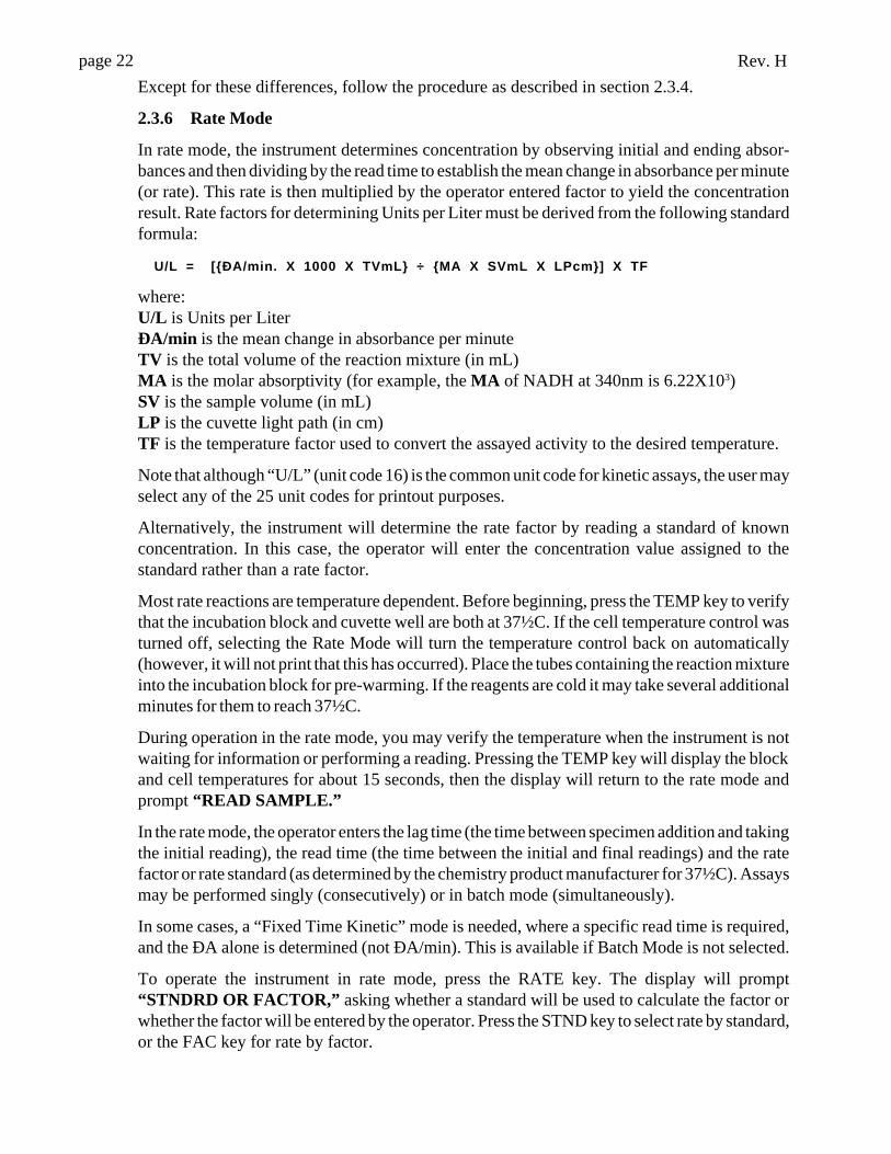
In rate mode, the instrument determines concentration by observing initial and ending absor-bances and then dividing by the read time to establish the mean change in absorbance per minute(or rate). This rate is then multiplied by the operator entered factor to yield the concentrationresult. Rate factors for determining Units per Liter must be derived from the following standardformula:
U/L = [{ÐA/min. X 1000 X TVmL} ÷ {MA X SVmL X LPcm}] X TF
where:U/L is Units per LiterÐA/min is the mean change in absorbance per minuteTV is the total volume of the reaction mixture (in mL)MA is the molar absorptivity (for example, the MA of NADH at 340nm is 6.22X10³)SV is the sample volume (in mL)LP is the cuvette light path (in cm)TF is the temperature factor used to convert the assayed activity to the desired temperature.
Note that although “U/L” (unit code 16) is the common unit code for kinetic assays, the user mayselect any of the 25 unit codes for printout purposes.
Alternatively, the instrument will determine the rate factor by reading a standard of knownconcentration. In this case, the operator will enter the concentration value assigned to thestandard rather than a rate factor.
Most rate reactions are temperature dependent. Before beginning, press the TEMP key to verifythat the incubation block and cuvette well are both at 37½C. If the cell temperature control wasturned off, selecting the Rate Mode will turn the temperature control back on automatically(however, it will not print that this has occurred). Place the tubes containing the reaction mixtureinto the incubation block for pre-warming. If the reagents are cold it may take several additionalminutes for them to reach 37½C.
During operation in the rate mode, you may verify the temperature when the instrument is notwaiting for information or performing a reading. Pressing the TEMP key will display the blockand cell temperatures for about 15 seconds, then the display will return to the rate mode andprompt “READ SAMPLE.”
In the rate mode, the operator enters the lag time (the time between specimen addition and takingthe initial reading), the read time (the time between the initial and final readings) and the ratefactor or rate standard (as determined by the chemistry product manufacturer for 37½C). Assaysmay be performed singly (consecutively) or in batch mode (simultaneously).
In some cases, a “Fixed Time Kinetic” mode is needed, where a specific read time is required,and the ÐA alone is determined (not ÐA/min). This is available if Batch Mode is not selected.
To operate the instrument in rate mode, press the RATE key. The display will prompt“STNDRD OR FACTOR,” asking whether a standard will be used to calculate the factor orwhether the factor will be entered by the operator. Press the STND key to select rate by standard,or the FAC key for rate by factor.
Rev. H page 23
The printer prints the date, time, and mode of operation: either “RATE BY STANDARD” or“RATE BY FACTOR.” In either case the display will then show “SELECT FILTER.” Selectthe filters by pressing the appropriate key for each wavelength followed by the ENTER key. Theprinter will print the selected wavelengths. The display then shows “BATCH MODE Y/N.”Press YES to use batch mode, NO to read kinetic assays individually. If NO, the display shows“FIXED TIME Y/N.” If ÐA instead of ÐA/min is desired, select YES, otherwise select NO.The display then shows “KEY IN LAG TIME.” Type the lag time in seconds and press theENTER key. The lag time you entered will be printed. The display then shows “KEY IN READTIME.” Type the read time duration in seconds, and press the ENTER key. The read time youentered will be printed. The display will prompt “KEY VALUE OF S#1” or “ENTERFACTOR” depending on your mode selection.
Enter either the rate factor, corrected for 37°C reading (if using the FACTOR method), or thevalue assigned to the standard (if using the STANDARD method), and then press the ENTERkey. The value that you entered will be printed. For negative factors, press the ALT key beforetyping the factor value.
Note: The instrument accepts standard and factor values of six orfewer digits, and accepts up to 2 digits after the decimal point if
the value is less than 1000.
The display prompts “KEY UNIT CODE” ; see section 2.2.3-Unit of Measurement Codes. Thedisplay then prompts “SET RANGES Y/N” ; see section 2.2.4-Ranges. The instrument thenprints the column headings.
Instructions for proceeding in Batch Mode follow at the end of this section.
The display will momentarily indicate “REFERENCING AIR.” The display will then prompt“READ BLANK TUBE” and the printer will print the column headings. Insert the blank tubeand the tube’s absorbance referenced to air will be displayed. Remove the blank tube, and thedisplay will prompt “READ STANDARD,” if STND was selected or “READ SAMPLE XX”if FAC was selected.
Be certain that the lamp is on. If it is not, press the LAMP key, then wait for the lamp warmupto complete. Begin the first reaction by adding the specimen to a pre-warmed reagent tube. Invertthe tube two or three times to quickly mix and then immediately insert the first sample tube intothe cuvette well. The display will show the lag time counting down on the left side and thecontinuously updating absorbance reading on the right side. It will look like this: “LT XXXXA 0.000,” where XXXX is the time and 0.000 is the absorbance. When the lag time period haselapsed, the instrument will take an initial absorbance reading and the display will change toshow the read time counting down on the left side. It will look like this: “RT XXXX A 0.000,”where XXXX is the time and 0.000 is the absorbance. At the end of the read time, the instrumentwill take a final absorbance reading and the printer will print the sample number, the averagechange in absorbance per minute and the concentration. If you are in “Fixed Time Mode”, thechange in absorbance will be printed, not the change in absorbance per minute.
Additional information is available if the read time and lag time meet certain criteria. If the readtime is a multiple of 30 seconds, you may print the interval absorbance data (at 30 secondintervals) and the ÐA for each interval. If both the lag time and the read time are a multiple offive seconds, you may plot the curve. By pressing the AUX (.) key after the sample’s results haveprinted, you will see “PRN INT DATA Y/N” (if available). Press NO and you will see “PLOT
Rev. Hpage 24
KINETIC Y/N” (if available). Choose YES for either option to print/plot the information.
When you remove the sample tube, the display will prompt “READ SAMPLE XX” to indicatethat it is ready for the next sample tube. Begin the second reaction and insert the second tube. Ifthe factor is calculated based upon a standard tube reading, the factor will be printed after the firsttube is removed. Perform and read each reaction one by one, removing the tubes only after theresults are printed. If you remove a tube prematurely, the rate calculation will cease.
Batch Mode Information:
If “BATCH MODE” was selected, you may read a batch consisting of up to twelve tubes(samples + standard (if applicable)).
Note: Do not use Batch Rate Mode if read time is 30 seconds orless.
After setting the ranges, the display will prompt “# OF SAMPLES=?” Type the number ofsamples (including the standard, if you are using one), and then press ENTER. The printer willthen add “# OF SAMPLES=XX” to the heading. After the display momentarily indicates“REFERENCING AIR,” it will prompt “READ BLANK TUBE.” You may wish to save thetest at this time, since the mode cancels automatically upon batch completion.
After you insert the blank tube, the instrument will display and print “X.XXX,” where X.XXXis the absorbance value of the blank tube relative to the air reference. After the blank tube is readand removed, “ADD SERUMS” and “THEN PRESS ENTER” will be alternately displayed.Add patient serums to the pre-warmed reagent tubes in a quick and uniformly timed manner.
When all of the serums have been added to the sample tubes, press ENTER to begin the Lag Timecountdown. After the displayed Lag Time has expired, there will be a double beep and the displaywill prompt “READ STANDARD” if you are using a standard or “READ SAMPLE 1” if youare using a factor. Read the tubes in the same uniformly timed manner that you added the serums.When each sample is placed in the cuvette well the display will show the absorbance. The displaywill quickly return to “READ SAMPLE ##” when the tube is removed, prompting the readingof the next sample. The absorbance values for the samples can be seen on the printout.
After all the samples in the batch have had an initial reading, the display will indicate thebeginning of the Read Time countdown. At the end of the countdown there will be a double beepand the appropriate prompt “READ SAMPLE 1” or “READ STANDARD” will be displayed,after a brief “REFERENCING AIR” message. The printout will indicate the sample number,final absorbance, time in minutes, absorbance per minute, and units based on the factor used.Note that although the actual read time may not be exactly as specified, the final answer iscalculated in absorbance per minute and compensates for the varied time. Remove the sampleafter all the information has been printed. When the instrument is ready to read the next sample,it will give a double beep and display “READ SAMPLE ##,” where ## is the next samplenumber.
After the last sample has been read, the printer will print “**** END OF BATCH ****” andthe Rate Mode will discontinue.
Rev. H page 25
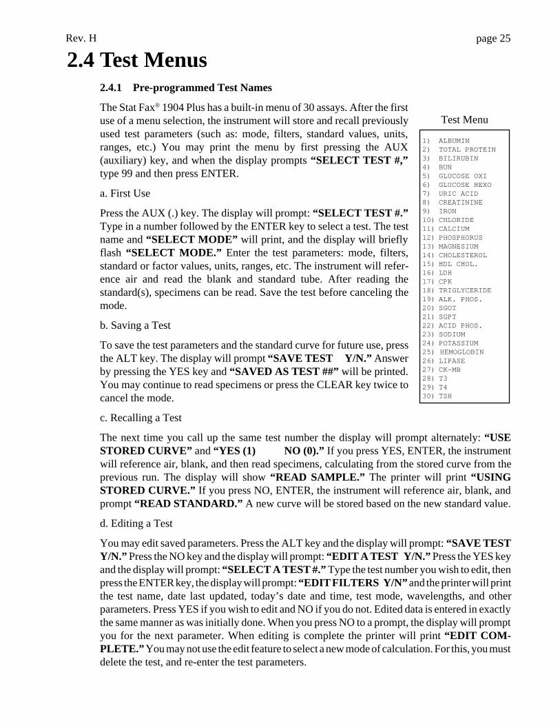
2.4 Test Menus2.4.1 Pre-programmed Test Names
The Stat Fax® 1904 Plus has a built-in menu of 30 assays. After the firstuse of a menu selection, the instrument will store and recall previouslyused test parameters (such as: mode, filters, standard values, units,ranges, etc.) You may print the menu by first pressing the AUX(auxiliary) key, and when the display prompts “SELECT TEST #,”type 99 and then press ENTER.
a. First Use
Press the AUX (.) key. The display will prompt: “SELECT TEST #.”Type in a number followed by the ENTER key to select a test. The testname and “SELECT MODE” will print, and the display will brieflyflash “SELECT MODE.” Enter the test parameters: mode, filters,standard or factor values, units, ranges, etc. The instrument will refer-ence air and read the blank and standard tube. After reading thestandard(s), specimens can be read. Save the test before canceling themode.
b. Saving a Test
To save the test parameters and the standard curve for future use, pressthe ALT key. The display will prompt “SAVE TEST Y/N.” Answerby pressing the YES key and “SAVED AS TEST ##” will be printed.You may continue to read specimens or press the CLEAR key twice tocancel the mode.
c. Recalling a Test
The next time you call up the same test number the display will prompt alternately: “USESTORED CURVE” and “YES (1) NO (0).” If you press YES, ENTER, the instrumentwill reference air, blank, and then read specimens, calculating from the stored curve from theprevious run. The display will show “READ SAMPLE.” The printer will print “USINGSTORED CURVE.” If you press NO, ENTER, the instrument will reference air, blank, andprompt “READ STANDARD.” A new curve will be stored based on the new standard value.
d. Editing a Test
You may edit saved parameters. Press the ALT key and the display will prompt: “SAVE TESTY/N.” Press the NO key and the display will prompt: “EDIT A TEST Y/N.” Press the YES keyand the display will prompt: “SELECT A TEST #.” Type the test number you wish to edit, thenpress the ENTER key, the display will prompt: “EDIT FILTERS Y/N” and the printer will printthe test name, date last updated, today’s date and time, test mode, wavelengths, and otherparameters. Press YES if you wish to edit and NO if you do not. Edited data is entered in exactlythe same manner as was initially done. When you press NO to a prompt, the display will promptyou for the next parameter. When editing is complete the printer will print “EDIT COM-PLETE.” You may not use the edit feature to select a new mode of calculation. For this, you mustdelete the test, and re-enter the test parameters.
1) ALBUMIN2) TOTAL PROTEIN3) BILIRUBIN4) BUN5) GLUCOSE OXI6) GLUCOSE HEXO7) URIC ACID8) CREATININE9) IRON10) CHLORIDE11) CALCIUM12) PHOSPHORUS13) MAGNESIUM14) CHOLESTEROL15) HDL CHOL.16) LDH17) CPK18) TRIGLYCERIDE19) ALK. PHOS.20) SGOT21) SGPT22) ACID PHOS.23) SODIUM24) POTASSIUM25) HEMOGLOBIN26) LIPASE27) CK-MB28) T329) T430) TSH
Test Menu
Rev. Hpage 26
e. Deleting a Test
You may delete a test from the menu. This will remove all the stored parameters. The test namewill be retained. Press the ALT key and the display will prompt: “SAVE TEST Y/N,” press theNO key and the display will prompt: “EDIT A TEST Y/N,” press the NO key an the display willprompt “DELETE A TEST Y/N.” Press the YES key and the display will prompt “SELECTTEST #.” Type the test number and press the ENTER key. The display will alternately prompt“DELETE TEST # XX” and “YES<1> NO<0>” to confirm the deletion. Press the YESkey then the ENTER key to delete the test.
To delete all tests from memory press the AUX key. The display will prompt “SELECT TEST#,” select test number 183 and press enter. This will also delete all user stored tests.
2.4.2 User Test Menu
a. Creating a User Test
If you want to set up a test that is not named in the menu, you can add it by name and number.Press any Mode key. Enter all the test parameters in the usual fashion. Read the blank andstandards. You may save the test any time between reading the last standard and turning theinstrument OFF or quitting the Mode. To save the test parameters and the standard curve for futureuse, press the ALT key. The display will prompt “SAVE TEST Y/N.” Press YES, and thedisplay asks “NAME TEST Y/N.” If you press NO the test is saved by the lowest availablenumber and named “USER TEST.” If you press YES, the first part of the alphabet is displayed.Use the 4 key to move left and the 6 key to move right. A blinking line will indicate the selectedletter. Press the ENTER key to select a letter. When selecting the last letter press ENTER twicein rapid succession. Press the YES key and the printer will print “SAVED AS TEST # XX” whereXX is the next available test number. You may continue to read specimens or press CLEAR twiceto cancel the mode. The user test parameters and curve will be stored by test numbers beginningwith number 31. There is memory for 39 user tests. If you try to save more, the error message“MEMORY IS FULL” will be displayed and printed.
A log page is provided in the back of this manual for maintain a list of user tests. Since user testsare stored by number, not by name, this will be an easy method of recalling your user tests.
b. Using a Stored Test
User tests are recalled, edited, and deleted in exactly the same manner as the menu tests describedin section 2.4.1.
Rev. H page 27
3. Additional Tips and Information
3.1 Restoring Electronic CalibrationIn this instrument, electronic calibration information is entered at the factory as the originalcalibration data and is maintained in the non-volatile RAM of the instrument. This informationis printed on the CALIBRATION DATA label affixed to the bottom of the unit.
DO NOT ALTER ANY POTENTIOMETER SETTING. SUCHALTERATION RENDERS THE FACTORY CALIBRATION
DATA INVALID !!!
If the calibration data is lost (primarily due to power surges or fluctuations), the printout willshow the messages, “DO ABS SET TEST #212!”, “DO TEMP SET TEST 210” , or both,depending on the nature of the loss. If the data is not restored, these messages will continue tobe printed each time the unit is turned on and every time a new mode is selected. The mode willoperate, but calibration of the absorbance and temperatures must be restored to assure accuracy.
If the date is lost, restore the date (see section 2.1.3-Set Time) before restoring the calibration data.Then, to enter the data from the CALIBRATION DATA label:
1. Select the indicated test by using the AUX key and entering the test number (210 or 212).
2. Test 210:
2a. Test 210 prompts “BLOCK =” ; enter the number from the BLOCK TEMP line of theCALIBRATION DATA label.
2b.Test 210 prompts “CELL =” ; enter the number from the CELL TEMP line of theCALIBRATION DATA label.
3. Test 212: Test 212 prompts “ABS FACTOR=” , enter the number from the ABSOR-BANCE line of the CALIBRATION DATA label.
4. If the message “ADJUST OUT OF RANGE” appears, select the test again and re-enter thecorrect data.
5. To print a report of the entered data, run test 213. The data in test 213 should match the datafrom the CALIBRATION DATA label.
Note: When the stored calibration data is lost, the absorbancefactor is set to 1.000 and the temperature offset adjustments forthe block and cell are set to 0.0. The instrument will not accept a
change greater than ±10% (.900 - 1.100) in the absorbance factor,nor will it accept a temperature change greater than ±2.5½C. If the
calibration data is lost, these limits assure that the instrumentrequires only minimal adjustment from the keyboard to remain
calibrated.
.1
Rev. Hpage 28
Note 2: The absorbance factor is an actual factor, which whenentered is multiplied by the current factor in memory. The block
temp and cell temp values are offsets, and are added to the currentvalues in memory. Re-entering data when data is already presentwill result in incorrect calibration data, unless the values already
stored in memory are considered.
3.2 Precautions3.2.1 Assure operator safety and prolong the life of your instrument:
• Use only the prescribed input voltage. The voltage select switch on the base of the instrument willindicate the acceptable input voltage.
• NEVER remove the ground plug.
• NEVER operate the instrument with the cover off.
• Do not attempt to make repairs or adjustments to the circuitry. Do not install any non-specifiedparts. Awareness Technology will supply all service and accessories. Consult your dealer tomake arrangements. Use of the improper fuse rating may be a fire hazard.
• Do not continue to operate a malfunctioning instrument.
3.2.2 Minimize operator error:
Most errors in laboratory testing are due not to bad reagents or malfunctioning instrumentation,but rather to operator error. Many measures have been taken in the design of this instrument tominimize operator error: stable factory calibration, automatic zeroing, complete operatorprompting, detailed labeling, pre-programmed calculations, comprehensive visual and audiblefeedback, flags and error messages, and minimal maintenance requirements, for example. Thefollowing precautions are offered to further assure quality laboratory results:
1. Read your instrument instruction manual before performing testing, then keep it handy as areference. Be sure that you fully understand how to choose the proper modes of operation andthe proper filters. Always work within the specified limitations of this instrument.
2. Use clean tubes and follow the instructions for blanking and standardizing very closely. (Useof the appropriate blanking material is also very important - water is not always specified.) Donot read tubes with bubbles or condensation. Some glass tubes absorb significantly at 405 and340nm. Be careful not to mix soda lime glass with borosilicate glass within an assay.
3. Check your display and printed results during operation. Your display and printer provideuseful information such as the values you enter, the mode of operation and filters you select, andall absorbance readings. Monitoring the printer and display during operation may help you todetect an error in the making. To correct a typed entry before pressing the ENTER key, press theCLEAR key and type again. To correct a typed entry after pressing the ENTER key, press theCLEAR key twice to clear the mode, and begin again with mode selection.
4. Prior to running temperature controlled assays, and periodically while running temperaturecontrolled assays, monitor the block and cell temperature on the display to assure that 37½C(±.3)is being properly maintained.
Rev. H page 29
5. Periodically check the calibration and linearity of your instrument against a standard reference.A carefully prepared serial dilution of a stable, darkly-colored substance such as REDI-CHECK®
may be used.
6. Appropriate controls should be run with each assay as indicated in the package inserts of thechemistry products used. If controls do not give expected results, the assay is invalid.
3.3 Maintenance and Service3.3.1 Preventing Trouble
It is important to follow the installation instructions carefully as described in section 1.2.Adequate clearance and ventilation should be provided as well as a vibration free surface.Connections to main circuits with large pumps, compressors or refrigerators should be avoided.
Your instrument is designed to be an essentially maintenance free instrument. To insure optimumtrouble free performance, the instrument should be kept dry and operated in an area free ofexcessive dust. The instrument employs interference filters of advanced technology, and willprovide extended life in humid environments when compared to standard soft interference filters.In general however, excessive humidity should be avoided. Optimum operating conditions arefrom 15 to 33° centigrade, and less than 80% relative humidity. Storage temperatures should notexceed -10 to +50° centigrade.
Cleaning should be done when necessary. A puff of air may be used to eliminate dust from theread well. Use a slightly damp soft cloth to remove dirt or spills. For decontamination, 70%isopropanol is recommended. Use of other chemicals or abrasive cleaners is not recommended.Care should be exercised not to wet the keypad excessively.
3.3.2 Troubleshooting Guide
Using the following guidelines, simple problems can often be isolated and corrected by theoperator.
IN ANY EVENT, IF THE INSTRUMENT CONTINUES TOMALFUNCTION, CALL YOUR DEALER TO ARRANGE FOR
SERVICE.
Service and repair work should be performed only by trainedservice personnel.
PROBLEM: The paper jam error message is displayed.
REMEDY: This is usually caused by a small piece of paper lodged between the flying print headand the side of the printer mechanism. Turn the instrument off. Reach into the printer mechanismwith a pair of tweezers, and carefully remove the paper. If you are unable to clear the jam, callyour dealer to arrange for service. Do not attempt to dismantle the printer.
PROBLEM: The lamp does not light.
REMEDY: Lamp replacement is an infrequent event since your lamp is rated to read over300,000 tubes, and your lampsaver feature minimizes idle time. Lamp replacement is onlyindicated if the lamp does not light. Instructions for lamp replacement are provided with eachreplacement lamp.
Rev. Hpage 30
PROBLEM: The instrument is several years old and has lost some linearity with time.
REMEDY: You may need new filters. Return the instrument for replacements. To retard thedeterioration of filters, store the instrument in an air conditioned environment, and do not exposeit to severe temperature shock. Call your dealer to arrange for service.
PROBLEM: Incorrect answers are obtained for chemistry controls.
REMEDY:
a. Check that the procedures and materials used were valid. Turbid or contaminated reagents mayaffect absorbance readings. Data collected using REDI-CHECK® can be very helpful inseparating instrument problems from reagent problems. Be sure that you are reading anappropriate chromophore for the operational and differential wavelengths. Check that theappropriate mode of operation was selected and review the operating procedures for that mode.Tubes should not have bubbles, condensation, severe scratches or smudges.
b. Check the standard(s) or calibrator values printed on the printer paper for accurate entry.
c. Review the procedure for blanking. Remember to use the same type of tube for the blank andthe samples.
d. Read the same tube several times to confirm repeatability.
PROBLEM: The instrument lacks reproducibility.
REMEDY:
a. If repeat readings of a tube show upward or downward drifting, check that the reaction iscompleted and that the affected tube(s) were not contaminated prior to use (a chromophorereleasing or consuming reaction may still be occurring). Next, check that the substance is notaffected by the warming of the lamp or temperature controlled cell. This can be done by insertinga tube with water, reading it several times, and observing whether or not the “drifting” disappears.(10 repeat readings of a glass tube containing water, read in the bichromatic absorbance modeand blanked on the first reading should consistently provide results within ± 0.005A with awarmed up lamp, improving with better quality vessels.) If repeatability on water is good, andthe temperature effect seems to be causing the drifting, use the incubation block to pre-warm allof the tubes to 37½C before reading and then read them in the 37½C cell.
b. If repeatability is poor but does not appear to be drifting in any direction, swirl the tube andlook for particulate matter. Bubbles, severe scratches or smudges, and condensation on tubes canalso cause poor repeatability. Lamp warmup is also important.
c. Secure tube fit is necessary for good repeatability. Be sure to select a vessel with a snug fit. Ifthe appropriate round glass tube (either 12 mm, or special model) does not fit snugly, return yourinstrument with several typical tubes for cell holder adjustment. Be sure you are reading at least1 mL of solution.
PROBLEM: The printing is dim or incomplete.
REMEDY: Use only the specified paper available from your instrument dealer.
PROBLEM: The normal operation of the instrument is suddenly interrupted.
REMEDY: As with all microprocessor-controlled devices, fluctuations and interruptions of the

Rev. H page 31
power supply may cause instrument failure. The keys may not respond to touch, and the displaymay remain fixed. Turn the power switch off and wait for about 5 seconds. Then switch theinstrument back on. The instrument will start up normally. If this interruption to normaloperation occurs with frequency, you should try plugging your instrument into a different circuit.Choose a circuit that is free of large transient voltages such as pumps, refrigerators, etc. If thisis not possible, install a commercially available surge protector (or noise filter).
PROBLEM: The instrument does not recognize tube insertion.
REMEDY: Check to see if the instrument is in Mosquito™ mode. If the line “SAMPLE VOL= XXXuL” is printed in the test header, you are in Mosquito™ mode. See section 3.4.1-Mosquito™ for additional information.
3.4 Accessories3.4.1 Mosquito™
Mosquito™ is an aspiration cell accessory designed for use with the Stat Fax® ChemistryAnalyzer and other models in the 1900 series that have temperature controlled 12mm cuvette wells.Minimum aspiration volume is only 250µL. Mosquito™ includes: a plug in micro-flow cell withall connections, a control unit including electronically regulated vacuum pump, valve, andinterface circuits, a 500mL waste bottle with full sensor, and all cabling.
To set the Mosquito™ on or off, press the ALT key, then press NO until you see “SETMOSQUITO Y/N” . Press YES. The display will show “MOSQUITO IN Y/N” . If you wantto read using the Mosquito™, press YES; if you want to read tubes, press NO.
WARNING: NEVER READ TUBES IN THE MOSQUITOMODE! The Mosquito mode uses a different pathlength
calculation, and answers will be wrong.
Setting up the Mosquito™ and reading with it are discussed separately in the Mosquito™Owner’s Manual. However, it is useful to be aware of the following software specific operationswhile using the Mosquito™:
If you wish to cancel a Rate reaction, press the CLEAR key.
If you are working with the printer off , the answers will stay in the display until you pressthe CLEAR key.
For more information regarding Mosquito™, contact your dealer.
3.4.2 REDI-CHECK®
REDI-CHECK® is a photometer check set used to verify the absorbance calibration, linearity,and precision of filter photometers on a routine basis. The kit contains 4 different chromophoresolutions to cover a wide range of wavelengths between 340nm and 630nm. Instructions areincluded for preparing dilutions of the chromophores to check linearity. Acceptance ranges areprovided for both bichromatic and monochromatic readings, with technical information trace-able to NIST. The kit, which is designed for monthly use, also includes a record keeping systemwhich visually indicates instrument performance and performance trends. For more informationregarding REDI-CHECK®, contact your dealer.
.1
Rev. Hpage 32
3.4.3 Stat Tracks™
Stat Tracks™ is a PC program that connects your analyzer to your PC. It provides simple yetpowerful tracking and reporting capabilities. With Stat Tracks™, you can store patient lists,setup and run worklists, see curves, print reports, and collect QC data. Stat Tracks™ employsa graphical user interface, making the program very simple to use. All functions are menu driven.
Stat Tracks™ includes a floppy disk containing the software program, an instruction manual, aserial cable for connecting your analyzer to a computer, and an updated EPROM containing theanalyzer software for running Stat Tracks™ (if necessary). For more information regarding StatTracks™, contact your dealer. Supply your instrument’s serial number when requestinginformation.
4. References1. Engineering data supplied by Awareness Technology, Inc. Palm City, Florida (1988)
2. Information on REDI-CHECK® Photometer QA Kit provided by Awareness Technology,Inc., Palm City FL (1990-1991)
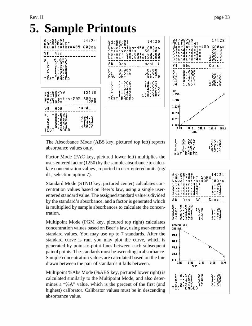
Rev. H page 33
5. Sample Printouts
The Absorbance Mode (ABS key, pictured top left) reportsabsorbance values only.
Factor Mode (FAC key, pictured lower left) multiplies theuser-entered factor (1250) by the sample absorbance to calcu-late concentration values , reported in user-entered units (ng/dL, selection option 7).
Standard Mode (STND key, pictured center) calculates con-centration values based on Beer’s law, using a single user-entered standard value. The assigned standard value is dividedby the standard’s absorbance, and a factor is generated whichis multiplied by sample absorbances to calculate the concen-tration.
Multipoint Mode (PGM key, pictured top right) calculatesconcentration values based on Beer’s law, using user-enteredstandard values. You may use up to 7 standards. After thestandard curve is run, you may plot the curve, which isgenerated by point-to-point lines between each subsequentpair of points. The standards must be ascending in absorbance.Sample concentration values are calculated based on the linedrawn between the pair of standards it falls between.
Multipoint %Abs Mode (%ABS key, pictured lower right) iscalculated similarly to the Multipoint Mode, and also deter-mines a “%A” value, which is the percent of the first (andhighest) calibrator. Calibrator values must be in descendingabsorbance value.
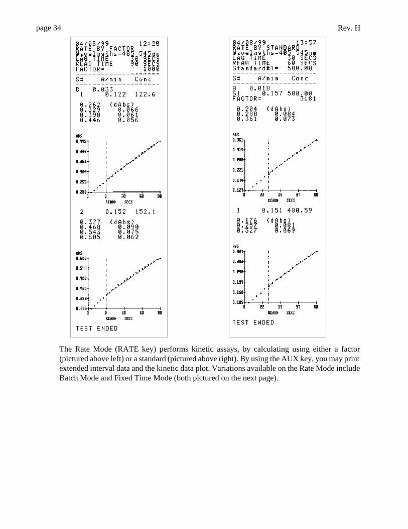
Rev. Hpage 34
The Rate Mode (RATE key) performs kinetic assays, by calculating using either a factor(pictured above left) or a standard (pictured above right). By using the AUX key, you may printextended interval data and the kinetic data plot. Variations available on the Rate Mode includeBatch Mode and Fixed Time Mode (both pictured on the next page).
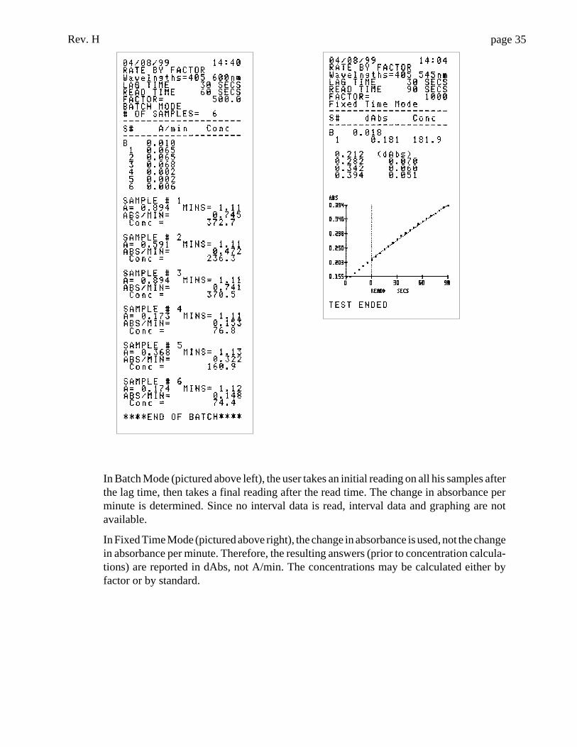
Rev. H page 35
In Batch Mode (pictured above left), the user takes an initial reading on all his samples afterthe lag time, then takes a final reading after the read time. The change in absorbance perminute is determined. Since no interval data is read, interval data and graphing are notavailable.
In Fixed Time Mode (pictured above right), the change in absorbance is used, not the changein absorbance per minute. Therefore, the resulting answers (prior to concentration calcula-tions) are reported in dAbs, not A/min. The concentrations may be calculated either byfactor or by standard.
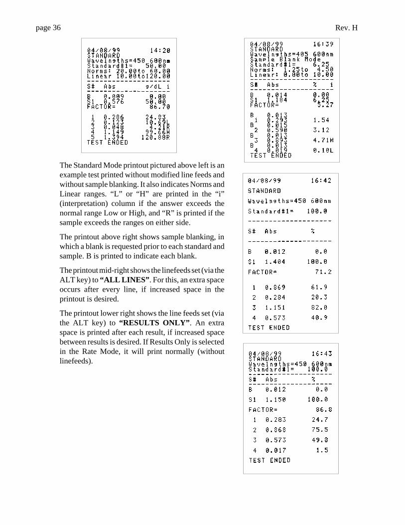
Rev. Hpage 36
The Standard Mode printout pictured above left is anexample test printed without modified line feeds andwithout sample blanking. It also indicates Norms andLinear ranges. “L” or “H” are printed in the “i”(interpretation) column if the answer exceeds thenormal range Low or High, and “R” is printed if thesample exceeds the ranges on either side.
The printout above right shows sample blanking, inwhich a blank is requested prior to each standard andsample. B is printed to indicate each blank.
The printout mid-right shows the linefeeds set (via theALT key) to “ALL LINES” . For this, an extra spaceoccurs after every line, if increased space in theprintout is desired.
The printout lower right shows the line feeds set (viathe ALT key) to “RESULTS ONLY” . An extraspace is printed after each result, if increased spacebetween results is desired. If Results Only is selectedin the Rate Mode, it will print normally (withoutlinefeeds).

Rev. H page 37
Stat Fax 1904+ (SN_____) User Test Menu Log page______
Test No. Analyte Stored By Date Notes
®
6. User Test Menu Log

Rev. Hpage 38
Rev. H page 39
Stat Fax® 1904 PlusOwner's Manual
Copyright 1989-1999 Awareness Technology, Inc. Revised 5/99. Doc. 1904P Rev. H.1
Table of Contents
1. Introduction ........................................... 11.1 Applications .................................... 1
1.1.1 Intended Uses ........................ 11.1.2 Summary of the Instrument ... 1
1.2 General Safety Summary ................ 21.2.1 To Avoid Fire or Personal
Injury ..................................... 21.2.2 Safety Terms and Symbols .... 3
1.3 Installation ...................................... 41.3.1 General Installation................ 41.3.2 Power Requirements .............. 41.3.3 Electrical Setup and Safety
Information ............................ 51.3.3 Paper Installation ................... 61.3.4 Checkout Procedure............... 7
1.4 Principle of Operation .................... 71.5.2 Keyboard Functions............... 8
1.5 Parts and Controls ........................... 91.5.1 Parts of the Instrument ........... 9
1.6 Instrument Specifications ............. 102. Operating Procedures ......................... 11
2.1 General Functions ......................... 112.1.1 Start Up ................................ 112.1.2 ALT Menu ........................... 112.1.3 Set Time ............................... 122.1.4 Lamp Warm Up ................... 122.1.5 Temperature Control ............ 122.1.6 Selecting a Mode ................. 132.1.7 Filter Selection..................... 13
2.2 General Operation......................... 142.2.1 Bichromatic Differential
Operation ............................. 142.2.2 Blanking .............................. 152.2.3 Unit of Measurement Codes
(Unit Code) .......................... 152.2.4 Ranges ................................. 152.2.5 Printer .................................. 162.2.6 Lamp Saver Feature ............. 16
2.2.7 Flags and Error Messages .... 172.3 Modes of Operation ......................... 18
2.3.1 Absorbance Mode ................ 182.3.2 Single Standard Mode ......... 192.3.3 Factor Mode......................... 202.3.4 Programmable Mode
(Multipoint) ......................... 202.3.5 Multipoint % Abs Mode ...... 212.3.6 Rate Mode ........................... 22
2.4 Test Menus.................................... 252.4.1 Pre-programmed Test Names252.4.2 User Test Menu .................... 26
3. Additional Tips and Information ....... 273.1 Restoring Electronic Calibration .. 273.2 Precautions ................................... 283.3 Maintenance and Service .............. 29
3.3.1 Preventing Trouble .............. 293.3.2 Troubleshooting Guide ........ 29
3.4 Accessories ................................... 313.4.1 Mosquito™ .......................... 313.4.2 REDI-CHECK® .................. 313.4.3 Stat Tracks™ ....................... 32
4. References............................................. 325. Sample Printouts ................................. 336. User Test Menu Log ............................. 37