Start Elevator Srl - ITASIA · 2019-04-25 · LD32 Blue LED ON = Wi-Fi module activated LD35 Orange...
48
file lb_HSe250_02_g.p65 G Operating instructions Operating instructions Operating instructions Operating instructions Operating instructions VAL AL AL AL ALVE UNIT VE UNIT VE UNIT VE UNIT VE UNIT HSe250 - 1"1/4 HSe250 - 1"1/4 HSe250 - 1"1/4 HSe250 - 1"1/4 HSe250 - 1"1/4 and BOARD SCH001 and BOARD SCH001 and BOARD SCH001 and BOARD SCH001 and BOARD SCH001 29010 Incrociata di Calendasco (PIACENZA) - ITALIA Tel. 0523 771131 - 0523 772774 Fax 0523 771632 e-mail: [email protected] - Internet: http://www.startelevator.it C.F. e P.I. 01410730335 - C.I. IT 01410730335 R.I. PC 01410730335 - R.E.A. 160057 Cap. Soc. Euro 40.000 i.v COMPONENTI OLEODINAMICI PER COMPONENTI OLEODINAMICI PER COMPONENTI OLEODINAMICI PER COMPONENTI OLEODINAMICI PER COMPONENTI OLEODINAMICI PER ASCENSORI ASCENSORI ASCENSORI ASCENSORI ASCENSORI Start Elevator Start Elevator Start Elevator Start Elevator Start Elevator Srl Srl Srl Srl Srl
Transcript of Start Elevator Srl - ITASIA · 2019-04-25 · LD32 Blue LED ON = Wi-Fi module activated LD35 Orange...

file
lb_
HS
e250
_02_
g.p6
5
G
Operating instructionsOperating instructionsOperating instructionsOperating instructionsOperating instructions
VVVVVALALALALALVE UNITVE UNITVE UNITVE UNITVE UNIT HSe250 - 1"1/4 HSe250 - 1"1/4 HSe250 - 1"1/4 HSe250 - 1"1/4 HSe250 - 1"1/4and BOARD SCH001and BOARD SCH001and BOARD SCH001and BOARD SCH001and BOARD SCH001
29010 Incrociata di Calendasco (PIACENZA) - ITALIATel. 0523 771131 - 0523 772774 Fax 0523 771632
e-mail: [email protected] - Internet: http://www.startelevator.it
C.F. e P.I. 01410730335 - C.I. IT 01410730335R.I. PC 01410730335 - R.E.A. 160057
Cap. Soc. Euro 40.000 i.v
COMPONENTI OLEODINAMICI PER COMPONENTI OLEODINAMICI PER COMPONENTI OLEODINAMICI PER COMPONENTI OLEODINAMICI PER COMPONENTI OLEODINAMICI PER ASCENSORIASCENSORIASCENSORIASCENSORIASCENSORI Start Elevator Start Elevator Start Elevator Start Elevator Start Elevator SrlSrlSrlSrlSrl

file
lb_
HS
e250
_02_
g.p6
5
GENERAL INDEX
GENERALITY 0230800- DESCRIPTION Pag. 1/2- INSPECTION ON DELIVERY Pag. 1/2- STORAGE Pag. 1/2- DISPOSING Pag. 1/2- DIRECTIVES AND TECHNICAL STANDARDS CONSIDERED Pag. 1/2- CONDITIONS OF USE Pag. 2/2- DECLARATION OF CONFORMITY Pag. 2/2
DIAGRAMS AND ADJUSTMENTS 0231003- MAIN COMPONENTS AND OPERATING LIMITS Pag. 1/9- HYDRAULIC DIAGRAM Pag. 2/9- BOARD SCH001 CONNECTION AND MAIN COMPONENTS Pag 3/9- RSW SELECTOR POSITION Pag. 4/9- W-IFI CONNECTION (Optional) Pag. 4/9- SD-CARD PARAMETERS RECOVERY Pag. 4/9- SD-CARD PARAMETERS LOADING Pag. 5/9- OVERLOAD PRESSURE AUTOMATIC SETTING Pag. 5/9- SOFTWARE UPDATING PROCEDURE Pag. 5/9- WORKING CYCLES PARAMETERS Pag. 6/9- SIGNAL AND SPEED PARAMETERS COMBINATION Pag. 7/9- COMMAND DEVICE WORKING DIAGRAM Pag. 8/9- VALVES FUNCTIONAL DIAGRAM Pag. 9/9
MOUNTING ARRANGEMENT 0231101- VALVE UNIT Pag. 1/2- SCH001 BOARD Pag. 2/2
WORKING 0231203- 1. UPWARD WORKING CYCLE Pag. 1/6- 2. DOWNWARD WORKING CYCLE Pag. 3/6- 3. UPWARD RELEVELING Pag. 4/6- 4. DOWNWARD RELEVELING Pag. 4/6- 5. DROP TEST Pag. 4/6- 6. MAXIMUM PRESSURE VALVE TEST Pag. 5/6- 7. ERROR CONDITION Pag. 5/6- 8 WORKING CYCLE DIAGRAMS Pag. 6/6
PROTECTION AGAINST THE UNCONTROLLEDMOVEMENT OF THE CABIN 0231302- INTRODUCTION Pag. 1/7- SCHEDULE OF OPERATION SIGNALS AND CONTROLS Pag. 1/7- 1.0 DEVICE TEST AGAINST UNCONTROLLED MOVEMENT Pag. 2/7- 2.0 SELF-CONTROL OF TYPE OF FUNCTIONAL REDUNDANCY Pag. 3/7- 2.1 CYCLE WITH SELF MONITORING FUNCTIONAL REDUNDANCY Pag. 4/7- 2.2 VERIFICATION OF THE PERIODIC AUTODETECTOR FUNCTION Pag. 4/7
OF REDUNDANCY- 3.0 SELF-CONTROL OF MONITORING PNP1 SIGNAL Pag. 5/7- 3.1 CONTROL OF THE CYCLE OF MONITORING PNP1 SIGNAL Pag. 5/7- 3.2 VERIFICATION OF THE SUPERVISORY FUNCTION Pag. 6/7
OF MONITORING PNP1 SIGNAL- 4.0 IDENTIFICATION AND TRACEABILITY Pag. 7/7

file
lb_
HS
e250
_02_
g.p6
5
This book is integrant part of the unit therefore must be kept for the lasting in operation of the unit, in a place accessibleand known by the installation, use and maintenance personnel.
The herewith instructions aim to permit the positive and safe execution of the installation operations, starting-up, working,control, maintenance and possible repair of the unit.
If any situation or event, not specified in the following pages, should occur, please refer to our Technical Department.For any request of general technical information or spare parts, please quote the identification data of the unit.
The instructions, drawings and documentation contained in this manual are reserved for technical, narrow property ofthe manufacturer and may not be reproduced in any way, either in full, or in part.
MANOEUVRES OF EMERGENCY 02314 00- DOWNWARD MOVEMENT OF THE CABIN Pag. 1/1- UPWARD MOVEMENT OF THE CAB Pag. 1/1
PARAMETERS ERRORS CODES 0231502- P1 BASE PARAMETERS Pag. 1/6- P2 UPWARD PARAMETERS Pag. 1/6- P3 DOWNWARD PARAMETERS Pag. 2/6- P4 ADVANCED PARAMETERS Pag. 2/6- P5 VIEW PARAMETERS Pag. 4/6- P7 COMMANDS Pag. 5/6- P8 TECHNICAL PARAMETERS Pag. 5/6- ERROR TABLE Pag, 6/6
AUTOMATIC REDUCTION OF TRAVEL TIMES 0231601- INTRODUCTION Pag. 1/2- RECOVERY SPACE LEVELING Pag. 1/2- REDUCTION OF STARTING TIME AND MAXIMUM UPWARD SPEED Pag. 2/2
WITH VVVF DRIVE WORKING 0231701
MAINTENANCE 0231800- MAINTENANCE PROGRAM AND PERIODIC CHECKS Pag. 1/2- DESCRIPTION OF CONTROLS Pag. 1/2
SCHEMES AND ADJUSTMENTS MULTI-VALVE 0232000- DESCRIPTION Pag. 1/4- HYDRAULIC DIAGRAM Pag. 2/4- CONNECTIONS MASTER-SLAVE Pag. 3/4- DIAGRAM OF FUNCTIONING CONTROL DEVICES Pag. 4/4
SYNBOLS LEGEND
This symbol warns that not observing therelated instruction involves a risk of damageto the unit or to the system
This symbol warns that not observing therelated instruction involves an electric shockrisk

02 308 / G rev. 0 1/2
GENERALITYVALVE UNIT
HSe250
Start Elevator
INSPECTION ON DELIVERYOn delivery, check that the material has not been damaged during transportation from the production plant;check that the packing is undamaged and that you have all the necessary accessories and / or required; alsocheck the correspondence of data on delivery and identification plates with those of the expected material.In the event of faults, defects or deficiencies, promptly notify our Technical Department.
STORAGEIn the installation waiting, the group must be stored away from the elements (can be especially damagedby water, damp and sun) and in a stable position.The temperature of the storage location should be between 0 and + 50 ° C (32 and 122 °F)
DISPOSINGThe device must be disposed of according to applicable regulations.
DIRECTIVES AND TECHNICAL STANDARDS CONSIDEREDThe groupe is designed in accordance with the Technical Standards listed below:
Standard - Directive Title2014/33/UE Lift Directive
EN 81-20:2014 Safety rules for the construction and installation of lifts
EN 81-50:2014 Design rules, calculations, examinations and tests of lift components
2006/42/CE Machinery Directive
2014/35/UE Low voltage Directive
2014/30/UE Electromagnetic compatibility Directive
EN 12015:2014 Electromagnetic compatibility - Emission
EN 12016:2016 Electromagnetic compatibility - Immunity
EN 60068-2-6 VibrationEnvironmental testing - Part 2: Tests - Test Fc: Vibration
EN 60068-2-14 TemperatureEnvironmental testing - Part 14: Tests - Test N. Change of temperature
EN 60068-2-27 ShockEnvironmental testing - Part 2-27: Tests - Test Еа and guidance: Shock
EN 60664-1: 2007Grado di inquinamento 2
Insulation coordination for equipment within low-voltage systems
2011/65/EU RoHS 2 Directive - on the restriction of the use of certain hazardous substances in electrical and electronic equipment
DESCRIPTIONThe HSe250 Valve unit is a component designed for use in lifting systems such as elevators and goods lifts.The function of the valve assembly, is to control the speed of the cabin and is to represent the stop element, downward.
It is forbidden the commissioning of the valve unit as part of a lifting system that has not been declared in conformity withlocal regulations.
The room where the unit is installed must be ventilated, free from dust and moisture.

02 308 / G rev. 0 2/2
GENERALITYVALVE UNIT
HSe250
Start Elevator
DECLARATION OF CONFORMITY ' Below an example of the declaration of conformity issued for each component
*---------------------------------------------------------------------------* * Start Elevator Srl * * * * * Incrociata di Calendasco * EU DRECLARATION * N. AANNNN * * * (Piacenza) Italia * OF CONFORMITY FOR *----------------------* * tel.0523 771131-772774 * A SAFETY COMPONENT * PAGE 1 * OF 1 * * www.startelevator.it * * * * *---------------------------------------------------------------------------* * * * The manufacturer : START ELEVATOR SRL * * 29010 INCROCIATA DI CALENDASCO - ITALY * * * * Declares that the product Valve unit * * Type - Model HSe250 * * * * Year of constr. - Serial number : MMAA - AANNNN * * Customer - Reference : ASCENS.ROSSI - IMP. 100 * * * * It is part of a device against uncontrolled downward movement * * of the cabin, composed of two hydraulic valves controlled * * electrically operating in series. * * Harmonized standard used : EN 81-20, 81-50 :2014 * * EU-type examination certificate NR. : CCCCCCC * * Released by: * * [ ] * * Implementing entity of the production checks in accordance with Annex IX * * of the Directive 2014/33/UE: * * [ ] * * . . * * Calendasco 07/11/2016 * * * * Legal representative . . * *---------------------------------------------------------------------------*
CONDITIONS OF USE- The part connected to the electrical safety devices is suitable to operate with the degree of pollution 3.- In industrial environments, provide an IP54 protective casing for the SCH001 board.- Nevertheless, use in a environment with permanent presence of conductive powder is excluded.- Usage altitude limit: 3000 m s.l.m.
For special conditions of use, please contact the Start Elevator Technical Department.

02 310 / G rev. 3 1/9
DIAGRAMS AND ADJUSTMENTSVALVE UNIT
HSe250
Start Elevator
MAIN COMPONENTS
1 Gauge2 Gauge cut-out cock5 Maximum pressure valve adjusting screw
- clockwise increase (+) - anticlockwise decrease (-)12 VSC valve zero contact16 ENR solenoid valve (unblock VNR valve)17 Emergency manual lowering (clockwise rotation)18 Filter19 Ball valve20 ERS solenoid valve (unblock VSR valve)25 Emergency manual lowering minimum pressure
- clockwise increase (+) - anticlockwise decrease (-)26 Hand pump27 Hand pump maximum pressure valve
- clockwise increase (+) - anticlockwise decrease (-)28 Hand pump non-return valve29 Hand pump air-release screw
TF Flow meterTP1 Pressure meterTT Temperature meterMPP VSC valve command Stepper motor
M Cylinder portP Pump portS Tank portPM Hand pump input port(P1) Auxiliary microrelevelling port
SP
TF
PM
TP1
TF
MPP
TP1
MPP
16
20
19
18
2517
TT
1
2
12
26
2829
27
5
MM
PS
TF
16
20
17
26
2
25
27
OPERATING LIMITS METRIC USA- Max static pressure: 45 bar 650 psi- Max operating pressure: 55 bar 800 psi- Minimum pressure: 10 bar 145 psi- Flow: 20 - 250 l/min 3- 65 gpm- Room temperature: 10 - 60 °C 50 - 150 °F- Viscosity: 14 - 290 cSt
P1

02 310 / G rev. 3 2/9
DIAGRAMS AND ADJUSTMENTSVALVE UNIT
HSe250
Start Elevator
1 Gauge2 Gauge cut-out cock5 Maximum pressure valve adjusting screw
- clockwise increase (+) - anticlockwise decrease (-)12 VSC valve zero contact16 ENR solenoid valve (unblock VNR valve)17 Emergency manual lowering (clockwise rotation)18 Filter19 Ball valve20 ERS solenoid valve (unblock VSR valve)23 VSC valve block control throttle25 Emergency manual lowering minimum pressure
- clockwise increase (+) - anticlockwise decrease (-)26 Hand pump27 Hand pump maximum pressure valve
- clockwise increase (+) - anticlockwise decrease (-)28 Hand pump non-return valve29 Hand pump air-release screw97 VNR valve block control throttle
TF Flow meterTP1 Pressure meterTT Temperature meterENR VNR valve unblock solenoid valveERS VSC valve unblock solenoid valveMPP VSC valve command Stepper motorVNP Pump no return valveVNR No return and downstroke safety valveVPM Pump maximum pressure valveVSC Flow control valveP1 Auxiliary microrelevelling port
HYDRAULIC DIAGRAM
LEGEND
OTHER PUMP UNIT COMPONENTS
M Pump motorP PumpS Pump silencerT Flexible pump connection pipe

02 310 / G rev. 3 3/9
DIAGRAMS AND ADJUSTMENTSVALVE UNIT
HSe250
Start Elevator
M1 Input Voltage 24-30 VDC- Max input power 25 W- Standby consumption 24VDC: 200mA, 300 mA with conencted data entry device
F1 Fuse 5A-T
M2 Solenoid valve ENR 24-30 VDC 35 W inputSolenoid valve ERS 24-30 VDC 35 W input
LD29 Red LED ON = Error conditionLD30 Yellow LED CAN operatingLD31 Green LED ON = Normal conditionLD32 Blue LED ON = Wi-Fi module activatedLD35 Orange LED ON = SD memory activated
OPTO-ISOLATED DIGITAL INPUT- Working voltage 20 - 60 VDC - 100 mA
CN6 UP Upward command inputDW Downward command inputHSP Upward high speed command input
(Downward also when Par. 453 = 0)MSP Maintenance and V2 speed command (Par. 205 e 305)
combined with high speed command when Par.454=1
CN7 SFY Motor Pump ON signalSP1 V3 Speed (together high speed command input)SP2 V4 Speed (together high speed command input)SP3 Downward high speed command input (when Par. 453 = 1)
CN8 -V Digital input negative common0V Bridge with -V negative for dry contacts+24V Voltage for dry contacts utilization max 100 mA
SWITCHING RELAY OUTPUT 2A-220VDC/250VAC
CN9 AVV Motor Pump startingCN10 T1 TMAX-TMIN (Par.105-110) temperature range exit:
> Par.105 always active,< Par. 110 during waiting command only active.
CN11 P1 PMAX-PMIN pressure range exit, (Par.106-107)always active if Par.457 =1 otherwiseduring waiting command only active if Par. 457=0
CN12 P2 Overload PS pressure limit overcoming, (Par.108)during waiting command only active
CN13 ERR Error conditionCN14 RDY Ready condition
DIGITAL OUTPUT V = 23 VDC - 500mA - PNP type
CN15 PNP1 Valve monitoring signalCN16 PNP2
M3 ENR solenoid valve connectionERS solenoid valve connection
RSW Working selector with 10 positionS1-S2 Confirmation keysRJ11 Hand terminal connectionSD Micro SD 2-16 GB FAT32CN20 Stepper motor connectionUSB Micro-Usb PC direct connectionCAN CAN net connectionWi-Fi Wi-Fi net connection moduleZERO VSC, TF, TP1, TT, sensor inputDSP1-2 digit signalyng display
BOARD SCH001 CONNECTION
ENR
ERS
ENR
ERSM2 M3
M124VDC
B2B1A1A2
CN20
UPDWHSPMSP
SFYSP1SP2SP3
CN6
CN7
CN8-V0V+24V
CN9 AVV
CN10 T1
CN11 P1
CN12 P2
CN13 ERR
CN14 RDY
CN15 PNP1
CN16 PNP2
SD USBRJ11
ZERO VSC
TF
TP1
TT
WI-FI
RSW
CNCNO
CNCNO
+24--+24--
_+
+GND+GND
CNCNO
CNCNO
CNCNO
CNCNO
S1
S2
LD29
LD32
DSP1
DSP2
F1
Inpu
t
Out
put
LD35
GND
CN5
CN4
CN2
CN1
CAN
CANH CANL GND

02 310 / G rev. 3 4/9
DIAGRAMS AND ADJUSTMENTSVALVE UNIT
HSe250
Start Elevator
RSW SELECTOR POSITION DSP1-2 CONFIRMATION DSP1-2BUTTON
0 NORMAL WORKING CONDITION (0000000000) (**) /1 HAND TERMINAL PARAMETER MODIFICATION (*) /2 WI-FI NET PARAMETER MODIFICATION (**) (ufufufufuf) /3 DROP TEST CONDITION (FCFCFCFCFC) S1 (fpfpfpfpfp) (***)4 UCM TEST (ucucucucuc) S1 (UPUPUPUPUP) (***)5 SD-CARD PARAMETERS READING (Iccccc) S26 PNP1 SIGNAL TEST (c-c-c-c-c-) S1/S2 (CCCCCu)(cccccd) (***)7 SD-CARD PARAMETERS WRITING (occccc) S28 MAXIMUM PRESSURE VALVE TEST CONDITION (PPPPPPPPPP) S1 (HPHPHPHPHP) (***)9 LAST ERROR NUMBER DISPLAY (----------) S1=RESET
With the selector in a position other than 0, the Ready signal (Pos.CN14) is normally deactivated andreactivated momentarily during the execution of a specific command.The Red LED near the RSW selector shows the position of the selector itself:The always-on LED corresponds to position 0, while it executes a flash sequence corresponding to the number of otherselected positions.
(*) Sensor pressure value display(**) The DSP1-2 display turns off after 10 s in the absence maneuvers(***) Switching the RSW selector in 0 position and pressing the S1 button the command is deleted
W-IFI CONNECTION (Optional)To Using a Wi-Fi device for managing parameters, you must download and install the Start Elevator applicationfrom the App Stores or Google play.- Switches the RSW selector in the position 2.- Wait until the LD32 blue light is fixed ON.- In Your device, to find and connect the WiFi network, with the name of serial number (ex. 16187901 or 16187902).- Start the application and when the login key is required, enter the name of WiFi network (ex. 16187901 or 16187902).
With the RSW selector in the position number 2 you can change the parameters.With the RSW selector in others position, you can only view the parameters until the blue light remains fixed.If the RSW selector is not in the position number two, the WiFi blue light and the WIFi network fall when there is noconnection for more that one minute.
However, remember to return to the position 0 of the switch RSW.
SD-CARD PARAMETERS RECOVERYTo save the parameters via SD CARD must use a Micro SD 2 to 16 GB already formatted FAT 32.
- Switch the RSW selector in position 7, the display will then show [occccc] and will turn on (ON) Yellow LED LD35.- Then press S2 button once and the Yellow LED will start flashing (ON-OFF) until the completion of the writing of
the parameters on the SD card.The file containing the parameters on the SD card is named with the number corresponding to network ID stored in the499 parameter and PAR extension (ex. 16187901.PAR) with the 31/12/2097 generic creation date .Then the display will show [0000000000] and the Yellow LED will turn off (OFF) and the Green LED executes a blinking(ON-OFF-ON).After the display shows [occccc] and will turn on again (ON) LED Yellow.
However, remember to return to the position 0 of the switch RSW.

02 310 / G rev. 3 5/9
DIAGRAMS AND ADJUSTMENTSVALVE UNIT
HSe250
Start Elevator
SD-CARD PARAMETERS LOADINGTo read the parameters from SD CARD must use a Micro SD 2 to 16 GB, formatted FAT 32 and containing the file with thenumber corresponding to network ID stored in the 499 parameter and PAR extension (ex. 16187901.PAR) with the data tobe loaded.
- Switch the RSW selector in position 5, the display will then show [Iccccc] and will turn on (ON) Yellow LED LD35.- Then press S2 button once and the Yellow LED will start flashing (ON-OFF) until the completion of parameters loading
from the SD card.Then the display will show [0000000000] and the Yellow LED will turn off (OFF) and the Green LED executes a blinking (ON-OFF-ON).After the display shows [Iccccc] and will turn on again (ON) LED Yellow.
However, remember to return to the position 0 of the switch RSW.
OVERLOAD PRESSURE AUTOMATIC SETTINGIt is possibile to put automatically the overload pressure in the P108 parameter, with the RSW selector in position = 1,which is normally displayed actual pressure value that is detected by the sensor.
There are two input modes:- The first is to place the load in the cabin of the overload swiching.
In this case the parameter P111, which stores the nominal load rate, must contain the value 0 and the acquisition in theparameter P108 will be that of pressure sensor reading in the current condition.
- The second is to acquire the overload value with empty cabin.In this case, the P111 parameter must contain the value of the nominal laod rate and therefore will be entered inparameter P108, the calculated pressure, according to the characteristics given in the parameters P101, P103, P104and P109, whereas as overload, the load rate increased by 10%, with a minimum of 75 kg (165 lb).
In both cases, pressing the S1 button toggles the insert mode, where the display shows [APAPAPAPAP], and then pressingthe S2 button is acquired or calculated, in the P108 parameter, the overload value.
Instead using the hand terminal, you must set the parameter P711 = 1, the first time to switch to insert mode [APAPAPAPAP],and the second time the parameter P711 = 1, to acquire or calculate, in the P108 parameter, the overload value .
However, remember to return to the position 0 of the switch RSW.
SOFTWARE UPDATING PROCEDUREBefore the upgrade of board software should save the current operating parameters(Ex. SD-CARD PARAMETERS RECOVERY).
- To update the software must be present on SD CARD the file FIRMWARE.DAT to install.- Insert the SD CARD in the SD slot.- Disconnect and reconnect the power connector M1.- After powering the M1 power connector of the card, the DISP1-2 "wheel" for 8 s, and during this time,
keep the S1 button pressed until [F1F1F1F1F1] appears on the DSP1-2.Then press the S2 button once to confirm the update command.
- At the end of the update appears on DISP1-2 [ohhhhh]- Remove the SD CARD from the SD slot- Disconnect and reconnect the power connector M1.

02 310 / G rev. 3 6/9
DIAGRAMS AND ADJUSTMENTSVALVE UNIT
HSe250
Start Elevator
P2 UPWARD PARAMETERS
P201 Upward initial acceleration change rateP202 Upward accelation distance (m, ft)P203 Upward final acceleration change rateP204 Upward high speed (m/s, fpm)P205 Second upward high speed (maintenance) (m/s, fpm)P206 Third upward high speed (m/s, fpm)P207 Upward initial deceleration change rateP208 Upward deceleration distance (m, ft)P209 Second upward deceleration distance (m, ft)P210 Third upward deceleration distance (m, ft)P211 Upward final deceleration change rateP212 Upward low speed (m/s, fpm)P213 Upward stopping distance (m)P214 Upward releveling acceleration distance (m, ft)P215 Upward releveling speed (m/s, fpm)P216 Upward releveling stopping distance (m, ft)P217 Fourth upward high speed (m/s, fpm)P218 Fourth upward deceleration distance (m, ft)
(uX) Display on DSP during phase execution
UP Upward command inputDW Downward command inputHSP Upward high speed command input (Downward also when Par. 453 = 0)MSP Maintenanans and V2 speed command
combined with high speed command when Par.454=1SP3 Downward high speed command input (when Par. 453 = 1)MOT Motor pump input (corresponding to AVV output relay)ENR Solenoid valve ENR inputERS Solenoid valve ERS input(For signal and device management see section 02312)
P3 DOWNWARD PARAMETERS
P301 Downward initial acceleration change rateP302 Downward accelation distance(m, ft)P303 Downward final acceleration change rateP304 Downward high speed (m/s, fpm)P305 Second downward high speed (maintenance) (m/s, fpm)P306 Third downward high speed (m/s, fpm)P307 Downward initial deceleration change rateP308 Downward deceleration distance (m, ft)P309 Second downward deceleration distance (m, ft)P310 Third downward deceleration distance (m, ft)P311 Downward final deceleration change rateP312 Downward low speed (m/s, fpm)P313 Downward stopping distance (m)P314 Downward releveling acceleration distance (m, ft)P315 Downward releveling speed (m/s, fpm)P316 Downward releveling stopping distance (m, ft)P317 Fourth downward high speed (m/s, fpm)P318 Fourth downward deceleration distance (m, ft)
(dX) Display on DSP during phase execution
WORKING CYCLES PARAMETERS
P201
P202(u1)
P203
P204P205P206P217(u2, u6)
P207
P208P209P210P218(u3)
P212(u4)
P215 (u8)P213 (u5)
P211
P216(u9)
P214 (u7)
P301
P302(d1)P303
P307
P304P305P306P307(d2, d6)
P308P309P310P318 (d3)
P311P312(d4)
P315 (d8)P313(d5)
P316(d9)
P314 (d7)
UP
HS
(M
SP
)
DW (MS
P) H
SP
o S
P3
ERS
ENR
ERS
MO
T

02 310 / G rev. 3 7/9
DIAGRAMS AND ADJUSTMENTSVALVE UNIT
HSe250
Start Elevator
SIGNAL AND SPEED PARAMETERS COMBINATION
0 1 0 1 0 1 0 1
UP 1DW 2HSP 6 1 0 1 0 1 0 1 0MSP 3
SP1 4SP2 5SP3 7 0 1 0 1 0 1 0 1
2.1 Downward releveling 2.2.1 Normal Downward (first) Cycle2.2.2.1 Maintenance (inspection) Downward (second) Cycle without deceleration to low speed2.2.2.2 Maintenance (inspection) Downward (second) Cycle with deceleration to low speed2.3.3 Third Downward Cycle2.3.4 Fourth Downward Cycle
Advan.param.
Digital Input
/PriorityLevel
Cycle param.
0 or 1
1
0
P314P315
P453 P454
P310
Downward starting conbination2.1 2.2.1 2.2.2.1 2.2.2.2 2.2.3 2.3.4
1 0 or 1 0 or 10
0 or 1 0 or 1 0
P309 P309
0
0
0 1 1
0 0
0 0
0 0 0 0 1 00 0 0 1
P302P306
P316
P302P304P308
P302P305
P302P305
P302P317P318
01 1 1 1 1
0 or 1
0
0
0 0 0 0
Accel.SpeedDeceler
1.1 1.2.1 1.2.2.1 1.2.2.2 1.2.3 1.2.40 or 1 0 or 1 0 or 1 0 or 1 0 or 1 0 or 10 or 1 0 or 1 0 1 0 or 1 0 or 1
UP 1 1 1 1 1 1 1DW 2 0 0 0 0 0 0HSP 6 0 1 0 1 1 1MSP 3 0 0 1 1 0 0
SP1 4 0 0 0 0 1 0SP2 5 0 0 0 0 0 1SP3 7 0 or 1 0 or 1 0 or 1 0 or 1 0 or 1 0 or 1
P214 P202 P202 P202 P202 P202P215 P204 P205 P205 P206 P217P216 P208 P209 P209 P210 P218
1.1 Upward releveling 1.2.1 Normal Upward (first) Cycle1.2.2.1 Maintenance (inspection) Upward (second) Cycle without deceleration to low speed 1.2.2.2 Maintenance (inspection) Upward (second) Cycle with deceleration to low speed1.2.3 Third Upward Cycle1.2.4 Fourth Upward Cycle
Advan.param.
Digital Input
/PriorityLevel
Cycle param.
Upward starting conbination
P453 P454
Accel.SpeedDeceler
Note: Simultaneous activation of SP1 and SP2 digital inputs, for 3 seconds, allows you to send a Reset Errorscommand to the card.

02 310 / G rev. 3 8/9
DIAGRAMS AND ADJUSTMENTSVALVE UNIT
HSe250
Start Elevator
COMMAND DEVICE WORKING DIAGRAM
SCH001CONTROL PANEL
M1
M3M2
MPPRM
RMENR
ERS
24VDC
V-ERS
V-ENR
A-ENR
A-ERS
D-MPP
CN6-8
CN9-16
M1 BOARD INPUT CONNECTIONM2 SOLENOID VALVES INPUT CONNECTIONM3 SOLENOID VALVES CONENCTIONV-ENR ENR INPUT CONTROLV-ERS ERS INPUT CONTROLA-ENR ENR CURRENT CONTROLA-ERS ERS CURRENT CONTROLENR VNR VALVE UNBLOCK SOLENOID VALVEERS VSC VALVE UNBLOCK SOLENOID VALVEZERO VSC VALVE POSITION SENSORTF FLOW SENSORTP1 PRESSURE SENSORTT TEMPERATURE SENSOR
MPP VSC VALVE COMAMND STEPPER MOTORD-MPP STEPPER MOTOR CONTROL DRIVERRM STEPPER MOTOR CONNECTION RELAYA1-A2 STEPPER MOTOR A PHASEB1-B2 STEPPER MOTOR B PHASE
CN6-8 BOARD SIGNALS INPUT CONNECTIONSCN9-16 BOARD SIGNALS OUTPUT CONNECTIONS
EN81-20 DOWNWARD DOWNWARD COMMAND DEVICESEN81-20 TRAVEL UPWARD AND DOWNWARD COMMAND DEVICES
DOWNWARDEN81-20
TRAVELEN81-20
B2
B1
A1
A2
ZERO VSCTFTP1TT
ENR
ERS
Inpu
t
Out
put

02 310 / G rev. 3 9/9
DIAGRAMS AND ADJUSTMENTSVALVE UNIT
HSe250
Start Elevator
1 Gauge2 Gauge cut-out cock5 Maximum pressure valve adjusting screw
- clockwise increase (+) - anticlockwise decrease (-)12 VSC valve zero contact16 ENR solenoid valve (unblock VNR valve)17 Emergency manual lowering (clockwise rotation)18 Filter19 Ball valve20 ERS solenoid valve (unblock VSR valve)23 VSC valve block control throttle25 Emergency manual lowering minimum pressure
- clockwise increase (+) - anticlockwise decrease (-)26 Hand pump27 Hand pump maximum pressure valve
- clockwise increase (+) - anticlockwise decrease (-)28 Hand pump non-return valve29 Hand pump air-release screw97 VNR valve block control throttle
VALVES FUNCTIONAL DIAGRAMLEGEND
TF Flow meterTP1 Pressure meterTT Temperature meterENR VNR valve unblock solenoid valveERS VSC valve unblock solenoid valveMPP VSC valve command Stepper motorVNP Pump no return valveVNR No return and downstroke safety valveVPM Pump maximum pressure valveVSC Flow control valveP1 Auxiliary microrelevelling port(M) Cylinder port(P) Pump port(S) Tank port(PM) Hand pump input port(SM) Maximum pressure valves draining
(PM) (SM) (S)
(P)
(S)
(M)
OTHER PUMP UNIT COMPONENTSM Pump motorP PumpS Pump silencerT Flexible pump connection pipe

02 311 / G rev. 1 1/2
MOUNTING ARRANGEMENTVALVE UNIT
HSe250
Start Elevator
Pumpportaxle
Plate mounting hole/shape pattern
Pump tube mounting hole pattern
Weight 13 Kg
~ Measures in mm
02 311 / G rev. 1 2/2
MOUNTING ARRANGEMENTVALVE UNIT
HSe250
Start Elevator
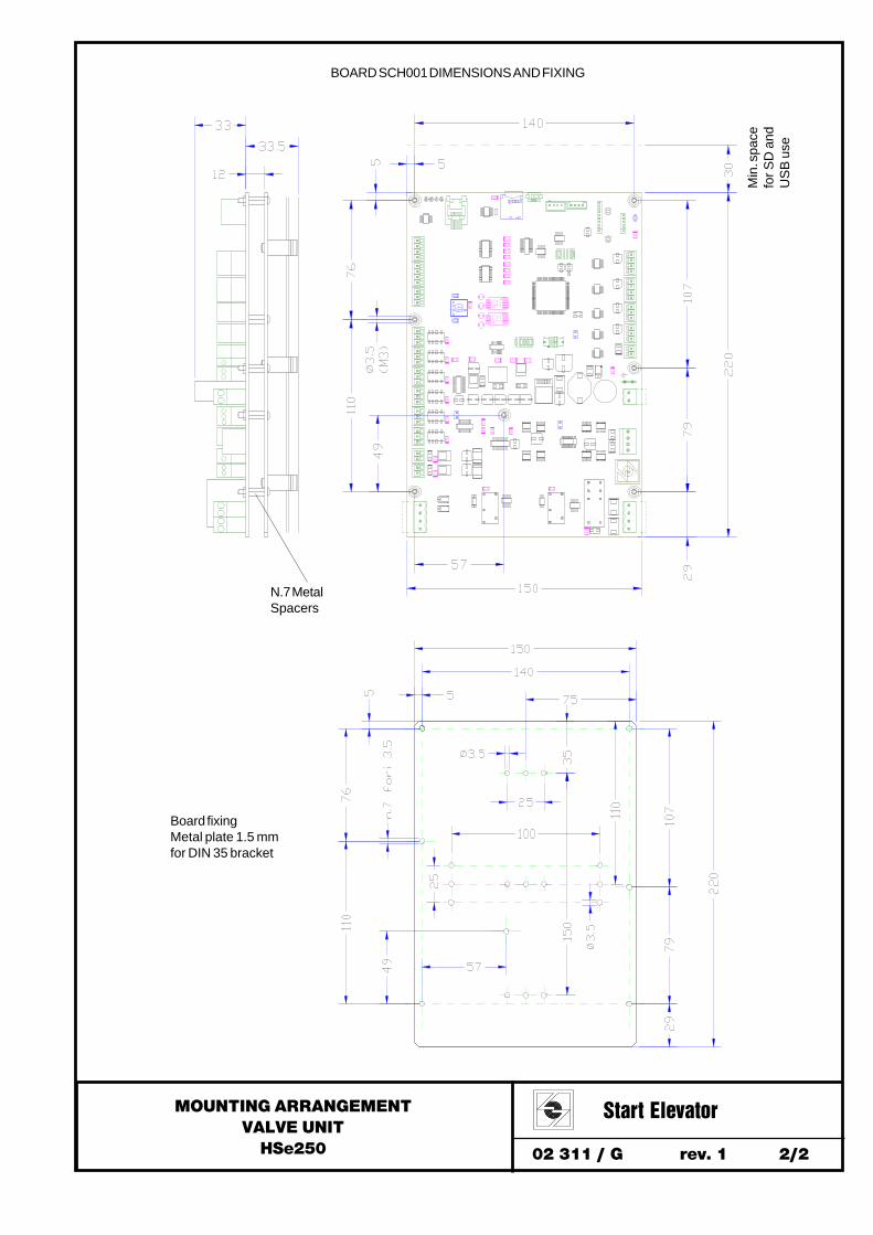
BOARD SCH001 DIMENSIONS AND FIXING
Board fixingMetal plate 1.5 mmfor DIN 35 bracket
Min
. spa
cefo
r SD
and
US
B u
se
N.7 MetalSpacers

02 312 / G rev. 3 1/6
WORKINGVALVE UNIT
HSe250
Start Elevator
RDY
UPWARD 1/8 - STATIONARY (DSP=00 00 00 00 00 or OFF)
Ready signal RDY from board to control panel during the waiting commands..
SCH001
UPWARD 2/8 - STARTING REQUEST (DSP=u0u0u0u0u0)
ERS
UP HSP
RD
Y
SCH001
To activate Upward UP and high speed HSP command input and make put on the solenoid valve ERS.The HSP high speed command can be replaced by MSP maintenance command (P454=0) or work together to signalsMSP (P454=1), SP1 o SP2 to determine different values of high-speed set in the corresponding parameters.
UPWARD 3/8 - MOTOR INPUT CONSENT (DSP=u0u0u0u0u0)
ERS
UP
HS
P
RD
Y
SCH001
The board commutes the AVV output to give consent for motor pump starting .In the case of non-use of this signal, the motor starting must occur after a time of about 1.5 s from the phase 2/8.In this phase, the pump oil flow is discharged in the tank at low pressure to allow a proper motor starting and avoid hitin the cabin caused by pump direct flow to piston.
AVV
UPWARD 4/8 - MOTOR STARTING COMPLETED AND CABIN ACCELERATION (DSP=u1u1u1u1u1)ER
S
UP
HS
P
RD
Y
SCH001
Once finisch the motor starting (direct, star-delta or soft starter) the control must return a signal to SFY board input.If the SFY signal is not available, it is useful to adjust the parameter P403 which sets the valve pre-starting time, after which, however,the valve unit executes the starting phase.The starting phase provides for the load taking, with a small movement of the cabin, and the execution of the acceleration curveaccording to corresponding parameters setting: P201, P202, P203.
AV
VSFY
The speed obtained corresponds to the parameter connected to the used high speed signal (P204 or P205, P206, P217).In case the speed selected in the parameter corresponds to a oil flow higher than the real pump flow rate, however the valve unit adapts itsoperation to the real maxim speed.
UPWARD 5/8 - HIGH SPEED (DSP=u2,u6u2,u6u2,u6u2,u6u2,u6)
RSW=0
RSW=0
1.UPWARD WORKING CYCLE
RSW=0
RSW=0

02 312 / G rev. 3 2/6
WORKINGVALVE UNIT
HSe250
Start Elevator
UPWARD 6/8 - DECELERATION (DSP=u3u3u3u3u3)
ERS
UP
RD
Y
SCH001
Upon arrival at the deceleration contact in the shaft, turn off the high speed HSP signal and the valve unit executesthe deceleration curve seted up in the parameters P207, P208 (209,210,218) and P211 for to obtain the low speed valuecorresponding to P212 parameter.
AV
VSFY
UPWARD 7/8 - LOW SPEED (DSP=u4u4u4u4u4)
UPWARD 8/8 - STOPPING (DSP=u5u5u5u5u5)
The duration of low speed phase depends on the difference between the space from the contacts of deceleration and stopping in theshaft and the deceleration distance programmed in the parameters.When the parameter P 456 = 1, during the deceleration and low speed phases, is calculated the distance traveled until the stop contactthat allows to run the next deceleration with a minimum low residual distance setted in the P458 parameter.The calculation is reset when the board is off.
ERS
RD
Y
AV
VSFY
HSP
UP
Upon arrival at the stopping contact in the shaft, it must turn off the upward UP signal.If the Soft-Stop parameter P232 = 1, the valve unit executes the stopping curve seted up in the parameter P213.
ERS
RD
Y
AVVSFY
ERS
RD
Y
Subsequently the shutdown of the RDY board signal also remove the ERS solenoid input.The RDY board signal is active again after about 0.5 s, when the valve unit will be ready for the next travel.However not to delay to remove the ERS solenoid input more than 2 s from the arrival on the stopping contact in the shaft.
If during the starting phase it has not used the AVV motor contact activation, to stop the motor with a delay of 1.5 s,otherwise when the signal AVV turns off, to stop the motor (and then the input signal SFY).However not to delay the stopping of the motor more than 2 s from the arrival on the stopping contact in the shaft.
RSW=0
RSW=0
RSW=0
RSW=0
SCH001
SCH001
SCH001

02 312 / G rev. 3 3/6
WORKINGVALVE UNIT
HSe250
Start Elevator
RDY
DOWNWARD 1/7 - STATIONARY (DSP=00 00 00 00 00 or OFF)
Ready signal RDY from board to control panel during the waiting commands..
SCH001
RD
Y
DOWNWARD 2/7 - STARTING (DSP=d00000)
To activate Downward DW and high speed HSP (or SP3 if the parameter P453=1) command input and make put onthe solenoid valves ENR and ERS.The HSP (or SP3) high speed command can be replaced by MSP maintenance command (P454=0) or work together to signalsMSP (P454=1), SP1 o SP2 to determine different values of high-speed set in the corresponding parameters.
SCH001
DW
HSP
(SP3
)
ENR
ERS
DOWNWARD 3/7 - ACCELERATION (DSP=d11111)This phase provides the execution of the acceleration curve according to corresponding parameters setting: P301, P302, P303.
DOWNWARD 4/7 - HIGH SPEED (DSP=d2,2,2,2,2,d66666)The speed obtained corresponds to the parameter connected to the used high speed signal (P304 oppure P305, P306, P317).
RD
Y
DOWNWARD 5/7 - DECELERATION (DSP=d33333)
SCH001
DW HSP
(SP3
)
ENR
ERS
Upon arrival at the deceleration contact in the shaft, turn off the high speed HSP signal (or the SP3 signal if the parameter P453=1)and the valve unit executes the deceleration curve seted up in the parameters P307, P308 (309,310,318) and P311for to obtain the low speed value corresponding to P312 parameter.
DOWNWARD 6/7 - LOW SPEED (DSP=d44444)
The duration of low speed phase depends on the difference between the space from the contacts of deceleration and stopping in theshaft and the deceleration distance programmed in the parameters.When the parameter P 456 = 1, during the deceleration and low speed phases, is calculated the distance traveled until the stop contactthat allows to run the next deceleration with a minimum low residual distance setted in the P459 parameter.The calculation is reset when the board is off.
2.DOWNWARD WORKING CYCLE
RSW=0
RSW=0
RSW=0

02 312 / G rev. 3 4/6
WORKINGVALVE UNIT
HSe250
Start Elevator
DOWNWARD 7/7 - STOPPING (DSP=d55555)
RD
Y
SCH001
DW
ENR
ERS
Upon arrival at the stopping contact in the shaft, it must turn off the downward DW signal.
RD
Y
SCH001
ENR
ERS
Subsequently the shutdown of the RDY board signal also remove the ERN and ERS solenoid inputs.The RDY board signal is active again after about 0.5 s, when the valve unit will be ready for the next travel.However not to delay to remove the ENR and ERS solenoid inputs more than 2 s from the arrival on the stopping contact in the shaft.
3.UPWARD RELEVELING (DSP=u7, u8, u9u7, u8, u9u7, u8, u9u7, u8, u9u7, u8, u9)Relevelling operations follow the sequence indicated in the normal upward cycle but without the use of the HSP high speed signal.The parameters P214, P215 e P216 define the acceleration distance, the movement speed and the stopping distance.
4.DOWNWARD RELEVELING (DSP=d77777, d88888, d99999)Relevelling operations follow the sequence indicated in the normal downward cycle but without the use of theHSP high speed signal.(or SP3 if the parameter P453 = 1).The parameters P314, P315 e P316 define the acceleration distance, the movement speed and the stopping distance.
5.DROP TEST (DSP=FC, FPFC, FPFC, FPFC, FPFC, FP)
Set the working selector RSW = 3 (DSP=FCFCFCFCFC) and then press S1 button until appear FP FP FP FP FP on display.This prepares the valve unit to execute the next descent with increased speed to verify the intervention of the rupture valve of thepiston.Go upward, with half load in the cabin, on a high floor then run a normal downstroke (to see the point DOWNWARD 2/7 in the presentinstruction),the increase of speed compared to the norrmal speed is defined by parameter P422.During drop test the value of reached maximum speed is stored in parameter P556.At the end of the downward maneuver the board no more provide the signal RDY if not performing a new drop test,by pressing the button S1 as described above, or a normal maneuver setting the selector RSW = 0.
Note: As an alternative to the use of RSW switch, you can activate the test condition setting parameter 705 to the value 1.At the end of the test the value of the parameter returns automatically to 0.
SCH001 S1
RSW=0
RSW=0
RSW=3

02 312 / G rev. 3 5/6
WORKINGVALVE UNIT
HSe250
Start Elevator
6.MAXIMUM PRESSURE VALVE TEST (DSP=PP, HPPP, HPPP, HPPP, HPPP, HP)
Set the working selector RSW = 8 (DSP=pppppppppp) and then press S1 button until appear hP hP hP hP hP on display.This prepares the valve unit to execute the next upward working cycle with a progressive pressure starting and without flow errorcondition.To close the ball valve.Run a normal upstroke (to see the point UPWARD 2/8 in the present instruction) ), it will be progressive and takes more time thanusual (at least 10 s).At the end of the upward maneuver the board no more provide the signal RDY if not performing a new maximim pressure test,by pressing the button S1 as described above, or a normal maneuver setting the selector RSW = 0.
Note: As an alternative to the use of RSW switch, you can activate the test condition setting parameter 704 to the value 1.At the end of the test the value of the parameter returns automatically to 0.
SCH001 S1
RSW=8
ERR
SCH001SF=0
7. ERROR CONDITION
Any operation must be disabled if the error signal ERR on relay is active.For error handling see the section 02315 "Parameters and Errors codes"
You can force on the error condition the signal ERR by setting the parameter 463 to the value 1This allows to verify the block of the control panel to the switching of the error signal ERR.At the end of the test remember to set the value of parameter 463 to 0 to resume the normal state of error.

02 312 / G rev. 3 6/6
WORKINGVALVE UNIT
HSe250
Start Elevator
1. UPWARD WORKING CYCLE DIAGRAM
SCH
001
Inpu
t ON
2. DOWNWARD WORKING CYCLE DIAGRAM
SCH
001
Out
put O
N
Dev
ice
Com
man
d O
N >
>
b - Upward deceleration contactd - Upward stopping contactf - Downward deceleration contacth - Downward stopping contact
Mot
or S
tart
ing
0.5-
1 s
0.5-
1 s
M -
Mot
or in
put
ENR
- EN
R S
olen
oid
valv
e in
put
ERS
- ER
S So
leno
id v
alve
inpu
t

02 313 / G rev. 2 1/7
PROTECTION AGAINST THE UNCONTROLLEDMOVEMENT OF THE CABIN
VALVE UNIT HSe250
Start Elevator
The valve unit is a part of the protective device against the uncontrolled movement of the lift, with the door not locked up or with the door open cabin, provided for in section 5.6.7 of the EN 81.20 standard. The device must detect the uncontrolled movement of the lift, cause it to stop, and keep it still. The valve unit is the stop element, downhill, provided as a subsystem in point 5.8.1 of the standard EN 81.50.
The protection against uncontrolled movement must act, uphill, interrupting the electrical supply of the motor / pump, while, in descent, the Start Elevator involved the use of a system formed by two electrically controlled valves and the hydraulic block ENR solenoid valves and ERS) operating in series, that participate in the normal operation of the lift.
It is expected, for this type of device, a self-monitoring by the electrical panel, according to point 5.6.7.3 of EN 81.20. To run the self-control of redundant descent devices, the electrical panel can operate in two modes: - Functional, operating periodically, automatically, the two valves for leaks (see section 2.0) - Checking the supplied tracking signal from the electronic board of the valve group (see section 3.0).
When the circuit required in Section 5.6.7.7 of the EN 81-20 identifies uncontrolled movements of the cabin doors open,i It must activate the stop element, interrupting any signal and command to the valve group. In particular, must be disconnected, on SCH001 electronic card, the inputs of ENR solenoid valves and ERS on the M2 terminal block, and in any case we have to stop the input signals to the card, the CN6-7 connector. The device must be actuated (interruption of the input signals), before the cab moves away 200 mm from the floor. There shall be a test of the device in accordance with Section 6.3.13 of the standard EN81-20 (see point 1.0)
When the device is activated or self-control redundancy has indicated a fault element device arrest, as required in section 5.6.7.9 of 81-20 standard, his release or the lift recovery must be checked by a competent person.
SCHEDULE OF OPERATION SIGNALS AND CONTROLS
M1 BOARD INPUT CONNECTIONM2 SOLENOID VALVES INPUT CONNECTIONM3 SOLENOID VALVES CONENCTIONV-ENR ENR INPUT CONTROLV-ERS ERS INPUT CONTROLA-ENR ENR CURRENT CONTROLA-ERS ERS CURRENT CONTROLENR VNR VALVE UNBLOCK SOLENOID VALVEERS VSC VALVE UNBLOCK SOLENOID VALVE
MPP VSC VALVE COMAMND STEPPER MOTORD-MPP STEPPER MOTOR CONTROL DRIVERRM STEPPER MOTOR CONNECTION RELAYA1-A2 STEPPER MOTOR A PHASEB1-B2 STEPPER MOTOR B PHASE
CN6-8 BOARD SIGNALS INPUT CONNECTIONSCN9-16 BOARD SIGNALS OUTPUT CONNECTIONS
EN81-20 DOWNWARD DOWNWARD COMMAND DEVICESEN81-20 TRAVEL UPWARD AND DOWNWARD COMMAND DEVICE
INTRODUCTION
ZERO VSC VALVE POSITION SENSORTF FLOW SENSORTP1 PRESSURE SENSORTT TEMPERATURE SENSOR
SCH001CONTROL PANEL
M1
M3M2
MPPRM
RMENR
ERS
24VDC
V-ERS
V-ENR
A-ENR
A-ERS
D-MPP
CN6-8
CN9-16
DOWNWARDEN81-20
TRAVELEN81-20
B2
B1
A1
A2
ZERO VSCTFTP1TT
ENR
ERS
Inpu
t
Out
put

02 313 / G rev. 2 2/7
PROTECTION AGAINST THE UNCONTROLLEDMOVEMENT OF THE CABIN
VALVE UNIT HSe250
Start Elevator
1.0 DEVICE TEST AGAINST UNCONTROLLED MOVEMENT (DSP=uc, upuc, upuc, upuc, upuc, up)
It describes a procedure to verify the conformity of the device in accordance with Section 6.3.13 of the EN81-20 norm.
Before proceeding, verify, however, the manual of the electrical panel, the operations necessary for the tests. Usually it predisposes the implant so as to exclude the possibility of calls and open the electric chain safeties at the level of the floor doors (for the system doors must be open even if physically closed) So the cab has to move up out of the door zone and stop responding for intervention of the safety circuit ..
Setting on the electronic board SCH001 the switch RSW = 4 (DSP = UC) and pressing the S1 button until UP appears on the display, It predisposes the valve group to perform the next cycle of ascent or descent with nominal speed, even during the respective releveling maneuvers.
1.1 Ascent with empty car, and positioned in the upper part of the compartment
Open, manually, the emergency lowering valve, pulling down the cabin until the intervention of re-leveling uphill. When the re-leveling intervenes, the system will start uphill at nominal speed and the switch intended to detect the movement uncontrolled must act by stopping the cab. Check that the stop position of the cab complies with the requirements in section 5.6.7.5 of EN 81-20.
1.2 Descent with a full load in the cabin, and the cabin located at the bottom of the compartment
Using the hand pump, moving uphill the plant, until the start of the downhill re-leveling. Intervenes when re-leveling, the plant will start descending at nominal speed and the switch purpose of identifying the uncontrolled movement must act by stopping the cabin. The device must operate the stop element, i.e., interrupt signals to the valve group during the descent, before the cab moves away from 200 mm from the floor. In particular, to activate the stop element, the device must disconnect, on SCH001 card, the inputs of the ENR solenoid valves and ERS
on the M2 terminal board, and in any case are to exclude the input signals to the card, the CN6-7 connectors. Check that the stop position of the cab complies with the requirements in section 5.6.7.5 of EN 81-20.
At the end of each maneuver, performed during the test, the card no longer provide the RDY signal, if not setting a new test,by pressing the S1 button again, or a normal operation changing the switch RSW = 0.
At the end of the test, restore normal system operation.
Note: As an alternative to the use of RSW switch, you can activate the test condition by setting the parameter P711 to the value 1. At the end of the test the value of the parameter returns automatically to 0.
For the verification of the monitoring function of the protective equipment refer to steps 2.2 or 3.2, depending on the type of self-control expected in the electrical panel.
SCH001 S1
RSW=4
ENR
ERS
UP
DW HS
PM
SP
SFY
SP
1S
P2
SP
3
M2CN6 - CN7
02 313 / G rev. 2 3/7
PROTECTION AGAINST THE UNCONTROLLEDMOVEMENT OF THE CABIN
VALVE UNIT HSe250
Start Elevator
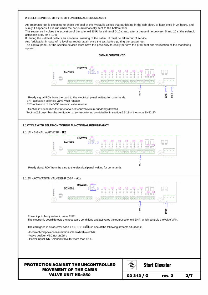
2.0 SELF-CONTROL OF TYPE OF FUNCTIONAL REDUNDANCY
An automatic test is expected to check the seal of the hydraulic valves that participate in the cab block, at least once in 24 hours, andsurely it happens if it is run when the car is automatically sent to the bottom floor.The sequence involves the activation of the solenoid ENR for a time of 5-10 s and, after a pause time between 5 and 10 s, the solenoidactivation ERS for 5-10 s.If, during the self-test detects an abnormal lowering of the cabin , it must be taken out of service.And 'advisable, in case of re-leveling, repeat again once the test before putting the system out.The control panel, or the specific devices must have the possibility to easily perform the proof test and verification of the monitoringsystem.
RD
Y
Ready signal RDY from the card to the electrical panel waiting for commands. ENR activation solenoid valve VNR release ERS activation of the VSC solenoid valve release
Section 2.1 describes the functional self-control cycle redundancy downhill Section 2.2 describes the verification of self-monitoring provided for in section 6.3.13 of the norm EN81-20
SCH001RSW=0
SIGNALS INVOLVED
ENR
ERS
RD
Y
2.1.1/4 - SIGNAL WAIT (DSP = 0000000000)
Ready signal RDY from the card to the electrical panel waiting for commands.
SCH001RSW=0
2.1 CYCLE WITH SELF MONITORING FUNCTIONAL REDUNDANCY
RD
Y
2.1.2/4 - ACTIVATION VALVE ENR (DSP = A1)
SCH001
ENR
RSW=0
Power input of only solenoid valve ENRThe electronic board detects the necessary conditions and activates the output solenoid ENR, which controls the valve VRN.
The card goes in error (error code = 19, DSP = E3 E3 E3 E3 E3)) in one of the following streams situations:
- Incorrect coil power consumption solenoid valvole ENR- Valve position VSC not on Zero- Power input ENR Solenoid valve for more than 12 s.
02 313 / G rev. 2 4/7
PROTECTION AGAINST THE UNCONTROLLEDMOVEMENT OF THE CABIN
VALVE UNIT HSe250
Start Elevator
RD
Y
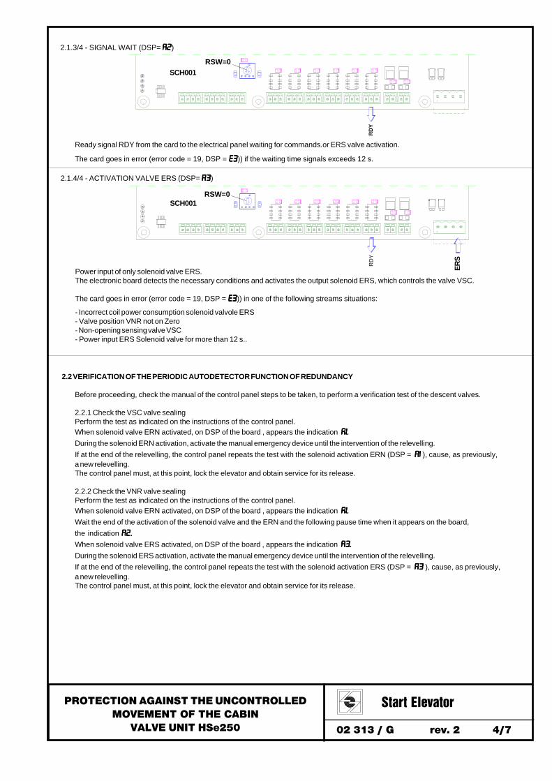
2.1.3/4 - SIGNAL WAIT (DSP= A2A2A2A2A2)
Ready signal RDY from the card to the electrical panel waiting for commands.or ERS valve activation.
The card goes in error (error code = 19, DSP = E3 E3 E3 E3 E3)) if the waiting time signals exceeds 12 s.
SCH001RSW=0
RD
Y
2.1.4/4 - ACTIVATION VALVE ERS (DSP= A3A3A3A3A3)
Power input of only solenoid valve ERS.The electronic board detects the necessary conditions and activates the output solenoid ERS, which controls the valve VSC.
The card goes in error (error code = 19, DSP = E3 E3 E3 E3 E3)) in one of the following streams situations:
- Incorrect coil power consumption solenoid valvole ERS- Valve position VNR not on Zero- Non-opening sensing valve VSC- Power input ERS Solenoid valve for more than 12 s..
SCH001
ERS
RSW=0
2.2 VERIFICATION OF THE PERIODIC AUTODETECTOR FUNCTION OF REDUNDANCY
Before proceeding, check the manual of the control panel steps to be taken, to perform a verification test of the descent valves.
2.2.1 Check the VSC valve sealingPerform the test as indicated on the instructions of the control panel.When solenoid valve ERN activated, on DSP of the board , appears the indication A1.A1.A1.A1.A1.
During the solenoid ERN activation, activate the manual emergency device until the intervention of the relevelling.If at the end of the relevelling, the control panel repeats the test with the solenoid activation ERN (DSP = A1A1A1A1A1 ), cause, as previously,a new relevelling.The control panel must, at this point, lock the elevator and obtain service for its release.
2.2.2 Check the VNR valve sealingPerform the test as indicated on the instructions of the control panel.When solenoid valve ERN activated, on DSP of the board , appears the indication A1.A1.A1.A1.A1.
Wait the end of the activation of the solenoid valve and the ERN and the following pause time when it appears on the board,the indication A2.A2.A2.A2.A2.
When solenoid valve ERS activated, on DSP of the board , appears the indication A3.A3.A3.A3.A3.
During the solenoid ERS activation, activate the manual emergency device until the intervention of the relevelling.If at the end of the relevelling, the control panel repeats the test with the solenoid activation ERS (DSP = A3A3A3A3A3 ), cause, as previously,a new relevelling.The control panel must, at this point, lock the elevator and obtain service for its release.

02 313 / G rev. 2 5/7
PROTECTION AGAINST THE UNCONTROLLEDMOVEMENT OF THE CABIN
VALVE UNIT HSe250
Start Elevator
3.0 SELF-CONTROL OF MONITORING PNP1 SIGNAL
An automatic control of PNP1 monitoring signal can be performed, alternatively or in addition to the functional control of the downhillredundancy (point 2.0), to check, for each maneuver, including releveling, the correct sequence of opening and closing of the valveshydraulic participating at the block of the cabin.The monitoring must be carried by controlling the timing of PNP1 following a change of state of the switching signal, corresponding, onthe electronic board SCH001, the entrance solenoid ERS + the up signal or down.
RD
Y
Ready signal RDY from the card to the waiting framework commands.
Section 3.1 describes the monitoring of PNP1 signal check cycle. Section 3.2 describes the verification of self-monitoring provided for in section 6.3.13 of the norm EN81-20
SCH001RSW=0
SIGNALS INVOLVED
PN
P1
ERS
The framework must be able to detect two different errors:
Error 1: When the maneuver signal switches from high to low level, the PNP1 signal switches to the high state within a time from 0.1s to1s.If the deadlines are not met an alarm to manage , as required by the standard , to be generated.
Error 2: When the maneuver signal goes from low to high level, the PNP1 signal switches to the low state within 0.1s.If the deadlines are not met an alarm to manage, as required by the standard ,to be generated.
Note: The schedule in the PNP1 signal handling are compatible with those used in the monitoring of the valves to signal + SMA iValve BucherGroup.
UP
DW
3.1 CONTROL OF THE CYCLE OF MONITORING PNP1 SIGNAL
3.1.
1/3
-SI
GN
ALW
AITI
NG
3.1.
2/3
-M
ANEU
VER
ACTI
VATI
ON
3.1.
3/3
-M
ANEU
VER
STO
P
Maneuver signalERS + (UP o DW)
Error condition PNP1 signal(0‐7) switching phases
OFF ON OFF ON
0) when ERS‐on + (UP‐on o DW‐on)se > 0,1 sError 2 1) if VSC and VNR closed ‐‐ > OFF
2) if VSC and VNR opened
3) when ERS‐off + UP‐off + DW‐offse < 0,1 s 4) Temporit = 0,1 sor > 1 sError 1 5) if VSC and VNR closed ‐‐> ON
6) Tempoext = 6 s
7) if VSC and VNR closed ‐‐ > OFF
Time ‐‐‐‐‐‐‐‐‐‐‐‐‐‐‐>
Error 2
Error 1

02 313 / G rev. 2 6/7
PROTECTION AGAINST THE UNCONTROLLEDMOVEMENT OF THE CABIN
VALVE UNIT HSe250
Start Elevator
RD
Y
3.1.1 / 3 - SIGNALS WAITING (DSP = 00)
Ready signal RDY from the card to the waiting framework commands.
SCH001RSW=0
RD
Y
3.1.2 / 3 - OPERATION ACTIVATION (DSP = 00)
SCH001RSW=0
(EN
R)
ERS(U
P)
(DW
)(H
SP
)
(SP3
)
The signals in parentheses are used together or alternatively as in normal maneuvers
RD
Y
3.1.3 / 3 - OPERATION STOP (DSP = 00)
SCH001RSW=0
ERS(U
P)
(DW
)
PN
P1
PN
P1
3.2 VERIFICATION OF THE SUPERVISORY FUNCTION OF MONITORING PNP1 SIGNAL
With the P461 parameter it is possible to lock them always PNP1 the signal at high level (P461 = 1) or low level (P461 = 2).The block of the the signal allows to check error detection from the electrical control panel.Only with the parameter P461 = 0 the PNP1 signal switches according to the normal operation.It is possible to change the value of parameter P461 by setting on the SCH001 board the selector RSW = 6 (DSP=C-C-C-C-C-)and pressing the S1 button until the display shows CCCCCu, to set P461 = 1 or, by pressing the S2 button until that CCCCCd appears on the display,to set P461 = 2.
3.2.1 Always check ON signalChange the parameter P461 to the value 1.Perform a maneuver in any direction.At the end of the maneuver, the control system, must indicate an error state corresponding to the signal PNP1 (Error 2).Reset on the panel the error, re-start the lift.
3.2.2 Always check signal OFFChange the P461 parameter to 2.Perform a maneuver in any direction.At the end of the maneuver, the control system, must indicate an error state corresponding to the signal PNP1 (Error 1).Reset on the panel the error, re-start the lift.
3.2.3 Verification normal operation.At the end of a maneuver as described in point 3.2.1 or 3.2.2 the P461 parameter automatically returns to the value 0,which corresponds to the normal operating condition, otherwise manually modify the P461 parameter to return to the value 0.Perform a maneuver, in any direction to ensure that, does not appear no error corresponding to PNP1 signal.

02 313 / G rev. 2 7/7
PROTECTION AGAINST THE UNCONTROLLEDMOVEMENT OF THE CABIN
VALVE UNIT HSe250
Start Elevator
4.0 IDENTIFICATION AND TRACEABILITY
4.1 The valve group is applied a plaque showing the name and address of Start Elevator, serial number,the type / model and the certification data in addition to a barcode (QR TAG).
The serial number matches that of the Order confirmation concerning the part or unit on which it is mounted. The number of the order confirmation also appears on the material delivery note.
4.2 The customer receives the documentation "EC Declaration of Conformity" which contains, in addition to data seen in Section 4.1, theCustomer's name and the reference of the customer. The certificate number is the number of the safety component series and then to thatof the corresponding order confirmation.
4.3 Start Elevator keeps a database in the list of Customer, Customer Order Reference, number of component serieswhich allows traceability with historical sampling archives and manufacture of components.
Label size: 42 x 64 mmQR TAG size 19 x 19 mm
Pos. Field content typeLength max Sample content
1 Type and component model CHAR 40 HSe2502 Not used CHAR 23 Not used CHAR 24 Sales Reference CHAR 35 IMP. 16/0205 Serial number CHAR 18 1618516 Not used CHAR 10 - - -7 Maker CHAR 30 Start Elevator8 Postal code CHAR 10 290109 City CHAR 30 Calendasco (PC)
10 Country code CHAR 5 IT11 Not used CHAR 30 - - -12 Not used CHAR 10 - - -13 Not used CHAR 30 - - -14 Not used CHAR 5 - - -
The content QR TAG is shown in the following table.

02 314 / I rev. 0 1/1
MANOEUVRES OF EMERGENCYVALVE UNIT
HSe250
Start Elevator
DOWNWARD MOVEMENT OF THE CABIN
UPWARD MOVEMENT OF THE CAB
The automatic emergency, in the case of mains failure, must use devices of the valves of the group , that workingduring the normal descent maneuver, powered by a battery 24 VDC and 100 W.For the manually downhill maneuver , operate the knob 17, in a clockwise direction, up to a level where thepassengers can get out of the cab.The regulation of the N° 25 determines the residual pressure of the piston manual lowering.Turn clockwise to increase pressure, counterclockwise decreases.To check the minimum pressure adjustment:- turn on the tap 2 of the gauge cut,- turn off the faucet valve assembly 19 and- turn the knob 17.The gauge should show 5-6 bars, if not open the tap 19, adjust the screw n. 25, and then test again.At the end remember to close the gauge cut tap.
The displacement of the cabin upwards is possible by acting on the hand pump 26, through the appropriateactuating lever.If the hand pump is not triggered:- Unscrew one turn the vent screw 29 and pump until oil comes out from the same screw,- tighten the vent screw.The hand pump is equipped with an overpressure valve which limits the maximum pressure.the screw N° 27 allows you to adjust the maximum pressure which, normally, must not exceed 2.3 timesthe maximum static pressure.Turn clockwise to increase pressure, counterclockwise decreases.To test the pressure relief valve:- turn on the tap 2 of the gauge cut,- turn off the faucet valve assembly 19 and- operate the hand pump 26 until the pressure continues to increase.The gauge should show the pressure defined by installation specifications.Otherwise, release the pressure by turning the knob 17, adjust the screw 27 and then test again.At end remember to close the gauge cut tap.
17
26
2
25
27
19
29

02 315 / G rev. 3 1/7
PARAMETERSERRORS CODES
VALVE UNIT HSe250
Start Elevator
The parameters of the series P1, P2, P3, P5 and P6 have free access, while those of series P4, P7 and P8need the setting of parameter P199 with the value = 8369111 (user password), which will reset when youdisconnect the device or you re-enter in P199 parameter.The P5 and P6 parameters (error stack) are read-only.
The parameters change has on the SCH001 board effect only with the selector position RSW = 1
ParameterNr Desc. Hand term. Large Description Unit Default
Value Nota
P1 Base Par. BASE PARAMETERS Min Max101 Piston Dia Piston working diameter mm 5 999 80102 Pump Flow Pump nominal flow lt/min 1 1000 100103 Tackle X:1 Roping Ratio 1 4 2104 Pist. Pistons number 1 4 1105 TMAX limit Maximum temperature limit °C 10 80 60 > P110106 PMAX limit High pressure limit bar 1 200 45 > P107107 PMIN limit Low pressure limit bar 0 200 10 < P106108 PS overload Load Weighing bar 0,1 200,0 30,0109 Pist.Stages Pistons stages number 1,000 4,000 1,000110 TMIN limit Low temperature limit °C 0 80 4 < P105111 Cabin Load Cabin nominal load kg 0 200000 600199 User Pass User password 0000000 9999999 0000000 8369111
Setting Range
ParameterNr Desc. Hand term. Large Description Unit Default
Value Nota
P2 Upward Par. UPWARD PARAMETERS Min Max201 %AccStart U Upward initial acceleration change rate % 0 100 1202 Acc Dist U Upward accelation distance m 0,000 10,000 1,500203 %Acc End U Upward final acceleration change rate % 0 100 100204 HighSpeedU1 Upward high speed m/s 0,000 2,000 0,600
205 HighSpeedU2 Second upward high speed (maintenance) m/s 0,000 2,000 0,300 < P204
206 HighSpeedU3 Third upward high speed m/s 0,000 2,000 0,200 < P204207 %DecStart U Upward initial deceleration change rate % 0 100 50208 Dec Dist U1 Upward deceleration distance m 0,000 10,000 0,400209 Dec Dist U2 Second upward deceleration distance m 0,000 10,000 0,400210 Dec Dist U3 Third upward deceleration distance m 0,000 10,000 0,400211 %Dec End U Upward final deceleration change rate % 0 100 50212 Low Speed U Upward low speed m/s 0,000 0,300 0,050 < P204,P205213 Stop Dist U Upward stopping distance m 0,000 10,000 0,010214 Acc Dist UR Upward releveling acceleration distance m 0,000 10,000 0,010215 RelevSpeedU Upward releveling speed m/s 0,000 0,300 0,050 < P204, P205216 Stop DistUR Upward releveling stopping distance m 0,000 10,000 0,020217 HighSpeedU4 Fourth upward high speed m/s 0,000 2,000 0,119 < P204218 Dec Dist U4 Fourth upward deceleration distance m 0,000 10,000 1,000
231 Y/N VVVF U Upward travel: with VVVF driver = 1, with microlevelling = 2, hybrid with VVVF=3 0 3 0
232 Y/N SoftS U Soft stop setting, if = 1 upward travel with soft stop 0 1 1
233 OverSpeed U Nominal speed maximum increasing % 0 20 8
Setting Range

02 315 / G rev. 3 2/7
PARAMETERSERRORS CODES
VALVE UNIT HSe250
Start Elevator
ParameterNr Desc. Hand term. Large Description Unit Default
Value Nota
P3 Downward Par DOWNWARD PARAMETERS Min Max
301 %AccStart D Downward initial acceleration change rate % 0 100 1
302 Acc Dist D Downward accelation distance m 0,000 10,000 1,500303 %Acc End D Downward final acceleration change rate % 0 100 100304 HighSpeedD1 Downward high speed m/s 0,000 2,000 0,600
305 HighSpeedD2 Second downward high speed (maintenance) m/s 0,000 2,000 0,300 < P304
306 HighSpeedD3 Third downward high speed m/s 0,000 2,000 0,200 < P304
307 %DecStart D Downward initial deceleration change rate % 0 100 50
308 Dec Dist D1 Downward deceleration distance m 0,000 10,000 0,400309 Dec Dist D2 Second downward deceleration distance m 0,000 10,000 0,400310 Dec Dist D3 Third downward deceleration distance m 0,000 10,000 0,400311 %Dec End D Downward final deceleration change rate % 0 100 50312 Low Speed D Downward low speed m/s 0,000 0,300 0,050 < P304,P305313 Stop Dist D Downward stopping distance m 0,000 10,000 0,010
314 Acc Dist DR Downward releveling acceleration distance m 0,000 10,000 0,010
315 RelevSpeedD Downward releveling speed m/s 0,000 0,300 0,050 < P304, P305316 Stop DistDR Downward releveling stopping distance m 0,000 10,000 0,020317 HighSpeedD4 Fourth downward high speed m/s 0,000 2,000 0,259 < P304318 Dec Dist D4 Fourth downward deceleration distance m 0,000 10,000 1,000319 MinSpeedERS Minimum speed for ENR stop m/s 0,000 0,300 0,050
Setting Range
ParameterNr Desc. Hand term. Large Description Unit Default
Value Nota
P4 Advanced Par ADVANCED PARAMETERS Min Max401 Open Time2U Starting opening time 2 s/1000 0 20000 1000
402 Max Pos MPP STEPPERMOTOR maximum opening position step 0 23000 13000
403 Wait Time2U Opening waiting time 2 dec 0 30 5404 CloseTime2U Starting closing time 2 s/1000 0 20000 2000406 TargetMPP U Upward MPP opening initial position step 0 23000 2300 <= P402407 Open Time4U Arrival opening time 4 s/1000 0 20000 1000408 TargetMPP D Downward MPP opening initial position step 0 23000 0 <= P402409 Wait Time4U Opening waiting time 4 dec 0 30 10410 CloseTime4U Arrival closing time 4 s/1000 0 20000 2000411 FlowMaxStop Max dounward flow with closed MPP lt/min 0 30 5412 Stop Time D Downward stopping time s/1000 0 20000 5000422 %SpeedIncrD Drop test parameter increase rate % 0 100 60423 ZeroPos MIS Flow meter zero position 0 50000 850
424 Pause ERS U STEPPER upward start time delay from ERS dec 0 30 1
425 Pos Min MPP STEPPER position inferior limit step 0 23000 2000 <= P402
426 Pause ERS D STEPPER downward start time delay from ERS dec 0 30 1
427 TemperZeroM Flow meter zero temperature °C 0 80 0
Setting Range

02 315 / G rev. 3 3/7
PARAMETERSERRORS CODES
VALVE UNIT HSe250
Start Elevator
ParameterNr Desc. Hand term. Large Description Unit Default
Value Nota
430 Start Time1 STEPPER starting time 1 s/1000 0 20000 150432 StopPos MPP STEPPER stopping position step 0 23000 10 <= P402433 StartPos2 D Downward starting target position 2 step 0 23000 7000 <= P402
434 StartPos1 D Downward starting ENR activation position 1 step 0 23000 1800 <= P402
435 StartTime2D Downward starting opening time 2 s/1000 0 20000 4000436 Pos Max MIS Flow meter max position 0 10000 2400437 Oil Vis 40 Oil viscosity at 40 °C cSt 0,00 999,99 46,00 > P438438 Oil Vis 100 Oil viscosity at 100 °C cSt 0,00 999,99 8,40 < P437441 Min Speed U Upward minimum speed m/s 0,000 0,100 0,010442 Min Speed D Downward minimum speed m/s 0,000 0,100 0,005443 Minim.Temp. Minimum temperature limit °C 0 80 5444 StartTime3U Upward starting time 3 s/1000 0 20000 4000445 P0WaitTime Waiting time at pressure 0 s/1000 0 20000 10000446 StartTimeP0 Time searching flow at pressure 0 s/1000 0 20000 3000451 ControlType Control type: 1=PID, PID+Map, 0=Map 0 2 1
452 SP Calcul. Deceleration space recalculation, 1=Activate 0 1 0
453 SignalSpeeD Downward high speed signal: 1=Activate 0 1 0
454 OnOff V2+V1 Maintenance with high speed signal: 1=Activate 0 1 0
456 SP recovery Levelling space recovery: 1=Activate 0 1 0
457 OnOff P1-P2During manoeuvre P1 relay updating : 0=OFF, 1=ON, +2 speed bloccok under P107
0 3 0
458 MinSP Low U Upward minimum levelling space mm 0 1000 150459 MinSP Low D Downward minimum levelling space mm 0 1000 150
460 OnOff CompT Flow meter temperature compensation: 1=Activate 0 3 1
461 PNP1 Test PNP1 signal check test: 0=normal, 1= fixed ON, 2= fixed OFF 0 9 0
462 RotDisplay Display direction 0=right, 1=left 0 1 0
463 ErrRelay ON Error output relay test: 0= nomal, 1= blocked ON 0 1 0
464 E1 E2 Block E1 E2 error block in PNP1 0 1 0
475 CanNodeType CAN node type: 0=no ; 1=master; 2=slave 0 2 0
476 CanNodeAddr CAN node address 1 99999999 1477 Slaves Slave nodes total number 1 7 1478 CAN Active CAN node activation: 0=OFF, 1=ON 0 1 0479 Offset CAN Offset value for CAN addresses 0 99999999 0480 ConBoardCAN CAN address control board 0 99999999 0
488 Test Cond. Test condition with solenoid valve always supplied: 1=ON , 0=OFF 0 1 0
489 MinPressure Minimum Pressure limit 0,1 20,0 2,0491 Offset MsT1 Flow meter zero temperature 1 °C 0 80 20492 Offset Mis1 Flow meter zero position 1 0 10000 893493 Offset MsT2 Flow meter zero temperature 2 °C 0 80 60494 Offset Mis2 Flow meter zero position 2 0 10000 976
497 A3 Error A3 monitoring during error: 1=Activate, 2=Also maximum time 0 2 1
499 Network ID Network ID 0 99999999 12345678
Setting Range

02 315 / G rev. 3 4/7
PARAMETERSERRORS CODES
VALVE UNIT HSe250
Start Elevator
ParameterNr Desc. Hand term. Large Description Unit Default
Value Nota
P5 View VIEW PARAMETERS Min Max501 MPP step MPP position step 0 23000502 Temperature Temperature sensor °C 0 100509 Speed Cabin speed m/s 0 2510 Flow sensor Flow sensor value 0 10000511 Flow Flow meter l/min 0 999512 Pressure Pressure sensor bar 0,0 999,0513 OnOffI zero STEPPER zero sensor 0 1
514 OnOffI ENRI ENR downward solenoid valve consumption 0 1
515 OnOffI ERSI ERS discharg solenoid valve consumption 0 1516 OnOffI ENRV ENR downward solenoid valve input 0 1517 OnOffI ERSV ERS discharg solenoid valve input 0 1521 OnOffI UP Upward command input 0 1522 OnOffI DOWN Downward command input 0 1523 OnOffI HS High speed command input 0 1524 OnOffI MAN Maintenance command input 0 1
525 OnOffI DHS Downward high speed optional command input 0 1
526 OnOffI PWM Motop pump started input 0 1527 OnOffI HS1 Auxiliary speed 1 commad input 0 1528 OnOffI HS2 Auxiliary speed 2 commad input 0 1531 OnOffO ERR Error relay output 0 1532 OnOffO RDY Ready relay output 0 1533 OnOffO PWM Motor pump relay output 0 1
534 OnOffO T1 TMAX-PMIN temperature out of gap T1 relay output 0 1
535 OnOffO P1 PMAX-PMIN pressure out gap P1 relay output 0 1
536 OnOffO P2 Overload pressure P2 relay output 0 1
537 OnOffO ENR ENR downward solenoid valve switching on 0 1
538 OnOffO ERS ENR discharg solenoid valve switching on 0 1541 OnOffO PNP1 PNP1 transistor output 0 1542 OnOffO PNP2 PNP2 transistor output 0 1545 URelCyclesN Up releveling cycles number 0 99999999546 UpCyclesNum Up working cycles number 0 99999999547 DRelCyclesN Down releveling cycles number 0 99999999548 DwCyclesNum Down working cycles number 0 99999999551 Input 14 bit input view 0 16383552 Output 14 bit output view 0 16383553 Sensor FL Flow sensor value 0 10000554 A3 Phase A3 test phase 0 1000555 A3 PhaseErr A3 test error phase 0 1000556 MaxSpd SVT Max speed during safety valve drop test m/s 0 2569 Mach Time Machine time min 0 33554431571 VNR closed VNR valve closed 0 1572 Active Node Multi-Valve system attive CAN nodes 0 8580 A3 TimeTest Time between A3 tests min 0 33554431596 Vers Boot Bootloader version 0 99999999597 SoftW Vers Software version 0 99999999598 Board SN Board SN 0 99999999599 Board Vers Board Version 0 99999999
Setting Range

02 315 / G rev. 3 5/7
PARAMETERSERRORS CODES
VALVE UNIT HSe250
Start Elevator
P8 Technic.Par TECHNICAL PARAMETERS Min Max851 Gain U4 Upward gain U4 0 5000 2000852 Gain SP U Upward gain set-point import 0 5000 100853 Deriv U Upward derivative 0 5000 1000854 Gain U2-3 Upward gain U2-3 0 5000 2000855 Gain U3 Upward gain U3 0 5000 2000856 Gain U3-4 Upward gain U3-4 0 5000 2000857 Gain U1 Upward gain U1 0 5000 1000858 Gain U2 Upward gain U2 0 5000 100859 Gain U5 Upward gain U5 0 5000 3000860 Gain U1-2 Upward gain U1-2 0 5000 1000861 Gain D4 Downward gain D4 0 5000 2000862 Gain SP D Downward gain set-point import 0 5000 100863 Deriv D Downward derivative 0 5000 1000864 Gain D2-3 Downward gain D2-3 0 5000 500865 Gain D3 Downward gain D3 0 5000 1000866 Gain D3-4 Downward gain D3-4 0 5000 1500867 Gain D1 Downward gain D1 0 5000 1000868 Gain D2 Downward gain D2 0 5000 100869 Gain D5 Downward gain D5 0 5000 3000870 Gain D1-2 Downward gain D1-2 0 5000 1000871 Gain D0-1 Downward gain D0-1 0 5000 1000872 Gain U0-1 UPward gain U0-1 0 5000 1000881 Integrat U Upward integrative factor 1 1000 50882 Integrat D Downward integrative factor 1 1000 50883 IntegStop D Downward stopping integrative factor 1 1000 50887 Flux Cor U Up flow valve mapping correction % +/- 0 2000 0888 Flux Cor D Down flow valve mapping correction % +/- 0 2000 0889 Map Flow % Mapping flow correction % +/- 0 199 0890 RDY Pause Cycle RDY OFF-ON signal pause time s/1000 0 20000 1200
891 MaxOffRDY U Upward max time from stop and RDY OFF signal s/1000 0 20000 3500
892 MaxOffRDY D Downward max time from stop and RDY OFF signal s/1000 0 20000 4000
893 MaxOffPause Cycle travel OFF-ON signal pause max time s/1000 0 20000 2500
895 MinCoilCurr Minimum coils current 0 2000 180 < P896896 MaxCoilCurr Maximum coils current 0 2000 500 > P895
ParameterNr Desc. Hand term. Large Description Unit Default
Value Nota
P7 Commands COMMANDS Min Max701 Default Rec Default data recovery 0 9999702 Del Err Mem Errors memory reset 0 9999703 Memory Res Machine time reset 0 9999704 Filling Vmax adjusting and filling phases 0 9999705 RuptureTest Rupture valve testing 0 9999706 Dist. Reset Low speed distance recovery reset 0 9999707 OverloadSet Overload pressure acquisition 0 9999711 UCM test UCM stopping test condition 0 9999
712 Copy Master Master parameters duplication in the slave nodes 0 9999
713 Reset Err Errors reset master+slave 0 9999
Setting Range

02 315 / G rev. 3 6/7
PARAMETERSERRORS CODES
VALVE UNIT HSe250
Start Elevator
The errors are stored in parameters P600 (most recent error) to P679 (oldest error) in which appears the error code and themachine time spent, en minutes, from the event that caused it.In parameters P680 to P699 stores the last commands (from newest to oldest), performed with the P7 series saddleparameters or performed with the RSW selector.
Errors 25(E1), (26)E2, (19)E3 and (27)E4 are at once blocking the maneuver and are only resettable with a specific command.
The errors that block the maneuver, marked in the list by (Er), are still reset every 5 sec for 20 times.It may be possible to reset this error with specific command or switching off the power to the board.
The error status resetting is performed with the RSW selector in position = 9 and confirm with key S1, or with command 713from hand terminal, or with SP1 and SP2 inputs active for 3 s, in the absence of other signals.
Num # ERROR Description Cause / Corrective Action
0 Maneuver blocked with a specific error that follows (Er) Analyze the number of next error1 (Er) Auxiliary power absence Check board voltage supply
2 (EA) High temperature limit TMAX Check the P105 parameter value and the fluid working temperature
3 (EA) Low temperature limit TMIN Check the P110 parameter value and the fluid working temperature
4 (Er) At rest pressure meter error Check pressure sensor TP15 (Er) At rest flow meter error Check connection of the sensor TF
6 (Er) Pressure in a disabled node in Multi-valve system Close the group ball of valve group excluded from the operation and discharge the pressure
7 (Er) Pressure too low Check system sliding or heat the oil8 (Er) Stepper driver already busy Try restarting the board9 Not used /
10 (Er*)ERS solenoid valve already active without relay activation Try restarting the board
11 (Er) Not properly activated ERS solenoid valve Check ERS solenoid valve coil12 Not used /
13 (Er*) ENR solenoid valve already active without relay activation Try restarting the board
14 (Er) Not properly activated ENR solenoid valve Check ENR solenoid valve coil
15 (Er) Travel command failure Check TP1 and TF sensor, ERS and ENR and manoeuvre input
16 (Er) In movement flow meter error Check if there are impediments to the flow
17 (Er) At the working anomaly of a solenoid valve Check starting input voltage ERS and ERN solenoid valves
18 (Er) At rest VSC zero sensor error Verify sensor 12 zero valve VSC in the waiting phase
19 (E3) A3 test not properly termined when P497 >0 Repeat A3 functional test20 Not used /21 Not used /
22 (Er) Between upward stop and RDY signal OFF excessive delay (P891)
Reduce upward stopping distance or increase low speed
23 (Er) Between downward stop and RDY signal OFF excessive delay (P892)
Reduce downward stopping distance or increase low speed
24 (Er) At rest temperature meter error Check the connection and reading of the temperature sensor
25 (E1) Sequence PNP1 monitoring signal Error1 if P464=0 Check TF and 12 zero valve VSC sensors26 (E2) Sequence PNP1 monitoring signal Error2 if P464=0 Check TF and 12 zero valve VSC sensors27 (E4) Valves working Error Check working and leakage valves

02 315 / G rev. 3 7/7
PARAMETERSERRORS CODES
VALVE UNIT HSe250
Start Elevator
The error status is displayed on DISP display as follows:EA = Warning error not blocking the maneuver:
The relay ERR does not turn on and the error message disappears at the first maneuver.Er = Generic error blocking the maneuver.E* = Generic error blocking the maneuver without automatic reset.E1 = Error 25, which also considers the malfunction on a Slaves board.E2 = Error 26, which also considers the malfunction on a Slaves board.E3 = Error 19.E4 = Error 27, which also considers the malfunction on a Slaves board.
The reference value for manoge the error is quoted in P411.E- = It appears on the Master board for a generic error on a Slave board, on which it will be displayed and
stored the type.An error reset via specific command on the Master board, run the same command also on all the Slaveboards of Multi-Valve system.
Num # ERROR Description Cause / Corrective Action
28 (E5) VSC valve movement error in relay test phase Try restarting the board29 (Er) Checksum error Try to reload the software
30 (Er) Solenoid valves always supplied Check the connection circuit of the solenoid valves
31 Not used /
32 (EA) During reading/writing SD absence Insert SD-CARD and check orange LED LD35 lighting
33 (EA) Reading SD error Check SD CARD content34 (EA) Writing SD error Check SD CARD formatting35 (Er) Reading EEPROM error Board memory problems36 (Er) Writing EEPROM error Board memory problems37 (EA) WiFi error WiFi module is not installed or defective38 (Er) Stepper driver undervoltage Check voltage supply board39 (Er) Stepper driver overcurrent Check voltage supply board40 (Er) MPP starting anomaly MPP or ERS valve or 12 zero sensor problem41 Not used /
42 (Er) Stepper step loss MPP driver signaling valve ERS electro \ mechanical problem
43 (Er) Stepper temperature warning MPP driver temperature attention level
44 (Er) Stepper overtemperature MPP driver thermal protection for valve ERS problem
45 Not used /46 Not used /47 (Er*) CAN error in Multi-valve system (Er*) CAN error with the framework system48 Not used /49 (Er) CAN error with the lift system (Er) CAN error with the framework system50 (Er) Checksum error Try to reload the software51 (Er) Hardware error Upload appropriate software52 Not used /
53 (EA) Flow error during upward stopping Delay the closing of the MPP with 409 and 410 parameters
54 Not used /

02 316 / I rev. 1 1/2
AUTOMATIC REDUCTIONOF TRAVEL TIMES
VALVE UNIT HSe 250
Start Elevator
INTRODUCTION
Reduce travel times it allows to increase performance of 'elevator and upward, in the presence of aconstant speed motor-pump, reduce consumption and oil heating.In HSe group the reduction of travel times is realized in two modes:- automatic reduction of upward and downward leveling space,- reduction of the time of starting and maximum obtainable upward speed.
RECOVERY LEVELING SPACE
The automatic recovery of leveling spaces is activated by setting the Par. 456 = 1.So, the first up and down stroke, the system calculates the value of the leveling space, and if space isdifferent from the minimum provided by Par. 458 for upstroke, and Par. 459 for downstroke, implements adeceleration space correction to reflect the value provided in the parameter.The self-learning system is reset every time is turned off the control board or the operating parametersare modified (speed or space).
P458 (u4)P459 (d4)(r1-r2)
P212P312
P212P312
P212P312
P213 (u5)P313 (d5)
P458 (u4)P459 (d4)
(u4)(d4)
P208-210-218P308-310-318
P208-210-218P308-310-318
P204-206-217P304-306-317
P204-206-217P304-306-317
P204-206-217P304-306-317
P204-206-217P304-306-317
P213 (u5)P313 (d5)
P213 (u5)P313 (d5)
P213 (u5)P313 (d5)
(u2-u6)(d2-d6)
(u2-u6)(d2-d6)
(u2-u6)(d2-d6)
(u2-u6)(d2-d6)
1.A Normal stroke with "short" deceleration 1.B Deceleration delay r1 o r2
2.A Normal stroke with "long" deceleration 2.B Deceleration correction
UP-DWHSP o SP3
UP-DWHSP o SP3
(u2-u6,d2-d6,u3,d3,u4,d4,u5,d5,r1-r2) Display on DSP during phase execution
(u3)(d3)
(u3)(d3)
(u3)(d3)
(u3)(d3)
P208-210-218P308-310-318

02 316 / I rev. 1 2/2
AUTOMATIC REDUCTIONOF TRAVEL TIMES
VALVE UNIT HSe 250
Start Elevator
The value of the limit reference speed (VRL) uphill, you can still calculate as follows:
VRL = P102 x (P233 / 100 + 1) / (P101) ^2 x P103 / P104 x P109 x 21.22
The system can then work to always make the most of the flow supplied by the pump and direct it tothe piston, blocking the control when the VSC valve reaches a considered closing position.During operation in this position on the DSP display u6u6u6u6u6.In the deceleration position the system acquires the current speed and the control returns to act tocalculate the deceleration necessary to obtain the deceleration distance set in the parameters.
Notes :To reduce the consumption and ensure the functionality of the system, set the low-speed value and ofthe stop space so as to limit the stopping time to 1-1.5 s max, according to the following formula Time [s] = 2 x Stop space [m] / Low-speed [m/s]
ex.: 2 x 0.02 [m] / 0.05 [m/s] = 0.8 s
REDUCTION OF STARTING TIME AND MAXIMUM UPWARD SPEED
The reduction of the total upstroke time reduces the consumption and oil heating.The synchronization between the output contact AVV and digital input SFY electronic card, allows youto start the engine when the VSC valve, which controls the discharge of the oil coming from the pump isopen and begin to close the VSC soon as the engine is started, reducing to a minimum the engineoperation during the "dead" times, this also occurs during stoppage of the engine in the soft-stop.Once started the engine, to optimize the starting time of equipment, the system prepares the closing ofthe valve to the mapped VSC position, depending on the pressure in the circuit and of the value of thenominal flow of the pump (Par. 102) and from that moment start the taking charge of the cabin.
When a minimum flow to piston is detected, the system enters a control to implement the accelerationprescribed in the corresponding parameters.However, setting a short acceleration space, it allows to reduce the acceleration time and therefore thedissipation during this phase.Based on the pressure and the operating temperature, the flow rate of the pump can have variations of+/- 10%.The uphill reference speed are however limited, during operation, to the valuecorresponding to the nominal capacity of the pump set in Par.102, increased by a percentage set inPar. 233.So to ensure to arrive at the maximum flow rate to the piston, you must set the Par. 233 to a value thatcompensates for the variability of the pump, and which enables however not exceed the legal limit ofincrease of the nominal speed.It must then set the speed parameter provided with a value equal to or greater than the limit referencespeed.It is generally sufficient to increase the speed prescribed value, the percentage set in Par.233.

02 317 / G rev. 0 1/1
WITH VVVF DRIVE WORKINGVALVE UNIT
HSe250
Start Elevator
The HSe valve unit can work in conjunction with a VVVF drive, dedicated for the hydraulics systems , which worksupward for adjust the speed of equipment, by setting the parameter P231 = 1.In this condition the valve unit remains passive throughout the upstroke and the flow coming from the pump is, at alltimes, addressed to the piston.
The substantial differences compared to normal operation concerned solely with the up phase and they are:
1) In the upward the single input recognized by the board is UP2) The test command relief valve is not executed3) The upward UCM test command is not executed4) During the upstroke the PNP1 monitoring signal is not operated and remains at level 05) The output contact AVV (motor-pump management) is activated for to manage the motor stopping6) During the upstroke is not used the ERS solenoid
UP Upward signal to SCH001 board and to VVVF drive inputV High Speed signal to VVVF drive inputM Inspection signal to VVVF drive inputMOT Motor-pump power supply managed by the VVVF drive and controlled by the upstroke contactorsPI Parameters generally set on VVVF drive (see specific VVVF manual)
Note: During the upstroke travel the Display of SCH001 shows "ir".
SCH001Board
UpwardVVVF drive
MO
T
UPUP
V (M
)
PI
PI
PIPI
PIPI
PI
PIPI
PI
AV
V
0.5
s
SCH
001
inpu
t ON
SCH
001
Out
put O
N
VVVF
driv
e in
put O
N

02 318 / I rev. 0 1/2
MAINTENANCEVALVE UNIT
HSe250
Start Elevator
MAINTENANCE PROGRAM AND PERIODIC CHECKS
DESCRIPTION OF CONTROLS
1. Check the list of errors through the terminal or Wi-Fi device. Using teminal you need access to read parameters from P600 to P679 indicate that, from newest to oldest, the error code and time of storing machine. Via Wi-Fi device, it reads through the access to the specific section of its application.
However, it is possible to reset the fault history through command P702.2. Close the ball valve (19) and open the manometer shut off valve (2). Release all pressure by manually
adjusting the knob (17). Check that the level of pressure on the pressure gauge is next to zero (equal to thevalve setting 25),
then, after one minute, re-open the valve (19).3. With oil at room temperature close the ball valve (19) and open the manometer shut off valve (2). Verify that the pressure indicated on the pressure gauge does not drop more than 4 bar in 5 minutes.4. If there are traces of oil outside the group, check the tightness of the adjustment screws (5, 25, 27) and the vent plug (29). Check also the drain of the seals of the group under the MPP motor.5. Proceed, after installation, the recognition, up and down, the static and dynamic pressure. Periodically check that the pressure values are unchanged6. Execute the maximum pressure test, as shown in the "Operation valve group", to verify that the calibration value corresponds to that expected. The calibration of the maximum pressure value is determined by the adjustment (5) of the valve group.7. Execute a test of the cabin downward displacement and a verification of the minimum operating pressure adjus (25), as provided in the "emergency maneuvers."8 Execute a test of the cab moving upward and a check of pressure relief valve (27), as provided in the "emergency maneuvers."9. The double pressure test allows you to check the integrity of all the entities under normal pressure.
Use the hand pump valve group to reach a value gradually double pressure than the static maximum expectedin the system.
10.Check that the oil level with the cabin top floor, is in the tank, above the minimum mark on the dipstick. Make sure the color of the oil is not changed and that it does not present a strange smell.
Installation Months Annual 10 years1 SCH001 BOARD ERROR STORAGE X 22 GROUP AND GAUGE SHUT-OFF VALVE 63 VALVES LEAKAGES X 2 X4 EXTERNAL LEAKAGES X 25 W ORKING PRESSURES X X6 PRESSURE RELIEF VALVE CALIBRATION X X7 MANUAL LOW ERING CHECKING X X8 HAND PUMP CHECKING X X9 CHECK TO DOUBLE PRESSURE X 610 OIL CHECKING X X11 MOTOR PROTECTION CHECKING X 612 FILTERS X X13 FLEXIBLE HOSE X X14 FLEXIBLE HOSE REPLACEMENT X15 GROUP REVIEW X16 PLATES AND SCHEMES X X
Recommended timeControl operations ListN.

02 318 / I rev. 0 2/2
MAINTENANCEVALVE UNIT
HSe250
Start Elevator
11. If present, disconnect one of the ends of the motor protection series and verify that the motor protection device is intervened.12. Check the status of the solenoid valves and filters the tap to the drawing 1.13. Check the hose not leaking or deformation on the outside and on the fittings and it is visible the test marking (manufacturer, date and test pressure).14. If not specified by the manufacturer of the hose, necessary to replace, within a period of 10 years from its
installation.15. The revision of the valve unit provides for the replacement of the seals on the valves and filters. After a review
performed all the inizials tests.16. Verify that the group's identification number plate is in the correct position and legible. Also check the instructions of the emergency maneuvers, the oil plate, the wiring diagrams of the picture and the hydraulic diagram of the control unit.
ENR
ERS
18
FLRS
FLNR
DRAWING 1 - filters and solenoid valveAttention all filters are normally pressurized!18 - Flow Filter - code DSG0231620019 - Exclusion tap valve groupFLNR - Solenoid valve filter ENR - code DSG09903201FLRS - Solenoid valve filter ERS - code DSG09903201
19

02 320 / I rev. 0 1/4
SCHEMES AND ADJUSTMENTSMULTI-VALVE
HSe250
Start Elevator
DESCRIPTION
The SCH001 card uses more HSe groups acting in parallel, to increase performance in terms of speed of theplant, in a hierarchical system with A CARD HOME (MASTER) AND MORE 'CARDS SECONDARY (SLAVES),connected by a CAN communication network.
The characteristics of the multi-valve system are the following:- minimizing signal connections with the Slaves cards,- automatic sharing of the operating parameters, the Master card with the Slaves,- Automatic setting of the plant test commands, the Master card with the Slaves,- be able to exclude, in the operation, one or more tabs and the related groups, with the lowest performance decay.
Requirements for the operation of the Multi-valve system are:- matches of the nominal capacity of the pump of each group,- separate management for each of the motor adapter connected to its own pump,- the ERR error output management of all the board to report to the framework also problems with hardware,- separate management from the framework of the solenoid inputs ENR and ERS.All the parameters that define the speed, the space and the general operating characteristics, have the valuesrelated to those of the system it is connected to the multi-valve system, while the value of the parameter P102defines the rated flow of the pump of the individual HSe groups.
A series of specific parameters allow the configuration of the multi-valve system:- Par. 475 (normally = 0) defines the hierarchy of the corresponding card (Master = 1, Slaves = 2),- Par. 476 defines the address of the CAN node (1 to 127) of the corresponding card,- Par. 477 defines the total number of Slaves in the Multi-specific valves system (1 to 7),- Par. 478 defines the active status (1) or inactive (0) of the corresponding card.
Initialization (operation to be performed at first installation or whenever a CAN node is added or removed)1) Set on all the Slaves, and in the order as indicated, the following parameters:
- Par. 476 = node address arbitrarily chosen, making sure that each card has a different address (also from the Master node);
- Par. 478 = 1 if you want the unit participates in the movement of the lift, Par. 478 = 0 otherwise;- Par. 475 = 2.
2) Set on the Master, and in the order as indicated, the following parameters:- Par. 476 = node address chosen arbitrarily making sure it is different from that of all other Slaves nodes;- Par. 477 = number of slaves connected to the CAN bus;- Par. 478 = 1 if you want the unit participates in the movement of the lift, Par. 478 = 0 otherwise;- Par. 475 = 1.
3) Restart the multi-valve system by removing power and then reigniting each system circuit board (if a separatepower supply, Power up for the latest Master Card)The successful completion of initialization will be confirmed by the lighting of all of the yellow cards (LD30LED), which will also indicate that the exchange of data on the CAN bus is active.N.B .: if an error occurs, the yellow LED will flash and the display will show "Er" (error code: 47).To solve the problem, refer to the specific section.
4) Set on the Masters Par. 712 = 1 to automatically copy all of Slaves basic parameters, rise and fall of the master himself.
In case of disabling a Slaves group, the system allows to keep unaltered the deceleration spaces, the low speedand stopping distances.

02 320 / I rev. 0 2/4
SCHEMES AND ADJUSTMENTSMULTI-VALVE
HSe250
Start Elevator
1G
auge
2G
auge
cut
-out
coc
k5
Max
imum
pre
ssur
e va
lve
adju
stin
g sc
rew
- clo
ckw
ise
incr
ease
(+) -
ant
iclo
ckw
ise
decr
ease
(-)
12VS
C v
alve
zer
o co
ntac
t16
ENR
sol
enoi
d va
lve
(unb
lock
VN
R v
alve
)17
Emer
genc
y m
anua
l low
erin
g (c
lock
wis
e ro
tatio
n)18
Filte
r19
Ball v
alve
20ER
S so
leno
id v
alve
(unb
lock
VSR
val
ve)
23VS
C v
alve
blo
ck c
ontro
l thr
ottle
25Em
erge
ncy
man
ual lo
wer
ing
min
imum
pre
ssur
e- c
lock
wis
e in
crea
se (+
) - a
ntic
lock
wis
e de
crea
se (-
)26
Han
d pu
mp
27H
and
pum
p m
axim
um p
ress
ure
valv
e- c
lock
wis
e in
crea
se (+
) - a
ntic
lock
wis
e de
crea
se (-
)28
Han
d pu
mp
non-
retu
rn v
alve
29H
and
pum
p ai
r-rel
ease
scr
ew97
VNR
val
ve b
lock
con
trol t
hrot
tle
HYDRAULIC DIAGRAMLE
GEN
D
TFFl
ow m
eter
TP1
Pres
sure
met
erTT
Tem
pera
ture
met
erEN
RVN
R v
alve
unb
lock
sol
enoi
d va
lve
ERS
VSC
val
ve u
nblo
ck s
olen
oid
valv
eM
PP
VSC
val
ve c
omm
and
Step
per m
otor
VNP
Pum
p no
retu
rn v
alve
VNR
No
retu
rn a
nd d
owns
troke
saf
ety
valv
eV
PM
Pum
p m
axim
um p
ress
ure
valv
eVS
CFl
ow c
ontro
l val
veP1
Auxi
liary
mic
rore
leve
lling
port
CAN
Sign
al c
omm
unic
atio
n lin
e an
dco
nfig
urat
ion
OTH
ERS
PUM
P U
NIT
CO
MPO
NEN
TS
MPu
mp
mot
orP
Pum
pS
Pum
p si
lenc
erT
Flex
ible
pum
p co
nnec
tion
pipe
CAN

02 320 / I rev. 0 3/4
SCHEMES AND ADJUSTMENTSMULTI-VALVE
HSe250
Start Elevator
CAN
CAN
MAIN CARD(MASTER)
SECONDARY CARD(SLAVE)
CN6
CN7
CN8
CN9 AVV
CN10 T1
CN11 P1
CN12 P2
CN13 ERR
CN14 RDY
CN15 PNP1
M2
CN13 ERR
JP5
JP5
CONNECTIONS MASTER-SLAVE
The sockets are interchangeableCAN
The jumper JP5 is to be inserted inboth terminator cards, while it isto be let free in thoseintermediatedie
UPDWHSPMSPSFYSP1SP2SP3
The connectionsto the devices
valve groups andthe power of the
board are thesame as those ofthe single group
CN9 AVV
ENRERS
M2ENRERS
The engine start signalAVV is to manage foreach valve and motor
CN16 PNP2
Cav
o CAN
001
Is possible to handle up to7 Slave Groups
LD30
LD30
Series connection if usedNC or in parallel as NO

02 320 / I rev. 0 4/4
SCHEMES AND ADJUSTMENTSMULTI-VALVE
HSe250
Start Elevator
DIAGRAM OF FUNCTIONING CONTROL DEVICES
M1 BOARD INPUT CONNECTIONM2 SOLENOID VALVES INPUT CONNECTIONM3 SOLENOID VALVES CONENCTION
ENR VNR VALVE UNBLOCK SOLENOID VALVEERS VSC VALVE UNBLOCK SOLENOID VALVE
ZERO VSC VALVE POSITION SENSORTF FLOW SENSORTP1 PRESSURE SENSORTT TEMPERATURE SENSOR
MPP VSC VALVE COMAMND STEPPER MOTORD-MPP STEPPER MOTOR CONTROL DRIVER
RM STEPPER MOTOR CONNECTION RELAY
CN1-5 BOARD SENSOR INPUT CONNECTIONSCN6-8 BOARD SIGNALS INPUT CONNECTIONSCN9-16 BOARD SIGNALS OUTPUT CONNECTIONSCN20 STEP MOTOR CONNECTOR CONNECTION
CAN LINE COMMUNICATION AND SIGNALS CONFIGURATION
EN81-20 DOWNWARD DOWNWARD COMMAND DEVICESEN81-20 TRAVEL UPWARD AND DOWNWARD COMMAND
DEVICES
D-MPP
SLAVE CARD
MASTER CARD
M1
ELECTRICPANEL
M1
ZERO VSCTFTP1TT
CAN
ZERO VSCTFTP1TT
SCH001
24VDC
SCH001
CN6-8
CN9-16
D-MPP
M3
RM
RM
ENR
ERS
Inpu
t
Out
put
CN20
M2
MPP
ENR
ERS
CN9CN13
M3RM
ENR
ERS
Inpu
t
Out
put
M2
ENR
ERS
RM
CN20
MPP
DOWNWARDEN81-20
TRAVELEN81-20
DOWNWARDEN81-20
TRAVELEN81-20
CN1-5
CN1-5

file
lb_
HS
e250
_02.
p65
NOTE

file
lb_
HS
e250
_02.
p65
A CURA DELL'UFFICIO TECNICOHSe250 1-2018
29010 Incrociata di Calendasco (PIACENZA) - ITALIATel. +39 0523 771131 - 0523 772774 Fax +39 0523 771632e-mail: [email protected] - Internet: http://www.startelevator.it
C.F. e P.I. 01410730335 - C.I. IT 01410730335 - R.I. PC 01410730335 - R.E.A. 160057Cap. Soc. Euro 40.000 i.v.
COMPONENTI OLEODINAMICI PER COMPONENTI OLEODINAMICI PER COMPONENTI OLEODINAMICI PER COMPONENTI OLEODINAMICI PER COMPONENTI OLEODINAMICI PER ASCENSORIASCENSORIASCENSORIASCENSORIASCENSORIStart Elevator SrlStart Elevator SrlStart Elevator SrlStart Elevator SrlStart Elevator Srl