Starling Associates GOFW2015
99
STARLING ASSOCIATES, INC. i Starling Associates GOFW2015 User’s Manual © 2015 Starling Associates, Inc.
Transcript of Starling Associates GOFW2015
S T A R L I N G A S S O C I A T E S , I N C .
i
Starling Associates GOFW2015
User’s Manual
© 2015 Starling Associates, Inc.
G O F W 2 0 1 5 V 1 . 0
ii
S T A R L I N G A S S O C I A T E S , I N C .
iii
GOFW2015 License Agreement
The license agreement given below is the normal license agreement for GOFW2015. It can be noted according to condition number 11 that “This agreement constitutes the sole understanding between the parties concerning GOFW2015 and may only be modified in writing agreed to by all parties.” If your company has agreed to a modified license agreement, a record of this modified license agreement should reside in your company’s records. This Agreement is by and between: Starling Associates, Inc. 1324 Brookside Drive, Norman OK 73072, U.S.A. (hereinafter referred to as “DEVELOPER”) and Licensee (hereinafter referred to as “USER”) for the use of a certain proprietary computer software product known as GOFW2015 and its related documentation (herein referred to as “MANUALS”) which together have been developed by DEVELOPER. DEVELOPER grants to USER a non-exclusive license to use GOFW2015 solely by USER or USER company personnel and solely using USER or USER company owned Windows-based personal computers. Use of GOFW2015 by any person other than USER or USER company personnel is prohibited. Installation of software using GOFW2015 on any computer not owned by the USER or USER company is prohibited. Installation of software using GOFW2015 on any intranet or internet server is prohibited. The following conditions also apply. 1. License Fee. USER must pay the current license fee. 2. Activation. USER must activate the software only on the number of computers for which the license fee has been paid (Windows based personal computers). For each installed computer, USER must supply a file containing GOFW2015 security information, so DEVELOPER can supply a GOFW2015 license file for each installed computer. Any change in this activation process must be agreed between USER and DEVELOPER. 3. Support Service. DEVELOPER will provide one instance per installed computer, up to a maximum of ten instances per licensee, of reactivation or e-mail support service during the first year of this license agreement. Additional support will be billed at then current rates. Support service involving issues specific to computer operating systems and/or Microsoft Office software and/or other software or systems which affect the use of GOFW2015 will be billed at current rates at the time of service. 4. Copyright. USER will abide by the Copyright laws with respect to GOFW2015. USER may copy MANUALS for use by USER and/or USER company employees. Selling or distributing this software or executable programs (including intranet or internet applications) using this software without written permission from Starling Associates, Inc. is prohibited. 5. Disclaimer. GOFW2015 and the information contained therein are provided “as is.” DEVELOPER and any agent, representative, publisher, or distributor of GOFW2015, or any of their respective directors, officers, employees, agents, representatives or members make no guarantee or warranty of any kind, either express or implied, including, but not limited to warranties
G O F W 2 0 1 5 V 1 . 0
iv
of merchantability or fitness for any particular use or any other warranties implied by law and USER specifically releases all such Developer and all such person from any such warranties and representations. 6. INDEMNIFICATION Starling Associates, and any agent, representative, publisher or distributor of GOFW2015, or any of their respective directors, officers, employees, agents, representatives or members (the "Indemnified Parties") shall have no liability for, and User shall defend, indemnify and hold each of the Indemnified Parties harmless from and against any judgment, liability, loss, cost or damage (including any settlement amount, litigation costs, reasonable attorneys' fees, and other legal expenses) incurred as a result of any suit, action, or claim arising out of, pertaining to, or resulting in any way from, the use or possession of, or information contained in GOFW2015 by User and/or any of its users directors, officers, employees, representatives, agents or contractors. 7. LIMITATIONS OF LIABILITY A. User acknowledges that each of the Indemnified Parties' obligations and liabilities with respect to GOFW2015 are exhaustively defined in this Agreement. NONE OF THE INDEMNIFIED PARTIES NOR ANY OF ITS DIRECTORS, OFFICERS, EMPLOYEES, AGENTS, REPRESENTATIVES, OR MEMBERS SHALL BE LIABLE TO USER, WHETHER UNDER CONTRACT, TORT (INCLUDING NEGLIGENCE) OR OTHERWISE, FOR ANY LOSS OF PROFITS, LOSS OF BUSINESS, INTERRUPTION OF BUSINESS OR INDIRECT, SPECIAL, INCIDENTAL OR CONSEQUENTIAL DAMAGES OF ANY KIND RESULTING FROM ANY BREACH OF ITS AGREEMENT OR FROM ANY USE OF GOFW2015, EVEN IF THE DAMAGED PARTY HAS ADVISED THE OTHER PARTY OF THE POSSIBILITY OF SUCH LOSS. WITHOUT LIMITING THE FOREGOING, THE INDEMNIFIED PARTIES' AGGREGATE LIABILITY TO USER SHALL BE LIMITED TO THE AMOUNT RECEIVED BY DISTRIBUTOR FROM USER HEREUNDER. B. If at any time an allegation of infringement of any rights of any third party is made, or in the Indemnified Parties' opinion is likely to be made, with respect to GOFW2015, Distributor may, at its option and at its own expense (i) obtain for User the right to continue using GOFW2015, (ii) modify or replace GOFW2015 or any portion thereof so as to avoid any such claim of infringement, or (iii) refund to User the License Fee. The Indemnified Parties shall have no liability to User if any claim of infringement would have been avoided except for users refusal to use any modified or replacement GOFW2015 supplied or offered to be supplied pursuant to this Section 7(b) or to otherwise cease using GOFW2015. C. Section 7(b) states the entire liability of the Indemnified Parties with respect to the infringement or alleged infringement of any third party rights of any kind whatsoever by any of GOFW2015. 8. Effective Date and Termination. a. This Agreement shall become effective on the date of license fee purchase by USER. b. For a one year license, the GOFW2015 license will continue from the date of purchase of license fee by the USER for one year. c. For a three year license, the GOFW2015 license will continue from the date of purchase of license fee by the USER for three years.
S T A R L I N G A S S O C I A T E S , I N C .
v
9. GOVERNING LAW. This Agreement shall be governed and construed in accordance with the laws of the United States and with the laws of the state of Oklahoma applicable to contracts entered into and to be performed entirely therein without regard to any choice or law or conflict of law provisions. 10. DISPUTE RESOLUTION. In the event of a dispute arising from or relating to this Agreement, each Party shall appoint a senior management representative to negotiate a resolution. If such efforts are not successful within thirty (30) days or as otherwise agreed by the Parties, then the Parties may submit any dispute arising from or related to this Agreement to non-binding mediation in a neutral location mutually agreeable to the Parties. If the Parties cannot agree on a neutral location within thirty (30) days, then the mediation shall be in Norman, Oklahoma. If such mediation is not chosen or is not successful, then the Parties shall submit the dispute to arbitration by a single arbitrator in accordance with the Rules for Commercial Arbitration of the American Arbitration Association in a neutral location mutually agreeable to the parties. If the Parties cannot agree on a neutral location within thirty (30) days, then the arbitration shall be in Norman, Oklahoma. The arbitrator shall have the power to award damages, costs and attorneys’ fees in his/her discretion and subject to the principles of equity. 11. Miscellaneous. - This agreement constitutes the sole understanding between the parties concerning GOFW2015 and may only be modified in writing agreed to by all parties. - Any obligations and duties which by their nature extend beyond the expiration or termination of this Agreement shall survive the expiration or termination of this Agreement.
G O F W 2 0 1 5 V 1 . 0
vi
Disclaimer, Copy and Copyright Notice
Nothing contained in this manual or the GOFW2015 dynamic link library is to be construed as granting any right, by implication or otherwise, for the manufacture, sale, or use in connection with any method, apparatus, or product covered by letters patent, nor as insuring anyone against liability for infringement of letters patent.
Every effort has been made to assure the accuracy and reliability of the data contained herein; however, Starling Associates, Inc. makes no representation, warranty, or guarantee in connection with this software and hereby expressly disclaims any liability or responsibility for loss or damage resulting from its use; for any violation of any federal, state, or municipal regulation with which this software may conflict; or for the infringement of any patent resulting from its use.
The GOFW2015 software product and computer code is copyrighted and all rights reserved by Starling Associates, Inc. Selling or otherwise distributing this software without written permission from Starling Associates, Inc. is prohibited.
Visit our Web Site at http://www.starlingassoc.com
The GOFW2015 V1.0, Release 1.0 Manual May 4, 2015

S T A R L I N G A S S O C I A T E S , I N C .
vii
Acknowledgments
The technical information which provides the basis for the present computer program for natural gas orifice and linear meter flow was developed through the cooperative efforts of many individuals and organizations, including the Gas Research Institute, the American Gas Association, the American Petroleum Institute, the Gas Processors Association, the Chemical Manufacturers Association, the Canadian Gas Association, the International Standards Organization, the Gaz European Recherches Groupe, the European Community, Norway, Japan, and others.
The algorithms and equations for orifice meters which are in the present computer program are based on the AGA Reports No. 3.3(2013) and No. 8(1994), the 1992 AGA Report No. 3, the 1985 AGA Reports Nos. 3 and 8, the 1962 AGA Report NX-19 and the 2009, 1996 and1986 G.P.A. 2172 Standards. The AGA 7 and AGA 9 Linear Meters calculations are based on AGA 7 - Measurement of Gas by Turbine Meters, Transmission Measurement Committee Report No. 7(2005) and AGA 9 – Measurement of Gas by Multipath Ultrasonic Meters, Transmission Measurement Committee Report No. 9 (2007). Note that AGA Report No. 3.3 and API MPMS Ch. 14.3.3 are equivalent reports and that AGA Reports No. 8 and API MPMS Ch. 14.2 are equivalent reports.
G O F W 2 0 1 5 V 1 . 0
viii
Table of Contents
Starling Associates, Inc. GOFW2015 License Agreement .................................................................................................................................. iii
Disclaimer, Copy and Copyright Notice ............................................................................................................................................................... vi
Acknowledgments.................................................................................................................................................................................................. vii
GOFW2015 Product Support ................................................................................................................................................................................ 1 Technical Support ................................................................................................................................................................................................. 1 Contacting Starling Associates, Inc. ...................................................................................................................................................................... 1 Activating the License for GOFW2015 ................................................................................................................................................................ 1
CHAPTER 1 ...................................................................................................................................................................................... 2
INTRODUCTION ............................................................................................................................................................................... 2
Installation ............................................................................................................................................................................................................... 2 System Requirements ............................................................................................................................................................................................ 2 Installing GOFW2015 .......................................................................................................................................................................................... 2
Check List ................................................................................................................................................................................................................ 3
Manual File .............................................................................................................................................................................................................. 3
Running GOFW2015 .............................................................................................................................................................................................. 4
User Interface .......................................................................................................................................................................................................... 4 The Titlebar ........................................................................................................................................................................................................... 5 The Meter Titlebar................................................................................................................................................................................................. 5 The Menu Bar ....................................................................................................................................................................................................... 5 The Toolbar ........................................................................................................................................................................................................... 5
Meter Properties ..................................................................................................................................................................................................... 6 General .................................................................................................................................................................................................................. 6 Saved ..................................................................................................................................................................................................................... 7
GOFW2015 Help ..................................................................................................................................................................................................... 8
Unit Converter......................................................................................................................................................................................................... 9
Generating a Report ............................................................................................................................................................................................. 10
CHAPTER 2 .................................................................................................................................................................................... 13
A QUICK TUTORIAL ....................................................................................................................................................................... 13 Creating, Saving and Reopening GOFW2015 Input Files ................................................................................................................................... 18
CHAPTER 3 .................................................................................................................................................................................... 20
GOFW2015 STANDARDS AND CALCULATION TYPES ............................................................................................................... 20
Standards Covered ................................................................................................................................................................................................ 20
Units ....................................................................................................................................................................................................................... 22
Calculation Types.................................................................................................................................................................................................. 22 Volume Flow Rate ............................................................................................................................................................................................... 23 Mass Flow Rate ................................................................................................................................................................................................... 24 Differential Pressure ............................................................................................................................................................................................ 25 Orifice Size.......................................................................................................................................................................................................... 26
CHAPTER 4 .................................................................................................................................................................................... 29
METER DATA TAB ......................................................................................................................................................................... 29
Meter Data ............................................................................................................................................................................................................. 29 Flowing Conditions ............................................................................................................................................................................................. 30 Linear Meters ...................................................................................................................................................................................................... 30 Hardware ............................................................................................................................................................................................................. 31 Gas Value ............................................................................................................................................................................................................ 31 Gas Flow Rate ..................................................................................................................................................................................................... 31 Error Indicator ..................................................................................................................................................................................................... 31 Useful Outputs .................................................................................................................................................................................................... 31 Heating Value...................................................................................................................................................................................................... 31
CHAPTER 5 .................................................................................................................................................................................... 33

S T A R L I N G A S S O C I A T E S , I N C .
ix
TYPE AND MATERIALS TAB ......................................................................................................................................................... 33
Type and Materials ............................................................................................................................................................................................... 33 Type of Taps........................................................................................................................................................................................................ 33 Location of Tap for Measurement of Flowing Pressure ....................................................................................................................................... 33 Tube Material ...................................................................................................................................................................................................... 34 Meter Tube Diameter Measurement Temperature, Tr ......................................................................................................................................... 34 Orifice Material ................................................................................................................................................................................................... 34 Orifice Diameter Measurement Temperature, Tr ................................................................................................................................................. 35
CHAPTER 6 .................................................................................................................................................................................... 36
GAS CHARACTERIZATION TAB .................................................................................................................................................... 36
Gas Characterization ............................................................................................................................................................................................ 36 Gas Analysis ........................................................................................................................................................................................................ 36
The Cal. w/Fracts. in error Checkbox .............................................................................................................................................................. 37 The Normalize Mole % Button........................................................................................................................................................................ 37 Other Features ................................................................................................................................................................................................. 37
Gross Methods .................................................................................................................................................................................................... 37 User Input Method .............................................................................................................................................................................................. 38
CHAPTER 7 .................................................................................................................................................................................... 41
DEFAULT TAB ................................................................................................................................................................................ 41
Default Quantities ................................................................................................................................................................................................. 41 Reference Conditions .......................................................................................................................................................................................... 41 Mercury (Hg) Manometer ................................................................................................................................................................................... 42 Other Properties................................................................................................................................................................................................... 43
How to Change the Default Configuration ......................................................................................................................................................... 44
CHAPTER 8 .................................................................................................................................................................................... 45
INSTRUMENT CALIBRATION CORRECTION FACTORS TAB ...................................................................................................... 45
Instrument Calibration ......................................................................................................................................................................................... 45 Static Pressure Deadweight Calibrator ................................................................................................................................................................ 45 Water Manometer Calibration Correction ........................................................................................................................................................... 46 Differential Pressure Dead Weight Calibrator ..................................................................................................................................................... 47 User Input Calibration Factor .............................................................................................................................................................................. 48
APPENDIX A ................................................................................................................................................................................... 50
Warnings and Errors ............................................................................................................................................................................................ 50 Introduction ......................................................................................................................................................................................................... 50 GOFW2015 Program Selection Errors, Input Quantity Warnings and Errors and Calculation Warnings and Errors ........................................ 50
Warning and Error Categories ......................................................................................................................................................................... 50 GOFW2015 Warnings and Errors .................................................................................................................................................................. 51 Input Quantity Warnings and Errors ............................................................................................................................................................... 53 Calculation Warnings and Errors .................................................................................................................................................................... 58
APPENDIX B................................................................................................................................................................................... 60
Discussion of Differences in the 1992 and 2012 Flange Tapped Orifice Meter Standards ............................................................................. 60 INTRODUCTION ............................................................................................................................................................................................... 60 Comparison of Qv and Y1 using the 1992 and 2012 standards with x1 = 0.2 .................................................................................................. 61 Calculation of Qv and Y1 using the 2012 standard with x1 = 0.249999 ........................................................................................................... 66
Discussion of Energy Flow Rate Calculations, Gross Heating Value and Differences in Standards for Wet Gases .................................... 68 INTRODUCTION ............................................................................................................................................................................................... 68 ENERGY FLOW RATE ...................................................................................................................................................................................... 68 EXAMPLE CALCULATIONS FOR DRY GAS ENERGY FLOW RATE .......................................................................................................... 69 DIFFERENCES IN STANDARDS FOR WET GAS GROSS HEATING VALUE ............................................................................................. 71 WATER SATURATED GAS GROSS HEATING VALUE CALCULATIONS ................................................................................................. 72
GOFW2015 Calculations for Linear Meters ...................................................................................................................................................... 76 INTRODUCTION ............................................................................................................................................................................................... 76 EXAMPLE CALCULATIONS FOR A TURBINE METER ............................................................................................................................... 76 EXAMPLE CALCULATIONS FOR A CORIOLIS METER .............................................................................................................................. 79 TURBINE METER AND CORIOLIS METER GOFW2015 INPUT FILES ...................................................................................................... 86


1
GOFW2015 Product Support
Starling Associates Inc. is committed to providing the best possible technical support for GOFW2015 and all our products. Please follow the procedure outlined below.
The Starling Associates web site is the fastest and most efficient way to locate information about our products including maintenance files and contact information. The web site is available 24 hours a day and allows you to send your questions, comments and suggestions by e-mail to [email protected].
Technical Support
When requesting technical support, please provide the following information:
Your name and the name of the registered user, if different.
Address, phone and fax number, and email address, if available.
System information of the computer you are using including the operating system, the amount of memory and system resources and any relevant devices or peripherals.
A detailed description of the problem. Describe error messages exactly as they appear. List the steps and conditions that led to the problem.
Contacting Starling Associates, Inc.
Starling Associates website http://www.starlingassoc.com
E-mail [email protected]
Activating the License for GOFW2015
Click the GOFW2015 License Manager in the Starling Associates GOFW2015 License Manager folder on the Start Menu and save the .c2v file on your PC with a name of your choice. Send this file to [email protected]. A file with the extension .v2c will be returned to you; you can check it in using the GOFW2015 License Manager and your license will be activated for the previously agreed term.
G O F W 2 0 1 5 V 1 . 0
2
Chapter 1
Introduction
Congratulations on licensing GOFW2015. Discover how easy it is to perform flow calculations and to evaluate the economic impact of using different standards to measure natural gas flow.
Installation
System Requirements
Please check that the system on which you will be installing GOFW2015 meets these requirements:
Personal Computer with a 486 or higher microprocessor
Minimum 8 MB RAM
Microsoft Windows Operating System (XP or later)
Hard disk space requirement: 60 MB (+ 24 MB for Acrobat reader).
Installing GOFW2015
If your installation is from a setup executable program, merely follow the instructions provided. If your installation is from a CD-ROM follow the instructions below. Start Windows and close all open applications
Insert the supplied diskettes/CD-ROM
Click the Start button on the Windows taskbar.
Point to Settings and click on Control Panel. In the Control Panel window, click on the Add/Remove Programs icon.
Follow the instructions on the screen.
I C O N K E Y
Valuable information
Steps
Contents
S T A R L I N G A S S O C I A T E S , I N C .
3
Check List
After installation you should have the following items installed in C:\Starling Associates GOFW2015\.
GOFW2015 program files
GOFW2015 MANUAL.PDF
Example-As Found.CS1
Comparison of Qv and Y1 using 1992 and 2012 Standards
Dry Gas Orifice Meter Energy Flow Rate Calculation.CS1
Water Saturated Methane Gross HV at Base Conditions.CS1
Turbine Meter Qb Calculation.CS1
Coriolis Meter Calculation.CS1
GOFW2015.INI
LICENSE
GOFW2015 License Manager
Manual File
The file GOFW2015 MANUAL.PDF is a copy of the GOFW2015 User Manual. It is installed during GOFW2015 installation. If the Adobe Acrobat reader is installed on the user computer, the manual may be viewed by clicking “GOFW2015 Manual” in the GOFW2015 folder on the Start taskbar. The Adobe Acrobat reader software also is available on the Internet. Note that the “Find” option in the “Edit” menu available with Adobe Acrobat provides the user with an effective tool for searching the GOFW2015 Manual for specific topics of interest. Also, viewing the index of the GOFW2015 Manual can be helpful in locating numerous topics.
The appendices for GOFW2015 provide useful information. Appendix A, titled Warnings and Errors, provides tables of warning and error codes which may be indicated by GOFW2015. Appendix B, titled Discussion of Differences in the 1992 and 2012 Flange Tapped Orifice Meter Standards, presents calculations which focus on the effects of changes in the equation for the expansion factor and changed limits for the ratio of differential pressure to absolute upstream static pressure. Appendix C, titled Discussion of Energy Flow Rate Calculations, Gross Heating Value and Differences in Standards for Wet Gases, presents calculations illustrating how these quantities are calculated in GOFW2015. Appendix D, titled GOFW2015 Calculations for Linear Meters, presents a discussion of the general equations for the flow rate for linear meters and performs example calculations for turbine meters and coriolis meters.
G O F W 2 0 1 5 V 1 . 0
4
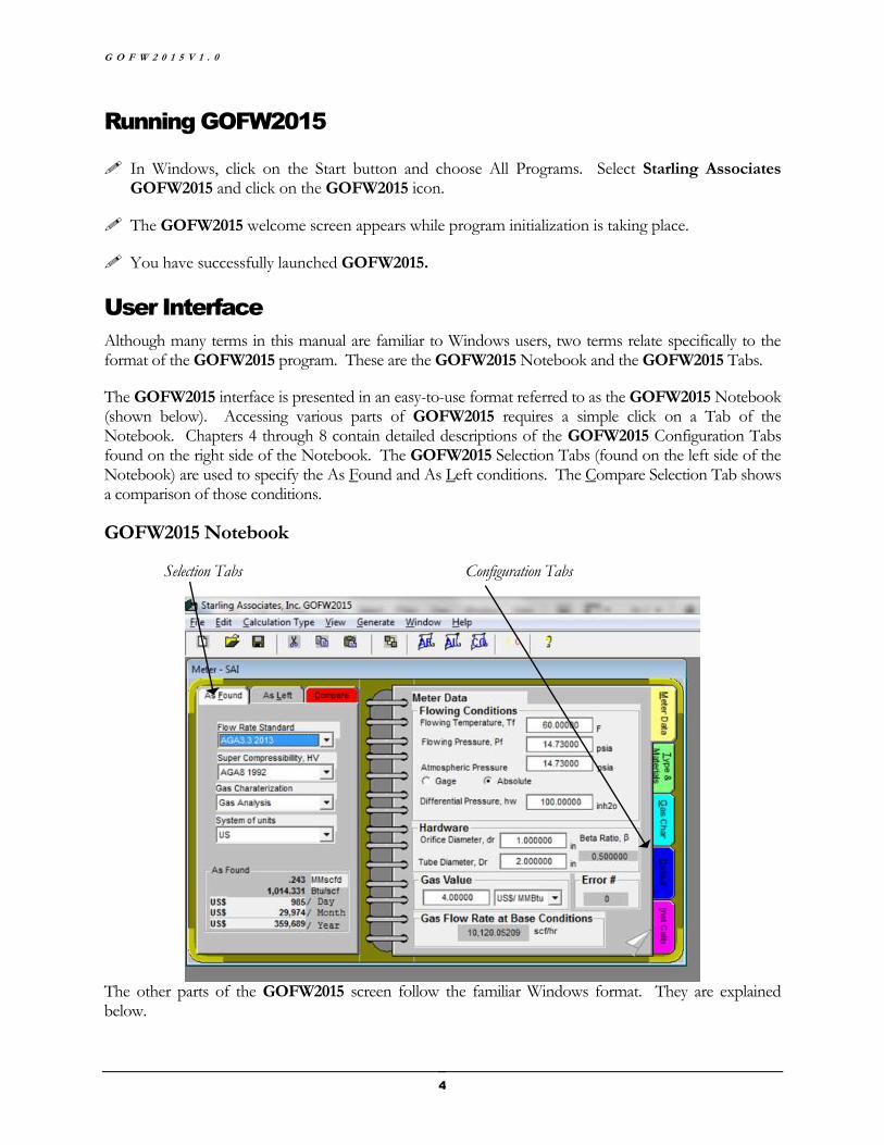
Running GOFW2015
In Windows, click on the Start button and choose All Programs. Select Starling Associates GOFW2015 and click on the GOFW2015 icon.
The GOFW2015 welcome screen appears while program initialization is taking place.
You have successfully launched GOFW2015.
User Interface
Although many terms in this manual are familiar to Windows users, two terms relate specifically to the format of the GOFW2015 program. These are the GOFW2015 Notebook and the GOFW2015 Tabs.
The GOFW2015 interface is presented in an easy-to-use format referred to as the GOFW2015 Notebook (shown below). Accessing various parts of GOFW2015 requires a simple click on a Tab of the Notebook. Chapters 4 through 8 contain detailed descriptions of the GOFW2015 Configuration Tabs found on the right side of the Notebook. The GOFW2015 Selection Tabs (found on the left side of the Notebook) are used to specify the As Found and As Left conditions. The Compare Selection Tab shows a comparison of those conditions.
GOFW2015 Notebook
Selection Tabs Configuration Tabs
The other parts of the GOFW2015 screen follow the familiar Windows format. They are explained below.
S T A R L I N G A S S O C I A T E S , I N C .
5
The Titlebar
The titlebar shows the software name, Starling Associates, Inc. GOFW2015.
The Meter Titlebar
The Meter Titlebar displays the meter’s name.
The Menu Bar
The GOFW2015 Menu Bar is always visible within GOFW2015. It contains the following drop-down menus:
The File menu contains New Meter, Open, Save As, Save, Close, Print Setup and Exit
The Edit menu contains Cut, Copy, Paste, Delete, AF-AL/AL-AF
The Calculation Type menu contains Volume Flow Rate, Mass Flow Rate, Differential Pressure, Orifice Size
The View menu contains As Found, As Left, Comparison, Meter Properties, Toolbar, Statusbar
The Generate menu contains As Found Report, As Left Report and Comparison Report
The Window menu contains Unit Converter and all active windows in GOFW2015
The Help menu contains Help Topics and About GOFW2015
The Toolbar
Many essential GOFW2015 Tools are included on the toolbar located at the top of the GOFW2015 Notebook.
The toolbar can be toggled on and off on the View menu
Button Name Function
New meter Opens a New Meter for a new calculation, comparison, etc.
Open Opens an existing GOFW2015 file
Save Saves your GOFW2015 file under its current name and location with the
default .CS1 extension
Cut Cuts the selected text and places it on the clipboard
Copy Copies the selected text and places it on the clipboard
Paste Pastes the text from the clipboard at the point where the cursor is located
G O F W 2 0 1 5 V 1 . 0
6
AF-AL/ AL-AF
If the As Found Selection Tab is selected when this tool button is clicked, the configuration in the As Found Tab is copied to the As Left Tab. If the As Left Tab is selected when this tool button is clicked, the configuration in the As Left Tab is copied to the As Found Tab (note that this operation also occurs with the AF-AL/AL-AF selection on the Edit drop-down menu on the GOFW2015 Menu Bar.
AF Opens the As Found report
AL Opens the As Left report
CO Opens the Comparison report
FC Opens the Units Converter
Meter Properties
Meter Properties is the first GOFW2015 screen encountered after program initialization. Meter Properties also can be accessed from the drop-down menu under View on the GOFW2015 menu bar. Meter Properties allows the user to record information pertinent to the meter. There are two Tabs in Meter Properties which are used to identify the meter:
General
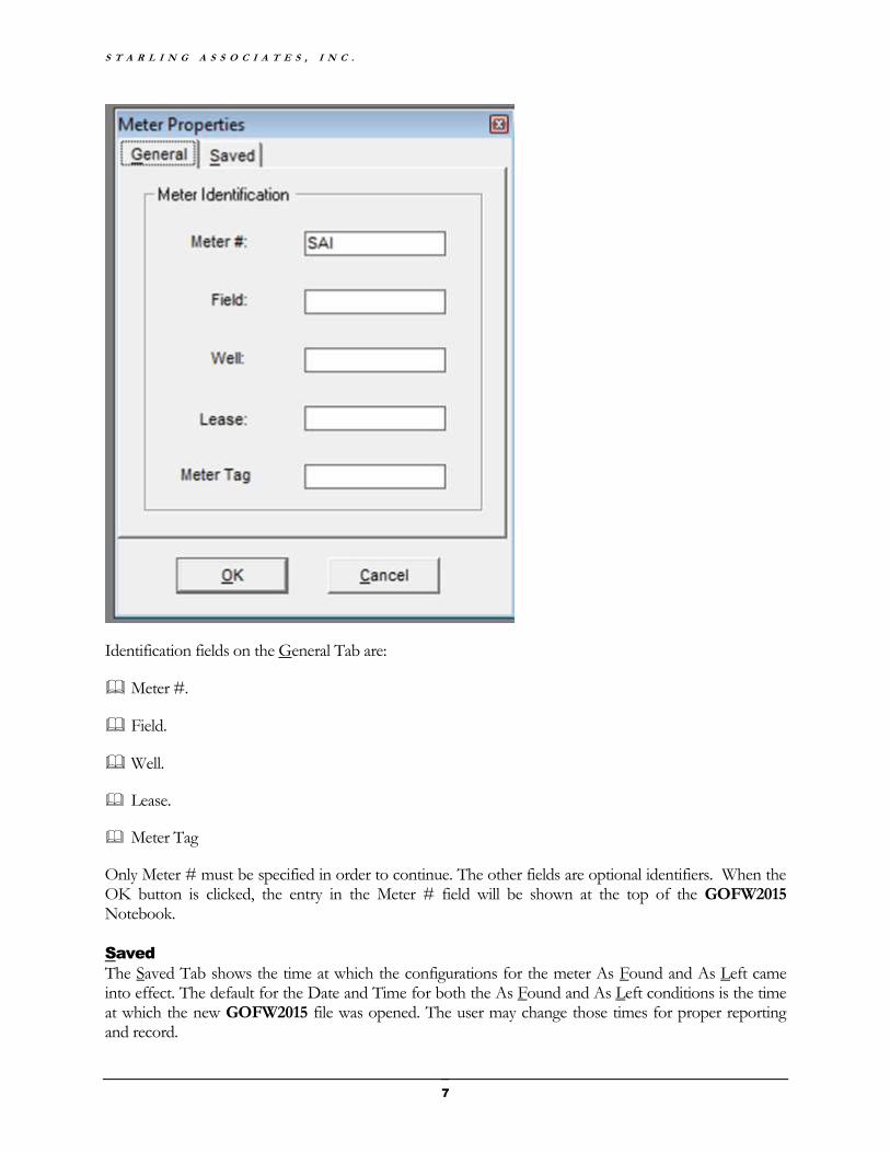
In the General Tab, the user identifies the meter for which a calculation is being performed.
S T A R L I N G A S S O C I A T E S , I N C .
7
Identification fields on the General Tab are:
Meter #.
Field.
Well.
Lease.
Meter Tag
Only Meter # must be specified in order to continue. The other fields are optional identifiers. When the OK button is clicked, the entry in the Meter # field will be shown at the top of the GOFW2015 Notebook.
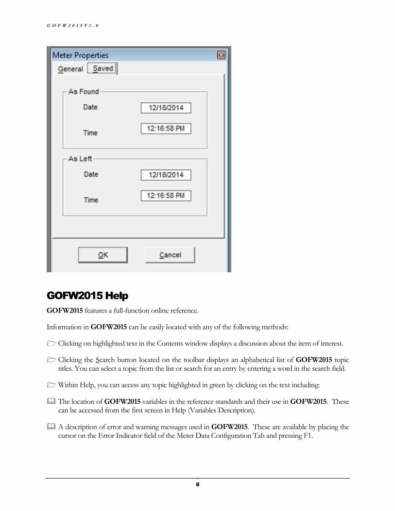
Saved
The Saved Tab shows the time at which the configurations for the meter As Found and As Left came into effect. The default for the Date and Time for both the As Found and As Left conditions is the time at which the new GOFW2015 file was opened. The user may change those times for proper reporting and record.
G O F W 2 0 1 5 V 1 . 0
8
GOFW2015 Help
GOFW2015 features a full-function online reference.
Information in GOFW2015 can be easily located with any of the following methods:
Clicking on highlighted text in the Contents window displays a discussion about the item of interest.
Clicking the Search button located on the toolbar displays an alphabetical list of GOFW2015 topic titles. You can select a topic from the list or search for an entry by entering a word in the search field.
Within Help, you can access any topic highlighted in green by clicking on the text including:
The location of GOFW2015 variables in the reference standards and their use in GOFW2015. These can be accessed from the first screen in Help (Variables Description).
A description of error and warning messages used in GOFW2015. These are available by placing the cursor on the Error Indicator field of the Meter Data Configuration Tab and pressing F1.
S T A R L I N G A S S O C I A T E S , I N C .
9
The list of outputs generated by GOFW2015. These can be accessed from the opening Help screen by choosing Variables Description, then Output Variables, then Outputs.
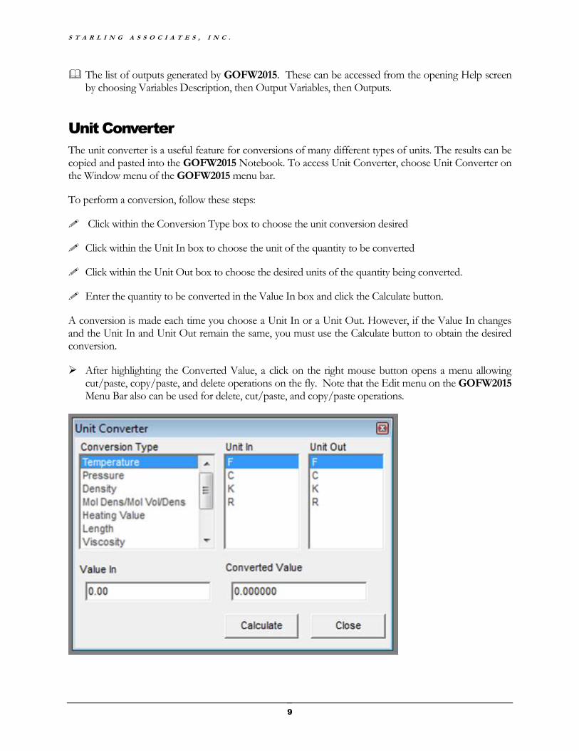
Unit Converter
The unit converter is a useful feature for conversions of many different types of units. The results can be copied and pasted into the GOFW2015 Notebook. To access Unit Converter, choose Unit Converter on the Window menu of the GOFW2015 menu bar.
To perform a conversion, follow these steps:
Click within the Conversion Type box to choose the unit conversion desired
Click within the Unit In box to choose the unit of the quantity to be converted
Click within the Unit Out box to choose the desired units of the quantity being converted.
Enter the quantity to be converted in the Value In box and click the Calculate button.
A conversion is made each time you choose a Unit In or a Unit Out. However, if the Value In changes and the Unit In and Unit Out remain the same, you must use the Calculate button to obtain the desired conversion.
After highlighting the Converted Value, a click on the right mouse button opens a menu allowing cut/paste, copy/paste, and delete operations on the fly. Note that the Edit menu on the GOFW2015 Menu Bar also can be used for delete, cut/paste, and copy/paste operations.
G O F W 2 0 1 5 V 1 . 0
10
Generating a Report
Three reports can be generated with GOFW2015:
An As Found Report
An As Left Report
A Comparison Report
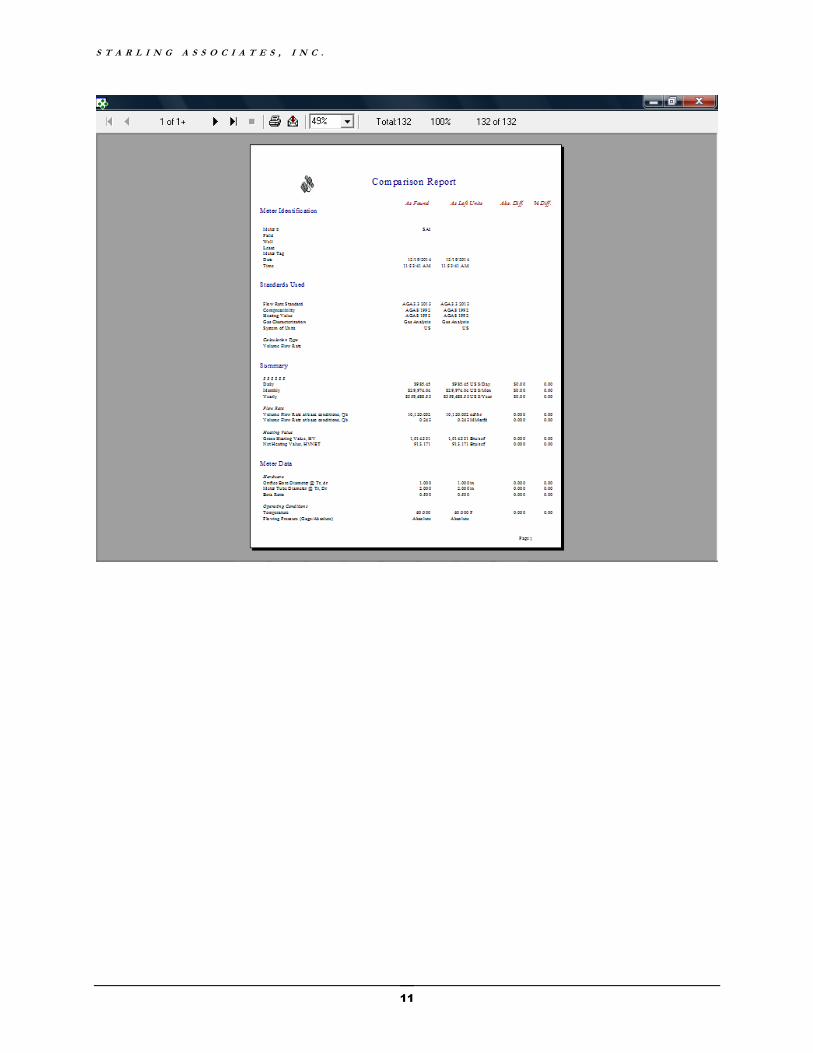
The Comparison Report contains the information in the As Found Report and the As Left Report plus additional information about the numerical differences and percent differences between the As Found and As Left Conditions (As Left-As Found). GOFW2015 uses Crystal Reports technology to generate the reports. Information in the reports is written into a database that is replaced each time a report is generated. The reports included allow the user to perform the following functions:
Choose among three different reports, each with its own screen display.
Export a given report. The Crystal Reports technology includes an export button on the report screen display with a number of choices for the format of the exported report file and a number of choices for the destination of the exported report file. To avoid problems related to different versions of software applications such as Microsoft Word, it is recommended that “Rich Text Format” be selected as the format of the exported report file and that “Disk file” be selected as the destination of the exported report file. The resulting Rich Text Format (*.rtf) report file can be saved in the desired computer subdirectory folder. When the Rich Text Format (*.rtf) report file is opened, it can be saved by the user in one of the formats available on the user’s computer, for example as a Microsoft Word document (*.doc or *.docx) or a portable file document (*.pdf).
Print the report. The Crystal Reports technology includes a print button on the report screen display which allows printing of the report on the computer default printer.
S T A R L I N G A S S O C I A T E S , I N C .
11

13
CHAPTER 2
A Quick Tutorial
he GOFW2015 program allows the user to compare the flow rate in the As Left condition with the As Found condition following a linear meter or orifice meter calibration. In this tutorial, we will use GOFW2015 to find the difference in flow rate after the calibration of an orifice meter differential pressure gage. The technician equipped with a laptop and the
GOFW2015 software can immediately calculate the difference in flow rate (and other quantities) and with the click of an icon generate a detailed report which can be saved for subsequent use, printed or emailed.
This tutorial will familiarize users with the major features of GOFW2015 for orifice meter (calculations for turbine meters and coriolis meters are discussed in Appendix D). Follow along with the steps below:
Launch GOFW2015 by clicking on the Windows Start button and selecting All Programs. Select Starling Associates GOFW2015 and click on the GOFW2015 icon.
Click the OK button on the Meter Properties screen. The GOFW2015 Notebook opens with the default configuration (see Chapter 7 for information on changing the default configuration).
T

G O F W 2 0 1 5 V 1 . 0
14
The As Found and As Left Conditions are the same. The default configuration is:
Flow Rate Standard: AGA3.3 2013
Compressibility Factor, HV: AGA8 1992
Gas Characterization: Gas Analysis
System of Units: US
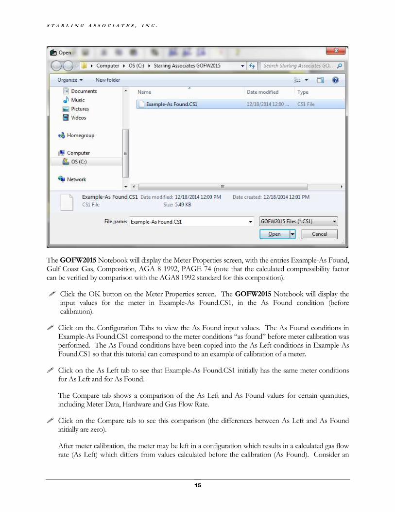
Next, open the following file provided with GOFW2015: Example-As Found.CS1
Click on the Open button and select the file Example-As Found.CS1 from the Open screen.
S T A R L I N G A S S O C I A T E S , I N C .
15
The GOFW2015 Notebook will display the Meter Properties screen, with the entries Example-As Found, Gulf Coast Gas, Composition, AGA 8 1992, PAGE 74 (note that the calculated compressibility factor can be verified by comparison with the AGA8 1992 standard for this composition).
Click the OK button on the Meter Properties screen. The GOFW2015 Notebook will display the input values for the meter in Example-As Found.CS1, in the As Found condition (before calibration).
Click on the Configuration Tabs to view the As Found input values. The As Found conditions in Example-As Found.CS1 correspond to the meter conditions “as found” before meter calibration was performed. The As Found conditions have been copied into the As Left conditions in Example-As Found.CS1 so that this tutorial can correspond to an example of calibration of a meter.
Click on the As Left tab to see that Example-As Found.CS1 initially has the same meter conditions for As Left and for As Found.
The Compare tab shows a comparison of the As Left and As Found values for certain quantities, including Meter Data, Hardware and Gas Flow Rate.
Click on the Compare tab to see this comparison (the differences between As Left and As Found initially are zero).
After meter calibration, the meter may be left in a configuration which results in a calculated gas flow rate (As Left) which differs from values calculated before the calibration (As Found). Consider an

G O F W 2 0 1 5 V 1 . 0
16
example for which the calibration of the differential pressure gage results in hw (As Left) = 50.5 inches of water, compared to hw (As Found) = 50.0 inches of water.
Change the Differential Pressure, hw for the As Left condition from 50.0 to 50.5.
Click on the Compare tab to view the effect of this calibration of the differential pressure gage.
Notice on the Compare screen that the increase in Differential Pressure hw from 50.0 to 50.5 inches of water yields an increase in the calculated Gas Flow Rate from 3.898 to 3.917 MMscfd. The Gas Analysis used (viewed by clicking the Gas Char tab) yields a calculated Gross HV = 1036.04 Btu/scf (viewed by clicking the meter Data tab then clicking the “dog ear” on that page to reveal the second page of the Meter Data section of the Notebook). On the Comparison Report a Gas Value of 3.63 US$/MMBtu has been used resulting in a gas value increase from $14,660 to $14,733 per Day.
The Compare Tab shows only a summary of the differences between the As Left and As Found conditions. GOFW2015 also prepares reports with detailed information on inputs and calculated outputs. Click on Generate on the GOFW2015 menu bar to view the drop-down menu which allows the report options As Found Report, As Left Report and Comparison Report (the Toolbar options AF, AL and CO also provide these report options).
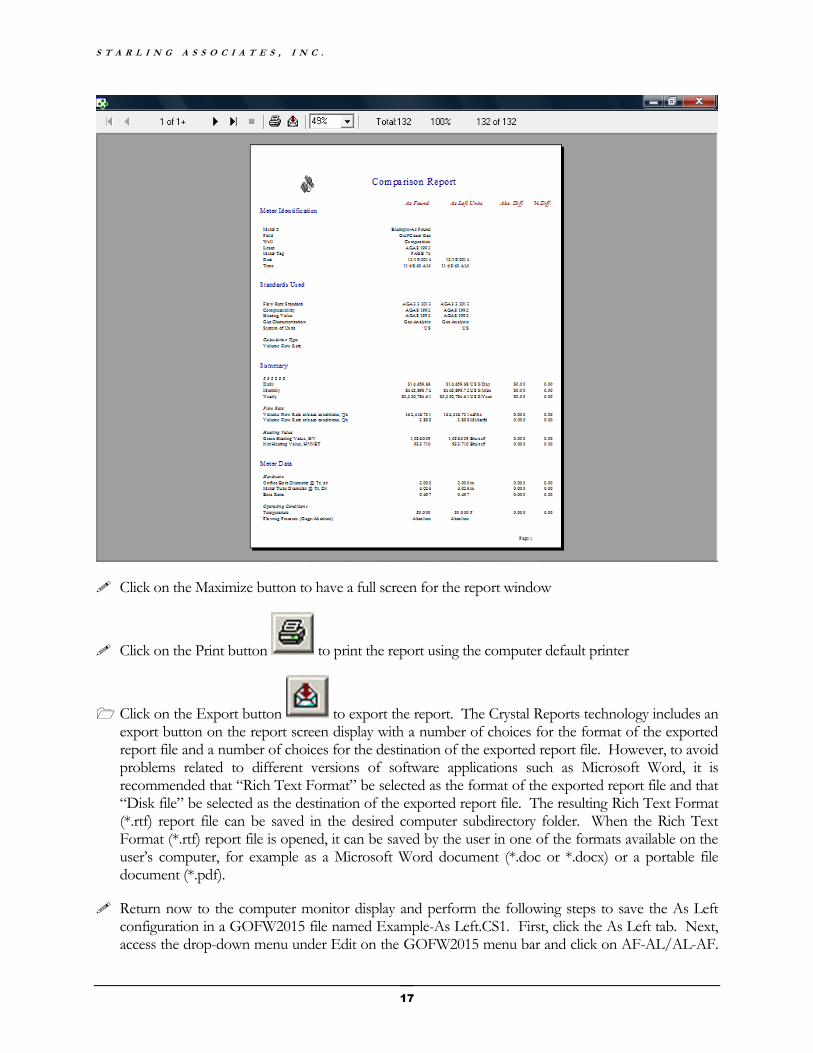
Next, generate a Comparison Report. Simply choose Comparison Report from the Generate menu (or click on the CO button on the toolbar).
S T A R L I N G A S S O C I A T E S , I N C .
17
Click on the Maximize button to have a full screen for the report window
Click on the Print button to print the report using the computer default printer
Click on the Export button to export the report. The Crystal Reports technology includes an export button on the report screen display with a number of choices for the format of the exported report file and a number of choices for the destination of the exported report file. However, to avoid problems related to different versions of software applications such as Microsoft Word, it is recommended that “Rich Text Format” be selected as the format of the exported report file and that “Disk file” be selected as the destination of the exported report file. The resulting Rich Text Format (*.rtf) report file can be saved in the desired computer subdirectory folder. When the Rich Text Format (*.rtf) report file is opened, it can be saved by the user in one of the formats available on the user’s computer, for example as a Microsoft Word document (*.doc or *.docx) or a portable file document (*.pdf).
Return now to the computer monitor display and perform the following steps to save the As Left configuration in a GOFW2015 file named Example-As Left.CS1. First, click the As Left tab. Next, access the drop-down menu under Edit on the GOFW2015 menu bar and click on AF-AL/AL-AF.
G O F W 2 0 1 5 V 1 . 0
18
This step moves all of the As Left input variable values into the As Found input text boxes, causing the As Found information to be the same as the As Left information. Next, access the drop-down menu under View on the GOFW2015 menu bar and click on Meter Properties. In the Meter# textbox, type Example-As Left and click the OK button. Then, access the drop-down menu under File on the GOFW2015 menu bar and click on Save As. In the File name dialog box type Example-As Left, then click the Save button, which saves the GOFW2015 file named Example-As Left.CS1.
Note that the As Found information still is in the original GOFW2015 file named Example-As Found.CS1 and the As Left information is in the newly created GOFW2015 file named Example-As Left.CS1. The next section provides a more general discussion of GOFW2015 file handling.
Creating, Saving and Reopening GOFW2015 Input Files
When GOFW2015 is started, a set of default values appear on the GOFW2015 window. GOFW2015 uses the file GOFW2015.ini for this initial default configuration. The file GOFW2015.ini is placed in the subdirectory in which the GOFW2015 software is installed. The first screen which appears when GOFW2015 is started up has a form on the left hand side titled Meter Properties. The Meter# box is already filled in with “SAI”, which comes from the initialization file GOFW2015.ini. Clicking OK in the Meter Properties form places “Meter – SAI” on the banner of the next window which appears. A new input file can be created by modifying the entries in the boxes in the GOFW2015 windows. Accessing the drop-down menu under View on the GOFW2015 menu bar and clicking on Meter Properties allows changing the Meter# from “SAI” to a Meter# corresponding to the newly created calculation. Then accessing the drop-down menu under File on the GOFW2015 menu bar and clicking on Save As allows entering a file name for the newly created input file. Similarly, another input file can be created by modifying the entries in the boxes in the GOFW2015 windows, changing the Meter# and saving the input file with an appropriate name. Then to reopen an input file which was created earlier, access the drop-down menu under File on the GOFW2015 menu bar and click on Open. You will be asked if you wish to save the information for the current meter before opening a new meter. It is best if you have saved the current information previously so you can click No. If you click No, you will immediately be allowed to reopen any previously saved GOFW2015 input file. When this meter reopens, be sure to click OK on the Meter Properties screen to preserve the Meter# associated with the meter calculation.
To insure that you know whether a GOFW2015 .CS1 file contains As Found information or As Left information, it is recommended that the As Left information be moved into the As Found input textboxes and that the file be saved using an easily identified file name. The procedure is (1) click the As Left tab, (2) access the drop-down menu under Edit on the GOFW2015 menu bar and click on AF-AL/AL-AF, (3) access the drop-down menu under View on the GOFW2015 menu bar and click on Meter Properties, (4) in the Meter# textbox, type text identifying the meter information as being in the As Left description and click the OK button, (5) access the drop-down menu under File on the GOFW2015 menu bar and click on Save As, (6) in the File name dialog box type the desired file name, then click the Save button, which saves the GOFW2015 file with extension .CS1. An easy way to be reminded of what

S T A R L I N G A S S O C I A T E S , I N C .
19
the configuration is for a GOFW2015 input (.CS1) file is to use the same file name as the Meter# textbox entry (as was done in the previous section for Example-As Found.CS1 and Example-As Left.CS1).
The format of the GOFW2015 user interface is similar to a notebook with tabs in which there are two major sections. These two major sections are the As Found section with all of the inputs as found, and the As Left section with all of the inputs as left. The As Left section inputs include any changes to the meter affecting the meter calculation inputs, such as the change of an orifice plate, the calibration of a pressure or differential pressure transducer, etc.
To view and compare the changes in calculated quantities for the As Left versus As found meter conditions requires the generation of a comparison report. To retain a record of the information in the comparison report requires saving the comparison report. As noted earlier, if the comparison report is saved as a Rich Text Format (.rtf) file, it can be viewed subsequently on the vast majority of computers. On the other hand, a GOFW2015 input (.CS1) file, saved from the comparison calculations generally will not yield the outputs which were successfully saved in the (.rtf) file. The reason is because when the input (.CS1) file is opened the inputs in the As Found section generally are copied into the As Left section before the GOFW2015 user interface appears. Thus, before saving a GOFW2015 input (.CS1) file, it is useful to be sure that the As Found section contains the inputs desired when the file is reopened at a later time. The user of GOFW2015 needs to be aware that two different outcomes can result when saving a GOFW2015 project file, dependent on the procedures utilized by the user. As discussed earlier, the SaveAs method is used to name a GOFW2015 project file and save the file with the assigned name. Subsequently, when the file is closed the user is given the choice to save the file with a Yes or No option. If the user clicks Yes, the GOFW2015 project file will be saved with the inputs in the AsLeft tab input boxes copied into the AsFound tab input boxes. The purpose of this procedure is to provide the user with the opportunity to open the GOFW2015 project file for the subject meter at a later date, for example at the time of a new meter inspection or instrument calibration, and enter new inputs in the AsLeft tab input boxes. Conversely, if the user clicks No, the GOFW2015 project file will be saved with the inputs in the AsFound tab input boxes copied into the AsLeft tab input boxes. This is the reason that it is recommended that the As Left information be moved into the As Found input textboxes before closing the GOFW2015 project file.
G O F W 2 0 1 5 V 1 . 0
20
CHAPTER 3
GOFW2015 Standards and Calculation Types
OFW2015 is a powerful analysis and calculation tool for orifice meters and linear meters, including turbine meters, ultrasonic meters and coriolis meters. It allows the user to compare the volumetric flow rate in the As Left condition with the As Found condition following meter calibration. In a similar manner, it can be used to compare the use of
different measurement standards. In addition to the volumetric flow rate, GOFW2015 can be used to calculate the mass flow rate and other quantities for the meter. For orifice meters, GOFW2015 can be used to size an orifice plate or to estimate the differential pressure for a specified flow rate. This chapter will discuss the standards and calculations available using GOFW2015.
Standards Covered
The flow rate standard used in a GOFW2015 calculation is selected on the left side of the Notebook.
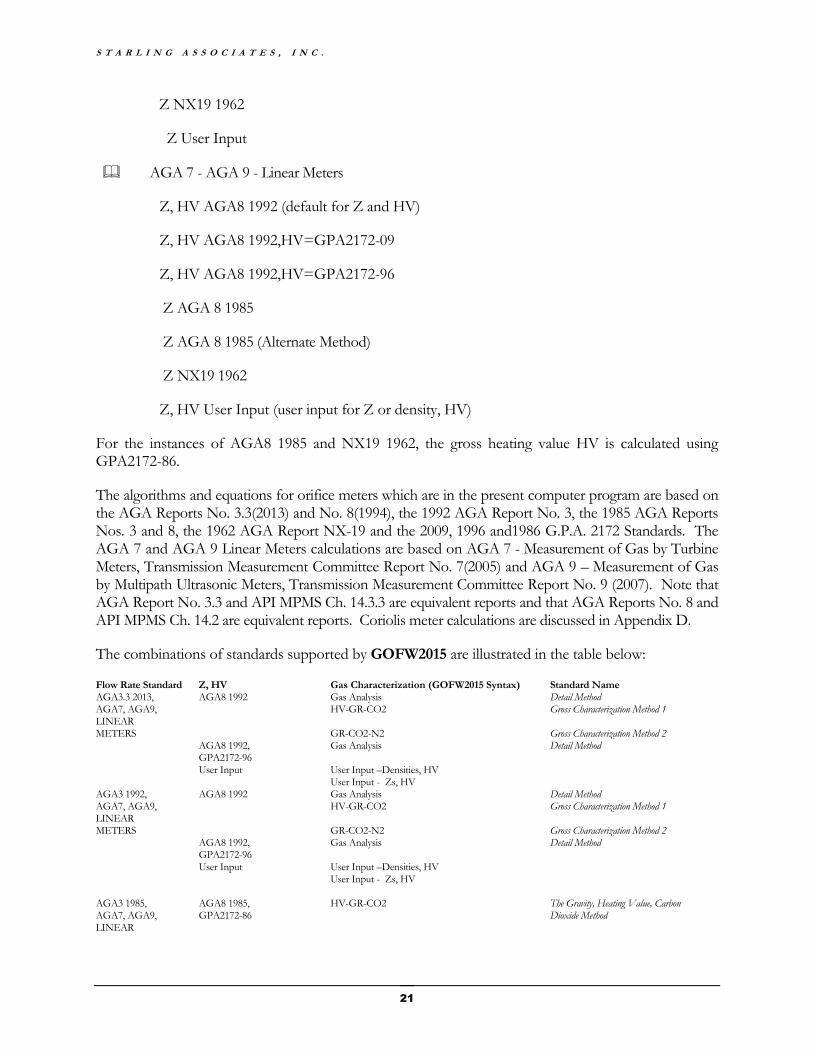
The choices for Flow Rate Standard () and associated compressibility Z (or density) and gross heating value HV include:
AGA3.3 2013 (default for flow rate)
Z, HV AGA8 1992 (default for Z and HV)
Z, HV AGA8 1992,HV=GPA2172-09
Z, HV User Input (user input for Z or density, HV)
AGA3 1992 (flow rate)
Z, HV AGA8 1992 (AGA8 1992 for Z and HV)
Z, HV AGA8 1992,HV=GPA2172-96
Z, HV User Input (user input for Z or density, HV)
AGA 3 1985 (flow rate)
Z AGA 8 1985
Z AGA 8 1995 (Alternate Method)
G
S T A R L I N G A S S O C I A T E S , I N C .
21
Z NX19 1962
Z User Input
AGA 7 - AGA 9 - Linear Meters
Z, HV AGA8 1992 (default for Z and HV)
Z, HV AGA8 1992,HV=GPA2172-09
Z, HV AGA8 1992,HV=GPA2172-96
Z AGA 8 1985
Z AGA 8 1985 (Alternate Method)
Z NX19 1962
Z, HV User Input (user input for Z or density, HV)
For the instances of AGA8 1985 and NX19 1962, the gross heating value HV is calculated using GPA2172-86.
The algorithms and equations for orifice meters which are in the present computer program are based on the AGA Reports No. 3.3(2013) and No. 8(1994), the 1992 AGA Report No. 3, the 1985 AGA Reports Nos. 3 and 8, the 1962 AGA Report NX-19 and the 2009, 1996 and1986 G.P.A. 2172 Standards. The AGA 7 and AGA 9 Linear Meters calculations are based on AGA 7 - Measurement of Gas by Turbine Meters, Transmission Measurement Committee Report No. 7(2005) and AGA 9 – Measurement of Gas by Multipath Ultrasonic Meters, Transmission Measurement Committee Report No. 9 (2007). Note that AGA Report No. 3.3 and API MPMS Ch. 14.3.3 are equivalent reports and that AGA Reports No. 8 and API MPMS Ch. 14.2 are equivalent reports. Coriolis meter calculations are discussed in Appendix D.
The combinations of standards supported by GOFW2015 are illustrated in the table below:
Flow Rate Standard Z, HV Gas Characterization (GOFW2015 Syntax) Standard Name AGA3.3 2013, AGA8 1992 Gas Analysis Detail Method AGA7, AGA9, LINEAR
HV-GR-CO2 Gross Characterization Method 1
METERS GR-CO2-N2 Gross Characterization Method 2 AGA8 1992,
GPA2172-96 Gas Analysis Detail Method
User Input User Input –Densities, HV User Input - Zs, HV AGA3 1992, AGA8 1992 Gas Analysis Detail Method AGA7, AGA9, LINEAR
HV-GR-CO2 Gross Characterization Method 1
METERS GR-CO2-N2 Gross Characterization Method 2 AGA8 1992,
GPA2172-96 Gas Analysis Detail Method
User Input User Input –Densities, HV User Input - Zs, HV AGA3 1985, AGA7, AGA9, LINEAR
AGA8 1985, GPA2172-86
HV-GR-CO2
The Gravity, Heating Value, Carbon Dioxide Method
G O F W 2 0 1 5 V 1 . 0
22
METERS GR-CO2-N2 The Gravity, Carbon Dioxide, Nitrogen Method
Gas Analysis Primary, Compositional Analysis Method
HV-GR-CO2-N2 The Gravity, Heating Value, Carbon Dioxide, Nitrogen Method
HV-CO2-N2 The Heating Value, Carbon Dioxide, Nitrogen Method
GR-CH4-CO2-N2 The Gravity, Methane, Carbon Dioxide, Nitrogen Method
AGA8 1985 (Alternate Method), GPA2172-86
HV-GR-CO2 The Gravity, Heating Value, Carbon Dioxide Method
GR-CO2-N2 The Gravity, Carbon Dioxide, Nitrogen Method
Gas Analysis Primary, Compositional Analysis Method
HV-GR-CO2-N2 The Gravity, Heating Value, Carbon Dioxide, Nitrogen Method
HV-CO2-N2 The Heating Value, Carbon Dioxide, Nitrogen Method
GR-CH4-CO2-N2 The Gravity, Methane, Carbon Dioxide, Nitrogen Method
NX19 1962, GPA2172-86
GR-CO2-N2 Standard Method
Gas Analysis Analysis Method HV-CO2-N2 Heating Value Method GR-CH4-CO2-N2 Methane – Gravity Method User Input User Input – Densities, HV User Input - Zs, HV
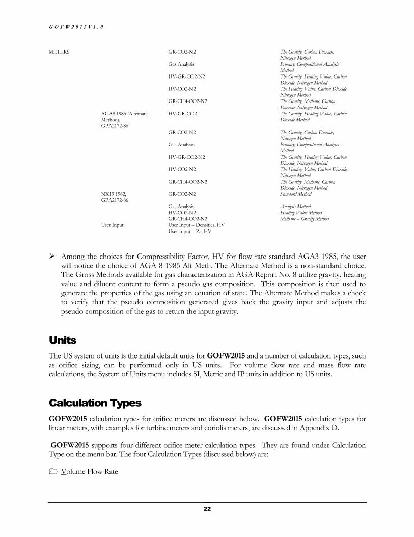
Among the choices for Compressibility Factor, HV for flow rate standard AGA3 1985, the user will notice the choice of AGA 8 1985 Alt Meth. The Alternate Method is a non-standard choice. The Gross Methods available for gas characterization in AGA Report No. 8 utilize gravity, heating value and diluent content to form a pseudo gas composition. This composition is then used to generate the properties of the gas using an equation of state. The Alternate Method makes a check to verify that the pseudo composition generated gives back the gravity input and adjusts the pseudo composition of the gas to return the input gravity.
Units
The US system of units is the initial default units for GOFW2015 and a number of calculation types, such as orifice sizing, can be performed only in US units. For volume flow rate and mass flow rate calculations, the System of Units menu includes SI, Metric and IP units in addition to US units.
Calculation Types
GOFW2015 calculation types for orifice meters are discussed below. GOFW2015 calculation types for linear meters, with examples for turbine meters and coriolis meters, are discussed in Appendix D.
GOFW2015 supports four different orifice meter calculation types. They are found under Calculation Type on the menu bar. The four Calculation Types (discussed below) are:
Volume Flow Rate
S T A R L I N G A S S O C I A T E S , I N C .
23
Mass Flow Rate
Differential Pressure
Orifice Size
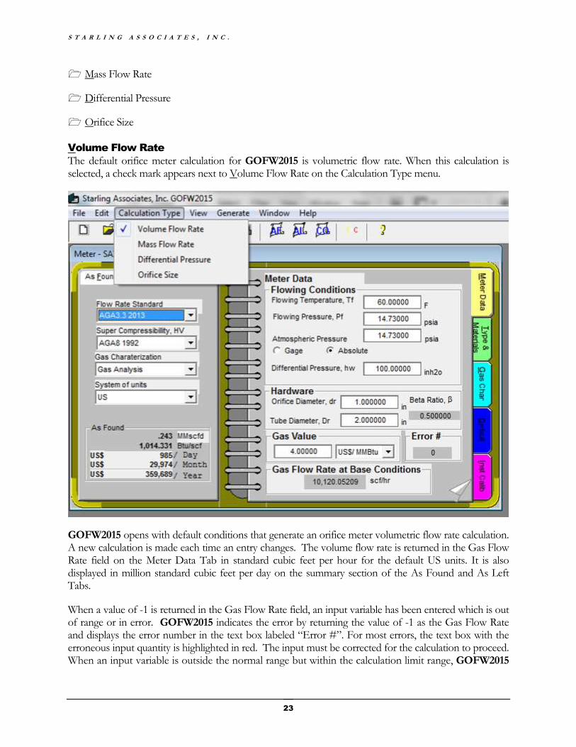
Volume Flow Rate
The default orifice meter calculation for GOFW2015 is volumetric flow rate. When this calculation is selected, a check mark appears next to Volume Flow Rate on the Calculation Type menu.
GOFW2015 opens with default conditions that generate an orifice meter volumetric flow rate calculation. A new calculation is made each time an entry changes. The volume flow rate is returned in the Gas Flow Rate field on the Meter Data Tab in standard cubic feet per hour for the default US units. It is also displayed in million standard cubic feet per day on the summary section of the As Found and As Left Tabs.
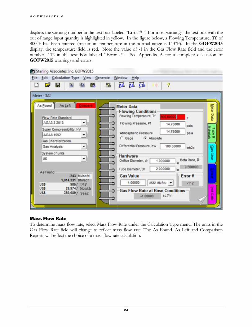
When a value of -1 is returned in the Gas Flow Rate field, an input variable has been entered which is out of range or in error. GOFW2015 indicates the error by returning the value of -1 as the Gas Flow Rate and displays the error number in the text box labeled “Error #”. For most errors, the text box with the erroneous input quantity is highlighted in red. The input must be corrected for the calculation to proceed. When an input variable is outside the normal range but within the calculation limit range, GOFW2015
G O F W 2 0 1 5 V 1 . 0
24
displays the warning number in the text box labeled “Error #”. For most warnings, the text box with the out of range input quantity is highlighted in yellow. In the figure below, a Flowing Temperature, Tf, of 800°F has been entered (maximum temperature in the normal range is 143°F). In the GOFW2015 display, the temperature field is red. Note the value of -1 in the Gas Flow Rate field and the error number -112 in the text box labeled “Error #”. See Appendix A for a complete discussion of GOFW2015 warnings and errors.
Mass Flow Rate
To determine mass flow rate, select Mass Flow Rate under the Calculation Type menu. The units in the Gas Flow Rate field will change to reflect mass flow rate. The As Found, As Left and Comparison Reports will reflect the choice of a mass flow rate calculation.
S T A R L I N G A S S O C I A T E S , I N C .
25
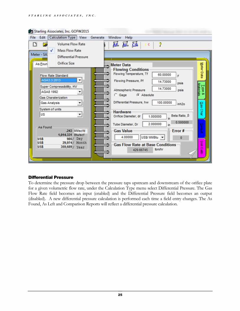
Differential Pressure
To determine the pressure drop between the pressure taps upstream and downstream of the orifice plate for a given volumetric flow rate, under the Calculation Type menu select Differential Pressure. The Gas Flow Rate field becomes an input (enabled) and the Differential Pressure field becomes an output (disabled). A new differential pressure calculation is performed each time a field entry changes. The As Found, As Left and Comparison Reports will reflect a differential pressure calculation.
G O F W 2 0 1 5 V 1 . 0
26
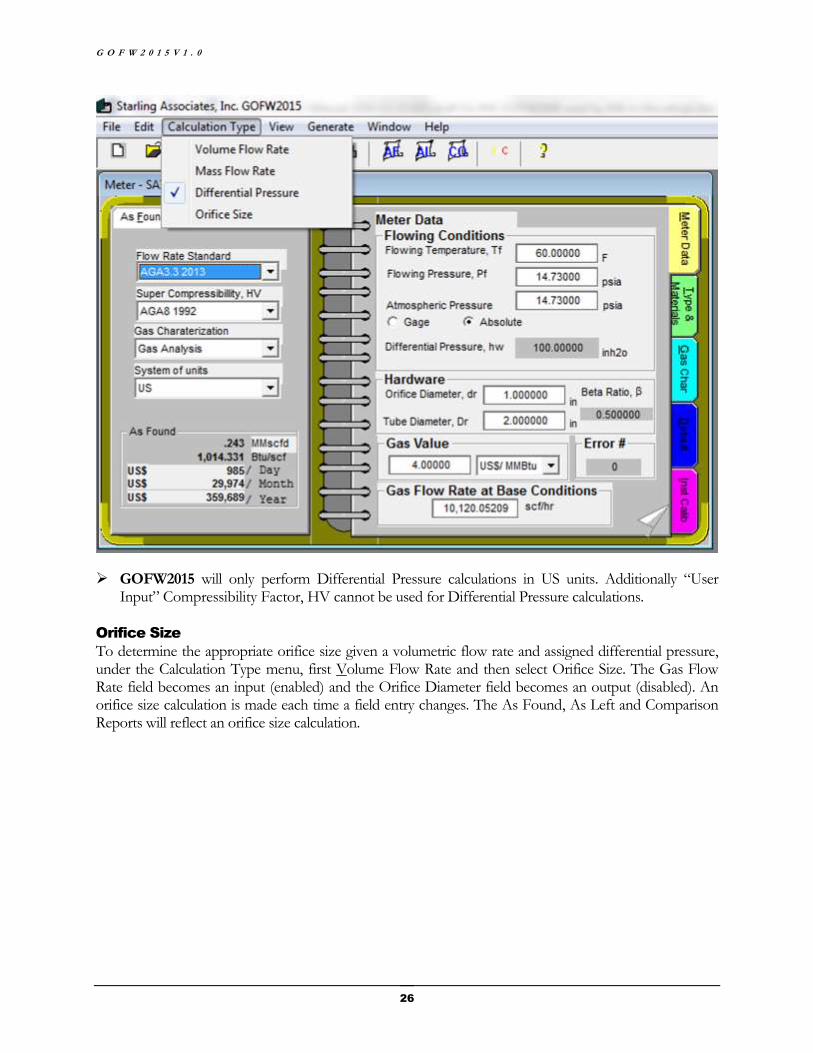
GOFW2015 will only perform Differential Pressure calculations in US units. Additionally “User Input” Compressibility Factor, HV cannot be used for Differential Pressure calculations.
Orifice Size
To determine the appropriate orifice size given a volumetric flow rate and assigned differential pressure, under the Calculation Type menu, first Volume Flow Rate and then select Orifice Size. The Gas Flow Rate field becomes an input (enabled) and the Orifice Diameter field becomes an output (disabled). An orifice size calculation is made each time a field entry changes. The As Found, As Left and Comparison Reports will reflect an orifice size calculation.
S T A R L I N G A S S O C I A T E S , I N C .
27
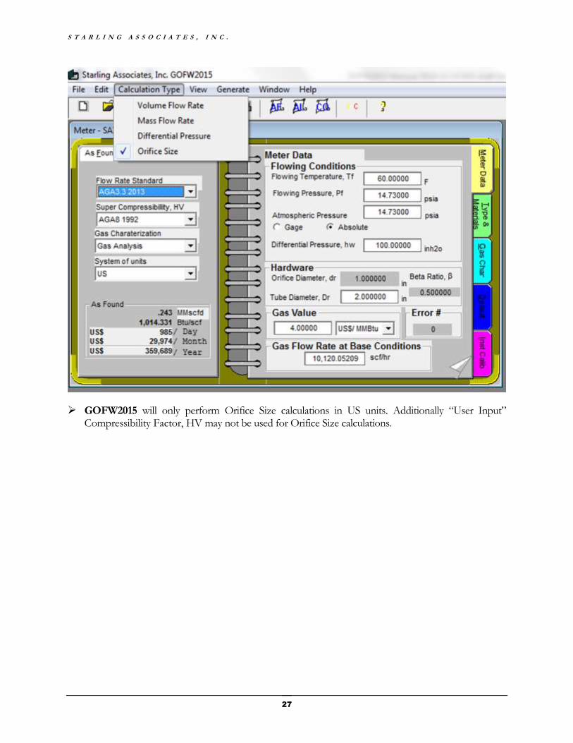
GOFW2015 will only perform Orifice Size calculations in US units. Additionally “User Input” Compressibility Factor, HV may not be used for Orifice Size calculations.


29
CHAPTER 4
Meter Data Tab
The Meter Data Tab contains basic meter information necessary to perform a calculation. Additionally, it contains gas value information and a calculation error indicator.
Meter Data
The Meter Data Tab appears when the GOFW2015 Notebook is opened. There are two pages in the Meter Data Tab. The page can be changed by clicking on the “dog ear” on the current page. Most of the information in this tab is self-explanatory so only a brief description of the fields is given below.

G O F W 2 0 1 5 V 1 . 0
30
Flowing Conditions
The flowing conditions for an orifice meter calculation are Flowing Temperature, Tf, Flowing Pressure, Pf and Differential Pressure, hw. The ranges of applicability of the flowing conditions vary depending on the standard chosen. A click on the field of entry displays the range of applicability for the flowing condition in the statusbar at the bottom of the screen.
GOFW2015 allows the use of either absolute pressure or gage pressure for the input flowing pressure.
Linear Meters
The Linear Meter Frame appears when AGA7, AGA9 or LINEAR METER is indicated under the “flow rate standard” combo box and disappears otherwise.
Specify the pulse counts, meter factor and k factor.
The volume through the meter at flowing conditions is calculated with the simple relation:
Volume at flowing conditions = pulse counts * meter factor / k factor.
The volume at flowing conditions is converted to base conditions using the Compressibility Factor, HV method specified.
S T A R L I N G A S S O C I A T E S , I N C .
31
Hardware
The Hardware section of the Meter Data Tab is used to specify Orifice Diameter and Meter Tube Diameter. It outputs the ratio of the orifice plate diameter to the tube diameter (commonly known as Beta Ratio). Since it is possible for both diameters to be within the range of the applicable standard, while their ratio is not, the Beta Ratio field follows the color formats used to display warnings and errors.
Gas Value
The Gas Value is used to indicate the monetary value of the energy unit which is driven by the market. Depending on the System of Units used, the Gas Value may be expressed in different units.
Gas Flow Rate
The Gas Flow Rate shows the volume in scf/hr flowing through a pipeline. If an error occurs in the calculation, the Gas Flow Rate shown is -1.
Error Indicator
When an error or warning occurs in the calculation, a number corresponding to an error or warning description will be displayed in the error indicator field (zero indicates no error or warning was detected in the calculations). The meaning of the error indicator can be obtained by positioning the cursor on the error indicator field. The error/warning short description will appear in the statusbar.
Useful Outputs
The second page of the Meter Data Tab is titled Useful Outputs. These outputs include the Gas Relative Density, the Gross Heating Value, the Net Heating Value, the Molecular Weight (Molar Mass), the Critical Temperature and Critical Pressure (calculated by the Kay’s rules method) and the Reduced Temperature and Reduced Pressure.
Heating Value
The Heating Value of the gas is needed to evaluate the economic value of a gas stream (discussion of how the Heating Value is used in the calculation of the energy flow rate is given in Appendix C). When the full composition of the gas is specified, the Heating Value is automatically calculated and displayed in the Heating Value field. When a Gross Method or User Input gas characterization is used, GOFW2015 outputs -1 for the Heating Value of the gas indicating that the Heating Value has not been calculated. The -1 output as well as any other gross heating value output from GOFW2015 can be overwritten if user wishes to input the gross heating value of the gas. Simply check the HV Overwrite check box and then input the desired Heating Value which will then be used for the economic evaluation performed by GOFW2015 for either As Found or As Left, depending upon which tab has been clicked. Note that while the As Found tab display is still open, an As Found Report will display the overwritten HV. Similarly, while the As Left tab display is still open, an As Left Report will display the overwritten HV. To reduce the possibility of use of an overwritten HV when the user did not intend its use, the As Found check box for HV Overwrite is returned to the default unchecked status when the As Left tab has been clicked and the user subsequently returns to the As Found tab. Consequently, the user should avoid the above sequence before generating a Comparison Report and also before saving a file to disk.

33
CHAPTER 5
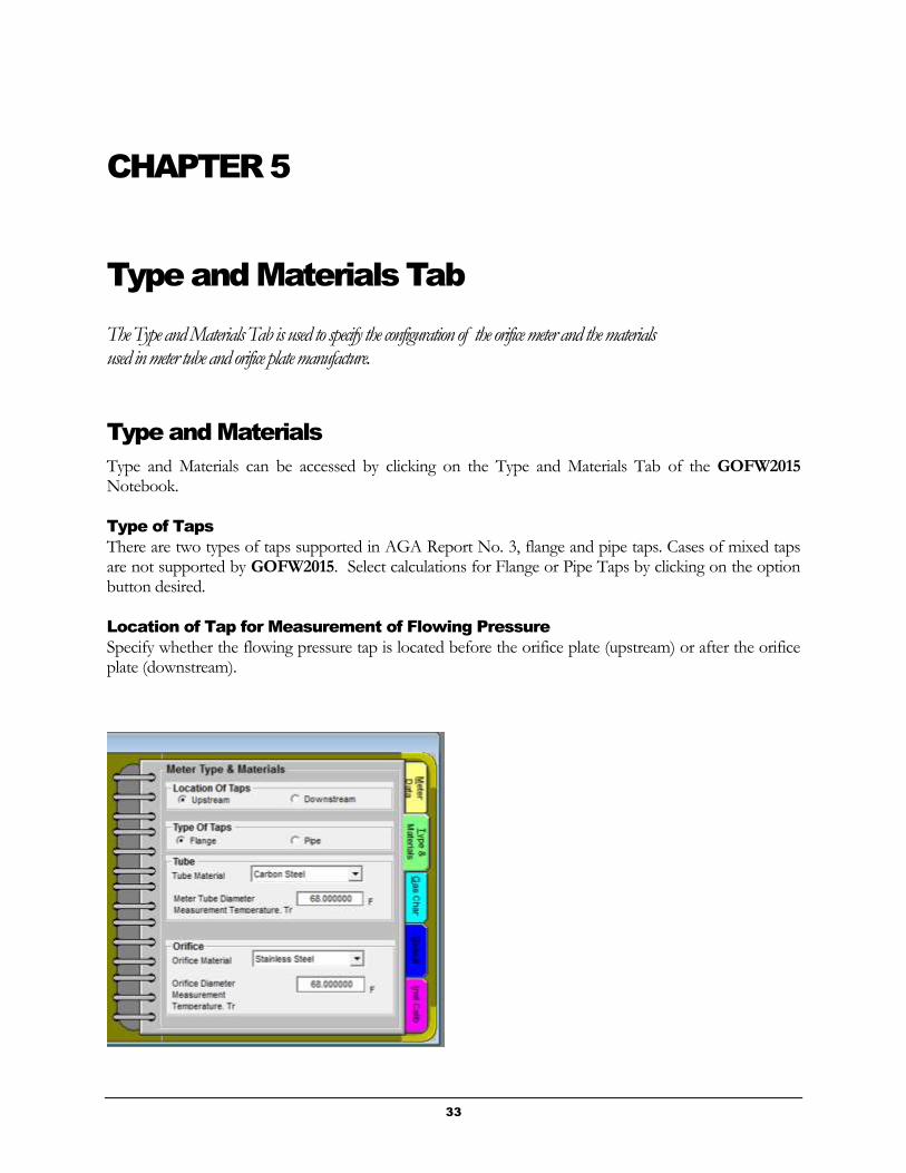
Type and Materials Tab
The Type and Materials Tab is used to specify the configuration of the orifice meter and the materials used in meter tube and orifice plate manufacture.
Type and Materials
Type and Materials can be accessed by clicking on the Type and Materials Tab of the GOFW2015 Notebook.
Type of Taps
There are two types of taps supported in AGA Report No. 3, flange and pipe taps. Cases of mixed taps are not supported by GOFW2015. Select calculations for Flange or Pipe Taps by clicking on the option button desired.
Location of Tap for Measurement of Flowing Pressure
Specify whether the flowing pressure tap is located before the orifice plate (upstream) or after the orifice plate (downstream).

G O F W 2 0 1 5 V 1 . 0
34
Tube Material
Tube material must be specified to account for thermal expansion of the meter tube at different temperatures since metals have different thermal expansion coefficients. The linear coefficient of thermal expansion is tabulated for five materials in AGA Report No. 3, Part 3 (2013).
Carbon Steel
Monel
Stainless Steel
304 Stainless Steel
316 Stainless Steel
The linear coefficient of thermal expansion is tabulated for three materials in AGA Report No. 3 (1985 and 1992), Carbon Steel, Monel, and Stainless Steel.
The category Stainless Steel tabulated linear coefficient of thermal expansion is the average of 304 Stainless Steel and 316 Stainless Steel. The category Monel tabulated linear coefficient of thermal expansion is slightly different in AGA Report No. 3 (1985 and 1992) from AGA Report No. 3, Part 3 (2013), which specifically specifies Monel 400 (alloy).
Carbon steel is the default meter tube material since it is most commonly used in orifice meter installations.
Meter Tube Diameter Measurement Temperature, Tr
The Meter Tube Diameter Measurement Temperature refers to the tube temperature when the tube diameter was measured. When a tube diameter is given, a temperature must accompany it since the diameter is sensitive to temperature changes. A default temperature of 68°F is given.
Orifice Material
Orifice material must be specified to account for thermal expansion of the orifice at different temperatures since metals have different thermal expansion coefficients. . The linear coefficient of thermal expansion is tabulated for five materials in AGA Report No. 3, Part 3 (2013).
Stainless Steel
Monel
Carbon Steel *
304 Stainless Steel
316 Stainless Steel
The linear coefficient of thermal expansion is tabulated for three materials in AGA Report No. 3 (1992), Stainless Steel, Monel, and Carbon Steel, and for only two materials in AGA Report No. 3 (1985), Stainless Steel and Monel.

S T A R L I N G A S S O C I A T E S , I N C .
35
The category Stainless Steel tabulated linear coefficient of thermal expansion is the average of 304 Stainless Steel and 316 Stainless Steel. The category Monel tabulated linear coefficient of thermal expansion is slightly different in AGA Report No. 3 (1985 and 1992) from AGA Report No. 3, Part 3 (2013), which specifically specifies Monel 400 (alloy).
* Carbon Steel as the orifice material is not supported in AGA Report No.3, 1985. If the user selects Carbon Steel with AGA3 1985 as the flow rate standard, the program will issue a warning and change the selection to Stainless Steel. If Carbon Steel has been selected and the user changes the flow rate standard to AGA 3 1985, GOFW2015 will change the Carbon Steel selection to Stainless Steel
Stainless steel is the default orifice material since it is most commonly used for orifice plates.
Orifice Diameter Measurement Temperature, Tr
The Orifice Diameter Measurement Temperature refers to the orifice temperature when the orifice diameter was measured. When an orifice diameter is given, a temperature must accompany it since the diameter is sensitive to temperature changes. A default temperature of 68°F is given.

G O F W 2 0 1 5 V 1 . 0
36
CHAPTER 6
Gas Characterization Tab
The Gas Characterization Tab is used to specify the composition of the gas or the means to characterize its physical properties.
Gas Characterization
The Gas Characterization Tab changes according to the Gas Characterization option chosen on the left side of the GOFW2015 Notebook.
Gas Analysis
The Gas Analysis screen is used when the full compositional analysis of the gas mixture is known. The Gas Analysis screen is displayed on the Gas Characterization Tab when the Gas Analysis option is chosen under Gas Characterization on the left side of the Notebook.
S T A R L I N G A S S O C I A T E S , I N C .
37
The Gas Analysis screen permits the user to enter values for 21 components. However, when the Gas Analysis Method under AGA8 1985 or NX19 1962 is used argon is excluded. A click on the field of entry displays the range of applicability for the component mole percentage in the statusbar at the bottom of the screen.
The Cal. w/Fracts. in error Checkbox
A check in the Cal. w/Fracts. in error (calculate with fractions in error) checkbox allows computations to be performed even if the mole percent of a gas component is outside the range recommended for some standards. For example, AGA Report No. 8 was developed and tested within certain limits. The accuracy of calculations made with components outside the tested range cannot be assured. If, however, a computation is required under these circumstances, the Cal. w/Fracts. in error checkbox prevents GOFW2015 from checking fractions and allows the calculation to proceed. Since the numbers entered are outside the tested limit, an unexpected math error may occur. The user is cautioned that the use of this override is not in conformance with the limits of the standards and therefore this override is not recommended.
The Normalize Mole % Button
A useful feature of the Gas Analysis Method is the Normalize Mole % button. When the sum of the user input mole percentages is very close to 100% this button can be clicked to normalize all component percentages so that the sum equals 100%.
Other Features
Other features of the Gas Analysis input screen include the Mole % Sum and the Diff labels. They assist the user in assessing the deviation of the total of the input mole percentages from 100%.
The Gas Analysis input screen carries a summation of butanes, pentanes and hexane+ percentages. It is possible for individual percentages to be within the accepted range while their sum is not. For example, if AGA Report No. 8 is used to characterize a gas with 3.5% n-butane and 3.5% i-butane, the individual components are within the allowed range but their sum is not. GOFW2015 indicates the error by displaying the Butanes summation label in red.
Gross Methods
Gross Methods include all the characterization methods that use a combination of Relative Density, Heating Value, Mole Percent of Nitrogen, Carbon Dioxide, Methane, Hydrogen and Carbon Monoxide.
Gross Methods in GOFW2015 are those which are characterized neither as Gas Analysis Methods nor as User Input Methods. An example of a Gross Method is the Gross Characterization Method 2 in AGA Report No. 8 (1992).

G O F W 2 0 1 5 V 1 . 0
38
User Input Method
A gas can also be characterized directly in GOFW2015 by specifying the gas densities at base and flowing conditions or by specifying the compressibility factor of the gas at base and flowing conditions and the gas relative density. These are equivalent since, if the temperature and pressure of the gas are known, having the density at base and flowing conditions allows one to calculate the compressibility factor at base and flowing conditions as well as the gas relative density at base conditions. Nevertheless, either screen may be used to input known properties.
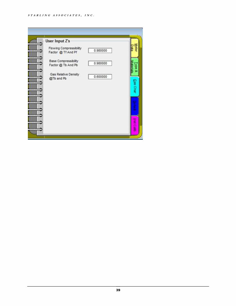
S T A R L I N G A S S O C I A T E S , I N C .
39


41
CHAPTER 7
Default Tab
Default Quantities
The Default Configuration Tab in the GOFW2015 Notebook has three pages. The user can change the page by clicking on the “dog ear” on the current page. Page 1 of the Default Tab is used to configure default temperatures and pressures.
Reference Conditions
The various reference temperatures and pressures include the following:
The contract temperature and pressure or base conditions (Tb, Pb)
The reference temperature and pressure for relative density (specific gravity) (Tgr,Pgr)
The reference temperature and pressure for the mass (and molar) heating value, the reference temperature and pressure of gas combustion (Th, Ph)
The reference temperature and pressure for gas calorimetric density (Td, Pd). Td and Pd is used for conversion of mass (or molar) heating value to volumetric heating value, the gas density used for calorimeter/heating value calculations.

G O F W 2 0 1 5 V 1 . 0
42
Appendix C of AGA Report No. 8 (1992) can be consulted for a detailed discussion of reference conditions. The default reference temperatures of 60°F and reference pressures of 14.73 psia are commonly used in the U.S. gas industry.
GPA 2172-09 provides gross heating value calculations for only two temperatures, 60.0 F and 15.0 C (59.0 F). Because 60.0 F is the base temperature most used within the United States and 15.0 C (59.0 F) is the base temperature most used outside of the United States, this GPA 2172-09 restriction generally should not be a limitation encountered in practice.
The contract pressure and temperature (Pb and Tb) are used for all standard options to calculate the gas volume flow rate at base conditions. However, all other reference pressures and temperatures are only used when AGA Report No. 3.3 (2013) or AGA Report No. 3 (1992) is combined with AGA Report No. 8 (1992) and in other standards’ combinations that include a full gas composition analysis.
Mercury (Hg) Manometer
Page 2 of the Default Tab, Mercury (Hg) Manometer, is needed only if a mercury manometer is used to measure the differential pressure. It should be noted that AGA Report No. 3.3 (2013) does not support calculations involving the use of mercury manometers. If earlier standards for a metering system using a mercury manometer are utilized, then the calculation of the factors Fhgm, Fhgl and Fhgt require:
The temperature of the mercury when the manometer was calibrated.
The meter ambient temperature.
The gravitational acceleration at the meter location.
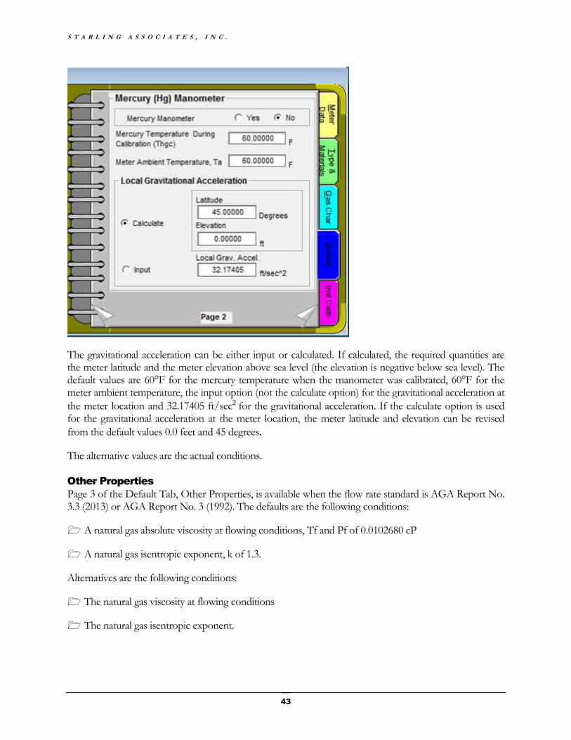
S T A R L I N G A S S O C I A T E S , I N C .
43
The gravitational acceleration can be either input or calculated. If calculated, the required quantities are the meter latitude and the meter elevation above sea level (the elevation is negative below sea level). The default values are 60°F for the mercury temperature when the manometer was calibrated, 60°F for the meter ambient temperature, the input option (not the calculate option) for the gravitational acceleration at
the meter location and 32.17405 ft/sec2 for the gravitational acceleration. If the calculate option is used for the gravitational acceleration at the meter location, the meter latitude and elevation can be revised
from the default values 0.0 feet and 45 degrees.
The alternative values are the actual conditions.
Other Properties
Page 3 of the Default Tab, Other Properties, is available when the flow rate standard is AGA Report No. 3.3 (2013) or AGA Report No. 3 (1992). The defaults are the following conditions:
A natural gas absolute viscosity at flowing conditions, Tf and Pf of 0.0102680 cP
A natural gas isentropic exponent, k of 1.3.
Alternatives are the following conditions:
The natural gas viscosity at flowing conditions
The natural gas isentropic exponent.

G O F W 2 0 1 5 V 1 . 0
44
AGA Report No. 3.3 (2013) and AGA Report No. 3 (1992) note that the default value for viscosity is an average value for natural gases with relative density from 0.55 to 0.75 in the temperature range from 30 to 90°F. For gases with viscosity outside the range 5.9E-6 to 7.9E-6 pounds mass per foot-second and/or flow outside the above ranges, particularly at low Reynolds numbers, the default value should be replaced by a more accurate gas viscosity input value.
Discussions in AGA Report No. 3.3 (2013) and AGA Report No. 3 (1992) state that for many applications, the real compressible fluid isentropic exponent is nearly identical to the ideal gas isentropic exponent. This is nearly identical to the perfect gas isentropic exponent, and accepted practice for natural gas applications is to use 1.3 for the isentropic exponent. For gases with isentropic exponents significantly different from 1.3, the default should be replaced with a more accurate value.
How to Change the Default Configuration
GOFW2015 uses the file GOFW2015.ini for the default configuration. This file is placed in the subdirectory in which you install the software. The format of GOFW2015.ini is the same as the .CS1 files. If you prefer a different set of default values when you run GOFW2015, simply edit a GOFW2015 file to the desired defaults and save it. Then, in Windows Explorer, rename the saved .CS1 file to GOFW2015.ini and replace the original GOFW2015.ini file.
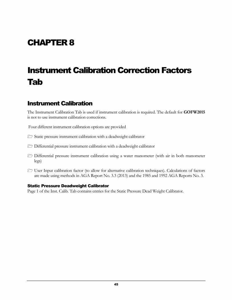
45
CHAPTER 8
Instrument Calibration Correction Factors
Tab
Instrument Calibration
The Instrument Calibration Tab is used if instrument calibration is required. The default for GOFW2015 is not to use instrument calibration corrections.
Four different instrument calibration options are provided
Static pressure instrument calibration with a deadweight calibrator
Differential pressure instrument calibration with a deadweight calibrator
Differential pressure instrument calibration using a water manometer (with air in both manometer legs)
User Input calibration factor (to allow for alternative calibration techniques). Calculations of factors are made using methods in AGA Report No. 3.3 (2013) and the 1985 and 1992 AGA Reports No. 3.
Static Pressure Deadweight Calibrator
Page 1 of the Inst. Calib. Tab contains entries for the Static Pressure Dead Weight Calibrator.
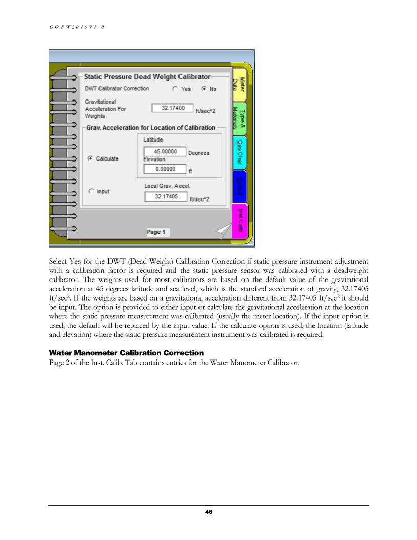
G O F W 2 0 1 5 V 1 . 0
46
Select Yes for the DWT (Dead Weight) Calibration Correction if static pressure instrument adjustment with a calibration factor is required and the static pressure sensor was calibrated with a deadweight calibrator. The weights used for most calibrators are based on the default value of the gravitational acceleration at 45 degrees latitude and sea level, which is the standard acceleration of gravity, 32.17405 ft/sec2. If the weights are based on a gravitational acceleration different from 32.17405 ft/sec2 it should be input. The option is provided to either input or calculate the gravitational acceleration at the location where the static pressure measurement was calibrated (usually the meter location). If the input option is used, the default will be replaced by the input value. If the calculate option is used, the location (latitude and elevation) where the static pressure measurement instrument was calibrated is required.
Water Manometer Calibration Correction
Page 2 of the Inst. Calib. Tab contains entries for the Water Manometer Calibrator.
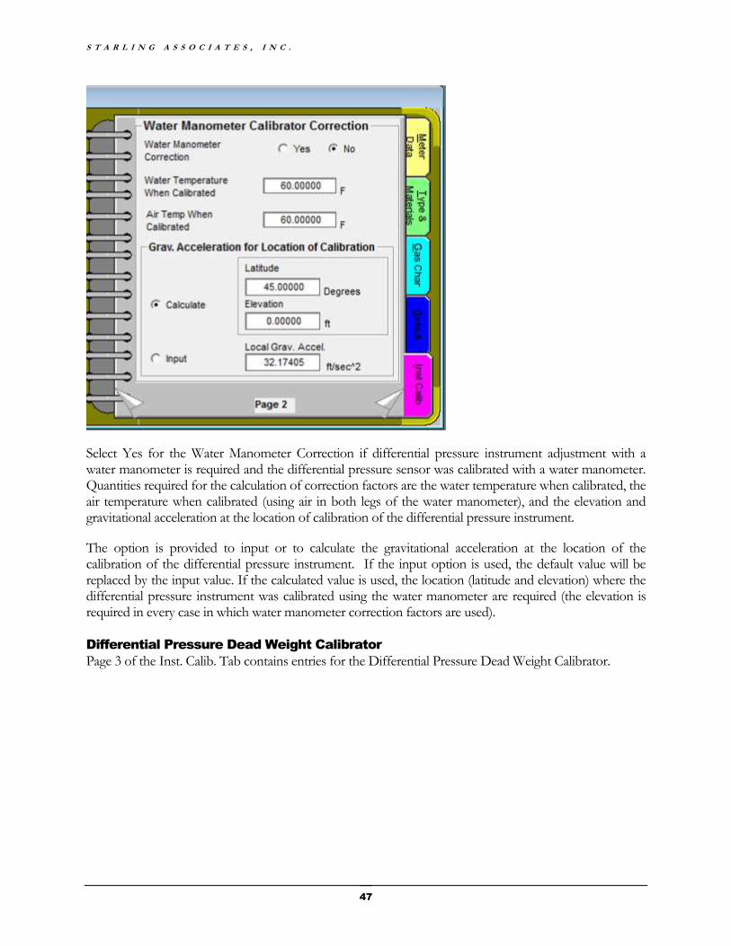
S T A R L I N G A S S O C I A T E S , I N C .
47
Select Yes for the Water Manometer Correction if differential pressure instrument adjustment with a water manometer is required and the differential pressure sensor was calibrated with a water manometer. Quantities required for the calculation of correction factors are the water temperature when calibrated, the air temperature when calibrated (using air in both legs of the water manometer), and the elevation and gravitational acceleration at the location of calibration of the differential pressure instrument.
The option is provided to input or to calculate the gravitational acceleration at the location of the calibration of the differential pressure instrument. If the input option is used, the default value will be replaced by the input value. If the calculated value is used, the location (latitude and elevation) where the differential pressure instrument was calibrated using the water manometer are required (the elevation is required in every case in which water manometer correction factors are used).
Differential Pressure Dead Weight Calibrator
Page 3 of the Inst. Calib. Tab contains entries for the Differential Pressure Dead Weight Calibrator.
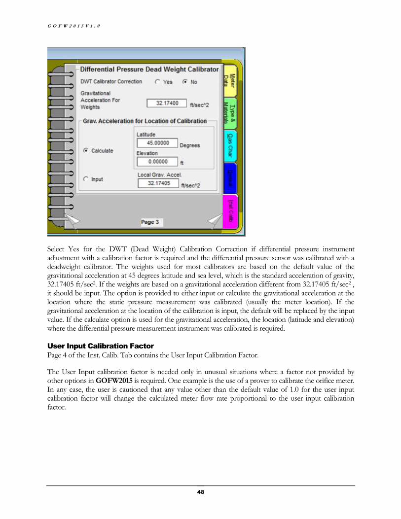
G O F W 2 0 1 5 V 1 . 0
48
Select Yes for the DWT (Dead Weight) Calibration Correction if differential pressure instrument adjustment with a calibration factor is required and the differential pressure sensor was calibrated with a deadweight calibrator. The weights used for most calibrators are based on the default value of the gravitational acceleration at 45 degrees latitude and sea level, which is the standard acceleration of gravity, 32.17405 ft/sec2. If the weights are based on a gravitational acceleration different from 32.17405 ft/sec2 , it should be input. The option is provided to either input or calculate the gravitational acceleration at the location where the static pressure measurement was calibrated (usually the meter location). If the gravitational acceleration at the location of the calibration is input, the default will be replaced by the input value. If the calculate option is used for the gravitational acceleration, the location (latitude and elevation) where the differential pressure measurement instrument was calibrated is required.
User Input Calibration Factor
Page 4 of the Inst. Calib. Tab contains the User Input Calibration Factor.
The User Input calibration factor is needed only in unusual situations where a factor not provided by other options in GOFW2015 is required. One example is the use of a prover to calibrate the orifice meter. In any case, the user is cautioned that any value other than the default value of 1.0 for the user input calibration factor will change the calculated meter flow rate proportional to the user input calibration factor.
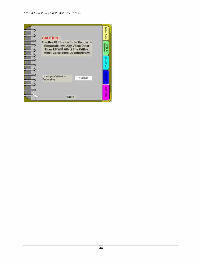
S T A R L I N G A S S O C I A T E S , I N C .
49
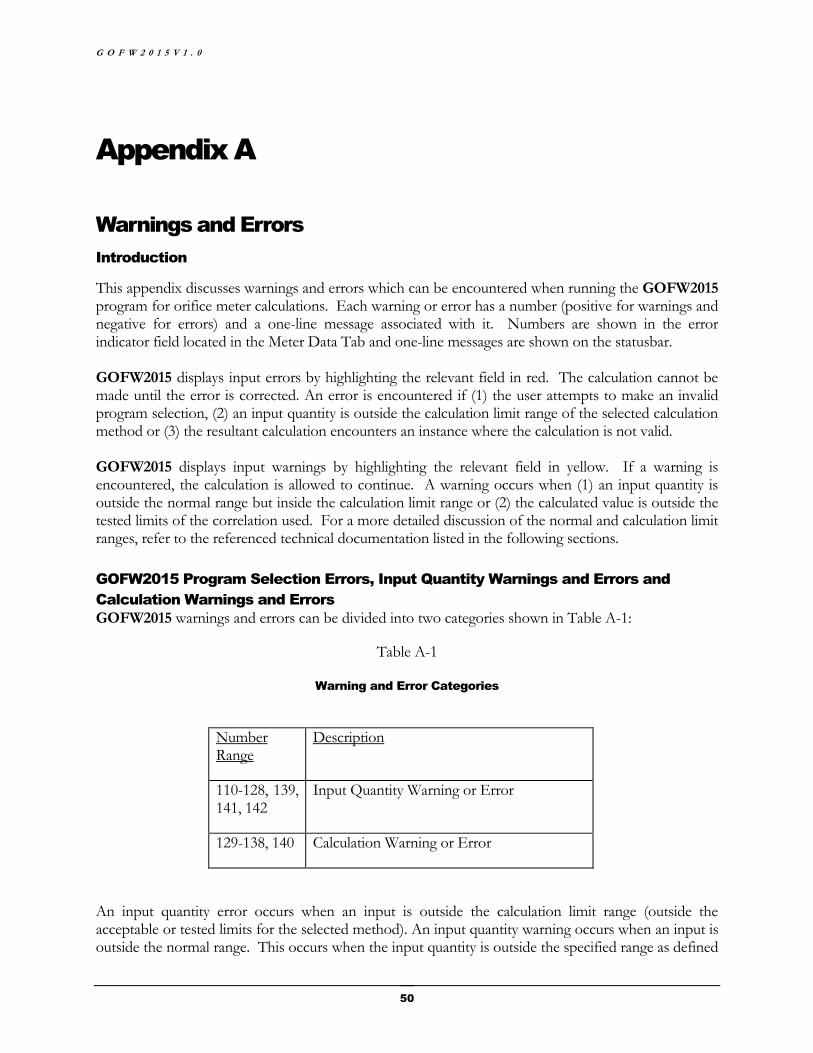
G O F W 2 0 1 5 V 1 . 0
50
Appendix A
Warnings and Errors
Introduction
This appendix discusses warnings and errors which can be encountered when running the GOFW2015 program for orifice meter calculations. Each warning or error has a number (positive for warnings and negative for errors) and a one-line message associated with it. Numbers are shown in the error indicator field located in the Meter Data Tab and one-line messages are shown on the statusbar. GOFW2015 displays input errors by highlighting the relevant field in red. The calculation cannot be made until the error is corrected. An error is encountered if (1) the user attempts to make an invalid program selection, (2) an input quantity is outside the calculation limit range of the selected calculation method or (3) the resultant calculation encounters an instance where the calculation is not valid. GOFW2015 displays input warnings by highlighting the relevant field in yellow. If a warning is encountered, the calculation is allowed to continue. A warning occurs when (1) an input quantity is outside the normal range but inside the calculation limit range or (2) the calculated value is outside the tested limits of the correlation used. For a more detailed discussion of the normal and calculation limit ranges, refer to the referenced technical documentation listed in the following sections.
GOFW2015 Program Selection Errors, Input Quantity Warnings and Errors and
Calculation Warnings and Errors
GOFW2015 warnings and errors can be divided into two categories shown in Table A-1:
Table A-1
Warning and Error Categories
Number Range
Description
110-128, 139, 141, 142
Input Quantity Warning or Error
129-138, 140 Calculation Warning or Error
An input quantity error occurs when an input is outside the calculation limit range (outside the acceptable or tested limits for the selected method). An input quantity warning occurs when an input is outside the normal range. This occurs when the input quantity is outside the specified range as defined
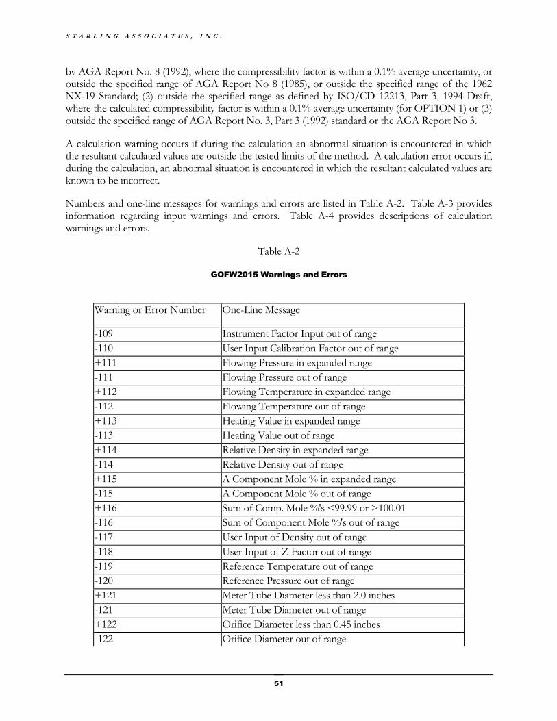
S T A R L I N G A S S O C I A T E S , I N C .
51
by AGA Report No. 8 (1992), where the compressibility factor is within a 0.1% average uncertainty, or outside the specified range of AGA Report No 8 (1985), or outside the specified range of the 1962 NX-19 Standard; (2) outside the specified range as defined by ISO/CD 12213, Part 3, 1994 Draft, where the calculated compressibility factor is within a 0.1% average uncertainty (for OPTION 1) or (3) outside the specified range of AGA Report No. 3, Part 3 (1992) standard or the AGA Report No 3.
A calculation warning occurs if during the calculation an abnormal situation is encountered in which the resultant calculated values are outside the tested limits of the method. A calculation error occurs if, during the calculation, an abnormal situation is encountered in which the resultant calculated values are known to be incorrect.
Numbers and one-line messages for warnings and errors are listed in Table A-2. Table A-3 provides information regarding input warnings and errors. Table A-4 provides descriptions of calculation warnings and errors.
Table A-2
GOFW2015 Warnings and Errors
Warning or Error Number One-Line Message
-109 Instrument Factor Input out of range
-110 User Input Calibration Factor out of range
+111 Flowing Pressure in expanded range
-111 Flowing Pressure out of range
+112 Flowing Temperature in expanded range
-112 Flowing Temperature out of range
+113 Heating Value in expanded range
-113 Heating Value out of range
+114 Relative Density in expanded range
-114 Relative Density out of range
+115 A Component Mole % in expanded range
-115 A Component Mole % out of range
+116 Sum of Comp. Mole %'s <99.99 or >100.01
-116 Sum of Component Mole %'s out of range
-117 User Input of Density out of range
-118 User Input of Z Factor out of range
-119 Reference Temperature out of range
-120 Reference Pressure out of range
+121 Meter Tube Diameter less than 2.0 inches
-121 Meter Tube Diameter out of range
+122 Orifice Diameter less than 0.45 inches
-122 Orifice Diameter out of range

G O F W 2 0 1 5 V 1 . 0
52
Warning or Error Number One-Line Message
+123 Diameter Measurement Temperature not 68 Deg.F
-123 Diameter Measurement Temperature out of range
+124 Beta Ratio < 0.1 or > 0.75
-124 Beta Ratio out of range
-125 Differential Pressure out of range
-126 Gas Viscosity out of range
-127 Isentropic Exponent out of range
-128 Gas Flowrate out of range
-129 Density Root out of range
-130 DGROSS iterations out of range
-131 VIRGS Calculation out of range
-132 Pressure Derivative out of range
+133 Density in BRAKET out of range
-134 No. of BRAKET iterations out of range
-135 No. of DDETAIL iterations out of range
+136 Reynolds Number out of range
-137 Gr, HV and CO2 not consistent
-138 VIRGS term out of range
-139 Differential Pressure exceeds Upstream Static Pressure
-140 Calculated Expansion Factor Y is negative
-141 Th or Td outside GPA2172-09 range 58.99 F to 60.01 F
-142 AGA3.3 2013 Mercury Manometer calcs. not allowed
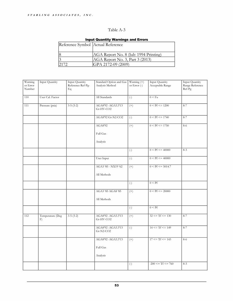
S T A R L I N G A S S O C I A T E S , I N C .
53
Table A-3
Input Quantity Warnings and Errors
Reference Symbol Actual Reference
8 AGA Report No. 8 (July 1994 Printing) 3 AGA Report No. 3, Part 3 (2013) 2172 GPA 2172-09 (2009)
Warning or Error Number
Input Quantity Input Quantity Reference Ref-Pg-Eq
Standard Option and Gas Analysis Method
Warning (+) or Error (-)
Input Quantity Acceptable Range
Input Quantity Range Reference Ref-Pg
110 User Cal. Factor All Standards (-) 0 < Fu
111 Pressure (psia) 3-5-(3-2) AGA8’92 -AGA3.3’13 Gr-HV-CO2
(+) 0 < Pf <= 1200 8-7
AGA8’92 Gr-N2-CO2 (-) 0 < Pf <= 1740 8-7
AGA8’92
Full Gas
Analysis
(+) 0 < Pf <= 1750 8-6
(-) 0 < Pf <= 40000 8-3
User Input (-) 0 < Pf <= 40000
AGA3 ‘85 - NX19 ‘62
All Methods
(+) 0 < Pf <= 5014.7
(-) 0 < Pf
AGA3 ‘85 AGA8 ‘85
All Methods
(+) 0 < Pf <= 20000
(-) 0 < Pf
112 Temperature (Deg F)
3-5-(3-2) AGA8’92 -AGA3.3’13 Gr-HV-CO2
(+) 32 <= Tf <= 130 8-7
AGA8’92 -AGA3.3’13 Gr-N2-CO2
(-) 14 <= Tf <= 149 8-7
AGA8’92 -AGA3.3’13
Full Gas
Analysis
(+) 17 <= Tf <= 143 8-6
(-) -200 <= Tf <= 760 8-3
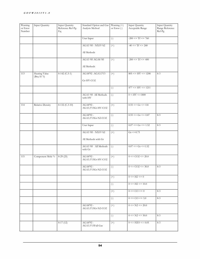
G O F W 2 0 1 5 V 1 . 0
54
Warning or Error Number
Input Quantity Input Quantity Reference Ref-Pg-Eq
Standard Option and Gas Analysis Method
Warning (+) or Error (-)
Input Quantity Acceptable Range
Input Quantity Range Reference Ref-Pg
User Input (-) -200 <= Tf <= 760
AGA3 ‘85 - NX19 ‘62
All Methods
(+) -40 <= Tf <= 240
AGA3 ‘85 AGA8 ‘85
All Methods
(+) -200 <= Tf <= 400
113 Heating Value (Btu/ft^3)
8-142-(C.5-1) AGA8’92 -AGA3.3’13
Gr-HV-CO2
(+) 805 <= HV <= 1208 8-3
(-) 477 <= HV <= 1211
AGA3 ‘85 All Methods with HV
(-) 0 < HV <=1800
114 Relative Density 8-132-(C.3-10) AGA8’92 -AGA3.3’13Gr-HV-CO2
(+) 0.55 <= Gr <= 0.8
AGA8’92 -AGA3.3’13Gr-N2-CO2
(-) 0.55 <= Gr <= 0.87 8-3
User Input (-) 0.07 <= Gr <= 1.52 8-3
AGA3 ‘85 - NX19 ‘62
All Methods with Gr
(+) Gr <=0.75
AGA3 ‘85 All Methods with Gr
(-) 0.07 <= Gr <=1.52
115 Component Mole % 8-29-(25) AGA8’92 -AGA3.3’13Gr-HV-CO2
(+) 0 <= CO2 <= 20.0
AGA8’92 -AGA3.3’13Gr-N2-CO2
(-) 0 <= CO2 <= 30.0 8-3
(+) 0 <= H2 <= 0
(-) 0 <= H2 <= 10.0
(+) 0 <= CO <= 0 8-3
(-) 0 <= CO <= 3.0 8-3
AGA8’92 -AGA3.3’13Gr-N2-CO2
(+) 0 <= N2 <= 20.0
(-) 0 <= N2 <= 50.0 8-3
8-17-(12) AGA8’92 -AGA3.3’13Full Gas
(+) 0 <= H2O <= 0.05 8-3

S T A R L I N G A S S O C I A T E S , I N C .
55
Warning or Error Number
Input Quantity Input Quantity Reference Ref-Pg-Eq
Standard Option and Gas Analysis Method
Warning (+) or Error (-)
Input Quantity Acceptable Range
Input Quantity Range Reference Ref-Pg
Analysis
(-) 0 <= H2O <= 10.0
(+) 0 <= He <= 0.2 8-3
(-) 0 <= He <= 3.0 8-3
(+) 45.0 <= Meth <= 100.0 8-3
(-) 0 <= Meth <= 100.0 8-3
(+) 0 <= Ethane <= 10.0 8-3
(-) 0 <= Ethane <= 100.0 8-3
(+) 0 <= Prop <= 4.0 8-3
(-) 0 <= Prop <= 12.0 8-3
(+) 0 <= Butanes <= 1.0 8-3
(-) 0 <= Butanes <= 6.0 8-3
(+) 0 <= Pentanes <= 0.3 8-3
(-) 0 <= Pentanes <= 4.0 8-3
(+) 0 <= Hexanes + <= 0.2 8-3
(-) 0 <= Hexanes + <= 10.0
(+) 0 <= O2 <= 0.0 8-3
(-) 0 <= O2 <= 21.0 8-3
(+) 0 <= CO <= 3.0 8-3
(-) 0 <= CO <= 3.0 8-3
(+) 0 <= H2 <= 10.0 8-3
(-) 0 <= H2 <= 100.0 8-3
(+) 0 <= N2 <= 50.0 8-3
(-) 0 <= N2 <= 100.0 8-3
(+) 0 <= CO2 <= 30.0 8-3
(-) 0 <= CO2 <= 100.0 8-3
(+) 0 <= H2S <= 0.02 8-3
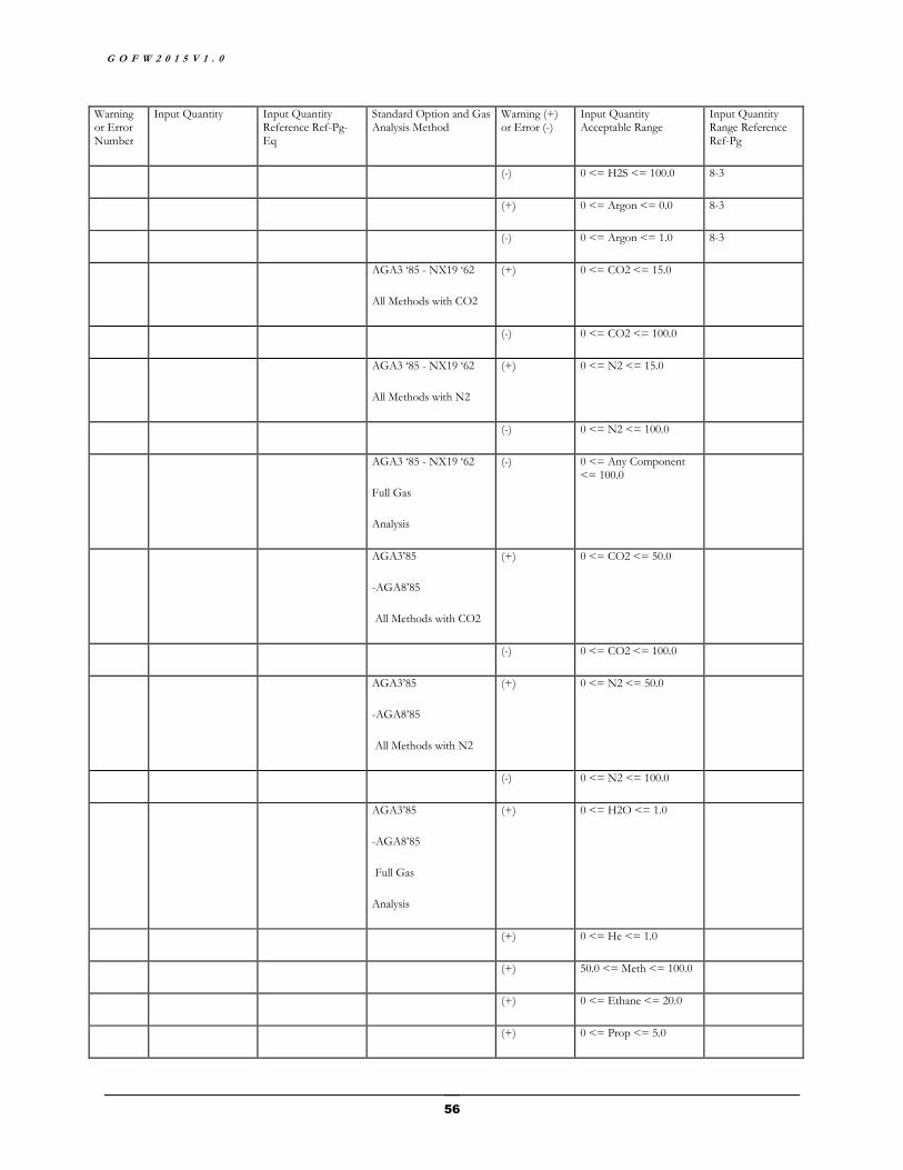
G O F W 2 0 1 5 V 1 . 0
56
Warning or Error Number
Input Quantity Input Quantity Reference Ref-Pg-Eq
Standard Option and Gas Analysis Method
Warning (+) or Error (-)
Input Quantity Acceptable Range
Input Quantity Range Reference Ref-Pg
(-) 0 <= H2S <= 100.0 8-3
(+) 0 <= Argon <= 0.0 8-3
(-) 0 <= Argon <= 1.0 8-3
AGA3 ‘85 - NX19 ‘62
All Methods with CO2
(+) 0 <= CO2 <= 15.0
(-) 0 <= CO2 <= 100.0
AGA3 ‘85 - NX19 ‘62
All Methods with N2
(+) 0 <= N2 <= 15.0
(-) 0 <= N2 <= 100.0
AGA3 ‘85 - NX19 ‘62
Full Gas
Analysis
(-) 0 <= Any Component <= 100.0
AGA3’85
-AGA8’85
All Methods with CO2
(+) 0 <= CO2 <= 50.0
(-) 0 <= CO2 <= 100.0
AGA3’85
-AGA8’85
All Methods with N2
(+) 0 <= N2 <= 50.0
(-) 0 <= N2 <= 100.0
AGA3’85
-AGA8’85
Full Gas
Analysis
(+) 0 <= H2O <= 1.0
(+) 0 <= He <= 1.0
(+) 50.0 <= Meth <= 100.0
(+) 0 <= Ethane <= 20.0
(+) 0 <= Prop <= 5.0
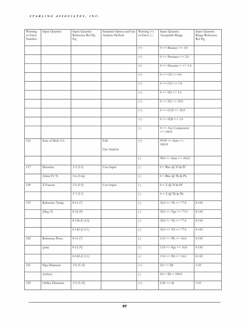
S T A R L I N G A S S O C I A T E S , I N C .
57
Warning or Error Number
Input Quantity Input Quantity Reference Ref-Pg-Eq
Standard Option and Gas Analysis Method
Warning (+) or Error (-)
Input Quantity Acceptable Range
Input Quantity Range Reference Ref-Pg
(+) 0 <= Butanes <= 3.0
(+) 0 <= Pentanes <= 2.0
(+) 0 <= Hexanes + <= 1.0
(+) 0 <= O2 <= 0.0
(+) 0 <= CO <= 1.0
(+) 0 <= H2 <= 1.0
(+) 0 <= N2 <= 50.0
(+) 0 <= CO2 <= 50.0
(+) 0 <= H2S <= 1.0
(-) 0 <= Any Component <= 100.0
116 Sum of Mole %'s Full
Gas Analysis
(+) 99.99 <= Sum <= 100.01
(-) 98.0 <= Sum <= 102.0
117 Densities 3-5-(3-1) User Input (-) 0 < Rho @ Tf & Pf
(Lbm/Ft^3) 3-6-(3-4a) (-) 0 < Rho @ Tb & Pb
118 Z Factors 3-5-(3-2) User Input (-) 0 < Z @ Tf & Pf
3-7-(3-7) (-) 0 < Z @ Tb & Pb
119 Reference Temp. 8-11-(7) (-) 32.0 <= Tb <= 77.0 8-143
(Deg. F) 8-12-(9) (-) 32.0 <= Tgr <= 77.0 8-143
8-136-(C.4-5) (-) 32.0 <= Th <= 77.0 8-143
8-142-(C.5-1) (-) 32.0 <= Td <= 77.0 8-143
120 Reference Press. 8-11-(7) (-) 13.0 <= Pb <= 16.0 8-143
(psia) 8-12-(9) (-) 13.0 <= Pgr <= 16.0 8-143
8-142-(C.5-1) (-) 13.0 <= Pd <= 16.0 8-143
121 Pipe Diameter 3-9-(3-13) (+) 2.0 <= Dr 3-10
(inches) (-) 0.0 < Dr < 100.0
122 Orifice Diameter 3-9-(3-12) (+) 0.45 <= dr 3-10
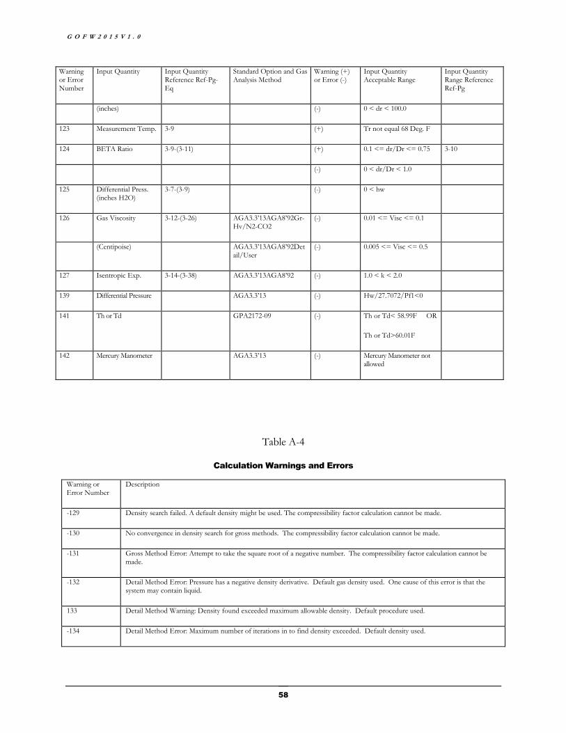
G O F W 2 0 1 5 V 1 . 0
58
Warning or Error Number
Input Quantity Input Quantity Reference Ref-Pg-Eq
Standard Option and Gas Analysis Method
Warning (+) or Error (-)
Input Quantity Acceptable Range
Input Quantity Range Reference Ref-Pg
(inches) (-) 0 < dr < 100.0
123 Measurement Temp. 3-9 (+) Tr not equal 68 Deg. F
124 BETA Ratio 3-9-(3-11) (+) 0.1 <= dr/Dr <= 0.75 3-10
(-) 0 < dr/Dr < 1.0
125 Differential Press. (inches H2O)
3-7-(3-9) (-) 0 < hw
126 Gas Viscosity 3-12-(3-26) AGA3.3’13AGA8’92Gr-Hv/N2-CO2
(-) 0.01 <= Visc <= 0.1
(Centipoise) AGA3.3’13AGA8’92Detail/User
(-) 0.005 <= Visc <= 0.5
127 Isentropic Exp. 3-14-(3-38) AGA3.3’13AGA8’92 (-) 1.0 < k < 2.0
139 Differential Pressure AGA3.3’13 (-) Hw/27.7072/Pf1<0
141 Th or Td GPA2172-09 (-) Th or Td< 58.99F OR
Th or Td>60.01F
142 Mercury Manometer AGA3.3’13 (-) Mercury Manometer not allowed
Table A-4
Calculation Warnings and Errors
Warning or Error Number
Description
-129 Density search failed. A default density might be used. The compressibility factor calculation cannot be made.
-130 No convergence in density search for gross methods. The compressibility factor calculation cannot be made.
-131 Gross Method Error: Attempt to take the square root of a negative number. The compressibility factor calculation cannot be made.
-132 Detail Method Error: Pressure has a negative density derivative. Default gas density used. One cause of this error is that the system may contain liquid.
133 Detail Method Warning: Density found exceeded maximum allowable density. Default procedure used.
-134 Detail Method Error: Maximum number of iterations in to find density exceeded. Default density used.
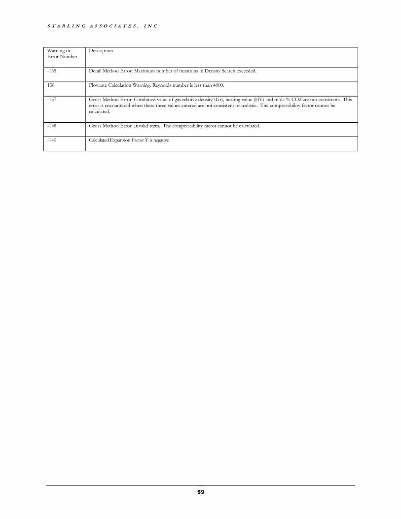
S T A R L I N G A S S O C I A T E S , I N C .
59
Warning or Error Number
Description
-135 Detail Method Error: Maximum number of iterations in Density Search exceeded.
136 Flowrate Calculation Warning: Reynolds number is less than 4000.
-137 Gross Method Error: Combined value of gas relative density (Gr), heating value (HV) and mole % CO2 are not consistent. This error is encountered when these three values entered are not consistent or realistic. The compressibility factor cannot be calculated.
-138 Gross Method Error: Invalid term. The compressibility factor cannot be calculated.
-140 Calculated Expansion Factor Y is negative
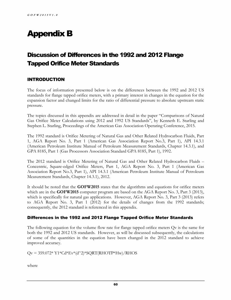
G O F W 2 0 1 5 V 1 . 0
60
Appendix B
Discussion of Differences in the 1992 and 2012 Flange
Tapped Orifice Meter Standards
INTRODUCTION
The focus of information presented below is on the differences between the 1992 and 2012 US standards for flange tapped orifice meters, with a primary interest in changes in the equation for the expansion factor and changed limits for the ratio of differential pressure to absolute upstream static pressure. The topics discussed in this appendix are addressed in detail in the paper “Comparisons of Natural Gas Orifice Meter Calculations using 2012 and 1992 US Standards”, by Kenneth E. Starling and Stephen L. Starling, Proceedings of the American Gas Association Operating Conference, 2015. The 1992 standard is Orifice Metering of Natural Gas and Other Related Hydrocarbon Fluids, Part 1, AGA Report No. 3, Part 1 (American Gas Association Report No.3, Part 1), API 14.3.1 (American Petroleum Institute Manual of Petroleum Measurement Standards, Chapter 14.3.1), and GPA 8185, Part 1 (Gas Processors Association Standard GPA 8185, Part 1), 1992. The 2012 standard is Orifice Metering of Natural Gas and Other Related Hydrocarbon Fluids – Concentric, Square-edged Orifice Meters, Part 1, AGA Report No. 3, Part 1 (American Gas Association Report No.3, Part 1), API 14.3.1 (American Petroleum Institute Manual of Petroleum Measurement Standards, Chapter 14.3.1), 2012. It should be noted that the GOFW2015 states that the algorithms and equations for orifice meters which are in the GOFW2015 computer program are based on the AGA Report No. 3, Part 3 (2013), which is specifically for natural gas applications. However, AGA Report No. 3, Part 3 (2013) refers to AGA Report No. 3, Part 1 (2012) for the details of changes from the 1992 standards; consequently, the 2012 standard is referenced in this appendix.
Differences in the 1992 and 2012 Flange Tapped Orifice Meter Standards
The following equation for the volume flow rate for flange tapped orifice meters Qv is the same for both the 1992 and 2012 US standards. However, as will be discussed subsequently, the calculations of some of the quantities in the equation have been changed in the 2012 standard to achieve improved accuracy. Qv = 359.072* Y1*Cd*Ev*(d^2)*SQRT(RHOTP*Hw)/RHOS
where
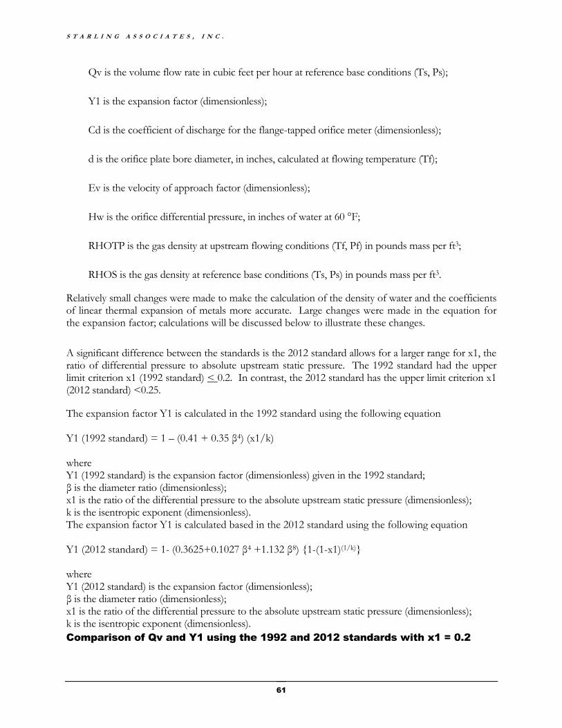
S T A R L I N G A S S O C I A T E S , I N C .
61
Qv is the volume flow rate in cubic feet per hour at reference base conditions (Ts, Ps);
Y1 is the expansion factor (dimensionless);
Cd is the coefficient of discharge for the flange-tapped orifice meter (dimensionless);
d is the orifice plate bore diameter, in inches, calculated at flowing temperature (Tf);
Ev is the velocity of approach factor (dimensionless);
Hw is the orifice differential pressure, in inches of water at 60 °F;
RHOTP is the gas density at upstream flowing conditions (Tf, Pf) in pounds mass per ft3;
RHOS is the gas density at reference base conditions (Ts, Ps) in pounds mass per ft3.
Relatively small changes were made to make the calculation of the density of water and the coefficients of linear thermal expansion of metals more accurate. Large changes were made in the equation for the expansion factor; calculations will be discussed below to illustrate these changes.
A significant difference between the standards is the 2012 standard allows for a larger range for x1, the ratio of differential pressure to absolute upstream static pressure. The 1992 standard had the upper limit criterion x1 (1992 standard) < 0.2. In contrast, the 2012 standard has the upper limit criterion x1 (2012 standard) <0.25.
The expansion factor Y1 is calculated in the 1992 standard using the following equation Y1 (1992 standard) = 1 – (0.41 + 0.35 β4) (x1/k) where Y1 (1992 standard) is the expansion factor (dimensionless) given in the 1992 standard; β is the diameter ratio (dimensionless); x1 is the ratio of the differential pressure to the absolute upstream static pressure (dimensionless); k is the isentropic exponent (dimensionless). The expansion factor Y1 is calculated based in the 2012 standard using the following equation Y1 (2012 standard) = 1- (0.3625+0.1027 β4 +1.132 β8) {1-(1-x1)(1/k)} where Y1 (2012 standard) is the expansion factor (dimensionless); β is the diameter ratio (dimensionless); x1 is the ratio of the differential pressure to the absolute upstream static pressure (dimensionless); k is the isentropic exponent (dimensionless).
Comparison of Qv and Y1 using the 1992 and 2012 standards with x1 = 0.2

G O F W 2 0 1 5 V 1 . 0
62
Consider the following example orifice meter calculation for dry natural gas. The natural gas composition is the “AGA8 Amarillo Gas Composition” given in Table B.6-1 of AGA Report No. 8 1992 (1994 Reprint). The “AGA8 Amarillo Gas Composition” is shown on the screenshot below.
The inputs to the calculations are listed below. Descriptions of these input variables and how they are used in the calculation of the volume flow rate Qv are presented in the 1992 and 2012 standards.
d is the mean orifice bore diameter at Tr of 68 °F, in inches = 1.000.
D is the mean meter tube internal diameter at Tr of 68 °F, in inches = 2.000.
Hw is the average differential pressure, in inches of water at 60 °F = 200.0.
Pb is the contract base pressure, in psia = 14.73.
Pf1 is the upstream absolute static pressure, in psia = 36.092.
Tb is the contract base temperature of 60 °F, in degrees Rankine (60 °F + 459.67) = 519.67.
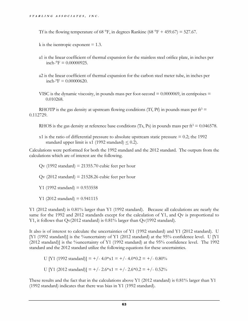
S T A R L I N G A S S O C I A T E S , I N C .
63
Tf is the flowing temperature of 68 °F, in degrees Rankine (68 °F + 459.67) = 527.67.
k is the isentropic exponent = 1.3.
a1 is the linear coefficient of thermal expansion for the stainless steel orifice plate, in inches per inch-°F = 0.00000925.
a2 is the linear coefficient of thermal expansion for the carbon steel meter tube, in inches per inch-ºF = 0.00000620.
VISC is the dynamic viscosity, in pounds mass per foot-second = 0.0000069, in centipoises = 0.010268.
RHOTP is the gas density at upstream flowing conditions (Tf, Pf) in pounds mass per ft3 = 0.112729.
RHOS is the gas density at reference base conditions (Ts, Ps) in pounds mass per ft3 = 0.046578. x1 is the ratio of differential pressure to absolute upstream static pressure = 0.2; the 1992
standard upper limit is x1 (1992 standard) < 0.2).
Calculations were performed for both the 1992 standard and the 2012 standard. The outputs from the calculations which are of interest are the following.
Qv (1992 standard) = 21355.70 cubic feet per hour Qv (2012 standard) = 21528.26 cubic feet per hour Y1 (1992 standard) = 0.933558 Y1 (2012 standard) = 0.941115
Y1 (2012 standard) is 0.81% larger than Y1 (1992 standard). Because all calculations are nearly the same for the 1992 and 2012 standards except for the calculation of Y1, and Qv is proportional to Y1, it follows that Qv(2012 standard) is 0.81% larger than Qv(1992 standard). It also is of interest to calculate the uncertainties of Y1 (1992 standard) and Y1 (2012 standard). U [Y1 (1992 standard)] is the %uncertainty of Y1 (2012 standard) at the 95% confidence level. U [Y1 (2012 standard)] is the %uncertainty of Y1 (1992 standard) at the 95% confidence level. The 1992 standard and the 2012 standard utilize the following equations for these uncertainties.
U [Y1 (1992 standard)] = +/- 4.0*x1 = +/- 4.0*0.2 = +/- 0.80%
U [Y1 (2012 standard)] = +/- 2.6*x1 = +/- 2.6*0.2 = +/- 0.52% These results and the fact that in the calculations above Y1 (2012 standard) is 0.81% larger than Y1 (1992 standard) indicates that there was bias in Y1 (1992 standard).

G O F W 2 0 1 5 V 1 . 0
64
The following GOFW2015 screenshots show key inputs and outputs for the calculations discussed above. The As Found screenshot is for the 1992 standard. The As Left screenshot is for the 2012 standard as utilized in AGA3.3 (2013).
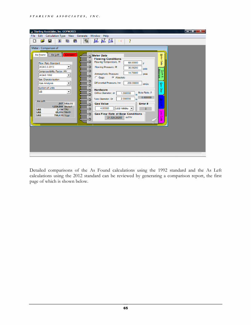
S T A R L I N G A S S O C I A T E S , I N C .
65
Detailed comparisons of the As Found calculations using the 1992 standard and the As Left calculations using the 2012 standard can be reviewed by generating a comparison report, the first page of which is shown below.
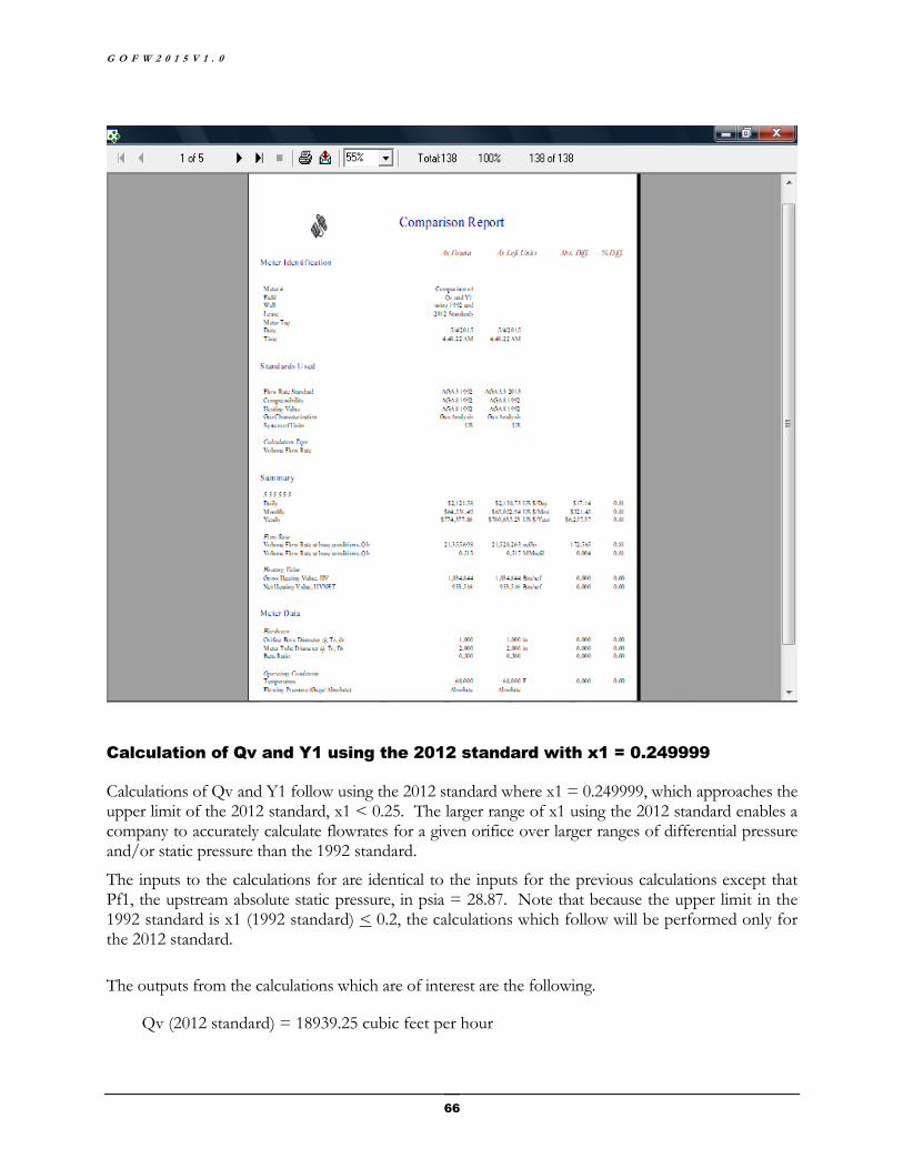
G O F W 2 0 1 5 V 1 . 0
66
Calculation of Qv and Y1 using the 2012 standard with x1 = 0.249999
Calculations of Qv and Y1 follow using the 2012 standard where x1 = 0.249999, which approaches the upper limit of the 2012 standard, x1 < 0.25. The larger range of x1 using the 2012 standard enables a company to accurately calculate flowrates for a given orifice over larger ranges of differential pressure and/or static pressure than the 1992 standard.
The inputs to the calculations for are identical to the inputs for the previous calculations except that Pf1, the upstream absolute static pressure, in psia = 28.87. Note that because the upper limit in the 1992 standard is x1 (1992 standard) < 0.2, the calculations which follow will be performed only for the 2012 standard.
The outputs from the calculations which are of interest are the following.
Qv (2012 standard) = 18939.25 cubic feet per hour
S T A R L I N G A S S O C I A T E S , I N C .
67
Y1 (2012 standard) = 0.925887
Because the static pressure in these calculations is lower than in the previous calculations, both the density RHOTP of the flowing natural gas and Y1 (2012 standard) are lower and consequently Qv is lower than in the previous calculations.
The calculation of U [Y1 (2012 standard)], the %uncertainty of Y1 (2012 standard) at the 95% confidence level for Case B yields the following result.
U [Y1 (2012 standard)] = +/- 2.6*x1 = +/- 2.6*0.249999 = +/- 0.65%
Note that because the upper limit in the 1992 standard is x1 (1992< 0.2, the calculations in the present case should not be performed using Y1 (1992 standard). In fact, in the upstream static pressure range from Pf1= 36.092 psia (previous calculations) to Pf1= 28.87 psia (present calculations), x1 varies from x1=0.2 (previous calculations) to x1=0.249999 (present calculations) so that x1 is outside the x1 upper limit in the 1992 standard except when x1 = 0.2. This means that the 2012 standard allows a significant increase in the operating range of the upstream static pressure compared to the 1992 standard. The increased upstream static pressure operating range using the 2012 standard includes conditions which, using the 1992 standard, would have required an orifice plate change in order to achieve the same flow rates.
It is clear from the set of volume flow rate calculations presented above that the new expansion factor equation in the 2012 orifice meter standard provides not only improved accuracy in natural gas flow rate calculations but increases the allowed operating ranges for the differential pressure and/or the static pressure without orifice plate replacements. The improved accuracy is of general benefit to commerce through reductions in bias in custody transfer. The increases in allowed operating ranges are of benefit to the natural gas industry in reducing flow measurement operating costs.
G O F W 2 0 1 5 V 1 . 0
68
Appendix C
Discussion of Energy Flow Rate Calculations, Gross Heating
Value and Differences in Standards for Wet Gases
INTRODUCTION
Information is presented below regarding how the energy flow rate, ENERGY_FLOWRATE, is calculated in GOFW2015. In addition, the differences in the definitions for the wet gas gross heating value used in different standards are discussed. An example calculation is given using GOFW2015 to compare the heating value of water saturated methane calculated using GPA2172-09 and AGA8 1992.
ENERGY FLOW RATE
The ENERGY_FLOWRATE in MMBtu/hr is calculated in GOFW2015 using the equation below. ENERGY_FLOWRATE = QB_IDEAL*HV_IDEAL/1000000 In this equation, QB_IDEAL is the ideal gas volume flow rate. QB_IDEAL = Qb/Zb Qb is the volume flow rate in scf/hr calculated using the Flow Rate Standard, for example, AGA3.3 2013. Zb is the natural gas compressibility factor at base conditions, Tb and Pb, calculated using the Compressibility Factor standard, for example, AGA8 1992. HV_IDEAL is the ideal gas gross heating value. HV_IDEAL = HV*Zhv HV is the natural gas gross heating and Zhv is the natural gas compressibility factor at base conditions; both HV and Zhv are calculated using the heating value standard, for example, GPA2172-09. Although the differences between Zb and Zhv are small for lean dry natural gases, the differences increase for gases containing water. Consequently, for accounting purposes, the above equation for ENERGY_FLOWRATE should be used. Note that the heating value standard GPA2172-09 as well as GOFW2015 use the above equation for ENERGY_FLOWRATE. This topic is discussed in the paper “Heating Value and Orifice Standards Integration Methods”, by Kenneth E. Starling and Don Sextro, Proceedings, Gas Processors Association Convention, 2013. ENERGY_FLOWRATE in MMBtu/hr, QB_IDEAL in scf/hr and HV_IDEAL in Btu/scf are in the last three lines of numerical outputs of the GOFW2015 AsFound, AsLeft and Comparison reports.
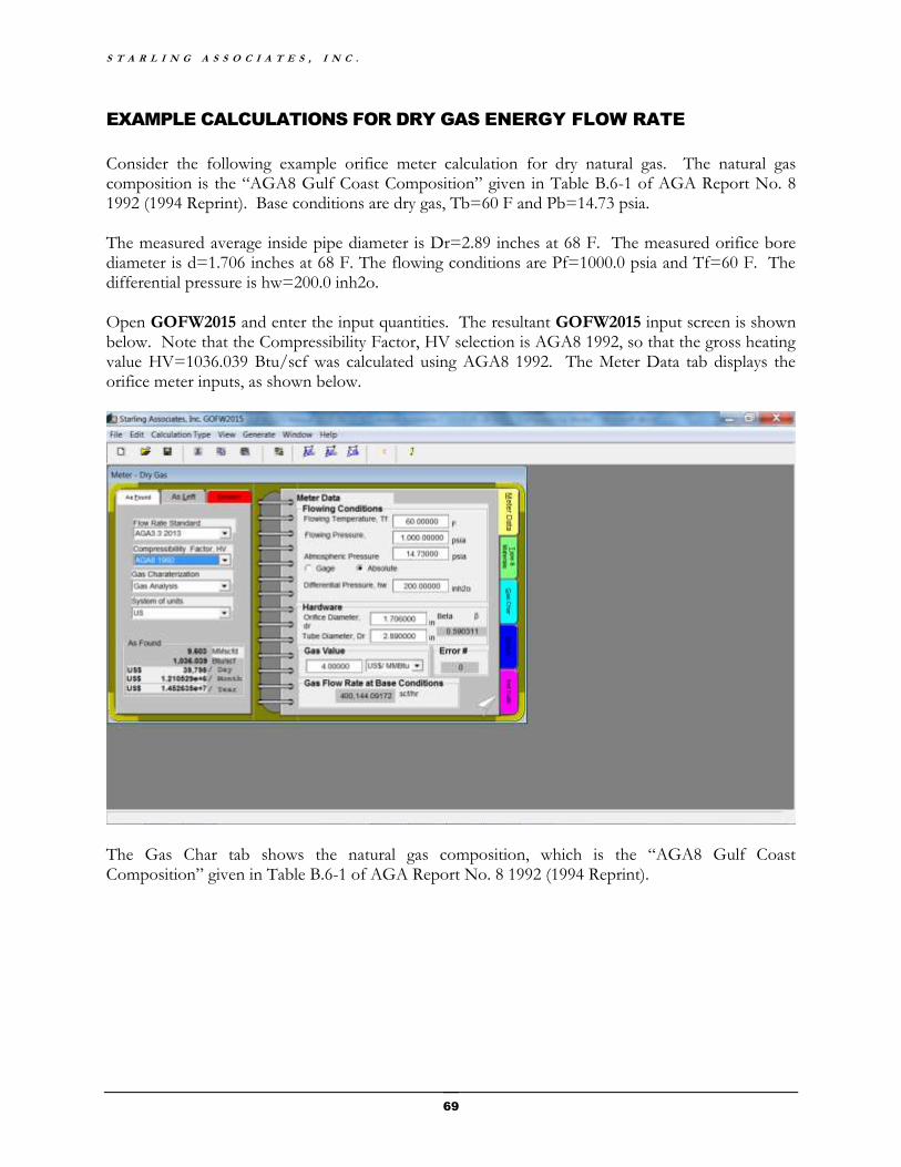
S T A R L I N G A S S O C I A T E S , I N C .
69
EXAMPLE CALCULATIONS FOR DRY GAS ENERGY FLOW RATE
Consider the following example orifice meter calculation for dry natural gas. The natural gas composition is the “AGA8 Gulf Coast Composition” given in Table B.6-1 of AGA Report No. 8 1992 (1994 Reprint). Base conditions are dry gas, Tb=60 F and Pb=14.73 psia. The measured average inside pipe diameter is Dr=2.89 inches at 68 F. The measured orifice bore diameter is d=1.706 inches at 68 F. The flowing conditions are Pf=1000.0 psia and Tf=60 F. The differential pressure is hw=200.0 inh2o. Open GOFW2015 and enter the input quantities. The resultant GOFW2015 input screen is shown below. Note that the Compressibility Factor, HV selection is AGA8 1992, so that the gross heating value HV=1036.039 Btu/scf was calculated using AGA8 1992. The Meter Data tab displays the orifice meter inputs, as shown below.
The Gas Char tab shows the natural gas composition, which is the “AGA8 Gulf Coast Composition” given in Table B.6-1 of AGA Report No. 8 1992 (1994 Reprint).
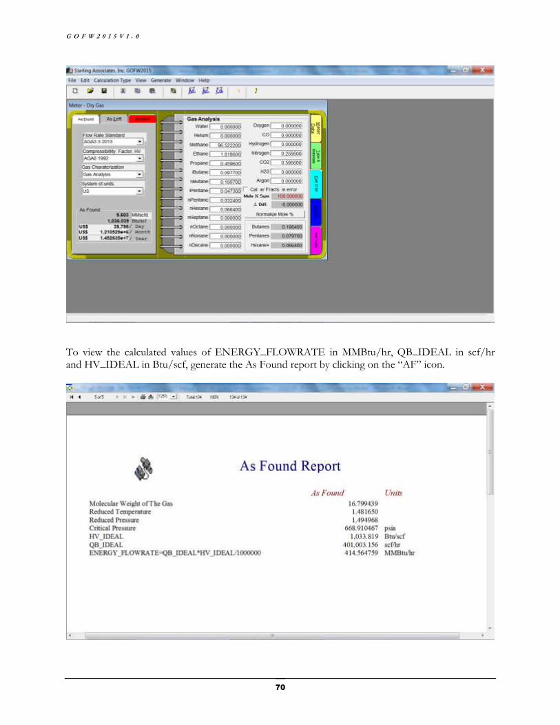
G O F W 2 0 1 5 V 1 . 0
70
To view the calculated values of ENERGY_FLOWRATE in MMBtu/hr, QB_IDEAL in scf/hr and HV_IDEAL in Btu/scf, generate the As Found report by clicking on the “AF” icon.
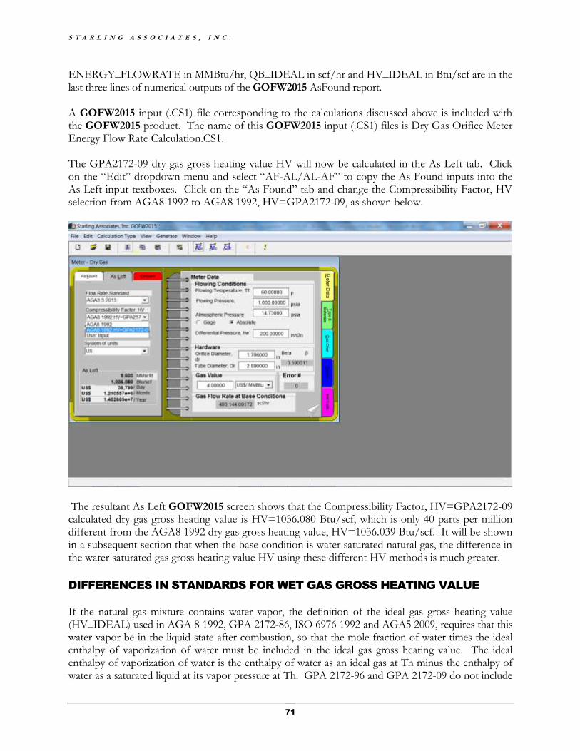
S T A R L I N G A S S O C I A T E S , I N C .
71
ENERGY_FLOWRATE in MMBtu/hr, QB_IDEAL in scf/hr and HV_IDEAL in Btu/scf are in the last three lines of numerical outputs of the GOFW2015 AsFound report. A GOFW2015 input (.CS1) file corresponding to the calculations discussed above is included with the GOFW2015 product. The name of this GOFW2015 input (.CS1) files is Dry Gas Orifice Meter Energy Flow Rate Calculation.CS1. The GPA2172-09 dry gas gross heating value HV will now be calculated in the As Left tab. Click on the “Edit” dropdown menu and select “AF-AL/AL-AF” to copy the As Found inputs into the As Left input textboxes. Click on the “As Found” tab and change the Compressibility Factor, HV selection from AGA8 1992 to AGA8 1992, HV=GPA2172-09, as shown below.
The resultant As Left GOFW2015 screen shows that the Compressibility Factor, HV=GPA2172-09 calculated dry gas gross heating value is HV=1036.080 Btu/scf, which is only 40 parts per million different from the AGA8 1992 dry gas gross heating value, HV=1036.039 Btu/scf. It will be shown in a subsequent section that when the base condition is water saturated natural gas, the difference in the water saturated gas gross heating value HV using these different HV methods is much greater.
DIFFERENCES IN STANDARDS FOR WET GAS GROSS HEATING VALUE
If the natural gas mixture contains water vapor, the definition of the ideal gas gross heating value (HV_IDEAL) used in AGA 8 1992, GPA 2172-86, ISO 6976 1992 and AGA5 2009, requires that this water vapor be in the liquid state after combustion, so that the mole fraction of water times the ideal enthalpy of vaporization of water must be included in the ideal gas gross heating value. The ideal enthalpy of vaporization of water is the enthalpy of water as an ideal gas at Th minus the enthalpy of water as a saturated liquid at its vapor pressure at Th. GPA 2172-96 and GPA 2172-09 do not include

G O F W 2 0 1 5 V 1 . 0
72
the ideal enthalpy of vaporization of the water in the gas mixture in the ideal gas gross heating value calculation. Thus, although there is close agreement among AGA 8 1992, GPA 2172-86, GPA 2172-96 and GPA 2172-09 for ideal gas gross heating value calculations for dry natural gases, the differences increase with increasing water content for natural gases containing water.
WATER SATURATED GAS GROSS HEATING VALUE CALCULATIONS
Water saturated methane gross heating value calculations for GPA 2172-09 and AGA 8 1992 are compared below to illustrate the magnitude of differences in HV standards for wet gases. Both GPA 2172-09 and AGA 8 1992 explain that the mole fraction of water in the water saturated natural gas, Xw, is the ratio of the vapor pressure of water, Pw, at the base temperature Tb, divided by the base pressure, Pb. Xw = Pw/Pb At Tb=60 F, Pw=0.25640 psia, so that for the base Pb=14.73 psia, Xw=0.0174066, as shown below. Xw = Pw/Pb = (0.25640 psia) /(14.73 psia) = 0.0174066 Thus, the composition of water saturated methane at Tb=60 F and Pb=14.73 psia is 1.74066 mole percent water and 98.25934 mole percent methane. Open GOFW2015, click the Gas Char tab and input the water saturated methane gas composition, as shown below.

S T A R L I N G A S S O C I A T E S , I N C .
73
Note that with the Compressibility Factor, HV selection is AGA8 1992, so that the water saturated methane gross heating value HV=997.594 Btu/scf was calculated using AGA8 1992. The GPA2172-09 water saturated methane gross heating value will now be calculated in the As Left tab. Click on the “Edit” dropdown menu and select “AF-AL/AL-AF” to copy the As Found inputs into the As Left input textboxes. Click on the “As Found” tab and change the Compressibility Factor, HV selection from AGA8 1992 to AGA8 1992, HV=GPA2172-09, as shown below.
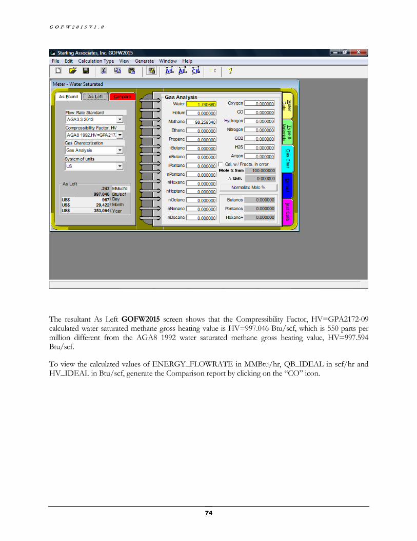
G O F W 2 0 1 5 V 1 . 0
74
The resultant As Left GOFW2015 screen shows that the Compressibility Factor, HV=GPA2172-09 calculated water saturated methane gross heating value is HV=997.046 Btu/scf, which is 550 parts per million different from the AGA8 1992 water saturated methane gross heating value, HV=997.594 Btu/scf.
To view the calculated values of ENERGY_FLOWRATE in MMBtu/hr, QB_IDEAL in scf/hr and HV_IDEAL in Btu/scf, generate the Comparison report by clicking on the “CO” icon.
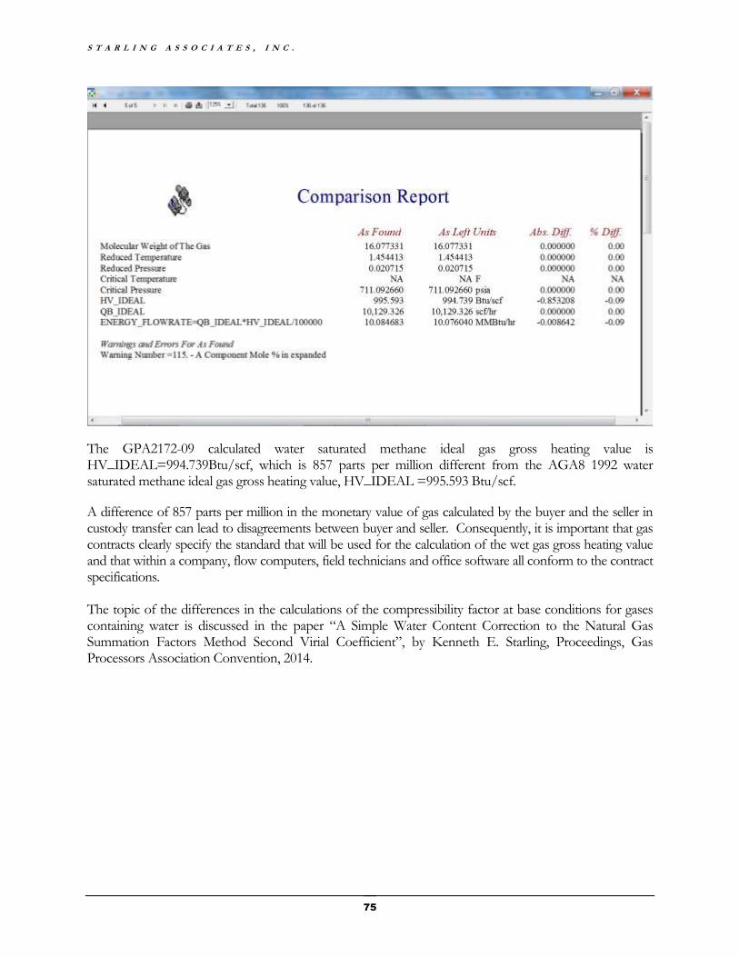
S T A R L I N G A S S O C I A T E S , I N C .
75
The GPA2172-09 calculated water saturated methane ideal gas gross heating value is HV_IDEAL=994.739Btu/scf, which is 857 parts per million different from the AGA8 1992 water saturated methane ideal gas gross heating value, HV_IDEAL =995.593 Btu/scf.
A difference of 857 parts per million in the monetary value of gas calculated by the buyer and the seller in custody transfer can lead to disagreements between buyer and seller. Consequently, it is important that gas contracts clearly specify the standard that will be used for the calculation of the wet gas gross heating value and that within a company, flow computers, field technicians and office software all conform to the contract specifications. The topic of the differences in the calculations of the compressibility factor at base conditions for gases containing water is discussed in the paper “A Simple Water Content Correction to the Natural Gas Summation Factors Method Second Virial Coefficient”, by Kenneth E. Starling, Proceedings, Gas Processors Association Convention, 2014.
G O F W 2 0 1 5 V 1 . 0
76
Appendix D
GOFW2015 Calculations for Linear Meters
INTRODUCTION
A number of calculations for linear meters can be performed using GOFW2015. Linear meters are commonly classified as any meter for which the volume or mass flow rate is proportional to a measured quantity.
For a turbine meter, the volume flow rate is proportional to the rotational speed of the turbine. For an ultrasonic meter, the volume flow rate is proportional to the pipe cross section average fluid velocity, which is determined by analysis of pulses by the ultrasonic meter. For a coriolis meter, the flow in the pipeline passes through a vibrated tube; the mass flow rate is proportional to the measured inertial force of the mass in the vibrated tube. For a positive displacement meter, the volume flow rate is proportional to the number of discrete volumes displaced through the meter divided by the displacement time.
For linear meters, GOFW2015 utilizes the following equation for Qf, the volume flow rate at flowing conditions of temperature Tf and pressure Pf.
Qf = (NUMBER_OF_COUNTS / K_FACTOR )* METER_FACTOR
NUMBER_OF_COUNTS = Number of Counts for a linear meter (pulses)
K_FACTOR = K factor for a linear meter, for example, pulses/cubic foot
METER_FACTOR = Meter factor for a linear meter (unitless)
EXAMPLE CALCULATIONS FOR A TURBINE METER
Consider the following example calculation for a turbine meter. The natural gas composition is the “AGA8 Gulf Coast Composition” given in Table B.6-1 of AGA Report No. 8 1992 (1994 Reprint). Base conditions are Tb=60 F and Pb=14.73 psia.
The pipe nominal inside diameter is D=3.0 inches. The flowing conditions are Pf=1000.0 psia and Tf=60 F. Using METER_FACTOR=1.0, the turbine meter coefficient is expressed as the K factor in the units of pulses per actual cubic foot at flowing conditions. From calibration of the meter, K_FACTOR=190.0 pulses/ft^3. The recorded number of counts (pulses) for the installed turbine meter for a one hour period was 966306.0 pulses. The calculated average volume flow rate Qf in actual cubic feet per hour is determined by the following calculation.
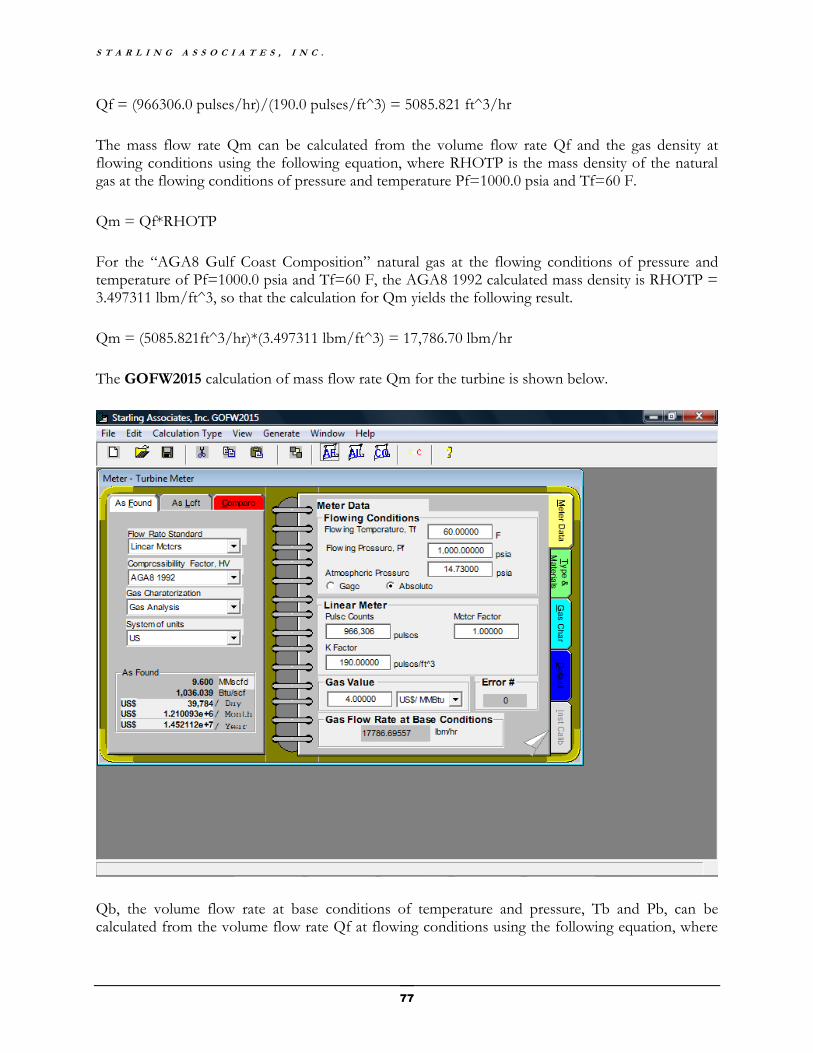
S T A R L I N G A S S O C I A T E S , I N C .
77
Qf = (966306.0 pulses/hr)/(190.0 pulses/ft^3) = 5085.821 ft^3/hr
The mass flow rate Qm can be calculated from the volume flow rate Qf and the gas density at flowing conditions using the following equation, where RHOTP is the mass density of the natural gas at the flowing conditions of pressure and temperature Pf=1000.0 psia and Tf=60 F.
Qm = Qf*RHOTP
For the “AGA8 Gulf Coast Composition” natural gas at the flowing conditions of pressure and temperature of Pf=1000.0 psia and Tf=60 F, the AGA8 1992 calculated mass density is RHOTP = 3.497311 lbm/ft^3, so that the calculation for Qm yields the following result.
Qm = (5085.821ft^3/hr)*(3.497311 lbm/ft^3) = 17,786.70 lbm/hr
The GOFW2015 calculation of mass flow rate Qm for the turbine is shown below.
Qb, the volume flow rate at base conditions of temperature and pressure, Tb and Pb, can be calculated from the volume flow rate Qf at flowing conditions using the following equation, where

G O F W 2 0 1 5 V 1 . 0
78
RHOTP is the mass density of the natural gas at the flowing conditions and RHOB is the mass density of the natural gas at the base conditions.
Qb = Qf*RHOTP/RHOB
For the “AGA8 Gulf Coast Composition” natural gas at the base conditions of pressure and temperature of Pb=14.73 psia and Tf=60.0 F, the AGA8 1992 calculated mass density is RHOB = 0.044467 lbm/ft^3, so that the calculation for Qm yields the following result.
Qb = (5085.821 ft^3/hr)*( 3.497311 lbm/ft^3)/( 0.044467 lbm/ft^3) = 399,997.6 scf/hr
The GOFW2015 calculation of the volume flow rate Qb for the turbine is shown below. The difference between the GOFW2015 calculation of the volume flow rate Qb and the manual calculation of the volume flow rate Qb is the fact that RHOB in the manual calculations has a precision on five significant figures, while the GOFW2015 calculations use greater precision.
S T A R L I N G A S S O C I A T E S , I N C .
79
EXAMPLE CALCULATIONS FOR A CORIOLIS METER
All of the calculations discussed above are performed when GOFW2015 is used for turbine meter calculations. The use of GOFW2015 for other linear meters for which the meter output is proportional to the volume flow rate (such as ultrasonic meters and positive displacement meters) are essentially the same as the calculations described above for turbine meters. For coriolis meters, the meter output is proportional to the mass flow rate rather than the volume flow rate. Consequently, when using GOFW2015, the calculation procedure for coriolis meters is somewhat different from the calculation procedure described above for turbine meters.
As discussed in AGA Report No. 11 (2013), coriolis meters are typically calibrated on water at pressures below 65 psia by the manufacturer. Gas flow testing of a coriolis meter above the manufacturer’s water calibration pressure typically will show that the flow rate from the coriolis meter flow computer is lower than the actual flow rate and therefore needs compensation for the pressure effect on the coriolis meter flow rate. Although there are a number of methods for pressure effect compensation, only the commonly used flow pressure effect compensation factor method is presented here.
An additional calibration adjustment factor (Fadj) can be applied to the uncompensated mass flow rate to minimize the calculated mass flowrate uncertainty when additional calibration information is available. An example is the use of “multi-point piecewise linear interpolation”, discussed in the paper “New Developments to Improve Natural Gas Custody Transfer Applications with Coriolis Meters Including Application of Multi-Point Piecewise Linear Interpolation (PWL)”, by Marc Butler, Tonya Wyatt, Karl Stappert, Ron Gibson, and Gary McCargar, Proceedings of the American Gas Association Operating Conference, 2015.
Consider a coriolis meter including a flow computer which outputs Qm(unadjusted), the mass flow rate without flow pressure effect compensation and without additional calibration adjustment. The mass flow rate with flow pressure effect compensation and with additional calibration adjustment, Qm(adjusted), is calculated using the following equation.
Qm(adjusted) = (Fadj)*(Fp)*Qm(unadjusted) = METER_FACTOR *Qm(unadjusted)
where
Fp = Flow pressure effect compensation factor
Fadj = Additional calibration adjustment factor
METER_FACTOR = (Fadj)*(Fp)
The flow pressure effect compensation factor Fp is calculated using the following equation
Fp = 1/[1+(Peffect/100)*(Pf-Pcalibration)]
where
Fp = Flow pressure effect compensation factor
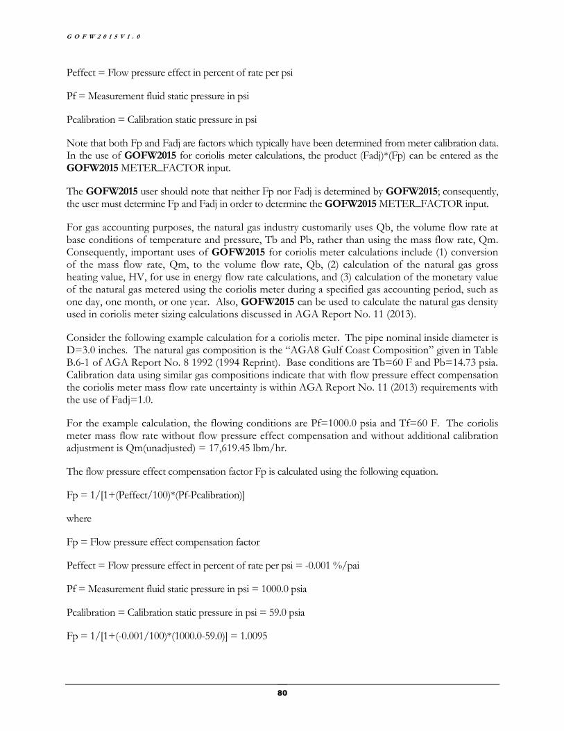
G O F W 2 0 1 5 V 1 . 0
80
Peffect = Flow pressure effect in percent of rate per psi
Pf = Measurement fluid static pressure in psi
Pcalibration = Calibration static pressure in psi
Note that both Fp and Fadj are factors which typically have been determined from meter calibration data. In the use of GOFW2015 for coriolis meter calculations, the product (Fadj)*(Fp) can be entered as the GOFW2015 METER_FACTOR input.
The GOFW2015 user should note that neither Fp nor Fadj is determined by GOFW2015; consequently, the user must determine Fp and Fadj in order to determine the GOFW2015 METER_FACTOR input.
For gas accounting purposes, the natural gas industry customarily uses Qb, the volume flow rate at base conditions of temperature and pressure, Tb and Pb, rather than using the mass flow rate, Qm. Consequently, important uses of GOFW2015 for coriolis meter calculations include (1) conversion of the mass flow rate, Qm, to the volume flow rate, Qb, (2) calculation of the natural gas gross heating value, HV, for use in energy flow rate calculations, and (3) calculation of the monetary value of the natural gas metered using the coriolis meter during a specified gas accounting period, such as one day, one month, or one year. Also, GOFW2015 can be used to calculate the natural gas density used in coriolis meter sizing calculations discussed in AGA Report No. 11 (2013).
Consider the following example calculation for a coriolis meter. The pipe nominal inside diameter is D=3.0 inches. The natural gas composition is the “AGA8 Gulf Coast Composition” given in Table B.6-1 of AGA Report No. 8 1992 (1994 Reprint). Base conditions are Tb=60 F and Pb=14.73 psia. Calibration data using similar gas compositions indicate that with flow pressure effect compensation the coriolis meter mass flow rate uncertainty is within AGA Report No. 11 (2013) requirements with the use of Fadj=1.0.
For the example calculation, the flowing conditions are Pf=1000.0 psia and Tf=60 F. The coriolis meter mass flow rate without flow pressure effect compensation and without additional calibration adjustment is Qm(unadjusted) = 17,619.45 lbm/hr.
The flow pressure effect compensation factor Fp is calculated using the following equation.
Fp = 1/[1+(Peffect/100)*(Pf-Pcalibration)]
where
Fp = Flow pressure effect compensation factor
Peffect = Flow pressure effect in percent of rate per psi = -0.001 %/pai
Pf = Measurement fluid static pressure in psi = 1000.0 psia
Pcalibration = Calibration static pressure in psi = 59.0 psia
Fp = 1/[1+(-0.001/100)*(1000.0-59.0)] = 1.0095
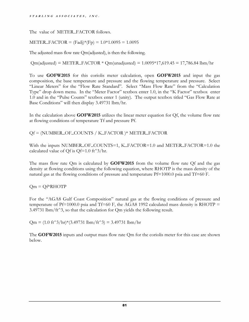
S T A R L I N G A S S O C I A T E S , I N C .
81
The value of METER_FACTOR follows.
METER_FACTOR = (Fadj)*(Fp) = 1.0*1.0095 = 1.0095
The adjusted mass flow rate Qm(adjusted), is then the following.
Qm(adjusted) = METER_FACTOR * Qm(unadjusted) = 1.0095*17,619.45 = 17,786.84 lbm/hr
To use GOFW2015 for this coriolis meter calculation, open GOFW2015 and input the gas composition, the base temperature and pressure and the flowing temperature and pressure. Select “Linear Meters” for the “Flow Rate Standard”. Select “Mass Flow Rate” from the “Calculation Type” drop down menu. In the “Meter Factor” textbox enter 1.0, in the “K Factor” textbox enter 1.0 and in the “Pulse Counts” textbox enter 1 (unity). The output textbox titled “Gas Flow Rate at Base Conditions” will then display 3.49731 lbm/hr.
In the calculation above GOFW2015 utilizes the linear meter equation for Qf, the volume flow rate at flowing conditions of temperature Tf and pressure Pf.
Qf = (NUMBER_OF_COUNTS / K_FACTOR )* METER_FACTOR
With the inputs NUMBER_OF_COUNTS=1, K_FACTOR=1.0 and METER_FACTOR=1.0 the calculated value of Qf is Qf=1.0 ft^3/hr.
The mass flow rate Qm is calculated by GOFW2015 from the volume flow rate Qf and the gas density at flowing conditions using the following equation, where RHOTP is the mass density of the natural gas at the flowing conditions of pressure and temperature Pf=1000.0 psia and Tf=60 F.
Qm = Qf*RHOTP
For the “AGA8 Gulf Coast Composition” natural gas at the flowing conditions of pressure and temperature of Pf=1000.0 psia and Tf=60 F, the AGA8 1992 calculated mass density is RHOTP = 3.49731 lbm/ft^3, so that the calculation for Qm yields the following result.
Qm = (1.0 ft^3/hr)*(3.49731 lbm/ft^3) = 3.49731 lbm/hr
The GOFW2015 inputs and output mass flow rate Qm for the coriolis meter for this case are shown below.

G O F W 2 0 1 5 V 1 . 0
82
The input pulse counts in GOFW2015 can be adjusted to obtain an output mass flow rate Qm which matches the coriolis meter flow pressure effect unadjusted mass flow rate of Qm(unadjusted) = 17,619.45 lbm/hr using NUMBER_OF_COUNTS=(17,619.45 lbm/hr)/( 3.49731 lbm/hr)=5038. With the input pulse counts of 5038 in GOFW2015, the output unadjusted mass flow rate for the coriolis meter is Qm(unadjusted) = 17,619.45 lbm/hr, as shown for GOFW2015 below.
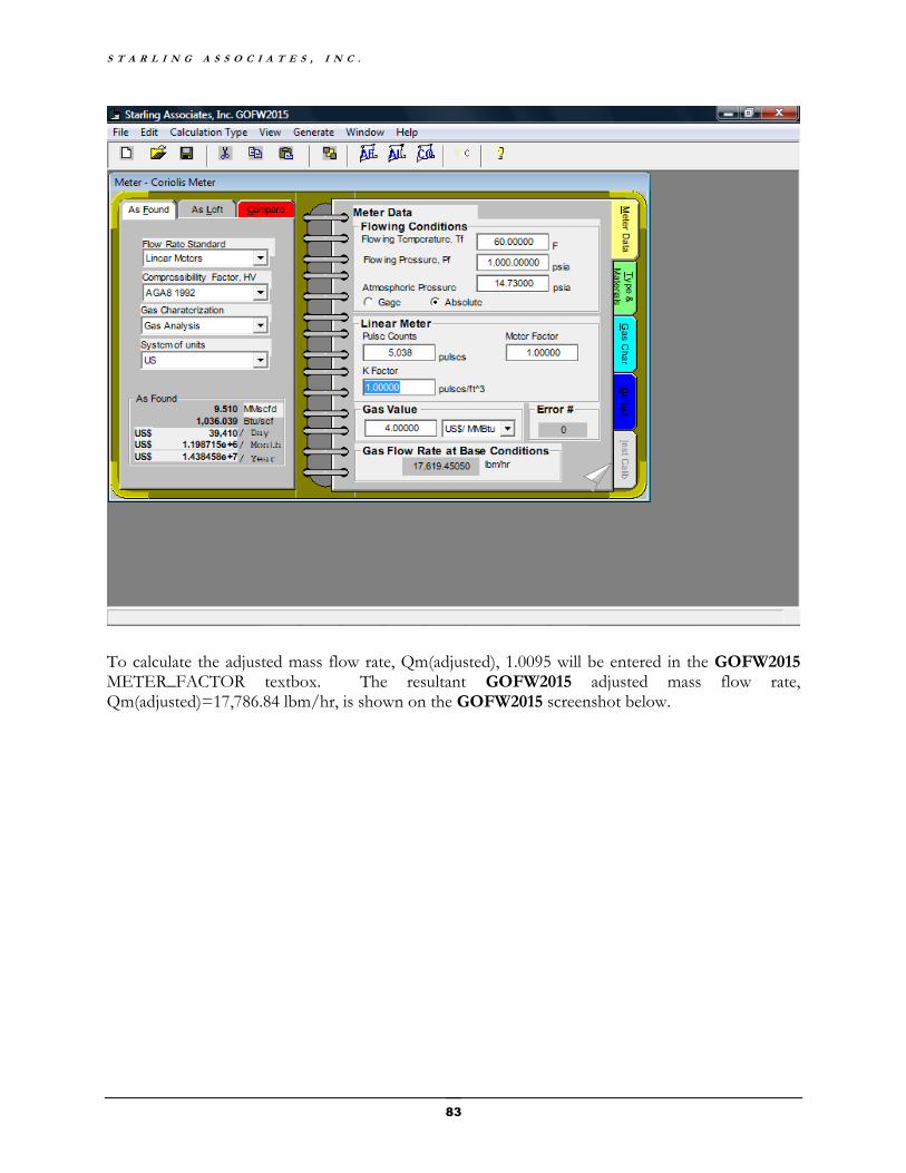
S T A R L I N G A S S O C I A T E S , I N C .
83
To calculate the adjusted mass flow rate, Qm(adjusted), 1.0095 will be entered in the GOFW2015 METER_FACTOR textbox. The resultant GOFW2015 adjusted mass flow rate, Qm(adjusted)=17,786.84 lbm/hr, is shown on the GOFW2015 screenshot below.

G O F W 2 0 1 5 V 1 . 0
84

S T A R L I N G A S S O C I A T E S , I N C .
85
The second GOFW2015 screen (above) results from changing the selection in the “Calculation Type” dropdown menu from “Mass Flow Rate” to “Volume Flow Rate”. This GOFW2015 screen displays the volume flow rate at base conditions of temperature and pressure, Tb and Pb, Qb=
400,003.1 scf/hr. The calculation of coriolis meter volume flow rate is useful, since for gas accounting purposes, the natural gas industry customarily uses Qb, the volume flow rate at base conditions of temperature and pressure, Tb and Pb, rather than using the mass flow rate, Qm.
As noted earlier, valuable uses of GOFW2015 for coriolis meter calculations include (1) conversion of the mass flow rate, Qm, to the volume flow rate, Qb, (2) calculation of the natural gas gross heating value, HV, and (3) calculation of the monetary value of the natural gas metered using the coriolis meter during a specified gas accounting period, such as one day, one month, or one year. In addition, GOFW2015 can be used to calculate the natural gas density used in coriolis meter sizing calculations discussed in AGA Report No. 11 (2013).
The second page of the Meter Data Tab is titled Useful Outputs. These outputs include the Gas Relative Density, the Gross Heating Value, the Net Heating Value, and the Molecular Weight (Molar Mass). The GOFW2015 Gross Heating Value default method of calculation is AGA8 1992 (1994 Reprint) which yields HV= 1036.04 Btu/scf, as shown below.
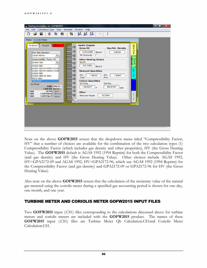
G O F W 2 0 1 5 V 1 . 0
86
Note on the above GOFW2015 screen that the dropdown menu titled “Compressibility Factor, HV” that a number of choices are available for the combination of the two calculation types (1) Compressibility Factor (which includes gas density and other properties), HV (the Gross Heating Value). The GOFW2015 default is AGA8 1992 (1994 Reprint) for both the Compressibility Factor (and gas density) and HV (the Gross Heating Value). Other choices include AGA8 1992, HV=GPA2172-09 and AGA8 1992, HV=GPA2172-96, which use AGA8 1992 (1994 Reprint) for the Compressibility Factor (and gas density) and GPA2172-09 or GPA2172-96 for HV (the Gross Heating Value).
Also note on the above GOFW2015 screen that the calculation of the monetary value of the natural gas metered using the coriolis meter during a specified gas accounting period is shown for one day, one month, and one year.
TURBINE METER AND CORIOLIS METER GOFW2015 INPUT FILES
Two GOFW2015 input (.CS1) files corresponding to the calculations discussed above for turbine meters and coriolis meters are included with the GOFW2015 product. The names of these GOFW2015 input (.CS1) files are Turbine Meter Qb Calculation.CS1and Coriolis Meter Calculation.CS1.

S T A R L I N G A S S O C I A T E S , I N C .
87
Index .CS1 5, 14, 44
.ini (initiation file extension) 3, 18
304 Stainless Steel 34, 35
316 Stainless Steel 34, 35
Activating License 1
AGA 8 1985 Alt Meth 22
AGA Report No. 3.3 (2013) 42, 43, 44, 45
AGA3 1992 14
AGA3.3 2013 20, 21, 52
AGA7 21, 30
AGA9 21, 30
algorithms and equations vi, 21, 60
American Gas Association vi
American Petroleum Institute vi
As Found 4, 5, 6, 7, 10, 14, 16, 23, 24, 25, 26
As Found Report 10, 16
As Left 4, 5, 6, 7, 10, 23, 24, 25, 26
As Left Report 10
Beta Ratio 31, 52
Cal. w/Fracts. in error 37
Calculation Type 5, 20, 22, 23, 24, 25, 26
CALIBRATION EXAMPLE.CS1 14
Canadian Gas Association vi
Cd is the coefficient of discharge for the flange-tapped orifice meter (dimensionless) 61
changing the default configuration 44
Check List 3
Chemical Manufacturers Association vi
Comparison Report 5, 10, 24, 25, 26
Creating GOFW2015 Input Files 18
critical pressure 31
critical temperature 31
CS1 (GOFW2008 input file extension) 87
CS1 (GOFW2015 input file extension) 3, 15, 17, 18, 19, 44, 71
D is the mean meter tube internal diameter 62
d is the orifice plate bore diameter, in inches, calculated at flowing temperature (Tf) 61
deadweight calibrator 45, 46, 48
default configuration 13, 14, 44
Default Tab 41
density 38, 41, 44, 58, 59
differential pressure 25, 26, 42, 47, 48
energy flow rate 31, 68
ENERGY_FLOWRATE 68, 70, 71, 75
error and warning messages 8
Error Indicator 8, 31
European Community vi
Ev is the velocity of approach factor (dimensionless) 61
Example-As Found.CS1 18
Example-As Left.CS1 17
Fadj 80, 81, 82
Fadj = Additional calibration adjustment factor 80
Flow Rate Standard 14, 20
flowing conditions 30, 38, 43
Fp = Flow pressure effect compensation factor 80, 81
Gas Analysis 14, 36, 37, 53, 57
Gas Characterization 14, 36
Gas Processors Association vi
gas relative density 31
Gas Research Institute vi
Gaz European Recherches Groupe vi
General Tab 6
GOFW2015 Input Files 18
GOFW2015 License Activation 1
GOFW2015.ini 44
GOFW2015.ini initiation file 18, 44
GPA 2172-09 42, 53
gravitational acceleration 42, 43, 46, 47, 48
G O F W 2 0 1 5 V 1 . 0
88
gravity 22, 41, 46, 48
gross heating value 31
Gross Methods 22, 37
heating value 22, 31, 41, 59
Help 5, 8, 9
HV_IDEAL 68, 70, 71, 72, 75, 76
Hw is the orifice differential pressure, in inches of water at 60 °F 61
ideal gas gross heating value 68, 72, 76
Input Files 18
Instrument Calibration Tab 45
International Standards Organization vi
intranet, internet server iii
IP units 22
isentropic exponent 43, 44
Japan vi
k is the isentropic exponent (dimensionless) 61
License iii
license activation iii
License Activation 1
linear coefficient of thermal expansion 34, 35
linear meter vi, 13
Linear Meters 21, 30
Manual File 3
Manual, launching from the Start button 3
mass flow rate 20, 24
Mercury (Hg) Manometer 42
Mercury Manometer 52, 58
Meter Data Tab 23, 29, 31, 50
Meter Properties 5, 6, 13
metric units 22
molecular weight 31
Monel 400 34, 35
net heating value 31
Normalize Mole % 37
Norway vi
Notebook 4
Orifice material 34
orifice plate diameter 31
orifice size 26
overriding composition inputs 37
overriding heating value 31
Pb is the contract base pressure, in psia 62
Pcalibration = Calibration static pressure in psi 81
Peffect = Flow pressure effect in percent of rate per psi 81
Pf = Measurement fluid static pressure in psi 81
Pf1 is the upstream absolute static pressure 62
QB_IDEAL 68, 70, 71, 75
Qm 78, 79, 80, 81, 82, 83, 84, 86
Qm(adjusted) 80, 82, 84
Qm(unadjusted) 80, 81, 82, 83
Qv (2012 standard) 66
reduced pressure 31
reduced temperature 31
Reference Conditions 41
Reopening GOFW2015 Input Files 18
RHOS is the gas density at reference base conditions (Ts, Ps) in pounds mass per ft3 61, 63
RHOTP is the gas density at upstream flowing conditions (Tf, Pf) in pounds mass per ft3 61, 63
Saved Tab 7
Saving GOFW2015 Input Files 18
SI units 22
Starling Associates, Inc. i, 1, 3, 4, 5, 13
Super Compressibility 14, 20, 22, 26, 27, 30
support service iii
system of units 22
System of Units 31
System Requirements 2
Tab 4
Tabs 4, 6, 15, 23

S T A R L I N G A S S O C I A T E S , I N C .
89
tap 33
Tb is the contract base temperature of 60 °F, in degrees Rankine 62
technical support 1
Tf is the flowing temperature of 68 °F, in degrees Rankine 63
The Menu Bar 5
The Meter Title Bar 5
The Title Bar 5
tube diameter 31, 34
Tube material 34
tutorial 13
Type and Materials Tab 33
U [Y1 (1992 standard)] is the %uncertainty of Y1 (2012 standard) at the 95% confidence level 63
U [Y1 (2012 standard)] is the %uncertainty of Y1 (1992 standard) at the 95% confidence level 63
U [Y1 (2012 standard)], the %uncertainty of Y1 (2012 standard) at the 95% confidence level 67
ultrasonic meter 20
unit converter 9
units 22
US units 22, 23, 26, 27
user input calibration factor 45, 48
User Input Method 38
Variables Description 8, 9
viscosity 43, 44
volume flow rate 23, 42
warnings and errors 50
water manometer 45, 47
website 1
x1 is the ratio of the differential pressure to the absolute upstream static pressure (dimensionless) 61
Y1 (1992 standard) 67
Y1 (1992 standard) is the expansion factor (dimensionless) given in the 1992 standard 61
Y1 (2012 standard) 67
Y1 (2012 standard) is the expansion factor (dimensionless) 61
Y1 is the expansion factor (dimensionless) 61
β is the diameter ratio (dimensionless) 61