Standardisation recommendation documentjoin-em.eu/documents/D7.5_final.pdf · • ISO 17639:2003...
57
JOIN’EM - 677660 02/08/2018 Information is provided as is and no guarantee or warranty is given that the information is fit for any particular purpose. The user thereof uses the information at its sole risk and liability. JOIN’EM - Grant Agreement 677660 JOINing of copper to aluminium by ElectroMagnetic fields Project co-funded by the European Commission H2020 Programme Deliverable D7.5 Standardisation recommendation document
Transcript of Standardisation recommendation documentjoin-em.eu/documents/D7.5_final.pdf · • ISO 17639:2003...

JOIN’EM - 677660 02/08/2018
Information is provided as is and no guarantee or warranty is given that the information is fit for any particular purpose. The user thereof uses the information at its sole risk and liability.
JOIN’EM - Grant Agreement 677660
JOINing of copper to aluminium by ElectroMagnetic fields
Project co-funded by the European Commission H2020 Programme
Deliverable D7.5
Standardisation recommendation document

JOIN’EM - 677660 02/08/2018
D7.5_final.docx p. i
Grant Agreement Number: 677660
Project Title: JOINing of copper to aluminium by ElectroMagnetic fields
Project Acronym: JOIN’EM Funding Scheme: Collaborative Project
Date: August 2018 Project Website Address: http://www.join-em.eu/
EC Project Officer: Arnaud Pétein Email: [email protected]
Deliverable Number: 7.5 Deliverable Name: Standardisation recommendation document
Work Package Number: WP7
Date of Delivery: M33 Actual M36
Status Draft ☐ Final ☒
Nature
Prototype
Report
Specification
Tool
Other
☐
☒
☐
☐
☐
Distribution Type Public ☒ Restricted ☐ Consortium ☐
Authoring Partner: EWF
Contact Person: André Cereja
Phone
+351 964 719 915
Fax
NA
Abstract (for dissemination) n/a
Keywords n/a
Name of the Scientific Representative of the Project's Co-ordinator, Title and Organisation:
Name: Dr.-Ing. Verena Psyk
Tel: +49 371 5397-1731
Fax: +49 371 5397-6-1731
E-mail: [email protected]

JOIN’EM - 677660 02/08/2018
D7.5_final.docx p. ii
Document status
Version Date Description
1
2
3
Final
28/05/2018
18/06/2018
05/07/2018
02/08/2018
First draft
Second draft with added contents
Third draft with consortium partners’ inputs
Final version.

JOIN’EM - 677660 02/08/2018
D7.5_final.docx p. iii
TABLE OF CONTENTS
1 Executive summary ............................................................................................................ 6
2 Introduction ........................................................................................................................ 7
3 Topics to include in a future standard on electromagnetic pulse welding of metallic materials ..................................................................................................................................... 8
3.1 Scope of the future standard ...................................................................................... 8
3.2 Normative references .................................................................................................. 8
3.3 Terms and Definitions.................................................................................................. 9
3.4 Welding knowledge ................................................................................................... 12
3.4.1 Process principles ............................................................................................... 12
3.4.2 Process variants .................................................................................................. 13
3.4.2.1 Electromagnetic pulse crimping ................................................................. 13
3.4.2.2 Electromagnetic pulse welding of tubular products ................................... 13
3.4.2.3 Electromagnetic pulse sheet welding ......................................................... 14
3.4.3 Parameters ......................................................................................................... 15
3.4.4 Welding window ................................................................................................. 16
3.4.5 Weld description ................................................................................................ 18
3.4.6 Materials and material combinations ................................................................ 18
3.4.7 Electromagnetic pulse welding equipment ....................................................... 19
3.4.7.1 General ........................................................................................................ 19
3.4.7.2 Pulse generator ........................................................................................... 19
3.4.7.3 Coils ............................................................................................................. 20
3.4.7.4 Features ...................................................................................................... 21
3.5 Development of Welding Procedure Specification (WPS) ........................................ 22
3.5.1 General ............................................................................................................... 22
3.5.2 Technical content of a pWPS ............................................................................. 23
3.5.2.1 Manufacturer information .......................................................................... 23
3.5.2.2 Target material type(s), temper(s), and reference standard(s).................. 23
3.5.2.3 Target material dimensions ........................................................................ 23
3.5.2.4 Equipment identification ............................................................................ 23
3.5.2.5 Tool coil identification ................................................................................ 23
3.5.2.6 Clamping arrangement ............................................................................... 23
3.5.2.7 Joint design ................................................................................................. 23
3.5.2.8 Joint preparation and cleaning methods .................................................... 23
3.5.3 Qualification based on a welding procedure test .............................................. 24

JOIN’EM - 677660 02/08/2018
D7.5_final.docx p. iv
3.5.3.1 Test specimens ............................................................................................ 24
3.5.3.2 Examination and testing of test specimens ................................................ 25
3.5.4 Qualification based on pre-production welding test ......................................... 30
3.5.4.1 General ........................................................................................................ 30
3.5.4.2 Test specimens ............................................................................................ 30
3.5.4.3 Examination and testing of test specimens ................................................ 30
3.5.4.4 Range of qualification ................................................................................. 30
3.5.5 Welding procedure qualification record (WPQR) .............................................. 30
3.6 Range of qualification ................................................................................................ 31
3.6.1 Related to the target material ........................................................................... 31
3.6.2 Common to all welding procedures ................................................................... 31
3.7 Welding personnel ..................................................................................................... 31
3.7.1 EPW machine operator ...................................................................................... 31
3.7.2 EPW machine setter ........................................................................................... 31
3.7.3 Welding coordination personnel (supervisor) ................................................... 32
3.8 Health and safety ....................................................................................................... 32
3.8.1 Directive 2013/35/EU from the European Parliament and from the Board (26th July 2013).......................................................................................................................... 32
4 Conclusions ....................................................................................................................... 35
5 Annexes ............................................................................................................................ 36
5.1 Annex A: Material combinations weldable by EPW .................................................. 36
5.1.1 References .......................................................................................................... 37
5.2 Annex B: Examination and testing ............................................................................. 40
5.2.1 Non-destructive testing ...................................................................................... 40
5.2.1.1 General ........................................................................................................ 40
5.2.1.2 Visual examination ...................................................................................... 40
5.2.1.3 Dimensional measurements ....................................................................... 40
5.2.1.4 Surface crack inspection ............................................................................. 41
5.2.1.5 Dye penetration testing .............................................................................. 41
5.2.1.6 Leak testing ................................................................................................. 41
5.2.1.7 Laser ultrasound testing ............................................................................. 41
5.2.1.8 Tomography ................................................................................................ 42
5.2.2 Destructive testing ............................................................................................. 42
5.2.2.1 General ........................................................................................................ 42
5.2.2.2 Bend testing ................................................................................................ 43
5.2.2.3 Peel testing .................................................................................................. 43

JOIN’EM - 677660 02/08/2018
D7.5_final.docx p. v
5.2.2.4 Compression testing ................................................................................... 44
5.2.2.5 Torsion testing ............................................................................................ 44
5.2.2.6 Tensile testing ............................................................................................. 45
5.2.2.7 Fatigue testing............................................................................................. 45
5.2.2.8 Metallographic examination ....................................................................... 45
5.2.2.9 Hardness measurements ............................................................................ 46
5.2.2.10 Electrical conductivity measurements ........................................................ 46
5.2.3 Proof testing ....................................................................................................... 47
5.3 Annex C: Welding Procedure Specifications.............................................................. 48
5.4 Annex D: Imperfections in electromagnetic pulse welds .......................................... 50

JOIN’EM - 677660 02/08/2018
Deliverable D7.5 p. 6
1 Executive summary
The present document serves the purpose of summarizing all the standardization recommendations that were found to be important for the uptake of Electromagnetic Pulse Welding (EPW) by the industry. This report was developed under the scope of the Work Package 7 - Industrial implementation issues.
Within WP7 is being developed all the knowledge concerning the integration of the individual process steps into a manufacturing process chain. WP7 also focuses on the environmental monitoring, on disassembly and recycling, and on cost analysis of the introduction of the technologies developed during Join’EM. Relevant standards and regulations that will affect the successful implementation of the project are also identified in this WP.
The focus of Join’EM is on joining aluminium and copper to improve performance and reduce costs of electrical as well as heating and cooling applications in different industrial sectors, including machine and equipment construction, automotive and transport, white goods, air-conditioning and high-power electronics. This was achieved by using EPW. EPW is a high-speed forming technology using magnetic fields for forming electrically-conductive tube or sheet metal workpieces without mechanical contact between tool and workpiece.
To fully exploit the potentialities of the project outcomes, BWI and EWF pursued the integration of new guidelines and specifications with existing standards, defined on the basis of the project results. Since the introduction of new standards is a delicate issue, close collaboration with the appropriate legislation bodies (particularly CEN/TC 121 – Welding and allied processes) is also being sought by EWF and BWI.

JOIN’EM - 677660 02/08/2018
Deliverable D7.5 p. 7
2 Introduction
Electromagnetic Pulse Welding (EPW) has been a subject of intensive research and development during the last years. This is related to the need of improving welded parts in terms of weight, safety, environmental impact and cost.
This document is organised by subjects that were considered relevant in terms of standardisation issues. This report presents recommendations in terms of standards themselves. Also, terminology recommendations are described, to have uniform terms for the EPW process, its equipment and parameters. Also welding imperfections that can be found in EPW are described. Some of these imperfections are already documented in standard ISO 6520-2:2013 – Welding and allied processes -- Classification of geometric imperfections in metallic materials -- Part 2: Welding with pressure.
Moreover, additional work was performed and is reported here as well, focusing not only on the need to propose the creation of a Welding Procedure Specification (WPS) regarding EPW, but also on health and safety considerations that should not be disregarded when working with such a process.
Finally, the main conclusions obtained regarding standardisation needs for EPW are summarised.
This report is intended to be disseminated through Joining Standardisation National Contact points and the Comité Européen de Normalisation (CEN). This report’s due date was on M33 under the scope of Deliverable 7.5 (D7.5).

JOIN’EM - 677660 02/08/2018
Deliverable D7.5 p. 8
3 Topics to include in a future standard on electromagnetic pulse welding of metallic materials
Complying with standards is for most companies a time-consuming, complex and expensive task, although the benefits of complying with a certain standard usually outweigh the drawbacks. Overall, standardisation ensures an optimum quality of the products by specifying guidelines that assure that companies meet the customer and regulatory requirements. Standardisation also boosts productivity and efficiency by providing details on the critical parts of the process/component. Thus, they make the processes more efficient. Besides all these factors, it also fosters marketing strategies, since it helps building costumer trust.
3.1 Scope of the future standard
A new standard addressing electromagnetic pulse welding should specify requirements for the assembly of components manufactured from metals, welding knowledge, a WPS structure, quality requirements, welding procedure approval, testing methods, welding personnel and health and safety.
The use of standards is appropriate where a contract, an application standard or a regulatory requirement requires the demonstration of the manufacturer's capability to produce EPW welded products of a specified quality. It should be prepared in a comprehensive manner to be used as a reference in contracts. The requirements given may be adopted in full or some can be deleted, if not relevant for the product concerned.
3.2 Normative references
• ISO 6520-2:2013: Welding and allied processes - Classification of geometric imperfections in metallic materials - Part 2: Welding with pressure
• EN ISO 15607: Specification and qualification of welding procedures for metallic materials. General rules
• ISO 15614-1:2017 Specification and qualification of welding procedures for metallic materials -- Welding procedure test -- Part 1: Arc and gas welding of steels and arc welding of nickel and nickel alloys
• ISO 15614-2:2005 Specification and qualification of welding procedures for metallic materials -- Welding procedure test -- Part 2: Arc welding of aluminium and its alloys
• ISO 15614-3:2008 Specification and qualification of welding procedures for metallic materials -- Welding procedure test -- Part 3: Fusion welding of non-alloyed and low-alloyed cast irons
• ISO 15614-4:2005 Specification and qualification of welding procedures for metallic materials -- Welding procedure test -- Part 4: Finishing welding of aluminium castings
• ISO 15614-5:2004 Specification and qualification of welding procedures for metallic materials -- Welding procedure test -- Part 5: Arc welding of titanium, zirconium and their alloys

JOIN’EM - 677660 02/08/2018
Deliverable D7.5 p. 9
• ISO 15614-6:2006 Specification and qualification of welding procedures for metallic materials -- Welding procedure test -- Part 6: Arc and gas welding of copper and its alloys
• ISO 15614-7:2016 Specification and qualification of welding procedures for metallic materials -- Welding procedure test -- Part 7: Overlay welding.
• ISO 15614-11:2002 Specification and qualification of welding procedures for metallic materials -- Welding procedure test -- Part 11: Electron and laser beam welding
• ISO 15614-12:2014 Specification and qualification of welding procedures for metallic materials -- Welding procedure test -- Part 12: Spot, seam and projection welding
• ISO 15614-13:2012 Specification and qualification of welding procedures for metallic materials -- Welding procedure test -- Part 13: Upset (resistance butt) and flash welding
• ISO 15614-14:2013 Specification and qualification of welding procedures for metallic materials -- Welding procedure test -- Part 14: Laser-arc hybrid welding of steels, nickel and nickel alloys
• ISO 17637:2016: Non-destructive testing of welds - Visual testing of fusion-welded joints
• ISO 17639:2003 Destructive tests on welds in metallic materials -- Macroscopic and microscopic examination of welds
• ISO 19828:2017: Welding for aerospace applications - Visual inspection of welds.
• ISO 23277:2015: Non-destructive testing of welds - Penetrant testing - Acceptance levels
3.3 Terms and Definitions
The present section contains recommendations regarding the terminology used when referring to the EPW process, the process parameters, equipment or used test specimens. In D7.1, the need for uniformizing the terminology regarding this innovative welding process was described. In the various sources studied, EPW has been referred to as:
• Electro Magnetic Welding (EMW)
• Electro Magnetic Pulse Welding (EMPW)
• Magnetic Pulse Welding (MPW)
• Magnetic Pressure Welding (MPW)
• Magnetic Impulse Welding (MIW)
• Electromagnetic Pulse Technology (EMPT)
• Electromagnetic Pulse Metal Processing Techniques (EPMPT)
• Electromagnetic pulse technology (EMPT)
• Welding by electromagnetic forming
As previously mentioned, it was considered relevant to harmonise the vocabulary related to the process in order to name it always the same way according to the diversity of terminology used. The terminology should be included in the ISO and IEC terminological databases for use in standardisation. This can be found online at the following addresses:
• IEC Electropedia: available at http://www.electropedia.org/
• ISO Online browsing platform: available at http://www.iso.org/obp

JOIN’EM - 677660 02/08/2018
Deliverable D7.5 p. 10
For the purposes of this document, the following Terms and Definitions are proposed:
• Electromagnetic pulse crimping: creation of a crimp connection using electromagnetic forming.
• Electromagnetic Pulse Welding (EPW): creation of a welded joint using electromagnetic forming.
• Electromagnetic pulse sheet welding: creation of a welded joint of sheets using electromagnetic forming.
• Flyer sheet/tube: the sheet or tube that will be accelerated during the EPW process.
• Target sheet/tube: the sheet or tube that is stationary during the EPW process.
• Impact velocity: Normal component of the velocity of the flyer plate/tube velocity when it impacts with the target material.
• Collision point velocity: Mean velocity along the target material at which the weld moves forward.
Figure 1: Definition of EPW characteristic velocities Image courtesy of: Fraunhofer IWU
• Impact angle: Angle between flyer’s impact surface and target’s impact surface at the moment of collision.
• Jetting critical angle: Angle from which a jet is created at the collision front.
• Standoff distance: Initial gap between the joining partners; the distance by which the metals to be welded are separated from each other prior to discharge.
• Free length between the flyer tube/sheet and the internal workpiece: part of the flyer (tube or sheet) that can freely move under the effect of the magnetic forces (not hold up by the support or a part of the target part). Corresponds to the area that will be in contact after the magnetic impulse.
• Overlap of flyer and tool: Distance that the flyer workpiece overlaps with the coil or field shaper.
• Discharge energy: The set charging voltage of the capacitors and their capacitance; this is discharged into the coil. The discharge energy is characterized as follows:

JOIN’EM - 677660 02/08/2018
Deliverable D7.5 p. 11
𝐸 =1
2 𝐶 𝑉2
𝐸 = discharge energy (J)
𝐶 = capacitance (F)
𝑉 = charging voltage (V)
• Current discharge frequency: significant frequency of the current induced in the coil from 𝑡0 until 𝑡𝑓𝑖𝑟𝑠𝑡 𝑝𝑒𝑎𝑘. The following figure illustrates this concept and presents the
current discharge frequency equation:
Figure 2: Pulsed current parameters Image courtesy of: Fraunhofer IWU
• Pulse repetition rate: Number of pulses per unit of time.
• Pulse rise time: Time taken by the electromagnetic pulse to change from a specified low value to a specified high maximum value (∆𝑡𝑚𝑎𝑥,𝑙).
• Skin effect: Alternating current tends to distribute itself inside a conductor in such a way that the current density is highest near the surface of the conductor. This is called the skin effect. This effect is caused by the eddy currents.
• Skin depth: How deep eddy currents penetrate into a material is defined as the depth at which their intensity drops to 1/e (about 37 %) of their original intensity.
• Bitter coil: Coil formed by stacking alternating conductors and insulating discs, each foreseen with a radial cut.
• Single turn coil: Coil consisting of one turn.
• Helix coil: Coil with the turn arranged in a helical shape.
• Flat coil: Coil with the turns arranged in a single plane.
• Rogowski coil: A toroidal coil without a ferromagnetic core to measure the discharge current in an electrical circuit.
• Pitch of the coil: Number of turns per unit of length.

JOIN’EM - 677660 02/08/2018
Deliverable D7.5 p. 12
• Pulsed power generator: Consists of a device that stores electrical energy and discharges it in the forming or welding coil in a very short time interval. Machine supplying the discharge energy needed for EPW.
• Field shaper: Component that concentrates the magnetic field in the forming or welding zone. It essentially increases the amplitude of the magnetic field, in a smaller region (axially). Also called ‘field concentrator’.
3.4 Welding knowledge
3.4.1 Process principles
The electromagnetic pulse technology (also known as electromagnetic pulse forming, crimping and welding) is a highly innovative automatic production technique which use electromagnetic forces to deform and join products.
Electromagnetic pulse forming is a high-speed deformation process that uses a pulsed magnetic field for contactless forming of metals. The energy stored in a capacitor bank is discharged rapidly through a coil (see Figure 3-right for the configuration for joining of tubular products). The magnetic field produced by the coil generates eddy currents in the adjacent workpiece from metallic material with good electrical conductivity. These currents, in turn, produce their own magnetic field. The forces generated by the two magnetic fields oppose each other. Consequently, a repelling force between coil and workpiece is created. The forces generated can for example be used to collapse a tube with high velocity onto an internal workpiece, to form, cut or perforate a sheet using a special-shaped die. Under precisely controlled conditions and process parameters, a solid-state weld can be realised. Depending on the arrangement of the tool coil and workpiece, tubular profiles can be expanded or compressed or sheet metals can be formed (Figure 3-left). The joining partner to be deformed must possess a good electrical conductivity. Due to the solid-state nature, this process can be used for joints of similar and dissimilar materials. Even joints between metal and non-metal materials can be realised.
Figure 3: Left: possible process variants of electromagnetic pulse forming and joining Right: process layout for joining of tubular workpieces
Image courtesy of: Dortmund TU (left), Shribman, V.. Magnetic Pulse Welding of Automotive HVAC Parts. Pulsar - Magnetic Pulse Solutions, (2007) pp. 1-31 (right)

JOIN’EM - 677660 02/08/2018
Deliverable D7.5 p. 13
3.4.2 Process variants
3.4.2.1 Electromagnetic pulse crimping
Joints manufactured by electromagnetic pulse forming (also known as electromagnetic pulse crimping) can be classified into 2 categories according to the dominating mechanism against an external load.
• Interference fit joints are manufactured by a plastic deformation of one and an elastic deformation of the other joining partner. As a result, friction and interference stresses between both joining partners are generated, creating a mechanical joint.
• Form fit joints are manufactured by forming one joining partner’s material into an undercut (for example a groove) of the other joining partner, so that the joint is locked against an external load (mechanical interlock).
3.4.2.2 Electromagnetic pulse welding of tubular products
If the workpieces are impacted with high velocity and under a certain angle, a jet is created along the materials’ surface before they make contact. This jet removes surface contaminants such as oxide films, which eliminates the need for pre-process cleaning. Also, due to the intense plastic deformation, mostly in the more ductile material, microscopic roughness isn't necessarily an obstacle when bringing the workpieces together.
A wavy or a flat bond interface is created like in explosion welding. If an intermetallic layer is formed, this is caused by mechanical mixing, intensive plastic deformation and local heating. The temperature increase occurs due to Joule effects and the collision itself. Because the process takes place in a very short lapse of time, heating is not enough to generate a temperature increase in a wide area, so there is no significant heat affected zone.
Figure 4: Principle sketch of electromagnetic pulse welding Image courtesy of: BWI

JOIN’EM - 677660 02/08/2018
Deliverable D7.5 p. 14
Figure 5: Impact welding parameters Image courtesy of: BWI, adapted from Shribman, V.. Magnetic Pulse Welding of Automotive HVAC
Parts. Pulsar - Magnetic Pulse Solutions, (2007) pp. 1-31.
Figure 6 and Figure 7 show the typical part geometries before and after welding, for both hermetically sealed capsules (Figure 6) and tubes (Figure 7). In all cases, the weld is a lap weld, in which there is an initial mandatory gap between the surfaces to be welded. Note that the weld is always accompanied by deformation in the weld area, as shown in the figures.
Figure 6: Capsule weld geometry
Figure 7: Tube weld geometry
3.4.2.3 Electromagnetic pulse sheet welding
In this process variant, a flat coil is used instead of a circular coil. One of the both sheets to be joined, is accelerated by the pulsed electromagnetic field towards the target sheet. A principle sketch is shown in Figure 8.

JOIN’EM - 677660 02/08/2018
Deliverable D7.5 p. 15
Figure 8: Working principle of electromagnetic pulse sheet welding Image courtesy of: Watanabe, Mitsuhiro, Kumai, Shinji. Interfacial morphology of magnetic pulse
welded aluminum/aluminium and copper/copper lap joints. Journal of Japan Institute of Light Metals, (2009) Vol.59, nr.3, pp.140-147
3.4.3 Parameters
Like in explosive welding, the quality of EPW welds is dependent on the impact angle and the impact velocity during coalescence. Numerous process parameters influence these 2 parameters in some way. These include the material properties, the electrical properties of the EPW machine and the geometry of workpieces and field shaper. The majority of these parameters are invariable, either because they are inherent to the EPW welding equipment, or because they are chosen to be kept constant.
The parameters which influence the process and the result are:
• Material properties of the workpieces: o mechanical properties o magnetic permeability o electrical conductivity o density o thermal conductivity
• Impact welding parameters (see definitions in section 3.3): o Impact angle (Ƴ in Figure 5) o Impact velocity (Vr in Figure 5) o Collision point velocity (VC in Figure 5) o Jetting critical angle
• Geometrical parameters: o Shape of workpieces o Standoff distance (ginitial in Figure 9) o Free length between the flyer tube/sheet and the internal workpiece
(Oflyer/target in Figure 9) o Overlap of flyer and tool (Oflyer/tool in Figure 9) o Overlap of flyer and target o Concentricity
JOIN’EM - 677660 02/08/2018
Deliverable D7.5 p. 16
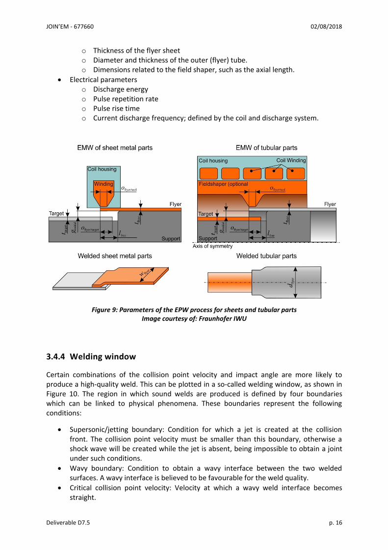
o Thickness of the flyer sheet o Diameter and thickness of the outer (flyer) tube. o Dimensions related to the field shaper, such as the axial length.
• Electrical parameters o Discharge energy o Pulse repetition rate o Pulse rise time o Current discharge frequency; defined by the coil and discharge system.
Figure 9: Parameters of the EPW process for sheets and tubular parts Image courtesy of: Fraunhofer IWU
3.4.4 Welding window
Certain combinations of the collision point velocity and impact angle are more likely to produce a high-quality weld. This can be plotted in a so-called welding window, as shown in Figure 10. The region in which sound welds are produced is defined by four boundaries which can be linked to physical phenomena. These boundaries represent the following conditions:
• Supersonic/jetting boundary: Condition for which a jet is created at the collision front. The collision point velocity must be smaller than this boundary, otherwise a shock wave will be created while the jet is absent, being impossible to obtain a joint under such conditions.
• Wavy boundary: Condition to obtain a wavy interface between the two welded surfaces. A wavy interface is believed to be favourable for the weld quality.
• Critical collision point velocity: Velocity at which a wavy weld interface becomes straight.

JOIN’EM - 677660 02/08/2018
Deliverable D7.5 p. 17
• Plasticity boundary: Condition for which the impact pressure must exceed the yield strength of the materials, otherwise no weld can be formed.
• Melt boundary: Condition to form a continuous molten intermetallic layer between the welded surfaces, which can create cracking or cavitation during or after the solidification phase.
Figure 10: Welding windows Image courtesy of: Bmax; Cuq-Lelandais, J.-P. ; Avrillaud, G. ; Ferreira, S. ; Mazars, G. ; Nottebaert,
A. ; Teilla, G. ; Shribman, V. : 3D Impacts Modeling of the Magnetic Pulse Welding Process and Comparison to Experimental Data. Proceedings of the 7th International Conference of High Speed
Forming, April 27th-29th, 2016, Dortmund

JOIN’EM - 677660 02/08/2018
Deliverable D7.5 p. 18
Figure 11: Overview of a typical EMW weld Image courtesy of: BWI
3.4.5 Weld description
A typical weld interface is shown in Figure 11. The weld is characterised by a non-welded zone (at the right side in Figure 11), a welded zone (in the middle) and again by a non-welded zone (at the left side). A magnification of a non-welded zone is shown in Figure 11 (bottom). The black area in Figure 11 is a non-welded area.
3.4.6 Materials and material combinations
Experience of electromagnetic pulse welding many metallic materials and material combinations is already documented in many literature sources (see Annex A). Weldability criteria for other welding processes is not always valid for electromagnetic pulse welding.
The data shown in Annex A is based upon actual experience from test welds, but it is not necessarily complete. For many materials and material combinations, further data is available which is only valid for those particular geometries or materials.
The following factors can affect the welding quality:
• mechanical and electric properties of the materials to be welded
• thickness, size and shape of the products to be welded
• formation of intermetallic phases at the weld interface
• porosity in target material(s)
• amount, distribution and shape of non-metallic inclusions in the target material(s)

JOIN’EM - 677660 02/08/2018
Deliverable D7.5 p. 19
3.4.7 Electromagnetic pulse welding equipment
3.4.7.1 General
The electromagnetic pulse welding set-up consists of an energy-storage capacitor bank, a high-voltage charging power supply, a discharge circuit, a work coil and, if appropriate, a field shaper.
3.4.7.2 Pulse generator
To generate the required magnetic pressure, it is necessary to apply pulsed currents in the range from 100 to more than 1000 kA. The energy has to be stored in a pulse generator, consisting of a capacitor bank, a charging unit and a high current switch.
The high-voltage charging power supply receives its power from the power grid and supplies it to the energy storage capacitor bank. The capacitor bank stores the energy until it reaches the predefined target level. The amount of stored energy is measured through the charging voltage level, which is the parameter that needs to be set before starting the process.
When the required energy level is reached, the capacitor bank discharges a current pulse through a secondary circuit containing the coil. The capacitor bank needs to possess a sufficiently high capacitance in order to store enough energy, while the inductance of the discharge circuit should be low enough, in order to ensure a fast energy release and thus a larger current pulse when discharging the current through the coil. The damped sinusoidal current induced in the work coil produces a transient magnetic field.
Figure 12: Industrial electromagnetic pulse joining system with circular coil Image courtesy of: Poynting GmbH

JOIN’EM - 677660 02/08/2018
Deliverable D7.5 p. 20
3.4.7.3 Coils
Coils and field shapers are used to focus the magnetic pressure onto a certain area of the flyer workpieces. A circular coil consists of one or more electrical windings and is made from a highly conductive material, usually a special copper or aluminium alloy.
Either single-turn coils or multi-turn coils can be used. A single-turn coil is shown in Figure 15. Multi-turn coils (see for example Figure 13) are mostly used in combination with a field shaper.
An example of a flat coil for EPW of sheets is shown in Figure 14.
Figure 13: Multi-turn coil
Figure 14: Flat coil
Figure 15: Single turn coil
Figure 16: Field shaper
A field shaper is sectioned with at least one radial slot (see Figure 17), and is electrically insulated from the workpiece and the coil. The axial coil length and the field shaper length at its outer diameter are usually the same, with the gap between coil and field shaper being kept as small as possible.
As the electrical pulse is transferred, the coil induces an eddy current in the skin of the field shaper, which flows to the inner surface of the field shaper bore by means of the radial slot (see Figure 17, right). The inner diameter of the field shaper is similar to the outer diameter of the workpiece to be joined. The axial length of the inner bore is usually shorter than that of the coil and thus provides a current concentration.

JOIN’EM - 677660 02/08/2018
Deliverable D7.5 p. 21
Figure 17: Current flow in the field shaper and coil
A Rogowski coil is usually used for measurement of the discharge current in the coil system. It consists of a toroidal coil without a ferromagnetic core. A schematic representation of this type of coil is shown in Figure 18.
Figure 18 : Schematic representation of a Rogowski coil Image courtesy of: John D.Ramboz “Machinable Rogowski Coil, Design, and Calibration”, IEEE
Transaction on Instrumentation and Measurement, Vol.45, No.2, April 1996
3.4.7.4 Features
Electromagnetic pulse welding machines can be equipped with the following options:
• loading equipment
• unloading equipment
• turning units for facing, machining
• extended memory for welding programmes
• weld identification unit
• angular orientation
• monitoring
• identification
• in process proof testing

JOIN’EM - 677660 02/08/2018
Deliverable D7.5 p. 22
3.5 Development of Welding Procedure Specification (WPS)
Besides standards themselves, there are other documents that provide guidance on the welding process, including the procedure to weld the joint step by step. This section of the report will address the need of creating a WPS for electromagnetic pulse welding as well as the obligation of complying with European regulatory documents.
3.5.1 General
A WPS is of extreme importance to industry, since it is the document that describes how a weld should be carried out. It is a document that has been qualified by a specific method and provides the required variables of the welding procedure to ensure repeatability during production welding. The document should contain welding parameters, materials used, configuration of the joint, equipment characteristics and weld shape. For more information see EN ISO 15607.
The presented WPS for EPW is in everything similar to the already defined WPSs for other welding processes. Two different type of joints are possible; joints of overlapping sheets and overlapping tubes. For that reason, two distinct WPSs should also be developed, based on the tables in Annex C. The first one presents a preliminary WPS for sheets regarding the parameters found. The second one is based on the first one but adapted to overlapping tubes.
Qualification of welding procedures shall be performed prior to start of production welding. The manufacturer shall prepare a preliminary welding procedure specification (pWPS) and shall ensure that it is applicable for production using experience from previous production jobs and the general knowledge of the welding technology.
A pWPS shall be used as the basis for the establishment of a welding procedure qualification record (WPQR). The pWPS shall be tested in accordance with one of the methods listed in section 3.5.3 (welding procedure test) or section 3.5.4 (pre-production test).
Section 3.5.3 shall be used when the production part or joint geometry is accurately represented by a standardised test piece or pieces, as shown in section 3.5.3.1. However, section 3.5.4 shall be used when the production part or joint geometry is not accurately represented by the standardised test specimens.
The information required in a pWPS is given in section 3.5.2. For some applications, it may be necessary to supplement or reduce the list.
A WPS covers a certain range of target materials and thicknesses. Ranges and tolerances in accordance with the relevant standard and the manufacturer's experience shall be specified when appropriate.

JOIN’EM - 677660 02/08/2018
Deliverable D7.5 p. 23
3.5.2 Technical content of a pWPS
The following information, as a minimum, shall be included in a pWPS:
3.5.2.1 Manufacturer information
• identification of the manufacturer
• identification of the pWPS
3.5.2.2 Target material type(s), temper(s), and reference standard(s)
3.5.2.3 Target material dimensions
Thickness of the members comprising the welded joint:
• outer diameter and wall thickness of tubes OR
• thicknesses of the sheets
3.5.2.4 Equipment identification
• model
• serial number
• manufacturer
3.5.2.5 Tool coil identification
• materials
• drawing or drawing number
• description
3.5.2.6 Clamping arrangement
• method and type of clamps and fixtures (dimensions and material)
3.5.2.7 Joint design
• sketch of the joint design and dimensions
3.5.2.8 Joint preparation and cleaning methods

JOIN’EM - 677660 02/08/2018
Deliverable D7.5 p. 24
3.5.3 Qualification based on a welding procedure test
3.5.3.1 Test specimens
3.5.3.1.1 Shape and dimensions of test specimens
General
The length or number of test specimens shall be sufficient to allow for all required tests to be performed. Test specimens longer than the minimum size may be used, to allow for additional specimens, for re-testing of specimens, or both (see section 3.5.3.2.6). If relevant, the rolling direction or extrusion direction shall be marked on the test pieces.
Overlap joint of tubular parts
The test piece shall be prepared in accordance with Figure 19.
With:
• L1 & L2: minimum length of the tubes (example proposition: 100 mm)
• D1 & D2: outside diameter of the tubes
• t1 & t2: wall thicknesses of the tubes
Figure 19: Test piece for an overlap joint of tubular parts
Overlap joint of sheets
The test piece shall be prepared in accordance with Figure 20.
With:
• L1 & L2: minimum length of the sheets (example proposition: 100 mm)
• t1: thickness of the target sheet
• t2: thickness of the flyer sheet
• W1: width of the target sheet
• W2: width of the flyer sheet

JOIN’EM - 677660 02/08/2018
Deliverable D7.5 p. 25
Figure 20: Test piece for overlap joint of sheets Image courtesy of: Fraunhofer IWU
3.5.3.1.2 Welding of test specimens
The test specimens shall be welded in accordance with the pWPS.
3.5.3.2 Examination and testing of test specimens
3.5.3.2.1 Extent of testing
Testing includes both non-destructive and destructive testing. It is proposed to perform testing in accordance with the requirements of Table 1 (tubular joints) and Table 2 (sheet joints). Annex B provides additional information on possible destructive and non-destructive testing. Specific service, material or manufacturing conditions may require more comprehensive testing in order to obtain additional test data.
Table 1: Examination and testing of the test specimens of tubular joints
Type of examination and testing Extent of examination and testing
Visual testing 100%
Transverse tensile test a 3 test specimens
Macroscopic examination 1 test specimen
Microscopic examination 2 test specimens
Additional tests (e.g. non-destructive) If required b
a: At least one transverse tensile test should be taken from the weld overlap area.
b: Additional tests shall be carried out in accordance with the relevant requirements or the design specifications.

JOIN’EM - 677660 02/08/2018
Deliverable D7.5 p. 26
Table 2: Examination and testing of the test specimens of overlapping sheet joints
Type of examination and testing Extent of examination and testing
Visual testing a 100%
Shear tensile test b 3 test specimens
Macroscopic examination 1 test specimen
Microscopic examination 2 test specimens
Additional tests (e.g. non-destructive, peel test, …).
If required b
a: Testing shall be carried out to avoid discarded areas, as shown in Figure 22.
b: Additional tests shall be carried out in accordance with the relevant requirements or the design specification.
3.5.3.2.2 Visual testing
The test specimens shall be visually tested in accordance with ISO 17637 prior to extracting the test specimens. This standard is however for fusion processes, so it needs to be investigated if this standard can be used completely. Alternatively, ISO 19828:2017 (Welding for aerospace applications - Visual inspection of welds) could also be applied, but also for this standard, the relevance needs to be examined.
The extent of testing shall be as specified in section 3.5.3.2.1; Table 1 and Table 2.
Acceptance levels for visual inspections need to be defined as part of future standardisation work.
3.5.3.2.3 Destructive testing
General
The extent of testing shall be as required by Table 1 and Table 2.
Location and extraction of test specimens
After the test piece has passed visual testing, test specimens for destructive testing shall be extracted. The test specimens shall be located in accordance with Figure 21 and Figure 22 (proposition).

JOIN’EM - 677660 02/08/2018
Deliverable D7.5 p. 27
Figure 21: Location of test specimens for test specimens for tubular joints
With:
• 3: Area for 3 tensile test specimens
• 4: Area for additional test specimens, if required
• 6: Area for 1 test specimen for macroscopic and microscopic examination. This is the area of the tool coil or field shaper cut (= area with the lowest magnetic pressure)
Figure 22: Location of test specimens in an overlap joint of sheets

JOIN’EM - 677660 02/08/2018
Deliverable D7.5 p. 28
With:
• 1: Discard at least 30 mm from each end of the test weld (dependent on the coil used)
• 3 & 6: Area for 2 test specimens for macroscopic examination
• 4 & 5: Area for shear test or additional test specimens if required
3.5.3.2.4 Alternative tests
Alternative tests may be used in certain instances. For further examinations and tests, see Annex B.
3.5.3.2.5 Acceptance levels
Acceptance levels should be determined in laboratory, so the welds can be classified properly. There are some standards referring to acceptance levels, however they mostly address arc welding, gas welding and repair welding. In the following standards, it is possible to find testing methods for approval of welding procedures and the required acceptance levels:
• ISO 15614-1:2017 Specification and qualification of welding procedures for metallic materials -- Welding procedure test -- Part 1: Arc and gas welding of steels and arc welding of nickel and nickel alloys
• ISO 15614-2:2005 Specification and qualification of welding procedures for metallic materials -- Welding procedure test -- Part 2: Arc welding of aluminium and its alloys
• ISO 15614-3:2008 Specification and qualification of welding procedures for metallic materials -- Welding procedure test -- Part 3: Fusion welding of non-alloyed and low-alloyed cast irons
• ISO 15614-4:2005 Specification and qualification of welding procedures for metallic materials -- Welding procedure test -- Part 4: Finishing welding of aluminium castings
• ISO 15614-5:2004 Specification and qualification of welding procedures for metallic materials -- Welding procedure test -- Part 5: Arc welding of titanium, zirconium and their alloys
• ISO 15614-6:2006 Specification and qualification of welding procedures for metallic materials -- Welding procedure test -- Part 6: Arc and gas welding of copper and its alloys
• ISO 15614-7:2016 Specification and qualification of welding procedures for metallic materials -- Welding procedure test -- Part 7: Overlay welding.
• ISO 15614-11:2002 Specification and qualification of welding procedures for metallic materials -- Welding procedure test -- Part 11: Electron and laser beam welding
• ISO 15614-12:2014 Specification and qualification of welding procedures for metallic materials -- Welding procedure test -- Part 12: Spot, seam and projection welding
• ISO 15614-13:2012 Specification and qualification of welding procedures for metallic materials -- Welding procedure test -- Part 13: Upset (resistance butt) and flash welding
• ISO 15614-14:2013 Specification and qualification of welding procedures for metallic materials -- Welding procedure test -- Part 14: Laser-arc hybrid welding of steels, nickel and nickel alloys

JOIN’EM - 677660 02/08/2018
Deliverable D7.5 p. 29
Again, it needs to be investigated if these testing methods and quality requirements can be applied for EPW. For welding of tubular parts, the standards ISO 15614-2, ISO 15614-6 and ISO 15614-13 seem appropriate to be adapted for EPW. For welding of sheets, the standards ISO 15614-1, ISO 15614-11 and ISO 15614-12 could be investigated further to verify if these standards can be adapted/applied.
Some recommendations for macroscopic and microscopic investigation specified below.
Macroscopic examination
The test specimen shall be prepared and examined in accordance with ISO 17639 to clearly reveal the weld region. The macroscopic examination shall include unaffected target material. Macroscopic examination before etching shall reveal no cracks. Care should be taken when etching certain alloys to avoid producing false indications.
Imperfections such as lack of bonding, cavities and elongated cavities, shall be within the specified limits of the relevant requirements or the design specifications. These requirements are however subject of further investigation.
ISO 6520-2 classifies the possible imperfections in welds made with pressure. A uniform designation is specified. Only the type, shape, and dimensions of the different imperfections caused by welding with pressure are included. Metallurgical deviations are not considered. Information concerning the consequences of the imperfections and the use of particular structures is not given, because this depends on the specific requirements of the joint.
Electromagnetic pulse welding is however not included in this standard. Therefore, a proposition of the welding defects possible with electromagnetic pulse welding is specified in Annex D.
3.5.3.2.6 Re-testing
If the test piece fails to comply with any of the requirements for visual testing specified in section 3.5.3.2.2, an additional test piece shall be welded and subjected to the same examination. If this additional test piece does not comply with the requirements, the welding procedure test has failed.
If any test specimen fails to comply with the requirements for destructive tests done in accordance with section 3.5.3.2.3 but only due to weld imperfections, then two further test specimens shall be tested for each one that failed.
The additional test specimens shall be taken from the same test piece if there is sufficient material or from a new test piece. Each additional test specimen shall be subjected to the same tests as the initial test specimen that failed. If either of the additional test specimens fails to comply with the requirements, then the welding procedure test has failed.

JOIN’EM - 677660 02/08/2018
Deliverable D7.5 p. 30
3.5.4 Qualification based on pre-production welding test
3.5.4.1 General
The pre-production welding test shall be carried out in accordance with the relevant parts of section 3.5.3, unless modified by section 3.5.4.2 - 3.5.4.4. Fulfilling the requirements of this standard may also qualify the welding operator.
3.5.4.2 Test specimens
Preparation and welding of test specimens shall be performed under the general conditions of production welding.
The test specimens shall be designed such that their shapes and dimensions simulate the actual welding conditions of the product. This includes welding positions and other essential items (for example conditions, access, …). When actual components are used, fixtures shall be those that will be used in production.
3.5.4.3 Examination and testing of test specimens
The test specimens shall be tested in accordance with the relevant parts of section 3.5.3. The following tests shall be performed as a minimum (proposition):
• visual testing (100 %)
• macroscopic examination (the number depends on the geometry of the product)
• microscopic examination
3.5.4.4 Range of qualification
Any WPS issued in accordance is limited to the type of joint used in the pre-production welding test. The range of qualification is generally in accordance with the relevant parts of section 3.6.
3.5.5 Welding procedure qualification record (WPQR)
All relevant data from welding of components needed for approval of a welding procedure specification as well as all results from testing of the test welds shall be recorded in a welding procedure approval record (WPQR). A standard format for the WPQR shall be used.
The relevant items listed in the qualified WPS shall be included, together with details of any features that would be rejectable, in accordance with the requirements of section 3.5.3.2.
If the test results are acceptable, then the WPQR is qualified and shall be signed and dated. In addition, the pWPS is also qualified. A qualified WPS shall be issued. A standard format for the WPQR shall be used.

JOIN’EM - 677660 02/08/2018
Deliverable D7.5 p. 31
3.6 Range of qualification
3.6.1 Related to the target material
Materials should be grouped accordingly with the groups that are presented below:
• Steels, nickel and nickel alloys
• Aluminium and aluminium alloys
• Titanium, zirconium and their alloys
• Copper and copper alloys
• Grouping materials accordingly to ISO/TR 15608
3.6.2 Common to all welding procedures
The following topics should be identified when performing welding:
• Welding process: electromagnetic pulse welding
• Type of joint: o Sheet overlap joint o Tube overlap joint
• Energy, defined by the stored energy in the capacities
• Preheat temperature, when necessary
• Post-weld heat treatment or ageing, when necessary
• Initial Heat treatment, when necessary
3.7 Welding personnel
3.7.1 EPW machine operator
EPW welding machine operators shall receive appropriate practical training including safe operating practices.
3.7.2 EPW machine setter
The EPW machine setter is the person who is competent to set up welding equipment according to specified welding procedures.
He/she has the required knowledge and skill for carrying out the work for quality assurance in the field of EPW.
The required competence may be proved by sufficient experience, in-house training, or can be by record or certificate of successful participation in an education and training course for EPW.

JOIN’EM - 677660 02/08/2018
Deliverable D7.5 p. 32
3.7.3 Welding coordination personnel (supervisor)
The manufacturer shall have available suitable welding coordination personnel in order to give the welding personnel the necessary instructions and to perform and supervise the work carefully. The welding coordinator personnel shall have knowledge and experience in the field of friction welding, behaviour of materials and quality assurance. The persons responsible for quality work shall be sufficiently authorised to take all the necessary steps. The duties, interrelations and limits of the spheres of responsibility of those persons should be well defined.
3.8 Health and safety
Regarding health and safety considerations that are specific to this welding process, the maximum exposure of a worker to electromagnetic fields (EMFs) should be compliant with the European Directive 2013/35/UE. This directive addresses the minimum health and safety requirements regarding the exposure of works from the risks arising from physical agents (electromagnetic fields).
The details of this directive have been detailed in deliverable D7.1. After the research carried out during this deliverable, and considering the EPW’s nature, it was concluded that this directive should be strictly followed in order to prevent health and safety issues to workers using EPW machines.
For reference, some of the European Directive 2013/35/UE contents are given next:
3.8.1 Directive 2013/35/EU from the European Parliament and from the Board (26th July 2013).
• 1st article – Subject-matter and scope
• 2nd article – Definitions
a) ‘electromagnetic fields’ means static electric, static magnetic and time-varying electric, magnetic and electromagnetic fields with frequencies up to 300 GHz;
b) ‘direct biophysical effects’ means effects in the human body directly caused by its presence in an electromagnetic field, including:
i. thermal effects, such as tissue heating through energy absorption from electromagnetic fields in the tissue;
ii. non-thermal effects, such as the stimulation of muscles, nerves or sensory organs. These effects might have a detrimental effect on the mental and physical health of exposed workers. Moreover, the stimulation of sensory organs may lead to transient symptoms, such as vertigo or phosphines. These effects might create temporary annoyance or affect cognition or other brain or muscle functions, and may thereby affect the ability of a worker to work safely (i.e. safety risks);
iii. limb currents;

JOIN’EM - 677660 02/08/2018
Deliverable D7.5 p. 33
c) ‘indirect effects’ means effects, caused by the presence of an object in an electromagnetic field, which may become the cause of a safety or health hazard, such as:
i. interference with medical electronic equipment and devices, including cardiac pacemakers and other implants or medical devices worn on the body;
ii. the projectile risk from ferromagnetic objects in static magnetic fields;
iii. the initiation of electro-explosive devices (detonators);
iv. fires and explosions resulting from the ignition of flammable materials by sparks caused by induced fields, contact currents or spark discharges;
v. contact currents;
d) ‘exposure limit values (ELVs)’ means values established on the basis of biophysical and biological considerations, in particular on the basis of scientifically well-established short-term and acute direct effects, i.e. thermal effects and electrical stimulation of tissues;
e) ‘health effects ELVs’ means those ELVs above which workers might be subject to adverse health effects, such as thermal heating or stimulation of nerve and muscle tissue;
f) ‘sensory effects ELVs’ means those ELVs above which workers might be subject to transient disturbed sensory perceptions and minor changes in brain functions;
g) ‘action levels (ALs)’ means operational levels established for the purpose of simplifying the process of demonstrating the compliance with relevant ELVs or, where appropriate, to take relevant protection or prevention measures specified in this Directive. The AL terminology used in Annex II is as follows:
i. for electric fields, ‘low ALs’ and ‘high ALs’ means levels which relate to the specific protection or prevention measures specified in this Directive;
ii. for magnetic fields, ‘low ALs’ means levels which relate to the sensory effects ELVs and ‘high ALs’ to the health effects ELVs.
o 3rd Article – Exposure limit values and action levels o 4th Article – Risk assessment and determination of exposure o 5th Article – Provisions aimed at avoiding or reducing risks o 6th Article – Information and training of workers o 7th Article – Consultation and participation of workers o 8th Article – Health surveillance o 9th Article – Sanctions o 10th Article – Exceptions o 11th Article – Technical amendment of Annexes o 12th Article – Exercise of delegation o 13th Article – Urgency procedure o 14th Article – Practical Guides
JOIN’EM - 677660 02/08/2018
Deliverable D7.5 p. 34
o 15th Article – Review and reporting o 16th Article – Transposition o 17th Article – Revocation o 18th Article – Implementation o 19th Article – Recipients
In conclusion, as this process involves electromagnetic fields, this directive should be taken in consideration when performing EPW.

JOIN’EM - 677660 02/08/2018
Deliverable D7.5 p. 35
4 Conclusions
After the research performed regarding EPW standards, it can be concluded that no existing standards address EPW. Moreover, there are no parameters defined, vocabulary or acceptance levels; so the need of developing a standard regarding this process is tremendous. Finally, only by having a common understanding of all parties involved in the EPW process (researchers, manufacturers, end-users) can this technology be well understood and implemented across the European industrial landscape.
According to the research carried out under the scope of this WP and the fast-paced development of this technology, it was possible to conclude that the following subjects should be adressed in terms of standardisation:
• Terms and definitions regarding the process, process parameters and equipment should be uniformized
• Acceptance levels: there are already standards addressing this matter, although they do not refer to EPW but to different welding processes. Adaptation of these standards for EPW should be performed or requirements for EPW should be drafted based on existing standards
• Indexing of welding imperfections (cracks, cavities, shape and dimension defects), together with their applicable test methods, the cause of these defects, the typical appearance using pictures of examples and remedial measures for corrections
• A welding procedure specification structure for EPW should be defined
• Applicable testing methods and the required test specimens should be defined
• All the work for development of standards for EPW should be compliant with the 2013/35/UE Directive on the risks of exposure to EMFs.

JOIN’EM - 677660 02/08/2018
Deliverable D7.5 p. 36
5 Annexes
5.1 Annex A: Material combinations weldable by EPW
Joints between dissimilar materials can be found in various manufacturing industries because of their technical and economic advantages. The combination of good mechanical properties of one material and either low specific weight, good corrosion resistance or good electrical properties of a second material can be very useful in many applications. Especially in the automotive industry, due to the potential weight reduction of components and structures, welding of dissimilar materials has become an important topic. Lightweight materials as aluminium and magnesium became very popular for structures. However, taking in consideration the production and processing cost compared to steel, aluminium alloy is more economical when it can be used in hybrid structures with steel. Copper to aluminium joints are the key components of high-voltage lines and heat exchangers, just like joints between titanium and aluminium. Aluminium-steel and aluminium-stainless steel bimetallic components have attracted interest for applications in power transmission and appliances. Possible material combinations are listed in [1] and [2], see Figure 23. Other data is provided in [3]; see Figure 24. Other references regarding dissimilar material combinations are listed below.
Target\
Flyer Zr Mo Mg
Stainlesss steel
Ni Ti Steel Brass Cu Al
Al x x x x x x x x x x
Cu x x x x x x x x x x
Brass x x x
Steel x x
Nickel x x x
Stainless steel x x x
Mg x x
Mo x
Zr x
Figure 23: Overview of possible material combinations by EPW [1,2]

JOIN’EM - 677660 02/08/2018
Deliverable D7.5 p. 37
Figure 24: Overview of possible material combinations by EPW [3]
5.1.1 References
1. A. Izhar; Y. Livshitz and O. Gafri, “High-voltage/high-current pulse power for civil, commercial, research, and military test applications – part IV: pulse magnetic welding”. 16th IEEE International Pulsed Power Conference, p. 706-710, 2007.
2. B.Y. Kang, “Review of magnetic pulse welding”. Journal of welding and joining, vol. 33, p. 7-13, 2015.
3. V. Shribman. Magnetic Pulse Welding. BWI Welding Symposium. Belgian Welding Institute, Brussels, 18.10.07.
4. H. Yu; Z. Xu; Z. Fan; Z. Zhao and C. Li, “Mechanical property and micro-structure of aluminium alloy-steel tubes joint by magnetic pulse welding”. Materials Science & Engineering A, vol. 561, p. 259-265, 2013.
5. V. Shribman, “Magnetic pulse welding for dissimilar and similar materials”. 3rd international conference on high speed forming, 2008.
6. M.M.H. Athar and B. Tolaminejad, “Weldability window and the effect of interface morphology on the properties of Al/Cu/Al laminated composites fabricated by explosive welding”. Materials & Design, vol. 86, p. 516-525, 2015.
7. M Watanabe; S. Kumai and K. Nakayama, “Interfacial microstructure of Al/Metallic Glass lap joints fabricated by MP welding”. Materials Transactions, vol. 50, p. 1279-1285, 2009.
8. H. Hokari; T. Sato; K. Kawauchi and A. Muto, “Magnetic impulse welding of aluminium tube and copper tube with various core materials”. Welding international, vol. 12, p. 619-626, 1998.
9. H. Yu; Z. Xu; Z. Fan; Z. Zhao and C. Li, “Mechanical property and micro-structure of aluminium alloy-steel tubes joint by magnetic pulse welding”. Materials Science & Engineering A, vol. 561, p. 259-265, 2013.

JOIN’EM - 677660 02/08/2018
Deliverable D7.5 p. 38
10. M. Marya; S. Marya and D. Priem, “On the characteristics of electromagnetic welds between aluminium and other metals and alloys”. Welding in the World, vol. 49, p. 74-84, 2005.
11. T. Aizawa; K. Okogawa and M. Kashani, “Application of magnetic pulse welding for aluminium alloys and SPCC steel sheet joints”. Welding Journal, vol. 86, p. 119-124, 2007.
12. A. Lorenz; J. Lueg-Althoff; G. Göbel; C. Weddeling; E. Beyer and A. E. Tekkaya, “Influence of axial workpiece positioning during magnetic pulse welding of aluminum-steel joints”. 6th international conference on high speed forming, p. 189-198, 2014.
13. R. N. Raoelison; T. Sapanathan; N. Buiron and M. Rachik, “Magnetic pulse welding of Al/Al and Al/Cu metal pairs: consequences of the dissimilar combination on the interfacial behavior during the welding process”. Jour-nal of manufacturing processes, vol. 20, p. 112-127, 2015.
14. G. Göbel; J. Kaspar; T. Herrmannsdörfer; B. Brenner and E. Beyer, “Insights into intermetallic phases on pulse welded dissimilar metal joints”. 4th international conference on high speed forming, p. 127-136, 2010.
15. T. Sapanathan, R. N. Raoelison, N. Buiron and M. Rachik, “Magnetic Pulse Welding: An Innovative Joining Technology for Similar and Dissimilar Metal Pairs,” in Joining Technologies, M. Ishak, Ed., Rijeka, InTech, 2016.
16. A. Kapil and A. Sharma, “Magnetic pulse welding: an efficient and environmentally friendly multi-material joining technique,” Journal of Cleaner Production, vol. 100, pp. 35-58, 2015.
17. A. Ben-Artzy, A. Stern, N. Frage, V. Shribman and O. Sadot, “Wave formation mechanism in magnetic pulse welding,” International Journal of Impact Engineering, vol. 37, pp. 397-404, 2010.
18. A. Lorenz, J. Lueg-Althoff, J. Bellmann, G. Göbel, S. Gies, C. Weddeling, E. Beyer and A. E. Tekkaya, “Workpiece Positioning During Magnetic Pulse Welding of Aluminum-Steel Joints,” Welding Journal, 3 2016.
19. B. Simoen, W. De Waele and K. Faes, Investigation of the weldability of dissimilar metals using the electromagnetic welding process, UGent, 2017.
20. K. Faes and I. Kwee, Report on guidelines for joining of tubular components by EMW: Joining of thin-walled inner tubes, Gent University, 2017.
21. L. Roeygens, W. De Waele and K. Faes, Experimental investigation of the weldability of tubular dissimilar metals using the electromagnetic welding process, UGent, 2017.
22. S. D. Kore, P. P. Date, S. V. Kulkarni, S. Kumar, D. Rani, M. R. Kulkarni, S. V. Desai, R. K. Rajawat, K. V. Nagesh and D. P. Chakravarty, “Application of electromagnetic impact technique for welding copper-to-stainless steel sheets,” The International Journal of Advanced Manufacturing Technology, vol. 54, pp. 949-955, 01 6 2011.
23. B. Simoen, K. Faes and W. De Waele, “Investigation of the weldability of copper to steel tubes using the electromagnetic welding process,” International Journal Sustainable Construction & Design, vol. 8, p. 7, 10 2017.
24. S. Patra, K. S. Arora, M. Shome and S. Bysakh, “Interface characteristics and performance of magnetic pulse welded copper-Steel tubes,” Journal of Materials Processing Technology, vol. 245, pp. 278-286, 2017.
25. J. Lueg-Althoff, J. Bellmann, S. Gies, S. Schulze, A. Tekkaya and E. Beyer, Magnetic Pulse Welding of Tubes: Ensuring the Stability of the Inner Diameter, 2016.

JOIN’EM - 677660 02/08/2018
Deliverable D7.5 p. 39
26. S. Bertelsbeck, M. Geyer and S. Böhm, “Magnetic impulse welding of flexible tubes”. 27. J. Lueg-Althoff, J. Bellmann, S. Gies, S. Schulze, A. Tekkaya and E. Beyer, “Magnetic
Pulse Welding of Dissimilar Metals in Tube-to-Tube Configuration,” 10 2016. 28. W. Demonie, “Experimental investigation of the weldability of copper to aluminium
using the electromagnetic pulse process”. Master dissertation Department of Electrical Energy, Systems and Automation, Ghent University, Labo Soete, 2016.
29. J. Broeckhove and L. Willemsens, “Experimental research on magnetic pulse welding of dissimilar metals”. Master dissertation Department of Electrical Energy, Systems and Automation, Ghent University, Labo Soete, 2010.
30. M. Marya; S. Marya and D. Priem, “Fundamentals of magnetic pulse welding for the fabrication of dissimilar material structures”. Springer handbook of mechanical engineering, vol. 10, p. 723-732, 2009.
31. S. V. Desai; S. Kumar; P. Satyamurthy; J.K. Chakravartty and D.P. Chakravarthy, “Scaling relationships for input energy in electromagnetic welding of similar and dissimilar metals. Journal of electromagnetic analysis & applications, vol. 2, p. 563-570, 2010.
32. R.N. Raoelison; N. Buiron; M. Rachik; D. Haye and G. Franz, “Efficient welding conditions in magnetic pulse welding process”. Journal of manufacturing processes, vol. 14, p. 372-377, 2012.
33. K. Loncke, “An exploratory study into the feasibility of magnetic pulse welding”. Master dissertation Department of mechanical construction and Production, Ghent University, Labo Soete, 2009.
34. J. Cui; G. Sun; J. Xu; Z. Xu; X. Huang and G. Li, “A study on the critical wall thickness of the inner tube for magnetic pulse welding of tubular Al-Fe parts”. Journal of materials processing technology, vol. 227, p. 138-146, 2016.
35. J. Lueg-Althoff; B. Schilling; J. Bellmann; S. Gies; S. Schulze; A.E. Tekkaya and E. Beyer, “Influence of the wall thickness on the joint quality during magnetic pulse welding in tube-to-tube configuration”. 7th International conference on high speed forming, Dortmund, Germany, p. 259-268, 2016.
36. J. Lueg-Althoff; J. Bellmann; S. Gies; S. Schulze; A.E. Tekkaya and E. Beyer, “Magnetic pulse welding of dissimilar metals in tube-to-tube configuration”. 9th International welding symposium of Japan Welding Society, Tokyo, Japan, p. 87-90, 2016.

JOIN’EM - 677660 02/08/2018
Deliverable D7.5 p. 40
5.2 Annex B: Examination and testing
This annex lists the possible non-destructive and destructive testing techniques applicable for EPW.
5.2.1 Non-destructive testing
5.2.1.1 General
Prior to testing permissible and non-permissible characteristics and results have to be specified in the test specifications.
Each testing method has its restrictions which are dependent on the welding process, material and component geometry. It is therefore sometimes necessary to determine a suitable test procedure to be used for a particular welded assembly.
5.2.1.2 Visual examination
Visual examination provides an initial impression of shape and appearance. Attention should be paid in particular to:
• the shape and size of the weld,
• gaps, geometric distortions, surface deflections,
• the axial and angular deviation.
The following standards could be used, on the condition that these standards are adapted for EPW (subject of further investigation):
• ISO 17637:2016: Non-destructive testing of welds - Visual testing of fusion-welded joints
• ISO 19828:2017: Welding for aerospace applications - Visual inspection of welds
5.2.1.3 Dimensional measurements
With this test, axial misalignment, angular deviation and length variations in welded assemblies are measured.
For tubular specimens:
• Coaxial alignment – before welding
• Quantification of angular errors – after welding
• Measurement of the diameter and roundness
For sheet metal specimens:
• Assure the flatness of the sheets after welding

JOIN’EM - 677660 02/08/2018
Deliverable D7.5 p. 41
5.2.1.4 Surface crack inspection
Inspecting the joining appearance and detecting surface flaws (particularly – surface cracks)
5.2.1.5 Dye penetration testing
To perform liquid penetrant testing, the following standard should be followed:
• ISO 3452-1: Non-destructive testing -- Penetrant testing -- Part 1: General principles
Also, the following standard can be used, on the condition that it is adapted for EPW:
• ISO 23277:2015: Non-destructive testing of welds - Penetrant testing - Acceptance levels
5.2.1.6 Leak testing
For tubular specimens only.
The leak tightness is a parameter that evaluates the passage of fluids through the weld interface. It is measured by visual estimation of the amount of bubbles released from the weld interface or by determination of the pressure loss in a certain time range.
Checking if a fluid can pass through the joint:
• Put the inner part of the joined tubes under air pressure
• Immerse the joined tubes
• Check if air bubbles occur
Note: depending on the application of the joint the leak test is made with different levels of air pressure, water pressure or special gas pressure.
5.2.1.7 Laser ultrasound testing
The ultrasonic waves are generated by thermo-elastic expansion or ablation of the surface
by a short laser pulse. Further the sample itself is the ultrasonic generator and thus
determines the direction of propagation of the sound waves. The detection of the ultrasonic
wave is done also contactless with a laser vibrometer.

JOIN’EM - 677660 02/08/2018
Deliverable D7.5 p. 42
Figure 25: Laser ultrasound testing Image courtesy of: Laser ultrasound investigations on composites with optical generation from visible to infrared; Research Center for Non Destructive Testing GmbH, Linz, Austria; 19th World
Conference on Non-Destructive Testing 2016
5.2.1.8 Tomography
Computerised Tomography, or CT-scan, is a technique which uses a large quantity of flat X-ray images of an object, taken around a single axis, to produce 3D cross-sectional images of an object. This imaging technique is based on the difference of absorption of the X-rays in different materials. Due to this difference in absorption, shadowgraphs can be made which then ultimately can be put together to generate the 3D-model. Internal defects and other internal structures of the object can be found on these images.
Figure 26: A schematic view of a CT scan test rig with X-ray tube, turntable, image intensifier and PC with capturing hardware
5.2.2 Destructive testing
5.2.2.1 General
Destructive testing shall be applied to production weldments or, where appropriate, to welded test specimens representative of the actual weldment.
Each specimen should be representative. Attention should be paid to any possible changes in the material characteristics. Methods of cutting which seriously affect the metallurgical structure of the specimen shall not be used.

JOIN’EM - 677660 02/08/2018
Deliverable D7.5 p. 43
5.2.2.2 Bend testing
Relevant parameters, which can be determined via bending tests, are:
• The slope of the linear section, which is a suitable value to describe the workpiece stiffness, if exposed to bending load
• The force at which plastic deformation is initiated
• The maximum bending force
• The failure type, which leads to interruption of the test. This can be: o fracture in the joining zone o fracture in the base material o strong deformation in the base material hindering a further testing of the part
To evaluate the part quality, these parameters will be determined and referenced to the according values of the base materials. In the tests, either the full part or individual sections can be tested. The latter approach allows even the detection of quality deviations along the weld seam.
Figure 27: Bend testing Image courtesy of: Fraunhofer IWU
5.2.2.3 Peel testing
In peel testing, the shear strength of bonded strips of metals is determined by peeling or pulling strips off and recording the required force. It is important to note that peel tests are normally used to compare or to validate the joint quality using a simple test, rather than to measure properties. The peel test also introduces a different stress state in the weld zone, as the angle at which the material is peeled generally equals or exceeds 90 degrees (see also Figure 28). Unlike other tests (tensile test, compression test, torsion test), the weld is not subjected to pure shear stress. Several EN, DIN and ASTM standard peel testing procedures for the quality control of resistance welds are available. The standards differ mainly in the angle at which the layer is peeled off.

JOIN’EM - 677660 02/08/2018
Deliverable D7.5 p. 44
Figure 28: Peel testing
5.2.2.4 Compression testing
Both ends of the workpiece must be perfectly flat and perpendicular to the specimen axis (so the specimen does not buckle during testing).
Very small-diameter tubes should not be too long (also to avoid buckling). The radius (r) and the weld length (a) should be estimated/determined (via supplementary metallographic investigations).
Figure 29: Compression Testing
5.2.2.5 Torsion testing
To measure the torsional resistance of the joint, as a function of:
• time
• angular displacement
Figure 30: Schematic representation of torsion test.

JOIN’EM - 677660 02/08/2018
Deliverable D7.5 p. 45
5.2.2.6 Tensile testing
The following characteristics can be determined by lap shear tests:
• The slope of linear section, which is a suitable value to describe the workpiece stiffness if exposed to tensile load
• The force at which plastic deformation is initiated
• The maximum tolerable tensile force
• The failure type, which leads to interruption of the test. This can be: o fracture in the joining zone o fracture in the base material
For taking sections of specimens for tests; see the following images for plates and tubes (more than 60 mm diameter) respectively:
Figure 31: Tensile testing Image courtesy of: Fraunhofer IWU
5.2.2.7 Fatigue testing
To apply a cyclic load to the joined workpiece until failure occurs.
5.2.2.8 Metallographic examination
This examination is employed to examine the metallurgical characteristics of the welds. These features can include microstructure, heat-affected zone, interface, lack of bond, inclusions and defects.
The Weld Quality Indicator (WQI) can be used to evaluate the weld. it is an arbitrary value that relates the process parameters and process-related geometrical parameters to the weld length. Relates x weld lengths measured along the circumference of the weld interface.

JOIN’EM - 677660 02/08/2018
Deliverable D7.5 p. 46
• Li: the weld length measured (i = location x at the circumference of the weld interface)
• A: number of times Li is equal to 0 (i.e. no weld length measured) at the cross sections x
5.2.2.9 Hardness measurements
Vickers hardness test (EN ISO 18265 – Metallic Materials – Conversion of hardness values) is shown in Figure 32.
Figure 32: Hardness measurements
5.2.2.10 Electrical conductivity measurements
In contrast to the above described testing and characterisation methods, the measurement of the electrical resistance and conductivity respectively is not a typical method for evaluating the joint quality. However, for applications cases related to heating and cooling or to electrical devices, knowledge about the electrical and thermal conductivity / resistance is essential for a function-oriented evaluation of the parts.
Electrical conductivity test:
• Long specimens and constant small cross section
• Feed the specimen with constant current I
• Measure the voltage drop U
• Calculate the electrical resistance via R=U/I
If the specimen includes a welded area:

JOIN’EM - 677660 02/08/2018
Deliverable D7.5 p. 47
𝑅𝑡𝑜𝑡𝑎𝑙 = 𝑅𝑎𝑙𝑢𝑚𝑖𝑛𝑖𝑢𝑚 + 𝑅𝑗𝑜𝑖𝑛𝑡 + 𝑅𝑐𝑜𝑝𝑝𝑒𝑟
Figure 33: Electrical conductivity measurements Image courtesy of: Fraunhofer IWU
The individual resistances of aluminium and copper can be calculated via:
𝑅 = 𝜌 ∙𝑙
𝐴
Where:
• ρ : specific electric resistance of the material
• l : true length of the sections
• A : size of the cross section
The resistance of the joint can then be calculated as:
𝑅𝑗𝑜𝑖𝑛𝑡 = 𝑅𝑡𝑜𝑡𝑎𝑙 − (𝜌𝐴𝑙 ∙𝑙𝐴𝑙
𝐴𝐴𝑙
+ 𝜌𝐶𝑢 ∙𝑙𝐶𝑢
𝐴𝐶𝑢
)
For thermal conductivity are used correlations to electrical conductivity (Wiedemann-Franz law).
5.2.3 Proof testing
Where practical considerations allow and when specified in the test specification, an approved method of proof testing can be applied to an agreed percentage of production weldments. Where such methods are employed, the applied loads should be greater than those expected in service and the component tested shall subsequently show no damage likely to cause failure in service.

JOIN’EM - 677660 02/08/2018
Deliverable D7.5 p. 48
5.3 Annex C: Welding Procedure Specifications
PRELIMINARY WELDING PROCEDURE SPECIFICATION Electromagnetic Pulse Welding (EPW)
1. Material Type
ITEM Type and Grade/Standard
Flyer sheet
Target sheet
2. Weld Shape
2.1. Detail
2.2. Other
3. Material thickness 5. Scheme
3.1. Flyer sheet
A – Top sheet B – Bottom sheet
3.2. Target sheet
4. Material Length
4.1. Flyer sheet
4.2. Target sheet
6. Tool coil 8. Welding Parameters
6.1. Identifier
6.2. Material
6.3. Winding scheme and active area
6.4. Length of active area
6.5. Width of active area
6.6. Coil inductance
Discharge energy
Standoff distance
Overlap of flyer and target
Overlap of flyer and tool
Current characteristics (rise time and
maximum value)
7. Machine / Pulsed power generator
7.1. Identifier
7.2. Inner resistance
7.3. Inner inductance
7.4. Capacitance
Rev. Date Issued Approved Description Reference
/ /

JOIN’EM - 677660 02/08/2018
Deliverable D7.5 p. 49
PRELIMINARY WELDING PROCEDURE SPECIFICATION Electromagnetic Pulse Welding (EPW)
1. Material Type
ITEM Type and Grade/Standard
Flyer Tube
Target Tube
2. Weld Shape
2.1. Detail
2.2. Other
3. Material thickness 5. Scheme
3.1. Flyer tube
A – Outer tube B – Inner tube
3.2. Target tube
4. Material Length
4.1. Flyer tube
4.2. Target tube
6. Tool coil and field shaper if applicable 7. Machine / Pulsed power generator
6.1. Identifier
6.2. Tool Material
6.3. Field Shaper Material
6.2. Winding scheme and active area
6.3. Number of turns
6.4. diameter of the coil
6.5. Length of the coil
Length of active area
6.6. Diameter of active area
6.7. Coil inductance (including field shaper if applicable)
7.1. Identifier
7.2. Inner resistance
7.3. Inner inductance
7.4. Capacitance
8. Welding Parameters
Discharge energy
Standoff distance
Overlap of flyer and target
Overlap of flyer and tool
Type of current
Rev. Date Issued Approved Description Reference
/ /

JOIN’EM - 677660 02/08/2018
Deliverable D7.5 p. 50
5.4 Annex D: Imperfections in electromagnetic pulse welds
Table 3 shows imperfections that can occur in electromagnetic pulse welds. The list is based on the existing standard ISO 6520-2:2013 (Welding and allied processes - Classification of geometric imperfections in metallic materials - Part 2: Welding with pressure). The defects that can occur in EPW are indicated and additional items are added to the list. It also proposes a standardised terminology for weld defects for EPW.
It is proposed to expand this table with data about the applicable test methods, the cause of these defects, the typical appearance using pictures of examples and remedial measures for corrections. Some examples of defects are shown in Figure 34 and following. It is proposed to illustrate each weld defect of Table 3 with a representative image.
Table 3 : Weld defects in EPW
No. Group Designation EPW Comment
1001 1: Cracks Micro-crack: A crack usually only visible under a microscope
X
1011 / 1014
Longitudinal crack in the weld seam / base material. A crack substantially parallel to the axis of the weld. (1011: in the weld / 1014: in the unaffected target material).
X
1013 Longitudinal crack in the HAZ. Not applicable: no HAZ with EPW
1021 / 1024
Transverse crack in the weld seam / base material. A crack substantially transverse to the axis of the weld. It may be situated in the weld (1021) or in the unaffected target material (1024).
X
1023 Transverse crack in the HAZ. Not applicable: no HAZ with EPW
1100 Star cracks: Multiple cracks radiating from a common central point and usually contained within the nugget.
Not applicable for EPW (only for resistance spot welding)
1200 Crack at the edge of the nugget: Crack, often in the shape of a comma, which can extend into the HAZ.
Not applicable for EPW (only for resistance spot welding). No HAZ with EPW.
1300 Crack in the joining plane: Cracks usually directed to the edge of the nugget
Not applicable for EPW (only resistance spot welding)
1400 Crack in the HAZ. Not applicable: no HAZ with EPW
1500 Crack in the (unaffected) target metal: discontinuity produced by a local rupture which can arise from the effect of cooling or stresses.
X
1600 Surface-breaking crack: Crack, open at the X

JOIN’EM - 677660 02/08/2018
Deliverable D7.5 p. 51
No. Group Designation EPW Comment
surface, found in the weld zone.
1700 Hook crack: Crack in the area of the upset metal often starting from inclusions
Additional item
Group of disconnected cracks: group of disconnected cracks in any direction that can arise in the weld metal.
X
Additional item
Branching crack: group of connected cracks originating from a common crack and distinguishable from a group of disconnected cracks and from radiating cracks.
X
2011 2: Cavities Gas pore: A gas cavity of essentially spherical form. Cavity formed by entrapped gas.
X
2012 Uniformly distributed porosity: A number of gas pores distributed in a substantially uniform manner throughout the weld metal.
X
2013 Localized (clustered) porosity: Evenly distributed group of pores
X
2016 Worm hole: A tubular cavity in the weld metal, generally grouped in clusters and distributed in a herringbone formation.
X
202 Shrinkage cavity: A cavity produced in the weld metal during solidification.
No melting in EPW
203 Forging cavity: A forging cavity can be accentuated by shrinkage.
Additional item
Elongated cavity: large, non-spherical cavity with its major dimension approximately parallel to the axis of the weld.
X
Additional item
Clustered (localized) porosity: Gas pores having random geometric distribution.
X
300 3: Solid inclusions
Solid inclusion: Solid foreign substance entrapped in the weld.
X
301 Slag inclusion: Non-metallic inclusions in the weld (isolated or clustered).
X
303 Oxide inclusion: Thin metallic oxide inclusions in the weld (isolated or clustered).
X
304 Metallic inclusion: A particle of foreign metal trapped in the weld metal.
X
306 Inclusion of cast metal: Solidified residual molten material enclosed in the joint including impurities.
Not applicable for EPW
400 4: Lack of fusion
Lack of fusion: Incomplete fusion in the joint.
X The designation should be changed; e.g. in “lack of

JOIN’EM - 677660 02/08/2018
Deliverable D7.5 p. 52
No. Group Designation EPW Comment
bonding”
401 No weld: The faying surfaces are not joined. X A better description would be: “Lack of bonding”.
403 Insufficient fusion: The faying surfaces are only partly or insufficiently joined.
X
404 Insufficiently welded: The fusion between the workpieces and the foils is insufficient.
X
500 5: Imperfect shape and dimensions
Imperfect shape: Deviation from the required joint shape.
X
501 Undercut: A groove in the surface due to welding.
Not applicable for EPW
502 Excessive upset metal: Upset metal in excess of that specified.
Not applicable for EPW
503 Insufficient set-down: Thickness at weld is excessive as a result of insufficient setdown in mash seam welding.
Not applicable for EPW
507 Linear misalignment: Misalignment between two welded pieces such that whilst their surface planes are parallel they are not at the required level.
X
508 Angular misalignment: Misalignment between two welded pieces such that their surface planes are not parallel (or at the intended angle).
X
520 Distortion: The welded workpieces deviate from the required dimension and shape.
X
521 Imperfect nugget or weld seam dimensions: Deviation of the required dimensions of the nugget or of the seam.
No weld nugget in EPW
5211 Insufficient nugget or upset thickness: The nugget penetration or weld upset is too small.
No weld nugget in EPW
5212 Excessive nugget thickness: The nugget is thicker than required
No weld nugget in EPW
5213 Nugget diameter too small: The nugget diameter is smaller than that required
No weld nugget in EPW
5214 Nugget diameter too large: The nugget diameter is greater than that required
No weld nugget in EPW
5215 Asymmetrical nugget or weld upset: Asymmetry in shape and/or position of the nugget or amount of upset metal
No weld nugget in EPW
5216 Insufficient depth of penetration of nuggets: Depth of penetration of nugget measured from the joint plane insufficient in one of the workpieces being joined
No weld nugget in EPW
522 Burn-through from one side: Blind hole at Not applicable for EPW

JOIN’EM - 677660 02/08/2018
Deliverable D7.5 p. 53
No. Group Designation EPW Comment
the weld point caused by expulsion of molten metal
523 Burn-through in nugget or weld: Fully penetrating hole at the weld point caused by expulsion of molten metal
No weld nugget in EPW
524 Excessive heat affected zone. The HAZ is larger than required
X There is no HAZ in EPW, however, the intermetallic layer can be excessive due to too much heat input.
525 Excessive sheet Separation: The gap between the welded workpieces is greater than the maximum allowed
X For EPW of sheets
526 Surface imperfection: Deviation from the required appearance of the surface of the welded workpiece in the as-welded condition
X E.g. for clamping the parts during welding.
5261 Pits: Local depressions on surface of welded workpiece in the area of the electrode indentation
Not applicable for EPW
5262 Surface protrusions: Upstand of material as upset or flash next to the electrode indentation
Not applicable for EPW
5263 Adhering electrode material: Electrode material adhering to the surface of the welded workpiece
Not applicable for EPW
5264 Incorrect electrode Indentation: Deviation of dimensions of electrode indentation from those required. It can be:
Not applicable for EPW
52641 Excessive indentation: indentation diameter or width greater than required;
Not applicable for EPW
52642 Excessive depth of electrode indentation: indentation depth greater than required;
Not applicable for EPW
52643 Non-uniform electrode Indentation: indentation depth and/or diameter or width irregular
Not applicable for EPW
5265 Fusing of the foil surface Not applicable for EPW
5266 Local fusion caused by clamps (die burn): Fusion at the surface of the welded workpiece in the area of current contact points
Not applicable for EPW
5267 Clamp marks: Mechanical damage to workpiece surface caused by clamps
X
5268 Damaged coating X
527 Non-continuous weld: Spot welds do not overlap sufficiently to give a continuous seam weld
X

JOIN’EM - 677660 02/08/2018
Deliverable D7.5 p. 54
No. Group Designation EPW Comment
528 Misaligned weld: weld not aligned as it was supposed.
X
529 Displacement of foils: The two foils are displaced in relation to each other
Not applicable for EPW
530 “Belled” joint: The welded tubes are expanded in the weld area
Not applicable for EPW
Additional item
Excessive convexity: the tubes/plates changed its curvature/flatness after the welding process;
X
Additional item
Overlap: excessive weld metal covering the target material surface but not fused to it;
X
Additional item
Irregular weld width: excessive variation in width of the weld;
X
Additional item
Irregular surface: excessive surface roughness.
X
Additional item
Incorrect weld dimensions: deviation from the prescribed dimensions of the weld.
X
600 6: Miscellaneous imperfections;
Miscellaneous imperfections: All imperfections which cannot be included in groups 1 to 5
X E.g.: excessive intermetallic layer thickness
602 Spatter: Globules of metal adhering to the surface of the welded workpiece
Not applicable for EPW
6011 Temper colour (visible oxide film): Surface oxidized in the area of the weld spot or seam
X Colour change due to excessive heat input
612 Material extrusion (splash weld): Molten metal expelled from the weld area including spatter or weld splash
Not applicable for EPW
Additional item
Hardness peaks: Local high hardness values due to rapid heat input during EPW.
X This could cause a brittle weld.
Additional item
Distortion of the grain structure: grain structure of base material distorted due to EPW.
X
Additional item
(large) intermetallic phases: diffusion of elements during EPW
X Large intermetallic phases have the tendency to crack and cause defects.

JOIN’EM - 677660 02/08/2018
Deliverable D7.5 p. 55
Figure 34: Undesired deformation of the workpieces
Figure 35: Porosities in the intermetallic layer
Figure 36: Porosities
Figure 37: Spherical pore within an interfacial layer, revealing a molten and re-solidified area that indicates that localized interfacial melting
has occurred
Figure 38: Porosities
Figure 39: Cracks in the base material

JOIN’EM - 677660 02/08/2018
Deliverable D7.5 p. 56
Figure 40: Cracked intermetallic layer
Figure 41: Thick intermetallic layer with a
transverse crack
Figure 42: Longitudinal crack at the weld
interface
Figure 43: Melting in the intermetallic layer
Figure 44: intermetallic pocket creation
Figure 45: Longitudinal crack at the weld
interface