Standard Troubleshooting Procedures - iCraneTrax · Standard Troubleshooting Procedures CalAmp...
14
Standard Troubleshooting Procedures CalAmp TTU-720, CalAmp LMU-3000, CalAmp TTU-1200, Morey MC-3, JDES MTG VERSION 1.1 COURTNEY GINDER 3/27/2014 STANDARD TELEMATICS TROUBLESHOOTING
Transcript of Standard Troubleshooting Procedures - iCraneTrax · Standard Troubleshooting Procedures CalAmp...

Standard Troubleshooting Procedures
CalAmp TTU-720, CalAmp LMU-3000, CalAmp TTU-1200, Morey MC-3, JDES MTG VERSION 1.1
COURTNEY GINDER
3/27/2014
STANDARD TELEMATICS TROUBLESHOOTING

Version 1.1 Standard Troubleshooting Procedures
Page 2 of 14
LHP Telematics, LLC Proprietary & Confidential All rights reserved worldwide © 2013
Version History
Date Description Author Version
03/27/2014 Initial Creation Courtney Ginder 1.0 03/31/2014 Revisions Noah Rider 1.1

Version 1.1 Standard Troubleshooting Procedures
Page 3 of 14
LHP Telematics, LLC Proprietary & Confidential All rights reserved worldwide © 2013
Contents
1 DOCUMENT OVERVIEW ................................................................................................................................. 4
1.1 TERMS AND ACRONYMS ............................................................................................................................................... 4 1.2 PRE-TROUBLESHOOTING REQUIREMENTS ................................................................................................................. 4
2 CALAMP TTU-720 TROUBLESHOOTING .................................................................................................. 5
2.1 FORCE A CALL-IN .......................................................................................................................................................... 5 2.2 CHECK CELLULAR SIGNAL ............................................................................................................................................ 6 2.3 CHECK GPS FIX ............................................................................................................................................................. 6 2.4 CHECK BATTERY ........................................................................................................................................................... 6
3 CALAMP LMU-3000 TROUBLESHOOTING ............................................................................................... 7
3.1 TROUBLESHOOTING USING STATUS LEDS ................................................................................................................. 7 All LEDs Unlit ....................................................................................................................................................................... 7 COMM LED............................................................................................................................................................................. 7 GPS LED .................................................................................................................................................................................. 7
3.2 CHECK OBD PORT FUNCTIONALITY ........................................................................................................................... 8
4 CALAMP TTU-1200 TROUBLESHOOTING................................................................................................ 9
4.1 TROUBLESHOOTING USING STATUS LEDS ................................................................................................................. 9 All LEDs Unlit ....................................................................................................................................................................... 9 COMM LED............................................................................................................................................................................. 9 GPS LED .................................................................................................................................................................................. 9
4.2 CHECK WIRING INSTALLATION ................................................................................................................................... 9
5 MOREY MC-3 TROUBLESHOOTING ......................................................................................................... 11
5.1 TROUBLESHOOTING USING STATUS LEDS .............................................................................................................. 11 All LEDs Unlit .....................................................................................................................................................................11 Power LED ...........................................................................................................................................................................12 Modem LED .........................................................................................................................................................................12 GPS LED ................................................................................................................................................................................12
5.2 CHECK WIRING INSTALLATION IN A 3-WIRE INSTALLATION ............................................................................... 13 5.3 CHECK WIRING INSTALLATION IN 6-PIN OR 9-PIN WIRING HARNESS ............................................................... 13
6 JDES MTG TROUBLESHOOTING ............................................................................................................... 14
6.1 CHECK INSTALLATION ............................................................................................................................................... 14

Version 1.1 Standard Troubleshooting Procedures
Page 4 of 14
LHP Telematics, LLC Proprietary & Confidential All rights reserved worldwide © 2013
1 Document Overview This document was created by LHP Telematics as a set of standard troubleshooting procedures for the CalAmp TTU-270, CalAmp LMU-3000, CalAmp TTU-1200, Morey MC-3, and JDES MTG telematics control units.
1.1 Terms and Acronyms Table 1 lists the definitions for the terms and acronyms that will be used in this guide. TABLE 1: TERMS AND ACRONYMS
Term/Acronym Definition
LHPT LHP Telematics, LLC TCU Telematics Control Unit JDES MTG John Deere Electronic Solutions (formerly Phoenix) Modular Gateway
1.2 Pre-Troubleshooting Requirements Before you begin troubleshooting your TCU, you should check Equipment Intelligence or your web portal to be sure that the TCU has been properly assigned to the asset you are viewing in the portal. If you are using Equipment Intelligence, you will also need to be sure that the TCU you are looking for has not been Ignored. If it has been Ignored, it will not show up in Fleet Views or Fleet Reports.

Version 1.1 Standard Troubleshooting Procedures
Page 5 of 14
LHP Telematics, LLC Proprietary & Confidential All rights reserved worldwide © 2013
2 CalAmp TTU-720 Troubleshooting The CalAmp TTU-720 is a battery-powered slap-and-track TCU that is designed to wake every 12 hours and report the current location of the asset. If a TTU-720 has stopped reporting in, you can force a call-in, check for lost cellular signal or GPS fix, and check the battery.
2.1 Force a Call-In Complete the following steps to force the TTU-720 to wake and send a report.
1. Locate the activation magnet that was included in the TTU-720 kit.
2. Place the activation magnet on the TTU-720 inside the rectangular outline on the topside of the unit for a minimum of 30 seconds.
3. Remove the activation magnet. This should force the TTU-720 to wake and send a report.
Version 1.1 Standard Troubleshooting Procedures
Page 6 of 14
LHP Telematics, LLC Proprietary & Confidential All rights reserved worldwide © 2013
2.2 Check Cellular Signal If the TTU-720 is not reporting in, it may have lost its cellular signal. Complete the following steps to check for a lost cellular signal.
1. Make sure the asset is not parked inside of a building, such as a parking garage. a. Move the asset outside.
2. Make sure there are no large metal obstructions around the asset. 3. Make sure there is cellular coverage in the area. 4. Wait out any severe weather, as inclement weather can disrupt cellular signals.
If the TTU-720 is in an open area with cellular signal but is still not reporting in, it may have lost its GPS fix.
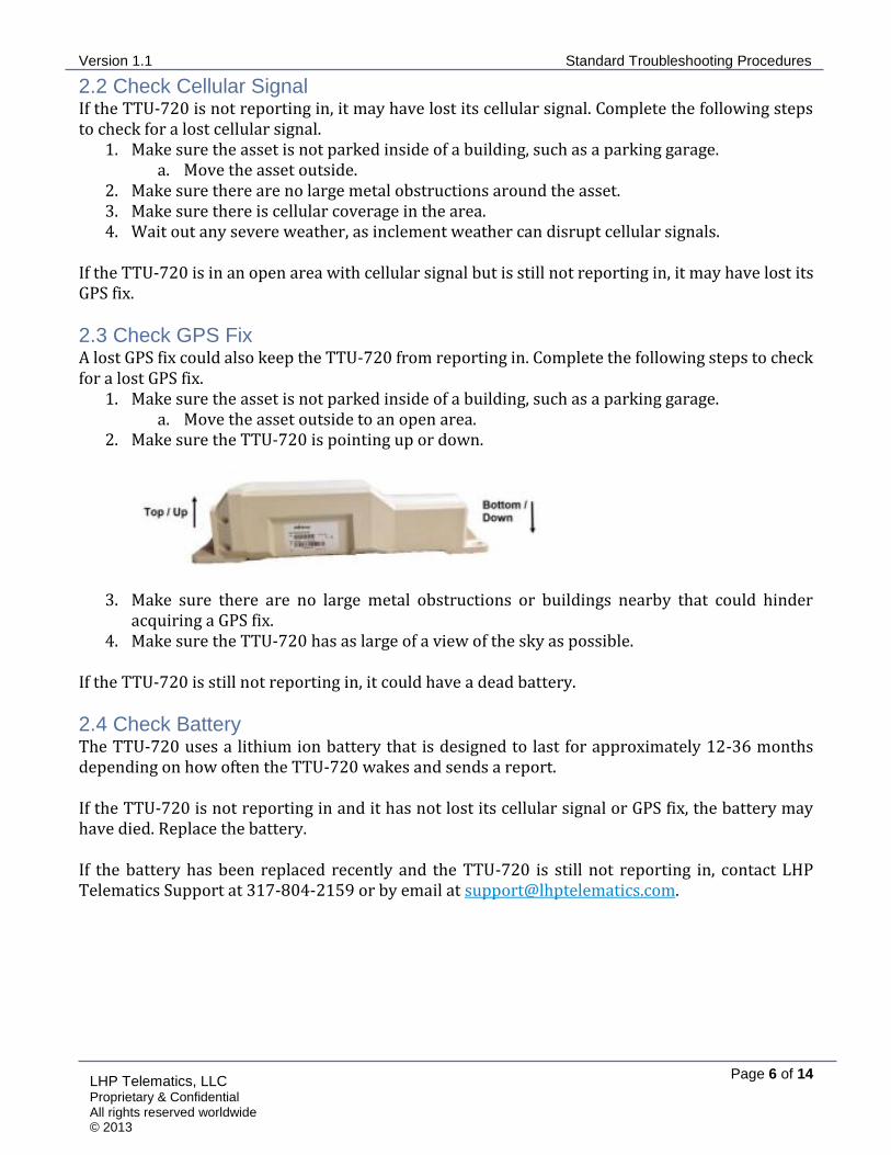
2.3 Check GPS Fix A lost GPS fix could also keep the TTU-720 from reporting in. Complete the following steps to check for a lost GPS fix.
1. Make sure the asset is not parked inside of a building, such as a parking garage. a. Move the asset outside to an open area.
2. Make sure the TTU-720 is pointing up or down.
3. Make sure there are no large metal obstructions or buildings nearby that could hinder acquiring a GPS fix.
4. Make sure the TTU-720 has as large of a view of the sky as possible. If the TTU-720 is still not reporting in, it could have a dead battery.
2.4 Check Battery The TTU-720 uses a lithium ion battery that is designed to last for approximately 12-36 months depending on how often the TTU-720 wakes and sends a report. If the TTU-720 is not reporting in and it has not lost its cellular signal or GPS fix, the battery may have died. Replace the battery. If the battery has been replaced recently and the TTU-720 is still not reporting in, contact LHP Telematics Support at 317-804-2159 or by email at [email protected].

Version 1.1 Standard Troubleshooting Procedures
Page 7 of 14
LHP Telematics, LLC Proprietary & Confidential All rights reserved worldwide © 2013
3 CalAmp LMU-3000 Troubleshooting The CalAmp LMU-3000 telematics control unit is an OBD unit designed for light trucks and passenger cars. The LMU-3000 has three status LEDs for Power, Communication, and GPS states, as shown in Figure 1.
FIGURE 1: CALAMP LMU-3000 LEDS
3.1 Troubleshooting Using Status LEDs You can use the Status LEDs on the LMU-3000 to perform basic troubleshooting if the TCU stops responding. Use the following LED states to troubleshoot using the LMU-3000’s Status LEDs. ALL LEDS UNLIT
If all Status LEDs are unlit, there might not be power provided to the unit. Make sure the LMU-3000 is securely plugged in to the asset’s OBD port, and then turn ignition on. All three LEDs should light up. COMM LED
If the orange LED is not lit but the green LED is, you have a GPS fix but you have lost cellular signal. Complete the following steps to restore cellular signal.
1. Make sure the asset is not parked inside a building, such as a parking garage. a. Move the asset outside.
2. Make sure there is no severe weather. Inclement weather can sometimes cause a loss of cellular signal.
3. Make sure there are no metal obstructions that could hinder the LMU-3000’s ability to obtain a cellular signal.
4. Make sure you are in an area with cellular coverage. GPS LED
If the green LED is not lit but the orange LED is, you have cellular signal but you do not have a GPS fix. Complete the following steps to restore a GPS fix.
1. Make sure the asset is not parked inside a building, such as a parking garage. a. Move the asset outside.
2. Make sure the asset is in an open area, without any large buildings or metal obstructions.

Version 1.1 Standard Troubleshooting Procedures
Page 8 of 14
LHP Telematics, LLC Proprietary & Confidential All rights reserved worldwide © 2013
3.2 Check OBD Port Functionality If the LMU-3000 is correctly installed and outside in an open area but it is still not reporting in, there may be a problem with the OBD port in your vehicle. To check the OBD port functionality, install the LMU-3000 in an asset that you know has a correctly-functioning OBD port. If the LMU-3000 functions correctly in the new OBD port, it is likely that the OBD port in the original asset is malfunctioning or the vehicles you are using are not on the approved vehicle list. If the LMU-3000 does not function correctly in the new OBD port, it is likely that the LMU-3000 is malfunctioning. Contact LHPT Support at 317-804-2159 or by email at [email protected].

Version 1.1 Standard Troubleshooting Procedures
Page 9 of 14
LHP Telematics, LLC Proprietary & Confidential All rights reserved worldwide © 2013
4 CalAmp TTU-1200 Troubleshooting The CalAmp TTU-1200 is a three-wire fleet tracking unit with internal GPS and cellular antennas. It has an internal back-up battery and has two status LEDs: cellular status and GPS status.
4.1 Troubleshooting Using Status LEDs You can use the TTU-1200’s Status LEDs to perform some basic troubleshooting if the TCU stops reporting in. Use the following LED key to troubleshoot using the TTU-1200’s Status LEDs. ALL LEDS UNLIT
If both LEDs are unlit, there is likely no power being provided to the unit. Turn the asset’s ignition on and see if the LEDs light up. COMM LED
If the orange COMM LED is not lit, but the green GPS LED is lit, you have a GPS fix but no cellular signal. Complete the following steps to try to restore a cellular signal.
1. Make sure the asset is not parked inside a building, such as a parking garage. a. If the asset is inside a building, move it outside.
2. Make sure the asset is in an area with no large metal obstructions that could hinder the TTU-1200’s ability to obtain a cellular signal.
3. If there is any severe weather, wait until it passes and then check the cellular status LED. Inclement weather can sometimes knock out cellular signal.
4. Make sure the asset is in an area of cellular coverage. GPS LED
If the orange COMM LED is lit, but the green GPS LED is not, you have cellular signal, but no GPS fix. Complete the following steps to try to acquire a GPS fix.
1. Make sure the asset is not parked inside a building, such as a parking garage. a. If the asset is inside a building, move it outside.
2. Make sure the asset is in an open area with no metal obstructions or large buildings. 3. Make sure the TTU-1200 has as large a view of the sky as possible.
4.2 Check Wiring Installation The TTU-1200 is installed on an asset using a three-wire wiring harness, as shown in Figure 2. If the TCU is malfunctioning, the wiring harness may not have been installed properly.
FIGURE 2: CALAMP TTU-1200 WIRING HARNESS

Version 1.1 Standard Troubleshooting Procedures
Page 10 of 14
LHP Telematics, LLC Proprietary & Confidential All rights reserved worldwide © 2013
Complete the following steps to check the wiring installation. 1. Check that the black Ground wire is connected to the provided ring connector and is then
connected to chassis ground. 2. Check that the white Ignition wire is connected to a source of switched power. 3. Check that the red Power Input wire is connected to the provided 3 AMP inline fuse and
connected to a source of constant power. a. Make sure the 3 AMP inline fuse is not blown.
4. Verify that the point of Chassis Ground is common to the Signal Ground. If the wiring harness has been correctly installed, contact LHPT Support at 317-804-2159 or by email at [email protected].

Version 1.1 Standard Troubleshooting Procedures
Page 11 of 14
LHP Telematics, LLC Proprietary & Confidential All rights reserved worldwide © 2013
5 Morey MC-3 Troubleshooting The Morey MC-3 a fleet-tracking unit that uses a three-wire, 6-pin, or 9-pin wiring harness to connect to the asset. It also has three status LEDs for monitoring Power, Modem, and GPS Status, as shown in Figure 3.
FIGURE 3: MOREY MC-3 STATUS LEDS
5.1 Troubleshooting Using Status LEDs You can use the MC-3’s status LEDs to perform basic troubleshooting tasks if the MC-3 is malfunctioning. Use the following LED key to troubleshoot using the MC-3’s Status LEDs. ALL LEDS UNLIT
If all LEDs are unlit, the MC-3 is not receiving any power. Make sure that the wiring harness is correctly installed and that the T-Connector is securely plugged in to the MC-3, as shown in Figure 4.
FIGURE 4: T-CONNECTOR AND MC-3
Turn the asset’s ignition on to see if the LEDs light up. NOTE: If you are waking the MC-3 from a cold boot, it could take up to 30 minutes for it to turn on. If the GPS fix is especially weak, it will take longer to wake up.

Version 1.1 Standard Troubleshooting Procedures
Page 12 of 14
LHP Telematics, LLC Proprietary & Confidential All rights reserved worldwide © 2013
POWER LED
The red Power LED indicates power status to the MC-3. If it is lit, but the green Modem and yellow GPS LEDs are not lit, this indicates that you have power to the MC-3, but no GPS fix or cellular signal. Complete the following steps to attempt to acquire a GPS fix and a valid cellular signal.
1. Make sure the asset is not parked inside of a building, such as a parking garage. a. If the asset is inside a building, move it outside to an open area.
2. Make sure the asset has a large view of the sky with no metal obstructions or large buildings. MODEM LED
The green Modem LED monitors cellular status. If the red and yellow LEDs are lit but the green LED is not, you have power and a GPS fix, but no cellular signal. Complete the following steps to attempt to restore cellular signal.
1. Make sure the asset is outside in an open area. 2. Make sure the asset is in an area with cellular coverage. 3. Make sure there are no metal obstructions or large buildings nearby that could interfere with
a cellular signal. 4. If there is any severe weather, wait out the storm and see if cellular coverage returns.
Inclement weather can sometimes interfere with cellular signal. GPS LED
The yellow GPS LED monitors GPS status. If the red and green LEDs are lit but the yellow LED is not, you have power and cellular signal, but no GPS fix. Complete the following steps to attempt to acquire a valid GPS fix.
1. Make sure the asset is outside in an open area. 2. Make sure the MC-3 has as large of a view of the sky as possible. 3. Make sure there are no metal obstructions or large buildings that could hinder the MC-3’s
ability to acquire a valid GPS fix.

Version 1.1 Standard Troubleshooting Procedures
Page 13 of 14
LHP Telematics, LLC Proprietary & Confidential All rights reserved worldwide © 2013
5.2 Check Wiring Installation in a 3-Wire Installation The MC-3 can be installed on an asset using a three-wire harness, as shown in Figure 5. If the TCU is malfunctioning, the wiring harness may not have been installed properly.
FIGURE 5: MC-3 3-WIRE HARNESS
Complete the following steps to check the wiring installation.
1. Check that the black Ground wire is connected to the provided ring connector and is then connected to Chassis Ground.
2. Check that the white Ignition wire is connected to a source of switched power. 3. Check that the red Power Input wire is connected to the provided 3 AMP inline fuse and
connected to a source of constant power. a. Make sure the 3 AMP inline fuse is not blown.
4. Verify that the point of chassis ground is common to the signal ground.
5.3 Check Wiring Installation in 6-Pin or 9-Pin Wiring Harness The MC-3 can be installed on an asset using a 6-pin or 9-pin wiring harness connected to the equipment’s diagnostic port. No special consideration on wiring is needed for this type of installation. LHPT Support cannot troubleshoot diagnostic port installation issues. If the MC-3 is still not reporting in, contact LHPT Support by phone at 317-804-2159 or by email at [email protected].

Version 1.1 Standard Troubleshooting Procedures
Page 14 of 14
LHP Telematics, LLC Proprietary & Confidential All rights reserved worldwide © 2013
6 JDES MTG Troubleshooting The JDES (formerly Phoenix) MTG is a rugged full telematics control unit. It is installed with a wiring harness and external antenna.
6.1 Check Installation Complete the following steps to check that the MTG has been installed correctly.
1. Make sure that the MTG has been keyed on for at least 5 minutes in a location with a clear view of the sky and where cellular reception is adequate.
2. Make sure that the antenna is securely connected and placed somewhere without obstructions to a sky view.
3. Check the red Power and orange or white Ignition lines for power above at least 10 volts. a. Check both lines while ignition is on. b. Check both lines while ignition is off.
4. Check the black ground line for continuity to a common ground by using an ohms meter to test resistance over the grounding line.
5. If you are not seeing CAN data, make sure that there are a maximum of two terminating resistors on the CAN line.
a. SAE J-1939 specifies that a minimum of 2 load terminating resistors are required at ether end of the physical network, but if there are no terminating resistors or more than two, CAN data will not be properly transmitted. See Table 2 for detailed information of CAN diagnosis. NOTE: When performing J1939 resistance tests, batteries must be disconnected and ignition must be turned off. Leaving Ignition On and batteries connected may cause inconclusive resistance measurements. Note that the J1939 datalink is not completely inactive when Ignition is off, meaning that it may still be active even if there does not appear to have any voltage on the datalink.
6. Verify that the point of Chassis Ground is common to the Signal Ground.
TABLE 2: J1939 RESISTANCE DIAGNOSTICS
Meter Readings Probable Issue
60Ω ± 6Ω J1939 Bus appears correct in structure
120Ω ± 12Ω Any or all of the following Terminating Resistor OPEN An open circuit between the terminating
resistors One of the two terminating resistors is missing
40Ω ± 4Ω Three or more terminating resistors reside on the Datalink layer. One terminating resistor needs to be removed.
0Ω - 5Ω CAN High and CAN Low are shorted together. Find short and repair.
Greater than 1000Ω Possible open circuit between point of reference and the CAN Bus. Could also be that the J1939 Bus has no terminating resistors installed.
Values not Defined Any or all of the following Open/corroded connectors Incorrect terminating resistor used Short or open circuit in physical bus structure
If the MTG is still not reporting in, contact LHPT support at 317-804-2159 or by email at [email protected].