Evaluation of Shear Modulus and Damping in Dynamic Centrifuge ...
Upload
duongthuanCategory
view
227download
1
Designation: D 4015 – 92 (Reapproved 2000)
Standard Test Methods forModulus and Damping of Soils by the Resonant-ColumnMethod 1
This standard is issued under the fixed designation D 4015; the number immediately following the designation indicates the year oforiginal adoption or, in the case of revision, the year of last revision. A number in parentheses indicates the year of last reapproval. Asuperscript epsilon (e) indicates an editorial change since the last revision or reapproval.
1. Scope
1.1 These test methods cover the determination of shearmodulus, shear damping, rod modulus (commonly referred toas Young’s modulus), and rod damping for solid cylindricalspecimens of soil in the undisturbed and remolded conditionsby vibration using the resonant column. The vibration of thespecimen may be superposed on a controlled ambient state ofstress in the specimen. The vibration apparatus and specimenmay be enclosed in a triaxial chamber and subjected to anall-around pressure and axial load. In addition, the specimenmay be subjected to other controlled conditions (for example,pore-water pressure, degree of saturation, temperature). Thesetest methods of modulus and damping determination areconsidered nondestructive when the strain amplitudes of vibra-tion are less than 10−4 rad (10−4 in./in.), and many measure-ments may be made on the same specimen and with variousstates of ambient stress.
1.2 These test methods cover only the determination of themodulus and damping, the necessary vibration, and specimenpreparation procedures related to the vibration, etc., and do notcover the application, measurement, or control of the ambientstress. The latter procedures may be covered by, but are notlimited to, Test Methods D 2166 or D 2850.
1.3 This standard does not purport to address all of thesafety concerns, if any, associated with its use. It is theresponsibility of the user of this standard to establish appro-priate safety and health practices and determine the applica-bility of regulatory limitations prior to use.
2. Referenced Documents
2.1 ASTM Standards:D 2166 Test Method for Unconfined Compressive Strength
of Cohesive Soil2
D 2216 Test Method for Laboratory Determination of Water(Moisture) Content of Soil and Rock2
D 2850 Test Method for Unconsolidated, Undrained Com-pressive Strength of Cohesive Soils in Triaxial Compres-sion2
D 4767 Test Method for Consolidated-Undrained TriaxialCompression Test on Cohesive Soils2
3. Terminology
3.1 Definitions of Terms Specific to This Standard:3.1.1 ambient stress—stresses applied to the specimen,
during the test, that do not result from the vibration strains.These test methods do not cover the application and measure-ment of ambient stresses; however, the ambient stress at thetime of measurement of the system resonant frequency andsystem damping shall be measured and recorded in accordancewith the final section of the paper.
3.1.2 apparatus model and constants—the rigidity and massdistribution of the resonant column shall be as required in thefollowing section in order for the resonant-column system to beaccurately represented by the model shown in Fig. 1. Theapparatus constants are the mass of the passive-end platen,MP, including the mass of all attachments rigidly connected to it;the rotational inertia of the passive-end platen,JP, includingthe rotational inertia of all attachments rigidly connected to it;similar mass,MA, and rotational inertia,JA, for the active-endplaten and all attachments rigidly connected to it, such asportions of the vibration excitation device; the spring anddamping constants for both longitudinal and torsional springsand dashpots (K SL, KST, ADCL, ADCT); the apparatus resonantfrequencies for longitudinal vibration,foL, and torsional vibra-tion, foT; the force/current constant,FCF, relating appliedvibratory force to the current applied to the longitudinalexcitation device; the torque/current constant,TCF, relatingapplied vibratory torque to the current applied to the torsionalexcitation device; and the motion transducer calibration factors(LCFA, RCFA, LCFP, RCFP) relating the transducer outputs toactive- and passive-end longitudinal and rotational motion.
3.1.3 moduli and damping capacities—Young’s modulus(herein called rod modulus),E, is determined from longitudinalvibration, and the shear modulus,G, is determined fromtorsional vibration. The rod and shear moduli shall be definedas the elastic moduli of a uniform, linearly viscoelastic (Voigtmodel) specimen of the same mass density and dimensions asthe soil specimen necessary to produce a resonant columnhaving the measured system resonant frequency and responsedue to a given vibratory force or torque input. The stress-strainrelation for a steady-state vibration in the resonant column is ahysteresis loop. These moduli will correspond to the slope of a
1 These test methods are under the jurisdiction of ASTM Committee D18 on Soiland Rock and are the direct responsibility of Subcommittee D18.09 on SoilDynamics.
Current edition approved May 15, 1992. Published September 1992. Originallypublished as D 4015 – 81. Last previous edition D 4015 – 87.
2 Annual Book of ASTM Standards,Vol 04.08.
1
Copyright © ASTM, 100 Barr Harbor Drive, West Conshohocken, PA 19428-2959, United States.

line through the end points of the hysteresis loop. The sectionon calculations provides for computation of rod and shearmoduli from the measured system longitudinal and torsionalresonant frequencies. The energy dissipated by the system is ameasure of the damping of the soil. Damping will be describedby the rod damping ratio,DL, and the shear damping ratio,DT,which are analogous to the critical viscous damping ratio,c/cr,for a single-degree-of-freedom system. The damping ratiosshall be defined by:
DL 5 0.5~hv/E! (1)
where:h = viscous coefficient for rod motion, N·s/m2,v = circular resonant frequency, rad/s, andE = rod modulus, Pa.
and by:
DT 5 0.5~µv/G! (2)
where:µ = viscous coefficient for torsional motion, N-s/m2, andG = shear modulus, Pa.
3.1.3.1 Values of damping determined in this way willcorrespond to the area of the stress-strain hysteresis loopdivided by 4p times the elastic strain energy stored in thespecimen at maximum strain. Methods for determining damp-ing ratio are prescribed later. In viscoelastic theory, it iscommon to use complex moduli to express both modulus anddamping. The complex rod modulus is given by:
E* 5 E~1 1 2iD L! (3)
and the complex shear modulus is given by:
G* 5 G~1 1 2iDT! (4)
wherei = =21.3.1.4 resonant-column system—a system consisting of a
cylindrical specimen or column of soil that has platens attached
to each end as shown in Fig. 1. A sinusoidal vibrationexcitation device is attached to the active-end platen. The otherend is the passive-end platen. It may be rigidly fixed (thecriterion for establishing fixity is given later) or its mass androtational inertia must be known. The vibration excitationdevice may incorporate springs and dashpots connected to theactive-end platen, where the spring constants and viscousdamping coefficients are known. Vibration excitation may belongitudinal or torsional. A given apparatus may have thecapability of applying one or the other, or both. The mass androtational inertia of the active-end platen and portions of thevibration excitation device moving with it must be known.Transducers are used to measure the vibration amplitudes foreach type of motion at the active end and also at the passiveend if it is not rigidly fixed. The frequency of excitation will beadjusted to produce resonance of the system, composed of thespecimen and its attached platens and vibration excitationdevice.
3.1.5 specimen strain—for longitudinal motion, the strain,e, is the average axial strain in the entire specimen. Fortorsional motion, the strain,g, is the average shear strain in thespecimen. In the case of torsion, shear strain in each crosssection varies from zero along the axis of rotation to amaximum at the perimeter of the specimen, and the averageshear strain for each cross section occurs at a radius equal to 80percent the radius of the specimen. Methods for calculatingspecimen strain are given later in the calculations section.
3.1.6 system resonant frequency—the definition of systemresonance depends on both apparatus and specimen character-istics. For the case where the passive-end platen is fixed,motion at the active end is used to establish resonance, whichis defined as the lowest frequency for which the sinusoidalexcitation force (or moment) is in phase with the velocity of theactive-end platen. For the case where the passive-end platenmass (or passive end platen rotational inertia) is greater than100 times the corresponding value of the specimen and is notrigidly fixed, resonance is the lowest frequency for which thesinusoidal excitation force (or moment) is 180° out of phasewith the velocity of the active-end platen. Otherwise, motion atthe passive end is used to establish resonance, which is thesecond lowest frequency for which the sinusoidal excitationforce (or moment) is in phase with the velocity of thepassive-end platen. (The lowest frequency for this condition isnot used because it does not produce significant strains in thespecimen.) In general, the system resonant frequency fortorsional excitation will be different from the system resonantfrequency for longitudinal excitation.
4. Significance and Use
4.1 The modulus and damping of a given soil, as measuredby the resonant-column technique herein described, dependupon the strain amplitude of vibration, the ambient state ofeffective stress, and the void ratio of the soil, temperature, time,etc. Since the application and control of the ambient stressesand the void ratio are not prescribed in these methods, theapplicability of the results to field conditions will depend onthe degree to which the application and control of the ambientstresses and the void ratio, as well as other parameters such assoil structure, duplicate field conditions. The techniques used
FIG. 1 Resonant-column Schematic
D 4015
2
to simulate field conditions depend on many factors and it is upto the engineer to decide on which techniques apply to a givensituation and soil type.
5. Apparatus
5.1 General—The complete test apparatus includes theplatens for holding the specimen in the pressure cell, thevibration excitation device, transducers for measuring theresponse, the control and readout instrumentation, and auxil-iary equipment for specimen preparation.
5.2 Specimen Platens—Both the active-end and passive-endplatens shall be constructed of noncorrosive material having amodulus at least ten times the modulus of the material to betested. Each platen shall have a circular cross section and aplane surface of contact with the specimen, except that theplane surface of contact may be roughened to provide for moreefficient coupling with the ends of the specimen. The diameterof platens shall be equal to or greater than the diameter of thespecimen. The construction of the platens shall be such thattheir stiffness is at least ten times the stiffness of the specimen.The active-end platen may have a portion of the excitationdevice, transducers, springs, and dashpots connected to it. Thetransducers and moving portions of the excitation device mustbe connected to the platen in such a fashion that they are to beconsidered part of the platen and have the same motion as theplaten for the full range of frequencies to be encountered whentesting soils. The theoretical model used for the resonant-column system represents the active-end platen, with allattachments, as a rigid mass that is attached to the specimen;
this mass may also have massless springs and dashpotsattached to it as shown in Fig. 1. If springs are used, theexcitation device and active-end platen (without the specimenin place) form a two degree-of-freedom system (one-degree-of-freedom system for devices designed for only longitudinalor only torsional motion) having undamped natural frequenciesfor longitudinal motion,foL, and torsional motion,foT. Thedevice shall be constructed such that these modes of vibrationare uncoupled. The passive-end platen may have a mass andtransducers rigidly attached to it or it may be rigidly fixed. Thepassive-end platen may be assumed to be rigidly fixed whenthe inertia of it and the mass(es) attached to it and the stiffnessof the support of the mass(es) provide a dimensionless fre-quency factor within 1 % of the dimensionless frequency factorfor the passive-end inertia ratio equal to infinity. (Use Fig. 2and the calculations section to get the dimensionless frequencyfactor.)
5.3 Vibration Excitation Device—This shall be an electro-magnetic device capable of applying a sinusoidal longitudinalvibration or torsional vibration or both to the active-end platento which it is rigidly coupled. The frequency of excitation shallbe adjustable and controlled to within 0.5 %. The excitationdevice shall have a means of measuring the current applied tothe drive coils that has at least a 5 % accuracy. The voltagedrop across a fixed, temperature-and-frequency-stable powerresistor in series with the drive coils may be used for thispurpose. The force/current and torque/current factors for thevibration excitation devices must be linear within 5 % for the
FIG. 2 (a) Dimensionless Frequency Factors 3
D 4015
3

entire range of operating frequencies anticipated when testingsoils.
5.4 Sine Wave Generator—The sine wave generator is anelectric instrument capable of producing a sinusoidal currentwith a means of adjusting the frequency over the entire rangeof operating frequencies anticipated. This instrument shallprovide sufficient power to produce the required vibrationamplitude, or its output may be electronically amplified toprovide sufficient power. The total distortion of the signalapplied to the excitation device shall be less than 3 %.
5.5 Vibration-Measuring Devices and ReadoutInstruments—The vibration-measuring devices shall be accel-eration, velocity, or displacement transducers that can beattached to and become a part of the active- and passive-endplatens. On each platen, one transducer shall be mounted toproduce a calibrated electrical output that is proportional to thelongitudinal acceleration, velocity, or displacement of thatplaten (not required for torsion-only apparatus). The othertransducer(s) shall be mounted to produce a calibrated electri-cal output that is proportional to the rotational acceleration,velocity, or displacement (not required for longitudinal-onlyapparatus). The readout instrument and transducers shall havea sensitivity such that a displacement of 2.53 10−6 m (10−4
in.) and a rotation of 10−5 rad can be measured with 10 %accuracy for the entire range of frequency anticipated. It is alsonecessary to have anx-y-time oscilloscope available forobserving signal waveforms and for establishing the systemresonant frequency. This oscilloscope must have at least oneamplifier (vertical or horizontal) with sufficient gain to observethe motion transducer output over the entire range of outputvoltages and frequencies anticipated. For measurement ofdamping by the free-vibration method, and for calibration ofthe apparatus damping, the readout instrument shall be capableof recording the decay of free vibration. Either a strip-chartrecorder with appropriate response time and chart speed or anoscilloscope and camera or a digital oscilloscope may be usedfor this purpose.
5.6 Support for Vibration Excitation Device—For the spe-cial case where the passive end of the specimen is rigidly fixedand the vibration excitation device and active-end platen are
placed on top of the specimen, it may be necessary to supportall or a portion of the weight of the platen and excitation deviceto prevent excessive axial stress or compressive failure of thespecimen. This support may be provided by a spring, counter-balance weights, or pneumatic cylinder as long as the support-ing system does not prevent axial movement of the active-endplaten and as long as it does not alter the vibration character-istics of the excitation device.
5.7 Temporary Platen Support Device— The temporarysupport may be any clamping device that can be used tosupport one or both end platens during attachment of vibrationexcitation device to prevent specimen disturbance duringapparatus assembly. This device is to be removed prior to theapplication of vibration.
5.8 Specimen Dimension-Measuring Devices—Dimension-measuring devices are needed to measure portions of theapparatus during calibration and specimen diameter and length.All dimensions measurements should be accurate to 0.1 %.Any suitable device may be used to make these measurementsexcept that the device(s) used to measure the length anddiameter of the specimen must not deform or otherwise affectthe specimen. Specially designed perimeter tapes that measurecircumference but read out in diameter are preferred formeasuring specimen diameters.
5.9 Balances—Devices for determining the mass of the soilspecimens as well as portions of the device during calibration.All measurements of mass should be accurate to 0.1 %.
5.10 Specimen Preparation and Triaxial Equipment—Thesemethods cover specimen preparation and procedures related tothe vibration of the specimen and do not cover the applicationand control of ambient stresses. Any or all of the apparatusdescribed in Test Methods D 2166, D 2850, or D 4767 may beused for specimen preparation and application of ambientstresses. Additional apparatus may be used for these purposesas required.
5.11 Miscellaneous Apparatus—The miscellaneous appara-tus consists of specimen trimming and carving tools, a mem-brane expander, remolding apparatus, moisture content cans,and data sheets as required.
FIG. 2 (b) Dimensionless Frequency Factors 3 (continued)
D 4015
4

6. Test Specimen
6.1 General—These methods cover only the special speci-men preparation procedures related to the vibration andresonant-column technique. Since the resonant-column testmay be conducted in conjunction with controlled ambientstresses, the provisions for preparation of specimens in TestMethods D 2166, D 2850, or D 4767 may be applicable or maybe used as a guide in connection with other methods ofapplication and control of ambient stresses.
6.2 Specimen Size—Specimens shall be of uniform circularcross section with ends perpendicular to the axis of thespecimen. Specimens shall have a minimum diameter of 33mm (1.3 in.). The largest particle contained within the testspecimen shall be smaller than one tenth of the specimendiameter except that, for specimens having a diameter of 70mm (2.8 in.) or larger, the largest particle size shall be smallerthan one sixth of the specimen diameter. If, after completion ofa test, it is found that larger particles than permitted are present,indicate this information in the report of test data under“Remarks.” The length-to-diameter ratio shall be not less than2 nor more than 7 except that, when an ambient axial stressgreater than the ambient lateral stress is applied to thespecimen, the ratio of length to diameter shall be between 2and 3. Measure the length at the third points along theperimeter and average the values. Measure two diameters ateach of three elevations and average the values. Determine theweight of the test specimen. For determination of moisturecontent (Test Method D 2216), secure a representative speci-men of the cuttings from undisturbed specimens, or of the extrasoil for remolded specimens, placing the specimen immedi-ately in a covered container.
6.3 End Coupling for Torsion—For torsional motion, com-plete coupling of the ends of the specimen to the specimen capand base must be assured. Complete coupling for torsion maybe assumed if the mobilized coefficient of friction between theend platens and the specimen is less than 0.2 for all shear strainamplitudes. The coefficient of fraction is approximately givenby:
Coefficient of friction5 gG/s8a (5)
where:g = shear strain amplitude (see calculations section),G = shear modulus (see calculations section), ands8a = effective axial stress.
6.3.1 When this criterion is not met, other provisions suchas the use of adhesives must be made in order to assurecomplete coupling. In such cases, the effectiveness of thecoupling provisions shall be evaluated by testing two speci-mens of the same material but of different length. The lengthsof these specimens shall differ by at least a factor of 1.5. Theprovisions for end coupling may be considered satisfactory ifthe values of the shear modulus for these two specimens ofdifferent length do not differ by more than 10 %.
7. Calibration
7.1 Motion Transducers—Motion transducers shall be cali-brated with each other and with an independent method toensure calibration accuracy within 5 %. Linear motion trans-
ducers whose axes are located fixed distances from the axis ofrotation may be used to measure rotational motion if thecross-axis sensitivities of the transducers are less than 5 %. Forthis case the distance between the axis of rotation and thetransducer axes shall be known to within 5 %. The calibrationfactors for longitudinal motion shall be expressed in terms ofpeak-meters/peak-volt. The calibration factors for rotationalmotion shall be expressed in terms of peak-radians/peak-volt.This means that for velocity and acceleration transducers thevibration frequency shall be included as a term in the calibra-tion factor. For velocity transducers, the displacement calibra-tion factors are given by:
LCF or RCF 5 velocity calibration factor/~2pf! (6)
wheref = frequency, Hz.For acceleration transducers, the displacement calibration fac-tors are given by:
LCF or RCF 5 acceleration calibration factor/~2pf! 2 (7)
7.1.1 Thus, for velocity and acceleration transducers, thedisplacement calibration factors will not be constants but willvary with measured frequency,f. Calibration factors for longi-tudinal motion are given by the symbolLCF with a subscriptA or P denoting whether the transducer is located on theactive-end platen or passive-end platen. Likewise, the calibra-tion factors for rotational motion will be given by the symbolRCF and will have subscriptsA or P depending on theirlocation.
7.2 Passive-End Platen Mass and Rotational Inertia—Themass and rotational inertia of the passive-end platen shall bedetermined with all transducers and other rigid attachmentssecurely in place. The mass,MP, is determined by use of abalance. The rotational inertia of the concentric solid cylindri-cal components of the passive-end platen and its attachments isgiven by:
~JP!1 518 (
i 5 1
n
Midi2 (8)
where:Mi = mass ofith solid cylindrical component,di = diameter ofith solid cylindrical component, andn = number of solid cylindrical components.
Transducers and other masses attached to this platen can beaccounted for by:
~JP!2 5 (i 5 1
n
Mir i2 (9)
where:Mi = mass of ith component,ri = distance from the platen axis to center of mass for ith
component, andn = number of components attached to passive-end
platen and not covered in determination of (JP)1.
The total rotational inertia for the passive end is given by:
D 4015
5

JP 5 ~JP! 1 1 ~JP!2 (10)
7.3 Active-End Platen Mass and Rotational Inertia—Themass,M A, and rotational inertia,JA, of the active-end platenshall be determined with all transducers and rigid attachments,including attached portions of the vibration excitation device,securely in place. The equations just given may be used toobtain the mass and rotational inertia. For rotational inertia, ifall components do not have simple geometry, an alternativeprocedure that involves a metal calibration rod of knowntorsional stiffness may be used. One end of the rod shall berigidly fixed and the other end shall be rigidly fastened to theactive-end platen. Since it may be very difficult to fasten thecalibration rod to the platen without adding rotational inertia, itis recommended that the calibration rod be permanentlyfastened by welding, etc., to an auxiliary platen. If the auxiliaryplaten is not identical to the one to be used in testing, thedifference between its rotational inertia and that of the platenfor soil testing must be taken into account by use of aforemen-tioned equations. (For example, suppose that the value of theactive-end rotational inertia with the calibration rod wasJ1 andthe rotational inertia of the calibration rod platen wasJ2. If therotational inertia of the platen for testing soil isJ3, then thevalue of J A would be given byJ A = J1 − J2 + J3.) Thetorsional stiffness of the calibration rod should be chosen suchthat the system resonant frequency with the calibration rod inplace is near the middle of the range of system resonantfrequencies anticipated for soil testing. Several calibration rodsmay be necessary to account for different specimen sizes. Withthe calibration rod in place, determine the low-amplitudesystem resonant frequency for torsional vibration, (frod)T. Therotational inertia of the active end platen system is calculatedfrom:
JA 5~Krod!T
~2p! 2@~frod!T2 2 f oT
2#(11)
where:(K rod)T = torsional stiffness of calibration rod,
= (IpG)/L,Ip = polar moment of inertia of calibration rod,
= (pd 4)/32,d = calibration rod diameter,G = shear modulus for calibration rod material, andfoT = apparatus torsional resonant frequency as de-
scribed in the following subsection.7.3.1 The foregoing equations assume that the rotational
inertia of the calibration rods is much less than the correspond-ing values for the active-end platen system. A second alterna-tive procedure is to couple the metal calibration rod to theplatens in place of the specimen and then use the procedures ofthe Calculations section to backfigure the active end inertiasfrom the known moduli of the rod.
7.4 Apparatus Resonant Frequencies, Spring Constants,and Damping Constants—Apparatus resonant frequencies andspring constants are defined only for those apparatus that havesprings attached to the active-end platen system. To determinethe resonant frequencies, set up the apparatus complete withactive-end platen and O-rings but no specimen. Vibrate at lowamplitude and adjust the frequency of vibration until the input
force is in phase with the velocity ofthe active-end platensystem. For longitudinal vibration, this apparatus resonantfrequency is foL and for torsional vibration it isfoT. Thelongitudinal and torsional apparatus spring constants (KSL, KST) may be calculated from:
KSL 5 ~2pfoL!2MA (12)
KST5 ~2pf oT!2JA
whereMA andJA are defined in the previous subsection.7.4.1 To measure the damping constants for the apparatus,
attach the same masses as used for the determination ofapparatus resonant frequencies. For apparatus without springsattached to the active-end platen, insert the calibration roddescribed in the previous subsection. With the apparatusvibrating at the resonant frequency, cut off the power to theexcitation device and record the decay curve for the vibrationof the apparatus. From the decay curve, compute the logarith-mic decrement,d, as follows:
d 5 ~1/n!ln ~A1/An11! (13)
where:A 1 = amplitude of vibration for first cycle after power is
cut off, andAn+1 = amplitude for (n + 1)th cycle.
The apparatus damping coefficient,ADCL, from longitudinalvibration shall be given by:
ADCoL 5 2foLM AdL (14)
where:fo L = longitudinal motion resonant frequency measured
during apparatus damping determination,MA = active-end platen mass from previous subsection,
anddL = logarithmic decrement for longitudinal motion.
For torsional motion, the apparatus damping coefficient,ADCoTis given by:
ADCoT 5 2f oTJAdT (15)
where:fo T = torsional motion resonant frequency measured dur-
ing apparatus damping determination,JA = active-end rotational inertia from previous subsec-
tion, anddT = logarithmic decrement for torsional motion.
7.5 Force/Current and Torque/Current— For apparatuswithout springs attached to the active-end platen, insert thecalibration rod as described earlier. Determine the resonantfrequency of this single-degree-of-freedom system consistingof the active-end platen and apparatus spring (or calibrationrod) by use of the same procedure as described later in theprocedures section. Then set the frequency to 0.707 times theresonant frequency and apply sufficient current to the vibrationexcitation device so that the vibration transducer output to thereadout device has a signal of at least ten times the signal dueto ambient vibrations and electrical noise when no power isapplied to the excitation device. Read and record the output of
D 4015
6

both the vibration transducer and the current measuring instru-ment. Next, set the frequency to 1.414 times the systemresonant frequency and obtain the vibration transducer andcurrent instrument readings in a similar fashion to those at0.707 times the resonant frequency. CalculateC1 andC2 from:
C1 5 0.5~VTCF!~TO1!/CR1 (16)
C2 5 ~VTCF!~TO2!/CR2
where:VTCF = active-end vibration transducer displacement
calibration factor (LCF or RCF) (Note 1) depend-ing on whether vibration is longitudinal or tor-sional,
TO1 = active-end transducer output at 0.707 times reso-nant frequency,
CR1 = current instrument reading at 0.707 times reso-nant frequency (Note 2),
TO2 = active-end transducer output at 1.414 times reso-nant frequency, and
CR2 = current instrument reading at 1.414 times reso-nant frequency (Note 2).
NOTE 1—LCF andRCFwill be functions of frequency for velocity andacceleration measuring transducers (see 7.1).
NOTE 2—If a current-measuring instrument is used, the units will beamperes. Alternatively, voltage drop across a fixed resistance may also bemeasured and the units will then be volts.
C1 andC2 should agree within 10 %. By use ofC1 andC2
from longitudinal vibration, the force/current calibration factor,FCF, is obtained from:
FCF 5 0.5~C 1 1 C2!K (17)
whereK = apparatus spring constant (or for apparatuswithout springs, the calibrating rod spring constant) for longi-tudinal motion.By use of C 1 and C2 from torsional vibration, the torque/current calibration factor,TCF, is obtained from:
TCF 5 0.5~C1 1 C 2!K (18)
whereK = apparatus spring constant (or for apparatus with-out springs, the calibrating rod spring constant) for torsionalmotion.
8. Procedure
8.1 Test Setup—The exact procedure to be followed duringtest setup will depend on the apparatus and electronic equip-ment used and on methods used for application, measurement,and control of the ambient stresses. However, the specimenshall be placed in the apparatus by procedures that willminimize the disturbance of the specimen. Particular care mustbe exercised when attaching the end platens to the specimenand when attaching the vibration excitation device to theplatens. A temporary support as discussed earlier may beneeded. For cases where ambient isotropic stresses are to beapplied to a membrane-enclosed specimen, liquid- or air-confining media may be used for dry or partially saturatedspecimens. For tests where complete saturation is important, aliquid-confining medium should be used. Where the vibrationexcitation device is located within the pressure chamber, an
air-liquid interface is acceptable as long as the liquid covers theentire membrane that encloses the specimen.
8.2 Electronic Equipment—Connect the vibration excitationdevice to the sine wave generator (with amplifier, if required).The power supplied to the vibration excitation device should bevery low in order not to exceed the amplitude of vibrationprescribed later. Connect the vibration transducers to thereadout instruments for the type of motion (longitudinal ortorsional) to be applied. Adjust the readout instruments accord-ing to the instruction manuals for these instruments.
8.3 Measurement of Resonant Frequency— The procedurefor measuring system resonant frequency is the same for bothlongitudinal and torsional vibration except that the longitudinalmotion transducer is used for longitudinal motion and therotational motion transducer is used for torsional motion. If thepassive end is fixed or ifP> 100 (see the calculations sectionfor definition ofP), motion of the active-end platen is used toestablish resonance. Otherwise, motion of the passive-endplaten is used. With the power as low as practical, increase thefrequency of excitation from a very low value (for example, 10Hz) until the system resonant frequency is obtained. The phaserelationship describing resonance can be established by observ-ing the Lissajous figure formed on anx-y oscilloscope with thevoltage proportional to the driving current applied to thehorizontal amplifier and the output from the transducer appliedto the vertical amplifier. If a velocity transducer is used forvibration measurement, the system resonant frequency occurswhen the figure formed is a straight, sloping line. If adisplacement or acceleration transducer is used, the frequencyshould be adjusted to produce an ellipse with axes vertical andhorizontal. (Refer to Definitions section to establish whichresonant frequency should be recorded.) It is recommendedthat the frequency be measured with a digital electronicfrequency meter and be recorded to at least three significantfigures. The system resonant frequency for longitudinal motionshall be designatedfL and that for torsional motion shall bedesignatedf T.
8.4 Measurement of Strain Amplitude— The strain ampli-tude measurements shall be made only at the system resonantfrequencies. Thus, for a given current applied to the excitationdevice, the vibration motion transducer outputs recorded at thesystem resonant frequency give sufficient information to cal-culate strain amplitude. To increase or decrease strain ampli-tude, the current to the vibration excitation device must beincreased or decreased. After making a change in currentapplied to the vibration excitation device, the procedure of theprevious subsection must be followed to establish the corre-sponding system resonant frequency before the transduceroutputs can be used to establish the new strain amplitude value.
8.5 Measurement of System Damping— Associated witheach strain amplitude and system resonant frequency is a valueof damping. Two methods are available for measuring systemdamping: the steady-state vibration method and the amplitudedecay method. Theoretically, both methods should give iden-tical results. In practice, results of each method are usuallyclose to each other. The steady-state method is easier andquicker. It is generally always used and the amplitude decaymethod is used for occasional spot-checking. The procedures
D 4015
7

for both methods are independent of whether longitudinal ortorsional motion is under consideration. For the steady-statemethod, the active-end or the passive-end vibration transduceroutput (depending on which end is used to establish resonance)and the current applied to the vibration excitation device mustbe measured at each resonant frequency. The calculations areoutlined in the following section. For the free-vibrationmethod, with the system vibrating at the system resonantfrequency, cut off the power to the vibration excitation deviceand record the output of the transducer used in establishingresonance as a function of time. This gives the decay curve forfree vibration. The calculations for damping are also outlinedin the following section.
9. Calculation
9.1 General—Calculations require the apparatus calibrationfactors and the physical dimensions and weight of the speci-men. In addition, for each ambient stress condition, one dataset is required for each vibration strain amplitude. A data setconsists of the type of vibration (longitudinal or torsional),duration of vibration (this time can be used to calculate thenumber of vibration cycles), system resonant frequency, active-or passive-end transducer outputs (depending on which end isused to establish resonance), the reading associated with thecurrent applied to the vibration excitation device, and thefree-vibration amplitude decay curve (if the amplitude decaymethod of measuring damping is also going to be used). Thecalculations outlined in this section may all be made bycomputer. A program for making some of the calculations isprovided in Appendix X1. Other programs may be used tomake a portion or all of the calculations as long as they provideidentical results.
9.2 Soil Mass Density—The soil mass density,r, is givenby:
r 5MV (19)
where:M = total mass of specimen, andV = volume of specimen.
9.3 Specimen Rotational Inertia—The specimen rotationalinertia about the axis of rotation is given by:
J 5Md 2
8 (20)
whered = diameter of specimen.9.4 Active-End Inertia Factors:9.4.1 The active-end inertia factor for longitudinal motion,
TL, is calculated from:
TL 5MA
M @1 2 ~f oL/fL! 2# (21)
where:MA = mass of active-end platen system as calculated
earlier,foL = apparatus resonant frequency for longitudinal mo-
tion (for apparatus without springs attached to theactive end platen, this term is zero), and
fL = system resonant frequency for longitudinal motion.
9.4.2 The active-end inertia factor for torsional motion,TT,is given by:
TT 5JA
J @1 2 ~foT/f T! 2# (22)
where:JA = rotational inertia of active-end platen system as
calculated earlier,J = specimen rotational inertia as calculated earlier,foT = apparatus resonant frequency for torsional motion
(for apparatus without springs attached to the active-end platen, this factor is zero), and
f T = system resonant frequency for torsional motion.9.5 Passive-End Inertia Ratios:9.5.1 For longitudinal motion, the passive-end inertia ratio,
PL, is given by:
PL 5MP
M (23)
whereMP = mass of passive-end platen system as de-scribed earlier.
9.5.2 For torsional motion, the passive-end inertia ratio,PT,is given by:
PT 5 Jp/J (24)
whereJP = rotational inertia of passive-end platen systemas calculated earlier.
9.5.3 For the special case where the passive end of thespecimen is rigidly fixed,P L andPT are equal to infinity.
9.6 Apparatus Damping Factors:9.6.1 For longitudinal motion, the apparatus damping factor,
ADFL, is calculated from
ADFL 5 ADCoL/@2pfLM# (25)
whereADCoL = apparatus damping coefficient for longi-tudinal motion as described earlier.
9.6.2 For rotational motion, the apparatus damping facto-r,ADF
o T, is calculated from:
ADFT 5 ADC0T/@2pfTJ# (26)
whereADCoT = apparatus damping coefficient for tor-sional motion as described earlier.
9.7 Dimensionless Frequency Factor— The dimensionlessfrequency factor,F, is used in calculating modulus. It is afunction of system factorsT, P, and ADF and of specimendamping ratio,D. Values ofF are provided by the computerprogram in Appendix X1, which is written in FORTRAN IV.For cases whereADF is zero and specimen damping ratio isless than 10 % values ofF can be obtained from Fig. 2. Fig. 2bis similar to Fig. 2a except that the range ofT is different. Thisfigure is independent of which end of the specimen is used todetermine resonance.
9.8 Magnification Factors:9.8.1 These factors are used in calculating damping. For
longitudinal motion, the magnification factor is calculatedfrom:
D 4015
8

MMFL 5 F~LCF!~LTO!
~FCF!~CRL!GM~2pfL! 2 (27)
where:LCF = longitudinal motion transducer displacement cali-
bration factor for transducer used in establishingresonance (Note 3),3
LTO = longitudinal motion transducer output of transducerused in establishing resonance,
FCF = force/current factor given earlier, andCRL = current reading to longitudinal excitation system
(Note 4).
NOTE 3—LCF andRCFwill be functions of frequency for velocity- andacceleration-measuring transducers (see 7.1).
NOTE 4—If a current-measuring instrument is used, the units will beamperes. Alternatively, this may be a voltage measurement across a fixedresistance and in units of volts. In the latter case, the same fixed resistanceuse in calibration (see 7.5) must be used for these measurements.
9.8.2 For torsional motion, the magnification factor is cal-culated from:
MMFT 5 F~RCF!~RTO!
~TCF!~CRT!GJ~2pfT! 2 (28)
where:RCF = rotational transducer displacement calibration fac-
tor for transducer used in establishing resonance(Note 3)
RTO = rotational transducer output for transducer used inestablishing resonance,
TCF = torque/current factor given earlier, andCRT = current reading to torsional excitation system (Note
4)9.9 Moduli:9.9.1 The rod modulus is calculated from:
E 5 r~2pL! 2~fL/F L! 2 (29)
where:r = specimen mass density given earlier,fL = system resonant frequency for longitudinal motion
given earlier,FL = dimensionless frequency factor given earlier, andL = specimen length.
9.9.2 The shear modulus is calculated from:
G 5 r~2pL! 2~f T/FT! 2 (30)
where:fT = system resonant frequency for torsional motion given
earlier, andFT = dimensionless frequency factor given earlier.
9.10 Strain Amplitude:9.10.1 The average rod strain amplitude,e, for longitudinal
vibration shall be calculated from:
e 5 ~LCF!~LTO!~SF/L! (31)
where:LCF = longitudinal motion transducer displacement cali-
bration factor for the transducer used in establish-ing resonance (Note 5),
LTO = longitudinal transducer output for the transducerused in establishing resonance,
SF = strain factor calculated by program in the AppendixX1 or, for cases of ADF = 0 and specimen dampingequal to 10 %, it may be obtained from Fig. 3. Forother values of specimen damping ratio, valuesfrom Fig. 3 are only approximately correct. (Notethat Fig. 3 is for the case where resonance isestablished by phase measurement between inputforce and motion at the active end and Fig. 3b is forthe case where resonance is established by phasemeasurement between input force and motion at thepassive end), and
L = specimen length.
NOTE 5—LCF andRCFwill be functions of frequency for velocity- andacceleration-measuring transducers (see 7.1).
9.10.2 For torsional motion, the average shear strain ampli-tude,g , shall be calculated from:
g 5RCF RTO SF d
2.5L (32)
where:RCF = rotational motion transducer displacement calibra-
tion factor for transducer used in establishingresonance (Note 5),
RTO = rotational transducer output for transducer used inestablishing resonance,
SF = strain factor determined in same manner as de-scribed for rod strain amplitude, and
d = specimen diameter.9.11 Damping Ratio from Steady-State Vibration—If the
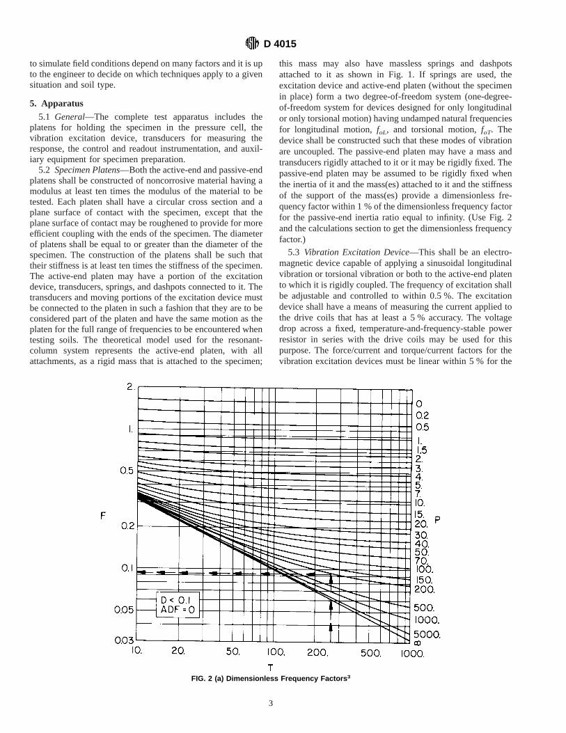
computer program in the Appendix is used, the damping ratioof the specimen is established as part of the output. Manualcalculation of damping ratio may be done for cases where theapparatus damping factor,ADF, is zero or may be assumed tobe zero (definition ofADF given earlier). The procedurerequires that Fig. 4a be used if resonance is established byphase measurement between input force (or torque) and thelongitudinal (or rotational) motion at the active-end platen. Fig.4b is used for the case where resonance is established by phasemeasurement between the input force (or torque) and thelongitudinal (or rotational) motion at the passive-end platen.The damping ratio,D, is calculated from:
D 5 1/@A~MMF!# (33)
where:A = value from Fig. 4, andMMF = magnification factor given earlier.
9.11.1 Damping ratios obtained from longitudinal vibrationare not the same as damping ratios obtained from torsionalvibration. SubscriptsL and T should be used to relate thedamping ratios to the type of vibration used in their determi-nation.
3 Enlarged and detailed copies of Figs. 2a, 2b, 3a, 3b, 4a, and 4b may be obtainedat a nominal charge from ASTM Headquarters, 1916 Race St., Philadelphia, Pa.19103. Request Adjunct No. 12-440150-00.
D 4015
9

9.12 Damping Ratio from Free Vibration— This procedureis theoretically exact for apparatus where the passive end canbe assumed to be rigidly fixed. For the cases where the passiveend is not rigidly fixed, irrespective of which end of thespecimen is used in establishing resonance, this method isapproximate. The same transducer that is used to determineresonance must be used to obtain the amplitude decay curve.For the case where resonance is established by use of thepassive transducer, values ofT and P should both be greaterthan 10 when amplitude decay is used. For apparatus where theactive-end platen is restrained by a spring, a system energyratio must be calculated. For other apparatus, this factor is zero.For longitudinal motion, this ratio is calculated from:
SL 5 ~MA/M!~foLF L/fL! 2 (34)
and for torsional motion from:
ST 5 ~JA/J!~foTF T/fT! 2 (35)
whereFL, FT = dimensionless frequency factors for longi-tudinal and torsional motion, respectively, from Fig. 2.Compute the system logarithmic decrement from the free-vibration decay curve (as obtained in the previous section)from:
ds 5 ~1/n! ln ~A1/An11! (36)
where:A 1 = amplitude of vibration for first cycle after power is
cut off,An+1 = amplitude of vibration for (n + 1)th cycle of free
vibration, andn = number of free vibration cycles which must be 10
or less.
Finally, calculate the damping ratio from:
D 5 @ds~1 1 S! 2 Sd#/~2p! (37)
FIG. 3 (a) Strain Factors for Resonance Determined from Motion at Active End 3
D 4015
10

where:D = DL or DT depending on whether vibration is longitu-
dinal or torsional,ds = ds L or dsT depending on whether vibration is longi-
tudinal or torsional,S = SL or ST depending on whether vibration is longitu-
dinal or torsional, andd = d L or dT, apparatus logarithmic decrement given
earlier.
10. Report
10.1 General—The report shall include characteristics of
the apparatus, specimen, ambient test conditions, and theresults for each data set.
10.2 Apparatus Characteristics—The following apparatuscharacteristics shall be included: apparatus name, model num-ber, and serial number; active-end and passive-end masses androtational inertias (MA, MP, JA, J P); longitudinal and torsionalapparatus resonant frequencies (foL, f oT); longitudinal andtorsional apparatus logarithmic decrements (dL, dT); the force/current and torque/current constants (FCF, TCF); and theapplicable motion transducer calibration factors (LCFA, LCF P,RCFA, RCFP). (Note that if the passive end is fixed, inertias
FIG. 3 (b) Strain Factors for Resonance Determined from Motion at Passive End 3 (continued)
D 4015
11
and transducers are not needed for the passive end. Likewise,if only one type of motion, longitudinal or torsional, is used,then only factors and inertias for that type need be given.)
10.3 Specimen Characteristics—A visual description andorigin of the soil shall be given, including name, group symbol,and whether undisturbed or remolded. Initial and final speci-men mass, dimensions, void ratio, water content, and degree ofsaturation shall also be given. Specimen preparation proce-dures and test setup procedures should be outlined.
10.4 Ambient Test Conditions—A complete description ofthe ambient stress conditions shall be given, including totalstresses and pore water pressures, drainage conditions, and theprocedures used to measure applied stresses, pore pressures,length change, and volume change.
10.5 Results for Each Data Set—For each data set, thefollowing items shall be reported: approximate time of vibra-tion at this strain amplitude, cell pressure, back or pore
pressure, axial stress, specimen length and volume, type ofvibration, system resonant frequency, strain amplitude, modu-lus, and damping ratio.
11. Precision and Bias
11.1 Precision—Round-robin testing of soil using this testmethod has been attempted. The modulus and damping of soildepend upon strain amplitude of vibration, the ambient state ofeffective stress, and the void ratio of soil, as well as otherfactors. Further, these test methods allow for two differenttechniques for measurement of damping. Also, it provides theoption for manual or computer data reduction. The manualprocess is less precise than the computer process because itdoes not consider apparatus damping and it requires interpo-lating from curves. Because of the above considerations,Subcommittee D18.09 deemed the results to be inappropriatefor publication in this test method. Subcommittee D18.09 is
FIG. 4 (a) Damping Factors for Resonance Determined from Motion at Active End 3
D 4015
12

seeking assistance from users of the test method to resolve theproblems.
11.2 Bias—The variability of soil and resultant inability todetermine a true reference value prevent development ofmeaningful statement of bias.
12. Keywords
12.1 amplitude; confining pressure; damping; dynamicloading; elastic waves; elasticity modulus; frequency; labora-
tory tests; nondestructive tests; resonance; shear tests; soils;strain; stress; torsional oscillations; triaxial stress; verticaloscillations; vibrations; Young’s modulus
FIG. 4 (b) Damping Factors for Resonance Determined from Motion at Passive End 3 (continued)
D 4015
13

APPENDIX
(Nonmandatory Information)
X1. COMPUTER PROGRAM FOR RESONANT COLUMN DATA REDUCTION (JUNE 1978)
D 4015
14

D 4015
15

D 4015
16

D 4015
17

D 4015
18

D 4015
19

D 4015
20

The American Society for Testing and Materials takes no position respecting the validity of any patent rights asserted in connectionwith any item mentioned in this standard. Users of this standard are expressly advised that determination of the validity of any suchpatent rights, and the risk of infringement of such rights, are entirely their own responsibility.
This standard is subject to revision at any time by the responsible technical committee and must be reviewed every five years andif not revised, either reapproved or withdrawn. Your comments are invited either for revision of this standard or for additional standardsand should be addressed to ASTM Headquarters. Your comments will receive careful consideration at a meeting of the responsibletechnical committee, which you may attend. If you feel that your comments have not received a fair hearing you should make yourviews known to the ASTM Committee on Standards, at the address shown below.
This standard is copyrighted by ASTM, 100 Barr Harbor Drive, PO Box C700, West Conshohocken, PA 19428-2959, United States.Individual reprints (single or multiple copies) of this standard may be obtained by contacting ASTM at the above address or at610-832-9585 (phone), 610-832-9555 (fax), or [email protected] (e-mail); or through the ASTM website (www.astm.org).
D 4015
21