Drainage Structures, Storm Sewers, Division 7 Sanitary Sewers
Standard Specifications for Water Mains
and Sanitary Sewers
Etowah Water & Sewer Authority
P.O. Box 769
1162 Highway 53 East
Dawsonville, GA 30534
Revision Date: December 2017
ETOWAH WATER & SEWER AUTHORITY
WATER MAINS & SANITARY SEWER REV 6/2017
TABLE OF CONTENTS
List of changes, additions & deletions for December 2017 Specification Update
SECTION 100: GENERAL INFORMATION Page
101 General Requirements-Use of this Document 100-1
102 Plan Review Process 100-2-3
103 Construction Permit 100-3
104 Approval by Other Government Agencies 100-4
105 Construction 100-4-5
106 Inspection 100-5
107 As-Builts 100-5-6
108 One-Year Maintenance 100-6
109 Building Permits 100-7
110 Sanitary Sewer Availability 100-7
111 Sewer Tap Fees 100-8
112 List of Commonly Used Terms 100-8
113 List of Acronyms 100-9
114 Appeals 100-9
SECTION 200: PLANS
201. Water Pressure Flow Test 200-1
202 Water System Plan Requirements 200-1-2
203 Sewage Collection System Plan Requirements 200-3-4
GENERAL NOTES FOR WATER AND SEWER CONSTRUCTION 200-5-6
204 Plan Approval 200-6-7
205 As-Built Drawings 200-7
206 Erosion and Sedimentation Control Plan 200-7-8
207 Easement Acquisition and Utility Encroachment Permits 200-8-9
208 Relocation of Existing Water and Sewer Facilities 200-9
209 Approval by Other Government Agencies 200-9-10
SECTION 300: DESIGN CRITERIA
301 General 300-1
302 Water Main Extension Requirements 300-1
303 Minimum Water Main Sizes and Fire Hydrant Requirements 300-1
304 Water Main Sizes, Fire Main Sizes and Materials 300-2
305 Fire Protection 300-2-3
306 Sprinkler Systems & Other Commercial Applications 300-4
307 Disconnection of Wells 300-4
308 Location of Water Mains and Fixtures 300-4-7
309 Fire Line Metering Requirements 300-7-8
ETOWAH WATER & SEWER AUTHORITY
WATER MAINS & SANITARY SEWER REV 6/2017
310 Water Pump Stations 300-8
311 Water Mains on Private Roads 300-8
312 Types of Sewers 300-9
313 Design Considerations 300-9
314 Design Factors 300-9
315 Details of Design and Construction 300-10
316 Slope 300-11
317 Increasing Size 300-11
318 Gravity Sewer Pipe 300-11
319 Sanitary Sewer Force Mains 300-11-12
320 Manholes 300-12
321 Drop Manholes 300-12
322 Connections to the Authority’s Sewer System 300-12
323 Connections to Existing Manholes 300-12-13
324 Steel Casings 300-13
325 Protection of Water Supply and Other Utilities 300-13
326 Sewer Services 300-14
327 Grease Traps and Sand/Oil Traps 300-14-15
328 Wastewater Lift Stations 300-15-16
329 Industrial Sewage Pretreatment 300-17
330 Private Wastewater Treatment Systems 300-17
331 Privately Owned Community Water Systems 300-17
SECTION 400: MATERIALS FOR CONSTRUCTION
401 General 400-1
402 Water Main 400-1-4
403 Fire Hydrants 400-4-5
404 Valves and Accessories 400-5-10
405 Sewerage Pipe 400-10-11
406 Sanitary Sewer Force Mains 400-11
407 Precast Concrete Manholes 400-12-16
408 Stone and Gravel Materials 400-16
409 Air Release and Vacuum Break Valves for Force Main 400-16
410 Wastewater Lift Stations 400-17-47
ETOWAH WATER & SEWER AUTHORITY
WATER MAINS & SANITARY SEWER REV 6/2017
SECTION 500: CONSTRUCTION METHODS
501 Excavation General 500-1
502 Erosion and Sedimentation Control 500-1-2
503 Clearing and Grubbing 500-3
504 Trench Excavation 500-3-5
505 Rock Excavation 500-6
506 Subgrade and Bedding 500-6-8
507 Bedding Material 500-8-9
508 Installation of Water Main 500-9
509 Installation of Sewer Pipe 500-10-11
510 Backfilling Trenches 500-11-12
511 Thrust Restraint for Pressure Lines 500-13
512 Setting Fire Hydrants 500-14
513 Setting Valves and Fittings 500-14-15
514 Placing of Steel Casing Pipe and Jack and Bore 500-15-16
515 Marking Location of Valves 500-16
516 Connection of the Existing Authority Water System 500-16
517 Highway Crossings 500-16-17
518 Stream Crossings 500-17-18
519 Replacement of Pavement 500-18-19
520 Location and Protection of Existing Underground Utilities 500-19
521 Protection of Water Supply and Other Utilities 500-19-20
522 Clean-Up 500-20-21
523 Grassing 500-21
524 Standard Detail Drawings 500-21
525 Construction 500-21-22
526 Interruption of Water Supply during Construction 500-22
527 Barricades 500-22
SECTION 600: INSPECTION, TESTING AND ACCEPTANCE
601 Inspection 600-1-2
602 Water System Testing 600-2-5
603 Sewer System Testing 600-6-9
604 Acceptance 600-9-10
605 “As-Built” Record Drawings 600-10-11
Section 700: Standard Detail
December 2017 - Etowah Water and Sewer Authority Standard Specifications for Water Mains and Sanitary Sewers Update
Changes, additions and deletions Page 1
Revision 6 - December 2017
Etowah Water and Sewer Authority Standard Specifications for Water Mains and Sanitary Sewers Update
Changes, additions and deletions that have been made to the Standard Specifications for Water Mains
and Sanitary for the 2017 Update:
1. Table of Contents corrected to reflect correct page numbers for individual sections.
2. Section 404, paragraph # 3: Removed “….Vulcan Pattern VVB-4….” and replaced with “….East
Jordan Series 8550….” within the last sentence.
3. Section 404, paragraph # 4: Removed “….or approved equal….” and replaced with “…..or Series
RGX as manufactured by Vent-O-Mat.” at end of the 4th sentence.
4. Section 404, paragraph # 4: Removed “….a ball valve, a discharge elbow, pipe nipples….” and
replaced with “….316 grade stainless steel ball valve, 316 grade stainless steel pipe nipples, a
connection to the water main with 316 grade stainless steel service saddle or ductile iron
tapped tee ….” within the 5th
sentence.
5. Section 407, FRAME AND COVER, paragraph # 1: Removed
“MANHOLES - Precast manholes shall be constructed of Portland cement concrete with
compressive strength of not less than 4,000 pounds per square inch at an age of 28 days. The wall
thickness shall not be less than 5 inches. Precast concrete manholes shall consist of precast
reinforced concrete sections with eccentric top section, or flat slab for shallow manholes, and a base
section conforming to the typical manhole details as shown on the Standard Detail Drawings. Flat
top manholes will be approved only if a real need for such can be demonstrated by the design
engineer. All manholes shall be installed in accordance with OSHA regulations and the details in
these specifications.
MANHOLE SECTIONS - The design, the materials used in, the manufacturing process, the testing
and the transportation of precast manhole sections shall be subject to inspection at any time by the
Authority. Materials found defective by the Authority will not be delivered to the job site. Material
on the job site that is found defective shall be moved immediately after notified that such materials
are unacceptable. Precast manholes shall conform to ASTM C478.
MANHOLE SECTION JOINTS - Manhole sections shall be of the tongue-and-grove type. Sections
shall be jointed using O-ring rubber gaskets, flexible plastic gaskets conforming to the applicable
provisions of ASTM Standard Specification, Serial Designation C 433, latest revision, or an
approved bituminous mastic joint material. .The outside joints shall be wrapped with a CRETEX
WRAP per the manufacturer’s recommended procedures or an approved equal.
LIFT HOLES - Each section of the precast manhole shall not have more than two holes for the
purpose of handling and installing. These holes shall be sealed with cement mortar using one part
Portland cement to two parts clean sand, meeting ASTM Standard Specifications, Serial
Designation C 144, latest revision.
December 2017 - Etowah Water and Sewer Authority Standard Specifications for Water Mains and Sanitary Sewers Update
Changes, additions and deletions Page 2
MANHOLE STEPS - Manhole steps conforming to the applicable provision of ASTM Specification
C 478, latest edition, shall be #4 steel reinforcing bars covered with Polypropylene Plastic or rubber
and shall be supplied with depth rings and other necessary appurtenances. Steps shall be similar to
and of an equal quality to the “PS1-PF” by M.A. Industries, Inc. of Peachtree City, Ga. The step
shall be factory built into the precast section. See the Standard Detail for a typical manhole step
detail.
PIPE HOLES - Holes in precast bases to receive sewer pipe shall be precise at the factory at the
required locations and heights. Knocking out the holes in the field will not be permitted; however,
holes can be cored in the field with coring machine. Pre-molded rubber boots with stainless steel
bands shall be used for connecting sewer pipe to manholes. These may be either the Lock-in “Kor-
N-Seal” type as manufactured by National Pollution Control Systems, Inc. or cast-in type as
manufactured by Interpace Division of Ball Rubber, Inc. In all cases the boot shall be sized to suite
the outside diameter of the type being used.
BASES AND INVERTS - Manhole bases and inverts shall be constructed of 4,000 PSI concrete in
accordance with details of Standard Detail Drawings and the trough shall have the same cross-
section as the sewer which it connects. The manhole base and invert shall be carefully formed to the
required size and grade and even changes in the sections. Changes in direction of flow through the
sewer shall be made a true curve with as large a radius as the size for the manhole will permit. The
minimum drop through a manhole shall be 0.1’. All inverts must be Rowlock brick type and the
table will require gravel, sand and mortar mixture.
MANHOLE FOUNDATION - The manhole base shall be set upon 6 inch compacted (minimum
thickness) mat of Size #57 crushed stone 12” outside the base of the manhole. Refer to the State of
Georgia DOT Standard Specifications, Section 800.01. Excavation in excess of the depths required
for manholes shall be corrected by pouring a sub-foundation of 2500 psi concrete or placement of
#57 stone, whichever is directed by the Authority Inspector. A pre-cast base section shall be
installed on a firm stabilized foundation so prepared to prevent settlement and misalignment.
BRICK - Brick work required to complete the precast concrete manhole shall be constructed using 1
part Portland cement to 2 parts clean sand, meeting ASTM Specifications, Serial Designation C 144,
thoroughly mixed to a workable plaster mixture. Brick work shall be constructed in a neat and
workmanlike manner. Cement shall be used to grout interior exposed brick and faces. No more than
3 courses of brick with 9” maximum total depth of bricks may be used to adjust manhole covers.
FRAME AND COVER - Manhole frames and covers shall meet the requirements of ASTM A48
Class 35B gray iron or ASTM A536 for ductile iron and all applicable local standards. All castings
shall be tough, close grained and smooth and free from blow holes, blisters, shrinkage, strains,
cracks, cold shots and other imperfections. No casting will be accepted which weighs less than 95%
of the design weight. Shop drawings must indicate the design weight and provide sufficient
dimensions to permit checking. All castings shall be thoroughly cleaned in the shop.
1. Manhole frames and covers shall be the following:
Design Type Weight Manufacturer’s Reference
Traffic 236 lbs East Jordan Iron Works

December 2017 - Etowah Water and Sewer Authority Standard Specifications for Water Mains and Sanitary Sewers Update
Changes, additions and deletions Page 3
Hinged Manhole Assembly
Product #: 00104023L01
Traffic 270 lbs US Foundry
USF 924 Ring & US Cover
Ring #: 8020767
Cover #: 8017134
Traffic 195 lbs. Pamrex RE24R8FS
Traffic 137 lbs East Jordan Iron Works
Hinged Assembly
Product #: 00103304
Cross-country/Outfall 152 lbs East Jordan Iron Works
Bolt Revolution Assembly
Product #: 00104016R01
Cross-country/Outfall 160 lbs US Foundry
USF 275 Ring & RO Cover
Ring #: 8021273
Cover: 8017136
2. Watertight traffic type frames and covers shall have the same weight and dimensions as those
specified.
3. All manhole covers shall have the words “ETOWAH WSA SANITARY SEWER” cast in the
top and be in accordance with Standard Detail 728. “SANITARY SEWER” is acceptable for the
Pamrex & EJIW product # 00103304 lids for use only on test manholes for grease traps and
combination sand/oil traps.
4. Manhole frame and cover clear openings shall be 32” for sanitary sewers 18” and larger.
5. All cross-country/outfall frames and covers shall be cast into the manhole cones.
MASONRY WORK - Masonry work shall be allowed to set for a period of not less than 24 hours.
All loose or waste material shall be removed from the interior of the manhole. The manhole cover
then shall be placed and the surface in the vicinity of the work cleaned off and left in a neat and
orderly condition.” and replace with
“1. Manufacturers:
A. Durham & Taylor Supply Company, Inc.
B. Georgia Precast Concrete
C. or Approved Equal
2. Manholes shall be cylindrical and constructed of steel reinforced precast concrete.
3. Precast sections shall consist of a base section, riser section and eccentric cone top or
flat slab top section, as conditions require. The sections shall form a continuous uniform
assembly.
4. Precast sections shall be manufactured, tested and marked in accordance with ASTM
C478.

December 2017 - Etowah Water and Sewer Authority Standard Specifications for Water Mains and Sanitary Sewers Update
Changes, additions and deletions Page 4
5. Absorption shall not exceed 9 percent when determined in accordance with ASTM
C497, as amended to date.
6. Steel reinforcement shall be as specified in ASTM C478.
7. The external perimeter of all joints between each precast manhole section shall be sealed
with a polyethylene backed flat butyl rubber sheet measuring a minimum of one
sixteenth of an inch thick and 6 inches wide. When applied the rubber sheet shall be
held securely in place so that it is not disturbed during the installation or backfill.
Acceptable manufacturers are Cretex Wrap or an Approved Equal.
8. Manhole Base Sections
A. Base sections for precast concrete manholes shall have a bottom poured
monolithically with the walls.
B. Base sections shall be furnished with inside diameters sized to provide
structurally sound bases at all pipe deflections and sized to provide a watertight pipe
connection.
C. Minimum manhole diameters are identified on the Contract Drawings. To
ensure the integrity of the manhole base is maintained or to provide sufficient wall
thickness for the pipe connector, where required, the manhole manufacturer shall
provide larger diameter manholes than those detailed.
D. Base sections shall be furnished with a minimum height of 20 inches for pipes
having a diameter of 8, 10 or 12 inches, a minimum height of 24 inches for pipes having
a diameter of 15 or 16 inches, and a minimum of 60 inches for pipe having a diameter of
30 inches.
E. The openings in the base section for the accommodation of the pipe shall be cast
to closely conform to job conditions and shall be sized specifically for the type of pipe
and connector being used.
F. Unless otherwise required, a minimum clearance (i.e., sump) of three (3) inches
shall be provided between the inside bottom of the base and outside bottom of the pipe
barrel.
G. Inverts shall be Rowlock Brick Type and the table shall be constructed of
gravel, sand and mortar.
H. Where calculations indicate the manholes will float, the base sections shall be
constructed with an extended base slab to resist flotation.
1) If the extended base slab is utilized, design calculations shall be provided to
show the slab extension will not shear.
9. Riser Sections:
A. The riser sections shall be furnished in a minimum of sixteen (16) inch
increments and shall be four (4) feet in diameter with,
1) tongue and groove joint to be sealed with approved butyl rubber or
bitumastic material, or
2) O-ring gasket type joint conforming to ASTM C443, as amended to
date.
B. Transition sections, which convert bases that are larger than four feet in
diameter to four-foot in diameter for risers, shall be designed by the manhole
manufacturer to carry the live and dead loads exerted on the section.

December 2017 - Etowah Water and Sewer Authority Standard Specifications for Water Mains and Sanitary Sewers Update
Changes, additions and deletions Page 5
C. No manhole riser sections shall be altered by the Contractor.
10. Top Sections:
A. The flat slab tops shall be furnished where shown on the Drawings and shall be
designed to carry the dead and live loads for that specific installation.
11. Precast “Dog House” Manholes shall be furnished and installed at the locations
identified and shall comply with this section.
A. Dog house opening shall be precast by the manufacturer. Field cutting-in dog
house opening shall be prohibited.
B. The minimum manhole diameters are identified on the drawings. The diameter
of dog house manholes shall be as recommended by the manhole manufacturer to
ensure the base is structurally sound at all pipe deflections and pipe diameters.
C. Annulus between pipe and opening shall be grouted water tight with non-shrink
grout.
12. Manhole and Structure Sections: Maximum leakage based on vacuum testing as
outlined in Section 33 01 32.
13. Manhole Frames and Covers:
A. Cast Iron Castings: ASTM A48/A48M, Class 30 or better; and all applicable
local standards.
B. All castings shall be tough, close grained, and smooth and free from bubbles,
sand and air holes, blowholes, blisters, shrinkage, strains, cracks, cold shots and other
imperfections.
C. All frames and covers shall have machined and matched horizontal bearing
contact surfaces.
D. Manhole covers shall have the word “SEWER”, cast on top.
E. See Standard Detail No. 728 for water tight manhole frame and cover, 728-1 for
standard manhole frame and cover, and728-2 for vented manhole frame and cover
additional manhole casting requirements.
F. No casting will be accepted which weighs less than 95% of the design weight.
G. All castings shall be thoroughly cleaned in the shop and given two coats of an
approved bituminous paint before rusting begins.
H. All manholes shall have standard frames and covers except where specifically
shown otherwise on the Drawings.
I. Manhole covers required to be bolt-down shall be secured with not less than
four (4) stainless steel bolts as provided by the manufacturer.
J. Covers rated for traffic shall have a weight of at least 335 pounds and
K. Manhole frame and covers shall be East Jordan Iron Works V-1418 or U.S.
Foundry Catalog No. 362.
L. If specifically called for on the Drawings, covers shall be hinged and be Pamrex
RE24R8FS with a weight of 195 pounds.
M. Where required, the manhole frame shall be adjusted to the required grade
with precast grade rings. All joints between the cone, adjusting rings and manhole
frame shall be sealed with a butyl sealant rope and sheet. Grade rings shall conform to
ASTM C478 and shall be no less than four (4) inches in height. No more than ten (10)
vertical inches of grade rings will be allowed per manhole.
N. All cross-country/outfall frames and covers shall be cast into the manhole cone.
December 2017 - Etowah Water and Sewer Authority Standard Specifications for Water Mains and Sanitary Sewers Update
Changes, additions and deletions Page 6
14. Brick and Mortar: Brick shall be whole and hard burned, conforming to ASTM C32
Grade MS. Mortar shall be made of one part Portland cement and two parts clean
sharp sand. Cement shall conform to ASTM C150. Sand shall meet ASTM C33.
15. Provide preformed rubber boots and fasteners equal to those manufactured by "KOR N
SEAL" as manufactured by National Pollution Control Systems, Inc., or Press Seal
Gasket Corporation or equal.
A. The joint system shall be a synthetic rubber boot or sleeve, either cast or core
drilled hole of the proper diameter into the wall of the manhole.
B. The boot or sleeve shall be clamped and seated to the pipe with a stainless steel
band.
C. The design of the connector shall provide a flexible, watertight seal between the
pipe and the manhole and the connector shall be sized specifically for the type of pipe
being used and shall be installed in accordance with the manufacturer’s
recommendation.
16. Butyl rubber sealant shall be equal to "E Z Stik" as manufactured by Concrete Supply
Company, Kent Seal No. 2 or Concrete Sealants DS202.
17. Access Steps:
A. Steel reinforced copolymer polypropylene meeting the following specifications:
1) ASTM C478.
2) ASTM C497, Method of test.
3) ASTM D4104, PP0344B33534Z02 copolymer polypropylene.
4) ASTM A615/A615M, Grade 60, 1/2" reinforced rod.
5) Steps shall be uniformly spaced along a vertical centerline as specified in this
section.
6) Manhole steps shall be as manufactured by M.A. Industries or equal.
18. Masonry Work
A. Masonry work shall be allowed to set for a period of not less than 24 hours. All
loose or waste material shall be removed from the interior of the manhole. The manhole
cover then shall be placed and the surface in the vicinity of the work cleaned off and left
in a neat and orderly condition.”.
6. Section 409, paragraph # 1: Added “…..316 grade….” within the 3rd
sentence.
7. Section 409: Removed paragraph # 3 “Discharge of pressurized air shall be controlled by two
orifices controlling the flow of air. The large orifice shall be sealed with a Buna-N-Seal o-ring
while the smaller mechanism is maintained by a modulating diaphragm for air release accuracy.”
Paragraph 4 is now paragraph 3 and so on.
8. Section 409, paragraph # 3: Added “….. 316 grade….” at 2 locations within the 1st sentence.
9. Section 409, paragraph # 4: Added “…..or Series RGX as manufactured by Vent-O-Mat.” at end
of the sentence.
10. Section 409, paragraph # 5: Added “…..tapped or…..” within the 1st sentence.
11. Section 409, paragraph # 6: Removed “…..or air valve container….” within the sentence.
December 2017 - Etowah Water and Sewer Authority Standard Specifications for Water Mains and Sanitary Sewers Update
Changes, additions and deletions Page 7
12. Section 410, Wastewater Lift Stations, Approved Pump Manufacturers: Added “…., Grundfos….”
As an approved submersible pump manufacturer.
13. Section 410, Above Ground Lift Stations, Paragraph D, subparagraph 3b: Removed the second
sentence; “For operating pressures greater than or equal to 100 psi TDH or at force main velocities
greater than or equal to 4 ft/s, cushioned check valves shall be installed.” and replaced with
“Provide a non-clog design, taper type, plug valve providing drip tight shutoff. Check valve
shall be of the flanged, full body type with no internal moving parts except for the resilient
disc. The flanged ends shall be manufactured in accordance with ANSI B16.1 Class 125.
Valves shall be rated to 250 psi for all sizes. For operating pressures greater than or equal to
100 psi TDH or at force main velocities greater than or equal to 4 ft/s, cushioned check valves
shall be installed. Check Valves shall be Val-Matic Surgebuster Check Valve with Backflow
Actuator or PSI - Pratt Surge Inhibitor Check Valve with Backflush Device.”.
14. Section 410, Above Ground Lift Stations, Paragraph D, subparagraph 3c: Removed entire
paragraph; “Provide a 3-way non-lubricated, taper type, plug valve providing drip tight shutoff.”
15. Section 410, Above Ground Lift Stations, Paragraph D, subparagraph 3d is now subparagraph 3c: Add
“Plug valves shall be non-lubricating, eccentric type, designed for a working pressure of 150 psi,
tight shut-off at rated pressure, cast iron body with ductile iron valve plug, full port, bi-
directional, manufactured and tested per AWWA C517. 6” and smaller plug valves shall be ¼
turn lever and 8” and larger shall be provided with a worm and gear type manual actuator.
Plug valves shall be Pratt Ballcentric plug valve or Val-Matic Cam- Centric plug valve. As
directed by the Authority,….” before the first sentence.
16. Add Section 411:
“411. MEDICAL FACILITIES & DETENTION CENTERS
A. General
1. The Authority requires all hospitals, medical facilities (hospitals, nursing
homes, assisted living facilities, etc.) and Detention Centers (prisons, jails, etc.)
to install, operate, and maintain a Muffin Monster on their sewer service line
prior to our clean out. The Authority needs to ensure no wipes enter our
collection system.”
ETOWAH WATER & SEWER AUTHORITY
WATER MAINS AND SANITARY SEWER 100-1 REV 6/2017
SECTION 100 – GENERAL INFORMATION
101. GENERAL REQUIREMENTS USE OF THIS DOCUMENT
1. These Etowah Water and Sewer Authority Standard Specifications
(hereinafter also called “Standard Specifications” or “Standards” or
“Specifications”) have been developed by Etowah Water and Sewer Authority
(hereinafter also called “Authority” or “Etowah” or “EWSA”) to guide and
direct the developer, design professional, and contractor in the design,
permitting and construction of proposed private developments.
2. This document is subject to periodic revision to meet changing requirements
for materials, fire and safety regulations, environmental regulations, etc. At
the beginning of a project, users should verify that they have the latest edition.
3. This document is intended to convey the general design and construction
requirements for a typical project. It also lists specific Etowah Water and
Sewer Authority requirements relating to plan review, inspection, testing and
acceptance of facilities. It is not intended as a substitute for site-specific
engineering and construction techniques. Individual project conditions may
require variances from the provisions in this document in which case such
variances should be noted in the plans and other data submitted by the project
design professional for the Authority’s approval.
4. The Standard Details in Section 700 are complementary to the Specifications
written herein. If the developer or designer notes any discrepancies or desires
an interpretation of a specification, they should submit their question to the
Authority in writing for a decision by the Authority or the Authority’s
representative.
5. No part of these Standards is intended to conflict with the requirements of the
Authority’s Sewage Disposal Ordinance. If a conflict is noted, the stronger
requirement shall govern.
6. Bench marks and control point shall be shown on the plan and profile sheets.
Horizontal and vertical coordinate data shall be provided on the plans for each
bench mark and control point. The vertical datum used shall be the elevation
above mean sea level and the horizontal datum shall be Georgia State Plane
West Coordinates.
7. Please refer to the 10-States Standard, most recent edition, for unique
conditions not covered by this Specification.
8. All electrical equipment associated with any system expansion or upgrade
must be in accordance with NFPA 820.

ETOWAH WATER & SEWER AUTHORITY
WATER MAINS AND SANITARY SEWER 100-2 REV 6/2017
102. PLAN REVIEW PROCESS
The following steps apply to the approval for installation of water mains and
sanitary sewers, fire hydrants, valves, manholes, force mains, pump stations,
private wastewater treatment systems, and appurtenances by private developers in
commercial, industrial, institutional or residential developments:
1. One (1) copy of preliminary plans showing the type of development,
location and general plan for water supply and sewer collection must be
submitted to the Authority. Preliminary Plans will be prepared and submitted
for review as described in Section 200. Questions related to adequate
remaining capacity and proposed locations of connections to the existing
system should be resolved at this stage before proceeding with detailed
planning. The submittal for preliminary review must include all land to be
developed showing all phases and/or units planned for the entire project.
Adequacy determinations of the existing water distribution system and
sanitary sewage collection system will be made for the entire project.
2. Sewer availability will be determined by the Authority in the area of the
proposed development. The Authority will review the plans to determine if the
wastewater treatment facilities lift stations and sanitary sewers in the area of
the proposed development have sufficient remaining capacity to serve the
proposed development. (See Section 110.)
3. Flow and pressure tests will be conducted by the Authority in the area of the
proposed development. These tests shall be paid for by the developer prior to
the performance of tests at the rate then in effect as established by the
Authority. Refer to rate schedule for current fees. Comments will then be
addressed to the developer by the Authority relating to the availability of
water or other items pertinent to the development.
4. Availability of water and sewer and/or plans to provide water supply and/or
sewerage service to the site must be approved by the Authority BEFORE
going to Dawson County or City of Dawsonville Planning to apply for
permits.
5. The Developer should procure a copy of the current set of water main and
sanitary sewer standards. It is the Owner/Developer’s responsibility to get
copies made and distributed to the appropriate contractors. The Authority’s
Water Main & Sanitary Sewer Standard Specifications are available on line at
www.etowahwater.org.
6. The developer must then submit one (1) copy of construction plans as outlined
in these specifications to the Authority for review. These plans must carry the
stamp of a registered professional engineer and/or registered land surveyor.
Refer to rate schedule for current plan review fees. There will also be an
additional fee charged if the project requires the plan review of a lift station to
ETOWAH WATER & SEWER AUTHORITY
WATER MAINS AND SANITARY SEWER 100-3 REV 6/2017
serve the development or the project includes a private wastewater treatment
system. Consult with the Authority regarding the amount of these fees. This
additional fee must be paid prior to the Authority performing the review. If
the project requires the services of any of the Authority’s outside consultants,
those review fees will be charged accordingly. These additional fees must be
paid prior to the scheduling of the preconstruction conference.
7. If revisions are required, a checklist noting the deficiencies of the plans will
be returned to the developer.
8. After the revisions have been made, the developer must submit one (1) copy
of revised construction plans to the Authority for review.
9. If approved as submitted, three (3) copies must be submitted for the
Authority’s approval stamp. One copy will be returned to the developer at the
pre-construction meeting.
10. The Developer shall complete the Project Information Form (Exhibit A-1) and
Ownership Forms, Exhibit B and submit these to the Authority.
11. The Developer shall forward a copy of all county and state permits to the
Etowah Water & Sewer Authority.
12. The Developer shall obtain all necessary utility easements and record these at
the Dawson County Courthouse. The Developer shall provide the Authority
with a copy of the recorded easements. Etowah Water and Sewer Authority
shall be Grantee on all water and sanitary sewer easements.
13. The Developer shall contact the Engineering & Construction Department at
(706) 216-8474 to arrange the preconstruction meeting prior to the beginning
any water and sewer construction.
14. When the project is completed, the Developer shall forward one copy of the
recorded final plat and the “As-Built” to the Authority. Refer to sections 107,
205 and 605 for further information.
103. CONSTRUCTION PERMIT
When the water and/or sewer plans have been approved by the Authority, an
approved set of plans will be issued to the developer which must be displayed at
the project site at all times. No water main or sanitary sewer construction shall be
allowed until the plans have been approved and a preconstruction meeting has
been held. The approval will expire if the developer does not begin construction
of the water or sewer facilities within one year from the date of issuance. If the
approval expires, the plans will have to be resubmitted for review, and the
developer will have to pay all associated costs of the new review.
ETOWAH WATER & SEWER AUTHORITY
WATER MAINS AND SANITARY SEWER 100-4 REV 6/2017
104. APPROVAL BY OTHER GOVERNMENT AGENCIES
No part of the approval process is intended to relieve the developer of the
responsibility to comply with minimum standards of the Georgia Department of
Natural Resources, United States Environmental Protection Agency (EPA),
Georgia Environmental Protection Division (EPD), Natural Resources
Conservation Service (NRCS), Georgia Department of Transportation (GDOT),
Dawson County or other appropriate regulatory agencies.
105. CONSTRUCTION
1. Preconstruction Conference
The Developer, Design Professional, Contractor and Dawson County or City
of Dawsonville representatives are required to meet with the Authority for the
purpose of discussing the construction and inspection of the proposed
development. The proposed start date and an approximate time for completion
will be given to the Authority.
2. Approved Plans
An approved set of construction plans stamped by the Authority must be kept
onsite at all times by the Contractor.
3. Notification
The Authority shall be notified by the developer or his contractor before
construction begins, and at the various stages in construction as required by
the Authority. The Authority shall be given a 24 hour advance notice before
an inspection is needed.
4. Contractor Qualifications
Contractors performing utility construction must be licensed in accordance
with State of Georgia law and local ordinances and approved by the
Authority. They should be completely familiar with the procedures and
contract requirements associated with the project. The contractor must be pre-
qualified by the Authority prior to the pre-construction conference. The
Authority reserves the right to disqualify any contractor for unsatisfactory
work.
Any and all subcontractors preforming work connected to or which will
connect to the Authority’s water and/or sanitary sewer system shall be
approved by the Authority.
ETOWAH WATER & SEWER AUTHORITY
WATER MAINS AND SANITARY SEWER 100-5 REV 6/2017
5. Damage to Water and/or Sewer Facilities
The Developer is responsible for replacing any and all water and/or sewer
facilities which are damaged by the Developer, any of his Contractors and any
Builder working at the project site. Water and sewer facilities include but are
not limited to service lines, meters, meter boxes, valves, valve boxes, valve
markers, fire hydrants, and manholes. Developer is responsible for
maintaining marked location of water and sewer systems, per Utilities
Protection Center (UPC) guidelines, until final acceptance by the Authority.
106. INSPECTION
1. All water mains and sanitary sewers shall be installed as provided for in these
Specifications and will be subject to inspection during construction by the
Authority or a representative of the Authority.
2. On any system to be accepted for ownership and operation by the Authority, a
final inspection will be made to accept or reject the work when completed.
Water systems must pass hydrostatic and disinfection test requirements and
Sewer Systems must pass infiltration, exfiltration, air, deflection, and vacuum
test as set out in these specifications before acceptance.
3. Authorized representatives of the Authority and/or the EPD, or other state or
federal agencies shall have access to the site for inspection at all times.
107. AS-BUILTS
Two sets of as-built drawings must be submitted to the Authority immediately
after the completion of construction. These as-built drawings shall include:
1. The water and sewer system as-built shall show locations of fire hydrants, line
valves, tees, bends, service locations, water main sizes, manholes, sewer main
sizes, sewer service laterals, cleanouts, manhole invert elevations, line grades
and types of materials. Please review Sections 205 and 605 for further detail
on items to be included.
2. Complete Project Information describing the water/sewer system
improvements shall be given to the Authority when the as-built drawings are
submitted. An AutoCAD file containing the as-builts must also be submitted.
Each object type shall have its own layer. Each of the following shall have its
own layer: topographical lines, water mains, valves, fire hydrants, sewer
lines, manholes, etc. All as-built drawings shall use the state plane coordinate
system USA GA NAD 83 West Foot. Both electronic and paper as-built
drawings shall include all information contained on the approved construction
drawings in the as-built state.
ETOWAH WATER & SEWER AUTHORITY
WATER MAINS AND SANITARY SEWER 100-6 REV 6/2017
3. The Authority shall have the right to withhold water meters until the as-built
drawings have been submitted and approved as required.
4. The conditional approval letter will not be issued until the as-built drawings
have been completed and submitted to the Authority.
5. Hand-marked copies prepared by the Contractor will not be acceptable. The
copies must be sharp, clear, clean and legible and must be suitable for filming
for permanent records.
108. ONE-YEAR MAINTENANCE
1. The developer shall maintain the improvements in his development for a
period of one year from the date the Authority issues written conditional
approval of the improvements. At the end of the one year maintenance period,
the Authority will perform an inspection of the development. The developer
will be notified of the inspection results in writing including a list of
deficiencies for immediate correction.
2. If repairs are needed for the development to meet Authority specifications, the
developer shall be required to make such repairs within 60 days, after written
notification by the Authority. If no action is taken to correct deficiencies noted
within 30 days, a hold will be placed on any remaining meter taps until those
deficiencies are corrected. If no lots remain, the Authority will not approve
any future proposed development by the Developer. Should any
Developer/Contractor fail to comply with the specifications and regulations of
the Authority or fail to correct deficiencies identified by the Authority,
approval will not be given on any future proposals by the
Developer/Contractor until ALL previous projects of the Developer are in
compliance with these regulations.
3. At its discretion, the Authority may take action to correct any deficiencies. It
will be the responsibility of the developer to reimburse the Authority for any
costs associated with correcting the deficiencies.
4. If the work is free from defects, or after the required repairs have been
completed to the satisfaction of the Authority, a letter of final acceptance will
be issued to the Developer. The letter will state that the one year maintenance
period has expired and that the Authority is now the owner of the water and
sewer facilities and is responsible for all future maintenance of these facilities.
5. A 24 month extended warranty may be required after the initial 12 month/one
year maintenance period. See section 604 for further details.
ETOWAH WATER & SEWER AUTHORITY
WATER MAINS AND SANITARY SEWER 100-7 REV 6/2017
109. BUILDING PERMITS
Water and/or sewer construction plans must be approved by the Authority prior
to the issuance of a building permit. Replacement of water and/or sewer facilities
damaged by Builders shall be the responsibility of the Developer.
110. SANITARY SEWER AVAILABILITY
1. DRY SEWERAGE SYSTEMS
In cases where the Etowah Water and Sewer Authority is to expend funds
within a drainage basin in two years but said sewers are not available at
present, the Developer will be required to install dry lines to serve any
structure to be built in the development. These lines will collect at a single
point at the property line at the lowest point on the property or at a point
designated by the Engineer and approved by the Authority. The installation of
dry lines does not in any way relieve the requirements of the Dawson County
Health Department for approving septic tanks in the development. NO dry
sewers shall be used until such time as trunk sewers are constructed to an
acceptable treatment facility. NO pumping and hauling of sewage is allowed.
Septic tanks placed on the lots shall be located at a point to facilitate future
connection of the home or business to the tap provided.
2. SEWERAGE NOT AVAILABLE
If sewerage is not available nor planned to be available, a 40 foot permanent
and 60 foot construction sanitary sewer easement shall be shown on the plans
and dedicated to the Etowah Water & Sewer Authority for future use. The
Etowah Water & Sewer Authority may at its option require additional
easements.
Minimum easement widths to be dedicated are 40 feet for permanent
easements and 60 feet for construction easements, with the construction
easement centered on the permanent easement. Also, in the event that a trunk
or interceptor greater than 15” is expected to pass through the development, the
construction easement width shall be increased to the amount required for
construction of the expected sanitary sewer. All easements are to be checked in
the field and must be adequate for the purpose for which they are dedicated.
Also, consideration must be given for expected building locations and the
easement shall be located for the least possibility of conflict before the sanitary
sewer may be constructed. No structures shall be built on dedicated easements
and the Authority will not be responsible for the removal or replacement of
fences that are placed on dedicated easements when the sanitary sewer is
constructed. Septic tanks in these developments shall be placed in a location to
facilitate tie-on of structure to the sanitary sewer.
ETOWAH WATER & SEWER AUTHORITY
WATER MAINS AND SANITARY SEWER 100-8 REV 6/2017
111. SEWER TAP FEES
A connection fee shall be paid to the Etowah Water & Sewer Authority before
any structure is connected to the Authority’s sewer system. The connection fee
shall be calculated as follows:
1. The calculation of the sewer connection fee will be based on established
formulas currently used by the Authority. Requests to deviate from these
established formulas will not be accepted. The connection fee shall be that
which is in effect at the date the application is made.
2. The fee for all types of development shall be calculated based on a
comparison of the expected sewage effluent of the user with a typical single
family residence (227 gpd). If the comparison results in an amount less than a
single family residence, the tap fee shall be the same as a single family
residence.
112. LIST OF COMMONLY USED TERMS
“Authority” shall mean the Etowah Water & Sewer Authority.
“Contractor” shall mean the individual, firm or corporation undertaking the
execution of the Work under the terms of the contract and acting through its
agents and employees.
“Developer” shall mean the individual, firm or corporation financing the
execution of the Work.
“Engineer” shall refer to the engineer appointed by the Developer as
representatives of the Developer and to its properly authorized agents.
“Owner” shall refer to the Etowah Water & Sewer Authority.
“Plans” shall refer to those drawings that show the character and scope of the
Work and shall include all drawings identified in the contract documents.
“Shall” and “Will” are mandatory; “May” is permissive.
“Specifications” shall refer to the Water Main and Sanitary Sewer Standards of
the Etowah Water & Sewer Authority.
“Work” of the contractor shall include all labor, material, equipment,
transportation, skills, tools, machinery, and other equipment and things useful and
necessary to complete the contract.
ETOWAH WATER & SEWER AUTHORITY
WATER MAINS AND SANITARY SEWER 100-9 REV 6/2017
113. LIST OF ACRONYMS
ASTM: American Society for Testing and Materials
AWWA: American Water Works Association
DIP: Ductile Iron Pipe
DOT: Georgia Department of Transportation
EPA: United States Environmental Protection Agency
EPD: Georgia Department of Natural Resources, Environmental Protection
Division
EWSA: Etowah Water & Sewer Authority
HDPE: High Density Polyethylene
NRCS: National Resource Conservation Service
OSHA: United States Department of Labor, Occupational Safety and Health
Administration
PVC: Polyvinyl Chloride
RCP: Reinforced Concrete Pipe
USACE – United States Army Corps of Engineers
VCP Vitrified Clay Pipe
114. APPEALS
Any requirement that is outlined in these specifications may be modified or
revoked by the General Manager of the Etowah Water & Sewer Authority.
ETOWAH WATER & SEWER AUTHORITY
WATER MAINS & SANITARY SEWER 200-1 REV 6/2017
SECTION 200 – PLANS
201. WATER PRESSURE FLOW TEST
1. A water pressure flow test must be run on any existing Authority water main
to determine the adequacy of water supply for the project. The test shall
consist of fire hydrant flow test and a twenty-four (24) hour pressure test. The
Authority will perform the test. Refer to rate schedule for current fees.
Test information shall consist of:
A. Static Pressure
B. Recorded Flow in GPM and Residual Pressure
C. Twenty-four (24) hour pressure chart
An adequate supply of water for the proposed project must be available prior
to the submittal of any construction plans unless an exception is granted by
the Authority. The Authority does not guarantee pressure and flow above
minimum state standards for domestic service.
2. All projects which have flow test/pressure chart test results showing static
pressures of less than 40 PSI or a residual pressure of less than 30 PSI will
require a special design study to be completed and submitted to the Authority
for approval to insure that no problems will be encountered during peak
demand periods. This study must be approved by the Authority before any
construction plans will be approved.
202. WATER SYSTEM PLAN REQUIREMENTS
1. Preliminary Plan Review: Preliminary plans will be prepared and submitted
for review as described in these specifications. Questions relating to adequate
fire protection, multiple feeds, water supply and proposed location of
connection(s) should be resolved at this stage before proceeding with detailed
planning. The submittal for preliminary review must include all land to be
developed showing all phases and/or units planned for the entire project.
Adequacy determinations of the existing water supply system will be made for
the entire project.
2. Water Construction Plans shall consist of the following:
A. Site plan with project name, streets, street names, topography with
contour lines at two foot intervals, location map, lot layout (if
subdivision) or building location (multi-family, commercial or
industrial site), land lots, district and north arrow showing the water
layout only. Note if any other utilities are existing. Plan scale shall be
a maximum of 1”=50’. Sheet size shall be 24” x 36”.
B. Proposed pipe sizes and service lateral locations.
ETOWAH WATER & SEWER AUTHORITY
WATER MAINS & SANITARY SEWER 200-2 REV 6/2017
C. Location and size of water valves
D. Thrust blocks where used.
E. Fire hydrant locations
F. Water system materials.
G. Location and sizes of existing water lines surrounding project, with
nearest line valve in each direction from proposed connection.
H. Detail of connection to existing water mains.
I. Proposed meter sizes and locations.
J. Detailed plan of fire line meters, detector meters, compound meters,
backflow preventers, etc. if applicable.
K. Any other items incidental to the proposed system.
L. Details of special water line installations such as stream crossings,
elevated lines on piers, bridges, pipe bedding, special highway
crossings, railroad crossings, etc.
M. Show all right-of-way widths and easement widths. Show all pavement
widths.
N. Include the name of the design engineer, professional engineer
signature and his registration stamp. All engineers preparing
construction plans and specifications must be registered in the State of
Georgia as a professional engineer.
O. The cover sheet shall also include the Owners/Developer’s name,
address, telephone number, and fax number, plus the engineer’s name,
address, telephone number, and fax number. The cover sheet shall also
include the funding source if state or federally funded, and detailed
project location map.
P. The vertical datum used should be the elevation above mean sea level.
Q. A sheet index shall be provided, as well as a legend of symbols used.
R. Each plan sheet should include a note stating “The Contractor must
call the Utilities Protection Center “Call Before You Dig” telephone
number (Georgia811) four days before starting any excavation.”
S. The General Notes for Construction following Section 203 shall be
included in each set of plans.
T. Water systems for domestic, fire & irrigation needs must be designed,
installed and maintained as separate systems.

ETOWAH WATER & SEWER AUTHORITY
WATER MAINS & SANITARY SEWER 200-3 REV 6/2017
203. SEWAGE COLLECTION SYSTEM PLAN REQUIREMENTS
1. Preliminary Plan Review: Preliminary plans will be prepared and submitted
for review as described in these specifications. The submittal for preliminary
review must include all land to be developed although the land is to be
developed in several phases or units. Adequacy determinations of the existing
sewage collection system will be made for the entire project. Plans for sewers
shall include a site plan, plan and profile sheets, sections and supplementary
views, and detailed design drawings for all special fixtures.
2. The Site plan shall show land lots, district, north arrow, lot layout and existing
and proposed building locations. The site plan shall also show all existing and
proposed streets and their names, all streams, water courses, and storm drains,
and the discharge points for all drainage structures. The site plan shall show
the topography with contour lines at suitable intervals. On the site plan show
the sewer layout with existing and proposed lines, manhole numbers, line
designation and direction of flow. Also, show the size of all lines and the
location of proposed services.
The design of cross-country sewer lines and force mains shall be based on
field-run surveys. The site plan for cross-country sewer lines and force mains
need not show contour intervals, but the profiles shall be based on mean sea
elevation. Site plans for lift stations shall show existing and proposed
contours.
In the event the subdivision is developed in phases, the final construction
plans for sewers may be submitted in phases or units. However, at the time the
first phase is submitted, the engineer will submit one copy of the preliminary
layout of the entire sewer system. This layout will show all lines required to
serve any lots to be developed and any surrounding property that may be
served through the property. The site plans for each phase or unit shall contain
a location drawing showing the relationship of the phase or unit to the total
project and to the surrounding streets and sewer outfalls.
3. Profiles should have a horizontal scale of not more than 100’ to the inch for
cross-country lines and 50’ to the inch for congested areas, and a vertical scale
of not more than 10’ to the inch. The plan view should be drawn to a
corresponding horizontal scale. The plan view should normally be shown on
the same sheet as the profile. In any case both the plan and profile view should
have line designations, station numbers, manhole numbers and any other
indexing necessary to easily correlate the plan and profile view. Match lines
shall be provided where necessary.
4. Plans and profiles shall show:
A. Location of streets, sewers and drainage easements.
ETOWAH WATER & SEWER AUTHORITY
WATER MAINS & SANITARY SEWER 200-4 REV 6/2017
B. Profile of ground surface, the grade of the sewer between each two
adjacent manholes, size and material of pipe, length between
manholes, invert of sewer in and out of each manhole, and surface
elevation at each manhole. All manholes shall be numbered on the
plan and correspondingly numbered on the profile and station numbers
will be shown for each manhole. The profile of adjacent parallel
stream beds and of adjacent lake surfaces, low buildings, and lots shall
be shown on the profile. When a body of water is located adjacent to a
project, indicate the 100 year flood zone elevation of the stream/river
and/or the high water/winter pool elevations of lakes or reservoirs.
C. Locations of all special features such as connections to existing
sewers, concrete encasements, collar walls, ductile iron pipe sections,
elevated sewers, piers, special manhole covers such as vented outfall
covers or sealed covers, etc.
D. All known existing structures both above and below ground which
might interfere with the proposed construction, particularly water
mains, gas mains, storm drains, utility conduits, etc.
E. Bench marks and control point shall be shown on the plan and profile
sheets. Horizontal and vertical coordinate data shall be provided on the
plans for each bench mark and control point. The vertical datum used
shall be the elevation above mean sea level and the horizontal datum
shall be on the Georgia State Planes Coordinate System.
F. Special detail drawings made to a scale to clearly show the nature of
the design shall be furnished to show the following particulars:
1. All stream crossings and storm drain outlets with elevations of
the stream bed and of normal and extreme high and low water
levels.
2. Details of special sewer joints and cross sections.
3. Details of special sewer appurtenances such as standard
manholes, drop manholes, service connections, manhole
frames and covers, manhole steps, air relief valves and thrust
blocking for force mains, elevated sewers, piers, pipe bedding,
special highway crossings, railroad crossings, etc.

ETOWAH WATER & SEWER AUTHORITY
WATER MAINS & SANITARY SEWER 200-5 REV 6/2017
GENERAL NOTES FOR WATER MAIN AND SANITARY SEWER MAIN
CONSTRUCTION
1. All water/sewer system construction must follow the current Etowah Water &
Sewer Authority Standard Specifications for Water Mains and Sanitary Sewer.
2. Ductile Iron Pipe (DIP) is required for water mains.
3. Polyvinyl Chloride (PVC) is preferred on Gravity Sanitary Sewers 24” and
less diameter and where cover is less than 15 feet. Lined DIP, per these
Specifications, is required for all other sanitary sewers. DIP is required on all
sewer force mains and lined DIP is required (80’ minimum) at all high points
and air relief valves.
4. All valves shall be marked by concrete valve markers with the exception of
fire hydrant valves.
5. A concrete valve marker is to be placed directly above the plug on all standard
terminations.
6. Information regarding underground utilities on these plans is not guaranteed
as to accuracy or completeness. Prior to beginning work, the Contractor shall
request a field location through the utilities protection center and any utility
owners thought to have facilities in the area. The Contractor shall promptly
compare these field-marked locations with the project plans and then notify
the Designer of any anticipated problems or need for contract changes. It is
the Contractor’s responsibility to excavate or cause the utility owner to
excavate for the purpose of determining exact elevations or locations at utility
crossings and other critical locations well in advance of the work under
contract. Damage to existing utilities resulting from the Contractor’s
negligence shall be repaired at the Contractor’s expense.
7. All water service lines under pavement shall be encased in PVC casing with a
minimum diameter of 2”
8. Concrete blocking shall be placed at all bends, tees, valves, reducers and all
other fittings.
9. The developer shall obtain a permit from the AUTHORITY and notify the
water/sewer system inspector 24 hours before beginning construction.
10. Water mains smaller than 12” diameter shall be installed with a minimum of
48 cover ” and 12” diameter and larger a minimum of 60” of cover
11. The exterior of manhole section joints shall be wrapped with a 5-inch wide
seal.
ETOWAH WATER & SEWER AUTHORITY
WATER MAINS & SANITARY SEWER 200-6 REV 6/2017
12. Grease trap frames & covers shall be the EJIW Hinged Manhole Assembly.
The test manhole on a grease trap shall have a Pamrex frame and cover.
13. All manhole frames & covers in areas that must be flush with grade or in
traffic areas shall be the EJIW Hinged Manhole Assembly.
14. All manhole frames & covers in cross-country/outfall areas where the top
must be elevated 18” above the ground shall be the EJIW Bolt Revolution
Assembly.
15. All inverts must be rowlock brick type and the table will require gravel, sand
and mortar mixture.
16. Trench excavation, bedding, backfilling and compaction shall comply with the
Authority’s approved Standard Specifications for Water Mains and Sanitary
Sewer.
17. No permanent structure (including but not limited to: retaining walls, signs,
trees, etc.) shall be erected or placed within a permanent easement obtained by
the Authority. Any structure deemed permanent must be removed by the
property owner or developer at the direction of the Authority. All costs
associated with removing the item will be the responsibility of the property
owner or developer. All damages will be incurred by the property owner or
developer.
18. In the event a fence is necessary within a permanent easement obtained by the
Authority, a 12’ gate must be installed by the property owner or developer for
the Authority’s access purposes.
19. As-Built drawings prepared per current specifications must be submitted for
review and approval prior to the final construction inspection.
204. PLAN APPROVAL
1. All plans must be submitted to the Etowah Water & Sewer Authority for
approval. The approved plans shall not be changed except by written
approval of the Authority.
2. The following sanitary sewer projects shall be reviewed and approved by both
the Etowah Water & Sewer Authority and the Georgia EPD:
A. Land Application System.
B. Water Pollution Control Plants.
C. Sanitary Sewers and Force Mains greater than 36 inches in diameter.
D. Pumping Stations with capacity of 700 gallons per minute and greater.
ETOWAH WATER & SEWER AUTHORITY
WATER MAINS & SANITARY SEWER 200-7 REV 6/2017
3. No work shall begin until plan approval is received from the Georgia
Department of Natural Resources. The Authority shall have final approval of
the preliminary plans, construction plans and final plans. Etowah Water &
Sewer Authority may, if they feel it is in the best interest and future integrity
of the Authority, modify, or cause to be modified, any plans. If a discrepancy
occurs between the approved plans and the Etowah Water Main and Sanitary
Sewer Specifications, the specifications shall be the superseding document.
4. When any deviations from approved plans are proposed, the Authority shall
be notified for authorization. Revised plans should be submitted as soon as
possible to the Authority. Minor changes not affecting water/sewer system
operation may be allowed in the field during construction by the Authority.
The Authority shall have final approval as to what constitutes a minor or
major change. “As-Built” plans clearly showing any changes shall be
submitted to the Authority at the completion of the work.
205. AS-BUILT DRAWINGS
1. As-Built Drawings: Two copies of record drawings shall be furnished to the
Authority at the completion of construction. “As-Built” drawings shall include
a site plan, plan and profile sheets, and any supplementary drawings and shop
drawings. The “As-Built” drawings shall meet the same requirements as plans
for review. (Also see Sections 107 and 605)
A. As-Built drawings will be the same format as the original plans.
B. Road names and lot numbers should be on plans.
C. “Record Drawings” are to be stamped in large clear print on plans.
D. Mains including size and type of meter should be shown.
E. Service and meter locations shall be shown.
F. Fire hydrants, gate valves, and air release valves should be shown and
tied down with distances from permanent objects adjacent to water
system.
G. Plan of fire meters or detector meters should be shown if applicable.
206. EROSION AND SEDIMENTATION CONTROL PLAN
1. The provisions of the Erosion and Sedimentation Act of 1975 (O.C.G.A. 12-7-
1 et seq.), latest edition shall govern all land disturbing activities as relates to
construction performed. The Etowah Water & Sewer Authority is not
delegated enforcement powers for enforcing the provisions of the Erosion and
Sediment Control Act of 1975, latest edition.
2. The Georgia Soil and Water Conservation Commission has taken provisions
of ACT 599 and published a MANUAL FOR EROSION AND SEDIMENT
CONTROL IN GEORGIA, latest Edition. Water and sewer construction
ETOWAH WATER & SEWER AUTHORITY
WATER MAINS & SANITARY SEWER 200-8 REV 6/2017
plans and specifications shall include appropriate segments of this manual.
Developers, Engineers, Design Professionals and Contractors performing
work in Dawson County are responsible for acquiring a copy of this manual
and using the best practical methods contained therein to control the erosion
and sedimentation of the construction site in conformance with the intent of
ACT 599.
3. Erosion Control Details: Erosion Control Details and Symbols may be taken
directly from the MANUAL FOR EROSION AND SEDIMENT
CONTROL IN GEORGIA, latest edition.
4. An erosion control plan must be approved by the Dawson County
Government Dawson County). Contact Dawson County for applicable
requirements for the proposed land disturbing activity, including coverage
under the appropriate NPDES General Permit.
207. EASEMENT ACQUISITION AND UTILITY ENCROACHMENT PERMITS
1. It shall be the responsibility of the developer to obtain any off-site easements
required to connect the project to the Authority’s existing water and sewer
systems. Easements will be conveyed to the Authority. This process must be
started early enough to allow construction of the water mains and sanitary
sewer before any building construction is to begin. No water meter or sewer
tap applications shall be issued until off-site water mains and sanitary sewers
have been constructed and accepted. A sample water main and sanitary sewer
easement agreement is included at the end of Section 200.
2. All easements shall allow adequate room to construct the water mains and
sanitary sewer and appurtenances. Permanent water main easements shall be a
minimum of 20’ wide, 10’ on each side of the line for water mains, and a
minimum of 40’ wide, 20’ on each side of the line for sanitary sewer.
Construction easements shall typically be a minimum of 60’ wide, 30’ on each
side of the line, unless adjacent to a creek where the construction easement
may be all on the side of the sewer opposite the creek. Wider easements shall
be required where water and sewer lines are deeper than normal or where a
trunk or interceptor sewer line greater than 15” is expected to pass through the
development.
3. Easement drawings shall be prepared for work outside the development prior
to approval of the water and sewer system plans. The drawings shall be
prepared by a Surveyor. The drawing shall show property lines, the name of
property owners with the length of line and easement area encroaching on
each property owner, size of line, width of permanent and construction
easement, scale of drawing, north arrow, land lot and district numbers, and a
tie to the nearest land lot corner. Any streets or other existing easements shall
also be shown. Easement agreements referencing these drawings shall be

ETOWAH WATER & SEWER AUTHORITY
WATER MAINS & SANITARY SEWER 200-9 REV 6/2017
prepared and attached to the drawings, signed by the property owners, and
recorded easement agreement shall be provided to the Authority prior to the
construction of off-site facilities.
4. The Developer is responsible for obtaining all permits and easements
necessary to construct water mains and sanitary sewer lines to and on the site
to be developed. Construction permits will not be issued until all other permits
and easements have been obtained and until any special conditions such as
insurance requirements have been complied with.
5. Easements outside of paved areas shall be left accessible for service vehicles.
The Authority reserves the right to determine acceptable accessibility on a
case by case basis.
6. No permanent structure (including but not limited to: retaining walls, signs,
trees, etc.) shall be erected or placed within a permanent easement obtained by
the Authority. Any structure deemed permanent must be removed by the
property owner or developer at the direction of the Authority. All costs
associated with removing the item will be the responsibility of the property
owner or developer. All damages will be incurred by the property owner or
developer.
7. In the event a fence is necessary within a permanent easement obtained by the
Authority, a 12’ gate must be installed by the property owner or developer for
the Authority’s access purposes.
208. RELOCATION OF EXISTING WATER AND SEWER FACILITIES
All existing water or sewer facilities that have to be relocated, as might occur at
building, roadway entrances, easements, elevation changes, etc., will be relocated
by the Developer at the Developer’s expense.
209. APPROVAL BY OTHER GOVERNMENT AGENCIES
No part of the plan approval process is intended to relieve the developer of the
responsibility to comply with the minimum standards of the Georgia Department
of Natural Resources, EPA, EPD, NRCS, USACE, Georgia Department of
Transportation, Dawson County, or other appropriate regulatory agency.
Generally speaking, the following documents should be provided to the Authority
with the plans, and should also be sent to the proper agency claiming jurisdiction:
1. An approved Erosion and Sedimentation Control Plan (Note: a Land
Disturbing Activity Permit must be acquired by the Developer prior to
beginning construction.)
ETOWAH WATER & SEWER AUTHORITY
WATER MAINS & SANITARY SEWER 200-10 REV 6/2017
2. A letter stating that none of the water mains and sanitary sewers, services, or
other utilities associated with the project are constructed on or proposed to be
constructed on a solid waste landfill, according to the records of the Dawson
County Public Works Department.
The submittals listed above are not intended to be an all-inclusive list of
submittals needed to adhere to all of the government agencies having jurisdiction
over construction on a project. It is up to the Developer to inform himself and
adhere to the development regulations of the respective governing agencies.
ETOWAH WATER & SEWER AUTHORITY
WATER MAINS & SANITARY SEWER 300-1 REV 6/2017
SECTION 300 – DESIGN CRITERIA
301. GENERAL
The criteria listed herein is not intended to cover all aspects of design, but rather
to mention the basic guidelines and those particulars that are required by the
Etowah Water & Sewer Authority.
302. WATER MAIN EXTENSION REQUIREMENTS
1. All specifications required by the Authority and by the Georgia Department of
Natural Resources must be met by the Developer.
2. Developers are required to extend all mains along their entire property
frontage if the existing main is adjacent to the proposed development. The
size of the main is described in Section 303 and Section 304.
3. If an existing main must be extended to serve the property, the developer will
be required to pay all of the costs, including but not limited to contract prices,
testing fees, engineering fees, etc.
4. In certain circumstances, the Authority may require a larger pipe size to be
installed than is required by these standards, and the cost of this upsizing may
be funded by the Authority. The Authority will not pay for any upsizing that is
not agreed to in a written agreement prior to construction.
5. Cross-country water mains are not allowed by the Authority if any other
option exists. Cross-country water mains must have an above ground marker,
approved by the Authority, installed over the water line every 100 feet.
303. MINIMUM WATER MAIN SIZES AND FIRE HYDRANT REQUIREMENTS
1. Any system, whether served from an existing Authority water main or
otherwise, shall have a minimum size of 8 inch pipe installed. Six inch
diameter mains may only be used for dead end lines serving 10 or less houses
and less than 500 feet in length.
2. Where a water main extension from an existing Authority water main is
required along an existing public right-of-way or future supply route, the size
of pipe to be used will be 12-inches or larger if required by the development
or the Authority.
3. Fire hydrants will be required as set forth in these specifications where a
proposed system is to be served from an existing Authority water main or in
any case where the Authority is to accept a new system for ownership and
operation.
ETOWAH WATER & SEWER AUTHORITY
WATER MAINS & SANITARY SEWER 300-2 REV 6/2017
304. WATER MAIN SIZES, FIRE MAIN SIZES AND MATERIALS
1. Water systems for domestic, fire and irrigation needs must be designed,
installed and maintained as separate systems.
2. Multi-Family: Water mains to be no less than 8” in diameter; 6” diameter pipe
may be used only where it completes a loop and then only up to 600’ in length
between interconnecting mains of approved diameter. Water mains shall be
ductile iron.
3. Large Shopping Centers, Malls, etc.: Water mains to be no less than 8” in
diameter. Water mains shall be ductile iron.
4. Commercial Areas with less than 200,000 sq. ft.: Water mains to be no less
than 8” in diameter. Water mains shall be ductile iron.
5. Motels, Light Industry and Schools: Water mains to be no less than 8” in
diameter. Water mains shall be ductile iron.
6. Commercial areas with 200,000 sq. ft. or more, Heavy Industry, Large/Tall
Buildings: Water mains to be no less than 12” in diameter. Water mains shall
be ductile iron.
7. Single Family: Single family residential developments shall use a minimum of
8” water mains; larger size mains dependent on demand. 6” diameter mains
may only be used for dead end lines serving 10 or less houses and less than
500’ in length. Water mains shall be DIP. 2” PVC water mains will be
allowed on cul-de-sacs only and shall be no more than 100 feet in length.
8. Acceptable main sizes are 6”, 8”, 12”, 16”, 20”, 24”, 30” & 36”.
9. The AUTHORITY has the authority to waive the above minimum fire main
sizes provided the following conditions have been met:
A. Note on Plans – “I have designed the water service installation for this
facility in accordance with all applicable Authority standards in regard
to fire flows and these conditions have been met.” **THIS NOTE TO
BE SIGNED AND STAMPED BY THE PROFESSIONAL
ENGINEER PROVIDING THE CALCULATIONS**
B. Provide the Authority with the calculations stamped and certified as
above provided.
305. FIRE PROTECTION
1. Minimum flows in GPM with 20 PSI residual pressure by type of
development are recommended as follows:

ETOWAH WATER & SEWER AUTHORITY
WATER MAINS & SANITARY SEWER 300-3 REV 6/2017
A. Multi-family: 750 GPM for 30 minutes
B. Shopping Centers: 750 GPM for 30 minutes
C. Motels, Light Industry and Schools: 750 GPM for 30 minutes
D. Heavy Industry, Large/Tall Buildings (Warehouses, Office Buildings,
Institutional): 1000 GPM for 45 minutes
E. Residential: 500 GPM for 30 minutes
The Authority may require these recommended flow/duration quantities prior to
development of property.
2. Fire Protection – Hose Lay
Hose lay distance is defined as being measured along the route a piece of fire
apparatus must travel in laying a fire line from the fire to the fire hydrant.
3. All plans for development must meet all applicable fire protection codes.
4. All requirements for design criteria, material and construction specifications
must be met to secure approval from the Authority for construction.
5. Spacing of fire hydrants where required shall be as follows:
A. Multi-family: Fire hydrants shall be spaced as necessary to permit all
portions of buildings to be reached by hose lays of not more than 300’
in length.
B. Shopping Centers, Malls, etc.: Fire hydrants shall be spaced so all
portions of buildings can be reached by hose lays of not more than
300’ in length.
C. Motels, Light Industry and Schools: Fire hydrants shall be spaced so
all portion of the building can be reached by hose lays of not more
than 300’ in length.
D. Heavy Industry, Large/Tall Buildings: Fire hydrants shall be spaced so
any portion of the building can be reached by hose lays of not more
than 300’ in length.
E. Single Family: Single family residential developments shall have a
maximum hose lay distance of 500’ from the hydrant to the most
distant building served by that hydrant.
F. Water Line Extensions along Existing Roads/Highways: Fire hydrants
spaced not more than 750’ apart.
G. No installation requiring fire hydrants shall have spacing greater than
750’ apart as measured along the main supply line.
H. Fire hydrants shall be required in cul-de-sacs and at standard
terminations.
I. Fire hydrants shall be located on the back side of the right-of-way in
usable locations.
J. Fire hydrants shall normally be located at all intersections.
ETOWAH WATER & SEWER AUTHORITY
WATER MAINS & SANITARY SEWER 300-4 REV 6/2017
306. SPRINKLER SYSTEMS & OTHER COMMERCIAL APPLICATIONS
All sprinkler systems shall have a double check detector assembly equipped with
a by-pass meter assembly to monitor low flow.
All other commercial applications must refer to the Authority for guidance
regarding the appropriate backflow prevention device required for installation.
307. DISCONNECTION OF WELLS
All wells in developments which supply water to distribution are to be
disconnected. It shall be the Developer’s responsibility to fill, plug, and seal the
wells in such a manner which meets the requirements of the Georgia EPD rules
for safe drinking water.
308. LOCATION OF WATER MAINS AND FIXTURES
1. Existing County Roads
On existing roads, water mains shall be located within five feet of the edge of
the right-of-way whenever possible with a minimum cover of 48” and/or with
a minimum cover of 48” below the level of the roadway, whichever is lower.
Permission must be granted by the Authority to vary from this requirement.
Fire hydrants on existing roads shall be located as near to the right-of-way as
practical or as required by the Georgia Department of Transportation
(GDOT).
2. Existing State or Federal Highways and Roads
On existing state or federal highways and roads, water mains shall be located
within five feet of the edge of the right-of-way whenever possible with a
minimum cover of 48” and/or with a minimum cover of 48” below the nearest
edge of pavement, whichever is lower. Permission must be granted by the
GDOT. to vary from this requirement. Fire hydrants on existing roads shall be
located as near to the right-of-way as practical or as required by the GDOT.
3. New Streets Within Subdivisions
Water mains on new streets shall be located within five feet of the edge of the
right-of-way whenever possible with a minimum cover of 48” and/or with a
minimum cover of 48” below the level of the roadway, whichever is lower.
Permission must be granted by the Authority to vary from this requirement.
Fire hydrants on new streets shall be located as near to the right-of-way as
practical or as required by the Dawson County Road Department. The
construction of the water main shall not begin until the rough grading is
completed and all curbing is installed.
ETOWAH WATER & SEWER AUTHORITY
WATER MAINS & SANITARY SEWER 300-5 REV 6/2017
4. Service Laterals
Service laterals shall be located with a minimum bury equal to that of the
main line within the right-of-way and shallowing to bury of 18” at the water
meter location. Service line size shall be ¾” for single residential service and
1” for double residential service. All long side services for single residential
service shall be a minimum 1” service encased in 2” PVC tubing. All long
side services for developments other than single-family residential shall be
encased in 4” PVC pipe. Contractor to install appropriate size service saddle
and corporation stop at the main, service laterals and curb stops in meter
boxes. For double residential services, contractor to provide tee, bends and
curb stops in a meter boxes.
Any portion of service lateral located under pavement shall be encased in
PVC tubing, extending a minimum of 3’ beyond the edge of pavement on both
sides of the road. Copper tubing shall be used for all services.
5. Within Commercial Developments
Water mains within commercial, multi-family, industrial, office/institutional
or school developments shall have a minimum cover of 48”.
6. Water Meter Boxes
Water meters smaller than 2” will be furnished and installed by the Authority
in boxes located at the edge of the street right-of-way or directly behind the
curb. Water meters 2” and larger will be furnished by the Authority and
installed by the developer in vaults located at the edge of the street right-of-
way or directly behind the curb. The developer is to clearly mark the lot
number inside each meter box. Services shall be sized and located as shown in
the Details. All meters shall be located in back 5’ of the GDOT or County
road right-of-way. No in-house meters are permitted.
Lids must have an integrally cast 1 ¾” hole in center of lid to accommodate
installation of Invensys Smart Point Pad.
Service lines shall be connected to the water main by using a double strapped
service saddle and corporation cock.
7. Water Valves
Valves 16” and smaller shall be gate valves. Valves 20” and larger can be
butterfly valves.
Water valves at intersections shall be located behind the curb or edge of
pavement. As a general rule, the number of valves shall equal the number of
streets in the intersection.
ETOWAH WATER & SEWER AUTHORITY
WATER MAINS & SANITARY SEWER 300-6 REV 6/2017
The maximum spacing of line valves shall be 2,000’. The Authority may
require closer spacing in high-density urban areas and subdivisions.
Generally, the Authority will require a main line valve at every other fire
hydrant as a minimum. The required spacing shall be at the discretion of the
Authority based on individual development circumstances. Unless at an
intersection, line valves shall be located at fire hydrants. Concrete valve
markers are required at all line valves and at the end of every termination.
All fire hydrants shall be provided with a 6” gate valve between the water
main and the hydrant. The gate valve for a hydrant shall be connected to the
main by using a locked hydrant tee. The Developer shall connect the gate
valve to the hydrant by using a locked hydrant adapter or anchor coupling..
All valves shall be provided with valve boxes. Each valves box shall have a
concrete collar. These collars must be a minimum of 4” thick. They shall be
squared sized 24” x 24”. Precast collars may be used, provided that they are
grouted in place to the valve box. The box is to be flush with or a maximum of
1” above the finished grade. The edge of the valve box is to be ½” above the
edge of the concrete collar and grouted.
8. Gate Valves and Line Plug
A gate valve and a minimum of 20’ of M.J. DIP shall be provided at the end
of all lines for phased developments, and at locations where the water main
may be extended in the future for water system improvements. The end of the
line shall be provided with a M.J. plug and thrust collar. A1” tap for
chlorination /dechlorination purposes shall be provided.
9. Road Crossings
At road crossings where a bore is required, the pipe shall be encased in steel
casing. The ends of the casing shall be sealed with brick to secure the position
of the main. All pipe installed in casing shall be installed with Field Lock
Gasket.
10. Polyethylene Encasement
Ductile iron pipe shall be provided with polyethylene encasement whenever
the water main either crosses or is in close proximity to a steel gas main.
11. Easements
Water mains that are located off the right-of-way shall have a 20’ wide
permanent easement or other widths specified by the Authority.

ETOWAH WATER & SEWER AUTHORITY
WATER MAINS & SANITARY SEWER 300-7 REV 6/2017
12. Acceleration/Deceleration lanes
Where applicable, if an acceleration lane or a deceleration lane is to be
constructed and will cover or encroach over existing non-DIP water mains, it
is the Developer’s responsibility to fund the relocation of the existing main
out from under the proposed pavement with a new DIP water main.
13. Separation between Water Main and Sanitary Sewer
A horizontal separation of at least 10’ is required between water mains and
existing or proposed sanitary sewer mains (measured edge to edge).
Where water mains cross existing or proposed sewer lines, 18” vertical
separation is required between the two mains (measured edge to edge). A full
joint of DIP water main is to be centered on the sewer main so that both joints
are as far away from the sewer line as possible.
14. Existing Water Mains
In the event that a development requires fill in an area where an Authority
water main exists, the fill shall not cause the water main to be buried more
than 8 feet. If the development requires cutting in an area where an Authority
water main exists, the cut shall not cause the existing water main to be less
than 4 feet deep. If the existing water main will be deeper than 8 feet or more
shallow than 4 feet, the water main must be relocated per the Authority’s
Specifications. Any additional permanent easements required must be granted
to the Authority at no cost.
309. FIRE LINE METERING REQUIREMENTS
1. Persons making applications for new fire service connections with private fire
hydrants, hand hose connections, or sprinkler heads will be required to have
an underwriter approved Sensus iPERL, Automatic Meter Reading (AMR),
Advanced Metering Infrastructure (AMI) detector meter or a factory mutual
Sensus OMNI fire line meter installed as a part of the fire service system. If
the normal usage of the development is such that the service meter required to
serve the development is 2” or smaller, the Authority will allow the Developer
purchased service meter, Authority installed meter, to serve both the normal
usage and the fire line needs of the development. If the normal usage of the
development is such that the service meter required to serve the development
is larger than 2”, the Authority shall require the Developer to use a 3” or
larger meter for normal usage and an underwriter approved Sensus iPERL
AMR AMI detector meter or a factory mutual Sensus OMNI fire line meter
assembly on the fire line.
ETOWAH WATER & SEWER AUTHORITY
WATER MAINS & SANITARY SEWER 300-8 REV 6/2017
2. When unauthorized water is used through a detector meter in three or more
billing periods in one calendar year, the customer shall be required to replace
the detector meter with a factory mutual Sensus OMNI fire line meter.
Unauthorized use of water is defined as non-fire-fighting water and/or water
use without prior notification and approval of the Authority. The water that is
measured by the detector meter will be billed at five times the normal water
charge. If the services of legal counsel are required to collect bills, the cost of
said legal council shall be added to the billing.
3. All domestic water supplies must be metered with a meter purchased from the
Authority.
4. Installation of detector meters or factory mutual fire line meters will be the
responsibility of the Developer under supervision of the Authority’s
inspectors.
5. The Authority shall have the right to cut off water service to buildings whose
owners refuse to comply with these provisions upon proper notification of
sixty (60) days.
6. Backflow prevention devices are required on all domestic water services and
fire lines and shall meet all the requirements of the Authority’s Backflow
Prevention Program, latest revision as approved by GEPD.
310. WATER PUMP STATIONS
Where pump stations are required to serve a development, the Developer’s design
professional shall prepare and submit detailed plans, specifications and
calculations for the Authority’s review. Design requirements shall be discussed in
the preliminary stages of plan review. Each case shall be reviewed individually,
and the Authority shall retain the right to require changes to the pump station
design or materials at the Authority’s discretion. All pump stations shall be
designed and built by Engineered Fluid, Inc. All station controls shall be
designed and built by Control Automation, Inc. Contact information will be
provided by the Authority upon request.
311. WATER MAINS ON PRIVATE ROADS
The Authority will not accept for ownership water mains installed along roadways
that are not dedicated for public use (i.e., are without public right-of-way). The
Authority will not extend water mains along private roadways that do not have a
dedicated, recorded right-of-way for the road and utilities or water main easement
as required by the Authority.

ETOWAH WATER & SEWER AUTHORITY
WATER MAINS & SANITARY SEWER 300-9 REV 6/2017
312. TYPES OF SEWERS
1. Storm Sewer shall be designed separate from sanitary sewers. Rainwater from
roofs, streets, parking lots, and all other areas, and groundwater from foundation
drains shall not be connected to sanitary sewers. Overflows from sanitary sewers
shall not be permitted.
2. All specifications required by the Authority and by the Georgia Department of
Natural Resources must be met.
3. If an existing sanitary sewer main must be extended to serve a particular
development, the Developer will be required to pay all of the costs, including
but not limited to construction costs, testing fees, engineering fees, etc.
4. In certain circumstances, the Authority may require a larger pipe size to be
installed than is required by these standards, and the cost of this upsizing may
be funded by the Authority. If the purpose of the upsizing is due to the
Authority’s master plan for sewage collection within the County, the
Authority may enter into negotiations with the Developer to provide funding
for the betterment.
313. DESIGN CONSIDERATIONS
Sewer systems shall be designed for the estimated ultimate tributary population.
Tributary population is considered to be all areas upstream of the discharge point
of the system being designed. Sewers will be designed and installed to the
uppermost property line of the development being served. Consideration should
be given to the maximum anticipated capacity of institutions, industrial parks, etc.
314. DESIGN FACTORS
In determining the required capacities of sanitary sewers, the following factors
should be considered:
1. Maximum hourly sewage flow.
2. Additional maximum sewage or waste flow from industrial plants.
3. Ground water infiltration.
4. Topography of the area.
5. Depth of excavation.
New sewer systems shall be designed on the basis of an average daily flow of
sewage of not less than 227 gallons per household per day. Sewers should be
designed to carry the peak hour flow when flowing one-half full. Normally, all
sewers shall be designed with an hourly peaking factor of not less than 3.0 and
this may be increased upon the direction of the Authority.

ETOWAH WATER & SEWER AUTHORITY
WATER MAINS & SANITARY SEWER 300-10 REV 6/2017
315. DETAILS OF DESIGN AND CONSTRUCTION
1. Size - No sewer shall be less than 8” after leaving the uppermost property line
to be served.
2. Depth - Any sewers installed in the street shall be sufficiently deep to provide
5’ of cover at the inlet end of all service laterals at the street right-of-way, and
over any part of the main or service within the street right-of-way.
Any sewers on off street easements shall have a minimum of three feet of
cover. Filling over the pipe to obtain minimum cover is not allowed if the fill
will impede the natural flow of surface water or will cause an erosion
problem.
Sanitary sewers paralleling creeks or ditches shall be designed to make the top
of the sewer line at least 2’ below the bottom of the creek or ditch adjacent to
the sewer throughout the site to be developed.
3. Ditch and Creek Crossings - Aerial sewers are not allowed. The required
method of crossing a river, stream, creek, impoundments, or wet weather ditch
is with a bore consisting of Lined DIP inside steel casing under the creek or
river with a minimum of 2’ of cover between the lowest point in the stream
and the top of the outside diameter of the casing.
4. Existing Force Main - In the event that a development requires fill in an area
where an Authority force main exists, the fill shall not cause the force main to
be buried more than 8 feet. If the development requires cutting in an area
where an Authority force main exists, the cut shall not cause the existing force
main to be less than 4 feet deep. If the existing force main will be deeper than
8 feet or more shallow than 4 feet, the force main must be relocated per the
Authority’s Specifications. Any additional permanent easements required
must be granted to the Authority at no cost.
5. Existing Gravity Sewer - In the event that a development requires fill in an
area where an Authority gravity sewer main exists, the fill shall not cause the
gravity sewer main to be buried more than 16 feet. If the development
requires cutting in an area where an Authority gravity sewer main exists, the
cut shall not cause the gravity sewer main to be less than 4 feet deep. If the
existing gravity sewer main will be more than 16 feet deep, the main must be
replaced with DIP. If the existing gravity sewer main will be less than 4 feet
deep, the main must be replaced with DIP or encased in concrete. Any
additional permanent easements required must be granted to the Authority at
no cost.

ETOWAH WATER & SEWER AUTHORITY
WATER MAINS & SANITARY SEWER 300-11 REV 6/2017
316. SLOPE
All sewers shall be so designed and constructed to give mean velocities, when
flowing one-half full, of greater than 2’ per second based on Kutter’s formula
using and “N” value of 0.013. The following are the minimum slopes which
should be provided; however slopes greater than these are desirable:
Sewer Size Minimum Slope in Feet per 100 Feet
8” 0.50
12” 0.30
15” 0.20
16” 0.20
18” 0.18
21” 0.14
24” 0.10
30” 0.10
36” 0.10
These minimum slopes shall be used only when sufficient flows are expected to
maintain velocity of greater than 2’ per second and maintain a cleansing action in
the line. Sewers shall be laid with uniform slope between manholes. Sewers on
15% slope or greater shall be ductile iron pipe and shall be anchored securely with
concrete anchors to prevent displacement by erosion or shock. Maximum slope of
sewers shall be 15 %.
317. INCREASING SIZE
When a certain size sewer is connected to a larger one, match crowns of the two
pipes.
318. GRAVITY SEWER PIPE
All sanitary sewer pipes up through 18” diameter shall be PVC or DIP. For 24”
diameter pipe and above, the pipe material shall be DIP. All pipes shall be
installed with a minimum of Class “B” bedding for PVC and Class “C” bedding
for DIP. All non-ferrous pipes shall be marked with the installation of detection
wire installed one foot above the pipe and properly connected to valves and
fittings so that the sewer line can be located with a pipe detector after burial.
319. SANITARY SEWER FORCE MAINS
1. All force mains shall be DIP. Lined DIP is required 40 feet each side of high
points and/or air relief valves.
2. See Standard Details for the minimum concrete blocking requirements.
Design engineer shall be responsible for design of blocking where more than
ETOWAH WATER & SEWER AUTHORITY
WATER MAINS & SANITARY SEWER 300-12 REV 6/2017
the minimum is required. For internal pressures in excess of 100 PSI, blocking
calculations MUST be submitted to the Authority for review.
3. A green stripe must be painted on top of pipe.
4. Cross-country force mains must have an above ground marker installed over
the force main every 100 feet.
320. MANHOLES
Manholes shall be installed at the end of each line; all changes in grade, size, or
alignment; at all intersections; and at distances normally not greater than 350 feet
but not more than 400’ and will be allowed only in isolated cases when, in the
opinion of the Authority, it is impractical to install an additional manhole and
when the extra distance will not impede maintenance of the line. In no
circumstance will a spacing of greater than 300’ be allowed when the slope
exceeds 10%. Manholes in cross-country and/or outfall areas shall be elevated so
that the top is 18” above ground. See Section 407 for the type of frames and
covers required.
321. DROP MANHOLES
A drop pipe shall be provided for a sewer entering a manhole at an elevation of
more than 2 feet above the manhole invert. The drop pipe shall be of ductile iron
materials. All outside 90 degree elbows shall have thrust block poured below the
elbow. Outside Drop Manhole will be noted on the construction plans at any time
the drop exceeds 2’. Where the difference in elevation between the incoming
sewer and the manhole invert is less than 2 feet, the invert shall be sloped to
prevent solids deposition. When outside drops are installed in cross-country
locations, the clean out must be raised 18” above grade along with the top of the
manhole. When an outside drop is installed in pavement or concrete, the clean
out must be installed in a traffic rated box with traffic rated lid. Inside drop
manholes are not allowed.
322. CONNECTIONS TO THE AUTHORITY’S SEWER SYSTEM
At the point of connection to the Authority’s existing sanitary sewer system, the
new sanitary sewer line shall remain plugged or otherwise disconnected from the
system until the new sanitary sewer lines are inspected, tested and determined to
be acceptable to the Authority’s Inspector. The Developer will be fined for any
storm water flows, mud or other construction debris that enters the Authority’s
system due to non-compliance with this requirement.
323. CONNECTIONS TO EXISTING MANHOLES
Connections to existing manholes shall be made by coring the existing manhole
with a coring machine. “Knocking out” holes for connections shall not be
ETOWAH WATER & SEWER AUTHORITY
WATER MAINS & SANITARY SEWER 300-13 REV 6/2017
allowed. The cores shall be made at an elevation of 2’ or less above the invert of
the manhole.
324. STEEL CASINGS
Steel casing pipe shall be used for all cased piping where the carrier pipe is 8” or
greater in size. See Section 402, paragraph 4 for casing size requirements.
325. PROTECTION OF WATER SUPPLY AND OTHER UTILITIES
1. The Authority has an established Cross-Connection Program (1987) to
prevent the entry of contaminants or pollutants into any area of the potable
water supply through the control of cross connections. It is illegal to introduce
any substance into or to have any cross connections with potable water
supply. There shall be no physical connection between a public or private
potable water supply system and a sanitary sewer which would permit the
passage of any sewage or polluted water into the potable water supply.
2. Relation to Water Mains
Whenever possible, sewers should be laid at least 10 feet horizontally from
any existing or proposed water main. Should conditions prevent a separation
of 10 feet, the lines shall be laid in separate trenches. In either case, the
elevation of the crown of the sewer shall be at least 18 inches below the invert
of the water main.
When sewers cross under water mains, the sewer shall be laid so that the
crown of the sewer shall be at least 18” below the invert of the water main.
The two pipes shall be installed such that a full length of pipe will be centered
over the crossing so that all joints will be separated as much as possible
Ductile iron pipe shall be installed for both mains when clearance is less than
2’.
In the rare circumstance when the 18” clearance between the water and sewer
mains cannot be maintained, the DIP mains shall be installed as described in
the paragraph above with the joints as far apart as possible, plus both mains
shall be wrapped in polyethylene tubing and then encased in concrete for a
distance of 10’ on both sides of the crossing.
When the sewers are laid within public streets, the manholes and sewer lines
shall normally be laid along the centerline of the street at a depth of not less
than 6’ from the pavement surface to the top of the pipe. In curves and other
areas where this is not possible, the lines and manholes are to be installed
within the confines of the curb to avoid conflict with the curb and other
utilities. Ductile iron pipe shall be used for sewer lines crossing storm sewers
with less than a 2’ clearance and at other times when directed by the
Authority.
ETOWAH WATER & SEWER AUTHORITY
WATER MAINS & SANITARY SEWER 300-14 REV 6/2017
326. SEWER SERVICES
A sewer service shall be provided for every existing or proposed lot or building.
All services shall be shown on the construction and as-built drawings. A common
service shall not be allowed for two or more buildings. The service shall extend to
the property line of the lot being served and normally be within 10’ of the lower
corner of the lot. Each service shall have posts installed as shown in standard
detail 709.
The developer shall be responsible for serving all lots developed. On any lot
where the service cannot be found, the developer shall be responsible for payment
of the cost of installation of the service. Also, unless noted on the final plat, the
service shall be low enough to serve the first floor elevation at building line.
The builder shall be responsible for the location of the service prior to the pouring
of the foundation, driveway or other appurtenance. The Authority will not be
responsible for any house built too low to be served nor for any service covered
by construction.
No plumber or contractor will be allowed to connect to the sewerage system
except to the end of the service provided for his connection. Also, any service
provided will be utilized without the installation of additional service.
All clean outs installed in concrete or pavement must be installed in a traffic rated
box with a traffic rated lid.
All clean out caps shall consist of a cast iron ferrule with a brass screw plug.
All sewer service laterals shall have an “L” sawn into the curb to indicate the
cleanout beyond the curb at the edge of the ROW. The Authority Inspector will
verify the cutting in the field by marking it with green paint.
327. GREASE TRAPS AND SAND/OIL TRAPS
The Authority has developed and implemented a program to limit the amount of
grease, sand and oil entering the sewer system from restaurants, service stations,
feed mills, car wash operations and any other establishment where such devices
are necessary for the proper handling of liquid wastes containing sand, grease, oil,
flammable wastes or other harmful ingredients. The Authority requires all such
establishments to include a grease trap and/or a combination sand/oil trap as part
of their sewage collection system, located between the business and the tap into
the Authority’s sewer line. The trap must be installed at least 5 feet away from
the building. The Standard Details include a typical design for these structures,
but the size and dimensions of the trap and piping are dependent on the quantity
of flow from the business. The design engineer will be responsible for sizing the
structure and the piping and submitting design calculations with the plans.
(Minimum Size = 1500 gallons) The Authority will review the design and

ETOWAH WATER & SEWER AUTHORITY
WATER MAINS & SANITARY SEWER 300-15 REV 6/2017
calculations for minimum requirements prior to approving the construction plans.
The Authority will require that the traps be maintained and cleaned out on a
regular basis at intervals determined by the Authority.
To bring the grease trap openings to grade, 48” diameter reinforced concrete pipe
must be used to build the risers. The lids shall be the same as indicated in Section
407, Frame and Cover. When the grease trap will be located in traffic areas, a 6”
thick reinforced concrete pad with a 12” overhang on all 4 sides must be poured
on top.
The Authority reserves the right to require the installation of a grease or sand/oil
trap for any existing or new structure serviced by the sanitary sewer system.
328. WASTEWATER LIFT STATIONS
Lift stations will only be permitted when gravity sewer is unavailable to the
property. Unavailability shall generally be interpreted to mean more than 5,000
feet, but this distance can be increased or decreased by the Authority based upon
actual field conditions, and the size of the project involved.
The developer shall furnish, install and dedicate to the Authority the entire lift
station/force main system. The system will be designed by the developer’s
engineer (designer) and shall be sealed by an engineer registered in the State of
Georgia. The design must be reviewed and approved by the Authority.
The designer shall consult with the Authority during the design of the system.
The system shall be designed with all components sized to meet the ultimate
flows adjusted for peaks.
The Authority may pay for the cost of the additional main(s) and additional pump
station capacity as betterment if agreed to in a written agreement prior to
beginning construction.
Generally a pump station will not be allowed to be installed downstream from an
existing pump station with its flow going to the existing pump station. The
Authority may, at its discretion, require that a gravity line be installed to carry
flow from the existing pump station to the proposed pump station thus eliminating
the existing pump station. The Authority may, at its discretion, allow the
developer to move some or all of the existing equipment and reuse it. If the reuse
of equipment is allowed, the developer must coordinate with the Authority and
assume complete responsibility for the handling of all flows during the transition
period.
ETOWAH WATER & SEWER AUTHORITY
WATER MAINS & SANITARY SEWER 300-16 REV 6/2017
All pump stations shall be provided with standby power to service the station’s
full load demand. This shall include running one pump and other auxiliary
equipment (e.g. lights, etc.)
Generally Gorman-Rupp self-priming centrifugal suction lifts should be used
when depth of station will allow the pumps and manifold piping to be placed at
finish grade, while insuring suction and reprime lifts. When this condition cannot
be met, submersible pumps may be used upon approval of the Authority.
All gravity sewer mains should be extended to the highest point possible for
connection with a proposed force main.
Submittals
A. Lift Station Design Submittal to include:
1. Pump curve from manufacturer showing system curve and operating point
(flow, TDH, NPDH, static head and C-factor)
2. Pump submittal with shop drawings and specifications
3. Air Relief Valve Sizing
4. Wet well sizing calculations showing TBSS = 10 minutes and wet well
operating elevations
5. Wet well buoyancy analysis
6. Emergency storage calculation
7. Valve information and shop drawings
8. Surge calculations
9. Generator submittal with specifications and shop drawings, along with
automatic transfer switch specifications and shop drawings
10. Telemetry and SCADA equipment submittal
11. Single line electrical drawing showing power distribution for station
12. Site development plan and profile, and construction details
13. Gravity system and connection to lift station
14. Force main design showing connection to existing system (Length, type,
diameter, valve locations)
15. Plan of the sub-basin which drains to the lift station to include contours
and projected flow calculations for the entire sub-basin
16. Stamped by a professional engineer registered in the State of Georgia
17. All station controls shall be designed and built by Control Automation,
Inc. Contact Information will be provided by the Authority upon request.
18. These standard spare parts shall be required and provided at the time of
station installation: spare parts kit, filter kit, air pump, air release valve
and rotating assembly.
ETOWAH WATER & SEWER AUTHORITY
WATER MAINS & SANITARY SEWER 300-17 REV 6/2017
329. INDUSTRIAL SEWAGE PRETREATMENT
Sewage connections from industrial sites shall not be made until the Authority or
its authorized reviewing agency has approved the deposit of the sewage into the
system. Sewage may need to be pretreated on site before the Authority will accept
the sewage from certain processes. This need for pretreatment will be reviewed in
the first stages of the preliminary plan review process. The results of the
Authority’s review will be based on the Authority’s “Consolidated Water System
Regulations and Sewage Disposal Ordinance, latest edition”. All specifications
required by the Authority and by the Georgia Department of Natural Resources
must be met.
330. PRIVATE WASTEWATER TREATMENT SYSTEMS
All proposed private wastewater treatment systems shall be designed and
constructed in accordance with the Authority’s “Consolidated Water System
Regulations and Sewage Disposal Ordinance, latest edition”. All specifications
required by the Authority and by the Georgia Department of Natural Resources
must be met.
331. PRIVATELY OWNED COMMUNITY WATER SYSTEMS
All proposed privately owned community water systems shall be designed and
constructed in accordance with the Authority’s “Consolidated Water System
Regulations and Sewage Disposal Ordinance, latest edition.” All specifications
required by the Authority and by the Georgia Department of Natural Resources
must be met.

ETOWAH WATER & SEWER AUTHORITY
WATER MAINS & SANITARY SEWER 400-1 REV 6/2017
SECTION 400 – MATERIALS FOR CONSTRUCTION
401. GENERAL
All materials used in the work including equipment shall be new and unused
materials of a reputable U.S. Manufacturer conforming to the applicable
requirements of these Specifications, and no materials shall be used in the work
until they have been approved by the Authority. Any reference to a AWWA,
ANSI or other such specification shall mean the latest revision published.
402. WATER MAIN
1. Ductile Iron Pipe and Fittings
A. Ductile iron pipe shall conform to AWWA C 151 (ANSI A21.5) and shall
be a minimum of pressure Class 350 or thickness Class 50 unless otherwise
specified or shown on the drawings. Sizes will be as shown. All pipe shall be
furnished in nominal lengths of 18 to 20 feet, Pipe and fittings shall be cement
lined in accordance with AWWA C 110 with rated working pressure of 250
psi. Pipe and fittings shall be furnished with a bituminous outside coating and
an interior seal coat. Acceptable manufacturers of DIP are American and U.S.
Pipe.
B. Fittings shall be cast from ductile iron and conform to ANSI
Specifications A21.10 (AWWA C110) or ANSI Specification A21.53
(AWWA C153). Fittings shall have standard mechanical or flanged joints as
called for or shown on the construction plans. Mechanical joint fittings for
size 3-inch through 24-inch pipe shall be Class 350 ductile iron. Mechanical
joint fittings for size 30-inch though 48-inch pipe shall be Class 250 ductile
iron. Fittings may be furnished with a 6-mil minimum nominal thickness
fusion bonded epoxy coating conforming to ANSI/AWWAC 550 AND
C116/a21.16 in lieu of bituminous coating and cement lining. Weights of
fittings shall conform strictly to the requirements of ANSI specifications.
Fittings shall be manufactured by American Cast Iron Pipe Company, U.S.
Pipe, Union Foundry, Sigma or approved equal.
C. Joints shall be push-on type for pipe and standard mechanical joints for
fittings with the exception of hydrant fittings. Fittings for bends and hydrants
shall be mechanical joint with retainer glands. Hydrant tees used in lieu of
retainer glands and harness rods on fire hydrants shall be equal to ACIPCO
A10180, U.S. Pipe U-592 or approved equal. Anchor couplings used in lieu
of retainer glands and harness rods on fire hydrant leads shall be American A-
10895 or approved equal. Joints shall conform to AWWA C 111. Provide
and install the appropriate gaskets, nuts, and bolts for mechanical joints. Nuts

ETOWAH WATER & SEWER AUTHORITY
WATER MAINS & SANITARY SEWER 400-2 REV 6/2017
shall be steel with American Standard Regular hexagonal dimensions, all as
specified in ANSI B 17.2.
All bolt and all nuts shall be threaded in accordance with ANSI B 1.1, Coarse
Thread Series, Class 2A and 2B fit. Mechanical joint glands shall be ductile
iron.
D. When flanged joints are indicated, provide gaskets for flange joints made
of 1/8-inch thick cloth reinforced rubber. Gaskets may be ring type or full-
face type.
Provide bolts for flange connections. Bolts shall be steel with American
Regular unfinished square or hexagon heads. Nuts shall be steel with
American Standard Regular hexagonal dimensions, all as specified in ANSI B
17.2. All bolts and all nuts shall be threaded in accordance with ANSI B 1.1,
Course Thread Series, Class 2A and 2B fit.
2. Polyvinyl Chloride Pipe (PVC) – for 2” water mains only
A. All PVC pipe shall have belled ends for push on type jointing and shall
conform to ASTM D 2241. The pipe shall have a Standard Dimension Ratio
(SDR) of 13.5 and shall be capable of withstanding a working pressure of 315
psi. The PVC material shall be designated as PVC 1120 and shall conform to
ASTM D 1784. The joints shall be gasket bell joints conforming to ASTM D
3139. Pipe shall be supplied in minimum lengths of 20 feet.
B. No PVC pipe fittings shall be used in conjunction with the installation of
water mains. A Pack Joint Coupling conforming to Model No. C87-77 by
Ford Corporation shall be provided. Special adapters shall be provided as
recommended by the manufacturer to adapt the PVC pipe to mechanical
jointing with ductile iron pipe, fittings or valve.
C. All PVC pipe shall be wrapped in locator wire. Locator wire shall be
Number 12 American Wire Gauge (AWG) PE30 solid plastic coated copper
wire.
D. Acceptance will be on the basis of the Authority’s inspection and the
manufacturer’s written certification that the pipe was manufactured and tested
in accordance with the applicable standards, including the National Sanitation
Foundation. Additionally, each piece of pipe shall be stamped “NSF
Approved”.
ETOWAH WATER & SEWER AUTHORITY
WATER MAINS & SANITARY SEWER 400-3 REV 6/2017
3. Copper Tubing for Services
A. Copper tubing shall be ASTM B 88, Type K. Fittings shall be brass with
compression connection inlets and outlets and shall conform to ANSI B 16.26.
B. Where required, adapters shall be brass ANSI B 16.18. Unions shall be cast
bronze. Joints shall be compression type.
4. PVC Casing for Services
PVC casing pipe used for long-side services shall be schedule 40 and a
minimum of 2” in diameter for residential developments and 4” diameter for
all other type developments.
5. Casing Pipe
A. The steel casing pipe shall be manufactured from steel conforming to
ASTM A139, Grade B and be new and un-used. Minimum size and
Thickness shall be as follows:
Pipe Diameter Casing Diameter Wall Thickness
(Inches) (Inches) (Inches)
6 12 0.250
8 16 0.250
12 18 0.250
16 24 0.250
20 30 0.312
24 36 0.375
30 42 0.375
B. The materials for casing under State Highways shall be in accordance with
the Georgia Department of Transportation (GDOT) Standard Specifications
for the Construction of Roads and Bridges, latest edition. It shall be the
Contractor’s responsibility to determine the exact requirements of the Georgia
Department of Transportation Specifications. If there is a conflict between
these specifications and the GDOT Specifications, the latter shall take
precedent.
6. Stainless Steel Casing Spacers
Spacers shall be bolt on style with a two piece shell made from T-304
stainless steel of a minimum 14 gauge thickness. The shell shall be lined with
a ribbed PVC sheet of a .090-inch thickness that overlaps the edges. Runners

ETOWAH WATER & SEWER AUTHORITY
WATER MAINS & SANITARY SEWER 400-4 REV 6/2017
made from UMVW polymer, shall be attached to risers at appropriate
positions to properly locate the carrier within the casing and to ease
installation. Risers shall be made from T-304 stainless steel of a minimum
14-gauge thickness and shall be attached to the shell by MIG welding. All
welds and metal surfaces shall be chemically passivated. All fasteners shall be
made from T-304 stainless steel. Casing spacers shall be Model CCS as
manufactured by Cascade Waterworks Manufacturing Company of Yorkville,
Illinois or approved equal.
7. Retainer Glands
A. Retainer glands shall be ductile iron wedge-type. All retainer glands on the
Project shall be the product of a single manufacturer. Wedge-type retainer
glands shall be MEGALUG Series 1100 by EBAA Iron; Uniflange Series
1400 by Ford Meter Box Co.; or SIGMA One-Lok by SIGMA Corp.
B. Retainer glands shall be provided at all mechanical joints, including
fittings, valves, hydrants and other locations as shown on the Drawings.
8. Ductile Iron Pipe Fittings
Fittings shall be ductile iron and furnished in accordance with AWWA C110
or AWWA C153, latest revisions, and shall be a minimum of 250 PSI
pressure class rating. Joints shall be mechanical joint conforming to AWWA
C111, latest revision, and furnished with the proper sized gasket for the SDR
or DIP water main. Cement mortar lining, conforming to AWWA C104,
latest revision, shall be furnished for fittings.
403. FIRE HYDRANTS
1. All fire hydrants shall comply in all respect with Authority Standards and
shall be designed and manufactured to comply with the latest revision of
AWWA C 502. The hydrants shall be designed for 250 pounds working
pressure, of simple design to operate, effectively and positively drained and
protected from damage by freezing, and convenient for repairing and
replacing parts.
A. Hydrants shall be equipped with one 4½” pumper nozzle and two
2½”diameter hose connections, which shall have threads meeting the latest
requirements of the State Fire Insurance Commission. Hydrants shall have a
safety flange on the barrel and a safety coupling on the valve stem, to prevent
damage to barrel and stem in case of traffic accident. Hydrants shall be M&H
Valve and Fitting Co., Traffic Model Style 129 or Mueller Co. Centurion A-
423.

ETOWAH WATER & SEWER AUTHORITY
WATER MAINS & SANITARY SEWER 400-5 REV 6/2017
B. The connection at the base of the hydrant shall be mechanical joint with
ductile iron retainer gland for 6” ductile pipe. The valve opening shall meet
the requirements of the AWWA Specification s for a 5-1/4” hydrant. The
valve, valve seat and inner working parts shall be easily accessible. The height
from the surface of the ground to the bottom of the pumper nozzle shall be no
less than 18”.
C. Leads from the main line to the fire hydrant shall use 6” ductile iron pipe
and shall have a 6” gate valve between the main line and fire hydrant. The
valve shall be connected to the main line by using a fire hydrant tee, American
Pipe model A-10180 or approved equal. When the hydrant is close enough to
the valve to allow its use, the hydrant shall be connected to the valve by using
an anchor coupling, American Pipe model A-10895.
404. VALVES AND ACCESSORIES
1. Gate Valves
A. Gate valves 3” and larger shall be of non-rising stem design, and have a
ductile iron body, bronze mounted, resilient seated wedge type meeting all
requirements of AWWA C509, latest edition. Valves shall be designed for a
minimum working pressure of 250 PSI and shall have 2” square operating
nuts, except in meter vaults where hand wheels shall be installed. Valves shall
open when turned counter-clockwise.
B. All gate valves shall be Mueller Co. A-2360-20 with mechanical joints, or
M&H 4067-01 with mechanical joints. Where flange joints are used, flanges
must meet the requirements of AWWA C115, latest revision. Where threaded
joints are needed for 2” to 3” pipe, approved resilient seated valves include the
Mueller A-2360-8 and M&H 4067-07.
2. Butterfly Valves
A. Valves 20 inches and larger can be butterfly valves or gate valves.
B. All butterfly valves shall be bubble-tight closing at the rated pressure with
flow in either direction, and shall be satisfactory for applications involving
throttling service with frequent operations or operations after long periods of
inactivity. Valves shall meet the full requirements of AWWA C504, latest
revision, for 250 PSI working pressure and shall be suitable for above ground
or buried service.
ETOWAH WATER & SEWER AUTHORITY
WATER MAINS & SANITARY SEWER 400-6 REV 6/2017
C. All interior ferrous surfaces of valves shall have a special epoxy coating
meeting the requirements of AWWA C550. Valves bodies shall be equipped
with integrally cast mechanical joint ends meeting AWWA C111, latest
revision. Mechanical joints shall be furnished with retainer glands as specified
above.
D. Butterfly valves installed underground shall come equipped with a manual
operator. This manual operator shall be of the traveling nut, self-locking type
and shall be designed to hold the valve in any intermediate position between
fully open and fully close without creeping of fluttering. Operators shall be
equipped with mechanical stop-limiting devices to prevent over travel of the
disc in the open and closed positions.
E. Valves shall open when turned counter-clockwise. Operators shall be fully
enclosed and designed for buried operations. Valves shall be Mueller, M & H,
Valmatic or Pratt.
3. Valve Boxes
All valve boxes and valve box risers shall be cast or ductile iron. Valve boxes
shall be two-piece heavy roadway type with inside diameter of barrel not less
than 5 inches. Valve covers shall weigh a minimum of 13 pounds. Valve box
assemblies shall have a total minimum weight of 135 pounds. They shall be
the extension type with screw-type adjustment and with flared base. The
minimum thickness of metal shall be 3/16-inch. The word “WATER” shall be
cast on the cover. The boxes shall be of such length as will be adapted without
full extension, to the depth of cover required over the pipe at the valve
location. Valve box riser extensions shall be made of 6” ductile iron pipe.
Boxes shall be East Jordan Series 8550 or approved equal.
4. Air and Vacuum Relief Valve Assemblies (Combination Valves)
Air and vacuum relief valve (ARV) shall be stainless steel body and covers,
with all mechanical parts manufactured of corrosion-resistant materials. The
float shall be non- metallic and free of all welds, All rubber parts must be
NBR or HNBR, and shall be designed for a minimum working pressure of 250
PSI, and have an operating range of 0 - 250 PSI. The valves shall be designed
to exhaust large quantities of air during the filling period, and small quantities
of air which collect in the line while operating under pressure. The valves
shall be H-TEC Model 992 and 993, depending on the application,
combination air release and vacuum relief valves or Series RGX as
manufactured by Vent-O-Mat. Valves shall be a minimum of 2”. ARV
installation shall include air and vacuum relief valve, 316 grade stainless steel
ball valve, 316 grade stainless steel pipe nipples, a connection to the water
ETOWAH WATER & SEWER AUTHORITY
WATER MAINS & SANITARY SEWER 400-7 REV 6/2017
main with 316 grade stainless steel service saddle or ductile iron tapped tee,
and the manhole. ARV shall be installed at the locations indicated. Each valve
manhole shall be pre-cast as specified for manholes.
5. Tapping Sleeves and Valves
A. Tapping sleeves shall be ductile iron of the split-sleeve, mechanical joint
type. Tapping sleeves upon approval of the Authority may also be stainless
steel fabricated with 360 degree coverage with 250 psi working pressure.
Tapping sleeves shall be Mueller Model H-615, M & H Style 1174-01,
American-Darling M.J. sizes 4”-48”, U. S. Pipe T-9 M.J. sizes 4”-24”, or
Tyler M.J. sizes 6”-12”.
B. Tapping Valves shall be resilient seat gate valves sizes 4”-24” furnished in
accordance with these gate valve specifications with a flanged connection to
the tapping sleeve with full-faced gasket and a mechanical joint connection to
the branch pipe. Tapping valves shall be Mueller Model T-2360 sizes 4”-12”,
or T-2361 sizes 14” -36:”, M & H Style 4751-NRS sizes 4”-12” or Style 751
sizes 14”-24”, American-Darling No. 865 sizes 4”-12” or 565 sizes 14”-24” or
U.S. Pipe Metroseal valve Fig. No. 5860 sizes 4”-24”.
6. Backflow Preventers for Fire Sprinkler Systems & Other Commercial
Applications
A. All in house sprinklers shall have a double check detector assembly
equipped with a by-pass meter assembly to monitor low flow. The device
must be testable and must have a valve on each end for testing purposes. The
utility contractor must submit specifications on the device to be installed to
the Authority for approval prior to installation.
B. All other commercial applications must refer to the Authority for guidance
regarding the appropriate backflow prevention device required for installation.
7. Pipe Connection Couplings
A. Pipe connections between new pipe and existing pipe shall be made with
dresser style 90 long steel couplings for pipe sizes 2” and below; for pipe sizes
above 2”, M.J. solid sleeves (long style) shall be used. Spacer rings must be
used at all solid sleeve locations. A spacer ring is defined as a short section of
pipe cut to fit the gap between the two plain ends of pipe at the sleeve
location.
B. All services valves shall be Mueller 300 Ball valves. All service
connections shall be Mueller 110 conductive compression connection.
ETOWAH WATER & SEWER AUTHORITY
WATER MAINS & SANITARY SEWER 400-8 REV 6/2017
8. Curb Stops for ¾“ and 1” shall be Mueller # B-24350N or B-24258N where
90 degree is required and for 2” shall be Mueller # B-24335N.
9. Wyes for Single Family Residential (Subdivisions)
Wyes shall be Mueller H-15343N.
10. Corporation Cocks
Corporation cocks shall have threaded inlets and compression outlet
connection. All metal parts of the cock assembly shall be made of bronze. The
cock shall be operated with the tee head and shall open when turned counter-
clockwise. The cock shall be a Mueller H-15008N.
11. Meter Boxes for Single Family Residential(subdivisions)
Meter boxes shall be cast iron oval boxes and lids, 10X19X12 MBX 1, with
Ford TP 2 Plug. The lid must have an integrally cast 1 ¾” hole in the center
of the lid to accommodate installation of Invensys Smart Point Pad.
12. Meter Boxes for non-Single Family Residential Use
All meter boxes shall be jumbo fiberglass composite meter boxes and shall be
Hubbell PE-20U for 2” meter and Hubbell PE-30U for 3” meter or an
approved equal. Lids shall be steel and be traffic rated when installed within
traffic areas. Meter box shall be installed on clean, compacted gravel at least
twelve inches (8") deep to allow for good drainage, with no trash, mud or
other items left in the meter box. Meters 4” and larger shall be installed in a
pre-cast reinforced concrete vaults. Meters must be supported with
commercial pipe supports. In open bottom vaults the pipe supports must be
on concrete cap blocks or poured concrete footing placed on compacted soil or
directly on top of compacted clean gravel. Concrete blocks, bricks, pieces of
wood, etc. are not acceptable as pipe supports and shimming is not allowed.
There must be a minimum of eight inches (8") clearance between the bottom
of the meter assembly and the gravel or vault bottom. Open bottom vault
must have clean, compacted gravel at least twelve inches (12") deep covering
the entire bottom to allow for good drainage, with no trash, mud or other items
left in the vault. The ends of the vault where the pipe enters and exits must be
concreted in or properly blocked in with mortared bricks or blocks. Minimum
size 3' x 3' aluminum hatch is to be offset to step side of vault and centered
over the steps. Steps are to be twelve inches (12") on centers maximum and
centered in the hatch opening. Solid bottom vaults shall be set in such a
manner to allow for complete drainage through drainage sump openings that
ETOWAH WATER & SEWER AUTHORITY
WATER MAINS & SANITARY SEWER 400-9 REV 6/2017
are provided. The lid must have a 1 ¾” hole in the center of the lid to
accommodate installation of Invensys Smart Point Pad.
13. Service Saddles.
Service saddles shall be Muller Model DR2A with cc tap treads for DIP and
DR2S with cc tap treads for PVC pipe with double strap clamps, or approved
equal.
14. Water Meters and Service Lines
A. Water meters and service lines 2” and smaller are normally furnished and
installed by the Authority once the Authority’s current water meter connection
fees have been paid. If installed by a private Contractor approved by the
Authority, this installation shall be tested and disinfected as part of the water
main testing. A water service connection shall consist of a service saddle or
corporation tapped into the main, copper service line to a curb stop inside a
meter box, an Authority furnished water meter and meter set fittings.
B. Water meters 3” and larger are normally installed by the developer’s
contractor in a precast concrete meter vault approved by the Authority. All
meters 3” and larger meters shall be installed with flange gate valves with
hand wheel, flange ductile iron pipe and fittings, a meter by-pass, backflow
preventer, and an Authority furnished water meter. All materials shall be as
specified by the Authority.
C. All service lines crossing under existing pavement shall be installed by
boring. All service line taps shall be made with Authority’s water system
pressure on the main and any visible leaks shall be repaired. After each meter
service has been completed, the entire assembly shall be flushed to remove
any foreign matter. All service lines shall have a minimum bury depth of 36-
inches under ditches and shoulders, and 48” under the roadway.
15. Valve Markers
One concrete valve marker shall be furnished and set at each line valve. The
marker shall be made of 3,000 PSI concrete, and shall be four feet (4’) long
and 4” on each side, with #4 reinforcing bars.
16. Valve Box Collars

ETOWAH WATER & SEWER AUTHORITY
WATER MAINS & SANITARY SEWER 400-10 REV 6/2017
Each valve box shall have a concrete collar. These collars must be a minimum
of 4” thick. They shall be 24” x 24” square. Precast collars may be used,
provided that they are grouted in place to the valve box. The box is to be flush
with or a maximum of 1” above the finished grade. The edge of the valve box
is to be ½ above the edge of the concrete collar.
17. Concrete for Thrust Blocks and Thrust Collars
Concrete for thrust blocks and thrust collars shall have a minimum
compressive strength of 3,000 PSI at 28 days.
18. Subgrade Stabilizer Stone
Stabilizer for subgrade shall be either approved crushed stone or gravel,
uniformly graded from ¼” to 1-1/4” in size.
405. SEWERAGE PIPE
All sanitary sewer pipes up through 24-inch diameter must be PVC or DIP except
where DIP is required. For Pipe larger than 18-inches diameter, DIP shall be used.
At the direction of the Authority, DIP shall be installed with Class C Bedding.
Class B Bedding must be used for PVC. All non-ferrous pipes shall be marked
with the installation of detection wire installed one foot above the pipe and
properly connected to valves and fittings so that the sewer line can be located with
a pipe detector after burial.
A. DUCTILE IRON PIPE (DIP)
Ductile iron pipe shall be used for all gravity sewers with depth of cover greater than
16 feet or less than 4 feet, sewage force mains, stream crossing, highway crossing, in
fills and other applications where indicated or specified. All pipes shall be furnished in
nominal lengths of 18 or 20 feet.
1. Ductile iron pipe shall conform to AWWA C 151 and shall be thickness Class
50 or pressure Class 350 unless otherwise specified or shown on the drawings.
Flanged pipe shall be minimum Class 53. Pipe and fittings shall be lined with
a composite lining utilizing a primer coating containing fusion bonded epoxy
(FBE) and a surface coating containing fusion bonded polyurethane (FBP).
The lining shall conform to ASTM D 1248 and be Protecto 401. Fittings shall
conform to AWWA C 110 with rated working pressure of 250 psi. Pipe and
fittings shall be furnished with bituminous outside coating.
ETOWAH WATER & SEWER AUTHORITY
WATER MAINS & SANITARY SEWER 400-11 REV 6/2017
2. Unless shown or specified otherwise, joints shall be push-on type for pipe and
standard mechanical joints for fittings. Joints shall conform to AWWA C 111.
Flanged joints shall conform to AWWA C 115.
3. Acceptance will be based on inspection and the manufacturer’s written
certification that the pipe was manufactured and tested in accordance with the
applicable standards.
B. POLYVINYL CHLORIDE (PVC) PIPE
Polyvinyl chloride (PVC) gravity sanitary sewer pipe (“4 – 24” in diameter)
shall be integral bell and spigot joint for the conveyance of domestic sewage.
The pipe and its joints shall meet the following minimum specifications.
1. The pipe shall be manufactured in accordance with ASTM D3034.
2. The pipe shall have a minimum wall thickness that provides a SDR 26 and
a minimum pipe stiffness of 115 PSI.
3. The PVC compound shall be produced in accordance with ASTM D1784.
4. Pipe joint design shall meet or exceed ASTM D3132 performance testing
requirements. The joint gasket shall be integral elastomeric ring in
compliance with ASTM F477.
5. The maximum depth allowed with the required Class B bedding is 20 feet.
Over 20 feet shall have concrete encasement, 8-inch minimum encasement
is required on all sides of piping.
406. SANITARY SEWER FORCE MAINS
1. All force mains shall be Ductile Iron Pipe.
2. See Standards Details for the minimum concrete blocking requirements.
Design engineer shall be responsible for design of blocking where more than
the minimum is required. For internal pressures in excess of 100 PSI, blocking
calculations MUST be submitted to the Authority for review.
3. All fittings shall be mechanical joint with retainer glands. All retainer glands
shall be EBAA MEGALUG or approved equal.
ETOWAH WATER & SEWER AUTHORITY
WATER MAINS & SANITARY SEWER 400-12 REV 6/2017
407. PRECAST CONCRETE MANHOLES
1. Manufacturers:
A. Durham & Taylor Supply Company, Inc.
B. Georgia Precast Concrete
C. or Approved Equal
2. Manholes shall be cylindrical and constructed of steel reinforced precast concrete.
3. Precast sections shall consist of a base section, riser section and eccentric cone
top or flat slab top section, as conditions require. The sections shall form a
continuous uniform assembly.
4. Precast sections shall be manufactured, tested and marked in accordance with
ASTM C478.
5. Absorption shall not exceed 9 percent when determined in accordance with
ASTM C497, as amended to date.
6. Steel reinforcement shall be as specified in ASTM C478.
7. The external perimeter of all joints between each precast manhole section shall
be sealed with a polyethylene backed flat butyl rubber sheet measuring a
minimum of one sixteenth of an inch thick and 6 inches wide. When applied
the rubber sheet shall be held securely in place so that it is not disturbed
during the installation or backfill. Acceptable manufacturers are Cretex Wrap
or an Approved Equal.
8. Manhole Base Sections
A. Base sections for precast concrete manholes shall have a bottom poured
monolithically with the walls.
B. Base sections shall be furnished with inside diameters sized to provide
structurally sound bases at all pipe deflections and sized to provide a
watertight pipe connection.
C. Minimum manhole diameters are identified on the Contract Drawings. To
ensure the integrity of the manhole base is maintained or to provide
sufficient wall thickness for the pipe connector, where required, the
manhole manufacturer shall provide larger diameter manholes than those
detailed.
ETOWAH WATER & SEWER AUTHORITY
WATER MAINS & SANITARY SEWER 400-13 REV 6/2017
D. Base sections shall be furnished with a minimum height of 20 inches for
pipes having a diameter of 8, 10 or 12 inches, a minimum height of 24
inches for pipes having a diameter of 15 or 16 inches, and a minimum of
60 inches for pipe having a diameter of 30 inches.
E. The openings in the base section for the accommodation of the pipe shall
be cast to closely conform to job conditions and shall be sized specifically
for the type of pipe and connector being used.
F. Unless otherwise required, a minimum clearance (i.e., sump) of three (3)
inches shall be provided between the inside bottom of the base and outside
bottom of the pipe barrel.
G. Inverts shall be Rowlock Brick Type and the table shall be constructed of
gravel, sand and mortar.
H. Where calculations indicate the manholes will float, the base sections shall
be constructed with an extended base slab to resist flotation.
1) If the extended base slab is utilized, design calculations shall be
provided to show the slab extension will not shear.
9. Riser Sections:
A. The riser sections shall be furnished in a minimum of sixteen (16) inch
increments and shall be four (4) feet in diameter with,
1) tongue and groove joint to be sealed with approved butyl rubber or
bitumastic material, or
2) O-ring gasket type joint conforming to ASTM C443, as amended to
date.
B. Transition sections, which convert bases that are larger than four feet in
diameter to four-foot in diameter for risers, shall be designed by the
manhole manufacturer to carry the live and dead loads exerted on the
section.
C. No manhole riser sections shall be altered by the Contractor.
10. Top Sections:
A. The flat slab tops shall be furnished where shown on the Drawings and
shall be designed to carry the dead and live loads for that specific
installation.

ETOWAH WATER & SEWER AUTHORITY
WATER MAINS & SANITARY SEWER 400-14 REV 6/2017
11. Precast “Dog House” Manholes shall be furnished and installed at the
locations identified and shall comply with this section.
A. Dog house opening shall be precast by the manufacturer. Field cutting-in
dog house opening shall be prohibited.
B. The minimum manhole diameters are identified on the drawings. The
diameter of dog house manholes shall be as recommended by the manhole
manufacturer to ensure the base is structurally sound at all pipe deflections
and pipe diameters.
C. Annulus between pipe and opening shall be grouted water tight with non-
shrink grout.
12. Manhole and Structure Sections: Maximum leakage based on vacuum testing
as outlined in Section 33 01 32.
13. Manhole Frames and Covers:
A. Cast Iron Castings: ASTM A48/A48M, Class 30 or better; and all
applicable local standards.
B. All castings shall be tough, close grained, and smooth and free from
bubbles, sand and air holes, blowholes, blisters, shrinkage, strains, cracks,
cold shots and other imperfections.
C. All frames and covers shall have machined and matched horizontal
bearing contact surfaces.
D. Manhole covers shall have the word “SEWER”, cast on top.
E. See Standard Detail No. 728 for water tight manhole frame and cover
and728-1 for vented manhole frame and cover casting requirements.
F. No casting will be accepted which weighs less than 95% of the design
weight.
G. All castings shall be thoroughly cleaned in the shop and given two coats of
an approved bituminous paint before rusting begins.
H. All manholes shall have standard frames and covers except where
specifically shown otherwise on the Drawings.
ETOWAH WATER & SEWER AUTHORITY
WATER MAINS & SANITARY SEWER 400-15 REV 6/2017
I. Manhole covers required to be bolt-down shall be secured with not less
than four (4) stainless steel bolts as provided by the manufacturer.
J. Covers rated for traffic shall have a weight of at least 335 pounds and
K. Manhole frame and covers shall be East Jordan Iron Works V-1418 or
U.S. Foundry Catalog No. 362.
L. If specifically called for on the Drawings, covers shall be hinged and be
Pamrex RE24R8FS with a weight of 195 pounds.
M. Where required, the manhole frame shall be adjusted to the required grade
with precast grade rings. All joints between the cone, adjusting rings and
manhole frame shall be sealed with a butyl sealant rope and sheet. Grade
rings shall conform to ASTM C478 and shall be no less than four (4)
inches in height. No more than ten (10) vertical inches of grade rings will
be allowed per manhole.
N. All cross-country/outfall frames and covers shall be cast into the manhole
cone.
14. Brick and Mortar: Brick shall be whole and hard burned, conforming to
ASTM C32 Grade MS. Mortar shall be made of one part Portland cement and
two parts clean sharp sand. Cement shall conform to ASTM C150. Sand shall
meet ASTM C33.
15. Provide preformed rubber boots and fasteners equal to those manufactured by
"KOR-N-SEAL" as manufactured by National Pollution Control Systems,
Inc., or Press Seal Gasket Corporation or equal.
A. The joint system shall be a synthetic rubber boot or sleeve, either cast or
core drilled hole of the proper diameter into the wall of the manhole.
B. The boot or sleeve shall be clamped and seated to the pipe with a stainless
steel band.
C. The design of the connector shall provide a flexible, watertight seal
between the pipe and the manhole and the connector shall be sized
specifically for the type of pipe being used and shall be installed in
accordance with the manufacturer’s recommendation.
16. Butyl rubber sealant shall be equal to "E-Z Stik" as manufactured by Concrete
Supply Company, Kent Seal No. 2 or Concrete Sealants DS202.
ETOWAH WATER & SEWER AUTHORITY
WATER MAINS & SANITARY SEWER 400-16 REV 6/2017
17. Access Steps:
A. Steel reinforced copolymer polypropylene meeting the following
specifications:
1) ASTM C478.
2) ASTM C497, Method of test.
3) ASTM D4104, PP0344B33534Z02 copolymer polypropylene.
4) ASTM A615/A615M, Grade 60, 1/2" reinforced rod.
5) Steps shall be uniformly spaced along a vertical centerline as specified
in this section.
6) Manhole steps shall be as manufactured by M.A. Industries or equal.
18. Masonry Work–
A. Masonry work shall be allowed to set for a period of not less than 24 hours. All
loose or waste material shall be removed from the interior of the manhole. The
manhole cover then shall be placed and the surface in the vicinity of the work
cleaned off and left in a neat and orderly condition.
408. STONE AND GRAVEL MATERIALS
All rip-rap, construction exit stone, sub-grade stabilizer stone, graded aggregate
base and drainage stone shall meet requirements set forth on the Manual for
Erosion and Sediment Control in Georgia, Appendix C Construction Materials,
latest edition.
409. AIR RELEASE AND VACUUM BREAK VALVES FOR FORCE MAINS
1. The Sewerage Air Release and Vacuum Brake Valve shall consist of a wide,
all 316Ti stainless steel fabricated body. It shall have a hollow, direct acting
non-metallic float with a woven dirt inhibitor screen and debris shield. All
internal parts shall be non-corrosive plastics or 316 grade stainless steel.
2. The valve shall have a reduced outlet to maintain an air pocket to prevent
surge and premature closing.
3. The valve connections for 2” and 3” air release valves shall be NPT and the
use of a 316 grade stainless steel ball valve and 316 grade nipples are
required. Larger sizes are flanged and require the use of a plug valve for
isolation of the ARV.
4. The Air Release and Vacuum Valves shall be model number 986 or 988,
depending on design criteria, manufactured by H-TEC, Inc or Series RGX as
manufactured by Vent-O-Mat.
5. All Air Release & Vacuum Valves shall be installed off a tapped or reducing
tee in the main line. It can be installed on the blind flange or reduced down to
its appropriate size flange.
6. All valves must be installed in a manhole per the Authorities specifications.
ETOWAH WATER & SEWER AUTHORITY
WATER MAINS & SANITARY SEWER 400-17 REV 6/2017
410. WASTEWATER LIFT STATIONS
Acceptable Pump Manufacturers
Gorman-Rupp - Above-ground suction lift
ABS Sulzer, Grundfos and Flygt – Submersible
Site Layout
A. A minimum 6 inch thick concrete pad extending a minimum of 4 feet outside all
building and structures associated with the lift station. All other areas within the
fenced area and extending 2’ outside the fenced area shall have 6 inches crusher-
run base compacted with 2 inches of 57 stone topping. Grade shall have a 0.5%
fall away from station in all directions. Reinforcing steel shall be used in the slab.
Asphalt is not acceptable for the pad.
B. Access road and turnaround to be paved 12 feet width minimum. Concrete or
asphalt to Dawson County road standards is acceptable. If access road is over 25
feet in length, it must have a turnaround at least 15 feet long and 15 feet away
from the station fence.
C. A buffer shall be placed around each lift station site. The buffer will extend 30
feet outside the fenced in station. The Authority, at its discretion, may require a
larger buffer dependent on the proximity of structures, type of development, size
of pump station, or other factors which may indicate a need for additional buffer.
This buffer is required in residential subdivisions, and shall be indicated on the
final plat. In addition, a permanent easement, dedicated to Authority, shall be
provided to include the required fenced in area and access road, with an additional
ten feet extending beyond the fence on all sides.
D. Fence is to be 8 feet high 9 gauge fabric (chain link type) with top rails and
tension wires; 3 strands 12 gauge galvanized barbed wire at top on angled
extension arms on 6 inch spacing w/ 4 point barbs; 4 inch diameter gate corner
posts; posts in 3 feet concrete minimum spaced 10 feet apart, 14 feet wide gate.
The fence, posts, and tension wires shall be black vinyl coated. The gate shall be
secured by the Authority with a keyed lock conforming to the Authority standard.
“No Trespassing” signs, approved by the Authority, to include lift station name,
address and emergency phone numbers shall be installed on all fenced sides.
ETOWAH WATER & SEWER AUTHORITY
WATER MAINS & SANITARY SEWER 400-18 REV 6/2017
E. Provide potable water for wash down (50 feet of ¾ inch industrial grade water
hose supplied with nozzle and reel installed). Yard hydrant shall be Simmons 800
Series freeze proof with RPZ back flow preventer installed in a meter box with
two (2) cutoffs with drains on each end.
F. Water meter to be installed at the right-of-way.
G. Install an exterior hinged light pole with 120 V ballast, 150 W LED, photoelectric
control with heat and impact resistant lens. Pole is to be Architectural Brown and
is to be supplied with lowering winch.
H. Site plan to show finished grade contour lines (2 feet intervals) in and around lift
station access road.
I. Earth slopes around the pump station created by “fill” that are steeper than 3 to 1
must be stabilized with “rip-rap.” All fill slopes shall be compacted to not less
than 95% of maximum density. A certified letter of compaction shall be provided
to the inspector prior to final inspection.
J. Site plan to show all existing and proposed utilities. All utility meters must be
properly mounted outside of fenced station.
K. On submersible stations the force main must have a cut-off valve positioned after
the check valve. Self-priming lift pump stations must come with built in cut off
valves. (In no case will the mounting of check valves inside the wet well be
acceptable.)
L. All pump stations shall have a plug valve installed on the force main. Plug valve
shall be installed within the fenced area of the pump station. A valve key shall be
provided to the Authority.
M. All pump stations shall be equipped with a by-pass flange located on the force
main 2 feet within the pump station fence and a minimum 18 inches tall.
N. Pump stations with 6” diameter force mains and greater shall install a GE
Panametrics Flowcell complete with connectors leading to a NEMA 4X
enclosure mounted on a unistrut inside the pump station fence with EMT conduit
for future connection to a portable flow monitoring device currently owned by
Authority.
ETOWAH WATER & SEWER AUTHORITY
WATER MAINS & SANITARY SEWER 400-19 REV 6/2017
O. Authority will investigate each proposed pump station for possible odor
problems. If the detention time in the force main is calculated to be more than 24
hours or if odors are a problem during the one year warranty period, the developer
will be required to install a purchased chemical feeder to combat odors and
subject to Authority approval. The developer will be required to pay a fee to the
Authority equal to the anticipated 5 year cost of owning and maintaining said
equipment.
P. All lift stations shall be designed to be above the 100-year flood plain.
Wet Well/Check Valve Vault
A. Lift stations shall have a minimum 6’ diameter (or equivalent rectangular area)
concrete wet well with stainless steel 300 psf secure access hatch 36 inches x 36
inches minimum or as recommended by the pump supplier to allow adequate
clearance to easily remove the pumps. Access hatch to be provided with safety
grate.
B. The wet well shall be sized to prevent excessive cycling of pumps. Starts shall be
limited to one start per ten minutes.
C. Storage shall be provided above the high-level alarm equal to two (2) hour at
design flow. Storage volume is calculated to be that volume between the high-
level alarm and the influent gravity sewer.
D. Check valve vaults for all submersible stations shall be 6’ X 6’ pre-cast concrete
with (1) 48” X 48” double leaf aluminum 300 psf hatch with safety grate for 4”
and 6” piping. Vault size shall be 8’ X 8’ for piping 8” and above.
E. All piping in the wet well and check valve vault to be flanged with restrained
mechanical coupling and rodded, as required.
F. Wet well penetrations shall utilize “Link-Seal” devices.
G. Wet well including walls, floor and ceiling shall be lined with Tnemec Series 436
Perma-Shield H2S Chemical resistant Mortar to a thickness of 125 mils followed
by a 15 mil top coat of series 435 Perma-Glaze or approved equal.
H. Steps are to be removed and grouted from wet well and check valve vault before
station is accepted by the Authority.
ETOWAH WATER & SEWER AUTHORITY
WATER MAINS & SANITARY SEWER 400-20 REV 6/2017
I. Gravity discharge piping into wet well shall be fitted with a tee and pipe extension
to pump on elevation so flow will not discharge directly onto pumps or suction
piping. Only one gravity discharge penetration shall be allowed into the wet well.
J. On submersible pump stations the access ladder for the check valve vault shall be
an OSHA approved type ladder with safety extension.
K. All submersible pump stations shall be equipped with a minimum of one (1) 4.5”
diameter, 0 to 250 psi, glycerin filled pressure gauge with a diaphragm isolator
and ball valve located downstream of the check valve.
Above Ground Lift Stations
A. General
1. Generally Gorman-Rupp self-priming centrifugal suction lifts should be used
when depth of station will allow the pumps and manifold piping to be placed
at finish grade, while insuring suction and reprime lifts. When this condition
cannot be met, submersible pumps should be used.
2. Lift stations and associated components shall be manufactured and/or supplied
by Gorman Rupp.
3. Material requirements specific to lift stations are included in this section.
B. Pumps
1. Lift stations shall be equipped with a minimum of two (2) above ground
centrifugal pumps of the same size capable of passing a 3” solid, unless the
Authority approves in writing a pump carrying 2 ½” solid. The pumps shall
be belt driven, “Super T”-series type or “V” – series type.
2. Pumps shall be sized so that the system curve intersects the middle one-third
portion of the pump operational curve. Each pump shall have the discharge
capacity to overcome the development’s discharge and have run times ranging
from two (2) to five (5) minutes.
ETOWAH WATER & SEWER AUTHORITY
WATER MAINS & SANITARY SEWER 400-21 REV 6/2017
3. Each pump shall be equipped with an automatic air release valve assembly.
Valves shall open automatically during pump priming or re-priming cycle and
shall close automatically at pump full flow to eliminate re-circulation of liquid
to the wet well. Valves shall be piped independently back to wet well with
unions and long sweep elbows to allow cleaning.
4. Each pump shall be equipped with compound suction and discharge pressure
gauges mounted on a resilient panel. Pressure gauges shall be as follows.
a. Four (4) inches in diameter.
b. Glycerin filled for “no shock”.
c. Graduated from -34 ft to 34 ft water column.
d. Equipped with stainless steel shut off valves and fittings.
C. Pump Motors
1. Each pump shall be equipped with a “WEG Brand” motor utilizing three-phase
power or other approved Gorman Rupp supplied motor. Motors shall be class F
insulated and 1.15 S.F single phase power supply to pump motors shall be
prohibited.
2. Motors having a 20-horse power rating or larger shall be equipped with soft start.
3. Motors shall be sized so that each pump may overcome peak discharge from the
development.
4. Motors shall be non-overloading over the entire power range.
5. Pump motors shall have the following features.
a. Power control electrical enclosure: NEMA 1 stainless steel. Enclosure to
house motor starters and circuit breakers, 3-inch main entrance conduit,
and two (2) spare 1-inch conduits to ground and to generator.
b. Alternator to select each pump/motor to be lead pump. Contacts transfer
upon de-energizing, alternating pumps at end of pump cycle.
ETOWAH WATER & SEWER AUTHORITY
WATER MAINS & SANITARY SEWER 400-22 REV 6/2017
c. Three position pump sequence selector switch for automatic alternation or
manual selection of lead pump.
d. Hand-Off-Auto switch to control mode of each pump selected. H-O-A
switch shall be provided with required contacts to SCADA.
e. High temperature protection circuitry to override level control system and
turn off pump motors to protect against excessive temperatures. An
indicator light shall be located on front of control panel. Pump shall
remain locked out until pump motor is manually reset.
f. Pump-run lights to indicate which pump is in operation.
g. Elapse time indicator on each motor to indicate total run time in hours and
tenths of hours.
h. Motor overload reset buttons to permit resetting of each motor without
opening control panel door.
D. Suction and Discharge Piping
1. Piping shall be minimum 4-inch diameter, flanged, ductile iron.
2. The following shall be provided on the suction side
a. Provide a flanged customer connection on each suction line drilled to a
standard 125# template.
b. Provide long radius 90º reducing elbow at each pump. Elbow shall be no
smaller than 3-inch by 4-inch diameter.
c. Provide long radius 90º reducing elbow at intake of each suction line.
Elbow shall be 2-inches in diameter larger than the suction line. The
elbow shall be aligned to the center of the wet well. Elbow shall be
supported such that if suction connection at the pump is disconnected the
suction pipe does not drop.
ETOWAH WATER & SEWER AUTHORITY
WATER MAINS & SANITARY SEWER 400-23 REV 6/2017
3. The following shall be provided on the discharge side.
a. Provide a flanged customer connection on discharge side drilled to a
standard 125# template.
b. Provide a check valve at each pump suitable for sewer applications.
Provide a non-clog design, taper type, plug valve providing drip tight
shutoff. Check valve shall be of the flanged, full body type with no
internal moving parts except for the resilient disc. The flanged ends shall
be manufactured in accordance with ANSI B16.1 Class 125. Valves shall
be rated to 250 psi for all sizes. Check Valves shall be Val-Matic
Surgebuster Check Valve with Backflow Actuator or PSI - Pratt Surge
Inhibitor Check Valve with Backflush Device. Depending on the results of
a surge analysis, additional elements for surge control may be required by
the Authority.
c. Plug valves shall be non-lubricating, eccentric type, designed for a
working pressure of 150 psi, tight shut-off at rated pressure, cast iron body
with ductile iron valve plug, full port, bi-directional, manufactured and
tested per AWWA C517. 6” and smaller plug valves shall be ¼ turn lever
and 8” and larger shall be provided with a worm and gear type manual
actuator. Plug valves shall be Pratt Ballcentric plug valve or Val-Matic
Cam- Centric plug valve. As directed by the Authority, provide plug valve
in force main no more than three (3) feet outside of the pump station
fence.
E. Enclosure
1. Construction and Design
a. A minimum of four (4) lifting eyes arranged on the corners shall be
provided to ease handling and installation onto a concrete pad furnished
by the contractor.
b. Enclosure walls and roof shall be seamless, one-piece sprayed fiberglass
panels laminated to form a structural composite as follows: 1/8” thick
ETOWAH WATER & SEWER AUTHORITY
WATER MAINS & SANITARY SEWER 400-24 REV 6/2017
fiberglass outside surface, 1” thick ura-foam polyurethane core, 7/16”
thick oriented strand board (OSB), and 3/32” thick fiberglass inside
surface. OSB shall replace foam at all cutout openings and penetration
points. RTU shall be mounted on the stainless steel frame and support.
c. Each wall panel shall overlap at the corner and form an internal
connection joint using stainless steel hardware. All panel joints shall be
thoroughly sealed with silicone caulk. The enclosure shall have a
minimum R-10 insulation factor and shall be capable of withstanding 150
mph wind loads.
d. All exterior surfaces shall be stucco textured (green, tan, or gray colored)
isophthalic gel coat finish incorporating ultraviolet inhibitors.
e. All interior surfaces shall be sprayed white isophthalic gel coat finish
offering the same characteristics as the exterior surfaces.
f. The roof panel shall be an arched, one-piece design incorporating the same
materials of construction as the side walls. The roof shall be removable as
a unit, allowing for complete access to the pumping equipment with a
crane. The pitch of the roof shall be sufficient for good moisture drainage
and withstand a minimum snow load of 40 pounds per square foot.
g. After the pumping equipment is installed, the fully assembled station
enclosure shall be positioned on the concrete mounting pad and sealed
with butyl autoglass tape as furnished by the pump station manufacturer.
The interior base flange shall be drilled, positioned, and fastened to the
pad using expansion anchors on 24” maximum centers.
2. Enclosure Functional Equipment:
a. The interior of the station shall be illuminated by factory-installed 120
volt, 40 watt, two (2) lamp LED light fixtures providing two (2) watts
illumination per square foot. The lighting circuit shall be protected by a
thermal-magnetic circuit breaker.
ETOWAH WATER & SEWER AUTHORITY
WATER MAINS & SANITARY SEWER 400-25 REV 6/2017
b. Two (2) self-contained, unpowered, thermally actuated fresh air intake
vents shall progressively open or close exterior louvers as a result of
thermal expansion or contraction of a wax-like material contained in an
enclosed plunger actuator.
c. Two (2) sets of unpowered thermally actuated exhaust vents shall be
supplied for each engine used.
d. A critical grade spiral muffler and flexible exhaust pipe shall be supplied
for each engine. The pump station enclosure shall incorporate provisions
for installation of the exhaust equipment through the wall panel.
e. The pump control panel for the Auto-Start Pump Station shall be shipped
completely pre-wired to the pumps, motors, and engine(s) through conduit
secured to the pump base. Upon installation, the contractor shall remove
any temporary shipping hardware and brackets and anchor the control
panel permanently to the concrete station pad.
f. A battery back-up 12 volt DC emergency lighting system shall provide 50
watts of illumination for 1½ hours in the event of power outage. The
system shall be fully self-contained for automatic operation of two (2)
sealed beam lamps powered by a maintenance-free pure lead 12 volt
battery. An automatic solid state battery charger with integral transfer
circuit shall maintain the battery in a constant state of readiness. A charge
rate pilot light and test switch shall be provided. The charging circuit shall
be protected by a thermal-magnetic circuit breaker.
g. A high capacity station heater shall be provided for the protection of the
pumping equipment. The heater shall maintain an inside/outside
differential temperature of 60 degrees F while operating on the electricity
supplied to the station. The heater shall be provided with an adjustable
thermostat.
h. The station enclosure shall be furnished with two extra-wide doors or roll
up style doors. A double-hung door design with 3-point locking hardware,
door closer and hinges on each section shall allow complete access to the
6’0” x 6’8” full door opening without the need for a center sill.
ETOWAH WATER & SEWER AUTHORITY
WATER MAINS & SANITARY SEWER 400-26 REV 6/2017
i. A wall-mounted duplex GFI utility receptacle providing 120 volt AC
power shall be installed and pre-wired through PVC conduit with the
station lighting. An additional duplex GFI receptacle shall be provided on
the exterior wall of the enclosure. The receptacle shall be protected by
thermal magnetic circuit breaker.
F. Liquid Level Control
1. Pump motors shall be controlled by an air bubbler.
2. The air bubbler shall be equipped as follows.
a. Two (2) air pumps equipped with a manual selector switch.
b. One (1) in-line airflow indicator and one (1) 3-inch PVC air bell for wet
well mounting.
c. One (1) spare air pump shall be provided. Bubbler system piping shall be
½-inch diameter schedule 80 PVC with cleanout.
3. The air bubbler controller shall be “Integrinex Standard Level Control
System” and shall include integral components to sense pressure conditions.
The controller shall be equipped as follows.
a. Level control electrical enclosure: NEMA 1 stainless steel.
b. EMI and RFI suppression.
c. 12-24V DC-current power supply and 108 – 132/60/1 AC-current.
d. Function in temperature range of 14o
F through 131o F.
e. Control range from zero (0) to twelve (12) feet with a repeat capacity of
+/- 0.1 feet.
f. High water alarm visible indicator on control panel. Maintain alarm signal
until manual reset. 12V DC exterior alarm light with flasher mounted to
the exterior of enclosure.

ETOWAH WATER & SEWER AUTHORITY
WATER MAINS & SANITARY SEWER 400-27 REV 6/2017
g. High water alarm audio indicator. Maintain alarm signal until manual
reset of silence circuit.
4. A backup high level alarm float switch shall be connected directly to the auto-
dialer and RTU.
G. Standby Engine
1. Type
a. Standby engine shall be a four (4) or six (6) cylinder Natural Gas or Diesel
fueled water cooled type, and shall have continuous duty power rating
suitable for the horsepower requirements of the pump, after derating to
factors set forth under performance. Engine shall be cooled by an integral
water cooling system capable of maintaining safe engine operating
temperature under expected operating loads, and subject to the expected
maximum ambient temperatures in the pump station enclosure.
2. Equipment
a. The engine shall be equipped with all controls and components required
for manual and automatic operation when used with the engine controls
and DC level control system described in these specifications. Such
components shall include, but not be limited to, the following:
1) 12 Volt dc electrical system including starter and alternator
2) Storage battery, 84 ampere-hour capacity minimum
3) Elapsed running time meter
4) Sensors for engine temperature, oil pressure, and overspeed
5) Muffler designed to limit engine noise to a level acceptable in a
residential area
6) Switch for manual operation of the cranking motor, mounted on or
near the engine
7) Alternator Ammeter
b. Engine electrical equipment shall be wired to a terminal board on the
engine and pre-wired to the base secured control panel.
ETOWAH WATER & SEWER AUTHORITY
WATER MAINS & SANITARY SEWER 400-28 REV 6/2017
c. Because the engine shall be required to operate during emergency
situations, the following minimum performance standards shall be used for
engine selection:
1) Engine speed shall be controlled by an electronic, governor-controlled
throttle which shall maintain the preset speed over the range of
expected pumping loads. This speed shall not be less than 1800 rpm to
insure adequate cooling, nor more than 3000 rpm so that internal
engine wear is held to a minimum. This governed speed shall not be
acceptable if it is greater than that speed at which the engine torque
and horsepower curves intersect. Engine manufacturer's published
performance curves shall be submitted for review to support engine
selection.
2) The engine shall develop approximately 95 percent of manufacturer's
published performance after a reasonable run-in period.
3) For selection of engine size, engine performance shall be derated
according to manufacturer's specifications to allow for decreased
performance if installed at elevations more than 1000 feet above sea
level.
4) For selection of engine size, engine performance shall be derated
according to manufacturer's specifications to allow for decreased
performance in an ambient temperature of 100-degrees F, which can
reasonably be expected in the pump station.
5) Engine rating shall be further reduced to conform to engine
manufacturer's recommendations for continuous service applications.
d. Brake horsepower requirements of pump shall not exceed calculated
engine horsepower after derating for power available after run-in,
temperature compensation, and altitude compensation.
H. Spare Parts
1. One (1) cover plate O-ring
ETOWAH WATER & SEWER AUTHORITY
WATER MAINS & SANITARY SEWER 400-29 REV 6/2017
2. One (1) rotating assembly O-ring
3. One (1) mechanical seal.
4. One (1) set of rotating assembly shims.
5. One (1) air compressor or air pump for bubbler system
Submersible Lift Stations
A. General
1. Where TDH or other factor makes an above-ground suction lift pump
impractical, then a submersible pump station should be used. Pumps shall be
ABS Sulzer or Flygt submersible.
B. Submersible pumps shall be explosion proof and equipped with thermal switches,
float leakage sensor, and a lower bearing temperature monitor that shall be
connected to a CAS (Control and Status) monitoring unit. The CAS shall be
designed to be mounted in the control panel.
C. Pump Design
1. The pump(s) shall be automatically and firmly connected to the discharge
connection, guided by no less than two parallel stainless steel guide bars
extending from the top of the station to the wet well mounted discharge
connection. There shall be no need for personnel to enter the wet well. Sealing of
the pumping unit to the discharge connection shall be accomplished by a
machined metal to metal watertight contact. Sealing of the discharge interface
with a diaphragm, O-ring or profile gasket will not be acceptable. The entire
weight of the pump/motor unit shall be borne by the pump discharge elbow. No
portion of the pump/motor unit shall bear on the sump floor directly or on a sump
floor mounted stand.
a. Power and pilot cable supports shall be provided and consist of a wire
braid sleeve with attachment loops or tails to connection to the underside
of the access frame.
ETOWAH WATER & SEWER AUTHORITY
WATER MAINS & SANITARY SEWER 400-30 REV 6/2017
D. Pump Construction
1. Major pump components shall be of gray cast iron, ASTM A-48, Class 35B,
with smooth surfaces devoid of blow holes or other casting irregularities. All
exposed nuts or bolts shall be AISI type 304 stainless steel. All metal surfaces
coming into contact with the pumped media, other than stainless steel, shall be
protected by a factory applied spray coating of acrylic dispersion zinc
phosphate primer with a polyester resin paint finish on the exterior of the
pump.
2. Sealing design shall incorporate metal-to-metal contact between machined
surfaces. Pump/Motor unit mating surfaces where watertight sealing is
required shall be machined and fitted with Nitrile or Viton rubber O-rings.
Joint sealing will be the result of controlled compression of rubber O-rings in
two planes and O-ring contact of four sides without the requirement of a
specific bolt torque limit. Rectangular cross sectioned rubber, paper or
synthetic gaskets that require specific torque limits to achieve compression
shall not be considered as adequate or equal. No secondary sealing
compounds, elliptical O-rings, grease or other devices shall be used.
E. Cooling System
1. Each pump/motor unit shall be provided with an integral, self-supplying
cooling system. The motor water jacket shall encircle the stator housing and
shall be of cast iron, ASTM A-48, Class 35B. The water jacket shall thus
provide heat dissipation for the motor regardless of whether the motor unit is
submerged in the pumped media or surrounded by air. After passing through a
classifying labyrinth, the impeller back vanes shall provide the necessary
circulation of the cooling liquid, a portion of the pumpage, through the
cooling system. Two cooling liquid supply pipes, one discharging low and one
discharging high within the jacket, shall supply the cooling liquid to the
jacket. An air evacuation tube shall be provided to facilitate air removal from
within the jacket. Any piping internal to the cooling system shall be shielded
from the cooling media flow allowing for unobstructed circular flow within
the jacket about the stator housing. Two cooling liquid return ports shall be
provided. The internals to the cooling system shall be non-clogging by virtue
of their dimensions. Drilled and threaded provisions for external cooling and,
ETOWAH WATER & SEWER AUTHORITY
WATER MAINS & SANITARY SEWER 400-31 REV 6/2017
seal flushing or air relief are to be provided. The cooling jacket shall be
equipped with two flanged, gasketed and bolted inspection ports of not less
than 4"Ø located 180° apart. The cooling system shall provide for continuous
submerged or completely non-submerged pump operation in liquid or in air
having a temperature of up to 40°C (104°F), in accordance with NEMA
standards. Restrictions limiting the ambient or liquid temperatures at levels
less than 40°C are not acceptable.
F. Cable Entry Seal
1. The cable entry seal design shall preclude specific torque requirements to
insure a watertight and submersible seal. The cable entry shall consist of dual
cylindrical elastomer grommets, flanked by washers, all having a close
tolerance fit against the cable outside diameter and the cable entry inside
diameter. The grommets shall be compressed by the cable entry unit, thus
providing a strain relief function. The assembly shall provide ease of changing
the cable when necessary using the same entry seal. The cable entry junction
chamber and motor shall be sealed from each other, which shall isolate the
stator housing from foreign material gaining access through the pump top.
Epoxies, silicones, or other secondary sealing systems shall not be considered
acceptable.
G. Motor
1. The pump motor shall be a NEMA B design, induction type with a squirrel
cage rotor, shell type design, housed in an air filled, watertight chamber. The
stator windings shall be insulated with moisture resistant Class H insulation
rated for 180˚C (356˚F). The stator shall be insulated by the trickle
impregnation method using Class H monomer-free polyester resin resulting in
a winding fill factor of at least 95%. The stator shall be heat-shrink fitted into
the cast iron stator housing. The use of multiple step dip and bake-type stator
insulation process is not acceptable. The use of bolts, pins or other fastening
devices requiring penetration of the stator housing is not acceptable. The
motor shall be specifically designed for submersible pump usage and designed
for continuous duty pumping media of up to 40°C (104°F) with an 80°C
temperature rise and capable of at least 15 evenly spaced starts per hour. The
rotor bars and short circuit rings shall be made of cast aluminum. Thermal

ETOWAH WATER & SEWER AUTHORITY
WATER MAINS & SANITARY SEWER 400-32 REV 6/2017
switches shall be embedded in the stator end coils to monitor the temperature
of each phase winding. These thermal switches shall be used in conjunction
with and supplemental to external motor overload protection and shall be
connected to the control panel. The junction chamber shall be sealed off from
the stator housing and shall contain a terminal board for connection of power
and pilot sensor cables using threaded compression type terminals. The use of
wire nuts or crimp-type connectors is not acceptable. The motor and the pump
shall be produced by the same manufacturer.
2. The combined service factor (combined effect of voltage, frequency and
specific gravity) shall be a minimum of 1.15. The motor shall have a voltage
tolerance of plus or minus 10%. The motor shall be designed for operation up
to 40°C (104°F) ambient and with a temperature rise not to exceed 80°C. A
performance chart shall be provided upon request showing curves for torque,
current, power factor, input/output kW and efficiency. This chart shall also
include data on starting and no-load characteristics. The power cable shall be
sized according to the NEC and ICEA standards and shall be of sufficient
length to reach the junction box without the need of any splices. The outer
jacket of the cable shall be oil resistant chloroprene rubber. The motor and
cable shall be capable of continuous submergence underwater without loss of
watertight integrity to a depth of at least 65 feet.
3. The motor horsepower shall be adequate so that the pump is non-overloading
throughout the entire pump performance curve from shut-off through run-out.
H. Bearings
1. The pump shaft shall rotate on at least three grease-lubricated bearings. The
upper bearing, provided for radial forces, shall be a single roller bearing. The
lower bearings shall consist of at least one roller bearing for radial forces and
one or two angular contact ball bearings for axial thrust.
2. The minimum L10 bearing life shall be 100,000 hours at any point along the
usable portion of the pump curve at maximum product speed. The lower
bearing housing shall include an independent thermal sensor to monitor the
bearing temperature. If a high temperature occurs, the sensor shall activate an
alarm and shut the pump down.
ETOWAH WATER & SEWER AUTHORITY
WATER MAINS & SANITARY SEWER 400-33 REV 6/2017
I. Mechanical Seal
1. Each pump shall be provided with a tandem mechanical shaft seal system
consisting of two totally independent seal assemblies. The lower seal shall be
independent of the impeller hub. The seals shall operate in a lubricant
reservoir that hydro dynamically lubricates the lapped seal faces at a constant
rate. The lower, primary seal unit, located between the pump and the lubricant
chamber, shall contain one stationary and one positively driven rotating
corrosion resistant tungsten-carbide seal ring. The upper, secondary seal unit,
located between the lubricant chamber and the motor housing, shall contain
one stationary and one positively driven rotating corrosion resistant tungsten-
carbide seal ring. Each seal interface shall be held in contact by its own
spring system. The seals shall require neither maintenance nor adjustment and
shall be capable of operating in either clockwise or counter clockwise
direction of rotation without damage or loss of seal. For special applications,
other seal face materials shall be available.
2. Should both seals fail and allow fluid to enter the stator housing, a port shall
be provided to direct that fluid immediately to the stator float switch to shut
down the pump and activate an alarm. Any intrusion of fluid shall not come
into contact with the lower bearings.
3. The following seal types shall be considered unacceptable or unequal to the
dual independent seal specified: shaft seals without positively driven rotating
members, or conventional double mechanical seals containing either a
common single or double spring acting between the upper and lower seal
faces. No system requiring a pressure differential to offset pressure and to
affect sealing shall be used.
4. Each pump shall be provided with a lubricant chamber for the shaft sealing
system. The lubricant chamber shall be designed to prevent overfilling and to
provide lubricant expansion capacity. The drain and inspection plug, with
positive anti-leak seal shall be easily accessible from the outside. The seal
system shall not rely upon the pumped media for lubrication. The motor shall
be able to operate continuously while non-submerged without damage while
pumping under load.

ETOWAH WATER & SEWER AUTHORITY
WATER MAINS & SANITARY SEWER 400-34 REV 6/2017
5. Seal lubricant shall be FDA Approved, nontoxic.
J. Pump Shaft
1. Pump and motor shaft shall be a solid continuous shaft. The pump shaft is an
extension of the motor shaft. Couplings shall not be acceptable. The pump
shaft shall be of carbon steel ASTM A572 Grade 50 and shall be completely
isolated from the pumped liquid.
K. Impeller
1. The impeller(s) shall be of gray cast iron, Class 35B, dynamically balanced,
multiple vaned, double shrouded non-clogging design having long throughlets
without acute turns. The impeller(s) shall be capable of handling solids,
fibrous materials, heavy sludge and other matter found in wastewater. Mass
moment of inertia calculations shall be provided by the pump manufacturer
upon request. Impeller(s) shall be keyed to the shaft, retained with an
expansion ring and shall be capable of passing a minimum 3 inch diameter
solid. All impellers shall be coated with an acrylic dispersion zinc phosphate
primer.
L. Wear Rings
1. A wear ring system shall be used to provide efficient sealing between the
volute and suction inlet of the impeller. Each pump shall be equipped with a
Nitrile rubber coated steel or brass ring insert that is drive fitted to the volute
inlet.
2. This pump shall also have a stainless steel impeller wear ring heat-shrink fitted
onto the suction inlet of the impeller.
M. Volute
1. Pump volute(s) shall be single-piece gray cast iron, Class 35B, non-concentric
design with smooth passages large enough to pass any solids that may enter
the impeller. Minimum inlet and discharge size shall be as specified.
ETOWAH WATER & SEWER AUTHORITY
WATER MAINS & SANITARY SEWER 400-35 REV 6/2017
N. Protection
1. All stators shall incorporate thermal switches in series to monitor the
temperature of each phase winding. Should high temperature occur, the
thermal switches shall open, stop the motor and activate an alarm.
2. A lower bearing temperature sensor shall be provided. The sensor shall
directly contact the outer race of the thrust bearing providing for accurate
temperature monitoring. A leakage sensor shall be provided to detect water in
the stator chamber. The Float Leakage Sensor (FLS), a small float switch,
shall be used to detect the presence of water in the stator chamber. When
activated, the FLS will stop the motor and activate an alarm.
3. USE OF VOLTAGE SENSITIVE SOLID STATE SENSORS SHALL NOT
BE ALLOWED.
4. The thermal switches, FLS and the lower bearing temperature monitor shall be
connected to a CAS (Control and Status) monitoring unit. The CAS shall be
designed to be mounted in the control panel.
Control Panel (Submersible Pump Stations)
A. General
1. The control panel shall be supplied by the submersible pump supplier.
2. The control system shall be designed to operate the required number of pumps
specified on the drawings at the power characteristics shown on the plans.
B. Enclosure
1. The enclosure shall be a 14 gauge, NEMA 4X rated enclosure (derated to
NEMA-3R if holes are cut in the cabinet for the purpose of mounting alarm
horns, lights, vent fans, etc.) manufactured from 304 stainless steel. The
enclosure shall be a wall mounted or as required on drawings with a minimum
depth of 12”, sized to adequately house all the components. The door gasket
ETOWAH WATER & SEWER AUTHORITY
WATER MAINS & SANITARY SEWER 400-36 REV 6/2017
shall be formed in place, seamless to assure a positive weatherproof seal. The
door shall open a minimum of 180 degrees.
C. Inner Dead Door
1. A polished, aluminum dead front shall be mounted on a continuous aircraft
type hinge. It shall contain cutouts for mounted equipment, and provide
protection of personnel from live, internal wiring. Cutouts for breaker handles
shall be provided to allow operation of breakers without entering the
compartment. All control switches, indicator pilot lights, elapsed time meters,
duplex receptacle, and other operational devices shall be mounted on the
external surface of the dead front. The dead front shall open a minimum of
150 degrees to allow access to equipment for maintenance. A 3/4” break shall
be formed around the perimeter of the dead front to provide rigidity.
D. Back Plate
1. The back plate shall be manufactured of 12-gauge steel and be finished with a
primer coat and two (2) coats of baked on, white enamel. All hardware
mounted to the subpanel shall be attached with machine thread, tapped holes.
Sheet metal screws are not acceptable. All devices shall be permanently
identified.
E. Power Distribution
1. The panel power distribution shall include necessary components and be
completely wired with stranded tinned copper conductors rated at 90 degrees
C, type DLO. All conductor terminations shall be as recommended by the
device manufacturer.
F. Circuit Breakers
1. All circuit breakers shall be heavy-duty thermal magnetic or motor circuit
protectors similar and equal to Square D Type FAL. Each motor breaker shall
be adequately sized to meet the pump motor operating characteristics and
shall have a minimum of 14,000 amps interrupting capacity at 480 VAC.
Heavy-duty breakers shall control the control circuit.
ETOWAH WATER & SEWER AUTHORITY
WATER MAINS & SANITARY SEWER 400-37 REV 6/2017
2. Circuit breakers shall be indicating type, providing “on-off-trip” positions of
the operating handle. When the breaker is tripped automatically, the handle
shall assume a middle position indicating “trip.”
3. Thermal magnetic breakers shall be quick-make and quick-break on manual
and automatic operation and have inverse time characteristics secured through
the use of bimetallic tripping elements supplemented by a magnetic trip.
4. Breakers shall be designed so that an overload on one pole automatically trips
and opens all legs. Field installed handle ties shall not be acceptable.
5. Each control panel shall be furnished with 4 – 20A, 120V, 1P spare breakers
for the GE Panametrics flow monitoring device and the exterior light. If an
on-site generator is furnished, then additional breakers will be required in the
mini-power zone for the heater and battery chargers.
G. Motor Starters
1. Motor starters shall be NEMA FVNR type for motor with full load currents of
40amps or less. Motor starters above 40 amps shall be solid state - soft start
motor starters to provide smooth, stepless acceleration through the use of
silicon controlled rectifiers. By gradually applying voltage to the motor a soft
start condition will accelerate the motors to full speed. The adjustable current-
limit feature the starters shall limit currents to 25% - 70% and starting torque
to 6% - 49% respectively of full voltage values. Adjustable ramp shall be for 1
- 30 seconds. A ramp down signal may be required and must be available on
the starters. Motor protection shall be provided by calculation of temperature
rise of the motor and starter and shut the motor down in case of an out of
tolerance condition.
The reduced voltage solid state starter shall include the following features:
a. Built-in overload protection
b. Adjustable kick start control
c. Programmable overload settings: 31-100% of rated current for the unit
d. Built-in run bypass contact
ETOWAH WATER & SEWER AUTHORITY
WATER MAINS & SANITARY SEWER 400-38 REV 6/2017
e. Multiple trip class settings (5, 10, 20 and 30)
f. Overload Options including Jam, Phase Loss, and Phase Reversal
3. The RVSS shall be furnished with 2 sets of normally open auxiliary contacts
for run, stop, and fault.
H. Level Controller System
1. The pump control device shall be provided as a liquid level control device.
The device must be capable of controlling any mix of constant speed and
variable speed pumps. It shall be capable of alternating the pumps, and shall
provide lag pump delays and high and low level alarms.
2. The device must be field configurable from the front of the unit, and require
no special tools or software to set-up or operate. It shall be a microprocessor-
based device and not require a battery to maintain the operating program. All
set-up values shall be stored in non-volatile memory.
3. A numerical level display must be provided on the front of the unit. It shall have
a 3 digit, 7 segment LED display and show levels in feet and tenths of feet.
4. An isolated analog input (4-20mA) with zero and span adjustments must be
provided for the wet well level input.
5. All electrical connections, for power or I/O, must be by quick-disconnect
phoenix-style connectors.
6. An RS232 serial port with the Modbus protocol shall be provided for
SCADA. Modbus RTU or ASCII modes must be menu selectable. RTS and
CTS hardware connections along with all necessary programming must be in
place to fully interface with commonly used radio or telephone modems.
Programming must be in place to collect and transmit the station status, and to
allow for the remote control of the pumps. The pump On/Off levels, high
level alarm, and low-level alarm setup values must be viewable and
changeable from a remote location. Pump elapsed time meters must be
ETOWAH WATER & SEWER AUTHORITY
WATER MAINS & SANITARY SEWER 400-39 REV 6/2017
viewable and resettable from a remote location. Pump elapsed time meter
values must be stored in non-volatile memory during a power outage.
7. The Controller must have provisions for float back-up control built into the
unit.
8. The Controller must contain an internal power supply to power the level input
transducer.
9. The pump controller shall be an Mutlitrode Multismart Pump Station Manager
with 3 MP (Moter Protection Board) or approved equal.
I. H-O-A (Hand/Off/Automatic) Switches
1. A three-position H-O-A switch shall be provided for each motor. The switch
shall be NEMA 4X rated with 10 amp contacts. A position indicating legend
plate shall be provided. The H-O-A switches shall be mounted on the dead
front door. H-O-A switch shall be provided with required contacts to SCADA.
2. The H-O-A in the hand position will allow the pump to run and bypass all
safety shutdowns except for the overloads. In the automatic position the pump
controller will control the pumps while monitoring all shutdowns and stop the
pump.
J. Liquid Level Control
1. Liquid level shall be controlled with an 8’ 10 sensor Fail Safe Probe with 100’
of cable, or approved equal probe or float system by the Authority.
2. Back up float switches shall be provided for High level and Low level
conditions in the wet well. Float switches shall be non-mercury type. Provide
intrinsic safe barrier for float switches. High and low level floats shall be
connected to the SCADA system and the pump controller shall provide an
ETOWAH WATER & SEWER AUTHORITY
WATER MAINS & SANITARY SEWER 400-40 REV 6/2017
alarm. The high level float switch should call for a pump to run and the low
level float (4” below pump off) should stop the pumps if running.
K. Run Indicators
1. A green run pilot indicator shall be mounted on the dead front door.
L. Elapsed Time Meter and Amp Meter
1. An elapsed time meter shall be mounted on the dead front door. The meter
shall operate on 120 VAC, shall indicate in hours (6 digits) and tenths and
shall not be re-settable. There shall be an amp meter for each pump.
M. Moisture and Thermal Measurement
1. A plug-in, solid state control and status relay with indicating LED’s shall be
provided to measure motor thermal overload and moisture in the pump
housing. Any moisture or thermal condition shall signal failure and stop the
pump. An illuminated light on the pump controller shall also indicate the
failure mode.
N. Heater
1. An internal 100-watt heater shall be provided to maintain temperature above
the dew point. The unit shall be thermostatically controlled.
O. Trouble Light
1. An internal trouble light shall be installed to illuminate the internal portion of
the enclosure.
P. Alarm System
ETOWAH WATER & SEWER AUTHORITY
WATER MAINS & SANITARY SEWER 400-41 REV 6/2017
1. The alarm light shall be a weatherproof, shatterproof, red light fixture with a
40-watt bulb to indicate alarm conditions. The alarm light shall be turned on
by the alarm relay.
Q. Lightning-Transient Protection
1. Each complete suppression unit shall be UL listed as a secondary surge
arrestor and bear CSA certification and meet ANSI/IEEE C62-11-1987;
suitable for indoor and outdoor applications; suitable for use in service
entrance location; meet requirements of NEC Article 280; rated at 650V
phase-to-ground maximum.
R. Additional Requirements
1. For stations with a permanently mounted generator there will be an automatic
transfer switch exterior to the control panel. Inside the control panel there will
be a main breaker. No emergency breaker will be required.
2. Automatic transfer switch, if required, will be furnished by generator supplier.
S. Transformers
1. Control transformers shall be provided to produce the 120 VAC and/or 24
VAC for control circuits. Transformers shall be fused on the primary and
secondary circuits. The secondary circuits shall be grounded.
T. Mini-Power Zone
1. When a permanently installed emergency, standby generator is used, a mini-
power zone is to be supplied by the control panel manufacturer. This will
include a 7.5 KVA transformer plus bolt-on breakers for the generator's crank
case heater and trickle battery charger and for an external light.
U. Phase Monitor
1. A line voltage rated, adjustable phase monitor shall be installed to sense low
voltage, loss of power, reverse phase, and loss of phase. Control circuit shall
de-energize upon sensing any of the faults and shall automatically restore
service upon return to normal power. The phase loss sensor shall include
output contacts for use as follows: 1.) interlock to disable pump motors upon

ETOWAH WATER & SEWER AUTHORITY
WATER MAINS & SANITARY SEWER 400-42 REV 6/2017
loss of phase; 2.) Station alarm upon loss of phase; 3.) Remote alarm via
telemetry alarm system upon loss of phase.
V. Drawings
1. A final, record electrical/control drawing encapsulated in Mylar shall be
attached to the inside of the front door. A list of all legends shall be included.
2. The Engineer shall provide half size laminated record drawings of all site/civil
piping plans that shall be attached to the inside of the front door. A list of all
legends shall be included.
W. Panel Markings
1. All component parts in the control panel shall be permanently marked and
identified as they are indicated on the drawing. Marking shall be on the back
plate adjacent to the component. All control conductors shall be identified
with wire markers at each end, as close as practical to the end of the
conductor.
X. Testing
1. All panels shall be tested to the power requirements as shown on the plans to
assure proper operation of all components. Each control function shall be
activated to check for proper indication.
Y. Spare Parts
1. Extra fuses (10%) for each type.
2. One (1) Pressure Transducer
3. Two (2) Float Switches
4. One (1) Phase Monitor
5. One (1) Moisture and Thermal Sensor
6. One (1) Motor Starter
Generator (Submersible Pump Stations)
ETOWAH WATER & SEWER AUTHORITY
WATER MAINS & SANITARY SEWER 400-43 REV 6/2017
A. General
1. The standby generator shall be rated for continuous standby service for the
stations full load demand (i.e. single pump-duplex station, two pumps –
triplex station, etc.) This shall include running all pumps with staggered
startups. All generators shall be diesel or natural gas.
2. Acceptable generator manufactures:
a. Cummins
b. Caterpillar
c. Kohler
d. Generac
3. The entire generator set shall be warranted for a period of five years from the
date of commissioning. Generator manufacturer shall furnish service and
maintenance of packaged engine generator system for one year from Date of
Substantial Completion.
B. Extra Materials
1. Furnish one set of tools required for preventative maintenance of the engine
generator system. Package tools in adequately sized metal toolbox.
2. Provide two additional sets of each fuel, oil, and air filter element required for
the engine generator system.
C. Dry Contacts
1. Dry contacts shall be provided for all signals required to be monitored by the
SCADA RTU.
D. Weather-Protective Housing
1. Weather-protective Housing: Reinforced steel housing allowing access to
control panel and service points, with lockable doors and panels. Include
fixed louvers, skid mounted fuel tank, battery rack, and silencer.

ETOWAH WATER & SEWER AUTHORITY
WATER MAINS & SANITARY SEWER 400-44 REV 6/2017
E. Fuel Tank
1. A 24-hour double-walled sub-base fuel tank with level control shall be
provided. No underground storage will be allowed. Include flexible fuel line
connections, fuel gauge, check valve, leak detection alarm contact for remote
use and indicating light.
F. Circuit Breaker
1. Provide a generator mounted circuit breaker, molded case or insulated case
construction, sized to the Amp rating as indicated on the drawing, 3 pole
Breaker shall be Square D or equal and utilize a thermal magnetic trip steel
NEMA 1 enclosure mounted on a separate support stand vibration isolated
from the engine/generator arrangement. Bus bars, sized for the cable type
shown on drawing, shall be supplied on the load side of breaker.
G. Controls
1. Generator Mounted Control Panel. Provide a generator set mounted control
panel for complete control and monitoring of the engine and generator set
functions. Panel shall include automatic start/stop operation, cycle cranking,
AC metering with phase selector switch, shutdown sensors and alarms with
horn and reset, adjustable cool down timer and emergency stop push-button.
Critical components shall be environmentally sealed to protect against failure
from moisture and dirt. Generator shall include 2 sets of normally open
auxiliary contacts for run and common fault. Components shall be housed in a
NEMA 1/IP22 enclosure with hinged door. The panel itself shall be mounted
on a separate support stand isolated from the engine / generator arrangement.
Panel / breaker arrangements mounted on the generator set in such a way that
access to the AC Generator terminal box is restricted in any way whatsoever
are not acceptable.
2. Provide the following readouts:
a. Engine oil pressure
b. Coolant temperature
c. Engine RPM
d. System DC Volts
ETOWAH WATER & SEWER AUTHORITY
WATER MAINS & SANITARY SEWER 400-45 REV 6/2017
e. Engine running hours
f. Generator AC volts
g. Generator AC amps
h. Generator frequency
i. Control Panel Annunciation - Provide the following indications for
protection and diagnostics:
j. Low oil pressure
k. High water temperature
l. Low coolant level
m. Overspeed
n. Overcrank
o. Emergency stop depressed
p. Approaching high coolant temperature
q. Approaching low oil pressure
r. Low coolant temperature
s. Low voltage in battery
t. Control switch not in auto. position
u. Low gas pressure
v. Battery charger ac failure
w. High battery voltage
x. Two (2) Spare
y. Remote Annunciator
H. Remote Annunciator Panel
1. The Annunciator shall provide remote annunciation of all points stated above
and shall incorporate ring-back capability so that after silencing the initial
alarm, any subsequent alarms will sound the horn. Provide alarm indication
for "generator ground fault" on solidly grounded wye systems of more than
150 volts to ground and circuit breakers rated 1000 amp or more, to meet
NEC.
I. Field Quality Control
1. Provide full load test utilizing portable test bank, if required, for two hours
minimum. Simulate power failure including operation of transfer switch,
automatic starting cycle, and automatic shutdown, and return to normal.

ETOWAH WATER & SEWER AUTHORITY
WATER MAINS & SANITARY SEWER 400-46 REV 6/2017
2. During test, record the following at 20 minute intervals:
a. Kilowatts.
b. Amperes.
c. Voltage.
d. Coolant temperature.
e. Room temperature.
f. Frequency.
g. Oil pressure.
3. Test alarm and shutdown circuits by simulating conditions.
4. Provide copy of test results to Engineer.
5. Simulate power outage by interrupting normal source, and demonstrate that
system operates to provide emergency power.
J. Start-Up and Testing
1. Coordinate all start-up and testing activities with the Engineer and Owner.
After installation is complete and normal power is available, the
manufacturer's local dealer shall perform the following: Verify that the
equipment is installed properly. Check all auxiliary devices for proper
operation, including battery charger, jacket water heater(s), generator space
heater, remote Annunciator, etc. Test all alarms and safety shutdown devices
for proper operation and annunciation.
2. Check all fluid levels. Start engine and check for exhaust, oil, vibrations, etc.
Verify proper voltage and phase rotation at the transfer switch before
connecting to the load. Connect the generator to building load and verify that
the generator will start and run all designated loads in the plant. Perform a 4
hour load bank test at full nameplate load using a load bank and cables
supplied by the local generator dealer. Observe and record the following data
at 15 minute intervals: Service meter hours, Volts AC - All phases, Amps AC
- All phases, Frequency, Power factor or Vars, Jacket water temperature, Oil
Pressure, Ambient temperature, Operation and Maintenance Manuals, Provide

ETOWAH WATER & SEWER AUTHORITY
WATER MAINS & SANITARY SEWER 400-47 REV 6/2017
three (3) sets of operation and maintenance manuals covering the generator,
switchgear, and auxiliary components. Include parts manuals, final as-built
wiring interconnect diagrams and recommended preventative maintenance
schedules.
K. Training
1. Provide one day of on-site training to instruct the owner's personnel in the
proper operation and maintenance of the equipment. Review operation and
maintenance manuals, parts manuals, and emergency service procedures.
Training shall be conducted by a certified manufacturer’s representative.
Telemetry System
A. General
1. Remote terminal units (RTUs) shall be provided for each pump station in the
system and shall be installed as shown on the plan drawings or as otherwise
directed by the Authority. The RTU equipment shall be purchased from and
set-up by the vendor approved by the Authority for these services. Contractor
is responsible for all associated cost.
411. MEDICAL FACILITIES & DETENTION CENTERS
A. General
1. The Authority requires all hospitals, medical facilities (hospitals, nursing
homes, assisted living facilities, etc.) and Detention Centers (prisons, jails, etc.)
to install, operate, and maintain a Muffin Monster on their sewer service line
prior to our clean out. The Authority needs to ensure no wipes enter our
collection system.
ETOWAH WATER & SEWER AUTHORITY
WATER MAINS & SANITARY SEWER 500-1 REV 6/2017
SECTION 500 – CONSTRUCTION METHODS
501. EXCAVATION GENERAL
It is the responsibility of the General Contractor, any subcontractor, their
employees, and inspectors to job sites to observe all safety regulations.
Deficiencies in safety measures noted should be immediately reported to the
Contractor’s superintendent, so that immediate corrective measures can be taken
by the Contractor. It is, however, the Contractor’s responsibility to conform to all
safety regulations and practices as pertain to his construction site. The Contractor
shall contact the U.S. Department of Labor, Occupational Safety and Health
Administration (OSHA), Region IV, Atlanta, Georgia for any assistance needed
to complying with the appropriate regulations.
All unsuitable excavated material must be properly disposed of in a manner
acceptable to the Authority and in a manner that will not adversely affect the
environment.
It shall be expressly understood that these Standards are for the installation of all
underground water/sewer mains and appurtenances. All work shall conform to the
applicable provisions of the AWWA Specifications of the latest revision except as
otherwise specified herein.
502. EROSION AND SEDIMENTATION CONTROL
All erosion and sedimentation control methods shall be in compliance with the
Manual for Erosion Control in Georgia, latest edition, and the EPD requirements
covered under the applicable NPDES General Permit.
1. Grassing
See Section 523 for temporary and permanent grassing requirements. The
installation area shall be grassed and cleaned within 2000’ of pipe laying
activity. Grassing shall be done on a daily basis unless otherwise approved by
the Authority’s Inspector.
2. Silt Fence
The Contractor shall install Type “A” temporary silt fence according to the
approved plans or as directed by the Engineer. A trench 4” to 6” in depth shall
be excavated. Post installation shall start at the center of the low point (if
applicable) with the remaining posts spaced a maximum of 6’ apart. Posts
shall be installed with at least 18” in the ground. The silt fence fabric shall be
installed in the trench such that 4” to 6” of fabric is against the side of the
trench with 2” to 4” of fabric across the bottom in the upstream direction. The
trench is then backfilled and compacted so that no flow can pass under the
barrier. Sediment should be removed when it reaches a depth of ½ full. Type
ETOWAH WATER & SEWER AUTHORITY
WATER MAINS & SANITARY SEWER 500-2 REV 6/2017
“C” silt fence may be required in accordance with the plans approved. All silt
fence shall be removed after the disturbed area has been stabilized.
3. Outlet Protection
The Contractor shall install riprap at all storm drain outlets and stream
crossings in accordance with the approved plans or as directed by the
Engineer. A filter fabric shall be placed between the riprap and soil
foundation. A graded gravel layer shall be installed over the filter fabric. The
outlet pipe apron shall be lined with a minimum 6” diameter riprap to extend
to at least 6 times the outlet pipe diameter.
4. Check Dam
Check dams shall be required in open channels where the drainage area is not
more than 2 acres. Stone check dams shall be constructed of graded size 2” to
10” diameter stone. Haybale check dams may be used where the drainage area
does not exceed 1 acre and shall be staked and embedded. Sediment shall be
removed from the check dams when the soil depth reaches ½ the original dam
height.
5. Temporary Sediment Basin
Temporary sediment basins shall be installed according to the approved plans
or as directed by the Engineer and will consist of a dam, a pipe outlet, and an
emergency spillway. The purpose is to detain runoff waters and trap sediment
from erodible areas. They shall be located to obtain the maximum storage
benefit from the terrain and for ease of clean out of the trapped sediment.
6. Responsible for Erosion Control
The Contractor shall designate one individual to be responsible for the
implementation and maintenance of erosion and sedimentation controls on a
24 hour, everyday basis. The Contractor shall furnish the Authority the
individual’s name, address, and 24 hour telephone number. This person
should also meet the applicable education or training certification
requirements Fundamentals Seminar Level 1A. This information shall be
updated as is necessary.
7. Dust Control
The Contractor shall use all means necessary to control dust on and near the
work site and on and near all off-site borrow areas when dust is caused by the
operations during performance of the work or if resulting from the condition
in which the subcontractor leaves the site. The Contractor shall thoroughly
moisten all surfaces as required to prevent dust from being a nuisance to the
public neighbors, and concurrent performance of work on the site.
ETOWAH WATER & SEWER AUTHORITY
WATER MAINS & SANITARY SEWER 500-3 REV 6/2017
503. CLEARING AND GRUBBING
Areas for water/sewer system construction shall be cleared and grubbed. All trees,
shrubs, stumps, brush, paving and other waste material must be removed from the
site. Trees may be ground up and used as erosion control.
504. TRENCH EXCAVATION
1. It is the responsibility of those installing water/sewer mains and related
appurtenances to conform to OSHA regulations, 29 CFR Part 1926, Subpart P,
and Paragraph 1926.650 through 1926.653 during trench excavation. OSHA
publications are available to assist the Contractor in having a safe construction
site (i.e. Excavating and Trenching Operations, 1995 (Revised), OSHA 2226).
Publications from OSHA can be obtained by contacting OSHA Publications
Distribution, Washington, D.C. The Authority assumes neither liability nor
responsibility for unsafe trench condition.
2. Trenches shall have a minimum width of 12” plus the diameter of the outside
of the bell of the water/sewer main and the depth thereof shall be such that
there shall be a minimum of required cover measured below the roadway
surface, natural ground, or proposed grade to the top of the pipe. Maximum
trench width at the top of the pipe shall not be more than the outside diameter
of the bell plus 2’. The sides of the trench above the pipe shall be sloped or
benched as necessary to maintain stability. Minimum pipe cover shall be as
shown on the approved plans.
3. In cases where water lines cross above sanitary sewers, there shall be a
minimum of 18” vertical separation between the water and sewer mains. In
cases where a sanitary sewer crosses above a water main, there shall be a
minimum of 18” vertical separation, plus the sanitary sewer shall be encased
in concrete. Both mains shall be DIP At crossings, one full length of water
pipe must be located so that both joints are as far from the sanitary sewer as
possible. In cases where water mains parallel sewer mains there shall be a
minimum of 10’ horizontal separation maintained between the mains. These
distances are measured edge to edge.
4. Pipe trenches shall be straight and true to grade and in the location shown on
the plans. Trenches shall be dug so that the pipe can be laid to the alignment
and depth required, and the trench shall be of such width shall be braced and
drained so that the workmen may work therein safely and efficiently. No
chocking under the pipe will be permitted. All joints shall be as specified
herein. Excavation must be made under the bell of each pipe so that the entire
length of the pipe weight shall not rest on the bells.
5. Trenches shall be free of water during the work. Whenever water is present in
the trench, it shall be removed in a manner satisfactory to the Authority and
enough backfill shall be placed on the pipe to prevent floating. Any pipe that
has floated shall be removed from the trench and re-laid later during dry

ETOWAH WATER & SEWER AUTHORITY
WATER MAINS & SANITARY SEWER 500-4 REV 6/2017
conditions. No pipe shall be laid in wet trench conditions that preclude proper
bedding, or on frozen trench bottom, or when, in the opinion of the Authority,
the trench conditions or the weather are unsuitable for proper installation.
The Contractor shall do all necessary pumping or bailing, build all drains and
do all other work necessary at his own expense to keep the trenches clear of
water during the progress of the work. No structure shall be built or pipe shall
be laid in water, and water shall not be allowed to flow over or rise upon any
concrete, masonry or pipe until the same has been inspected and the concrete
or joint material has thoroughly set. All water pumped, bailed or otherwise
removed from the trench or other excavation shall be conveyed in a proper
manner to a suitable place of discharge where it will not cause injury to the
public health or to public or private property or to work completed or in
progress, or to the surface of the streets or cause any interference with the use
of same by the public.
6. All changes in grade shall be made gradually. At points of interference with
storm sewers and cross drains on DOT right-of-way, the pipe will be run
under the conflicting utility. Where the water main crosses beneath a storm
sewer, there shall be a minimum of 12” clearance between the main and the
storm sewer.
7. In laying pipe across water courses, the top of the water/sewer main shall be a
minimum of 2’ below the creek or river bed.
8. Where necessary, the line shall be lowered at valves so that the top of the
valve stem is approximately one foot below the finished grade. The trench
shall be deepened to provide a gradual approach to all low points of the line.
9. No excavation shall be made under highways, streets, alleys or private
property until satisfactory arrangements have been made with the State, City,
County or owners of the property to be crossed. All excavated material shall
be placed so as to not interfere with public travel on the streets and highways
along which the lines are laid. All work shall be performed to cause the least
possible inconvenience to the public. Adequate temporary bridges or crossings
shall be constructed and maintained where required to permit uninterrupted
vehicular and pedestrian traffic. Not more than 100’ of trench shall be opened
on any line in advance of pipe-laying.
10. All excavations shall be adequately guarded with barricades and lights in
compliance with all OSHA and Georgia Department of Transportation
requirements so as to protect the public and workers from hazard.
11. When possible, all crossings of paved highways or driveways shall be made
by boring or jacking the pipe under the pavement and shall be done in such
manner as not to damage the pavement or subgrade, unless the casing or pipe
is in solid rock, in which the crossing shall be made by the open cut method or
by tunneling.

ETOWAH WATER & SEWER AUTHORITY
WATER MAINS & SANITARY SEWER 500-5 REV 6/2017
Where ever streets, roads, or driveways are cut, they shall be immediately
backfilled and compacted after the pipe is laid and shall be maintained in first-
class condition as passable at all times until repaved. Backfilling, compaction,
dressing and clean-up shall be kept as close to the line laying crew as is
practical, and negligence in this feature of the work will not be tolerated.
Streets, sidewalks, parkways, and other public and private property disturbed
in the course of the work shall be restored to as near as original condition as
possible or better in a manner satisfactory to the Authority. The Contractor
shall carefully protect all trees adjacent to the work. He shall not permit
excavating machinery or trucks to scrape the bark or tear the limbs from the
trees, nor connect ropes or guy cables to them. No trees or shrubs will be
removed without approval of the Owner and Authority.
12. In excavation and backfilling and laying pipe, care must be taken not to
remove or injure any water, sewer, gas, or other pipes, conduits or other
structures without an order from the Design Engineer. When an obstruction is
encountered, the Contractor shall notify the Design Engineer who will have
the Owners of the obstruction adjust same or make necessary changes in grade
and/or alignment to avoid such obstruction. Any house connections, drains or
other structures damaged by the Contractor shall be repaired or replaced
immediately.
13. All excavation shall be placed on one side of the trench, unless permission is
given by the Authority to place it on both sides. Excavation materials shall be
so placed as not to endanger the work and so that free access may be had at all
times to all parts of the trench and to all fire hydrants or water valve boxes,
etc.
14. Excavations adjacent to existing or proposed buildings and structures or in
paved streets or alleys shall be adequately protected by the use of trench
boxes, sheathing, shoring and bracing to support the sides of the excavation
and to prevent cave-ins of the excavation, or the undermining or subsequent
settlement of adjacent structures or pavements. Underpinning of adjacent
structures shall be done when necessary to maintain structures in safe
condition.
15. Not more than 100’ shall be excavated ahead of pipe laying activity.
16. No trench may be left open overnight, weekends or holidays, unless approved
by the Authority.
17. Construction occurring around active sewer systems shall be done in such a
way as to prevent the passage of wastewater on the ground. Absolutely no
wastewater shall be allowed to spill onto the ground. The bypassing of raw
wastewater into a receiving stream is prohibited.
ETOWAH WATER & SEWER AUTHORITY
WATER MAINS & SANITARY SEWER 500-6 REV 6/2017
505. ROCK EXCAVATION
All materials shall be considered as rock which cannot be excavated except by
drilling, blasting or wedging. It shall consist of undecomposed stone in solid
layers or of boulders of not less than ½ cubic yard. Wherever rock is encountered
in the excavation, it shall be removed by suitable means. If blasting is used for
removal of rock, the contractor shall take all proper safety precautions. He shall
comply with all rules and regulations for the protection of life and property that
may be imposed by any public body having jurisdiction relative to the handling,
storing and use of explosives. He is fully responsible for filing for and acquiring
any blasting permits which may be required by those agencies with jurisdiction.
Before blasting, the Contractor shall cover the excavation with heavy timbers and
mats in such a manner as to prevent damage to persons or the adjacent property.
Rock excavation near existing pipelines or other structures shall be conducted
with the utmost care to avoid damage. The Contractor shall be wholly responsible
for any damage resulting from blasting, and any injury or damage to structures or
property shall be promptly repaired by the Contractor to the satisfaction of the
Authority and property owner.
Rock in trenches shall be excavated over the horizontal limits of excavation and
to the depth of 12” below any size pipe.
The space below grade for pipe lines shall then be backfilled with Size #57 and
smaller crushed rock, gravel, or other approved bedding material and compacted.
In rock excavation, the backfill from the bottom of the trench to 1’ above the top
of the pipe shall be finely pulverized soil, free from rocks and stones. The rest of
the backfill shall not contain over 75% broken stone, and the maximum sized
stone placed in the trench shall not exceed 2” in diameter. Excess rock and
fragments of rock larger than 2” in diameter shall be loaded and hauled to
disposal. If it is necessary, in order to comply with these specifications, selected
backfill shall be borrowed and hauled to the trenches in rock excavation. Sides of
the trench shall be trimmed of projecting rock that will interfere with backfilling
operations. Rock excavation by blasting shall be at least 75’ in advance of pipe-
laying.
506. SUBGRADE AND BEDDING
The bottom of the trench shall be accurately cut to grade so that the pipe will have
a longitudinal bearing on undisturbed soil for the full length of the pipe, except
for such distances that are necessary for bell holes.
If the soil at the bottom of the trench is in such condition that it cannot be
properly shaped or graded, due to the hardness of the soil and in all cases where
rock or shale is encountered at subgrade, the trench shall be refilled with suitable
backfill material to the required subgrade elevation, thoroughly tamped with
mechanical tampers and shaped to fit the outside of the pipe as specified in the
preceding paragraph. Wherever water is encountered in conjunction with the
ETOWAH WATER & SEWER AUTHORITY
WATER MAINS & SANITARY SEWER 500-7 REV 6/2017
additional subgrade excavation, the backfill shall consist of subgrade stabilizer
stone. Suitable backfill material and compaction is required.
In the event that a trench is excavated below grade, the Contractor shall refill the
trench to the proper grade with suitable, thoroughly compacted material.
Allowable soils shall be dry course-grained soils ranging from well-graded
gravel-sand mixtures with little or no fines to clayey sands and sand-clay mixtures
with appreciable amounts of fines. All soil materials shall have 100% passing a
1 ½” sieve and a maximum of 55% passing a no. 200 sieve. The maximum
volume change allowable shall be 15%. Allowable soils shall be Class I and Class
II as defined in Section 810, of the Georgia Department of Transportation
Specifications for the Construction of Roads and Bridges.
All gravel or crushed stone used for Class “C” Bedding shall have a gradation
equal to or smaller than #57 stone in order to limit the void area, and all the
material must pass a 1 ½” sieve. Where sand or other acceptable soil is used, it
shall be spread over the trench bottom, compacted to at least 90% maximum
density and shaped before placing the pipe; after the pipe is placed; additional
material shall be compacted under the haunches and for the full trench width as
described above.
All DIP, RCP and Steel pipe shall have a minimum of Class “C” Bedding. All
PVC pipe shall have minimum “Class B” bedding as described below and shown
in the standard details. Wherever water or wet soil is encountered, Class “B”
Bedding shall be provided for DIP, RCP and Steel Pipe. If specifically designated
on the plans, Class “A” or “B” Bedding may be required. Class “D” Bedding is
not allowed for use with gravity sewer. All bedding shall conform to ASTM C12
specifications.
A description of Class “A”, “B”, “C” is as follows:
1. Class “A” Bedding - Class “A” Bedding refers to bedding with concrete
cradle or arch. The Contractor shall conform to details shown in the detailed
drawings when Class “A” Bedding is required.
A. Concrete Cradle - The sewer pipe is bedded in a cast-in-place cradle of
plain or reinforced concrete having a thickness equal to ¼ the inside pipe
diameter, with a minimum of 4” (100mm) and a maximum of 15”
(380mm) under the pipe barrel and extending up the sides for at least the
outside diameter of the sewer pipe barrel plus 8” (200mm). Construction
procedures must be executed carefully to prevent the sewer pipe from
floating off line and grade during placement of the cradle concrete.
B. Concrete Arch - The sewer pipe is bedded in carefully compacted granular
material having a minimum thickness of 1/8 the outside sewer pipe
diameter but not less than 4” (100mm) or more than 6” (150mm) between
the sewer pipe barrel and bottom of the trench excavation. Granular
ETOWAH WATER & SEWER AUTHORITY
WATER MAINS & SANITARY SEWER 500-8 REV 6/2017
material is then placed to the spring line of the sewer pipe and across the
full breadth of the trench. The haunching material beneath the sides of the
arch must be compacted so as to be unyielding. Crushed stone in the 0.25”
to 0.75” (5mm to 20mm) size range is preferred material. The top half of
the sewer pipe is covered with a cast-in-place plain or reinforced concrete
arch having a minimum thickness of 4” (100mm) or ¼ the inside pipe
diameter but not to exceed 15” (380mm), and having a minimum width
equal to the outside sewer pipe diameter plus 8” (200mm).
2. Class “B” Bedding - The pipe shall be bedded in crushed granite material or
other suitable materials approved by the Authority. The bedding shall be
placed on a flat trench bottom with a minimum thickness beneath the pipe of
1/8 the outside pipe diameter, but not less than 6” (150mm) and sliced under
the haunches of the pipe with a shovel or other suitable tool to a height of ½
the outside pipe diameter, or to the horizontal centerline. The initial backfill
shall be hand placed to a level of 12” (300mm) over the top of the pipe and
shall consist of finely divided materials free from debris, organic material and
large rocks or stone.
3. Class “C” Bedding - The pipe shall be bedded in crushed granite material or
other suitable materials approved by the Authority. The bedding shall be
placed on a flat trench bottom with a minimum thickness beneath the pipe of
1/8 the outside pipe diameter, but not less than 6” (150mm) and sliced under
the haunches of the pipe with a shovel or other suitable tool to a height of 1/6
the outside diameter of the pipe. The initial backfill shall be hand placed to a
level of 12” (300mm) over the top of the pipe and shall consist of finely
divided materials free from debris, organic material and large rocks or stones.
507. BEDDING MATERIAL
Bedding material shall conform to ASTM D2487 standards.
1. Class I - This class includes angular, 0.25” to 1.5” (6mm to 40mm), graded
stone, including a number of fill materials that have regional significance such
as coral, slag, cinders, crushed stone, and crushed shells. Class I material
provides the best material for the construction of a stable sewer pipe – soil
system.
2. Class II - This class comprises coarse sands and gravels with maximum
particle size of 1.5” (40mm), including variously graded sands and gravels
containing small percentages of fines, generally granular and non-cohesive,
either wet or dry. Soil types GW, GP, SW and SP are included.
3. Class III - This class comprises fine sand and clayey gravels, including fine
sands, sand – clay mixtures, and gravel – clay mixtures. Soil types GM, GC,
SM and SC are included.
ETOWAH WATER & SEWER AUTHORITY
WATER MAINS & SANITARY SEWER 500-9 REV 6/2017
4. Class IV - Class IV materials require special effort for compaction, thus may
be suitable for sewer pipe foundation if special care is taken during excavation
to provide a uniform, undisturbed trench bottom. Use of Class IV materials for
bedding, haunching or initial backfilling is not recommended. Soil types
include ML, CL, MH, and CH.
5. Class V - Class V materials present special problems in providing an adequate
foundation and should not be used for any part of the sewer pipe envelope.
Soil types include OL, OH and PT.
508. INSTALLATION OF WATER MAIN
Pipe and accessories shall at all times be handled with care to avoid damage.
Proper and suitable tools and equipment for the safe and convenient handling and
laying of pipe shall be used. Whether moved by hand, skidways, or hoists,
material shall not be dropped or bumped. Great care shall be taken to prevent the
pipe from being damaged, particularly the cement lining on the interior of ductile
iron pipe. The interior of all pipe shall be kept free from dirt and foreign matter at
all times. Each joint of pipe shall be unloaded opposite or near the place where it
is to be laid in the trench. All pipe shall be carefully examined for cracks and
other defects. All such material that is defective in manufacture, has been
damaged in transit, after delivery or in installation shall be removed from the job
site and replaced with new material.
All pipe shall be laid straight, true to line and grade. Bell and coupling holes shall
be dug in the trench and the pipe shall have a continuous bearing with the trench
bottom between bells or coupling holes. No shimming or blocking up of the pipe
shall be allowed. When the work is not going on, all pipe openings shall be
securely closed by the insertion of the proper size plug and caulking so that dirt
and debris will not be washed into the pipe in case of rain. All pipe and fittings
shall be thoroughly cleaned before being laid and shall be kept clean until
completion of the work.
Water mains shall be joined by “push-on” joints using elastomeric gaskets to
affect the pressure seal. The spigot end of the pipe and the inside of the bell shall
be thoroughly cleaned and the gasket inspected to see that it is properly placed;
lubricant shall be applied to the spigot end of the pipe and it shall be inserted into
the bell of the adjoining pipe to the stop mark on the pipe, and the assembly shall
be made as recommended by the pipe manufacturer. Lubricant used must be non-
toxic and supplied or approved for use by the pipe manufacturer.
Water shall not be allowed to run or stand in the trench before the trench has been
backfilled. The Contractor at no time shall open up more trench than his available
pumping facilities are able to dewater.
ETOWAH WATER & SEWER AUTHORITY
WATER MAINS & SANITARY SEWER 500-10 REV 6/2017
509. INSTALLATION OF SEWER PIPE
1. Pipe and accessories shall at all times be handled with care to avoid damage.
Whether moved by hand, skidways or hoists, material shall not be dropped or
bumped. The interior of all pipes shall be kept free from dirt and foreign
matter at all times. Each joint shall be unloaded opposite or near the place
where it is to be laid in the trench.
2. All such material that is defective in manufacture or has been damaged in
transit or after delivery shall be removed from the job site.
3. Sewer pipes shall be joined by “push-on” joints using elastomeric gaskets to
affect the pressure seal. The ends of pipe to be joined and the gaskets shall be
cleaned immediately before assembly, and the assembly shall be made as
recommended by the pipe manufacturer. Lubricant used must be not-toxic and
supplied or approved for use by the pipe manufacturer. Sewer pipes shall be
laid in the uphill direction with the bells pointing upgrade. Any variation from
this procedure shall require approval from the Authority. Pipe grades shall be
obtained by use of a laser and double checked with a surveying level and rod.
4. When pipe-laying is not in progress, the open ends of installed pipe shall be
plugged by approved means to prevent entrance of trench water into the line.
5. No special laying conditions are required for ductile iron pipe (DIP) other than
haunching and soil compaction to 12” above the spring line and any other
conditions which are stipulated elsewhere in these specifications.
6. The following laying conditions shall be followed with PVC pipe:
A. PVC pipe shall be installed in accordance with the requirements of ASTM
D 2321, latest revision.
B. In any area where the pipe is below the existing ground water level, the
contractor will embed PVC pipe in sand or graded gravel. By embedding
PVC pipe in sand or graded gravel, no special compaction requirements
will be necessary. However, the sand or gravel must extend from 6” below
the pipe to 12” above the pipe and the material must be firmly placed
under the pipe haunches. See the standard details.
C. When embedding PVC pipe in friable, compressible soils (E.G., silt, clay,
sandy clay, silty clays, etc.), special care must be exercised to provide a
uniform (undisturbed or fully compacted) trench bottom. Additionally the
backfill must be compacted to 95% Standard Proctor in 6” lifts to 12”
above the top of the pipe.
D. Initial backfill shall be compacted to the densities outlined in D2321. The
engineer may require up to 10 random compaction tests to insure
compliance with D2321. If any material tested is less than the required
density, the Contractor shall recompact said material.
E. The Contractor shall use SDR-26 material for pipe with 0-15’ of fill. PVC
pipe cannot be used with more than 15’ of fill.

ETOWAH WATER & SEWER AUTHORITY
WATER MAINS & SANITARY SEWER 500-11 REV 6/2017
F. Deflection Limit: Vertical deflection of installed pipe shall not exceed 5%
of the undeflected diameter as defined in Table X1.1 of ASTM D3034,
latest revision.
7. Bell holes shall be provided of sufficient size to allow ample room for making
the pipe joints properly. The bottom of the trench between bell holes shall be
carefully graded so that the pipe barrel will rest on a solid foundation for its
entire length as shown on the plans. Each joint shall be laid so that it will form
a close concentric joint with adjoining pipe and in order to avoid sudden
offsets or inequalities in the flow line.
8. Water shall not be allowed to run or stand in the trench before the trench has
been backfilled. The Contractor at no time shall open up more trench than his
available pumping facilities are able to dewater.
9. Any pipe which has its alignment, grade or joints disturbed after installation
shall be taken up and re-laid.
10. At the point of connection to the Authority’s existing sanitary sewer system,
the new sanitary sewer line shall remain plugged or otherwise disconnected
from the system until the new sanitary sewer lines are inspected, tested and
determined to be acceptable to the Authority. The Developer will be fined for
any storm water flows, mud or other construction debris that enters the
Authority’s system due to non-compliance with this requirement.
11. If the as-built capacity decreases below the approved plan capacity in excess
of the acceptable percentages listed below, the pipe shall be taken up and re-
laid.
Proposed Flow Rate Acceptable Percent Decrease In Capacity
0-400 GPM 5%
401-800 GPM 7.5%
>801 GPM 10%
510. BACKFILLING TRENCHES
1. Backfill material shall consist of fine, loose earth containing sufficient but not
excessive moisture content for thorough compaction. Material that is too dry
for adequate compaction shall receive a prior admixes of sufficient water to
secure adequate moisture content. Material having excessive water content
shall not be placed at any time. Backfill material shall be free of large clods,
stones, vegetable matter, debris, and other objectionable material. All
unsuitable excavated material and excess material must be properly disposed
of in a manner that will not adversely affect the environment. After the pipe
has been laid, backfilling shall be done in two (2) distinct operations. In
general, all backfill beneath, around and to a depth of twelve (12”) inches

ETOWAH WATER & SEWER AUTHORITY
WATER MAINS & SANITARY SEWER 500-12 REV 6/2017
above the top of the pipe shall be placed by hand in four (4”) inch layers for
the full width of the trench and thoroughly compacted by hand with vibratory
equipment. The remainder of the backfill shall be placed in 6” layers and
compacted to the top of the trench, either by pneumatic hand tamps, hydro-
tamps, or other approved methods. Care shall be taken so that the pipe is not
laterally displaced during backfilling operations. The backfill lifts shall be
placed by an approved method in accordance with that hereinafter specified.
Backfill materials shall be the excavated materials without bricks, stone, or
corrosive materials.
2. Backfill under permanent concrete or bituminous pavement and as elsewhere
specified or indicated on the plans shall be compacted graded aggregate free
from large stones and containing not more than ten percent (10%) by weight
of loam or clay. This backfill shall be compacted to ninety eight percent
(98%) as determined by the standard Proctor test from pipe bedding to the top
of the trench. Mechanical vibrating equipment shall be used to achieve the
required compaction.
3. Backfill under gravel or crushed stone surface roadways and surface treated
type bituminous roadways shall be the approved suitable excavated material
placed in six (6) inch layers thoroughly compacted for the full depth and
width of the trench. Backfill shall be free from large stones and contain no
more than ten percent (10%) by weight of loam or clay. This backfill shall be
compacted to ninety-five percent (95%) as determined by the Standard Proctor
test from pipe bedding to the top of the trench. Mechanical vibrating
equipment shall be used to achieve the required compaction.
4. Backfill in unpaved areas shall be compacted with mechanical vibrating
equipment to ninety-five percent (95%) as determined by the Modified
Proctor Test. Backfill material from pipe bedding to ground surface shall be
excavated earth free from large stones and other debris.
5. Contractor shall fully restore and replace all pavement, surface structures, etc.,
removed or disturbed as part of the work to a condition equal to that before
the work began. Pavement shall be replaced immediately after the backfilling
is completed.
6. Where sheeting is used in connection with the work, it is in no case to be
withdrawn before the trench is sufficiently filled to prevent damage to banks,
road surfaces, adjacent pipes, adjacent structures or property. When the
removal of sheeting endangers adjoining improvements, it will be left in
place.
7. All cost of compaction testing shall be the responsibility of the Developer.
ETOWAH WATER & SEWER AUTHORITY
WATER MAINS & SANITARY SEWER 500-13 REV 6/2017
511. THRUST RESTRAINT FOR PRESSURE LINES
1. Reaction Blocking
A. Underground piping laid around curves and at all unsupported changes
of direction, all tees, wyes, crosses, plugs and other like fittings shall
be solidly and properly blocked with high early strength concrete
against solid earth to take the reaction of the main pressure and to
prevent lateral movement of the pipe or fittings when under pressure.
Concrete for reaction blocking shall be Class A concrete and shall
have a minimum compressive strength of 3,000 PSI at twenty-eight
(28) days. The Contractor shall allow the concrete to set up for a
minimum of six hours before backfilling. The blocking, unless
otherwise shown, shall be so placed that the pipe and fittings joints
will be accessible for repair.
B. Reaction blocking shall be constructed in conformance with the
Standard Detail Drawings for Reaction Blocking. Prior to blocking any
joint or fitting with concrete, that joint or fitting shall be wrapped with
polyethylene film in such a manner that the concrete will not stick
directly to the fitting, but that the load bearing capacity of the blocking
will not be affected.
C. The sizing of the thrust block bearing area given in the detailed
drawings is based on soil strength of 2000 PSF and a water pressure of
250 PSI. The Design Professional preparing the water main design
shall verify the soil conditions before the thrust block design is
implemented.
2. Retainer Glands
Mechanical joint fittings, valves and fire hydrants on Ductile Iron Pipe shall
be installed with retainer glands where specified herein
3. Rodding / Straps
Where blocking cannot be poured against undisturbed earth, the Contractor
shall pour concrete deadmen with threaded rods and/or metal straps coming
out of the deadman and connecting to the valve/fitting for restraint. The rods
and metal straps shall be coated with an approved bitumastic coating prior to
backfilling. Verticals bends shall be restrained with threaded rods and
concrete deadmen as shown in the detailed drawings (Section 700)
ETOWAH WATER & SEWER AUTHORITY
WATER MAINS & SANITARY SEWER 500-14 REV 6/2017
512. SETTING FIRE HYDRANTS
Fire hydrants shall be placed at the locations shown on the plans. Gate valves for
fire hydrants shall be connected directly to the main by means of a “Locked
Hydrant Tee”. All other connections between the main and the fire hydrant shall
be mechanical joint with ductile iron retainer glands. Fittings shall be restrained
by a “Locked Hydrant Adapter” whenever the fire hydrant is located close enough
to the main to allow its use. Care shall be exercised that set screws and retainer
glands are tightened sufficiently to secure the hydrants before pressure is put on
the main. Not less than four cubic feet of No. 5 or NO. 57 stone shall be placed
around the base of the hydrants, as shown in the Standard Detail Drawings,
Section 700. The fire hydrants shall be set plumb with the pumper nozzle facing
the street. Hydrants shall also be placed at the back of the main toward the ROW.
Before placing the hydrants, care shall be taken to see that all foreign material is
removed from within the body. The stuffing boxes shall be tightened and the
hydrant valve opened and closed to see that all parts are in first class working
condition. All hydrant openings shall be kept capped, except when hydrant is
being worked on. When a fire hydrant has been constructed but is not yet in
service, the Contractor shall provide and attach to the fire hydrant, bags or collars
indicating that the fire hydrant is not in service. Said bags or collars shall remain
on the fire hydrant until it is put in service. Whenever an existing fire hydrant is
taken out of service, whether temporary or permanently, it shall be equipped with
a bag or collar indicating that it is not in service. The Contractor shall provide and
install bags or collars as required and shall notify the Fire Department whenever
the operating status of any fire hydrant changes.
FIRE HYDRANTS SHALL NOT BE OPERATED WITH ANY TOOL EXCEPT
A SPECIFICALLY DESIGNED FIRE HYDRANT WRENCH. If the Contractor
observes any other contractor or person operating a fire hydrant with an
unapproved fire hydrant wrench, he shall report that fact to the Authority
immediately. It is the Contractor’s responsibility to insure that all new facilities
are maintained in new condition until final completion of the project and
acceptance by the Authority. Fire hydrants with damaged operating nuts shall not
be accepted.
513. SETTING VALVES AND FITTINGS
Valves and fittings shall be placed where shown on the plans. Valves shall be set
plumb, and shall have cast iron valves boxes. The valve boxes shall be placed
directly over the valve and set plumb, the top of the box being brought to the
surface of the ground. After the boxes are in place, earth shall be filled in the
trench and thoroughly tamped around the box. After all settlement has taken
place, a concrete collar shall be constructed for each valve box. No push in joint
shall be installed within 18 feet of a valve. Fittings shall be properly braced to
insure that they will not be blown off or broken loose under the greatest possible
working pressure. All fittings shall be mechanical joint unless specified otherwise.
ETOWAH WATER & SEWER AUTHORITY
WATER MAINS & SANITARY SEWER 500-15 REV 6/2017
In situations where there is insufficient undisturbed earth to act as a bearing
surface or where otherwise directed by the Authority, fittings shall be restrained
by the use of threaded rods or other rods or other method acceptable to the
Authority. Line valves shall be supported and restrained by concrete blocking and
threaded rods as shown in the detailed drawings (Section 700).
514. PLACING OF STEEL CASING PIPE & JACK AND BORE
1. In general, jack and bore operations shall conform to the requirements of the
Georgia Department of Transportation as presented in their Standard
Specifications for the Construction of Roads and Bridges, latest edition. If a
conflict between these Specifications and the Georgia Department of
Transportation Specifications exists, the more stringent Specifications shall
govern.
2. Casing pipe shall be installed at the locations shown on the plans. Unless
directed otherwise, the installation procedure shall be the dry bore method.
The hole is to be mechanically bored and cased through the soil by cutting
head on a continuous auger mounted inside the casing pipe. The installation of
the casing and boring of the hole shall be done simultaneously by jacking.
Lengths of pipe are to be full circumference butt-welded to the preceding
section installed. Excavation material will be removed and placed at the top of
the working pit. Backfill material and methods of backfilling and tamping
shall be as required under Section 510. Carrier pipe shall be DIP.
3. Jacks for forcing the casing pipe through the roadbed shall have a jacking
head constructed in such a manner as to apply uniform pressure around the
ring of the pipe. The pipe to be jacked shall be set on guides, braced together,
to properly support the section of the pipe and direct it to the proper line and
grade. In general, roadbed material shall be excavated just ahead of the pipe,
the excavated material removed through the pipe, and the pipe then forced
through the roadbed into the excavated space.
4. Where pipe is required to be installed under highways, streets or other
facilities by jacking or boring methods, construction shall be done in a manner
that will not interfere with the operation of the facility, and shall not weaken
the roadbed or structure.
5. The use of water or other fluids in connection with the boring operation will
be permitted only to the extent necessary to lubricate cuttings. Jetting will not
be permitted.
6. The diameter of the excavation shall conform to the outside diameter and
circumference of the casing pipe as closely as practicable. Any voids which
develop during the installation operation shall be pressure grouted.
7. The pipe shall be jacked from the low or downstream end. At each end of the
casing pipe the void between the carrier pipe and casing shall be sealed with

ETOWAH WATER & SEWER AUTHORITY
WATER MAINS & SANITARY SEWER 500-16 REV 6/2017
brick and mortar. Any pipe damaged in jacking operations shall be removed,
and replaced by the Contractor at his expense.
8. After the steel casing pipe has been installed, the DIP carrier pipe shall be
installed in the casing pipe. Care shall be exercised at all times to protect the
coating and lining of this pipe and to maintain tight, full-seated joints in the
carrier pipe.
9. Two stainless steel spacers shall be placed per joint of pipe.
10. Ends of casing pipe will be sealed with brick and water proofed with asphalt
roofing cement or approved boot seal.
11. Free boring shall be allowed under driveways, landscaping or other areas
approved by the Authority.
515. MARKING LOCATION OF VALVES
1. Each main line water valve shall be marked by cutting a letter “V” in the curb.
The “V” shall be turned to point towards the valve. The letter height shall be
6”. The Authority Inspector will verify the cutting in the field by marking it
with blue paint.
2. Concrete valves markers and concrete valves pads are to be installed at all
main lines valves.
516. CONNECTION TO THE EXISTING AUTHORITY WATER SYSTEM
1. The developer’s private contractor shall make all required connections and
taps to the Authority’s water system. The Authority’s Inspector will supervise
the tap and all associated work. The contractor shall give the Authority a
minimum of 24 hour notice prior to any water system work.
2. The Contractor will provide proper traffic control devices and certified
personnel to direct traffic required.
3. All taps shall be wet taps (on pressurized water mains in service). All taps to
be made with stainless steel fabricated tapping sleeves.
517. HIGHWAY CROSSINGS
1. The Contractor shall be responsible for coordinating and scheduling all
construction work in the Georgia State Highway right-of-way with the
Georgia Department of Transportation.
2. Work along and across Georgia State Highway right-of-way shall conform to
Georgia DOT Standard Specifications for Construction of Roads and Bridges.
ETOWAH WATER & SEWER AUTHORITY
WATER MAINS & SANITARY SEWER 500-17 REV 6/2017
The Authority will obtain all necessary DOT Permits to install the
water/sewer main with required information provided by the Developer.
3. Traffic control within the Georgia State Highway right-of-way shall comply
with Section 107.09 of the State of Georgia D.O.T. Standard Construction
Specification, or Section 104.05 and 107.7 of the U.S. Manual on Uniform
Traffic Control Devices for Streets and Highways, latest editions.
518. STREAM CROSSINGS
Crossing streams shall be done in compliance with the federal, State and Local
laws and permits requirements. The methods described below are subject to
change due to more recent regulations implemented by the varying government
agencies. The Developer is liable for knowing and complying with the most
stringent regulations in force at the time of construction.
1. The preferred method of crossing a river, stream, creek, impoundments, or
wet weather ditch is with a minimum of two feet (2’) of cover between the
lowest point in the stream and the top of outside diameter of the pipe. Ductile
Iron pipe is required for all stream crossings and shall extend a minimum of
ten feet (10’) beyond the top of bank on each side. Concrete collars or
encasement must be provided at all joints for ductile iron pipe with less than
three feet (3’) of cover.
2. Design engineer is responsible for checking and designing against floatation.
3. The stream bed and sides at the crossing site shall be protected from erosion
with the use of Rip-Rap, as defined and sized in the Manual for Erosion and
Sediment Control in Georgia, Appendix C- Construction Materials, most
current edition.
4. Aerial Crossings will not be permitted.
5. Construction in stream beds:
A. Construction in and around stream beds must adhere to the current
regulations of the Georgia EPD, Corps of Engineers and the U.S.
Department of Fish and Wildlife. The design engineer and contractor are
responsible for knowing and complying with these regulations. Any item
published within these specifications that is in conflict with stream bed
protection regulations is hereby deemed invalid, unless the specifications
herein is considered more stringent by the reviewing agency.
B. Fording of live streams with construction equipment will not be permitted,
unless specifically approved in writing. Unless otherwise approved in
writing, mechanized equipment shall not be operated in live streams
except as may be required to construct temporary diversion structures and
temporary or permanent structures.
ETOWAH WATER & SEWER AUTHORITY
WATER MAINS & SANITARY SEWER 500-18 REV 6/2017
C. Erosion control measures shall be installed prior to performing any stream
crossings. All work should be performed when stream flows are at their
lowers, and all work should be performed as quickly and safely as
possible. As soon as conditions permit, the stream bed shall be cleared of
all falsework, debris, and other obstructions placed therein or caused by
construction operations.
D. Erosion control measures can include, but is not limited to , the following
items:
1) Silt fencing, type A, B, and/or C
2) Erosion control check dams
3) Channel diversion through temporary storm drain pipe
4) Rock filter dams
The construction and installation of these various structures are detailed
on the Manual for Erosion and Sedimentation Control in Georgia or the
Georgia Department of Transportation Standards and Construction
Details.
6. Developer shall obtain all permits associated with stream crossings.
519. REPLACEMENT OF PAVEMENT
1. General
Contractor shall fully restore and replace all pavement, curbs, gutters,
sidewalks and other surface structures removed or disturbed, to a condition
that is equal to or better than the original condition in a manner satisfactory to
the Authority.
2. Pavement Cuts
A. All paved roads will be bored and cased. A bore must be attempted before
consideration will be given to cutting the street.
B. Existing roadways shall not be open cut unless permission is granted by
the Georgia DOT and/or the Dawson County Road Department (DCRD).
Submittal of an authorization letter from the DOT or the DCRD is
required.
C. One lane of traffic shall be maintained open at all times. Construction
work shall be limited to time between 9 A.M. and 4 P.M.
D. The Contractor shall furnish traffic control devices and certified personnel
to direct traffic, if required.
E. The above requirements may be altered with written approval of the
Authority in extenuating circumstances.
F. Assuming that a road bore has been attempted and failed, or that the
Developer has received permission to open cut road, pavement
replacement shall adhere to the following guidelines:
1) Removing and replacing pavement shall consist of removing the type
of pavement and base encountered, and replacing same to its original
shape, appearance and riding quality, in accordance with the detailed
ETOWAH WATER & SEWER AUTHORITY
WATER MAINS & SANITARY SEWER 500-19 REV 6/2017
plans. Casing will be required where the installation is under any
roadway. Carrier pipe shall be DIP.
2) Concrete pavement shall be replaced with pavement of a thickness
equal to that removed, or 6” for driveways and 8” for roads, whichever
is thicker. The concrete shall meet the specifications of the DOT for
concrete paving.
3) Where bitumastic paving is replaced, a base course of 3000 psi
concrete shall be placed over the ditch line. The concrete shall be 6”
thick for driveways and parking lots and 8” thick for public roads. The
top of the base course shall be left with a rough float finish 1-1/2”
below the surface of the existing paving. After the concrete has
attained its strength, a tack coat of AC-15 or equal shall be applied at
the rate of 0.25 gallons per square yard, and a plant mix surface course
applied over this, and finished off level with existing pavement.
4) Unless otherwise directed in writing all pavement will be removed to a
width of the trench plus 12” on each side as shown on the detailed
drawings. Under normal circumstances, the maximum allowable
trench width shall be the nominal diameter of the pipe plus 24 inches.
5) All Pavement cuts on County roads shall be made by sawing prior to
excavation to eliminate uneven ragged edges.
6) The Contractor shall adhere to the Georgia DOT. Specifications for the
Installation of Safety Barricades, Section 107.09 during construction in
the roadway or shoulder.
7) Where possible, all pipe under existing paved driveways will be either
free bored or installed in casing. Free bores under driveways will be
made with DIP.
520. LOCATION AND PROTECTION OF EXISTING UNDERGROUND
UTILITIES
It is the responsibility of the Contractor to locate and protect all underground
utilities and structures. No utility is to be moved or disturbed without the approval
of utility company. Any damage caused by water/sewer installation to any utility
or structure shall be immediately reported to the Authority and repaired at the
Contractor’s expense.
521. PROTECTION OF WATER SUPPLY AND OTHER UTILITIES
1. The Etowah Water and Sewer Authority established a Cross-Connection
Program (1987) to prevent the entry of contaminants or pollutants into any
area of the potable water supply through the control of cross connections. It is
illegal to introduce any substance into or to have any cross connections with
potable water supply. There shall be no physical connection between a public
or private potable water supply system and a sanitary sewer system which
would permit the passage of any sewage or polluted water into the potable
water supply.

ETOWAH WATER & SEWER AUTHORITY
WATER MAINS & SANITARY SEWER 500-20 REV 6/2017
2. Relation to Sanitary Sewer Mains
Whenever possible, water mains should be laid at least 10 feet horizontally
from any existing or proposed sanitary sewer main. Should conditions prevent
a separation of 10 feet, the lines shall be laid in separate trenches. In either
case, the elevation of the invert of the water main shall be at least 18 inches
above the crown of the sewer. When water mains cross over sewer mains, the
water main shall be laid so that the invert of the water main shall be at least
18” above the crown of the sewer. The two pipes shall be installed such that a
full length of pipe will be possible. Ductile iron pipe shall be installed for both
mains when clearance is less than two feet. In the rare circumstance when the
18” clearance between the water and sewer mains cannot be maintained, the
DIP mains shall be installed as described in the paragraph above with the
joints as far apart as possible, plus both mains shall be wrapped in
polyethylene tubing and then encased in concrete for a distance of 10 feet on
both sides of the crossing.
522. CLEAN-UP
1. The Contractor shall remove all unused material, excess rock and earth, and
all other debris from the construction site as closely behind the work as
practical. If the Contractor fails to maintain clean-up responsibilities as
directed by the Authority’s representative, the Authority may choose to use
their own forces to do so, followed by an invoice to the Developer for the
Authority’s work.
2. All trenches shall be backfilled and tamped before the end of each day’s work.
3. Prior to requesting the “completion of water/sewer main construction”
inspection, the Contractor shall do the following:
A. Remove and dispose of in an acceptable manner all shipping timbers,
shipping bands, spacers, excess materials, broken materials, crates, boxes
and any other materials brought to the job site.
B. Repair or replace any work, trees, lawns, shrubs, fences, flower beds,
drainage culverts or other property damage by the water/sewer line
construction. All items damaged beyond repair shall be replaced with the
same kind of material that existed prior to the damage occurring.
C. Insure that all valves have been located and are fully open. Adjust all
valve boxes to grade and install concrete collars at all valve boxes outside
paved areas.
D. Insure that fire hydrants are set to grade and that connections are open.
E. All easements areas shall be cleared of trees, stumps and other debris and
left in a condition such that the easement can be maintained by bush-hog
equipment.

ETOWAH WATER & SEWER AUTHORITY
WATER MAINS & SANITARY SEWER 500-21 REV 6/2017
F. All shoulders, ditches, culverts, and other areas impacted by the
water/sewer main construction shall be at the proper grades and smooth in
appearance.
G. No bury pits will be allowed within any easements.
523. GRASSING
A uniform of grass or mulch for erosion protection is required over all road
shoulders and water/sewer main easements prior to the Authority’s acceptance.
Grass shall be as defined and planted in conformity with the Temporary and
Permanent Disturbed Area Stabilization of the Manual for Erosion and Sediment
Control in Georgia, latest edition. Grass seed shall be selected based on the type
of seed suitable to the area and season of year. Refer to the Manual for Erosion
and Sediment Control in Georgia for grass growing schedule, selection of grass
seed, fertilizers, lime, inoculants, mulching, etc. The ground shall be prepared for
planting in accordance with Georgia DOT Standard Specifications, Section 700,
latest edition.
The Contractor shall provide water for irrigation from the nearest available
metered source. The soil must be thoroughly wet to a depth that will insure
germination of the seed. Water must be applied at a rate not causing runoff or
erosion.
Growth and coverage on areas grassed shall be considered in reasonably close
conformity with the intent of this requirement when viable stand of grass covers
at least 98% of the total area with no bare spots exceeding one (1) square foot and
the ground surface is fully stabilized against erosion. The Contractor shall repeat
all work, including plowing, fertilizing, watering, and seeding as necessary to
produce a satisfactory stand.
The Contractor or Developer shall do all maintenance work necessary to keep all
planted areas in satisfactory condition until the work is finally accepted. This shall
include mowing, repairing washes that occur, reseeding, and water as required to
produce a healthy and growing stand of grass. Mowing will be required to remove
tall and obnoxious weeds before they go to seed.
524. STANDARD DETAIL DRAWINGS
Installation of fire hydrants, water valves, valve boxes, meters, long side services,
water/sewer lines, manholes etc. shall be made in accordance with the Standard
Detail Drawings in these specifications.
525. CONSTRUCTION
No construction shall be allowed until permission is granted by the Authority.
The contractor shall submit one copy of the approved construction plans which
have been stamped approved. The contractor shall be on the Authority’s approved
ETOWAH WATER & SEWER AUTHORITY
WATER MAINS & SANITARY SEWER 500-22 REV 6/2017
contractors list. The contractor shall furnish his name and address, telephone
number, and proof of his State Utility Contractor’s License to do this type of
work. He shall also furnish the name of the person in charge of the project and
any subcontractors and the name and telephone number of a responsible person
who can be contacted in case of emergencies on a 24 hour basis.
The Contractor (whose name shall appear on the approved contractor’s list) shall
furnish his construction schedule and shall notify the Authority 24 hours prior to
doing any work. The contractor shall begin work and shall proceed in a
workmanlike manner and shall complete the work in a reasonable time without
undue off days and periods of inactivity which make it hard for the Authority to
keep up with his activity.
526. INTERRUPTION OF WATER SUPPLY DURING CONSTRUCTION
No interruptions of water service will be allowed without permission and
supervision of Authority personnel. A minimum of eight (8) hours advance notice
shall be given to any occupied building served by a water line which is required to
be shut off. Occupants shall be informed of the date, time of cutoff and the
duration of stoppage. Failure to do so will make the contractor liable for any
damages reported to the Authority’s Office. For outages affecting several
customers, 5 day notice shall be prepared and given to the affected customers and
must be coordinated with the Authority and the Fire Department.
527. BARRICADES
The Contractor shall provide, erect and maintain all necessary barricades, suitable
and sufficient red lights, danger signals and necessary precautions for protection
of the work and the safety of the public. Streets closed to traffic shall be protected
by the effective barricades on which shall be placed acceptable warning signs.
Barricades shall extend completely across the street which is to be closed, and
shall be illuminated at night by lights not farther than (5) feet apart, and lights
shall be kept burning from sunset to sunrise.
ETOWAH WATER & SEWER AUTHORITY
WATER MAINS & SANITARY SEWER 600-1 REV 6/2017
SECTION 600 – INSPECTION, TESTING AND ACCEPTANCE
601. INSPECTION
1. Inspection will be done by the Authority. Inspections will be scheduled as
received by the Authority. The Authority must be notified 24 hours prior to any
construction.
2. The Authority shall be notified when specific inspections are required so that
the inspection time can be scheduled.
3. The contractor shall present the following when requesting a project inspection:
A. The size and length of all lines installed including services.
B. Cost of the system installed by line size.
C. As-built plans showing the location of all lines, valves, fire hydrants, and
any other special appurtenances installed. All manholes, services and other
fixtures shall be located by station number along the main line. The length
and approximate depth of services shall be shown and the distance to the
nearest property corner shall be given.
4. In no circumstances shall any buildings and plumbing fixtures be connected to
the line, until inspected and approved by the Authority.
5. Upon request, the contractor shall furnish the Authority with appropriate copies
of the manufacture’s certification that the materials to be used meet the
materials requirements of these specifications. The Authority may reject any
materials not meeting specifications or any faulty or damaged materials. Any
materials so rejected must be removed from the project immediately and must
be prominently marked so that they can be spotted on this or any other project.
6. Authorized representatives of the Authority, which may include appropriate
state or federal agencies, shall have access to the site for inspection at any time.
7. The Authority shall be notified by 8:30 A.M. when specific inspections are
required so that the inspection time can be scheduled.
8. The Authority may at any time direct that its authorized representative(s) be
allowed to see any pipe work, bedding, fire hydrant, tee, valve or other
appurtenance.
9. Manholes and lines shall be clean and free of all mud and debris at the time of
inspection. The contractor shall furnish adequate personnel to open manholes
and to provide whatever assistance needed.
ETOWAH WATER & SEWER AUTHORITY
WATER MAINS & SANITARY SEWER 600-2 REV 6/2017
10. The contractor shall complete the project and shall have cleaned up the job site
prior to requesting a final inspection. The Authority or its representative(s) may
terminate the inspection and direct further work at any time he feels that the
project is not substantially complete and ready for inspection. The contractor
shall furnish adequate personnel to check for open valves and give assistance
needed by the Authority.
11. The representative of the Authority will normally visually inspect all water and
sewer lines and appurtenances for conformance to the specification and will
check the measurements shown on the “As-Builts” for accuracy. The
representative will witness pressure and leakage test to insure all lines are
watertight and sealed. The representative shall also supervise a disinfection test.
Any of the following tests may also be required at the discretion of the
representative:
A. Fire Hydrant /Hammer Test (See Section 403)
B. Trench compaction test
C. Measurement of infiltration
D. Smoke test
E. Mandrel test
F. Velocity test
G. T.V. Inspection
H. Compaction test
I. Ball test
Any defects found by these tests must be corrected before construction may
proceed.
12. The Authority shall not perform the contractor’s work by finding all of his
problems before the project is reasonably complete.
602. WATER SYSTEM TESTING
1. General - All lines designed to operate under pressure shall be successfully
tested. Test of installed piping shall consist of pressure and leakage test and a
disinfection test.
All piping to be tested must satisfactorily comply with these tests before being
eligible for acceptance. In general, test shall be conducted in accordance with
AWWA C600 and C651 except as otherwise herein specified.
2. Pressure and Leakage Testing
A. After all piping has been placed, each section between line valves shall be
tested by the Developer’s Contractor in the presence of the Authority’s
representative and test shall be continued until all leaks have been made
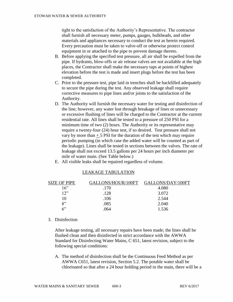
ETOWAH WATER & SEWER AUTHORITY
WATER MAINS & SANITARY SEWER 600-3 REV 6/2017
tight to the satisfaction of the Authority’s Representative. The contractor
shall furnish all necessary meter, pumps, gauges, bulkheads, and other
materials and appliances necessary to conduct the test as herein required.
Every precaution must be taken to valve-off or otherwise protect control
equipment in or attached to the pipe to prevent damage thereto.
B. Before applying the specified test pressure, all air shall be expelled from the
pipe. If hydrants, blow-offs or air release valves are not available at the high
places, the Contractor shall make the necessary taps at points of highest
elevation before the test is made and insert plugs before the test has been
completed.
C. Prior to the pressure test, pipe laid in trenches shall be backfilled adequately
to secure the pipe during the test. Any observed leakage shall require
corrective measures to pipe lines and/or joints to the satisfaction of the
Authority.
D. The Authority will furnish the necessary water for testing and disinfection of
the line; however, any water lost through breakage of lines or unnecessary
or excessive flushing of lines will be charged to the Contractor at the current
residential rate. All lines shall be tested to a pressure of 250 PSI for a
minimum time of two (2) hours. The Authority or its representative may
require a twenty-four (24) hour test, if so desired. Test pressure shall not
vary by more than + 5 PSI for the duration of the test which may require
periodic pumping (in which case the added water will be counted as part of
the leakage). Lines shall be tested in sections between the valves. The rate of
leakage shall not exceed 13.5 gallons per 24 hours per inch diameter per
mile of water main. (See Table below.)
E. All visible leaks shall be repaired regardless of volume.
LEAKAGE TABULATION
SIZE OF PIPE GALLONS/HOUR/100FT GALLONS/DAY/100FT
16” .170 4.080
12” .128 3.072
10 .106 2.544
8” .085 2.040
6” .064 1.536
3. Disinfection
After leakage testing, all necessary repairs have been made; the lines shall be
flushed clean and then disinfected in strict accordance with the AWWA
Standard for Disinfecting Water Mains, C 651, latest revision, subject to the
following special conditions:
A. The method of disinfection shall be the Continuous Feed Method as per
AWWA C651, latest revision, Section 5.2. The potable water shall be
chlorinated so that after a 24 hour holding period in the main, there will be a

ETOWAH WATER & SEWER AUTHORITY
WATER MAINS & SANITARY SEWER 600-4 REV 6/2017
free-chlorine residual of not less than 10 mg/L at all points in the system
when tested with standard orthotolidine solution.
B. The form of chlorine shall be a 1 percent made either sodium hypochlorite
or calcium hypochlorite which shall be measured and pumped into the
pipeline. Water must be flowing during the feeding operation and the
injection point must be located so that the flow of water will disperse the
chlorine throughout the pipeline. AWWA C651 requires the injection point
be located at a point not more than 10 feet from the point of connection to
the existing water supply. The chlorine should be fed at a constant rate such
that the water will have not less than 25 mg/L free chlorine. The table below
gives the amount of chlorine required for each 100 feet of various pipe
diameters to produce a 25 mg/L concentration.
Chlorination Tabulation
Pipe Diameter 100% Chlorine 1% Chlorine Solution
(in.)_ _____(lb.)____ ______(gal.)________
6 0.030 0.36
8 0.054 0.65
10 0.085 1.02
12 0.120 1.44
16 0.217 2.60
C. After 24 hours, the line shall be flushed until the chlorine content is not
more than 2.0 parts per million. When this step is completed, the Authority
will complete a bacteriological test after the 24 hour period. If the test fails,
the chlorination must be completed once again in the same manner as stated
earlier. If the samples show evidence of contamination upon testing, the
above procedure of disinfection shall be repeated until approved samples are
obtained. No connections shall be made to the existing system until all of
the samples have been tested and approved by the Authority.
D. The Contractor has the option of discharging the highly-chlorinated water
being flushed from the pipeline to the existing sewers (if available) or to
open areas where the discharge will not damage the roadbed or adjacent
property. De-chlorinating this water prior to discharge may be required. If
there is any possibility that the chlorinated discharge will cause damage to
the environment, then a neutralizing chemical shall be applied to the water
to be wasted to neutralize thoroughly the chlorine residual remaining in the
water. The highly chlorinated water shall not be discharged near any
streams, ponds, lakes or other bodies of water without being de-chlorinated.

ETOWAH WATER & SEWER AUTHORITY
WATER MAINS & SANITARY SEWER 600-5 REV 6/2017
The chlorine residual of water being disposed may be neutralized by treating the
water with one of the chemicals listed in the table below:
Chemical Required
Residual Sulfur Sodium Sodium Sodium
Chlorine Dioxide Bisulfite Sulfite Thiosulfate
Concentration (SO-2) (NaHSO-3) (Na-2SO-3) (Na2S2O3.5H2O)
Mg/L lb (kg) lb (kg) lb (kg) lb (kg)
_____________________________________________________________
1 0.8 (.36) 1.2 (.54) 1.4 (.64) 1.2 (.54)
2 1.7 (.77) 2.5 (1.13) 2.9 (1.32) 2.4 (1.09)
10 8.3 (3.76) 12.5 (5.67) 14.6 (6.62) 12.0 (5.44)
50 41.7 (18.91) 62.6 (28.39) 73.0 (33.11) 60.0 (27.22)
Amounts of chemicals required to neutralize various residual chlorine concentrations in
100,000 gal (378.5 m-3) of water.
4. All trenches shall be subject to compaction testing after backfilling and shall
meet the compaction requirements set forth in Section 510. All trenches failing
to meet compaction requirements shall be excavated and recompacted and
retested. This process shall continue until a passing test is achieved. All cost of
compaction testing shall be the responsibility of the Developer.
5. Bacteriological Testing: After final flushing and before the main is placed into
service, the Contractor shall assist the owner in collecting samples from the line to
have tested for bacteriological quality. Testing shall be performed by the Authority
at a laboratory certified by the State of Georgia. Re-chlorinate lines until the required
results are obtained. Provide the owner a minimum 24 hours notice to take samples.
Weekends and recognized holidays shall not be included as part of the 24 hour
notice. Contractors shall open all valves being a part of said system being tested
upon approval of bacteriological testing.
6. Guarantee against Taste, Odor or Color: The Contractor shall guarantee for a
period of one year against taste, odor, or color caused by pipe lining materials.
The Contractor shall, at his own expense, provide all necessary treatment to
counteract any such taste, odor or color. Bona fide complaints of taste, odor, or
color in the area served by the new mains shall be deemed caused by pipe lining
materials.
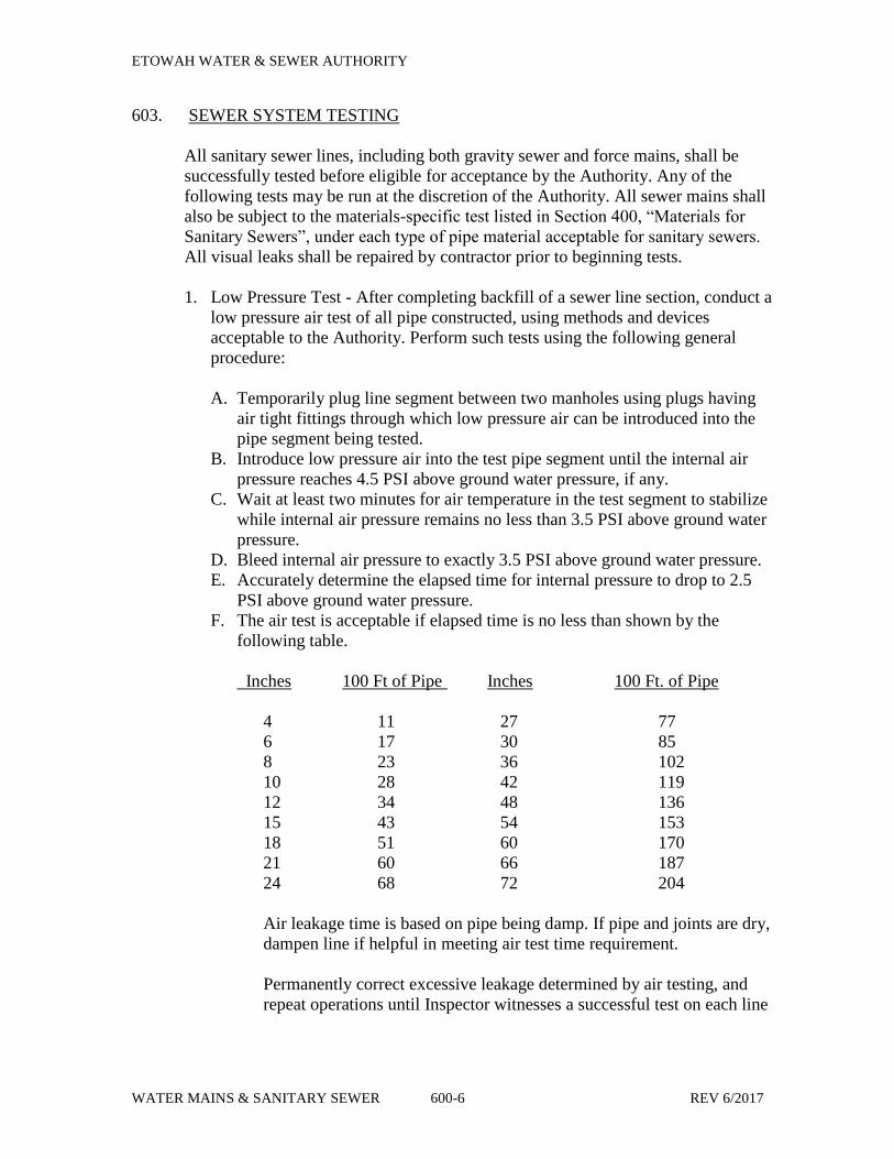
ETOWAH WATER & SEWER AUTHORITY
WATER MAINS & SANITARY SEWER 600-6 REV 6/2017
603. SEWER SYSTEM TESTING
All sanitary sewer lines, including both gravity sewer and force mains, shall be
successfully tested before eligible for acceptance by the Authority. Any of the
following tests may be run at the discretion of the Authority. All sewer mains shall
also be subject to the materials-specific test listed in Section 400, “Materials for
Sanitary Sewers”, under each type of pipe material acceptable for sanitary sewers.
All visual leaks shall be repaired by contractor prior to beginning tests.
1. Low Pressure Test - After completing backfill of a sewer line section, conduct a
low pressure air test of all pipe constructed, using methods and devices
acceptable to the Authority. Perform such tests using the following general
procedure:
A. Temporarily plug line segment between two manholes using plugs having
air tight fittings through which low pressure air can be introduced into the
pipe segment being tested.
B. Introduce low pressure air into the test pipe segment until the internal air
pressure reaches 4.5 PSI above ground water pressure, if any.
C. Wait at least two minutes for air temperature in the test segment to stabilize
while internal air pressure remains no less than 3.5 PSI above ground water
pressure.
D. Bleed internal air pressure to exactly 3.5 PSI above ground water pressure.
E. Accurately determine the elapsed time for internal pressure to drop to 2.5
PSI above ground water pressure.
F. The air test is acceptable if elapsed time is no less than shown by the
following table.
Inches 100 Ft of Pipe Inches 100 Ft. of Pipe
4 11 27 77
6 17 30 85
8 23 36 102
10 28 42 119
12 34 48 136
15 43 54 153
18 51 60 170
21 60 66 187
24 68 72 204
Air leakage time is based on pipe being damp. If pipe and joints are dry,
dampen line if helpful in meeting air test time requirement.
Permanently correct excessive leakage determined by air testing, and
repeat operations until Inspector witnesses a successful test on each line
ETOWAH WATER & SEWER AUTHORITY
WATER MAINS & SANITARY SEWER 600-7 REV 6/2017
segment; then remove nipple through manhole wall without disturbing
adjacent grout. Permanently caulk resulting hole watertight.
2. Mandrel Test - The mandrel testing shall be performed in accordance with
ASTM F 679. Procedure for testing PVC sewer pipe for maximum allowable
deflection:
A. The mandrel deflection test shall be conducted at the end of the one year
maintenance period.
B. Completely flush the line making sure the pipe is clean of any mud or trash
that would hinder the passage of the mandrel.
C. During the final flushing of the line, attach a floating block or ball to the end
of the mandrel pull rope and float the rope through the line. (A nylon ski
rope is recommended).
D. After the rope is threaded through line, connect the pull rope to the mandrel
and place the mandrel in the entrance of the pipe.
E. Connect a second rope to the back of the mandrel. This will enable the
mandrel to be retrieved if excessive deflection is encountered.
F. Remove all slack in the pull rope by gently pulling the rope at the far
manhole. After the slack has been removed, place a tape marker on the rope,
close to the pipe opening where the mandrel will exit. If mandrel encounters
excessive deflection, the marker will provide a means of measuring the
travel distance of the mandrel so that the deflected area can be located.
G. Draw mandrel through the sewer line.
H. An increasing resistance to pull is an indication of excessive deflection. If
this occurs measure the distance from the beginning marker on rope to
manhole. Locate section and replace bedding or pipe if visual examination
reveals damage.
I. Retest until acceptable.
3. Velocity Test - On lines installed at minimum grade at any time the Authority
suspects that a problem with flow will occur, we may ask for a velocity test of
the suspect section.
The contractor will add sufficient water at a point upstream of the suspect
section. After flow has reached a steady state, dye or some type of floating
object such as a ping pong ball, or fishing float, will be passed through the line.
The float will be timed as it passes through the section. Any line in which a
velocity of 2.0 feet per second cannot be obtained will not be acceptable.
4. T.V. Inspection - In the event that the Authority cannot see through the line
properly or conditions cause him to suspect that the line may be settled or
broken or that joints may not be made properly, he may direct that a T.V.
camera be passed through the line. A film of the inspection will be made and
submitted to the Authority.
ETOWAH WATER & SEWER AUTHORITY
WATER MAINS & SANITARY SEWER 600-8 REV 6/2017
Any discrepancies noted such as sagged pipes, broken pipes, bad joints, etc.,
will be dug up and will be corrected. Internal grouting to repair new lines will
not be allowed. After correction of the discrepancies, the line will be re-
inspected.
5. Infiltration Test - Infiltration of ground water in to sewer lines shall not exceed
25 gallons per inch of diameter per 24-hour day per mile of sewer.
Sewers shall be tested for infiltration in accordance with the requirements of
ASTM C969 or in the following manner, whichever is more stringent:
Following a period of heavy rain, a test for infiltration into the sewers shall be
made using suitable weirs in manholes selected by the Authority with upstream
sewers plugged as directed. Three measurements shall be made at one hour
intervals, and the average of three measurements shall be used to compute the
amount of infiltration. The Authority shall determine whether the ground is
sufficiently saturated and whether the amount of rainfall is of sufficient quantity
to permit the making of the test. In the event that sufficient rain does not occur
before the date set for the final inspection, the Contractor will be required to
conduct tests at any time during the one year maintenance period.
6. Exfiltration Test - When weather conditions will not permit infiltration testing
due to low ground water table, exfiltration tests may be used. Leakage, under a
5 feet head, shall not exceed 25 gallons/day per inch of pipe diameter per mile.
The exfiltration test may be required by the Authority instead of or in addition
to the infiltration test.
Manholes, which have been backfilled around, shall be tested for exfiltration.
The minimum test time duration is 1 hour. Manholes shall be filled with water
to the top of the ring. The maximum allowable exfiltration rate is two
gallons/foot of depth/24 hours/foot of manhole diameter.
7. Compaction Test - All trenches shall be subject to compaction testing after
backfilling and shall meet the compaction requirements set forth in Section 510.
All trenches failing to meet compaction requirements shall be excavated and
recompacted and restored. This process shall continue until a passing test is
achieved. All cost of compaction testing shall be the responsibility of the
Developer.
8. Force Main Pressure and Leakage Test
A. After all piping has been placed, the main shall be tested by the Developer’s
Contractor in the presence of the Authority or his designated representative
and test shall be continued until all leaks have been made tight to the
satisfaction of the Authority. The Contractor shall furnish all necessary
meters, pumps, gauges, bulkheads, and other materials and appliances
ETOWAH WATER & SEWER AUTHORITY
WATER MAINS & SANITARY SEWER 600-9 REV 6/2017
necessary to conduct the test as herein required. Every precaution must be
taken to valve-off or otherwise protect control equipment in or attached to
the pipe line to prevent damage thereto.
B. Before applying the specified test pressure, all air shall be expelled from the
pipe. If air release valves are not available at the high places, the Contractor
shall make the necessary taps at points of highest elevations before the test
is made and insert plugs before the test has been completed.
C. Prior to the pressure test, pipe laid in trenches shall be backfilled adequately
to secure the pipe during the test. Any observed leakage shall require
corrective measures to pipe lines and/or joints to the satisfaction of the
Inspector.
D. The Authority will furnish the necessary water for the testing of the force
mains; however. Any water lost through breakage of lines or unnecessary or
excessive flushing of lines will be charged to the Contractor at the current
residential rate. All lines shall be tested to a pressure of 250 PSI. Test
duration shall be two (2) hours. However, test pressure shall not exceed
pipe, valve and/or thrust-restraint design pressure. Test pressure shall not
vary by more than + 5 PSI for the duration of the test which may require
periodic pumping (in which case the added water will be counted as part of
the leakage). The rate of leakage shall not exceed 15 gallons per 24 hours
per inch diameter per mile of force main. (See Table below)
LEAKAGE TABULATION
SIZE OF PIPE GALLONS/HOUR/100 FT GALLONS/DAY/FT
16” .189 4.545
12” .142 3.409
10” .118 2.841
8” .095 2.273
6” .071 1.705
4” .047 1.136
3” .035 0.846
Any section of the line not meeting the above test shall have the leaks found and
corrected at once and re-tested until the leakage falls within the limits specified
above. Leakage testing must be witnessed and approved by the Authority.
604. ACCEPTANCE
1. Upon completion of all work items in a private development including water
and sewer lines, storm drains and all other utilities, the Authority will re-inspect
all phases of the development. During this inspection, the water/sewer mains
and appurtenances will be checked for any cuts lines, shifted hydrants,
adjustment of valve boxes and meter boxes, damaged manholes, and any
damage by other construction. The curbs will be checked for markings of line
valves and meters. Upon satisfactory completion of any discrepancies noted
ETOWAH WATER & SEWER AUTHORITY
WATER MAINS & SANITARY SEWER 600-10 REV 6/2017
during this inspection, the developer will begin the 12 month warranty /
maintenance period. At the beginning of the 12 month warranty / maintenance
period, all utility accounts associated with any pump and/or lift stations installed
for the development shall be transferred to the Authority. At the end of 12
months, the Authority will again re-inspect the entire development. When all
discrepancies have been corrected, the Authority will issue an acceptance letter
and will begin perpetual maintenance of the water and sewer system. At the end
of the 12 month warranty / maintenance period, all warranties associated with
pump and/or lift stations shall be transferred to the Authority.
2. At the discretion of the Authority, at the end of the 12 month warranty /
maintenance period, if condition as determined by the Authority warrant, a 24
month extended warranty can be required of the development owner. It shall be
the responsibility of the owner to ensure that all items associated with the water
and/or sewer system installation remain safe from harm from any entity working
within the development. In the event of any damage and/or failure to the water
and/or sewer system within the 24 month extended warranty period, the
development owner must pay for the item(s) replacement or repair. The
development owner will be notified in writing in 12 month intervals as to the
status of the water and/or sewer system within the development. At the end of
the 24 month extended warranty period, additional inspections and maintenance
will be required. Gravity sewer mains can be required to be cleaned. A T.V.
Inspection can be required for all gravity sewer mains. A mandrel test can be
required for all PVC gravity sewer mains. A pressure test and re-disinfection
can be required for all water mains.
605. “AS-BUILT” RECORD DRAWINGS
At the completion of the water/sewer lines and before the final construction
inspection, the contractor will furnish 2 black line copies of “As-Built” drawings of
the project. The copies must be developed from plans which have been corrected to
show all field changes made to the approved construction drawings. In the event
that the design engineer does not perform the field staking, the contractor must
furnish certification from a licensed engineer or surveyor attesting to the accuracy
of all valve, hydrant, bend and tee locations and all elevations, grades, manhole
locations and service locations. This certification and the certification of the
engineer preparing the “As-Builts” must be shown on the drawings. Hand marked
copies prepared by the contractor will not be accepted for “As-Builts”. The copies
must be sharp, clear, clean and legible and must be suitable for filming as
permanent records.
“As-Built” drawings shall include a site plan, construction plan sheets, and any
supplementary drawings and shop drawings. The “As-Built” drawings shall meet
the same requirements as plans for review. SEE SECTIONS 107 AND 205 FOR
MORE DETAILED INFORMATION.
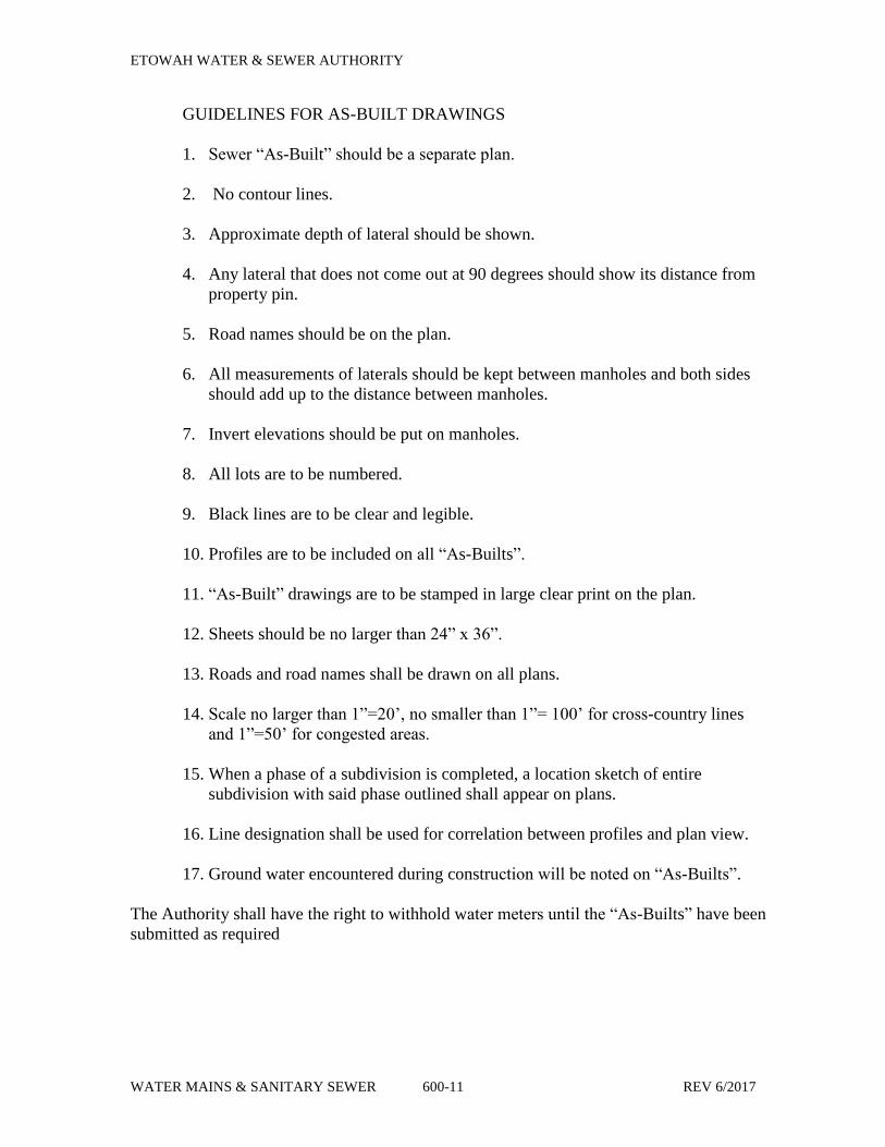
ETOWAH WATER & SEWER AUTHORITY
WATER MAINS & SANITARY SEWER 600-11 REV 6/2017
GUIDELINES FOR AS-BUILT DRAWINGS
1. Sewer “As-Built” should be a separate plan.
2. No contour lines.
3. Approximate depth of lateral should be shown.
4. Any lateral that does not come out at 90 degrees should show its distance from
property pin.
5. Road names should be on the plan.
6. All measurements of laterals should be kept between manholes and both sides
should add up to the distance between manholes.
7. Invert elevations should be put on manholes.
8. All lots are to be numbered.
9. Black lines are to be clear and legible.
10. Profiles are to be included on all “As-Builts”.
11. “As-Built” drawings are to be stamped in large clear print on the plan.
12. Sheets should be no larger than 24” x 36”.
13. Roads and road names shall be drawn on all plans.
14. Scale no larger than 1”=20’, no smaller than 1”= 100’ for cross-country lines
and 1”=50’ for congested areas.
15. When a phase of a subdivision is completed, a location sketch of entire
subdivision with said phase outlined shall appear on plans.
16. Line designation shall be used for correlation between profiles and plan view.
17. Ground water encountered during construction will be noted on “As-Builts”.
The Authority shall have the right to withhold water meters until the “As-Builts” have been
submitted as required