STANDARD SPECIFICATIONS FOR SANITARY … COUNTY SEWER SERVICE L.L.C. Post Office Box 1628 Foley,...
82
BALDWIN COUNTY SEWER SERVICE L.L.C. Post Office Box 1628 Foley, Alabama 36536 STANDARD SPECIFICATIONS FOR SANITARY SEWER SYSTEMS AND PUMPING STATION CONSTRUCTION REVISED FEBRUARY 19, 2014
Transcript of STANDARD SPECIFICATIONS FOR SANITARY … COUNTY SEWER SERVICE L.L.C. Post Office Box 1628 Foley,...

BALDWIN COUNTY SEWER SERVICE L.L.C. Post Office Box 1628
Foley, Alabama 36536
STANDARD SPECIFICATIONS
FOR
SANITARY SEWER SYSTEMS AND PUMPING
STATION CONSTRUCTION
REVISED FEBRUARY 19, 2014

2
STANDARD SPECIFICATIONS

3
DIVISION I
GENERAL INFORMATION AND REQUIREMENTS
1.01 BALDWIN COUNTY SEWER SERVICE’S STANDARD SPECIFICATIONS:
Copies of these Standard Specifications for Sanitary Sewers and Sewage Pumping Stations may be purchased from the offices of the Baldwin County Sewer Service, 14747 Underwood Road, Summerdale, AL 36580.
1.02 JURISDICTION:
These Standard Specifications shall apply to all proposed wastewater mains and pumping stations to be constructed by any person, firm or corporation and eventually be owned, operated or maintained by the Baldwin County Sewer Service, L.L.C. (BCSS).
• CITY OF SPANISH FORT Within the City of Spanish Fort, Alabama, BCSS Standard Specifications and the 10 State Standards Recommended Standards for Wastewater Facilities, latest edition, shall be required along with the City’s requirements and approvals for the construction and installation of wastewater mains and pumping stations.
1.03 PURPOSE:
These Standards and Specifications are adopted to establish minimum acceptable standards for the design and construction of wastewater collection and transmission facilities constructed by any person, firm or corporation and eventually to be owned, operated or maintained by the Baldwin County Sewer Service such facilities include gravity sewers, wastewater force mains, low pressure sewer systems, wastewater pump stations, and miscellaneous related appurtenances associated with any such systems or combinations thereof.
1.04 STANDARDS FOR PLANS:
Plans for sanitary sewers, and other appurtenances to the Baldwin County Sewer Service, L.L.C. sewer systems shall clearly define the work and all details shall be in conformance with the Standards. Baldwin County Sewer Service, LLC reserves the right to reject any plans that may on their face appear to conform to these specifications if the circumstances to which they are attempted to be applied are not best practice or they pose, in Baldwin County Sewer Service, LLC sole opinion too great an environmental hazard. A. Datum: All elevations on Plans are to NAVD 1988.
B. Locality Maps: Locality maps, showing the area of the county in which the project
is located, shall be included in all sets of Plans.

4
C. Review and Approval of Plans: Copies of all Plans must be submitted to the BCSS for approval prior to construction of any or all sewer system connected to BCSS sewer system.
1.05 PROJECT SUBMITTAL REQUIREMENTS
The following requirements apply to sanitary sewer facilities for all new sewer projects submitted to the BCSS for review, approval and maintenance by any person, firm or corporation. The sewer system for new projects will not be accepted unless the project sewer plans have been approved by Baldwin County Sewer Service or a Baldwin County Sewer Service representative in writing with reference to the project.
A. General:
1. Submit three sets of Plans that have an Alabama Registered Engineer’s Seal
and/or Signature and Registration Number affixed to the cover sheet of each set.
2. All material and construction shall be in strict conformance with the Standard
Specifications, latest revision.
3. The Baldwin County Sewer Service shall be furnished with permanent easements for sewer facilities not located in public right-of-way. The minimum width of easements shall be 20 feet. Easements shall be submitted in a form satisfactory to Baldwin County Sewer Service, LLC. Easement descriptions shall be prepared by a professional land surveyor licensed in the State of Alabama, and shall conform to the Minimum Surveying Technical standards for Land Surveying as adopted by the Alabama Board of Registration for professional engineers and land surveyors.
4. Permits required for the construction of sewer facilities located in public
right-of-way shall be obtained from the city, county or state and a copy delivered to the Baldwin County Sewer Service office. Permits are to be submitted and approved prior to the start of construction.
5. Where future phases of construction are planned, two copies of the Master
Development Plan shall be submitted to the Baldwin County Sewer Service office.
6. The Baldwin County Sewer Service, L.L.C. requires that sewer facilities serving new projects be designed and constructed such that they may be extended to serve any future development as a result of cutouts from or additions to the initial and subsequent development. The total cost of sewer facilities to serve such cutouts, subdivisions, or additions shall be at the expense of the developer. Should redesign of these facilities be required, the revised Plans shall be submitted for review and approval by Baldwin County Sewer Service, L.L.C.
Digital copies of all documents should be sent in State Plane as well as such other formats as may be specified herein.

5
BALDWIN COUNTY SEWER SYSTEM ACCEPTANCE CRITERIA
The following guidance is provided to assist Developers/Owners in securing Baldwin County Sewer Service, LLC acceptance of sewer projects. The user should verify that this guidance as dated above is current. Appropriate work plans and specifications shall describe all projects:
1. Plans and Specifications must be in accordance with Baldwin County Sewer Service, LLC requirements and bear the signature of an Alabama- registered Engineer.
2. Developer/Owner and Engineer must certify to Baldwin County Sewer Service,
LLC that project has been designed in accordance with and will be constructed in conformance with Baldwin County Sewer Service, LLC specifications and requirements.
3. Developer/Owner must secure any required SAHD, COE, etc. permits; if permit
is secured in the name of Baldwin County Sewer Service, LLC the Developer/Owner must bond Baldwin County Sewer Service, LLC for work under the permit.
The Developer/Owner or their Engineer should contact Baldwin County Sewer Service, LLC to secure a copy of current Baldwin County Sewer Service, LLC specifications and to discuss particular Baldwin County Sewer Service, LLC requirements as may be applicable to their project. Upon acceptable completion of the preceding items Baldwin County Sewer Service, LLC can approve the project construction documents. The Developer/Owner shall then schedule a Pre-construction Conference to be attended by the Developer/Owner, Engineer, Contractor and Baldwin County Sewer Service, LLC. A project schedule shall be provided to Baldwin County Sewer Service, LLC at the Conference. Upon satisfactory conclusion of the Pre-construction Conference Baldwin County Sewer Service, LLC can authorize the Developer/Owner to release the project for construction. The Developer/Owner is responsible for assuring that Baldwin County Sewer Service, LLC is provided 24 hours notice of initiation of any construction. It is the responsibility of the Developer/Owner and/or their Engineer to verify that all materials are supplied and installed in accordance with approved Plans and Specifications. All parties are reminded that Baldwin County Sewer Service, LLC will not inspect the work but reserves the right to enter upon the work at any time to verify conformance with project requirements.

6
Baldwin County Sewer Service, LLC can consider the project for acceptance upon satisfactory accomplishment of the following:
1. Completion of all work in accordance with approved project documents and Baldwin County Sewer Service, LLC requirements and provision of an Alabama-registered Engineer's written certification of same. (Sample Enclosed)
2. Provision of two (2) full-size sets of verifiable, discrete As-Built drawings of the
project and one set of 11 "x 17" As-Built drawings.
3. Provision of a Schedule of Values.
4. Provision of an acceptable Bill of Sale from the Developer/Owner to Baldwin County Sewer Service, LLC for the subject sewer facilities. (Sample Enclosed)
5. Provision of an acceptable blanket release of any/all liens on the project. (Sample
Enclosed)
6. Provision of copies of successful pressure tests charts on the project.
7. As may be applicable, provision of documentation that streets have been dedicated to the public and/or easements acceptable to Baldwin County Sewer Service, LLC have been granted. (Sample Enclosed)
8. Provision of Warranty/Maintenance Bond for all work in effect for one (1) year after
Final Acceptance of the project by Baldwin County Sewer Service, LLC. Surety must be acceptable to Baldwin County Sewer Service, LLC. (Sample Enclosed)
Please contact Baldwin County Sewer Service, LLC should there be any questions regarding the form of the required submissions or to obtain sample documents. A requirement surviving Final Acceptance by Baldwin County Sewer Service, LLC of the sewer facilities in the project shall bind the Developer/Owner to conduct an inspection of such facilities prior to the expiration of the Maintenance Bond (the Eleven-Month Inspection). Such Eleven- Month Inspection shall be attended by the Developer/Owner, Engineer and Baldwin County Sewer Service, LLC. The Engineer shall identify any project deficiencies for correction by the Developer/Owner and shall document it in a written report to Baldwin County Sewer Service, LLC. Such report will include a schedule for the remedy of any deficiencies. Should no deficiencies be noted or upon acceptable correction of noted deficiencies, the Engineer shall so certify to Baldwin County Sewer Service, LLC. Conformance with above guidance should expedite the approval and acceptance of a project by Baldwin County Sewer Service, LLC. The Developer/Owner should keep Baldwin County Sewer Service, LLC informed of progress throughout the prosecution of the project by provision of timely, written project schedules updates. Should Baldwin County Sewer Service, LLC be able to provide any assistance or information please come by our office or call us at 251-971-3022.

7
ENGINEER CERTIFICATION
This letter is our statement that sewer utilities for the referenced project have been designed in accordance with, and will be/have been constructed in conformance to the current Baldwin County Sewer Service, LLC Standard Specifications. ________________________________ Date ___________________ SEAL

8
GUARANTEE Developer/Owner ____________________________guarantees to Baldwin County Sewer Service, LLC that should Contractor and/or Bonding Company fail to perform the obligations set forth in that certain Maintenance Bond dated ________________________in favor of Baldwin County Sewer Service, LLC in the principal amount of $___________________________, then Developer/Owner shall perform said obligations. Effective ________________________ ______________________________ By______________________________ STATE OF ALABAMA COUNTY OF BALDWIN
I, the undersigned Notary Public in and for said State and County, hereby certify that
_____________________ whose name is signed to the foregoing instrument, and who is known
to me, acknowledged before me on this day that, being informed of the contents of the
instrument, he executed the same voluntarily on the day the same bears date.
Given under my hand and seal on this the _____ day of _____________, 20___.
_______________________________________
Notary Public-State of Alabama at Large
My Commission Expires:_______________

9
LIEN WAVER
The Undersigned, _______________________________________________________ certify that all bills regarding the Sewer System, for ____________________________ have been paid and the project is free and clear of any and all materials or mechanics liens.
_____________________________________
By___________________________________
Its___________________________________

10
SEWER EASEMENT STATE OF ALABAMA
COUNTY OF BALDWIN
KNOW ALL MEN BY THESE PRESENTS that _____________________ an Alabama Limited
Liability Company, the owner of the real property hereinafter described (hereinafter referred to as
the "Grantor"), for and in consideration of the sum of TEN AND NO/100THS ($10.00)
DOLLARS and other good and valuable considerations to Grantor in hand paid by BALDWIN
COUNTY SEWER SERVICE, L.L.C. (hereinafter sometimes referred to as "Grantee"), the
receipt and sufficiency of which is hereby acknowledged, does hereby GRANT, BARGAIN,
SELL AND CONVEY unto Grantee, BALDWIN COUNTY SEWER SERVICE, L.L.C., and its
successors and assigns, a perpetual right and easement to operate, and maintain sewage
transmission lines and sewage pumping and lift stations, and related appurtenances, and a right of
way in, on, across or under the ______________subdivision recorded in Baldwin County,
Alabama probate records, and more particularly described as follows on Exhibit A attached
hereto and made a part hereof by reference.
TOGETHER WITH all the rights and privileges necessary or convenient for the full
enjoyment or use thereof, including the right to operate, and maintain necessary appurtenances to
the same and the right of ingress and egress by the agents or employees of the Grantee and
Grantee’s successors or assigns, on, over, under and across said real property for the purpose of
installing, laying, constructing, inspecting, repairing, relocating and maintaining said sewage
transmission lines and sewage pumping and lift stations and other appurtenances to the same on
or under the aforesaid real property.
TO HAVE AND TO HOLD the same unto Grantee, BALDWIN COUNTY SEWER
SERVICE, L.L.C., and its successors and assigns forever.
Grantor, for Grantor's self and Grantor's heirs, successors and assigns, hereby covenants
and agrees with Grantee, and Grantee's successors and assigns, that Grantor is lawfully seized of

11
an indefeasible estate in fee simple in said premises, of which Grantor is in quiet and peaceable
possession; that said premises are free and clear of all encumbrances and that they will
FOREVER WARRANT and DEFEND said premises and the peaceable possession thereof,
including the right of Grantee to remove anything obstructing Grantee’s use of said premises,
unto Grantee, and Grantee's successors and assigns, against the lawful claims of all persons
whomsoever.
IN WITNESS WHEREOF, the Grantor, _____________________, has caused these presents to
be executed on this the _____ day of ___________,20__.
_____________________________
By:_______________________________(SEAL)
Its:________________________________
GRANTOR’S MAILING ADDRESS: GRANTEE’S MAILING ADDRESS: P.O. Box 1628 Foley, AL 36536 STATE OF ALABAMA COUNTY OF BALDWIN I, the undersigned Notary Public in and for said State and County, hereby certify that __________________, whose name is signed to the foregoing conveyance, and who is known to me, acknowledged before me on this day that, being informed of the contents of the conveyance, he executed the same voluntarily on the day the same bears date. Given under my hand and seal on this the _____ day of ______________, 20__. _______________________________________ Notary Public-State of Alabama at Large

12
“EXHIBIT A” TO SEWER EASEMENT

13
BILL OF SALE STATE OF ALABAMA
COUNTY OF BALDWIN
KNOW ALL MEN BY THESE PRESENTS that ___________________, an Alabama
Limited Liability Company, the owner of the Sewage Collection System hereinafter described
(hereinafter referred to as the "Grantor"), for and in consideration of the sum of TEN AND
NO/100THS ($10.00) DOLLARS and other good and valuable considerations to Grantor in hand
paid by BALDWIN COUNTY SEWER SERVICE, L.L.C. (hereinafter referred to as "Grantee"),
the receipt and sufficiency of which is hereby acknowledged, does hereby GRANT, BARGIN,
SELL, CONVEY, TRANSFER, SET OVER AND ASSIGN unto Grantee, BALDWIN
COUNTY SEWER SERVICE, L.L.C., and its successors and assigns, all that property pertaining
or related to the sewage collection system, including all sewage transmission lines, lift stations,
pumps, valves, and appurtenances, located on the real property located in Baldwin County,
Alabama described on the Exhibit A attached hereto and made a part hereof by reference (herein
referred to as the "Sewage Collection System");
TOGETHER WITH ALL AND SINGULAR the tenements, hereditaments and
appurtenances thereunto belonging or in anywise appertaining;
TO HAVE AND TO HOLD the Sewage Collection System unto the Grantee, BALDWIN
COUNTY SEWER SERVICE, L.L.C., and its successors and assigns forever.
Grantor covenants that it is the lawful owner of the Sewage Collection System lawfully
seized of an indefeasible estate in fee simple in same; that Grantor is in quiet and peaceable
possession of same; that same are free and clear of all liens and encumbrances, and that Grantor
will forever WARRANT AND DEFEND the title to the Sewage Collection System and the
peaceable possession thereof against all lawful claims and demands of all persons.
14
IN WITNESS WHEREOF, Grantor has caused these presents to be executed on the
_____ day of _______, 20__.
_________________________________
By:_________________________________(SEAL)
Its:__________________________________
STATE OF ALABAMA
COUNTY OF BALDWIN
I, the undersigned Notary Public in and for said State and County, hereby certify that
_____________________ whose name is signed to the foregoing instrument, and who is known
to me, acknowledged before me on this day that, being informed of the contents of the
instrument, he executed the same voluntarily on the day the same bears date.
Given under my hand and seal on this the _____ day of ______,20__.
_______________________________________
Notary Public-State of Alabama at Large

15
EXHIBIT A
TO
BILL OF SALE
16
DIVISION II – CONTRACT SPECIFICATIONS
SECTION 3
SPECIFICATIONS FOR SANITARY SEWERS 3.01 SCOPE
These general and detailed specifications form a part of the Contract documents and shall govern the handling and installation of sanitary sewer mains, manholes, service connections, and accessories described herein, and as shown on the accompanying plans. Existing sanitary sewer facilities are owned and operated by the Baldwin County Sewer Service, L.L.C., hereinafter referred to as "Owner". The construction methods employed in the placement of the sanitary sewer main and appurtenances shall be in accordance with current codes, practices and specifications of the Owner.
3.02 MATERIALS
A. PVC Pipe:
1. Gravity Pipe - Plastic gravity sewer pipe and fittings shall be unplasticized polyvinyl chloride (PVC), meeting or exceeding ASTM Specification D-3034 latest edition, Classification SDR 35. Pipe lengths shall not exceed 20 feet and provisions shall be made at each joint to accommodate expansion and contraction. All pipe and fittings shall be joined by means of an integral wall bell and spigot and sealed with a rubber gasket. This joint shall be capable of withstanding an internal hydrostatic pressure of 25 psi for one hour with no leakage. All pipes shall be green in color or have a green strip impregnated on pipe.
PVC seamless ribbed pipe shall meet the requirements of ASTM F-794 and Uni-Bell Uni B-9. The pipe shall be homogeneous and have a smooth interior with a solid cross-sectional rib exterior. Exterior ribs shall be open profile and perpendicular to the axis of the pipe to allow placement of the sealing gasket (whenever desired during construction) without field marking, beveling, sealing channels, gluing, welding, machining or additional cutting. The pipe stiffness at 5% deflection shall be a minimum of 46 psi when tested in accordance with ASTM D-2412. All pipes shall be green in color or have a green strip impregnated on pipe.
B. Ductile Iron Pipe shall be push-on joint. All pipe shall conform to ANSI/AWWA Specifications C151/A21.51Standard Pressure Classes. Pipe shall be made of Grade 60-42-10 iron. The interior of all pipe shall be cement-mortar lined as specified in ANSI Specification A 21.4 and the interior and exterior shall receive an approved bituminous coating. Pipe shall be centrifugally cast with minimum wall thickness associated with Pressure Class 350. All such pipe shall have a green strip impregnated or otherwise running the length of said pipe.
17
The pressure rating, metal thickness, net weight of pipe without lining, length of pipe, name of manufacturer, and letters "D.I." shall be clearly marked on each length of pipe.
Where it is necessary to cut new ductile iron pipe or existing cast iron pipe, in no case shall it be cut by burning, but shall be cut by saw, cutter, abrasion or other approved means.
Ductile iron fittings shall be as specified in Division III, Section 3, Paragraph 3.04 B, herein.
C. Transitions for dissimilar pipes up to 12 inch O.D. for gravity sewer mains shall
be made by use of a flexible coupling with an adapter busing and stainless steel band and clamps. Transitions from dissimilar type pipe over 12 inch O.D. shall be made by use of approved adapters specifically designed for this purpose. Joining of dissimilar pipes with concrete collars shall not be permitted except at such places where specifically approved.
D. Manhole Steps shall be steel rods encased in polypropylene plastic and shall be
of the type manufactured by M.S. Industries, Inc., or approved equal. Steps shall be Type PS-1 - PF, for precast manholes and Type PS-1-B or PS-2-BG for brick manholes. Steps shall conform to the requirements of A.S.T.M. C-478.
E. Brick shall be hard-burned common brick meeting ASTM Specification Number
C-32, Grade NA or concrete brick meeting ASTM Specification Number C-55, Grade A. Brick shall be nominal 2"x4"x8".
F. Cast Iron Frames and Covers shall conform to the drawings in all essentials of
design. All castings shall be made of clean, even grain, tough gray cast iron. The quality of iron in the castings shall conform to the current A.S.T.M. Specification A-48 for Class 30 Gray Iron Castings. Frames and covers shall weigh not less than that shown on the drawings. The castings shall be smooth, true to pattern and free from projections, sand holes or defects. The portion of the frame and cover which forms the cover seat shall be machined so that no rocking of the cover is possible the castings shall be coated with coal tar pitch varnish.
On paved streets, the frame and cover shall be set flush with the finished grade and in the plane of the paved surface. In other locations, they shall be set to the grades determined in the field by the Engineer.
G. Class "A" Concrete shall have a minimum compressive strength at twenty-eight
days of 3,000 pounds per square inch satisfying pertinent paragraphs of Alabama Highway Department Specifications for Class "A" concrete.
H. Mortar shall be in accordance with Section 611 of the Alabama Highway
Department's Standard Specifications. Mortar for inverts and seals in sewer structures shall be a 1:3 Type II Portland Cement Sand Mix, provided that hydrated lime or mortar mix is substituted for, but not to exceed ten percent (10%) by weight of the cement.
18
3.03 INSPECTION
A. Material at Factory: All materials are subject to inspection and approval at the plant of the manufacturer.
All material shall meet the requirements specified and suppliers of pipe and fittings shall furnish, in triplicate, to the Engineer, an affidavit stating that all pipe and fittings furnished under this contract conform to the requirements as set forth in these specifications.
B. Field Inspection: All pipe and accessories shall be laid, jointed and backfilled in the presence of the Engineer. The Contractor shall notify the Engineer in charge of construction at least twenty-four (24) hours in advance before any section of sewer is checked with the "GO-NO-GO" mandrel. The Engineer shall give a certified certificate to the Owner that the pipe after inspection meets the Owner's specifications.
C. Disposition of Defective Material: All material found during the progress of the
work to have flaws, or other defects will be rejected and the Contractor shall promptly remove from the site of the work such defective material.
3.04 HANDLING PIPE AND ACCESSORIES
A. Care: Pipe, fittings, valves, and other accessories shall, unless otherwise directed, be unloaded at the point of delivery, hauled to and distributed at the site of the project by the Contractor; items shall at all times be handled with care to avoid damage. In loading and unloading, items shall be lifted by hoists or slid, or rolled on sideways in such manner as to avoid shock. Under no circumstances shall they be dropped. Pipe handled on sideways must not be skidded or rolled against pipe already on the ground.
B. At Site of Work: In distributing the material at the site of the work, each piece
shall be unloaded opposite or near the place where it is to be laid in the trench. Pipe shall be retained in shipping cradles when stored along the right-of-way until pipe is ready to be laid. In no case will removal of pipe from cradles be permitted more than 24 hours in advance of placing in trench.
C. Care of Pipe Coating: Pipe shall be handled in such manner that a minimum
amount of damage to the coating will result. Damaged coating shall be repaired in accordance with the pipe manufacturer's recommendations.
D. Bell Ends (Direction): Pipe shall be placed on the site of the work parallel with
the trench alignment and with bell ends facing the direction in which the work will proceed.
E. Pipe Kept Clean: The interior of all pipe, fittings, and other accessories shall be
kept free from dirt and foreign matter at all times. Each pipe shall have a swab run through it until all foreign matter has been removed.

19
3.05 ALIGNMENT AND GRADE
A. General: All pipe shall be laid and maintained to the required lines and grades; with fittings at the required locations for connecting existing service laterals; and with joints centered and spigots home.
B. Protecting Underground and Surface Structures: Temporary support, adequate
protection and maintenance of all pipelines, underground and surface utility structures, drains, sewers and other obstructions encountered in the progress of the work shall be furnished by the Contractor at his own expense. Existing side drain pipes and curbs and gutters that interfere with the Contractor's operation shall be removed and replaced in kind at no additional cost to the Owner.
C. Sub-Surface Explorations: Existing underground pipes and structures have been
shown on the plans from existing records for the contractor's convenience. The contractor shall verify locations of existing underground pipes and structures through examination of all available records and shall make all explorations and excavations necessary to determine the location of existing pipelines, service connections, or other underground structures. This investigation shall be made in advance of any pipe laying and any damage to existing pipelines, service connections or underground structures shall be repaired by the Contractor at no additional cost to the Owner.
3.06 EXCAVATION AND PREPARATION OF TRENCH
A. Description: The trench shall be dug to the alignment and depth required and only a minimum distance in advance of pipe laying. The trench shall be so drained that workmen may work therein efficiently.
B. Width: The trench width may vary with and depend upon the depth of trench and
the nature of the excavated material encountered, but in any case shall be of ample width to permit the pipe to be laid and jointed properly and the backfill to be placed and compacted properly. The minimum width of trench shall be as approved by the Engineer; the maximum clear width of trench shall be not more than two and one-half (2-1/2) feet greater than the pipe diameter at the trench bottom, unless otherwise specified by the latest OSHA requirements.
C. Pipe Foundation in Good Soil: The trench, unless otherwise specified, shall have
a flat bottom conforming to the grade to which the pipe is to be laid. The pipe shall be laid upon sound soil cut true and even so that the barrel of the pipe will have a bearing for its full length.
D. Correcting Faulty Grade: Any part of the trench excavated below grade shall be
corrected with approved material, thoroughly compacted.
E. Pipe Foundation in Poor Soil: When the bottom uncovered at subgrade is soft and cannot support the pipe, a further depth as noted on the plans shall be excavated and refilled to pipe foundation grade as required. Material used for backfill to the elevation of the pipe will be paid for separately.

20
F. Bell Holes Required: Bell holes of ample dimensions shall be dug in earth trenches at each joint to permit the joining to be made properly.
G. Bracing: When the material through which the trench is excavated tends to fall
in, run, or cave, the sides of the trench shall be braced, open sheeted or close sheeted, to an extent necessary to protect the pipe being laid. Such sheeting shall remain in place until the backfill is carried to a point at least two (2) feet above the top of the pipe. The Contractor shall exercise every precaution in removing the sheeting in order to avoid damaging the pipe. Should there be evidence that the removal of sheeting would damage the pipe, the sheeting shall be left in place and no additional compensation will be allowed therefor. The top of sheeting left in place shall be at least twelve (12) inches below natural ground. The Contractor shall place such other sheeting and/or bracing as he and his surety deem necessary to protect workmen and the public.
H. Care of Surface Material for Re-Use: If local conditions permit their re-use, all
surface materials suitable for re-use in restoring the surface shall be kept separate from the general excavation material.
I. Manner of Piling Excavated Material: All excavated material shall be piled in a
manner that will not endanger the work and that will avoid obstructing sidewalks and driveways. Gutters shall be kept clear, or other satisfactory provisions made for street drainage. Also, storm drains shall be kept clear.
J. Trenching by Machine or by Hand: The use of trench-digging machinery will be
permitted except in places where operation of same will cause damage to trees, building, or existing structures above or below ground, in which case hand methods shall be employed.
K. Barricades, Guards and Safety Provisions: To protect persons from injury and to
avoid property damage, adequate barricades, and construction signs in accordance with Section G of the Alabama Manual on Uniform Traffic Control Devices, shall be placed and maintained during the progress of the construction work and until it is safe for traffic to use the trenched highway. Rules and regulations of the local authorities and OSHA regarding safety provisions shall be observed.
L. Traffic and Utility Controls: Excavations for pipe laying operations shall be
conducted in a manner to cause the least interruption to traffic. Where traffic must cross open trenches, the Contractor shall provide suitable bridges at street intersections and driveways. Hydrants under pressure, valve pit covers, valve boxes, curb stop boxes, fire or police call boxes, or other utility controls shall be left unobstructed and accessible during the construction period.
M. Flow of Drains and Sewers Maintained: Adequate provisions shall be made for
the flow of sewers, drains and water courses encountered during construction, and the structures which may have been disturbed shall be satisfactorily restored upon completion of the work. No separate compensation will be made the Contractor for removal, replacement and restoration of existing facilities.

21
N. Property Protection: Trees, fences, poles, and all other property shall be protected unless their removal is authorized; and the Contractor shall satisfactorily restore any property damaged. No separate compensation will be made the Contractor for removal of existing obstructions, including abandoned concrete slabs, within the roadway right of way.
O. Plugging Dead Ends: Dead ends of abandoned or new lines shall be capped or
plugged as shown on the plans. 3.07 PIPE LAYING
A. Manner of Handling Pipe and Accessories into Trench: Proper implements, tools, and facilities shall be provided and used by the Contractor for the safe and convenient prosecution of the work. All pipe, fittings, and accessories shall be carefully lowered into the trench, piece by piece, by means of derrick, ropes or other suitable tools or equipment, in such manner as to prevent damage to pipe or pipe coating. Under no circumstances shall pipe or accessories be dropped into the trench.
B. Pipe Kept Clean: All foreign matter or dirt shall be removed from the inside of
the pipe before it is lowered into its position in the trench and it shall be kept clean by approved means during and after laying.
C. Laying the Pipe: The pipes and fittings shall be so laid in the trench that after the
sewer is completed, the interior surface of the bottom thereof shall conform accurately to grade and alignment. Sewers shall be laid in the direction opposite to the direction of flow with spigot ends of pipe pointing down grade.
PVC pipe shall be installed in accordance with ASTM D-2321, latest edition. Deflection of PVC pipe after installation and backfill shall exceed 5%. All PVC sewer lines shall be tested for initial diametric deflection not less than 30 days following installation and backfill using a "GO-NO-GO" type mandrel or other approved method. Pipe found to be deflected more than 5% shall be replaced at the Contractor's expense.
While the pipes and fittings are being laid between adjoining manholes in each straight or working section of the sewer, a round circle of light from the finished or other end of the section shall remain constantly in plain view throughout the entire length of such section and shall show the true character and shape of the interior surface of the sewer. The same test shall be applied for each working section after the sewer is completed in all respects and before it is accepted. On completion of sewer lines, the Contractor shall float a wooden ball through each main line. In each case, the size of the ball shall be one inch (1") in diameter less than the sewer through which it is to go.
The Contractor shall pump, bail, or otherwise remove any water which may be found or may accumulate in the trenches and shall perform all work necessary to keep them clear of water while pipe laying is in progress.
Whenever pipe laying is stopped for the night or for any other cause, the end of the pipe shall be securely closed with a stopper to prevent the entrance of water,
22
mud, or other obstructing matter, and shall be secured in such manner as to prevent the end pipe from being dislodged by sliding or other movement of the backfilling.
After placing a length of pipe in the trench, the joint shall be held around the bottom of the spigot, so that it will enter the bell as the pipe is shoved into position.
The spigot shall be centered in the bell, the pipe shoved into position, and brought into true alignment; it shall be secured there with earth carefully tamped under and on each side. Care shall be taken to prevent dirt from entering the joint space, and joints between individual pipes shall be made watertight.
Four-inch (4") diameter tees or wyes shall be inserted in the sewer lines for connection of all existing sewer laterals. The sewer line shall be cut in a neat and workmanlike manner for insertion of tees or wyes. Tees or wyes shall be rolled 45 degrees in the vertical plane or as dictated by existing lateral elevations. All tees or wyes shall be temporarily closed by means of plugs and properly referenced for recovery and connection of existing sewer laterals upon completion of the sewer main construction.
In every instance where pipe enters or leaves a manhole, a fitting shall be provided which shall accommodate expansion and contraction of the pipe, release strain on the pipe (caused by differential settlement between pipe and manhole) and provide a rubber ring water seal between pipe and manhole. Where indicated, fittings shall also be provided for stubouts for future connections and stubouts shall be sealed with plug fittings. Fittings shall be included in the price of the manholes.
D. Connecting Existing Sewer Laterals: Wherever existing sewer laterals are
intercepted by the excavation for the new sewer, the existing connection shall be maintained temporarily to the old sewer until the particular section of new sewer is completed and tested, then the house lateral shall be cut at the required location and connected to the new sewer through the tee or wye placed in the sewer line for that purpose. No separate compensation shall be allowed the Contractor for connecting the existing lateral to new main.
Sewer laterals shall be constructed of four-inch (4") SDR 35 PVC pipe. All tees or wyes for sewer laterals shall be SDR 35 PVC.
Where existing lateral elevations dictate the rolling of tees or wyes 45 degrees in the vertical plane, the sewer lateral pipe shall be cut and a 45-degree bend provided for vertical alignment of the new and existing sewer lateral.
The Contractor shall take particular care to keep sewer laterals clean of all dirt, mud and other obstructing matter.
No separate compensation shall be allowed the Contractor for work and materials required in maintaining temporary service of the existing sewer lateral to the old sewer line nor for handling sewage while connecting the existing lateral to the new main.
23
All pipe for force mains shall be marked within the right of way using a metalized tape buried between 18 and 24 inches below the ground surface. Tape shall be 3" wide minimum, Terra Tape, as manufactured by Griffolyn Company, Inc., Detectatape as manufactured by Allen Systems, Inc., or an approved equal. The pipe trench shall be backfilled to approximately 24 inches below the ground surface and then metalized tape shall be placed flat over top of pipe. Backfill shall be carefully placed to a depth of 3 inches by hand to assure that the tape is secured in place over the pipe. It is the intent of this paragraph to provide a means to locate sewer laterals using standard pipe location equipment.
3.08 EMBEDMENT OF PVC GRAVITY SEWER PIPE
A. Embedment:
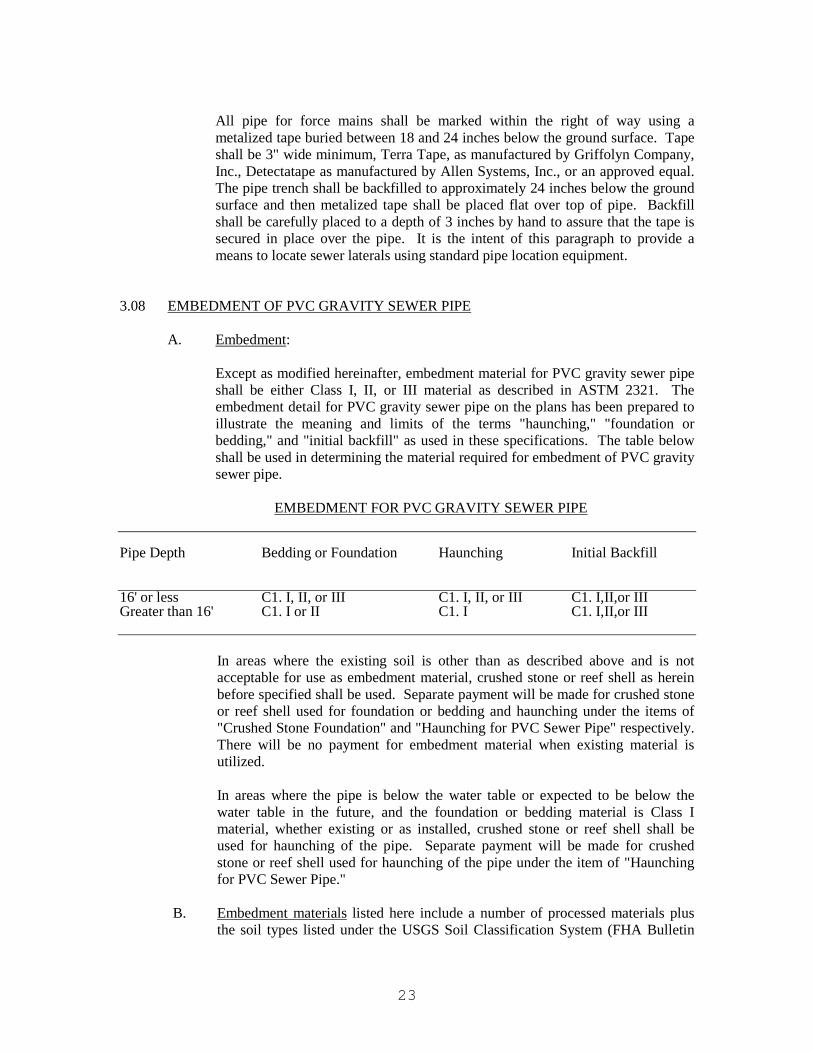
Except as modified hereinafter, embedment material for PVC gravity sewer pipe shall be either Class I, II, or III material as described in ASTM 2321. The embedment detail for PVC gravity sewer pipe on the plans has been prepared to illustrate the meaning and limits of the terms "haunching," "foundation or bedding," and "initial backfill" as used in these specifications. The table below shall be used in determining the material required for embedment of PVC gravity sewer pipe.
EMBEDMENT FOR PVC GRAVITY SEWER PIPE Pipe Depth Bedding or Foundation Haunching Initial Backfill 16' or less C1. I, II, or III C1. I, II, or III C1. I,II,or III Greater than 16' C1. I or II C1. I C1. I,II,or III
In areas where the existing soil is other than as described above and is not acceptable for use as embedment material, crushed stone or reef shell as herein before specified shall be used. Separate payment will be made for crushed stone or reef shell used for foundation or bedding and haunching under the items of "Crushed Stone Foundation" and "Haunching for PVC Sewer Pipe" respectively. There will be no payment for embedment material when existing material is utilized.
In areas where the pipe is below the water table or expected to be below the water table in the future, and the foundation or bedding material is Class I material, whether existing or as installed, crushed stone or reef shell shall be used for haunching of the pipe. Separate payment will be made for crushed stone or reef shell used for haunching of the pipe under the item of "Haunching for PVC Sewer Pipe."
B. Embedment materials listed here include a number of processed materials plus
the soil types listed under the USGS Soil Classification System (FHA Bulletin
24
No. 373). These materials are grouped into five broad categories according to the suitability for this application:
(1) Class I - Angular, 6 to 40 mm (1/4 to 1-1/2 inch), graded stone, including
a number of fill materials that have regional significance such as coral, slag, cinders, crushed stone, and crushed shells.
(2) Class II - Coarse sand and gravel with maximum particle size of 40 mm
(1-1/2 inch), including variously graded sands and gravel containing small percentages of fines, generally granular and non-cohesive, either wet or dry. Soil types GW, GP, SW and SP are included in this class.
(3) Class III - Fine sand and clayey gravel, including fine sands, sand-clay mixtures, and gravel-clay mixtures. Soil types GM, GC, SM and SC are included in this class.
(4) Class IV - Silt, silty clays, and clays including inorganic clays and silts of
medium to high plasticity and liquid limits. Soil types MH, ML, CH, and CL are included in this class. These materials are not acceptable for bedding, haunching, or initial backfill.
(5) Class V - This class includes the organic soils OL, OH, and PT as well as
soils containing frozen earth, debris, rocks larger than 40 mm (1-1/2 inch) in diameter, and other foreign materials. These materials are not acceptable for bedding, haunching, or initial backfill.
3.09 BACKFILL
A. Backfilling: Backfill material shall be free from rocks or boulders and shall be deposited in the trench simultaneously on both sides of the pipe for the full width of the trench in four-inch (4") layers to an elevation of at least 6 inches above the top of the barrels of the pipe. Material shall be dry enough to compact to the equivalent density of the surrounding earth. If too dry the backfill material shall be dampened. Backfill containing broken pavement shall not be used. Backfill shall be in four-inch (4") layers, tamped with hand tamps, to 6 inches above the top of the pipe. The remainder of the trench shall be backfilled in six-inch (6") layers and tamped with a mechanical tamper specifically manufactured for compacting backfill.
B. Deficiency of Backfill, by Whom Supplied: Any deficiency in the quantity of
material for backfilling the trenches, or for filling depressions caused by settlement, shall be supplied by the Contractor at no cost to the Owner.
C. Backfill Under Pavement: Backfill under all existing or proposed pavement for
street, driveways, sidewalks, or roadways up to the existing grade or proposed grade, whichever is lower, and to a minimum distance of ten (10) feet adjacent to existing or proposed pavement, shall be as specified elsewhere herein.
25
3.10 PRECAST CONCRETE MANHOLES
Precast manholes shall conform to the requirements of A.S.T.M. C-478. Type II Portland Cement along with calcareous aggregate or limestone shall also be used in the construction of the manholes in lieu of lesser corrosive resistant materials. The top section of manholes 6 feet or more in depth shall be eccentric cone sections. The top section of manholes less than 6 feet in depth shall be flat concrete slabs.
A. Manhole bottoms shall be either cast in place concrete or integral with the lower
section of riser walls as hereinafter specified.
1. Poured in place bottoms shall be a minimum of 8" thick and shall be not less than 12 inches in diameter larger than the outside of the riser section. The top of the manhole bottom shall be not less than 3 inches below the lowest pipe invert. The invert of the manhole shall be built up with cement grout as shown for brick manholes.
Special care shall be taken to assure a good seal around the manhole bottom. The joint between the bottom and walls shall be sealed on the outside with grout.
2. Bottoms integral with side walls shall be set on a prepared bed of not less
than 6 inches of crushed stone or an approved equal. The bed shall be accurately shaped to fit the manhole bottom to assure uniform bearing over the entire manhole bottom. The invert of the manhole shall be built up with cement grout as shown for brick manholes.
B. Joints in riser and cone sections shall have rubber gaskets or an approved equal.
C. Pipe cutouts shall be sealed with non-shrink, calcareous, grout or an approved
equal after pipe stubouts are in place.
D. Every manhole shall be fully and completely built as the work progresses and as each is reached.
E. Manholes shall be neatly and accurately built, according to the plans, and
specifications, of proper materials and in a workmanlike manner.
F. The invert and bottom curves of all manholes shall be neatly and accurately constructed of a calcareous cement mix and so formed as to facilitate the entrance and flow of sewage over them.
G. Steps shall be placed in manholes and shall be spaced not more than 15 inches
vertically and shall be so arranged that the lowest step shall not be more than two (2) feet above the bench. The top step shall not be more than 3 inches below the manhole frame.
H. The Contractor shall furnish and properly set in mortar to line and grade all cast
iron covers and frames. Brick stacks not more than 12 inches and not less than 6 inches in total height shall be used to adjust manhole covers and frames to the proper grade where tops of manholes are to be flush with existing or proposed

26
ground or streets or where directed. Brick stacks will not be required where tops of manholes are to be above the existing or proposed ground surface.
I. When required, stubouts of required size shall be built into manholes to receive
either present or future branch lines. Where it is not intended to construct the branch lines at once, the stubouts thus inserted must be securely closed in such a manner that future connections can be made without breaking the stubout.
J. Where manholes intercept existing sewer mains or laterals connected to existing
manholes, the Contractor shall keep the sewer main or lateral service to the existing manhole intact until the next adjacent section of new sewer is completed and approved. The laterals or mains shall then be broken and fed to the new sewer laterals or mains and the dead end of the abandoned mains or laterals plugged with an approved plug.
3.11 CONNECTIONS AT MANHOLES
Where indicated on the plans or where directed by the Engineer in the field, connections shall be neatly and accurately constructed of proper materials in a workmanlike manner, including the reconstruction of the manhole wall. Connections shall be made at the manhole bottom invert, where possible, and shall in no case be more than two (2) feet above the manhole bottom invert without a drop connection.
Where indicated on the plans or instructed in the field, drop connections shall be neatly and accurately constructed of proper materials and in a workmanlike manner, in strict accordance with the details shown on the plans. Piping for drop connections shall be ductile iron except where noted otherwise on the drawings.
In every instance where pipe enters or leaves manhole, a fitting shall be provided which shall accommodate expansion and contraction of the pipe, release strain on the pipe (caused by differential settlement between pipe and manhole) and provide a rubber ring water seal between pipe and manhole. Where indicated, fittings shall also be provided for stubouts for future connections, and stubouts shall be sealed with PVC plug. Fittings shall be included in the unit price for the manholes or the manhole connection, as appropriate.
3.12 INFILTRATION
Leakage into the completed sewer main shall not exceed 100 gallons per mile of sewer per inch of inside diameter of the sewer per 24 hours in any section between successive manholes. The amount of leakage shall be measured by a suitable weir or other device. All equipment and labor for measuring the infiltration shall be furnished by the Contractor. If the infiltration exceeds the amount specified above, the Contractor shall make the necessary corrections to bring it within the acceptable limits. All visible leaks or points of infiltration shall be repaired even though the infiltration is below the maximum specified.
3.13 CLEAN-UP
Where these operations are on City, State, County or Private Property, the job shall be kept clean at all times. Loose dirt shall not be allowed to clog ditches or cover

27
sidewalks. Soft clay or other undesirable material removed from the trenches shall be removed from the streets, sidewalks or ditches. The Owner reserves the right to demand that the Contractor's forces be diverted to this clean-up at any time that condition of streets, driveways, sidewalks, or private property warrants such diversion. Such diversion of Contractor's forces will not entitle the Contractor to any extension of time or additional compensation.
3.14 TESTING OF SANITARY SEWERS
A. General: On all sanitary sewer lines, including laterals, wherever possible and practical, the Contractor shall conduct a line acceptance test. The test shall be conducted after the pipe has been backfilled and the cost of testing shall be included in other items of work. Equipment to be used in making the test shall be specifically designed for this purpose. Air tests for gravity sewers shall include the use of Cherne Air-Lock Equipment, NB Products, Inc. equipment, or approved equal. The Engineer or Baldwin County Sewer Service, LLC shall be advised at least 48 hours before tests are conducted.
B. Procedures: Sanitary sewer lines shall be tested by the following methods:
1. Gravity Sanitary Sewer Lines
a. All pneumatic plugs shall be seal tested before being used in the
actual test installation. One length of pipe shall be laid on the ground and sealed at both ends with the pneumatic plugs to be checked. Air shall be introduced into the plugs to 25 psig. The sealed pipe shall be pressurized to 5 psig. The plugs shall hold this pressure without bracing and without movement of the plugs out of the pipe.
b. After a manhole to manhole reach of pipe has been backfilled and
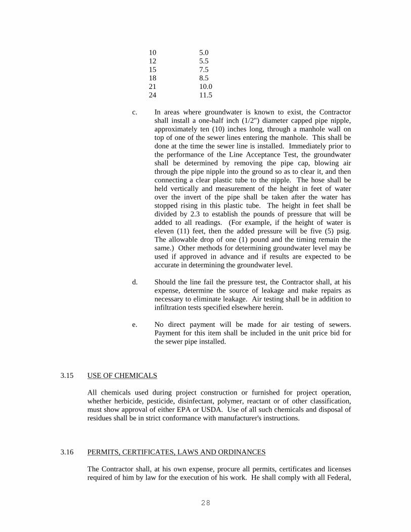
cleaned, and the pneumatic plugs are checked by the above procedure, the plugs shall be placed in the line at each manhole and inflated to 25 psig. Low pressure air shall be introduced into this sealed line until the internal air pressure reaches 4 psig greater than the average back pressure of any groundwater that may be over the pipe. At least two minutes shall be allowed for the air pressure to stabilize. After the stabilization period (3.5 psig minimum pressure in the pipe), the air hose from the control panel to the air supply shall be disconnected. The test time required in minutes for the pressure to decrease from 3.5 to 2.5 psig (greater than the average back pressure of any groundwater that may be over the pipe) shall not be less than the time shown for the given diameters in the following table:
Pipe Dia. in Inches Minutes
4 2.0 6 3.0 8 4.0
28
10 5.0 12 5.5 15 7.5 18 8.5 21 10.0 24 11.5
c. In areas where groundwater is known to exist, the Contractor
shall install a one-half inch (1/2") diameter capped pipe nipple, approximately ten (10) inches long, through a manhole wall on top of one of the sewer lines entering the manhole. This shall be done at the time the sewer line is installed. Immediately prior to the performance of the Line Acceptance Test, the groundwater shall be determined by removing the pipe cap, blowing air through the pipe nipple into the ground so as to clear it, and then connecting a clear plastic tube to the nipple. The hose shall be held vertically and measurement of the height in feet of water over the invert of the pipe shall be taken after the water has stopped rising in this plastic tube. The height in feet shall be divided by 2.3 to establish the pounds of pressure that will be added to all readings. (For example, if the height of water is eleven (11) feet, then the added pressure will be five (5) psig. The allowable drop of one (1) pound and the timing remain the same.) Other methods for determining groundwater level may be used if approved in advance and if results are expected to be accurate in determining the groundwater level.
d. Should the line fail the pressure test, the Contractor shall, at his
expense, determine the source of leakage and make repairs as necessary to eliminate leakage. Air testing shall be in addition to infiltration tests specified elsewhere herein.
e. No direct payment will be made for air testing of sewers.
Payment for this item shall be included in the unit price bid for the sewer pipe installed.
3.15 USE OF CHEMICALS
All chemicals used during project construction or furnished for project operation, whether herbicide, pesticide, disinfectant, polymer, reactant or of other classification, must show approval of either EPA or USDA. Use of all such chemicals and disposal of residues shall be in strict conformance with manufacturer's instructions.
3.16 PERMITS, CERTIFICATES, LAWS AND ORDINANCES
The Contractor shall, at his own expense, procure all permits, certificates and licenses required of him by law for the execution of his work. He shall comply with all Federal,

29
State, or Local laws, ordinances, or rules and regulations relating to the performance of the work.
3.17 UNDERGROUND UTILITIES
The plans show certain features of topography, and certain underground utilities, but they do not purport to show in complete detail all such lines or obstructions. Such topography and notes on the plans were inserted from records available and are for the Contractor's convenience only, and shall not be used as the basis for claims of extra compensation. Whenever necessary to determine the location of existing pipes, valves, or other underground structures, the Contractor shall examine all available records and shall make all explorations and excavations for such purpose. Any damage to existing facilities resulting from the Contractor's operations shall be immediately repaired by the Contractor at no cost to the Owner.
3.18 ABANDONED SEWER MAINS AND APPURTENANCES
The Owner shall retain ownership of all salvageable material removed from the project. The Contractor shall neatly store these materials at locations designated by the Engineer. The cost of removing and storing these materials as directed will be borne by the Contractor with no direct payment. Any material deemed unsalvageable by the Engineer or that is not wanted by the Owner shall become the property of the Contractor and removed from the work site for no additional compensation.
3.19 PUMPING AND BYPASSING
No sewage or solids shall be dumped, bypassed or allowed to overflow into streets, streams, ditches, catch basins or storm drains nor will it be allowed to "back up" upstream to such an extent that homes, businesses, etc. along the sewer are flooded.
When pumping/bypassing is required, the Contractor shall supply the necessary pumps, conduits and other equipment to divert the flow of sewage around the manhole or pumping station at which work is to be performed. The bypass system shall be of sufficient capacity to handle existing flows plus additional flow that may occur during periods of a rainstorm. The Contractor will be responsible for furnishing the necessary labor and supervision to set up and operate the pumping and bypassing system. If pumping is required on a 24-hour basis, all engines shall be equipped in a manner to keep the pump noise at a minimum.
Where pump discharge lines cross streets or alleys, they shall be covered with wooden or metal ramps designed and installed in such manner that they do not unreasonably impair vehicular traffic traveling said streets and alleys. All "pumping" or "bypassing" work, the arrangement or layout of the pumping and bypassing facilities, and the manholes and sewer lines to be utilized in such work must be approved by the Owner's representative prior to the time said "pumping" and "bypassing" work is started. Whenever possible, the Contractor and the Owner's representative shall discuss and resolve the use of and arrangement of any "pumping" and "bypassing" facilities well in advance of the time of the need for such work and facilities is anticipated.
30
The Contractor shall inspect the various sewer lines to determine for himself the quantity and depth of sewage flow in said lines, and shall determine therefrom the size of and the number of pumps and related pumping facilities will need to adequately perform the "pumping" and "bypassing" work. No direct payment will be made for pumping and bypassing.
3.20 CONCRETE
The minimum compressive strength required at 28 days is 3,000 pounds per square inch. Field specimens and laboratory tests shall be made in accordance with the standards of the American Society of Testing Materials. The minimum amount of water shall be used to produce a workable mix and shall not exceed six U.S. gallons per sack of cement. Slump shall range between two and five inches.
3.21 BRICK
Brick shall be hard-burned common brick meeting ASTM Specification No. C32, Grade MS. Brick shall be nominal 2" x 4" x 8" size.
3.22 MORTAR FOR SEWER STRUCTURES
Mortar for masonry in sewer structures shall be a 1:3 Portland Cement sand mix, provided that hydrated lime or mortar mix may be substituted for, not to exceed 10% by weight of the cement.
3.23 RUNNING BOARDS, SADDLE PILES AND MATS
Running boards, saddle piles and mats shall be two inch pine, which has been pressure treated with pentachlorophenol, C.Z.C. or other suitable preservative to resist decay.
3.24 GRAVEL, SLAG OR CRUSHED STONE
Gravel, slag or crushed stone shall be screened, washed and shall be 100% retained by a 1-1/4" screen. 100% shall pass a one inch (1") opening and shall be uniformly graded from maximum size to minimum size. Foreign matter shall not exceed 3% by weight when dry.
3.25 EROSION AND PROPERTY CONTROL
Any existing sod or grass removed shall be replaced with new sod of the same type.
A. Flow of Drains and Sewer Maintained: Adequate provisions shall be made for the flow of sewers, drains, and water courses encountered during construction and the lines and structures which may have been disturbed shall be immediately restored to their original condition at the expense of the Contractor.
B. Property Protection: Trees, grass, fences, signboards, poles and all other
property shall be protected unless their removal is authorized. Any property damage shall be satisfactorily restored by the Contractor at the expense of the Contractor.

31
C. Erosion The Contractor shall at all times take necessary precautions to prevent
erosion or transportation of soil due to natural or induced water flows. Spoil banks and soil stockpiles shall be contained to prevent transportation of soil by run-off waters.
1. Topsoil:
As indicated on the plans or specifically required in the specifications, the final top surface (depth as specified) of soil within the specific area shall be a good quality topsoil which shall be material obtained from the striping operation and whatever additional topsoil required at the Contractor's cost from an off-site source. Topsoil shall be workable, friable, loamy soil free from hard lumps, stiff clay, gravel, noxious weeds, brush and other deleterious materials. Lime shall be added to reduce the possibility of odor. Topsoil shall be placed in all areas disturbed by construction, prior to grassing. No direct payment will be made for topsoil unless specifically noted otherwise.
a. Grading: The Contractor shall perform grading of every
description regardless of the character of material encountered, within the limits and to the lines and grade shown on the plans. Slight changes in grades shown on the plans may be required to allow for final dressing and drainage as the work progresses. Sufficient topsoil shall be stockpiled for final dressing.
b. Stripping: Stripping shall consist of the removal of a minimum of
four inches of grass and topsoil from within the limits of the new construction as shown on the plans. Topsoil obtained from the stripping operation that meets or exceeds topsoil requirements of this section shall be stockpiled on the site in areas approved by the Owner. If any of the stripped material is not suitable for use as topsoil or embankment material, the Contractor at no cost to the Owner shall dispose it of away from the construction site.
2. Grassing and Mulching:
The trench lines and other areas disturbed by construction of sewer lines shall be grassed and mulched as hereinafter specified where indicated on the plans or where directed. These items are to be considered as special erosion control measures to be utilized only where specifically required and payment will be made only when these items are shown on the proposal or where Engineer authorization is granted. In all other areas, the provisions of paragraph entitled "Erosion and Property Control" of this section shall apply with respect to erosion control.
a. General: After pipe trenches have been backfilled, the area to be
grassed shall be graded to the final grade and roots, stumps, or other materials which might be harmful to grass growth shall be

32
removed and disposed of. Care shall be taken to spread topsoil over the entire area to be grassed to the extent that topsoil along and adjacent to the trench lines is available.
b. Fertilizer: After the surface has been prepared for grassing and
before any grass or seeds are planted, the soil shall be loosened by harrowing or other approved methods, and the areas specified to be grassed shall be fertilized at a uniform rate of 1,500 pounds per acre with a standard commercial 8:8:8 fertilizer and 3,000 pounds of agricultural lime per acre.
c. Seeding: The areas to be grassed shall be seeded with good sound
seed in the following minimum quantities per acre:
Kentucky 31 Fescue 34 pounds Common Bermuda 10 pounds White Dutch Clover 10 pounds
In some areas, it may be necessary to vary the concentrations of various seed to suit local conditions and the Owner reserves the right to change proportions of the various seed so long as the total amount of seed does not exceed 74 pounds per acre at no change in contract price.
Seed shall be broadcast with hand operated equipment. When broadcast, seed shall be sown over the areas and raked or dragged and covered to the desired depth. Hydro seeding may, at the Contractor's option, be used in lieu of the above.
Unless specifically noted otherwise, Pensacola Bahia shall not be used.
d. Mulching: In areas directed by the Owner, the surface of
sprigged and overseeded slopes of the roadway or embankments shall be protected by the application of a mulch. The mulch shall be spread uniformly in a continuous blanket by hand or by suitable approved equipment, at a rate of two tons to the acre. Mulching material which, in the opinion of the Engineer, is too coarse or too short for proper securing in the surface soil will be rejected. Mulching shall be started at the windward side of relatively flat areas or at the upper part of a steep slope and continued uniformly over the entire area. The mulch material shall be anchored to the soil by spraying a light coating of emulsified asphalt over the straw or hay after these materials have been placed. The asphalt shall be applied by hand sprayers attached by hoses to an asphalt spreader or other approved methods. The asphalt adhesive shall be applied to the mulch at a rate of 150 gallons of undiluted (straight emulsion) asphalt per ton of straw or hay (300 gallons per acre). If the straight emulsion is further diluted with water in the ratio of 60 (straight emulsion) to 40 (water), the application rate shall be 250 gallons of asphalt

33
emulsion per ton of straw or hay (500 gallons per acre). This will secure the mulch on the ground to form a soil binding mulch and prevent loss or bunching by wind or water.
e. Maintenance: the Contractor shall maintain all grassed areas until
acceptance of the entire contract and for a period of three months thereafter. Areas upon which an established stand of grass is not obtained, the Contractor shall re-seed and re-mulch as hereinafter specified. A satisfactory stand of grass is defined as a cover of living grass in which gaps larger than 12 inches do not occur at the time of acceptance. Maintenance shall consist of watering, preserving, protecting, replacing dead grass, filling washes and generally maintaining the area until final acceptance.
If the grassing operation is accomplished after the month of August or before the month of March, in addition to the seeding as outlined above, the entire grassed areas shall also be over seeded with Italian Rye Grass seed at the uniform rate of 40 pounds per acre at no additional cost to the Owner.
f. Asphaltic Adhesive: Asphalt shall be a bituminous soil cover
suitable for mulching of seeded areas and shall contain no petroleum solvents or other diluents which would be toxic to plant growth. It shall be a homogenous emulsification of especially refined petroleum asphalt suitable for spray application with or without dilution with water. Laykoid Soil Cover, manufactured by American Bitumuls and Asphalt Company, or other commercial types of asphalt specifically designed for mulching of seeded areas for erosion protection against rain or wind, will be acceptable. Cost of this item shall be included in unit price bid for grassing and mulching for erosion control.
3.26 REMOVING AND REPLACING PAVEMENT
A. General: All paved streets and other paved areas cut by these operations shall be repaved in a workmanlike manner as shown or specified. All work shall be performed in accordance with the Alabama State Highway Department's current standard specifications. Prior to excavation in paved street or other paved areas, the pavement shall be cut along straight and perpendicular lines parallel to the centerline of the pipe. Upon completion of the pipe laying, backfill shall be placed as required by these specifications. Immediately prior to repaving, jagged edges shall be squared and cut to a string line so that the pavement replacement will present a neat appearance. Centerline strips or other pavement markings which existed prior to the start of construction shall be replaced. No separate payment will be made for striping or marking.
The term "Pavement" shall be construed to mean either concrete, bituminous, cobblestones, or brick placed as wearing surface in streets, driveways, or sidewalks, or placed as slope protection for ditches or drains.
34
B. Removing and Replacing Bituminous Base Course: Pipe trenches at paved
surface crossings shall be backfilled with select or other stable material and compacted at near optimum moisture content to a minimum density of 95% of AASHTO T-99 placed evenly on each side of the pipe to the top of the subgrade elevation. A crushed aggregate base course, twelve (12) inches minimum compacted thickness and in accordance with Section 301 of the State of Alabama Highway Department Specifications, latest edition, shall then be constructed. For bituminous and concrete pavement replacement for street crossings, compaction tests shall be performed by a certified testing lab at two (2) foot increments vertically and at sufficient intervals along the trench to verify that density requirements have been achieved. Copies of certified lab reports shall be submitted to the Engineer, verifying that the backfill and base material meet the requirements of the contract specifications. Immediately following the completion of the required backfill and crushed aggregate base course trench construction, the top of two (2) inches of the trench shall then be filled with a Bituminous Wearing Surface 1” Max. aggregate size ESAL range A/B, flush with the road surface and continuously maintained for a period of one (1) to six (6) months, as directed by the Engineer.
C. Bituminous Wearing Surface: The following procedure shall then be followed at
the completion of the maintenance period for the Bituminous Base Course, as directed by the Engineer. Jagged edges shall be squared and cut to a neat line with an appropriate saw. The edges of the pavement shall be cut along straight lines parallel to the center of the pavement cut.
Upon completion of the repaired backfill and base course trench construction, a tack coat using SS1 of SS1h emulsified asphalt shall then be applied at a rate of 0.05 gallons per square yard to the full trench width. The bituminous flexible Pavement Wearing Layer, bituminous wearing surface 1” max. aggregate size ESAL range A/B, shall then be constructed at two hundred and twenty (220) pounds per square yard. It is intended for sanitary sewer mains in streets to be constructed in one lane and therefore requiring resurfacing of only one half of the existing street extending from the nearest edge to the center line. Care shall be taken to assure a smooth transition at each edge of pavement flush with the road surface at roadway crossing and at all other transition locations, as shown in the plan details.
After resurfacing, the Contractor shall warranty the pavement for one (1) year. Any pavement failure that occurs during this period shall be replaced at the Contractor's expense, including removing and replacing subgrade material, if necessary. Copies of certified lab reports verifying that the construction materials used meet the project specifications shall be submitted to the Engineer.
3.27 EROSION CONTROL NETTING
Erosion control netting shall be utilized in locations where specifically required by the engineer and installed in accordance with the manufacturers recommendation using 3/4
35
inch x 2 ½ inch x 12 inch wedge shaped wooden stakes and/or staples. The netting material shall be Enkamat 7220 or engineer approved equal.
A. Construction Requirements
All surfaces to be protected shall be graded, fertilized, limed, and finished so as to be stable and firm.
Synthetic mat used as a ditch liner shall be applied with the length of roll laid parallel to the flow of the water. Where more than one width is required, a multi-width welded mat shall be supplied in multiples of 3 feet. All lap joints and upslope edges shall be staked at intervals of 3 feet or less. Where three-wide mat is required, lap joints to be limited to one every nine feet of width.
All wood stakes shall be driven to within 2 inches of the ground surface.
An anchor slot shall be placed at the upslope and downslope ends of the mat placement. At least 12 inches of the end of the mat shall be buried vertically in a slot dug in the soil. The mat shall be secured in the anchor slot by staples or stakes at intervals of 3 feet or less prior to burying, except when the ditch is located above the synthetic liner, in which case no stakes or staples shall be used in the anchor slot unless 6 inches separation is maintained between the point of the installed stake or staple, and the synthetic liner. The soil shall be firmly tamped against the mat in the slot.
Successive lengths of mat shall be overlapped at least 3 feet, with the upstream length on top. Stake or staple the overlap in 3 places evenly spaced across the end of each of the overlapping lengths and in 3 places across the width of the center of overlap area. Check slots shall be spaced so that a check slot occurs within each 20 feet. Stake or staple the mat in the check slot at each edge overlap and in the center of the mat, except when the ditch is located above the synthetic liner, in which case no stakes or staples shall be used in the check slot, unless 6 inches separation is maintained between the point of the installed stake or staple and the synthetic liner. Beginning and terminal ends to be staked in accordance with installation manual.
Upslope edges of mat used as ditch lining shall terminate on 4-inch wide horizontal shelves running parallel to the axis of the ditch for the full length of the ditch. Edges of the mat shall be staked at 3-foot intervals, backfilled with soil, and tamped to original slope.
After the mat has been placed, the area shall be evenly seeded or sodded, as specified and where shown on the plans.
Synthetic liner damaged by the contractor during mat installation shall be repaired immediately.
The Contractor shall maintain the blanket until all work on the contract has been completed and accepted. Maintenance shall consist of the repair of areas where damaged by any cause.

36
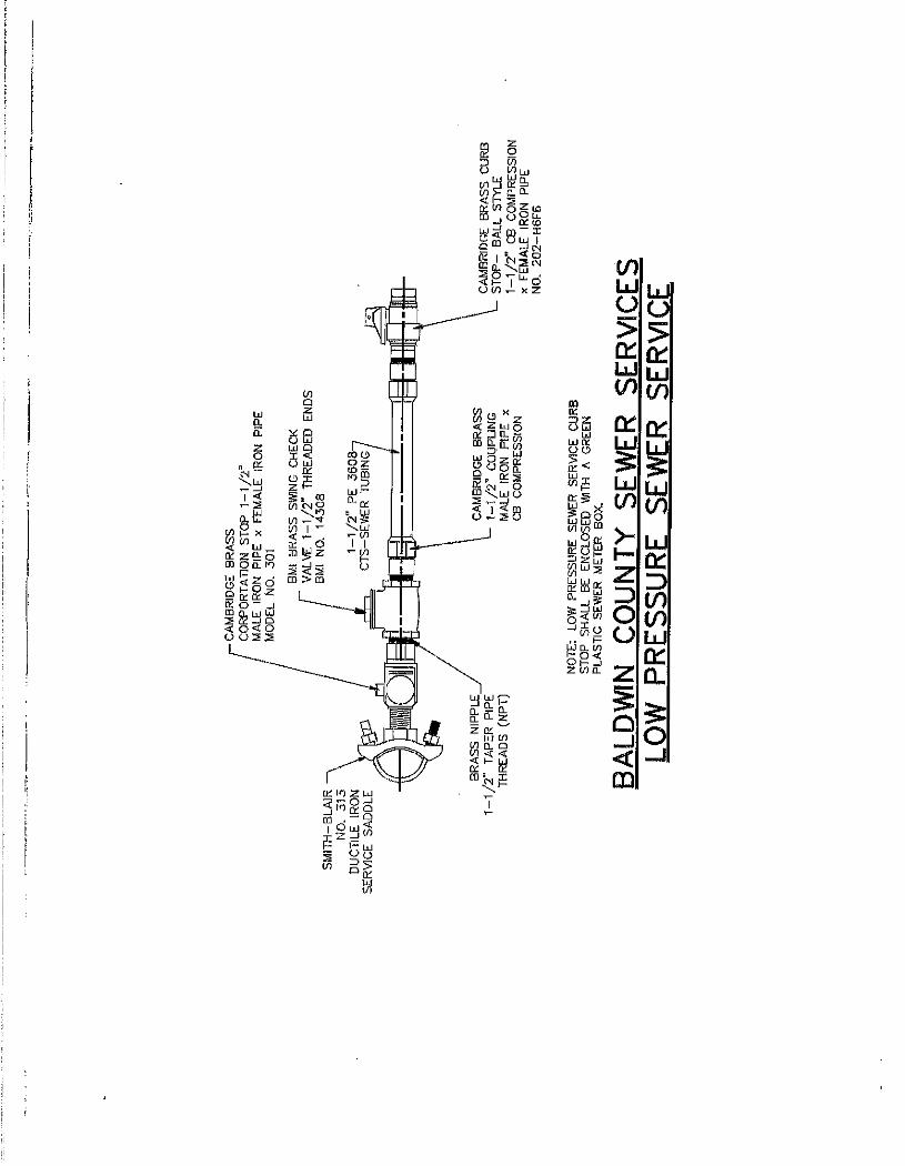
FORCE MAIN AND LOW PRESSURE SEWER SYSTEM
PVC PRESSURE PIPE Pipe: All pipe shall meet the requirements of ASTM Standard D-2241. Pipe supplied with a solvent cement joint shall meet the requirements of ASTM D-2672. Pipe supplied with a gasketed joint shall meet the requirements of ASTM D-3139, and the joint gasket shall conform to the requirements of ASTM F-477. All pipe shall meet the requirements of NSF Standard #14, “Plastic Piping Components and Related Materials,” and Standard #61, “Drinking Water System Components-Health Effects”. The pipe displays the “NSF-PW” listing mark signifying use in potable water applications. Pipe shall be furnished in laying lengths of 20’ (+/-). Other lengths and plain end finish may be available. This product is manufactured green for Sanitary Sewer Force Main applications. Print legend will include “Force Main”.
ASTM D-2241 Pressure Pipe
Nominal Size (Inches) (m.m.)
Standard Dimension Ratio
(SDR)
Pressure Rating (PSI)
"A" Average Outside Diameter
(O.D.)
Minimum
Wall
Maximum
O.D. 2 50 21 200 2.375 0.113 3.650
3 75 21 200 3.5 0.167 4.900
4 100 26 160 4.5 0.173 5.900
6 150 26 160 6.625 0.255 8.210
8 200 26 160 8.625 0.332 10.380
10 250 26 160 10.75 0.413 12.690
12 300 26 160 12.75 0.49 14.860
POLYETHYLENE PE 3408/3608 IPS – FORCE MAIN SEWER PIPE Pressure rated HDPE municipal water and industrial pipe material color – Black pipe with 3 single and evenly spaced green stripes. National Pipe & Plastics, Inc. Polyethylene PE 3408/3608 IPS. Forced main pressure pipe is manufactured in accordance with the specifications set-forth in ASTM Standard F-714. This product also meets the requirements of AWWA C906 “Standard for Polyethylene (PE) Pressure Pipe and Fittings, 4 inch (100 mm) through 63 inch (1,575 mm), for water distribution and transmission” with the exception that it is not approved for potable/drinking water applications. Black in color PE 3408/3608 water pipe is provided with 3 single and evenly spaced green

37
stripes. This material is manufactured from a HDPE Resin listed in PPI TR4 meeting a 1600-PSI Hydrostatic Design Basis, with a cell classification of PE345464C as defined in ASTM Standard D 3350.
PIPE DIMENSIONS
Pressure Class
Nominal Size
(inches)
Metric Size
(mm)
Average
O.D.
Wall Thickness (minimum)
Pressure Rating @ 73 deg F (PSI)
Weight Per
Ft. 4 100 4.5 0.409 160 2.290
PC 160 6 150 6.625 0.602 160 4.970
DR 11 8 200 8.625 0.784 160 8.420
10 250 10.75 0.977 160 13.090
12 300 12.75 1.159 160 18.410
3.31 INSTALLATION OF FORCE MAIN VALVES
A. Resilient Seated Gate Valves: All valves shall be non-rising stem for underground direct burial service and shall close when operating nut is turned in clockwise rotation. Valves shall be in accordance with and meet the requirements and recommendations of AWWA C509. O-ring seals shall be provided. The valve shall be a compression resilient seated gate valve. Disc shall be SBR coated. Valve body shall be fusion-epoxy bonded inside and out. Valves shall be furnished complete with necessary gaskets, bolts, and nuts as needed for mechanical joint ends. Mechanical joints and accessories shall comply with the latest published AWWA C111.
1. Valves (12 Inches and Smaller): Each valve shall have mechanical joint bell ends, and shall be on the Baldwin County Sewer Service’s list of materials and approved manufacturers. Valve shall be installed with the operating stem in the vertical position. Valve stem shall be furnished with 2 inch square water works nut.
B. Check Valves:
1. Swing check Valves 4-ionches and larger shall have a cast iron or cast steel body with a bronze or stainless steel seat ring, non-corrosive shaft for attachment of weight and lever and a 300 psi hydrostatic test pressure rating. Check valves shall absolutely prevent the return of water back through the valve when the inlet pressure decreases below the delivery pressure. The valve must be full opening, tight seating and its seat ring shall be renewable and must be securely held in lace by a threaded joint; the valve disc shall be of cast iron or cast steel and shall be suspended from a noncorrosive shaft which will pass through a stuffing box. A tapped boss with plug shall be provided on the check

38
valve bonnet for future use with a pressure gauge. All check valves shall have a Muller, with weight and lever. 2. Check valves smaller than 4-inches shall be bronze, bronze disc, swing check valves with lever and weight conforming to Federal Specification WW-V-51E, type 4 Class A-125 pound. Ends shall be as shown or indicated on the Drawings.
C. Valve Boxes:
1. All gate valve stems shall have access for operation with cast iron valve box. Screw type manufactured by Signma VB 261 or approved equal.
D. Mechanical Joint Restrant for PVC Pipe
1. All mechanical joint fittings shall be restraint with EBAA Iron Inc. Series 2000 PV or approved equal.
3.32 ENCASEMENT PIPE
A. General: Encasement pipe shall conform to AASHTO Standards and Alabama Department of Transportation standards where placed under highways and to AREA 1-5-B where placed under railroads. Except where noted on the Plans, encasement pipe shall be installed by a dry boring method in which the casing pipe is placed simultaneously with the boring action.
The Contractor shall inspect the roadway or track directly above the Work before, during, and after the placing of the encasement for settlement. If settlement occurs, the Contractor shall, at no additional expense to the Owner, bring the roadway surface to its original grade by means approved by the State Highway Department or realign the track to its proper grade by means approved by the railway owner.
B. Material: Welded Steel Encasement Pipe shall be of the size and well thickness
shown on the Plans and shall conform to ASTM Designation A252, Grade 2 and the Alabama Department of Transportation standard specifications. The pipe shall be coated on the outside only with a coal tar primer coat followed by a single application of hot coal-tar enamel 3/32 inches thick ± 1/32 inches. At the option of the Contractor, uncoated pipe may be used subject to approval of the State Highway Department or railway company provided the wall thickness is at least 0.063 inch greater than shown on the Plans or in the Proposal.
C. Encasement Spacers: Encasement pipe spacers and their accessories shall be
used to maintain separation of the encasement pipe and the carrier pipe. The installation and spacing from center to center of encasement spacers shall be in accordance with the manufacturer’s requirements. Spacers shall be stainless steel as manufactured by Maloney Pipeline Products Co., Cascade Water Works Mfg., Pipeline Seal and Insulator, Inc., or Engineer approved equal.
D. Encasement End Seals: encasement end seals shall be as manufactured by
Maloney Pipeline Products Company, Pipeline Seal and Insulator, Inc., Cascade Water Works Mfg., or an Engineer approved equal. Material shall be 1/8 inch synthetic rubber, stainless steel sipper or closer, pressure molded to the rubber

39
and a rubber protective strip attached to the seal under the zipper. Seals shall be secured to encasement using ½ inch stainless steel “Band-It” clips or thumbscrew banding clips with a polyethylene strip placed under each clip. a telescopic fold shall be placed in the seal before banding to assure proper flexibility between the carrier pipe and the casing.
3.33 TAPPING SLEEVE
A. The tapping sleeve shall have a body made of carbon steel per ASTM A283 C. The neck shall be carbon steel per ASTM A63. The flange shall be carbon steel A36 and recessed to accept a tapping valve per MSS-SP60. The flange drilling shall be per AWWA C207 class D (ANSI 150# hole pattern). The gasket shall be NSF 61 approved. Nitrile (Buna N) compounded to resist oil, alkalies, most (aliphatic) hydrocarbon fluids, water and many chemicals. The gasket temperature rating shall be -20°F to +180°F. The nuts and bolts shall be ¾” (5/8” in 4” and 6” nominal) high strength low alloy steel per ASTM A307 (ANSI 21.11) standards. The nuts shall be semi-finished hex head. The bolts shall be replaceable. The tapping sleeve shall be coated with a fusion bonded Flexi-Coat epoxy per AWWA C213, coated to an average of 12-mil thickness. A ¾” test outlet and plug shall be provided. The plug shall be ¾” carbon steel with square head and fusion bonded epoxy coating. The tapping sleeve shall meet applicable AWWA C223 standards and be certified to NSF®/ANSI 61-G. The tapping sleeve shall be Smith-Blair, Inc. style 622 or approved equal.
3.34 MECHANICAL JOINT RESTRAINT FOR PVC PIPE
A. All mechanical joint fittings shall be restraint with EBAA Iron Inc. Series 2000PV or approved equal.
3.35 COPPER LOCATION WIRE
A. All sewer force mains (including service lines) shall be installed with underground 12 gauge THHN insulated traceable copper wire. The insulated copper wire shall be laid in the pipe trench 3 to 6 inches above the sewer force mains and shall be a continuous strand from valve box to valve box, wrapped two times around each valve and extended 24 inches inside each valve box to enable location devices to be attached without digging up the valve box. All wire splices shall be insulated. Following placement of the traceable wire, the trench shall be backfilled with due caution to prevent displacement or damage to wire. After insulation and backfill have been completed the contractor shall perform a detection test in the Engineer’s presence using a commercially available pipe detector furnished by the Contractor. Any undetectable wire shall be replaced by the Contractor to the satisfaction of the Engineer at no additional expense to the Owner.
3.36 AIR RELEASE VALVES

40
The Combination Air Valve combines an Air and Vacuum large orifice and an Automatic small orifice in a single body. The air and vacuum valve shall be A.R.I. D-025 or approved equivalent. The valve is specially designed to operate with liquids carrying sold particles such as sewage and effluent. The combination air valve discharges air (gases) during the filling or charging of the system, admits air to the system while it is being emptied of liquid and discharges accumulated air (gases) from the system while it is under pressure and operating. Main Features: Working pressure range 0.2-10 bar. The valve’s unique design prevents any contact between sewage and the sealing
mechanism by creating an air gap at the top of the valve. This air gap is guaranteed even under extreme conditions. Those features are achieved by:
The conical body shape designed to: maintain the maximum distnace between the liquid and the Sealing Mechanism; so as to obtain minimum body length.
Spring loaded joint between the stem and the upper float. Vibrations of the lower float will not unseal the automatic valve. Release of air will occur only after enough air accumulates.
The valve design, Rolling Seal Mechanism: is less sensitive to pressure differentials than a direct float seal. It accomplishes this by having a comparably large orifice for a wide pressure range (up to 10 bar).
Funnel-shaped lower body is designed to ensure that residue sewage matter will sink to the system and be carried away and will not remain in the valve.
All inner metal parts made of stainless steel. Float made of plastic material. 1 ½” threaded drainage outlet enables removal of excess fluids. Preventing premature closing the valve discharges air at high velocity. Working temperature 60°. Maximum instantaneous working temperature 90°. Valve Selection These valves are available with 2”, 3” male BSP connections, or flanged, ANSI
standard. These valves are available with body made of reinforced nylon or stainless steel SAE
316 or ductile iron. With a Vacuum Guarding. Out-only attachment, which only allows air intake, not
allowing air discharge. With a Non-Slam, discharge-throttling attachment, which allows free air intake, but
throttles air discharge. Parts List and Specification No. Part Material 1. Drainage Outlet Polypropylene
2. Seal Plug Assembly R.N. + E.P.D.M. + St. St. 3. Float Foamed Polypropylene 4. Clamping Stem Reinforced Nylon 5. Body Reinforced Nylon / St. St. 6. Crown Nut Stainless Steel SAE 316

41
7. O-Ring Vitun / BUNA-N 8. Stopper Acetal 9. Spring Stainless Steel SAE 316 10. Washer Stainless Steel SAE 316 11. Stem Stainless Steel SAE 316 12. Body R.N. / St. St./ Ductile Iron 13. Clamp Stainless Steel SAE 316 14. O-Ring BUNA-N 15. Float Foamed Polypropylene 16. Tap Brass ASTN A124 17. Washer Stainless Steel SAE 316 18. Base R.N. / St. St. / Ductile Iron
3.37 FULL CIRCLE REPAIR CLAMPS
A. The full circle repair clamp shall have an 18-8 Type 304 stainless steel band. It shall be a minimum of 7.5” in width (5” minimum width for the 221). The lugs shall be made of high strength ductile iron per ASTM A536 GR80-55-06 and have a fusion bonded Flexi Coat epoxy coating. The lugs shall be attached to the band by hemming the band and sliding it into the lug slot. The slot shall be cast into the lug base. The lug shall have a friction fit with the band, preventing it from sliding off, yet allowing for easy removal and reattachment incase of installing the clamp in restricted spaces. The gasket shall be made of Nitrile (Buna N) specially compounded to resist water, oils, acids, alkalies, most (aliphatic) hydrocarbon fluids, and many other chemicals. The temperature range of the gasket shall be -20°F thru +180°F. The gasket must have a bridge plate that helps the end of the clamp band to seal across the gap. The bridge plate shall be made of quarter-hard 304 stainless steel. It shall be recessed and bonded into the gasket. The gasket shall have a gridded pattern. The gasket shall be tapered on the ends and overlap for range capability. All bolts shall be at least 5/8” x 6” high strength low alloy per ANSI A21.11 and B18.10. At least one 5/8” x 6 7/8” bolt with a taller nut shall be furnished to help facilitate installation of clamps up thru 4.50” O.D. Heavy semi-finished nuts meeting ASTM A563 shall be provided with the bolts. Multiband clamps shall have all closed lugs except for one set of open and closed lugs to allow for easy opening and installation of the clamp. (Optional – stainless steel type 304 bolts and nuts. The nuts shall be fluoropolymer coated to prevent galling.) The clamp shall be a Smith-Blair, Inc. 226 full circle clamp or approved equal.
3.38 SANITARY SEWER FORCE MAINS TESTING REQUIREMENTS
All sanitary sewer force mains shall be tested as follows:
After the pipe has been laid and partially backfilled, all pipe or any valved section shall, unless otherwise specified, be subjected to a minimum hydrostatic pressure of

42
100 psi. The pressure test shall be for at least two hours. Before testing, all air shall be expelled from the line. The Contractor shall make all necessary taps to expel the air and then plug all taps watertight. The Contractor shall use an approved recording pressure gauge with 12” chart.
The Contractor shall provide approved and suitable means for determining the quantity of water lost by leakage. No pipe installation will be accepted until or unless the leakage (evaluated on a pressure basis of 100 psi) is less than 25 U.S. gallons per 24 hours per mile of pipe per inch nominal diameter of pipe. The Contractor shall repair any observed leaks.
PRE-SET LOW PRESSURE SEWER SERVICE SPECIFICATIONS
All new low pressure sewer service installations shall consist of the following referenced materials:
1. 1 ½” low pressure sewer pre-set service. 2. Service saddle – Smith-Blair Ductile iron service saddle No. 313.
3. Corporation stop – Cambridge Brass Model No. 301, male iron pipe x female iron
pipe.
4. Brass Nipple – Merit Brass taper pipe threads (NPT).
5. Swing check valve – BMI Model No. 14308 threaded ends.
6. Coupling – Cambridge Brass male iron pipe x CP compression.
7. Sewer tubing – PE 3608 CTS – Sewer tubing.
8. Curb Stop – Cambridge Brass ball type CB compression x female iron pipe No. 202-H6F6.
9. The pressure sewer service curb-stop shall be enclosed with a green plastic meter
box.
NOTE: See low pressure sewer service detail.
All manufacturers are recommended, but an equal may be approved by Baldwin County Sewer Service, LLC.
43
GENERAL SEWAGE PUMPING STATION REQUIREMENTS
4.01 SCOPE:
These Specifications form a part of the Contract Documents and shall govern the construction of sewage pumping stations. The Work covered by this Section includes the furnishings of all labor, equipment, and materials, and performing all operations in connection with the construction and installation of Sewage Pumping Stations complete pumps, piping, wet well, electrical work and all necessary auxiliary equipment. The station shall be complete and in strict accordance with this section of the specifications and the applicable plans, the standard practices and ordinances of the UTILITY and subject to the terms and conditions of the Contract.
4.02 MATERIALS: Materials of this Section shall be as specified herein. 4.03 INTENT OF PLANS AND SPECIFICATIONS:
The intent of the plans and specifications associated with this Section is to provide a complete sewage pumping station which will function as intended and is ready for operation. It shall be the responsibility of the Contractor as a part of the Work through careful quality control and coordination with the Engineer to avoid all conflicts occurring during construction such as available space, routing, mismatched or otherwise incompatible component selection, incomplete systems, substitutions, etc. Where inter-system components, devices, adapters, etc., are not specified or noted in the design, but required to complete the system, it shall be the responsibility of the Contractor to provide such items and materials as part of the Work. Unless otherwise noted, items specified herein by manufacturer or trade name shall be used as a guide to quality and inherent features. Special drawings and Specifications shall be submitted by the contractor for the Engineer’s evaluation covering all equipment, controls, material, and construction procedures. The actual field installation shall reflect only that material and equipment submitted and approved by the Engineer. Any work performed without an approved submittal and considered not acceptable by the Engineer shall be removed and reworked at the Contractor’s expense.
4.04 SUBMITTAL AND TESTS:
Prior to installation of any material or equipment, the Contractor shall submit for approval of the Engineer, five sets of required submittal material indicating item identification, manufacturer, type, size, ratings, and other descriptive information

44
required for adequate evaluation. Wiring diagrams shall be submitted where item function description necessitates, and as required by the Engineer. Submittals shall be conspicuously marked to denote departures from the design references shown on the plans or specified. Incomplete submittals will not be evaluated. Submittals shall bear a stamp or specific written indication that the Contractor has satisfied his responsibilities under the Contract with respect to the Contractor’s review of the submission. Omissions and/or design revisions made in submittals shall not relieve the Contractor from the responsibility of providing the omitted item or required material as a part of this Work. Approval by the Engineer shall not constitute acceptance of an erroneous or incomplete system submittal. Material submittals shall be manufacturer’s catalog sheets or similar published data marked to denote only the item or items covered by the submittal. Materials of unique production shall have special submittal attention to give complete identification of the materials being proposed. A. Equipment submittals shall present the equipment for evaluation as a unit piece
including all component parts by manufacturer’s designation. Submittals shall be marked to denote only the equipment being proposed and shall be complete including electrical, physical, and operational data. Additional supporting data shall be provided where necessary.
B. Fabrications, assemblies, and special productions shall have submittals of unique
preparation to present the finished item completely identified. Such shop drawings shall include all material components and assembly work.
C. Systems composed of multiple parts or subsystems shall have submittals to
denote the system as a completed composite. All component parts and subsystems shall be identified.
D. Documentation of the finished installation shall be made as a part of final
acceptance and shall include corrected submittals, operation and maintenance publications, and other data to accurately define the final field installation.
E. Test Instructions and Reports:
The following listed items shall be required in addition to other special requirements within these Specifications.
1. Written conductor insulation resistance test.
2. Written ground rod resistance test.
3. Local public electrical inspector’s certificate.
4. Operational demonstration test.

45
4.05 SITE WORK:
In general, clearing shall consist of the removal and disposal of all undergrowth, brush, logs, trash and other objectionable. All materials cleared from the site shall be disposed of off site by the Contractor. It is the intent that the entire area within the limits of the sewage pumping stations as shown on the plans shall be cleared and graded for proper storm drainage and grassed in accordance with the specifications contained herein.
4.06 EXCAVATION FOR PIPES AND STRUCTURES:
A. General: The Contractor shall perform excavation of every description regardless of the nature of the materials. Trenches or foundations for pipes or structures shall be excavated to the lines, grades, and elevations shown on the plans. Trench and structure excavations shall be of sufficient size to permit the placing of pipes and forms.
B. Overcuts: If, at any point in excavating for structures, material is excavated
beyond the neat lines upon or against which concrete is to be placed, the overcut shall be filled with reef shell, crushed slag or crushed stone fill properly compacted, or with concrete, as directed by the Engineer. The proposed elevations and positions for the different structures are shown on the plans. However, the Engineer reserves the rights to make such modifications as in his opinion are necessary to carry out the intent of the plans and specifications. No payment will be made for overcuts or reef shell, crushed slag or crushed stone fill in overcuts. Reef shell, crushed slag or crushed stone shall be specified in the Board’s Standard Specifications.
C. Dewatering: The Contractor shall remove any water which may be found or may
accumulate in the trenches and shall perform all work necessary to keep them clear of water while foundations are being laid, masonry is being constructed, or pipe laying is in progress. Such removal shall be accomplished by means of a well point system or other approved means. Comprehensive plans for dewatering operations, if used, shall be submitted prior to installation. No payment will be made for dewatering.
4.07 CONCRETE:
The minimum compressive strength required at 28 days is 3,000 pounds per square inch. Field specimens and laboratory tests shall be made in accordance with the standards of the American Society of Testing Materials. The minimum amount of water shall be used to produce a workable mix and shall also be in accordance with those specified for manhole structures.
4.08 WET WELL/VALVE BOX GENERAL:
All duplex pump stations including grinder and non-clog pumps shall include a prepiped fiberglass wet well including all necessary components. All duplex non-clog stations shall include an external valve box. All duplex grinder stations shall include valves arranged in the wet well to allow ease of maintenance and shall not require an external valve box.

46
4.09 WET WELL/VALVE BOX FIBERGLASS CONSTRUCTION:
The resins used shall be commercial grade polyester and shall be evaluated as a laminate by test or determined by previous service to be acceptable for the intended environment.
The reinforcing material shall be a commercial grade of glass fiber (filament wound) having a coupling agent which will provide a suitable bond between the glass reinforcement material and resin.
The FRP laminate wall thickness shall vary with the wet well height to provide the aggregate strength necessary to meet the tensile and flexural physical properties requirements. The wet well/valve box FRP wall laminate must be designed to withstand wall collapse or bucking based on a hydrostatic pressure of 62.4 pounds per square foot; a saturated soil weight of 120 pounds per cubit foot; a soil modulus of 700 pounds per square foot; and the pipe stiffness values as specified in ASTM D3753. The wet well/valve box FRP laminate must be constructed to withstand or exceed two times the assumed loading on any depth of the wet well/valve box.
The finished FRP laminate will have a Barcol hardness of at least 90% of the resin manufacturer’s specified hardness for the fully cured resin. The Barcol hardness shall be the same for both interior and exterior surfaces.
The wet well/valve box flange shall have an outside diameter at least 4.0 inches greater than the inside diameter of the wet well/valve box. A six hole pattern shall accommodate the mounting of a cover with at least 0.25 inches in diameter 300 series stainless steel fasteners. Non-corroding stainless steel threaded inserts shall be full encapsulated with non-continuous or chopped-strand glass fiber reinforcement. The inserts shall have an offset tab to prevent stripping or spinning out when removing and reinserting cover fasteners.
4.10 WETWELL/VALVE BOX COVER
The basin cover shall be Model BPS as manufactured by U.S.F. Fabrication, Inc., Hialeah, Florida, or equal with the size being specified on the plans. Cover plate and door leaf shall be 1/4 inch thick aluminum diamond plate reinforced for a 300 p.s.f. live load. The cover shall have six (6) 5/8 inch diameter holes equally spaced around the perimeter to bolt it down to the structure for fiberglass wells or pour in place for concrete wells. The access door shall be equipped with a flush drop handle that does not protrude above the cover, and a stainless steel hold open arm with red vinyl grip that automatically locks the cover in the 90 degree open position. The door shall have stainless steel hinges and stainless steel tamper resistant bolts/locknuts. A staple for a padlock shall be supplied for security. All stainless steel components shall be type 316 alloy. Installation shall be in accordance with the manufacturer's attached instructions. The door shall be manufactured and assembled in the United States. Venting for both wetwell and valvebox shall be provided through pvc constructed mushroom vents and through bolted with stainless steel fasteners to each cover. Painted steel vents will not be accepted. Manufacturer shall guarantee the door against defects in materials and workmanship for a period of ten (10) years.

47
4.11 PUMPS
There shall be supplied as shown by the plans two (2) WEMCO Model CLES vertical submersible, non-clogging vortex-type slurry pumping unit(s) or approved equal specifically designed to pump slurries of grit, debris and organic solids without clogging.
4.121 QUALITY ASSURANCE
A. All pumping equipment furnished under this Section shall be of a design and
manufacture that has been used in similar applications and it shall be demonstrated to the satisfaction of the Owner that the quality is equal to equipment made by that manufacturer specifically named herein.
B. To insure a consistent high standard of quality, the manufacturer of this pumping
equipment shall comply with the requirements of the ISO 9001 Quality System, and such compliance shall be verified by an independent certification agency approved by the International Organization for Standardization. Documentation shall be submitted for approval showing compliance with this requirement, and the equipment will not be released for shipment until approved.
C. Pump(s), complete with motor, slide-away couplings and all other specified
accessories and appurtenances shall be furnished by the pump manufacturer to insure compatibility and integrity of the individual components, and provide the specified warranty for all components. The pump manufacturer accepts unit responsibility for each pump assembly.
D. The vortex-type pumps specified in this section shall be furnished by and be the
product of one manufacturer.
4.122 SUBMITTALS
A. Submit shop drawings and product data. B. Submit manufacturer’s installation instructions. C. The submittal data shall be prepared, in its entirety, by the equipment manufacturer
and each page shall be initialed by the manufacturer’s employee responsible for the preparation of the data. Shop drawings prepared by the manufacturer’s sales representative, fabrication shop or other than the listed manufacturers shall not be acceptable. No additions or modifications to the manufacturer’s submittal will be accepted, with the sole exception of a cover sheet provided by the manufacturer’s local representative.
4.123 OPERATION AND MAINTENANCE DATA
A. Submit operation and maintenance data. B. Include installation instructions, assembly views, lubrication instructions, and
replacement parts lists.

48
4.124 DELIVERY, STORAGE, AND HANDLING
A. Deliver, store, handle and protect.
4.125 SERVICES OF MANUFACTURER
A. Furnish the services of a representative of the pump manufacturer to assist in adjusting and testing the equipment furnished, to supervise the initial operation, and to make final adjustments as may be necessary to assure the OWNER that the pump(s) is (are) in satisfactory operating condition.
B. Furnish sufficient supervision, data, and information from the manufacturer to train
operators in the proper operation and maintenance of the pump(s) furnished.
4.126 PERFORMANCE
A. The pumps shall be designed for continuous operation and will be operated continuously under normal service.
B. Operation Criteria:
Flow GPM
TDH FT
Max. Pump RPM
Solids Passage
Min. Suction
Dia.
Min. Disch. Dia.
Min. Motor Size
Design Condition
Secondary Condition
4.127 DESIGN
A. The pump(s) shall be end-type vertical suction and horizontal discharge, and shall be completely open from suction to discharge with no wearing rings or impeller faceplates required. All flow path clearances within the pump(s) shall be equal to or greater than the discharge diameter, so that all solids which will pass through the discharge will pass through the pump. The discharge connection shall be located on the pump case centerline.
B. The impeller shall be of the recessed design, and shall be mounted completely out of
the flow path between the suction inlet and discharge connections, so that the solids pumped are not required to flow through the impeller. The impeller shall be keyed to the shaft and secured by an impeller bolt.
4.128 MATERIALS OF CONSTRUCTION
Select from available materials 1. Cast Iron ASTM A48 Class 25 or 30

49
2. Hi-chrome ASTM A 532-CL.III Type A1 3. 316 S.S. ASTM A 314 4. CD 4 MCU ASTM A 890
A. The volute shall be manufactured of Cast Iron material, ASTM A48 Class 25 or
30. B. The impeller shall be manufactured of Cast Iron material, ASTM A48 Class 25 or
30.
C. The impeller back plate shall be manufactured of Cast Iron material, ASTM A48 Class 25 or 30.
4.129 MOUNTING A. Slide Away Coupling Type
1. The pump manufacturer shall supply a slide away coupling for the pump, designed such that the pump can be removed from the installation without entering the pit or disconnecting the discharge piping.
2. The slide away coupling shall consist of a foot mounted discharge elbow
and adapter, steel base plate, upper and lower guide rail supports, lifting yoke and cable.
a. The coupling halves shall be angled, and the locking lugs shall be
adjustable in order to eliminate any mechanical looseness that could cause leakage.
b. The slide away couplings shall be designed for use with two
stainless steel 2” schedule 40 guide rails. 3. The foot mounted discharge elbow and adapter shall be cast iron, ASTM A 48
Class 30. 4. The slide away coupling shall include a self-energizing U cupped rubber gasket,
to provide positive sealing under all conditions. This gasket shall be serviceable as required with pump removal.
4.1210 MOTOR
A. Motor shall be a submersible type, ______ HP, ______Phase, ______ Cycle,
_______ Volt, ______ RPM, and shall be directly connected to the pump. All motors shall be Reliance air filled submersible and labeled by Underwriters Laboratory, Inc. or Factory Mutual as approved for use in Class 1, Group D hazardous locations, rated for submergence in raw sewage and shall conform to NEMA standards and specifications.
B. The motor(s) shall be provided with thrust and radial bearings of sufficient size to
carry the entire load which may be imposed upon it under all operating conditions.

50
C. The motor shall include two mechanical seals. The lower (outer) mechanical seal
shall be located to exclude the pumped material from entering the lower cavity of the motor. The upper (inner) seal shall be located in an oil filled chamber such that it excludes any moisture from entering the winding compartment of the motor. The seal material for both upper and lower seal faces shall be Tungsten Carbide vs Tungsten Carbide with Buna-N o-rings.
D. The motor shall include thermal overload protectors, which shall be imbedded in the
motor windings and connected to the motor starter in such a way that the motor automatically shuts down in the event of overload.
E. The motor shall include a moisture probe located in the oil chamber, which shall be
connected to a customer-supplied alarm to indicate the presence of moisture in the seal chamber.
F. The motor shall be in accordance with the provisions of Section _____
4.12 VALVES AND PIPING:
A) DUPLEX NON-CLOG STATIONS
1. Piping shall be class 52 ductile iron pipe or SDR 9 HDPE as required by Baldwin County Sewer Service, LLC.
2. Gate valves shall be cast iron AVK Resilient Seated Gate Valve model
#25/40-xxx-40x tested to AWWA C509 or approved equivalent. 3. Check valves shall be cast iron AVK Swing Check Valve model #41/45-
xxx tested to AWWA C508-93 or approved equivalent.
B) DUPLEX GRINDER STATIONS 2HP AND LARGER:
1. Piping shall be 304L stainless steel pipe.
2. Gate valves shall be brass Matco-Norca gate valve model# 518.
3. Check valves shall be brass Matco-Norca swing check valve model#521.
Valves and piping shall be located as shown on the drawings.
4.13 ELECTRICAL:
A. General: All electrical material and equipment provided by the Contractor shall be new and free of defects. All work performed under this section of the specifications shall be carried out by skilled workers regularly engaged in the performance of such duties. The entire electrical installation shall be not less than that required by the latest edition of the National Electrical code, the

51
Occupational Safety and Health Act, and all electrical codes locally enforced in the project area. The Contractor shall obtain all permits required by local ordinances and after completion of the work, shall give the Engineer a certificate of final inspection and approval from the local Electrical inspection office. Any expenses connected with such inspection and certificate shall be borne by the Contractor.
Electrical material and equipment shall be designed in accordance with the latest
requirements of applicable standards such as NEMA, ANSI, IEEE, and where listings are available for such items, shall be approved by the Underwriters Laboratories, Inc. Equipment, components, material, etc., rated by other standards and agencies including but not limited to IEC, VDE, and DIN will not be considered equal to NEMA, ANSI, IEEE, and UL. Electrical items shall be standard cataloged products of manufacturers regularly engaged in the manufacture of such products, unless otherwise noted.
B. Grounding:
1. Non-current carrying metal parts of electrical items such as cabinets, enclosures, frames, etc., and the neutral conductor shall be grounded in accordance with the National Electric Code unless additional grounding requirements are indicated. Grounding conductors shall be copper, sized as noted. Special grounding system features shall be provided as indicated.
2. All conduit runs installed for lighting and power loads shall contain a
grounding conductor throughout the entire length of the run forming a part of the grounding system. The grounding system shall be electrically continuous throughout the electrical system and shall be connected to earth ground at the point of power service and as otherwise indicated.
3. Ground rods shall be copper welded steel type, ¾ inch diameter, 20’-0”
length, minimum. Ground rods shall be driven to 1” – 0” (minimum) below finished grade unless otherwise indicated and shall be electrically connected with suitable cast type ground clamps or exothermic welding.
4. Resistance to ground of each ground rod shall not exceed 10 ohms when
measured during dry weather. In the event this value is not obtained, one additional rod or rod section equal to that tested shall be driven. Should the additional rod or section fail to achieve the required value, the Engineer shall be immediately notified. A written record of all resistance measurements and test dates shall be submitted to the Engineer prior to completion of the project.
C. Lightning and Surge Protection:
1. Lightning protector unites shall be provided for power circuit protection at the main service connection point and elsewhere as noted on the plans. Lightning protectors shall be Intermatic for three and single phase circuits respectively.

52
D. Insulation Tests:
1. Circuit insulation tests shall be performed to prove each circuit free of faults after all wiring is completed prior to equipment and fixture connection, and again after the installation is complete and ready to use.
2. Tests shall be made at the main electrical service connection between all
conductors and between line conductors and ground. Tests shall be made with a 1,000 Vdc instrument capable of accurately measuring the resistance involved. Readings shall be taken in the presence of the Engineer or his representative for each test and the written results of each test shall be submitted to the Engineer.
E. Conductors:
1. Single conductors installed in raceways shall be copper and AWG sizes as noted and shall have 600 volt rated, type THW/THHN/THWN or XHHW, 75˚ C (minimum) insulation. Conductors requiring special consideration shall have insulation material and ratings noted on the plans and as required by the National Electrical Code. Type TW insulation shall not be used for any purpose in this contract except ground wire identification only.
2. Lightning and power conductors shall be minimum size No. 12 AWG,
with AWG No. 8 and larger to be stranded, and AWG No. 10 and smaller to be solid unless otherwise noted. Conductors shall be stranded where movement, vibration, or other flexing occurs in order to prevent conductor fatigue. Control conductors may be AWG No. 14 stranded, unless otherwise noted.
3. Insulation colors shall be: green for ground; white for neutral; and black for single phase line conductor. “Stinger” phase conductor of 120/240 V systems shall be orange as per NEC 215.8. Unless otherwise noted, a uniform insulation color scheme for all new three phase systems shall be established as black for phase A, red for phase B, and blue for phase C. Control circuit insulation shall be yellow. Conductors size AWG 10 and larger may be black with entire exposed tends taped with “Scotch #35” or equal by Plymouth, in accordance with color schemes mentioned herein.
4. Direct buried grounding system conductors shall be bare copper, sized as
noted. F. Splices and Terminations:
1. 600 volt system conductors shall be spliced with “Ideal Wire-Nuts” or equal by T & B for AWG No. 10 and smaller for dry areas and machine crimped or bolted connectors with “Scotch 88” or equal by Plymouth full coverage tape for all other splices. Soldered and taped splices will not be acceptable. Terminations shall be made with mechanical lugs or other acceptable termination features of the equipment supplied.

53
2. Control conductors shall terminate on box clamp, grinding post screw, or set screws only. Soldered, taped and free-standing connections will not be acceptable.
G. Conduit:
1. Steel conduit shall be provided unless otherwise indicated and shall be heavy-wall, rigid galvanized type bearing the Underwriter’s Laboratories, Inc. label of approval. Conduit minimum size shall be ½ inch. Fittings for rigid steel conduit shall be threaded types made up with conductive waterproof compound. Seal-off fittings shall be provided as required by the National Electrical Code.
2. All conduits shall be clean and free from dents, scars, or other
deformities. Connections shall be made watertight and bushings shall be provided where smooth hubs are not encountered. Changes in directions shall be made with symmetrical bends or conduit boxes. Field made bends shall be made with an approved hickey or conduit bending apparatus. Conduit runs shall be installed parallel or perpendicular to structural members. Conduit hangers and supports
4.14 PANEL
A. General: All electrical components and materials supplied shall function as a
complete unit to automatically control the pump down of the sewage pump station wet well. All devices and material shall be new and of standard product design. Electrical work shall be in accordance with the latest edition of the National Electrical Code (NEC) and subject to local codes. Panel supplier shall be a certified UL 508 manufacturer. Panel shall be as manufactured by Best Controls Corp or equal.
All power wire shall be stranded copper and sized as required for load and application according to NEC. All control and signal wire shall be a minimum of #16 AWG, 90 degree C insulated and color-coded. Colors shall be red for all AC control, blue for all DC control, yellow for external source control, white for AC neutral and green for equipment ground wiring. All wiring on the rear of the inner door shall be neatly bundled using tie wraps or other means. All internal wiring on the backplate shall be neatly routed in wire duct with removable covers. All wiring shall be continuous point to point (no splices) and be totally accessible.
B. Scope and Panel Operation: The control panel shall provide power and logic control to operate two submersible pumps at the rated voltage and FLA of the pump motors. The control voltage shall be 120-Volt, single phase.
The control logic shall provide for the automatic operation and alternation of the

54
lead pump under normal conditions. If the incoming flow exceeds the pumping capacity of the lead pump, the lag pump shall automatically operate to handle the increased flow. As the wet well level decreases, both pumps shall shut off at the pumps off level. In the event of a pump failure or a flow that exceeds the capacity of both pumps, a high alarm level shall operate a red flashing alarm light. The pump designated as lead pump shall alternate each duty cycle
C. Enclosure Construction and Materials: The pump controls shall be housed in a
NEMA 4X, 304Stainless Steel enclosure sized to house all the required components and allow adequate space for testing and maintenance as necessary, with minimum enclosure size 36”X30”X12”. The enclosure shall have a drip shield, padlockable three-point latch (clamp hasp are not acceptable), steel back plate painted white, continuous door hinge, and an aluminum inner door with continuous hinge to protect all live internal wiring from operator personnel. The inner door shall be able to open a minimum of 150 degrees to allow safe access to the components. All controls, switches, indicator pilot lights, and elapsed time meters shall be mounted through the inner door.
All other components shall be securely mounted to the backplate with stainless steel hardware through machine thread tapped holes in the backplate. The screws shall be of adequate size for the device being secured. Permanent marking to identify each component as shown on the drawing shall be provided on the back plate and schematic laminated on inside of enclosure door.
D. Duplex Pump Controller: The Duplex Float Switch Controller shall be a
dedicated solid-state controller, easily replaceable, that automatically controls two wastewater pumps. Conventional relay/timer logic is not acceptable. The controller shall five normally open floats as level sensing inputs so when the tank is empty all of the floats are open. The lowest float shall be the low alarm float. On rising water the Off float closes first which causes the controller to take no action. The Lead float will close next as the water rises. The controller will then turn on the lead pump. If this pump causes the water level to fall the lead pump will be turned off when both the Lead and Off float are out of the water and open. If the lead pump is not sufficient to control the water level then the lag pump will be started when the Lag float closes. The two pumps will not be turned off until the Lag, Lead, and Off floats are out of the water and open, at which time, all pumps will be turned off. The controller shall be designed in such a way that any single float which is stuck in either the closed or open position will not cause a station overflow or cause the station to be pumped down below the low float level.
The controller shall have selectable soft start delays built into the software, which will insure when both pumps are called the second pump cannot start for at least 6 or 12 seconds, and a minimum 4 second soft stop delay to insure both pumps cannot stop at the same time. These delays shall insure smooth pump operation and prevent excessive electrical surges and water hammer.
The controller shall include; three position selector switch for alternation, inputs for pump seal fail sensors and motor thermal sensors. If a seal fail is detected the pump with this condition shall be automatically demoted to lag pump until failure is corrected. Temp fail condition shall disable pump with this condition and the other pump called in its place. This condition shall not be cleared until the sensor in the

55
pump is cleared and the controller is manually reset. Indicating lights for: pump run, temp fail, seal fail, high alarm, low alarm, floats “out of order” and pump disable. Also controller shall provide integrated indicator lamps with push-to-test switches for each float input. Externally wired push-to-test switches will no be considered equal. Power input for controller shall be fused and transient protected. Float inputs shall be no more than 6Vdc when open and 26 Ma max when closed. All input and output wiring shall use quick connect removable terminal strips. Float switch controller to be mounted through inner door of enclosure and shall be Model PC2000 manufactured by Best Controls Corp or equal.
E. Control Panel: Provide properly sized transfer switch for main and emergency
power, Square D motor circuit breaker, IEC Telemecanique motor starter with overload protection or Square D ATS soft start as required (20HP and larger), ground and neutral block, fused 115V control circuit with circuit breaker, phase monitor relay, and lightning arrestor (shipped loose for installation at incoming feed by the contractor). Elapsed Time Meters for each pump, Elapsed Time Meters for simultaneous pump run non-reset type, 22mm HOA switches, 22mm pump run indicator lights and general-purpose duplex GFCI outlet minimum rating of 10 amps to be mounted on inner door. Provide circuit breaker for GFCI outlet. Provide weatherproof exterior 3 ½” diameter flashing alarm light with red Lexan lens mounted on right side of control panel.
F. Site Visual Alarm System: The red alarm light shall be activated for pump
failure and high water level. 4.15 WIRELESS MONITORING SYSTEM
The Wireless Monitoring System shall be manufactured by Mission Communications and shall be model number M113 or equal. It shall be incorporated into the construction of the control panel to insure the proper integration of the monitoring and control system. It shall be capable of reacting to various external alarm inputs to include 8 inputs as follows:
Input One: Pump One runtime Input Two: Pump Two runtime Input Three: Simultaneous pump runtime Input Four: Spare Input Five: Panel door alarm Input Six: Wetwell hatch alarm Input Seven: High Level One Input Eight: High Level Two
In addition it shall report power/phase failure independent of the eight inputs.
It shall report these inputs/alarms to a central monitoring facility continuously operated by the monitoring company, which will in turn notify the designated local recipients via telephone, fax, email, pager or web determined by the local utility. The central monitoring facility shall also have the capability of responding to queries for information from the user via the WEB, and shall automatically generate useful reports giving details
56
of all activity, and summary reports. The system and service shall be specifically designed and intended for use in the water and wastewater industry.
It shall have battery-back-up with integral charging to insure the report of all alarms in the event of power failure. It shall have an externally mounted key-reader to allow the technician to put the unit in service mode before servicing any equipment at the site. It shall include a dual element highlevel alarm float to insure redundancy in the high level alarm notification.
4.16 STAINLESS STEEL CONTROL PANEL STAND
The control panel shall be supplied with a panel stand constructed from 2”x2”x.125” stainless steel tubing (minimum 304 grade) with a 9’ overall height dimension with 5.5’ to be above grade. The stand shall include a Nema 3r fused disconnect rated for the voltage and current range necessary to facilitate proper station operation. In addition there shall be space provided for the contractor installed meter base. The stand shall have the panel and disconnect mounted, pre-wired, and tested. (per drawing)
4.17 VENTILATED JUNCTION BOX
The control panel shall incorporate a Nema 4x Stainless Steel (minimum 304 grade) junction box permanently mounted to the bottom of the control panel enclosure to vent gases from entering the control space. This panel shall include an expanded metal removable front cover. In addition the cables shall be sealed into the control panel enclosure with the use of U.L. Listed cord grips. (per drawing)
4.18 INSTALLATION OF PANEL STAND
The control panel stand shall be installed by equipment provider so as to meet all of the requirements of UTILITY. The cost for this installation shall be included in the pump suppliers pricing to the contractor. This installation shall included one full day of site work. It shall be scheduled with the contractor after all pump station site work has been completed. The installation shall include setting of stand per utility’s recommended location and installation of conduit from wet-well to control panel. It shall NOT include installation of electrical service, installation of meter-base, or connection of the main power feed to the main disconnect, as this shall be the responsibility of the contractor.
4.19 INSTALLATION OF PUMPS AND FLOATS
The pumps and floats shall be installed by equipment provider so as to meet all of the requirements of the UTILITY. The cost for this installation shall be included in the pump suppliers pricing to the contractor. This installation shall include one full day of site work. It shall be scheduled with the contractor after all pump station site work including electrical service has been completed. This installation shall be the day before start-up to insure that the pumps are not installed in the wetwell for an extended period of time without power that could lead to premature failure.
4.20 START UP/PERFORMANCE TEST

57
The start up shall be conducted by equipment provider so as to meet all of the requirements of utility, the Engineer, and the requirements outlined by the equipment manufacture. The cost of the test shall be included in the pump supplier pricing to the contractor. This test shall include one full day of site testing. It shall be scheduled with the contractor, engineer, and local utility after all equipment installation has been completed. Reports shall be provided to the engineer and owner as per the utility’s specifications immediately following commissioning of the lift station.
4.21 DRAWINGS AND MARKINGS
A. Panel Markings: All component parts in the control panel shall be permanently marked and identified as they are indicated on the back plate, adjacent to the component.
B. Nameplates: The panel shall include engraved nameplates on the inner door for
all components to indicate the device function. The nameplates shall be permanently affixed with plated machine screws or a bonding adhesive suitable for the application.
C. Final Drawings: Upon completion of the panel a complete set of As Built
drawings and Bill of Materials shall be supplied to the owner. The drawings shall include a power and control schematic and a terminal block diagram showing each remote connection to the panel. An adhesive Mylar copy of the schematic drawings and terminal diagram must be permanently affixed to the inside of the control panel door.
4.22 WARRANTY
All equipment shall be warranted against defects in material and workmanship for a period of one (1) year from the date of Owner’s final inspection and acceptance or eighteen (18) months from date of shipment, to the effect that any defective equipment shall be repaired or replaced, at the discretion of the supplier.

58
DUPLEX PUMP CONTROL PANEL SPECIFICATIONS
General All electrical components and materials supplied shall function as a complete unit to automatically control the pump down of the sewage pump station wet well. All devices and material shall be new and of standard product design. Electrical work shall be in accordance with the latest edition of the National Electrical Code (NEC) and subject to local codes. Panel supplier shall be a certified UL 508 manufacturer. Panel shall be as manufactured by Best Controls Corp. or approved equivalent. All power wire shall be stranded copper and sized as required for load and application according to NEC. All control and signal wire shall be a minimum of #16 AWG, 90 degree C insulated and color-coded. Colors shall be red for all AC control, blue for all DC control, yellow for external source control, white for AC neutral and green for equipment ground wiring. All wiring on the rear of the inner door shall be neatly bundled using tie wraps or other means. All internal wiring on the backplate shall be neatly routed in wire duct with removable covers. All wiring shall be continuous point to point (no splices) and be totally accessible.
Scope and Panel Operation The control panel shall provide power and logic control to operate two submersible pumps at the rated voltage and FLA of the pump motors. The control voltage shall be 120-Volt, single phase. The control logic shall provide for the automatic operation and alternation of the lead pump under normal conditions. If the incoming flow exceeds the pumping capacity of the lead pump, the lag pump shall automatically operate to handle the increased flow. As the wet well level decreases, both pumps shall shut off at the pumps off level. In the event of a pump failure or a flow that exceeds the capacity of both pumps, a high alarm level shall operate a red flashing alarm light. The pump designated as lead pump shall alternate each duty cycle
Enclosure Construction and Materials The pump controls shall be housed in a NEMA 4X, 304Stainless Steel enclosure sized to house all the required components and allow adequate space for testing and maintenance as necessary, with minimum enclosure size 36”X30”X12”. The enclosure shall have a drip shield, padlockable three-point latch (clamp hasp are not acceptable), steel back plate painted white, continuous door hinge, and an aluminum inner door with continuous hinge to protect all live internal wiring from operator personnel. The inner door shall be able to open a minimum of 150 degrees to allow safe access to the components. All controls, switches, indicator pilot lights, and elapsed time meters shall be mounted through the inner door. All other components shall be securely mounted to the backplate with stainless steel hardware through machine thread tapped holes in the backplate. The screws shall be of adequate size for the device being secured. Permanent marking to identify each component as shown on the drawing shall be provided on the back plate and schematic laminated on inside of enclosure door.
59
Duplex Pump Controller The Duplex Float Switch Controller shall be a dedicated solid-state controller, easily replaceable, that automatically controls two wastewater pumps. Conventional relay/timer logic is not acceptable. The controller shall five normally open floats as level sensing inputs so when the tank is empty all of the floats are open. The lowest float shall be the low alarm float. On rising water the Off float closes first which causes the controller to take no action. The Lead float will close next as the water rises. The controller will then turn on the lead pump. If this pump causes the water level to fall the lead pump will be turned off when both the Lead and Off float are out of the water and open. If the lead pump is not sufficient to control the water level then the lag pump will be started when the Lag float closes. The two pumps will not be turned off until the Lag, Lead, and Off floats are out of the water and open, at which time, all pumps will be turned off. The controller shall be designed in such a way that any single float which is stuck in either the closed or open position will not cause a station overflow or cause the station to be pumped down below the low float level. The controller shall have selectable soft start delays built into the software, which will insure when both pumps are called the second pump cannot start for at least 6 or 12 seconds, and a minimum 4 second soft stop delay to insure both pumps cannot stop at the same time. These delays shall insure smooth pump operation and prevent excessive electrical surges and water hammer. The controller shall include; three position selector switch for alternation, inputs for pump seal fail sensors and motor thermal sensors. If a seal fail is detected the pump with this condition shall be automatically demoted to lag pump until failure is corrected. Temp fail condition shall disable pump with this condition and the other pump called in its place. This condition shall not be cleared until the sensor in the pump is cleared and the controller is manually reset. Indicating lights for: pump run, temp fail, seal fail, high alarm, low alarm, floats “out of order” and pump disable. Also controller shall provide indicator lamps with push-to-test switches for each float input. Power input for controller shall be fused and transient protected. Float inputs shall be no more than 6Vdc when open and 26 Ma max when closed. All input and output wiring shall use quick connect removable terminal strips. Float switch controller to be mounted through inner door of enclosure and shall be Model PC2000 manufactured by Best Controls Corp.
Control Panel Provide properly sized transfer switch for main and emergency power, Square D motor circuit breaker, IEC Telemecanique motor starter with overload protection or Square D ATS soft start (20hp and larger), ground and neutral block, fused 115V control circuit with circuit breaker, phase monitor relay, and lightning arrestor (shipped loose for installation at incoming feed by the contractor). Elapsed Time Meters for each pump, Elapsed Time Meters for simultaneous pump run non-reset type, 22mm HOA switches, 22mm pump run indicator lights and general-purpose duplex GFCI outlet minimum rating of 10 amps to be mounted on inner door. Provide circuit breaker for GFCI outlet. Provide weatherproof exterior 3 ½” diameter flashing alarm light with red Lexan lens mounted on right side of control panel. Site Visual Alarm System The red alarm light shall be activated for pump failure and high water level. Mission Wireless Remote Monitoring System

60
The Wireless Monitoring System shall be manufactured by Mission Communications and shall be model number M113BCSS. It shall be incorporated into the construction of the control panel to insure the proper integration of the monitoring and control system. It shall be capable of reacting to various external alarm inputs to include 8 inputs as follows:
Input One: Pump One runtime Input Two: Pump Two runtime Input Three: Simultaneous pump runtime Input Four: Spare Input Five: Panel door alarm Input Six: Wetwell hatch alarm Input Seven: High Level One Input Eight: High Level Two
In addition it shall report power/phase failure independent of the eight inputs. It shall report these inputs/alarms to a central monitoring facility continuously operated by the monitoring company, which will in turn notify the designated local recipients via telephone, fax, email, pager or web determined by the Baldwin County Sewer Service. The central monitoring facility shall also have the capability of responding to queries for information from the user via the WEB, and shall automatically generate useful reports giving details of all activity, and summary reports. The system and service shall be specifically designed and intended for use in the water and wastewater industry. It shall have battery-back-up with integral charging to insure the report of all alarms in the event of power failure. It shall have an externally mounted key-reader to allow the technician to put the unit in service mode before servicing any equipment at the site. It shall include a dual element high level alarm float to insure redundancy in the high level alarm notification. Intrusion Alarm Switches The control panel door switch shall be a button type Nema 6p rated as manufactured by Square D part number 9007MS06S0500. The wetwell hatch switch shall be the non-metallic magnetic type Nema 6p rated as manufactured by Allen-Bradley part number 440N-G02082. Ventilated Junction Box The control panel shall incorporate a Nema 4x Stainless Steel (minimum 304 grade) junction box permanently mounted to the bottom of the control panel enclosure to vent gases from entering the control space. This panel shall include an expanded metal removable front cover. In addition the cables shall be sealed into the control panel enclosure with the use of U.L. Listed cord grips. Stainless Steel Control Panel Stand The control panel shall be supplied with a panel stand constructed from 2”x2”x.125” stainless steel tubing (minimum 304 grade) with a 9’ overall height dimension with 5.5’ to be above grade. The stand shall include a Nema 3r fused disconnect rated for the voltage and current range necessary to facilitate proper station operation. In addition there shall be space provided for the contractor installed meter base. The stand shall have the panel and disconnect mounted, pre-wired, and tested. (per J.H. Wright and Associates drawing PS-RB1)
61
Installation of Panel Stand The control panel stand shall be installed by J.H. Wright and Associates or approved pump supplier so as to meet all of the requirements of Baldwin County Sewer Service. The cost for this installation shall be included in the pump suppliers pricing to the contractor. This installation shall included one full day of site work. It shall be scheduled with the contractor after all pump station site work has been completed. The installation shall include setting of stand per Baldwin County Sewer Service’s recommended location and installation of conduit from wet-well to control panel. It shall NOT include installation of electrical service, installation of meter-base, or connection of the main power feed to the main disconnect, as this shall be the responsibility of the contractor. Installation of Pumps and Floats The pumps and floats shall be installed by J.H. Wright and Associates or approved pump supplier so as to meet all of the requirements of Baldwin County Sewer Service. The cost for this installation shall be included in the pump suppliers pricing to the contractor. This installation shall include one full day of site work. It shall be scheduled with the contractor after all pump station site work including electrical service has been completed. This installation shall be the day before start-up to insure that the pumps are not installed in the wetwell for an extended period of time without power that could lead to premature failure. Start Up/Performance Test The start up shall be conducted by J.H.Wright and Associates or approved pump supplier so as to meet all of the requirements of Baldwin County Sewer Service, the Engineer, and the requirements outlined by the equipment manufacture. The cost of the test shall be included in the pump supplier pricing to the contractor. This test shall include one full day of site testing. It shall be scheduled with the contractor, engineer, and Baldwin County Sewer Service after all equipment installation has been completed. Reports shall be provided to the engineer and owner as per Baldwin County Sewer Service specifications immediately following commissioning of the lift station. DRAWINGS AND MARKINGS Panel Markings All component parts in the control panel shall be permanently marked and identified as they are indicated on the back plate, adjacent to the component. Nameplates The panel shall include engraved nameplates on the inner door for all components to indicate the device function. The nameplates shall be permanently affixed with plated machine screws or a bonding adhesive suitable for the application. Final Drawings Upon completion of the panel a complete set of As Built drawings and Bill of Materials shall be supplied to the owner. The drawings shall include a power and control schematic and a terminal block diagram showing each remote connection to the panel. An adhesive Mylar copy of the schematic drawings and terminal diagram must be permanently affixed to the inside of the control panel door.

62
Warranty All equipment shall be warranted against defects in material and workmanship for a period of one (1) year from the date of Owner’s final inspection and acceptance or eighteen (18) months from date of shipment, to the effect that any defective equipment shall be repaired or replaced, at the discretion of the supplier.

63
Supreme Grinder Pump Station
With EWL Level Sensors
Typical Specifications
Semi-Positive
Displacement Type Grinder Pump Stations
64
SECTION: GRINDER PUMP STATIONS 1.0 GENERAL 1.01 OPERATING CONDITIONS: The pumps shall be capable of delivering 15 GPM
against a rated total dynamic head of 0 feet (0 PSIG), 11 GPM against a rated total dynamic head of 92 feet (40 PSIG), and 7.8 GPM against a rated total dynamic head of 185 feet (80 PSIG). The pump(s) must also be capable of operating at negative total dynamic head without overloading the motor(s). Under no conditions shall in-line piping or valving be allowed to create a false apparent head.
2.0 PRODUCT 2.01 PUMP: The pump shall be a custom designed, integral, vertical rotor, motor driven,
solids handling pump of the progressing cavity type with a single mechanical seal. Double radial O-ring seals are required at all casting joints to minimize corrosion and create a protective barrier. All pump castings shall be cast iron, fully epoxy coated to 8-10 mil Nominal dry thickness, wet applied. The rotor shall be through-hardened, highly polished, precipitation hardened stainless steel. The stator shall be of a specifically compounded ethylene propylene synthetic elastomer. The material shall be suitable for domestic wastewater service. Its physical properties shall include high tear and abrasion resistance, grease resistance, water and detergent resistance, temperature stability, excellent aging properties, and outstanding wear resistance. Buna-N is not acceptable as a stator material because it does not exhibit the properties as outlined above and required for wastewater service. The pump shall have 30’ electrical leads suitable for wastewater service.
2.02 GRINDER: The grinder shall be placed immediately below the pumping elements and
shall be direct-driven by a single, one-piece motor shaft. The grinder impeller assembly shall be securely fastened to the pump motor shaft by means of a threaded connection attaching the grinder impeller to the motor shaft. Attachment by means of pins or keys will not be acceptable. The grinder shall be of the rotating type with a stamped stainless steel shredder ring assembly spaced in accurate, close annular alignment with the driven impeller assembly, which shall carry two hardened, 400 Series steel cutter bars.
This assembly shall be dynamically balanced and operate without objectionable noise or vibration over the entire range of recommended operating pressures. The grinder shall be constructed so as to minimize clogging and jamming under all normal operating conditions including starting. Sufficient vortex action shall be created to scour the tank free of deposits or sludge banks which would impair the operation of the pump. These requirements shall be accomplished by the following, in conjunction with the pump:
1. The grinder shall be positioned in such a way that solids are fed in an upward flow direction.
2. The maximum flow rate through the cutting mechanism must not exceed 4 feet
per second. This is a critical design element to minimize jamming and as such must be adhered to.

65
3. The inlet shroud shall have a diameter of no less than 5 inches. Inlet shrouds that are less than 5 inches in diameter will not be accepted due to their inability to maintain the specified 4 feet per second maximum inlet velocity which by design prevents unnecessary jamming of the cutter mechanism and minimizes blinding of the pump by large objects that block the inlet shroud.
4. The impeller mechanism must rotate at a nominal speed of no greater than 1800
rpm.
The grinder shall be capable of reducing all components in normal domestic sewage, including a reasonable amount of “foreign objects,” such as paper, wood, plastic, glass, wipes, rubber and the like, to finely-divided particles which will pass freely through the passages of the pump and the 1-1/4" diameter stainless steel discharge piping.
2.03 ELECTRIC MOTOR: As a maximum, the motor shall be a 1 HP, 1725 RPM, 240 Volt
60 Hertz, 1 Phase, capacitor start, ball bearing, air-cooled induction type with Class F installation, low starting current not to exceed 30 amperes and high starting torque of 8.4 foot pounds. The motor shall be press-fit into the casting for better heat transfer and longer winding life. Inherent protection against running overloads or locked rotor conditions for the pump motor shall be provided by the use of an automatic-reset, integral thermal overload protector incorporated into the motor. This motor protector combination shall have been specifically investigated and listed by Underwriters Laboratories, Inc., for the application. Non-capacitor start motors or permanent split capacitor motors will not be accepted because of their reduced starting torque and consequent diminished grinding capability. The wet portion of the motor armature must be 300 Series stainless steel. To reduce the potential of environmental concerns, the expense of handling and disposing of oil, and the associated maintenance costs, oil-filled motors will not be accepted.
2.04 MECHANICAL SEAL: The pump/core shall be provided with a mechanical shaft seal
to prevent leakage between the motor and pump. The seal shall have a stationary ceramic seat and carbon rotating surface with faces precision lapped and held in position by a stainless steel spring.
2.05 TANK: Fiberglass Construction. The tank shall be a wetwell design consisting of a
single wall, laminated fiberglass construction. The resin used shall be of a commercial grade suitable for the environment. The reinforcing material shall be a commercial grade of glass fiber capable of bonding with the selected resin. The inner surface shall have a smooth finish and be free of cracks and crazing. The exterior tank surface shall be relatively smooth with no exposed fiber or sharp projections present.
The tank wall and bottom shall be of sufficient thickness and construction to withstand
the imposed loading due to saturated soil at the specified burial depth for each available tank height. All station components must function normally when exposed to the external soil and hydrostatic pressures developed at the specified burial depth. The tank bottom shall be reinforced with a fiberglass plate extending beyond the tank walls to support concrete anchoring, as required, to prevent flotation.
The tank shall have a stainless steel discharge bulkhead which terminates outside the tank
wall with a 1-1/4" female pipe thread. The discharge bulkhead shall be factory installed and warranted by the manufacturer to be watertight. The tank shall be furnished with a field installed EPDM grommet to accept a 4.50" OD (4" DWV or SCH 40) inlet pipe.
66
The power and control cable shall connect to the pump by means of the provided SO cables and shall enter the tank through a field installed watertight conduit connector supplied by the manufacturer. An electrical junction box shall not be permitted in the tank. Installation of the inlet grommets shall require field penetration of the tank wall by the installing party. The tank shall also be vented to prevent sewage gases from accumulating inside the tank by means of a factory-provided, field-installed mushroom vent. The station cover shall be factory drilled to accept the mushroom vent. The tank and stainless steel discharge bulkhead shall be factory-tested to be watertight.
2.06 DISCHARGE AND DISCONNECT VALVE: The pump discharge piping components
shall be 1-1/4" IPS and consist of PVC pipe fittings, a brass gate valve, rated at 235 psi WOG, with union to facilitate piping disconnect. Installation of the pump discharge piping shall require field assembly by the installing party.
2.07 CHECK VALVE: The pump discharge shall be equipped with a factory installed,
gravity operated, flapper-type integral check valve built into the discharge piping. The check valve will provide a full-ported passageway when open, and shall introduce a friction loss of less than 6 inches of water at maximum rated flow. Moving parts will be made of a 300 Series stainless steel and fabric reinforced synthetic elastomer to ensure corrosion resistance, dimensional stability, and fatigue strength. A nonmetallic hinge shall be an integral part of the flapper assembly providing a maximum degree of freedom to assure seating even at a very low back-pressure. The valve body shall be an injection molded part made of an engineered thermoplastic resin. The working pressure of the valve shall be at least 235 psi. Ball type check valves are unacceptable due to their limited sealing capacity in slurry applications.
2.08 ANTI-SIPHON VALVE: The pump discharge shall be equipped with a factory-
installed, gravity-operated, flapper-type integral anti-siphon valve built into the discharge piping. Moving parts will be made of 300 Series stainless steel and fabric-reinforced synthetic elastomer to ensure corrosion resistance, dimensional stability, and fatigue strength. A nonmetallic hinge shall be an integral part of the flapper assembly, providing a maximum degree of freedom to ensure proper operation even at a very low pressure. The valve body shall be injection-molded from an engineered thermoplastic resin. Holes or ports in the discharge piping are not acceptable anti-siphon devices, due to their tendency to clog from the solids in the slurry being pumped. Anti-siphon port diameter shall be no less than 60% of the inside diameter of the pump discharge piping.
2.09 LEVEL CONTROLS: Standard control duty narrow angle float switch type level
sensors shall be utilized. Tube or piping runs outside of the station tank or into tank-mounted junction boxes providing pressure switch equalization will not be permitted due to their susceptibility to condensation, kinking, pinching, and insect infestation.
2.10 CONTROL PANEL: Each grinder pump station shall include a NEMA 4X, control
panel suitable for wall or pole mounting. The NEMA 4X enclosure shall be manufactured of corrosion resistant thermoplastic and be furnished with a lockable hinged cover.

67
For each pump, the panel shall contain one 15 amp, double pole circuit breaker for the power circuit and one 15 amp single pole circuit breaker for the alarm circuit. One push to run button and one motor starter. The control panel shall operate on a four float system which includes a redundant off float. The panel shall include a visual high-level alarm indicator. The visual alarm lamp shall be inside a red fluted lens mounted to the top of the enclosure in such a manner as to maintain NEMA 4X rating.
2.11 WARRANTY: The pump shall be guaranteed by the factory to be free from defects in
material and workman ship for a period of one year from the date of installation, or 15 months from the date of shipment, whichever comes first.

68
MONITORING RTU REQUIREMENTS The monitoring RTU shall be enclosed in a NEMA 1 or NEMA4x enclosure. The RTU shall be powered by 12 volts AC and have a built in battery backup capable of keeping the RTU powered for 40 hours in case of primary AC failure. All terminations inside the RTU enclosure shall be low voltage AC or DC (28 volts or less). The RTU shall have two (2) analog, 10-but resolution, 4-20ma or 0-5 vdc inputs, with four (4) alarm thresholds per input. The RTU shall have built in wiring fault, AC failure, communication failure and low battery detection. The RTU shall have eight (8) digital inputs of which up to three (3) shall be capable of recording pump runtimes in one (1) minute resolution with hourly updates of runtimes and starts. The RTU shall have at least three (3) remotely controllable relay outputs. The RTU shall have up to two (2) optional pulse counting totalizers of which one can ben programmed to report every 15 minutes. The RTU shall have:
− Third generation cellular radios for transmitting data, − Cellular carrier approvals of such cellular radios, − Security encryption (128 bit) at all states of data transfer and storage, − Private IP addresses for all field radio devices, − Consolidated situation awareness and diagnostic screen graphics for operators, − Electronic access control keys to track personnel, maintenance and alarm response, − Automatic pump performance analysis to early detect problems, − Integrated rainfall monitoring for determining inflow and infiltration, − Audit/history reports of alarm dispatch events with phone call recordings, − Alarm filters to reduce nuisance/false alarm callouts, − Guaranteed service price stability, − Guaranteed hardware replace costs.
The RTU shall be capable of reporting alarms and all supervisory information to a password protected customer web site, an OPC compliant HMI software package or both. The web site or HMI software package shall be capable of displaying all RTU alarms and supervisory data. This to include alarms, individuals accepting alarms, RTU electronic key/card reads with user names and time of read, pump, run times with historical graphs, individual pump flow estimates, automatic daily analysis of pump runtimes for abnormalities with automatic customer notification of such abnormalities, pump starts, hourly analysis of excess pump starts with automatic notification of non-reporting or poorly reporting RTU’s, scaled and labeled pulse totalizations and if rainfall gauges are used, inter-day rainfall graphs. The customer web site or HMI software shall produce an audit report of every alarm or notification event with accurate results of all notification attempts. The customer web site or HMI software shall produce and deliver weekly reports which summarize alarms and responses, pump runtimes and flow estimates and all electronic key or card uses at the RTU sites. The field hardware test transmissions shall indicate current and historical radio signal reception quality and shall report any radio signal outages and the duration of the outage. The field unit shall be capable of optionally providing a method to monitor the wet well float circuit directly while providing auxiliary wet well alarm relay contact closures with out the addition of a separate high wet well float. This optional circuitry shall detect high wet well conditions in the event of pump station AC failures.

69
STANDARD DETAILS