Standard Specification for Steel, Strip, Carbon (0.25 ...
569
Designation: A 109/A 109M – 03 Standard Specification for Steel, Strip, Carbon (0.25 Maximum Percent), Cold-Rolled 1 This standard is issued under the fixed designation A 109/A 109M; the number immediately following the designation indicates the year of original adoption or, in the case of revision, the year of last revision. A number in parentheses indicates the year of last reapproval. A superscript epsilon (e) indicates an editorial change since the last revision or reapproval. This standard has been approved for use by agencies of the Department of Defense. 1. Scope* 1.1 This specification covers cold-rolled carbon steel strip in cut lengths or coils, furnished to closer tolerances than cold- rolled carbon steel sheet, with specific temper, with specific edge or specific finish, and in sizes as follows: Width, in. Thickness, in. Over 1 /2 to 23 15 /16 0.300 and under Over 12.5 to 600 mm 7.6 mm and under 1.2 Cold-rolled strip is produced with a maximum specified carbon not exceeding 0.25 percent. 1.3 Strip tolerance products may be available in widths wider than 23 15 /16 in. [600 mm] by agreement between pur- chaser and supplier. However, such products are technically classified as cold rolled sheet. This specification does not include cold-rolled carbon spring steel, Specification A 682/ A 682M. The tolerances, finishes, tempers, edges, and avail- able widths and thicknesses differentiate cold rolled strip from the product known as cold rolled sheet which is defined by Specification A 568/A 568M and Specification A 682/A 682M. 1.4 For the purpose of determining conformance with this specification, values shall be rounded to the nearest unit in the right hand place of figures used in expressing the limiting values in accordance with the rounding method of Practice E 29. 1.5 The SI portions of the tables contained herein list permissible variations in dimensions and mass (see Note 1) in SI (metric) units. The values listed are not exact conversions of the values listed in the inch-pound tables, but instead are rounded or rationalized values. Conformance to SI tolerances is mandatory when the “M” specification is used. NOTE 1—The term weight is used when inch-pound units are the standard. However, under SI the preferred term is mass. 1.6 The values stated in either inch-pound units or SI units are to be regarded as standard. Within the text, the SI units are shown in brackets. The values stated in each system are not exact equivalents; therefore, each system must be used inde- pendently of the other. Combining values from the two systems will result in nonconformance with the specification. 1.7 This specification is expressed in both inch-pound units and SI units. However, unless the order specifies the applicable “M” specification designation (SI units), the material shall be furnished to inch-pound units. 2. Referenced Documents 2.1 ASTM Standards: A 370 Test Methods and Definitions for Mechanical Testing of Steel Products 2 A 568/A 568M Specification for Steel, Sheet, Carbon, and High-Strength, Low-Alloy, Hot-Rolled and Cold-Rolled, General Requirements for 2 A 682/A 682M Specification for Steel, Strip, High-Carbon, Cold-Rolled, General Requirements for 2 A 700 Practices for Packaging, Marking, and Loading Methods for Steel Products for Domestic Shipment 3 A 751 Test Methods, Practices, and Terminology for Chemical Analysis of Steel Products 2 E 8 Test Methods for Tension Testing of Metallic Materials 4 E 29 Practice for Using Significant Digits in Test Data to Determine Conformance with Specifications 5 E 430 Test Methods for Measurement of Gloss of High- Gloss Surfaces by Goniophotometry 6 2.2 Military Standards: MIL-STD-129 Marking for Shipment and Storage 7 MIL-STD-163 Steel Mill Products, Preparation for Ship- ment and Storage 7 2.3 Federal Standard: 123 Marking for Shipments (Civil Agencies) 7 183 Continuous Identification Marking of Iron and Steel Products 7 3. Terminology 3.1 Definitions of Terms Specific to This Standard: 1 This specification is under the jurisdiction of ASTM Committee A01 on Steel, Stainless Steel and Related Alloys, and is the direct responsibility of Subcommittee A01.19 on Steel Sheet and Strip. Current edition approved Sept. 10, 2003. Published Sept. 2003. Originally approved in 1926. Last previous edition approved in 2000 as A 109/A 109M – 00 e1 . 2 Annual Book of ASTM Standards, Vol 01.03. 3 Annual Book of ASTM Standards, Vol 01.05. 4 Annual Book of ASTM Standards, Vol 03.01. 5 Annual Book of ASTM Standards, Vol 14.02. 6 Annual Book of ASTM Standards, Vol 06.01. 7 Available from Standardization Documents Order Desk, Bldg. 4 Section D, 700 Robbins Ave., Philadelphia, PA 19111-5094, Attn: NPODS. 1 *A Summary of Changes section appears at the end of this standard. Copyright © ASTM International, 100 Barr Harbor Drive, PO Box C700, West Conshohocken, PA 19428-2959, United States.
Transcript of Standard Specification for Steel, Strip, Carbon (0.25 ...

Designation: A 109/A 109M – 03
Standard Specification forSteel, Strip, Carbon (0.25 Maximum Percent), Cold-Rolled 1
This standard is issued under the fixed designation A 109/A 109M; the number immediately following the designation indicates the yearof original adoption or, in the case of revision, the year of last revision. A number in parentheses indicates the year of last reapproval.A superscript epsilon (e) indicates an editorial change since the last revision or reapproval.
This standard has been approved for use by agencies of the Department of Defense.
1. Scope*
1.1 This specification covers cold-rolled carbon steel strip incut lengths or coils, furnished to closer tolerances than cold-rolled carbon steel sheet, with specific temper, with specificedge or specific finish, and in sizes as follows:
Width, in. Thickness, in.
Over 1⁄2 to 2315⁄16 0.300 and underOver 12.5 to 600 mm 7.6 mm and under
1.2 Cold-rolled strip is produced with a maximum specifiedcarbon not exceeding 0.25 percent.
1.3 Strip tolerance products may be available in widthswider than 2315⁄16 in. [600 mm] by agreement between pur-chaser and supplier. However, such products are technicallyclassified as cold rolled sheet. This specification does notinclude cold-rolled carbon spring steel, Specification A 682/A 682M. The tolerances, finishes, tempers, edges, and avail-able widths and thicknesses differentiate cold rolled strip fromthe product known as cold rolled sheet which is defined bySpecification A 568/A 568M and Specification A 682/A 682M.
1.4 For the purpose of determining conformance with thisspecification, values shall be rounded to the nearest unit in theright hand place of figures used in expressing the limitingvalues in accordance with the rounding method of PracticeE 29.
1.5 The SI portions of the tables contained herein listpermissible variations in dimensions and mass (see Note 1) inSI (metric) units. The values listed are not exact conversions ofthe values listed in the inch-pound tables, but instead arerounded or rationalized values. Conformance to SI tolerancesis mandatory when the “M” specification is used.
NOTE 1—The term weight is used when inch-pound units are thestandard. However, under SI the preferred term ismass.
1.6 The values stated in either inch-pound units or SI unitsare to be regarded as standard. Within the text, the SI units areshown in brackets. The values stated in each system are notexact equivalents; therefore, each system must be used inde-
pendently of the other. Combining values from the two systemswill result in nonconformance with the specification.
1.7 This specification is expressed in both inch-pound unitsand SI units. However, unless the order specifies the applicable“M” specification designation (SI units), the material shall befurnished to inch-pound units.
2. Referenced Documents
2.1 ASTM Standards:A 370 Test Methods and Definitions for Mechanical Testing
of Steel Products2
A 568/A 568M Specification for Steel, Sheet, Carbon, andHigh-Strength, Low-Alloy, Hot-Rolled and Cold-Rolled,General Requirements for2
A 682/A 682M Specification for Steel, Strip, High-Carbon,Cold-Rolled, General Requirements for2
A 700 Practices for Packaging, Marking, and LoadingMethods for Steel Products for Domestic Shipment3
A 751 Test Methods, Practices, and Terminology forChemical Analysis of Steel Products2
E 8 Test Methods for Tension Testing of Metallic Materials4
E 29 Practice for Using Significant Digits in Test Data toDetermine Conformance with Specifications5
E 430 Test Methods for Measurement of Gloss of High-Gloss Surfaces by Goniophotometry6
2.2 Military Standards:MIL-STD-129 Marking for Shipment and Storage7
MIL-STD-163 Steel Mill Products, Preparation for Ship-ment and Storage7
2.3 Federal Standard:123 Marking for Shipments (Civil Agencies)7
183 Continuous Identification Marking of Iron and SteelProducts7
3. Terminology
3.1 Definitions of Terms Specific to This Standard:
1 This specification is under the jurisdiction of ASTM Committee A01 on Steel,Stainless Steel and Related Alloys, and is the direct responsibility of SubcommitteeA01.19 on Steel Sheet and Strip.
Current edition approved Sept. 10, 2003. Published Sept. 2003. Originallyapproved in 1926. Last previous edition approved in 2000 as A 109/A 109M – 00e1.
2 Annual Book of ASTM Standards, Vol 01.03.3 Annual Book of ASTM Standards, Vol 01.05.4 Annual Book of ASTM Standards, Vol 03.01.5 Annual Book of ASTM Standards, Vol 14.02.6 Annual Book of ASTM Standards, Vol 06.01.7 Available from Standardization Documents Order Desk, Bldg. 4 Section D, 700
Robbins Ave., Philadelphia, PA 19111-5094, Attn: NPODS.
1
*A Summary of Changes section appears at the end of this standard.
Copyright © ASTM International, 100 Barr Harbor Drive, PO Box C700, West Conshohocken, PA 19428-2959, United States.
3.1.1 annealing—the process of heating to and holding at asuitable temperature and then cooling at a suitable rate, forsuch purposes as reducing hardness, facilitating cold working,producing a desired microstructure, or obtaining desired me-chanical, physical, or other properties.
3.1.1.1 box annealing—involves annealing in a sealed con-tainer under conditions that minimize oxidation. The strip isusually heated slowly to a temperature below the transforma-tion range, but sometimes above or within it, and is then cooledslowly.
3.1.1.2 continuous annealing—involves heating the strip incontinuous strands through a furnace having a controlledatmosphere followed by a controlled cooling.
3.1.2 carbon steel—the designation for steel when no mini-mum content is specified or required for aluminum, chromium,cobalt, columbium, molybdenum, nickel, titanium, tungsten,vanadium, zirconium or any other element added to obtain adesired alloying effect; when the specified minimum for copperdoes not exceed 0.40 % or when the maximum contentspecified for any of the following elements does not exceed thepercentage noted: manganese 1.65, silicon 0.60, or copper0.60.
3.1.2.1 Discussion—In all carbon steels small quantities ofcertain residual elements unavoidably retained from raw ma-terials are sometimes found which are not specified or required,such as copper, nickel, molybdenum, chromium, etc. Theseelements are considered as incidental and are not normallyreported.
3.1.3 cold reduction—the process of reducing the thicknessof the strip at room temperature. The amount of reduction isgreater than that used in skin-rolling (see 3.1.7).
3.1.4 dead soft—the temper of strip produced withoutdefinite control of stretcher straining or fluting. It is intendedfor deep drawing applications where such surface disturbancesare not objectionable.
3.1.5 finish—the degree of smoothness or luster of the strip.The production of specific finishes requires special preparationand control of the roll surfaces employed.
3.1.6 normalizing—heating to a suitable temperature abovethe transformation range and then cooling in air to a tempera-ture substantially below the transformation range. In brightnormalizing the furnace atmosphere is controlled to preventoxidizing of the strip surface.
3.1.7 skin-rolled—a term denoting a relatively light coldrolling operation following annealing. It serves to reduce thetendency of the steel to flute or stretcher strain during fabrica-tion. It is also used to impart surface finish, or affect hardnessor other mechanical properties, or to improve flatness.
3.1.8 temper— a designation by number to indicate thehardness as a minimum, as a maximum, or as a range. Thetempers are obtained by the selection and control of chemicalcomposition, by amounts of cold reduction, by thermal treat-ment, and by skin-rolling.
4. Ordering Information
4.1 Orders for material to this specification shall include thefollowing information, as necessary, to describe adequately thedesired product:
4.1.1 Quantity,
4.1.2 Name of material (cold-rolled carbon steel strip),4.1.3 Condition (oiled or not oiled),4.1.4 Temper (Section 7),4.1.5 Edge (Section 8),4.1.6 Dimensions (Section 9),4.1.7 Workmanship, Finish, and Appearance (Section 10),4.1.8 Coil size requirements (15.3),4.1.9 ASTM designation and year of issue,4.1.10 Copper-bearing steel, if required,4.1.11 Application (part identification or description),4.1.12 Cast or heat analysis (request, if required), and4.1.13 Special requirements, if required.
NOTE 2—A typical ordering description is as follows: 20 000 lbCold-Rolled Strip, Oiled, Temper 4, Edge 3, Finish 3, 0.035 by 9 in. bycoil, 5000 lb max, 16-in. ID ASTM A 109-XX, for Toaster Shells.
5. Materials and Manufacture
5.1 The steel shall be made by the open-hearth, basic-oxygen, or electric-furnace process.
5.2 Cold-rolled carbon steel strip is normally manufacturedfrom continuously cast steel with aluminum used as thedeoxidizer. However, some applications are specified as siliconkilled. Ingot cast rimmed, capped and semi-killed steels aresubject to limited availability.
5.3 Cold-rolled carbon steel strip is manufactured fromhot-rolled descaled coils by cold reducing to the desiredthickness on a single stand mill or on a tandem mill consistingof several single stands in series. Sometimes an anneal is usedat some intermediate thickness to facilitate further cold reduc-tion or to obtain desired temper and mechanical properties inthe finished strip. An anneal and skin pass is typically used asthe final step for Temper 4 and 5.
6. Chemical Composition
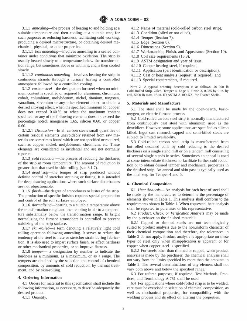
6.1 Heat Analysis— An analysis for each heat of steel shallbe made by the manufacturer to determine the percentage ofelements shown in Table 1. This analysis shall conform to therequirements shown in Table 1. When requested, heat analysisshall be reported to purchaser or his representative.
6.2 Product, Check, or Verification Analysismay be madeby the purchaser on the finished material.
6.2.1 Capped or rimmed steels are not technologicallysuited to product analysis due to the nonuniform character oftheir chemical composition and therefore, the tolerances inTable 2 do not apply. Product analysis is appropriate on thesetypes of steel only when misapplication is apparent or forcopper when copper steel is specified.
6.2.2 For steels other than rimmed or capped, when productanalysis is made by the purchaser, the chemical analysis shallnot vary from the limits specified by more than the amounts inTable 2. The several determinations of any element shall notvary both above and below the specified range.
6.3 For referee purposes, if required, Test Methods, Prac-tices, and Terminology A 751 shall be used.
6.4 For applications where cold-rolled strip is to be welded,care must be exercised in selection of chemical composition, aswell as mechanical properties, for compatibility with thewelding process and its effect on altering the properties.
A 109/A 109M – 03
2
7. Temper and Bend Test Requirement
7.1 Cold-rolled carbon strip specified to temper numbersshall conform to the Rockwell hardness requirements shown inTable 3.
7.1.1 When a temper number is not specified, rockwellhardness requirements are established by agreement.
7.2 It is recommended that hardness values be specified inthe same scale as that which will be used in testing the strip.
7.3 Bend tests shall be conducted at room temperature andtest specimens shall be capable of being bent to the require-ments shown in Table 4.
7.4 All mechanical tests are to be conducted in accordancewith Test Methods and Definitions A 370.
8. Edge
8.1 The desired edge number shall be specified as follows:8.1.1 Number 1 Edgeis a prepared edge of a specified
contour (round or square), which is produced when a very
accurate width is required or when an edge condition suitablefor electroplating is required, or both.
8.1.2 Number 2 Edgeis a natural mill edge carried throughthe cold rolling from the hot-rolled strip without additionalprocessing of the edge.
8.1.3 Number 3 Edgeis an approximately square edge,produced by slitting, on which the burr is not eliminated.Normal coiling or piling does not necessarily provide a definitepositioning of the slitting burr.
8.1.4 Number 4 Edgeis a rounded edge produced by edgerolling either the natural edge of hot-rolled strip or slit-edgestrip. This edge is produced when the width tolerance and edgecondition are not as exacting as for No. 1 edge.
TABLE 1 Heat Analysis A
Composition– Wt %
ElementTemper No.
1, 2, 3Temper No.
4, 5
Carbon, max 0.25 0.15Manganese, max 0.90 0.60Phosphorous, max 0.025 0.025Sulfur, max 0.025 0.025SiliconA . . . . . .AluminumA,B . . . . . .Copper, when copper steel is
specified, min0.20 0.20
Copper, maxC 0.20 0.20Nickel, maxC 0.20 0.20Chromium, maxC,D 0.15 0.15Molybdenum, maxC 0.06 0.06VanadiumE . . . . . .ColumbiumE . . . . . .TitaniumE . . . . . .
A Where an ellipsis (. . .) appears in this table, there is no requirement, but theanalysis shall be reported unless otherwise specified in this specification.
B The analysis shall be reported. When killed steel is specified and aluminum isthe deoxidizing element, the minimum is 0.02, and the analysis shall be reported.
C The sum of copper, nickel, chromium, and molybdenum shall not exceed0.50 % on heat analysis. When one or more of these elements is specified, thesum does not apply; in which case, only the individual limits on the remainingelements will apply.
D Chromium is permitted, at the producer’s option, to 0.25 % maximum when thecarbon is less than or equal to 0.05 %. In such case, the limit on the sum of the fourelements in Footnote C does not apply.
E Reporting shall be required when the level for any of these elements exceeds0.008 wt%.
TABLE 2 Tolerances for Product Analysis
ElementLimit or Maximumof Specified Ele-
ment %
Tolerance
UnderMinimum
Limit
OverMaxi-mumLimit
Carbon to 0.15, inclover 0.15 to 0.25, incl
0.020.03
0.030.04
Manganese to 0.60, incl 0.03 0.03Phosphorus ... 0.01Sulfur ... 0.01Copper 0.02 ...
TABLE 3 Hardness Requirements
INCH-POUND UNITS
Temper
Thickness, in. Rockwell Hardness
Under Through MinimumMaximum(approx.)
No. 1 (hard) 0.025 . . . 15T90 . . .0.040 0.025 30T76 . . .0.070 0.040 B90.0 . . .0.300 0.070 B84.0 . ..
No. 2A (half-hard) 0.025 . . . 15T83.5 15T88.50.040 0.025 30T63.5 30T73.50.300 0.040 B70.0 B85
No. 3A (quarter-hard) 0.025 . . . 15T80 15T850.040 0.025 30T56.5 30T670.300 0.040 B60 B75
No. 4A,B (skin-rolled) 0.025 . . . . . . 15T820.040 0.025 . . . 30T600.300 0.040 . . . B65
No. 5A,B (dead-soft) 0.025 . . . . . . . 15T78.50.040 0.025 . . . 30T530.300 0.040 . . . B55
SI UNITS
Thickness, mm Rockwell Hardness
TemperUnder Through Minimum
Maximun(approx.)
No. 1 (hard) 0.6 . . . 15T90 . . .1.0 0.6 30T76 . . .1.8 1.0 B90.0 . . .7.6 1.8 B84.0 . . .
No. 2A (half-hard) 0.6 . . . 15T83.5 15T88.51.0 0.6 30T63.5 30T73.57.6 1.0 B70.0 B85
No. 3A (quarter-hard) 0.6 . . . 15T80 15T851.0 0.6 30T56 30T677.6 1.0 B60 B75
No. 4A,B (skin-rolled) 0.6 . . . . . . 15T821.0 0.6 . . . 30T607.6 1.0 . . . B65
No. 5A,B (dead-soft) 0.6 . . . . . . 15T78.51.0 0.6 . . . 30T537.6 1.0 . . . B55
A Rockwell hardness values apply at time of shipment. Aging may cause slightlyhigher values when tested at a later date.
B Where No. 4 and 5 tempers are ordered with a carbon range of 0.15 to 0.25 %,the maximum hardness requirement is established by agreement.
A 109/A 109M – 03
3

8.1.5 Number 5 Edgeis an approximately square edgeproduced from slit-edge material on which the burr is elimi-nated usually by rolling or filing.
8.1.6 Number 6 Edgeis a square edge produced by edgerolling the natural edge of hot-rolled strip or slit-edge strip.This edge is produced when the width tolerance and edgecondition are not as exacting as for No. 1 edge.
8.1.7 Skived Edgesare custom shaped edges produced bymechanical edge shaving with special tooling.
9. Dimensional Tolerances
9.1 The dimensional tolerances shall be in accordance withTables 5-11 as follows:
Tolerances for Table Number
Thickness, in. 5Width, in. 6,7,8Length, in. 9Camber, in. 10Flatness, in. 11
10. Workmanship, Finish, and Appearance
10.1 Cut lengths shall have a workmanlike appearance andshall not have imperfections of a nature or degree for theproduct, the grade, and the description ordered that will bedetrimental to the fabrication of the finished part.
10.2 Coils may contain some abnormal imperfections whichrender a portion of the coil unusable since the inspection ofcoils does not afford opportunity to remove portions containingimperfections as in the case with cut lengths.
10.3 Cold-rolled strip steel finishes are usually specified toone of the following finishes. Typical surface roughness (Ra)ranges for each are included in Table 10.
10.3.1 Number 1 or Matte (Dull) Finishis a finish withoutluster produced by rolling on rolls roughened by mechanical orother means. This finish is especially suitable for paint adhe-sion and may aid in drawing by reducing friction between dieand steel surface. The user and the producer should agree onthe permissible surface roughness range, based on the intendedend-use.
TABLE 4 Bend Test Requirement
NOTE 1—Test specimens shall be capable of being bent as specifiedabove without cracking on the outside of the bent portion. (See applicablefigure in Test Methods and Definitions A 370.)
Temper Bend Test Requirement
No. 1 (hard) Not required to make bends in any direction.No. 2 (half-hard) Bend 90° transverse around a radius equal to that
of the thickness.No. 3 (quarter-hard) Bend 180° transverse over one thickness of the
strip and 90° longitudinal around a radius equalto the thickness.
No. 4 (skin-rolled) Bend flat upon itself in any direction.No. 5 (dead-soft) Bend flat upon itself in any direction.
TABLE 5 Thickness Tolerances of Cold-Rolled Carbon Steel Strip A,B,C
Cold-Rolled Carbon Strip Steel Including High-Carbon Strip Steel
Inch-Pound Units (in.)
Thickness Tolerances (Plus or Minus, in.)
NominalGage(in.)
Over 1⁄2 toless than12 wide
12 to lessthan 18
18 to 2315⁄16
0.251 - 0.300 0.0030 0.0035 0.00400.160 - 0.250 0.0025 0.0032 0.0036
0.125 - 0.1599 0.0022 0.0028 0.00320.070 - 0.1249 0.0018 0.0022 0.00280.040 - 0.0699 0.0014 0.0018 0.00240.030 - 0.0399 0.0012 0.0015 0.00200.020 - 0..0299 0.0010 0.0013 0.00150.015 - 0.0199 0.0008 0.0010 0.00120.010 - 0.0149 0.0005 0.0008 0.0010
<0.010 0.0003 0.0006 0.0008
SI Units (mm)
Thickness Tolerances (Plus and Minus, mm)
NominalGage(mm)
Over 12.7 toless than
300300 to lessthan 450 450 to 600
6.40 - 7.50 0.080 0.090 0.1004.00 - 6.39 0.065 0.080 0.0903.20 - 3.99 0.055 0.070 0.0801.80 - 3.19 0.045 0.055 0.0701.00 - 1.79 0.035 0.045 0.0600.75 - 0.99 0.030 0.035 0.0500.50 - 0.74 0.025 0.030 0.0400.38 - 0.49 0.020 0.025 0.0300.25 - 0.37 0.013 0.020 0.025
<0.25 0.007 0.015 0.020A Measured 3⁄8 in. or more in from edge; and on narrower than 1 in., at any place between edges.B Measured 10 mm or more in from edge; and on narrower than 25 mm, at any place between edges.C Number 3 edge strip with thickness tolerance guaranteed at less than 3⁄8 in. [10 mm] from the slit edge is available by agreement between the consumer and the strip
manufacturer.
A 109/A 109M – 03
4

10.3.2 Number 2 or Regular Bright Finishis produced byrolling on moderately smooth rolls. It is suitable for manyrequirements, but not generally applicable to bright plating.
10.3.3 Number 21⁄2 or Better Bright Finish is a smoothfinish suitable for those plating applications where high lusteris not required.
10.3.4 Number 3 or Best Bright Finishis generally of highluster produced by special rolling practices, including the useof specially prepared rolls. It is the highest quality finishcommonly produced and is particularly suited for brightplating. The production of this finish requires extreme care inprocessing and extensive inspection. Paper interleaving isfrequently used for protection. In addition to the surfaceroughness values in Table 12, the user and producer may agreeon goniophotometric measurement values (Rs/DI) in accor-dance with Test Methods E 430.
11. Inspection
11.1 When purchaser’s order stipulates that inspection andtests (except product analysis) for acceptance on the steel bemade prior to shipment from the mill, the manufacturer shallafford the purchaser’s inspector all reasonable facilities to
satisfy him that the steel is being manufactured and furnishedin accordance with the specification. Mill inspection by thepurchaser shall not interfere unnecessarily with the manufac-turer’s operation. All tests and inspection (except productanalysis) shall be made at the place of manufacture unlessotherwise agreed.
12. Rejection and Rehearing
12.1 Unless otherwise specified, any rejection shall bereported to the producer within a reasonable time after receiptof material by the purchaser.
12.2 Material that is reported to be defective subsequent tothe acceptance at the purchaser’s works shall be set aside,adequately protected, and correctly identified. The producershall be notified as soon as possible so that an investigationmay be initiated.
12.3 Samples that are representative of the rejected materialshall be made available to the producer. In the event that theproducer is dissatisfied with the rejection, he may request arehearing.
13. Test Reports and Certification
13.1 When test reports are required by the purchaser, thesupplier shall report the results of all tests required by thisspecification and any additional tests required by this specifi-cation and/or the purchase order.
13.2 When certification is required by the purchase order,the supplier shall furnish a certification that the material hasbeen manufactured and tested in accordance with the require-ments of this specification.
13.3 A signature is not required on test reports. However,the document shall clearly identify the organization submittingthe document. Notwithstanding the absence of a signature, theorganization submitting the document is responsible for thecontent of the document.
13.4 When test reports are required, it is acceptable for thesupplier to report test data from the original manufacturer,provided such data is not rendered invalid by the stripmakingprocess.
TABLE 6 Width Tolerances of Edge Numbers 1, 4, 5, and 6 ofCold-Rolled Carbon-Steel Strip
INCH - POUND UNITS
EdgeNumber
Specified Width, in.ASpecified Thickness,
in.BWidth
Tolerance,Plus and
Minus, in.COver Through min max
1 1⁄2 3⁄4 . . . 0.0938 0.0051 3⁄4 5 . . . 0.125 0.005
4 1⁄2 1 0.025 0.1875 0.0154 1 2 0.025 0.2499 0.0254 2 4 0.035 0.2499 0.0474 4 6 0.047 0.2499 0.047
5 1⁄2 3⁄4 . . . 0.0938 0.0055 3⁄4 5 . . . 0.125 0.0055 5 9 0.008 0.125 0.0105 9 20 0.015 0.105 0.0105 20 2315⁄16 0.023 0.080 0.015
6 1⁄2 1 0.025 0.1875 0.0156 1 2 0.025 0.2499 0.0256 2 4 0.035 0.2499 0.0476 4 6 0.047 0.2499 0.047
SI UNITS
Edge No.
Specified Width, mmA Specific Thickness,mmB
WidthTolerance,Plus and
Minus, in.COver Through min max
1 12.5 200 . . . 3.0 0.134 . . . 25 0.6 5.0 0.384 25 50 0.6 6.0 0.654 50 150 1.0 6.0 1.205 . . . 100 . . . 3.0 0.135 100 500 0.4 3.0 0.255 500 600 0.6 2.0 0.386 . . . 25 0.6 5.0 0.386 25 50 0.6 6.0 0.656 50 150 1.0 6.0 1.20
A Specified width must be within ranges stated for specified edge number.B Specified thickness must be within ranges stated for specified width.C When edge, width and thickness are not defined by this table, tolerances are
by agreement between producer and supplier.
TABLE 7 Width Tolerances of Edge Number 2 of Cold-RolledCarbon Steel Strip
INCH - POUND UNITS
Specified Width, in. Width Tolerance, Plus andMinus, in.Over Through
1⁄2 2 1⁄32
2 5 3⁄64
5 10 5⁄64
10 15 3⁄32
15 20 1⁄820 2315⁄16 5⁄32
SI UNITS
Specified Width, mm Width Tolerance, mm
Over Through Plus and Minus
12.5 50 0.850 100 1.2
100 200 1.6200 400 2.5400 500 3.0500 600 4.0
A 109/A 109M – 03
5

13.5 A Material Test Report, Certificate of Inspection, orsimilar document printed from or used in electronic form froman electronic data interchange (EDI) transmission shall beregarded as having the same validity as a counterpart printed inthe certifier’s facility. The content of the EDI transmitteddocument must meet the requirements of the invoked ASTMstandard(s) and conform to any existing EDI agreement be-tween the purchaser and the supplier. Notwithstanding theabsence of a signature, the organization submitting the EDItransmission is responsible for the context of the report.
NOTE 3—The industry definition as invoked here is: EDI is thecomputer to computer exchange of business information in an agreed uponstandard format such as ANSI ASC X12.
14. Product Marking
14.1 As a minimum requirement, the material shall beidentified by having the manufacturer’s name, ASTM designa-tion, weight, purchaser’s order number, and material identifi-cation legibly stenciled on the top of each lift or shown on a tagattached to the coils or shipping units.
14.2 Bar coding is acceptable as a supplementary identifi-cation method. Bar coding should be consistent with the
Automotive Industry Action Group (AIAG) standard preparedby the primary metals subcommittee of the AIAG bar codeproject team.
15. Packaging and Package Marking
15.1 Unless otherwise specified, the strip shall be packedand loaded in accordance with Practices A 700.
15.2 When specified in the contract or order, and for directprocurement by or direct shipment to the government whenLevel A is specified, preservation, packaging, and packing shallbe in accordance with the Level A requirements of MIL-STD-163.
15.3 When coils are ordered it is customary to specify aminimum or range of inside diameter, maximum outsidediameter, and a maximum coil weight, if required. The abilityof manufacturers to meet the maximum coil weights dependsupon individual mill equipment. When required, minimum coilweights are subject to negotiation.
16. Keywords
16.1 carbon steel, strip; cold rolled steel strip; steel strip
TABLE 8 Width Tolerances for Edge Number 3 (Slit), Cold-Rolled Carbon Steel Strip
INCH-POUND UNITS
Specified Thickness, in.Width Tolerance, Plus and Minus, in.
For Specified Width, in.A
Over ThroughOver 1⁄2Through
6
Over 6Through
9
Over 9Through
12
Over 12Through
20
Over 20Through2315⁄16
. . . 0.016 0.005 0.005 0.010 0.016 0.0200.016 0.068 0.005 0.005 0.010 0.016 0.0200.068 0.099 0.008 0.010 0.010 0.016 0.0200.099 0.160 0.010 0.016 0.016 0.020 0.0200.160 0.300 0.016 0.020 0.020 0.031 0.031
S.I. UNITSSpecified
Thickness mmWidth Tolerance, Plus and Minus, mm
For Specified Width, mmA
Over ThroughThrough
100
Over 100Through
200
Over200
Through300
Over 300Through
400
Over 450Through
600
. . . 1.5 0.13 0.13 0.25 0.40 0.501.5 2.5 0.20 0.25 0.25 0.40 0.502.5 4.5 0.25 0.40 0.40 0.50 0.504.5 7.5 0.40 0.50 0.50 0.80 0.80
A Width is measured from the shear surface of the slit edge and not from the break.
TABLE 9 Length Tolerances of Cold-Rolled Carbon Steel Strip
INCH-POUND UNITSSpecified Width,
in.Length Tolerance, Plus Only, in. for
Specified Length, in.
Over ThroughFrom 24
Through 60Over 60
Through 120Over 120
Through 2401⁄2 12 1⁄4 1⁄2 3⁄412 2315⁄16 1⁄2 3⁄4 1
SI UNITSSpecified Width,
mmLength Tolerance, Plus Only, mm for
Specified Length, mm
Over ThroughFrom 600
Through 1500Over 1500
Through 3000Over3000
. . . 300 10 15 25300 600 15 20 25
A 109/A 109M – 03
6
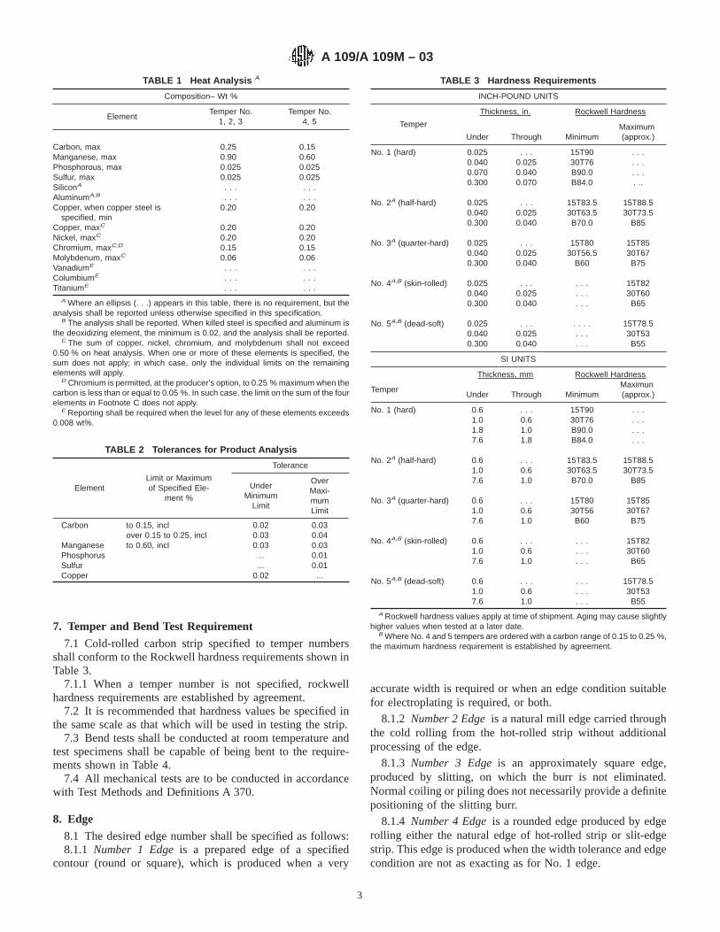
TABLE 10 Camber Tolerances of Cold-Rolled Carbon Steel Strip
INCH-POUND UNITS
Note 1—Camber is the greatest deviation of a side edge from a straight line,the measurement being taken on the concave side with a straight edge.Note 2—Camber tolerances as shown in the table are for any 8 ft. of length.For strip length under 8 ft., camber tolerance shall be subject to negotiation.Note 3—When the camber tolerances shown in Table 10 are suitable for aparticular purpose, cold-rolled strip is sometimes machine straightened.
W = Width of strip, in.C = Camber, in.
Specified Width, in.Camber Tolerance, in.
Over Through1⁄2 11⁄2 1⁄211⁄2 2315⁄16 1⁄4
SI UNITS
Note 1—Camber is the greatest deviation of a side edge from a straight line,the measurement being taken on the concave side with a straight edge.Note 2—Camber tolerances as shown in the table are for any 2000 mmlength. For strip length under 2000 mm, camber tolerance shall be subject tonegotiation.Note 3—When the camber tolerances shown in Table 10 are suitable for aparticular purpose, cold-rolled strip is sometimes machine straightened.
W = Width of strip, mmC = Camber, mm
Width, in. Standard Camber Tolerance,mmOver Through
. . . 50 1050 600 5
TABLE 11 Flatness Tolerances of Cold-Rolled Carbon SteelStrip
It has not been practical to formulate flatness tolerances for cold-rolled carbonsteel strip to represent the wide range of widths and thicknesses and varietyof tempers produced.
A 109/A 109M – 03
7

APPENDIX
(Nonmandatory Information)
X1. GENERAL INFORMATION AND METALLURGICAL ASPECTS
X1.1 Mechanical Properties
X1.1.1 Table X1.1 shows the approximate mechanical prop-erties corresponding to the five commercial tempers of cold-rolled carbon steel strip. This table is presented as a matter ofgeneral information. The limits of tensile strength, etc., are notintended as criteria for acceptance or rejection unless specifi-cally agreed to by the manufacturer when accepting the order.The exact processing by different manufacturers will naturallyvary slightly, so that absolute identity cannot be expected intheir commercial tempers of cold-rolled strip.
X1.2 Identified Part
X1.2.1 Cold-rolled carbon steel strip can be furnished in thevarious tempers to make an identified part provided thefabrication of the part is compatible with the grade and temperof the steel specified. Proper identification of parts may includevisual examination, prints or descriptions, or a combination ofthese. It is the general experience that most identified parts canbe satisfactorily produced from one of the tempers. There areapplications or requirements that necessitate additional con-trols or limit the choice of processing methods. For most endpart application only one kind of mechanical test requirement
is normally employed. This test requirement is generally theRockwell hardness test.
X1.3 Rockwell Scales and Loads
X1.3.1 Various scales and loads are employed in Rockwelltesting, depending on the hardness and thickness of the strip tobe tested. It is common practice to make the Rockwell hardnesstest at a point midway between the side edges on a singlethickness only. There is some overlapping among the differentscales, but the best scale to use in any given case is the onewhich will give the maximum penetration, without showingundue evidence of impression on the undersurface and withoutexceeding B100 or its equivalent on the dial. The use of alighter load results in a loss of sensitivity, while a heavier loadleads to a loss in accuracy. If the Rockwell ball is flattened byusing it on a hard sample, it should be replaced, otherwise thesubsequent readings will be affected. A tolerance for checktesting, of two Rockwell points on the B scale below theminimum and above the maximum of the range specified, iscommonly allowed to compensate for normal differences inequipment. It is recommended that hardness numbers bespecified to the same scale as that to be used during testing.
TABLE 12 Typical Surface Roughness Ranges A
Number 1 or Matte (Dull)B Ra 20-80 µin.Number 2 or Regular BrightC Ra 20 µin. maxNumber 21⁄2 or Better BrightC Ra 10 µin. maxNumber 3 or Best BrightC Ra 4 µin. max
A Due to vagaries in measuring surface roughness, as well as the inherent variability in such rolled surfaces, these values are only typical, and values outside theseranges would not be considered unexpected.
B Measured either parallel with or across the rolling direction.C Measured across the rolling direction.
TABLE X1.1 Approximate Mechanical Properties for Various Tempers of Cold-Rolled Carbon Strip
NOTE 1—These values are given as information only and are not intended as criteria for acceptance or rejection. S.I. units appear in brackets.
TemperTensile Strength,A
† psi [MPa]
Elongation in 2 in. (50 mm)for 0.050 in. (1.27 mm)Thickness of Strip,B %
Remarks
No. 1 (hard) 90 000 6 10 000[620 6 70]
. . . A very stiff, cold-rolled strip intended for flat blanking only, and not requiringability to withstand cold forming.
No. 2 (half-hard) 65 000 6 10 000[450 6 70]
10 6 6 A moderately stiff cold-rolled strip intended for limited bending.
No. 3 (quarter-hard) 55 000 6 10 000[380 6 70]
20 6 7 A medium soft cold-rolled strip intended for limited bending, shallow drawingand stamping.
No. 4 (skin-rolled) 48 000 6 6 000[330 6 40]
32 6 8 A soft ductile cold-rolled strip intended for deep drawing where no surface strainor fluting is permissible.C
No. 5 (dead-soft) 44 000 6 6 000[300 6 40]
39 6 6 A soft ductile cold-rolled strip intended for deep drawing where stretcher strainsor fluting are permissible.C Also for extrusions.
A Tensile properties are based on the standard tension-test specimen for sheet metals, see appropriate figure in Test Methods and Definitions A 370.B Elongation in 2 in. (50 mm) varies with thickness of strip. For Temper No. 5, dead-soft temper, the percentage of elongation = 41 + 10 log “ t” (t = thickness, in. (mm)).
Other tempers vary in a similar way.C See X1.4 for Aging Phenomenon.
† Editorially changed from ksi to psi.
A 109/A 109M – 03
8
X1.4 Aging Phenomenon
X1.4.1 Although the maximum ductility is obtained in steelstrip in its dead soft (annealed last) condition, such strip isunsuited for many forming operations due to its tendency tostretcher strain or flute. A small amount of cold rolling(skin-rolling) will prevent this tendency, but the effect is onlytemporary due to a phenomenon called aging. The phenom-
enon of aging is accompanied by a loss of ductility with anincrease in hardness, yield point, and tensile strength. For thoseuses in which stretcher straining, fluting, or breakage due toaging of the steel is likely to occur, the steel should befabricated as promptly as possible after skin-rolling. When theabove aging characteristics are undesirable, special killed(generally aluminum killed) steel is used.
SUMMARY OF CHANGES
This section identifies the location of selected changes to this standard that have been incorporated since theA 109/A 109M-00e1 issue. For the convenience of the user, Committee A01 has highlighted those changes thatimpact the use of this standard. This section may also include descriptions of changes or reasons for changes,or both.
(1) Revisions were made to Table 1 and Table 5.
ASTM International takes no position respecting the validity of any patent rights asserted in connection with any item mentionedin this standard. Users of this standard are expressly advised that determination of the validity of any such patent rights, and the riskof infringement of such rights, are entirely their own responsibility.
This standard is subject to revision at any time by the responsible technical committee and must be reviewed every five years andif not revised, either reapproved or withdrawn. Your comments are invited either for revision of this standard or for additional standardsand should be addressed to ASTM International Headquarters. Your comments will receive careful consideration at a meeting of theresponsible technical committee, which you may attend. If you feel that your comments have not received a fair hearing you shouldmake your views known to the ASTM Committee on Standards, at the address shown below.
This standard is copyrighted by ASTM International, 100 Barr Harbor Drive, PO Box C700, West Conshohocken, PA 19428-2959,United States. Individual reprints (single or multiple copies) of this standard may be obtained by contacting ASTM at the aboveaddress or at 610-832-9585 (phone), 610-832-9555 (fax), or [email protected] (e-mail); or through the ASTM website(www.astm.org).
A 109/A 109M – 03
9

Designation: A 167 – 99
Standard Specification forStainless and Heat-Resisting Chromium-Nickel Steel Plate,Sheet, and Strip 1
This standard is issued under the fixed designation A 167; the number immediately following the designation indicates the year oforiginal adoption or, in the case of revision, the year of last revision. A number in parentheses indicates the year of last reapproval. Asuperscript epsilon (e) indicates an editorial change since the last revision or reapproval.
This standard has been approved for use by agencies of the Department of Defense.
1. Scope
1.1 This specification covers stainless and heat-resistingchromium-nickel steel plate, sheet, and strip.
1.2 The values stated in inch-pound units are to be regardedas the standard.
NOTE 1—Grades that were previously covered in both SpecificationsA 167 and A 240/A 240M have been removed from this specification andmay now be supplied and purchased in compliance with SpecificationA 240/A 240M. The chemical and mechanical property requirements ofthese grades were identical in Specifications A 167 and A 240/A 240M atthe time of removal from Specification A 167.
2. Referenced Documents
2.1 ASTM Standards:A 240/A240M Specification for Heat-Resisting Chromium
and Chromium-Nickel Stainless Steel Plate, Sheet andStrip for Pressure Vessels2
A 370 Test Methods and Definitions for Mechanical Testingof Steel Products2
A 480/A480M Specification for General Requirements forFlat-Rolled Stainless and Heat-Resisting Steel Plate,Sheet, and Strip2
E 527 Practice for Numbering Metals and Alloys (UNS)3
2.2 SAE Standard:J 1086 Numbering Metals and Alloys (UNS)4
3. Chemical Composition
3.1 The steel shall conform to the requirements as tochemical composition specified in Table 1, and shall conformto applicable requirements specified in Specification A 480/A 480M.
4. Mechanical Properties
4.1 The material shall conform to the mechanical propertiesspecified in Table 2.
5. General Requirements
5.1 The following requirements for orders for materialfurnished under this specification shall conform to the appli-cable requirements of the current edition of SpecificationA 480/A 480M.
5.1.1 Definitions,5.1.2 General requirements for delivery,5.1.3 Ordering information,5.1.4 Process,5.1.5 Heat treatment,5.1.6 Special tests,5.1.7 Dimensions and permissible variations,5.1.8 Workmanship, finish and appearance,5.1.9 Number of tests,5.1.10 Specimen preparation,5.1.11 Retreatment,5.1.12 Inspection,5.1.13 Rejection and rehearing,5.1.14 Material test report,5.1.15 Certification, and5.1.16 Packaging, marking, and loading.
1 This specification is under the jurisdiction of ASTM Committee A-1 on Steel,Stainless Steel and Related Alloysand is the direct responsibility of SubcommitteeA01.17 on Flat Stainless Steel Products.
Current edition approved Sept. 10, 1999. Published November 1999. Originallypublished as A 167 – 35 T. Last previous edition A 167 – 96.
2 Annual Book of ASTM Standards, Vol 01.03.3 Annual Book of ASTM Standards, Vol 01.01.4 Available from Society of Automotive Engineers, 400 Commonwealth Drive,
Warrendale, PA 15096.
1
Copyright © ASTM International, 100 Barr Harbor Drive, PO Box C700, West Conshohocken, PA 19428-2959, United States.
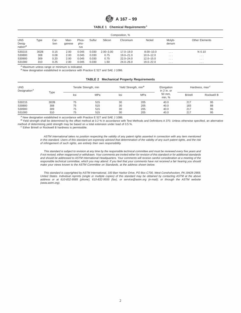
TABLE 1 Chemical Requirements A
Composition, %
UNSDesig-nationB
Type Car-bon
Man-ganese
Phos-pho-rus
Sulfur Silicon Chromium Nickel Molyb-denum
Other Elements
S30215 302B 0.15 2.00 0.045 0.030 2.00–3.00 17.0–19.0 8.00–10.0 . . . N 0.10S30800 308 0.08 2.00 0.045 0.030 0.75 19.0–21.0 10.0–12.0 . . . . . .S30900 309 0.20 2.00 0.045 0.030 0.75 22.0–24.0 12.0–15.0 . . . . . .S31000 310 0.25 2.00 0.045 0.030 1.50 24.0–26.0 19.0–22.0 . . . . . .
A Maximum unless range or minimum is indicated.B New designation established in accordance with Practice E 527 and SAE J 1086.
TABLE 2 Mechanical Property Requirements
UNSDesignationA
Type
Tensile Strength, min Yield Strength, minB Elongationin 2 in. or50 mm,min, %
Hardness, maxC
ksi MPa ksi MPa Brinell Rockwell B
S30215 302B 75 515 30 205 40.0 217 95S30800 308 75 515 30 205 40.0 183 88S30900 309 75 515 30 205 40.0 217 95S31000 310 75 515 30 205 40.0 217 95
A New designation established in accordance with Practice E 527 and SAE J 1086.B Yield strength shall be determined by the offset method at 0.2 % in accordance with Test Methods and Definitions A 370. Unless otherwise specified, an alternative
method of determining yield strength may be based on a total extension under load of 0.5 %.C Either Brinell or Rockwell B hardness is permissible.
ASTM International takes no position respecting the validity of any patent rights asserted in connection with any item mentionedin this standard. Users of this standard are expressly advised that determination of the validity of any such patent rights, and the riskof infringement of such rights, are entirely their own responsibility.
This standard is subject to revision at any time by the responsible technical committee and must be reviewed every five years andif not revised, either reapproved or withdrawn. Your comments are invited either for revision of this standard or for additional standardsand should be addressed to ASTM International Headquarters. Your comments will receive careful consideration at a meeting of theresponsible technical committee, which you may attend. If you feel that your comments have not received a fair hearing you shouldmake your views known to the ASTM Committee on Standards, at the address shown below.
This standard is copyrighted by ASTM International, 100 Barr Harbor Drive, PO Box C700, West Conshohocken, PA 19428-2959,United States. Individual reprints (single or multiple copies) of this standard may be obtained by contacting ASTM at the aboveaddress or at 610-832-9585 (phone), 610-832-9555 (fax), or [email protected] (e-mail); or through the ASTM website(www.astm.org).
A 167 – 99
2

Designation: A 176 – 99
Standard Specification forStainless and Heat-Resisting Chromium Steel Plate, Sheet,and Strip 1
This standard is issued under the fixed designation A 176; the number immediately following the designation indicates the year oforiginal adoption or, in the case of revision, the year of last revision. A number in parentheses indicates the year of last reapproval. Asuperscript epsilon (e) indicates an editorial change since the last revision or reapproval.
This standard has been approved for use by agencies of the Department of Defense.
1. Scope
1.1 This specification covers stainless and heat-resistingchromium steel plate, sheet, and strip available in a widevariety of surface finishes.
1.2 The values stated in inch-pound units are to be regardedas the standard.
NOTE 1—Grades that were previously covered in both SpecificationsA 176 and A 240/A 240M have been removed from this specification andmay now be supplied and purchased in compliance with SpecificationA 240/A 240M. The chemical and mechanical property requirements ofthese grades were identical in Specifications A 176 and A 240/A 240M atthe time of removal from Specification A 176.
2. Referenced Documents
2.1 ASTM Standards:A 240/A240M Specification for Heat-Resisting Chromium
and Chromium-Nickel Stainless Steel Plate, Sheet andStrip for Pressure Vessels2
A 370 Test Methods and Definitions for Mechanical Testingof Steel Products2
A 480/A480M Specification for General Requirements forFlat-Rolled Stainless and Heat-Resisting Steel Plate,Sheet, and Strip2
E 527 Practice for Numbering Metals and Alloys (UNS)3
2.2 SAE Standard:J1086 Practice for Unified Numbering for Metals and Al-
loys (UNS)4
3. Chemical Composition
3.1 The steel shall conform to the requirements as tochemical composition specified in Table 1, and shall conformto applicable requirements specified in Specification A 480/A 480M.
4. Mechanical Properties
4.1 The material shall conform to the mechanical propertiesspecified in Table 2.
5. General Requirements
5.1 The following requirements for orders for materialfurnished under this specification shall conform to the appli-cable requirements of the current edition of SpecificationA 480/A480M.
5.1.1 Definitions,5.1.2 General requirements for delivery,5.1.3 Ordering information,5.1.4 Process,5.1.5 Special tests,5.1.6 Heat treatment,5.1.7 Dimensions and permissible variations,5.1.8 Workmanship, finish and appearance,5.1.9 Number of tests/test methods,5.1.10 Specimen preparation,5.1.11 Retreatment,5.1.12 Inspection,5.1.13 Rejection and rehearing,5.1.14 Material test report, and5.1.15 Certification.
1 This specification is under the jurisdiction of ASTM Committee A-1 on Steel,Stainless Steel and Related Alloysand is the direct responsibility of SubcommitteeA01.17 on Flat Stainless Steel Products.
Current edition approved Sept. 10, 1999. Published November 1999. Originallypublished as A 176 – 35 T. Last previous edition A 176 – 97.
2 Annual Book of ASTM Standards, Vol 01.03.3 Annual Book of ASTM Standards, Vol 01.01.4 Available from the Society for Automotive Engineers, 400 Commonwealth
Drive, Warrendale, PA 15096.
1
Copyright © ASTM International, 100 Barr Harbor Drive, PO Box C700, West Conshohocken, PA 19428-2959, United States.

ASTM International takes no position respecting the validity of any patent rights asserted in connection with any item mentionedin this standard. Users of this standard are expressly advised that determination of the validity of any such patent rights, and the riskof infringement of such rights, are entirely their own responsibility.
This standard is subject to revision at any time by the responsible technical committee and must be reviewed every five years andif not revised, either reapproved or withdrawn. Your comments are invited either for revision of this standard or for additional standardsand should be addressed to ASTM International Headquarters. Your comments will receive careful consideration at a meeting of theresponsible technical committee, which you may attend. If you feel that your comments have not received a fair hearing you shouldmake your views known to the ASTM Committee on Standards, at the address shown below.
This standard is copyrighted by ASTM International, 100 Barr Harbor Drive, PO Box C700, West Conshohocken, PA 19428-2959,United States. Individual reprints (single or multiple copies) of this standard may be obtained by contacting ASTM at the aboveaddress or at 610-832-9585 (phone), 610-832-9555 (fax), or [email protected] (e-mail); or through the ASTM website(www.astm.org).
TABLE 1 Chemical Requirements A
UNSDesignationB Type
Composition, %
Carbon Manganese Phosphorus Sulfur Silicon Chromium Nickel Nitrogen Other ElementsC
S40300 403 0.15 1.00 0.040 0.030 0.50 11.5–13.0 0.60 . . . . . .S42000 420 0.15 min 1.00 0.040 0.030 1.00 12.0–14.0 0.75 . . . Mo 0.50 max
S42200 422 0.20–0.25 0.50–1.00 0.025 0.025 0.50 11.0–12.5 0.50–1.00 . . . Mo 0.90-1.25V 0.20-0.30W 0.90-1.25
S43100 431 0.20 1.00 0.040 0.030 1.00 15.0–17.0 1.25–2.50 . . . . . .S44200 442 0.20 1.00 0.040 0.040 1.00 18.0–23.0 0.60 . . . . . .S44600 446 0.20 1.50 0.040 0.030 1.00 23.0–27.0 0.75 0.25 . . .
A Maximum unless range or minimum is indicated.B New designation established in accordance with Practice E 527 and SAE J1086.C The terms Columbium (Cb) and Niobium (Nb) both relate to the same element.
TABLE 2 Mechanical Test Requirements
UNSDesignation
TypeTensile Strength, min Yield Strength, minA Elongation
in 2 in. or50 mm,min, %
Hardness, maxB
Cold Bend,degC
ksi MPa ksi MPa Brinell Rockwell B
S40300 403 70 485 30 205 25.0D 217 96 180S42000 420 100E 690 . . . . . . 15.0 217 96 . . .S42200 422 . . . . . . . . . . . . . . . 248 24F not requiredS43100 431 . . . . . . . . . . . . . . . 285 29F not requiredS44200 442 65 515 40 275 20.0 217 96 180S44600 446 65 515 40 275 20.0 217 96 135
A Yield strength shall be determined by the offset method at 0.2 % in accordance with Test Methods and Definitions A 370. Unless otherwise specified (see 5.1.10), analternative method of determining yield strength may be based on a total extension under load of 0.5 %.
B Either Brinell or Rockwell B hardness is permissible.C Bend test not required for steels thicker than 1 in. (25.4 mm) unless specified by the purchaser.D Material 0.050 in. (1.27 mm) and under in thickness shall have a minimum elongation of 20.0 %.E Maximum. Type 420 is usually used in the heat treated condition (quenched and tempered to a specified range of hardness or tensile strength).F Rockwell C scale.
A 176 – 99
2
Designation: A 227/A 227M – 99
Standard Specification forSteel Wire, Cold-Drawn for Mechanical Springs 1
This standard is issued under the fixed designation A 227/A 227M; the number immediately following the designation indicates the yearof original adoption or, in the case of revision, the year of last revision. A number in parentheses indicates the year of last reapproval.A superscript epsilon (e) indicates an editorial change since the last revision or reapproval.
This standard has been approved for use by agencies of the Department of Defense.
1. Scope
1.1 This specification covers two classes of round cold-drawn steel spring wire having properties and quality for themanufacture of mechanical springs that are not subject to highstress or requiring high fatigue properties and wire forms.
1.2 The values stated in either SI (metric) units or inch-pound units are to be regarded separately as standard. Thevalues stated in each system are not exact equivalents; there-fore, each system must be used independent of the other.
2. Referenced Documents
2.1 ASTM Standards:A 370 Test Methods and Definitions for Mechanical Testing
of Steel Products2
A 510 Specification for General Requirements for WireRods and Coarse Round Wire, Carbon Steel2
A 510M Specification for General Requirements for WireRods and Coarse Round Wire, Carbon Steel [Metric]2
A 700 Practices for Packaging, Marking, and LoadingMethods for Steel Products for Domestic Shipment3
A 751 Test Methods, Practices, and Terminology forChemical Analysis of Steel Products2
A 941 Terminology Relating to Steel, Stainless Steel, Re-lated Alloys and Ferroalloys2
E 29 Practice for Using Significant Digits in Test Data toDetermine Conformance with Specifications4
2.2 American National Standard:B 32.4M Preferred Metric Sizes for Round, Square, Rec-
tangle, and Hexagon Metal Products5
2.3 Military Standard:
MIL-STD-163 Steel Mill Products, Preparation for Ship-ment and Storage6
2.4 Federal Standard:Fed. Std. No. 123 Marking for Shipment (Civil Agencies)6
2.5 AIAG Standard:AIAG B-5 02.00 Primary Metals Identification Tag Appli-
cation Standard7
3. Terminology
3.1 Definitions of Terms Specific to This Standard:3.1.1 For definition of terms used in this specification, refer
to Terminology A 941.
4. Ordering Information
4.1 It shall be the responsibility of the purchaser to specifyall requirements that are necessary for material under thisspecification. Such requirement may include, but are notlimited to, the following:
4.1.1 Quantity (mass),4.1.2 Name of material (cold-drawn steel mechanical spring
wire) and class (Table 1 or Table 2),4.1.3 Wire diameter (Table 1 or Table 2),4.1.4 Packaging (Section 15),4.1.5 Cast or heat analysis report, if requested (Section 6),4.1.6 Certification or test report, or both, if specified (Sec-
tion 14), and4.1.7 ASTM designation and date of issue.
NOTE 1—A typical ordering description is as follows: 15 000 kgCold-Drawn Mechanical Spring Wire, Class I, Size 5.00 mm in 700-kgcoils to ASTM A 227M dated_______ , or for non-SI units, 30 000 lbCold-Drawn Mechanical Spring Wire, Class I, Size 0.207 in. diameter in500-lb coils to ASTM A 227 dated_______ .
5. Manufacture
5.1 The steel may be made by any commercially acceptedsteel-making process. The steel may be either ingot cast orstrand cast.
1 This specification is under the jurisdiction of ASTM committee A-1 on Steel,Stainless Steel, and Related Alloys and is the direct responsibility of SubcommitteeA01.03 on Steel Rod and Wire.
Current edition approved March 10, 1999. Published May 1999. Originallypublished as A 227 – 39 T and A 227M – 80. Last previous edition A 227/A 227M – 93.
2 Annual Book of ASTM Standards, Vol 01.03.3 Annual Book of ASTM Standards, Vol 01.05.4 Annual Book of ASTM Standards, Vol 14.02.5 Available from American National Standards Institute, 11 West 42nd Street,
13th Floor, New York, NY 10036.
6 Available from Standardization Documents Order Desk, Bldg. 4 Section D, 700Robbins Ave., Philadelphia, PA 19111-5094, Attn: NPODS.
7 Available from the Automotive Industry Action Group, 26200 Lahser, Suite200, Southfield, MI 48034.
1
Copyright © ASTM International, 100 Barr Harbor Drive, PO Box C700, West Conshohocken, PA 19428-2959, United States.

5.2 The finished wire shall be free of detrimental pipe andundue segregation.
5.3 The wire shall be cold drawn to produce the desiredmechanical properties.
6. Chemical Composition
6.1 The steel shall conform to the requirements for chemicalcomposition prescribed in Table 3.
6.2 Cast or Heat Analysis—Each cast or heat of steel shallbe analyzed by the manufacturer to determine the percentage ofelements prescribed in Table 3. This analysis shall be madefrom a test specimen preferably taken during the pouring of thecast or heat. When requested, this shall be reported to thepurchaser and shall conform to the requirements of Table 3.
6.3 Product Analysis—An analysis may be made by thepurchaser from finished wire representing each cast or heat ofsteel. The chemical composition thus determined, as to ele-ments required or restricted, shall conform to the productanalysis requirements specified in Table 10 of SpecificationA 510 or A 510M.
6.4 For referee purposes, Test Methods, Practices and Ter-minology, A 751 shall be used.
7. Mechanical Properties
7.1 Tension Test:
7.1.1 Requirements—The material as represented by tensiontest specimens shall conform to the requirements prescribed inTable 1 or Table 2.
7.1.2 Number of Tests—One test specimen shall be taken foreach ten coils or fraction thereof, in a lot. Each cast or heat ina given lot shall be tested.
7.1.3 Location of Tests—Test specimens shall be taken fromeither end of the coil.
7.1.4 Test Method—The tension test shall be made inaccordance with Test Methods and Definitions A 370.
7.2 Wrap Test:7.2.1 Requirements—The material as represented by the
wrap test specimens shall conform to the requirements speci-fied in Table 4 or Table 5. Wrap test on wires over 8.5 mm or
TABLE 1 Tensile Requirements, SI Units A
Diameter,B
mm
Class I Class II
Tensile Strength, MPa Tensile Strength MPa
min max min max
0.50 1960 2240 2240 25200.55 1940 2220 2220 25000.60 1920 2200 2200 24800.65 1900 2180 2180 24600.70 1870 2140 2140 24100.80 1830 2100 2100 23700.90 1800 2070 2070 23401.00 1770 2040 2040 23101.10 1740 2000 2000 22601.20 1720 1980 1980 22401.40 1670 1930 1930 21801.60 1640 1880 1880 21201.80 1600 1840 1840 20802.00 1580 1810 1810 20402.20 1550 1780 1780 20102.50 1510 1730 1730 19602.80 1480 1700 1700 19203.00 1460 1680 1680 19003.50 1420 1630 1630 18404.00 1380 1590 1600 17004.50 1350 1550 1550 17505.00 1320 1510 1510 17005.50 1300 1490 1490 16706.00 1280 1470 1470 16506.50 1250 1440 1440 16307.00 1220 1410 1410 16007.50 1200 1390 1390 15808.00 1190 1370 1370 15509.00 1160 1340 . . . . . .
10.00 1130 1310 . . . . . .11.00 1110 1280 . . . . . .12.00 1090 1260 . . . . . .14.00 1050 1210 . . . . . .16.00 1010 1170 . . . . . .
A Tensile strength values for intermediate diameters may be interpolated.B Preferred sizes. For a complete list, refer to ANSI B32.4M, Preferred Metric
Sizes for Round, Square, Rectangle, and Hexagon Metal Products.
TABLE 2 Tensile Requirements, Inch-Pound Units A
Diameter, in.
Class I Class II
Tensile Strength, ksi Tensile Strength, ksi
min max min max
0.020 283 323 324 3640.023 279 319 320 3600.026 275 315 316 3560.029 271 311 312 3520.032 266 306 307 3470.035 261 301 302 3420.041 255 293 294 3320.048 248 286 287 3250.054 243 279 280 3160.062 237 272 273 3080.072 232 266 267 3010.080 227 261 262 2960.092 220 253 254 2870.106 216 248 249 2810.120 210 241 242 2730.135 206 237 238 2690.148 203 234 235 2660.162 200 230 231 2610.177 195 225 226 2560.192 192 221 222 2510.207 190 218 219 2470.225 186 214 215 2430.250 182 210 211 2390.312 174 200 201 2270.375 167 193 194 2200.438 165 190 191 2160.500 156 180 181 2050.562 152 176 177 2010.625 147 170 171 294
A Tensile strength values for intermediate diameters shall be interpolated.
TABLE 3 Chemical Requirements
Element Composition, %
Carbon 0.45–0.85A
Manganese 0.30–1.30B
Phosphorus, max 0.040Sulfur, max 0.050Silicon 0.15–0.35A Carbon in any one lot shall not vary more than 0.13 %.B Manganese in any one lot shall not vary more than 0.30 %.
TABLE 4 Wrap Test Requirements, SI Units
Diameter, mmMandrel Size
Class I Class II0.50 to 4.0, inclOver 4.0 to 8.0, incl
1XA
2X2X4X
A For 1X mandrel, wire shall be wrapped on itself.
A 227/A 227M – 99
2
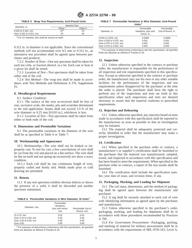
0.312 in. in diameter is not applicable. Since the conventionalmethods will not accommodate over 8.5 mm or 0.312 in., analternative test procedure shall be agreed upon between pur-chaser and producer.
7.2.2 Number of Tests—One test specimen shall be taken foreach ten coils, or fraction thereof, in a lot. Each cast or heat ina given lot shall be tested.
7.2.3 Location of Test—Test specimens shall be taken fromeither end of the coil.
7.2.4 Test Method—The wrap test shall be made in accor-dance with Test Methods and Definitions A 370, SupplementIV.
8. Metallurgical Requirements
8.1 Surface Condition:8.1.1 The surface of the wire as-received shall be free of
rust, excessive scale, die marks, pits and scratches detrimentalto the end application. Seams shall not exceed 3.5 % of thewire diameter or 0.25 mm [0.010 in.], whichever is less.
8.1.2 Location of Test—Test specimens shall be taken fromeither or both ends of the coil.
9. Dimensions and Permissible Variations
9.1 The permissible variations in the diameter of the wireshall be as specified in Table 6 or Table 7.
10. Workmanship and Appearance
10.1 Workmanship—The wire shall not be kinked or im-properly cast. To test for cast, a few convolutions of wire shallbe cut from the coil and placed on a flat surface. The wire shalllie flat on itself and not spring up excessively nor show a wavycondition.
10.1.1 Each coil shall be one continuous length of wire,properly coiled and firmly tied. Welds made prior to colddrawing are permitted.
11. Retests
11.1 If any test specimen exhibits obvious defects or showsthe presence of a weld, it shall be discarded and anotherspecimen substituted.
12. Inspection
12.1 Unless otherwise specified in the contract or purchaseorder, the manufacturer is responsible for the performance ofall inspection and test requirements specified in this specifica-tion. Except as otherwise specified in the contract or purchaseorder, the manufacturer may use his own or any other suitablefacilities for the performance of the inspection and testrequirements unless disapproved by the purchaser at the timethe order is placed. The purchaser shall have the right toperform any of the inspections and tests set forth in thisspecification when such inspections and tests are deemednecessary to assure that the material conforms to prescribedrequirements.
13. Rejection and Rehearing
13.1 Unless otherwise specified, any rejection based on testsmade in accordance with this specification shall be reported tothe manufacturer as soon as possible so that an investigationmay be initiated.
13.2 The material shall be adequately protected and cor-rectly identified in order that the manufacturer may make aproper investigation.
14. Certification
14.1 When specified in the purchase order or contract, amanufacturer’s or supplier’s certification shall be furnished tothe purchaser that the material was manufactured, sampled,tested, and inspected in accordance with this specification andhas been found to meet the requirements. When specified in thepurchase order or contract, a report of the test results shall befurnished.
14.2 The certification shall include the specification num-ber, year date of issue, and revision letter, if any.
15. Packaging, Marking, and Loading for Shipment
15.1 The coil mass, dimensions, and the method of packag-ing shall be agreed upon between the manufacturer andpurchaser.
15.2 A tag shall be securely attached to each coil of wirewith identifying information as agreed upon by the purchaserand manufacturer.
15.3 Unless otherwise specified in the purchaser’s order,packaging, marking, and loading for shipments shall be inaccordance with those procedures recommended by PracticesA 700.
15.4 For Government Procurement—Packaging, packing,and marking of material for military procurement shall be inaccordance with the requirements of MIL-STD-163, Level A,
TABLE 5 Wrap Test Requirements, Inch-Pound Units
Diameter, in.Mandrel Size
Class I Class II0.020 to 0.162, incl 1XA 2XOver 0.162 to 0.312, incl 2X 4X
A For 1X mandrel, wire shall be wound on itself.
TABLE 6 Permissible Variations in Wire Diameter, SI Units A
Diameter, mm
PermissibleVariations,
plus and minus,mm
Permissible Out-ofRound, mm
To 0.70, incl 0.02 0.02Over 0.70 to 2.00, incl 0.03 0.03Over 2.00 to 9.00, incl 0.05 0.05Over 9.00 0.08 0.08
A For purposes of determining conformance with this specification, all specifiedlimits are absolute as defined in Practice E 29.
TABLE 7 Permissible Variations in Wire Diameter, Inch-PoundUnits A
Diameter, in.Permissible
Variations, plus andminus, in.
PermissibleOut-of-Round, in.
0.020 to 0.028, incl 0.0008 0.0008Over 0.028 to 0.075, incl 0.001 0.001Over 0.075 to 0.375, incl 0.002 0.002Over 0.375 to 0.625, incl 0.003 0.003
A For purposes of determining conformance with this specification, all specifiedlimits are absolute as defined in Practice E 29.
A 227/A 227M – 99
3

Level C, or commercial as specified in the contract or purchaseorder. Marking for shipment of material for civil agencies shallbe in accordance with Fed. Std. No. 123.
15.5 Bar Coding—In addition to the previously statedidentification requirements, bar coding is acceptable as asupplementary identification method. Bar coding should be
consistent with AIAG Standard 02.00, Primary Metals Identi-fication Tag Application. The bar code may be applied to asubstantially affixed tag.
16. Keywords
16.1 cold-drawn; springs; wire
ASTM International takes no position respecting the validity of any patent rights asserted in connection with any item mentionedin this standard. Users of this standard are expressly advised that determination of the validity of any such patent rights, and the riskof infringement of such rights, are entirely their own responsibility.
This standard is subject to revision at any time by the responsible technical committee and must be reviewed every five years andif not revised, either reapproved or withdrawn. Your comments are invited either for revision of this standard or for additional standardsand should be addressed to ASTM International Headquarters. Your comments will receive careful consideration at a meeting of theresponsible technical committee, which you may attend. If you feel that your comments have not received a fair hearing you shouldmake your views known to the ASTM Committee on Standards, at the address shown below.
This standard is copyrighted by ASTM International, 100 Barr Harbor Drive, PO Box C700, West Conshohocken, PA 19428-2959,United States. Individual reprints (single or multiple copies) of this standard may be obtained by contacting ASTM at the aboveaddress or at 610-832-9585 (phone), 610-832-9555 (fax), or [email protected] (e-mail); or through the ASTM website(www.astm.org).
A 227/A 227M – 99
4
Designation: A 228/A 228M – 02
Standard Specification forSteel Wire, Music Spring Quality 1
This standard is issued under the fixed designation A 228/A 228M; the number immediately following the designation indicates the yearof original adoption or, in the case of revision, the year of last revision. A number in parentheses indicates the year of last reapproval.A superscript epsilon (e) indicates an editorial change since the last revision or reapproval.
This standard has been approved for use by agencies of the Department of Defense.
1. Scope
1.1 This specification covers a high quality, round, cold-drawn steel music spring quality wire, uniform in mechanicalproperties, intended especially for the manufacture of springssubject to high stresses or requiring good fatigue properties.
1.2 The values stated in either SI (metric) units or inch-pound units are to be regarded separately as standard. Thevalues stated in each system are not exact equivalents; there-fore, each system must be used independently of the other.
2. Referenced Documents
2.1 ASTM Standards:A 370 Test Methods and Definitions for Mechanical Testing
of Steel Products2
A 510 Specification for General Requirements for WireRods and Coarse Round Wire, Carbon Steel2
A 510M Specification for General Requirements for WireRods and Coarse Round Wire, Carbon Steel [Metric]2
A 700 Practices for Packaging, Marking, and LoadingMethods for Steel Products for Domestic Shipment3
A 751 Test Methods, Practices, and Terminology forChemical Analysis of Steel Products2
A 938 Standard Test Method for Torsion Testing of Wire2
A 941 Terminology Relating to Steel, Stainless Steel, Re-lated Alloys, and Ferroalloys4
E 29 Practice for Using Significant Digits in Test Data toDetermine Conformance with Specifications5
E 1077 Test Method for Estimating the Depth of Decarbur-ization of Steel Specimens6
2.2 Military Standard:MIL-STD-163 Steel Mill Products, Preparation for Ship-
ment and Storage7
2.3 Federal Standard:Fed. Std. No. 123, Marking for Shipment (Civil Agencies)7
2.4 American National Standard:B32.4 Preferred Metric Sizes for Round, Square, Rectangle,
and Hexagon Metal Products8
2.5 AIAG Standard:AIAG B-5 02.00 Primary Metals Identification Tag Appli-
cation Standard9
3. Terminology
3.1 Definitions—For definitions of terms used in this speci-fication, refer to Terminology A 941.
4. Ordering Information
4.1 It shall be the responsibility of the purchaser to specifyall requirements that are necessary for material under thisspecification. Such requirements may include, but are notlimited to, the following information:
4.1.1 Quantity (mass),4.1.2 Name of material (music steel spring wire),4.1.3 Dimensions (Table 1 and Section 9),4.1.4 Finish (see 10.2),4.1.5 Packaging (Section 15),4.1.6 Heat analysis report, if requested (see 6.2),4.1.7 Certification or test report, or both, if specified (Sec-
tion 14), and4.1.8 ASTM designation and year of issue.
NOTE 1—A typical metric ordering description is as follows: 2500 kgMusic Spring Wire, 1.40 mm diameter, phosphate coated in 25 kg coils toASTM A 288M dated _____, or for inch-pound units, 5000 lb MusicSpring Wire, 0.055 in. diameter, phosphate coated in 50 lb coils to ASTMA 288 dated _____.
5. Materials and Manufacture
5.1 The steel may be made by any commercially acceptedsteel-making process. The steel may be either ingot cast orstrand cast. The rod to be used in the manufacture of wirefurnished to this specification shall be in accordance withSpecification A 510 or A 510M.
1 This specification is under the jurisdiction of ASTM Committee A01 on Steel,Stainless Steel, and Related Alloys and is the direct responsibility of SubcommitteeA01.03 on Steel Rod and Wire.
Current edition approved March 10, 2002. Published April 2002. Originallypublished as A 228 – 39 T. Last previous edition A 228/A 228M – 00.
2 Annual Book of ASTM Standards,Vol 01.03.3 Annual Book of ASTM Standards,Vol 01.05.4 Annual Book of ASTM Standards,Vol 01.01.5 Annual Book of ASTM Standards,Vol 14.02.6 Annual Book of ASTM Standards,Vol 03.01.7 Available from Standardization Documents Order Desk, Bldg. 4 Section D, 700
Robbins Ave., Philadelphia, PA 19111-5094, Attn: NPODS.
8 Available from American National Standards Institute, 11 West 42nd Street,13th Floor, New York, NY 10036.
9 Available from the Automotive Industry Action Group, 26200 Lahser, Suite200, Southfield, MI 48034.
1
Copyright © ASTM International, 100 Barr Harbor Drive, PO Box C700, West Conshohocken, PA 19428-2959, United States.
5.2 The finished wire shall be free from detrimental pipeand undue segregation.
5.3 The wire shall be cold drawn to produce the desiredmechanical properties.
6. Chemical Composition
6.1 The steel shall conform to the requirements for chemicalcomposition prescribed in Table 2.
6.2 Heat Analysis—Each heat of steel shall be analyzed bythe manufacturer to determine the percentage of elementsprescribed in Table 2. This analysis shall be made from a testspecimen preferably taken during the pouring of the heat.When requested in the purchase order, the heat analysis shallbe reported to the purchaser.
6.3 Product Analysis—An analysis may be made by thepurchaser from finished wire representing each heat of steel.The chemical composition thus determined, as to elementsrequired or restricted, shall conform to the product analysisrequirements specified in Table 7 of Specification A 510M orA 510.
6.4 For referee purposes, Test Methods, Practices, andTerminology A 751 shall be used.
7. Mechanical Properties
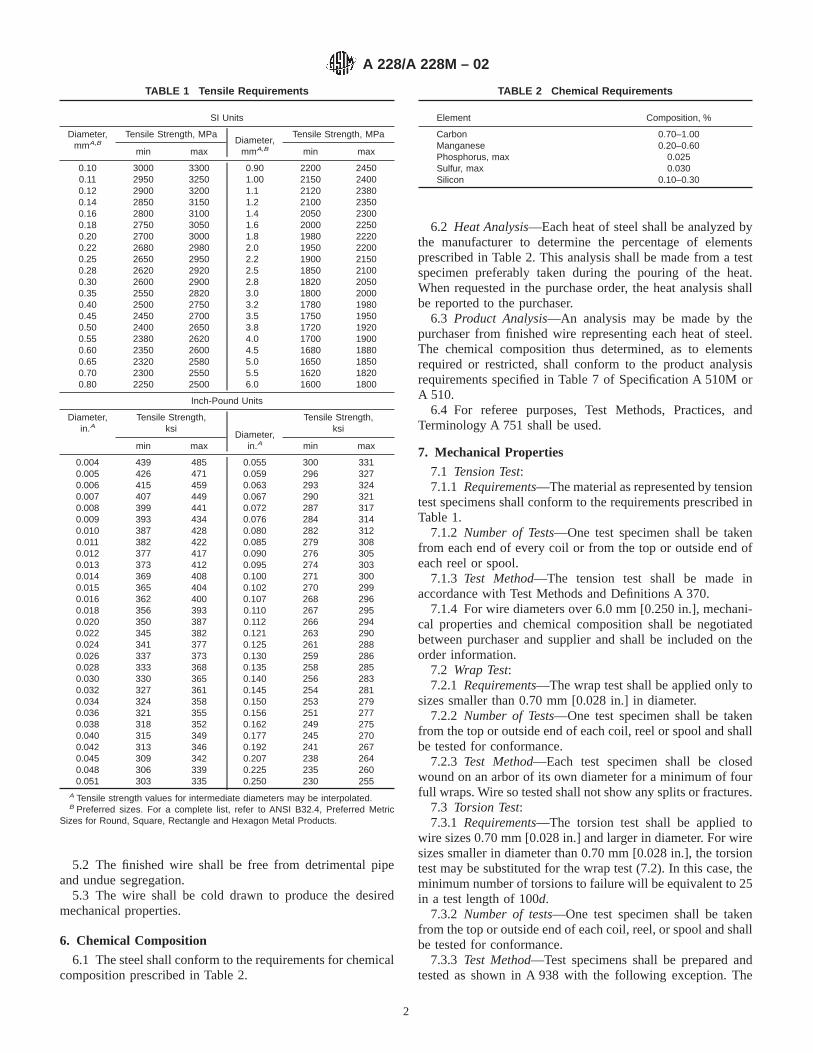
7.1 Tension Test:7.1.1 Requirements—The material as represented by tension
test specimens shall conform to the requirements prescribed inTable 1.
7.1.2 Number of Tests—One test specimen shall be takenfrom each end of every coil or from the top or outside end ofeach reel or spool.
7.1.3 Test Method—The tension test shall be made inaccordance with Test Methods and Definitions A 370.
7.1.4 For wire diameters over 6.0 mm [0.250 in.], mechani-cal properties and chemical composition shall be negotiatedbetween purchaser and supplier and shall be included on theorder information.
7.2 Wrap Test:7.2.1 Requirements—The wrap test shall be applied only to
sizes smaller than 0.70 mm [0.028 in.] in diameter.7.2.2 Number of Tests—One test specimen shall be taken
from the top or outside end of each coil, reel or spool and shallbe tested for conformance.
7.2.3 Test Method—Each test specimen shall be closedwound on an arbor of its own diameter for a minimum of fourfull wraps. Wire so tested shall not show any splits or fractures.
7.3 Torsion Test:7.3.1 Requirements—The torsion test shall be applied to
wire sizes 0.70 mm [0.028 in.] and larger in diameter. For wiresizes smaller in diameter than 0.70 mm [0.028 in.], the torsiontest may be substituted for the wrap test (7.2). In this case, theminimum number of torsions to failure will be equivalent to 25in a test length of 100d.
7.3.2 Number of tests—One test specimen shall be takenfrom the top or outside end of each coil, reel, or spool and shallbe tested for conformance.
7.3.3 Test Method—Test specimens shall be prepared andtested as shown in A 938 with the following exception. The
TABLE 1 Tensile Requirements
SI Units
Diameter,mmA,B
Tensile Strength, MPaDiameter,
mmA,B
Tensile Strength, MPa
min max min max
0.10 3000 3300 0.90 2200 24500.11 2950 3250 1.00 2150 24000.12 2900 3200 1.1 2120 23800.14 2850 3150 1.2 2100 23500.16 2800 3100 1.4 2050 23000.18 2750 3050 1.6 2000 22500.20 2700 3000 1.8 1980 22200.22 2680 2980 2.0 1950 22000.25 2650 2950 2.2 1900 21500.28 2620 2920 2.5 1850 21000.30 2600 2900 2.8 1820 20500.35 2550 2820 3.0 1800 20000.40 2500 2750 3.2 1780 19800.45 2450 2700 3.5 1750 19500.50 2400 2650 3.8 1720 19200.55 2380 2620 4.0 1700 19000.60 2350 2600 4.5 1680 18800.65 2320 2580 5.0 1650 18500.70 2300 2550 5.5 1620 18200.80 2250 2500 6.0 1600 1800
Inch-Pound Units
Diameter,in.A
Tensile Strength,ksi
Diameter,in.A
Tensile Strength,ksi
min max min max
0.004 439 485 0.055 300 3310.005 426 471 0.059 296 3270.006 415 459 0.063 293 3240.007 407 449 0.067 290 3210.008 399 441 0.072 287 3170.009 393 434 0.076 284 3140.010 387 428 0.080 282 3120.011 382 422 0.085 279 3080.012 377 417 0.090 276 3050.013 373 412 0.095 274 3030.014 369 408 0.100 271 3000.015 365 404 0.102 270 2990.016 362 400 0.107 268 2960.018 356 393 0.110 267 2950.020 350 387 0.112 266 2940.022 345 382 0.121 263 2900.024 341 377 0.125 261 2880.026 337 373 0.130 259 2860.028 333 368 0.135 258 2850.030 330 365 0.140 256 2830.032 327 361 0.145 254 2810.034 324 358 0.150 253 2790.036 321 355 0.156 251 2770.038 318 352 0.162 249 2750.040 315 349 0.177 245 2700.042 313 346 0.192 241 2670.045 309 342 0.207 238 2640.048 306 339 0.225 235 2600.051 303 335 0.250 230 255
A Tensile strength values for intermediate diameters may be interpolated.B Preferred sizes. For a complete list, refer to ANSI B32.4, Preferred Metric
Sizes for Round, Square, Rectangle and Hexagon Metal Products.
TABLE 2 Chemical Requirements
Element Composition, %
Carbon 0.70–1.00Manganese 0.20–0.60Phosphorus, max 0.025Sulfur, max 0.030Silicon 0.10–0.30
A 228/A 228M – 02
2

minimum number of torsions (twists) to failure in a test lengthof 100d (whered = the wire diameter being tested) are shownin Table 3.
7.3.4 Following completion of the torsion test, the torsionfracture shall be perpendicular to the longitudinal axis of thetest specimen and the surface of the test specimen shall not besplit. Secondary (recoil) fractures shall be ignored.
7.3.5 Test lengths other than 100d may be utilized. In thiscase, the minimum number of torsions to failure shall beadjusted in direct proportion to the change in test length asdetermined by the following formula:
Tx 5Td 3 Lx
Ld(1)
whereTx = minimum number of torsions for new test length,Td = minimum number of torsions for 100d test length,Lx = new test length, andLd = 100d test length
8. Metallurgical Requirements
8.1 Surface Condition:8.1.1 The surface of the wire as-received shall be free of
rust, excessive scale, die marks, pits, and scratches detrimentalto the end application. Seams shall not exceed 2 % of the wirediameter or 0.15 mm [0.006 in.], whichever is less.
8.1.2 Location of Test—Test specimens shall be taken fromeither or both ends of the coil.
8.2 Decarburization:8.2.1 The maximum affected depth of decarburization shall
not exceed 2 % of the wire diameter or 0.15 mm [0.006 in.],whichever is less. The maximum average partial decarburiza-tion depth shall not exceed 1.5% of the wire diameter whenmeasured using the test method described in 8.2.3.
8.2.2 Test Method—Decarburization shall be determined byetching a suitably polished transverse section of wire withnital. The entire periphery to be examined should be in a singleplane with no edge rounding. (See Test Method E 1077.)
8.2.3 The entire periphery shall be examined at a magnifi-cation of no less than 1003 for depth of free ferrite andmaximum affected depth. Smaller wire sizes may requirehigher magnification. Complete decarburization exists whenonly free ferrite is present. The worst case location shall beused to position perpendicular bisectors as shown in Fig. 1. Thedepth of decarburization (D) shall be measured at each of thefour points where the perpendicular bisectors cross the circum-
ference of the wire. The four readings so obtained shall beaveraged, and the average shall not exceed 1.5% of the wirediameter.
8.2.4 The purchaser may specify more restrictive decarbur-ization requirements where necessary for special applications.These requirements shall be negotiated between the purchaserand supplier and must be included in the order information.
8.2.5 There are no decarburization requirements for wiresizes smaller in diameter than 2.0 mm [0.078 in].
9. Dimensions and Permissible Variations
9.1 The permissible variations in the diameter of the wireshall be as specified in Table 4.
10. Workmanship, Finish, and Appearance
10.1 Workmanship—The wire shall not be kinked or im-properly cast. To test for cast, one convolution of wire shall becut from the coil, reel, or spool and placed on a flat surface. The
TABLE 3 Test Lengths for Torsion Test
SI Units
Diameter, mm Number of Torsions in 100d
0.70 to 2.0, incl 25over 2.0 to 3.5, incl 20over 3.5 to 6.0, incl 15
Inch-Pound Units
Diameter, in. Number of Torsions in 100d
0.028 to 0.079, incl 25over 0.079 to 0.138, incl 20over 0.138 to 0.250, incl 15
FIG. 1 Positioning of Perpendicular Bisectors
TABLE 4 Permissible Variations in Wire Diameter A
SI Units
Diameter, mmPermissible
Variations, plusand minus, mm
PermissibleOut-of-Round,
mm
to 0.25, incl 0.005 0.005Over 0.25 to 0.70, incl 0.008 0.008Over 0.70 to 1.50, incl 0.010 0.010Over 1.50 to 2.00, incl 0.013 0.013Over 2.00 0.03 0.03
Inch-Pound Units
Diameter, in.Permissible
Variations, plusand minus, in.
PermissibleOut-of-Round,
in.
0.004 to 0.010, incl 0.0002 0.0002Over 0.010 to 0.028, incl 0.0003 0.0003Over 0.028 to 0.063, incl 0.0004 0.0004Over 0.063 to 0.080, incl 0.0005 0.0005Over 0.080 to 0.250, incl 0.001 0.001
A For purposes of determining conformance with this specification, all specifiedlimits are absolute as defined in Practice E 29.
A 228/A 228M – 02
3

wire shall not spring up nor show a wavy condition. Wirebelow 4.0 mm or 0.156 in. diameter shall lie flat while wirediameters larger than the above shall lie substantially flat.
10.1.1 Each coil, reel, or spool shall be one continuouslength of wire, properly coiled and firmly tied.
10.1.2 Welds made prior to cold drawing are permitted. Ifunmarked welds are unacceptable to the purchaser, specialarrangements should be made with the manufacturer at the timeof purchase.
10.2 Finish—Music wire is supplied with many differenttypes of finish such as bright, phosphate, tin, and others. Finishdesired should be specified on purchase orders.
11. Retests
11.1 If any test specimen exhibits obvious defects or showsthe presence of a weld, it shall be discarded and anotherspecimen substituted.
12. Inspection
12.1 Unless otherwise specified in the contract or purchaseorder, the manufacturer is responsible for the performance ofall inspection and test requirements specified in this specifica-tion. Except as otherwise specified in the contract or purchaseorder, the manufacturer may use his own or any other suitablefacilities for the performance of the inspection and testrequirements unless disapproved by the purchaser at the timethe order is placed. The purchaser shall have the right toperform any of the inspections and tests set forth in thisspecification when such inspections and tests are deemednecessary to assure that the material conforms to prescribedrequirements.
13. Rejection and Rehearing
13.1 Unless otherwise specified, any rejection based on testsmade in accordance with these specifications shall be reportedto the manufacturer as soon as possible so that an investigationmay be initiated.
13.2 The material shall be adequately protected and identi-fied correctly for the manufacturer to make a proper investi-gation.
14. Certification
14.1 When specified in the purchase order or contract, aproducer’s or supplier’s certification shall be furnished to thepurchaser that the material was manufactured, sampled, tested,and inspected in accordance with this specification and hasbeen found to meet the requirements. When specified in thepurchase order or contract, a report of the test results shall befurnished.
14.2 The certification shall include the specification num-ber, year date of issue, and revision letter, if any.
15. Packaging, Marking, and Loading for Shipment
15.1 The coil, reel or spool mass, dimensions, and themethod of packaging shall be agreed upon between themanufacturer and purchaser.
15.2 A tag shall be attached securely to each coil of wirewith identifying information as agreed upon by the purchaserand manufacturer.
15.3 Unless otherwise specified in the purchaser’s order,packaging, marking, and loading for shipments shall be inaccordance with those procedures recommended by PracticesA 700.
15.4 For Government Procurement:15.4.1 Packaging, packing, and marking of material for
military procurement shall be in accordance with the require-ments of MIL-STD-163, Level A, Level C, or commercial asspecified in the contract or purchase order. Marking forshipment of material for civil agencies shall be in accordancewith Fed. Std No. 123.
15.5 Bar Coding—In addition to the previously-stated iden-tification requirements, bar coding is acceptable as a supple-mentary identification method. Bar coding should be consistentwith AIAG Standard 02.00, Primary Metals Identification TagApplication. The bar code may be applied to a substantiallyaffixed tag.
16. Keywords
16.1 music spring; wire
ASTM International takes no position respecting the validity of any patent rights asserted in connection with any item mentionedin this standard. Users of this standard are expressly advised that determination of the validity of any such patent rights, and the riskof infringement of such rights, are entirely their own responsibility.
This standard is subject to revision at any time by the responsible technical committee and must be reviewed every five years andif not revised, either reapproved or withdrawn. Your comments are invited either for revision of this standard or for additional standardsand should be addressed to ASTM International Headquarters. Your comments will receive careful consideration at a meeting of theresponsible technical committee, which you may attend. If you feel that your comments have not received a fair hearing you shouldmake your views known to the ASTM Committee on Standards, at the address shown below.
This standard is copyrighted by ASTM International, 100 Barr Harbor Drive, PO Box C700, West Conshohocken, PA 19428-2959,United States. Individual reprints (single or multiple copies) of this standard may be obtained by contacting ASTM at the aboveaddress or at 610-832-9585 (phone), 610-832-9555 (fax), or [email protected] (e-mail); or through the ASTM website(www.astm.org).
A 228/A 228M – 02
4
Designation: A 229/A 229M – 99
Standard Specification forSteel Wire, Oil-Tempered for Mechanical Springs 1
This standard is issued under the fixed designation A 229/A 229M; the number immediately following the designation indicates the yearof original adoption or, in the case of revision, the year of last revision. A number in parentheses indicates the year of last reapproval.A superscript epsilon (e) indicates an editorial change since the last revision or reapproval.
This standard has been approved for use by agencies of the Department of Defense.
1. Scope
1.1 This specification covers two classes of oil-temperedsteel spring wire intended especially for the manufacture ofmechanical springs and wire forms.
1.2 The values stated in either SI (metric) units or inch-pound units are to be regarded separately as standard. Thevalues stated in each system are not exact equivalents; there-fore, each system must be used independent of the other.
2. Referenced Documents
2.1 ASTM Standards:A 370 Test Methods and Definitions for Mechanical Testing
of Steel Products2
A 510 Specification for General Requirements for WireRods and Coarse Round Wire, Carbon Steel2
A 510M Specification for General Requirements for WireRods and Coarse Round Wire, Carbon Steel [Metric]2
A 700 Practices for Packaging, Marking, and LoadingMethods for Steel Products for Domestic Shipment3
A 751 Test Methods, Practices, and Terminology forChemical Analysis of Steel Products2
A 941 Terminology Relating to Steel, Stainless Steel, Re-lated Alloys and Ferroalloys2
E 29 Practice for Using Significant Digits in Test Data toDetermine Conformance with Specifications4
E 1077 Test Methods for Estimating the Depth of Decar-burization of Steel Specimens4
2.2 American National Standard:B 32.4M Preferred Metric Sizes for Round, Square, Rect-
angle, and Hexagon Metal Products5
2.3 Military Standard:
MIL-STD-163 Steel Mill Products, Preparation for Ship-ment and Storage6
2.4 Federal Standard:Fed. Std. No. 123 Marking for Shipment (Civil Agencies)6
2.5 AIAG Standard:AIAGB-5 02.00 Primary Metals Identification Tag Applica-
tion Standard7
3. Terminology
3.1 Definitions of Terms Specific to This Standard:3.1.1 For definition of terms used in this specification, refer
to Terminology A 941.
4. Ordering Information
4.1 It shall be the responsibility of the purchaser to specifyall requirements that are necessary for material under thisspecification. Such requirements may include, but are notlimited to, the following:
4.1.1 Quantity (mass or weight),4.1.2 Name of material (oil-tempered steel mechanical
spring wire) and class (Table 1 or Table 2),4.1.3 Dimensions (Section 10),4.1.4 Chemical composition (Table 3), if required,4.1.5 Packaging (Section 16),4.1.6 Cast or heat analysis report, if desired (see 7.2),4.1.7 Certification or test report, or both, if specified (Sec-
tion 15), and4.1.8 ASTM designation and date of issue.
NOTE 1—A typical metric ordering description is as follows: 10 000 kgoil-tempered steel mechanical spring wire, Class I, 8.00 mm diameter, in250-kg coils to ASTM A 229 M – xx, or for inch-pound units, 20 000 lboil-tempered steel mechanical Spring Wire, Class I 0.315 in. diameter, in500-lb coils to ASTM A 229 – xx.
1 This specification is under the jurisdiction of ASTM Committee A-1 on Steel,Stainless Steel, and Related Alloys, and is the direct responsibility of SubcommitteeA01.03 on Steel Rod and Wire.
Current edition approved March 10, 1999. Published May 1999. Originallypublished as A 229 – 39 T. Last previous edition A 229/A 229M – 93.
2 Annual Book of ASTM Standards, Vol 01.03.3 Annual Book of ASTM Standards, Vol 01.05.4 Annual Book of ASTM Standards, Vol 14.02.5 Available from American National Standards Institute, 11 West 42nd Street,
13th Floor, New York, NY 10036.
6 Available from Standardization Documents Order Desk, Bldg. 4 Section D, 700Robbins Ave., Philadelphia, PA 19111-5094, Attn: NPODS.
7 Available from the Automotive Industry Action Group, 26200 Lahser, Suite200, Southfield, MI 48034.
1
Copyright © ASTM International, 100 Barr Harbor Drive, PO Box C700, West Conshohocken, PA 19428-2959, United States.

5. General Requirements
5.1 Material furnished to this specification shall conform tothe applicable requirements of either Specification A 510M orSpecification A 510.
6. Materials and Manufacture
6.1 The steel may be made by any commercially acceptedsteel-making process. The steel may be either ingot cast orstrand cast.
6.2 The finished wire shall be free of detrimental pipe andundue segregation.
6.3 The wire shall be oil quenched and tempered to producethe desired mechanical properties.
7. Chemical Composition
7.1 The steel shall conform to the requirements for chemicalcomposition prescribed in Table 3.
7.2 Cast or Heat Analysis—Each cast or heat of steel shallbe analyzed by the manufacturer to determine the percentage ofelements prescribed in Table 3. This analysis shall be madefrom a test specimen preferably taken during the pouring of thecast or heat. When requested, this shall be reported to thepurchaser and shall conform to the requirements of Table 3.
7.3 Product Analysis—An analysis may be made by thepurchaser from finished wire representing each cast or heat of
steel. The chemical composition thus determined, as to ele-ments required or restricted, shall conform to the productanalysis requirements specified in Table 10 of SpecificationA 510 or A 510M.
7.4 For referee purposes, Test Methods, Practices, andTerminology A 751 shall be used.
8. Mechanical Properties
8.1 Tension Test:8.1.1 Requirements—The material as represented by tension
test specimens shall conform to the requirements prescribed inTable 1 or Table 2.
8.1.2 Number of Tests—One test specimen shall be taken foreach ten coils or fraction thereof, in a lot. Each cast or heat ina given lot shall be tested.
8.1.3 Location of Tests—Test specimens shall be taken fromeither end of the coil.
TABLE 1 Tensile Requirements, SI Units A
Diameter,B mm
Class I Class II
Tensile Strength, MPa Tensile Strength, MPa
min max min max
0.50 2050 2250 2230 24500.55 2020 2220 2220 24400.60 2000 2200 2210 24300.65 1950 2150 2190 24100.70 1950 2150 2170 21900.80 1900 2100 2140 23600.90 1850 2050 2100 23201.00 1800 2000 2060 22801.10 1780 1980 2030 22401.20 1750 1950 2000 22101.40 1700 1900 1950 21501.60 1650 1850 1900 21001.80 1620 1820 1860 20602.00 1600 1800 1820 20202.20 1580 1780 1790 19902.50 1550 1750 1750 19502.80 1520 1720 1710 19003.00 1500 1700 1690 18803.50 1450 1620 1640 18304.00 1400 1580 1600 17804.50 1380 1550 1560 17405.00 1350 1520 1520 17005.50 1320 1500 1500 16806.00 1300 1480 1480 16607.00 1280 1450 1450 16308.00 1250 1430 1430 16109.00 1220 1400 1410 1590
10.00 1200 1380 1400 158011.00 1180 1350 1380 156012.00 1150 1320 1360 154014.00 1120 1300 1340 152016.00 1120 1300 1320 1500
A Tensile strength values for intermediate diameters shall be interpolated.B Preferred sizes. For a complete list, refer to ANSI B32.4M , Preferred Metric
Sizes for Round, Square, Rectangle, and Hexagon Metal Products.
TABLE 2 Tensile Requirements, Inch-Pound Units
Diameter,A in.
Class I Class II
Tensile Strength, ksi† Tensile Strength, ksi
min max min max
0.020 293 323 324 3540.023 289 319 320 3500.026 286 316 317 3470.029 283 313 314 3440.032 280 310 311 3410.035 274 304 305 3350.041 266 296 297 3270.048 259 289 290 3200.054 253 283 284 3140.062 247 277 278 3080.072 241 271 272 3020.080 235 265 266 2960.092 230 260 261 2910.106 225 255 256 2860.120 220 250 251 2810.135 215 240 241 2660.148 210 235 236 2610.162 205 230 231 2560.177 200 225 226 2510.192 195 220 221 2460.207 190 215 216 2410.225 188 213 214 2390.244 187 212 213 2380.250 185 210 211 2360.312 183 208 209 2340.375 180 205 206 2310.438 175 200 201 2260.500 170 195 196 2210.562 165 190 191 2160.625 165 190 191 216
A Tensile strength values for intermediate diameters shall be interpolated.
TABLE 3 Chemical Requirements
Element Composition, %
Carbon 0.55–0.85Manganese 0.30–1.20A
Phosphorus, max 0.040Sulfur, max 0.050Silicon 0.15–0.35
A Generally 0.80/1.20 % manganese for diameter 5.00 mm or 0.192 in. andlarger; 0.30/0.90 % for diameters less than 5.00 mm or 0.192 in. The choice ofcomposition shall be optional with the manufacturer unless the purchaser definitelyspecifies otherwise.
A 229/A 229M – 99
2
8.1.4 Test Method—The tension test shall be made inaccordance with Test Methods and Definitions A 370.
8.2 Wrap Test:8.2.1 Requirements—Wire 4.00 mm or 0.162 in. and
smaller in diameter shall wind on itself as an arbor withoutbreakage. Larger diameter wire, up to and including 8.00 mmor 0.312 in. shall wind, without breakage, on a mandrel twicethe wire diameter. Wrap test on wires over 8.00 mm or 0.312in. diameter is not applicable.
8.2.2 Number of Tests—One test specimen shall be taken foreach ten coils, or fraction thereof, in a lot. Each cast or heat ina given lot shall be tested.
8.2.3 Location of Test—Test specimens shall be taken fromeither end of the coil.
8.2.4 Test Method—The wrap test shall be made in accor-dance with Test Methods and Definitions A 370, SupplementIV.
9. Metallurgical Requirements
9.1 Surface Condition—The surface of the wire as-receivedshall be free of rust, excessive scale die marks, pits andscratches detrimental to the end application. Seams shall notexceed 3.5 % of the wire diameter or 0.25 mm [0.010 in.],whichever is less.
9.1.1 Location of Test—Test specimens shall be taken fromeither or both ends of the coil.
9.2 Microstructure—A longitudinal section of the wire shallshow a fine, homogeneous, tempered martensite structure.
9.3 Decarburization:9.3.1 The maximum depth of decarburization (free ferrite
plus partial decarburization) shall not exceed 2 % of the wirediameter or 0.15 mm [0.006 in.] whichever is less. The depthof complete decarburization (free ferrite shall not exceed0.75 % of the wire diameter.
9.3.2 Test Method—Decarburization shall be determined byetching a suitably polished transverse section of wire withnital. The entire periphery to be examined should be in a singleplane with no edge rounding.
9.3.3 The entire periphery shall be examined at a magnifi-cation of no less than 1003 for depth of free ferrite andmaximum affected depth. Smaller wire sizes may requirehigher magnification. Measure the worst area present exclud-ing decarburization associated with seams or other surfaceimperfections. Complete decarburization exists when only freeferrite is present. Partial decarburization exists when ferrite isfound mixed with pearlite or tempered martensite. Structuresof 100 % martensite shall be defined as not decarburized.
10. Dimensions and Permissible Variations
10.1 The permissible variations in the diameter of the wireshall be as specified in Table 4 or Table 5.
11. Workmanship and Appearance
11.1 The wire shall be uniform in quality and temper andshall not be wavy or crooked.
11.2 Each coil shall be one continuous length of wire,properly coiled and firmly tied. Welds made prior to colddrawing are permitted.
12. Retests
12.1 If any test specimen exhibits obvious defects or showsthe presence of a weld, it may be discarded and anotherspecimen substituted.
13. Inspection
13.1 Unless otherwise specified in the contract or purchaseorder, the manufacturer is responsible for the performance ofall inspection and test requirements specified in this specifica-tion. Except as otherwise specified in the contract or purchaseorder, the manufacturer may use his own or any other suitablefacilities for the performance of the inspection and testrequirements unless disapproved by the purchaser at the timethe order is placed. The purchaser shall have the right toperform any of the inspections and tests set forth in thisspecification when such inspections and tests are deemednecessary to assure that the material conforms to prescribedrequirements.
14. Rejection and Rehearing
14.1 Unless otherwise specified, any rejection based on testsmade in accordance with this specification shall be reported tothe manufacturer as soon as possible so that an investigationmay be initiated.
14.2 The material shall be adequately protected and cor-rectly identified in order that the manufacturer may make aproper investigation.
15. Certification
15.1 When specified in the purchase order or contract, amanufacturer’s or supplier’s certification shall be furnished tothe purchaser that the material was manufactured, sampled,tested, and inspected in accordance with this specification andhas been found to meet the requirements. When specified in thepurchase order or contract, a report of the test results shall befurnished.
TABLE 4 Permissible Variations in Wire Diameter, SI Units A
Diameter, mmPermissible
Variations, plus andminus, mm
Permissible Out-ofRound, mm
To 0.70, incl 0.02 0.02Over 0.70 to 2.00, incl 0.03 0.032.00 to 9.00, incl 0.05 0.05Over 9.00 0.08 0.08
A For purposes of determining conformance with this specification, all specifiedlimits are absolute as defined in Practice E 29.
TABLE 5 Permissible Variations in Wire Diameter, Inch-PoundUnits A
Diameter, in. PermissibleVariations, plusand minus, in.
Permissible Out-of-Round, in.
0.020 to 0.028, incl 0.0008 0.0008Over 0.028 to 0.075, incl 0.001 0.001Over 0.075 to 0.375, incl 0.002 0.002Over 0.375 0.003 0.003A For purposes of determining conformance with this specification, all specified
limits are absolute as defined in Practice E 29.
A 229/A 229M – 99
3
15.2 The certification shall include the specification num-ber, year date of issue, and revision letter, if any.
16. Packaging, Marking, and Loading for Shipment
16.1 The coil mass, dimensions, and the method of packag-ing shall be agreed upon between the manufacturer andpurchaser.
16.2 A tag shall be securely attached to each coil of wirewith identifying information as agreed upon by the purchaserand manufacturer.
16.3 Unless otherwise specified in the purchaser’s order,packaging, marking, and loading for shipments shall be inaccordance with those procedures recommended by PracticesA 700.
16.4 For Government Procurement—Packaging, packing,and marking of material for military procurement shall be inaccordance with the requirements of MIL-STD-163, Level A,Level C, or commercial as specified in the contract or purchaseorder. Marking for shipment of material for civil agencies shallbe in accordance with Fed. Std. No. 123.
16.5 Bar Coding—In addition to the previously-stated iden-tification requirements, bar coding is acceptable as a supple-mentary identification method. Bar coding should be consistentwith AIAG Standard 02.00, Primary Metals Identification TagApplication. The bar code may be applied to a substantiallyaffixed tag.
17. Keywords
17.1 oil-tempered; springs; wire
ASTM International takes no position respecting the validity of any patent rights asserted in connection with any item mentionedin this standard. Users of this standard are expressly advised that determination of the validity of any such patent rights, and the riskof infringement of such rights, are entirely their own responsibility.
This standard is subject to revision at any time by the responsible technical committee and must be reviewed every five years andif not revised, either reapproved or withdrawn. Your comments are invited either for revision of this standard or for additional standardsand should be addressed to ASTM International Headquarters. Your comments will receive careful consideration at a meeting of theresponsible technical committee, which you may attend. If you feel that your comments have not received a fair hearing you shouldmake your views known to the ASTM Committee on Standards, at the address shown below.
This standard is copyrighted by ASTM International, 100 Barr Harbor Drive, PO Box C700, West Conshohocken, PA 19428-2959,United States. Individual reprints (single or multiple copies) of this standard may be obtained by contacting ASTM at the aboveaddress or at 610-832-9585 (phone), 610-832-9555 (fax), or [email protected] (e-mail); or through the ASTM website(www.astm.org).
A 229/A 229M – 99
4

Designation: A 230/A 230M – 99
Standard Specification forSteel Wire, Oil-Tempered Carbon Valve Spring Quality 1
This standard is issued under the fixed designation A 230/A 230M; the number immediately following the designation indicates the yearof original adoption or, in the case of revision, the year of last revision. A number in parentheses indicates the year of last reapproval.A superscript epsilon (e) indicates an editorial change since the last revision or reapproval.
This standard has been approved for use by agencies of the Department of Defense.
1. Scope
1.1 This specification covers the highest quality of roundcarbon steel spring wire, uniform in quality and temper,intended especially for the manufacture of valve springs andother springs requiring high-fatigue properties.
1.2 The values stated in either SI (metric) units or inch-pound units are to be regarded separately as standard. Thevalues stated in each system are not exact equivalents; there-fore, each system must be used independent of the other.
2. Referenced Documents
2.1 ASTM Standards:A 370 Test Methods and Definitions for Mechanical Testing
of Steel Products2
A 510 Specification for General Requirements for WireRods and Coarse Round Wire, Carbon Steel2
A 510M Specification for General Requirements for WireRods and Coarse Round Wire, Carbon Steel [Metric]2
A 700 Practices for Packaging, Marking, and LoadingMethods for Steel Products for Domestic Shipment3
A 751 Test Methods, Practices, and Terminology forChemical Analysis of Steel Products2
E 29 Practice for Using Significant Digits in Test Data toDetermine Conformance with Specifications4
2.2 ANSI Standard:B 32.4M Preferred Metric Sizes for Round, Square, Rec-
tangle, and Hexagon Metal Products5
2.3 Military Standard:MIL-STD-163 Steel Mill Products, Preparation for Ship-
ment and Storage6
2.4 Federal Standard:FED STD No. 123 Marking for Shipment (Civil Agencies)6
2.5 AIAG Standard:AIAGB-5 02.00 Primary Metals Identification Tag Applica-
tion Standard7
3. Ordering Information
3.1 Material furnished under this specification shall con-form to the applicable requirements of the current edition ofeither Specification A 510 or A 510M.
3.2 Orders for material under this specification shouldinclude the following information for each ordered item:
3.2.1 Quantity (mass or weight),3.2.2 Name of material (oil-tempered carbon steel valve
spring quality wire),3.2.3 Dimensions (Section 8),3.2.4 Chemical composition (Table 1), if required,3.2.5 Packaging (Section 14),3.2.6 Cast or heat analysis report, if desired (see 5.2),3.2.7 Certification or test report, or both, if specified (Sec-
tion 13), and3.2.8 ASTM designation and date of issue.
NOTE 1—A typical metric ordering description is as follows: 20 000 kgoil-tempered carbon steel valve spring quality wire, 6.00 mm diameter in125-kg coils to ASTM A 230M dated _____, or for inch-pound units,40 000 lb oil-tempered carbon steel valve spring quality wire, 0.250 in.diameter in 350-lb coils to ASTM A 230 dated _____.
4. Materials and Manufacture
4.1 The steel may be made by any commercially acceptedsteel-making process. The steel may be either ingot cast orstrand cast.
4.2 The finished wire shall be free of detrimental pipe andundue segregation.
4.3 The wire shall be hardened and tempered to produce thedesired mechanical properties.
5. Chemical Composition
5.1 The steel shall conform to the requirements for chemicalcomposition prescribed in Table 1.
5.2 Cast or Heat Analysis—Each cast or heat of steel shallbe analyzed by the manufacturer to determine the percentage of
1 This specification is under the jurisdiction of ASTM Committee A-1 on Steel,Stainless Steel, and Related Alloys and is the direct responsibility of SubcommitteeA01.03 on Steel Rod and Wire.
Current edition approved March 10, 1999. Published May 1999. Originallypublished as A 230 – 39 T. Last previous edition A 230/A 230M – 96e1.
2 Annual Book of ASTM Standards, Vol 01.03.3 Annual Book of ASTM Standards, Vol 01.05.4 Annual Book of ASTM Standards, Vol 14.02.5 Available from American National Standards Institute, 11 West 42nd Street,
13th Floor, New York, NY 10036.6 Available from Standardization Documents Order Desk, Bldg. 4 Section D, 700
Robbins Ave., Philadelphia, PA 19111-5094, Attn: NPODS.
7 Available from the Automotive Industry Action Group, 26200 Lahser, Suite200, Southfield, MI 48034.
1
Copyright © ASTM International, 100 Barr Harbor Drive, PO Box C700, West Conshohocken, PA 19428-2959, United States.

elements prescribed in Table 1. This analysis shall be madefrom a test specimen preferably taken during the pouring of thecast or heat. When requested, this shall be reported to thepurchaser and shall conform to the requirements of Table 1.
5.3 Product Analysis—An analysis may be made by thepurchaser from finished wire representing each cast or heat ofsteel. The chemical composition thus determined, as to ele-ments required or restricted, shall conform to the productanalysis requirements specified in Table 10 of SpecificationA 510 or A 510M.
5.4 For referee purposes, Test Methods, Practices, andTerminology A 751 shall be used.
6. Mechanical Properties
6.1 Tension Test:6.1.1 Requirements—The material as represented by tension
test specimens shall conform to the requirements prescribed inTable 2 or Table 3.
6.1.2 Number of Tests—One test specimen shall be taken foreach five coils, or fraction thereof, in a lot. Each cast or heat ina given lot shall be tested.
6.1.3 Location of Tests—Test specimens shall be taken fromeither end of the coil.
6.1.4 Test Method—The tension test shall be made inaccordance with Test Methods and Definitions A 370.
6.2 Wrap Test:6.2.1 Requirements—Wire 4.00 mm or 0.162 in. and
smaller in diameter shall wind on itself as an arbor withoutbreakage. Larger diameter wire, up to and including 6.50 mmor 0.250 in., shall wind, without breakage, on a mandrel twicethe diameter of the wire.
6.2.2 Number of Tests—One test specimen shall be taken foreach five coils, or fraction thereof, in a lot. Each cast or heat ina given lot shall be tested.
6.2.3 Location of Test—Test specimens shall be taken fromeither end of the coil.
6.2.4 Test Method—The wrap test shall be made in accor-dance with Test Methods and Definitions A 370, SupplementIV.
6.3 Twist Test—A 250 mm (10 in.) specimen of wire slowlytwisted four revolutions in one direction and then twisted in theother direction until failure shall show a square break normal tothe axis of the wire without splits or cracks.
6.4 Special Surface Inspection—When specified, the entirelength of every coil used by engine valve spring manufacturersshall be inspected for surface imperfections with a magneticand/or eddy current defect analyzer or equivalent.
7. Metallurgical Properties
7.1 Decarburization:7.1.1 Requirements—Transverse sections of the wire prop-
erly mounted, polished and etched shall show no completelydecarburized (carbon free) areas when examined at 1003magnification. Partial decarburization shall not exceed a depthof 0.025 mm (0.001 in.) on wire 4.90 mm (0.192 in.) andsmaller or 0.038 mm (0.0015 in.) on wire larger than 4.90 mm(0.192 in.). Measure the worst area present excluding decar-burization associated with seams or other surface imperfec-tions. Complete decarburization exists when only free ferrite ispresent. Partial decarburization exists when ferrite is foundmixed with pearlite or tempered martensite. Structures of100 % tempered martensite shall be defined as not decarbur-ized.
7.1.2 Number of Tests—One test specimen shall be taken foreach five coils, or fraction thereof, in a lot.
7.1.3 Location of Tests—Test specimens may be taken fromeither end of the coil.
7.2 Surface Condition:7.2.1 The surface shall be smooth and free of defects such as
seams, pits, die marks, and other defects tending to impair thefatigue value of the springs. Any additional surface require-ments must be negotiated at the time of entry of the order.
7.2.2 Number of Tests—One test specimen from each end ofevery coil shall be tested for conformance to the provisionsof7.2.1.
7.2.3 Test Method—The surface shall be examined afteretching in a solution of equal parts of hydrochloric acid andwater that has been heated to approximately 80°C for asufficient length of time to remove up to approximately 1 % ofthe diameter of the wire. Examination shall be made using 103magnification.
7.3 Microstructure—A longitudinal section shall show afine homogeneous tempered martensitic structure.
TABLE 1 Chemical Requirements
Element Composition, %
Carbon 0.60–0.75A
Manganese 0.60–0.90A
Phosphorus, max 0.025Sulfur, max 0.030Silicon 0.15–0.35
A Carbon and manganese may be varied by the manufacturer at his discretion,provided the mechanical properties specified are maintained and provided thepurchaser does not specifically stipulate otherwise.
TABLE 2 Tensile Requirements, SI Units
Diameter, mm Tensile Strength, MPa Reduction ofAreas, min, %A
min max
Less than 1.50 1700 1850 . . .1.50 to 2.50, incl 1650 1800 . . .Over 2.50 to 3.50, incl 1600 1750 40Over 3.50 to 4.00, incl 1580 1720 40Over 4.00 to 4.80, incl 1550 1700 40Over 4.80 to 5.50, incl 1520 1680 40Over 5.50 to 6.50, incl 1500 1650 40Over 6.50 1450 1600 40A The reduction of area test is not applicable to wire diameters under 2.34 mm.
TABLE 3 Tensile Requirements, Inch-Pound Units
Diameter, in.Tensile Strength, ksi Reduction of
Area, min, %Amin max
Less than 0.062 245 265 . . .0.062 to 0.092, incl 240 260 . . .Over 0.092 to 0.128, incl 235 255 40Over 0.128 to 0.162, incl 230 250 40Over 0.162 to 0.192, incl 225 245 40Over 0.192 to 0.225, incl 220 240 40Over 0.225 to 0.250, incl 215 235 40Over 0.250 210 230 40
A The reduction of area test is not applicable to wire diameters under 0.092 in.
A 230/A 230M – 99
2

8. Dimensions and Permissible Variations
8.1 The permissible variations in the diameter of the wireshall be as specified in Table 4 or Table 5. The preferred wirediameters are listed in Table 6.
8.2 Number of Tests—One test specimen from each end ofthe coil shall be tested for conformance (see 8.1).
9. Workmanship and Appearance
9.1 The wire shall be uniform in quality and temper andshall not be wavy or crooked.
9.2 Each coil shall be one continuous length of wire,properly coiled, and firmly tied.
9.3 No welds are permitted in the finished product and anywelds made during processing must be removed.
10. Retests
10.1 If any test specimen exhibits obvious defects or showsthe presence of a weld, it may be discarded and anotherspecimen substituted.
11. Inspection
11.1 Unless otherwise specified in the contract or purchaseorder, the manufacturer is responsible for the performance ofall inspection and test requirements specified in this specifica-tion. Except as otherwise specified in the contract or purchaseorder, the manufacturer may use his own or any other suitablefacilities for the performance of the inspection and testrequirements unless disapproved by the purchaser at the timethe order is placed. The purchaser shall have the right toperform any of the inspections and tests set forth in thisspecification when such inspections and tests are deemednecessary to assure that the material conforms to prescribedrequirements.
12. Rejection and Rehearing
12.1 Unless otherwise specified, any rejection based on testsmade in accordance with this specification shall be reported tothe manufacturer as soon as possible so that an investigationmay be initiated.
12.2 The material must be adequately protected and cor-rectly identified in order that the manufacturer may make aproper investigation.
13. Certification
13.1 When specified in the purchase order or contract, amanufacturer’s or supplier’s certification shall be furnished to
the purchaser that the material was manufactured, sampled,tested, and inspected in accordance with this specification andhas been found to meet the requirements. When specified in thepurchase order or contract, a report of the test results shall befurnished.
13.2 The certification shall include the specification num-ber, year date of issue, and revision letter, if any.
14. Packaging, Marking, and Loading for Shipment14.1 The coil mass, dimensions, and the method of packag-
ing shall be as agreed upon between the manufacturer andpurchaser.
14.2 The size of the wire, purchaser’s order number, ASTMspecification number, heat number, and name or mark of themanufacturer shall be marked on a tag securely attached toeach coil of wire.
14.3 Unless otherwise specified in the purchaser’s order,packaging, marking, and loading for shipments shall be inaccordance with those procedures recommended by PracticesA 700.
14.4 For Government Procurement—Packaging, packing,and marking of material for military procurement shall be inaccordance with the requirements of MIL-STD-163, Level A,Level C, or commercial as specified in the contract or purchaseorder. Marking for shipment of material for civil agencies shallbe in accordance with Fed. Std. No. 123.
14.5 Bar Coding—In addition to the previously-stated iden-tification requirements, bar coding is acceptable as a supple-mentary identification method. Bar coding should be consistentwith AIAG B-5 02.00, Primary Metals Identification TagApplication. The bar code may be applied to a substantiallyaffixed tag.
15. Keywords15.1 carbon; oil-tempered; valve spring; wire
TABLE 4 Permissible Variations in Wire Diameter, SI Units A
Diameter, mmPermissible Variations,
plus and minus, mmPermissible Out-of
Round, mm
Less than 1.50 0.01 0.011.50 to 2.50, incl 0.02 0.02Over 2.50 to 3.50, incl 0.03 0.033.50 to 4.50, incl 0.04 0.04Over 4.50 0.05 0.05
A For purposes of determining conformance with this specification, all specifiedlimits are absolute as defined in Practice E 29.
TABLE 5 Permissible Variations in Wire Diameter, Inch-PoundUnits A
Diameter, in.Permissible Variations,
plus and minus, in.Permissible Out-of-
Round, in.
Less than 0.062 0.0005 0.00050.062 to 0.092, incl 0.0008 0.0008Over 0.092 to 0.148, incl 0.001 0.001Over 0.148 to 0.177, incl 0.0015 0.0015Over 0.177 0.002 0.002
A For purposes of determining conformance with this specification, all specifiedlimits are absolute as defined in Practice E 29.
TABLE 6 Preferred Diameters for Steel Wire, A mm
1.6 2.8 4.51.8 3.0 4.82.1 3.2 5.02.2 3.5 5.52.4 3.8 6.02.5 4.0 6.52.6 4.2
AFor a complete list of preferred sizes, refer to ANSI B 32.4M, Preferred MetricSizes for Round, Square, Rectangle, and Hexagon Metal Products.
A 230/A 230M – 99
3

ASTM International takes no position respecting the validity of any patent rights asserted in connection with any item mentionedin this standard. Users of this standard are expressly advised that determination of the validity of any such patent rights, and the riskof infringement of such rights, are entirely their own responsibility.
This standard is subject to revision at any time by the responsible technical committee and must be reviewed every five years andif not revised, either reapproved or withdrawn. Your comments are invited either for revision of this standard or for additional standardsand should be addressed to ASTM International Headquarters. Your comments will receive careful consideration at a meeting of theresponsible technical committee, which you may attend. If you feel that your comments have not received a fair hearing you shouldmake your views known to the ASTM Committee on Standards, at the address shown below.
This standard is copyrighted by ASTM International, 100 Barr Harbor Drive, PO Box C700, West Conshohocken, PA 19428-2959,United States. Individual reprints (single or multiple copies) of this standard may be obtained by contacting ASTM at the aboveaddress or at 610-832-9585 (phone), 610-832-9555 (fax), or [email protected] (e-mail); or through the ASTM website(www.astm.org).
A 230/A 230M – 99
4

Designation: A 231/A231M – 96 (Reapproved 2002)
Standard Specification forChromium-Vanadium Alloy Steel Spring Wire 1
This standard is issued under the fixed designation A 231/A231M; the number immediately following the designation indicates the yearof original adoption or, in the case of revision, the year of last revision. A number in parentheses indicates the year of last reapproval.A superscript epsilon (e) indicates an editorial change since the last revision or reapproval.
This standard has been approved for use by agencies of the Department of Defense.
1. Scope
1.1 This specification covers round chromium-vanadiumalloy steel spring wire having properties and quality intendedfor the manufacture of springs used at moderately elevatedtemperatures. This wire shall be either in the annealed andcold-drawn or oil-tempered condition as specified by thepurchaser.
1.2 The values stated in either SI (metric) units or inch-pound units are to be regarded separately as standard. Thevalues stated in each system are not exact equivalents; there-fore, each system must be used independent of the other.
2. Referenced Documents
2.1 ASTM Standards:A 370 Test Methods and Definitions for Mechanical Testing
of Steel Products2
A 700 Practices for Packaging, Marking, and LoadingMethods for Steel Products for Domestic Shipment3
A 751 Test Methods, Practices, and Terminology forChemical Analysis of Steel Products2
A 752 Specification for General Requirements for WireRods and Coarse Round Wire, Alloy Steel2
E 29 Practice for Using Significant Digits in Test Data toDetermine Conformance with Specifications4
2.2 ANSI Standard:B 32.4M Preferred Metric Sizes for Round, Square, Rect-
angle, and Hexagon Metal Products5
2.3 Military Standard:MIL-STD-163 Steel Mill Products, Preparation for Ship-
ment and Storage6
2.4 Federal Standard:Fed. Std. No. 123 Marking for Shipment (Civil Agencies)6
2.5 AIAG Standard:AIAGB-5 02.00 Primary Metals Identification Tag Applica-
tion Standard7
3. Ordering Information
3.1 Orders for material under this specification shouldinclude the following information for each ordered item:
3.1.1 Quantity (mass),3.1.2 Name of material (chromium-vanadium alloy steel
wire),3.1.3 Wire diameter (Table 1 and Table 2),3.1.4 Packaging (Section 14),3.1.5 Cast or heat analysis report (if requested) (5.2),3.1.6 Certification or test report, or both, if specified (Sec-
tion 13), and3.1.7 ASTM designation and date of issue.
NOTE 1—A typical ordering description is as follows: 20 000 kgoil-tempered chromium-vanadium alloy steel wire, size 6.00 mm in150-kg coils to ASTM A 231M dated_______ , or for inch-pound units,40 000 lb oil-tempered chromium-vanadium alloy steel spring wire, size0.250 in. in 350-lb coils to ASTM A 231 dated_______.
4. Materials and Manufacture
4.1 The steel may be made by any commercially acceptedsteel–making process. The steel may be either ingot cast orstrand cast.
4.2 The finished wire shall be free from detrimental pipeand undue segregation.
5. Chemical Composition
5.1 The steel shall conform to the requirements as tochemical composition specified in Table 3.
5.2 Cast or Heat Analysis—Each cast or heat of steel shallbe analyzed by the manufacturer to determine the percentage ofelements prescribed in Table 3. This analysis shall be madefrom a test specimen preferably taken during the pouring of thecast or heat. When requested, this shall be reported to thepurchaser and shall conform to the requirements of Table 3.
5.3 Product Analysis( formerly Check Analysis)—Ananalysis may be made by the purchaser from finished wire
1 This specification is under the jurisdiction of ASTM Committee A01 on Steel,Stainless Steel, and Related Alloys and is the direct responsibility of SubcommitteeA01.03 on Steel Rod and Wire.
Current edition approved March 10, 1996. Published May 1996. Originallypublished as A 230 – 39 T. Last previous edition A 231/A 231M – 93.
2 Annual Book of ASTM Standards, Vol 01.03.3 Annual Book of ASTM Standards, Vol 01.05.4 Annual Book of ASTM Standards, Vol 14.02.5 Available from American National Standards Institute, 11 West 42nd Street,
13th Floor, New York, NY 10036.6 Available from Standardization Documents Order Desk, Bldg. 4 Section D, 700
Robbins Ave., Philadelphia, PA 19111-5094, Attn: NPODS.
7 Available from the Automotive Industry Action Group, 26200 Lahser, Suite200, Southfield, MI 48034.
1
Copyright © ASTM International, 100 Barr Harbor Drive, PO Box C700, West Conshohocken, PA 19428-2959, United States.

representing each cast or heat of steel. The chemical compo-sition thus determined, as to elements required or restricted,shall conform to the product (check) analysis requirementsspecified in Table 5 of Specification A 752.
5.4 For referee purposes, Test Methods, Practices, andTerminology A 751 shall be used.
6. Mechanical Properties
6.1 Annealed and Cold Drawn—When purchased in theannealed and cold-drawn condition, the wire shall have beengiven a sufficient amount of cold working to meet the purchas-er’s coiling requirements and shall be in a suitable condition torespond properly to heat treatment. In special cases thehardness, if desired, shall be stated in the purchase order.
6.2 Oil Tempered—When purchased in the oil-temperedcondition, the tensile strength and minimum percent reductionof area, sizes 2.50 mm or 0.105 in. and coarser, of the wireshall conform to the requirements as shown in Table 1 or Table2.
6.2.1 Number of Tests—One test specimen shall be taken foreach ten coils, or fraction thereof, in a lot. Each cast or heat ina given lot shall be tested.
6.2.2 Location of Tests—Test specimens shall be taken fromeither end of the coil.
6.2.3 Test Method—The tension test shall be made inaccordance with Test Methods and Definitions A 370.
6.3 Wrap Test:6.3.1 Oil tempered or cold drawn wire 4.00 mm or 0.162 in.
and smaller in diameter shall wind on itself as an arbor withoutbreakage. Larger diameter wire up to and including 8.00 mm or0.312 in. in diameter shall wrap without breakage on a mandreltwice the wire diameter. The wrap test is not applicable to wireover 8.00 mm or 0.312 in. in diameter.
6.3.2 Number of Tests—One test specimen shall be taken foreach ten coils, or fraction thereof, in a lot. Each cast or heat ina given lot shall be tested.
6.3.3 Location of Test—Test specimens shall be taken fromeither end of the coil.
6.3.4 Test Method—The wrap test shall be made in accor-dance with Supplement IV of Test Methods and DefinitionsA 370.
7. Metallurgical Properties
7.1 Surface Condition:7.1.1 The surface of the wire as received shall be free of rust
and excessive scale. No serious die marks, scratches, or seamsmay be present. Based upon examination of etched endspecimen, seams shall not exceed 3.5 % of the wire diameter,or 0.25 mm or 0.010 in., whichever is the smaller as measuredon a transverse section.
7.1.2 Number of Tests—One test specimen shall be taken foreach ten coils, or fraction thereof, in a lot. Each cast or heat ina given lot shall be tested.
7.1.3 Location of Test—Test specimens shall be taken fromeither or both ends of the coil.
TABLE 1 Tensile Requirements, SI Units A
Diameter,B mmTensile Strength, MPa Reduction of Areas,
min, %min max
0.50 2060 2260 C
0.55 2050 2240 C
0.60 2030 2220 C
0.65 2010 2200 C
0.70 2000 2160 C
0.80 1980 2140 C
0.90 1960 2120 C
1.00 1940 2100 C
1.10 1920 2080 C
1.20 1900 2060 C
1.40 1860 2020 C
1.60 1820 1980 C
1.80 1800 1960 C
2.00 1780 1930 C
2.20 1750 1900 C
2.50 1720 1860 452.80 1680 1830 453.00 1660 1800 453.50 1620 1760 454.00 1580 1720 404.50 1560 1680 405.00 1520 1640 405.50 1480 1620 406.00 1460 1600 406.50 1440 1580 407.00 1420 1560 408.00 1400 1540 409.00 1380 1520 40
10.00 1360 1500 4011.00 1340 1480 4012.00 1320 1460 40
A Tensile strength values for intermediate diameters may be interpolated.B Preferred sizes. For a complete list, refer to ANSI B 32.4M, Preferred Metric
Sizes for Round, Square, Rectangle, and Hexagon Metal Products.C The reduction of area test is not applicable to wire diameters under 2.34 mm.
TABLE 2 Tensile Requirements, Inch-Pound Units A
Diameter,B in.Tensile Strength, ksi Reduction of Area,
min, %min max
0.020 300 325 C
0.032 290 315 C
0.041 280 305 C
0.054 270 295 C
0.062 265 290 C
0.080 255 275 C
0.105 245 265 450.135 235 255 450.162 225 245 400.192 220 240 400.244 210 230 400.283 205 225 400.312 203 223 400.375 200 220 400.438 195 215 400.500 190 210 40
A Tensile strength values for intermediate diameters may be interpolated.B Preferred sizes. For a complete list, refer to ANSI B 32.4M, Preferred Metric
Sizes for Round, Square, Rectangle, and Hexagon Metal Products.C The reduction of area test is not applicable to wire diameters under 0.092 in.
TABLE 3 Chemical Requirements
Element Analysis, %
Carbon 0.48–0.53Manganese 0.70–0.90Phosphorus 0.040 maxSulfur 0.040 maxSilicon 0.15–0.35Chromium 0.80–1.10Vanadium 0.15 min
A 231/A231M – 96 (2002)
2
7.1.4 Test Method—The surface shall be examined afteretching in a solution of equal parts of hydrochloric acid andwater that has been heated to approximately 80°C. Test endsshall be examined using 103 magnification. Any specimenwhich shows questionable seams of borderline depth shall havea transverse section taken from the unetched area, properlymounted and polished and examined to measure the depth ofthe seam.
8. Dimensions and Permissible Variations
8.1 The permissible variations in the diameter of the wireshall be as specified in Table 4 or Table 5.
9. Workmanship and Appearance
9.1 Annealed and Cold Drawn—The wire shall not bekinked or improperly cast. To test for cast, a few convolutionsof wire shall be cut loose from the coil and placed on a flatsurface. The wire shall lie flat on itself and not spring up norshow a wavy condition.
9.2 Oil Tempered—The wire shall be uniform in quality andtemper and shall not be wavy or crooked.
9.3 Each coil shall be one continuous length of wireproperly coiled. Welds made prior to cold drawing are permit-ted. If unmarked welds are unacceptable to the purchaser,special arrangements should be made with the manufacturer atthe time of the purchase.
9.4 Appearance—The surface shall be smooth and free ofdefects such as seams, pits, die marks, and other defectstending to impair the use of the wire for springs. Any additionalsurface requirements must be negotiated at the time of entry ofthe order.
10. Retests
10.1 If any test specimen exhibits obvious defects or showsthe presence of a weld, it may be discarded and anotherspecimen substituted.
11. Inspection
11.1 Unless otherwise specified in the contract or purchaseorder, the manufacturer is responsible for the performance ofall inspection and test requirements specified in this specifica-tion. Except as otherwise specified in the contract or purchaseorder, the manufacturer may use his own or any other suitablefacilities for the performance of the inspection and testrequirements unless disapproved by the purchaser at the timethe order is placed. The purchaser shall have the right toperform any of the inspections and tests set forth in this
specification when such inspections and tests are deemednecessary to assure that the material conforms to prescribedrequirements.
12. Rejection and Rehearing
12.1 Unless otherwise specified, any rejection based on testsmade in accordance with this specification shall be reported tothe manufacturer as soon as possible so that an investigationmay be initiated.
12.2 The material must be adequately protected and cor-rectly identified in order that the manufacturer may make aproper investigation.
13. Certification
13.1 When specified in the purchase order or contract, amanufacturer’s or supplier’s certification shall be furnished tothe purchaser that the material was manufactured, sampled,tested, and inspected in accordance with this specification andhas been found to meet the requirements. When specified in thepurchase order or contract, a report of the test results shall befurnished.
13.2 The certification shall include the specification num-ber, year date of issue, and revision letter, if any.
14. Packaging, Marking, and Loading for Shipment
14.1 The coil mass, dimensions, and the method of packag-ing shall be as agreed upon between the manufacturer andpurchaser.
14.2 The size of the wire, purchaser’s order number, ASTMSpecification number, heat number, and name or mark of themanufacturer shall be marked on a tag securely attached toeach coil of wire.
14.3 Unless otherwise specified in the purchaser’s order,packing, marking, and loading for shipments shall be inaccordance with those procedures recommended by PracticesA 700.
14.4 For Government Procurement:14.4.1 Packaging, packing, and marking of material for
military procurement shall be in accordance with the require-ments of MIL-STD-163, Level A, Level C, or commercial asspecified in the contract or purchase order. Marking forshipment of material for civil agencies shall be in accordancewith Fed. Std. No. 123.
14.5 Bar Coding—In addition to the previously-stated iden-tification requirements, bar coding is acceptable as a supple-mentary identification method. Bar coding should be consistentwith AIAG B-5 02.00, Primary Metals Identification TagApplication. The bar code may be applied to a substantiallyaffixed tag.
TABLE 4 Permissible Variations in Wire Diameter, SI Units A
Diameter, mmPermissible
Variations, plus andminus, mm
Permissible Out-ofRound, mm
To 0.70, incl 0.02 0.02Over 0.70 to 2.00, incl 0.03 0.03Over 2.00 to 9.00, incl 0.05 0.05Over 9.00 0.08 0.08
A For purposes of determining conformance with this specification, all specifiedlimits are absolute as defined in Practice E 29.
TABLE 5 Permissible Variations in Wire Diameter, Inch-PoundUnits A
Diameter, in.Permissible
Variations, plus andminus, in.
Permissible Out-of-Round, in.
0.020 to 0.028, incl 0.0008 0.0008Over 0.028 to 0.075, incl 0.001 0.001Over 0.075 to 0.375, incl 0.002 0.002Over 0.375 to 0.500, incl 0.003 0.003
A For purposes of determining conformance with this specification, all specifiedlimits are absolute as defined in Practice E 29.
A 231/A231M – 96 (2002)
3
15. Keywords15.1 alloy; chromium-vanadium; spring; wire
ASTM International takes no position respecting the validity of any patent rights asserted in connection with any item mentionedin this standard. Users of this standard are expressly advised that determination of the validity of any such patent rights, and the riskof infringement of such rights, are entirely their own responsibility.
This standard is subject to revision at any time by the responsible technical committee and must be reviewed every five years andif not revised, either reapproved or withdrawn. Your comments are invited either for revision of this standard or for additional standardsand should be addressed to ASTM International Headquarters. Your comments will receive careful consideration at a meeting of theresponsible technical committee, which you may attend. If you feel that your comments have not received a fair hearing you shouldmake your views known to the ASTM Committee on Standards, at the address shown below.
This standard is copyrighted by ASTM International, 100 Barr Harbor Drive, PO Box C700, West Conshohocken, PA 19428-2959,United States. Individual reprints (single or multiple copies) of this standard may be obtained by contacting ASTM at the aboveaddress or at 610-832-9585 (phone), 610-832-9555 (fax), or [email protected] (e-mail); or through the ASTM website(www.astm.org).
A 231/A231M – 96 (2002)
4
Designation: A 232/A 232M – 99
Standard Specification forChromium-Vanadium Alloy Steel Valve Spring Quality Wire 1
This standard is issued under the fixed designation A 232/A 232M; the number immediately following the designation indicates the yearof original adoption or, in the case of revision, the year of last revision. A number in parentheses indicates the year of last reapproval.A superscript epsilon (e) indicates an editorial change since the last revision or reapproval.
This standard has been approved for use by agencies of the Department of Defense.
1. Scope
1.1 This specification covers the highest quality of roundchromium-vanadium alloy steel valve spring wire, uniform inquality and temper, intended for the manufacture of valvesprings and other springs requiring high-fatigue propertieswhen used at moderately elevated temperatures. This wire shallbe either in the annealed and cold-drawn or oil-temperedcondition as specified by the purchaser.
1.2 The values stated in either SI units or inch-pound unitsare to be regarded separately as standard. Within the text, theinch-pound units are shown in brackets. The values stated ineach system are not exact equivalents; therefore, each systemmust be used independent of the other.
2. Referenced Documents
2.1 ASTM Standards:A 370 Test Methods and Definitions for Mechanical Testing
of Steel Products2
A 700 Practices for Packaging, Marking, and LoadingMethods for Steel Products for Domestic Shipment3
A 751 Test Methods, Practices, and Terminology forChemical Analysis of Steel Products2
E 29 Practice for Using Significant Digits in Test Data toDetermine Conformance with Specifications4
2.2 ANSI Standard:B 32.4 Preferred Metric Sizes for Round, Square, Rect-
angle, and Hexagon Metal Products5
2.3 Federal Standard:Fed. Std. No. 123 Marking for Shipment (Civil Agencies)6
2.4 Military Standard:MIL-STD-163 Steel Mill Products, Preparation for Ship-
ment and Storage6
2.5 AIAG Standard:AIAG B-5 02.00 Primary Metals Identification Tag Appli-
cation Standard7
3. Ordering Information
3.1 Orders for material under this specification shouldinclude the following information for each ordered item:
3.1.1 Quantity (mass),3.1.2 Name of material (chromium-vanadium alloy steel
valve spring quality wire),3.1.3 Dimensions (Table 1 and Section 8),3.1.4 Condition (Section 6),3.1.5 Packaging (Section 14),3.1.6 Heat analysis report, if requested (5.2),3.1.7 Certification or test report, or both, if specified (Sec-
tion 13), and3.1.8 ASTM designation and year of issue.
NOTE 1—A typical ordering description is as follows: 20 000 kgoil-tempered chromium-vanadium alloy steel valve spring quality wire,size 6.00 mm in 150 kg coils to ASTM A 232/A 232M dated , or forinch-pound units, 40 000 lb oil-tempered chromium-vanadium alloy steelvalve spring quality wire, size 0.250 in. in 350-lb coils to ASTMA 232/A 232M dated .
4. Materials and Manufacture
4.1 The steel may be made by any commercially acceptedsteel making process. The steel may be either ingot cast orstrand cast.
4.2 The finished wire shall be free from detrimental pipeand undue segregation.
5. Chemical Composition
5.1 The steel shall conform to the requirements for chemicalcomposition specified in Table 2.
5.2 Heat Analysis—Each heat of steel shall be analyzed bythe manufacturer to determine the percentage of elementsprescribed in Table 2. This analysis shall be made from a testspecimen preferably taken during the pouring of the heat.When requested, this shall be reported to the purchaser andshall conform to the requirements of Table 2.
1 This specification is under the jurisdiction of ASTM Committee A-1 on Steel,Stainless Steel, and Related Alloys and is the direct responsibility of SubcommitteeA1.03 on Steel Rod and Wire.
Current edition approved April 10, 1999. Published June 1999. Originallypublished as A 232 – 39 T. Last previous edition A 232/A 232M – 96.
2 Annual Book of ASTM Standards, Vol 01.03.3 Annual Book of ASTM Standards, Vol 01.05.4 Annual Book of ASTM Standards, Vol 14.02.5 Available from the American National Standards Institute, 11 West 42nd Street,
13th Floor, New York, NY 10036.6 Available from Standardization Documents Order Desk, Bldg. 4 Section D, 700
Robbins Ave., Philadelphia, PA 19111-5094, Attn: NPODS.
7 Available from the Automotive Industry Action Group, 26200 Lahser, Suite200, Southfield, MI 48034.
1
Copyright © ASTM International, 100 Barr Harbor Drive, PO Box C700, West Conshohocken, PA 19428-2959, United States.

5.3 Product Analysis—An analysis may be made by thepurchaser from finished wire representing each heat of steel.The average of all the separate determinations made shall bewithin the limits specified in the analysis column. Individualdeterminations may vary to the extent shown in the productanalysis tolerance column, except that the several determina-tions of a single element in any one heat shall not vary bothabove and below the specified range.
5.4 For referee purposes, Test Methods, Practices and Ter-minology A 751 shall be used.
6. Mechanical Properties
6.1 Annealed and Cold-Drawn—When purchased in theannealed and cold-drawn condition, the wire shall have beengiven a sufficient amount of cold working to meet the purchas-er’s coiling requirements and shall be in a suitable condition torespond properly to heat treatment. In special cases thehardness, if desired, shall be stated in the purchase order.
6.2 Oil Tempered—When purchased in the oil-temperedcondition, the tensile strength and minimum percent reductionof area, sizes 2.50 mm [0.105 in.] and coarser, of the wire shallconform to the requirements prescribed in Table 1.
6.2.1 Number of Tests—One test specimen shall be taken foreach five coils, or fraction thereof, in a lot. Each heat in a givenlot shall be tested.
6.2.2 Location of Tests—Test specimens shall be taken fromeither end of the coil.
6.2.3 Test Method—The tension test shall be made inaccordance with Test Methods and Definitions A 370.
6.3 Wrap Test:6.3.1 Oil-tempered or cold-drawn wire 4.00 mm [0.162 in.]
and smaller in diameter shall wind on itself as an arbor withoutbreakage. Larger diameter wire up to and including 8.00 mm[0.312 in.] in diameter shall wrap without breakage on amandrel twice the wire diameter. The wrap test is not appli-cable to wire over 8.00 mm in diameter.
6.3.2 Number of Tests—One test specimen shall be taken foreach five coils, or fraction thereof, in a lot. Each heat in a givenlot shall be tested.
6.3.3 Location of Test—Test specimens shall be taken fromeither end of the coil.
6.3.4 Test Method—The wrap test shall be made in accor-dance with Test Methods and Definitions A 370.
6.4 Special Surface Inspection—When specified, the entirelength of every coil used by engine valve spring manufacturersshall be inspected for surface imperfections with a magneticand/or eddy current defect analyzer or equivalent.
7. Metallurgical Requirements
7.1 Surface Condition:7.1.1 The surface of the wire as received shall be free of
imperfections such as pits, die marks, scratches, seams, andother defects tending to impair the fatigue value of the springs.
7.1.2 Number of Tests—One test specimen shall be takenfrom each end of every coil.
7.1.3 Test Method—The surface shall be examined afteretching in a solution of equal parts of hydrochloric acid andwater that has been heated to approximately 80°C for a
TABLE 1 Tensile Requirements A
SI Units
Diameter,B mm MPa, min MPa, maxReductionof Area,min, %
0.50 2060 2260 C
0.55 2050 2240 C
0.60 2030 2220 C
0.65 2010 2200 C
0.70 2000 2160 C
0.80 1980 2140 C
0.90 1960 2120 C
1.00 1940 2100 C
1.10 1920 2080 C
1.20 1900 2060 C
1.40 1860 2020 C
1.60 1820 1980 C
1.80 1800 1960 C
2.00 1780 1930 C
2.20 1750 1900 C
2.50 1720 1860 452.80 1680 1830 453.00 1660 1800 453.50 1620 1760 454.00 1580 1720 404.50 1560 1680 405.00 1520 1640 405.50 1480 1620 406.00 1460 1600 406.50 1440 1580 407.00 1420 1560 408.00 1400 1540 409.00 1380 1520 40
10.00 1360 1500 4011.00 1340 1480 4012.00 1320 1460 40
Inch-Pound Units
Diameter, in. ksi, min ksi, maxReductionof Area,min, %
0.020 300 325 C
0.032 290 315 C
0.041 280 305 C
0.054 270 295 C
0.062 265 290 C
0.080 255 275 C
0.105 245 265 450.135 235 255 450.162 225 245 400.192 220 240 400.244 210 230 400.283 205 225 400.312 203 223 400.375 200 220 400.438 195 215 400.500 190 210 40
A Tensile strength values for intermediate diameters may be interpolated.B Preferred sizes. For a complete list, refer to ANSI B32.4.C The reduction of area test is not applicable to wire diameters under 0.092 in.
[2.34 mm].
TABLE 2 Chemical Requirements
Analysis, %ProductAnalysis
Tolerance, %
Carbon 0.48–0.53 60.02Manganese 0.70–0.90 60.03Phosphorus 0.020 max +0.005Sulfur 0.035 max +0.005Silicon 0.15–0.35 60.02Chromium 0.80–1.10 60.05Vanadium 0.15 min −0.01
A 232/A 232M – 99
2
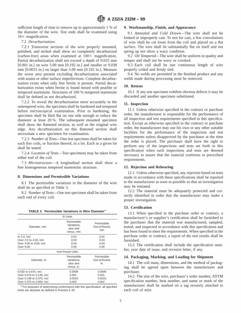
sufficient length of time to remove up to approximately 1 % ofthe diameter of the wire. Test ends shall be examined using103 magnification.
7.2 Decarburization:7.2.1 Transverse sections of the wire properly mounted,
polished, and etched shall show no completely decarburized(carbon-free) areas when examined at 1003 magnification.Partial decarburization shall not exceed a depth of 0.025 mm[0.001 in.] on wire 5.00 mm [0.192 in.] and smaller or 0.038mm [0.0015 in.] on larger than 5.00 mm [0.192 in.]. Measurethe worst area present excluding decarburization associatedwith seams or other surface imperfections. Complete decarbur-ization exists when only free ferrite is present. Partial decar-burization exists when ferrite is found mixed with pearlite ortempered martensite. Structures of 100 % tempered martensiteshall be defined as not decarburized.
7.2.2 To reveal the decarburization more accurately in theuntempered wire, the specimen shall be hardened and temperedbefore microscopical examination. Prior to hardening, thespecimen shall be filed flat on one side enough to reduce thediameter at least 20 %. The subsequent mounted specimenshall show the flattened section, as well as the original wireedge. Any decarburization on this flattened section shallnecessitate a new specimen for examination.
7.2.3 Number of Tests—One test specimen shall be taken foreach five coils, or fraction thereof, in a lot. Each in a given lotshall be tested.
7.2.4 Location of Tests—Test specimens may be taken fromeither end of the coil.
7.3 Microstructure—A longitudinal section shall show afine homogeneous tempered martensitic structure.
8. Dimensions and Permissible Variations
8.1 The permissible variations in the diameter of the wireshall be as specified in Table 3.
8.2 Number of Tests—One test specimen shall be taken fromeach end of every coil.
9. Workmanship, Finish, and Appearance
9.1 Annealed and Cold Drawn—The wire shall not bekinked or improperly cast. To test for cast, a few convolutionsof wire shall be cut loose from the coil and placed on a flatsurface. The wire shall lie substantially flat on itself and notspring up nor show a wavy condition.
9.2 Oil Tempered—The wire shall be uniform in quality andtemper and shall not be wavy or crooked.
9.3 Each coil shall be one continuous length of wireproperly coiled and firmly tied.
9.4 No welds are permitted in the finished product and anywelds made during processing must be removed.
10. Retests
10.1 If any test specimen exhibits obvious defects it may bediscarded and another specimen substituted.
11. Inspection
11.1 Unless otherwise specified in the contract or purchaseorder, the manufacturer is responsible for the performance ofall inspection and test requirements specified in this specifica-tion. Except as otherwise specified in the contract or purchaseorder, the manufacturer may use his own or any other suitablefacilities for the performance of the inspection and testrequirements unless disapproved by the purchaser at the timethe order is placed. The purchaser shall have the right toperform any of the inspections and tests set forth in thisspecification when such inspections and tests are deemednecessary to assure that the material conforms to prescribedrequirements.
12. Rejection and Rehearing
12.1 Unless otherwise specified, any rejection based on testsmade in accordance with these specifications shall be reportedto the manufacturer as soon as possible so that an investigationmay be initiated.
12.2 The material must be adequately protected and cor-rectly identified in order that the manufacturer may make aproper investigation.
13. Certification
13.1 When specified in the purchase order or contract, amanufacturer’s or supplier’s certification shall be furnished tothe purchaser that the material was manufactured, sampled,tested, and inspected in accordance with this specification andhas been found to meet the requirements. When specified in thepurchase order or contract, a report of the test results shall befurnished.
13.2 The certification shall include the specification num-ber, year date of issue, and revision letter, if any.
14. Packaging, Marking, and Loading for Shipment
14.1 The coil mass, dimensions, and the method of packag-ing shall be agreed upon between the manufacturer andpurchaser.
14.2 The size of the wire, purchaser’s order number, ASTMspecification number, heat number, and name or mark of themanufacturer shall be marked on a tag securely attached toeach coil of wire.
TABLE 3 Permissible Variations in Wire Diameter A
SI Units
Diameter, mm
PermissibleVariations,plus and
minus, mm
PermissibleOut-of-Round,
mm
to 2.0, incl 0.02 0.02Over 2.0 to 4.00, incl 0.03 0.03Over 4.00 to 9.00, incl 0.04 0.04Over 9.00 0.05 0.05
Inch-Pound Units
Permissible PermissibleDiameter, in. Variations, Out-of-Round,
plus and in.minus, in.
0.020 to 0.075, incl 0.0008 0.0008Over 0.075 to 0.148, incl 0.001 0.001Over 0.148 to 0.375, incl 0.0015 0.0015Over 0.375 to 0.500, incl 0.002 0.002
A For purposes of determining conformance with this specification, all specifiedlimits are absolute as defined in Practice E 29.
A 232/A 232M – 99
3

14.3 Unless otherwise specified in the purchaser’s order,packaging, marking, and loading for shipments shall be inaccordance with those procedures recommended by PracticeA 700.
14.4 For Government Procurement—Packaging, packing,and marking of material for military procurement shall be inaccordance with the requirements of MIL-STD-163, Level A,Level C, or commercial as specified in the contract or purchaseorder. Marking for shipment of material for civil agencies shallbe in accordance with Fed. Std. No. 123.
14.5 Bar Coding—In addition to the previously-stated iden-tification requirements, bar coding is acceptable as a supple-mentary identification method. Bar coding should be consistentwith AIAG B-5 02.00, Primary Metals Identification TagApplication. The bar code may be applied to a substantiallyaffixed tag.
15. Keywords
15.1 alloy; chromium-vanadium; valve spring; wire
ASTM International takes no position respecting the validity of any patent rights asserted in connection with any item mentionedin this standard. Users of this standard are expressly advised that determination of the validity of any such patent rights, and the riskof infringement of such rights, are entirely their own responsibility.
This standard is subject to revision at any time by the responsible technical committee and must be reviewed every five years andif not revised, either reapproved or withdrawn. Your comments are invited either for revision of this standard or for additional standardsand should be addressed to ASTM International Headquarters. Your comments will receive careful consideration at a meeting of theresponsible technical committee, which you may attend. If you feel that your comments have not received a fair hearing you shouldmake your views known to the ASTM Committee on Standards, at the address shown below.
This standard is copyrighted by ASTM International, 100 Barr Harbor Drive, PO Box C700, West Conshohocken, PA 19428-2959,United States. Individual reprints (single or multiple copies) of this standard may be obtained by contacting ASTM at the aboveaddress or at 610-832-9585 (phone), 610-832-9555 (fax), or [email protected] (e-mail); or through the ASTM website(www.astm.org).
A 232/A 232M – 99
4
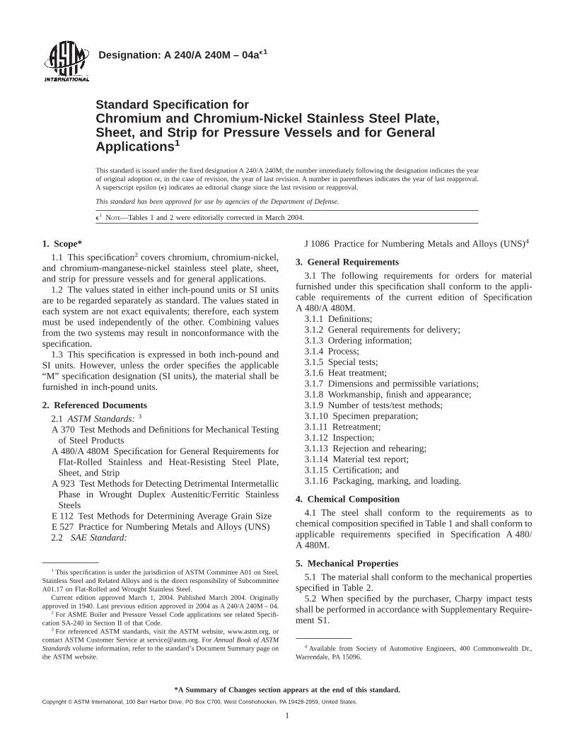
Designation: A 240/A 240M – 04a e1
Standard Specification forChromium and Chromium-Nickel Stainless Steel Plate,Sheet, and Strip for Pressure Vessels and for GeneralApplications 1
This standard is issued under the fixed designation A 240/A 240M; the number immediately following the designation indicates the yearof original adoption or, in the case of revision, the year of last revision. A number in parentheses indicates the year of last reapproval.A superscript epsilon (e) indicates an editorial change since the last revision or reapproval.
This standard has been approved for use by agencies of the Department of Defense.
e1 NOTE—Tables 1 and 2 were editorially corrected in March 2004.
1. Scope*
1.1 This specification2 covers chromium, chromium-nickel,and chromium-manganese-nickel stainless steel plate, sheet,and strip for pressure vessels and for general applications.
1.2 The values stated in either inch-pound units or SI unitsare to be regarded separately as standard. The values stated ineach system are not exact equivalents; therefore, each systemmust be used independently of the other. Combining valuesfrom the two systems may result in nonconformance with thespecification.
1.3 This specification is expressed in both inch-pound andSI units. However, unless the order specifies the applicable“M” specification designation (SI units), the material shall befurnished in inch-pound units.
2. Referenced Documents
2.1 ASTM Standards:3
A 370 Test Methods and Definitions for Mechanical Testingof Steel Products
A 480/A 480M Specification for General Requirements forFlat-Rolled Stainless and Heat-Resisting Steel Plate,Sheet, and Strip
A 923 Test Methods for Detecting Detrimental IntermetallicPhase in Wrought Duplex Austenitic/Ferritic StainlessSteels
E 112 Test Methods for Determining Average Grain SizeE 527 Practice for Numbering Metals and Alloys (UNS)2.2 SAE Standard:
J 1086 Practice for Numbering Metals and Alloys (UNS)4
3. General Requirements
3.1 The following requirements for orders for materialfurnished under this specification shall conform to the appli-cable requirements of the current edition of SpecificationA 480/A 480M.
3.1.1 Definitions;3.1.2 General requirements for delivery;3.1.3 Ordering information;3.1.4 Process;3.1.5 Special tests;3.1.6 Heat treatment;3.1.7 Dimensions and permissible variations;3.1.8 Workmanship, finish and appearance;3.1.9 Number of tests/test methods;3.1.10 Specimen preparation;3.1.11 Retreatment;3.1.12 Inspection;3.1.13 Rejection and rehearing;3.1.14 Material test report;3.1.15 Certification; and3.1.16 Packaging, marking, and loading.
4. Chemical Composition
4.1 The steel shall conform to the requirements as tochemical composition specified in Table 1 and shall conform toapplicable requirements specified in Specification A 480/A 480M.
5. Mechanical Properties
5.1 The material shall conform to the mechanical propertiesspecified in Table 2.
5.2 When specified by the purchaser, Charpy impact testsshall be performed in accordance with Supplementary Require-ment S1.
1 This specification is under the jurisdiction of ASTM Committee A01 on Steel,Stainless Steel and Related Alloys and is the direct responsibility of SubcommitteeA01.17 on Flat-Rolled and Wrought Stainless Steel.
Current edition approved March 1, 2004. Published March 2004. Originallyapproved in 1940. Last previous edition approved in 2004 as A 240/A 240M – 04.
2 For ASME Boiler and Pressure Vessel Code applications see related Specifi-cation SA-240 in Section II of that Code.
3 For referenced ASTM standards, visit the ASTM website, www.astm.org, orcontact ASTM Customer Service at [email protected]. ForAnnual Book of ASTMStandardsvolume information, refer to the standard’s Document Summary page onthe ASTM website.
4 Available from Society of Automotive Engineers, 400 Commonwealth Dr.,Warrendale, PA 15096.
1
*A Summary of Changes section appears at the end of this standard.
Copyright © ASTM International, 100 Barr Harbor Drive, PO Box C700, West Conshohocken, PA 19428-2959, United States.

6. Materials for High-Temperature Service
6.1 The austeniticH Types shall conform to an averagegrain size of ASTM No. 7 or coarser as measured by TestMethods E 112.
6.2 Supplementary Requirement S2 shall be invoked whennon-H grade austenitic stainless steels are ordered for ASMECode applications for service above 1000°F [540°C].
6.3 Grade S31060, unless otherwise specified in the pur-chase order, shall conform to an average grain size of ASTMNo. 7 or coarser, as measured by Test Methods E 112.
A 240/A 240M – 04ae1
2

TAB
LE1
Che
mic
alC
ompo
sitio
nR
equi
rem
ents
,%A
UN
SD
esig
natio
nBTy
peC
Car
bonD
Man
gane
seP
hos-
phor
usS
ulfu
rS
ilico
nC
hrom
ium
Nic
kel
Mol
ybde
num
Nitr
ogen
Cop
per
Oth
er Ele
men
tsE
,F
Aus
teni
tic(C
hrom
ium
-Nic
kel)
(Chr
omiu
m-M
anga
nese
-Nic
kel)
N08
020
...
0.07
2.00
0.04
50.
035
1.00
19.0
–21.
032
.0–3
8.0
2.00
–3.0
0..
.3.
0–4.
0C
b83
Cm
in,
1.00
max
N08
367
...
0.03
02.
000.
040
0.03
01.
0020
.0–2
2.0
23.5
–25.
56.
0–7.
00.
18–0
.25
0.75
...
N08
800
800G
0.10
1.50
0.04
50.
015
1.00
19.0
–23.
030
.0–3
5.0
...
...
0.75
FeH
39.5
min
Al0
.15–
0.60
Ti0.
15–0
.60
N08
810
800H
G0.
05–0
.10
1.50
0.04
50.
015
1.00
19.0
–23.
030
.0–3
5.0
...
...
0.75
FeH
39.5
min
Al0
.15–
0.60
Ti0.
15–0
.60
N08
811
...
0.06
–0.1
01.
500.
040
0.01
51.
0019
.0–2
3.0
30.0
–35.
0..
...
.0.
75F
eH39
.5m
inTi
I0.
15–0
.60
AlI
0.15
–0.6
0N
0890
490
4LG
0.02
02.
000.
045
0.03
51.
0019
.0–2
3.0
23.0
–28.
04.
0–5.
00.
101.
0–2.
0..
.N
0892
6..
.0.
020
2.00
0.03
00.
010
0.50
19.0
–21.
024
.0–2
6.0
6.0–
7.0
0.15
–0.2
50.
5–1.
5..
.S
2010
020
10.
155.
5–7.
50.
060
0.03
01.
0016
.0–1
8.0
3.5–
5.5
...
0.25
...
...
S20
103
...
0.03
5.5–
7.5
0.04
50.
030
0.75
16.0
–18.
03.
5–5.
5..
.0.
25..
...
.S
2015
3..
.0.
036.
4–7.
50.
045
0.01
50.
7516
.0–1
7.5
4.0–
5.0
...
0.10
–0.2
51.
00..
.S
2016
1..
.0.
154.
0–6.
00.
040
0.04
03.
0–4.
015
.0–1
8.0
4.0–
6.0
...
0.08
–0.2
0..
...
.S
2020
020
20.
157.
5–10
.00.
060
0.03
01.
0017
.0–1
9.0
4.0–
6.0
...
0.25
...
...
S20
400
...
0.03
07.
0–9.
00.
040
0.03
01.
0015
.0–1
7.0
1.50
–3.0
0..
.0.
15–0
.30
...
...
S20
910
XM
-19J
0.06
4.0–
6.0
0.04
00.
030
0.75
20.5
–23.
511
.5–1
3.5
1.50
–3.0
00.
20–0
.40
...
Cb
0.10
–0.3
0V
0.10
–0.3
0S
2140
0X
M-3
1J0.
1214
.0–1
6.0
0.04
50.
030
0.30
–1.0
017
.0–1
8.5
1.00
...
0.35
min
...
...
S21
600
XM
-17J
0.08
7.5–
9.0
0.04
50.
030
0.75
17.5
–22.
05.
0–7.
02.
00–3
.00
0.25
–0.5
0..
...
.S
2160
3X
M-1
8J0.
037.
5–9.
00.
045
0.03
00.
7517
.5–2
2.0
5.0–
7.0
2.00
–3.0
00.
25–0
.50
...
...
S21
800
...
0.10
7.0–
9.0
0.06
00.
030
3.5–
4.5
16.0
–18.
08.
0–9.
0..
.0.
08–0
.18
...
...
S24
000
XM
-29J
0.08
11.5
–14.
50.
060
0.03
00.
7517
.0–1
9.0
2.3–
3.7
...
0.20
–0.4
0..
...
.S
3010
030
10.
152.
000.
045
0.03
01.
0016
.0–1
8.0
6.0–
8.0
...
0.10
...
...
S30
103
301L
G0.
032.
000.
045
0.03
01.
0016
.0–1
8.0
6.0–
8.0
...
0.20
...
...
S30
153
301L
NG
0.03
2.00
0.04
50.
030
1.00
16.0
–18.
06.
0–8.
0..
.0.
07–0
.20
...
...
S30
200
302
0.15
2.00
0.04
50.
030
0.75
17.0
–19.
08.
0–10
.0..
.0.
10..
...
.S
3040
030
40.
082.
000.
045
0.03
00.
7518
.0–2
0.0
8.0–
10.5
...
0.10
...
...
S30
403
304L
0.03
02.
000.
045
0.03
00.
7518
.0–2
0.0
8.0–
12.0
...
0.10
...
...
S30
409
304H
0.04
–0.1
02.
000.
045
0.03
00.
7518
.0–2
0.0
8.0–
10.5
...
...
...
...
S30
415
...
0.04
–0.0
60.
800.
045
0.03
01.
00–2
.00
18.0
–19.
09.
0–10
.0..
.0.
12–0
.18
...
Ce
0.03
–0.0
8S
3045
130
4N0.
082.
000.
045
0.03
00.
7518
.0–2
0.0
8.0–
10.5
...
0.10
–0.1
6..
...
.S
3045
2X
M-2
1J0.
082.
000.
045
0.03
00.
7518
.0–2
0.0
8.0–
10.5
...
0.16
–0.3
0..
...
.S
3045
330
4LN
0.03
02.
000.
045
0.03
00.
7518
.0–2
0.0
8.0–
12.0
...
0.10
–0.1
6..
...
.S
3050
030
50.
122.
000.
045
0.03
00.
7517
.0–1
9.0
10.5
–13.
0..
...
...
...
.S
3060
0..
.0.
018
2.00
0.02
00.
020
3.7–
4.3
17.0
–18.
514
.0–1
5.5
0.20
...
0.50
...
S30
601
...
0.01
50.
50–0
.80
0.03
00.
013
5.0–
5.6
17.0
–18.
017
.0–1
8.0
0.20
0.05
0.35
...
S30
615
...
0.16
–0.2
42.
000.
030
0.03
03.
2–4.
017
.0–1
9.5
13.5
–16.
0..
...
...
.A
l0.8
0–1.
50S
3081
5..
.0.
05–0
.10
0.80
0.04
00.
030
1.40
–2.0
020
.0–2
2.0
10.0
–12.
0..
.0.
14–0
.20
...
Ce
0.03
–0.0
8S
3090
830
9S0.
082.
000.
045
0.03
00.
7522
.0–2
4.0
12.0
–15.
0..
...
...
...
.S
3090
930
9HG
0.04
–0.1
02.
000.
045
0.03
00.
7522
.0–2
4.0
12.0
–15.
0..
...
...
...
.S
3094
030
9CbG
0.08
2.00
0.04
50.
030
0.75
22.0
–24.
012
.0–1
6.0
...
...
...
Cb
103
Cm
in,
1.10
max
S30
941
309H
CbG
0.04
–0.1
02.
000.
045
0.03
00.
7522
.0–2
4.0
12.0
–16.
0..
...
...
.C
b10
3C
min
,1.
10m
axS
3100
831
0S0.
082.
000.
045
0.03
01.
5024
.0–2
6.0
19.0
–22.
0..
...
...
...
.S
3100
931
0HG
0.04
–0.1
02.
000.
045
0.03
00.
7524
.0–2
6.0
19.0
–22.
0..
...
...
...
.S
3104
031
0CbG
0.08
2.00
0.04
50.
030
1.50
24.0
–26.
019
.0–2
2.0
...
...
...
Cb
103
Cm
in,
1.10
max
A 240/A 240M – 04ae1
3

TAB
LE1
Con
tinue
d
UN
SD
esig
natio
nBTy
peC
Car
bonD
Man
gane
seP
hos-
phor
usS
ulfu
rS
ilico
nC
hrom
ium
Nic
kel
Mol
ybde
num
Nitr
ogen
Cop
per
Oth
er Ele
men
tsE
,F
S31
041
310H
CbG
0.04
–0.1
02.
000.
045
0.03
00.
7524
.0–2
6.0
19.0
–22.
0..
...
...
.C
b10
3C
min
,1.
10m
axS
3105
031
0M
oLN
G0.
020
2.00
0.03
00.
010
0.50
24.0
–26.
020
.5–2
3.5
1.60
–2.6
00.
09–0
.15
...
...
S31
060
...
0.05
–0.1
01.
000.
040
0.03
00.
5022
.0–2
4.0
10.0
–12.
5..
.0.
18–0
.25
...
Ce
+La
0.02
5–0.
070
B0.
001–
0.01
0S
3125
4..
.0.
020
1.00
0.03
00.
010
0.80
19.5
–20.
517
.5–1
8.5
6.0–
6.5
0.18
–0.2
20.
50–1
.00
...
S31
266
...
0.03
02.
0–4.
00.
035
0.02
01.
0023
.0–2
5.0
21.0
–24.
05.
2–6.
20.
35–0
.60
1.00
–2.5
0W
1.50
–2.5
0S
3127
7..
.0.
020
3.00
0.03
00.
010
0.50
20.5
–23.
026
.0–2
8.0
6.5–
8.0
0.30
–0.4
00.
50–1
.50
...
S31
600
316
0.08
2.00
0.04
50.
030
0.75
16.0
–18.
010
.0–1
4.0
2.00
–3.0
00.
10..
...
.S
3160
331
6L0.
030
2.00
0.04
50.
030
0.75
16.0
–18.
010
.0–1
4.0
2.00
–3.0
00.
10..
...
.S
3160
931
6H0.
04–0
.10
2.00
0.04
50.
030
0.75
16.0
–18.
010
.0–1
4.0
2.00
–3.0
0..
...
...
.S
3163
531
6TiG
0.08
2.00
0.04
50.
030
0.75
16.0
–18.
010
.0–1
4.0
2.00
–3.0
00.
10..
.Ti
53
(C+
N)
min
,0.
70m
axS
3164
031
6CbG
0.08
2.00
0.04
50.
030
0.75
16.0
–18.
010
.0–1
4.0
2.00
–3.0
00.
10..
.C
b10
3C
min
,1.
10m
axS
3165
131
6N0.
082.
000.
045
0.03
00.
7516
.0–1
8.0
10.0
–14.
02.
00–3
.00
0.10
–0.1
6..
...
.S
3165
331
6LN
0.03
02.
000.
045
0.03
00.
7516
.0–1
8.0
10.0
–14.
02.
00–3
.00
0.10
–0.1
6..
...
.S
3170
031
70.
082.
000.
045
0.03
00.
7518
.0–2
0.0
11.0
–15.
03.
0–4.
00.
10..
...
.S
3170
331
7L0.
030
2.00
0.04
50.
030
0.75
18.0
–20.
011
.0–1
5.0
3.0–
4.0
0.10
...
...
S31
725
317L
MG
0.03
02.
000.
045
0.03
00.
7518
.0–2
0.0
13.5
–17.
54.
0–5.
00.
20..
...
.S
3172
631
7LM
NG
0.03
02.
000.
045
0.03
00.
7517
.0–2
0.0
13.5
–17.
54.
0–5.
00.
10–0
.20
...
...
S31
727
...
0.03
01.
000.
030
0.03
01.
0017
.5–1
9.0
14.5
–16.
53.
8–4.
50.
15–0
.21
2.8–
4.0
...
S31
753
317L
NG
0.03
02.
000.
045
0.03
00.
7518
.0–2
0.0
11.0
–15.
03.
0–4.
00.
10–0
.22
...
...
S32
050
...
0.03
01.
500.
035
0.02
01.
0022
.0–2
4.0
20.0
–23.
06.
0–6.
80.
21–0
.32
0.40
...
S32
053
...
0.03
01.
000.
030
0.01
01.
0022
.0–2
4.0
24.0
–26.
05.
0–6.
00.
17–0
.22
...
...
S32
100
321
0.08
2.00
0.04
50.
030
0.75
17.0
–19.
09.
0–12
.0..
.0.
10..
.Ti
53
(C+
N)
min
,0.
70m
axS
3210
932
1H0.
04–0
.10
2.00
0.04
50.
030
0.75
17.0
–19.
09.
0–12
.0..
...
...
.Ti
43
(C+
N)
min
,0.
70m
axS
3261
5..
.0.
072.
000.
045
0.03
04.
8–6.
016
.5–1
9.5
19.0
–22.
00.
30–1
.50
...
1.50
–2.5
0..
.S
3265
4..
.0.
020
2.0–
4.0
0.03
00.
005
0.50
24.0
–25.
021
.0–2
3.0
7.0–
8.0
0.45
–0.5
50.
30–0
.60
...
S33
228
...
0.04
–0.0
81.
000.
020
0.01
50.
3026
.0–2
8.0
31.0
–33.
0..
...
...
.C
e0.
05–0
.10
Cb
0.6–
1.0
Al0
.025
S33
400
334G
0.08
1.00
0.03
00.
015
1.00
18.0
–20.
019
.0–2
1.0
...
...
...
Al0
.15–
0.60
Ti0.
15–0
.60
S34
565
...
0.03
05.
0–7.
00.
030
0.01
01.
0023
.0–2
5.0
16.0
–18.
04.
0–5.
00.
40–0
.60
...
Cb
0.10
S34
700
347
0.08
2.00
0.04
50.
030
0.75
17.0
–19.
09.
0–13
.0..
...
...
.C
b10
3C
min
,1.
00m
axS
3470
934
7H0.
04–0
.10
2.00
0.04
50.
030
0.75
17.0
–19.
09.
0–13
.0..
...
...
.C
b8
3C
min
,1.
00m
axS
3480
034
80.
082.
000.
045
0.03
00.
7517
.0–1
9.0
9.0–
13.0
...
...
...
(Cb
+Ta
)10
3C
min
,1.
00m
axTa
0.10
Co
0.20
S34
809
348H
0.04
–0.1
02.
000.
045
0.03
00.
7517
.0–1
9.0
9.0–
13.0
...
...
...
(Cb
+Ta
)83
Cm
in,
1.00
max
Ta0.
10C
o0.
20S
3504
5..
.0.
06–0
.10
1.50
0.04
50.
015
1.00
25.0
–29.
032
.0–3
7.0
...
...
0.75
Al0
.15–
0.60
Ti0.
15–0
.60
S35
135
...
0.08
1.00
0.04
50.
015
0.60
–1.0
020
.0–2
5.0
30.0
–38.
04.
0–4.
8..
.0.
75Ti
0.40
–1.0
0S
3531
5..
.0.
04–0
.08
2.00
0.04
00.
030
1.20
–2.0
024
.0–2
6.0
34.0
–36.
0..
.0.
12–0
.18
...
Ce
0.03
–0.1
0S
3810
0X
M-1
5J0.
082.
000.
030
0.03
01.
50–2
.50
17.0
–19.
017
.5–1
8.5
...
...
...
...
S38
815
...
0.03
02.
000.
040
0.02
05.
5–6.
513
.0–1
5.0
13.0
–17.
00.
75–1
.50
...
0.75
–1.5
0A
l0.3
0
A 240/A 240M – 04ae1
4
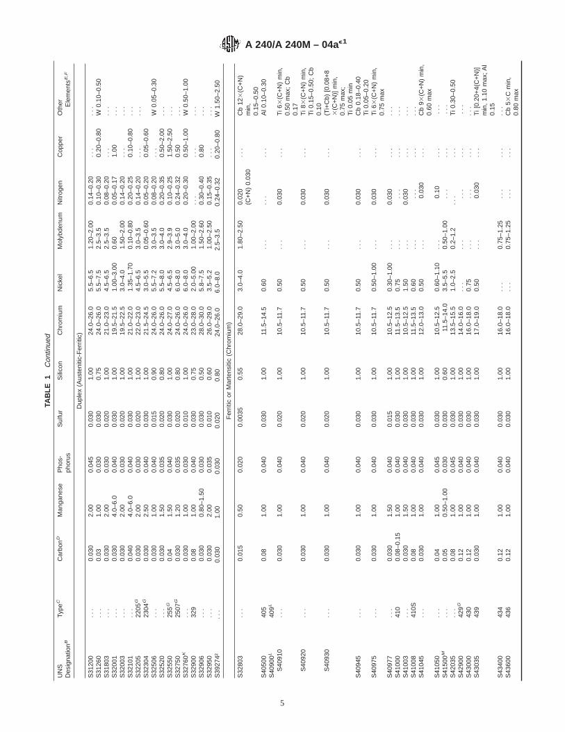
TAB
LE1
Con
tinue
d
UN
SD
esig
natio
nBTy
peC
Car
bonD
Man
gane
seP
hos-
phor
usS
ulfu
rS
ilico
nC
hrom
ium
Nic
kel
Mol
ybde
num
Nitr
ogen
Cop
per
Oth
er Ele
men
tsE
,F
Dup
lex
(Aus
teni
tic-F
errit
ic)
S31
200
...
0.03
02.
000.
045
0.03
01.
0024
.0–2
6.0
5.5–
6.5
1.20
–2.0
00.
14–0
.20
...
...
S31
260
...
0.03
1.00
0.03
00.
030
0.75
24.0
–26.
05.
5–7.
52.
5–3.
50.
10–0
.30
0.20
–0.8
0W
0.10
–0.5
0S
3180
3..
.0.
030
2.00
0.03
00.
020
1.00
21.0
–23.
04.
5–6.
52.
5–3.
50.
08–0
.20
...
...
S32
001
...
0.03
04.
0–6.
00.
040
0.03
01.
0019
.5–2
1.5
1.00
–3.0
00.
600.
05–0
.17
1.00
...
S32
003
...
0.03
02.
000.
030
0.02
01.
0019
.5–2
2.5
3.0–
4.0
1.50
–2.0
00.
14–0
.20
...
...
S32
101
...
0.04
04.
0–6.
00.
040
0.03
01.
0021
.0–2
2.0
1.35
–1.7
00.
10–0
.80
0.20
–0.2
50.
10–0
.80
...
S32
205
2205
G0.
030
2.00
0.03
00.
020
1.00
22.0
–23.
04.
5–6.
53.
0–3.
50.
14–0
.20
...
...
S32
304
2304
G0.
030
2.50
0.04
00.
030
1.00
21.5
–24.
53.
0–5.
50.
05–0
.60
0.05
–0.2
00.
05–0
.60
S32
506
...
0.03
01.
000.
040
0.01
50.
9024
.0–2
6.0
5.5–
7.2
3.0–
3.5
0.08
–0.2
0..
.W
0.05
–0.3
0S
3252
0..
.0.
030
1.50
0.03
50.
020
0.80
24.0
–26.
05.
5–8.
03.
0–4.
00.
20–0
.35
0.50
–2.0
0..
.S
3255
025
5G0.
041.
500.
040
0.03
01.
0024
.0–2
7.0
4.5–
6.5
2.9–
3.9
0.10
–0.2
51.
50–2
.50
...
S32
750
2507
G0.
030
1.20
0.03
50.
020
0.80
24.0
–26.
06.
0–8.
03.
0–5.
00.
24–0
.32
0.50
...
S32
760K
...
0.03
01.
000.
030
0.01
01.
0024
.0–2
6.0
6.0–
8.0
3.0–
4.0
0.20
–0.3
00.
50–1
.00
W0.
50–1
.00
S32
900
329
0.08
1.00
0.04
00.
030
0.75
23.0
–28.
02.
0–5.
001.
00–2
.00
...
...
...
S32
906
...
0.03
00.
80–1
.50
0.03
00.
030
0.50
28.0
–30.
05.
8–7.
51.
50–2
.60
0.30
–0.4
00.
80..
.S
3295
0..
.0.
030
2.00
0.03
50.
010
0.60
26.0
–29.
03.
5–5.
21.
00–2
.50
0.15
–0.3
5..
...
.S
3927
4†..
.0.
030
1.00
0.03
00.
020
0.80
24.0
–26.
06.
0–8.
02.
5–3.
50.
24–0
.32
0.20
–0.8
0W
1.50
–2.5
0
Fer
ritic
orM
arte
nsiti
c(C
hrom
ium
)
S32
803
...
0.01
50.
500.
020
0.00
350.
5528
.0–2
9.0
3.0–
4.0
1.80
–2.5
00.
020
(C+
N)
0.03
0..
.C
b12
3(C
+N
)m
in,
0.15
–0.5
0S
4050
040
50.
081.
000.
040
0.03
01.
0011
.5–1
4.5
0.60
...
...
...
Al0
.10–
0.30
S40
900L
409L
S40
910
...
0.03
01.
000.
040
0.02
01.
0010
.5–1
1.7
0.50
...
0.03
0..
.Ti
63(C
+N
)m
in,
0.50
max
;C
b0.
17S
4092
0..
.0.
030
1.00
0.04
00.
020
1.00
10.5
–11.
70.
50..
.0.
030
...
Ti83
(C+
N)
min
,Ti
0.15
–0.5
0;C
b0.
10S
4093
0..
.0.
030
1.00
0.04
00.
020
1.00
10.5
–11.
70.
50..
.0.
030
...
(Ti+
Cb)
[0.0
8+8
3(C
+N
)]m
in,
0.75
max
;Ti
0.05
min
S40
945
...
0.03
01.
000.
040
0.03
01.
0010
.5–1
1.7
0.50
...
0.03
0..
.C
b0.
18–0
.40
Ti0.
05–0
.20
S40
975
...
0.03
01.
000.
040
0.03
01.
0010
.5–1
1.7
0.50
–1.0
0..
.0.
030
...
Ti63
(C+
N)
min
,0.
75m
axS
4097
7..
.0.
030
1.50
0.04
00.
015
1.00
10.5
–12.
50.
30–1
.00
...
0.03
0..
...
.S
4100
041
00.
08–0
.15
1.00
0.04
00.
030
1.00
11.5
–13.
50.
75..
...
...
...
.S
4100
3..
.0.
030
1.50
0.04
00.
030
1.00
10.5
–12.
51.
50..
.0.
030
...
...
S41
008
S41
045
410S
...
0.08
0.03
01.
001.
000.
040
0.04
00.
030
0.03
01.
001.
0011
.5–1
3.5
12.0
–13.
00.
600.
50..
...
...
.0.
030
...
...
...
Cb
93(C
+N
)m
in,
0.60
max
S41
050
...
0.04
1.00
0.04
50.
030
1.00
10.5
–12.
50.
60–1
.10
...
0.10
...
...
S41
500M
...
0.05
0.50
–1.0
00.
030
0.03
00.
6011
.5–1
4.0
3.5–
5.5
0.50
–1.0
0..
...
...
.S
4203
5..
.0.
081.
000.
045
0.03
01.
0013
.5–1
5.5
1.0–
2.5
0.2–
1.2
...
...
Ti0.
30–0
.50
S42
900
429G
0.12
1.00
0.04
00.
030
1.00
14.0
–16.
0..
...
...
...
...
.S
4300
043
00.
121.
000.
040
0.03
01.
0016
.0–1
8.0
0.75
...
...
...
...
S43
035
439
0.03
01.
000.
040
0.03
01.
0017
.0–1
9.0
0.50
...
0.03
0..
.Ti
[0.2
0+4(
C+
N)]
min
,1.
10m
ax;A
l0.
15S
4340
043
40.
121.
000.
040
0.03
01.
0016
.0–1
8.0
...
0.75
–1.2
5..
...
...
.S
4360
043
60.
121.
000.
040
0.03
01.
0016
.0–1
8.0
...
0.75
–1.2
5..
...
.C
b53
Cm
in,
0.80
max
A 240/A 240M – 04ae1
5

TAB
LE1
Con
tinue
d
UN
SD
esig
natio
nBTy
peC
Car
bonD
Man
gane
seP
hos-
phor
usS
ulfu
rS
ilico
nC
hrom
ium
Nic
kel
Mol
ybde
num
Nitr
ogen
Cop
per
Oth
er Ele
men
tsE
,F
S43
932
...
0.03
01.
000.
040
0.03
01.
0017
.0–1
9.0
0.50
...
0.03
0..
.(T
i+C
b)[0
.20+
4(C
+N
)]m
in,
0.75
max
;A
l0.1
5S
4394
0..
.0.
030
1.00
0.04
00.
015
1.00
17.5
–18.
5..
...
...
...
.Ti
0.10
–0.6
0C
b[0
.30+
(33
C)]
min
S44
400
444
0.02
51.
000.
040
0.03
01.
0017
.5–1
9.5
1.00
1.75
–2.5
00.
035
...
(Ti+
Cb)
[0.2
0+4(
C+
N)]
min
,0.
80m
axS
4450
0..
.0.
020
1.00
0.04
00.
012
1.00
19.0
–21.
00.
60..
.0.
030.
30–0
.60
Cb
103
(C+
N)
min
,0.
80m
axS
4462
6X
M-3
3J0.
060.
750.
040
0.02
00.
7525
.0–2
7.0
0.50
0.75
–1.5
00.
040.
20Ti
0.20
–1.0
0;Ti
7(C
+N
)m
inS
4462
7X
M-2
7J0.
010N
0.40
0.02
00.
020
0.40
25.0
–27.
50.
500.
75–1
.50
0.01
5N0.
20C
b0.
05–0
.20
(Ni+
Cu)
0.50
S44
635
...
0.02
51.
000.
040
0.03
00.
7524
.5–2
6.0
3.5–
4.5
3.5–
4.5
0.03
5..
.(T
i+C
b)[0
.20+
4(C
+N
)]m
in,
0.80
max
S44
660
...
0.03
01.
000.
040
0.03
01.
0025
.0–2
8.0
1.0–
3.5
3.0–
4.0
0.04
0..
.(T
i+C
b)0.
20−
1.00
,Ti
+C
b63
(C+
N)
min
S44
700
...
0.01
00.
300.
025
0.02
00.
2028
.0–3
0.0
0.15
3.5–
4.2
0.02
00.
15(C
+N
)0.
025
S44
735
...
0.03
01.
000.
040
0.03
01.
0028
.0–3
0.0
1.00
3.6–
4.2
0.04
5..
.(T
i+C
b)0.
20–1
.00,
(Ti+
Cb)
63(C
+N
)m
inS
4480
0..
.0.
010
0.30
0.02
50.
020
0.20
28.0
–30.
02.
00–2
.50
3.5–
4.2
0.02
00.
15(C
+N
)0.
025
S46
800
...
0.03
01.
000.
040
0.03
01.
0018
.0–2
0.0
0.50
...
0.03
0..
.Ti
0.07
–0.3
0C
b0.
10–0
.60
(Ti+
Cb)
[0.2
0+4
(C+
N)]
min
,0.
80m
axA
Max
imum
,un
less
rang
eor
min
imum
isin
dica
ted.
BD
esig
natio
nes
tabl
ishe
din
acco
rdan
cew
ithP
ract
ice
E52
7an
dS
AE
J10
86.
CU
nles
sot
herw
ise
indi
cate
d,a
grad
ede
sign
atio
nor
igin
ally
assi
gned
byth
eA
mer
ican
Iron
and
Ste
elIn
stitu
te(A
ISI)
.D
Car
bon
anal
ysis
shal
lbe
repo
rted
tone
ares
t0.
01%
exce
ptfo
rth
elo
w-c
arbo
nty
pes,
whi
chsh
allb
ere
port
edto
near
est
0.00
1%
.E
The
term
sC
olum
bium
(Cb)
and
Nio
bium
(Nb)
both
rela
teto
the
sam
eel
emen
t.F
Whe
ntw
om
inim
ums
ortw
om
axim
ums
are
liste
dfo
ra
sing
lety
pe,
asin
the
case
ofbo
tha
valu
efr
oma
form
ula
and
anab
solu
teva
lue,
the
high
erm
inim
umor
low
erm
axim
umsh
alla
pply
.G
Com
mon
nam
e,no
ta
trad
emar
k,w
idel
yus
ed,
not
asso
ciat
edw
ithan
yon
epr
oduc
er.
HIr
onsh
allb
ede
term
ined
arith
met
ical
lyby
diffe
renc
eof
100
min
usth
esu
mof
the
othe
rsp
ecifi
edel
emen
ts.
I(A
l+Ti
)0.
85–1
.20.
JN
amin
gsy
stem
deve
lope
dan
dap
plie
dby
AS
TM
.K
Cr
+3.
3M
o+
16N
=40
min
.L
S40
900
(Typ
e40
9)ha
sbe
enre
plac
edby
S40
910,
S40
920,
and
S40
930.
Unl
ess
othe
rwis
esp
ecifi
edin
the
orde
ring
info
rmat
ion,
anor
der
spec
ifyin
gS
4090
0or
Type
409
shal
lbe
satis
fied
byan
yon
eof
S40
910,
S40
920,
orS
4093
0at
the
optio
nof
the
selle
r.M
ater
ialm
eetin
gth
ere
quire
men
tsof
S40
910,
S40
920,
orS
4093
0,m
ayat
the
optio
nof
the
man
ufac
ture
rbe
cert
ified
asS
4090
0.M
Pla
teve
rsio
nof
CA
-6N
M.
NP
rodu
ct(c
heck
orve
rifica
tion)
anal
ysis
tole
ranc
eov
erth
em
axim
umlim
itfo
rC
and
Nin
XM
-27
shal
lbe
0.00
2%
.†
UN
Snu
mbe
rw
ased
itoria
llyco
rrec
ted.
A 240/A 240M – 04ae1
6

TAB
LE2
Mec
hani
calT
est
Req
uire
men
ts
UN
SD
esig
natio
nTy
peA
Tens
ileS
tren
gth,
min
Yie
ldS
tren
gth,
Bm
inE
long
atio
nin
2in
.or
50m
m,
min
,%
Har
dnes
s,m
axC
Col
dB
end°
D
ksi
MP
aks
iM
Pa
Brin
ell
Roc
kwel
lB
Aus
teni
tic(C
hrom
ium
-Nic
kel)
(Chr
omiu
m-M
anga
nese
-Nic
kel)
N08
020
...
8055
035
240
30E
217
95no
tre
quire
dN
0836
7S
heet
and
Str
ip10
069
045
310
30..
.10
0no
tre
quire
dP
late
9565
545
310
3024
1..
.no
tre
quire
dN
0880
080
0F75
520
30G
205G
30H
...
...
not
requ
ired
N08
810
800H
F65
450
25G
170G
30..
...
.no
tre
quire
dN
0881
1..
.65
450
2517
030
...
...
not
requ
ired
N08
904
904L
F71
490
3122
035
...
90no
tre
quire
dN
0892
6..
.94
650
4329
535
...
...
not
requ
ired
S20
100
201-
1I75
515
3826
040
217
95..
.S
2010
020
1-2I
9565
545
310
4024
110
0..
.S
2010
320
1LF
9565
538
260
4021
795
not
requ
ired
S20
153
201L
NF
9565
545
310
4524
110
0no
tre
quire
dS
2016
1..
.12
586
050
345
4025
525
Jno
tre
quire
dS
2020
020
290
620
3826
040
241
...
...
S20
400
...
9565
548
330
3524
110
0no
tre
quire
dS
2091
0X
M-1
9K
She
etan
dS
trip
Pla
te10
510
072
569
060 55
415
380
30 3524
124
110
010
0no
tre
quire
dno
tre
quire
dS
2160
0X
M-1
7J
She
etan
dS
trip
Pla
te10
0 9069
062
060 50
415
345
40 4024
124
110
010
0no
tre
quire
dno
tre
quire
dS
2160
3X
M-1
8K
She
etan
dS
trip
Pla
te10
0 9069
062
060 50
415
345
40 4024
124
110
010
0no
tre
quire
dno
tre
quire
dS
2180
0..
.95
655
5034
535
241
100
not
requ
ired
S24
000
XM
-29K
She
etan
dS
trip
Pla
te10
010
069
069
060 55
415
380
40 4024
124
110
010
0no
tre
quire
dno
tre
quire
dS
3010
030
175
515
3020
540
217
95no
tre
quire
dS
3010
330
1LF
8055
032
220
4524
110
0no
tre
quire
dS
3015
330
1LN
F80
550
3524
045
241
100
not
requ
ired
S30
200
302
7551
530
205
4020
192
not
requ
ired
S30
400
304
7551
530
205
4020
192
not
requ
ired
S30
403
304L
7048
525
170
4020
192
not
requ
ired
S30
409
304H
7551
530
205
4020
192
not
requ
ired
S30
415
...
8760
042
290
4021
795
not
requ
ired
S30
451
304N
8055
035
240
3021
795
not
requ
ired
S30
452
XM
-21K
She
etan
dS
trip
Pla
te90 85
620
585
50 4034
527
530 30
241
241
100
100
not
requ
ired
not
requ
ired
S30
453
304L
N75
515
3020
540
217
95no
tre
quire
dS
3050
030
570
485
2517
040
183
88no
tre
quire
dS
3060
0..
.78
540
3524
040
...
...
...
S30
601
...
7854
037
255
30..
...
.no
tre
quire
dS
3061
5..
.90
620
4027
535
217
95no
tre
quire
dS
3081
5..
.87
600
4531
040
217
95..
.S
3090
830
9S75
515
3020
540
217
95no
tre
quire
dS
3090
930
9HF
7551
530
205
4021
795
not
requ
ired
S30
940
309C
bF75
515
3020
540
217
95no
tre
quire
dS
3094
130
9HC
bF75
515
3020
540
217
95no
tre
quire
d
A 240/A 240M – 04ae1
7

TAB
LE2
Con
tinue
d
UN
SD
esig
natio
nTy
peA
Tens
ileS
tren
gth,
min
Yie
ldS
tren
gth,
Bm
inE
long
atio
nin
2in
.or
50m
m,
min
,%
Har
dnes
s,m
axC
Col
dB
end°
D
ksi
MP
aks
iM
Pa
Brin
ell
Roc
kwel
lB
S31
008
310S
7551
530
205
4021
795
not
requ
ired
S31
009
310H
F75
515
3020
540
217
95no
tre
quire
dS
3104
031
0CbF
7551
530
205
4021
795
not
requ
ired
S31
041
310H
CbF
7551
530
205
4021
795
not
requ
ired
S31
050
310
MoL
NF
t#
0.25
in.
8458
039
270
2521
795
not
requ
ired
t>
0.25
in.
7854
037
255
2521
795
not
requ
ired
S31
060
...
8760
041
280
4021
795
not
requ
ired
S31
254
She
etan
dS
trip
100
690
4531
035
223
96no
tre
quire
dP
late
9565
545
310
3522
396
not
requ
ired
S31
266
...
109
750
6142
035
...
...
not
requ
ired
S31
277
...
112
770
5236
040
...
...
not
requ
ired
S31
600
316
7551
530
205
4021
795
not
requ
ired
S31
603
316L
7048
525
170
4021
795
not
requ
ired
S31
609
316H
7551
530
205
4021
795
not
requ
ired
S31
635
316T
iF75
515
3020
540
217
95no
tre
quire
dS
3164
031
6CbF
7551
530
205
3021
795
not
requ
ired
S31
651
316N
8055
035
240
3521
795
not
requ
ired
S31
653
316L
N75
515
3020
540
217
95no
tre
quire
dS
3170
031
775
515
3020
535
217
95no
tre
quire
dS
3170
331
7L75
515
3020
540
217
95no
tre
quire
dS
3172
531
7LM
F75
515
3020
540
217
95no
tre
quire
dS
3172
631
7LM
NF
8055
035
240
4022
396
not
requ
ired
S31
727
...
8055
036
245
3521
796
not
requ
ired
S31
753
317L
N80
550
3524
040
217
95no
tre
quire
dS
3205
0..
.98
675
4833
040
250
...
not
requ
ired
S32
053
...
9364
043
295
4021
796
not
requ
ired
S32
100
321
7551
530
205
4021
795
not
requ
ired
S32
109
321H
7551
530
205
4021
795
not
requ
ired
S32
615L
...
8055
032
220
25..
...
.no
tre
quire
dS
3265
4..
.10
975
062
430
4025
0..
.no
tre
quire
dS
3322
8..
.73
500
2718
530
217
95no
tre
quire
dS
3340
033
4F70
485
2517
030
...
92no
tre
quire
dS
3456
5..
.11
579
560
415
3524
110
0no
tre
quire
dS
3470
034
775
515
3020
540
201
92no
tre
quire
dS
3470
934
7H75
515
3020
540
201
92no
tre
quire
dS
3480
034
875
515
3020
540
201
92no
tre
quire
dS
3480
934
8H75
515
3020
540
201
92no
tre
quire
dS
3504
5..
.70
485
2517
035
...
...
not
requ
ired
S35
135
She
etan
dS
trip
...
8055
030
205
30..
...
.no
tre
quire
dP
late
...
7551
530
205
30..
...
.no
tre
quire
dS
3531
5..
.94
650
3927
040
217
95no
tre
quire
dS
3810
0X
M-1
5K75
515
3020
540
217
95no
tre
quire
dS
3881
5..
.78
540
3725
530
...
...
not
requ
ired
Dup
lex
(Aus
teni
tic-F
errit
ic)
S31
200
...
100
690
6545
025
293
31J
not
requ
ired
S31
260
...
100
690
7048
520
290
...
...
S31
803
...
9062
065
450
2529
331
Jno
tre
quire
dS
3200
1..
.90
620
6545
025
...
25J
not
requ
ired
S32
003
...
9062
065
450
2529
331
Jno
tre
quire
dS
3210
1..
.
A 240/A 240M – 04ae1
8

TAB
LE2
Con
tinue
d
UN
SD
esig
natio
nTy
peA
Tens
ileS
tren
gth,
min
Yie
ldS
tren
gth,
Bm
inE
long
atio
nin
2in
.or
50m
m,
min
,%
Har
dnes
s,m
axC
Col
dB
end°
D
ksi
MP
aks
iM
Pa
Brin
ell
Roc
kwel
lB
t#
0.25
in.
[6.4
mm
]10
170
077
530
3029
0..
.no
tre
quire
d
t>
0.25
in.
[6.4
mm
]94
650
6545
030
290
...
not
requ
ired
S32
205
2205
F95
655
6545
025
293
31J
not
requ
ired
S32
304
2304
F87
600
5840
025
290
32J
not
requ
ired
S32
506
...
9062
065
450
1830
232
Jno
tre
quire
dS
3252
0..
.11
277
080
550
2531
0..
.no
tre
quire
dS
3255
025
5F11
076
080
550
1530
232
Jno
tre
quire
dS
3275
025
07F
116
795
8055
015
310
32J
not
requ
ired
S32
760
...
108
750
8055
025
270
...
not
requ
ired
S32
900
329
9062
070
485
1526
928
Jno
tre
quire
dS
3290
6..
.t
<0.
4in
.[1
.0m
m]
116
800
9465
025
.031
032
Jno
tre
quire
d
t$
0.4
in.
[1.0
mm
]10
975
080
550
25.0
310
32J
not
requ
ired
S32
950M
...
100
690
7048
515
293
32J
not
requ
ired
S39
274†
...
116
800
8055
015
310
32J
not
requ
ired
Fer
ritic
orM
arte
nsiti
c(C
hrom
ium
)
S32
803
...
8760
072
500
1624
110
0no
tre
quire
dS
4050
040
560
415
2517
020
179
8818
0S
4090
0N40
9N
S40
910
...
5538
025
170
2017
988
180
S40
920
...
5538
025
170
2017
988
180
S40
930
...
5538
025
170
2017
988
180
S40
945
...
5538
030
205
22..
.80
180
S40
975
...
6041
540
275
2019
792
180
S40
977
...
6545
041
280
1818
088
not
requ
ired
S41
000
410
6545
030
205
2021
796
180
S41
003
...
6645
540
275
1822
320
Jno
tre
quire
dS
4100
841
0S60
415
3020
522
O18
389
180
S41
045
...
5538
030
205
22..
.80
180
S41
050
...
6041
530
205
2218
389
180
S41
500
...
115
795
9062
015
302
32J
not
requ
ired
S42
035
...
8055
055
380
1618
088
not
requ
ired
S42
900
429F
6545
030
205
22O
183
8918
0S
4300
043
065
450
3020
522
O18
389
180
S43
035
439
6041
530
205
2218
389
180
S43
400
434
6545
035
240
22..
.89
180
S43
600
436
6545
035
240
22..
.89
180
S43
932
...
6041
530
205
2218
389
180
S43
940
...
6243
036
250
1818
088
not
requ
ired
A 240/A 240M – 04ae1
9

TAB
LE2
Con
tinue
d
UN
SD
esig
natio
nTy
peA
Tens
ileS
tren
gth,
min
Yie
ldS
tren
gth,
Bm
inE
long
atio
nin
2in
.or
50m
m,
min
,%
Har
dnes
s,m
axC
Col
dB
end°
D
ksi
MP
aks
iM
Pa
Brin
ell
Roc
kwel
lB
S44
400
...
6041
540
275
2021
796
180
S44
500
...
6242
730
205
22..
.83
180
S44
626
XM
-33K
6847
045
310
2021
796
180
S44
627
XM
-27K
6545
040
275
2218
790
180
S44
635
...
9062
075
515
2026
928
J18
0S
4466
0..
.85
585
6545
018
241
100
180
S44
700
...
8055
060
415
2022
320
J18
0S
4473
5..
.80
550
6041
518
255
25J
180
S44
800
...
8055
060
415
2022
320
J18
0S
4680
0..
.60
415
3020
522
...
9018
0A
Unl
ess
othe
rwis
ein
dica
ted,
agr
ade
desi
gnat
ion
orig
inal
lyas
sign
edby
the
Am
eric
anIr
onan
dS
teel
Inst
itute
(AIS
I).
BY
ield
stre
ngth
shal
lbe
dete
rmin
edby
the
offs
etm
etho
dat
0.2
%in
acco
rdan
cew
ithTe
stM
etho
dsan
dD
efini
tions
A37
0.U
nles
sot
herw
ise
spec
ified
(see
Spe
cific
atio
nA
480/
A48
0M,
para
grap
h4.
1.11
,O
rder
ing
Info
rmat
ion)
,an
alte
rnat
ive
met
hod
ofde
term
inin
gyi
eld
stre
ngth
may
beba
sed
onto
tale
xten
sion
unde
rlo
adof
0.5
%.
CE
ither
Brin
ello
rR
ockw
ellB
Har
dnes
sis
perm
issi
ble.
DB
end
test
sar
eno
tre
quire
dfo
rch
rom
ium
stee
ls(f
errit
icor
mar
tens
itic)
thic
ker
than
1in
.[2
5m
m]
orfo
ran
yau
sten
itic
ordu
plex
(aus
teni
tic-f
errit
ic)
stai
nles
sst
eels
rega
rdle
ssof
thic
knes
s.E
Elo
ngat
ion
for
thic
knes
s,le
ssth
an0.
015
in.
(0.3
8m
m)
shal
lbe
20%
min
imum
,in
1in
.(2
5.4
mm
).†
UN
Snu
mbe
rw
ased
itoria
llyco
rrec
ted.
FC
omm
onna
me,
not
atr
adem
ark,
wid
ely
used
,no
tas
soci
ated
with
any
one
prod
ucer
.G
Yie
ldst
reng
thre
quire
men
tssh
alln
otap
ply
tom
ater
ialu
nder
0.02
0in
[0.5
0m
m]
inth
ickn
ess.
HN
otap
plic
able
for
thic
knes
ses
unde
r0.
010
in.
[0.2
5m
m].
ITy
pe20
1is
gene
rally
prod
uced
with
ach
emic
alco
mpo
sitio
nba
lanc
edfo
rric
hsi
de(T
ype
201-
1)or
lean
side
(Typ
e20
1-2)
aust
enite
stab
ility
depe
ndin
gon
the
prop
ertie
sre
quire
dfo
rsp
ecifi
cap
plic
atio
ns.
JR
ockw
ellC
scal
e.K
Nam
ing
syst
emde
velo
ped
and
appl
ied
byA
ST
M.
LF
orS
3261
5,th
egr
ain
size
asde
term
ined
inac
cord
ance
with
the
Test
Met
hods
E11
2,C
ompa
rison
Met
hod,
Pla
teII,
shal
lbe
No.
3or
finer
.M
Prio
rto
Spe
cific
atio
nA
240
–89
b,th
ete
nsile
valu
efo
rS
3295
0w
as90
ksi.
NS
4090
0(T
ype
409)
has
been
repl
aced
byS
4091
0,S
4092
0,an
dS
4093
0.U
nles
sot
herw
ise
spec
ified
inth
eor
derin
gin
form
atio
n,an
orde
rsp
ecify
ing
S40
900
orTy
pe40
9sh
allb
esa
tisfie
dby
any
one
ofS
4091
0,S
4092
0,or
S40
930
atth
eop
tion
ofth
ese
ller.
Mat
eria
lmee
ting
the
requ
irem
ents
ofS
4091
0,S
4092
0,or
S40
930,
may
atth
eop
tion
ofth
em
anuf
actu
rer
bece
rtifi
edas
S40
900.
OM
ater
ial0
.050
in(1
.27
mm
)an
dun
der
inth
ickn
ess
shal
lhav
ea
min
imum
elon
gatio
nof
20%
.
A 240/A 240M – 04ae1
10

SUPPLEMENTARY REQUIREMENTS
A supplementary requirement shall apply only when specified in the purchase order.
S1. Charpy Impact Testing of Plate
S1.1 Charpy impact tests shall be conducted in accordancewith Test Methods and Definitions A 370.
S1.2 Number of Tests—One impact test (3 specimens) shallbe made from one plate per heat treatment lot in the final heattreated condition.
S1.3 Orientation of Test Specimens—Unless specified astransverse specimens (long axis of the specimen transverse tothe final rolling direction, root of the notch perpendicular to therolling face) on the purchase order, the orientation of thespecimens shall be longitudinal (long axis of the specimenparallel to the final rolling direction, root of the notch perpen-dicular to the rolling face). The manufacturer is permitted totest transverse specimens provided that such tests meet theacceptance criteria applicable to longitudinal specimens. Un-less otherwise specified on the purchase order, the specimensshall be taken so as to include the mid-thickness of the product.
S1.4 Test Temperature—The purchaser shall specify thetest temperature. The manufacturer is permitted to test speci-mens at a temperature lower than that specified by thepurchaser, provided that such tests shall meet the acceptancecriteria applicable to specimens tested at the specified tempera-ture (see Note ).
NOTE —Test Methods A 923, Method B, applicable to some duplex(austenitic-ferritic) stainless steels as listed in Test Methods A 923, uses aCharpy impact test for the purpose of determining the absence ofdetrimental intermetallic phases. Method B specifies a test temperatureand acceptance criterion, expressed as impact energy, for each type of
steel covered. It may be economical for the Charpy impact tests performedon duplex stainless steels covered in both Specification A 240 and TestMethods A 923 to be performed at the lower of the temperatures specifiedby this supplementary requirement and Test Methods A 923 Method B,with measurement of both lateral expansion and impact energy.
S1.5 Acceptance Limit —Unless otherwise specified on thepurchase order, each of the three specimens tested shall showa lateral expansion opposite the notch of not less than 0.015 in.[0.38 mm].
S1.6 Records—The recorded results shall include thespecimen orientation, specimen size, test temperature, ab-sorbed energy values (if required), and lateral expansionopposite the notch.
S2. Materials for High-Temperature Service
S2.1 Unless an H grade has been ordered, this supplemen-tary requirement shall be specified for ASME Code applica-tions for service above 1000°F [540°C].
S2.2 The user is permitted to use an austenitic stainlesssteel as the corresponding H grade when the material meets allrequirements of the H grade including chemistry, annealingtemperature, and grain size (see Section 6).
S2.3 The user is permitted to use an L grade austeniticstainless steel for service above 1000°F [540°C], subject to theapplicable allowable stress table of the ASME Code, when thematerial meets all requirements of this specification and thegrain size is ASTM No. 7 or coarser as determined inaccordance with Test Method E 112. The grain size shall bereported on a Certified Test Report.
SUMMARY OF CHANGES
This section identifies the location of selected changes to this standard that have been incorporated since the A 240/A 240M-04 issue. For the convenience of the user, Committee A01 has highlighted those changes that impact the use of this standard.
This section may also include descriptions of changes or reasons for changes, or both. (Approved March 1, 2004.)
(1) Added S31727 to Tables 1 and 2.(2) Added S32053 to Tables 1 and 2.
(3) Added S32506 to Tables 1 and 2.(4) Added S39274 to Tables 1 and 2.
A 240/A 240M – 04ae1
11

This section identifies the location of selected changes to this standard that have been incorporated since the A 240/A 240M-03c issue. For the convenience of the user, Committee A01 has highlighted those changes that impact the use of this standard.This section may also include descriptions of changes or reasons for changes, or both. (Approved Jan. 1, 2004.)
(1) Added new grade, UNS S31060, to Section 6 and Tables 1and 2.
This section identifies the location of selected changes to this standard that have been incorporated since the A 240/A 240M-03b issue. For the convenience of the user, Committee A01 has highlighted those changes that impact the use of this standard.This section may also include descriptions of changes or reasons for changes, or both. (Approved Sept. 10, 2003.)
(1) In Table 2, HBN and HRB for S20100, S30451, andS30453 were reconciled with those in Specification A 666,annealed condition.
This section identifies the location of selected changes to this standard that have been incorporated since the A 240/A 240M-03a issue. For the convenience of the user, Committee A01 has highlighted those changes that impact the use of this standard.This section may also include descriptions of changes or reasons for changes, or both. (Approved May 10, 2003.)
(1) Added new alloy UNS S31277 to Tables 1 and 2.
This section identifies the location of selected changes to this standard that have been incorporated since the A 240/A 240M-03 issue. For the convenience of the user, Committee A01 has highlighted those changes that impact the use of this standard.
This section may also include descriptions of changes or reasons for changes, or both. (Approved April 10, 2003.)
(1) Added UNS S32906 to Tables 1 and 2. (2) Added UNS S32101 to Tables 1 and 2.
This section identifies the location of selected changes to this standard that have been incorporated since the A 240/A 240M-02a issue. For the convenience of the user, Committee A01 has highlighted those changes that impact the use of this standard.
This section may also include descriptions of changes or reasons for changes, or both. (Approved February 10, 2003.)
(1) Added a new duplex stainless steel (S32003) to Tables 1and 2.
ASTM International takes no position respecting the validity of any patent rights asserted in connection with any item mentionedin this standard. Users of this standard are expressly advised that determination of the validity of any such patent rights, and the riskof infringement of such rights, are entirely their own responsibility.
This standard is subject to revision at any time by the responsible technical committee and must be reviewed every five years andif not revised, either reapproved or withdrawn. Your comments are invited either for revision of this standard or for additional standardsand should be addressed to ASTM International Headquarters. Your comments will receive careful consideration at a meeting of theresponsible technical committee, which you may attend. If you feel that your comments have not received a fair hearing you shouldmake your views known to the ASTM Committee on Standards, at the address shown below.
This standard is copyrighted by ASTM International, 100 Barr Harbor Drive, PO Box C700, West Conshohocken, PA 19428-2959,United States. Individual reprints (single or multiple copies) of this standard may be obtained by contacting ASTM at the aboveaddress or at 610-832-9585 (phone), 610-832-9555 (fax), or [email protected] (e-mail); or through the ASTM website(www.astm.org).
A 240/A 240M – 04ae1
12

Designation: A 262 – 02a An American National Standard
Standard Practices forDetecting Susceptibility to Intergranular Attack in AusteniticStainless Steels 1
This standard is issued under the fixed designation A 262; the number immediately following the designation indicates the year oforiginal adoption or, in the case of revision, the year of last revision. A number in parentheses indicates the year of last reapproval. Asuperscript epsilon (e) indicates an editorial change since the last revision or reapproval.
This standard has been approved for use by agencies of the Department of Defense.
1. Scope*
1.1 These practices cover the following five tests:1.1.1 Practice A—Oxalic Acid Etch Test for Classification of Etch Structures of Austenitic Stainless Steels (Sections 3 to 7,
inclusive),1.1.2 Practice B—Ferric Sulfate–Sulfuric Acid Test for Detecting Susceptibility to Intergranular Attack in Austenitic Stainless
Steels (Sections 8 to 14, inclusive),1.1.3 Practice C—Nitric Acid Test for Detecting Susceptibility to Intergranular Attack in Austenitic Stainless Steels (Sections
15 to 21, inclusive),1.1.4 Practice E—Copper–Copper Sulfate–Sulfuric Acid Test for Detecting Susceptibility to Intergranular Attack in Austenitic
Stainless Steels (Sections 22 to 31, inclusive), and1.1.5 Practice F—Copper–Copper Sulfate–50 % Sulfuric Acid Test for Detecting Susceptibility to Intergranular Attack in
Molybdenum-Bearing Cast Austenitic Stainless Steels (Sections 32 to 38, inclusive).1.2 The following factors govern the application of these practices:1.2.1 Susceptibility to intergranular attack associated with the precipitation of chromium carbides is readily detected in all six
tests.1.2.2 Sigma phase in wrought chromium-nickel-molybdenum steels, which may or may not be visible in the microstructure, can
result in high corrosion rates only in nitric acid.1.2.3 Sigma phase in titanium or columbium stabilized alloys and cast molybdenum-bearing stainless alloys, which may or may
not be visible in the microstructure, can result in high corrosion rates in both the nitric acid and ferric sulfate–sulfuric acidsolutions.
1.3 The oxalic acid etch test is a rapid method of identifying, by simple etching, those specimens of certain stainless steel gradesthat are essentially free of susceptibility to intergranular attack associated with chromium carbide precipitates. These specimenswill have low corrosion rates in certain corrosion tests and therefore can be eliminated (screened) from testing as “acceptable.”
1.4 The ferric sulfate–sulfuric acid test, the copper–copper sulfate–50 % sulfuric acid test, and the nitric acid test are based onweight loss determinations and, thus, provide a quantitative measure of the relative performance of specimens evaluated. Incontrast, the copper–copper sulfate–16 % sulfuric acid test is based on visual examination of bend specimens and, therefore,classifies the specimens only as acceptable or nonacceptable.
1.5 In most cases either the 24-h copper–copper sulfate–16 % sulfuric acid test or the 120-h ferric sulfate–sulfuric acid test,combined with the oxalic acid etch test, will provide the required information in the shortest time. All stainless grades listed inthe accompanying table may be evaluated in these combinations of screening and corrosion tests, except those specimens ofmolybdenum-bearing grades (for example 316, 316L, 317, and 317L), which represent steel intended for use in nitric acidenvironments.
1.6 The 240-h nitric acid test must be applied to stabilized and molybdenum-bearing grades intended for service in nitric acidand to all stainless steel grades that might be subject to end grain corrosion in nitric acid service.
1.7 Only those stainless steel grades are listed in Table 1 for which data on the application of the oxalic acid etch test and ontheir performance in various quantitative evaluation tests are available.
1 These practices are under the jurisdiction of ASTM Committee A01 on Steel, Stainless Steel and Related Alloys and are the direct responsibility of Subcommittee A01.14on Methods of Corrosion Testing.
Current edition approved June Nov. 10, 2002. Published August December 2002. Originally published as A 262 – 43 T. approved in 1943. Last previous edition approvedin 2002 as A 262 – 012.
1
This document is not an ASTM standard and is intended only to provide the user of an ASTM standard an indication of what changes have been made to the previous version. Becauseit may not be technically possible to adequately depict all changes accurately, ASTM recommends that users consult prior editions as appropriate. Inall cases only the current versionof the standard as published by ASTM is to be considered the official document.
*A Summary of Changes section appears at the end of this standard.
Copyright © ASTM International, 100 Barr Harbor Drive, PO Box C700, West Conshohocken, PA 19428-2959, United States.
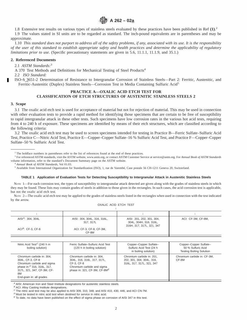
1.8 Extensive test results on various types of stainless steels evaluated by these practices have been published in Ref(1).2
1.9 The values stated in SI units are to be regarded as standard. The inch-pound equivalents are in parentheses and may beapproximate.
1.10 This standard does not purport to address all of the safety problems, if any, associated with its use. It is the responsibilityof the user of this standard to establish appropriate safety and health practices and determine the applicability of regulatorylimitations prior to use.(Specific precautionary statements are given in 5.6, 11.1.1, 11.1.9, and 35.1.)
2. Referenced Documents
2.1 ASTM Standards:3
A 370 Test Methods and Definitions for Mechanical Testing of Steel Products4
2.2 ISO Standard:ISO 5 3651-2 Determination of Resistance to Intergranular Corrosion of Stainless Steels—Part 2: Ferritic, Austenitic, and
Ferritic-Austenitic (Duplex) Stainless Steels—Corrosion Test in Media Containing Sulfuric Acid5
PRACTICE A—OXALIC ACID ETCH TEST FORCLASSIFICATION OF ETCH STRUCTURES OF AUSTENITIC STAINLESS STEELS 2
3. Scope
3.1 The oxalic acid etch test is used for acceptance of material but not for rejection of material. This may be used in connectionwith other evaluation tests to provide a rapid method for identifying those specimens that are certain to be free of susceptibilityto rapid intergranular attack in these other tests. Such specimens have low corrosion rates in the various hot acid tests, requiringfrom 4 to 240 h of exposure. These specimens are identified by means of their etch structures, which are classified according tothe following criteria:
3.2 The oxalic acid etch test may be used to screen specimens intended for testing in Practice B—Ferric Sulfate–Sulfuric AcidTest, Practice C—Nitric Acid Test, Practice E—Copper–Copper Sulfate–16 % Sulfuric Acid Test, and Practice F—Copper–CopperSulfate–50 % Sulfuric Acid Test.
2 The boldface numbers in parentheses refer to the list of references found at the end of these practices.3 For referenced ASTM standards, visit the ASTM website, www.astm.org, or contact ASTM Customer Service at [email protected]. ForAnnual Book of ASTM Standards
volume information, refer to the standard’s Document Summary page on the ASTM website.4 Annual Book of ASTM Standards, Vol 01.03.5 Available from International Organization for Standardization (ISO), 1, rue de Varembé, Case postale 56 CH-1211 Geneva 20, Switzerland.
TABLE 1 Application of Evaluation Tests for Detecting Susceptibility to Intergranular Attack in Austenitic Stainless Steels
NOTE 1—For each corrosion test, the types of susceptibility to intergranular attack detected are given along with the grades of stainless steels in whichthey may be found. These lists may contain grades of steels in addition to those given in the rectangles. In such cases, the acid corrosion test is applicable,but not the oxalic acid etch test.
NOTE 2—The oxalic acid etch test may be applied to the grades of stainless steels listed in the rectangles when used in connection with the test indicatedby the arrow.
OXALIC ACID ETCH TEST↓
↓ ↓ ↓ ↓
AISIA: 304, 304L AISI: 304, 304L, 316, 316L,317, 317L
AISI: 201, 202, 301, 304,304L, 304H, 316, 316L,
316H, 317, 317L, 321, 347
ACI: CF-3M, CF-8M,
ACIB: CF-3, CF-8 ACI: CF-3, CF-8, CF-3M,CF-8M
Nitric Acid TestC (240 h inboiling solution)
Ferric Sulfate–Sulfuric Acid Test(120 h in boiling solution)
Copper–Copper Sulfate–Sulfuric Acid Test (24 h
in boiling solution)
Copper–Copper Sulfate–50 % Sulfuric Acid
Testing Boiling Solution
Chromium carbide in: 304,304L, CF-3, CF-8Chromium carbide and sigmaphase in:D 316, 316L, 317,317L, 321, 347, CF-3M, CF-8MEnd-grain in: all grades
Chromium carbide in: 304,304L, 316, 316L, 317, 317L,CF-3, CF-8Chromium carbide and sigmaphase in: 321, CF-3M, CF-8ME
Chromium carbide in: 201,202, 301, 304, 304L, 316,316L, 317, 317L, 321, 347
Chromium carbide in: CF-3M,CF-8M
A AISI: American Iron and Steel Institute designations for austenitic stainless steels.B ACI: Alloy Casting Institute designations.C The nitric acid test may be also applied to AISI 309, 310, 348, and AISI 410, 430, 446, and ACI CN-7M.D Must be tested in nitric acid test when destined for service in nitric acid.E To date, no data have been published on the effect of sigma phase on corrosion of AISI 347 in this test.
A 262 – 02a
2
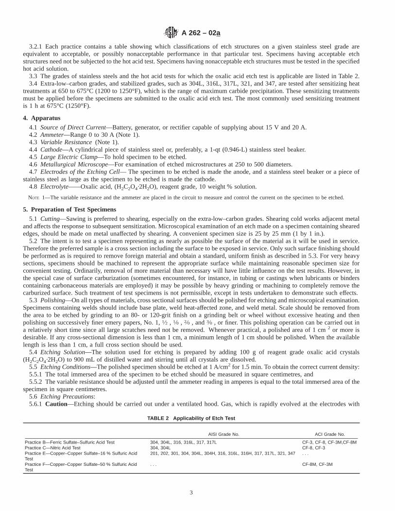
3.2.1 Each practice contains a table showing which classifications of etch structures on a given stainless steel grade areequivalent to acceptable, or possibly nonacceptable performance in that particular test. Specimens having acceptable etchstructures need not be subjected to the hot acid test. Specimens having nonacceptable etch structures must be tested in the specifiedhot acid solution.
3.3 The grades of stainless steels and the hot acid tests for which the oxalic acid etch test is applicable are listed in Table 2.3.4 Extra-low–carbon grades, and stabilized grades, such as 304L, 316L, 317L, 321, and 347, are tested after sensitizing heat
treatments at 650 to 675°C (1200 to 1250°F), which is the range of maximum carbide precipitation. These sensitizing treatmentsmust be applied before the specimens are submitted to the oxalic acid etch test. The most commonly used sensitizing treatmentis 1 h at675°C (1250°F).
4. Apparatus
4.1 Source of Direct Current—Battery, generator, or rectifier capable of supplying about 15 V and 20 A.4.2 Ammeter—Range 0 to 30 A (Note 1).4.3 Variable Resistance(Note 1).4.4 Cathode—A cylindrical piece of stainless steel or, preferably, a 1-qt (0.946-L) stainless steel beaker.4.5 Large Electric Clamp—To hold specimen to be etched.4.6 Metallurgical Microscope—For examination of etched microstructures at 250 to 500 diameters.4.7 Electrodes of the Etching Cell— The specimen to be etched is made the anode, and a stainless steel beaker or a piece of
stainless steel as large as the specimen to be etched is made the cathode.4.8 Electrolyte——Oxalic acid, (H2C2O4·2H2O), reagent grade, 10 weight % solution.
NOTE 1—The variable resistance and the ammeter are placed in the circuit to measure and control the current on the specimen to be etched.
5. Preparation of Test Specimens
5.1 Cutting—Sawing is preferred to shearing, especially on the extra-low–carbon grades. Shearing cold works adjacent metaland affects the response to subsequent sensitization. Microscopical examination of an etch made on a specimen containing shearededges, should be made on metal unaffected by shearing. A convenient specimen size is 25 by 25 mm (1 by 1 in.).
5.2 The intent is to test a specimen representing as nearly as possible the surface of the material as it will be used in service.Therefore the preferred sample is a cross section including the surface to be exposed in service. Only such surface finishing shouldbe performed as is required to remove foreign material and obtain a standard, uniform finish as described in 5.3. For very heavysections, specimens should be machined to represent the appropriate surface while maintaining reasonable specimen size forconvenient testing. Ordinarily, removal of more material than necessary will have little influence on the test results. However, inthe special case of surface carburization (sometimes encountered, for instance, in tubing or castings when lubricants or binderscontaining carbonaceous materials are employed) it may be possible by heavy grinding or machining to completely remove thecarburized surface. Such treatment of test specimens is not permissible, except in tests undertaken to demonstrate such effects.
5.3 Polishing—On all types of materials, cross sectional surfaces should be polished for etching and microscopical examination.Specimens containing welds should include base plate, weld heat-affected zone, and weld metal. Scale should be removed fromthe area to be etched by grinding to an 80- or 120-grit finish on a grinding belt or wheel without excessive heating and thenpolishing on successively finer emery papers, No. 1,1⁄2 , 1⁄0 , 2⁄0 , and3⁄0 , or finer. This polishing operation can be carried out ina relatively short time since all large scratches need not be removed. Whenever practical, a polished area of 1 cm2 or more isdesirable. If any cross-sectional dimension is less than 1 cm, a minimum length of 1 cm should be polished. When the availablelength is less than 1 cm, a full cross section should be used.
5.4 Etching Solution—The solution used for etching is prepared by adding 100 g of reagent grade oxalic acid crystals(H2C2O4·2H2O) to 900 mL of distilled water and stirring until all crystals are dissolved.
5.5 Etching Conditions—The polished specimen should be etched at 1 A/cm2 for 1.5 min. To obtain the correct current density:5.5.1 The total immersed area of the specimen to be etched should be measured in square centimetres, and5.5.2 The variable resistance should be adjusted until the ammeter reading in amperes is equal to the total immersed area of the
specimen in square centimetres.5.6 Etching Precautions:5.6.1 Caution—Etching should be carried out under a ventilated hood. Gas, which is rapidly evolved at the electrodes with
TABLE 2 Applicability of Etch Test
AISI Grade No. ACI Grade No.
Practice B—Ferric Sulfate–Sulfuric Acid Test 304, 304L, 316, 316L, 317, 317L CF-3, CF-8, CF-3M,CF-8MPractice C—Nitric Acid Test 304, 304L CF-8, CF-3Practice E—Copper–Copper Sulfate–16 % Sulfuric AcidTest
201, 202, 301, 304, 304L, 304H, 316, 316L, 316H, 317, 317L, 321, 347 . . .
Practice F—Copper–Copper Sulfate–50 % Sulfuric AcidTest
. . . CF-8M, CF-3M
A 262 – 02a
3

some entrainment of oxalic acid, is poisonous and irritating to mucous membranes.5.6.2 A yellow-green film is gradually formed on the cathode. This increases the resistance of the etching cell. When this occurs,
the film should be removed by rinsing the inside of the stainless steel beaker (or the steel used as the cathode) with an acid suchas 30 % HNO3.
5.6.3 The temperature of the etching solution gradually increases during etching. The temperature should be kept below 50°Cby alternating two beakers. One may be cooled in tap water while the other is used for etching. The rate of heating depends onthe total current (ammeter reading) passing through the cell. Therefore, the area etched should be kept as small as possible whileat the same time meeting the requirements of desirable minimum area to be etched.
5.6.4 Immersion of the clamp holding the specimen in the etching solution should be avoided.5.7 Rinsing—Following etching, the specimen should be thoroughly rinsed in hot water and in acetone or alcohol to avoid
crystallization of oxalic acid on the etched surface during drying.5.8 On some specimens containing molybdenum (AISI 316, 316L, 317, 317L), which are free of chromium carbide
sensitization, it may be difficult to reveal the presence of step structures by electrolytic etching with oxalic acid. In such cases, anelectrolyte of a 10 % solution of ammonium persulfate, (NH4)2S2O8, may be used in place of oxalic acid. An etch of 5 or 10 minat 1 A/cm2 in a solution at room temperature readily develops step structures on such specimens.
6. Classification of Etch Structures
6.1 The etched surface is examined on a metallurgical microscope at 2503 to 5003 for wrought steels and at about 2503 forcast steels.
6.2 The etched cross-sectional areas should be thoroughly examined by complete traverse from inside to outside diameters ofrods and tubes, from face to face on plates, and across all zones such as weld metal, weld-affected zones, and base plates onspecimens containing welds.
6.3 The etch structures are classified into the following types (Note 2):6.3.1 Step Structure(Fig. 1) —Steps only between grains, no ditches at grain boundaries.6.3.2 Dual Structure (Fig. 2)—Some ditches at grain boundaries in addition to steps, but no single grain completely surrounded
by ditches.6.3.3 Ditch Structure(Fig. 3) —One or more grains completely surrounded by ditches.6.3.4 Isolated Ferrite(Fig. 4) —Observed in castings and welds. Steps between austenite matrix and ferrite pools.6.3.5 Interdendritic Ditches(Fig. 5)—Observed in castings and welds. Deep interconnected ditches.6.3.6 End-Grain Pitting I(Fig. 6) —Structure contains a few deep end-grain pits along with some shallow etch pits at 5003.
(Of importance only when nitric acid test is used.)6.3.7 End-Grain Pitting II(Fig. 7)—Structure contains numerous, deep end-grain pits at 5003. (Of importance only when nitric
acid test is used.)
NOTE 2—All photomicrographs were made with specimens that were etched under standard conditions: 10 % oxalic acid, room temperature, 1.5 minat 1 A/cm2.
FIG. 1 Step Structure (500 3) (Steps between grains, no ditchesat grain boundaries)
A 262 – 02a
4
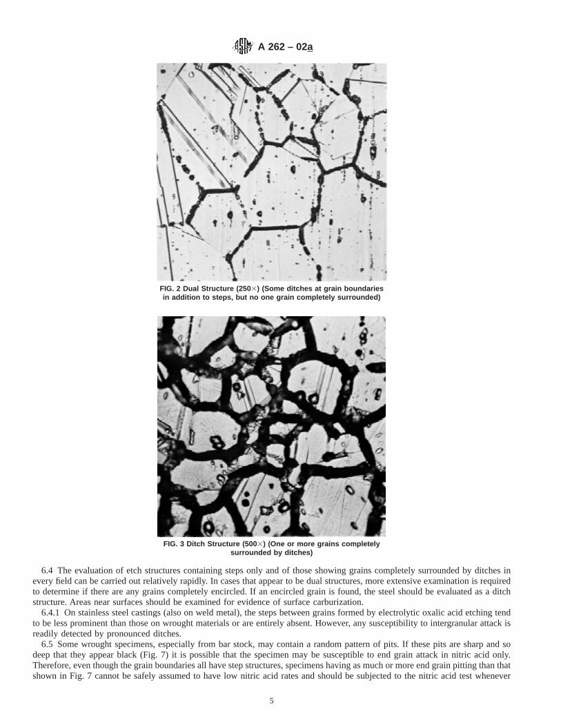
6.4 The evaluation of etch structures containing steps only and of those showing grains completely surrounded by ditches inevery field can be carried out relatively rapidly. In cases that appear to be dual structures, more extensive examination is requiredto determine if there are any grains completely encircled. If an encircled grain is found, the steel should be evaluated as a ditchstructure. Areas near surfaces should be examined for evidence of surface carburization.
6.4.1 On stainless steel castings (also on weld metal), the steps between grains formed by electrolytic oxalic acid etching tendto be less prominent than those on wrought materials or are entirely absent. However, any susceptibility to intergranular attack isreadily detected by pronounced ditches.
6.5 Some wrought specimens, especially from bar stock, may contain a random pattern of pits. If these pits are sharp and sodeep that they appear black (Fig. 7) it is possible that the specimen may be susceptible to end grain attack in nitric acid only.Therefore, even though the grain boundaries all have step structures, specimens having as much or more end grain pitting than thatshown in Fig. 7 cannot be safely assumed to have low nitric acid rates and should be subjected to the nitric acid test whenever
FIG. 2 Dual Structure (250 3) (Some ditches at grain boundariesin addition to steps, but no one grain completely surrounded)
FIG. 3 Ditch Structure (500 3) (One or more grains completelysurrounded by ditches)
A 262 – 02a
5

it is specified. Such sharp, deep pits should not be confused with the shallow pits shown in Fig. 1 and Fig. 6.
7. Use of Etch Structure Classifications
7.1 The use of these classifications depends on the hot acid corrosion test for which stainless steel specimens are being screenedby etching in oxalic acid and is described in each of the practices. Important characteristics of each of these tests are describedbelow.
7.2 Practice B—Ferric Sulfate–Sulfuric Acid Testis a 120-h test in boiling 50 % solution that detects susceptibility tointergranular attack associated primarily with chromium carbide precipitate. It does not detect susceptibility associated with sigmaphase in wrought chromium-nickel-molybdenum stainless steels (316, 316L, 317, 317L), which is known to lead to rapidintergranular attack only in certain nitric acid environments. It does not detect susceptibility to end grain attack, which is also found
FIG. 4 Isolated Ferrite Pools (250 3) (Observed in castings andwelds. Steps between austenite matrix and ferrite pools)
FIG. 5 Interdendritic Ditches (250 3) (Observed in castings andwelds. Deep interconnected ditches)
A 262 – 02a
6
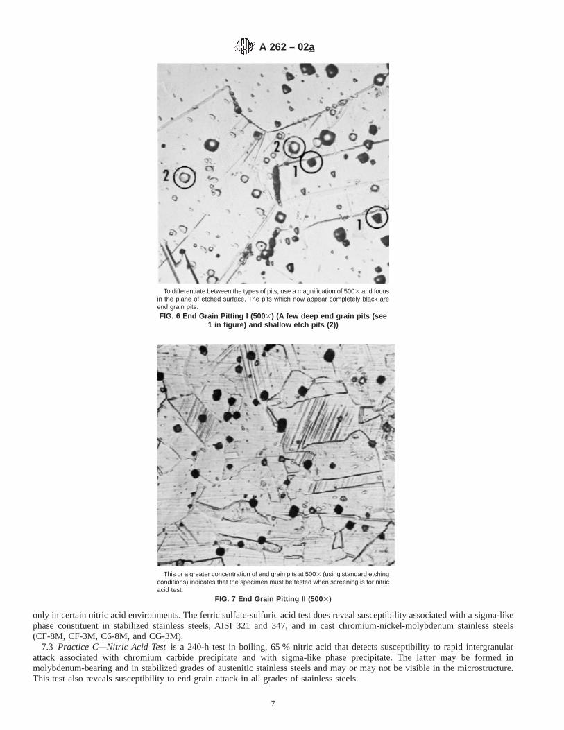
only in certain nitric acid environments. The ferric sulfate-sulfuric acid test does reveal susceptibility associated with a sigma-likephase constituent in stabilized stainless steels, AISI 321 and 347, and in cast chromium-nickel-molybdenum stainless steels(CF-8M, CF-3M, C6-8M, and CG-3M).
7.3 Practice C—Nitric Acid Testis a 240-h test in boiling, 65 % nitric acid that detects susceptibility to rapid intergranularattack associated with chromium carbide precipitate and with sigma-like phase precipitate. The latter may be formed inmolybdenum-bearing and in stabilized grades of austenitic stainless steels and may or may not be visible in the microstructure.This test also reveals susceptibility to end grain attack in all grades of stainless steels.
To differentiate between the types of pits, use a magnification of 5003 and focusin the plane of etched surface. The pits which now appear completely black areend grain pits.
FIG. 6 End Grain Pitting I (500 3) (A few deep end grain pits (see1 in figure) and shallow etch pits (2))
This or a greater concentration of end grain pits at 5003 (using standard etchingconditions) indicates that the specimen must be tested when screening is for nitricacid test.
FIG. 7 End Grain Pitting II (500 3)
A 262 – 02a
7

7.4 Practice E—Copper–Copper Sulfate–16 % Sulfuric Acid Testis a 24-h test in a boiling solution containing 16 % sulfuricacid and 6 % copper sulfate with the test specimen embedded in metallic copper shot or grindings, which detects susceptibility tointergranular attack associated with the precipitation of chromium-rich carbides. It does not detect susceptibility to intergranularattack associated with sigma phase or end-grain corrosion, both of which have been observed to date only in certain nitric acidenvironments.
7.5 Practice F—Copper–Copper Sulfate–50 % Sulfuric Acid Testis a 120-h test in a boiling solution that contains 50 % sulfuricacid, copper sulfate, and metallic copper and that detects susceptibility to intergranular attack associated with the precipitation ofchromium-rich carbides. It does not detect susceptibility to attack associated with sigma phase.
PRACTICE B—FERRIC SULFATE–SULFURIC ACID TEST FOR DETECTING SUSCEPTIBILITY TOINTERGRANULAR ATTACK IN AUSTENITIC STAINLESS STEELS (3)
8. Scope
8.1 This practice describes the procedure for conducting the boiling 120-h ferric sulfate–50 % sulfuric acid test (Note 3) whichmeasures the susceptibility of stainless steels to intergranular attack. The presence or absence of intergranular attack in this testis not necessarily a measure of the performance of the material in other corrosive environments. The test does not provide a basisfor predicting resistance to forms of corrosion other than intergranular, such as general corrosion, pitting, or stress-corrosioncracking.
NOTE 3—See Practice A for information on the most appropriate of the several test methods available for the evaluation of specific grades of stainlesssteel.
8.1.1 The ferric sulfate–sulfuric acid test detects susceptibility to intergranular attack associated with the precipitation ofchromium carbides in unstabilized austenitic stainless steels. It does not detect susceptibility to intergranular attack associated withsigma phase in wrought austenitic stainless steels containing molybdenum, such as Types 316, 316L, 317, and 317L. The ferricsulfate–sulfuric acid test will detect intergranular corrosion associated with sigma phase in the cast stainless steels CF-3M andCF-8M.
NOTE 4—To detect susceptibility to intergranular attack associated with sigma phase in austenitic stainless steels containing molybdenum, the nitricacid test, Practice C, should be used.
8.2 In stabilized stainless steel, Type 321 (and perhaps 347) and cast austenitic stainless steels containing molybdenum such asTypes CF-8M, CF-3M, CG-8M, and CG-3M, the ferric sulfate–sulfuric acid test detects susceptibility associated with precipitatedchromium carbides and with a sigma phase that may be invisible in the microstructure.
8.3 The ferric sulfate–sulfuric acid test may be used to evaluate the heat treatment accorded as-received material. It may alsobe used to check the effectiveness of stabilizing columbium or titanium additions and of reductions in carbon content in preventingsusceptibility to rapid intergranular attack. It may be applied to wrought products (including tubes), castings, and weld metal.
8.4 Specimens of extra low carbon and stabilized grades are tested after sensitizing heat treatments at 650 to 675°C (1200 to1250°F), which is the range of maximum carbide precipitation. The length of time of heating used for this sensitizing treatmentdetermines the maximum permissible corrosion rate for such grades in the ferric sulfate–sulfuric acid test. The most commonlyused sensitizing treatment is 1 h at675°C (1250°F).
9. Rapid Screening Test
9.1 Before testing in the ferric sulfate sulfuric acid test, specimens of certain grades of stainless steels (see Table 3) may be givena rapid screening test in accordance with procedures given in Practice A, Oxalic Acid Etch Test for Classification of Etch Structuresof Austenitic Stainless Steels. Preparation, etching, and the classification of etch structures are described therein. The use of etchstructure evaluations in connection with the ferric sulfate–sulfuric acid test is specified in Table 3.
9.1.1 Corrosion test specimens having acceptable etch structures in the oxalic acid etch test will be essentially free ofintergranular attack in the ferric sulfate-sulfuric acid test. Such specimens are acceptable without testing in the ferricsulfate-sulfuric acid test. All specimens having nonacceptable etch structures must be tested in the ferric sulfate-sulfuric acid test.
10. Apparatus
10.1 The apparatus (Note 6) is illustrated in Fig. 8.10.1.1 An Allihn or Soxhlet condenser with a minimum of four bulbs and with a 45/50 ground glass joint. Overall length: about
330 mm (13 in.), condensing section, 91⁄2 in. (241 mm).10.1.2 A 1-L Erlenmeyer flask with a 45/50 ground glass joint. The ground glass opening is somewhat over 38 mm (11⁄2 in.)
wide.10.1.3 The glass cradle (Note 5) can be supplied by a glass-blowing shop. To pass through the ground glass joint on the
Erlenmeyer flask, the width of the cradle should not exceed 38 mm (11⁄2 in.), and the front-to-back distance must be such that thecradle will fit the 34-mm (11⁄3-in.) diameter opening. It should have three or four holes to increase circulation of the testing solutionaround the specimen.
NOTE 5—Other equivalent means of specimen support, such as glass hooks or stirrups, may also be used.
A 262 – 02a
8

10.1.4 Boiling chips must be used to prevent bumping.10.1.5 A silicone grease6 is recommended for the ground glass joint.10.1.6 During testing, there is some deposition of iron oxides on the upper part of the Erlenmeyer flask. This can be readily
removed, after test completion, by boiling a solution of 10 % hydrochloric acid in the flask.10.1.7 A device such as an electrically heated hot plate that provides heat for continuous boiling of the solution.10.1.8 An analytical balance capable of weighing to the nearest 0.001 g.
NOTE 6—No substitutions for this equipment may be used. The cold-finger type of condenser with standard Erlenmeyer flasks may not be used.
6 Dow Corning Stopcock Grease has been found satisfactory for this purpose.
TABLE 3 Use of Etch Structure Classifications from the OxalicAcid Etch Test with Ferric Sulfate–Sulfuric Acid Test
NOTE 1—Grades AISI 321 and 347 cannot be screened because thesegrades may contain a type of sigma phase which is not visible in the etchstructure but which may cause rapid corrosion in the ferric sulfate-sulfuricacid test.
Grade Acceptable EtchStructures
NonacceptableEtch Structures A
AISI 304 Step, dual, end grain, I & II DitchAISI 304L Step, dual, end grain, I & II DitchAISI316 Step, dual, end grain, I & II DitchAISI316L Step, dual, end grain, I & II DitchAISI 317 Step, dual, end grain, I & II DitchAISI 317L Step, dual, end grain, I & II DitchAISI 321 None . . .ACI CF-3 Step, dual, isolated ferrite pools Ditch, interdendritic ditchesACI CF-8 Step, dual, isolated ferrite pools Ditch, interdendritic ditchesACI CF-3M Step, dual, isolated ferrite pools Ditch, interdendritic ditchesACI CF-8M Step, dual, isolated ferrite pools Ditch, interdendritic ditches
A Specimens having these structures must be tested in the ferric sulfate-sulfuricacid test.
FIG. 8 Apparatus for Ferric Sulfate–Sulfuric Acid Test
A 262 – 02a
9

11. Ferric Sulfate–Sulfuric Acid Test Solution
11.1 Prepare 600 mL of 50 % (49.4 to 50.9 %) solution as follows:11.1.1 Caution—Protect the eyes and use rubber gloves for handling acid. Place the test flask under a hood.11.1.2 First, measure 400.0 mL of distilled water in a 500-mL graduate and pour into the Erlenmeyer flask.11.1.3 Then measure 236.0 mL of reagent-grade sulfuric acid of a concentration that must be in the range from 95.0 to 98.0 %
by weight in a 250-mL graduate. Add the acid slowly to the water in the Erlenmeyer flask to avoid boiling by the heat evolved.
NOTE 7—Loss of vapor results in concentration of the acid.
11.1.4 Weigh 25 g of reagent-grade ferric sulfate (contains about 75 % Fe2(SO4)3) and add to the sulfuric acid solution. A tripbalance may be used.
11.1.5 Drop boiling chips into the flask.11.1.6 Lubricate ground glass joint with silicone grease.11.1.7 Cover flask with condenser and circulate cooling water.11.1.8 Boil solution until all ferric sulfate is dissolved (see Note 7).11.1.9 Caution—It has been reported that violent boiling resulting in acid spills can occur. It is important to ensure that the
concentration of acid does not become more concentrated and that an adequate number of boiling chips (which are resistant toattack by the test solution) are present.7
12. Preparation of Test Specimens
12.1 A specimen having a total surface area of 5 to 20 cm2 is recommended. Specimens containing welds should be cut so thatno more than 13-mm (1⁄2-in.) width of base metal is included on either side of the weld.
12.2 The intent is to test a specimen representing as nearly as possible the surface of the material as used in service. Only suchsurface finishing should be performed as is required to remove foreign material and obtain a standard, uniform finish as specified.For very heavy sections, specimens should be machined to represent the appropriate surface while maintaining reasonablespecimen size for convenience in testing. Ordinarily, removal of more material than necessary will have little influence on the testresults. However, in the special case of surface carburization (sometimes encountered, for instance, in tubing or castings whenlubricants or binders containing carbonaceous materials are employed) it may be possible by heavy grinding or machining toremove the carburized surface completely. Such treatment of test specimens is not permissible, except in tests undertaken todemonstrate such surface effects.
12.3 When specimens are cut by shearing, the sheared edges should be refinished by machining or grinding prior to testing.12.4 Any surfaces of the specimen, including sheared edges, that are to be refinished should be done by using No. 80 or 120
grit abrasive paper. If dry abrasive paper is used, polish slowly to avoid overheating. Sand blasting should not be used.12.5 All traces of oxide scale formed during heat treatments must be thoroughly removed. Any scale that cannot be removed
by grinding (for example, in stamped numbers) must be removed by immersing the specimen in concentrated nitric acid at about93°C (200°F). (Residual oxide scale causes galvanic action and consequent activation in the test solution.)
12.6 The specimen should be measured, including the inner surfaces of any holes, and the total exposed area calculated.12.7 The specimen should then be degreased and dried using suitable nonchlorinated agents, such as soap and acetone, and then
weighed to the nearest 0.001 g.
13. Procedure
13.1 Place specimen in glass cradle and immerse in boiling solution.13.2 Mark liquid level on flask with wax crayon to provide a check on vapor loss, which would result in concentration of the
acid. If there is an appreciable change in the level, the test must be repeated with fresh solution and a reground specimen.13.3 Continue immersion of the specimen for a total of 120 h, then remove specimen, rinse in water and acetone, and dry.13.4 Weigh specimen and subtract weight from original weight.13.5 No intermediate weighings are usually necessary. The tests can be run without interruption for 120 h. However, if
preliminary results are desired, the specimen can be removed at any time for weighing.13.6 No changes in solution are necessary during the 120-h test periods.13.7 Additional ferric sulfate inhibitor may have to be added during the test if the corrosion rate is extraordinarily high as
evidenced by a change in the color of the solution. More ferric sulfate must be added if the total weight loss of all specimensexceeds 2 g. (During the test, ferric sulfate is consumed at a rate of 10 g for each 1 g of dissolved stainless steel.)
13.8 Several specimens may be tested simultaneously. The number (3 or 4) is limited only by the number of glass cradles thatcan be fitted into the flask.
14. Calculation and Report
14.1 The effect of the acid solution on the material shall be measured by determining the loss of weight of the specimen. Thecorrosion rates should be reported as millimetres of penetration per month (Note 8), calculated as follows:
7 Amphoteric alundum granules, Hengar Granules, from the Hengar Co., Philadelphia, PA have been found satisfactory for this purpose.
A 262 – 02a
10
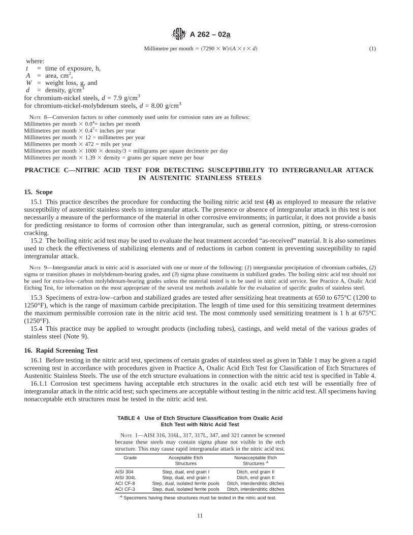
Millimetre per month5 ~72903 W!/~A 3 t 3 d! (1)
where:t = time of exposure, h,A = area, cm2,W = weight loss, g, andd = density, g/cm3
for chromium-nickel steels,d = 7.9 g/cm3
for chromium-nickel-molybdenum steels,d = 8.00 g/cm3
NOTE 8—Conversion factors to other commonly used units for corrosion rates are as follows:Millimetres per month3 0.04= inches per monthMillimetres per month3 0.47= inches per yearMillimetres per month3 12 = millimetres per yearMillimetres per month3 472 = mils per yearMillimetres per month3 10003 density/3 = milligrams per square decimetre per dayMillimetres per month3 1.393 density = grams per square metre per hour
PRACTICE C—NITRIC ACID TEST FOR DETECTING SUSCEPTIBILITY TO INTERGRANULAR ATTACKIN AUSTENITIC STAINLESS STEELS
15. Scope
15.1 This practice describes the procedure for conducting the boiling nitric acid test(4) as employed to measure the relativesusceptibility of austenitic stainless steels to intergranular attack. The presence or absence of intergranular attack in this test is notnecessarily a measure of the performance of the material in other corrosive environments; in particular, it does not provide a basisfor predicting resistance to forms of corrosion other than intergranular, such as general corrosion, pitting, or stress-corrosioncracking.
15.2 The boiling nitric acid test may be used to evaluate the heat treatment accorded “as-received” material. It is also sometimesused to check the effectiveness of stabilizing elements and of reductions in carbon content in preventing susceptibility to rapidintergranular attack.
NOTE 9—Intergranular attack in nitric acid is associated with one or more of the following: (1) intergranular precipitation of chromium carbides, (2)sigma or transition phases in molybdenum-bearing grades, and (3) sigma phase constituents in stabilized grades. The boiling nitric acid test should notbe used for extra-low–carbon molybdenum-bearing grades unless the material tested is to be used in nitric acid service. See Practice A, Oxalic AcidEtching Test, for information on the most appropriate of the several test methods available for the evaluation of specific grades of stainless steel.
15.3 Specimens of extra-low–carbon and stabilized grades are tested after sensitizing heat treatments at 650 to 675°C (1200 to1250°F), which is the range of maximum carbide precipitation. The length of time used for this sensitizing treatment determinesthe maximum permissible corrosion rate in the nitric acid test. The most commonly used sensitizing treatment is 1 h at675°C(1250°F).
15.4 This practice may be applied to wrought products (including tubes), castings, and weld metal of the various grades ofstainless steel (Note 9).
16. Rapid Screening Test
16.1 Before testing in the nitric acid test, specimens of certain grades of stainless steel as given in Table 1 may be given a rapidscreening test in accordance with procedures given in Practice A, Oxalic Acid Etch Test for Classification of Etch Structures ofAustenitic Stainless Steels. The use of the etch structure evaluations in connection with the nitric acid test is specified in Table 4.
16.1.1 Corrosion test specimens having acceptable etch structures in the oxalic acid etch test will be essentially free ofintergranular attack in the nitric acid test; such specimens are acceptable without testing in the nitric acid test. All specimens havingnonacceptable etch structures must be tested in the nitric acid test.
TABLE 4 Use of Etch Structure Classification from Oxalic AcidEtch Test with Nitric Acid Test
NOTE 1—AISI 316, 316L, 317, 317L, 347, and 321 cannot be screenedbecause these steels may contain sigma phase not visible in the etchstructure. This may cause rapid intergranular attack in the nitric acid test.
Grade Acceptable EtchStructures
Nonacceptable EtchStructures A
AISI 304 Step, dual, end grain I Ditch, end grain IIAISI 304L Step, dual, end grain I Ditch, end grain IIACI CF-8 Step, dual, isolated ferrite pools Ditch, interdendritic ditchesACI CF-3 Step, dual, isolated ferrite pools Ditch, interdendritic ditches
A Specimens having these structures must be tested in the nitric acid test.
A 262 – 02a
11
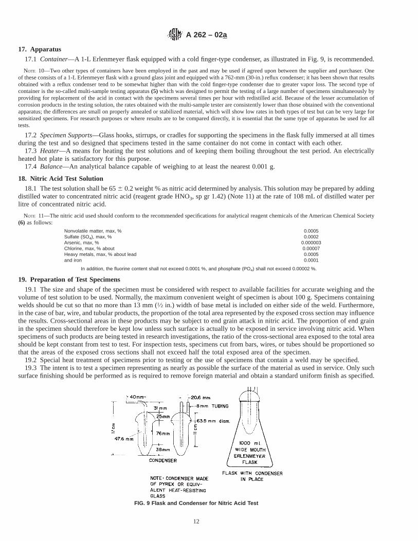
17. Apparatus
17.1 Container—A 1-L Erlenmeyer flask equipped with a cold finger-type condenser, as illustrated in Fig. 9, is recommended.
NOTE 10—Two other types of containers have been employed in the past and may be used if agreed upon between the supplier and purchaser. Oneof these consists of a 1-L Erlenmeyer flask with a ground glass joint and equipped with a 762-mm (30-in.) reflux condenser; it has been shown that resultsobtained with a reflux condenser tend to be somewhat higher than with the cold finger-type condenser due to greater vapor loss. The second type ofcontainer is the so-called multi-sample testing apparatus(5) which was designed to permit the testing of a large number of specimens simultaneously byproviding for replacement of the acid in contact with the specimens several times per hour with redistilled acid. Because of the lesser accumulation ofcorrosion products in the testing solution, the rates obtained with the multi-sample tester are consistently lower than those obtained with the conventionalapparatus; the differences are small on properly annealed or stabilized material, which will show low rates in both types of test but can be very large forsensitized specimens. For research purposes or where results are to be compared directly, it is essential that the same type of apparatus be used for alltests.
17.2 Specimen Supports—Glass hooks, stirrups, or cradles for supporting the specimens in the flask fully immersed at all timesduring the test and so designed that specimens tested in the same container do not come in contact with each other.
17.3 Heater—A means for heating the test solutions and of keeping them boiling throughout the test period. An electricallyheated hot plate is satisfactory for this purpose.
17.4 Balance—An analytical balance capable of weighing to at least the nearest 0.001 g.
18. Nitric Acid Test Solution
18.1 The test solution shall be 656 0.2 weight % as nitric acid determined by analysis. This solution may be prepared by addingdistilled water to concentrated nitric acid (reagent grade HNO3, sp gr 1.42) (Note 11) at the rate of 108 mL of distilled water perlitre of concentrated nitric acid.
NOTE 11—The nitric acid used should conform to the recommended specifications for analytical reagent chemicals of the American Chemical Society(6) as follows:
Nonvolatile matter, max, % 0.0005Sulfate (SO4), max, % 0.0002Arsenic, max, % 0.000003Chlorine, max, % about 0.00007Heavy metals, max, % about lead 0.0005and iron 0.0001
In addition, the fluorine content shall not exceed 0.0001 %, and phosphate (PO4) shall not exceed 0.00002 %.
19. Preparation of Test Specimens
19.1 The size and shape of the specimen must be considered with respect to available facilities for accurate weighing and thevolume of test solution to be used. Normally, the maximum convenient weight of specimen is about 100 g. Specimens containingwelds should be cut so that no more than 13 mm (1⁄2 in.) width of base metal is included on either side of the weld. Furthermore,in the case of bar, wire, and tubular products, the proportion of the total area represented by the exposed cross section may influencethe results. Cross-sectional areas in these products may be subject to end grain attack in nitric acid. The proportion of end grainin the specimen should therefore be kept low unless such surface is actually to be exposed in service involving nitric acid. Whenspecimens of such products are being tested in research investigations, the ratio of the cross-sectional area exposed to the total areashould be kept constant from test to test. For inspection tests, specimens cut from bars, wires, or tubes should be proportioned sothat the areas of the exposed cross sections shall not exceed half the total exposed area of the specimen.
19.2 Special heat treatment of specimens prior to testing or the use of specimens that contain a weld may be specified.19.3 The intent is to test a specimen representing as nearly as possible the surface of the material as used in service. Only such
surface finishing should be performed as is required to remove foreign material and obtain a standard uniform finish as specified.
FIG. 9 Flask and Condenser for Nitric Acid Test
A 262 – 02a
12
For very heavy sections, specimens should be machined to represent the appropriate surface while maintaining reasonablespecimen size for convenience in testing. Ordinarily, removal of more material than necessary will have little influence on the testresults. However, in the special case of surface carburization (sometimes encountered, for instance, in tubing or castings whenlubricants or binders containing carbonaceous materials are employed), it may be possible by heavy grinding or machining toremove the carburized surface completely. Such treatment of test specimens is not permissible except in tests undertaken todemonstrate such surface effects.
19.4 When specimens are cut by shearing, the sheared edges should be refinished by machining or grinding prior to testing.19.5 Any surfaces of the specimen, including sheared edges, that are to be refinished should be done by using No. 80 or 120
grit abrasive paper. If dry abrasive paper is used, polish slowly to avoid overheating. Sandblasting should not be used.19.6 The specimen should be measured, including the inner surfaces of any holes, and the total exposed area calculated.19.7 The specimen should then be degreased and dried using suitable nonchlorinated agents, such as soap and acetone (Note
12), and then weighed to the nearest 0.001 g (see 17.4).
NOTE 12—The cleaning treatment described may be supplemented by immersing the specimen in nitric acid (for example, 20 weight % at 49 to 60°C(120 to 140°F)) for 20 min, followed by rinsing, drying, and weighing. In the case of small-diameter tubular specimens which cannot be convenientlyresurfaced on the inside, it is desirable to include in the preparation an immersion in boiling nitric acid (65 %) for 2 to 4 h using the same apparatus asfor the actual test. The purpose of these treatments is to remove any surface contamination that may not be accomplished by the regular cleaning methodand which may increase the apparent weight loss of the specimen during the early part of the test.
19.8 It is common practice to test only one specimen of each material or lot of material, as defined by those using the test forspecification purposes. However, the use of at least two specimens for check purposes is recommended.
20. Procedure
20.1 Use a sufficient quantity of the nitric acid test solution to cover the specimens and to provide a volume of at least 20 mL/cm2 (125 mL/in.2) of specimen surface. Normally, a volume of about 600 cm3 is used.
20.2 The best practice is to use a separate container for each test specimen.
NOTE 13—For routine evaluations, it is acceptable to test as many as three specimens in the same container provided that they all are of the same gradeand all show satisfactory resistance to corrosion. If more than one of the specimens tested in the same container fail to pass the test, it is necessary toretest all specimens in separate containers, since excessive corrosion of one specimen may result in accelerated corrosion of the other specimens testedwith it. Excessive corrosion may often be detected by changes in the color of the test solution, and it may be appropriate to provide separate containersfor such specimens without waiting until the end of the test period. A record should be made showing which specimens were tested together.
NOTE 14—If the multi-sample testing apparatus (see Note 10) is employed, a large number of specimens may be tested in the large container provided.
20.3 After the specimens have been placed in the acid in the container, pass cooling water through the condenser and bring theacid to a boil on the hot plate and then keep boiling throughout the test period (Note 15). After each test period, rinse the specimenswith water and treat by scrubbing with rubber or a nylon brush under running water to remove any adhering corrosion products,after which they should be dried and weighed. Drying may be facilitated, if desired, by dipping the specimens in acetone after theyare scrubbed.
NOTE 15—Care should be taken to prevent contamination of the testing solution, especially by fluorides, either before or during the test. Experiencehas shown that the presence of even small amounts of hydrofluoric acid will increase the corrosion rate in the nitric acid test. It is not permissible, forexample, to conduct nitric-hydrofluoric acid tests in the same hood with nitric acid tests.
20.4 For most consistent results, the test should consist of five boiling periods of 48 h each (Note 16) with a fresh test solutionbeing used in each period.
NOTE 16—For specification purposes, those experienced in the use of the test may, by mutual agreement, shorten the standard test to three 48-h boilingperiods. However, if with this shorter test procedure the rate of attack in the third period should exceed that in either the first or second periods to somepreviously agreed-upon extent, then the test should be continued for a total of five periods. As an alternative, when the test is being used for inspectionprior to approval of steel for shipment, a procedure may be agreed upon by the purchaser and the manufacturer whereby the material will be releasedfor shipment following satisfactory performance in three 48-h boiling periods with final acceptance being dependent upon satisfactory performanceinthe longer test of five 48-h boiling periods. Also, by mutual agreement, a combination of one 48-h period and two 96-h periods (not necessarily in thatorder) instead of five 48-h test periods may be acceptable for routine evaluations.
21. Calculation and Report
21.1 Calculation—The effect of the acid on the material shall be measured by determining the loss of weight of the specimenafter each test period and for the total of the test periods. Such weight-loss determinations should be made with the accuracyprescribed in 17.4. The corrosion rates are usually reported as millimetres per month (Note 17), calculated in the following rateof corrosion equation:
Millimetres per month5 ~72903 W!/~A 3 d 3 t! (2)
where:t = time of exposure, h,A = total surface area, cm2,
A 262 – 02a
13

W = weight loss, g, andd = density of the sample, g/cm3.
NOTE 17—Conversion factors to other commonly used units for corrosion rates are as follows:Millimetres per month3 0.04 = inches per monthMillimetres per month3 0.47 = inches per yearMillimetres per month3 12 = millimetres per yearMillimetres per month3 472 = mils per yearMillimetres per month3 10003 density/3 = milligrams per square decimetre per dayMillimetres per month3 1.393 density = grams per square metre per hours
21.2 Report—Results should be reported for the individual periods, as well as the average for the three or five test periods.
PRACTICE E—COPPER–COPPER SULFATE–16 % SULFURIC ACID TEST FOR DETECTING
SUSCEPTIBILITY TO INTERGRANULAR ATTACK IN AUSTENITIC STAINLESS STEELS 7,8
22. Scope
22.1 This practice describes the procedure by which the copper–copper sulfate–16 % sulfuric acid test is conducted to determinethe susceptibility of austenitic stainless steels to intergranular attack. The presence or absence of intergranular corrosion in this testis not necessarily a measure of the performance of the material in other corrosive media. The test does not provide a basis forpredicting resistance to other forms of corrosion, such as general corrosion, pitting, or stress-corrosion cracking.
22.2 The copper–copper sulfate–16 % sulfuric acid test indicates susceptibility to intergranular attack associated with theprecipitation of chromium-rich carbides. It does not detect susceptibility associated with sigma phase. This test may be used toevaluate the heat treatment accorded as-received material. It may also be used to evaluate the effectiveness of stabilizing elementadditions (Cb, Ti, and so forth) and reductions in carbon content to aid in resisting intergranular attack.
22.3 All wrought products and weld material of austenitic stainless steels can be evaluated by this test.
23. Rapid Screening Test
23.1 Before testing in the copper–copper sulfate–16 % sulfuric acid test, specimens of certain grades of stainless steel (see Table5) may be given a rapid screening test in accordance with the procedures given in Practice A (Sections 3 through 7). Preparation,etching, and the classification of etch structures are described therein. The use of etch-structure evaluations in connection with thecopper–copper sulfate–16 % sulfuric acid test is specified in Table 5.
23.1.1 Corrosion test specimens having acceptable etch structures in the oxalic acid etch test will be essentially free ofintergranular attack in the copper–copper sulfate–16 % sulfuric acid test. Such specimens are acceptable without testing in thecopper–copper sulfate–16 % sulfuric acid test. All specimens having nonacceptable etch structures must be tested in thecopper–copper sulfate–16 % sulfuric acid test.
24. Summary of Practice
24.1 A suitable sample of an austenitic stainless steel, embedded in copper shot or grindings, is exposed to boiling acidifiedcopper sulfate solution for 24 15 h. After exposure in the boiling solution, the specimen is bent. Intergranular cracking or crazingis evidence of susceptibility.
24.2 Alternative Testing Procedures:
TABLE 5 Use of Etch Structure Classifications from the OxalicAcid Etch Test with the Copper-Copper Sulfate-16 % Sulfuric
Acid Test
Grade Acceptable EtchStructures
Nonacceptable EtchStructures A
AISI 201 Step, dual, end grain I and II DitchAISI 202 Step, dual, end grain I and II DitchAISI 301 Step, dual, end grain I and II DitchAISI 304 Step, dual, end grain I and II DitchAISI 304L Step, dual, end grain I and II DitchAISI 304H Step, dual, end grain I and II DitchAISI 316 Step, dual, end grain I and II DitchAISI 316L Step, dual, end grain I and II DitchAISI 316H Step, dual, end grain I and II DitchAISI 317 Step, dual, end grain I and II DitchAISI 317L Step, dual, end grain I and II DitchAISI 321 Step, dual, end grain I and II DitchAISI 347 Step, dual, end grain I and II Ditch
A Specimens having these structures must be tested in the copper–coppersulfate–16 % sulfuric acid test.
A 262 – 02a
14

24.2.1 Unless prohibited by the purchaser in the purchase order, the supplier is permitted to meet the requirements of PracticeE by performing a test in accordance with ISO 3651–2, Method A, provided that the testing period shall be a minimum of 15 h.When a sensitization treatment is required, sensitization heat treatment T1 [700°C6 10°C (1292°F6 18°F), 30 minutes, waterquench] shall be used unless the supplier and purchaser shall agree upon preparation of welded test pieces to be tested in theas-welded condition.
24.2.2 When this alternative test procedure is used, it shall be noted on the test report.
25. Apparatus
25.1 A 1-L glass Erlenmeyer flask with a ground 45/50 glass joint and four-bulb (minimum) Allihn condenser with 45/50 groundglass joint (as in 10.1.1 and 10.1.2 and Fig. 8) are required. A silicone grease is recommended for the ground glass joint.
25.2 Specimen Supports—An open glass cradle capable of supporting the specimens and copper shot or grindings in the flaskis recommended.
NOTE 18—It may be necessary to embed large specimens, such as from heavy bar stock, in copper shot on the bottom of the test flask. A copper cradlemay also be used.
25.3 Heat Source—Any gas or electrically heated hot plate may be utilized for heating the test solution and keeping it boilingthroughout the test period.
26. Acidified Copper Sulfate Test Solution
26.1 Dissolve 100 g of copper sulfate (CuSO4·5H 2O) in 700 mL of distilled water, add 100 mL of sulfuric acid (H2SO4, cp,sp gr 1.84), and dilute to 1000 mL with distilled water.
NOTE 19—The solution will contain approximately 6 weight % of anhydrous CuSO4 and 16 weight % of H2SO4.
27. Copper Addition
27.1 Electrolytic grade copper shot or grindings may be used. Shot is preferred for its ease of handling before and after the test.27.2 A sufficient quantity of copper shot or grindings is to be used to cover all surfaces of the specimen whether it is in a vented
glass cradle or embedded in a layer of copper shot on the bottom of the test flask.27.3 The amount of copper used, assuming an excess of metallic copper is present, is not critical. The effective galvanic
coupling between copper and the test specimen may have importance(9).27.4 The copper shot or grindings may be reused if they are cleaned in warm tap water after each test.
28. Specimen Preparation
28.1 The size of the sample submitted for test and the area from which it is to be taken (end or middle of coil, midway surfaceand center, and so forth) is generally specified in the agreement between the purchaser and the seller. The testing apparatus dictatesthe final size and shape of the test specimen. The specimen configuration should permit easy entrance and removal through theneck of the test container.
28.1.1 Table 6 may be used as a guide to determine acceptable specimen sizes. There may be restrictions placed on specimensize by the testing apparatus.
28.1.2 Specimens obtained by shearing should have the sheared edges machined or ground off prior to testing. Care should betaken when grinding to avoid overheating or “burning.” A “squared” edge is desirable.
28.2 Any scale on the specimens should be removed mechanically unless a particular surface finish is to be evaluated. Chemicalremoval of scale is permissible when this is the case. Mechanical removal of scale should be accomplished with 120-grit iron-freealuminum oxide abrasive.
28.2.1 Each specimen should be degreased using a cleaning solvent such as acetone, alcohol, ether, or a vapor degreaser priorto being tested.
28.3 All austenitic material in the “as-received” (mill-annealed) condition should be capable of meeting this test.28.3.1 Specimens of extra-low–carbon and stabilized grades are tested after sensitizing heat treatments at 650 to 675°C (1200
to 1250°F), which is the range of maximum carbide precipitation. The most commonly used sensitizing treatment is 1 h at675°C.Care should be taken to avoid carburizing or nitriding the specimens. The heat treating is best carried out in air or neutral salt.
NOTE 20—The sensitizing treatment 675°C is performed to check the effectiveness of stabilized and 0.03 % maximum carbon materials in resistingcarbide precipitation, hence, intergranular attack.
29. Test Conditions
29.1 The volume of acidified copper sulfate test solution used should be sufficient to completely immerse the specimens andprovide a minimum of 8 mL/cm2 (50 mL/in.2) of specimen surface area.
29.1.1 As many as three specimens can be tested in the same container. It is ideal to have all the specimens in one flask to beof the same grade, but it is not absolutely necessary. The solution volume-to-sample area ratio is to be maintained.
29.1.2 The test specimen(s) should be immersed in ambient test solution, which is then brought to a boil and maintained boilingthroughout the test period. Begin timing the test period when the solution reaches the boiling point.
A 262 – 02a
15
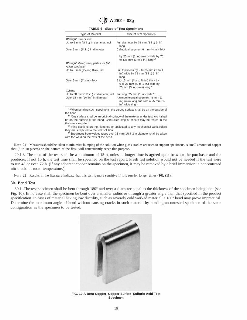
NOTE 21—Measures should be taken to minimize bumping of the solution when glass cradles are used to support specimens. A small amount of coppershot (8 to 10 pieces) on the bottom of the flask will conveniently serve this purpose.
29.1.3 The time of the test shall be a minimum of 15 h, unless a longer time is agreed upon between the purchaser and theproducer. If not 15 h, the test time shall be specified on the test report. Fresh test solution would not be needed if the test wereto run 48 or even 72 h. (If any adherent copper remains on the specimen, it may be removed by a brief immersion in concentratednitric acid at room temperature.)
NOTE 22—Results in the literature indicate that this test is more sensitive if it is run for longer times(10), (11).
30. Bend Test
30.1 The test specimen shall be bent through 180° and over a diameter equal to the thickness of the specimen being bent (seeFig. 10). In no case shall the specimen be bent over a smaller radius or through a greater angle than that specified in the productspecification. In cases of material having low ductility, such as severely cold worked material, a 180° bend may prove impractical.Determine the maximum angle of bend without causing cracks in such material by bending an untested specimen of the sameconfiguration as the specimen to be tested.
TABLE 6 Sizes of Test Specimens
Type of Material Size of Test Specimen
Wrought wire or rod:Up to 6 mm (¼ in.) in diameter, incl Full diameter by 75 mm (3 in.) (min)
longOver 6 mm (¼ in.) in diameter Cylindrical segment 6 mm (¼ in.) thick
by 25 mm (1 in.) (max) wide by 75to 125 mm (3 to 5 in.) long A
Wrought sheet, strip, plates, or flatrolled products:Up to 5 mm (3⁄16 in.) thick, incl Full thickness by 9 to 25 mm (" to 1
in.) wide by 75 mm (3 in.) (min)long
Over 5 mm (3⁄16 in.) thick 5 to 13 mm (3⁄16 to ½ in.) thick by9 to 25 mm (" to 1 in.) wide by75 mm (3 in.) (min) long B
Tubing:Up to 38 mm (1½ in.) in diameter, incl Full ring, 25 mm (1 in.) wide C
Over 38 mm (1½ in.) in diameter A circumferential segment 75 mm (3in.) (min) long cut from a 25 mm (1-in.) wide ring D
A When bending such specimens, the curved surface shall be on the outside ofthe bend.
B One surface shall be an original surface of the material under test and it shallbe on the outside of the bend. Cold-rolled strip or sheets may be tested in thethickness supplied.
C Ring sections are not flattened or subjected to any mechanical work beforethey are subjected to the test solution.
D Specimens from welded tubes over 38 mm (1½ in.) in diameter shall be takenwith the weld on the axis of the bend.
FIG. 10 A Bent Copper–Copper Sulfate–Sulfuric Acid TestSpecimen
A 262 – 02a
16

30.1.1 Duplicate specimens shall be obtained from sheet material so that both sides of the rolled samples may be bent througha 180° bend. This will assure detection of intergranular attack resulting from carburization of one surface of sheet material duringthe final stages of rolling.
NOTE 23—Identify the duplicate specimen in such a manner as to ensure both surfaces of the sheet material being tested are subjected to the tensionside of the 180° bends.
30.1.2 Samples machined from round sections or cast material shall have the curved or original surface on the outside of thebend.
30.1.3 The specimens are generally bent by holding in a vise and starting the bend with a hammer. It is generally completedby bringing the two ends together in the vise. Heavy specimens may require bending in a fixture of suitable design. An air orhydraulic press may also be used for bending the specimens.
30.1.4 Tubular products should be flattened in accordance with the flattening test, prescribed in Test Methods and DefinitionsA 370.
30.1.5 When agreed upon between the purchaser and the producer, the following shall apply to austenitic stainless steel plates4.76 mm (0.1875 in.) and thicker:
30.1.5.1 Samples shall be prepared according to Table 7.30.1.5.2 The radius of bend shall be two times the sample thickness, and the bend axis shall be perpendicular to the direction
of rolling.30.1.5.3 Welds on material 4.76 mm (0.1875 in.) and thicker shall have the above bend radius, and the weld-base metal interface
shall be located approximately in the centerline of the bend.30.1.5.4 Face, root, or side bend tests may be performed, and the type of bend test shall be agreed upon between the purchaser
and the producer. The bend radius shall not be less than that required for mechanical testing in the appropriate material specification(for base metal) or in ASME Code Section IX (for welds).
31. Evaluation
31.1 The bent specimen shall be examined under low (5 to 203) magnification (see Fig. 11). The appearance of fissures orcracks indicates the presence of intergranular attack (see Fig. 12).
31.1.1 When an evaluation is questionable (see Fig. 13), the presence or absence of intergranular attack shall be determined bythe metallographic examination of the outer radius of a longitudinal section of the bend specimen at a magnification of 100 to2503.
NOTE 24—Cracking that originates at the edge of the specimen should be disregarded. The appearance of deformation lines, wrinkles, or “orange peel”on the surface, without accompanying cracks or fissures, should be disregarded also.
NOTE 25—Cracks suspected as arising through poor ductility may be investigated by bending a similar specimen that was not exposed to the boilingtest solution. A visual comparison between these specimens should assist in interpretation.
PRACTICE F—COPPER–COPPER SULFATE–50 % SULFURIC ACID TEST FOR DETERMININGSUSCEPTIBILITY TO INTERGRANULAR ATTACK IN AUSTENITIC
STAINLESS STEELS
32. Scope
32.1 This practice describes the procedure for conducting the boiling copper–copper sulfate–50 % sulfuric acid test, whichmeasures the susceptibility of stainless steels to intergranular attack. The presence or absence of intergranular attack in this testis not necessarily a measure of the performance of the material in other corrosive environments. The test does not provide a basisfor predicting resistance to forms of corrosion other than intergranular, such as general corrosion, pitting, or stress-corrosioncracking.
32.2 This test may be used to evaluate the susceptibility of as received material to intergranular corrosion caused by chromiumcarbide precipitation. It may also be used to evaluate the resistance of extra-low–carbon grades to sensitization to intergranularattack caused by welding or heat treatments.
32.3 This test should not be used to detect susceptibility to intergranular attack resulting from the formation of sigma phase.For detecting susceptibility to environments known to cause intergranular attack due to sigma use Practices B or C.
33. Rapid Screening Test
33.1 Before testing in copper–copper sulfate–50 % sulfuric acid test, specimens of certain grades of stainless steels (see Table
TABLE 7 Use of Etch Structure Classifications from the OxalicAcid Etch Test With the Copper-Copper Sulfate-50 % Sulfuric
Acid Test
Grade Acceptable Etch Structures Non-acceptable Etch Structures
CF-3M Step, dual, isolated ferrite Ditch, interdendritic ditchesCF-8M Step, dual, isolated ferrite Ditch, interdendritic ditches
A 262 – 02a
17

1) may be given a rapid screening test in accordance with procedures given in Practice A, oxalic acid etch test for classificationof etch structures of austenitic stainless steels. Preparation, etching, and the classification of etch structures are described therein.The use of etch structure evaluations in connection with the copper–copper sulfate–50 % sulfuric acid test is specified in Table 7.
33.1.1 Corrosion test specimens having acceptable etch structures in the oxalic acid etch test will be essentially free ofintergranular attack in the copper–copper sulfate–50 % sulfuric acid test. Such specimens are acceptable without testing in the
FIG. 11 Passing Test Specimen—View of the Bent Area (20 3 magnification before reproduction)
FIG. 12 Failing Test Specimen (Note the many intergranular fissures. Bent area at 20 3 magnification before reproduction.)
A 262 – 02a
18

copper–copper sulfate–50 % sulfuric acid test. All specimens having nonacceptable etch structures must be tested in thecopper–copper sulfate–50 % sulfuric acid test.
34. Apparatus
34.1 The basic apparatus is described in Section 10. Also needed are the following:34.1.1 For weight loss determination, an analytical balance capable of weighing to the nearest 0.001 g.34.1.2 A piece of copper metal about 3.2 by 19 by 38 mm (1⁄8 by 3⁄4 by 11⁄2 in.) with a bright, clean finish. An equivalent area
of copper shot or chips may be used. The copper should be washed and degreased before use. A rinse in 5 % H2SO4 will cleancorrosion products from the copper.
35. Copper–Copper Sulfate–50 % Sulfuric Acid Test Solution
35.1 Prepare 600 mL of test solution as follows.Caution—Protect the eyes and face by face shield and use rubber gloves andapron when handling acid. Place flask under hood.
35.1.1 First, measure 400.0 mL of distilled water in a 500-mL graduate and pour into the Erlenmeyer flask.35.1.2 Then measure 236.0 mL of reagent grade sulfuric acid of a concentration that must be in the range from 95.0 to 98.0
weight % in a 250 mL graduate. Add the acid slowly to the water in the Erlenmeyer flask to avoid boiling by the heat received.35.1.3 Weigh 72 g of reagent grade copper sulfate
(CuSO4·5 H2O) and add to the sulfuric acid solution. A trip balance may be used.35.1.4 Place the copper piece into one glass cradle and put it into the flask.35.1.5 Drop boiling chips into the flask.7
35.1.6 Lubricate the ground-glass joint with silicone grease.35.1.7 Cover the flask with the condenser and circulate cooling water.35.1.8 Heat the solution slowly until all of the copper sulfate is dissolved.
36. Preparation of Test Specimens
36.1 Prepare test specimens as described in Section 12.36.2 Specimens of extra-low carbon and stabilized grades are tested after sensitizing heat treatments at 650 to 675°C (1200 to
1250°F), which is the range of maximum carbide precipitation. The length of time of heating used for this sensitizing treatmentdetermines the maximum permissible corrosion rate for such grades in the copper–copper sulfate–50 % sulfuric acid test. The mostcommonly used sensitizing treatment is 1 h at675°C.
37. Procedure
37.1 Place the specimen in another glass cradle and immerse in boiling solution.
FIG. 13 Doubtful Test Result (Note the traces of intergranular fissures and “orange-peel” surface. Bent area at 20 3 magnificationbefore reproduction.)
A 262 – 02a
19
37.2 Mark the liquid level on the flask with wax crayon to provide a check on vapor loss, which would result in concentrationof the acid. If there is an appreciable change in the level, repeat the test with fresh solution and a reground specimen.
37.3 Continue immersion of the specimen for 120 h, then remove the specimen, rinse in water and acetone, and dry. If anyadherent copper remains on the specimen, it may be removed by a brief immersion in concentrated nitric acid at room temperature.
37.4 For weight loss determination, weigh the specimen and subtract the weight from the original weight.37.5 No intermediate weighings are usually necessary. The tests can be run without interruption. However, if preliminary results
are desired, the specimen can be removed at any time for weighing.37.6 No changes in solution are necessary during the test.
38. Calculation and Report
38.1 The effect of the acid solution on the material shall be measured by determining the loss of weight of the specimen. Thecorrosion rate should be reported as millimetres of penetration per month (Note 8) calculated as follows:
Millimetres per month5 ~72903 w!/~A 3 t 3 d! (3)
where:t = time or exposure, h,A = area, cm2,w = weight loss, g, andd = density, g/cm3.
For chromium-nickel-molybdenum steels,d = 8.00 g/cm3.
39. Keywords
39.1 austenitic stainless steel; copper sulfate; corrosion testing; etch structures; ferric sulfate; intergranular corrosion; nitric acid;oxalic acid
REFERENCES
(1) Brown, M. H., “Behavior of Austenitic Stainless Steels in Evaluation Tests for the Detection of Susceptibility to Intergranular Corrosion,”Corrosion,Vol 30, January 1974, pp. 1–12.
(2) For original descriptions of the use of etch structure classifications, see Streicher, M. A., “Screening Stainless Steels from the 240-h Nitric AcidTestby Electrolytic Etching in Oxalic Acid,”ASTM Bulletin,No. 188, February 1953, p. 35; also “Results of Cooperative Testing Program for theEvaluation of the Oxalic Acid Etch Test,”ASTM Bulletin,No. 195, January 1954, p. 63.
(3) For original description of ferric sulfate-sulfuric acid test, see Streicher, M. A., “Intergranular Corrosion Resistance of Austenitic Stainless Steels: AFerric Sulfate-Sulfuric Acid Test,”ASTM Bulletin, No. 229, April 1958, pp. 77–86.
(4) For original descriptions of the boiling nitric acid test, see Huey, W. R., “Corrosion Test for Research and Inspection of Alloys,”Transactions,American Society of Steel Treating,Vol 18, 1930, p. 1126; also, “Report of Subcommittee IV on Methods of Corrosion Testing,”Proceedings,ASTM,Vol 33, Part I, 1933, p. 187.
(5) For details, see DeLong, W. B., “Testing Multiple Specimens of Stainless Steels in a Modified Boiling Nitric Acid Test Apparatus,”Symposium onEvaluation Tests for Stainless Steels, ASTM STP 93,ASTM, 1950, p. 211.
(6) SeeIndustrial and Engineering Chemistry,Vol 17, 1925, p. 756; also, “A.C.S. Analytical Reagents. Specifications Recommended by Committee onAnalytical Reagents,” American Chemical Society, March 1941.
(7) The use of copper to accelerate the intergranular corrosion of sensitized austenitic stainless steels in copper sulfate-sulfuric acid was first describedby H. J. Rocha in the discussion of a paper by Brauns, E., and Pier, G.,Stahl und Eisen,Vol 75, 1955, p. 579.
(8) For original evaluation of the copper-copper sulfate-sulfuric acid test, see Scharfstein, L. R., and Eisenbrown, C. M., “An Evaluation of AcceleratedStrauss Testing,”ASTM STP369, ASTM, 1963, pp. 235–239.
(9) Subtle effects due to variations in copper surface areas, galvanic contact, condenser design, etc., are described by Herbsleb, G., and Schwenk, W.,“Untersuchungen zur Einstellung des Redoxpotentials der Strausschen Lösung mit Zusatz von Mettalischem Kupfer,”Corrosion Science,Vol 7, 1967,pp. 501–511.
(10) Streicher, M. A., “Theory and Application of Evaluation Tests for Detecting Susceptibility to Intergranular Attack in Stainless Steels and RelatedAlloys-Problems and Opportunities,”Intergranular Corrosion of Stainless Alloys, ASTM STP 656, R. F. Steigerwald ed., ASTM, 1978, pp. 3–84.
(11) Walker, W. L., “Variations in the Evaluation of ASTM A 262, Practice E, Results (ASTM Subcommittee A01.14 Round Robin),”IntergranularCorrosion of Stainless Alloys, ASTM STP 656, R. F. Steigerwald ed., ASTM, 1978, pp. 146–153.
A 262 – 02a
20
SUMMARY OF CHANGES
This section contains the principal changes to the standard that have been incorporated since the last issue(A 262 – 02).
(1) In 24.1, changed from 24 h to 15 h.
ASTM International takes no position respecting the validity of any patent rights asserted in connection with any item mentionedin this standard. Users of this standard are expressly advised that determination of the validity of any such patent rights, and the riskof infringement of such rights, are entirely their own responsibility.
This standard is subject to revision at any time by the responsible technical committee and must be reviewed every five years andif not revised, either reapproved or withdrawn. Your comments are invited either for revision of this standard or for additional standardsand should be addressed to ASTM International Headquarters. Your comments will receive careful consideration at a meeting of theresponsible technical committee, which you may attend. If you feel that your comments have not received a fair hearing you shouldmake your views known to the ASTM Committee on Standards, at the address shown below.
This standard is copyrighted by ASTM International, 100 Barr Harbor Drive, PO Box C700, West Conshohocken, PA 19428-2959,United States. Individual reprints (single or multiple copies) of this standard may be obtained by contacting ASTM at the aboveaddress or at 610-832-9585 (phone), 610-832-9555 (fax), or [email protected] (e-mail); or through the ASTM website(www.astm.org).
A 262 – 02a
21

Designation: A 276 – 04
Standard Specification forStainless Steel Bars and Shapes 1
This standard is issued under the fixed designation A 276; the number immediately following the designation indicates the year oforiginal adoption or, in the case of revision, the year of last revision. A number in parentheses indicates the year of last reapproval. Asuperscript epsilon (e) indicates an editorial change since the last revision or reapproval.
This standard has been approved for use by agencies of the Department of Defense.
1. Scope*
1.1 This specification covers hot-finished or cold-finishedbars except bars for reforging (Note 1). It includes rounds,squares, and hexagons, and hot-rolled or extruded shapes, suchas angles, tees, and channels in the more commonly used typesof stainless steels. The free-machining types (Note 2), forgeneral corrosion resistance and high-temperature service, arecovered in a separate specification.
NOTE 1—For bars for reforging, see Specification A 314.NOTE 2—For free-machining stainless bars designed especially for
optimum machinability, see Specification A 582/A 582M.NOTE 3—There are standards covering high nickel, chromium, austen-
itic corrosion, and heat resisting alloy materials. These standards are underthe jurisdiction of ASTM Subcommittee B02.07 and may be found inAnnual Book of ASTM Standards, Vol. 02.04.
1.2 The values stated in inch-pound units are to be regardedas the standard.
2. Referenced Documents
2.1 ASTM Standards:2
A 314 Specification for Stainless Steel Billets and Bars forForging
A 370 Test Methods and Definitions for Mechanical Testingof Steel Products
A 484/A 484M Specification for General Requirements forStainless Steel Bars, Billets, and Forgings
A 582/A 582M Specification for Free-Machining StainlessSteel Bars
A 751 Test Methods, Practices, and Terminology forChemical Analysis of Steel Products
E 527 Practice for Numbering Metals and Alloys (UNS)2.2 Other Document:
SAE J 1086 Recommended Practice for Numbering Metalsand Alloys3
3. Ordering Information
3.1 It is the responsibility of the purchaser to specify allrequirements that are necessary for material ordered under thisspecification. Such requirements may include but are notlimited to the following:
3.1.1 Quantity (weight or number of pieces),3.1.2 Name of material: stainless steel,3.1.3 Form (bars, angles, etc.),3.1.4 Condition (Section 4.1),3.1.5 Finish (Section 8 of Specification A 484/A 484M),3.1.6 Surface preparation of shapes (Section 8 of Specifica-
tion A 484/A 484M),3.1.7 Applicable dimensions including size, thickness,
width, and length,13.1.8 Cross section (round, square, etc.),3.1.9 Type or UNS designation (Table 1),3.1.10 ASTM designation and date of issue, and3.1.11 Whether bars are to be rolled as bars or cut from strip
or plate.3.1.12 Test for magnetic permeability when specified by
customer purchase order when ordering Types 201 and 205.3.1.13 Special requirements.
NOTE 4—A typical ordering description is as follows: 5000 lb (2268 kg)Stainless Steel Bars, Annealed and Centerless Ground, 11⁄2 in. (38.10mm) Round, 10 to 12 ft (3.05 to 3.66 m) in length, Type 304, ASTMSpecification A 276 dated ______. End use: machined valve parts.
4. Manufacture
4.1 Condition:4.1.1 Bars shall be furnished in one of the following
conditions listed in the Mechanical Requirements table:4.1.1.1 Condition A—Annealed4.1.1.2 Condition H—Hardened and tempered at a rela-
tively low temperature
1 This specification is under the jurisdiction of ASTM Committee A01 on Steel,Stainless Steel and Related Alloys and is the direct responsibility of SubcommitteeA01.17 on Flat-Rolled and Wrought Stainless Steel.
Current edition approved Feb. 1, 2004. Published February 2004. Originallyapproved in 1944. Last previous edition approved in 2003 as A 276 – 03.
2 For referenced ASTM standards, visit the ASTM website, www.astm.org, orcontact ASTM Customer Service at [email protected]. ForAnnual Book of ASTMStandardsvolume information, refer to the standard’s Document Summary page onthe ASTM website.
3 Available from Society of Automotive Engineers (SAE), 400 CommonwealthDr., Warrendale, PA 15096-0001.
1
*A Summary of Changes section appears at the end of this standard.
Copyright © ASTM International, 100 Barr Harbor Drive, PO Box C700, West Conshohocken, PA 19428-2959, United States.

TABLE 1 Chemical Requirements A
UNSDesigna-
tionBType
Composition, %
Carbon ManganesePhos-phorus
Sulfur Silicon Chromium NickelMolyb-denum
Nitrogen Other Elements
Austenitic Grades
N08367 . . . 0.030 2.00 0.040 0.030 1.00 20.0–22.0 23.5–25.5 6.0–7.0 0.18–0.25 Cu 0.75S20100 201 0.15 5.5–7.5 0.060 0.030 1.00 16.0–18.0 3.5–5.5 . . . 0.25 . . .S20161 . . . 0.15 4.0–6.0 0.045 0.030 3.0–4.0 15.0–18.0 4.0–6.0 . . . 0.08–0.20 . . .S20162 . . . 0.15 4.0–8.0 0.040 0.040 2.5–4.5 16.5–21.0 6.0–10.0 0.50–2.50 0.05–0.25 . . .S20200 202 0.15 7.5–10.0 0.060 0.030 1.00 17.0–19.0 4.0–6.0 . . . 0.25 . . .S20500 205 0.12–0.25 14.0–15.5 0.060 0.030 1.00 16.5–18.0 1.0–1.7 . . . 0.32–0.40 . . .S20910 XM-19 0.06 4.0–6.0 0.045 0.030 1.00 20.5–23.5 11.5–13.5 1.50–3.00 0.20–0.40 Cb 0.10–0.30,
V 0.10–0.30S21800 . . . 0.10 7.0–9.0 0.060 0.030 3.5–4.5 16.0–18.0 8.0–9.0 . . . 0.08–0.18 . . .S21900 XM-10 0.08 8.0–10.0 0.045 0.030 1.00 19.0–21.5 5.5–7.5 . . . 0.15–0.40 . . .S21904 XM-11 0.04 8.0–10.0 0.045 0.030 1.00 19.0–21.5 5.5–7.5 . . . 0.15–0.40 . . .S24000 XM-29 0.08 11.5–14.5 0.060 0.030 1.00 17.0–19.0 2.3–3.7 . . . 0.20–0.40 . . .S24100 XM-28 0.15 11.0–14.0 0.045 0.030 1.00 16.5–19.0 0.50–2.50 . . . 0.20–0.45 . . .S28200 . . . 0.15 17.0–19.0 0.045 0.030 1.00 17.0–19.0 . . . 0.75–1.25 0.40–0.60 Cu 0.75–1.25S30200 302 0.15 2.00 0.045 0.030 1.00 17.0–19.0 8.0–10.0 . . . 0.10 . . .S30215 302B 0.15 2.00 0.045 0.030 2.00–3.00 17.0–19.0 8.0–10.0 . . . 0.10 . . .S30400 304 0.08 2.00 0.045 0.030 1.00 18.0–20.0 8.0–11.0 . . . . . . . . .S30403 304LC 0.030 2.00 0.045 0.030 1.00 18.0–20.0 8.0–12.0 . . . . . . . . .S30451 304N 0.08 2.00 0.045 0.030 1.00 18.0–20.0 8.0–11.0 . . . 0.10–0.16 . . .S30452 XM-21 0.08 2.00 0.045 0.030 1.00 18.0–20.0 8.0–10.0 . . . 0.16–0.30 . . .S30453 304LN 0.030 2.00 0.045 0.030 1.00 18.0–20.0 8.0–11.0 . . . 0.10–0.16 . . .S30454 . . . 0.03 2.00 0.045 0.030 1.00 18.0–20.0 8.0–11.0 . . . 0.16–0.30 . . .S30500 305 0.12 2.00 0.045 0.030 1.00 17.0–19.0 11.0–13.0 . . . . . . . . .S30800 308 0.08 2.00 0.045 0.030 1.00 19.0–21.0 10.0–12.0 . . . . . . . . .S30815 . . . 0.05–0.10 0.80 0.040 0.030 1.40–2.00 20.0–22.0 10.0–12.0 . . . 0.14–0.20 Ce 0.03–0.08S30900 309 0.20 2.00 0.045 0.030 1.00 22.0–24.0 12.0–15.0 . . . . . . . . .S30908 309S 0.08 2.00 0.045 0.030 1.00 22.0–24.0 12.0–15.0 . . . . . . . . .S30940 309Cb 0.08 2.00 0.045 0.030 1.00 22.0–24.0 12.0–16.0 . . . . . . Cb 103C-1.10S31000 310 0.25 2.00 0.045 0.030 1.50 24.0–26.0 19.0–22.0 . . . . . . . . .S31008 310S 0.08 2.00 0.045 0.030 1.50 24.0–26.0 19.0–22.0 . . . . . . . . .S31040 310Cb 0.08 2.00 0.045 0.030 1.50 24.0–26.0 19.0–22.0 . . . . . . Cb 103C-1.10S31254 . . . 0.020 1.00 0.030 0.010 0.80 19.5–20.5 17.5–18.5 6.0–6.5 0.18–0.22 Cu 0.50–1.00S31400 314 0.25 2.00 0.045 0.030 1.50–3.00 23.0–26.0 19.0–22.0 . . . . . . . . .S31600 316 0.08 2.00 0.045 0.030 1.00 16.0–18.0 10.0–14.0 2.00–3.00 . . . . . .S31603 316LC 0.030 2.00 0.045 0.030 1.00 16.0–18.0 10.0–14.0 2.00–3.00 . . . . . .S31635 316Ti 0.08 2.00 0.045 0.030 1.00 16.0–18.0 10.0–14.0 2.00–3.00 0.10 Ti 53(C+N)-0.70S31640 316Cb 0.08 2.00 0.045 0.030 1.00 16.0–18.0 10.0–14.0 2.00–3.00 0.10 Cb 103C-1.10S31651 316N 0.08 2.00 0.045 0.030 1.00 16.0–18.0 10.0–14.0 2.00–3.00 0.10–0.16 . . .S31653S31654
316LN. . .
0.0300.03
2.002.00
0.0450.045
0.0300.030
1.001.00
16.0–18.016.0–18.0
10.0–13.010.0–13.0
2.00–3.002.00–3.00
0.10–0.160.16–0.30
. . .
. . .S31700 317 0.08 2.00 0.045 0.030 1.00 18.0–20.0 11.0–15.0 3.0–4.0 0.10 . . .S31725 . . . 0.030 2.00 0.045 0.030 1.00 18.0–20.0 13.5–17.5 4.0–5.0 0.20 . . .S31726 . . . 0.030 2.00 0.045 0.030 1.00 17.0–20.0 14.5–17.5 4.0–5.0 0.10–0.20 . . .S32100 321 0.08 2.00 0.045 0.030 1.00 17.0–19.0 9.0–12.0 . . . . . . Ti 53(C+N)-0.70D
S32654 . . . 0.020 2.0–4.0 0.030 0.005 0.50 24.0–25.0 21.0–23.0 7.0–8.0 0.45–0.55 Cu 0.30–0.60S34565 . . . 0.030 5.0–7.0 0.030 0.010 1.00 23.0–25.0 16.0–18.0 4.0–5.0 0.40–0.60 Cb 0.10S34700 347 0.08 2.00 0.045 0.030 1.00 17.0–19.0 9.0–12.0 . . . . . . Cb 103C–1.10S34800 348 0.08 2.00 0.045 0.030 1.00 17.0–19.0 9.0–12.0 . . . . . . Cb 103C–1.10,
Ta 0.10Co 0.20
Austenitic-Ferritic Grades
S31100 XM-26 0.06 1.00 0.045 0.030 1.00 25.0–27.0 6.0–7.0 . . . . . . Ti 0.25S31803 . . . 0.030 2.00 0.030 0.020 1.00 21.0–23.0 4.5–6.5 2.5–3.5 0.08–0.20 . . .S32101 . . . 0.040 4.0–6.0 0.040 0.030 1.00 21.0–22.0 1.35–1.70 0.10–0.80 0.20–0.25 Cu 0.10–0.80S32205 . . . 0.030 2.00 0.030 0.020 1.00 22.0–23.0 4.5–6.5 3.0–3.5 0.14–0.20 . . .S32304 . . . 0.030 2.50 0.040 0.030 1.00 21.5–24.5 3.0–5.5 0.05–0.60 0.05–0.20 Cu 0.05–0.60S32550 . . . 0.04 1.50 0.040 0.030 1.0 24.0–27.0 4.5–6.5 2.9–3.9 0.10–0.25 Cu 1.50–2.50
S32760E . . . 0.030 1.00 0.030 0.010 1.00 24.0–26.0 6.0–8.0 3.0–4.0 0.20–0.30 Cu 0.50–1.00W 0.50–1.00
Ferritic Grades
S40500 405 0.08 1.00 0.040 0.030 1.00 11.5–14.5 0.50 . . . . . . Al 0.10–0.30S40976 . . . 0.030 1.00 0.040 0.030 1.00 10.5–11.7 0.75–1.00 . . . 0.040 Cb 103(C+N)-
0.80S42900 429 0.12 1.00 0.040 0.030 1.00 14.0–16.0 . . . . . . . . . . . .S43000 430 0.12 1.00 0.040 0.030 1.00 16.0–18.0 . . . . . . . . . . . .S44400 444 0.025 1.00 0.040 0.030 1.00 17.5–19.5 1.00 1.75–2.50 0.035 Ti+Cb 0.20+4 3
(C+N)-0.80
A 276 – 04
2
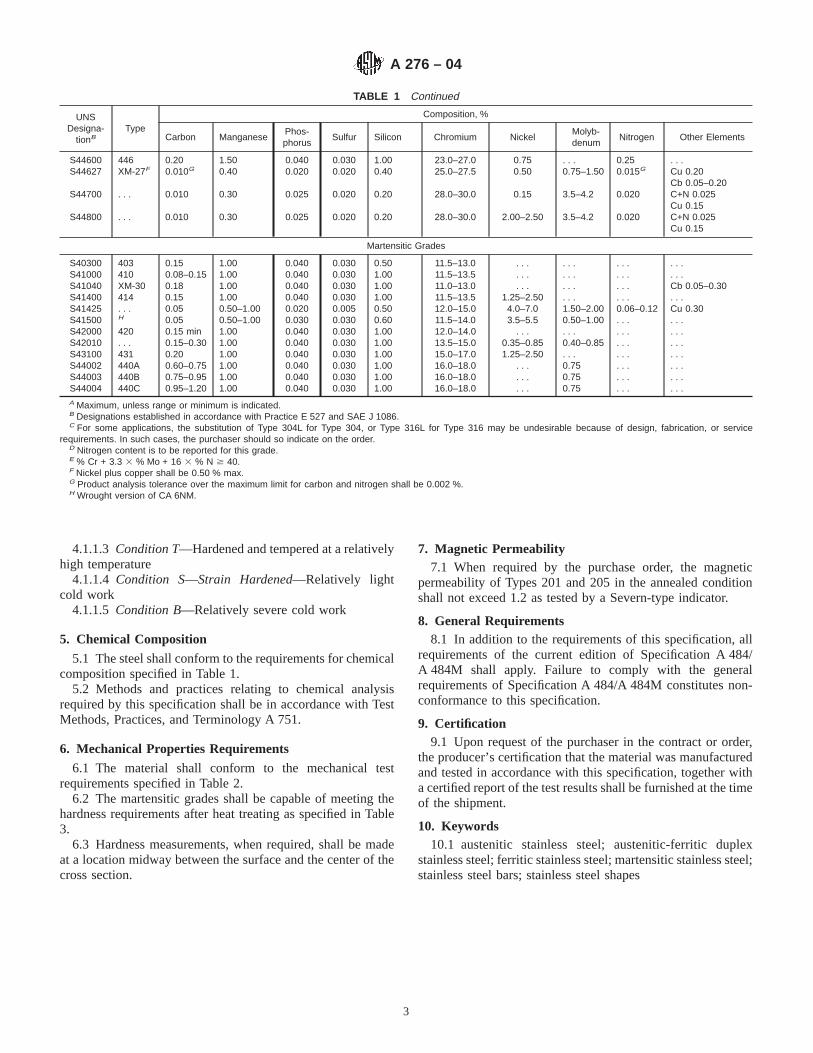
4.1.1.3 Condition T—Hardened and tempered at a relativelyhigh temperature
4.1.1.4 Condition S—Strain Hardened—Relatively lightcold work
4.1.1.5 Condition B—Relatively severe cold work
5. Chemical Composition
5.1 The steel shall conform to the requirements for chemicalcomposition specified in Table 1.
5.2 Methods and practices relating to chemical analysisrequired by this specification shall be in accordance with TestMethods, Practices, and Terminology A 751.
6. Mechanical Properties Requirements
6.1 The material shall conform to the mechanical testrequirements specified in Table 2.
6.2 The martensitic grades shall be capable of meeting thehardness requirements after heat treating as specified in Table3.
6.3 Hardness measurements, when required, shall be madeat a location midway between the surface and the center of thecross section.
7. Magnetic Permeability7.1 When required by the purchase order, the magnetic
permeability of Types 201 and 205 in the annealed conditionshall not exceed 1.2 as tested by a Severn-type indicator.
8. General Requirements8.1 In addition to the requirements of this specification, all
requirements of the current edition of Specification A 484/A 484M shall apply. Failure to comply with the generalrequirements of Specification A 484/A 484M constitutes non-conformance to this specification.
9. Certification9.1 Upon request of the purchaser in the contract or order,
the producer’s certification that the material was manufacturedand tested in accordance with this specification, together witha certified report of the test results shall be furnished at the timeof the shipment.
10. Keywords10.1 austenitic stainless steel; austenitic-ferritic duplex
stainless steel; ferritic stainless steel; martensitic stainless steel;stainless steel bars; stainless steel shapes
TABLE 1 Continued
UNSDesigna-
tionBType
Composition, %
Carbon ManganesePhos-phorus
Sulfur Silicon Chromium NickelMolyb-denum
Nitrogen Other Elements
S44600 446 0.20 1.50 0.040 0.030 1.00 23.0–27.0 0.75 . . . 0.25 . . .S44627 XM-27F 0.010G 0.40 0.020 0.020 0.40 25.0–27.5 0.50 0.75–1.50 0.015G Cu 0.20
Cb 0.05–0.20S44700 . . . 0.010 0.30 0.025 0.020 0.20 28.0–30.0 0.15 3.5–4.2 0.020 C+N 0.025
Cu 0.15S44800 . . . 0.010 0.30 0.025 0.020 0.20 28.0–30.0 2.00–2.50 3.5–4.2 0.020 C+N 0.025
Cu 0.15
Martensitic Grades
S40300 403 0.15 1.00 0.040 0.030 0.50 11.5–13.0 . . . . . . . . . . . .S41000 410 0.08–0.15 1.00 0.040 0.030 1.00 11.5–13.5 . . . . . . . . . . . .S41040 XM-30 0.18 1.00 0.040 0.030 1.00 11.0–13.0 . . . . . . . . . Cb 0.05–0.30S41400 414 0.15 1.00 0.040 0.030 1.00 11.5–13.5 1.25–2.50 . . . . . . . . .S41425 . . . 0.05 0.50–1.00 0.020 0.005 0.50 12.0–15.0 4.0–7.0 1.50–2.00 0.06–0.12 Cu 0.30S41500 H 0.05 0.50–1.00 0.030 0.030 0.60 11.5–14.0 3.5–5.5 0.50–1.00 . . . . . .S42000 420 0.15 min 1.00 0.040 0.030 1.00 12.0–14.0 . . . . . . . . . . . .S42010 . . . 0.15–0.30 1.00 0.040 0.030 1.00 13.5–15.0 0.35–0.85 0.40–0.85 . . . . . .S43100 431 0.20 1.00 0.040 0.030 1.00 15.0–17.0 1.25–2.50 . . . . . . . . .S44002 440A 0.60–0.75 1.00 0.040 0.030 1.00 16.0–18.0 . . . 0.75 . . . . . .S44003 440B 0.75–0.95 1.00 0.040 0.030 1.00 16.0–18.0 . . . 0.75 . . . . . .S44004 440C 0.95–1.20 1.00 0.040 0.030 1.00 16.0–18.0 . . . 0.75 . . . . . .A Maximum, unless range or minimum is indicated.B Designations established in accordance with Practice E 527 and SAE J 1086.C For some applications, the substitution of Type 304L for Type 304, or Type 316L for Type 316 may be undesirable because of design, fabrication, or service
requirements. In such cases, the purchaser should so indicate on the order.D Nitrogen content is to be reported for this grade.E % Cr + 3.3 3 % Mo + 16 3 % N $ 40.F Nickel plus copper shall be 0.50 % max.G Product analysis tolerance over the maximum limit for carbon and nitrogen shall be 0.002 %.H Wrought version of CA 6NM.
A 276 – 04
3

TABLE 2 Mechanical Requirements
Type Condition FinishDiameter or Thickness,
in. (mm)
TensileStrength,
min
Yield Strength,A
min
Elonga-tion in 2
in. (50 mm)B
or 4Dmin %
Reduc-tion of
Area,C,D
min, %
BrinellHard-ness,E
maxksi MPa ksi MPa
Austenitic Grades
N08367 A hot-finished orcold-finished
all 95 655 45 310 30 50 . . .
201, 202 A hot-finished orcold-finished
all 75 515 40 275 40 45 . . .
S20161 A hot-finished all 125 860 50 345 40 40 255cold-finished all 125 860 50 345 40 40 311
S20162 A hot-finished orcold finished
all 100 690 50 345 50 60 . . .
205 A hot-finished orcold-finished
all 100 690 60 414 40 50 . . .
XM-19 A hot-finished orcold-finished
all 100 690 55 380 35 55 . . .
Ashot-
rolled
hot-finished orcold-finished
up to 2 (50.8), incl 135 930 105 725 20 50 . . .
over 2 to 3 (50.8 to 76.2),incl
115 795 75 515 25 50 . . .
over 3 to 8 (76.2 to 203.2),incl
100 690 60 415 30 50 . . .
S21800 A hot-finished orcold-finished
all 95 655 50 345 35 55 241
XM-10, XM-11 A hot-finished orcold-finished
all 90 620 50 345 45 60 . . .
XM-29 A hot-finished orcold-finished
all 100 690 55 380 30 50 . . .
XM-28 A hot-finished orcold-finished
all 100 690 55 380 30 50 . . .
S24565 A hot-finished orcold-finished
all 115 795 60 415 35 40 . . .
S28200 A hot-finished orcold finished
all 110 760 60 410 35 55 . . .
302, 302B, 304, 304LN, A hot-finished all 75F 515 30F 205 40G 50 . . .305, 308, 309, 309S, cold-finished up to 1⁄2 (12.70) incl 90 620 45 310 30 40 . . .309Cb, 310, 310S, over 1⁄2 (12.70) 75F 515 30F 205 30 40 . . .310Cb, 314, 316,316LN, 316Cb, 316TI,317, 321, 347,348
304L, 316L A hot-finished all 70 485 25 170 40G 50 . . .cold-finished up to 1⁄2 (12.70) incl.
over 1⁄2 (12.70)9070
620485
4525
310170
3030
4040
. . .
. . .304N, 316N A hot-finished or
cold-finishedall 80 550 35 240 30 . . . . . .
202, 302, 304, 304N, 316,316N
B cold-finished up to 3⁄4 (19.05) incl 125 860 100 690 12 35 . . .
over 3⁄4 (19.05) to1 (25.40)
115 795 80 550 15 35 . . .
over 1 (25.40) to 11⁄4(31.75)
105 725 65 450 20 35 . . .
over 11⁄4 (31.75) to 11⁄2(38.10)
100 690 50 345 24 45 . . .
over 11⁄2 (38.10) to 13⁄4(44.45)
95 655 45 310 28 45 . . .
304, 304N, 316, 316N S cold-finished up to 2 (50.8) incl 95 650 75 515 25 40 . . .over 2 to 21⁄2 (50.8 to 63.5)
incl90 620 65 450 30 40 . . .
over 21⁄2 to 3 (63.5 to 76.2)incl
80 550 55 380 30 40 . . .
XM-21, S30454,S31654
A hot-finished orcold-finished
all 90 620 50 345 30 50 . . .
XM-21, S30454S31654
B cold-finished up to 1 (25.40) incl 145 1000 125 860 15 45 . . .
over 1 (25.40) to 11⁄4(31.75)
135 930 115 795 16 45 . . .
over 11⁄4 (31.75) to 11⁄2(38.10)
135 895 105 725 17 45 . . .
over 11⁄2 (38.10) to 13⁄4(44.45)
125 860 100 690 18 45 . . .
A 276 – 04
4

TABLE 2 Continued
Type Condition FinishDiameter or Thickness,
in. (mm)
TensileStrength,
min
Yield Strength,A
min
Elonga-tion in 2
in. (50 mm)B
or 4Dmin %
Reduc-tion of
Area,C,D
min, %
BrinellHard-ness,E
maxksi MPa ksi MPa
S30815 A hot-finished orcold-finished
all 8787
600600
4545
310310
4040
5050
. . .
. . .S31254 A hot-finished or
cold-finishedall 95 650 44 300 35 50 . . .
S31725 A hot-finished orcold-finished
all 75 515 30 205 40 . . . . . .
S31726 A hot-finished orcold-finished
all 80 550 35 240 40 . . . . . .
S32654 A hot-finished orcold-finished
all 109 750 62 430 40 40 250
Austenitic-Ferritic Grades
XM-26 A hot-finished orcold-finished
all 90 620 65 450 20 55 . . .
S31803 A hot-finished orcold-finished
all 90 620 65 448 25 . . . 290
S32101 A hot-finished orcold-finished
all 94 650 65 450 30 . . . 290
S32205 A hot-finished orcold-finished
all 95 655 65 450 25 . . . 290
S32304 A hot-finished orcold-finished
all 87 600 58 400 25 . . . 290
S32550 A hot-finished or all 109 750 80 550 25 . . . 290cold-finished
S32550 S cold-finished all 125 860 105 720 16 . . . 335S32760 A hot-finished or all 109 750 80 550 25 . . . 290
cold-finishedS32760 S cold-finished all 125 860 105 720 16 . . . 335
Ferritic Grades
405H A hot-finished all . . . . . . . . . . . . . . . . . . 207cold-finished all . . . . . . . . . . . . . . . . . . 217
429 A hot-finished all 70 480 40 275 20 45 . . .cold-finished all 70 480 40 275 16 45 . . .
430 A hot-finished orcold-finished
all 60 415 30 207 20 45 . . .
S40976 A hot-finished orcold-finished
all 60 415 20 140 20 45 244
S44400 A hot-finishedcold-finished
allall
6060
415415
4545
310310
2016
4545
217217
446, XM-27 A hot-finished all 65 450 40 275 20 45 219cold-finished all 65 450 40 275 16 45 219
S44700 A hot-finished all 70 480 55 380 20 40 . . .cold-finished all 75 520 60 415 15 30 . . .
S44800 A hot-finished all 70 480 55 380 20 40 . . .cold-finished all 75 520 60 415 15 30 . . .
Martensitic Grades
403, 410 A hot-finished all 70 480 40 275 20 45 . . .cold-finished all 70 480 40 275 16 45 . . .
403, 410 T hot-finished all 100 690 80 550 15 45 . . .cold-finished all 100 690 80 550 12 40 . . .
XM-30 T hot-finishedcold-finished
allall
125125
860860
100100
690690
1312
4535
302. . .
403, 410 H hot-finished all 120 830 90 620 12 40 . . .cold-finished all (rounds only) 120 830 90 620 12 40 . . .
XM-30 A hot-finished all 70 480 40 275 13 45 235cold-finished all 70 480 40 275 12 35 . . .
414 A hot-finished orcold-finished
all . . . . . . . . . . . . . . . . . . 298
414 T hot-finished orcold-finished
all 115 790 90 620 15 45 . . .
S41425 T hot-finished all 120 825 95 655 15 45 321S41500 T hot-finished or
cold-finishedall 115 795 90 620 15 45 295
420 A hot-finished all . . . . . . . . . . . . . . . . . . 241cold-finished all . . . . . . . . . . . . . . . . . . 255
S42010 A hot-finished all . . . . . . . . . . . . . . . . . . 235cold-finished all . . . . . . . . . . . . . . . . . . 255
A 276 – 04
5

SUMMARY OF CHANGES
Committee A01.17 has identified the location of selected changes to this standard since the last issue,A276–03, that may impact the use of this standard. (Approved Feb. 1, 2004.)
(1) Added new Footnote D to Table 2.
Committee A01.17 has identified the location of selected changes to this standard since the last issue, A276–02a, that mayimpact the use of this standard. (Approved April 10, 2003.)
(1) Added UNS 32101 to Tables 1 and 2.
TABLE 2 Continued
Type Condition FinishDiameter or Thickness,
in. (mm)
TensileStrength,
min
Yield Strength,A
min
Elonga-tion in 2
in. (50 mm)B
or 4Dmin %
Reduc-tion of
Area,C,D
min, %
BrinellHard-ness,E
maxksi MPa ksi MPa
431 A hot-finished orcold-finished
all . . . . . . . . . . . . . . . . . . 285
440A, 440B, and 440C A hot-finished all . . . . . . . . . . . . . . . . . . 269cold-finished all . . . . . . . . . . . . . . . . . . 285
A Yield strength shall be determined by the 0.2 % offset method in accordance with Test Methods and Definitions A 370. An alternative method of determining yieldstrength may be used based on a total extension under load of 0.5 %.
B For some specific products, it may not be practicable to use a 2-in. or 50-mm gage length. The use of sub-size test specimens, when necessary, is permissible inaccordance with Test Methods and Definitions A 370.
C Reduction of area does not apply on flat bars 3⁄16 in. (4.76 mm) and under in thickness as this determination is not generally made in this product size.DThe material shall be capable of meeting the required reduction of area where listed, but actual measurement and reporting of the reduction of area are not required
unless specified in the purchase order.E Or equivalent Rockwell hardness.F For extruded shapes of all Cr-Ni grades of Condition A, the yield strength shall be 25 ksi (170 MPa) min and tensile strength shall be 70 ksi (480 MPa) min.G For shapes having section thickness of 1⁄2 in. (12.5 mm) or less, 30% min. elongation is acceptable.H Material shall be capable of being heat treated to a maximum Brinell hardness of 250 when oil quenched from 1750°F (953°C).
TABLE 3 Response to Heat Treatment
TypeAHeat TreatmentTemperatureB
°F (°C), minQuenchant
HardnessHRC, min
403 1750 (955) Air 35410 1750 (955) Air 35414 1750 (955) Oil 42420 1825 (995) Air 50S42010 1850 (1010) Oil 48431 1875 (1020) Oil 40440A 1875 (1020) Air 55440B 1875 (1020) Oil 56440C 1875 (1020) Air 58A Samples for testing shall be in the form of a section not exceeding 3⁄8 in. (9.50
mm) in thickness.B Temperature tolerance is 625°F (14°C).
A 276 – 04
6

ASTM International takes no position respecting the validity of any patent rights asserted in connection with any item mentionedin this standard. Users of this standard are expressly advised that determination of the validity of any such patent rights, and the riskof infringement of such rights, are entirely their own responsibility.
This standard is subject to revision at any time by the responsible technical committee and must be reviewed every five years andif not revised, either reapproved or withdrawn. Your comments are invited either for revision of this standard or for additional standardsand should be addressed to ASTM International Headquarters. Your comments will receive careful consideration at a meeting of theresponsible technical committee, which you may attend. If you feel that your comments have not received a fair hearing you shouldmake your views known to the ASTM Committee on Standards, at the address shown below.
This standard is copyrighted by ASTM International, 100 Barr Harbor Drive, PO Box C700, West Conshohocken, PA 19428-2959,United States. Individual reprints (single or multiple copies) of this standard may be obtained by contacting ASTM at the aboveaddress or at 610-832-9585 (phone), 610-832-9555 (fax), or [email protected] (e-mail); or through the ASTM website(www.astm.org).
A 276 – 04
7

Designation: A 313/A 313M – 03
Standard Specification forStainless Steel Spring Wire 1
This standard is issued under the fixed designation A 313/A 313M; the number immediately following the designation indicates the yearof original adoption or, in the case of revision, the year of last revision. A number in parentheses indicates the year of last reapproval.A superscript epsilon (e) indicates an editorial change since the last revision or reapproval.
This standard has been approved for use by agencies of the Department of Defense.
1. Scope*
1.1 This specification covers austenitic and age-hardenablestainless steel round spring wire intended especially for themanufacture of springs.
1.2 The values stated in inch-pound units or SI units are tobe regarded separately as the standard. Within the text andtables, the SI units are shown in brackets. The values stated ineach system are not exact equivalents; therefore, each systemmust be used independently of the other. Combining valuesfrom the two systems may result in nonconformance with thespecification.
1.3 Unless the order specifies an “M” designation, thematerial shall be furnished to inch-pound units.
2. Referenced Documents
2.1 ASTM Standards:A 555/A 555M Specification for General Requirements for
Stainless Steel Wire and Wire Rods2
A 751 Test Methods, Practices, and Terminology forChemical Analysis of Steel Products2
E 527 Practice for Numbering Metals and Alloys (UNS)3
2.2 Society of Automotive Engineers Standard:J 1086 Numbering Metals and Alloys4
3. Ordering Information
3.1 It is the responsibility of the purchaser to specify allrequirements that are necessary for material ordered under thisspecification. Such requirements may include, but are notlimited to the following:
3.1.1 Quantity (weight),3.1.2 Name of material (stainless steel spring wire),3.1.3 Finish (see 8.1),3.1.4 Dimension (diameter),
3.1.5 Type designation (Table 1),3.1.6 ASTM designation and date of issue,3.1.7 Supplementary requirements for government procure-
ment, and3.1.8 Special requirements.
NOTE 1—A typical ordering description is as follows:2000 lb (1000 kg) Stainless Steel Spring Wire, cold-drawn Class 1,
bright finish, 0.032-in. (0.82 mm) diameter, in 100-lb (50 kg) 16-in. (0.4m) coils, Type 302 to ASTM A 313, dated ____.
4. General Requirements for Delivery
4.1 In addition to the requirements of this specification, allrequirements of the current edition of Specification A 555/A 555M shall apply. Failure to comply with the generalrequirements of Specification A 555/A 555M constitutes non-conformance with this specification.
5. Manufacture
5.1 Types 302 Class 1, 304, 305, 316, 321, 347, and GradesS20430 and XM-28 shall be cold drawn to produce therequired mechanical properties.
5.2 Type 631, Type 302 Class 2, and Grade XM-16 shall befurnished in the cold-drawn condition ready for fabrication.Following fabrication Type 631 and Grade XM-16 shall be ageor precipitation hardened to produce their maximum strengthproperties. The tensile strengths to be obtained following theprescribed heat treatment are shown in Table 2 and Table 3 forhardened wire. Type 302 Class 2 shall be stress relievedfollowing fabrication and meet the requirements shown inTable 4. The nominal as-drawn tensile strengths are providedas a guide for the spring manufacturer.
6. Chemical Composition
6.1 The steel shall conform to the requirements as tochemical composition prescribed in Table 1.
6.2 Methods and practices relating to chemical analysisrequired by this specification shall be in accordance with TestMethods, Practices, and Terminology A 751.
7. Mechanical Requirements
7.1 Tensile Properties:
1 This specification is under the jurisdiction of ASTM Committee A01 on Steel,Stainless Steel and Related Alloys, and is the direct responsibility of SubcommitteeA01.17 on Flat-Rolled and Stainless Steel.
Current edition approved May 10, 2003. Published June 2003. Originallyapproved in 1947 . Last previous edition approved in 1998 as A 313/A 313M – 98.
2 Annual Book of ASTM Standards, Vol 01.03.3 Annual Book of ASTM Standards,Vol 01.01.4 Available from Society of Automotive Engineers (SAE), 400 Commonwealth
Dr., Warrendale, PA 15096.
1
*A Summary of Changes section appears at the end of this standard.
Copyright © ASTM International, 100 Barr Harbor Drive, PO Box C700, West Conshohocken, PA 19428-2959, United States.

7.1.1 Types 302 Class 1 and 304 shall conform to therequirements shown in Table 5.
7.1.2 Types 305, 316, 321, and 347 shall conform to therequirements shown in Table 6.
7.1.3 Type 631 shall conform to the requirements shown inTable 2 when heat treated 900°F [482°C] for 1 h and air cooled.
7.1.4 Grade XM-16 shall conform to the requirementsshown in Table 3 when heat treated 850°F [454°C] for1⁄2 h andair cooled.
7.1.5 Grade XM-28 shall conform to the requirementsshown in Table 7.
7.1.6 Type 302 Class 2 shall conform to the requirementsshown in Table 4.
7.1.7 Grade S20430 shall conform to the requirementsshown in Table 8.
7.2 Wrap Test:
7.2.1 Wire 0.162 in. [4.11 mm] and smaller in diameter shallwind on itself as an arbor without breaking.
7.2.2 Wire larger than 0.162 in. [4.11 mm] in diameter shallwind without breaking on a mandrel having a diameter twicethe diameter of the wire.
7.3 Uniformity (Coil Test):7.3.1 In the as-cold drawn condition, a specimen coil shall
be wound on an arbor of the size specified in Table 9 to forma tightly wound coil.
7.3.2 After winding, the specimen coil shall be stretched toa permanent set four times its as-wound length. After thistreatment, the specimen coil shall show uniform pitch with nosplits or fractures.
7.4 Cast—A loop or ring shall be cut from the bundle andallowed to fall on the floor. The wire shall lie flat and not springup or show a wavy condition.
TABLE 1 Chemical Requirements
UNS Desig-nationA
Type Composition,B %
Carbon Manganese Phosphorus Sulfur Silicon Chromium Nickel Molybdenum Nitrogen Other Elements
Austenitic Grades
S 24100 XM-28 0.15 11.0–14.0 0.060 0.030 1.00 16.5–19.0 0.50–2.50 0.20–0.45S 30200 302 0.12 2.00 0.045 0.030 1.00 17.0–19.0 8.0–10.0 0.10S 30400 304 0.08 2.00 0.045 0.030 1.00 18.0–20.0 8.0–10.5 0.10S 30500 305 0.12 2.00 0.045 0.030 1.00 17.0–19.0 10.5–13.0S 31600 316 0.07 2.00 0.045 0.030 1.00 16.5–18.0 10.5–13.5 2.00–2.50 0.10S 32100S 34700
321347
0.080.08
2.002.00
0.0450.045
0.0300.030
1.001.00
17.0–19.017.0–19.0
9.0–12.09.0–13.0
Ti 53C min(Cb + Ta) 103C min
Age-Hardenable Grades
S 17700S 45500
631XM-16
0.090.05
1.000.50
0.0400.040
0.0300.030
1.000.50
16.0–18.011.0–12.5
6.50– 7.87.50– 9.5 0.50 max
Al 0.75–1.50Ti 0.80–1.40Cu 1.50–2.50
(Cb + Ta) 0.10–0.50S 20430 . . . 0.15 6.5–9.0 0.060 0.030 1.00 15.5–17.5 1.50– 3.50 0.05–0.25 Cu 2.0–4.0
A New designations established in accordance with Practice E 527 and SAE J 1086, Practice for Numbering Metals and Alloys (UNS).B Maximum unless range is shown.
TABLE 2 Tensile Strength Requirements for Type 631 A
Diameter, in. [mm] Cold Drawn ConditionC, ksi [MPa]
Nominal
Condition CH-900B, ksi [MPa]
min max
0.010 [0.25] to 0.015 [0.38], incl 295 [2035] 335 [2310] 365 [2515]Over 0.015 [0.38] to 0.020 [0.51], incl 290 [2000] 330 [2275] 360 [2480]Over 0.020 [0.51] to 0.029 [0.74], incl 285 [1965] 325 [2240] 355 [2450]Over 0.029 [0.74] to 0.041 [1.04], incl 275 [1895] 320 [2205] 350 [2415]Over 0.041 [1.04] to 0.051 [1.30], incl 270 [1860] 310 [2135] 340 [2345]Over 0.051 [1.30] to 0.061 [1.55], incl 265 [1825] 305 [2100] 335 [2310]Over 0.061 [1.55] to 0.071 [1.80], incl 257 [1770] 297 [2050] 327 [2255]Over 0.071 [1.80] to 0.086 [2.18], incl 255 [1760] 292 [2015] 322 [2220]Over 0.086 [2.18] to 0.090 [2.29], incl 245 [1690] 282 [1945] 312 [2150]Over 0.090 [2.29] to 0.100 [2.54], incl 242 [1670] 279 [1925] 309 [2130]Over 0.100 [2.54] to 0.106 [2.69], incl 238 [1640] 274 [1890] 304 [2095]Over 0.106 [2.69] to 0.130 [3.30], incl 236 [1625] 272 [1875] 302 [2080]Over 0.130 [3.30] to 0.138 [3.50], incl 230 [1585] 260 [1795] 290 [2000]Over 0.138 [3.50] to 0.146 [3.71], incl 228 [1570] 258 [1780] 288 [1985]Over 0.146 [3.71] to 0.162 [4.11], incl 226 [1560] 256 [1765] 286 [1970]Over 0.162 [4.11] to 0.180 [4.57], incl 224 [1545] 254 [1750] 284 [1960]Over 0.180 [4.57] to 0.207 [5.26], incl 222 [1530] 252 [1740] 282 [1945]Over 0.207 [5.26] to 0.225 [5.72], incl 218 [1505] 248 [1710] 278 [1915]Over 0.225 [5.72] to 0.306 [7.77], incl 213 [1470] 242 [1670] 272 [1875]Over 0.306 [7.77] to 0.440 [11.2], incl 207 [1425] 235 [1620] 265 [1825]Over 0.440 [11.2] to 0.625 [15.88], incl 203 [1400] 230 [1585] 260 [1795]
A When wire is specified in straightened and cut lengths, the minimum tensile strength shall be 90 % of the values listed in the table.B Aged at 900°F [482°C] for 1 h and air cooled.
A 313/A 313M – 03
2
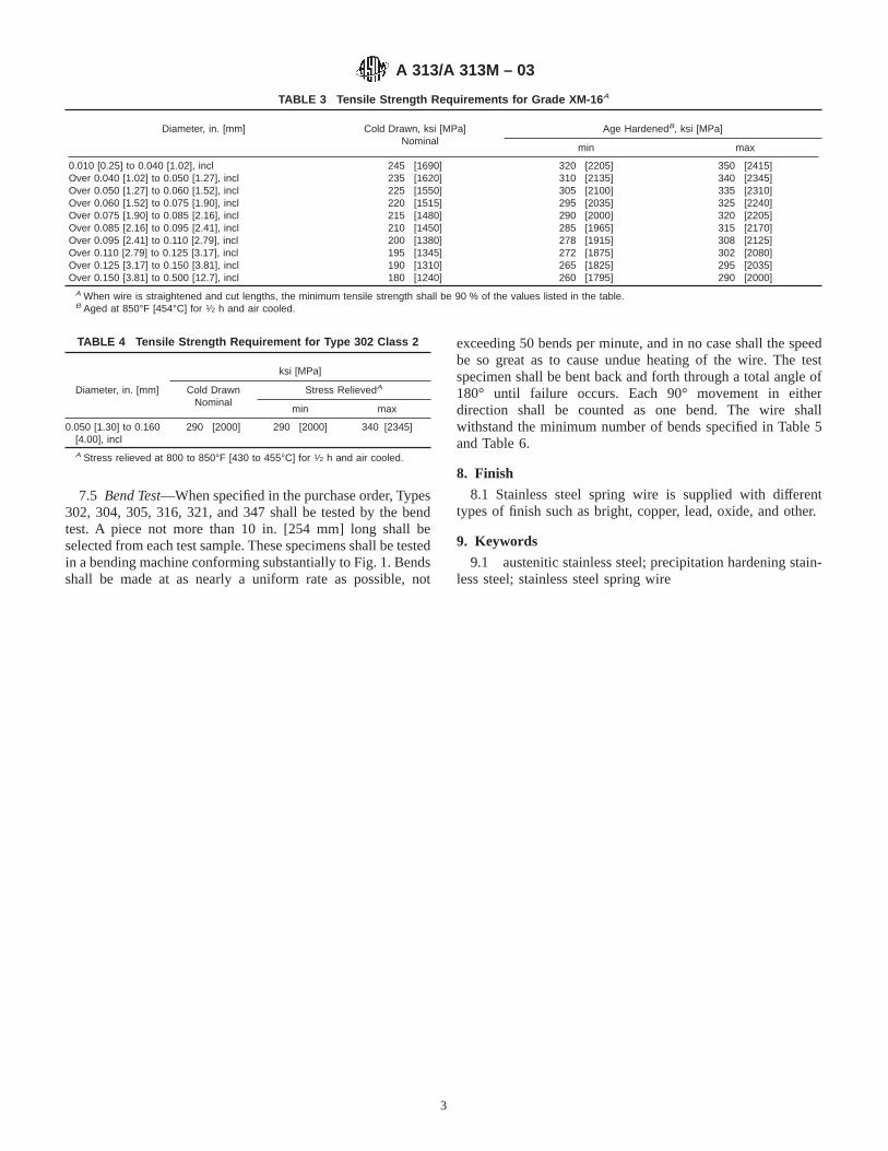
7.5 Bend Test—When specified in the purchase order, Types302, 304, 305, 316, 321, and 347 shall be tested by the bendtest. A piece not more than 10 in. [254 mm] long shall beselected from each test sample. These specimens shall be testedin a bending machine conforming substantially to Fig. 1. Bendsshall be made at as nearly a uniform rate as possible, not
exceeding 50 bends per minute, and in no case shall the speedbe so great as to cause undue heating of the wire. The testspecimen shall be bent back and forth through a total angle of180° until failure occurs. Each 90° movement in eitherdirection shall be counted as one bend. The wire shallwithstand the minimum number of bends specified in Table 5and Table 6.
8. Finish
8.1 Stainless steel spring wire is supplied with differenttypes of finish such as bright, copper, lead, oxide, and other.
9. Keywords
9.1 austenitic stainless steel; precipitation hardening stain-less steel; stainless steel spring wire
TABLE 3 Tensile Strength Requirements for Grade XM-16 A
Diameter, in. [mm] Cold Drawn, ksi [MPa]Nominal
Age HardenedB, ksi [MPa]
min max
0.010 [0.25] to 0.040 [1.02], incl 245 [1690] 320 [2205] 350 [2415]Over 0.040 [1.02] to 0.050 [1.27], incl 235 [1620] 310 [2135] 340 [2345]Over 0.050 [1.27] to 0.060 [1.52], incl 225 [1550] 305 [2100] 335 [2310]Over 0.060 [1.52] to 0.075 [1.90], incl 220 [1515] 295 [2035] 325 [2240]Over 0.075 [1.90] to 0.085 [2.16], incl 215 [1480] 290 [2000] 320 [2205]Over 0.085 [2.16] to 0.095 [2.41], incl 210 [1450] 285 [1965] 315 [2170]Over 0.095 [2.41] to 0.110 [2.79], incl 200 [1380] 278 [1915] 308 [2125]Over 0.110 [2.79] to 0.125 [3.17], incl 195 [1345] 272 [1875] 302 [2080]Over 0.125 [3.17] to 0.150 [3.81], incl 190 [1310] 265 [1825] 295 [2035]Over 0.150 [3.81] to 0.500 [12.7], incl 180 [1240] 260 [1795] 290 [2000]
A When wire is straightened and cut lengths, the minimum tensile strength shall be 90 % of the values listed in the table.B Aged at 850°F [454°C] for 1⁄2 h and air cooled.
TABLE 4 Tensile Strength Requirement for Type 302 Class 2
Diameter, in. [mm]
ksi [MPa]
Cold DrawnNominal
Stress RelievedA
min max
0.050 [1.30] to 0.160[4.00], incl
290 [2000] 290 [2000] 340 [2345]
A Stress relieved at 800 to 850°F [430 to 455°C] for 1⁄2 h and air cooled.
A 313/A 313M – 03
3
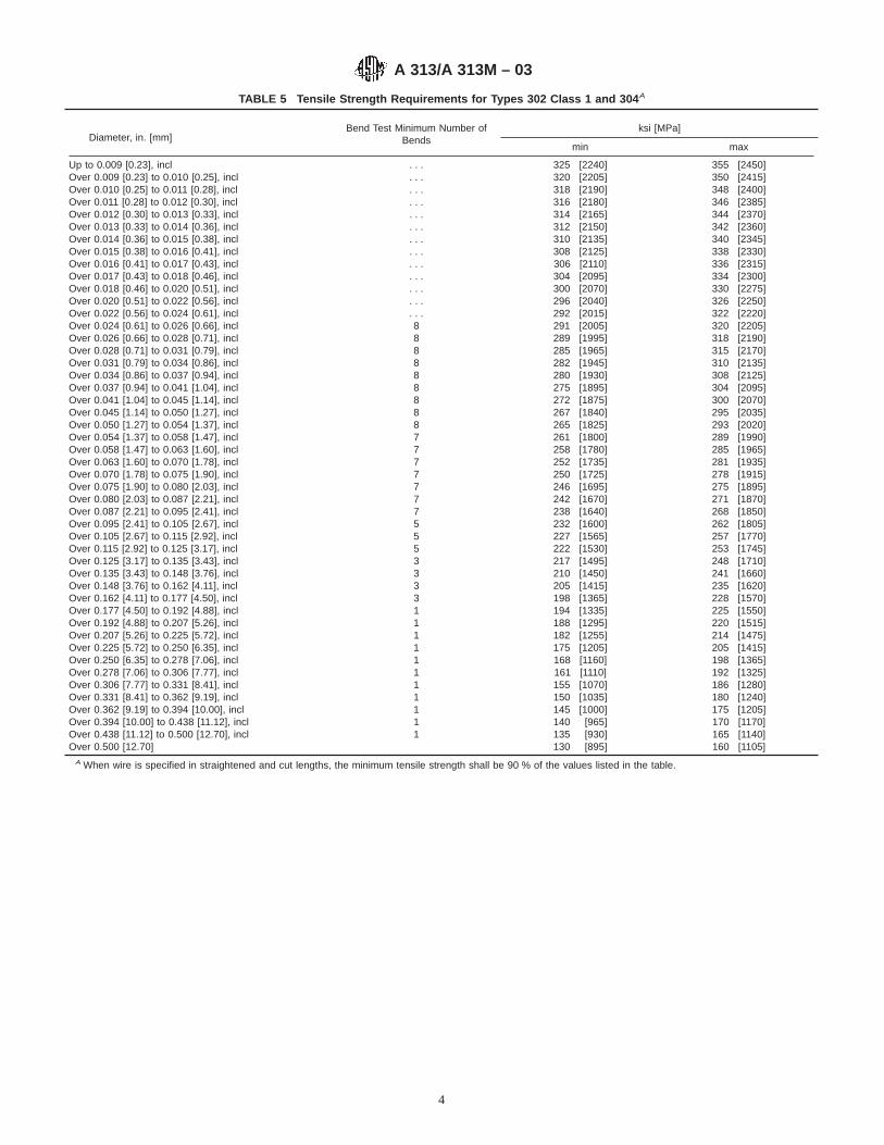
TABLE 5 Tensile Strength Requirements for Types 302 Class 1 and 304 A
Diameter, in. [mm]Bend Test Minimum Number of
Bendsksi [MPa]
min max
Up to 0.009 [0.23], incl . . . 325 [2240] 355 [2450]Over 0.009 [0.23] to 0.010 [0.25], incl . . . 320 [2205] 350 [2415]Over 0.010 [0.25] to 0.011 [0.28], incl . . . 318 [2190] 348 [2400]Over 0.011 [0.28] to 0.012 [0.30], incl . . . 316 [2180] 346 [2385]Over 0.012 [0.30] to 0.013 [0.33], incl . . . 314 [2165] 344 [2370]Over 0.013 [0.33] to 0.014 [0.36], incl . . . 312 [2150] 342 [2360]Over 0.014 [0.36] to 0.015 [0.38], incl . . . 310 [2135] 340 [2345]Over 0.015 [0.38] to 0.016 [0.41], incl . . . 308 [2125] 338 [2330]Over 0.016 [0.41] to 0.017 [0.43], incl . . . 306 [2110] 336 [2315]Over 0.017 [0.43] to 0.018 [0.46], incl . . . 304 [2095] 334 [2300]Over 0.018 [0.46] to 0.020 [0.51], incl . . . 300 [2070] 330 [2275]Over 0.020 [0.51] to 0.022 [0.56], incl . . . 296 [2040] 326 [2250]Over 0.022 [0.56] to 0.024 [0.61], incl . . . 292 [2015] 322 [2220]Over 0.024 [0.61] to 0.026 [0.66], incl 8 291 [2005] 320 [2205]Over 0.026 [0.66] to 0.028 [0.71], incl 8 289 [1995] 318 [2190]Over 0.028 [0.71] to 0.031 [0.79], incl 8 285 [1965] 315 [2170]Over 0.031 [0.79] to 0.034 [0.86], incl 8 282 [1945] 310 [2135]Over 0.034 [0.86] to 0.037 [0.94], incl 8 280 [1930] 308 [2125]Over 0.037 [0.94] to 0.041 [1.04], incl 8 275 [1895] 304 [2095]Over 0.041 [1.04] to 0.045 [1.14], incl 8 272 [1875] 300 [2070]Over 0.045 [1.14] to 0.050 [1.27], incl 8 267 [1840] 295 [2035]Over 0.050 [1.27] to 0.054 [1.37], incl 8 265 [1825] 293 [2020]Over 0.054 [1.37] to 0.058 [1.47], incl 7 261 [1800] 289 [1990]Over 0.058 [1.47] to 0.063 [1.60], incl 7 258 [1780] 285 [1965]Over 0.063 [1.60] to 0.070 [1.78], incl 7 252 [1735] 281 [1935]Over 0.070 [1.78] to 0.075 [1.90], incl 7 250 [1725] 278 [1915]Over 0.075 [1.90] to 0.080 [2.03], incl 7 246 [1695] 275 [1895]Over 0.080 [2.03] to 0.087 [2.21], incl 7 242 [1670] 271 [1870]Over 0.087 [2.21] to 0.095 [2.41], incl 7 238 [1640] 268 [1850]Over 0.095 [2.41] to 0.105 [2.67], incl 5 232 [1600] 262 [1805]Over 0.105 [2.67] to 0.115 [2.92], incl 5 227 [1565] 257 [1770]Over 0.115 [2.92] to 0.125 [3.17], incl 5 222 [1530] 253 [1745]Over 0.125 [3.17] to 0.135 [3.43], incl 3 217 [1495] 248 [1710]Over 0.135 [3.43] to 0.148 [3.76], incl 3 210 [1450] 241 [1660]Over 0.148 [3.76] to 0.162 [4.11], incl 3 205 [1415] 235 [1620]Over 0.162 [4.11] to 0.177 [4.50], incl 3 198 [1365] 228 [1570]Over 0.177 [4.50] to 0.192 [4.88], incl 1 194 [1335] 225 [1550]Over 0.192 [4.88] to 0.207 [5.26], incl 1 188 [1295] 220 [1515]Over 0.207 [5.26] to 0.225 [5.72], incl 1 182 [1255] 214 [1475]Over 0.225 [5.72] to 0.250 [6.35], incl 1 175 [1205] 205 [1415]Over 0.250 [6.35] to 0.278 [7.06], incl 1 168 [1160] 198 [1365]Over 0.278 [7.06] to 0.306 [7.77], incl 1 161 [1110] 192 [1325]Over 0.306 [7.77] to 0.331 [8.41], incl 1 155 [1070] 186 [1280]Over 0.331 [8.41] to 0.362 [9.19], incl 1 150 [1035] 180 [1240]Over 0.362 [9.19] to 0.394 [10.00], incl 1 145 [1000] 175 [1205]Over 0.394 [10.00] to 0.438 [11.12], incl 1 140 [965] 170 [1170]Over 0.438 [11.12] to 0.500 [12.70], incl 1 135 [930] 165 [1140]Over 0.500 [12.70] 130 [895] 160 [1105]
A When wire is specified in straightened and cut lengths, the minimum tensile strength shall be 90 % of the values listed in the table.
A 313/A 313M – 03
4

TABLE 6 Tensile Strength Requirements for Types 305, 316, 321, and 347 A
Diameter, in. [mm] Bend Test Minimum Number ofBends
ksi [MPa]
min max
Up to 0.010 [0.25], incl . . . 245 [1690] 275 [1895]Over 0.010 [0.25] to 0.015 [0.38], incl . . . 240 [1655] 270 [1860]Over 0.015 [0.38] to 0.024 [0.61], incl . . . 235 [1620] 265 [1825]Over 0.024 [0.61] to 0.041 [1.04], incl 8 235 [1620] 265 [1825]Over 0.041 [1.04] to 0.047 [1.19], incl 8 230 [1585] 260 [1790]Over 0.047 [1.19] to 0.054 [1.37], incl 8 225 [1550] 255 [1760]Over 0.054 [1.37] to 0.062 [1.57], incl 7 220 [1515] 250 [1725]Over 0.062 [1.57] to 0.072 [1.83], incl 7 215 [1480] 245 [1690]Over 0.072 [1.82] to 0.080 [2.03], incl 7 210 [1450] 240 [1655]Over 0.080 [2.03] to 0.092 [2.34], incl 7 205 [1415] 235 [1620]Over 0.092 [2.34] to 0.105 [2.67], incl 5 200 [1380] 230 [1585]Over 0.105 [2.67] to 0.120 [3.05], incl 5 195 [1345] 225 [1550]Over 0.120 [3.05] to 0.148 [3.76], incl 3 185 [1275] 215 [1480]Over 0.148 [3.76] to 0.166 [4.22], incl 3 180 [1240] 210 [1450]Over 0.166 [4.22] to 0.177 [4.50], incl 3 170 [1170] 200 [1380]Over 0.177 [4.50] to 0.207 [5.26], incl 1 160 [1105] 190 [1310]Over 0.207 [5.26] to 0.225 [5.72], incl 1 155 [1070] 185 [1275]Over 0.225 [5.72] to 0.250 [6.35], incl 1 150 [1035] 180 [1240]Over 0.250 [6.35] to 0.312 [7.92], incl 1 140 [965] 170 [1170]Over 0.312 [7.92] to 0.375 [9.53], incl 1 135 [930] 165 [1140]Over 0.375 [9.53] to 0.500 [12.70], incl 130 [895] 160 [1105]Over 0.500 [12.70] 125 [860] 155 [1070]
A When wire is specified in straightened and cut lengths, the minimum tensile strength shall be 90 % of the values listed in the table.
TABLE 7 Tensile Strength Requirements for Grade XM-28 A
Diameter, in. [mm] ksi [MPa]
min max
Up to 0.009 [0.23], incl 325 [2240] 355 [2450]Over 0.009 [0.23] to 0.010 [0.25], incl 320 [2205] 350 [2415]Over 0.010 [0.25] to 0.011 [0.28], incl 318 [2195] 348 [2400]Over 0.011 [0.28] to 0.012 [0.30], incl 316 [2180] 346 [2385]Over 0.012 [0.30] to 0.013 [0.33], incl 314 [2165] 344 [2370]Over 0.013 [0.33] to 0.014 [0.36], incl 312 [2150] 342 [2360]Over 0.014 [0.36] to 0.015 [0.38], incl 310 [2135] 340 [2345]Over 0.015 [0.38] to 0.016 [0.41], incl 308 [2125] 338 [2330]Over 0.016 [0.41] to 0.017 [0.43], incl 306 [2110] 336 [2315]Over 0.017 [0.43] to 0.018 [0.46], incl 304 [2095] 334 [2305]Over 0.018 [0.46] to 0.020 [0.51], incl 300 [2070] 330 [2275]Over 0.020 [0.51] to 0.022 [0.56], incl 296 [2040] 326 [2250]Over 0.022 [0.56] to 0.024 [0.61], incl 292 [2015] 322 [2220]Over 0.024 [0.61] to 0.026 [0.66], incl 289 [1995] 319 [2200]Over 0.026 [0.66] to 0.028 [0.71], incl 286 [1970] 316 [2180]Over 0.028 [0.71] to 0.032 [0.81], incl 282 [1945] 312 [2150]Over 0.032 [0.81] to 0.037 [0.94], incl 277 [1910] 307 [2120]Over 0.037 [0.94] to 0.041 [1.04], incl 273 [1880] 303 [2090]Over 0.041 [1.04] to 0.047 [1.19], incl 270 [1860] 300 [2070]Over 0.047 [1.19] to 0.054 [1.37], incl 265 [1825] 295 [2035]Over 0.054 [1.37] to 0.087 [2.21], incl 260 [1795] 290 [2000]Over 0.087 [2.21] to 0.120 [3.05], incl 255 [1760] 285 [1965]Over 0.120 [3.05] to 0.166 [4.22], incl 250 [1725] 280 [1930]Over 0.166 [4.22] to 0.192 [4.88], incl 240 [1655] 270 [1860]Over 0.192 [4.88] to 0.225 [5.72], incl 230 [1585] 260 [1795]Over 0.225 [5.72] to 0.278 [7.06], incl 215 [1480] 245 [1690]Over 0.278 [7.06] to 0.331 [8.41], incl 200 [1380] 230 [1585]Over 0.331 [8.41] to 0.394 [10.00], incl 185 [1275] 215 [1480]Over 0.394 [10.00] to 0.500 [12.70], incl 160 [1105] 190 [1310]
A When wire is specified in straightened and cut lengths, the minimum tensilestrength shall be 85 % of the values listed in the table.
TABLE 8 Tensile Strength Requirement for Grade S20430
Diameter, in. [mm]ksi [MPa]
min max
Over 0.080 [2.03] to 0.095 [2.41],incl
230 [1585] 260 [1795]
Over 0.095 [2.41] to 0.105 [2.67],incl
215 [1480] 245 [1690]
TABLE 9 Arbor Diameter Size for Uniformity Test
Wire Diameter, in. [mm] Arbor Diameter, in. [mm]
0.034 [0.85] and under 0.102 [2.60]Over 0.034 [0.85] to 0.045 [1.20], incl 0.145 [3.70]Over 0.045 [1.20] to 0.055 [1.40], incl 0.212 [5.40]Over 0.055 [1.40] to 0.125 [3.20], incl 0.250 [6.40]Over 0.125 [3.20] to 0.180 [4.60], incl 0.350 [9.00]
A 313/A 313M – 03
5
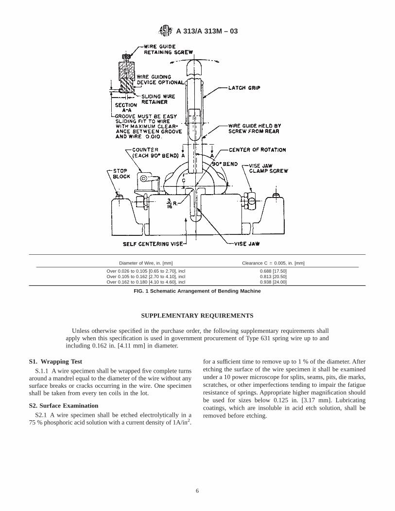
SUPPLEMENTARY REQUIREMENTS
Unless otherwise specified in the purchase order, the following supplementary requirements shallapply when this specification is used in government procurement of Type 631 spring wire up to andincluding 0.162 in. [4.11 mm] in diameter.
S1. Wrapping Test
S.1.1 A wire specimen shall be wrapped five complete turnsaround a mandrel equal to the diameter of the wire without anysurface breaks or cracks occurring in the wire. One specimenshall be taken from every ten coils in the lot.
S2. Surface Examination
S2.1 A wire specimen shall be etched electrolytically in a75 % phosphoric acid solution with a current density of 1A/in2.
for a sufficient time to remove up to 1 % of the diameter. Afteretching the surface of the wire specimen it shall be examinedunder a 10 power microscope for splits, seams, pits, die marks,scratches, or other imperfections tending to impair the fatigueresistance of springs. Appropriate higher magnification shouldbe used for sizes below 0.125 in. [3.17 mm]. Lubricatingcoatings, which are insoluble in acid etch solution, shall beremoved before etching.
Diameter of Wire, in. [mm] Clearance C 6 0.005, in. [mm]
Over 0.026 to 0.105 [0.65 to 2.70], inclOver 0.105 to 0.162 [2.70 to 4.10], inclOver 0.162 to 0.180 [4.10 to 4.60], incl
0.688 [17.50]0.813 [20.50]0.938 [24.00]
FIG. 1 Schematic Arrangement of Bending Machine
A 313/A 313M – 03
6
SUMMARY OF CHANGES
Committee A01 has identified the location of selected changes made to this standard since the last issue(A 313/A 313M-98) that may impact the use of this standard (approved May 10, 2003).
(1) The composition of S30200 was revised in Table 1.
ASTM International takes no position respecting the validity of any patent rights asserted in connection with any item mentionedin this standard. Users of this standard are expressly advised that determination of the validity of any such patent rights, and the riskof infringement of such rights, are entirely their own responsibility.
This standard is subject to revision at any time by the responsible technical committee and must be reviewed every five years andif not revised, either reapproved or withdrawn. Your comments are invited either for revision of this standard or for additional standardsand should be addressed to ASTM International Headquarters. Your comments will receive careful consideration at a meeting of theresponsible technical committee, which you may attend. If you feel that your comments have not received a fair hearing you shouldmake your views known to the ASTM Committee on Standards, at the address shown below.
This standard is copyrighted by ASTM International, 100 Barr Harbor Drive, PO Box C700, West Conshohocken, PA 19428-2959,United States. Individual reprints (single or multiple copies) of this standard may be obtained by contacting ASTM at the aboveaddress or at 610-832-9585 (phone), 610-832-9555 (fax), or [email protected] (e-mail); or through the ASTM website(www.astm.org).
A 313/A 313M – 03
7

Designation: A 314 – 97
Standard Specification forStainless Steel Billets and Bars for Forging 1
This standard is issued under the fixed designation A 314; the number immediately following the designation indicates the year oforiginal adoption or, in the case of revision, the year of last revision. A number in parentheses indicates the year of last reapproval. Asuperscript epsilon (e) indicates an editorial change since the last revision or reapproval.
1. Scope
1.1 This specification covers stainless steel billets and barsintended only for forging.
2. Referenced Documents
2.1 ASTM Standards:A 484/A 484M Specification for General Requirements forStainless Steel Bars, Billets and Forgings2
A 751 Test Methods, Practices, and Terminology forChemical Analysis of Steel Products3
E 527 Practice for Numbering Metals and Alloys (UNS)4
2.2 Other Document:SAE J1086 Recommended Practice for Numbering Metalsand Alloys5
3. Ordering Information
3.1 It is the responsibility of the purchaser to specify allrequirements that are necessary for material ordered under thisspecification. Such requirements may include but are notlimited to the following:3.1.1 Quantity (weight or number of pieces),3.1.2 Name of material: type or UNS designation (Table 1),3.1.3 Condition,3.1.4 Cross section (round, round-cornered square, etc.),3.1.5 Form: bar or forging billet,3.1.6 Applicable dimensions, including size, thickness,
width, and length,3.1.7 ASTM designation and date of issue,3.1.8 Preparation for delivery (see Specification A 484/
A 484M),3.1.9 Marking (see Specification A 484/A 484M), and3.1.10 Exceptions to the specification or special require-
ments.3.2 If possible, the intended use of the item should be given
on the purchase order especially when the item is ordered fora specific end use or uses.
NOTE 1—A typical ordering description is as follows: 10 000 lb, Type420, annealed, round-cornered square billets, ASTM A 314 dated ———for valve parts.
4. Manufacture
4.1 Annealing4.1.1 Blooms and billets of the 400 series of stainless steel
types which are highly hardenable, such as Types 414, 420,431, 440A, 440B, and 440C, are commonly annealed prior toshipment and so specified in order to avoid the possibility ofthermal cracking. Those grades are not normally furnished inthe as-rolled or as-forged condition. Other hardenable grades,such as Types 403, 410, 416, and 416 Se, which may alsorequire annealing, depending on their composition and size, arefurnished suitable for cold cutting when so specified on thepurchase order.4.2 Conditioning4.2.1 Material may be conditioned by chipping or grinding
to remove injurious surface defects provided the depth ofconditioning does not exceed that which will affect the surfacecondition or dimensions of the article to be forged from the baror billet.
5. Chemical Composition
5.1 The steel shall conform to the chemical compositionprescribed in Table 1 for the respective grades.5.2 Methods and practices relating to chemical analysis
required by this specification shall be in accordance with TestMethods, Practices, and Terminology A 751.
6. Dimensions
6.1 Billets and bars shall conform to the shape and dimen-sions specified by the purchaser within a permissible variationof 65 %.
7. General Requirements
7.1 In addition to the requirements of this specification, allrequirements of the current edition of Specification A 484/A 484M shall apply. Failure to comply with the generalrequirements of Specification A 484/A 484M constitutes non-conformance with this specification.
1 This specification is under the jurisdiction of ASTM Committee A-1 on Steel,Stainless Steel, and Related Alloys, and is the direct responsibility of SubcommitteeA01.17 on Flat Stainless Steel Products.
Current edition approved Sept. 10, 1997. Published September 1998. Originallypublished as A 314 – 47 T. Last previous edition A 314 – 95.
2 Annual Book of ASTM Standards, Vol 01.05.3 Annual Book of ASTM Standards, Vol 01.03.4 Annual Book of ASTM Standards, Vol 01.01.5 Available from Society of Automotive Engineers, 400 Commonwealth Drive,
Warrendale, PA 15096.
1
AMERICAN SOCIETY FOR TESTING AND MATERIALS100 Barr Harbor Dr., West Conshohocken, PA 19428
Reprinted from the Annual Book of ASTM Standards. Copyright ASTM
NOTICE:¬This¬standard¬has¬either¬been¬superseded¬and¬replaced¬by¬a¬new¬version¬ordiscontinued.¬Contact¬ASTM¬International¬(www.astm.org)¬for¬the¬latest¬information.

8. Keywords
8.1 austenitic stainless steel; austenitic-ferritic duplex stain-less steel; ferritic stainless steel; martensitic stainless steel;stainless steel bars; stainless steel billets
TABLE 1 Chemical Requirements
UNSDesig-nationA
TypeNumber
Chemical Composition, %B
CarbonMan-
ganese,Phos-phorus,
Sulfur, Silicon, Chromium NickelMolyb-denum
NitrogenOther
Elements
Austenitic Grades
S20161 . . . 0.15 4.00–6.00 0.040 0.040 3.00–4.00 15.00–18.00 4.00–6.00 . . . 0.08–0.20 . . .S20200 202 0.15 7.50–10.00 0.060 0.030 1.00 17.00–19.00 4.00–6.00 . . . 0.25 . . .S20910 XM-19 0.06 4.00–6.00 0.040 0.030 1.00 20.50–23.50 11.50–13.50 1.50–3.00 0.20–0.40 Cb 0.10–0.30
V 0.10–0.30S21800 . . . 0.10 7.00–9.00 0.060 0.030 3.50–4.50 16.00–18.00 8.00–9.00 . . . 0.08–0.18 . . .S21900 XM-10 0.08 8.00–10.00 0.060 0.030 1.00 19.00–21.50 5.50–7.50 . . . 0.15–0.40 . . .S21904 XM-11 0.04 8.00–10.00 0.060 0.030 1.00 19.00–21.50 5.50–7.50 . . . 0.15–0.40 . . .S24000 XM-29 0.08 11.50–14.50 0.060 0.030 1.00 17.00–19.00 2.25–3.75 . . . 0.20–0.40 . . .S24100 XM-28 0.15 11.00–14.00 0.060 0.030 1.00 16.50–19.00 0.50–2.25 . . . 0.20–0.45 . . .S28200 . . . 0.15 17.00–19.00 0.045 0.030 1.00 17.00–19.00 . . . 0.75–1.25 0.40–0.60 . . .S30200 302 0.15 2.00 0.045 0.030 1.00 17.00–19.00 8.00–10.00 . . . 0.10 . . .S30215 302B 0.15 2.00 0.045 0.030 2.00–3.00 17.00–19.00 8.00–10.00 . . . . . . . . .S30300 303 0.15 2.00 0.20 0.15 min 1.00 17.00–19.00 8.00–10.00 . . . . . . . . .S30323 303Se 0.15 2.00 0.20 0.06 1.00 17.00–19.00 8.00–10.00 . . . . . . Se 0.15 minS30400 304 0.08 2.00 0.045 0.030 1.00 18.00–20.00 8.00–10.50 . . . 0.10 . . .S30403 304L 0.030 2.00 0.045 0.030 1.00 18.00–20.00 8.00–12.00 . . . 0.10 . . .S30500 305 0.12 2.00 0.045 0.030 1.00 17.00–19.00 10.50–13.00 . . . . . . . . .S30800 308 0.08 2.00 0.045 0.030 1.00 19.00–21.00 10.00–12.00 . . . . . . . . .S30900 309 0.20 2.00 0.045 0.030 1.00 22.00–24.00 12.00–15.00 . . . . . . . . .S30908 309S 0.08 2.00 0.045 0.030 1.00 22.00–24.00 12.00–15. . . . . . . . .S30940 309Cb 0.08 2.00 0.045 0.030 1.00 22.00–24.00 12.00–16.00 . . . . . . Cb + Ta − 10 3 CS31000 310 0.25 2.00 0.045 0.030 1.50 24.00–26.00 19.00–22.00 . . . . . . . . .S31008 310S 0.08 2.00 0.045 0.030 1.50 24.00–26.00 19.00–22.00 . . . . . . . . .S31400 314 0.25 2.00 0.045 0.030 1.50–3.00 23.00–26.00 19.00–22.00 . . .. . . . . . .S31600 316 0.08 2.00 0.045 0.030 1.00 16.00–18.00 10.00–14.00 2.00–3.00 0.10 . . .S31603 316L 0.030 2.00 0.045 0.030 1.00 16.00–18.00 10.00–14.00 2.00–3.00 0.10 . . .S31635 316Ti 0.08 2.00 0.045 0.030 1.00 16.00–18.00 10.00–14.00 2.00–3.00 . . . Ti − 5 3 (C+N)
min; 0.70S31640 316Cb 0.08 2.00 0.045 0.030 1.00 16.00–18.00 10.00–14.00 2.00–3.00 . . . Cb + Ta − 10 3
C min; 1.10S31700 317 0.08 2.00 0.045 0.030 1.00 18.00–20.00 11.00–15.00 3.00–4.00 0.10S32100 321 0.08 2.00 0.045 0.030 1.00 17.00–19.00 9.00–12.00 . . . . . . Ti 5 3 C minS33228 . . . 0.04–0.08 1.00 0.020 0.015 0.030 26.00–28.00 31.00–33.00 . . . . . . Cb 0.6–1.0
Ce 0.05–0.10Al 0.025
S34700 347 0.08 2.00 0.045 0.030 1.00 17.00–19.00 9.00–13.00 . . . . . . Cb + Ta 10 3 Cmin
S34800 348 0.08 2.00 0.045 0.030 1.00 17.00–19.00 9.00–13.00 . . . . . . Cb + Ta 10 3 Cmin; Ta 0.10
S38031 . . . 0.015 2.0 0.020 0.010 0.3 26.0–28.0 30.0–32.0 6.0–7.0 0.15–0.25 Cu 1.0–1.5S38926 . . . 0.020 2.00 0.03 0.01 0.5 19.00–21.00 24.00–26.00 6.0–7.0 0.15–0.25 Cu 0.5–1.5
Austenitic-Ferritic Grades
S32760C . . . 0.030 1.00 0.030 0.010 1.00 24.00–26.00 6.00–8.00 3.00–4.00 0.20–0.30 Cu 0.50–1.00W 0.50–1.00
S32950 . . . 0.03 2.00 0.035 0.010 0.60 26.00–29.00 3.50–5.20 1.00–2.50 0.15–0.35 . . .
Ferritic Grades
S42900 429 0.12 1.00 0.040 0.030 1.00 14.00–16.00 . . . . . . . . . . . .S43000 430 0.12 1.00 0.040 0.030 1.00 16.00–18.00 . . . . . . . . . . . .S43020 430F 0.12 1.25 0.06 0.15 min 1.00 16.00–18.00 . . . 0.60D . . . . . .S43023 430F Se 0.12 1.25 0.06 0.06 1.00 16.00–18.00 . . . . . . . . . Se 0.15 minS44600 446 0.20 1.50 0.040 0.030 1.00 23.00–27.00 . . . . . . 0.25 . . .S44625 XM-27E 0.010 0.40 0.020 0.020 0.40 25.00–27.50 0.50 0.75–1.50 0.015 . . .
A 314
2
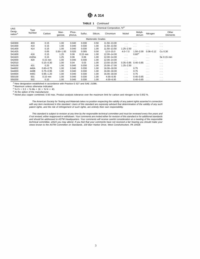
TABLE 1 Continued
UNSDesig-nationA
TypeNumber
Chemical Composition, %B
CarbonMan-
ganese,Phos-phorus,
Sulfur, Silicon, Chromium NickelMolyb-denum
NitrogenOther
Elements
Martensitic Grades
S40300 403 0.15 1.00 0.040 0.030 0.50 11.50–13.00 . . . . . . . . . . . .S41000 410 0.15 1.00 0.040 0.030 1.00 11.50–13.50 . . . . . . . . . . . .S41400 414 0.15 1.00 0.040 0.030 1.00 11.50–13.50 1.25–2.50 . . . . . . . . .S41425 . . . 0.05 0.50–1.00 0.020 0.005 0.50 12.0–15.0 4.0–7.0 1.50–2.00 0.06–0.12 Cu 0.30S41600 416 0.15 1.25 0.06 0.15 min 1.00 12.00–14.00 . . . 0.60D . . . . . .S41623 416Se 0.15 1.25 0.06 0.06 1.00 12.00–14.00 . . . . . . . . . Se 0.15 minS42000 420 0.15 min 1.00 0.040 0.030 1.00 12.00–14.00 . . . . . . . . . . . .S42010 . . . 0.15–0.30 1.00 0.04 0.03 1.00 13.50–15.00 0.35–0.85 0.40–0.85 . . . . . .S43100 431 0.20 1.00 0.040 0.030 1.00 15.00–17.00 1.25–2.50 . . . . . . . . .S44002 440A 0.60–0.75 1.00 0.040 0.030 1.00 16.00–18.00 . . . 0.75 . . . . . .S44003 440B 0.75–0.95 1.00 0.040 0.030 1.00 16.00–18.00 . . . 0.75 . . . . . .S44004 440C 0.95–1.20 1.00 0.040 0.030 1.00 16.00–18.00 . . . 0.75 . . . . . .S50100 501 0.10 min 1.00 0.040 0.030 1.00 4.00–6.00 . . . 0.40–0.65 . . . . . .S50200 502 0.10 1.00 0.040 0.030 1.00 4.00–6.00 . . . 0.40–0.65 . . . . . .
A New designation established in accordance with Practice E 527 and SAE J1086.B Maximum unless otherwise indicated.C % Cr + 3.3 3 % Mo + 16 3 % N $ 40.D At the option of the manufacturer.E Nickel plus copper combined; 0.50 max. Product analysis tolerance over the maximum limit for carbon and nitrogen to be 0.002 %.
The American Society for Testing and Materials takes no position respecting the validity of any patent rights asserted in connectionwith any item mentioned in this standard. Users of this standard are expressly advised that determination of the validity of any suchpatent rights, and the risk of infringement of such rights, are entirely their own responsibility.
This standard is subject to revision at any time by the responsible technical committee and must be reviewed every five years andif not revised, either reapproved or withdrawn. Your comments are invited either for revision of this standard or for additional standardsand should be addressed to ASTM Headquarters. Your comments will receive careful consideration at a meeting of the responsibletechnical committee, which you may attend. If you feel that your comments have not received a fair hearing you should make yourviews known to the ASTM Committee on Standards, 100 Barr Harbor Drive, West Conshohocken, PA 19428.
A 314
3
Designation: A 314 – 97 (Reapproved 2002)
Standard Specification forStainless Steel Billets and Bars for Forging 1
This standard is issued under the fixed designation A 314; the number immediately following the designation indicates the year oforiginal adoption or, in the case of revision, the year of last revision. A number in parentheses indicates the year of last reapproval. Asuperscript epsilon (e) indicates an editorial change since the last revision or reapproval.
This standard has been approved for use by agencies of the Department of Defense.
1. Scope
1.1 This specification covers stainless steel billets and barsintended only for forging.
2. Referenced Documents
2.1 ASTM Standards:A 484/A 484M Specification for General Requirements for
Stainless Steel Bars, Billets and Forgings2
A 751 Test Methods, Practices, and Terminology forChemical Analysis of Steel Products3
E 527 Practice for Numbering Metals and Alloys (UNS)4
2.2 Other Document:SAE J1086 Recommended Practice for Numbering Metals
and Alloys5
3. Ordering Information
3.1 It is the responsibility of the purchaser to specify allrequirements that are necessary for material ordered under thisspecification. Such requirements may include but are notlimited to the following:
3.1.1 Quantity (weight or number of pieces),3.1.2 Name of material: type or UNS designation (Table 1),3.1.3 Condition,3.1.4 Cross section (round, round-cornered square, etc.),3.1.5 Form: bar or forging billet,3.1.6 Applicable dimensions, including size, thickness,
width, and length,3.1.7 ASTM designation and date of issue,3.1.8 Preparation for delivery (see Specification A 484/
A 484M),3.1.9 Marking (see Specification A 484/A 484M), and
3.1.10 Exceptions to the specification or special require-ments.
3.2 If possible, the intended use of the item should be givenon the purchase order especially when the item is ordered fora specific end use or uses.
NOTE 1—A typical ordering description is as follows: 10 000 lb, Type420, annealed, round-cornered square billets, ASTM A 314 dated ———for valve parts.
4. Manufacture
4.1 Annealing4.1.1 Blooms and billets of the 400 series of stainless steel
types which are highly hardenable, such as Types 414, 420,431, 440A, 440B, and 440C, are commonly annealed prior toshipment and so specified in order to avoid the possibility ofthermal cracking. Those grades are not normally furnished inthe as-rolled or as-forged condition. Other hardenable grades,such as Types 403, 410, 416, and 416 Se, which may alsorequire annealing, depending on their composition and size, arefurnished suitable for cold cutting when so specified on thepurchase order.
4.2 Conditioning4.2.1 Material may be conditioned by chipping or grinding
to remove injurious surface defects provided the depth ofconditioning does not exceed that which will affect the surfacecondition or dimensions of the article to be forged from the baror billet.
5. Chemical Composition
5.1 The steel shall conform to the chemical compositionprescribed in Table 1 for the respective grades.
5.2 Methods and practices relating to chemical analysisrequired by this specification shall be in accordance with TestMethods, Practices, and Terminology A 751.
6. Dimensions
6.1 Billets and bars shall conform to the shape and dimen-sions specified by the purchaser within a permissible variationof 65 %.
1 This specification is under the jurisdiction of ASTM Committee A01 on Steel,Stainless Steel, and Related Alloys, and is the direct responsibility of SubcommitteeA01.17 on Flat Stainless Steel Products.
Current edition approved Sept. 10, 1997. Published September 1998. Originallypublished as A 314 – 47 T. Last previous edition A 314 – 95.
2 Annual Book of ASTM Standards, Vol 01.05.3 Annual Book of ASTM Standards, Vol 01.03.4 Annual Book of ASTM Standards, Vol 01.01.5 Available from Society of Automotive Engineers, 400 Commonwealth Drive,
Warrendale, PA 15096.
1
Copyright © ASTM International, 100 Barr Harbor Drive, PO Box C700, West Conshohocken, PA 19428-2959, United States.

7. General Requirements
7.1 In addition to the requirements of this specification, allrequirements of the current edition of Specification A 484/A 484M shall apply. Failure to comply with the generalrequirements of Specification A 484/A 484M constitutes non-conformance with this specification.
8. Keywords
8.1 austenitic stainless steel; austenitic-ferritic duplex stain-less steel; ferritic stainless steel; martensitic stainless steel;stainless steel bars; stainless steel billets
TABLE 1 Chemical Requirements
UNSDesig-nationA
TypeNumber
Chemical Composition, %B
CarbonMan-
ganese,Phos-
phorus,Sulfur, Silicon, Chromium Nickel
Molyb-denum
NitrogenOther
Elements
Austenitic Grades
S20161 . . . 0.15 4.00–6.00 0.040 0.040 3.00–4.00 15.00–18.00 4.00–6.00 . . . 0.08–0.20 . . .S20200 202 0.15 7.50–10.00 0.060 0.030 1.00 17.00–19.00 4.00–6.00 . . . 0.25 . . .S20910 XM-19 0.06 4.00–6.00 0.040 0.030 1.00 20.50–23.50 11.50–13.50 1.50–3.00 0.20–0.40 Cb 0.10–0.30
V 0.10–0.30S21800 . . . 0.10 7.00–9.00 0.060 0.030 3.50–4.50 16.00–18.00 8.00–9.00 . . . 0.08–0.18 . . .S21900 XM-10 0.08 8.00–10.00 0.060 0.030 1.00 19.00–21.50 5.50–7.50 . . . 0.15–0.40 . . .S21904 XM-11 0.04 8.00–10.00 0.060 0.030 1.00 19.00–21.50 5.50–7.50 . . . 0.15–0.40 . . .S24000 XM-29 0.08 11.50–14.50 0.060 0.030 1.00 17.00–19.00 2.25–3.75 . . . 0.20–0.40 . . .S24100 XM-28 0.15 11.00–14.00 0.060 0.030 1.00 16.50–19.00 0.50–2.25 . . . 0.20–0.45 . . .S28200 . . . 0.15 17.00–19.00 0.045 0.030 1.00 17.00–19.00 . . . 0.75–1.25 0.40–0.60 . . .S30200 302 0.15 2.00 0.045 0.030 1.00 17.00–19.00 8.00–10.00 . . . 0.10 . . .S30215 302B 0.15 2.00 0.045 0.030 2.00–3.00 17.00–19.00 8.00–10.00 . . . . . . . . .S30300 303 0.15 2.00 0.20 0.15 min 1.00 17.00–19.00 8.00–10.00 . . . . . . . . .S30323 303Se 0.15 2.00 0.20 0.06 1.00 17.00–19.00 8.00–10.00 . . . . . . Se 0.15 minS30400 304 0.08 2.00 0.045 0.030 1.00 18.00–20.00 8.00–10.50 . . . 0.10 . . .S30403 304L 0.030 2.00 0.045 0.030 1.00 18.00–20.00 8.00–12.00 . . . 0.10 . . .S30500 305 0.12 2.00 0.045 0.030 1.00 17.00–19.00 10.50–13.00 . . . . . . . . .S30800 308 0.08 2.00 0.045 0.030 1.00 19.00–21.00 10.00–12.00 . . . . . . . . .S30900 309 0.20 2.00 0.045 0.030 1.00 22.00–24.00 12.00–15.00 . . . . . . . . .S30908 309S 0.08 2.00 0.045 0.030 1.00 22.00–24.00 12.00–15. . . . . . . . .S30940 309Cb 0.08 2.00 0.045 0.030 1.00 22.00–24.00 12.00–16.00 . . . . . . Cb + Ta − 10 3 CS31000 310 0.25 2.00 0.045 0.030 1.50 24.00–26.00 19.00–22.00 . . . . . . . . .S31008 310S 0.08 2.00 0.045 0.030 1.50 24.00–26.00 19.00–22.00 . . . . . . . . .S31400 314 0.25 2.00 0.045 0.030 1.50–3.00 23.00–26.00 19.00–22.00 . . . . . . . . .S31600 316 0.08 2.00 0.045 0.030 1.00 16.00–18.00 10.00–14.00 2.00–3.00 0.10 . . .S31603 316L 0.030 2.00 0.045 0.030 1.00 16.00–18.00 10.00–14.00 2.00–3.00 0.10 . . .S31635 316Ti 0.08 2.00 0.045 0.030 1.00 16.00–18.00 10.00–14.00 2.00–3.00 . . . Ti − 5 3 (C+N)
min; 0.70S31640 316Cb 0.08 2.00 0.045 0.030 1.00 16.00–18.00 10.00–14.00 2.00–3.00 . . . Cb + Ta − 10 3
C min; 1.10S31700 317 0.08 2.00 0.045 0.030 1.00 18.00–20.00 11.00–15.00 3.00–4.00 0.10S32100 321 0.08 2.00 0.045 0.030 1.00 17.00–19.00 9.00–12.00 . . . . . . Ti 5 3 C minS33228 . . . 0.04–0.08 1.00 0.020 0.015 0.030 26.00–28.00 31.00–33.00 . . . . . . Cb 0.6–1.0
Ce 0.05–0.10Al 0.025
S34700 347 0.08 2.00 0.045 0.030 1.00 17.00–19.00 9.00–13.00 . . . . . . Cb + Ta 10 3 Cmin
S34800 348 0.08 2.00 0.045 0.030 1.00 17.00–19.00 9.00–13.00 . . . . . . Cb + Ta 10 3 Cmin; Ta 0.10
S38031 . . . 0.015 2.0 0.020 0.010 0.3 26.0–28.0 30.0–32.0 6.0–7.0 0.15–0.25 Cu 1.0–1.5S38926 . . . 0.020 2.00 0.03 0.01 0.5 19.00–21.00 24.00–26.00 6.0–7.0 0.15–0.25 Cu 0.5–1.5
Austenitic-Ferritic Grades
S32760C . . . 0.030 1.00 0.030 0.010 1.00 24.00–26.00 6.00–8.00 3.00–4.00 0.20–0.30 Cu 0.50–1.00W 0.50–1.00
S32950 . . . 0.03 2.00 0.035 0.010 0.60 26.00–29.00 3.50–5.20 1.00–2.50 0.15–0.35 . . .
Ferritic Grades
S42900 429 0.12 1.00 0.040 0.030 1.00 14.00–16.00 . . . . . . . . . . . .S43000 430 0.12 1.00 0.040 0.030 1.00 16.00–18.00 . . . . . . . . . . . .S43020 430F 0.12 1.25 0.06 0.15 min 1.00 16.00–18.00 . . . 0.60D . . . . . .S43023 430F Se 0.12 1.25 0.06 0.06 1.00 16.00–18.00 . . . . . . . . . Se 0.15 minS44600 446 0.20 1.50 0.040 0.030 1.00 23.00–27.00 . . . . . . 0.25 . . .S44625 XM-27E 0.010 0.40 0.020 0.020 0.40 25.00–27.50 0.50 0.75–1.50 0.015 . . .
A 314 – 97 (2002)
2

TABLE 1 Continued
UNSDesig-nationA
TypeNumber
Chemical Composition, %B
CarbonMan-
ganese,Phos-
phorus,Sulfur, Silicon, Chromium Nickel
Molyb-denum
NitrogenOther
Elements
Martensitic Grades
S40300 403 0.15 1.00 0.040 0.030 0.50 11.50–13.00 . . . . . . . . . . . .S41000 410 0.15 1.00 0.040 0.030 1.00 11.50–13.50 . . . . . . . . . . . .S41400 414 0.15 1.00 0.040 0.030 1.00 11.50–13.50 1.25–2.50 . . . . . . . . .S41425 . . . 0.05 0.50–1.00 0.020 0.005 0.50 12.0–15.0 4.0–7.0 1.50–2.00 0.06–0.12 Cu 0.30S41600 416 0.15 1.25 0.06 0.15 min 1.00 12.00–14.00 . . . 0.60D . . . . . .S41623 416Se 0.15 1.25 0.06 0.06 1.00 12.00–14.00 . . . . . . . . . Se 0.15 minS42000 420 0.15 min 1.00 0.040 0.030 1.00 12.00–14.00 . . . . . . . . . . . .S42010 . . . 0.15–0.30 1.00 0.04 0.03 1.00 13.50–15.00 0.35–0.85 0.40–0.85 . . . . . .S43100 431 0.20 1.00 0.040 0.030 1.00 15.00–17.00 1.25–2.50 . . . . . . . . .S44002 440A 0.60–0.75 1.00 0.040 0.030 1.00 16.00–18.00 . . . 0.75 . . . . . .S44003 440B 0.75–0.95 1.00 0.040 0.030 1.00 16.00–18.00 . . . 0.75 . . . . . .S44004 440C 0.95–1.20 1.00 0.040 0.030 1.00 16.00–18.00 . . . 0.75 . . . . . .S50100 501 0.10 min 1.00 0.040 0.030 1.00 4.00–6.00 . . . 0.40–0.65 . . . . . .S50200 502 0.10 1.00 0.040 0.030 1.00 4.00–6.00 . . . 0.40–0.65 . . . . . .
A New designation established in accordance with Practice E 527 and SAE J1086.B Maximum unless otherwise indicated.C % Cr + 3.3 3 % Mo + 16 3 % N $ 40.D At the option of the manufacturer.E Nickel plus copper combined; 0.50 max. Product analysis tolerance over the maximum limit for carbon and nitrogen to be 0.002 %.
ASTM International takes no position respecting the validity of any patent rights asserted in connection with any item mentionedin this standard. Users of this standard are expressly advised that determination of the validity of any such patent rights, and the riskof infringement of such rights, are entirely their own responsibility.
This standard is subject to revision at any time by the responsible technical committee and must be reviewed every five years andif not revised, either reapproved or withdrawn. Your comments are invited either for revision of this standard or for additional standardsand should be addressed to ASTM International Headquarters. Your comments will receive careful consideration at a meeting of theresponsible technical committee, which you may attend. If you feel that your comments have not received a fair hearing you shouldmake your views known to the ASTM Committee on Standards, at the address shown below.
This standard is copyrighted by ASTM International, 100 Barr Harbor Drive, PO Box C700, West Conshohocken, PA 19428-2959,United States. Individual reprints (single or multiple copies) of this standard may be obtained by contacting ASTM at the aboveaddress or at 610-832-9585 (phone), 610-832-9555 (fax), or [email protected] (e-mail); or through the ASTM website(www.astm.org).
A 314 – 97 (2002)
3

Designation: A 368 – 95a (Reapproved 2000)
Standard Specification forStainless Steel Wire Strand 1
This standard is issued under the fixed designation A 368; the number immediately following the designation indicates the year oforiginal adoption or, in the case of revision, the year of last revision. A number in parentheses indicates the year of last reapproval. Asuperscript epsilon (e) indicates an editorial change since the last revision or reapproval.
1. Scope
1.1 This specification covers stainless steel wire strandcomposed of a multiplicity of round wires and suitable for useas guy wires, overhead ground wires, and similar purposes.
1.2 The values stated in inch-pound units are to be regardedas the standard.
2. Referenced Documents
2.1 ASTM Standards:A 555/A 555M Specification for General Requirements for
Stainless Steel Wire and Wire Rods2
A 751 Test Methods, Practices, and Terminology forChemical Analysis of Steel Products2
3. Ordering Information
3.1 It is the responsibility of the purchaser to specify allrequirements that are necessary for material ordered under thisspecification. Such requirements may include, but are notlimited to, the following:
3.1.1 Quantity (length of strand or weight of quantityordered, or both; see 13.1 and Table 1),
3.1.2 Name of material (stainless steel),3.1.3 Form (wire strand in coils or on reels),3.1.4 Applicable dimensions (for nominal strand diameter,
see Table 1),3.1.5 Number of wires per strand (Table 1),3.1.6 Minimum breaking strength (medium or high
strength),3.1.7 Type designation (see Section 7),3.1.8 ASTM designation, and date of issue, and3.1.9 Special requirements, if any.
NOTE 1—A typical ordering description is as follows: 1000 ft, stainlesssteel 7-wire strand,7⁄16-in. diameter, medium strength, on reel, Type 302,ASTM A 368 dated _____.
4. General Requirements for Delivery
4.1 In addition to the requirements of this specification, allrequirements of the current edition of Specification A 555/
A 555M shall apply. Failure to comply with the generalrequirements of Specification A 555/A 555M constitutes non-conformance with this specification.
5. Stranding
5.1 Three-wire strand shall have a left lay with a uniformpitch of not less than 10 nor more than 16 times the nominaldiameter of the strand. Seven-wire strand and the outer layer of19-wire strand, shall have a left lay with a uniform pitch of notless than 12 nor more than 16 times the nominal diameter of thestrand. A left lay is defined as a counter-clockwise twist awayfrom the observer. All wires shall be stranded with uniformtension. Stranding shall be sufficiently close to ensure noappreciable reduction in diameter when stressed to 10 % of thespecified strength.
5.2 All wires in the strand shall lie naturally in their truepositions in the completed strand, and when the strand is cut,the ends shall remain in position or be readily replaced by handand then remain in position. This may be accomplished by anymeans or process, such as preforming, post forming, or formsetting.
6. Joints
6.1 There shall be no strand joints or strand splices in anylength of the completed strand.
6.2 In 3-wire strand, there shall be no joints in the individualwires.
6.3 In 7-wire strand, joints in individual wires shall beacceptable provided there is not more than one joint in any150-ft (46-m) section of the completed strand and the locationof each wire joint is marked on the strand with paint or someother distinguishing mark.
6.4 In 19-wire strand, joints in the individual wires of theouter layer of 12 wires shall be acceptable provided there is notmore than one joint in any 150-ft (46-m) section and thelocation of each wire joint is marked on the strand with paintor some other distinguishing mark. Joints in the 7-wire innerlayer of 19-wire strand shall be acceptable provided there is notmore than one joint in any 150-ft section.
6.5 Joints in the individual wires shall be flash or upsetbutt-welded. Care shall be taken to prevent injury to the wireduring welding.
1 This specification is under the jurisdiction of ASTM Committee A-1 on Steel,Stainless Steel and Related Alloys, and is the direct responsibility of SubcommitteeA01.17 on Flat Stainless Steel Products.
Current edition approved Feb. 15, 1995. Published April 1995. Originallypublished as A 368 – 53 T. Last previous edition A 368 – 95.
2 Annual Book of ASTM Standards,Vol 01.03.
1
Copyright © ASTM International, 100 Barr Harbor Drive, PO Box C700, West Conshohocken, PA 19428-2959, United States.
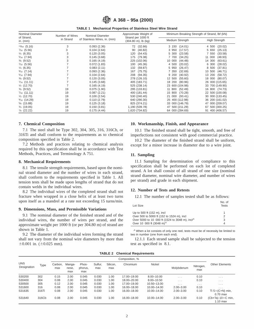
7. Chemical Composition
7.1 The steel shall be Type 302, 304, 305, 316, 316Cb, or316Ti and shall conform to the requirements as to chemicalcomposition specified in Table 2.
7.2 Methods and practices relating to chemical analysisrequired by this specification shall be in accordance with TestMethods, Practices, and Terminology A 751.
8. Mechanical Requirements
8.1 The tensile strength requirements, based upon the nomi-nal strand diameter and the number of wires in each strand,shall conform to the requirements specified in Table 1. Alltension tests shall be made upon lengths of strand that do notcontain welds in the individual wires.
8.2 The individual wires of the completed strand shall notfracture when wrapped in a close helix of at least two turnsupon itself as a mandrel at a rate not exceeding 15 turns/min.
9. Dimensions, Mass, and Permissible Variations
9.1 The nominal diameter of the finished strand and of theindividual wires, the number of wires per strand, and theapproximate weight per 1000 ft (or per 304.80 m) of strand areshown in Table 1.
9.2 The diameter of the individual wires forming the strandshall not vary from the nominal wire diameters by more than60.001 in. (60.025 mm).
10. Workmanship, Finish, and Appearance
10.1 The finished strand shall be tight, smooth, and free ofimperfections not consistent with good commercial practice.
10.2 The diameter of the finished strand shall be uniform,except for a minor increase in diameter due to a wire joint.
11. Sampling
11.1 Sampling for determination of compliance to thisspecification shall be performed on each lot of completedstrand. A lot shall consist of all strand of one size (nominalstrand diameter, nominal wire diameter, and number of wiresper strand) and grade in each shipment.
12. Number of Tests and Retests
12.1 The number of samples tested shall be as follows:
Lot SizeNo. ofTests
Up to 500 ft (152 m), incl 1Over 500 to 5000 ft (152 to 1524 m), incl 2Over 5000 to 10 000 ft (1524 to 3048 m), inclA 3Over 10 000 ft (3048 m)A 4
A When a lot consists of only one reel, tests must be of necessity be limited totwo in number (one from each end).
12.1.1 Each strand sample shall be subjected to the tensiontest as specified in 8.1.
TABLE 1 Mechanical Properties of Stainless Steel Wire Strand
Nominal Diameterof Strand,in. (mm)
Number of Wiresin Strand
Nominal Diameterof Stainless Wires, in. (mm)
Approximate Weight ofStrand per 1000 ft(304.80 m), lb (kg)
Minimum Breaking Strength of Strand, lbf (kN)
Medium Strength High Strength
13⁄64 (5.16) 3 0.093 (2.36) 72 (32.66) 3 150 (14.01) 4 500 (20.02)7⁄32 (5.56) 3 0.104 (2.64) 90 (40.82) 3 950 (17.57) 5 650 (25.13)1⁄4 (6.35) 3 0.120 (3.05) 120 (54.43) 5 300 (23.58) 7 550 (33.58)5⁄16 (7.94) 3 0.145 (3.68) 175 (79.38) 7 700 (34.25) 11 000 (48.93)3⁄8 (9.52) 3 0.165 (4.19) 225 (102.06) 10 000 (44.48) 14 300 (63.61)7⁄32 (5.56) 7 0.072 (1.83) 100 (45.36) 4 500 (20.02) 6 300 (28.02)1⁄4 (6.35) 7 0.083 (2.11) 132 (59.87) 5 950 (26.47) 8 500 (37.81)9⁄32 (7.14) 7 0.093 (2.36) 167 (75.75) 7 350 (32.69) 10 500 (46.71)5⁄16 (7.94) 7 0.104 (2.64) 208 (94.35) 9 200 (40.92) 13 200 (58.72)3⁄8 (9.52) 7 0.120 (3.05) 278 (126.10) 12 500 (55.60) 18 000 (80.07)7⁄16 (11.11) 7 0.145 (3.68) 405 (183.71) 18 200 (80.96) 26 000 (115.65)1⁄2 (12.70) 7 0.165 (4.19) 525 (238.14) 23 600 (104.98) 33 700 (149.90)3⁄8 (9.52) 19 0.075 (1.90) 295 (133.81) 11 800 (52.49) 16 800 (74.73)7⁄16 (11.11) 19 0.087 (2.21) 400 (181.44) 15 800 (70.28) 22 500 (100.08)1⁄2 (12.70) 19 0.100 (2.54) 530 (240.40) 21 000 (93.41) 30 000 (133.45)9⁄16 (14.29) 19 0.110 (2.79) 640 (290.30) 25 400 (112.98) 36 200 (161.02)5⁄8 (15.88) 19 0.125 (3.18) 825 (374.21) 33 000 (146.79) 47 000 (209.07)3⁄4 (19.05) 19 0.150 (3.81) 1,190 (539.78) 47 500 (211.29) 67 500 (300.25)7⁄8 (22.22) 19 0.175 (4.44) 1,620 (734.82) 64 000 (284.69) 91 400 (406.57)
TABLE 2 Chemical Requirements
UNSDesignation
Type
Composition, %
Carbon,max
Manga-nese,max
Phos-phorus,
max
Sulfur,max
Silicon,max
Chromium NickelMolybdenum
Nitrogen,max
Other Elements
S30200 302 0.15 2.00 0.045 0.030 1.00 17.00–19.00 8.00–10.00 . . . 0.10 . . .S30400 304 0.08 2.00 0.045 0.030 1.00 18.00–20.00 8.00–10.50 . . . 0.10 . . .S30500 305 0.12 2.00 0.045 0.030 1.00 17.00–19.00 10.50–13.00 . . . . . . . . .S31600 316 0.08 2.00 0.045 0.030 1.00 16.00–18.00 10.00–14.00 2.00–3.00 0.10 . . .S31635 316Ti 0.08 2.00 0.045 0.030 1.00 16.00–18.00 10.00–14.00 2.00–3.00 0.10 Ti 53(C+N) min,
0.70 maxS31640 316Cb 0.08 2.00 0.045 0.030 1.00 16.00–18.00 10.00–14.00 2.00–3.00 0.10 (Cb+Ta) 103C min,
1.10 max
A 368 – 95a (2000)
2
12.1.2 In addition to the strand testing specified in12.1.1,the individual wires shall be subjected to the wrapping testspecified in 8.2. The number of individual wires to be testedfrom each strand shall be as follows:
3-wire strand: test all 3 wires7-wire strand: test any 4 wires19-wire strand: test 3 wires from each layer (inner and outer layer),
for a total of 6 tests
12.2 In case of reasonable doubt in the first tests as to thefailure of the wire or strand to meet any requirement of thisspecification, two additional tests shall be made on samples ofwire or strand from the same coil (or reel). If failure occurs ineither of these tests, the lot shall be rejected. However, theproducer may, at his option, requalify individual coils (or reels)by performing the required tests on an individual coil (or reel)basis.
13. Packaging and Marking
13.1 Wire strand shall be furnished in standard lengths (see13.1.1) and in compact coils or on reels (see 13.1.2) as
specified by the purchaser; otherwise lengths shall be as agreedupon at the time of purchase.
13.1.1 Standard lengths of strand are as follows: 100 ft(30.48 m), 250 ft (76.2 m), 500 ft (152.40 m), 1000 ft (304.80m), 2500 ft (762.00 m), and 5000 ft (1524.00 m).
13.1.2 Standard practice is to furnish all strand of7⁄16 in.(11.11 mm) and over in diameter on reels in lengths of 1000 ft(304.80 m) and over. Strand lengths of less than 1000 ft areregularly furnished in coils.
13.2 The strand shall be protected against damage in ordi-nary handling and shipping as agreed upon at the time ofpurchase. Each coil (or reel) shall have a strong weather-prooftag securely fastened to it showing the minimum breakingstrength, the nominal diameter of the strand, the length of thestrand, the steel type designation, ASTM Designation A 368dated _____, and the name or mark of the manufacturer.
14. Keywords
14.1 stainless steel; wire strand
ASTM International takes no position respecting the validity of any patent rights asserted in connection with any item mentionedin this standard. Users of this standard are expressly advised that determination of the validity of any such patent rights, and the riskof infringement of such rights, are entirely their own responsibility.
This standard is subject to revision at any time by the responsible technical committee and must be reviewed every five years andif not revised, either reapproved or withdrawn. Your comments are invited either for revision of this standard or for additional standardsand should be addressed to ASTM International Headquarters. Your comments will receive careful consideration at a meeting of theresponsible technical committee, which you may attend. If you feel that your comments have not received a fair hearing you shouldmake your views known to the ASTM Committee on Standards, at the address shown below.
This standard is copyrighted by ASTM International, 100 Barr Harbor Drive, PO Box C700, West Conshohocken, PA 19428-2959,United States. Individual reprints (single or multiple copies) of this standard may be obtained by contacting ASTM at the aboveaddress or at 610-832-9585 (phone), 610-832-9555 (fax), or [email protected] (e-mail); or through the ASTM website(www.astm.org).
A 368 – 95a (2000)
3

Designation: A 380 – 99 e1
Standard Practice forCleaning, Descaling, and Passivation of Stainless SteelParts, Equipment, and Systems 1
This standard is issued under the fixed designation A 380; the number immediately following the designation indicates the year oforiginal adoption or, in the case of revision, the year of last revision. A number in parentheses indicates the year of last reapproval. Asuperscript epsilon (e) indicates an editorial change since the last revision or reapproval.
This standard has been approved for use by agencies of the Department of Defense.
e1 NOTE—Table A2.1 was corrected editorially in January 2000.
1. Scope
1.1 This practice covers recommendations and precautionsfor cleaning, descaling, and passivating of new stainless steelparts, assemblies, equipment, and installed systems. Theserecommendations are presented as procedures for guidancewhen it is recognized that for a particular service it is desiredto remove surface contaminants that may impair the normalcorrosion resistance, or result in the later contamination of theparticular stainless steel grade, or cause product contamination.For certain exceptional applications, additional requirementswhich are not covered by this practice may be specified uponagreement between the manufacturer and the purchaser. Al-though they apply primarily to materials in the compositionranges of the austenitic, ferritic, and martensitic stainlesssteels, the practices described may also be useful for cleaningother metals if due consideration is given to corrosion andpossible metallurgical effects.
1.1.1 The term passivation is commonly applied to severaldistinctly different operations or processes relating to stainlesssteels. In order to avoid ambiguity in the setting of require-ments, it may be necessary for the purchaser to define preciselythe intended meaning of passivation. Some of the variousmeanings associated with the term passivation that are incommon usage include the following:
1.1.1.1 Passivation is the process by which a stainless steelwill spontaneously form a chemically inactive surface whenexposed to air or other oxygen-containing environments. It wasat one time considered that an oxidizing treatment was neces-sary to establish this passive film, but it is now accepted thatthis film will form spontaneously in an oxygen-containingenvironment providing that the surface has been thoroughlycleaned or descaled.
1.1.1.2 Passivation is removal of exogenous iron or ironcompounds from the surface of a stainless steel by means of achemical dissolution, most typically by a treatment with anacid solution that will remove the surface contamination butwill not significantly affect the stainlees steel itself. Thisprocess is described in a general way in 6.2.11 and definedprecisely in 6.4 with further reference to the requirements ofAnnex A2 and Part II of the table on acid cleaning of steel.Unless otherwise specified, it is this definition of passivationthat is taken as the meaning of a specified requirement forpassivation.
1.1.1.3 Passivation is the chemical treatment of a stainlesssteel with a mild oxidant, such as a nitric acid solution, for thepurpose of enhancing the spontaneous formation of the protec-tive passive film. Such chemical treatment is generally notnecessary for the formation of the passive film.
1.1.1.4 Passivation does not indicate the separate process ofdescaling as described in Section 5, although descaling may benecessary before passivation can be effective.
1.2 This practice does not cover decontamination or clean-ing of equipment or systems that have been in service, nor doesit cover descaling and cleaning of materials at the mill. On theother hand, some of the practices may be applicable for thesepurposes. While the practice provides recommendations andinformation concerning the use of acids and other cleaning anddescaling agents, it cannot encompass detailed cleaning proce-dures for specific types of equipment or installations. Ittherefore in no way precludes the necessity for careful planningand judgment in the selection and implementation of suchprocedures.
1.3 These practices may be applied when free iron, oxidescale, rust, grease, oil, carbonaceous or other residual chemicalfilms, soil, particles, metal chips, dirt, or other nonvolatiledeposits might adversely affect the metallurgical or sanitarycondition or stability of a surface, the mechanical operation ofa part, component, or system, or contaminate a process fluid.The degree of cleanness required on a surface depends on theapplication. In some cases, no more than degreasing or removal
1 This practice is under the jurisdiction of ASTM Committee A-1 on Steel,Stainless Steel, and Related Alloys and is the direct responsibility of SubcommitteeA01.14 on Methods of Corrosion Testing.
Current edition approved Sept. 10, 1999. Published November 1999. Originallypublished as A 380 – 54 T. Last previous edition A 380 – 96.
1
Copyright © ASTM International, 100 Barr Harbor Drive, PO Box C700, West Conshohocken, PA 19428-2959, United States.

of gross contamination is necessary. Others, such as food-handling, pharmaceutical, aerospace, and certain nuclear ap-plications, may require extremely high levels of cleanness,including removal of all detectable residual chemical films andcontaminants that are invisible to ordinary inspection methods.
NOTE 1—The term “iron,” when hereinafter referred to as a surfacecontaminant, shall denote free iron.
1.4 Attainment of surfaces that are free of iron, metallicdeposits, and other contamination depends on a combination ofproper design, fabrication methods, cleaning and descaling,and protection to prevent recontamination of cleaned surfaces.Meaningful tests to establish the degree of cleanness of asurface are few, and those are often difficult to administer andto evaluate objectively. Visual inspection is suitable for thedetection of gross contamination, scale, rust, and particulates,but may not reveal the presence of thin films of oil or residualchemical films. In addition, visual inspection of internalsurfaces is often impossible because of the configuration of theitem. Methods are described for the detection of free iron andtransparent chemical and oily deposits.
1.5 This standard does not purport to address all of thesafety concerns, if any, associated with its use. It is theresponsibility of the user of this standard to establish appro-priate safety and health practices and determine the applica-bility of regulatory limitations prior to use.(For more specificsafety precautions see 7.2.5.3, 7.3.4, Section 8, A1.7, andA2.11.)
2. Referenced Documents
2.1 ASTM Standards:F 21 Test Method for Hydrophobic Surface Films by the
Atomizer Test2
F 22 Test Method for Hydrophobic Surface Films by theWater-Break Test2
2.2 Federal Standard:Fed. Std. No. 209e for Clean Room and Work Station
Requiring Controlled Environments3
3. Design
3.1 Consideration should be given in the design of parts,equipment, and systems that will require cleaning to minimizethe presence of crevices, pockets, blind holes, undrainablecavities, and other areas in which dirt, cleaning solutions, orsludge might lodge or become trapped, and to provide foreffective circulation and removal of cleaning solutions. Inequipment and systems that will be cleaned in place or thatcannot be immersed in the cleaning solution, it is advisable toslope lines for drainage: to provide vents at high points anddrains at low points of the item or system; to arrange forremoval or isolation of parts that might be damaged by thecleaning solution or fumes from the cleaning solutions; toprovide means for attaching temporary fill and circulationlines; and to provide for inspection of cleaned surfaces.
3.2 In a complex piping system it may be difficult todetermine how effective a cleaning operation has been. Onemethod of designing inspectability into the system is to providea short flanged length of pipe (that is, a spool piece) at alocation where the cleaning is likely to be least effective; thespool piece can then be removed for inspection upon comple-tion of cleaning.
4. Precleaning
4.1 Precleaning is the removal of grease, oil, paint, soil, grit,and other gross contamination preparatory to a fabricationprocess or final cleaning. Precleaning is not as critical and isgenerally not as thorough as subsequent cleaning operations.Materials should be precleaned before hot-forming, annealing,or other high-temperature operation, before any descalingoperation, and before any finish-cleaning operation where theparts will be immersed or where the cleaning solutions will bereused. Items that are subject to several redraws or a series ofhot-forming operations, with intermediate anneals, must becleaned after each forming operation, prior to annealing.Precleaning may be accomplished by vapor degreasing; im-mersion in, spraying, or swabbing with alkaline or emulsioncleaners, steam, or high-pressure water-jet (see 6.2).
5. Descaling
5.1 General—Descaling is the removal of heavy, tightlyadherent oxide films resulting from hot-forming, heat-treatment, welding, and other high-temperature operations.Because mill products are usually supplied in the descaledcondition, descaling (except removal of localized scale result-ing from welding) is generally not necessary during fabricationof equipment or erection of systems (see 6.3). When neces-sary, scale may be removed by one of the chemical methodslisted below, by mechanical methods (for example, abrasiveblasting, sanding, grinding, power brushing), or by a combi-nation of these.
5.2 Chemical Descaling (Pickling)—Chemical descalingagents include aqueous solutions of sulfuric, nitric, and hydrof-luoric acid as described in Annex A1, Table A1.1, molten alkalior salt baths, and various proprietary formulations.
5.2.1 Acid Pickling— Nitric-hydrofluoric acid solution ismost widely used by fabricators of stainless steel equipmentand removes both metallic contamination, and welding andheat-treating scales. Its use should be carefully controlled andis not recommended for descaling sensitized austenitic stain-less steels or hardened martensitic stainless steels or where itcan come into contact with carbon steel parts, assemblies,equipment, and systems. See also A1.3. Solutions of nitric acidalone are usually not effective for removing heavy oxide scale.
5.2.2 Surfaces to be descaled are usually precleaned prior tochemical treatment. When size and shape of product permit,total immersion in the pickling solution is preferred. Whereimmersion is impractical, descaling may be accomplished by(1) wetting the surfaces by swabbing or spraying; or (2) bypartially filling the item with pickling solution and rotating orrocking to slosh the solution so that all surfaces receive therequired chemical treatment. The surface should be kept incontact with agitated solution for about 15 to 30 min or until
2 Annual Book of ASTM Standards,Vol 10.05.3 Available from Standardization Documents Order Desk, Bldg 4 Section D, 700
Robbins Ave., Philadelphia, PA 19111-5094, Attn: NPODS.
A 380 – 99e1
2
inspection shows that complete scale removal has been accom-plished. Without agitation, additional exposure time may berequired. If rocking or rotation are impracticable, picklingsolution may be circulated through the item or system untilinspection shows that descaling has been accomplished.
5.2.3 Over-pickling must be avoided. Uniform removal ofscale with acid pickling depends on the acid used, acidconcentration, solution temperature, and contact time (seeAnnex A1). Continuous exposure to pickling solutions formore than 30 min is not recommended. The item should bedrained and rinsed after 30 min and examined to check theeffectiveness of the treatment. Additional treatment may berequired. Most pickling solutions will loosen weld and heat-treating scale but may not remove them completely. Intermit-tent scrubbing with a stainless steel brush or fiber-bristle brush,in conjunction with pickling or the initial rinse, may facilitatethe removal of scale particles and products of chemicalreaction (that is, picklingsmut).
5.2.4 After chemical descaling, surfaces must be thoroughlyrinsed to remove residual chemicals; a neutralization step issometimes necessary before final rinsing. To minimize stain-ing, surfaces must not be permitted to dry between successivesteps of the acid descaling and rinsing procedure, and thoroughdrying should follow the final water rinse. Chemical descalingmethods, factors in their selection, and precautions in their useare described in theMetals Handbook.4 When chemicaldescaling is necessary, it should be done while the part is in itssimplest possible geometry, before subsequent fabrication orinstallation steps create internal crevices or undrainable spacesthat may trap descaling agents, sludge, particles, or contami-nated rinse water that might either result in eventual corrosionor adversely affect operation of the item after it is placed inservice.
5.3 Mechanical Descaling—Mechanical descaling methodsinclude abrasive blasting, power brushing, sanding, grinding,and chipping. Procedural requirements and precautions forsome of these methods are given in theMetals Handbook.4
Mechanical descaling methods have the advantage that they donot produce such physical or chemical conditions as inter-granular attack, pitting, hydrogen embrittlement, cracks, orsmut deposits. For some materials, in particular the austeniticstainless steels when in the sensitized condition and themartensitic stainless steels when in the hardened condition,mechanical descaling may be the only suitable method. Grind-ing is usually the most effective means of removing localizedscale such as that which results from welding. Disadvantagesof mechanical descaling are cost, as compared to chemicaldescaling, and the fact that surface defects (for example, laps,pits, slivers) may be obscured, making them difficult to detect.
5.3.1 Surfaces to be descaled may have to be precleaned.Particular care must be taken to avoid damage by mechanicalmethods when descaling thin sections, polished surfaces, andclose-tolerance parts. After mechanical descaling, surfacesshould be cleaned by scrubbing with hot water and fiberbrushes, followed by rinsing with clean, hot water.
5.3.2 Grinding wheels and sanding materials should notcontain iron, iron oxide, zinc, or other undersirable materialsthat may cause contamination of the metal surface. Grindingwheels, sanding materials, and wire brushes previously used onother metals should not be used on stainless steel. Wire brushesshould be of a stainless steel which is equal in corrosionresistance to the material being worked on.
5.3.3 Clean, previously unused abrasives, such as glassbeads or iron-free silica or alumina sand, are recommended forabrasive blasting. Steel shot or grit is generally not recom-mended because of the possibility of embedding iron particles.The use of stainless steel shot or grit reduces the danger ofrusting and iron contamination, but cannot completely elimi-nate the possibility of embedding residues of iron-oxide scale.
5.3.4 If a totally iron and scale free surface is required, mostabrasive blasting may be followed by a brief acid dip (seeAnnex A2).
6. Cleaning
6.1 General—Cleaning includes all operations necessaryfor the removal of surface contaminants from metals to ensure(1) maximum corrosion resistance of the metal; (2) preventionof product contamination; and (3) achievement of desiredappearance. Cleanness is a perishable condition. Careful plan-ning is necessary to achieve and maintain clean surfaces,especially where a high degree of cleanness is required.Selection of cleaning processes is influenced mainly by thetype of contaminant to be removed, the required degree ofcleanness, and cost. If careful control of fabrication processes,sequencing of cleaning and fabrication operations, and mea-sures to prevent recontamination of cleaned surfaces areexercised, very little special cleaning of the finished item orsystem may be necessary to attain the desired level ofcleanness. If there is a question concerning the effectiveness ofcleaning agents or procedures, or the possible adverse effectsof some cleaning agents or procedures on the materials to becleaned, trial runs, using test specimens and sensitive inspec-tion techniques may be desirable. Descriptions, processes, andprecautions to be observed in cleaning are given in theMetalsHandbook.4 Proprietary cleaners may contain harmful ingredi-ents, such as chlorides or sulfur compounds, which couldadversely affect the performance of a part, equipment, orsystem under service conditions. It is recommended that themanufacturer of the cleaner be consulted if there is reason forconcern.
NOTE 2—Instances are known where stainless steel vessels have stresscracked before start-up due to steaming out or boiling out with achloride-containing detergent.
6.2 Cleaning Methods— Degreasing and general cleaningmay be accomplished by immersion in, swabbing with, orspraying with alkaline, emulsion, solvent, or detergent cleanersor a combination of these; by vapor degreasing; by ultrasonicsusing various cleaners; by steam, with or without a cleaner; orby high-pressure water-jetting. The cleaning method availableat any given time during the fabrication or installation of acomponent or system is a function of the geometric complexityof the item, the type of contamination present, the degree ofcleanliness required, and cost. Methods commonly used for
4 “Surface Cleaning, Finishing, and Coating,’’Metals Handbook,Am. Soc.Metals, 9th ed., Vol 5, 1982.
A 380 – 99e1
3

removing deposited contaminants (as opposed to scale) aredescribed briefly below and in greater detail (including factorsto be considered in their selection and use) in theMetalsHandbook4and theSSPC Steel Structures Painting Handbook.5
The safety precautions of 8.6 must be observed in the use ofthese methods. Particular care must be exercised when clean-ing closed systems and items with crevices or internal voids toprevent retention of cleaning solutions and residues.
6.2.1 Alkaline Cleaningis used for the removal of oily,semisolid, and solid contaminants from metals. To a greatextent the solutions used depend on their detergent qualities forcleaning action and effectiveness. Agitation and temperature ofthe solution are important.
6.2.2 Emulsion Cleaningis a process for removing oilydeposits and other common contaminants from metals by theuse of common organic solvents dispersed in an aqueoussolution with the aid of a soap or other emulsifying agent (anemulsifying agent is one which increases the stability of adispersion of one liquid in another). It is effective for removinga wide variety of contaminants including pigmented andunpigmented drawing compounds and lubricants, cutting flu-ids, and residues resulting from liquid penetrant inspection.Emulsion cleaning is used when rapid, superficial cleaning isrequired and when a light residual film of oil is not objection-able.
6.2.3 Solvent Cleaning is a process for removing contami-nants from metal surfaces by immersion or by spraying orswabbing with common organic solvents such as the aliphaticpetroleums, chlorinated hydrocarbons, or blends of these twoclasses of solvents. Cleaning is usually performed at or slightlyabove room temperature. Except for parts with extremelyheavy contamination or with hard-to-reach areas, or both, goodagitation will usually eliminate the need for prolonged soaking.Virtually all metal can be cleaned with the commonly usedsolvents unless the solvent has become contaminated with acid,alkali, oil, or other foreign material. Chlorinated solvents arenot recommended for degreasing of closed systems or itemswith crevices or internal voids.
6.2.4 Vapor Degreasing is a generic term applied to acleaning process that employs hot vapors of a volatile chlori-nated solvent to remove contaminants, and is particularlyeffective against oils, waxes, and greases. The cleanness andchemical stability of the degreasing solvent are critical factorsin the efficiency of the vapor and possible chemical attack ofthe metal. Water in the degreasing tank or on the item beingcleaned may react with the solvent to form hydrochloric acid,which may be harmful to the metal. No water should be presentin the degreasing tank or on the item being cleaned. Acids,oxidizing agents, and cyanides must be prevented from con-taminating the solvent. Materials such as silicones causefoaming at the liquid-vapor interface and may result inrecontamination of the workpiece as it is removed from thedegreaser. Vapor degreasing with chlorinated solvents is notrecommended for closed systems or items with internal voidsor crevices.
6.2.5 Ultrasonic Cleaningis often used in conjunction withcertain solvent and detergent cleaners to loosen and removecontaminants from deep recesses and other difficult to reachareas, particularly in small work-pieces. Cavitation in theliquid produced by the high frequency sound causes microagitation of the solvent in even tiny recesses of the workpiece,making the method especially desirable for cleaning parts orassemblies having an intricate configuration. For extremelyhigh levels of surface cleanness, high-purity solvents (1 ppmtotal nonvolatile residue) are required.
6.2.6 Synthetic Detergentsare extensively used as surface-active agents because they are freer rinsing than soaps, aid insoils dispersion, and prevent recontamination. They are effec-tive for softening hard water and in lowering the surface andinterfacial tensions of the solutions. Synthetic detergents, inparticular, should be checked for the presence of harmfulingredients as noted in 6.1.
6.2.7 Chelate Cleaning— Chelates are chemicals that formsoluble, complex molecules with certain metal ions, inactivat-ing the ions in solution so they cannot normally react withanother element or ions to produce precipitates or scale. Theyenhance the solubility of scales and certain other contaminants,do not precipitate different scales when the cleaning solutionbecomes spent, and can be used on some scales and contami-nants that even mineral acids will not attack. When properlyused (chelating agents must be continuously circulated andmust be maintained within carefully controlled temperaturelimits), intergranular attack, pitting, and other harmful effectsare minimal. Chelating agents are particularly useful forcleaning installed equipment and systems.
6.2.8 Mechanical Cleaning(also see 5.3)—Abrasive blast-ing, vapor blasting using a fine abrasive suspended in water,grinding, or wire brushing are often desirable for removingsurface contaminants and rust. Cleanliness of abrasives andcleaning equipment is extremely important to prevent recon-tamination of the surfaces being cleaned. Although surfacesmay appear visually clean following such procedures, residualfilms which could prevent the formation of an optimum passivecondition may still be present. Subsequent treatment such asadditional iron-free abrasive cleaning methods, acid cleaning,passivation, or combinations of these is, therefore, required forstainless steel parts, equipment, and systems to be used wherecorrosion resistance is a prime factor to satisfy performanceand service requirements, or where product contaminationmust be avoided.
6.2.9 Steam Cleaning is used mostly for cleaning bulkyobjects that are too large for soak tanks or spray-washingequipment. It may be used with cleaning agents such asemulsions, solvents, alkalis, and detergents. Steam lances arefrequently used for cleaning piping assemblies. Steam pres-sures from 50 to 75 psi (345 to 515 kPa) are usually adequate(see 6.1).
6.2.10 Water-Jetting at water pressures of up to 10 000 psi(70 mPa) is effective for removing grease, oils, chemicaldeposits (except adsorbed chemicals), dirt, loose and moder-ately adherent scale, and other contaminants that are notactually bonded to the metal. The method is particularlyapplicable for cleaning piping assemblies which can withstand
5 Good Painting Practices,Steel Structures Painting Council, Vol 1, 1982,Chapters 2.0–2.9, 3.1–3.2.
A 380 – 99e1
4
the high pressures involved; self-propelled nozzles or “moles”are generally used for this purpose.
6.2.11 Acid Cleaning is a process in which a solution of amineral or organic acid in water, sometimes in combinationwith a wetting agent or detergent or both, is employed toremove iron and other metallic contamination, light oxidefilms, shop soil, and similar contaminants. Suggested solutions,contact times, and solution temperatures for various alloys aregiven in Annex A2. Acid cleaning is not generally effective forremoval of oils, greases, and waxes. Surfaces should beprecleaned to remove oils and greases before acid cleaning.Common techniques for acid cleaning are immersion, swab-bing, and spraying. Maximum surface quality is best achievedby using a minimum cleaning time at a given acid concentra-tion and temperature. After acid cleaning the surfaces must bethoroughly rinsed with clean water to remove all traces of theacid and thoroughly dried after the final water rinse. Tominimize staining, surfaces must not be permitted to drybetween successive steps of the acid cleaning and rinsingprocedure. A neutralizing treatment may be required undersome conditions; if used, neutralization must be followed byrepeated water rinsing to remove all trace of the neutralizingagent followed by thorough drying after the final water rinse.Acid cleaning is not recommended where mechanical cleaningor other chemical methods will suffice on the basis of intendeduse and, as may be necessary, on inspection tests (see 7.2 and7.3). Requirements for superfluous cleaning and inspectiontesting can result in excessive costs. Acid cleaning, if notcarefully controlled, may damage the surface and may result infurther contamination of the surface.
6.3 Cleaning of Welds and Weld-Joint Areas—The joint areaand surrounding metal for several inches back from the jointpreparation, on both faces of the weld, should be cleanedimmediately before starting to weld. Cleaning may be accom-plished by brushing with a clean stainless steel brush orscrubbing with a clean, lint-free cloth moistened with solvent,or both. When the joint has cooled after welding, remove allaccessible weld spatter, welding flux, scale, arc strikes, etc., bygrinding. According to the application, some scale or heattemper may be permissible on the nonprocess side of a weld,but should be removed from the process side if possible. Ifchemical cleaning of the process side of the weld is deemednecessary, the precautions of this standard must be observed.Austenitic stainless steels in the sensitized condition shouldgenerally not be descaled with nitric-hydrofluoric acid solu-tions. Welds may also be cleaned as described in Table A2.1,Part III, TreatmentP andQ (also see 5.2.3 and 5.2.4).
6.4 Final Cleaning or Passivation, or Both—If proper carehas been taken in earlier fabrication and cleaning, finalcleaning may consist of little more than scrubbing with hotwater or hot water and detergent (such as trisodium phosphate,TSP), using fiber brushes. Detergent washing must be followedby a hot-water rinse to remove residual chemicals. Spotcleaning to remove localized contamination may be accom-plished by wiping with a clean, solvent-moistened cloth. If thepurchaser specifies passivation, the final cleaning shall be inaccordance with the requirements of Table A2.1, Part II. Whenthe stainless steel parts are to be used for applications where
corrosion resistance is a prime factor to achieve satisfactoryperformance and service requirements, or where product con-tamination must be avoided, passivation followed by thoroughrinsing several times with hot water and drying thoroughlyafter the final water rinse is recommended, whenever practical.
6.5 Precision Cleaning—Certain nuclear, space, and otherespecially critical applications may require that only veryhigh-purity alcohols, acetone, ketones, or otherprecisioncleaning agentsbe used for final cleaning or recleaning ofcritical surfaces after fabrication advances to the point thatinternal crevices, undrainable spaces, blind holes, or surfacesthat are not accessible for thorough scrubbing, rinsing, andinspection are formed. Such items are often assembled underclean-room conditions (see 8.5.5) and require approval, by thepurchaser, of carefully prepared cleaning procedures before thestart of fabrication.
6.6 Cleaning of Installed Systems—There are two ap-proaches to cleaning installed systems. In the first, which isprobably adequate for most applications, cleaning solutions arecirculated through the completed system after erection, takingcare to remove or protect items that could be damaged duringthe cleaning operation. In the second approach, which may berequired for gaseous or liquid oxygen, liquid metal, or otherreactive-process solutions, piping and components are installedin a manner to avoid or minimize contamination of process-solution surfaces during erection so that little additionalcleaning is necessary after erection; post-erection flushing, ifnecessary, is done with the process fluid. If process surfaces arecoated with an appreciable amount of iron oxide, a chelatingtreatment or high-pressure water-jetting treatment should beconsidered in place of acid treatment (see 6.2.7 and 6.2.10).
6.6.1 Post-Erection Cleaning—Circulate hot water to whicha detergent has been added, for at least 4 to 8 h. A watertemperature of at least 140 to 160°F (60 to 71°C) is recom-mended (see 6.1). Rinse by circulating clean hot water until theeffluent is clear. If excessive particulate matter is present, thecleaning cycle may be preceded with a high-pressure steamblow, repeating as necessary until a polished-aluminum targeton the outlet of the system is no longer dulled and scratched byparticulates loosened by the high-velocity steam. Valves andsimilar items must be protected from damage during a steamblow.
6.6.2 If metallic iron is indicated by one of the methodssuggested in Section 7, it can be removed by circulating one ofthe acid cleaning solutions suggested in Annex A2 at roomtemperature until laboratory determination for iron, made onsamples of the solution taken hourly, indicates no furtherincrease in iron content, after which circulation may be stoppedand the system drained. After this treatment, circulate clean hotwater (that is, without detergent) through the system for 4 h toremove all traces of acid and corrosion product resulting fromthe acid treatment, or until the pH of the rinse water returns toneutral.
6.6.3 In critical systems where post-erection cleaning is notdesirable (for example, liquid oxygen or nuclear reactorprimary coolant systems), on-site erection may be conductedunder clean-room conditions. Erection instructions may requirethat wrapping and seals of incoming materials and equipment
A 380 – 99e1
5

be kept intact until the item is inside the clean area, and thatcareful surveillance be exercised to prevent foreign materials(for example, cleaning swabs or tools) from being dropped orleft in the system. Where contamination does occur, thecleaning procedure usually is developed through consultationbetween the erector and the purchaser (or his site representa-tive). Frequently, post-erection flushing is accomplished bycirculating the process fluid through the system until contami-nation is reduced to tolerable levels.
6.6.4 When cleaning critical installed systems, do not per-mit the process surfaces to dry between successive cleaningand rinsing steps, or between the final rinse and filling with thelayup solution.
7. Inspection After Cleaning
7.1 General—Inspection techniques should represent care-ful, considered review of end use requirements of parts,equipment, and systems. There is no substitute for good,uniform, cleaning practices which yield a metallurgicallysound and smooth surface, followed by adequate protection topreserve that condition. Establishment of the most reliable testsand test standards for cleanness are helpful in attaining thedesired performance of parts, equipment, and systems. Testingshould be sufficiently extensive to ensure the cleanness of allsurfaces exposed to process fluids when in service. Thefollowing represent some tests that have been successfullyapplied to stainless steels. The purchaser shall have the optionof specifying in his purchase documents that any of thesequality assurance tests be used as the basis for acceptability ofthe cleanness or state of passivity of the stainless steel item.
7.2 Gross Inspection:7.2.1 Visual—Items cleaned in accordance with this practice
should be free of paint, oil, grease, welding flux, slag,heat-treating and hot-forming scale (tightly adherent scaleresulting from welding may be permissible on some surfaces),dirt, trash, metal and abrasive particles and chips, and othergross contamination. Some deposited atmospheric dust willnormally be present on exterior surfaces but should not bepresent on interior surfaces. Visual inspection should be carriedout under a lighting level, including both general and supple-mentary lighting, of at least 100 footcandles (1076 lx), andpreferably 250 footcandles (2690 lx) on the surfaces beinginspected. Visual inspection should be supplemented withborescopes, mirrors, and other aids, as necessary, to properlyexamine inaccessible or difficult-to-see surfaces. Lights shouldbe positioned to prevent glare on the surfaces being inspected.
7.2.2 Wipe Tests—Rubbing of a surface with a clean,lint-free, white cotton cloth, commercial paper product, or filterpaper moistened (but not saturated) with high-purity solvent(see 6.5), may be used for evaluating the cleanness of surfacesnot accessible for direct visual inspection. Wipe tests of smalldiameter tubing are made by blowing a clean white felt plug,slightly larger in diameter than the inside diameter of the tube,through the tube with clean, dry, filtered compressed air.Cleanness in wipe tests is evaluated by the type of contamina-tion rubbed off on the swab or plug. The presence of a smudgeon the cloth is evidence of contamination. In cases of disputeconcerning the harmful nature of the contamination, a sampleof the smudge may be transferred to a clean quartz microscope
slide for infrared analysis. The wipe test is sometimes supple-mented by repeating the test with a black cloth to disclosecontaminants that would be invisible on a white cloth.
7.2.3 Residual Pattern—Dry the cleaned surface afterfinish-cleaning at 120°F (49°C) for 20 min. The presence ofstains or water spots on the dried surfaces indicates thepresence of residual soil and incomplete cleaning. The test israpid but not very sensitive.
7.2.4 Water-Break Test—This is a test for the presence ofhydrophobic contaminants on a cleaned surface. It is applicableonly for items that can be dipped in water and should be madewith high-purity water. The test procedure and interpretation ofresults are described in Test Method F 22. The test is moder-ately sensitive.
7.2.5 Tests for Free Iron: Gross Indications—When ironcontamination is clearly visible, items should be cleaned inaccordance with this practice.
7.2.5.1 Water-Wetting and Drying—Formation of rust stainsmay be accelerated by periodically wetting the surface withpreferably distilled or deionized water or clean, fresh, potabletap water. The wet-dry cycles should be such that the sampleremains dry for a total of 8 h in a 24-h test period. Aftercompletion of this test, the surface should show no evidence ofrust stains or other corrosion products.
7.2.5.2 High-Humidity Test—Subject the surface to a 95 to100 % humidity at 100 to 115°F (38 to 46°C) in a suitablehumidity cabinet for 24 to 26 h. After completion of this test,the surface should show no evidence of rust stains or othercorrosion products.
7.2.5.3 Copper Sulfate Test—This method is recommendedfor the detection of metallic iron or iron oxide on the surface ofaustenitic 200 and 300 Series, the precipitation hardeningalloys, and the ferritic 400 Series stainless steels containing16% chromium or more. It is not recommended for themartensitic and lower chromium ferritic stainless steels of the400 Series since the test will show a positive reaction on thesematerials. This test is hypersensitive and should be used andinterpreted only by personnel familiar with its limitations.Caution: This test must not be applied to surfaces of items tobe used in food processing. The test solution is prepared by firstadding sulfuric acid to distilled water (Caution: Always addacid to cold water) and then dissolving copper sulfate in thefollowing proportions:
250-cm3 BatchDistilled waterSulfuric acid (H2SO4, sp gr 1.84) 1 cm3
Copper sulfate (CuSO4·5H2O) 4 g
Swab the surface to be inspected with test solution, applyingadditional solution if needed to keep the surface wet for aperiod of 6 min. The specimen shall be rinsed and dried in amanner not to remove any deposited copper. Copper depositwill indicate the presence of free iron.
NOTE 3—The copper sulfate test as set forth above is not applicable tosurgical and dental instruments made of hardened martensitic stainlesssteels. Instead, a specialized copper sulfate test is extensively used for thepurpose of detecting free iron and determining overall good manufactur-ing practice. Copper deposits at the surface of such instruments are wipedwith moderate vigor to determine if the copper is adherent or nonadherent.Instruments with nonadherent copper are considered acceptable. The
A 380 – 99e1
6
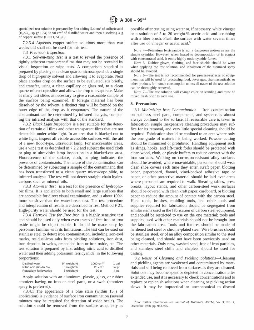
specialized test solution is prepared by first adding 5.4 cm3 of sulfuric acid(H2SO4, sp gr 1.84) to 90 cm3 of distilled water and then dissolving 4 gof copper sulfate (CuSO4·5H2O).
7.2.5.4 Aqueous copper sulfate solutions more than twoweeks old shall not be used for this test.
7.3 Precision Inspection:7.3.1 Solvent-Ring Testis a test to reveal the presence of
tightly adherent transparent films that may not be revealed byvisual inspection or wipe tests. A comparison standard isprepared by placing on a clean quartz microscope slide a singledrop of high-purity solvent and allowing it to evaporate. Nextplace another drop on the surface to be evaluated, stir briefly,and transfer, using a clean capillary or glass rod, to a cleanquartz microscope slide and allow the drop to evaporate. Makeas many test slides as necessary to give a reasonable sample ofthe surface being examined. If foreign material has beendissolved by the solvent, a distinct ring will be formed on theouter edge of the drop as it evaporates. The nature of thecontaminant can be determined by infrared analysis, compar-ing the infrared analysis with that of the standard.
7.3.2 Black Light Inspectionis a test suitable for the detec-tion of certain oil films and other transparent films that are notdetectable under white light. In an area that is blacked out towhite light, inspect all visible accessible surfaces with the aidof a new, flood-type, ultraviolet lamp. For inaccessible areas,use a wipe test as described in 7.2.2 and subject the used clothor plug to ultraviolet lamp inspection in a blacked-out area.Fluorescence of the surface, cloth, or plug indicates thepresence of contaminants. The nature of the contamination canbe determined by subjecting a sample of the contaminant, thathas been transferred to a clean quartz microscope slide, toinfrared analysis. The test will not detect straight-chain hydro-carbons such as mineral oils.
7.3.3 Atomizer Test is a test for the presence of hydropho-bic films. It is applicable to both small and large surfaces thatare accessible for direct visual examination, and is about 1003more sensitive than the water-break test. The test procedureand interpretation of results are described in Test Method F 21.High-purity water should be used for the test.
7.3.4 Ferroxyl Test for Free Ironis a highly sensitive testand should be used only when even traces of free iron or ironoxide might be objectionable. It should be made only bypersonnel familiar with its limitations. The test can be used onstainless steel to detect iron contamination, including iron-toolmarks, residual-iron salts from pickling solutions, iron dust,iron deposits in welds, embedded iron or iron oxide, etc. Thetest solution is prepared by first adding nitric acid to distilledwater and then adding potassium ferricyanide, in the followingproportions:
Distilled water 94 weight % 1000 cm3 1 galNitric acid (60–67 %) 3 weight % 20 cm3 1⁄5 ptPotassium ferricyanide 3 weight % 30 g 4 oz
Apply solution with an aluminum, plastic, glass, or rubberatomizer having no iron or steel parts, or a swab (atomizerspray is preferred).
7.3.4.1 The appearance of a blue stain (within 15 s ofapplication) is evidence of surface iron contamination (severalminutes may be required for detection of oxide scale). Thesolution should be removed from the surface as quickly as
possible after testing using water or, if necessary, white vinegaror a solution of 5 to 20 weight % acetic acid and scrubbingwith a fiber brush. Flush the surface with water several timesafter use of vinegar or acetic acid.6
NOTE 4—Potassium ferricyanide is not a dangerous poison as are thesimple cyanides. However, when heated to decomposition or in contactwith concentrated acid, it emits highly toxic cyanide fumes.
NOTE 5—Rubber gloves, clothing, and face shields should be wornwhen applying the test solution, and inhalation of the atomized sprayshould be avoided.
NOTE 6—The test is not recommended for process-surfaces of equip-ment that will be used for processing food, beverages, pharmaceuticals, orother products for human consumption unless all traces of the test solutioncan be thoroughly removed.
NOTE 7—The test solution will change color on standing and must bemixed fresh prior to each use.
8. Precautions
8.1 Minimizing Iron Contamination— Iron contaminationon stainless steel parts, components, and systems is almostalways confined to the surface. If reasonable care is taken infabrication, simple inexpensive cleaning procedures may suf-fice for its removal, and very little special cleaning should berequired. Fabrication should be confined to an area where onlythe one grade of material is being worked. Powder cuttingshould be minimized or prohibited. Handling equipment suchas slings, hooks, and lift-truck forks should be protected withclean wood, cloth, or plastic buffers to reduce contact with theiron surfaces. Walking on corrosion-resistant alloy surfacesshould be avoided; where unavoidable, personnel should wearclean shoe covers each time they enter. Kraft paper, blottingpaper, paperboard, flannel, vinyl-backed adhesive tape orpaper, or other protective material should be laid over areaswhere personnel are required to walk. Shearing tables, pressbreaks, layout stands, and other carbon-steel work surfacesshould be covered with clean kraft paper, cardboard, or blottingpaper to reduce the amount of contact with the carbon steel.Hand tools, brushes, molding tools, and other tools andsupplies required for fabrication should be segregated fromsimilar items used in the fabrication of carbon steel equipment,and should be restricted to use on the one material; tools andsupplies used with other materials should not be brought intothe fabrication area. Tools and fixtures should be made ofhardened tool steel or chrome-plated steel. Wire brushes shouldbe stainless steel, or of an alloy composition similar to the steelbeing cleaned, and should not have been previously used onother materials. Only new, washed sand, free of iron particles,and stainless steel chills and chaplets should be used forcasting.
8.2 Reuse of Cleaning and Pickling Solutions—Cleaningand pickling agents are weakened and contaminated by mate-rials and soil being removed from surfaces as they are cleaned.Solutions may become spent or depleted in concentration afterextended use, and it is necessary to check concentrations and toreplace or replenish solutions when cleaning or pickling actionslows. It may be impractical or uneconomical to discard
6 For further information seeJournal of Materials,ASTM, Vol 3, No. 4,December 1968, pp. 983-995.
A 380 – 99e1
7

solutions after a single use, even in precision cleaning opera-tions (that is, finish-cleaning using very high-purity solventsand carried out under clean-room and rigidly controlled envi-ronmental conditions). When solutions are re-used, care mustbe taken to prevent the accumulation of sludge in the bottom ofcleaning tanks; the formation of oil, scums, and undissolvedmatter on liquid surfaces; and high concentrations of emulsi-fied oil, metal or chemical ions, and suspended solids in theliquids. Periodic cleaning of vats and degreasing tanks, decant-ing, periodic bottom-drain, agitation of solutions, and similarprovisions are essential to maintain the effectiveness of solu-tions. Care must be taken to prevent water contamination oftrichloroethylene and other halogenated solvents, both while instorage and in use. Redistillation and filtering of solvents andvapor-degreasing agents are necessary before reuse. Makeup isoften required to maintain concentrations and pH of cleaningsolutions at effective levels. Do not overuse chemical cleaners,particularly acids and vapor-degreasing solvents; if light filmsor oily residues remain on the metal surfaces after use of suchagents, additional scrubbing with hot water and detergent,followed by repeated rinsing with large quantities of hot water,may be necessary.
8.3 Rinse Water—Ordinary industrial or potable waters areusually suitable for most metal-cleaning applications. Biologi-cally tested potable water should be used for final rinsing offood-handling, pharmaceutical, dairy, potable-water, and othersanitary equipment and systems. Rinsing and flushing ofcritical components and systems after finish-cleaning oftenrequires high-purity deionized water, having strict controls onhalide content, pH, resistivity, turbidity, and nonvolatile resi-dues. Analytical methods that may be used for establishing thepurity of rinse water should be demonstrated to have thesensitivity necessary to detect specified impurity levels; theanalytical methods given in theAnnual Book of ASTM Stan-dards, Vol 03.05, are recommended for referee purposes incase of dispute. To minimize the use of costly high-puritywater, preliminary rinses can often be made with somewhatlesser quality water, followed by final rinsing with the high-purity water. It is also possible in many cases to use effluent oroverflow from the final rinse operation for preliminary rinsingof other items.
8.4 Circulation of Cleaning Solutions and Rinse Water—For restricted internal surfaces (for example, small diameterpiping systems or the shell or tube side of a heat exchanger),high-velocity, turbulent flow of cleaning solutions and rinsewater may be necessary to provide the scrubbing action neededfor effective cleaning and rinsing. The velocity required is afunction of the degree of cleanness required and the size ofparticles that are permissible in the system after the start ofoperation. For example, if particles between 500 and 1000 µmare acceptable to remain, a mean flushing velocity of 1 to 2 ft/s(0.3 to 0.6 m/s) may be sufficient for pipe diameters of 2 in. andsmaller; to remove 100 to 200-µm particles, a mean flushingvelocity of 3 to 4 ft/s (0.9 to 1.2 m/s) may be required.
8.5 Protection of Cleaned Surfaces— Measures to protectcleaned surfaces should be taken as soon as final cleaning is
completed, and should be maintained during all subsequentfabrication, shipping, inspection, storage, and installation.
8.5.1 Do not remove wrappings and seals from incomingmaterials and components until they are at the use site, ready tobe used or installed. If wrappings and seals must be disturbedfor receiving inspection, do not damage them, remove no morethan necessary to carry out the inspection, and rewrap andreseal as soon as the inspection is complete. For critical itemsthat were cleaned by the supplier, and that will not be givenfurther cleaning at the use site or after installation, thecondition of seals and wrappings should be inspected regularlyand at fairly short intervals while the item is in storage.
8.5.2 Finish-cleaned materials and components should notbe stored directly on the ground or floor, and should not bepermitted, insofar as practicable, to come in contact withasphalt, galvanized or carbon steel, mercury, zinc, lead, brass,low-melting point metals, or alloys or compounds of suchmaterials. Acid cleaning of surfaces that have been in contactwith such materials may be necessary to prevent failure of theitem when subsequently heated. The use of carbon or galva-nized steel wire for bundling and galvanized steel identificationtags should be avoided.
8.5.3 Store materials and equipment, when in process, onwood skids or pallets or on metal surfaces that have beenprotected to prevent direct contact with stainless steel surfaces.Keep openings of hollow items (pipe, tubing, valves, tanks,pumps, pressure vessels, etc.,) capped or sealed at all timesexcept when they must be open to do work on the item, usingpolyethylene, nylon, TFE-fluorocarbon plastic, or stainlesssteel caps, plugs, or seals. Where cleanness of exterior surfacesis important, keep the item wrapped with clear polyethylene orTFE-fluorocarbon plastic sheet at all times except when it isactually being worked on. Avoid asphalt-containing materials.Canvas, adhesive paper or plastics such as poly(vinyl chloride)may decompose in time to form corrosive substances, forexample, when exposed to sunlight or ultraviolet light. Thereuse of caps, plugs, or packaging materials should be avoidedunless they have been cleaned prior to reuse.
8.5.4 Clean stainless steel wire brushes and hand toolsbefore reuse on corrosion-resistant materials; if they have notbeen cleaned and if they could have been used on electrolyti-cally different materials, the surfaces contacted by the toolsshould be acid-cleaned. The use of soft-face hammers or terne(lead)-coated, galvanized, or unprotected carbon steel tables,jigs, racks, slings, or fixtures should be avoided (see 8.5.2).
8.5.5 If close control of particulate contamination is re-quired, particularly of internal surfaces, the latter stages ofassembly and fabrication may have to be carried out in a cleanroom. For most large items an air cleanliness class (see Fed.Std. 209e) at the work surface of Class 50 000 to 100 000(that is, a maximum of from 50 000 to 100 000 particles 0.5µm or larger suspended in the air) is probably sufficient.
NOTE 8—Clean room is a specially constructed enclosure in whichintake air is filtered so that the air at a work station contains no more thana specified number of particles of a specified size; special personnel andhousekeeping procedures are required to maintain cleanness levels in a
A 380 – 99e1
8
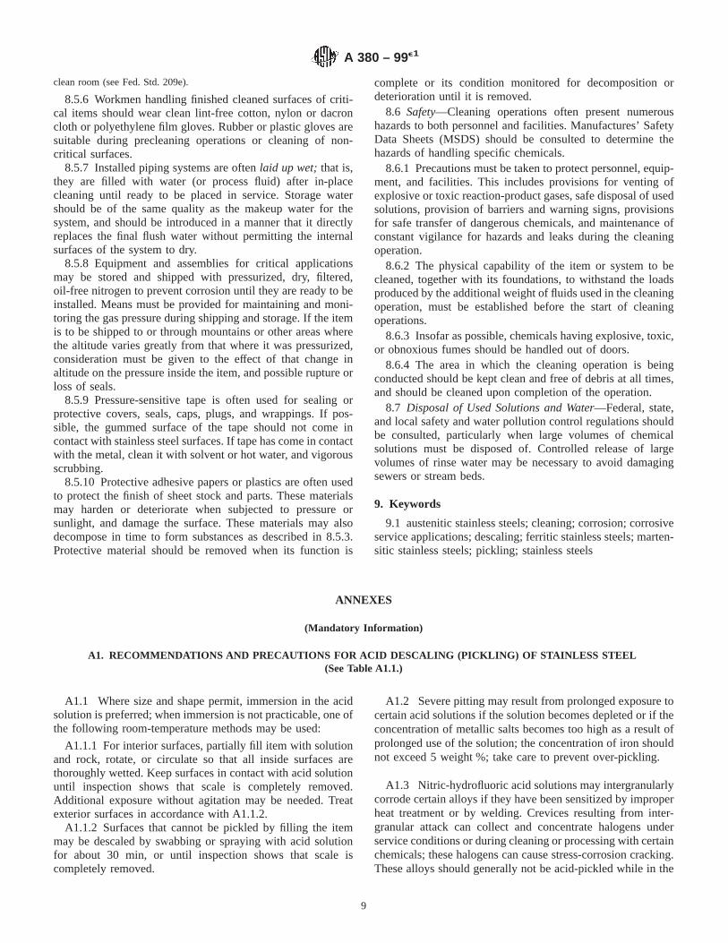
clean room (see Fed. Std. 209e).
8.5.6 Workmen handling finished cleaned surfaces of criti-cal items should wear clean lint-free cotton, nylon or dacroncloth or polyethylene film gloves. Rubber or plastic gloves aresuitable during precleaning operations or cleaning of non-critical surfaces.
8.5.7 Installed piping systems are oftenlaid up wet;that is,they are filled with water (or process fluid) after in-placecleaning until ready to be placed in service. Storage watershould be of the same quality as the makeup water for thesystem, and should be introduced in a manner that it directlyreplaces the final flush water without permitting the internalsurfaces of the system to dry.
8.5.8 Equipment and assemblies for critical applicationsmay be stored and shipped with pressurized, dry, filtered,oil-free nitrogen to prevent corrosion until they are ready to beinstalled. Means must be provided for maintaining and moni-toring the gas pressure during shipping and storage. If the itemis to be shipped to or through mountains or other areas wherethe altitude varies greatly from that where it was pressurized,consideration must be given to the effect of that change inaltitude on the pressure inside the item, and possible rupture orloss of seals.
8.5.9 Pressure-sensitive tape is often used for sealing orprotective covers, seals, caps, plugs, and wrappings. If pos-sible, the gummed surface of the tape should not come incontact with stainless steel surfaces. If tape has come in contactwith the metal, clean it with solvent or hot water, and vigorousscrubbing.
8.5.10 Protective adhesive papers or plastics are often usedto protect the finish of sheet stock and parts. These materialsmay harden or deteriorate when subjected to pressure orsunlight, and damage the surface. These materials may alsodecompose in time to form substances as described in 8.5.3.Protective material should be removed when its function is
complete or its condition monitored for decomposition ordeterioration until it is removed.
8.6 Safety—Cleaning operations often present numeroushazards to both personnel and facilities. Manufactures’ SafetyData Sheets (MSDS) should be consulted to determine thehazards of handling specific chemicals.
8.6.1 Precautions must be taken to protect personnel, equip-ment, and facilities. This includes provisions for venting ofexplosive or toxic reaction-product gases, safe disposal of usedsolutions, provision of barriers and warning signs, provisionsfor safe transfer of dangerous chemicals, and maintenance ofconstant vigilance for hazards and leaks during the cleaningoperation.
8.6.2 The physical capability of the item or system to becleaned, together with its foundations, to withstand the loadsproduced by the additional weight of fluids used in the cleaningoperation, must be established before the start of cleaningoperations.
8.6.3 Insofar as possible, chemicals having explosive, toxic,or obnoxious fumes should be handled out of doors.
8.6.4 The area in which the cleaning operation is beingconducted should be kept clean and free of debris at all times,and should be cleaned upon completion of the operation.
8.7 Disposal of Used Solutions and Water—Federal, state,and local safety and water pollution control regulations shouldbe consulted, particularly when large volumes of chemicalsolutions must be disposed of. Controlled release of largevolumes of rinse water may be necessary to avoid damagingsewers or stream beds.
9. Keywords
9.1 austenitic stainless steels; cleaning; corrosion; corrosiveservice applications; descaling; ferritic stainless steels; marten-sitic stainless steels; pickling; stainless steels
ANNEXES
(Mandatory Information)
A1. RECOMMENDATIONS AND PRECAUTIONS FOR ACID DESCALING (PICKLING) OF STAINLESS STEEL(See Table A1.1.)
A1.1 Where size and shape permit, immersion in the acidsolution is preferred; when immersion is not practicable, one ofthe following room-temperature methods may be used:
A1.1.1 For interior surfaces, partially fill item with solutionand rock, rotate, or circulate so that all inside surfaces arethoroughly wetted. Keep surfaces in contact with acid solutionuntil inspection shows that scale is completely removed.Additional exposure without agitation may be needed. Treatexterior surfaces in accordance with A1.1.2.
A1.1.2 Surfaces that cannot be pickled by filling the itemmay be descaled by swabbing or spraying with acid solutionfor about 30 min, or until inspection shows that scale iscompletely removed.
A1.2 Severe pitting may result from prolonged exposure tocertain acid solutions if the solution becomes depleted or if theconcentration of metallic salts becomes too high as a result ofprolonged use of the solution; the concentration of iron shouldnot exceed 5 weight %; take care to prevent over-pickling.
A1.3 Nitric-hydrofluoric acid solutions may intergranularlycorrode certain alloys if they have been sensitized by improperheat treatment or by welding. Crevices resulting from inter-granular attack can collect and concentrate halogens underservice conditions or during cleaning or processing with certainchemicals; these halogens can cause stress-corrosion cracking.These alloys should generally not be acid-pickled while in the
A 380 – 99e1
9

sensitized condition. Consideration should be given to stabi-lized or low-carbon grades if acid pickling after welding isunavoidable.
A1.4 Some latitude is permissible in adjusting acid con-centrations, temperatures, and contact times. In general, lowervalues in this table apply to lower alloys, and higher values tohigher alloys. Close control over these variables is necessaryonce proper values are established in order to preserve desiredfinishes or close dimensional tolerances, or both.
A1.5 Materials must be degreased before acid pickling andmust be vigorously brushed with hot water and a bristle brushor with high-pressure water jet on completion of pickling; pHof final rinse water should be between 6 and 8 for mostapplications, or 6.5 to 7.5 for critical applications. To minimizestaining, surfaces must not be permitted to dry between
successive steps of the acid descaling and rinsing procedure.Thorough drying should follow the final water rinse.
A1.6 Hardenable 400 Series alloys, maraging alloys, andprecipitation-hardening alloys in the hardened condition aresubject to hydrogen embrittlement or intergranular attack byacids. Descaling by mechanical methods is recommendedwhere possible. If acid pickling is unavoidable, parts should beheated at 250 to 300°F (121 to 149°C) for 24 h immediatelyfollowing acid treatment to drive off the hydrogen and reducethe susceptibility to embrittlement.
A1.7 Proper personnel protection, including face shields,rubber gloves, and rubber protective clothing, must be pro-vided when handling acids and other corrosive chemicals.Adequate ventilation and strict personnel-access controls mustbe maintained in areas where such chemicals are being used.
TABLE A1.1 Acid Descaling (Pickling) of Stainless Steel
AlloyA ConditionB
Treatment
Code Solution, Volume, %C Temperature °F(°C)
Time,Minutes
200, 300, and 400 Series, precipitationhardening, and maraging alloys (except
free-machining alloys)
fully annealed only A H2SO4, 8–11 %D
Follow by treatment D or F,Annex A2, as appropriate
150–180(66–82)
5–45 maxE
200 and 300 Series; 400 Series containing Cr16 % or more; precipitation-hardening alloys
(except free-machining alloys)
fully annealed only B HNO3, 15–25 % plus HF,1–8 %F,G
70–140 max(21–60)
5–30E
All free-machining alloys and 400 Seriescontaining less than Cr 16 %
fully annealed only C HNO3, 10–15 % plus HF,½–1½ %F,G
70 (up to 140with
caution)
5–30E
A This table is also applicable to the cast grades equivalent to the families of wrought materials listed.B Other heat treatments may be acceptable if proven by experience: see 5.2.1, A2.4, and A2.5 for further information.C Solution prepared from reagents of following weight %: H 2SO4, 98; HNO3, 67; HF, 70.D Tight scale may be removed by a dip in this solution for a few minutes followed by water rinse and nitric-hydrofluoric acid treatment as noted.E Minimum contact times necessary to obtain the desired surface should be used in order to prevent over-pickling. Tests should be made to establish correct procedures
for specific applications.F For reasons of convenience and handling safety, commercial formulations containing fluoride salts may be found useful in place of HF for preparing nitric-hydrofluoric
acid solutions.G After pickling and water rinsing, an aqueous caustic permanganate solution containing NaOH, 10 weight % and KMnO4, 4 weight %, 160 to 180°F (71 to 82°C), 5 to
60 min, may be used as a final dip for removal of smut, followed by thorough water rinsing and drying.
A2. RECOMMENDATIONS AND PRECAUTIONS FOR ACID CLEANING OF STAINLESS STEEL (See Table A2.1.)
A2.1 Treatments shown are generally adequate for removalof contamination without seriously changing surface appear-ance of parts. Passivated parts should exhibit a clean surfaceand should show no etching, pitting, or frosting. The purchasershall specify whether a slight discoloration is acceptable.Passivated parts should not exhibit staining attributable to thepresence of free iron particles imbedded in the surface whensubjected to the test described in 7.2.5.1. For specific require-ments for items to be used in corrosive service or where surfaceappearance is critical, trials should be conducted to establishsatisfactory procedures.
A2.2 The high-carbon and free-machining alloys may besubject to etching or discoloration in nitric acid. This tendencycan be minimized by the use of high acid concentrations withinhibitors such as Na2Cr2O7·2H 2O and CuSO4·5H2O. Oxidiz-ing action increases with increasing concentration of nitricacid; additional oxidizing action is provided byNa2Cr2O7·2H2O. Avoid acid cleaning when possible; usemechanical cleaning followed by scrubbing with hot water and
detergent, final thorough water rinsing and drying.
A2.3 Inhibitors may not always be required to maintainbright finishes on 200 and 300 Series, maraging, andprecipitation-hardening alloys.
A2.4 Hardenable 400 Series, maraging, and precipitation-hardening alloys in the hardened condition are subject tohydrogen embrittlement or intergranular attack when exposedto acids. Cleaning by mechanical methods or other chemicalmethods is recommended. If acid treatment is unavoidable,parts should be heated at 250 and 300°F (121 to 149°C) for 24h immediately following acid cleaning to drive off hydrogenand reduce susceptibility to embrittlement.
A2.5 Nitric-hydrofluoric acid solutions may intergranularlycorrode certain alloys if they have been sensitized by improperheat treatment or by welding. Crevices resulting from inter-granular attack can collect and concentrate halogens underservice conditions or during cleaning or subsequent processing;
A 380 – 99e1
10
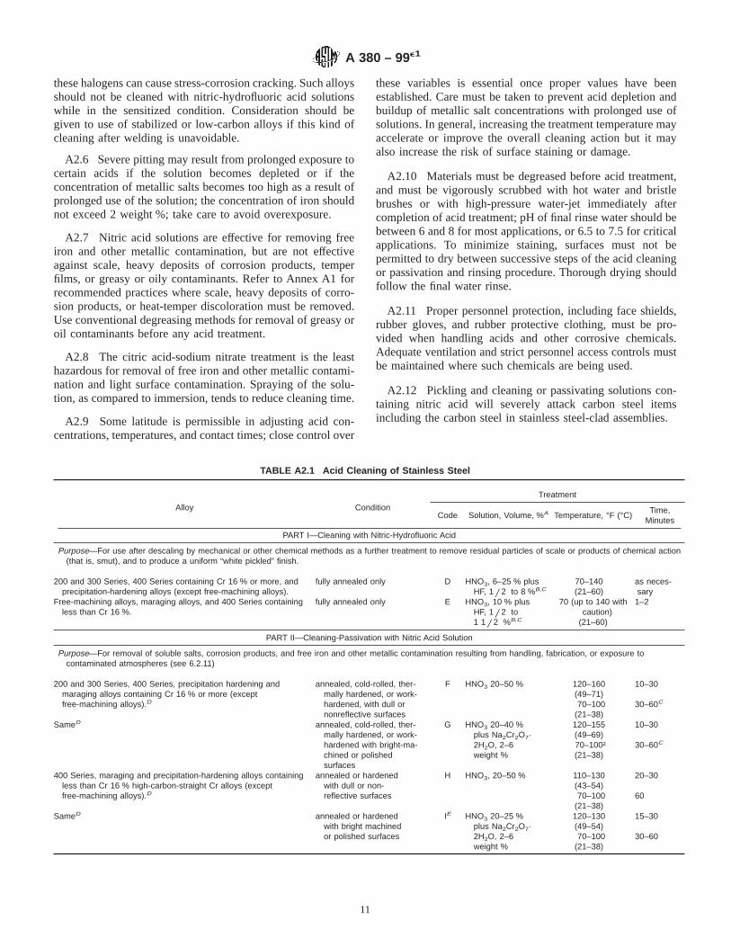
these halogens can cause stress-corrosion cracking. Such alloysshould not be cleaned with nitric-hydrofluoric acid solutionswhile in the sensitized condition. Consideration should begiven to use of stabilized or low-carbon alloys if this kind ofcleaning after welding is unavoidable.
A2.6 Severe pitting may result from prolonged exposure tocertain acids if the solution becomes depleted or if theconcentration of metallic salts becomes too high as a result ofprolonged use of the solution; the concentration of iron shouldnot exceed 2 weight %; take care to avoid overexposure.
A2.7 Nitric acid solutions are effective for removing freeiron and other metallic contamination, but are not effectiveagainst scale, heavy deposits of corrosion products, temperfilms, or greasy or oily contaminants. Refer to Annex A1 forrecommended practices where scale, heavy deposits of corro-sion products, or heat-temper discoloration must be removed.Use conventional degreasing methods for removal of greasy oroil contaminants before any acid treatment.
A2.8 The citric acid-sodium nitrate treatment is the leasthazardous for removal of free iron and other metallic contami-nation and light surface contamination. Spraying of the solu-tion, as compared to immersion, tends to reduce cleaning time.
A2.9 Some latitude is permissible in adjusting acid con-centrations, temperatures, and contact times; close control over
these variables is essential once proper values have beenestablished. Care must be taken to prevent acid depletion andbuildup of metallic salt concentrations with prolonged use ofsolutions. In general, increasing the treatment temperature mayaccelerate or improve the overall cleaning action but it mayalso increase the risk of surface staining or damage.
A2.10 Materials must be degreased before acid treatment,and must be vigorously scrubbed with hot water and bristlebrushes or with high-pressure water-jet immediately aftercompletion of acid treatment; pH of final rinse water should bebetween 6 and 8 for most applications, or 6.5 to 7.5 for criticalapplications. To minimize staining, surfaces must not bepermitted to dry between successive steps of the acid cleaningor passivation and rinsing procedure. Thorough drying shouldfollow the final water rinse.
A2.11 Proper personnel protection, including face shields,rubber gloves, and rubber protective clothing, must be pro-vided when handling acids and other corrosive chemicals.Adequate ventilation and strict personnel access controls mustbe maintained where such chemicals are being used.
A2.12 Pickling and cleaning or passivating solutions con-taining nitric acid will severely attack carbon steel itemsincluding the carbon steel in stainless steel-clad assemblies.
TABLE A2.1 Acid Cleaning of Stainless Steel
Alloy Condition
Treatment
Code Solution, Volume, %A Temperature, °F (°C)Time,
Minutes
PART I—Cleaning with Nitric-Hydrofluoric Acid
Purpose—For use after descaling by mechanical or other chemical methods as a further treatment to remove residual particles of scale or products of chemical action(that is, smut), and to produce a uniform “white pickled” finish.
200 and 300 Series, 400 Series containing Cr 16 % or more, andprecipitation-hardening alloys (except free-machining alloys).
fully annealed only D HNO3, 6–25 % plusHF, 1 / 2 to 8 %B,C
70–140(21–60)
as neces-sary
Free-machining alloys, maraging alloys, and 400 Series containingless than Cr 16 %.
fully annealed only E HNO3, 10 % plusHF, 1 / 2 to1 1 / 2 %B,C
70 (up to 140 withcaution)
(21–60)
1–2
PART II—Cleaning-Passivation with Nitric Acid Solution
Purpose—For removal of soluble salts, corrosion products, and free iron and other metallic contamination resulting from handling, fabrication, or exposure tocontaminated atmospheres (see 6.2.11)
200 and 300 Series, 400 Series, precipitation hardening andmaraging alloys containing Cr 16 % or more (exceptfree-machining alloys).D
annealed, cold-rolled, ther-mally hardened, or work-hardened, with dull ornonreflective surfaces
F HNO3 20–50 % 120–160(49–71)70–100
(21–38)
10–30
30–60C
SameD annealed, cold-rolled, ther-mally hardened, or work-hardened with bright-ma-chined or polishedsurfaces
G HNO3 20–40 %plus Na2Cr2O7·2H2O, 2–6weight %
120–155(49–69)70–100†(21–38)
10–30
30–60C
400 Series, maraging and precipitation-hardening alloys containingless than Cr 16 % high-carbon-straight Cr alloys (exceptfree-machining alloys).D
annealed or hardenedwith dull or non-reflective surfaces
H HNO3, 20–50 % 110–130(43–54)70–100
(21–38)
20–30
60
SameD annealed or hardenedwith bright machinedor polished surfaces
IE HNO3 20–25 %plus Na2Cr2O7·2H2O, 2–6weight %
120–130(49–54)70–100
(21–38)
15–30
30–60
A 380 – 99e1
11

TABLE A2.1 Continued
Alloy Condition
Treatment
Code Solution, Volume, %A Temperature, °F (°C)Time,
Minutes
200, 300, and 400 Series free-machining alloys.D annealed or hardened, withbright-machined or pol-ished surfaces
JE HNO3, 20–50 %plus Na2Cr2O7·2H2O, 2–6weight %F
70–120(21–49)
25–40
SameD same KG HNO3, 1–2 % plusNa2Cr2O7·2H2O,1–5, weight %
120–140(49–60)
10
SameD same LE HNO3, 12 % plusCuSO4·5H2O, 4weight %
120–140(49–60)
10
Special free-machining 400 Series alloys with more than Mn 1.25 %or more than S 0.40 %D
annealed or hard-ened with bright-machinedor polished surfaces
ME HNO3, 40–60 %plus Na2Cr2O7·2H2O, 2–6weight %
120–160(49–71)
20–30
PART III—Cleaning with Other Chemical Solutions
Purpose—General cleaning.200, 300, and 400 Series (except free-machining alloys),
precipitation hardening and maraging alloysfully annealed only N citric acid, 1 weight %
plus, NaNO3, 1weight %
70(21)
60
Same same O ammonium citrate,5–10 weight %
120–160(49–71)
10–60
Assemblies of stainless and carbon steel (for example, heatexchanger with stainless steel tubes and carbon steel shell)
sensitized P inhibited solution ofhydroxyacetic acid,2 weight % andformic acid, 1weight %
200(93)
6 h
Same same Q inhibited ammonia-neutralized solutionof EDTA(ethylene-diamene-tetraacetic acid) fol-lowed by hot-waterrinse and dip insolution of 10 ppmammonium hy-droxide plus 100ppm hydrazine
up to 250(121)
6 h
A Solution prepared from reagents of following weight %: HNO3, 67; HF, 70.B For reasons of convenience and handling safety, commercial formulations containing fluoride salts may be found useful in place of HF for preparing nitric-hydrofluoric
acid solutions.C After acid cleaning and water rising, a caustic permanganate solution containing NaOH, 10 weight %, and KMnO 4, 4 weight %, 160 to 180°F (71 to 82°C), 5 to 60
min, may be used as a final dip for removal of smut, followed by thorough water rinsing and drying.D The purchaser shall have the option of specifying in his purchase documents that all 400 Series ferritic or martensitic parts receive additional treatment as follows:
Within 1 h after the water rinse following the specified passivation treatment, all parts shall be immersed in an aqueous solution containing 4 to 6 weight % Na2Cr2O7·2H2O, at 140 to 160°F (60 to 71°C), 30 min. This immersion shall be followed by thorough rinsing with clean water. The parts then shall be thoroughly dried.
E See A2.2.F If flash attack (clouding of stainless steel surface) occurs, a fresh (clean) passivating solution or a higher HNO 3 concentration will usually eliminate it.G Shorter times may be acceptable where established by test and agreed upon by the purchaser.
†Corrected Editorially.
ASTM International takes no position respecting the validity of any patent rights asserted in connection with any item mentionedin this standard. Users of this standard are expressly advised that determination of the validity of any such patent rights, and the riskof infringement of such rights, are entirely their own responsibility.
This standard is subject to revision at any time by the responsible technical committee and must be reviewed every five years andif not revised, either reapproved or withdrawn. Your comments are invited either for revision of this standard or for additional standardsand should be addressed to ASTM International Headquarters. Your comments will receive careful consideration at a meeting of theresponsible technical committee, which you may attend. If you feel that your comments have not received a fair hearing you shouldmake your views known to the ASTM Committee on Standards, at the address shown below.
This standard is copyrighted by ASTM International, 100 Barr Harbor Drive, PO Box C700, West Conshohocken, PA 19428-2959,United States. Individual reprints (single or multiple copies) of this standard may be obtained by contacting ASTM at the aboveaddress or at 610-832-9585 (phone), 610-832-9555 (fax), or [email protected] (e-mail); or through the ASTM website(www.astm.org).
A 380 – 99e1
12

Designation: A 401/A 401M – 03
Standard Specification forSteel Wire, Chromium-Silicon Alloy 1
This standard is issued under the fixed designation A 401/A 401M; the number immediately following the designation indicates the yearof original adoption or, in the case of revision, the year of last revision. A number in parentheses indicates the year of last reapproval.A superscript epsilon (e) indicates an editorial change since the last revision or reapproval.
1. Scope*
1.1 This specification covers round chromium-silicon alloysteel spring wire having properties and quality intended for themanufacture of springs resistant to set when used at moderatelyelevated temperatures. This product is not meant to be used forhigh cycle fatique applications (see Specification A 877/A 877M). This wire shall be provided either in the annealedand cold-drawn or oil-tempered condition as specified by thepurchaser.
1.2 The values stated in either SI units or inch-pound unitsare to be regarded separately as standard. Within the text, theinch-pound units are shown in brackets. The values stated ineach system are not exact equivalents; therefore, each systemmust be used independent of the other.
2. Referenced Documents
2.1 ASTM Standards:A 370 Test Methods and Definitions for Mechanical Testing
of Steel Products2
A 700 Practices for Packaging, Marking, and LoadingMethods for Steel Products for Domestic Shipment3
A 751 Test Methods, Practices, and Terminology forChemical Analysis of Steel Products2
A 752 Specification for General Requirements for WireRods and Coarse Round Wire, Alloy Steel2
A 877/A 877M Specification for Steel Wire, Chromium-Silicon Alloy Valve Spring Quality2
E 29 Practice for Using Significant Digits in Test Data toDetermine Conformance with Specifications4
2.2 ANSI Standard:B 32.4 Preferred Metric Sizes for Round, Square, Rectangle
and Hexagon Metal Products5
2.3 Federal Standards:
Fed. Std. No. 123 Marking for Shipment (Civil Agencies)6
2.4 Military Standard:MIL-STD-163 Steel Mill Products, Preparation for Ship-
ment and Storage6
2.5 AIAG Standard:AIAG B-5 02.00 Primary Metals Identification Tag Appli-
cation Standard7
3. Ordering Information
3.1 It shall be the responsibility of the purchaser to specifyall requirements that are necessary for material under thisspecification. Such requirements may include, but are notlimited to, the following:
3.1.1 Quantity (mass),3.1.2 Name of material (chromium-silicon alloy steel wire),3.1.3 Dimensions (Table 1 and Section 8),3.1.4 Condition (Section 6),3.1.5 Packaging (Section 14),3.1.6 Heat analysis report, if requested (5.2),3.1.7 Certification or test report, or both, if specified (Sec-
tion 13), and3.1.8 ASTM designation and year of issue.
NOTE 1—A typical ordering description is as follows: 20 000-kg,oil-tempered chromium-silicon alloy steel wire, size 6.00 mm in 150 kgcoils to ASTM A 401/A 401M dated ____, or for inch-pound units,40 000-lb oil-tempered chromium-silicon alloy steel spring wire, size0.250 in. in 350-lb coils to ASTM A 401/A 401M dated ____.
4. Materials and Manufacture
4.1 The steel may be made by any commercially acceptedsteel making process. The steel may be either ingot cast orstrand cast.
4.2 The finished wire shall be free from detrimental pipeand undue segregation.
5. Chemical Composition
5.1 The steel shall conform to the requirements of Grade9254 for chemical composition specified in Table 2.
1 This specification is under the jurisdiction of ASTM Committee A01 on Steel,Stainless Steel, and Related Alloys and is the direct responsibility of SubcommitteeA01.03 on Steel Rod and Wire.
Current edition approved Sept. 10, 2003. Published Sept. 2003. Originallyapproved in 1956. Last previous edition approved in 1998 as A 401/A 401M – 98.
2 Annual Book of ASTM Standards, Vol 01.03.3 Annual Book of ASTM Standards, Vol 01.05.4 Annual Book of ASTM Standards, Vol 14.02.5 Available from American National Standards Institute (ANSI), 25 W. 43rd St.,
4th Floor, New York, NY 10036.
6 Available from Standardization Documents Order Desk, Bldg. 4 Section D, 700Robbins Ave., Philadelphia, PA 19111-5094, Attn: NPODS.
7 Available from Automotive Industry Action Group (AIAG), 26200 Lahser Rd.,Suite 200, Southfield, MI 48034.
1
*A Summary of Changes section appears at the end of this standard.
Copyright © ASTM International, 100 Barr Harbor Drive, PO Box C700, West Conshohocken, PA 19428-2959, United States.
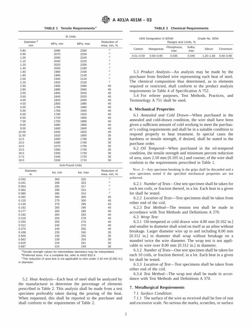
5.2 Heat Analysis—Each heat of steel shall be analyzed bythe manufacturer to determine the percentage of elementsprescribed in Table 2. This analysis shall be made from a testspecimen preferably taken during the pouring of the heat.When requested, this shall be reported to the purchaser andshall conform to the requirements of Table 2.
5.3 Product Analysis—An analysis may be made by thepurchaser from finished wire representing each heat of steel.The chemical composition thus determined, as to elementsrequired or restricted, shall conform to the product analysisrequirements in Table 4 of Specification A 752.
5.4 For referee purposes, Test Methods, Practices, andTerminology A 751 shall be used.
6. Mechanical Properties
6.1 Annealed and Cold Drawn—When purchased in theannealed and cold-drawn condition, the wire shall have beengiven a sufficient amount of cold working to meet the purchas-er’s coiling requirements and shall be in a suitable condition torespond properly to heat treatment. In special cases thehardness or tensile strength, if desired, shall be stated in thepurchase order.
6.2 Oil Tempered—When purchased in the oil-temperedcondition, the tensile strength and minimum percent reductionof area, sizes 2.50 mm [0.105 in.] and coarser, of the wire shallconform to the requirements prescribed in Table 1.
NOTE 2—Any specimen breaking in the grips shall be discarded and anew specimen tested if the specified mechanical properties are notachieved.
6.2.1 Number of Tests—One test specimen shall be taken foreach ten coils, or fraction thereof, in a lot. Each heat in a givenlot shall be tested.
6.2.2 Location of Tests—Test specimens shall be taken fromeither end of the coil.
6.2.3 Test Method—The tension test shall be made inaccordance with Test Methods and Definitions A 370.
6.3 Wrap Test:6.3.1 Oil-tempered or cold drawn wire 4.00 mm [0.162 in.]
and smaller in diameter shall wind on itself as an arbor withoutbreakage. Larger diameter wire up to and including 8.00 mm[0.312 in.] in diameter shall wrap without breakage on amandrel twice the wire diameter. The wrap test is not appli-cable to wire over 8.00 mm [0.312 in.] in diameter.
6.3.2 Number of Tests—One test specimen shall be taken foreach 10 coils, or fraction thereof, in a lot. Each heat in a givenlot shall be tested.
6.3.3 Location of Test—Test specimens shall be taken fromeither end of the coil.
6.3.4 Test Method—The wrap test shall be made in accor-dance with Test Methods and Definitions A 370.
7. Metallurgical Requirements
7.1 Surface Condition:7.1.1 The surface of the wire as received shall be free of rust
and excessive scale. No serious die marks, scratches, or surface
TABLE 1 Tensile Requirements A
SI Units
Diameter,B
mmMPa, min MPa, max
Reduction ofArea, min, %
0.80 2080 2260 C
0.90 2070 2250 C
1.00 2060 2240 C
1.10 2040 2220 C
1.20 2020 2200 C
1.40 2000 2180 C
1.60 1980 2160 C
1.80 1960 2140 C
2.00 1940 2120 C
2.20 1920 2100 C
2.50 1900 2080 452.80 1880 2060 453.00 1860 2040 453.50 1840 2020 404.00 1820 2000 404.50 1800 1980 405.00 1780 1960 405.50 1760 1940 406.00 1740 1920 406.50 1720 1900 407.00 1700 1880 408.00 1680 1860 409.00 1660 1840 40
10.00 1640 1820 4011.00 1620 1800 3512.0 1600 1780 3513.0 1580 1760 3014.0 1570 1750 3015.0 1560 1740 3016.0 1550 1730 3017.0 1540 1720 3018.0 1530 1710 30
Inch-Pound Units
Diameter,in.
ksi, min ksi, maxReduction ofArea, min, %
0.032 300 325 C
0.041 298 323 C
0.054 292 317 C
0.062 290 315 C
0.080 285 310 C
0.092 280 305 450.120 275 300 450.135 270 295 400.162 265 290 400.177 260 285 400.192 260 283 400.219 255 278 400.250 250 275 400.312 245 270 400.375 240 265 400.438 235 260 350.500 230 255 350.562 228 253 300.625 226 251 300.687 224 249 30
ATensile strength values for intermediate diameters may be interpolated.BPreferred sizes. For a complete list, refer to ANSI B32.4.CThe reduction of area test is not applicable to wire under 2.34 mm [0.092 in.]
in diameter.
TABLE 2 Chemical Requirements
UNS Designation G 92540 Grade No. 9254Ranges and Limits, %
Carbon ManganesePhosphorus,
maxSulfur,max
Silicon Chromium
0.51–0.59 0.60–0.80 0.035 0.040 1.20–1.60 0.60–0.80
A 401/A 401M – 03
2
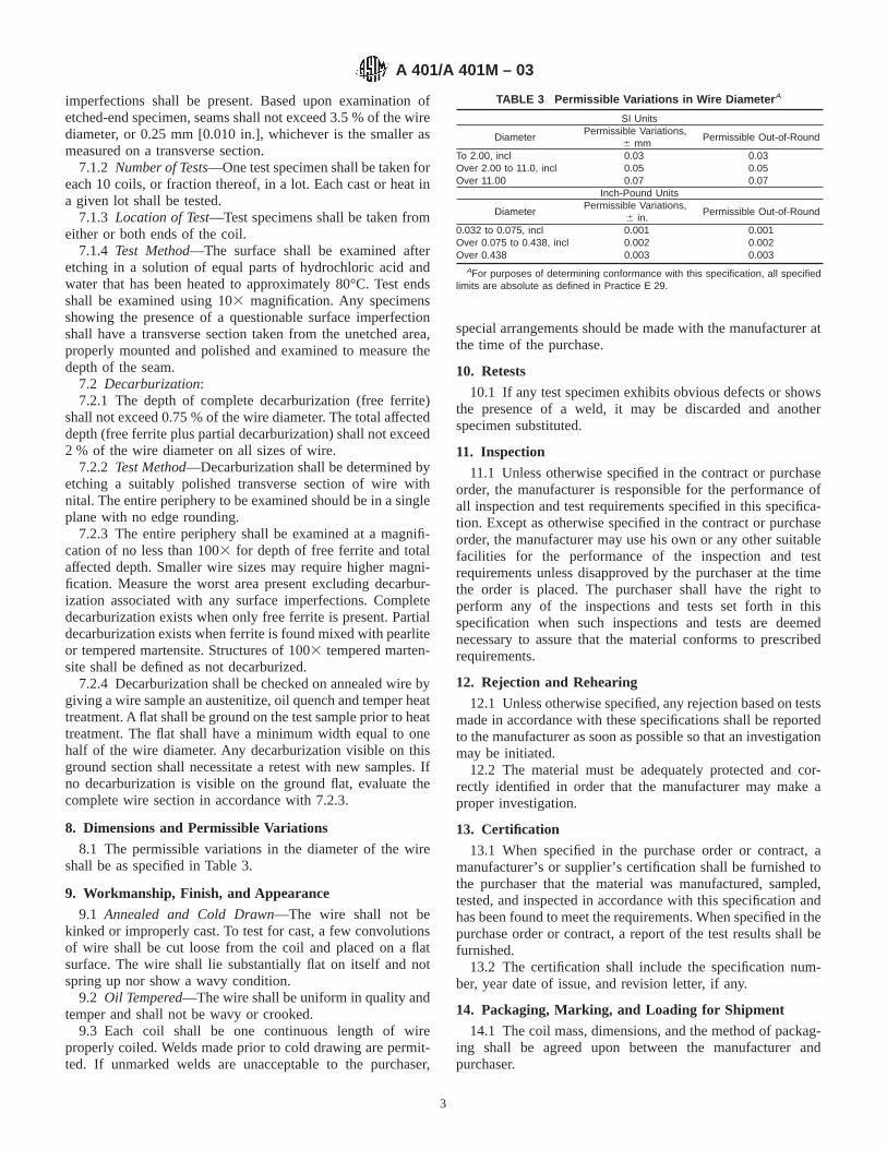
imperfections shall be present. Based upon examination ofetched-end specimen, seams shall not exceed 3.5 % of the wirediameter, or 0.25 mm [0.010 in.], whichever is the smaller asmeasured on a transverse section.
7.1.2 Number of Tests—One test specimen shall be taken foreach 10 coils, or fraction thereof, in a lot. Each cast or heat ina given lot shall be tested.
7.1.3 Location of Test—Test specimens shall be taken fromeither or both ends of the coil.
7.1.4 Test Method—The surface shall be examined afteretching in a solution of equal parts of hydrochloric acid andwater that has been heated to approximately 80°C. Test endsshall be examined using 103 magnification. Any specimensshowing the presence of a questionable surface imperfectionshall have a transverse section taken from the unetched area,properly mounted and polished and examined to measure thedepth of the seam.
7.2 Decarburization:7.2.1 The depth of complete decarburization (free ferrite)
shall not exceed 0.75 % of the wire diameter. The total affecteddepth (free ferrite plus partial decarburization) shall not exceed2 % of the wire diameter on all sizes of wire.
7.2.2 Test Method—Decarburization shall be determined byetching a suitably polished transverse section of wire withnital. The entire periphery to be examined should be in a singleplane with no edge rounding.
7.2.3 The entire periphery shall be examined at a magnifi-cation of no less than 1003 for depth of free ferrite and totalaffected depth. Smaller wire sizes may require higher magni-fication. Measure the worst area present excluding decarbur-ization associated with any surface imperfections. Completedecarburization exists when only free ferrite is present. Partialdecarburization exists when ferrite is found mixed with pearliteor tempered martensite. Structures of 1003 tempered marten-site shall be defined as not decarburized.
7.2.4 Decarburization shall be checked on annealed wire bygiving a wire sample an austenitize, oil quench and temper heattreatment. A flat shall be ground on the test sample prior to heattreatment. The flat shall have a minimum width equal to onehalf of the wire diameter. Any decarburization visible on thisground section shall necessitate a retest with new samples. Ifno decarburization is visible on the ground flat, evaluate thecomplete wire section in accordance with 7.2.3.
8. Dimensions and Permissible Variations
8.1 The permissible variations in the diameter of the wireshall be as specified in Table 3.
9. Workmanship, Finish, and Appearance
9.1 Annealed and Cold Drawn—The wire shall not bekinked or improperly cast. To test for cast, a few convolutionsof wire shall be cut loose from the coil and placed on a flatsurface. The wire shall lie substantially flat on itself and notspring up nor show a wavy condition.
9.2 Oil Tempered—The wire shall be uniform in quality andtemper and shall not be wavy or crooked.
9.3 Each coil shall be one continuous length of wireproperly coiled. Welds made prior to cold drawing are permit-ted. If unmarked welds are unacceptable to the purchaser,
special arrangements should be made with the manufacturer atthe time of the purchase.
10. Retests
10.1 If any test specimen exhibits obvious defects or showsthe presence of a weld, it may be discarded and anotherspecimen substituted.
11. Inspection
11.1 Unless otherwise specified in the contract or purchaseorder, the manufacturer is responsible for the performance ofall inspection and test requirements specified in this specifica-tion. Except as otherwise specified in the contract or purchaseorder, the manufacturer may use his own or any other suitablefacilities for the performance of the inspection and testrequirements unless disapproved by the purchaser at the timethe order is placed. The purchaser shall have the right toperform any of the inspections and tests set forth in thisspecification when such inspections and tests are deemednecessary to assure that the material conforms to prescribedrequirements.
12. Rejection and Rehearing
12.1 Unless otherwise specified, any rejection based on testsmade in accordance with these specifications shall be reportedto the manufacturer as soon as possible so that an investigationmay be initiated.
12.2 The material must be adequately protected and cor-rectly identified in order that the manufacturer may make aproper investigation.
13. Certification
13.1 When specified in the purchase order or contract, amanufacturer’s or supplier’s certification shall be furnished tothe purchaser that the material was manufactured, sampled,tested, and inspected in accordance with this specification andhas been found to meet the requirements. When specified in thepurchase order or contract, a report of the test results shall befurnished.
13.2 The certification shall include the specification num-ber, year date of issue, and revision letter, if any.
14. Packaging, Marking, and Loading for Shipment
14.1 The coil mass, dimensions, and the method of packag-ing shall be agreed upon between the manufacturer andpurchaser.
TABLE 3 Permissible Variations in Wire Diameter A
SI Units
DiameterPermissible Variations,
6 mmPermissible Out-of-Round
To 2.00, incl 0.03 0.03Over 2.00 to 11.0, incl 0.05 0.05Over 11.00 0.07 0.07
Inch-Pound Units
DiameterPermissible Variations,
6 in.Permissible Out-of-Round
0.032 to 0.075, incl 0.001 0.001Over 0.075 to 0.438, incl 0.002 0.002Over 0.438 0.003 0.003
AFor purposes of determining conformance with this specification, all specifiedlimits are absolute as defined in Practice E 29.
A 401/A 401M – 03
3

14.2 The size of the wire, purchaser’s order number, ASTMspecification number, heat number, and name or mark of themanufacturer shall be marked on a tag securely attached toeach coil of wire.
14.3 Unless otherwise specified in the purchaser’s order,packaging, marking, and loading for shipments shall be inaccordance with those procedures recommended by PracticesA 700.
14.4 For Government Procurement—Packaging, packing,and marking of material for military procurement shall be inaccordance with the requirements of MIL-STD-163, Level A,Level C, or commercial as specified in the contract or purchase
order. Marking for shipment of material for civil agencies shallbe in accordance with Fed. Std. No. 123.
14.5 Bar Coding—In addition to the previously-stated iden-tification requirements, bar coding is acceptable as a supple-mentary identification method. Bar coding should be consistentwith AIAG B-5 02.00, Primary Metals Identification TagApplication. The bar code may be applied to a substantiallyaffixed tag.
15. Keywords
15.1 annealed chromium-silicon alloy; oil; springs; tem-pered; wire
SUMMARY OF CHANGES
This section identifies the location of selected changes to this standard that have been incorporated since theA 401/A 401M-98 issue. For the convenience of the user, Committee A01 has highlighted those changes thatimpact the use of this standard. This section may also include descriptions of changes or reasons for changes,or both.
(1) Revised language in Sections 3.1, 6.1, 7.1.1, 7.1.4, and7.2.3.
ASTM International takes no position respecting the validity of any patent rights asserted in connection with any item mentionedin this standard. Users of this standard are expressly advised that determination of the validity of any such patent rights, and the riskof infringement of such rights, are entirely their own responsibility.
This standard is subject to revision at any time by the responsible technical committee and must be reviewed every five years andif not revised, either reapproved or withdrawn. Your comments are invited either for revision of this standard or for additional standardsand should be addressed to ASTM International Headquarters. Your comments will receive careful consideration at a meeting of theresponsible technical committee, which you may attend. If you feel that your comments have not received a fair hearing you shouldmake your views known to the ASTM Committee on Standards, at the address shown below.
This standard is copyrighted by ASTM International, 100 Barr Harbor Drive, PO Box C700, West Conshohocken, PA 19428-2959,United States. Individual reprints (single or multiple copies) of this standard may be obtained by contacting ASTM at the aboveaddress or at 610-832-9585 (phone), 610-832-9555 (fax), or [email protected] (e-mail); or through the ASTM website(www.astm.org).
A 401/A 401M – 03
4

Designation: A 407 – 93 (Reapproved 2004)
Standard Specification forSteel Wire, Cold-Drawn, for Coiled-Type Springs 1
This standard is issued under the fixed designation A 407; the number immediately following the designation indicates the year oforiginal adoption or, in the case of revision, the year of last revision. A number in parentheses indicates the year of last reapproval. Asuperscript epsilon (e) indicates an editorial change since the last revision or reapproval.
1. Scope
1.1 This specification covers round, cold-drawn, steel springwire having properties and quality intended for the manufac-ture of the following types of upholstery springs:
1.1.1 Type A—Coiled (Marshall pack),1.1.2 Type B—Coiled and knotted,1.1.3 Type C—Coiled and knotted (offset style),1.1.4 Type D—Coiled and hooked (single and cross heli-
cals),1.1.5 Type E—Coiled and hooked (short tension—regular
tensile strength),1.1.6 Type F—Coiled and hooked (short tension—high
tensile strength),1.1.7 Type G—Regular lacing, and1.1.8 Type H—Automatic lacing.1.2 These types of upholstery springs are used in the
manufacture of bed spring units, mattresses, furniture cushions,and automobile seats. This wire is not intended for themanufacture of mechanical springs.
2. Referenced Documents
2.1 ASTM Standards:2
A 370 Test Methods and Definitions for Mechanical Testingof Steel Products
A 700 Practices for Packaging, Marking, and LoadingMethods for Steel Products for Domestic Shipment
E 29 Practice for Using Significant Digits in Test Data toDetermine Conformance with Specifications
2.2 AIAG Standard:AIAGB-5 02.00 Primary Metals Identification Tag Applica-
tion Standard3
3. Ordering Information
3.1 Orders for material under this specification shouldinclude the following information for each ordered item:
3.1.1 Quantity (weight),3.1.2 Name of material (name of specific type required)
(Section 1 and Table 1),3.1.3 Diameter (Table 2),3.1.4 Packaging, marking, and loading (Section 12),3.1.5 ASTM designation and date of issue, and3.1.6 Heat (cast) analysis (if desired).
NOTE 1—A typical ordering description is as follows: 50 000 lb[15 000 kg], cold-drawn upholstery spring wire Type B for coiling andknotting, size 0.080 in. [2.0 mm], 1500-lb [700 kg] coils on tubularcarriers to ASTM A 407 dated.
4. Manufacture
4.1 The steel shall be made by any of the followingprocesses: open-hearth, basic-oxygen, or electric-furnace.
4.2 A sufficient discard shall be made to ensure freedomfrom injurious piping and undue segregation.
4.3 The wire shall be cold-drawn to produce the desiredmechanical properties.
5. Chemical Composition
5.1 Upholstery spring wire for coiled-type springs is cus-tomarily produced within the chemical ranges shown below.Chemical composition and processing may vary depending onthe gage of wire and specific use.
Carbon, % 0.45 to 0.70A
Manganese, %, 0.60 to 1.20A
A In any lot in which all the wire is of the same size and type, and submitted forinspection at the same time, the carbon content shall not vary more than 0.20 %,and the manganese content shall not vary more than 0.30 %.
5.2 An analysis of each heat (cast) shall be made by theproducer to determine the percentage of elements specifiedabove. The analysis shall be made from a test sample prefer-ably taken during the pouring of the heat (cast). The chemicalcomposition thus determined shall be reported to the purchaseror his representative upon request.
1 This specification is under the jurisdiction of ASTM Committee A01 on Steel,Stainless Steel and Related Alloys, and is the direct responsibility of SubcommitteeA01.03 on Steel Rod and Wire.
Current edition approved March 1, 2004. Published March 2004. Originallyapproved in 1957. Last previous edition approved in 1998 as A 407 – 93 (1998).
2 For referenced ASTM standards, visit the ASTM website, www.astm.org, orcontact ASTM Customer Service at [email protected]. ForAnnual Book of ASTMStandardsvolume information, refer to the standard’s Document Summary page onthe ASTM website.
3 Available from Automotive Industry Action Group (AIAG), 26200 Lahser Rd.,Suite 200, Southfield, MI 48034.
1
Copyright © ASTM International, 100 Barr Harbor Drive, PO Box C700, West Conshohocken, PA 19428-2959, United States.
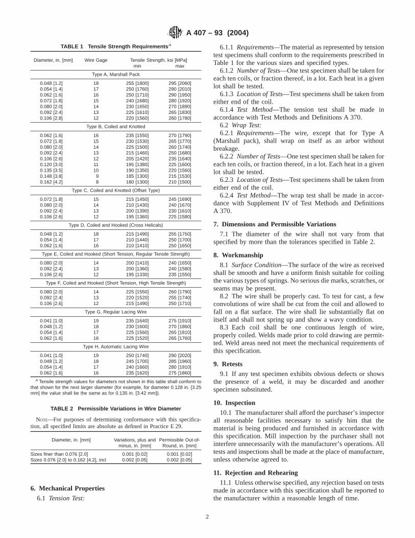
6. Mechanical Properties
6.1 Tension Test:
6.1.1 Requirements—The material as represented by tensiontest specimens shall conform to the requirements prescribed inTable 1 for the various sizes and specified types.
6.1.2 Number of Tests—One test specimen shall be taken foreach ten coils, or fraction thereof, in a lot. Each heat in a givenlot shall be tested.
6.1.3 Location of Tests—Test specimens shall be taken fromeither end of the coil.
6.1.4 Test Method—The tension test shall be made inaccordance with Test Methods and Definitions A 370.
6.2 Wrap Test:6.2.1 Requirements—The wire, except that for Type A
(Marshall pack), shall wrap on itself as an arbor withoutbreakage.
6.2.2 Number of Tests—One test specimen shall be taken foreach ten coils, or fraction thereof, in a lot. Each heat in a givenlot shall be tested.
6.2.3 Location of Tests—Test specimens shall be taken fromeither end of the coil.
6.2.4 Test Method—The wrap test shall be made in accor-dance with Supplement IV of Test Methods and DefinitionsA 370.
7. Dimensions and Permissible Variations
7.1 The diameter of the wire shall not vary from thatspecified by more than the tolerances specified in Table 2.
8. Workmanship
8.1 Surface Condition—The surface of the wire as receivedshall be smooth and have a uniform finish suitable for coilingthe various types of springs. No serious die marks, scratches, orseams may be present.
8.2 The wire shall be properly cast. To test for cast, a fewconvolutions of wire shall be cut from the coil and allowed tofall on a flat surface. The wire shall lie substantially flat onitself and shall not spring up and show a wavy condition.
8.3 Each coil shall be one continuous length of wire,properly coiled. Welds made prior to cold drawing are permit-ted. Weld areas need not meet the mechanical requirements ofthis specification.
9. Retests
9.1 If any test specimen exhibits obvious defects or showsthe presence of a weld, it may be discarded and anotherspecimen substituted.
10. Inspection
10.1 The manufacturer shall afford the purchaser’s inspectorall reasonable facilities necessary to satisfy him that thematerial is being produced and furnished in accordance withthis specification. Mill inspection by the purchaser shall notinterfere unnecessarily with the manufacturer’s operations. Alltests and inspections shall be made at the place of manufacture,unless otherwise agreed to.
11. Rejection and Rehearing
11.1 Unless otherwise specified, any rejection based on testsmade in accordance with this specification shall be reported tothe manufacturer within a reasonable length of time.
TABLE 1 Tensile Strength Requirements A
Diameter, in. [mm] Wire Gage Tensile Strength, ksi [MPa]min max
Type A, Marshall Pack
0.048 [1.2] 18 255 [1800] 295 [2060]0.054 [1.4] 17 250 [1760] 290 [2010]0.062 [1.6] 16 250 [1710] 290 [1950]0.072 [1.8] 15 240 [1680] 280 [1920]0.080 [2.0] 14 230 [1650] 270 [1890]0.092 [2.4] 13 225 [1610] 265 [1830]0.106 [2.8] 12 220 [1560] 260 [1780]
Type B, Coiled and Knotted
0.062 [1.6] 16 235 [1550] 270 [1790]0.072 [1.8] 15 230 [1530] 265 [1770]0.080 [2.0] 14 225 [1500] 260 [1740]0.092 [2.4] 13 215 [1460] 250 [1680]0.106 [2.6] 12 205 [1420] 235 [1640]0.120 [3.0] 11 195 [1380] 225 [1600]0.135 [3.5] 10 190 [1350] 220 [1560]0.148 [3.8] 9 185 [1300] 215 [1530]0.162 [4.2] 8 180 [1300] 210 [1500]
Type C, Coiled and Knotted (Offset Type)
0.072 [1.8] 15 215 [1450] 245 [1690]0.080 [2.0] 14 210 [1430] 240 [1670]0.092 [2.4] 13 200 [1390] 230 [1610]0.106 [2.6] 12 195 [1360] 225 [1580]
Type D, Coiled and Hooked (Cross Helicals)
0.048 [1.2] 18 215 [1490] 255 [1750]0.054 [1.4] 17 210 [1440] 250 [1700]0.062 [1.6] 16 210 [1410] 250 [1650]
Type E, Coiled and Hooked (Short Tension, Regular Tensile Strength)
0.080 [2.0] 14 200 [1410] 240 [1650]0.092 [2.4] 13 200 [1360] 240 [1580]0.106 [2.6] 12 195 [1330] 235 [1550]
Type F, Coiled and Hooked (Short Tension, High Tensile Strength)
0.080 [2.0] 14 225 [1550] 260 [1790]0.092 [2.4] 13 220 [1520] 255 [1740]0.106 [2.6] 12 215 [1490] 250 [1710]
Type G, Regular Lacing Wire
0.041 [1.0] 19 235 [1640] 275 [1910]0.048 [1.2] 18 230 [1600] 270 [1860]0.054 [1.4] 17 225 [1560] 265 [1810]0.062 [1.6] 16 225 [1520] 265 [1760]
Type H, Automatic Lacing Wire
0.041 [1.0] 19 250 [1740] 290 [2020]0.048 [1.2] 18 245 [1700] 285 [1960]0.054 [1.4] 17 240 [1660] 280 [1910]0.062 [1.6] 16 235 [1620] 275 [1860]
A Tensile strength values for diameters not shown in this table shall conform tothat shown for the next larger diameter (for example, for diameter 0.128 in. [3.25mm] the value shall be the same as for 0.135 in. [3.42 mm]).
TABLE 2 Permissible Variations in Wire Diameter
NOTE—For purposes of determining conformance with this specifica-tion, all specified limits are absolute as defined in Practice E 29.
Diameter, in. [mm] Variations, plus andminus, in. [mm]
Permissible Out-of-Round, in. [mm]
Sizes finer than 0.076 [2.0]Sizes 0.076 [2.0] to 0.162 [4.2], incl
0.001 [0.02]0.002 [0.05]
0.001 [0.02]0.002 [0.05]
A 407 – 93 (2004)
2

11.2 Failure of any of the test specimens to comply with therequirements of this specification shall constitute grounds forrejection of the lot represented by the specimen. The lot may beresubmitted for inspection by testing every coil for the char-acteristic in which the specimen failed and sorting out thedefective coils.
11.3 The material must be adequately protected and cor-rectly identified in order that the producer may make properinvestigation.
12. Packaging, Marking, and Loading
12.1 Packaging of the coils of wire shall be by agreementbetween the producer and the purchaser. This agreement shallinclude coil dimensions and weights.
12.2 When specified, the packaging, marking, and loadingshall be in accordance with Practices A 700.
12.3 Marking shall be by a tag securely attached to each coilof wire and shall show the identity of the producer, size of thewire, type, and ASTM specification designation.
12.4 Bar Coding—In addition to the previously-stated iden-tification requirements, bar coding is acceptable as a supple-mentary identification method. Bar coding should be consistentwith AIAG Standard 02.00, Primary Metals Identification TagApplication. The bar code may be applied to a substantiallyaffixed tag.
13. Keywords
13.1 coiled-type; cold-drawn; springs; wire
ASTM International takes no position respecting the validity of any patent rights asserted in connection with any item mentionedin this standard. Users of this standard are expressly advised that determination of the validity of any such patent rights, and the riskof infringement of such rights, are entirely their own responsibility.
This standard is subject to revision at any time by the responsible technical committee and must be reviewed every five years andif not revised, either reapproved or withdrawn. Your comments are invited either for revision of this standard or for additional standardsand should be addressed to ASTM International Headquarters. Your comments will receive careful consideration at a meeting of theresponsible technical committee, which you may attend. If you feel that your comments have not received a fair hearing you shouldmake your views known to the ASTM Committee on Standards, at the address shown below.
This standard is copyrighted by ASTM International, 100 Barr Harbor Drive, PO Box C700, West Conshohocken, PA 19428-2959,United States. Individual reprints (single or multiple copies) of this standard may be obtained by contacting ASTM at the aboveaddress or at 610-832-9585 (phone), 610-832-9555 (fax), or [email protected] (e-mail); or through the ASTM website(www.astm.org).
A 407 – 93 (2004)
3

Designation: A 414/A 414M – 04
Standard Specification forSteel, Sheet, Carbon, for Pressure Vessels 1
This standard is issued under the fixed designation A 414/A 414M; the number immediately following the designation indicates the yearof original adoption or, in the case of revision, the year of last revision. A number in parentheses indicates the year of last reapproval.A superscript epsilon (e) indicates an editorial change since the last revision or reapproval.
1. Scope*
1.1 This specification2 covers hot-rolled carbon steel sheetfor pressure vessels involving fusion welding or brazing.Welding and brazing technique is of fundamental importanceand shall be in accordance with commercial practices.
1.2 The following grades are included in this specification:Mechanical Requirements
Grade Yield Strength, min Tensile Strength, minksi MPa ksi MPa
ABCDEFG
25303335384245
170205230240260290310
45505560657075
310345380415450485515
1.3 Hot-rolled carbon steel sheet is generally furnished incut lengths and to decimal thickness only. Coils may befurnished, provided tension test specimens are taken to repre-sent the middle of the slab as required by 5.1.4. The purchasershould recognize this requires cutting the coils to obtain testsamples and results in half-size coils. The sheet is furnished tothe following size limits:
Width, in. [mm]
Thickness, in. [mm] Over 12 to 48[Over 300 to 1200]
Over 48[Over 1200]
0.270 to 0.230 [7.0 to 6.0] sheet (coils only) sheet (coils only)Under 0.230 to 0.180 [6.0 to 4.5] sheet sheet (coils only)Under 0.180 to 0.057 [under 4.5 to 1.5] sheet sheet
1.4 The values stated in either inch-pound units or SI unitsare to be regarded separately as standard. Within the text, theSI units are shown in brackets. The values stated in eachsystem are not exact equivalents; therefore, each system shall
be used independently of the other. Combining values from thetwo systems may result in nonconformance with the specifi-cation.
1.5 Tolerances are found in General Requirements Specifi-cations A 568/A 568M and A 635/A 635M. The appropriateGeneral Requirements specification is applied based on thethickness and width of the product ordered.
2. Referenced Documents
2.1 ASTM Standards:3
A 568/A 568M Specification for Steel, Sheet, Carbon, andHigh-Strength, Low-Alloy, Hot-Rolled and Cold-Rolled,General Requirements for
A 635/A 635M Specification for Steel, Sheet and Strip,Heavy-Thickness Coils, Carbon, Hot Rolled
3. Ordering Information
3.1 Orders for material under this specification shall includethe following information, as required, to describe the materialadequately:
3.1.1 Designation or specification number, date of issue, andgrade,
3.1.2 Copper bearing steel, when required,3.1.3 Special requirements, if required,3.1.4 Condition—pickled (or blast cleaned), if required.
(Material so ordered will be oiled unless ordered dry.), and3.1.5 Dimensions, including type of edges.3.1.5.1 As agreed upon between the purchaser and the
producer, material ordered to this specification will be suppliedto meet the appropriate standard or restricted thickness toler-ance table shown in Specification A 568/A 568M.
NOTE 1—Not all producers are capable of meeting all of the limitationsof the thickness tolerance tables in Specification A 568/A 568M. Thepurchaser should contact the producer regarding possible limitations priorto placing an order.
3.1.6 Cast or heat analysis, or test report request, or both, ifrequired.
NOTE 2—A typical ordering description is as follows: “ASTM A 414,1 This specification is under the jurisdiction of ASTM Committee A01 on Steel,Stainless Steel, and Related Alloys and is the direct responsibility of SubcommitteeA01.19 on Steel Sheet and Strip.
Current edition approved March 1, 2004. Published March 2004. Originallyapproved in 1971. Last previous edition approved in 2001 as A 414/A 414M – 01.
2 For ASME Boiler and Pressure Vessel Code applications see related Specifi-cation SA-414 in Section 11 of that Code.
3 For referenced ASTM standards, visit the ASTM website, www.astm.org, orcontact ASTM Customer Service at [email protected]. ForAnnual Book of ASTMStandardsvolume information, refer to the standard’s Document Summary page onthe ASTM website.
1
*A Summary of Changes section appears at the end of this standard.
Copyright © ASTM International, 100 Barr Harbor Drive, PO Box C700, West Conshohocken, PA 19428-2959, United States.

Grade A, Hot-Rolled Sheet, 0.100 in. [2.54 mm] by 36 in. [914.4 mm] by96 in. [2438 mm], cut edges.”
4. Chemical Requirements
4.1 Cast or Heat Analysis—The analysis of the steel shallconform to the requirements prescribed in Table 1.
4.1.1 Unspecified elements may be present. Limits on ele-ments shall be as stated in Table 2.
4.1.1.1 Each of the elements listed in Table 2 shall beincluded in the report of the heat analysis. When the amount ofan element present is less than 0.02 %, the analysis may bereported as “<0.02 %.”
4.2 Product, Check, or Verification Analysis—Analysesmay be made by the purchaser from finished material repre-senting each heat.
4.3 Deoxidation—For all grades, killed steel is required.See Table 1 and footnotes A and B.
5. Mechanical Property Requirements
5.1 Tensile Strength:5.1.1 Requirements—Material as represented by the test
specimen shall conform to the tensile requirements specified inTable 3.
5.1.2 Number of Tests—Two tensile tests shall be madefrom the product of each slab as rolled.
5.1.3 Location and Orientation(see Fig. 1):5.1.3.1 Tensile test specimens shall be taken at locations
representing the middle and back end of each slab as rolled.5.1.3.2 Tensile test samples shall be taken from the full
thickness of the sheet as rolled.5.1.3.3 Tensile test specimens shall be taken from a location
approximately halfway between the center of the sheet and theedge of the material as-rolled.
5.1.3.4 Tensile test specimens shall be taken with the axis ofthe test specimen perpendicular to the rolling direction (trans-verse test).
5.1.4 Test Method—Yield strength shall be determined byeither the 0.2 % offset method or by the 0.5 % extension underload method, unless otherwise specified.
6. General Requirements for Delivery
6.1 Material furnished under this specification shall con-form to the applicable requirements of the current edition ofSpecification A 568/A 568M unless otherwise provided herein.
7. Workmanship
7.1 The material shall be free from injurious defects (seeSpecifications A 568/A 568M or A 635/A 635M, as appropri-ate due to thickness).
8. Finish and Appearance
8.1 Surface Finish:8.1.1 Unless otherwise specified, the material shall be fur-
nished without removing the hot-rolled oxide or scale.8.1.2 When required, the material may be specified to be
pickled or blast cleaned.8.2 Oiling:8.2.1 Unless otherwise specified, the material shall be fur-
nished not oiled.8.2.2 When specified to be pickled or blast cleaned, the
material shall be furnished oiled. When required, pickled orblast-cleaned material may be specified to be furnished dry.
8.3 Edges—Unless otherwise specified, mill edges shall befurnished on material that has not had the hot-rolled oxide orscale removed and cut edges shall be furnished on material thathas had the hot-rolled oxide or scale removed.
9. Certification and Reports
9.1 The manufacturer shall furnish copies of a test reportshowing the results of the heat analysis and mechanicalproperty tests made to determine compliance with this speci-fication. The report shall include the purchase order number,
TABLE 1 Chemical Requirements
ElementComposition — Weight % Heat Analysis
Grade A Grade B Grade C Grade D Grade E Grade F Grade G
Carbon, max 0.15 0.22 0.25 0.25 0.27 0.31 0.31Manganese, max 0.90 0.90 0.90 1.20 1.20 1.20 1.35Phosphorus, max 0.035 0.035 0.035 0.035 0.035 0.035 0.035Sulfur, max 0.035 0.035 0.035 0.035 0.035 0.035 0.035Aluminum 0.02–0.08 0.02–0.08 0.02–0.08 0.02–0.08 0.02–0.08 0.02–0.08 0.02–0.08SiliconA,B . . . . . . . . . . . . . . . . . . . . .Copper, when copper steel is specified, min 0.20 0.20 0.20 0.20 0.20 0.20 0.20
A Where an ellipsis (. . .) appears in this table, there is no requirement, but the analysis shall be reported.B When silicon or aluminum-silicon killed steel is specified, a range of 0.15 to 0.30 shall apply to the silicon and a range of 0.02 to 0.08 shall apply to the aluminum.
TABLE 2 Limits on Unspecified Elements (See 4.1.1)
Copper, max %A Heat analysis 0.40Product analysis 0.43
Nickel, max %A Heat analysis 0.40Product analysis 0.43
Chromium, max %A,B Heat analysis 0.30Product analysis 0.34
Molybdenum, max %A,B Heat analysis 0.12Product analysis 0.13
Vanadium, max %C Heat analysis 0.03Product analysis 0.04
Columbium, max %C Heat analysis 0.02Product analysis 0.03
A The sum of copper, nickel, chromium, and molybdenum shall not exceed1.00 % on heat analysis. When one or more of these elements are specified, thesum does not apply, in which case, only the individual limits on the remainingunspecified elements will apply.
B The sum of chromium and molybdenum shall not exceed 0.32 % on heatanalysis. When one or more of these elements are specified, the sum does notapply, in which case, only the individual limits on the remaining unspecifiedelements will apply.
C By agreement, the heat analysis limits for vanadium or columbium, or both,may be increased up to 0.10 % and 0.05 %, respectively.
A 414/A 414M – 04
2
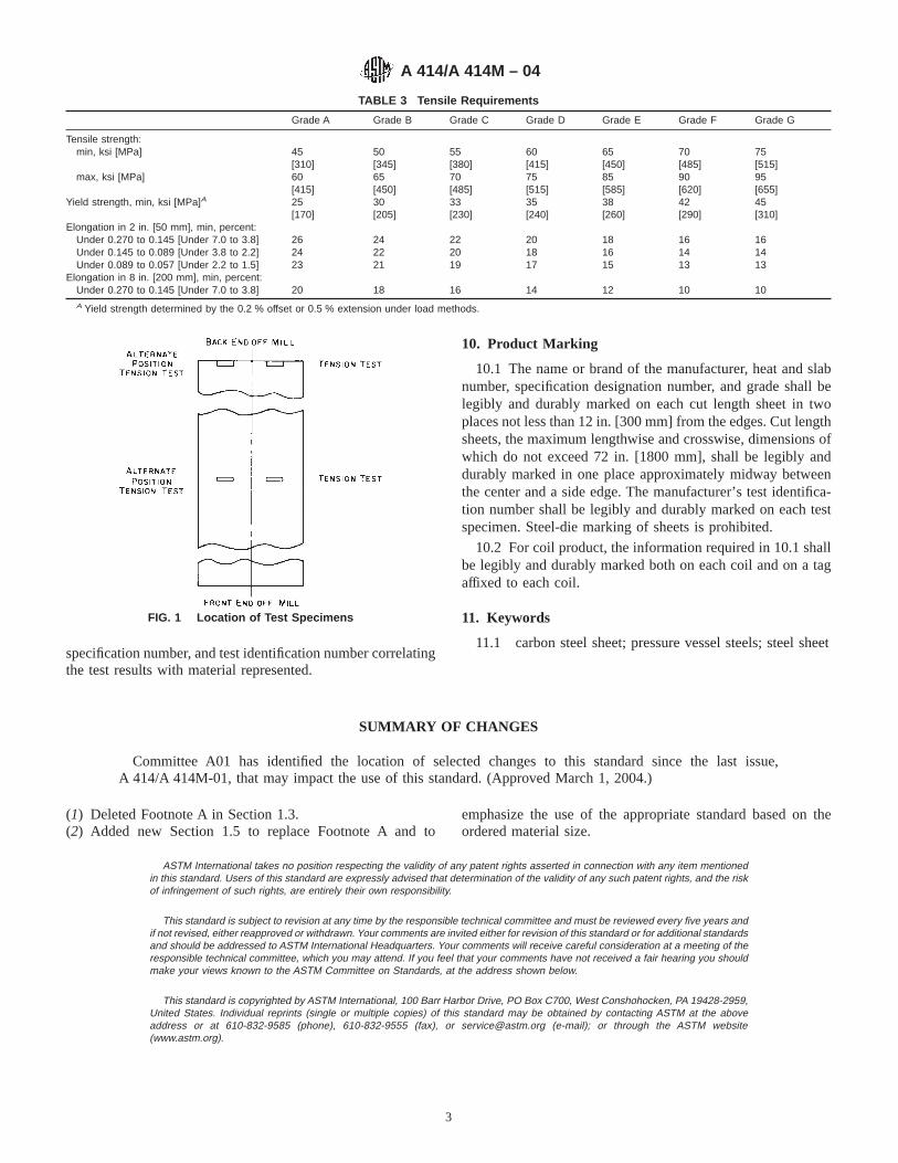
specification number, and test identification number correlatingthe test results with material represented.
10. Product Marking
10.1 The name or brand of the manufacturer, heat and slabnumber, specification designation number, and grade shall belegibly and durably marked on each cut length sheet in twoplaces not less than 12 in. [300 mm] from the edges. Cut lengthsheets, the maximum lengthwise and crosswise, dimensions ofwhich do not exceed 72 in. [1800 mm], shall be legibly anddurably marked in one place approximately midway betweenthe center and a side edge. The manufacturer’s test identifica-tion number shall be legibly and durably marked on each testspecimen. Steel-die marking of sheets is prohibited.
10.2 For coil product, the information required in 10.1 shallbe legibly and durably marked both on each coil and on a tagaffixed to each coil.
11. Keywords
11.1 carbon steel sheet; pressure vessel steels; steel sheet
SUMMARY OF CHANGES
Committee A01 has identified the location of selected changes to this standard since the last issue,A 414/A 414M-01, that may impact the use of this standard. (Approved March 1, 2004.)
(1) Deleted Footnote A in Section 1.3.(2) Added new Section 1.5 to replace Footnote A and to
emphasize the use of the appropriate standard based on theordered material size.
ASTM International takes no position respecting the validity of any patent rights asserted in connection with any item mentionedin this standard. Users of this standard are expressly advised that determination of the validity of any such patent rights, and the riskof infringement of such rights, are entirely their own responsibility.
This standard is subject to revision at any time by the responsible technical committee and must be reviewed every five years andif not revised, either reapproved or withdrawn. Your comments are invited either for revision of this standard or for additional standardsand should be addressed to ASTM International Headquarters. Your comments will receive careful consideration at a meeting of theresponsible technical committee, which you may attend. If you feel that your comments have not received a fair hearing you shouldmake your views known to the ASTM Committee on Standards, at the address shown below.
This standard is copyrighted by ASTM International, 100 Barr Harbor Drive, PO Box C700, West Conshohocken, PA 19428-2959,United States. Individual reprints (single or multiple copies) of this standard may be obtained by contacting ASTM at the aboveaddress or at 610-832-9585 (phone), 610-832-9555 (fax), or [email protected] (e-mail); or through the ASTM website(www.astm.org).
TABLE 3 Tensile Requirements
Grade A Grade B Grade C Grade D Grade E Grade F Grade G
Tensile strength:min, ksi [MPa] 45 50 55 60 65 70 75
[310] [345] [380] [415] [450] [485] [515]max, ksi [MPa] 60 65 70 75 85 90 95
[415] [450] [485] [515] [585] [620] [655]Yield strength, min, ksi [MPa]A 25
[170]30[205]
33[230]
35[240]
38[260]
42[290]
45[310]
Elongation in 2 in. [50 mm], min, percent:Under 0.270 to 0.145 [Under 7.0 to 3.8] 26 24 22 20 18 16 16Under 0.145 to 0.089 [Under 3.8 to 2.2] 24 22 20 18 16 14 14Under 0.089 to 0.057 [Under 2.2 to 1.5] 23 21 19 17 15 13 13
Elongation in 8 in. [200 mm], min, percent:Under 0.270 to 0.145 [Under 7.0 to 3.8] 20 18 16 14 12 10 10A Yield strength determined by the 0.2 % offset or 0.5 % extension under load methods.
FIG. 1 Location of Test Specimens
A 414/A 414M – 04
3

Designation: A 417 – 93 (Reapproved 2004)
Standard Specification forSteel Wire, Cold-Drawn, for Zig-Zag, Square-Formed, andSinuous-Type Upholstery Spring Units 1
This standard is issued under the fixed designation A 417; the number immediately following the designation indicates the year oforiginal adoption or, in the case of revision, the year of last revision. A number in parentheses indicates the year of last reapproval. Asuperscript epsilon (e) indicates an editorial change since the last revision or reapproval.
1. Scope
1.1 This specification covers round, uncoated, cold-drawnspring wire in coils having properties and quality intended forthe manufacture of the following upholstery springs:
1.1.1 Type A—Zig-zag (U-formed),1.1.2 Type B—Square-formed, and1.1.3 Type C—Sinuous for furniture spring units.1.2 These types of upholstery springs are used in the
manufacture of automotive seat springs and furniture springs.The wire is not intended for the manufacture of mechanicalsprings.
2. Referenced Documents
2.1 ASTM Standards:2
A 370 Test Methods and Definitions for Mechanical Testingof Steel Products
A 700 Practices for Packaging, Marking, and LoadingMethods for Steel Products for Domestic Shipment
E 29 Practice for Using Significant Digits in Test Data toDetermine Conformance With Specifications
2.2 AIAG Standard:AIAG B-5 02.00 Primary Metals Identification Tag Appli-
cation Standard3
3. Ordering Information
3.1 Orders for material under this specification shouldinclude the following information for each ordered item:
3.1.1 Quantity (weight),3.1.2 Name of material (name of specific type required)
(Section 1 and Table 1),3.1.3 Diameter (Table 2),3.1.4 Packaging, marking, and loading (Section 10),
3.1.5 ASTM designation and date of issue, and3.1.6 Heat (cast) analysis (if desired).
NOTE 1—A typical ordering description is as follows: 50 000 lb[15 000 kg] cold-drawn, upholstery, spring wire Type A for zig-zag-typesprings, Class 1, 200 to 300 ksi, size 0.148 in. [3.0 mm] in 2000-lb [700kg] coils to ASTM A 417, dated .
4. Manufacture
4.1 The steel shall be made by any of the followingprocesses: open-hearth, basic-oxygen, or electric-furnace.
4.2 A sufficient discard shall be made to ensure freedomfrom injurious piping and undue segregation.
4.3 The wire shall be cold-drawn to produce the desiredmechanical properties.
5. Chemical Composition
5.1 Upholstery spring wire for these types of springs iscustomarily produced within the chemical ranges shown be-low. Chemical composition and processing may vary depend-ing on the gage of wire and specific use.
Carbon, % 0.50 to 0.75A
Manganese, % 0.60 to 1.20A
Phosphorus, max, % 0.040Sulfur, max, % 0.050
A In any lot in which all the wire is of the same size and type, and submitted forinspection at the same time, the carbon content shall not vary more than 0.20 %,and the manganese content shall not vary more than 0.30 %.
5.2 An analysis of each heat (cast) shall be made by themanufacturer to determine the percentage of elements specifiedabove. The analysis shall be made from a test sample prefer-ably taken during the pouring of the heat (cast). The chemicalcomposition thus determined shall be reported to the purchaseror his representative upon request.
6. Mechanical Properties
6.1 Tension Test:6.1.1 Requirements—The material as represented by tension
test specimens shall conform to the requirements prescribed inTable 1 for the various sizes and specified types.
6.1.2 Number of Tests—One test specimen shall be taken foreach ten coils, or fraction thereof, in a lot. Each heat in a givenlot shall be tested.
6.1.3 Location of Tests—The test specimen shall be takenfrom either end of the coil.
1 This specification is under the jurisdiction of ASTM Committee A01 on Steel,Stainless Steel and Related Alloys, and is the direct responsibility of SubcommitteeA01.03 on Steel Rod and Wire.
Current edition approved March 1, 2004. Published March 2004. Originallyapproved in 1957. Last previous edition approved in 1998 as A 417 – 93 (1998).
2 For referenced ASTM standards, visit the ASTM website, www.astm.org, orcontact ASTM Customer Service at [email protected]. ForAnnual Book of ASTMStandardsvolume information, refer to the standard’s Document Summary page onthe ASTM website.
3 Available from Automotive Industry Action Group (AIAG), 26200 Lahser Rd.,Suite 200, Southfield, MI 48034.
1
Copyright © ASTM International, 100 Barr Harbor Drive, PO Box C700, West Conshohocken, PA 19428-2959, United States.

6.1.4 Test Method—The tension test shall be made inaccordance with Test Methods and Definitions A 370.
6.2 Wrap Test:6.2.1 Requirements—The wire for zig-zag-type and for
square-formed-type springs for automobile seat and backspring units shall wrap on itself as an arbor without breakage.The wire for sinuous-type furniture spring units shall wrap ona mandrel twice the diameter of the wire without breakage.
6.2.2 Number of Tests—One test specimen shall be taken foreach ten coils, or fraction thereof in a lot. Each heat in a givenlot shall be tested.
6.2.3 Location of Tests—The test specimen shall be takenfrom either end of the coil.
6.2.4 Test Method—The wrap test shall be made in accor-dance with Supplement IV of Test Methods and DefinitionsA 370.
7. Dimensions and Permissible Variations
7.1 The diameter of the wire shall not vary from thatspecified by more than the tolerances specified in Table 2.
8. Workmanship
8.1 Surface Condition—The surface of the wire as receivedshall be smooth and shall have a uniform finish suitable forshaping the various type springs. No serious die marks,scratches, or seams may be present.
8.2 The wire shall be properly cast. To test for cast, a fewconvolutions of wire shall be cut from the coil and allowed tofall on a flat surface. The wire shall lie substantially flat onitself and shall not spring up and show a wavy condition.
8.3 Each coil shall be one continuous length of wire,properly coiled. Welds made prior to cold drawing are permit-ted. Weld areas need not meet the mechanical requirements ofthis specification.
9. Retests
9.1 If any test specimen exhibits obvious defects or showsthe presence of a weld, it may be discarded and anotherspecimen substituted.
10. Inspection
10.1 The manufacturer shall afford the purchaser’s inspectorall reasonable facilities necessary to satisfy him that thematerial is being produced and furnished in accordance withthis specification. Mill inspection by the purchaser shall notinterfere unnecessarily with the manufacturer’s operations. Alltests and inspections shall be made at the place of manufacture,unless otherwise agreed to.
11. Rejection and Rehearing
11.1 Unless otherwise specified, any rejection based on testsmade in accordance with this specification shall be reported tothe manufacturer within a reasonable length of time.
11.2 Failure of any of the test specimens to comply with therequirements of this specification shall constitute grounds forrejection of the lot represented by the specimen. The lot may beresubmitted for inspection by testing every coil for the char-acteristic in which the specimen failed and sorting out thedefective coils.
11.3 The material must be adequately protected and cor-rectly identified in order that the manufacturer may makeproper investigation.
12. Packaging, Product Marking, and Loading
12.1 Packaging of the coils of wire shall be by agreementbetween the manufacturer and the purchaser. This agreementshall include coil dimensions and weights.
12.2 When specified, the packaging, marking, and loadingshall be in accordance with Practices A 700.
12.3 Marking shall be by a tag securely attached to each coilof wire and shall show the identity of the producer, size of thewire, type, and ASTM specification number.
12.4 Bar Coding—In addition to the previously-stated iden-tification requirements, bar coding is acceptable as a supple-mentary identification method. Bar coding should be consistentwith AIAG Standard 02.00, Primary Metals Identification TagApplication. The bar code may be applied to a substantiallyaffixed tag.
TABLE 1 Tensile Strength Requirements A
DiameterB
Decimal Size,in. [mm]
Wire Gage
Tensile Strength, ksi(MPa)C
Tensile Strength, ksi(MPa)C
min max min max
Type A, Zig-Zag Type Automobile Seat and Back Spring Units
Class I Class II
0.092 [2.4] 13 220 250 230 2600.106 [2.6] 12 215 245 225 2550.120 [3.0] 11 210 240 215 2450.135 [3.5] 10 205 235 210 2400.148 [3.8] 9 200 230 210 2400.162 [4.2] 8 190 220 200 230
Type B, Square-Formed Type Automobile Seat and Back Spring Units
0.092 [2.4] 13 215 245 225 2550.106 [2.6] 12 210 240 220 2500.120 [3.0] 11 205 235 215 2450.135 [3.5] 10 200 230 210 2400.148 [3.8] 9 190 220 200 2300.162 [4.2] 8 180 210 190 220
Type C, Sinuous Type Furniture Spring Units
0.092 [2.4] 13 235 2650.106 [2.6] 12 235 2650.120 [3.0] 11 230 2600.135 [3.5] 10 225 2550.148 [3.8] 9 220 2500.162 [4.2] 8 215 2450.177 [4.5] 7 210 2400.192 [5.0] 6 207 237
A Tensile strength values for diameters not shown in this table shall conform tothat shown for the next larger diameter. (For example, for diameter 0.128 in. [3.25mm], the value shall be the same as for 0.135 in. [3.5 mm])
B Decimal size is rounded to three significant places in accordance with PracticeE 29.
C 1 ksi = 6.89 MPa.
TABLE 2 Permissible Variations in Wire Diameter
NOTE 1—For purposes of determining conformance with this specifi-cation, all limits are considered absolute as defined in Practice E 29.
Diameter, in. [mm]Variations, plus and
minus, in. [mm]Permissible Out-of-
Round, in. [mm]
Sizes 0.092 [2.2] to 0.192 [5.2] 0.002 [0.05] 0.002 [0.05]
A 417 – 93 (2004)
2

13. Keywords13.1 cold-drawn; sinuous; spring; square-formed; uphol-
stery; wire; zig-zag
ASTM International takes no position respecting the validity of any patent rights asserted in connection with any item mentionedin this standard. Users of this standard are expressly advised that determination of the validity of any such patent rights, and the riskof infringement of such rights, are entirely their own responsibility.
This standard is subject to revision at any time by the responsible technical committee and must be reviewed every five years andif not revised, either reapproved or withdrawn. Your comments are invited either for revision of this standard or for additional standardsand should be addressed to ASTM International Headquarters. Your comments will receive careful consideration at a meeting of theresponsible technical committee, which you may attend. If you feel that your comments have not received a fair hearing you shouldmake your views known to the ASTM Committee on Standards, at the address shown below.
This standard is copyrighted by ASTM International, 100 Barr Harbor Drive, PO Box C700, West Conshohocken, PA 19428-2959,United States. Individual reprints (single or multiple copies) of this standard may be obtained by contacting ASTM at the aboveaddress or at 610-832-9585 (phone), 610-832-9555 (fax), or [email protected] (e-mail); or through the ASTM website(www.astm.org).
A 417 – 93 (2004)
3

Designation: A 424 – 00
Standard Specification forSteel, Sheet, for Porcelain Enameling 1
This standard is issued under the fixed designation A 424; the number immediately following the designation indicates the year oforiginal adoption or, in the case of revision, the year of last revision. A number in parentheses indicates the year of last reapproval. Asuperscript epsilon (e) indicates an editorial change since the last revision or reapproval.
This standard has been approved for use by agencies of the Department of Defense.
1. Scope
1.1 This specification covers sheet steel in coils and cutlengths for porcelain enameling. The compositions and pro-cessing of these steels are such that articles for porcelainenameling may be fabricated from them and, under properconditions, enameled. The steels are furnished as Type I, TypeII, and Type III. Type I and Type II are supplied in twodesignations, Commercial Steel and Drawing Steel. Type IIIsteel is interstitial-free and does not require a designation.
2. Referenced Documents
2.1 ASTM Standards:A 568/A568M Specification for Steel, Sheet, Carbon, and
High-Strength, Low-Alloy, Hot-Rolled and Cold-Rolled,General Requirements for2
3. Terminology
3.1 Types:3.1.1 Type I has an extremely low carbon level. This
material is suitable for direct cover coat enameling practice,but this requirement must be indicated by the purchaser inaccordance with 4.1.6. This material is also suitable for groundand cover coat enameling practice. It has good sag resistanceand good formability.
3.1.2 Type II steel is suitable for applications where groundand cover coat enameling operations are employed. Thecomposition of the Type II steel is obtained in meltingoperations.
3.1.3 Type III is an interstitial-free steel and is suitable forapplications where ground and cover coat enameling opera-tions are employed. The composition of the Type III steel isobtained in melting operations. It has good sag resistance andexcellent formability.
3.2 Quality Designations:
3.2.1 Commercial Steel is intended for parts where bend-ing, moderate forming, or moderate drawing may be involved.
3.2.2 Drawing Steel is intended for fabricating identifiedparts where the draw is particularly severe or where thematerial shall be essentially free of changes in mechanicalproperties over a period of time. Drawing Steel should bespecified where the formed material shall be essentially free ofsuch surface disturbances as stretcher strains or fluting withoutthe need of prior roller leveling.
3.2.3 Type III interstitial-free steel is intended for fabricat-ing identified parts where the most severe drawing or formingis involved and where the material must be free of changes inmechanical properties over a period of time and free of suchsurface disturbances as stretcher strains or fluting without theneed of prior roller leveling.
3.3 Porcelain Enamels:3.3.1 Ground coat enamels are glasses used primarily for
their bonding characteristics. They may be applied after propermetal preparation (either pickle or pickle-free depending onenamel system). These glasses may be applied as either drypowders or wet slips. This type enamel is suitable for all threetypes of steel (Type I, II, or III).
3.3.2 Cover coat enamels are appearance glasses applied forspecific color, corrosion, alkali resistance, and so forth. Theseenamels may be applied directly to Type I steels after suitablemetal preparation. They may also be applied over fired groundcoat enamels. They may be applied as either dry powder or wetslip.
3.3.3 Two coat-one fire enamels are special glass systemsapplied as dry powders. They usually are applied as pickle-freesystems. They are suitable for all three types of steel (Type I,II, or III). Both the base coat (adherence promoting enamel)and the cover coat (color or other specific properties) areapplied and fired at the same time.
4. Ordering Information
4.1 Orders for material under this specification shall includethe following information, as required, to describe adequatelythe desired material:
4.1.1 Quantity,4.1.2 ASTM specification number and date of issue,
1 This specification is under the jurisdiction of ASTM Committee A-1 on Steel,Stainless Steel and Related Alloysand is the direct responsibility of SubcommitteeA01.19on Steel Sheet and Strip.
Current edition approved March 10, 2000. Published May 2000. Originallypublished as A 424 – 58 T. Last previous edition A 424 – 97.
2 Annual Book of ASTM Standards,Vol 01.03.
1
Copyright © ASTM International, 100 Barr Harbor Drive, PO Box C700, West Conshohocken, PA 19428-2959, United States.

4.1.3 Name of material (Porcelain Enameling Sheet, Type I,Drawing Steel),
4.1.4 Condition (oiled unless otherwise specified),4.1.5 Finish (matte (dull) finish will be supplied unless
otherwise specified),4.1.6 Enameling practice (for Type I, indicate if direct cover
coat practice will be used), and4.1.7 Dimensions (thickness, width, and length for cut
lengths, or thickness and width of coils).4.1.7.1 As agreed upon between the purchaser and the
producer, material ordered to this specification will be suppliedto meet the appropriate standard or restricted thickness toler-ance table shown in Specification A 568/A 568M.
NOTE 1—Not all producers are capable of meeting all of the limitationsof the thickness tolerance tables in Specification A 568/A 568M. Thepurchaser should contact the producer regarding possible limitations priorto placing an order.
4.1.8 Coil size and weight requirements (must includeinside and outside diameters and maximum weight),
4.1.9 Application (show part identification and description),4.1.10 Special requirements (if required), and4.1.11 Heat analysis (if required) (see 9.1).
NOTE 2—A typical ordering description is as follows: 40 000 lb,ASTM A 424 (latest issue) Porcelain Enameling Sheet, Type I, DrawingSteel, direct cover coat, 0.048 in. by 35 in. by 96 in., Part 2587, RangeTop.
5. Chemical Requirements
5.1 The heat analysis of Type I, Type II, and Type III shallconform to the requirements prescribed in Table 1 except forcarbon in Type I as noted.
6. Mechanical Requirements
6.1 Bend Test—Commercial Steel sheet shall be capable ofbeing bent at room temperature in any direction through 180°flat on itself without cracking on the outside of the bentportion.
6.2 Formability—Drawing Steel and Type III sheet shallproduce an identified part within a properly established break-age allowance.
7. Workmanship, Finish, and Appearance
7.1 Surface Finish—Unless otherwise specified, the sheetshall have a matte (dull) finish suitable for porcelain enamel-ing.
7.2 Oiling—Unless otherwise specified, the sheet shall beoiled.
8. General Requirements for Delivery
8.1 Material furnished under this specification shall con-form to the applicable requirements of the current edition ofSpecification A 568/A 568M.
8.2 Products covered by this specification are produced todecimal thickness only and decimal thickness tolerances apply.
9. Certification
9.1 When requested, the manufacturer shall furnish theresults of the heat analysis made to determine compliance withthis specification and shall include the purchase order number,ASTM designation number, and heat number correlating theresults with the material represented.
10. Keywords
10.1 sheet; steel
ASTM International takes no position respecting the validity of any patent rights asserted in connection with any item mentionedin this standard. Users of this standard are expressly advised that determination of the validity of any such patent rights, and the riskof infringement of such rights, are entirely their own responsibility.
This standard is subject to revision at any time by the responsible technical committee and must be reviewed every five years andif not revised, either reapproved or withdrawn. Your comments are invited either for revision of this standard or for additional standardsand should be addressed to ASTM International Headquarters. Your comments will receive careful consideration at a meeting of theresponsible technical committee, which you may attend. If you feel that your comments have not received a fair hearing you shouldmake your views known to the ASTM Committee on Standards, at the address shown below.
This standard is copyrighted by ASTM International, 100 Barr Harbor Drive, PO Box C700, West Conshohocken, PA 19428-2959,United States. Individual reprints (single or multiple copies) of this standard may be obtained by contacting ASTM at the aboveaddress or at 610-832-9585 (phone), 610-832-9555 (fax), or [email protected] (e-mail); or through the ASTM website(www.astm.org).
TABLE 1 Chemical Requirements A
ElementComposition, max, percent
Type I Type II Type III
Carbon 0.008B 0.05 0.02Manganese 0.40 0.50 0.35Phosphorus 0.020 0.020 0.020Sulfur 0.030 0.030 0.030Other C D
A Where aluminum is used as the deoxidizing agent, the aluminum content totalby product analysis is usually in excess of 0.010 %.
B Heat analysis of carbon is not appropriate for Type I. Sheet product analysis isappropriate for checking proper type of material. Extremely low carbon levels canbe checked accurately with carbon-combustion type of analyzers.
C Microalloy additions are permitted to meet special customer requirements.D Columbium or titanium additions, or both, are made to combine with carbon
and nitrogen to produce an interstitial-free steel.
A 424 – 00
2
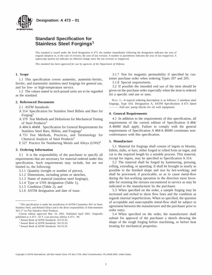
Designation: A 473 – 01
Standard Specification forStainless Steel Forgings 1
This standard is issued under the fixed designation A 473; the number immediately following the designation indicates the year oforiginal adoption or, in the case of revision, the year of last revision. A number in parentheses indicates the year of last reapproval. Asuperscript epsilon (e) indicates an editorial change since the last revision or reapproval.
This standard has been approved for use by agencies of the Department of Defense.
1. Scope
1.1 This specification covers austenitic, austenitic-ferritic,ferritic, and martensitic stainless steel forgings for general use,and for low- or high-temperature service.
1.2 The values stated in inch-pound units are to be regardedas the standard.
2. Referenced Documents
2.1 ASTM Standards:A 314 Specification for Stainless Steel Billets and Bars for
Forging2
A 370 Test Methods and Definitions for Mechanical Testingof Steel Products3
A 484/A 484M Specification for General Requirements forStainless Steel Bars, Billets, and Forgings2
A 751 Test Methods, Practices, and Terminology forChemical Analysis of Steel Products3
E 527 Practice for Numbering Metals and Alloys (UNS)4
3. Ordering Information
3.1 It is the responsibility of the purchaser to specify allrequirements that are necessary for material ordered under thisspecification. Such requirements may include, but are notlimited to, the following:
3.1.1 Quantity (weight or number of pieces),3.1.2 Dimensions, including prints or sketches,3.1.3 Name of material (stainless steel forgings),3.1.4 Type or UNS designation (Table 1),3.1.5 Condition (Table 2), and3.1.6 ASTM designation and date of issue.
3.1.7 Test for magnetic permeability if specified by cus-tomer purchase order when ordering Types 207 and 205.
3.1.8 Special requirements.3.2 If possible the intended end use of the item should be
given on the purchase order especially when the item is orderedfor a specific end use or uses.
NOTE 1—A typical ordering description is as follows: 5 stainless steelforgings, Type 410, Designation A, ASTM Specification A 473 dated———. End use: pump blocks for oil well equipment.
4. General Requirements
4.1 In addition to the requirements of this specification, allrequirements of the current edition of Specification A 484/A 484M shall apply. Failure to comply with the generalrequirements of Specification A 484/A 484M constitutes non-conformance with this specification.
5. Manufacture
5.1 Material for forgings shall consist of ingots or blooms,billets, slabs, or bars, either forged or rolled from an ingot, andcut to the required length by a suitable process. This material,except for ingots, may be specified to Specification A 314.
5.2 The material shall be forged by hammering, pressing,rolling, extruding, or upsetting. It shall be brought as nearly aspossible to the finished shape and size by hot-working; andshall be processed, if practicable, so as to cause metal-flowduring the hot-working operation in the direction most favor-able for resisting the stresses encountered in service as may beindicated to the manufacturer by the purchaser.
5.3 When specified on the order, a sample forging may besectioned and etched to show flow lines and the condition asregards internal imperfections. When so specified, the questionof acceptable and unacceptable metal-flow shall be subject toagreement between the manufacturer and the purchaser prior toorder entry.
5.4 When specified on the order, the manufacturer shallsubmit for approval of the purchaser a sketch showing theshape of the rough forging before machining, or before heattreating for mechanical properties.
1 This specification is under the jurisdiction of ASTM Committee A01 on Steel,Stainless Steel, and Related Alloys and is the direct responsibility of SubcommitteeA01.17 on Flat Stainless Steel Products.
Current edition approved Mar. 10, 2001. Published April 2001. Originallypublished as A 473 – 62 T. Last previous edition A 473 – 99.
2 Annual Book of ASTM Standards, Vol 01.05.3 Annual Book of ASTM Standards, Vol 01.03.4 Annual Book of ASTM Standards, Vol 01.01.
1
Copyright © ASTM International, 100 Barr Harbor Drive, PO Box C700, West Conshohocken, PA 19428-2959, United States.
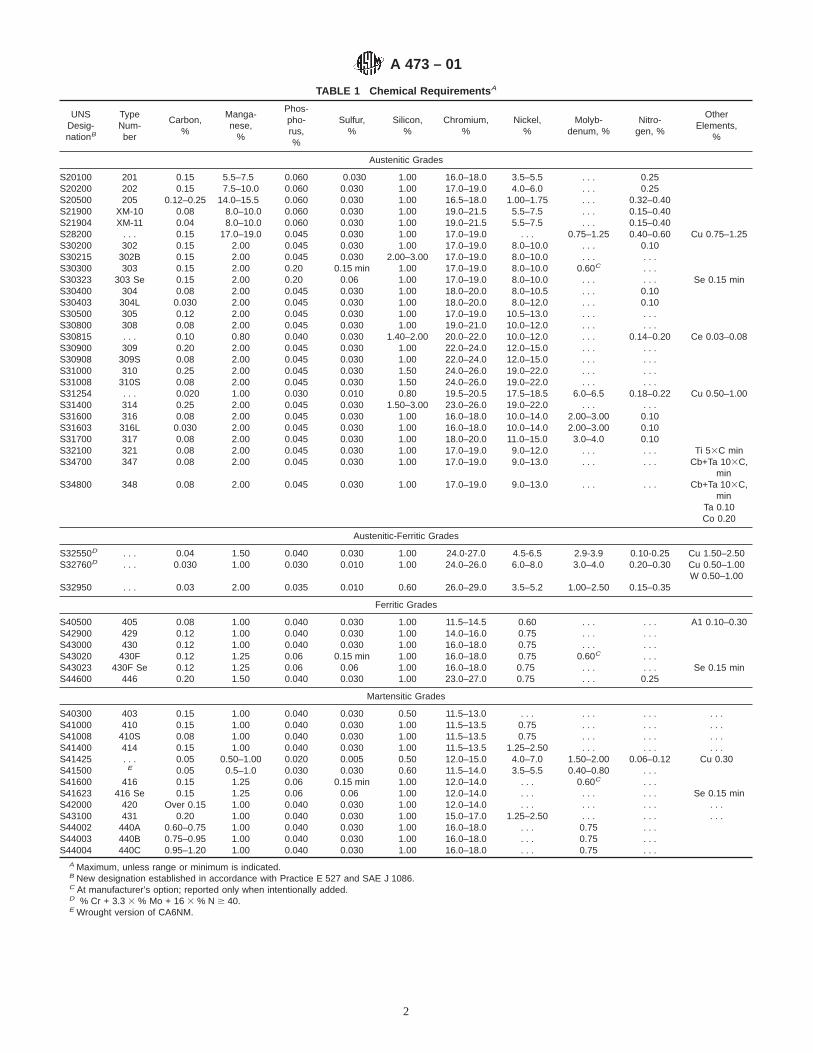
TABLE 1 Chemical Requirements A
UNSDesig-nationB
TypeNum-ber
Carbon,%
Manga-nese,
%
Phos-pho-rus,%
Sulfur,%
Silicon,%
Chromium,%
Nickel,%
Molyb-denum, %
Nitro-gen, %
OtherElements,
%
Austenitic Grades
S20100 201 0.15 5.5–7.5 0.060 0.030 1.00 16.0–18.0 3.5–5.5 . . . 0.25S20200 202 0.15 7.5–10.0 0.060 0.030 1.00 17.0–19.0 4.0–6.0 . . . 0.25S20500 205 0.12–0.25 14.0–15.5 0.060 0.030 1.00 16.5–18.0 1.00–1.75 . . . 0.32–0.40S21900 XM-10 0.08 8.0–10.0 0.060 0.030 1.00 19.0–21.5 5.5–7.5 . . . 0.15–0.40S21904 XM-11 0.04 8.0–10.0 0.060 0.030 1.00 19.0–21.5 5.5–7.5 . . . 0.15–0.40S28200 . . . 0.15 17.0–19.0 0.045 0.030 1.00 17.0–19.0 . . . 0.75–1.25 0.40–0.60 Cu 0.75–1.25S30200 302 0.15 2.00 0.045 0.030 1.00 17.0–19.0 8.0–10.0 . . . 0.10S30215 302B 0.15 2.00 0.045 0.030 2.00–3.00 17.0–19.0 8.0–10.0 . . . . . .S30300 303 0.15 2.00 0.20 0.15 min 1.00 17.0–19.0 8.0–10.0 0.60C . . .S30323 303 Se 0.15 2.00 0.20 0.06 1.00 17.0–19.0 8.0–10.0 . . . . . . Se 0.15 minS30400 304 0.08 2.00 0.045 0.030 1.00 18.0–20.0 8.0–10.5 . . . 0.10S30403 304L 0.030 2.00 0.045 0.030 1.00 18.0–20.0 8.0–12.0 . . . 0.10S30500 305 0.12 2.00 0.045 0.030 1.00 17.0–19.0 10.5–13.0 . . . . . .S30800 308 0.08 2.00 0.045 0.030 1.00 19.0–21.0 10.0–12.0 . . . . . .S30815 . . . 0.10 0.80 0.040 0.030 1.40–2.00 20.0–22.0 10.0–12.0 . . . 0.14–0.20 Ce 0.03–0.08S30900 309 0.20 2.00 0.045 0.030 1.00 22.0–24.0 12.0–15.0 . . . . . .S30908 309S 0.08 2.00 0.045 0.030 1.00 22.0–24.0 12.0–15.0 . . . . . .S31000 310 0.25 2.00 0.045 0.030 1.50 24.0–26.0 19.0–22.0 . . . . . .S31008 310S 0.08 2.00 0.045 0.030 1.50 24.0–26.0 19.0–22.0 . . . . . .S31254 . . . 0.020 1.00 0.030 0.010 0.80 19.5–20.5 17.5–18.5 6.0–6.5 0.18–0.22 Cu 0.50–1.00S31400 314 0.25 2.00 0.045 0.030 1.50–3.00 23.0–26.0 19.0–22.0 . . . . . .S31600 316 0.08 2.00 0.045 0.030 1.00 16.0–18.0 10.0–14.0 2.00–3.00 0.10S31603 316L 0.030 2.00 0.045 0.030 1.00 16.0–18.0 10.0–14.0 2.00–3.00 0.10S31700 317 0.08 2.00 0.045 0.030 1.00 18.0–20.0 11.0–15.0 3.0–4.0 0.10S32100 321 0.08 2.00 0.045 0.030 1.00 17.0–19.0 9.0–12.0 . . . . . . Ti 53C minS34700 347 0.08 2.00 0.045 0.030 1.00 17.0–19.0 9.0–13.0 . . . . . . Cb+Ta 103C,
minS34800 348 0.08 2.00 0.045 0.030 1.00 17.0–19.0 9.0–13.0 . . . . . . Cb+Ta 103C,
minTa 0.10Co 0.20
Austenitic-Ferritic Grades
S32550D . . . 0.04 1.50 0.040 0.030 1.00 24.0-27.0 4.5-6.5 2.9-3.9 0.10-0.25 Cu 1.50–2.50S32760D . . . 0.030 1.00 0.030 0.010 1.00 24.0–26.0 6.0–8.0 3.0–4.0 0.20–0.30 Cu 0.50–1.00
W 0.50–1.00S32950 . . . 0.03 2.00 0.035 0.010 0.60 26.0–29.0 3.5–5.2 1.00–2.50 0.15–0.35
Ferritic Grades
S40500 405 0.08 1.00 0.040 0.030 1.00 11.5–14.5 0.60 . . . . . . A1 0.10–0.30S42900 429 0.12 1.00 0.040 0.030 1.00 14.0–16.0 0.75 . . . . . .S43000 430 0.12 1.00 0.040 0.030 1.00 16.0–18.0 0.75 . . . . . .S43020 430F 0.12 1.25 0.06 0.15 min 1.00 16.0–18.0 0.75 0.60C . . .S43023S44600
430F Se446
0.120.20
1.251.50
0.060.040
0.060.030
1.001.00
16.0–18.023.0–27.0
0.750.75
. . .
. . .. . .0.25
Se 0.15 min
Martensitic Grades
S40300 403 0.15 1.00 0.040 0.030 0.50 11.5–13.0 . . . . . . . . . . . .S41000 410 0.15 1.00 0.040 0.030 1.00 11.5–13.5 0.75 . . . . . . . . .S41008 410S 0.08 1.00 0.040 0.030 1.00 11.5–13.5 0.75 . . . . . . . . .S41400 414 0.15 1.00 0.040 0.030 1.00 11.5–13.5 1.25–2.50 . . . . . . . . .S41425 . . . 0.05 0.50–1.00 0.020 0.005 0.50 12.0–15.0 4.0–7.0 1.50–2.00 0.06–0.12 Cu 0.30S41500 E 0.05 0.5–1.0 0.030 0.030 0.60 11.5–14.0 3.5–5.5 0.40–0.80 . . .S41600 416 0.15 1.25 0.06 0.15 min 1.00 12.0–14.0 . . . 0.60C . . .S41623 416 Se 0.15 1.25 0.06 0.06 1.00 12.0–14.0 . . . . . . . . . Se 0.15 minS42000 420 Over 0.15 1.00 0.040 0.030 1.00 12.0–14.0 . . . . . . . . . . . .S43100 431 0.20 1.00 0.040 0.030 1.00 15.0–17.0 1.25–2.50 . . . . . . . . .S44002 440A 0.60–0.75 1.00 0.040 0.030 1.00 16.0–18.0 . . . 0.75 . . .S44003 440B 0.75–0.95 1.00 0.040 0.030 1.00 16.0–18.0 . . . 0.75 . . .S44004 440C 0.95–1.20 1.00 0.040 0.030 1.00 16.0–18.0 . . . 0.75 . . .
A Maximum, unless range or minimum is indicated.B New designation established in accordance with Practice E 527 and SAE J 1086.C At manufacturer’s option; reported only when intentionally added.D % Cr + 3.3 3 % Mo + 16 3 % N $ 40.E Wrought version of CA6NM.
A 473 – 01
2

5.5 The grain size shall be as fine as practicable andprecautions shall be taken to minimize grain growth.
6. Heat Treatment
6.1 Except for S31254, the austenitic steels shall receive asolution heat treatment, consisting of heating the material to aminimum temperature of 1900°F (1040°C), followed by cool-ing rapidly in air or water.
6.2 S31254 shall receive a solution heat treatment, consist-ing of heating the material to a minimum temperature of2100°F (1150°C) followed by cooling rapidly in air or water.
6.3 When specified, Types 347, 348, and 321 shall receive astabilization heat treatment in addition to the solution heattreatment specified in 6.1, which shall consist of holding theforgings at 1550 to 1750°F (845 to 955°C) for 1 h for each inchof section thickness with a minimum holding time of 2 h,followed by air-cooling or water quenching. The stabilizationheat treatment is not usually specified, unless thesesteels areintended for severely corrosive environments in the tempera-ture range from 800 to 1600°F (425 to 870°C). When specified,
the stabilization heat treatment shall be the final heat treatmentand may be performed before machining.
6.4 S32950 shall receive an annealing treatment, consistingof heating the material to a temperature of 1825°F (995°C) to1875°F (1025°C) for an appropriate time followed by waterquenching or rapid cooling by other means.
6.5 S32760 shall receive an annealing treatment consistingof heating the material to a minimum temperature of 2010°F(1100°C), followed by water quenching or rapid cooling byother means.
6.6 The ferritic grades shall be properly annealed:6.7 Except for S41425 and S41500, the martensitic grades
shall be annealed, or hardened and tempered as specified.Liquid quenching shall be permitted only by agreement withthe purchaser.
6.8 For S41425, heat to 1700°F (925°C) minimum and holdfor 1 h attemperature minimum. Air cool to below 90°F (32°C)and temper at 1100°F (595°C) minimum for 1 h/in. ofcross-sectional thickness minimum.
TABLE 2 Mechanical Property Requirements
Type ConditionYield Strength,
min, ksi(MPa)A
Tensile Strength,min, ksi(MPa)
Elongationin 2 in.
(50 mm) or4D, min %
Reductionof Area,min, %
BrinellHardnessNumber,
max
Austenitic Grades
201, 302, 302B, 303, 303SE, 305, 308, 309,309S, 310, 310S, 314, 317, 321, 347, 348
A 30 (205) 75 (515) 40 50 . . .
202 A 45 (310) 90 (620) 40 50 . . .205 A 50 (345) 90 (620) 40 50 . . .304 and 316, Sections 5 in. (127 mm) andUnder
A 30 (205) 75 (515) 40 50 . . .
304 and 316, Sections Over 5 in. (127 mm) A 30 (205) 70 (485) 40 50 . . .304L and 316L A 25 (170) 65 (450) 40 50 . . .XM-10 and XM-11 A 50 (345) 90 (620) 45 60 . . .S28200 A 60 (415) 110 (760) 40 55 . . .S30815 A 45 (310) 87 (600) 40 50 . . .S31254 A 44 (300) 95 (650) 35 50 . . .
Austenitic-Ferritic Grades
S32550 A 80 (550) 109 (750) 25.0 . . . 290S32950 A 70 (480) 100 (690) 15 . . . 293S32760 A 80 (550) 109 (750) 25 . . . 290
Ferritic Grades
430F, 430FSE, 446 A 40 (275) 70 (485) 20 45 223405 A 30 (205) 60 (415) 20 45 207429 A 35 (240) 65 (450) 23 45 207430 A 35 (240) 70 (485) 20 45 217
Martensitic Grades
403, 410, 416, 416SE A 40 (275) 70 (485) 20 45 223410S A 35 (240) 65 (450) 22 45 217414 A . . . . . . . . . . . . . . . . . . 298
T 90 (620) 115 (795) 15 45 321H 100 (690) 125 (860) 15 45 321
S41425 T 120 (825) 95 (655) 15 45 321S41500 normalized and tempered 90 (620) 115 (795) 15 45 295420 A . . . . . . . . . . . . . . . . . . 223431 A . . . . . . . . . . . . . . . . . . 277B
T 90 (620) 115 (795) 15 . . . 321H 135 (930) 175 (1210) 13 . . . 440
440A, 440B, 440C A . . . . . . . . . . . . . . . . . . 269A Yield strength shall be determined by the 0.2 % offset method in accordance with Test Methods and Definitions A 370. An alternative method of determining yield
strength may be used based on a total extension under load of 0.5 %.B Type 431 forgings of designation A, when specified, shall be capable of meeting the above mechanical property requirements of designation T after oil quenching from
1800 to 1900°F (980 to 1038°C) and tempering at not less than 1100°F (595°C), or designation H when oil quenched from 1850 to 1950°F (1010 to 1065°C) and temperedat not more than 700°F (370°C).
A 473 – 01
3
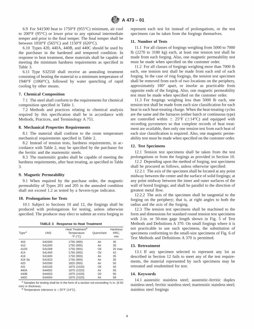
6.9 For S41500 heat to 1750°F (955°C) minimum, air coolto 200°F (95°C) or lower prior to any optional intermediatetemper and prior to the final temper. The final temper shall bebetween 1050°F (565°C) and 1150°F (620°C).
6.10 Types 420, 440A, 440B, and 440C should be used bythe purchaser in the hardened and tempered condition. Inresponse to heat treatment, these materials shall be capable ofmeeting the minimum hardness requirements as specified inTable 3.
6.11 Type S32550 shall receive an annealing treatmentconsisting of heating the material to a minimum temperature of1940°F (1060°C), followed by water quenching of rapidcooling by other means.
7. Chemical Composition
7.1 The steel shall conform to the requirements for chemicalcomposition specified in Table 1.
7.2 Methods and practices relating to chemical analysisrequired by this specification shall be in accordance withMethods, Practices, and Terminology A 751.
8. Mechanical Properties Requirements
8.1 The material shall conform to the room temperaturemechanical requirements specified in Table 2.
8.2 Instead of tension tests, hardness requirements, in ac-cordance with Table 2, may be specified by the purchaser forthe ferritic and the martensitic steels.
8.3 The martensitic grades shall be capable of meeting thehardness requirements, after heat treating, as specified in Table3.
9. Magnetic Permeability
9.1 When required by the purchase order, the magneticpermeability of Types 201 and 205 in the annealed conditionshall not exceed 1.2 as tested by a Severn-type indicator.
10. Prolongations for Tests
10.1 Subject to Sections 10 and 12, the forgings shall beproduced with prolongations for testing, unless otherwisespecified. The producer may elect to submit an extra forging to
represent each test lot instead of prolongations, or the testspecimens can be taken from the forgings themselves.
11. Number of Tests
11.1 For all classes of forgings weighing from 5000 to 7000lb (2270 to 3180 kg) each, at least one tension test shall bemade from each forging. Also, one magnetic permeability testmust be made when specified on the customer order.
11.2 For all classes of forgings weighing more than 7000 lbeach, one tension test shall be made from each end of eachforging. In the case of ring forgings, the tension test specimenshall be removed from each of two locations on the periphery,approximately 180° apart, or insofar as practicable fromopposite ends of the forging. Also, one magnetic permeabilitytest must be made when specified on the customer order.
11.3 For forgings weighing less than 5000 lb each, onetension test shall be made from each size classification for eachheat in each heat-treating charge. When the heat-treating cyclesare the same and the furnaces (either batch or continuous type)are controlled within6 25°F (614°C) and equipped withrecording pyrometers so that complete records of heat treat-ment are available, then only one tension test from each heat ofeach size classification is required. Also, one magnetic perme-ability test must be made when specified on the customer order.
12. Test Specimens
12.1 Tension test specimens shall be taken from the testprolongations or from the forgings as provided in Section 10.
12.2 Depending upon the method of forging, test specimensshall be procured as follows, unless otherwise specified:
12.2.1 The axis of the specimen shall be located at any pointmidway between the center and the surface of solid forgings; atany point midway between the inner and outer surfaces of thewall of bored forgings; and shall be parallel to the direction ofgreatest metal flow.
12.2.2 The axis of the specimen shall be tangential to theforging on the periphery; that is, at right angles to both theradius and the axis of the forging.
12.3 The tension test specimens shall be machined to theform and dimensions for standard round tension test specimenswith 2-in. or 50-mm gage length shown in Fig. 5 of TestMethods and Definitions A 370. On small forgings where it isnot practicable to use such specimens, the substitution ofspecimens conforming to the small-size specimens of Fig. 6 ofTest Methods and Definitions A 370 is permitted.
13. Retreatment
13.1 If any specimen selected to represent any lot asdescribed in Section 12 fails to meet any of the test require-ments, the material represented by such specimens may beretreated and resubmitted for test.
14. Keywords
14.1 austenitic stainless steel; austenitic-ferritic duplexstainless steel; ferritic stainless steel; martensitic stainless steel;stainless steel forgings
TABLE 3 Response to Heat Treatment
TypeA UNSHeat TreatmentB
Temperature°F (°C)
QuenchantHardness
HRC,min
403 S40300 1750 (955) Air 35410 S41000 1750 (955) Air 35410S S41008 1750 (955) Oil 25 max414 S41400 1750 (955) Oil 42416 S41600 1750 (955) Air 35416 Se S41623 1750 (955) Air 35420 S42000 1825 (955) Air 50431 S43100 1875 (1020) Oil 40440A S44002 1875 (1020) Air 55440B S44003 1875 (1020) Oil 56440C S44004 1875 (1020) Air 58A Samples for testing shall be in the form of a section not exceeding 3⁄8 in. (9.50
min) in thickness.B Temperature tolerance is 625°F (14°C).
A 473 – 01
4
ASTM International takes no position respecting the validity of any patent rights asserted in connection with any item mentionedin this standard. Users of this standard are expressly advised that determination of the validity of any such patent rights, and the riskof infringement of such rights, are entirely their own responsibility.
This standard is subject to revision at any time by the responsible technical committee and must be reviewed every five years andif not revised, either reapproved or withdrawn. Your comments are invited either for revision of this standard or for additional standardsand should be addressed to ASTM International Headquarters. Your comments will receive careful consideration at a meeting of theresponsible technical committee, which you may attend. If you feel that your comments have not received a fair hearing you shouldmake your views known to the ASTM Committee on Standards, at the address shown below.
This standard is copyrighted by ASTM International, 100 Barr Harbor Drive, PO Box C700, West Conshohocken, PA 19428-2959,United States. Individual reprints (single or multiple copies) of this standard may be obtained by contacting ASTM at the aboveaddress or at 610-832-9585 (phone), 610-832-9555 (fax), or [email protected] (e-mail); or through the ASTM website(www.astm.org).
A 473 – 01
5

Designation: A 478 – 97 (Reapproved 2002)
Standard Specification forChromium-Nickel Stainless Steel Weaving and KnittingWire1
This standard is issued under the fixed designation A 478; the number immediately following the designation indicates the year oforiginal adoption or, in the case of revision, the year of last revision. A number in parentheses indicates the year of last reapproval. Asuperscript epsilon (e) indicates an editorial change since the last revision or reapproval.
This standard has been approved for use by agencies of the Department of Defense.
1. Scope
1.1 This specification covers the more commonly used typesof round stainless steel wire intended especially for weavingand knitting.
1.2 The values stated in inch-pound units are to be regardedas the standard.
2. Referenced Documents
2.1 ASTM Standards:A 555/A555M Specification for General Requirements for
Stainless Steel Wire and Wire Rods2
A 751 Test Methods, Practices, and Terminology forChemical Analysis of Steel Products2
3. Ordering Information
3.1 It is the responsibility of the purchaser to specify allrequirements that are necessary for material ordered under thisspecification. Such requirements may include, but are notlimited to, the following:
3.1.1 Quantity (weight),3.1.2 Name of material (stainless steel),3.1.3 Condition (see Section 5),3.1.4 Finish (see Section 7),3.1.5 Cross section (round),3.1.6 Form (wire),3.1.7 Applicable dimensions (diameter),3.1.8 Type designation (see Table 1),3.1.9 ASTM designation and date of issue, and3.1.10 Special requirements.3.2 If possible, the intended end use of the item should be
given on the purchase order especially when the item is orderedfor a specific end use or uses.
NOTE 1—A typical ordering description is as follows: 1000 lb; stainlesssteel, dead soft, bright annealed wire, 0.015 in. diameter, spools, Type 304,
ASTM Specification A 478 dated ______, End Use Wire Screen.
4. Chemical Composition
4.1 The steel shall conform to the requirements as tochemical composition specified in Table 1.
4.2 Methods and practices relating to chemical analysisrequired by this specification shall be in accordance with TestMethods, Practices, and Terminology A 751.
5. Conditions
5.1 Wire may be furnished in one of the following condi-tions:
5.1.1 Annealed,5.1.2 Bright annealed, or5.1.3 Cold drawn.
6. Mechanical Requirements
6.1 The material shall conform to the requirements as tomechanical properties specified in Table 2.
7. Finish
7.1 The types of finish procurable are as follows:7.1.1 Pickled finish and7.1.2 Bright finish.
8. General Requirements for Delivery
8.1 In addition to the requirements of this specification, allrequirements of the current edition of Specification A 555/A 555M shall apply. Failure to comply with the generalrequirements of Specification A 555/A 555M constitutes non-conformance with this specification.
9. Packaging
9.1 Each coil or spool shall be one continuous length ofwire. Each coil shall be firmly tied and each spool shall betightly wound. Unless otherwise specified, coils shall be placedin drums or shall be paper wrapped, and spools shall be boxedin such a manner as to ensure safe delivery to their destinationwhen properly transported by any common carrier.
10. Keywords
10.1 knitting wire; stainless steel; weaving wire
1 This specification is under the jurisdiction of ASTM Committee A01 on Steel,Stainless Steel and Related Alloys, and is the direct responsibility of SubcommitteeA01.17 on Flat Stainless Steel Products.
Current edition approved Sept 10, 1997. Published September 1998. Originallypublished as A 478 – 62 T. Last previous edition A 478 – 95a.
2 Annual Book of ASTM Standards, Vol 01.03.
1
Copyright © ASTM International, 100 Barr Harbor Drive, PO Box C700, West Conshohocken, PA 19428-2959, United States.
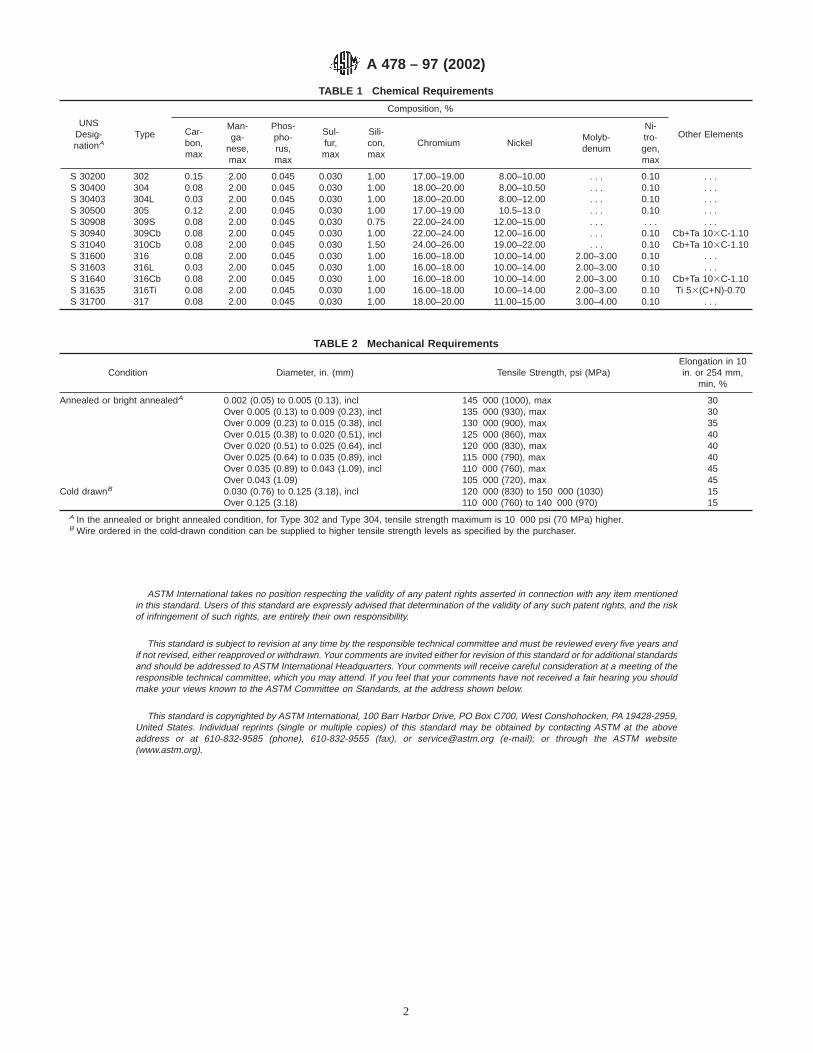
ASTM International takes no position respecting the validity of any patent rights asserted in connection with any item mentionedin this standard. Users of this standard are expressly advised that determination of the validity of any such patent rights, and the riskof infringement of such rights, are entirely their own responsibility.
This standard is subject to revision at any time by the responsible technical committee and must be reviewed every five years andif not revised, either reapproved or withdrawn. Your comments are invited either for revision of this standard or for additional standardsand should be addressed to ASTM International Headquarters. Your comments will receive careful consideration at a meeting of theresponsible technical committee, which you may attend. If you feel that your comments have not received a fair hearing you shouldmake your views known to the ASTM Committee on Standards, at the address shown below.
This standard is copyrighted by ASTM International, 100 Barr Harbor Drive, PO Box C700, West Conshohocken, PA 19428-2959,United States. Individual reprints (single or multiple copies) of this standard may be obtained by contacting ASTM at the aboveaddress or at 610-832-9585 (phone), 610-832-9555 (fax), or [email protected] (e-mail); or through the ASTM website(www.astm.org).
TABLE 1 Chemical Requirements
UNSDesig-nationA
Type
Composition, %
Other ElementsCar-bon,max
Man-ga-
nese,max
Phos-pho-rus,max
Sul-fur,max
Sili-con,max
Chromium NickelMolyb-denum
Ni-tro-gen,max
S 30200 302 0.15 2.00 0.045 0.030 1.00 17.00–19.00 8.00–10.00 . . . 0.10 . . .S 30400 304 0.08 2.00 0.045 0.030 1.00 18.00–20.00 8.00–10.50 . . . 0.10 . . .S 30403 304L 0.03 2.00 0.045 0.030 1.00 18.00–20.00 8.00–12.00 . . . 0.10 . . .S 30500 305 0.12 2.00 0.045 0.030 1.00 17.00–19.00 10.5–13.0 . . . 0.10 . . .S 30908 309S 0.08 2.00 0.045 0.030 0.75 22.00–24.00 12.00–15.00 . . . . . . . . .S 30940 309Cb 0.08 2.00 0.045 0.030 1.00 22.00–24.00 12.00–16.00 . . . 0.10 Cb+Ta 103C-1.10S 31040 310Cb 0.08 2.00 0.045 0.030 1.50 24.00–26.00 19.00–22.00 . . . 0.10 Cb+Ta 103C-1.10S 31600 316 0.08 2.00 0.045 0.030 1.00 16.00–18.00 10.00–14.00 2.00–3.00 0.10 . . .S 31603 316L 0.03 2.00 0.045 0.030 1.00 16.00–18.00 10.00–14.00 2.00–3.00 0.10 . . .S 31640 316Cb 0.08 2.00 0.045 0.030 1.00 16.00–18.00 10.00–14.00 2.00–3.00 0.10 Cb+Ta 103C-1.10S 31635 316Ti 0.08 2.00 0.045 0.030 1.00 16.00–18.00 10.00–14.00 2.00–3.00 0.10 Ti 53(C+N)-0.70S 31700 317 0.08 2.00 0.045 0.030 1.00 18.00–20.00 11.00–15.00 3.00–4.00 0.10 . . .
TABLE 2 Mechanical Requirements
Condition Diameter, in. (mm) Tensile Strength, psi (MPa)Elongation in 10in. or 254 mm,
min, %
Annealed or bright annealedA 0.002 (0.05) to 0.005 (0.13), incl 145 000 (1000), max 30Over 0.005 (0.13) to 0.009 (0.23), incl 135 000 (930), max 30Over 0.009 (0.23) to 0.015 (0.38), incl 130 000 (900), max 35Over 0.015 (0.38) to 0.020 (0.51), incl 125 000 (860), max 40Over 0.020 (0.51) to 0.025 (0.64), incl 120 000 (830), max 40Over 0.025 (0.64) to 0.035 (0.89), incl 115 000 (790), max 40Over 0.035 (0.89) to 0.043 (1.09), incl 110 000 (760), max 45Over 0.043 (1.09) 105 000 (720), max 45
Cold drawnB 0.030 (0.76) to 0.125 (3.18), inclOver 0.125 (3.18)
120 000 (830) to 150 000 (1030)110 000 (760) to 140 000 (970)
1515
A In the annealed or bright annealed condition, for Type 302 and Type 304, tensile strength maximum is 10 000 psi (70 MPa) higher.B Wire ordered in the cold-drawn condition can be supplied to higher tensile strength levels as specified by the purchaser.
A 478 – 97 (2002)
2

Designation: A 479/A 479M – 04 Used in USDOE-NE Standards
Standard Specification forStainless Steel Bars and Shapes for Use in Boilers andOther Pressure Vessels 1
This standard is issued under the fixed designation A 479/A 479M; the number immediately following the designation indicates the yearof original adoption or, in the case of revision, the year of last revision. A number in parentheses indicates the year of last reapproval.A superscript epsilon (e) indicates an editorial change since the last revision or reapproval.
This standard has been approved for use by agencies of the Department of Defense.
1. Scope*
1.1 This specification2 covers hot- and cold-finished bars ofstainless steel, including rounds, squares, and hexagons, andhot-rolled or extruded shapes such as angles, tees, and channelsfor use in boiler and pressure vessel construction.2
NOTE 1—There are standards covering high nickel, chromium, austen-itic corrosion, and heat-resisting alloy materials. These standards areunder the jurisdiction of ASTM Subcommittee B02.07 and may be foundin Annual Book of ASTM Standards, Vol 02.04.
1.2 The values stated in either inch-pound units or SI(metric) units are to be regarded separately as standards; withinthe text and tables, the SI units are shown in [brackets]. Thevalues stated in each system are not exact equivalents; there-fore, each system must be used independent of the other.Combining values from the two systems may result in noncon-formance with the specification.
1.3 Unless the order specifies the applicable “M” specifica-tion designation, the material shall be furnished to the inch-pound units.
2. Referenced Documents
2.1 ASTM Standards:3
A 262 Practices for Detecting Susceptibility to Intergranu-lar Attack in Austenitic Stainless Steels
A 370 Test Methods and Definitions for Mechanical Testingof Steel Products
A 484/A 484M Specification for General Requirements forStainless Steel Bars, Billets, and Forgings
A 751 Test Methods, Practices, and Terminology forChemical Analysis of Steel Products
E 112 Test Methods for Determining Average Grain SizeE 527 Practice for Numbering Metals and Alloys (UNS)2.2 Other Document:SAE J1086 Recommended Practice for Numbering Metals
and Alloys4
3. Ordering Information
3.1 It is the responsibility of the purchaser to specify allrequirements that are necessary for material ordered under thisspecification. Such requirements may include, but are notlimited to, the following:
3.1.1 Quantity (weight or number of pieces);3.1.2 Dimensions, including diameter or thickness (and
width), shape or form, applicable prints or sketches, length,etc.;
3.1.3 Type or UNS designation (Table 1);3.1.4 ASTM designation and edition year if other than latest
edition;3.1.5 Heat treated condition (Section 4);3.1.6 Finish (see Manufacture section of Specification
A 484/A 484M);3.1.7 Supplementary Requirements invoked for special ser-
vices (described at the end of this specification);3.1.8 Whether bars are to be rolled as bars or cut from strip
or plate;3.1.9 Preparation for delivery (see Preparation for Delivery
section of Specification A 484/A 484M);3.1.10 Marking requirements (see Marking section of
Specification A 484/A 484M);3.1.11 Surface preparation of shapes (see Manufacture sec-
tion of Specification A 484/A 484M); and3.1.12 The intended use of the material, if the purchaser
considers this useful information.
NOTE 2—A typical ordering description is as follows: 5000 lb [2000kg]; 1.000 in. [25 mm] round bar by 10 to 12 ft [3 to 4 m]; Type 304 orUNS S30400; to Specification A 479 [A 479M]; annealed; centerlessground; plus any optional supplementary requirements, such as, for
1 This specification is under the jurisdiction of ASTM Committee A01 on Steel,Stainless Steel and Related Alloys and is the direct responsibility of SubcommitteeA01.17 on Flat-Rolled and Wrought Stainless Steel.
Current edition approved Feb. 1, 2004. Published February 2004. Originallyapproved in 1962. Last previous edition approved in 2003 as A 479/A 479M – 03.
2 For ASME Boiler and Pressure Vessel Code applications see related Specifi-cation SA-479/SA-479M in Section II of that Code.
3 For referenced ASTM standards, visit the ASTM website, www.astm.org, orcontact ASTM Customer Service at [email protected]. ForAnnual Book of ASTMStandardsvolume information, refer to the standard’s Document Summary page onthe ASTM website.
4 Available from Society of Automotive Engineers (SAE), 400 CommonwealthDr., Warrendale, PA 15096-0001.
1
*A Summary of Changes section appears at the end of this standard.
Copyright © ASTM International, 100 Barr Harbor Drive, PO Box C700, West Conshohocken, PA 19428-2959, United States.

example, special marking instructions.
4. Heat Treatment
4.1 Austenitic Grades:4.1.1 Except for the strain-hardened grade (see 4.1.3) and
the hot-rolled grade (see 4.1.4), all austenitic grades of stain-less steel shall be furnished in the solution-annealed condition,with subsequent light cold drawing and straightening permit-ted. (See Supplementary Requirement S5 if annealing must bethe final operation.) Solution annealing for all grades, exceptthe H grades (see 4.1.2), N08367 (see 4.1.8), S31254 (see4.1.5), S32050 (see 4.1.5), S33228 (see 4.1.7), S34565 (see4.1.6), and S35315 (see 4.1.9), shall consist of(1) heating thematerial to a temperature of 1900°F [1040°C] minimum so thatgrain boundary carbides enter into solution, and coolingrapidly to prevent grain boundary carbide precipitation; oralternatively5 (2) (except for the columbium and titaniumstabilized grades 309Cb, 310Cb, 316Cb, 316Ti, 321, 347, and348) immediately following hot working while the temperatureis above 1750°F [955°C] so that grain boundary carbides are insolution, cooling rapidly to prevent grain boundary carbideprecipitation. When Supplementary Requirement S2 is in-voked, all austenitic grades except S30815 shall pass theintergranular corrosion test requirements described in S2.
4.1.2 For H grades, the minimum solution annealing tem-peratures shall be as follows:
4.1.2.1 When hot finished, 1900°F [1040°C] for Types304H, 309H, 310H, and 316H; 1925°F [1050°C] for Types321H, 347H, and 348H,
4.1.2.2 When cold worked prior to solution annealing,1900°F [1040°C] for Types 304H, 309H, 310H, and 316H;2000°F [1095°C] for Types 321H, 347H, and 348H.
NOTE 3—Solution annealing temperatures above 1950°F [1065°C] mayimpair the resistance to intergranular corrosion after subsequent exposureto sensitizing conditions in the stabilized grades, Types 321, 321 H, 347,347 H, 348 and 348 H. When intergranular corrosion is of concern, thepurchaser should specify the corrosion test of S2 (to be conducted onsensitized specimens). The manufacturer may, if necessary, use a lowertemperature resolution anneal or a stabilization anneal after a hightemperature solution anneal in order to meet corrosion test requirements.Consideration should be given to the corrosive media before using astabilization anneal at less than 1800°F [980°C], as such a treatment maynot be fully effective for all media.
NOTE 4—Grain size requirements for the H grades are described inSection 7.
4.1.3 Strain-Hardened Austenitic Type 316—When Type316 is desired with increased mechanical properties, thestrain-hardened condition may be specified and is produced bysolution annealing, as described in 4.1.1, followed by strainhardening sufficient to meet the required mechanical proper-ties. Solution-annealed and strain-hardened material shall becapable of meeting the intergranular corrosion test of Supple-mentary Requirement S2.
4.1.3.1 Two strain hardened conditions have been estab-lished for different applications: Level 1 and Level 2 (see Table2).
4.1.4 High tensile Type XM-19 shall be in the hot-rolled orstrain-hardened condition and shall be capable of meeting themechanical property requirements of Table 2 and passing theintergranular corrosion test prescribed in S2. The strain hard-ened condition is achieved by solution annealing followed bycold working sufficient to develop the required mechanicalproperties.
4.1.5 Solution annealing of S31254, S32050, and S32654shall consist of heating the material to a temperature of 2100°F[1150°C] minimum for an appropriate time, followed by waterquenching or rapidly cooling by other means.
4.1.6 Solution annealing of S34565 shall consist of heatingthe material in the range of temperature from 2050°F [1120°C]to 2140°F [1170°C] for an appropriate time, followed by waterquenching or rapidly cooling by other means.
4.1.7 Solution annealing of S33228 shall consist of heatingthe material in the temperature range 2050 to 2160°F [1120 to1180°C] for an appropriate time, followed by water quenchingor rapid cooling by other means.
4.1.8 Solution annealing of N08367 shall consist of heatingthe material to a temperature of 2025°F [1105°C] minimum foran appropriate time, followed by water quenching or rapidlycooling by other means.
4.1.9 Solution annealing of S35315 shall consist of heatingthe material to a temperature of 2100°F [1150°C] minimum foran appropriate time, followed by water quenching or rapidlycooling by other means.
4.2 Austenitic-Ferritic Grades:4.2.1 S31803, S32205, and S32550 shall be furnished in the
annealed condition with subsequent straightening permitted.The annealing treatment of S31803 and S32550 shall consist ofheating the material to a temperature of 1900°F [1040°C]minimum for an appropriate time followed by water quenchingor rapid cooling by other means. The annealing treatment forS32205 shall consist of heating the material to a temperature of1900°F [1040°C] minimum for an appropriate time, followedby water quenching.
4.2.2 S32101 shall be annealed by heating the material to atemperature of 1870°F [1020°C] minimum for an appropriatetime followed by water quenching or rapid cooling by othermeans.
4.2.3 S32950 shall be annealed by heating the material to atemperature of 1825°F [995°C] to 1875°F [1025°C] for anappropriate time, followed by water quenching or rapid coolingby other means.
4.2.4 S32750 shall be annealed by heating the material to atemperature of 1880°F [1025°C] to 2060°F [1125°C] for anappropriate time, followed by water quenching or rapid coolingby other means. Subsequent straightening shall be permitted.
4.2.5 S32760 shall be annealed by heating the material to atemperature of 2010°F [1100°C] to 2085°F [1140°C] for anappropriate time, followed by water quenching or rapid coolingby other means.
4.2.6 UNS S32906 shall be annealed by heating the materialto a temperature of 1900°F (1040°C) to 1980°F (1080°C) foran appropriate time followed by rapid cooling in air or water.Subsequent straightening shall be permitted.5 For explanation see Appendix X1.
A 479/A 479M – 04
2

4.2.7 S39277 shall be annealed by heating the material to1940°F [1060°C] to 2060°F [1125°C] for an appropriate time,followed by water quenching or rapid cooling by other means.Subsequent straightening shall be permitted.
4.3 Ferritic Grades—Ferritic grades shall be annealed tomeet the requirements of Table 2.
4.4 Martensitic Grades:4.4.1 All grades of martensitic steels shall be supplied in
either the annealed condition or in the tempered condition as
specified by the purchaser (see 3.1.3). Tempered material shallbe normalized, or shall be liquid quenched from 1700°F[925°C] minimum, followed by tempering in accordance with4.4.2, 4.4.3, or 4.4.5.
4.4.2 Types 403 and 410 tempered material shall be held attempering temperature for at least 1 h/in. [25.4 mm] of crosssection as follows:
TABLE 1 Chemical Requirements
UNSDesigna-
tionAType
Composition, %B
CarbonMan-
ganesePhos-phorus
Sulfur Silicon Chromium Nickel NitrogenMolyb-denum
Other ElementsC
Austenitic Grades
N08367 . . . 0.030 2.00 0.040 0.030 1.00 20.0–22.0 23.5–25.5 0.18–0.25 6.0–7.0 Cu 0.75S20161 . . . 0.15 4.0–6.0 0.045 0.030 3.0–4.0 15.0–18.0 4.0–6.0 0.08–0.20 . . . . . .S20910 XM-19 0.06 4.0–6.0 0.045 0.030 1.00 20.5–23.5 11.5–13.5 0.20–0.40 1.50–3.00 Cb 0.10–0.30;
V 0.10–0.30S21600 XM-17 0.08 7.5–9.0 0.045 0.030 1.00 17.5–20.5 5.0–7.0 0.25–0.50 2.00–3.00 . . .S21603 XM-18 0.03 7.5–9.0 0.045 0.030 1.00 17.5–20.5 5.0–7.0 0.25–0.50 2.00–3.00 . . .S21800S21904
. . .XM-11
0.100.04
7.0–9.08.0–10.0
0.0600.045
0.0300.030
3.5–4.51.00
16.0–18.019.0–21.5
8.0–9.05.5–7.5
0.08–0.180.15–0.40
. . . . . .
S24000 XM-29 0.08 11.5–14.5 0.060 0.030 1.00 17.0–19.0 2.3–3.7 0.20–0.40 . . . . . .S30200 302 0.15 2.00 0.045 0.030 1.00 17.0–19.0 8.0–10.0 0.10 . . . . . .S30400 304 0.08C 2.00 0.045 0.030 1.00 18.0–20.0 8.0–10.5 . . . . . . . . .S30403 304L 0.030 2.00 0.045 0.030 1.00 18.0–20.0 8.0–12.0 . . . . . . . . .S30409 304H 0.04–0.10 2.00 0.045 0.030 1.00 18.0–20.0 8.0–10.5 . . . . . . . . .S30451 304N 0.08 2.00 0.045 0.030 1.00 18.0–20.0 8.0–12.0 0.10–0.16 . . . . . .S30453 304LN 0.030 2.00 0.045 0.030 1.00 18.0–20.0 8.0–11.0 0.10–0.16 . . . . . .S30600 . . . 0.018 2.00 0.020 0.020 3.7–4.3 17.0–18.5 14.0–15.5 . . . 0.20 Cu 0.50S30815 . . . 0.05–0.10 0.80 0.040 0.030 1.40–2.00 20.0–22.0 10.0–12.0 0.14–0.20 . . . Ce 0.03–0.08S30908 309S 0.08 2.00 0.045 0.030 1.00 22.0–24.0 12.0–15.0 . . . . . . . . .S30909 309H 0.04–0.10 2.00 0.045 0.030 1.00 22.0–24.0 12.0–15.0 . . . . . . . . .S30940 309Cb 0.08 2.00 0.045 0.030 1.00 22.0–24.0 12.0–16.0 . . . . . . Cb 103C- 1.10S30880 ER308D 0.08 1.00–2.50 0.030 0.030 0.25–0.60 19.5–22.0 9.0–11.0 . . . . . . . . .S31008 310S 0.08 2.00 0.045 0.030 1.00 24.0–26.0 19.0–22.0 . . . . . . . . .S31009 310H 0.04–0.10 2.00 0.045 0.030 1.00 24.0–26.0 19.0–22.0 . . . . . . . . .S31040 310Cb 0.08 2.00 0.045 0.030 1.00 24.0–26.0 19.0–22.0 . . . . . . Cb 103C-1.10S31254 . . . 0.020 1.00 0.030 0.010 0.80 19.5–20.5 17.5–18.5 0.18–0.22 6.0–6.5 Cu 0.50–1.00S31600 316 0.08C 2.00 0.045 0.030 1.00 16.0–18.0 10.0–14.0 . . . 2.00–3.00 . . .S31603 316L 0.030 2.00 0.045 0.030 1.00 16.0–18.0 10.0–14.0 . . . 2.00–3.00 . . .S31609 316H 0.04–0.10 2.00 0.045 0.030 1.00 16.0–18.0 10.0–14.0 . . . 2.00–3.00 . . .S31635 316Ti 0.08 2.00 0.045 0.030 1.00 16.0–18.0 10.0–14.0 0.10 2.00–3.00 Ti 53(C+N)- 0.70S31640 316Cb 0.08 2.00 0.045 0.030 1.00 16.0–18.0 10.0–14.0 0.10 2.00–3.00 Cb 103C- 1.10S31651 316N 0.08 2.00 0.045 0.030 1.00 16.0–18.0 10.0–14.0 0.10–0.16 2.00–3.00 . . .S31653 316LN 0.030 2.00 0.045 0.030 1.00 16.0–18.0 10.0–14.0 0.10–0.16 2.00–3.00 . . .S31700 317 0.08 2.00 0.045 0.030 1.00 18.0–20.0 11.0–15.0 . . . 3.0–4.0 . . .S31725 . . . 0.030 2.00 0.045 0.030 1.00 18.0–20.0 13.5–17.5 0.20 4.0–5.0 . . .S31726 . . . 0.030 2.00 0.045 0.030 1.00 17.0–20.0 14.5–17.5 0.10–0.20 4.0–5.0 . . .S32050 . . . 0.030 1.50 0.035 0.020 1.00 22.0–24.0 20.0–23.0 0.21–0.32 6.0–6.8 Cu 0.40S32100 321 0.08E 2.00 0.045 0.030 1.00 17.0–19.0 9.0–12.0 . . . . . . Ti 53(C+N)- 0.70F
S32109 321H 0.04–0.10 2.00 0.045 0.030 1.00 17.0–19.0 9.0–12.0 . . . . . . Ti 43(C+N)- 0.70F
S32615 . . . 0.07 2.00 0.045 0.030 4.8–6.0 16.5–19.5 19.0–22.0 . . . 0.30–1.50 Cu 1.50–2.50S32654 . . . 0.020 2.0–4.0 0.030 0.005 0.50 24.0–25.0 21.0–23.0 7.0–8.0 0.45–0.55 Cu 0.30–0.60S33228 . . . 0.04–0.08 1.00 0.020 0.015 0.30 26.0–28.0 31.0–33.0 . . . . . . Cb 0.60–1.00;
Ce 0.05–0.10;Al 0.025
S34565 . . . 0.030 5.0–7.0 0.030 0.010 1.00 23.0–25.0 16.0–18.0 0.40–0.60 4.0–5.0 Cb 0.10S34700 347 0.08E 2.00 0.045 0.030 1.00 17.0–19.0 9.0–12.0 . . . . . . Cb 103C–1.10S34709 347H 0.04–0.10 2.00 0.045 0.030 1.00 17.0–19.0 9.0–12.0 . . . . . . Cb 83C–1.10S34800 348 0.08E 2.00 0.045 0.030 1.00 17.0–19.0 9.0–12.0 . . . . . . (Cb+Ta) 103C–1.10;
Ta 0.10;Co 0.20
S34809 348H 0.04–0.10 2.00 0.045 0.030 1.00 17.0–19.0 9.0–12.0 . . . . . . (Cb + Ta) 83C–1.10;Co 0.20;Ta 0.10
S35315 . . . 0.04–0.08 2.00 0.040 0.030 1.20–2.00 24.0–26.0 34.0–36.0 0.12–0.18 . . . Ce 0.03–0.08S38815 . . . 0.030 2.00 0.040 0.020 5.50–6.50 13.0–15.0 15.0–17.0 . . . 0.75–1.50 Al 0.30;
Cu 0.75–1.50
Austenitic-Ferritic Grades
A 479/A 479M – 04
3

TABLE 1 Continued
UNSDesigna-
tionAType
Composition, %B
CarbonMan-
ganesePhos-phorus
Sulfur Silicon Chromium Nickel NitrogenMolyb-denum
Other ElementsC
S31803 . . . 0.030 2.00 0.030 0.020 1.00 21.0–23.0 4.5–6.5 0.08–0.20 2.5–3.5 . . .S32101 . . . 0.040 4.0–6.0 0.040 0.030 1.00 21.0–22.0 1.35–1.70 0.20–0.25 0.10–0.80 Cu 0.10–0.80S32205 . . . 0.030 2.00 0.030 0.020 1.00 22.0–23.0 4.5–6.5 0.14–0.20 3.0–3.5 . . .S32550 . . . 0.04 1.50 0.040 0.030 1.00 24.0–27.0 4.5–6.5 0.10–0.25 2.9–3.9 Cu 1.50–2.50S32750 . . . 0.030 1.20 0.035 0.020 0.80 24.0–26.0 6.0–8.0 0.24–0.32 3.0–5.0 Cu 0.50S32760G . . . 0.030 1.00 0.030 0.010 1.00 24.0–26.0 6.0–8.0 0.20–0.30 3.0–4.0 Cu 0.50–1.00;
W 0.50–1.00S32906 . . . 0.030 0.80–1.50 0.030 0.030 0.50 28.0–30.0 5.8–7.5 0.30–0.40 1.50–2.60 Cu 0.80S32950 . . . 0.03 2.00 0.035 0.010 0.60 26.0–29.0 3.5–5.2 0.15–0.35 1.00–2.50 . . .S39277 . . . 0.025 0.80 0.025 0.002 0.80 24.0–26.0 6.5–8.0 0.23–0.33 3.0–4.0 Cu 1.20–2.00
W 0.80–1.20
Ferritic Grades
S40500 405 0.08 1.00 0.040 0.030 1.00 11.5–14.5 0.50 . . . . . . Al 0.10–0.30S43000 430 0.12 1.00 0.040 0.030 1.00 16.0–18.0 . . . . . . . . . . . .S43035 439 0.07 1.00 0.040 0.030 1.00 17.0–19.0 0.50 0.04 . . . Ti 0.20 + 4 3 (C+N)
–1.10; Al 0.15S44400 444 0.025 1.00 0.040 0.030 1.00 17.5–19.5 1.00 0.035 1.75–2.50 (Ti+Cb) 0.20 + 4 3
(C+N)-0.80S44627 XM-27 0.010H 0.40 0.020 0.020 0.40 25.0–27.5 0.50 0.015H 0.75–1.50 Cu 0.20;
Cb 0.05–0.20;(Ni+Cu) 0.50
S44700 . . 0.010 0.30 0.025 0.020 0.20 28.0–30.0 0.15 0.020 3.5–4.2 (C+N) 0.025;Cu 0.15
S44800 . . . 0.010 0.30 0.025 0.020 0.20 28.0–30.0 2.00–2.50 0.020 3.5–4.2 (C+N) 0.025;Cu 0.15
Martensitic Grades
S40300 403 0.15 1.00 0.040 0.030 0.50 11.5–13.0 . . . . . . . . . . . .S41000 410 0.15 1.00 0.040 0.030 1.00 11.5–13.5 . . . . . . . . . . . .S41040 XM-30 0.18 1.00 0.040 0.030 1.00 11.5–13.5 . . . . . . . . . Cb 0.05–0.30S41400 414 0.15 1.00 0.040 0.030 1.00 11.5–13.5 1.25–2.50 . . . . . . . . .S41425 . . . 0.05 0.50–1.00 0.020 0.005 0.50 12.0–15.0 4.0–7.0 0.06–0.12 1.50–2.00 Cu 0.30S41500 I 0.05 0.50–1.00 0.030 0.030 0.60 11.5–14.0 3.5–5.5 . . . 0.50–1.00 . . .S43100 431 0.20 1.00 0.040 0.030 1.00 15.0–17.0 1.25–2.50 . . . . . . . . .
A New designations established in accordance with Practice E 527 and SAE J 1086 published jointly by ASTM and SAE. See ASTM DS–56C, available from ASTMHeadquarters.
B Maximum unless otherwise indicated.C Except as required for specific alloy type, molybdenum, titanium, nickel, cobalt, tantalum, nitrogen, and copper need not be reported but shall not be present in other
than residual amounts, the intent being to prohibit substitution of one alloy type for another due to absence of control of the above named elements in certain alloys.D American Welding Society designation.E See Supplementary Requirement S1.F Nitrogen content is to be reported for this grade.G % Cr + 3.3 3 % Mo + 16 3 % N $ 40.H Product analysis tolerance over the maximum limit for carbon and nitrogen to be 0.002 %.I Wrought version of CA6NM.
4.4.2.1 Condition 1—1250°F [675°C] minimum, 1400°F[760°C] maximum.
4.4.2.2 Condition 2—1100°F [595°C] minimum, 1400°F[760°C] maximum.
4.4.2.3 Condition 3—1050°F [565°C] minimum, 1400°F[760°C] maximum.
4.4.3 Types XM-30, 414, and 431 tempered materials shallbe held at 1100°F [595°C] minimum for at least 1 h/in. [25mm] of cross section. Maximum tempering temperature shallbe 1400°F [760°C].
4.4.4 For S41425, heat to 1700°F [925°C] minimum andhold for 1 h attemperature minimum. Air cool to below 90°F[32°C] and temper at 1100°F [595°C] minimum of 1 h per inchof cross-sectional thickness minimum.
4.4.5 For S41500 heat to 1750°F [955°C] minimum, air coolto 200°F [95°C] or lower prior to any optional intermediatetemper and prior to the final temper. The final temper shall bebetween 1050°F [565°C] and 1150°F [620°C].
4.4.6 When the purchaser elects to perform the hardeningand tempering heat treatment, martensitic materials shall besupplied by the manufacturer in the annealed condition (see4.4.1). In this case it shall be the purchaser’s responsibility toapply the proper heat treatment and to conduct the tests hedeems necessary to assure that the required properties areobtained.
5. General Requirements
5.1 In addition to the requirements of this specification, allrequirements of the current editions of Specification A 484/A 484M shall apply. Failure to comply with the generalrequirements of Specification A 484/A 484M constitutes non-conformance with this specification.
6. Chemical Composition
6.1 Chemical composition shall be reported to the pur-chaser, or his representative, and shall conform to the require-ments specified in Table 1.
A 479/A 479M – 04
4

6.2 When a product analysis is performed or requested bythe purchaser, the tolerance limits as described in SpecificationA 484/A 484M apply unless Supplementary Requirement S3 isinvoked.
6.3 Methods and practices relating to chemical analysisrequired by this specification shall be in accordance with TestMethods, Practices, and Terminology A 751.
7. Grain Size for Austenitic Grades
7.1 All austenitic grades shall be tested for average grainsize by Test Methods E 112.
7.2 The H grades shall conform to an average grain size asfollows:
7.2.1 ASTM No. 6 or coarser for Types 304H, 309H, 310H,and 316H,
7.2.2 ASTM No. 7 or coarser for Types 321H, 347H, and348H.
7.3 For S32615, the grain size as determined in accordancewith Test Methods E 112, comparison method, Plate 11, shallbe No. 3 or finer.
7.4 Supplementary Requirement S1 shall be invoked whennon–H grade austenitic stainless steels are ordered for ASMECode applications for service above 1000°F [540°C].
8. Mechanical Properties Requirements
8.1 The material shall conform to the mechanical propertyrequirements specified in Table 2 for the grade ordered. At leastone room-temperature test shall be performed by the manufac-turer on a sample from at least one bar or shape from each lotof material.
TABLE 2 Mechanical Property Requirements
UNS Designation Type Condition
TensileStrength,
min,ksi [MPa]
YieldStrength,A
min,ksi [MPa]
Elongationin 2 in.
[50 mm] or4D, min, %
Reductionof Area,
min, %B,C
BrinellHardness,
max
Austenitic Grades
N08367 . . . annealed 95 [655] 45 [310] 30 . . . 241S20161 . . . annealed 125 [860] 50 [345] 40 40 311S20910 XM-19 annealed 100 [690] 55 [380] 35 55 293
Up to 2 in. [50.8 mm], incl hot-rolled 135 [930] 105 [725] 20 50 . . .Over 2 to 3 in. [50.8 to 76.2
mm], inclhot-rolled 115 [795] 75 [515] 25 50 . . .
Over 3 to 8 in. [76.2 to 203.2mm], incl
hot-rolled 100 [690] 60 [415] 30 50 . . .
Up to 11⁄2 in. [38.1 mm], incl strain-hardened 145 [1000] 125 [860] 12 40 . . .Over 11⁄2 to 21⁄4 in. [38.1 to 57.2
mm], inclstrain-hardened 120 [825] 105 [725] 15 45 . . .
S21600, S21603 XM-17, XM-18 annealed 90 [620] 50 [345] 40 50 212S21800 . . . annealed 95 [655] 50 [345] 35 55 241S21904 XM-11 annealed 90 [620] 50 [345] 45 60 . . .S24000 XM-29 annealed 100 [690] 55 [380] 30 50 . . .S30200, S30400, S30409, S30453,
S30880, S30908, S30909, S30940,S31008, S31009, S31040, S31600,S31609, S31635, S31640, S31653,S31700, S32100,S32109, S34700,
S34709,S34800, S34809
302, 304, 304H, 304LN, ER308,D
309S, 309H, 309Cb, 310S,310H, 310Cb, 316, 316H,316Ti, 316Cb, 316LN, 317,321, 321H, 347, 347H,348, 348H
annealed 75 [515]E 30 [205] 30 40 . . .
316 strain-hardenedlevel 1
85 [585] 65 [450]F 30 60 . . .
2 in. and under strain-hardenedlevel 2
95 [655] 75 [515] 25 40 . . .
Over 2 to 21⁄2 in. [50.8 to 63.5mm], incl.
strain-hardenedlevel 2
90 [620] 65 [450] 30 40 . . .
Over 21⁄2 to 3 in. [63.5 to 76.2mm], incl
strain-hardenedlevel 2
80 [550] 55 [380] 30 40 . . .
S30403, S31603 304L, 316L annealed 70 [485] 25 [170] 30 40 . . .S30451, S31651 304N, 316N annealed 80 [550] 35 [240] 30 40 . . .S30600 . . . annealed 78 [540] 35 [240] 40 . . . . . .S30815 . . . annealed 87 [600] 45 [310] 40 50 . . .S31254 . . . annealed 95 [655] 44 [305] 35 50 . . .S31725 . . . annealed 75 [515] 30 [205] 40 . . . . . .S31726 . . . annealed 80 [550] 35 [240] 40 . . . . . .S32050 . . . annealed 98 [675] 48 [330] 40 . . . . . .S32615 . . . annealed 80 [550] 32 [220] 25 40 . . .S32654 . . . annealed 109 [750] 62 [430] 40 40 250S33228 . . . annealed 73 [500] 27 [185] 30 . . . . . .S34565 . . . annealed 115 [795] 60 [415] 35 40 230S35315 . . . annealed 94 [650] 39 [270] 40 . . . . . .S353815 . . . annealed 78 [540] 37 [255] 30 . . . . . .
Austenitic-Ferritic Grades
S31803 . . . annealed 90 [620] 65 [450] 25 . . . 290S32101 . . . annealed 94 [650] 65 [450] 30 . . . 290
A 479/A 479M – 04
5
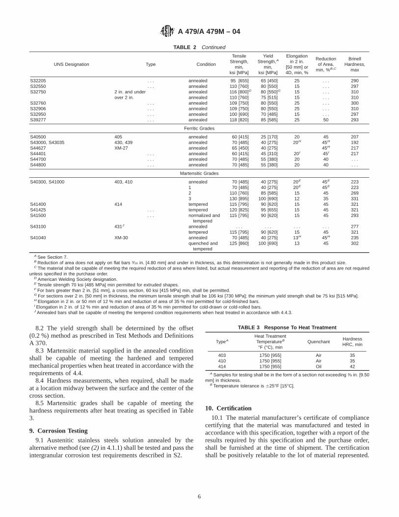
TABLE 2 Continued
UNS Designation Type Condition
TensileStrength,
min,ksi [MPa]
YieldStrength,A
min,ksi [MPa]
Elongationin 2 in.
[50 mm] or4D, min, %
Reductionof Area,
min, %B,C
BrinellHardness,
max
S32205 . . . annealed 95 [655] 65 [450] 25 . . . 290S32550 . . . annealed 110 [760] 80 [550] 15 . . . 297S32750 2 in. and under annealed 116 [800]G 80 [550]G 15 . . . 310
over 2 in. annealed 110 [760] 75 [515] 15 . . . 310S32760 . . . annealed 109 [750] 80 [550] 25 . . . 300S32906 . . . annealed 109 [750] 80 [550] 25 . . . 310S32950 . . . annealed 100 [690] 70 [485] 15 . . . 297S39277 . . . annealed 118 [820] 85 [585] 25 50 293
Ferritic Grades
S40500 405 annealed 60 [415] 25 [170] 20 45 207S43000, S43035 430, 439 annealed 70 [485] 40 [275] 20H 45H 192S44627 XM-27 annealed 65 [450] 40 [275] 45H 217S44401 . . . annealed 60 [415] 45 [310] 20I 45I 217S44700 . . . annealed 70 [485] 55 [380] 20 40 . . .S44800 . . . annealed 70 [485] 55 [380] 20 40 . . .
Martensitic Grades
S40300, S41000 403, 410 annealed 70 [485] 40 [275] 20E 45E 2231 70 [485] 40 [275] 20E 45E 2232 110 [760] 85 [585] 15 45 2693 130 [895] 100 [690] 12 35 331
S41400 414 tempered 115 [795] 90 [620] 15 45 321S41425 . . . tempered 120 [825] 95 [655] 15 45 321S41500 . . . normalized and
tempered115 [795] 90 [620] 15 45 293
S43100 431J annealed . . . . . . . . . . . . 277tempered 115 [795] 90 [620] 15 45 321
S41040 XM-30 annealed 70 [485] 40 [275] 13H 45H 235quenched and
tempered125 [860] 100 [690] 13 45 302
A See Section 7.B Reduction of area does not apply on flat bars 3⁄16 in. [4.80 mm] and under in thickness, as this determination is not generally made in this product size.C The material shall be capable of meeting the required reduction of area where listed, but actual measurement and reporting of the reduction of area are not required
unless specified in the purchase order.D American Welding Society designation.E Tensile strength 70 ksi [485 MPa] min permitted for extruded shapes.F For bars greater than 2 in. [51 mm], a cross section, 60 ksi [415 MPa] min, shall be permitted.G For sections over 2 in. [50 mm] in thickness, the minimum tensile strength shall be 106 ksi [730 MPa]; the minimum yield strength shall be 75 ksi [515 MPa].H Elongation in 2 in. or 50 mm of 12 % min and reduction of area of 35 % min permitted for cold-finished bars.I Elongation in 2 in. of 12 % min and reduction of area of 35 % min permitted for cold-drawn or cold-rolled bars.J Annealed bars shall be capable of meeting the tempered condition requirements when heat treated in accordance with 4.4.3.
8.2 The yield strength shall be determined by the offset(0.2 %) method as prescribed in Test Methods and DefinitionsA 370.
8.3 Martensitic material supplied in the annealed conditionshall be capable of meeting the hardened and temperedmechanical properties when heat treated in accordance with therequirements of 4.4.
8.4 Hardness measurements, when required, shall be madeat a location midway between the surface and the center of thecross section.
8.5 Martensitic grades shall be capable of meeting thehardness requirements after heat treating as specified in Table3.
9. Corrosion Testing
9.1 Austenitic stainless steels solution annealed by thealternative method (see(2) in 4.1.1) shall be tested and pass theintergranular corrosion test requirements described in S2.
10. Certification
10.1 The material manufacturer’s certificate of compliancecertifying that the material was manufactured and tested inaccordance with this specification, together with a report of theresults required by this specification and the purchase order,shall be furnished at the time of shipment. The certificationshall be positively relatable to the lot of material represented.
TABLE 3 Response To Heat Treatment
TypeAHeat TreatmentTemperatureB
°F (°C), minQuenchant
HardnessHRC, min
403 1750 [955] Air 35410 1750 [955] Air 35414 1750 [955] Oil 42
A Samples for testing shall be in the form of a section not exceeding 3⁄8 in. [9.50mm] in thickness.
B Temperature tolerance is 625°F [15°C].
A 479/A 479M – 04
6
11. Product Marking
11.1 In addition to the marking requirements of Specifica-tion A 484/A 484M, materials that have been heat treated inaccordance with 4.1, 4.2, 4.3, 4.4 or have been strain hardenedin accordance with 4.1.3 shall be identified by placement of thefollowing symbols after the grade designation:
11.1.1 Austenitic Grades:11.1.1.1 All grades in the annealed condition—A,11.1.1.2 Strain hardened Type 316, Level 1—S1,11.1.1.3 Strain hardened Type 316, Level 2—S2,11.1.1.4 Hot-rolled Type XM-19—H,11.1.1.5 Strain hardened Type XM-19—S,11.1.1.6 Material meeting Supplementary Requirement
S1—ELT (unnecessary for H grades).11.1.1.7 In addition to all other marking requirements of this
specification, when S1 is invoked, all grades in the directquenched condition (heat treated in accordance with 4.1.1(2))shall be marked “D”.
11.1.2 Austenitic-Ferritic Grades—All grades in the an-nealed condition—A.
11.1.3 Ferritic Grades—All grades in the annealedcondition—A.
11.1.4 Martensitic Grades:11.1.4.1 All grades in the annealed condition—A.11.1.4.2 Types 403 and 410—COND 1, COND 2, or COND
3 as appropriate for the tempering temperature employed.11.1.4.3 Type 414, S41500, and Type XM-30 tempered
materials—T.
12. Keywords
12.1 austenitic stainless steel; austenitic-ferritic duplexstainless steel; ferritic stainless steel; martensitic stainless steel;pressure-containing parts; pressure vessel service; stainlesssteel bars; stainless steel shapes; temperature serviceapplications—high
SUPPLEMENTARY REQUIREMENTS
The following may be made requirements when the purchaser specifies them to be applicable.
S1. Materials for High-Temperature Service
S1.1 Unless an H grade has been ordered, this supplemen-tary requirement shall be specified for ASME Code applica-tions for service above 1000°F [540°C].
S1.2 The user is permitted to use an austenitic stainless steelas the corresponding H grade when the material meets allrequirements of the H grade including chemistry, annealingtemperature, and grain size (see Section 7).
S1.3 The user is permitted to use an L grade austeniticstainless steel for service above 1000°F [540°C], subject to theapplicable allowable stress table of the ASME Code, when thematerial meets all requirements of this specification and thegrain size is ASTM No. 7 or coarser as determined inaccordance with Test Method E 112. The grain size shall bereported on a Certified Test Report.
S2. Corrosion Tests
S2.1 Intergranular corrosion tests shall be performed by themanufacturer on sensitized specimens of Types 304L, 316L,321, 347, and 348, and for the other austenitic grades, onspecimens representative of the as-shipped condition. Allaustenitic stainless steels shall be capable of passing inter-granular corrosion tests in the as-shipped condition. Tests shallbe performed in accordance with Practice E of Practices A 262.
S3. Product Analysis
S3.1 An analysis shall be made by the manufacturer on asample from one bar in each lot as defined in SpecificationA 484/A 484M. The analysis shall meet the requirements ofTable 1. In the event of failure, the lot represented shall berejected except that, at the option of the manufacturer, each barin the lot may be tested for acceptance. Product analysistolerance provisions do not apply.
S4. Material for High Cycle Fatigue Service
S4.1 The mechanical properties of bars furnished in lengthsunder 20 ft [6 m] shall be determined by testing one end ofeach bar. Bars furnished in lengths of 20 ft [6 m] and over shallbe tested at each end.
S5. Material for Optimum Resistance to Stress CorrosionCracking
S5.1 This supplementary requirement is to be referencedwhen austenitic stainless steels are to be purchased in accor-dance with 4.1.1 with solution-annealing as the final operationand with no subsequent cold drawing permitted. Straighteningis permitted as a final operation to meet the straightnessrequirements of Specification A 484/A 484M unless specifi-cally prohibited by the purchaser.
A 479/A 479M – 04
7
APPENDIX
(Nonmandatory Information)
X1. RATIONALE REGARDING DEFINITION OF SOLUTION ANNEALING IN 4.1.1
X1.1 It is generally recognized that austenitic stainlesssteels are solution annealed by heating to a temperature thatdissolves (takes into solution) chromium carbides and quench-ing rapidly so that the chromium carbides will not participatein the grain boundaries, which could cause susceptibility tointergranular corrosion in a critically corrosive environment.Thus, solution annealing also can be accomplished for non-stabilized grades by taking advantage of hot rolling tempera-tures (which always exceed solution annealing temperaturerequirements), maintaining hot rolling finishing temperatureswell above minimum solution annealing requirements, andimmediately quenching integral with hot rolling. Stabilizedgrades (with columbium or titanium added) cannot be handledthis way, since they would become destabilized due to colum-bium or titanium carbide solution, without subsequent reheat-ing.
X1.2 For Boiler Code applications involving temperaturesat which optimum resistance to creep is desired, the larger
grain size of material solution annealed by reheating isgenerally desired. For that reason, a minimum grain size hasbeen required of the H grades (created for optimum elevatedtemperature properties), and a mandatory grain size test andreport has been added for the non–H grades so that theinformation is available for those desiring to reclassify anon–H grade to H grade.
X1.3 To satisfy the concerns of inadvertent assignment offine grained material to elevated temperature applications,special marking has been added for material that meets therequirements of Supplementary Requirement S1.
X1.4 A mandatory test for susceptibility to intergranularcorrosion has been added for material solution annealed by thealternative method [see(2) in 4.1.1] so that a history of datacan be accumulated, as has been done in the past for materialsolution annealed by reheating.
SUMMARY OF CHANGES
Committee A01.17 has identified the location of selected changes to this standard since the last issue,A 479/A 479M – 03, that may impact the use of this standard. (Approved Feb. 1, 2004.)
(1) Added new Footnote C to Table 2.
Committee A01.17 has identified the location of selected changes to this standard since the last issue, A 479/A 479M – 02, thatmay impact the use of this standard. (Approved April 10, 2003.)
(1) UNS S32101 added to Tables 1 and 2.(2) Heat treatment added to Section 4.2.2, with subsequentrenumbering.
ASTM International takes no position respecting the validity of any patent rights asserted in connection with any item mentionedin this standard. Users of this standard are expressly advised that determination of the validity of any such patent rights, and the riskof infringement of such rights, are entirely their own responsibility.
This standard is subject to revision at any time by the responsible technical committee and must be reviewed every five years andif not revised, either reapproved or withdrawn. Your comments are invited either for revision of this standard or for additional standardsand should be addressed to ASTM International Headquarters. Your comments will receive careful consideration at a meeting of theresponsible technical committee, which you may attend. If you feel that your comments have not received a fair hearing you shouldmake your views known to the ASTM Committee on Standards, at the address shown below.
This standard is copyrighted by ASTM International, 100 Barr Harbor Drive, PO Box C700, West Conshohocken, PA 19428-2959,United States. Individual reprints (single or multiple copies) of this standard may be obtained by contacting ASTM at the aboveaddress or at 610-832-9585 (phone), 610-832-9555 (fax), or [email protected] (e-mail); or through the ASTM website(www.astm.org).
A 479/A 479M – 04
8

Designation: A 480/A 480M – 04
Standard Specification forGeneral Requirements for Flat-Rolled Stainless and Heat-Resisting Steel Plate, Sheet, and Strip 1
This standard is issued under the fixed designation A 480/A 480M; the number immediately following the designation indicates the yearof original adoption or, in the case of revision, the year of last revision. A number in parentheses indicates the year of last reapproval.A superscript epsilon (e) indicates an editorial change since the last revision or reapproval.
This standard has been approved for use by agencies of the Department of Defense.
1. Scope*
1.1 This specification2 covers a group of general require-ments that, unless otherwise specified in the purchase order orin an individual specification, shall apply to rolled steel plate,sheet, and strip, under each of the following specificationsissued by ASTM: Specifications A 167, A 176, A 240/A 240M,A 263, A 264, A 265, A 666, A 693, A 793, and A 895.
1.2 In the case of conflict between a requirement of aproduct specification and a requirement of this specification,the product specification shall prevail. In the case of conflictbetween a requirement of the product specification or arequirement of this specification and a more stringent require-ment of the purchase order, the purchase order shall prevail.The purchase order requirements shall not take precedence ifthey, in any way, violate the requirements of the productspecification or this specification; for example, by waiving atest requirement or by making a test requirement less stringent.
1.3 The values stated in either inch-pound units or SI unitsare to be regarded separately as standard. Within the text, theSI units are shown in brackets, except that when A 480M isspecified, Annex A3 shall apply for the dimensional tolerancesand not the bracketed SI values in Annex A2. The values statedin each system are not exact equivalents; therefore, eachsystem must be used independently of the other. Combiningvalues from the two systems may result in nonconformancewith the specification.
1.4 This specification and the applicable material specifica-tions are expressed in both inch-pound and SI units. However,unless the order specifies the applicable “M” specificationdesignation [SI units], the material shall be furnished ininch-pound units.
2. Referenced Documents
2.1 ASTM Standards:3
A 167 Specification for Stainless and Heat-ResistingChromium-Nickel Steel Plate, Sheet, and Strip
A 176 Specification for Stainless and Heat-Resisting Chro-mium Steel Plate, Sheet, and Strip
A 240/A 240M Specification for Chromium andChromium-Nickel Stainless Steel Plate, Sheet, and Stripfor Pressure Vessels and for General Applications
A 262 Practices for Detecting Susceptibility to Intergranu-lar Attack in Austenitic Stainless Steels
A 263 Specification for Stainless Chromium Steel-CladPlate
A 264 Specification for Stainless Chromium-Nickel Steel-Clad Plate
A 265 Specification for Nickel and Nickel-Base Alloy-CladSteel Plate
A 342/A 342M Test Methods for Permeability of FeeblyMagnetic Materials
A 370 Test Methods and Definitions for Mechanical Testingof Steel Products
A 666 Specification for Annealed or Cold-Worked Austen-itic Stainless Steel Sheet, Strip, Plate, and Flat Bar
A 693 Specification for Precipitation-Hardening Stainlessand Heat-Resisting Steel Plate, Sheet, and Strip
A 700 Practices for Packaging, Marking, and LoadingMethods for Steel Products for Domestic Shipment
A 751 Test Methods, Practices, and Terminology forChemical Analysis of Steel Products
A 763 Practices for Detecting Susceptibility to Intergranu-lar Attack in Ferritic Stainless Steels3
A 793 Specification for Rolled Floor Plate, Stainless SteelA 895 Specification for Free-Machining Stainless Steel
Plate, Sheet, and Strip1 This specification is under the jurisdiction of ASTM Committee A01 on Steel,Stainless Steel and Related Alloys and is the direct responsibility of SubcommitteeA01.17 on Flat-Rolled and Wrought Stainless Steel.
Current edition approved March 1, 2004. Published March 2004. Originallyapproved in 1962. Last previous edition approved in 2003 as A 480/A 480M – 03c.
2 For ASME Boiler and Pressure Vessel Code applications see related Specifi-cation SA – 480 in Section II of that Code.
3 For referenced ASTM standards, visit the ASTM website, www.astm.org, orcontact ASTM Customer Service at [email protected]. ForAnnual Book of ASTMStandardsvolume information, refer to the standard’s Document Summary page onthe ASTM website.
1
*A Summary of Changes section appears at the end of this standard.
Copyright © ASTM International, 100 Barr Harbor Drive, PO Box C700, West Conshohocken, PA 19428-2959, United States.
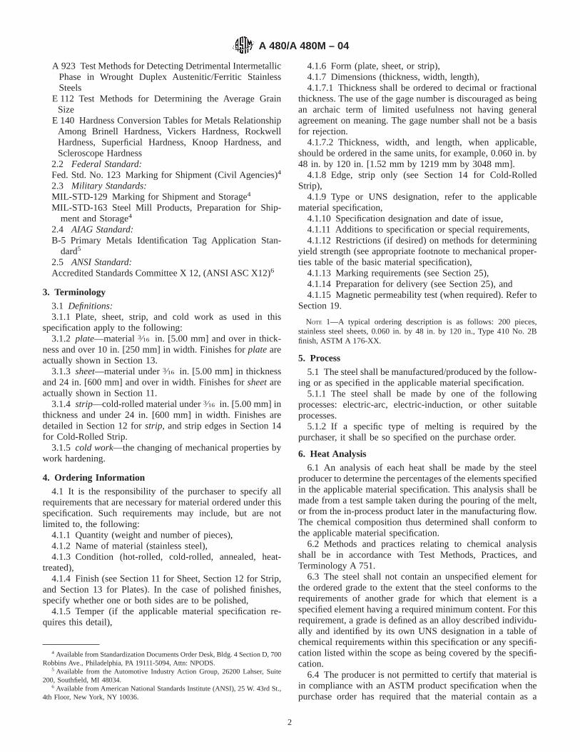
A 923 Test Methods for Detecting Detrimental IntermetallicPhase in Wrought Duplex Austenitic/Ferritic StainlessSteels
E 112 Test Methods for Determining the Average GrainSize
E 140 Hardness Conversion Tables for Metals RelationshipAmong Brinell Hardness, Vickers Hardness, RockwellHardness, Superficial Hardness, Knoop Hardness, andScleroscope Hardness
2.2 Federal Standard:Fed. Std. No. 123 Marking for Shipment (Civil Agencies)4
2.3 Military Standards:MIL-STD-129 Marking for Shipment and Storage4
MIL-STD-163 Steel Mill Products, Preparation for Ship-ment and Storage4
2.4 AIAG Standard:B-5 Primary Metals Identification Tag Application Stan-
dard5
2.5 ANSI Standard:Accredited Standards Committee X 12, (ANSI ASC X12)6
3. Terminology
3.1 Definitions:3.1.1 Plate, sheet, strip, and cold work as used in this
specification apply to the following:3.1.2 plate—material3⁄16 in. [5.00 mm] and over in thick-
ness and over 10 in. [250 mm] in width. Finishes forplateareactually shown in Section 13.
3.1.3 sheet—material under3⁄16 in. [5.00 mm] in thicknessand 24 in. [600 mm] and over in width. Finishes forsheetareactually shown in Section 11.
3.1.4 strip—cold-rolled material under3⁄16 in. [5.00 mm] inthickness and under 24 in. [600 mm] in width. Finishes aredetailed in Section 12 forstrip, and strip edges in Section 14for Cold-Rolled Strip.
3.1.5 cold work—the changing of mechanical properties bywork hardening.
4. Ordering Information
4.1 It is the responsibility of the purchaser to specify allrequirements that are necessary for material ordered under thisspecification. Such requirements may include, but are notlimited to, the following:
4.1.1 Quantity (weight and number of pieces),4.1.2 Name of material (stainless steel),4.1.3 Condition (hot-rolled, cold-rolled, annealed, heat-
treated),4.1.4 Finish (see Section 11 for Sheet, Section 12 for Strip,
and Section 13 for Plates). In the case of polished finishes,specify whether one or both sides are to be polished,
4.1.5 Temper (if the applicable material specification re-quires this detail),
4.1.6 Form (plate, sheet, or strip),4.1.7 Dimensions (thickness, width, length),4.1.7.1 Thickness shall be ordered to decimal or fractional
thickness. The use of the gage number is discouraged as beingan archaic term of limited usefulness not having generalagreement on meaning. The gage number shall not be a basisfor rejection.
4.1.7.2 Thickness, width, and length, when applicable,should be ordered in the same units, for example, 0.060 in. by48 in. by 120 in. [1.52 mm by 1219 mm by 3048 mm].
4.1.8 Edge, strip only (see Section 14 for Cold-RolledStrip),
4.1.9 Type or UNS designation, refer to the applicablematerial specification,
4.1.10 Specification designation and date of issue,4.1.11 Additions to specification or special requirements,4.1.12 Restrictions (if desired) on methods for determining
yield strength (see appropriate footnote to mechanical proper-ties table of the basic material specification),
4.1.13 Marking requirements (see Section 25),4.1.14 Preparation for delivery (see Section 25), and4.1.15 Magnetic permeability test (when required). Refer to
Section 19.
NOTE 1—A typical ordering description is as follows: 200 pieces,stainless steel sheets, 0.060 in. by 48 in. by 120 in., Type 410 No. 2Bfinish, ASTM A 176-XX.
5. Process
5.1 The steel shall be manufactured/produced by the follow-ing or as specified in the applicable material specification.
5.1.1 The steel shall be made by one of the followingprocesses: electric-arc, electric-induction, or other suitableprocesses.
5.1.2 If a specific type of melting is required by thepurchaser, it shall be so specified on the purchase order.
6. Heat Analysis
6.1 An analysis of each heat shall be made by the steelproducer to determine the percentages of the elements specifiedin the applicable material specification. This analysis shall bemade from a test sample taken during the pouring of the melt,or from the in-process product later in the manufacturing flow.The chemical composition thus determined shall conform tothe applicable material specification.
6.2 Methods and practices relating to chemical analysisshall be in accordance with Test Methods, Practices, andTerminology A 751.
6.3 The steel shall not contain an unspecified element forthe ordered grade to the extent that the steel conforms to therequirements of another grade for which that element is aspecified element having a required minimum content. For thisrequirement, a grade is defined as an alloy described individu-ally and identified by its own UNS designation in a table ofchemical requirements within this specification or any specifi-cation listed within the scope as being covered by the specifi-cation.
6.4 The producer is not permitted to certify that material isin compliance with an ASTM product specification when thepurchase order has required that the material contain as a
4 Available from Standardization Documents Order Desk, Bldg. 4 Section D, 700Robbins Ave., Philadelphia, PA 19111-5094, Attn: NPODS.
5 Available from the Automotive Industry Action Group, 26200 Lahser, Suite200, Southfield, MI 48034.
6 Available from American National Standards Institute (ANSI), 25 W. 43rd St.,4th Floor, New York, NY 10036.
A 480/A 480M – 04
2

minimum or range an element that is neither a specifiedelement nor an intentionally added unspecified element for theordered grade in accordance with the definitions of TestMethods, Practices, and Terminology A 751.
7. Product Analysis
7.1 The purchaser is permitted to perform a product analysis(formerly check analysis) to verify the identity of the finishedmaterial representing each heat or lot. Such analysis shall bemade by any of the commonly accepted methods that willpositively identify the material.
7.2 The chemical composition determined in accordancewith 7.1 shall conform to the limits of the material specificationwithin the tolerances of Table A1.1, unless otherwise specifiedin the applicable material specification or the purchase order.The allowable variation of a particular element in a singlesample for product analysis is permitted to be either above orbelow the specified range. However, percentages must exhibitthe same tendencies in all samples; that is, the severaldeterminations of any individual element in a heat shall notvary both above and below the specified range.
8. Material Test Report and Certification
8.1 A report of the results of all tests required by the productspecification shall be supplied to the purchaser. This materialtest report shall reference the product specification designationand year date indicating that the material was manufactured,sampled, tested, and inspected in accordance with requirementsof the product specification and has been found to meet thoserequirements. The material test report shall report the meltingprocess when the purchase order requires either a specific typeof melting or requires that the melting process used is to bereported.
8.1.1 The report shall indicate the type of steel. If certifyingthat the material conforms to the requirements for more thanone type of steel, the manufacturer may indicate each type ofsteel on the report, or may issue a separate report for each typeof steel.
8.2 A signature is not required on the report. However, thedocument shall clearly identify the organization submitting thereport. Not withstanding the absence of a signature, theorganization submitting the document is responsible for itscontent.
8.3 A material test report, certificate of inspection, or similardocument printed from or used in electronic form from anelectronic data interchange (EDI) transmission shall be re-garded as having the same validity as a counterpart printed inthe certifiers’ facility. The content of the EDI transmitteddocument must meet the requirements of the invoked ASTMstandard(s) and conform to any existing EDI agreement be-tween the purchaser and the supplier. Notwithstanding theabsence of a signature, the organization submitting the EDItransmission is responsible for the content of the report.
8.4 When finished material is supplied to a purchase orderspecifying the product specification, the organization supply-ing that material shall provide the purchaser with a copy of theoriginal manufacturer’s test report.
NOTE 2—Notwithstanding the absence of a signature, the organization
submitting the report is responsible for the content of the report.NOTE 3—The industry definition as invoked here is: EDI is the
computer-to-computer exchange of business information in a standardformat such as ANSI ASC X 12.
8.4.1 When the original manufacturer’s test report wasprovided by EDI to the organization supplying the finishedmaterial to the purchaser, the organization supplying thefinished material shall provide to the purchaser a printed formof the original test report or shall retransmit the test report byEDI to the purchaser. In either case, the test report shall becomplete with the full identification of the original manufac-turer and with all data provided on the test report of the originalmanufacturer.
9. Permitted Variations in Dimensions and Weight
9.1 Sheet, strip, and plate shall conform to the permittedvariations in thickness, width, length and flatness, and otherproperties when specified, as listed in Annex A2 and Annex A3for A 480 and A 480M respectively, for the ordered productform, or as agreed upon by seller and user and specified in thepurchase order.
10. Workmanship
10.1 The material shall be of uniform quality consistentwith good manufacturing and inspection practices. The steelshall have no imperfections of a nature or degree, for the typeand quality ordered, that will adversely affect the stamping,forming, machining, or fabrication of finished parts.
10.2 Sheet, Strip, and Plate—For sheet, and strip with No.1 finish and plate with hot-roll anneal or hot-roll anneal andpickle finish it is permitted to grind to remove surfaceimperfections, provided such grinding does not reduce thethickness or width at any point beyond the permissible varia-tions in dimensions. An iron free abrasive wheel shall be usedfor such grinding and shall be operated at a speed ample toensure that defective areas are cleanly cut out.
11. Finish for Sheet
11.1 The types of finish available on sheet products are:11.1.1 No. 1 Finish—Hot-rolled, annealed, and descaled.11.1.2 No. 2D Finish—Cold-rolled, dull finish.11.1.3 No. 2B Finish—Cold-rolled, bright finish.11.1.3.1Bright Annealed Finish—A bright cold-rolled fin-
ish retained by final annealing in a controlled atmospherefurnace.
11.1.4 No. 3 Finish—Intermediate polished finish, one orboth sides.
11.1.5 No. 4 Finish—General purpose polished finish, oneor both sides.
11.1.6 No. 6 Finish—Dull satin finish, Tampico brushed,one or both sides.
11.1.7 No. 7 Finish—High luster finish.11.1.8 No. 8 Finish—Mirror finish.11.1.9 TR Finish—Cold-worked to obtain specified proper-
ties.
NOTE 4—Explanation of Sheet Finishes:No. 1—Commonly referred to as hot-rolled annealed and pickled or
descaled. This is a dull, nonreflective finish.
A 480/A 480M – 04
3
No. 2D—A smooth, nonreflective cold-rolled annealed and pickled ordescaled finish. This nondirectional finish is favorable for retention oflubricants in deep drawing applications.
No. 2B—A smooth, moderately reflective cold-rolled annealed andpickled or descaled finish typically produced by imparting a final lightcold-rolled pass using polished rolls. This general-purpose finish is morereadily polished than No. 1 or 2D finishes. Product with 2B finish isnormally supplied in the annealed plus lightly cold-rolled condition unlessa tensile-rolled product is specified.
Bright Annealed Finish—A smooth, bright, reflective finish typicallyproduced by cold rolling followed by annealing in a protective atmosphereso as to prevent oxidation and scaling during annealing.
No. 3—A linearly textured finish that may be produced by eithermechanical polishing or rolling. Average surface roughness (Ra) maygenerally be up to 40 micro-inches. A skilled operator can generally blendthis finish. Surface roughness measurements differ with different instru-ments, laboratories, and operators. There may also be overlap in measure-ments of surface roughness for both No. 3 and No. 4 finishes.
No. 4—A linearly textured finish that may be produced by eithermechanical polishing or rolling. Average surface roughness (Ra) maygenerally be up to 25 micro-inches. A skilled operator can generally blendthis finish. Surface roughness measurements differ with different instru-ments, laboratories, and operators. There may also be overlap in measure-ments of surface roughness for both No. 3 and No. 4 finishes.
No. 6—This finish has a soft, satin appearance typically produced bytampico brushing a No. 4 finish.
No. 7—Has a high degree of reflectivity. It is produced by buffing afinely ground surface, but the grit lines are not removed. It is chiefly usedfor architectural or ornamental purposes.
No. 8—This is a highly reflective, smooth finish typically produced bypolishing with successively finer grit abrasives, then buffing. Typically,very faint buff of polish lines may still be visible on the final product.Blending after part assembly may be done with buffing.
TR Finish—The finish resulting from the cold-rolling of an annealedand descaled or bright annealed product to obtain mechanical propertieshigher than that of the annealed condition. Appearance will vary depend-ing upon the starting finish, amount of cold work, and the alloy.
Architectural Finishes—Sometimes described as a No. 5 finish, theseare a separate category and may be negotiated between buyer and seller,as there are many techniques and finish variations available throughout theworld.
11.1.10 Architectural finish, No. 5, or other proprietarynames are special finishes.
11.1.11 Note 4 is not meant to be restrictive or to be used asa basis for rejection but is intended to give general guidelines.Various production methods may be used to obtain thesefinishes.
11.1.12 Sheets can be produced with one or two sidespolished. When polished on one side only, it is permitted torough grind the other side in order to obtain the necessaryflatness.
12. Finish for Strip
12.1 The various types of finish procurable on cold-rolledstrip products are:
12.1.1 No. 1 Finish—Cold-rolled to specified thickness,annealed, and descaled.
12.1.2 No. 2 Finish—Same as No. 1 Finish, followed by afinal light cold-roll pass, generally on highly polished rolls.
12.1.3 Bright Annealed Finish—A bright cold-rolled finishretained by final annealing in a controlled atmosphere furnace.
12.1.4 TR Finish—Cold-worked to obtain specified proper-ties.
12.1.5 Polished Finish—Stainless steel strip is also avail-able in polished finishes such as No. 3 and No. 4, which areexplained in Note 4.
NOTE 5—Explanation of Strip Finishes:No. 1—Appearance of this finish varies from dull gray matte finish to
a fairly reflective surface, depending largely upon composition. This finishis used for severely drawn or formed parts, as well as for applicationswhere the brighter No. 2 Finish is not required, such as parts for heatresistance.
No. 2—This finish has a smoother and more reflective surface, theappearance of which varies with composition. This is a general purposefinish, widely used for household and automotive trim, tableware, utensils,trays, etc.
Bright Annealed Finish—See Note 4.TR Finish—See Note 4.
13. Finish for Plates
13.1 The types of finish available on plates are:13.1.1 Hot-Rolled or Cold-Rolled, and Annealed or Heat
Treated—Scale not removed, an intermediate finish. Use ofplates in this condition is generally confined to heat-resistingapplications. Scale impairs corrosion resistance.
13.1.2 Hot-Rolled or Cold-Rolled, and Annealed or HeatTreated, and Blast Cleaned or Pickled—Condition and finishcommonly preferred for corrosion-resisting and most heat-resisting applications, essentially a No. 1 Finish.
13.1.3 Hot-Rolled or Cold-Rolled, and Annealed or HeatTreated, and Surface Cleaned and Polished—Polish finish isgenerally No. 4 Finish.
13.1.4 Hot-Rolled or Cold-Rolled, and Annealed or HeatTreated, and Descaled, and Temper Passed—Smoother finishfor specialized applications.
13.1.5 Hot-Rolled or Cold-Rolled, and Annealed or HeatTreated, and Descaled; and Cold-Rolled, and Annealed orHeat Treated, and Descaled, and Optionally Temper Passed—Smooth finish with greater freedom from surface imperfectionsthan in 13.1.4.
14. Edges for Cold-Rolled Strip
14.1 The types of edges available on strip products are:14.1.1 No. 1 Edge—A rolled edge, either round or square as
specified.14.1.2 No. 3 Edge—An edge produced by slitting.14.1.3 No. 5 Edge—An approximately square edge pro-
duced by rolling or filing after slitting.
15. Heat Treatment
15.1 The heat treatments shown in this section are to befollowed unless otherwise specified in the applicable materialspecification. Heat treatment thermal cycles shall be separatefrom other thermal processing cycles; for example, in-processthermal cycles are not permitted as a substitute for the separateannealing cycle.
15.2 Austenitic Types:15.2.1 The material shall be solution annealed to meet the
mechanical property requirements of the applicable materialspecification unless otherwise stated in the material specifica-tion.
15.2.2 Except as indicated in Table A1.2, Series 300,XM-15, N08800, S30415, S30815, S31725, S31726, and
A 480/A 480M – 04
4

S32615 austenitic chromium-nickel steels, when specified onthe purchase order, shall be capable of meeting the test forresistance to intergranular corrosion specified in 18.2.
15.2.3 For grades stabilized with titanium or columbium,refer to Note 6.
NOTE 6—Solution-annealing temperatures above 1950°F [1066°C] canimpair the resistance to intergranular corrosion after subsequent exposureto sensitizing conditions in the stabilized grades, Types 309Cb, 309HCb,310Cb, 310HCb, 316Ti, 316Cb, 321, 321H, 347, 347H, 348, 348H, andS35135. When intergranular corrosion is of concern, the purchaser shouldspecify the corrosion test of 18.2 (to be conducted on sensitized speci-mens). The manufacturer is permitted, if necessary, use a lower tempera-ture resolution anneal or a stabilization anneal after a high temperaturesolution anneal in order to meet corrosion test requirements. Consider-ation should be given to the corrosive media before using a stabilizationanneal at less than 1800°F [982°C], as such treatment is not equallyeffective for all media.
15.2.4 For the stabilized H types, it is noted that the heattreatment requirements shown in Table A1.2 differ as afunction of whether the material was cold worked or hotfinished.
15.2.5 The chromium-manganese-nickel types (201, 202,S20103, S20400, S20153, S21800, XM-17, XM-18, XM-19,XM-29, and XM-31) shall be solution annealed to meet themechanical property requirements of the applicable materialspecification and, to exhibit adequate resistance to intergranu-lar corrosion (see 18.2). For S20161, the heat treatment isspecified in Table A1.2.
15.2.5.1 Note that some of these types contain high carboncontent that can adversely affect resistance to intergranularcorrosion.
15.3 Duplex Types—The duplex types shall be solutionannealed in accordance with Table A1.2.
15.4 Martensitic and Ferritic Types:15.4.1 The chromium steels (S32803, 400 Series, S40945,
S41045, S41050, S41500, S43932, S44400, S44635, S44660,S44700, S44735, S44800, XM-27, and XM-33) shall be heattreated in such a manner as to satisfy all the requirements formechanical and bending properties specified in the applicablematerial specification and (except for 400 Series, S41050, andS41500) to provide for adequate resistance to intergranularattack.
15.4.2 For S41500, heat to 1750°F [955°C] minimum, aircool to 200°F [93°C] or lower prior to any optional interme-diate temper and prior to final temper. The final temper shall bebetween 1050°F [566°C] and 1150°F [621°C].
16. Number of Tests
16.1 Unless otherwise specified by the applicable materialspecification or by agreement between the seller and thepurchaser to perform a greater number of tests, the followingnumber of tests are to be performed.
16.1.1 In the case of plate, sheet, and strip produced in coilform, two or more hardness tests (one from each end of thecoil); one bend test, when required; one permeability test, whenrequired; and one or more tension tests shall be made onspecimens taken from each coil. If the hardness differencebetween the two ends of the coil exceeds 5 HRB, or equivalent,
or if the material is temper rolled, tensile properties must bedetermined on both coil ends.
16.1.2 In the case of plate, sheet, or strip produced in cutlengths, one tension test; two tension tests if the material istemper rolled (one tension test for single piece lots); one bendtest when required, and one or more hardness tests shall bemade on each 100 or less pieces of the same heat and nominalthickness rolled separately or continuously and heat treatedwithin the same operating period, either as a lot or continu-ously.
NOTE 7—The term continuously, as applied to heat treatment, is meantto describe a heat-treating operation in which one cut length followsanother through the furnace. Interspersement of different melts is permis-sible if they are of approximately the same nominal thickness and are heattreated in the same operating period and under the same conditions (timeand temperature).
16.1.3 One intergranular corrosion test, when required, shallbe selected from each heat and thickness subjected to the sameheat treatment practice. It is permitted to obtain such speci-mens from specimens selected for mechanical testing.
17. Test Specimens
17.1 Tension Test:17.1.1 Tension test specimens shall be taken from finished
material and shall be selected in either or both longitudinal andtransverse direction. The tension test specimen shall conformto the appropriate sections of Test Methods and DefinitionsA 370, unless otherwise specified in the applicable materialspecification or agreed upon by the seller and the purchaser.
17.1.2 The testing speed between the yield strength and thefracture of the specimen, shall be conducted at a constant strainrate between1⁄8 in. [3.18 mm] and 1⁄2 in. [12.70 mm]inclusive, per inch [25.40 mm] of gage length per minute, or ata crosshead speed that will give a strain rate within this range.For the purposes of this specification, the rate of strain shall bedetermined by a strain-rate pacer, indicator, or controller, or bydividing the unit elongation by the elapsed time from yieldstrength to fracture.
17.2 Hardness Test—It is permitted to perform hardnesstests on the grip ends of the tension specimens before they aresubjected to the tension test.
17.3 Bend Test:17.3.1 Bend test specimens (when required) shall be taken
from finished material and shall be selected in the transversedirection or as indicated in the applicable material specificationor as agreed upon by the seller and the purchaser. In the caseof transverse bend test specimens, the axis of bend shall beparallel to the direction of rolling.
17.3.2 Bend test specimens from sheet and strip productshall be the full thickness of the material and approximately 1in. [25.4 mm] in width. It is permitted to round the edges of thetest specimen to a radius equal to one half the specimenthickness.
17.3.3 The width of strip for which bend tests can be madeis subject to practical limitations on the length of the bend testspecimen. For narrow strip, the following widths can be tested:
A 480/A 480M – 04
5

Strip thickness, in. [mm]
Minimum Strip Width and Mini-mum Specimen Length for Bend
Tests, in. [mm]
0.100 [2.5] and under 1⁄2 [12.7]Over 0.100 [2.5] to
0.140 [3.5], excl. 1 [25.4]0.140 [3.5] and over 11⁄2 [38.1]
Bend test specimens shall be of any suitable length over thespecified minimum length.
17.3.4 Bend test specimens taken from plates shall be in fullthickness of the material up to and including1⁄2 in. [12.7 mm]in thickness, of suitable length, and between 1 and 2 in [25.4and 50.8 mm] in width. It is permitted to remove the shearededges to a depth of at least1⁄8 in. [3.2 mm] and it is permittedto smooth the sides with a file. It is permitted to break thecorners of the cross section of the specimen with a file, but noappreciable rounding of the corners is permitted.
17.3.5 In the case of plates over1⁄2 in. [12.7 mm] inthickness, it is permitted to use bend test specimens, machinedto 1 in. [25.4 mm] nominal width by1⁄2 in. [12.7 mm] nominalthickness and at least 6 in. [152.4 mm] in length. One surface,to be the outside surface in bending, shall be the originalsurface of the plate; however, surface preparation by lightgrinding is permitted. It is permitted to round the edges to a1⁄16
in. [1.6 mm] radius. When agreed by the seller and thepurchaser, it is permitted to modify the cross section to1⁄2 in.[12.7 mm] nominal square.
17.3.6 In the case of plates over 1 in. [25.4 mm] inthickness, bend tests must be agreed upon between the sellerand the purchaser.
17.3.7 The bend test specimen shall withstand cold bendingthrough the angle specified in the applicable material specifi-cation without cracking on the outside of the bent portion.
17.4 The bend shall be made over a diameter equal to thenumber of thicknesses of flat stock shown in the applicablematerial specification or over a single piece of flat stock equalto the number of thicknesses shown in the applicable materialspecification; or as follows:
17.4.1 Material up to and including3⁄8 in. [9.5 mm] inthickness shall be bent over a piece (or pieces) of flat stock thathas the same nominal thickness of the material being tested(1T), allowing the test material to form its natural curvature.
17.4.2 Material over3⁄8 in. [9.5 mm] and up to andincluding 1 in [25.4 mm] in thickness shall be bent over a piece(or pieces) of flat stock equalling two times the thickness of thematerial being tested (2T), allowing the test material to form itsnatural curvature.
18. Special Tests
18.1 If other tests are required, the methods and acceptancecriteria shall be agreed upon between the seller and thepurchaser and specified on the purchase order.
18.2 Resistance to Intergranular Corrosion:18.2.1 The intergranular corrosion test, Practice E of Prac-
tices A 262, is not required unless it is specified on thepurchase order. All austenitic chromium-nickel types exceptthe H types are expected to be capable of passing this test.However, it is not necessary to actually run the test unless it isspecified on the purchase order. Note that Practices A 262
requires the test to be performed on sensitized specimens in thelow-carbon and stabilized types and on specimens representa-tive of the as-shipped condition for other types. In the case oflow-carbon types containing 3 % or more molybdenum in theirspecified composition, the applicability of the sensitizingtreatment prior to testing shall be a matter for negotiationbetween the seller and the purchaser. When specified, all flatrolled products of the chromium-nickel series (300 series) inthickness up to and including 2 in. [50.8 mm] nominal sizeshall be capable of passing the intergranular corrosion test inthe as shipped condition. In the case of heavier plates of typesother than 304L, 304LN, 309Cb, 310Cb, 316Cb, 316L, 316LN,316Ti, 317L, 321, 347, 348, S31725, and S31726, the appli-cability of this test shall be a matter for negotiation between theseller and the purchaser.
18.2.2 The H types are not normally subject to intergranularcorrosion tests. However, it is permitted to specify Practice Eof Practices A 262 for Type 321H when intergranular corrosionis of concern. In this case, the purchaser shall inform the sellerand agree upon the requirements and these requirements shallbe so stated on the purchase order.
18.2.3 Austenitic chromium-manganese-nickel types (201,202, XM-17, XM-18, XM-19, XM-29, XM-31, S20400, andS21800) are to be heat treated for intergranular corrosionresistance. When intergranular corrosion tests are required,they shall be as agreed upon between the seller and thepurchaser.
18.2.4 N08800 shall be heat treated for intergranular corro-sion resistance. When intergranular corrosion tests are re-quired, they shall be as agreed upon between the seller andpurchaser.
18.2.5 Corrosion tests are not normally required for the 400series types. Lower-carbon corrosion-resistant types (S44400,S44635, S44660, S44700, S44800, S44735, XM-27, and XM-33) are heat treated for resistance to corrosion. For S44400,S44635, S44660, S44700, S44800, S44735, XM-27, and XM-33, intergranular corrosion testing of Practices A 763, PracticeX, Y, or Z shall be specified as agreed upon between the sellerand the purchaser.
18.3 Detrimental Intermetallic Phases in Duplex StainlessSteels—The tests for detrimental intermetallic phases inwrought duplex stainless steels, Methods A, B, or C of TestMethods A 923, are not required unless it is specified on thepurchase order. All duplex (austenitic-ferritic) types that arelisted in Test Methods A 923 are expected to be capable ofpassing these tests. However, it is not necessary to actually runthe tests unless specified on the purchase order. The applica-bility of these tests to duplex stainless steels not listed in TestMethods A 923 shall be a matter for negotiation between theseller and the purchaser.
19. Test Methods
19.1 The properties enumerated in applicable specificationsshall be determined in accordance with the following ASTMstandards.
19.1.1 Tension Tests—Test Methods and Definitions A 370.19.1.2 Brinell Tests—Test Methods and Definitions A 370.19.1.3 Rockwell Hardness—Test Methods and Definitions
A 370.
A 480/A 480M – 04
6

19.1.4 Hardness Equivalents—Tables E 140.19.1.5 Intergranular Corrosion (when specified)—
Practices A 262, Practices A 763.19.1.6 Permeability Test(when required)—Test Methods
A 342.19.1.7 Charpy Impact Testing (when required)—Test Meth-
ods and Definitions A 370.19.1.8 Intermetallic Phases (when specified)—Test Meth-
ods A 923.
20. Retests and Retreatment
20.1 Retests are permitted in accordance with the provisionsof Test Methods and Definitions A 370.
20.2 If any test specimen shows defective machining ordevelops flaws, it is permitted to discard the flawed specimenand substitute another specimen.
20.2.1 If the percentage of elongation of any tension speci-men is less than that specified and any part of the fracture ismore than3⁄4 in. [19.1 mm] from the center of the gage lengthof the 2 in. [50.8 mm] specimen or is outside the middle halfof the gage length of an 8-in. [203.2-mm] specimen, asindicated by scribe marks placed on the specimen beforetesting, a retest shall be allowed.
20.3 If a bend test specimen fails, due to conditions ofbending more severe than required by the specification, a retestshall be permitted, either on a duplicate specimen or on aremaining portion of the failed specimen.
20.4 If the results of any test lot are not in conformance withthe requirements of the applicable material specification, theproducer is permitted the option of retreating such lots. Thematerial shall be accepted if the results of retests on retreatedmaterial are within the specified requirements.
20.5 If any specimens selected to represent any heat fail tomeet any of the test requirements as specified in the applicablematerial specification, it is permitted to reheat treat the materialrepresented and resubmit it for testing.
20.6 If the product analysis fails to conform to the specifiedlimits, analysis shall be made on a new sample. The results ofthis retest shall be within the specified requirements.
21. Repair of Plate by Welding
21.1 Repair of surface defects of plate, by welding, ispermitted unless prohibited by other specifications or purchaseorder requirements.
21.2 Defect depth shall not exceed1⁄3 of the nominalthickness, and the total area shall not exceed 1 % of the platesurface area, unless prior approval from the purchaser isobtained.
21.3 Unacceptable imperfections shall be suitably preparedfor welding by grinding or machining. Open clean defects,such as pits or impressions, will not necessarily requirepreparation.
21.4 The welding procedure and the welders or weldingoperators shall be qualified in accordance with Section IX ofthe ASME Code.2
21.5 The welding consumables shall be suitable with theplate.
21.6 After repair welding, the welded area shall be groundsmooth and blended uniformly to the surrounding surface.
22. Inspection
22.1 Inspection of the material by the purchaser’s represen-tative at the producing plant shall be made as agreed uponbetween the purchaser and the seller as part of the purchaseorder.
22.2 Unless otherwise specified in the contract or purchaseorder: (1) the seller is responsible for the performance of all theinspection and test requirements in this specification, (2) theseller is permitted to use own or other suitable facilities for theperformance of the inspection and testing, and (3) the pur-chaser shall have the right to perform any of the inspection andtests set forth in this specification. The manufacturer shallafford the purchaser’s inspector all reasonable facilities neces-sary to satisfy the inspector that the material is being furnishedin accordance with the specification. Inspection by the pur-chaser shall not interfere unnecessarily with the manufacturer.
23. Rejection
23.1 Unless otherwise specified, any rejection based on testsmade in accordance with this specification shall be reported tothe seller within 60 working days from the receipt of thematerial by the purchaser.
23.2 Material that shows injurious imperfections as de-scribed in Section 10 subsequent to its acceptance at thepurchaser’s works will be rejected and the seller shall benotified.
24. Rehearing
24.1 Samples tested in accordance with this specificationthat represent rejected material shall be retained for threeweeks from the date of the notification to the seller of therejection. In case of dissatisfaction with the results of the test,the seller is permitted to make claim for a rehearing within thattime.
25. Packaging, Marking, and Loading
25.1 For Commercial Procurement:25.1.1 Marking—Unless otherwise specified in the appli-
cable material specification or the purchase order, markingshall be conducted as follows:
25.1.1.1 Sheet, strip, and plate shall be marked on one face,in the location indicated below with the specification designa-tion number, type of steel (type or UNS designation), materialidentification number, and the name or mark of the manufac-turer. For sheet, strip, and plate whose length and widthdimensions are both less than 24 in., each piece shall bemarked with the type of steel and material identificationnumber. The specification and designation number, and nameor mark of the manufacturer shall be marked on the piece(s) orattached to the item or bundle. The characters shall be of suchsize as to be clearly legible. The marking shall be sufficientlystable to withstand normal handling. Unless otherwise speci-fied by the purchaser, the marking, at the producers option, ispermitted to be done with(a) marking fluid (if a specificmaximum impurity limit of designated elements in the markingfluid is required by the purchaser, it shall be so stated on thepurchase order),(b) low-stress blunt-nosed continuous or
A 480/A 480M – 04
7

low-stress blunt-nosed-interrupted-dot die stamp,(c) a vibra-tory tool with a minimum tip radius of 0.005 in. [0.1 mm], or(d) electrochemical etching.
25.1.1.2 Flat sheet, strip in cut lengths, and plate shall bemarked in two places near the ends or shall be continuouslyline marked along one edge. For flat sheet, strip in cut lengths,and plate whose length and width dimensions are both less than48 in., it is permitted to mark such pieces in only one place.
25.1.1.3 Sheet, strip, and plate in coil form shall be markednear the outside end of the coil. The inside of the coil shall alsobe marked or shall have a tag or label attached and marked withthe information of 25.1.1.1.
25.1.1.4 Material less than1⁄4 in. [6.4 mm] in thicknessshall not be marked with die stamps.
25.1.1.5 The manufacturer’s test identification number shallbe legibly stamped on each test specimen, if to be shipped tothe customer.
25.1.1.6 Material that conforms completely with the re-quirements of two types of steel within the ordering specifica-tion is permitted to be marked as both types of steel providedthat the manufacturer is certifying the material as meeting therequirements of each of the types of steel. Such marking, if
used, shall be part of the same marking as used for a single typeof steel, or shall be a separate but similar marking immediatelyadjacent to the marking used for a single type of steel.
25.1.1.7 The AIAG primary metals identification tag (AIAGB-5) is permitted to be used as an auxiliary method ofidentification in cases where a bar-coded identification tag isdesired. Use of this method shall be by agreement betweenpurchaser and supplier.
25.1.2 Packaging and Loading—Unless otherwise speci-fied in the applicable material specification or the purchaseorder, packaging and loading shall be in accordance with theprocedures recommended by Practices A 700.
25.2 For U.S. Government Procurement:25.2.1 When specified in the contract or order, and for direct
procurement by or direct shipment to the government, markingfor shipment shall be in accordance with Fed. Std. No. 123 forcivil agencies and MIL-STD-129 for military agencies.
25.2.2 When specified in the contract or order, material shallbe preserved, packaged, and packed in accordance with therequirements of MIL-STD-163. The applicable levels shall beas specified in the contract or order.
ANNEXES
(Mandatory Information)
A1. PRODUCT ANALYSIS TOLERANCES AND HEAT TREATMENT REQUIREMENTS
A1.1 Listed in Annex A1 are tables showing the permittedvariations of composition for product analysis relative tospecified chemical requirements (Table A1.1) and the heat
treatment requirements for types of stainless steel covered byproduct specifications that reference Specification A 480/A 480M (Table A1.2).
A 480/A 480M – 04
8
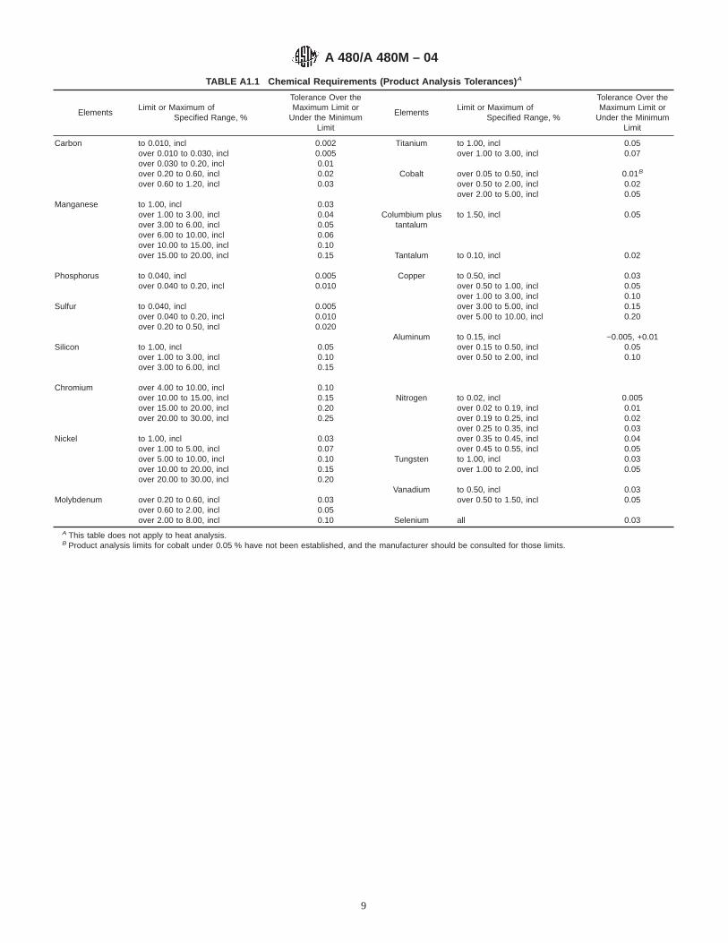
TABLE A1.1 Chemical Requirements (Product Analysis Tolerances) A
ElementsLimit or Maximum of
Specified Range, %
Tolerance Over theMaximum Limit or
Under the MinimumLimit
ElementsLimit or Maximum of
Specified Range, %
Tolerance Over theMaximum Limit or
Under the MinimumLimit
Carbon to 0.010, incl 0.002 Titanium to 1.00, incl 0.05over 0.010 to 0.030, incl 0.005 over 1.00 to 3.00, incl 0.07over 0.030 to 0.20, incl 0.01over 0.20 to 0.60, incl 0.02 Cobalt over 0.05 to 0.50, incl 0.01B
over 0.60 to 1.20, incl 0.03 over 0.50 to 2.00, incl 0.02over 2.00 to 5.00, incl 0.05
Manganese to 1.00, incl 0.03over 1.00 to 3.00, incl 0.04 Columbium plus to 1.50, incl 0.05over 3.00 to 6.00, incl 0.05 tantalumover 6.00 to 10.00, incl 0.06over 10.00 to 15.00, incl 0.10over 15.00 to 20.00, incl 0.15 Tantalum to 0.10, incl 0.02
Phosphorus to 0.040, incl 0.005 Copper to 0.50, incl 0.03over 0.040 to 0.20, incl 0.010 over 0.50 to 1.00, incl 0.05
over 1.00 to 3.00, incl 0.10Sulfur to 0.040, incl 0.005 over 3.00 to 5.00, incl 0.15
over 0.040 to 0.20, incl 0.010 over 5.00 to 10.00, incl 0.20over 0.20 to 0.50, incl 0.020
Silicon to 1.00, inclover 1.00 to 3.00, inclover 3.00 to 6.00, incl
0.050.100.15
Aluminum to 0.15, inclover 0.15 to 0.50, inclover 0.50 to 2.00, incl
−0.005, +0.010.050.10
Chromium over 4.00 to 10.00, incl 0.10over 10.00 to 15.00, incl 0.15 Nitrogen to 0.02, incl 0.005over 15.00 to 20.00, incl 0.20 over 0.02 to 0.19, incl 0.01over 20.00 to 30.00, incl 0.25 over 0.19 to 0.25, incl 0.02
over 0.25 to 0.35, incl 0.03Nickel to 1.00, incl 0.03 over 0.35 to 0.45, incl 0.04
over 1.00 to 5.00, incl 0.07 over 0.45 to 0.55, incl 0.05over 5.00 to 10.00, incl 0.10 Tungsten to 1.00, incl 0.03over 10.00 to 20.00, incl 0.15 over 1.00 to 2.00, incl 0.05over 20.00 to 30.00, incl 0.20
Vanadium to 0.50, incl 0.03Molybdenum over 0.20 to 0.60, incl 0.03 over 0.50 to 1.50, incl 0.05
over 0.60 to 2.00, incl 0.05over 2.00 to 8.00, incl 0.10 Selenium all 0.03
A This table does not apply to heat analysis.B Product analysis limits for cobalt under 0.05 % have not been established, and the manufacturer should be consulted for those limits.
A 480/A 480M – 04
9
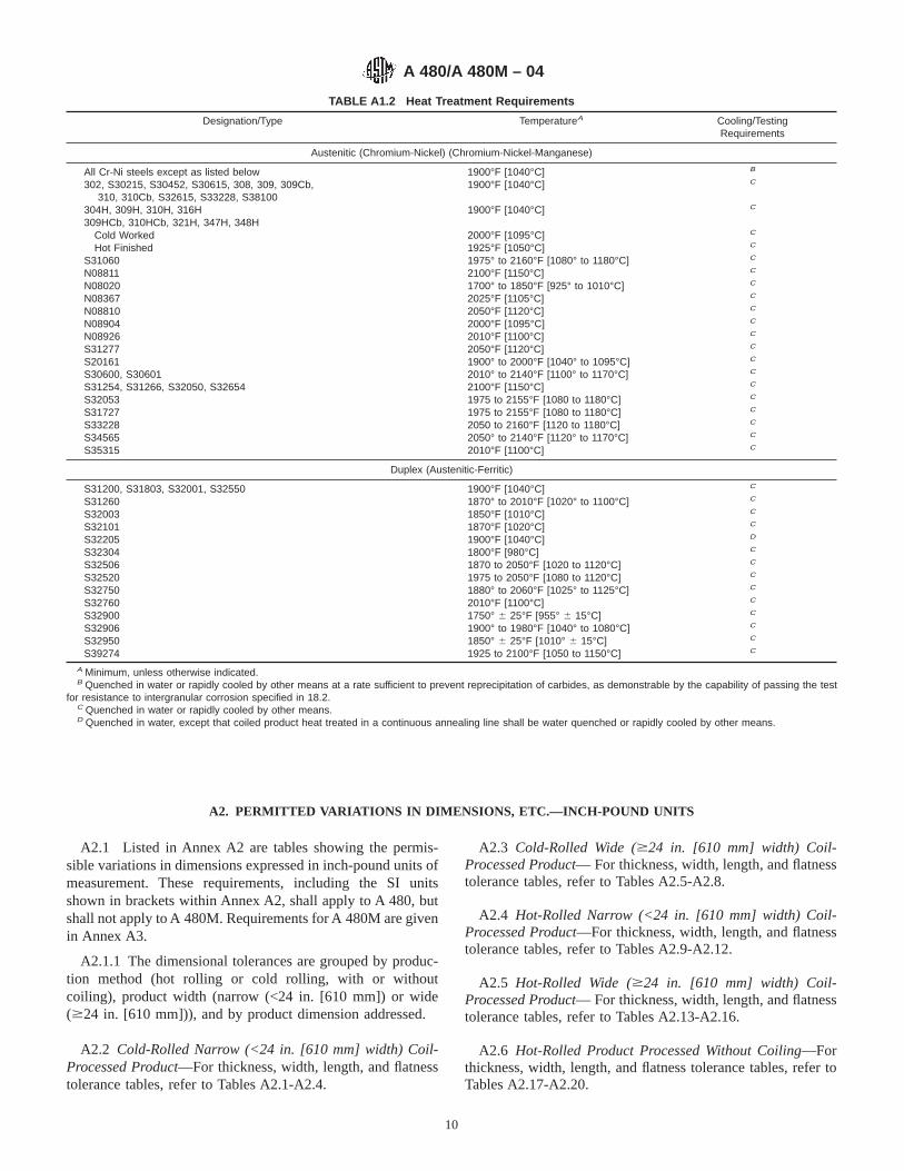
A2. PERMITTED VARIATIONS IN DIMENSIONS, ETC.—INCH-POUND UNITS
A2.1 Listed in Annex A2 are tables showing the permis-sible variations in dimensions expressed in inch-pound units ofmeasurement. These requirements, including the SI unitsshown in brackets within Annex A2, shall apply to A 480, butshall not apply to A 480M. Requirements for A 480M are givenin Annex A3.
A2.1.1 The dimensional tolerances are grouped by produc-tion method (hot rolling or cold rolling, with or withoutcoiling), product width (narrow (<24 in. [610 mm]) or wide($24 in. [610 mm])), and by product dimension addressed.
A2.2 Cold-Rolled Narrow (<24 in. [610 mm] width) Coil-Processed Product—For thickness, width, length, and flatnesstolerance tables, refer to Tables A2.1-A2.4.
A2.3 Cold-Rolled Wide ($24 in. [610 mm] width) Coil-Processed Product— For thickness, width, length, and flatnesstolerance tables, refer to Tables A2.5-A2.8.
A2.4 Hot-Rolled Narrow (<24 in. [610 mm] width) Coil-Processed Product—For thickness, width, length, and flatnesstolerance tables, refer to Tables A2.9-A2.12.
A2.5 Hot-Rolled Wide ($24 in. [610 mm] width) Coil-Processed Product— For thickness, width, length, and flatnesstolerance tables, refer to Tables A2.13-A2.16.
A2.6 Hot-Rolled Product Processed Without Coiling—Forthickness, width, length, and flatness tolerance tables, refer toTables A2.17-A2.20.
TABLE A1.2 Heat Treatment Requirements
Designation/Type TemperatureA Cooling/TestingRequirements
Austenitic (Chromium-Nickel) (Chromium-Nickel-Manganese)
All Cr-Ni steels except as listed below 1900°F [1040°C] B
302, S30215, S30452, S30615, 308, 309, 309Cb,310, 310Cb, S32615, S33228, S38100
1900°F [1040°C] C
304H, 309H, 310H, 316H 1900°F [1040°C] C
309HCb, 310HCb, 321H, 347H, 348HCold Worked 2000°F [1095°C] C
Hot Finished 1925°F [1050°C] C
S31060 1975° to 2160°F [1080° to 1180°C] C
N08811 2100°F [1150°C] C
N08020 1700° to 1850°F [925° to 1010°C] C
N08367 2025°F [1105°C] C
N08810 2050°F [1120°C] C
N08904 2000°F [1095°C] C
N08926 2010°F [1100°C] C
S31277 2050°F [1120°C] C
S20161S30600, S30601
1900° to 2000°F [1040° to 1095°C]2010° to 2140°F [1100° to 1170°C]
C
C
S31254, S31266, S32050, S32654 2100°F [1150°C] C
S32053 1975 to 2155°F [1080 to 1180°C] C
S31727 1975 to 2155°F [1080 to 1180°C] C
S33228 2050 to 2160°F [1120 to 1180°C] C
S34565 2050° to 2140°F [1120° to 1170°C] C
S35315 2010°F [1100°C] C
Duplex (Austenitic-Ferritic)
S31200, S31803, S32001, S32550 1900°F [1040°C] C
S31260 1870° to 2010°F [1020° to 1100°C] C
S32003 1850°F [1010°C] C
S32101 1870°F [1020°C] C
S32205 1900°F [1040°C] D
S32304 1800°F [980°C] C
S32506 1870 to 2050°F [1020 to 1120°C] C
S32520 1975 to 2050°F [1080 to 1120°C] C
S32750 1880° to 2060°F [1025° to 1125°C] C
S32760 2010°F [1100°C] C
S32900 1750° 6 25°F [955° 6 15°C] C
S32906 1900° to 1980°F [1040° to 1080°C] C
S32950 1850° 6 25°F [1010° 6 15°C] C
S39274 1925 to 2100°F [1050 to 1150°C] C
A Minimum, unless otherwise indicated.B Quenched in water or rapidly cooled by other means at a rate sufficient to prevent reprecipitation of carbides, as demonstrable by the capability of passing the test
for resistance to intergranular corrosion specified in 18.2.C Quenched in water or rapidly cooled by other means.D Quenched in water, except that coiled product heat treated in a continuous annealing line shall be water quenched or rapidly cooled by other means.
A 480/A 480M – 04
10

A2.7 Cold-Rolled Product Processed Without Coiling—Forthickness, width, length, and flatness tolerance tables, refer toTable A2.21.
A2.8 Tolerances for other dimensional characteristics—Forother tolerance tables, refer to Tables A2.22-A2.30.
TABLE A2.1 Permitted Variations in Thickness for Cold-Rolled, Narrow, Coil-Processed Product as Coils and Cut Lengths
NOTE 1—Thickness measurements are taken at least3⁄8 in. [9.52 mm] in from the edge of the product, except on widths less than 1 in. [25.4 mm] themeasurements should be taken at least1⁄8 in. [3.18 mm] from the product edge.
NOTE 2—The tolerances in this table include crown tolerances.
Specified Thickness, in. [mm]
Thickness Tolerances, for the Thickness and Widths Given, Over and Under, in. [mm]
Width (w ), in. [mm]
3⁄16 [4.76] to6 [152], inclw # 6 [152]
Over 6 [152] to12 [305], incl
6 [152] < w # 12 [305]
Over 12 [305] to24 [610], excl
12 [305] < w # 24 [610]
Thickness TolerancesA
0.002 [0.05] to 0.005 [0.13], excl 10 % 10 % 10 %0.005 [0.13] to 0.010 [0.25] , incl. 0.0006 [0.015] 0.0008 [0.020] 0.001 [0.025]Over 0.010 [0.25] to 0.012 [0.30], incl 0.001 [0.025] 0.001 [0.025] 0.001 [0.025]Over 0.012 [0.30] to 0.015 [0.40], incl 0.001 [0.025] 0.0015 [0.04] 0.0015 [0.04]Over 0.015 [0.40] to 0.020 [0.50], incl 0.001 [0.025] 0.0015 [0.04] 0.0015 [0.04]Over 0.020 [0.50] to 0.029 [0.74], incl 0.0015 [0.04] 0.0015 [0.04] 0.002 [0.050]Over 0.029 [0.74] to 0.035 [0.89], incl 0.0015 [0.04] 0.002 [0.050] 0.002 [0.050]Over 0.035 [0.89] to 0.050 [1.27], incl 0.0025 [0.060] 0.003 [0.070] 0.003 [0.070]Over 0.050 [1.27] to 0.069 [1.75], incl 0.003 [0.070] 0.003 [0.070] 0.003 [0.070]Over 0.069 [1.75] to 0.100 [2.54], incl 0.003 [0.070] 0.003 [0.070] 0.004 [0.10]Over 0.100 [2.54] to 0.125 [2.98], incl 0.004 [0.10] 0.004 [0.10] 0.005 [0.12]Over 0.125 [2.98] to 0.161 [4.09], incl 0.005 [0.12] 0.005 [0.12] 0.005 [0.12]Over 0.161 [4.09] to under 3⁄16 [4.76] 0.005 [0.12] 0.005 [0.12] 0.006 [0.15]
A Thickness tolerances given in in. [mm] unless otherwise indicated.
TABLE A2.2 Permitted Variations in Width for Cold-Rolled, Narrow, Coil-Processed Product as Coils and Cut Lengths for Edge No. 3 A
Specified ThicknessB,in. [mm]
Width Tolerance, Over and Under, for Thickness and Width Given, in. [mm]
w # 1.60 [40] 1.60 [40] < w # 6 [150] 6 [150] < w # 12 [305] 12 [300] < w # 24 [610]
0.010 [0.25] 0.003 [0.085] 0.004 [0.10] 0.005 [0.125] 0.020 [0.50]0.020 [0.50] 0.005 [0.125] 0.005 [0.125] 0.010 [0.25] 0.020 [0.50]0.040 [1.00] 0.005 [0.125] 0.005 [0.125] 0.010 [0.25] 0.020 [0.50]0.060 [1.50] 0.005 [0.125] 0.006 [0.15] 0.010 [0.25] 0.020 [0.50]0.100 [2.50] . . . 0.010 [0.25] 0.016 [0.40] 0.020 [0.50]0.120 [3.00] . . . 0.010 [0.25] 0.016 [0.40] 0.024 [0.60]0.160 [4.00] . . . 0.016 [0.40] 0.016 [0.40] 0.024 [0.60]0.200 [4.99] . . . 0.030 [0.80] 0.030 [0.80] 0.030 [0.80]
A For tolerances applicable to narrow product with Edge No. 1 or No. 5, see Table A2.31.B For specified thickness other than those shown, the tolerances for the next higher thickness shall apply.
TABLE A2.3 Permitted Variations in Length for Cold-Rolled,Narrow, Coil-Processed Product as Cut Lengths
Specified Length, ft [mm] Tolerances, in. [mm]
#6 [1830] +1⁄8 [3], −0>6 [1830] to #12 [3660] +0.2 [5], −0
>12 [3069] to #20 [6096] +0.3 [8], −0
TABLE A2.4 Permitted Variations in Flatness of Cold-Rolled,Narrow, Coil-Processed Product as Cut Lengths
Tolerances for variations of flatness cold-rolled products, narrow, coil-processed product as cut lengths shall be identical to the tolerances for cold-rolled, wide, coil-processed product as listed in Table A2.8 unless otherwiseagreed upon by seller and purchaser and specified in the purchase order.
A 480/A 480M – 04
11
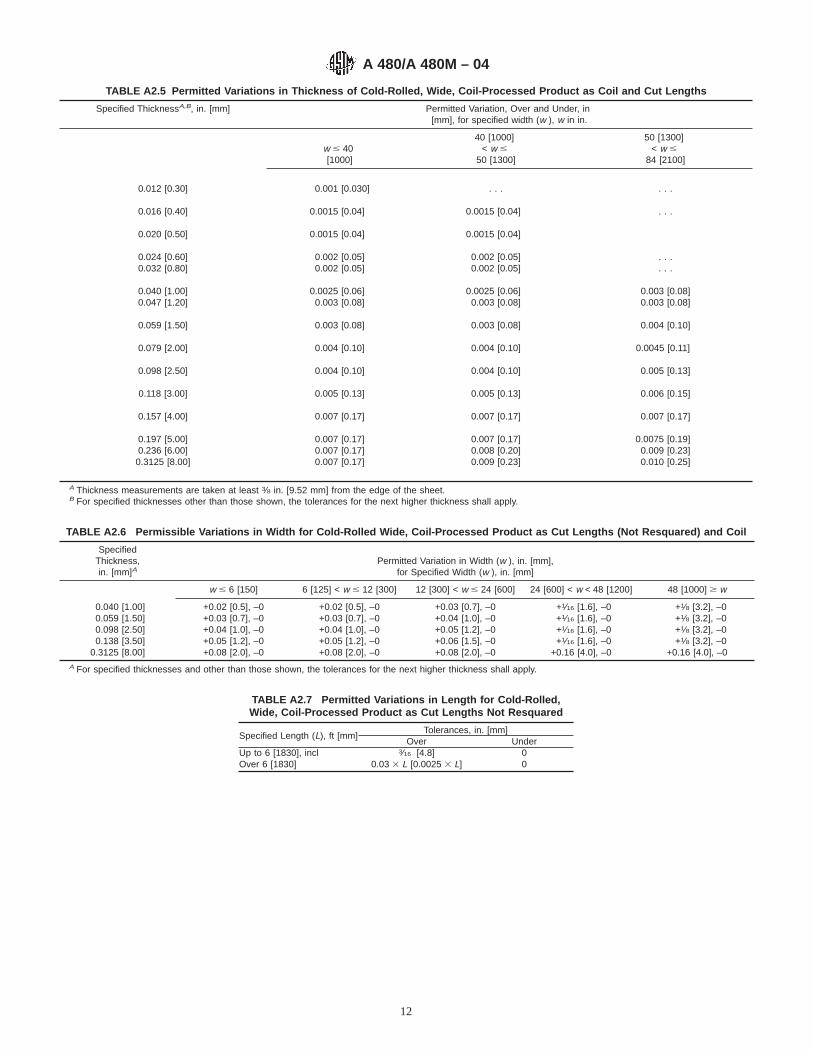
TABLE A2.5 Permitted Variations in Thickness of Cold-Rolled, Wide, Coil-Processed Product as Coil and Cut Lengths
Specified ThicknessA,B, in. [mm] Permitted Variation, Over and Under, in[mm], for specified width (w ), w in in.
w # 40[1000]
40 [1000]< w #
50 [1300]
50 [1300]< w #
84 [2100]
0.012 [0.30] 0.001 [0.030] . . . . . .
0.016 [0.40] 0.0015 [0.04] 0.0015 [0.04] . . .
0.020 [0.50] 0.0015 [0.04] 0.0015 [0.04]
0.024 [0.60] 0.002 [0.05] 0.002 [0.05] . . .0.032 [0.80] 0.002 [0.05] 0.002 [0.05] . . .
0.040 [1.00] 0.0025 [0.06] 0.0025 [0.06] 0.003 [0.08]0.047 [1.20] 0.003 [0.08] 0.003 [0.08] 0.003 [0.08]
0.059 [1.50] 0.003 [0.08] 0.003 [0.08] 0.004 [0.10]
0.079 [2.00] 0.004 [0.10] 0.004 [0.10] 0.0045 [0.11]
0.098 [2.50] 0.004 [0.10] 0.004 [0.10] 0.005 [0.13]
0.118 [3.00] 0.005 [0.13] 0.005 [0.13] 0.006 [0.15]
0.157 [4.00] 0.007 [0.17] 0.007 [0.17] 0.007 [0.17]
0.197 [5.00] 0.007 [0.17] 0.007 [0.17] 0.0075 [0.19]0.236 [6.00] 0.007 [0.17] 0.008 [0.20] 0.009 [0.23]0.3125 [8.00] 0.007 [0.17] 0.009 [0.23] 0.010 [0.25]
A Thickness measurements are taken at least 3⁄8 in. [9.52 mm] from the edge of the sheet.B For specified thicknesses other than those shown, the tolerances for the next higher thickness shall apply.
TABLE A2.6 Permissible Variations in Width for Cold-Rolled Wide, Coil-Processed Product as Cut Lengths (Not Resquared) and Coil
SpecifiedThickness,in. [mm]A
Permitted Variation in Width (w ), in. [mm],for Specified Width (w ), in. [mm]
w # 6 [150] 6 [125] < w # 12 [300] 12 [300] < w # 24 [600] 24 [600] < w < 48 [1200] 48 [1000] $ w
0.040 [1.00] +0.02 [0.5], –0 +0.02 [0.5], –0 +0.03 [0.7], –0 +1⁄16 [1.6], –0 +1⁄8 [3.2], –00.059 [1.50] +0.03 [0.7], –0 +0.03 [0.7], –0 +0.04 [1.0], –0 +1⁄16 [1.6], –0 +1⁄8 [3.2], –00.098 [2.50] +0.04 [1.0], –0 +0.04 [1.0], –0 +0.05 [1.2], –0 +1⁄16 [1.6], –0 +1⁄8 [3.2], –00.138 [3.50] +0.05 [1.2], –0 +0.05 [1.2], –0 +0.06 [1.5], –0 +1⁄16 [1.6], –0 +1⁄8 [3.2], –0
0.3125 [8.00] +0.08 [2.0], –0 +0.08 [2.0], –0 +0.08 [2.0], –0 +0.16 [4.0], –0 +0.16 [4.0], –0A For specified thicknesses and other than those shown, the tolerances for the next higher thickness shall apply.
TABLE A2.7 Permitted Variations in Length for Cold-Rolled,Wide, Coil-Processed Product as Cut Lengths Not Resquared
Specified Length (L), ft [mm]Tolerances, in. [mm]
Over UnderUp to 6 [1830], incl 3⁄16 [4.8] 0Over 6 [1830] 0.03 3 L [0.0025 3 L] 0
A 480/A 480M – 04
12

TABLE A2.8 Permitted Variations in Flatness of Cold-Rolled,Wide, Coil-Processed Product as Cut Lengths
Not Specified to Stretcher-Leveled Standard of FlatnessA
Specified Thickness,in. [mm]
Width, in. [mm]Flatness
Tolerance,B
in. [mm]
<0.062 [1.57] #60 [1524] 0.40 [10]>60 [1524] 0.50 [12]
$0.062 [1.57] #60 [1524] 0.40 [10]#60 [1524] 0.50 [12]
Stretcher-Leveled Standard of FlatnessC
Specified Thickness,in. [mm]
Width,in. [mm]
Length,in. [mm]
FlatnessTolerance,B
in. [mm]
<3⁄16 [4.76] <48 [1219] <96 [2438] 1⁄8 [3.2]<48 [1219] $96 [2438] 1⁄4 [6.4]
<3⁄16 [4.76] $48 [1219] <96 [2438] 1⁄4 [6.4]$48 [1219] $96 [2438] 1⁄4 [6.4]
2xx and 3xx Series Specified to 1⁄4 and 1⁄2 Hard Tempers
Specified Thickness,in. [mm]
Width, in. [mm] Flatness Tolerance,B
in. [mm]
1⁄4 Hard 1⁄2 Hard
<0.016 [0.41] 24 [610] to <36 [914] 1⁄2 [12.70] 3⁄4 [19.05]0.016 [0.41] to
0.030 [0.76]
5⁄8 [15.88] 7⁄8 [22.22]
>0.030 [0.76] 3⁄4 [19.05] 7⁄8 [22.22]
#0.016 [0.41] 36 [914] to <48 [1219] 5⁄8 [15.88] 1 [25.40]>0.016 [0.41] to 3⁄4 [19.05] 11⁄8 [28.58]
0.030 [0.76]>0.030 [0.76] 1 [25.40] 11⁄8 [28.58]
A Not specified to stretcher-leveled standard of flatness, and not including hardtempers of 2xx and 3xx Series, dead-soft sheets, and deep-drawing sheets.
B Maximum deviation from a horizontal flat surface.C Not including hard tempers of 2xx and 3xx Series, dead-soft sheets, and
deep-drawing sheets.
TABLE A2.9 Permitted Variations in Thickness of Hot-Rolled,Narrow, Flat-Rolled, Coil-Processed Product as Cut Lengths and
Coil
Tolerances for variations of thickness of hot-rolled, narrow, coil-processedproduct as cut lengths and coil shall be identical to the tolerances for hot-rolled,wide, coil-processed product as listed in Table A2.13, unless otherwise agreedupon by seller and purchaser and specified in the purchase order.
TABLE A2.10 Permitted Variations in Width of Hot-Rolled,Narrow, Flat-Rolled, Coil-Processed Product as Cut Lengths and
Coil
Tolerances for variations of width of hot-rolled, narrow, coil-processed productas cut lengths and coil shall be identical to the tolerances for hot-rolled, wide,coil-processed product as listed in Table A2.14 unless otherwise agreed uponby seller and purchaser and specified in the purchase order.
TABLE A2.11 Permitted Variations in Length of Hot-Rolled,Narrow, Coil-Processed Product as Cut Lengths
Tolerances for variations of length of hot-rolled, narrow, coil-processed productas cut lengths shall be identical to the tolerances for hot-rolled, wide, coil-processed product as listed in Table A2.15 unless otherwise agreed upon byseller and purchaser and specified in the purchase order.
TABLE A2.12 Permitted Variations in Flatness of Hot-Rolled,Narrow, Coil-Processed Product as Cut Lengths
Tolerances for variations of flatness of hot-rolled, narrow, coil-processedproduct as cut lengths shall be identical to the tolerances for hot-rolled, wide,coil-processed product as listed in Table A2.16 unless otherwise agreed uponby seller and purchaser and specified in the purchase order.
A 480/A 480M – 04
13

TABLE A2.13 Permitted Variations in Thickness of Hot-Rolled, Wide, Coil-Processed Product as Coil and Cut Lengths
Specified ThicknessA,in. [mm]
Permitted Variations, in. [mm], Over and Underfor specified width (w ) in. [mm]
w # 60 [1525] w > 60 [1525]
0.072 [1.83] 0.006 [0.15] 0.009 [0.22]>0.072 [1.83] to 0.083 [2.11] 0.007 [0.18] 0.010 [0.25]>0.083 [2.11] to 0.098 [2.49] 0.008 [0.20] 0.011 [0.27]>0.098 [2.49] to 0.114 [2.90] 0.009 [0.23] 0.012 [0.30]>0.114 [2.90] to 0.130 [3.30] 0.011 [0.27] 0.013 [0.33]>0.130 [3.30] to 0.145 [3.68] 0.012 [0.30] 0.013 [0.33]>0.145 [3.68] to 0.1875 [4.76] 0.013 [0.34] 0.014 [0.35]
>0.1875 [4.76] to 0.250 [6.35] 0.015 [0.38] 0.015 [0.38]>0.250 [6.35] to 0.3125 [7.94] 0.016 [0.40] 0.016 [0.40]
>0.3125 [7.94] 0.020 [0.50] 0.020 [0.50]A Thickness measurements are taken at least 3⁄8 in. [9.52 mm] from the edge of the sheet.
TABLE A2.14 Permitted Variations in Width of Hot-Rolled, Wide,Coil-Processed Product as Cut Lengths (Not Resquared) and
Coil
Specified Thickness, t, in.[mm]
Width (w ), in. [mm] Tolerances on Width, in.[mm], for Trimmed Edges
t < 3⁄16 [4.76] w < 48 [1219] +1⁄16 , –0w $ 48 [1219] +1⁄8 , –0
3⁄16 [4.76] # t < 3⁄8 [9.5] w < 48 [1219] +5⁄32 , –0w $ 48 [1219] +7⁄32 , –0
t $ 3⁄8 [9.5] w < 48 [1219] +1⁄4 , –0w $ 48 [1219] +13⁄32 , –0
TABLE A2.15 Permitted Variations in Length of Hot-Rolled, Wide,Coil-Processed Product as Cut Lengths Not Resquared
Length (L), ft [mm] Tolerances, in. [mm], Over and Under
L # 10 [3048] + 1⁄4 [6.35], −010 [3048] < L # 20 [6096] + 1⁄2 [12.70], −0
TABLE A2.16 Permitted Variations in Flatness of Hot-Rolled, Wide, Coil-Processed Product as Cut Lengths
Not Specified to Stretcher-Leveled Standard of Flatness
Specified Thickness (t ), in. [mm] Width (w ), in. [mm] Flatness Tolerance,A in. [mm]
t < 3⁄16 [4.76] w # 36 [914], 0.50 [12.7]36 [914] < w # 60 [1524] 0.75 [19.1]
w > 60 [1524] 1.00 [25.4]
t $ 3⁄16 [4.76] w # 60 [1524] 0.90 [23]60 [1524] < w # 72 [1829] 1.20 [30]
w > 72 [1829] 1.50 [38]
Stretcher-Leveled Standard of Flatness
Specified Thickness(t ), in. [mm]
Specified Width(w ), in. [mm]
Specified Length(L), in. [mm]
Flatness Tolerance,A
in. [mm]
t < 3⁄16 [4.76] w # 48 [1219] L # 96 [2438] 1⁄8 [3.18]w # 48 [1219] L > 96 [2438] 1⁄4 [6.35]
t < 3⁄16 [4.76] w > 48 [1219] L # 96 [2438] 1⁄4 [6.35]w > 48 [1219] L > 96 [2438] 1⁄4 [6.35]
A Maximum deviation from a horizontal flat surface.
A 480/A 480M – 04
14

TABLE A2.17 Permitted Variations in Thickness of Hot-Rolled Mill Plate (Quarto Plate) A,B
Specified Thickness (t ), in. [mm]
Width (w ), in. [mm]
w # 84 [2134]84 [2134] < w #
120 [3048]120 [3048] < w #
144 [3658]w > 144 [3658]
Tolerance Over Specified Thickness,C in. [mm]
t < 3⁄16 [4.76] 0.055 [1.35] 0.070 [1.78] . . . . . .3⁄16 [4.76] # t < 3⁄8 [9.52] 0.045 [1.14] 0.050 [1.27] 0.085 [2.16] . . .3⁄8 [9.52] # t < 3⁄4 [19.05] 0.055 [1.40] 0.060 [1.52] 0.085 [2.16] 0.090 [2.29]
3⁄4 [19.05] # t < 1 [25.40] 0.060 [1.52] 0.065 [1.65] 0.085 [2.16] 0.100 [2.54]1 [25.40] # t < 2 [50.80] 0.070 [1.78] 0.075 [1.90] 0.095 [2.41] 0.115 [2.92]2 [50.80] # t < 3 [76.20] 0.125 [3.20] 0.150 [3.80] 0.175 [4.45] 0.200 [5.08]3 [76.20] # t < 4 [101.6] 0.150 [3.81] 0.160 [4.06] 0.200 [5.08] 0.225 [5.72]
4 [101.6] # t < 6 [152.4] 0.180 [4.57] 0.200 [5.08] 0.335 [8.50] 0.355 [9.02]6 [152.4] # t < 8 [203.2] 0.235 [6.00] 0.255 [6.48] 0.355 [9.02] 0.435 [11.0]8 [203.2] # t < 10 [254.0] 0.315 [8.00] 0.335 [8.50] 0.435 [11.0] 0.550 [14.0]
A Thickness is measured along the longitudinal edges of the plate at least 3⁄8 in. [9.52 mm], but not more than 3 in. [76.20 mm], from the edge.B For plates up to 10 in. [254.0 mm], excl, in thickness, the tolerance under the specified thickness is 0.010 in. [0.25 mm].C For circles, the over thickness tolerances in this table apply to the diameter of the circle corresponding to the width ranges shown. For plates of irregular shape, the
over thickness tolerances apply to the greatest width corresponding to the width ranges shown.
TABLE A2.18 Permitted Variations in Width for Hot-RolledRectangular Sheared Plate Mill Plates (Quarto Plates)
Specified Width (w ), in. [mm]Tolerances, over specified width, in.
[mm]A
w # 84 [2135] 5⁄8 [15.9]84 [2135] < w # 108 [2745] 3⁄4 [19.1]
w > 108 [2745] 1 [25.4]A The tolerance under specified width is 1⁄4 in. [6.35 mm].
TABLE A2.19 Permitted Variations in Length for Hot-RolledSheared Rectangular Plate Mill Plates (Quarto Plates)
Nominal Length (L), in. [mm] Tolerances, over and under, in. [mm]A
L < 160 [4064] 3⁄4 [19.1]160 [4064] # L < 240 [6096] 11⁄4 [31.8]240 [6000] # L < 315 [8000] 15⁄8 [41.3]315 [8000] # L < 394 [10 008] 2 [50.8]
394 [10 008] # L < 590 [15 000] 21⁄4 [57.2]590 [15 000] # L < 790 [20 066] 21⁄4 [57.2]
A The tolerance under specified length is 1⁄4 in. [6.35 mm].
TABLE A2.20 Permitted Variations in Flatness of Plate Mill Plate(Quarto Plate)
NOTE 1—Tolerances in this table apply to any length, not necessarilythe rolling direction, up to 36 in. [914 mm] and to any 36 in. [914 mm] oflonger lengths in the plane of the plate measured while the plate rests ona flat surface with the concavity of the curvature upward.
NOTE 2—If the longer dimension is under 36 in. [914 mm], thetolerance is not greater than1⁄4 in. [6.4 mm].
NOTE 3—For plates with specified minimum yield strengths of 35 ksi[240 MPa] or more, the permitted variations are increased to 11⁄2 times theamounts shown.
Specified Thickness (t ),in. [mm]
Flatness Tolerance for ThicknessesGiven, in. [mm]
t < 1⁄4 [6.35] 7⁄16 [11]1⁄4 [6.35] # t < 3⁄8 [9.52] 3⁄8 [9.5]3⁄8 [9.52] # t < 1⁄2 [12.70] 5⁄16 [7.9]
1⁄2 [12.70] # t < 3⁄4 [19.05] 5⁄16 [7.9]3⁄4 [19.05] # t < 1 [25.40] 5⁄16 [7.9]1 [25.40] # t < 11⁄2 [38.10] 1⁄4 [6.4]
11⁄2 [38.10] # t < 4 [101.60] 1⁄4 [6.4]t $ 4 [101.60] 1⁄4 [6.4]
A 480/A 480M – 04
15
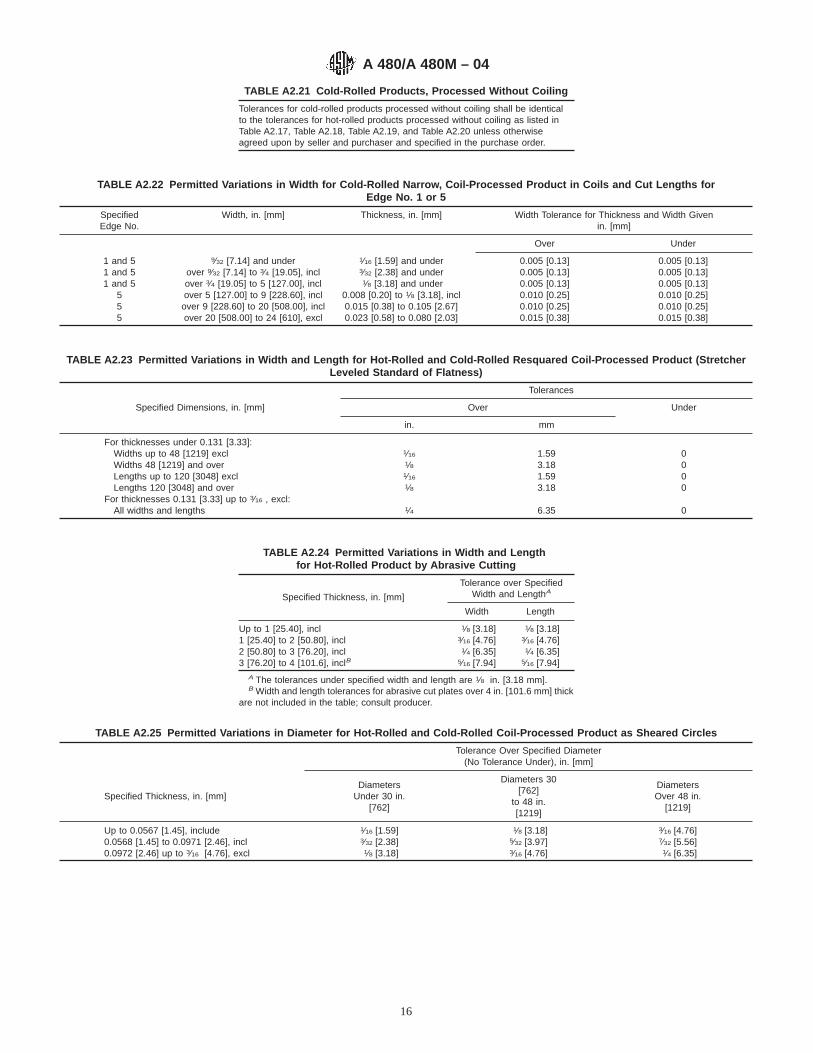
TABLE A2.21 Cold-Rolled Products, Processed Without Coiling
Tolerances for cold-rolled products processed without coiling shall be identicalto the tolerances for hot-rolled products processed without coiling as listed inTable A2.17, Table A2.18, Table A2.19, and Table A2.20 unless otherwiseagreed upon by seller and purchaser and specified in the purchase order.
TABLE A2.22 Permitted Variations in Width for Cold-Rolled Narrow, Coil-Processed Product in Coils and Cut Lengths forEdge No. 1 or 5
SpecifiedEdge No.
Width, in. [mm] Thickness, in. [mm] Width Tolerance for Thickness and Width Givenin. [mm]
Over Under
1 and 5 9⁄32 [7.14] and under 1⁄16 [1.59] and under 0.005 [0.13] 0.005 [0.13]1 and 5 over 9⁄32 [7.14] to 3⁄4 [19.05], incl 3⁄32 [2.38] and under 0.005 [0.13] 0.005 [0.13]1 and 5 over 3⁄4 [19.05] to 5 [127.00], incl 1⁄8 [3.18] and under 0.005 [0.13] 0.005 [0.13]
5 over 5 [127.00] to 9 [228.60], incl 0.008 [0.20] to 1⁄8 [3.18], incl 0.010 [0.25] 0.010 [0.25]5 over 9 [228.60] to 20 [508.00], incl 0.015 [0.38] to 0.105 [2.67] 0.010 [0.25] 0.010 [0.25]5 over 20 [508.00] to 24 [610], excl 0.023 [0.58] to 0.080 [2.03] 0.015 [0.38] 0.015 [0.38]
TABLE A2.23 Permitted Variations in Width and Length for Hot-Rolled and Cold-Rolled Resquared Coil-Processed Product (StretcherLeveled Standard of Flatness)
Tolerances
Specified Dimensions, in. [mm] Over Under
in. mm
For thicknesses under 0.131 [3.33]:Widths up to 48 [1219] excl 1⁄16 1.59 0Widths 48 [1219] and over 1⁄8 3.18 0Lengths up to 120 [3048] excl 1⁄16 1.59 0Lengths 120 [3048] and over 1⁄8 3.18 0
For thicknesses 0.131 [3.33] up to 3⁄16 , excl:All widths and lengths 1⁄4 6.35 0
TABLE A2.24 Permitted Variations in Width and Lengthfor Hot-Rolled Product by Abrasive Cutting
Specified Thickness, in. [mm]
Tolerance over SpecifiedWidth and LengthA
Width Length
Up to 1 [25.40], incl 1⁄8 [3.18] 1⁄8 [3.18]1 [25.40] to 2 [50.80], incl 3⁄16 [4.76] 3⁄16 [4.76]2 [50.80] to 3 [76.20], incl 1⁄4 [6.35] 1⁄4 [6.35]3 [76.20] to 4 [101.6], inclB 5⁄16 [7.94] 5⁄16 [7.94]
A The tolerances under specified width and length are 1⁄8 in. [3.18 mm].B Width and length tolerances for abrasive cut plates over 4 in. [101.6 mm] thick
are not included in the table; consult producer.
TABLE A2.25 Permitted Variations in Diameter for Hot-Rolled and Cold-Rolled Coil-Processed Product as Sheared Circles
Tolerance Over Specified Diameter(No Tolerance Under), in. [mm]
Specified Thickness, in. [mm]Diameters
Under 30 in.[762]
Diameters 30[762]
to 48 in.[1219]
DiametersOver 48 in.
[1219]
Up to 0.0567 [1.45], include 1⁄16 [1.59] 1⁄8 [3.18] 3⁄16 [4.76]0.0568 [1.45] to 0.0971 [2.46], incl 3⁄32 [2.38] 5⁄32 [3.97] 7⁄32 [5.56]0.0972 [2.46] up to 3⁄16 [4.76], excl 1⁄8 [3.18] 3⁄16 [4.76] 1⁄4 [6.35]
A 480/A 480M – 04
16

TABLE A2.26 Permitted Variations in Diameter for Circular Plates Taken From Hot-Rolled Product Processed With or Without Coiling
Tolerance Over Specified Diameter for GivenDiameter and Thickness,A in. [mm]
Specified Diameter, in. [mm]To 3⁄8 [9.52] in.,
excl, inThickness
3⁄8 [9.52] to 5⁄8[15.88] in., excl,
in Thickness
5⁄8 [15.88] in.and Over inThicknessB
To 60 [1524], excl 1⁄4 [6.35] 3⁄8 [9.52] 1⁄2 [12.70]60 [1524] to 84 [2134], excl 5⁄16 [7.94] 7⁄16 [11.11] 9⁄16 [14.29]84 [2134] to 108 [2743], excl 3⁄8 [9.52] 1⁄2 [12.70] 5⁄8 [15.88]108 [2743] to 180 [4572], excl 7⁄16 [11.11] 9⁄16 [14.29] 11⁄16 [17.46]
A No tolerance under.B Circular and sketch plates over 5⁄8 in. [15.88 mm] in thickness are not commonly sheared but are machined or flame cut.
TABLE A2.27 Torch Cutting Tolerances A and RecommendedCleanup Allowance for Rectangular Plates, Circles, Rings, and
Sketches
SpecifiedThickness, in.
Tolerance, in. CleanupAllowanceB per
Edge, in.Outside Dimension Inside Dimension
2 and under +3⁄8 , −0 −3⁄8 , +0 61⁄4Over 2 to 3 incl +1⁄2 , −0 −1⁄2 , +0 63⁄8Over 3 to 6 incl +3⁄4 , −0 −3⁄4 , +0 61⁄2
A Tolerances to apply unless otherwise agreed. Note that for some applicationsuser may wish to specify minus rather than plus tolerance or vice versa.
B Recommended cleanup allowance which, unless otherwise specified, will beapplied by supplier to purchasers ordered size.
TABLE A2.28 Permitted Variations in Weight for Hot-Rolled or Cold-Rolled Coil Processed Product with Thickness less than 3⁄16 in.[4.76 mm]
Any item of five sheets or less, or any itemestimated to weigh 200 lb [90.72 kg] or less,may actually weigh as much as 10 % over thetheoretical weight
weigh 200 lb [90.72 kg]or less
Any item of more than five sheets and estimatedto weigh more than 200 lb [90.72 kg], mayactually weigh as much as 71⁄2 % over thetheoretical weight
weigh more than 200 lb[90.72 kg]
Chromium-manganese-nickel 40.7 lb/ft2·in. thickness[7.82 kg/m2·mm thick]
Chromium-nickel 42.0 lb/ft2·in. thickness[8.07 kg/m2·mm thick]
Chromium 41.2 lb/ft2·in. thickness[7.92 kg/m2·mm thick]
TABLE A2.29 Permitted Variations in Camber for Cold-RolledCoil Processed Product in Coils and Cut Lengths A
Specified Width, in. [mm]Tolerance per Unit Length ofAny 8 ft [2438 mm], in. [mm]
To 11⁄2 [38.10], inclOver 11⁄2 [38.10] to 24 [609.60], excl
1⁄2 [12.70]1⁄4 [6.35]
A Camber is the deviation of a side edge from a straight line and measurementis taken by placing an 8-ft [2438-mm] straightedge on the concave side andmeasuring the greatest distance between the strip edge and the straightedge.
A 480/A 480M – 04
17

A3. PERMITTED VARIATIONS IN DIMENSIONS, ETC.—SI UNITS
A3.1 Listed in Annex A3 are tables showing the permittedvariations in dimensions expressed in SI units of measurement.These requirements shall apply to A 480M but shall not applyto A 480. Requirements for A 480 are given in Annex A2.
A3.1.1 The dimensional tolerances are grouped by produc-tion method (hot rolling or cold rolling, with or withoutcoiling), product width (narrow (<600 mm) or wide ($600mm)), and by product dimension addressed.
A3.2 Cold-Rolled Narrow (<600 mm width) Coil-ProcessedProduct—For thickness, width, length, and flatness tolerancetables, refer to Tables A3.1-A3.4.
A3.3 Cold-Rolled Wide ($600 mm width) Coil-ProcessedProduct—For thickness, width, length, and flatness tolerancetables, refer to Tables A3.5-A3.8.
A3.4 Hot-Rolled Narrow (<600 mm width) Coil-ProcessedProduct—For thickness, width, length, and flatness tolerance
tables, refer to Tables A3.9-A3.12.
A3.5 Hot-Rolled Wide ($600 mm width) Coil-ProcessedProduct—For thickness, width, length, and flatness tolerancetables, refer to Tables A3.13-A3.16.
A3.6 Hot-Rolled Product Processed Without Coiling—Forthickness, width, length, and flatness tolerance tables, refer toTables A3.17-A3.20.
A3.7 Cold-Rolled Product Processed Without Coiling—Forthickness, width, length, and flatness tolerance tables, refer toTable A3.21.
A3.8 Tolerances for Other Dimensional Characteristics—For other tolerance tables, refer to Tables A2.31-A3.29.
TABLE A2.30 Permitted Variations in Camber for Sheared Milland Universal Mill Plates A
Maximum camber = 1⁄8 in. in any 5 ft= 3.18 mm in any 1.524 m
A Camber is the deviation of a side edge from a straight line, and measurementis taken by placing a 5-ft straightedge on the concave side and measuring thegreatest distance between the plate and the straightedge.
TABLE A3.1 Permitted Variations in Thickness of Cold-Rolled,Narrow, Coil-Processed Product as Coil and Cut Lengths
NOTE 1—Thickness measurements are taken at least 10 mm in from theedge of the product, except that on widths less than 26 mm, the tolerancesare applicable for measurements at all locations.
NOTE 2—The tolerances in this table include crown tolerances.NOTE 3—For specified thicknesses other than those shown, the toler-
ances for the next higher thickness shall apply.
SpecifiedThickness,
mm
Thickness Tolerances, for the Thickness and Widths Given,Over and Under, mm
Width (w ), mm
50 to 150, inclw # 125
Over 150 to300, incl
125 < w # 250
Over 300 to600, excl
250 < w < 600
Thickness TolerancesA
0.15 0.010 0.015 0.0200.25 0.015 0.020 0.0250.50 0.025 0.030 0.0350.75 0.030 0.040 0.0501.00 0.030 0.040 0.0501.25 0.035 0.045 0.0501.50 0.040 0.050 0.0601.75 0.050 0.060 0.0702.00 0.050 0.060 0.0702.50 0.050 0.070 0.0803.00 0.060 0.070 0.0904.00 0.070 0.070 0.0904.99 0.070 0.070 0.090
A Thickness tolerances given in mm unless otherwise indicated.
TABLE A3.2 Permitted Variations in Width of Cold-Rolled,Narrow, Coil-Processed Product in Coils and Cut Lengths for
Edge No. 3 A
SpecifiedThicknessB, mm
Width Tolerance, Over and Under, for Thickness and WidthGiven, mm
w # 40 40 < w # 125 125 < w # 250 250 < w # 600
0.25 0.085 0.10 0.125 0.500.50 0.10 0.125 0.15 0.501.00 0.125 0.125 0.20 0.501.50 0.125 0.15 0.25 0.502.50 . . . 0.20 0.30 0.503.00 . . . 0.25 0.30 0.604.00 . . . 0.25 0.40 0.604.99 . . . 0.40 0.50 0.80
A For tolerances applicable to narrow product with Edge No. 1 or No. 5, seeTable A2.31.
B For specified thickness other than those shown, the tolerances for the nexthigher thickness shall apply.
TABLE A3.3 Permitted Variations in Length of Cold-Rolled,Narrow, Coil-Processed Products as Cut Lengths
Specified Length, mm Tolerances, mm
#1500 +3, −0>1500, #4000 +5, −0>4000, #6000 +8, −0
TABLE A3.4 Permitted Variations in Flatness of Cold-Rolled,Narrow, Coil-Processed Product as Cut Lengths
Tolerances for variations of flatness cold-rolled products, narrow, coil-processed product as cut lengths shall be identical to the tolerances for cold-rolled, wide, coil-processed product as listed in Table A3.8, unless otherwiseagreed upon by seller and purchaser and specified in the purchase order.
A 480/A 480M – 04
18
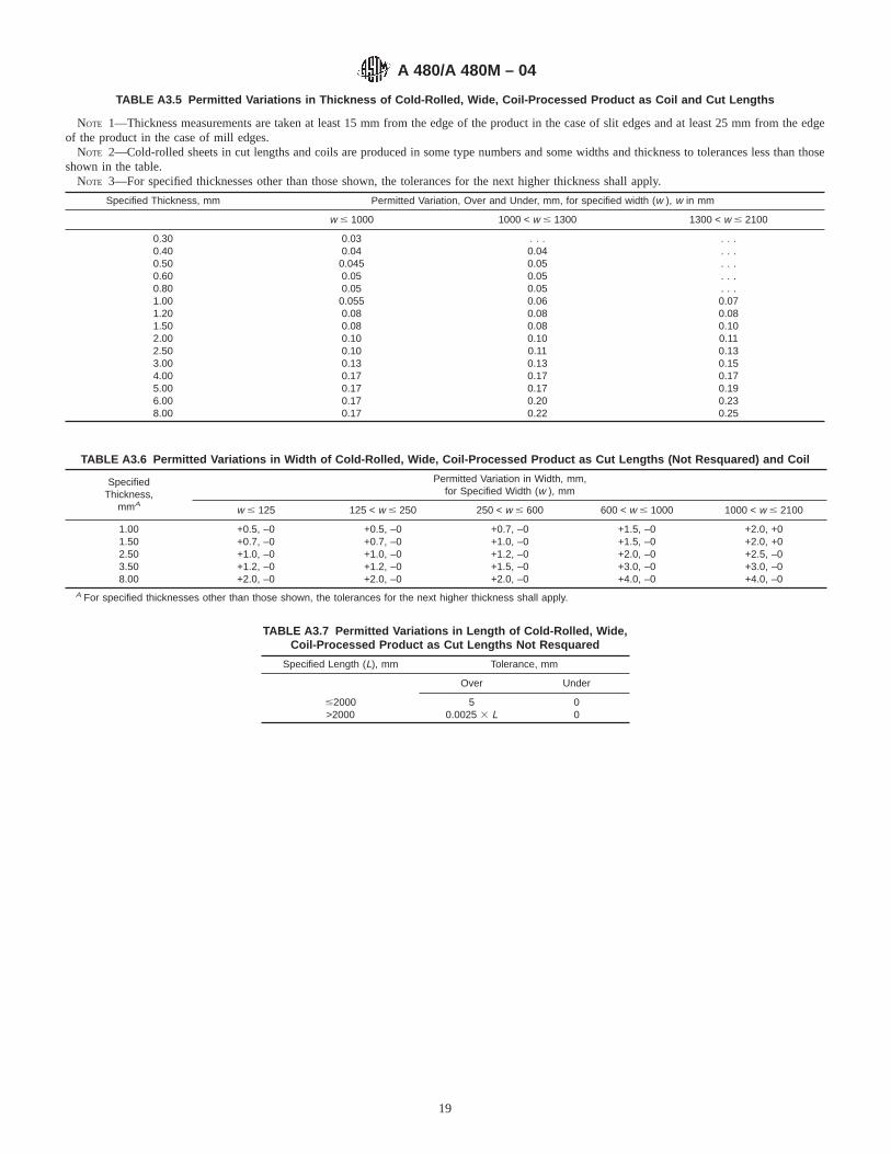
TABLE A3.5 Permitted Variations in Thickness of Cold-Rolled, Wide, Coil-Processed Product as Coil and Cut Lengths
NOTE 1—Thickness measurements are taken at least 15 mm from the edge of the product in the case of slit edges and at least 25 mm from the edgeof the product in the case of mill edges.
NOTE 2—Cold-rolled sheets in cut lengths and coils are produced in some type numbers and some widths and thickness to tolerances less than thoseshown in the table.
NOTE 3—For specified thicknesses other than those shown, the tolerances for the next higher thickness shall apply.
Specified Thickness, mm Permitted Variation, Over and Under, mm, for specified width (w ), w in mm
w # 1000 1000 < w # 1300 1300 < w # 2100
0.30 0.03 . . . . . .0.40 0.04 0.04 . . .0.50 0.045 0.05 . . .0.60 0.05 0.05 . . .0.80 0.05 0.05 . . .1.00 0.055 0.06 0.071.20 0.08 0.08 0.081.50 0.08 0.08 0.102.00 0.10 0.10 0.112.50 0.10 0.11 0.133.00 0.13 0.13 0.154.00 0.17 0.17 0.175.00 0.17 0.17 0.196.00 0.17 0.20 0.238.00 0.17 0.22 0.25
TABLE A3.6 Permitted Variations in Width of Cold-Rolled, Wide, Coil-Processed Product as Cut Lengths (Not Resquared) and Coil
SpecifiedThickness,
mmA
Permitted Variation in Width, mm,for Specified Width (w ), mm
w # 125 125 < w # 250 250 < w # 600 600 < w # 1000 1000 < w # 2100
1.00 +0.5, –0 +0.5, –0 +0.7, –0 +1.5, –0 +2.0, +01.50 +0.7, –0 +0.7, –0 +1.0, –0 +1.5, –0 +2.0, +02.50 +1.0, –0 +1.0, –0 +1.2, –0 +2.0, –0 +2.5, –03.50 +1.2, –0 +1.2, –0 +1.5, –0 +3.0, –0 +3.0, –08.00 +2.0, –0 +2.0, –0 +2.0, –0 +4.0, –0 +4.0, –0
A For specified thicknesses other than those shown, the tolerances for the next higher thickness shall apply.
TABLE A3.7 Permitted Variations in Length of Cold-Rolled, Wide,Coil-Processed Product as Cut Lengths Not Resquared
Specified Length (L), mm Tolerance, mm
Over Under
#2000 5 0>2000 0.0025 3 L 0
A 480/A 480M – 04
19
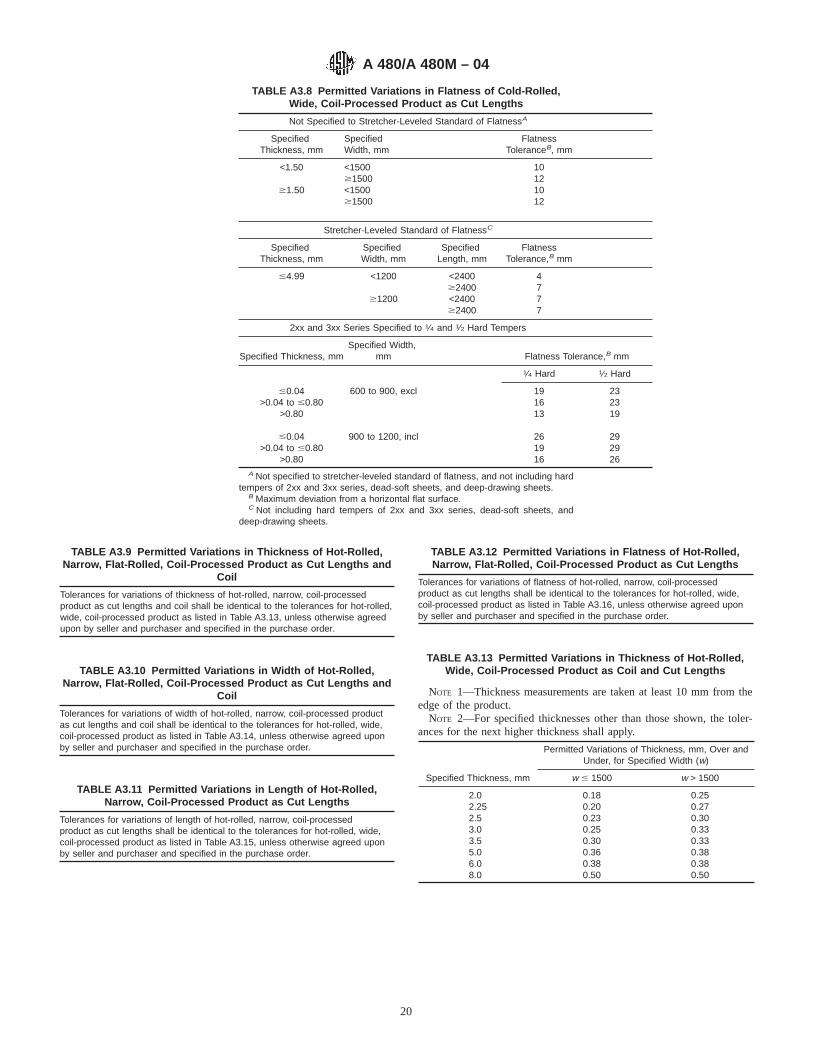
TABLE A3.8 Permitted Variations in Flatness of Cold-Rolled,Wide, Coil-Processed Product as Cut Lengths
Not Specified to Stretcher-Leveled Standard of FlatnessA
SpecifiedThickness, mm
SpecifiedWidth, mm
FlatnessToleranceB, mm
<1.50 <1500 10$1500 12
$1.50 <1500 10$1500 12
Stretcher-Leveled Standard of FlatnessC
SpecifiedThickness, mm
SpecifiedWidth, mm
SpecifiedLength, mm
FlatnessTolerance,B mm
#4.99 <1200 <2400 4$2400 7
$1200 <2400 7$2400 7
2xx and 3xx Series Specified to 1⁄4 and 1⁄2 Hard Tempers
Specified Thickness, mmSpecified Width,
mm Flatness Tolerance,B mm
1⁄4 Hard 1⁄2 Hard
#0.04 600 to 900, excl 19 23>0.04 to #0.80 16 23
>0.80 13 19
#0.04 900 to 1200, incl 26 29>0.04 to #0.80 19 29
>0.80 16 26A Not specified to stretcher-leveled standard of flatness, and not including hard
tempers of 2xx and 3xx series, dead-soft sheets, and deep-drawing sheets.B Maximum deviation from a horizontal flat surface.C Not including hard tempers of 2xx and 3xx series, dead-soft sheets, and
deep-drawing sheets.
TABLE A3.9 Permitted Variations in Thickness of Hot-Rolled,Narrow, Flat-Rolled, Coil-Processed Product as Cut Lengths and
Coil
Tolerances for variations of thickness of hot-rolled, narrow, coil-processedproduct as cut lengths and coil shall be identical to the tolerances for hot-rolled,wide, coil-processed product as listed in Table A3.13, unless otherwise agreedupon by seller and purchaser and specified in the purchase order.
TABLE A3.10 Permitted Variations in Width of Hot-Rolled,Narrow, Flat-Rolled, Coil-Processed Product as Cut Lengths and
Coil
Tolerances for variations of width of hot-rolled, narrow, coil-processed productas cut lengths and coil shall be identical to the tolerances for hot-rolled, wide,coil-processed product as listed in Table A3.14, unless otherwise agreed uponby seller and purchaser and specified in the purchase order.
TABLE A3.11 Permitted Variations in Length of Hot-Rolled,Narrow, Coil-Processed Product as Cut Lengths
Tolerances for variations of length of hot-rolled, narrow, coil-processedproduct as cut lengths shall be identical to the tolerances for hot-rolled, wide,coil-processed product as listed in Table A3.15, unless otherwise agreed uponby seller and purchaser and specified in the purchase order.
TABLE A3.12 Permitted Variations in Flatness of Hot-Rolled,Narrow, Flat-Rolled, Coil-Processed Product as Cut Lengths
Tolerances for variations of flatness of hot-rolled, narrow, coil-processedproduct as cut lengths shall be identical to the tolerances for hot-rolled, wide,coil-processed product as listed in Table A3.16, unless otherwise agreed uponby seller and purchaser and specified in the purchase order.
TABLE A3.13 Permitted Variations in Thickness of Hot-Rolled,Wide, Coil-Processed Product as Coil and Cut Lengths
NOTE 1—Thickness measurements are taken at least 10 mm from theedge of the product.
NOTE 2—For specified thicknesses other than those shown, the toler-ances for the next higher thickness shall apply.
Specified Thickness, mm
Permitted Variations of Thickness, mm, Over andUnder, for Specified Width (w)
w # 1500 w > 1500
2.0 0.18 0.252.25 0.20 0.272.5 0.23 0.303.0 0.25 0.333.5 0.30 0.335.0 0.36 0.386.0 0.38 0.388.0 0.50 0.50
A 480/A 480M – 04
20
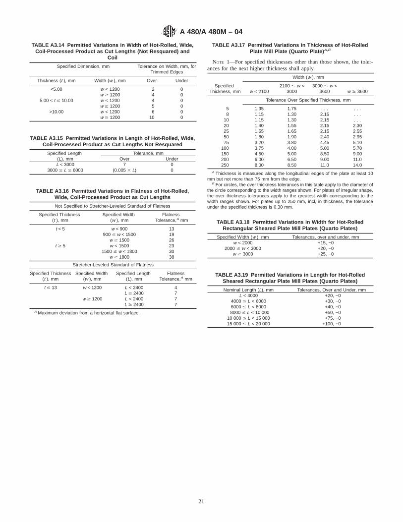
TABLE A3.14 Permitted Variations in Width of Hot-Rolled, Wide,Coil-Processed Product as Cut Lengths (Not Resquared) and
Coil
Specified Dimension, mm Tolerance on Width, mm, forTrimmed Edges
Thickness (t ), mm Width (w ), mm Over Under
<5.00 w < 1200 2 0w $ 1200 4 0
5.00 < t # 10.00 w < 1200 4 0w $ 1200 5 0
>10.00 w < 1200 6 0w $ 1200 10 0
TABLE A3.15 Permitted Variations in Length of Hot-Rolled, Wide,Coil-Processed Product as Cut Lengths Not Resquared
Specified Length(L), mm
Tolerance, mmOver Under
L < 3000 7 03000 # L # 6000 (0.005 3 L) 0
TABLE A3.16 Permitted Variations in Flatness of Hot-Rolled,Wide, Coil-Processed Product as Cut Lengths
Not Specified to Stretcher-Leveled Standard of Flatness
Specified Thickness(t ), mm
Specified Width(w ), mm
FlatnessTolerance,A mm
t < 5 w < 900 13900 # w < 1500 19
w $ 1500 26t $ 5 w < 1500 23
1500 # w < 1800 30w $ 1800 38
Stretcher-Leveled Standard of Flatness
Specified Thickness(t ), mm
Specified Width(w ), mm
Specified Length(L), mm
FlatnessTolerance,A mm
t # 13 w < 1200 L < 2400 4L $ 2400 7
w $ 1200 L < 2400 7L $ 2400 7
A Maximum deviation from a horizontal flat surface.
TABLE A3.17 Permitted Variations in Thickness of Hot-RolledPlate Mill Plate (Quarto Plate) A,B
NOTE 1—For specified thicknesses other than those shown, the toler-ances for the next higher thickness shall apply.
Width (w ), mm
SpecifiedThickness, mm w < 2100
2100 # w <3000
3000 # w <3600 w $ 3600
Tolerance Over Specified Thickness, mm
5 1.35 1.75 . . . . . .8 1.15 1.30 2.15 . . .
10 1.15 1.30 2.15 . . .20 1.40 1.55 2.15 2.3025 1.55 1.65 2.15 2.5550 1.80 1.90 2.40 2.9575 3.20 3.80 4.45 5.10
100 3.75 4.00 5.00 5.70150 4.50 5.00 8.50 9.00200 6.00 6.50 9.00 11.0250 8.00 8.50 11.0 14.0
A Thickness is measured along the longitudinal edges of the plate at least 10mm but not more than 75 mm from the edge.
B For circles, the over thickness tolerances in this table apply to the diameter ofthe circle corresponding to the width ranges shown. For plates of irregular shape,the over thickness tolerances apply to the greatest width corresponding to thewidth ranges shown. For plates up to 250 mm, incl, in thickness, the toleranceunder the specified thickness is 0.30 mm.
TABLE A3.18 Permitted Variations in Width for Hot-RolledRectangular Sheared Plate Mill Plates (Quarto Plates)
Specified Width (w ), mm Tolerances, over and under, mmw < 2000 +15, −0
2000 # w < 3000 +20, −0w $ 3000 +25, −0
TABLE A3.19 Permitted Variations in Length for Hot-RolledSheared Rectangular Plate Mill Plates (Quarto Plates)
Nominal Length (L), mm Tolerances, Over and Under, mmL < 4000 +20, −0
4000 # L < 6000 +30, −06000 # L < 8000 +40, −08000 # L < 10 000 +50, −0
10 000 # L < 15 000 +75, −015 000 # L < 20 000 +100, −0
A 480/A 480M – 04
21
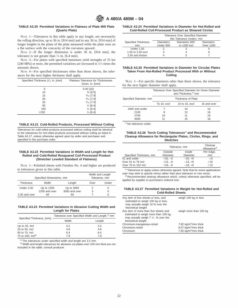
TABLE A3.20 Permitted Variations in Flatness of Plate Mill Plate(Quarto Plate)
NOTE 1—Tolerances in this table apply to any length, not necessarilythe rolling direction, up to 36 in. [914 mm] and to any 36 in. [914 mm] oflonger lengths in the plane of the plate measured while the plate rests ona flat surface with the concavity of the curvature upward.
NOTE 2—If the longer dimension is under 36 in. [914 mm], thetolerance is not greater than1⁄4 in. [6.4 mm].
NOTE 3—For plates with specified minimum yield strengths of 35 ksi[240 MPa] or more, the permitted variations are increased to 11⁄2 times theamounts shown.
NOTE 4—For specified thicknesses other than those shown, the toler-ances for the next higher thickness shall apply.
Specified Thickness (t ), in. [mm] Flatness Tolerance for ThicknessesGiven, in. [mm]
5 0.40 [10]10 3⁄8 [9.5]15 5⁄16 [7.9]20 5⁄16 [7.9]25 5⁄16 [7.9]50 1⁄4 [6.4]
150 1⁄4 [6.4]>150 1⁄4 [6.4]
TABLE A3.21 Cold-Rolled Products, Processed Without Coiling
Tolerances for cold-rolled products processed without coiling shall be identicalto the tolerances for hot-rolled products processed without coiling as listed inTable A3.17, unless otherwise agreed upon by seller and purchaser andspecified in the purchase order.
TABLE A3.22 Permitted Variations in Width and Length for Hot-Rolled and Cold-Rolled Resquared Coil-Processed Product
(Stretcher Leveled Standard of Flatness)
NOTE 1—Polished sheets with Finishes No. 4 and higher are producedto tolerances given in this table.
Specified Dimensions, mmWidth and Length
Tolerance, mm
Thickness Width Length Over Under
Under 3.30 Up to 1200 Up to 3000 2 01200 and over 3000 and over 3 0
3.30 and over All All 7 0
TABLE A3.23 Permitted Variations in Abrasive Cutting Width andLength for Plates
Specified Thickness, [mm]Tolerance over Specified Width and Length,A mm
Width Length
Up to 25, incl 3.2 3.225 to 50, incl 4.8 4.850 to 75, incl 6.4 6.475 to 100, inclB 7.9 7.9
A The tolerances under specified width and length are 3.2 mm.B Width and length tolerances for abrasive cut plates over 100 mm thick are not
included in the table; consult producer.
TABLE A3.24 Permitted Variations in Diameter for Hot-Rolled andCold-Rolled Coil-Processed Product as Sheared Circles
Tolerance Over Specified Diameter(No Tolerance Under), mm
Specified Thickness,mm
DiametersUnder 600
Diameters 600to 1200 incl
DiametersOver 1200
Under 1.50 2 3 51.50 to 2.50 excl 3 4 62.50 and thicker 4 5 7
TABLE A3.25 Permitted Variations in Diameter for Circular PlatesTaken From Hot-Rolled Product Processed With or Without
Coiling
NOTE 1—For specific diameters other than those shown, the tolerancefor the next higher diameter shall apply.
Tolerance Over Specified Diameter for Given Diameterand Thickness,A mm
Specified Diameter, mm Thickness of Plate
To 10, excl 10 to 15, excl 15 and over
1500 and under 7 10 132100 8 13 162700 10 11 154500 11 15 18
A No tolerance under.
TABLE A3.26 Torch Cutting Tolerances A and RecommendedCleanup Allowance for Rectangular Plates, Circles, Rings, and
Sketches
Specified Thickness, mm
Tolerance, mmCleanup
AllowanceB
OutsideDiameter
InsideDiameter
Per Edge,mm
51 and under +10, –0 –10, +0 66Over 51 to 76 incl +13, –0 –13, +0 610Over 76 to 152 incl +19, –0 –19, +0 613
A Tolerances to apply unless otherwise agreed. Note that for some applicationsuser may wish to specify minus rather than plus tolerance or vice versa.
B Recommended cleanup allowance which, unless otherwise specified, will beapplied by supplier to purchasers ordered size.
TABLE A3.27 Permitted Variations in Weight for Hot-Rolled andCold-Rolled Sheets
Any item of five sheets or less, andestimated to weigh 100 kg or less,may actually weigh 10 % over thetheoretical weight
weigh 100 kg or less
Any item of more than five sheets andestimated to weigh more than 100 kg,may actually weigh 7 1⁄2 % over thetheoretical weight
weigh more than 100 kg
Chromium-manganese-nickel 7.82 kg/m2/mm thickChromium-nickel 8.07 kg/m2/mm thickChromium 7.92 kg/m2/mm thick
A 480/A 480M – 04
22

A4. REQUIREMENTS FOR THE INTRODUCTION OF NEW MATERIALS
A4.1 New materials may be proposed for inclusion inspecifications referencing this specification subject to thefollowing conditions:
A4.1.1 Application for the addition of a new grade to aspecification shall be made to the Chairman of the subcommit-tee which has jurisdiction over that specification.
A4.1.2 The application shall be accompanied by a statementfrom at least one user indicating that there is a need for the newgrade to be included in the applicable specification.
A4.1.3 The application shall be accompanied by test data asrequired by the applicable specification. Test data from aminimum of three test lots, as defined by the specification, eachfrom a different heat, shall be furnished.
A4.1.4 The application shall provide recommendations forall requirements appearing in the applicable specification.
A4.1.5 The application shall state whether the new grade iscovered by patent.
SUMMARY OF CHANGES
Committee A01 has identified the location of selected changes to this standard since the last issue, A 480/A 480M – 03c, thatmay impact the use of this standard. (Approved March 1, 2004).
(1) Added heat treatment requirements for S32053 in TableA1.2.(2) Added heat treatment requirements for S31727 in TableA1.2.
(3) Added heat treatment requirements for S32506 in TableA1.2.(4) Added heat treatment requirement for S39274 in TableA1.2.
TABLE A3.28 Permitted Variations in Camber for Cold-RolledNarrow Coil-Processed Product in Coils and Cut Lengths A
Specified Width, mm Tolerance Per Unit Length Of Any 2400 mm
To 40, incl 13Over 40 to 600, incl 7
A Camber is the deviation of a side edge from a straight line and measurementis taken by placing a 2400-mm straightedge on the concave side and measuringthe greatest distance between the strip edge and the straightedge.
TABLE A3.29 Permitted Variations in Camber for Hot-Rolled andCold-Rolled Wide Coil-Processed Product as Cut Lengths NotResquared and Cold-Rolled Wide Coil-Processed Product as
Coils A
Specified Width, mm Tolerance per Unit Length of Any 2400 mm, mm
600 to 900, excl 4900 and over 3
A Camber is the greatest deviation of a side edge from a straight line andmeasurement is taken by placing an 8-ft [2438-mm] straightedge on the concaveside and measuring the greatest distance between the sheet edge and thestraightedge.
A 480/A 480M – 04
23

Committee A01 has identified the location of selected changes to this standard since the last issue, A 480/A 480M – 03b, thatmay impact the use of this standard. (Approved Oct. 1, 2003).
(1) Added UNS S31060 to Table A1.2.
Committee A01 has identified the location of selected changes to this standard since the last issue, A 480/A 480M – 03a, thatmay impact the use of this standard. (Approved May 10, 2003.)
(1) Added UNS S31277 to Table A1.2.
Committee A01 has identified the location of selected changes to this standard since the last issue, A 480/A 480M – 03, thatmay impact the use of this standard. (Approved April 10, 2003.)
(1) Added UNS S32906 and UNS S32101 to Table A1.2.(2) Revised Sections 1.3, 9.1, A2.1, and A3.1 to require use
of Annex A3 for A 480M when specified.
Committee A01 has identified the location of selected changes to this standard since the last issue, A 480/A 480M – 02, thatmay impact the use of this standard. (Approved February 10, 2003.)
(1) Added heat treatment requirements for S32003 in TableA1.2.
ASTM International takes no position respecting the validity of any patent rights asserted in connection with any item mentionedin this standard. Users of this standard are expressly advised that determination of the validity of any such patent rights, and the riskof infringement of such rights, are entirely their own responsibility.
This standard is subject to revision at any time by the responsible technical committee and must be reviewed every five years andif not revised, either reapproved or withdrawn. Your comments are invited either for revision of this standard or for additional standardsand should be addressed to ASTM International Headquarters. Your comments will receive careful consideration at a meeting of theresponsible technical committee, which you may attend. If you feel that your comments have not received a fair hearing you shouldmake your views known to the ASTM Committee on Standards, at the address shown below.
This standard is copyrighted by ASTM International, 100 Barr Harbor Drive, PO Box C700, West Conshohocken, PA 19428-2959,United States. Individual reprints (single or multiple copies) of this standard may be obtained by contacting ASTM at the aboveaddress or at 610-832-9585 (phone), 610-832-9555 (fax), or [email protected] (e-mail); or through the ASTM website(www.astm.org).
A 480/A 480M – 04
24

Designation: A 484/A 484M – 03a
Standard Specification forGeneral Requirements for Stainless Steel Bars, Billets, andForgings 1
This standard is issued under the fixed designation A 484/A 484M; the number immediately following the designation indicates the yearof original adoption or, in the case of revision, the year of last revision. A number in parentheses indicates the year of last reapproval.A superscript epsilon (e) indicates an editorial change since the last revision or reapproval.
This standard has been approved for use by agencies of the Department of Defense.
1 This specification is under the jurisdiction of ASTM Committee A01 on Steel, Stainless Steel and Related Alloys and is the direct responsibility of Subcommittee A01.17on Flat-Rolled and Wrought Stainless Steel.
Current edition approved April June 10, 2003. Published May July 2003. Originally approved in 1963. Last previous edition approved in 20003 as A 484/A484M – 003.
1
This document is not an ASTM standard and is intended only to provide the user of an ASTM standard an indication of what changes have been made to the previous version. Becauseit may not be technically possible to adequately depict all changes accurately, ASTM recommends that users consult prior editions as appropriate. Inall cases only the current versionof the standard as published by ASTM is to be considered the official document.
Copyright © ASTM International, 100 Barr Harbor Drive, PO Box C700, West Conshohocken, PA 19428-2959, United States.

1. Scope*
1.1 This specification2 covers general requirements that shall apply to wrought stainless steel bars, shapes, forgings, and billetsor other semi-finished material (except wire) for forging, under the latest revision of each of the following ASTM specifications:A 276, A 314, A 458, A 473, A 477, A 479/A 479M, A 564/A 564M, A 565, A 582/A 582M, A 638/A 638M, A 705/A 705M, andA 831/A 831M.
1.2 In the case of conflict between a requirement of a product specification and a requirement of this specification, the productspecification shall prevail. In the case of conflict between a requirement of the product specification or a requirement of thisspecification and a more stringent requirement of the purchase order, the purchase order shall prevail. The purchase orderrequirements shall not take precedence if they, in any way, violate the requirements of the product specification or thisspecification; for example, by waiving a test requirement or by making a test requirement less stringent.
1.3 The requirements for introduction of new materials in specifications referencing this specification are given in Annex A1.1.4 General requirements for flat-rolled stainless steel products other than bar are covered in Specification A 480/A 480M.1.5 General requirements for wire products in coils are covered in Specification A 555/A 555M.1.6 The values stated in either inch-pound units or SI (metric) units are to be regarded separately as the standard; within the
text and tables, the SI units are shown in [brackets]. The values stated in each system are not exact equivalents; therefore, eachsystem must be used independently of the other. Combining values from the two systems may result in nonconformance with thespecification.
1.7 Unless the order specifies an “M” designation, the material shall be furnished to inch-pound units.
2. Referenced Documents
2.1 ASTM Standards:A 262 Practices for Detecting Susceptibility to Intergranular Attack in Austenitic Stainless Steels3
A 276 Specification for Stainless Steel Bars and Shapes3
A 314 Specification for Stainless Steel Billets and Bars for Forging3
A 370 Test Methods and Definitions for Mechanical Testing of Steel Products3
A 458 Specification for Hot-Worked, Hot-Cold-Worked, and Cold-Worked Alloy Steel Bars for High Strength at ElevatedTemperature4
A 473 Specification for Stainless Steel Forgings3
A 479/A 479M Specification for Stainless Steel Bars and Shapes for Use in Boilers and Other Pressure Vessels3
A 480/A 480M Specification for General Requirements for Flat-Rolled Stainless and Heat-Resisting Steel Plate, Sheet, andStrip3
A 555/A 555M Specification for General Requirements for Stainless and Heat-Resisting Steel Wire and Wire Rods3
A 564/A 564M Specification for Hot-Rolled and Cold-Finished Age-Hardening Stainless Steel Bars and Shapes3
A 565 Specification for Martensitic Stainless Steel Bars, Forgings, and Forging Stock for High-Temperature Service3
A 582/A 582M Specification for Free-Machining Stainless and Steel Bars3
A 638/A 638M Specification for Precipitation Hardening Iron Base Superalloy Bars, Forgings, and Forging Stock forHigh-Temperature Service3
A 700 Practices for Packaging, Marking, and Loading Methods for Steel Products for Domestic Shipment5
A 705/A 705M Specification for Age-Hardening Stainless Steel Forgings3
A 751 Test Methods, Practices, and Terminology for Chemical Analysis of Steel Products3
A 831/A 831M Specification for Austenitic and Martensitic Stainless Steel Bars, Billets, and Forgings for Liquid Metal CooledReactor Core Components3
E 112 Test Methods for Determining Average Grain Size6
E 139 Test Methods for Conducting Creep, Creep-Rupture, and Stress-Rupture Tests of Metallic Materials6
2.2 Federal Standards:Fed. Std. No. 123 Marking for Shipment (Civil Agencies)7
Fed Std. No. 183 Continuous Marking of Iron and Steel Products7
2.3 Military Standards:MIL-STD-129 Marking for Shipment and Storage7
MIL-STD-163 Preservation of Steel Products for Shipment (Storage and Overseas Shipment)7
2.4 Other Standard:
2 For ASME Boiler and Pressure Vessel Code Applications, see related Specification SA-484/SA-484M in Section II of that code.3 Annual Book of ASTM Standards, Vol 01.03.4 Discontinued, see1991 Annual Book of ASTM Standards, Vol 01.05.5 Annual Book of ASTM Standards, Vol 01.05.6 Annual Book of ASTM Standards, Vol 03.01.7 Available from Standardization Documents Order Desk, Bldg. 4, Section D, 700 Robbins Ave., Philadelphia, PA 19111–5094. Attn: NPODS.
A 484/A 484M – 03a
2
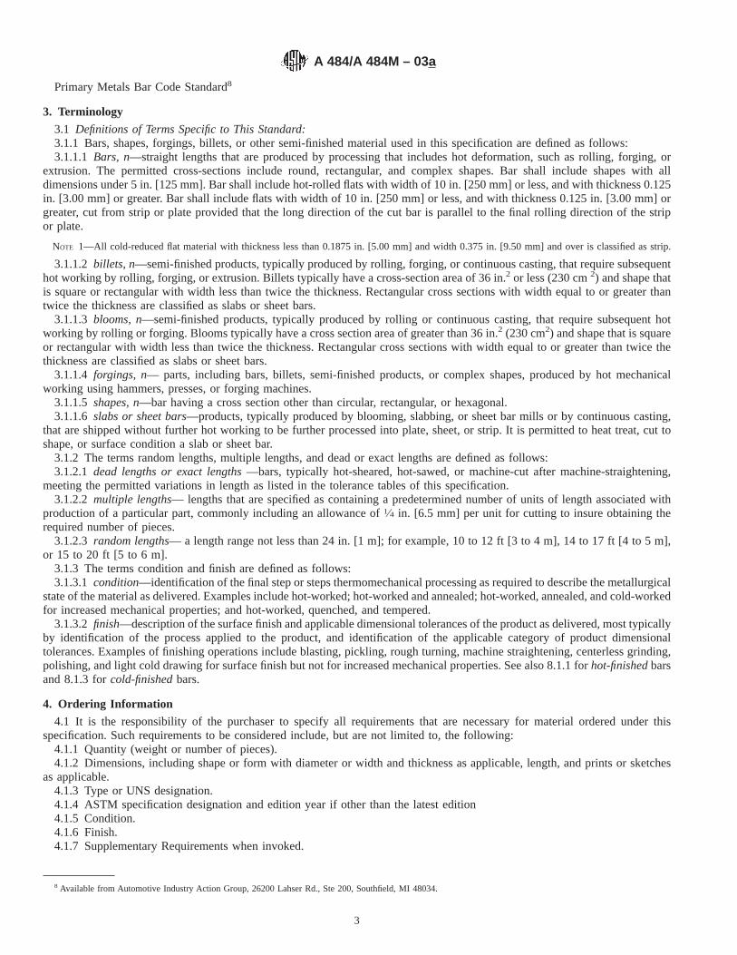
Primary Metals Bar Code Standard8
3. Terminology
3.1 Definitions of Terms Specific to This Standard:3.1.1 Bars, shapes, forgings, billets, or other semi-finished material used in this specification are defined as follows:3.1.1.1 Bars, n—straight lengths that are produced by processing that includes hot deformation, such as rolling, forging, or
extrusion. The permitted cross-sections include round, rectangular, and complex shapes. Bar shall include shapes with alldimensions under 5 in. [125 mm]. Bar shall include hot-rolled flats with width of 10 in. [250 mm] or less, and with thickness 0.125in. [3.00 mm] or greater. Bar shall include flats with width of 10 in. [250 mm] or less, and with thickness 0.125 in. [3.00 mm] orgreater, cut from strip or plate provided that the long direction of the cut bar is parallel to the final rolling direction of the stripor plate.
NOTE 1—All cold-reduced flat material with thickness less than 0.1875 in. [5.00 mm] and width 0.375 in. [9.50 mm] and over is classified as strip.
3.1.1.2 billets, n—semi-finished products, typically produced by rolling, forging, or continuous casting, that require subsequenthot working by rolling, forging, or extrusion. Billets typically have a cross-section area of 36 in.2 or less (230 cm2) and shape thatis square or rectangular with width less than twice the thickness. Rectangular cross sections with width equal to or greater thantwice the thickness are classified as slabs or sheet bars.
3.1.1.3 blooms, n—semi-finished products, typically produced by rolling or continuous casting, that require subsequent hotworking by rolling or forging. Blooms typically have a cross section area of greater than 36 in.2 (230 cm2) and shape that is squareor rectangular with width less than twice the thickness. Rectangular cross sections with width equal to or greater than twice thethickness are classified as slabs or sheet bars.
3.1.1.4 forgings, n— parts, including bars, billets, semi-finished products, or complex shapes, produced by hot mechanicalworking using hammers, presses, or forging machines.
3.1.1.5 shapes, n—bar having a cross section other than circular, rectangular, or hexagonal.3.1.1.6 slabs or sheet bars—products, typically produced by blooming, slabbing, or sheet bar mills or by continuous casting,
that are shipped without further hot working to be further processed into plate, sheet, or strip. It is permitted to heat treat, cut toshape, or surface condition a slab or sheet bar.
3.1.2 The terms random lengths, multiple lengths, and dead or exact lengths are defined as follows:3.1.2.1 dead lengths or exact lengths—bars, typically hot-sheared, hot-sawed, or machine-cut after machine-straightening,
meeting the permitted variations in length as listed in the tolerance tables of this specification.3.1.2.2 multiple lengths— lengths that are specified as containing a predetermined number of units of length associated with
production of a particular part, commonly including an allowance of1⁄4 in. [6.5 mm] per unit for cutting to insure obtaining therequired number of pieces.
3.1.2.3 random lengths— a length range not less than 24 in. [1 m]; for example, 10 to 12 ft [3 to 4 m], 14 to 17 ft [4 to 5 m],or 15 to 20 ft [5 to 6 m].
3.1.3 The terms condition and finish are defined as follows:3.1.3.1 condition—identification of the final step or steps thermomechanical processing as required to describe the metallurgical
state of the material as delivered. Examples include hot-worked; hot-worked and annealed; hot-worked, annealed, and cold-workedfor increased mechanical properties; and hot-worked, quenched, and tempered.
3.1.3.2 finish—description of the surface finish and applicable dimensional tolerances of the product as delivered, most typicallyby identification of the process applied to the product, and identification of the applicable category of product dimensionaltolerances. Examples of finishing operations include blasting, pickling, rough turning, machine straightening, centerless grinding,polishing, and light cold drawing for surface finish but not for increased mechanical properties. See also 8.1.1 forhot-finishedbarsand 8.1.3 forcold-finishedbars.
4. Ordering Information
4.1 It is the responsibility of the purchaser to specify all requirements that are necessary for material ordered under thisspecification. Such requirements to be considered include, but are not limited to, the following:
4.1.1 Quantity (weight or number of pieces).4.1.2 Dimensions, including shape or form with diameter or width and thickness as applicable, length, and prints or sketches
as applicable.4.1.3 Type or UNS designation.4.1.4 ASTM specification designation and edition year if other than the latest edition4.1.5 Condition.4.1.6 Finish.4.1.7 Supplementary Requirements when invoked.
8 Available from Automotive Industry Action Group, 26200 Lahser Rd., Ste 200, Southfield, MI 48034.
A 484/A 484M – 03a
3
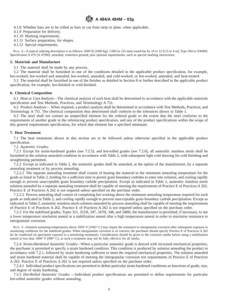
4.1.8 Whether bars are to be rolled as bars or cut from strip or plate, when applicable.4.1.9 Preparation for delivery.4.1.10 Marking requirements.4.1.11 Surface preparation, for shapes.4.1.12 Special requirements.
NOTE 2—A typical ordering description is as follows: 5000 lb [2000 kg]; 1.000 in. [25 mm] round bar by 10 to 12 ft [3 to 4 m]; Type 304 or S30400;Specification A 479 [A 479M]; annealed, centerless ground; plus optional requirements, such as special marking instructions.
5. Materials and Manufacture
5.1 The material shall be made by any process.5.2 The material shall be furnished in one of the conditions detailed in the applicable product specification, for example,
hot-worked; hot-worked and annealed; hot-worked, annealed, and cold-worked; or hot-worked, annealed, and heat-treated.5.3 The material shall be furnished in one of the finishes as detailed in Section 8 or further described in the applicable product
specification, for example, hot-finished or cold-finished.
6. Chemical Composition
6.1 Heat or Cast Analysis—The chemical analysis of each heat shall be determined in accordance with the applicable materialsspecification and Test Methods, Practices, and Terminology A 751.
6.2 Product Analysis— When required, a product analysis shall be determined in accordance with Test Methods, Practices, andTerminology A 751. The chemical composition thus determined shall conform to the tolerances shown in Table 1.
6.3 The steel shall not contain an unspecified element for the ordered grade to the extent that the steel conforms to therequirements of another grade in the referencing product specification, and any of the product specifications within the scope ofthis general requirements specification, for which that element has a specified minimum.
7. Heat Treatment
7.1 The heat treatments shown in this section are to be followed unless otherwise specified in the applicable productspecification.
7.2 Austenitic Grades:7.2.1 Except for strain-hardened grades (see 7.2.5), and hot-rolled grades (see 7.2.6), all austenitic stainless steels shall be
furnished in the solution annealed condition in accordance with Table 2, with subsequent light cold drawing for cold finishing andstraightening permitted.
7.2.2 Except as indicated in Table 2, the austenitic grades shall be annealed, at the option of the manufacturer, by a separateannealing treatment or by process annealing.
7.2.2.1 The separate annealing treatment shall consist of heating the material to the minimum annealing temperature for thegrade as listed in Table 2, holding for a sufficient time to permit grain boundary carbides to enter into solution, and cooling rapidlyenough to prevent unacceptable grain boundary carbide precipitation. Except as indicated in Table 2, austenitic stainless steelssolution annealed by a separate annealing treatment shall be capable of meeting the requirements of Practice E of Practices A 262.Practice E of Practices A 262 is not required unless specified on the purchase order.
7.2.2.2 Process annealing shall consist of completing hot working above the minimum annealing temperature required for eachgrade as indicated in Table 2, and cooling rapidly enough to prevent unacceptable grain boundary carbide precipitation. Except asindicated in Table 2, austenitic stainless steels solution annealed by process annealing shall be capable of meeting the requirementsof Practice E of Practices A 262. Practice E of Practices A 262 is not required unless specified on the purchase order.
7.2.3 For the stabilized grades, Types 321, 321H, 347, 347H, 348, and 348H, the manufacturer is permitted, if necessary, to usea lower temperature resolution anneal or a stabilization anneal after a high temperature anneal in order to maximize resistance tointergranular corrosion.
NOTE 3—Solution annealing temperatures above 1950° F [1065° C] may impair the resistance to intergranular corrosion after subsequent exposure tosensitizing conditions for the stabilized grades. When intergranular corrosion is of concern, the purchaser should specify Practice E of PracticesA 262(to be conducted on specimens exposed to a sensitizing treatment). Consideration should be given to the corrosive media before using a stabilizationanneal at less than 1800° F [980° C], as such a treatment may not be fully effective for all media.
7.2.4 Strain-Hardened Austenitic Grades—When a particular austenitic grade is desired with increased mechanical properties,the purchaser is permitted to specify a strain hardened condition. This condition is produced by solution annealing the product inaccordance with 7.2.1, followed by strain hardening sufficient to meet the required mechanical properties. The solution annealedand strain hardened material shall be capable of meeting the intergranular corrosion test requirements of Practice E of PracticesA 262. Practice E of Practices A 262 is not required unless specified on the purchase order.
7.2.4.1 Individual product specifications are permitted to define particular strain hardened conditions as functions of grade, size,and degree of strain hardening.
7.2.5 Hot-Rolled Austenitic Grades—Individual product specifications are permitted to define requirements for particularhot-rolled austenitic grades without annealing.
A 484/A 484M – 03a
4

7.3 Austenitic-Ferritic (Duplex) Grades:7.3.1 The austenitic-ferritic (duplex) grades shall be furnished in the solution annealed condition in accordance with Table 2,
with subsequent light cold drawing for cold finishing and straightening permitted.7.4 Ferritic Grades— Ferritic grades shall be annealed to meet their respective mechanical testing requirements as shown in
the applicable product specification.7.5 Martensitic Grades:7.5.1 All martensitic grades shall be supplied in either the annealed condition or in the tempered condition as specified by the
purchaser. Tempered material shall be normalized, or shall be liquid quenched from 1700° F [925° C], minimum, followed bytempering in accordance with 7.5.2, 7.5.3, or 7.5.4.
7.5.2 Types 403 and 410 tempered material shall be held at the tempering temperature for at least 1 h/in. (25.4 mm) of crosssection as follows:
7.5.2.1 Condition 1— 1250° F [675° C] minimum, 1400° F [760° C] maximum.7.5.2.2 Condition 2— 1100° F [595° C] minimum, 1400° F [760° C] maximum.7.5.2.3 Condition 3— 1050° F [565° C] minimum, 1400° F [760° C] maximum.
TABLE 1 Product Analysis Tolerances
NOTE 1—This table specifies tolerances over the maximum limits or under the minimum limits of the chemical requirements of the applicable materialspecification (see 1.1); it does not apply to heat analysis.
ElementUpper Limit of Maximum of
Specified Range, %
Tolerances over theMaximum (Upper
Limit) or Under theMinimum (Lower
Limit)
ElementUpper Limit or Maximum of
Specified Range, %
Tolerances over theMaximum (Upper
Limit) or Under theMinimum (Lower
Limit)
Carbon to 0.010, incl 0.002 Cobalt over 0.05 to 0.50, incl 0.01over 0.010 to 0.030, incl 0.005 over 0.50 to 2.00, incl 0.02over 0.030 to 0.20, incl 0.01 over 2.00 to 5.00, incl 0.05over 0.20 to 0.60, incl 0.02 over 5.00 to 10.00, incl 0.10over 0.60 to 1.20, incl 0.03 over 10.00 to 15.00, incl 0.15
over 15.00 to 22.00, incl 0.20over 22.00 to 30.00, incl 0.25
Manganese to 1.00, incl 0.03 Columbium + to 1.50, incl 0.05over 1.00 to 3.00, incl 0.04 tantalum over 1.50 to 5.00, incl 0.10over 3.00 to 6.00, incl 0.05 over 5.00 0.15over 6.00 to 10.00, incl 0.06over 10.00 to 15.00, incl 0.10over 15.00 to 20.00, incl 0.15
Phosphorus to 0.040, inclover 0.040 to 0.20, incl
0.0050.010
Tantalum to 0.10, incl 0.02
Sulfur to 0.040, incl 0.005 Copper to 0.50, incl 0.03over 0.040 to 0.20, incl 0.010 over 0.50 to 1.00, incl 0.05over 0.20 to 0.50, incl 0.020 over 1.00 to 3.00, incl 0.10
over 3.00 to 5.00, incl 0.15over 5.00 to 10.00, incl 0.20
Silicon to 1.00, incl 0.05 Aluminum to 0.15, incl −0.005over 1.00 to 3.00, incl 0.10 +0.01over 3.00 to 6.00 incl. 0.15 over 0.15 to 0.50, incl 0.05
over 0.50 to 2.00, incl 0.10over 2.00 to 5.00, incl 0.20over 5.00 to 10.00, incl 0.35
Chromium over 4.00 to 10.00, incl 0.10 Nitrogen to 0.02, incl 0.005over 10.00 to 15.00, incl 0.15 over 0.02 to 0.19, incl 0.01over 15.00 to 20.00, incl 0.20 over 0.19 to 0.25, incl 0.02over 20.00 to 30.00, incl 0.25 over 0.25 to 0.35, incl 0.03
over 0.35 to 0.45, incl 0.04over 0.45 0.05
Nickel to 1.00, incl 0.03 Tungsten to 1.00, incl 0.03over 1.00 to 5.00, incl 0.07 over 1.00 to 2.00, incl 0.05over 5.00 to 10.00, incl 0.10 over 2.00 to 5.00, incl 0.07over 10.00 to 20.00, incl 0.15 over 5.00 to 10.00, incl 0.10over 20.00 to 30.00, incl 0.20 over 10.00 to 20.00, incl 0.15over 30.00 to 40.00, incl 0.25over 40.00 0.30
Molybdenum over 0.20 to 0.60, inclover 0.60 to 2.00, inclover 2.00 to 7.00, inclover 7.00 to 15.00, inclover 15.00 to 30.00, incl
0.030.050.100.150.20
Vanadium to 0.50, inclover 0.50 to 1.50, incl
0.030.05
Titanium to 1.00, inclover 1.00 to 3.00, inclover 3.00
0.050.070.10
Selenium all 0.03
A 484/A 484M – 03a
5
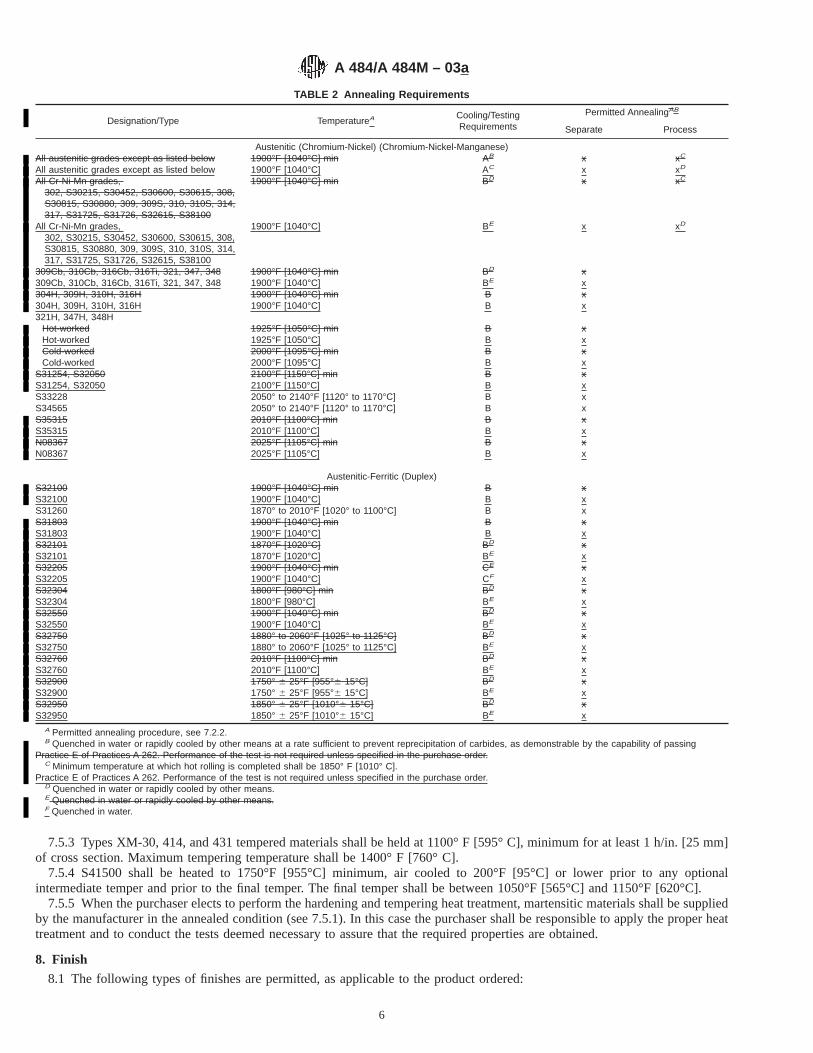
7.5.3 Types XM-30, 414, and 431 tempered materials shall be held at 1100° F [595° C], minimum for at least 1 h/in. [25 mm]of cross section. Maximum tempering temperature shall be 1400° F [760° C].
7.5.4 S41500 shall be heated to 1750°F [955°C] minimum, air cooled to 200°F [95°C] or lower prior to any optionalintermediate temper and prior to the final temper. The final temper shall be between 1050°F [565°C] and 1150°F [620°C].
7.5.5 When the purchaser elects to perform the hardening and tempering heat treatment, martensitic materials shall be suppliedby the manufacturer in the annealed condition (see 7.5.1). In this case the purchaser shall be responsible to apply the proper heattreatment and to conduct the tests deemed necessary to assure that the required properties are obtained.
8. Finish
8.1 The following types of finishes are permitted, as applicable to the product ordered:
TABLE 2 Annealing Requirements
Designation/Type TemperatureA Cooling/TestingRequirements
Permitted AnnealingAB
Separate Process
Austenitic (Chromium-Nickel) (Chromium-Nickel-Manganese)All austenitic grades except as listed below 1900°F [1040°C] min AB x xC
All austenitic grades except as listed below 1900°F [1040°C] AC x xD
All Cr-Ni-Mn grades,302, S30215, S30452, S30600, S30615, 308,S30815, S30880, 309, 309S, 310, 310S, 314,317, S31725, S31726, S32615, S38100
1900°F [1040°C] min BD x xC
All Cr-Ni-Mn grades,302, S30215, S30452, S30600, S30615, 308,S30815, S30880, 309, 309S, 310, 310S, 314,317, S31725, S31726, S32615, S38100
1900°F [1040°C] BE x xD
309Cb, 310Cb, 316Cb, 316Ti, 321, 347, 348 1900°F [1040°C] min BD x309Cb, 310Cb, 316Cb, 316Ti, 321, 347, 348 1900°F [1040°C] BE x304H, 309H, 310H, 316H 1900°F [1040°C] min B x304H, 309H, 310H, 316H 1900°F [1040°C] B x321H, 347H, 348H
Hot-worked 1925°F [1050°C] min B xHot-worked 1925°F [1050°C] B xCold-worked 2000°F [1095°C] min B xCold-worked 2000°F [1095°C] B x
S31254, S32050 2100°F [1150°C] min B xS31254, S32050 2100°F [1150°C] B xS33228 2050° to 2140°F [1120° to 1170°C] B xS34565 2050° to 2140°F [1120° to 1170°C] B xS35315 2010°F [1100°C] min B xS35315 2010°F [1100°C] B xN08367 2025°F [1105°C] min B xN08367 2025°F [1105°C] B x
Austenitic-Ferritic (Duplex)S32100 1900°F [1040°C] min B xS32100 1900°F [1040°C] B xS31260 1870° to 2010°F [1020° to 1100°C] B xS31803 1900°F [1040°C] min B xS31803 1900°F [1040°C] B xS32101 1870°F [1020°C] BD xS32101 1870°F [1020°C] BE xS32205 1900°F [1040°C] min CE xS32205 1900°F [1040°C] CF xS32304 1800°F [980°C] min BD xS32304 1800°F [980°C] BE xS32550 1900°F [1040°C] min BD xS32550 1900°F [1040°C] BE xS32750 1880° to 2060°F [1025° to 1125°C] BD xS32750 1880° to 2060°F [1025° to 1125°C] BE xS32760 2010°F [1100°C] min BD xS32760 2010°F [1100°C] BE xS32900 1750° 6 25°F [955°6 15°C] BD xS32900 1750° 6 25°F [955°6 15°C] BE xS32950 1850° 6 25°F [1010°6 15°C] BD xS32950 1850° 6 25°F [1010°6 15°C] BE x
A Permitted annealing procedure, see 7.2.2.B Quenched in water or rapidly cooled by other means at a rate sufficient to prevent reprecipitation of carbides, as demonstrable by the capability of passing
Practice E of Practices A 262. Performance of the test is not required unless specified in the purchase order.C Minimum temperature at which hot rolling is completed shall be 1850° F [1010° C].
Practice E of Practices A 262. Performance of the test is not required unless specified in the purchase order.D Quenched in water or rapidly cooled by other means.E Quenched in water or rapidly cooled by other means.F Quenched in water.
A 484/A 484M – 03a
6

8.1.1 Hot-Finished Bars—Hot-finished bars shall have the surface finish that results from hot processing, with or without certainadditional surface modification. Hot-finished bars are commonly produced by hot rolling, forging, pressing, extruding, or similarhot working procedures applied to ingots, blooms, or billets. The resulting products are typically subject to various additionaloperations affecting the surface of the bars, including but not limited to one or more of the following: annealing or other heattreatment; cleaning by blasting, pickling, or other descaling methods; rough turning; and machine straightening. The producer ispermitted to use centerless grinding, polishing, or other operations commonly associated with cold finishing in order to provideimproved dimensional tolerances or surface condition for the hot-finished bar. The dimensional tolerances applicable tohot-finished bars are less stringent than those applicable to cold-finished bars.
8.1.2 Bars Cut from Strip or Plate—Bars cut from flat-rolled stainless steel products shall have two surfaces that are pickledor descaled, and two cut surfaces, except when the bar is heat treated subsequent to cutting, in which case all surfaces shall bedescaled or pickled.
8.1.3 Cold-Finished Bar—Cold-finished bars shall have the surface finish that results from hot-finished bars being furtherprocessed by additional mechanical operations on the surface of the bar, including but not limited to light cold drawing, burnishing,centerless grinding, and polishing to provide closer tolerances and improved surface finish. The dimensional tolerances applicableto cold-finished bars are more stringent than those applicable to hot-finished bars.
8.1.4 Bars and Billets or Other Semi-Finished Material for Reforging—Material intended for reforging shall be delivered in thehot-finished condition. It is permitted to condition the surface by removing surface defects provided that the depth of theconditioning does not exceed that which affects the surface condition or dimensions of the article to be forged from the bar or billet.
8.1.5 Shapes—Shapes shall be descaled by machining, grinding, blasting, or pickling.8.1.5.1 Shapes shall be subject to either Class A or Class C surface preparation as specified on the purchase order. Class A
consists of grinding for the removal of imperfections of a hazardous nature, such as fins, tears, and jagged edges, provided theunderweight tolerance is not exceeded and the maximum depth of grinding at any one point does not exceed 10 % of the thicknessof the section. Class C consists of grinding for the removal of all visible surface imperfections, provided that the underweighttolerance is not exceeded and the maximum depth of grinding at any point does not exceed 10 % of the thickness of the section.
8.1.6 Forgings—Forgings shall be descaled by machining, blasting, or pickling. The selection of the descaling methods shallbe at the option of the producer unless a particular descaling method is specified in the purchase order.
9. Dimensions, Mass, and Permissible Variations
9.1 Unless otherwise specified on the purchase order, the material shall conform to the permitted variations in dimensions asspecified in the following:
9.1.1 Bars—Tables 3-12.9.1.2 Shapes—Tables 13-19 and Figs. 1 and 2.9.1.3 Forgings—As specified in the purchase order, or in prints or sketches accompanying the purchase order.9.1.4 Billets or Other Semi-Finished Material for Reforging—Billets and other semi-finished material shall conform to the
shape and dimensions specified by the purchaser within a permitted variation of65 %.
TABLE 3 Permitted Variations in Size of Hot-Finished Round, Turned, A and Square Bars
Specified Size, in. [mm]
Permitted Variations from Specified Size,in. [mm] Out-of-RoundB or
Out-of-Square,C in. [mm]Over Under
5⁄16 to 7⁄16 [8.00 to 11.00], inclD 0.006 [0.15] 0.006 [0.15] 0.009 [0.23]Over 7⁄16 to 5⁄8 [11.00 to 15.50], inclD 0.007 [0.18] 0.007 [0.18] 0.010 [0.26]Over 5⁄8 to 7⁄8 [15.50 to 22.00], incl 0.008 [0.20] 0.008 [0.20] 0.012 [0.30]Over 7⁄8 to 1 [22.00 to 25.00], incl 0.009 [0.23] 0.009 [0.23] 0.013 [0.34]Over 1 to 11⁄8 [25.00 to 28.00], incl 0.010 [0.25] 0.010 [0.25] 0.015 [0.38]Over 11⁄8 to 11⁄4 [28.00 to 31.50], incl 0.011 [0.28] 0.011 [0.28] 0.016 [0.42]Over 11⁄4 to 13⁄8 [31.50 to 34.50], incl 0.012 [0.30] 0.012 [0.30] 0.018 [0.46]Over 13⁄8 to 11⁄2 [34.50 to 38.00], incl 0.014 [0.35] 0.014 [0.35] 0.021 [0.53]Over 11⁄2 to 2 [38.00 to 50.00], incl 1⁄64 [0.40] 1⁄64 [0.40] 0.023 [0.60]Over 2 to 21⁄2 [50.00 to 63.00], incl 1⁄32 [0.80] 0 0.023 [0.60]Over 21⁄2 to 31⁄2 [63.00 to 90.00], incl 3⁄64 [1.20] 0 0.035 [0.90]Over 31⁄2 to 41⁄2 [90.00 to 115.00], incl 1⁄16 [1.60] 0 0.046 [1.20]Over 41⁄2 to 51⁄2 [115.00 to 140.00], incl 5⁄64 [2.00] 0 0.058 [1.50]Over 51⁄2 to 61⁄2 [140.00 to 165.00], incl 1⁄8 [3.00] 0 0.070 [1.80]Over 61⁄2 to 8 [165.00 to 200.00], incl 5⁄32 [4.00] 0 0.085 [2.20]Over 8 to 12 [200.00 to 300.00], inclA 3⁄16 [4.80] 0 3⁄32 [2.40]Over 12 to 15 [300.00 to 400.00], inclA 7⁄32 [5.50] 0 7⁄64 [2.80]Over 15 to 25 [400.00 to 625.00], inclA 1⁄4 [6.50] 0 1⁄8 [3.20]
A Turned bars are generally available from 2 to 25 in. [50 to 625 mm] in diameter, over 8 in. [200 mm] only turned bars are available.B Out-of-round is the difference between the maximum and minimum diameters of the bar measured at the same cross section.C Out-of-square section is the difference in the two dimensions at the same cross section of a square bar, each dimension being the distance between opposite faces.D Size tolerances have not been evolved for round sections in the size range of 5⁄16 in. [8.00 mm] to approximately 5⁄8 in. [15.5 mm] in diameter which are produced on
rod mills in coils.
A 484/A 484M – 03a
7

10. Workmanship, Finish and Appearance
10.1 The material shall be of uniform quality consistent with good manufacturing and inspection practices. Imperfections shallbe of such a nature or degree for the type and quality ordered, that they shall not adversely affect the forming, machining, orfabrication of finished parts.
TABLE 4 Permitted Variations in Size of Hot-Finished Hexagonal and Octagonal Bar
Specified Sizes Measured Between OppositeSides, in. [mm]
Permitted Variations from Specified Size,in. [mm]
Maximum Difference in 3Measurements for Hexagons
Only, in. [mm]Over Under
1⁄4 to 1⁄2 [6.50 to 13.00], incl 0.007 [0.18] 0.007 [0.18] 0.011 [0.28]Over 1⁄2 to 1 [13.00 to 25.00], incl 0.010 [0.25] 0.010 [0.25] 0.015 [0.38]
Over 1 to 11⁄2 [25.00 to 38.00], incl 0.021 [0.53] 0.021 [0.53] 0.025 [0.64]Over 11⁄2 to 2 [38.00 to 50.00], incl 1⁄32 [0.80] 1⁄32 [0.80] 1⁄32 [0.80]Over 2 to 21⁄2 [50.00 to 63.00], incl 3⁄64 [1.20] 3⁄64 [1.20] 3⁄64 [1.20]
Over 21⁄2 to 31⁄2 [63.00 to 90.00], incl 1⁄16 [1.60] 1⁄16 [1.60] 1⁄16 [1.60]
TABLE 5 Permitted Variations in Thickness and Width for Hot-Finished Flat Bars Rolled as Bars
Specified Width,in. [mm]
Permitted Variations in Thickness for Thicknesses Given, in. [mm] PermittedVariations in
Width, in,[mm]
1⁄8 to 1⁄2[3.2 to 13], incl
Over 1⁄2 to 1[13 to 25], incl
Over 1 to 2[25 to 50], incl
Over 2 to 4[50 to 100], incl
Over 4 to 6[100 to 150], incl
Over 6 to 8[150 to 200], incl
Over Under Over Under Over Under Over Under Over Under Over Under Over Under
To 1 [25.00], incl 0.008[0.20]
0.008[0.20]
0.010[0.25]
0.010[0.25]
. . . . . . . . . . . . . . . . . . . . . . . . 0.015[0.40]
0.015[0.40]
Over 1 to 2 [25.00 to50.00], incl
0.012[0.30]
0.012[0.30]
0.015[0.40]
0.015[0.40]
0.031[0.80]
0.031[0.80]
. . . . . . . . . . . . . . . . . . 0.031[0.80]
0.031[0.80]
Over 2 to 4 [50.00 to100.00], incl
0.015[0.40]
0.015[0.40]
0.020[0.50]
0.020[0.50]
0.031[0.80]
0.031[0.80]
0.062[1.60]
0.031[0.80]
. . . . . . . . . . . . 0.062[1.60]
0.031[0.80]
Over 4 to 6 [100.00 to150.00], incl
0.015[0.40]
0.015[0.40]
0.020[0.50]
0.020[0.50]
0.031[0.80]
0.031[0.80]
0.062[1.60]
0.031[0.80]
0.093[2.40]
0.062[1.60]
. . . . . . 0.093[2.40]
0.062[1.60]
Over 6 to 8 [150.00 to200.00], incl
0.016[0.40]
0.016[0.40]
0.025[0.65]
0.025[0.65]
0.031[0.80]
0.031[0.80]
0.062[1.60]
0.031[0.80]
0.093[2.40]
0.062[1.60]
0.125[3.20]
0.156[4.00]
0.125[3.20]
0.156[4.00]
Over 8 to 10 [200.00 to250.00], incl
0.020[0.50]
0.020[0.50]
0.031[0.80]
0.031[0.80]
0.031[0.80]
0.031[0.80]
0.062[1.60]
0.031[0.80]
0.093[2.40]
0.062[1.60]
0.125[3.20]
0.156[4.00]
0.156[4.00]
0.187[4.80]
TABLE 6 Permitted Variations in Dimensions for Flat Bars Cut from Strip or Plate
Order Thickness
Permitted Variation inThickness, in. [mm]
Permitted VariationA in WidthPermitted Variation in
LengthB
Over UnderWidths to 4 [100] Widths Over 4 [100]
Over UnderOver Under Over Under
Over 0.114 to 0.130 [2.90 to 3.30],incl
0.010[0.25]
0.010[0.25]
0.094[2.40]
0.031[0.80]
0.094[2.40]
0.094[2.40]
0.188[4.80]
00
Over 0.130 to 0.145 [3.30 to 3.70],incl
0.012[0.30]
0.012[0.30]
0.094[2.40]
0.031[0.80]
0.094[2.40]
0.094[2.40]
0.188[4.80]
00
Over 0.145 to less than 3⁄16 , [3.70to 4.80]
0.014[0.35]
0.014[0.35]
0.094[2.40]
0.031[0.80]
0.094[2.40]
0.094[2.40]
0.188[4.80]
00
3⁄16 to 3⁄8 [4.80 to 9.00], excl 0.050[1.25]
0.010[0.25]
0.094[2.40]
0.031[0.80]
0.094[2.40]
0.094[2.40]
0.188[4.80]
00
3⁄8 to 3⁄4 [9.00 to 19.00], excl 0.060[1.50]
0.010[0.25]
0.094[2.40]
0.031[0.80]
0.094[2.40]
0.094[2.40]
0.188[4.80]
00
3⁄4 to 1 [19.00 to 25.00], excl 0.065[1.65]
0.010[0.25]
0.094[2.40]
0.031[0.80]
0.094[2.40]
0.094[2.40]
0.188[4.80]
00
1 to 2 [25.00 to 50.00], excl 0.075[1.90]
0.010[0.25]
0.094[2.40]
0.031[0.80]
0.094[2.40]
0.094[2.40]
0.188[4.80]
00
2 to 3 [50.00 to 75.00], excl 0.150[3.80]
0.010[0.25]
0.125[3.00]
0.062[1.60]
0.125[3.00]
0.125[3.00]
0.250[6.50]
00
3 to 4 [75.00 to 100.00], excl 0.210[5.30]
0.010[0.25]
0.125[3.00]
0.062[1.60]
0.125[3.00]
0.125[3.00]
0.250[6.50]
00
4 to 6 [100.00 to 150.00], excl 0.300[7.60]
0.010[0.25]
0.125[3.00]
0.062[1.60]
0.125[3.00]
0.125[3.00]
0.250[6.50]
00
6 to 8 [150.00 to 200.00], excl 0.420[10.65]
0.010[0.25]
0.125[3.00]
0.062[1.60]
0.125[3.00]
0.125[3.00]
0.250[6.50]
00
8 to 10 [200.00 to 250.00], excl 0.540[13.70]
0.010[0.25]
0.125[3.00]
0.062[1.60]
0.125[3.00]
0.125[3.00]
0.250[6.50]
00
A By agreement between purchaser and seller, tolerances can be shifted as desired to any combination of plus-minus tolerance between all minus and all plus.B Not applicable when bars are ordered random length.
A 484/A 484M – 03a
8

11. Sampling
11.1 A lot for product analysis shall consist of all bars, shapes, or forgings made from the same heat.11.2 For other tests required by the product specification, a lot shall consist of all bar products of the same size, or forgings
weighing less than 1000 lb [500 kg] each, from the same heat, and produced under the same processing conditions. All austenitic,ferritic, austenitic-ferritic, and free-machining grades, martensitic grades annealed to Condition A, and precipitation orage-hardening grades when solution treated are permitted to be heat treated in the same furnace or in several furnaces utilizingcontrolled processing and equipment (see Appendix X1). When heat treating martensitic stainless steels to Condition T or H, andwhen age hardening the precipitation hardening grades, a lot shall consist of the same size, same heat, and the same heat treatcharge in a batch-type furnace or under the same conditions in a continuous furnace.
11.2.1 For forgings weighing from 1000 lb [500 kg] to 5000 lb [2500 kg] each, a lot shall consist of one size classification fromeach heat and each heat-treating charge. Where continuous heat-treating furnaces are used, a lot shall consist of one sizeclassification from each heat, heated in a period of 8 h or less.
11.2.2 For all classes of forgings weighing from 5000 to 7000 lb [2300 to 3200 kg], each unit shall be considered a lot.11.2.3 For all classes of forgings weighing more than 7000 lb [3200 kg], each unit shall be considered a double lot, and two
tension tests shall be required, one from each end of each forging. In the case of ring forgings, the tension test specimens shallbe removed from each of two locations on the periphery, approximately 180° apart, and insofar as practicable, from opposite endsof the forging.
12. Number of Tests and Retests
12.1 Unless otherwise specified in the product specification, one sample per heat shall be selected for chemical analysis and onemechanical test sample shall be selected from each lot of bars and shapes and from each lot of forgings. Except for bars cut fromstrip or plate, tension tests of bars and shapes shall be made in the longitudinal direction. Testing for bars cut from strip or plateshall conform to the requirements of the applicable product specification for the strip or plate and to Specification A 480/A 480M.Hardness tests on bars shall be conducted midway between the center and surface of the product. Tension tests on forgings shallbe prepared from suitable prolongations, or at the option of the supplier, excess forgings may be provided for test. All tests shallconform to the chemical and mechanical requirements of the product specification.
TABLE 7 Permitted Variations in Size of Cold-FinishedRound Bars
Specified Size, in. [mm]
Permitted Variations from SpecifiedSize, in. [mm]A,B
Over Under
1⁄16 to 5⁄16 [1.50 to 8.00], excl 0.001 [0.03] 0.001 [0.03]5⁄16 to 1⁄2 [8.00 to 13.00], excl 0.0015 [0.04] 0.0015 [0.04]1⁄2 to 1 [13.00 to 25.00], excl 0.002 [0.05] 0.002 [0.05]1 to 11⁄2 [25.00 to 38.00], excl 0.0025 [0.06] 0.0025 [0.06]11⁄2 to 4 [38.00 to 100.00], inclC 0.003 [0.08] 0.003 [0.08]
A Unless otherwise specified, size tolerances are over and under as shown inthe above table. When required, however, they may be specified all over andnothing under, or all under and nothing over, or any combination of over and under,if the total spread in size tolerance for a specified size is not less than the totalspread shown in the table.
B When it is necessary to heat treat or heat treat and pickle after cold finishing,size tolerances are double those shown in the table.
C Cold-finished bars over 4 in. [100 mm] in diameter are produced; sizetolerances for such bars are not included herein.
TABLE 8 Permitted Variations in Size of Cold FinishedHexagonal, Octagonal, and Square Bars
Specified Size,Ain. [mm]
Permitted Variations fromSpecified Size,
in. [mm]B
Over Under
1⁄8 to 5⁄16 [3.00 to 8.00], excl 0 0.002 [0.05]5⁄16 to 1⁄2 [8.00 to 13.00], excl 0 0.003 [0.08]1⁄2 to 1 [13.00 to 25.00], incl 0 0.004 [0.10]Over 1 to 2 [25.00 to 50.00], incl 0 0.006 [0.15]Over 2 to 3 [50.00 to 75.00], incl 0 0.008 [0.20]Over 3 [75.00] 0 0.010 [0.25]
A Distance across flats.B When it is necessary to heat treat or heat treat and pickle after cold finishing,
size tolerances are double those shown in the table.
A 484/A 484M – 03a
9

12.2 One intergranular corrosion test, when required, and one grain size test, when required shall be made on each lot. Often,it is convenient to obtain test material from the specimen selected for mechanical testing.
12.3 If any test specimen shows defective machining or flaws, it is permitted to discard the specimen and to substitute anotherspecimen.
12.4 If the results of any test are not in conformance with the requirements of this specification or the requirements of theapplicable product specification, it is permitted to retest a new sample of two specimens, to replace the original failed sample. Ifone of the retest specimens fails, the lot shall be rejected.
13. Retreatment
13.1 Where the failure of a lot is attributable to inadequate heat treatment, the producer may reheat treat the material and submitthe retreated material for test.
TABLE 9 Permitted Variations in Width and Thickness of Cold-Finished Flat Bars
Width, in. [mm]
Permitted Variations in Width, Over andUnder, in. [mm]A
For Thicknesses1⁄4 in. [6.5]and Under
For ThicknessesOver 1⁄4 in.
[6.5]
1⁄16 to 3⁄8 [1.50 to 9.50], incl 0.005 [0.12] 0.005 [0.12]Over 3⁄8 to 1 [9.50 to 25.00], incl 0.004 [0.10] 0.004 [0.10]Over 1 to 2 [25.00 to 50.00], incl 0.006 [0.15] 0.004 [0.10]Over 2 to 3 [50.00 to 75.00], incl 0.008 [0.20] 0.004 [0.10]Over 3 to 41⁄2 [75.00 to 115.00], incl 0.010 [0.25] 0.005 [0.13]
Thickness, in. [mm]Permitted Variationsin Thickness, Over
and Under, in [mm]A
Up to .029 [0.70], incl 0.001 [0.03]Over .029 to .035 [0.70 to 1.00], incl 0.0015 [0.04]Over .035 to 1 [1.00 to 25.00], incl 0.002 [0.05]Over 1 to 2 [25.00 to 50.00], incl 0.003 [0.08]Over 2 to 3 [50.00 to 75.00], incl 0.004 [0.10]Over 3 to 41⁄2 [75.00 to 115.00], inclB 0.005 [0.13]
A When it is necessary to heat treat or heat treat and pickle after cold finishing,size tolerances are double those shown in the table.
B Cold-finished flat bars over 41⁄2 in. [115 mm] wide or thick are produced; widthand thickness tolerances for such bars are not included herein.
TABLE 10 Permitted Variations in Length of Hot-Finished orCold-Finished Bars
Specified Size ofRounds, Squares,Hexagons, Octa-gons, and Widthsof Flats,A in. [mm]
Permitted Variations in Length, in. [mm]B
For Lengths upto 12 ftC
[4 m], incl
For Lengths Over12 to 25 ft[4 to 8 m],
incl
Over Under Over Under
Up to .500 [13.00], incl 1⁄16 [1.5] 0 1⁄8 [3.0] 0Over .500 to 2 [13.00 to
50.00], incl
1⁄2 [13] 0 3⁄4 [19.0] 0
Over 2 to 4 [50.00 to100.00], incl
3⁄4 [19] 0 1 [25.00] 0
Over 4 to 6 [100.00 to150.00], incl
1 [25] 0 11⁄4 [31.50] 0
Over 6 to 9 [150.00 to225.00], incl
11⁄4 [31.5] 0 11⁄2 [38.00] 0
Over 9 to 12 [225.00 to300.00], incl
11⁄2 [38] 0 2 [50.00] 0
A The maximum width of bar flats is 10 in. [250 mm].B Random Lengths—When ordered as random lengths, permissible variation is
2 ft [0.6 m] over and under the specified length. When ordered as random lengthssubject to a minimum length requirement, permissible variation is 2 ft [0.6 m] overand nothing under the specified length.
C For lengths under 3 ft [1 m] and sizes up to 1⁄2 in. [13.00 mm] incl., thepermissible variation in length is 1⁄32 in. [0.80 mm] over and nothing under.
A 484/A 484M – 03a
10

14. Test Methods
14.1 The properties enumerated in the applicable product specification shall be tested in accordance with the following ASTMmethods:
14.1.1 Chemical Analysis—Test Methods, Practices, and Terminology A 751.14.1.2 Tension Tests— Test Methods and Definitions A 370.14.1.3 Stress Rupture— Practice E 139.14.1.4 Brinell Hardness— Test Methods and Definitions A 370.14.1.5 Rockwell Hardness—Test Methods and Definitions A 370.14.1.6 Intergranular Corrosion—Practice E of Practices A 262.14.1.7 Grain Size—Test Methods E 112.14.1.8 Charpy V-Notch Impact Test—Test Methods and Definitions A 370.
15. Inspection
15.1 Civilian Procurement—Inspection of the material shall be as agreed upon between the purchaser and the supplier as partof the purchase contract.
TABLE 11 Permitted Variations in Length of Hot-Finished orCold-Finished Bars Machine Cut After Machine Straightening
NOTE 1—These tolerances are not applicable when bars are orderedrandom length.
Specified Size ofRounds, Squares,Hexagons, Octa-
gons, and Width ofFlats,A in. [mm]
Permitted Variations in Length, in. [mm]
For Lengths up to 12ft [4 m], incl
For Lengths Over 12to 25 ft [4 to 8 m], incl
Over Under Over UnderTo 3 [75], incl 1⁄8 [3.0] 0 3⁄16 [4.8] 0Over 3 to 6 [75 to 150], incl 3⁄16 [4.8] 0 1⁄4 [6.5] 0Over 6 to 9 [150 to 225], incl 1⁄4 [6.5] 0 5⁄16 [8.0] 0Over 9 to 12 [225 to 300], incl 1⁄2 [13.0] 0 1⁄2 [13.0] 0
A The maximum width of bar flats is 10 in. [250 mm].
TABLE 12 Permitted Variations in Straightness of MachineStraightened Hot-Finished or Cold-Finished Bars A
Measurement is taken on the concave side of the bar with a straightedge.Unless otherwise specified, hot-finished or cold-finished bars for machiningpurposes are furnished machine straightened to the following tolerances:
Hot finished:1⁄8 in. [3.00 mm] in any 5 ft [1.50 m]; but may not exceed
1⁄8 in. [3.00 mm] x (length in ft/5) [m/1.50]Cold finished:
1⁄16 in. [1.5 mm] in any 5 ft [1.5 m]; but may not exceed1⁄16 in. [1.5 mm] x (length in ft/5) [m/1.50]
A Straightness tolerances have not been established for sizes less than 1⁄2 in.[6.50 m].
TABLE 13 Permitted Variations for Hot-Finished Angles
NOTE 1—For unequal leg angles, the longer leg determines the toler-ance for the length of each leg.
Weight:A
For angles of 6 lb/ft [9.0 kg/m] or less, the weight tolerances shall not exceed671⁄2 %. For angles over 6 lb/ft [9 kg/m], the weight tolerance shall not exceed641⁄2 %.Length of Legs:
For angles having legs or flanges up to 6 in. [150 mm], incl, the length toler-ance shall not exceed 61⁄8 in. [3.00 mm]. For angles having legs or flangesover 6 in., the length tolerance shall not exceed +3⁄16 in. [5.00 mm] and -1⁄8 in.Squareness of Legs:
The tolerance for the right angle between the legs is 62°.A For equal leg angles, the theoretical weight per foot is:
Weight/foot = (24 W 3 t − 12t2) (0.2871 lb/ft)where W is the specified length of the leg, and t is the specified thickness, both ininches.
For unequal leg angles, the theoretical weight per foot is:Weight/foot = [12 W1 3 t + 12 W2 3 t− 12t2] (0.2871 lb/ft)
where W1 and W2 are the specified leg lengths, and t is the specified legthickness, all in inches.
A 484/A 484M – 03a
11
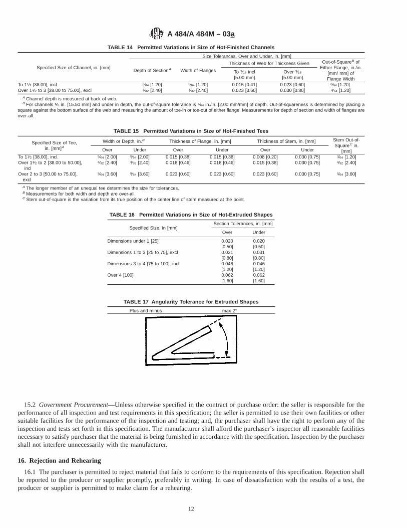
15.2 Government Procurement—Unless otherwise specified in the contract or purchase order: the seller is responsible for theperformance of all inspection and test requirements in this specification; the seller is permitted to use their own facilities or othersuitable facilities for the performance of the inspection and testing; and, the purchaser shall have the right to perform any of theinspection and tests set forth in this specification. The manufacturer shall afford the purchaser’s inspector all reasonable facilitiesnecessary to satisfy purchaser that the material is being furnished in accordance with the specification. Inspection by the purchasershall not interfere unnecessarily with the manufacturer.
16. Rejection and Rehearing
16.1 The purchaser is permitted to reject material that fails to conform to the requirements of this specification. Rejection shallbe reported to the producer or supplier promptly, preferably in writing. In case of dissatisfaction with the results of a test, theproducer or supplier is permitted to make claim for a rehearing.
TABLE 14 Permitted Variations in Size of Hot-Finished Channels
Specified Size of Channel, in. [mm]
Size Tolerances, Over and Under, in. [mm]
Depth of SectionA Width of Flanges
Thickness of Web for Thickness Given Out-of-SquareB ofEither Flange, in./in.
[mm/ mm] ofFlange Width
To 3⁄16 incl[5.00 mm]
Over 3⁄16
[5.00 mm]
To 11⁄2 [38.00], incl 3⁄64 [1.20] 3⁄64 [1.20] 0.015 [0.41] 0.023 [0.60] 3⁄64 [1.20]Over 11⁄2 to 3 [38.00 to 75.00], excl 3⁄32 [2.40] 3⁄32 [2.40] 0.023 [0.60] 0.030 [0.80] 3⁄64 [1.20]
A Channel depth is measured at back of web.B For channels 5⁄8 in. [15.50 mm] and under in depth, the out-of-square tolerance is 5⁄64 in./in. [2.00 mm/mm] of depth. Out-of-squareness is determined by placing a
square against the bottom surface of the web and measuring the amount of toe-in or toe-out of either flange. Measurements for depth of section and width of flanges areover-all.
TABLE 15 Permitted Variations in Size of Hot-Finished Tees
Specified Size of Tee,in. [mm]A
Width or Depth, in.B Thickness of Flange, in. [mm] Thickness of Stem, in. [mm] Stem Out-of-SquareC in.
[mm]Over Under Over Under Over Under
To 11⁄2 [38.00], incl. 5⁄64 [2.00] 5⁄64 [2.00] 0.015 [0.38] 0.015 [0.38] 0.008 [0.20] 0.030 [0.75] 3⁄64 [1.20]Over 11⁄2 to 2 [38.00 to 50.00],
incl
3⁄32 [2.40] 3⁄32 [2.40] 0.018 [0.46] 0.018 [0.46] 0.015 [0.38] 0.030 [0.75] 3⁄32 [2.40]
Over 2 to 3 [50.00 to 75.00],excl
9⁄64 [3.60] 9⁄64 [3.60] 0.023 [0.60] 0.023 [0.60] 0.023 [0.60] 0.030 [0.75] 9⁄64 [3.60]
A The longer member of an unequal tee determines the size for tolerances.B Measurements for both width and depth are over-all.C Stem out-of-square is the variation from its true position of the center line of stem measured at the point.
TABLE 16 Permitted Variations in Size of Hot-Extruded Shapes
Specified Size, in [mm]Section Tolerances, in. [mm]
Over Under
Dimensions under 1 [25] 0.020[0.50]
0.020[0.50]
Dimensions 1 to 3 [25 to 75], excl 0.031[0.80]
0.031[0.80]
Dimensions 3 to 4 [75 to 100], incl. 0.046[1.20]
0.046[1.20]
Over 4 [100] 0.062[1.60]
0.062[1.60]
TABLE 17 Angularity Tolerance for Extruded Shapes
Plus and minus max 2°
A 484/A 484M – 03a
12
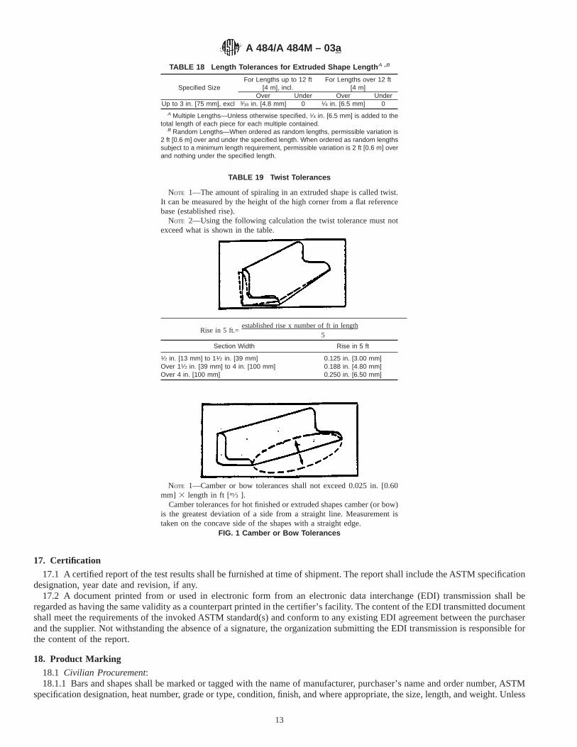
17. Certification
17.1 A certified report of the test results shall be furnished at time of shipment. The report shall include the ASTM specificationdesignation, year date and revision, if any.
17.2 A document printed from or used in electronic form from an electronic data interchange (EDI) transmission shall beregarded as having the same validity as a counterpart printed in the certifier’s facility. The content of the EDI transmitted documentshall meet the requirements of the invoked ASTM standard(s) and conform to any existing EDI agreement between the purchaserand the supplier. Not withstanding the absence of a signature, the organization submitting the EDI transmission is responsible forthe content of the report.
18. Product Marking
18.1 Civilian Procurement:18.1.1 Bars and shapes shall be marked or tagged with the name of manufacturer, purchaser’s name and order number, ASTM
specification designation, heat number, grade or type, condition, finish, and where appropriate, the size, length, and weight. Unless
TABLE 18 Length Tolerances for Extruded Shape Length A ,B
Specified SizeFor Lengths up to 12 ft
[4 m], incl.For Lengths over 12 ft
[4 m]Over Under Over Under
Up to 3 in. [75 mm], excl 3⁄16 in. [4.8 mm] 0 1⁄4 in. [6.5 mm] 0A Multiple Lengths—Unless otherwise specified, 1⁄4 in. [6.5 mm] is added to the
total length of each piece for each multiple contained.B Random Lengths—When ordered as random lengths, permissible variation is
2 ft [0.6 m] over and under the specified length. When ordered as random lengthssubject to a minimum length requirement, permissible variation is 2 ft [0.6 m] overand nothing under the specified length.
TABLE 19 Twist Tolerances
NOTE 1—The amount of spiraling in an extruded shape is called twist.It can be measured by the height of the high corner from a flat referencebase (established rise).
NOTE 2—Using the following calculation the twist tolerance must notexceed what is shown in the table.
Rise in 5 ft.=established rise x number of ft in length
5
Section Width Rise in 5 ft
1⁄2 in. [13 mm] to 11⁄2 in. [39 mm] 0.125 in. [3.00 mm]Over 11⁄2 in. [39 mm] to 4 in. [100 mm] 0.188 in. [4.80 mm]Over 4 in. [100 mm] 0.250 in. [6.50 mm]
NOTE 1—Camber or bow tolerances shall not exceed 0.025 in. [0.60mm] 3 length in ft [m⁄3 ].
Camber tolerances for hot finished or extruded shapes camber (or bow)is the greatest deviation of a side from a straight line. Measurement istaken on the concave side of the shapes with a straight edge.
FIG. 1 Camber or Bow Tolerances
A 484/A 484M – 03a
13

otherwise specified, the method of marking is at the option of the manufacturer. Marking shall be made by hot stamping, coldstamping, or painting of bars, or by marking tags attached to bundles, lifts, or boxes.
18.1.2 Forgings shall be legibly die stamped with the manufacturer’s symbol or name, material specification designation, gradeor type, and heat identification. When die stamping is not permitted by the purchaser, electric pencil or electro-etching shall beused.
18.2 Government Procurement:18.2.1 When specified in the contract or order, and for direct procurement by or direct shipment to the government, marking
for shipment, in addition to any requirements specified in the contract or order, shall be in accordance with MIL-STD-129 formilitary agencies and in accordance with Fed. Std. No. 123 for civil agencies.
18.2.2 For government procurement by the Defense Supply Agency, bars and shapes shall be marked continuously foridentification in accordance with Fed. Std. No. 183.
19. Packaging and Package Marking
19.1 Unless otherwise specified, the bars and shapes shall be packaged and loaded in accordance with Practices A 700.19.2 When specified in the contract or order, and for direct procurement by or direct shipment to the government, when Level
A is specified, preservation, packaging, and packing shall be in accordance with the Level A requirements of MIL-STD-163.
20. Keywords
20.1 general delivery requirements; stainless steel bars; stainless steel billets; stainless steel forgings; stainless steel shapes
ANNEX
(Mandatory Information)
A1. REQUIREMENTS FOR THE INTRODUCTION OF NEW MATERIALS
A1.1 New materials may be proposed for inclusion in specifications referencing this Specification of General Requirements,subject to the following conditions:
A1.1.1 The application for the addition of a new grade to a specification shall be made to the chairman of the subcommitteewhich has jurisdiction over that specification.
A1.1.2 The application shall be accompanied by a statement from at least one user indicating that there is a need for the newgrade to be included in the applicable specification.
A1.1.3 The application shall be accompanied by test data as required by the applicable specification. Test data from a minimumof three test lots, as defined by the specification, each from a different heat, shall be furnished.
A1.1.4 The application shall provide recommendations for all requirements appearing in the applicable specification.A1.1.5 The application shall state whether the new grade is covered by patent.
NOTE 1—Allowable deviation from flat is max 0.010 in. [0.25 mm] per1 in. [25 mm] of width. Maximum deviation on dimensions of less than 1in. [25 mm] is 0.010 in. [0.250 mm].
The transverse flatness tolerance is the maximum deviation from areference base across any cross-section flat surface.
FIG. 2 Transverse Flatness Tolerances
A 484/A 484M – 03a
14

APPENDIXES
(Nonmandatory Information)
X1. RATIONALE REGARDING DEFINITION OF LOT FOR MECHANICAL PROPERTIES AND CORROSION TESTING
X1.1 It is generally recognized that material described as a lot must be “produced under the same processing conditions,” whichmeans the same manufacturing order number, same size, same heat, same heat-treating procedure, and same subsequentprocessing. Under those conditions, single samples can be selected to be representative of the total lot, with at least one samplefor each 20 000 pounds of material.
X1.2 Following the principle described in X1.1 generallyrequires that the producer control each of several furnace loads constituting the same lot so that:
X1.2.1 Set point temperature and process tolerance match,X1.2.2 Time at temperature for all thermal treatment shall match within 10 %,X1.2.3 All furnaces used be similar in size and meet the uniformity requirements of a documented furnace quality assurance
program and,X1.2.4 The quench systems are the same with respect to volume, type of quenchant, and circulation rate.X1.2.5 Further, it would be expected that grouped loads be handled within a relatively short time period, and that hardness
testing be performed on at least one sample per charge.
X1.3 The old definition of a lot for mechanical testing based on simply the words “same size, heat, and heat treatment chargein a batch furnace” assumes that heat treating is the only process affecting properties. This kind of definition ignores the effectsof other processing, prior to and subsequent to heat treating. Moreover, it assumes that each heat-treated batch will be uniform andunique rather than reproducible. In reality, heat treating is a process which can be controlled easily throughout a batch and frombatch to batch, with the net result that multiple batches can be considered part of a single lot if equipment and processingparameters meet the mandates of X1.1 and X1.2.
X1.4 The sampling specified for mechanical properties is not a statistical sampling plan. Therefore, it provides only typicaldata. Assurance of uniformity within the lot can be obtained only by the producer adequately controlling the processing parameters.
X2. BAR CODING
X2.1 Bar coding to identify steel is not specifically addressed in Committee A01 specifications. Committee A01 endorses theAIAG bar code standard for primary metals for steel products and proposes that this bar coding standard be considered as apossible auxiliary method of identification.
SUMMARY OF CHANGES
Committee A01 has identified the location of selected changes to this standard since the last issue(A 484/A 484M – 00) that may impact the use of this standard (approved April 10, 2003).
(1) Heat treatment for S32101 added to Table 2.
A 484/A 484M – 03a
15

Committee A01 has identified the location of selected changes to this standard since the last issue (A 484/A 484M – 03)that may impact the use of this standard (approved June 10, 2003).
(1) Minimum temperature revised in Table 2, Footnote C.
ASTM International takes no position respecting the validity of any patent rights asserted in connection with any item mentionedin this standard. Users of this standard are expressly advised that determination of the validity of any such patent rights, and the riskof infringement of such rights, are entirely their own responsibility.
This standard is subject to revision at any time by the responsible technical committee and must be reviewed every five years andif not revised, either reapproved or withdrawn. Your comments are invited either for revision of this standard or for additional standardsand should be addressed to ASTM International Headquarters. Your comments will receive careful consideration at a meeting of theresponsible technical committee, which you may attend. If you feel that your comments have not received a fair hearing you shouldmake your views known to the ASTM Committee on Standards, at the address shown below.
This standard is copyrighted by ASTM International, 100 Barr Harbor Drive, PO Box C700, West Conshohocken, PA 19428-2959,United States. Individual reprints (single or multiple copies) of this standard may be obtained by contacting ASTM at the aboveaddress or at 610-832-9585 (phone), 610-832-9555 (fax), or [email protected] (e-mail); or through the ASTM website(www.astm.org).
A 484/A 484M – 03a
16

Designation: A 492 – 95 (Reapproved 2000)
Standard Specification forStainless Steel Rope Wire 1
This standard is issued under the fixed designation A 492; the number immediately following the designation indicates the year oforiginal adoption or, in the case of revision, the year of last revision. A number in parentheses indicates the year of last reapproval. Asuperscript epsilon (e) indicates an editorial change since the last revision or reapproval.
This standard has been approved for use by agencies of the Department of Defense.
1. Scope
1.1 This specification covers the more commonly used typesof round stainless steel wire intended especially for strandinginto wire rope.
1.2 The values stated in inch-pound units are to be regardedas the standard.
2. Referenced Documents
2.1 ASTM Standards:A 555/A555M Specification for General Requirements for
Stainless Steel Wire and Wire Rods2
A 751 Test Methods, Practices, and Terminology forChemical Analysis of Steel Products2
3. Ordering Information
3.1 It is the responsibility of the purchaser to specify allrequirements that are necessary for material ordered under thisspecification. Such requirements may include, but are notlimited to the following:
3.1.1 Quantity (weight),3.1.2 Name of material (stainless steel),3.1.3 Condition (see Section 5),3.1.4 Finish (see Section 7),3.1.5 Cross section (round),3.1.6 Form (wire),3.1.7 Applicable dimensions (diameter),3.1.8 Type designation (Table 1),3.1.9 ASTM designation and date of issue, and3.1.10 Special requirements.3.2 If possible, the intended end use of the item should be
given on the purchase order, especially when the item isordered for a specific end use or uses.
NOTE 1—A typical ordering description is as follows: 1000 lb stainlesssteel, cold-drawn, bright-finish, wire, 0.009-in. diameter, spools. Type
304, ASTM Specification A 492 dated , End Use .
4. Chemical Composition
4.1 The steel shall conform to the requirements as tochemical composition specified in Table 1.
4.2 Methods and practices relating to chemical analysisrequired by this specification shall be in accordance with TestMethods, Practices, and Terminology A 751.
5. Condition
5.1 The wire is cold drawn and furnished in the finish (seeSection 7) specified on the purchase order.
6. Mechanical Requirements
6.1 The material shall conform to the requirements as tomechanical properties specified in Table 2.
7. Finish
7.1 The types of finish procurable are pickled finish andbright finish (available only in sizes that can be diamond drawnwhich are generally 0.045 in. (1.14 mm) and smaller).
8. General Requirements for Delivery
8.1 In addition to the requirements of this specification, allrequirements of the current edition of Specification A 555/A 555M, shall apply. Failure to comply with the generalrequirements of Specification A 555/A 555M constitutes non-conformance with this specification.
9. Packaging and Package Marking
9.1 Each coil or spool shall be one continuous length ofwire. Each coil shall be firmly tied and each spool shall betightly wound. Unless otherwise specified coils shall be placedin drums or paper wrapped and spools shall be boxed in sucha manner as to assure safe delivery to their designation whenproperly transported by any common carrier.
9.2 Each coil or spool of wire shall be properly taggedshowing heat number, grade, condition, ASTM specificationnumber, and size.
10. Keywords
10.1 austenitic stainless steel; stainless steel rope wire
1 This specification is under the jurisdiction of ASTM Committee A01 on Steel,Stainless Steel and Related Alloys, and is the direct responsibility of SubcommitteeA01.17 on Flat Stainless Steel Products.
Current edition approved Jan. 15, 1995. Published March 1995. Originallypublished as A 492 – 63. Last previous edition A 492 – 94.
2 Annual Book of ASTM Standards,Vol 01.03.
1
Copyright © ASTM International, 100 Barr Harbor Drive, PO Box C700, West Conshohocken, PA 19428-2959, United States.

ASTM International takes no position respecting the validity of any patent rights asserted in connection with any item mentionedin this standard. Users of this standard are expressly advised that determination of the validity of any such patent rights, and the riskof infringement of such rights, are entirely their own responsibility.
This standard is subject to revision at any time by the responsible technical committee and must be reviewed every five years andif not revised, either reapproved or withdrawn. Your comments are invited either for revision of this standard or for additional standardsand should be addressed to ASTM International Headquarters. Your comments will receive careful consideration at a meeting of theresponsible technical committee, which you may attend. If you feel that your comments have not received a fair hearing you shouldmake your views known to the ASTM Committee on Standards, at the address shown below.
This standard is copyrighted by ASTM International, 100 Barr Harbor Drive, PO Box C700, West Conshohocken, PA 19428-2959,United States. Individual reprints (single or multiple copies) of this standard may be obtained by contacting ASTM at the aboveaddress or at 610-832-9585 (phone), 610-832-9555 (fax), or [email protected] (e-mail); or through the ASTM website(www.astm.org).
TABLE 1 Chemical Requirements
UNSDesignation
Type
Composition, %
Carbon,max
Manga-neseB
Phos-phorus, max
Sulfur,max
Silicon,max
Chromium NickelMolyb-denum
NitrogenA
S 21600 XM-17 0.08 7.50–9.00 0.045 0.030 1.00 17.50–22.00 5.00–7.00 2.00–3.00 0.25–0.50S 21603 XM-18 0.03 7.50–9.00 0.045 0.030 1.00 17.50–22.00 5.00–7.00 2.00–3.00 0.25–0.50S 30200 302 0.15 2.00 0.045 0.030 1.00 17.00–19.00 8.00–10.00 . . . 0.10S 30400 304 0.08 2.00 0.045 0.030 1.00 18.00–20.00 8.00–10.50 . . . 0.10S 30500 305 0.12 2.00 0.045 0.030 1.00 17.00–19.00 10.50–13.00 . . . . . .S 31600 316 0.08 2.00 0.045 0.030 1.00 16.00–18.00 10.00–14.00 2.00–3.00 0.10
A Maximum unless otherwise indicated.
TABLE 2 Tensile Strength Requirements
Diameter, in. (mm)
For Types XM-17, XM-18, 302, and 304 For Types 305 and 316
min max min
psi MPa psi MPa psi MPa
0.007 (0.18) and smaller 320 000 2210 355 000 2450 245 000 1690Over 0.007 (0.18) to 0.010 (0.25), incl 312 000 2150 350 000 2410 245 000 1690Over 0.010 (0.25) to 0.015 (0.38), incl 310 000 2140 345 000 2380 240 000 1650Over 0.015 (0.38) to 0.019 (0.48), incl 305 000 2100 340 000 2340 240 000 1650Over 0.019 (0.48) to 0.025 (0.64), incl 295 000 2030 330 000 2280 235 000 1620Over 0.025 (0.64) to 0.030 (0.76), incl 285 000 1960 315 000 2170 235 000 1620Over 0.030 (0.76) to 0.035 (0.89), incl 275 000 1900 310 000 2140 235 000 1620Over 0.035 (0.89) to 0.040 (1.02), incl 260 000 1790 300 000 2070 235 000 1620Over 0.040 (1.02) to 0.050 (1.27), incl 255 000 1760 285 000 1970 230 000 1590Over 0.050 (1.27) to 0.060 (1.52), incl 250 000 1720 280 000 1930 225 000 1550Over 0.060 (1.52) to 0.070 (1.78), incl 245 000 1690 275 000 1900 220 000 1520Over 0.070 (1.78) to 0.080 (2.03), incl 240 000 1650 270 000 1860 210 000 1450Over 0.080 (2.03) to 0.090 (2.29), incl 240 000 1650 270 000 1860 210 000 1450Over 0.090 (2.29) to 0.100 (2.54), incl 235 000 1620 265 000 1830 205 000 1410
A 492 – 95 (2000)
2

Designation: A 493 – 95 (Reapproved 2000)
Standard Specification forStainless Steel Wire and Wire Rods for Cold Heading andCold Forging 1
This standard is issued under the fixed designation A 493; the number immediately following the designation indicates the year oforiginal adoption or, in the case of revision, the year of last revision. A number in parentheses indicates the year of last reapproval. Asuperscript epsilon (e) indicates an editorial change since the last revision or reapproval.
This standard has been approved for use by agencies of the Department of Defense.
1. Scope
1.1 This specification covers cold-finished and hot-finishedstainless steel wire and wire rods for cold heading or coldforging for applications, such as fasteners, where corrosionresistance is a factor.
1.2 The values stated in inch-pound units are to be regardedas the standard. The SI equivalents are in parentheses and maybe approximate.
2. Referenced Documents
2.1 ASTM Standards:A 262 Practices for Detecting Susceptibility to Intergranu-
lar Attack in Austenitic Stainless Steels2
A 555/A555M Specification for General Requirements forStainless Steel Wire and Wire Rods2
A 751 Test Methods, Practices, and Terminology forChemical Analysis of Steel Products2
3. Ordering Information
3.1 It is the responsibility of the purchaser to specify allrequirements that are necessary for material ordered under thisspecification. Such requirements may include, but are notlimited to the following:
3.1.1 Quantity (weight),3.1.2 Size (diameter),3.1.3 Type or UNS number (see Table 1),3.1.4 Name (wire or wire rods),3.1.5 ASTM designation and issue date,3.1.6 Condition (see 5.2),3.1.7 Coating (see 5.3),3.1.8 Coil size (inside and outside diameter),3.1.9 Special requirements, and3.1.10 Supplementary requirements.
4. General Requirements for Delivery
4.1 In addition to the requirements of this specification, allrequirements of the current editions of Specification A 555/A 555M shall apply. Failure to comply with the generalrequirements of Specification A 555/A 555M constitutes non-conformance with this specification.
NOTE 1—A typical ordering description is as follows: 5000 lb (2268 kg).225 in. (5.72 mm) round Type 305 cold heading wire, lightly drafted,copper coated, 32 in. (813 mm) max OD—22 in. (559 mm) min ID, coils,ASTM Specification A 493 – XX. End use: hex head machine bolts.
5. Manufacture
5.1 Heat Treatment:5.1.1 Austenitic grades shall be annealed at 1800°F (980°C)
minimum, so that grain boundary carbides enter into solution,and rapidly quenched to prevent grain boundary precipitationof carbides that would cause susceptibility to intergranularcorrosion. See Supplementary Requirements.
5.1.2 Ferritic and martensitic grades shall be annealed tomeet the requirements for mechanical properties.
5.2 Condition:5.2.1 Wire shall be furnished in one of the following
conditions:5.2.1.1 Lightly drafted (normal condition and need not be
specified if this is condition desired),5.2.1.2 Annealed, or5.2.1.3 Drafted to a specified tensile strength range (as
agreed upon between purchaser and producer).5.2.2 Rods shall be furnished in the annealed condition,
scale removed.5.3 Coatings and Lubricants:5.3.1 Coatings are necessary for most cold-heading or
forming operations. An electroplated copper coating is oftenused. The following coatings may be specified: copper, lime, orspecial (as agreed upon between purchaser and producer).
1 This specification is under the jurisdiction of ASTM Committee A01 on Steel,Stainless Steel and Related Alloysand is the direct responsibility of SubcommitteeA01.17on Flat Stainless Steel Products.
Current edition approved Jan. 15, 1995. Published March 1995. Originallypublished as A 493 – 63. Last previous edition A 493 – 94.
2 Annual Book of ASTM Standards, Vols 01.03.
1
Copyright © ASTM International, 100 Barr Harbor Drive, PO Box C700, West Conshohocken, PA 19428-2959, United States.

5.3.2 Lubricants are applied over the coating during thefinal drafting operation performed by the producer. Soap isgenerally used. The following lubricants may be specified:soap, grease, or special (as agreed upon between purchaser andproducer).
6. Chemical Requirements
6.1 The steel shall conform to the requirements for chemicalcomposition specified in Table 1.
6.2 Methods and practices relating to chemical analysisrequired by this specification shall be in accordance with TestMethods, Practices, and Terminology A 751.
7. Mechanical Requirements
7.1 The material shall conform to the requirements as tomechanical properties specified in Table 2. Material can bemanufactured to tensile strength ranges other than those shownin Table 2. The producer should be consulted when material isrequired to tensile strength ranges other than those specified.
8. Resistance to Intergranular Corrosion
8.1 All austenitic grades in the annealed condition orannealed and lightly drafted condition shall be capable ofpassing Practice E of Practices A 262. When SupplementaryRequirement S1 is invoked, all austenitic grades shall be testedand pass Practice E of Practices A 262.
9. Packaging and Package Marking
9.1 Packaging—Coils shall be bundled or boxed in such amanner as to assure safe delivery to their destination whenproperly transported by any common carrier.
9.2 Markings—Each lift, bundle, or box shall be properlytagged with durable tags (metal, plastic, or equivalent), show-ing size, grade, cold-heading wire, condition coating, heatnumber and ASTM A 493.
10. Keywords
10.1 austenitic stainless steel; ferritic stainless steel; mar-tensitic stainless steel; stainless steel cold forging wire; stain-less steel cold heading wire
TABLE 1 Chemical Requirements
Grade Composition, %
UNSDesignation
AISIType
Carbon,maxA
Manga-nese,max
Phos-phorus,
max
Sulfur,max
Silicon,max
Chromium Nickel Copper Molyb-denum
Nitrogen,maxA
OtherElements
Austenitic Grades
S 30200 302 0.15 2.00 0.045 0.030 1.00 17.0–19.0 8.0–10.0 1.00 max† 0.10S 30400 304 0.08 2.00 0.045 0.030 1.00 18.0–20.0 8.0–10.5 1.00 max† 0.10S 30403 304L 0.030 2.00 0.045 0.030 1.00 18.0–20.0 8.0–12.0 1.00 max† 0.10S 30430 0.03 2.00 0.045 0.030 1.00 17.0–19.0 8.0–10.0 3.0–4.0S 30500 305 0.04 2.00 0.045 0.030 1.00 17.0–19.0 10.5–13.0 1.00 maxS 31600 316 0.08 2.00 0.045 0.030 1.00 16.0–18.0 10.0–14.0 2.00–3.00 0.10S 31603 316L 0.030 2.00 0.045 0.030 1.00 16.0–18.0 10.0–14.0 2.00–3.00† 0.10S 38400 384 0.04 2.00 0.045 0.030 1.00 15.0–17.0 17.0–19.0
Ferritic Grades
S 40940 0.06 1.00 0.045 0.040 1.00 10.5–11.7 0.50 max Cb 10XC–0.75S 42900 429 0.12 1.00 0.040 0.030 1.00 14.0–16.0S 43000 430 0.04 1.00 0.040 0.030 1.00 16.0–18.0S 44401 . . . 0.025 1.00 0.040 0.030 . . . 17.5–19.5 1.00 max 1.75–2.50 0.035 Ti+Cb 0.20+43
(C+N)−0.80S 44625B . . . 0.010B 0.40 0.020 0.020 0.40 25.0–27.5 0.50 max 0.2 max 0.75–1.50 0.015B Ni+Cu 0.5 maxS 44700B . . . 0.010B 0.30 0.025 0.020 0.20 28.0–30.0 0.15 max 0.15 max 3.5–4.2 0.020B C+N 0.025 maxS 44800B . . . 0.010B 0.30 0.025 0.020 0.20 28.0–30.0 2.00–2.50 0.15 max 3.5–4.2 0.020B C+N 0.025 max
Martensitic Grades
S 41000 410 0.15 1.00 0.040 0.030 1.00 11.5–13.5S 42010 . . . 0.15–0.30 1.00 0.040 0.030 1.00 13.5–15.0 0.35–0.85 0.40–0.85S 43100 431 0.20 1.00 0.040 0.030 1.00 15.0–17.0 1.25–2.50S 44004 440C 0.95–1.20 1.00 0.040 0.030 1.00 16.0–18.0 0.75 max
A Maximum, unless otherwise indicated.B Product analysis tolerance over the maximum limit for carbon and nitrogen to be 0.002 %.† Editorially corrected.
A 493 – 95 (2000)
2

SUPPLEMENTARY REQUIREMENTS
The following may be required when the purchase order so specifies:
S1. Austenitic GradesS1.1 Austenitic grades shall be tested and pass the test for
intergranular susceptibility in accordance with Practice E ofPractices A 262.
ASTM International takes no position respecting the validity of any patent rights asserted in connection with any item mentionedin this standard. Users of this standard are expressly advised that determination of the validity of any such patent rights, and the riskof infringement of such rights, are entirely their own responsibility.
This standard is subject to revision at any time by the responsible technical committee and must be reviewed every five years andif not revised, either reapproved or withdrawn. Your comments are invited either for revision of this standard or for additional standardsand should be addressed to ASTM International Headquarters. Your comments will receive careful consideration at a meeting of theresponsible technical committee, which you may attend. If you feel that your comments have not received a fair hearing you shouldmake your views known to the ASTM Committee on Standards, at the address shown below.
This standard is copyrighted by ASTM International, 100 Barr Harbor Drive, PO Box C700, West Conshohocken, PA 19428-2959,United States. Individual reprints (single or multiple copies) of this standard may be obtained by contacting ASTM at the aboveaddress or at 610-832-9585 (phone), 610-832-9555 (fax), or [email protected] (e-mail); or through the ASTM website(www.astm.org).
TABLE 2 Mechanical Property Requirements for Lightly Drafted and Annealed Wire
NOTE 1— This table applies to sizes 0.100 in. (2.5 mm) and larger. For smaller sizes, similar mechanical properties apply to ferritic and martensiticgrades; however the producer should be consulted regarding somewhat higher tensile properties applicable to austenitic grades.
Grade As-Annealed Lightly Drafted
UNS No. Type No. ksi max. MPa max. ksi max. MPa max.
Austenitic Grades
S 30200 302 95 655 105 725S 30400 304 90 620 105 725S 30403 304L 90 620 102 705S 30430 . . . 88 605 96 660S 30500 305 85 585 95 655S 31600 316 90 620 95 655S 31603 316L 85 585 93 640S 38400 384 80 550 85 585
Ferritic Grades
S 40940 409Cb 70 485 80 550S 42900 429 85 485 90 620S 43000 430 75 520 86 595S 44401 . . . 80 550 90 620S 44625 . . . 100 690 105 725S 44700 . . . 100 690 105 725S 44800 . . . 100 690 105 725
Martensitic Grades
S 41000 410 82 565 85A 585A
S 42010 . . . 100 690 105 725S 43100 431 110 760 115 795S 44004 440C 110 760 120 830
A For sizes below 0.160 in. (4 mm) 90 ksi (620 MPa) max.
A 493 – 95 (2000)
3
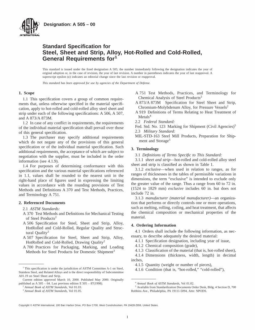
Designation: A 505 – 00
Standard Specification forSteel, Sheet and Strip, Alloy, Hot-Rolled and Cold-Rolled,General Requirements for 1
This standard is issued under the fixed designation A 505; the number immediately following the designation indicates the year oforiginal adoption or, in the case of revision, the year of last revision. A number in parentheses indicates the year of last reapproval. Asuperscript epsilon (e) indicates an editorial change since the last revision or reapproval.
This standard has been approved for use by agencies of the Department of Defense.
1. Scope
1.1 This specification covers a group of common require-ments that, unless otherwise specified in the material specifi-cation, apply to hot-rolled and cold-rolled alloy steel sheet andstrip under each of the following specifications: A 506, A 507,and A 873/A 873M.
1.2 In case of any conflict in requirements, the requirementsof the individual material specification shall prevail over thoseof this general specification.
1.3 The purchaser may specify additional requirementswhich do not negate any of the provisions of this generalspecification or of the individual material specification. Suchadditional requirements, the acceptance of which are subject tonegotiation with the supplier, must be included in the orderinformation (see 4.1.9).
1.4 For purposes of determining conformance with thisspecification and the various material specifications referencedin 1.1, values shall be rounded to the nearest unit in theright-hand place of figures used in expressing the limitingvalues in accordance with the rounding provisions of TestMethods and Definitions A 370 and Test Methods, Practices,and Terminology A 751.
2. Referenced Documents
2.1 ASTM Standards:A 370 Test Methods and Definitions for Mechanical Testing
of Steel Products2
A 506 Specification for Steel, Sheet and Strip, Alloy,HotRolled and Cold-Rolled, Regular Quality and Struc-tural Quality2
A 507 Specification for Steel, Sheet and Strip, Alloy,HotRolled and Cold-Rolled, Drawing Quality2
A 700 Practices for Packaging, Marking, and LoadingMethods for Steel Products for Domestic Shipment3
A 751 Test Methods, Practices, and Terminology forChemical Analysis of Steel Products2
A 873/A 873M Specification for Steel Sheet and Strip,Chromium-Molybdenum Alloy, for Pressure Vessels2
A 919 Definitions of Terms Relating to Heat Treatment ofMetals4
2.2 Federal Standard:Fed. Std. No. 123 Marking for Shipment (Civil Agencies)5
2.3 Military Standard:MIL-STD-163 Steel Mill Products, Preparation for Ship-
ment and Storage5
3. Terminology
3.1 Definitions of Terms Specific to This Standard:3.1.1 sheet and strip—hot-rolled and cold-rolled alloy steel
sheet and strip is classified as shown in Table 1.3.1.2 exclusive—when used in relation to ranges, as for
ranges of thicknesses in the tables of permissible variations indimensions, the term “exclusive” is intended to exclude onlythe greater value of the range. Thus a range from 60 to 72 in.(1524 to 1829 mm)exclusiveincludes 60 in. but does notinclude 72 in.
3.1.3 manufacturer (material manufacturer)—an organiza-tion that performs or directly controls one or more operations,such as melting, rolling, coiling, and heat treatment, that affectsthe chemical composition or mechanical properties of thematerial.
4. Ordering Information
4.1 Orders shall include the following information, as nec-essary, to describe adequately the desired material:
4.1.1 Specification designation, including year of issue,4.1.2 Chemical composition (grade),4.1.3 Classification of the material (that is, hot-rolled sheet),4.1.4 Dimensions (thickness, width, length) in decimal
inches,4.1.5 Quantity (weight or number of pieces),4.1.6 Condition (that is, “hot-rolled,” “cold-rolled”),
1 This specification is under the jurisdiction of ASTM Committee A-1 on Steel,Stainless Steel, and Related Alloys and is the direct responsibility of SubcommitteeA01.19 on Steel Sheet and Strip.
Current edition approved March 10, 2000. Published May 2000. Originallypublished as A 505 – 64. Last previous edition E 505 – 87(1998).
2 Annual Book of ASTM Standards, Vol 01.03.3 Annual Book of ASTM Standards, Vol 01.05.
4 Annual Book of ASTM Standards, Vol 01.02.5 Available from Standardization Documents Order Desk, Bldg. 4 Section D, 700
Robbins Ave., Philadelphia, PA 19111-5094, Attn: NPODS.
1
Copyright © ASTM International, 100 Barr Harbor Drive, PO Box C700, West Conshohocken, PA 19428-2959, United States.

4.1.7 Heat treatment required, if any,4.1.8 Type of edge,4.1.9 Additional information as specified in the individual
material specification,4.1.10 Any special requirements not specified in the indi-
vidual material specification, and4.1.11 Whether certification of compliance or test reports
are required.
5. Materials and Manufacture
5.1 Melting Process—Unless otherwise specified in theindividual material specification, the steel may be made by anyprocess that produces material that conforms to the specifiedrequirements.
5.2 Hot or Cold Rolling—The sheet and strip shall beproduced by hot rolling or cold rolling, as specified in theindividual material specification and as specified on the order.
5.3 Heat Treatment—When heat treatment is required, itshall be performed in accordance with the requirements speci-fied in the individual material specification. Heat treatmentmay be performed by either the manufacturer or the purchaser;however, if the purchaser intends to perform the heat treatment,it shall be so stated on the order.
5.3.1 Heat treatment terms shall be in accordance withDefinitions A 919.
6. Chemical Requirements
6.1 Cast or Heat Analysisof each cast or heat shall be madeby the manufacturer to determine the percentage of elementsspecified in the individual material specification. This analysisshall be made from a test specimen preferably taken during theteeming of the cast or heat. The chemical composition thusdetermined shall be reported to the purchaser or his represen-tative upon request, and shall conform to the cast or heatanalysis requirements of the applicable material specification.
6.2 Product or Verification Analysis— An analysis may bemade by the purchaser from finished material representing eachcast or heat. The composition thus determined shall conform tothe requirements for product analysis specified in the indi-vidual material specification or on the order; however, if onlycast or heat analysis requirements are specified in the materialspecification or on the order, the composition determined onproduct analysis shall conform to those requirements subject tothe product analysis tolerances specified in Table 2.
6.3 Referee Analysis—In case referee analysis is required toresolve a dispute concerning the results of a chemical analysis,the procedures for performing the referee analysis shall be inaccordance with Test Methods, Practices, and TerminologyA 751.
7. Metallurgical Structure
7.1 The requirements for metallurgical structure, if any,shall be as specified in the individual material specification.
8. Mechanical Property Requirements
8.1 Requirements—The requirements for mechanical prop-erties, if any, shall be as specified in the individual materialspecification.
8.2 Number of Tests—The number of specimens shall be asspecified in the individual material specification.
8.3 Location and Orientation of Tension Test Specimens—Unless otherwise specified in the individual material specifi-cation, tension test specimens shall be the full thickness of thematerial. The test coupons shall be taken from the material inits finished condition except as otherwise provided in 8.4; shallbe taken approximately midway between the edge and center-line of the sheet or strip; and shall be taken such that the longaxis of the test specimen will be transverse to the final directionof rolling.
8.4 Heat Treatment of Test Coupons:8.4.1 When heat treatment is required by the material
specification and is to be performed by the purchaser or hisagent, and the material is to be supplied by the manufacturer ina condition other than that required by the material specifica-tion, the material shall be qualified on the basis of tests madeon specimens taken from coupons, obtained from the materialin its as-shipped condition, that have been heat treated inaccordance with the requirements specified in the materialspecification or on the order. If the heat-treatment temperaturesare not specified, the manufacturer shall heat treat the couponsunder conditions he considers appropriate.
8.4.2 When specified on the order, the test coupons may besubjected to additional heat treatment to simulate thermaltreatments that will be used during fabrication.
8.4.3 The purchaser shall be informed of the proceduresfollowed in heat treating the test coupons.
8.5 Test Methods:8.5.1 All tests shall be conducted in accordance with Test
Methods and Definitions A 370.8.5.2 Yield strength shall be determined either by the 0.2 %
offset method or by the 0.5 % extension-under-load method.
9. Quality
9.1 General—Sheet and strip furnished under this specifi-cation shall be clean, sound, and free of internal or externalimperfections which would make the material unsuitable forthe intended application. Care should be taken to avoid cracks,seams, slivers, grooves, laminations, pits, blisters, buckles, coilbreaks, creases, holes, pickling stains and patches, ragged andtorn edges, and “rolled-in” dirt and scale.
9.2 Surface Finish—The degree or amount of surface im-perfections on material in cut lengths shall be such that only areasonable amount of metal finishing is required. Slight surfaceimperfections that are completely removable without reducingthe thickness below the minimum permissible limits shall notbe considered to be defects. Coils may contain some abnormaldefects such as holes, welds, etc., which render a portion of thecoil unusuable, since the inspection of coils does not affort thesame opportunity to reject portions containing defects as is thecase with cut lengths. However, an excessive number ofabnormal imperfections is cause for rejection.
10. Edges
10.1 Edges—The types of edges procurable in hot-rolledand in cold-rolled alloy-steel sheet and strip are as follows:
10.2 Hot-Rolled Sheet and Strip:
A 505 – 00
2

10.2.1 Mill Edge—Normal edge produced in hot rolling thatdoes not conform to any definite contour.
10.2.2 Cut Edge—Approximately square edge resultingfrom the cutting of sheet into one or more desired widths bymeans of rotary knives (slit edge) or blade shears (shearededge).
10.2.3 Square Edge—Type of mill edge produced by hotedge-rolling; furnished on strip only.
10.3 Cold-Rolled Sheet:10.3.1 Cut Edge—Same description as shown in 10.2.2 for
hot-rolled sheet and strip.10.4 Cold-Rolled Strip:10.4.1 No. 1 Edge—Prepared edge of a specified round or
square contour that is produced when a very accurate width isrequired.
10.4.2 No. 2 Edge—Natural mill edge carried through thecold rolling from the hot-rolled strip without additional pro-cessing of the edge.
10.4.3 No. 3 Edge—Approximately square edge producedby slitting.
10.4.4 No. 4 Edge—Rounded edge produced by edge roll-ing either the natural edge of hot-rolled strip or slit-edge strip.Used when an approximately round edge is desired and whenthe finish of the edge is not important.
10.4.5 No. 5 Edge—Square edge produced by edge rollingor filing for the purpose of eliminating burr.
10.4.6 No. 6 Edge—Square edge produced by edge rollingthe natural edge of hot-rolled strip or slit-edge strip, when thewidth tolerances and finish required are not as exacting as forthe No. 1 Edge.
11. Permissible Variations in Dimensions
11.1 The permissible variations in dimensions (see Table 3)for hot-rolled and cold-rolled alloy steel sheet and strip shall bein accordance with Tables 4-22.
12. Identification of Product
12.1 As a minimum, the material shall be identified with themanufacturer’s name or brand, the specification designation,weight, purchaser’s order number, and material identificationwhich is traceable to the heat or cast.
12.2 The identification shall be legibly stenciled on top ofeach lift or shown on a tag attached to each coil or shippingunit.
12.3 When specified on the order, each sheet shall beidentified as agreed upon.
13. Retests
13.1 The retest provisions of Test Methods and DefinitionsA 370 shall apply.
13.2 If the results of any tests do not conform to thespecified requirements, (unless otherwise specified in theindividual material specification), retests may be made ondouble the original number of specimens from the same lot,each of which must conform to the requirements specified. Ifthe results of the retests do not conform to the specifiedrequirements, the lot shall be rejected.
14. Inspection and Testing
14.1 When the order specifies that the purchaser will inspectthe material and witness testing, the inspector representing thepurchaser shall have entry at all times while work on thecontract of the purchaser is being performed, to all parts of themanufacturer’s works that concern the manufacture of thematerial ordered. The manufacturer shall afford the inspectorall reasonable facilities to satisfy the inspector that the materialis being furnished in accordance with the specification.
14.2 All tests (except product analysis) and inspection shallbe made at the place of manufacture before shipment, unlessotherwise specified on the order, and shall be so conducted asnot to interfere unnecessarily with the operation of the works.
15. Rework and Retreatment
15.1 If inspection and test results fail to conform to thespecified requirements, the material may be reworked orretreated, if the manufacturer can assure that the cause offailure is curable and that the quality of the material shallconform to the specified requirements. After retreatment,testing shall be done in accordance with the material specifi-cation requirements.
16. Rejection Subsequent to Shipment
16.1 Material that shows characteristics not in conformancewith the material specification subsequent to its initial accep-tance may be rejected. In such cases, the manufacturer shouldbe notified in a timely manner.
17. Certification
17.1 When specified on the order, a certification of compli-ance shall be furnished that the material was manufactured,sampled, tested, and inspected in accordance with the require-ments of the applicable specification.
17.2 When specified on the order, a report of the test resultsshall be furnished.
17.3 A signature is not required on the certification ofcompliance or the report of test results. However, the documentshall clearly identify the organization submitting the document.Notwithstanding the absence of a signature, the organizationsubmitting the document is responsible for the content of thedocument.
18. Packaging, Marking, and Loading for Shipment
18.1 Packaging, marking, and loading for shipment shall bein accordance with those procedures recommended in PracticesA 700.
18.2 For Government Procurement—Packaging, packing,and marking of material for military procurement shall be inaccordance with the requirements of MIL-STD-163, Level A,Level C, or commercial, as specified in the contract or purchaseorder. Marking for shipment of material for civil agencies shallbe in accordance with Fed. Std. No. 123.
A 505 – 00
3
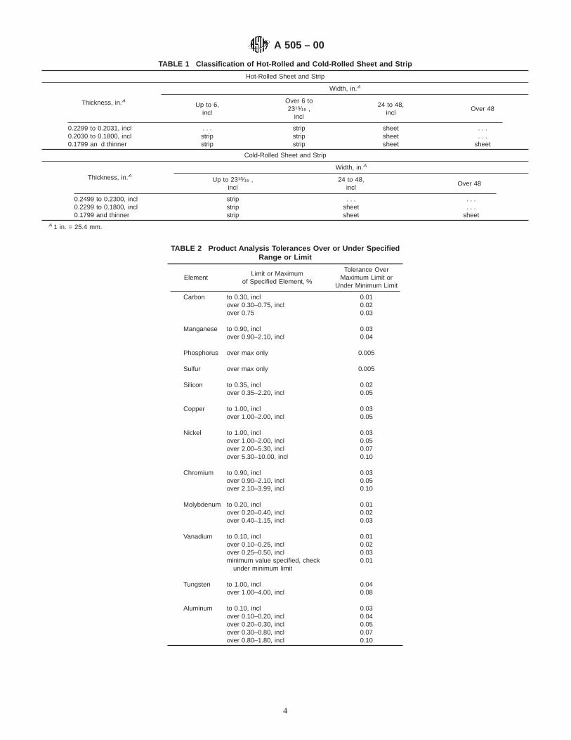
TABLE 1 Classification of Hot-Rolled and Cold-Rolled Sheet and Strip
Hot-Rolled Sheet and Strip
Thickness, in.A
Width, in.A
Up to 6,incl
Over 6 to2315⁄16 ,
incl
24 to 48,incl
Over 48
0.2299 to 0.2031, incl . . . strip sheet . . .0.2030 to 0.1800, incl strip strip sheet . . .0.1799 an d thinner strip strip sheet sheet
Cold-Rolled Sheet and Strip
Thickness, in.AWidth, in.A
Up to 2315⁄16 ,incl
24 to 48,incl
Over 48
0.2499 to 0.2300, incl strip . . . . . .0.2299 to 0.1800, incl strip sheet . . .0.1799 and thinner strip sheet sheet
A 1 in. = 25.4 mm.
TABLE 2 Product Analysis Tolerances Over or Under SpecifiedRange or Limit
ElementLimit or Maximum
of Specified Element, %
Tolerance OverMaximum Limit or
Under Minimum Limit
Carbon to 0.30, inclover 0.30–0.75, inclover 0.75
0.010.020.03
Manganese to 0.90, inclover 0.90–2.10, incl
0.030.04
Phosphorus over max only 0.005
Sulfur over max only 0.005
Silicon to 0.35, inclover 0.35–2.20, incl
0.020.05
Copper to 1.00, inclover 1.00–2.00, incl
0.030.05
Nickel to 1.00, incl 0.03over 1.00–2.00, incl 0.05over 2.00–5.30, incl 0.07over 5.30–10.00, incl 0.10
Chromium to 0.90, inclover 0.90–2.10, inclover 2.10–3.99, incl
0.030.050.10
Molybdenum to 0.20, inclover 0.20–0.40, inclover 0.40–1.15, incl
0.010.020.03
Vanadium to 0.10, incl 0.01over 0.10–0.25, incl 0.02over 0.25–0.50, incl 0.03minimum value specified, check
under minimum limit0.01
Tungsten to 1.00, inclover 1.00–4.00, incl
0.040.08
Aluminum to 0.10, incl 0.03over 0.10–0.20, incl 0.04over 0.20–0.30, incl 0.05over 0.30–0.80, incl 0.07over 0.80–1.80, incl 0.10
A 505 – 00
4

TABLE 3 Dimensional Tolerance Tables
NOTE 1— The following table shows the dimensional tolerance table number applicable to the different product classification and rolling methods.Continuous mill tolerances apply unless otherwise specified.
Hot-Rolled Cold-Rolled
Sheet Strip Sheet Strip
Hand Mill Continuous Mill Continuous Mill
MillEdge
CutEdge
MillEdge
CutEdge
MillEdge
CutEdge
Edges
1 2 3 4 5 6
Mill Slit
Thickness 5 5 4 4 13 6 6 18 18 18 18 18 18Width 7 8 7 8 15 7 8 21 19 20 21 21 21Length 9 9 9 9 16 9 9 22 22 22 22 22 22Flatness for cut lengths 10 10 10 10 17 10 10 . . . . . . . . . . . . . . . . . .Camber 11 11 11 11 11 11 11 11 11 11 11 11 11Out-of-square . . . 12 . . . 12 . . . . . . . . . . . . . . . . . . . . . . . . . . .Crown . . . . . . . . . . . . 14 . . . . . . . . . . . . . . . . . . . . . . . .
TABLE 4 Thickness A Tolerances for Hot-Rolled Sheet (Continuous Mill Product), Coils, or Cut Lengths
Width, in. (mm)
Thickness, in. (mm)
0.2299 to 0.1800(5.84 to 4.57),
incl
0.1799 to 0.0972(4.56 to 2.47),
incl
0.0971 to 0.0822(2.46 to 2.09),
incl
0.0821 to 0.0710(2.08 to 1.80),
incl
0.0709 to 0.0568(1.79 to 1.44),
incl
Thickness Tolerances, Over and Under, in. (mm), for Specified Widths and Thicknesses
24 to 32 0.009 (0.23) 0.008 (0.20) 0.007 (0.18) 0.007 (0.18) 0.006 (0.15)(610 to 810), incl
Over 32 to 40 0.009 (0.23) 0.009 (0.23) 0.008 (0.20) 0.007 (0.18) 0.006 (0.15)(810 to 1020), incl
Over 40 to 48 0.010 (0.25) 0.010 (0.25) 0.008 (0.20) 0.007 (0.18) 0.006 (0.15)(1020 to 1220), incl
Over 48 to 60 . . . 0.010 (0.25) 0.008 (0.20) 0.007 (0.18) 0.007 (0.18)(1220 to 1520), incl
Over 60 to 70 . . . 0.011 (0.28) 0.009 (0.23) 0.008 (0.20) 0.007 (0.18)(1520 to 1780), incl
Over 70 to 80 . . . 0.012 (0.30) 0.009 (0.23) 0.008 (0.20) . . .(1780 to 2030), incl
Over 80 to 90 . . . 0.012 (0.30) 0.010 (0.25) . . . . . .(2030 to 2290), incl
Over 90 (2290) . . . 0.012 (0.30) . . . . . . . . .A Thickness is measured at any point on the sheet not less than " in. (9.5 mm) from a cut edge and not less than 3⁄4 in. (19 mm) from a mill edge.
TABLE 5 Thickness A Tolerances, Hot-Rolled Sheet, Hand MillProduct
Thickness, in.BTolerance, in.B
Over and Under
0.229 to 0.188, incl 0.015Under 0.188 to 0.146, incl 0.014Under 0.146 to 0.131, incl 0.012Under 0.131 to 0.115, incl 0.010Under 0.115 to 0.099, incl 0.009Under 0.099 to 0.084, incl 0.008Under 0.084 to 0.073, incl 0.007Under 0.073 to 0.059, incl 0.006Under 0.059 to 0.041, incl 0.005Under 0.041 to 0.027, incl 0.004Under 0.027 to 0.019, incl 0.003
A Thickness is measured at any point on the sheet not less than 3⁄8 in. from a cutedge and not less than 3⁄4 in. from a mill edge.
B 1 in. = 25.4 mm.
A 505 – 00
5

TABLE 6 Thickness A Tolerances for Cold-Rolled Sheet, Coils, or Cut Lengths
Specified Width,in.B
Thickness, in.B
0.0313to
0.0195,incl
0.0508to
0.0314,incl
0.0567to
0.0509,incl
0.0709to
0.0568,incl
0.0821to
0.0710,incl
0.0971to
0.0822,incl
0.1419to
0.0972,incl
0.1799to
0.1420,incl
0.2299to
0.1800,incl
Thickness Tolerances, Over and Under, in.B, for Specified Widths and Thicknesses
24 to 32, incl 0.003 0.004 0.005 0.005 0.005 0.006 0.007 0.008 0.008Over 32 to 40, incl 0.003 0.004 0.005 0.005 0.006 0.007 0.008 0.009 0.009Over 40 to 48, incl 0.003 0.004 0.005 0.005 0.006 0.007 0.009 0.010 0.010Over 48 to 60, incl 0.003 0.004 0.005 0.006 0.006 0.008 0.010 0.010 . . .Over 60 to 70, incl . . . 0.005 0.006 0.006 0.007 0.009 0.010 0.011 . . .Over 70 to 80, incl . . . . . . . . . . . . 0.007 0.009 0.011 0.012 . . .Over 80 to 90, incl . . . . . . . . . . . . . . . . . . 0.012 0.012 . . .Over 90 . . . . . . . . . . . . . . . . . . 0.012 0.012 . . .
A Thickness is measured at any point on the sheet not less than " in. from a cut edge and not less than 3⁄4 in. from a mill edge.B 1 in. = 25.4 mm.
TABLE 7 Width Tolerances for Mill Edge of Hot-Rolled or Cold-Rolled Sheet, Coils, or Cut Lengths
Specified Widths, in.ATolerances Over Specified
Width, in.A, No Tolerance Under
24 to 26, excl 13⁄16
26 to 28, excl 15⁄16
28 to 35, excl 11⁄835 to 50, excl 11⁄450 to 60, excl 11⁄20 to 65, excl 15⁄85 to 70, excl 13⁄470 to 80, excl 17⁄880 and over 2
A 1 in. = 25.4 mm.
TABLE 8 Width Tolerances for Cut Edge of Hot-Rolled or Cold-Rolled Sheet, Coils, or Cut Lengths
Specified Width, in.ATolerance Over Specified
Width, in.A, No Tolerance Under
24 to 30, incl 3⁄16
Over 30 to 50, incl ¼Over 50 to 80, incl 5⁄16
Over 80 "A 1 in. = 25.4 mm.
TABLE 9 Length Tolerances for Hot-Rolled or Cold-Rolled Sheet
Specified Length, in. (mm)Tolerance Over Specified Length,
in. (mm),No Tolerance Under
24 to 30 (610 to 760), incl ¼(6.4)Over 30 to 60 (760 to 1520), incl ½(12.7)Over 60 to 120 (1520 to 3050), incl 3⁄4 (19)Over 120 to 156 (3050 to 3960), incl 1 (25)Over 156 to 192 (3960 to 4880), incl 1¼ (31)Over 192 to 240 (4880 to 6100), incl 1½ (38)Over 240 (6100) 13⁄4 (44)
A 505 – 00
6

TABLE 10 Flatness Tolerances for Cut Lengths of Hot-Rolled orCold-Rolled Sheet A
Specified Thickness, in.B Specified Width, in.BFlatness
Tolerance,in.B,C
From 0.0195 to 0.0567,incl
24 to 36, inclOver 36 to 60, inclOver 60
1⁄23⁄41
From 0.0568 to 0.2299,incl
24 to 60, inclOver 60 to 72, inclOver 72
1⁄23⁄41
A Rolled or thermally treated and flattened.B 1 in. = 25.4 mm.C Deviations from flatness are measured by laying the sheet on a horizontal flat
surface and measuring the maximum elevation above that surface to any point onthe bottom surface of the sheet.
TABLE 11 Camber A Tolerances for Hot-Rolled or Cold-RolledSheet and Strip
For sheet ¼ in. (6.35 mm) in any 8 ft(2440 mm)
For strip to 1½ in. (38 mm)in width, incl
½ in. (12.7 mm) in any 8 ft(2440 mm)
For strip over 1½ to 2315⁄16
in. (38.1 to 608.0 mm)in width, incl
¼ in. (6.35 mm) in any 8 ft(2440 mm)
A Camber is determined by placing an 8-ft straightedge on the concave edge ofthe sheet or strip and measuring the greatest distance between the sheet edge orstrip edge and the straightedge. When the camber shown in Table 11 is not suitablefor a particular purpose, hot-rolled strip is sometimes machine straightened to aspecified camber. For that requirement, the producer should be consulted.
TABLE 12 Out-Of-Square Tolerance for Hot-Rolled or Cold-Rolled Sheet (Cut Edge Not Resquared)
Out-of-square is the greatest deviation of an end edge from a straight line ata right angle to a side and touching one corner. The tolerance for sheets of allgages and all sizes is 1⁄16 in./6 in., 10.5 mm/m or fraction thereof, of width.
It is also obtained by measuring the difference between the diagonals of thesheet. The out-of-square deviation is one half of that difference.
TABLE 13 Thickness Tolerances for Hot-Rolled Strip Coils, or Cut Lengths A,B
Specified Width,in.C
Thickness, in.C
0.2299 to0.2031,
incl
0.2030 to0.1875,
incl
0.1874 to0.1719,
incl
0.1718 to0.1420,
incl
0.1419 to0.1121,
incl
0.1120 to0.0972,
incl
0.0971 to0.0710,
incl
0.0709 to0.0568,
incl
Thickness Tolerances, in.C, Over and Under for Specified Widths and Thicknesses
To 6, incl . . . 0.006 0.006 0.005 0.005 0.005 0.005 0.005Over 6 to 12, incl 0.007 0.006 0.006 0.006 0.006 0.005 0.005 0.005Over 12 to 15, incl 0.008 0.008 0.007 0.007 0.007 0.007 0.006 0.006Over 15 to 20, incl 0.009 0.009 0.009 0.008 0.008 0.008 0.007 0.006Over 20 to 2315⁄16 , incl 0.009 0.009 0.009 0.009 0.008 0.008 0.007 0.006
A Thickness measurements are taken " in. from edge of strip on 1 in. or wider; and at any place on the strip when narrower than 1 in.B See Table 16 for applicable crown tolerances.C 1 in. = 25.4 mm.
A 505 – 00
7

TABLE 14 Crown Tolerances for Hot-Rolled Strip, Coils, or CutLengths A
Specified Widths, in.B Additional Thickness at Center, in.B
Over 1 to 3½, incl 0.002Over 3½ to 6, incl 0.003Over 6 to 12, incl 0.004Over 12 to 15, incl 0.005Over 15 to 2315⁄16 , incl 0.006
A Hot-rolled alloy strip may be thicker at the center than at a point 3⁄8 in. from theedge as shown in this table.
B 1 in. = 25.4 mm.
TABLE 15 Width Tolerances for Hot-Rolled Strip, Coils, or Cut Lengths
Cut EdgeA
Mill Edge Slit Edge Sheared Edge
Thickness, in. (mm)
Specified Width, in. (mm)To 0.109 (2.77),
inclOver 0.109 (2.77)
Width Tolerance,in. (mm), Over
and Under
Width Tolerance, in. (mm),Over and Under
Width Tolerance,in. (mm), OverWidth No Toler-
ance Under
To 2 (50), incl 1⁄32 (0.79) 0.010 (0.25) 0.016 (0.41) ! (3.2)Over 2 to 5 (50 to 130), incl 1⁄16 (1.59) 0.010 (0.25) 0.020 (0.51) ! (3.2)Over 5 to 9 (130 to 230), incl 3⁄32 (2.38) 0.016 (0.41) 0.024 (0.61) ! (3.2)Over 9 to 12 (230 to 300), incl ! (3.20) 0.016 (0.41) 0.031 (0.79) ! (3.2)Over 12 to 20 (300 to 510), incl ¼ (6.35) 0.020 (0.51) 0.031 (0.79) ! (3.2)Over 20 to 2315⁄16 (510 to 610),incl
"(9.50) 0.031 (0.79) 0.031 (0.79) ! (3.2)
A Some alloy grades require annealing before cutting because of their high hardenability.
TABLE 16 Length Tolerances for Hot-Rolled Strip
Specified Widths,in.A
Length, in.A
To 60,incl
Over60 to120,incl
Over120 to240,incl
Over240 to360,incl
Over360 to480,incl
Over480
Length Tolerances, in.A, Over Specified Length,No Tolerance Under
To 3, incl ¼ 3⁄8 ½ 3⁄4 1 1½Over 3 to 6, incl " ½ 5⁄8 3⁄4 1 1½Over 6 to 2315⁄16 ,
incl½ 3⁄4 1 11⁄4 11⁄2 13⁄4
A 1 in. = 25.4 mm.
TABLE 17 Flatness Tolerances for Cut Lengths of Hot-RolledStrip As-Rolled or Thermally Treated and Flattened
½ in., max, in 8 ft (5.2 mm/m) of length
A 505 – 00
8

TAB
LE18
Thi
ckne
ssTo
lera
nces
for
Col
d-R
olle
dS
trip
A
Spe
cifie
dT
hick
ness
,in
.(m
m)
Wid
th,
in.
(mm
)
3⁄16
to1
(4.8
to25
),ex
cl1
to3
(25
to75
),ex
cl3
to6
(75
to15
0),
incl
Ove
r6
to9
(150
to23
0),
incl
Ove
r9
to12
(230
to30
0),
incl
Ove
r12
to16
(300
to41
0),
incl
Ove
r16
to20
(410
to51
0),
incl
Ove
r20
to23
15⁄16
(510
to61
0),
incl
Thi
ckne
ssTo
lera
nces
,in
.(m
m)
Ove
ran
dU
nder
for
Spe
cifie
dT
hick
ness
esan
dW
idth
s
Und
er0.
010
(0.2
5)..
...
...
...
...
...
...
...
.0.
010
(0.2
5)0.
001
(0.0
3)0.
001
(0.0
3)0.
001
(0.0
3)0.
001
(0.0
3)0.
001
(0.0
3)0.
001
(0.0
3)0.
0015
(0.0
4)0.
0015
(0.0
4)0.
011
(0.2
8)0.
001
(0.0
3)0.
001
(0.0
3)0.
001
(0.0
3)0.
001
(0.0
3)0.
001
(0.0
3)0.
0015
(0.0
4)0.
0015
(0.0
4)0.
0015
(0.0
4)0.
012
(0.3
0)0.
001
(0.0
3)0.
001
(0.0
3)0.
001
(0.0
3)0.
001
(0.0
3)0.
0015
(0.0
4)0.
0015
(0.0
4)0.
0015
(0.0
4)0.
0015
(0.0
4)O
ver
0.01
2to
0.01
6(0
.30
to0.
41),
incl
0.00
1(0
.03)
0.00
1(0
.03)
0.00
1(0
.03)
0.00
15(0
.04)
0.00
15(0
.04)
0.00
15(0
.04)
0.00
2(0
.05)
0.00
2(0
.05)
Ove
r0.
016
to0.
019
(0.4
1to
0.48
),in
cl0.
001
(0.0
3)0.
001
(0.0
3)0.
001
(0.0
3)0.
0015
(0.0
4)0.
0015
(0.0
4)0.
002
(0.0
5)0.
002
(0.0
5)0.
002
(0.0
5)O
ver
0.01
9to
0.02
5(0
.48
to0.
64),
incl
0.00
1(0
.03)
0.00
1(0
.03)
0.00
15(0
.04)
0.00
2(0
.05)
0.00
2(0
.05)
0.00
2(0
.05)
0.00
25(0
.06)
0.00
25(0
.06)
Ove
r0.
025
to0.
028
(0.6
4to
0.71
),in
cl0.
001
(0.0
3)0.
0015
(0.0
4)0.
0015
(0.0
4)0.
002
(0.0
5)0.
002
(0.0
5)0.
002
(0.0
5)0.
0025
(0.0
6)0.
003
(0.0
8)O
ver
0.02
8to
0.03
4(0
.71
to0.
86),
incl
0.00
15(0
.04)
0.00
15(0
.04)
0.00
2(0
.05)
0.00
25(0
.06)
0.00
25(0
.06)
0.00
25(0
.06)
0.00
3(0
.08)
0.00
3(0
.08)
Ove
r0.
034
to0.
039
(0.8
6to
0.99
),in
cl0.
002
(0.0
5)0.
002
(0.0
5)0.
0025
(0.0
6)0.
003
(0.0
8)0.
003
(0.0
8)0.
003
(0.0
8)0.
003
(0.0
8)0.
003
(0.0
8)O
ver
0.03
9to
0.04
9(0
.99
to1.
25),
incl
0.00
2(0
.05)
0.00
2(0
.05)
0.00
25(0
.06)
0.00
3(0
.08)
0.00
3(0
.08)
0.00
3(0
.08)
0.00
4(0
.10)
0.00
4(0
.10)
Ove
r0.
049
to0.
068
(1.2
5to
1.73
),in
cl0.
002
(0.0
5)0.
002
(0.0
5)0.
003
(0.0
8)0.
003
(0.0
8)0.
003
(0.0
8)0.
003
(0.0
8)0.
004
(0.1
0)0.
004
(0.1
0)O
ver
0.06
8to
0.09
9(1
.73
to2.
52),
incl
0.00
2(0
.05)
0.00
2(0
.05)
0.00
3(0
.08)
0.00
3(0
.08)
0.00
3(0
.08)
0.00
4(0
.10)
0.00
4(0
.10)
0.00
4(0
.10)
Ove
r0.
099
to0.
160
(2.5
2to
4.06
),in
cl0.
002
(0.0
5)0.
003
(0.0
8)0.
003
(0.0
8)0.
004
(0.1
0)0.
004
(0.1
0)0.
004
(0.1
0)0.
005
(0.1
3)0.
005
(0.1
3)O
ver
0.16
0to
0.18
7(4
.06
to4.
75),
incl
0.00
2(0
.05)
0.00
35(0
.09)
0.00
4(0
.10)
0.00
4(0
.10)
0.00
4(0
.10)
0.00
5(0
.13)
0.00
6(0
.15)
0.00
6(0
.15)
Ove
r0.
187
to0.
2499
(4.7
5to
6.35
),in
cl..
...
...
...
...
...
...
...
.A
Thi
ckne
ssm
easu
rem
ents
are
take
n"
in.(
9.5
mm
)in
from
edge
ofst
rip,e
xcep
ttha
ton
wid
ths
less
than
1in
.(25
mm
),th
eto
lera
nces
are
appl
icab
lefo
rm
easu
rem
ents
atal
lloc
atio
ns.
A 505 – 00
9

TABLE 19 Width Tolerances for No. 2 Edge (Mill Edge) Cold-Rolled Strip
Specified Width, in.A Tolerances for Specified Width, 6, in.A
To 2, incl 1⁄32
Over 2 to 5, incl 1⁄16
Over 5 to 9, incl 3⁄32
Over 9 to 12, incl !Over 12 to 20, incl ¼Over 20 to 2315⁄16 ,incl
"
A 1 in. = 25.4 mm.
TABLE 20 Width Tolerances for No. 3 Edge (Slit Edge) of Cold-Rolled Strip
Specified Thickness, in.A Width, in.A
Over To and incl
3⁄16 to ½,excl
½ to 6, inclOver 6 to
9, inclOver 9 to12, incl
Over 12 to20, incl
Over 20 to2315⁄16 , incl
Width Tolerances, in.A, Over and Under for Indicated Thicknesses and Widths
0.187 0.2499 . . . . . . . . . . . . . . . . . .0.160 0.187 . . . 0.016 0.020 0.020 0.031 0.0310.099 0.160 0.010 0.010 0.016 0.016 0.020 0.0200.068 0.099 0.008 0.008 0.010 0.010 0.016 0.0200.0099 0.068 0.005 0.005 0.005 0.010 0.016 0.020
0.0099 and under . . . . . . . . . . . . . . . . . . . . .A 1 in. = 25.4 mm.
A 505 – 00
10
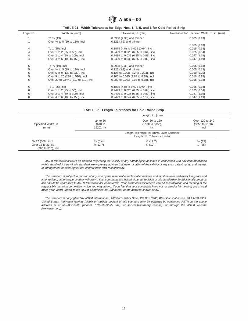
TABLE 21 Width Tolerances for Edge Nos. 1, 4, 5, and 6 for Cold-Rolled Strip
Edge No. Width, in. (mm) Thickness, in. (mm) Tolerances for Specified Width, 6, in. (mm)
1 To 3⁄4 (19) 0.0938 (2.38) and thinner 0.005 (0.13)1 Over 3⁄4 to 5 (19 to 130), incl 0.125 (3.2) and thinner
0.005 (0.13)4 To 1 (25), incl 0.1875 (4.8) to 0.025 (0.64), incl 0.015 (0.38)4 Over 1 to 2 (25 to 50), incl 0.2499 to 0.025 (6.35 to 0.64), incl 0.025 (0.64)4 Over 2 to 4 (50 to 100), incl 0.2499 to 0.035 (6.35 to 0.89), incl 0.047 (1.19)4 Over 4 to 6 (100 to 150), incl 0.2499 to 0.035 (6.35 to 0.89), incl 0.047 (1.19)
5 To 3⁄4 (19), incl 0.0938 (2.38) and thinner 0.005 (0.13)5 Over 3⁄4 to 5 (19 to 130), incl 0.125 (3.2) and thinner 0.005 (0.13)5 Over 5 to 9 (130 to 230), incl 0.125 to 0.008 (3.2 to 0.203), incl 0.010 (0.25)5 Over 9 to 20 (230 to 510), incl 0.105 to 0.015 (2.67 to 0.38), incl 0.010 (0.25)5 Over 20 to 2315⁄16 (510 to 610), incl 0.080 to 0.023 (2.03 to 0.58), incl 0.015 (0.38)
6 To 1 (25), incl 0.1875 (4.8) to 0.025 (0.64), incl 0.015 (0.38)6 Over 1 to 2 (25 to 50), incl 0.2499 to 0.025 (6.35 to 0.64), incl 0.025 (0.64)6 Over 2 to 4 (50 to 100), incl 0.2499 to 0.035 (6.35 to 0.89), incl 0.047 (1.19)6 Over 4 to 6 (100 to 150), incl 0.2499 to 0.047 (6.35 to 1.19), incl 0.047 (1.19)
TABLE 22 Length Tolerances for Cold-Rolled Strip
Specified Width, in.(mm)
Length, in. (mm)
24 to 60(610 to
1520), incl
Over 60 to 120(1520 to 3050),
incl
Over 120 to 240(3050 to 6100),
incl
Length Tolerance, in. (mm), Over SpecifiedLength, No Tolerance Under
To 12 (300), incl 1⁄4 (6.4) 1⁄2 (12.7) 3⁄4 (19)Over 12 to 2315⁄16 ½(12.7) 3⁄4 (19) 1 (25)
(300 to 610), incl
ASTM International takes no position respecting the validity of any patent rights asserted in connection with any item mentionedin this standard. Users of this standard are expressly advised that determination of the validity of any such patent rights, and the riskof infringement of such rights, are entirely their own responsibility.
This standard is subject to revision at any time by the responsible technical committee and must be reviewed every five years andif not revised, either reapproved or withdrawn. Your comments are invited either for revision of this standard or for additional standardsand should be addressed to ASTM International Headquarters. Your comments will receive careful consideration at a meeting of theresponsible technical committee, which you may attend. If you feel that your comments have not received a fair hearing you shouldmake your views known to the ASTM Committee on Standards, at the address shown below.
This standard is copyrighted by ASTM International, 100 Barr Harbor Drive, PO Box C700, West Conshohocken, PA 19428-2959,United States. Individual reprints (single or multiple copies) of this standard may be obtained by contacting ASTM at the aboveaddress or at 610-832-9585 (phone), 610-832-9555 (fax), or [email protected] (e-mail); or through the ASTM website(www.astm.org).
A 505 – 00
11

Designation: A 506 – 04
Standard Specification forAlloy and Structural Alloy Steel, Sheet and Strip, Hot-Rolledand Cold-Rolled 1
This standard is issued under the fixed designation A 506; the number immediately following the designation indicates the year oforiginal adoption or, in the case of revision, the year of last revision. A number in parentheses indicates the year of last reapproval. Asuperscript epsilon (e) indicates an editorial change since the last revision or reapproval.
This standard has been approved for use by agencies of the Department of Defense.
1. Scope*
1.1 This specification covers hot-rolled and cold-rolledalloy and structural alloy-steel sheet and strip. Alloy steel isfurnished to chemical composition requirements and is in-tended primarily for general or miscellaneous use wherebending and moderate forming is a requirement. Structuralalloy steel is furnished to chemical composition requirementsand to specific mechanical property requirements which mayinclude tension tests, hardness tests, or other commonlyaccepted mechanical tests.
1.2 If material of a higher degree of uniformity of internalsoundness and freedom from surface imperfections is required,reference should be made to Specification A 507.
1.3 Alloy and structural alloy-steel sheet and strip are notproduced to internal cleanliness requirements. Normally sur-face imperfections are not objectionable, and a good finish isnot a prime requirement.
1.4 The formability of structural alloy steel decreases withincreasing yield strength or hardness. Therefore, product de-sign in relation to the mechanical properties of the grade usedmust be considered.
1.5 The material covered by this specification may befurnished in several conditions: heat treatments, surface con-ditions, and edges, as specified herein, in coils or cut lengths.
1.6 The values stated in inch-pound units are to be regardedas the standard. SI units are provided for information only.
2. Referenced Documents
2.1 ASTM Standards:2
A 505 Specification for Steel, Sheet and Strip, Alloy, Hot-Rolled and Cold-Rolled, General Requirements for
A 507 Specification for Drawing Alloy Steel, Sheet andStrip, Hot-Rolled and Cold-Rolled
3. Terminology
3.1 Definitions of Terms Specific to This Standard:3.1.1 alloy steel—alloy-steel sheet and strip furnished to
chemical composition requirements and intended for general ormiscellaneous applications where normal surface imperfec-tions are not objectionable and a good finish is not the primerequirement.
3.1.2 SAE—Society of Automotive Engineers.3.1.3 standard steels—steel chemical compositions defined
as “standard” by SAE, shown in Table 1 and Table A1.1.3.1.4 steels other than standard—steel chemical composi-
tions other than those defined as “standard,” and furnished tothe composition limits shown in Table 2.
3.1.5 structural alloy steel—alloy-steel sheet and stripmeeting the requirements of regular quality and also producedto specific mechanical property requirements.
4. General Requirements and Ordering Information
4.1 Material supplied to this specification shall conform toSpecification A 505, which includes the general requirementsand establishes the rules for the ordering information thatshould be complied with when purchasing material to thisspecification.
4.2 In addition to the ordering information required bySpecification A 505, the following shall also be included:
4.2.1 Mechanical properties required for structural quality,when applicable,
4.2.2 Surface finish, if other than standard (see 8.1), and4.2.3 Surface treatment, if other than standard (see 8.2).
5. Materials and Manufacture
5.1 Rolling—The material shall be furnished either hot-rolled or cold-rolled, as specified on the order.
5.2 Heat Treatment:5.2.1 Hot-Rolled—Hot-rolled material shall be furnished in
one of the following conditions, as specified on the order:5.2.1.1 As-rolled,5.2.1.2 Annealed,
1 This specification is under the jurisdiction of ASTM Committee A01 on Steel,Stainless Steel and Related Alloys, and is the direct responsibility of SubcommitteeA01.19 on Steel Sheet and Strip.
Current edition approved March 1, 2004. Published March 2004. Originallyapproved in 1964. Last previous edition approved in 2000 as A 506 – 00.
2 For referenced ASTM standards, visit the ASTM website, www.astm.org, orcontact ASTM Customer Service at [email protected]. ForAnnual Book of ASTMStandardsvolume information, refer to the standard’s Document Summary page onthe ASTM website.
1
*A Summary of Changes section appears at the end of this standard.
Copyright © ASTM International, 100 Barr Harbor Drive, PO Box C700, West Conshohocken, PA 19428-2959, United States.
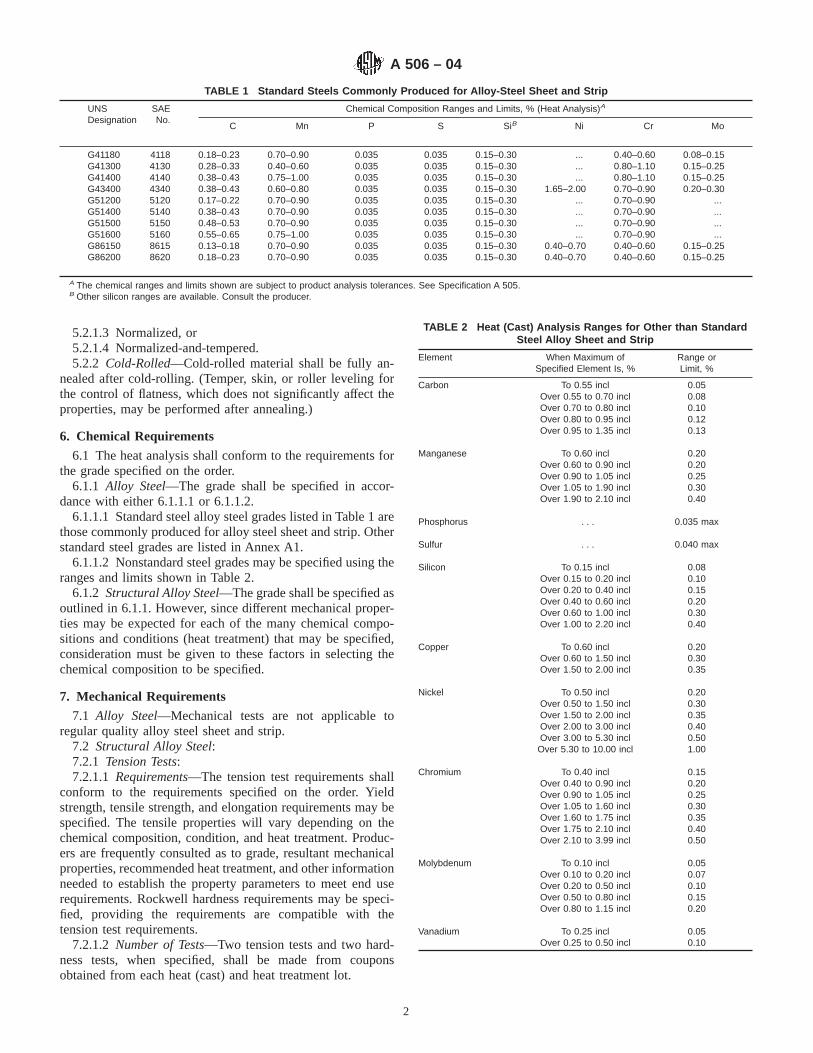
5.2.1.3 Normalized, or5.2.1.4 Normalized-and-tempered.5.2.2 Cold-Rolled—Cold-rolled material shall be fully an-
nealed after cold-rolling. (Temper, skin, or roller leveling forthe control of flatness, which does not significantly affect theproperties, may be performed after annealing.)
6. Chemical Requirements
6.1 The heat analysis shall conform to the requirements forthe grade specified on the order.
6.1.1 Alloy Steel—The grade shall be specified in accor-dance with either 6.1.1.1 or 6.1.1.2.
6.1.1.1 Standard steel alloy steel grades listed in Table 1 arethose commonly produced for alloy steel sheet and strip. Otherstandard steel grades are listed in Annex A1.
6.1.1.2 Nonstandard steel grades may be specified using theranges and limits shown in Table 2.
6.1.2 Structural Alloy Steel—The grade shall be specified asoutlined in 6.1.1. However, since different mechanical proper-ties may be expected for each of the many chemical compo-sitions and conditions (heat treatment) that may be specified,consideration must be given to these factors in selecting thechemical composition to be specified.
7. Mechanical Requirements
7.1 Alloy Steel—Mechanical tests are not applicable toregular quality alloy steel sheet and strip.
7.2 Structural Alloy Steel:7.2.1 Tension Tests:7.2.1.1 Requirements—The tension test requirements shall
conform to the requirements specified on the order. Yieldstrength, tensile strength, and elongation requirements may bespecified. The tensile properties will vary depending on thechemical composition, condition, and heat treatment. Produc-ers are frequently consulted as to grade, resultant mechanicalproperties, recommended heat treatment, and other informationneeded to establish the property parameters to meet end userequirements. Rockwell hardness requirements may be speci-fied, providing the requirements are compatible with thetension test requirements.
7.2.1.2 Number of Tests—Two tension tests and two hard-ness tests, when specified, shall be made from couponsobtained from each heat (cast) and heat treatment lot.
TABLE 1 Standard Steels Commonly Produced for Alloy-Steel Sheet and Strip
UNSDesignation
SAENo.
Chemical Composition Ranges and Limits, % (Heat Analysis)A
C Mn P S SiB Ni Cr Mo
G41180 4118 0.18–0.23 0.70–0.90 0.035 0.035 0.15–0.30 ... 0.40–0.60 0.08–0.15G41300 4130 0.28–0.33 0.40–0.60 0.035 0.035 0.15–0.30 ... 0.80–1.10 0.15–0.25G41400 4140 0.38–0.43 0.75–1.00 0.035 0.035 0.15–0.30 ... 0.80–1.10 0.15–0.25G43400 4340 0.38–0.43 0.60–0.80 0.035 0.035 0.15–0.30 1.65–2.00 0.70–0.90 0.20–0.30G51200 5120 0.17–0.22 0.70–0.90 0.035 0.035 0.15–0.30 ... 0.70–0.90 ...G51400 5140 0.38–0.43 0.70–0.90 0.035 0.035 0.15–0.30 ... 0.70–0.90 ...G51500 5150 0.48–0.53 0.70–0.90 0.035 0.035 0.15–0.30 ... 0.70–0.90 ...G51600 5160 0.55–0.65 0.75–1.00 0.035 0.035 0.15–0.30 ... 0.70–0.90 ...G86150G86200
86158620
0.13–0.180.18–0.23
0.70–0.900.70–0.90
0.0350.035
0.0350.035
0.15–0.300.15–0.30
0.40–0.700.40–0.70
0.40–0.600.40–0.60
0.15–0.250.15–0.25
A The chemical ranges and limits shown are subject to product analysis tolerances. See Specification A 505.B Other silicon ranges are available. Consult the producer.
TABLE 2 Heat (Cast) Analysis Ranges for Other than StandardSteel Alloy Sheet and Strip
Element When Maximum ofSpecified Element Is, %
Range orLimit, %
Carbon To 0.55 incl 0.05Over 0.55 to 0.70 incl 0.08Over 0.70 to 0.80 incl 0.10Over 0.80 to 0.95 incl 0.12Over 0.95 to 1.35 incl 0.13
Manganese To 0.60 incl 0.20Over 0.60 to 0.90 incl 0.20Over 0.90 to 1.05 incl 0.25Over 1.05 to 1.90 incl 0.30Over 1.90 to 2.10 incl 0.40
Phosphorus . . . 0.035 max
Sulfur . . . 0.040 max
Silicon To 0.15 incl 0.08Over 0.15 to 0.20 incl 0.10Over 0.20 to 0.40 incl 0.15Over 0.40 to 0.60 incl 0.20Over 0.60 to 1.00 incl 0.30Over 1.00 to 2.20 incl 0.40
Copper To 0.60 inclOver 0.60 to 1.50 inclOver 1.50 to 2.00 incl
0.200.300.35
Nickel To 0.50 incl 0.20Over 0.50 to 1.50 incl 0.30Over 1.50 to 2.00 incl 0.35Over 2.00 to 3.00 incl 0.40Over 3.00 to 5.30 incl 0.50Over 5.30 to 10.00 incl 1.00
Chromium To 0.40 incl 0.15Over 0.40 to 0.90 incl 0.20Over 0.90 to 1.05 incl 0.25Over 1.05 to 1.60 incl 0.30Over 1.60 to 1.75 incl 0.35Over 1.75 to 2.10 incl 0.40Over 2.10 to 3.99 incl 0.50
Molybdenum To 0.10 incl 0.05Over 0.10 to 0.20 incl 0.07Over 0.20 to 0.50 incl 0.10Over 0.50 to 0.80 incl 0.15Over 0.80 to 1.15 incl 0.20
Vanadium To 0.25 inclOver 0.25 to 0.50 incl
0.050.10
A 506 – 04
2
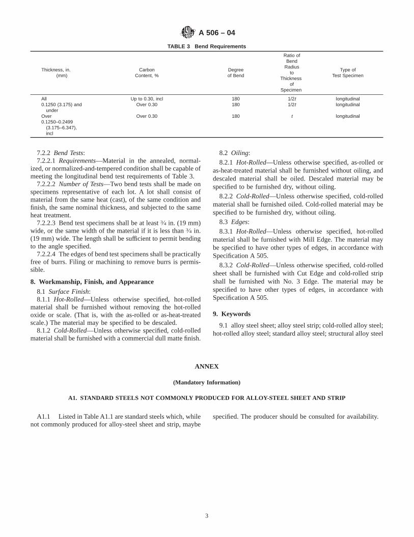
7.2.2 Bend Tests:7.2.2.1 Requirements—Material in the annealed, normal-
ized, or normalized-and-tempered condition shall be capable ofmeeting the longitudinal bend test requirements of Table 3.
7.2.2.2 Number of Tests—Two bend tests shall be made onspecimens representative of each lot. A lot shall consist ofmaterial from the same heat (cast), of the same condition andfinish, the same nominal thickness, and subjected to the sameheat treatment.
7.2.2.3 Bend test specimens shall be at least3⁄4 in. (19 mm)wide, or the same width of the material if it is less than3⁄4 in.(19 mm) wide. The length shall be sufficient to permit bendingto the angle specified.
7.2.2.4 The edges of bend test specimens shall be practicallyfree of burrs. Filing or machining to remove burrs is permis-sible.
8. Workmanship, Finish, and Appearance
8.1 Surface Finish:8.1.1 Hot-Rolled—Unless otherwise specified, hot-rolled
material shall be furnished without removing the hot-rolledoxide or scale. (That is, with the as-rolled or as-heat-treatedscale.) The material may be specified to be descaled.
8.1.2 Cold-Rolled—Unless otherwise specified, cold-rolledmaterial shall be furnished with a commercial dull matte finish.
8.2 Oiling:
8.2.1 Hot-Rolled—Unless otherwise specified, as-rolled oras-heat-treated material shall be furnished without oiling, anddescaled material shall be oiled. Descaled material may bespecified to be furnished dry, without oiling.
8.2.2 Cold-Rolled—Unless otherwise specified, cold-rolledmaterial shall be furnished oiled. Cold-rolled material may bespecified to be furnished dry, without oiling.
8.3 Edges:
8.3.1 Hot-Rolled—Unless otherwise specified, hot-rolledmaterial shall be furnished with Mill Edge. The material maybe specified to have other types of edges, in accordance withSpecification A 505.
8.3.2 Cold-Rolled—Unless otherwise specified, cold-rolledsheet shall be furnished with Cut Edge and cold-rolled stripshall be furnished with No. 3 Edge. The material may bespecified to have other types of edges, in accordance withSpecification A 505.
9. Keywords
9.1 alloy steel sheet; alloy steel strip; cold-rolled alloy steel;hot-rolled alloy steel; standard alloy steel; structural alloy steel
ANNEX
(Mandatory Information)
A1. STANDARD STEELS NOT COMMONLY PRODUCED FOR ALLOY-STEEL SHEET AND STRIP
A1.1 Listed in Table A1.1 are standard steels which, whilenot commonly produced for alloy-steel sheet and strip, maybe
specified. The producer should be consulted for availability.
TABLE 3 Bend Requirements
Thickness, in.(mm)
CarbonContent, %
Degreeof Bend
Ratio ofBend
Radiusto
Thicknessof
Specimen
Type ofTest Specimen
All Up to 0.30, incl 180 1/2t longitudinal0.1250 (3.175) and
underOver 0.30 180 1/2t longitudinal
Over0.1250–0.2499
(3.175–6.347),incl
Over 0.30 180 t longitudinal
A 506 – 04
3
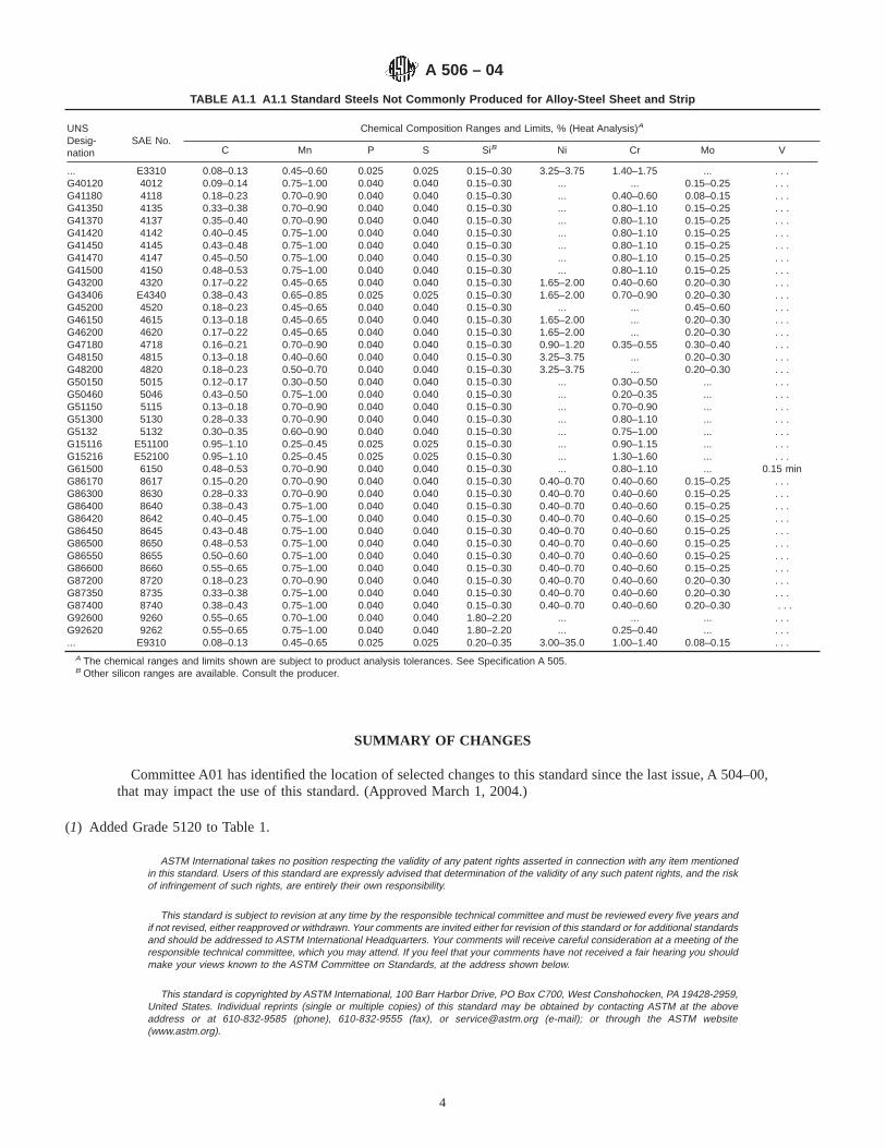
SUMMARY OF CHANGES
Committee A01 has identified the location of selected changes to this standard since the last issue, A 504–00,that may impact the use of this standard. (Approved March 1, 2004.)
(1) Added Grade 5120 to Table 1.
ASTM International takes no position respecting the validity of any patent rights asserted in connection with any item mentionedin this standard. Users of this standard are expressly advised that determination of the validity of any such patent rights, and the riskof infringement of such rights, are entirely their own responsibility.
This standard is subject to revision at any time by the responsible technical committee and must be reviewed every five years andif not revised, either reapproved or withdrawn. Your comments are invited either for revision of this standard or for additional standardsand should be addressed to ASTM International Headquarters. Your comments will receive careful consideration at a meeting of theresponsible technical committee, which you may attend. If you feel that your comments have not received a fair hearing you shouldmake your views known to the ASTM Committee on Standards, at the address shown below.
This standard is copyrighted by ASTM International, 100 Barr Harbor Drive, PO Box C700, West Conshohocken, PA 19428-2959,United States. Individual reprints (single or multiple copies) of this standard may be obtained by contacting ASTM at the aboveaddress or at 610-832-9585 (phone), 610-832-9555 (fax), or [email protected] (e-mail); or through the ASTM website(www.astm.org).
TABLE A1.1 A1.1 Standard Steels Not Commonly Produced for Alloy-Steel Sheet and Strip
UNSDesig-nation
SAE No.Chemical Composition Ranges and Limits, % (Heat Analysis)A
C Mn P S SiB Ni Cr Mo V
... E3310 0.08–0.13 0.45–0.60 0.025 0.025 0.15–0.30 3.25–3.75 1.40–1.75 ... . . .G40120 4012 0.09–0.14 0.75–1.00 0.040 0.040 0.15–0.30 ... ... 0.15–0.25 . . .G41180 4118 0.18–0.23 0.70–0.90 0.040 0.040 0.15–0.30 ... 0.40–0.60 0.08–0.15 . . .G41350 4135 0.33–0.38 0.70–0.90 0.040 0.040 0.15–0.30 ... 0.80–1.10 0.15–0.25 . . .G41370 4137 0.35–0.40 0.70–0.90 0.040 0.040 0.15–0.30 ... 0.80–1.10 0.15–0.25 . . .G41420 4142 0.40–0.45 0.75–1.00 0.040 0.040 0.15–0.30 ... 0.80–1.10 0.15–0.25 . . .G41450 4145 0.43–0.48 0.75–1.00 0.040 0.040 0.15–0.30 ... 0.80–1.10 0.15–0.25 . . .G41470 4147 0.45–0.50 0.75–1.00 0.040 0.040 0.15–0.30 ... 0.80–1.10 0.15–0.25 . . .G41500 4150 0.48–0.53 0.75–1.00 0.040 0.040 0.15–0.30 ... 0.80–1.10 0.15–0.25 . . .G43200 4320 0.17–0.22 0.45–0.65 0.040 0.040 0.15–0.30 1.65–2.00 0.40–0.60 0.20–0.30 . . .G43406 E4340 0.38–0.43 0.65–0.85 0.025 0.025 0.15–0.30 1.65–2.00 0.70–0.90 0.20–0.30 . . .G45200 4520 0.18–0.23 0.45–0.65 0.040 0.040 0.15–0.30 ... ... 0.45–0.60 . . .G46150 4615 0.13–0.18 0.45–0.65 0.040 0.040 0.15–0.30 1.65–2.00 ... 0.20–0.30 . . .G46200 4620 0.17–0.22 0.45–0.65 0.040 0.040 0.15–0.30 1.65–2.00 ... 0.20–0.30 . . .G47180 4718 0.16–0.21 0.70–0.90 0.040 0.040 0.15–0.30 0.90–1.20 0.35–0.55 0.30–0.40 . . .G48150 4815 0.13–0.18 0.40–0.60 0.040 0.040 0.15–0.30 3.25–3.75 ... 0.20–0.30 . . .G48200 4820 0.18–0.23 0.50–0.70 0.040 0.040 0.15–0.30 3.25–3.75 ... 0.20–0.30 . . .G50150 5015 0.12–0.17 0.30–0.50 0.040 0.040 0.15–0.30 ... 0.30–0.50 ... . . .G50460 5046 0.43–0.50 0.75–1.00 0.040 0.040 0.15–0.30 ... 0.20–0.35 ... . . .G51150 5115 0.13–0.18 0.70–0.90 0.040 0.040 0.15–0.30 ... 0.70–0.90 ... . . .G51300 5130 0.28–0.33 0.70–0.90 0.040 0.040 0.15–0.30 ... 0.80–1.10 ... . . .G5132 5132 0.30–0.35 0.60–0.90 0.040 0.040 0.15–0.30 ... 0.75–1.00 ... . . .G15116 E51100 0.95–1.10 0.25–0.45 0.025 0.025 0.15–0.30 ... 0.90–1.15 ... . . .G15216 E52100 0.95–1.10 0.25–0.45 0.025 0.025 0.15–0.30 ... 1.30–1.60 ... . . .G61500 6150 0.48–0.53 0.70–0.90 0.040 0.040 0.15–0.30 ... 0.80–1.10 ... 0.15 minG86170 8617 0.15–0.20 0.70–0.90 0.040 0.040 0.15–0.30 0.40–0.70 0.40–0.60 0.15–0.25 . . .G86300 8630 0.28–0.33 0.70–0.90 0.040 0.040 0.15–0.30 0.40–0.70 0.40–0.60 0.15–0.25 . . .G86400 8640 0.38–0.43 0.75–1.00 0.040 0.040 0.15–0.30 0.40–0.70 0.40–0.60 0.15–0.25 . . .G86420 8642 0.40–0.45 0.75–1.00 0.040 0.040 0.15–0.30 0.40–0.70 0.40–0.60 0.15–0.25 . . .G86450 8645 0.43–0.48 0.75–1.00 0.040 0.040 0.15–0.30 0.40–0.70 0.40–0.60 0.15–0.25 . . .G86500 8650 0.48–0.53 0.75–1.00 0.040 0.040 0.15–0.30 0.40–0.70 0.40–0.60 0.15–0.25 . . .G86550 8655 0.50–0.60 0.75–1.00 0.040 0.040 0.15–0.30 0.40–0.70 0.40–0.60 0.15–0.25 . . .G86600 8660 0.55–0.65 0.75–1.00 0.040 0.040 0.15–0.30 0.40–0.70 0.40–0.60 0.15–0.25 . . .G87200 8720 0.18–0.23 0.70–0.90 0.040 0.040 0.15–0.30 0.40–0.70 0.40–0.60 0.20–0.30 . . .G87350 8735 0.33–0.38 0.75–1.00 0.040 0.040 0.15–0.30 0.40–0.70 0.40–0.60 0.20–0.30 . . .G87400 8740 0.38–0.43 0.75–1.00 0.040 0.040 0.15–0.30 0.40–0.70 0.40–0.60 0.20–0.30 . . .G92600 9260 0.55–0.65 0.70–1.00 0.040 0.040 1.80–2.20 ... ... ... . . .G92620 9262 0.55–0.65 0.75–1.00 0.040 0.040 1.80–2.20 ... 0.25–0.40 ... . . .... E9310 0.08–0.13 0.45–0.65 0.025 0.025 0.20–0.35 3.00–35.0 1.00–1.40 0.08–0.15 . . .
A The chemical ranges and limits shown are subject to product analysis tolerances. See Specification A 505.B Other silicon ranges are available. Consult the producer.
A 506 – 04
4

Designation: A 507 – 04
Standard Specification forDrawing Alloy Steel, Sheet and Strip, Hot-Rolled and Cold-Rolled 1
This standard is issued under the fixed designation A 507; the number immediately following the designation indicates the year oforiginal adoption or, in the case of revision, the year of last revision. A number in parentheses indicates the year of last reapproval. Asuperscript epsilon (e) indicates an editorial change since the last revision or reapproval.
This standard has been approved for use by agencies of the Department of Defense.
1. Scope*
1.1 This specification covers hot-rolled and cold-rolleddrawing alloy-steel sheet and strip. Material of this quality isproduced principally for applications involving severe coldplastic deformation such as deep drawn or severely formedparts. This steel is produced by a closely controlled steel-making practice designed to assure internal soundness, relativeuniformity of chemical composition, and freedom from injuri-ous imperfections.
1.2 The material covered by this specification may befurnished in several conditions, heat treatments, surface fin-ishes, and edges, as specified herein, in coils or cut lengths.
2. Referenced Documents
2.1 ASTM Standards:2
A 505 Specification for Steel, Sheet and Strip, Alloy, Hot-Rolled and Cold-Rolled, General Requirements for
A 941 Terminology Relating to Steel, Stainless Steel, Re-lated Alloys, and Ferroalloys
3. Terminology
3.1 Definitions of Terms Specific to This Standard:3.1.1 capable of—as used in this specification, means that
tests need not be performed. However, if application by thepurchaser establishes that the material does not meet therequirements, the material shall be subject to rejection.
3.1.2 drawing alloy steel—alloy-steel sheet and strip in-tended for applications involving severe cold plastic deforma-tion such as deep drawn or severely formed parts.
3.1.3 standard steels—steel chemical compositions definedas “standard” by the Society of Automotive Engineers (SAE).See Table 1 and Table A1.1.
3.1.4 steels other than standard—steel chemical composi-tions other than those defined as “standard,” and furnished tothe composition limits shown in Table 2.
4. General Requirements and Ordering Information
4.1 Material supplied to this specification shall conform toSpecification A 505, which includes the general requirementsand establishes the rules for the ordering information thatshould be complied with when purchasing material to thisspecification.
4.2 In addition to the Ordering Information required bySpecification A 505, the following shall also be included:
4.2.1 Mechanical properties, if required (show propertiesdesired, which must be consistent with the grade and heattreatment),
4.2.2 Surface finish, if other than that normally furnished(see Section 10), and
4.2.3 Application, or end use (identification of the part to bemade).
5. Manufacture
5.1 Rolling—The material shall be furnished either hot-rolled or cold-rolled, as specified on the order.
5.2 Heat Treatment—Unless otherwise specified on theorder, the material shall be furnished spheroidize-annealed.(See Terminology A 941 for heat treatment terms.)
5.2.1 If the material is to be heat treated by other than theproducer, the order shall so state. The material may be orderedin the as-rolled condition, in such cases.
6. Chemical Requirements
6.1 The heat (cast) analysis shall conform to the require-ments for the grade specified on the order.
6.1.1 Standard steel alloy steel grades listed in Table 1 arethose commonly produced for drawing alloy-steel sheet andstrip.
1 This specification is under the jurisdiction of ASTM Committee A01 on Steel,Stainless Steel and Related Alloys and is the direct responsibility of SubcommitteeA01.19 on Steel Sheet and Strip.
Current edition approved March 1, 2004. Published March 2004. Originallyapproved in 1964. Last previous edition approved in 2000 as A 507 – 00.
2 For referenced ASTM standards, visit the ASTM website, www.astm.org, orcontact ASTM Customer Service at [email protected]. ForAnnual Book of ASTMStandardsvolume information, refer to the standard’s Document Summary page onthe ASTM website.
1
*A Summary of Changes section appears at the end of this standard.
Copyright © ASTM International, 100 Barr Harbor Drive, PO Box C700, West Conshohocken, PA 19428-2959, United States.
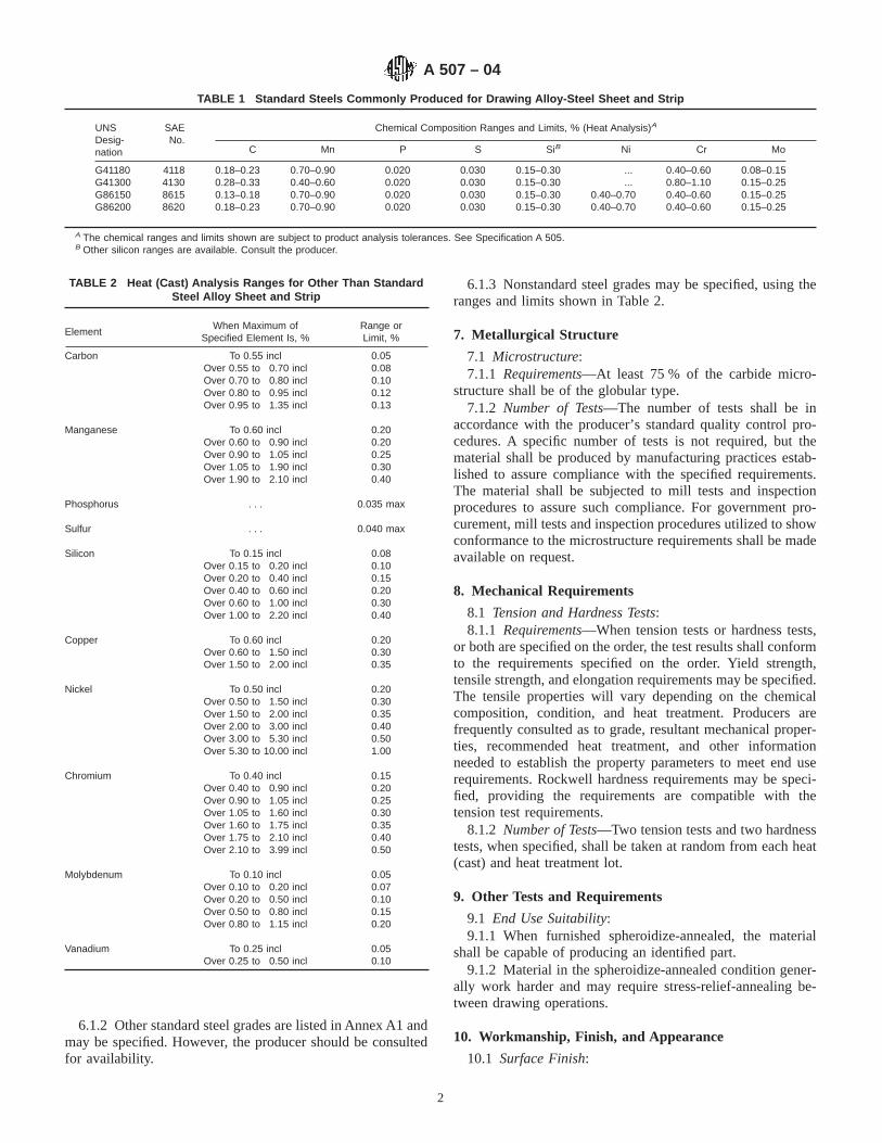
6.1.2 Other standard steel grades are listed in Annex A1 andmay be specified. However, the producer should be consultedfor availability.
6.1.3 Nonstandard steel grades may be specified, using theranges and limits shown in Table 2.
7. Metallurgical Structure
7.1 Microstructure:7.1.1 Requirements—At least 75 % of the carbide micro-
structure shall be of the globular type.7.1.2 Number of Tests—The number of tests shall be in
accordance with the producer’s standard quality control pro-cedures. A specific number of tests is not required, but thematerial shall be produced by manufacturing practices estab-lished to assure compliance with the specified requirements.The material shall be subjected to mill tests and inspectionprocedures to assure such compliance. For government pro-curement, mill tests and inspection procedures utilized to showconformance to the microstructure requirements shall be madeavailable on request.
8. Mechanical Requirements
8.1 Tension and Hardness Tests:8.1.1 Requirements—When tension tests or hardness tests,
or both are specified on the order, the test results shall conformto the requirements specified on the order. Yield strength,tensile strength, and elongation requirements may be specified.The tensile properties will vary depending on the chemicalcomposition, condition, and heat treatment. Producers arefrequently consulted as to grade, resultant mechanical proper-ties, recommended heat treatment, and other informationneeded to establish the property parameters to meet end userequirements. Rockwell hardness requirements may be speci-fied, providing the requirements are compatible with thetension test requirements.
8.1.2 Number of Tests—Two tension tests and two hardnesstests, when specified, shall be taken at random from each heat(cast) and heat treatment lot.
9. Other Tests and Requirements
9.1 End Use Suitability:9.1.1 When furnished spheroidize-annealed, the material
shall be capable of producing an identified part.9.1.2 Material in the spheroidize-annealed condition gener-
ally work harder and may require stress-relief-annealing be-tween drawing operations.
10. Workmanship, Finish, and Appearance
10.1 Surface Finish:
TABLE 1 Standard Steels Commonly Produced for Drawing Alloy-Steel Sheet and Strip
UNSDesig-nation
SAENo.
Chemical Composition Ranges and Limits, % (Heat Analysis)A
C Mn P S SiB Ni Cr Mo
G41180G41300
41184130
0.18–0.230.28–0.33
0.70–0.900.40–0.60
0.0200.020
0.0300.030
0.15–0.300.15–0.30
...
...0.40–0.600.80–1.10
0.08–0.150.15–0.25
G86150G86200
86158620
0.13–0.180.18–0.23
0.70–0.900.70–0.90
0.0200.020
0.0300.030
0.15–0.300.15–0.30
0.40–0.700.40–0.70
0.40–0.600.40–0.60
0.15–0.250.15–0.25
A The chemical ranges and limits shown are subject to product analysis tolerances. See Specification A 505.B Other silicon ranges are available. Consult the producer.
TABLE 2 Heat (Cast) Analysis Ranges for Other Than StandardSteel Alloy Sheet and Strip
ElementWhen Maximum of
Specified Element Is, %Range orLimit, %
Carbon To 0.55 incl 0.05Over 0.55 to 0.70 incl 0.08Over 0.70 to 0.80 incl 0.10Over 0.80 to 0.95 incl 0.12Over 0.95 to 1.35 incl 0.13
Manganese To 0.60 incl 0.20Over 0.60 to 0.90 incl 0.20Over 0.90 to 1.05 incl 0.25Over 1.05 to 1.90 incl 0.30Over 1.90 to 2.10 incl 0.40
Phosphorus . . . 0.035 max
Sulfur . . . 0.040 max
Silicon To 0.15 incl 0.08Over 0.15 to 0.20 incl 0.10Over 0.20 to 0.40 incl 0.15Over 0.40 to 0.60 incl 0.20Over 0.60 to 1.00 incl 0.30Over 1.00 to 2.20 incl 0.40
Copper To 0.60 inclOver 0.60 to 1.50 inclOver 1.50 to 2.00 incl
0.200.300.35
Nickel To 0.50 incl 0.20Over 0.50 to 1.50 incl 0.30Over 1.50 to 2.00 incl 0.35Over 2.00 to 3.00 incl 0.40Over 3.00 to 5.30 incl 0.50Over 5.30 to 10.00 incl 1.00
Chromium To 0.40 incl 0.15Over 0.40 to 0.90 incl 0.20Over 0.90 to 1.05 incl 0.25Over 1.05 to 1.60 incl 0.30Over 1.60 to 1.75 incl 0.35Over 1.75 to 2.10 incl 0.40Over 2.10 to 3.99 incl 0.50
Molybdenum To 0.10 incl 0.05Over 0.10 to 0.20 incl 0.07Over 0.20 to 0.50 incl 0.10Over 0.50 to 0.80 incl 0.15Over 0.80 to 1.15 incl 0.20
Vanadium To 0.25 inclOver 0.25 to 0.50 incl
0.050.10
A 507 – 04
2
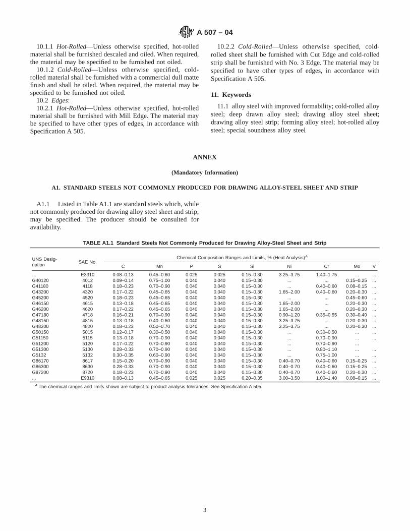
10.1.1 Hot-Rolled—Unless otherwise specified, hot-rolledmaterial shall be furnished descaled and oiled. When required,the material may be specified to be furnished not oiled.
10.1.2 Cold-Rolled—Unless otherwise specified, cold-rolled material shall be furnished with a commercial dull mattefinish and shall be oiled. When required, the material may bespecified to be furnished not oiled.
10.2 Edges:10.2.1 Hot-Rolled—Unless otherwise specified, hot-rolled
material shall be furnished with Mill Edge. The material maybe specified to have other types of edges, in accordance withSpecification A 505.
10.2.2 Cold-Rolled—Unless otherwise specified, cold-rolled sheet shall be furnished with Cut Edge and cold-rolledstrip shall be furnished with No. 3 Edge. The material may bespecified to have other types of edges, in accordance withSpecification A 505.
11. Keywords
11.1 alloy steel with improved formability; cold-rolled alloysteel; deep drawn alloy steel; drawing alloy steel sheet;drawing alloy steel strip; forming alloy steel; hot-rolled alloysteel; special soundness alloy steel
ANNEX
(Mandatory Information)
A1. STANDARD STEELS NOT COMMONLY PRODUCED FOR DRAWING ALLOY-STEEL SHEET AND STRIP
A1.1 Listed in Table A1.1 are standard steels which, whilenot commonly produced for drawing alloy steel sheet and strip,may be specified. The producer should be consulted foravailability.
TABLE A1.1 Standard Steels Not Commonly Produced for Drawing Alloy-Steel Sheet and Strip
UNS Desig-nation
SAE No.Chemical Composition Ranges and Limits, % (Heat Analysis)A
C Mn P S Si Ni Cr Mo V
... E3310 0.08–0.13 0.45–0.60 0.025 0.025 0.15–0.30 3.25–3.75 1.40–1.75 ... ...G40120 4012 0.09–0.14 0.75–1.00 0.040 0.040 0.15–0.30 ... ... 0.15–0.25 ...G41180 4118 0.18–0.23 0.70–0.90 0.040 0.040 0.15–0.30 ... 0.40–0.60 0.08–0.15 ...G43200 4320 0.17–0.22 0.45–0.65 0.040 0.040 0.15–0.30 1.65–2.00 0.40–0.60 0.20–0.30 ...G45200 4520 0.18–0.23 0.45–0.65 0.040 0.040 0.15–0.30 ... ... 0.45–0.60 ...G46150 4615 0.13–0.18 0.45–0.65 0.040 0.040 0.15–0.30 1.65–2.00 ... 0.20–0.30 ...G46200 4620 0.17–0.22 0.45–0.65 0.040 0.040 0.15–0.30 1.65–2.00 ... 0.20–0.30 ...G47180 4718 0.16–0.21 0.70–0.90 0.040 0.040 0.15–0.30 0.90–1.20 0.35–0.55 0.30–0.40 ...G48150 4815 0.13–0.18 0.40–0.60 0.040 0.040 0.15–0.30 3.25–3.75 ... 0.20–0.30 ...G48200 4820 0.18–0.23 0.50–0.70 0.040 0.040 0.15–0.30 3.25–3.75 ... 0.20–0.30 ...G50150 5015 0.12–0.17 0.30–0.50 0.040 0.040 0.15–0.30 ... 0.30–0.50 ... ...G51150 5115 0.13–0.18 0.70–0.90 0.040 0.040 0.15–0.30 ... 0.70–0.90 ... ...G51200 5120 0.17–0.22 0.70–0.90 0.040 0.040 0.15–0.30 ... 0.70–0.90 ...G51300 5130 0.28–0.33 0.70–0.90 0.040 0.040 0.15–0.30 ... 0.80–1.10 ... ...G5132 5132 0.30–0.35 0.60–0.90 0.040 0.040 0.15–0.30 ... 0.75–1.00 ... ...G86170 8617 0.15–0.20 0.70–0.90 0.040 0.040 0.15–0.30 0.40–0.70 0.40–0.60 0.15–0.25 ...G86300 8630 0.28–0.33 0.70–0.90 0.040 0.040 0.15–0.30 0.40–0.70 0.40–0.60 0.15–0.25 ...G87200 8720 0.18–0.23 0.70–0.90 0.040 0.040 0.15–0.30 0.40–0.70 0.40–0.60 0.20–0.30 ...... E9310 0.08–0.13 0.45–0.65 0.025 0.025 0.20–0.35 3.00–3.50 1.00–1.40 0.08–0.15 ...
A The chemical ranges and limits shown are subject to product analysis tolerances. See Specification A 505.
A 507 – 04
3

SUMMARY OF CHANGES
Committee A01 has identified the location of selected changes to this standard since the last issue, A 507–00,that may impact the use of this standard. (Approved March 1, 2004.)
(1) Added Grade 5120 to Table A1.1.
ASTM International takes no position respecting the validity of any patent rights asserted in connection with any item mentionedin this standard. Users of this standard are expressly advised that determination of the validity of any such patent rights, and the riskof infringement of such rights, are entirely their own responsibility.
This standard is subject to revision at any time by the responsible technical committee and must be reviewed every five years andif not revised, either reapproved or withdrawn. Your comments are invited either for revision of this standard or for additional standardsand should be addressed to ASTM International Headquarters. Your comments will receive careful consideration at a meeting of theresponsible technical committee, which you may attend. If you feel that your comments have not received a fair hearing you shouldmake your views known to the ASTM Committee on Standards, at the address shown below.
This standard is copyrighted by ASTM International, 100 Barr Harbor Drive, PO Box C700, West Conshohocken, PA 19428-2959,United States. Individual reprints (single or multiple copies) of this standard may be obtained by contacting ASTM at the aboveaddress or at 610-832-9585 (phone), 610-832-9555 (fax), or [email protected] (e-mail); or through the ASTM website(www.astm.org).
A 507 – 04
4

Designation: A 510 – 03
Standard Specification forGeneral Requirements for Wire Rods and Coarse RoundWire, Carbon Steel 1
This standard is issued under the fixed designation A 510; the number immediately following the designation indicates the year oforiginal adoption or, in the case of revision, the year of last revision. A number in parentheses indicates the year of last reapproval. Asuperscript epsilon (e) indicates an editorial change since the last revision or reapproval.
This standard has been approved for use by agencies of the Department of Defense.
1. Scope*
1.1 This specification covers general requirements for car-bon steel wire rods and uncoated coarse round wire in coils orstraightened and cut lengths.
1.2 In case of conflict, the requirements in the purchaseorder, on the drawing, in the individual specification, and inthis general specification shall prevail in the sequence named.
NOTE 1—A complete metric companion to Specification A 510 hasbeen developed—Specification A 510M; therefore, no metric equivalentsare presented in this specification.
2. Referenced Documents
2.1 ASTM Standards:A 370 Test Methods and Definitions for Mechanical Testing
of Steel Products2
A 700 Practices for Packaging, Marking, and LoadingMethods for Steel Products for Domestic Shipment3
A 751 Test Methods, Practices, and Terminology forChemical Analysis of Steel Products2
E 29 Practice for Using Significant Digits in Test Data toDetermine Conformance with Specifications4
E 30 Test Methods for Chemical Analysis of Steel, CastIron, Open-Hearth Iron, and Wrought Iron5
E 112 Test Methods for Determining Average Grain Size6
E 527 Practice for Numbering Metals and Alloys (UNS)7
2.2 SAE Standard:J 1086 Numbering Metals and Alloy8
2.3 AIAG Standard:
AIAGB-5 02.00 Primary Metals Identification Tag Applica-tion Standard9
3. Terminology
3.1 Definitions of Terms Specific to This Standard:3.1.1 carbon steel—steel in which no minimum content is
specified or required for aluminum, chromium, cobalt, colum-bium, molybdenum, nickel, titanium, tungsten, vanadium, orzirconium, or any other element added to obtain a desiredalloying effect; when the specified minimum for copper doesnot exceed 0.40 %; or when the maximum content specified forany of the following elements does not exceed these percent-ages: manganese 1.65, silicon 0.60, or copper 0.60.
3.1.2 Discussion—In all carbon steels small quantities ofcertain residual elements unavoidably retained from raw ma-terials are sometimes found that are not specified or required,such as copper, nickel, molybdenum, chromium, etc. Theseelements are considered as incidental and are not formallydetermined or reported.
—Elements may be specified to improve machinability ofcarbon steels such as sulfur and lead.
3.1.4 coarse round wire—from 0.035 to 0.999 in. in diam-eter, inclusive, wire that is produced from hot-rolled wire rodsor hot-rolled coiled bars by one or more cold reductionsprimarily for the purpose of obtaining a desired size withdimensional accuracy, surface finish, and mechanical proper-ties. By varying the amount of cold reduction and other wiremill practices, including thermal treatment, a wide diversity ofmechanical properties and finishes are made available.
3.1.5 Discussion—Coarse round wire is designated by SteelWire Gage numbers, common fractions, or decimal parts of aninch. The Steel Wire Gage system is shown in Table 1. Sincethe many gage systems in use may cause confusion, thepurchaser is encouraged to specify wire diameters in inches ordecimal parts, or both.
1 This specification is under the jurisdiction of ASTM Committee A01 on Steel,Stainless Steel and Related Alloys and is the direct responsibility of SubcommitteeA01.03 on Steel Rod and Wire.
Current edition approved Sept. 10, 2003. Published Sept. 2003. Originallyapproved in 1964. Last previous edition approved in 2002 as A 510 – 02.
2 Annual Book of ASTM Standards, Vol 01.03.3 Annual Book of ASTM Standards, Vol 01.05.4 Annual Book of ASTM Standards, Vol 14.02.5 Discontinued—See 1994Annual Book of ASTM Standards, Vol 03.05.6 Annual Book of ASTM Standards, Vol 03.01.7 Annual Book of ASTM Standards, Vol 01.01.8 Available from Society of Automotive Engineers (SAE), 400 Commonwealth
Dr., Warrendale, PA 15096-0001.
9 Available from Automotive Industry Action Group (AIAG), 26200 Lahser Rd.,Suite 200, Southfield, MI 48034.
1
*A Summary of Changes section appears at the end of this standard.
Copyright © ASTM International, 100 Barr Harbor Drive, PO Box C700, West Conshohocken, PA 19428-2959, United States.
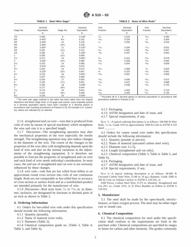
3.1.6 straightened and cut wire—wire that is produced fromcoils of wire by means of special machinery which straightensthe wire and cuts it to a specified length.
3.1.7 Discussion—The straightening operation may alterthe mechanical properties of the wire especially the tensilestrength. The straightening operation may also induce changesin the diameter of the wire. The extent of the changes in theproperties of the wire after cold straightening depends upon thekind of wire and also on the normal variations in the adjust-ments of the straightening equipment. It is therefore notpossible to forecast the properties of straightened and cut wireand each kind of wire needs individual consideration. In mostcases, the end use of straightened and cut wire is not seriouslyinfluenced by these changes.
3.1.8 wire rods—rods that are hot rolled from billets to anapproximate round cross section into coils of one continuouslength. Rods are not comparable to hot-rolled bars in accuracyof cross section or surface finish and as a semifinished productare intended primarily for the manufacture of wire.
3.1.9 Discussion—Rod sizes from7⁄32 to 47⁄64 in. in diam-eter, inclusive, are designated by fractions or decimal parts ofan inch as shown in Table 2.
4. Ordering Information
4.1 Orders for hot-rolled wire rods under this specificationshould include the following information:
4.1.1 Quantity (pounds),4.1.2 Name of material (wire rods),4.1.3 Diameter (Table 2),4.1.4 Chemical composition grade no. (Table 3, Table 4,
Table 5, and Table 6),
4.1.5 Packaging,4.1.6 ASTM designation and date of issue, and4.1.7 Special requirements, if any.
NOTE 2—A typical ordering description is as follows: 100 000 lb WireRods,7⁄32 in., Grade 1010 in approximately 1000 lb Coils to ASTM A 510dated _______.
4.2 Orders for coarse round wire under this specificationshould include the following information:
4.2.1 Quantity (pounds or pieces),4.2.2 Name of material (uncoated carbon steel wire),4.2.3 Diameter (see 3.1.5),4.2.4 Length (straightened and cut only),4.2.5 Chemical composition (Table 3, Table 4, Table 5, and
Table 6),4.2.6 Packaging,4.2.7 ASTM designation and date of issue, and4.2.8 Special requirements, if any.
NOTE 3—A typical ordering description is as follows: 40 000 lbUncoated Carbon Steel Wire, 0.148 in. (9 ga.) diameter, Grade 1008 in500 lb Coils on Tubular Carriers to ASTM A 510-XX, or
2500 Pieces, Carbon Steel Wire, 0.375 in. diameter, Straightened andCut 291⁄2 in., Grade 1015, in 25 Piece Bundles on Pallets to ASTM A510-XX.
5. Manufacture
5.1 The steel shall be made by the open-hearth, electric-furnace, or basic-oxygen process. The steel may be either ingotcast or strand cast.
6. Chemical Composition
6.1 The chemical composition for steel under this specifi-cation shall conform to the requirements set forth in thepurchase order. Chemical compositions are specified by rangesor limits for carbon and other elements. The grades commonly
TABLE 1 Steel Wire Gage A
Gage No.Decimal
Equivalent,in.
Gage No.Decimal
Equivalent,in.
7/0 0.490 9 0.148*6/0 0.462* 91⁄2 0.1425/0 0.430* 10 0.1354/0 0.394* 101⁄2 0.1283/0 0.362* 11 0.120*2/0 0.331 111⁄2 0.1131/0 0.306 12 0.106*1 0.283 121⁄2 0.09911⁄2 0.272 13 0.092*2 0.262* 131⁄2 0.08621⁄2 0.253 14 0.0803 0.244* 141⁄2 0.07631⁄2 0.234 15 0.0724 0.225* 151⁄2 0.06741⁄2 0.216 16 0.062*5 0.207 161⁄2 0.05851⁄2 0.200 17 0.0546 0.192 171⁄2 0.05161⁄2 0.184 18 0.048*7 0.177 181⁄2 0.04471⁄2 0.170 19 0.0418 0.162 191⁄2 0.03881⁄2 0.155 20 0.035*
A The steel wire gage outlined in this table has been taken from the originalWashburn and Moen Gage chart. In 20 gage and coarser, sizes originally quotedto 4 decimal equivalent places have been rounded to 3 decimal places inaccordance with rounding procedures of Practice E 29. All rounded U.S. custom-ary values are indicated by an asterisk.
TABLE 2 Sizes of Wire Rods A
InchFraction
DecimalEquivalent,
in.
InchFraction
DecimalEquivalent,
in.
7⁄32 0.219 31⁄64 0.48415⁄64 0.234 1⁄2 0.5001⁄4 0.250 33⁄64 0.516
17⁄64 0.266 17⁄32 0.5319⁄32 0.281 35⁄64 0.54719⁄64 0.297 9⁄16 0.562
5⁄16 0.312 37⁄64 0.57821⁄64 0.328 19⁄32 0.59411⁄32 0.344 39⁄64 0.609
23⁄64 0.359 5⁄8 0.6253⁄8 0.375 41⁄64 0.64125⁄64 0.391 21⁄32 0.656
13⁄32 0.406 43⁄64 0.67227⁄64 0.422 11⁄16 0.6887⁄16 0.438 45⁄64 0.703
29⁄64
15⁄32
0.4530.469
23⁄32
47⁄64
0.7190.734
A Rounded off to 3 decimal places in decimal equivalents in accordance withprocedures outlined in Practice E 29.
A 510 – 03
2

TABLE 3 Nonresulfurized Carbon Steel Cast or Heat Chemical Ranges and Limits
NOTE 1—Silicon—When silicon is required the following ranges and limits are commonly used for nonresulfurized carbon steels: 0.10 max, %, 0.07to 0.15 %, 0.10 to 0.20 %, 0.15 to 0.35 %, 0.20 to 0.40 %, or 0.30 to 0.60 %.
NOTE 2—Copper—When required, copper is specified as an added element.NOTE 3—Lead—When lead is required as an added element, a range from 0.15 to 0.35 % is specified. Such a steel is identified by inserting the letter
“L’’ between the second and third numerals of the grade number, for example, 10L18.NOTE 4—Boron Addition to Improve Hardenability—Standard killed carbon steels, which are fine grain, may be produced with a boron addition to
improve hardenability and typically contain an intentional addition of .01 % minimum titanium. Such steels are produced to a range of 0.0005 to 0.003 %boron. These steels are identified by inserting the letter “B’’ between the second and third numerals of the grade number, for example, 10B46. The UNSdesignation is also modified by changing the last digit to “1” to indicate boron, for example, G 1046.1.
NOTE 5—Boron Additions to Control Strain-Ageing Behavior—Intentional additions of Boron to low carbon steels for the purpose of controllingstrain-ageing behavior during wire drawing is permissible only with the agreement of the purchaser. In such cases, the Boron content shall be reportedin either a material test report or certification.
NOTE 6—For steels that do not have intentional boron additions for hardenability or for control of strain aging behavior, the boron content will notnormally exceed .0008 %.
UNSDesignationA Grade No.
Chemical Composition Limits, %
SAE No.Carbon Manganese
Phosphorus,max
Sulfur, max
G 10050 1005 0.06 max 0.35 max 0.040 0.050 1005G 10060 1006 0.08 max 0.25 to 0.40 0.040 0.050 1006G 10080 1008 0.10 max 0.30 to 0.50 0.040 0.050 1008G 10100 1010 0.08 to 0.13 0.30 to 0.60 0.040 0.050 1010G 10110 1011 0.08 to 0.13 0.60 to 0.90 0.040 0.050 1011G 10120 1012 0.10 to 0.15 0.30 to 0.60 0.040 0.050 1012G 10130 1013 0.11 to 0.16 0.50 to 0.80 0.040 0.050 1013G 10150 1015 0.13 to 0.18 0.30 to 0.60 0.040 0.050 1015G 10160 1016 0.13 to 0.18 0.60 to 0.90 0.040 0.050 1016G 10170 1017 0.15 to 0.20 0.30 to 0.60 0.040 0.050 1017G 10180 1018 0.15 to 0.20 0.60 to 0.90 0.040 0.050 1018G 10190 1019 0.15 to 0.20 0.70 to 1.00 0.040 0.050 1019G 10200 1020 0.18 to 0.23 0.30 to 0.60 0.040 0.050 1020G 10210 1021 0.18 to 0.23 0.60 to 0.90 0.040 0.050 1021G 10220 1022 0.18 to 0.23 0.70 to 1.00 0.040 0.050 1022G 10230 1023 0.20 to 0.25 0.30 to 0.60 0.040 0.050 1023G 10250 1025 0.22 to 0.28 0.30 to 0.60 0.040 0.050 1025G 10260 1026 0.22 to 0.28 0.60 to 0.90 0.040 0.050 1026G 10290 1029 0.25 to 0.31 0.60 to 0.90 0.040 0.050 1029G 10300 1030 0.28 to 0.34 0.60 to 0.90 0.040 0.050 1030G 10340 1034 0.32 to 0.38 0.50 to 0.80 0.040 0.050 . . .G 10350 1035 0.32 to 0.38 0.60 to 0.90 0.040 0.050 1035G 10370 1037 0.32 to 0.38 0.70 to 1.00 0.040 0.050 1037G 10380 1038 0.35 to 0.42 0.60 to 0.90 0.040 0.050 1038G 10390 1039 0.37 to 0.44 0.70 to 1.00 0.040 0.050 1039G 10400 1040 0.37 to 0.44 0.60 to 0.90 0.040 0.050 1040G 10420 1042 0.40 to 0.47 0.60 to 0.90 0.040 0.050 1042G 10430 1043 0.40 to 0.47 0.70 to 1.00 0.040 0.050 1043G 10440 1044 0.43 to 0.50 0.30 to 0.60 0.040 0.050 1044G 10450 1045 0.43 to 0.50 0.60 to 0.90 0.040 0.050 1045G 10460 1046 0.43 to 0.50 0.70 to 1.00 0.040 0.050 1046G 10490 1049 0.46 to 0.53 0.60 to 0.90 0.040 0.050 1049G 10500 1050 0.48 to 0.55 0.60 to 0.90 0.040 0.050 1050G 10530 1053 0.48 to 0.55 0.70 to 1.00 0.040 0.050 1053G 10550 1055 0.50 to 0.60 0.60 to 0.90 0.040 0.050 1055G 10590 1059 0.55 to 0.65 0.50 to 0.80 0.040 0.050 1059G 10600 1060 0.55 to 0.65 0.60 to 0.90 0.040 0.050 1060G 10640 1064 0.60 to 0.70 0.50 to 0.80 0.040 0.050 1064G 10650 1065 0.60 to 0.70 0.60 to 0.90 0.040 0.050 1065G 10690 1069 0.65 to 0.75 0.40 to 0.70 0.040 0.050 1069G 10700 1070 0.65 to 0.75 0.60 to 0.90 0.040 0.050 1070G 10740 1074 0.70 to 0.80 0.50 to 0.80 0.040 0.050 1074G 10750 1075 0.70 to 0.80 0.40 to 0.70 0.040 0.050 1075G 10780 1078 0.72 to 0.85 0.30 to 0.60 0.040 0.050 1078G 10800 1080 0.75 to 0.88 0.60 to 0.90 0.040 0.050 1080G 10840 1084 0.80 to 0.93 0.60 to 0.90 0.040 0.050 1084G 10850 1085 0.80 to 0.93 0.70 to 1.00 0.040 0.050 1085G 10860 1086 0.80 to 0.93 0.30 to 0.50 0.040 0.050 1086G 10900 1090 0.85 to 0.98 0.60 to 0.90 0.040 0.050 1090G 10950 1095 0.90 to 1.03 0.30 to 0.50 0.040 0.050 1095
A Designation established in accordance with Practice E 527 and SAE J 1086.
A 510 – 03
3

specified for carbon steel wire rods and coarse round wire areshown in Table 3, Table 4, Table 5, and Table 6.
6.2 Cast or Heat Analysis(Formerly Ladle Analysis)—Ananalysis of each cast or heat shall be made by the producer todetermine the percentage of the elements specified. The analy-sis shall be made from a test sample, preferably taken duringthe pouring of the cast or heat. The chemical composition thusdetermined shall be reported, if required, to the purchaser, or
his representative. Reporting of significant figures and round-ing shall be in accordance with Test Methods, Practices, andTerminology A 751.
6.3 Product Analysis (Formerly Check Analysis)—A prod-uct analysis may be made by the purchaser. The analysis is notused for a duplicate analysis to confirm a previous result. Thepurpose of the product analysis is to verify that the chemical
TABLE 4 Nonresulfurized Carbon Steel, High Manganese, Cast or Heat Chemical Ranges and Limits
NOTE 1—Silicon—When silicon is required the following ranges and limits are commonly used for nonresulfurized carbon steels: 0.10 max, %, 0.07to 0.15 %, 0.10 to 0.20 %, 0.15 to 0.35 %, 0.20 to 0.40 %, or 0.30 to 0.60 %.
NOTE 2—Copper—When required, copper is specified as an added element.NOTE 3—Lead—When lead is required as an added element a range from 0.15 to 0.35 % is specified. Such a steel is identified by inserting the letter
“L’’ between the second and third numerals of the grade number, for example, 15L18.
UNS DesignationA Grade No.
Chemical Composition Limits, %
SAE No.Carbon Manganese
Phosphorus,max
Sulfur,max
G 15130 1513 0.10 to 0.16 1.10 to 1.40 0.040 0.050 1513G 15180 1518 0.15 to 0.21 1.10 to 1.40 0.040 0.050 1518G 15220 1522 0.18 to 0.24 1.10 to 1.40 0.040 0.050 1522G 15240 1524B 0.19 to 0.25 1.35 to 1.65 0.040 0.050 1524G 15250 1525 0.23 to 0.29 0.80 to 1.10 0.040 0.050 1525G 15260 1526 0.22 to 0.29 1.10 to 1.40 0.040 0.050 1526G 15270 1527B 0.22 to 0.29 1.20 to 1.50 0.040 0.050 1527G 15360 1536B 0.30 to 0.37 1.20 to 1.50 0.040 0.050 1536G 15410 1541B 0.36 to 0.44 1.35 to 1.65 0.040 0.050 1541G 15470 1547 0.43 to 0.51 1.35 to 1.65 0.040 0.050 1547G 15480 1548B 0.44 to 0.52 1.10 to 1.40 0.040 0.050 1548G 15510 1551B 0.45 to 0.56 0.85 to 1.15 0.040 0.050 1551G 15520 1552B 0.47 to 0.55 1.20 to 1.50 0.040 0.050 1552G 15610 1561B 0.55 to 0.65 0.75 to 1.05 0.040 0.050 1561G 15660 1566B 0.60 to 0.71 0.85 to 1.15 0.040 0.050 1566G 15720 1572B 0.65 to 0.76 1.00 to 1.30 0.040 0.050 1572
A Designation established in accordance with Practice E 527 and SAE J 1086.B These grades were formerly designated as 10XX steels.
TABLE 5 Resulfurized Carbon Steels, Cast or Heat Chemical Ranges and Limits
NOTE 1—Silicon—When silicon is required, the following ranges and limits are commonly used: Up to 1110, incl, 0.10 max, %; 1116 and over, 0.10max, %, 0.10 to 0.20 %, or 0.15 to 0.35 %.
NOTE 2—Because of the degree to which sulfur segregates, product analysis for sulfur in resulfurized carbon steel is not technologically appropriateunless misapplication is clearly indicated.
UNS DesignationA Grade No.
Chemical Composition Limits, %
SAE No.Carbon Manganese
Phosphorus,max
Sulfur
G 11080 1108 0.08 to 0.13 0.50 to 0.80 0.040 0.08 to 0.13 1108G 11090 1109 0.08 to 0.13 0.60 to 0.90 0.040 0.08 to 0.13 1109G 11100 1110 0.08 to 0.13 0.30 to 0.60 0.040 0.08 to 0.13 1110G 11160 1116 0.14 to 0.20 1.10 to 1.40 0.040 0.16 to 0.23 1116G 11170 1117 0.14 to 0.20 1.00 to 1.30 0.040 0.08 to 0.13 1117G 11180 1118 0.14 to 0.20 1.30 to 1.60 0.040 0.08 to 0.13 1118G 11190 1119 0.14 to 0.20 1.00 to 1.30 0.040 0.24 to 0.33 1119G 11320 1132 0.27 to 0.34 1.35 to 1.65 0.040 0.08 to 0.13 1132G 11370 1137 0.32 to 0.39 1.35 to 1.65 0.040 0.08 to 0.13 1137G 11390 1139 0.35 to 0.43 1.35 to 1.65 0.040 0.13 to 0.20 1139G 11400 1140 0.37 to 0.44 0.70 to 1.10 0.040 0.08 to 0.13 1140G 11410 1141 0.37 to 0.45 1.35 to 1.65 0.040 0.08 to 0.13 1141G 11440 1144 0.40 to 0.48 1.35 to 1.65 0.040 0.24 to 0.33 1144G 11450 1145 0.42 to 0.49 0.70 to 1.00 0.040 0.04 to 0.07 1145G 11460 1146 0.42 to 0.49 0.70 to 1.00 0.040 0.08 to 0.13 1146G 11510 1151 0.48 to 0.55 0.70 to 1.00 0.040 0.08 to 0.13 1151
A Designation established in accordance with Practice E 527 and SAE J 1086.
A 510 – 03
4

composition is within specified limits for each element, includ-ing applicable permissible variations in product analysis. Theresults of analyses taken from different pieces of a heat maydiffer within permissible limits from each other and from theheat or cast analysis. Table 7 shows the permissible variationsfor product analysis of carbon steel. The results of the productanalysis obtained, except lead, shall not vary both above andbelow the permissible limits.
6.3.1 Rimmed or capped steels are characterized by a lackof uniformity in their chemical composition, especially for theelements carbon, phosphorus, and sulfur, and for this reasonproduct analysis is not technologically appropriate for theseelements unless misapplication is clearly indicated.
6.3.2 Because of the degree to which phosphorus and sulfursegregate, product analysis for these elements is not techno-logically appropriate for rephosphorized or resulfurized steels,or both, unless misapplication is clearly indicated.
6.3.3 The location at which chips for product analysis areobtained from the sample is important because of segregation.For rods and wire, chips are taken by milling or machining thefull cross section of the sample.
6.3.3.1 Steel subjected to certain thermal treatment opera-tions by the purchaser may not give chemical analysis results
that properly represent its original composition. Therefore,purchasers should analyze chips taken from the steel in thecondition in which it is received from the producer.
6.3.3.2 When samples are returned to the producer forproduct analysis, the samples should consist of pieces of thefull cross section.
6.3.4 For referee purposes, Test Methods E 30 shall be used.
7. Metallurgical Structure
7.1 Grain size, when specified, shall be determined inaccordance with the requirements of Test Methods E 112.
7.2 Wire rods of the steel grades listed in Table 3, whensupplied in the “as-rolled’’ condition, shall not contain injuri-ous microconstituents such as untempered martensite.
8. Mechanical Requirements
8.1 The properties enumerated in individual specificationsshall be determined in accordance with Test Methods andDefinitions A 370.
8.2 Because of the great variety in the kinds of wire and theextensive diversity of end uses, a number of formal mechanicaltest procedures have been developed. These tests are used ascontrol tests by producers during the intermediate stages ofwire processing, as well as for final testing of the finishedproduct, and apply particularly to specification wire and wiresfor specified end uses. A number of these tests are furtherdescribed in Supplement IV, Round Wire Products, of TestMethods and Definitions A 370.
8.3 Since the general utility of rods and wire requirescontinuity of length, in the case of rods, tests are commonlymade on samples taken from the ends of coils after removingtwo to three rings. In the case of wire, tests are commonlymade on samples taken from the ends of coils, thereby notimpairing the usefulness of the whole coil.
9. Dimensions, Mass, and Permissible Variations
9.1 The diameter and out-of-roundness of the wire rod shallnot vary from that specified by more than that prescribed inTable 8.
9.2 The diameter and out-of-roundness of the coarse roundwire and straightened and cut wire shall not vary from thatspecified by more than that prescribed in Table 9.
TABLE 6 Rephosphorized and Resulfurized Carbon Steel Cast or Heat Chemical Ranges and Limits
NOTE 1— It is not common practice to produce the 12XX series of steel to specified limits for silicon. Silicon impairs machinability.NOTE 2—Because of the degree to which phosphorus and sulfur segregate, product analysis for phosphorus and sulfur in the 12XX series steel is not
technologically appropriate unless misapplication is clearly indicated.
UNS DesignationA GradeNo.
Chemical Composition Limits, %
SAE No.Carbon,max
Manganese Phosphorus Sulfur Lead
G 12110 1211 0.13 0.60 to 0.90 0.07 to 0.12 0.10 to 0.15 . . . 1211G 12120 1212 0.13 0.70 to 1.00 0.07 to 0.12 0.16 to 0.23 . . . 1212G 12130 1213 0.13 0.70 to 1.00 0.07 to 0.12 0.24 to 0.33 . . . 1213G 12150 1215 0.09 0.75 to 1.05 0.04 to 0.09 0.26 to 0.35 . . . 1215. . . 12L13 0.13 0.70 to 1.00 0.07 to 0.12 0.24 to 0.33 0.15 to 0.35 12L13. . . 12L14 0.15 0.85 to 1.15 0.04 to 0.09 0.26 to 0.35 0.15 to 0.35 12L14. . . 12L15 0.09 0.75 to 1.05 0.04 to 0.09 0.26 to 0.35 0.15 to 0.35 12L15
A Designation established in accordance with Practice E 527 and SAE J 1086.
TABLE 7 Permissible Variations for Product Analysis ofCarbon Steel
Element
Limit, or Max ofSpecified Range,
%
OverMaxLimit,
%
UnderMin
Limit,%
Carbon 0.25 and under 0.02 0.02over 0.25 to 0.55, incl 0.03 0.03
over 0.55 0.04 0.04Manganese 0.90 and under 0.03 0.03
over 0.90 to 1.65, incl 0.06 0.06Phosphorus to 0.040, incl 0.008 . . .Sulfur to 0.060, incl 0.008 . . .Silicon 0.35 and under 0.02 0.02
over 0.35 to 0.60, incl 0.05 0.05CopperA under minimum only . . . 0.02LeadB 0.15 to 0.35, incl 0.03 0.03
A Product analysis permissible variations for copper apply only when the amountof copper is specified or required. Copper bearing steels typically specify 0.20 %min copper.
B Product analysis permissible variations for lead apply only when the amount oflead is specified or required. A range from 0.15 to 0.35 % lead is normally specifiedfor leaded steels.
A 510 – 03
5

9.3 The length of straightened and cut wire shall not varyfrom that specified by more than that prescribed in Table 10.
9.4 The burrs formed in cutting straightened and cut wireshall not exceed the diameter specified by more than thatprescribed in Table 11.
10. Workmanship, Finish, and Appearance
10.1 The wire rod shall be free of detrimental surfaceimperfections, tangles, and sharp kinks.
10.1.1 Two or more rod coils may be welded together toproduce a larger coil. The weld zone may not be as sound as theoriginal material. The mechanical properties existing in theweld metal may differ from those in the unaffected base metal.The weld may exceed the standard dimensional permissiblevariations on the minus side and must be within the permissiblevariations on the plus side.
10.2 The wire as received shall be smooth and substantiallyfree from rust, shall not be kinked or improperly cast. Nodetrimental die marks or scratches may be present. Each coilshall be one continuous length of wire. Welds made during colddrawing are permitted.
10.3 The straightened and cut wire shall be substantiallystraight and not be kinked or show excessive spiral marking.
11. Number of Tests and Retests
11.1 The difficulties in obtaining truly representativesamples of wire rod and coarse round wire without destroyingthe usefulness of the coil of wire account for the generallyaccepted practice of allowing retests for mechanical tests andsurface examination. Two additional test pieces are cut fromeach end of the coil from which the original sample was taken.A portion of the coil may be discarded prior to cutting thesample for retest. If any of the retests fails to comply with therequirements, the coil of wire may be rejected. Before finalrejection, however, it is frequently advisable to base finaldecision on an actual trial of the material to determine whetheror not it will do the job for which it is intended.
12. Inspection
12.1 The manufacturer shall afford the purchaser’s inspectorall reasonable facilities necessary to satisfy him that thematerial is being produced and furnished in accordance withthis specification. Mill inspection by the purchaser shall notinterfere unnecessarily with the manufacturer’s operations. Alltests and inspections shall be made at the place of manufacture,unless otherwise agreed to.
13. Rejection and Rehearing
13.1 Any rejection based on tests made in accordance withthis specification shall be reported to the producer within areasonable length of time. The material must be adequatelyprotected and correctly identified in order that the producermay make a proper investigation.
14. Certification
14.1 When specified in the purchase order or contract, aproducer’s or supplier’s certification shall be furnished to thepurchaser that the material was manufactured, sampled, tested,and inspected in accordance with this specification and hasbeen found to meet the requirements. When specified in thepurchase order or contract, a report of the test results shall befurnished.
TABLE 8 Permissible Variations in Diameter for Wire Rod inCoils
NOTE 1—For purposes of determining conformance with this specifi-cation, all specified limits are absolute as defined in Practice E 29.
Diameter of Rod PermissibleVariation,Plus andMinus, in.
PermissibleOut-of-
Round, in.Fractions Decimal
7⁄32 to 47⁄64 in., incl 0.219 to 0.734 in., incl 0.016 0.025
TABLE 9 Permissible Variations in Diameter for UncoatedCoarse Round Wire
NOTE 1— For purposes of determining conformance with this specifi-cation, all specified limits are absolute as defined in Practice E 29.
In Coils
Diameter of Wire, in.Permissible Varia-
tions, Plus andMinus, in.
Permissible Out-Of-Round, in.
0.035 to under 0.076 0.001 0.0010.076 to under 0.500 0.002 0.0020.500 and over 0.003 0.003
Straightened and Cut
Diameter of Wire, in.
Permissible Varia-tions, Plus and
Minus, in.Permissible Out-
of-Round, in.
0.035 to under 0.076 0.001 0.0010.076 to 0.148, incl 0.002 0.002Over 0.148 to under 0.500 0.003 0.0030.500 and over 0.004 0.004
TABLE 10 Permissible Variations in Length for Straightened andCut Wire
NOTE 1—For purposes of determining conformance with this specifi-cation, all specified limits are absolute as defined in Practice E 29.
Cut Length, ft Permissible Variations, Plus and Minus, in.
Under 3 1⁄16
3 to 12, incl 3⁄32
Over 12 1⁄8
TABLE 11 Permissible Variations for Burrs for Straightened andCut Wire
NOTE 1—For purposes of determining conformance with this specifi-cation, all specified limits are absolute as defined in Practice E 29.
Diameter of Wire, in.Permissible Variation over Measured
Diameter, in.
Up to 0.125, incl 0.004Over 0.125 to 0.250, incl 0.006Over 0.250 to 0.500, incl 0.008Over 0.500 0.010
A 510 – 03
6
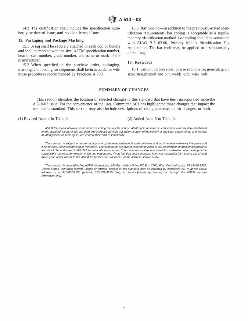
14.2 The certification shall include the specification num-ber, year date of issue, and revision letter, if any.
15. Packaging and Package Marking
15.1 A tag shall be securely attached to each coil or bundleand shall be marked with the size, ASTM specification number,heat or cast number, grade number, and name or mark of themanufacturer.
15.2 When specified in the purchase order, packaging,marking, and loading for shipments shall be in accordance withthose procedures recommended by Practices A 700.
15.3 Bar Coding—In addition to the previously-stated iden-tification requirements, bar coding is acceptable as a supple-mentary identification method. Bar coding should be consistentwith AIAG B-5 02.00, Primary Metals Identification TagApplication. The bar code may be applied to a substantiallyaffixed tag.
16. Keywords
16.1 carbon; carbon steel; coarse round wire; general; grainsize; straightened and cut; weld; wire; wire rods
SUMMARY OF CHANGES
This section identifies the location of selected changes to this standard that have been incorporated since theA 510-02 issue. For the convenience of the user, Committee A01 has highlighted those changes that impact theuse of this standard. This section may also include descriptions of changes or reasons for changes, or both.
(1) Revised Note 4 in Table 3. (2) Added Note 6 to Table 3.
ASTM International takes no position respecting the validity of any patent rights asserted in connection with any item mentionedin this standard. Users of this standard are expressly advised that determination of the validity of any such patent rights, and the riskof infringement of such rights, are entirely their own responsibility.
This standard is subject to revision at any time by the responsible technical committee and must be reviewed every five years andif not revised, either reapproved or withdrawn. Your comments are invited either for revision of this standard or for additional standardsand should be addressed to ASTM International Headquarters. Your comments will receive careful consideration at a meeting of theresponsible technical committee, which you may attend. If you feel that your comments have not received a fair hearing you shouldmake your views known to the ASTM Committee on Standards, at the address shown below.
This standard is copyrighted by ASTM International, 100 Barr Harbor Drive, PO Box C700, West Conshohocken, PA 19428-2959,United States. Individual reprints (single or multiple copies) of this standard may be obtained by contacting ASTM at the aboveaddress or at 610-832-9585 (phone), 610-832-9555 (fax), or [email protected] (e-mail); or through the ASTM website(www.astm.org).
A 510 – 03
7
Designation: A 510M – 03
METRIC
Standard Specification forGeneral Requirements for Wire Rods and Coarse RoundWire, Carbon Steel [Metric] 1
This standard is issued under the fixed designation A 510M; the number immediately following the designation indicates the year oforiginal adoption or, in the case of revision, the year of last revision. A number in parentheses indicates the year of last reapproval. Asuperscript epsilon (e) indicates an editorial change since the last revision or reapproval.
This standard has been approved for use by agencies of the Department of Defense.
1. Scope*
1.1 This specification covers general requirements for car-bon steel wire rods and uncoated coarse round wire in coils orstraightened and cut lengths.
1.2 In case of conflict, the requirements in the purchaseorder, on the drawing, in the individual specification, andin this general specification shall prevail in the sequencenamed.
NOTE 1—This metric specification is equivalent to Specification A 510,and is compatible in technical content.
2. Referenced Documents
2.1 ASTM Standards:A 370 Test Methods and Definitions for Mechanical Testing
of Steel Products2
A 700 Practices for Packaging, Marking, and LoadingMethods for Steel Products for Domestic Shipment3
A 751 Test Methods, Practices, and Terminology forChemical Analysis of Steel Products2
E 29 Practice for Using Significant Digits in Test Data toDetermine Conformance with Specifications4
E 30 Test Methods for Chemical Analysis of Steel, CastIron, Open-Hearth Iron, and Wrought Iron5
E 112 Test Methods for Determining Average Grain Size6
E 527 Practice for Numbering Metals and Alloys (UNS)7
2.2 Society of Automotive Engineers Standard:8
J 1086 Numbering Metals and Alloys2.3 AIAG Standard:AIAG B-5 02.00 Primary Metals Identification Tag Appli-
cation Standard9
3. Terminology
3.1 Definitions of Terms Specific to This Standard:3.1.1 carbon steel—steel is considered to be carbon steel
when no minimum content is specified or required for alumi-num, chromium, cobalt, columbium, molybdenum, nickel,titanium, tungsten, vanadium, or zirconium, or any otherelement added to obtain a desired alloying effect; when thespecified minimum for copper does not exceed 0.40 %; orwhen the maximum content specified for any of the followingelements does not exceed these percentages: manganese 1.65,silicon 0.60, or copper 0.60.
3.1.2 Discussion— In all carbon steels small quantities ofcertain unspecified and unrequired residual elements (such ascopper, nickel, molybdenum, chromium, etc.) unavoidablyretained from raw materials are sometimes found. Theseelements are considered as incidental and are not normallydetermined or reported.
Elements (such as sulfur and lead) may be specified toimprove machinability of carbon steels.
3.1.3 coarse round wire—from 0.90 to 25 mm in diameter,inclusive, wire produced from hot-rolled wire rods or hot-rolled coiled rounds by one or more cold reductions primarilyfor the purpose of obtaining a desired size with dimensionalaccuracy, surface finish, and mechanical properties. By varyingthe amount of cold reduction and other wire mill practices,including thermal treatment, a wide diversity of mechanicalproperties and finishes are made available. Suggested wirediameters are shown in Table 1.
1 This specification is under the jurisdiction of ASTM Committee A1 on Steel,Stainless Steel, and Related Alloys and is the direct responsibility of SubcommitteeA01.03 on Steel Rod and Wire.
Current edition approved Sept. 10, 2003. Published Sept. 2003. Originallyapproved in 1977. Last previous edition approved in 2002 as A 510M – 02.
2 Annual Book of ASTM Standards, Vol 01.03.3 Annual Book of ASTM Standards, Vol 01.05.4 Annual Book of ASTM Standards, Vol 14.02.5 Discontinued—See 1994Annual Book of ASTM Standards, Vol 03.05.6 Annual Book of ASTM Standards, Vol 03.01.7 Annual Book of ASTM Standards, Vol 01.01.8 Available from Society of Automotive Engineers (SAE), 400 Commonwealth
Dr., Warrendale, PA 15096-0001.
9 Available from Automotive Industry Action Group (AIAG), 26200 Lahser Rd.,Suite 200, Southfield, MI 48034.
1
*A Summary of Changes section appears at the end of this standard.
Copyright © ASTM International, 100 Barr Harbor Drive, PO Box C700, West Conshohocken, PA 19428-2959, United States.

3.1.4 straightened and cut wire—wire produced from coilsof wire by means of special machinery that straightens the wireand cuts it to a specified length.
3.1.5 Discussion—The straightening operation may alterthe mechanical properties of the wire, especially the tensilestrength. The straightening operation may also induce changesin the diameter of the wire. The extent of the changes in theproperties of the wire after cold straightening depends upon thekind of wire and also on the normal variation in the adjust-ments of the straightening equipment. It is therefore notpossible to forecast the properties of straightened and cut wire.Each kind of wire needs individual consideration. In mostcases, the application of straightened and cut wire is notseriously influenced by these changes.
3.1.6 wire rods—rods that are hot rolled from billets to anapproximately round cross section and into coils of onecontinuous length. Rods are not comparable to hot-rolled barsin accuracy of cross section or surface finish and as asemi-finished product are intended primarily for the manufac-ture of wire.
3.1.7 Discussion—Table 2 shows the nominal diameter for
hot-rolled wire rods. Sizes are shown in 0.5-mm incrementsfrom 5.5 to 19 mm.
4. Ordering Information
4.1 Orders for hot-rolled wire rods under this specificationshould include the following information:
4.1.1 Quantity (kilograms or megagrams),4.1.2 Name of material (wire rods),4.1.3 Diameter (Table 2),4.1.4 Chemical composition grade number (Table 3, Table
4, Table 5, and Table 6),4.1.5 Packaging,4.1.6 ASTM designation and date of issue, and4.1.7 Special requirements, if any_____.
NOTE 2—A typical ordering description is as follows: 50 000 kg SteelWire Rods, 5.5 mm, Grade G10100 in approximately 600-kg Coils toASTM A 510M-XX.
4.2 Orders for coarse round wire under this specificationshall include the following information:
4.2.1 Quantity (kilograms or pieces),4.2.2 Name of material (uncoated carbon steel wire),4.2.3 Diameter (Table 1),4.2.4 Length (straightened and cut only),4.2.5 Chemical composition (Table 3, Table 4, Table 5, and
Table 6),4.2.6 Packaging,4.2.7 ASTM designation and date of issue, and4.2.8 Special requirements, if any.
NOTE 3—A typical ordering description is as follows: 15 000 kgUncoated Carbon Steel Wire, 3.8 mm diameter, Grade G10080 in 1000-kgCoils on Tubular Carriers, to ASTM A 510M-XX, or 2500 Pieces, CarbonSteel Wire, 9.5 mm diameter, Straightened and Cut, 0.76 m, GradeG10500, in 25-Piece Bundles on Pallets to ASTM A 510M-XX.
5. Manufacture
5.1 The steel may be made by any commercially acceptedsteel making process. The steel may be either ingot cast orstrand cast.
6. Chemical Composition
6.1 The chemical composition for steel under this specifi-cation shall conform to the requirements set forth in thepurchase order. Chemical compositions are specified by rangesor limits for carbon and other elements. The grades commonlyspecified for carbon steel wire rods and coarse round wire areshown in Table 3, Table 4, Table 5, and Table 6.
6.2 Cast or Heat Analysis—An analysis of each heat shallbe made by the producer to determine the percentage of theelements specified. The analysis shall be made from a testsample, preferably taken during the pouring of the heat. Thechemical composition thus determined shall be reported, ifrequired, to the purchaser or his representative. Reporting ofsignificant figures and rounding shall be in accordance withTest Methods, Practices, and Terminology A 751.
6.3 Product Analysis—A product analysis may be made bythe purchaser. The analysis is not used for a duplicate analysisto confirm a previous result. The purpose of the productanalysis is to verify that the chemical composition is within
TABLE 1 Suggested Diameters for Steel Wire, mm
0.90 6.01.00 6.51.10 7.01.20 7.51.30 8.01.40 8.51.60 9.01.80 9.52.0 10.02.1 11.02.2 12.02.4 13.02.5 14.02.6 15.02.8 16.03.0 17.03.2 18.03.5 19.03.8 20.04.0 21.04.2 22.04.5 23.04.8 24.05.0 25.05.5
TABLE 2 Sizes of Wire Rods, mm
5.5 12.56 136.5 13.57 147.5 14.58 158.5 15.59 169.5 16.5
10 1710.5 17.511 1811.5 18.512 19
A 510M – 03
2

TABLE 3 Nonresulfurized Carbon Steel Cast or Heat Chemical Ranges and Limits
NOTE 1—Silicon—When silicon is required the following ranges and limits are commonly used for nonresulfurized carbon steels: 0.10 max %, 0.07to 0.15 %, 0.10 to 0.20 %, 0.15 to 0.35 %, 0.20 to 0.40 %, or 0.30 to 0.60 %.
NOTE 2—Copper—When required, copper is specified as an added element.NOTE 3—Lead—When lead is required as an added element, a range from 0.15 to 0.35 % is specified. Such a steel is identified by inserting the letter
“L” between the second and third numerals of the grade number, for example, 10L18.NOTE 4—Boron Addition to Improve Hardenability—Standard killed carbon steels, which are fine grain, may be produced with a boron addition to
improve hardenability and typically contain an intentional addition of .01 % minimum titanium. Such steels are produced to a range of 0.0005 to 0.003 %boron. These steels are identified by inserting the letter “B” between the second and third numerals of the grade number, for example, 10B46. The UNSdesignation is also modified by changing the last digit to “1” to indicate boron, for example, G 10461.
NOTE 5—Boron Additions to Control Strain-Ageing Behavior—Intentional additions of boron to low carbon steels for the purpose of controllingstrain-ageing behavior during wire drawing is permissible only with the agreement of the purchaser. In such cases, the boron content shall be reportedin either a material test report or certification.
NOTE 6—For steels that do not have intentional boron additions for hardenability or for control of strain aging behavior, the boron content will notnormally exceed .0008 %.
UNSDesignationA Grade No.
Chemical Composition Limits, %
SAE No.Carbon Manganese Phosphorus,max
Sulfur, max
G 10050 1005 0.06 max 0.35 max 0.040 0.050 1005G 10060 1006 0.08 max 0.25 to 0.40 0.040 0.050 1006G 10080 1008 0.10 max 0.30 to 0.50 0.040 0.050 1008G 10100 1010 0.08 to 0.13 0.30 to 0.60 0.040 0.050 1010G 10110 1011 0.08 to 0.13 0.60 to 0.90 0.040 0.050 1011G 10120 1012 0.10 to 0.15 0.30 to 0.60 0.040 0.050 1012G 10130 1013 0.11 to 0.16 0.50 to 0.80 0.040 0.050 1013G 10150 1015 0.13 to 0.18 0.30 to 0.60 0.040 0.050 1015G 10160 1016 0.13 to 0.18 0.60 to 0.90 0.040 0.050 1016G 10170 1017 0.15 to 0.20 0.30 to 0.60 0.040 0.050 1017G 10180 1018 0.15 to 0.20 0.60 to 0.90 0.040 0.050 1018G 10190 1019 0.15 to 0.20 0.70 to 1.00 0.040 0.050 1019G 10200 1020 0.18 to 0.23 0.30 to 0.60 0.040 0.050 1020G 10210 1021 0.18 to 0.23 0.60 to 0.90 0.040 0.050 1021G 10220 1022 0.18 to 0.23 0.70 to 1.00 0.040 0.050 1022G 10230 1023 0.20 to 0.25 0.30 to 0.60 0.040 0.050 1023G 10250 1025 0.22 to 0.28 0.30 to 0.60 0.040 0.050 1025G 10260 1026 0.22 to 0.28 0.60 to 0.90 0.040 0.050 1026G 10290 1029 0.25 to 0.31 0.60 to 0.90 0.040 0.050 1029G 10300 1030 0.28 to 0.34 0.60 to 0.90 0.040 0.050 1030G 10340 1034 0.32 to 0.38 0.50 to 0.80 0.040 0.050 . . .G 10350 1035 0.32 to 0.38 0.60 to 0.90 0.040 0.050 1035G 10370 1037 0.32 to 0.38 0.70 to 1.00 0.040 0.050 1037G 10380 1038 0.35 to 0.42 0.60 to 0.90 0.040 0.050 1038G 10390 1039 0.37 to 0.44 0.70 to 1.00 0.040 0.050 1039G 10400 1040 0.37 to 0.44 0.60 to 0.90 0.040 0.050 1040G 10420 1042 0.40 to 0.47 0.60 to 0.90 0.040 0.050 1042G 10430 1043 0.40 to 0.47 0.70 to 1.00 0.040 0.050 1043G 10440 1044 0.43 to 0.50 0.30 to 0.60 0.040 0.050 1044G 10450 1045 0.43 to 0.50 0.60 to 0.90 0.040 0.050 1045G 10460 1046 0.43 to 0.50 0.70 to 1.00 0.040 0.050 1046G 10490 1049 0.46 to 0.53 0.60 to 0.90 0.040 0.050 1049G 10500 1050 0.48 to 0.55 0.60 to 0.90 0.040 0.050 1050G 10530 1053 0.48 to 0.55 0.70 to 1.00 0.040 0.050 1053G 10550 1055 0.50 to 0.60 0.60 to 0.90 0.040 0.050 1055G 10590 1059 0.55 to 0.65 0.50 to 0.80 0.040 0.050 1059G 10600 1060 0.55 to 0.65 0.60 to 0.90 0.040 0.050 1060G 10640 1064 0.60 to 0.70 0.50 to 0.80 0.040 0.050 1064G 10650 1065 0.60 to 0.70 0.60 to 0.90 0.040 0.050 1065G 10690 1069 0.65 to 0.75 0.40 to 0.70 0.040 0.050 1069G 10700 1070 0.65 to 0.75 0.60 to 0.90 0.040 0.050 1070G 10740 1074 0.70 to 0.80 0.50 to 0.80 0.040 0.050 1074G 10750 1075 0.70 to 0.80 0.40 to 0.70 0.040 0.050 1075G 10780 1078 0.72 to 0.85 0.30 to 0.60 0.040 0.050 1078G 10800 1080 0.75 to 0.88 0.60 to 0.90 0.040 0.050 1080G 10840 1084 0.80 to 0.93 0.60 to 0.90 0.040 0.050 1084G 10850 1085 0.80 to 0.93 0.70 to 1.00 0.040 0.050 1085G 10860 1086 0.80 to 0.93 0.30 to 0.50 0.040 0.050 1086G 10900 1090 0.85 to 0.98 0.60 to 0.90 0.040 0.050 1090G 10950 1095 0.90 to 1.03 0.30 to 0.50 0.040 0.050 1095
A Designation established in accordance with Practice E 527 and SAE J 1086.
A 510M – 03
3

specified limits for each element, including applicable permis-sible variations in product analysis. The results of analysestaken from different pieces of a heat may differ withinpermissible limits from each other and from the heat analysis.Table 7 shows the permissible variations for product analysisof carbon steel. The results of the product analysis, except lead,shall not vary both above and below the permissible limits.
6.3.1 Rimmed or capped steels are characterized by a lackof uniformity in their chemical composition, especially for theelements carbon, phosphorus, and sulfur, and for this reason
product analysis is not technologically appropriate for theseelements unless misapplication is clearly indicated.
6.3.2 Because of the degree to which phosphorus and sulfursegregate, product analysis for these elements is not techno-logically appropriate for rephosphorized or resulfurized steels,or both, unless misapplication is clearly indicated.
6.3.3 The location at which chips for product analysis areobtained from the sample is important because of segregation.For rods and wire, chips must be taken by milling or machiningthe full cross section of the sample.
TABLE 4 Nonresulfurized Carbon Steel, High Manganese, Cast or Heat Chemical Ranges and Limits
NOTE 1—Silicon—When silicon is required the following ranges and limits are commonly used for nonresulfurized carbon steels: 0.10 max %, 0.07to 0.15 %, 0.10 to 0.20 %, 0.15 to 0.35 %, 0.20 to 0.40 %, or 0.30 to 0.60 %.
NOTE 2—Copper—When required, copper is specified as an added element.NOTE 3—Lead—When lead is required as an added element a range from 0.15 to 0.35 % is specified. Such a steel is identified by inserting the letter
“L’’ between the second and third numerals of the grade number, for example, 15L18.
UNSDesignationA
Grade No. Chemical Composition Limits, %
SAE No.Carbon Manganese Phosphorus,max
Sulfur,max
G 15130 1513 0.10 to 0.16 1.10 to 1.40 0.040 0.050 1513G 15180 1518 0.15 to 0.21 1.10 to 1.40 0.040 0.050 1518G 15220 1522 0.18 to 0.24 1.10 to 1.40 0.040 0.050 1522G 15240 1524B 0.19 to 0.25 1.35 to 1.65 0.040 0.050 1524G 15250 1525 0.23 to 0.29 0.80 to 1.10 0.040 0.050 1525G 15260 1526 0.22 to 0.29 1.10 to 1.40 0.040 0.050 1526G 15270 1527B 0.22 to 0.29 1.20 to 1.50 0.040 0.050 1527G 15360 1536B 0.30 to 0.37 1.20 to 1.50 0.040 0.050 1536G 15410 1541B 0.36 to 0.44 1.35 to 1.65 0.040 0.050 1541G 15470 1547 0.43 to 0.51 1.35 to 1.65 0.040 0.050 1547G 15480 1548B 0.44 to 0.52 1.10 to 1.40 0.040 0.050 1548G 15510 1551B 0.45 to 0.56 0.85 to 1.15 0.040 0.050 1551G 15520 1552B 0.47 to 0.55 1.20 to 1.50 0.040 0.050 1552G 15610 1561B 0.55 to 0.65 0.75 to 1.05 0.040 0.050 1561G 15660 1566B 0.60 to 0.71 0.85 to 1.15 0.040 0.050 1566G 15720 1572B 0.65 to 0.76 1.00 to 1.30 0.040 0.050 1572
A Designation established in accordance with Practice E 527 and SAE J 1086.BThese grades were formerly designated as 10XX steels.
TABLE 5 Resulfurized Carbon Steels, Cast or Heat Chemical Ranges and Limits
NOTE 1—Silicon—When silicon is required, the following ranges and limits are commonly used: Up to 1110, incl, 0.10 max %, 1116 and over, 0.10max %, 0.10 to 0.20 %, or 0.15 to 0.35 %.
NOTE 2—Because of the degree to which sulfur segregates, products analysis for sulfur in resulfurized carbon steel is not technologically appropriateunless misapplication is clearly indicated.
UNSDesignationA Grade No.
Chemical Composition Limits, %
SAE No.Carbon Manganese Phosphorus,max
Sulfur
G 11080 1108 0.08 to 0.13 0.50 to 0.80 0.040 0.08 to 0.13 1108G 11090 1109 0.08 to 0.13 0.60 to 0.90 0.040 0.08 to 0.13 1109G 11100 1110 0.08 to 0.13 0.30 to 0.60 0.040 0.08 to 0.13 1110G 11160 1116 0.14 to 0.20 1.10 to 1.40 0.040 0.16 to 0.23 1116G 11170 1117 0.14 to 0.20 1.00 to 1.30 0.040 0.08 to 0.13 1117G 11180 1118 0.14 to 0.20 1.30 to 1.60 0.040 0.08 to 0.13 1118G 11190 1119 0.14 to 0.20 1.00 to 1.30 0.040 0.24 to 0.33 1119G 11320 1132 0.27 to 0.34 1.35 to 1.65 0.040 0.08 to 0.13 1132G 11370 1137 0.32 to 0.39 1.35 to 1.65 0.040 0.08 to 0.13 1137G 11390 1139 0.35 to 0.43 1.35 to 1.65 0.040 0.13 to 0.20 1139G 11400 1140 0.37 to 0.44 0.70 to 1.10 0.040 0.08 to 0.13 1140G 11410 1141 0.37 to 0.45 1.35 to 1.65 0.040 0.08 to 0.13 1141G 11440 1144 0.40 to 0.48 1.35 to 1.65 0.040 0.24 to 0.33 1144G 11450 1145 0.42 to 0.49 0.70 to 1.00 0.040 0.04 to 0.07 1145G 11460 1146 0.42 to 0.49 0.70 to 1.00 0.040 0.08 to 0.13 1146G 11510 1151 0.48 to 0.55 0.70 to 1.00 0.040 0.08 to 0.13 1151
A Designation established in accordance with Practice E 527 and SAE J 1086.
A 510M – 03
4
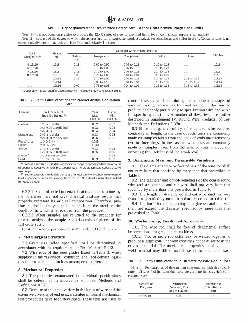
6.3.3.1 Steel subjected to certain heat treating operations bythe purchaser may not give chemical analysis results thatproperly represent its original composition. Therefore, pur-chasers should analyze chips taken from the steel in thecondition in which it is received from the producer.
6.3.3.2 When samples are returned to the producer forproduct analysis, the samples should consist of pieces of thefull cross section.
6.3.4 For referee purposes, Test Methods E 30 shall be used.
7. Metallurgical Structure
7.1 Grain size, when specified, shall be determined inaccordance with the requirements of Test Methods E 112.
7.2 Wire rods of the steel grades listed in Table 3, whensupplied in the “as-rolled’’ condition, shall not contain injuri-ous microconstituents such as untempered martensite.
8. Mechanical Properties
8.1 The properties enumerated in individual specificationsshall be determined in accordance with Test Methods andDefinitions A 370.
8.2 Because of the great variety in the kinds of wire and theextensive diversity of end uses, a number of formal mechanicaltest procedures have been developed. These tests are used as
control tests by producers during the intermediate stages ofwire processing, as well as for final testing of the finishedproduct, and apply particularly to specification wire and wiresfor specific applications. A number of these tests are furtherdescribed in Supplement IV, Round Wire Products, of TestMethods and Definitions A 370.
8.3 Since the general utility of rods and wire requirescontinuity of length, in the case of rods, tests are commonlymade on samples taken from the ends of coils after removingtwo to three rings. In the case of wire, tests are commonlymade on samples taken from the ends of coils, thereby notimpairing the usefulness of the whole coil.
9. Dimensions, Mass, and Permissible Variations
9.1 The diameter and out-of-roundness of the wire rod shallnot vary from that specified by more than that prescribed inTable 8.
9.2 The diameter and out-of-roundness of the coarse roundwire and straightened and cut wire shall not vary from thatspecified by more than that prescribed in Table 9.
9.3 The length of straightened and cut wire shall not varyfrom that specified by more than that prescribed in Table 10.
9.4 The burrs formed in cutting straightened and cut wireshall not exceed the diameter specified by more than thatprescribed in Table 11.
10. Workmanship, Finish, and Appearance
10.1 The wire rod shall be free of detrimental surfaceimperfections, tangles, and sharp kinks.
10.1.1 Two or more rod coils may be welded together toproduce a larger coil. The weld zone may not be as sound as theoriginal material. The mechanical properties existing in theweld material may differ from those in the unaffected base
TABLE 6 Rephosphorized and Resulfurized Carbon Steel Cast or Heat Chemical Ranges and Limits
NOTE 1—It is not common practice to produce the 12XX series of steel to specified limits for silicon. Silicon impairs machinability.NOTE 2—Because of the degree to which phosphorus and sulfur segregate, product analysis for phosphorus and sulfur in the 12XX series steel is not
technologically appropriate unless misapplication is clearly indicated.
UNSDesignationA
GradeNo.
Chemical Composition Limits, %
SAE No.Carbon,max
Manganese Phosphorus Sulfur Lead
G 12110 1211 0.13 0.60 to 0.90 0.07 to 0.12 0.10 to 0.15 . . . 1211G 12120 1212 0.13 0.70 to 1.00 0.07 to 0.12 0.16 to 0.23 . . . 1212G 12130 1213 0.13 0.70 to 1.00 0.07 to 0.12 0.24 to 0.33 . . . 1213G 12150 1215 0.09 0.75 to 1.05 0.04 to 0.09 0.26 to 0.35 . . . 1215. . . 12L13 0.13 0.70 to 1.00 0.07 to 0.12 0.24 to 0.33 0.15 to 0.35 12L13. . . 12L14 0.15 0.85 to 1.15 0.04 to 0.09 0.26 to 0.35 0.15 to 0.35 12L14. . . 12L15 0.09 0.75 to 1.05 0.04 to 0.09 0.26 to 0.35 0.15 to 0.35 12L15
A Designation established in accordance with Practice E 527 and SAE J 1086.
TABLE 7 Permissible Variations for Product Analysis of CarbonSteel
Element Limit, or Max ofSpecified Range, %
OverMax
Limit, %
UnderMin
Limit, %
Carbon 0.25 and under 0.02 0.02over 0.25 to 0.55, incl 0.03 0.03over 0.55 0.04 0.04
Manganese 0.90 and under 0.03 0.03over 0.90 to 1.65, incl 0.06 0.06
Phosphorus to 0.040, incl 0.008 . . .Sulfur to 0.060, incl 0.008 . . .Silicon 0.35 and under 0.02 0.02
over 0.35 to 0.60, incl 0.05 0.05CopperA under minimum only . . . 0.02LeadB 0.15 to 0.35, incl 0.03 0.03
A Product analysis permissible variations for copper apply only when the amountof copper is specified or required. Copper bearing steels typically specify 0.20 %min copper.
B Product analysis permissible variations for lead apply only when the amount oflead is specified or required. A range from 0.15 to 0.35 % lead is normally specifiedfor leaded steels.
TABLE 8 Permissible Variation in Diameter for Wire Rod in Coils
NOTE 1—For purposes of determining conformance with this specifi-cation, all specified limits in this table are absolute limits as defined inPractice E 29.
Diameter ofRod, mm
PermissibleVariation, Plusand Minus, mm
PermissibleOut-of-Round,
mm
5.5 to 19 0.40 0.60
A 510M – 03
5
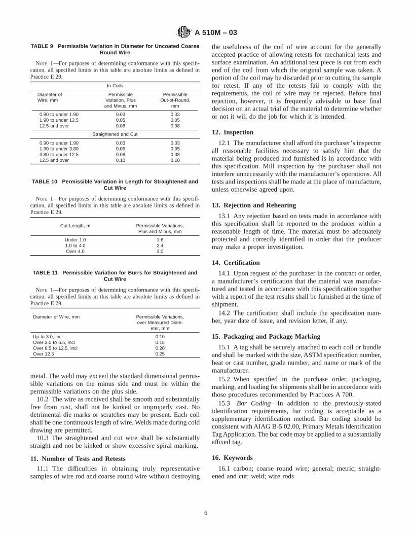
metal. The weld may exceed the standard dimensional permis-sible variations on the minus side and must be within thepermissible variations on the plus side.
10.2 The wire as received shall be smooth and substantiallyfree from rust, shall not be kinked or improperly cast. Nodetrimental die marks or scratches may be present. Each coilshall be one continuous length of wire. Welds made during colddrawing are permitted.
10.3 The straightened and cut wire shall be substantiallystraight and not be kinked or show excessive spiral marking.
11. Number of Tests and Retests
11.1 The difficulties in obtaining truly representativesamples of wire rod and coarse round wire without destroying
the usefulness of the coil of wire account for the generallyaccepted practice of allowing retests for mechanical tests andsurface examination. An additional test piece is cut from eachend of the coil from which the original sample was taken. Aportion of the coil may be discarded prior to cutting the samplefor retest. If any of the retests fail to comply with therequirements, the coil of wire may be rejected. Before finalrejection, however, it is frequently advisable to base finaldecision on an actual trial of the material to determine whetheror not it will do the job for which it is intended.
12. Inspection
12.1 The manufacturer shall afford the purchaser’s inspectorall reasonable facilities necessary to satisfy him that thematerial being produced and furnished is in accordance withthis specification. Mill inspection by the purchaser shall notinterfere unnecessarily with the manufacturer’s operations. Alltests and inspections shall be made at the place of manufacture,unless otherwise agreed upon.
13. Rejection and Rehearing
13.1 Any rejection based on tests made in accordance withthis specification shall be reported to the producer within areasonable length of time. The material must be adequatelyprotected and correctly identified in order that the producermay make a proper investigation.
14. Certification
14.1 Upon request of the purchaser in the contract or order,a manufacturer’s certification that the material was manufac-tured and tested in accordance with this specification togetherwith a report of the test results shall be furnished at the time ofshipment.
14.2 The certification shall include the specification num-ber, year date of issue, and revision letter, if any.
15. Packaging and Package Marking
15.1 A tag shall be securely attached to each coil or bundleand shall be marked with the size, ASTM specification number,heat or cast number, grade number, and name or mark of themanufacturer.
15.2 When specified in the purchase order, packaging,marking, and loading for shipments shall be in accordance withthose procedures recommended by Practices A 700.
15.3 Bar Coding—In addition to the previously-statedidentification requirements, bar coding is acceptable as asupplementary identification method. Bar coding should beconsistent with AIAG B-5 02.00, Primary Metals IdentificationTag Application. The bar code may be applied to a substantiallyaffixed tag.
16. Keywords
16.1 carbon; coarse round wire; general; metric; straight-ened and cut; weld; wire rods
TABLE 9 Permissible Variation in Diameter for Uncoated CoarseRound Wire
NOTE 1—For purposes of determining conformance with this specifi-cation, all specified limits in this table are absolute limits as defined inPractice E 29.
In Coils
Diameter ofWire, mm
PermissibleVariation, Plusand Minus, mm
PermissibleOut-of-Round,
mm
0.90 to under 1.90 0.03 0.031.90 to under 12.5 0.05 0.0512.5 and over 0.08 0.08
Straightened and Cut
0.90 to under 1.901.90 to under 3.80
0.030.05
0.030.05
3.80 to under 12.512.5 and over
0.080.10
0.080.10
TABLE 10 Permissible Variation in Length for Straightened andCut Wire
NOTE 1—For purposes of determining conformance with this specifi-cation, all specified limits in this table are absolute limits as defined inPractice E 29.
Cut Length, m Permissible Variations,Plus and Minus, mm
Under 1.0 1.61.0 to 4.0 2.4Over 4.0 3.0
TABLE 11 Permissible Variation for Burrs for Straightened andCut Wire
NOTE 1—For purposes of determining conformance with this specifi-cation, all specified limits in this table are absolute limits as defined inPractice E 29.
Diameter of Wire, mm Permissible Variations,over Measured Diam-
eter, mm
Up to 3.0, incl 0.10Over 3.0 to 6.5, incl 0.15Over 6.5 to 12.5, incl 0.20Over 12.5 0.25
A 510M – 03
6

SUMMARY OF CHANGES
This section identifies the location of selected changes to this standard that have been incorporated since theA 510M-02 issue. For the convenience of the user, Committee A01 has highlighted those changes that impactthe use of this standard. This section may also include descriptions of changes or reasons for changes, or both.
(1) Revised Note 4 in Table 3. (2) Added Note 6 to Table 3.
ASTM International takes no position respecting the validity of any patent rights asserted in connection with any item mentionedin this standard. Users of this standard are expressly advised that determination of the validity of any such patent rights, and the riskof infringement of such rights, are entirely their own responsibility.
This standard is subject to revision at any time by the responsible technical committee and must be reviewed every five years andif not revised, either reapproved or withdrawn. Your comments are invited either for revision of this standard or for additional standardsand should be addressed to ASTM International Headquarters. Your comments will receive careful consideration at a meeting of theresponsible technical committee, which you may attend. If you feel that your comments have not received a fair hearing you shouldmake your views known to the ASTM Committee on Standards, at the address shown below.
This standard is copyrighted by ASTM International, 100 Barr Harbor Drive, PO Box C700, West Conshohocken, PA 19428-2959,United States. Individual reprints (single or multiple copies) of this standard may be obtained by contacting ASTM at the aboveaddress or at 610-832-9585 (phone), 610-832-9555 (fax), or [email protected] (e-mail); or through the ASTM website(www.astm.org).
A 510M – 03
7

Designation: A 555/A 555M – 97 (Reapproved 2002)
Standard Specification forGeneral Requirements for Stainless Steel Wire and WireRods 1
This standard is issued under the fixed designation A 555/A 555M; the number immediately following the designation indicates the yearof original adoption or, in the case of revision, the year of last revision. A number in parentheses indicates the year of last reapproval.A superscript epsilon (e) indicates an editorial change since the last revision or reapproval.
This standard has been approved for use by agencies of the Department of Defense.
1. Scope
1.1 This specification covers general requirements that shallapply to stainless wire and wire rods. Wire rods are asemifinished product intended primarily for the manufacture ofwire. Wire is intended primarily for cold forming, includingcoiling, stranding, weaving, heading and machining as coveredunder the latest revision of each of the following ASTMspecifications: A 313/A 313M, A 368, A 478, A 492, A 493,A 580/A 580M and A 581/A 581M.
1.2 In case of conflicting requirements, the individual ma-terial specification and this general requirement specificationshall prevail in the order named.
1.3 General requirements for flat products other than wireare covered in Specification A 480/A 480M.
1.4 General requirements for bar and billet products arecovered in Specification A 484/A 484M.
1.5 The values stated in inch-pound units or SI (metric)units are to be regarded separately as standard; within the textand tables, the SI units are shown in brackets ([]). The valuesstated in each system are not exact equivalents; therefore, eachsystem must be used independent of the other. Combiningvalues from the two systems may result in nonconformancewith the specification.
1.6 Unless the order specifies the applicable metric specifi-cation designation, the material shall be furnished in theinch-pound units.
2. Referenced Documents
2.1 ASTM Standards:A 262 Practices for Detecting Susceptibility to Intergranu-
lar Attack in Austenitic Stainless Steels2
A 313/A 313M Specification for Stainless Steel SpringWire2
A 368 Specification for Stainless Steel Wire Strand3
A 370 Test Methods and Definitions for Mechanical Testingof Steel Products2
A 478 Specification for Chromium-Nickel Stainless SteelWeaving and Knitting Wire2
A 480/A 480M Specification for General Requirements forFlat-Rolled Stainless and Heat-Resisting Steel Plate,Sheet, and Strip2
A 484/A 484M Specification for General Requirements forStainless and Heat-Resisting Bars, Billets, and Forgings2
A 492 Specification for Stainless Steel Rope Wire3
A 493 Specification for Stainless Steel Wire and Wire Rodsfor Cold Heading and Cold Forging2
A 580/A 580M Specification for Stainless Steel Wire2
A 581/A 581M Specification for Free-Machining Stainlessand Heat-Resisting Steel Wire and Wire Rods2
A 700 Practices for Packaging, Marking, and LoadingMethods for Steel Products for Domestic Shipment3
A 751 Test Methods, Practices, and Terminology forChemical Analysis of Steel Products2
E 112 Test Methods for Determining Average Grain Size4
2.2 Federal Standard:Fed. Std. No. 123 Marking for Shipment (Civil Agencies)5
2.3 Military Standards:MIL-STD-129 Marking for Shipment and Storage5
MIL-STD-163 Preservation of Steel Products for DomesticShipment5
2.4 Other Standard:Primary Metals Bar Code Standard6
3. Terminology
3.1 Definitions of Terms Specific to This Standard:
1 This specification is under the jurisdiction of ASTM Committee A01 on Steel,Stainless Steel, and Related Alloys and is the direct responsibility of SubcommitteeA01.17 on Flat Stainless Steel Products.
Current edition approved March 10, 1997. Published November 1997. Originallypublished as A 555 – 65. Last previous edition A 555/A 555M – 94a.
2 Annual Book of ASTM Standards, Vol 01.03.
3 Annual Book of ASTM Standards, Vol 01.05.4 Annual Book of ASTM Standards, Vol 03.01.5 Available from Standardization Documents Order Desk, Bldg. 4 Section D, 700
Robbins Ave., Philadelphia, PA 19111-5094. Attn: NPODS.6 Automotive Industry Action Group, 26200 Lahser Road, Suite 200, Southfield,
MI 48034.
1
Copyright © ASTM International, 100 Barr Harbor Drive, PO Box C700, West Conshohocken, PA 19428-2959, United States.

3.1.1 bar—wire that has been straightened and cut (seeSpecification A 484/A 484M). However, a straightened and cutsmall diameter product is often called straightened and cutwire.
3.1.2 wire—as covered by this specification and the speci-fications itemized in 1.1, is any round or shaped cold-reducedproduct, in coils only, produced by cold-finishing coiled wirerod.
3.1.3 wire rods—semifinished product intended primarilyfor the manufacture of wire. They are hot rolled generally to anapproximate round cross section in continuous length coils.
4. Materials and Manufacture
4.1 The material may be furnished in one of the conditionsdetailed in the applicable material specification, that is, an-nealed, bright annealed, cold worked, or as otherwise specifiedon the purchase order.
4.2 A variety of finishes, coatings, and lubricants are avail-able. The particular type used is dependent upon the specificend use. Unless otherwise specified, the finish, coating, andlubricant will be furnished as required by the individualmaterial specification or purchase order.
5. Chemical Composition
5.1 Heat or Cast Analysis—The chemical analysis of eachheat shall be determined in accordance with the applicablematerial specification and Test Methods, Practices, and Termi-nology A 751.
5.2 Product Analysis—When required, a product analysisshall be determined in accordance with Test Methods, Prac-tices, and Terminology A 751. The chemical composition thusdetermined shall conform to the tolerances shown in Table 1.
5.3 The steel shall not contain an unspecified element forthe ordered grade to the extent that the steel conforms to therequirements of another grade in the referencing productspecification, and any of the product specifications within thescope of this general specification, for which that element hasa specified minimum.
6. Permissible Variations in Dimensions
6.1 Unless otherwise specified in the purchase order, theproduct shall conform to the permissible variations in dimen-sions as specified in Tables 2-5 of this specification.
7. Workmanship, Finish, and Appearance
7.1 The material shall be of uniform quality consistent withgood manufacturing and inspection practices. Imperfectionsthat may be present shall be of such a nature or degree, for thetype and quality ordered, that they will not adversely affect theforming, machining, or fabrication of finished parts.
8. Lot Size
8.1 A lot for product analysis shall consist of all wire madefrom the same heat.
8.2 For other tests required by the product specification, alot shall consist of all product of the same size, same heat, andproduced under the same processing conditions. All austenitic,ferritic, and free-machining stainless steels, as well as marten-sitic grades when annealed to Condition A and precipitation or
age hardening grades when solution treated, may be heattreated in more than one charge in the same furnace or inseveral furnaces, utilizing controlled processing and equipment(see appendix). However, when heat treating martensitic stain-less steels to Condition T or H and when age hardening theprecipitation hardening stainless steels, a lot shall consist of thesame size, same heat, and the same heat treat charge in abatch-type furnace or under the same conditions in a continu-ous furnace.
9. Number of Tests and Retests
9.1 Unless otherwise specified in the product specification,one sample per heat shall be selected for chemical analysis andone mechanical test sample shall be selected from each lot ofwire. All tests shall conform to the chemical and mechanicalrequirements of the material specification.
9.2 One intergranular corrosion test, when required, and onegrain size test, when required, shall be made from each lot. Itis often convenient to obtain test material from the specimenselected for mechanical testing.
9.3 If any test specimen shows imperfections that may affectthe test results, it may be discarded and another specimensubstituted.
9.4 If the results of any test lot are not in conformance withthe requirements of this specification and the applicableproduct specification, a retest sample of two specimens may betested to replace each failed specimen of the original sample. Ifone of the retest specimens fails, the lot shall be rejected.
10. Retreatment
10.1 Where failure of any lot is due to inadequate heattreatment, the material may be reheat treated and resubmittedfor test.
11. Test Methods
11.1 The properties enumerated in applicable specificationsshall be determined in accordance with the following ASTMmethods:
11.1.1 Chemical Analysis—Test Methods, Practices, andTerminology A 751.
11.1.2 Tension Test—Test Methods and Definitions A 370.11.1.3 Intergranular Corrosion(when required)—Practice
E of Practices A 262.11.1.4 Grain Size(when required)—Test Methods E 112.
12. Inspection
12.1 For Civilian Procurement—Inspection of the materialshall be as agreed upon between the purchaser and the supplieras part of the purchase contract.
12.2 For Government Procurement—Unless otherwisespecified in the contract or purchase order: (1) the seller isresponsible for the performance of all inspection and testrequirements in this specification, (2) the seller may use hisown or other suitable facilities for the performance of theinspection and testing, and (3) the purchaser shall have theright to perform any of the inspection and tests set forth in thisspecification. The manufacturer shall afford the purchaser’sinspector all reasonable facilities necessary to satisfy him that
A 555/A 555M – 97 (2002)
2

the material is being furnished in accordance with the inspec-tion. Inspection by the purchaser shall not interfere unneces-sarily with the manufacturer.
13. Rejection and Rehearing
13.1 Material that fails to conform to the requirements ofthis specification may be rejected. Rejection should be reportedto the producer or supplier promptly, preferably in writing. Incase of dissatisfaction with the results of the test, the produceror supplier may make claim for a rehearing.
TABLE 1 Product Analysis Tolerances
NOTE— This table specifies tolerances over the maximum limits or under the minimum limits of the chemical requirements of the applicable materialspecification (see 1.1); it does not apply to heat analysis.
ElementUpper Limit or Maximumof Specified Range, %
Tolerances over theMaximum (Upper
Limit) or Under theMinimum (Lower
Limit)
ElementUpper Limit or Maximumof Specified Range, %
Tolerances over theMaximum (Upper
Limit) or Under theMinimum (Lower
Limit)
Carbon to 0.010, incl 0.002 Cobalt over 0.05 to 0.50, incl 0.01over 0.010 to 0.030, incl 0.005 over 0.50 to 2.00, incl 0.02over 0.030 to 0.20, incl 0.01 over 2.00 to 5.00, incl 0.05over 0.20 to 0.60, incl 0.02 over 5.00 to 10.00, incl 0.10over 0.60 to 1.20, incl 0.03 over 10.00 to 15.00, incl 0.15
over 15.00 to 22.00, incl 0.20Manganese to 1.00, incl 0.03 over 22.00 to 30.00, incl 0.25
over 1.00 to 3.00, incl 0.04over 3.00 to 6.00, incl 0.05 Columbium to 1.50, incl 0.05over 6.00 to 10.00, incl 0.06 + over 1.50 to 5.00, incl 0.10over 10.00 to 15.00, incl 0.10 tantalum over 5.00 0.15over 15.00 to 20.00, incl 0.15
Phosphorus to 0.040, inclover 0.040 to 0.20, incl
0.0050.010
Tantalum to 0.10, incl 0.02
Sulfur to 0.040, inclover 0.040 to 0.20, inclover 0.20 to 0.50, incl
0.0050.0100.020
Copper to 0.50, inclover 0.50 to 1.00, incl
0.030.05
over 1.00 to 3.00, inclover 3.00 to 5.00, inclover 5.00 to 10.00, incl
0.100.150.20
Silicon to 1.00, inclover 1.00 to 3.00, incl
0.050.10
Chromium over 4.00 to 10.00, inclover 10.00 to 15.00, inclover 15.00 to 20.00, inclover 20.00 to 30.00, incl
0.100.150.200.25
Aluminum to 0.15, incl
over 0.15 to 0.50, incl
−0.005,+0.010.05
over 0.50 to 2.00, inclover 2.00 to 5.00, inclover 5.00 to 10.00, incl
0.100.200.35
Nickel to 1.00, incl 0.03 Nitrogen to 0.02, incl 0.005over 1.00 to 5.00, incl 0.07 over 0.02 to 0.19, incl 0.01over 5.00 to 10.00, incl 0.10 over 0.19 to 0.25, incl 0.02over 10.00 to 20.00, incl 0.15 over 0.25 to 0.35, incl 0.03over 20.00 to 30.00, incl 0.20 over 0.35 to 0.45, incl 0.04over 30.00 to 40.00, incl 0.25over 40.00 0.30 Tungsten to 1.00, incl 0.03
over 1.00 to 2.00, incl 0.05Molybdenum over 0.20 to 0.60, incl 0.03 over 2.00 to 5.00, incl 0.07
over 0.60 to 2.00, incl 0.05 over 5.00 to 10.00, incl 0.10over 2.00 to 7.00, incl 0.10 over 10.00 to 20.00, incl 0.15over 7.00 to 15.00, incl 0.15over 15.00 to 30.00, incl 0.20 Vanadium to 0.50, incl 0.03
over 0.50 to 1.50, incl 0.05Titanium to 1.00, incl
over 1.00 to 3.00, inclover 3.00
0.050.070.10
Selenium all 0.03
TABLE 2 Permissible Variations in Size of Hot Finished RoundWire Rods
Specified Size,in. [mm]
Permissible Variations SpecifiedSize, in. [mm]
Out-of-Round,A
in. [mm]Over Under
under 1⁄4 [6.35] 0.008 [0.20] 0.008 [0.20] 0.011 [0.28]1⁄4 [6.35] to 7⁄16 [10] 0.006 [0.15] 0.006 [0.15] 0.009 [0.23]over 7⁄16 [10] to 5⁄8 [16] 0.007 [0.18] 0.007 [0.18] 0.010 [0.25]over 5⁄8 [16] to 7⁄8 [22] 0.008 [0.20] 0.008 [0.20] 0.012 [0.30]over 7⁄8 [22] to 1-1⁄8 [28] 0.010 [0.25] 0.010 [0.25] 0.015 [0.38]over 1-1⁄8 [28] to 1-3⁄8 [34] 0.012 [0.30] 0.012 [0.30] 0.018 [0.45]
A Out-of-round is the difference between the maximum and minimum diametersof the wire rod measured at the same cross section.
A 555/A 555M – 97 (2002)
3
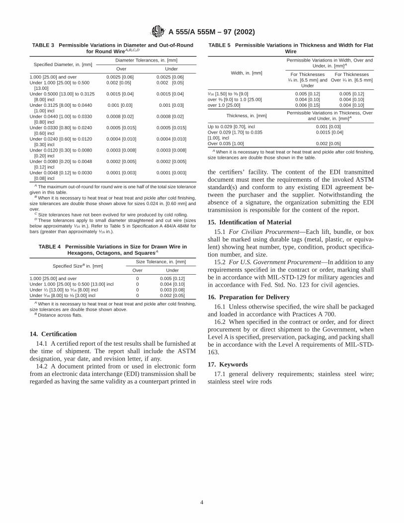
14. Certification
14.1 A certified report of the test results shall be furnished atthe time of shipment. The report shall include the ASTMdesignation, year date, and revision letter, if any.
14.2 A document printed from or used in electronic formfrom an electronic data interchange (EDI) transmission shall beregarded as having the same validity as a counterpart printed in
the certifiers’ facility. The content of the EDI transmitteddocument must meet the requirements of the invoked ASTMstandard(s) and conform to any existing EDI agreement be-tween the purchaser and the supplier. Notwithstanding theabsence of a signature, the organization submitting the EDItransmission is responsible for the content of the report.
15. Identification of Material
15.1 For Civilian Procurement—Each lift, bundle, or boxshall be marked using durable tags (metal, plastic, or equiva-lent) showing heat number, type, condition, product specifica-tion number, and size.
15.2 For U.S. Government Procurement—In addition to anyrequirements specified in the contract or order, marking shallbe in accordance with MIL-STD-129 for military agencies andin accordance with Fed. Std. No. 123 for civil agencies.
16. Preparation for Delivery
16.1 Unless otherwise specified, the wire shall be packagedand loaded in accordance with Practices A 700.
16.2 When specified in the contract or order, and for directprocurement by or direct shipment to the Government, whenLevel A is specified, preservation, packaging, and packing shallbe in accordance with the Level A requirements of MIL-STD-163.
17. Keywords
17.1 general delivery requirements; stainless steel wire;stainless steel wire rods
TABLE 3 Permissible Variations in Diameter and Out-of-Roundfor Round Wire A,B,C,D
Specified Diameter, in. [mm]Diameter Tolerances, in. [mm]
Over Under
1.000 [25.00] and over 0.0025 [0.06] 0.0025 [0.06]Under 1.000 [25.00] to 0.500
[13.00]0.002 [0.05] 0.002 [0.05]
Under 0.5000 [13.00] to 0.3125[8.00] incl
0.0015 [0.04] 0.0015 [0.04]
Under 0.3125 [8.00] to 0.0440[1.00] incl
0.001 [0.03] 0.001 [0.03]
Under 0.0440 [1.00] to 0.0330[0.80] incl
0.0008 [0.02] 0.0008 [0.02]
Under 0.0330 [0.80] to 0.0240[0.60] incl
0.0005 [0.015] 0.0005 [0.015]
Under 0.0240 [0.60] to 0.0120[0.30] incl
0.0004 [0.010] 0.0004 [0.010]
Under 0.0120 [0.30] to 0.0080[0.20] incl
0.0003 [0.008] 0.0003 [0.008]
Under 0.0080 [0.20] to 0.0048[0.12] incl
0.0002 [0.005] 0.0002 [0.005]
Under 0.0048 [0.12] to 0.0030[0.08] incl
0.0001 [0.003] 0.0001 [0.003]
A The maximum out-of-round for round wire is one half of the total size tolerancegiven in this table.
B When it is necessary to heat treat or heat treat and pickle after cold finishing,size tolerances are double those shown above for sizes 0.024 in. [0.60 mm] andover.
C Size tolerances have not been evolved for wire produced by cold rolling.D These tolerances apply to small diameter straightened and cut wire (sizes
below approximately 1⁄16 in.). Refer to Table 5 in Specification A 484/A 484M forbars (greater than approximately 1⁄16 in.).
TABLE 4 Permissible Variations in Size for Drawn Wire inHexagons, Octagons, and Squares A
Specified SizeB in. [mm]Size Tolerance, in. [mm]
Over Under
1.000 [25.00] and over 0 0.005 [0.12]Under 1.000 [25.00] to 0.500 [13.00] incl 0 0.004 [0.10]Under 1⁄2 [13.00] to 5⁄16 [8.00] incl 0 0.003 [0.08]Under 5⁄16 [8.00] to 1⁄8 [3.00] incl 0 0.002 [0.05]
A When it is necessary to heat treat or heat treat and pickle after cold finishing,size tolerances are double those shown above.
B Distance across flats.
TABLE 5 Permissible Variations in Thickness and Width for FlatWire
Width, in. [mm]
Permissible Variations in Width, Over andUnder, in. [mm]A
For Thicknesses1⁄4 in. [6.5 mm] and
Under
For ThicknessesOver 1⁄4 in. [6.5 mm]
1⁄16 [1.50] to 3⁄8 [9.0] 0.005 [0.12] 0.005 [0.12]over 3⁄8 [9.0] to 1.0 [25.00] 0.004 [0.10] 0.004 [0.10]over 1.0 [25.00] 0.006 [0.15] 0.004 [0.10]
Thickness, in. [mm]Permissible Variations in Thickness, Over
and Under, in. [mm]A
Up to 0.029 [0.70], incl 0.001 [0.03]Over 0.029 [1.70] to 0.035[1.00], incl
0.0015 [0.04]
Over 0.035 [1.00] 0.002 [0.05]A When it is necessary to heat treat or heat treat and pickle after cold finishing,
size tolerances are double those shown in the table.
A 555/A 555M – 97 (2002)
4

ANNEX
(Mandatory Information)
A1. REQUIREMENTS FOR THE INTRODUCTION OF NEW MATERIALS
A1.1 New materials may be proposed for inclusion inspecifications referencing this specification subject to thefollowing conditions:
A1.1.1 Application for the addition of a new grade to aspecification shall be made to the chairman of the subcommit-tee which has jurisdiction over that specification.
A1.1.2 The application shall be accompanied by a statementfrom at least one user indicating that there is a need for the newgrade to be included in the applicable specification.
A1.1.3 The application shall be accompanied by test data asrequired by the applicable specification. Test data from aminimum of three test lots, as defined by the specification, eachfrom a different heat, shall be furnished.
A1.1.4 The application shall provide recommendations forall requirements appearing in the applicable specification.
A1.1.5 The application shall state whether the new grade iscovered by patent.
APPENDIXES
(Nonmandatory Information)
X1. RATIONALE REGARDING DEFINITION OF LOT FOR MECHANICAL PROPERTIES AND CORROSION TESTING
X1.1 It is generally recognized that material described as alot must be “produced under the same processing conditions,’’which means the same manufacturing order number, same size,same heat, same heat treating procedure, and same subsequentprocessing. Under those conditions, single samples can beselected to be representative of the total lot, with at least onesample for each 20 000 pounds of material.
X1.2 Following the principle described in X1.1 generallyrequires that the producer control each of several furnace loadsconstituting the same lot so that
X1.2.1 Set point temperature and process tolerance match,X1.2.2 Time at temperature for all thermal treatment shall
match within 10 %,X1.2.3 All furnaces used be similar in size and meet the
uniformity requirements of a documented furnace qualityassurance program, and
X1.2.4 The quench systems are the same with respect tovolume, type of quenchant, and circulation rate.
X1.2.5 Further, it would be expected that grouped loads behandled within a relatively short time period, and that hardnesstesting be performed on at least one sample per charge.
X1.3 The old definition of a lot for mechanical testingbased on simply the words “same size, heat, and heat treatmentcharge in a batch furnace” assumes that heat treating is the onlyprocess affecting properties. This kind of definition ignores theeffects of other processing, prior to and subsequent to heattreating. Moreover, it assumes that each heat treat batch will beuniform and unique rather than reproducible. In reality, heattreating is a process which can be controlled easily throughouta batch and from batch to batch, with the net result thatmultiple batches can be considered part of a single lot ifequipment and processing parameters meet the mandates ofX1.1 and X1.2.
X1.4 The sampling specified for mechanical properties isnot a statistical sampling plan. Therefore, it provides onlytypical data. Assurance of uniformity within the lot can beobtained only by the producer adequately controlling theprocessing parameters.
X2. BAR CODING
X2.1 Bar coding to identify steel is not specifically ad-dressed in Committee A01 specifications. Committee A01endorses the AIAG Bar Code Standard for primary metals for
steel products and proposes that this bar coding standard beconsidered as a possible auxiliary method of identification.
A 555/A 555M – 97 (2002)
5

ASTM International takes no position respecting the validity of any patent rights asserted in connection with any item mentionedin this standard. Users of this standard are expressly advised that determination of the validity of any such patent rights, and the riskof infringement of such rights, are entirely their own responsibility.
This standard is subject to revision at any time by the responsible technical committee and must be reviewed every five years andif not revised, either reapproved or withdrawn. Your comments are invited either for revision of this standard or for additional standardsand should be addressed to ASTM International Headquarters. Your comments will receive careful consideration at a meeting of theresponsible technical committee, which you may attend. If you feel that your comments have not received a fair hearing you shouldmake your views known to the ASTM Committee on Standards, at the address shown below.
This standard is copyrighted by ASTM International, 100 Barr Harbor Drive, PO Box C700, West Conshohocken, PA 19428-2959,United States. Individual reprints (single or multiple copies) of this standard may be obtained by contacting ASTM at the aboveaddress or at 610-832-9585 (phone), 610-832-9555 (fax), or [email protected] (e-mail); or through the ASTM website(www.astm.org).
A 555/A 555M – 97 (2002)
6
Designation: A 564/A 564M – 04
Standard Specification forHot-Rolled and Cold-Finished Age-Hardening Stainless SteelBars and Shapes 1
This standard is issued under the fixed designation A 564/A 564M; the number immediately following the designation indicates the yearof original adoption or, in the case of revision, the year of last revision. A number in parentheses indicates the year of last reapproval.A superscript epsilon (e) indicates an editorial change since the last revision or reapproval.
This standard has been approved for use by agencies of the Department of Defense.
1. Scope*
1.1 This specification2 covers bars and shapes of age-hardening stainless steels. Hot-finished or cold-finished rounds,squares, hexagons, bar shapes, angles, tees, and channels areincluded; these shapes may be produced by hot rolling,extruding, or forging. Billets or bars for reforging may bepurchased to this specification.
1.2 These steels are generally used for parts requiringcorrosion resistance and high strength at room temperature, orat temperatures up to 600°F [315°C]; 700°F [370°C] for Type632; 840°F [450°C] for Type UNS S46910. They are suitablefor machining in the solution-annealed condition after whichthey may be age-hardened to the mechanical properties speci-fied in Section 7 without danger of cracking or distortion. TypeXM-25 is machinable in the as-received fully heat treatedcondition. Type UNS S46910 is suitable for machining in thesolution-annealed, cold-worked, and aged-hardened condition.
1.3 Types 631 and 632 contain a large amount of ferrite inthe microstructure and can have low ductility in forgings andlarger diameter bars. Applications should be limited to smalldiameter bar.
1.4 The values stated in either inch-pound units or SI(metric) units are to be regarded separately as standards; withinthe text and tables, the SI units are shown in [brackets]. Thevalues stated in each system are not exact equivalents; there-fore, each system must be used independent of the other.Combining values from the two systems may result in noncon-formance with the specification.
1.5 Unless the order specifies an “M’’ designation, thematerial shall be furnished to inch-pound units.
NOTE 1—For forgings, see Specification A 705/A 705M.NOTE 2—For billets and bars for forging see Specification A 314.
2. Referenced Documents
2.1 ASTM Standards:3
A 314 Specification for Stainless Steel Billets and Bars forForging
A 370 Test Methods and Definitions for Mechanical Testingof Steel Products
A 484/A 484M Specification for General Requirements forStainless Steel Bars, Billets, and Forgings
A 705/A 705M Specification for Age-Hardening, StainlessSteel Forgings
A 751 Test Methods, Practices, and Terminology forChemical Analysis of Steel Products
E 527 Practice for Numbering Metals and Alloys (UNS)2.2 Other Documents:SAE J1086 Recommended Practice for Numbering Metals
and Alloys (UNS)4
3. Ordering Information
3.1 It is the responsibility of the purchaser to specify allrequirements that are necessary for material ordered under thisspecification. Such requirements may include but are notlimited to the following:
3.1.1 Quantity (weight or number of pieces),3.1.2 Type or UNS designation (Table 1),3.1.3 Specific melt type when required,3.1.4 Heat treated condition (5.1),3.1.5 Transverse properties when required (7.6),3.1.6 Finish (Specification A 484/A 484M),3.1.7 Surface preparation of shapes (5.2.1),3.1.8 Size, or applicable dimension including diameter,
thickness, width, length, etc.,3.1.9 Preparation for delivery (Specification A 484/
A 484M),
1 8This specification is under the jurisdiction of ASTM Committee A01 on Steel,Stainless Steel, and Related Alloys and is the direct responsibility of SubcommitteeA01.17 on Flat Stainless Steel Products.
Current edition approved March 1, 2004. Published March 2004. Originallyapproved in 1966. Last previous edition approved in 2002 as A 564/A 564M – 02a.
2 For ASME Boiler and Pressure Vessel Code applications, see related Specifi-cation SA-564/SA-564M in Section II of that Code.
3 For referenced ASTM standards, visit the ASTM website, www.astm.org, orcontact ASTM Customer Service at [email protected]. ForAnnual Book of ASTMStandardsvolume information, refer to the standard’s Document Summary page onthe ASTM website.
4 Available from Society of Automotive Engineers (SAE), 400 CommonwealthDr., Warrendale, PA 15096-0001.
1
*A Summary of Changes section appears at the end of this standard.
Copyright © ASTM International, 100 Barr Harbor Drive, PO Box C700, West Conshohocken, PA 19428-2959, United States.
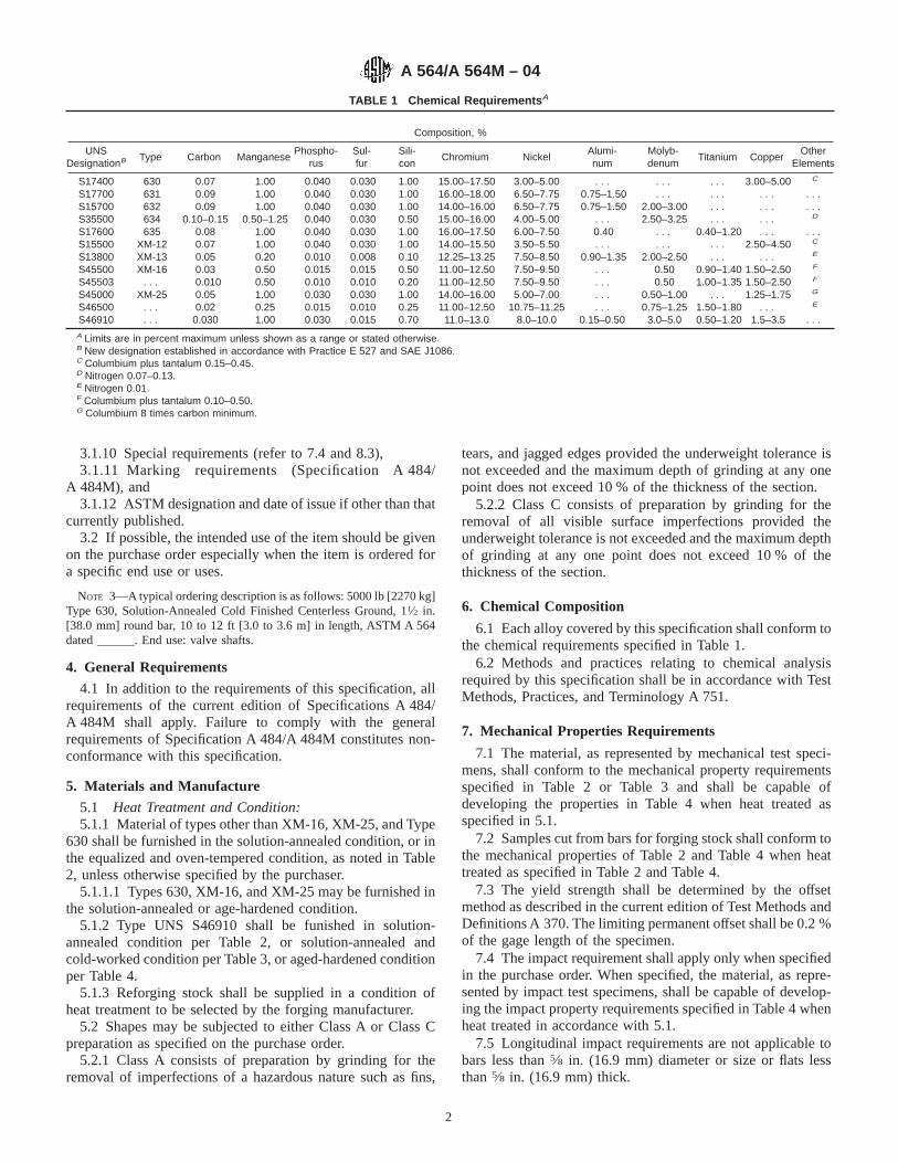
3.1.10 Special requirements (refer to 7.4 and 8.3),3.1.11 Marking requirements (Specification A 484/
A 484M), and3.1.12 ASTM designation and date of issue if other than that
currently published.3.2 If possible, the intended use of the item should be given
on the purchase order especially when the item is ordered fora specific end use or uses.
NOTE 3—A typical ordering description is as follows: 5000 lb [2270 kg]Type 630, Solution-Annealed Cold Finished Centerless Ground, 11⁄2 in.[38.0 mm] round bar, 10 to 12 ft [3.0 to 3.6 m] in length, ASTM A 564dated ______. End use: valve shafts.
4. General Requirements
4.1 In addition to the requirements of this specification, allrequirements of the current edition of Specifications A 484/A 484M shall apply. Failure to comply with the generalrequirements of Specification A 484/A 484M constitutes non-conformance with this specification.
5. Materials and Manufacture
5.1 Heat Treatment and Condition:5.1.1 Material of types other than XM-16, XM-25, and Type
630 shall be furnished in the solution-annealed condition, or inthe equalized and oven-tempered condition, as noted in Table2, unless otherwise specified by the purchaser.
5.1.1.1 Types 630, XM-16, and XM-25 may be furnished inthe solution-annealed or age-hardened condition.
5.1.2 Type UNS S46910 shall be funished in solution-annealed condition per Table 2, or solution-annealed andcold-worked condition per Table 3, or aged-hardened conditionper Table 4.
5.1.3 Reforging stock shall be supplied in a condition ofheat treatment to be selected by the forging manufacturer.
5.2 Shapes may be subjected to either Class A or Class Cpreparation as specified on the purchase order.
5.2.1 Class A consists of preparation by grinding for theremoval of imperfections of a hazardous nature such as fins,
tears, and jagged edges provided the underweight tolerance isnot exceeded and the maximum depth of grinding at any onepoint does not exceed 10 % of the thickness of the section.
5.2.2 Class C consists of preparation by grinding for theremoval of all visible surface imperfections provided theunderweight tolerance is not exceeded and the maximum depthof grinding at any one point does not exceed 10 % of thethickness of the section.
6. Chemical Composition
6.1 Each alloy covered by this specification shall conform tothe chemical requirements specified in Table 1.
6.2 Methods and practices relating to chemical analysisrequired by this specification shall be in accordance with TestMethods, Practices, and Terminology A 751.
7. Mechanical Properties Requirements
7.1 The material, as represented by mechanical test speci-mens, shall conform to the mechanical property requirementsspecified in Table 2 or Table 3 and shall be capable ofdeveloping the properties in Table 4 when heat treated asspecified in 5.1.
7.2 Samples cut from bars for forging stock shall conform tothe mechanical properties of Table 2 and Table 4 when heattreated as specified in Table 2 and Table 4.
7.3 The yield strength shall be determined by the offsetmethod as described in the current edition of Test Methods andDefinitions A 370. The limiting permanent offset shall be 0.2 %of the gage length of the specimen.
7.4 The impact requirement shall apply only when specifiedin the purchase order. When specified, the material, as repre-sented by impact test specimens, shall be capable of develop-ing the impact property requirements specified in Table 4 whenheat treated in accordance with 5.1.
7.5 Longitudinal impact requirements are not applicable tobars less than5⁄8 in. (16.9 mm) diameter or size or flats lessthan5⁄8 in. (16.9 mm) thick.
TABLE 1 Chemical Requirements A
Composition, %
UNSDesignationB Type Carbon Manganese
Phospho-rus
Sul-fur
Sili-con
Chromium NickelAlumi-num
Molyb-denum
Titanium CopperOther
Elements
S17400 630 0.07 1.00 0.040 0.030 1.00 15.00–17.50 3.00–5.00 . . . . . . . . . 3.00–5.00 C
S17700 631 0.09 1.00 0.040 0.030 1.00 16.00–18.00 6.50–7.75 0.75–1.50 . . . . . . . . . . . .S15700 632 0.09 1.00 0.040 0.030 1.00 14.00–16.00 6.50–7.75 0.75–1.50 2.00–3.00 . . . . . . . . .S35500 634 0.10–0.15 0.50–1.25 0.040 0.030 0.50 15.00–16.00 4.00–5.00 . . . 2.50–3.25 . . . . . . D
S17600 635 0.08 1.00 0.040 0.030 1.00 16.00–17.50 6.00–7.50 0.40 . . . 0.40–1.20 . . . . . .S15500 XM-12 0.07 1.00 0.040 0.030 1.00 14.00–15.50 3.50–5.50 . . . . . . . . . 2.50–4.50 C
S13800 XM-13 0.05 0.20 0.010 0.008 0.10 12.25–13.25 7.50–8.50 0.90–1.35 2.00–2.50 . . . . . . E
S45500 XM-16 0.03 0.50 0.015 0.015 0.50 11.00–12.50 7.50–9.50 . . . 0.50 0.90–1.40 1.50–2.50 F
S45503 . . . 0.010 0.50 0.010 0.010 0.20 11.00–12.50 7.50–9.50 . . . 0.50 1.00–1.35 1.50–2.50 F
S45000 XM-25 0.05 1.00 0.030 0.030 1.00 14.00–16.00 5.00–7.00 . . . 0.50–1.00 . . . 1.25–1.75 G
S46500 . . . 0.02 0.25 0.015 0.010 0.25 11.00–12.50 10.75–11.25 . . . 0.75–1.25 1.50–1.80 . . . E
S46910 . . . 0.030 1.00 0.030 0.015 0.70 11.0–13.0 8.0–10.0 0.15–0.50 3.0–5.0 0.50–1.20 1.5–3.5 . . .A Limits are in percent maximum unless shown as a range or stated otherwise.B New designation established in accordance with Practice E 527 and SAE J1086.C Columbium plus tantalum 0.15–0.45.D Nitrogen 0.07–0.13.E Nitrogen 0.01.F Columbium plus tantalum 0.10–0.50.G Columbium 8 times carbon minimum.
A 564/A 564M – 04
2
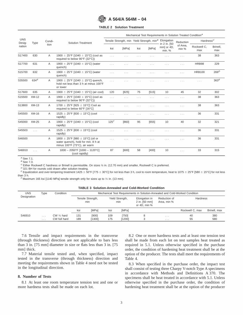
7.6 Tensile and impact requirements in the transverse(through thickness) direction are not applicable to bars lessthan 3 in. [75 mm] diameter in size or flats less than 3 in. [75mm] thick.
7.7 Material tensile tested and, when specified, impacttested in the transverse (through thickness) direction andmeeting the requirements shown in Table 4 need not be testedin the longitudinal direction.
8. Number of Tests
8.1 At least one room temperature tension test and one ormore hardness tests shall be made on each lot.
8.2 One or more hardness tests and at least one tension testshall be made from each lot on test samples heat treated asrequired in 5.1. Unless otherwise specified in the purchaseorder, the condition of hardening heat treatment shall be at theoption of the producer. The tests shall meet the requirements ofTable 4.
8.3 When specified in the purchase order, the impact testshall consist of testing three Charpy V-notch Type A specimensin accordance with Methods and Definitions A 370. Thespecimens shall be heat treated in accordance with 5.1. Unlessotherwise specified in the purchase order, the condition ofhardening heat treatment shall be at the option of the producer
TABLE 2 Solution Treatment
UNSDesig-nation
TypeCondi-
tionSolution Treatment
Mechanical Test Requirements in Solution Treated ConditionA
Tensile Strength, min Yield Strength, minB Elongationin 2 in. [50mm] or 4D,
min. %
Reductionof Area,min %
HardnessC
ksi [MPa] ksi [MPa]Rockwell C,
maxBrinell,
max
S17400 630 A 1900 6 25°F [1040 6 15°C] (cool asrequired to below 90°F (32°C))
. . . . . . . . . . . . . . . . . . 38 363
S17700 631 A 1900 6 25°F [1040 6 15°C] (waterquench)
. . . . . . . . . . . . . . . . . . HRB98 229
S15700 632 A 1900 6 25°F [1040 6 15°C] (waterquench)
. . . . . . . . . . . . . . . . . . HRB100 269D
S35500 634E A 1900 6 25°F [1040 6 15°C] quench,hold not less than 3 h at minus 100°For lower
. . . . . . . . . . . . . . . . . . . . . 363E
S17600 635 A 1900 6 25°F [1040 6 15°C] (air cool) 120 [825] 75 [515] 10 45 32 302
S15500 XM-12 A 1900 6 25°F [1040 6 15°C] (cool asrequired to below 90°F (32°C))
. . . . . . . . . . . . . . . . . . 38 363
S13800 XM-13 A 1700 6 25°F [925 6 15°C] Cool asrequired to below 60°F [16°C]
. . . . . . . . . . . . . . . . . . 38 363
S45500 XM-16 A 1525 6 25°F [830 6 15°C] (coolrapidly)
. . . . . . . . . . . . . . . . . . 36 331
S45000 XM-25 A 1900 6 25°F [1040 6 15°C] (coolrapidly)
125F [860] 95 [655] 10 40 32 321
S45503 . . . A 1525 6 25°F [830 6 15°C] (coolrapidly)
. . . . . . . . . . . . . . . . . . 36 331
S46500 A 1800 6 25°F [980 6 15°C] (oil orwater quench), hold for min. 8 h atminus 100°F (73°C), air warm
. . . . . . . . . . . . . . . . . . 36 331
S46910 . . . A 1830 – 2050°F [1000 – 1120°C](cool rapidly)
87 [600] 58 [400] 10 . . . 33 315
A See 7.1.B See 7.3.C Either Rockwell C hardness or Brinell is permissible. On sizes ½ in. (12.70 mm) and smaller, Rockwell C is preferred.D 321 BH for rounds cold drawn after solution treating.E Equalization and over-tempering treatment 1425 6 50°F [775 6 30°C] for not less than 3 h, cool to room temperature, heat to 1075 6 25°F [580 6 15°C] for not less
than 3 h.F Maximum 165 ksi [1140 MPa] tensile strength only for sizes up to 1⁄2 in. (13 mm).
TABLE 3 Solution-Annealed and Cold-Worked Condition
UNSDesignation
Type Condition Mechanical Test Requirements in Solution-Annealed and Cold-Worked Condition
Tensile Strength,min
Yield Strength,min
Elongation in2 in. [50 mm]or 4D, min %
Reduction ofArea, min %
Hardness
ksi [MPa] ksi [MPa] Rockwell C, max Brinell, max
S46910 . . . CW 1⁄2 hard 131 [900] 109 [750] 8 . . . 40 380. . . CW full hard 189 [1300] 175 [1200] 3 . . . 55 580
A 564/A 564M – 04
3

TABLE 4 Mechanical Test Requirements After Age Hardening Heat Treatment A
TypeCondi-
tion
Suggested Hardening or AgingTreatment, or BothB,C,D Applicable
Thickness,in. and TestDirectionE
TensileStrength,
min
YieldStrength,
minF
Elon-gationin 2 in.
[50 mm]or 4D,min. %
Reduc-tion ofarea,
min, %
HardnessGImpact
Charpy-V,min
Tem-perature,°F [°C]
Time,h
QuenchH ksi [MPa] ksi [MPa]Rock-well C,
min
Brinell,min
ft·lbf J
630
H900 900 [480] 1.0 air cool
Up to 3 in. incl[75 mm] (L)
190 [1310] 170 [1170] 10
40
40 388 . . . . . .Over 3 in. [75 mm]to 8 in. incl [200
mm] (T)
35
H925 925 [495] 4.0 air cool
Up to 3 min. incl[75 mm] (L)
170 [1170] 155 [1070] 10
44
38 375 5 6.8Over 3 in. [75 mm]to 8 in. incl [200
mm] (T)
38
H1025 1025 [550]
4.0 air coolUp to 8 in. incl[200 mm] (L)
155 [1070] 145 [1000] 12 45 35 331 15 20
H1075 1075 [580] 145 [1000] 125 [860] 13 45 32 311 20 27
H1100 1100 [595] 140 [965] 115 [795] 14 45 31 302 25 34
H1150 1150 [620] 135 [930] 105 [725] 16 50 28 277 30 41
H1150M1400 [760] for 2 h, air cool plus
1150 [620] for 4 h, air cool115 [795] 75 [520] 18 55 24 255 55 75
H1150D1150 [620] for 4 h, air cool plus
1150 [620] for 4 h, air cool125 [860] 105 [725] 16 50
2433 max
255311 max
30 41
631
RH950
1750°F [955°C] for not less than10 min, but not more than 1 h,cool rapidly to room temperature.Cool within 24 h to minus 100 610°F [75°C], hold not less than 8h. Warm in air to roomtemperature. Heat to 950°F[510°C], hold 1 h, air cool.
Up to 4 in. incl.[100 mm] (L)
185 [1280] 150 [1030] 6 10 41 388 . . . . . .
TH1050
Alternative treatment: 1400°F[760°C] hold 90 min, cool to 556 5°F [15 6 3°C] within 1 h.Hold not less than 30 min, heatto 1050°F [565°C] hold for 90min, air cool.
Up to 6 in. incl[150 mm] (L)
170 [1170] 140 [965] 6 25 38 352 . . . . . .
632RH950
Same as Type 631
Up to 4 in. incl[100 mm] (L) 200 [1380] 175 [1210] 7 25 . . . 415
. . . . . .
TH1050 Up to 6 in. incl[150 mm] (L)
180 [1240] 160 [1100] 8 25 . . . 375 . . . . . .
634I
H1000
1750 [955] for not less than 10min, but not more than 1 h.Water quench. Cool to not higherthan minus 100°F [75°C]. Holdfor not less than 3 h. Temper at1000°F [540°C], holding for notless than 3 h.
170 [1170] 155 [1070] 12 25 37 341 . . . . . .
635
H950 950 (510)
0.5 air cool
190 [1310] 170 [1170] 8 25 39 363 . . . . . .
H1000 1000 [540] 180 [1240] 160 [1100] 8 30 37 352 . . . . . .
H1050 1050 [565] 170 [1170] 150 [1035] 10 40 35 331 . . . . . .
XM-12
H900 900 [480] 1.0 air cool
Up to 12 in. incl[300 mm] (L)
190 [1310] 170 [1170]10 35
40 388 . . . . . .Up to 12 in. incl
[300 mm] (T)6 15
H925 925 [495] 4.0 air cool
Up to 12 in. incl[300 mm] (L)
170 [1170] 155 [1070]10 38
38 3755 6.8
Up to 12 in. incl[300 mm] (T)
7 20 . . . . . .
A 564/A 564M – 04
4

TABLE 4 Continued
TypeCondi-
tion
Suggested Hardening or AgingTreatment, or BothB,C,D Applicable
Thickness,in. and TestDirectionE
TensileStrength,
min
YieldStrength,
minF
Elon-gationin 2 in.
[50 mm]or 4D,min. %
Reduc-tion ofarea,
min, %
HardnessGImpact
Charpy-V,min
Tem-perature,°F [°C]
Time,h
QuenchH ksi [MPa] ksi [MPa]Rock-well C,
min
Brinell,min
ft·lbf J
H1025 1025 [550] 4.0 air cool
Up to 12 in. incl[300 mm] (L)
155 [1070] 145 [1000]12 45
35 33115 20
Up to 12 in. incl[300 mm] (T)
8 27 10 14
H1075 1075 [580] 4.0 air cool
Up to 12 in. incl[300 mm] (L)
145 [1000] 125 [860]13 45
32 31120 27
Up to 12 in. incl[300 mm] (T)
9 28 15 20
H1100 1100 [595] 4.0 air cool
Up to 12 in. incl[300 mm] (L)
140 [965] 115 [795]14 45
31 30225 34
Up to 12 in. incl[300 mm] (T)
10 29 15 20
H1150 1150 [620] 4.0 air cool
Up to 12 in. incl[300 mm] (L)
135 [930] 105 [725]16 50
28 27730 41
Up to 12 in. incl[300 mm] (T)
11 30 20 27
H1150M1400 [760] for 2 h, air cool plus
1150 [620] for 4 h, air cool
Up to 12 in. incl[300 mm] (L)
115 [795] 75 [515]18 55
24 25555 75
Up to 12 in. incl[300 mm] (T)
14 35 35 47
XM-13
H950 950 [510] 4.0 air cool
Up to 12 in. incl[300 mm] (L)
220 [1515] 205 [1415] 1045
45 430 . . . . . .Up to 12 in. incl
[300 mm] (T)35
H1000 1000 [540] 4.0 air cool
Up to 12 in. incl[300 mm] (L)
205 [1415] 190 [1310]10 50
43 400. . . . . .Up to 12 in. incl
[300 mm] (T)10 40
H1025 1025 [550] 4.0 air cool
Up to 12 in. incl[300 mm] (L)
185 [1280] 175 [1210] 1150
41 380 . . . . . .Up to 12 in. incl
[300 mm] (T)45
H1050 1050 [565] 4.0 air cool
Up to 12 in. incl[300 mm] (L)
175 [1210] 165 [1140] 1250
40 372 . . . . . .Up to 12 in. incl
[300 mm] (T)45
H1100 1100 [595] 4.0 air cool
Up to 12 in. incl[300 mm] (L)
150 [1035] 135 [930] 1450
34 313 . . . . . .Up to 12 in. incl
[300 mm] (T)50
H1150 1150 [620] 4.0 air cool
Up to 12 in. incl[300 mm] (L)
135 [930] 90 [620] 1450
30 283 . . . . . .Up to 12 in. incl
[300 mm] (T)50
H1150M1400 [760] for 2 h, air cool plus
1150 [620] for 4 h, air cool
Up to 12 in. incl[300 mm] (L)
125 [860] 85 [585] 1655
26 259 . . . . . .Up to 12 in. incl
[300 mm] (T)55
XM-16 H900 900 [480]
4.0 air coolUp to 6 in. incl
[150 mm] (L)
235 [1620] 220 [1515] 8 30 47 444 . . . . . .
H950 950 [510] 220 [1515] 205 [1415] 10 40 44 415 . . . . . .
H1000 1000 [540] 205 [1415] 185 [1275] 10 40 40 363 . . . . . .
A 564/A 564M – 04
5

TABLE 4 Continued
TypeCondi-
tion
Suggested Hardening or AgingTreatment, or BothB,C,D Applicable
Thickness,in. and TestDirectionE
TensileStrength,
min
YieldStrength,
minF
Elon-gationin 2 in.
[50 mm]or 4D,min. %
Reduc-tion ofarea,
min, %
HardnessGImpact
Charpy-V,min
Tem-perature,°F [°C]
Time,h
QuenchH ksi [MPa] ksi [MPa]Rock-well C,
min
Brinell,min
ft·lbf J
S45503
H900 900 [480] 4.0 air cool
Up to 6 in. incl[150 mm] (L)
235 [1620] 220 [1520]8 30
47 444 . . . . . .Up to 6 in. incl[150 mm] (T)
4 15
H950 950 [510] 4.0 air cool
Up to 6 in. incl[150 mm] (L)
220 [1515] 205 [1410]10 40
44 415 . . . . . .Up to 6 in. incl[150 mm] (T)
5 20
H1000 1000 [540] 4.0 air cool
Up to 6 in. incl[150 mm] (L)
205 [1410] 185 [1275]10 40
40 363 . . . . . .Up to 6 in. incl[150 mm] (T)
6 25
XM-25
H900 900 [480] 4.0 air cool
Up to 12 in. incl[300 mm] (L)
180 [1240] 170 [1170]10 40
39 363 . . . . . .Up to 12 in. incl
[300 mm] (T)6 20
H950 950 [510] 4.0 air cool
Up to 12 in. incl[300 mm] (L)
170 [1170] 160 [1100]10 40
37 341 . . . . . .Up to 12 in. incl
[300 mm] (T)7 22
H1000 1000 [540] 4.0 air cool
Up to 12 in. incl[300 mm] (L)
160 [1100] 150 [1035]12 45
36 331 . . . . . .Up to 12 in. incl
[300 mm] (T)8 27
H1025 1025 [550] 4.0 air coolUp to 8 in. incl
[200 mm]150 [1035] 140 [965] 12 45 34 321 . . . . . .
H1050 1050 [565] 4.0 air cool
Up to 12 in. incl[300 mm] (L)
145 [1000] 135 [930]12 45
34 321 . . . . . .Up to 12 in. incl
[300 mm] (T)9 30
H1100 1100 [595] 4.0 air cool
Up to 12 in. incl[300 mm] (L)
130 [895] 105 [725]16 50
30 285 . . . . . .Up to 12 in. incl
[300 mm] (T)11 30
H1150 1150 [620] 4.0 air cool
Up to 12 in. incl[300 mm] (L)
125 [860] 75 [515]18 55
26 262 . . . . . .Up to 12 in. incl
[300 mm] (T)12 35
S46500
H950 950 [510] 4.0 air or oil
Up to 12 in. incl[300 mm] (L)
240 [1655] 220 [1515]10 45
47 444 . . . . . .Up to 12 in. incl
[300 mm] (T)8 35
H1000 1000 [540] 4.0 air or oil
Up to 12 in. incl[300 mm] (L)
220 [1515] 200 [1380]10 50
45 430 . . . . . .Up to 12 in. incl
[300 mm] (T)10 40
H1025 1025 [560] 4.0 air or oil
Up to 12 in. incl[300 mm] (L)
210 [1450] 195 [1345]
12 50
44 415 . . . . . .Up to 12 in. incl
[300 mm] (T)11 45
A 564/A 564M – 04
6

and testing shall be done at 70 to 80°F [20 to 25°C]. The testsshall meet the requirements of Table 4. When tested attemperatures other than 70 to 80°F, [20 to 25°C] the impact testrequirements will be as agreed upon by purchaser and pro-ducer.
9. Keywords
9.1 age-hardening stainless steel; precipitation hardeningstainless steel; stainless steel bars; stainless steel shapes
TABLE 4 Continued
TypeCondi-
tion
Suggested Hardening or AgingTreatment, or BothB,C,D Applicable
Thickness,in. and TestDirectionE
TensileStrength,
min
YieldStrength,
minF
Elon-gationin 2 in.
[50 mm]or 4D,min. %
Reduc-tion ofarea,
min, %
HardnessGImpact
Charpy-V,min
Tem-perature,°F [°C]
Time,h
QuenchH ksi [MPa] ksi [MPa]Rock-well C,
min
Brinell,min
ft·lbf J
H1050 1050 [565] 430 air or oil
Up to 12 in. incl[300 mm] (L)
200 [1380] 185 [1280]
13 50
43 400 . . . . . .Up to 12 in. incl
[300 mm] (T)12 45
UNSS46910
CW 1⁄2hard +aging
890 [475] 1.0 Air cool . . . 245 [1690] 218 [1500] 6 . . . 48 456 . . . . . .
CW fullhard +aging
890 [475] 1.0 Air cool . . . 320 [2205] 290 [2005] 2 . . . 55 561 . . . . . .
A See 7.1.B Time refers to minimum time material is at temperature and may be extended to obtain required ductility properties.C Unless otherwise noted, temperatures shown are suggested temperatures and may be varied to obtain required tensile properties.D Intermediate temperatures must meet the ductility requirements of the next highest suggested hardening or aging temperature, or both. Example: Type 630 at 1050°F
[565°C] must have 13 % elongation and 45 % reduction, same as for age hardening at 1075°F [580°C].E (L) - Longitudinal axis of specimen parallel to direction of grain flow during rolling or forging. (T) - Transverse axis of specimen perpendicular to direction of grain flow
during rolling or forging.F See 7.3.G Either Rockwell C hardness or Brinell is permissible. On sizes 1⁄2 in. (12.70 mm) and smaller, Rockwell C is preferred.H When air cooling is specified, gases other than air may be used.I Refer to Table 2 for details on equalize and over temper heat treatment.
A 564/A 564M – 04
7

SUMMARY OF CHANGES
Committee A01.17 has identified the location of selected changes to this standard since the last issue,A 564/A 564M – 02a, that may impact the use of this standard. (Approved March 1, 2004.)
(1) Added new grade S46910 in Table 1, Table 2, and Table 4.(2) Revised Sections 1.2 and 5.2.1.
(3) Added new Table 3 and renumbered previous Table 3 asTable 4.
ASTM International takes no position respecting the validity of any patent rights asserted in connection with any item mentionedin this standard. Users of this standard are expressly advised that determination of the validity of any such patent rights, and the riskof infringement of such rights, are entirely their own responsibility.
This standard is subject to revision at any time by the responsible technical committee and must be reviewed every five years andif not revised, either reapproved or withdrawn. Your comments are invited either for revision of this standard or for additional standardsand should be addressed to ASTM International Headquarters. Your comments will receive careful consideration at a meeting of theresponsible technical committee, which you may attend. If you feel that your comments have not received a fair hearing you shouldmake your views known to the ASTM Committee on Standards, at the address shown below.
This standard is copyrighted by ASTM International, 100 Barr Harbor Drive, PO Box C700, West Conshohocken, PA 19428-2959,United States. Individual reprints (single or multiple copies) of this standard may be obtained by contacting ASTM at the aboveaddress or at 610-832-9585 (phone), 610-832-9555 (fax), or [email protected] (e-mail); or through the ASTM website(www.astm.org).
A 564/A 564M – 04
8
Designation: A 565 – 03ab An American National Standard
Standard Specification forMartensitic Stainless Steel Bars for High-TemperatureService 1
This standard is issued under the fixed designation A 565; the number immediately following the designation indicates the year oforiginal adoption or, in the case of revision, the year of last revision. A number in parentheses indicates the year of last reapproval. Asuperscript epsilon (e) indicates an editorial change since the last revision or reapproval.
This standard has been approved for use by agencies of the Department of Defense.
1. Scope*
1.1 This specification covers hot-finished and cold-finished martensitic chromium steel bars for high-temperature service. Themechanical properties are developed by suitable heat treatment, as indicated for each alloy.
1.2 Where strength at temperature is a factor, these steels are generally limited to a maximum service temperature of 1200°F[649°C]. For oxidation (scaling) resistance and at low stresses, these steels are useful to 1450°F [788°C].
1.3 The values stated in inch-pound units are to be regarded as the standard.
2. Referenced Documents
2.1 ASTM Standards:A 370 Test Methods and Definitions for Mechanical Testing of Steel Products2
1 This specification is under the jurisdiction of ASTM Committee A01 on Steel, Stainless Steel, and Related Alloys and is the direct responsibility of Subcommittee A01.17on Flat-Rolled and Wrought Stainless Steel.
Current edition approved April May 10, 2003. Published May July 2003. Originally approved in 1966. Last previous edition approved in 2003 as A 565 – 03a.
1
This document is not an ASTM standard and is intended only to provide the user of an ASTM standard an indication of what changes have been made to the previous version. Becauseit may not be technically possible to adequately depict all changes accurately, ASTM recommends that users consult prior editions as appropriate. Inall cases only the current versionof the standard as published by ASTM is to be considered the official document.
*A Summary of Changes section appears at the end of this standard.
Copyright © ASTM International, 100 Barr Harbor Drive, PO Box C700, West Conshohocken, PA 19428-2959, United States.
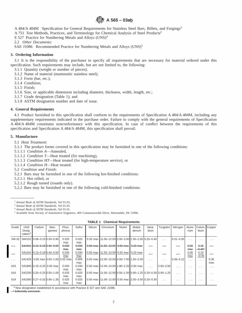
A 484/A 484M Specification for General Requirements for Stainless Steel Bars, Billets, and Forgings3
A 751 Test Methods, Practices, and Terminology for Chemical Analysis of Steel Products2
E 527 Practice for Numbering Metals and Alloys (UNS)4
2.2 Other Documents:SAE J1086 Recommended Practice for Numbering Metals and Alloys (UNS)5
3. Ordering Information
3.1 It is the responsibility of the purchaser to specify all requirements that are necessary for material ordered under thisspecification. Such requirements may include, but are not limited to, the following:
3.1.1 Quantity (weight or number of pieces);3.1.2 Name of material (martensitic stainless steel);3.1.3 Form (bar, etc.);3.1.4 Condition;3.1.5 Finish;3.1.6 Size, or applicable dimension including diameter, thickness, width, length, etc.;3.1.7 Grade designation (Table 1); and3.1.8 ASTM designation number and date of issue.
4. General Requirements
4.1 Product furnished to this specification shall conform to the requirements of Specification A 484/A 484M, including anysupplementary requirements indicated in the purchase order. Failure to comply with the general requirements of SpecificationA 484/A 484M constitutes nonconformance with this specification. In case of conflict between the requirements of thisspecification and Specification A 484/A 484M, this specification shall prevail.
5. Manufacture
5.1 Heat Treatment:5.1.1 The product forms covered in this specification may be furnished in one of the following conditions:5.1.1.1 Condition A—Annealed,5.1.1.2 Condition T—Heat treated (for machining),5.1.1.3 Condition HT—Heat treated (for high-temperature service), or5.1.1.4 Condition H—Heat treated.5.2 Condition and Finish:5.2.1 Bars may be furnished in one of the following hot-finished conditions:5.2.1.1 Hot rolled, or5.2.1.2 Rough turned (rounds only).5.2.2 Bars may be furnished in one of the following cold-finished conditions:
2 Annual Book of ASTM Standards, Vol 01.03.3 Annual Book of ASTM Standards, Vol 01.05.4 Annual Book of ASTM Standards, Vol 01.01.5 Available from Society of Automotive Engineers, 400 Commonwealth Drive, Warrendale, PA 15096.
TABLE 1 Chemical Requirements
Grade UNSDesig-nationA
Carbon Man-ganese
Phos-phorus
Sulfur Silicon Chromium Nickel Molyb-denum
Vana-dium
Tungsten Nitrogen Alumi-num
Colum-bium
Copper
XM-32 S64152 0.08–0.15 0.50–0.90 0.025max
0.025max
0.35 max 11.00–12.50 2.00–3.00 1.50–2.00 0.25–0.40 . . . 0.01–0.05 . . . . . . . . .
. . . S41041 0.13–0.18 0.40–0.60 0.030max
0.030max
0.50 max 11.50–13.00 0.50 max 0.20 max . . . . . . . . . 0.05max
0.15–0.45†
. . .
. . . S41041 0.13–0.18 0.40–0.60 0.030max
0.030max
0.50 max 11.50–13.00 0.50 max 0.20 max . . . . . . . . . 0.05max
0.15–0.45
. . .
. . . S41425 0.05 max 0.50–1.00 0.02 max 0.005max
0.50 max 12.00–15.00 4.00–7.00 1.50–2.00 . . . . . . 0.06–0.12 . . . . . . 0.30max
615 S41800 0.15–0.20 0.50 max 0.040max
0.030max
0.50 max 12.00–14.00 1.80–2.20 0.50 max . . . 2.50–3.50 . . . . . . . . . . . .
616 S42200 0.20–0.25 0.50–1.00 0.025max
0.025max
0.50 max 11.00–12.50 0.50–1.00 0.90–1.25 0.20–0.30 0.90–1.25 . . . . . . . . . . . .
619 S42300 0.27–0.32 0.95–1.35 0.025max
0.025max
0.50 max 11.00–12.00 0.50 max 2.50–3.00 0.20–0.30 . . . . . . . . . . . . . . .
A New designation established in accordance with Practice E 527 and SAE J1086.† Editorially corrected.
A 565 – 03ab
2

5.2.2.1 Cold drawn,
5.2.2.2 Centerless ground (rounds only), or
5.2.2.3 Polished (rounds only).
6. Chemical Requirements
6.1 Each alloy covered by this specification shall conform to the chemical composition specified in Table 1.
6.2 Methods and practices relating to chemical analysis required by this specification shall be in accordance with Test Methods,Practices, and Terminology A 751.
7. Metallurgical Requirements
7.1 The microstructure shall not contain more than 5 % delta-ferrite after full heat treatment as described in Table 2.
8. Mechanical Properties Requirements
8.1 The material shall conform to the mechanical properties listed in Table 3 for the ordered condition.
8.2 Material furnished in Condition A or T shall be capable of developing the room-temperature properties specified forCondition HT when subjected to heat treatment as specified in Table 2.
8.3 The yield strength shall be determined by the offset method as described in the current edition of Test Methods andDefinitions A 370.
8.4 The impact strength shall be determined at 70 to 80°F [21 to 27°C], by Charpy V-notch specimen Type A as described inTest Methods and Definitions A 370.
9. Keywords
9.1 martensitic stainless steel; stainless steel bars; stainless steel billets; stainless steel forgings; temperature serviceapplications—high
TABLE 2 Heat Treatment
NOTE 1— If straightened, a stress-relieving treatment is necessary. Stress-relieving temperature should be 50°F [28°C] below the final temperingtemperature.
NOTE 2—Air or oil quenching depends on section size; heavier sections, approximately 3 in. [76.2 mm] or greater, should be oil quenched. Suitablesynthetic quenchants may be substituted for oil.
Grade UNS DesignationA Condition Heat Treatment
615 S41800 HT 1800 to 1850 °F [981 to 1008 °C], quench in air or oil and double temper at 1150 °F [620 °C] min for 2 h min foreach tempering treatment.
. . . S41425 HT 1700 to 1800 °F [925 to 981 °C], quench in air and temper at 1100 °F min for 1 h, min, per inch thickness.616 S42200 HT 1875 to 1925 °F [1022 to 1050 °C], quench in air or oil and temper at 1150 °F [620 °C] min for 2 h min.
H 1875 to 1925 °F [1022 to 1050 °C], quench in air or oil and temper at 1250 °F [677 °C] min for 2 h min.619 S42300 HT 1875 to 1925 °F [1022 to 1050 °C], quench in air or oil and temper at 1150 °F [620 °C] min for 2 h min.XM-32 K64152 HT 1825 to 1875 °F [995 to 1022 °C], quench in air or oil and temper at 1050 °F [565 °C] min for 2 h min.. . . S41041 HT 2075 to 2125 °F [1136 to 1163 °C] for 2 h min, quench in air or oil and temper at 1250 °F [677 °C] min for 2 h min.
A New designation established in accordance with Practice E 527 and SAE J1086.
A 565 – 03ab
3
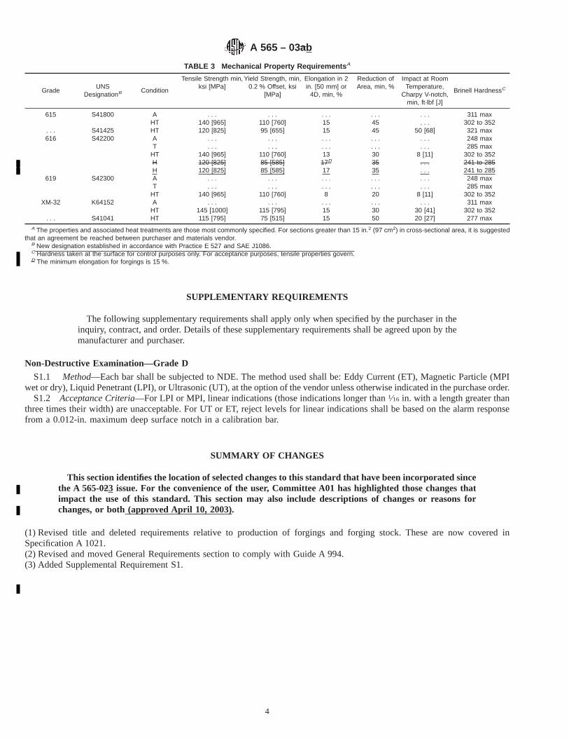
SUPPLEMENTARY REQUIREMENTS
The following supplementary requirements shall apply only when specified by the purchaser in theinquiry, contract, and order. Details of these supplementary requirements shall be agreed upon by themanufacturer and purchaser.
Non-Destructive Examination—Grade D
S1.1 Method—Each bar shall be subjected to NDE. The method used shall be: Eddy Current (ET), Magnetic Particle (MPIwet or dry), Liquid Penetrant (LPI), or Ultrasonic (UT), at the option of the vendor unless otherwise indicated in the purchase order.
S1.2 Acceptance Criteria—For LPI or MPI, linear indications (those indications longer than1⁄16 in. with a length greater thanthree times their width) are unacceptable. For UT or ET, reject levels for linear indications shall be based on the alarm responsefrom a 0.012-in. maximum deep surface notch in a calibration bar.
SUMMARY OF CHANGES
This section identifies the location of selected changes to this standard that have been incorporated sincethe A 565-023 issue. For the convenience of the user, Committee A01 has highlighted those changes thatimpact the use of this standard. This section may also include descriptions of changes or reasons forchanges, or both (approved April 10, 2003).
(1) Revised title and deleted requirements relative to production of forgings and forging stock. These are now covered inSpecification A 1021.(2) Revised and moved General Requirements section to comply with Guide A 994.(3) Added Supplemental Requirement S1.
TABLE 3 Mechanical Property Requirements A
GradeUNS
DesignationB Condition
Tensile Strength min,ksi [MPa]
Yield Strength, min,0.2 % Offset, ksi
[MPa]
Elongation in 2in. [50 mm] or
4D, min, %
Reduction ofArea, min, %
Impact at RoomTemperature,
Charpy V-notch,min, ft·lbf [J]
Brinell HardnessC
615 S41800 A . . . . . . . . . . . . . . . 311 maxHT 140 [965] 110 [760] 15 45 . . . 302 to 352
. . . S41425 HT 120 [825] 95 [655] 15 45 50 [68] 321 max616 S42200 A . . . . . . . . . . . . . . . 248 max
T . . . . . . . . . . . . . . . 285 maxHT 140 [965] 110 [760] 13 30 8 [11] 302 to 352H 120 [825] 85 [585] 17D 35 . . . 241 to 285H 120 [825] 85 [585] 17 35 . . . 241 to 285
619 S42300 A . . . . . . . . . . . . . . . 248 maxT . . . . . . . . . . . . . . . 285 max
HT 140 [965] 110 [760] 8 20 8 [11] 302 to 352XM-32 K64152 A . . . . . . . . . . . . . . . 311 max
HT 145 [1000] 115 [795] 15 30 30 [41] 302 to 352. . . S41041 HT 115 [795] 75 [515] 15 50 20 [27] 277 max
A The properties and associated heat treatments are those most commonly specified. For sections greater than 15 in.2 (97 cm2) in cross-sectional area, it is suggestedthat an agreement be reached between purchaser and materials vendor.
B New designation established in accordance with Practice E 527 and SAE J1086.C Hardness taken at the surface for control purposes only. For acceptance purposes, tensile properties govern.D The minimum elongation for forgings is 15 %.
A 565 – 03ab
4
This section identifies the location of selected changes to this standard that have been incorporated since the A 565-03aissue. For the convenience of the user, Committee A01 has highlighted those changes that impact the use of this
standard. This section may also include descriptions of changes or reasons for changes,or both (approved May 10, 2003).
(2) Deleted Footnote D in Table 3.
ASTM International takes no position respecting the validity of any patent rights asserted in connection with any item mentionedin this standard. Users of this standard are expressly advised that determination of the validity of any such patent rights, and the riskof infringement of such rights, are entirely their own responsibility.
This standard is subject to revision at any time by the responsible technical committee and must be reviewed every five years andif not revised, either reapproved or withdrawn. Your comments are invited either for revision of this standard or for additional standardsand should be addressed to ASTM International Headquarters. Your comments will receive careful consideration at a meeting of theresponsible technical committee, which you may attend. If you feel that your comments have not received a fair hearing you shouldmake your views known to the ASTM Committee on Standards, at the address shown below.
This standard is copyrighted by ASTM International, 100 Barr Harbor Drive, PO Box C700, West Conshohocken, PA 19428-2959,United States. Individual reprints (single or multiple copies) of this standard may be obtained by contacting ASTM at the aboveaddress or at 610-832-9585 (phone), 610-832-9555 (fax), or [email protected] (e-mail); or through the ASTM website(www.astm.org).
A 565 – 03ab
5

Designation: A 568/A 568M – 03
Standard Specification forSteel, Sheet, Carbon, and High-Strength, Low-Alloy, Hot-Rolled and Cold-Rolled, General Requirements for 1
This standard is issued under the fixed designation A 568/A 568M; the number immediately following the designation indicates the yearof original adoption or, in the case of revision, the year of last revision. A number in parentheses indicates the year of last reapproval.A superscript epsilon (e) indicates an editorial change since the last revision or reapproval.
This standard has been approved for use by agencies of the Department of Defense.
1. Scope *
1.1 This specification covers the general requirements forsteel sheet in coils and cut lengths. It applies to the followingspecifications that describe carbon steel and high-strength,low-alloy steel (HSLA) furnished as hot-rolled sheet andcold-rolled sheet: Specifications A 414/A 414M, A 424, A 606,A 659/A 659M, A 794, A 1008/A 1008M, and A 1011/A 1011M.
1.2 This specification is not applicable to hot-rolled heavy-thickness carbon sheet coils (ASTM Specification A 635/A 635M).
1.3 In case of any conflict in requirements, the requirementsof the individual material specification shall prevail over thoseof this general specification.
1.4 For the purposes of determining conformance with thisand the appropriate product specification referenced in 1.1,values shall be rounded to the nearest unit in the right handplace of figures used in expressing the limiting values inaccordance with the rounding method of Practice E 29.
1.5 Annex A1 lists permissible variations in dimensions andmass (see Note 1) in SI [metric] units. The values listed are notexact conversions of the values listed in the inch-pound tables,but instead are rounded or rationalized values. Conformance toAnnex A1 is mandatory when the “M” specification is used.
NOTE 1—The term weight is used when inch-pound units are thestandard. However, under SI the preferred term ismass.
1.6 The values stated in either inch-pound units or SI unitsare to be regarded as standard. Within the text, the SI units areshown in brackets. The values stated in each system are notexact equivalents; therefore, each system must be used inde-pendently of the other. Combining values from the two systemsmay result in nonconformance with the specification.
1.7 This specification and the applicable material specifica-tions are expressed in both inch-pound units and SI units.However, unless the order specifies the applicable “M” speci-fication designation (SI units), the material shall be furnishedto inch-pound units.
2. Referenced Documents
2.1 ASTM Standards:A 370 Test Methods and Definitions for Mechanical Testing
of Steel Products2
A 414/A 414M Specification for Steel, Sheet, Carbon, forPressure Vessels2
A 424 Specification for Steel, Sheet, for Porcelain Enamel-ing2
A 606 Specification for Steel, Sheet and Strip, High-Strength, Low-Alloy, Hot-Rolled and Cold-Rolled, withImproved Atmospheric Corrosion Resistance2
A 635/A 635M Specification for Steel, Sheet and Strip,Heavy-Thickness Coils, Carbon, Commercial Steel, Draw-ing Steel, Structural, High-Strength Low-Alloy, and High-Strength Low-Alloy with Improved Formability, Hot-Rolled, General Requirements for2
A 659/A 659M Specification for Commercial Steel (CS),Sheet and Strip, Carbon (0.16 Maximum to 0.25 Maxi-mum Percent), Hot-Rolled2
A 700 Practices for Packaging, Marking, and LoadingMethods for Steel Products for Domestic Shipment3
A 751 Test Methods, Practices, and Terminology forChemical Analysis of Steel Products2
A 794 Specification for Commercial Steel (CS), Sheet,Carbon (0.16 % Maximum to 0.25 % Maximum), Cold-Rolled2
A 1008/A 1008M Specification for Steel, Sheet, Cold-Rolled, Carbon, Structural, High-Strength Low-Alloy andHigh-Strength Low-Alloy with Improved Formability2
1 This specification is under the jurisdiction of ASTM Committee A01 on Steel,Stainless Steel and Related Alloys and is the direct responsibility of SubcommitteeA01.19 on Steel Sheet and Strip.
Current edition approved April 10, 2003. Published May 2003. Originallyapproved in 1966. Last previous edition approved in 2002 as A 568 – 02.
2 Annual Book of ASTM Standards, Vol 01.03.3 Annual Book of ASTM Standards, Vol 01.05.
1
*A Summary of Changes section appears at the end of this standard.
Copyright © ASTM International, 100 Barr Harbor Drive, PO Box C700, West Conshohocken, PA 19428-2959, United States.

A 1011/A 1011M Specification for Steel, Sheet and Strip,Hot-Rolled, Carbon, Structural, High-Strength Low-Alloyand High-Strength Low-Alloy with Improved Formability2
E 11 Specification for Wire-Cloth Sieves for Testing Pur-poses4
E 29 Practice for Using Significant Digits in Test Data toDetermine Conformance with Specifications4
E 59 Practice for Sampling Steel and Iron for Determinationof Chemical Composition5
E 290 Test Method for Bend Testing of Material for Duc-tility 6
2.2 Military Standards:7
MIL-STD-129 Marking for Shipment and StorageMIL-STD-163 Steel Mill Products Preparation for Ship-
ment and Storage2.3 Federal Standards:7
Fed. Std. No. 123 Marking for Shipments (Civil Agencies)Fed. Std. No. 183 Continuous Identification Marking of Iron
and Steel Products
3. Terminology
3.1 Definitions of Terms Specific to This Standard:3.1.1 Steel Types:3.1.2 carbon steel—the designation for steel when no mini-
mum content is specified or required for aluminum, chromium,cobalt, columbium, molybdenum, nickel, titanium, tungsten,vanadium, zirconium, or any element added to obtain a desiredalloying effect; when the specified minimum for copper doesnot exceed 0.40 %; or when the maximum content specified forany of the following elements does not exceed the percentagesnoted: manganese 1.65, silicon 0.60, or copper 0.60.
3.1.2.1 Discussion—In all carbon steels small quantities ofcertain residual elements unavoidably retained from raw ma-terials are sometimes found which are not specified or required,such as copper, nickel, molybdenum, chromium, etc. Theseelements are considered as incidental and are not normallydetermined or reported.
3.1.3 high-strength, low-alloy steel—a specific group ofsteels in which higher strength, and in some cases additionalresistance to atmospheric corrosion or improved formability,are obtained by moderate amounts of one or more alloyingelements.
3.1.4 Product Types:3.1.5 hot-rolled sheet—manufactured by hot rolling slabs in
a continuous mill to the required thickness and can be suppliedin coils or cut lengths as specified.
(a) Hot-rolled carbon and high-strength low-alloy (HSLA)steel sheet is commonly classified by size as follows:
Coils and Cut LengthsWidth, in. Thickness, in.
12 to 48, incl 0.031 to 0.230, exclOver 48 0.031 to 0.180, excl
Coils and Cut LengthsWidth, mm Thickness, mm
Over 300 to 1200, incl 0.8 to 6.0, exclOver 1200 0.8 to 4.5, excl
3.1.6 cold-rolled sheet—manufactured from hot-rolled des-caled coils by cold reducing to the desired thickness, generallyfollowed by annealing to recrystallize the grain structure. If thesheet is not annealed after cold reduction it is known as fullhard with a hardness of 84 HRB minimum and can be used forcertain applications where ductility and flatness are not re-quired.
(a) Cold-rolled carbon sheet is commonly classified by sizeas follows:
Width, in. Thickness, in.
Through 12A Through 0.082Over 12B through 23 15/16 Through 0.142
Over 23 15/16 Through 0.142
Width, mm Thickness, mmTo 300, inclA Through 2.0Over 300B Through 4.0
A Cold-rolled sheet coils and cut lengths, slit from wider coils with cut edge (only)and in thicknesses through 0.082 in. [2.0 mm] carbon 0.25 % maximum by castanalysis.
B When no special edge or finish (other than matte, commercial bright, or lusterfinish) or single strand rolling of widths, or both under 24 in. [600 mm] is notspecified or required.
(b) Cold-rolled high-strength low-alloy sheet is commonlyclassified by size as follows:
Width, in. Thickness, in.Through 12A 0.019 through 0.082
Over 12B 0.020 and over
Width, mm Thickness, mmTo 300, inclA
Over 300B0.5 to 2.0, incl0.5 and Over
A Cold-rolled sheet coils and cut lengths, slit from wider coils with cut edge (only)and in thicknesses 0.019 in. [0.5 mm] through 0.82 in. [2.0 mm] carbon 0.25 %maximum by cast analysis.
B When no special edge or finish (other than matte, commercial bright, or lusterfinish) or single strand rolling of widths, or both under 24 in. [600 mm] is notspecified or required.
3.1.6.1 Discussion—Steel products are available in variousthickness, width, and length combinations depending uponequipment and processing capabilities of various manufactur-ers and processors. Historic limitations of a product based upondimensions (thickness, width, and length) do not take intoaccount current production and processing capabilities. Toqualify any product for a particular product specificationrequires all appropriate and necessary tests be performed andthat the results meet the limits prescribed in that productspecification. If the necessary tests required by a productspecification cannot be conducted, the product cannot bequalified to that specification. This general requirements speci-fication contains permitted variations for the commonly avail-able sizes. Permitted variations for other sizes are subject toagreement between the customer and the manufacturer orprocessor, whichever is applicable.
3.1.7 retests, n—an additional test, or tests, made from theoriginal material when the original test did not meet the
4 Annual Book of ASTM Standards, Vol 14.02.5 Discontinued;see 1996 Annual Book of ASTM Standards, Vol 03.05.6 Annual Book of ASTM Standards, Vol 03.01.7 Available from Standardization Documents Order Desk, Bldg. 4 Section D, 700
Robbins Ave., Philadelphia, PA 19111-5094, Attn: NPODS.
A 568/A 568M – 03
2

appropriate acceptance criteria required by a product specifi-cation and the failure was mechanical in natures as described inSection 11.
3.1.8 resample, n—an additional test, or tests, made whenthe test on the original sample did not meet the appropriateacceptance criteria required by the product specification butpossible requiring that the material in question have anappropriate amount discarded prior to securing the new sampleor samples.
4. Materials and Manufacture
4.1 Unless otherwise specified, hot-rolled material shall befurnished hot-rolled, not annealed, not pickled.
4.2 Coil breaks, stretcher strains, and fluting can occurduring the user’s processing of hot-rolled or hot-rolled pickledsheet. When any of these features are detrimental to theapplication, the manufacturer shall be notified at time ofordering in order to properly process the sheet.
4.3 Cold-rolled carbon steel sheet is available as discussedin 10.2, 10.3, and in Table 1.
4.4 Unless specified as a full-hard product, cold-rolled sheetis annealed after being cold reduced to thickness. The an-nealed, cold-rolled sheet can be used as annealed last (deadsoft) for unexposed end-use applications. When cold-rolledsheet is used for unexposed applications and coil breaks are ahazard in uncoiling, it may be necessary to further process thematerial. In this case the manufacturer should be consulted.After annealing, cold-rolled sheet is generally given a lightskin pass to impart shape or may be given a heavier skin passor temper pass to prevent the phenomenon known as stretcherstraining or fluting, when formed. Temper passing also pro-vides a required surface texture.
4.5 Temper Rolling:4.5.1 Unless otherwise specified, cold-rolled sheet for ex-
posed applications shall be temper rolled and is usually
specified and furnished in the strain free condition as shipped.See Appendix X1, Effect of Aging of Cold-Rolled Carbon SteelSheet on Drawing and Forming.
4.5.2 Cold-rolled sheet for unexposed applications may bespecified and furnished “annealed last” or “temper rolled.”“Annealed last” is normally produced without temper rollingbut may be lightly temper rolled during oiling or rewinding.Unexposed temper-rolled material may be specified strain-freeor nonfluting. Where specific hardness range or limit or aspecified surface texture is required, the application is consid-ered as exposed.
NOTE 2—Skin-passed sheet is subject to an aging phenomenon (seeAppendix X1). Unless special killed (nonaging) steel is specified, it is tothe user’s interest to fabricate the sheet as soon as possible, for optimumperformance.
5. Chemical Composition
5.1 Limits:5.1.1 The chemical composition shall be in accordance with
the applicable product specification. However, if other compo-sitions are required for carbon steel, they shall be prepared inaccordance with Appendix X2.
5.1.2 Where the material is used for fabrication by welding,care must be exercised in selection of chemical composition ormechanical properties to assure compatibility with the weldingprocess and its effect on altering the properties.
5.2 Cast or Heat Analysis:5.2.1 An analysis of each cast or heat of steel shall be made
by the manufacturer to determine the percentage of elementsspecified or restricted by the applicable specification.
5.2.2 When requested, cast or heat analysis for elementslisted or required shall be reported to the purchaser or to hisrepresentative.
5.3 Product, Check, or Verification Analysis:
TABLE 1 Cold-Rolled Sheet Steel Class Comparison
Exposed Unexposed
Major imperfections:Cut lengths Mill rejects Mill rejectsCoils Purchaser accepts within the manufacturer’s published
standards (policy)Purchaser accepts within the manufacturer’s published
standards (policy)Minor imperfections:
Cut lengths Mill rejections repetitive imperfections. May containrandom imperfections which the purchaser accepts within
the manufacturer’s published standards (policy)
Purchaser accepts all minor imperfections
Coils Purchaser accepts within the manufacturer’s publishedstandards (policy)
Purchaser accepts all minor imperfections
Finish Matte unless otherwise specified Purchaser accepts all finishesSpecial oils May be specified May not be specifiedThickness, width and lengthtolerance:
Standard Will be met Will be metRestricted May be specified May not be specified
Flatness tolerance:Standard Will be met Will be met (temper rolled) Not guaranteed—normally
within twice standard (annealed last)Restricted Squareness May be specified May not be specifiedCoil wraps Purchaser accepts within the manufacturer’s published
standards (policy)Purchaser accepts all
Coil welds Purchaser accepts within the manufacturer’s publishedstandards (policy)
Purchaser accepts within the manufacturer’s publishedstandards (policy)
Outside inspection May be specified May not be specifiedSpecial testing May be specified May not be specified
A 568/A 568M – 03
3
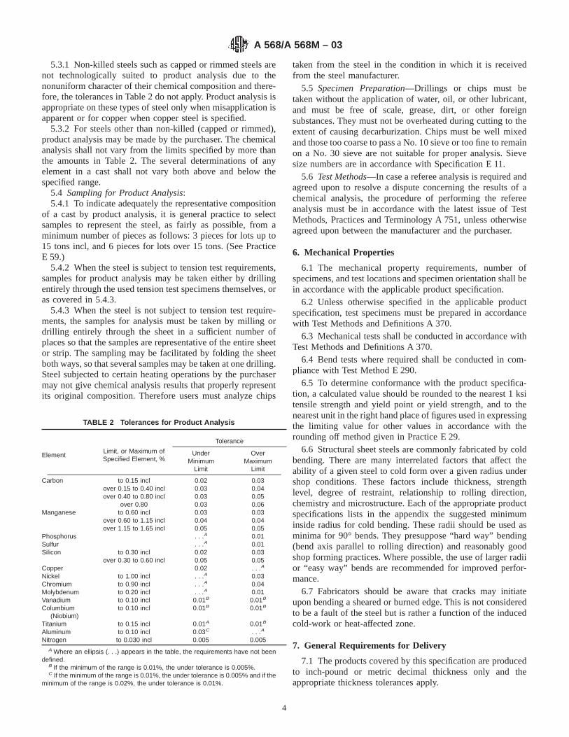
5.3.1 Non-killed steels such as capped or rimmed steels arenot technologically suited to product analysis due to thenonuniform character of their chemical composition and there-fore, the tolerances in Table 2 do not apply. Product analysis isappropriate on these types of steel only when misapplication isapparent or for copper when copper steel is specified.
5.3.2 For steels other than non-killed (capped or rimmed),product analysis may be made by the purchaser. The chemicalanalysis shall not vary from the limits specified by more thanthe amounts in Table 2. The several determinations of anyelement in a cast shall not vary both above and below thespecified range.
5.4 Sampling for Product Analysis:5.4.1 To indicate adequately the representative composition
of a cast by product analysis, it is general practice to selectsamples to represent the steel, as fairly as possible, from aminimum number of pieces as follows: 3 pieces for lots up to15 tons incl, and 6 pieces for lots over 15 tons. (See PracticeE 59.)
5.4.2 When the steel is subject to tension test requirements,samples for product analysis may be taken either by drillingentirely through the used tension test specimens themselves, oras covered in 5.4.3.
5.4.3 When the steel is not subject to tension test require-ments, the samples for analysis must be taken by milling ordrilling entirely through the sheet in a sufficient number ofplaces so that the samples are representative of the entire sheetor strip. The sampling may be facilitated by folding the sheetboth ways, so that several samples may be taken at one drilling.Steel subjected to certain heating operations by the purchasermay not give chemical analysis results that properly representits original composition. Therefore users must analyze chips
taken from the steel in the condition in which it is receivedfrom the steel manufacturer.
5.5 Specimen Preparation—Drillings or chips must betaken without the application of water, oil, or other lubricant,and must be free of scale, grease, dirt, or other foreignsubstances. They must not be overheated during cutting to theextent of causing decarburization. Chips must be well mixedand those too coarse to pass a No. 10 sieve or too fine to remainon a No. 30 sieve are not suitable for proper analysis. Sievesize numbers are in accordance with Specification E 11.
5.6 Test Methods—In case a referee analysis is required andagreed upon to resolve a dispute concerning the results of achemical analysis, the procedure of performing the refereeanalysis must be in accordance with the latest issue of TestMethods, Practices and Terminology A 751, unless otherwiseagreed upon between the manufacturer and the purchaser.
6. Mechanical Properties
6.1 The mechanical property requirements, number ofspecimens, and test locations and specimen orientation shall bein accordance with the applicable product specification.
6.2 Unless otherwise specified in the applicable productspecification, test specimens must be prepared in accordancewith Test Methods and Definitions A 370.
6.3 Mechanical tests shall be conducted in accordance withTest Methods and Definitions A 370.
6.4 Bend tests where required shall be conducted in com-pliance with Test Method E 290.
6.5 To determine conformance with the product specifica-tion, a calculated value should be rounded to the nearest 1 ksitensile strength and yield point or yield strength, and to thenearest unit in the right hand place of figures used in expressingthe limiting value for other values in accordance with therounding off method given in Practice E 29.
6.6 Structural sheet steels are commonly fabricated by coldbending. There are many interrelated factors that affect theability of a given steel to cold form over a given radius undershop conditions. These factors include thickness, strengthlevel, degree of restraint, relationship to rolling direction,chemistry and microstructure. Each of the appropriate productspecifications lists in the appendix the suggested minimuminside radius for cold bending. These radii should be used asminima for 90° bends. They presuppose “hard way” bending(bend axis parallel to rolling direction) and reasonably goodshop forming practices. Where possible, the use of larger radiior “easy way” bends are recommended for improved perfor-mance.
6.7 Fabricators should be aware that cracks may initiateupon bending a sheared or burned edge. This is not consideredto be a fault of the steel but is rather a function of the inducedcold-work or heat-affected zone.
7. General Requirements for Delivery
7.1 The products covered by this specification are producedto inch-pound or metric decimal thickness only and theappropriate thickness tolerances apply.
TABLE 2 Tolerances for Product Analysis
ElementLimit, or Maximum ofSpecified Element, %
Tolerance
UnderMinimum
Limit
OverMaximum
Limit
Carbon to 0.15 incl 0.02 0.03over 0.15 to 0.40 incl 0.03 0.04over 0.40 to 0.80 incl 0.03 0.05
over 0.80 0.03 0.06Manganese to 0.60 incl 0.03 0.03
over 0.60 to 1.15 incl 0.04 0.04over 1.15 to 1.65 incl 0.05 0.05
Phosphorus . . .A 0.01Sulfur . . .A 0.01Silicon to 0.30 incl 0.02 0.03
over 0.30 to 0.60 incl 0.05 0.05Copper 0.02 . . .A
Nickel to 1.00 incl . . .A 0.03Chromium to 0.90 incl . . .A 0.04Molybdenum to 0.20 incl . . .A 0.01Vanadium to 0.10 incl 0.01B 0.01B
Columbium(Niobium)
to 0.10 incl 0.01B 0.01B
Titanium to 0.15 incl 0.01A 0.01B
Aluminum to 0.10 incl 0.03C . . .A
Nitrogen to 0.030 incl 0.005 0.005A Where an ellipsis (. . .) appears in the table, the requirements have not been
defined.B If the minimum of the range is 0.01%, the under tolerance is 0.005%.C If the minimum of the range is 0.01%, the under tolerance is 0.005% and if the
minimum of the range is 0.02%, the under tolerance is 0.01%.
A 568/A 568M – 03
4
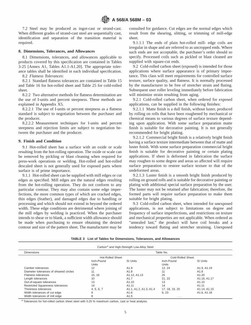
7.2 Steel may be produced as ingot-cast or strand-cast.When different grades of strand-cast steel are sequentially cast,identification and separation of the transition material isrequired.
8. Dimensions, Tolerances, and Allowances
8.1 Dimensions, tolerances, and allowances applicable toproducts covered by this specification are contained in Tables3-25 [Annex A1, Tables A1.1-A1.20]. The appropriate toler-ance tables shall be identified in each individual specification.
8.2 Flatness Tolerances:8.2.1 Standard flatness tolerances are contained in Table 15
and Table 16 for hot-rolled sheet and Table 25 for cold-rolledsheet.
8.2.2 Two alternative methods for flatness determination arethe use of I-units and percent steepness. These methods areexplained in Appendix X5.
8.2.2.1 The use of I-units or percent steepness as a flatnessstandard is subject to negotiation between the purchaser andthe producer.
8.2.2.2 Measurement techniques for I-units and percentsteepness and rejection limits are subject to negotiation be-tween the purchaser and the producer.
9. Finish and Condition
9.1 Hot-rolled sheet has a surface with an oxide or scaleresulting from the hot-rolling operation. The oxide or scale canbe removed by pickling or blast cleaning when required forpress-work operations or welding. Hot-rolled and hot-rolleddescaled sheet is not generally used for exposed parts wheresurface is of prime importance.
9.1.1 Hot-rolled sheet can be supplied with mill edges or cutedges as specified. Mill edges are the natural edges resultingfrom the hot-rolling operation. They do not conform to anyparticular contour. They may also contain some edge imper-fections, the more common types of which are cracked edges,thin edges (feather), and damaged edges due to handling orprocessing and which should not extend in beyond the orderedwidth. These edge conditions are detrimental where joining ofthe mill edges by welding is practiced. When the purchaserintends to shear or to blank, a sufficient width allowance shouldbe made when purchasing to ensure obtaining the desiredcontour and size of the pattern sheet. The manufacturer may be
consulted for guidance. Cut edges are the normal edges whichresult from the shearing, slitting, or trimming of mill-edgesheet.
9.1.1.1 The ends of plain hot-rolled mill- edge coils areirregular in shape and are referred to as uncropped ends. Wheresuch ends are not acceptable, the purchaser’s order should sospecify. Processed coils such as pickled or blast cleaned aresupplied with square-cut ends.
9.2 Cold-rolled carbon sheet (exposed) is intended for thoseapplications where surface appearance is of primary impor-tance. This class will meet requirements for controlled surfacetexture, surface quality, and flatness. It is normally processedby the manufacturer to be free of stretcher strain and fluting.Subsequent user roller leveling immediately before fabricationwill minimize strain resulting from aging.
9.2.1 Cold-rolled carbon sheet, when ordered for exposedapplications, can be supplied in the following finishes:
9.2.1.1 Matte finish is a dull finish, without luster, producedby rolling on rolls that have been roughened by mechanical orchemical means to various degrees of surface texture depend-ing upon application. With some surface preparation mattefinish is suitable for decorative painting. It is not generallyrecommended for bright plating.
9.2.1.2 Commercial bright finish is a relatively bright finishhaving a surface texture intermediate between that of matte andluster finish. With some surface preparation commercial brightfinish is suitable for decorative painting or certain platingapplications. If sheet is deformed in fabrication the surfacemay roughen to some degree and areas so affected will requiresurface preparation to restore surface texture to that of theundeformed areas.
9.2.1.3 Luster finish is a smooth bright finish produced byrolling on ground rolls and is suitable for decorative painting orplating with additional special surface preparation by the user.The luster may not be retained after fabrication; therefore, theformed parts will require surface preparation to make themsuitable for bright plating.
9.3 Cold-rolled carbon sheet, when intended for unexposedapplications, is not subject to limitations on degree andfrequency of surface imperfections, and restrictions on textureand mechanical properties are not applicable. When ordered as“annealed last,” the product will have coil breaks and atendency toward fluting and stretcher straining. Unexposed
TABLE 3 List of Tables for Dimensions, Tolerances, and Allowances
CarbonA and High-Strength Low-Alloy Steel
Dimensions Table No.
Hot-Rolled Sheet Cold-Rolled SheetInch-PoundUnits
SI Units Inch-PoundUnits
SI Units
Camber tolerances 12 A1.9 12, 24 A1.9, A1.19Diameter tolerances of sheared circles 11 A1.8 11 A1.8Flatness tolerances 15, 16 A1.12, A1.13 25 A1.20Length tolerances 10 A1.7 21, 22 A1.16, A1.17Out-of-square tolerances 13 A1.10 13 A1.10Restricted Squareness tolerances 14 A1.11 14 A1.11Thickness tolerances 4, 5, 6, 7 A1.1, A1.2, A1.3, A1.4 17, 18, 19, 20 A1.14, A1.15Width tolerances of cut edge 9 A1.6 9, 23 A1.6, A1.18Width tolerances of mill edge 8 A1.5 . . .
A Tolerances for hot-rolled carbon sheet steel with 0.25 % maximum carbon, cast or heat analysis.
A 568/A 568M – 03
5
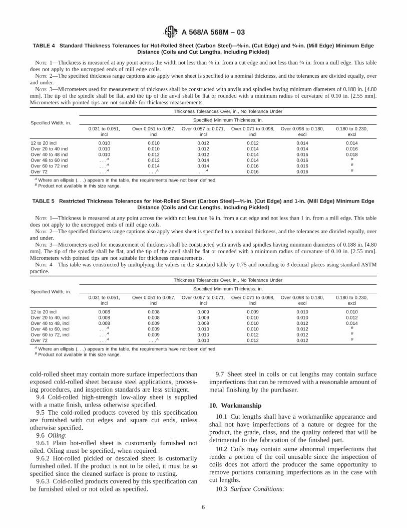
cold-rolled sheet may contain more surface imperfections thanexposed cold-rolled sheet because steel applications, process-ing procedures, and inspection standards are less stringent.
9.4 Cold-rolled high-strength low-alloy sheet is suppliedwith a matte finish, unless otherwise specified.
9.5 The cold-rolled products covered by this specificationare furnished with cut edges and square cut ends, unlessotherwise specified.
9.6 Oiling:9.6.1 Plain hot-rolled sheet is customarily furnished not
oiled. Oiling must be specified, when required.9.6.2 Hot-rolled pickled or descaled sheet is customarily
furnished oiled. If the product is not to be oiled, it must be sospecified since the cleaned surface is prone to rusting.
9.6.3 Cold-rolled products covered by this specification canbe furnished oiled or not oiled as specified.
9.7 Sheet steel in coils or cut lengths may contain surfaceimperfections that can be removed with a reasonable amount ofmetal finishing by the purchaser.
10. Workmanship
10.1 Cut lengths shall have a workmanlike appearance andshall not have imperfections of a nature or degree for theproduct, the grade, class, and the quality ordered that will bedetrimental to the fabrication of the finished part.
10.2 Coils may contain some abnormal imperfections thatrender a portion of the coil unusable since the inspection ofcoils does not afford the producer the same opportunity toremove portions containing imperfections as in the case withcut lengths.
10.3 Surface Conditions:
TABLE 4 Standard Thickness Tolerances for Hot-Rolled Sheet (Carbon Steel)— 3⁄8-in. (Cut Edge) and 3⁄4-in. (Mill Edge) Minimum EdgeDistance (Coils and Cut Lengths, Including Pickled)
NOTE 1—Thickness is measured at any point across the width not less than3⁄8 in. from a cut edge and not less than3⁄4 in. from a mill edge. This tabledoes not apply to the uncropped ends of mill edge coils.
NOTE 2—The specified thickness range captions also apply when sheet is specified to a nominal thickness, and the tolerances are divided equally, overand under.
NOTE 3—Micrometers used for measurement of thickness shall be constructed with anvils and spindles having minimum diameters of 0.188 in. [4.80mm]. The tip of the spindle shall be flat, and the tip of the anvil shall be flat or rounded with a minimum radius of curvature of 0.10 in. [2.55 mm].Micrometers with pointed tips are not suitable for thickness measurements.
Specified Width, in.
Thickness Tolerances Over, in., No Tolerance Under
Specified Minimum Thickness, in.
0.031 to 0.051,incl
Over 0.051 to 0.057,incl
Over 0.057 to 0.071,incl
Over 0.071 to 0.098,incl
Over 0.098 to 0.180,excl
0.180 to 0.230,excl
12 to 20 incl 0.010 0.010 0.012 0.012 0.014 0.014Over 20 to 40 incl 0.010 0.010 0.012 0.014 0.014 0.016Over 40 to 48 incl 0.010 0.012 0.012 0.014 0.016 0.018Over 48 to 60 incl . . .A 0.012 0.014 0.014 0.016 B
Over 60 to 72 incl . . .A 0.014 0.014 0.016 0.016 B
Over 72 . . .A . . .A . . .A 0.016 0.016 B
A Where an ellipsis (. . .) appears in the table, the requirements have not been defined.B Product not available in this size range.
TABLE 5 Restricted Thickness Tolerances for Hot-Rolled Sheet (Carbon Steel)— 5⁄8-in. (Cut Edge) and 1-in. (Mill Edge) Minimum EdgeDistance (Coils and Cut Lengths, Including Pickled)
NOTE 1—Thickness is measured at any point across the width not less than5⁄8 in. from a cut edge and not less than 1 in. from a mill edge. This tabledoes not apply to the uncropped ends of mill edge coils.
NOTE 2—The specified thickness range captions also apply when sheet is specified to a nominal thickness, and the tolerances are divided equally, overand under.
NOTE 3—Micrometers used for measurement of thickness shall be constructed with anvils and spindles having minimum diameters of 0.188 in. [4.80mm]. The tip of the spindle shall be flat, and the tip of the anvil shall be flat or rounded with a minimum radius of curvature of 0.10 in. [2.55 mm].Micrometers with pointed tips are not suitable for thickness measurements.
NOTE 4—This table was constructed by multiplying the values in the standard table by 0.75 and rounding to 3 decimal places using standard ASTMpractice.
Specified Width, in.
Thickness Tolerances Over, in., No Tolerance Under
Specified Minimum Thickness, in.
0.031 to 0.051,incl
Over 0.051 to 0.057,incl
Over 0.057 to 0.071,incl
Over 0.071 to 0.098,incl
Over 0.098 to 0.180,excl
0.180 to 0.230,excl
12 to 20 incl 0.008 0.008 0.009 0.009 0.010 0.010Over 20 to 40, incl 0.008 0.008 0.009 0.010 0.010 0.012Over 40 to 48, incl 0.008 0.009 0.009 0.010 0.012 0.014Over 48 to 60, incl . . .A 0.009 0.010 0.010 0.012 B
Over 60 to 72, incl . . .A 0.009 0.010 0.012 0.012 B
Over 72 . . .A . . .A 0.010 0.012 0.012 B
A Where an ellipsis (. . .) appears in the table, the requirements have not been defined.B Product not available in this size range.
A 568/A 568M – 03
6
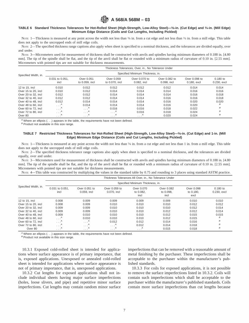
10.3.1 Exposed cold-rolled sheet is intended for applica-tions where surface appearance is of primary importance, thatis, exposed applications. Unexposed or annealed cold-rolledsheet is intended for applications where surface appearance isnot of primary importance, that is, unexposed applications.
10.3.2 Cut lengths for exposed applications shall not in-clude individual sheets having major surface imperfections(holes, loose slivers, and pipe) and repetitive minor surfaceimperfections. Cut lengths may contain random minor surface
imperfections that can be removed with a reasonable amount ofmetal finishing by the purchaser. These imperfections shall beacceptable to the purchaser within the manufacturer’s pub-lished standards.
10.3.3 For coils for exposed applications, it is not possibleto remove the surface imperfections listed in 10.3.2. Coils willcontain such imperfections which shall be acceptable to thepurchaser within the manufacturer’s published standards. Coilscontain more surface imperfections than cut lengths because
TABLE 6 Standard Thickness Tolerances for Hot-Rolled Sheet (High-Strength, Low-Alloy Steel)— 3⁄8-in. (Cut Edge) and 3⁄4-in. (Mill Edge)Minimum Edge Distance (Coils and Cut Lengths, Including Pickled)
NOTE 1—Thickness is measured at any point across the width not less than3⁄8 in. from a cut edge and not less than3⁄4 in. from a mill edge. This tabledoes not apply to the uncropped ends of mill edge coils.
NOTE 2—The specified thickness range captions also apply when sheet is specified to a nominal thickness, and the tolerances are divided equally, overand under.
NOTE 3—Micrometers used for measurement of thickness shall be constructed with anvils and spindles having minimum diameters of 0.188 in. [4.80mm]. The tip of the spindle shall be flat, and the tip of the anvil shall be flat or rounded with a minimum radius of curvature of 0.10 in. [2.55 mm].Micrometers with pointed tips are not suitable for thickness measurements.
Specified Width, in.
Thickness Tolerances, Over, in., No Tolerance Under
Specified Minimum Thickness, in.
0.031 to 0.051,incl
Over 0.051to 0.059, incl
Over 0.059to 0.070, incl
Over 0.070 to0.082, incl
Over 0.082 to0.098, incl
Over 0.098 to0.180, excl
0.180 to0.230, excl
12 to 15, incl 0.010 0.012 0.012 0.012 0.012 0.014 0.014Over 15 to 20, incl 0.010 0.012 0.014 0.014 0.014 0.016 0.016Over 20 to 32, incl 0.012 0.012 0.014 0.014 0.014 0.016 0.018Over 32 to 40, incl 0.012 0.012 0.014 0.014 0.016 0.016 0.018Over 40 to 48, incl 0.012 0.014 0.014 0.014 0.016 0.020 0.020Over 48 to 60, incl . . .A 0.014 0.014 0.014 0.016 0.020 B
Over 60 to 72, incl . . .A . . .A 0.016 0.016 0.018 0.022 B
Over 72 to 80, incl . . .A . . .A . . .A 0.016 0.018 0.024 B
Over 80 . . .A . . .A . . .A . . .A 0.020 0.024 B
A Where an ellipsis (. . .) appears in the table, the requirements have not been defined.B Product not available in this size range.
TABLE 7 Restricted Thickness Tolerances for Hot-Rolled Sheet (High-Strength, Low-Alloy Steel)— 5⁄8-in. (Cut Edge) and 1-in. (MillEdge) Minimum Edge Distance (Coils and Cut Lengths, Including Pickled)
NOTE 1—Thickness is measured at any point across the width not less than5⁄8 in. from a cut edge and not less than 1 in. from a mill edge. This tabledoes not apply to the uncropped ends of mill edge coils.
NOTE 2—The specified thickness tolerance range captions also apply when sheet is specified to a nominal thickness, and the tolerances are dividedequally, over and under.
NOTE 3—Micrometers used for measurement of thickness shall be constructed with anvils and spindles having minimum diameters of 0.188 in. [4.80mm]. The tip of the spindle shall be flat, and the tip of the anvil shall be flat or rounded with a minimum radius of curvature of 0.10 in. [2.55 mm].Micrometers with pointed tips are not suitable for thickness measurements.
NOTE 4—This table was constructed by multiplying the values in the standard table by 0.75 and rounding to 3 places using standard ASTM practice.
Specified Width, in.
Thickness Tolerances All Over, in., No Tolerance Under
Specified Minimum Thickness, in.
0.031 to 0.051,incl
Over 0.051 to0.059, incl
Over 0.059 to0.070, incl
Over 0.070to 0.082,
incl
Over 0.082to 0.098,
incl
Over 0.098to 0.180,
excl
0.180 to0.230, excl
12 to 15, incl 0.008 0.009 0.009 0.009 0.009 0.010 0.010Over 15 to 20, incl 0.008 0.009 0.010 0.010 0.010 0.012 0.012Over 20 to 32, incl 0.009 0.009 0.010 0.010 0.010 0.012 0.014Over 32 to 40, incl 0.009 0.009 0.010 0.010 0.012 0.012 0.014Over 40 to 48, incl 0.009 0.010 0.010 0.010 0.012 0.015 0.015Over 48 to 60, incl . . .A 0.010 0.010 0.010 0.012 0.015 B
Over 60 to 72, incl . . .A . . .A 0.012 0.012 0.014 0.016 B
Over 72 to 80, incl . . .A . . .A . . .A 0.012 0.014 0.018 B
Over 80 . . .A . . .A . . .A . . .A 0.015 0.018 B
A Where an ellipsis (. . .) appears in the table, the requirements have not been defined.B Product not available in this size range.
A 568/A 568M – 03
7
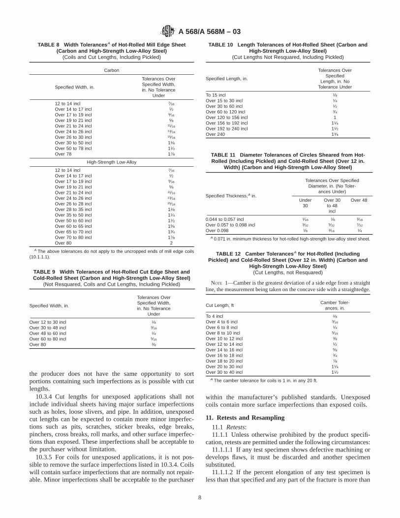
the producer does not have the same opportunity to sortportions containing such imperfections as is possible with cutlengths.
10.3.4 Cut lengths for unexposed applications shall notinclude individual sheets having major surface imperfectionssuch as holes, loose slivers, and pipe. In addition, unexposedcut lengths can be expected to contain more minor imperfec-tions such as pits, scratches, sticker breaks, edge breaks,pinchers, cross breaks, roll marks, and other surface imperfec-tions than exposed. These imperfections shall be acceptable tothe purchaser without limitation.
10.3.5 For coils for unexposed applications, it is not pos-sible to remove the surface imperfections listed in 10.3.4. Coilswill contain surface imperfections that are normally not repair-able. Minor imperfections shall be acceptable to the purchaser
within the manufacturer’s published standards. Unexposedcoils contain more surface imperfections than exposed coils.
11. Retests and Resampling
11.1 Retests:11.1.1 Unless otherwise prohibited by the product specifi-
cation, retests are permitted under the following circumstances:11.1.1.1 If any test specimen shows defective machining or
develops flaws, it must be discarded and another specimensubstituted.
11.1.1.2 If the percent elongation of any test specimen isless than that specified and any part of the fracture is more than
TABLE 8 Width Tolerances A of Hot-Rolled Mill Edge Sheet(Carbon and High-Strength Low-Alloy Steel)
(Coils and Cut Lengths, Including Pickled)
Carbon
Specified Width, in.
Tolerances OverSpecified Width,in. No Tolerance
Under
12 to 14 incl 7⁄16
Over 14 to 17 incl 1⁄2Over 17 to 19 incl 9⁄16
Over 19 to 21 incl 5⁄8Over 21 to 24 incl 11⁄16
Over 24 to 26 incl 13⁄16
Over 26 to 30 incl 15⁄16
Over 30 to 50 incl 11⁄8Over 50 to 78 incl 11⁄2Over 78 17⁄8
High-Strength Low-Alloy
12 to 14 incl 7⁄16
Over 14 to 17 incl 1⁄2Over 17 to 19 incl 9⁄16
Over 19 to 21 incl 5⁄8Over 21 to 24 incl 11⁄16
Over 24 to 26 incl 13⁄16
Over 26 to 28 incl 15⁄16
Over 28 to 35 incl 11⁄8Over 35 to 50 incl 11⁄4Over 50 to 60 incl 11⁄2Over 60 to 65 incl 15⁄8Over 65 to 70 incl 13⁄4Over 70 to 80 incl 17⁄8Over 80 2
A The above tolerances do not apply to the uncropped ends of mill edge coils(10.1.1.1).
TABLE 9 Width Tolerances of Hot-Rolled Cut Edge Sheet andCold-Rolled Sheet (Carbon and High-Strength Low-Alloy Steel)
(Not Resquared, Coils and Cut Lengths, Including Pickled)
Specified Width, in.
Tolerances OverSpecified Width,in. No Tolerance
Under
Over 12 to 30 incl 1⁄8Over 30 to 48 incl 3⁄16
Over 48 to 60 incl 1⁄4Over 60 to 80 incl 5⁄16
Over 80 3⁄8
TABLE 10 Length Tolerances of Hot-Rolled Sheet (Carbon andHigh-Strength Low-Alloy Steel)
(Cut Lengths Not Resquared, Including Pickled)
Specified Length, in.
Tolerances OverSpecified
Length, in. NoTolerance Under
To 15 incl 1⁄8Over 15 to 30 incl 1⁄4Over 30 to 60 incl 1⁄2Over 60 to 120 incl 3⁄4Over 120 to 156 incl 1Over 156 to 192 incl 11⁄4Over 192 to 240 incl 11⁄2Over 240 13⁄4
TABLE 11 Diameter Tolerances of Circles Sheared from Hot-Rolled (Including Pickled) and Cold-Rolled Sheet (Over 12 in.
Width) (Carbon and High-Strength Low-Alloy Steel)
Specified Thickness,A in.
Tolerances Over SpecifiedDiameter, in. (No Toler-
ances Under)
Under30
Over 30to 48incl
Over 48
0.044 to 0.057 incl 1⁄16 1⁄8 3⁄16
Over 0.057 to 0.098 incl 3⁄32 5⁄32 7⁄32
Over 0.098 1⁄8 3⁄16 1⁄4A 0.071 in. minimum thickness for hot-rolled high-strength low-alloy steel sheet.
TABLE 12 Camber Tolerances A for Hot-Rolled (IncludingPickled) and Cold-Rolled Sheet (Over 12 in. Width) (Carbon and
High-Strength Low-Alloy Steel)(Cut Lengths, not Resquared)
NOTE 1—Camber is the greatest deviation of a side edge from a straightline, the measurement being taken on the concave side with a straightedge.
Cut Length, ftCamber Toler-
ances, in.
To 4 incl 1⁄8Over 4 to 6 incl 3⁄16
Over 6 to 8 incl 1⁄4Over 8 to 10 incl 5⁄16
Over 10 to 12 incl 3⁄8Over 12 to 14 incl 1⁄2Over 14 to 16 incl 5⁄8Over 16 to 18 incl 3⁄4Over 18 to 20 incl 7⁄8Over 20 to 30 incl 11⁄4Over 30 to 40 incl 11⁄2
A The camber tolerance for coils is 1 in. in any 20 ft.
A 568/A 568M – 03
8
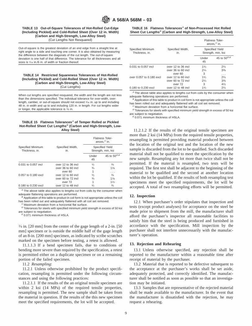
3⁄4 in. [20 mm] from the center of the gage length of a 2-in. [50mm] specimen or is outside the middle half of the gage lengthof an 8-in. [200 mm] specimen, as indicated by scribe scratchesmarked on the specimen before testing, a retest is allowed.
11.1.1.3 If a bend specimen fails, due to conditions ofbending more severe than required by the specification, a retestis permitted either on a duplicate specimen or on a remainingportion of the failed specimen.
11.2 Resampling:11.2.1 Unless otherwise prohibited by the product specifi-
cation, resampling is permitted under the following circum-stances and using the following practices:
11.2.1.1 If the results of the an original tensile specimen arewithin 2 ksi (14 MPa) of the required tensile properties,resampling is permitted. The new sample shall be taken fromthe material in question. If the results of the this new specimenmeet the specified requirements, the lot will be accepted.
11.2.1.2 If the results of the original tensile specimen aremore than 2 ksi (14 MPa) from the required tensile properties,resampling is permitted providing material produced betweenthe location of the original test and the location of the newsample is discarded from the lot to be qualified. Such discardedmaterial shall not be qualified to meet the specification by thenew sample. Resampling any lot more than twice shall not bepermitted. If the material is resampled, two tests will berequired. The first test shall be adjacent to the beginning of thematerial to be qualified and the second at another locationwithin the lot be qualified. If the results of both resampling testspecimens meet the specified requirements, the lot will beaccepted. A total of two resampling efforts will be permitted.
12. Inspection
12.1 When purchaser’s order stipulates that inspection andtests (except product analyses) for acceptance on the steel bemade prior to shipment from the mill, the manufacturer shallafford the purchaser’s inspector all reasonable facilities tosatisfy him that the steel is being produced and furnished inaccordance with the specification. Mill inspection by thepurchaser shall not interfere unnecessarily with the manufac-turer’s operation.
13. Rejection and Rehearing
13.1 Unless otherwise specified, any rejection shall bereported to the manufacturer within a reasonable time afterreceipt of material by the purchaser.
13.2 Material that is reported to be defective subsequent tothe acceptance at the purchaser’s works shall be set aside,adequately protected, and correctly identified. The manufac-turer shall be notified as soon as possible so that an investiga-tion may be initiated.
13.3 Samples that are representative of the rejected materialshall be made available to the manufacturer. In the event thatthe manufacturer is dissatisfied with the rejection, he mayrequest a rehearing.
TABLE 13 Out-of-Square Tolerances of Hot-Rolled Cut-Edge(Including Pickled) and Cold-Rolled Sheet (Over 12 in. Width)
(Carbon and High-Strength, Low-Alloy Steel)(Cut Lengths Not Resquared)
Out-of-square is the greatest deviation of an end edge from a straight line atright angle to a side and touching one corner. It is also obtained by measuringthe difference between the diagonals of the cut length. The out-of-squaredeviation is one half of that difference. The tolerance for all thicknesses and allsizes is 1⁄16 in./6 in. of width or fraction thereof.
TABLE 14 Restricted Squareness Tolerances of Hot-Rolled(Including Pickled) and Cold-Rolled Sheet (Over 12 in. Width)
(Carbon and High-Strength, Low-Alloy Steel)(Cut Lengths)
When cut lengths are specified resquared, the width and the length are not lessthan the dimensions specified. The individual tolerance for over-width, over-length, camber, or out-of-square should not exceed 1⁄16 in. up to and including48 in. in width and up to and including 120 in. in length. For cut lengths wideror longer, the applicable tolerance is 1⁄8 in.
TABLE 15 Flatness Tolerances A of Temper Rolled or PickledHot-Rolled Sheet Cut Lengths B (Carbon and High-Strength, Low-
Alloy Steel)
Specified MinimumThickness, in.
Specified Width,in.
Flatness Toler-ances,C in.
Specified YieldStrength, min, ksi
Under45
45 to 50D,E
0.031 to 0.057 incl over 12 to 36 inclover 36 to 60 incl
over 60
1⁄23⁄41
3⁄411⁄8. . .
0.057 to 0.180 excl over 12 to 60 inclover 60 to 72 incl
over 72
1⁄23⁄41
3⁄411⁄811⁄2
0.180 to 0.230 excl over 12 to 48 incl 1⁄2 3⁄4A The above table also applies to lengths cut from coils by the consumer when
adequate flattening operations are performed.B Application of this table to product in coil form is not appropriate unless the coil
has been rolled out and adequately flattened with all coil set removed.C Maximum deviation from a horizontal flat surface.D Tolerances for steels with specified minimum yield strength in excess of 50 ksi
are subject to negotiation.E 0.071 minimum thickness of HSLA.
TABLE 16 Flatness Tolerances A of Non-Processed Hot RolledSheet Cut Lengths B (Carbon and High-Strength, Low-Alloy Steel)
Specified MinimumThickness, in.
Specified Width,in.
Flatness Toler-ances,C in.
Specified YieldStrength, min, ksi
Under45
45 to 50D,E
0.031 to 0.057 incl over 12 to 36 inclover 36 to 60 incl
over 60
11⁄221⁄43
21⁄433⁄8. . .
over 0.057 to 0.180 excl over 12 to 60 inclover 60 to 72 incl
over 72
11⁄221⁄43
21⁄433⁄841⁄2
0.180 to 0.230 excl over 12 to 48 incl 11⁄2 21⁄4A The above table also applies to lengths cut from coils by the consumer when
adequate flattening operations are performed.B Application of this table to product in coil form is not appropriate unless the coil
has been rolled out and adequately flattened with all coil set removed.C Maximum deviation from a horizontal flat surface.D Tolerances for steels with specified minimum yield strength in excess of 50 ksi
are subject to negotiation.E 0.071 minimum thickness of HSLA.
A 568/A 568M – 03
9
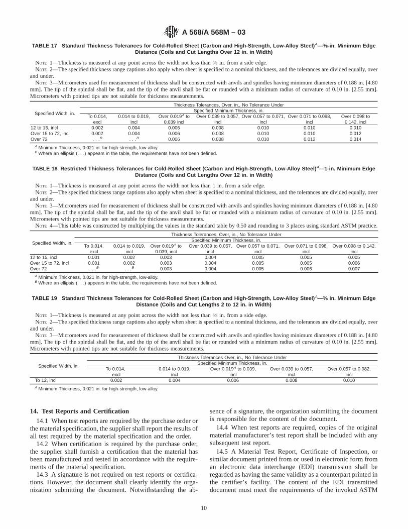
14. Test Reports and Certification
14.1 When test reports are required by the purchase order orthe material specification, the supplier shall report the results ofall test required by the material specification and the order.
14.2 When certification is required by the purchase order,the supplier shall furnish a certification that the material hasbeen manufactured and tested in accordance with the require-ments of the material specification.
14.3 A signature is not required on test reports or certifica-tions. However, the document shall clearly identify the orga-nization submitting the document. Notwithstanding the ab-
sence of a signature, the organization submitting the documentis responsible for the content of the document.
14.4 When test reports are required, copies of the originalmaterial manufacturer’s test report shall be included with anysubsequent test report.
14.5 A Material Test Report, Certificate of Inspection, orsimilar document printed from or used in electronic form froman electronic data interchange (EDI) transmission shall beregarded as having the same validity as a counterpart printed inthe certifier’s facility. The content of the EDI transmitteddocument must meet the requirements of the invoked ASTM
TABLE 17 Standard Thickness Tolerances for Cold-Rolled Sheet (Carbon and High-Strength, Low-Alloy Steel) A—3⁄8-in. Minimum EdgeDistance (Coils and Cut Lengths Over 12 in. in Width)
NOTE 1—Thickness is measured at any point across the width not less than3⁄8 in. from a side edge.NOTE 2—The specified thickness range captions also apply when sheet is specified to a nominal thickness, and the tolerances are divided equally, over
and under.NOTE 3—Micrometers used for measurement of thickness shall be constructed with anvils and spindles having minimum diameters of 0.188 in. [4.80
mm]. The tip of the spindal shall be flat, and the tip of the anvil shall be flat or rounded with a minimum radius of curvature of 0.10 in. [2.55 mm].Micrometers with pointed tips are not suitable for thickness measurements.
Specified Width, in.
Thickness Tolerances, Over, in., No Tolerance UnderSpecified Minimum Thickness, in.
To 0.014,excl
0.014 to 0.019,incl
Over 0.019A to0.039 incl
Over 0.039 to 0.057,incl
Over 0.057 to 0.071,incl
Over 0.071 to 0.098,incl
Over 0.098 to0.142, incl
12 to 15, incl 0.002 0.004 0.006 0.008 0.010 0.010 0.010Over 15 to 72, incl 0.002 0.004 0.006 0.008 0.010 0.010 0.012Over 72 . . .B . . .B 0.006 0.008 0.010 0.012 0.014
A Minimum Thickness, 0.021 in. for high-strength, low-alloy.B Where an ellipsis (. . .) appears in the table, the requirements have not been defined.
TABLE 18 Restricted Thickness Tolerances for Cold-Rolled Sheet (Carbon and High-Strength, Low-Alloy Steel) A—1-in. Minimum EdgeDistance (Coils and Cut Lengths Over 12 in. in Width)
NOTE 1—Thickness is measured at any point across the width not less than 1 in. from a side edge.NOTE 2—The specified thickness range captions also apply when sheet is specified to a nominal thickness, and the tolerances are divided equally, over
and under.NOTE 3—Micrometers used for measurement of thickness shall be constructed with anvils and spindles having minimum diameters of 0.188 in. [4.80
mm]. The tip of the spindal shall be flat, and the tip of the anvil shall be flat or rounded with a minimum radius of curvature of 0.10 in. [2.55 mm].Micrometers with pointed tips are not suitable for thickness measurements.
NOTE 4—This table was constructed by multiplying the values in the standard table by 0.50 and rounding to 3 places using standard ASTM practice.
Specified Width, in.
Thickness Tolerances, Over, in., No Tolerance UnderSpecified Minimum Thickness, in.
To 0.014,excl
0.014 to 0.019,incl
Over 0.019A to0.039, incl
Over 0.039 to 0.057,incl
Over 0.057 to 0.071,incl
Over 0.071 to 0.098,incl
Over 0.098 to 0.142,incl
12 to 15, incl 0.001 0.002 0.003 0.004 0.005 0.005 0.005Over 15 to 72, incl 0.001 0.002 0.003 0.004 0.005 0.005 0.006Over 72 . . .B . . .B 0.003 0.004 0.005 0.006 0.007
A Minimum Thickness, 0.021 in. for high-strength, low-alloy.B Where an ellipsis (. . .) appears in the table, the requirements have not been defined.
TABLE 19 Standard Thickness Tolerances for Cold-Rolled Sheet (Carbon and High-Strength, Low-Alloy Steel) A—3⁄8 in. Minimum EdgeDistance (Coils and Cut Lengths 2 to 12 in. in Width)
NOTE 1—Thickness is measured at any point across the width not less than3⁄8 in. from a side edge.NOTE 2—The specified thickness range captions also apply when sheet is specified to a nominal thickness, and the tolerances are divided equally, over
and under.NOTE 3—Micrometers used for measurement of thickness shall be constructed with anvils and spindles having minimum diameters of 0.188 in. [4.80
mm]. The tip of the spindal shall be flat, and the tip of the anvil shall be flat or rounded with a minimum radius of curvature of 0.10 in. [2.55 mm].Micrometers with pointed tips are not suitable for thickness measurements.
Specified Width, in.
Thickness Tolerances Over, in., No Tolerance UnderSpecified Minimum Thickness, in.
To 0.014,excl
0.014 to 0.019,incl
Over 0.019A to 0.039,incl
Over 0.039 to 0.057,incl
Over 0.057 to 0.082,incl
To 12, incl 0.002 0.004 0.006 0.008 0.010A Minimum Thickness, 0.021 in. for high-strength, low-alloy.
A 568/A 568M – 03
10
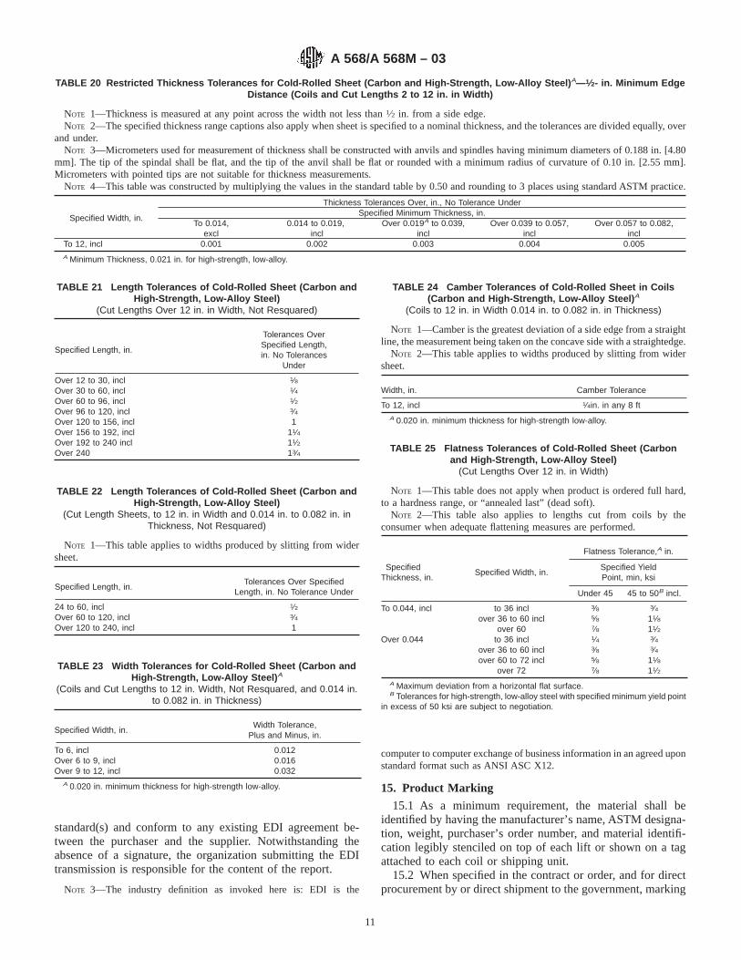
standard(s) and conform to any existing EDI agreement be-tween the purchaser and the supplier. Notwithstanding theabsence of a signature, the organization submitting the EDItransmission is responsible for the content of the report.
NOTE 3—The industry definition as invoked here is: EDI is the
computer to computer exchange of business information in an agreed uponstandard format such as ANSI ASC X12.
15. Product Marking
15.1 As a minimum requirement, the material shall beidentified by having the manufacturer’s name, ASTM designa-tion, weight, purchaser’s order number, and material identifi-cation legibly stenciled on top of each lift or shown on a tagattached to each coil or shipping unit.
15.2 When specified in the contract or order, and for directprocurement by or direct shipment to the government, marking
TABLE 20 Restricted Thickness Tolerances for Cold-Rolled Sheet (Carbon and High-Strength, Low-Alloy Steel) A—1⁄2- in. Minimum EdgeDistance (Coils and Cut Lengths 2 to 12 in. in Width)
NOTE 1—Thickness is measured at any point across the width not less than1⁄2 in. from a side edge.NOTE 2—The specified thickness range captions also apply when sheet is specified to a nominal thickness, and the tolerances are divided equally, over
and under.NOTE 3—Micrometers used for measurement of thickness shall be constructed with anvils and spindles having minimum diameters of 0.188 in. [4.80
mm]. The tip of the spindal shall be flat, and the tip of the anvil shall be flat or rounded with a minimum radius of curvature of 0.10 in. [2.55 mm].Micrometers with pointed tips are not suitable for thickness measurements.
NOTE 4—This table was constructed by multiplying the values in the standard table by 0.50 and rounding to 3 places using standard ASTM practice.
Specified Width, in.
Thickness Tolerances Over, in., No Tolerance UnderSpecified Minimum Thickness, in.
To 0.014,excl
0.014 to 0.019,incl
Over 0.019A to 0.039,incl
Over 0.039 to 0.057,incl
Over 0.057 to 0.082,incl
To 12, incl 0.001 0.002 0.003 0.004 0.005A Minimum Thickness, 0.021 in. for high-strength, low-alloy.
TABLE 21 Length Tolerances of Cold-Rolled Sheet (Carbon andHigh-Strength, Low-Alloy Steel)
(Cut Lengths Over 12 in. in Width, Not Resquared)
Specified Length, in.
Tolerances OverSpecified Length,in. No Tolerances
Under
Over 12 to 30, incl 1⁄8Over 30 to 60, incl 1⁄4Over 60 to 96, incl 1⁄2Over 96 to 120, incl 3⁄4Over 120 to 156, incl 1Over 156 to 192, incl 11⁄4Over 192 to 240 incl 11⁄2Over 240 13⁄4
TABLE 22 Length Tolerances of Cold-Rolled Sheet (Carbon andHigh-Strength, Low-Alloy Steel)
(Cut Length Sheets, to 12 in. in Width and 0.014 in. to 0.082 in. inThickness, Not Resquared)
NOTE 1—This table applies to widths produced by slitting from widersheet.
Specified Length, in.Tolerances Over Specified
Length, in. No Tolerance Under
24 to 60, incl 1⁄2Over 60 to 120, incl 3⁄4Over 120 to 240, incl 1
TABLE 23 Width Tolerances for Cold-Rolled Sheet (Carbon andHigh-Strength, Low-Alloy Steel) A
(Coils and Cut Lengths to 12 in. Width, Not Resquared, and 0.014 in.to 0.082 in. in Thickness)
Specified Width, in.Width Tolerance,
Plus and Minus, in.
To 6, incl 0.012Over 6 to 9, incl 0.016Over 9 to 12, incl 0.032
A 0.020 in. minimum thickness for high-strength low-alloy.
TABLE 24 Camber Tolerances of Cold-Rolled Sheet in Coils(Carbon and High-Strength, Low-Alloy Steel) A
(Coils to 12 in. in Width 0.014 in. to 0.082 in. in Thickness)
NOTE 1—Camber is the greatest deviation of a side edge from a straightline, the measurement being taken on the concave side with a straightedge.
NOTE 2—This table applies to widths produced by slitting from widersheet.
Width, in. Camber Tolerance
To 12, incl 1⁄4in. in any 8 ftA 0.020 in. minimum thickness for high-strength low-alloy.
TABLE 25 Flatness Tolerances of Cold-Rolled Sheet (Carbonand High-Strength, Low-Alloy Steel)
(Cut Lengths Over 12 in. in Width)
NOTE 1—This table does not apply when product is ordered full hard,to a hardness range, or “annealed last” (dead soft).
NOTE 2—This table also applies to lengths cut from coils by theconsumer when adequate flattening measures are performed.
SpecifiedThickness, in.
Specified Width, in.
Flatness Tolerance,A in.
Specified YieldPoint, min, ksi
Under 45 45 to 50B incl.
To 0.044, incl to 36 incl 3⁄8 3⁄4over 36 to 60 incl 5⁄8 11⁄8
over 60 7⁄8 11⁄2Over 0.044 to 36 incl 1⁄4 3⁄4
over 36 to 60 incl 3⁄8 3⁄4over 60 to 72 incl 5⁄8 11⁄8
over 72 7⁄8 11⁄2A Maximum deviation from a horizontal flat surface.B Tolerances for high-strength, low-alloy steel with specified minimum yield point
in excess of 50 ksi are subject to negotiation.
A 568/A 568M – 03
11

for shipment in addition to requirements specified in thecontract or order, shall be in accordance with MIL-STD-129for military agencies and in accordance with Fed. Std. No. 123for civil agencies.
15.3 Bar coding is acceptable as a supplementary identifi-cation method. Bar coding should be consistent with theAutomotive Industry Action Group (AIAG) standard preparedby the primary metals subcommittee of the AIAG bar codeproject team.
16. Packing and Package Marking
16.1 Unless otherwise specified, the sheet shall be pack-aged and loaded in accordance with Practices A 700.
16.2 When specified in the contract or order, and for directprocurement by or direct shipment to the government, when
Level A is specified, preservation, packaging, and packing shallbe in accordance with the Level A requirements of MIL-STD-163.
16.3 When coils are ordered, it is customary to specify aminimum or range of inside diameter, maximum outsidediameter, and a maximum coil weight, if required. The abilityof manufacturers to meet the maximum coil weights dependsupon individual mill equipment. When required, minimum coilweights are subject to negotiation.
17. Keywords
17.1 alloy steel sheet; carbon steel sheet; cold rolled steelsheet; general delivery requirements; high strength low alloysteel; hot rolled steel sheet; steel sheet
ANNEX
(Mandatory Information)
A1. PERMISSIBLE VARIATIONS IN DIMENSIONS AND MASS IN SI UNITS
A1.1 Listed in Tables A1.1-A1.20 are permissible varia-tions in dimensions and mass expressed in the International
System of Units (SI) terminology.
TABLE A1.1 Standard Thickness Tolerances [Metric] for Hot-Rolled Sheet (Carbon Steel)—10-mm (Cut Edge) and 20-mm (Mill Edge)Minimum Edge Distance (Coils and Cut Lengths, Including Pickled)
NOTE 1—Thickness is measured at any point across the width not less than 10 mm from a cut edge and not less than 20 mm from a mill edge. Thistable does not apply to the uncropped ends of mill edge coils.
NOTE 2—The specified thickness range captions also apply when sheet is specified to a nominal thickness, and the tolerances are divided equally, overand under.
NOTE 3—Micrometers used for measurement of thickness shall be constructed with anvils and spindles having minimum diameters of 0.188 in. [4.80mm]. The tip of the spindle shall be flat, and the tip of the anvil shall be flat or rounded with a minimum radius of curvature of 0.10 in. [2.55 mm].Micrometers with pointed tips are not suitable for thickness measurements.
Specified Width, mm
Thickness Tolerances, Over, mm, No Tolerance Under
Specified Minimum Thickness, mm
Through 2.0 Over 2.0 to 2.5, incl Over 2.5 to 4.5, excl 4.5 to 6.0, excl
Over 300 to 600, incl 0.30 0.30 0.35 0.40Over 600 to 1200, incl 0.30 0.35 0.40 0.45Over 1200 to 1500, incl 0.35 0.35 0.40 A
Over 1500 to 1800, incl 0.35 0.40 0.40 A
Over 1800 0.35 0.40 0.40 A
A Product not available in this size range.
A 568/A 568M – 03
12
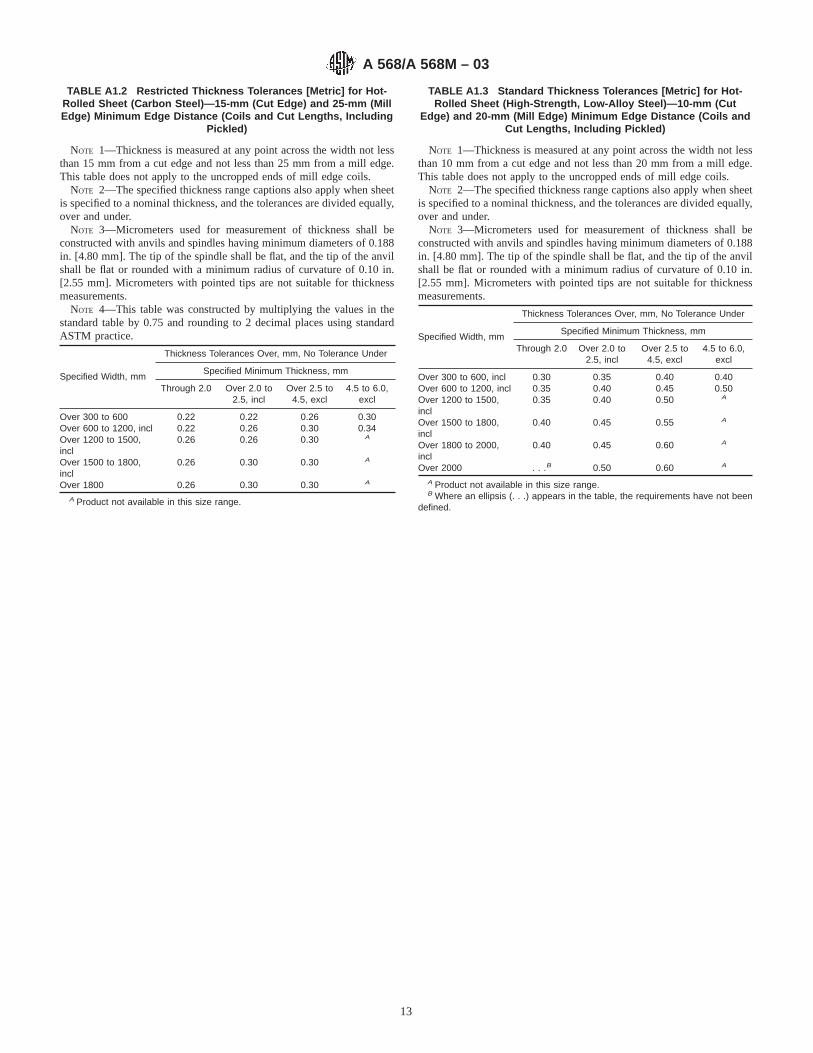
TABLE A1.2 Restricted Thickness Tolerances [Metric] for Hot-Rolled Sheet (Carbon Steel)—15-mm (Cut Edge) and 25-mm (MillEdge) Minimum Edge Distance (Coils and Cut Lengths, Including
Pickled)
NOTE 1—Thickness is measured at any point across the width not lessthan 15 mm from a cut edge and not less than 25 mm from a mill edge.This table does not apply to the uncropped ends of mill edge coils.
NOTE 2—The specified thickness range captions also apply when sheetis specified to a nominal thickness, and the tolerances are divided equally,over and under.
NOTE 3—Micrometers used for measurement of thickness shall beconstructed with anvils and spindles having minimum diameters of 0.188in. [4.80 mm]. The tip of the spindle shall be flat, and the tip of the anvilshall be flat or rounded with a minimum radius of curvature of 0.10 in.[2.55 mm]. Micrometers with pointed tips are not suitable for thicknessmeasurements.
NOTE 4—This table was constructed by multiplying the values in thestandard table by 0.75 and rounding to 2 decimal places using standardASTM practice.
Specified Width, mm
Thickness Tolerances Over, mm, No Tolerance Under
Specified Minimum Thickness, mm
Through 2.0 Over 2.0 to2.5, incl
Over 2.5 to4.5, excl
4.5 to 6.0,excl
Over 300 to 600 0.22 0.22 0.26 0.30Over 600 to 1200, incl 0.22 0.26 0.30 0.34Over 1200 to 1500,incl
0.26 0.26 0.30 A
Over 1500 to 1800,incl
0.26 0.30 0.30 A
Over 1800 0.26 0.30 0.30 A
A Product not available in this size range.
TABLE A1.3 Standard Thickness Tolerances [Metric] for Hot-Rolled Sheet (High-Strength, Low-Alloy Steel)—10-mm (Cut
Edge) and 20-mm (Mill Edge) Minimum Edge Distance (Coils andCut Lengths, Including Pickled)
NOTE 1—Thickness is measured at any point across the width not lessthan 10 mm from a cut edge and not less than 20 mm from a mill edge.This table does not apply to the uncropped ends of mill edge coils.
NOTE 2—The specified thickness range captions also apply when sheetis specified to a nominal thickness, and the tolerances are divided equally,over and under.
NOTE 3—Micrometers used for measurement of thickness shall beconstructed with anvils and spindles having minimum diameters of 0.188in. [4.80 mm]. The tip of the spindle shall be flat, and the tip of the anvilshall be flat or rounded with a minimum radius of curvature of 0.10 in.[2.55 mm]. Micrometers with pointed tips are not suitable for thicknessmeasurements.
Specified Width, mm
Thickness Tolerances Over, mm, No Tolerance Under
Specified Minimum Thickness, mm
Through 2.0 Over 2.0 to2.5, incl
Over 2.5 to4.5, excl
4.5 to 6.0,excl
Over 300 to 600, incl 0.30 0.35 0.40 0.40Over 600 to 1200, incl 0.35 0.40 0.45 0.50Over 1200 to 1500,incl
0.35 0.40 0.50 A
Over 1500 to 1800,incl
0.40 0.45 0.55 A
Over 1800 to 2000,incl
0.40 0.45 0.60 A
Over 2000 . . .B 0.50 0.60 A
A Product not available in this size range.B Where an ellipsis (. . .) appears in the table, the requirements have not been
defined.
A 568/A 568M – 03
13

TABLE A1.4 Restricted Thickness Tolerances of Hot-RolledSheet (High-Strength, Low-Alloy Steel)—15-mm (Cut Edge) and
25-mm (Mill Edge) Minimum Edge Distance (Coils and CutLengths, Including Pickled)
NOTE 1—Thickness is measured at any point across the width not lessthan 15 mm from a cut edge and not less than 25 mm from a mill edge.This table does not apply to the uncropped ends of mill edge coils.
NOTE 2—The specified thickness range captions also apply when sheetis specified to a nominal thickness, and the tolerances are divided equally,over and under.
NOTE 3—Micrometers used for measurement of thickness shall beconstructed with anvils and spindles having minimum diameters of 0.188in. [4.80 mm]. The tip of the spindle shall be flat, and the tip of the anvilshall be flat or rounded with a minimum radius of curvature of 0.10 in.[2.55 mm]. Micrometers with pointed tips are not suitable for thicknessmeasurements.
NOTE 4—This table was constructed by multiplying the values in thestandard table by 0.75 and rounding to 2 decimal places using standardASTM practice.
Specified Width, mm
Thickness Tolerances Over, mm, No Tolerance Under
Specified Minimum Thickness, mm
Through2.0
Over 2.0 to2.5, incl
Over 2.5 to4.5, excl
4.5 to6.0, excl
Over 300 to 600, incl 0.22 0.26 0.30 0.30Over 600 to 1200, incl 0.26 0.30 0.34 0.38Over 1200 to 1500, incl 0.26 0.30 0.38 A
Over 1500 to 1800, incl 0.30 0.34 0.41 A
Over 1800 to 2000, incl 0.30 0.34 0.45 A
Over 2000 . . .B 0.38 0.45 A
A Product not available in this size range.B Where an ellipsis (. . .) appears in the table, the requirements have not been
defined.
TABLE A1.5 Width Tolerances A of Hot-Rolled Mill Edge Sheet(Carbon and High-Strength Low-Alloy Steel)
(Coils and Cut Lengths, Including Pickled)
Specified Width, mm Width Tolerance, Over Only, mm
Over Through Carbon HSLA
300 600 16 16600 1200 26 28
1200 1500 32 381500 1800 35 451800 . . . 48 50
A The above tolerances do not apply to the uncropped ends of mill edge coils(9.1.1.1).
TABLE A1.6 Width Tolerances of Hot-Rolled Cut Edge Sheet andCold-Rolled Sheet (Carbon and High-Strength Low-Alloy Steel)
(Not Resquared Coils and Cut Lengths, Including Pickled)
Specified Width, mm Width Tolerance, Over Only, mm
Over Through
300 600 3600 1200 5
1200 1500 61500 1800 81800 . . . 10
TABLE A1.7 Length Tolerances of Hot-Rolled Sheet (Carbon andHigh-Strength Low-Alloy Steel)
(Cut Lengths Not Resquared, Including Pickled)
Specified Length, mm Length Tolerance, OverOnly, mm
Over Through
300 600 6600 900 8900 1500 12
1500 3000 203000 4000 254000 5000 355000 6000 406000 . . . 45
TABLE A1.8 Diameter Tolerances of Circles from Hot-Rolled(Including Pickled) and Cold-Rolled Sheet (Over 300 mm Width)
(Carbon and High-Strength Low-Alloy Steel)
Specified ThicknessA, mm Tolerances Over Specified Diameter, mm (NoTolerances Under)
Over Through Diameters, mm
Through 600 Over 600 to1200, incl
Over 1200
. . . 1.5 1.5 3.0 5.01.5 2.5 2.5 4.0 5.52.5 . . . 3.0 5.0 6.5
A 1.8 mm minimum thickness for hot-rolled high-strength low-alloy steel sheet.
TABLE A1.9 Camber Tolerances A for Hot-Rolled (IncludingPickled) and Cold-Rolled Sheet (Over 300 mm Width) (Carbon
and High-Strength Low-Alloy Steel)(Cut Lengths, Not Resquared)
NOTE 1— Camber is the greatest deviation of a side edge from astraight line, the measurement being taken on the concave side with astraightedge.
Cut Length, mm Camber TolerancesA, mm
Over Through
. . . 1200 41200 1800 51800 2400 62400 3000 83000 3700 103700 4300 134300 4900 164900 5500 195500 6000 226000 9000 329000 12 200 38
A The camber tolerance for coils is 25.0 mm in any 6000 mm.
A 568/A 568M – 03
14

TABLE A1.10 Out-of-Square Tolerances of Hot-Rolled Cut-Edge(Including Pickled) and Cold-Rolled Sheet (Over 300 mm Width)
(Carbon and High-Strength Low-Alloy Steel)(Cut Lengths Not Resquared)
Out-of-square is the greatest deviation of an end edge from a straight line atright angle to a side and touching one corner. It is also obtained by measuringthe difference between the diagonals of the cut length. The out-of-squaredeviation is one half of that difference. The tolerance for all thicknesses and allsizes is 1.0 mm/100 mm of width or fraction thereof.
TABLE A1.11 Restricted Squareness Tolerances of Hot-Rolled(Including Pickled) and Cold-Rolled Sheet (Over 300 mm Width)
(Carbon and High-Strength Low-Alloy Steel)(Cut Lengths)
When cut lengths are specified resquared, the width and the length are not lessthan the dimensions specified. The individual tolerance for over-width, over-length, camber, or out-of-square should not exceed 1.6 mm up to and including1200 mm in width and up to and including 3000 mm in length. For cut lengthswider or longer, the applicable tolerance is 3.2 mm.
TABLE A1.12 Flatness Tolerances A of Temper Rolled or Pickled Hot-Rolled Sheet Cut Lengths B (Carbon and High-Strength Low-AlloySteel)
Specified Thickness, mm
Specified Width, mm
Flatness ToleranceC, mm Specified YieldStrength, min, MPaD
Over Through Under 310 310 to 345MPa YieldPoint, min,
MPa
1.2 1.5 to 900, incl 15 20over 900 to 1500, incl 20 30
over 1500 25 . . .1.5 4.5 to 1500, incl 15 20
over 1500 to 1800, incl 20 30over 1800 25 40
4.5 6.0 excl to 1200, incl 15 20A The above table also applies to lengths cut from coils by the consumer when adequate flattening operations are performed.B Application of this table to product in coil form is not appropriate unless the coil has been rolled out and adequately flattened with all coil set removed.C Maximum deviation from a horizontal surface.D Tolerances for high-strength, low-alloy steels with specified minimum yield strength in excess of 345 MPa are subject to negotiation.
A 568/A 568M – 03
15

TABLE A1.13 Flatness Tolerances A of Non-Processed Hot-Rolled Sheet Cut Lengths B (Carbon and High-Strength Low-Alloy Steel)
Specified Thickness, mm
Specified Width, mm
Flatness ToleranceC, mm Specified YieldStrength, min, MPaD
Over Through Under 310 310 to 345MPa YieldPoint, min,
MPa
1.2 1.5 to 900, incl 45 60over 900 to 1500, incl 60 90
over 1500 75 . . .1.5 4.5 to 1500, incl 45 60
over 1500 to 1800, incl 60 90over 1800 75 120
4.5 6.0 excl to 1200, incl 45 60A The above table also applies to lengths cut from coils by the consumer when adequate flattening operations are performed.B Application of this table to product in coil form is not appropriate unless the coil has been rolled out and adequately flattened with all coil set removed.C Maximum deviation from a horizontal surface.D Tolerances for high-strength, low-alloy steels with specified minimum yield strength in excess of 345 MPa are subject to negotiation.
TABLE A1.14 Standard Thickness Tolerances [Metric] for Cold-Rolled Sheet (Carbon and High-Strength, Low-Alloy Steel) A—10-mmMinimum Edge Distance
NOTE 1—Thickness is measured at any point across the width not less than 10 mm from a side edge.NOTE 2—Widths up to and including 300 mm in this table apply to widths produced by slitting from wider sheet.NOTE 3—The specified thickness range captions also apply when sheet is specified to a nominal thickness, and the tolerances are divided equally, over
and under.NOTE 4—Micrometers used for measurement of thickness shall be constructed with anvils and spindles having minimum diameters of 0.188 in. [4.80
mm]. The tip of the spindle shall be flat, and the tip of the anvil shall be flat or rounded with a minimum radius of curvature of 0.10 in. [2.55 mm].Micrometers with pointed tips are not suitable for thickness measurements.
Specified Width, mm Thickness Tolerances Over, mm, No Tolerance UnderSpecified Minimum Thickness, mm
Over Through Through 0.4 Over 0.4 to 1.0, incl Over 1.0 to 1.2, incl Over 1.2 to 2.5, incl Over 2.5 to 4.0, incl50 1800 0.10 0.15 0.20 0.25 0.30B
1800 2000 . . .C 0.15 0.20 0.30 0.352000 . . .C . . .C 0.30 0.30 0.35 0.40
A0.55-mm minimum thickness for high-strength low-alloy.BNot applicable to widths under 300 mm.CWhere an ellipsis (. . .) appears in the table, the requirements have not been defined.
TABLE A1.15 Restricted Thickness Tolerances of Cold-Rolled Sheet (Carbon and High-Strength, Low-Alloy Steel) A—25-mm MinimumEdge Distance
NOTE 1—Thickness is measured at any point across the width not less than 25 mm from a side edge.NOTE 2—Widths up to and including 300 mm in this table apply to widths produced by slitting from wider sheet.NOTE 3—The specified thickness range captions also apply when sheet is specified to a nominal thickness, and the tolerances are divided equally, over
and under.NOTE 4—Micrometers used for measurement of thickness shall be constructed with anvils and spindles having minimum diameters of 0.188 in. [4.80
mm]. The tip of the spindle shall be flat, and the tip of the anvil shall be flat or rounded with a minimum radius of curvature of 0.10 in. [2.55 mm].Micrometers with pointed tips are not suitable for thickness measurements.
NOTE 5—This table was constructed by multiplying the values in the standard table by 0.50 and rounding to 2 decimal places using standard ASTMpractice.
Specified Width, mm Thickness Tolerances Over, mm, No Tolerance UnderSpecified Minimum Thickness, mm
Over Through Through 0.4 Over 0.4 to 1.0, incl Over 1.0 to 1.2, incl Over 1.2 to 2.5, incl Over 2.5 to 4.0, incl50 1800 0.05 0.08 0.10 0.12 0.15B
1800 2000 . . .C 0.08 0.10 0.15 0.182000 . . .C . . .C 0.15 0.15 0.15 0.20
A 0.55 mm minimum thickness for high-strength low-alloy.B Not applicable to widths under 300 mm.C Where an ellipsis (. . .) appears in the table, the requirements have not been defined.
A 568/A 568M – 03
16

TABLE A1.16 Length Tolerances of Cold-Rolled Sheet (Carbonand High-Strength Low-Alloy Steel)
(Cut Lengths Over 300 mm in Width, Not Resquared)
Specified Length, mm Tolerance Over SpecifiedLength (No Tolerance
Under), mmOver Through
300 1500 61500 3000 203000 6000 356000 . . . 45
TABLE A1.17 Length Tolerances of Cold-Rolled Sheet (Carbonand High-Strength Low-Alloy Steel)
(Cut Length Sheets, to 300 mm in Width and 0.35 to 2.0 mm inThickness, Not Resquared)
NOTE 1—This table applies to widths produced by slitting from widersheet.
Specified Length, mm Tolerances Over SpecifiedLength (No Tolerance Un-
der), mmOver Through
600 1500 151500 3000 203000 6000 25
TABLE A1.18 Width Tolerances for Cold-Rolled Sheet (Carbonand High-Strength Low-Alloy Steel) A
(Coils and Cut Lengths to 300 mm in Width, Not Resquared, and 0.35to 2.0 mm in Thickness)
NOTE 1—This table applies to widths produced by slitting from widersheet.
Specified Width, mm Width Tolerance, Overand Under, mm
Over Through
50 100 0.3100 200 0.4200 300 0.8
A 0.50 mm thickness for high-strength low-alloy.
TABLE A1.19 Camber Tolerances of Cold-Rolled Sheet in Coils(Carbon and High-Strength Low-Alloy Steel 0.35 A to 2.0 mm in
Thickness)
NOTE 1—Camber is the greatest deviation of a side edge from a straightline, the measurements being taken on the concave side with a straight-edge.
NOTE 2—This table applies to widths produced by slitting from widersheet.
Width, mm Camber Tolerances
Through 300, incl 5.0 mm in any 2000 mmA 0.50 mm minimum thickness for high-strength low-alloy.
A 568/A 568M – 03
17

APPENDIXES
(Nonmandatory Information)
X1. AGING EFFECTS ON FORMABILITY OF COLD-ROLLED CARBON-STEEL SHEET PRODUCTS
X1.1 Cold-rolled carbon-steel sheet products exhibit maxi-mum formability in the annealed last, or dead-soft, condition.However, many sheet products are not suitable for exposedapplications in the dead-soft condition because Luder’s lines(sometimes referred to as“ stretcher strains” or “fluting”) maydevelop during subsequent forming. This problem is avoided inmost cases by temper rolling the sheet after annealing. Aftertemper rolling, however, some sheet products are susceptible toaging. Aging refers to a gradual increase in yield strength andcorresponding decrease in ductility during storage after temperrolling. Aging always has a negative effect on formability and,when aging leads to the redevelopment of an upper yield point,can result in renewed susceptibility to fluting.
X1.2 Aging can occur when interstitial solute atoms,carbon or nitrogen, are present in the steel. Solute carbon ornitrogen atoms are those not chemically combined with otherelements in the steel (as carbides or nitrides, for example).Over time, these carbon or nitrogen interstitial solute atomsdiffuse to crystalline imperfections within the steel and, in sodoing, give rise to aging. The extent to which aging occursdepends on the interstitial solute level and the combination oftemperature and time to which the steel is exposed after temperrolling. In general, higher interstitial solute levels result inlarger strength increases during storage; the rate of agingincreases with increasing temperature. As described as follows,the final interstitial solute level and aging characteristicsdepend on the chemical composition of the steel as well asspecific sheet-processing methods used by the steel producer.
X1.3 Low-Carbon Steels—In conventional aluminum-killedlow-carbon steels, the level of interstitial solute is affectedmainly through the formation of aluminum nitride and ironcarbides within the steel during processing, which is influencedby the manner in which annealing is performed.
X1.3.1 Many sheet products are annealed in batches oflarge, tightly wound coils. During heating, any solute nitrogenpresent in the full-hard sheet combines with aluminum to formaluminum nitride. Subsequent cooling is very slow and allowsessentially all of the carbon to precipitate as iron carbide. Finalinterstitial solute levels are very low and, as a result, batch-annealed low-carbon steels have excellent resistance to aging.
X1.3.1.1 Deep drawing steel (DDS) sheet typically is batch-annealed and has excellent aging resistance. With temperrolling, DDS sheet is suitable for use in many exposedapplications with severe forming requirements.
X1.3.2 Cold-rolled low-carbon steels are sometimes pro-cessed in a continuous annealing line, in which the full-hardsheet is uncoiled, passed through an annealing furnace, andthen rewound in a continuous manner. Heating and coolingrates are much higher than those found in batch annealing. Thefaster cooling, in particular, results in higher levels of intersti-tial solute in the product as compared with batch annealing.The manner in which the sheet is cooled can be controlled tominimize the solute carbon level, and temper rolling is effec-tive for reducing fluting tendencies. However, continuous-annealed low-carbon steels are more prone to subsequent agingthan batch-annealed steels.
TABLE A1.20 Flatness Tolerances of Cold-Rolled Sheet (Carbonand High-Strength Low-Alloy Steel) A
(Cut Lengths Over 300 mm in Width)
NOTE 1—This table does not apply when product is ordered full hard,to a hardness range or “annealed last” (dead soft).
NOTE 2—This table also applies to lengths cut from coils by theconsumer when adequate flattening measures are performed.
NOTE 3—Application of this table to product in coil form is notappropriate unless the coil has been rolled out and adequately flattenedwith all coil set removed.
SpecifiedThickness,
mm
Specified Width, mmFlatness Tolerance, mm Speci-fied Yield Point, min, MPa
Over Through Under310 MPa
310 to 345MPaB
Through 1.0 . . . 900 10 20900 1500 15 30
1500 20 40Over 1.0 . . . 900 8 20
900 1500 10 201500 1800 15 301800 . . . 20 40
A Maximum deviation from a horizontal flat surface.B Tolerances for high-strength, low-alloy steel with specified minimum yield point
in excess of 345 MPa are subject to negotiation.
A 568/A 568M – 03
18

X1.3.2.1 Low-carbon commercial steel (CS) and drawingsteel (DS) sheet are available as either batch- or continuous-annealed products, depending on the facilities of a givenproducer. To minimize aging effects in continuous-annealedproducts, rotation of stock by fabricating the oldest materialfirst is recommended.
X1.4 Interstitial-Free Steels—Interstitial-free steels haveessentially no interstitial solutes and, as a result, are nonaging.Processing involves vacuum degassing during refining of theliquid steel, as well as additions of elements that form verystable carbides and nitrides, such as titanium or columbium(niobium). These steps ensure that total interstitial levels arevery low, and that the interstitials are all chemically combined(or stabilized) in the form of alloy carbides or nitrides.Interstitial-free steels are nonaging regardless of whetherannealing is conducted in a continuous or batch manner.
X1.4.1 Extra-deep drawing steel (EDDS) must be vacuumdegassed and stabilized. This nonaging, interstitial-free productis suitable for exposed applications with the most severeforming requirements.
X1.5 Bake-Hardenable Steels—Bake-hardenable steels area special product class with controlled interstitial solute levelsand aging behavior. These steels are processed to have mod-erate aging resistance, to permit forming while the steel is in itsmost ductile condition. Aging occurs largely during a subse-quent thermal treatment (for example, paint-curing), whichresults in desirable hardening of the final part for betterdurability.
X1.5.1 Continuous-annealed low-carbon steels can exhibitsignificant bake-hardening, as well as certain vacuum-degassedand batch-annealed steels.
X2. STANDARD CHEMICAL RANGES AND LIMITS
X2.1 Standard chemical ranges and limits are prescribedfor carbon steels in Table X2.1 and Table X2.2.
A 568/A 568M – 03
19

TABLE X2.1 Standard Steels—Carbon Sheet Steel Compositions
Steel DesignationNo.
Chemical Composition Limits, %
C Mn P max S max
1001 0.01 max 0.35 max 0.030 0.0351002 0.02 max 0.35 max 0.030 0.0351003 0.04 max 0.35 max 0.030 0.0351004 0.02/0.06 0.35 max 0.030 0.0351005 0.06 max 0.35 max 0.030 0.035
1006A 0.02/0.08 0.45 max 0.030 0.0351006 0.08 max 0.45 max 0.030 0.0351007 0.02/0.10 0.50 max 0.030 0.0351008 0.10 max 0.50 max 0.030 0.0351009 0.15 max 0.60 max 0.030 0.0351010 0.08–0.13 0.30–0.60 0.030 0.0351012 0.10–0.15 0.30–0.60 0.030 0.0351015 0.12–0.18 0.30–0.60 0.030 0.0351016 0.12–0.18 0.60–0.90 0.030 0.0351017 0.14–0.20 0.30–0.60 0.030 0.0351018 0.14–0.20 0.60–0.90 0.030 0.0351019 0.14–0.20 0.70–1.00 0.030 0.0351020 0.17–0.23 0.30–0.60 0.030 0.0351021 0.17–0.23 0.60–0.90 0.030 0.0351022 0.17–0.23 0.70–1.00 0.030 0.0351023 0.19–0.25 0.30–0.60 0.030 0.0351025 0.22–0.28 0.30–0.60 0.030 0.0351026 0.22–0.28 0.60–0.90 0.030 0.0351030 0.27–0.34 0.60–0.90 0.030 0.0351033 0.29–0.36 0.70–1.00 0.030 0.0351035 0.31–0.38 0.60–0.90 0.030 0.0351037 0.31–0.38 0.70–1.00 0.030 0.0351038 0.34–0.42 0.60–0.90 0.030 0.0351039 0.36–0.44 0.70–1.00 0.030 0.0351040 0.36–0.44 0.60–0.90 0.030 0.0351042 0.39–0.47 0.60–0.90 0.030 0.0351043 0.39–0.47 0.70–1.00 0.030 0.0351045 0.42–0.50 0.60–0.90 0.030 0.0351046 0.42–0.50 0.70–1.00 0.030 0.0351049 0.45–0.53 0.60–0.90 0.030 0.0351050 0.47–0.55 0.60–0.90 0.030 0.0351055 0.52–0.60 0.60–0.90 0.030 0.0351060 0.55–0.66 0.60–0.90 0.030 0.0351064 0.59–0.70 0.50–0.80 0.030 0.0351065 0.59–0.70 0.60–0.90 0.030 0.0351070 0.65–0.76 0.60–0.90 0.030 0.0351074 0.69–0.80 0.50–0.80 0.030 0.0351078 0.72–0.86 0.30–0.60 0.030 0.0351080 0.74–0.88 0.60–0.90 0.030 0.0351084 0.80–0.94 0.60–0.90 0.030 0.0351085 0.80–0.94 0.70–1.00 0.030 0.0351086 0.80–0.94 0.30–0.50 0.030 0.0351090 0.84–0.98 0.69–0.90 0.030 0.0351095 0.90–1.04 0.30–0.50 0.030 0.0351524 0.18–0.25 1.30–1.65 0.030 0.0351527 0.22–0.29 1.20–1.55 0.030 0.0351536 0.30–0.38 1.20–1.55 0.030 0.0351541 0.36–0.45 1.30–1.65 0.030 0.03515481552
0.43–0.520.46–0.55
1.05–1.401.20–1.55
0.0300.030
0.0350.035
Note—When silicon is required, the following ranges and limits are commonly used.
To 1015, excl 0.10 max1015 to 1025, incl 0.10 max, 0.10–0.25, or 0.15–0.30Over 1025 0.10–0.25 or 0.15–0.30
A 568/A 568M – 03
20

TABLE X2.2 Standard Chemical Ranges and Limits
NOTE 1—The carbon ranges shown in the column headed “Range” apply when the specified maximum limit for manganese does not exceed 1.00 %.When the maximum manganese limit exceeds 1.00 %, add 0.01 to the carbon ranges shown below.
Element
Carbon Steels Only, Cast or Heat Analysis
Maximum SpecifiedElement, %
Range Lowestmax
Carbon (see to 0.15 incl 0.05 0.08Note) over 0.15 to 0.30 incl 0.06
over 0.30 to 0.40 incl 0.07over 0.40 to 0.60 incl 0.08over 0.60 to 0.80 incl 0.11over 0.80 to 1.35 incl 0.14
Manganese to 0.50 inclover 0.50 to 1.15 inclover 1.15 to 1.65 incl
0.200.300.35
0.40
Phosphorus to 0.08 inclover 0.08 to 0.015 incl
0.030.05
0.030A
Sulfur to 0.08 inclover 0.08 to 0.15 inclover 0.15 to 0.23 inclover 0.23 to 0.33 incl
0.030.050.070.10
0.035A
Silicon to 0.15 inclover 0.15 to 0.30 inclover 0.30 to 0.60 incl
0.080.150.30
0.10
Copper When copper is required 0.20min is commonly specified.
A Certain individual specifications provide for lower standard limits for phosphorus and sulfur.
A 568/A 568M – 03
21
X3. PROCEDURE FOR DETERMINING BREAKAGE ALLOWANCE LEVELS (APPLICABLE TO CARBON STEEL SHEETONLY)
X3.1 In spite of the many extra precautions exercised inmaking sheet for drawing purposes, certain manufacturingvariables may be encountered, all beyond the manufacturer’sreasonable control, which may contribute to breakage infabrication and must be considered as part of the normal hazardof the purchaser’s use. The manufacturer will undertake toestablish with the purchaser’s concurrence a breakage allow-ance level.
X3.2 Breakage, for the purpose of this proposal, is definedas unrepairable parts, broken during drawing and classed asscrap. Parts showing laminations, resulting from pipe, may beexcluded provided they are separately identified. Broken partsthat can be salvaged are not covered in this procedure.
X3.3 This procedure is intended to establish a breakageallowance without the need for reinspection of each brokenstamping. It will apply to overall breakage on a given part (ascalculated by the method outlined below) in excess of 1 % upto and including 8 %. Inherent variations in steel and normalvariables in the stamping operation preclude 100 % satisfac-tory performance. Therefore, it is accepted that practicalperfection is attained when 99 % of the stampings are producedwithout breakage. When the overall breakage is in excess of8 %, it is considered to be the result of abnormal stampingconditions, and this method does not apply.
X3.4 When there are two or more suppliers, the recom-mended procedure for determining a breakage allowance for anidentified part is based on the average percentage of breakageof at least 75 % of the blanks run on that part, on one set ofdies, during at least one month (3000 piece minimum). Thetotal production of all suppliers used to obtain this 75 %minimum is to be included in the calculation starting with thebest performance. The average breakage thus determined shallbe considered the allowance for the part.
X3.4.1 Example:
Vendor Parts Produced Parts Scrap % ScrapA 32 466 630 1.94B 27 856 579 2.08C 67 120 1477 2.20D 56 200 1349 2.40E 40 900 1125 2.75F 850 60 7.0511 225 392 total 5220 total 2.32 avg
X3.4.2 Seventy-five percent of 225 392 equals to 169 044;therefore, it is necessary to include the total production ofvendors A, B, C, and D (A+ B + C + D = total production of183 642 parts) since the total of A, B, and C is only 127 442,which is less than 75 % of the total. Total production of 183642 parts (A+ B + C + D) with 4035 parts being rejected,results in a percentage allowance of 2.20 %. On this basis,vendors D, E, and F exceed the allowance.
X4. PROCEDURES FOR DETERMINING THE EXTENT OF PLASTIC DEFORMATION ENCOUNTERED IN FORMING ORDRAWING
X4.1 Introduction
X4.1.1 The preferred method for determining plastic strainis the circle grid and forming limit curve. The scribed squareand change in thickness methods may also be used to evaluatedeformation during the forming of a flat sheet into the desiredshape.
X4.2 Circle Grid Method
X4.2.1 The test system employs photographic or electro-chemically etched circle patterns on the surface of a sheetmetal blank of known “quality” and a forming limit curve forthe evaluation of strains developed by forming in pressoperations. It is useful in the laboratory and in the press room.Selection from the various steels that are commercially avail-able can be done effectively by employing this technique. Inaddition, corrective action in die or part design to improveperformance is indicated.
X4.2.2 The forming limit curve in Fig. X4.1 has beendeveloped from actual measurements of the major (e1) andassociated minor (e 2) strains found in critical areas of produc-tion type stampings. Strain combinations that locate below thiscurve are safe, while those that fail above the curve are critical.For analysis of metal strain on production stampings, one must
recognize that day-to-day variations of material, lubrication,and die settings will affect the strain level. To ensure trouble-free press performance a zone below the forming limit curvebounded by the dashed and solid lines is designated as the“safety band.” Therefore, strain combinations falling below thedashed lines should not exceed the forming limit curve innormal production operations. The left of zero portion of thecurve defines the limiting biaxial tension-compression straincombination while the right side defines the forming limitcurve. Because the production stampings used to develop forforming limit curve represented all qualities of low-carbonlight-gage sheet steel, this single forming limit curve can beused successfully for these products.
X4.2.3 The circle grid method can also be used for otherlow-carbon sheet categories if the following adjustments to theforming limit curve are made:
X4.2.3.1 Material Thickness—As the metal thickness in-creases the forming limit curve shifts upwards in a parallelmanner, 0.2 % (e1) strain for each 0.025-mm increase in metalthickness above 0.75 mm.
X4.2.3.2 Material Properties—When material propertiesare considerably different from that of conventional low-carbon sheet steel (for example, higher strength-low ductility),
A 568/A 568M – 03
22

the forming limit curve is lower. The magnitude of thedowngrade displacement is specific to each material; therefore,current material information should be consulted to determineplacement of the forming limit curve.
X4.3 Procedure
X4.3.1 Obtain a sheet sample of “known quality,” the sheetquality being established by either supplier designation, con-sumer purchase order, or most preferred tensile data obtainedfrom a companion sheet sample.
X4.3.2 Obtain or prepare a negative on stencil with selectedcircles in a uniform pattern. The circles may be 2.5 to 25.0 mmin diameter; the most convenient diameter is 5.0 mm becauseit is easy to read and the gage spacing is short enough to showthe maximum strain in a specific location on the part.
X4.3.3 The sheet metal blanks should be cleaned to removeexcess oil and dirt; however, some precoated sheets can beetched without removing the coating. The area(s) to be etchedshould be determined from observation of panels previouslyformed; generally, the area that has a split problem is selectedfor etching. Normally, the convex side of the radius is gridded.If sufficient time is available, the entire blank may be etched,since valuable information can be obtained about the move-ment of metal in stamping a part when strains can be evaluatedin what may appear to be noncritical areas. Additionally, forcomplex shapes it may be desirable to etch both surfaces ofblanks so that the strains that occur in reverse draws can bedetermined.
X4.3.4 The sheet metal blanks may be etched by a photo-graphic or electrochemical method. In the former method ofphotosensitive solution, for example, 50 % Kodak Photo Resist(KPR) emulsion and 50 % KPR-thinner, is sprayed onto thesheet. The emulsion is dried by baking the sheet at 65°C for 15min or by just standing it for several hours at room temperaturein a dark room. The latter should be employed in materials thatage and, hence, become stronger when baked at 65°C. Thenegative is placed on the emulsion, held intimately in contactwith the sheet, and exposed to a strong ultraviolet light sourcefor 1 to 11⁄2 min. The sheet is developed for 30 to 45 s in KPRdeveloper, rinsed with water, and sprayed with alcohol to setthe resist. It is again rinsed with water and then sprayed withKPR black dye to reveal the etched circles.
X4.3.5 In the electrochemical method, the etch pad issaturated with an appropriate electrolyte. Various electrolytesare available from suppliers of the etching equipment. Someelectrolytes are more effective than others for etching certainsurfaces, such as terne plate and other metallic coated steels. Arust-inhibiting solution is preferred for steel sheets.
X4.3.6 A ground clamp for the transformer of suitableamperage (10 to 50 A is usually used) is fastened to the blankand the second lead is attached to the etch pad. Although thecurrent may be turned on at this time, caution should be takennot to lay the pad on the sheet blank as it will arc. It isadvisable to refrain from touching the metal of the etch pad andthe grounded sheet blank.
FIG. X4.1 Forming Limit Curve
A 568/A 568M – 03
23

X4.3.7 The stencil is placed with the plastic coating againstthe sheet surface in the area to be etched. Wetting the stencilwith a minimum amount of electrolyte will assist in smoothingout the wrinkles and gives a more uniform etch. The etch padis now positioned on the stencil and the current turned on, if itis not already on. Apply suitable pressure to the pad. Only theminimum time necessary to produce a clear etched patternshould be used. The etching time will vary with the amperageavailable from the power source and the stencil area, as well asthe pad area in contact with the stencil. Rocker-type etch padsgive good prints and require less amperage than flat-surfacedpads. Excessive current causes stencil damage.
X4.3.8 The etching solution activates the surface of themetal and may cause rusting unless it is inhibited. After thedesired area has been etched, the blank should be wiped orrinsed, dried, and neutralized.
X4.3.9 The etched blank is now ready for forming. Thelubricants and press conditions should simulate productionsituations. If a sequence of operations is used in forming a part,it is desirable to etch sufficient blanks so that each operationcan be studied.
X4.4 Measurement of Strain After Forming
X4.4.1 After forming, the circles are generally distorted intoelliptical shapes (Fig. X4.2). These ellipses have major andminor strain axes. The major strain (e1) is always defined to bethe direction in which the greatest positive strain has occurredwithout regard to original blank edges or the sheet rollingdirection. The minor strain (e2) is defined to be 90° to the majorstrain direction.
X4.4.2 There are several methods for determining the majorand minor strains of the formed panel. Typical tools are a pairof dividers and a scale ruled in 0.5 mm. For sharp radii, a thinplastic scale that can follow the contour of the stamping can beused to determine the dimensions of the ellipses. (Scales areavailable to read the percent strain directly.)
X4.5 Evaluation of Strain Measurements
X4.5.1 Thee1 strain is always positive while thee2 strainmay be zero, positive, or negative, as indicated on the forminglimit curve chart (Fig. X4.1). The maximume1 and associatede2 values measured in critical areas on the formed part areplotted on the graph paper containing the forming limit curveby locating the point of intersections of thee1, e2 strains.
X4.5.2 If this point is on or below the “safety band” of theforming limit curve, the strain should not cause breakage.Points further below the curve indicate that a less ductilematerial of a lower grade may be applied. Points above the“safety band” show that fabrication has induced strains thatcould result in breakage. Therefore, in evaluation on stampingsexhibiting these strains, efforts should be made to provide ane1, e2 strain combination that would lie on or below the “safetyband” of the forming limit curve. A differente1, e2 straincombination can be obtained through changes of one or moreof the forming variables such as die conditions, lubricants,blank size, thickness, or material grade. It should be noted atthis time that these conclusions are derived from a referencebase being the steel “quality” used to fabricate the gridstamping.
X4.5.3 When attempting to change the relationship ofe1
ande2 strains, it should be noted that on the forming limit curvethe most severe condition for a givene1 strain is at 0 %e2
strain. This means the metal works best when it is allowed todeform in two dimensions,e1 and e2, rather than beingrestricted in one dimension. A change ine2 to decrease theseverity can be made by changing one of the previouslymentioned forming variables of the die design, for example,improving lubrication on the tension-tension side will increasee2 and decrease the severity.
X4.5.4 In addition to the forming limit curve, thee1e2 strainmeasurements may be used to evaluate the material require-ments on the basis of strain gradients, as illustrated in Fig.X4.3, or by plotting contours of equivalent strain levels on thesurface of the formed part. Even when the level of strain isrelatively low, parts in which thee1 strain is changing rapidlyeither in magnitude or direction over a short span on thesurface may require more ductile grades of sheet metal, changein lubrication, or change in part design.
X4.6 Example of Major and Minor Strain Distribution
X4.6.1 A formed panel (Fig. X4.4) with a cross section asshown in Fig. X4.3 is used to illustrate major and minor strain
FIG. X4.2 Major and Minor Strain AxesFIG. X4.3 Graph of Major Strains and Critical Major Strains and
Cross Section of Etched Panel
A 568/A 568M – 03
24

combinations. A plot of the major strain distribution should bemade by finding the ellipse with the largest major strain (circle7) and measuring both the major and minor strains in the rowof ellipses running in the direction of the major strain. Thesolid dots (Fig. X4.3) are the measured major strains for eachellipse. The Xs are the critical major strains as determined fromthe forming limit curve at the corresponding minor strain(intersection of the measured minor strain and the severitycurve).
X4.6.2 Usually a single row of ellipses will suffice todetermine the most severe strain distribution. The resultingstrain distribution plot (Fig. X4.3) illustrates both severity ofthe strain compared to the critical strain limits and theconcentration of strain in the stamping. Steep strain gradientsshould be avoided because they are inherent to fracture sites.
X4.7 Example for Reducing Splitting Tendency
X4.7.1 In an area such as that represented in Fig. X4.3, thesplitting tendency can be reduced as follows:
X4.7.1.1 If the radius of the part in the region of circle 1 isincreased, some strain can be induced to take place in this areawhich will allow the major strain in circle 7 to be reducedsufficiently to bring the strain combination below the criticallimit. This course of action requires no binding nor reshapingof the punch, only grinding in the radius.
X4.7.1.2 The total average major strain required to makethis formation is only 17.5 %; yet in a 5.0-mm circle the strain
is as high as 40 %. The strain distribution curve puts forthgraphically the need to distribute the strain over the length ofthe time by some means as described above.
X4.7.1.3 Change in lubrication can also improve the straindistribution of a stamping. If the strain over the punch iscritical, the amount of stretch (strain) required to make theshape can be reduced by allowing metal to flow in over thepunch by decreasing the friction through the use of a moreeffective lubricant in the hold-down era.
X4.7.1.4 If the part is critical, a change in material mayhelp. That is, a material having a better uniform elongation willdistribute the strain more uniformly or a material having ahigher “r” value will make it possible to “draw” in more metalfrom the hold-down area so that less stretch is necessary toform the part.
X4.8 Scribed Square Method
X4.8.1 The basic technique is to draw a panel from a blankthat has been scribed both longitudinally and transversely witha series of parallel lines spaced at 25.0-mm intervals. The lineson the panel are measured after drawing and the stretch or drawcalculated as the percent increase in area of a 25.0-mm square.This is a fairly simple procedure for panels having generousradii and fairly even stretch or draw. Many major panels fall inthis category, and in these instances it is quite easy to pick outthe square area exhibiting the greatest increase.
X4.8.2 If the square or line to be measured is no longer a flatsurface, place a narrow strip of masking (or other suitable tape)on the formed surface and mark the points which are to bemeasured. Remove the tape, place on a plane surface, anddetermine the distance between the points with a steel scale.
X4.8.3 There will be cases of minor increase in area withmajor elongation in the one direction. In these instances, thepercent elongation should be recorded.
X4.9 Thickness Method
X4.9.1 There are instances when the maximum stretch iscontinued to an area smaller than 645 mm2 or the shape of thesquare has been distorted irregularly, making measurementsdifficult and calculation inaccurate. When either of theseconditions exists, an electronic thickness gage may be used atthe area in question or this area may be sectioned and thedecrease in metal thickness measured with a ball-point mi-crometer. The increase in unit area can be calculated bydividing the original thickness by the final thickness.
X4.9.2 ExampleAssuming the blank thickness to be 0.80 mm and the final
thickness to be 0.60 mm, the increase in unit area would be a[(0.80 − 0.60)/0.80]3 100 = 25 % increase.
FIG. X4.4 Formed Panel and Cross Section
A 568/A 568M – 03
25
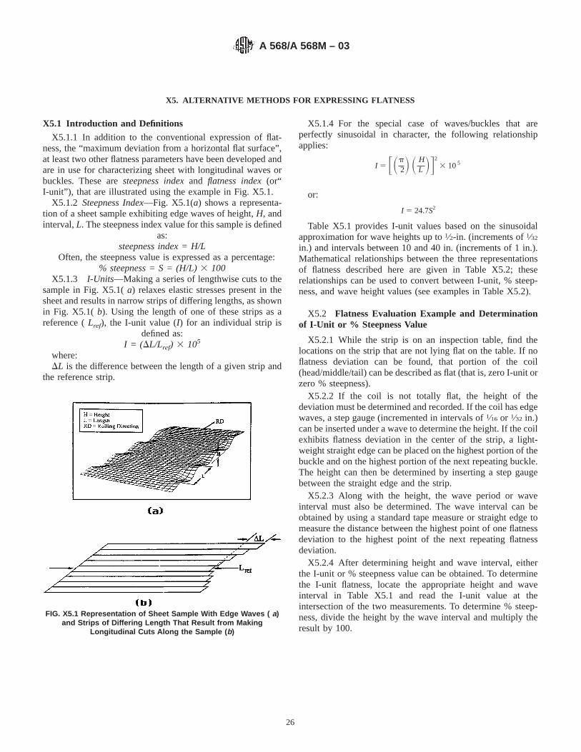
X5. ALTERNATIVE METHODS FOR EXPRESSING FLATNESS
X5.1 Introduction and Definitions
X5.1.1 In addition to the conventional expression of flat-ness, the “maximum deviation from a horizontal flat surface”,at least two other flatness parameters have been developed andare in use for characterizing sheet with longitudinal waves orbuckles. These aresteepness indexand flatness index(or“I-unit”), that are illustrated using the example in Fig. X5.1.
X5.1.2 Steepness Index—Fig. X5.1(a) shows a representa-tion of a sheet sample exhibiting edge waves of height,H, andinterval,L. The steepness index value for this sample is defined
as:steepness index = H/L
Often, the steepness value is expressed as a percentage:% steepness = S = (H/L) 3 100
X5.1.3 I-Units—Making a series of lengthwise cuts to thesample in Fig. X5.1(a) relaxes elastic stresses present in thesheet and results in narrow strips of differing lengths, as shownin Fig. X5.1( b). Using the length of one of these strips as areference (Lref), the I-unit value (I) for an individual strip is
defined as:I = ( DL/Lref) 3 105
where:DL is the difference between the length of a given strip and
the reference strip.
X5.1.4 For the special case of waves/buckles that areperfectly sinusoidal in character, the following relationshipapplies:
I 5 FSp2D S H
L DG2
3 105
or:
I 5 24.7S2
Table X5.1 provides I-unit values based on the sinusoidalapproximation for wave heights up to1⁄2-in. (increments of1⁄32
in.) and intervals between 10 and 40 in. (increments of 1 in.).Mathematical relationships between the three representationsof flatness described here are given in Table X5.2; theserelationships can be used to convert between I-unit, % steep-ness, and wave height values (see examples in Table X5.2).
X5.2 Flatness Evaluation Example and Determinationof I-Unit or % Steepness Value
X5.2.1 While the strip is on an inspection table, find thelocations on the strip that are not lying flat on the table. If noflatness deviation can be found, that portion of the coil(head/middle/tail) can be described as flat (that is, zero I-unit orzero % steepness).
X5.2.2 If the coil is not totally flat, the height of thedeviation must be determined and recorded. If the coil has edgewaves, a step gauge (incremented in intervals of1⁄16 or 1⁄32 in.)can be inserted under a wave to determine the height. If the coilexhibits flatness deviation in the center of the strip, a light-weight straight edge can be placed on the highest portion of thebuckle and on the highest portion of the next repeating buckle.The height can then be determined by inserting a step gaugebetween the straight edge and the strip.
X5.2.3 Along with the height, the wave period or waveinterval must also be determined. The wave interval can beobtained by using a standard tape measure or straight edge tomeasure the distance between the highest point of one flatnessdeviation to the highest point of the next repeating flatnessdeviation.
X5.2.4 After determining height and wave interval, eitherthe I-unit or % steepness value can be obtained. To determinethe I-unit flatness, locate the appropriate height and waveinterval in Table X5.1 and read the I-unit value at theintersection of the two measurements. To determine % steep-ness, divide the height by the wave interval and multiply theresult by 100.
FIG. X5.1 Representation of Sheet Sample With Edge Waves ( a)and Strips of Differing Length That Result from Making
Longitudinal Cuts Along the Sample ( b)
A 568/A 568M – 03
26
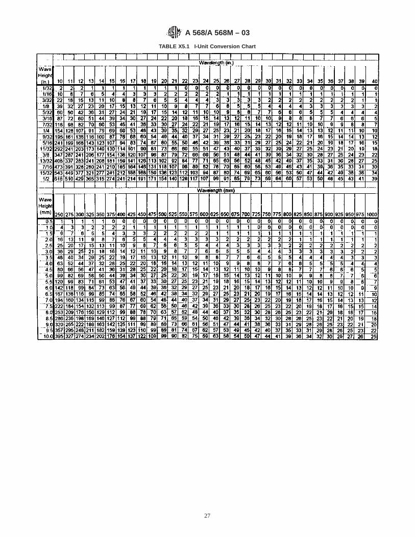
TABLE X5.1 I-Unit Conversion Chart
A 568/A 568M – 03
27
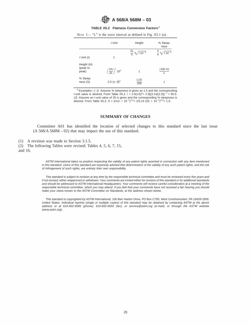
SUMMARY OF CHANGES
Committee A01 has identified the location of selected changes to this standard since the last issue(A 568/A 568M – 02) that may impact the use of this standard.
(1) A revision was made to Section 3.1.5.(2) The following Tables were revised: Tables 4, 5, 6, 7, 15,and 16.
ASTM International takes no position respecting the validity of any patent rights asserted in connection with any item mentionedin this standard. Users of this standard are expressly advised that determination of the validity of any such patent rights, and the riskof infringement of such rights, are entirely their own responsibility.
This standard is subject to revision at any time by the responsible technical committee and must be reviewed every five years andif not revised, either reapproved or withdrawn. Your comments are invited either for revision of this standard or for additional standardsand should be addressed to ASTM International Headquarters. Your comments will receive careful consideration at a meeting of theresponsible technical committee, which you may attend. If you feel that your comments have not received a fair hearing you shouldmake your views known to the ASTM Committee on Standards, at the address shown below.
This standard is copyrighted by ASTM International, 100 Barr Harbor Drive, PO Box C700, West Conshohocken, PA 19428-2959,United States. Individual reprints (single or multiple copies) of this standard may be obtained by contacting ASTM at the aboveaddress or at 610-832-9585 (phone), 610-832-9555 (fax), or [email protected] (e-mail); or through the ASTM website(www.astm.org).
TABLE X5.2 Flatness Conversion Factors A
NOTE 1— “L” is the wave interval as defined in Fig. X5.1 (a).
I Unit Height % Steep-ness
I Unit (I) 1
2Lp =I 1025 2
p =I 1021
Height (H)(peak topeak) SHp
2L D2105 1
~100 H!L
% Steep-ness (S) 2.5 (p S)2
~LS!100 1
A Examples—( 1) Assume % steepness is given as 1.5 and the correspondingI-unit value is desired. From Table X5.2, I = 2.5(pS)2= 2.5[(3.14)(1.5)] 2 = 55.5.(2) Assume an I-unit value of 25 is given and the corresponding % steepness isdesired. From Table X5.2, S = 2/p(I 3 10−1)1/2= 2/3.14 (25 3 10−1)1/2= 1.0.
A 568/A 568M – 03
28
Designation: A 580/A 580M – 98
Standard Specification forStainless Steel Wire 1
This standard is issued under the fixed designation A 580/A 580M; the number immediately following the designation indicates the yearof original adoption or, in the case of revision, the year of last revision. A number in parentheses indicates the year of last reapproval.A superscript epsilon (e) indicates an editorial change since the last revision or reapproval.
This standard has been approved for use by agencies of the Department of Defense.
1. Scope
1.1 This specification covers stainless steel wire, except thefree-machining types. It includes round, square, octagon,hexagon, and shape wire in coils only for the more commonlyused types of stainless steels for general corrosion resistanceand high-temperature service. For bars in straightened and cutlengths, see Specifications A 276 or A 479/A 479M.
NOTE 1—For free-machining stainless wire, designed especially foroptimum machinability, see Specification A 581/A 581M.
1.2 The values stated in either inch-pound units or SI(metric) units are to be regarded separately as standards; withinthe text and tables, the SI units are shown in [brackets]. Thevalues stated in each system are not exact equivalents; there-fore, each system must be used independently of the other.Combining values from the two systems may result in noncon-formance with the specification.
1.3 Unless the order specifies the applicable “M” specifica-tion designation, the material shall be furnished to the inch-pound units.
2. Referenced Documents
2.1 ASTM Standards:A 276 Specification for Stainless and Heat-Resisting Steel
Bars and Shapes2
A 370 Test Methods and Definitions for Mechanical Testingof Steel Products3
A 479/A 479M Specification for Stainless and Heat-Resisting Steel Bars, and Shapes for Use in Boilers andOther Pressure Vessels2
A 555/A 555M Specification for General Requirements forStainless Steel Wire and Wire Rods3
A 581/A 581M Specification for Free-Machining StainlessSteel Wire and Wire Rods3
E 527 Practice for Numbering Metals and Alloys (UNS)4
2.2 Society of Automotive Engineers Standard:J 1086 Numbering Metals and Alloys5
3. Ordering Information
3.1 It is the responsibility of the purchaser to specify allrequirements that are necessary for material ordered under thisspecification. Such requirements may include, but are notlimited to, the following:
3.1.1 Quantity (weight),3.1.2 Name of material (stainless steel),3.1.3 Type or UNS designation (Table 1),3.1.4 Condition (4.1),3.1.5 Finish (4.2),3.1.6 Cross section (round, square, etc.),3.1.7 Applicable dimensions including size, thickness and
width.3.1.8 ASTM designation A 580/A 580M and date of issue.3.1.9 Coil diameter (inside or outside diameter, or both) and
coil weight.3.1.10 Special requirements.
NOTE 2—A typical ordering description is as follows: 5000 lb [2000 kg]Type 304, wire, annealed and cold drawn,1⁄2 in. [13 mm] round, ASTMSpecification A 580/A 580M dated . End use: machined hydrauliccoupling parts.
4. Manufacture
4.1 Condition (Table 2):4.1.1 Condition A—Annealed as a final heat treatment.
Material in Condition A may be given a final cold drawing forsize control or finish, or both, slightly raising tensile strength.
4.1.2 Condition B—Cold worked to higher strength.4.1.3 Condition T—Heat treated to an intermediate temper
generally by austenitizing, quenching, and tempering at arelatively low temperature.
4.1.4 Condition H—Heat treated to a hard temper generallyby austenitizing, quenching, and tempering at a relatively lowtemperature.
4.2 Finish:4.2.1 Cold Drawn—A finish resulting from a final cold
drawing pass, generally with cold drawing lubricant left on.
1 This specification is under the jurisdiction of ASTM Committee A01 on Steel,Stainless Steel, and Related Alloys and is the direct responsibility of SubcommitteeA01.17 on Flat Stainless Steel Products.
Current edition approved June 10, 1998. Published September 1998. Originallypublished as A 580 – 67. Last previous edition A 580 – 95a.
2 Annual Book of ASTM Standards, Vol 01.05.3 Annual Book of ASTM Standards, Vol 01.03.4 Annual Book of ASTM Standards, Vol 01.01.
5 Available from Society of Automotive Engineers (SAE), 400 CommonwealthDr., Warrendale, PA 15096.
1
Copyright © ASTM International, 100 Barr Harbor Drive, PO Box C700, West Conshohocken, PA 19428-2959, United States.
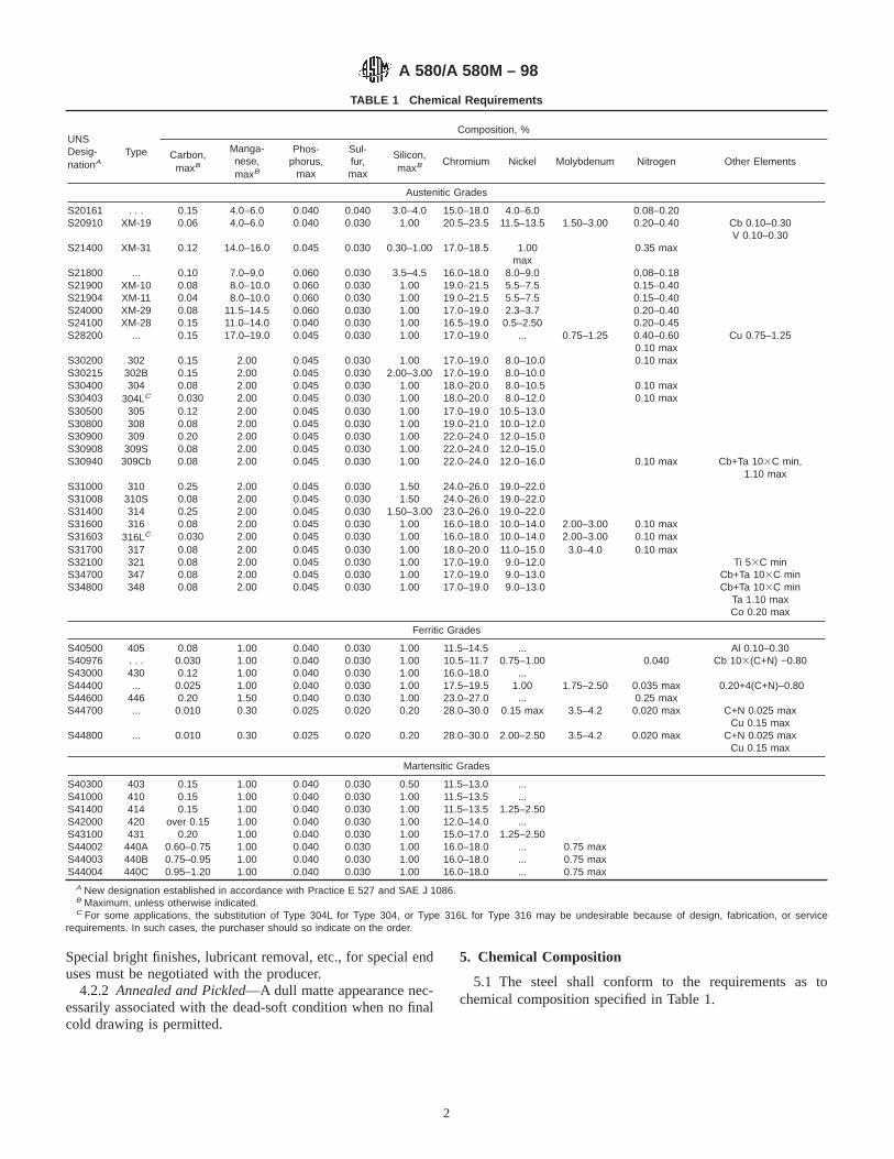
Special bright finishes, lubricant removal, etc., for special enduses must be negotiated with the producer.
4.2.2 Annealed and Pickled—A dull matte appearance nec-essarily associated with the dead-soft condition when no finalcold drawing is permitted.
5. Chemical Composition
5.1 The steel shall conform to the requirements as tochemical composition specified in Table 1.
TABLE 1 Chemical Requirements
UNSDesig-nationA
Type
Composition, %
Carbon,maxB
Manga-nese,maxB
Phos-phorus,
max
Sul-fur,max
Silicon,maxB Chromium Nickel Molybdenum Nitrogen Other Elements
Austenitic Grades
S20161S20910
. . .XM-19
0.150.06
4.0–6.04.0–6.0
0.0400.040
0.0400.030
3.0–4.01.00
15.0–18.020.5–23.5
4.0–6.011.5–13.5 1.50–3.00
0.08–0.200.20–0.40 Cb 0.10–0.30
V 0.10–0.30S21400 XM-31 0.12 14.0–16.0 0.045 0.030 0.30–1.00 17.0–18.5 1.00
max0.35 max
S21800 ... 0.10 7.0–9.0 0.060 0.030 3.5–4.5 16.0–18.0 8.0–9.0 0.08–0.18S21900 XM-10 0.08 8.0–10.0 0.060 0.030 1.00 19.0–21.5 5.5–7.5 0.15–0.40S21904 XM-11 0.04 8.0–10.0 0.060 0.030 1.00 19.0–21.5 5.5–7.5 0.15–0.40S24000S24100
XM-29XM-28
0.080.15
11.5–14.511.0–14.0
0.0600.040
0.0300.030
1.001.00
17.0–19.016.5–19.0
2.3–3.70.5–2.50
0.20–0.400.20–0.45
S28200 ... 0.15 17.0–19.0 0.045 0.030 1.00 17.0–19.0 ... 0.75–1.25 0.40–0.60 Cu 0.75–1.250.10 max
S30200 302 0.15 2.00 0.045 0.030 1.00 17.0–19.0 8.0–10.0 0.10 maxS30215 302B 0.15 2.00 0.045 0.030 2.00–3.00 17.0–19.0 8.0–10.0S30400 304 0.08 2.00 0.045 0.030 1.00 18.0–20.0 8.0–10.5 0.10 maxS30403 304LC 0.030 2.00 0.045 0.030 1.00 18.0–20.0 8.0–12.0 0.10 maxS30500 305 0.12 2.00 0.045 0.030 1.00 17.0–19.0 10.5–13.0S30800 308 0.08 2.00 0.045 0.030 1.00 19.0–21.0 10.0–12.0S30900 309 0.20 2.00 0.045 0.030 1.00 22.0–24.0 12.0–15.0S30908 309S 0.08 2.00 0.045 0.030 1.00 22.0–24.0 12.0–15.0S30940 309Cb 0.08 2.00 0.045 0.030 1.00 22.0–24.0 12.0–16.0 0.10 max Cb+Ta 103C min,
1.10 maxS31000 310 0.25 2.00 0.045 0.030 1.50 24.0–26.0 19.0–22.0S31008S31400
310S314
0.080.25
2.002.00
0.0450.045
0.0300.030
1.501.50–3.00
24.0–26.023.0–26.0
19.0–22.019.0–22.0
S31600 316 0.08 2.00 0.045 0.030 1.00 16.0–18.0 10.0–14.0 2.00–3.00 0.10 maxS31603 316LC 0.030 2.00 0.045 0.030 1.00 16.0–18.0 10.0–14.0 2.00–3.00 0.10 maxS31700S32100S34700
317321347
0.080.080.08
2.002.002.00
0.0450.0450.045
0.0300.0300.030
1.001.001.00
18.0–20.017.0–19.017.0–19.0
11.0–15.09.0–12.09.0–13.0
3.0–4.0 0.10 maxTi 53C min
Cb+Ta 103C minS34800 348 0.08 2.00 0.045 0.030 1.00 17.0–19.0 9.0–13.0 Cb+Ta 103C min
Ta 1.10 maxCo 0.20 max
Ferritic Grades
S40500S40976S43000
405. . .430
0.080.0300.12
1.001.001.00
0.0400.0400.040
0.0300.0300.030
1.001.001.00
11.5–14.510.5–11.716.0–18.0
...0.75–1.00
...0.040
Al 0.10–0.30Cb 103(C+N) −0.80
S44400S44600
...446
0.0250.20
1.001.50
0.0400.040
0.0300.030
1.001.00
17.5–19.523.0–27.0
1.00...
1.75–2.50 0.035 max0.25 max
0.20+4(C+N)–0.80
S44700 ... 0.010 0.30 0.025 0.020 0.20 28.0–30.0 0.15 max 3.5–4.2 0.020 max C+N 0.025 maxCu 0.15 max
S44800 ... 0.010 0.30 0.025 0.020 0.20 28.0–30.0 2.00–2.50 3.5–4.2 0.020 max C+N 0.025 maxCu 0.15 max
Martensitic Grades
S40300 403 0.15 1.00 0.040 0.030 0.50 11.5–13.0 ...S41000 410 0.15 1.00 0.040 0.030 1.00 11.5–13.5 ...S41400 414 0.15 1.00 0.040 0.030 1.00 11.5–13.5 1.25–2.50S42000 420 over 0.15 1.00 0.040 0.030 1.00 12.0–14.0 ...S43100 431 0.20 1.00 0.040 0.030 1.00 15.0–17.0 1.25–2.50S44002 440A 0.60–0.75 1.00 0.040 0.030 1.00 16.0–18.0 ... 0.75 maxS44003 440B 0.75–0.95 1.00 0.040 0.030 1.00 16.0–18.0 ... 0.75 maxS44004 440C 0.95–1.20 1.00 0.040 0.030 1.00 16.0–18.0 ... 0.75 max
A New designation established in accordance with Practice E 527 and SAE J 1086.B Maximum, unless otherwise indicated.C For some applications, the substitution of Type 304L for Type 304, or Type 316L for Type 316 may be undesirable because of design, fabrication, or service
requirements. In such cases, the purchaser should so indicate on the order.
A 580/A 580M – 98
2

6. Mechanical Requirements
6.1 The material shall conform to the mechanical testrequirements specified in Table 2.
6.2 The martensitic grades shall be capable of meeting thehardness requirements, after heat treating, as specified in Table3.
7. General Requirements for Delivery
7.1 In addition to the requirements of this specification, allrequirements of the current edition of Specification A 555/A 555M shall apply. Failure to comply with the generalrequirements of Specification A 555/A 555M constitutes non-conformance with this specification.
TABLE 2 Mechanical Test Requirements
UNS Designation TypeCondition
(see 4.1)
FinalOperation
Tensile Strength,A minYield Strength,B min
Elongationin Length4 3 GageDiameterof Test
Specimens,C
min, %
Reductionof Area,min, %
ksiksi
Austenitic Grades
S20161 . . . A cold finishedannealed
125 [860] 50 [345] 40 40
S20910 XM-19 A cold finishedannealed
100 [690] 55 [380] 35 55
S21400 XM-31 A cold finishedannealed
130100
[900][690]
8550
[585][345]
2440
6065
B cold finished 220 190 5 50S21800 . . . A cold finished
annealed95 [655] 50 [345] 35 55
S21900 and S21904 XM-10 and XM-11 A cold finishedannealed
90 [620] 50 [345] 45 60
S24000 and S24100 XM-29 and XM-28 A cold finishedannealed
100 [690] 55 [380] 30 50
S28200 . . . A cold finishedannealed
110 [760] 60 [415] 35 55
B cold finished 175 150 15 50S30200, S30215,S30400, S30500,S30800, S30900,S30908, S30940,S31000, S31008,S31400, S31600,
S31700, S32100,S34700,S34800
302, 302B, 304,305, 308, 309,
309S, 309Cb, 310,310S, 314, 316,317, 321, 347,
348
A cold finishedannealed
9075
[620][520]
4530
[310][210]
30D
35D40D
50D
S30403 and S31603 304L and 316L A cold finishedannealed
9070
[620][485]
4525
[310][170]
30D
35D40D
50D
Ferritic Grades
S40976 . . . A annealed 60 [415] 20 [140] 20 45S40500,E S43000,S44401, S44600
405, 430,. . ., 446
A cold finishedannealed
7070
[485][485]
4040
[275][275]
1620
4545
S44700 and S44800 . . ., . . . A cold finishedannealed
7570
[520][485]
6055
[415][380]
1520
3040
Martensitic Grades
S40300 and S41000 403 and 410 A cold finishedannealed
7070
[485][485]
4040
[275][275]
1620
4545
TH
cold finishedcold finished
100120
[690][830]
8090
[550][620]
1212
4040
S41400 414 A cold finished 150 max max . . . . . . . . . . . .S42000 420 A cold finished 125 max [860]
max. . . . . . . . . . . .
S43100, S44002,S44003, S44004
431, 440A,440B, 440C
A cold finished 140 max [965]max
. . . . . . . . . . . .
A Minimum unless otherwise noted.B Yield strength shall be determined by the 0.2 % offset method in accordance with Test Methods and Definitions A 370. An alternative method of determining yield
strength, based on a total extension under load of 0.5 %, may be used.C For wire products, it is generally necessary to use sub-size test specimens in accordance with Test Methods and Definitions A 370.D For material 5⁄32 in. [3.96 mm] and under in size, the elongation and reduction in area shall be 25 % and 40 %, respectively.E Material shall be capable of being heat treated to a maximum hardness of HRC 25 when oil quenched from 1750°F [955°C].
A 580/A 580M – 98
3
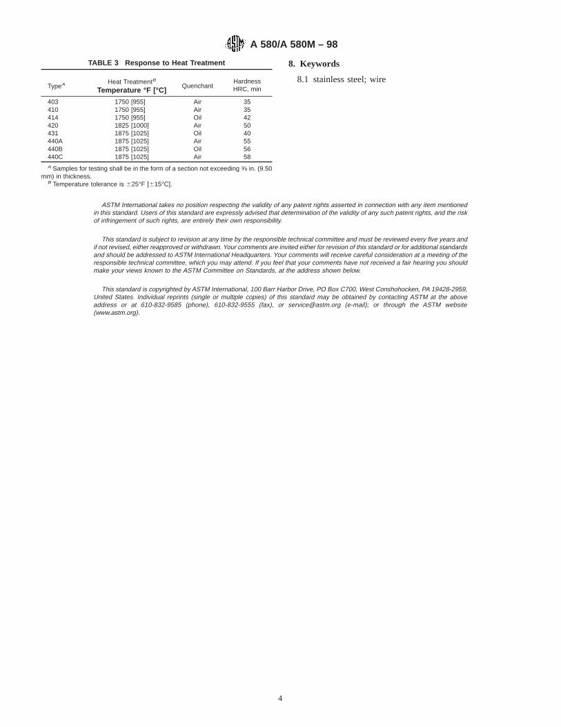
8. Keywords
8.1 stainless steel; wire
ASTM International takes no position respecting the validity of any patent rights asserted in connection with any item mentionedin this standard. Users of this standard are expressly advised that determination of the validity of any such patent rights, and the riskof infringement of such rights, are entirely their own responsibility.
This standard is subject to revision at any time by the responsible technical committee and must be reviewed every five years andif not revised, either reapproved or withdrawn. Your comments are invited either for revision of this standard or for additional standardsand should be addressed to ASTM International Headquarters. Your comments will receive careful consideration at a meeting of theresponsible technical committee, which you may attend. If you feel that your comments have not received a fair hearing you shouldmake your views known to the ASTM Committee on Standards, at the address shown below.
This standard is copyrighted by ASTM International, 100 Barr Harbor Drive, PO Box C700, West Conshohocken, PA 19428-2959,United States. Individual reprints (single or multiple copies) of this standard may be obtained by contacting ASTM at the aboveaddress or at 610-832-9585 (phone), 610-832-9555 (fax), or [email protected] (e-mail); or through the ASTM website(www.astm.org).
TABLE 3 Response to Heat Treatment
TypeA Heat TreatmentB
Temperature °F [°C]Quenchant
HardnessHRC, min
403 1750 [955] Air 35410 1750 [955] Air 35414 1750 [955] Oil 42420 1825 [1000] Air 50431 1875 [1025] Oil 40440A 1875 [1025] Air 55440B 1875 [1025] Oil 56440C 1875 [1025] Air 58A Samples for testing shall be in the form of a section not exceeding 3⁄8 in. (9.50
mm) in thickness.B Temperature tolerance is 625°F [615°C].
A 580/A 580M – 98
4

Designation: A 581/A581M – 95b (Reapproved 2000)
Standard Specification forFree-Machining Stainless Steel Wire and Wire Rods 1
This standard is issued under the fixed designation A 581/A581M; the number immediately following the designation indicates the yearof original adoption or, in the case of revision, the year of last revision. A number in parentheses indicates the year of last reapproval.A superscript epsilon (e) indicates an editorial change since the last revision or reapproval.
This standard has been approved for use by agencies of the Department of Defense.
1. Scope
1.1 This specification covers cold-finished wire and hot-finished wire rods in coils. Wire rods are a semi-finishedproduct primarily for the manufacture of wire. Wire includesrounds, squares, hexagons and special shapes in the morecommonly used types of stainless free-machining steels de-signed especially for optimum machinability and for generalcorrosion and high temperature service.
NOTE 1—For wire other than those of the free-machining types, seeSpecification A 580/A 580M.
1.2 The values stated in either inch-pound units or SI(metric) units are to be regarded separately as standards: withinthe text and tables, the SI units are shown in [brackets]. Thevalues stated in each system are not exact equivalents; there-fore, each system must be used independently of the other.Combining values from the two systems may result in noncon-formance with the specification.
1.3 Unless the order specifies the applicable “M” specifica-tion designation, the material shall be furnished to the inch-pound units.
2. Referenced Documents
2.1 ASTM Standards:A 555/A555M Specification for General Requirements for
Stainless Steel Wire and Wire Rods2
A 580/A580M Specification for Stainless Steel Wire2
A 751 Test Methods, Practices, and Terminology forChemical Analysis of Steel Products2
E 527 Practice for Numbering Metals and Alloys (UNS)3
2.2 SAE Standard:J 1086 Practice for Numbering Metals and Alloys (UNS)4
3. Ordering Information
3.1 It is the responsibility of the purchaser to specify allrequirements that are necessary for material ordered under thisspecification. Such requirements may include, but are notlimited to, the following:
3.1.1 Quantity (weight),3.1.2 Name of material (stainless steel),3.1.3 Condition (see Section 5),3.1.4 Finish (see Section 7),3.1.5 Applicable dimensions including size, thickness,
width, and length or coil diameter (inside, or outside diameter),and coil weights,
3.1.6 Cross section (round, square, etc.),3.1.7 Type or UNS designation (Table 1),3.1.8 ASTM designation (Specification A 581/A 581M) and
date of issue, and3.1.9 Exceptions to the specification or special require-
ments.
NOTE 2—A typical ordering description is as follows: 5000 lb [2000 kg]stainless steel wire, annealed,1⁄4in. [6.5 mm] round, coils, Type 303,ASTM Specification A 581/A 581M dated . End use: machined valveparts.
4. Chemical Composition
4.1 The steel shall conform to the requirements as tochemical composition specified in Table 1.
4.2 Methods and practices relating to chemical analysisrequired by this specification shall be in accordance with TestMethods, Practices, and Terminology A 751.
5. Condition
5.1 Cold-finished wire may be furnished in one of theconditions listed in Table 2.
5.2 Wire rods may be furnished in the as-hot-rolled oras-hot-rolled and annealed condition.
6. Mechanical Requirements
6.1 Wire products shall conform to the mechanical testrequirements specified in Table 3.
1 This specification is under the jurisdiction of ASTM Committee A01 on Steel,Stainless Steel, and Related Alloys and is the direct responsibility of SubcommitteeA01.17 on Flat Stainless Steel Products.
Current edition approved Sept. 10, 1995. Published November 1995. Originallypublished as A 581 – 67. Last previous edition A 581 – 95a.
2 Annual Book of ASTM Standards, Vol 01.03.3 Annual Book of ASTM Standards, Vol 01.01.4 Available from Society of Automotive Engineers, 400 Commonwealth Drive,
Warrendale, PA 15096.
1
Copyright © ASTM International, 100 Barr Harbor Drive, PO Box C700, West Conshohocken, PA 19428-2959, United States.

6.2 Wire rods shall conform to the annealed mechanical testrequirements specified in Table 3.
7. Finish
7.1 Wire rods are furnished with a hot rolled or a hot rolledand cleaned finish.
7.2 Wire in the cold-finished condition, is generally fur-nished with a cold drawn finish.
8. General Requirements for Delivery
8.1 In addition to the requirements of this specification, allrequirements of the current edition of Specification A 555/A 555M shall apply. Failure to comply with the generalrequirements of Specification A 555/A 555M constitutes non-conformance with this specification.
9. Keywords
9.1 free-machining; free-machining wire; stainless steel
TABLE 1 Chemical Requirements
UNSDesig-nationA
Type
Composition, %
Carbon,max
Manga-neseB
Phos-phorus,
maxSulfurB
Silicon,max
Chromium Nickel Other Elements
AUSTENITICS20300 XM-1 0.08 5.0–6.5 0.04 0.18–0.35 1.00 16.0–18.0 5.0–6.5 Cu 1.75–2.25S30300 303 0.15 2.00 0.20 0.15 min 1.00 17.0–19.0 8.0–10.0 . . .
0.20S30310 XM-5 0.15 2.5–4.5 0.20 0.25 min 1.00 17.0–19.0 7.0–10.0 . . .S30323 303 Se 0.15 2.00 0.20 0.06 1.00 17.0–19.0 8.0–10.0 Se 0.15 minS30345 XM-2 0.15 2.00 0.05 0.11–0.16 1.00 17.0–19.0 8.0–10.0 Mo 0.40–0.60
Al 0.60–1.00MARTENSITIC
S41600 416 0.15 1.25 0.06 0.15 min 1.00 12.0–14.0 . . . . . .S41610 XM-6 0.15 1.50–2.50 0.06 0.15 min 1.00 12.0–14.0 . . . . . .S41623 416 Se 0.15 1.25 0.06 0.06 1.00 12.0–14.0 . . . Se 0.15 min
FERRITICS18200 XM-34 0.08 2.50 0.04 0.15 min 1.00 17.5–19.5 . . . Mo 1.50–2.50S18235 . . . 0.025 0.50 0.030 0.15–0.35 1.00 17.5–18.5 1.00 Mo 2.00–2.50
Ti 0.30–1.00N 0.025 maxC+N 0.035 max
S41603 . . . 0.08 1.25 0.06 0.15 min 1.00 12.0-14.0 . . . . . .S43020 430 F 0.12 1.25 0.06 0.15 min 1.00 16.0–18.0 . . . . . .S43023 430 F Se 0.12 1.25 0.06 0.06 1.00 16.0–18.0 . . . Se 0.15 minA New designation established in accordance with Practice E 527 and SAE J 1086, Practice for Numbering Metals and Alloys (UNS).B Maximum unless otherwise noted.
TABLE 2 Condition
UNSDesignation
TypeCondition A(Annealed)
ConditionB (ColdWorked)
ConditionT (Inter-mediateTemper)
ConditionH (HardTemper)
AUSTENITICS20300 XM-1 A B . . . . . .S30300 303 A B . . . . . .S30310 XM-5 A B . . . . . .S30323 303 Se A B . . . . . .S30345 XM-2 A B . . . . . .
MARTENSITICS41600 416 A . . . T HS14160 XM-6 A . . . T HS41623 416 Se A . . . T H
FERRITICS18200 XM-34 A . . . . . . . . .S18235 . . . A B . . . . . .S41603 . . . A . . . . . . . . .S43020 430 F A . . . . . . . . .S43023 430 F Se A . . . . . . . . .
TABLE 3 Mechanical Test Requirements
TypeCondition(see Sec-
tion 5)
Tensile Strength
ksi [MPa]
All (Except S 18235) A 85 to 125 [585 to 860]S18235 A
B60 to 9080 to 120
[415 to 620][550 to 830]
303, 303Se, XM-1, XM-2,XM-3, and XM-5
BA 115 to 145 [795 to 1000]
416, 416Se, and XM-6 T 115 to 145 [790 to 1000]416, 416Se, and XM-6 H 140 to 175 [965 to1210]
A Condition B applies only to wire annealed and cold worked to produce highstrength in chromium-nickel types not hardenable by heat treatment.
A 581/A581M – 95b (2000)
2

APPENDIX
(Nonmandatory Information)
X1. CROSS REFERENCE
This table is intended to assist the user when SpecificationA 581/A 581M is referenced in a Government procurement. Itshows the types of steels in Specification A 581/A 581M
replacing the steels formerly specified in MIL-W-52263C(MR).
TABLE X1.1 Cross Reference
UNS DesignationA MIL-W-52263C(MR)Specification A 581,
Type
S20300 203 EZ XM-1S30300 303 303S30310 303 plus X XM-5S30323 303 Se 303 SeS30345 303 Ma XM-2S41600 416 416S41610 416 plus X XM-16S41623 416 Se 416 SeS43020 430 F 430 FS43023 430 Se 430 F Se
A New designation established in accordance with Practice E 527 and SAE J 1086, Practice for Numbering Metals and Alloys (UNS).
ASTM International takes no position respecting the validity of any patent rights asserted in connection with any item mentionedin this standard. Users of this standard are expressly advised that determination of the validity of any such patent rights, and the riskof infringement of such rights, are entirely their own responsibility.
This standard is subject to revision at any time by the responsible technical committee and must be reviewed every five years andif not revised, either reapproved or withdrawn. Your comments are invited either for revision of this standard or for additional standardsand should be addressed to ASTM International Headquarters. Your comments will receive careful consideration at a meeting of theresponsible technical committee, which you may attend. If you feel that your comments have not received a fair hearing you shouldmake your views known to the ASTM Committee on Standards, at the address shown below.
This standard is copyrighted by ASTM International, 100 Barr Harbor Drive, PO Box C700, West Conshohocken, PA 19428-2959,United States. Individual reprints (single or multiple copies) of this standard may be obtained by contacting ASTM at the aboveaddress or at 610-832-9585 (phone), 610-832-9555 (fax), or [email protected] (e-mail); or through the ASTM website(www.astm.org).
A 581/A581M – 95b (2000)
3

Designation: A 582/A 582M – 95b (Reapproved 2000) e1
Standard Specification forFree-Machining Stainless Steel Bars 1
This standard is issued under the fixed designation A 582/A 582M; the number immediately following the designation indicates the yearof original adoption or, in the case of revision, the year of last revision. A number in parentheses indicates the year of last reapproval.A superscript epsilon (e) indicates an editorial change since the last revision or reapproval.
This standard has been approved for use by agencies of the Department of Defense.
e1 NOTE—Table X1.1 was editorially corrected in May 2003.
1. Scope
1.1 This specification covers hot-finished or cold-finishedbars, except bars for forging (Note 1). It includes rounds,squares, and hexagons in the more commonly used types ofstainless free-machining steels designed especially for opti-mum machinability and for general corrosion and high-temperature service. Stainless steel bars other (Note 2) than thefree-machining types are covered in a separate specification.
1.2 The values stated in either inch-pound units or SI(metric) units are to be regarded separately as standard: withinthe text and tables, the SI units are shown in [brackets]. Thevalues stated in each system are not exact equivalents: there-fore, each system must be used independent of the other.Combining values from the two systems may result in noncon-formance with the specification.
1.3 Unless the order specifies the applicable “M” specifica-tion designation, the material shall be furnished to the inch-pound units.
NOTE 1—For bars for reforging, see Specification A 314.NOTE 2—For non-free machining stainless bars, see Specification
A 276.
2. Referenced Documents
2.1 ASTM Standards:A 276 Specification for Stainless Steel Bars and Shapes2
A 314 Specification for Stainless Steel Billets and Bars forForging2
A 484/A 484M Specification for General Requirements forStainless Steel Bars, Billets, and Forgings2
A 751 Test Methods, Practices, and Terminology forChemical Analysis of Steel Products3
E 527 Practice for Numbering Metals and Alloys (UNS)4
2.2 Other Document:
SAE J 1086 Recommended Practice for Numbering Metalsand Alloys5
3. Ordering Information
3.1 It is the responsibility of the purchaser to specify allrequirements that are necessary for material ordered under thisspecification. Such requirements may include, but are notlimited to, the following:
3.1.1 Quantity (weight or number of pieces),3.1.2 Type or UNS designation (Table 1),3.1.3 Form (bars, angles, etc.),3.1.4 Condition (Table 2),3.1.5 Finish (5.1),3.1.6 Applicable dimensions, including size, thickness,
width, and length,3.1.7 Cross section (round, square, etc.),3.1.8 ASTM designation (Specification A 582/A 582M) and
date of issue,3.1.9 Preparation for delivery, and3.1.10 Marking requirements.
NOTE 3—A typical ordering description is as follows: 5000 lb [2000 kg]Type 416 bars, annealed and centerless ground, 11⁄2 in. [40 mm] round, 10to 12 ft [3 to 4 m] in length, ASTM Specification A 582/A 582M dated .
4. General Requirements for Delivery
4.1 In addition to the requirements of this specification, allrequirements of the current edition of Specification A 484/A 484M shall apply. Failure to comply with the generalrequirements of Specification A 484/A 484M constitutes non-conformance with this specification.
5. Materials and Manufacture
5.1 Bars may be furnished either hot finished or coldfinished in one of the conditions listed in Table 2.
6. Chemical Requirements
6.1 The chemical composition shall conform to the require-ments specified in Table 1.
1 This specification is under the jurisdiction of ASTM Committee A01 on Steel,Stainless Steel and Related Alloysand is the direct responsibility of SubcommitteeA01.17on Flat Stainless Steel Products.
Current edition approved Sept. 10, 1995. Published November 1995. Originallypublished as A 582 – 67. Last previous edition A 582 – 95a.
2 Annual Book of ASTM Standards, Vol 01.05.3 Annual Book of ASTM Standards, Vol 01.03.4 Annual Book of ASTM Standards, Vol 01.01.
5 Available from Society of Automotive Engineers, 400 Commonwealth Drive,Warrendale, PA 15096.
1
Copyright © ASTM International, 100 Barr Harbor Drive, PO Box C700, West Conshohocken, PA 19428-2959, United States.
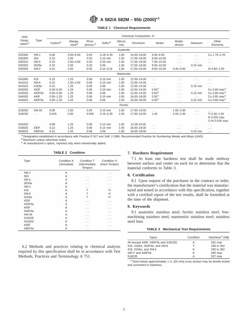
6.2 Methods and practices relating to chemical analysisrequired by this specification shall be in accordance with TestMethods, Practices and Terminology A 751.
7. Hardness Requirement7.1 At least one hardness test shall be made midway
between surface and center on each lot to determine that thematerial conforms to Table 3.
8. Certification8.1 Upon request of the purchaser in the contract or order,
the manufacturer’s certification that the material was manufac-tured and tested in accordance with this specification, togetherwith a certified report of the test results, shall be furnished atthe time of the shipment.
9. Keywords9.1 austenitic stainless steel; ferritic stainless steel; free-
machining stainless steel; martensitic stainless steel; stainlesssteel bars
TABLE 1 Chemical Requirements
UNSDesig-nationA
Type
Chemical Composition, %
CarbonB Manga-neseB
Phos-phorus,B
SulfurBSilicon,
maxChromium Nickel
Molyb-denum
SeleniumOther
Elements
Austenitic
S20300 XM-1 0.08 5.00–6.50 0.04 0.18–0.35 1.00 16.00–18.00 5.00–6.50 . . . . . . Cu 1.75–2.25S30300 303 0.15 2.00 0.20 0.15 min 1.00 17.00–19.00 8.00–10.00 . . . . . . . . .S30310 XM-5 0.15 2.50–4.50 0.20 0.25 min 1.00 17.00–19.00 7.00–10.00 . . . . . . . . .S30323 303Se 0.15 2.00 0.20 0.06 1.00 17.00–19.00 8.00–10.00 . . . 0.15 min . . .S30345 XM-2 0.15 2.00 0.05 0.11–0.16 1.00 17.00–19.00 8.00–10.00 0.40–0.60 . . . Al 0.60–1.00
Martensitic
S41600 416 0.15 1.25 0.06 0.15 min 1.00 12.00–14.00 . . . . . . . . . . . .S41610 XM-6 0.15 1.50–2.50 0.06 0.15 min 1.00 12.00–14.00 . . . . . . . . . . . .S41623 416Se 0.15 1.25 0.06 0.06 1.00 12.00–14.00 . . . . . . 0.15 min . . .S42020 420F 0.30–0.40 1.25 0.06 0.15 min 1.00 12.00–14.00 0.50C . . . . . . Cu 0.60 maxC
S42023 420FSe 0.20–0.40 1.25 0.06 0.06 1.00 12.00–14.00 0.50C . . . 0.15 min Cu 0.60 maxC
S44020 440F 0.95–1.20 1.25 0.06 0.15 min 1.00 16.00–18.00 0.50C . . . . . . Cu 0.60 maxC
S44023 440FSe 0.95–1.20 1.25 0.06 0.06 1.00 16.00–18.00 0.50C . . . 0.15 min Cu 0.60 maxC
Ferritic
S18200 XM-34 0.08 2.50 0.04 0.15 min 1.00 17.50–19.50 . . . 1.50–2.50 . . . . . .S18235 . . . 0.025 0.50 0.030 0.15–0.35 1.00 17.50–18.50 1.00 2.00–2.50 . . . Ti 0.30–1.00
N 0.025 maxC+N 0.035 max
S41603 . . . 0.08 1.25 0.06 0.15 min 1.00 12.00-14.00 . . . . . . . . . . . .S43020 430F 0.12 1.25 0.06 0.15 min 1.00 16.00–18.00 . . . . . . . . . . . .S43023 430FSe 0.12 1.25 0.06 0.06 1.00 16.00–18.00 . . . . . . 0.15 min . . .
A Designation established in accordance with Practice E 527 and SAE J 1086, Recommended Practice for Numbering Metals and Alloys (UNS).B Maximum unless otherwise noted.C At manufacturer’s option, reported only when intentionally added.
TABLE 2 Condition
Type Condition A(Annealed)
Condition T(Intermediate
Temper)
Condition H(Hard Temper)
XM-1 A . . .303 A . . . . . .XM-5 A . . . . . .303Se A . . . . . .XM-2 A . . . . . .416 A T HXM-6 A T H416Se A T H420F A . . . . . .420FSe A . . . . . .440F A . . . . . .440FSe A . . . . . .XM-34 A . . . . . .S18235 A . . . . . .S41603 A . . . . . .430F A . . . . . .430FSe A . . . . . . TABLE 3 Mechanical Test Requirements
Types Condition HardnessA (HB)
All (except 440F, 440FSe and S18235) A 262 max416, 416Se, 420FSe, and XM-6 T 248 to 302416, 416Se, and XM-6 H 293 to 352440 F and 440FSe A 285 maxS18235 A 207 max
A Sizes below approximately 1 in. [25 mm] cross section may be tensile testedand converted to hardness.
A 582/A 582M – 95b (2000) e1
2
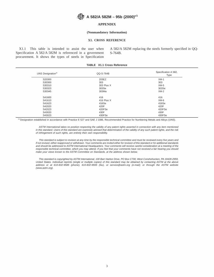
APPENDIX
(Nonmandatory Information)
X1. CROSS REFERENCE
X1.1 This table is intended to assist the user whenSpecification A 582/A 582M is referenced in a governmentprocurement. It shows the types of steels in Specification
A 582/A 582M replacing the steels formerly specified in QQ-S-764B.
TABLE X1.1 Cross Reference
UNS DesignationA QQ-S-764BSpecification A 582,
Type
S20300 203EZ XM-1S30300 303 303S30310 303 Plus X XM-5S30323 303Se 303SeS30345 303Ma XM-2
S41600 416 416S41610 416 Plus X XM-6S41623 416Se 416SeS42020 420F 420FS42023 420FSe 420FSeS43020 430F 430FS43023 430FSe 430FSe
A Designation established in accordance with Practice E 527 and SAE J 1086, Recommended Practice for Numbering Metals and Alloys (UNS).
ASTM International takes no position respecting the validity of any patent rights asserted in connection with any item mentionedin this standard. Users of this standard are expressly advised that determination of the validity of any such patent rights, and the riskof infringement of such rights, are entirely their own responsibility.
This standard is subject to revision at any time by the responsible technical committee and must be reviewed every five years andif not revised, either reapproved or withdrawn. Your comments are invited either for revision of this standard or for additional standardsand should be addressed to ASTM International Headquarters. Your comments will receive careful consideration at a meeting of theresponsible technical committee, which you may attend. If you feel that your comments have not received a fair hearing you shouldmake your views known to the ASTM Committee on Standards, at the address shown below.
This standard is copyrighted by ASTM International, 100 Barr Harbor Drive, PO Box C700, West Conshohocken, PA 19428-2959,United States. Individual reprints (single or multiple copies) of this standard may be obtained by contacting ASTM at the aboveaddress or at 610-832-9585 (phone), 610-832-9555 (fax), or [email protected] (e-mail); or through the ASTM website(www.astm.org).
A 582/A 582M – 95b (2000) e1
3

Designation: A 606 – 04
Standard Specification forSteel, Sheet and Strip, High-Strength, Low-Alloy, Hot-Rolledand Cold-Rolled, with Improved Atmospheric CorrosionResistance 1
This standard is issued under the fixed designation A 606; the number immediately following the designation indicates the year oforiginal adoption or, in the case of revision, the year of last revision. A number in parentheses indicates the year of last reapproval. Asuperscript epsilon (e) indicates an editorial change since the last revision or reapproval.
This standard has been approved for use by agencies of the Department of Defense.
1. Scope*
1.1 This specification covers high-strength, low-alloy, hot-and cold-rolled sheet and strip in cut lengths or coils, intendedfor use in structural and miscellaneous purposes, where savingsin weight or added durability are important. These steels haveenhanced atmospheric corrosion resistance and are supplied intwo types: Type 2 contains 0.20 % minimum copper based oncast or heat analysis (0.18 % minimum Cu for product check).Type 4 contains additional alloying elements and provides alevel of corrosion resistance substantially better than that ofcarbon steels with or without copper addition (Note 1). Whenproperly exposed to the atmosphere, Type 4 steel can be usedbare (unpainted) for many applications.
NOTE 1—For methods of establishing the atmospheric corrosion resis-tance of low-alloy steels, see Guide G 101.
1.2 The values stated in inch-pound units are to be regardedas the standard.
2. Referenced Documents
2.1 ASTM Standards:2
A 109/A 109M Specification for Steel, Strip, Carbon (0.25Maximum Percent), Cold-Rolled
A 568/A 568M Specification for Steel, Sheet, Carbon, andHigh-Strength, Low-Alloy, Hot-Rolled and Cold-Rolled,General Requirements for
A 749/A 749M Specification for Steel, Strip, Carbon andHigh-Strength, Low-Alloy, Hot-Rolled, General Require-ments for
G 101 Guide for Estimating the Atmospheric CorrosionResistance of Low-Alloy Steels
3. General Requirements for Delivery —
3.1 Material furnished under this specification shall con-form to the applicable requirements of the current edition ofSpecification A 568/A 568M and the dimensional tolerancetables of Specification A 109/A 109M, unless otherwise pro-vided herein.
4. Ordering Information
4.1 Orders for material under this specification shall includethe following information, as required, to describe adequatelythe desired material:
4.1.1 ASTM specification number and date of issue, andtype,
4.1.2 Name of material (high-strength low-alloy hot-rolledsheet or strip or high-strength low-alloy cold-rolled sheet orstrip),
4.1.3 Condition (specify oiled or dry, as required),4.1.4 Edges (must be specified for hot-rolled sheet or strip)
(see 8.1),4.1.5 Finish—Cold-rolled only (indicate exposed (E) or
unexposed (U). Matte (dull) finish will be supplied unlessotherwise specified), and
4.1.6 Dimensions (thickness, width, and whether cut lengthsor coils).
4.1.6.1 As agreed upon between the purchaser and theproducer, material ordered to this specification will be suppliedto meet the appropriate standard or restricted thickness toler-ance table shown in Specification A 568/A 568M.
NOTE 2—Not all producers are capable of meeting all of the limitationsof the thickness tolerance tables in Specification A 568/A 568M. Thepurchaser should contact the producer regarding possible limitations priorto placing an order.
4.1.7 Coil size (must include inside diameter, outside diam-eter, and maximum weight),
4.1.8 Application (show part identification and description),
1 This specification is under the jurisdiction of ASTM Committee A01 on Steel,Stainless Steel and Related Alloys, and is the direct responsibility of SubcommitteeA01.19 on Steel Sheet and Strip.
Current edition approved March 1, 2004. Published March 2004. Originallyapproved in 1970. Last previous edition approved in 2001 as A 606 – 01.
2 For referenced ASTM standards, visit the ASTM website, www.astm.org, orcontact ASTM Customer Service at [email protected]. ForAnnual Book of ASTMStandardsvolume information, refer to the standard’s Document Summary page onthe ASTM website.
1
*A Summary of Changes section appears at the end of this standard.
Copyright © ASTM International, 100 Barr Harbor Drive, PO Box C700, West Conshohocken, PA 19428-2959, United States.

4.1.9 Special requirements (if required), and4.1.10 Cast or heat (formerly ladle) analysis and mechanical
properties report (if required) (see 10.1).
NOTE 3—A typical ordering description is as follows: “ASTMA 606–XX, Type 4 high-strength low-alloy hot-rolled sheet, dry, mill edge0.106 by 48 by 96 in. for truck frame side members.”
5. Materials and Manufacture
5.1 Condition—The material shall be furnished hot-rolledor cold-rolled as specified on the purchase order.
5.2 Heat Treatment—Unless otherwise specified, hot-rolledshall be furnished as rolled. When hot-rolled annealed orhot-rolled normalized material is required, it shall be specifiedon the purchase order.
6. Chemical Composition
6.1 The maximum limits of carbon, manganese, and sulfurshall be as prescribed in Table 1, unless otherwise agreed uponbetween the manufacturer and the purchaser.
6.2 The manufacturer shall use such alloying elements,combined with the carbon, manganese, and sulfur within thelimits prescribed in Table 1 to satisfy the mechanical propertiesprescribed in Table 2 or Table 3. Such elements shall beincluded and reported in the specified heat or cast analysis. Asindicated in 1.1, these steels have enhanced atmosphericcorrosion resistance and are supplied in two types: Type 2 andType 4. When requested, the producer shall supply acceptableevidence of corrosion resistance to the purchaser. For Type 2steel, confirmation of the minimum copper content requirementof 1.1 shall be sufficient evidence of corrosion resistance. ForType 4 steel, the basis for this evidence can be a corrosion-resistance index calculated from the chemical composition ofthe steel in accordance with Guide G 101. To comply withSpecification A 606, Type 4 steel shall have a minimumcorrosion-resistance index of 6.0, based upon Guide G 101—Predictive Method Based on the Data of Larabee and Coburn(see Note 4.)
NOTE 4—The user is cautioned that the Guide G 101 predictiveequation (Predictive Method Based on the Data of Larabee and Coburn)for calculation of an atmospheric corrosion index has been verified onlyfor the composition limits stated in that guide.
6.3 When the steel is used in welded applications, weldingprocedure shall be suitable for the steel chemistry as describedin 6.2 and the intended service.
7. Mechanical Property Requirements
7.1 Tension Tests:
7.1.1 Requirements—Material as represented by the testspecimen shall conform to the tensile requirements specified inTable 2 (hot-rolled material) or in Table 3 (cold-rolled mate-rial).
7.1.2 Number of Tests—Two tensile tests shall be madefrom each heat or from each lot of 50 tons (45 Mg). When theamount of finished material from a heat or lot is less than 50tons, one test shall be made. When material rolled from oneheat differs 0.050 in. (1.27 mm) or more in thickness, onetensile test shall be made from the thickest and thinnestmaterial regardless of the weight represented.
7.1.3 Location and Orientation:7.1.3.1 Tensile test specimens shall be taken at a point
immediately adjacent to the material to be qualified.7.1.3.2 Tensile test samples shall be taken from the full
thickness of the sheet as rolled.7.1.3.3 Tensile test specimens shall be taken from a location
approximately halfway between the center of the sheet and theedge of the material as rolled.
7.1.3.4 Tensile test specimens shall be taken with the axis ofthe test specimen parallel to the rolling direction (longitudinaltest).
7.1.4 Test Method—Yield strength shall be determined byeither the 0.2 % offset method or by the 0.5 % extension underload method unless otherwise specified.
7.2 Bending Properties—The minimum forming radius (ra-dii) that steel covered by this specification can be expected tosustain is listed in the Appendix X1 and is discussed in moredetail in Specifications A 568/A 568M and A 749/A 749M.Where tighter bend radii are required, where curved or offsetbends are involved, or where stretching or drawing are also aconsideration, the producers should be consulted.
8. Workmanship, Finish, and Appearance
8.1 Edges:8.1.1 Hot-Rolled—In the as-rolled condition the material
has mill edges. Pickled or blast-cleaned material has cut edges.When required, as-rolled material may be specified to have cutedges. If mill edge material is required it must be specified.
8.1.2 Cold-Rolled—Cold-rolled material shall have cutedges only.
8.2 Oiling:
TABLE 1 Chemical Requirements
Composition, max, %
Cast or Heat(Formerly Ladle)
Analysis
Product Check,or Verification
Analysis
CarbonA 0.22 0.26Manganese 1.25 1.30Sulfur 0.04 0.06
A For compositions with a maximum carbon content of 0.15 % on heat or castanalysis, the maximum limit for manganese on heat or cast analysis may beincreased to 1.40 % (with product analysis limits of 0.19 % carbon and 1.45 %manganese).
TABLE 2 Tensile Requirements A for Hot-Rolled Material
As-RolledAnnealed orNormalized
Tensile strength, min ksi (MPa) 70 (480) 65 (450)Yield strength, min, ksi (MPa) 50 (340) 45 (310)Elongation in 2 in. or 50 mm, 22 22
min, %A For coil products, testing by the producer is limited to the end of the coil.
Mechanical properties throughout the coil shall comply with the minimum valuesspecified.
TABLE 3 Tensile Requirements for Cold-Rolled Material
Cut Lengths and Coils
Tensile strength, min, ksi (MPa) 65 (450)Yield strength, min, ksi (MPa) 45 (310)Elongation in 2 in. or 50 mm, min, % 22A
A 0.0448 in. (1.14 mm) and under in thickness—20 %.
A 606 – 04
2
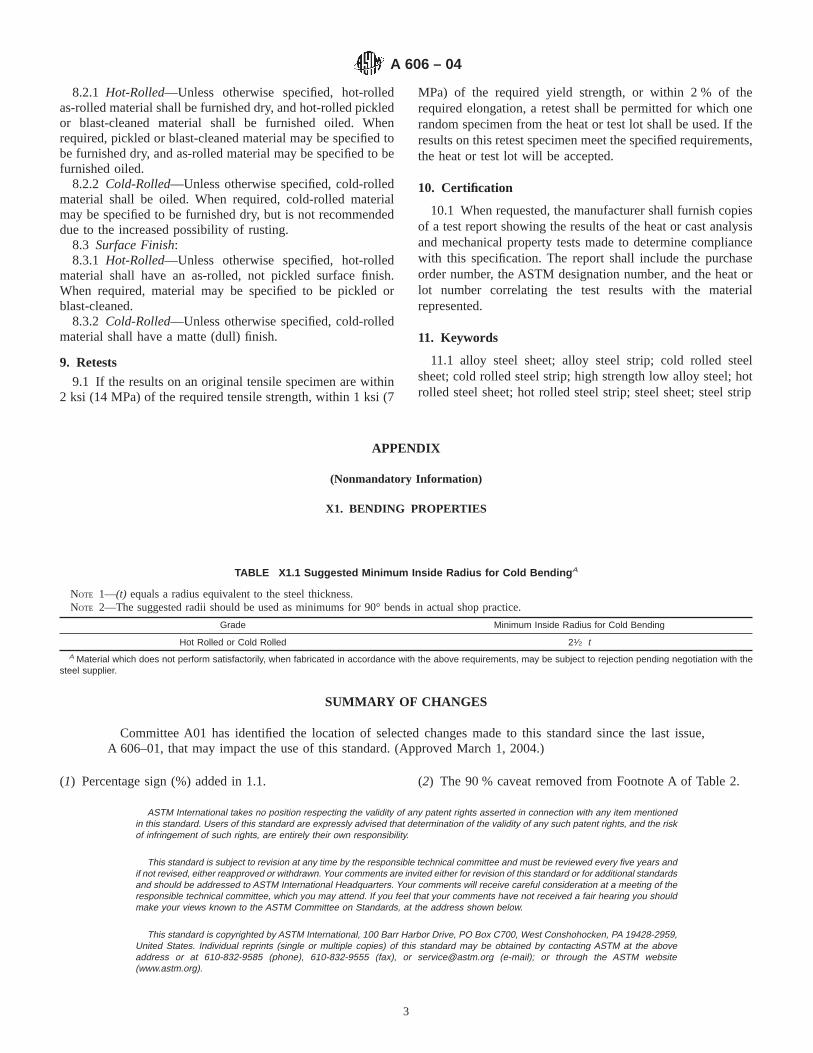
8.2.1 Hot-Rolled—Unless otherwise specified, hot-rolledas-rolled material shall be furnished dry, and hot-rolled pickledor blast-cleaned material shall be furnished oiled. Whenrequired, pickled or blast-cleaned material may be specified tobe furnished dry, and as-rolled material may be specified to befurnished oiled.
8.2.2 Cold-Rolled—Unless otherwise specified, cold-rolledmaterial shall be oiled. When required, cold-rolled materialmay be specified to be furnished dry, but is not recommendeddue to the increased possibility of rusting.
8.3 Surface Finish:8.3.1 Hot-Rolled—Unless otherwise specified, hot-rolled
material shall have an as-rolled, not pickled surface finish.When required, material may be specified to be pickled orblast-cleaned.
8.3.2 Cold-Rolled—Unless otherwise specified, cold-rolledmaterial shall have a matte (dull) finish.
9. Retests
9.1 If the results on an original tensile specimen are within2 ksi (14 MPa) of the required tensile strength, within 1 ksi (7
MPa) of the required yield strength, or within 2 % of therequired elongation, a retest shall be permitted for which onerandom specimen from the heat or test lot shall be used. If theresults on this retest specimen meet the specified requirements,the heat or test lot will be accepted.
10. Certification
10.1 When requested, the manufacturer shall furnish copiesof a test report showing the results of the heat or cast analysisand mechanical property tests made to determine compliancewith this specification. The report shall include the purchaseorder number, the ASTM designation number, and the heat orlot number correlating the test results with the materialrepresented.
11. Keywords
11.1 alloy steel sheet; alloy steel strip; cold rolled steelsheet; cold rolled steel strip; high strength low alloy steel; hotrolled steel sheet; hot rolled steel strip; steel sheet; steel strip
APPENDIX
(Nonmandatory Information)
X1. BENDING PROPERTIES
TABLE X1.1 Suggested Minimum Inside Radius for Cold Bending A
NOTE 1—(t) equals a radius equivalent to the steel thickness.NOTE 2—The suggested radii should be used as minimums for 90° bends in actual shop practice.
Grade Minimum Inside Radius for Cold Bending
Hot Rolled or Cold Rolled 21⁄2 tA Material which does not perform satisfactorily, when fabricated in accordance with the above requirements, may be subject to rejection pending negotiation with the
steel supplier.
SUMMARY OF CHANGES
Committee A01 has identified the location of selected changes made to this standard since the last issue,A 606–01, that may impact the use of this standard. (Approved March 1, 2004.)
(1) Percentage sign (%) added in 1.1. (2) The 90 % caveat removed from Footnote A of Table 2.
ASTM International takes no position respecting the validity of any patent rights asserted in connection with any item mentionedin this standard. Users of this standard are expressly advised that determination of the validity of any such patent rights, and the riskof infringement of such rights, are entirely their own responsibility.
This standard is subject to revision at any time by the responsible technical committee and must be reviewed every five years andif not revised, either reapproved or withdrawn. Your comments are invited either for revision of this standard or for additional standardsand should be addressed to ASTM International Headquarters. Your comments will receive careful consideration at a meeting of theresponsible technical committee, which you may attend. If you feel that your comments have not received a fair hearing you shouldmake your views known to the ASTM Committee on Standards, at the address shown below.
This standard is copyrighted by ASTM International, 100 Barr Harbor Drive, PO Box C700, West Conshohocken, PA 19428-2959,United States. Individual reprints (single or multiple copies) of this standard may be obtained by contacting ASTM at the aboveaddress or at 610-832-9585 (phone), 610-832-9555 (fax), or [email protected] (e-mail); or through the ASTM website(www.astm.org).
A 606 – 04
3
Designation: A 635/A 635M – 04 e1
Standard Specification forSteel, Sheet and Strip, Heavy-Thickness Coils, Hot-Rolled,Carbon, Structural, High-Strength Low-Alloy, and High-Strength Low-Alloy with Improved Formability, GeneralRequirements for 1
This standard is issued under the fixed designation A 635/A 635M; the number immediately following the designation indicates the yearof original adoption or, in the case of revision, the year of last revision. A number in parentheses indicates the year of last reapproval.A superscript epsilon (e) indicates an editorial change since the last revision or reapproval.
This standard has been approved for use by agencies of the Department of Defense.
e1 NOTE—Section 4.1 was editorially corrected in April 2004.
1. Scope*
1.1 This specification covers the general requirements forhot-rolled, heavy-thickness sheet and strip in coils.
1.2 It applies to Specification A 1018/A 1018.1.3 This material is available only in coils described as
follows:Size Limits, Coils Only
Product Width, in. [mm] Thickness, in. [mm]
Strip over 8 to 12, incl[over 200 through 300]
0.230 to1.000, incl[from 6.0 through 25]
Sheet over 12 to 48, incl[over 300 through 1200]
0.230 to 1.000, incl[from 6.0 through 25]
Sheet over 48[over 1200]
0.180 to 1.000, incl[from 4.5 though 25]
1.4 In case of any conflict in requirements, the requirementsof the individual material specification shall prevail over thoseof this general specification.
1.5 Annex A1 lists permissible variations in dimensions andmass (see Note 1) in SI [metric] units. The values listed are notexact conversions of the values listed in the inch-pound tables,but instead are rounded or rationalized values. Conformance toAnnex A1 is mandatory when the “M” specification is used.
NOTE 1—The term weight is used when inch-pound units are thestandard. However, under SI, the preferred term ismass.
1.6 The values stated in either inch-pound units or SI unitsare to be regarded as standard. Within the text, the SI units areshown in brackets. The values stated in each system are notexact equivalents; therefore, each system must be used inde-pendently of the other. Combining values from the two systemsmay result in nonconformance with this specification.
1.7 This specification and the applicable material specifica-tions are expressed in both inch-pound units and SI units.
However, unless the order specifies the applicable “M” speci-fication designation (SI units), the material shall be furnishedto inch-pound units.
2. Referenced Documents
2.1 ASTM Standards:2
A 370 Test Methods and Definitions for Mechanical Testingof Steel Products
A 700 Practices for Packaging, Marking, and LoadingMethods for Steel Products for Domestic Shipment
A 751 Test Methods, Practices, and Terminology forChemical Analysis of Steel Products
A 1018/A 1018M Specification for Steel, Sheet and Strip,Heavy-Thickness Coils, Hot-Rolled, Carbon, Commercial,Drawing, Structural, High-Strength Low-Alloy, and High-Strength Low-Alloy with Improved Formability
E 11 Specification for Wire Cloth and Sieves for TestingPurposes
E 29 Practice for Using Significant Digits in Test Data toDetermine Conformance with Specifications
E 59 Practice for Sampling Steel and Iron for Determinationof Chemical Composition3
2.2 Federal Standards:Fed. Std. No. 123 Marking for Shipment (Civil Agencies)4
Fed. Std. No. 183 Continuous Identification Marking of Ironand Steel Products4
2.3 Military Standards:MIL-STD-129 Marking for Shipment and Storage4
MIL-STD-163 Steel Mill Products, Preparation for Ship-ment and Storage4
1 This specification is under the jurisdiction of ASTM Committee A01 on Steel,Stainless Steel and Related Alloys and is the direct responsibility of SubcommitteeA01.19 on Steel Sheet and Strip.
Current edition approved March 1, 2004. Published March 2004. Originallyapproved in 1970. Last previous edition approved in 2002 as A 635 – 02.
2 For referenced ASTM standards, visit the ASTM website, www.astm.org, orcontact ASTM Customer Service at [email protected]. ForAnnual Book of ASTMStandardsvolume information, refer to the standard’s Document Summary page onthe ASTM website.
3 Withdrawn.4 Available from Standardization Documents Order Desk, Bldg. 4 Section D, 700
Robbins Ave., Philadelphia, PA 19111-5094, Attn: NPODS.
1
*A Summary of Changes section appears at the end of this standard.
Copyright © ASTM International, 100 Barr Harbor Drive, PO Box C700, West Conshohocken, PA 19428-2959, United States.

3. Terminology
3.1 Definitions of Terms Specific to This Standard:3.1.1 Steel Types:3.1.2 carbon steel—the designation for steel when no mini-
mum content is specified or required for aluminum, chromium,cobalt, columbium, molybdenum, nickel, titanium, tungsten,vanadium, zirconium, or any element added to obtain a desiredalloying effect; when the specified minimum for copper doesnot exceed 0.40 %; or when the maximum content specified forany of the following elements does not exceed the percentagesnoted: manganese 1.65, silicon 0.60, or copper 0.60.
3.1.2.1 Discussion—In all carbon steels small quantities ofcertain residual elements unavoidably retained from raw ma-terials are sometimes found which are not specified or required,such as copper, nickel, molybdenum, chromium, etc. Theseelements are considered as incidental and are not normallydetermined or reported.
3.1.3 high-strength, low-alloy steel—a specific group ofsteels in which higher strength, and in some cases additionalresistance to atmospheric corrosion or improved formability,are obtained by moderate amounts of one or more alloyingelements.
3.2 Product Types:3.3 hot-rolled sheet and strip—manufactured by hot rolling
slabs in a continuous mill to the required thickness; however,the product classification of sheet and strip is based on acombination of thickness and width (see Specification A 1018/A 1018M.)
4. Index of Tables, Dimensions, and Allowances
4.1 See the following table.Index of Tables for Dimensions, Tolerances, and AllowancesDimensions Table No.
Inch-PoundUnits†
SI Units
CamberSheet 6 A1.5Strip 11 A1.10
CrownStrip 9 A1.8
ThicknessSheet 2, 3 A1.1, A1.2Strip 7, 8 A1.6, A1.7
WidthSheet 4, 5 A1.3, A1.4Strip 10 A1.9
† Table numbers in this column were corrected editorially.
5. Materials and Manufacture
5.1 Melting Practice—Hot-rolled heavy thickness sheet andstrip coils are normally produced from rimmed, capped, orsemi-killed steel. If either coarse or fine-grain practice isspecified, special soundness steel will be furnished.
5.2 Steel may be produced as ingot-cast or strand-cast.When different grades of strand-cast steel are sequentially cast,identification and separation of the transition material isrequired.
5.3 The steel shall be in the hot-rolled condition.
6. Chemical Composition
6.1 Cast or Heat (Formerly Ladle) Analysis—An analysisof each heat or cast shall be made by the manufacturer to
determine the conformance with the appropriate requirement.The analysis shall be from a test sample preferably takenduring the pouring of the heat or cast.
6.1.1 Where the material is used for fabrication by welding,care must be exercised in selection of chemical composition ormechanical properties to assure compatibility with the weldingprocess and its effect on altering the properties.
6.2 Product, Check, or Verification Analysis:6.2.1 Non-killed steels such as capped or rimmed steels are
not technologically suited to product analysis due to thenonuniform character of their chemical composition, andtherefore, the tolerances in Table 1 do not apply. Productanalysis is appropriate on these types of steel only whenmisapplication is apparent, or for copper when copper steel isspecified.
6.2.2 For steels other than non-killed (capped or rimmed),product analysis may be made by the purchaser. The chemicalanalysis shall not vary from the limits specified by more thanthe amounts in Table 1. The several determinations of anyelement in a cast shall not vary both above and below thespecified range.
6.2.3 Sampling for Product Analysis:6.2.3.1 To indicate adequately the representative composi-
tion of a cast by product analysis, it is general practice to selectsamples to represent the steel, as fairly as possible, from aminimum number of pieces as follows: three pieces for lots upto 15 tons included, and six pieces for lots over 15 tons (seePractice E 59).
6.2.3.2 When the steel is subject to tension test require-ments, samples for product analysis may be taken either bydrilling entirely through the used tension test specimensthemselves, or as covered in 6.2.3.3.
6.2.3.3 When the steel is not subject to tension test require-ments, the samples for analysis must be taken by milling ordrilling entirely through the sheet in a sufficient number ofplaces so that the samples are representative of the entire sheetor strip. The sampling may be facilitated by folding the sheetboth ways, so that several samples may be taken at one drilling.Steel subjected to certain heating operations by the purchasermay not give chemical analysis results that properly representits original composition. Therefore, users must analyze chipstaken from the steel in the condition in which it is receivedfrom the steel manufacturer.
TABLE 1 Tolerances for Product Analysis
ElementLimit, or Maximum ofSpecified Element, %
Tolerance
UnderMini-mumLimit
OverMaxi-mumLimit
Carbon to 0.15, incl 0.02 0.03over 0.15 to 0.25, incl 0.03 0.04
Manganese to 0.60, incl 0.03 0.03over 0.60 to 1.15, incl 0.04 0.04over 1.15 to 1.65, incl 0.05 0.05
Phosphorus . . . 0.01Sulfur . . . 0.01Silicon to 0.30, incl 0.02 0.03
over 0.30 to 0.60, incl 0.05 0.05Copper 0.02 . . .
A 635/A 635M – 04e1
2
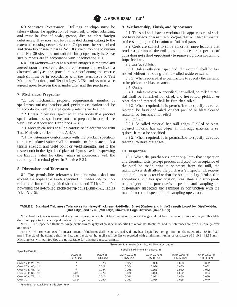
6.3 Specimen Preparation—Drillings or chips must betaken without the application of water, oil, or other lubricant,and must be free of scale, grease, dirt, or other foreignsubstances. They must not be overheated during cutting to theextent of causing decarburization. Chips must be well mixedand those too coarse to pass a No. 10 sieve or too fine to remainon a No. 30 sieve are not suitable for proper analysis. Sievesize numbers are in accordance with Specification E 11.
6.4 Test Methods—In case a referee analysis is required andagreed upon to resolve a dispute concerning the results of achemical analysis, the procedure for performing the refereeanalysis must be in accordance with the latest issue of TestMethods, Practices, and Terminology A 751, unless otherwiseagreed upon between the manufacturer and the purchaser.
7. Mechanical Properties
7.1 The mechanical property requirements, number ofspecimens, and test locations and specimen orientation shall bein accordance with the applicable product specification.
7.2 Unless otherwise specified in the applicable productspecification, test specimens must be prepared in accordancewith Test Methods and Definitions A 370.
7.3 Mechanical tests shall be conducted in accordance withTest Methods and Definitions A 370.
7.4 To determine conformance with the product specifica-tion, a calculated value shall be rounded to the nearest 1 ksitensile strength and yield point or yield strength, and to thenearest unit in the right hand place of figures used in expressingthe limiting value for other values in accordance with therounding off method given in Practice E 29.
8. Dimensions and Tolerances
8.1 The permissible tolerances for dimensions shall notexceed the applicable limits specified in Tables 2-6 for hot-rolled and hot-rolled, pickled-sheet coils and Tables 7-11 forhot-rolled and hot-rolled, pickled-strip coils (Annex A1, TablesA1.1-A1.10).
9. Workmanship, Finish, and Appearance
9.1 The steel shall have a workmanlike appearance and shallnot have defects of a nature or degree that will be detrimentalto the stamping or fabrication of finished parts.
9.2 Coils are subject to some abnormal imperfections thatrender a portion of the coil unusable since the inspection ofcoils does not afford opportunity to remove portions containingimperfections.
9.3 Surface Finish:9.3.1 Unless otherwise specified, the material shall be fur-
nished without removing the hot-rolled oxide or scale.9.3.2 When required, it is permissible to specify the material
to be pickled or blast-cleaned.9.4 Oiling:9.4.1 Unless otherwise specified, hot-rolled, as-rolled mate-
rial shall be furnished not oiled, and hot-rolled, pickled, orblast-cleaned material shall be furnished oiled.
9.4.2 When required, it is permissible to specify as-rolledmaterial be furnished oiled, or that pickled or blast-cleanedmaterial be furnished not oiled.
9.5 Edges:9.5.1 As-rolled material has mill edges. Pickled or blast-
cleaned material has cut edges; if mill-edge material is re-quired, it must be specified.
9.5.2 When required, it is permissible to specify as-rolledmaterial to have cut edges.
10. Inspection
10.1 When the purchaser’s order stipulates that inspectionand chemical tests (except product analyses) for acceptance ofthe steel be made prior to shipment from the mill, themanufacturer shall afford the purchaser’s inspector all reason-able facilities to determine that the steel is being furnished inaccordance with this specification. Steel sheet and strip prod-ucts subject to the purchaser’s inspection and sampling arecustomarily inspected and sampled in conjunction with themanufacturer’s inspection and sampling operations.
TABLE 2 Standard Thickness Tolerances for Heavy-Thickness Hot-Rolled Sheet (Carbon and High-Strength Low-Alloy Steel)— 3⁄8-in.(Cut Edge) and 3⁄4-in. (Mill Edge) Minimum Edge Distance (Coils Only)
NOTE 1—Thickness is measured at any point across the width not less than3⁄8 in. from a cut edge and not less than3⁄4 in. from a mill edge. This tabledoes not apply to the uncropped ends of mill edge coils.
NOTE 2—The specified thickness range captions also apply when sheet is specified to a nominal thickness, and the tolerances are divided equally, overand under.
NOTE 3—Micrometers used for measurement of thickness shall be constructed with anvils and spindles having minimum diameters of 0.188 in. [4.80mm]. The tip of the spindle shall be flat, and the tip of the anvil shall be flat or rounded with a minimum radius of curvature of 0.10 in. [2.55 mm].Micrometers with pointed tips are not suitable for thickness measurements.
Specified Width, in.
Thickness Tolerances Over, in., No Tolerance Under
Specified Minimum Thickness, in.
0.180 to0.229, incl
0.230 to0.313, incl
Over 0.313 to0.375, incl
Over 0.375 to0.500, incl
Over 0.500 to0.625, incl
Over 0.625 to1.000, incl
Over 12 to 20, incl A 0.020 0.024 0.028 0.030 0.032Over 20 to 40, incl A 0.022 0.024 0.028 0.030 0.032Over 40 to 48, incl A 0.024 0.026 0.028 0.030 0.032Over 48 to 60, incl 0.020 0.024 0.028 0.030 0.032 0.034Over 60 to 72, incl 0.022 0.026 0.030 0.032 0.036 0.038Over 72 0.024 0.030 0.032 0.036 0.038 0.040
A Product not available in this size range.
A 635/A 635M – 04e1
3

11. Rejection and Rehearing
11.1 Material that is reported to be defective subsequent tothe acceptance at the purchaser’s works shall be set aside,adequately protected, and correctly identified. The manufac-turer shall be notified as soon as possible so that an investiga-tion may be initiated.
11.2 Samples that are representative of the rejected materialshall be made available to the manufacturer. In the event thatthe manufacturer is dissatisfied with the rejection, he mayrequest a rehearing.
12. Test Reports and Certification
12.1 When test reports are required by the purchase order orthe material specification, the supplier shall report the results ofall tests required by the material specification and the order.
12.2 When certification is required by the purchase order,the supplier shall furnish a certification that the material hasbeen manufactured and tested in accordance with the require-ments of this material specification.
12.3 A signature is not required on test reports or certifica-tions. However, the document shall clearly identify the orga-nization submitting the document. Notwithstanding the ab-sence of a signature, the organization submitting the documentis responsible for the content of the document.
12.4 When test reports are required, copies of the originalmaterial manufacturer’s test report shall be included with anysubsequent test report.
12.5 A Material Test Report, Certificate of Inspection, orsimilar document printed from or used in electronic form froman electronic data interchange (EDI) transmission shall beregarded as having the same validity as a counterpart printed in
TABLE 3 Restricted Thickness Tolerances for Heavy-Thickness Hot-Rolled Sheet (Carbon and High-Strength Low-Alloy Steel)— 5⁄8-in.(Cut Edge) and 1-in. (Mill Edge) Minimum Edge Distance (Coils Only)
NOTE 1—Thickness is measured at any point across the width not less than5⁄8 in. from a cut edge and not less than 1 in. from a mill edge. This tabledoes not apply to the uncropped ends of mill edge coils.
NOTE 2—The specified thickness range captions also apply when sheet is specified to a nominal thickness, and the tolerances are divided equally, overand under.
NOTE 3—Micrometers used for measurement of thickness shall be constructed with anvils and spindles having minimum diameters of 0.188 in. [4.80mm]. The tip of the spindle shall be flat, and the tip of the anvil shall be flat or rounded with a minimum radius of curvature of 0.10 in. [2.55 mm].Micrometers with pointed tips are not suitable for thickness measurements.
NOTE 4—This table was constructed by multiplying the values in the standard table by 0.75 and rounding to 3 decimal places using standard ASTMpractice.
Specified Width, in.
Thickness Tolerances Over, in., No Tolerance Under
Specified Minimum Thickness, in.
0.180 to0.229, incl
0.230 to0.313, incl
Over 0.313 to0.375, incl
Over 0.375 to0.500, incl
Over 0.500 to0.625, incl
Over 0.625 to1.000, incl
Over 12 to 20, incl A 0.015 0.018 0.021 0.022 0.024Over 20 to 40, incl A 0.016 0.018 0.021 0.022 0.024Over 40 to 48, incl A 0.018 0.020 0.021 0.022 0.024Over 48 to 60, incl 0.015 0.018 0.021 0.022 0.024 0.026Over 60 to 72, incl 0.016 0.020 0.022 0.024 0.027 0.028Over 72 0.018 0.022 0.024 0.027 0.028 0.030
A Product is not available in this size range.
TABLE 4 Width Tolerances for Heavy-Thickness Mill Edge Sheet(Coils Only)
NOTE 1—This table does not apply to the uncropped end of mill-edgecoils.
Specified Width, in.Tolerance Over Specified Width,
in. (No Tolerance Under)
Over 12 to 14, incl 7⁄16
Over 14 to 17, incl 1⁄2Over 17 to 19, incl 9⁄16
Over 19 to 21, incl 5⁄8Over 21 to 24, incl 11⁄16
Over 24 to 26, incl 13⁄16
Over 26 to 28, incl 15⁄16
Over 28 to 35, incl 11⁄8Over 35 to 50, incl 11⁄4Over 50 to 60, incl 11⁄2Over 60 to 65, incl 1#Over 65 to 70, incl 13⁄4Over 70 to 80, incl 17⁄8Over 80 2
TABLE 5 Width Tolerances for Heavy-Thickness Cut-Edge Sheet(Coils Only)
NOTE 1—Heavy-thickness edge cutting results in a bevelled edge. Thewidth shall be measured on the wide surface of the cut-edge coil.Depending upon the angle of the bevelled edge cut, the width of thenarrow surface of the cut-edge coil may be less than the minimum orderedwidth. The manufacturer must be consulted regarding the capability tocontrol bevel angle.
Specified Width, in.Tolerance Over SpecifiedWidth, in. (No Tolerance
Under)
Over 12 to 30, incl !Over 30 to 48, incl 3⁄16
Over 48 to 60, incl 1⁄4Over 60 to 80, incl 5⁄16
Over 80 3⁄8
TABLE 6 Camber Tolerances for Heavy-Thickness Sheet(Coils Only)
NOTE 1—Camber is the deviation of a side edge from a straight line.Such a deviation is measured by placing a straightedge on the concaveside and measuring the greatest distance between the sheet edge and thestraightedge.
Camber should not exceed 1 in. in any 20 ft of length.
A 635/A 635M – 04e1
4
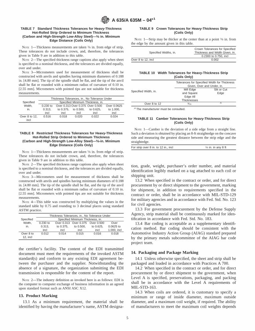
the certifier’s facility. The content of the EDI transmitteddocument must meet the requirements of the invoked ASTMstandard(s) and conform to any existing EDI agreement be-tween the purchaser and the supplier. Notwithstanding theabsence of a signature, the organization submitting the EDItransmission is responsible for the content of the report.
NOTE 2—The industry definition as invoked here is as follows: EDI isthe computer to computer exchange of business information in an agreedupon standard format such as ANSI ASC X12.
13. Product Marking
13.1 As a minimum requirement, the material shall beidentified by having the manufacturer’s name, ASTM designa-
tion, grade, weight, purchaser’s order number, and materialidentification legibly marked on a tag attached to each coil orshipping unit.
13.2 When specified in the contract or order, and for directprocurement by or direct shipment to the government, markingfor shipment, in addition to requirements specified in thecontract or order, shall be in accordance with MIL-STD-129for military agencies and in accordance with Fed. Std. No. 123for civil agencies.
13.3 For government procurement by the Defense SupplyAgency, strip material shall be continuously marked for iden-tification in accordance with Fed. Std. No. 183.
13.4 Bar coding is acceptable as a supplementary identifi-cation method. Bar coding should be consistent with theAutomotive Industry Action Group (AIAG) standard preparedby the primary metals subcommittee of the AIAG bar codeproject team.
14. Packaging and Package Marking
14.1 Unless otherwise specified, the sheet and strip shall bepackaged and loaded in accordance with Practices A 700.
14.2 When specified in the contract or order, and for directprocurement by or direct shipment to the government, whenLevel A is specified, preservations, packaging, and packingshall be in accordance with the Level A requirements ofMIL-STD-163.
14.3 When coils are ordered, it is customary to specify aminimum or range of inside diameter, maximum outsidediameter, and a maximum coil weight, if required. The abilityof manufacturers to meet the maximum coil weights depends
TABLE 7 Standard Thickness Tolerances for Heavy-ThicknessHot-Rolled Strip Ordered to Minimum Thickness
(Carbon and High-Strength Low-Alloy Steel)— 3⁄8 in. MinimumEdge Distance (Coils Only)
NOTE 1—Thickness measurements are taken3⁄8 in. from edge of strip.These tolerances do not include crown, and, therefore, the tolerancesgiven in Table 9 are in addition to this table.
NOTE 2—The specified thickness range captions also apply when sheetis specified to a nominal thickness, and the tolerances are divided equally,over and under.
NOTE 3—Micrometers used for measurement of thickness shall beconstructed with anvils and spindles having minimum diameters of 0.188in. [4.80 mm]. The tip of the spindle shall be flat, and the tip of the anvilshall be flat or rounded with a minimum radius of curvature of 0.10 in.[2.55 mm]. Micrometers with pointed tips are not suitable for thicknessmeasurements.
SpecifiedWidth,
in.
Thickness Tolerances, in., No Tolerance UnderSpecified Minimum Thickness, in.
0.230 to0.313,
incl
Over 0.313to 0.375,
incl
Over 0.375to 0.500,
incl
Over 0.500to 0.625,
incl
Over 0.0625to 1.000,
inclOver 8 to 12,
incl0.516 0.018 0.020 0.022 0.024
TABLE 8 Restricted Thickness Tolerances for Heavy-ThicknessHot-Rolled Strip Ordered to Minimum Thickness
(Carbon and High-Strength Low-Alloy Steel)— 5⁄8-in. MinimumEdge Distance (Coils Only)
NOTE 1—Thickness measurements are taken5⁄8 in. from edge of strip.These tolerances do not include crown, and, therefore, the tolerancesgiven in Table 9 are in addition to this table.
NOTE 2—The specified thickness range captions also apply when sheetis specified to a nominal thickness, and the tolerances are divided equally,over and under.
NOTE 3—Micrometers used for measurement of thickness shall beconstructed with anvils and spindles having minimum diameters of 0.188in. [4.80 mm]. The tip of the spindle shall be flat, and the tip of the anvilshall be flat or rounded with a minimum radius of curvature of 0.10 in.[2.55 mm]. Micrometers with pointed tips are not suitable for thicknessmeasurements.
NOTE 4—This table was constructed by multiplying the values in thestandard table by 0.75 and rounding to 3 decimal places using standardASTM practice.
SpecifiedWidth,
in.
Thickness Tolerances, in., No Tolerance UnderSpecified Minimum Thickness, in.
0.230 to0.313,
incl
Over 0.313to 0.375,
incl
Over 0.375to 0.500,
incl
Over 0.500to 0.625,
incl
Over0.0625 to1.000, incl
Over 8 to12, incl
0.012 0.014 0.015 0.016 0.018
TABLE 9 Crown Tolerances for Heavy-Thickness Strip(Coils Only)
NOTE 1—Strip may be thicker at the center than at a point3⁄8 in. fromthe edge by the amount given in this table.
Specified Widths, in.Crown Tolerances for SpecifiedThickness and Width Given, in.
0.2300 to 0.750, inclOver 8 to 12, incl 0.002
TABLE 10 Width Tolerances for Heavy-Thickness Strip(Coils Only)
Specified Width, in.
Tolerances for Specified Width for ThicknessGiven, Over and Under, in.
Mill Edgeand Square
Edge AllThicknesses
Slit or CutEdge
Over 8 to 12 3⁄16A
A The manufacturer must be consulted.
TABLE 11 Camber Tolerances for Heavy-Thickness Strip(Coils Only)
NOTE 1—Camber is the deviation of a side edge from a straight line.Such a deviation is obtained by placing an 8-ft straightedge on the concaveside and measuring the greatest distance between the strip edge and thestraightedge.
For strip over 8 in. to 12 in., incl 1⁄4 in. in any 8 ft
A 635/A 635M – 04e1
5

upon individual mill equipment. When required, minimum coilweights are subject to negotiation.
15. Keywords
15.1 carbon commercial; drawing; heavy thickness coils;high-strength low-alloy; high-strength low-alloy with im-proved formability; sheet steel; strip steel
ANNEX
(Mandatory Information)
A1. PERMISSIBLE VARIATIONS IN DIMENSIONS AND MASS IN SI UNITS
A1.1 Listed in Tables A1.1-A1.10 are permissible varia-tions in dimensions and mass expressed in the International
System of Units (SI) terminology.
TABLE A1.1 Standard Thickness Tolerances [Metric] for Heavy-Thickness Hot-Rolled Sheet Ordered to Minimum Thickness (Carbonand High-Strength Low-Alloy Steel)—10-mm (Cut Edge) and 20-mm (Mill Edge) Minimum Edge Distance (Coils Only)
NOTE 1—Thickness is measured at any point across the width not less than 10 mm from a cut edge and not less than 20 mm from a mill edge. Thistable does not apply to the uncropped ends of mill edge coils.
NOTE 2—The specified thickness range captions also apply when sheet is specified to a nominal thickness, and the tolerances are divided equally, overand under.
NOTE 3—Micrometers used for measurement of thickness shall be constructed with anvils and spindles having minimum diameters of 0.188 in. [4.80mm]. The tip of the spindle shall be flat, and the tip of the anvil shall be flat or rounded with a minimum radius of curvature of 0.10 in. [2.55 mm].Micrometers with pointed tips are not suitable for thickness measurements.
Specified Width, mm
Thickness Tolerances, mm, No Tolerance Under
Specified Minimum Thickness, mm
From 4.5 to 6.0,incl
Over 6.0 to 8.0,incl
Over 8.0 to 10.0,incl
Over 10.0 to 12.5,incl
Over 12.5 to 16.0,incl
Over 16.0 to 25.0,incl
Over 300 to 600, incl A 0.56 0.60 0.64 0.70 0.76Over 600 to 1200, incl A 0.60 0.64 0.70 0.76 0.80Over 1200 to 1500, incl 0.50 0.60 0.70 0.76 0.80 0.84Over 1500 to 1800, incl 0.56 0.64 0.76 0.80 0.90 0.96Over 1800 0.60 0.72 0.80 0.90 0.96 1.00
A Product not available in this size range.
A 635/A 635M – 04e1
6

TABLE A1.2 Restricted Thickness Tolerances [Metric] for Heavy-Thickness Hot-Rolled Sheet Ordered to Minimum Thickness (Carbonand High-Strength Low-Alloy Steel)—15-mm (Cut Edge) and 25-mm (Mill Edge) Minimum Edge Distance (Coils Only)
NOTE 1—Thickness is measured at any point across the width not less than 15 mm from a cut edge and not less than 25 mm from a mill edge. Thistable does not apply to the uncropped ends of mill edge coils.
NOTE 2—The specified thickness range captions also apply when sheet is specified to a nominal thickness, and the tolerances are divided equally, overand under.
NOTE 3—Micrometers used for measurement of thickness shall be constructed with anvils and spindles having minimum diameters of 0.188 in. [4.80mm]. The tip of the spindle shall be flat, and the tip of the anvil shall be flat or rounded with a minimum radius of curvature of 0.10 in. [2.55 mm].Micrometers with pointed tips are not suitable for thickness measurements.
NOTE 4—This table was constructed by multiplying the values in the standard table by 0.75 and rounding to 2 decimal places using standard ASTMpractice.
Specified Width, mm
Thickness Tolerances, mm, No Tolerance Under
Specified Minimum Thickness, mm
From 4.5 to 6.0,incl
Over 6.0 to 8.0,incl
Over 8.0 to 10.0,incl
Over 10.0 to 12.5,incl
Over 12.5 to 16.0,incl
Over 16.0 to 25.0,incl
Over 300 to 600, incl A 0.42 0.45 0.48 0.52 0.57Over 600 to 1200, incl A 0.45 0.48 0.52 0.57 0.60Over 1200 to 1500, incl 0.38 0.45 0.52 0.57 0.60 0.63Over 1500 to 1800, incl 0.42 0.48 0.57 0.60 0.68 0.72Over 1800 0.45 0.54 0.60 0.68 0.72 0.75
A Product not available in this size range.
TABLE A1.3 Width Tolerances for Heavy-Thickness Mill-EdgeSheet Steel (Coils Only)
NOTE 1—This table does not apply to the uncropped end of mill-edgecoils.
Specified Width, mm Width Tolerance,Plus Only, mmOver Through
300 600 16600 1200 28
1200 1500 381500 1800 451800 . . . 50
TABLE A1.4 Width Tolerances for Heavy-Thickness Cut-EdgeSheet Steel (Coils Only)
Specified Width, mm Width Tolerance, PlusOnly, mmOver Through
300 600 3600 1200 5
1200 1500 61500 1800 81800 . . . 10
TABLE A1.5 Camber Tolerances for Heavy-Thickness SheetSteel (Coils Only)
NOTE 1—Camber is the deviation of a side edge from a straight line.Such a deviation is measured by placing a straightedge on the concaveside and measuring the greatest distance between the sheet edge and thestraightedge.
Camber should not exceed 25 mm in any 6000 mm of length
A 635/A 635M – 04e1
7

TABLE A1.6 Standard Thickness Tolerances [Metric] for Heavy-Thickness Hot-Rolled Strip Ordered to Minimum Thickness (Carbonand High-Strength Low-Alloy Steel)—10-mm Minimum Edge Distance (Coils Only)
NOTE 1—Thickness measurements for this table are taken 10 mm from the edge of the strip. These tolerances do not include crown, and, therefore,the tolerances given in Table A1.8 are in addition to those in this table.
NOTE 2—Micrometers used for measurement of thickness shall be constructed with anvils and spindles having minimum diameters of 0.188 in. [4.80mm]. The tip of the spindle shall be flat, and the tip of the anvil shall be flat or rounded with a minimum radius of curvature of 0.10 in. [2.55 mm].Micrometers with pointed tips are not suitable for thickness measurements.
Specified Width, mm
Thickness Tolerances, mm, No Tolerance UnderSpecified Nominal Thickness, mm
From 6.0 to8.0, incl
Over 8.0 to12.5, incl
Over 12.5to 16.0,incl
Over 16.0 to25.0, incl
Over 200 to 300, incl 0.40 0.50 0.55 0.60
TABLE A1.7 Restricted Thickness Tolerances [Metric] for Heavy-Thickness Hot-Rolled Strip Ordered to Minimum Thickness (Carbonand High-Strength Low-Alloy Steel)—15-mm Minimum Edge Distance (Coils Only)
NOTE 1—Thickness measurements for this table are taken 15 mm for the edge of the strip. These tolerances do not include crown, and, therefore, thetolerance given in Table A1.8 are in addition to those in this table.
NOTE 2—Micrometers used for measurement of thickness shall be constructed with anvils and spindles having minimum diameters of 0.188 in. [4.80mm]. The tip of the spindle shall be flat, and the tip of the anvil shall be flat or rounded with a minimum radius of curvature of 0.10 in. [2.55 mm].Micrometers with pointed tips are not suitable for thickness measurements.
NOTE 3—This table was constructed by multiplying the values in the standard table by 0.75 and rounding to 2 decimal places using standard ASTMpractice.
Specified Width, mm
Thickness Tolerances, mm, No Tolerance UnderSpecified Minimum Thickness, mm
From 6.0 to8.0, incl
Over 8.0 to12.5, incl
Over 12.5 to16.0, incl
Over 16.0 to25.0, incl
Over 200 to 300, incl 0.30 0.38 0.41 0.45
TABLE A1.8 Crown Tolerances for Heavy-Thickness Strip Steel(Coils Only)
NOTE 1—Strip may be thicker at the center than at a point 10.0 mmfrom the edge by the amount given in the table.
Specified Widths, mmCrown Tolerances for
Specified Thickness andWidth Given, mm
Over Through Over 6.0 to 19, incl
200 300 0.05
TABLE A1.9 Width Tolerances for Heavy-Thickness Strip(Coils Only)
Specified Widths, mmTolerances for Specified Width for Thickness
Given, Plus and Minus, mm
Over Through Mill Edge and SquareEdge, All Thicknesses
Slit or CutEdge
200 300 5 A
A The manufacturer must be consulted.
A 635/A 635M – 04e1
8

SUMMARY OF CHANGES
Committee A01 has identified the location of selected changes made to this standard since the last issue,A 635/A 635M-02, that may impact the use of this standard. (Approved March 1, 2004.)
(1) Revised title.(2) Revised Section 1.1.(3) Added new Section 1.2.(4) Added new Section 1.3.(5) Deleted references to Specifications A 6/A 6M andA 568/A 568M in the Referenced Documents section.(6) Added Specifications A 1018/A 1018M, A 370, E 11,E 29, and E 59 to the Referenced Documents section.(7) Replaced Section 3.1.1.
(8) Deleted Ordering Information section.(9) Added new Sections 6.1.1, 6.2.3, and 6.3.(10) Deleted Sections 7.1 through 7.4.(11) Revised Sections 9.1 through 9.5.(12) Added new table, Tolerances for Product Analysis.(13) Added new Section 15, Keywords.(14) Deleted Tables 1 and 2 on Chemical Composition.(15) Renumbered remaining inch-pound tolerance tables.
ASTM International takes no position respecting the validity of any patent rights asserted in connection with any item mentionedin this standard. Users of this standard are expressly advised that determination of the validity of any such patent rights, and the riskof infringement of such rights, are entirely their own responsibility.
This standard is subject to revision at any time by the responsible technical committee and must be reviewed every five years andif not revised, either reapproved or withdrawn. Your comments are invited either for revision of this standard or for additional standardsand should be addressed to ASTM International Headquarters. Your comments will receive careful consideration at a meeting of theresponsible technical committee, which you may attend. If you feel that your comments have not received a fair hearing you shouldmake your views known to the ASTM Committee on Standards, at the address shown below.
This standard is copyrighted by ASTM International, 100 Barr Harbor Drive, PO Box C700, West Conshohocken, PA 19428-2959,United States. Individual reprints (single or multiple copies) of this standard may be obtained by contacting ASTM at the aboveaddress or at 610-832-9585 (phone), 610-832-9555 (fax), or [email protected] (e-mail); or through the ASTM website(www.astm.org).
TABLE A1.10 Camber Tolerances for Heavy-Thickness Strip(Coils Only)
NOTE 1—Camber is the deviation of a side edge from a straight line.Such a deviation is obtained by placing a 2000-mm straightedge on theconcave side and measuring the greatest distance between the strip edgeand the straightedge.
For strip over 200 mm to 300 mm, incl 5 mm in any 2000 mm
A 635/A 635M – 04e1
9

Designation: A 638/A 638M – 00
Standard Specification forPrecipitation Hardening Iron Base Superalloy Bars,Forgings, and Forging Stock for High-Temperature Service 1
This standard is issued under the fixed designation A 638/A 638M; the number immediately following the designation indicates the yearof original adoption or, in the case of revision, the year of last revision. A number in parentheses indicates the year of last reapproval.A superscript epsilon (e) indicates an editorial change since the last revision or reapproval.
1. Scope
1.1 This specification2 covers hot-finished or cold-finishedprecipitation hardening iron base superalloy bars, forgings, andforging stock for high-temperature service. The mechanicalproperties of these alloys are developed by suitable solutiontreating and precipitation hardening treatments.
1.2 Two grades of iron base alloy are covered. Selection willdepend upon design, service conditions, mechanical properties,and elevated temperature characteristics.
1.3 The values stated in either inch-pound units or SI(metric) units are to be regarded separately as standards; withinthe text and tables, the SI units are shown in [brackets]. Thevalues stated in each system are not exact equivalents; there-fore, each system must be used independent of the other.Combining values from the two systems may result in noncon-formance with the specification.
1.4 Unless the order specifies an “M” designation, thematerial shall be furnished to inch-pound units.
2. Referenced Documents
2.1 ASTM Standards:A 484/A484M Specification for General Requirements for
Stainless Steel Bars, Billets and Forgings3
A 751 Test Methods, Practices, and Terminology forChemical Analysis of Steel Products4
E 30 Test Methods for Chemical Analysis of Steel, CastIron, Open-Hearth Iron, and Wrought Iron5
3. Ordering Information
3.1 It is the responsibility of the purchaser to specify allrequirements that are necessary for material ordered under this
specification. Such requirements may include, but are notlimited to, the following:
3.1.1 Quantity (weight or number of pieces),3.1.2 Name of material (precipitation hardening iron base
superalloy),3.1.3 Form (bars, forgings, and forging stock),3.1.4 Dimensions (in the case of rough or finished forgings
the order shall be accompanied by a print or drawing orotherwise adequately described as to the shape and dimension),
3.1.5 Grade designation (Table 1),3.1.6 Condition (Section 5),3.1.7 Finish (Section 3),3.1.8 Mechanical requirements (Section 8),3.1.9 ASTM designation, and3.1.10 Special requirements.
4. General Requirements
4.1 In addition to the requirements of this specification, allrequirements of the current edition of Specification A 484/A 484M shall apply. Failure to comply with the generalrequirements of Specification A 484/A 484M constitutes non-conformance with this specification.
5. Condition
5.1 The product forms covered in this specification may befurnished in one of the following conditions:
5.1.1 Hot-finished,5.1.2 Solution treated (Grade 660 only—Type 1 or Type 2
solution treatment as specified),5.1.3 Solution and precipitation treated (Grade 660 only—
Type 1 or Type 2 solution treatment as specified), or5.1.4 Other as specified.
6. Heat Treatment
6.1 Samples cut from bars, forgings, or a sample forgedfrom the forging stock shall conform to the mechanicalproperties of Table 1 and Table 2 when heat treated asprescribed in Table 3.
1 This specification is under the jurisdiction of ASTM Committee A-1 on Steel,Stainless Steel and Related Alloys, and is the direct responsibility of SubcommitteeA01.17 on Flat Stainless Steel Products.
Current edition approved March 10, 2000. Published May 2000. Originallypublished as A 638 – 70. Last previous edition A 638/A 638M – 95.
2 For ASME Boiler and Pressure Vessel Code applications see related Specifi-cation SA-638 in Section II of that Code.
3 Annual Book of ASTM Standards, Vol 01.05.4 Annual Book of ASTM Standards, Vol 01.03.5 Annual Book of ASTM Standards, Vol 03.05.
1
Copyright © ASTM International, 100 Barr Harbor Drive, PO Box C700, West Conshohocken, PA 19428-2959, United States.
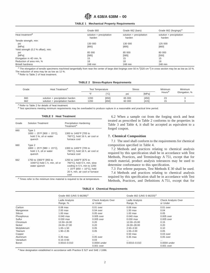
6.2 When a sample cut from the forging stock and heattreated as prescribed in Table 2 conforms to the properties inTable 3 and Table 4, it shall be accepted as equivalent to aforged coupon.
7. Chemical Composition
7.1 The steel shall conform to the requirements for chemicalcomposition specified in Table 4.
7.2 Methods and practices relating to chemical analysisrequired by this specification shall be in accordance with TestMethods, Practices, and Terminology A 751, except that forremelt material, product analysis tolerances may be used todetermine conformance to this specification.
7.3 For referee purposes, Test Methods E 30 shall be used.7.4 Methods and practices relating to chemical analysis
required by this specification shall be in accordance with TestMethods, Practices, and Definitions A 751, except that for
TABLE 1 Mechanical Property Requirements
Grade 660 Grade 662 (bars) Grade 662 (forgings)A
Heat treatmentB solution + precipitationharden
solution + precipitationharden
solution + precipitationharden
Tensile strength, min:psi 130 000 130 000 125 000[MPa] [895] [895] [860]
Yield strength (0.2 % offset), min:psi 85 000 85 000 80 000[MPa] [585] [585] [550]
Elongation in 4D min, % 15 15 15Reduction of area min, % 18 18 18Brinell hardness 248 min 248 min 248 min
A The elongation of tensile specimens machined tangentially from near the center of large disk forgings over 50 in.2[320 cm 2] in cross section may be as low as 10 %.The reduction of area may be as low as 12 %.
B Refer to Table 2 of heat treatment.
TABLE 2 Stress-Rupture Requirements
Grade Heat TreatmentA Test Temperature Stress MinimumHoursB
MinimumElongation, %
°F [°C] psi [MPa]
660 solution + precipitation harden 1200 [650] 65 000 [450] 23 3662 solution + precipitation harden 1200 [650] 60 000 [415] 15 3
A Refer to Table 2 for details of heat treatment.B Test specimens meeting minimum requirements may be overloaded to produce rupture in a reasonable and practical time period.
TABLE 3 Heat Treatment
Grade Solution Treatment Precipitation HardeningTreatmentA
660 Type 11650 6 25°F [900 6 15°C], 1300 to 1400°F [705 to
hold 2 hr, oil or water 760°C], hold 16 h, air cool orquench furnace cool
660 Type 21800 6 25°F [980 6 15°C], 1300 to 1400°F [705 to
hold 1 h, oil or water 760°C], hold 16 h, air cool orquench furnace cool
662 1750 to 1900°F [955 to 1250 to 1400°F [675 to1040°C] hold 1 h, min, oil or 760°C], hold 5 h, min, slowwater quench cooling in 5 h, min to 1200
6 15°F [650 6 10°C], hold20 h, min, air cool or furnacecool
A Times refer to the minimum time material is required to be at temperature.
TABLE 4 Chemical Requirements
Grade 660 (UNS S 66286)A Grade 662 (UNS S 66220)A
Ladle AnalysisRange, %
Check Analysis Overor Under
Ladle AnalysisRange, %
Check Analysis Overor Under
Carbon 0.08 max 0.01 over 0.08 max 0.01 overManganese 2.00 max 0.04 over 1.50 max 0.04Silicon 1.00 max 0.05 over 1.00 max 0.05Phosphorus 0.040 max 0.005 over 0.040 max 0.005 overSulfur 0.030 max 0.005 over 0.030 max 0.005 overChromium 13.50–16.00 0.20 12.00–15.00 0.15Nickel 24.00–27.00 0.20 24.00–28.00 0.20Molybdenum 1.00–1.50 0.05 2.50–3.50 0.10Titanium 1.90–2.35 0.05 1.55–2.00 0.05Copper ... ... 0.50 max 0.03 overAluminum 0.35 max 0.05 over 0.35 max 0.05 overVanadium 0.10–0.50 0.03 ... ...Boron 0.0010–0.010 0.0004 under 0.0010–0.010 0.0004 under
0.001 over 0.001 overA New designation established in accordance with Practice E 527 and SAE J 1086.
A 638/A 638M – 00
2

remelt material, product analysis tolerances may be used todetermine conformance to this specification.
8. Mechanical Properties
8.1 The material shall conform to the mechanical propertyrequirements specified in Table 1 after heat treatment asdescribed in Table 3.
8.2 The material shall meet the requirements as to stress-rupture properties specified in Table 2 at the test temperatureindicated after heat treatment as described in Table 3.
8.3 When specified in the ordering information (3.1.8),material may be ordered without stress-rupture testing. Mate-rial not stress-rupture tested shall be permanently stamped NR(See Section 10).
9. Metallurgical Properties
9.1 When specified, the grain size shall be 1 or finer.
10. Product Marking10.1 Unless otherwise specified on the purchase order, each
bundle shall be properly tagged with metal tags showing thepurchase order number, heat number, name of alloy (or grade),“NR” when material has not been stress-rupture tested,specification number, and size.
10.1.1 Bars 1 in. [25 mm] and over in diameter, or 1 in. [25mm] and over in thickness between parallel sides, shall bestamped with the heat number,and if not stress-rupture tested,with the letters “NR” within approximately 2 in. [50 mm] ofone end. Smaller sizes shall be boxed or bundled and identifiedwith metal tags as described in 10.1.
10.1.2 Forgings shall be identified as agreed upon betweenthe seller and the purchaser.
11. Keywords11.1 precipitation hardening superalloy steel; superalloy
steel bars; superalloy steel billets; superalloy steel forgings;temperature service applications—high
ASTM International takes no position respecting the validity of any patent rights asserted in connection with any item mentionedin this standard. Users of this standard are expressly advised that determination of the validity of any such patent rights, and the riskof infringement of such rights, are entirely their own responsibility.
This standard is subject to revision at any time by the responsible technical committee and must be reviewed every five years andif not revised, either reapproved or withdrawn. Your comments are invited either for revision of this standard or for additional standardsand should be addressed to ASTM International Headquarters. Your comments will receive careful consideration at a meeting of theresponsible technical committee, which you may attend. If you feel that your comments have not received a fair hearing you shouldmake your views known to the ASTM Committee on Standards, at the address shown below.
This standard is copyrighted by ASTM International, 100 Barr Harbor Drive, PO Box C700, West Conshohocken, PA 19428-2959,United States. Individual reprints (single or multiple copies) of this standard may be obtained by contacting ASTM at the aboveaddress or at 610-832-9585 (phone), 610-832-9555 (fax), or [email protected] (e-mail); or through the ASTM website(www.astm.org).
A 638/A 638M – 00
3

Designation: A 659/A 659M – 97 (Reapproved 2001)
Standard Specification forCommercial Steel (CS), Sheet and Strip, Carbon (0.16Maximum to 0.25 Maximum Percent), Hot-Rolled 1
This standard is issued under the fixed designation A 659/A 659M; the number immediately following the designation indicates the yearof original adoption or, in the case of revision, the year of last revision. A number in parentheses indicates the year of last reapproval.A superscript epsilon (e) indicates an editorial change since the last revision or reapproval.
This standard has been approved for use by agencies of the Department of Defense.
1. Scope
1.1 This specification covers hot-rolled carbon steel (CS)sheet and strip, in coils and cut lengths, in which the maximumof the specified carbon range is over 0.15 and not over 0.25 %and the maximum of the specified manganese range is not over0.90 %. This material is ordered to chemical composition.
1.2 This specification is not applicable to the steels coveredby Specification A 635/A 635M.
1.3 The values stated in either acceptable SI (metric) unitsor in other units shall be regarded separately as standard. Thevalues stated in each system may not be exact equivalents;therefore, each system must be used independently of the other,without combining values in any way.
2. Referenced Documents
2.1 ASTM Standards:A 568/A 568M Specification for Steel, Sheet, Carbon and
High-Strength, Low-Alloy, Hot-Rolled and Cold-Rolled,General Requirements for2
A 635/A 635M Specification for Steel, Sheet and Strip,Heavy-Thickness Coils, Carbon, Hot-Rolled2
A 749/A 749M Specification for Steel, Strip, Carbon andHigh-Strength, Low-Alloy, Hot-Rolled, General Require-ments for2
E 527 Practice for Numbering Metals and Alloys3
2.2 Society of Automotive Engineers Standard:4
J 1086 Numbering Metals and Alloys
3. Ordering Information
3.1 It is the purchaser’s responsibility to specify in thepurchase order all ordering information necessary to purchase
the needed material. Examples of such information include butare not limited to the following:
3.1.1 ASTM specification number and year of issue,3.1.2 Name of material (hot-rolled commercial steel (CS)
sheet, or hot-rolled commercial steel (CS) strip),3.1.3 Grade designation or chemical composition, or both,3.1.4 Copper-bearing steel (if required),3.1.5 Condition (as-rolled, pickled, or blast cleaned) (see
4.1),3.1.5.1 Material to this specification is furnished in the
hot-rolled condition. Pickled (or blast cleaned) must be speci-fied if required,
3.1.6 Oiling (see 7.2),3.1.7 Edges (see 7.1),3.1.8 Dimensions (thickness, width, and whether cut lengths
or coils),3.1.8.1 As agreed upon between the purchaser and the
producer, material ordered to this specification will be suppliedto meet the appropriate standard or restricted thickness toler-ance table shown in Specification A 568/A 568M.
NOTE 1—Not all producers are capable of meeting all of the limitationsof the thickness tolerance tables in Specification A 568/A 568M. Thepurchaser should contact the producer regarding possible limitations priorto placing an order.
3.1.9 Coil size (must include inside diameter, outside diam-eter, and maximum mass),
3.1.10 Quantity,3.1.11 Application (show part identification and descrip-
tion),3.1.12 Special requirements (if required), and3.1.13 Cast or heat analysis report (request, if required).
NOTE 2—A typical ordering description is as follows:“ASTM A659-XX [or A659M-XX], Hot-Rolled Commercial Steel (CS)Sheet, Grade 1017, Pickled and Oiled, Cut Edge, 0.075 by 36 in. [or 1.85by 900 mm], by coil, ID 24 in., OD 48 in., max weight 11 250 lb max [orID 600 mm, OD 1200 mm, max, weight 7500 kg, max], 100 000 lb [or 45000 kg] for Part No. 6509, Shelf Leg, Cast or heat analysis reportrequired.”
1 This specification is under the jurisdiction of ASTM Committee A01 on Steel,Stainless Steel, and Related Alloys and is the direct responsibility of SubcommitteeA01.19 on Steel Sheet and Strip.
Current edition approved March 10, 1997. Published November 1997. Originallypublished as A 659 – 72. Last previous edition A 659/A 659M – 96.
2 Annual Book of ASTM Standards, Vol 01.03.3 Annual Book of ASTM Standards, Vol 01.01.4 Available from Society of Automotive Engineers, 400 Commonwealth Dr.,
Warrendale, PA 15096.
1
Copyright © ASTM International, 100 Barr Harbor Drive, PO Box C700, West Conshohocken, PA 19428-2959, United States.

4. Materials and Manufacture
4.1 Condition—Unless otherwise specified, the material isfurnished in the as-rolled condition (not annealed or pickled).
5. Chemical Composition
5.1 The Cast or Heat Analysisof the steel shall conform tothe chemical requirements shown in Table 1, or chemicalcompositions can be specified from carbon 0.16 maximum to0.25 % maximum, inclusive, and manganese 0.90 % maxi-mum, inclusive, which conform to the ranges and limits inAppendix X1 of Specifications A 568/A 568M and A 749/A749M.
5.1.1 Unspecified elements may be present. Limits on ele-ments shall be as stated in Table 2.
5.1.1.1 Each of the elements listed in Table 2 shall beincluded in the report of the heat analysis. When the amount ofcopper, nickel, chromium, or molybdenum is less than 0.02 %,the analysis may be reported as “<0.02 %.” When the amountof vanadium or columbium is less than 0.008 %, the analysismay be reported as “<0.008 %.”
5.2 Where material is used for fabrication by welding, caremust be exercised in selection of the chemical composition toassure compatibility with the welding process and its effect onaltering the properties of the steel.
6. Bending Properties
6.1 The minimum forming radius (radii) that steel coveredby this specification can be expected to sustain is listed in theappendix and is discussed in more detail in SpecificationsA 568/A 568M, and A 749/A 749M. When tighter bend radii
are required, or curved or offset bends are involved, or whenstretching or drawing are also a consideration, the producersshall be consulted.
7. Workmanship, Finish, and Appearance
7.1 Edge:7.1.1 Sheet can be supplied with mill edge or cut edge.7.1.2 Strip can be supplied with mill edge or slit (cut) edge.7.2 Oiling—Hot-rolled, non-pickled material is commonly
furnished not oiled, while hot-rolled pickled (or blast cleaned)material is commonly furnished oiled. When required, pickled(or blast cleaned) material may be specified to be furnished notoiled, and non-pickled material may be specified to be fur-nished oiled.
8. General Requirements for Delivery
8.1 Material furnished under this specification shall con-form to the applicable requirements of the current edition ofSpecification A 568/A 568M for sheet, and SpecificationA 749/A 749M for strip, unless otherwise provided herein.
9. Certification and Reports
9.1 When requested, the producer shall furnish copies of areport showing test results of the cast or heat analysis. Thereport shall include the purchase order number, the ASTMdesignation number, and the cast or heat number representingthe material.
10. Keywords
10.1 carbon steel sheet; carbon steel strip; hot rolled steelsheet; hot rolled steel strip; steel sheet; steel strip
TABLE 1 Typical Grade Designations and Chemical Compositions A
UNS DesignationB Grade Designation Carbon, % Manganese, % Phosphorus, max, % Sulfur, max, %
G10150 1015 0.12–0.18 0.30–0.60 0.030 0.035G10160 1016 0.12–0.18 0.60–0.90 0.030 0.035G10170 1017 0.14–0.20 0.30–0.60 0.030 0.035G10180 1018 0.14–0.20 0.60–0.90 0.030 0.035G10200 1020 0.17–0.23 0.30–0.60 0.030 0.035G10210 1021 0.17–0.23 0.60–0.90 0.030 0.035G10230 1023 0.19–0.25 0.30–0.60 0.030 0.035
A Copper, when specified, shall have a minimum content of 0.20 % by cast or heat analysis.B Designation established in accordance with Practice E 527 and SAE J 1086.
A 659/A 659M – 97 (2001)
2
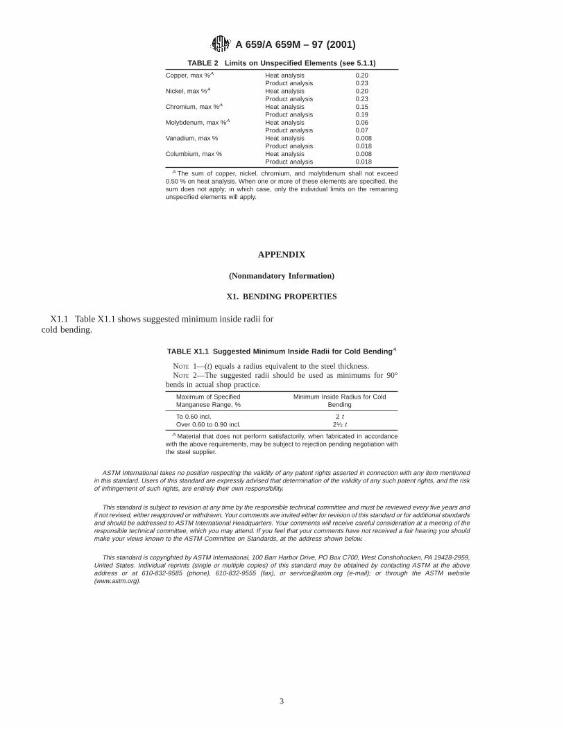
APPENDIX
(Nonmandatory Information)
X1. BENDING PROPERTIES
X1.1 Table X1.1 shows suggested minimum inside radii forcold bending.
ASTM International takes no position respecting the validity of any patent rights asserted in connection with any item mentionedin this standard. Users of this standard are expressly advised that determination of the validity of any such patent rights, and the riskof infringement of such rights, are entirely their own responsibility.
This standard is subject to revision at any time by the responsible technical committee and must be reviewed every five years andif not revised, either reapproved or withdrawn. Your comments are invited either for revision of this standard or for additional standardsand should be addressed to ASTM International Headquarters. Your comments will receive careful consideration at a meeting of theresponsible technical committee, which you may attend. If you feel that your comments have not received a fair hearing you shouldmake your views known to the ASTM Committee on Standards, at the address shown below.
This standard is copyrighted by ASTM International, 100 Barr Harbor Drive, PO Box C700, West Conshohocken, PA 19428-2959,United States. Individual reprints (single or multiple copies) of this standard may be obtained by contacting ASTM at the aboveaddress or at 610-832-9585 (phone), 610-832-9555 (fax), or [email protected] (e-mail); or through the ASTM website(www.astm.org).
TABLE 2 Limits on Unspecified Elements (see 5.1.1)
Copper, max %A Heat analysisProduct analysis
0.200.23
Nickel, max %A Heat analysisProduct analysis
0.200.23
Chromium, max %A Heat analysisProduct analysis
0.150.19
Molybdenum, max %A Heat analysisProduct analysis
0.060.07
Vanadium, max % Heat analysisProduct analysis
0.0080.018
Columbium, max % Heat analysisProduct analysis
0.0080.018
A The sum of copper, nickel, chromium, and molybdenum shall not exceed0.50 % on heat analysis. When one or more of these elements are specified, thesum does not apply; in which case, only the individual limits on the remainingunspecified elements will apply.
TABLE X1.1 Suggested Minimum Inside Radii for Cold Bending A
NOTE 1—(t) equals a radius equivalent to the steel thickness.NOTE 2—The suggested radii should be used as minimums for 90°
bends in actual shop practice.
Maximum of SpecifiedManganese Range, %
Minimum Inside Radius for ColdBending
To 0.60 incl. 2 tOver 0.60 to 0.90 incl. 21⁄2 t
A Material that does not perform satisfactorily, when fabricated in accordancewith the above requirements, may be subject to rejection pending negotiation withthe steel supplier.
A 659/A 659M – 97 (2001)
3

Designation: A 666 – 03
Standard Specification forAnnealed or Cold-Worked Austenitic Stainless Steel Sheet,Strip, Plate, and Flat Bar 1
This standard is issued under the fixed designation A 666; the number immediately following the designation indicates the year oforiginal adoption or, in the case of revision, the year of last revision. A number in parentheses indicates the year of last reapproval. Asuperscript epsilon (e) indicates an editorial change since the last revision or reapproval.
This standard has been approved for use by agencies of the Department of Defense.
1. Scope*
1.1 This specification covers austenitic stainless steels in theannealed and normally required cold-worked conditions forvarious structural, architectural, pressure vessel, magnetic,cryogenic, and heat-resisting applications. (This revision ofSpecification A 666 replaces prior Specifications A 412 andA 177.)
1.2 The application of this specification, or the use ofmaterial covered by this specification does not automaticallyallow usage in pressure vessel applications. Only annealedconditions of grades specifically approved by the ASME codeare permitted for pressure vessel use.
1.3 The values stated in inch-pound units are to be regardedas the standard. The values given in parentheses are forinformation only.
2. Referenced Documents
2.1 ASTM Standards:2
A 240/A 240M Specification for Chromium andChromium-Nickel Stainless Steel Plate, Sheet, and Stripfor Pressure Vessels and for General Applications
A 370 Test Methods and Definitions for Mechanical Testingof Steel Products
A 480/A 480M Specification for General Requirements forFlat-Rolled Stainless and Heat-Resisting Steel Plate,Sheet, and Strip
A 484/A 484M Specification for General Requirements forStainless Steel Bars, Billets, and Forgings
3. Material Test Report and Certification
3.1 In addition to the requirements of Specification A 480/A 480M, the cold-worked condition (annealed,1⁄4 H, 1⁄2 H, andso forth) shall be noted.
4. Chemical Composition
4.1 The steel shall conform to the requirements as tochemical composition specified in Table 1, and shall conformto applicable requirements specified in the current edition ofSpecification A 480/A 480M.
5. Mechanical Properties
5.1 The material shall conform to the mechanical propertiesspecified in Table 2 and Table 3, or Table 2 and Table 4.
6. General Requirements
6.1 The following requirements for orders for materialfurnished under this specification shall conform to the appli-cable requirements of the current edition of SpecificationA 480/A 480M or A 484/A 484M:
6.1.1 Definitions,6.1.2 General requirements for delivery,6.1.3 Ordering information,6.1.4 Process,6.1.5 Special tests,6.1.6 Heat treatment,6.1.7 Dimensions and permissible variations,6.1.8 Workmanship, finish and appearance,6.1.9 Number of tests/test methods,6.1.10 Specimen preparation,6.1.11 Retreatment,6.1.12 Inspection,6.1.13 Rejection and rehearing,6.1.14 Material test report,6.1.15 Certification, and6.1.16 Packaging, marking, and loading.
7. Sampling
7.1 Tension and bend-test specimens of sheet, strip, andplate products shall be selected from finished material and shallbe selected in the transverse direction, except in the case ofstrip under 9 in. (229 mm) in width, in which case tension testspecimens shall be selected in the longitudinal direction.
7.2 Flat bar tension and bend-test specimens shall be se-lected from the finished material and shall be in the longitudi-nal direction.
1 This specification is under the jurisdiction of ASTM Committee A01 on Steel,Stainless Steel and Related Alloys and is the direct responsibility of SubcommitteeA01.17 on Flat-Rolled and Wrought Stainless Steel.
Current edition approved Oct. 1, 2003. Published October 2003. Originallyapproved in 1972. Last previous edition approved in 2000 as A 666 – 00.
2 For referenced ASTM standards, visit the ASTM website, www.astm.org, orcontact ASTM Customer Service at [email protected]. For Annual Book of ASTMStandards volume information, refer to the standard’s Document Summary page onthe ASTM website.
1
*A Summary of Changes section appears at the end of this standard.
Copyright © ASTM International, 100 Barr Harbor Drive, PO Box C700, West Conshohocken, PA 19428-2959, United States.
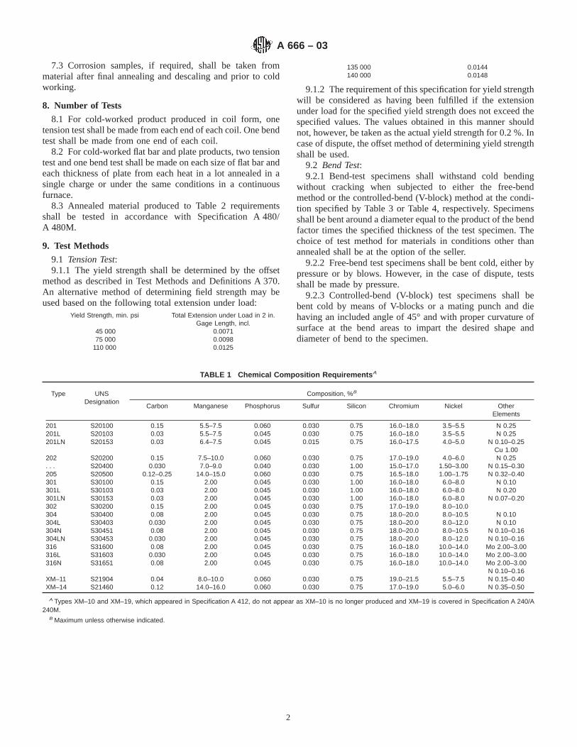
7.3 Corrosion samples, if required, shall be taken frommaterial after final annealing and descaling and prior to coldworking.
8. Number of Tests
8.1 For cold-worked product produced in coil form, onetension test shall be made from each end of each coil. One bendtest shall be made from one end of each coil.
8.2 For cold-worked flat bar and plate products, two tensiontest and one bend test shall be made on each size of flat bar andeach thickness of plate from each heat in a lot annealed in asingle charge or under the same conditions in a continuousfurnace.
8.3 Annealed material produced to Table 2 requirementsshall be tested in accordance with Specification A 480/A 480M.
9. Test Methods
9.1 Tension Test:9.1.1 The yield strength shall be determined by the offset
method as described in Test Methods and Definitions A 370.An alternative method of determining field strength may beused based on the following total extension under load:
Yield Strength, min. psi Total Extension under Load in 2 in.Gage Length, incl.
45 000 0.007175 000 0.0098
110 000 0.0125
135 000 0.0144140 000 0.0148
9.1.2 The requirement of this specification for yield strengthwill be considered as having been fulfilled if the extensionunder load for the specified yield strength does not exceed thespecified values. The values obtained in this manner shouldnot, however, be taken as the actual yield strength for 0.2 %. Incase of dispute, the offset method of determining yield strengthshall be used.
9.2 Bend Test:9.2.1 Bend-test specimens shall withstand cold bending
without cracking when subjected to either the free-bendmethod or the controlled-bend (V-block) method at the condi-tion specified by Table 3 or Table 4, respectively. Specimensshall be bent around a diameter equal to the product of the bendfactor times the specified thickness of the test specimen. Thechoice of test method for materials in conditions other thanannealed shall be at the option of the seller.
9.2.2 Free-bend test specimens shall be bent cold, either bypressure or by blows. However, in the case of dispute, testsshall be made by pressure.
9.2.3 Controlled-bend (V-block) test specimens shall bebent cold by means of V-blocks or a mating punch and diehaving an included angle of 45° and with proper curvature ofsurface at the bend areas to impart the desired shape anddiameter of bend to the specimen.
TABLE 1 Chemical Composition Requirements A
Type UNSDesignation
Composition, %B
Carbon Manganese Phosphorus Sulfur Silicon Chromium Nickel OtherElements
201 S20100 0.15 5.5–7.5 0.060 0.030 0.75 16.0–18.0 3.5–5.5 N 0.25201L S20103 0.03 5.5–7.5 0.045 0.030 0.75 16.0–18.0 3.5–5.5 N 0.25201LN S20153 0.03 6.4–7.5 0.045 0.015 0.75 16.0–17.5 4.0–5.0 N 0.10–0.25
Cu 1.00202 S20200 0.15 7.5–10.0 0.060 0.030 0.75 17.0–19.0 4.0–6.0 N 0.25. . . S20400 0.030 7.0–9.0 0.040 0.030 1.00 15.0–17.0 1.50–3.00 N 0.15–0.30205 S20500 0.12–0.25 14.0–15.0 0.060 0.030 0.75 16.5–18.0 1.00–1.75 N 0.32–0.40301 S30100 0.15 2.00 0.045 0.030 1.00 16.0–18.0 6.0–8.0 N 0.10301L S30103 0.03 2.00 0.045 0.030 1.00 16.0–18.0 6.0–8.0 N 0.20301LN S30153 0.03 2.00 0.045 0.030 1.00 16.0–18.0 6.0–8.0 N 0.07–0.20302 S30200 0.15 2.00 0.045 0.030 0.75 17.0–19.0 8.0–10.0304 S30400 0.08 2.00 0.045 0.030 0.75 18.0–20.0 8.0–10.5 N 0.10304L S30403 0.030 2.00 0.045 0.030 0.75 18.0–20.0 8.0–12.0 N 0.10304N S30451 0.08 2.00 0.045 0.030 0.75 18.0–20.0 8.0–10.5 N 0.10–0.16304LN S30453 0.030 2.00 0.045 0.030 0.75 18.0–20.0 8.0–12.0 N 0.10–0.16316 S31600 0.08 2.00 0.045 0.030 0.75 16.0–18.0 10.0–14.0 Mo 2.00–3.00316L S31603 0.030 2.00 0.045 0.030 0.75 16.0–18.0 10.0–14.0 Mo 2.00–3.00316N S31651 0.08 2.00 0.045 0.030 0.75 16.0–18.0 10.0–14.0 Mo 2.00–3.00
N 0.10–0.16XM–11XM–14
S21904S21460
0.040.12
8.0–10.014.0–16.0
0.0600.060
0.0300.030
0.750.75
19.0–21.517.0–19.0
5.5–7.55.0–6.0
N 0.15–0.40N 0.35–0.50
A Types XM–10 and XM–19, which appeared in Specification A 412, do not appear as XM–10 is no longer produced and XM–19 is covered in Specification A 240/A240M.
B Maximum unless otherwise indicated.
A 666 – 03
2
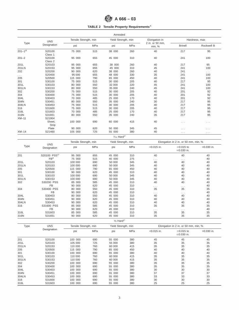
TABLE 2 Tensile Property Requirements A
Annealed
TypeUNS
Designation
Tensile Strength, min Yield Strength, min Elongation in2 in. or 50 mm,
min, %
Hardness, max
psi MPa psi MPa Brinell Rockwell B
201–1B S20100 75 000 515 38 000 260 40 217 95Class 1
201–2 S20100 95 000 655 45 000 310 40 241 100Class 2
201L S20103 95 000 655 38 000 260 40 217 95201LN S20153 95 000 655 45 000 310 45 241 100202 S20200 90 000 620 38 000 260 40 241 . . .. . . S20400 95 000 655 48 000 330 35 241 100205 S20500 115 000 790 65 000 450 40 241 100301 S30100 75 000 515 30 000 205 40 217 95301L S30103 80 000 550 32 000 220 45 241 100301LN S30153 80 000 550 35 000 240 45 241 100302 S30200 75 000 515 30 000 205 40 201 92304 S30400 75 000 515 30 000 205 40 201 92304L S30403 70 000 485 25 000 170 40 201 92304N S30451 80 000 550 35 000 240 30 217 95304LN S30453 75 000 515 30 000 205 40 217 95316 S31600 75 000 515 30 000 205 40 217 95316L S31603 70 000 485 25 000 170 40 217 95316N S31651 80 000 550 35 000 240 35 217 95XM–11 S21904
Sheet,Strip
100 000 690 60 000 415 40 . . . . . .
Plate 90 000 620 50 000 345 45 . . . . . .XM–14 S21460 105 000 725 55 000 380 40 . . . . . .
1⁄16 HardC
TypeUNS
Designation
Tensile Strength, min Yield Strength, min Elongation in 2 in. or 50 mm, min, %
psi MPa psi MPa <0.015 in. $0.015 to#0.030 in.
>0.030 in.
201 S20100 PSSD 95 000 655 45 000 310 40 40 40FBE 75 000 515 40 000 275 . . . . . . 40
201L S20103 100 000 690 50 000 345 40 40 40201LN S20153 100 000 690 50 000 345 40 40 40205 S20500 115 000 790 65 000 450 40 40 40301 S30100 90 000 620 45 000 310 40 40 40301L S30103 100 000 690 50 000 345 40 40 40301LN S30153 100 000 690 50 000 345 40 40 40302 S30200 PSS 85 000 585 45 000 310 40 40 40
FB 90 000 620 45 000 310 . . . . . . 40304 S30400 PSS 80 000 550 45 000 310 35 35 35
FB 90 000 620 45 000 310 . . . . . . 40304L S30403 80 000 550 45 000 310 40 40 40304N S30451 90 000 620 45 000 310 40 40 40304LN S30453 90 000 620 45 000 310 40 40 40316 S31600 PSS 85 000 585 45 000 310 35 35 35
FB 90 000 620 45 000 310 . . . . . . 40316L S31603 85 000 585 45 000 310 35 35 35316N S31651 90 000 620 45 000 310 35 35 35
1⁄8 HardC
Type UNSDesignation
Tensile Strength, min Yield Strength, min Elongation in 2 in. or 50 mm, min, %
psi MPa psi MPa <0.015 in. $0.015 to#0.030 in.
>0.030 in.
201 S20100 100 000 690 55 000 380 45 45 45201L S20103 105 000 725 55 000 380 35 35 35201LN S20153 110 000 760 60 000 415 35 35 35205 S20500 115 000 790 65 000 450 40 40 40301 S30100 100 000 690 55 000 380 40 40 40301L S30103 110 000 760 60 000 415 35 35 35301LN S30153 110 000 760 60 000 415 35 35 35302 S30200 100 000 690 55 000 380 35 35 35304 S30400 100 000 690 55 000 380 35 35 35304L S30403 100 000 690 55 000 380 30 30 30304N S30451 100 000 690 55 000 380 37 37 37304LN S30453 100 000 690 55 000 380 33 33 33316 S31600 100 000 690 55 000 380 30 30 30316L S31603 100 000 690 55 000 380 25 25 25
A 666 – 03
3

TABLE 2 Continued
316N S31651 100 000 690 55 000 380 32 32 32
1⁄4 Hard
TypeUNS
Designation
Tensile Strength, min Yield Strength, min Elongation in 2 in. or 50 mm, min, %
psi MPa psi MPa <0.015 in. $0.015 to#0.030 in.
>0.030 in.
201 S20100 125 000 860 75 000 515 25 25 25201L S20103 120 000 825 75 000 515 25 25 25201LN S20153 120 000 825 75 000 515 25 25 25202 S20200 125 000 860 75 000 515 12 12 . . .. . . S20400 140 000 965 100 000 960 20 20 20205 S20500 125 000 860 75 000 515 45 45 45301 S30100 125 000 860 75 000 515 25 25 25301L S30103 120 000 825 75 000 515 25 25 25301LN S30153 120 000 825 75 000 515 25 25 25302 S30200 125 000 860 75 000 515 10 10 12304 S30400 125 000 860 75 000 515 10 10 12304L S30403 125 000 860 75 000 515 8 8 10304N S30451 125 000 860 75 000 515 12 12 12304LN S30453 125 000 860 75 000 515 10 10 12316 S31600 125 000 860 75 000 515 10 10 10316L S31603 125 000 860 75 000 515 8 8 8316N S31651 125 000 860 75 000 515 12 12 12XM-11 S21904 130 000 895 115 000 795 15 15 . . .
1⁄2 Hard
TypeUNS
Designation
Tensile Strength, min Yield Strength, min Elongation in 2 in. or 50 mm, min, %
psi MPa psi Mpa <0.015 in. $0.015 to#0.030 in.
>0.030 in.
201 S20100 150 000 1035 110 000 760 15 18 18201L S20103 135 000 930 100 000 690 22 22 20201LN S20153 135 000 930 100 000 690 22 22 20205 S20500 150 000 1035 110 000 760 15 18 18301 S30100 150 000 1035 110 000 760 15 18 18301L S30103 135 000 930 100 000 690 20 20 20301LN S30153 135 000 930 100 000 690 20 20 20302 S30200 150 000 1035 110 000 760 9 10 10304 S30400 150 000 1035 110 000 760 6 7 7304L S30403 150 000 1035 110 000 760 5 6 6304N S30451 150 000 1035 110 000 760 6 8 8304LN S30453 150 000 1035 110 000 760 6 7 7316 S31600 150 000 1035 110 000 760 6 7 7316L S31603 150 000 1035 110 000 760 5 6 6316N S31651 150 000 1035 110 000 760 6 8 8
3⁄4 Hard
TypeUNS
Designation
Tensile Strength, min Yield Strength, min Elongation in 2 in. or 50 mm, min, %
psi MPa psi MPa <0.015 in. $0.015 to#0.030 in.
>0.030 in.
201 S20100 175 000 1205 135 000 930 10 12 12205 S20500 175 000 1205 135 000 930 15 15 15301 S30100 175 000 1205 135 000 930 10 12 12302 S30200 175 000 1205 135 000 930 5 6 6
Full Hard
TypeUNS
Designation
Tensile Strength, min Yield Strength, min Elongation in 2 in. or 50 mm, min, %
psi MPa psi MPa <0.015 in. $0.015 to#0.030 in.
>0.030 in.
201 S20100 185 000 1275 140 000 965 8 9 9205 S20500 185 000 1275 140 000 965 10 10 10301 S30100 185 000 1275 140 000 965 8 9 9302 S30200 185 000 1275 140 000 965 3 4 4
A This specification defines minimum properties only and does not imply a range. Depending on the work hardening characteristics of the particular grade, either theyield or the tensile strength can be the controlling factor in meeting the properties. The noncontrolling factor normally will exceed considerably the specified minimum.
B Type 201 is generally produced with a chemical composition balanced for rich side (Type 201-1) or lean side (Type 201-2) austenite stability depending on theproperties required for specific applications.
C Annealed material that naturally meets mechanical properties may be applied.D PSS means plate, strip, sheet.E FB means flat bar.
A 666 – 03
4

TABLE 3 Free Bend Requirements
Annealed and 1⁄16 and 1⁄8 Hard
Type UNS DesignationThickness #0.050 in. Thickness >0.050 to #0.1874 in.
Included Bend Angle,° Bend Factor Included Bend Angle,° Bend Factor
201 S20100 180 1 180 1201L S20103 180 1 180 1201LN S20153 180 1 180 1202 S20200 180 1 180 1. . . S20400 180 1 180 1205 S20500 180 1 180 1301 S30100 180 1 180 1301L S30103 180 1 180 1301LN S30133 180 1 180 1302 S30200 180 1 180 1304 S30400 180 1 180 1304L S30403 180 1 180 2304N S30451 180 1 180 1304LN S30453 180 1 180 2316 S31600 180 1 180 2316L S31603 180 1 180 2316N S31651 180 1 180 1XM-11 S21904 180 1 180 1XM-14 S21460 180 1 180 2
1⁄4 Hard
Type UNS Designation Thickness #0.050 in. Thickness >0.050 to #0.1874 in.
Included Bend Angle,° Bend Factor Included Bend Angle,° Bend Factor
201 S20100 180 1 90 2201L S20103 180 1.5 135 1.5201LN S20153 180 1.5 135 1.5202 S20200 180 2 90 2. . . S20400 180 1 90 2205 S20500 180 1 90 2301 S30100 180 1 90 2301L S30103 180 1.5 90 1.5301LN S30153 180 1.5 90 1.5302 S30200 180 1 90 2304 S30400 180 1 90 2304L S30403 180 2 90 3304N S30451 180 1 90 2304LN S30453 180 2 90 3316 S31600 180 2 90 2316L S31603 180 2 90 3316N S31651 180 1 90 2XM-11 S21904 90 2 90 2
1⁄2 Hard
Type UNS Designation Thickness #0.050 in. Thickness >0.050 to #0.1874 in.
Included Bend Angle,° Bend Factor Included Bend Angle,° Bend Factor
201 S20100 180 2 90 2201L S20103 180 2 135 2201LN S20153 180 2 135 2205 S20500 180 2 90 2301 S30100 180 2 90 2301L S30103 180 2 90 2301LN S30153 180 2 90 2302 S30200 180 2 90 2304 S30400 180 2 90 2304L S30403 180 3 90 3304N S30451 180 2 90 2304LN S30453 180 3 90 3316 S31600 180 3 90 3316L S31603 180 3 90 3316N S31651 180 2 90 2
A 666 – 03
5

TABLE 3 Continued3⁄4 Hard
Type UNS Designation Thickness #0.050 in. Thickness >0.050 to #0.1874 in.
Included Bend Angle,° Bend Factor Included Bend Angle,° Bend Factor
201 S20100 180 3 90 3205 S20500 180 3 90 3301 S30100 180 3 90 3302 S30200 180 4 90 5
Full Hard
Type UNS Designation Thickness #0.050 in. Thickness >0.050 to #0.1874 in.
Included Bend Angle,° Bend Factor Included Bend Angle,° Bend Factor
201 S20100 180 4 90 5205 S20500 180 4 90 5301 S30100 180 4 90 5302 S30200 180 6 90 8
TABLE 4 V-Block Bend Requirements
Annealed and 1⁄8 Hard
Type UNS DesignationThickness #0.050 in. Thickness >0.050 to #0.1874 in.
Included Bend Angle,° Bend Factor Included Bend Angle,° Bend Factor
201 S20100 135 2 135 3201L S20103 135 2 135 3201LN S20153 135 2 135 3202 S20200 135 4 135 4205 S20500 135 2 135 3301 S30100 135 2 135 3301L S30103 135 2 135 3301LN S30153 135 2 135 3302 S30200 135 2 135 3304 S30400 135 2 135 3304L S30403 135 5 135 6304N S30451 135 3 135 4304LN S30453 135 4 135 5316 S31600 135 5 135 6316L S31603 135 6 135 7316N S31651 135 5 135 6
1⁄4 Hard
Type UNS Designation Thickness #0.050 in. Thickness >0.050 to #0.1874 in.
Included Bend Angle,° Bend Factor Included Bend Angle,° Bend Factor
201 S20100 135 2 135 3201L S20103 135 2 135 3201LN S20153 135 2 135 3205 S20500 135 2 135 3301 S30100 135 2 135 3301L S30103 135 2 135 3301LN S30153 135 2 135 3302 S30200 135 2 135 3304 S30400 135 2 135 3304L S30403 135 5 135 6304N S30451 135 3 135 4304LN S30453 135 4 135 5316 S31600 135 5 135 6316L S31603 135 6 135 7316N S31651 135 5 135 6
A 666 – 03
6
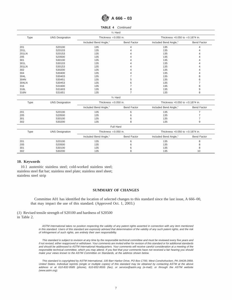
TABLE 4 Continued1⁄2 Hard
Type UNS Designation Thickness #0.050 in. Thickness >0.050 to #0.1874 in.
Included Bend Angle,° Bend Factor Included Bend Angle,° Bend Factor
201 S20100 135 4 135 4201L S20103 135 4 135 4201LN S20153 135 4 135 4205 S20500 135 4 135 4301 S30100 135 4 135 4301L S30103 135 4 135 4301LN S30153 135 4 135 4302 S30200 135 4 135 4304 S30400 135 4 135 4304L S30403 135 7 135 8304N S30451 135 5 135 6304LN S30453 135 6 135 7316 S31600 135 7 135 8316L S31603 135 8 135 9316N S31651 135 7 135 8
3⁄4 Hard
Type UNS Designation Thickness #0.050 in. Thickness >0.050 to #0.1874 in.
Included Bend Angle,° Bend Factor Included Bend Angle,° Bend Factor
201 S20100 135 6 135 7205 S20500 135 6 135 7301 S30100 135 6 135 7302 S30200 135 8 135 9
Full Hard
Type UNS Designation Thickness #0.050 in. Thickness >0.050 to #0.1874 in.
Included Bend Angle,° Bend Factor Included Bend Angle,° Bend Factor
201 S20100 135 6 135 8205 S20500 135 6 135 8301 S30100 135 6 135 8302 S30200 135 8 135 10
10. Keywords10.1 austenitic stainless steel; cold-worked stainless steel;
stainless steel flat bar; stainless steel plate; stainless steel sheet;stainless steel strip
SUMMARY OF CHANGES
Committee A01 has identified the location of selected changes to this standard since the last issue, A 666–00,that may impact the use of this standard. (Approved Oct. 1, 2003.)
(1) Revised tensile strength of S20100 and hardness of S20500in Table 2.
ASTM International takes no position respecting the validity of any patent rights asserted in connection with any item mentionedin this standard. Users of this standard are expressly advised that determination of the validity of any such patent rights, and the riskof infringement of such rights, are entirely their own responsibility.
This standard is subject to revision at any time by the responsible technical committee and must be reviewed every five years andif not revised, either reapproved or withdrawn. Your comments are invited either for revision of this standard or for additional standardsand should be addressed to ASTM International Headquarters. Your comments will receive careful consideration at a meeting of theresponsible technical committee, which you may attend. If you feel that your comments have not received a fair hearing you shouldmake your views known to the ASTM Committee on Standards, at the address shown below.
This standard is copyrighted by ASTM International, 100 Barr Harbor Drive, PO Box C700, West Conshohocken, PA 19428-2959,United States. Individual reprints (single or multiple copies) of this standard may be obtained by contacting ASTM at the aboveaddress or at 610-832-9585 (phone), 610-832-9555 (fax), or [email protected] (e-mail); or through the ASTM website(www.astm.org).
A 666 – 03
7

Designation: A 679/A 679M – 00
Standard Specification forSteel Wire, High Tensile Strength, Cold Drawn 1
This standard is issued under the fixed designation A 679/A 679M; the number immediately following the designation indicates the yearof original adoption or, in the case of revision, the year of last revision. A number in parentheses indicates the year of last reapproval.A superscript epsilon (e) indicates an editorial change since the last revision or reapproval.
1. Scope
1.1 This specification covers round, uncoated, high tensilestrength, cold-drawn steel spring wire, having properties andquality suitable for the manufacture of mechanical springs andwire forms subject to high static stresses or infrequent dynamicload, or both.
1.2 The values stated in either SI units or inch-pound unitsare to be regarded separately as standard. The values stated ineach system are not exact equivalents; therefore, each systemmust be used independently of the other.
2. Referenced Documents
2.1 ASTM Standards:A 370 Test Methods and Definitions for Mechanical Testing
of Steel Products2
A 510 Specification for General Requirements for WireRods and Coarse Round Wire, Carbon Steel2
A 510M Specification for General Requirements for WireRods and Coarse Round Wire, Carbon Steel [Metric]2
A 700 Practices for Packaging, Marking, and LoadingMethods for Steel Products for Domestic Shipment3
A 751 Test Methods, Practices, and Terminology forChemical Analysis of Steel Products2
A 941 Terminology Relating to Steel, Stainless Steel, Re-lated Alloys, and Ferroalloys4
E 29 Practice for Using Significant Digits in Test Data toDetermine Conformance with Specifications5
2.2 ANSI Standard:B32.4 Preferred Metric Sizes for Round, Square, Rectangle,
and Hexagon Metal Products6
2.3 Federal Standard:Fed. Std. No. 123 Marking for Shipment (Civil Agencies)7
2.4 Military Standard:MIL-STD-163 Steel Mill Products, Preparation for Ship-
ment and Storage7
2.5 AIAG Standard:AIAGB-5 02.00 Primary Metals Identification Tag Applica-
tion Standard8
3. Terminology
3.1 Definitions—For definitions of terms used in this speci-fication, refer to Terminology A 941.
4. Ordering Information
4.1 It shall be the responsibility of the purchaser to specifyall requirements that are necessary for material under thisspecification. Such requirements may include, but are notlimited to, the following:
4.1.1 Quantity (mass),4.1.2 Name of material (steel wire, high tensile strength,
hard drawn),4.1.3 Dimensions (Table 1 and Section 9),4.1.4 Packaging (Section 15),4.1.5 Heat analysis report, if requested (6.2),4.1.6 Certification or test report, or both, if specified (Sec-
tion 14), and4.1.7 ASTM designation and year of issue.
NOTE 1—A typical ordering description is as follows: 20 Mg hightensile strength, hard-drawn steel mechanical spring wire, 5.00-mmdiameter, 500-kg coils to ASTM A 679/A 679M dated ____ , or forinch-pound units, 40,000-lb high tensile strength, hard-drawn steel me-chanical spring wire, 0.192-in. diameter, in 1000-lb coils to ASTMA 679/A 679M dated ____ .
5. Materials and Manufacture
5.1 The steel may be made by any commercially acceptedsteel making process. The steel may be either ingot cast orcontinuous strand cast. The rod to be used in the manufactureof wire furnished to this specification shall be in accordancewith Specification A 510 or A 510M.
5.2 The finished wire shall be free from detrimental pipeand undue segregation.
5.3 The wire shall be cold drawn to produce the desiredmechanical properties.
1 This specification is under the jurisdiction of ASTM Committee A-1 on Steel,Stainless Steel, and Related Alloys and is the direct responsibility of SubcommitteeA01.03 on Steel Rod and Wire.
Current edition approved April 10, 2000. Published June 2000. Originallypublished as A 679 – 73. Last previous edition A 679/A 679M – 93.
2 Annual Book of ASTM Standards, Vol 01.03.3 Annual Book of ASTM Standards, Vol 01.05.4 Annual Book of ASTM Standards, Vol 01.01.5 Annual Book of ASTM Standards, Vol 14.02.6 Available from American National Standards Institute, 11 West 42nd Street,
13th Floor, New York, NY 10036.7 Available from Standardization Documents Order Desk, Bldg. 4 Section D, 700
Robbins Ave., Philadelphia, PA 19111-5094, Attn: NPODS.
8 Available from the Automotive Industry Action Group, 26200 Lahser, Suite200, Southfield, MI 48034.
1
Copyright © ASTM International, 100 Barr Harbor Drive, PO Box C700, West Conshohocken, PA 19428-2959, United States.

5.4 The wire finish shall be suitable for forming or coiling.It is not intended that this material be furnished with a metalliccoating.
6. Chemical Composition
6.1 The steel shall conform to the requirements for chemicalcomposition prescribed in Table 2.
6.2 Heat Analysis— Each heat of steel shall be analyzed bythe manufacturer to determine the percentage of elementsprescribed in Table 2. This analysis shall be made from a testspecimen preferably taken during the pouring of the heat.When requested, in the purchase order, the heat analysis shallbe reported to the purchaser.
6.3 Product Analysis— An analysis may be made by thepurchaser from finished wire representing each heat of steel.The chemical composition thus determined, as to elementsrequired or restricted, shall conform to the product analysisrequirements specified in Table 10 of Specification A 510M orA 510.
6.4 For referee purposes, Test Methods, Practices, andTerminology for Chemical Analysis of Steel Products, A 751shall be used.
7. Mechanical Properties
7.1 Tension Test:
7.1.1 Requirements— The material as represented by ten-sion test specimens shall conform to the requirements pre-scribed in Table 1.
7.1.2 Number of Tests— One test specimen shall be takenfor each 10 coils or fraction thereof, in a lot. Each heat in agiven lot shall be tested.
7.1.3 Test Method— The tension test shall be made inaccordance with Test Methods and Definitions A 370.
7.2 Wrap Test:7.2.1 Requirements— The material as represented by the
wrap test specimens shall conform to the requirements speci-fied in Table 3.
7.2.2 Number of Tests— One test specimen shall be takenfor each 10 coils, or fraction thereof, in a lot. Each heat in agiven lot shall be tested.
7.2.3 Location of Test— Test specimens shall be taken fromeither end of the coil.
7.2.4 Test Method— The wrap test shall be made in accor-dance with Test Methods and Definitions A 370.
8. Metallurgical Requirements
8.1 Microstructure—The wire shall be cold drawn with afine pearlite structure.
8.2 Surface Conditions—The wire surface shall not exhibitimperfections that exceed 3.5 % of the wire diameter or 0.25mm (0.010 in.) in depth, whichever is smaller.
9. Dimensions and Permissible Variations
9.1 The permissible variations in the diameter of the wireshall be as specified in Table 4.
10. Workmanship, Finish, and Appearance
10.1 Workmanship— The wire shall not be kinked orimproperly cast. To test for cast, one convolution of wire shallbe cut from the coil and placed on a flat surface. The wire shallnot spring up excessively nor show a wavy condition.
10.1.1 Each coil shall be one continuous length of wire,properly coiled and firmly tied. Welds made prior to colddrawing are permitted.
10.2 Appearance—The surface shall be smooth and free ofrust with no imperfections such as pits or die marks that tendto impair the use of the wire for springs. Any other surfacerequirements shall be negotiated at the time of entry of theorder.
TABLE 1 Tensile Requirements
SI Units Inch-Pound Units
Diameter,mmA,B
Tensile Strength, MPaDiameter, in.
Tensile Strength, ksi
min max min max
0.50 2400 2650 0.020 350 3870.55 2380 2620 0.023 343 3800.60 2350 2600 0.026 337 3730.65 2320 2580 0.029 331 3660.70 2300 2550 0.032 327 3610.80 2250 2500 0.035 322 3560.90 2200 2450 0.041 314 3471.00 2150 2400 0.048 306 3391.10 2120 2380 0.054 300 3311.20 2100 2350 0.062 293 3241.40 2050 2300 0.072 287 3171.60 2000 2250 0.080 282 3121.80 1980 2220 0.092 275 3042.00 1950 2200 0.106 268 2962.20 1900 2150 0.120 263 2902.50 1850 2100 0.135 258 2852.80 1820 2050 0.148 253 2793.00 1800 2000 0.162 249 2753.50 1750 1950 0.177 245 2704.00 1700 1900 0.1927 241 2674.50 1680 1880 0.207 238 2645.00 1650 1850
A Tensile strength values for intermediate diameters shall be interpolated.B Preferred sizes. For a complete list, refer to ANSI B32.4
TABLE 2 Chemical Requirements
Element Composition, %
Carbon 0.65–1.00A
Manganese 0.20–1.30B
Phosphorus, max 0.040Sulfur, max 0.050Silicon 0.15–0.35
A Carbon in any one lot shall not vary more than 0.13 %.B Manganese in any one lot shall not vary more than 0.30 %.
TABLE 3 Wrap Test Requirements A
SI Units
Diameter, mm Mandrel Size
Over 0.50 to 3.00, inclOver 3.00 to 5.00, incl
2343
Inch-Pound Units
Diameter, in. Mandrel Size
0.020 to 0.162, inclOver 0.162 to 0.207, incl
2343
A The symbol “X” represents the diameter of the wire tested.
A 679/A 679M – 00
2
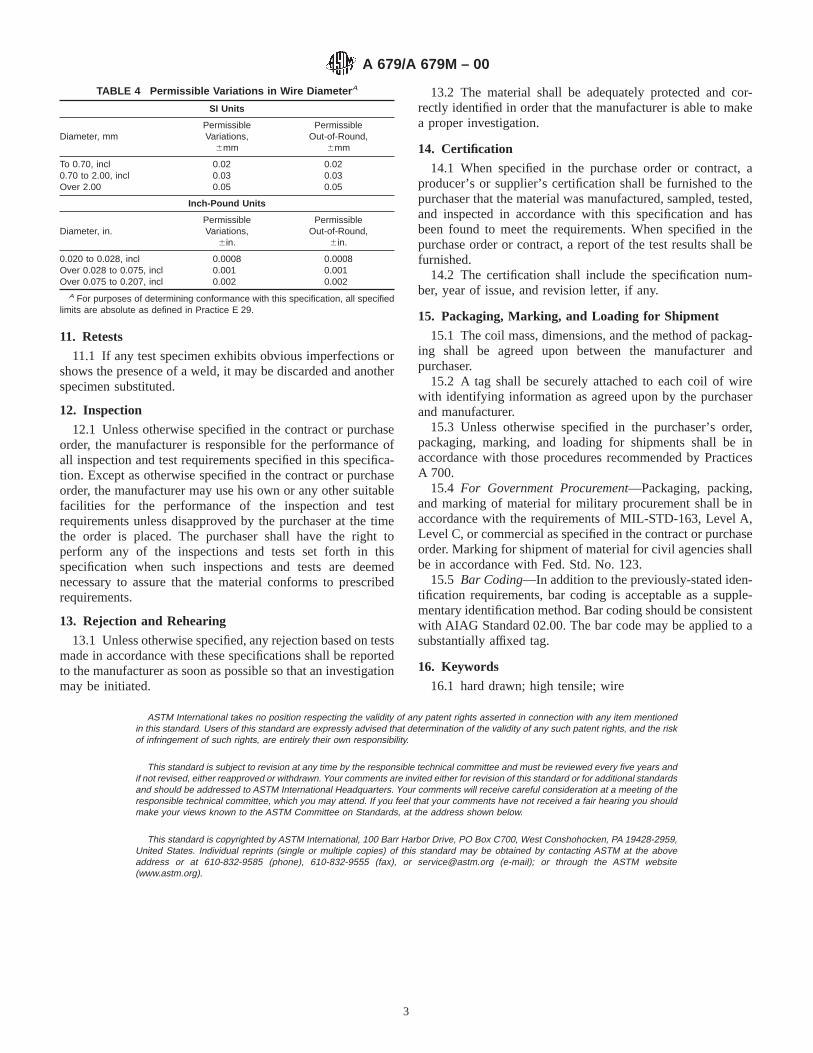
11. Retests
11.1 If any test specimen exhibits obvious imperfections orshows the presence of a weld, it may be discarded and anotherspecimen substituted.
12. Inspection
12.1 Unless otherwise specified in the contract or purchaseorder, the manufacturer is responsible for the performance ofall inspection and test requirements specified in this specifica-tion. Except as otherwise specified in the contract or purchaseorder, the manufacturer may use his own or any other suitablefacilities for the performance of the inspection and testrequirements unless disapproved by the purchaser at the timethe order is placed. The purchaser shall have the right toperform any of the inspections and tests set forth in thisspecification when such inspections and tests are deemednecessary to assure that the material conforms to prescribedrequirements.
13. Rejection and Rehearing
13.1 Unless otherwise specified, any rejection based on testsmade in accordance with these specifications shall be reportedto the manufacturer as soon as possible so that an investigationmay be initiated.
13.2 The material shall be adequately protected and cor-rectly identified in order that the manufacturer is able to makea proper investigation.
14. Certification
14.1 When specified in the purchase order or contract, aproducer’s or supplier’s certification shall be furnished to thepurchaser that the material was manufactured, sampled, tested,and inspected in accordance with this specification and hasbeen found to meet the requirements. When specified in thepurchase order or contract, a report of the test results shall befurnished.
14.2 The certification shall include the specification num-ber, year of issue, and revision letter, if any.
15. Packaging, Marking, and Loading for Shipment
15.1 The coil mass, dimensions, and the method of packag-ing shall be agreed upon between the manufacturer andpurchaser.
15.2 A tag shall be securely attached to each coil of wirewith identifying information as agreed upon by the purchaserand manufacturer.
15.3 Unless otherwise specified in the purchaser’s order,packaging, marking, and loading for shipments shall be inaccordance with those procedures recommended by PracticesA 700.
15.4 For Government Procurement—Packaging, packing,and marking of material for military procurement shall be inaccordance with the requirements of MIL-STD-163, Level A,Level C, or commercial as specified in the contract or purchaseorder. Marking for shipment of material for civil agencies shallbe in accordance with Fed. Std. No. 123.
15.5 Bar Coding—In addition to the previously-stated iden-tification requirements, bar coding is acceptable as a supple-mentary identification method. Bar coding should be consistentwith AIAG Standard 02.00. The bar code may be applied to asubstantially affixed tag.
16. Keywords
16.1 hard drawn; high tensile; wire
ASTM International takes no position respecting the validity of any patent rights asserted in connection with any item mentionedin this standard. Users of this standard are expressly advised that determination of the validity of any such patent rights, and the riskof infringement of such rights, are entirely their own responsibility.
This standard is subject to revision at any time by the responsible technical committee and must be reviewed every five years andif not revised, either reapproved or withdrawn. Your comments are invited either for revision of this standard or for additional standardsand should be addressed to ASTM International Headquarters. Your comments will receive careful consideration at a meeting of theresponsible technical committee, which you may attend. If you feel that your comments have not received a fair hearing you shouldmake your views known to the ASTM Committee on Standards, at the address shown below.
This standard is copyrighted by ASTM International, 100 Barr Harbor Drive, PO Box C700, West Conshohocken, PA 19428-2959,United States. Individual reprints (single or multiple copies) of this standard may be obtained by contacting ASTM at the aboveaddress or at 610-832-9585 (phone), 610-832-9555 (fax), or [email protected] (e-mail); or through the ASTM website(www.astm.org).
TABLE 4 Permissible Variations in Wire Diameter A
SI Units
Diameter, mmPermissibleVariations,
6mm
PermissibleOut-of-Round,
6mm
To 0.70, incl 0.02 0.020.70 to 2.00, incl 0.03 0.03Over 2.00 0.05 0.05
Inch-Pound Units
Diameter, in.PermissibleVariations,
6in.
PermissibleOut-of-Round,
6in.
0.020 to 0.028, incl 0.0008 0.0008Over 0.028 to 0.075, incl 0.001 0.001Over 0.075 to 0.207, incl 0.002 0.002
A For purposes of determining conformance with this specification, all specifiedlimits are absolute as defined in Practice E 29.
A 679/A 679M – 00
3

Designation: A 682/A 682M – 02 An American National Standard
Standard Specification forSteel, Strip, High-Carbon, Cold-Rolled, GeneralRequirements For 1
This standard is issued under the fixed designation A 682/A 682M; the number immediately following the designation indicates the yearof original adoption or, in the case of revision, the year of last revision. A number in parentheses indicates the year of last reapproval.A superscript epsilon (e) indicates an editorial change since the last revision or reapproval.
This standard has been approved for use by agencies of the Department of Defense.
1. Scope *
1.1 This specification covers the general requirements forcold-rolled carbon spring steel strip in coils or cut lengths.Strip is classified as product that is 0.3000 in. (7.6 mm) or lessin thickness and over1⁄2 to 2315⁄16 in. (12.5 to 600 mm) inwidth, inclusive. Strip tolerance products may be available inwidths wider than 2315⁄16 in. (600 mm) by agreement betweenpurchaser and supplier; however, such products are technicallyclassified as cold-rolled sheet.
1.2 The maximum of the specified carbon range is over0.25 % to 1.35 %, inclusive.
1.3 The above shall apply to the cold-rolled carbon springsteel strip furnished under each of the following specificationsissued by ASTM:
Title of SpecificationASTM
DesignationSteel, Strip, High Carbon,Cold Rolled
A 684/A 684M
1.4 The tolerances in this specification are different thanthose in Specification A 568/A 568M and Specification A 109/A 109M.
1.5 For the purpose of determining conformance with thisspecification, values shall be rounded to the nearest unit in theright hand place of figures used in expressing the limitingvalues in accordance with the rounding method of PracticeE 29.
1.6 The metric portions of the tables herein list permissiblevariations in dimensions and mass (see Note 1) in SI (metric)units. The values listed are not exact conversions of the valueslisted in the inch-pound tables but instead are rounded orrationalized values. Conformance to SI tolerances is mandatorywhen the “M” specification is used.
NOTE 1—The term weight is used when inch-pound units are thestandard. However, under SI the preferred term inmass.
1.7 The values stated in either inch-pound units or SI unitsare to be regarded as standard. Within the text, the SI units areshown in brackets. The values stated in each system are notexact equivalents; therefore, each system must be used inde-pendently of the other. Combining values from the two systemswill result in nonconformance with the specification.
1.8 This specification is expressed in both inch-pound unitsand SI units. However, unless the order specifies the applicable“M” specification designation (SI units), the material shall befurnished to inch-pound units.
2. Referenced Documents
2.1 ASTM Standards:A 109/ A 109M Specification for Steel, Strip, Carbon (0.25
Maximum Percent), Cold-Rolled2
A 370 Test Methods and Definitions for Mechanical Testingof Steel Products2
A 568/ A 568M Specification for Steel, Sheet, Carbon, andHigh-Strength, Low-Alloy, Hot-Rolled and Cold-Rolled,General Requirements for2
A 680/A 680M Specification for Steel—High-Carbon,Strip, Cold-Rolled Hard, Untempered Quality3
A 684/A 684M Specification for Steel, Strip, High-Carbon,Cold-Rolled2
A 700 Practices for Packaging, Marking, and LoadingMethods for Steel Products for Domestic Shipment4
A 751 Test Methods, Practices, and Terminology forChemical Analysis of Steel Products2
A 941 Terminology Relating to Steel, Stainless Steel, Re-lated Alloys, and Ferroalloys5
E 3 Methods of Preparation of Metallographic Specimens6
E 29 Practice for Using Significant Digits in Test Data toDetermine Conformance with Specifications7
E 112 Test Methods for Determining Average Grain Size6
1 This specification is under the jurisdiction of ASTM Committee A01 on Steel,Stainless Steel, and Related Alloys, and is the direct responsibility of SubcommitteeA01.19 on Sheet Steel and Steel Sheets.
Current edition approved March 10, 2002. Published April 2002. Originallypublished as A 682 – 73. Last previous edition A 682 – 00.
2 Annual Book of ASTM Standards, Vol 01.03.3 Discontinued; see 1985Annual Book of ASTM Standards,Vol 01.03.4 Annual Book of ASTM Standards, Vol 01.05.5 Annual Book of ASTM Standards,Vol 01.01.6 Annual Book of ASTM Standards, Vol 03.01.7 Annual Book of ASTM Standards,Vol 14.02.
1
*A Summary of Changes section appears at the end of this standard.
Copyright © ASTM International, 100 Barr Harbor Drive, PO Box C700, West Conshohocken, PA 19428-2959, United States.

E 527 Practice for Numbering Metals and Alloys (UNS)5
2.2 Federal Standards:Fed. Std. No. 123 Marking for Shipments (Civil Agencies)8
Fed. Std. No. 183 Continuous Identification Marking ofIron and Steel Products8
2.3 Military Standards:MIL-STD-129 Marking for Shipping and Storage8
MIL-STD-163 Steel Mill Products Preparation for Ship-ment and Storage8
2.4 SAE Standard:J 1086 Recommended Practice for Numbering Metals and
Alloys (UNS)9
3. Terminology
3.1 Definitions:3.1.1 burr—metal displaced beyond the plane of the surface
by slitting or shearing.3.1.2 decarburization—refer to Terminology A 941.3.1.3 lot—the quantity of material of the same type, size,
and finish produced at one time from the same cast or heat, andheat treated in the same heat-treatment cycle.
4. General Requirements for Delivery
4.1 The requirements of the purchase order, the individualmaterial specification, and this general specification shallgovern in the sequence stated.
4.2 Products covered by this specification are produced todecimal thickness only, and decimal thickness tolerances apply.
5. Materials and Manufacture
5.1 Melting Practice—The steel shall be made by either theopen-hearth, basic-oxygen, or electric-furnace process. It isnormally produced as a fully killed steel. Elements such asaluminum may be added in sufficient amounts to control theaustenitic grain size.
5.2 Cold Working Procedure:5.2.1 Prior to cold rolling, the hot-rolled strip shall be
descaled by chemical or mechanical means.5.2.2 The strip shall be cold rolled by reducing to thickness
at room temperature (that is, below the recrystallization tem-perature).
6. Chemical Composition
6.1 Limits:6.1.1 When carbon steel strip is specified to chemical
composition, the compositions are commonly prepared usingthe ranges and limits shown in Table 1. The elements compris-ing the desired chemical composition are specified in one ofthree ways:
6.1.1.1 By a maximum limit,6.1.1.2 By a minimum limit, or6.1.1.3 By minimum and maximum limits, termed the
“range.” By common usage, the range is the arithmeticaldifference between the two limits (for example, 0.60 to 0.71 is0.11 range).
6.1.2 Steel grade numbers indicating chemical compositioncommonly produced to this specification are shown in Table 2and may be used. Table 3 shows requirements for additionalelements.
6.1.3 Additional elements may be present. Limits on suchelements are by agreement between purchaser and supplier.
6.1.3.1 Any additional elements specified shall be includedin the report of heat analysis.
6.2 Heat (Formerly Ladle) Analysis:6.2.1 An analysis of each heat of steel shall be made by the
manufacturer to determine the percentage of elements specifiedor restricted by the applicable specification.
6.2.2 When requested, heat analysis for elements listed orrequired shall be reported to the purchaser or to his represen-tative. Each of the elements listed in Tables 2 and 3 andadditional elements agreed upon by the purchaser and thesupplier shall be included in the report of heat analysis. Whenthe amount of copper, nickel, chromium, or molybdenum isless than 0.02 %, the analysis may be reported as < 0.02 %.When the amount of vanadium, columbium, or titanium is lessthan 0.008 %, the analysis may be reported as < 0.008 %. thereported heat analysis shall conform to the chemical composi-tion requirements of the appropriate grade in Table 2, if used,the additional elements in Table 3, and the limits of any otherelements agreed upon by the purchaser and supplier.
6.3 Product Analysis (Formerly Check Analysis)—Productanalysis is the chemical analysis of the semi-finished productform. The strip may be subjected to product analysis by thepurchaser either for the purpose of verifying that the chemicalcomposition is within specified limits for each element, includ-ing applicable tolerance for product analysis, or to determinevariations in compositions within a cast or heat. The results ofanalyses taken from different pieces within a heat may differfrom each other and from the cast analysis. The chemical
8 Available from Standardization Documents Order Desk, Bldg. 4 Section D, 700Robbins Ave., Philadelphia, PA 19111-5094, Attn: NPODS
9 Available from Society of Automotive Engineers, 400 Commonwealth Drive,Warrendale, PA 15096.
TABLE 1 Heat (Formerly Ladle) Analysis Limits and Ranges
ElementStandard Chemical Limits and
Ranges, Limit or Max ofSpecified Range
Range, %
CarbonA over 0.25 to 0.30, incl 0.06over 0.30 to 0.40, incl 0.07over 0.40 to 0.60, incl 0.08over 0.60 to 0.80, incl 0.11over 0.80 to 1.35, incl 0.14
Manganese to 0.50, inclover 0.50 to 1.15, inclover 1.15 to 1.65, incl
0.200.300.35
Phosphorous to 0.08, inclover 0.08 to 0.15, incl
0.030.05
Sulfur to 0.08, incl 0.03over 0.08 to 0.15, incl 0.05over 0.15 to 0.23, incl 0.07over 0.23 to 0.33, incl 0.10
Silicon to 0.20, inclover 0.20 to 0.30, inclover 0.30 to 0.60, incl
0.100.150.30
A The carbon ranges shown in the column headed “Range” apply when thespecified maximum limit for manganese does not exceed 1.00 %. When themaximum manganese limit exceeds 1.00 %, add 0.01 to the carbon ranges shownabove.
A 682/A 682M
2

composition thus determined shall not vary from the limitsspecified by more than the amounts shown in Table 4, but theseveral determinations of any element in any cast may not varyboth above and below the specified range.
6.4 Methods of Analysis—Test Methods, Practices, andTerminology A 751 shall be used for referee purposes.
7. Metallurgical Structure
7.1 Grain Size:
7.1.1 Unless otherwise specified, the steel strip shall bemanfactured to a fine grain (austenitic and ferritic) practice.
7.2 Decarburization:7.2.1 When specified, the steel strip shall have a maximum
permissible depth of complete plus partial decarburization of0.001 in. or 1.5 % of the thickness of the strip, whichever isgreater, except that strip less than 0.011 in. thick shall show nocomplete decarburization.
8. Mechanical Requirements
8.1 The mechanical property requirements, number ofspecimens, and test locations and specimen orientation shall bein accordance with the applicable product specification.
8.2 Unless otherwise specified in the applicable productspecification, test specimens must be prepared in accordancewith Test Methods and Definitions A 370.
8.3 Mechanical tests shall be conducted in accordance withTest Methods and Definitions A 370.
9. Dimensions, Mass, and Permissible Variations
9.1 The thickness, width, camber, and length tolerancesshall conform to the requirements specified in Tables 5-10.
9.2 Flatness—It is not practical to formulate flatness toler-ances for cold-rolled carbon spring steel strip to represent therange of widths and thicknesses in coils and cut lengths.
10. Finish and Edges
10.1 Surface—The surface requirements shall be as speci-fied in the product specifications.
10.2 Edges—Cold-rolled carbon spring steel strip shall besupplied with one of the following edges as specified:
10.2.1 No. 1—A prepared edge of a specified contour(round or square) that is produced when a very accurate widthis required or when an edge condition suitable for electroplat-ing is required, or both.
10.2.2 No. 2—A natural mill edge carried through the coldrolling from the hot-rolled strip without additional processingof the edge.
10.2.3 No. 3—An approximately square edge produced byslitting on which the burr is not eliminated. This is producedwhen the edge condition is not a critical requirement for the
TABLE 2 Heat (Formerly Ladle) Analysis Chemical Composition, %
UNS DesignationA SteelGrade
Carbon ManganesePhosphorus,
maxSulfur,max
SiliconB
G10300 1030 0.28 to 0.34 0.60 to 0.90 0.035 0.040 0.15 to 0.30G10350 1035 0.32 to 0.38 0.60 to 0.90 0.035 0.040 0.15 to 0.30G10400 1040 0.37 to 0.44 0.60 to 0.90 0.035 0.040 0.15 to 0.30G10450 1045 0.43 to 0.50 0.60 to 0.90 0.035 0.040 0.15 to 0.30G10500 1050 0.48 to 0.55 0.60 to 0.90 0.035 0.040 0.15 to 0.30G10550 1055 0.50 to 0.60 0.60 to 0.90 0.035 0.040 0.15 to 0.30G10600 1060 0.55 to 0.65 0.60 to 0.90 0.035 0.040 0.15 to 0.30G10640 1064 0.60 to 0.70 0.50 to 0.80 0.035 0.040 0.15 to 0.30G10650 1065 0.60 to 0.70 0.60 to 0.90 0.035 0.040 0.15 to 0.30G10700 1070 0.65 to 0.75 0.60 to 0.90 0.035 0.040 0.15 to 0.30G10740 1074 0.70 to 0.80 0.50 to 0.80 0.035 0.040 0.15 to 0.30G10800 1080 0.75 to 0.88 0.60 to 0.90 0.035 0.040 0.15 to 0.30G10850 1085 0.80 to 0.93 0.70 to 1.00 0.035 0.040 0.15 to 0.30G10860 1086 0.80 to 0.93 0.30 to 0.50 0.035 0.040 0.15 to 0.30G10950 1095 0.90 to 1.03 0.30 to 0.50 0.035 0.040 0.15 to 0.30A New designation established in accordance with Practice E 527 and SAE J1086.B When agreed by purchaser and supplier, other silicon ranges are permissible.
TABLE 3 Additional Chemical Composition Requirements—HeatAnalysis
Element Composition—Weight %
AluminumA . . .Copper, maxB 0.30Nickel, maxB 0.30Chromium, maxB,C 0.25Molybdenum, maxB 0.10VanadiumA . . .ColumbiumA . . .TitaniumA . . .
A Where an ellipsis (. . .) appears in this table, there is no specified limit, but theanalysis shall be reported.
B The sum of copper, nickel, chromium, and molybdenum shall not exceed0.80 % on heat analysis. When one or more of these elements is specified, thesum does not apply, in which case only the individual limits on the remainingelements will apply.
C When the chromium is specified or added for antigraphitization, the maximumshall be 1.40 wt. %
TABLE 4 Permissible Variations from Specified Cast or Heat(Formerly Ladle) Analysis Ranges and Limits
ElementLimit or Max ofSpecification, %
Variations Over Max Limit or UnderMin Limit
Under Min Limit Over Max Limit
Carbon over 0.25 to 0.40, inclover 0.40 to 0.80, inclover 0.80
0.030.030.03
0.040.050.06
Manganese to 0.60, inclover 0.60 to 1.15, inclover 1.15 to 1.65, incl
0.030.040.05
0.030.040.05
Phosphorus . . . . . . 0.01Sulfur . . . . . . 0.01Silicon to 0.30, incl
over 0.30 to 0.600.020.05
0.030.05
A 682/A 682M
3
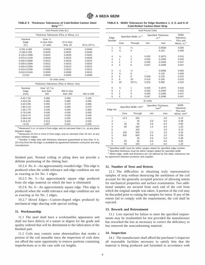
finished part. Normal coiling or piling does not provide adefinite positioning of the slitting burr.
10.2.4 No. 4—An approximately rounded edge. This edge isproduced when the width tolerance and edge condition are notas exacting as for No. 1 edges.
10.2.5 No. 5—An approximately square edge producedfrom slit edge material on which the burr is eliminated.
10.2.6 No. 6—An approximately square edge. This edge isproduced when the width tolerance and edge condition are notas exacting as for No. 1 edges.
10.2.7 Skived Edges—Custom-shaped edges produced bymechanical edge shaving with special tooling.
11. Workmanship
11.1 The steel shall have a workmanlike appearance andshall not have defects of a nature or degree for the grade andquality ordered that will be detrimental to the fabrication of thefinished part.
11.2 Coils may contain some abnormalities that render aportion of the coil unusable since the inspection of coils doesnot afford the same opportunity to remove portions containingimperfections as is the case with cut lengths.
12. Number of Tests and Retests
12.1 The difficulties in obtaining truly representativesamples of strip without destroying the usefulness of the coilaccount for the generally accepted practice of allowing retestsfor mechanical properties and surface examination. Two addi-tional samples are secured from each end of the coil fromwhich the original sample was taken. A portion of the coil maybe discarded prior to cutting the samples for retest. If any of theretests fail to comply with the requirements, the coil shall berejected.
13. Rework and Retreatment
13.1 Lots rejected for failure to meet the specified require-ments may be resubmitted for test provided the manufacturerhas reworked the lots as necessary to correct the deficiency orhas removed the nonconforming material.
14. Inspection
14.1 The manufacturer shall afford the purchaser’s inspectorall reasonable facilities necessary to satisfy him that thematerial is being produced and furnished in accordance with
TABLE 5 Thickness Tolerances of Cold-Rolled Carbon SteelStrip A,B,C
Inch-Pound Units (in.)
Thickness Tolerances (Plus or Minus, in.)
NominalGage(in.)
Over 1⁄2to less than
12 wide12 to less
than 18 18 to 2315⁄16
0.251-0.300 0.0030 0.0035 0.00400.160-0.250 0.0025 0.0032 0.0036
0.125-0.1599 0.0022 0.0028 0.00320.070-0.1249 0.0018 0.0022 0.00280.040-0.0699 0.0014 0.0018 0.00240.030-0.0399 0.0012 0.0015 0.00200.020-0.0299 0.0010 0.0013 0.00150.015-0.0199 0.0008 0.0010 0.00120.010-0.0149 0.0005 0.0008 0.0010
<0.010 0.0003 0.0006 0.0008
SI Units (mm)
Thickness Tolerances (Plus or Minus, mm)
NominalGage(mm)
Over 12.7 toless than
300300 to less
than 450 450 to 600
6.40-7.50 0.080 0.090 0.1004.00-6.39 0.065 0.080 0.0903.20-3.99 0.055 0.070 0.0801.80-3.19 0.045 0.055 0.0701.00-1.79 0.035 0.045 0.0600.75-0.99 0.030 0.030 0.0500.50-0.74 0.025 0.035 0.0400.38-0.49 0.020 0.025 0.0300.25-0.37 0.013 0.020 0.025
<0.25 0.007 0.015 0.020A Measured 3⁄8 in. or more in from edge; and on narrower than 1 in., at any place
between edges.B Measured 10 mm or more in from edge; and on narrower than 25 mm, at any
place between edges.C Number 3 edge strip with thickness tolerance guaranteed at less than 3⁄8 in.
(10 mm) from the slit edge, is available by agreement between consumer and stripmanufacturer.
TABLE 6 Width Tolerances for Edge Numbers 1, 4, 5, and 6 ofCold-Rolled Carbon-Steel Strip
Inch-Pound Units
EdgeNumber
Specified Width, in.ASpecified Thickness,
in.BWidth
Tolerance,Plus and
Minus, in.COver Through min max
1 1⁄2 3⁄4 . . . 0.0938 0.0051 3⁄4 5 . . . 0.125 0.005
4 1⁄2 1 0.025 0.1875 0.0154 1 2 0.025 0.2499 0.0254 2 4 0.035 0.2499 0.0474 4 6 0.047 0.2499 0.047
5 1⁄2 3⁄4 . . . 0.0938 0.0055 3⁄4 5 . . . 0.125 0.0055 5 9 0.008 0.125 0.0105 9 20 0.015 0.105 0.0105 20 2315⁄16 0.023 0.080 0.015
6 1⁄2 1 0.025 0.1875 0.0156 1 2 0.025 0.2499 0.0256 2 4 0.035 0.2499 0.0476 4 6 0.047 0.2499 0.047
SI Units
Edge No.Specified Width, mmA Specified Thickness,
mmB
WidthTolerance,Plus and
Minus, mmCOver Through min max
1 12.5 200 . . . 3.0 0.134 . . . 25 0.6 5.0 0.384 25 50 0.6 6.0 0.654 50 150 1.0 6.0 1.205 . . . 100 . . . 3.0 0.135 100 500 0.4 3.0 0.255 500 600 0.6 2.0 0.386 . . . 25 0.6 5.0 0.386 25 50 0.6 6.0 0.656 50 150 1.0 6.0 1.20
A Specified width must be within ranges stated for specified edge number.B Specified thickness must be within ranges stated for specified width.C When edge, width and thickness are not defined by this table, tolerances are
by agreement between producer and supplier.
A 682/A 682M
4

this specification. Mill inspection by the purchaser shall notinterfere unnecessarily with the manufacturer’s operations.Unless otherwise agreed to, all tests and inspections, exceptproduct analysis, shall be made at the place of production.
15. Rejection and Rehearing
15.1 Unless otherwise specified, any rejection based on testsmade in accordance with this specification shall be reported tothe purchaser within a reasonable time.
15.2 Material that shows injurious defects subsequent to itsacceptance at the purchaser’s works shall be rejected and themanufacturer shall be notified. The material must be ad-equately protected and correctly identified in order that themanufacturer may make a proper investigation. In case ofdissatisfaction with the results of the test, the manufacturermay make claims for a rehearing.
16. Certification and Reports
16.1 When test reports are required by the purchaser, thesupplier shall report the results of all tests required by thisspecification and any additional tests required by the materialspecification and/or the purchase order.
16.2 When certification is required by the purchase order,the supplier shall furnish a certification that the material hasbeen manufactured and tested in accordance with the require-ments of this specification and the applicable material specifi-cation.
16.3 A signature is not required on test reports. However,the document shall clearly identify the organization submittingthe document. Notwithstanding the absence of a signature, theorganization submitting the document is responsible for thecontent of the document.
16.4 When test reports are required, it is acceptable for thesupplier to report test data from the original manufacturer,provided such data is not rendered invalid by the stripmakingprocess.
16.5 A Material Test Report, Certificate of Inspection, orsimilar document printed from or used in electronic form froman electronic data interchange (EDI) transmission shall beregarded as having the same validity as a counterpart printed inthe certifier’s facility. The content of the EDI transmitteddocument must meet the requirements of the invoked ASTMstandard(s) and conform to any existing EDI agreement be-tween the purchaser and the supplier. Notwithstanding theabsence of a signature, the organization submitting the EDItransmission is responsible for the context of the report.
NOTE 2—The industry definition as invoked here is: EDI is thecomputer to computer exchange of business information in an agreed uponstandard format such as ANSI ASC X12.
17. Marking
17.1 Unless otherwise specified, the material shall be iden-tified by having the manufacturer’s name or mark, ASTMdesignation, weight, purchase order number, and materialidentification legibly stenciled on top of each lift or shown ona tag attached to each coil or shipping unit.
17.2 When specified in the contract or order, and for directprocurement by or direct shipment to the Government, markingfor shipment, in addition to requirements specified in thecontract or order, shall be in accordance with MIL-STD-129for military agencies and in accordance with Fed. Std. No. 123for civil agencies.
17.3 For U.S. Government procurement by the DefenseSupply Agency, strip material shall be continuously marked foridentification in accordance with Fed. Std. No. 183.
17.4 Bar coding is acceptable as a supplementary identifi-cation method. Bar coding should be consistent with theAutomotive Industry Action Group (AIAG) standard preparedby the primary metals subcommittee of the AIAG bar codeproject team.
18. Packaging
18.1 Unless otherwise specified, the strip shall be packagedand loaded in accordance with Practices A 700.
18.2 When Level A is specified in the contract or order andfor direct procurement by or direct shipment to the U.S.Government, preservation, packaging, and packing shall be inaccordance with the Level A requirements of MIL-STD-163.
18.3 When coils are ordered it is customary to specify aminimum or range of inside diameter and maximum outsidediameter and a maximum coil weight, if required. The abilityof manufacturers to meet the maximum coil weights dependsupon individual mill equipment. When required, minimum coilweights are subject to negotiation.
TABLE 7 Width Tolerances for Edge Number 2 of Cold-RolledCarbon-Steel Strip
Inch Pound Units
Specified Width, in. Width Tolerance, Plus and
Over Through Minus, in.
1⁄2 2 1⁄32
2 5 3⁄64
5 10 5⁄64
10 15 3⁄32
15 20 1⁄820 2315⁄16 5⁄32
SI Units
Specified Width, mm Width Tolerance, mm
Over ThroughPlus and
Minus
12.5 50 0.850 100 1.2
100 200 1.6200 400 2.5400 500 3.0500 600 4.0
A 682/A 682M
5
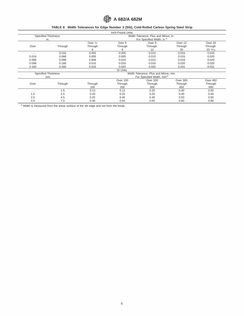
TABLE 8 Width Tolerances for Edge Number 3 (Slit), Cold-Rolled Carbon Spring Steel Strip
Inch-Pound UnitsSpecified Thickness
in.Width Tolerance, Plus and Minus, in.
For Specified Width, in.A
Over ThroughOver 1⁄2Through
6
Over 6Through
9
Over 9Through
12
Over 12Through
20
Over 20Through23 15⁄16
. . . 0.016 0.005 0.005 0.010 0.016 0.0200.016 0.068 0.005 0.005 0.010 0.016 0.0200.068 0.099 0.008 0.010 0.010 0.016 0.0200.099 0.160 0.010 0.016 0.016 0.020 0.0200.160 0.300 0.016 0.020 0.020 0.031 0.031
SI UnitsSpecified Thickness
mmWidth Tolerance, Plus and Minus, mm
For Specified Width, mmA
Over Through Through100
Over 100Through
200
Over 200Through
300
Over 300Through
450
Over 450Through
600. . . 1.5 0.13 0.13 0.25 0.40 0.501.5 2.5 0.20 0.25 0.25 0.40 0.502.5 4.5 0.25 0.40 0.40 0.50 0.504.5 7.5 0.40 0.50 0.50 0.80 0.80
A Width is measured from the shear surface of the slit edge and not from the break.
A 682/A 682M
6
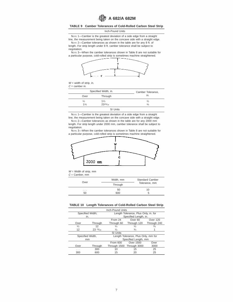
TABLE 9 Camber Tolerances of Cold-Rolled Carbon Steel Strip
Inch-Pound Units
NOTE 1—Camber is the greatest deviation of a side edge from a straightline, the measurement being taken on the concave side with a straight edge.
NOTE 2—Camber tolerances as shown in the table are for any 8 ft. oflength. For strip length under 8 ft. camber tolerance shall be subject tonegotiation.
NOTE 3—When the camber tolerances shown in Table 8 are not suitable fora particular purpose, cold-rolled strip is sometimes machine straightened.
W = width of strip, in.C = camber in.
Specified Width, in. Camber Tolerance,in.Over Through
1⁄2 11⁄2 1⁄211⁄2 2315⁄16 1⁄4
SI Units
NOTE 1—Camber is the greatest deviation of a side edge from a straightline, the measurement being taken on the concave side with a straight edge.
NOTE 2—Camber tolerances as shown in the table are for any 2000 mmlength. For strip length under 2000 mm, camber tolerance shall be subject tonegotiation.
NOTE 3—When the camber tolerances shown in Table 8 are not suitable fora particular purpose, cold-rolled strip is sometimes machine straightened.
W = Width of strip, mmC = Camber, mm
OverWidth, mm Standard Camber
Tolerance, mmThrough
. . . 50 1050 600 5
TABLE 10 Length Tolerances of Cold-Rolled Carbon Steel Strip
Inch-Pound UnitsSpecified Width;
in.Length Tolerance, Plus Only, in. for
Specified Length, in.
Over ThroughFrom 24
Through 60Over 60
Through 120Over 120
Through 2401⁄2 12 1⁄4 1⁄2 3⁄412 23 15⁄16 1⁄2 3⁄4 1
SI UnitsSpecified Width,
mmLength Tolerance, Plus Only, mm for
Specified Length, mm
Over ThroughFrom 600
Through 1500Over 1500
Through 3000Over3000
. . . 300 10 15 25300 600 15 20 25
A 682/A 682M
7

SUMMARY OF CHANGES
This section contains the principal changes that have been incorporated since the last issue.
1. Revision to 6.1.2.2. Revision to 6.2.2.
3. Revision to Table 2.
ASTM International takes no position respecting the validity of any patent rights asserted in connection with any item mentionedin this standard. Users of this standard are expressly advised that determination of the validity of any such patent rights, and the riskof infringement of such rights, are entirely their own responsibility.
This standard is subject to revision at any time by the responsible technical committee and must be reviewed every five years andif not revised, either reapproved or withdrawn. Your comments are invited either for revision of this standard or for additional standardsand should be addressed to ASTM International Headquarters. Your comments will receive careful consideration at a meeting of theresponsible technical committee, which you may attend. If you feel that your comments have not received a fair hearing you shouldmake your views known to the ASTM Committee on Standards, at the address shown below.
This standard is copyrighted by ASTM International, 100 Barr Harbor Drive, PO Box C700, West Conshohocken, PA 19428-2959,United States. Individual reprints (single or multiple copies) of this standard may be obtained by contacting ASTM at the aboveaddress or at 610-832-9585 (phone), 610-832-9555 (fax), or [email protected] (e-mail); or through the ASTM website(www.astm.org).
A 682/A 682M
8

Designation: A 684/A 684M – 86 (Reapproved 2002)
Standard Specification forSteel, Strip, High-Carbon, Cold-Rolled 1
This standard is issued under the fixed designation A 684/A 684M; the number immediately following the designation indicates the yearof original adoption or, in the case of revision, the year of last revision. A number in parentheses indicates the year of last reapproval.A superscript epsilon (e) indicates an editorial change since the last revision or reapproval.
This standard has been approved for use by agencies of the Department of Defense.
1. Scope
1.1 This specification covers cold-rolled, high-carbon strip.It is furnished in the following types as specified:
1.1.1 Soft spheroidized annealed high-carbon steel is in-tended for applications requiring maximum cold forming. It isnormally produced to give the lowest maximum Rockwellhardness for each grade.
1.1.2 Soft annealed high-carbon steel is intended for appli-cations requiring moderate cold forming. It is produced to amaximum Rockwell hardness.
1.1.3 Intermediate hardness high-carbon steel is intendedfor applications where cold forming is slight or a stiff, springyproduct is needed, or both. It is produced to specified Rockwellhardness ranges, the maximum being higher than obtained forthe annealed type.
1.1.4 Full hard high-carbon steel is intended for flat appli-cations. It is produced to minimum Rockwell hardness require-ments, which vary with grade, microstructure and gage. Fullhard can be produced with either a pearlitic or spheroidizedmicrostructure or a mixture of both. The minimum hardnessshould be established between the consumer and the producer.
1.2 This specification is applicable for orders in eitherinch-pound units (as A 684) or SI units (A 684M).
2. Referenced Documents
2.1 ASTM Standards:A 370 Test Methods and Definitions for Mechanical Testing
of Steel Products2
A 682 Specification for Steel, Strip, High-Carbon, Cold-Rolled, Spring Quality, General Requirements for2
A 682M Specification for Steel, Strip, High-Carbon, Cold-Rolled, Spring Quality, General Requirements for [Met-ric]2
E 3 Methods of Preparation of Metallographic Specimens3
3. Terminology
3.1 Number 1 or matte (dull) finish—finish without luster,produced by rolling on rolls roughened by mechanical orchemical means. This finish is especially suitable for lacquer orpaint adhesion, and is beneficial in aiding drawing operationsby reducing the contact friction between the die and the strip.
3.2 Number 2 (regular bright) finish—finish produced byrolling on rolls having a moderately smooth finish. It is lesssuitable that No. 1 (matte) finish for cold forming and may beapplicable for certain types of plating.
3.3 spheroidizing—the heating and cooling of the strip incontrolled conditions (annealing) to produce a spheroidal orglobular form of carbide microconstituent.
3.4 stretcher strains—elongated markings that appear onthe surface of the strip when dead soft (fully annealed) materialis deformed beyond its yield point (see 5.2).
4. Ordering Information
4.1 Orders for material under this specification shall includethe following information:
4.1.1 ASTM designation and date of issue,4.1.2 Name, type, and steel grade number,4.1.3 Hardness (if intermediate or restricted hardness is
specified),4.1.4 Decarburization (if required),4.1.5 Application,4.1.6 Dimensions,4.1.7 Coil size requirements,4.1.8 Edge (indicate No. 1 round, square, etc.),4.1.9 Finish (indicate and specify),4.1.10 Conditions (specify whether material is oiled or dry),4.1.11 Package (bare coils, skid, etc.),4.1.12 Cast or heat (formerly ladle) analysis report (if
required), and4.1.13 Special requirements (if required).
NOTE 1—A typical ordering description is as follows: ASTM A 684dated ———Cold Rolled, High-Carbon Soft, Strip, Spheroidized 1064,
1 This specification is under the jurisdiction of ASTM Committee A01 on Steel,Stainless Steel and Related Alloys, and is the direct responsibility of SubcommitteeA01.19 on Steel Sheet and Strip.
Current edition approved November 10, 2002. Published January 2003. Origi-nally approved in 1973. Last previous edition approved in 1998 as A 684 – 86(1998).
2 Annual Book of ASTM Standards, Vol 01.03. 3 Annual Book of ASTM Standards, Vol 03.01.
1
Copyright © ASTM International, 100 Barr Harbor Drive, PO Box C700, West Conshohocken, PA 19428-2959, United States.

0.042 in. by 6 in. by coil (16 in. ID by 40 in. OD max), No. 5 Edge, No.2 Finish, Oiled, Bare Skid or“ASTM A 684 dated ———Cold Rolled, High-Carbon, Soft, Strip,Spheroidized 1064, 0.6 mm by 200 mm by coil (400 mm ID by 7500 mmOD max), No. 3 Edge, No. 2 Finish, Oiled, Bare Skid.”
5. Manufacture
5.1 Condition:5.1.1 The strip shall be furnished cold rolled spheroidized
annealed, soft annealed, intermediate hardness, or full hard, asspecified.
5.1.2 Intermediate hardness may be obtained by eitherrolling the strip after final annealing or by varying theannealing treatment, or both.
5.2 Pinch Pass—Spheroidized annealed and annealed ma-terial may be pinch rolled after the final anneal to improveflatness, uniformly oil, modify surface, and minimize stretcherstrains if required by the purchaser.
6. Chemical Requirements
6.1 Cast or Heat Analysis—The heat or cast analysis shallconform to that specified in Specification A 682 or A 682M forthe steel grade ordered; or to such other limits as may bespecified using the standard ranges in Specification A 682 orA 682M.
7. Metallurgical Structure
7.1 Pearlite is the normal structure of cold rolled high-carbon strip unless it has had an intermediate anneal.
7.2 Annealed is mostly a spheroidized structure, but maycontain some vestiges of pearlite.
7.3 Spheroidize annealed is essentially free of pearlite.7.4 At least one specimen shall be taken from each lot (see
Specification A 682 or A 682M) for microexamination.7.4.1 The specimens shall be prepared for microscopical
examination in accordance with Methods E 3.
8. Mechanical Requirements
8.1 Hardness:8.1.1 Spheroidized Annealed and Annealed Types—When
furnished spheroidized annealed or annealed, the hardness ofthe strip shall not exceed the maximum values specified in Fig.1 and Fig. 2 for the applicable carbon range and type.
8.1.2 Intermediate Hardness Type—When furnished as in-termediate hardness, the hardness of the strip shall conform tothe range specified on the purchase order. The maximumhardness limit and the corresponding minimum shall be speci-fied by the purchaser. If the maximum temper is underRockwell B 100 (15T93 or 30T82), that scale should be usedexclusively. If the minimum temper is over Rockwell C 20(15N69.5 or 30N41.5), that scale should be used exclusively.For accuracy in testing, the hardness scales should not overlap.On either hardness scale, a range of ten points arithmeticdifference is required. Refer to Table 1 for appropriate scaletesting requirements.
8.1.3 Full hard is specified to a minimum hardness value.Refer to Table 1 for appropriate scale testing requirements.
FIG. 1 Approximate Relationship Between Carbon Designations and the Maximum Hardness Limit of Soft Type Annealed Cold RolledHigh Carbon Steel Strip
A 684/A 684M – 86 (2002)
2

8.1.4 At least one specimen shall be taken from each lot (seeSpecification A 682 or A 682M).
8.1.5 The sample shall be tested in accordance with TestMethods and Definitions A 370.
8.2 Bend Test:8.2.1 The steel strip produced as spheroidized, or the
annealed type shall meet the cold bend requirement in Table 2.Any visible cracking on the tension side of the bend portionshall be cause for rejection.
8.2.2 At least one specimen shall be taken from each lot (seeSpecification A 682 or A 682M).
8.2.3 The specimen shall be the full thickness and shall betaken transverse to the rolling direction as described in TestMethods and Definitions A 370. The edges of the bend testspecimens shall be rounded and free of burrs; filing ormachining is permissible.
9. Finish and Edges
9.1 Surface—The strip shall be furnished with a No. 2Regular Bright or No. 1 Matte (Dull) finish, as specified.
9.2 Oiling—The strip shall be furnished oiled or dry, asspecified.
9.3 Edges—The strip shall be furnished with a No. 1 roundor Square, No. 2 Mill, No. 3 Square Slit, No. 4 ApproximatelyRound, No. 5 Approximately Square Burr Free, or No. 6Approximately Square Edge, as specified.
FIG. 2 Approximate Relationship Between Carbon Designations and the Maximum Hardness Limit of Spheroidized Annealed ColdRolled High Carbon Steel Strip
TABLE 1 Rockwell Hardness Testing Ranges for Cold-RolledHigh-Carbon Steel Strip
Rockwell “B” and “T” Scales Rockwell “C” and “N” Scales
Thickness Scale Thickness Scale
Over 0.030 in.[over 0.8 mm]
B Over 0.040 in.[over 1.0 mm]
C
0.020 to 0.030 in.[0.5 to 0.8 mm]
30T 0.025 to 0.040 in.[0.6 to 1.0 mm]
30N
Under 0.020 in.[under 0.5 mm]
15T Under 0.025 in.[under 0.6 mm]
15N
TABLE 2 Cold Bending Requirements A,B for Spheroidized,Annealed, and Soft-Annealed Cold-Rolled Carbon Steel Strip
Type Degree ofBend
InsideRadius toThickness
Relation of BendTest Specimen toRolling Direction
AnnealedSpheroidized
180°180°
3t2t
transverseC
transverseC
A Up to 0.100 in. [2.5 mm], incl, thickness maximum. When bend radius forthickness is over 0.100 in. [2.5 mm] the producer should be consulted. These ratiosapply to bending performance of the test specimen.
B These bend tests apply to the bending performance of test specimens only.Where material is to be bent in fabricating operations a more liberal bend radiusmay be required and should be based on prior experience or consultation with thesteel producer, or both.
C If finished strip width prohibits taking a transverse bend test specimen, alongitudinal specimen may be substituted, except the bend radius shall be reducedby 1t.
A 684/A 684M – 86 (2002)
3
10. General Requirements10.1 Material furnished under this specification shall con-
form to the applicable requirements for the current edition ofeither Specification A 682 or A 682M.
ASTM International takes no position respecting the validity of any patent rights asserted in connection with any item mentionedin this standard. Users of this standard are expressly advised that determination of the validity of any such patent rights, and the riskof infringement of such rights, are entirely their own responsibility.
This standard is subject to revision at any time by the responsible technical committee and must be reviewed every five years andif not revised, either reapproved or withdrawn. Your comments are invited either for revision of this standard or for additional standardsand should be addressed to ASTM International Headquarters. Your comments will receive careful consideration at a meeting of theresponsible technical committee, which you may attend. If you feel that your comments have not received a fair hearing you shouldmake your views known to the ASTM Committee on Standards, at the address shown below.
This standard is copyrighted by ASTM International, 100 Barr Harbor Drive, PO Box C700, West Conshohocken, PA 19428-2959,United States. Individual reprints (single or multiple copies) of this standard may be obtained by contacting ASTM at the aboveaddress or at 610-832-9585 (phone), 610-832-9555 (fax), or [email protected] (e-mail); or through the ASTM website(www.astm.org).
A 684/A 684M – 86 (2002)
4

Designation: A 693 – 03
Standard Specification forPrecipitation-Hardening Stainless and Heat-Resisting SteelPlate, Sheet, and Strip 1
This standard is issued under the fixed designation A 693; the number immediately following the designation indicates the year oforiginal adoption or, in the case of revision, the year of last revision. A number in parentheses indicates the year of last reapproval. Asuperscript epsilon (e) indicates an editorial change since the last revision or reapproval.
This standard has been approved for use by agencies of the Department of Defense.
1. Scope*
1.1 This specification2 covers precipitation-hardening stain-less steel plate, sheet, and strip. The mechanical properties ofthese steels are developed by suitable low-temperature heattreatments generally referred to as precipitation hardening.
1.2 These steels are used for parts requiring corrosionresistance and high strength at room temperature or at tem-peratures up to 600°F (315°C). Some of these steels areparticularly suitable for moderate to severe drawing andforming in the solution-treated condition. Others are capable ofmild forming only. They are suitable for machining in thesolution-annealed condition, after which they may be hardenedto the mechanical properties specified in this standard withoutdanger of cracking or distortion.
1.3 The values stated in inch-pound units are to be regardedas the standard.
2. Referenced Documents
2.1 ASTM Standards:A 480/A 480M Specification for General Requirements for
Flat-Rolled Stainless and Heat-Resisting Steel Plate,Sheet, and Strip3
E 527 Practice for Numbering Metals and Alloys (UNS)4
2.2 SAE Standard:SAE J 1086 Recommended Practice for Numbering Metals
and Alloys (UNS)5
3. General Requirements
3.1 The following requirements for orders for materialfurnished under this specification shall conform to the appli-
cable requirements of the current edition of SpecificationA 480/A 480M or as specified in the following:
3.1.1 Ordering Information:3.1.1.1 In addition to the requirements of A 480/A 480M,
the heat treatment (see 6) shall be specified on the purchaseorder if other than the solution-annealed condition is beingordered.
4. Materials and Manufacture
4.1 The steel shall be melted by one of the followingprocesses:
4.1.1 Electric furnace (with separate degassing and refiningoptional),
4.1.2 Vacuum furnace, and4.1.3 One of the former followed by:4.1.3.1 Consumable remelting in vacuum, inert gas, or
electroslag, or4.1.3.2 Electron beam refining.4.1.4 Other commercial melting methods as agreed upon
between purchaser and seller are acceptable.
5. Chemical Composition
5.1 The steel shall conform to the requirements as tochemical composition specified in Table 1, and shall conformto applicable requirements specified in the current edition ofSpecification A 480/A 480M.
6. Heat Treatment of Product
6.1 Material shall be furnished in the solution-annealedcondition as noted in Table 2 and Table 3 unless otherwisespecified by the purchaser on the purchase order.
7. Mechanical Properties
7.1 The material, as represented by mechanical test speci-mens, shall conform to the mechanical property requirementsspecified in Table 4 and shall be capable of developing theproperties in Table 5 when heat treated as specified in 9.1.
1 This specification is under the jurisdiction of ASTM Committee A01 on Steel,Stainless Steel and Related Alloys, and is the direct responsibility of SubcommitteeA01.17 on Flat-Rolled and Wrought Stainless Steel.
Current edition approved June 10, 2003. Published July 2003. Originallyapproved in 1974. Last previous edition approved in 2002 as A 693 – 02e1.
2 For ASME Boiler and Pressure Vessel Code applications see related Specifi-cation SA-693 in Section II of that Code.
3 Annual Book of ASTM Standards, Vol 01.03.4 Annual Book of ASTM Standards, Vol 01.01.5 Available from SAE, 400 Commonwealth Drive, Warrendale, PA 15096.
1
*A Summary of Changes section appears at the end of this standard.
Copyright © ASTM International, 100 Barr Harbor Drive, PO Box C700, West Conshohocken, PA 19428-2959, United States.
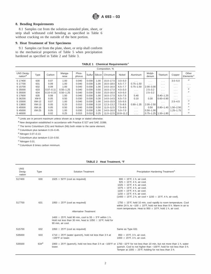
8. Bending Requirements
8.1 Samples cut from the solution-annealed plate, sheet, orstrip shall withstand cold bending as specified in Table 6without cracking on the outside of the bent portion.
9. Heat Treatment of Test Specimens
9.1 Samples cut from the plate, sheet, or strip shall conformto the mechanical properties of Table 5 when precipitationhardened as specified in Table 2 and Table 3.
TABLE 1 Chemical Requirements A
Composition, %
UNS Desig-nationB Type Carbon
Manga-nese
Phos-phorus
Sulfur Silicon Chromium Nickel AluminumMolyb-denum
Titanium CopperOther
ElementsC
S 17400 630 0.07 1.00 0.040 0.030 1.00 15.0–17.5 3.0–5.0 . . . . . . . . . 3.0–5.0 D
S 17700 631 0.09 1.00 0.040 0.030 1.00 16.0–18.0 6.5–7.7 0.75–1.50 . . . . . . . . . . . .S 15700 632 0.09 1.00 0.040 0.030 1.00 14.0–16.0 6.5–7.7 0.75–1.50 2.00–3.00 . . . . . . . . .S 35000 633 0.07–0.11 0.50–1.25 0.040 0.030 0.50 16.0–17.0 4.0–5.0 . . . 2.5–3.2 . . . . . . E
S 35500 634 0.10–0.15 0.50–1.25 0.040 0.030 0.50 15.0–16.0 4.0–5.0 . . . 2.5–3.2 . . . . . . F
S 17600 635 0.08 1.00 0.040 0.030 1.00 16.0–17.5 6.0–7.5 0.40 . . . 0.40–1.20 . . . . . .S 36200 XM-9 0.05 0.50 0.030 0.030 0.30 14.0–14.5 6.5–7.0 0.10 0.30 0.60–0.90 . . . . . .S 15500 XM-12 0.07 1.00 0.040 0.030 1.00 14.0–15.5 3.5–5.5 . . . . . . . . . 2.5–4.5 D
S 13800 XM-13 0.05 0.20 0.010 0.008 0.10 12.3–13.2 7.5–8.5 0.90–1.35 2.00–2.50 . . . . . . G
S 45500 XM-16 0.05 0.50 0.040 0.030 0.50 11.0–12.5 7.5–9.5 . . . 0.50 0.80–1.40 1.50–2.50 F
S 45000 XM-25 0.05 1.00 0.030 0.030 1.00 14.0–16.0 5.0–7.0 . . . 0.50–1.00 . . . 1.25–1.75 H
S 46500 . . . 0.02 0.25 0.015 0.010 0.25 11.0–12.5 10.8–11.2 . . . 0.75–1.25 1.50–1.80 . . . G
A Limits are in percent maximum unless shown as a range or stated otherwise.B New designation established in accordance with Practice E 527 and SAE J1086.C The terms Columbium (Cb) and Niobium (Nb) both relate to the same element.D Columbium plus tantalum 0.15–0.45.E Nitrogen 0.07–0.13.F Columbium plus tantalum 0.10–0.50.G Nitrogen 0.01.H Columbium 8 times carbon minimum.
TABLE 2 Heat Treatment, °F
UNSDesig-nation
Type Solution Treatment Precipitation Hardening TreatmentA
S17400 630 1925 6 50°F (cool as required) 900 6 15°F, 1 h, air cool.925 6 15°F, 4 h, air cool.
1025 6 15°F, 4 h, air cool.1075 6 15°F, 4 h, air cool.1100 6 15°F, 4 h, air cool.1150 6 15°F, 4 h, air cool.
(1400 6 15°F, 2 h, air cool + 1150 6 15°F, 4 h, air cool).
S17700 631 1950 6 25°F (cool as required) 1750 6 15°F, hold 10 min, cool rapidly to room temperature. Coolwithin 24 h, to −100 6 10°F, hold not less than 8 h. Warm in air toroom temperature. Heat to 950 6 10°F, hold 1 h, air cool.
Alternative Treatment:
1400 6 25°F, hold 90 min, cool to 55 6 5°F within 1 h.Hold not less than 30 min, heat to 1050 6 10°F, hold for90 min, air cool.
S15700 632 1950 6 25°F (cool as required) Same as Type 631
S35000 633 1710 6 25°F (water quench), hold not less than 3 h at−100°F or lower.
850 6 15°F, 3 h, air cool.1000 6 15°F, 3 h, air cool.
S35500 634B 1900 6 25°F (quench), hold not less than 3 h at −100°F orlower.
1750 −10°F for not less than 10 min, but not more than 1 h, waterquench. Cool to not higher than −100°F, hold for not less than 3 h.Temper at 1000 6 25°F, holding for not less than 3 h.
A 693 – 03
2
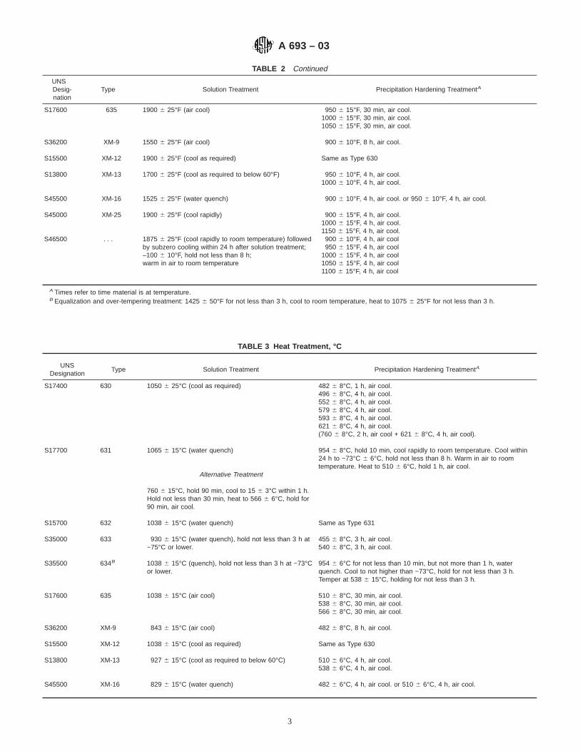
TABLE 2 Continued
UNSDesig-nation
Type Solution Treatment Precipitation Hardening TreatmentA
S17600 635 1900 6 25°F (air cool) 950 6 15°F, 30 min, air cool.1000 6 15°F, 30 min, air cool.1050 6 15°F, 30 min, air cool.
S36200 XM-9 1550 6 25°F (air cool) 900 6 10°F, 8 h, air cool.
S15500 XM-12 1900 6 25°F (cool as required) Same as Type 630
S13800 XM-13 1700 6 25°F (cool as required to below 60°F) 950 6 10°F, 4 h, air cool.1000 6 10°F, 4 h, air cool.
S45500 XM-16 1525 6 25°F (water quench) 900 6 10°F, 4 h, air cool. or 950 6 10°F, 4 h, air cool.
S45000 XM-25 1900 6 25°F (cool rapidly) 900 6 15°F, 4 h, air cool.1000 6 15°F, 4 h, air cool.1150 6 15°F, 4 h, air cool.
S46500 . . . 1875 6 25°F (cool rapidly to room temperature) followedby subzero cooling within 24 h after solution treatment;–100 6 10°F, hold not less than 8 h;warm in air to room temperature
900 6 10°F, 4 h, air cool950 6 15°F, 4 h, air cool
1000 6 15°F, 4 h, air cool1050 6 15°F, 4 h, air cool1100 6 15°F, 4 h, air cool
A Times refer to time material is at temperature.B Equalization and over-tempering treatment: 1425 6 50°F for not less than 3 h, cool to room temperature, heat to 1075 6 25°F for not less than 3 h.
TABLE 3 Heat Treatment, °C
UNSDesignation
Type Solution Treatment Precipitation Hardening TreatmentA
S17400 630 1050 6 25°C (cool as required) 482 6 8°C, 1 h, air cool.496 6 8°C, 4 h, air cool.552 6 8°C, 4 h, air cool.579 6 8°C, 4 h, air cool.593 6 8°C, 4 h, air cool.621 6 8°C, 4 h, air cool.(760 6 8°C, 2 h, air cool + 621 6 8°C, 4 h, air cool).
S17700 631 1065 6 15°C (water quench) 954 6 8°C, hold 10 min, cool rapidly to room temperature. Cool within24 h to −73°C 6 6°C, hold not less than 8 h. Warm in air to roomtemperature. Heat to 510 6 6°C, hold 1 h, air cool.
Alternative Treatment
760 6 15°C, hold 90 min, cool to 15 6 3°C within 1 h.Hold not less than 30 min, heat to 566 6 6°C, hold for90 min, air cool.
S15700 632 1038 6 15°C (water quench) Same as Type 631
S35000 633 930 6 15°C (water quench), hold not less than 3 h at−75°C or lower.
455 6 8°C, 3 h, air cool.540 6 8°C, 3 h, air cool.
S35500 634B 1038 6 15°C (quench), hold not less than 3 h at −73°Cor lower.
954 6 6°C for not less than 10 min, but not more than 1 h, waterquench. Cool to not higher than −73°C, hold for not less than 3 h.Temper at 538 6 15°C, holding for not less than 3 h.
S17600 635 1038 6 15°C (air cool) 510 6 8°C, 30 min, air cool.538 6 8°C, 30 min, air cool.566 6 8°C, 30 min, air cool.
S36200 XM-9 843 6 15°C (air cool) 482 6 8°C, 8 h, air cool.
S15500 XM-12 1038 6 15°C (cool as required) Same as Type 630
S13800 XM-13 927 6 15°C (cool as required to below 60°C) 510 6 6°C, 4 h, air cool.538 6 6°C, 4 h, air cool.
S45500 XM-16 829 6 15°C (water quench) 482 6 6°C, 4 h, air cool. or 510 6 6°C, 4 h, air cool.
A 693 – 03
3

TABLE 3 Continued
UNSDesignation
Type Solution Treatment Precipitation Hardening TreatmentA
S45000 XM-25 1038 6 15°C (cool rapidly) 482 6 8°C, 4 h, air cool.538 6 8°C, 4 h, air cool.621 6 8°C, 4 h, air cool.
S46500 . . . 1024 6 15°C, (cool rapidly to room temperature)followed by subzero cooling within 24 h after solutiontreatment; –73 6 6°C; hold not less than 8 h;warm in air to room temperature
482 6 6°C, 4 h, air cool510 6 8°C, 4 h, air cool538 6 8°C, 4 h, air cool566 6 8°C, 4 h, air cool593 6 8°C, 4 h, air cool
A Times refer to time material is at temperature.B Equalization and over-tempering treatment: 774 6 25°C for not less than 3 h, cool to room temperature, heat to 579 6 15°C for not less than 3 h.
TABLE 4 Mechanical Test Requirements in Solution-Treated Condition
TypeTensile Strength, max Yield Strength, max Elongation in
2 in. or 50 mm,min, %
Hardness, max
ksi MPa ksi MPa Rockwell Brinell
630 0.015 to 4.0 in. (0.38 to 102 mm) . . . . . . . . . . . . . . . C38 363631 0.010 in. (0.25 mm) and under
Over 0.010 to 4.0 in. (0.25 to 102 mm)150150
10351035
6555
450380
. . .20
. . .B92
. . .
. . .632 0.0015 to 4.0 in. (0.038 to 102 mm) 150 1035 65 450 25 B100 . . .633 0.001 to 0.0015 in. (0.03 to 0.038 mm), excl 200 1380 90 620 8 C30 . . .
0.0015 to 0.002 in. (0.03 to 0.05 mm), excl 200 1380 88 605 8 C30 . . .0.002 to 0.005 in. (0.05 to 0.13 mm), excl 200 1380 86 595 8 C30 . . .0.005 to 0.010 in. (0.13 to 0.25 mm), excl 200 1380 85 585 8 C30 . . .Over 0.010 in. (0.254 mm) 200 1380 85 585 12 C30 . . .
634A Plate . . . . . . . . . . . . . . . C40 . . .635 0.030 in. (0.76 mm) and under
Over 0.030 to 0.060 in. (0.76 to 1.52 mm)Over 0.060 in. (1.52 mm)
120120120
825825825
757575
515515515
345
C32C32C32
. . .
. . .
. . .XM-9 Over 0.010 in. (0.25 mm) 150 1035 125 860 4 C28 . . .XM-12 0.0015 to 4.00 in. (0.038 to 101.6 mm) . . . . . . . . . . . . . . . C38 363XM-13 0.0015 to 4.00 in. (0.038 to 101.6 mm) . . . . . . . . . . . . . . . C38 363XM-16 0.010 in. (0.25 mm) and greater 175 1205 160 1105 3 C36 331XM-25B 0.010 in. (0.25 mm) and greater 165 1205 150 1035 4 C33 311S46500 0.140 in. (3.56 mm) and under 160 1105 150 1035 4 C33 . . .
A Solution-treated, equalized, and over-tempered plate only.B XM-25 also furnished to the following minimum properties: 130 895 90 620 4 C25 255
TABLE 5 Mechanical Test Requirements After Precipitation Hardening Treatment
Grade
Hardening orPrecipitationTreatment orboth, °F(°C)
Thickness, in. (mm)
Tensile Strength,min
Yield Strength,min
Elonga-tion in 2
in. or50 mm,
min,%A
Reduc-tion ofArea,min,%A
Hardness, minImpact Charpy
V, minB
ksi MPa ksi MPaRockwell,min/max
Brinell,min/max
ft·lbf J
630 and 900 (482) Under 0.1875 (4.762) 190 1310 170 1170 5 . . . C40/C48 . . . . . . . . .XM-12 0.1875 to 0.625 (4.762 to 15.88) 190 1310 170 1170 8 25 C40/C48 388/477 . . . . . .
0.626 to 4.0 (15.90 to 102) 190 1310 170 1170 10 30 C40/C48 388/477 . . . . . .
925 (496) Under 0.1875 (4.762) 170 1170 155 1070 5 . . . C38/C46 . . . . . . . . .0.1875 to 0.625 (4.762 to 15.88) 170 1170 155 1070 8 25 C38/C47 375/477 . . . . . .0.626 to 4.0 (15.90 to 102) 170 1170 155 1070 10 30 C38/C47 375/477 . . . . . .
1025 (552) Under 0.1875 (4.762) 155 1070 145 1000 5 . . . C35/C43 . . . . . . . . .0.1875 to 0.625 (4.762 to 15.88) 155 1070 145 1000 8 30 C33/C42 321/415 10 140.626 to 4.0 (15.90 to 102) 155 1070 145 1000 12 35 C33/C42 321/415 15 20
1075 (579) Under 0.1875 (4.762) 145 1000 125 860 5 . . . C31/C40 . . . . . . . . .0.1875 to 0.625 (4.762 to 15.88) 145 1000 125 860 9 30 C29/C38 293/375 15 200.626 to 4.0 (15.88 to 102) 145 1000 125 860 13 35 C29/C38 293/375 20 27
A 693 – 03
4

TABLE 5 Continued
Grade
Hardening orPrecipitationTreatment orboth, °F(°C)
Thickness, in. (mm)
Tensile Strength,min
Yield Strength,min
Elonga-tion in 2
in. or50 mm,
min,%A
Reduc-tion ofArea,min,%A
Hardness, minImpact Charpy
V, minB
ksi MPa ksi MPaRockwell,min/max
Brinell,min/max
ft·lbf J
1100 (593) Under 0.1875 (4.762) 140 965 115 790 5 . . . C31/C40 . . . . . . . . .0.1875 to 0.625 (4.762 to 15.88) 140 965 115 790 10 30 C29/C38 293/375 15 200.626 to 4.0 (15.88 to 102) 140 965 115 790 14 35 C29/C38 293/375 20 27
1150 (621) Under 0.1875 (4.762) 135 930 105 725 8 . . . C28/C38 . . . . . . . . .0.1875 to 0.625 (4.762 to 15.88) 135 930 105 725 10 35 C26/C36 269/352 25 340.626 to 4.0 (15.88 to 102) 135 930 105 725 16 40 C26/C36 269/352 30 41
1400 + 1150 Under 0.1875 (4.762) 115 790 75 515 9 . . . C26/C36 255/331 . . . . . .(760 + 621) 0.1875 to 0.625 (4.762 to 15.88) 115 790 75 515 11 40 C24/C34 248/321 55 75
0.626 to 4.0 (15.88 to 102) 115 790 75 515 18 45 C24/C34 248/321 55 75
631 1400 (760) + 0.0015 to 0.0049 (0.038 to 0.124) 180 1240 150 1035 3 . . . C38 . . . . . . . . .plus 55 (15) + 0.0050 to 0.0099 (0.127 to 0.251) 180 1240 150 1035 4 . . . C38 . . . . . . . . .
1050 (566) 0.010 to 0.0199 (0.25 to 0.505) 180 1240 150 1035 5 . . . C38 . . . . . . . . .0.020 to 0.1874 (0.51 to 4.760) 180 1240 150 1035 6 . . . C38 . . . . . . . . .0.1875 to 0.625 (4.762 to 15.88) 170 1170 140 965 7 20 C38 352 . . . . . .
1750 (954) + 0.0015 to 0.0049 (0.038 to 0.124) 210 1450 190 1310 1 . . . C44 . . . . . . . . .minus 100 (73) 0.0050 to 0.0099 (0.127 to 0.251) 210 1450 190 1310 2 . . . C44 . . . . . . . . .
+ 950 (510) 0.010 to 0.0199 (0.25 to 0.505) 210 1450 190 1310 3 . . . C44 . . . . . . . . .0.020 to 0.1874 (0.51 to 4.760) 210 1450 190 1310 4 . . . C44 . . . . . . . . .0.1875 to 0.625 (4.762 to 15.88) 200 1380 180 1240 6 20 C43 401 . . . . . .
Cold rolled at mill 0.0015 to 0.050 (0.038 to 1.27) 200 1380 175 1205 1 . . . C41 . . . . . . . . .
Cold rolled at mill+ 900 (482)
0.0015 to 0.050 (0.038 to 1.27) 240 1655 230 1580 1 . . . C46 . . . . . . . . .
632 1400 (760) + 0.0015 to 0.0049 (0.038 to 0.124) 190 1310 170 1170 2 . . . C40 . . . . . . . . .plus 55 (15) + 0.0050 to 0.0099 (0.127 to 0.251) 190 1310 170 1170 3 . . . C40 . . . . . . . . .
1050 (566) 0.010 to 0.0199 (0.25 to 0.505) 190 1310 170 1170 4 . . . C40 . . . . . . . . .0.020 to 0.1874 (0.51 to 4.760) 190 1310 170 1170 5 . . . C40 . . . . . . . . .0.1875 to 0.625 (4.762 to 15.88) 190 1310 170 1170 4 20 C40 375 . . . . . .
1750 (954) + 0.0015 to 0.0049 (0.038 to 0.124) 225 1550 200 1380 1 . . . C46 . . . . . . . . .minus 100 (73) 0.0050 to 0.0099 (0.127 to 0.251) 225 1550 200 1380 2 . . . C46 . . . . . . . . .
+ 950 (510) 0.010 to 0.0199 (0.25 to 0.505) 225 1550 200 1380 3 . . . C46 . . . . . . . . .0.020 to 0.1874 (0.51 to 4.760) 225 1550 200 1380 4 . . . C46 . . . . . . . . .0.1875 to 0.625 (4.762 to 15.88) 225 1550 200 1380 4 20 C45 429 . . . . . .
Cold rolled at mill 0.0015 to 0.050 (0.038 to 0.13) 200 1380 175 1205 1 . . . C41 . . . . . . . . .
Cold rolled at mill+ 900 (482)
0.0015 to 0.050 (0.038 to 0.13) 240 1655 230 1585 1 . . . C46 . . . . . . . . .
633 850 (455) 0.0005 to 0.0015 (0.022 to 0.038) 185 1275 150 1035 2 . . . C42 . . . . . . . . .0.0015 to 0.0020 (0.038 to 0.041) 185 1275 150 1035 4 . . . C42 . . . . . . . . .0.0020 to 0.0100 (0.041 to 0.254) 185 1275 150 1035 6 . . . C42 . . . . . . . . .0.0100 to 0.1875 (0.254 to 4.762) 185 1275 150 1035 8 . . . C42 . . . . . . . . .
1000 (540) 0.0005 to 0.0015 (0.022 to 0.038) 165 1140 145 1000 2 . . . C36 . . . . . . . . .0.0015 to 0.0020 (0.038 to 0.041) 165 1140 145 1000 4 . . . C36 . . . . . . . . .0.0020 to 0.0100 (0.041 to 0.254) 165 1140 145 1000 6 . . . C36 . . . . . . . . .0.0100 to 0.1875 (0.254 to 4.762) 165 1140 145 1000 8 . . . C36 . . . . . . . . .
634 850 (455) 190 1310 165 1140 10 . . . . . . . . . . . . . . .
1000 (540) 170 1170 150 1035 12 . . . C37 . . . . . . . . .
635 950 (510) 0.030 (0.76) and under0.030 to 0.060 (0.76 to 1.52)
190190
13101310
170170
11701170
34
. . .
. . .C39C39
. . .
. . .. . .. . .
. . .
. . .
Over 0.060 (1.52)Plate
190190
13101310
170170
11701170
58
. . .25
C39C39
. . .363
. . .
. . .. . .. . .
1000 (540) 0.030 (0.76) and under 180 1240 160 1105 3 . . . C37 . . . . . . . . .0.030 to 0.060 (0.76 to 1.52) 180 1240 160 1105 4 . . . C37 . . . . . . . . .Over 0.060 (1.52) 180 1240 160 1105 5 . . . C37 . . . . . . . . .
A 693 – 03
5

TABLE 5 Continued
Grade
Hardening orPrecipitationTreatment orboth, °F(°C)
Thickness, in. (mm)
Tensile Strength,min
Yield Strength,min
Elonga-tion in 2
in. or50 mm,
min,%A
Reduc-tion ofArea,min,%A
Hardness, minImpact Charpy
V, minB
ksi MPa ksi MPaRockwell,min/max
Brinell,min/max
ft·lbf J
Plate 180 1240 160 1105 8 30 C38 352 . . . . . .
1050 (565) 0.030 (0.76) and under 170 1170 150 1035 3 . . . C35 . . . . . . . . .0.030 to 0.060 (0.76 to 1.52) 170 1170 150 1035 4 . . . C35 . . . . . . . . .Over 0.060 (1.52) 170 1170 150 1035 5 . . . C35 . . . . . . . . .Plate 170 1170 150 1035 8 30 C36 331 . . . . . .
XM-13 950 (510) Under 0.020 (0.51) 220 1515 205 1410 6 . . . C45 . . . . . . . . .0.020 to 0.1874 (0.51 to 4.760) 220 1515 205 1410 8 . . . C45 . . . . . . . . .0.1875 to 0.625 (4.760 to 15.88) 220 1515 205 1410 10 . . . C45 . . . . . . . . .0.626 to 4.0 (15.90 to 102) 220 1515 205 1410 10 . . . C45 429 . . . . . .
1000 (538) Under 0.020 (0.51) 200 1380 190 1310 6 . . . C43 . . . . . . . . .0.020 to 0.1874 (0.51 to 4.760) 200 1380 190 1310 8 . . . C43 . . . . . . . . .0.1875 to 0.625 (4.760 to 15.88) 200 1380 190 1310 10 . . . C43 . . . . . . . . .0.626 to 4.0 (15.90 to 102) 200 1380 190 1310 10 . . . C43 401 . . . . . .
XM-16 950 (510) Up to 0.020 (0.51)Over 0.020 to 0.062 (0.51 to 1.57)Over 0.062 (1.57)
222222222
152515251525
205205205
141014101410
. . .
34
. . .
. . .
. . .
C44C44C44
. . .
. . .
. . .
. . .
. . .
. . .
. . .
. . .
. . .
XM-25 900 (482) Up to 0.020 (0.51)Over 0.020 to 0.062 (0.51 to 1.57)Over 0.062 (1.57)
180180180
124012401240
170170170
117011701170
345
. . .
. . .
. . .
C40C40C40
. . .
. . .
. . .
. . .
. . .
. . .
. . .
. . .
. . .
1000 (538) Up to 0.020 (0.51)Over 0.020 to 0.062 (0.51 to 1.57)Over 0.062 (1.57)
160160160
110511051105
150150150
103510351035
567
. . .
. . .
. . .
C36C36C36
. . .
. . .
. . .
. . .
. . .
. . .
. . .
. . .
. . .
1150 (621) Up to 0.020 (0.51)Over 0.020 to 0.062 (0.51 to 1.57)Over 0.062 (1.57)
125125125
860860860
757575
515515515
89
10
. . .
. . .
. . .
C26C26C26
. . .
. . .
. . .
. . .
. . .
. . .
. . .
. . .
. . .
XM-9 900 (482) Over 0.010 (0.25) 180 1240 160 1105 3 . . . C38 . . . . . . . . .
S46500 900 (482)950 (510)
1000 (538)1050 (566)1100 (593)
0.140 (3.56) and under0.140 (3.56) and under0.140 (3.56) and under0.140 (3.56) and under0.140 (3.56) and under
245235220200180
16901620151513801240
235225210185145
16201550144512751000
23456
. . .
. . .
. . .
. . .
. . .
C48C47C45C43C39
. . .
. . .
. . .
. . .
. . .
. . .
. . .
. . .
. . .
. . .
. . .
. . .
. . .
. . .
. . .
A Applicable to tests in the long transverse direction. Transverse to the direction of rolling and parallel to the product surface.B Impact test is not required unless specified on the purchase order.
TABLE 6 Bend Test Requirements in Solution-Treated Condition
Type Size, in. (mm) Cold BendDegrees
Bend TestMandrel
630 none required631 0.187 (4.76) and under
Over 0.187 to 0.275 (4.76 to 6.98)180180
1T A
3T632 0.187 (4.76) and under
Over 0.187 to 0.275 (4.76 to 6.98)180180
1T3T
A 693 – 03
6

TABLE 6 Continued
Type Size, in. (mm) Cold BendDegrees
Bend TestMandrel
633 Under 0.1875 (4.762) 180 2T634 0.187 to 0.249 (4.76 to 6.32)
Over 0.249 to 0.750 (6.32 to 19.08)13090
3T3T
635 none requiredXM-9 0.109 (2.77) and under 180 9TXM-12 none requiredXM-13 none requiredXM-16 Under 0.1875 (4.762) 180 6TXM-25 Under 0.1875 (4.762) 180 6TS46500 0.140 (3.56) and under 180 6T
AT = thickness of sheet being tested.
10. Keywords10.1 plate; precipitation hardening; sheet; stainless steel;
strip
SUMMARY OF CHANGES
Committee A01 has identified the location of selected changes to this standard since the last issue (A 693-02e1)that may impact the use of this standard.
(1) Table 1 brought into compliance with Guide A 959 guide-lines.(2) Sections 3.1.1 and 3.1.2 deleted with subsequent renum-bering.
(3) Keywords section was added.
ASTM International takes no position respecting the validity of any patent rights asserted in connection with any item mentionedin this standard. Users of this standard are expressly advised that determination of the validity of any such patent rights, and the riskof infringement of such rights, are entirely their own responsibility.
This standard is subject to revision at any time by the responsible technical committee and must be reviewed every five years andif not revised, either reapproved or withdrawn. Your comments are invited either for revision of this standard or for additional standardsand should be addressed to ASTM International Headquarters. Your comments will receive careful consideration at a meeting of theresponsible technical committee, which you may attend. If you feel that your comments have not received a fair hearing you shouldmake your views known to the ASTM Committee on Standards, at the address shown below.
This standard is copyrighted by ASTM International, 100 Barr Harbor Drive, PO Box C700, West Conshohocken, PA 19428-2959,United States. Individual reprints (single or multiple copies) of this standard may be obtained by contacting ASTM at the aboveaddress or at 610-832-9585 (phone), 610-832-9555 (fax), or [email protected] (e-mail); or through the ASTM website(www.astm.org).
A 693 – 03
7

Designation: A 705/A705M – 95 (Reapproved 2000)
Standard Specification forAge-Hardening Stainless Steel Forgings 1
This standard is issued under the fixed designation A 705/A705M; the number immediately following the designation indicates the yearof original adoption or, in the case of revision, the year of last revision. A number in parentheses indicates the year of last reapproval.A superscript epsilon (e) indicates an editorial change since the last revision or reapproval.
1. Scope
1.1 This specification2 covers age-hardening stainless steelforgings for general use.
1.2 The values stated in either inch-pound units or SI(metric) units are to be regarded separately as standards; withinthe text and tables, the SI units are shown in[brackets]. Thevalues stated in each system are not exact equivalents; there-fore, each system must be used independent of the other.Combining values from the two systems may result in noncon-formance with the specification.
1.3 Unless the order specifies an “M” designation, thematerial shall be furnished to inch-pound units.
NOTE 1—Bar products are covered by Specification A 564/A 564M.
2. Referenced Documents
2.1 ASTM Standards:A 370 Test Methods and Definitions for Mechanical Testing
of Steel Products3
A 484/A484M Specification for General Requirements forStainless Steel Bars, Billets, and Forgings4
A 564/A564M Specification for Hot-Rolled and Cold-Finished Age-Hardening Stainless Steel Bars and Shapes4
A 751 Test Methods, Practices, and Terminology forChemical Analysis of Steel Products3
E 527 Practice for Numbering Metals and Alloys (UNS)5
2.2 Other Documents:SAE J 1086 Recommended Practice for Numbering Metals
and Alloys (UNS)6
3. Ordering Information
3.1 It is the responsibility of the purchaser to specify allrequirements that are necessary for material ordered under thisspecification. Such requirements may include but are notlimited to the following:
3.1.1 Quantity (weight or number of pieces),3.1.2 Name of material (age-hardening stainless steel forg-
ings),3.1.3 Dimensions, including prints or sketches,3.1.4 Type or UNS designation (Table 1),3.1.5 Heat treated condition (Section 5),3.1.6 Transverse properties when required (7.4),3.1.7 ASTM designation and date of issue, and3.1.8 Special requirements (5.3, 5.4).3.2 If possible the intended end use of the item should be
given on the purchase order, especially when the item isordered for a specific end use or uses.
NOTE 2—A typical ordering description is as follows: 5 age-hardeningstainless steel forgings, Type 630, solution-annealed, ASTM SpecificationA 705 dated __ . End use: pump blocks for oil well equipment.
4. General Requirements
4.1 In addition to the requirements of this specification, allrequirements of the current edition of Specification A 484/A 484M shall apply. Failure to comply with the generalrequirements of Specification A 484/A 484M, constitutes non-conformance with this specification.
5. Materials and Manufacture
5.1 Material for forgings shall consist of billets or bars,either forged, rolled or cast, or a section cut from an ingot. Thecuts shall be made to the required length by a suitable process.This material may be specified to Specification A 564/A 564M.
5.2 The material shall be forged by hammering, pressing,rolling, extruding, or upsetting to produce a wrought structurethroughout and shall be brought as nearly as possible to thefinished shape and size by hot working.
1 This specification is under the jurisdiction of ASTM Committee A-1 on Steel,Stainless Steel and Related Alloys, and is the direct responsibility of SubcommitteeA01.17 on Flat Stainless Steel Products.
Current edition approved Jan. 15, 1995. Published March 1995. Originallypublished as A 705 – 74. Last previous edition A 705/A 705M – 94.
2 For ASME Boiler and Pressure Vessel Code applications see related Specifi-cation SA-705/SA-705M in Section II of that Code.
3 Annual Book of ASTM Standards, Vol 01.03.4 Annual Book of ASTM Standards, Vol 01.05.5 Annual Book of ASTM Standards, Vol 01.01.6 Available from Society of Automotive Engineers, 400 Commonwealth Drive,
Warrendale, PA 15096.
1
Copyright © ASTM International, 100 Barr Harbor Drive, PO Box C700, West Conshohocken, PA 19428-2959, United States.
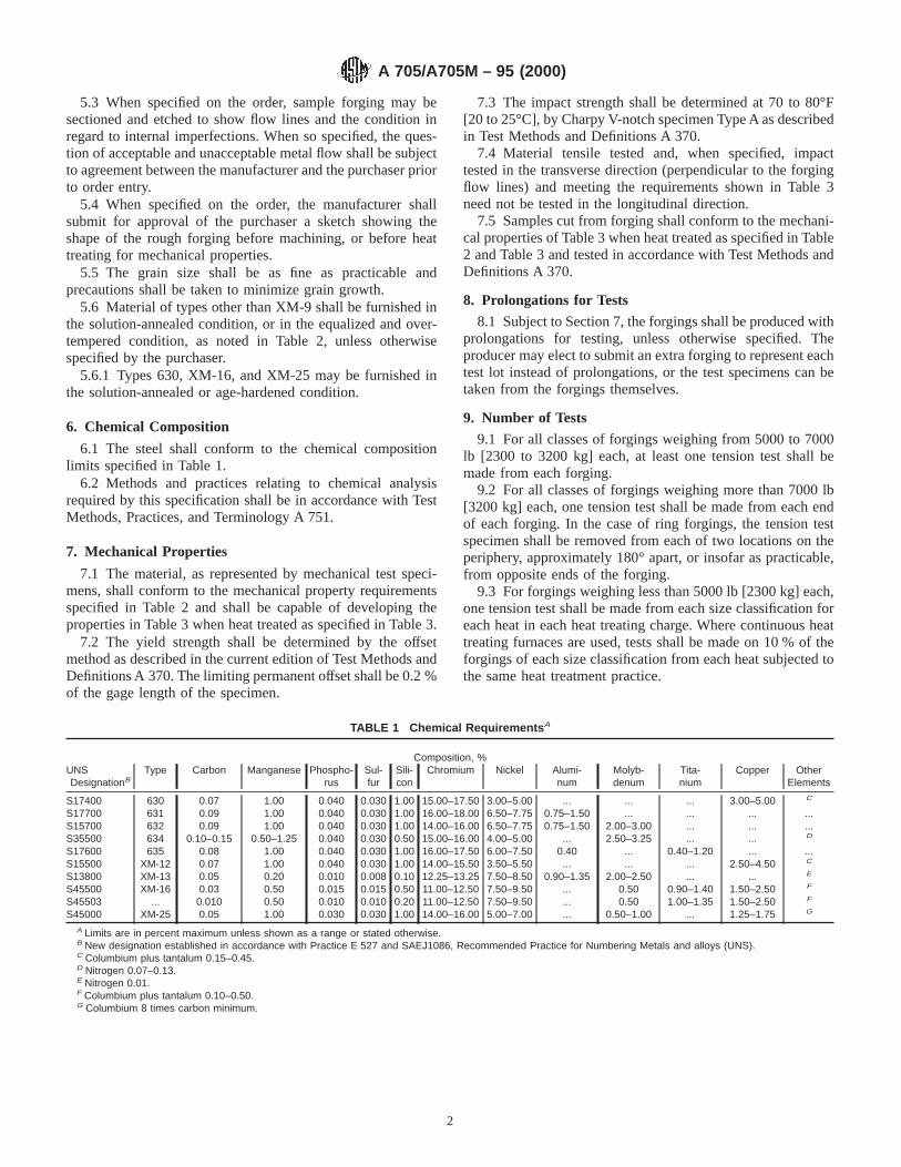
5.3 When specified on the order, sample forging may besectioned and etched to show flow lines and the condition inregard to internal imperfections. When so specified, the ques-tion of acceptable and unacceptable metal flow shall be subjectto agreement between the manufacturer and the purchaser priorto order entry.
5.4 When specified on the order, the manufacturer shallsubmit for approval of the purchaser a sketch showing theshape of the rough forging before machining, or before heattreating for mechanical properties.
5.5 The grain size shall be as fine as practicable andprecautions shall be taken to minimize grain growth.
5.6 Material of types other than XM-9 shall be furnished inthe solution-annealed condition, or in the equalized and over-tempered condition, as noted in Table 2, unless otherwisespecified by the purchaser.
5.6.1 Types 630, XM-16, and XM-25 may be furnished inthe solution-annealed or age-hardened condition.
6. Chemical Composition
6.1 The steel shall conform to the chemical compositionlimits specified in Table 1.
6.2 Methods and practices relating to chemical analysisrequired by this specification shall be in accordance with TestMethods, Practices, and Terminology A 751.
7. Mechanical Properties
7.1 The material, as represented by mechanical test speci-mens, shall conform to the mechanical property requirementsspecified in Table 2 and shall be capable of developing theproperties in Table 3 when heat treated as specified in Table 3.
7.2 The yield strength shall be determined by the offsetmethod as described in the current edition of Test Methods andDefinitions A 370. The limiting permanent offset shall be 0.2 %of the gage length of the specimen.
7.3 The impact strength shall be determined at 70 to 80°F[20 to 25°C], by Charpy V-notch specimen Type A as describedin Test Methods and Definitions A 370.
7.4 Material tensile tested and, when specified, impacttested in the transverse direction (perpendicular to the forgingflow lines) and meeting the requirements shown in Table 3need not be tested in the longitudinal direction.
7.5 Samples cut from forging shall conform to the mechani-cal properties of Table 3 when heat treated as specified in Table2 and Table 3 and tested in accordance with Test Methods andDefinitions A 370.
8. Prolongations for Tests
8.1 Subject to Section 7, the forgings shall be produced withprolongations for testing, unless otherwise specified. Theproducer may elect to submit an extra forging to represent eachtest lot instead of prolongations, or the test specimens can betaken from the forgings themselves.
9. Number of Tests
9.1 For all classes of forgings weighing from 5000 to 7000lb [2300 to 3200 kg] each, at least one tension test shall bemade from each forging.
9.2 For all classes of forgings weighing more than 7000 lb[3200 kg] each, one tension test shall be made from each endof each forging. In the case of ring forgings, the tension testspecimen shall be removed from each of two locations on theperiphery, approximately 180° apart, or insofar as practicable,from opposite ends of the forging.
9.3 For forgings weighing less than 5000 lb [2300 kg] each,one tension test shall be made from each size classification foreach heat in each heat treating charge. Where continuous heattreating furnaces are used, tests shall be made on 10 % of theforgings of each size classification from each heat subjected tothe same heat treatment practice.
TABLE 1 Chemical Requirements A
Composition, %UNSDesignationB
Type Carbon Manganese Phospho-rus
Sul-fur
Sili-con
Chromium Nickel Alumi-num
Molyb-denum
Tita-nium
Copper OtherElements
S17400 630 0.07 1.00 0.040 0.030 1.00 15.00–17.50 3.00–5.00 ... ... ... 3.00–5.00 C
S17700 631 0.09 1.00 0.040 0.030 1.00 16.00–18.00 6.50–7.75 0.75–1.50 ... ... ... ...S15700 632 0.09 1.00 0.040 0.030 1.00 14.00–16.00 6.50–7.75 0.75–1.50 2.00–3.00 ... ... ...S35500 634 0.10–0.15 0.50–1.25 0.040 0.030 0.50 15.00–16.00 4.00–5.00 ... 2.50–3.25 ... ... D
S17600 635 0.08 1.00 0.040 0.030 1.00 16.00–17.50 6.00–7.50 0.40 ... 0.40–1.20 ... ...S15500 XM-12 0.07 1.00 0.040 0.030 1.00 14.00–15.50 3.50–5.50 ... ... ... 2.50–4.50 C
S13800 XM-13 0.05 0.20 0.010 0.008 0.10 12.25–13.25 7.50–8.50 0.90–1.35 2.00–2.50 ... ... E
S45500 XM-16 0.03 0.50 0.015 0.015 0.50 11.00–12.50 7.50–9.50 ... 0.50 0.90–1.40 1.50–2.50 F
S45503 ... 0.010 0.50 0.010 0.010 0.20 11.00–12.50 7.50–9.50 ... 0.50 1.00–1.35 1.50–2.50 F
S45000 XM-25 0.05 1.00 0.030 0.030 1.00 14.00–16.00 5.00–7.00 ... 0.50–1.00 ... 1.25–1.75 G
A Limits are in percent maximum unless shown as a range or stated otherwise.B New designation established in accordance with Practice E 527 and SAEJ1086, Recommended Practice for Numbering Metals and alloys (UNS).C Columbium plus tantalum 0.15–0.45.D Nitrogen 0.07–0.13.E Nitrogen 0.01.F Columbium plus tantalum 0.10–0.50.G Columbium 8 times carbon minimum.
A 705/A705M – 95 (2000)
2

TABLE 2 Solution Heat Treatment
TypeCondi-
tionSolution Treatment
Mechanical Test Requirements in Solution Treated ConditionA
Tensile Strength, min Yield Strength, min Elongationin 2 in. [50mm] or 4D,
min. %
Reductionof Area,
minute %
HardnessB
ksi [MPa] ksi [MPa]Rockwell C,
maxBrinell,
max
630 A 1900 6 25°F [1040 6 15°C] (coolas required to below 90°F [32°C])
. . . . . . . . . . . . . . . . . . 38 363
631 A 1900 6 25°F [1040 6 15°C] (waterquench)
. . . . . . . . . . . . . . . . . . Rb89 229
632 A 1900 6 25°F [1040 6 15°C] (waterquench)
. . . . . . . . . . . . . . . . . . Rb100 269C
634D A 1900 6 25°F [1040 6 15°C]quench, hold not less than 3 h atminus 100°F or lower
. . . . . . . . . . . . . . . . . . . . . 363D
635 A 1900 6 25°F [1040 6 15°C] (aircool)
120 [825] 75 [515] 10 45 32 302
XM-12 A 1900 6 25°F [1040 6 15°C] (coolas required to below 90°F [32°C])
. . . . . . . . . . . . . . . . . . 38 363
XM-13 A 1700 6 25°F [925 6 15°C] (cool asrequired to below 60°F [16°C])
. . . . . . . . . . . . . . . . . . 38 363
XM-16 A 1525 6 25°F [830 6 15°C] (coolrapidly)
. . . . . . . . . . . . . . . . . . 36 331
S45503 A 1525 6 25°F [830 6 15°C] (coolrapidly)
. . . . . . . . . . . . . . . . . . 36 331
XM-25 A 1900 6 25°F [1040 6 15°C] (coolrapidly)
125E [860] 95 [655] 10 40 33 311
A See 6.1.B Either Rockwell C hardness or Brinell is permissible. On sizes of 1⁄2in. (12.70 mm) and smaller, Rockwell C is preferred.C 321 BHN for rounds cold drawn after solution treating.D Equalization and over-tempering treatment 1425 6 50°F [775 6 30°C] for not less than 3 h, cool to room temperature, heat to 1075 6 25°F [580 6 15°C] for not less
than 3 h.E 125 − 165 ksi [860 − 1140 MPa] for sizes up to 1⁄2 in. [13 mm].
A 705/A705M – 95 (2000)
3
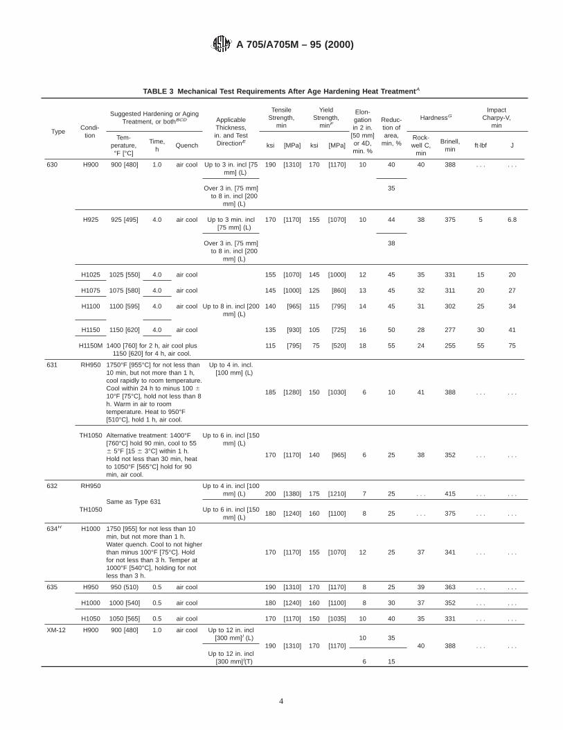
TABLE 3 Mechanical Test Requirements After Age Hardening Heat Treatment A
TypeCondi-
tion
Suggested Hardening or AgingTreatment, or bothBCD Applicable
Thickness,in. and TestDirectionE
TensileStrength,
min
YieldStrength,
minF
Elon-gationin 2 in.
[50 mm]or 4D,min. %
Reduc-tion ofarea,
min, %
HardnessGImpact
Charpy-V,min
Tem-perature,°F [°C]
Time,h
Quench ksi [MPa] ksi [MPa]Rock-well C,
min
Brinell,min
ft·lbf J
630 H900 900 [480] 1.0 air cool Up to 3 in. incl [75mm] (L)
190 [1310] 170 [1170] 10 40 40 388 . . . . . .
Over 3 in. [75 mm]to 8 in. incl [200
mm] (L)
35
H925 925 [495] 4.0 air cool Up to 3 min. incl[75 mm] (L)
170 [1170] 155 [1070] 10 44 38 375 5 6.8
Over 3 in. [75 mm]to 8 in. incl [200
mm] (L)
38
H1025 1025 [550] 4.0 air cool 155 [1070] 145 [1000] 12 45 35 331 15 20
H1075 1075 [580] 4.0 air cool 145 [1000] 125 [860] 13 45 32 311 20 27
H1100 1100 [595] 4.0 air cool Up to 8 in. incl [200mm] (L)
140 [965] 115 [795] 14 45 31 302 25 34
H1150 1150 [620] 4.0 air cool 135 [930] 105 [725] 16 50 28 277 30 41
H1150M 1400 [760] for 2 h, air cool plus1150 [620] for 4 h, air cool.
115 [795] 75 [520] 18 55 24 255 55 75
631 RH950 1750°F [955°C] for not less than10 min, but not more than 1 h,cool rapidly to room temperature.Cool within 24 h to minus 100 610°F [75°C], hold not less than 8h. Warm in air to roomtemperature. Heat to 950°F[510°C], hold 1 h, air cool.
Up to 4 in. incl.[100 mm] (L)
185 [1280] 150 [1030] 6 10 41 388 . . . . . .
TH1050 Alternative treatment: 1400°F[760°C] hold 90 min, cool to 556 5°F [15 6 3°C] within 1 h.Hold not less than 30 min, heatto 1050°F [565°C] hold for 90min, air cool.
Up to 6 in. incl [150mm] (L)
170 [1170] 140 [965] 6 25 38 352 . . . . . .
632 RH950 Up to 4 in. incl [100mm] (L) 200 [1380] 175 [1210] 7 25 . . . 415 . . . . . .
Same as Type 631TH1050 Up to 6 in. incl [150
mm] (L)180 [1240] 160 [1100] 8 25 . . . 375 . . . . . .
634H H1000 1750 [955] for not less than 10min, but not more than 1 h.Water quench. Cool to not higherthan minus 100°F [75°C]. Holdfor not less than 3 h. Temper at1000°F [540°C], holding for notless than 3 h.
170 [1170] 155 [1070] 12 25 37 341 . . . . . .
635 H950 950 (510) 0.5 air cool 190 [1310] 170 [1170] 8 25 39 363 . . . . . .
H1000 1000 [540] 0.5 air cool 180 [1240] 160 [1100] 8 30 37 352 . . . . . .
H1050 1050 [565] 0.5 air cool 170 [1170] 150 [1035] 10 40 35 331 . . . . . .
XM-12 H900 900 [480] 1.0 air cool Up to 12 in. incl[300 mm]I (L)
190 [1310] 170 [1170]10 35
40 388 . . . . . .Up to 12 in. incl
[300 mm]I(T) 6 15
A 705/A705M – 95 (2000)
4

TABLE 3 Continued
TypeCondi-
tion
Suggested Hardening or AgingTreatment, or bothBCD Applicable
Thickness,in. and TestDirectionE
TensileStrength,
min
YieldStrength,
minF
Elon-gationin 2 in.
[50 mm]or 4D,min. %
Reduc-tion ofarea,
min, %
HardnessGImpact
Charpy-V,min
Tem-perature,°F [°C]
Time,h
Quench ksi [MPa] ksi [MPa]Rock-well C,
min
Brinell,min
ft·lbf J
H925 925 [495] 4.0 air cool Up to 12 in. incl[300 mm]I (L)
170 [1170] 155 [1070]10 38
38 3755 6.8
Up to 12 in. incl[300 mm]I(T)
7 20. . . . . .
H1025 1025 [550] 4.0 air cool Up to 12 in. incl[300 mm]I (L)
155 [1070] 145 [1000]12 45
35 33115 20
Up to 12 in. incl[300 mm]I(T) 8
27 10 14
H1075 1075 [580] 4.0 air cool Up to 12 in. incl[300 mm]I (L)
145 [1000] 125 [860]13 45
32 31120 27
Up to 12 in. incl[300 mm]I(T)
9 28 15 20
H1100 1100 [595] 4.0 air cool Up to 12 in. incl[300 mm]I (L)
140 [965] 115 [795]14 45
31 30225 34
Up to 12 in. incl[300 mm]I(T)
10 29 15 20
H1150 1150 [620] 4.0 air cool Up to 12 in. incl[300 mm]I (L)
135 [930] 105 [725]16 50
28 27730 41
Up to 12 in. incl[300 mm]I(T)
11 30 20 27
H1150M 1400 [760] for 2 h, air cool plus1150 [620] for 4 h, air cool
Up to 12 in. incl[300 mm]I (L)
115 [795] 75 [515]18 55
24 25555 75
Up to 12 in. incl[300 mm]I(T)
14 35 35 47
XM-13 H950 950 [510] 4.0 air cool Up to 12 in. incl[300 mm]I(L)
220 [1520] 205 [1420] 1045
45 430 . . . . . .Up to 12 in. incl
[300 mm]I(T)35
H1000 1000 [540] 4.0 air cool Up to 12 in. incl[300 mm]I (L)
205 [1420] 190 [1310]10 50
43 400 . . . . . .Up to 12 in. incl
[300 mm]I (T)10 40
H1025 1025 [550] 4.0 air cool Up to 12 in. incl[300 mm] (L)
185 [1280] 175 [1210] 1150
41 380 . . . . . .Up to 12 in. incl
[300 mm] (T)45
H1050 1050 [565] 4.0 air cool Up to 12 in. incl[300 mm] (L)
175 [1210] 165 [1140] 1250
40 372 . . . . . .Up to 12 in. incl
[300 mm] (T)45
H1100 1100 [595] 4.0 air cool Up to 12 in. incl[300 mm] (L)
150 [1030] 135 [930] 1450
34 313 . . . . . .Up to 12 in. incl
[300 mm] (T)50
H1150 1150 [620] 4.0 air cool Up to 12 in. incl[300 mm] (L)
135 [930] 90 [620] 1450
30 283 . . . . . .Up to 12 in. incl
[300 mm] (T)50
A 705/A705M – 95 (2000)
5
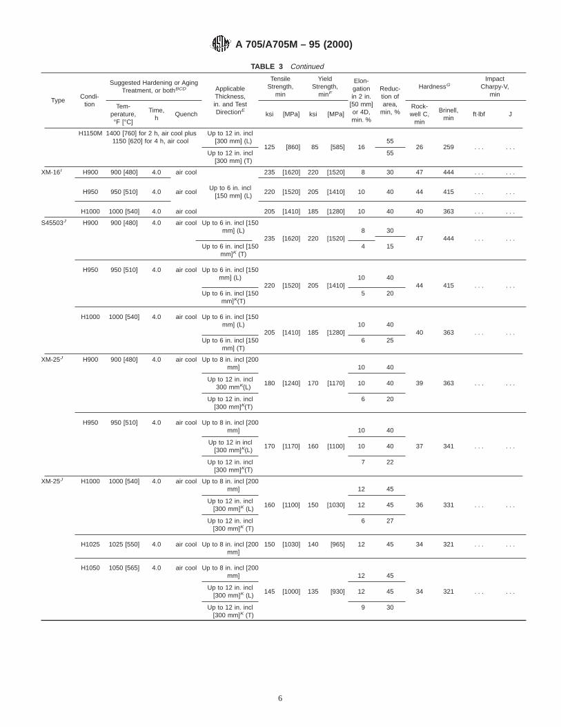
TABLE 3 Continued
TypeCondi-
tion
Suggested Hardening or AgingTreatment, or bothBCD Applicable
Thickness,in. and TestDirectionE
TensileStrength,
min
YieldStrength,
minF
Elon-gationin 2 in.
[50 mm]or 4D,min. %
Reduc-tion ofarea,
min, %
HardnessGImpact
Charpy-V,min
Tem-perature,°F [°C]
Time,h
Quench ksi [MPa] ksi [MPa]Rock-well C,
min
Brinell,min
ft·lbf J
H1150M 1400 [760] for 2 h, air cool plus1150 [620] for 4 h, air cool
Up to 12 in. incl[300 mm] (L)
125 [860] 85 [585] 1655
26 259 . . . . . .Up to 12 in. incl
[300 mm] (T)55
XM-16I H900 900 [480] 4.0 air cool 235 [1620] 220 [1520] 8 30 47 444 . . . . . .
H950 950 [510] 4.0 air coolUp to 6 in. incl
[150 mm] (L)220 [1520] 205 [1410] 10 40 44 415 . . . . . .
H1000 1000 [540] 4.0 air cool 205 [1410] 185 [1280] 10 40 40 363 . . . . . .
S45503J H900 900 [480] 4.0 air cool Up to 6 in. incl [150mm] (L)
235 [1620] 220 [1520]8 30
47 444 . . . . . .Up to 6 in. incl [150
mm]K (T)4 15
H950 950 [510] 4.0 air cool Up to 6 in. incl [150mm] (L)
220 [1520] 205 [1410]10 40
44 415 . . . . . .Up to 6 in. incl [150
mm]K(T)5 20
H1000 1000 [540] 4.0 air cool Up to 6 in. incl [150mm] (L)
205 [1410] 185 [1280]10 40
40 363 . . . . . .Up to 6 in. incl [150
mm] (T)6 25
XM-25J H900 900 [480] 4.0 air cool Up to 8 in. incl [200mm] 10 40
39 363 . . . . . .Up to 12 in. incl
300 mmK(L)180 [1240] 170 [1170] 10 40
Up to 12 in. incl[300 mm]K(T)
6 20
H950 950 [510] 4.0 air cool Up to 8 in. incl [200mm] 10 40
37 341 . . . . . .Up to 12 in incl
[300 mm]K(L)170 [1170] 160 [1100] 10 40
Up to 12 in. incl[300 mm]K(T)
7 22
XM-25J H1000 1000 [540] 4.0 air cool Up to 8 in. incl [200mm] 12 45
36 331 . . . . . .Up to 12 in. incl
[300 mm]K (L)160 [1100] 150 [1030] 12 45
Up to 12 in. incl[300 mm]K (T)
6 27
H1025 1025 [550] 4.0 air cool Up to 8 in. incl [200mm]
150 [1030] 140 [965] 12 45 34 321 . . . . . .
H1050 1050 [565] 4.0 air cool Up to 8 in. incl [200mm] 12 45
34 321 . . . . . .Up to 12 in. incl
[300 mm]K (L)145 [1000] 135 [930] 12 45
Up to 12 in. incl[300 mm]K (T)
9 30
A 705/A705M – 95 (2000)
6

TABLE 3 Continued
TypeCondi-
tion
Suggested Hardening or AgingTreatment, or bothBCD Applicable
Thickness,in. and TestDirectionE
TensileStrength,
min
YieldStrength,
minF
Elon-gationin 2 in.
[50 mm]or 4D,min. %
Reduc-tion ofarea,
min, %
HardnessGImpact
Charpy-V,min
Tem-perature,°F [°C]
Time,h
Quench ksi [MPa] ksi [MPa]Rock-well C,
min
Brinell,min
ft·lbf J
H1100 1100 [595] 4.0 air cool Up to 8 in. incl [200mm] 16 50
30 285 . . . . . .Up to 12 in. incl
[300 mm]K (L)130 [895] 105 [725] 16 50
Up to 12 in. incl[300 mm]K (T)
11 30
H1150 1150 [620] 4.0 air cool Up to 8 in. incl [200mm] 15 50
26 262 . . . . . .Up to 12 in. incl
[300 mm]K (L)125 [860] 75 [515] 18 55
Up to 12 in. incl[300 mm]K (T)
12 35
A See 6.1.B Time refers to minimum time material is at temperature and may be extended to obtain required ductility properties.C Unless otherwise noted, temperatures shown are suggested temperatures and may be varied to obtain required tensile properties.D Intermediate temperatures must meet the ductility requirements of the next highest suggested hardening or aging temperature, or both.Example: Type 630 at 1050°F [565°C] must have 13 % elongation and 45 % reduction, same as for age hardening at 1075°F [580°C].
E (L) - Longitudinal axis of specimen parallel to direction of grain flow during rolling or forging. (T) - Transverse axis of specimen perpendicular to direction of grain flowduring rolling or forging.
F See 6.2.G Either Rockwell C hardness or Brinell is permissible. On sizes 1⁄2 in. (12.70 mm) and smaller, Rockwell C is preferred.H Refer to Table 2 for details on equalize and over temper heat treatment.I Applies to consumable electrode vacuum remelted.J Only tensile strength applicable to sizes up to 1⁄2in. (13 mm).K Consumable electrode remelted only.
10. Keywords10.1 age-hardening stainless steel; precipitation hardening
stainless steel; stainless steel forgings
ASTM International takes no position respecting the validity of any patent rights asserted in connection with any item mentionedin this standard. Users of this standard are expressly advised that determination of the validity of any such patent rights, and the riskof infringement of such rights, are entirely their own responsibility.
This standard is subject to revision at any time by the responsible technical committee and must be reviewed every five years andif not revised, either reapproved or withdrawn. Your comments are invited either for revision of this standard or for additional standardsand should be addressed to ASTM International Headquarters. Your comments will receive careful consideration at a meeting of theresponsible technical committee, which you may attend. If you feel that your comments have not received a fair hearing you shouldmake your views known to the ASTM Committee on Standards, at the address shown below.
This standard is copyrighted by ASTM International, 100 Barr Harbor Drive, PO Box C700, West Conshohocken, PA 19428-2959,United States. Individual reprints (single or multiple copies) of this standard may be obtained by contacting ASTM at the aboveaddress or at 610-832-9585 (phone), 610-832-9555 (fax), or [email protected] (e-mail); or through the ASTM website(www.astm.org).
A 705/A705M – 95 (2000)
7

Designation: A 713 – 04
Standard Specification forSteel Wire, High-Carbon Spring, for Heat-TreatedComponents 1
This standard is issued under the fixed designation A 713; the number immediately following the designation indicates the year oforiginal adoption or, in the case of revision, the year of last revision. A number in parentheses indicates the year of last reapproval. Asuperscript epsilon (e) indicates an editorial change since the last revision or reapproval.
1. Scope*
1.1 This specification covers round carbon spring steel wirein coils intended for the manufacture of mechanical springs andwire forms that are heat treated (austenitized, quenched, andtempered) after fabrication.
1.2 The values stated in inch-pound units are to be regardedas the standard.
2. Referenced Documents
2.1 ASTM Standards:2
A 370 Test Methods and Definitions for Mechanical Testingof Steel Products
A 510 Specification for General Requirements for WireRods and Coarse Round Wire, Carbon Steel
A 700 Practices for Packaging, Marking, and LoadingMethods for Steel Products for Domestic Shipment
A 941 Terminology Relating to Steel, Stainless Steel, Re-lated Alloys, and Ferroalloys
E 29 Practice for Using Significant Digits in Test Data toDetermine Conformance With Specifications
E 30 Test Methods for Chemical Analysis of Steel, CastIron, Open-Hearth Iron, and Wrought Iron3
E 112 Test Methods for Determining Average Grain SizeE 350 Test Methods for Chemical Analysis of Carbon Steel,
Low-Alloy Steel, Silicon Electrical Steel, Ingot Iron, andWrought Iron
E 527 Practice for Numbering Metals and Alloys (UNS)2.2 Society of Automotive Engineers Standard:4
J 1086 Numbering Metals and Alloys
2.3 AIAG Standard:5
AIAGB-5 02.00 Primary Metals Identification Tag Applica-tion Standard
3. Terminology
3.1 Definitions:3.1.1 heat-treated components—mechanical springs or wire
forms that are austenitized, quenched, and tempered afterfabrication.
3.2 Refer to Terminology A 941 for a more detailed descrip-tion of heat-treating terms.
4. Ordering Information
4.1 It shall be the responsibility of the purchaser to specifyall requirements that are necessary for material under thisspecification. Such requirements include, but are not limited to,the following:
4.1.1 Quantity (weight),4.1.2 Name of material (Sections 1 and 7),4.1.3 Diameter (Table 1),4.1.4 Packaging, marking, and loading (Section 12),4.1.5 ASTM designation and date of issue,4.1.6 Special requirements (Sections 8 and 9), and4.1.7 End use.
NOTE 1—A typical ordering description is as follows: Steel Wire, HighCarbon Spring, for Heat-Treated Components, Grade 1070, to ASTMA 713 dated ________, for Door Closer Springs, 30 000 lb, Size 0.250 in.in 500-lb Catch Weight Coils.
5. General Requirements for Delivery
5.1 Material furnished under this specification shall con-form to the applicable requirements of the latest edition ofSpecification A 510 unless otherwise specified herein.
6. Materials and Manufacture
6.1 The steel shall be made by the open-hearth, basic-oxygen, or electric-furnace process.
6.2 The wire, prior to fabrication, shall be thermally treatedor thermally treated and drawn.
1 This specification is under the jurisdiction of ASTM Committee A01 on Steel,Stainless Steel and Related Alloys, and is the direct responsibility of SubcommitteeA01.03 on Steel Rod and Wire.
Current edition approved March 1, 2004. Published March 2004. Originallyapproved in 1975. Last previous edition approved in 1998 as A 713 – 93 (1998).
2 For referenced ASTM standards, visit the ASTM website, www.astm.org, orcontact ASTM Customer Service at [email protected]. ForAnnual Book of ASTMStandardsvolume information, refer to the standard’s Document Summary page onthe ASTM website.
3 Withdrawn.4 Available from American Society of Mechanical Engineers (ASME), ASME
International Headquarters, Three Park Ave., New York, NY 10016-5990.
5 Available from Automotive Industry Action Group (AIAG), 26200 Lahser Rd.,Suite 200, Southfield, MI 48034.
1
*A Summary of Changes section appears at the end of this standard.
Copyright © ASTM International, 100 Barr Harbor Drive, PO Box C700, West Conshohocken, PA 19428-2959, United States.

6.3 The condition or wire (metallurgical and mechanicalproperties) to be used is at the discretion of the purchaser andis generally dependent on the severity of the component part tobe formed.
7. Chemical Composition
7.1 The steel shall conform to the requirements for chemicalcomposition prescribed in Table 2 for the grade ordered.
7.2 A chemical composition other than those shown in Table2 may be supplied when agreed upon by the manufacturer andpurchaser.
7.3 An analysis of each cast or heat shall be made by themanufacturer to determine the percentage of elements specifiedin Table 2. The chemical composition thus determined shall bereported to the purchaser or his representative upon request.
7.4 A product analysis may be made by the purchaser. Thechemical composition thus determined, as to elements requiredor restricted, shall conform to permissible variations forproduct analysis as specified in Table 10 in SpecificationA 510. For referee purposes, Test Methods E 30 or TestMethods E 350 shall be used.
8. Metallurgical Structure
8.1 Austenitic grain size, when specified, shall be deter-mined in accordance with the requirements of Test MethodsE 112 or some other mutually agreeable method.
9. Mechanical Properties
9.1 Tensile strength is not normally a requirement. Mini-mum or maximum values for tensile strength may be agreedupon between the purchaser and manufacturer and are depen-dent on the chemical composition, thermal treatment, anddiameter of wire specified.
9.2 Wrap Test:9.2.1 Requirements—Wire shall wind without fracture on a
cylindrical mandrel of a diameter specified in Table 3. Thewrap test is not applicable to wires over 0.312 in. (8 mm).Since the conventional methods will not accommodate wiresizes over 0.312 in., an alternative test procedure may beagreed upon between the purchaser and manufacturer.
9.2.2 Number of Tests—At least one test specimen shall betaken for each ten coils or fraction thereof in a lot.
9.2.3 Location of Test—The test specimen shall be takenfrom either end of the coil.
9.2.4 Test Method—The wrap test shall be made in accor-dance with Supplement IV of Test Methods and DefinitionsA 370.
10. Dimensions and Tolerances
10.1 The diameter of the wire shall not vary from thespecified size by more than the tolerance shown in Table 1.
11. Workmanship
11.1 The surface of the wire as received shall be substan-tially free of rust and such other surface imperfections of anature or degree, for the grade ordered, that will be detrimentalto the fabrication of the parts.
11.2 Wire drawn as a final operation shall not be kinked orimproperly cast. To test for a cast, a single convolution, or ring,of wire shall be cut from the bundle and placed on a flatsurface. The wire shall lie substantially flat and not spring up.The wire shall not show a wavy condition.
11.3 Each coil of wire shall be one continuous length.11.4 Wire may be processed with welds made prior to wire
drawing. Weld areas need not meet the mechanical require-ments of the specification. If unmarked welds are unacceptableto the purchaser, special arrangements should be made with themanufacturer at the time of purchase.
12. Inspection
12.1 The manufacturer shall afford the inspector represent-ing the purchaser all reasonable facilities to satisfy him that the
TABLE 1 Permissible Variations in Wire Diameter
NOTE—For purposes of determining conformance with this specifica-tion, all specified limits are considered absolute as defined in PracticeE 29.
Diameter, in. (mm) PermissibleVariations,
Plus and Mi-nus, in. (mm)
PermissibleOut-of-Round,
in. (mm)
0.035 to 0.075 (0.89 to 1.90), incl 0.001 (0.03) 0.001 (0.03)Over 0.075 to 0.375 (1.90 to 9.52), incl 0.002 (0.05) 0.002 (0.05)Over 0.375 to 0.625 (9.52 to 15.88), incl 0.003 (0.08) 0.003 (0.08)
TABLE 2 Chemical Composition
NOTE— The following ranges of silicon are commonly specified forhigh-carbon steels: 0.10 to 0.20 %; 0.15 to 0.30 %; 0.20 to 0.40 %; or 0.30to 0.60 %.
UNSDesignationA Grade
Composition, %
Carbon Manga-nese
Phos-phorus,
max
Sulfur,max
G 10550 1055 0.50–0.60 0.60–0.90 0.040 0.050G 10590 1059 0.55–0.65 0.50–0.80 0.040 0.050G 10600 1060 0.55–0.65 0.60–0.90 0.040 0.050G 10640 1064 0.60–0.70 0.50–0.80 0.040 0.050G 10650 1065 0.60–0.70 0.60–0.90 0.040 0.050G 10690 1069 0.65–0.75 0.40–0.70 0.040 0.050G 10700 1070 0.65–0.75 0.60–0.90 0.040 0.050G 10740 1074 0.70–0.80 0.50–0.80 0.040 0.050G 10750 1075 0.70–0.80 0.40–0.70 0.040 0.050G 10780 1078 0.72–0.85 0.30–0.60 0.040 0.050G 10800 1080 0.75–0.88 0.60–0.90 0.040 0.050G 10840 1084 0.80–0.93 0.60–0.90 0.040 0.050G 10860 1086 0.80–0.93 0.30–0.50 0.040 0.050G 10900 1090 0.85–0.98 0.60–0.90 0.040 0.050G 10950 1095 0.90–1.03 0.30–0.50 0.040 0.050G 15610 1561 0.55–0.65 0.75–1.05 0.040 0.050G 15660 1566 0.60–0.71 0.85–1.15 0.040 0.050G 15720 1572 0.65–0.76 1.00–1.30 0.040 0.050ADesignation established in accordance with Practice E 527 and SAE J 1086.
TABLE 3 Wrap Test Requirements
Wire Diameter, in. (mm)
Mandrel Sizes
Grades to1090
Grades 1090and Over
Up to 0.162 (4) 13A 23Over 0.162 to 0.312 (4 to 8), incl 23 33
AThe symbol 3 represents the diameter of the wire tested. For 13 mandrel, wiremay be wrapped around itself.
A 713 – 04
2
material being furnished is in accordance with this specifica-tion. All tests (except product analysis) and inspections shall bemade at the place of manufacturer prior to shipment, and shallbe so conducted as not to interfere unnecessarily with theoperation of the works.
13. Rejection and Rehearing
13.1 Unless otherwise specified, any rejection based on testsmade in accordance with this specification shall be reported tothe manufacturer within a reasonable length of time.
13.2 Failure of any of the test specimens to comply with therequirements of this specification shall constitute grounds forrejection of the lot represented by the specimen. The lot may beresubmitted for inspection by testing every coil for the char-acteristic in which the specimen failed and sorting out thenonconforming coils.
13.3 The material must be adequately protected and cor-rectly identified in order that the manufacturer may make aproper investigation.
14. Certification
14.1 Upon request of the purchaser in the contract orpurchase order, a manufacturer’s certification that the materialwas manufactured and tested in accordance with this specifi-
cation together with a report of the test results shall befurnished at the time of shipment.
14.2 The certification shall include the specification num-ber, year date of issue, and revision letter, if any.
15. Packaging, Marking, and Loading
15.1 Packaging of the coils of wire shall be by agreementbetween the manufacturer and the purchaser. This agreementshall include coil dimensions and weights.
15.2 When specified, the packaging, marking, and loadingshall be in accordance with Practices A 700.
15.3 Marking shall be by tag securely attached to each coilof wire and shall show the identity of the manufacturer, size ofthe wire, grade, ASTM specification number, and cast or heatnumber.
15.4 Bar Coding—In addition to the previously-stated iden-tification requirements, bar coding is acceptable as a supple-mentary identification method. Bar coding should be consistentwith AIAG Standard 02.00, Primary Metals Identification TagApplication. The bar code may be applied to a substantiallyaffixed tag.
16. Keywords
16.1 components; heat treated; high-carbon; spring; wire
SUMMARY OF CHANGES
Committee A01 has identified the location of selected changes to this standard since the last issue,A 713–93 (1998), that may impact the use of this standard. (Approved March 1, 2004.)
(1) Revised 2.1 and 3.2 to change reference to the correctterminology standard.(2) Revised Section 4 to eliminate non-mandatory language.(3) Deleted second sentence of 7.3, since it duplicates Speci-fication A 510.
(4) Moved previous Section 11 to Section 5 to conform topreferred Committee A01 style and renumbered subsequentsections.
ASTM International takes no position respecting the validity of any patent rights asserted in connection with any item mentionedin this standard. Users of this standard are expressly advised that determination of the validity of any such patent rights, and the riskof infringement of such rights, are entirely their own responsibility.
This standard is subject to revision at any time by the responsible technical committee and must be reviewed every five years andif not revised, either reapproved or withdrawn. Your comments are invited either for revision of this standard or for additional standardsand should be addressed to ASTM International Headquarters. Your comments will receive careful consideration at a meeting of theresponsible technical committee, which you may attend. If you feel that your comments have not received a fair hearing you shouldmake your views known to the ASTM Committee on Standards, at the address shown below.
This standard is copyrighted by ASTM International, 100 Barr Harbor Drive, PO Box C700, West Conshohocken, PA 19428-2959,United States. Individual reprints (single or multiple copies) of this standard may be obtained by contacting ASTM at the aboveaddress or at 610-832-9585 (phone), 610-832-9555 (fax), or [email protected] (e-mail); or through the ASTM website(www.astm.org).
A 713 – 04
3

Designation: A 749/A749M – 97 (Reapproved 2002)
Standard Specification forSteel, Strip, Carbon and High-Strength, Low-Alloy, Hot-Rolled, General Requirements for 1
This standard is issued under the fixed designation A 749/A749M; the number immediately following the designation indicates the yearof original adoption or, in the case of revision, the year of last revision. A number in parentheses indicates the year of last reapproval.A superscript epsilon (e) indicates an editorial change since the last revision or reapproval.
This standard has been approved for use by agencies of the Department of Defense.
1. Scope
1.1 This specification covers the general requirements forhot-rolled steel strip in coils and cut lengths. It applies tocarbon steel and high-strength, low-alloy steel furnished ashot-rolled.
1.2 This specification is not applicable to hot-rolled heavy-thickness carbon sheet and strip coils (ASTM SpecificationA 635/A 635M), cold-rolled carbon steel strip (ASTM Speci-fication A 109 or A 109M), high-strength, low-alloy cold-rolled steel (ASTM Specifications A 606 and A 607) or cold-rolled carbon spring steel (ASTM Specification A 682 orA 682M).
1.3 In case of any conflict in requirements, the requirementsof the individual material specification shall prevail over thoseof this general specification.
1.4 For the purposes of determining conformance with thisand the appropriate product specification referenced under 2.1,values shall be rounded to the nearest unit in the right handplace of figures used in expressing the limiting values inaccordance with the rounding method of Practice E 29.
1.5 Annex A1 lists permissible variations in dimensions andmass (Note 1) in SI [metric] units. The values listed are notexact conversions of the values listed in the inch-pound tables,but instead are rounded or rationalized values. Conformance toAnnex A1 is mandatory when the “M” specification is used.
NOTE 1—The term “weight” is used when inch-pound units are thestandard; however, under SI, the preferred term is “mass.”
1.6 The values stated in either inch-pound units or SI unitsare to be regarded as standard. Within the text, the SI units areshown in brackets. The values stated in each system are notexact equivalents; therefore, each system must be used inde-pendently of the other. Combining values from the two systemsmay result in nonconformance with the specification.
1.7 This specification and the applicable material specifica-tions are expressed in both inch-pound units and SI units.
However, unless the order specifies the applicable “M” speci-fication designation (SI units), the material shall be furnishedto inch-pound units.
2. Referenced Documents
2.1 ASTM Standards:A 109 Specification for Steel, Strip, Carbon, Cold-Rolled2
A 109M Specification for Steel, Strip, Carbon, Cold-Rolled(Metric)2
A 370 Test Methods and Definitions for Mechanical Testingof Steel Products2
A 606 Specification for Steel, Sheet and Strip, High-Strength, Low-Alloy, Hot-Rolled and Cold-Rolled, withImproved Atmospheric Corrosion Resistance2
A 607 Specification for Steel, Sheet and Strip, High-Strength, Low-Alloy, Columbium or Vanadium, or Both,Hot-Rolled and Cold-Rolled2
A 635/A635M Specification for Steel, Sheet and Strip,Heavy-Thickness Coils, Carbon, Hot-Rolled2
A 682 Specification for Steel, Strip, High-Carbon, Cold-Rolled, Spring Quality, General Requirements For2
A 682M Specification for Steel, Strip, High-Carbon, Cold-Rolled, Spring Quality, General Requirements For (Met-ric)2
A 700 Practices for Packaging, Marking, and LoadingMethods for Steel Products for Domestic Shipment3
A 751 Test Methods, Practices, and Terminology forChemical Analysis of Steel Products2
E 11 Specification for Wire-Cloth Sieves for Testing Pur-poses4
E 29 Practice for Using Significant Digits in Test Data toDetermine Conformance with Specifications4
E 290 Test Method for Semi-Guided Bend Test for Ductilityof Metallic Materials5
2.2 Military Standards:6
1 This specification is under the jurisdiction of ASTM Committee A01 on Steel,Stainless Steel, and Related Alloys, and is the direct responsibility of SubcommitteeA01.19 on Steel Sheet and Strip.
Current edition approved November 10, 2002. Published January 2003. Origi-nally approved in 1981. Last previous edition approved in 1997 as A 749 – 97.
2 Annual Book of ASTM Standards, Vol 01.03.3 Annual Book of ASTM Standards, Vol 01.05.4 Annual Book of ASTM Standards, Vol 14.02.5 Annual Book of ASTM Standards, Vol 03.01.6 Available from Standardization Documents Order Desk, Bldg. 4 Section D, 700
Robbins Ave., Philadelphia, PA 19111-5094, Attn: NPODS.
1
Copyright © ASTM International, 100 Barr Harbor Drive, PO Box C700, West Conshohocken, PA 19428-2959, United States.
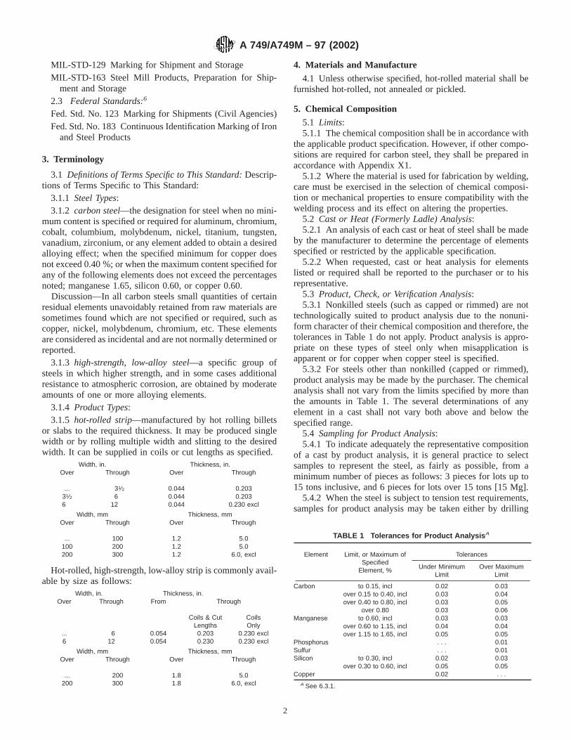
MIL-STD-129 Marking for Shipment and StorageMIL-STD-163 Steel Mill Products, Preparation for Ship-
ment and Storage2.3 Federal Standards:6
Fed. Std. No. 123 Marking for Shipments (Civil Agencies)Fed. Std. No. 183 Continuous Identification Marking of Iron
and Steel Products
3. Terminology
3.1 Definitions of Terms Specific to This Standard:Descrip-tions of Terms Specific to This Standard:
3.1.1 Steel Types:3.1.2 carbon steel—the designation for steel when no mini-
mum content is specified or required for aluminum, chromium,cobalt, columbium, molybdenum, nickel, titanium, tungsten,vanadium, zirconium, or any element added to obtain a desiredalloying effect; when the specified minimum for copper doesnot exceed 0.40 %; or when the maximum content specified forany of the following elements does not exceed the percentagesnoted; manganese 1.65, silicon 0.60, or copper 0.60.
Discussion—In all carbon steels small quantities of certainresidual elements unavoidably retained from raw materials aresometimes found which are not specified or required, such ascopper, nickel, molybdenum, chromium, etc. These elementsare considered as incidental and are not normally determined orreported.
3.1.3 high-strength, low-alloy steel—a specific group ofsteels in which higher strength, and in some cases additionalresistance to atmospheric corrosion, are obtained by moderateamounts of one or more alloying elements.
3.1.4 Product Types:3.1.5 hot-rolled strip—manufactured by hot rolling billets
or slabs to the required thickness. It may be produced singlewidth or by rolling multiple width and slitting to the desiredwidth. It can be supplied in coils or cut lengths as specified.
Width, in. Thickness, in.Over Through Over Through
... 31⁄2 0.044 0.20331⁄2 6 0.044 0.2036 12 0.044 0.230 excl
Width, mm Thickness, mmOver Through Over Through
... 100 1.2 5.0100 200 1.2 5.0200 300 1.2 6.0, excl
Hot-rolled, high-strength, low-alloy strip is commonly avail-able by size as follows:
Width, in. Thickness, in.Over Through From Through
Coils & CutLengths
CoilsOnly
...6
612
0.0540.054
0.2030.230
0.230 excl0.230 excl
Width, mm Thickness, mmOver Through Over Through
...200
200300
1.81.8
5.06.0, excl
4. Materials and Manufacture
4.1 Unless otherwise specified, hot-rolled material shall befurnished hot-rolled, not annealed or pickled.
5. Chemical Composition
5.1 Limits:5.1.1 The chemical composition shall be in accordance with
the applicable product specification. However, if other compo-sitions are required for carbon steel, they shall be prepared inaccordance with Appendix X1.
5.1.2 Where the material is used for fabrication by welding,care must be exercised in the selection of chemical composi-tion or mechanical properties to ensure compatibility with thewelding process and its effect on altering the properties.
5.2 Cast or Heat (Formerly Ladle) Analysis:5.2.1 An analysis of each cast or heat of steel shall be made
by the manufacturer to determine the percentage of elementsspecified or restricted by the applicable specification.
5.2.2 When requested, cast or heat analysis for elementslisted or required shall be reported to the purchaser or to hisrepresentative.
5.3 Product, Check, or Verification Analysis:5.3.1 Nonkilled steels (such as capped or rimmed) are not
technologically suited to product analysis due to the nonuni-form character of their chemical composition and therefore, thetolerances in Table 1 do not apply. Product analysis is appro-priate on these types of steel only when misapplication isapparent or for copper when copper steel is specified.
5.3.2 For steels other than nonkilled (capped or rimmed),product analysis may be made by the purchaser. The chemicalanalysis shall not vary from the limits specified by more thanthe amounts in Table 1. The several determinations of anyelement in a cast shall not vary both above and below thespecified range.
5.4 Sampling for Product Analysis:5.4.1 To indicate adequately the representative composition
of a cast by product analysis, it is general practice to selectsamples to represent the steel, as fairly as possible, from aminimum number of pieces as follows: 3 pieces for lots up to15 tons inclusive, and 6 pieces for lots over 15 tons [15 Mg].
5.4.2 When the steel is subject to tension test requirements,samples for product analysis may be taken either by drilling
TABLE 1 Tolerances for Product Analysis A
Element Limit, or Maximum ofSpecified
Element, %
Tolerances
Under MinimumLimit
Over MaximumLimit
Carbon to 0.15, incl 0.02 0.03over 0.15 to 0.40, incl 0.03 0.04over 0.40 to 0.80, incl 0.03 0.05
over 0.80 0.03 0.06Manganese to 0.60, incl 0.03 0.03
over 0.60 to 1.15, incl 0.04 0.04over 1.15 to 1.65, incl 0.05 0.05
Phosphorus . . . 0.01Sulfur . . . 0.01Silicon to 0.30, incl 0.02 0.03
over 0.30 to 0.60, incl 0.05 0.05Copper 0.02 . . .
A See 6.3.1.
A 749/A749M – 97 (2002)
2

entirely through the used tension test specimens themselves orin accordance with 5.4.3.
5.4.3 When the steel is not subject to tension test require-ments, the samples for analysis must be taken by milling ordrilling entirely through the strip in a sufficient number ofplaces so that the samples are representative of the entire strip.The sampling may be facilitated by folding the strip both ways,so that several samples may be taken at one drilling. Steelsubjected to certain heating operations by the purchaser maynot give chemical analysis results that properly represent itsoriginal composition. Therefore, users must analyze chipstaken from the steel in the condition in which it is receivedfrom the steel manufacturer.
5.5 Specimen Preparation—Drillings or chips must betaken without the application of water, oil, or other lubricant,and must be free of scale, grease, dirt, or other foreignsubstances. They must not be overheated during cutting to theextent of causing decarburization. Chips must be well mixed,and those too coarse to pass a No. 10 (2.00-mm) sieve or toofine to remain on a No. 30 (600-µm) sieve are not suitable forproper analysis. Sieve size numbers are in accordance withSpecification E 11.
5.6 Test Methods—In case a referee analysis is required andagreed upon to resolve a dispute concerning the results of achemical analysis, the procedure for performing the refereeanalysis must be in accordance with the latest issue of TestMethods, Practices, and Terminology A 751, unless otherwiseagreed upon between the manufacturer and the purchaser.
6. Mechanical Properties
6.1 The mechanical property requirements, number ofspecimens, test locations, and specimen orientation shall be inaccordance with the applicable product specification.
6.2 Unless otherwise specified in the applicable productspecification, test specimens must be prepared in accordancewith Test Methods and Definitions A 370.
6.3 Mechanical tests shall be conducted in accordance withTest Methods and Definitions A 370.
6.4 Bend tests, where required, shall be conducted incompliance with Test Methods E 290.
6.5 To determine conformance with the product specifica-tion, a calculated value should be rounded to the nearest 1 ksi[7 MPa] tensile strength and yield point or yield strength, andto the nearest unit in the right hand place of figures used inexpressing the limiting value for other values in accordancewith the rounding off method given in Practice E 29.
6.6 Structural steels are commonly fabricated by cold bend-ing. There are many interrelated factors that affect the ability ofa given steel to cold form over a given radius under shopconditions. These factors include thickness, strength level,degree of restraint, relationship to rolling direction, chemistry,and microstructure. Each of the appropriate product specifica-tions lists in the appendix the suggested minimum inside radiusfor cold bending. These radii should be used as minima for 90°bends. They presuppose “hard way” bending (bend axisparallel to rolling direction) and reasonably good shop formingpractices. Where possible, the use of larger radii or “easy way”bends are recommended for improved performance.
7.7 Fabricators should be aware that cracks may initiate
upon bending a sheared or burned edge. This is not consideredto be a fault of the steel but is rather a function of the inducedcold-work or heat-affected zone.
7. Dimensions, Tolerances, and Allowances
7.1 Dimensions, tolerances, and allowances applicable toproducts covered by this specification are contained in Tables2-9 [Annex A1, Tables A1.1-A1.7]. The appropriate tolerancetables shall be identified in each individual specification.
8. Workmanship
8.1 Cut lengths shall have a workmanlike appearance andshall not have imperfections of a nature or degree for theproduct, the grade, and the quality ordered that will bedetrimental to the fabrication of the finished part.
8.2 Coils may contain some abnormal imperfections thatrender a portion of the coil unusable since the inspection ofcoils does not afford the producer the same opportunity toremove portions containing imperfections as in the case withcut lengths.
9. Finish and Condition
9.1 Hot-rolled strip has a surface with an oxide or scaleresulting from the hot-rolling operation. The oxide or scale canbe removed by pickling or blast cleaning when required forpress-work operations or welding. Hot-rolled and hot-rolleddescaled strip are not generally used for exposed parts wheresurface is of prime importance. However, hot-rolled surfacemight be of importance, as in the case of weathering steels forexposed parts.
9.1.1 Hot-rolled strip can be supplied with mill edges,square edges, or cut (slit) edges as specified.
9.1.1.1 Mill edges are the natural edges resulting from thehot-rolling operation and are generally round and smoothwithout any definite contour.
9.1.1.2 Square edges are the edges resulting from rollingthrough vertical edging rolls during the hot-rolling operations.These edges are square and smooth, with the corners slightlyrounded.
9.1.1.3 Cut (slit) edges are the normal edges that result fromthe shearing, slitting, or trimming of mill edges.
9.1.2 The ends of plain hot-rolled mill-edge coils areirregular in shape and are referred to as uncropped ends. Wheresuch ends are not acceptable, the purchaser’s order should sospecify. Processed coils such as pickled or blast cleaned aresupplied with square-cut ends.
9.2 Oiling:
TABLE 2 Index of Tables for Dimensions, Tolerances, andAllowances
Dimensions Table No.Inch-Pound Units
SI Units
Camber tolerances 8 A1.6Crown tolerances 5 A1.3Flatness tolerances 9 A1.7Length tolerances 7 A1.5Thickness tolerances 3, 4 A1.1, A 1.2Width tolerances 6 A1.4
A 749/A749M – 97 (2002)
3

9.2.1 Plain hot-rolled strip is customarily furnished notoiled. Oiling must be specified when required
9.2.2 Hot-rolled pickled or descaled strip is customarilyfurnished oiled. If the product is not to be oiled, it must be sospecified since the cleaned surface is prone to rusting.
10. General Requirements for Delivery
10.1 Products covered by this specification are produced toinch-pound or metric decimal thickness only.
10.2 Steel may be produced as ingot-cast or strand-cast.When different grades of strand-cast steel are sequentially cast,identification and separation of the transition material isrequired.
11. Retests
11.1 If any test specimen shows defective machining ordevelops flaws, it must be discarded and another specimensubstituted.
11.2 If the percentage of elongation of any tension testspecimen is less than that specified and any part of the fractureis more than3⁄4 in. [20 mm] from the center of the gage lengthof a 2-in. [50 mm] specimen or is outside the middle half of thegage length of an 8-in. [200 mm] specimen, as indicated byscribe scratches marked on the specimen before testing, a retestis allowed.
11.3 If a bend specimen fails, due to conditions of bendingmore severe than required by the specification, a retest ispermitted either on a duplicate specimen or on a remainingportion of the failed specimen.
12. Inspection
12.1 When the purchaser’s order stipulates that inspectionand test (except product analyses) for acceptance on the steelbe made prior to shipment from the mill, the manufacturer shallafford the purchaser’s inspector all reasonable facilities to
TABLE 3 Thickness Tolerances of Hot-Rolled Strip A (Carbon and High-Strength, Low-Alloy Steel)Ordered to Nominal Thickness
(Coils and Cut Lengths, Including Pickled)
NOTE 1—Micrometres used for measurement of thickness shall be constructed with either flat anvils having a minimum diameter of 0.188 in. orrounded anvils having a minimum radius of curvature of 0.100 in. Micrometres with pointed anvils are not suitable for thickness measurement.
Specified Width, in. Thickness Tolerance, Over and Under, in., for Specified Nominal Thickness, in.
Over Through Through 0.057Over 0.057 to
0.118, inclOver 0.118 to
0.187, inclOver 0.187 to
0.203, inclOver 0.203 to
0.230, excl
. . . 3½ 0.003 0.004 0.005 0.006 . . .3½ 6 0.003 0.005 0.005 0.006 . . .6 12 0.004 0.005 0.005 0.006 0.006
A Measurements for the above table are taken " in. from the edge of a strip on 1 in. or wider; and at any place on the strip when narrower than 1 in. The given tolerancesdo not include crown and therefore the tolerances for crown as shown in Table 5 are in addition to tolerances in Table 3.
TABLE 4 Thickness Tolerances of Hot-Rolled Strip A (Carbon and High-Strength, Low-Alloy Steel) Ordered to Minimum Thickness(Coils and Cut Lengths, Including Pickling)
NOTE 1—Micrometres used for measurement of thickness shall be constructed with either flat anvils having a minimum diameter of 0.188 in. orrounded anvils having a minimum radius of curvature of 0.100 in. Micrometres with pointed anvils are not suitable for thickness measurement.
Specified Width, in. Thickness Tolerance, Over Only, for Specified Minimum Thickness, in.
Over Through Through 0.057Over 0.057 to
0.118, inclOver 0.118 to
0.187, inclOver 0.187 to
0.203, inclOver 0.203 to
0.230, excl
. . . 31⁄2 0.006 0.008 0.010 0.012 . . .31⁄2 6 0.006 0.010 0.010 0.012 . . .6 12 0.008 0.010 0.010 0.012 0.012
A Measurements for the above table are taken " in. from the edge of a strip on 1 in. or wider; and at any place on the strip when narrower than 1 in. The given tolerancesdo not include crown and therefore the tolerances for crown as shown in Table 5 are in addition to tolerances in Table 4Table 4.
TABLE 5 Crown Tolerances of Hot-Rolled Strip (Carbon andHigh-Strength, Low-Alloy Steel)
(Coils and Cut Lengths, Including Pickled)Strip may be thicker at the center than at a point 3⁄8 in. from the
edge by the following amounts:
Specified Width, in. Crown Tolerance, Over Only, for SpecifiedMinimum Thickness, in.
Over ThroughThrough
0.118
Over 0.118to 0.187,
incl
Over 0.187to 0.230,
excl
. . . 31⁄2 0.002 0.002 0.00131⁄2 6 0.003 0.002 0.0026 12 0.004 0.003 0.003
TABLE 6 Width Tolerances of Hot-Rolled Strip (Carbon andHigh-Strength, Low-Alloy Steel)
(Coils and Cut Lengths, Including Pickled)
Specified Width,in.
Width Tolerance, Over andUnder, in.
Over ThroughMill Edge
and SquareEdge Strip
Cut Edge
Through0.109 in.
Over0.109 in.Through
0.230 excl
. . . 2 1⁄32 0.008 0.0162 5 3⁄64 0.008 0.0165 10 1⁄16 0.010 0.016
10 12 3⁄32 0.016 0.016
A 749/A749M – 97 (2002)
4

satisfy him that the steel is being produced and furnished inaccordance with the specification. Mill inspection by thepurchaser shall not interfere unnecessarily with the manufac-turer’s operation.
13. Rejection and Rehearing
13.1 Unless otherwise specified, any rejection shall bereported to the manufacturer within a reasonable time afterreceipt of material by the purchaser.
13.2 Material that is reported to be defective subsequent tothe acceptance at the purchaser’s works shall be set aside,adequately protected, and correctly identified. The manufac-turer shall be notified as soon as possible so that an investiga-tion may be initiated.
13.3 Samples that are representative of the rejected materialshall be made available to the manufacturer. In the event thatthe manufacturer is dissatisfied with the rejection, he mayrequest a rehearing.
14. Test Reports and Certification
14.1 When test reports are required by the purchase order orthe material specification, the supplier shall report the results ofall tests required by the material specification and the order.
14.2 When certification is required by the purchase order,the supplier shall furnish a certification that the material hasbeen manufactured and tested in accordance with the require-ments of the material specification.
14.3 A signature is not required on test reports or certifica-tions. However, the document shall clearly identify the orga-nization submitting the document. Notwithstanding the ab-sence of a signature, the organization submitting the documentis responsible for the content of the document.
14.4 When test reports are required, copies of the originalmaterial manufacturer’s test report shall be included with anysubsequent test report.
14.5 A material test report, certificate of inspection, orsimilar document printed from or used in electronic form froman electronic data interchange (EDI) transmission shall beregarded as having the same validity as a counterpart printed inthe certifier’s facility. The content of the EDI transmitteddocument must meet the requirements of the invoked ASTMstandard(s) and conform to any existing EDI agreement be-tween the purchaser and the supplier. Notwithstanding theabsence of a signature, the organization submitting the EDItransmission is responsible for the content of the report.
NOTE 2—The industry definition as invoked here is: EDI is thecomputer to computer exchange of business information in an agreed uponstandard format such as ANSI ASC X12.
15. Marking
15.1 As a minimum requirement, the material shall beidentified by having the manufacturer’s name, ASTM designa-tion, weight, purchaser’s order number, and material identifi-cation legibly stenciled on top of each lift or shown on a tagattached to each coil or shipping unit.
15.2 When specified in the contract or order, and for directprocurement by or direct shipment to the government, markingfor shipment, in addition to requirements specified in thecontract or order, shall be in accordance with MIL-STD-129for military agencies and in accordance with Fed. Std. No. 123for civil agencies.
15.3 For Government procurement by the Defense SupplyAgency, strip material shall be continuously marked for iden-tification in accordance with Fed. Std. No. 183.
15.4 Bar coding is acceptable as a supplementary identifi-cation method. Bar coding should be consistent with theAutomotive Industry Action Group (AIAG) standard preparedby the primary metals subcommittee of the AIAG bar codeproject team.
TABLE 7 Length Tolerances of Hot-Rolled Strip (Carbon and High-Strength Alloy)(Cut Lengths, Including Pickled)
Specified Widths, in.
Length Tolerances over Specified Length, ft for Widths Given, in. No Tolerance Under
To 5 ft, inclOver 5 to 10 ft,
inclOver 10 to 20 ft,
inclOver 20 to 30 ft,
inclOver 30 to 40 ft,
inclOver 40 ft,
incl
To 3, incl 1⁄4 " 1⁄2 3⁄4 1 11⁄2Over 3 to 6, incl 3⁄8 1⁄2 5⁄8 3⁄4 1 11⁄2Over 6 to 12, incl 1⁄2 3⁄4 1 11⁄4 11⁄2 13⁄4
TABLE 8 Camber Tolerances A of Hot-Rolled Strip(Carbon and High-Strength Low-Alloy)
(Coils and Cut Lengths, Including Pickled, Applicable to MillEdge, Square Edge, and Slit or Cut Edge)
NOTE 1— Camber is the deviation of a side edge from a straight line.The standard for measuring this deviation is based on any 8-ft length.B Itis obtained by placing an 8-ft straightedge on the concave side andmeasuring the maximum distance between the strip edge and the straight-edge.
For strip wider than 11⁄2in.—1⁄4 in. in any 8 ft.For strip 11⁄2 in. and narrower—1⁄2 in. in any 8 ft.
A When the camber tolerances shown in the above table are not suitable for aparticular purpose, hot-rolled strip is sometimes machine straightened.
B For strip less than 8 ft tolerances are to be established in each instance.A formula for calculating camber is as follows:
L2 3 C1
64 5 C2 in L
where:C1 = Camber in 8 ft andC2= Camber in any given lengthL.
TABLE 9 Flatness Tolerances of Hot-Rolled Strip(Carbon and High-Strength Low-Alloy)
It has not been practicable to formulate flatness tolerances for hot-rolled carbonstrip steel because of the wide range of widths and thicknesses, and variety ofchemical compositions, mechanical properties and types, produced in coils andcut lengths.
A 749/A749M – 97 (2002)
5

16. Packaging
16.1 Unless otherwise specified, the strip shall be packagedand loaded in accordance with Practices A 700.
16.2 When specified in the contract or order, and for directprocurement by or direct shipment to the government, whenLevel A is specified, preservation, packaging, and packing shallbe in accordance with the Level A requirements of MIL-STD-163.
16.3 When coils are ordered it is customary to specify aminimum or range of inside diameter, maximum outsidediameter, and a maximum coil weight, if required. The abilityof manufacturers to meet the maximum coil weights dependsupon individual mill equipment. When required, minimum coilweights are subject to negotiation.
17. Keywords
17.1 carbon; steel; strip
ANNEX
(Mandatory Information)
A1. PERMISSIBLE VARIATIONS IN DIMENSIONS AND MASS IN SI UNITS
A1.1 Listed in Tables A1.1-A1.7 are permissible varia-tions in dimensions and mass expressed in the International
System of Units (SI) terminology.
TABLE A1.1 Thickness Tolerances of Hot-Rolled Strip A (Carbon and High-Strength, Low-Alloy Steel) Ordered to Nominal Thickness(Coils and Cut Lengths, Including Pickled)
NOTE 1—Micrometres used for measurement of thickness shall be constructed with either flat anvils having a minimum diameter of 4.80 mm orrounded anvils having a minimum radius of curvature of 2.55 mm. Micrometres with pointed anvils are not suitable for thickness measurement.
Specified Width, mm Thickness Tolerance, Over and Under, mm, for Specified Nominal Thickness, mm
Over Through Through 1.5Over 1.5 to 3.0,
inclOver 3.0 to 4.5,
inclOver 4.5 to 5.0,
inclOver 5.0 to 6.0,
excl
. . . 100 0.08 0.10 0.13 0.15 . . .100 200 0.08 0.13 0.13 0.15 . . .200 300 0.10 0.13 0.13 0.15 0.15
A Measurements for the above table are taken 10 mm from the edge of a strip on 25 mm or wider; and at any place on the strip when narrower than 25 mm. The giventolerances do not include crown and therefore the tolerances for crown as shown in Table A1.3 are in addition to tolerances in Table A1.1.
A 749/A749M – 97 (2002)
6
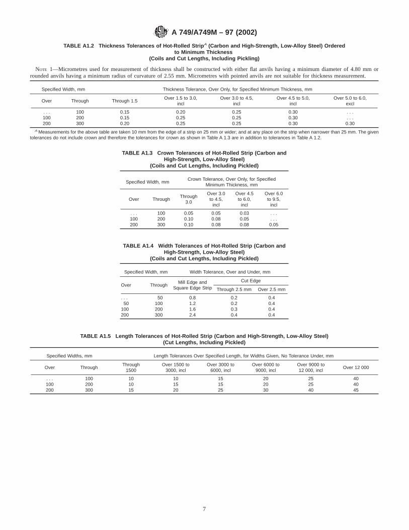
TABLE A1.2 Thickness Tolerances of Hot-Rolled Strip A (Carbon and High-Strength, Low-Alloy Steel) Orderedto Minimum Thickness
(Coils and Cut Lengths, Including Pickling)
NOTE 1—Micrometres used for measurement of thickness shall be constructed with either flat anvils having a minimum diameter of 4.80 mm orrounded anvils having a minimum radius of curvature of 2.55 mm. Micrometres with pointed anvils are not suitable for thickness measurement.
Specified Width, mm Thickness Tolerance, Over Only, for Specified Minimum Thickness, mm
Over Through Through 1.5Over 1.5 to 3.0,
inclOver 3.0 to 4.5,
inclOver 4.5 to 5.0,
inclOver 5.0 to 6.0,
excl
. . . 100 0.15 0.20 0.25 0.30 . . .100 200 0.15 0.25 0.25 0.30 . . .200 300 0.20 0.25 0.25 0.30 0.30
A Measurements for the above table are taken 10 mm from the edge of a strip on 25 mm or wider; and at any place on the strip when narrower than 25 mm. The giventolerances do not include crown and therefore the tolerances for crown as shown in Table A 1.3 are in addition to tolerances in Table A 1.2.
TABLE A1.3 Crown Tolerances of Hot-Rolled Strip (Carbon andHigh-Strength, Low-Alloy Steel)
(Coils and Cut Lengths, Including Pickled)
Specified Width, mmCrown Tolerance, Over Only, for Specified
Minimum Thickness, mm
Over ThroughThrough
3.0
Over 3.0to 4.5,
incl
Over 4.5to 6.0,
incl
Over 6.0to 9.5,
incl
. . . 100 0.05 0.05 0.03 . . .100 200 0.10 0.08 0.05 . . .200 300 0.10 0.08 0.08 0.05
TABLE A1.4 Width Tolerances of Hot-Rolled Strip (Carbon andHigh-Strength, Low-Alloy Steel)
(Coils and Cut Lengths, Including Pickled)
Specified Width, mm Width Tolerance, Over and Under, mm
Over ThroughMill Edge and
Square Edge Strip
Cut Edge
Through 2.5 mm Over 2.5 mm
. . . 50 0.8 0.2 0.450 100 1.2 0.2 0.4
100 200 1.6 0.3 0.4200 300 2.4 0.4 0.4
TABLE A1.5 Length Tolerances of Hot-Rolled Strip (Carbon and High-Strength, Low-Alloy Steel)(Cut Lengths, Including Pickled)
Specified Widths, mm Length Tolerances Over Specified Length, for Widths Given, No Tolerance Under, mm
Over ThroughThrough
1500Over 1500 to
3000, inclOver 3000 to
6000, inclOver 6000 to
9000, inclOver 9000 to12 000, incl
Over 12 000
. . . 100 10 10 15 20 25 40100 200 10 15 15 20 25 40200 300 15 20 25 30 40 45
A 749/A749M – 97 (2002)
7

APPENDIX
(Nonmandatory Information)
X1. STANDARD CHEMICAL RANGES AND LIMITS
X1.1 Standard chemical ranges and limits are prescribedfor carbon steels in Table X1.1
TABLE X1.1 Standard Chemical Ranges and Limits
NOTE 1—The carbon ranges shown in the column headed “Range” apply when the specified maximum limit for manganese does not exceed 1.00 %.When the maximum manganese limit exceeds 1.00 %, add 0.01 to the carbon ranges shown below.
Element Carbon Steels Only, Cast or Heat Analysis
Minimum of Specified Element, % Range Lowest, max
Carbon (see Note) to 0.15, incl 0.05 0.08over 0.15 to 0.30, incl 0.06over 0.30 to 0.40, incl 0.07over 0.40 to 0.60, incl 0.08over 0.60 to 0.80, incl 0.11over 0.80 to 1.35, incl 0.14
Manganese to 0.50, incl 0.20 0.40over 0.50 to 1.15, incl 0.30over 1.15 to 1.65, incl 0.35
Phosphorus to 0.08, incl 0.03 0.030A
over 0.08 to 0.15, incl 0.05Sulfur to 0.08, incl 0.03 0.035A
over 0.08 to 0.15, incl 0.05over 0.15 to 0.23, incl 0.07over 0.23 to 0.33, incl 0.10
Silicon to 0.15, incl 0.08 0.10over 0.15 to 0.30, incl 0.15over 0.30 to 0.60, incl 0.30
Copper When copper is required 0.20 min is commonly specified.
A Certain individual specifications provide for lower standard limits for phosphorus and sulfur.
TABLE A1.6 Camber Tolerances A of Hot-Rolled Strip (Carbonand High-Strength Low-Alloy)
(Coils and Cut Lengths, Including Pickled, Applicable to MillEdge, Square Edge, and Slit or Cut Edge)
NOTE 1—Camber is the deviation of a side edge from a straight line.The standard for measuring this deviation is based on any 2000-mmlength.B It is obtained by placing a 2000-mm straightedge on the concaveside and measuring the maximum distance between the strip edge and thestraightedge.
For strip wider than 50 mm—5.0 mm in any 2000 mmFor strip 50 mm and narrower—10.0 mm in any 2000 mm
A When the camber tolerances shown in the above table are not suitable for aparticular purpose, hot-rolled strip is sometimes machine straightened.
B For strip less than 2000 mm tolerances are to be established in each instance.
TABLE A1.7 Flatness Tolerances of Hot-Rolled Strip (Carbonand High-Strength Low-Alloy)
It has not been practicable to formulate flatness tolerances for hot-rolled stripbecause of the wide range of widths and thicknesses, and variety of chemicalcompositions and qualities, produced in coils and cut lengths.
A 749/A749M – 97 (2002)
8

ASTM International takes no position respecting the validity of any patent rights asserted in connection with any item mentionedin this standard. Users of this standard are expressly advised that determination of the validity of any such patent rights, and the riskof infringement of such rights, are entirely their own responsibility.
This standard is subject to revision at any time by the responsible technical committee and must be reviewed every five years andif not revised, either reapproved or withdrawn. Your comments are invited either for revision of this standard or for additional standardsand should be addressed to ASTM International Headquarters. Your comments will receive careful consideration at a meeting of theresponsible technical committee, which you may attend. If you feel that your comments have not received a fair hearing you shouldmake your views known to the ASTM Committee on Standards, at the address shown below.
This standard is copyrighted by ASTM International, 100 Barr Harbor Drive, PO Box C700, West Conshohocken, PA 19428-2959,United States. Individual reprints (single or multiple copies) of this standard may be obtained by contacting ASTM at the aboveaddress or at 610-832-9585 (phone), 610-832-9555 (fax), or [email protected] (e-mail); or through the ASTM website(www.astm.org).
A 749/A749M – 97 (2002)
9

Designation: A 752 – 04
Standard Specification forGeneral Requirements for Wire Rods and Coarse RoundWire, Alloy Steel 1
This standard is issued under the fixed designation A 752; the number immediately following the designation indicates the year oforiginal adoption or, in the case of revision, the year of last revision. A number in parentheses indicates the year of last reapproval. Asuperscript epsilon (e) indicates an editorial change since the last revision or reapproval.
1. Scope*
1.1 This specification covers general requirements for alloysteel rods and uncoated coarse round alloy wire in coils that arenot required to meet hardenability band limits.
1.2 In case of conflict, the requirements in the purchaseorder, on the drawing, in the individual specification, and inthis general specification shall prevail in the sequence named.
1.3 The values stated in inch-pound units are to be regardedas the standard.
2. Referenced Documents
2.1 ASTM Standards:2
A 370 Test Methods and Definitions for Mechanical Testingof Steel Products
A 700 Practices for Packaging, Marking, and LoadingMethods for Steel Products for Domestic Shipment
A 919 Terminology Relating to Heat Treatment of Metals3
E 29 Practice for Using Significant Digits in Test Data toDetermine Conformance with Specifications
E 30 Test Methods for Chemical Analysis of Steel, CastIron, Open-Hearth Iron, and Wrought Iron3
E 112 Test Methods for Determining Average Grain Size2.2 AIAG Standard:AIAGB-5 02.00 Primary Metals Identification Tag Applica-
tion Standard4
3. Terminology
3.1 Description of Terms Specific to This Standard:3.1.1 alloy steel— steel is considered to be alloy steel when
the maximum of the range given for the content of alloyingelements exceeds one or more of the following limits: manga-nese 1.65 %, silicon 0.60 %, copper 0.60 %; or in which adefinite range or a definite minimum quantity of any of thefollowing elements is specified or required within the limits ofthe recognized field of constructional alloy steels: aluminum,chromium up to 3.99 %, cobalt, columbium, molybdenum,nickel, titanium, tungsten, vanadium, zirconium, or any otheralloying elements added to obtain a desired alloying effect.Note that aluminum, columbium, and vanadium may also beused for grain refinement purposes.
3.1.1.1 Boron treatment of alloy steels, which are fine grain,may be specified to improve hardenability.
3.1.1.2 Other elements, such as lead, selenium, tellurium, orbismuth, may be specified to improve machinability.
3.1.2 coarse round wire—from 0.035 to 0.999 in. (0.89 to25.4 mm) in diameter, inclusive, wire produced from hot-rolledwire rods or hot-rolled coiled bars by one or more coldreductions primarily for the purpose of obtaining a desired sizewith dimensional accuracy, surface finish, and mechanicalproperties. By varying the amount of cold reduction and otherwire mill practices, including thermal treatment, a wide diver-sity of mechanical properties and finishes are made available.
3.1.2.1 Coarse round wire is designated by common frac-tions or decimal parts of an inch, or millimetres.
3.1.3 wire rods—rods that are hot rolled from billets into anapproximate round cross section and into coils of one continu-ous length. Rods are not comparable to hot-rolled bars inaccuracy of cross section or surface finish and as a semi-finished product are primarily for the manufacture of wire.
3.1.3.1 Rod sizes from7⁄32 to 47⁄64 in. (5.6 to 18.7 mm) indiameter, inclusive, are designated by fractions or decimalparts of an inch as shown in Table 1.
1 This specification is under the jurisdiction of ASTM Committee A01 on Steel,Stainless Steel and Related Alloys, and is the direct responsibility of SubcommitteeA01.03 on Steel Rod and Wire.
Current edition approved March 1, 2004. Published March 2004. Originallyapproved in 1977. Last previous edition approved in 2003 as A 752 – 93 (2003).
2 For referenced ASTM standards, visit the ASTM website, www.astm.org, orcontact ASTM Customer Service at [email protected]. ForAnnual Book of ASTMStandardsvolume information, refer to the standard’s Document Summary page onthe ASTM website.
3 Withdrawn.4 Available from Automotive Industry Action Group (AIAG), 26200 Lahser Rd.,
Suite 200, Southfield, MI 48034.
1
*A Summary of Changes section appears at the end of this standard.
Copyright © ASTM International, 100 Barr Harbor Drive, PO Box C700, West Conshohocken, PA 19428-2959, United States.

TABLE 1 Sizes of Alloy Steel Wire Rods
InchFraction
DecimalEquivalent,
in.
MetricEquivalent,
mm
InchFraction
DecimalEquivalent,
in.
MetricEquivalent,
mm
7⁄32 0.219 5.6 31⁄64 0.484 12.315⁄64 0.234 6.0 1⁄2 0.500 12.71⁄4 0.250 6.4 33⁄64 0.516 13.1
17⁄64 0.266 6.7 17⁄32 0.531 13.59⁄32 0.281 7.1 35⁄64 0.547 13.9
19⁄64 0.297 7.5 9⁄16 0.562 14.35⁄16 0.312 7.9 37⁄64 0.578 14.7
21⁄64 0.328 8.3 19⁄32 0.594 15.111⁄32 0.344 8.7 39⁄64 0.609 15.523⁄64 0.359 9.1 5⁄8 0.625 15.93⁄8 0.375 9.5 41⁄64 0.641 16.3
25⁄64 0.391 9.9 21⁄32 0.656 16.713⁄32 0.406 10.3 43⁄64 0.672 17.127⁄64 0.422 10.7 11⁄16 0.688 17.5
7⁄16 0.438 11.1 45⁄64 0.703 17.929⁄64 0.453 11.5 23⁄32 0.719 18.315⁄32 0.469 11.9 47⁄64 0.734 18.7
4. Ordering Information
4.1 It shall be the responsibility of the purchaser to specifyall requirements that are necessary for hot-rolled wire rodsunder this specification. Such requirements include, but are notlimited to, the following:
4.1.1 Quantity (pounds),4.1.2 Name of material (wire rods),4.1.3 Diameter (Table 1),4.1.4 Chemical composition grade number (Table 2),4.1.5 Thermal treatment, if required,4.1.6 Packaging, and4.1.7 ASTM designation and date of issue.
NOTE 1—A typical ordering description is as follows: 80 000 lbHot-Rolled Alloy Steel Wire Rods,1⁄4 in., Grade 4135 in 2 000-lbmaximum coils to ASTM A 752-XX.
4.2 It shall be the responsibility of the purchaser to specifyall requirements that are necessary for coarse round wire underthis specification. Such requirements include, but are notlimited to, the following:
4.2.1 Quantity (pounds),4.2.2 Name of material (alloy steel wire),4.2.3 Diameter (see 3.1.3.1),4.2.4 Chemical composition (Table 2 or Table 3),4.2.5 Thermal treatment, if required,4.2.6 Packaging,4.2.7 ASTM designation A 752 and date of issue, and4.2.8 Special requirements, if any.
NOTE 2—A typical ordering description is as follows: 40 000 lb, AlloySteel Wire, 0.312 in. diameter, Grade 8620, annealed at finish size, in500-lb Catch Weight Coils on Tubular Carriers to ASTM A 752-XX.
TABLE 2 Chemical Composition Ranges and Limits for Cast or Heat Analysis
NOTE 1—Grades shown in this table with prefix letter E are normally only made by the basic electric furnace process. All others are normallymanufactured by the basic open hearth or basic oxygen processes but may be manufactured by a basic electric furnace process. If the electric furnaceprocess is specified or required for grades other than those designated above, the limits for phosphorus and sulfur are respectively 0.025 % max.
NOTE 2—Small quantities of certain elements, which are not specified or required, are present in alloy steels. These elements are considered asincidental and may be present to the following maximum amounts: copper, 0.35 %, nickel, 0.25 %, chromium, 0.20 %, molybdenum, 0.06 %.
NOTE 3—Where minimum and maximum sulfur content is shown it is indicative of resulfurized steel.
NOTE 4—The chemical ranges and limits shown in Table 2 are produced to check, product, or verification analysis tolerances shown in Table 4.
NOTE 5—Standard alloy steels can be produced with a lead range of 0.15 to 0.35 %. Such steels are identified by inserting the letter “L’’ between thesecond and third numerals of the Grade number, for example, 41L40. Lead is reported only as a range of 0.15 to 0.35 % since it is added to the moldas the steel is poured.
UNS Desig-nation
Grade No.
Chemical Composition, Ranges and Limits, %
Carbon ManganesePhos-
phorus,max
Sulfur,max
Silicon Nickel ChromiumMolyb-denum
STANDARD ALLOY STEELS
G13300 1330 0.28 to 0.33 1.60 to 1.90 0.035 0.040 0.15 to 0.30 . . . . . . . . .G13350 1335 0.33 to 0.38 1.60 to 1.90 0.035 0.040 0.15 to 0.30 . . . . . . . . .G13400 1340 0.38 to 0.43 1.60 to 1.90 0.035 0.040 0.15 to 0.30 . . . . . . . . .G13450 1345 0.43 to 0.48 1.60 to 1.90 0.035 0.040 0.15 to 0.30 . . . . . . . . .G40120 4012 0.09 to 0.14 0.75 to 1.00 0.035 0.040 0.15 to 0.30 . . . . . . 0.15 to 0.25G40230 4023 0.20 to 0.25 0.70 to 0.90 0.035 0.040 0.15 to 0.30 . . . . . . 0.20 to 0.30G40240 4024 0.20 to 0.25 0.70 to 0.90 0.035 0.035 to
0.0500.15 to 0.30 . . . . . . 0.20 to 0.30
A 752 – 04
2
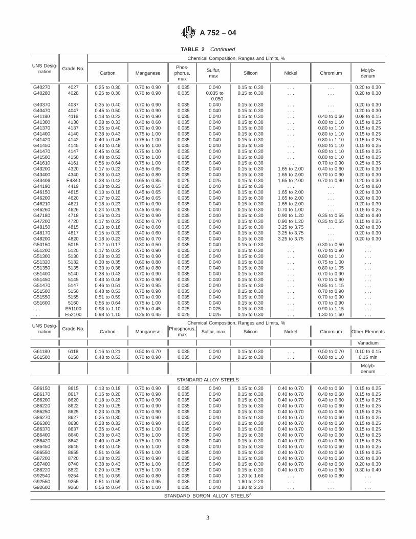
TABLE 2 Continued
UNS Desig-nation
Grade No.
Chemical Composition, Ranges and Limits, %
Carbon ManganesePhos-
phorus,max
Sulfur,max
Silicon Nickel ChromiumMolyb-denum
G40270 4027 0.25 to 0.30 0.70 to 0.90 0.035 0.040 0.15 to 0.30 . . . . . . 0.20 to 0.30G40280 4028 0.25 to 0.30 0.70 to 0.90 0.035 0.035 to
0.0500.15 to 0.30 . . . . . . 0.20 to 0.30
G40370 4037 0.35 to 0.40 0.70 to 0.90 0.035 0.040 0.15 to 0.30 . . . . . . 0.20 to 0.30G40470 4047 0.45 to 0.50 0.70 to 0.90 0.035 0.040 0.15 to 0.30 . . . . . . 0.20 to 0.30G41180 4118 0.18 to 0.23 0.70 to 0.90 0.035 0.040 0.15 to 0.30 . . . 0.40 to 0.60 0.08 to 0.15G41300 4130 0.28 to 0.33 0.40 to 0.60 0.035 0.040 0.15 to 0.30 . . . 0.80 to 1.10 0.15 to 0.25G41370 4137 0.35 to 0.40 0.70 to 0.90 0.035 0.040 0.15 to 0.30 . . . 0.80 to 1.10 0.15 to 0.25G41400 4140 0.38 to 0.43 0.75 to 1.00 0.035 0.040 0.15 to 0.30 . . . 0.80 to 1.10 0.15 to 0.25G41420 4142 0.40 to 0.45 0.75 to 1.00 0.035 0.040 0.15 to 0.30 . . . 0.80 to 1.10 0.15 to 0.25G41450 4145 0.43 to 0.48 0.75 to 1.00 0.035 0.040 0.15 to 0.30 . . . 0.80 to 1.10 0.15 to 0.25G41470 4147 0.45 to 0.50 0.75 to 1.00 0.035 0.040 0.15 to 0.30 . . . 0.80 to 1.10 0.15 to 0.25G41500 4150 0.48 to 0.53 0.75 to 1.00 0.035 0.040 0.15 to 0.30 . . . 0.80 to 1.10 0.15 to 0.25G41610 4161 0.56 to 0.64 0.75 to 1.00 0.035 0.040 0.15 to 0.30 . . . 0.70 to 0.90 0.25 to 0.35G43200 4320 0.17 to 0.22 0.45 to 0.65 0.035 0.040 0.15 to 0.30 1.65 to 2.00 0.40 to 0.60 0.20 to 0.30G43400 4340 0.38 to 0.43 0.60 to 0.80 0.035 0.040 0.15 to 0.30 1.65 to 2.00 0.70 to 0.90 0.20 to 0.30G43406 E4340 0.38 to 0.43 0.65 to 0.85 0.025 0.025 0.15 to 0.30 1.65 to 2.00 0.70 to 0.90 0.20 to 0.30G44190 4419 0.18 to 0.23 0.45 to 0.65 0.035 0.040 0.15 to 0.30 . . . . . . 0.45 to 0.60G46150 4615 0.13 to 0.18 0.45 to 0.65 0.035 0.040 0.15 to 0.30 1.65 to 2.00 . . . 0.20 to 0.30G46200 4620 0.17 to 0.22 0.45 to 0.65 0.035 0.040 0.15 to 0.30 1.65 to 2.00 . . . 0.20 to 0.30G46210 4621 0.18 to 0.23 0.70 to 0.90 0.035 0.040 0.15 to 0.30 1.65 to 2.00 . . . 0.20 to 0.30G46260 4626 0.24 to 0.29 0.45 to 0.65 0.035 0.040 0.15 to 0.30 0.70 to 1.00 . . . 0.15 to 0.25G47180 4718 0.16 to 0.21 0.70 to 0.90 0.035 0.040 0.15 to 0.30 0.90 to 1.20 0.35 to 0.55 0.30 to 0.40G47200 4720 0.17 to 0.22 0.50 to 0.70 0.035 0.040 0.15 to 0.30 0.90 to 1.20 0.35 to 0.55 0.15 to 0.25G48150 4815 0.13 to 0.18 0.40 to 0.60 0.035 0.040 0.15 to 0.30 3.25 to 3.75 . . . 0.20 to 0.30G48170 4817 0.15 to 0.20 0.40 to 0.60 0.035 0.040 0.15 to 0.30 3.25 to 3.75 . . . 0.20 to 0.30G48200 4820 0.18 to 0.23 0.50 to 0.70 0.035 0.040 0.15 to 0.30 3.25 to 3.75 . . . 0.20 to 0.30G50150 5015 0.12 to 0.17 0.30 to 0.50 0.035 0.040 0.15 to 0.30 . . . 0.30 to 0.50 . . .G51200 5120 0.17 to 0.22 0.70 to 0.90 0.035 0.040 0.15 to 0.30 . . . 0.70 to 0.90 . . .G51300 5130 0.28 to 0.33 0.70 to 0.90 0.035 0.040 0.15 to 0.30 . . . 0.80 to 1.10 . . .G51320 5132 0.30 to 0.35 0.60 to 0.80 0.035 0.040 0.15 to 0.30 . . . 0.75 to 1.00 . . .G51350 5135 0.33 to 0.38 0.60 to 0.80 0.035 0.040 0.15 to 0.30 . . . 0.80 to 1.05 . . .G51400 5140 0.38 to 0.43 0.70 to 0.90 0.035 0.040 0.15 to 0.30 . . . 0.70 to 0.90 . . .G51450 5145 0.43 to 0.48 0.70 to 0.90 0.035 0.040 0.15 to 0.30 . . . 0.70 to 0.90 . . .G51470 5147 0.46 to 0.51 0.70 to 0.95 0.035 0.040 0.15 to 0.30 . . . 0.85 to 1.15 . . .G51500 5150 0.48 to 0.53 0.70 to 0.90 0.035 0.040 0.15 to 0.30 . . . 0.70 to 0.90 . . .G51550 5155 0.51 to 0.59 0.70 to 0.90 0.035 0.040 0.15 to 0.30 . . . 0.70 to 0.90 . . .G51600 5160 0.56 to 0.64 0.75 to 1.00 0.035 0.040 0.15 to 0.30 . . . 0.70 to 0.90 . . .. . . E51100 0.98 to 1.10 0.25 to 0.45 0.025 0.025 0.15 to 0.30 . . . 0.90 to 1.15 . . .. . . E52100 0.98 to 1.10 0.25 to 0.45 0.025 0.025 0.15 to 0.30 . . . 1.30 to 1.60 . . .
UNS Desig-nation
Grade No.Chemical Composition, Ranges and Limits, %
Carbon ManganesePhosphorus,
maxSulfur, max Silicon Nickel Chromium Other Elements
Vanadium
G61180 6118 0.16 to 0.21 0.50 to 0.70 0.035 0.040 0.15 to 0.30 . . . 0.50 to 0.70 0.10 to 0.15G61500 6150 0.48 to 0.53 0.70 to 0.90 0.035 0.040 0.15 to 0.30 . . . 0.80 to 1.10 0.15 min
Molyb-denum
STANDARD ALLOY STEELS
G86150 8615 0.13 to 0.18 0.70 to 0.90 0.035 0.040 0.15 to 0.30 0.40 to 0.70 0.40 to 0.60 0.15 to 0.25G86170 8617 0.15 to 0.20 0.70 to 0.90 0.035 0.040 0.15 to 0.30 0.40 to 0.70 0.40 to 0.60 0.15 to 0.25G86200 8620 0.18 to 0.23 0.70 to 0.90 0.035 0.040 0.15 to 0.30 0.40 to 0.70 0.40 to 0.60 0.15 to 0.25G86220 8622 0.20 to 0.25 0.70 to 0.90 0.035 0.040 0.15 to 0.30 0.40 to 0.70 0.40 to 0.60 0.15 to 0.25G86250 8625 0.23 to 0.28 0.70 to 0.90 0.035 0.040 0.15 to 0.30 0.40 to 0.70 0.40 to 0.60 0.15 to 0.25G86270 8627 0.25 to 0.30 0.70 to 0.90 0.035 0.040 0.15 to 0.30 0.40 to 0.70 0.40 to 0.60 0.15 to 0.25G86300 8630 0.28 to 0.33 0.70 to 0.90 0.035 0.040 0.15 to 0.30 0.40 to 0.70 0.40 to 0.60 0.15 to 0.25G86370 8637 0.35 to 0.40 0.75 to 1.00 0.035 0.040 0.15 to 0.30 0.40 to 0.70 0.40 to 0.60 0.15 to 0.25G86400 8640 0.38 to 0.43 0.75 to 1.00 0.035 0.040 0.15 to 0.30 0.40 to 0.70 0.40 to 0.60 0.15 to 0.25G86420 8642 0.40 to 0.45 0.75 to 1.00 0.035 0.040 0.15 to 0.30 0.40 to 0.70 0.40 to 0.60 0.15 to 0.25G86450 8645 0.43 to 0.48 0.75 to 1.00 0.035 0.040 0.15 to 0.30 0.40 to 0.70 0.40 to 0.60 0.15 to 0.25G86550 8655 0.51 to 0.59 0.75 to 1.00 0.035 0.040 0.15 to 0.30 0.40 to 0.70 0.40 to 0.60 0.15 to 0.25G87200 8720 0.18 to 0.23 0.70 to 0.90 0.035 0.040 0.15 to 0.30 0.40 to 0.70 0.40 to 0.60 0.20 to 0.30G87400 8740 0.38 to 0.43 0.75 to 1.00 0.035 0.040 0.15 to 0.30 0.40 to 0.70 0.40 to 0.60 0.20 to 0.30G88220 8822 0.20 to 0.25 0.75 to 1.00 0.035 0.040 0.15 to 0.30 0.40 to 0.70 0.40 to 0.60 0.30 to 0.40G92540 9254 0.51 to 0.59 0.60 to 0.80 0.035 0.040 1.20 to 1.60 . . . 0.60 to 0.80 . . .G92550 9255 0.51 to 0.59 0.70 to 0.95 0.035 0.040 1.80 to 2.20 . . . . . . . . .G92600 9260 0.56 to 0.64 0.75 to 1.00 0.035 0.040 1.80 to 2.20 . . . . . . . . .
STANDARD BORON ALLOY STEELSA
A 752 – 04
3

TABLE 2 Continued
UNS Desig-nation
Grade No.
Chemical Composition, Ranges and Limits, %
Carbon ManganesePhos-
phorus,max
Sulfur,max
Silicon Nickel ChromiumMolyb-denum
G50441 50B44 0.43 to 0.48 0.75 to 1.00 0.035 0.040 0.15 to 0.30 . . . 0.40 to 0.60 . . .G50461 50B46 0.44 to 0.49 0.75 to 1.00 0.035 0.040 0.15 to 0.30 . . . 0.20 to 0.35 . . .G50501 50B50 0.48 to 0.53 0.75 to 1.00 0.035 0.040 0.15 to 0.30 . . . 0.40 to 0.60 . . .G50601 50B60 0.56 to 0.64 0.75 to 1.00 0.035 0.040 0.15 to 0.30 . . . 0.40 to 0.60 . . .G51601 51B60 0.56 to 0.64 0.75 to 1.00 0.035 0.040 0.15 to 0.30 . . . 0.70 to 0.90 . . .G81451 81B45 0.43 to 0.48 0.75 to 1.00 0.035 0.040 0.15 to 0.30 0.20 to 0.40 0.35 to 0.55 0.08 to 0.15G94171 94B17 0.15 to 0.20 0.75 to 1.00 0.035 0.040 0.15 to 0.30 0.30 to 0.60 0.30 to 0.50 0.08 to 0.15G94301 94B30 0.28 to 0.33 0.75 to 1.00 0.035 0.040 0.15 to 0.30 0.30 to 0.60 0.30 to 0.50 0.08 to 0.15
A These steels can be expected to a minimum boron content of 0.0005 %.
5. Manufacture
5.1 The product of the steel making processes is either castinto ingots that are hot rolled to blooms or billets, or strand castdirectly into blooms or billets for subsequent processing intorods.
6. Chemical Composition
6.1 The chemical composition for alloy steel under thisspecification shall conform to the requirements set forth in thepurchase order. The grades commonly specified for alloy steelwire rods and alloy steel wire are shown in Table 2. Forspecified compositions not contained in Table 2 the ranges andlimits expressed in Table 3 shall apply unless other such rangesand limits shall have been agreed upon between the purchaserand the manufacturer.
6.2 Cast or Heat Analysis—An analysis of each cast or heatshall be made by the producer to determine the percentage ofthe elements specified. The analysis shall be made from a testsample preferably taken during the pouring of the cast or heat.The chemical composition thus determined shall be reported, ifrequired, to the purchaser or his representative.
6.3 Product Analysis—A product analysis may be made bythe purchaser. The analysis is not used for a duplicate analysis
to confirm a previous result. The purpose of the productanalysis is to verify that the chemical composition is withinspecified limits for each element, including applicable permis-sible variations in product analysis. The results of analysestaken from different pieces of a heat may differ withinpermissible limits from each other and from the heat analysis.Table 4 shows the permissible variations for product analysisof alloy steel. The results of the product analysis, except lead,shall not vary both above and below the specified ranges.
6.3.1 The location from which chips for product analysis areobtained is important because of normal segregation. For rodsand wire, chips must be taken by milling or machining the fullcross section of the sample.
6.3.1.1 Steel subjected to certain thermal treatments by thepurchaser may not give chemical analysis results that properlyrepresent its original composition. Therefore, purchasersshould analyze chips taken from the steel in the condition inwhich it is received from the producer.
6.3.1.2 When samples are returned to the producer forproduct analysis, the samples should consist of pieces of thefull cross section.
6.3.2 For referee purposes, Test Methods E 30 shall be used.
TABLE 3 Alloy Steels—Chemical Composition Ranges and Limits for Cast or Heat Analysis
NOTE 1—Boron steels can be expected to have a 0.0005 % minimum boron content.
NOTE 2—Alloy steels can be produced with a lead range of 0.15 to 0.35 %. Lead is reported only as a range of 0.15 to 0.35 % since it is added to themold as the steel is poured.
NOTE 3—The chemical ranges and limits of alloy steels are produced to the check, product, or verification analysis tolerances shown in Table 4.
ElementWhen Maximum ofSpecified Element
is, %
Range, %
MaximumLimit, %A
Open-Hearth
or BasicOxygen
Steel
ElectricFurnace
Steel
Carbon To 0.55, incl 0.05 0.05Over 0.55 to 0.70, incl 0.08 0.07Over 0.70 to 0.80, incl 0.10 0.09Over 0.80 to 0.95, incl 0.12 0.11Over 0.95 to 1.35, incl 0.13 0.12
Manganese To 0.60, incl 0.20 0.15Over 0.60 to 0.90, incl 0.20 0.20Over 0.90 to 1.05, incl 0.25 0.25Over 1.05 to 1.90, incl 0.30 0.30Over 1.90 to 2.10, incl 0.40 0.35
A 752 – 04
4

TABLE 3 Continued
ElementWhen Maximum ofSpecified Element
is, %
Range, %
MaximumLimit, %A
Open-Hearth
or BasicOxygen
Steel
ElectricFurnace
Steel
Phosphorus Basic open-hearth or ba-sic oxygen steelBasic electric furnacesteel
0.0350.025
Sulfur To 0.050, incl 0.015 0.015Over 0.050 to 0.07, incl 0.02 0.02Over 0.07 to 0.10, incl 0.04 0.04Over 0.10 to 0.14, incl 0.05 0.05 0.040Basic open hearth or ba-sic oxygen steel
0.025
Basic electric furnacesteel
Silicon To 0.15, incl 0.08 0.08Over 0.15 to 0.20, incl 0.10 0.10Over 0.20 to 0.40, incl 0.15 0.15Over 0.40 to 0.60, incl 0.20 0.20Over 0.60 to 1.00, incl 0.30 0.30Over 1.00 to 2.20, incl 0.40 0.35
Nickel To 0.50, incl 0.20 0.20Over 0.50 to 1.50, incl 0.30 0.30Over 1.50 to 2.00, incl 0.35 0.35Over 2.00 to 3.00, incl 0.40 0.40Over 3.00 to 5.30, incl 0.50 0.50Over 5.30 to 10.00, incl 1.00 1.00
Chromium To 0.40, incl 0.15 0.15Over 0.40 to 0.90, incl 0.20 0.20Over 0.90 to 1.05, incl 0.25 0.25Over 1.05 to 1.60, incl 0.30 0.30Over 1.60 to 1.75, incl B 0.35Over 1.75 to 2.10, incl B 0.40Over 2.10 to 3.99, incl B 0.50
Molybdenum To 0.10, incl 0.05 0.05Over 0.10 to 0.20, incl 0.07 0.07Over 0.20 to 0.50, incl 0.10 0.10Over 0.50 to 0.80, incl 0.15 0.15Over 0.80 to 1.15, incl 0.20 0.20
Tungsten To 0.50, inclOver 0.50 to 1.00, inclOver 1.00 to 2.00, inclOver 2.00 to 4.00, incl
0.200.300.500.60
0.200.300.500.60
Vanadium To 0.25, inclOver 0.25 to 0.50, incl
0.050.10
0.050.10
Aluminum Up to 0.10, incl 0.05 0.05Over 0.10 to 0.20, incl 0.10 0.10Over 0.20 to 0.30, incl 0.15 0.15Over 0.30 to 0.80, incl 0.25 0.25Over 0.80 to 1.30, incl 0.35 0.35Over 1.30 to 1.80, incl 0.45 0.45
Copper To 0.60, inclOver 0.60 to 1.50, inclOver 1.50 to 2.00, incl
0.200.300.35
0.200.300.35
A Applies to only nonrephosphorized and nonresulfurized steels.B Not normally produced in open hearth.
TABLE 4 Product or Verification Analysis Tolerances—Alloy Steels
ElementLimit or Maximum of Specified
Range, %Tolerance Over Maximum Limit
or Under Minimum Limit, %
Carbon To 0.30, inclOver 0.30 to 0.75, inclOver 0.75
0.010.020.03
Manganese To 0.90, inclOver 0.90 to 2.10, incl
0.030.04
Phosphorus Over max only 0.005
A 752 – 04
5
TABLE 4 Continued
ElementLimit or Maximum of Specified
Range, %Tolerance Over Maximum Limit
or Under Minimum Limit, %
Sulfur To 0.060, inclA 0.005Silicon To 0.40, incl
Over 0.40 to 2.20, incl0.020.05
Nickel To 1.00, incl 0.03Over 1.00 to 2.00, incl 0.05Over 2.00 to 5.30, incl 0.07Over 5.30 to 10.00, incl 0.10
Chromium To 0.90, inclOver 0.90 to 2.10, inclOver 2.10 to 3.99, incl
0.030.050.10
Molybdenum To 0.20, inclOver 0.20 to 0.40, inclOver 0.40 to 1.15, incl
0.010.020.03
Vanadium To 0.10, incl 0.01Over 0.10 to 0.25, incl 0.02Over 0.25 to 0.50, incl 0.03Min value specified, check undermin limit
0.01
Tungsten To 1.00, inclOver 1.00 to 4.00, incl
0.040.08
Aluminum Up to 0.10, incl 0.03Over 0.10 to 0.20, incl 0.04Over 0.20 to 0.30, incl 0.05Over 0.30 to 0.80, incl 0.07Over 0.80 to 1.80, incl 0.10
Lead 0.15 to 0.35, incl 0.03B
Copper To 1.00, inclOver 1.00 to 2.00, incl
0.030.05
A Sulfur over 0.060 % is not subject to check, product, or verification analysis.B Tolerance is over and under.
7. Metallurgical Structure
7.1 Grain size when specified shall be determined in accor-dance with the requirements of Test Methods E 112.
7.2 Alloy steel wire rods may be specified as annealed,spheroidize annealed, or patented. Refer to Terminology A 919for definitions.
7.3 Alloy steel wire may be specified as drawn fromannealed, spheroidize annealed or patented wire rod or bars;also as annealed, spheroidize annealed, patented, or oil tem-pered at finish size. Refer to Terminology A 919 for definitions.
8. Mechanical Properties
8.1 The properties enumerated in individual specificationsshall be determined in accordance with Test Methods andDefinitions A 370.
8.2 The maximum expected tensile strengths for the morecommon grades of alloy rods with regular mill annealing(non-spheroidized) are shown in Table 5.
8.3 Because of the great variety in the kinds and grades ofrods and wire and the extensive diversity of application, anumber of formal mechanical test procedures have beendeveloped. These tests are used as control tests by producersduring intermediate stages of wire processing, as well as forfinal testing of the finished product, and apply particularly torods and wire for specific applications. A number of these testsare further described in Supplement IV, Round Wire Products,of Test Methods and Definitions A 370.
8.4 Since the general utility of rods and wire requirecontinuity of length, in the case of rods, tests are commonly
made on samples taken from the ends of coils after removingtwo to three rings; in the case of wire, tests are commonlytaken from the ends of the coils, thereby not impairing theusefulness of the whole coil.
9. Dimensions and Permissible Variation
9.1 The diameter and out-of-roundness of the alloy wire rodshall not vary from that specified by more than that prescribedin Table 6.
9.2 The diameter and out-of-roundness of the alloy coarseround wire shall not vary from that specified by more than thatprescribed in Table 7.
10. Workmanship, Finish, and Appearance
10.1 The alloy wire rod shall be free from detrimentalsurface imperfections, tangles, and sharp kinks.
10.1.1 Two or more rod coils may be welded together toproduce a larger coil. The weld zone may not be as sound as theoriginal material. The mechanical properties existing in theweld zone may differ from those in the unaffected base metal.The weld may exceed the permissible variations for diameterand out-of-roundness on the minus side of the permissiblevariation but not on the plus side.
10.2 The wire as received shall be smooth and substantiallyfree of rust, shall not be kinked or improperly cast. Nodetrimental die marks or scratches may be present. Each coilshall be one continuous length of wire. Welds made during colddrawing are permitted.
A 752 – 04
6
TABLE 5 Maximum Expected Tensile Strengths for Annealed Alloy Steel Rods
NOTE 1—Specific microstructures such as spheroidize anneal or lamellar pearlite anneal may require modification of these tensile strength values.
UNS Desig-nation
Grade No.Tensile
Strength,ksi (MPa)
UNS Desig-nation
Grade No.Tensile
Strength,ksi (MPa)
G13300 1330 88 (610) G50501 50B50 97 (670)G13350 1335 90 (620) G50601 50B60 103 (710)G13400 1340 92 (630) G51200 5120 82 (570)G13450 1345 97 (670) G51300 5130 84 (580)G40120 4012 71 (490) G51320 5132 84 (580)G40230 4023 73 (500) G51350 5135 86 (590)G40240 4024 73 (500) G51400 5140 90 (620)G40270 4027 82 (570) G51450 5145 94 (650)G40280 4028 82 (570) G51470 5147 99 (680)G40370 4037 89 (610) G51500 5150 97 (670)G40470 4047 97 (670) G51550 5155 103 (710)G41180 4118 82 (570) G51600 5160 104 (720)G41300 4130 86 (590) G51601 51B60 109 (750)G41370 4137 92 (630) G61180 6118 80 (550)G41400 4140 94 (650) G61500 6150 97 (670)G41420 4142 97 (670) G81451 81B45 92 (630)G41450 4145 99 (680) G86150 8615 80 (550)G41470 4147 100 (690) G86170 8617 80 (550)G41500 4150 100 (690) G86200 8620 82 (570)G41610 4161 111 (770) G86220 8622 84 (580)G43200 4320 94 (650) G86250 8625 84 (580)G43400 4340 104 (720) G86270 8627 84 (580)G44190 4419 82 (570) G86300 8630 88 (610)G46150 4615 80 (550) G86370 8637 92 (630)G46200 4620 82 (570) G86400 8640 94 (650)G46210 4621 82 (570) G86420 8642 97 (670)G46260 4626 84 (580) G86450 8645 99 (680)G47180 4718 84 (580) G86550 8655 104 (720)G47200 4720 82 (570) G87200 8720 82 (570)G48150 4815 92 (630) G87400 8740 97 (670)G48170 4817 94 (650) G88220 8822 88 (610)G48200 4820 94 (650) G92540 9254 111 (770)G50150 5015 73 (500) G92550 9255 111 (770)G50441 50B44 94 (650) G92600 9260 111 (770)G50461 50B46 92 (630) G94171 94B17 73 (500)
G94301 94B30 84 (580)
11. Retests
11.1 The difficulties in obtaining truly representativesamples of wire rod and coarse round wire without destroyingthe usefulness of the coil account for the generally acceptedpractice of allowing retests for mechanical tests and surfaceexamination. An additional test piece is cut from each end ofthe coil from which the original sample was taken. A portion of
the coil may be discarded prior to cutting the sample for retest.If any of the retests fail to comply with the requirements, thecoil of rod or wire may be rejected. Before final rejection,however, it is frequently advisable to base the final decision onan actual trial of the material to determine whether or not it willperform the function for which it is intended.
TABLE 6 Permissible Variation in Diameter of Alloy Wire Rod in Coils
NOTE 1— For purposes of determining conformance with this specification, all specified limits in Table 6 are absolute limits as defined in Practice E 29.
Diameter of RodPermissibleVariation,Plus andMinus,
in. (mm)
PermissibleOut-of-Round
in. (mm)Fractions, in. Decimal, in. (mm)
7⁄32 to 47⁄64 , incl 0.219 to 0.734(5.6 to 18.7), incl
0.016(0.41)
0.025(0.64)
A 752 – 04
7
TABLE 7 Permissible Variation in Diameter for Alloy Coarse Round Wire
NOTE 1—For purposes of determining conformance with this specification, all specified limits in Table 7 are absolute limits as defined in Practice E 29.
Diameter of Wire, in. (mm)
PermissibleVariation,
Plus and Minus,in. (mm)
PermissibleOut-of-Round,
in. (mm)
0.035 to 0.075 (0.89 to 1.90), incl 0.001 (0.03) 0.001 (0.03)Over 0.075 to 0.148 (1.90 to 3.76),
incl0.0015 (0.04) 0.0015 (0.04)
Over 0.148 to 0.500 (3.76 to 12.70),incl
Over 0.500 to 0.625 (12.70 to15.87), incl
0.002 (0.05) 0.002 (0.05)
Over 0.625 (15.87)0.0025 (0.06) 0.0025 (0.06)
0.003 (0.08) 0.003 (0.08)
12. Inspection12.1 The manufacturer shall afford the purchaser’s inspector
all reasonable facilities necessary to satisfy him that thematerial is being produced and furnished in accordance withthis specification. Mill inspection by the purchaser shall notinterfere unnecessarily with the manufacturer’s operations. Alltests and inspections shall be made at the place of manufacture,unless otherwise agreed to.
13. Rejection and Rehearing13.1 Any rejection based on tests made in accordance with
this specification shall be reported to the manufacturer withina reasonable length of time. The material must be adequatelyprotected and correctly identified in order that the manufacturermay make a proper investigation.
14. Certification14.1 Upon request of the purchaser in the contract or order,
a manufacturer’s certification that the material was manufac-tured and tested in accordance with this specification, togetherwith a report of the test results, shall be furnished at the timeof shipment.
14.2 The certification shall include the specification num-ber, year date of issue, and revision letter, if any.
15. Packaging, Marking, and Loading
15.1 A tag shall be securely attached to each coil and shallbe marked with the size, heat number, grade number, ASTMspecification number, and name or mark of the manufacturer.
15.2 When specified in the purchase order, packaging,marking, and loading for shipment shall be in accordance withthose procedures recommended by Practices A 700.
15.3 Bar Coding—In addition to the previously-stated iden-tification requirements, bar coding is acceptable as a supple-mentary identification method. Bar coding should be consistentwith AIAG Standard 02.00, Primary Metals Identification TagApplication. The bar code may be applied to a substantiallyaffixed tag.
16. Keywords
16.1 alloy; coarse round wire; general; wire rods
SUMMARY OF CHANGES
Committee A01 has identified the location of selected changes to this standard since the last issue,A 752–93 (2003), that may impact the use of this standard. (Approved March 1, 2004.)
(1) Revised Sections 4.1 and 4.2 to eliminate non-mandatorylanguage.
A 752 – 04
8

ASTM International takes no position respecting the validity of any patent rights asserted in connection with any item mentionedin this standard. Users of this standard are expressly advised that determination of the validity of any such patent rights, and the riskof infringement of such rights, are entirely their own responsibility.
This standard is subject to revision at any time by the responsible technical committee and must be reviewed every five years andif not revised, either reapproved or withdrawn. Your comments are invited either for revision of this standard or for additional standardsand should be addressed to ASTM International Headquarters. Your comments will receive careful consideration at a meeting of theresponsible technical committee, which you may attend. If you feel that your comments have not received a fair hearing you shouldmake your views known to the ASTM Committee on Standards, at the address shown below.
This standard is copyrighted by ASTM International, 100 Barr Harbor Drive, PO Box C700, West Conshohocken, PA 19428-2959,United States. Individual reprints (single or multiple copies) of this standard may be obtained by contacting ASTM at the aboveaddress or at 610-832-9585 (phone), 610-832-9555 (fax), or [email protected] (e-mail); or through the ASTM website(www.astm.org).
A 752 – 04
9
Designation: A 752M – 04
METRIC
Standard Specification forGeneral Requirements for Wire Rods and Coarse RoundWire, Alloy Steel [Metric] 1
This standard is issued under the fixed designation A 752M; the number immediately following the designation indicates the year oforiginal adoption or, in the case of revision, the year of last revision. A number in parentheses indicates the year of last reapproval. Asuperscript epsilon (e) indicates an editorial change since the last revision or reapproval.
1. Scope*
1.1 This specification covers general requirements for alloysteel rods and uncoated coarse round alloy wire in coils that arenot required to meet hardenability band limits.
1.2 In case of conflict, the requirements in the purchaseorder, on the drawing, in the individual specification, and inthis general specification shall prevail in the sequence named.
NOTE 1—This specification is the metric counterpart of SpecificationA 752.
2. Referenced Documents
2.1 ASTM Standards:2
A 370 Test Methods and Definitions for Mechanical Testingof Steel Products
A 700 Practices for Packaging, Marking, and LoadingMethods for Steel Products for Domestic Shipment
A 751 Test Methods, Practices, and Terminology forChemical Analysis of Steel Products
A 919 Terminology Relating to Heat Treatment of MetalsE 29 Practice for Using Significant Digits in Test Data to
Determine Conformance with SpecificationsE 112 Test Methods for Determining Average Grain Size2.2 Military Standard:MIL-STD-163 Steel Mill Products, Preparation for Ship-
ment and Storage3
2.3 Federal Standard:Fed. Std. No. 123 Marking for Shipment (Civil Agencies)3
2.4 AIAG Standard:
AIAGB-5 02.00 Primary Metals Identification Tag Applica-tion Standard4
3. Terminology
3.1 Definitions of Terms Specific to This Standard:3.1.1 alloy steel—steel is considered to be alloy steel when
the maximum of the range given for the content of alloyingelements exceeds one or more of the following limits: manga-nese 1.65 %, silicon 0.60 %, copper 0.60 %; or in which adefinite range or a definite minimum quantity of any of thefollowing elements is specified or required within the limits ofthe recognized field of constructional alloy steels: chromiumup to 3.99 %, cobalt, columbium, molybdenum, nickel, tita-nium, tungsten, vanadium, zirconium, or any other alloyingelements added to obtain a desired alloying effect.
3.1.1.1 Boron treatment of alloy steels, which are fine grain,may be specified to improve hardenability.
3.1.1.2 Other elements, such as lead, selenium, tellurium, orbismuth, may be specified to improve machinability.
3.1.2 coarse round wire—from 0.90 to 25 mm in diameter,inclusive, wire produced from hot-rolled wire rods or hot-rolled coiled rounds by one or more cold reductions primarilyfor the purpose of obtaining a desired size with dimensionalaccuracy, surface finish, and mechanical properties. By varyingthe amount of cold reduction and other wire mill practices,including thermal treatment, a wide diversity of mechanicalproperties and finishes are made available. Suggested wirediameters are shown in Table 1.
3.1.3 straightened and cut wire—wire produced from coilsof wire by means of special machinery that straightens the wireand cuts it to a specified length.
3.1.3.1 The straightening operation may alter the mechani-cal properties of the wire, especially the tensile strength. Thestraightening operation may also induce changes in the diam-eter of the wire. The extent of the changes in the properties ofthe wire after cold straightening depends upon the kind of wire
1 This specification is under the jurisdiction of ASTM Committee A01 on Steel,Stainless Steel and Related Alloys and is the direct responsibility of SubcommitteeA01.03 on Steel Rod and Wire.
Current edition approved March 1, 2004. Published March 2004. Originallyapproved in 1983. Last previous edition approved in 2003 as A 752M – 93 (2003).
2 For referenced ASTM standards, visit the ASTM website, www.astm.org, orcontact ASTM Customer Service at [email protected]. ForAnnual Book of ASTMStandardsvolume information, refer to the standard’s Document Summary page onthe ASTM website.
3 Available from Standardization Documents Order Desk, Bldg. 4 Section D, 700Robbins Ave., Philadelphia, PA 19111-5094, Attn: NPODS.
4 Available from the Automotive Industry Action Group, 26200 Lahser, Suite200, Southfield, MI 48034.
1
*A Summary of Changes section appears at the end of this standard.
Copyright © ASTM International, 100 Barr Harbor Drive, PO Box C700, West Conshohocken, PA 19428-2959, United States.
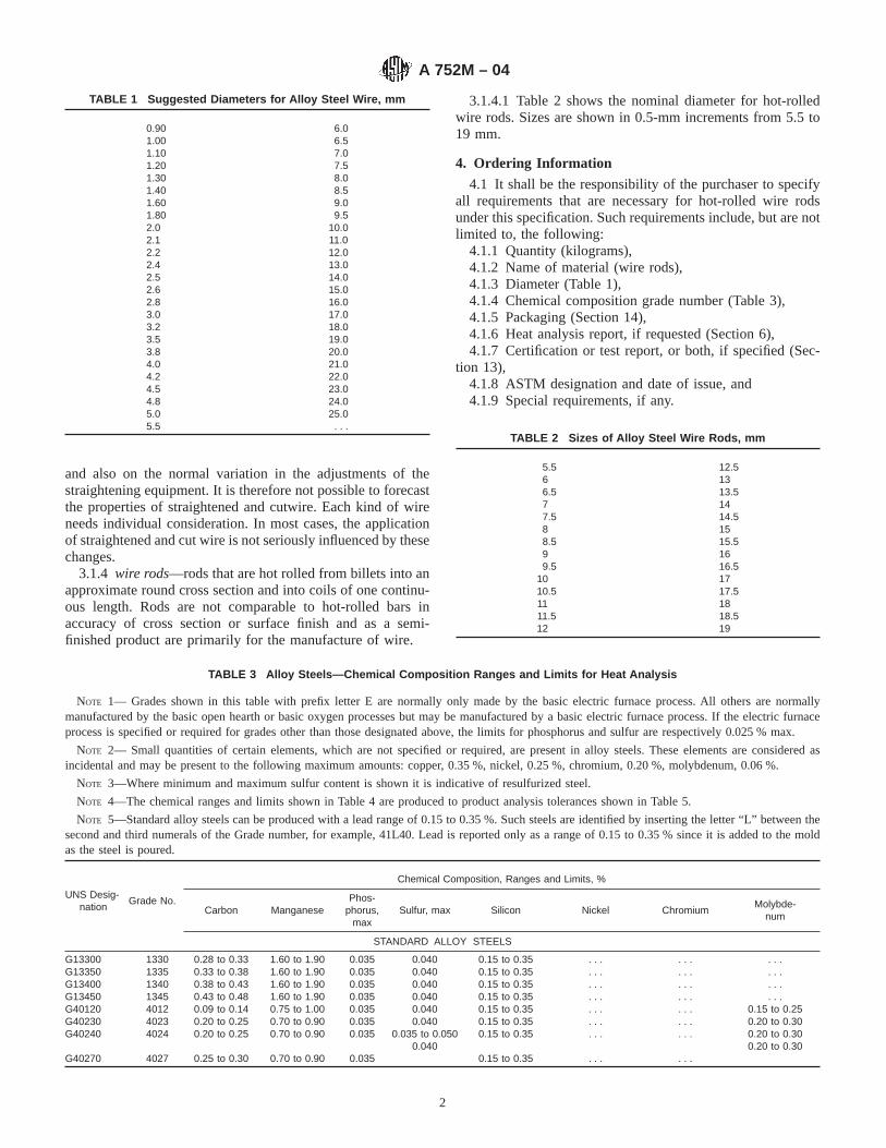
and also on the normal variation in the adjustments of thestraightening equipment. It is therefore not possible to forecastthe properties of straightened and cutwire. Each kind of wireneeds individual consideration. In most cases, the applicationof straightened and cut wire is not seriously influenced by thesechanges.
3.1.4 wire rods—rods that are hot rolled from billets into anapproximate round cross section and into coils of one continu-ous length. Rods are not comparable to hot-rolled bars inaccuracy of cross section or surface finish and as a semi-finished product are primarily for the manufacture of wire.
3.1.4.1 Table 2 shows the nominal diameter for hot-rolledwire rods. Sizes are shown in 0.5-mm increments from 5.5 to19 mm.
4. Ordering Information
4.1 It shall be the responsibility of the purchaser to specifyall requirements that are necessary for hot-rolled wire rodsunder this specification. Such requirements include, but are notlimited to, the following:
4.1.1 Quantity (kilograms),4.1.2 Name of material (wire rods),4.1.3 Diameter (Table 1),4.1.4 Chemical composition grade number (Table 3),4.1.5 Packaging (Section 14),4.1.6 Heat analysis report, if requested (Section 6),4.1.7 Certification or test report, or both, if specified (Sec-
tion 13),4.1.8 ASTM designation and date of issue, and4.1.9 Special requirements, if any.
TABLE 3 Alloy Steels—Chemical Composition Ranges and Limits for Heat Analysis
NOTE 1— Grades shown in this table with prefix letter E are normally only made by the basic electric furnace process. All others are normallymanufactured by the basic open hearth or basic oxygen processes but may be manufactured by a basic electric furnace process. If the electric furnaceprocess is specified or required for grades other than those designated above, the limits for phosphorus and sulfur are respectively 0.025 % max.
NOTE 2— Small quantities of certain elements, which are not specified or required, are present in alloy steels. These elements are considered asincidental and may be present to the following maximum amounts: copper, 0.35 %, nickel, 0.25 %, chromium, 0.20 %, molybdenum, 0.06 %.
NOTE 3—Where minimum and maximum sulfur content is shown it is indicative of resulfurized steel.
NOTE 4—The chemical ranges and limits shown in Table 4 are produced to product analysis tolerances shown in Table 5.
NOTE 5—Standard alloy steels can be produced with a lead range of 0.15 to 0.35 %. Such steels are identified by inserting the letter “L” between thesecond and third numerals of the Grade number, for example, 41L40. Lead is reported only as a range of 0.15 to 0.35 % since it is added to the moldas the steel is poured.
UNS Desig-nation
Grade No.
Chemical Composition, Ranges and Limits, %
Carbon ManganesePhos-
phorus,max
Sulfur, max Silicon Nickel ChromiumMolybde-
num
STANDARD ALLOY STEELS
G13300 1330 0.28 to 0.33 1.60 to 1.90 0.035 0.040 0.15 to 0.35 . . . . . . . . .G13350 1335 0.33 to 0.38 1.60 to 1.90 0.035 0.040 0.15 to 0.35 . . . . . . . . .G13400 1340 0.38 to 0.43 1.60 to 1.90 0.035 0.040 0.15 to 0.35 . . . . . . . . .G13450 1345 0.43 to 0.48 1.60 to 1.90 0.035 0.040 0.15 to 0.35 . . . . . . . . .G40120 4012 0.09 to 0.14 0.75 to 1.00 0.035 0.040 0.15 to 0.35 . . . . . . 0.15 to 0.25G40230 4023 0.20 to 0.25 0.70 to 0.90 0.035 0.040 0.15 to 0.35 . . . . . . 0.20 to 0.30G40240
G40270
4024
4027
0.20 to 0.25
0.25 to 0.30
0.70 to 0.90
0.70 to 0.90
0.035
0.035
0.035 to 0.0500.040
0.15 to 0.35
0.15 to 0.35
. . .
. . .
. . .
. . .
0.20 to 0.300.20 to 0.30
TABLE 1 Suggested Diameters for Alloy Steel Wire, mm
0.90 6.01.00 6.51.10 7.01.20 7.51.30 8.01.40 8.51.60 9.01.80 9.52.0 10.02.1 11.02.2 12.02.4 13.02.5 14.02.6 15.02.8 16.03.0 17.03.2 18.03.5 19.03.8 20.04.0 21.04.2 22.04.5 23.04.8 24.05.0 25.05.5 . . .
TABLE 2 Sizes of Alloy Steel Wire Rods, mm
5.5 12.56 136.5 13.57 147.5 14.58 158.5 15.59 169.5 16.5
10 1710.5 17.511 1811.5 18.512 19
A 752M – 04
2
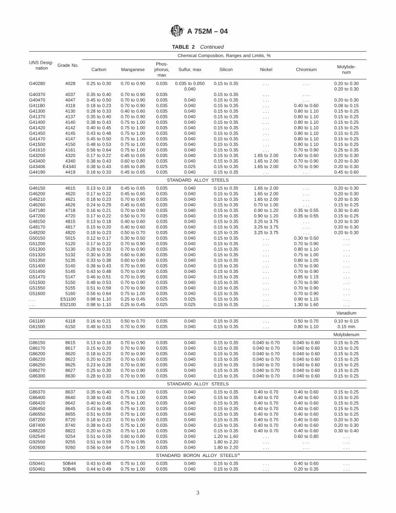
TABLE 2 Continued
UNS Desig-nation
Grade No.
Chemical Composition, Ranges and Limits, %
Carbon ManganesePhos-
phorus,max
Sulfur, max Silicon Nickel ChromiumMolybde-
num
G40280
G40370
4028
4037
0.25 to 0.30
0.35 to 0.40
0.70 to 0.90
0.70 to 0.90
0.035
0.035
0.035 to 0.0500.040
0.15 to 0.35
0.15 to 0.35
. . .
. . .
. . .
. . .
0.20 to 0.300.20 to 0.30
G40470 4047 0.45 to 0.50 0.70 to 0.90 0.035 0.040 0.15 to 0.35 . . . . . . 0.20 to 0.30G41180 4118 0.18 to 0.23 0.70 to 0.90 0.035 0.040 0.15 to 0.35 . . . 0.40 to 0.60 0.08 to 0.15G41300 4130 0.28 to 0.33 0.40 to 0.60 0.035 0.040 0.15 to 0.35 . . . 0.80 to 1.10 0.15 to 0.25G41370 4137 0.35 to 0.40 0.70 to 0.90 0.035 0.040 0.15 to 0.35 . . . 0.80 to 1.10 0.15 to 0.25G41400 4140 0.38 to 0.43 0.75 to 1.00 0.035 0.040 0.15 to 0.35 . . . 0.80 to 1.10 0.15 to 0.25G41420 4142 0.40 to 0.45 0.75 to 1.00 0.035 0.040 0.15 to 0.35 . . . 0.80 to 1.10 0.15 to 0.25G41450 4145 0.43 to 0.48 0.75 to 1.00 0.035 0.040 0.15 to 0.35 . . . 0.80 to 1.10 0.15 to 0.25G41470 4147 0.45 to 0.50 0.75 to 1.00 0.035 0.040 0.15 to 0.35 . . . 0.80 to 1.10 0.15 to 0.25G41500 4150 0.48 to 0.53 0.75 to 1.00 0.035 0.040 0.15 to 0.35 . . . 0.80 to 1.10 0.15 to 0.25G41610 4161 0.56 to 0.64 0.75 to 1.00 0.035 0.040 0.15 to 0.35 . . . 0.70 to 0.90 0.25 to 0.35G43200 4320 0.17 to 0.22 0.45 to 0.65 0.035 0.040 0.15 to 0.35 1.65 to 2.00 0.40 to 0.60 0.20 to 0.30G43400 4340 0.38 to 0.43 0.60 to 0.80 0.035 0.040 0.15 to 0.35 1.65 to 2.00 0.70 to 0.90 0.20 to 0.30G43406 E4340 0.38 to 0.43 0.65 to 0.85 0.025 0.025 0.15 to 0.35 1.65 to 2.00 0.70 to 0.90 0.20 to 0.30G44190 4419 0.18 to 0.33 0.45 to 0.65 0.035 0.040 0.15 to 0.35 . . . . . . 0.45 to 0.60
STANDARD ALLOY STEELS
G46150 4615 0.13 to 0.18 0.45 to 0.65 0.035 0.040 0.15 to 0.35 1.65 to 2.00 . . . 0.20 to 0.30G46200 4620 0.17 to 0.22 0.45 to 0.65 0.035 0.040 0.15 to 0.35 1.65 to 2.00 . . . 0.20 to 0.30G46210 4621 0.18 to 0.23 0.70 to 0.90 0.035 0.040 0.15 to 0.35 1.65 to 2.00 . . . 0.20 to 0.30G46260 4626 0.24 to 0.29 0.45 to 0.65 0.035 0.040 0.15 to 0.35 0.70 to 1.00 . . . 0.15 to 0.25G47180 4718 0.16 to 0.21 0.70 to 0.90 0.035 0.040 0.15 to 0.35 0.90 to 1.20 0.35 to 0.55 0.30 to 0.40G47200 4720 0.17 to 0.22 0.50 to 0.70 0.035 0.040 0.15 to 0.35 0.90 to 1.20 0.35 to 0.55 0.15 to 0.25G48150 4815 0.13 to 0.18 0.40 to 0.60 0.035 0.040 0.15 to 0.35 3.25 to 3.75 . . . 0.20 to 0.30G48170 4817 0.15 to 0.20 0.40 to 0.60 0.035 0.040 0.15 to 0.35 3.25 to 3.75 . . . 0.20 to 0.30G48200 4820 0.18 to 0.23 0.50 to 0.70 0.035 0.040 0.15 to 0.35 3.25 to 3.75 . . . 0.20 to 0.30G50150 5015 0.12 to 0.17 0.30 to 0.50 0.035 0.040 0.15 to 0.35 . . . 0.30 to 0.50 . . .G51200 5120 0.17 to 0.22 0.70 to 0.90 0.035 0.040 0.15 to 0.35 . . . 0.70 to 0.90 . . .G51300 5130 0.28 to 0.33 0.70 to 0.90 0.035 0.040 0.15 to 0.35 . . . 0.80 to 1.10 . . .G51320 5132 0.30 to 0.35 0.60 to 0.80 0.035 0.040 0.15 to 0.35 . . . 0.75 to 1.00 . . .G51350 5135 0.33 to 0.38 0.60 to 0.80 0.035 0.040 0.15 to 0.35 . . . 0.80 to 1.05 . . .G51400 5140 0.38 to 0.43 0.70 to 0.90 0.035 0.040 0.15 to 0.35 . . . 0.70 to 0.90 . . .G51450G51470
51455147
0.43 to 0.480.46 to 0.51
0.70 to 0.900.70 to 0.95
0.0350.035
0.0400.040
0.15 to 0.350.15 to 0.35
. . .
. . .0.70 to 0.900.85 to 1.15
. . .
. . .G51500 5150 0.48 to 0.53 0.70 to 0.90 0.035 0.040 0.15 to 0.35 . . . 0.70 to 0.90 . . .G51550 5155 0.51 to 0.59 0.70 to 0.90 0.035 0.040 0.15 to 0.35 . . . 0.70 to 0.90 . . .G51600 5160 0.56 to 0.64 0.75 to 1.00 0.035 0.040 0.15 to 0.35 . . . 0.70 to 0.90 . . .. . .. . .
E51100E52100
0.98 to 1.100.98 to 1.10
0.25 to 0.450.25 to 0.45
0.0250.025
0.0250.025
0.15 to 0.350.15 to 0.35
. . .
. . .0.90 to 1.151.30 to 1.60
. . .
. . .
Vanadium
G61180 6118 0.16 to 0.21 0.50 to 0.70 0.035 0.040 0.15 to 0.35 . . . 0.50 to 0.70 0.10 to 0.15G61500 6150 0.48 to 0.53 0.70 to 0.90 0.035 0.040 0.15 to 0.35 . . . 0.80 to 1.10 0.15 min
Molybdenum
G86150 8615 0.13 to 0.18 0.70 to 0.90 0.035 0.040 0.15 to 0.35 0.040 to 0.70 0.040 to 0.60 0.15 to 0.25G86170 8617 0.15 to 0.20 0.70 to 0.90 0.035 0.040 0.15 to 0.35 0.040 to 0.70 0.040 to 0.60 0.15 to 0.25G86200 8620 0.18 to 0.23 0.70 to 0.90 0.035 0.040 0.15 to 0.35 0.040 to 0.70 0.040 to 0.60 0.15 to 0.25G86220 8622 0.20 to 0.25 0.70 to 0.90 0.035 0.040 0.15 to 0.35 0.040 to 0.70 0.040 to 0.60 0.15 to 0.25G86250 8625 0.23 to 0.28 0.70 to 0.90 0.035 0.040 0.15 to 0.35 0.040 to 0.70 0.040 to 0.60 0.15 to 0.25G86270 8627 0.25 to 0.30 0.70 to 0.90 0.035 0.040 0.15 to 0.35 0.040 to 0.70 0.040 to 0.60 0.15 to 0.25G86300 8630 0.28 to 0.33 0.70 to 0.90 0.035 0.040 0.15 to 0.35 0.040 to 0.70 0.040 to 0.60 0.15 to 0.25
STANDARD ALLOY STEELS
G86370 8637 0.35 to 0.40 0.75 to 1.00 0.035 0.040 0.15 to 0.35 0.40 to 0.70 0.40 to 0.60 0.15 to 0.25G86400 8640 0.38 to 0.43 0.75 to 1.00 0.035 0.040 0.15 to 0.35 0.40 to 0.70 0.40 to 0.60 0.15 to 0.25G86420 8642 0.40 to 0.45 0.75 to 1.00 0.035 0.040 0.15 to 0.35 0.40 to 0.70 0.40 to 0.60 0.15 to 0.25G86450 8645 0.43 to 0.48 0.75 to 1.00 0.035 0.040 0.15 to 0.35 0.40 to 0.70 0.40 to 0.60 0.15 to 0.25G86550 8655 0.51 to 0.59 0.75 to 1.00 0.035 0.040 0.15 to 0.35 0.40 to 0.70 0.40 to 0.60 0.15 to 0.25G87200 8720 0.18 to 0.23 0.70 to 0.90 0.035 0.040 0.15 to 0.35 0.40 to 0.70 0.40 to 0.60 0.20 to 0.30G87400 8740 0.38 to 0.43 0.75 to 1.00 0.035 0.040 0.15 to 0.35 0.40 to 0.70 0.40 to 0.60 0.20 to 0.30G88220 8822 0.20 to 0.25 0.75 to 1.00 0.035 0.040 0.15 to 0.35 0.40 to 0.70 0.40 to 0.60 0.30 to 0.40G92540 9254 0.51 to 0.59 0.60 to 0.80 0.035 0.040 1.20 to 1.60 . . . 0.60 to 0.80 . . .G92550 9255 0.51 to 0.59 0.70 to 0.95 0.035 0.040 1.80 to 2.20 . . . . . . . . .G92600 9260 0.56 to 0.64 0.75 to 1.00 0.035 0.040 1.80 to 2.20 . . . . . . . . .
STANDARD BORON ALLOY STEELSA
G50441 50B44 0.43 to 0.48 0.75 to 1.00 0.035 0.040 0.15 to 0.35 . . . 0.40 to 0.60 . . .G50461 50B46 0.44 to 0.49 0.75 to 1.00 0.035 0.040 0.15 to 0.35 . . . 0.20 to 0.35 . . .
A 752M – 04
3

TABLE 2 Continued
UNS Desig-nation
Grade No.
Chemical Composition, Ranges and Limits, %
Carbon ManganesePhos-
phorus,max
Sulfur, max Silicon Nickel ChromiumMolybde-
num
G50501 50B50 0.48 to 0.53 0.75 to 1.00 0.035 0.040 0.15 to 0.35 . . . 0.40 to 0.60 . . .G50601 50B60 0.56 to 0.64 0.75 to 1.00 0.035 0.040 0.15 to 0.35 . . . 0.40 to 0.60 . . .G51601 51B60 0.56 to 0.64 0.75 to 1.00 0.035 0.040 0.15 to 0.35 . . . 0.70 to 0.90 . . .G81451 81B45 0.43 to 0.48 0.75 to 1.00 0.035 0.040 0.15 to 0.35 0.20 to 0.40 0.35 to 0.55 0.08 to 0.15G94171
G94301
94B17
94B30
0.15 to 0.20
0.28 to 0.33
0.75 to 1.00
0.75 to 1.00
0.035
0.035
0.040
0.040
0.15 to 0.35
0.15 to 0.35
0.30 to 0.60
0.30 to 0.60
0.30 to 0.50
0.30 to 0.50
0.08 to 0.150.08 to 0.15
A These steels can be expected to a minimum boron content of 0.0005 %.
NOTE 2—A typical ordering description is as follows: 50 000 kg SteelWire Rods, 5.5 mm, Grade G 41400 W approximately 600 kg coils toASTM A 752M dated-XX.
4.2 It shall be the responsibility of the purchaser to specifyall requirements that are necessary for coarse round wire underthis specification. Such requirements include, but are notlimited to, the following:
4.2.1 Quantity (kilograms),4.2.2 Name of material (alloy steel wire),4.2.3 Diameter (Table 2),4.2.4 Length (straightened and cut only),4.2.5 Chemical composition (Table 3),4.2.6 Packaging (Section 14),4.2.7 Heat analysis report, if requested (Section 6),4.2.8 Certification or test report, or both, if specified (Sec-
tion 13),4.2.9 ASTM designation and date of issue, and4.2.10 Special requirements, if any.
NOTE 3—A typical ordering description is as follows: 15 000 kg AlloySteel Wire, 3.8 mm diameter, Grade 4135 in 1000-kg Coils on TubularCarriers, to ASTM A 752M-XX, or 2500 Pieces, Alloy Steel Wire, 9.5 mmdiameter, Straightened and Cut, 0.76 m, Grade G 41400 in 25-PieceBundles on Pallets to ASTM A 752M-XX.
5. Manufacture
5.1 The steel may be produced by any commercially ac-cepted steel making process. The steel may be either ingot castor strand cast.
6. Chemical Composition
6.1 The chemical composition for alloy steel under thisspecification shall conform to the requirements set forth in thepurchase order. The grades commonly specified for alloy steelwire rods and alloy steel wire are shown in Table 3. Forspecified compositions not contained in Table 3 the ranges andlimits expressed in Table 4 shall apply unless other such rangesand limits shall have been agreed upon between the purchaserand the manufacturer.
TABLE 4 Alloy Steels—Chemical Composition Ranges and Limits for Cast or Heat Analysis
NOTE 1— Boron steels can be expected to have a 0.0005 % minimum boron content.NOTE 2—Alloy steels can be produced with a lead range of 0.15 to 0.35 %. Lead is reported only as a range of 0.15 to 0.35 % since it is added to the
mold as the steel is poured.NOTE 3—The chemical ranges and limits of alloy steels are produced to the check, product, or verification analysis tolerances shown in Table 5.
Element When Maximum of Specified Element is, %
Range, %
MaximumLimit, %A
Open-Hearth orBasic Oxygen
Steel
ElectricFurnace
Steel
Carbon To 0.55, incl 0.05 0.05Over 0.55 to 0.70, incl 0.08 0.07Over 0.70 to 0.80, incl 0.10 0.09Over 0.80 to 0.95, incl 0.12 0.11Over 0.95 to 1.35, incl 0.13 0.12
Manganese To 0.60, incl 0.20 0.15Over 0.60 to 0.90, incl 0.20 0.20Over 0.90 to 1.05, incl 0.25 0.25Over 1.05 to 1.90, incl 0.30 0.30Over 1.90 to 2.10, incl 0.40 0.35
Phosphorus Basic open-hearth or basic oxygen steelBasic electric furnace steel
0.0350.025
Sulfur To 0.050, incl 0.015 0.015Over 0.050 to 0.07, incl 0.02 0.02Over 0.07 to 0.10, incl 0.04 0.04Over 0.10 to 0.14, incl 0.05 0.05
Basic open hearth or basic oxygen steel 0.040Basic electric furnace 0.025
Silicon To 0.15, incl 0.08 0.08Over 0.15 to 0.20, incl 0.10 0.10Over 0.20 to 0.40, incl 0.15 0.15
A 752M – 04
4
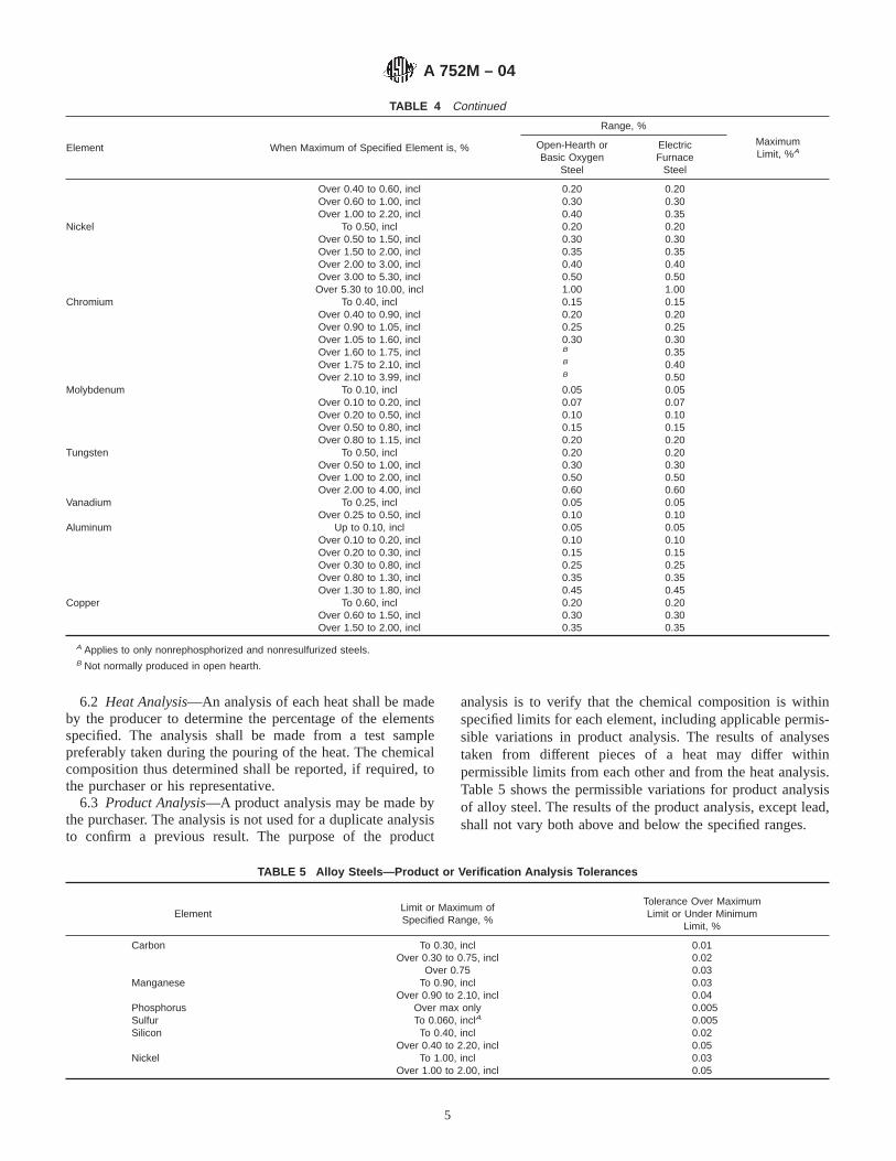
TABLE 4 Continued
Element When Maximum of Specified Element is, %
Range, %
MaximumLimit, %A
Open-Hearth orBasic Oxygen
Steel
ElectricFurnace
Steel
Over 0.40 to 0.60, incl 0.20 0.20Over 0.60 to 1.00, incl 0.30 0.30Over 1.00 to 2.20, incl 0.40 0.35
Nickel To 0.50, incl 0.20 0.20Over 0.50 to 1.50, incl 0.30 0.30Over 1.50 to 2.00, incl 0.35 0.35Over 2.00 to 3.00, incl 0.40 0.40Over 3.00 to 5.30, incl 0.50 0.50
Over 5.30 to 10.00, incl 1.00 1.00Chromium To 0.40, incl 0.15 0.15
Over 0.40 to 0.90, incl 0.20 0.20Over 0.90 to 1.05, incl 0.25 0.25Over 1.05 to 1.60, incl 0.30 0.30Over 1.60 to 1.75, incl B 0.35Over 1.75 to 2.10, incl B 0.40Over 2.10 to 3.99, incl B 0.50
Molybdenum To 0.10, incl 0.05 0.05Over 0.10 to 0.20, incl 0.07 0.07Over 0.20 to 0.50, incl 0.10 0.10Over 0.50 to 0.80, incl 0.15 0.15Over 0.80 to 1.15, incl 0.20 0.20
Tungsten To 0.50, inclOver 0.50 to 1.00, inclOver 1.00 to 2.00, inclOver 2.00 to 4.00, incl
0.200.300.500.60
0.200.300.500.60
Vanadium To 0.25, inclOver 0.25 to 0.50, incl
0.050.10
0.050.10
Aluminum Up to 0.10, incl 0.05 0.05Over 0.10 to 0.20, incl 0.10 0.10Over 0.20 to 0.30, incl 0.15 0.15Over 0.30 to 0.80, incl 0.25 0.25Over 0.80 to 1.30, incl 0.35 0.35Over 1.30 to 1.80, incl 0.45 0.45
Copper To 0.60, inclOver 0.60 to 1.50, inclOver 1.50 to 2.00, incl
0.200.300.35
0.200.300.35
A Applies to only nonrephosphorized and nonresulfurized steels.B Not normally produced in open hearth.
6.2 Heat Analysis—An analysis of each heat shall be madeby the producer to determine the percentage of the elementsspecified. The analysis shall be made from a test samplepreferably taken during the pouring of the heat. The chemicalcomposition thus determined shall be reported, if required, tothe purchaser or his representative.
6.3 Product Analysis—A product analysis may be made bythe purchaser. The analysis is not used for a duplicate analysisto confirm a previous result. The purpose of the product
analysis is to verify that the chemical composition is withinspecified limits for each element, including applicable permis-sible variations in product analysis. The results of analysestaken from different pieces of a heat may differ withinpermissible limits from each other and from the heat analysis.Table 5 shows the permissible variations for product analysisof alloy steel. The results of the product analysis, except lead,shall not vary both above and below the specified ranges.
TABLE 5 Alloy Steels—Product or Verification Analysis Tolerances
ElementLimit or Maximum ofSpecified Range, %
Tolerance Over MaximumLimit or Under Minimum
Limit, %
Carbon To 0.30, inclOver 0.30 to 0.75, incl
Over 0.75
0.010.020.03
Manganese To 0.90, inclOver 0.90 to 2.10, incl
0.030.04
Phosphorus Over max only 0.005Sulfur To 0.060, inclA 0.005Silicon To 0.40, incl 0.02
Over 0.40 to 2.20, incl 0.05Nickel To 1.00, incl 0.03
Over 1.00 to 2.00, incl 0.05
A 752M – 04
5

TABLE 5 Continued
ElementLimit or Maximum ofSpecified Range, %
Tolerance Over MaximumLimit or Under Minimum
Limit, %
Over 2.00 to 5.30, incl 0.07Over 5.30 to 10.00, incl 0.10
Chromium To 0.90, inclOver 0.90 to 2.10, inclOver 2.10 to 3.99, incl
0.030.050.10
Molybdenum To 0.20, inclOver 0.20 to 0.40, inclOver 0.40 to 1.15, incl
0.010.020.03
Vanadium To 0.10, incl 0.01Over 0.10 to 0.25, incl 0.02Over 0.25 to 0.50, incl 0.03
Min value specified, checkunder min limit
0.01
Tungsten To 1.00, inclOver 1.00 to 4.00, incl
0.040.08
Aluminum Up to 0.10, incl 0.03Over 0.10 to 0.20, incl 0.04Over 0.20 to 0.30, incl 0.05Over 0.30 to 0.80, incl 0.07Over 0.80 to 1.80, incl 0.10
LeadCopper
0.15 to 0.35, inclTo 1.00, incl
Over 1.00 to 2.00, incl
0.03B
0.030.05
A Sulfur over 0.060 % is not subject to product analysis.B Tolerance is over and under.
6.3.1 The location from which chips for product analysis areobtained is important because of normal segregation. For rodsand wire, chips must be taken by milling or machining the fullcross section of the sample.
6.3.1.1 Steel subjected to certain thermal treatments by thepurchaser may not give chemical analysis results that properlyrepresent its original composition. Therefore, purchasersshould analyze chips taken from the steel in the condition inwhich it is received from the producer.
6.3.1.2 When samples are returned to the producer forproduct analysis, the samples should consist of pieces of thefull cross section.
6.3.2 For referee purposes, Test Methods, Practices andTerminology A 751 shall be used.
7. Metallurgical Structure
7.1 Grain size when specified shall be determined in accor-dance with the requirements of Test Methods E 112.
7.2 Alloy steel wire rods may be specified as annealed,spheroidize annealed, or patented. Refer to Terminology A 919for definitions.
7.3 Alloy steel wire may be specified as drawn fromannealed or spheroidize annealed wire, rod, or bars, sphe-roidize annealed at finish size, patented, or oil tempered. Referto Terminology A 919 for definitions.
8. Mechanical Properties
8.1 The properties enumerated in individual specificationsshall be determined in accordance with Test Methods andDefinitions A 370.
8.2 The maximum expected tensile strengths for the morecommon grades of alloy rods with regular mill annealing(nonspheroidized) are shown in Table 6.
TABLE 6 Maximum Expected Tensile Strengths for Annealed Alloy Steel Rods
NOTE 1—Specific microstructures such as spheroidize anneal or lamellar pearlite anneal may require modification of these tensile strength values.
UNSDesignation
Grade no. TensileStrength,
MPa
UNSDesignation
Grade No. TensileStrength,
MPa
G13300 1330 610 G50601 50B60 710G13350 1335 620 G51200 5120 570G13400 1340 630 G51300 5130 580G13450 1345 670 G51320 5132 580G40120 4012 490 G51350 5135 590G40230 4023 500 G51400 5140 620G40240 4024 500 G51450 5145 650G40270 4027 570 G51470 5147 680G40280 4028 570 G51500 5150 670G40370 4037 610 G51550 5155 710G40470 4047 670 G51600 5160 720G41180 4118 570 G51601 51B60 750
A 752M – 04
6

TABLE 6 Continued
UNSDesignation
Grade no. TensileStrength,
MPa
UNSDesignation
Grade No. TensileStrength,
MPa
G41300 4130 590 G61180 6118 550G41370 4137 630 G61500 6150 670G41400 4140 650 G81451 81B45 630G41420 4142 670 G86150 8615 550G41450 4145 680 G86170 8617 550G41470 4147 690 G86200 8620 570G41500 4150 690 G86220 8622 580G41610 4161 770 G86250 8625 580G43200 4320 650 G86270 8627 580G43400 4340 720 G86300 8630 610G44190 4419 570 G86370 8637 630G46150 4615 550 G86400 8640 650G46200 4620 570 G86420 8642 670G46210 4621 570 G86450 8645 680G46260 4626 580 G86550 8655 720G47180 4718 580 G87200 8720 570G47200 4720 570 G87400 8740 670G48150 4815 630 G88220 8822 610G48170 4817 650 G92540 9254 770G48200 4820 650 G92550 9255 770G50150 5015 500 G92600 9260 770G50441 50B44 650 G94171 94B17 500G50461 50B46 630 G94301 94B30 580G50501 50B50 670
8.3 Because of the great variety in the kinds and grades ofrods and wire and the extensive diversity of application, anumber of formal mechanical test procedures have beendeveloped. These tests are used as control tests by producersduring intermediate stages of wire processing, as well as forfinal testing of the finished product, and apply particularly torods and wire for specific applications. A number of these testsare further described in Supplement IV, Round Wire Products,of Test Methods and Definitions A 370.
8.4 Since the general utility of rods and wire requirecontinuity of length, in the case of rods, tests are commonlymade on samples taken from the ends of coils after removingtwo to three rings; in the case of wire, tests are commonlytaken from the ends of the coils, thereby not impairing theusefulness of the whole coil.
9. Dimensions and Permissible Variation
9.1 The diameter and out-of-roundness of the alloy wire rodshall not vary from that specified by more than that prescribedin Table 7.
9.2 The diameter and out-of-roundness of the alloy coarseround wire shall not vary from that specified by more than thatprescribed in Table 8.
TABLE 7 Permissible Variation in Diameter for Alloy Steel WireRod in Coils
NOTE 1— For purposes of determining conformance with this specifi-cation, all specified limits in this table are absolute limits as defined inPractice E 29.
Diameter of Rod, mm Permissible Variation,Plus and Minus, mm
Permissible Out-of-Round, mm
3.5 to 19 0.40 0.60
TABLE 8 Permissible Variation in Diameter for Alloy Steel Coarse Round Wire
NOTE 1—For purposes of determining conformance with this specification, all specified limits in this table are absolute limits as defined in PracticeE 29.
In Coils
Diameter of Wire, mm Permissible Variation,Plus and Minus,
mm
PermissibleOut-of-Round,
mm
0.90 to under 1.90 0.03 0.031.90 to under 12.5 0.05 0.0512.5 and over 0.08 0.08
Straightened and Cut
0.90 to under 1.90 0.03 0.031.90 to under 3.80 0.05 0.053.80 to under 12.5 0.08 0.08
A 752M – 04
7

TABLE 8 Continued
In Coils
Diameter of Wire, mm Permissible Variation,Plus and Minus,
mm
PermissibleOut-of-Round,
mm12.5 and over 0.10 0.10
9.3 The length of straightened and cut wire shall not varyfrom that specified by more than that prescribed in Table 9.
TABLE 9 Permissible Variation in Length for Straightened andCut Alloy Steel Wire
NOTE 1—For purposes of determining conformance with this specifi-cation, all specified limits in this table are absolute limits as defined inPractice E 29.
Cut Length, m Permissible Variations, Plus andMinus, mm
Under 1.0 1.61.0 to 4.0 2.4Over 4.0 3.0
9.4 The burrs formed in cutting straightened and cut wireshall not exceed the diameter specified by more than thatprescribed in Table 10.
TABLE 10 Permissible Variation for Burrs for Straightened andCut Alloy Steel Wire
NOTE 1— For purposes of determining conformance with this specifi-cation, all specified limits in this table are absolute limits as defined inPractice E 29.
Diameter of Wire, mm Permissible Variations, overMeasured Diameter, mm
Up to 3.0, incl 0.10Over 3.0 to 6.5, incl 0.15Over 6.5 to 12.5, incl 0.20Over 12.5 0.25
10. Workmanship, Finish, and Appearance10.1 The alloy wire rod shall be free from detrimental
surface imperfections, tangles, and sharp kinks.10.1.1 Two or more rod coils may be welded together to
produce a larger coil. The weld zone may not be as sound as theoriginal material. The mechanical properties existing in theweld zone may differ from those in the unaffected base metal.The weld may exceed the permissible variations for diameterand out-of-roundness on the minus side of the permissiblevariation but not on the plus side.
10.2 The wire as received shall be smooth and substantiallyfree from rust, shall not be kinked or improperly cast. Nodetrimental die marks or scratches may be present. Each coilshall be one continuous length of wire. Welds made during colddrawing are permitted.
10.3 The straightened and cut wire shall be substantiallystraight and not be kinked or show excessive spiral marking.
11. Inspection11.1 The manufacturer shall afford the purchaser’s inspector
all reasonable facilities necessary to satisfy him that the
material is being produced and furnished in accordance withthis specification. Mill inspection by the purchaser shall notinterfere unnecessarily with the manufacturer’s operations. Alltests and inspections shall be made at the place of manufacture,unless otherwise agreed to.
12. Rejection
12.1 Any rejection based on tests made in accordance withthis specification shall be reported to the manufacturer withina reasonable length of time. The material must be adequatelyprotected and correctly identified in order that the manufacturermay make a proper investigation.
13. Certification
13.1 Upon request of the purchaser in the contract or order,a manufacturer’s certification that the material was manufac-tured and tested in accordance with this specification, togetherwith a report of the test results, shall be furnished at the timeof shipment.
13.2 The certification shall include the specification num-ber, year date of issue, and revision letter, if any.
14. Packaging, Marking, and Loading for Shipment
14.1 The coil mass, dimensions, and the method of packag-ing shall be agreed upon between the manufacturer andpurchaser.
14.2 The size of the wire, purchaser’s order number, ASTMspecification number, heat number, and name or mark of themanufacturer shall be marked on a tag securely attached toeach coil of wire.
14.3 Unless otherwise specified in the purchaser’s order,packaging, marking, and loading for shipments shall be inaccordance with those procedures recommended by PracticeA 700.
14.4 For Government Procurement—Packaging, packing,and marking of material for military procurement shall be inaccordance with the requirements of MIL-STD-163, Level A,Level C, or commercial as specified in the contract or purchaseorder. Marking for shipment of material for civil agencies shallbe in accordance with Fed. Std. No. 123.
14.5 Bar Coding—In addition to the previously-stated iden-tification requirements, bar coding is acceptable as a supple-mentary identification method. Bar coding should be consistentwith AIAG Standard 02.00, Primary Metals Identification TagApplication. The bar code may be applied to a substantiallyaffixed tag.
15. Keywords
15.1 alloy; general; rods; wire
A 752M – 04
8

SUMMARY OF CHANGES
Committee A01 has identified the location of selected changes to this standard since the last issue,A 752M–93 (2003), that may impact the use of this standard. (Approved March 1, 2004.)
(1) Revised Sections 4.1 and 4.2 to eliminate non-mandatorylanguage.
ASTM International takes no position respecting the validity of any patent rights asserted in connection with any item mentionedin this standard. Users of this standard are expressly advised that determination of the validity of any such patent rights, and the riskof infringement of such rights, are entirely their own responsibility.
This standard is subject to revision at any time by the responsible technical committee and must be reviewed every five years andif not revised, either reapproved or withdrawn. Your comments are invited either for revision of this standard or for additional standardsand should be addressed to ASTM International Headquarters. Your comments will receive careful consideration at a meeting of theresponsible technical committee, which you may attend. If you feel that your comments have not received a fair hearing you shouldmake your views known to the ASTM Committee on Standards, at the address shown below.
This standard is copyrighted by ASTM International, 100 Barr Harbor Drive, PO Box C700, West Conshohocken, PA 19428-2959,United States. Individual reprints (single or multiple copies) of this standard may be obtained by contacting ASTM at the aboveaddress or at 610-832-9585 (phone), 610-832-9555 (fax), or [email protected] (e-mail); or through the ASTM website(www.astm.org).
A 752M – 04
9
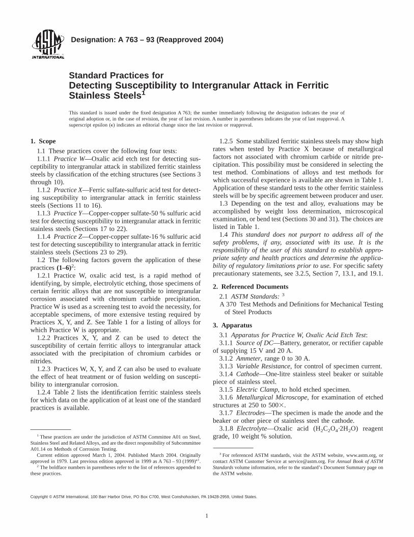
Designation: A 763 – 93 (Reapproved 2004)
Standard Practices forDetecting Susceptibility to Intergranular Attack in FerriticStainless Steels 1
This standard is issued under the fixed designation A 763; the number immediately following the designation indicates the year oforiginal adoption or, in the case of revision, the year of last revision. A number in parentheses indicates the year of last reapproval. Asuperscript epsilon (e) indicates an editorial change since the last revision or reapproval.
1. Scope
1.1 These practices cover the following four tests:1.1.1 Practice W—Oxalic acid etch test for detecting sus-
ceptibility to intergranular attack in stabilized ferritic stainlesssteels by classification of the etching structures (see Sections 3through 10).
1.1.2 Practice X—Ferric sulfate-sulfuric acid test for detect-ing susceptibility to intergranular attack in ferritic stainlesssteels (Sections 11 to 16).
1.1.3 Practice Y—Copper-copper sulfate-50 % sulfuric acidtest for detecting susceptibility to intergranular attack in ferriticstainless steels (Sections 17 to 22).
1.1.4 Practice Z—Copper-copper sulfate-16 % sulfuric acidtest for detecting susceptibility to intergranular attack in ferriticstainless steels (Sections 23 to 29).
1.2 The following factors govern the application of thesepractices(1–6)2:
1.2.1 Practice W, oxalic acid test, is a rapid method ofidentifying, by simple, electrolytic etching, those specimens ofcertain ferritic alloys that are not susceptible to intergranularcorrosion associated with chromium carbide precipitation.Practice W is used as a screening test to avoid the necessity, foracceptable specimens, of more extensive testing required byPractices X, Y, and Z. See Table 1 for a listing of alloys forwhich Practice W is appropriate.
1.2.2 Practices X, Y, and Z can be used to detect thesusceptibility of certain ferritic alloys to intergranular attackassociated with the precipitation of chromium carbides ornitrides.
1.2.3 Practices W, X, Y, and Z can also be used to evaluatethe effect of heat treatment or of fusion welding on suscepti-bility to intergranular corrosion.
1.2.4 Table 2 lists the identification ferritic stainless steelsfor which data on the application of at least one of the standardpractices is available.
1.2.5 Some stabilized ferritic stainless steels may show highrates when tested by Practice X because of metallurgicalfactors not associated with chromium carbide or nitride pre-cipitation. This possibility must be considered in selecting thetest method. Combinations of alloys and test methods forwhich successful experience is available are shown in Table 1.Application of these standard tests to the other ferritic stainlesssteels will be by specific agreement between producer and user.
1.3 Depending on the test and alloy, evaluations may beaccomplished by weight loss determination, microscopicalexamination, or bend test (Sections 30 and 31). The choices arelisted in Table 1.
1.4 This standard does not purport to address all of thesafety problems, if any, associated with its use. It is theresponsibility of the user of this standard to establish appro-priate safety and health practices and determine the applica-bility of regulatory limitations prior to use.For specific safetyprecautionary statements, see 3.2.5, Section 7, 13.1, and 19.1.
2. Referenced Documents
2.1 ASTM Standards:3
A 370 Test Methods and Definitions for Mechanical Testingof Steel Products
3. Apparatus
3.1 Apparatus for Practice W, Oxalic Acid Etch Test:3.1.1 Source of DC—Battery, generator, or rectifier capable
of supplying 15 V and 20 A.3.1.2 Ammeter, range 0 to 30 A.3.1.3 Variable Resistance, for control of specimen current.3.1.4 Cathode—One-litre stainless steel beaker or suitable
piece of stainless steel.3.1.5 Electric Clamp, to hold etched specimen.3.1.6 Metallurgical Microscope, for examination of etched
structures at 250 to 5003.3.1.7 Electrodes—The specimen is made the anode and the
beaker or other piece of stainless steel the cathode.3.1.8 Electrolyte—Oxalic acid (H2C2O4·2H2O) reagent
grade, 10 weight % solution.1 These practices are under the jurisdiction of ASTM Committee A01 on Steel,Stainless Steel and Related Alloys, and are the direct responsibility of SubcommitteeA01.14 on Methods of Corrosion Testing.
Current edition approved March 1, 2004. Published March 2004. Originallyapproved in 1979. Last previous edition approved in 1999 as A 763 – 93 (1999)e1.
2 The boldface numbers in parentheses refer to the list of references appended tothese practices.
3 For referenced ASTM standards, visit the ASTM website, www.astm.org, orcontact ASTM Customer Service at [email protected]. ForAnnual Book of ASTMStandardsvolume information, refer to the standard’s Document Summary page onthe ASTM website.
1
Copyright © ASTM International, 100 Barr Harbor Drive, PO Box C700, West Conshohocken, PA 19428-2959, United States.
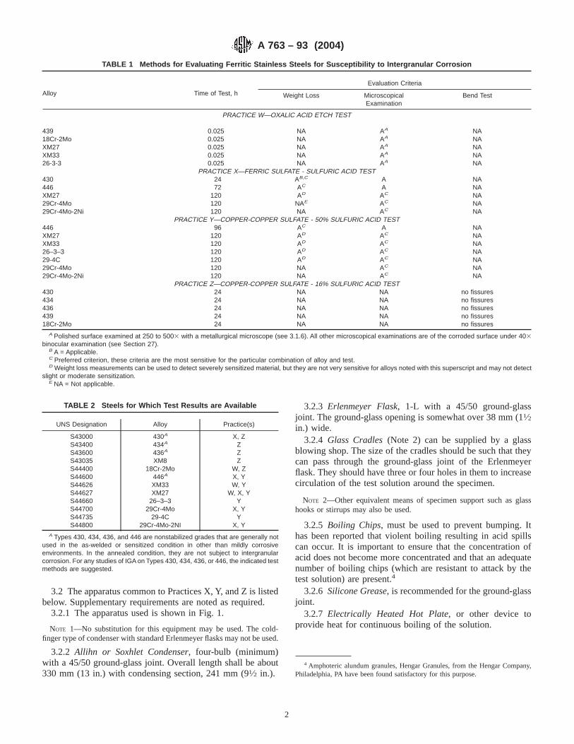
3.2 The apparatus common to Practices X, Y, and Z is listedbelow. Supplementary requirements are noted as required.
3.2.1 The apparatus used is shown in Fig. 1.
NOTE 1—No substitution for this equipment may be used. The cold-finger type of condenser with standard Erlenmeyer flasks may not be used.
3.2.2 Allihn or Soxhlet Condenser, four-bulb (minimum)with a 45/50 ground-glass joint. Overall length shall be about330 mm (13 in.) with condensing section, 241 mm (91⁄2 in.).
3.2.3 Erlenmeyer Flask, 1-L with a 45/50 ground-glassjoint. The ground-glass opening is somewhat over 38 mm (11⁄2in.) wide.
3.2.4 Glass Cradles(Note 2) can be supplied by a glassblowing shop. The size of the cradles should be such that theycan pass through the ground-glass joint of the Erlenmeyerflask. They should have three or four holes in them to increasecirculation of the test solution around the specimen.
NOTE 2—Other equivalent means of specimen support such as glasshooks or stirrups may also be used.
3.2.5 Boiling Chips, must be used to prevent bumping. Ithas been reported that violent boiling resulting in acid spillscan occur. It is important to ensure that the concentration ofacid does not become more concentrated and that an adequatenumber of boiling chips (which are resistant to attack by thetest solution) are present.4
3.2.6 Silicone Grease, is recommended for the ground-glassjoint.
3.2.7 Electrically Heated Hot Plate, or other device toprovide heat for continuous boiling of the solution.
4 Amphoteric alundum granules, Hengar Granules, from the Hengar Company,Philadelphia, PA have been found satisfactory for this purpose.
TABLE 1 Methods for Evaluating Ferritic Stainless Steels for Susceptibility to Intergranular Corrosion
Alloy Time of Test, h
Evaluation Criteria
Weight Loss MicroscopicalExamination
Bend Test
PRACTICE W—OXALIC ACID ETCH TEST
439 0.025 NA AA NA18Cr-2Mo 0.025 NA AA NAXM27 0.025 NA AA NAXM33 0.025 NA AA NA26-3-3 0.025 NA AA NA
PRACTICE X—FERRIC SULFATE - SULFURIC ACID TEST430 24 AB,C A NA446 72 AC A NAXM27 120 AD AC NA29Cr-4Mo 120 NAE AC NA29Cr-4Mo-2Ni 120 NA AC NA
PRACTICE Y—COPPER-COPPER SULFATE - 50% SULFURIC ACID TEST446 96 AC A NAXM27 120 AD AC NAXM33 120 AD AC NA26–3–3 120 AD AC NA29-4C 120 AD AC NA29Cr-4Mo 120 NA AC NA29Cr-4Mo-2Ni 120 NA AC NA
PRACTICE Z—COPPER-COPPER SULFATE - 16% SULFURIC ACID TEST430 24 NA NA no fissures434 24 NA NA no fissures436 24 NA NA no fissures439 24 NA NA no fissures18Cr-2Mo 24 NA NA no fissures
A Polished surface examined at 250 to 5003 with a metallurgical microscope (see 3.1.6). All other microscopical examinations are of the corroded surface under 403binocular examination (see Section 27).
B A = Applicable.C Preferred criterion, these criteria are the most sensitive for the particular combination of alloy and test.D Weight loss measurements can be used to detect severely sensitized material, but they are not very sensitive for alloys noted with this superscript and may not detect
slight or moderate sensitization.E NA = Not applicable.
TABLE 2 Steels for Which Test Results are Available
UNS Designation Alloy Practice(s)
S43000 430A X, ZS43400 434A ZS43600 436A ZS43035 XM8 ZS44400 18Cr-2Mo W, ZS44600 446A X, YS44626 XM33 W, YS44627 XM27 W, X, YS44660 26–3–3 YS44700 29Cr-4Mo X, YS44735 29-4C YS44800 29Cr-4Mo-2NI X, Y
A Types 430, 434, 436, and 446 are nonstabilized grades that are generally notused in the as-welded or sensitized condition in other than mildly corrosiveenvironments. In the annealed condition, they are not subject to intergranularcorrosion. For any studies of IGA on Types 430, 434, 436, or 446, the indicated testmethods are suggested.
A 763 – 93 (2004)
2
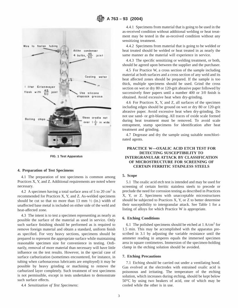
4. Preparation of Test Specimens
4.1 The preparation of test specimens is common amongPractices X, Y, and Z. Additional requirements are noted wherenecessary.
4.2 A specimen having a total surface area of 5 to 20 cm2 isrecommended for Practices X, Y, and Z. As-welded specimensshould be cut so that no more than 13 mm1⁄2 (in.) width ofunaffected base metal is included on either side of the weld andheat-affected zone.
4.3 The intent is to test a specimen representing as nearly aspossible the surface of the material as used in service. Onlysuch surface finishing should be performed as is required toremove foreign material and obtain a standard, uniform finishas specified. For very heavy sections, specimens should beprepared to represent the appropriate surface while maintainingreasonable specimen size for convenience in testing. Ordi-narily, removal of more material than necessary will have littleinfluence on the test results. However, in the special case ofsurface carburization (sometimes encountered, for instance, intubing when carbonaceous lubricants are employed) it may bepossible by heavy grinding or machining to remove thecarburized layer completely. Such treatment of test specimensis not permissible, except in tests undertaken to demonstratesuch surface effects.
4.4 Sensitization of Test Specimens:
4.4.1 Specimens from material that is going to be used in theas-received condition without additional welding or heat treat-ment may be tested in the as-received condition without anysensitizing treatment.
4.4.2 Specimens from material that is going to be welded orheat treated should be welded or heat treated in as nearly thesame manner as the material will experience in service.
4.4.3 The specific sensitizing or welding treatment, or both,should be agreed upon between the supplier and the purchaser.
4.5 For Practice W, a cross section of the sample includingmaterial at both surfaces and a cross section of any weld and itsheat affected zones should be prepared. If the sample is toothick, multiple specimens should be used. Grind the crosssection on wet or dry 80 or 120-grit abrasive paper followed bysuccessively finer papers until a number 400 or 3/0 finish isobtained. Avoid excessive heat when dry-grinding.
4.6 For Practices X, Y, and Z, all surfaces of the specimenincluding edges should be ground on wet or dry 80 or 120-gritabrasive paper. Avoid excessive heat when dry-grinding. Donot use sand- or grit-blasting. All traces of oxide scale formedduring heat treatment must be removed. To avoid scaleentrapment, stamp specimens for identification after heattreatment and grinding.
4.7 Degrease and dry the sample using suitable nonchlori-nated agents.
PRACTICE W—OXALIC ACID ETCH TEST FORDETECTING SUSCEPTIBILITY TO
INTERGRANULAR ATTACK BY CLASSIFICATIONOF MICROSTRUCTURE FOR SCREENING OF
CERTAIN FERRITIC STAINLESS STEELS
5. Scope
5.1 The oxalic acid etch test is intended and may be used forscreening of certain ferritic stainless steels to precede orpreclude the need for corrosion testing as described in PracticesX, Y, or Z. Specimens with unacceptable microstructuresshould be subjected to Practices X, Y, or Z to better determinetheir susceptibility to intergranular attack. See Table 1 for alisting of alloys for which Practice W is appropriate.
6. Etching Conditions
6.1 The polished specimens should be etched at 1 A/cm2 for1.5 min. This may be accomplished with the apparatus pre-scribed in 3.1 by adjusting the variable resistance until theammeter reading in amperes equals the immersed specimenarea in square centimetres. Immersion of the specimen-holdingclamp in the etching solution should be avoided.
7. Etching Precautions
7.1 Etching should be carried out under a ventilating hood.Gas evolved at the electrodes with entrained oxalic acid ispoisonous and irritating. The temperature of the etchingsolution, which increases during etching, should be kept below50°C by using two beakers of acid, one of which may becooled while the other is in use.
FIG. 1 Test Apparatus
A 763 – 93 (2004)
3

8. Rinsing Prior to Examination
8.1 Following etching, the specimen should be rinsed in hotwater then acetone or alcohol to avoid oxalic acid crystalliza-tion on the etched surface during forced air-drying.
9. Examination
9.1 Examine etched specimens on a metallurgical micro-scope at 250 to 5003 as appropriate for classification of etchedmicrostructure type as defined in Section 10.
10. Classification of Etched Structures
10.1 Acceptable structures indicating resistance to chro-mium carbide-type intergranular attack:
10.1.1 Step structure—Steps only between grains—noditches at grain boundaries (see Fig. 2).
10.1.2 Dual structure—Some ditches at grain boundaries inaddition to steps, but no single grain completely surrounded byditches (see Fig. 3).
FIG. 2 Acceptable Structures Practice W—Oxalic-Acid Etch Test Steps Between Grains No Ditching
A 763 – 93 (2004)
4
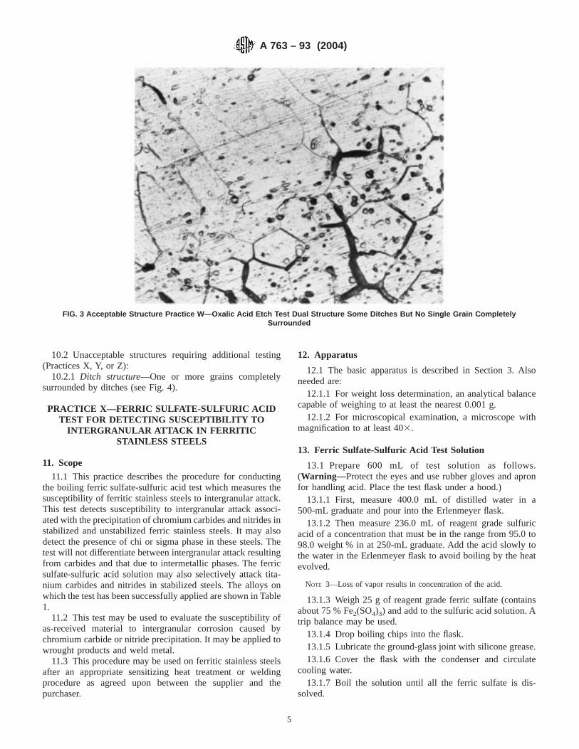
10.2 Unacceptable structures requiring additional testing(Practices X, Y, or Z):
10.2.1 Ditch structure—One or more grains completelysurrounded by ditches (see Fig. 4).
PRACTICE X—FERRIC SULFATE-SULFURIC ACIDTEST FOR DETECTING SUSCEPTIBILITY TO
INTERGRANULAR ATTACK IN FERRITICSTAINLESS STEELS
11. Scope
11.1 This practice describes the procedure for conductingthe boiling ferric sulfate-sulfuric acid test which measures thesusceptibility of ferritic stainless steels to intergranular attack.This test detects susceptibility to intergranular attack associ-ated with the precipitation of chromium carbides and nitrides instabilized and unstabilized ferric stainless steels. It may alsodetect the presence of chi or sigma phase in these steels. Thetest will not differentiate between intergranular attack resultingfrom carbides and that due to intermetallic phases. The ferricsulfate-sulfuric acid solution may also selectively attack tita-nium carbides and nitrides in stabilized steels. The alloys onwhich the test has been successfully applied are shown in Table1.
11.2 This test may be used to evaluate the susceptibility ofas-received material to intergranular corrosion caused bychromium carbide or nitride precipitation. It may be applied towrought products and weld metal.
11.3 This procedure may be used on ferritic stainless steelsafter an appropriate sensitizing heat treatment or weldingprocedure as agreed upon between the supplier and thepurchaser.
12. Apparatus
12.1 The basic apparatus is described in Section 3. Alsoneeded are:
12.1.1 For weight loss determination, an analytical balancecapable of weighing to at least the nearest 0.001 g.
12.1.2 For microscopical examination, a microscope withmagnification to at least 403.
13. Ferric Sulfate-Sulfuric Acid Test Solution
13.1 Prepare 600 mL of test solution as follows.(Warning—Protect the eyes and use rubber gloves and apronfor handling acid. Place the test flask under a hood.)
13.1.1 First, measure 400.0 mL of distilled water in a500-mL graduate and pour into the Erlenmeyer flask.
13.1.2 Then measure 236.0 mL of reagent grade sulfuricacid of a concentration that must be in the range from 95.0 to98.0 weight % in at 250-mL graduate. Add the acid slowly tothe water in the Erlenmeyer flask to avoid boiling by the heatevolved.
NOTE 3—Loss of vapor results in concentration of the acid.
13.1.3 Weigh 25 g of reagent grade ferric sulfate (containsabout 75 % Fe2(SO4)3) and add to the sulfuric acid solution. Atrip balance may be used.
13.1.4 Drop boiling chips into the flask.13.1.5 Lubricate the ground-glass joint with silicone grease.13.1.6 Cover the flask with the condenser and circulate
cooling water.13.1.7 Boil the solution until all the ferric sulfate is dis-
solved.
FIG. 3 Acceptable Structure Practice W—Oxalic Acid Etch Test Dual Structure Some Ditches But No Single Grain CompletelySurrounded
A 763 – 93 (2004)
5
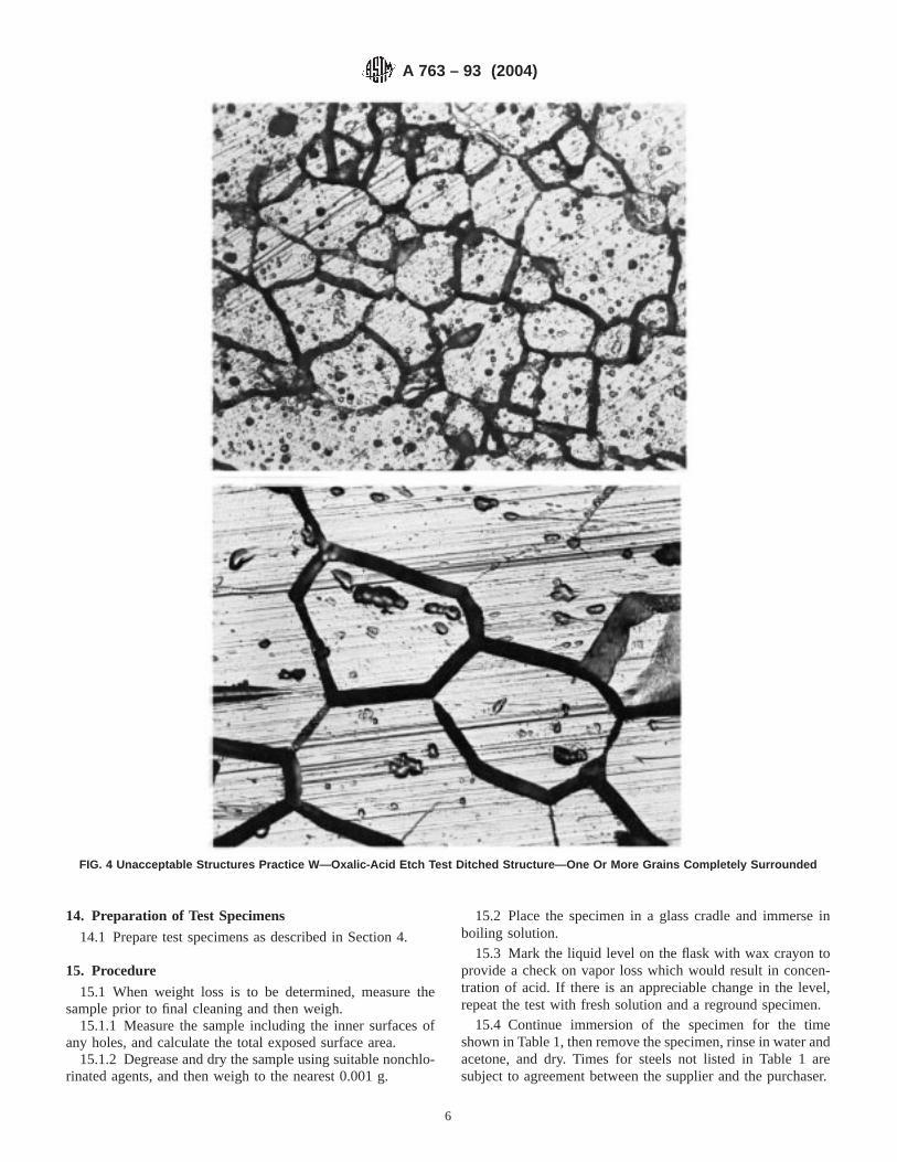
14. Preparation of Test Specimens
14.1 Prepare test specimens as described in Section 4.
15. Procedure
15.1 When weight loss is to be determined, measure thesample prior to final cleaning and then weigh.
15.1.1 Measure the sample including the inner surfaces ofany holes, and calculate the total exposed surface area.
15.1.2 Degrease and dry the sample using suitable nonchlo-rinated agents, and then weigh to the nearest 0.001 g.
15.2 Place the specimen in a glass cradle and immerse inboiling solution.
15.3 Mark the liquid level on the flask with wax crayon toprovide a check on vapor loss which would result in concen-tration of acid. If there is an appreciable change in the level,repeat the test with fresh solution and a reground specimen.
15.4 Continue immersion of the specimen for the timeshown in Table 1, then remove the specimen, rinse in water andacetone, and dry. Times for steels not listed in Table 1 aresubject to agreement between the supplier and the purchaser.
FIG. 4 Unacceptable Structures Practice W—Oxalic-Acid Etch Test Ditched Structure—One Or More Grains Completely Surrounded
A 763 – 93 (2004)
6
15.5 For weight loss determination, weigh the specimen andsubtract this weight from the original weight.
15.6 No intermediate weighings are usually necessary. Thetests can be run without interruption for the time specified inTable 1. However, if preliminary results are desired, thespecimen can be removed at any time for weighing.
15.7 No changes in solution are necessary during the testperiod.
15.8 Additional ferric sulfate inhibitor may have to beadded during the test if the corrosion rate is extraordinarilyhigh as evidenced by a change in the color of the solution.More ferric sulfate must be added if the total weight loss of allspecimens exceeds 2 g. (During the test, ferric sulfate isconsumed at a rate of 10 g for each 1 g of dissolved stainlesssteel.)
15.9 Testing of a single specimen in a flask is preferred.However, several specimens may be tested simultaneously. Thenumber is limited only by the number of glass cradles that canbe fitted into the flask (usually three or four). Each sample mustbe in a separate cradle so that the samples do not touch.
15.10 During testing, there is some deposition of ironoxides on the upper part of the Erlenmeyer flask. This can bereadily removed, after test completion, by boiling a solution of10 % hydrochloric acid in the flask.
16. Evaluation
16.1 Depending on the agreement between the supplier andthe purchaser, the results of the test may be evaluated byweight loss or microscopical examination as indicated in Table1. See Sections 30 and 31.
PRACTICE Y—COPPER-COPPER SULFATE-50 %SULFURIC ACID TEST FOR DETERMINING
SUSCEPTIBILITY TO INTERGRANULAR ATTACKIN FERRITIC STAINLESS STEELS
17. Scope
17.1 This practice describes the procedure for conductingthe boiling copper-copper sulfate-50 % sulfuric acid test whichmeasures the susceptibility of stainless steels to intergranularattack. This test detects susceptibility to intergranular attackassociated with the precipitation of chromium carbides ornitrides in unstabilized and stabilized ferritic stainless steels.
17.2 This test may be used to evaluate the susceptibility ofas-received material to intergranular corrosion caused bychromium carbide or nitride precipitation. It may also be usedto evaluate the resistance of high purity or stabilized grades tosensitization to intergranular attack caused by welding or heattreatments. It may be applied to wrought products.
17.3 This test should not be used to detect susceptibility tointergranular attack resulting from the formation or presence ofchi phase, sigma phase, or titanium carbides or nitrides. Fordetecting susceptibility to environments known to cause inter-granular attack due to these phases use Practice X.
18. Apparatus
18.1 The basic apparatus is described in Section 3. Alsoneeded are:
18.1.1 For weight loss determination, an analytical balancecapable of weighing to the nearest 0.001 g.
18.1.2 For microscopical examination, a microscope withmagnification to at least 403.
18.1.3 A piece of copper metal about 3.2 by 19 by 38 mm(1⁄8 by 3⁄4 by 11⁄2 in.) with a bright, clean finish. An equivalentarea of copper shot or chips may be used. The copper should bewashed and degreased before use. A rinse in 5 % H2SO4 willclean corrosion products from the copper.
19. Copper-Copper Sulfate-50 % Sulfuric Acid TestSolution
19.1 Prepare 600 mL of test solution as follows.(Warning—Protect the eyes and face by face shield and userubber gloves and apron when handling acid. Place flask underhood.)
19.1.1 First, measure 400.0 mL of distilled water in a500-mL graduate and pour into the Erlenmeyer flask.
19.1.2 Then measure 236.0 mL of reagent grade sulfuricacid of a concentration that must be in the range from 95.0 to98.0 weight % in a 250-mL graduate. Add the acid slowly tothe water in the Erlenmeyer flask to avoid boiling by the heatevolved.
19.1.3 Weigh 72 g of reagent grade cupric sulfate(CuSO4·5H2O) and add to the sulfuric acid solution. A tripbalance may be used.
19.1.4 Place the copper piece into one glass cradle and putit into the flask.
19.1.5 Drop boiling chips into the flask.19.1.6 Lubricate the ground-glass joint with silicone grease.19.1.7 Cover the flask with the condenser and circulate
cooling water.19.1.8 Boil the solution until all of the copper sulfate is
dissolved.
20. Preparation of Test Specimens
20.1 Prepare test specimens as described in Section 4.
21. Procedure
21.1 When weight loss is to be determined, measure thesample prior to final cleaning and then weigh.
21.1.1 Measure the sample including the inner surfaces ofany holes, and calculate the total area.
21.1.2 Degrease and dry the specimen using suitable non-chlorinated agents, such as soap and acetone, and then weigh tothe nearest 0.001 g.
21.2 Place the specimen in another glass cradle and im-merse in boiling solution.
21.3 Mark the liquid level on the flask with wax crayon toprovide a check on vapor loss which would result in concen-tration of the acid. If there is an appreciable change in the level,repeat the test with fresh solution and a reground specimen.
21.4 Continue immersion of the specimen for the timeshown in Table 1, then remove the specimen, rinse in water andacetone, and dry. Times for alloys not listed in Table 1 aresubject to agreement between the supplier and the purchaser.
21.5 For weight loss determination, weigh the specimen andsubtract this weight from the original weight.
A 763 – 93 (2004)
7

21.6 No intermediate weighings are usually necessary. Thetests can be run without interruption. However, if preliminaryresults are desired, the specimen can be removed at any timefor weighing.
21.7 No changes in solution are necessary during the testperiod.
22. Evaluation
22.1 Depending on the agreement between the supplier andthe purchaser, the results of the test may be evaluated byweight loss or microscopical examination as indicated in Table1. See Sections 30 and 31.
PRACTICE Z—COPPER-COPPER SULFATE-16 %SULFURIC ACID TEST FOR DETECTING
SUSCEPTIBILITY TO INTERGRANULAR ATTACKIN FERRITIC STAINLESS STEELS
23. Scope
23.1 This practice describes the procedure by which thecopper-copper sulfate-16 % sulfuric acid test is conducted todetermine the susceptibility of ferritic stainless steels to inter-granular attack. This test detects susceptibility to intergranularattack associated with the precipitation of chromium carbidesor nitrides in stabilized and unstabilized ferritic stainless steels.
23.2 This test may be used to evaluate the heat treatmentaccorded as-received material. It may also be used to evaluatethe effectiveness of stabilizing element additions (Cb, Ti, etc.)and reductions in interstitial content to aid in resistance tointergranular attack. It may be applied to all wrought productsand weld metal.
23.3 This test does not detect susceptibility associated withchi phase, sigma phase, or titanium carbides or nitrides. Fordetecting susceptibility in environments known to cause inter-granular attack due to these phases, use Practice X.
24. Apparatus
24.1 The basic apparatus is described in Section 3.
25. Copper-Copper Sulfate-16 % Sulfuric Acid TestSolution
25.1 Dissolve 100 g of copper sulfate (CuSO4·5H2O) in 700mL of distilled water, add 100 mL of sulfuric acid (H2SO4,reagent grade, sp gr 1.84), and dilute to 1000 mL with distilledwater.
NOTE 4—The solution will contain approximately 6 weight % ofanhydrous CuSO4, and 16 weight % of H2SO4.
26. Copper Addition
26.1 Electrolytic grade copper shot or grindings may beused. Shot is preferred for its ease of handling before and afterthe test.
26.2 A sufficient quantity of copper shot or grindings shallbe used to cover all surfaces of the specimen whether it is in avented cradle or embedded in a layer of copper shot on thebottom of the test flask.
26.3 The amount of copper used, assuming an excess ofmetallic copper is present, is not critical. The effect of galvaniccoupling between copper and the test specimen may haveimportance(7).
26.4 The copper shot or grindings may be reused if they arecleaned in warm tap water after each test.
27. Preparation of Test Specimens
27.1 Prepare test specimens as described in Section 4.
28. Procedure
28.1 The volume of acidified copper sulfate test solutionused should be sufficient to completely immerse the specimensand provide a minimum of 8 mL/cm2(50 mL/in.2).
28.1.1 As many as three specimens can be tested in the samecontainer. It is ideal to have all the specimens in one flask to beof the same grade, but it is not absolutely necessary. Thesolution volume-to-sample area ratio shall be maintained.
NOTE 5—It may be necessary to embed large specimens, such as fromheavy bar stock, in copper shot on the bottom of the test flask. A coppercradle may also be used.
28.1.2 The test specimen(s) should be immersed in ambienttest solution which is then brought to a boil and maintainedboiling throughout the test period. Begin timing the test periodwhen the solution reaches the boiling point.
NOTE 6—Measures should be taken to minimize bumping of thesolution when glass cradles are used to support specimens. A smallamount of copper shot (eight to ten pieces) on the bottom of the flask willconveniently serve this purpose.
28.1.3 The test shall consist of one 24-h boiling periodunless a longer time is specified. See Table 1. Times longerthan 24 h should be included in the test report. Fresh testsolution would not be needed if the test were to run 48 or 72h. (If any adherent copper remains on the specimen, it may beremoved by a brief immersion in concentrated nitric acid atroom temperature. The sample is then rinsed in water anddried.)
29. Evaluation
29.1 As shown in Table 1, the results of this test areevaluated by a bend test. See Section 32.
EVALUATION METHODS
30. Evaluation by Weight Loss
30.1 Measure the effect of the acid solution on the materialby determining the loss of weight of the specimen. Report thecorrosion rates as inches of penetration per month, calculatedas follows:
Millimeters per month5 72903 W/A 3 t 3 d
where:t = time of exposure, h,A = area, cm2,W = weight loss, g, andd = density, g/cm3. For steels 14-20Cr,d = 7.7 g/cm3; for
steels with more than 20Cr,d = 7.6 g/cm3.
NOTE 7—Conversion factors to other commonly used units for corro-sion rates are as follows:
Millimeters per month3 0.04 = inches per monthMillimeters per month3 0.47 = inches per yearMillimeters per month3 12 = millimeters per yearMillimeters per month3 472 = mils per year
A 763 – 93 (2004)
8

Millimeters per month3 1000 3 density/3 = milligram per squaredecimeter per day
Millimeters per month3 1.393 density = grams per square meter perhours
30.2 What corrosion rate is indicative of intergranular attackdepends on the alloy and must be determined by agreementbetween the supplier and the purchaser. Some experience withcorrosion rates of ferritic stainless steels in Practices X and Yis given in the literature(5).
31. Evaluation by Microscopical Examination
31.1 Examine the test specimens for Practices X and Yunder a binocular microscope at 403 magnification. Graindropping is usually an indication of intergranular attack, butthe number of dropped grains per unit area that can be toleratedis subject to agreement between the supplier and the purchaser.
31.1.1 Grain dropping is the dislodgement and loss of agrain or grains from a metal surface as the result of intergranu-lar corrosion.
32. Evaluation by Bend Test
32.1 Bend the test specimen through 180° and over a radiusequal to twice the thickness of the specimen being bent (seeFig. 5). In no case shall the specimen be bent over a smallerradius or through a greater angle than that specified in the
product specification. In cases of material having low ductility,such as severely cold worked material, a 180° bend may proveimpractical. Determine the maximum angle of bend withoutcausing cracks in such material by bending an untestedspecimen of the same configuration as the specimen to betested. Welded samples should be bent in such a manner thatweld and the heat-affected zone are strained.
32.1.1 Obtain duplicate specimens from sheet material sothat both sides of the rolled samples may be bent through a180° bend. This will ensure detection of intergranular attackresulting from carburizing of one surface of sheet materialduring the final stages of rolling.
NOTE 8—Identify the duplicate specimens in such a manner as toensure both surfaces of sheet material being tested are subjected to thetension side of the 180° bends.
32.1.2 Samples machined from round sections shall havethe curved or original surface on the outside of the bend.
32.1.3 The specimens are generally bent by holding in a viseand starting the bend with a hammer. It is generally completedby bringing the two ends together in the vise. Heavy specimensmay require bending in a fixture of suitable design. An air orhydraulic press may also be used for bending the specimens.
32.1.4 Flatten tubular products in accordance with theflattening test prescribed in Test Methods and DefinitionsA 370.
32.2 Examine the bent specimen under low (5 to 203)magnification (see Fig. 6). The appearance of fissures or cracksindicates the presence of intergranular attack (see Fig. 7).
32.2.1 When an evaluation is questionable, determine pres-ence or absence of intergranular attack by metallographicexamination of a longitudinal section of the specimen at amagnification of 100 to 2503.
NOTE 9—Cracking that originates at the edge of the specimen should bedisregarded. The appearance of deformation lines, wrinkles, or “orangepeel” on the surface, without accompanying cracks or fissures, should bedisregarded also.
NOTE 10—Cracks suspected as arising through poor ductility may beinvestigated by bending a similar specimen that was not exposed to theboiling test solution. A visual comparison between these specimens shouldassist in interpretation.
33. Keywords
33.1 copper sulfate; corrosion testing; etch structures; ferricsulfate; ferritic stainless steel; intergranular corrosion; oxalicacidFIG. 5 Bend Test Specimen
A 763 – 93 (2004)
9

FIG. 6 Bend Test Specimen That Does Not Show Fissures
FIG. 7 Bend Test Specimen Showing Intergranular Fissures
A 763 – 93 (2004)
10
REFERENCES
(1) Streicher, M. A., “Theory and Application of Evaluation Tests forDetecting Susceptibility to Intergranular Attack in Stainless Steels andRelated Alloys—Problems and Opportunities,”Intergranular Corro-sion of Stainless Alloys, ASTM STP 656, R. F. Steigerwald, ed., 1978,pp. 3–84.
(2) Dundas, H. J., and Bond, A. P., “Niobium and Titanium Requirementsfor Stabilization of Ferritic Stainless Steels,”Intergranular Corrosionof Stainless Alloys, ASTM STP 656, R. F. Steigerwald, Ed., 1978, pp.154–178.
(3) Nichol, T. J., and Davis, J. A., “Intergranular Corrosion Testing andSensitization of Two High-Chromium Ferritic Stainless Steels,”Inter-granular Corrosion of Stainless Alloys, ASTM STP 656, R. F. Steiger-
wald, ed., 1978, pp. 179–196.(4) Sweet, A. J., “Detection of Susceptibility of Alloy 26-1S to Inter-
granular Attack,”Intergranular Corrosion of Stainless Alloys, ASTMSTP 656, R. F. Steigerwald, Ed., 1978, pp. 197–232.
(5) Streicher, M. A., “The Role of Carbon, Nitrogen, and Heat Treatmentin the Dissolution of Iron Chromium Alloys in Acids,”Corrosion, Vol29, pp 337–360.
(6) Deverell, H. E., “Stabilization of AISI 439 (S43035) Stainless Steel,Materials Performance, Vol 24, No 2, 1985, pp. 47–50.
(7) Herbsleb, G., and Schwenk, W., “Untersuchungen zur Einstellung desRedoxpotentials der Strausschen Lösung mit Zusatz von Metalleis-chem Kufer,”Corrosion Science, Vol 7, 1967, pp. 501–511.
ASTM International takes no position respecting the validity of any patent rights asserted in connection with any item mentionedin this standard. Users of this standard are expressly advised that determination of the validity of any such patent rights, and the riskof infringement of such rights, are entirely their own responsibility.
This standard is subject to revision at any time by the responsible technical committee and must be reviewed every five years andif not revised, either reapproved or withdrawn. Your comments are invited either for revision of this standard or for additional standardsand should be addressed to ASTM International Headquarters. Your comments will receive careful consideration at a meeting of theresponsible technical committee, which you may attend. If you feel that your comments have not received a fair hearing you shouldmake your views known to the ASTM Committee on Standards, at the address shown below.
This standard is copyrighted by ASTM International, 100 Barr Harbor Drive, PO Box C700, West Conshohocken, PA 19428-2959,United States. Individual reprints (single or multiple copies) of this standard may be obtained by contacting ASTM at the aboveaddress or at 610-832-9585 (phone), 610-832-9555 (fax), or [email protected] (e-mail); or through the ASTM website(www.astm.org).
A 763 – 93 (2004)
11
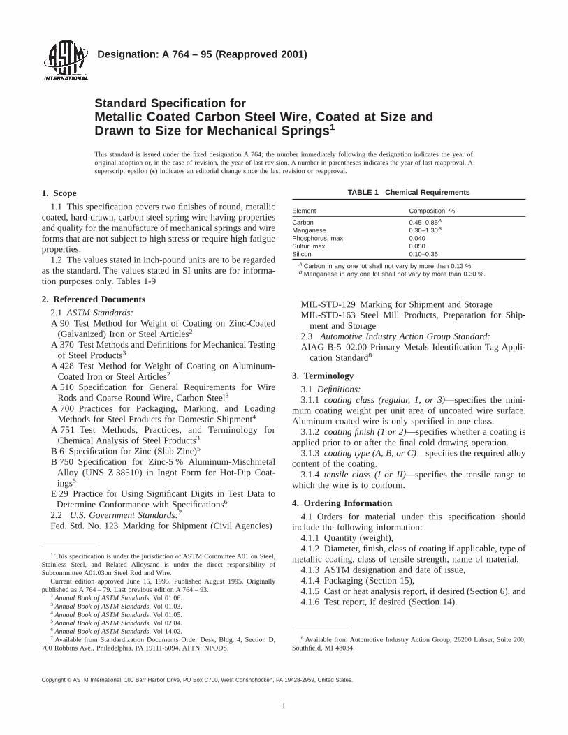
Designation: A 764 – 95 (Reapproved 2001)
Standard Specification forMetallic Coated Carbon Steel Wire, Coated at Size andDrawn to Size for Mechanical Springs 1
This standard is issued under the fixed designation A 764; the number immediately following the designation indicates the year oforiginal adoption or, in the case of revision, the year of last revision. A number in parentheses indicates the year of last reapproval. Asuperscript epsilon (e) indicates an editorial change since the last revision or reapproval.
1. Scope
1.1 This specification covers two finishes of round, metalliccoated, hard-drawn, carbon steel spring wire having propertiesand quality for the manufacture of mechanical springs and wireforms that are not subject to high stress or require high fatigueproperties.
1.2 The values stated in inch-pound units are to be regardedas the standard. The values stated in SI units are for informa-tion purposes only. Tables 1-9
2. Referenced Documents
2.1 ASTM Standards:A 90 Test Method for Weight of Coating on Zinc-Coated
(Galvanized) Iron or Steel Articles2
A 370 Test Methods and Definitions for Mechanical Testingof Steel Products3
A 428 Test Method for Weight of Coating on Aluminum-Coated Iron or Steel Articles2
A 510 Specification for General Requirements for WireRods and Coarse Round Wire, Carbon Steel3
A 700 Practices for Packaging, Marking, and LoadingMethods for Steel Products for Domestic Shipment4
A 751 Test Methods, Practices, and Terminology forChemical Analysis of Steel Products3
B 6 Specification for Zinc (Slab Zinc)5
B 750 Specification for Zinc-5 % Aluminum-MischmetalAlloy (UNS Z 38510) in Ingot Form for Hot-Dip Coat-ings5
E 29 Practice for Using Significant Digits in Test Data toDetermine Conformance with Specifications6
2.2 U.S. Government Standards:7
Fed. Std. No. 123 Marking for Shipment (Civil Agencies)
MIL-STD-129 Marking for Shipment and StorageMIL-STD-163 Steel Mill Products, Preparation for Ship-
ment and Storage2.3 Automotive Industry Action Group Standard:AIAG B-5 02.00 Primary Metals Identification Tag Appli-
cation Standard8
3. Terminology
3.1 Definitions:3.1.1 coating class (regular, 1, or 3)—specifies the mini-
mum coating weight per unit area of uncoated wire surface.Aluminum coated wire is only specified in one class.
3.1.2 coating finish (1 or 2)—specifies whether a coating isapplied prior to or after the final cold drawing operation.
3.1.3 coating type (A, B, or C)—specifies the required alloycontent of the coating.
3.1.4 tensile class (I or II)—specifies the tensile range towhich the wire is to conform.
4. Ordering Information
4.1 Orders for material under this specification shouldinclude the following information:
4.1.1 Quantity (weight),4.1.2 Diameter, finish, class of coating if applicable, type of
metallic coating, class of tensile strength, name of material,4.1.3 ASTM designation and date of issue,4.1.4 Packaging (Section 15),4.1.5 Cast or heat analysis report, if desired (Section 6), and4.1.6 Test report, if desired (Section 14).
1 This specification is under the jurisdiction of ASTM Committee A01 on Steel,Stainless Steel, and Related Alloysand is under the direct responsibility ofSubcommittee A01.03on Steel Rod and Wire.
Current edition approved June 15, 1995. Published August 1995. Originallypublished as A 764 – 79. Last previous edition A 764 – 93.
2 Annual Book of ASTM Standards, Vol 01.06.3 Annual Book of ASTM Standards, Vol 01.03.4 Annual Book of ASTM Standards, Vol 01.05.5 Annual Book of ASTM Standards, Vol 02.04.6 Annual Book of ASTM Standards, Vol 14.02.7 Available from Standardization Documents Order Desk, Bldg. 4, Section D,
700 Robbins Ave., Philadelphia, PA 19111-5094, ATTN: NPODS.
8 Available from Automotive Industry Action Group, 26200 Lahser, Suite 200,Southfield, MI 48034.
TABLE 1 Chemical Requirements
Element Composition, %
Carbon 0.45–0.85A
Manganese 0.30–1.30B
Phosphorus, max 0.040Sulfur, max 0.050Silicon 0.10–0.35
A Carbon in any one lot shall not vary by more than 0.13 %.B Manganese in any one lot shall not vary by more than 0.30 %.
1
Copyright © ASTM International, 100 Barr Harbor Drive, PO Box C700, West Conshohocken, PA 19428-2959, United States.

NOTE 1—A typical ordering description is as follows: 30 000 lb 0.120in. Finish 2, Class 1, Type B Metallic Coating, Tensile Class II, SteelMechanical Spring Wire in 400-lb, 22-in. coils to ASTM A 764, dated .
5. Materials and Manufacture
5.1 The base metal of the wire shall be of good commercialquality steel. The steel may be either ingot cast or strand cast.
5.2 A sufficient discard shall be made to ensure freedomfrom injurious piping and undue segregation.
5.3 The wire shall be cold drawn to produce the desiredmechanical properties.
5.4 Each coil shall be of one continuous length. Only weldsmade prior to cold drawing are permitted, unless otherwiseagreed upon at the time of the purchase or contract.
5.5 The material shall be metallic coated prior to colddrawing, or at an intermediate stage of cold drawing (Finish 1),or shall be metallic coated after the final cold drawing (Finish2).
5.6 The wire shall be furnished with one of three types ofmetallic coating, as specified:
5.6.1 Type A—Aluminum coated (aluminized),5.6.2 Type B—Zinc coated (galvanized), or5.6.3 Type C—Zinc-5 % aluminum-mischmetal (Zn-5Al-
MM) alloy coated.5.7 Coating Types A and C shall be produced by a hot-dip
process. Coating Type B may be produced by either a hot-dipor an electrolytic process at the option of the producer.
5.8 The slab zinc for Coating Type B shall be any grade ofzinc conforming to Specification B 6.
TABLE 2 Tensile Requirements A—Finish 1 (Drawn to Size Metallic Coated), Regular or Class 1 Coating (One Class on Coating Type A)
Wire Diameter,B in. (mm)
Tensile Class I Tensile Class II
Tensile Strength, ksi (MPa) Tensile Strength, ksi (MPa)
min max min max
0.032 (0.81)C 253 (1740) 306 (2110) 292 (2010) 347 (2390)0.035 (0.89)C 248 (1710) 301 (2080) 287 (1980) 342 (2360)0.041 (1.04)C 242 (1670) 293 (2020) 279 (1920) 332 (2290)0.048 (1.22)C 236 (1630) 286 (1970) 273 (1880) 325 (2240)0.054 (1.37) 231 (1590) 279 (1920) 266 (1830) 316 (2180)0.062 (1.57) 225 (1550) 272 (1880) 259 (1790) 308 (2120)0.072 (1.83) 220 (1520) 266 (1830) 254 (1750) 301 (2080)0.080 (2.03) 216 (1490) 261 (1800) 249 (1720) 296 (2040)0.092 (2.34) 209 (1440) 253 (1740) 241 (1660) 287 (1980)0.106 (2.69) 205 (1410) 248 (1710) 237 (1630) 281 (1940)0.120 (3.05) 200 (1380) 241 (1660) 230 (1590) 273 (1880)0.135 (3.43) 196 (1350) 237 (1630) 226 (1560) 269 (1850)0.148 (3.76) 193 (1330) 234 (1610) 223 (1540) 266 (1830)
A Tensile strength values for intermediate diameters may be interpolated.B Decimal size is rounded to three significant places in accordance with Practice E 29.C These sizes are not produced with metallic coating Type A.
TABLE 3 Tensile Requirements A—Finish 2 (Metallic Coated at Size) Regular, Class 1 or Class 3 Coating (One Class on Coating TypeA)
Wire Diameter,B in. (mm)
Class I Class II
Tensile Strength, ksi (MPa) Tensile Strength, ksi (MPa)
min max min max
0.062 (1.57)C 213 (1470) 272 (1880) 232 (1600) 291 (2010)0.072 (1.83)C 209 (1440) 266 (1830) 227 (1570) 284 (1960)0.080 (2.03) 204 (1410) 261 (1800) 223 (1540) 280 (1930)0.092 (2.34) 198 (1370) 253 (1740) 216 (1490) 271 (1870)0.106 (2.69) 194 (1340) 248 (1710) 212 (1460) 266 (1830)0.120 (3.05) 189 (1300) 241 (1660) 206 (1420) 258 (1780)0.135 (3.43) 185 (1280) 237 (1630) 202 (1390) 254 (1750)0.148 (3.76) 183 (1260) 234 (1610) 200 (1380) 251 (1730)0.162 (4.11) 180 (1240) 230 (1590) 196 (1350) 246 (1700)0.177 (4.50) 176 (1210) 225 (1550) 192 (1320) 241 (1660)0.192 (4.88) 173 (1190) 221 (1520) 189 (1300) 237 (1630)0.207 (5.26) 171 (1180) 218 (1500) 186 (1280) 233 (1610)0.225 (5.72)C 167 (1150) 214 (1480) 183 (1260) 230 (1590)0.250 (6.35)C 164 (1130) 210 (1450) 179 (1230) 225 (1550)
A Tensile strength values for intermediate diameters may be interpolated.B Decimal size is rounded to three significant places in accordance with Practice E 29.CThese sizes are not produced with metallic coating Type A.
TABLE 4 Mandrel Diameters for Steel Ductility and Adherenceof Metallic Coating Test for Finish 1 Wire (Drawn to Size Metallic
Coated)
Wire Diameter Mandrel Diameter
in. mm Class ITensile
Class IITensile
0.032 to0.148 incl
0.81 to 3.76incl
1DA 2D
AD equals nominal wire diameter being tested. For 1D mandrel, wire may bewound on itself.
A 764 – 95 (2001)
2

5.9 The ingot used for Coating Type C shall conform toSpecification B 750.
6. Chemical Requirements
6.1 The steel shall conform to the requirements for chemicalcomposition prescribed in Table 1.
6.2 Cast or Heat Analysis—Each cast or heat of steel shallbe analyzed by the manufacturer to determine compliance withthe percentage of elements prescribed in Table 1. This analysisshall be from a test specimen preferably taken during thepouring of the cast or heat. When required, this shall bereported to the purchaser.
6.3 Product Analysis—An analysis may be made by thepurchaser from finished wire representing each cast or heat ofsteel. The chemical composition thus determined, as to ele-ments required or restricted, shall conform to the productanalysis requirements specified in Table 10 of SpecificationA 510.
6.4 For referee purposes, Test Methods, Practices, andTerminology A 751 shall be used.
7. Mechanical Requirements
7.1 Tension Test:7.1.1 Requirements—The material as represented by tension
test specimens shall conform to the requirements prescribed inTable 2 or Table 3 for the various sizes and specified class.
TABLE 5 Mandrel Diameters for Steel Ductility and Adherence of Metallic Coating Test for Finish 2 Wire (Metallic Coated at Size)
Wire Diameter Mandrel Diameters for Various Coating and Tensile Strength Classes
Regular and Class I Coating Class 3 Coating
in. mm Class I Tensile Class I Tensile Class I Tensile Class II Tensile
0.062 to under 0.076 1.57 to under 1.93 1DA 2D 2D 3D0.076 to under 0.148 1.93 to under 3.76 2D 3D 3D 4D0.148 to under 0.162 3.76 to under 4.11 2D 4D 4D 5D0.162 to 0.250 incl 4.11 to 6.35 incl 3D 5D 4D 5D
AD equals nominal wire diameter being tested.
TABLE 6 Minimum Weight of Aluminum per Unit Area ofUncoated Wire Surface
Wire Diameter,A
in. (mm)Finish 1 Finish 2
oz/ft2 g/m2 oz/ft2 g/m2
0.054 (1.37) 0.20 61 . . . . . .0.062 (1.57) 0.20 61 . . . . . .0.072 (1.83) 0.20 61 . . . . . .0.076 (1.93) 0.21 64 . . . . . .0.080 (2.03) 0.21 64 0.30 920.092 (2.34) 0.21 64 0.32 980.099 (2.51) 0.23 70 0.32 980.106 (2.69) 0.23 70 0.35 1070.120 (3.05) 0.23 70 0.35 1070.135 (3.43) 0.25 70 0.35 1070.148 (3.76) 0.25 70 0.40 1220.162 (4.11) 0.27 82 0.40 1220.177 (4.50) 0.27 82 0.40 1220.192 (4.88) 0.30 92 0.40 1220.207 (5.26) 0.30 92 0.40 122
ADiameters, other than those shown above, are produced with aluminumcoating equivalent to those of the next smaller size.
TABLE 7 Minimum Weight of Zinc or Zinc-5 % Aluminum-Mischmetal Alloy per Unit Area of Uncoated Wire Surface
Wire Diameter,A
in. (mm)Class 1 Coating Class 3 Coating
oz/ft2 g/m2 oz/ft2 g/m2
0.032 (0.81) 0.05 16 0.25 760.035 (0.89) 0.10 31 0.40 1220.041 (1.04) 0.10 31 0.40 1220.048 (1.22) 0.15 46 0.40 1220.054 (1.37) 0.15 46 0.40 1220.062 (1.57) 0.15 46 0.50 1530.072 (1.83) 0.15 46 0.50 1530.076 (1.93) 0.20 61 0.60 1830.080 (2.03) 0.25 76 0.65 1980.092 (2.34) 0.30 92 0.70 2140.099 (2.51) 0.30 92 0.80 2440.106 (2.69) 0.30 92 0.80 2440.120 (3.05) 0.30 92 0.80 2440.135 (3.43) 0.30 92 0.80 2440.148 (3.76) 0.40 122 0.80 2440.162 (4.11) 0.40 122 0.80 2440.177 (4.50) 0.40 122 0.80 2440.192 (4.88) 0.50 153 0.90 2750.207 (5.26) 0.65 198 0.90 2750.225 (5.72) 0.65 198 0.90 2750.250 (6.35) 0.65 198 0.90 275
ADiameters, other than those shown above, are produced with metallic coatingequivalent to those of the next smaller size.
TABLE 8 Permissible Variations in Dimensions Finish 1, Drawnto Size Metallic Coated A
Wire Diameter, in. (mm) Permissible Variations,Plus and Minus, in. (mm)
Permissible Out-of-Round,in. (mm)
0.032 (0.81) to under0.076 (1.93)
0.001 (0.03) 0.001 (0.03)
0.076 (1.93) to 0.148(3.76) incl
0.002 (0.05) 0.002 (0.05)
AFor purposes of determining conformance with this specification, all specifiedlimits are absolute as defined in Practice E 29.
TABLE 9 Permissible Variations in Dimensions Finish 2, MetallicCoated at Size
Wire Diameter, in. (mm)A Tolerance,B Plus and Minus, in. (mm)
Regular and Class ICoating
Class 3 Coating
0.062 (1.57) to under0.076 (1.93)
0.002 (0.05) 0.002 (0.05)
0.076 (1.93) to 0.250(6.35) incl
0.003 (0.08) 0.004 (0.102)
AFor the purpose of determining conformance with this specification, anobserved value shall be rounded to the nearest 0.001 in. (0.03 mm) in accordancewith the rounding method of Practice E 29.
BIt is recognized that the surfaces of hot dipped metallic coatings are notperfectly smooth and devoid of irregularities. If the tolerances shown above arerigidly applied to such irregularities that are inherent to the product, unjustifiedrejections of wire that would actually be satisfactory for use could occur. Therefore,it is intended that these tolerances be used in gaging the uniform areas of themetallic coated wire.
A 764 – 95 (2001)
3

7.1.2 Test Method—The tension test shall be made inaccordance with Test Methods A 370, Supplement IV.
7.2 Wrap Test:7.2.1 Requirement—Finish 1 (drawn to size metallic coated)
wire shall withstand wrapping on a mandrel as shown in Table4 without the steel base fracturing or the metallic coatingpeeling or flaking to such an extent that coating metal can beremoved by rubbing with the bare fingers. Finish 2 (metalliccoated at size) wire shall withstand wrapping on a mandrel asshown in Table 5 without the steel base fracturing or themetallic coating peeling or flaking to such an extent thatcoating metal can be removed by rubbing with the bare fingers.Loosening or detachment, during the wrap test, of superficial,small particles of coating metal formed by mechanical polish-ing of the metallic coated wire shall not be considered cause forrejection.
7.2.2 Test Method—The wrap test shall be made in accor-dance with Test Methods A 370, Supplement IV.
7.3 Metallic Coating.7.3.1 Requirement:7.3.1.1 For metallic coating Type A, the wire shall conform
to the minimum weight of coating prescribed in Table 6.7.3.1.2 For metallic coating Type B or Type C, the wire shall
conform to the minimum weight of coating for Coating Class1 or 3 prescribed in Table 7. Regular coating has no minimumrequirement.
7.3.2 Test Methods:7.3.2.1 The weight of coating test for metallic coating Type
A shall be made in accordance with Test Method A 428.7.3.2.2 The weight of coating test for metallic coating Type
B or Type C shall be made in accordance with Test MethodA 90.
8. Dimensions and Permissible Variations
8.1 The diameter of the wire shall not vary from thatspecified by more than the tolerances specified in Table 8 orTable 9.
9. Workmanship, Finish, and Appearance
9.1 The surface of Finish 1, drawn metallic coated wire,shall be smooth and free from defects such as seams, pits, diemarks, and other defects tending to impair the use of the wirefor springs.
9.2 The surface of Finish 2, metallic coated at wire size,shall be free of slivers, scale, and other defects tending toimpair the use of this wire for springs. The metallic coatingshall be smooth and continuous. If a sample does not demon-strate a smooth and continuous coating, one sample shall be cutfrom each end of the coil and examined.
9.3 The wire shall be packaged so that it can be unwound ina trouble-free manner.
10. Sampling
10.1 A lot shall consist of all of the coils of wire of the samesize, type of coating, tensile strength class, metallic coatingtype, finish, and heat or cast offered for inspection at one time.A wire sample of sufficient length, approximately 4 ft (1.2 m),shall be cut from either end of each coil selected for testsdescribed in 7.1, 7.2, and 7.3.
11. Number of Tests and Retests
11.1 The number of test specimens taken from the ends ofcoils during production to ensure compliance with 7.1, 7.2, and7.3 varies with the quality control procedures and the manu-facturing facilities of each manufacturer, but is generally notless than 10 % of the coils produced. For the purpose of finalproduct testing, one specimen from every ten coils, or afraction thereof, in a lot shall be selected at random, or a totalof seven specimens, whichever is less.
11.2 Should one or more of the wire specimens fail anyrequirement, the lot shall be subjected to retest. For retestpurposes the original lot shall be regrouped into 50 coil lots orfractions thereof. Each lot shall be tested for the property inwhich the original sample failed to comply at a frequency of10 % or more so that the total number of tests is at least doublethe original. Any lot that exhibits a failure shall be rejected.The manufacturer may test each coil in the failed lot for theproperty in which failure occurred and reject only the noncon-forming coils.
11.3 If any test specimen exhibits obvious imperfectionsdue to cutting a sample from the coil or due to handlingdamage after the sample has been cut, it may be discarded andanother specimen substituted.
12. Inspection
12.1 Unless otherwise specified in the contract or purchaseorder, the manufacturer is responsible for the performance ofall inspection and test requirements specified in this specifica-tion. Except as otherwise specified in the contract or purchaseorder, the manufacturer may use his own or any other suitablefacilities for the performance of the inspection and testrequirements unless disapproved by the purchaser at the timethe order is placed. The purchaser shall have the right toperform any of the inspections and tests set forth in thisspecification when such inspections and tests are deemednecessary to ensure that the material conforms to prescribedrequirements.
13. Rejection and Rehearing
13.1 Unless otherwise specified, any rejection based on testsmade in accordance with this specification shall be reported tothe manufacturer within a reasonable length of time afterreceipt of the material.
13.2 The material must be adequately protected and cor-rectly identified in order that the producer may make a properinvestigation.
14. Certification
14.1 When specified on the purchase order or contract, amanufacturer’s or supplier’s certification shall be furnished tothe purchaser that the material was manufactured, sampled,tested, and inspected in accordance with this specification andhas been found to meet the requirements. When specified in thepurchase order or contract, a report of the test results shall befurnished.
14.2 The certification shall include the specification num-ber, year date of issue, and revision letter, if any.
A 764 – 95 (2001)
4

15. Packaging, Marking, and Loading
15.1 The coil weight, dimensions, and method of packagingshall be agreed upon between the manufacturer and thepurchaser.
15.2 The size of wire, ASTM specification, finish, coatingclass, coating type, tensile class, and name or mark of themanufacturer shall be shown on a tag securely attached to eachpackage of wire.
15.3 Unless otherwise specified in the purchaser’s order,packaging, marking, and loading for shipments shall be inaccordance with those procedures outlined in Practices A 700.
15.4 When specified in the contract or order, and for directprocurement by or direct shipment to the U.S. Government,when Level A is specified, preservation, packaging, and pack-ing shall be in accordance with the Level A requirement ofMIL-STD-163.
15.5 When specified in the contract or order, and for directprocurement by or direct shipment to the U.S. Government,marking for shipment, in addition to requirements specified inthe contract or order, shall be in accordance with MIL-STD-129 for U.S. Military Agencies and in accordance with Fed.Std. No. 123 for U.S. Government Civil Agencies.
15.6 Bar Coding—In addition to the previously statedidentification requirements, bar coding is acceptable as asupplementary identification method. Bar coding should beconsistent with AIAG Standard 02.00. The bar code may beapplied to a substantially affixed tag.
16. Keywords
16.1 aluminized; galvanized; mechanical springs; springs;steel wire; wire; wire forms; zinc-5 % aluminum-mischmetalalloy coated
ASTM International takes no position respecting the validity of any patent rights asserted in connection with any item mentionedin this standard. Users of this standard are expressly advised that determination of the validity of any such patent rights, and the riskof infringement of such rights, are entirely their own responsibility.
This standard is subject to revision at any time by the responsible technical committee and must be reviewed every five years andif not revised, either reapproved or withdrawn. Your comments are invited either for revision of this standard or for additional standardsand should be addressed to ASTM International Headquarters. Your comments will receive careful consideration at a meeting of theresponsible technical committee, which you may attend. If you feel that your comments have not received a fair hearing you shouldmake your views known to the ASTM Committee on Standards, at the address shown below.
This standard is copyrighted by ASTM International, 100 Barr Harbor Drive, PO Box C700, West Conshohocken, PA 19428-2959,United States. Individual reprints (single or multiple copies) of this standard may be obtained by contacting ASTM at the aboveaddress or at 610-832-9585 (phone), 610-832-9555 (fax), or [email protected] (e-mail); or through the ASTM website(www.astm.org).
A 764 – 95 (2001)
5

Designation: A 793 – 96 (Reapproved 2001)
Standard Specification forRolled Floor Plate, Stainless Steel 1
This standard is issued under the fixed designation A 793; the number immediately following the designation indicates the year oforiginal adoption or, in the case of revision, the year of last revision. A number in parentheses indicates the year of last reapproval. Asuperscript epsilon (e) indicates an editorial change since the last revision or reapproval.
This standard has been approved for use by agencies of the Department of Defense.
1. Scope
1.1 This specification covers stainless steel floor plates ½ in.and under for use in galley spaces, washrooms, engine rooms,and machinery spaces, and for ladder treads, gun platforms,and deck treads. For these uses, Patterns A, B, and C areconsidered interchangeable (see Fig. 1, Fig. 2, and Fig. 3).
1.2 The values stated in inch-pound units are to be regardedas the standard.
2. Referenced Documents
2.1 ASTM Standards:A 340 Terminology of Symbols and Definitions Relating to
Magnetic Testing2
A 370 Test Methods and Definitions for Mechanical Testingof Steel Products3
A 480/A 480M Specification for General Requirements forFlat-Rolled Stainless and Heat-Resisting Steel Plate,Sheet, and Strip3
A 700 Practices for Packaging, Marking, and LoadingMethods for Steel Products for Domestic Shipment4
2.2 Military Standards:MIL-I-17214 Indicator, Permeability; Low Mu (Go-NoGo)5
MIL-STD-163 Preservation of Steel Products for DomesticShipment (Storage and Overseas Shipment)5
3. Ordering Information
3.1 It is the responsibility of the purchaser to specify allrequirements that are necessary for material ordered under thisspecification. Such requirements may include, but are notlimited to, the following:
3.1.1 Quantity—number of pieces,3.1.2 Dimensions (thickness, width, and length, see Table
1),
3.1.3 Name of material (stainless steel floor plate),3.1.4 Grade (see Table 2),3.1.5 Flat back or hollow back (See Table 1),
1 This specification is under the jurisdiction of ASTM Committee A01 on Steel,Stainless Steel, and Related Alloys, and is the direct responsibility of SubcommitteeA01.17 on Flat Rolled and Wrought Stainless Steel.
Current edition approved Sept. 10, 1996. Published November 1996. Originallypublished as A 793 – 81. Last previous edition A 793 – 90e1.
2 Annual Book of ASTM Standards, Vol 03.04.3 Annual Book of ASTM Standards, Vol 01.03.4 Annual Book of ASTM Standards, Vol 01.05.5 Available from Standardization Documents Order Desk, Bldg. 4 Section D, 700
Robbins Ave., Philadelphia, PA 19111-5094, Attn: NPODS.
FIG. 1 Pattern A (percent of reduction, 61 %)
FIG. 2 Pattern B (original of raised figures approximately 1¼ in.,percent of reduction 61 %)
1
Copyright © ASTM International, 100 Barr Harbor Drive, PO Box C700, West Conshohocken, PA 19428-2959, United States.

3.1.6 Surface finish (see Specification A 480/A 480M),3.1.7 Special requirements, such as magnetic permeability
test (see 6.3),3.1.8 ASTM designation and date of issue,
3.1.9 Preparation for delivery, if different from SpecificationA 480/A 480M, and
3.1.10 Marking requirements, if different from SpecificationA 480/A 480M.
FIG. 3 Pattern C
TABLE 1 Dimensions, Weights, and Special Characteristics of Patterns A, B, and C
Thickness of Plate atBase of Raised Figure
(Nominal), in. (mm)
Thickness of Plate atBase of Raised Figure,
min, in. (mm)
Hollow Back Flat Back
Weight(Approximate),lb/ft2(kg/m2)A
Height of RaisedFigures, min,
in. (mm)
Weight(Approximate),lb/ft2(kg/m2)A
Height of RaisedFigures, min,
in. (mm)
0.025 (0.64) 0.015 (0.38) 1.10 (5.37) 0.025 (0.64) . . . . . .0.03125 (0.79) 0.02125 (0.54) 1.40 (6.84) 0.025 (0.64) . . . . . .0.0375 (0.95) 0.027 (0.69) 1.65 (5.69) 0.025 (0.64) . . . . . .0.05 (1.27) 0.039 (0.99) 2.30 (11.23) 0.035 (0.89) . . . . . .0.0625 (1.59) 0.051 (1.30) 2.90 (14.16) 0.035 (0.89) . . . . . .0.078 (1.98) 0.063 (1.60) 3.50 (17.09) 0.035 (0.89) . . . . . .
0.09375 (2.38) 0.079 (2.01) 3.938 (19.23) 0.035 (0.89) 4.875 (23.80) 0.035 (0.89)0.109 (2.77) 0.096 (2.44) 4.59 (22.41) 0.030 (0.76) 5.50 (26.85) 0.045 (1.14)0.125 (3.18) 0.110 (2.79) 5.25 (25.64) 0.030 (0.76) 6.125 (23.90) 0.055 (1.40)0.140 (3.56) 0.126 (3.20) . . . . . . 6.75 (32.96) 0.055 (1.40)0.156 (3.96) 0.141 (3.58) . . . . . . 7.375 (36.01) 0.055 (1.40)0.172 (4.37) 0.157 (3.99) . . . . . . 8.000 (39.06) 0.055 (1.40)0.1875 (4.76) 0.173 (4.39) . . . . . . 8.625 (42.11) 0.060 (1.52)0.203 (5.16) 0.189 (4.80) . . . . . . 9.25 (45.16) 0.060 (1.52)0.218 (5.54) 0.204 (5.18) . . . . . . 9.875 (48.21) 0.060 (1.52)0.234 (5.94) 0.219 (5.56) . . . . . . 10.50 (51.27) 0.060 (1.52)0.250 (6.35) 0.235 (5.97) . . . . . . 11.125 (54.32) 0.060 (1.52)
A Approximate weights are shown for estimating convenience.
TABLE 2 Heat Chemical Composition, %
TypeUNS Des-ignation
C, max Mn, max P, max S, max Si, max N, max Ni Cr Mo
304 S30400 0.08 2.00 0.045 0.030 0.75 0.10 8.00–10.50 18.00–20.00 . . .304L S30403 0.030 2.00 0.045 0.030 0.75 0.10 8.00–12.00 18.00–20.00 . . .316 S31600 0.08 2.00 0.045 0.030 0.75 0.10 10.00–14.00 16.00–18.00 2.00–3.00316L S31603 0.030 2.00 0.045 0.030 0.75 0.10 10.00–14.00 16.00–18.00 2.00–3.00
A 793 – 96 (2001)
2

NOTE 1—A typical ordering description is as follows: 100 pieces,stainless steel floor plates, 0.1875 by 60 by 120 in., Type 304 (S30400),ASTM 793 – XX.
4. Materials and Manufacture
4.1 The steel floor plate material shall conform to therequirements of one of the grades listed in Table 2.
4.2 Annealing shall be the last heat treatment to which thematerial is subjected by the manufacturer.
4.3 The stainless steel floor plate shall be of the followingpatterns, at the option of the manufacturer:
4.3.1 Pattern A—Angular (see Fig. 1).4.3.2 Pattern B—Angular (see Fig. 2).4.3.3 Pattern C—Angular (see Fig. 3).
5. Chemical Composition
5.1 The heat chemical composition shall be reported to thepurchaser, or his representative, and shall conform to therequirements for the specified grade as listed in Table 2.
5.2 For the purpose of chemical analysis, a lot shall consistof all floor plates and sheets made from the same heat. In casethe material cannot be identified by melt or heat, a lot shallconsist of not more than 25 tons (22.7 Mg) of floor plates andsheets offered for delivery at the same time.
5.3 One sample of suitable size shall be selected from eachlot identified by heat. When the material cannot be identifiedby melt or heat, five separate samples from each lot shall beselected. Samples may be taken from bend test specimensrepresentative of the lot. The chemical compositions thusdetermined shall conform to the expanded tolerances forproduct analysis shown in Table 2 of Specification A 480/A 480M. If any sample fails to conform, this shall be cause forrejection of the lot represented by the sample.
6. Mechanical Properties
6.1 Lot Size—A lot shall consist of all floor plates of thesame thickness made from the same heat. In case the materialcannot be identified by melt, a lot shall consist of not more than25 tons (22.7 Mg) of floor plates of the same thickness.
6.2 Bend Test:6.2.1 From each lot, two longitudinal cold bend test speci-
mens, 18 in. long by 2 in. wide (457 by 51 mm), shall beselected. When a lot cannot be identified by melt, fivelongitudinal cold bend test specimens, 18 in. long by 2 in.wide, shall be selected. Each of the specimens shall be takenfrom a different plate.
6.2.2 The specimens shall be bent cold, with the figures inthe inside of the bend test specimens, through an angle of 180°flat on itself. The raised figures shall not be removed and the
material shall not fracture nor develop cracks or flaws whensubjected to the cold bend test. In the case of failure of any ofthe bend test specimens to conform, this shall be cause forrejection of the lot represented by the sample (see TestMethods and Definitions A 370).
6.3 Magnetic Permeability Test:6.3.1 When magnetic permeability is specified, a lot shall
consist of all floor plates of the same thickness made from thesame melt. In case the material cannot be identified by melt, alot shall consist of not more than 25 tons (22.7 Mg) of floorplates of the same thickness.
6.3.2 Specimen for magnetic permeability test shall be aminimum of 13⁄16 in. wide by 2 in. by not more than1⁄2 in. thick(30 by 50 by 13 mm). The samples shall be large enough thatany cold work induced by cutting the sample from the masterplate shall not affect the magnetic permeability test. Thesample shall be tested in the as mill annealed condition.
6.3.3 The magnetic permeability shall not exceed 1.20 whenthe magnetic permeability indicator of MIL-I-17214 is used. Incase of failure of the specimen to comply, this shall be causefor rejection of the lot represented by the sample (see Termi-nology A 340).
7. Permissible Variations in Dimensions
7.1 Dimensions, weights, and special characteristics of Pat-terns A, B, and C shall be as specified in Table 1. The stainlesssteel floor plates shall have raised figures on one surface of thefloor plate. The reverse side shall be flat, except that the portionbelow the raised figure on plates having a nominal weightbelow 5.25 lb/ft2(25.5 kg/m2) may be hollow.
7.2 Plates shall not exceed the respective weight specified inTable 1 by more than 8 %.
7.3 Variations over the specified width and length shall notexceed the amounts permitted in Table 3. Variations under thespecified width and length shall not exceed1⁄4 in. (6.3 mm).
7.4 The thickness of the floor plates shall conform to therequirements of Table 1 and shall be measured at least3⁄8 in.(9.5 mm) from the edge of the plate exclusive of the raisedfigures.
7.5 Camber Tolerances—The camber tolerance for likeraised figures of rolled floor plates shall be determined by thefollowing equation:
Camber tolerance, in.53/8 3 number of feet of length
5
NOTE 2—Length shall be taken as the direction along which the camberis to be measured.
TABLE 3 Permissible Variations over Specified Width and Length of Regular Sheared Plates, in. (mm)
NOTE 1—Any other ordered thickness may be subject to agreement between purchaser and seller.
Specified DimensionsVariations over Specified Width and Length for Given Width, Length, and Thickness
Thickness Under 3⁄8 Thickness 3⁄8 to 1⁄2, incl
Width Length Width Length Width Length
48 (1219) and under 240 (6096) and under 1⁄8 (3.2) 3⁄16 (4.8) 3⁄16 (4.8) 1⁄4 (6.4)Over 48 to 60 (1219 to 1524), incl 240 (6096) and under 3⁄16 (4.8) 1⁄4 (6.4) 1⁄4 (6.4) 5⁄16 (7.9)
A 793 – 96 (2001)
3

7.6 Floor plates of stainless steel shall have figures not lessthan5⁄8 in. (15.9 mm) nor more than 11⁄2 in. (38.1 mm) long atthe base. The figures shall have a uniform pitch from center tocenter as indicated by the dimensions shown in Fig. 1 and Fig.2. A variation of61⁄32 in. (0.8 mm) will be permitted. Angularpattern plates and sheets shall have the figures arranged so thatthey are in an angular position from a vertical or horizontalline. Plates shall have a raised figure, and raised portion of theplates shall cover at least 30 % of the total surface of one sideof the plate. (Fig. 1 and Fig. 2 approximate actual horizontaldimensions and show the plates acceptable as to pattern ofraised figures.)
8. Workmanship
8.1 Floor plates of stainless steel shall be uniform in qualityand condition, free of injurious defects, that, due to their natureor severity, may detrimentally affect the suitability for theservice intended.
8.2 Floor plates shall be sheared on a line of approximately45° to the axis of the figures and located so far as practicablein such position as to cut through the minimum amount ofraised figure.
9. General Requirements for Delivery
9.1 Material furnished under this specification shall con-form to applicable requirements of the current edition ofSpecification A 480/A 480M.
10. Inspection
10.1 Inspection of the material by the purchaser’s represen-tative at the producing plant shall be made as agreed uponbetween the purchaser and the seller as part of the purchaseorder.
11. Packaging, Marking, and Loading
11.1 Unless otherwise specified, packaging, marking, andloading shall be in accordance with those procedures recom-mended by Practices A 700.
11.2 For Government Procurement—When specified in thecontract or order, marking or preparation for shipment shall bein accordance with MIL-STD-163.
ASTM International takes no position respecting the validity of any patent rights asserted in connection with any item mentionedin this standard. Users of this standard are expressly advised that determination of the validity of any such patent rights, and the riskof infringement of such rights, are entirely their own responsibility.
This standard is subject to revision at any time by the responsible technical committee and must be reviewed every five years andif not revised, either reapproved or withdrawn. Your comments are invited either for revision of this standard or for additional standardsand should be addressed to ASTM International Headquarters. Your comments will receive careful consideration at a meeting of theresponsible technical committee, which you may attend. If you feel that your comments have not received a fair hearing you shouldmake your views known to the ASTM Committee on Standards, at the address shown below.
This standard is copyrighted by ASTM International, 100 Barr Harbor Drive, PO Box C700, West Conshohocken, PA 19428-2959,United States. Individual reprints (single or multiple copies) of this standard may be obtained by contacting ASTM at the aboveaddress or at 610-832-9585 (phone), 610-832-9555 (fax), or [email protected] (e-mail); or through the ASTM website(www.astm.org).
A 793 – 96 (2001)
4

Designation: A 794 – 97 (Reapproved 2002)
Standard Specification forCommercial Steel (CS), Sheet, Carbon (0.16 % Maximum to0.25 % Maximum), Cold-Rolled 1
This standard is issued under the fixed designation A 794; the number immediately following the designation indicates the year oforiginal adoption or, in the case of revision, the year of last revision. A number in parentheses indicates the year of last reapproval. Asuperscript epsilon (e) indicates an editorial change since the last revision or reapproval.
This standard has been approved for use by agencies of the Department of Defense.
1. Scope
1.1 This specification covers cold-rolled commercial steel(CS) sheet in coils and cut lengths, in which the maximum ofthe specified carbon range is over 0.15 and not over 0.25 %,and the maximum of the specified manganese range is not over0.90 %. This material is ordered to chemical composition.
1.2 This specification is not applicable to the steels coveredin Specifications A 366/A 366M, A 611, A 109, and A 109M.
2. Referenced Documents
2.1 ASTM Standards:A 109 Specification for Steel, Strip, Carbon, Cold-Rolled2
A 109M Specification for Steel, Strip, Carbon, Cold-Rolled[Metric]2
A 366/A 366M Specification for Commercial Steel (CS),Sheet, Carbon, (0.15 % Maximum), Cold-Rolled2
A 568/A 568M Specification for Steel, Sheet, Carbon, andHigh-Strength, Low-Alloy, Hot-Rolled and Cold-Rolled,General Requirements for2
A 611 Specification for Structural Steel (SS), Sheet, Car-bon, Cold-Rolled2
A 749/A 749M Specification for General Requirements forSteel, Carbon and High-Strength, Low-Alloy, Hot-RolledStrip2
E 527 Practice for Numbering Metals and Alloys (UNS)3
2.2 Society of Automotive Engineers Standard:4
J 1086 Numbering Metals and Alloys
3. Ordering Information
3.1 It is the purchaser’s responsibility to specify in thepurchase order all ordering information necessary to purchase
the needed material. Examples of such information, include butare not limited to, the following:
3.1.1 ASTM specification number and year of issue,3.1.2 Name of material (cold-rolled commercial steel (CS)
sheet),3.1.3 Grade designation or chemical composition or both,3.1.4 Copper-bearing steel (if required),3.1.5 Finish; indicate unexposed with matte (dull) finish, or
exposed with either matte (dull), commercial bright or lusterfinish, as required,
3.1.6 Specify oiled or not oiled, as required,3.1.7 Dimensions (thickness, width, and whether cut lengths
or coils),3.1.7.1 As agreed upon between the purchaser and the
producer, material ordered to this specification will be suppliedto meet the appropriate standard or restricted thickness toler-ance table shown in Specification A 568/A 568M.
NOTE 1—Not all producers are capable of meeting all the limitations ofthe thickness tolerance tables in Specification A 568/A 568M. The pur-chaser should contact the producer regarding possible limitations prior toplacing an order.
3.1.8 Coil size (must include inside diameter, outside diam-eter, and maximum mass),
3.1.9 Quantity,3.1.10 Application (show part identification and descrip-
tion),3.1.11 Special requirements (if required), and3.1.12 Cast or heat analysis report (request, if required).
NOTE 2—A typical ordering description is as follows: ASTM A 794-XX, Cold-Rolled Commercial Steel (CS), Grade 1018, Exposed, MatteFinish, Oiled, 0.030 by 36 by 96 in., 100 000 lb., for Part No. 5226 SteelShelving.
4. Manufacture
4.1 Condition—The material shall be furnished in the an-nealed and temper-rolled condition but may be supplied fullhard if specified.
1 This specification is under the jurisdiction of ASTM Committee A01 on Steel,Stainless Steel, and Related Alloys and is the direct responsibility of SubcommitteeA01.19 on Steel Sheet and Strip.
Current edition approved November 10, 2002. Published January 2003. Origi-nally approved in 1982. Last previous edition approved in 1997 as A 794 – 97.
2 Annual Book of ASTM Standards, Vol 01.03.3 Annual Book of ASTM Standards, Vol 01.01.4 Available from Society of Automotive Engineers (SAE), 400 Commonwealth
Dr., Warrendale, PA 15096.
1
Copyright © ASTM International, 100 Barr Harbor Drive, PO Box C700, West Conshohocken, PA 19428-2959, United States.

5. Chemical Composition
5.1 The cast or heat (formerly ladle) analysis of the steelshall conform to the chemical requirements shown in Table 1,or chemical compositions can be specified from carbon 0.16 %maximum to 0.25 % maximum, inclusive, and manganese0.90 % maximum, inclusive, which conforms to the ranges andlimits in Appendix X1 of Specifications A 568/A 568M.
5.1.1 Unspecified elements may be present. Limits on ele-ments shall be as stated in Table 2.
5.1.1.1 Each of the elements listed in Table 2 shall beincluded in the report of the heat analysis. When the amount ofcopper, nickel, chromium, or molybdenum is less than 0.02 %,the analysis may be reported as <0.02 %. When the amount ofvanadium or columbium is less than 0.008 %, the analysis maybe reported as <0.008 %.
5.2 Where material is used for fabrication by welding, caremust be exercised in selection of the chemical composition toassure compatibility with the welding process and its effects onaltering the properties of the steel.
6. Bending Properties
6.1 The minimum forming radius (radii) which steel cov-ered by this specification can be expected to sustain is listed inthe appendix and is discussed in more detail in Specifications
A 568/A 568M and A 749/A 749M. When tighter bend radiiare required, or curved or offset bends are involved, or whenstretching or drawing are also a consideration, the producersshall be consulted.
7. General Requirements for Delivery
7.1 Material furnished under this specification shall con-form to the applicable requirements of the current edition ofSpecification A 568/A 568M, unless otherwise providedherein.
8. Certification and Reports
8.1 When requested, the producer shall furnish copies of areport showing test results of the cast or heat analysis. Thereport shall include the purchase order number, ASTM desig-nation number, and the cast or heat number representing thematerial.
9. Keywords
9.1 carbon steel sheet; carbon steel strip; cold rolled steelsheet; cold rolled steel strip; steel sheet; steel strip
TABLE 1 Typical Grade Designations and ChemicalCompositions A
UNSDesig-nationB
GradeDesig-nation
Carbon, % Mn, % P, Max, % S, Max, %
G10150 1015 0.12–0.18 0.30–0.60 0.030 0.035G10160 1016 0.12–0.18 0.60–0.90 0.030 0.035G10170 1017 0.14–0.20 0.30–0.60 0.030 0.035G10180 1018 0.14–0.20 0.60–0.90 0.030 0.035G10200 1020 0.17–0.23 0.30–0.60 0.030 0.035G10210 1021 0.17–0.23 0.60–0.90 0.030 0.035G10230 1023 0.19–0.25 0.30–0.60 0.030 0.035
A Copper, when specified, shall have a minimum content of 0.20 % by cast orheat analysis.
B Designation established in accordance with Practice E 527 and SAE J 1086.
TABLE 2 Limits on Additional Elements (see 5.1.1).
Copper,max %A
Nickel, max %A
Chromium, max %AB
Molybdenum, max %AB
Vanadium, max %
Columbium, max %
Heat analysisProduct analysisHeat analysisProduct analysisHeat analysisProduct analysisHeat analysisProduct analysisHeat analysisProduct analysisHeat analysisProduct analysis
0.200.230.200.230.150.190.060.070.0080.0180.0080.018
A The sum of copper, nickel, chromium, and molybdenum shall not exceed0.50 % on heat analysis. When one or more of these elements are specified, thesum does not apply; in which case, only the individual limits on the remainingunspecified elements will apply.
B The sum of chromium and molybdenum shall not exceed 0.16 % on heatanalysis. When one or more of these elements are specified, the sum does notapply; in which case, only the individual limits on the remaining unspecifiedelements will apply.
A 794 – 97 (2002)
2

APPENDIX
(Nonmandatory Information)
X1. BENDING PROPERTIES
ASTM International takes no position respecting the validity of any patent rights asserted in connection with any item mentionedin this standard. Users of this standard are expressly advised that determination of the validity of any such patent rights, and the riskof infringement of such rights, are entirely their own responsibility.
This standard is subject to revision at any time by the responsible technical committee and must be reviewed every five years andif not revised, either reapproved or withdrawn. Your comments are invited either for revision of this standard or for additional standardsand should be addressed to ASTM International Headquarters. Your comments will receive careful consideration at a meeting of theresponsible technical committee, which you may attend. If you feel that your comments have not received a fair hearing you shouldmake your views known to the ASTM Committee on Standards, at the address shown below.
This standard is copyrighted by ASTM International, 100 Barr Harbor Drive, PO Box C700, West Conshohocken, PA 19428-2959,United States. Individual reprints (single or multiple copies) of this standard may be obtained by contacting ASTM at the aboveaddress or at 610-832-9585 (phone), 610-832-9555 (fax), or [email protected] (e-mail); or through the ASTM website(www.astm.org).
TABLE X1.1 Suggested Minimum Inside Radii for Cold Bending A
NOTE 1—(t) equals a radius equivalent to the steel thickness.NOTE 2—The suggested radii should be used as minimums for 90°
bends in actual shop practice.
Maximum of SpecifiedManganese Range, %
Minimum Inside Radiusfor Cold Bending
To 0.60 incl.Over 0.60 to 0.90 incl.
11⁄2 t2 t
A Material that does not perform satisfactorily, when fabricated in accordancewith the above requirements, may be subject to rejection pending negotiation withthe steel supplier.
A 794 – 97 (2002)
3

Designation: A 805 – 93 (Reapproved 2002)
Standard Specification forSteel, Flat Wire, Carbon, Cold-Rolled 1
This standard is issued under the fixed designation A 805; the number immediately following the designation indicates the year oforiginal adoption or, in the case of revision, the year of last revision. A number in parentheses indicates the year of last reapproval. Asuperscript epsilon (e) indicates an editorial change since the last revision or reapproval.
This standard has been approved for use by agencies of the Department of Defense.
1. Scope
1.1 This specification covers carbon steel flat wire in coilsor cut lengths. Flat wire is classified as a cold-rolled section,rectangular in shape, 0.500 in. [12.7 mm] or less in width andunder 0.250 in. [6.35 mm] in thickness.
1.2 Low-carbon steel flat wire is produced from steelcompositions with a maximum carbon content of 0.25 % bycast or heat analysis.
1.3 Carbon spring steel flat wire is produced to a carbonrange in which the specified or required maximum is over0.25 % by cast or heat analysis.
1.3.1 Two types of carbon spring steel flat wire are pro-duced:
1.3.1.1 Untempered cold-rolled carbon spring steel flatwire, produced to several desirable combinations of propertiesand
1.3.1.2 Hardened and tempered carbon spring steel wire.1.4 Definite application flat wire is a product developed for
a specific application and may be specified only by size anddescriptive name.
2. Referenced Documents
2.1 ASTM Standards:A 370 Test Methods and Definitions for Mechanical Testing
of Steel Products2
A 510 Specification for General Requirements for WireRods and Coarse Round Wire, Carbon Steel2
A 751 Test Methods, Practices and Terminology for Chemi-cal Analysis of Steel Products2
E 45 Practice for Determining the Inclusion Content ofSteel3
E 112 Test Methods for Determining Average Grain Size3
E 140 Hardness Conversion Tables for Metals3
2.2 Military Standards:
MIL-STD-129 Marking for Shipment and Storage4
MIL-STD-163 Steel Mill Products, Preparation for Ship-ment and Storage4
2.3 Federal Standard:Fed. Std. No. 123 Marking for Shipment (Civil Agencies)4
2.4 SAE Standard:Recommended Practice SAE J 419 Methods of Measuring
Decarburization5
3. Terminology
3.1 Definitions of Terms Specific to This Standard:Descrip-tions of Terms Specific to This Standard:
3.1.1 annealing—the process of heating to and holding at asuitable temperature and then cooling at a suitable rate, forsuch purposes as reducing hardness, facilitating cold working,producing a desired microstructure, or obtaining desired me-chanical, physical, or other properties.
3.1.2 batch annealing—annealing that is generally per-formed in large cylindrical bell type or large rectangular box orcar-type furnaces. The product is protected from scaling anddecarburization by the use of a controlled atmosphere thatenvelops the charge in an inner chamber sealed to prevent theinflux of air or products of combustion. The coilsor bundles are heated to a temperature in the vicinity of thelower critical temperature for the grade of steel, and held at thattemperature for a definite length of time; after which the steelis allowed to cool slowly to room temperature. The time ofholding at the annealing temperature varies with the grade ofthe steel and the desired degree of softness.
3.1.3 continuous or strand annealing—annealing that con-sists of passing a number of individual strands of flat wirecontinuously through either a muffle furnace or a bath ofmolten lead or salt, thus heating the flat wire to the desiredtemperature for a definite time. The hardness obtained by thistype of annealing, as measured by Rockwell hardness number,is normally somewhat higher than is secured by batch-typeannealing. Other characteristics peculiar to strand–annealedsteel require this type of annealing for some flat wire products.
1 This specification is under the jurisdiction of ASTM Committee A01 on Steel,Stainless Steel, and Related Alloys and is the direct responsibility of SubcommitteeA01.19 on Sheet Steel and Strip.
Current edition approved November 10, 2002. Published January 2003. Origi-nally approved in 1982. Last previous edition approved in 1998 as A 805 – 93(1998).
2 Annual Book of ASTM Standards, Vol 01.03.3 Annual Book of ASTM Standards, Vol 03.01.
4 Available from Standardization Documents Order Desk, Bldg. 4 Section D, 700Robbins Ave., Philadelphia, PA 19111-5094, Attn: NPODS
5 Available from Society of Automotive Engineers, 400 Commonwealth Drive,Warrendale, PA 15096.
1
Copyright © ASTM International, 100 Barr Harbor Drive, PO Box C700, West Conshohocken, PA 19428-2959, United States.
3.1.4 salt annealing—annealing that is accomplished byimmersing bundles or coils of flat wire in a molten salt bath ata desired temperature for a definite time. Following theannealing, the coils are permitted to cool slowly, after whichthey are immersed in hot water to remove any adhering salts.
3.1.5 spheroidize annealing—an operation consisting ofprolonged heating and prolonged cooling cycles to produce aglobular or spheroidal condition of the carbide for maximumsoftness.
3.1.6 cold reduction—the process of reducing the thicknessof the strip at room temperature. The amount of reduction isgreater than that used in skin-rolling (see section 3.3).
3.1.7 finish—the degree of smoothness or lustre of the flatwire. The production of specific finishes requires specialpreparation and control of the roll surfaces employed.
3.1.8 hardening and tempering—a heat treatment for steelover 0.25 % carbon by cast or heat analysis involving continu-ous strand heating at finish size to an appropriate temperatureabove the critical temperature range, followed by quenching inoil and finally passing the strands through a tempering bath.This heat treatment is used in the production of such commodi-ties as oil–tempered spring wire for use in certain types ofmechanical springs that are not subjected to a final heattreatment after forming. Oil-tempered wire is intended prima-rily for the manufacture of products that are required towithstand high stresses. The mechanical properties and resil-iency of oil-tempered wire provide resistance to permanent setunder repeated and continuous stress applications.
3.1.9 patenting—a thermal treatment usually confined tosteel over 0.25 % carbon. In this process individual strands ofrods or wire are heated well above the upper critical tempera-ture followed by comparatively rapid cooling in air, moltensalt, or molten lead. This treatment is generally employed toprepare the material for subsequent processing.
3.1.10 skin-rolled—a term denoting a relatively light cold-rolling operation following annealing. It serves to reduce thetendency of the steel to flute or stretcher strain during fabrica-tion. It is also used to impart surface finish, or affect hardnessor other mechanical properties.
3.1.11 temper—a designation by number to indicate thehardness as a minimum, as a maximum, or as a range. Thetempers are obtained by the selection and control of chemicalcomposition, by amounts of cold reduction, and by thermaltreatment.
4. Ordering Information
4.1 Orders for material to this specification shall include thefollowing information, as necessary, to describe adequately thedesired product:
4.1.1 Quantity,4.1.2 Name of material (flat wire identified by type),4.1.3 Analysis or grade, if required (Section 6),4.1.4 Temper of low carbon or type of spring steel (Sections
9, 10, and 11),4.1.5 Edge (Section 7),4.1.6 Finish or coating (Sections 14and 12),4.1.7 Dimensions,4.1.8 Coil type and size requirements (Section 17),4.1.9 Packaging (17.1),
4.1.10 Condition (oiled or not oiled) (14.4),4.1.11 ASTM designation and date of issue,4.1.12 Copper-bearing steel, if required,4.1.13 Application (part identification or description),4.1.14 Case or heat analysis (request, if desired), and4.1.15 Exceptions to the specification, if required.
NOTE 1—A typical ordering description is as follows: 18 000 lbLow-Carbon Cold-Rolled Carbon Steel Flat Wire, Temper 4, Edge 4,Finish 2, 0.125 by 0.450-in. vibrated coils, 2000 lb max, coil weight, 16to 20 in. ID, 36 in. max OD, Face dimension 6 to 10 in., ASTM A 805dated , for Stove Frames.
5. Materials and Manufacture
5.1 Low-carbon steel flat wire is normally produced fromrimmed, capped, or semi-killed steel. When required, killedsteel may be specified, with silicon or aluminum as thedeoxidizer.
5.2 Untempered-carbon spring steel flat wire is commonlyproduced from killed steel, although semi-killed steel is some-times used.
5.3 Hardened and tempered carbon spring steel flat wirecustomarily has a carbon content over 0.60 %.
5.4 Flat wire is generally produced from hot-rolled rods orround wire, by one or more cold-rolling operations, primarilyfor the purpose of obtaining the size and section desired and forimproving surface finish, dimensional accuracy, and varyingmechanical properties. Flat wire can also be produced fromslitting hot- or cold-rolled flat steel to the desired width. Thehot-rolled slit flat steel is subsequently cold reduced. The widthto thickness ratio and the specified type of edge generallydetermine the process that is necessary to produce a specificflat-wire item.
5.5 The production of good surface quality flat wire isdependent upon scale-free and clean wire, rod, or hot-rolledsteel prior to cold-rolling. Scale removal can be accomplishedby chemical or mechanical cleaning.
5.6 Edge rolls, machined with contour grooves, may be usedin conjunction with flat-rolling passes to produce the desirededge shape.
5.7 Straightness in flat wire may be controlled by the use ofroll straighteners alone or in conjunction with cold-rollingpasses.
5.8 Edges of flat wire produced by slitting wider flat-rolledsteel can be dressed, depending upon requirements by:
5.8.1 Deburring—A process by which burrs are removed byrolling or filing to obtain an approximate square edge;
5.8.2 Rolling—A process by which the slit edge is dressedby edge rolling to the desired contour; and
5.8.3 Filing—A process by which the slit edge is filed to aspecific contour and dimension by passing one or more timesagainst a series of files mounted at various angles.
6. Chemical Composition
6.1 Limits:6.1.1 When carbon steel flat wire is specified to chemical
composition, the compositions are commonly prepared usingthe ranges and limits shown in Table 1. The elements compris-ing the desired chemical composition are specified in one ofthree ways:
A 805 – 93 (2002)
2
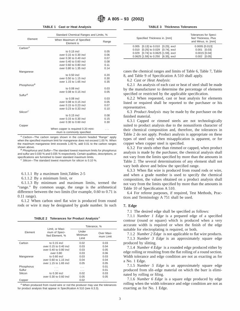
6.1.1.1 By a maximum limit,Tables 2-56.1.1.2 By a minimum limit, or6.1.1.3 By minimum and maximum limits, termed the
“range.” By common usage, the range is the arithmeticaldifference between the two limits (for example, 0.60 to 0.71 is0.11 range).
6.1.2 When carbon steel flat wire is produced from roundrods or wire it may be designated by grade number. In such
cases the chemical ranges and limits of Table 6, Table 7, Table8, and Table 9 of Specification A 510 shall apply.
6.2 Cast or Heat Analysis:6.2.1 An analysis of each cast or heat of steel shall be made
by the manufacturer to determine the percentage of elementsspecified or restricted by the applicable specification.
6.2.2 When requested, cast or heat analysis for elementslisted or required shall be reported to the purchaser or hisrepresentative.
6.3 Product Analysismay be made by the purchaser on thefinished material.
6.3.1 Capped or rimmed steels are not technologicallysuited to product analysis due to the nonuniform character oftheir chemical composition and, therefore, the tolerances inTable 2 do not apply. Product analysis is appropriate on thesetypes of steel only when misapplication is apparent, or forcopper when copper steel is specified.
6.3.2 For steels other than rimmed or capped, when productanalysis is made by the purchaser, the chemical analysis shallnot vary from the limits specified by more than the amounts inTable 2. The several determinations of any element shall notvary both above and below the specified range.
6.3.3 When flat wire is produced from round rods or wire,and when a grade number is used to specify the chemicalcomposition, the values obtained on a product analysis shallnot vary from the limits specified by more than the amounts inTable 10 of Specification A 510.
6.4 For referee purposes, if required, Test Methods, Prac-tices and Terminology A 751 shall be used.
7. Edge
7.1 The desired edge shall be specified as follows:7.1.1 Number 1 Edgeis a prepared edge of a specified
contour (round or square) which is produced when a veryaccurate width is required or when the finish of the edgesuitable for electroplating is required, or both.
7.1.2 Number 2 Edgeis not applicable to flat wire products.7.1.3 Number 3 Edgeis an approximately square edge
produced by slitting.7.1.4 Number 4 Edgeis a rounded edge produced either by
edge rolling or resulting from the flat rolling of a round section.Width tolerance and edge condition are not as exacting as fora No. 1 Edge.
7.1.5 Number 5 Edgeis an approximately square edgeproduced from slit–edge material on which the burr is elimi-nated by rolling or filing.
7.1.6 Number 6 Edgeis a square edge produced by edgerolling when the width tolerance and edge condition are not asexacting as for No. 1 Edge.
TABLE 1 Cast or Heat Analysis
Element
Standard Chemical Ranges and Limits, %
When Maximum of SpecifiedElement is
Range
CarbonA
to 0.15 incl 0.05over 0.15 to 0.30 incl 0.06over 0.30 to 0.40 incl 0.07over 0.40 to 0.60 incl 0.08over 0.60 to 0.80 incl 0.11over 0.80 to 1.35 incl 0.14
Manganeseto 0.50 incl 0.20
over 0.50 to 1.15 incl 0.30over 1.15 to 1.65 incl 0.35
PhosphorusB
to 0.08 incl 0.03over 0.08 to 0.15 incl 0.05
SulfurB
to 0.08 incl 0.03over 0.08 to 0.15 incl 0.05over 0.15 to 0.23 incl 0.07over 0.23 to 0.33 incl 0.10
SiliconC
to 0.15 incl 0.08over 0.15 to 0.30 incl 0.15over 0.30 to 0.60 incl 0.30
CopperWhen copper is required 0.20 mini-
mum is commonly specified.. . .
A Carbon—The carbon ranges shown in the column headed “Range’’ applywhen the specified maximum limit for manganese does not exceed 1.00 %. Whenthe maximum manganese limit exceeds 1.00 %, add 0.01 to the carbon rangesshown above.
B Phosphorus and Sulfur—The standard lowest maximum limits for phosphorusand sulfur are 0.030 % and 0.035 % respectively. Certain qualities, descriptions, orspecifications are furnished to lower standard maximum limits.
C Silicon—The standard lowest maximum for silicon is 0.10 %.
TABLE 2 Tolerances for Product Analysis A
ElementLimit, or Maxi-mum of Speci-
fied Element, %
Tolerance, %
UnderMinimum
Limit
Over Maxi-mum Limit
Carbon to 0.15 incl 0.02 0.03over 0.15 to 0.40 incl 0.03 0.04over 0.40 to 0.80 incl 0.03 0.05
over 0.80 0.03 0.06Manganese to 0.60 incl 0.03 0.03
over 0.60 to 1.15 incl 0.04 0.04over 1.15 to 1.65 incl 0.05 0.05
Phosphorus . . . . . . 0.01Sulfur . . . . . . 0.01Silicon to 0.30 incl 0.02 0.03
over 0.30 to 0.60 incl 0.05 0.05Copper . . . 0.02 . . .
A When produced from round wire or rod the producer may use the tolerancesfor product analysis that appear in Specification A 510 (see 6.3.3).
TABLE 3 Thickness Tolerances
Specified Thickness in. [mm]Tolerances for Speci-fied Thickness, Plusand Minus, in. [mm]
0.005 [0.13] to 0.010 [0.25], excl 0.0005 [0.013]0.010 [0.25] to 0.029 [0.74], excl 0.001 [0.03]0.029 [0.74] to 0.0625 [1.59], excl 0.0015 [0.04]0.0625 [1.59] to 0.250 [6.35], excl 0.002 [0.05]
A 805 – 93 (2002)
3

8. Dimensional Tolerances
8.1 The dimensional tolerances shall be in accordance withthe following:
Tolerances Table Number
Thickness 3Width 4Length 5
8.2 If restricted tolerances closer than those shown in Table3, Table 4, and Table 5 are required, the degree of restrictionshould be established between the purchaser and manufacturer.
8.3 Tolerances for camber should be established betweenthe purchaser and manufacturer. Camber is the greatest devia-tion of a side edge from a straight line, the measurement beingtaken on the concave side with a straight edge.
9. Temper and Bend Test Requirement for Low-CarbonSteel Flat Wire
9.1 Low-carbon steel flat wire specified to temper numbersshall approximate the hardness or tensile strength values shownin Table 6.
9.2 Bend test specimens shall stand being bent at roomtemperatures as required in Table 7.
9.3 All mechanical tests are to be conducted in accordancewith Test Methods and Definitions A 370.
10. Types of Untempered-Carbon Spring Steel Flat Wire
10.1 The following types are produced:10.1.1 Hard-Type Carbon Spring Steel Flat Wireis a very
stiff, springy product intended for flat work not requiringability to withstand cold forming. It is cold reduced with orwithout preparatory treatment to a minimum Rockwell value ofB 98.
10.1.2 Soft-Type Spring Steel Flat Wireis intended forapplication where varying degrees of cold forming are encoun-tered, that necessitates control of both carbon content andhardness. Maximum values for carbon vary from 0.25 to1.35 %, inclusive. This type also involves one of the following
hardness restrictions; a maximum only designated as “soft-typeannealed” or a range only designated as “soft-type intermediatehardness.”
10.1.2.1Soft-Type Annealed Carbon Spring Steel Flat Wire,intended for moderately severe cold forming, is produced to aspecific maximum hardness value. The final anneal is at thefinish thickness. Lowest maximum expected hardness values ortensile strength for specific carbon maximums for steel to0.90 % maximum manganese are shown in Table 8.
10.1.2.2Soft-Type Intermediate Carbon Spring Steel FlatWire is produced to a specified hardness range, somewhathigher than the category covered in 10.1.2.1. The product isproduced by rolling after annealing or by varying the annealingtreatment, or both.
10.1.2.3 The Rockwell hardness range which can be pro-duced varies with the carbon content, the required hardness,and the thickness of the material. In Table 9, Table 10, andTable 11 are shown the applicable hardness ranges for variouscarbon contents and several thickness ranges. If hardnessvalues other than those shown in the tables are required, theapplicable ranges should be agreed upon between the purchaserand the manufacturer. Rockwell hardness range is the arith-metical difference between two limits (for example B 82 toB 90 is an eight–point range).
10.1.3 Spheroidize-Type Carbon Spring Steel Flat Wireisbest suited for the severest cold-forming application, whereheat treatment after forming is employed. Spheroidize anneal-ing treatment is employed in its production. Lowest maximumexpected hardness values by carbon maximums for steel to0.90 % maximum manganese are shown in Table 12. Forthicknesses under 0.025 in. [0.64 mm] the values for the“Soft-Type Annealed” as contained in Table 8 shall apply.
11. Hardness and Tensile Properties of Hardened andTempered Carbon Spring Steel Flat Wire
11.1 This product is commonly produced to meet a range ofRockwell hardness as shown in Table 13.
11.2 The hardness scale appropriate to each thickness rangeis shown in Table 14. Although conversion tables for hardnessnumbers are available, the recommended practice is to specifythe same scale as that to be used in testing. A Rockwellhardness range is the arithmetic difference between two limits(for example C 42to C 46 is a four-point range). Below athickness of 0.008 in. [0.20 mm] the Rockwell 15N testbecomes inaccurate, and the use of the tensile test is recom-mended. The values of ultimate tensile strength cited in Fig. 1apply only to thicknesses less than 0.008 in. [0.20 mm]. When
TABLE 4 Tolerances (Plus and Minus) for Specified Width
Edge Number Specified Width, in. [mm]
Specified Thickness, in. [mm]
Under 0.0625 [1.60]0.0625 [1.59] to0.126 [3.20] excl
0.126 [3.20] to 0.250[6.35] excl
1 Under 0.0625 [1.60]0.0625 [1.60] to 0.126 [3.20] excl0.126 [3.20] to 0.500 [12.70] incl
0.003 [0.08]0.004 [0.10]0.005 [0.13]
. . .0.004 [0.10]0.005 [0.13]
. . .
. . .0.005 [0.13]
4 and 6 Under 0.0625 [1.60]0.0625 [1.60] to 0.126 [3.20] excl0.126 [3.20] to 0.500 [12.70] incl
0.006 [0.15]0.008 [0.20]0.010 [0.25]
. . .0.008 [0.20]0.010 [0.25]
. . .
. . .0.010 [0.25]
3 and 5 0.125 [3.18] to 0.500 [12.70] incl 0.005 [0.13] 0.008 [0.02] . . .
TABLE 5 Length Tolerances
Specified Length, in. [mm]Tolerances Over theSpecified Length in.
[mm]—No Tolerance Under
24 [600] to 60 [1500], incl 1 / 4 [6.4]Over 60 [1500] to 120 [3000], incl 1 / 2 [12.7]Over 120 [3000] to 240 [6100], incl 3 / 4 [19.1]
A 805 – 93 (2002)
4

necessary to specify tensile properties for thicknesses of 0.008in. [0.20 mm] and greater, the manufacturer should be con-sulted.
11.3 Shown in Fig. 1 is the relationship of thickness andcarbon content with Rockwell hardness or tensile strength forhardened and tempered spring steel flat wire appropriate forspring applications. When mechanical properties are specified,they should be compatible with the application.
12. Coatings
12.1 Low-carbon steel flat wire can be produced withvarious coatings, such as liquor finish, white-liquor finish,lacquer, paint, copper, zinc (galvanized), cadmium, chromium,nickel, and tin. Metallic coatings can be applied by the hot-dipmethod or by electrodeposition. The flat steel can be coatedprior to slitting to wire widths. In this case the slit edges willnot be coated.
12.1.1 Copper or liquor coatings consist of thin deposits ofeither copper or bronze produced by immersion of the materialin an acid solution of metallic salts. Because of the nature ofliquor coatings no appreciable corrosion protection is affordedby them.
12.1.2 Hot-dipped coatings are produced by passing strandsof cleaned flat wire continuously through a molten bath ofmetal or alloy. Zinc and tin are commonly applied in thismanner.
12.1.3 Electrodeposited coatings are produced by passingstrands of cleaned flat wire through an electroplating tankcontaining a solution of a metallic salt, wherein the metal isdeposited on the flat wire. Zinc, tin, nickel, cadmium, andcopper are applied in this manner.
12.2 Coatings applicable to untempered-carbon spring steelflat wire are the same as those covered in 14.1.
12.3 Metallic coatings are seldom applied to hardened andtempered carbon steel flat wire. If they are required themanufacturer should be consulted.
13. Workmanship
13.1 Cut lengths shall have a workmanlike appearance andshall not have defects of a nature or degree for the product, thegrade, and the quality ordered that will be detrimental to thefabrication of the finished part.
13.2 Coils may contain more frequent imperfections thatrender a portion of the coil unusable since the inspection ofcoils does not afford the manufacturer the same opportunity toremove portions containing imperfections as in the case withcut lengths.
14. Finish and Condition
14.1 The finish of low-carbon steel flat wire normallyspecified is one of the following:
14.1.1 Number 2 or Regular Bright Finishis produced byrolling on rolls having a moderately smooth finish. It is notgenerally applicable to plating.
14.1.2 Number 3 or Best Bright Finishis generally of highlustre produced by selective-rolling practices, including the useof specially prepared rolls. Number 3 finish is the highest
TABLE 6 Temper, Hardness and Tensile Strength Requirement for Low-Carbon Steel Flat Wire
Temper Thickness, in. [mm]
Rockwell Hardness Approximate Tensile Strength,ksi [MPa]
minmax (approx-
imatemin max
No. 1 (hard) Under 0.010 [0.25] 85 [586] . . .0.010 [0.25] to 0.025 [0.64] excl 15T90 . . .0.025 [0.64] to 0.040 [1.02] excl 30T76 . . .0.040 [1.02] to 0.070 [1.78] excl B90 . . .
0.070 [1.78] and over B84 . . .No. 2 (half-hard) Under 0.010 [0.25]
0.010 [0.25] to 0.025 [0.64] excl0.025 [0.64] to 0.040 [1.02] excl
0.040 [1.02] and over
15T83.530T63.5
B70
15T8830T74B85
65 [448] 90 [621]
No. 3 (quarter-hard) Under 0.010 [0.25]0.010 [0.25] to 0.025 [0.64] excl0.025 [0.64] to 0.040 [1.02] excl
0.040 [1.02] and over
15T8030T56.5
B60
15T8530T67B75
55 [379] 80 [552]
No. 4 (skin-rolled) Under 0.010 [0.25]0.010 [0.25] to 0.025 [0.64] excl0.025 [0.64] to 0.040 [1.02] excl
0.040 [1.02] and over
. . .
. . .
. . .
15T8230T60B65
. . . 65 [448]
No. 5 (dead-soft) Under 0.010 [0.25]0.010 [0.25] to 0.025 [0.64] excl0.025 [0.64] to 0.040 [1.02] excl
0.040 [1.02] and over
. . .
. . .
. . .
15T78.530T53B55
. . . 60 [414]
TABLE 7 Temper and Bend Test Requirement for Low-CarbonSteel Flat Wire
Temper Bend Test Requirement
No. 1 (hard) Not required to make bends in any direction.No. 2 (half-hard) Bend 90° acrossA the direction of rolling around a
radius equal to that of the thickness.No. 3 (quarter-hard) Bend 180° acrossA the direction of rolling over one
thickness of the wire.No. 4 (skin-rolled) Bend flat upon itself in any direction.No. 5 (dead-soft) Bend flat upon itself in any direction.
A To bend “across the direction of rolling’’ means that the bend axis (crease ofthe bend) shall be at a right angle to the length of the wire.
A 805 – 93 (2002)
5

quality finish produced and is particularly suited for electro-plating. The production of this finish requires extreme care inprocessing and extensive inspection.
14.2 Untempered-carbon spring steel flat wire is commonlysupplied in a Number 2 regular bright finish, as in 14.1.1. Themanufacturer should be consulted if another finish is required.
14.3 Hardened and tempered spring steel flat wire is usuallysupplied in one of the following recognized finishes:
14.3.1 Black-tempered,14.3.2 Scaleless-tempered,14.3.3 Bright-tempered,14.3.4 Tempered and polished,14.3.5 Tempered, polished, and colored(blue or straw), and14.4 Oiled.14.4.1 Unless otherwise specified, flat wire is coated with
oil to minimize scratching and to retard rusting in transit. If theproduct is not to be oiled, it must be so specified.
15. Inspection
15.1 When the purchaser’s order stipulates that inspectionand tests (except product analysis) for acceptance on the steel
be made prior to shipment from the mill, the manufacturer shallafford the purchaser’s inspector all reasonable facilities tosatisfy him that the steel is being produced and furnished inaccordance with the specification. Mill inspection by thepurchaser shall not interfere unnecessarily with the manufac-turer’s operation.
16. Rejection and Rehearing
16.1 Unless otherwise specified, any rejection shall bereported to the manufacturer within a reasonable time afterreceipt of material by the purchaser.
16.2 Material that is reported to be defective subsequent tothe acceptance at the manufacturer’s works shall be set aside,adequately protected, and correctly identified. The manufac-turer shall be notified as soon as possible so that an investiga-tion may be initiated.
16.3 Samples that are representative of the rejected materialshall be made available to the manufacturer. In the event thatthe manufacturer is dissatisfied with the rejection, he mayrequest a rehearing.
TABLE 8 Soft-Type Annealed Carbon Spring Steel Flat Wire Lowest Expected Maximum Rockwell Hardness or Tensile Strength
Maximum of CarbonRange, %
Flat Wire Thickness, in. [mm]
Under 0.010 [0.25]0.010 [0.25] to 0.025
[0.64] excl0.025 [0.64] to 0.040
[1.02] excl0.040 [1.02] and Over
Tensile Strengthksi [MPa]
Rockwell Hardness,15T Scale
Rockwell Hardness,30T Scale
Rockwell Hardness,B Scale
0.30 66 [455] 84 67 740.35 68 [469] 84 68 760.40 70 [483] 85 70 780.45 72 [496] 85 71 800.50 74 [510] 86 72 820.55 76 [524] 87 73 840.60 78 [538] 87 74 850.65 80 [552] 88 75 870.70 82 [565] 88 76 880.75 83 [572] 88 76 890.80 85 [586] 89 77 900.85 87 [600] 89 77 910.90 88 [607] 89 78 92
0.95 and over 90 [621] 90 78 92
TABLE 9 Rockwell Hardness Ranges for Soft-Type Intermediate Hardness Carbon Spring Steel Flat Wire Thickness Under 0.025 in.[0.64 mm]
Maximum ofCarbon Range,
%
For Maximum of Specified Rockwell Hardness Range, 15T Scale
83.5 84.5 85 85.5 86 86.5 87 87.5 88 88.5 89 89.5 90/92 Over 92A
0.26–0.30B . . . 5 5 5 5 5 4 4 4 4 4 4 3 . . .0.31–0.35B . . . . . . 5 5 5 5 4 4 4 4 4 4 3 . . .0.36–0.40B . . . . . . . . . 5 5 5 4 4 4 4 4 4 3 . . .0.41–0.45B . . . . . . . . . . . . 5 5 4 4 4 4 4 4 3 . . .0.46–0.50B . . . . . . . . . . . . . . . 5 4 4 4 4 4 4 3 30.51–0.55B . . . . . . . . . . . . . . . . . . 4 4 4 4 4 4 3 30.56–0.60B . . . . . . . . . . . . . . . . . . . . . 4 4 4 4 4 3 30.61–0.65B . . . . . . . . . . . . . . . . . . . . . . . . 4 4 4 4 3 30.66–0.70B . . . . . . . . . . . . . . . . . . . . . . . . . . . 4 4 4 3 30.71–0.75B . . . . . . . . . . . . . . . . . . . . . . . . . . . 4 4 4 3 30.76–0.80B . . . . . . . . . . . . . . . . . . . . . . . . . . . . . . 4 4 3 30.81–0.90B . . . . . . . . . . . . . . . . . . . . . . . . . . . . . . . . . 4 3 30.91–1.35 . . . . . . . . . . . . . . . . . . . . . . . . . . . . . . . . . . . . 3 3
A Rockwell 15T Scale is not recommended for values over 15T93.B Indicates soft-type annealed cold-rolled carbon spring steel flat wire which is furnished to a maximum (hardness) shown in Table 8.
A 805 – 93 (2002)
6

17. Packaging and Package Marking
17.1 Flat wire is prepared for shipment in a number of ways.The material may be bare, paper or burlap wrapped, boxed,skidded or palletized, skidded and shrouded, palletized andshrouded, barrelled, or a combination thereof. The purchasershould specify the method desired.
17.2 When specified in the contract or order, and for directprocurement by or direct shipment to the government, whenLevel A is specified, preservation, packaging, and packing shallbe in accordance with Level A requirements of MIL-STD-163.
17.3 When coils are ordered it should be specified whethera ribbon or tape wound or a vibrated coil is desired. Since coildiameters and weights vary by the manufacturers, the manu-facturer should be consulted for specific capability and limita-tions. When coil weight is specified for low-carbon steel flatwire or for untempered-carbon spring steel flat wire, it iscommon practice to ship not more than 10 % of the totalweight of an item in short coils, which are those weighingbetween 25 and 75 % of the maximum coil weight.
17.4 For flat wire in cut lengths, when the specified lengthis over 36 in. [915 mm], it is permissible to ship up to 10 % of
TABLE 10 Rockwell Hardness Ranges for Soft-Type Intermediate Hardness Carbon Spring Steel Flat Wire Thickness 0.025 to 0.040 in.[0.64 to 1.02 mm] excl
Maximum ofCarbon
Range, %
For Maximum of Specified Rockwell Hardness Range, 30T Scale
66.5 68 69.5 70.5 71.5 72.5 73.5 74.5 75.5 76 76.5 77.5 78 78.5/80.5
Over80.5A
Rockwell Hardness Range
0.26–0.30B . . . 8 8 6 6 6 6 6 6 5 5 5 5 4 . . .0.31–0.35B . . . . . . 8 6 6 6 6 6 6 5 5 5 5 4 . . .0.36–0.40B . . . . . . . . . 6 6 6 6 6 6 5 5 5 5 4 . . .0.41–0.45B . . . . . . . . . . . . 6 6 6 6 6 5 5 5 5 4 . . .0.46–0.50B . . . . . . . . . . . . . . . 6 6 6 6 5 5 5 5 4 40.51–0.55B . . . . . . . . . . . . . . . . . . 6 6 6 5 5 5 5 4 40.56–0.60B . . . . . . . . . . . . . . . . . . . . . 6 6 5 5 5 5 4 40.61–0.65B . . . . . . . . . . . . . . . . . . . . . . . . 6 5 5 5 5 4 40.66–0.70B . . . . . . . . . . . . . . . . . . . . . . . . . . . 5 5 5 5 4 40.71–0.75B . . . . . . . . . . . . . . . . . . . . . . . . . . . . . . 5 5 5 4 40.76–0.80B . . . . . . . . . . . . . . . . . . . . . . . . . . . . . . . . . 5 5 4 40.81–0.90B . . . . . . . . . . . . . . . . . . . . . . . . . . . . . . . . . . . . 5 4 40.91–1.35B . . . . . . . . . . . . . . . . . . . . . . . . . . . . . . . . . . . . . . . 4 4
A Rockwell 30T Scale is not recommended for values over 30T83.B Indicates soft-type annealed cold-rolled carbon spring steel flat wire which is furnished to a maximum hardness as shown in Table 8.
TABLE 11 Rockwell Hardness Ranges for Soft-Type Intermediate Hardness Carbon Spring Steel Flat Wire Thickness 0.040 in. [1.02mm] and Over
Maximum ofCarbon
Range, %
For Maximum of Specified Rockwell Hardness Range, B Scale
74 76 78 80 82 83.5 85 86.5 88 89 90 91 92 93/97 Over 97A
0.26–0.30B . . . 12 12 10 10 10 10 10 10 8 8 8 8 6 . . .0.31–0.35B . . . . . . 12 10 10 10 10 10 10 8 8 8 8 6 . . .0.36–0.40B . . . . . . . . . 10 10 10 10 10 10 8 8 8 8 6 . . .0.41–0.45B . . . . . . . . . . . . 10 10 10 10 10 8 8 8 8 6 . . .0.46–0.50B . . . . . . . . . . . . . . . 10 10 10 10 8 8 8 8 6 . . .0.51–0.55B . . . . . . . . . . . . . . . . . . 10 10 10 8 8 8 8 6 . . .0.56–0.60B . . . . . . . . . . . . . . . . . . . . . 10 10 8 8 8 8 6 . . .0.61–0.65B . . . . . . . . . . . . . . . . . . . . . . . . 10 8 8 8 8 6 50.66–0.70B . . . . . . . . . . . . . . . . . . . . . . . . . . . 8 8 8 8 6 50.71–0.75B . . . . . . . . . . . . . . . . . . . . . . . . . . . . . . 8 8 8 6 50.76–0.80B . . . . . . . . . . . . . . . . . . . . . . . . . . . . . . . . . 8 8 6 50.81–0.90B . . . . . . . . . . . . . . . . . . . . . . . . . . . . . . . . . . . . 8 6 50.91–1.35B . . . . . . . . . . . . . . . . . . . . . . . . . . . . . . . . . . . . . . . 6 5
A Rockwell B Scale is not recommended for values over B 100.B Indicates soft-type annealed cold-rolled carbon spring steel flat wire which is furnished to a maximum hardness as shown in Table 8.
TABLE 12 Spheroidize Type Carbon Spring Steel Flat WireLowest Expected Maximum Rockwell Hardness
Maximum of Car-bon Range, %
Flat Wire Thickness, in. [mm]
0.025 [0.64] to 0.040[1.02] excl
0.040 [1.02] and Over
Rockwell Hard-ness, 30T Scale
Rockwell Hard-ness, B Scale
0.30 63 680.35 65 700.40 66 720.45 67 740.50 68 770.55 69 780.60 70 800.65 71 820.70 72 830.75 73 840.80 73 860.85 74 870.90 75 87
0.95 and over 75 88
A 805 – 93 (2002)
7
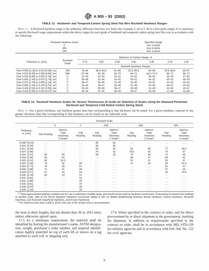
the item in short lengths, but not shorter than 36 in. [915 mm],unless otherwise agreed upon.
17.5 As a minimum requirement, the material shall beidentified by having the manufacturer’s name, ASTM designa-tion, weight, purchaser’s order number, and material identifi-cation legibly stenciled on top of each lift or shown on a tagattached to each coil or shipping unit.
17.6 When specified in the contract or order, and for directprocurement by or direct shipment to the government, markingfor shipment, in addition to requirements specified in thecontract or order, shall be in accordance with MIL-STD-129for military agencies and in accordance with Fed. Std. No. 123for civil agencies.
TABLE 13 Hardened- and Tempered-Carbon Spring Steel Flat Wire Rockwell Hardness Ranges
NOTE 1— A Rockwell hardness range is the arithmetic difference between two limits (for example, C 42 to C 46 is a four-point range). It is customaryto specify Rockwell range requirements within the above ranges for each grade of hardened and tempered carbon spring steel flat wire in accordance withthe following:
Rockwell Hardness Scale Specified RangeC Any 4 points
30N Any 4 points15N Any 3 points
Thickness in. [mm]Rockwell
Scale
Maximum of Carbon Range, %
0.75 0.80 0.85 0.90 0.95 1.00 1.05
Rockwell Hardness Ranges
Over 0.005 [0.13] to 0.015 [0.38], incl 15N 78–84 80.5–84.5 81–85 81.5–85.5 82–86 82.5–86.5 83–87Over 0.015 [0.38] to 0.035 [0.89], incl 30N 57–68 62–69 63–70 64–71 64.5–71.5 65–72 66–73Over 0.035 [0.89] to 0.055 [1.40], incl C 37–49 42–50 43–51 44–52 45–53 46–54 47–55Over 0.055 [1.40] to 0.070 [1.78], incl C 36–48 41–49 42–50 43–51 44–52 45–53 46–54Over 0.070 [1.78] to 0.085 [2.16], incl C 35–47 40–48 41–49 42–50 43–51 44–52 45–53Over 0.085 [2.16] to 0.100 [2.54], incl C 34–46 39–47 40–48 41–49 42–50 43–51 44–52Over 0.100 [2.54] to 0.115 [2.92], incl C 33–45 38–46 39–47 40–48 41–49 42–50 43–51Over 0.115 [2.92] to 0.125 [3.17], incl C 32–44 37–45 38–46 39–47 40–48 41–49 42–50
TABLE 14 Rockwell Hardness Scales for Various Thicknesses (A Guide for Selection of Scales Using the Diamond PenetratorHardened and Tempered Cold-Rolled Carbon Spring Steel)
NOTE 1—For a given thickness, any hardness greater than that corresponding to that thickness can be tested. For a given hardness, material of anygreater thickness than that corresponding to that hardness can be tested on the indicated scale.
Rockwell Scale
Thickness,in. [mm]
A C 15N 30N 45N
Dial Reading
Approxi-mate
HardnessC-ScaleA
DialReading
DialReading
Approxi-mate
HardnessC-ScaleA
DialReading
Approxi-mate
HardnessC-ScaleA
DialReading
Approxi-mate
HardnessC-ScaleA
0.008B [0.20] . . . . . . . . . 90 60 . . . . . . . . . . . .0.010 [0.25] . . . . . . . . . 88 55 . . . . . . . . . . . .0.012 [0.30] . . . . . . . . . 83 45 82 65 77 69.50.014 [0.36] . . . . . . . . . 76 32 78.5 61 74 670.016 [0.41] 86 69 . . . 68 18 74 56 72 650.018 [0.46] 84 65 . . . . . . . . . 66 47 68 610.020 [0.51] 82 61.5 . . . . . . . . . 57 37 63 570.022 [0.56] 79 56 69 . . . . . . 47 26 58 52.50.024 [0.71] 76 50 67 . . . . . . . . . . . . 51 470.026 [0.66] 71 41 65 . . . . . . . . . . . . 37 350.028 [0.71] 67 32 64 . . . . . . . . . . . . 20 20.50.030 [0.76] 60 19 57 . . . . . . . . . . . . . . . . . .0.032 [0.81] . . . . . . 52 . . . . . . . . . . . . . . . . . .0.034 [0.86] . . . . . . 45 . . . . . . . . . . . . . . . . . .0.036 [0.91] . . . . . . 37 . . . . . . . . . . . . . . . . . .0.038 [0.97] . . . . . . 28 . . . . . . . . . . . . . . . . . .0.040 [1.02] . . . . . . 20 . . . . . . . . . . . . . . . . . .
A These approximate hardness numbers are for use in selecting a suitable scale, and should not be used as hardness conversions. If necessary to convert test readingsto another scale, refer to the ASTM Standard Hardness Conversion Tables E 140, for Metals (Relationship Between Brinell Hardness, Vickers Hardness, RockwellHardness, and Rockwell Superficial Hardness, and Knoop Hardness).
B For thickness less than 0.008 in. [0.20 mm] use of the tension test is recommended.
A 805 – 93 (2002)
8
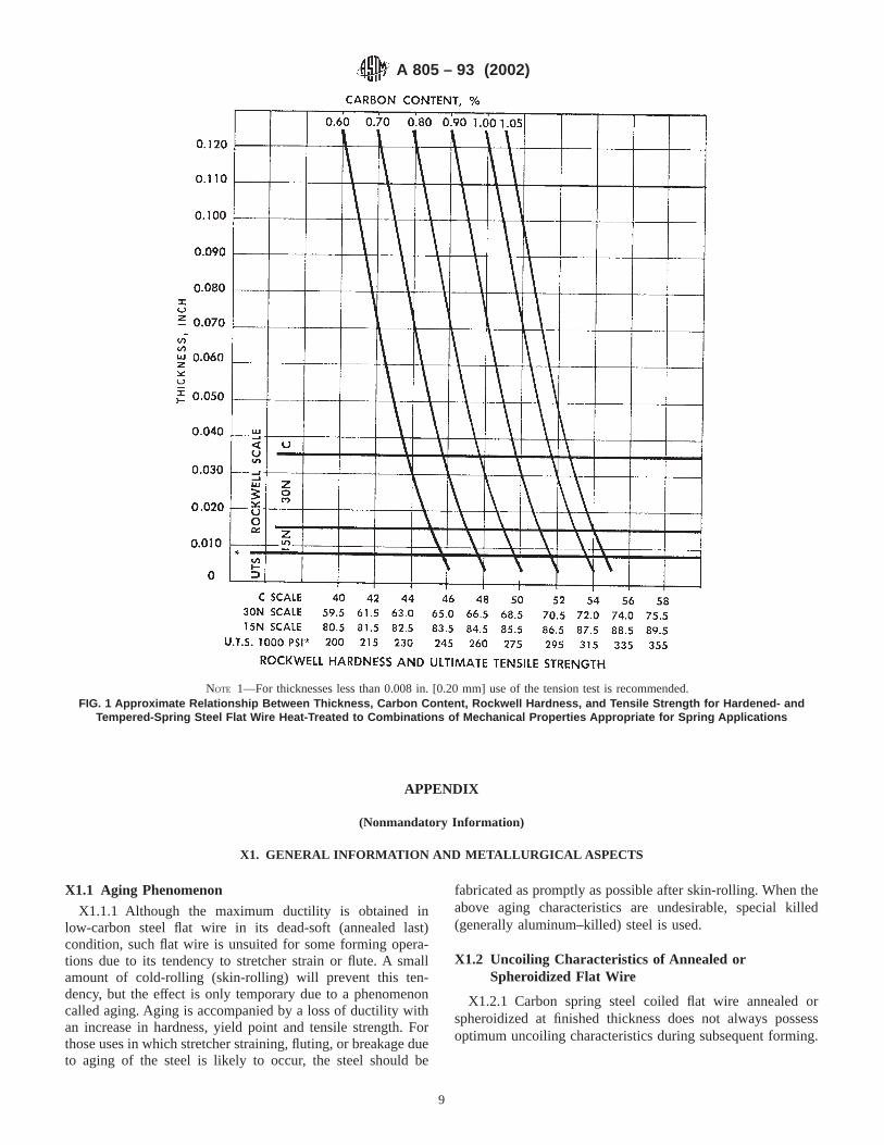
APPENDIX
(Nonmandatory Information)
X1. GENERAL INFORMATION AND METALLURGICAL ASPECTS
X1.1 Aging Phenomenon
X1.1.1 Although the maximum ductility is obtained inlow-carbon steel flat wire in its dead-soft (annealed last)condition, such flat wire is unsuited for some forming opera-tions due to its tendency to stretcher strain or flute. A smallamount of cold-rolling (skin-rolling) will prevent this ten-dency, but the effect is only temporary due to a phenomenoncalled aging. Aging is accompanied by a loss of ductility withan increase in hardness, yield point and tensile strength. Forthose uses in which stretcher straining, fluting, or breakage dueto aging of the steel is likely to occur, the steel should be
fabricated as promptly as possible after skin-rolling. When theabove aging characteristics are undesirable, special killed(generally aluminum–killed) steel is used.
X1.2 Uncoiling Characteristics of Annealed orSpheroidized Flat Wire
X1.2.1 Carbon spring steel coiled flat wire annealed orspheroidized at finished thickness does not always possessoptimum uncoiling characteristics during subsequent forming.
NOTE 1—For thicknesses less than 0.008 in. [0.20 mm] use of the tension test is recommended.FIG. 1 Approximate Relationship Between Thickness, Carbon Content, Rockwell Hardness, and Tensile Strength for Hardened- and
Tempered-Spring Steel Flat Wire Heat-Treated to Combinations of Mechanical Properties Appropriate for Spring Applications
A 805 – 93 (2002)
9
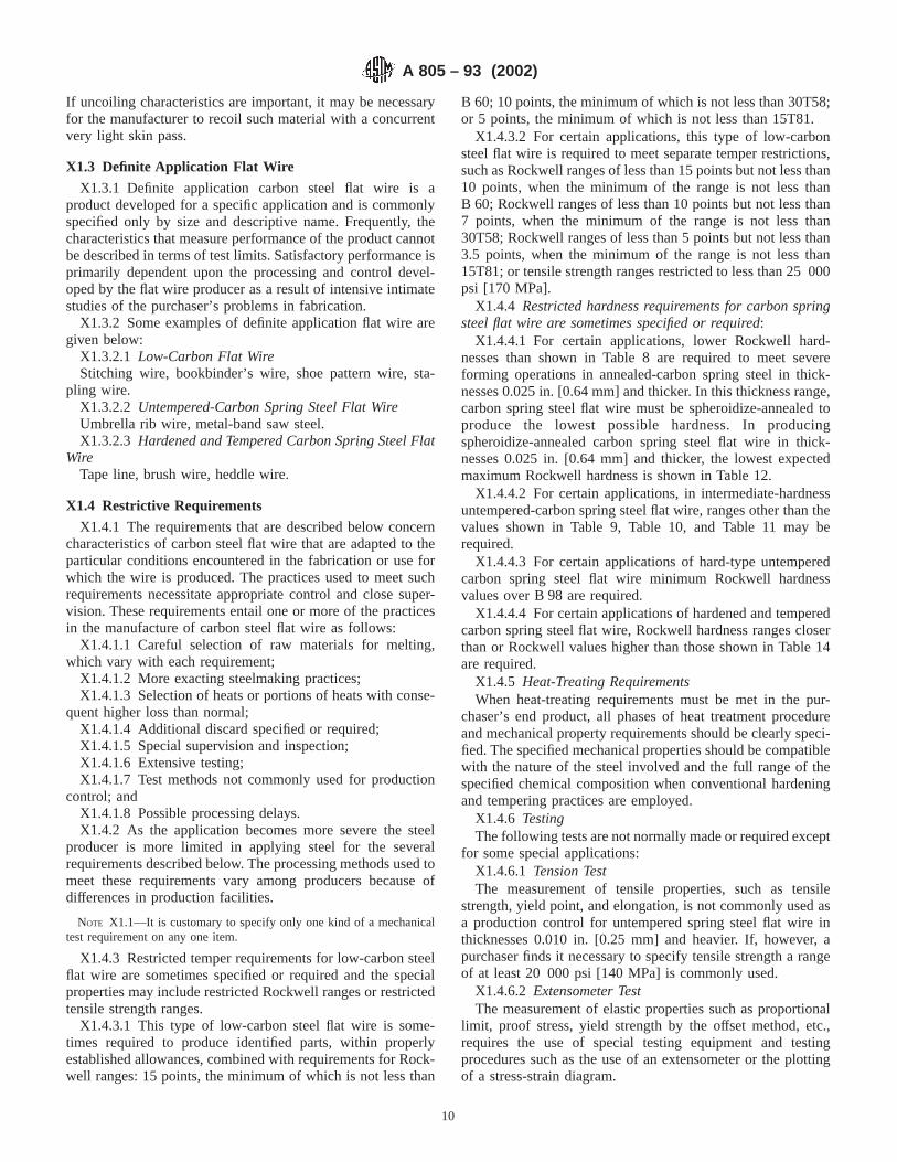
If uncoiling characteristics are important, it may be necessaryfor the manufacturer to recoil such material with a concurrentvery light skin pass.
X1.3 Definite Application Flat Wire
X1.3.1 Definite application carbon steel flat wire is aproduct developed for a specific application and is commonlyspecified only by size and descriptive name. Frequently, thecharacteristics that measure performance of the product cannotbe described in terms of test limits. Satisfactory performance isprimarily dependent upon the processing and control devel-oped by the flat wire producer as a result of intensive intimatestudies of the purchaser’s problems in fabrication.
X1.3.2 Some examples of definite application flat wire aregiven below:
X1.3.2.1 Low-Carbon Flat WireStitching wire, bookbinder’s wire, shoe pattern wire, sta-
pling wire.X1.3.2.2 Untempered-Carbon Spring Steel Flat WireUmbrella rib wire, metal-band saw steel.X1.3.2.3 Hardened and Tempered Carbon Spring Steel Flat
WireTape line, brush wire, heddle wire.
X1.4 Restrictive Requirements
X1.4.1 The requirements that are described below concerncharacteristics of carbon steel flat wire that are adapted to theparticular conditions encountered in the fabrication or use forwhich the wire is produced. The practices used to meet suchrequirements necessitate appropriate control and close super-vision. These requirements entail one or more of the practicesin the manufacture of carbon steel flat wire as follows:
X1.4.1.1 Careful selection of raw materials for melting,which vary with each requirement;
X1.4.1.2 More exacting steelmaking practices;X1.4.1.3 Selection of heats or portions of heats with conse-
quent higher loss than normal;X1.4.1.4 Additional discard specified or required;X1.4.1.5 Special supervision and inspection;X1.4.1.6 Extensive testing;X1.4.1.7 Test methods not commonly used for production
control; andX1.4.1.8 Possible processing delays.X1.4.2 As the application becomes more severe the steel
producer is more limited in applying steel for the severalrequirements described below. The processing methods used tomeet these requirements vary among producers because ofdifferences in production facilities.
NOTE X1.1—It is customary to specify only one kind of a mechanicaltest requirement on any one item.
X1.4.3 Restricted temper requirements for low-carbon steelflat wire are sometimes specified or required and the specialproperties may include restricted Rockwell ranges or restrictedtensile strength ranges.
X1.4.3.1 This type of low-carbon steel flat wire is some-times required to produce identified parts, within properlyestablished allowances, combined with requirements for Rock-well ranges: 15 points, the minimum of which is not less than
B 60; 10 points, the minimum of which is not less than 30T58;or 5 points, the minimum of which is not less than 15T81.
X1.4.3.2 For certain applications, this type of low-carbonsteel flat wire is required to meet separate temper restrictions,such as Rockwell ranges of less than 15 points but not less than10 points, when the minimum of the range is not less thanB 60; Rockwell ranges of less than 10 points but not less than7 points, when the minimum of the range is not less than30T58; Rockwell ranges of less than 5 points but not less than3.5 points, when the minimum of the range is not less than15T81; or tensile strength ranges restricted to less than 25 000psi [170 MPa].
X1.4.4 Restricted hardness requirements for carbon springsteel flat wire are sometimes specified or required:
X1.4.4.1 For certain applications, lower Rockwell hard-nesses than shown in Table 8 are required to meet severeforming operations in annealed-carbon spring steel in thick-nesses 0.025 in. [0.64 mm] and thicker. In this thickness range,carbon spring steel flat wire must be spheroidize-annealed toproduce the lowest possible hardness. In producingspheroidize-annealed carbon spring steel flat wire in thick-nesses 0.025 in. [0.64 mm] and thicker, the lowest expectedmaximum Rockwell hardness is shown in Table 12.
X1.4.4.2 For certain applications, in intermediate-hardnessuntempered-carbon spring steel flat wire, ranges other than thevalues shown in Table 9, Table 10, and Table 11 may berequired.
X1.4.4.3 For certain applications of hard-type untemperedcarbon spring steel flat wire minimum Rockwell hardnessvalues over B 98 are required.
X1.4.4.4 For certain applications of hardened and temperedcarbon spring steel flat wire, Rockwell hardness ranges closerthan or Rockwell values higher than those shown in Table 14are required.
X1.4.5 Heat-Treating RequirementsWhen heat-treating requirements must be met in the pur-
chaser’s end product, all phases of heat treatment procedureand mechanical property requirements should be clearly speci-fied. The specified mechanical properties should be compatiblewith the nature of the steel involved and the full range of thespecified chemical composition when conventional hardeningand tempering practices are employed.
X1.4.6 TestingThe following tests are not normally made or required except
for some special applications:X1.4.6.1 Tension TestThe measurement of tensile properties, such as tensile
strength, yield point, and elongation, is not commonly used asa production control for untempered spring steel flat wire inthicknesses 0.010 in. [0.25 mm] and heavier. If, however, apurchaser finds it necessary to specify tensile strength a rangeof at least 20 000 psi [140 MPa] is commonly used.
X1.4.6.2 Extensometer TestThe measurement of elastic properties such as proportional
limit, proof stress, yield strength by the offset method, etc.,requires the use of special testing equipment and testingprocedures such as the use of an extensometer or the plottingof a stress-strain diagram.
A 805 – 93 (2002)
10

X1.4.6.3 Specified Austenite Grain Sizeis determined inaccordance with Test Methods E 112. For any specified fine- orcoarse-grain size it is customary that not more than 30 % of thegrain structure be outside grain illustrations 5 to 8, inclusive, inthe case of fine grain steel, and grain illustrations 1 to 5,inclusive, in the case of coarse grain steel. The foregoingtesting procedures involve one or more of the following:
(a) Selection and preparation of special test specimens;(b) Additional handling and identification of product;(c) Special testing equipment, unusual testing procedures,
or both; and(d) Possible processing delays due to storage of product
while awaiting results of such tests.X1.4.6.4 DecarburizationThe loss of carbon at the surface of carbon steel when heated
for processing or to modify mechanical properties. Microscopi-cal chemical and hardness test methods are used to determine
the extent of decarburization. A definition and method fordetermination of decarburization is described in the Society ofAutomotive Engineers Recommended Practice SAE J 419.
X1.4.6.5 Macroetch Test
This test consists of immersing a carefully prepared sectionof the steel in hot acid to evaluate the soundness and homo-geneity of the products being tested. Because there are norecognized standards, the location and number of tests, detailsof testing technique, and interpretation of test results areestablished in each instance.
X1.4.6.6 Nonmetallic Inclusion Examination(Microscopical)—The samples for the determination of the
inclusion count are taken longitudinally. The rating is basedupon Practice E 45. Because there are no recognized standards,the area to be examined and the interpretation of test results areestablished in each instance.
ASTM International takes no position respecting the validity of any patent rights asserted in connection with any item mentionedin this standard. Users of this standard are expressly advised that determination of the validity of any such patent rights, and the riskof infringement of such rights, are entirely their own responsibility.
This standard is subject to revision at any time by the responsible technical committee and must be reviewed every five years andif not revised, either reapproved or withdrawn. Your comments are invited either for revision of this standard or for additional standardsand should be addressed to ASTM International Headquarters. Your comments will receive careful consideration at a meeting of theresponsible technical committee, which you may attend. If you feel that your comments have not received a fair hearing you shouldmake your views known to the ASTM Committee on Standards, at the address shown below.
This standard is copyrighted by ASTM International, 100 Barr Harbor Drive, PO Box C700, West Conshohocken, PA 19428-2959,United States. Individual reprints (single or multiple copies) of this standard may be obtained by contacting ASTM at the aboveaddress or at 610-832-9585 (phone), 610-832-9555 (fax), or [email protected] (e-mail); or through the ASTM website(www.astm.org).
A 805 – 93 (2002)
11
Designation: A 831/A831M – 95 (Reapproved 2000)
Standard Specification forAustenitic and Martensitic Stainless Steel Bars, Billets, andForgings for Liquid Metal Cooled Reactor CoreComponents 1
This standard is issued under the fixed designation A 831/A831M; the number immediately following the designation indicates the yearof original adoption or, in the case of revision, the year of last revision. A number in parentheses indicates the year of last reapproval.A superscript epsilon (e) indicates an editorial change since the last revision or reapproval.
1. Scope
1.1 This specification covers hot- and cold-finished austen-itic and martensitic stainless steel bars, billets, and forgingsintended for use in manufacturing core components used athigh temperatures in liquid metal cooled nuclear reactors.
1.2 The bars, billets, and forgings are intended for machin-ing, welding, hot- and cold-forming operations.
1.3 The values stated in either inch-pound units or SI unitsare to be regarded separately as standard. Within the text, theSI units are shown in brackets. The values stated in eachsystem are not exact equivalents; therefore, each system shallbe used independently of the other. Combining values from thetwo systems may result in nonconformance with the specifi-cation.
1.4 This specification and the applicable material specifica-tions are expressed in both inch-pound and SI units. However,unless the order specifies the applicable “M” specificationdesignation (SI units), the material shall be furnished ininch-pound units.
2. Referenced Documents
2.1 ASTM Standards:A 370 Test Methods and Definitions for Mechanical Testing
of Steel Products2
A 388/A388M Practice for Ultrasonic Examination ofHeavy Steel Forgings3
A 484/A484M Specification for General Requirements forStainless Steel Bars, Billets, and Forgings3
A 751 Test Methods, Practices, and Terminology forChemical Analysis of Steel Products2
E 3 Methods of Preparation of Metallographic Specimens4
E 45 Practice for Determining the Inclusion Content ofSteel4
E 112 Test Methods for Determining Average Grain Size4
E 407 Test Methods for Microetching Metals and Alloys4
2.2 ANSI Standard:B 46.1 Surface Texture5
2.3 ASNDT Standard:SNT-TC-1A Recommended Practice for Nondestructive
Testing Personnel Qualifications and Certification6
2.4 ASME Standard:NQA-1 Quality Assurance Program Requirements for
Nuclear Facilities7
3. Ordering Information
3.1 It is the responsibility of the purchaser to specify allrequirements that are necessary for material ordered under thisspecification. Such requirements may include but are notlimited to the following:
3.1.1 Quantity (weight or number of pieces).3.1.2 Condition (cold-worked, annealed, or tempered).3.1.3 Finish.3.1.4 Applicable dimensions, including size, thickness,
width, and length (if forgings, include prints or sketches).3.1.5 Form (bars, billets, etc.).3.1.6 Grade designation.3.1.7 ASTM designation and year of issue.3.1.8 Marking requirements.3.1.9 Other applicable documents (2.4).3.1.10 Melting process (4.1).3.1.11 Approval of procedures for conversion of ingots
(4.2).3.1.12 Cold working requirements for austenitic grades
(4.4.3).3.1.13 Identification requirements (4.6).3.1.14 Chemistry requirements (5.1).3.1.15 Product analysis tolerances (5.3).3.1.16 Grain size limits for bar, billets, and forgings requir-
ing rework (6.1).1 This specification is under the jurisdiction of ASTM Committee A01 on Steel,
Stainless Steel, and Related Alloys and is the direct responsibility of SubcommitteeA01.17 on Flat Stainless Steel Products.
Current edition approved Jan. 15, 1995. Published March 1995. Originallypublished as A 831 – 84. Last previous edition A 831 – 94.
2 Annual Book of ASTM Standards,Vol 01.03.3 Annual Book of ASTM Standards,Vol 01.05.4 Annual Book of ASTM Standards,Vol 03.01.
5 Available from American National Standards Institute, 11 W. 42nd St., 13thFloor, New York, NY 10036.
6 Available from American Society for Nondestructive Testing, P.O. Box 5642,3200 Riverside Dr., Columbus, OH 43228.
7 Available from American Society of Mechanical Engineers, 345 E. 47th St.,New York, NY 10017.
1
Copyright © ASTM International, 100 Barr Harbor Drive, PO Box C700, West Conshohocken, PA 19428-2959, United States.

3.1.17 Alternate inclusion limits (6.2).3.1.18 Surface roughness limits (4.3.2).3.1.19 Surface marring limits (4.3.3).3.1.20 Ultrasonic test requirements (8.1).3.1.21 Sampling levels (10.1).3.1.22 Packaging requirements (12.1).
NOTE 1—A typical ordering description is as follows: 5000-lb [2000-kg] stainless steel, annealed and centerless ground, round bar 11⁄2 in. [38mm] in diameter, 10 to 12 ft. [3 to 4 m] Type 316, ASTM SpecificationA 831 – xx.
4. Manufacture
4.1 Melting—Unless an alternative melting process hasbeen specified in Section 9, the process for austenitic gradesshall consist of a vacuum induction melt followed by aconsumable electrode vacuum-arc remelt. Additions of rareearths during melting are prohibited unless approved by thepurchaser. The melting process for other grades shall bespecified in the order.
4.2 Ingot Processing—A procedure for conversion of ingotsshall be approved by the purchaser prior to use if specified inthe order. The parameters for the conversion of austeniticgrades shall be selected to minimize the formation of complexcarbides and carbonitrides.
4.3 Surface Requirements:4.3.1 Surface Condition—The finished bar shall be free of
all scale, splits, laps, cracks, seams, and visible oxide.4.3.2 Surface Roughness—The surface finish of finished bar
shall meet the minimum requirements listed in Table 1. Thesurface finish of bar that will be machined subsequently shallbe as specified in the order and shall be compatible withnondestructive examination requirements.
4.3.3 Surface Marring—The finished bar shall be free ofscratches, dents, or mars as specified in the order.
4.4 Heat Treatment:4.4.1 Austenitic Grades—Except for material ordered in the
cold-worked condition, all austenitic grade material shall befurnished in the solution-annealed condition. Solution anneal-ing shall consist of heating the material to a temperature of1900°F [1038°C] minimum, for a time appropriate to ensurefull carbide solution, followed by rapid cooling in air or waterto prevent carbide precipitation at the grain boundaries.
4.4.2 Martensitic Grades—Unless otherwise specified bythe purchaser, martensitic grade materials shall be supplied inthe normalized and tempered condition. Tempered materialshall be normalized at 1900°F [1038°C] minimum as a finalheat treatment. Tempered martensitic materials shall be held attempering temperature for at least 1 h/1in. [25 mm] of crosssection as follows:
4.4.2.1 Grade T91—1350°F [732°C] minimum, 1485°F[807°C] maximum.
4.4.2.2 S42100—1365°F [740°C] minimum, 1470°F[799°C] maximum.
4.4.3 Cold-Worked Austenitic Grades—If required by thepurchaser, austenitic grades shall be furnished in the cold-worked condition. Prior to any final cold working operations,solution annealing shall be performed in accordance with 4.4.1.Percentage of cold work shall be based upon reduction in area.
4.4.4 Cleanliness During Manufacture—All lubricants shallbe removed prior to any heat treatment.
4.5 Lotting—Items of the same nominal dimension shall belotted on the basis of material having the same metallurgicalhistory, produced from the same melt heat, processed in onefinal tooling setup, annealed in the same annealing charge (orprocessed in one continuous run if annealed in a continuousfurnace) and given the same cold work.
4.6 Identification—Material shall be identified and pro-cessed in a manner that will ensure traceability as specified inthe order.
4.7 Handling—Special handling procedures shall be em-ployed to maintain the identity of material from the finalworking operation through packaging for shipment. The han-dling procedure shall be submitted to the purchaser for reviewand approval prior to use.
5. Chemical Requirements
5.1 The material shall conform to the applicable chemistryrequirements specified in Table 2 unless otherwise specified inthe order.
5.2 An analysis of each heat of steel shall be made by thesteel manufacturer in accordance with Test Methods, Practices,and Terminology A 751 to determine the percentages of theelements specified. If secondary melting processes are em-ployed, the heat analysis shall be obtained from one remeltedingot or the product of one remelted ingot of each primarymelt. The chemical composition thus determined shall bereported to the purchaser or his representative and shallconform to the requirements specified in 5.1.
TABLE 1 Austenitic Stainless Steel Bar—Surface Finishes
Bar Diameter, in. (mm) Surface Designation (ANSI B 46.1)
1⁄8 to 1⁄4 [3.2 to 6.4] incl 32 µin. [0.8 µm] or finerover 1⁄4to 2 [6.4 to 50.8] incl 63 µin. [1.6 µm] or finerover 2 to 10 [50.8 to 254.0] incl 125 µin. [3.2 µm] or finer
TABLE 2 Chemical Requirements
Grade (UNS Designation)
316 (S31600) . . . S 38660 . . . S 42100 T91 (. . .)
Carbon 0.040 to 0.060 0.030 to 0.050 0.17 to 0.23 0.08 to 0.12Manganese 1.00 to 2.00 1.65 to 2.35 0.40 to 0.70 0.30 to 0.60Phosphorus, max 0.040 0.040 0.040 0.020Sulfur, max 0.010 0.010 0.010 0.010Silicon 0.50 to 0.75 0.50 to 1.00 0.20 to 0.30 0.20 to 0.50Nickel 13.0 to 14.0 14.5 to 16.5 0.30 to 0.80 0.40 maxChromium 17.0 to 18.0 12.5 to 14.5 11.0 to 12.5 8.0 to 9.5Molybdenum 2.00 to 3.00 1.50 to 2.50 0.80 to 1.20 0.85 to 1.05Titanium . . . 0.10 to 0.40A . . . . . .Columbium 0.050 max 0.050 max 0.050 max 0.06 to 0.10Tantalum, max 0.020 0.020 . . . . . .Tungsten . . . . . . 0.40 to 0.60 . . .Nitrogen 0.010 max 0.005 max . . . 0.03 to 0.07Aluminum, max 0.050 0.050 0.050 0.04Arsenic, max 0.030 0.030 . . . . . .Boron, max 0.0020 0.0020 . . . . . .Cobalt, max 0.050 0.050 . . . . . .Copper, max 0.04 0.04 . . . . . .Vanadium 0.05 max 0.05 max 0.25 to 0.35 0.18 to 0.25
A Aim for 0.25.
A 831/A831M – 95 (2000)
2
5.3 A product analysis shall be made by the manufacturer ona sample from one bar, billet, or forging in each lot as definedin 4.5. The analysis shall meet the requirements of Table 2within appropriate product analysis tolerances as provided inSpecification A 484/A 484M, unless otherwise specified in theorder. In the event of failure, the lot represented shall berejected except that, at the option of the manufacturer, eachitem in the lot may be tested for acceptance.
6. Metallurgical Requirements
6.1 Grain Size—The grain size of finished bars for austen-itic grades shall meet the requirements specified in Table 3.Limits for bars, billets, and forgings that will be subsequentlyhot or cold worked shall be as specified in the order.
6.2 Inclusions—The inclusion content of the finished barsof austenitic grades shall not exceed the limits prescribed inTable 4 when determined as specified in Practice E 45, Micro-scope Method D, except, 35 % of the total fields rated mayexhibit inclusion levels up to a rating of 1 for Types A, B, C,and D combined, and 3 % of the total fields rated may exhibitinclusion levels up to a rating of 11⁄2 for Types A, B, C, and Dcombined. Other limits may be specified in the order. Complexcarbides shall not be classified as inclusions.
6.3 Carbide Precipitation—Specimens from finished auste-nitic grade bars shall be mounted as transverse sections,polished, etched, and examined at 5003. Specimen prepara-tion shall be as described in Methods E 3 using etchingProcedure 13 prescribed in Table 2 of Test Methods E 407.Specimens shall exhibit no visible carbide precipitation at thegrain boundaries.
7. Mechanical Properties Requirements
7.1 The material shall conform to the mechanical propertyrequirements specified in Table 5 for the grade ordered. At leastone room-temperature test shall be performed by the manufac-turer on a sample from at least one bar, billet, or forging fromeach lot of material.
7.2 The yield strength shall be determined by the offset(0.2 %) method as prescribed in Test Methods and DefinitionsA 370.
7.3 Martensitic material supplied in the tempered conditionshall meet the mechanical properties specified in Table 5 whenheat treated in accordance with the requirements of 4.3.2.Hardness measurements shall be made at a location midwaybetween the surface and the center of the cross section.
7.4 If in the course of preparation, a test specimen is madedefective, for example by machining errors, the specimen maybe replaced by another which shall be selected on the samebasis as the one discarded. If, however, a specimen developsflaws upon testing or otherwise fails to meet test requirements,the material represented by the specimen shall be rejected
except that, at the material manufacturer’s option, the materialmay be reprocessed and retested, or each item may be testedindividually for acceptance.
8. Nondestructive Examination
8.1 Ultrasonic Examination—Each bar greater than 1 in.(25.4 mm) in the least dimension shall be examined using theexamination and acceptance criteria specified in Section 9 andPractice A 388/A 388M. A bar 1 in. [25.4 mm] or less in theleast dimension shall be examined as specified in the order.
8.2 Testing Personnel—All nondestructive testing person-nel shall be qualified and perform in accordance with SNT-TC-1A.
9. General Requirements
9.1 Material supplied under this specification shall conformto the applicable requirements of Specification A 484/A 484Munless otherwise specified herein. Failure to comply with thegeneral requirements of Specification A 484/A 484M consti-tutes nonconformance with this specification.
10. Sampling
10.1 Lot Qualification—Sampling levels shall be as speci-fied in the order. Referenced test methods are the preferredmethods. Actual methods used shall be equal to or better thanthe methods referenced and shall be approved by the purchaserprior to use.
11. Certification
11.1 The manufacturer shall certify that the material wasmanufactured, tested, and examined in accordance with thisspecification and any added requirements of the purchaseorder. A copy of the certification shall be furnished at the timeof shipment, together with a report of the results of all requiredtests, examinations, and ASTM designation, year date andrevision letter, if any. Certifications, test reports, and examina-tion reports shall be positively traceable to the final product.
12. Packaging and Package Marking
12.1 Packaging—Packaging shall be in accordance with therequirements specified in the order.
12.2 Marking—Each lot shipment shall be legibly andconspicuously marked with the following data:
12.2.1 Purchase order number,12.2.2 Name of supplier,12.2.3 Alloy and heat numbers,12.2.4 Lot number,12.2.5 Number of pieces (or feet) in lot,12.2.6 Gross and net weights,12.2.7 Applicable drawing,12.2.8 Size, and
TABLE 3 Grain Size for Austenitic Grade Bar
Bar Diameter, in. (mm) ASTM Grain Size(Test Methods E 112 Plate II)
1⁄8 to 2 incl [3 to 50]Over 2 to 10 incl [50 to 254]
5 or finer3 or finer
TABLE 4 Inclusion Content Limits for Austenitic Grades
Inclusion Type (Practice E 45)
Sulfide Type (A) Alumina Type (B) Silicate Type (C) Globular Oxides (D)
Thin1⁄2
Thick0
Thin0
Thick0
Thin0
Thick0
Thin1⁄2
Thick1⁄2
A 831/A831M – 95 (2000)
3

12.2.9 Specification number.
13. Quality Assurance Requirement
13.1 Requirements—The materials manufacturer shall es-tablish, maintain, and function in accordance with a qualityverification program that will control quality of the productduring manufacture, testing, examination, repair, and treatmentof the material, including subcontracted services, to assure thatall materials supplied by him conform to the requirements ofthis specification. ASME NQA-1 is an example of a programwhich meets the requirements of this section. The programshall be subject to audit and shall include the following:
13.1.1 Organization—The authority and responsibilities ofpersonnel in charge of the quality assurance program shall beclearly established and be independent of the individual orgroup performing the specific manufacturing activity.
13.1.2 Manufacturing Control—The materials manufac-turer shall operate under a controlled system using processsheets, shop procedures, check lists, travelers, or equivalentprocedures.
13.1.3 Calibration of Measuring and Test Equipment—Procedures shall be in effect to ensure that tools, gages,instruments, and other measuring, testing, and examinationequipment and devices used to verify compliance of materialwith the basic material specification and this specification arecalibrated, controlled, adjusted, and maintained to assureaccuracy within the specified limits. Calibration shall beagainst measurement standards that have a known valid rela-tionship to those of the National Institute of Standards andTechnology, where such standards exist. Corrective action isrequired when discrepancies, which significantly affect themeasurement of material specification properties are found atcalibration. Methods for resolution of these discrepancies shallbe part of the quality system program.
13.1.4 Control of Nondestructive ExaminationProcedures—All nondestructive examinations required shallbe performed in accordance with detailed written proceduresthat are capable of detecting and locating unacceptable discon-tinuities. Qualification of personnel performing or interpretingnondestructive examination, or both, shall be in accordancewith SNT-TC-1A, supplements and appendixes, as applicable,for the technique and methods used. Written procedures and
records shall be made available to the purchaser on request. Atleast one copy of the procedure shall be available to nonde-structive examination personnel for reference on request.
13.1.5 Procedure Control—Procedural controls of heattreatment for all materials and material test coupons shall bemaintained and implemented.
13.1.6 Nonconforming Material—Nonconforming materialshall be identified and reviewed for acceptance, rejection,repair, or rework in accordance with documented procedures.The responsibility and authority for the disposition of noncon-forming material shall be defined. Repaired and reworkedmaterial shall be re-examined in accordance with applicableprocedures. Conditions adverse to final product quality (suchas malfunctions, deficiencies, deviations, defective materialand equipment and nonconformances) shall be identifiedpromptly and reported to appropriate levels of the materialsmanufacturer’s management. The identification, cause, andcorrective action taken on nonconformances shall be docu-mented.
13.1.7 Audits—Planned and periodic audits by personnelnot having direct responsibility in the areas being audited shallbe performed to assure compliance with the quality systemprogram. Written procedures or checklists shall be used.Follow-up action including reaudit of deficient areas, shall betaken where indicated.
13.1.8 Identification and Control of Materials—Proceduralcontrols for identification of materials including partiallyprocessed materials shall assure that identification is main-tained either on the material or on records traceable to thematerial throughout manufacture.
13.2 Records—The manufacturer is responsible for thepreparation of all quality assurance documentation specified inthis specification and in the order. Records of all tests andexaminations shall be kept complete and available to thepurchaser. Quality verification records shall be furnished withthe delivered product.
14. Keywords
14.1 austenitic stainless steel; high temperature core com-ponents; martensitic stainless steel; nuclear applications; stain-less steel bars; stainless steel billets; stainless steel forgings
TABLE 5 Mechanical Property Requirements
Alloy Condition Tensile Strength,min, psi (MPa)
Yield StrengthA,min, psi
Elongation in2 in. [50 mm] or 4D,
min %
Brinell Hardness,max
Austenitic Types
S31600, S 38660S31600, S 38660
annealed20 % cold-worked
75 000B [515]95 000 [655]
30 000 [205]75 000C [515]
3030
. . .302D (surface)
Martensitic Types
T91S42100
temperedtempered
85 000 [585]100 000 [690]
60 000 [415]71 000 [490]
2010
250229
A See Section 7.B Tensile strength 70 000 psi (485 MPa) minimum permitted for extruded shapes.C For bars greater than 2 in. (51 mm) in cross section, 65 000 psi (480 MPa) minimum.D Minimum properties for all sizes in cold-worked condition.
A 831/A831M – 95 (2000)
4
ASTM International takes no position respecting the validity of any patent rights asserted in connection with any item mentionedin this standard. Users of this standard are expressly advised that determination of the validity of any such patent rights, and the riskof infringement of such rights, are entirely their own responsibility.
This standard is subject to revision at any time by the responsible technical committee and must be reviewed every five years andif not revised, either reapproved or withdrawn. Your comments are invited either for revision of this standard or for additional standardsand should be addressed to ASTM International Headquarters. Your comments will receive careful consideration at a meeting of theresponsible technical committee, which you may attend. If you feel that your comments have not received a fair hearing you shouldmake your views known to the ASTM Committee on Standards, at the address shown below.
This standard is copyrighted by ASTM International, 100 Barr Harbor Drive, PO Box C700, West Conshohocken, PA 19428-2959,United States. Individual reprints (single or multiple copies) of this standard may be obtained by contacting ASTM at the aboveaddress or at 610-832-9585 (phone), 610-832-9555 (fax), or [email protected] (e-mail); or through the ASTM website(www.astm.org).
A 831/A831M – 95 (2000)
5
Designation: A 853 – 04
Standard Specification forSteel Wire, Carbon, for General Use 1
This standard is issued under the fixed designation A 853; the number immediately following the designation indicates the year oforiginal adoption or, in the case of revision, the year of last revision. A number in parentheses indicates the year of last reapproval. Asuperscript epsilon (e) indicates an editorial change since the last revision or reapproval.
This standard has been approved for use by agencies of the Department of Defense.
1. Scope*
1.1 This specification covers carbon steel wire, supplied incoils, for general use. It may be produced hard drawn, annealedin process, or annealed at finish size.
1.2 The values stated in inch-pound units are to be regardedas the standard.
2. Referenced Documents
2.1 ASTM Standards:2
A 370 Test Methods and Definitions for Mechanical Testingof Steel Products
A 510 Specification for General Requirements for WireRods and Coarse Round Wire, Carbon Steel
A 700 Practices for Packaging, Marking, and LoadingMethods for Steel Products for Domestic Shipment
A 751 Test Methods, Practices, and Terminology forChemical Analysis of Steel Products
E 29 Practice for Using Significant Digits in Test Data toDetermine Conformance with Specifications
2.2 Military Standards:MIL-STD-129 Marking for Shipment and Storage3
MIL-STD-163 Steel Mill Products, Preparation for Ship-ment and Storage3
2.3 Federal Standard:Fed. Std. No. 123 Marking for Shipments (Civil Agencies)3
2.4 AIAG Standard:AIAGB-5 02.00 Primary Metals Identification Tag Applica-
tion Standard4
3. Terminology
3.1 Definitions of Terms Specific to This Standard:3.1.1 annealed-in-process wire—steel wire that was ther-
mally treated and subsequently redrawn.3.1.2 annealed wire—wire that was drawn to size and
annealed at finish size.3.1.3 carbon steel—steel is considered to be carbon steel
when no minimum content is specified or required for alumi-num, chromium, cobalt, columbium, molybdenum, nickel,titanium, tungsten, vanadium, or zirconium or any otherelement added to obtain a desired alloying effect; when thespecified minimum copper content does not exceed 0.40 %; orwhen the maximum content for any of the following elementsdoes not exceed these percentages: manganese 1.65, silicon0.60, or copper 0.60 (see Specification A 510).
3.1.4 hard drawn wire—wire drawn without the use ofthermal treatment.
4. Ordering Information
4.1 It shall be the responsibility of the purchaser to specifyall requirements that are necessary for material under thisspecification. Such requirements include, but are not limited to,the following:
4.1.1 Quantity (weight in pounds),4.1.2 Name of material (carbon steel wire),4.1.3 Wire diameter in inches, to the third decimal point,4.1.4 Chemical composition grade number,4.1.5 Condition (hard drawn, annealed in process, annealed
at finished size),4.1.6 Finish (see Section 10),4.1.7 Packaging, and4.1.8 ASTM designation and year of issue.
NOTE 1—A typical ordering description is as follows: 40 000 lb, 0.148in., Bright Hard Drawn Carbon Steel Wire, Grade 1008, in 600-lb.catch-weight coils on tubular carriers to ASTM ACSW.
5. Materials and Manufacture
5.1 The steel shall be made by any commercially acceptedsteel making process. The steel may be either ingot cast orstrand cast.
1 This specification is under the jurisdiction of ASTM Committee A01 on Steel,Stainless Steel and Related Alloys and is the direct responsibility of SubcommitteeA01.03 on Steel Rod and Wire.
Current edition approved March 1, 2004. Published March 2004. Originallyapproved in 1985. Last previous edition approved in 2003 as A 853 – 93 (2003).
2 For referenced ASTM standards, visit the ASTM website, www.astm.org, orcontact ASTM Customer Service at [email protected]. ForAnnual Book of ASTMStandardsvolume information, refer to the standard’s Document Summary page onthe ASTM website.
3 Available from Standardization Documents Order Desk, Bldg. 4 Section D, 700Robbins Ave., Philadelphia, PA 19111-5094, Attn: NPODS.
4 Available from Automotive Industry Action Group (AIAG), 26200 Lahser Rd.,Suite 200, Southfield, MI 48034.
1
*A Summary of Changes section appears at the end of this standard.
Copyright © ASTM International, 100 Barr Harbor Drive, PO Box C700, West Conshohocken, PA 19428-2959, United States.
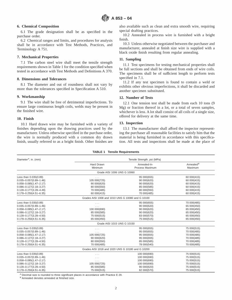
6. Chemical Composition
6.1 The grade designation shall be as specified in thepurchase order.
6.2 Chemical ranges and limits, and procedures for analysisshall be in accordance with Test Methods, Practices, andTerminology A 751.
7. Mechanical Properties
7.1 The carbon steel wire shall meet the tensile strengthrequirements shown in Table 1 for the condition specified whentested in accordance with Test Methods and Definitions A 370.
8. Dimensions and Tolerances
8.1 The diameter and out of roundness shall not vary bymore than the tolerances specified in Specification A 510.
9. Workmanship
9.1 The wire shall be free of detrimental imperfections. Toensure large continuous length coils, welds may be present inthe finished wire.
10. Finish
10.1 Hard drawn wire may be furnished with a variety offinishes depending upon the drawing practices used by themanufacturer. Unless otherwise specified in the purchase order,the wire is normally produced with a common dry drawnfinish, usually referred to as a bright finish. Other finishes are
also available such as clean and extra smooth wire, requiringspecial drafting practices.
10.2 Annealed in process wire is furnished with a brightfinish.
10.3 Unless otherwise negotiated between the purchaser andmanufacturer, annealed at finish size wire is supplied with ablack oxide finish resulting from regular annealing.
11. Sampling
11.1 Test specimens for testing mechanical properties shallbe full sections and shall be obtained from ends of wire coils.The specimens shall be of sufficient length to perform testsspecified in 7.1.
11.2 If any test specimen is found to contain a weld orexhibits other obvious imperfections, it shall be discarded andanother specimen substituted.
12. Number of Tests
12.1 One tension test shall be made from each 10 tons (9Mg) or fraction thereof in a lot, or a total of seven samples,whichever is less. A lot shall consist of all coils of a single size,offered for delivery at the same time.
13. Inspection
13.1 The manufacturer shall afford the inspector represent-ing the purchaser all reasonable facilities to satisfy him that thematerial is being furnished in accordance with this specifica-tion. All tests and inspections shall be made at the place of
TABLE 1 Tensile Requirements
DiameterA, in. (mm) Tensile Strength, psi (MPa)
Hard DrawnMinimum
Annealed-In-Process Maximum
AnnealedB
Maximum
Grade AISI 1006 UNS G 10060
Less than 0.035(0.89) . . . 95 000(655) 60 000(415)0.035–0.057(0.89–1.46) 105 000(725) 90 000(620) 60 000(415)0.058–0.085(1.47–2.17) 90 000(620) 90 000(620) 60 000(415)0.086–0.127(2.18–3.27) 80 000(550) 85 000(585) 60 000(415)0.128–0.177(3.28–4.49) 70 000(485) 80 000(550) 60 000(415)0.178–0.250(4.51–6.35) 60 000(415) 70 000(485) 60 000(415)
Grades AISI 1008 and 1010 UNS G 10080 and G 10100
Less than 0.035(0.89) . . . 95 000(655) 70 000(485)0.035–0.057(0.89–1.46) . . . 90 000(620) 65 000(450)0.058–0.085(1.47–2.17) 100 000(690) 90 000(620) 65 000(450)0.086–0.127(2.18–3.27) 85 000(585) 90 000(620) 65 000(450)0.128–0.177(3.28–4.50) 75 000(515) 83 000(570) 65 000(450)0.178–0.250(4.51–6.35) 65 000(450) 75 000(515) 65 000(450)
Grade AISI 1015 UNS G 10150
Less than 0.035(0.89) . . . 95 000(655) 75 000(515)0.035–0.057(0.89–1.46) . . . 95 000(655) 70 000(485)0.058–0.085(1.47–2.17) 105 000(725) 95 000(655) 70 000(485)0.086–0.127(2.18–3.27) 90 000(620) 95 000(655) 70 000(485)0.128–0.177(3.28–4.50) 80 000(550) 85 000(585) 70 000(485)0.178–0.250(4.51–6.35) 70 000(485) 78 000(540) 70 000(485)
Grades AISI 1018 and 1020 UNS G 10180 and G 10200
Less than 0.035(0.89) . . . 100 000(690) 75 000(515)0.035–0.057(0.89–1.46) . . . 100 000(690) 75 000(515)0.058–0.085(1.47–2.17) . . . 100 000(690) 75 000(515)0.086–0.127(2.18–3.27) 105 000(725) 100 000(690) 75 000(515)0.128–0.177(3.28–4.50) 85 000(585) 90 000(620) 75 000(515)0.178–0.250(4.51–6.35) 75 000(515) 82 000(570) 75 000(515)
A Decimal size is rounded to three significant places in accordance with Practice E 29.B Annealed denotes annealed at finished size.
A 853 – 04
2

manufacture prior to shipment, unless otherwise specified, andshall be so conducted as not to interfere with the operation ofthe works.
14. Rejection and Rehearing
14.1 Any rejection by the purchaser shall be reported to themanufacturer within a reasonable time from receipt of material.
14.2 The material must be adequately protected and cor-rectly identified in order that the manufacturer may make aproper investigation.
15. Certification
15.1 When specified in the purchase order or contract, aproducer’s or supplier’s certification shall be furnished to thepurchaser that the material was manufactured, sampled, tested,and inspected in accordance with this specification and hasbeen found to meet the requirements. When specified in thepurchase order or contract, a report of the test results shall befurnished.
15.2 The certification shall include the specification num-ber, year date of issue, and revision letter, if any.
16. Packaging and Package Marking
16.1 Unless otherwise specified, packaging, package mark-ing, and loading for shipment shall be in accordance withPractices A 700.
16.2 The size, name of product, grade and condition, ASTMspecification number, weight, and name or mark of the manu-facturer shall be indicated on a tag securely attached to eachcoil or package of wire.
16.3 When specified in the contract or order, and for directprocurement by or direct shipment to the U. S. Government,when Level A is specified, preservation, packaging and packingshall be in accordance with Level A requirements of MIL-STD-163.
16.4 When specified in the contract or order, and for directprocurement by or direct shipment to the U. S. Government,marking for shipment, in addition to requirements specified inthe contract or order, shall be in accordance with MIL-STD-129 for U. S. Military agencies and in accordance with Fed.Std. 123 for U. S. Government civil agencies.
16.5 Bar Coding—In addition to the previously-stated iden-tification requirements, bar coding is acceptable as a supple-mentary identification method. Bar coding should be consistentwith AIAG Standard 02.00, Primary Metals Identification TagApplication. The bar code may be applied to a substantiallyaffixed tag.
17. Keywords
17.1 annealed at finished size; annealed in process; carbon;hard drawn; wire
SUMMARY OF CHANGES
Committee A01 has identified the location of selected changes to this standard since the last issue,A 853–93 (2003), that may impact the use of this standard. (Approved March 1, 2004.)
(1) Revised Section 4 to eliminate non-mandatory language. (2) Revised Section 10.3 to eliminate obsolete terminology.
ASTM International takes no position respecting the validity of any patent rights asserted in connection with any item mentionedin this standard. Users of this standard are expressly advised that determination of the validity of any such patent rights, and the riskof infringement of such rights, are entirely their own responsibility.
This standard is subject to revision at any time by the responsible technical committee and must be reviewed every five years andif not revised, either reapproved or withdrawn. Your comments are invited either for revision of this standard or for additional standardsand should be addressed to ASTM International Headquarters. Your comments will receive careful consideration at a meeting of theresponsible technical committee, which you may attend. If you feel that your comments have not received a fair hearing you shouldmake your views known to the ASTM Committee on Standards, at the address shown below.
This standard is copyrighted by ASTM International, 100 Barr Harbor Drive, PO Box C700, West Conshohocken, PA 19428-2959,United States. Individual reprints (single or multiple copies) of this standard may be obtained by contacting ASTM at the aboveaddress or at 610-832-9585 (phone), 610-832-9555 (fax), or [email protected] (e-mail); or through the ASTM website(www.astm.org).
A 853 – 04
3
Designation: A 877/A877M – 99
Standard Specification forSteel Wire, Chromium-Silicon Alloy Valve Spring Quality 1
This standard is issued under the fixed designation A 877/A877M; the number immediately following the designation indicates the yearof original adoption or, in the case of revision, the year of last revision. A number in parentheses indicates the year of last reapproval.A superscript epsilon (e) indicates an editorial change since the last revision or reapproval.
1. Scope
1.1 This specification covers the highest quality of roundchromium-silicon alloy steel valve spring wire, uniform inquality and temper, intended for the manufacture of valvesprings and other springs requiring high-fatigue propertieswhen used at moderately elevated temperatures. This wire shallbe either in the annealed and cold-drawn or oil-temperedcondition as specified by purchaser.
1.2 The values stated in either SI units or inch-pound unitsare to be regarded separately as standard. Within the text, theinch-pound units are shown in brackets. The values stated ineach system are not exact equivalents; therefore, each systemmust be used independent of the other.
2. Referenced Documents
2.1 ASTM Standards:A 370 Test Methods and Definitions for Mechanical Testing
of Steel Products2
A 700 Practices for Packaging, Marking, and LoadingMethods for Steel Products for Domestic Shipment3
A 751 Test Methods, Practices, and Terminology forChemical Analysis of Steel Products2
E 29 Practice for Using Significant Digits in Test Data toDetermine Conformance with Specifications4
E 45 Practice for Determining the Inclusion Content ofSteel5
2.2 Federal Standard:Fed. Std. No. 123 Marking for Shipment (Civil Agencies)6
2.3 Military Standard:MIL-STD-163 Steel Mill Products, Preparation for Ship-
ment and Storage6
2.4 AIAG Standard:
AIAGB-5 02.00 Primary Metals Identification Tag Applica-tion Standard7
3. Ordering Information
3.1 Orders for material under this specification shall includethe following information for each ordered item:
3.1.1 Quantity (mass),3.1.2 Name of material (chromium-silicon alloy steel valve
spring quality wire),3.1.3 Dimensions (Table 1 and Section 8),3.1.4 Condition (Section 6),3.1.5 Packaging (Section 14),3.1.6 Heat analysis report, if requested (5.2),3.1.7 Certification or test report, or both, if specified (Sec-
tion 13), and3.1.8 ASTM designation and year of issue.
NOTE 1—A typical ordering description is as follows: 20 000-kgoiltempered chromium-silicon alloy steel valve spring quality wire, size6.00 mm in 150-kg coils to ASTM ___ dated ___, or for inch-pound units,40 000-lb oil-tempered chromium-silicon alloy steel valve spring qualitywire, size 0.250 in. in 350-lb coils to ASTM ___ dated ___ .
4. Materials and Manufacture
4.1 The steel may be made by any commercially acceptedsteel making process. The steel may be either ingot cast orstrand cast.
4.2 The finished wire shall be free from detrimental pipeand undue segregation.
5. Chemical Composition
5.1 The steel shall conform to the requirements for chemicalcomposition specified in Table 2.
5.2 Heat Analysis—Each heat of steel shall be analyzed bythe manufacturer to determine the percentage of elementsprescribed in Table 2. This analysis shall be made from a testspecimen preferably taken during the pouring of the heat.When requested, this shall be reported to the purchaser andshall conform to the requirements of Table 2.
5.3 Product Analysis—An analysis may be made by thepurchaser from finished wire representing each heat of steel.
1 This specification is under the jurisdiction of ASTM Committee A-1 on Steel,Stainless Steel, and Related Alloys and is the direct responsibility of SubcommitteeA01.03 on Steel Rod and Wire.
Current edition approved March 10, 1999. Published May 1999. Originallypublished as A 877/A 877M – 87. Last previous edition A 877/A 877M – 98.
2 Annual Book of ASTM Standards, Vol 01.03.3 Annual Book of ASTM Standards, Vol 01.05.4 Annual Book of ASTM Standards, Vol 14.02.5 Annual Book of ASTM Standards, Vol 03.01.6 Available from Standardization Documents Order Desk, Bldg. 4 Section D, 700
Robbins Ave., Philadelphia, PA 19111-5094, Attn: NPODS.
7 Available from the Automotive Industry Action Group, 26200 Lahser, Suite200, Southfield, MI 48034.
1
Copyright © ASTM International, 100 Barr Harbor Drive, PO Box C700, West Conshohocken, PA 19428-2959, United States.

The average of all the separate determinations made shall bewithin the limits specified in the analysis column. Individualdeterminations may vary to the extent shown in the productanalysis tolerance column, except that the several determina-tions of a single element in any one heat shall not vary bothabove and below the specified range.
5.4 For referee purposes, Test Methods, Practices, andTerminology A 751 shall be used.
6. Mechanical Properties
6.1 Annealed and Cold Drawn—When purchased in theannealed and cold-drawn condition, the wire shall have beengiven a sufficient amount of cold working to meet the purchas-er’s coiling requirements and shall be in a suitable condition torespond properly to heat treatment. In special cases thehardness, if desired, shall be stated in the purchase order.
6.2 Oil Tempered—When purchased in the oil-temperedcondition, the tensile strength shall conform to the require-ments prescribed in Table 3.
6.2.1 Number of Tests—One test specimen shall be taken foreach five coils, or fraction thereof, in a lot. Each heat in a givenlot shall be tested.
6.2.2 Location of Tests—Test specimens shall be taken fromeither end of the coil.
6.2.3 Test Method—The tension test shall be made inaccordance with Test Methods and Definitions A 370.
6.3 Wrap Test:6.3.1 Oil-tempered or cold-drawn wire 4.00 mm [0.162 in.]
and smaller in diameter shall wind on itself as an arbor withoutbreakage. Larger diameter wire up to and including 8.00 mm[0.312 in.] in diameter shall wrap without breakage on amandrel twice the wire diameter. The wrap test is not appli-cable to wire over 8.00 mm [0.312 in.] in diameter.
6.3.2 Number of Tests—One test specimen shall be taken foreach five coils, or fraction thereof, in a lot. Each heat in a givenlot shall be tested.
6.3.3 Location of Tests—Test specimens shall be taken fromeither end of the coil.
6.3.4 Test Method—The wrap test shall be made in accor-dance with Test Methods and Definitions A 370.
7. Metallurgical Requirements
7.1 Surface Condition:7.1.1 The surface of the wire as received shall be free of
imperfections such as pits, die marks, scratches, seams, andother defects tending to impair the fatigue value of the springs.
7.1.2 Number of Tests—One test specimen shall be takenfrom each end of every coil.
7.1.3 Test Method—The surface shall be examined afteretching in a solution of equal parts of hydrochloric acid andwater that has been heated to approximately 80°C for asufficient length of time to remove up to approximately 1 % ofthe diameter of the wire. Test ends shall be examined using103 magnification.
7.2 Decarburization:7.2.1 Transverse sections of the wire properly mounted,
polished, and etched shall show no completely decarburized(carbon-free) areas when examined at a magnification of 100diameters. Partial decarburization shall not exceed a depth of0.025 mm [0.001 in.] on wire 5.00 mm [0.192 in.] and smaller,or 0.038 mm [0.0015 in.] on larger than 5.00 mm [0.192 in.].
7.2.2 To reveal the decarburization more accurately inuntempered wire, the specimen shall be hardened and temperedbefore microscopic examination. Prior to hardening, the speci-men shall be filed flat on one side enough to reduce the
TABLE 1 Permissible Variations in Wire Diameter A
SI Units
Diameter, mm Permissible Varia-tions, 6mm
Permissible Out-ofRound, mm
0.5 to 2.0, incl 0.02 0.02Over 2.0 to 4.0, incl 0.03 0.03Over 4.0 to 9.5, incl 0.04 0.04
Inch-Pound Units
Diameter, in. Permissible Varia-tions, 6 in.
Permissible Out-ofRound, in.
0.020 to 0.075, incl 0.0008 0.0008Over 0.075 to 0.148, incl 0.001 0.001Over 0.148 to 0.375, incl 0.0015 0.0015
A For purposes of determining conformance with this specification, all specifiedlimits are absolute as defined in Recommended Practice E 29.
TABLE 2 Chemical Requirements
Analysis, % Product AnalysisTolerance, %
Carbon 0.51–0.59 60.02Manganese 0.50–0.80 60.03Phosphorus 0.025 max 60.005Sulfur 0.025 max 60.005Silicon 1.20–1.60 60.05Chromium 0.60–0.80 60.03
TABLE 3 Tensile Requirements A
SI Units
Diameter, mm MPa, min MPa, max
0.5 2100 22801.0 2070 22401.5 2030 22102.0 2000 21403.0 1930 20703.75 1900 20304.5 1830 19705.0 1810 19505.7 1800 19306.3 1760 19007.9 1730 18609.5 1690 1830
Inch-Pound Units
Diameter, in. ksi, min ksi, max
0.020 305 3300.040 300 3250.060 295 3200.080 290 3100.120 280 3000.148 275 2950.177 265 2850.200 263 2830.225 260 2800.250 255 2750.312 250 2700.375 245 265
A Tensile strength values for intermediate diameters may be interpolated.
A 877/A877M – 99
2
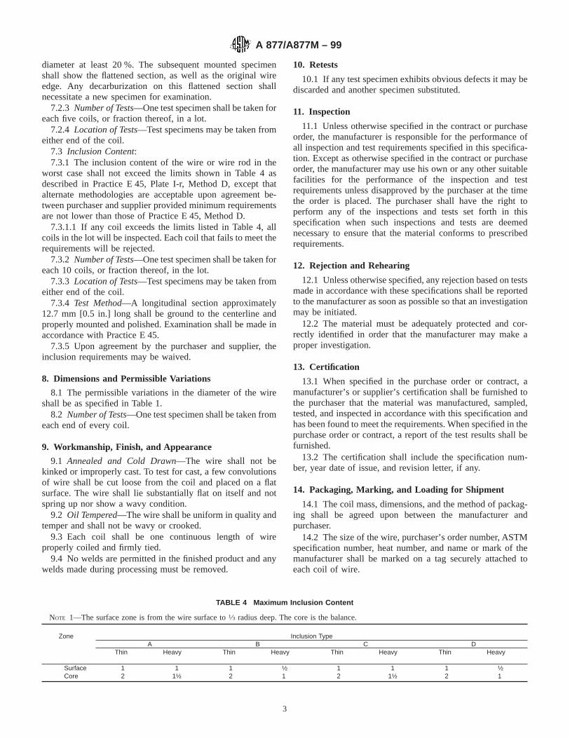
diameter at least 20 %. The subsequent mounted specimenshall show the flattened section, as well as the original wireedge. Any decarburization on this flattened section shallnecessitate a new specimen for examination.
7.2.3 Number of Tests—One test specimen shall be taken foreach five coils, or fraction thereof, in a lot.
7.2.4 Location of Tests—Test specimens may be taken fromeither end of the coil.
7.3 Inclusion Content:7.3.1 The inclusion content of the wire or wire rod in the
worst case shall not exceed the limits shown in Table 4 asdescribed in Practice E 45, Plate I-r, Method D, except thatalternate methodologies are acceptable upon agreement be-tween purchaser and supplier provided minimum requirementsare not lower than those of Practice E 45, Method D.
7.3.1.1 If any coil exceeds the limits listed in Table 4, allcoils in the lot will be inspected. Each coil that fails to meet therequirements will be rejected.
7.3.2 Number of Tests—One test specimen shall be taken foreach 10 coils, or fraction thereof, in the lot.
7.3.3 Location of Tests—Test specimens may be taken fromeither end of the coil.
7.3.4 Test Method—A longitudinal section approximately12.7 mm [0.5 in.] long shall be ground to the centerline andproperly mounted and polished. Examination shall be made inaccordance with Practice E 45.
7.3.5 Upon agreement by the purchaser and supplier, theinclusion requirements may be waived.
8. Dimensions and Permissible Variations
8.1 The permissible variations in the diameter of the wireshall be as specified in Table 1.
8.2 Number of Tests—One test specimen shall be taken fromeach end of every coil.
9. Workmanship, Finish, and Appearance
9.1 Annealed and Cold Drawn—The wire shall not bekinked or improperly cast. To test for cast, a few convolutionsof wire shall be cut loose from the coil and placed on a flatsurface. The wire shall lie substantially flat on itself and notspring up nor show a wavy condition.
9.2 Oil Tempered—The wire shall be uniform in quality andtemper and shall not be wavy or crooked.
9.3 Each coil shall be one continuous length of wireproperly coiled and firmly tied.
9.4 No welds are permitted in the finished product and anywelds made during processing must be removed.
10. Retests
10.1 If any test specimen exhibits obvious defects it may bediscarded and another specimen substituted.
11. Inspection
11.1 Unless otherwise specified in the contract or purchaseorder, the manufacturer is responsible for the performance ofall inspection and test requirements specified in this specifica-tion. Except as otherwise specified in the contract or purchaseorder, the manufacturer may use his own or any other suitablefacilities for the performance of the inspection and testrequirements unless disapproved by the purchaser at the timethe order is placed. The purchaser shall have the right toperform any of the inspections and tests set forth in thisspecification when such inspections and tests are deemednecessary to ensure that the material conforms to prescribedrequirements.
12. Rejection and Rehearing
12.1 Unless otherwise specified, any rejection based on testsmade in accordance with these specifications shall be reportedto the manufacturer as soon as possible so that an investigationmay be initiated.
12.2 The material must be adequately protected and cor-rectly identified in order that the manufacturer may make aproper investigation.
13. Certification
13.1 When specified in the purchase order or contract, amanufacturer’s or supplier’s certification shall be furnished tothe purchaser that the material was manufactured, sampled,tested, and inspected in accordance with this specification andhas been found to meet the requirements. When specified in thepurchase order or contract, a report of the test results shall befurnished.
13.2 The certification shall include the specification num-ber, year date of issue, and revision letter, if any.
14. Packaging, Marking, and Loading for Shipment
14.1 The coil mass, dimensions, and the method of packag-ing shall be agreed upon between the manufacturer andpurchaser.
14.2 The size of the wire, purchaser’s order number, ASTMspecification number, heat number, and name or mark of themanufacturer shall be marked on a tag securely attached toeach coil of wire.
TABLE 4 Maximum Inclusion Content
NOTE 1—The surface zone is from the wire surface to1⁄3 radius deep. The core is the balance.
Zone Inclusion TypeA B C D
Thin Heavy Thin Heavy Thin Heavy Thin Heavy
Surface 1 1 1 ½ 1 1 1 ½Core 2 1½ 2 1 2 1½ 2 1
A 877/A877M – 99
3

14.3 Unless otherwise specified in the purchaser’s order,packaging, marking, and loading for shipments shall be inaccordance with those procedures recommended by PracticesA 700.
14.4 For Government Procurement—Packaging, packing,and marking of material for military procurement shall be inaccordance with the requirements of MIL-STD-163, Level A,Level C, or commercial as specified in the contract or purchaseorder. Marking for shipment of material for civil agencies shallbe in accordance with Fed. Std. No. 123.
14.5 Bar Coding—In addition to the previously-stated iden-tification requirements, bar coding is acceptable as a supple-mentary identification method. Bar coding should be consistentwith AIAG Standard 02.00, Primary Metals Identification TagApplication. The bar code may be applied to a substantiallyaffixed tag.
15. Keywords
15.1 alloy; chromium-silicon; valve spring; wire
ASTM International takes no position respecting the validity of any patent rights asserted in connection with any item mentionedin this standard. Users of this standard are expressly advised that determination of the validity of any such patent rights, and the riskof infringement of such rights, are entirely their own responsibility.
This standard is subject to revision at any time by the responsible technical committee and must be reviewed every five years andif not revised, either reapproved or withdrawn. Your comments are invited either for revision of this standard or for additional standardsand should be addressed to ASTM International Headquarters. Your comments will receive careful consideration at a meeting of theresponsible technical committee, which you may attend. If you feel that your comments have not received a fair hearing you shouldmake your views known to the ASTM Committee on Standards, at the address shown below.
This standard is copyrighted by ASTM International, 100 Barr Harbor Drive, PO Box C700, West Conshohocken, PA 19428-2959,United States. Individual reprints (single or multiple copies) of this standard may be obtained by contacting ASTM at the aboveaddress or at 610-832-9585 (phone), 610-832-9555 (fax), or [email protected] (e-mail); or through the ASTM website(www.astm.org).
A 877/A877M – 99
4

Designation: A 878/A878M – 99
Standard Specification forSteel Wire, Modified Chromium Vanadium Valve SpringQuality 1
This standard is issued under the fixed designation A 878/A878M; the number immediately following the designation indicates the yearof original adoption or, in the case of revision, the year of last revision. A number in parentheses indicates the year of last reapproval.A superscript epsilon (e) indicates an editorial change since the last revision or reapproval.
1. Scope
1.1 This specification covers the highest quality of roundmodified chromium vanadium alloy steel valve spring wire,uniform in quality and temper, intended for the manufacture ofvalve springs and other springs requiring high-fatigue proper-ties when used at moderately elevated temperatures. This wireshall be either in the annealed and cold-drawn or oil-temperedcondition as specified by purchaser.
1.2 The values stated in either SI units or inch-pound unitsare to be regarded separately as standard. Within the text, theinch-pound units are shown in brackets. The values stated ineach system are not exact equivalents; therefore, each systemmust be used independent of the other.
2. Referenced Documents
2.1 ASTM Standards:A 370 Test Methods and Definitions for Mechanical Testing
of Steel Products2
A 700 Practices for Packaging, Marking, and LoadingMethods for Steel Products for Domestic Shipment3
A 751 Test Methods, Practices, and Terminology forChemical Analysis of Steel Products2
E 29 Practice for Using Significant Digits in Test Data toDetermine Conformance with Specifications4
E 45 Practice for Determining the Inclusion Content ofSteel5
2.2 Federal Standard:Fed. Std. No. 123 Marking for Shipment (Civil Agencies)6
2.3 Military Standard:MIL-STD-163 Steel Mill Products, Preparation for Ship-
ment and Storage6
2.4 AIAG Standard:AIAGB-5 02.00 Primary Metals Identification Tag Applica-
tion Standard7
3. Ordering Information
3.1 Orders for material under this specification shall includethe following information for each ordered item:
3.1.1 Quantity (mass),3.1.2 Name of material (modified chromium vanadium
alloy steel valve spring quality wire),3.1.3 Dimensions (Table 1 and Section 8),3.1.4 Condition (Section 6),3.1.5 Packaging (Section 14),3.1.6 Heat analysis report, if requested (5.2),3.1.7 Certification or test report, or both, if specified (Sec-
tion 13), and3.1.8 ASTM designation and year of issue.
NOTE 1—A typical ordering description is as follows: 20 000-kgoil-tempered modified chromium vanadium alloy steel valve springquality wire, size 6.00 mm in 150-kg coils to ASTM ___ dated ___ , or forinch-pound, 40 000-lb oil-tempered modified chromium vanadium alloysteel valve spring quality wire, size 0.250 in. in 350-lb coils to ASTM ___dated ___ .
4. Materials and Manufacture
4.1 The steel may be made by any commercially acceptedsteel making process. The steel may be either ingot cast orstrand cast.
4.2 The finished wire shall be free from detrimental pipeand undue segregation.
5. Chemical Composition
5.1 The steel shall conform to the requirements for chemicalcomposition specified in Table 2.
5.2 Heat Analysis—Each heat of steel shall be analyzed bythe manufacturer to determine the percentage of elementsprescribed in Table 2. This analysis shall be made from a testspecimen preferably taken during the pouring of the heat.
1 This specification is under the jurisdiction of ASTM Committee A-1 on Steel,Stainless Steel, and Related Alloys and is the direct responsibility of SubcommitteeA01.03 on Steel Rod and Wire.
Current edition approved March 10, 1999. Published May 1999. Originallypublished as A 878/A 878M – 87. Last previous edition A 878/A 878M – 98.
2 Annual Book of ASTM Standards, Vol 01.03.3 Annual Book of ASTM Standards, Vol 01.05.4 Annual Book of ASTM Standards, Vol 14.02.5 Annual Book of ASTM Standards, Vol 03.01.6 Available from Standardization Documents Order Desk, Bldg. 4 Section D, 700
Robbins Ave., Philadelphia, PA 19111-5094, Attn: NPODS.
7 Available from the Automotive Industry Action Group, 26200 Lahser, Suite200, Southfield, MI 48034.
1
Copyright © ASTM International, 100 Barr Harbor Drive, PO Box C700, West Conshohocken, PA 19428-2959, United States.

When requested, this shall be reported to the purchaser andshall conform to the requirements of Table 2.
5.3 Product Analysis—An analysis may be made by thepurchaser from finished wire representing each heat of steel.The average of all the separate determinations made shall bewithin the limits specified in the analysis column. Individualdeterminations may vary to the extent shown in the productanalysis tolerance column, except that the several determina-tions of a single element in any one heat shall not vary bothabove and below the specified range.
5.4 For referee purposes, Test Methods, Practices, andTerminology A 751 shall be used.
6. Mechanical Properties
6.1 Annealed and Cold Drawn—When purchased in theannealed and cold-drawn condition, the wire shall have beengiven a sufficient amount of cold working to meet the purchas-er’s coiling requirements and shall be in a suitable condition torespond properly to heat treatment. In special cases thehardness, if desired, shall be stated in the purchase order.
6.2 Oil Tempered—When purchased in the oil-temperedcondition, the tensile strength shall conform to the require-ments prescribed in Table 3.
6.2.1 Number of Tests—One test specimen shall be taken foreach five coils, or fraction thereof, in a lot. Each heat in a givenlot shall be tested.
6.2.2 Location of Tests—Test specimens shall be taken fromeither end of the coil.
6.2.3 Test Method—The tension test shall be made inaccordance with Test Methods and Definitions A 370.
6.3 Wrap Test:6.3.1 Oil-tempered or cold-drawn wire 4.00 mm [0.162 in.]
and smaller in diameter shall wind on itself as an arbor withoutbreakage. Larger diameter wire up to and including 8.00 mm[0.312 in.] in diameter shall wrap without breakage on amandrel twice the wire diameter. The wrap test is not appli-cable to wire over 8.00 mm [0.312 in.] in diameter.
6.3.2 Number of Tests—One test specimen shall be taken foreach five coils, or fraction thereof, in a lot. Each heat in a givenlot shall be tested.
6.3.3 Location of Tests—Test specimens shall be taken fromeither end of the coil.
6.3.4 Test Method—The wrap test shall be made in accor-dance with Test Methods and Definitions A 370.
7. Metallurgical Requirements
7.1 Surface Condition:7.1.1 The surface of the wire as received shall be free of
imperfections such as pits, die marks, scratches, seams, andother defects tending to impair the fatigue value of the springs.
7.1.2 Number of Tests—One test specimen shall be takenfrom each end of every coil.
7.1.3 Test Method—The surface shall be examined afteretching in a solution of equal parts of hydrochloric acid andwater that has been heated to approximately 80°C for asufficient length of time to remove up to approximately 1 % ofthe diameter of the wire. Test ends shall be examined using103 magnification.
7.2 Decarburization:7.2.1 Transverse sections of the wire properly mounted,
polished, and etched shall show no completely decarburized(carbon-free) areas when examined at a magnification of 100
TABLE 1 Permissible Variations in Wire Diameter A
SI Units
Diameter, mmPermissibleVariations,
6mm
PermissibleOut-of Round,
mm
0.5 to 2.0, incl 0.02 0.02Over 2.0 to 4.0, incl 0.03 0.03Over 4.0 to 9.5, incl 0.04 0.04
Inch-Pound Units
Diameter, in.PermissibleVariations,
6in.
PermissibleOut-of Round,
in.
0.020 to 0.075, incl 0.0008 0.0008Over 0.075 to 0.148, incl 0.001 0.001Over 0.148 to 0.375, incl 0.0015 0.0015
A For purposes of determining conformance with this specification, all specifiedlimits are absolute as defined in Recommended Practice E 29.
TABLE 2 Chemical Requirements
Analysis, % Product AnalysisTolerance, %
Carbon 0.60–0.75 60.02Manganese 0.50–0.90 60.03Phosphorus 0.025 max +0.005Sulfur 0.025 max +0.005Silicon 0.15–0.30 60.02Chromium 0.35–0.60 60.05Vanadium 0.10–0.25 60.01
TABLE 3 Tensile Requirements A
SI Units
Diameter, mm MPa, min MPa, max
0.5 2000 21701.0 1930 21001.5 1830 20002.0 1760 19003.0 1660 18003.75 1620 17604.5 1590 17305.0 1550 16905.7 1520 16606.3 1480 16207.9 1450 15909.5 1410 1550
Inch-Pound Units
Diameter, in. ksi, min ksi, max
0.020 290 3150.040 280 3050.060 265 2900.080 255 2750.120 240 2600.148 235 2550.177 230 2500.200 225 2450.225 220 2400.250 215 2350.312 210 2300.375 205 225A Tensile strength valves for intermediate diameters may be interpolated.
A 878/A878M – 99
2
diameters. Partial decarburization shall not exceed a depth of0.025 mm [0.001 in.] on wire 5.00 mm [0.192 in.] and smaller,or 0.038 mm [0.0015 in.] on larger than 5.00 mm [0.192 in.].
7.2.2 To reveal the decarburization more accurately inuntempered wire, the specimen shall be hardened and temperedbefore microscopic examination. Prior to hardening, the speci-men shall be filed flat on one side enough to reduce thediameter at least 20 %. The subsequent mounted specimenshall show the flattened section, as well as the original wireedge. Any decarburization on this flattened section shallnecessitate a new specimen for examination.
7.2.3 Number of Tests—One test specimen shall be taken foreach five coils, or fraction thereof, in a lot.
7.2.4 Location of Tests—Test specimens may be taken fromeither end of the coil.
7.3 Inclusion Content:7.3.1 The inclusion content of the wire or wire rod in the
worst case shall not exceed the limits shown in Table 4 asdescribed in Practice E 45, Plate I-r, Method D, except thatalternate methodologies are acceptable upon agreement be-tween purchaser and supplier provided minimum requirementsare not lower than those of Practice E 45, Method D.
7.3.1.1 If any coil exceeds the limits listed in Table 4, allcoils in the lot will be inspected. Each coil that fails to meet therequirements will be rejected.
7.3.2 Number of Tests—One test specimen shall be taken foreach 10 coils, or fraction thereof, in the lot.
7.3.3 Location of Tests—Test specimens may be taken fromeither end of the coil.
7.3.4 Test Method—A longitudinal section approximately12.7 mm [0.5 in.] long shall be ground to the centerline andproperly mounted and polished. Examination shall be made inaccordance with Practice E 45.
7.3.5 Upon agreement by the purchaser and supplier, theinclusion requirements may be waived.
8. Dimensions and Permissible Variations
8.1 The permissible variations in the diameter of the wireshall be as specified in Table 1.
8.2 Number of Tests—One test specimen shall be taken fromeach end of every coil.
9. Workmanship, Finish, and Appearance
9.1 Annealed and Cold Drawn—The wire shall not bekinked or improperly cast. To test for cast, a few convolutionsof wire shall be cut loose from the coil and placed on a flatsurface. The wire shall lie substantially flat on itself and notspring up nor show a wavy condition.
9.2 Oil Tempered—The wire shall be uniform in quality andtemper and shall not be wavy or crooked.
9.3 Each coil shall be one continuous length of wireproperly coiled and firmly tied.
9.4 No welds are permitted in the finished product and anywelds made during processing must be removed.
10. Retests
10.1 If any test specimen exhibits obvious defects it may bediscarded and another specimen substituted.
11. Inspection
11.1 Unless otherwise specified in the contract or purchaseorder, the manufacturer is responsible for the performance ofall inspection and test requirements specified in this specifica-tion. Except as otherwise specified in the contract or purchaseorder, the manufacturer may use his own or any other suitablefacilities for the performance of the inspection and testrequirements unless disapproved by the purchaser at the timethe order is placed. The purchaser shall have the right toperform any of the inspections and tests set forth in thisspecification when such inspections and tests are deemednecessary to assure that the material conforms to prescribedrequirements.
12. Rejection and Rehearing
12.1 Unless otherwise specified, any rejection based on testsmade in accordance with these specifications shall be reportedto the manufacturer as soon as possible so that an investigationmay be initiated.
12.2 The material must be adequately protected and cor-rectly identified in order that the manufacturer may make aproper investigation.
13. Certification
13.1 When specified in the purchase order or contract, amanufacturer’s or supplier’s certification shall be furnished tothe purchaser that the material was manufactured, sampled,tested, and inspected in accordance with this specification andhas been found to meet the requirements. When specified in thepurchase order or contract, a report of the test results shall befurnished.
13.2 The certification shall include the specification num-ber, year date of issue, and revision letter, if any.
14. Packaging, Marking, and Loading for Shipment
14.1 The coil mass, dimensions, and the method of packag-ing shall be agreed upon between the manufacturer andpurchaser.
TABLE 4 Maximum Inclusion Content
NOTE 1—The surface zone is from the wire surface to1⁄3 radius deep. The core is the balance.
Zone Inclusion Type
A B C D
Thin Heavy Thin Heavy Thin Heavy Thin Heavy
Surface 1 1 1 ½ 1 1 1 ½Core 2 1½ 2 1 2 1½ 2 1
A 878/A878M – 99
3

14.2 The size of the wire, purchaser’s order number, ASTMspecification number, heat number, and name or mark of themanufacturer shall be marked on a tag securely attached toeach coil of wire.
14.3 Unless otherwise specified in the purchaser’s order,packaging, marking, and loading for shipments shall be inaccordance with those procedures recommended by PracticesA 700.
14.4 For Government Procurement—Packaging, packing,and marking of material for military procurement shall be inaccordance with the requirements of MIL-STD-163, Level A,Level C, or commercial as specified in the contract or purchase
order. Marking for shipment of material for civil agencies shallbe in accordance with Fed. Std. No. 123.
14.5 Bar Coding—In addition to the previously-stated iden-tification requirements, bar coding is acceptable as a supple-mentary identification method. Bar coding should be consistentwith AIAG Standard 02.00, Primary Metals Identification TagApplication. The bar code may be applied to a substantiallyaffixed tag.
15. Keywords
15.1 alloy; modified chromium vanadium; valve spring;wire
ASTM International takes no position respecting the validity of any patent rights asserted in connection with any item mentionedin this standard. Users of this standard are expressly advised that determination of the validity of any such patent rights, and the riskof infringement of such rights, are entirely their own responsibility.
This standard is subject to revision at any time by the responsible technical committee and must be reviewed every five years andif not revised, either reapproved or withdrawn. Your comments are invited either for revision of this standard or for additional standardsand should be addressed to ASTM International Headquarters. Your comments will receive careful consideration at a meeting of theresponsible technical committee, which you may attend. If you feel that your comments have not received a fair hearing you shouldmake your views known to the ASTM Committee on Standards, at the address shown below.
This standard is copyrighted by ASTM International, 100 Barr Harbor Drive, PO Box C700, West Conshohocken, PA 19428-2959,United States. Individual reprints (single or multiple copies) of this standard may be obtained by contacting ASTM at the aboveaddress or at 610-832-9585 (phone), 610-832-9555 (fax), or [email protected] (e-mail); or through the ASTM website(www.astm.org).
A 878/A878M – 99
4

Designation: A 887 – 89 (Reapproved 2000)
Standard Specification forBorated Stainless Steel Plate, Sheet, and Strip for NuclearApplication 1
This standard is issued under the fixed designation A 887; the number immediately following the designation indicates the year oforiginal adoption or, in the case of revision, the year of last revision. A number in parentheses indicates the year of last reapproval. Asuperscript epsilon (e) indicates an editorial change since the last revision or reapproval.
1. Scope
1.1 This specification covers chromium-nickel stainlesssteel plate, sheet, and strip, modified by the addition of naturalor enriched boron, for nuclear application.
1.2 Borated stainless steels covered by this specification,because of their particular alloy content and specialized prop-erties, may require special care in their fabrication and weld-ing. Specific procedures are of fundamental importance, and itis presupposed that all parameters will be in accordance withapproved methods capable of producing the desired propertiesin the finished fabrication.
1.3 The values stated in inch-pound units are to be regardedas the standard. SI units are provided for information only.
2. Referenced Documents
2.1 ASTM Standards:A 370 Test Methods and Definitions for Mechanical Testing
of Steel Products2
A 480/A480M Specification for General Requirements forFlat-Rolled Stainless and Heat-Resisting Steel Plate,Sheet, and Strip2
A 751 Test Methods, Practices, and Terminology forChemical Analysis of Steel Products2
3. Terminology
3.1 Definitions of Terms Specific to This Standard:3.1.1 plate—material3⁄16 in. (4.8 mm) and over in thickness
and over 10 in. (250 mm) in width.3.1.2 sheet—material under3⁄16 in. (5.0 mm) in thickness
and 24 in. (600 mm) and over in width.3.1.3 strip—material under3⁄16 in. (5.0 mm) in thickness
and under 24 in. (600 mm) in width.
4. Ordering Information
4.1 Orders for material under this specification shall includethe information specified in the Ordering Information sectionof Specification A 480/A 480M.
5. Process
5.1 If a specific type of melting is required by the purchaser,it shall be stated on the purchase order.
5.2 When specified on the purchase order, or when aspecific type of melting has been specified on the purchaseorder, the material manufacturer shall indicate on the test reportthe type of melting used to produce the material.
6. Heat Treatment
6.1 The austenitic chromium-nickel steels shall be solution-annealed to meet the mechanical property requirements of thisspecification. Solution-annealing shall consist of heating thematerial to a temperature of 1900°F (1040°C) minimum for anappropriate time followed by water quenching or rapidlycooling by other means.
7. Material Test Report
7.1 A report of the results of all tests required by thisspecification and the type of melting used shall be supplied tothe purchaser.
8. Chemical Composition
8.1 The chemical analysis of representative material shall beperformed, as agreed upon between the purchaser and supplier,to determine the percentages of the elements identified in Table1. The chemical composition thus determined shall be reportedto the purchaser, or his representative, and shall conform to therequirements specified in Table 1.
8.2 When a product (check or verification) analysis isperformed, the chemical composition thus determined mayvary from the specified limits by the amounts shown in Table1, Product Analysis Tolerances, of Specification A 480/A480M.
8.3 Methods and practices relating to chemical analysisrequired by this specification shall be in accordance with TestMethods, Practices, and Terminology A 751.
8.4 Boron determination not covered in Test Methods,Practices, and Terminology A 751 shall be made as agreedupon between the purchaser and the supplier.
9. Mechanical Properties
9.1 Tensile Properties—The material shall conform to thetensile property requirements specified in Table 2.
1 This specification is under the jurisdiction of ASTM Committee A-1 on Steel,Stainless Steel, and Related Alloys, and is the direct responsibility of SubcommitteeA01.17 on Flat Stainless Steel Product.
Current edition approved November 20, 1989. Published January 1990. Origi-nally published as A 887 – 88. Last previous edition A 887 – 88.
2 Annual Book of ASTM Standards, Vol 01.03.
1
Copyright © ASTM International, 100 Barr Harbor Drive, PO Box C700, West Conshohocken, PA 19428-2959, United States.

9.2 Hardness—The material shall conform to the hardnessrequirements as specified in Table 2.
9.3 Grade—The grade of the material is defined by theuniformity of the dispersion of the boron within the melt.Grade A corresponds to the near-optimal dispersion, whileGrade B corresponds to a less-than-optimal dispersion of theboron. Conventional wrought metallurgical practice conformsto Grade B properties. The quality of the boron dispersion ismeasured indirectly through the ductility requirements, asspecified in Table 2.
10. Special Tests
10.1 If any special tests are required which are pertinent tothe intended application of the material ordered, they shall beagreed upon between the supplier and the purchaser.
10.2 Charpy V-notch impact testing is not required unless itis specified on the purchase order. If so specified, impacttesting shall be performed in accordance with Test Methodsand Definitions A 370. The impact test results thus determinedshall be reported to the purchaser, or his representative, andshall conform to the requirements specified in Table 3. Ifsubsize impact test specimens are used, the applicable require-ments shall be agreed upon between the purchaser and thesupplier.
11. Dimensions and Permissible Variations
11.1 Unless otherwise specified in the purchase order, ma-terial shall conform to the permissible tolerances shown inSpecification A 480/A 480M.
11.2 Sheet, Strip, and Plate—Material with No. 1 finishmay be ground to remove surface imperfections, provided such
TABLE 1 Chemical Requirements Composition A
UNSDesignation
Type Carbon Manganese Phosphorous Sulfur Silicon Chromium Nickel Boron OtherElementsB
S30460 304B 0.08 2.00 0.045 0.030 0.75 18.00–20.00 12.00–15.00 0.20–0.29 N 0.10 maxS30461 304B1 0.08 2.00 0.045 0.030 0.75 18.00–20.00 12.00–15.00 0.30–0.49 N 0.10 maxS30462 304B2 0.08 2.00 0.045 0.030 0.75 18.00–20.00 12.00–15.00 0.50–0.74 N 0.10 maxS30463 304B3 0.08 2.00 0.045 0.030 0.75 18.00–20.00 12.00–15.00 0.75–0.99 N 0.10 maxS30464 304B4 0.08 2.00 0.045 0.030 0.75 18.00–20.00 12.00–15.00 1.00–1.24 N 0.10 maxS30465 304B5 0.08 2.00 0.045 0.030 0.75 18.00–20.00 12.00–15.00 1.25–1.49 N 0.10 maxS30466 304B6 0.08 2.00 0.045 0.030 0.75 18.00–20.00 12.00–15.00 1.50–1.74 N 0.10 maxS30467 304B7 0.08 2.00 0.045 0.030 0.75 18.00–20.00 12.00–15.00 1.75–2.25 N 0.10 max
A Maximum, unless range or minimum is indicated.B Cobalt concentration shall be limited to 0.2 max, unless a lower concentration is agreed upon between the purchaser and the supplier.
TABLE 2 Mechanical Test Requirements
UNSDesignation
Type Grade Tensile Strength, min Yield Strength, min Elongation in 2in. or 50 mm,
min, %
Hardness, max
ksi MPa ksi MPa Brinell Rockwell B
S30460 304B A 75 515 30 205 40.0 201 92B 75 515 30 205 40.0 201 92
S30461 304B1 A 75 515 30 205 40.0 201 92B 75 515 30 205 35.0 201 92
S30462 304B2 A 75 515 30 205 35.0 201 92B 75 515 30 205 27.0 201 92
S30463 304B3 A 75 515 30 205 31.0 201 92B 75 515 30 205 19.0 201 92
S30464 304B4 A 75 515 30 205 27.0 217 95B 75 515 30 205 16.0 217 95
S30465 304B5 A 75 515 30 205 24.0 217 95B 75 515 30 205 13.0 217 95
S30466 304B6 A 75 515 30 205 20.0 241 100B 75 515 30 205 9.0 241 100
S30467 304B7 A 75 515 30 205 17.0 241 100B 75 515 30 205 6.0 241 100
TABLE 3 Impact Test Requirements
Type Grade Charpy V-Notch Energy,ft-lb (J), min
304B A 65 (88)B 40 (54)
304B1 A 60 (81)B 35 (47)
304B2 A 48 (65)B 16 (22)
304B3 A 38 (52)B 10 (14)
304B4 A 30 (41)B . . .
304B5 A 23 (31)B . . .
304B6 A 16 (22)B . . .
304B7 A 10 (14)B . . .
A 887 – 89 (2000)
2
grinding does not reduce the thickness or width at any pointbeyond the permissible variations in dimensions.
12. Workmanship, Finish, and Appearance
12.1 The material shall be uniform quality consistent withgood manufacturing and inspection practices. The steel shallhave no imperfections of a nature or degree, for the type andquality ordered, that will adversely affect the stamping, form-ing, machining, or fabrication of finished parts.
13. General Requirements for Delivery
13.1 Material furnished under this specification shall con-form to the applicable requirements of the current edition ofSpecification A 480/A 480M. In case of conflict, the require-ments of this specification shall prevail.
14. Number of Tests
14.1 In the case of sheet or strip produced in coil form, twoor more hardness tests (one from each end of the coil); oneimpact test, when required; and one or more tension tests shallbe made on specimens taken from each coil. If the hardnessdifference between the two ends of the coil exceeds 5 HRB, orequivalent, tensile properties must be determined on both ends.
14.2 In the case of sheet, strip, or plate produced in cutlengths, one tension test; one impact test, when required; andone or more hardness tests shall be made on each 100 or lesspieces of the same heat and nominal thickness rolled separatelyor continuously and heat treated within the same operatingperiod, either as a lot or continuously.
NOTE 1—The term “continuously,’’ as applied to heat treatment, ismeant to describe a heat-treating operation in which one cut length followsanother through the furnace. Interspersement of different melts is permis-sible if they are of approximately the same nominal thickness and are heattreated in the same operating period and under the same conditions (timeand temperature), provided that each heat is tested.
15. Specimen Preparation
15.1 Tension-test specimens shall be taken from finishedmaterial and shall be selected either in the longitudinal ortransverse direction. The tension-test specimen shall conformto the appropriate Sections, (Plate-Type Specimen, Sheet-TypeSpecimen, and Round Specimens) of Test Methods and Defi-nitions A 370.
NOTE 2—For plate material up to and including3⁄4 in. (19.05 mm) thick,the sheet-type tension specimen described in the Sheet-Type Specimensection (Figure relating to rectangular tension test specimens), of TestMethods and Definitions A 370 is also permitted.
15.2 Notched-bar impact test specimens shall be taken fromfinished material. Full-size (10 by 10 mm) Type A specimensshall be used when the material thickness permits. When thematerial thickness is insufficient to obtain full-size specimens,subsize specimens shall be used. The subsize specimens mayhave a width of full material thickness or may be reduced inthickness to provide the largest possible standard subsizespecimen listed in Test Methods and Definitions A 370. Alter-native specimens may be used, in place of the subsizespecimens, as agreed upon between the purchaser and thesupplier.
15.3 Hardness tests may be made on the grip ends of thetensions test specimens before they are subjected to the tensiontest.
16. Test Methods
16.1 The properties enumerated in this specification shall bedetermined in accordance with methods as specified in Speci-fication A 480/A 480M.
16.2 Retests may be made in accordance with the provisionsof the section on General Precautions of Test Methods andDefinitions A 370.
17. Retreatment
17.1 If any specimens selected to represent any heat fail tomeet any of the test requirements, the material represented bysuch specimens may be reheat-treated and resubmitted for test.
18. Inspection
18.1 In addition to inspection performed by the supplier,inspection of the material by the purchaser’s representative atthe producing plant shall be made as agreed upon between thepurchaser and supplier as part of the purchase order.
19. Rejection and Rehearing
19.1 Samples tested by the purchaser in accordance withthis specification that represent rejected material shall beretained for 3 weeks from the date of the notification to theseller of the rejection. In case of dissatisfaction with the resultsof the tests, the seller may make claim for a rehearing withinthat time.
20. Certification
20.1 The producer’s certification that the material wasmanufactured and tested in accordance with this specification,together with the report of the test results, shall be furnished atthe time of shipment.
21. Product Marking
21.1 Each sheet, strip, or plate shall be marked on one face,in the locations indicated below with the designation numberand its suffix, type, test identification number, and the name ormark of the manufacturer. The characters shall be of such sizeas to be clearly legible. The marking shall be sufficiently stableto withstand normal handling. Unless otherwise specified bythe purchaser, the marking, at the producer’s option, may bedone with: (a) marking fluid (if a specific maximum impuritylimit of designated elements in the marking fluid is required bythe purchaser, it shall be so stated on the purchase order), (b)low-stress blunt-nosed-continuous or low-stress blunt-nosed-interrupted-dot die stamp, (c), a vibratory tool with a minimumtip radius of 0.005 in. (0.1 mm), or (d) electrochemical etching.
21.1.1 Flat sheet, strip in cut lengths, and plate shall bemarked in two places near the ends.
21.1.2 Sheet and strip in coils shall be marked near theoutside end of the coil. The inside of the coil shall also bemarked or shall have a tag or label attached and marked withthe information of 21.1.
21.1.3 Material less than1⁄4 in. (6.4 mm) in thickness shallnot be marked with die stamps.
A 887 – 89 (2000)
3

21.2 The manufacturer’s test identification number shall belegibly stamped on each test specimen, if to be shipped to thecustomer.
21.3 Marking for identification for U.S. Government pro-curement shall be in accordance with Specification A 480/A 480M.
ASTM International takes no position respecting the validity of any patent rights asserted in connection with any item mentionedin this standard. Users of this standard are expressly advised that determination of the validity of any such patent rights, and the riskof infringement of such rights, are entirely their own responsibility.
This standard is subject to revision at any time by the responsible technical committee and must be reviewed every five years andif not revised, either reapproved or withdrawn. Your comments are invited either for revision of this standard or for additional standardsand should be addressed to ASTM International Headquarters. Your comments will receive careful consideration at a meeting of theresponsible technical committee, which you may attend. If you feel that your comments have not received a fair hearing you shouldmake your views known to the ASTM Committee on Standards, at the address shown below.
This standard is copyrighted by ASTM International, 100 Barr Harbor Drive, PO Box C700, West Conshohocken, PA 19428-2959,United States. Individual reprints (single or multiple copies) of this standard may be obtained by contacting ASTM at the aboveaddress or at 610-832-9585 (phone), 610-832-9555 (fax), or [email protected] (e-mail); or through the ASTM website(www.astm.org).
A 887 – 89 (2000)
4
Designation: A 895 – 89 (Reapproved 2000)
Standard Specification forFree-Machining Stainless Steel Plate, Sheet, and Strip 1
This standard is issued under the fixed designation A 895; the number immediately following the designation indicates the year oforiginal adoption or, in the case of revision, the year of last revision. A number in parentheses indicates the year of last reapproval. Asuperscript epsilon (e) indicates an editorial change since the last revision or reapproval.
1. Scope
1.1 This specification covers hot-finished or cold-finishedplate, sheet, and strip in the more commonly used types ofstainless free machining steels designed especially for opti-mum machinability and for general corrosion and high tem-perature service. Stainless and heat resisting plate, sheet, andstrip other than free machining types are covered in separatespecifications.
1.2 The values stated in inch-pound units are to be regardedas the standard.
2. Referenced Documents
2.1 ASTM Standards:A 370 Test Methods and Definitions for Mechanical Testing
of Steel Products2
A 480/A480M Specification for General Requirements forFlat-Rolled Stainless and Heat-Resisting Steel Plate,Sheet, and Strip2
A 751 Test Methods, Practices, and Terminology forChemical Analysis of Steel Products2
E 527 Practice for Numbering Metals and Alloys3
3. Terminology
3.1 Definitions of Terms Specific to This Standard:3.1.1 plate—material3⁄16 in. (4.8 mm) and over in thickness
and over 10 in. (250 mm) in width.3.1.2 sheet—material under3⁄16 in. (5.0 mm) in thickness
and 24 in. (600 mm) and over in width.3.1.3 strip—material under3⁄16 in. (5.0 mm) in thickness
and under 24 in. (600 mm) in width.
4. Process
4.1 The steel shall be made by one or more of the followingprocesses: electric-arc, electric-induction, or other suitablecommercial processes.
4.2 Plate, sheet, and strip may be furnished in one of theconditions listed in Table 1.
5. Ordering Information
5.1 Orders for material under this specification shouldinclude the following information:
5.1.1 Quantity (weight or number of pieces),5.1.2 Type or UNS designation (Table 2),5.1.3 Form (Plate, Sheet or Strip),5.1.4 Condition (Table 2),5.1.5 Finish (9.2),5.1.6 Dimensions (thickness, width, and length),5.1.7 Edge, strip only (see Specification A 480/A 480M),5.1.8 ASTM designation and date of issue,5.1.9 Additions to specification or special requirements,5.1.10 Preparation for delivery, and5.1.11 Marking requirements.
6. Chemical Composition
6.1 The chemical composition shall conform to the require-ments specified in Table 2.
6.2 Methods and practices relating to chemical analysisrequired by this specification shall be in accordance with TestMethods, Practices, and Terminology A 751.
7. Hardness Requirement
7.1 The material shall conform to the hardness requirementsas specified in Table 3.
1 This specification is under the jurisdiction of ASTM Committee A-1 on Steel,Stainless Steel and Related Alloys and is the direct responsibility of SubcommitteeA01.17 on Flat Stainless Steel Products.
Current edition approved Dec. 7, 1989. Published February 1990.2 Annual Book of ASTM Standards, Vol 01.03.3 Annual Book of ASTM Standards, Vol 01.01.
TABLE 1 Condition
TypeCondition A(Annealed)
Condition T(Intermediate
Temper)
Condition H (HardTemper)
303 A . . . . . .303Se A . . . . . .416 A T H416Se A T H420F A . . . . . .420FSe A T . . .430F A . . . . . .430FSe A . . . . . .
1
Copyright © ASTM International, 100 Barr Harbor Drive, PO Box C700, West Conshohocken, PA 19428-2959, United States.
7.2 The hardness test shall be determined in accordancewith Test Methods and Definitions A 370.
8. General Requirements for Delivery
8.1 Material furnished under this specification shall con-form to the applicable requirements of the current edition ofSpecification A 480/A 480M. In case of conflict, the require-ments of this specification shall prevail.
9. Workmanship, Finish, and Appearance
9.1 The material shall be of uniform quality consistent withgood manufacturing and inspection practices. The steel qualityshall be satisfactory for the production or fabrication offinished parts.
NOTE 1—Free-machining stainless steels may not equal the quality ofnon-free-machining stainless steels because of the inclusions present toimpart free-machining.
9.2 Plates and sheets may be ground to remove surfacedefects, provided such grinding does not reduce the thicknessor width at any point beyond the allowable dimensionaltolerances. An iron-free abrasive wheel shall be used for such
grinding and shall be operated at a speed ample to ensure thatdefective areas are cleanly cut out.
10. Product Marking
10.1 Each sheet, strip, or plate shall be marked on one face,in the locations indicated below with the designation numberand its suffix, type, heat number, and the name or mark of themanufacturer. The characters shall be of such size as to beclearly legible. The marking shall be sufficiently stable towithstand normal handling. Unless otherwise specified by thepurchaser, the marking, at the producer’s option, may be donewith: (a) marking fluid,(b) low-stress blunt-nosed-continuousor low-stress blunt-nosed-interrupted-dot die stamp,(c) avibratory tool with a minimum tip radius of 0.005 in. (0.01mm), or (d) electrochemical etching.
10.1.1 Flat sheet, strip in cut lengths, and plate shall bemarked in two places near the ends or may be continuously linemarked along one edge.
10.1.2 Sheet and strip in coils shall be marked near theoutside end of the coil. The inside of the coil shall also bemarked or shall have a tag or label attached and marked withthe information in 10.1. Alternatively, the coils may becontinuously line marked.
10.1.3 Material less than1⁄4 in. (6.4 mm) in thickness shallnot be marked with die stamps.
10.2 Marking for identification for U.S. Government pro-curement shall be in accordance with SpecificationA 480/A 480M.
ASTM International takes no position respecting the validity of any patent rights asserted in connection with any item mentionedin this standard. Users of this standard are expressly advised that determination of the validity of any such patent rights, and the riskof infringement of such rights, are entirely their own responsibility.
This standard is subject to revision at any time by the responsible technical committee and must be reviewed every five years andif not revised, either reapproved or withdrawn. Your comments are invited either for revision of this standard or for additional standardsand should be addressed to ASTM International Headquarters. Your comments will receive careful consideration at a meeting of theresponsible technical committee, which you may attend. If you feel that your comments have not received a fair hearing you shouldmake your views known to the ASTM Committee on Standards, at the address shown below.
This standard is copyrighted by ASTM International, 100 Barr Harbor Drive, PO Box C700, West Conshohocken, PA 19428-2959,United States. Individual reprints (single or multiple copies) of this standard may be obtained by contacting ASTM at the aboveaddress or at 610-832-9585 (phone), 610-832-9555 (fax), or [email protected] (e-mail); or through the ASTM website(www.astm.org).
TABLE 2 Chemical Requirements
UNSDesignationA
Chemical Composition, %
Type CarbonB Manganese,max
Phosphorus,max
SulfurB Silicon, max Chromium Nickel Other Elements
S30300 303 0.15 2.00 0.20 0.15 min 1.00 17.00–19.00 8.00–10.00 . . .S30323 303Se 0.15 2.00 0.20 0.06 1.00 17.00–19.00 8.00–10.00 Se 0.15 minS41600 416 0.15 1.25 0.06 0.15 min 1.00 12.00–14.00 . . . . . .S41623 416Se 0.15 1.25 0.06 0.06 1.00 12.00–14.00 . . . Se 0.15 minS42020 420F 0.30–0.40 1.25 0.06 0.15 min 1.00 12.00–14.00 0.50C Cu 0.60 maxC
S42023 420FSe 0.20–0.40 1.25 0.06 0.06 1.00 12.00–14.00 0.50C Cu 0.60 maxC
Se 0.15 minS43020 430F 0.12 1.25 0.06 0.15 min 1.00 16.00–18.00 . . . . . .S43023 430FSe 0.12 1.25 0.06 0.06 1.00 16.00–18.00 . . . Se 0.15 min
A New designation established in accordance with ASTM Practice E 527 and SAE J 1086, Practice for Numbering Metals and Alloys (UNS).B Maximum unless otherwise noted.C At manufacturer’s option, reported only when intentionally added.
TABLE 3 Mechanical Test Requirements
Types Condition Hardness (HBN)
303, 303Se A 202 maxAll (except 303, 303Se) A 262 max416, 416Se and 420FSe T 248 to 302416 and 416Se H 293 to 352
A 895 – 89 (2000)
2

Designation: A 899 – 91 (Reapproved 2002)
Standard Specification forSteel Wire, Epoxy-Coated 1
This standard is issued under the fixed designation A 899; the number immediately following the designation indicates the year oforiginal adoption or, in the case of revision, the year of last revision. A number in parentheses indicates the year of last reapproval. Asuperscript epsilon (e) indicates an editorial change since the last revision or reapproval.
1. Scope
1.1 This specification covers steel wire in the size range of0.120 to 0.500 in. (3.05 to 12.7 mm) with three classes ofprotective epoxy coating, in coils, for general use. Class Acoating is intended for use for moderate corrosion protection,Class B coating for more severe protection, and Class C forsevere corrosion and abrasion protection.
NOTE 1—The coating applicator is identified throughout this specifica-tion as the manufacturer.
1.2 The values stated in inch-pound units are to be regardedas the standard. The SI units given in parentheses are forinformation only.
2. Referenced Documents
2.1 ASTM Standards:A 510 Specification for General Requirements for Wire
Rods and Coarse Round Wire, Carbon Steel2
A 775/A775M Specification for Epoxy-Coated ReinforcingSteel Bars3
A 853 Specification for Steel Wire, Carbon, for GeneralUse2
G 12 Test Method for Nondestructive Measurement of FilmThickness of Pipeline Coatings on Steel4
3. Ordering Information
3.1 The purchaser shall specify the following:3.1.1 Wire size (the nominal diameter of the coated wire),3.1.2 Quantity,3.1.3 Class of coating, and3.1.4 Method of packaging, such as, coils, coils on steel
reels, etc.3.2 The purchaser may specify the following if desired:3.2.1 Requirements for certification (see 14.1),3.2.2 Requirements for patching material (see 4.3),
3.2.3 Specific requirements for test frequency (see 8.1), and3.2.4 Requirements for outside inspection of manufacturing
plant.
NOTE 2—A typical ordering description for wire is as follows: 40 000lb of epoxy coated wire, ASTM A 853, 0.148 in. diameter, Grade 1018with a Class A epoxy coating in 1000 lb coils on steel reels to ASTMA 899.
4. Materials and Manufacture
4.1 Steel wire to be coated shall meet the requirements ofthe purchaser or the requirements of an applicable general wirespecification such as Specification A 510 and SpecificationA 853, and shall be free of surface contaminants such as oil,grease, or paint when received at the manufacturer’s plant andprior to cleaning and coating.
4.2 The coating material shall meet the requirements listedin Annex A1 of Specification A 775/A 775M.
4.2.1 If specified in the order, a written certification shall befurnished to the purchaser that properly identifies the numberof each batch of coating material used in the order, material,quantity represented, date of manufacture, name and address ofmanufacturer, and a statement that the supplied coating mate-rial meets the requirements of Annex A1 of SpecificationA 775/A 775M.
4.3 If specified in the order, patching material, compatiblewith the coating material and meeting the requirements ofAnnex A1 of Specification A 775/A 775M shall be supplied tothe purchaser.
5. Surface Preparation
5.1 The surface of the steel wire to be coated shall becleaned by abrasive blast cleaning or chemical cleaning prior tocoating to ensure proper adherence of the epoxy to the steelsurface.
5.2 Prior to abrasive blast cleaning, the surface of the wireto be coated may be cleaned in an aqueous solution to removeresidual wire drawing lubricants.
6. Application of Coating
6.1 The coating shall be applied to the cleaned surface assoon as possible after cleaning, and before oxidation of thesurface discernible to the unaided eye occurs.
1 This specification is under the jurisdiction of ASTM Committee A01 on Steel,Stainless Steel, and Related Alloys and is the direct responsibility of SubcommitteeA01.03 on Steel Rod and Wire.
Current edition approved Dec. 15, 1991. Published February 1992. Originallypublished as A 899 – 90. Last previous edition A 899 – 90.
2 Annual Book of ASTM Standards, Vol 01.03.3 Annual Book of ASTM Standards, Vol 01.04.4 Annual Book of ASTM Standards, Vol 06.02.
1
Copyright © ASTM International, 100 Barr Harbor Drive, PO Box C700, West Conshohocken, PA 19428-2959, United States.
6.2 The coating shall be applied and properly cured inaccordance with the recommendations of the manufacturer ofthe coating material to satisfy the product requirements.
7. Requirements for Coated Wire
7.1 Thickness of Coating:7.1.1 Class A—The film thickness of the coating after
curing shall be 5 mils minimum (0.13 mm).7.1.2 Class B—The film thickness of the coating after
curing shall be 10 mils minimum (0.25 mm).7.1.3 Class C—The film thickness of the coating after
curing shall be 20 mils minimum (0.51 mm).7.1.4 The thickness of the coating film shall be measured in
accordance with Test Method G 12, or other thickness-measuring methods acceptable to the purchaser. For accep-tance, 90 % of these measurements shall be within the specifiedlimits. The five recommendations contained in A 1.3.4.1 inAnnex A 1 of Specification A 775/A 775M apply when thecoating thickness is measured as follows:
7.1.4.1 In accordance with Test Method G 12, and7.1.4.2 With commercially available pull-off gages and
fixed probe gages having a magnetic field of vision notexceeding 0.015 in. (0.38 mm) of steel depth.
7.2 Continuity of Coating:7.2.1 After curing, the coating shall be free of holes, voids,
cracks, and damaged areas discernible to the unaided eye.7.2.2 There shall not be more than an average of one
holiday, (pinholes not discernible to the unaided eye) per linearfoot (3 holidays per linear metre) of wire.
7.2.3 Holiday checks to determine acceptability of the wireshall be made at the manufacturer’s plant with a 67.5 V d-choliday detector.
7.3 Adherence of Coating:7.3.1 The epoxy coated wire shall be capable of being
wrapped in a closed helix at a rate not exceeding 15 turns perminute around a cylindrical steel mandrel having a diameter oftwo times the wire diameter being tested.
7.3.2 No cracking or disbonding of the coating from thewrap test of 7.3.1 shall be visible to the unaided eye. Except asspecified in 9.1, evidence of cracking or disbonding of thecoating shall be considered cause for rejection of the coatedwire represented by the wrap test sample.
7.4 Mechanical Tests—All specified mechanical tests shallbe made on the coated wire with the tensile strength basedupon the diameter of the uncoated steel core wire. When tensiletesting, portions of the coating may be removed for ease ofgripping specimen in the tensile testing machine.
7.5 Size Tolerance:7.5.1 The coated wire shall have a size tolerance of plus or
minus 0.004 in. (0.10 mm) maximum from the orderednominal diameter.
7.5.2 The uncoated wire intended for epoxy coating shall beproduced to a size tolerance that will allow the epoxy coatedwire to meet the tolerances of 7.5.1. However in no case willthe size tolerance of the uncoated wire be required to be morerestrictive than one-half the values of permissible variation indiameter of Table 3of Specification A 510.
7.6 Place of Testing—Tests for coating of steel wire shall bedone at the manufacturer’s plant prior to shipment.
7.7 Time of Testing—All requirements for coated wire shallbe met at the manufacturer’s plant prior to shipment.
8. Number of Tests
8.1 The purchaser may specify the sampling and test sched-ule for the number and frequency of tests for thickness ofcoating, adhesion of coating, and continuity of coating.
8.2 If the number and frequency of tests are not specified bythe purchaser:
8.2.1 Tests for thickness of coating and continuity of coatingshall be made on each size of wire coated during eachproduction hour.
8.2.2 Bend tests for adhesion of coating shall be conductedon at least one wire of each size from each production shift.
9. Retests
9.1 If the specimen for coating thickness or adhesion ofcoating fails to meet the specified requirements, two retests onrandom samples shall be conducted for each failed test. If theresults of both retests meet the specified requirements, thecoated material represented by the samples shall be accepted.
10. Handling and Identification
10.1 All systems for handling coated wire shall have paddedcontact areas. Suitable banding shall be used to preventdamage to the coating.
10.2 The identification of all wire shall be maintainedthroughout the coating process to the point of shipment.
11. Inspection
11.1 The inspector representing the purchaser shall havefree entry, at all times while work on the contract of thepurchaser is being performed, to all parts of the manufacturer’sworks that concern the manufacturer of the material ordered.The manufacturer shall afford the inspector all reasonablefacilities to satisfy that the material is being furnished inaccordance with this specification. All tests and inspectionsshall be made at the place of manufacture prior to shipment,unless otherwise specified, and shall be so conducted as not tointerfere unnecessarily with the operation of the works.
12. Permissible Coating Damage Due to Handling andProcessing
12.1 All damaged areas of each wire shall be repaired withpatching material.
12.2 The maximum amount of damage shall not exceed 1 %of the surface area per linear foot (300 mm) of each wire.
12.3 Patching shall be done in accordance with the patchingmaterial manufacturer’s recommendation.
13. Rejection and Rehearing
13.1 Coated steel wire represented by test samples that donot meet the requirements of this specification shall be re-jected. At the manufacturer’s option, such wire shall bereplaced or, alternatively, may be stripped of coating, re-cleaned, recoated, and resubmitted for acceptance testing inaccordance with the requirements of this specification.
A 899 – 91 (2002)
2
14. Certification
14.1 Upon request of the purchaser, the manufacturer shallfurnish, at the time of shipment, written certification that thecoated steel wire meets the requirements of this specificationand a copy of the manufacturer’s quality control tests.
14.2 The certification shall include the specification num-ber, year date of issue, and revision letter, if any.
15. Keywords
15.1 epoxy coated; wire
ASTM International takes no position respecting the validity of any patent rights asserted in connection with any item mentionedin this standard. Users of this standard are expressly advised that determination of the validity of any such patent rights, and the riskof infringement of such rights, are entirely their own responsibility.
This standard is subject to revision at any time by the responsible technical committee and must be reviewed every five years andif not revised, either reapproved or withdrawn. Your comments are invited either for revision of this standard or for additional standardsand should be addressed to ASTM International Headquarters. Your comments will receive careful consideration at a meeting of theresponsible technical committee, which you may attend. If you feel that your comments have not received a fair hearing you shouldmake your views known to the ASTM Committee on Standards, at the address shown below.
This standard is copyrighted by ASTM International, 100 Barr Harbor Drive, PO Box C700, West Conshohocken, PA 19428-2959,United States. Individual reprints (single or multiple copies) of this standard may be obtained by contacting ASTM at the aboveaddress or at 610-832-9585 (phone), 610-832-9555 (fax), or [email protected] (e-mail); or through the ASTM website(www.astm.org).
A 899 – 91 (2002)
3

Designation: A 905 – 93 (Reapproved 1998)
Standard Specification forSteel Wire, Pressure Vessel Winding 1
This standard is issued under the fixed designation A 905; the number immediately following the designation indicates the year oforiginal adoption or, in the case of revision, the year of last revision. A number in parentheses indicates the year of last reapproval. Asuperscript epsilon (e) indicates an editorial change since the last revision or reapproval.
1. Scope
1.1 This specification covers requirements for a highstrength drawn and cold rolled steel wire in two strengthclasses, with rectangular cross section, and round mill edge.This wire is intended for prestressed vessel and press framewindings.
1.2 The values stated in either inch-pound units or SI(metric) units are to be regarded separately as standards.Within the text and tables, the SI units are shown in parenthe-ses. The values stated in each system are not exact equivalents.Therefore, each system must be used independent of the other.Combining values from the two systems may result in noncon-formance with the specification.
2. Referenced Documents
2.1 ASTM Standards:A 370 Test Methods and Definitions for Mechanical Testing
of Steel Products2
A 510 Specification for General Requirements for WireRods and Coarse Round Wire, Carbon Steel2
A 510M Specification for General Requirements for WireRods and Coarse Round Wire, Carbon Steel [Metric]2
A 700 Practices for Packaging, Marking, and LoadingMethods for Steel Products for Domestic Shipment3
E 30 Methods for Chemical Analysis of Steel, Cast Iron,Open-Hearth Iron and Wrought Iron4
E 309 Practice for Eddy-Current Examination of Steel Tu-bular Products Using Magnetic Saturation5
2.2 Military Standard:MIL-STD-163 Steel Mill Products, Preparation for Ship-
ment and Storage6
2.3 Federal Standard:Fed. Std. No. 123 Marking for Shipment (Civil Agencies)6
2.4 AIAG Standard:
AIAGB-5 02.00 Primary Metals Identification Tag Applica-tion Standard7
3. Ordering Information
3.1 Material furnished under this specification shall con-form to the applicable requirements of the current edition ofSpecification A 510 or A 510M.
3.2 Orders for material under this specification shall includethe following information for each ordered item.
3.2.1 Quantity (mass),3.2.2 Name of material,3.2.3 Dimensions (see Section 7),3.2.4 Finish (see Section8),3.2.5 Packaging (see Section 11),3.2.6 Heat analysis report (see 5.2),3.2.7 Number of certification and test reports required,3.2.8 ASTM designation and year of issue, and3.2.9 Supplementary requirements, if any.
4. Material and Manufacture
4.1 The steel shall be produced by any of the followingprimary processes: (1) basic oxygen, and (2) electric furnace orvacuum induction (VIM). The primary melting may incorpo-rate separate degassing or refining and may be followed bysecondary melting by the electrode slag process (ESR) or thevacuum arc remelting process (VAR).
4.1.1 The steel may be ingot cast or continuously cast.4.2 The finished wire shall be free from detrimental pipe
and undue segregation.4.3 The wire shall be cold drawn or cold rolled, or both, to
produce the desired mechanical properties and dimensionsafter subjecting it to the patenting treatment.
4.4 The width to thickness ratio of the wire cross sectionshall not exceed 8.
5. Chemical Composition
5.1 The steel shall conform to the requirements for chemicalcomposition prescribed in Table 1.
5.2 Heat Analysis—Each heat of steel shall be analyzed bythe manufacturer to determine the percentage of elementsprescribed in Table 1. This analysis shall be made from a test
1 This specification is under the jurisdiction of ASTM Committee A-1 on Steel,Stainless Steel, and Related Alloys and is the direct responsibility of SubcommitteeA01.03 on Steel Rod and Wire.
Current edition approved July 15, 1993. Published September 1993. Originallypublished as A 905 – 91. Last previous edition A 905 – 91.
2 Annual Book of ASTM Standards, Vol 01.03.3 Annual Book of ASTM Standards, Vol 01.05.4 Annual Book of ASTM Standards, Vol 03.05.5 Annual Book of ASTM Standards, Vol 03.03.6 Available from Standardization Documents Order Desk, Bldg. 4 Section D, 700
Robbins Ave., Philadelphia, PA 19111-5094, Attn: NPODS.
7 Available from the Automotive Industry Action Group, 26200 Lahser, Suite200, Southfield, MI 48034.
1
Copyright © ASTM International, 100 Barr Harbor Drive, PO Box C700, West Conshohocken, PA 19428-2959, United States.
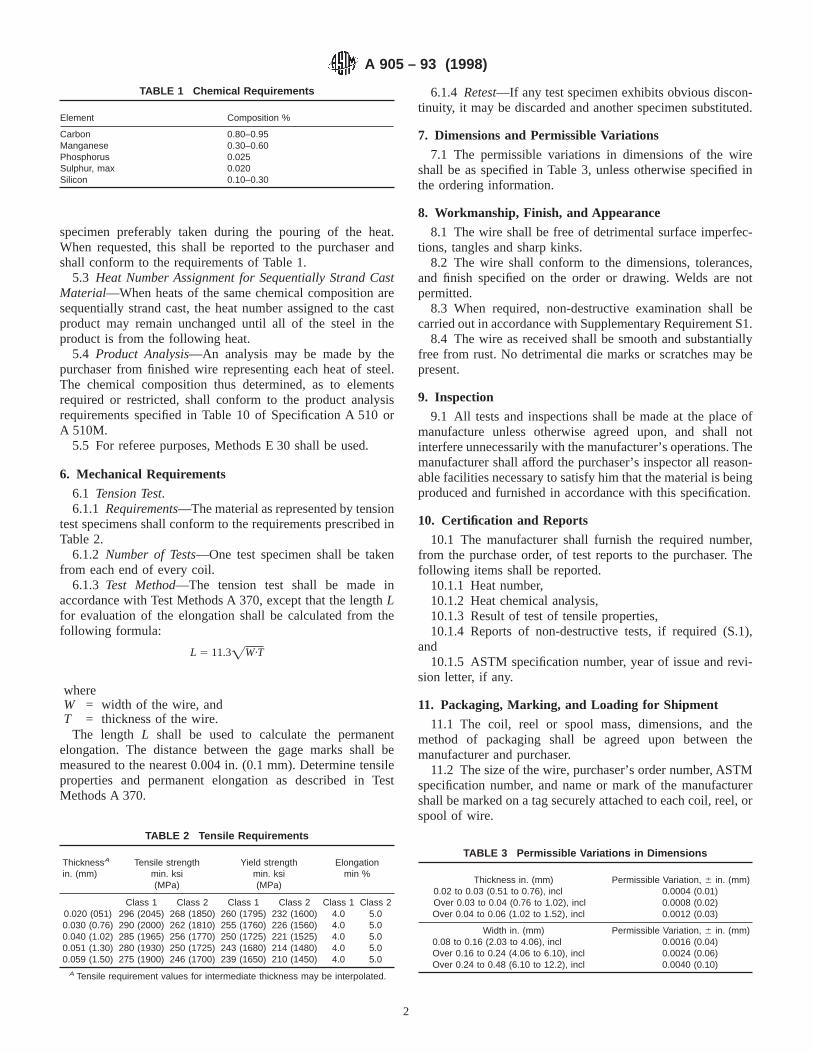
specimen preferably taken during the pouring of the heat.When requested, this shall be reported to the purchaser andshall conform to the requirements of Table 1.
5.3 Heat Number Assignment for Sequentially Strand CastMaterial—When heats of the same chemical composition aresequentially strand cast, the heat number assigned to the castproduct may remain unchanged until all of the steel in theproduct is from the following heat.
5.4 Product Analysis—An analysis may be made by thepurchaser from finished wire representing each heat of steel.The chemical composition thus determined, as to elementsrequired or restricted, shall conform to the product analysisrequirements specified in Table 10 of Specification A 510 orA 510M.
5.5 For referee purposes, Methods E 30 shall be used.
6. Mechanical Requirements
6.1 Tension Test.6.1.1 Requirements—The material as represented by tension
test specimens shall conform to the requirements prescribed inTable 2.
6.1.2 Number of Tests—One test specimen shall be takenfrom each end of every coil.
6.1.3 Test Method—The tension test shall be made inaccordance with Test Methods A 370, except that the lengthLfor evaluation of the elongation shall be calculated from thefollowing formula:
L 5 11.3=W·T
whereW = width of the wire, andT = thickness of the wire.
The length L shall be used to calculate the permanentelongation. The distance between the gage marks shall bemeasured to the nearest 0.004 in. (0.1 mm). Determine tensileproperties and permanent elongation as described in TestMethods A 370.
6.1.4 Retest—If any test specimen exhibits obvious discon-tinuity, it may be discarded and another specimen substituted.
7. Dimensions and Permissible Variations
7.1 The permissible variations in dimensions of the wireshall be as specified in Table 3, unless otherwise specified inthe ordering information.
8. Workmanship, Finish, and Appearance
8.1 The wire shall be free of detrimental surface imperfec-tions, tangles and sharp kinks.
8.2 The wire shall conform to the dimensions, tolerances,and finish specified on the order or drawing. Welds are notpermitted.
8.3 When required, non-destructive examination shall becarried out in accordance with Supplementary Requirement S1.
8.4 The wire as received shall be smooth and substantiallyfree from rust. No detrimental die marks or scratches may bepresent.
9. Inspection
9.1 All tests and inspections shall be made at the place ofmanufacture unless otherwise agreed upon, and shall notinterfere unnecessarily with the manufacturer’s operations. Themanufacturer shall afford the purchaser’s inspector all reason-able facilities necessary to satisfy him that the material is beingproduced and furnished in accordance with this specification.
10. Certification and Reports
10.1 The manufacturer shall furnish the required number,from the purchase order, of test reports to the purchaser. Thefollowing items shall be reported.
10.1.1 Heat number,10.1.2 Heat chemical analysis,10.1.3 Result of test of tensile properties,10.1.4 Reports of non-destructive tests, if required (S.1),
and10.1.5 ASTM specification number, year of issue and revi-
sion letter, if any.
11. Packaging, Marking, and Loading for Shipment
11.1 The coil, reel or spool mass, dimensions, and themethod of packaging shall be agreed upon between themanufacturer and purchaser.
11.2 The size of the wire, purchaser’s order number, ASTMspecification number, and name or mark of the manufacturershall be marked on a tag securely attached to each coil, reel, orspool of wire.
TABLE 1 Chemical Requirements
Element Composition %
Carbon 0.80–0.95Manganese 0.30–0.60Phosphorus 0.025Sulphur, max 0.020Silicon 0.10–0.30
TABLE 2 Tensile Requirements
ThicknessA
in. (mm)Tensile strength
min. ksi(MPa)
Yield strengthmin. ksi(MPa)
Elongationmin %
Class 1 Class 2 Class 1 Class 2 Class 1 Class 20.020 (051) 296 (2045) 268 (1850) 260 (1795) 232 (1600) 4.0 5.00.030 (0.76) 290 (2000) 262 (1810) 255 (1760) 226 (1560) 4.0 5.00.040 (1.02) 285 (1965) 256 (1770) 250 (1725) 221 (1525) 4.0 5.00.051 (1.30) 280 (1930) 250 (1725) 243 (1680) 214 (1480) 4.0 5.00.059 (1.50) 275 (1900) 246 (1700) 239 (1650) 210 (1450) 4.0 5.0
A Tensile requirement values for intermediate thickness may be interpolated.
TABLE 3 Permissible Variations in Dimensions
Thickness in. (mm) Permissible Variation, 6 in. (mm)0.02 to 0.03 (0.51 to 0.76), incl 0.0004 (0.01)Over 0.03 to 0.04 (0.76 to 1.02), incl 0.0008 (0.02)Over 0.04 to 0.06 (1.02 to 1.52), incl 0.0012 (0.03)
Width in. (mm) Permissible Variation, 6 in. (mm)0.08 to 0.16 (2.03 to 4.06), incl 0.0016 (0.04)Over 0.16 to 0.24 (4.06 to 6.10), incl 0.0024 (0.06)Over 0.24 to 0.48 (6.10 to 12.2), incl 0.0040 (0.10)
A 905 – 93 (1998)
2
11.3 Unless otherwise specified in the purchaser’s order,packaging, marking, and loading for shipments shall be inaccordance with those procedures recommended by PracticesA 700.
11.4 For Government Procurement—Packaging, packing,and marking of material for military procurement shall be inaccordance with the requirements of MIL-STD-163, Level A,Level C, or commercial as specified in the contract or purchaseorder. Marking for shipment of material for civil agencies shallbe in accordance with Fed. Std. No. 123.
11.5 Bar Coding—In addition to the previously-stated iden-tification requirements, bar coding is acceptable as a supple-mentary identification method. Bar coding should be consistentwith AIAG Standard 02.00, Primary Metals Identification TagApplication. The bar code may be applied to a substantiallyaffixed tag.
12. Keywords
12.1 pressure vessel; winding; wire
SUPPLEMENTARY REQUIREMENTS
Supplementary requirements to this specification shall only apply to a product specification whenspecified by the purchaser in his inquiry, contract or order. Details of the supplementary requirementsshall be agreed upon in writing between the manufacturer and purchaser.
S1. Surface Examination
S1.1 The surface of the wire shall be examined by the eddycurrent method in accordance with Practice E 309. The accep-tance criteria shall be mutally agreed upon by the purchaser
and manufacturer.
ASTM International takes no position respecting the validity of any patent rights asserted in connection with any item mentionedin this standard. Users of this standard are expressly advised that determination of the validity of any such patent rights, and the riskof infringement of such rights, are entirely their own responsibility.
This standard is subject to revision at any time by the responsible technical committee and must be reviewed every five years andif not revised, either reapproved or withdrawn. Your comments are invited either for revision of this standard or for additional standardsand should be addressed to ASTM International Headquarters. Your comments will receive careful consideration at a meeting of theresponsible technical committee, which you may attend. If you feel that your comments have not received a fair hearing you shouldmake your views known to the ASTM Committee on Standards, at the address shown below.
This standard is copyrighted by ASTM International, 100 Barr Harbor Drive, PO Box C700, West Conshohocken, PA 19428-2959,United States. Individual reprints (single or multiple copies) of this standard may be obtained by contacting ASTM at the aboveaddress or at 610-832-9585 (phone), 610-832-9555 (fax), or [email protected] (e-mail); or through the ASTM website(www.astm.org).
A 905 – 93 (1998)
3

Designation: A 923 – 03
Standard Test Methods forDetecting Detrimental Intermetallic Phase in DuplexAustenitic/Ferritic Stainless Steels 1
This standard is issued under the fixed designation A 923; the number immediately following the designation indicates the year oforiginal adoption or, in the case of revision, the year of last revision. A number in parentheses indicates the year of last reapproval. Asuperscript epsilon (e) indicates an editorial change since the last revision or reapproval.
1. Scope*
1.1 The purpose of these test methods is to allow detectionof the presence of intermetallic phases in duplex stainless steelsto the extent that toughness or corrosion resistance is affectedsignificantly. These test methods will not necessarily detectlosses of toughness or corrosion resistance attributable to othercauses.
1.2 Duplex (austenitic-ferritic) stainless steels are suscep-tible to the formation of intermetallic compounds duringexposures in the temperature range from approximately 600 to1750°F (320 to 955°C). The speed of these precipitationreactions is a function of composition and thermal or thermo-mechanical history of each individual piece. The presence ofthese phases is detrimental to toughness and corrosion resis-tance.
1.3 Correct heat treatment of duplex stainless steels caneliminate these detrimental phases. Rapid cooling of theproduct provides the maximum resistance to formation ofdetrimental phases by subsequent thermal exposures.
1.4 Compliance with the chemical and mechanical require-ments for the applicable product specification does not neces-sarily indicate the absence of detrimental phases in the product.
1.5 These test methods include the following:1.5.1 Test Method A—Sodium Hydroxide Etch Test for
Classification of Etch Structures of Duplex Stainless Steels(Sections 3-7).
1.5.2 Test Method B—Charpy Impact Test for Classificationof Structures of Duplex Stainless Steels (Sections 8-13).
1.5.3 Test Method C—Ferric Chloride Corrosion Test forClassification of Structures of Duplex Stainless Steels (Sec-tions 14-20).
1.6 The presence of detrimental intermetallic phases isreadily detected in all three tests, provided that a sample ofappropriate location and orientation is selected. Because theoccurrence of intermetallic phases is a function of temperatureand cooling rate, it is essential that the tests be applied to theregion of the material experiencing the conditions most likely
to promote the formation of an intermetallic phase. In the caseof common heat treatment, this region will be that whichcooled most slowly. Except for rapidly cooled material, it maybe necessary to sample from a location determined to be themost slowly cooled for the material piece to be characterized.
1.7 The tests do not determine the precise nature of thedetrimental phase but rather the presence or absence of anintermetallic phase to the extent that it is detrimental to thetoughness and corrosion resistance of the material.
1.8 Examples of the correlation of thermal exposures, theoccurrence of intermetallic phases, and the degradation oftoughness and corrosion resistance are given in Appendix X1and Appendix X2.
1.9 The values stated in either inch-pound or SI units are tobe regarded as the standard. The values given in parenthesesare for information only.
1.10 This standard does not purport to address all of thesafety concerns, if any, associated with its use. It is theresponsibility of the user of this standard to establish appro-priate safety and health practices and determine the applica-bility of regulatory limitations prior to use.
2. Referenced Documents
2.1 ASTM Standards:A 370 Test Methods and Definitions for Mechanical Testing
of Steel Products2
G 48 Test Methods for Pitting and Crevice Corrosion Re-sistance of Stainless Steels and Related Alloys by Use ofFerric Chloride Solution3
TEST METHOD A—SODIUM HYDROXIDE ETCHTEST FOR CLASSIFICATION OF ETCH
STRUCTURES OF DUPLEX STAINLESS STEELS
3. Scope
3.1 The sodium hydroxide etch test may be used for theacceptance of material but not for rejection. This test methodmay be used with other evaluation tests to provide a rapidmethod for identifying those specimens that are free ofdetrimental intermetallic phases as measured in these othertests.1 These test methods are under the jurisdiction of ASTM Committee A01 on
Steel, Stainless Steel, and Related Alloys and are the direct responsibility ofSubcommittee A01.14 on Methods of Corrosion Testing.
Current edition approved Oct. 1, 2003. Published October 2003. Originallyapproved in 1994. Last previous edition approved in 2001 as A 923–01e1.
2 Annual Book of ASTM Standards, Vol 01.03.3 Annual Book of ASTM Standards, Vol 03.02.
1
*A Summary of Changes section appears at the end of this standard.
Copyright © ASTM International, 100 Barr Harbor Drive, PO Box C700, West Conshohocken, PA 19428-2959, United States.

3.2 The sodium hydroxide etch test may be used to screenspecimens intended for testing in Test Method B, CharpyImpact Test for Classification of Structures of Duplex StainlessSteels, and in Test Method C, Ferric Chloride Corrosion Testfor Classification of Structures of Duplex Stainless Steels.
3.3 Reference photomicrographs are provided to show clas-sifications of etch structures of a particular stainless steel typethat are equivalent to acceptable or to possibly unacceptableperformance for each practice. When Test Method A is used asa screening test for Test Method B or Test Method C,specimens having acceptable etch structures need not besubjected to Test Method B or Test Method C.
3.4 Table 1 indicates the applicability and acceptance crite-ria for Test Method A. When Test Method A is specified as anacceptance test, specimens having other than acceptable etchstructures may, at the option of the producer, be tested by TestMethod B or Test Method C.
3.5 The steel shall be tested in the final solution heat treatedcondition or such other conditions as are agreed upon betweenthe producer and the user.
4. Apparatus
4.1 Source of Direct Current—Battery, generator, or recti-fier capable of supplying approximately 15 V and 20 A.
4.2 Ammeter—Range from 0 to 30 A (see Note 1).4.3 Variable Resistance(see Note 1).4.4 Cathode—A cylindrical piece of conductive metal.4.5 Large Electric Clamp, to hold the specimen to be
etched.4.6 Metallurgical Microscope, for examination of etched
microstructures to 400 to 500 diameters.4.7 Electrodes of the Etching Cell—The specimen to be
etched is made the anode, and a cylindrical piece of metal aslarge as the specimen to be etched is made the cathode.
4.8 Electrolyte, sodium hydroxide (NaOH), reagent grade.
NOTE 1—The variable resistance and ammeter are placed in the circuitto measure and control the current on the specimen to be etched.
5. Preparation of Test Specimens
5.1 For mill products, examination shall be made on alongitudinal or transverse section. For cast products, examina-tion shall be made on a separately cast test coupon which washeat treated in the same furnace load as the casting itrepresents. Unless otherwise specified, selection of the testcoupon size shall be at the discretion of the producer. Becausehigh temperature or mechanical deformation associated withparticular cutting processes may alter the structure of the steel,
the cutting of the test specimen should be by a technique thatprevents these effects. Alternatively, after the specimens arecut, any material that may have been affected by high tempera-ture or deformation associated with the cutting should beremoved by machining or wet grinding prior to testing.
5.2 For mill products, the specimen should allow for asurvey across the full thickness of the section or, in the case ofa heavy section, a survey from one surface through themid-thickness of the section. The specimen shall include themid-thickness.
5.3 For cast materials, the specimen shall be taken atapproximately 1/4T.
5.4 Polishing—On all materials, cross-sectional surfacesshould be polished to a metallographic finish suitable forexamination at 4003 after etching. Specimens containingwelds should include base metal, weld heat–affected zone, andweld metal. The area to be etched may be prepared by grindingto an 80- or 120-grit finish on a grinding belt or wheel withoutexcessive heating and then by polishing on successively fineremery papers, No. 1,1⁄2 , 1⁄0 , 2⁄0 , 3⁄0 , and finer. Other methodsof polishing may be acceptable.
5.5 Etching Solution—The solution for etching is preparedby adding 40 g of reagent grade sodium hydroxide (NaOH) to100 g of distilled water.
5.6 Etching Conditions—The polished specimen should beetched at approximately 1 to 3 V dc, for 5 to 60 s (see Note 2).
NOTE 2—When etching is performed at 1 to 3 V dc with a platinumcathode for 5 to 60 s, any intermetallic phase is revealed by yellow, thenbrown, staining, followed by staining of the ferrite.
5.7 Rinsing—Following etching, the specimen should berinsed thoroughly in hot water and in acetone or alcohol,followed by air drying.
6. Classification of Etch Structures
6.1 The etched surface shall be examined on a metallurgicalmicroscope at 400 to 5003.
6.2 The etched cross-sectional areas should be examinedthoroughly by complete traverse of the full sample and acrossall zones such as weld metal, weld-affected zones, and basemetal on specimens containing welds.
6.3 The etch structures are classified into the followingtypes:
6.3.1 Unaffected Structure(Fig. 1, Fig. 2)—The ferrite hasbeen etched without revelation of intermetallic phase. Theinterphase boundaries are smooth.
6.3.2 Possibly Affected Structure(Fig. 3, Fig. 4)—Theferrite has been etched with isolated indications of possibleintermetallic phase. The interphase boundaries may show a finewaviness.
6.3.3 Affected Structure(Fig. 5, Fig. 6)—The indications ofan intermetallic phase are readily revealed before or simulta-neously with the staining of the ferrite during etching.
6.3.4 Centerline Structure(Fig. 7)—An intermetallic phaseis observed as a continuous or semi-continuous phase in themid-thickness region of the product, with or without theaffected structure outside of the mid-thickness region, indica-tive of segregation.
TABLE 1 Applicability and Acceptance Criteria forTest Method A
Grade AcceptableEtch Structure
NonacceptableEtch Structure
S31803,S32205,S32750, J92205
unaffectedstructure (Fig. 1,Fig. 2)
possibly affectedstructure (Fig. 3,Fig. 4)affected structure(Fig. 5, Fig. 6)centerline structure(Fig. 7)
A 923 – 03
2
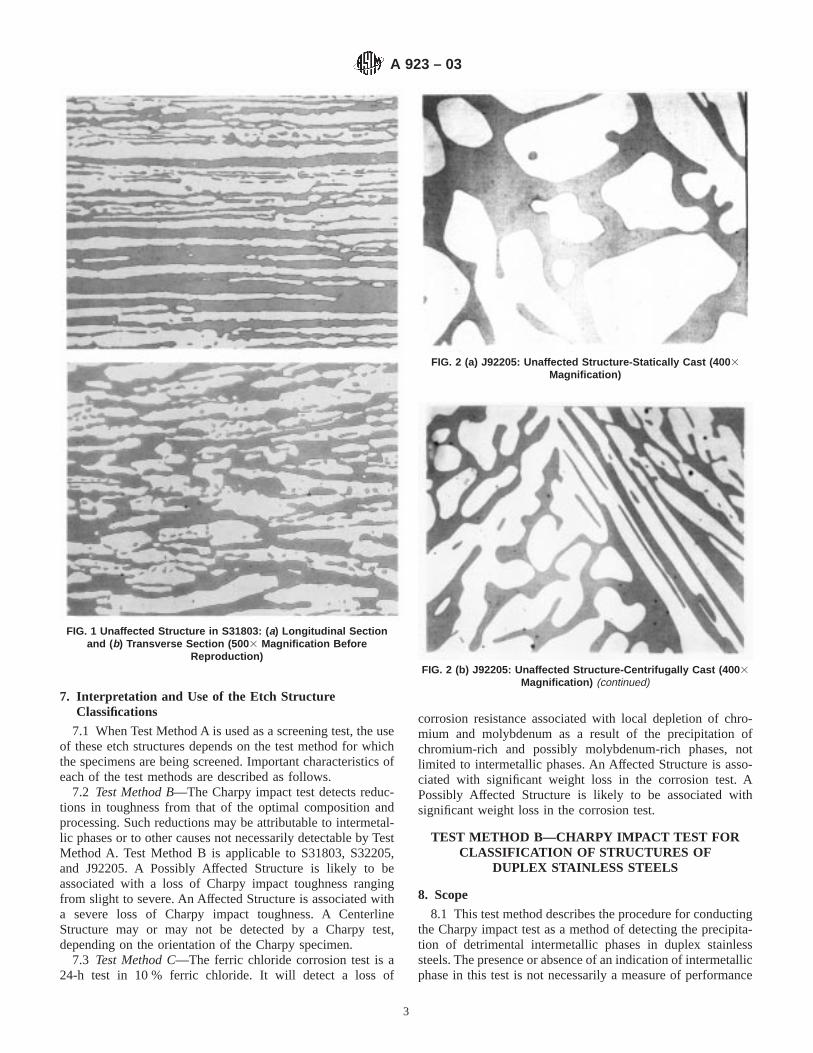
7. Interpretation and Use of the Etch StructureClassifications
7.1 When Test Method A is used as a screening test, the useof these etch structures depends on the test method for whichthe specimens are being screened. Important characteristics ofeach of the test methods are described as follows.
7.2 Test Method B—The Charpy impact test detects reduc-tions in toughness from that of the optimal composition andprocessing. Such reductions may be attributable to intermetal-lic phases or to other causes not necessarily detectable by TestMethod A. Test Method B is applicable to S31803, S32205,and J92205. A Possibly Affected Structure is likely to beassociated with a loss of Charpy impact toughness rangingfrom slight to severe. An Affected Structure is associated witha severe loss of Charpy impact toughness. A CenterlineStructure may or may not be detected by a Charpy test,depending on the orientation of the Charpy specimen.
7.3 Test Method C—The ferric chloride corrosion test is a24-h test in 10 % ferric chloride. It will detect a loss of
corrosion resistance associated with local depletion of chro-mium and molybdenum as a result of the precipitation ofchromium-rich and possibly molybdenum-rich phases, notlimited to intermetallic phases. An Affected Structure is asso-ciated with significant weight loss in the corrosion test. APossibly Affected Structure is likely to be associated withsignificant weight loss in the corrosion test.
TEST METHOD B—CHARPY IMPACT TEST FORCLASSIFICATION OF STRUCTURES OF
DUPLEX STAINLESS STEELS
8. Scope
8.1 This test method describes the procedure for conductingthe Charpy impact test as a method of detecting the precipita-tion of detrimental intermetallic phases in duplex stainlesssteels. The presence or absence of an indication of intermetallicphase in this test is not necessarily a measure of performance
FIG. 1 Unaffected Structure in S31803: ( a) Longitudinal Sectionand (b) Transverse Section (500 3 Magnification Before
Reproduction)
FIG. 2 (a) J92205: Unaffected Structure-Statically Cast (400 3Magnification)
FIG. 2 (b) J92205: Unaffected Structure-Centrifugally Cast (400 3Magnification) (continued)
A 923 – 03
3

of the material in service with regard to any property other thanthat measured directly. The Charpy procedure as here appliedis different from that as commonly applied for the determina-tion of toughness and should not be used when characterizationof material toughness is the purpose of the testing.
8.2 The Charpy impact test may be used to evaluate mill andcast products, provided that it is possible to obtain a specimenof relevant location and geometry.
8.3 Table 2 indicates the applicability and acceptance crite-ria for Test Method B.
9. Rapid Screening Test
9.1 Before testing by the Charpy impact test, specimens ofthe steel may be given a rapid screening test in accordance withthe procedures of Test Method A, Sodium Hydroxide Etch Testfor Classification of Etch Structures of Duplex Stainless Steels.Preparation, etching, and the classification of etch structuresare described therein. Specimens having an etch structuredescribed as Unaffected Structure in Test Method A will be
essentially free of detrimental effect on impact toughnessrelated to the formation of intermetallic phase. Other mecha-nisms for loss of toughness may occur independently but arebeyond the scope of this test method. Specimens showingUnaffected Structure in Test Method A are acceptable withrespect to the absence of intermetallic phases, without thenecessity of performing the Charpy test as described in TestMethod B. All specimens having other than Unaffected Struc-ture shall be tested by the Charpy impact test.
10. Apparatus
10.1 The test apparatus shall be as described in TestMethods and Definitions A 370.
11. Preparation of Test Specimens
11.1 The test specimen shall be as described in Test Meth-ods and Definitions A 370.
FIG. 3 Possibly Affected Structure in S31803: ( a) LongitudinalSection and ( b) Transverse Section (500 3 Magnification Before
Reproduction)
FIG. 4 (a) J92205: Possibly Affected Structure-Statically Cast(4003 Magnification)
FIG. 4 (b) J92205: Possibly Affected Structure-Centrifugally Cast(4003 Magnification) (continued)
A 923 – 03
4

11.2 An impact test for the purpose of detecting intermetal-lic phases shall consist of a single specimen taken from theproduct piece or lot to be represented.
11.3 For mill products, the test specimen may be aligned ineither the longitudinal or transverse direction (see Note 3). Forcastings, the test specimen shall be parallel to the side of thetest coupon; the notch may be either parallel to or perpendicu-lar to the coupon surface.
NOTE 3—The impact toughness of a transverse specimen from millproducts of duplex stainless steels is typically one half to two thirds of thatof a longitudinal specimen.
11.4 Subsize specimens may be used for products withthickness less than that of a full-size Charpy specimen. Subsizespecimens should be as large as permitted by the product, inquarter-size increments.
11.5 When this test is applied to a welded structure, or toany product having a less than uniform structure, particularattention should be paid to the location of the V-notch. For
example, in the heat-affected zone of a weld, the degree ofintermetallic formation may vary significantly over short
FIG. 5 Affected Structure in 8a S31803: ( a) Longitudinal Sectionand (b) Transverse Section (500 3 Magnification Before
Reproduction)
FIG. 6 J92205: Affected Structure (400 3 Magnification)
FIG. 7 S31803: Longitudinal Section (500 3 Magnification BeforeReproduction)
TABLE 2 Applicability and Acceptance Criteria forTest Method B
Grade Condition Acceptable Minimum ImpactEnergy at −40°F (−40°C) A
S31803, S32205, J92205 base metal 40 ft-lb (54 J)heat-affected zone 40 ft-lb (54 J)weld metal 25 ft-lb (34 J)
S32750 base metal B
A Energy for a full-size specimen. Required energy for a subsize specimen isreduced in direct proportion to the reduced area of the subsize specimen relativeto that of the full-size specimen.
B The acceptable minimum impact energy shall be agreed upon by seller andpurchaser.
A 923 – 03
5

distances as a function of the local thermal cycle. In such cases,the placement of the V-notch may affect the measured resultsignificantly.
12. Procedure
12.1 Perform the test in accordance with the proceduresdescribed in Test Methods and Definitions A 370.
12.2 Unless otherwise specified, perform the test at −40°F(−40°C).
13. Acceptance Values and Retests
13.1 Unless otherwise specified, the acceptance criteriashall be as given in Table 2.
13.2 If a test specimen shows a value below the specifiedminimum, one retest of two specimens is permitted. Foracceptance, both retest specimens shall show a value at orabove the specified minimum value.
13.3 A product that has failed the Charpy impact test may,at the option of the producer, be given a full anneal andretested.
TEST METHOD C—FERRIC CHLORIDECORROSION TEST FOR CLASSIFICATION OF
STRUCTURES OF DUPLEXSTAINLESS STEELS
14. Scope
14.1 This test method describes the procedure for conduct-ing the ferric chloride corrosion test for detecting the presenceof detrimental intermetallic phases in duplex stainless steels.The presence or absence of corrosion attack in this test is notnecessarily a measure of the performance of the material inother corrosive environments; in particular, it does not providea basis for predicting resistance to forms of corrosion notassociated with the precipitation of intermetallic phases (seeNote 4).
14.2 The ferric chloride corrosion test may be used toevaluate mill products, provided that it is possible to obtain aspecimen of relevant location and geometry.
14.3 Table 3 indicates the applicability and acceptancecriteria for Test Method C.
NOTE 4—Although this test method uses some equipment and proce-dures similar to those of Test Method G 48, this test method should not beconfused with Test Method G 48. This test method does not determine thecritical pitting temperature or test for the suitability for use in a particularenvironment. This test method is designed solely for detection of theprecipitation of detrimental intermetallic phases in duplex stainless steels.
15. Rapid Screening Test
15.1 Before testing by the ferric chloride corrosion test,specimens of the steel may be given a rapid screening test inaccordance with the procedures of Test Method A, SodiumHydroxide Etch Test for Classification of Etch Structures ofDuplex Stainless Steels. Preparation, etching, and the classifi-cation of etch structures are described therein. Specimenshaving an etch structure described as Unaffected Structure inTest Method A will be essentially free of detrimental effects onpitting corrosion resistance as related to the formation of anintermetallic phase. Other mechanisms for loss of pittingresistance may occur independently but are beyond the scopeof this test method. Specimens showing Unaffected3 Structurein Test Method A are acceptable with respect to the absence ofintermetallic phases and need not be tested by the ferricchloride corrosion test as described in Test Method C. Allspecimens having other than Unaffected Structure shall betested by the ferric chloride corrosion test.
16. Apparatus
16.1 Glass Beakers, 1000-mL, tall-form, or Erlenmeyerflasks, 1000-mL, wide neck, or 50-mm (2-in.) diameter testtubes, or other suitable glass containers.
16.2 Glass Cradles(Fig. 8)—The dimensions of the cradleshall be restricted to those that will permit its passage throughthe test container opening, a diameter of approximately 40 mm(1.6 in.) in the case of the Erlenmeyer flask.
16.3 Water or Oil Bath, constant temperature.
17. Ferric Chloride Test Solution
17.1 The test solution is prepared by dissolving 100 g ofreagent-grade ferric chloride, FeCl3·6H2O, in 900 mL ofdistilled water (approximately 6 % FeCl3 by weight). Thesolution is filtered through glass wool or filter paper to removeinsoluble particles.
17.2 The pH of the test solution shall be adjusted toapproximately 1.3 prior to beginning the test by the addition ofHCl or NaOH, as required.
18. Test Specimen
18.1 Various shapes and sizes of test specimens may beused. For flat products, a specimen should be approximately 25by 50 mm (1 by 2 in.) by thickness. The full thickness of theproduct should be included. In the case of heavier sections, thespecimen may be taken in a perpendicular orientation withdimensions of approximately 6 by 25 mm (1⁄4 by 1 in.) bythickness. In very heavy sections, the thickness dimension ofthe specimen may be cut so that one half to two thirds of theproduct thickness is tested.
18.2 Other product forms may be cut for test specimensconvenient for testing, provided that the specimen exposessurfaces representative of the full thickness of the product.
18.3 After the specimens are cut, any material that may havebeen affected by high temperature or deformation associatedwith the cutting should be removed by machining or grindingprior to testing.
18.4 For mill products, all surfaces of the specimen shouldbe polished to a uniform finish at least equal to a 120-gritfinish, or finer. Wet polishing is preferred. If used, dry
TABLE 3 Applicability and Acceptance Criteria forTest Method C
Grade Condition TestTemperature
Maximum AcceptableCorrosion Rate Calculated
from Weight Loss
S31803, S32205 base metal 25°C (77°F) 10 mddweld metal 22°C (72°F) 10 mdd
S32750 base metal 40°C (107°F) 10 mdd
A 923 – 03
6
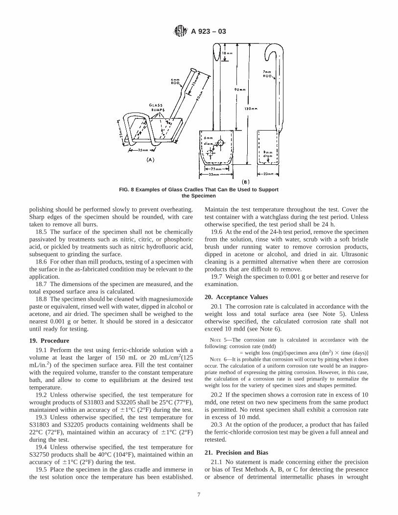
polishing should be performed slowly to prevent overheating.Sharp edges of the specimen should be rounded, with caretaken to remove all burrs.
18.5 The surface of the specimen shall not be chemicallypassivated by treatments such as nitric, citric, or phosphoricacid, or pickled by treatments such as nitric hydrofluoric acid,subsequent to grinding the surface.
18.6 For other than mill products, testing of a specimen withthe surface in the as-fabricated condition may be relevant to theapplication.
18.7 The dimensions of the specimen are measured, and thetotal exposed surface area is calculated.
18.8 The specimen should be cleaned with magnesiumoxidepaste or equivalent, rinsed well with water, dipped in alcohol oracetone, and air dried. The specimen shall be weighed to thenearest 0.001 g or better. It should be stored in a desiccatoruntil ready for testing.
19. Procedure
19.1 Perform the test using ferric-chloride solution with avolume at least the larger of 150 mL or 20 mL/cm2(125mL/in.2) of the specimen surface area. Fill the test containerwith the required volume, transfer to the constant temperaturebath, and allow to come to equilibrium at the desired testtemperature.
19.2 Unless otherwise specified, the test temperature forwrought products of S31803 and S32205 shall be 25°C (77°F),maintained within an accuracy of61°C (2°F) during the test.
19.3 Unless otherwise specified, the test temperature forS31803 and S32205 products containing weldments shall be22°C (72°F), maintained within an accuracy of61°C (2°F)during the test.
19.4 Unless otherwise specified, the test temperature forS32750 products shall be 40°C (104°F), maintained within anaccuracy of61°C (2°F) during the test.
19.5 Place the specimen in the glass cradle and immerse inthe test solution once the temperature has been established.
Maintain the test temperature throughout the test. Cover thetest container with a watchglass during the test period. Unlessotherwise specified, the test period shall be 24 h.
19.6 At the end of the 24-h test period, remove the specimenfrom the solution, rinse with water, scrub with a soft bristlebrush under running water to remove corrosion products,dipped in acetone or alcohol, and dried in air. Ultrasoniccleaning is a permitted alternative when there are corrosionproducts that are difficult to remove.
19.7 Weigh the specimen to 0.001 g or better and reserve forexamination.
20. Acceptance Values
20.1 The corrosion rate is calculated in accordance with theweight loss and total surface area (see Note 5). Unlessotherwise specified, the calculated corrosion rate shall notexceed 10 mdd (see Note 6).
NOTE 5—The corrosion rate is calculated in accordance with thefollowing: corrosion rate (mdd)
= weight loss (mg)/[specimen area (dm2) 3 time (days)]NOTE 6—It is probable that corrosion will occur by pitting when it does
occur. The calculation of a uniform corrosion rate would be an inappro-priate method of expressing the pitting corrosion. However, in this case,the calculation of a corrosion rate is used primarily to normalize theweight loss for the variety of specimen sizes and shapes permitted.
20.2 If the specimen shows a corrosion rate in excess of 10mdd, one retest on two new specimens from the same productis permitted. No retest specimen shall exhibit a corrosion ratein excess of 10 mdd.
20.3 At the option of the producer, a product that has failedthe ferric-chloride corrosion test may be given a full anneal andretested.
21. Precision and Bias
21.1 No statement is made concerning either the precisionor bias of Test Methods A, B, or C for detecting the presenceor absence of detrimental intermetallic phases in wrought
FIG. 8 Examples of Glass Cradles That Can Be Used to Supportthe Specimen
A 923 – 03
7

duplex stainless steels because the results state merely whetherthere is conformance to the criteria for success specified in theprocedure.
22. Keywords
22.1 duplex; intermetallic; stainless steels
APPENDIXES
(Nonmandatory Information)
X1. EXAMPLE OF THE EFFECT OF THERMAL EXPOSURE ON TOUGHNESS ANDCORROSION RESISTANCE OF S31803
TABLE X1.1 Effect of Thermal Exposure A
Composition of Test Material
C Mn P S Si Cr Ni Mo N
0.023 1.44 0.022 0.001 0.49 22.3 5.60 3.13 0.182
Heat Treatment Condition CVN Impact Energy (ft-lb at −40°F (J at −40°C)) B Critical Pitting Temperature (°C) C
Longitudinal Transverse
Mill annealed 185 (251) 127 (172) 351950°F (1066°C) + WQ 196 (266) 123 (167) not tested1950°F (1066°C) + WQ + 5 min, 1550°F 42 (60) 25 (34) 201950°F (1066°C) + WQ + 10 min,1550°F
32 (43) 16 (22) 15
1950°F (1066°C) + WQ + 15 min,1550°F
26 (35) 12 (16) not tested
1950°F (1066°C) + WQ + 20 min,1550°F
21 (28) 9 (12) 15
1950°F (1066°C) + air cool 198 (268) 133 (180) not tested1950°F (1066°C) + slow cool 80 (108) 88 (119) 30
A Davison, R. M., and Redmond, J. D., Paper No. 302, NACE Corrosion 91, 1991.B 3⁄8-in. (9.5-mm) plate, three-quarter size Charpy specimen.C CPT per Test Method G 48, Test Method A.
A 923 – 03
8

X2. EXAMPLE OF THE EFFECT OF THERMAL EXPOSURE ON TOUGHNESS OF J92205
SUMMARY OF CHANGES
Committee A01 had identified the location of selected changes made to this standard since the last issue,A 923–01e1, that may impact the use of this standard. (Approved Oct. 1, 2003).
(1) Title was revised.(2) Sections 1, 3, 5, 7, 8, and 11 were revised.(3) Tables 1 and 2 were revised.
(4) New figures were added
(5) Section 5.3 and Appendix X2 were added.
ASTM International takes no position respecting the validity of any patent rights asserted in connection with any item mentionedin this standard. Users of this standard are expressly advised that determination of the validity of any such patent rights, and the riskof infringement of such rights, are entirely their own responsibility.
This standard is subject to revision at any time by the responsible technical committee and must be reviewed every five years andif not revised, either reapproved or withdrawn. Your comments are invited either for revision of this standard or for additional standardsand should be addressed to ASTM International Headquarters. Your comments will receive careful consideration at a meeting of theresponsible technical committee, which you may attend. If you feel that your comments have not received a fair hearing you shouldmake your views known to the ASTM Committee on Standards, at the address shown below.
This standard is copyrighted by ASTM International, 100 Barr Harbor Drive, PO Box C700, West Conshohocken, PA 19428-2959,United States. Individual reprints (single or multiple copies) of this standard may be obtained by contacting ASTM at the aboveaddress or at 610-832-9585 (phone), 610-832-9555 (fax), or [email protected] (e-mail); or through the ASTM website(www.astm.org).
TABLE X2.1 Effect of Thermal Exposure on Cast Grade J92205 A
Heat C Mn Si Cr Ni S P Mo Cu N
1A 0.02 0.95 0.56 22.3 5.5 0.007 0.016 3.0 0.75 0.20
2 0.026 0.39 0.74 22.2 6.2 0.005 0.033 2.8 0.19 0.24
3 0.033 0.51 0.74 22.8 6.7 0.01 0.024 2.91 0.07 0.13
Heat Heat Treatment Condition CVN Impact Energy(ft-lb at −40°F (J at −40°C))
1A 1950°F (1066°C) + WQ 84 (114)1950°F (1066°C) + WQ, 1550°F (843°C) + WQ 47 (64)1950°F (1066°C) + WQ + 5 min, 1550°F (843°C) + WQ 18 (24)1950°F (1066°C) + WQ + 10 min, 1550°F (843°C) + WQ 15 (20)1950°F (1066°C) + WQ + 15 min, 1550°F (843°C) + WQ 9 (12)1950°F (1066°C) + WQ + 20 min, 1550°F (843°C) + WQ 10 (14)1950°F (1066°C) + air cool 22 (30)1950°F (1066°C) + hold 30 min, slow cool 4 (5)
2 1950°F (1066°C) + WQ 136 (184)1950°F (1066°C) + WQ, 1550°F (843°C) + WQ 34 (46)1950°F (1066°C) + WQ + 5 min, 1550°F (843°C) + WQ 39 (53)1950°F (1066°C) + WQ + 10 min, 1550°F (843°C) + WQ 26 (35)1950°F (1066°C) + WQ + 15 min, 1550°F (843°C) + WQ 35 (47)1950°F (1066°C) + WQ + 20 min, 1550°F (843°C) + WQ 17 (23)1950°F (1066°C) + air cool 25 (34)1950°F (1066°C) + hold 30 min, slow cool 5 (7)
3 1950°F (1066°C) + WQ 106 (144)1950°F (1066°C) + WQ, 1550°F (843°C) + WQ 84 (114)1950°F (1066°C) + WQ + 5 min, 1550°F (843°C) + WQ 59 (80)1950°F (1066°C) + WQ + 10 min, 1550°F (843°C) + WQ 36 (49)1950°F (1066°C) + WQ + 15 min, 1550°F (843°C) + WQ 26 (35)1950°F (1066°C) + WQ + 20 min, 1550°F (843°C) + WQ 27 (37)1950°F (1066°C) + air cool 50 (68)1950°F (1066°C) + hold 30 min, slow cool 8 (11)
A Heat 1 was centrifugally cast. Heats 2 and 3 were statically cast.
A 923 – 03
9

Designation: A 931 – 96 (Reapproved 2002)
Standard Test Method forTension Testing of Wire Ropes and Strand 1
This standard is issued under the fixed designation A 931; the number immediately following the designation indicates the year oforiginal adoption or, in the case of revision, the year of last revision. A number in parentheses indicates the year of last reapproval. Asuperscript epsilon (e) indicates an editorial change since the last revision or reapproval.
1. Scope
1.1 This test method covers the tension testing of wire ropesand strand at room temperature, specifically to determine theminimum acceptance strength or nominal strength, yieldstrength, elongation, and modulus of elasticity.
1.2 The values stated in inch-pound units are to be regardedas the standard. The SI units given in parentheses are forinformation only.
1.3 This standard does not purport to address all of thesafety concerns, if any, associated with its use. It is theresponsibility of the user of this standard to establish appro-priate safety and health practices and determine the applica-bility of regulatory limitations prior to use.Specific precau-tionary statements are given in Note 1, Note 2, Note 3, andNote 5.
2. Referenced Documents
2.1 ASTM Standards:A 586 Specification for Zinc-Coated Parallel and Helical
Steel Wire Structural Strand and Zinc-Coated Wire forSpun-In-Place Structural Strand2
A 603 Specification for Zinc-Coated Steel Structural WireRope2
B 6 Specification for Zinc3
E 4 Practices for Force Verification of Test Machines4
E 6 Terminology Relating to Methods of Mechanical Test-ing4
E 8 Test Methods for Tension Testing of Metallic Materials4
3. Terminology
3.1 The terminology relating to tensile testing in Terminol-ogy E 6 applies to this test method. In addition, the followingdefinitions for wire rope will apply:
3.2 Definitions:
3.2.1 abrasion—frictional surface wear on the wires of awire rope.
3.2.2 aggregate area—seearea, metallic.3.2.3 aggregate strength—the strength derived by totalling
the individual breaking strengths of the elements of the strandor rope. This strength does not give recognition to thereduction in strength resulting from the angularity of theelements in the rope, or other factors that may affect efficiency.
3.2.4 area, metallic—sum of the cross-sectional areas of allwires either in a wire rope or in a strand.
3.2.5 breaking strength—the ultimate load at which a tensilefailure occurs in the sample of wire rope being tested.
3.2.6 Discussion—The termbreaking strengthis synony-mous with actual strength.
3.2.7 cable—a term loosely applied to wire rope, wirestrand, and electrical conductors.
3.2.8 center—the axial member of a strand about which thewires are laid.
3.2.9 classification—group or family designation based onwire rope constructions with common strengths and weightslisted under the broad designation.
3.2.10 construction—geometric design description of thewire rope’s cross section. This includes the number of strands,the number of wires per strand, and the pattern of wirearrangement in each strand.
3.2.11 core—the axial member of a wire rope about whichthe strands are laid.
3.2.12 fiber core—cord or rope of vegetable or syntheticfiber used as the core of a rope.
3.2.13 galvanized rope—wire rope made up of galvanizedwire.
3.2.14 galvanized strand—strand made up of galvanizedwire.
3.2.15 grade—wire rope or strand classification by strengthor type of material, that is, Class 3, Type 302 stainless,phosphor bronze, etc. It does not apply to strength of theindividual wires used to manufacture the rope or strand.
3.2.16 independent wire rope core (IWRC)—a wire ropeused as the core of a larger wire rope.
3.2.17 inner wires—all wires of a strand except the outer orcover wires.
1 This test method is under the jurisdiction of ASTM Committee A01 on Steel,Stainless Steel, and Related Alloys and is the direct responsibility of SubcommitteeA01.03 on Steel Rod and Wire.
Current edition approved March 10, 1996. Published May 1996. Originallypublished as A 931 – 94. Last previous edition A 931 – 94.
2 Annual Book of ASTM Standards, Vol 01.06.3 Annual Book of ASTM Standards, Vol 02.04.4 Annual Book of ASTM Standards, Vol 03.01.
1
Copyright © ASTM International, 100 Barr Harbor Drive, PO Box C700, West Conshohocken, PA 19428-2959, United States.
3.2.18 lay—(a) the manner in which the wires in a strand orthe strands in a rope are helically laid, or (b) the distancemeasured parallel to the axis of the rope (or strand) in which astrand (or wire) makes one complete helical convolution aboutthe core (or center). In this connection, lay is also referred to aslay lengthor pitch.
3.2.19 minimum acceptance strength—that strength that is 21 / 2 % lower than the catalog or nominal strength. Thistolerance is used to offset variables that occur during samplepreparation and actual physical test of a wire rope.
3.2.20 modulus of elasticity—the slope of the elastic portionof the stress-strain curve. The ratio of stress to correspondingstrain below the proportional limit. This value is generallytaken between 20 and 50 % of the nominal strength.
3.2.21 nominal strength—the published (catalog) strengthcalculated by a standard procedure that is accepted by the wirerope industry. The wire rope manufacturer designs wire rope tothis strength, and the user should consider this strength whenmaking design calculations.
3.2.22 socket—generic name for a type of wire rope fitting.3.2.23 strand—a plurality of round or shaped wires heli-
cally laid about a center.3.2.24 wire rope—strands helically laid around a core.3.2.25 wire strand core (WSC)—a wire strand used as the
core of a wire rope.
4. Significance and Use
4.1 Wire rope tests are generally to be performed on newrope. The use of wire rope in any application can reduceindividual wire strengths due to abrasion and nicking that willresult in the wire rope strength being reduced. Damage to theouter wires will also lower the maximum strength achievedduring tension testing.
4.2 The modulus of elasticity of wire rope is not consideredto be a standard requirement at this time. The determination ofthis material property requires specialized equipment andtechniques.
4.3 Rope to be tested should be thoroughly examined toverify that no external wire damage is present. If present, itshould be noted. When possible, a new undamaged sampleshould be obtained for testing.
4.4 End attachments and their installation can directly affectbreaking strength achieved during testing. Any attachment thatcan be used to directly achieve the required rope breakingstrength can be used. Standard testing with a poured socket,using zinc, white metal or thermoset resin, has been consideredthe most efficient. Proficiency in attachment of any fitting canhave a direct effect on the final test results.
5. Interferences
5.1 Visual examination of the sample for any damage toouter wires should be done. If any damage is evident, thesample should not be used. The purpose of this test method isto verify the nominal or maximum strength the wire rope orstrand can achieve.
5.2 Measurement of the rope or strand sample is necessaryto document the size, length between end attachments, andlength of lay of the rope if necessary. Further details regardingthis will be discussed in test results.
5.3 The length of test specimen shall not be less than 3 ft,(0.91 m) between sockets for wire ropes up to 1 in. (25.4 mm)diameter, inclusive, and not less than 5 ft (1.52 m) betweensockets for wire ropes 11⁄8 in. (28.6 mm) to 3 in. (77 mm)diameter. On wire ropes larger than 3 in. (77 mm), the clearlength of the test specimen shall be at least 20 times the ropediameter.
6. Apparatus
6.1 Testing Machines—Machines used for tension testingshall conform to the requirements of Practices E 4. The loadsused in determining tensile strength and yield strength shall bewithin loading range of the tensile machine as defined inPractices E 4.
6.2 Gripping Devices:6.2.1 General—Various types of gripping devices may be
used to transmit the measured load applied by the testingmachine to test specimens. To ensure axial tensile stress withinthe gage length, the axis of the test specimen should coincidewith the center line of the heads of the machine. Any departurefrom this requirement may introduce bending stresses that arenot included in the usual stress computation.
6.2.2 Wedge Grips—Testing machines usually are equippedwith wedge grips. These wedge grips generally furnish asatisfactory means of gripping long specimens of ductile metal.If, however, for any reason, one grip of a pair advances fartherthan the other as the grips tighten, an undesirable bendingstress may be introduced. When liners are used behind thewedges, they must be of the same thickness and their facesmust be flat and parallel. For best results, the wedges should besupported over their entire lengths by the heads of the testingmachine. This requires that liners of several thicknesses beavailable to cover the range of specimen thickness. For propergripping, it is desirable that the entire length of the serratedface of each wedge be in contact with the specimen. Specially-designed round-shaped grips may have to be used for testingrope or strand. It is essential that all wires in the rope or strandare uniformly gripped when the load is applied.
6.2.3 Conical Grips—Conical grips are constructed so thatwhen they are fitted together, a conical-shaped cavity existswhich will hold a cone socket wire rope or strand andattachment (fitting).
7. Sample Preparation and Preparation of EndAttachments
7.1 Poured sockets are considered to be the most efficientand should be used due to their ability to distribute the loadevenly in the wire rope when installed properly. Procedures forthe proper installation of poured end attachments can be foundin socketing procedures.
7.2 Other end attachments such as grips may be usedprovided the required loading is achieved.
7.3 Sample Preparation Procedures:7.3.1 SocketingZinc-Poured Socketing:7.3.1.1 Measuring the Rope Ends to be Socketed—The rope
end should be of sufficient length so that the ends of the unlaidwires (from the strands) will be at the top of the socket basket(see Fig. 1(a)).
A 931 – 96 (2002)
2

FIG. 1 Wire Rope for Socketing
A 931 – 96 (2002)
3

7.3.1.2 Apply Serving at Base of Socket—Apply a tight wireserving band at the point where the socket base will be for alength of two rope diameters (see Fig. 1(b) and 1(c)).
7.3.1.3 Broom Out Strand Wires—Unlay and straighten theindividual rope strands and spread them evenly so that theyform an included angle of approximately 60°. Unlay the wiresof each individual strand for the full length of the rope end,being careful not to disturb or change the lay of the wires andstrands under the serving band. Unlay the wires of an indepen-dent wire rope core in the same manner. A fiber core should becut out and removed as close to the serving band as possible(see Fig. 1(c)).
7.3.2 Clean the Broomed-Out Ends—A suggested cleaningsolvent for this step is SC-5 methyl chloroform. It is alsoknown under the names chlorothane VG and 1-1-1 trichlore-thane.
NOTE 1—Warning: Breathing the vapor of this solvent is harmful; itshould only be used in a well-ventilated area. Be sure to follow the solventmanufacturer’s instructions, and carefully observe all instructions printedon the label.
Some non-chlorinated solvents are adequate and are preferable ifavailable.
7.3.2.1 Swish the broomed-out rope end in the solvent, thenbrush vigorously to remove all grease and dirt, making certainthat the wires are clean to the very bottom close to the servingband (see Fig. 1(d)). Additionally, a solution of muriatic acidmay also be used. If, however, acid is used, the broomed-outends should be rinsed in a solution of bicarbonate of soda so asto neutralize any acid that may remain on the rope. Care shouldbe exercised to prevent acid from entering the core; this isparticularly important if the rope has a fiber core. Where it isfeasible, the best and preferred cleaning method for rope endsprior to socketing is ultrasonic cleaning. After this cleaningstep, place the broomed-out end upright in a vise allowing it toremain until all solvent has evaporated and the wires are dry.
7.3.2.2 Solvent should never be permitted to remain on therope or on the serving band since it will run down the wireswhen the rope is removed from the vise.
7.3.3 Dip the Broomed-Out Rope Ends in Flux—Prepare ahot solution of zinc-ammonium chloride flux comparable toZaclon K. Use a concentration of 1 lb. (453.6 g) of zinc-ammonium chloride to 1 gal (3.774 L) of water, maintain thisat a temperature of 180°F (82°C) to 200°F (93°C). Swish thebroomed-out end in the flux solution, then place the rope endupright in the vise until such time as the wires have driedthoroughly (see Fig. 1(e)).
7.3.4 Close Rope Ends and Place Socket—Use clean wire tocompress the broomed-out rope end into a tight bundle that willpermit the socket to be slipped on easily over the wires (seeFig. 1(f)). Before placing the socket on the rope, make certainthat the socket itself is clean and heated to 200°F (93°C) to400°F (204°C). This heating is necessary in order to dispel anyresidual moisture, and to prevent the zinc from coolingprematurely.
NOTE 2—Caution: Never heat a socket after it is placed on the rope.To do so may cause heat damage to the rope.
7.3.4.1 After the socket is on the rope end, the wires shouldbe distributed evenly in the socket basket so that zinc can
surround each wire. Use extreme care in aligning the socketwith the rope’s centerline, and in making certain that there is aminimum vertical length of rope, extending from the socket,that is equal to that specified in 6.3.
7.3.4.2 Seal the socket base with fire clay or putty, but makecertain that this material does not penetrate into the socketbase. Should this occur, it would prevent the zinc frompenetrating the full length of the socket basket, therebycreating a void that would collect moisture after the socket isplaced in service.
7.3.5 Pour the Zinc—The zinc used should meet Specifica-tion B 6 Grade (1) High Grade. Pour the zinc at a temperatureof 950 to 970°F (510 to 521°C) (see Fig. 1(h)); makeallowances for cooling if the zinc pot is more than 25 ft. fromthe socket.
NOTE 3—Caution: Do not heat zinc above 1200°F (649°C) or itsbonding properties will be lost, and heat damage will occur to the rope.The zinc temperature may be measured with a portable pyrometer or aTempilstik. Remove all dross before pouring. Pour the zinc in onecontinuous stream until it reaches the basket top and all wire ends arecovered; there should be no “capping” of the socket.
7.3.6 Remove Serving—Remove the serving band from thesocket base; check to make certain that the zinc has penetratedto the socket base (see Fig. 1(i)).
7.3.7 Lubricate the Rope—Apply wire rope lubricant to therope at the socket base and on any rope section where theoriginal lubricant may have been removed.
8. Thermo-Set Socketing
8.1 Before proceeding with a thermo-set resin socketingprocedure, check manufacturer’s instructions carefully. Giveparticular attention to selecting sockets that have been specifi-cally designed for resin socketing.
8.2 Acceptable Resin Types—Commercially-available resinproperties vary considerably. Hence, it is important to refer tothe individual manufacturer’s instructions before using any onetype. General rules cannot, of course, be established.
8.3 When properly formulated, most thermo-e resins areacceptable for socketing. These formulations, when mixed,form a pourable material that will harden at ambient tempera-tures, or upon the application of moderate heat. No open flameor molten metal hazards exist with resin socketing sinceheat-curing, when necessary, requires a relatively low tempera-ture 250 to 300°F (121 to 149°C) obtainable by electricresistance heating.
8.4 Tests have demonstrated that satisfactory wire ropesocketing performance can be obtained with resins.
9. Procedure
9.1 Take measurements on the sample to determine theactual rope diameter and sample length between sockets beforeloading on the test machine.
NOTE 4— Rope diameter should be measured properly to determinethe actual diameter. (See Fig. 2 for the correct method.) An incorrectmeasurement is possible and should be avoided. (See Fig. 3 for the methodto avoid.)
9.2 After the sample is placed in the test machine, completethe zeroing before testing begins for accurate results. Start
A 931 – 96 (2002)
4
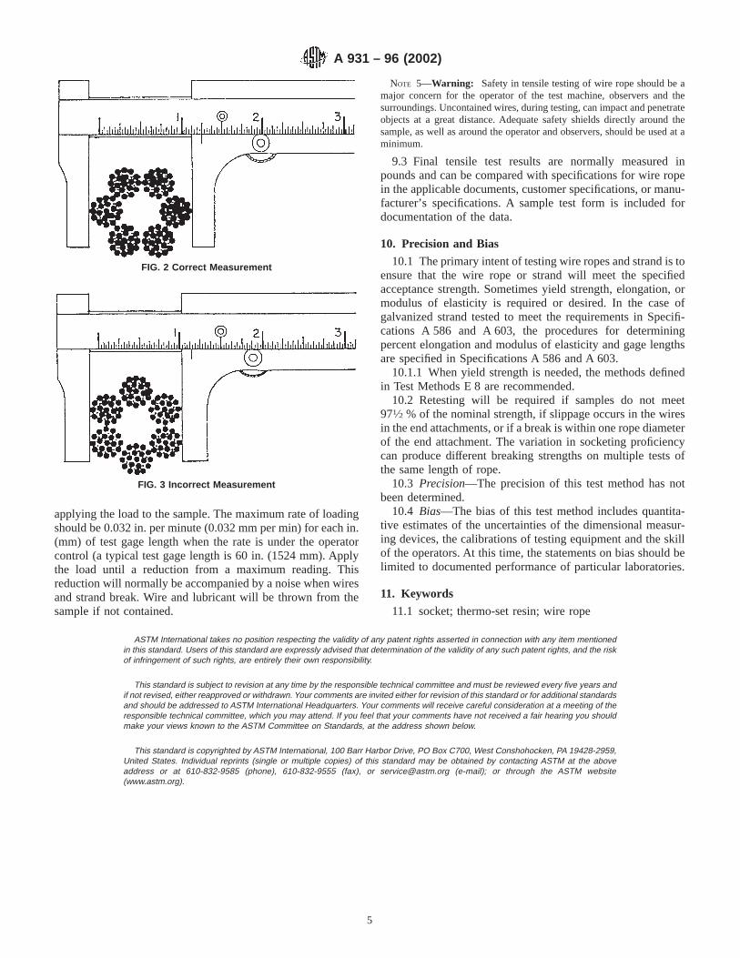
applying the load to the sample. The maximum rate of loadingshould be 0.032 in. per minute (0.032 mm per min) for each in.(mm) of test gage length when the rate is under the operatorcontrol (a typical test gage length is 60 in. (1524 mm). Applythe load until a reduction from a maximum reading. Thisreduction will normally be accompanied by a noise when wiresand strand break. Wire and lubricant will be thrown from thesample if not contained.
NOTE 5—Warning: Safety in tensile testing of wire rope should be amajor concern for the operator of the test machine, observers and thesurroundings. Uncontained wires, during testing, can impact and penetrateobjects at a great distance. Adequate safety shields directly around thesample, as well as around the operator and observers, should be used at aminimum.
9.3 Final tensile test results are normally measured inpounds and can be compared with specifications for wire ropein the applicable documents, customer specifications, or manu-facturer’s specifications. A sample test form is included fordocumentation of the data.
10. Precision and Bias
10.1 The primary intent of testing wire ropes and strand is toensure that the wire rope or strand will meet the specifiedacceptance strength. Sometimes yield strength, elongation, ormodulus of elasticity is required or desired. In the case ofgalvanized strand tested to meet the requirements in Specifi-cations A 586 and A 603, the procedures for determiningpercent elongation and modulus of elasticity and gage lengthsare specified in Specifications A 586 and A 603.
10.1.1 When yield strength is needed, the methods definedin Test Methods E 8 are recommended.
10.2 Retesting will be required if samples do not meet971⁄2 % of the nominal strength, if slippage occurs in the wiresin the end attachments, or if a break is within one rope diameterof the end attachment. The variation in socketing proficiencycan produce different breaking strengths on multiple tests ofthe same length of rope.
10.3 Precision—The precision of this test method has notbeen determined.
10.4 Bias—The bias of this test method includes quantita-tive estimates of the uncertainties of the dimensional measur-ing devices, the calibrations of testing equipment and the skillof the operators. At this time, the statements on bias should belimited to documented performance of particular laboratories.
11. Keywords
11.1 socket; thermo-set resin; wire rope
ASTM International takes no position respecting the validity of any patent rights asserted in connection with any item mentionedin this standard. Users of this standard are expressly advised that determination of the validity of any such patent rights, and the riskof infringement of such rights, are entirely their own responsibility.
This standard is subject to revision at any time by the responsible technical committee and must be reviewed every five years andif not revised, either reapproved or withdrawn. Your comments are invited either for revision of this standard or for additional standardsand should be addressed to ASTM International Headquarters. Your comments will receive careful consideration at a meeting of theresponsible technical committee, which you may attend. If you feel that your comments have not received a fair hearing you shouldmake your views known to the ASTM Committee on Standards, at the address shown below.
This standard is copyrighted by ASTM International, 100 Barr Harbor Drive, PO Box C700, West Conshohocken, PA 19428-2959,United States. Individual reprints (single or multiple copies) of this standard may be obtained by contacting ASTM at the aboveaddress or at 610-832-9585 (phone), 610-832-9555 (fax), or [email protected] (e-mail); or through the ASTM website(www.astm.org).
FIG. 2 Correct Measurement
FIG. 3 Incorrect Measurement
A 931 – 96 (2002)
5
Designation: A 938 – 97 (Reapproved 2003)
Standard Test Method forTorsion Testing of Wire 1
This standard is issued under the fixed designation A 938; the number immediately following the designation indicates the year oforiginal adoption or, in the case of revision, the year of last revision. A number in parentheses indicates the year of last reapproval. Asuperscript epsilon (e) indicates an editorial change since the last revision or reapproval.
1. Scope
1.1 This test method describes the torsion (or twist) testingof metallic wire.
1.2 The values stated in U.S. customary units are to beregarded as the standard. The SI equivalents of U.S. customaryunits may be approximate.
1.3 This standard does not purport to address all of thesafety concerns, if any, associated with its use. It is theresponsibility of the user of this standard to establish appro-priate safety and health practices and determine the applica-bility of regulatory limitations prior to use.
2. Referenced Documents
2.1 ASTM Standards:E 6 Terminology Relating to Methods of Mechanical Test-
ing2
3. Terminology
3.1 Definitions—The definitions related to torsion testingappearing in Terminology E 6 shall be considered as applyingto the terms used in this test method.
4. Significance and Use
4.1 The complex stress and strain conditions that occur inthe sample during the torsion test are sensitive to minorvariations in materials, making the torsion test a useful tool inassessing wire ductility under torsional loading.
5. Apparatus
5.1 Clamping Heads:5.1.1 The torsion test apparatus must have clamping heads
that will remain coaxial (within 10°) during the test.5.1.2 One clamping head shall be easily displaceable in the
direction of the wire axis. This longitudinally displaceableclamping head shall be equipped with a device capable ofapplying the necessary tensile load.
5.1.3 The clamping heads shall clamp the wire firmly, butshould not damage it to the extent that fracture occurs at theclamping point during twisting. The distance between theclamps is the test length. The wire shall be twisted only alongthe test length, and not at the point of clamping. Theserequirements can be satisfied by bending a short section at eachend of the specimen to an angle of about 90° to the wire axis,as described in 6.3.
5.2 Revolution Counter—A mechanism to count the numberof twists shall be provided.
5.3 Protective Shield—A protective shield shall be providedto protect the operator from flying fragments in cases when thewire breaks into more than two pieces.
6. Specimen Preparation
6.1 Straightening—The test piece, consisting of a length ofwire, should be straight before being tested. If straightening isnecessary, it shall, unless otherwise specified, be done by hand.Other straightening techniques are permitted provided surfacedamage is avoided. Since the shear stress is maximum at thesurface of the wire during testing, even slight surface damagesuch as pits or scratches can cause early fracture, and theresults may not be indicative of the full capability of the wire.
NOTE 1—During straightening, it is important that the properties andcross section remain unchanged as far as possible. In particular, thespecimen shall not be subjected to any twisting.
6.2 Test Length:6.2.1 Recommended test length is 8 in. (203 mm) (distance
between the clamping heads). Sufficient material must also beprovided to allow for gripping.
6.2.2 Other test lengths may be used as agreed uponbetween the producer and purchaser or as specified in theappropriate product specification.
6.2.3 When a test length other than 8 in. (203 mm) is used,the minimum torsions shall be revised in direct proportion tothe change in the jaw spacing, or as determined by thefollowing formula:
Tx 5~TL! ~Lx!
~LL!(1)
where:Tx = minimum torsions for new length,TL = minimum torsions for 8 in. (203 mm) length,
1 This test method is under the jurisdiction of ASTM Committee A01 on Steel,Stainless Steel and Related Alloys and is the direct responsibility of A1.03 on SteelRod and Wire.
Current edition approved April 10, 2003. Published June 2003. Originallyapproved in 1975. Last previous edition approved in 1997 as A 938 – 97.
2 Annual Book of ASTM Standards, Vol 03.01.
1
Copyright © ASTM International, 100 Barr Harbor Drive, PO Box C700, West Conshohocken, PA 19428-2959, United States.

Lx = new length, andLL = 8 in. (203 mm).
6.3 End Preparation—To prevent the gripped ends fromslipping tangentially in the clamps, a minimum of1⁄2 in. (12.7mm) of each end of the wire is often bent approximately 90° tothe axis of the test sample. The end sections need not be exactlyparallel to each other. See Fig. 1.
7. Procedure
7.1 Tensile Force—Clamp the specimen in the clamps of thetest apparatus with its longitudinal axis coaxial with theclamping heads and in such a manner that the specimenremains as straight as possible during testing (see 5.1.1).Unless specified otherwise, this can be accomplished byapplying a small tensile force to the specimen. This forceshould be just sufficient to prevent the specimen from deflect-ing away from the axis of rotation during twisting. Recom-mended tensile forces are shown in Table 1.
7.2 Speed of Twisting—The speed of testing should be suchthat the wire is not heated appreciably during the test sinceexcessive speed results in a lowering of torsion values.Recommended maximum speeds are shown in Table 2.
7.3 Number of Turns:7.3.1 After placing the test specimen in the machine, rotate
one clamp at a reasonably constant speed until the testspecimen fractures, defined as a complete separation of thebroken ends.
7.3.2 If the number of turns is satisfactory, the test specimenis considered as having passed the test, regardless of theposition of fracture, defined as complete separation of thebroken ends. If the number of turns does not satisfy therequirements of the specification, and the initial fracture,defined as complete separation of the broken ends, location iswithin two times the wire diameter from the clamps, the test isconsidered invalid and shall be repeated.
NOTE 2—Specimens often break into more than two pieces, subsequentfractures resulting from the rapid untwisting of the wire following theinitial fracture. In many cases, the initial fracture will have a smoothsurface perpendicular to the wire axis. The above validity test applies onlyto the location of this initial break.
8. Report
8.1 The following information shall be included in the testreport:
8.1.1 Specimen identification,
8.1.2 Wire diameter,8.1.3 Test length, including fractional turns when appli-
cable, and8.1.4 Total turns to fracture.
NOTE 3—If a minimum number of turns is specified and this number isexceeded, the test need not be continued to fracture. It is then sufficient torecord that no fracture occurred.
9. Precision and Bias
9.1 Precision—Sufficient multilaboratory tests have notbeen compared to establish the reproducibility of this testmethod. Test variables that affect precision include: (1) initiallength and straightness of the wire, (2) the amount of tensilestress, (3) the speed of testing, and (4) location of the fracture.
9.2 Bias—Determination of the bias of a test methodrequires reference standard values for one or more materialsbased on many measurements. Such standard reference valuesare not available for this test method. Therefore, the bias of themethod is not known.
10. Keywords
10.1 coaxial clamping; fracture; revolution counter; testlength; torsion; torsion testing; twisting rates; wire; wire axis;wire ductility
FIG. 1 Sketch Showing 90° Bends at Ends of Wire Twist TestSpecimen
TABLE 1 Recommended Tensile Forces to be Applied to WireDuring Torsion Testing
Wire SizeNominal Diameter
Applied TensileForceA
in. mm lb. N
0.011 to 0.016 0.28 to 0.42 1 40.017 to 0.020 0.43 to 0.52 2 90.021 to 0.030 0.53 to 0.77 4 180.031 to 0.040 0.78 to 1.02 6 270.041 to 0.050 1.03 to 1.28 8 360.051 to 0.060 1.29 to 1.53 9 400.061 to 0.070 1.54 to 1.79 11 490.071 to 0.080 1.80 to 2.04 12 580.081 to 0.090 2.05 to 2.30 16 710.091 to 0.100 2.31 to 2.55 19 850.101 to 0.110 2.56 to 2.80 21 930.111 to 0.120 2.81 to 3.06 23 1020.121 to 0.160 3.07 to 4.06 25 111A For sizes larger than 0.160 in., the tensile force of 1% of the nominal maximum
load of the wire is recommended.
TABLE 2 Recommended Maximum Twisting Speeds per 100Wire Diameters of Gage Length
Wire Diameter, in. (mm) Twisting Speed (Rpm)
< 0.040 (1.02) 900.040 to < 0.142 (1.02 to < 3.61) 600.142 and larger (3.61 and larger) 30
A 938 – 97 (2003)
2

ASTM International takes no position respecting the validity of any patent rights asserted in connection with any item mentionedin this standard. Users of this standard are expressly advised that determination of the validity of any such patent rights, and the riskof infringement of such rights, are entirely their own responsibility.
This standard is subject to revision at any time by the responsible technical committee and must be reviewed every five years andif not revised, either reapproved or withdrawn. Your comments are invited either for revision of this standard or for additional standardsand should be addressed to ASTM International Headquarters. Your comments will receive careful consideration at a meeting of theresponsible technical committee, which you may attend. If you feel that your comments have not received a fair hearing you shouldmake your views known to the ASTM Committee on Standards, at the address shown below.
This standard is copyrighted by ASTM International, 100 Barr Harbor Drive, PO Box C700, West Conshohocken, PA 19428-2959,United States. Individual reprints (single or multiple copies) of this standard may be obtained by contacting ASTM at the aboveaddress or at 610-832-9585 (phone), 610-832-9555 (fax), or [email protected] (e-mail); or through the ASTM website(www.astm.org).
A 938 – 97 (2003)
3
Designation: A 946 – 95 (Reapproved 2000)
Standard Specification forChromium, Chromium-Nickel and Silicon Alloy Steel Plate,Sheet, and Strip for Corrosion and Heat Resisting Service 1
This standard is issued under the fixed designation A 946; the number immediately following the designation indicates the year oforiginal adoption or, in the case of revision, the year of last revision. A number in parentheses indicates the year of last reapproval. Asuperscript epsilon (e) indicates an editorial change since the last revision or reapproval.
1. Scope
1.1 This specification covers alloy steels having a chromiumcontent equal to or less than 11.0 % in plate, sheet, strip formfor corrosion, and heat resisting applications.
1.2 Some steels covered by this specification, especially thehigh silicon containing steels, because of their particular alloycontent and specialized properties, may require special care intheir fabrication and welding. Specific procedures are offundamental importance, and it is presupposed that all param-eters will be in accordance with approved methods capable ofproducing the desired properties in the finished fabrication.
1.3 The values stated in inch-pound units or SI units are tobe regarded separately as standard. The values stated in eachsystem are not exact equivalents; therefore, each system mustbe used independently of the other. Combining values from thetwo systems may result in nonconformance with the specifi-cation.
1.4 This specification and the applicable material specifica-tions are expressed in both inch-pound and SI units. However,unless the order specifies the applicable “M” specificationdesignation (SI units), the material shall be furnished ininch-pound units.
2. Referenced Documents
2.1 ASTM Standards:A 480/A480M Specification for General Requirements for
Flat Rolled Stainless and Heat-Resisting Steel Plate, Sheet,and Strip2
E 527 Practice for Numbering Metals and Alloys (UNS)3
2.2 SAE Standard:
J 1086 Recommended Practice for Numbering Metals andAlloys (UNS)4
3. Chemical Composition
3.1 The steel shall conform to the requirements as tochemical composition specified in Table 1, and shall conformto applicable requirements specified in Specification A 480/A 480M.
4. Mechanical Properties
4.1 The material shall conform to the mechanical propertiesspecified in Table 2.
5. General Requirements
5.1 The following requirements for orders for materialfurnished under this specification shall conform to the appli-cable requirements of the current edition of SpecificationA 480/A 480M.
5.1.1 Definitions,5.1.2 General requirements for delivery,5.1.3 Ordering information,5.1.4 Process,5.1.5 Special tests,5.1.6 Heat treatment,5.1.7 Dimensions and permissible variations,5.1.8 Workmanship, finish and appearance,5.1.9 Number of tests/test methods,5.1.10 Specimen preparation,5.1.11 Retreatment,5.1.12 Inspection,5.1.13 Rejection and rehearing,5.1.14 Material test report,5.1.15 Certification, and5.1.16 Packaging, marking, and loading.
1 This specification is under the jurisdiction of ASTM Committee A01 on Steel,Stainless Steel, and Related Alloys and is under the direct responsibility ofSubcommittee A01.17 on Flat-Rolled and Wrought Stainless Steel Products.
Current edition approved Sept. 10, 1995. Published November 1995.2 Annual Book of ASTM Standards, Vol 01.03.3 Annual Book of ASTM Standards, Vol 01.01.
4 Available from Society of Automotive Engineers, 400 Commonwealth Drive,Warrendale, PA 15096.
1
Copyright © ASTM International, 100 Barr Harbor Drive, PO Box C700, West Conshohocken, PA 19428-2959, United States.
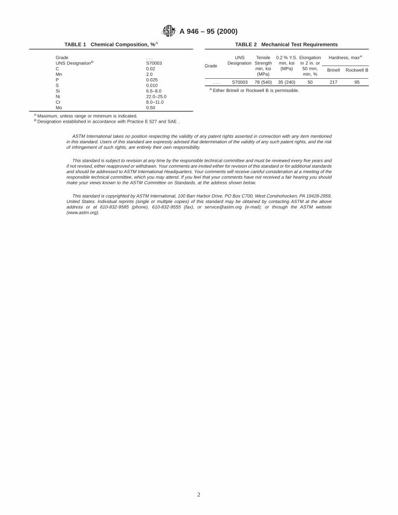
ASTM International takes no position respecting the validity of any patent rights asserted in connection with any item mentionedin this standard. Users of this standard are expressly advised that determination of the validity of any such patent rights, and the riskof infringement of such rights, are entirely their own responsibility.
This standard is subject to revision at any time by the responsible technical committee and must be reviewed every five years andif not revised, either reapproved or withdrawn. Your comments are invited either for revision of this standard or for additional standardsand should be addressed to ASTM International Headquarters. Your comments will receive careful consideration at a meeting of theresponsible technical committee, which you may attend. If you feel that your comments have not received a fair hearing you shouldmake your views known to the ASTM Committee on Standards, at the address shown below.
This standard is copyrighted by ASTM International, 100 Barr Harbor Drive, PO Box C700, West Conshohocken, PA 19428-2959,United States. Individual reprints (single or multiple copies) of this standard may be obtained by contacting ASTM at the aboveaddress or at 610-832-9585 (phone), 610-832-9555 (fax), or [email protected] (e-mail); or through the ASTM website(www.astm.org).
TABLE 1 Chemical Composition, % A
Grade . . .UNS DesignationB S70003C 0.02Mn 2.0P 0.025S 0.010Si 6.5–8.0Ni 22.0–25.0Cr 8.0–11.0Mo 0.50
A Maximum, unless range or minimum is indicated.B Designation established in accordance with Practice E 527 and SAE .
TABLE 2 Mechanical Test Requirements
Grade
UNSDesignation
TensileStrengthmin, ksi(MPa)
0.2 % Y.S.min, ksi(MPa)
Elongationin 2 in. or50 mm,min, %
Hardness, maxA
Brinell Rockwell B
. . . S70003 78 (540) 35 (240) 50 217 95A Either Brinell or Rockwell B is permissible.
A 946 – 95 (2000)
2

Designation: A 947M – 95 (Reapproved 2000)
METRIC
Standard Specification forTextured Stainless Steel Sheet [Metric] 1
This standard is issued under the fixed designation A 947M; the number immediately following the designation indicates the year oforiginal adoption or, in the case of revision, the year of last revision. A number in parentheses indicates the year of last reapproval. Asuperscript epsilon (e) indicates an editorial change since the last revision or reapproval.
1. Scope
1.1 This specification covers stainless steel, textured sheets,especially for use in electronic packaging applications, forexample, cabinet, rack, enclosure, and shelf constructions fortelecommunication, computer, and data-processing equipment.
1.2 This specification applies to all finished flat-rolledstainless products specified by standards organizations such asInternational Standards Organization (ISO), American Societyfor Testing and Materials (ASTM), European Committee forStandardization (CEN), German Institute for Standardization(DIN), and others participating in a global standards harmoni-zation effort.
1.3 The values stated in SI units are to be regarded as thestandard. The values given in parentheses are for informationonly.
2. Referenced Documents
2.1 ASTM Standards:A 176 Specification for Stainless and Heat-Resisting Chro-
mium Steel Plate, Sheet, and Strip2
A 370 Test Methods and Definitions for Mechanical Testingof Steel Products2
A 480/A480M Specification for General Requirements forFlat-Rolled Stainless and Heat-Resisting Steel Plate,Sheet, and Strip2
A 700 Practices for Packaging, Marking, and LoadingMethods for Steel Products for Domestic Shipment3
A 751 Test Methods, Practices, and Terminology forChemical Analysis of Steel Products2
B 117 Practice for Operating Salt Spray (Fog) Apparatus4
B 193 Test Method for Resistivity of Electrical ConductorMaterial5
D 257 Test Methods for D-C Resistance or Conductance ofInsulating Materials6
D 523 Test Method for Specular Gloss7
2.2 ISO Standards:ISO 1462 Accelerated Corrosion Tests and Evaluation of
Results8
ISO 6892 Metallic Materials Tensile Testing8
2.3 IEC Standard:IEC 68 Environmental Testing9
2.4 CEN Standard:EN 10002/1 Metallic Materials Tensile Testing10
2.5 DIN Standards:DIN 17441 Stainless Steel Technical Delivery Conditions
for Stainless Cold Rolled Steel11
DIN 50021-SS Spray Test with Different Sodium ChlorideSolutions11
DIN 50980 Evaluation of Corrosion Tests11
3. Terminology
3.1 Definitions of Terms Specific to This Standard:3.1.1 textured—a three-dimensional design pattern, regard-
less of the specific production-process approach.
4. Ordering Information
4.1 It is the responsibility of the purchaser to specify allrequirements that are necessary for material ordered under thisspecification. Such requirements may include, but are notlimited to the following:
4.1.1 Quantity—Number of sheets or weight.
1 This specification is under the jurisdiction of ASTM Committee A01 on Steel,Stainless Steel, and Related Alloys and is the direct responsibility of SubcommitteeA01.17 on Wrought Stainless Products.
Current edition approved Sept. 10, 1995. Published November 1995.2 Annual Book of ASTM Standards, Vol 01.03.3 Annual Book of ASTM Standards, Vol 01.05.4 Annual Book of ASTM Standards, Vol 03.02.5 Annual Book of ASTM Standards, Vol 02.03.
6 Annual Book of ASTM Standards, Vol 10.01.7 Annual Book of ASTM Standards, Vol 06.01.8 Available from International Organization for Standards (ISO), 1 Rue de
Varembe, Case Postale 56, 20 Geneve, Suisse 1211.9 Available from International Electrotechnical Commission (IEC), 3 Rue de
Varembe, 20 Geneve, Suisse 1211.10 Available from European Committee for Standardization (CEN), Rue Bred-
erode 2, B 1000 Bruxelles.11 Available from German Institute for Standardization (DIN), Burggrafenstrasse
6, 1000 Berlin 30.
1
Copyright © ASTM International, 100 Barr Harbor Drive, PO Box C700, West Conshohocken, PA 19428-2959, United States.

4.1.2 Dimensions of sheet (thickness (texture included),width, and length). See Tables 1-5 and Section 9 for preferredsizes and tolerances.
4.1.3 ASTM designation and date of issue.4.1.4 Name and type of material.4.1.5 Surface condition of the nontextured surface. See
Specification A 480/A 480M or DIN 17441 Table 8.4.1.6 Textured identification reference number. See Table 6.4.1.7 Type and thickness of protective liner, if required by
the purchaser.4.1.8 Marking requirements. Reference: Practices A 700.
NOTE 1—A typical ordering description is as follows: 500 sheets, 1.00by 1200 by 2500 mm; ASTM Specification 176, Type 430; Surface FinishTexture ID: S-F-O, 6-1, 3-6-170-3; 100 sheet maximum/skid, texturedside up. Each skid marked with purchase order number, applicable ASTMstandard, and date of shipment.
5. Materials and Manufacture
5.1 The textured side or sides of the sheet shall be producedin such a manner that guarantees repeatability of the patternover time. See 6.2.
5.2 Manufacture process of textured material under thisspecification shall follow industry practices.
6. Texture of Sheet
6.1 The texture of any sheet delivered under this specifica-tion shall meet the provisions outlined in Table 6 and Section13.
6.2 The customer shall either provide a control-sample (300mm by 400 mm) or designate a control-sample from a chosentextured material to ensure accurate repetition in appearance oflike products. See Section 13.
7. Chemical Composition
7.1 The heat chemical composition shall be reported to thepurchaser, or his representative, and shall conform to therequirements specified in the applicable ASTM standard of thesteel type selected for texturing.
7.2 Methods and practices relating to chemical analysisrequired by this specification shall be in accordance with TestMethods, Practices, and Terminology A 751.
8. Other Requirements
8.1 If requested by the purchaser, physical (electrical andoptical) and mechanical (tensile, yield, and elongation) prop-erty requirements shall be reported to the purchaser based on alot size as specified in 8.2.
8.2 A lot shall consist of all sheets of the same thicknessmade from the same coil. In case the material cannot beidentified by coil, a lot shall consist of no more than 5000 kg(approximately 5 tons) of sheets of the same thickness.
8.3 Electrical Requirements:8.3.1 The specific resistivity of the material measured at
20°C to be reported in: ohms·mm2/m (µV·cm).8.3.2 The surface resistivity of the material measured at
20°C to be reported in: milliohms. Refer to Test MethodsD 257.
8.4 Optical Requirements—The textured surface of thematerial selected under this specification shall meet the inspec-tion requirements (see 13.2) based on a visual sample com-parison or a 6:1 art master pattern comparison, or both.
8.5 Mechanical Requirements—The mechanical properties,tensile strength, yield strength, and elongation of the material
TABLE 1 Permissible Deviations in Thickness A
Preferred NominalThickness
Applicable ThicknessPermissibleThickness
Variations forNominal Sheet
Widths $10#1600
$ #
0.40 0.4 0.5 0.040.50; 0.60 0.5 0.7 0.050.70; 0.80; 0.90; 1.00 0.7 1.1 0.061.20 1.1 1.5 0.081.50; 2.00 1.5 2.5 0.12.50; 3.00 2.5 3.5 0.123.50; 4.00 3.5 4.5 0.144.50; 5.00; 6.00 4.5 6.0 0.15
A In reference to preferred sheet thicknesses. Dimensions stated are in millime-tres.
TABLE 2 Permissible Deviations for Nominal Widths A
NominalThickness
Permmissible Deviation at Nominal Width
$ # #100 $100 to #300 $300 to #700 $700 to #1600
0.40 1.00 0.5 0.8 1.0 1.51.00 1.75 0.7 1.0 1.5 1.51.75 3.00 1.0 1.5 1.5 2.03.00 6.00 . . . . . . 2.0 2.0A Dimensions stated are in millimetres.
TABLE 3 Permissible Deviations for Nominal Length A
Nominal “L”Permissible Deviation for Nominal
Length
#2000 5> 2000 0.0025 3 Length
A Dimensions stated are in millimetres.
TABLE 4 Permissible Deviations on Flatness A
Nominal Thickness
Total Deviation, %
Relating to LengthD/L
Relating to WidthD/W
0.40 2.00 0.4 0.52.00 4.00 0.3 0.44.00 6.00 0.1 0.4
A Dimensions stated are in millimetres.
TABLE 5 Permissible Deviations on Squareness A
Nominal LengthSquareness Tolerances at NominalWidth Ratio of AA/BB Dimension
$ # #1000 $1000 to #1600
. . . 2000 6 72000 3000 7 73000 3500 7 83500 5000 8 105000 6000 12 12
A Dimensions stated are in millimetres.
A 947M – 95 (2000)
2

selected for texturing shall be reported in values specified in12.5 of this specification.
9. Dimensions, Mass, and Permissible Variations
9.1 Unless noted in the purchase order, the stated toleranceconditions in Tables 1-5 are deemed to be acceptable.
9.2 Table 1 lists the tolerance for sheet-thickness relevant tothe preferred thickness-sizes of textured sheets in this specifi-cation.
9.3 Table 2 lists the tolerance for sheet widths relevant tothe preferred width-sizes of textured sheets in this specifica-tion.
9.4 Table 3 lists the tolerance for sheet lengths relevant tothe preferred length-sizes in this specification.
9.5 Table 4 lists the permissible tolerance for sheet flatnessrelevant to the preferred flatness tolerances in this specificationas a ratio of: deviation “D” to length “L” and width “W” oftextured sheet. (See 10.5.)
9.6 Table 5 lists the maximum permissible difference be-tween the diagonal dimensions “AA” and “BB” of the texturedsheet. (See 10.6 and Fig. 1.)
9.7 The maximum permissible deviation of the edge camber“D” for textured sheets is 0.2 % of the nominal length of thesheet. (See 10.6)
10. Measurement
10.1 Unless otherwise stated, the measurement of the geo-metrical requirements shall be based on the definition outlinedin Section 10.
10.2 Thickness—The thickness (texture included) may bemeasured at any point located more than 20 mm from theedges.
10.3 Width—The width is measured perpendicularly to thelongitudinal axis of the product.
10.4 Length—The length is measured along one of the sidesof the sheet or cut length.
10.5 Flatness—The measurement of the flatness deviation(pockets) is made according to the pictorial representation “A”and “B”, see Fig. 2. The sheet is lying on a flat surface with theconcave side upward.
10.6 Edge Camber—The edge camber is the greatest devia-tion of a side edge from a straight line, the measurement beingtaken on the concave side with a straight edge (see Fig. 3).
11. Workmanship
11.1 Textured sheets shall be uniform in quality and condi-tion and free of injurious defects, that due to their nature orseverity, may detrimentally affect the suitability for the serviceintended.
12. General Requirements for Delivery
12.1 Unless otherwise specified in the purchase order, thematerials furnished under this specification shall conform toapplicable requirements of the current edition of SpecificationA 480/A 480M or, if applicable, to DIN 17441.
12.2 If requested by the purchaser, material shall be deliv-ered with a protective liner of either polyvinyl (PVC) orpolyethylene (PE) on the textured side of the sheet. However,if a protective liner is being specified it must not be detrimen-tally affected by ultraviolet (UV) or temperature exposure, orboth, up to 70°C. Its removal from the sheet stock must be
TABLE 6 Textured Reference Identification
Pattern orientation Note 1Pattern appearance Note 2Height of pattern Note 3Size of pattern Note 4Type of pattern Note 5Pattern repetition configuration Note 6Pattern effect on far side of sheet Note 7
Example of typical ordering description:
S-F-O,6-1,3-6-170-3Note 1: S (Straight) Pattern oriented with flow line of rolling
process.A (Angular) Pattern oriented 45° to flow line of rolling
process.O (Other) Optional pattern orientation.
Note 2: F (Fine) If the number of pattern repetitions underNote 6 exceeds 100.
C (Coarse) If the number of pattern repetitions underNote 6 is less than 100.
Note 3: Height of pattern in millimetres.Note 4: Size of individual pattern.
(Largest individual pattern dimension in millimetres; length, width,diagonal, and so forth.)
Note 5: Type of pattern:No. 0 round No. 7 trapezoidal No. 14 arrowNo. 1 square No. 8 lines No. 15 snowflakeNo. 2 rectangular No. 9 points No. 16 teardropNo. 3 triangular No. 10 letters No. 17 combinationNo. 4 hex No. 11 numbers No. 18 shapelessNo. 5 octal No. 12 bricks No. 19 irregular shapeNo. 6 oblong No. 13 star No. 20 others not
defined
Note 6: Number of largest individual pattern repetitions within a 20-mm ·20-mm area of the stainless steel sheet. (Partial patternrepetition included.)
Note 7: A two-sided pattern under this specification displays the samepattern on both sides of the sheet. This pattern is usuallyreserved for material thicknesses of 2.5 mm and thicker.
No. 1 Two-sided pattern.No. 2 One-sided pattern. No visible marks from an one-sided
pattern, when viewed with the unaided eye from a distance of1 m.
No. 3 One-sided pattern. Shadings and reflections as a result fromthe pattern process on the opposite side of the sheet shall beacceptable.
No. 4 One-sided pattern. Measurable deformation, caused by thepattern on the opposite side of the sheet shall be acceptable.
FIG. 1 Squareness
A 947M – 95 (2000)
3

guaranteed not to leave any residue on the textured sheet up toa storage time of 18 months.
12.3 If requested by the purchaser, material shall be deliv-ered with a certification of electrical properties such as:
12.3.1 Specific resistivity—measured in ohms·mm2/m(µV·cm) in accordance with Test Method B 193.
12.3.2 Surface resistivity—measured in milliohms in accor-dance with Test Methods D 257.
12.4 If requested by the purchaser, material shall be deliv-ered with a certification of thermal conductivity: measured in:W/(m·K) at 20°C.
12.5 If requested by the purchaser, material shall be deliv-ered with a certification of mechanical properties such as:
12.5.1 Yield strength maximum in N/mm2.12.5.2 Tensile strength maximum in N/mm2.12.5.3 Elongation in 50 mm (2 in.) minimum %.
13. Inspection
13.1 Unless otherwise specified in the purchase order, theseller agrees to perform all the tests and inspections as outlinedin Section 11, demonstrating conformity to the applicablerelevant conditions or standards in a test report at the time ofthe initial purchase order.
13.2 Appearance—The textured and untextured surfacesshall match the appearance of the purchasers control sample orthat of a designated control sample agreed upon between bothparties, when viewed with the unaided eye from a distance of1 m by daylight.
13.2.1 If there is a substantial disagreement between theseller and the purchaser on the appearance, the followinginspection shall become the tie breaker.
13.2.1.1 The precision of the texture, as defined in Table 6,shall be established by comparing an art-master (100 mm by100 mm) magnified 6:1 (600 mm by 600 mm), provided by thepurchaser, with a photographic enlargement, 6:1, of the prod-uct, provided by the seller. See Fig. 4 for example. (Not toscale.)
13.2.1.2 The precision of the gloss shall be established bycomparing the measured values of gloss of the control samplewith the production sample. The measurement shall be per-formed in accordance with Test Method D 523.
13.3 Tensile Strength—A tensile test shall be carried out inaccordance with Test Methods A 370 or ISO 6892 or EN10002/1.
13.4 Corrosion: Indoor Environment—(Dry/damp heatcycle test) In accordance with IEC 68.
13.4.1 Specifics:13.4.1.1 Stabilizing in a climate of 23°C at 50 % RH
according to IEC 68.1.13.4.1.2 Duration: 8 h and immediately thereafter exposure
to climate of 40°C at 93 % RH according to IEC 68.2.3.13.4.1.3 Duration: 16 h.13.4.1.4 Total cycle time to be 10.13.5 Corrosion: Indoor Environment—(Corrosive atmo-
spheric test) In accordance with IEC 68.2.60: Method No. 4.13.5.1 Specific Type and Concentration of Polluting Gases:
H2S (10−9 vol/vol) 10 6 5NO2(10−9 vol/vol) 200 6 20Cl2(10−9 vol/vol) 10 6 5SO2(10−9 vol/vol) 200 6 20Temperature: 25 6 1°CRH: 75 6 3 %Volume change/h: 3 to 10Duration: 10 days
13.6 Corrosion: Outdoor Environment—In accordance withPractice B 117 or DIN 50021-SS.
13.7 Corrosion: Evaluation of Test Results—In accordancewith Practice ISO 1462 or DIN 50980.
FIG. 2 Flatness Deviation (Pockets)
FIG. 3 Edge Camber
A 947M – 95 (2000)
4
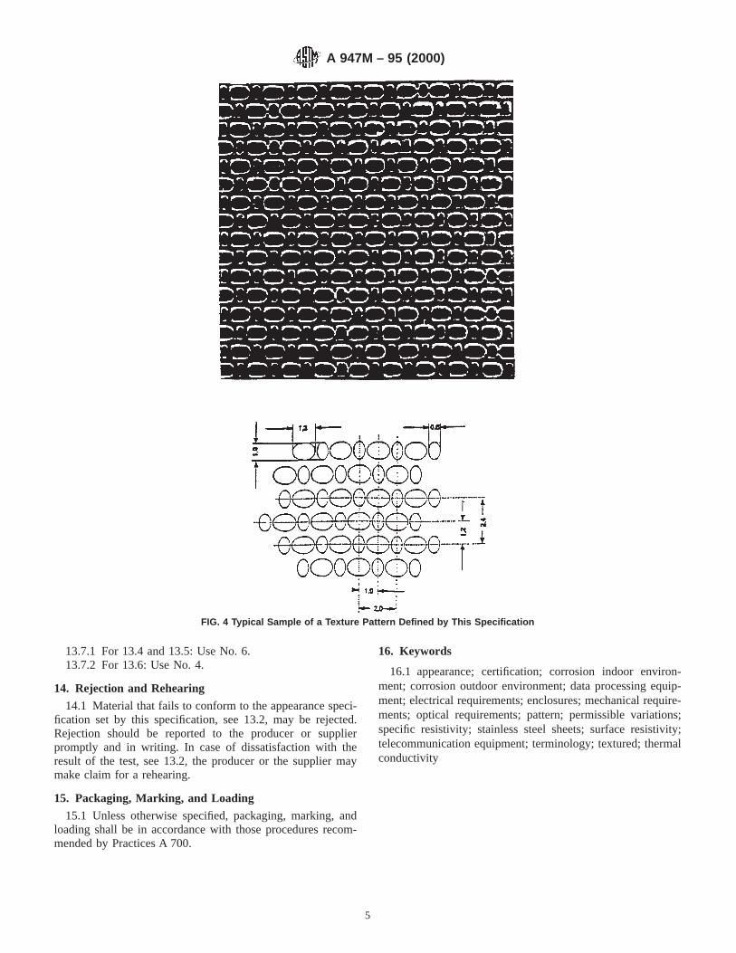
13.7.1 For 13.4 and 13.5: Use No. 6.13.7.2 For 13.6: Use No. 4.
14. Rejection and Rehearing
14.1 Material that fails to conform to the appearance speci-fication set by this specification, see 13.2, may be rejected.Rejection should be reported to the producer or supplierpromptly and in writing. In case of dissatisfaction with theresult of the test, see 13.2, the producer or the supplier maymake claim for a rehearing.
15. Packaging, Marking, and Loading
15.1 Unless otherwise specified, packaging, marking, andloading shall be in accordance with those procedures recom-mended by Practices A 700.
16. Keywords
16.1 appearance; certification; corrosion indoor environ-ment; corrosion outdoor environment; data processing equip-ment; electrical requirements; enclosures; mechanical require-ments; optical requirements; pattern; permissible variations;specific resistivity; stainless steel sheets; surface resistivity;telecommunication equipment; terminology; textured; thermalconductivity
FIG. 4 Typical Sample of a Texture Pattern Defined by This Specification
A 947M – 95 (2000)
5

ASTM International takes no position respecting the validity of any patent rights asserted in connection with any item mentionedin this standard. Users of this standard are expressly advised that determination of the validity of any such patent rights, and the riskof infringement of such rights, are entirely their own responsibility.
This standard is subject to revision at any time by the responsible technical committee and must be reviewed every five years andif not revised, either reapproved or withdrawn. Your comments are invited either for revision of this standard or for additional standardsand should be addressed to ASTM International Headquarters. Your comments will receive careful consideration at a meeting of theresponsible technical committee, which you may attend. If you feel that your comments have not received a fair hearing you shouldmake your views known to the ASTM Committee on Standards, at the address shown below.
This standard is copyrighted by ASTM International, 100 Barr Harbor Drive, PO Box C700, West Conshohocken, PA 19428-2959,United States. Individual reprints (single or multiple copies) of this standard may be obtained by contacting ASTM at the aboveaddress or at 610-832-9585 (phone), 610-832-9555 (fax), or [email protected] (e-mail); or through the ASTM website(www.astm.org).
A 947M – 95 (2000)
6
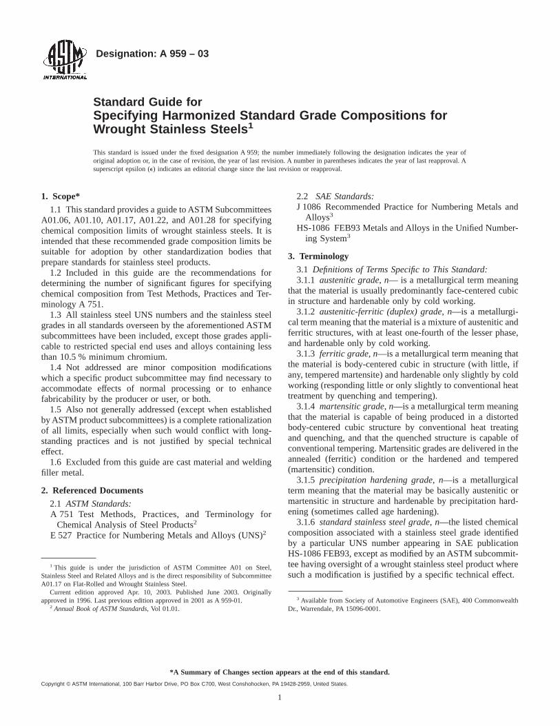
Designation: A 959 – 03
Standard Guide forSpecifying Harmonized Standard Grade Compositions forWrought Stainless Steels 1
This standard is issued under the fixed designation A 959; the number immediately following the designation indicates the year oforiginal adoption or, in the case of revision, the year of last revision. A number in parentheses indicates the year of last reapproval. Asuperscript epsilon (e) indicates an editorial change since the last revision or reapproval.
1. Scope*
1.1 This standard provides a guide to ASTM SubcommitteesA01.06, A01.10, A01.17, A01.22, and A01.28 for specifyingchemical composition limits of wrought stainless steels. It isintended that these recommended grade composition limits besuitable for adoption by other standardization bodies thatprepare standards for stainless steel products.
1.2 Included in this guide are the recommendations fordetermining the number of significant figures for specifyingchemical composition from Test Methods, Practices and Ter-minology A 751.
1.3 All stainless steel UNS numbers and the stainless steelgrades in all standards overseen by the aforementioned ASTMsubcommittees have been included, except those grades appli-cable to restricted special end uses and alloys containing lessthan 10.5 % minimum chromium.
1.4 Not addressed are minor composition modificationswhich a specific product subcommittee may find necessary toaccommodate effects of normal processing or to enhancefabricability by the producer or user, or both.
1.5 Also not generally addressed (except when establishedby ASTM product subcommittees) is a complete rationalizationof all limits, especially when such would conflict with long-standing practices and is not justified by special technicaleffect.
1.6 Excluded from this guide are cast material and weldingfiller metal.
2. Referenced Documents
2.1 ASTM Standards:A 751 Test Methods, Practices, and Terminology for
Chemical Analysis of Steel Products2
E 527 Practice for Numbering Metals and Alloys (UNS)2
2.2 SAE Standards:J 1086 Recommended Practice for Numbering Metals and
Alloys3
HS-1086 FEB93 Metals and Alloys in the Unified Number-ing System3
3. Terminology
3.1 Definitions of Terms Specific to This Standard:3.1.1 austenitic grade, n— is a metallurgical term meaning
that the material is usually predominantly face-centered cubicin structure and hardenable only by cold working.
3.1.2 austenitic-ferritic (duplex) grade, n—is a metallurgi-cal term meaning that the material is a mixture of austenitic andferritic structures, with at least one-fourth of the lesser phase,and hardenable only by cold working.
3.1.3 ferritic grade, n—is a metallurgical term meaning thatthe material is body-centered cubic in structure (with little, ifany, tempered martensite) and hardenable only slightly by coldworking (responding little or only slightly to conventional heattreatment by quenching and tempering).
3.1.4 martensitic grade, n—is a metallurgical term meaningthat the material is capable of being produced in a distortedbody-centered cubic structure by conventional heat treatingand quenching, and that the quenched structure is capable ofconventional tempering. Martensitic grades are delivered in theannealed (ferritic) condition or the hardened and tempered(martensitic) condition.
3.1.5 precipitation hardening grade, n—is a metallurgicalterm meaning that the material may be basically austenitic ormartensitic in structure and hardenable by precipitation hard-ening (sometimes called age hardening).
3.1.6 standard stainless steel grade, n—the listed chemicalcomposition associated with a stainless steel grade identifiedby a particular UNS number appearing in SAE publicationHS-1086 FEB93, except as modified by an ASTM subcommit-tee having oversight of a wrought stainless steel product wheresuch a modification is justified by a specific technical effect.
1 This guide is under the jurisdiction of ASTM Committee A01 on Steel,Stainless Steel and Related Alloys and is the direct responsibility of SubcommitteeA01.17 on Flat-Rolled and Wrought Stainless Steel.
Current edition approved Apr. 10, 2003. Published June 2003. Originallyapproved in 1996. Last previous edition approved in 2001 as A 959-01.
2 Annual Book of ASTM Standards, Vol 01.01.
3 Available from Society of Automotive Engineers (SAE), 400 CommonwealthDr., Warrendale, PA 15096-0001.
1
*A Summary of Changes section appears at the end of this standard.
Copyright © ASTM International, 100 Barr Harbor Drive, PO Box C700, West Conshohocken, PA 19428-2959, United States.

4. Significance and Use
4.1 It is anticipated that the ASTM Subcommittees A01.06,A01.10, A01.17, A01.22, and A01.28 will use the standardcomposition limits listed in this guide for the grades identifiedby the corresponding UNS designation in the product specifi-cation unless there is a specific technical justification for doingotherwise. The compositions in this guide shall not be consid-ered as chemical requirements for any particular product untiladopted by the subcommittee overseeing that product.
4.2 Assuming that uniform compositions among the manyproduct standards for stainless steel are desirable, the compo-sition limits provided in this standard are to be used as guidesin determining limits for each of the elements included in thetotal composition of each grade. The composition limits havebeen established with the intent that each product subcommit-tee will find it necessary to require only a minimum number ofchanges to reflect specific technical effects. Section 5 lists thegeneral guidelines followed for determining the limits for eachelement; the limits established in this guide are based on theseguidelines.
4.3 Not included in this standard stainless steel gradeharmonization effort is an attempt to unify stainless steelcompositions in ASTM product standards by any means otherthan recognizing current industry practices.
5. General Guidelines Used for Determining CompositionLimits
5.1 Carbon—It is recommended that limits be to only twodecimal places for levels of 0.04 % and higher because it is notnecessary to control to such precision at levels above 0.04 %.(It should be recognized that limits such as 0.045 % maximummay also be simply stated as 0.04 % maximum.) It is alsorecommended that three decimal places be used at levels of0.030 % and lower, unless, for example, it is clearly recognizedthat 0.03 % maximum means that 0.035 % is satisfactory.
5.2 Manganese—Except for the Cr-Ni-Mn grades(S2XXXX), it is recommended that limits of 2 % maximumand 1 % maximum be used for the austenitic and other gradesrespectively, except for the free machining grades with highsulfur or selenium, or when necessary to promote nitrogensolubility.
5.3 Phosphorus—It is recommended that 0.045 % maxi-mum be applied to austenitic grades, and 0.040 % maximum toother grades unless the sponsoring producer recommends alower limit for specific technical effect.Exception—some ofthe Cr-Ni-Mn austenitic grades have always been produced to0.060 % maximum.
5.4 Sulfur—It is recommended that 0.030 % maximum beapplied to all grades except the free-machining grades unlesslower limits have been required for specific technical effects.
5.5 Silicon—Past practice has been to establish 0.75 %maximum for tubular related products such as flat rolled andtubulars, and 1.00 % maximum for long products and forgings.For grades produced both as long and flat-rolled products, 1 %maximum was chosen since it will also include productsmelted to lower limits. Use of lower or higher limits should bebased on specific technical effect.
5.6 Chromium—A composition spread of 2 % is recom-mended; existing broader limits were not reduced to less thana 3 % spread.
5.7 Nickel—It is recommended that the composition spreadnot exceed 3 % unless a broader (generally higher) spread isjustified by specific technical effect.
5.8 Molybdenum—It is recommended that the compositionspread not exceed 1 %, unless a broader range is justified byspecific technical effect. Molybdenum limits having only amaximum limit but no minimum should not be used unlessjustified by specific technical effect.
5.9 Nitrogen—It is recommended that nitrogen limits hav-ing only a maximum limit but no minimum should not be usedunless justified by specific technical effect.
5.10 Copper—It is recommended that copper limits havingonly a maximum limit but no minimum should not be usedunless justified by specific technical effect.
5.11 Columbium and Tantalum—Except for special appli-cations requiring positive identification of tantalum, it isrecommended that prior listings of these two elements togetherbe limited to listing only columbium. The words “columbium”and “niobium” refer to the same element.
6. Harmonized Standard Grade Stainless SteelCompositions
6.1 The harmonized composition limits are shown in Table1, grouped by metallurgical classification, that is, austenitic,austenitic-ferritic, etc. Within those groups, grades are listed byUNS designation, in numerical order.
6.2 Unless adopted by the appropriate product subcommit-tee in a product standard, the compositions described in thisguide shall not be used for specifying an ASTM product.
7. Keywords7.1 austenitic stainless steels; austenitic-ferritic or ferritic-
austenitic stainless steels; duplex stainless steels; ferritic stain-less steels; harmonized stainless steel compositions; martensi-tic stainless steels; precipitation hardening stainless steels;standard stainless steel grade compositions
A 959 – 03
2

TABLE 1 Chemical Composition Limits, % A
UNSDesignation
TypeB Carbon ManganesePhos-phorus
Sulfur Silicon Chromium Nickel Molybdenum Nitrogen CopperOther
Elements
Austenitic Grades
S16800 16-8-2HC 0.05–0.10 2.00 0.045 0.030 1.00 14.5–16.5 7.5–9.5 1.50–2.00 . . . . . . . . .S20100 201 0.15 5.5–7.5 0.060 0.030 1.00 16.0–18.0 3.5–5.5 . . . 0.25 . . . . . .S20103 201L 0.03 5.5–7.5 0.045 0.030 1.00 16.0–18.0 3.5–5.5 . . . 0.25 . . . . . .S20153 201LNC 0.03 6.4–7.5 0.045 0.015 1.00 16.0–17.5 4.0–5.0 . . . 0.10–0.25 . . . Cu 1.00S20161 . . . 0.15 4.0–6.0 0.045 0.030 3.0–4.0 15.0–18.0 4.0–6.0 . . . 0.08–0.20 . . . . . .S20162 . . . 0.15 4.0–8.0 0.040 0.040 2.5–4.5 16.5–21.0 6.0–10.0 0.50–2.50 0.05–0.25 . . . . . .S20200 202 0.15 7.5–10.0 0.060 0.030 1.00 17.0–19.0 4.0–6.0 . . . 0.25 . . . . . .S20300 XM-1D 0.08 5.0–6.5 0.045 0.18–0.35 1.00 16.0–18.0 5.0–6.5 . . . . . . . . . Cu 1.75–2.25S20400 . . . . . . 0.030 7.0–9.0 0.045 0.030 1.00 15.0–17.0 1.50–3.00 . . . 0.15–0.30 . . .S20430 . . . 0.15 6.5–9.0 0.060 0.030 1.00 15.5–17.5 1.50–3.50 . . . 0.05–0.25 2.0–4.0 . . .S20500 205 0.12–0.25 14.0–15.0 0.060 0.030 1.00 16.5–18.0 1.00–1.75 . . . 0.32–0.40 . . . . . .S20910 XM-19D 0.06 4.0–6.0 0.045 0.030 1.00 20.5–23.5 11.5–13.5 1.50–3.00 0.20–0.40 . . . Cb 0.10–0.30,
V 0.10–0.30S21400 XM-31D 0.12 14.0–16.0 0.045 0.030 0.30–1.00 17.0–18.5 1.00 . . . 0.35 min . . . . . .S21460 XM-14D 0.12 14.0–16.0 0.060 0.030 1.00 17.0–19.0 5.0–6.0 . . . 0.35–0.50 . . . . . .S21500 . . . 0.06–0.15 5.5–7.0 0.045 0.030 0.2–1.0 14.0–16.0 9.0–11.0 0.80–1.20 . . . . . . Cb 0.75–1.25,
V 0.15–0.40,B 0.003–0.009
S21600 XM-17D 0.08D 7.5–9.0 0.045 0.030 1.00 17.5–20.5 5.0–7.0 2.00–3.00 0.25–0.50 . . . . . .S21603 XM-18D 0.03D 7.5–9.0 0.045 0.030 1.00 17.5–20.5 5.0–7.0 2.00–3.00 0.25–0.50 . . . . . .S21800 . . . 0.10 7.0–9.0 0.060 0.030 3.5–4.5 16.0–18.0 8.0–9.0 . . . 0.08–0.18 . . . . . .S21900 XM-10D 0.08 8.0–10.0 0.045 0.030 1.00 19.0–21.5 5.5–7.5 . . . 0.15–0.40 . . . . . .S21904 XM-11D 0.04 8.0–10.0 0.045 0.030 1.00 19.0–21.5 5.5–7.5 . . . 0.15–0.40 . . . . . .S24000 XM-29D 0.08 11.5–14.5 0.060 0.030 1.00 17.0–19.0 2.3–3.7 . . . 0.20–0.40 . . . . . .S24100 XM-28D 0.15 11.0–14.0 0.045 0.030 1.00 16.5–19.0 0.50–2.50 . . . 0.20–0.45 . . . . . .S28200 . . . 0.15 17.0–19.0 0.045 0.030 1.00 17.0–19.0 . . . 0.75–1.25 0.40–0.60 . . . Cu 0.75–1.25S30100 301 0.15 2.00 0.045 0.030 1.00 16.0–18.0 6.0–8.0 . . . 0.10 . . . . . .S30103 301LC 0.030 2.00 0.045 0.030 1.00 16.0–18.0 5.0–8.0 . . . 0.20 . . . . . .S30153 301LNC 0.030 2.00 0.045 0.030 1.00 16.0–18.0 5.0–8.0 . . . 0.07–0.20 . . . . . .S30200 302 0.15 2.00 0.045 0.030 1.00 17.0–19.0 8.0–10.0 . . . 0.10 . . . . . .S30215 302B 0.15 2.00 0.045 0.030 2.00–3.00 17.0–19.0 8.0–10.0 . . . 0.10 . . . . . .S30300 303 0.15 2.00 0.20 0.15 min 1.00 17.0–19.0 8.0–10.0 . . . . . . . . . . . .S30310 XM-15D 0.15 2.5–4.5 0.20 0.25 min 1.00 17.0–19.0 7.0–9.0 . . . . . . . . . . . .S30323 303Se 0.15 2.00 0.20 0.06 1.00 17.0–19.0 8.0–10.0 . . . . . . . . . Se 0.15 minS30345 XM-2D 0.15 2.00 0.05 0.11–0.16 1.00 17.0–19.0 8.0–10.0 0.40–0.60 . . . . . . Al 0.60–1.00S30400 304 0.08 2.00 0.045 0.030 1.00 18.0–20.0 8.0–11.0 . . . . . . . . . . . .S30403 304L 0.030 2.00 0.045 0.030 1.00 18.0–20.0 8.0–12.0 . . . . . . . . . . . .S30409 304H 0.04–0.10 2.00 0.045 0.030 1.00 18.0–20.0 8.0–11.0 . . . . . . . . . . . .S30415 . . . 0.04–0.06 0.80 0.045 0.030 1.00–2.00 18.0–19.0 9.0–10.0 . . . 0.12–0.18 . . . Ce 0.03–0.08S30430 . . . 0.03 2.00 0.045 0.030 1.00 17.0–19.0 8.0–10.0 . . . . . . . . . Cu 3.0–4.0S30432 . . . 0.07–0.13 0.50 0.045 0.030 0.30 17.0–19.0 7.5–10.5 . . . 0.05–0.12 2.5–3.5 Cb 0.20–0.60,
Al 0.003–0.030,B 0.001–0.010
S30451 304N 0.08 2.00 0.045 0.030 1.00 18.0–20.0 8.0–11.0 . . . 0.10–0.16 . . . . . .S30452 XM-21D 0.08 2.00 0.045 0.030 1.00 18.0–20.0 8.0–10.0 . . . 0.16–0.30 . . . . . .S30453 304LN 0.030 2.00 0.045 0.030 1.00 18.0–20.0 8.0–11.0 . . . 0.10–0.16 . . . . . .S30454 304LHNC 0.03 2.00 0.045 0.030 1.00 18.0–20.0 8.0–11.0 . . . 0.16–0.30 . . . . . .S30500 305 0.12 2.00 0.045 0.030 1.00 17.0–19.0 11.0–13.0 . . . . . . . . . . . .S30600 . . . 0.018 2.00 0.020 0.020 3.7–4.3 17.0–18.5 14.0–15.5 0.20 . . . . . . Cu 0.50S30601 . . . 0.015 0.50–0.80 0.030 0.013 5.0–5.6 17.0–18.0 17.0–18.0 0.20 0.05 . . . Cu 0.35S30615 . . . 0.16–0.24 2.00 0.030 0.030 3.2–4.0 17.0–19.5 13.5–16.0 . . . . . . . . . Al 0.80–1.50S30800 308 0.08 2.00 0.045 0.030 1.00 19.0–21.0 10.0–12.0 . . . . . . . . . . . .S30815 . . . 0.05–0.10 0.80 0.040 0.030 1.40–2.00 20.0–22.0 10.0–12.0 . . . 0.14–0.20 . . . Ce 0.03–0.08S30900 309 0.20 2.00 0.045 0.030 1.00 22.0–24.0 12.0–15.0 . . . . . . . . . . . .S30908 309S 0.08 2.00 0.045 0.030 1.00 22.0–24.0 12.0–15.0 . . . . . . . . . . . .S30909 309HC 0.04–0.10 2.00 0.045 0.030 1.00 22.0–24.0 12.0–15.0 . . . . . . . . . . . .S30940 309CbC 0.08 2.00 0.045 0.030 1.00 22.0–24.0 12.0–16.0 Cb 10xC-1.10S30941 309HCbC 0.04–0.10 2.00 0.045 0.030 1.00 22.0–24.0 12.0–16.0 . . . . . . . . . Cb 10xC-1.10S31000 310C 0.25 2.00 0.045 0.030 1.50 24.0–26.0 19.0–22.0 . . . . . . . . . ...S31002 . . . 0.015 2.00 0.020 0.015 0.15 24.0–26.0 19.0–22.0 0.10 0.10 . . . . . .S31008 310S 0.08 2.00 0.045 0.030 1.00 24.0–26.0 19.0–22.0 . . . . . . . . . . . .S31009 310HC 0.04–0.10 2.00 0.045 0.030 1.00 24.0–26.0 19.0–22.0 . . . . . . . . . . . .S31040 310CbC 0.08 2.00 0.045 0.030 1.00 24.0–26.0 19.0–22.0 . . . . . . . . . Cb 10xC-1.10S31041 310HCbC 0.04–0.10 2.00 0.045 0.030 1.00 24.0–26.0 19.0–22.0 . . . . . . . . . Cb 10xC-1.10S31042 310HCbNC 0.04–0.10 2.00 0.045 0.030 1.00 24.0–26.0 19.0–22.0 . . . 0.15–0.35 . . . Cb 0.20–0.60S31050 310MoLNC 0.030 2.00 0.030 0.015 0.40 24.0–26.0 21.0–23.0 2.00–3.00 0.10–0.16 . . .S31254 . . . 0.020 1.00 0.030 0.010 0.80 19.5–20.5 17.5–18.5 6.0–6.5 0.18–0.22 . . . Cu 0.50–1.00S31266 . . . 0.030 2.0–4.0 0.035 0.020 1.00 23.0–25.0 21.0–24.0 5.2–6.2 0.35–0.60 1.00–2.50 W 1.50–2.50S31272 . . . 0.08–0.12 1.50–2.00 0.030 0.015 0.30–0.70 14.0–16.0 14.0–16.0 1.00–1.40 . . . . . . Ti 0.30–0.60,
B 0.004–0.008S31400 314C 0.25 2.00 0.045 0.030 1.50–3.00 23.0–26.0 19.0–22.0 . . . . . . . . . . . .
A 959 – 03
3

TABLE 1 Continued
UNSDesignation
TypeB Carbon ManganesePhos-phorus
Sulfur Silicon Chromium Nickel Molybdenum Nitrogen CopperOther
Elements
S31600 316 0.08 2.00 0.045 0.030 1.00 16.0–18.0 10.0–14.0 2.00–3.00 . . . . . . . . .S31603 316L 0.030 2.00 0.045 0.030 1.00 16.0–18.0 10.0–14.0 2.00–3.00 . . . . . . . . .S31609 316H 0.04–0.10 2.00 0.045 0.030 1.00 16.0–18.0 10.0–14.0 2.00–3.00 . . . . . . . . .
S31635C 316Ti 0.08 2.00 0.045 0.030 1.00 16.0–18.0 10.0–14.0 2.00–3.00 0.10 . . . Ti 5x(C+N)-0.70S31640C 316Cb 0.08 2.00 0.045 0.030 1.00 16.0–18.0 10.0–14.0 2.00–3.00 0.10 . . . Cb 10xC-1.10S31651 316N 0.08 2.00 0.045 0.030 1.00 16.0–18.0 10.0–13.0 2.00–3.00 0.10–0.16 . . . . . .S31653 316LN 0.030 2.00 0.045 0.030 1.00 16.0–18.0 10.0–13.0 2.00–3.00 0.10–0.16 . . . . . .S31654 316LHNC 0.03 2.00 0.045 0.030 1.00 16.0–18.0 10.0–13.0 2.00–3.00 0.16–0.30 . . . . . .S31700 317 0.08 2.00 0.045 0.030 1.00 18.0–20.0 11.0–15.0 3.0–4.0 . . . . . . . . .S31703 317LC 0.030 2.00 0.045 0.030 1.00 18.0–20.0 11.0–15.0 3.0–4.0 . . . . . . . . .S31725 317LM 0.030 2.00 0.045 0.030 1.00 18.0–20.0 13.5–17.5 4.0–5.0 0.20 . . . . . .S31726 317LMN 0.030 2.00 0.045 0.030 1.00 17.0–20.0 13.5–17.5 4.0–5.0 0.10–0.20 . . . . . .S31753 317LNC 0.030 2.00 0.045 0.030 1.00 18.0–20.0 11.0–14.0 3.0–4.0 0.10–0.22 . . . . . .S32050 . . . 0.030 1.50 0.035 0.020 1.00 22.0–24.0 20.0–23.0 6.0–6.8 0.21–0.32 0.40 . . .S32100 321 0.08 2.00 0.045 0.030 1.00 17.0–19.0 9.0–12.0 . . . 0.10 . . . Ti 5x(C+N)-0.70S32109 321H 0.04–0.10 2.00 0.045 0.030 1.00 17.0–19.0 9.0–12.0 . . . 0.10 . . . Ti 4x(C+N)-0.70S32615 . . . 0.07 2.00 0.045 0.030 4.8–6.0 16.5–19.5 19.0–22.0 0.30–1.50 . . . . . . Cu 1.50–2.50S32654 . . . 0.020 2.0–4.0 0.030 0.005 0.50 24.0–25.0 21.0–23.0 7.0–8.0 0.45–0.55 . . . Cu 0.30–0.60S33228 . . . 0.04–0.08 1.00 0.020 0.015 0.30 26.0–28.0 31.0–33.0 . . . . . . . . . Cb 0.60–1.00,
Al 0.025,Ce 0.05–0.10
S33400 334C 0.08 1.00 0.030 0.015 1.00 18.0–20.0 19.0–21.0 . . . . . . . . . Al 0.15–0.60Ti 0.15–0.60
S34565 . . . 0.030 5.0–7.0 0.030 0.010 1.00 23.0–25.0 16.0–18.0 4.0–5.0 0.40–0.60 . . . Cb 0.10S34700 347 0.08 2.00 0.045 0.030 1.00 17.0–19.0 9.0–12.0 . . . . . . . . . Cb 10xC-1.10S34709 347H 0.04–0.10 2.00 0.045 0.030 1.00 17.0–19.0 9.0–12.0 . . . . . . . . . Cb 8xC-1.10S34751 . . . 0.015 2.00 0.020 0.030 0.75 17.0–20.0 9.0–13.0 . . . 0.06–0.10 . . . Cb 0.20-0.50S34800 348 0.08 2.00 0.045 0.030 1.00 17.0–19.0 9.0–12.0 . . . . . . . . . Cb+Ta-10xC-
1.10, Ta 0.10,Co 0.20
S34809 348H 0.04–0.10 2.00 0.045 0.030 1.00 17.0–19.0 9.0–12.0 . . . . . . . . . Cb+Ta 8xC-1.10, Ta 0.10,
Co 0.20S35045 . . . 0.06–0.10 1.50 0.045 0.015 1.00 25.0–29.0 32.0–37.0 . . . . . . 0.75 Al 0.15–0.60
Ti 0.15–0.60S35315 . . . 0.04–0.08 2.00 0.045 0.030 1.20–2.00 24.0–26.0 34.0–36.0 . . . 0.12–0.18 . . . Ce 0.03–0.10S38100 XM-15D 0.08 2.00 0.030 0.030 1.50–2.50 17.0–19.0 17.5–18.5 . . . . . . . . . . . .S38400 . . . 0.04 2.00 0.045 0.030 1.00 15.0–17.0 17.0–19.0 . . . . . . . . . . . .S38815 . . . 0.030 2.00 0.045 0.020 5.5–6.5 13.0–15.0 15.0–17.0 0.75–1.50 . . . 0.75–1.50 Al 0.30S66220 622C 0.08 1.50 0.040 0.030 1.00 12.0–15.0 24.0–28.0 2.5–3.5 . . . . . . Cu 0.50, Ti
1.55–2.00,Al 0.35,
B 0.001–0.010S66286 . . . 0.08 2.00 0.040 0.030 1.00 13.5–16.0 24.0–27.0 1.00–1.50 . . . . . . Ti 1.90–2.35,
Al 0.35,V 0.10–0.50,
B 0.003–0.010N08020 . . . 0.07 2.00 0.045 0.035 1.00 19.0–21.0 32.0–38.0 2.00–3.00 . . . 3.0–4.0 Cb 8xCmin;
1.00 maxN08367 . . . 0.030 2.00 0.040 0.030 1.00 20.0–22.0 23.5–25.5 6.0–7.0 0.18–0.25 . . . Cu 0.75N08800 800C 0.10 1.50 0.045 0.015 1.00 19.0–23.0 30.0–35.0 . . . . . . 0.75 FeE 39.5 min
Al 0.15–0.60Ti 0.15–0.60
N08810 800HC 0.05–0.10 1.50 0.045 0.015 1.00 19.0–23.0 30.0–35.0 . . . . . . 0.75 FeE 39.5 minAl 0.15–0.60Ti 0.15–0.60
N08811 . . . 0.06–0.10 1.50 0.040 0.015 1.00 19.0–23.0 30.0–35.0 . . . . . . 0.75 FeE 39.5 minTi 0.15–0.60Al 0.15–0.60
(Al+Ti)0.85–1.20
N08904 904LC 0.020 2.00 0.040 0.030 1.00 23.0–28.0 19.0–23.0 4.0–5.0 0.10 . . . Cu 1.00–2.00N08926 . . . 0.020 2.00 0.030 0.010 0.50 19.0–21.0 24.0–26.0 6.0–7.0 0.15–0.25 0.50
1.50. . .
Austenite-Ferritic (Duplex) Grades
S31100 XM-26D 0.06 1.00 0.045 0.030 1.00 25.0–27.0 6.0–7.0 . . . . . . . . . Ti 0.25S31200 . . . 0.030 2.00 0.045 0.030 1.00 24.0–26.0 5.5–6.5 1.20–2.00 0.14–0.20 . . .S31260 . . . 0.030 1.00 0.030 0.030 0.75 24.0–26.0 5.5–7.5 2.5–3.5 0.10–0.30 . . . Cu 0.20–0.80,
W 0.10–0.50S31500 . . . 0.030 1.20–2.00 0.030 0.030 1.40–2.00 18.0–19.0 4.3–5.2 2.50–3.00 0.05–0.10 . . . . . .S31803 . . . 0.030 2.00 0.030 0.020 1.00 21.0–23.0 4.5–6.5 2.5–3.5 0.08–0.20 . . . . . .S32001 . . . 0.030 4.0–6.0 0.040 0.030 1.00 19.5–21.5 1.00–3.00 0.60 0.05–0.17 1.00 . . .
A 959 – 03
4
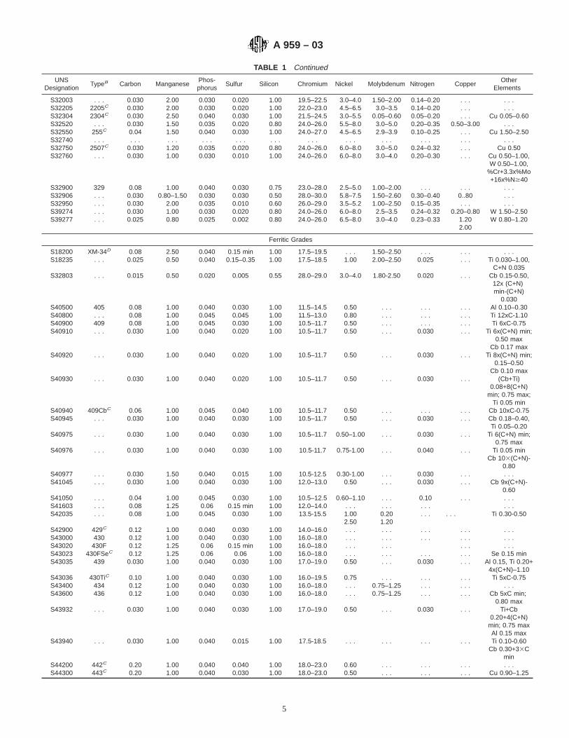
TABLE 1 Continued
UNSDesignation
TypeB Carbon ManganesePhos-phorus
Sulfur Silicon Chromium Nickel Molybdenum Nitrogen CopperOther
Elements
S32003 . . . 0.030 2.00 0.030 0.020 1.00 19.5–22.5 3.0–4.0 1.50–2.00 0.14–0.20 . . . . . .S32205 2205C 0.030 2.00 0.030 0.020 1.00 22.0–23.0 4.5–6.5 3.0–3.5 0.14–0.20 . . . . . .S32304 2304C 0.030 2.50 0.040 0.030 1.00 21.5–24.5 3.0–5.5 0.05–0.60 0.05–0.20 . . . Cu 0.05–0.60S32520 . . . 0.030 1.50 0.035 0.020 0.80 24.0–26.0 5.5–8.0 3.0–5.0 0.20–0.35 0.50–3.00 . . .S32550 255C 0.04 1.50 0.040 0.030 1.00 24.0–27.0 4.5–6.5 2.9–3.9 0.10–0.25 . . . Cu 1.50–2.50S32740 . . . . . . . . . . . . . . . . . . . . . . . . . . . . . . . . . . . .S32750 2507C 0.030 1.20 0.035 0.020 0.80 24.0–26.0 6.0–8.0 3.0–5.0 0.24–0.32 . . . Cu 0.50S32760 . . . 0.030 1.00 0.030 0.010 1.00 24.0–26.0 6.0–8.0 3.0–4.0 0.20–0.30 . . . Cu 0.50–1.00,
W 0.50–1.00,%Cr+3.3x%Mo+16x%N$40
S32900 329 0.08 1.00 0.040 0.030 0.75 23.0–28.0 2.5–5.0 1.00–2.00 . . . . . . . . .S32906 . . . 0.030 0.80–1.50 0.030 0.030 0.50 28.0–30.0 5.8–7.5 1.50–2.60 0.30–0.40 0..80 . . .S32950 . . . 0.030 2.00 0.035 0.010 0.60 26.0–29.0 3.5–5.2 1.00–2.50 0.15–0.35 . . . . . .S39274 . . . 0.030 1.00 0.030 0.020 0.80 24.0–26.0 6.0–8.0 2.5–3.5 0.24–0.32 0.20–0.80 W 1.50–2.50S39277 . . . 0.025 0.80 0.025 0.002 0.80 24.0–26.0 6.5–8.0 3.0–4.0 0.23–0.33 1.20
2.00W 0.80–1.20
Ferritic Grades
S18200 XM-34D 0.08 2.50 0.040 0.15 min 1.00 17.5–19.5 . . . 1.50–2.50 . . . . . . . . .S18235 . . . 0.025 0.50 0.040 0.15–0.35 1.00 17.5–18.5 1.00 2.00–2.50 0.025 . . . Ti 0.030–1.00,
C+N 0.035S32803 . . . 0.015 0.50 0.020 0.005 0.55 28.0–29.0 3.0–4.0 1.80-2.50 0.020 . . . Cb 0.15-0.50,
12x (C+N)min-(C+N)
0.030S40500 405 0.08 1.00 0.040 0.030 1.00 11.5–14.5 0.50 . . . . . . . . . Al 0.10–0.30S40800 . . . 0.08 1.00 0.045 0.045 1.00 11.5–13.0 0.80 . . . . . . . . . Ti 12xC-1.10S40900 409 0.08 1.00 0.045 0.030 1.00 10.5–11.7 0.50 . . . . . . . . . Ti 6xC-0.75S40910 . . . 0.030 1.00 0.040 0.020 1.00 10.5–11.7 0.50 . . . 0.030 . . . Ti 6x(C+N) min;
0.50 maxCb 0.17 max
S40920 . . . 0.030 1.00 0.040 0.020 1.00 10.5–11.7 0.50 . . . 0.030 . . . Ti 8x(C+N) min;0.15–0.50
Cb 0.10 maxS40930 . . . 0.030 1.00 0.040 0.020 1.00 10.5–11.7 0.50 . . . 0.030 . . . (Cb+Ti)
0.08+8(C+N)min; 0.75 max;
Ti 0.05 minS40940 409CbC 0.06 1.00 0.045 0.040 1.00 10.5–11.7 0.50 . . . . . . . . . Cb 10xC-0.75S40945 . . . 0.030 1.00 0.040 0.030 1.00 10.5–11.7 0.50 . . . 0.030 . . . Cb 0.18–0.40,
Ti 0.05–0.20S40975 . . . 0.030 1.00 0.040 0.030 1.00 10.5–11.7 0.50–1.00 . . . 0.030 . . . Ti 6(C+N) min;
0.75 maxS40976 . . . 0.030 1.00 0.040 0.030 1.00 10.5-11.7 0.75-1.00 . . . 0.040 . . . Ti 0.05 min
Cb 103(C+N)-0.80
S40977 . . . 0.030 1.50 0.040 0.015 1.00 10.5-12.5 0.30-1.00 . . . 0.030 . . . . . .S41045 . . . 0.030 1.00 0.040 0.030 1.00 12.0–13.0 0.50 . . . 0.030 . . . Cb 9x(C+N)-
0.60S41050 . . . 0.04 1.00 0.045 0.030 1.00 10.5–12.5 0.60–1.10 . . . 0.10 . . . . . .S41603 . . . 0.08 1.25 0.06 0.15 min 1.00 12.0–14.0 . . . . . . . . . . . .S42035 . . . 0.08 1.00 0.045 0.030 1.00 13.5-15.5 1.00
2.500.201.20
. . . . . . Ti 0.30-0.50
S42900 429C 0.12 1.00 0.040 0.030 1.00 14.0–16.0 . . . . . . . . . . . . . . .S43000 430 0.12 1.00 0.040 0.030 1.00 16.0–18.0 . . . . . . . . . . . . . . .S43020 430F 0.12 1.25 0.06 0.15 min 1.00 16.0–18.0 . . . . . . . . . . . .S43023 430FSeC 0.12 1.25 0.06 0.06 1.00 16.0–18.0 . . . . . . . . . . . . Se 0.15 minS43035 439 0.030 1.00 0.040 0.030 1.00 17.0–19.0 0.50 . . . 0.030 . . . Al 0.15, Ti 0.20+
4x(C+N)–1.10S43036 430TiC 0.10 1.00 0.040 0.030 1.00 16.0–19.5 0.75 . . . . . . . . . Ti 5xC-0.75S43400 434 0.12 1.00 0.040 0.030 1.00 16.0–18.0 . . . 0.75–1.25 . . . . . . . . .S43600 436 0.12 1.00 0.040 0.030 1.00 16.0–18.0 . . . 0.75–1.25 . . . . . . Cb 5xC min;
0.80 maxS43932 . . . 0.030 1.00 0.040 0.030 1.00 17.0–19.0 0.50 . . . 0.030 . . . Ti+Cb
0.20+4(C+N)min; 0.75 maxAl 0.15 max
S43940 . . . 0.030 1.00 0.040 0.015 1.00 17.5-18.5 . . . . . . . . . . . . Ti 0.10-0.60Cb 0.30+33C
minS44200 442C 0.20 1.00 0.040 0.040 1.00 18.0–23.0 0.60 . . . . . . . . . . . .S44300 443C 0.20 1.00 0.040 0.030 1.00 18.0–23.0 0.50 . . . . . . . . . Cu 0.90–1.25
A 959 – 03
5
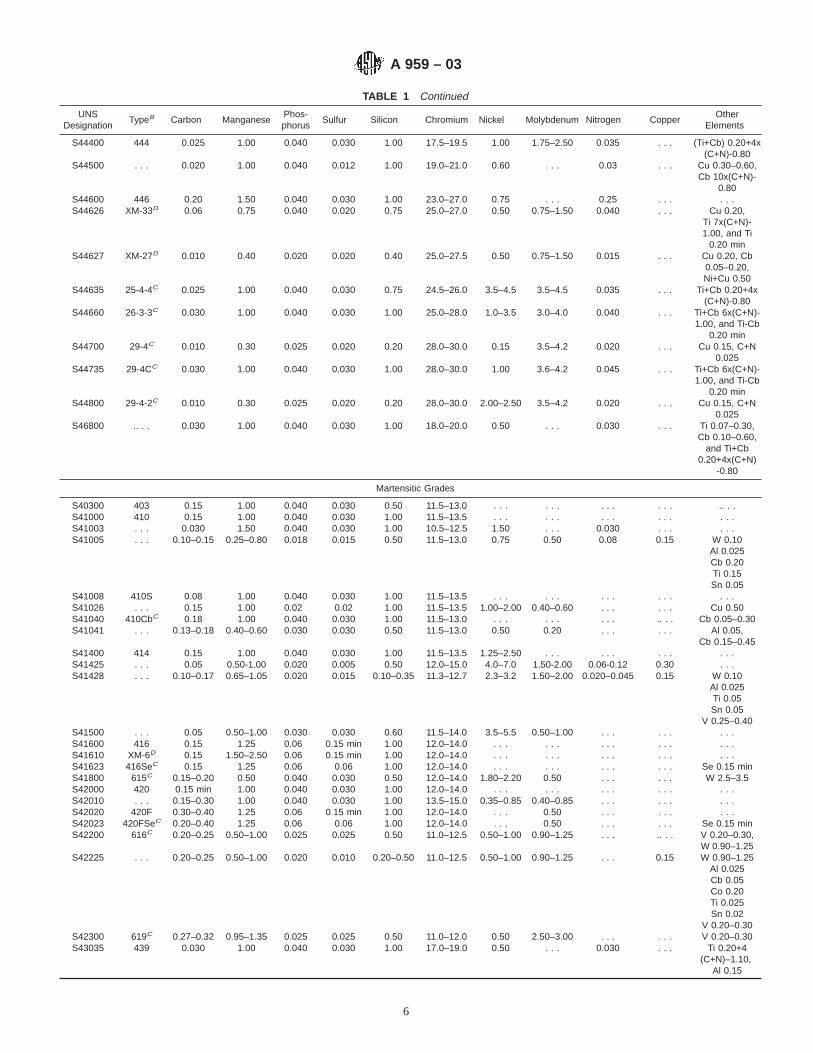
TABLE 1 Continued
UNSDesignation
TypeB Carbon ManganesePhos-phorus
Sulfur Silicon Chromium Nickel Molybdenum Nitrogen CopperOther
Elements
S44400 444 0.025 1.00 0.040 0.030 1.00 17.5–19.5 1.00 1.75–2.50 0.035 . . . (Ti+Cb) 0.20+4x(C+N)-0.80
S44500 . . . 0.020 1.00 0.040 0.012 1.00 19.0–21.0 0.60 . . . 0.03 . . . Cu 0.30–0.60,Cb 10x(C+N)-
0.80S44600 446 0.20 1.50 0.040 0.030 1.00 23.0–27.0 0.75 . . . 0.25 . . . . . .S44626 XM-33D 0.06 0.75 0.040 0.020 0.75 25.0–27.0 0.50 0.75–1.50 0.040 . . . Cu 0.20,
Ti 7x(C+N)-1.00, and Ti
0.20 minS44627 XM-27D 0.010 0.40 0.020 0.020 0.40 25.0–27.5 0.50 0.75–1.50 0.015 . . . Cu 0.20, Cb
0.05–0.20,Ni+Cu 0.50
S44635 25-4-4C 0.025 1.00 0.040 0.030 0.75 24.5–26.0 3.5–4.5 3.5–4.5 0.035 . . . Ti+Cb 0.20+4x(C+N)-0.80
S44660 26-3-3C 0.030 1.00 0.040 0.030 1.00 25.0–28.0 1.0–3.5 3.0–4.0 0.040 . . . Ti+Cb 6x(C+N)-1.00, and Ti-Cb
0.20 minS44700 29-4C 0.010 0.30 0.025 0.020 0.20 28.0–30.0 0.15 3.5–4.2 0.020 . . . Cu 0.15, C+N
0.025S44735 29-4CC 0.030 1.00 0.040 0.030 1.00 28.0–30.0 1.00 3.6–4.2 0.045 . . . Ti+Cb 6x(C+N)-
1.00, and Ti-Cb0.20 min
S44800 29-4-2C 0.010 0.30 0.025 0.020 0.20 28.0–30.0 2.00–2.50 3.5–4.2 0.020 . . . Cu 0.15, C+N0.025
S46800 .. . . 0.030 1.00 0.040 0.030 1.00 18.0–20.0 0.50 . . . 0.030 . . . Ti 0.07–0.30,Cb 0.10–0.60,
and Ti+Cb0.20+4x(C+N)
-0.80
Martensitic Grades
S40300 403 0.15 1.00 0.040 0.030 0.50 11.5–13.0 . . . . . . . . . . . . .. . .S41000 410 0.15 1.00 0.040 0.030 1.00 11.5–13.5 . . . . . . . . . . . . . . .S41003 . . . 0.030 1.50 0.040 0.030 1.00 10.5–12.5 1.50 . . . 0.030 . . . . . .S41005 . . . 0.10–0.15 0.25–0.80 0.018 0.015 0.50 11.5–13.0 0.75 0.50 0.08 0.15 W 0.10
Al 0.025Cb 0.20Ti 0.15Sn 0.05
S41008 410S 0.08 1.00 0.040 0.030 1.00 11.5–13.5 . . . . . . . . . . . . . . .S41026 . . . 0.15 1.00 0.02 0.02 1.00 11.5–13.5 1.00–2.00 0.40–0.60 . . . . . . Cu 0.50S41040 410CbC 0.18 1.00 0.040 0.030 1.00 11.5–13.0 . . . . . . . . . .. . . Cb 0.05–0.30S41041 . . . 0.13–0.18 0.40–0.60 0.030 0.030 0.50 11.5–13.0 0.50 0.20 . . . . . . Al 0.05,
Cb 0.15–0.45S41400 414 0.15 1.00 0.040 0.030 1.00 11.5–13.5 1.25–2.50 . . . . . . . . . . . .S41425 . . . 0.05 0.50-1.00 0.020 0.005 0.50 12.0–15.0 4.0–7.0 1.50-2.00 0.06-0.12 0.30 . . .S41428 . . . 0.10–0.17 0.65–1.05 0.020 0.015 0.10–0.35 11.3–12.7 2.3–3.2 1.50–2.00 0.020–0.045 0.15 W 0.10
Al 0.025Ti 0.05Sn 0.05
V 0.25–0.40S41500 . . . 0.05 0.50–1.00 0.030 0.030 0.60 11.5–14.0 3.5–5.5 0.50–1.00 . . . . . . . . .S41600 416 0.15 1.25 0.06 0.15 min 1.00 12.0–14.0 . . . . . . . . . . . . . . .S41610 XM-6D 0.15 1.50–2.50 0.06 0.15 min 1.00 12.0–14.0 . . . . . . . . . . . . . . .S41623 416SeC 0.15 1.25 0.06 0.06 1.00 12.0–14.0 . . . . . . . . . . . . Se 0.15 minS41800 615C 0.15–0.20 0.50 0.040 0.030 0.50 12.0–14.0 1.80–2.20 0.50 . . . . . . W 2.5–3.5S42000 420 0.15 min 1.00 0.040 0.030 1.00 12.0–14.0 . . . . . . . . . . . . . . .S42010 . . . 0.15–0.30 1.00 0.040 0.030 1.00 13.5–15.0 0.35–0.85 0.40–0.85 . . . . . . . . .S42020 420F 0.30–0.40 1.25 0.06 0.15 min 1.00 12.0–14.0 . . . 0.50 . . . . . . . . .S42023 420FSeC 0.20–0.40 1.25 0.06 0.06 1.00 12.0–14.0 . . . 0.50 . . . . . . Se 0.15 minS42200 616C 0.20–0.25 0.50–1.00 0.025 0.025 0.50 11.0–12.5 0.50–1.00 0.90–1.25 . . . .. . . V 0.20–0.30,
W 0.90–1.25S42225 . . . 0.20–0.25 0.50–1.00 0.020 0.010 0.20–0.50 11.0–12.5 0.50–1.00 0.90–1.25 . . . 0.15 W 0.90–1.25
Al 0.025Cb 0.05Co 0.20Ti 0.025Sn 0.02
V 0.20–0.30S42300 619C 0.27–0.32 0.95–1.35 0.025 0.025 0.50 11.0–12.0 0.50 2.50–3.00 . . . . . . V 0.20–0.30S43035 439 0.030 1.00 0.040 0.030 1.00 17.0–19.0 0.50 . . . 0.030 . . . Ti 0.20+4
(C+N)–1.10,Al 0.15
A 959 – 03
6

SUMMARY OF CHANGES
Committee A01 has identified the location of selected changes to this standard since the last edition (A 959-01)that may impact the use of this standard (approved April 2003).
(1) Added five new grades to Table 1.
TABLE 1 Continued
UNSDesignation
TypeB Carbon ManganesePhos-phorus
Sulfur Silicon Chromium Nickel Molybdenum Nitrogen CopperOther
Elements
S43100 431 0.20 1.00 0.040 0.030 1.00 15.0–17.0 1.25–2.50 . . . . . . . . . . . .S44002 440A 0.60–0.75 1.00 0.040 0.030 1.00 16.0–18.0 . . . 0.75 . . . . . . . . .S44003 440B 0.75–0.95 1.00 0.040 0.030 1.00 16.0–18.0 . . . 0.75 . . . . . . . . .S44004 440C 0.95–1.20 1.00 0.040 0.030 1.00 16.0–18.0 . . . 0.75 . . . . . . . . .S44020 440FC 0.95–1.20 1.25 0.06 0.15 min 1.00 16.0–18.0 . . . . . . . . . . . . . . .S44023 440FSeC 0.95–1.20 1.25 0.06 0.06 1.00 16.0–18.0 . . . . . . . . . . . . Se 0.15 minS44025 . . . 0.95–1.10 0.30–1.00 0.025 0.025 0.30–1.00 16.0–18.0 0.75 0.40–0.65 . . . . . . Cu 0.50S64512 XM-32D 0.08–0.15 0.50–0.90 0.025 0.025 0.35 11.0–12.5 2.00–3.00 1.50–2.00 0.01–0.05 . . . V 0.25–0.40
Precipitation Hardening Grades
S13800 XM-13D 0.05 0.20 0.010 0.008 0.10 12.3–13.2 7.5–8.5 2.00–3.00 0.01 . . . Al 0.90–1.35S15500 XM-12D 0.07 1.00 0.040 0.030 1.00 14.0–15.5 3.5–5.5 . . . . . . . . . Cu 2.5–4.5,
Cb 0.15–0.45S15700 632C 0.09 1.00 0.040 0.030 1.00 14.0–16.0 6.5–7.7 2.00–3.00 . . . . . . Al 0.75–1.50S17400 630C 0.07 1.00 0.040 0.030 1.00 15.0–17.0 3.0–5.0 . . . . . . . . . Cu 3.0–5.0,
Cb 0.15–0.45S17600 635C 0.08 1.00 0.040 0.030 1.00 16.0–17.5 6.0–7.5 . . . . . . . . . Al 0.40,
Ti 0.40–1.20S17700 631C 0.09 1.00 0.040 0.030 1.00 16.0–18.0 6.5–7.7 . . . . . . . . . Al 0.75–1.50S35000 633C 0.07–0.11 0.50–1.25 0.040 0.030 0.50 16.0–17.0 4.0–5.0 2.5–3.2 0.07–0.13 . . . . . .S35500 634C 0.10–0.15 0.50–1.25 0.040 0.030 0.50 15.0–16.0 4.0–5.0 2.5–3.2 0.07–0.13 . . . Cb 0.10–0.50S45000 XM-25D 0.05 1.00 0.040 0.030 1.00 14.0–16.0 5.0–7.0 0.50–1.00 . . . . . . Cu 1.25–1.75,
Cb 8xC minS45500 XM-16D 0.03 0.50 0.040 0.030 0.50 11.0–12.5 7.5–9.5 0.50 . . . . . . Cu 1.50–2.50,
Ti 0.80–1.40,Cb 0.10–0.50
S45503 . . . 0.010 0.50 0.010 0.010 0.20 11.0–12.5 7.5–9.5 0.50 . . . . . . Cu 1.50–2.50,Ti 1.00–1.35,Cb 0.10–0.50
S46500 . . . 0.020 0.25 0.015 0.010 0.25 11.0–12.5 10.7–11.3 0.75–1.25 0.010 . . . Ti 1.50–1.80S63198 651C 0.28–0.35 0.75–1.50 0.040 0.030 0.30–0.80 18.0–21.0 8.0–11.0 1.00–1.75 . . . 0.50 W 1.00–1.75
Ti 0.10–0.35Cb 0.25–0.60
S66220 662C 0.08 0.40–1.00 0.040 0.030 0.40–1.00 12.0–15.0 24.0–28.0 2.0–3.5 . . . 0.50 Ti 1.80–2.10Al 0.35
B 0.001–0.010S66286 660C 0.08 2.00 0.040 0.030 1.00 13.5–16.0 24.0–27.0 1.00–1.50 . . . . . . Ti 1.90–2.35
Al 0.35V 0.10–0.50
B 0.001–0.010S66545 665C 0.08 1.25–2.00 0.040 0.030 0.10–0.80 12.0–15.0 24.0–28.0 1.25–2.25 . . . 0.25 Ti 2.7–3.3
Al 0.25B 0.01–0.07
A Maximum, unless range or minimum is indicated.B Unless otherwise indicated, a grade designation originally assigned by the American Iron and Steel Institute (AISI).C Common type number, not a trademark, widely used; not associated with any one product.D Numbering system developed and applied by ASTM.E Iron shall be determined arithmetically by difference of 100 minus the sum of the other specified elements.
A 959 – 03
7

ASTM International takes no position respecting the validity of any patent rights asserted in connection with any item mentionedin this standard. Users of this standard are expressly advised that determination of the validity of any such patent rights, and the riskof infringement of such rights, are entirely their own responsibility.
This standard is subject to revision at any time by the responsible technical committee and must be reviewed every five years andif not revised, either reapproved or withdrawn. Your comments are invited either for revision of this standard or for additional standardsand should be addressed to ASTM International Headquarters. Your comments will receive careful consideration at a meeting of theresponsible technical committee, which you may attend. If you feel that your comments have not received a fair hearing you shouldmake your views known to the ASTM Committee on Standards, at the address shown below.
This standard is copyrighted by ASTM International, 100 Barr Harbor Drive, PO Box C700, West Conshohocken, PA 19428-2959,United States. Individual reprints (single or multiple copies) of this standard may be obtained by contacting ASTM at the aboveaddress or at 610-832-9585 (phone), 610-832-9555 (fax), or [email protected] (e-mail); or through the ASTM website(www.astm.org).
A 959 – 03
8

Designation: A 967 – 01 An American National Standard
Standard Specification forChemical Passivation Treatments for Stainless Steel Parts 1
This standard is issued under the fixed designation A 967; the number immediately following the designation indicates the year oforiginal adoption or, in the case of revision, the year of last revision. A number in parentheses indicates the year of last reapproval. Asuperscript epsilon (e) indicates an editorial change since the last revision or reapproval.
1. Scope
1.1 This specification covers several different types ofchemical passivation treatments for stainless steel parts. Itincludes recommendations and precautions for descaling,cleaning, and passivation of stainless steel parts. It includesseveral alternative tests, with acceptance criteria, for confirma-tion of effectiveness of such treatments for stainless steel parts.
1.2 Practices for the mechanical and chemical treatments ofstainless steel surfaces are discussed more thoroughly inPractice A 380.
1.3 Several alternative chemical treatments are defined forpassivation of stainless steel parts. Appendix X1 gives somenonmandatory information and provides some general guide-lines regarding the selection of passivation treatment appropri-ate to particular grades of stainless steel but makes norecommendations regarding the suitability of any grade, treat-ment, and acceptance criteria for any particular application orclass of applications.
1.4 The tests in this specification are intended to confirm theeffectiveness of passivation, particularly with regard to theremoval of free iron and other exogenous matter. These testsinclude the following practices:
1.4.1 Practice A—Water Immersion Test,1.4.2 Practice B—High Humidity Test,1.4.3 Practice C—Salt Spray Test,1.4.4 Practice D—Copper Sulfate Test,1.4.5 Practice E—Potassium Ferricyanide–Nitric Acid Test,
and1.4.6 Practice F—Free Iron Test.1.5 The values stated in inch-pound units are to be regarded
as the standard. The SI units given in parentheses are forinformation only.
1.6 The following precautionary caveat pertains only to thetest method portions, Sections 14 through 18 of this specifica-tion: This standard does not purport to address all of the safetyconcerns, if any, associated with its use. It is the responsibilityof the user of this standard to establish appropriate safety andhealth practices and determine the applicability of regulatorylimitations prior to use.
2. Referenced Documents
2.1 ASTM Standards:A 380 Practice for Cleaning, Descaling, and Depassivation
of Stainless Steel Parts, Equipment, and Systems2
B 117 Practice for Operating Salt Spray (Fog) Apparatus3
B 254 Practice for Preparation of and Electroplating onStainless Steel4
2.2 Federal Specification:QQ-P-35C Passivation Treatments for Corrosion-Resistant
Steels5
3. Terminology
3.1 Definition of Term Specific to This Standard—It isnecessary to define which of the several commonly useddefinitions of the termpassivation will be used in thisspecification. (See Discussion.)
3.1.1 Discussion—Stainless steels are autopassivating in thesense that the protective passive film is formed spontaneouslyon exposure to air or moisture. The presence of exogenoussurface contamination, including dirt, grease, free iron fromcontact with steel tooling, and so forth, may interfere with theformation of the passive film. The cleaning of these contami-nants from the stainless steel surface will facilitate the spon-taneous passivation by allowing the oxygen uniform access tothe surface. The passive film may be augmented by chemicaltreatments that provide an oxidizing environment for thestainless steel surface.
3.1.1.1 In this specification, passivation, unless otherwisespecified, is defined as the chemical treatment of a stainlesssteel with a mild oxidant, such as a nitric acid solution, for thepurpose of the removal of free iron or other foreign matter, butwhich is generally not effective in removal of heat tint or oxidescale on stainless steel. In the case of stainless steels withadditions of sulfur for the purpose of improved machinability,passivation may also include the removal of sulfides from thesurface of the metal for the purpose of maximizing corrosionresistance.
3.1.1.2 The formation of the protective passive film on astainless steel, also called passivation in a more general
1 This specification is under the jurisdiction of ASTM Committee A01 on Steel,Stainless Steel, and Related Alloys and is the direct responsibility of SubcommitteeA01.14 on Methods of Corrosion Testing.
Current edition approved Oct. 10, 2001. Published December 2001. Originallypublished as A 967 – 96. Last previoius edition A 967 – 99.
2 Annual Book of ASTM Standards, Vol 01.03.3 Annual Book of ASTM Standards, Vol 03.02.4 Annual Book of ASTM Standards, Vol 02.05.5 Available from Superintendent of Documents, U.S. Government Printing
Office, Washington, DC 20402.
1
Copyright © ASTM International, 100 Barr Harbor Drive, PO Box C700, West Conshohocken, PA 19428-2959, United States.
NOTICE: This standard has either been superseded and replaced by a new version or discontinued.Contact ASTM International (www.astm.org) for the latest information.
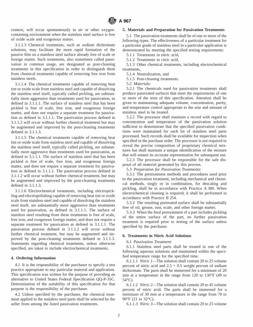
context, will occur spontaneously in air or other oxygen-containing environment when the stainless steel surface is freeof oxide scale and exogenous matter.
3.1.1.3 Chemical treatments, such as sodium dichromatesolutions, may facilitate the more rapid formation of thepassive film on a stainless steel surface already free of scale orforeign matter. Such treatments, also sometimes called passi-vation in common usage, are designated as post-cleaningtreatments in this specification in order to distinguish themfrom chemical treatments capable of removing free iron fromstainless steels.
3.1.1.4 The chemical treatments capable of removing heattint or oxide scale from stainless steel and capable of dissolvingthe stainless steel itself, typically called pickling, are substan-tially more aggressive than treatments used for passivation, asdefined in 3.1.1.1. The surface of stainless steel that has beenpickled is free of scale, free iron, and exogenous foreignmatter, and does not require a separate treatment for passiva-tion as defined in 3.1.1.1. The passivation process defined in3.1.1.2 will occur without further chemical treatment but maybe augmented and improved by the post-cleaning treatmentsdefined in 3.1.1.3.
3.1.1.5 The chemical treatments capable of removing heattint or oxide scale from stainless steel and capable of dissolvingthe stainless steel itself, typically called pickling, are substan-tially more aggressive than treatments used for passivation, asdefined in 3.1.1.1. The surface of stainless steel that has beenpickled is free of scale, free iron, and exogenous foreignmatter, and does not require a separate treatment for passiva-tion as defined in 3.1.1.1. The passivation process defined in3.1.1.2 will occur without further chemical treatment, but maybe augmented and improved by the post-cleaning treatmentsdefined in 3.1.1.3.
3.1.1.6 Electrochemical treatments, including electropick-ling and electropolishing capable of removing heat tint or oxidescale from stainless steel and capable of dissolving the stainlesssteel itself, are substantially more aggressive than treatmentsused for passivation, as defined in 3.1.1.1. The surface ofstainless steel resulting from these treatments is free of scale,free iron, and exogenous foreign matter, and does not require aseparate treatment for passivation as defined in 3.1.1.1. Thepassivation process defined in 3.1.1.2 will occur withoutfurther chemical treatment, but may be augmented and im-proved by the post-cleaning treatments defined in 3.1.1.3.Statements regarding chemical treatments, unless otherwisespecified, are taken to include electrochemical treatments.
4. Ordering Information
4.1 It is the responsibility of the purchaser to specify a testpractice appropriate to any particular material and application.This specification was written for the purpose of providing analternative to United States Federal Specification QQ-P-35C.Determination of the suitability of this specification for thatpurpose is the responsibility of the purchaser.
4.2 Unless specified by the purchaser, the chemical treat-ment applied to the stainless steel parts shall be selected by theseller from among the listed passivation treatments.
5. Materials and Preparation for Passivation Treatments
5.1 The passivation treatments shall be of one or more of thefollowing types. The effectiveness of a particular treatment fora particular grade of stainless steel in a particular application isdemonstrated by meeting the specified testing requirements:
5.1.1 Treatments in nitric acid,5.1.2 Treatments in citric acid,5.1.3 Other chemical treatments, including electrochemical
treatments,5.1.4 Neutralization, and5.1.5 Post-cleaning treatments.5.2 Materials:5.2.1 The chemicals used for passivation treatments shall
produce passivated surfaces that meet the requirements of oneor more of the tests of this specification. Attention shall begiven to maintaining adequate volume, concentration, purity,and temperature control appropriate to the size and amount ofstainless steel to be treated.
5.2.2 The processor shall maintain a record with regard toconcentration and temperature of the passivation solutionsufficient to demonstrate that the specified passivation condi-tions were maintained for each lot of stainless steel partsprocessed. Such records shall be available for inspection whenspecified in the purchase order. The processor is not required toreveal the precise composition of proprietary chemical mix-tures but shall maintain a unique identification of the mixturethat will ensure its accurate representation for subsequent use.
5.2.3 The processor shall be responsible for the safe dis-posal of all material generated by this process.
5.3 Preparation for Passivation Treatments:5.3.1 The pretreatment methods and procedures used prior
to the passivation treatment, including mechanical and chemi-cal methods, singly or in combination, for descaling andpickling, shall be in accordance with Practice A 380. Whenelectrochemical cleaning is required, it shall be performed inaccordance with Practice B 254.
5.3.2 The resulting pretreated surface shall be substantiallyfree of oil, grease, rust, scale, and other foreign matter.
5.3.3 When the final pretreatment of a part includes picklingof the entire surface of the part, no further passivationtreatment is required prior to testing of the surface unlessspecified by the purchaser.
6. Treatments in Nitric Acid Solutions
6.1 Passivation Treatment:6.1.1 Stainless steel parts shall be treated in one of the
following aqueous solutions and maintained within the speci-fied temperature range for the specified time.
6.1.1.1 Nitric 1—The solution shall contain 20 to 25 volumepercent of nitric acid and 2.5 + 0.5 weight percent of sodiumdichromate. The parts shall be immersed for a minimum of 20min at a temperature in the range from 120 to 130°F (49 to54°C).
6.1.1.2 Nitric 2—The solution shall contain 20 to 45 volumepercent of nitric acid. The parts shall be immersed for aminimum of 30 min at a temperature in the range from 70 to90°F (21 to 32°C).
6.1.1.3 Nitric 3—The solution shall contain 20 to 25 volume
A 967
2

percent nitric acid. The parts shall be immersed for a minimumof 20 min at a temperature in the range from 120 to 140°F (49to 60°C).
6.1.1.4 Nitric 4—The solution shall contain 45 to 55 volumepercent of nitric acid. The parts shall be immersed for aminimum of 30 min at a temperature in the range from 120 to130°F (49 to 54°C).
6.1.1.5 Nitric 5—Other combinations of temperature, time,and concentration of nitric acid, with or without other chemi-cals, including accelerants, inhibitors, or proprietary solutions,capable of producing parts that pass the specified test require-ments.
6.2 Water Rinse—Immediately after removal from the pas-sivating solution the parts shall be thoroughly rinsed, usingstagnant, countercurrent, or spray washes singly or in combi-nation, with or without a separate chemical treatment forneutralization (see 9.1) of the passivation media, with a finalrinse being carried out using water with a maximum total solidscontent of 200 ppm.
7. Treatments in Citric Acid
7.1 Passivation Treatment:7.1.1 Stainless steel parts shall be treated in one of the
following aqueous solutions and maintained within the speci-fied temperature range for the specified time.
7.1.1.1 Citric 1—The solution shall contain 4 to 10 weightpercent of citric acid. The parts shall be immersed for aminimum of 4 min at a temperature in the range from 140 to160°F (60 to 71°C).
7.1.1.2 Citric 2—The solution shall contain 4 to 10 weightpercent of citric acid. The parts shall be immersed for aminimum of 10 min at a temperature in the range from 120 to140°F (49 to 60°C).
7.1.1.3 Citric 3—The solution shall contain 4 to 10 weightpercent of citric acid. The parts shall be immersed for aminimum of 20 min at a temperature in the range from 70 to120°F (21 to 49°C).
7.1.1.4 Citric 4—Other combinations of temperature, time,and concentration of citric acid, with or without other chemi-cals to enhance cleaning, including accelerants, inhibitors, orproprietary solutions capable of producing parts that pass thespecified test requirements.
7.1.1.5 Citric 5—Other combinations of temperature, time,and concentrations of citric acid, with or without other chemi-cals to enhance cleaning, including accelerants, inhibitors, orproprietary solutions capable of producing parts that pass thespecified test requirements. Immersion bath to be controlled ata pH of 1.8–2.2.
7.2 Water Rinse—Immediately after removal from the pas-sivating solution, the parts shall be thoroughly rinsed, usingstagnant, countercurrent, or spray washes, singly or in combi-nation, with or without a separate chemical treatment forneutralization of the passivation media (see 9.2), with a finalrinse being carried out using water with a maximum total solidscontent of 200 ppm.
8. Treatments in Other Chemical Solutions, IncludingElectrochemical Treatments
8.1 It is recognized that the purpose of removal of all
exogenous matter from a stainless steel surface, including theremoval of free iron, can be accomplished by different media,with potential for benefits to be gained from use of proprietaryskills and art, including proprietary passivation media. Suchtreatments may include externally applying an electrical po-tential on the stainless steel parts, as in the case of electropol-ishing. The suitability of such passivation treatments for use inmeeting the requirements of this specification shall be deter-mined by the capability of the processed parts meeting thespecified test requirements.
8.2 Stainless steel parts shall be treated in a specifiedaqueous solution, with or without externally applied electricalpotential, and maintained within a specified temperature rangefor a time sufficient for the processed parts to meet thespecified test requirement.
8.3 Water Rinse—Immediately after removal from the pas-sivating solution, the parts shall be thoroughly rinsed, usingstagnant, countercurrent, or spray washes, singly or in combi-nation, with or without a separate chemical treatment forneutralization of the passivation media (see 9.2), with a finalrinse being carried out using water with a maximum total solidscontent of 200 ppm.
9. Neutralization
9.1 The chemical reactions of the passivating media on thesurface of the stainless steel shall be stopped by rinsing of thestainless steel part, with or without a separate neutralizationtreatment.
9.2 The suitability of a neutralization procedure is deter-mined by the capability of the processed parts meeting thespecified test requirements. (See Note 1.)
NOTE 1—The selection of medium and procedures for a neutralizationdepends of the chemistry of the passivation and on economic consider-ations. An example of a neutralizing treatment would be immersion of thepart for a minimum of 30 min in a solution of 5 % NaOH at 160 to 180°F(71 to 82°C), followed by a water rinse.
10. Post-Cleaning Treatments
10.1 Although the passive film characteristic of stainlesssteel will form spontaneously in air or any other oxygen-containing environment, the processor shall, when specified,apply a chemical treatment that will accelerate the formation ofthe passive film on a chemically clean stainless steel surface.An example of a medium that serves to accelerate the forma-tion of the passive film but does not contribute to the removalof free iron from the stainless steel surface would be anaqueous solution of sodium dichromate.
10.2 When specified, within one hour after the final waterrinse as required in 6.2, 7.2, or 8.2, all ferritic and martensiticsteel parts shall be immersed in an aqueous solution containing4 to 6 weight percent of sodium dichromate at a temperature inthe range from 140 to 160°F (60 to 71°C) for a minimum of 30min, followed by a rinse in accordance with 6.2, 7.2, or 8.2.The parts shall then be thoroughly dried.
10.3 The purchaser may specify other post-cleaning treat-ments.
11. Finish
11.1 The passivated parts shall exhibit a chemically cleansurface and shall, on visual inspection, show no etching,
A 967
3
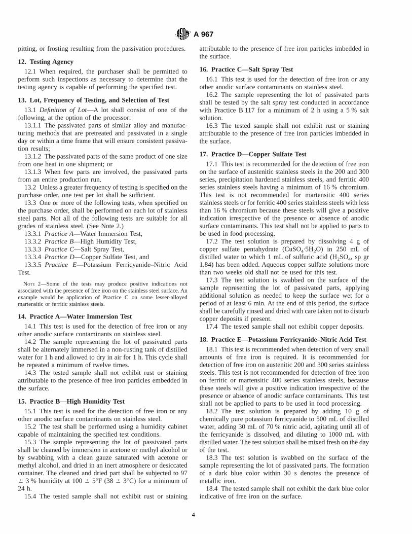
pitting, or frosting resulting from the passivation procedures.
12. Testing Agency
12.1 When required, the purchaser shall be permitted toperform such inspections as necessary to determine that thetesting agency is capable of performing the specified test.
13. Lot, Frequency of Testing, and Selection of Test
13.1 Definition of Lot—A lot shall consist of one of thefollowing, at the option of the processor:
13.1.1 The passivated parts of similar alloy and manufac-turing methods that are pretreated and passivated in a singleday or within a time frame that will ensure consistent passiva-tion results;
13.1.2 The passivated parts of the same product of one sizefrom one heat in one shipment; or
13.1.3 When few parts are involved, the passivated partsfrom an entire production run.
13.2 Unless a greater frequency of testing is specified on thepurchase order, one test per lot shall be sufficient.
13.3 One or more of the following tests, when specified onthe purchase order, shall be performed on each lot of stainlesssteel parts. Not all of the following tests are suitable for allgrades of stainless steel. (See Note 2.)
13.3.1 Practice A—Water Immersion Test,13.3.2 Practice B—High Humidity Test,13.3.3 Practice C—Salt Spray Test,13.3.4 Practice D—Copper Sulfate Test, and13.3.5 Practice E—Potassium Ferricyanide–Nitric Acid
Test.
NOTE 2—Some of the tests may produce positive indications notassociated with the presence of free iron on the stainless steel surface. Anexample would be application of Practice C on some lesser-alloyedmartensitic or ferritic stainless steels.
14. Practice A—Water Immersion Test
14.1 This test is used for the detection of free iron or anyother anodic surface contaminants on stainless steel.
14.2 The sample representing the lot of passivated partsshall be alternately immersed in a non-rusting tank of distilledwater for 1 h and allowed to dry in air for 1 h. This cycle shallbe repeated a minimum of twelve times.
14.3 The tested sample shall not exhibit rust or stainingattributable to the presence of free iron particles embedded inthe surface.
15. Practice B—High Humidity Test
15.1 This test is used for the detection of free iron or anyother anodic surface contaminants on stainless steel.
15.2 The test shall be performed using a humidity cabinetcapable of maintaining the specified test conditions.
15.3 The sample representing the lot of passivated partsshall be cleaned by immersion in acetone or methyl alcohol orby swabbing with a clean gauze saturated with acetone ormethyl alcohol, and dried in an inert atmosphere or desiccatedcontainer. The cleaned and dried part shall be subjected to 976 3 % humidity at 1006 5°F (386 3°C) for a minimum of24 h.
15.4 The tested sample shall not exhibit rust or staining
attributable to the presence of free iron particles imbedded inthe surface.
16. Practice C—Salt Spray Test
16.1 This test is used for the detection of free iron or anyother anodic surface contaminants on stainless steel.
16.2 The sample representing the lot of passivated partsshall be tested by the salt spray test conducted in accordancewith Practice B 117 for a minimum of 2 h using a 5 % saltsolution.
16.3 The tested sample shall not exhibit rust or stainingattributable to the presence of free iron particles imbedded inthe surface.
17. Practice D—Copper Sulfate Test
17.1 This test is recommended for the detection of free ironon the surface of austenitic stainless steels in the 200 and 300series, precipitation hardened stainless steels, and ferritic 400series stainless steels having a minimum of 16 % chromium.This test is not recommended for martensitic 400 seriesstainless steels or for ferritic 400 series stainless steels with lessthan 16 % chromium because these steels will give a positiveindication irrespective of the presence or absence of anodicsurface contaminants. This test shall not be applied to parts tobe used in food processing.
17.2 The test solution is prepared by dissolving 4 g ofcopper sulfate pentahydrate (CuSO4·5H2O) in 250 mL ofdistilled water to which 1 mL of sulfuric acid (H2SO4, sp gr1.84) has been added. Aqueous copper sulfate solutions morethan two weeks old shall not be used for this test.
17.3 The test solution is swabbed on the surface of thesample representing the lot of passivated parts, applyingadditional solution as needed to keep the surface wet for aperiod of at least 6 min. At the end of this period, the surfaceshall be carefully rinsed and dried with care taken not to disturbcopper deposits if present.
17.4 The tested sample shall not exhibit copper deposits.
18. Practice E—Potassium Ferricyanide–Nitric Acid Test
18.1 This test is recommended when detection of very smallamounts of free iron is required. It is recommended fordetection of free iron on austenitic 200 and 300 series stainlesssteels. This test is not recommended for detection of free ironon ferritic or martensitic 400 series stainless steels, becausethese steels will give a positive indication irrespective of thepresence or absence of anodic surface contaminants. This testshall not be applied to parts to be used in food processing.
18.2 The test solution is prepared by adding 10 g ofchemically pure potassium ferricyanide to 500 mL of distilledwater, adding 30 mL of 70 % nitric acid, agitating until all ofthe ferricyanide is dissolved, and diluting to 1000 mL withdistilled water. The test solution shall be mixed fresh on the dayof the test.
18.3 The test solution is swabbed on the surface of thesample representing the lot of passivated parts. The formationof a dark blue color within 30 s denotes the presence ofmetallic iron.
18.4 The tested sample shall not exhibit the dark blue colorindicative of free iron on the surface.
A 967
4

18.5 When the test is negative, the surface shall be thor-oughly washed with warm water to removal all traces of thetest solution. When the test is positive, the dark blue stain shallbe removed with a solution of 10 % acetic acid and 8 % oxalicacid, followed by a thorough hot water rinse.
19. Practice F—Free Iron Test
19.1 This test is used for the detection of free iron on thesurface of stainless steel. It is especially useful for large partsthat have been uniformly cleaned but that are inconvenient forreasons of size of equipment or ease of handling of the part toplace in the environments defined in Practice A (Section 14) orPractice B (Section 15). Unless otherwise specified by thepurchaser, the number of tests and the locations of the testsshall be at the option of the processor to assure a representativetesting of the part.
19.2 The test is performed by placing a clean cloth pad thathas been thoroughly soaked with distilled or deminaralizedwater on the surface of the part at a part temperature of 50°F(10°C) or greater for a period of not less than 60 minutes. Thecloth shall be in contact with the steel for an area of at least 20square inches (130 cm2). The pad shall be maintained wetthrough the test period, either by a method of retarding externalevaporation, by the further addition of potable water, or bybacking the pad with a sponge or similar water source. Thecloth pad used shall be used for only one such test, beingchanged for each test so as to avoid risk of contamination.
After removal of the cloth pad, the surface of the part shall beallowed to dry in air before inspection.
19.3 The tested part shall not exhibit rust or stainingattributable to the presence of free iron particles embedded inthe surface.
20. Rejection and Retest
20.1 Any lot failing to meet the specified test requirementsof the purchase order shall be rejected. A rejected lot may, atthe option of the processor, be re-passivated, with or withoutre-pretreatment, and then be retested. The number of samplestested from a lot subject to retest shall be twice the originalspecified test frequency, to the limit of the number of pieces inthe lot. All samples must pass the specified acceptance criterionfor the specified test for the retested lot to be accepted.
21. Precision and Bias
21.1 No statement is made concerning either the precisionor bias of Practices A, B, C, D, and E because the results statemerely whether there is conformance to the criteria for successspecified in the procedure.
22. Certification
22.1 When specified in the purchase order, a report of thepractice and tests used, including the record of process condi-tions when specified in accordance with 3.1.1.2, shall besupplied to the purchaser.
APPENDIX
(Nonmandatory Information)
X1. INFORMATION REGARDING PASSIVATION TREATMENTS
NOTE X1.1—The following information is based on a section of FederalSpecification QQ-P-35C (Oct. 28, 1988) identified as information of ageneral or explanatory nature that may be helpful, but is not mandatory.Minor changes have been made in the text to facilitate references to themain document and to correct technical inaccuracies.
X1.1 Intended Use—The passivation treatments providedby this specification are intended to improve the corrosionresistance of parts made from stainless steels of all types.
X1.1.1 During processing operations such as forming, ma-chining, tumbling, and lapping, iron particles or other foreignparticles may become smeared over or imbedded into thesurface of stainless steel parts. These particles must be re-moved or they will appear as rust or stain spots. This conditionmay be prevented by chemically treating the parts to removethe iron particles or other foreign particles, and then allowingthe passive film to form on the cleaned surface, with or withoutchemical enhancement of the formation of this oxide film.
X1.1.2 This specification is not intended for the black oxidecoating of parts typically used for photographic or opticalinstruments.
X1.2 Ordering Data—Purchasers should select the pre-ferred options permitted by this specification and include thefollowing information in the purchase order:
X1.2.1 Title, number, and date of this specification;X1.2.2 Identification of material by type and applicable
product specification;X1.2.3 Test practices to be imposed (see 1.4);X1.2.4 Definition of lot size, if other than described in this
specification; andX1.2.5 Required documentation, if other than the minimum
required by this specification.
X1.3 Grades of Stainless Steel—Different types of stainlesssteel are selected on a basis of properties required, for example,corrosion resistance and design criteria, and fabrication re-quirements. Table X1.1 is a compilation that serves as a guidefor the selection of passivation treatment for different grades,but is far from complete either in grades or in passivationtreatments.
X1.4 Clean Water—Clean water is defined as water con-taining a maximum total solid content of 200 ppm. Rinsing canbe accomplished by a combination of stagnant, countercurrentor spray rinses, or both, prior to final rinse.
X1.5 Chemically Clean Surface—A chemically clean sur-face is defined as a surface upon which water, when applied
A 967
5

momentarily to the surface, will remain on that surface in aneven, continuous film, and in addition is free of any foreignmaterial or residual film deposit which would be detrimental tothe quality of the part.
X1.6 Test Specimens—When using test specimens insteadof parts, the specimens can effectively represent the parts onlyif they have been exposed to the same processing steps, such asmachining, grinding, heat treating, welding, and so forth, as theparts they are to represent.
X1.7 Carburized Surfaces—Stainless steel parts with car-burized surfaces cannot be passivated because the carboncombines with the chromium forming chromium carbides onthe surface.
X1.8 Nitrided Surfaces—Stainless steel parts with nitridedsurfaces should not be passivated because the treatment will
severely corrode the nitrided case.
X1.9 This specification provides for the same passivationtreatments as Fed. Spec. QQ-P-35C, but also includes anumber of alternative passivation treatments. The effectivenessof any passivation treatment is demonstrated by the partsmeeting the specified testing requirements after treatment.
X1.10 Martensitic Grade 440C—High-strength gradessuch as 440C are subject to hydrogen embrittlement orintergranular attack when exposed to acids. Cleaning bymechanical methods or other chemical methods is recom-mended.
X1.11 The salt spray test is typically used to evaluateaustenitic stainless steels and may not be applicable to allmartensitic or ferritic stainless steels.
ASTM International takes no position respecting the validity of any patent rights asserted in connection with any item mentionedin this standard. Users of this standard are expressly advised that determination of the validity of any such patent rights, and the riskof infringement of such rights, are entirely their own responsibility.
This standard is subject to revision at any time by the responsible technical committee and must be reviewed every five years andif not revised, either reapproved or withdrawn. Your comments are invited either for revision of this standard or for additional standardsand should be addressed to ASTM International Headquarters. Your comments will receive careful consideration at a meeting of theresponsible technical committee, which you may attend. If you feel that your comments have not received a fair hearing you shouldmake your views known to the ASTM Committee on Standards, at the address shown below.
FIG. X1.1 Recommended Nitric Acid Passivation Treatments for Different Grades of Stainless Steel
A 967
6

This standard is copyrighted by ASTM International, 100 Barr Harbor Drive, PO Box C700, West Conshohocken, PA 19428-2959,United States. Individual reprints (single or multiple copies) of this standard may be obtained by contacting ASTM at the aboveaddress or at 610-832-9585 (phone), 610-832-9555 (fax), or [email protected] (e-mail); or through the ASTM website(www.astm.org).
A 967
7

Designation: A 968/A 968M – 96 (Reapproved 2001)
Standard Specification forChromium, Chromium-Nickel, and Silicon Alloy Steel Barsand Shapes for Corrosion and Heat-Resisting Service 1
This standard is issued under the fixed designation A 968/A 968M; the number immediately following the designation indicates the yearof original adoption or, in the case of revision, the year of last revision. A number in parentheses indicates the year of last reapproval.A superscript epsilon (e) indicates an editorial change since the last revision or reapproval.
1. Scope
1.1 This specification covers hot- and cold-finished alloysteel bars having a chromium content equal to or less than11.0 % including rounds, squares, hexagons, and hot-rolled orextruded shapes for use in corrosion and heat-resisting service.
1.2 Some steels covered by this specification, especially thehigh silicon-containing steels, because of their particular alloycontent and specialized properties, may require special care intheir fabrication and welding. Specific procedures are offundamental importance, and it is presupposed that all param-eters will be in accordance with approved test methods capableof producing the desired properties in the finished fabrication.
1.3 The values stated in either inch-pound units or SI unitsare to be regarded separately as standard. The values stated ineach system are not exact equivalents; therefore, each systemmust be used independently of the other. Combining valuesfrom the two systems may result in nonconformance with thisspecification.
1.4 This specification and the applicable material specifica-tions are expressed in both inch-pound and SI units. However,unless the order specifies the applicable “M” specificationdesignation (SI units), the material shall be furnished ininch-pound units.
2. Referenced Documents
2.1 ASTM Standards:A 484/A 484M Specification for General Requirements for
Stainless Steel Bars, Billets, and Forgings2
A 751 Test Methods, Practices, and Terminology forChemical Analysis of Steel Products2
E 527 Practice for Numbering Metals and Alloys (UNS)3
2.2 SAE Standard:
SAE J 1086 Recommended Practice for Numbering Metalsand Alloys4
3. Ordering Information
3.1 It is the responsibility of the purchaser to specify allrequirements that are necessary for material ordered under thisspecification. Such requirements may include, but are notlimited to, the following:
3.1.1 Quantity (weight or number of pieces);3.1.2 Dimensions, including diameter or thickness (and
width), shape or form, applicable prints or sketches, length, andso forth;
3.1.3 Type or UNS designation (see Table 1);3.1.4 ASTM designation and edition year if other than latest
edition;3.1.5 Heat-treated condition (see Section 5);3.1.6 Finish (see Manufacture section of Specification
A 484/A 484M);3.1.7 Supplementary requirements invoked for special ser-
vices;3.1.8 Whether bars are to be rolled as bars or cut from strip
or plate;3.1.9 Preparation for delivery (see Preparation for Delivery
section of Specification A 484/A 484M);3.1.10 Marking requirements (see Marking section of
Specification A 484/A 484M);3.1.11 Surface preparation of shapes (see Manufacture sec-
tion of Specification A 484/A 484M); and3.1.12 The intended use of the material, if the purchaser
considers this useful information.
NOTE 1—A typical ordering description is as follows: 5000 lb [2000kg]; 1.000-in. [25-mm] round bar by 10 to 12 ft [3 to 4 m]; UNS S70003;to Specification A XXX [A XXX]; annealed; centerless ground; plus anyoptional supplementary requirements; such as, for example, specialmarking instructions.1 This specification is under the jurisdiction of ASTM Committee A01 on Steel,
Stainless Steel, and Related Alloys and is the direct responsibility of SubcommitteeA01.17 on Flat-Rolled and Wrought Stainless.
Current edition approved Sept. 10, 1996. Published November 1996.2 Annual Book of ASTM Standards, Vol 01.03.3 Annual Book of ASTM Standards, Vol 01.01.
4 Available from Society of Automotive Engineers, 400 Commonwealth Drive,Warrendale, PA 15096.
1
Copyright © ASTM International, 100 Barr Harbor Drive, PO Box C700, West Conshohocken, PA 19428-2959, United States.
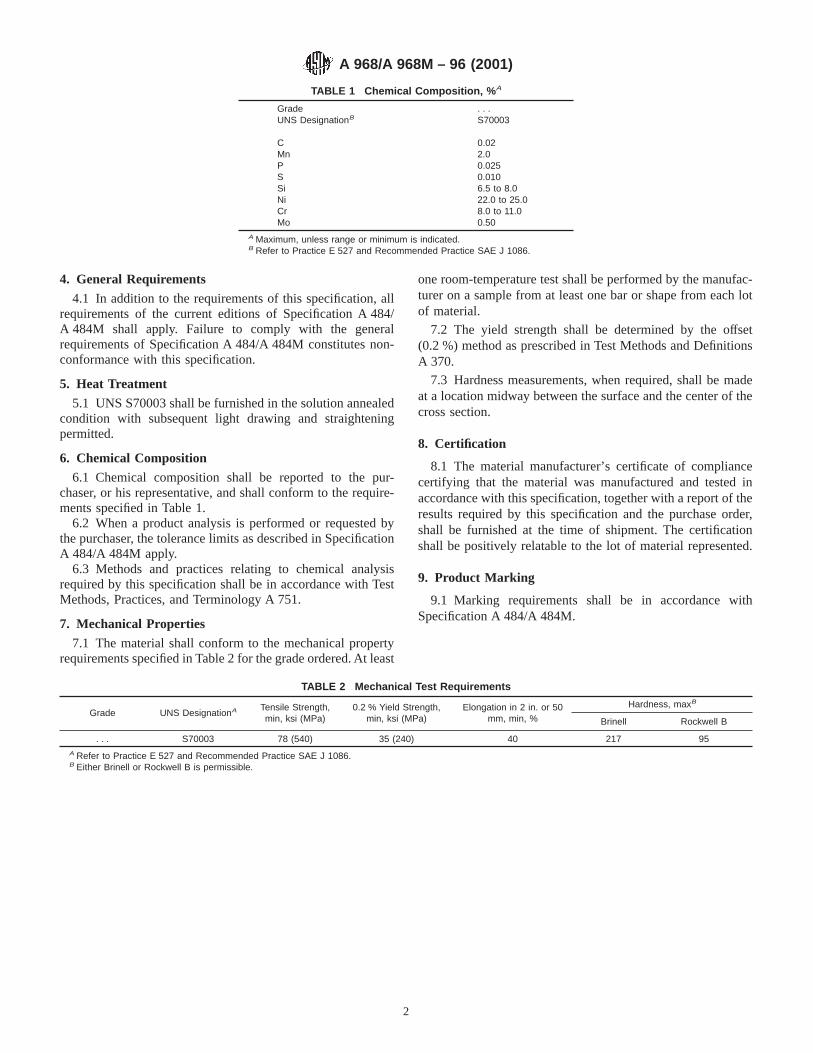
4. General Requirements
4.1 In addition to the requirements of this specification, allrequirements of the current editions of Specification A 484/A 484M shall apply. Failure to comply with the generalrequirements of Specification A 484/A 484M constitutes non-conformance with this specification.
5. Heat Treatment
5.1 UNS S70003 shall be furnished in the solution annealedcondition with subsequent light drawing and straighteningpermitted.
6. Chemical Composition
6.1 Chemical composition shall be reported to the pur-chaser, or his representative, and shall conform to the require-ments specified in Table 1.
6.2 When a product analysis is performed or requested bythe purchaser, the tolerance limits as described in SpecificationA 484/A 484M apply.
6.3 Methods and practices relating to chemical analysisrequired by this specification shall be in accordance with TestMethods, Practices, and Terminology A 751.
7. Mechanical Properties
7.1 The material shall conform to the mechanical propertyrequirements specified in Table 2 for the grade ordered. At least
one room-temperature test shall be performed by the manufac-turer on a sample from at least one bar or shape from each lotof material.
7.2 The yield strength shall be determined by the offset(0.2 %) method as prescribed in Test Methods and DefinitionsA 370.
7.3 Hardness measurements, when required, shall be madeat a location midway between the surface and the center of thecross section.
8. Certification
8.1 The material manufacturer’s certificate of compliancecertifying that the material was manufactured and tested inaccordance with this specification, together with a report of theresults required by this specification and the purchase order,shall be furnished at the time of shipment. The certificationshall be positively relatable to the lot of material represented.
9. Product Marking
9.1 Marking requirements shall be in accordance withSpecification A 484/A 484M.
TABLE 1 Chemical Composition, % A
Grade . . .UNS DesignationB S70003
C 0.02Mn 2.0P 0.025S 0.010Si 6.5 to 8.0Ni 22.0 to 25.0Cr 8.0 to 11.0Mo 0.50
A Maximum, unless range or minimum is indicated.B Refer to Practice E 527 and Recommended Practice SAE J 1086.
TABLE 2 Mechanical Test Requirements
Grade UNS DesignationA Tensile Strength,min, ksi (MPa)
0.2 % Yield Strength,min, ksi (MPa)
Elongation in 2 in. or 50mm, min, %
Hardness, maxB
Brinell Rockwell B
. . . S70003 78 (540) 35 (240) 40 217 95A Refer to Practice E 527 and Recommended Practice SAE J 1086.B Either Brinell or Rockwell B is permissible.
A 968/A 968M – 96 (2001)
2

ASTM International takes no position respecting the validity of any patent rights asserted in connection with any item mentionedin this standard. Users of this standard are expressly advised that determination of the validity of any such patent rights, and the riskof infringement of such rights, are entirely their own responsibility.
This standard is subject to revision at any time by the responsible technical committee and must be reviewed every five years andif not revised, either reapproved or withdrawn. Your comments are invited either for revision of this standard or for additional standardsand should be addressed to ASTM International Headquarters. Your comments will receive careful consideration at a meeting of theresponsible technical committee, which you may attend. If you feel that your comments have not received a fair hearing you shouldmake your views known to the ASTM Committee on Standards, at the address shown below.
This standard is copyrighted by ASTM International, 100 Barr Harbor Drive, PO Box C700, West Conshohocken, PA 19428-2959,United States. Individual reprints (single or multiple copies) of this standard may be obtained by contacting ASTM at the aboveaddress or at 610-832-9585 (phone), 610-832-9555 (fax), or [email protected] (e-mail); or through the ASTM website(www.astm.org).
A 968/A 968M – 96 (2001)
3

Designation: A 980 – 97 (Reapproved 2003)
Standard Specification forSteel, Sheet, Carbon, Ultra High Strength Cold Rolled 1
This standard is issued under the fixed designation A 980; the number immediately following the designation indicates the year oforiginal adoption or, in the case of revision, the year of last revision. A number in parentheses indicates the year of last reapproval. Asuperscript epsilon (e) indicates an editorial change since the last revision or reapproval.
1. Scope
1.1 This specification covers a cold rolled ultra highstrength carbon steel sheet in coils or cut lengths. The productis available in four strength levels. The steel’s strength isobtained by water quenching from an austenitic temperatureresulting in a martensitic microstructure. This product isintended for miscellaneous applications where ultra highstrength, weight saving, and good weldability are important.
2. Referenced Documents
2.1 ASTM Standards:A 568/A 568M Specification for Steel, Sheet, Carbon, and
High-Strength Low-Alloy, Hot-Rolled and Cold Rolled,General Requirements for2
3. Ordering Information
3.1 It is the purchaser’s responsibility to specify in thepurchase order all ordering information necessary to purchasethe needed material. Examples of such information include, butare not limited to:
3.1.1 ASTM specification number and year of issue,3.1.2 Name of material (cold rolled ultra high strength steel
sheet),3.1.3 Grade (see Table 1),3.1.4 Specify oiled or not oiled as required,3.1.5 Dimensions (thickness, width and whether cut lengths
or coils),3.1.6 Coil size (must include inside diameter, outside diam-
eter and maximum mass),3.1.7 Quantity,3.1.8 Application (show part identification and description),3.1.9 Special Requirements (if required), and3.1.10 Cast or heat analysis report (request if required).
4. Materials and Manufacture
4.1 Melting Practice—This sheet shall be produced fromaluminum killed steel.
4.2 Annealing—The material shall be continuous annealedto austenitic temperatures and water quenched.
5. General Requirements
5.1 Materials furnished under this specification shall con-form to the applicable requirements of the current edition ofSpecification A 568/A 568M unless otherwise provided herein.
6. Chemical Composition
6.1 The cast or heat analysis shall conform to the require-ments prescribed in Table 1 and Table 2.
6.1.1 Each of the elements listed in Table 2 shall be includedin the report of the cast or heat analysis. Where the amount ofcopper nickel, chromium or molybdenum is less than 0.02 %,the analysis may be reported as <0.02 %. When the amount ofvanadium or columbium is less than 0.008 %, the analysis maybe reported as <0.008 %.
7. Mechanical Properties
7.1 Tension Tests:7.1.1 Requirements—Materials as represented by the test
specimen shall conform to the tensile requirements specified inTable 3.
7.1.2 Number of Tests—Two tests shall be made from eachheat or from each lot of 50 tons. When the amount of finishedmaterial from a heat or lot is less than 50 tons, one test shall bemade. When material rolled from one heat differs by 0.050 in.or more in thickness, one tension test shall be made from thethickest and thinnest material regardless of the weight repre-sented.
7.1.3 Location and Orientation:7.1.3.1 Tension test specimens shall be taken at a point
immediately adjacent to the material to be qualified.
1 This specification is under the jurisdiction of ASTM Committee A01 on Steel,Stainless Steel and Related Alloys and is the direct responsibility of SubcommitteeA01.19 on Steel Sheet and Strip.
Current edition approved April 10, 2003. Published June 2003. Originallyapproved in 1997. Last previous edition approved in 1997 as A 980–97.
2 Annual Book of ASTM Standards, Vol 01.03.
TABLE 1 Chemical Requirements
Composition - Weight % Heat Analysis
Element Grade
130 160 190 220
Carbon, max 0.10 0.15 0.23 0.28Manganese, max 0.60 0.60 0.60 0.60Phosphorus, max 0.030 0.030 0.030 0.030Sulfur, max 0.035 0.035 0.035 0.035Aluminum, min 0.01 0.01 0.01 0.01
1
Copyright © ASTM International, 100 Barr Harbor Drive, PO Box C700, West Conshohocken, PA 19428-2959, United States.
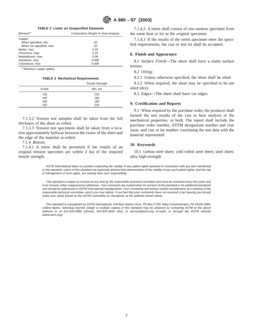
7.1.3.2 Tension test samples shall be taken from the fullthickness of the sheet as rolled.
7.1.3.3 Tension test specimens shall be taken from a loca-tion approximately halfway between the center of the sheet andthe edge of the material as-rolled.
7.1.4 Retests:7.1.4.1 A retest shall be permitted if the results of an
original tension specimen are within 2 ksi of the requiredtensile strength.
7.1.4.2 A retest shall consist of one random specimen fromthe same heat or lot as the original specimen.
7.1.4.3 If the results of the retest specimen meet the speci-fied requirements, the cast or test lot shall be accepted.
8. Finish and Appearance
8.1 Surface Finish—The sheet shall have a matte surfacetexture.
8.2 Oiling:8.2.1 Unless otherwise specified, the sheet shall be oiled.8.2.2 When required, the sheet may be specified to be not
oiled (dry).8.3 Edges—The sheet shall have cut edges.
9. Certification and Reports
9.1 When required by the purchase order, the producer shallfurnish the test results of the cast or heat analysis or themechanical properties, or both. The report shall include thepurchase order number, ASTM designation number and yearissue, and cast or lot number correlating the test data with thematerial represented.
10. Keywords
10.1 carbon steel sheet; cold rolled steel sheet; steel sheet;ultra high-strength
ASTM International takes no position respecting the validity of any patent rights asserted in connection with any item mentionedin this standard. Users of this standard are expressly advised that determination of the validity of any such patent rights, and the riskof infringement of such rights, are entirely their own responsibility.
This standard is subject to revision at any time by the responsible technical committee and must be reviewed every five years andif not revised, either reapproved or withdrawn. Your comments are invited either for revision of this standard or for additional standardsand should be addressed to ASTM International Headquarters. Your comments will receive careful consideration at a meeting of theresponsible technical committee, which you may attend. If you feel that your comments have not received a fair hearing you shouldmake your views known to the ASTM Committee on Standards, at the address shown below.
This standard is copyrighted by ASTM International, 100 Barr Harbor Drive, PO Box C700, West Conshohocken, PA 19428-2959,United States. Individual reprints (single or multiple copies) of this standard may be obtained by contacting ASTM at the aboveaddress or at 610-832-9585 (phone), 610-832-9555 (fax), or [email protected] (e-mail); or through the ASTM website(www.astm.org).
TABLE 2 Limits on Unspecified Elements
ElementA Composition Weight % Heat Analysis
CopperWhen specified, min .20When not specified, max .20
Nickel, max 0.20Chromium, max 0.15Molybdenum, max 0.06Vanadium, max 0.008Columbium, max 0.008
A Minimum copper added.
TABLE 3 Mechanical Requirements
Tensile Strength
Grade Min, ksi
130 130160 160190 190220 220
A 980 – 97 (2003)
2

Designation: A 991/A 991M – 98
Standard Test Method forConducting Temperature Uniformity Surveys of FurnacesUsed to Heat Treat Steel Products 1
This standard is issued under the fixed designation A 991/A 991M; the number immediately following the designation indicates the yearof original adoption or, in the case of revision, the year of last revision. A number in parentheses indicates the year of last reapproval.A superscript epsilon (e) indicates an editorial change since the last revision or reapproval.
1. Scope
1.1 This test method covers the procedures used to conducta temperature uniformity survey on a furnace used to heat treatsteel products. This method is used to determine the capabilityof the furnace to meet the permissible temperature variationspecified in the applicable product specification, or as agreed toby the purchaser and supplier of heat treat services. Surveydocumentation requirements, and the procedure used to subse-quently establish the furnace working zone, are defined in thistest method.
1.2 This test method covers heat treat furnaces in any of thefollowing categories:
1.2.1 Continuous or semi-continuous conveyance furnaces,1.2.2 Batch furnaces, and1.2.3 Salt or liquid baths and fluidized beds.1.3 This test method only applies when specified in the
product specification or the purchase order.1.4 Controlling a heat treatment of steel products using
thermocouples attached to the extremities of each load is analternative to performing a furnace survey.
1.5 By mutual agreement between the purchaser and thesupplier of heat treat services, more stringent and/or additionalrequirements may be specified. The acceptance of any suchadditional requirements shall be dependent on negotiationswith the supplier and must be included in the order as agreedupon by the purchaser and supplier.
1.6 The values stated in either inch-pound units or SI unitsare to be regarded separately as standard. Within the text, theSI units are shown in brackets. The values stated in eachsystem are not exact equivalents; therefore, each system is tobe used independently of the other, without combining valuesin any way.
1.7 This standard does not purport to address all of thesafety concerns, if any, associated with its use. It is theresponsibility of the user of this standard to establish appro-priate safety and health practices and determine the applica-bility of regulatory limitations prior to use.
2. Referenced Documents
2.1 ASTM Standards:E 207 Test Method for Thermal EMF Test of Single Ther-
moelement Materials by Comparison with a ReferenceThermoelement of Similar EMF - Temperature Properties2
E 220 Test Method for Calibration of Thermocouples ByComparison Techniques3
E 230 Specification and Temperature-Electromotive Force(EMF) Tables for Standardized Thermocouples2
E 608 Specification for Metal-Sheathed Base-Metal Ther-mocouples2
2.2 SAE Standard:AMS 2750 - Pyrometry4
3. Terminology
3.1 Definitions of Terms Specific to This Standard:3.1.1 batch furnace, n—a heating device in which material
may be stationary or oscillating during the processing cycle.3.1.2 continuous conveyance furnace, n—a heating device
through which material is moved intentionally at a constantrate during the processing cycle.
3.1.3 extremities, n—as referring to furnace working zone;outer boundaries in all three dimensions (length, width, andheight) of the material being processed.
3.1.4 operating range, n—the expected range of tempera-ture over which a furnace will be controlled to heat treat steelproducts.
3.1.5 primary survey, n—the initial evaluation of the fur-nace, or an evaluation triggered by the initiation of a majorfurnace modification.
3.1.6 secondary survey, n—an evaluation of the furnacetriggered by the expiration of a time requirement.
3.1.7 semi-continuous conveyance furnace, n—a heatingdevice through which material is moved intentionally with apredetermined start - stop - start pattern during the processingcycle.
3.1.8 working zone, n—the maximum volume and locationin the furnace that meet the permissible temperature variation.
1 This test method is under the jurisdiction of ASTM Committee A-1 on Steel,Stainless Steel and Related Alloys and is the direct responsibility of SubcommitteeA01.13 on Mechanical and Chemical Testing and Processing Methods of SteelProducts and Processes.
Current edition approved July 10, 1998. Published September 1998.
2 Annual Book of ASTM Standards, Vol 14.03.3 Discontinued; see1994 Annual Book of ASTM Standards, Vol 14.03.4 Available from Society of Automotive Engineers, 400 Commonwealth Drive,
Warrendale, PA 15096.
1
Copyright © ASTM International, 100 Barr Harbor Drive, PO Box C700, West Conshohocken, PA 19428-2959, United States.

4. Significance and Use
4.1 Furnaces for heat treatment of steel products are used inmany industries, in many ways. Regardless of heat treatfurnace type, or processing cycle, it may be necessary for usersto know the temperature uniformity in the furnace and whetherthe material is processed in a zone within the furnace that iscapable of meeting the applicable permissible temperaturevariation requirements.
4.2 The procedures in this test method may be used by thoseusing, manufacturing, and providing calibration service for,heat treat furnaces used to process steel products.
5. Furnace Survey Equipment
5.1 Thermocouples:5.1.1 Metal sheathed thermocouples shall be in accordance
with Specification E 608.5.1.2 The use of extension wires is permitted when com-
pensated connectors, plugs, jacks, and terminal strips are used.5.1.3 Thermocouples made from spool wire shall meet the
requirements of AMS 2750.5.1.4 The use of spliced extension wire is prohibited.5.1.5 Thermocouples may be reused if the requirements of
AMS 2750 (except Paragraph 3.1.1.7.2 of Rev. C) are met.5.2 Calibration:5.2.1 All reference, primary, secondary, test and working
equipment, instrumentation and sensors used in conjunctionwith this test method shall meet the requirements of calibrationdefined by Test Methods E 207, and E 220.
5.2.2 Temperature measuring devices shall be calibratedwithin three months prior to use.
5.2.3 Calibration shall be traceable to the National Instituteof Standards Technology standards, or equivalent nationalstandards. Calibration to such national standards shall be doneat least once every two years.
5.2.4 Calibration shall be within the temperature range to beused in the survey and at intervals not greater than 200°F[100°C] for primary and secondary standards.
5.2.5 Correction factors, limits of error, and deviations shallbe in accordance with Specification E 230.
6. Requirements
6.1 Uniformity Survey Test Conditions:6.1.1 The furnace to be surveyed shall be capable of being
tested at set point temperature(s) typical for the normaloperating range.
6.1.1.1 If the operating range does not exceed a spread of300°F [150°C], the midpoint temperature shall be selected forthe survey.
6.1.1.2 If the operating range exceeds a spread of 300°F[150°C], survey at the minimum and maximum set pointtemperature for the normal operating range, except that themaximum temperature need not be higher than 2000°F[1100°C].
6.1.2 Typical production size and weight furnace loads shallbe utilized during the survey. Use of representative material tosimulate product during survey is permitted.
6.1.3 The furnace atmosphere and operating conditionsshall be representative of those used in production.
6.2 Frequency of Uniformity Surveys:6.2.1 Primary Surveys:6.2.1.1 A primary survey shall have been performed within
twelve months prior to, or run concurrently with, the firstproduction heat treatment to which this test method applies.
6.2.1.2 A primary survey shall have been conducted when amajor furnace modification is completed. A major furnacemodification includes, but is not limited to, the installation ofthe following: a different burner type, a new heating elementdesign, a different type of insulation system, and, a differenttype of temperature controlling device.
6.2.1.3 Replacement of worn parts with similar parts orpatching of insulation that does not change the furnacecharacteristics does not constitute a major furnace modifica-tion.
6.2.1.4 The survey shall be conducted within twelve monthsprior to, or run concurrently with, the first production heattreatment performed after the modification.
6.2.2 Secondary Surveys:6.2.2.1 To maintain conformance with this test method, a
secondary survey shall be conducted within twelve monthsafter the primary survey.
6.2.2.2 Secondary surveys shall be conducted at a typicalfurnace set point temperature within the normal operatingrange. All other conditions described in 6.1 shall apply.
7. Procedure
7.1 Survey measuring equipment shall meet the require-ments of Section 5.
7.2 Test conditions and test frequency shall be as defined in6.1 and 6.2, respectively.
7.3 Place thermocouples to monitor time and temperatureprofiles in the furnace to evaluate the uniformity of theintended working zone. Place them at the outer extremities, thecenter of the proposed working zone, and in areas of suspectedvariability in the proposed working zone. Attach survey testsensors to, or set them in the load.
7.4 For proposed working zones less than 12 in. [300 mm]in height, it is acceptable to monitor the center height location,it is not necessary to monitor both the top and bottom of theheating chamber. For proposed working zones greater than, orequal to, 12 in. [300 mm] in height, both top and bottomextremities must be monitored.
7.5 Continuous Conveyance and Semi-Continuous Convey-ance Furnaces:
7.5.1 Convey test sensors through the furnace. The rate ofconveyance shall be representative of normal operating condi-tions.
7.5.2 The frequency of temperature recordings shall becapable of detecting variations from the test temperature rangeduring the entire conveyance through the furnace.
7.5.3 Several conveyances with the test sensors attached tothe steel product, under the same conditions, may be made toensure that any recurrent temperature profiles are determined atall test locations throughout the furnace.
7.5.4 Alternative surveying techniques are described in 7.7.7.6 Batch and Batch Liquid Media Furnaces:
A 991/A 991M
2

7.6.1 Take readings starting when the control instrumentrises to within 200°F [100°C] of the set point temperature andcontinue throughout the hold cycle at the set point temperature.
7.6.2 Take readings at a minimum frequency of 1/10 thenormal hold time.
7.6.3 Take the readings frequently enough to detect varia-tions from the test temperature range and to determine theextremes of the recurrent temperature profile, if any.
7.6.4 Alternative surveying techniques are described in 7.7.7.7 Alternative Surveying Techniques—When agreed to by
the purchaser and the supplier of heat treat services, alternativesurveying techniques may be used to characterize the tempera-ture uniformity of the furnace and subsequently define the sizeand location of the working zone. Examples of these surveyingtechniques are listed below.
7.7.1 Statistical Sampling:7.7.1.1 When it is impossible or impractical to perform the
tests outlined in 7.5 and 7.6, it is permissible to substitute ananalysis of the resultant mechanical properties of the steelproducts heat treated in the subject furnace to validate tem-perature uniformity. Details of this procedure shall be as agreedto between purchaser and supplier.
7.7.2 Sequential Load Sensors:7.7.2.1 This procedure may be used as an alternative to
those described in 7.5 and 7.6. It provides validation oftemperature uniformity by a series of tests rather than a singletest. In each test, determine the temperature variation pattern atone or more of the test locations.
7.7.2.2 The frequency of test shall be six months.7.7.2.3 The temperature shall be within the normal operat-
ing range, with the narrowest permissible variation for thematerial applied to the survey.
7.7.2.4 Run the furnace with a load similar to that used in anormal production cycle.
7.7.2.5 Load or test sensors shall be arranged in, or incontact with, the test load.
7.7.2.6 Control setting(s) shall be identical to those used innormal production.
7.7.2.7 Take readings starting when the control instrumentsrises to within 200°F [100°C] of the set point temperature andcontinued throughout the hold cycle at the set point tempera-ture.
7.7.2.8 Record the temperature of all load test and workingsensors frequently enough to detect when the specified oper-ating range is exceeded, and at least five cycles of any recurrentpattern have been observed.
7.7.2.9 If no recurrent temperature profile is detected, takereadings at intervals of five minutes or less, for at least 30 minafter thermal equilibrium is reached.
8. Documentation of Survey Results
8.1 Organizations performing surveys in accordance withthis test method shall keep pertinent documentation of the
conditions and procedures used in the completion of the surveyon file for a minimum of five years.
8.2 Pertinent documentation shall include, but not be lim-ited to, the following:
8.2.1 Specific identification of furnace surveyed,8.2.2 Date of the uniformity survey,8.2.3 Identification of the heat treat procedure,8.2.3.1 Set point temperatures,8.2.3.2 Type of atmosphere,8.2.3.3 Conveyance speed (when applicable),8.2.4 Size and weight of steel product loaded in furnace at
time of survey,8.2.5 Item identification numbers (lot, heat serial, etc.),8.2.6 Time and temperature data, including original tem-
perature charts or original manually recorded data,8.2.7 Dimensions and location of the working zone(s),8.2.8 Number and location of the survey thermocouples,8.2.9 Largest observed temperature variation from the set
points during the hold cycle,8.2.10 The time interval of the test, including the total
elapsed time. Starting time and chart speed shall be marked onthe original temperature charts,
8.2.11 All pertinent equipment calibration information,8.2.12 Deviations from the test method including, but not
limited to, thermocouple failure, malfunction, or disconnec-tion.
8.2.13 Name of personnel conducting the survey, and8.3 All data may be electronically recorded.
9. Interpretation of Results and Establishment of theWorking Zone
9.1 The results of the primary survey describe the tempera-ture uniformity of a furnace under a specific set of operatingconditions. Results of the application of this test method shallbe expressed as a variation from a temperature set point.
9.2 Establishment of the furnace working zone is made bycomparing the temperature variation required by the productspecification, or agreed to by purchaser and supplier of heattreat services, with the variation from the temperature set pointas determined by this uniformity survey.
9.3 The working zone may either be the entire heatingvolume, or it may only be some portion of the heating volumeof the furnace. The working zone may be comprised of one ormore heating zones in the furnace.
10. Heat Treatment in the Working Zone
10.1 When invoked by the product specification, or agreedto by purchaser and supplier of heat treat services, steelproducts shall be heat treated, as specified, only in the workingzone.
11. Keywords
11.1 furnace survey; temperature; uniformity; working zone
A 991/A 991M
3

The American Society for Testing and Materials takes no position respecting the validity of any patent rights asserted in connectionwith any item mentioned in this standard. Users of this standard are expressly advised that determination of the validity of any suchpatent rights, and the risk of infringement of such rights, are entirely their own responsibility.
This standard is subject to revision at any time by the responsible technical committee and must be reviewed every five years andif not revised, either reapproved or withdrawn. Your comments are invited either for revision of this standard or for additional standardsand should be addressed to ASTM Headquarters. Your comments will receive careful consideration at a meeting of the responsibletechnical committee, which you may attend. If you feel that your comments have not received a fair hearing you should make yourviews known to the ASTM Committee on Standards, 100 Barr Harbor Drive, West Conshohocken, PA 19428.
A 991/A 991M
4

Designation: A 1000 – 99
Standard Specification forSteel Wire, Carbon and Alloy Specialty Spring Quality 1
This standard is issued under the fixed designation A 1000; the number immediately following the designation indicates the year oforiginal adoption or, in the case of revision, the year of last revision. A number in parentheses indicates the year of last reapproval. Asuperscript epsilon (e) indicates an editorial change since the last revision or reapproval.
1. Scope
1.1 This specification covers a quality of round and shapedplain carbon and alloy steel spring wire, uniform in quality andtemper, intended for the manufacture of mechanical springsthat can withstand moderate fatigue stresses over some rela-tively low number of cycles. The quality level is between thecommercial quality grades of wire such as SpecificationsA 401, A 231 and A 229 and the valve spring quality gradessuch Specifications as A 230, A 232, A 877 and A 878. It issimilar to the grade TD (referenced in EN 10270-2) intendedfor medium fatigue levels, such as required for clutch springs.This wire shall be either in the annealed and cold-drawn oroil-tempered condition as specified by purchaser.
1.2 The values stated in either SI units or inch-pound unitsare to be regarded separately as standard. Within the text, theinch-pound units are shown in parentheses. The values statedin each system are not exact equivalents; therefore, eachsystem must be used independent of the other.
2. Referenced Documents
2.1 ASTM Standards:A 229 Specification for Steel Wire, Oil-Tempered for Me-
chanical Springs2
A 230 Specification for Steel Wire, Oil-Tempered CarbonValve Spring Quality2
A 231 Specification for Chrome-Vanadium Alloy SteelSpring Quality Wire2
A 232 Specification for Chrome-Vanadium Alloy SteelValve Spring Quality2
A 370 Test Methods and Definitions for Mechanical Testingof Steel Products2
A 401 Specification for Steel Wire, Chrome-Silicon Alloy2
A 700 Practices for Packaging, Marking, and LoadingMethods for Steel Products for Domestic Shipment3
A 751 Test Methods, Practices, and Terminology forChemical Analysis of Steel Products2
A 877 Specification for Steel Wire, Chrome-Silicon AlloyValve Spring Quality2
A 878 Specification for Steel Wire, Modified Chrome-Vanadium Valve Spring Quality2
A 941 Terminology Relating to Steel, Stainless Steel, Re-lated Alloys, and Ferroalloys4
E 29 Practice for Using Significant Digits in Test Data toDetermine Conformance with Specifications5
E 45 Practice for Determining the Inclusion Content ofSteel6
2.2 Federal Standard:Fed. Std. No. 123 Marking for Shipment (Civil Agencies)7
2.3 Military Standard:MIL-STD-163 Steel Mill Products, Preparation for Ship-
ment and Storage7
2.4 AIAG Standard:AIAG B-5 02.00 Primary Metals Identification Tag Appli-
cation Standard8
2.5 European Standard:EN 10270-2 Steel Wire for Mechanical Springs Part 2:
Oil-Hardened and Tempered Springsteel Wire of Unal-loyed and Alloyed Steels9
3. Terminology
3.1 Definitions:3.1.1 For definition of terms used in this practice, see
Terminology A 941.3.2 Definitions of Terms Specific to This Standard:3.2.1 commercial quality wire—a grade of wire that is fairly
common quality and intended for applications that are prima-rily static in nature, not involving significant fatigue loading.
4. Ordering Information
4.1 It shall be the responsibility of the purchaser to specifyall requirements that are necessary for material under thisspecification. Such requirements may include, but are notlimited to the following,
4.1.1 Quantity (mass),
1 This specification is under the jurisdiction of ASTM Committee A-1 on Steel,Stainless Steel and Related Alloys and is the direct responsibility of SubcommitteeA01.03 on Steel Rod and Wire.
Current edition approved March 10, 1999. Published May 1999.2 Annual Book of ASTM Standards, Vol 01.03.3 Annual Book of ASTM Standards, Vol 01.05.
4 Annual Book of ASTM Standards, Vol 01.01.5 Annual Book of ASTM Standards, Vol 14.02.6 Annual Book of ASTM Standards, Vol 03.01.7 Available from Standardization Documents Order Desk, Bldg 4 Section D. 700
Robbins Ave., Philadelphia, PA 19111-5094, Attn: NPODS8 Available from the Automotive Industry Action Group, 26200 Lasher, Suite
200, Southfield, MI 48034.9 Available from European Committee for Standardization, rue de Stassart
36,B-1050 Brussels
1
Copyright © ASTM International, 100 Barr Harbor Drive, PO Box C700, West Conshohocken, PA 19428-2959, United States.
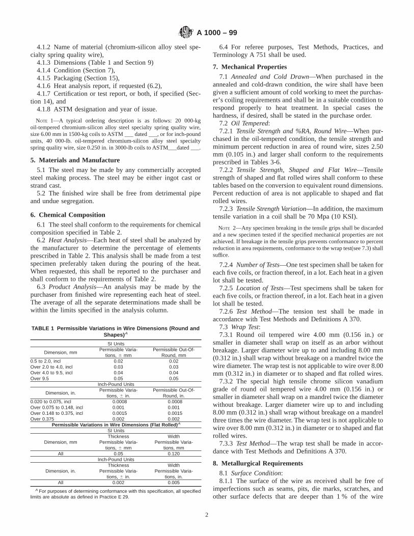
4.1.2 Name of material (chromium-silicon alloy steel spe-cialty spring quality wire),
4.1.3 Dimensions (Table 1 and Section 9)4.1.4 Condition (Section 7),4.1.5 Packaging (Section 15),4.1.6 Heat analysis report, if requested (6.2),4.1.7 Certification or test report, or both, if specified (Sec-
tion 14), and4.1.8 ASTM designation and year of issue.
NOTE 1—A typical ordering description is as follows: 20 000-kgoil-tempered chromium-silicon alloy steel specialty spring quality wire,size 6.00 mm in 1500-kg coils to ASTM ___ dated ___, or for inch-poundunits, 40 000-lb. oil-tempered chromium-silicon alloy steel specialtyspring quality wire, size 0.250 in. in 3000-lb coils to ASTM___dated ___.
5. Materials and Manufacture
5.1 The steel may be made by any commercially acceptedsteel making process. The steel may be either ingot cast orstrand cast.
5.2 The finished wire shall be free from detrimental pipeand undue segregation.
6. Chemical Composition
6.1 The steel shall conform to the requirements for chemicalcomposition specified in Table 2.
6.2 Heat Analysis—Each heat of steel shall be analyzed bythe manufacturer to determine the percentage of elementsprescribed in Table 2. This analysis shall be made from a testspecimen preferably taken during the pouring of the heat.When requested, this shall be reported to the purchaser andshall conform to the requirements of Table 2.
6.3 Product Analysis—An analysis may be made by thepurchaser from finished wire representing each heat of steel.The average of all the separate determinations made shall bewithin the limits specified in the analysis column.
6.4 For referee purposes, Test Methods, Practices, andTerminology A 751 shall be used.
7. Mechanical Properties
7.1 Annealed and Cold Drawn—When purchased in theannealed and cold-drawn condition, the wire shall have beengiven a sufficient amount of cold working to meet the purchas-er’s coiling requirements and shall be in a suitable condition torespond properly to heat treatment. In special cases thehardness, if desired, shall be stated in the purchase order.
7.2 Oil Tempered:7.2.1 Tensile Strength and %RA, Round Wire—When pur-
chased in the oil-tempered condition, the tensile strength andminimum percent reduction in area of round wire, sizes 2.50mm (0.105 in.) and larger shall conform to the requirementsprescribed in Tables 3-6.
7.2.2 Tensile Strength, Shaped and Flat Wire—Tensilestrength of shaped and flat rolled wires shall conform to thesetables based on the conversion to equivalent round dimensions.Percent reduction of area is not applicable to shaped and flatrolled wires.
7.2.3 Tensile Strength Variation—In addition, the maximumtensile variation in a coil shall be 70 Mpa (10 KSI).
NOTE 2—Any specimen breaking in the tensile grips shall be discardedand a new specimen tested if the specified mechanical properties are notachieved. If breakage in the tensile grips prevents conformance to percentreduction in area requirements, conformance to the wrap test(see 7.3) shallsuffice.
7.2.4 Number of Tests—One test specimen shall be taken foreach five coils, or fraction thereof, in a lot. Each heat in a givenlot shall be tested.
7.2.5 Location of Tests—Test specimens shall be taken foreach five coils, or fraction thereof, in a lot. Each heat in a givenlot shall be tested.
7.2.6 Test Method—The tension test shall be made inaccordance with Test Methods and Definitions A 370.
7.3 Wrap Test:7.3.1 Round oil tempered wire 4.00 mm (0.156 in.) or
smaller in diameter shall wrap on itself as an arbor withoutbreakage. Larger diameter wire up to and including 8.00 mm(0.312 in.) shall wrap without breakage on a mandrel twice thewire diameter. The wrap test is not applicable to wire over 8.00mm (0.312 in.) in diameter or to shaped and flat rolled wires.
7.3.2 The special high tensile chrome silicon vanadiumgrade of round oil tempered wire 4.00 mm (0.156 in.) orsmaller in diameter shall wrap on a mandrel twice the diameterwithout breakage. Larger diameter wire up to and including8.00 mm (0.312 in.) shall wrap without breakage on a mandrelthree times the wire diameter. The wrap test is not applicable towire over 8.00 mm (0.312 in.) in diameter or to shaped and flatrolled wires.
7.3.3 Test Method—The wrap test shall be made in accor-dance with Test Methods and Definitions A 370.
8. Metallurgical Requirements
8.1 Surface Condition:8.1.1 The surface of the wire as received shall be free of
imperfections such as seams, pits, die marks, scratches, andother surface defects that are deeper than 1 % of the wire
TABLE 1 Permissible Variations in Wire Dimensions (Round andShapes) A
SI Units
Dimension, mmPermissible Varia-
tions, 6 mmPermissible Out-Of-
Round, mm0.5 to 2.0, incl 0.02 0.02Over 2.0 to 4.0, incl 0.03 0.03Over 4.0 to 9.5, incl 0.04 0.04Over 9.5 0.05 0.05
Inch-Pound Units
Dimension, in.Permissible Varia-
tions, 6 in.Permissible Out-Of-
Round, in.0.020 to 0.075, incl 0.0008 0.0008Over 0.075 to 0.148, incl 0.001 0.001Over 0.148 to 0.375, incl 0.0015 0.0015Over 0.375 0.002 0.002
Permissible Variations in Wire Dimensions (Flat Rolled) A
SI Units
Dimension, mmThickness
Permissible Varia-tions, 6 mm
WidthPermissible Varia-
tions, mmAll 0.05 0.120
Inch-Pound Units
Dimension, in.Thickness
Permissible Varia-tions, 6 in.
WidthPermissible Varia-
tions, in.All 0.002 0.005
A For purposes of determining conformance with this specification, all specifiedlimits are absolute as defined in Practice E 29.
A 1000 – 99
2
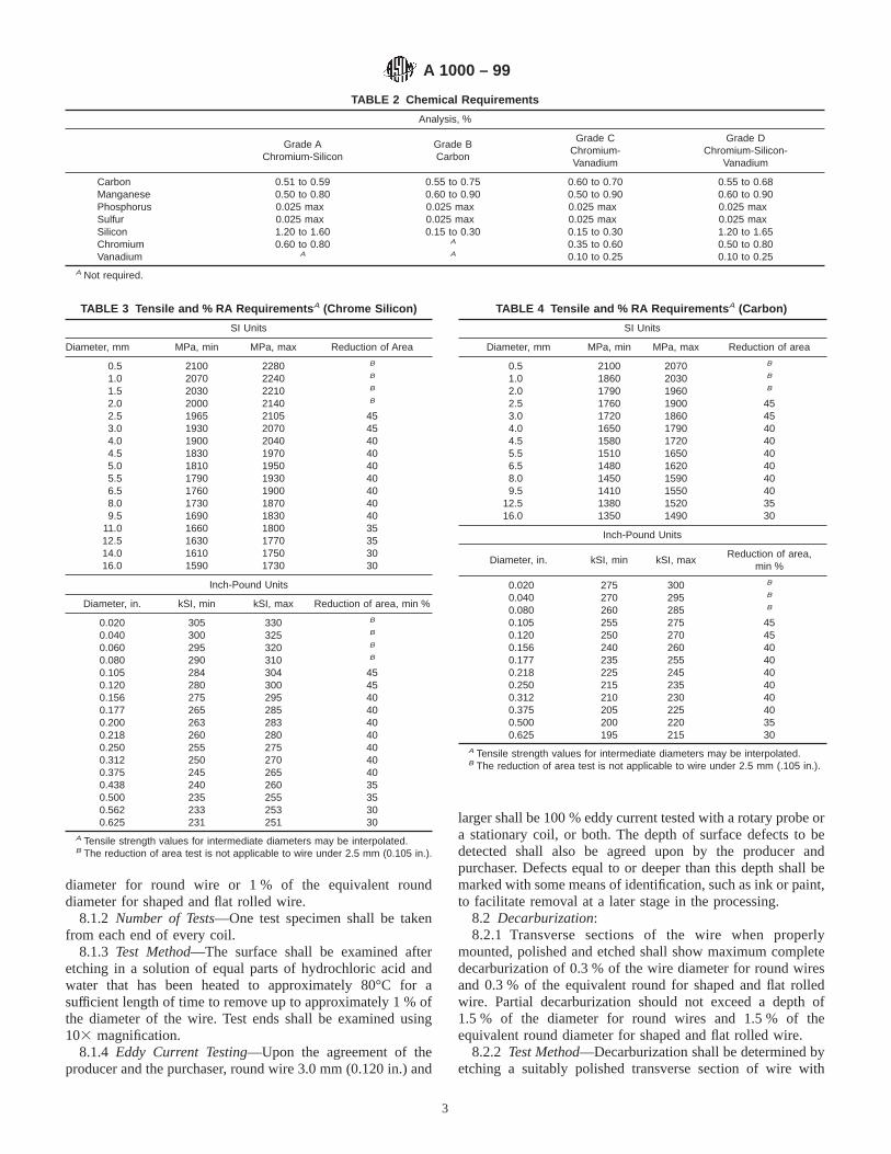
diameter for round wire or 1 % of the equivalent rounddiameter for shaped and flat rolled wire.
8.1.2 Number of Tests—One test specimen shall be takenfrom each end of every coil.
8.1.3 Test Method—The surface shall be examined afteretching in a solution of equal parts of hydrochloric acid andwater that has been heated to approximately 80°C for asufficient length of time to remove up to approximately 1 % ofthe diameter of the wire. Test ends shall be examined using103 magnification.
8.1.4 Eddy Current Testing—Upon the agreement of theproducer and the purchaser, round wire 3.0 mm (0.120 in.) and
larger shall be 100 % eddy current tested with a rotary probe ora stationary coil, or both. The depth of surface defects to bedetected shall also be agreed upon by the producer andpurchaser. Defects equal to or deeper than this depth shall bemarked with some means of identification, such as ink or paint,to facilitate removal at a later stage in the processing.
8.2 Decarburization:8.2.1 Transverse sections of the wire when properly
mounted, polished and etched shall show maximum completedecarburization of 0.3 % of the wire diameter for round wiresand 0.3 % of the equivalent round for shaped and flat rolledwire. Partial decarburization should not exceed a depth of1.5 % of the diameter for round wires and 1.5 % of theequivalent round diameter for shaped and flat rolled wire.
8.2.2 Test Method—Decarburization shall be determined byetching a suitably polished transverse section of wire with
TABLE 2 Chemical Requirements
Analysis, %
Grade AChromium-Silicon
Grade BCarbon
Grade CChromium-Vanadium
Grade DChromium-Silicon-
Vanadium
Carbon 0.51 to 0.59 0.55 to 0.75 0.60 to 0.70 0.55 to 0.68Manganese 0.50 to 0.80 0.60 to 0.90 0.50 to 0.90 0.60 to 0.90Phosphorus 0.025 max 0.025 max 0.025 max 0.025 maxSulfur 0.025 max 0.025 max 0.025 max 0.025 maxSilicon 1.20 to 1.60 0.15 to 0.30 0.15 to 0.30 1.20 to 1.65Chromium 0.60 to 0.80 A 0.35 to 0.60 0.50 to 0.80Vanadium A A 0.10 to 0.25 0.10 to 0.25
A Not required.
TABLE 3 Tensile and % RA Requirements A (Chrome Silicon)
SI Units
Diameter, mm MPa, min MPa, max Reduction of Area
0.5 2100 2280 B
1.0 2070 2240 B
1.5 2030 2210 B
2.0 2000 2140 B
2.5 1965 2105 453.0 1930 2070 454.0 1900 2040 404.5 1830 1970 405.0 1810 1950 405.5 1790 1930 406.5 1760 1900 408.0 1730 1870 409.5 1690 1830 40
11.0 1660 1800 3512.5 1630 1770 3514.0 1610 1750 3016.0 1590 1730 30
Inch-Pound Units
Diameter, in. kSI, min kSI, max Reduction of area, min %
0.020 305 330 B
0.040 300 325 B
0.060 295 320 B
0.080 290 310 B
0.105 284 304 450.120 280 300 450.156 275 295 400.177 265 285 400.200 263 283 400.218 260 280 400.250 255 275 400.312 250 270 400.375 245 265 400.438 240 260 350.500 235 255 350.562 233 253 300.625 231 251 30
A Tensile strength values for intermediate diameters may be interpolated.B The reduction of area test is not applicable to wire under 2.5 mm (0.105 in.).
TABLE 4 Tensile and % RA Requirements A (Carbon)
SI Units
Diameter, mm MPa, min MPa, max Reduction of area
0.5 2100 2070 B
1.0 1860 2030 B
2.0 1790 1960 B
2.5 1760 1900 453.0 1720 1860 454.0 1650 1790 404.5 1580 1720 405.5 1510 1650 406.5 1480 1620 408.0 1450 1590 409.5 1410 1550 40
12.5 1380 1520 3516.0 1350 1490 30
Inch-Pound Units
Diameter, in. kSI, min kSI, maxReduction of area,
min %
0.020 275 300 B
0.040 270 295 B
0.080 260 285 B
0.105 255 275 450.120 250 270 450.156 240 260 400.177 235 255 400.218 225 245 400.250 215 235 400.312 210 230 400.375 205 225 400.500 200 220 350.625 195 215 30
A Tensile strength values for intermediate diameters may be interpolated.B The reduction of area test is not applicable to wire under 2.5 mm (.105 in.).
A 1000 – 99
3

nital. The entire periphery to be examined should be in a singleplane with no edge rounding.
8.2.3 The entire periphery shall be examined at a magnifi-cation of no less than 1003 for depth of free ferrite and total
affected depth. Smaller wire sizes may require higher magni-fication. Measure the worst area present excluding decarbur-ization associated with seams or other surface imperfections,Complete decarburization exists when only free ferrite ispresent. Partial decarburization exists when ferrite is foundmixed with pearlite or tempered martensite. Structures of100 % tempered martensite shall be defined as not decarbur-ized.
8.2.4 Decarburization shall be checked on annealed wire bygiving a wire sample an austenitize, oil quench and temper heattreatment. A flat shall be ground on the sample prior to heattreatment. The flat shall have a minimum width equal to onehalf of the wire diameter. Any decarburization visible on thisground section shall necessitate a retest with new samples. Ifno decarburization is visible on the ground flat, evaluate thecomplete wire section in accordance with 8.2.3.
8.3 Inclusion Content:8.3.1 Restrictions on inclusion content may be agreed upon
by the producer and the purchaser. It is recommended thatmethods be used that are relevant for spring wire applicationssuch as maximum thickness (Max ’t’) and inclusion counttechniques (Swedish Method). These should concentrate onnon-deformable inclusions, the thickness (transverse to thelongitudinal wire axis) of inclusions and the condition in areasnear to the wire surface. The application of Practice E 45 to thisrequirement is not recommended.
9. Dimensions and Permissible Variations
9.1 The permissible variations in the dimensions of the wireshall be as specified in Table 1.
9.2 Number of Tests—One test specimen shall be taken fromeach end of every coil.
10. Workmanship, Finish and Appearance
10.1 Annealed and Cold Drawn—The wire shall not bekinked or improperly cast. To test for cast, a few convolutionsof wire shall be cut loose from the coil and placed on a flatsurface. The wire shall lie substantially flat on itself and notspring up nor show a wavy condition.
10.2 Oil Tempered—The wire shall be uniform in qualityand temper and shall not be wavy or crooked.
10.3 Each coil shall be one continuous length of wireproperly coiled and firmly tied.
10.4 No welds are permitted in the finished product and anywelds made during processing must be removed.
11. Retests
11.1 If any test specimen exhibits obvious defects it may bediscarded and another specimen substituted.
12. Inspection
12.1 Unless otherwise specified in the contract or purchaseorder, the manufacturer is responsible for the performance ofall inspection and test requirements specified in this specifica-tion. Except as otherwise specified in the contract or purchaseorder, the manufacturer may use his own or any other suitablefacilities for the performance of the inspection and testrequirements unless disapproved by the purchaser at the timethe order is placed. The purchaser shall have the right to
TABLE 5 Tensile and % RA Requirements A (Chrome Vanadium)
SI Units
Diameter, mm MPa, min MPa, max Reduction Of area
1.0 1860 2030 B
2.0 1760 1930 B
3.0 1650 1790 454.0 1620 1760 404.5 1590 1730 405.5 1520 1660 406.5 1480 1620 408.0 1450 1590 40
Inch-Pound Units
Diameter, in. kSI, min kSI, maxReduction of area,
min %
0.040 270 295 B
0.080 255 280 B
0.120 240 260 450.156 235 255 400.177 230 250 400.218 220 240 400.250 215 235 400.312 210 230 40
A Tensile strength values for intermediate diameters may be interpolated.B The reduction of area test is not applicable to wire under 2.5 mm (0.105 in.).
TABLE 6 Tensile and % RA Requirements A (Chromium SiliconVanadium)
SI Units
Diameter, mm MPa, min MPa, max Reduction Of area
1.0 2200 2370 B
1.5 2170 2340 B
2.5 2100 2270 403.0 2070 2210 404.0 2030 2170 404.5 2000 2140 355.0 1960 2100 355.5 1930 2070 356.5 1900 2040 358.0 1860 2000 309.5 1830 1970 30
11.0 1790 1930 3012.5 1760 1900 3014.0 1720 1860 3016.0 1690 1830 30
Inch-Pound Units
Diameter, in. kSI, min kSI, maxReduction of area,
min %
0.040 320 345 B
0.060 315 340 B
0.105 305 330 400.120 300 320 400.156 295 315 400.177 290 310 350.200 285 305 350.218 280 300 350.250 275 295 350.312 270 290 300.375 265 285 300.438 260 280 300.500 255 275 300.562 250 270 300.625 245 265 30
A Tensile strength values for intermediate diameters may be interpolated.B The reduction of area test is not applicable to wire under 2.5 mm (0.105 in.).
A 1000 – 99
4

perform any of the inspection and tests set forth in thisspecification when such inspections and tests are deemednecessary to ensure that the material conforms to prescribedrequirements.
13. Rejection and Rehearing
13.1 Unless otherwise specified, any rejection based on testsmade in accordance with these specifications shall be reportedto the manufacturer as soon as possible so that an investigationmay be initiated.
13.2 The material must be adequately protected and cor-rectly identified in order that the manufacturer may make aproper investigation.
14. Certification
14.1 When specified in the purchase order or contract, amanufacturer’s or supplier’s certification shall be furnished tothe purchaser that the material was manufactured, sampled,tested, and inspected in accordance with this specification andhas been found to meet the requirements. When specified in thepurchase order or contract, a report of the test results shall befurnished.
14.2 The certification shall include the specification num-ber, year date of issue, and revision letter, if any.
15. Packaging, Marking, and Loading for Shipment
15.1 The coil mass, dimensions, and the method of packag-ing shall be agreed upon between the manufacturer andpurchaser.
15.2 The size of the wire, purchaser’s order number, ASTMspecification number, heat number, and name or mark of themanufacturer shall be marked on a tag securely attached toeach coil of wire.
15.3 Unless otherwise specified in the purchaser’s order,packaging, marking, and loading for shipments shall be inaccordance with those procedures recommended by PracticesA 700.
15.4 For Government Procurement—Packaging, packing,and marking of material for military procurement shall be inaccordance with the requirements of MIL-STD-163, Level A,Level C, or commercial as specified in the contract or purchaseorder. Marking for shipment of material for civil agencies shallbe in accordance with Fed. Std. No. 123.
15.5 Bar Coding—In addition to the previously statedidentification requirements, bar coding is acceptable as asupplementary identification method. Bar coding should beconsistent with AIAG Standard 02.00, Primary Metals Identi-fication Tag Application. The bar code may be applied to asubstantially affixed tag.
16. Keywords
16.1 oil-tempered, shaped wire, flat rolled, inclusion con-tent, eddy current, alloy.
ASTM International takes no position respecting the validity of any patent rights asserted in connection with any item mentionedin this standard. Users of this standard are expressly advised that determination of the validity of any such patent rights, and the riskof infringement of such rights, are entirely their own responsibility.
This standard is subject to revision at any time by the responsible technical committee and must be reviewed every five years andif not revised, either reapproved or withdrawn. Your comments are invited either for revision of this standard or for additional standardsand should be addressed to ASTM International Headquarters. Your comments will receive careful consideration at a meeting of theresponsible technical committee, which you may attend. If you feel that your comments have not received a fair hearing you shouldmake your views known to the ASTM Committee on Standards, at the address shown below.
This standard is copyrighted by ASTM International, 100 Barr Harbor Drive, PO Box C700, West Conshohocken, PA 19428-2959,United States. Individual reprints (single or multiple copies) of this standard may be obtained by contacting ASTM at the aboveaddress or at 610-832-9585 (phone), 610-832-9555 (fax), or [email protected] (e-mail); or through the ASTM website(www.astm.org).
A 1000 – 99
5

Designation: A 1007 – 02
Standard Specification forCarbon Steel Wire for Wire Rope 1
This standard is issued under the fixed designation A 1007; the number immediately following the designation indicates the year oforiginal adoption or, in the case of revision, the year of last revision. A number in parentheses indicates the year of last reapproval. Asuperscript epsilon (e) indicates an editorial change since the last revision or reapproval.
1. Scope
1.1 This specification covers uncoated and four classes ofround, metallic coated, cold-drawn, carbon steel wire for wirerope in five strength levels. This specification specifies:
1.1.1 Dimensional tolerances,1.1.2 Mechanical characteristics,1.1.3 Chemical composition requirements,1.1.4 Coating requirements (if applicable), and1.1.5 Packaging requirements.1.2 The values stated for metric equivalents are provided for
informational purposes only.
2. Referenced Documents
2.1 This specification incorporates, by dated or undatedreference, provisions from other publications. These normativereferences are cited at their appropriate place in the text and thepublications are listed. For dated references, subsequentamendments to or revisions of any of these publications applyto this specification only when incorporated in it by amend-ment or revision. For undated references, the latest edition ofthe publication referred to would apply.
2.2 ASTM Standards:A 90/A 90M Test Method for Weight (Mass) of Coating on
Iron or Steel Articles with Zinc or Zinc-Alloy Coatings2
A 510 Specification for General Requirements for WireRods and Coarse Round Wire, Carbon Steel-Coated3
A 938 Test Method for Torsion Testing of Wire3
B 6 Specification for Zinc (Slab Zinc)4
B 750 Specification for Zinc-5 % Aluminum MischmetalAlloy (UNS Z38510) in Ingot Form for Hot-Dip Coatings4
E 8 Test Methods of Tension Testing of Metallic Materials5
IEEE/ASTM-SI-10 Standard for Use of the International
System of Units (SI): The Modern Metric System6
2.3 ISO/EN Standards:EN 10264-1.2 Steel Wire and Wire Products—Steel Wire
for Wire Rope7
2.4 Industry Standard:API 9A Specification for Wire Rope8
2.5 Industry References:AIME/ISS Carbon Steel, Wire and Rods9
AIAG 02.00 Primary Metals Identification Tag Application9
2.6 Non-Referenced Industry Applicable Standards:ISO Std. 2232 Drawn Wire for General Purpose Non-Alloy
Steel Wire Ropes7
3. Terminology
3.1 Definitions:3.1.1 actual diameter—the arithmetic mean of the mini-
mum and maximum diameter measurements in one location onthe wire.
3.1.2 breaking force level (Levels 1,2,3,4 or 5)—a wirestrength based on the minimum load carrying capability of adesignated wire.
3.1.3 drawn-galvanized—a zinc coating that is applied tothe wire prior to the final cold drawing operation by either anelectro-deposition or hot-galvanizing process.
3.1.4 drawn-Zn5 Al-MM—a zinc-aluminum alloy (misch-metal) coating that is applied to the wire prior to the final colddrawing operation by a molten coating process.
3.1.5 final-coated Zn5 Al-MM—a zinc-aluminum alloy(misch-metal) coating that is applied to the wire after the finalcold drawing operation by a molten coating process.
3.1.6 final-galvanized—a zinc coating that is applied to thewire after the final cold drawing operation by either anelectro-deposition or hot-galvanizing process.
3.1.7 nominal diameter—the diameter of the wire expressedin inches (millimetres) and specified by the user to designate
1 This specification is under the jurisdiction of ASTM Committee A01 on Steel,Stainless Steel and Related Alloys and is the direct responsibility of SubcommitteeA01.03 on Steel Rod and Wire.
Current edition approved March 10, 2002. Published March 2002 . Originallypublished as A 1007 – 00. Last previous edition A 1007 – 00.
2 Annual Book of ASTM Standards, Vol 01.06.3 Annual Book of ASTM Standards, Vol 01.03.4 Annual Book of ASTM Standards, Vol 02.04.5 Annual Book of ASTM Standards, Vol 03.01.
6 Available from ASTM International headquarters.7 Available from American National Standards Institute, 11 W. 42nd St., 13th
Floor, New York, NY 10036.8 Available from American Petroleum Institute, 1801 K Street, N.W., Washing-
ton, DC 20226.9 Available from Automotive Industry Action Group (AIAG), 26200 Lahser
Road, Suite 200, Southfield, MI 48034–7100.
1
Copyright © ASTM International, 100 Barr Harbor Drive, PO Box C700, West Conshohocken, PA 19428-2959, United States.
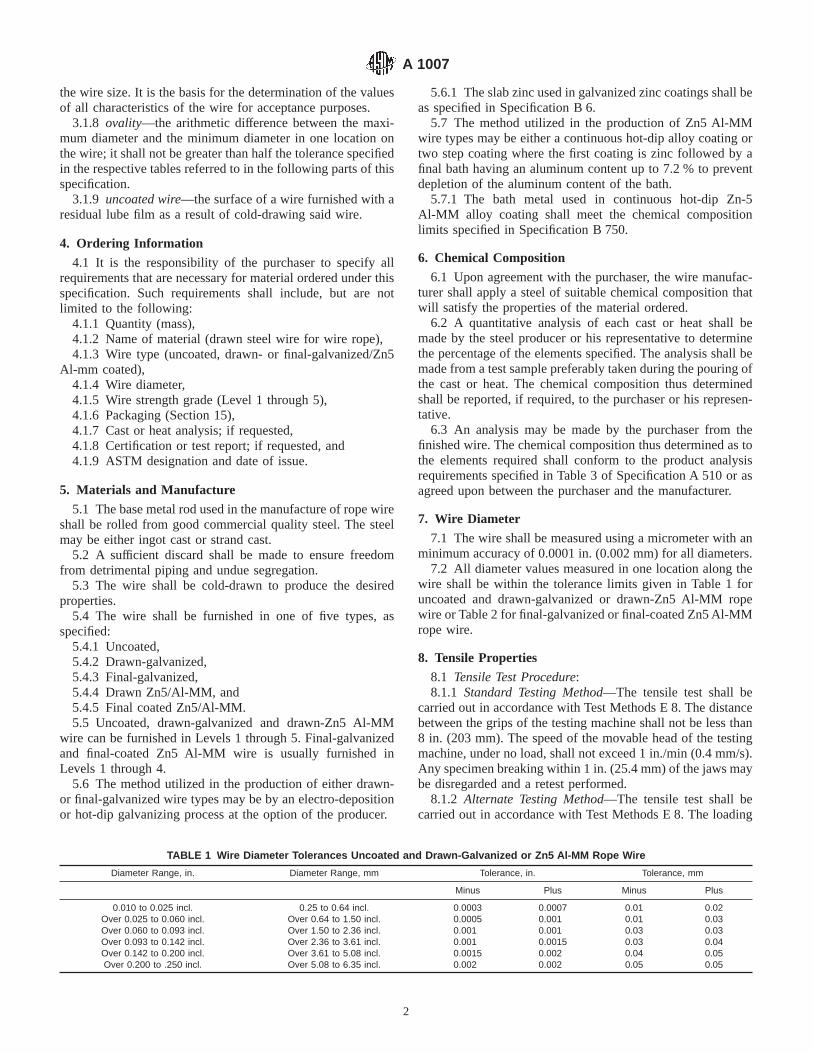
the wire size. It is the basis for the determination of the valuesof all characteristics of the wire for acceptance purposes.
3.1.8 ovality—the arithmetic difference between the maxi-mum diameter and the minimum diameter in one location onthe wire; it shall not be greater than half the tolerance specifiedin the respective tables referred to in the following parts of thisspecification.
3.1.9 uncoated wire—the surface of a wire furnished with aresidual lube film as a result of cold-drawing said wire.
4. Ordering Information
4.1 It is the responsibility of the purchaser to specify allrequirements that are necessary for material ordered under thisspecification. Such requirements shall include, but are notlimited to the following:
4.1.1 Quantity (mass),4.1.2 Name of material (drawn steel wire for wire rope),4.1.3 Wire type (uncoated, drawn- or final-galvanized/Zn5
Al-mm coated),4.1.4 Wire diameter,4.1.5 Wire strength grade (Level 1 through 5),4.1.6 Packaging (Section 15),4.1.7 Cast or heat analysis; if requested,4.1.8 Certification or test report; if requested, and4.1.9 ASTM designation and date of issue.
5. Materials and Manufacture
5.1 The base metal rod used in the manufacture of rope wireshall be rolled from good commercial quality steel. The steelmay be either ingot cast or strand cast.
5.2 A sufficient discard shall be made to ensure freedomfrom detrimental piping and undue segregation.
5.3 The wire shall be cold-drawn to produce the desiredproperties.
5.4 The wire shall be furnished in one of five types, asspecified:
5.4.1 Uncoated,5.4.2 Drawn-galvanized,5.4.3 Final-galvanized,5.4.4 Drawn Zn5/Al-MM, and5.4.5 Final coated Zn5/Al-MM.5.5 Uncoated, drawn-galvanized and drawn-Zn5 Al-MM
wire can be furnished in Levels 1 through 5. Final-galvanizedand final-coated Zn5 Al-MM wire is usually furnished inLevels 1 through 4.
5.6 The method utilized in the production of either drawn-or final-galvanized wire types may be by an electro-depositionor hot-dip galvanizing process at the option of the producer.
5.6.1 The slab zinc used in galvanized zinc coatings shall beas specified in Specification B 6.
5.7 The method utilized in the production of Zn5 Al-MMwire types may be either a continuous hot-dip alloy coating ortwo step coating where the first coating is zinc followed by afinal bath having an aluminum content up to 7.2 % to preventdepletion of the aluminum content of the bath.
5.7.1 The bath metal used in continuous hot-dip Zn-5Al-MM alloy coating shall meet the chemical compositionlimits specified in Specification B 750.
6. Chemical Composition
6.1 Upon agreement with the purchaser, the wire manufac-turer shall apply a steel of suitable chemical composition thatwill satisfy the properties of the material ordered.
6.2 A quantitative analysis of each cast or heat shall bemade by the steel producer or his representative to determinethe percentage of the elements specified. The analysis shall bemade from a test sample preferably taken during the pouring ofthe cast or heat. The chemical composition thus determinedshall be reported, if required, to the purchaser or his represen-tative.
6.3 An analysis may be made by the purchaser from thefinished wire. The chemical composition thus determined as tothe elements required shall conform to the product analysisrequirements specified in Table 3 of Specification A 510 or asagreed upon between the purchaser and the manufacturer.
7. Wire Diameter
7.1 The wire shall be measured using a micrometer with anminimum accuracy of 0.0001 in. (0.002 mm) for all diameters.
7.2 All diameter values measured in one location along thewire shall be within the tolerance limits given in Table 1 foruncoated and drawn-galvanized or drawn-Zn5 Al-MM ropewire or Table 2 for final-galvanized or final-coated Zn5 Al-MMrope wire.
8. Tensile Properties
8.1 Tensile Test Procedure:8.1.1 Standard Testing Method—The tensile test shall be
carried out in accordance with Test Methods E 8. The distancebetween the grips of the testing machine shall not be less than8 in. (203 mm). The speed of the movable head of the testingmachine, under no load, shall not exceed 1 in./min (0.4 mm/s).Any specimen breaking within 1 in. (25.4 mm) of the jaws maybe disregarded and a retest performed.
8.1.2 Alternate Testing Method—The tensile test shall becarried out in accordance with Test Methods E 8. The loading
TABLE 1 Wire Diameter Tolerances Uncoated and Drawn-Galvanized or Zn5 Al-MM Rope Wire
Diameter Range, in. Diameter Range, mm Tolerance, in. Tolerance, mm
Minus Plus Minus Plus
0.010 to 0.025 incl. 0.25 to 0.64 incl. 0.0003 0.0007 0.01 0.02Over 0.025 to 0.060 incl. Over 0.64 to 1.50 incl. 0.0005 0.001 0.01 0.03Over 0.060 to 0.093 incl. Over 1.50 to 2.36 incl. 0.001 0.001 0.03 0.03Over 0.093 to 0.142 incl. Over 2.36 to 3.61 incl. 0.001 0.0015 0.03 0.04Over 0.142 to 0.200 incl. Over 3.61 to 5.08 incl. 0.0015 0.002 0.04 0.05Over 0.200 to .250 incl. Over 5.08 to 6.35 incl. 0.002 0.002 0.05 0.05
A 1007
2

rate may be greater than that specified, depending on thenumber of tests to be carried out for the batch inspection.However, it shall not exceed the rate corresponding to a 25 %elongation between anchorages in 1 min. The minimumdistance between the clamping jaws of the test machine is 4 in.(100 mm). In the event of a dispute, the tensile test shall becarried out strictly in accordance with Test Methods E 8, inparticular with regard to the loading rate.
8.1.3 The minimum breaking forces are specified in Table 3of this specification, for wire grade Levels 1 through 5. Therange in breaking force for a given grade level is based on the
calculated minimum tensile strength requirement (psi). Whileno maximum values are shown for breaking force, rope wire isgenerally produced to a tensile strength range of 30 000 psi.The resultant minimum breaking force of either uncoated,drawn-galvanized, and drawn-Zn5 Al-MM wires of variouslevels shall meet or exceed the values shown in Table 3. Theresultant minimum breaking force for final-galvanized orfinal-coated Zn5 Al-MM wire is obtained by reducing the valuestated for its level in Table 3 for uncoated wire by 10 %.
TABLE 3 Minimum Breaking Forces
Wire Diameter Minimum Torsional Values(Number of Twists in 8 in.)
Minimum Breaking ForceA
in. mm Level 1 Level 2 Level 3 Level 4 Level 5 Level 1 Level 2 Level 3 Level 4 Level 5lbf N lbf N lbf N lbf N lbf N
0.010 0.254 274 254 234 218 190 16 70 17 80 20 90 22 100 24 1100.011 0.279 249 231 213 196 173 18 90 21 100 24 110 27 120 29 1300.012 0.305 228 212 195 182 158 22 100 25 120 29 130 32 150 31 1600.013 0.330 211 196 180 168 146 26 120 29 140 34 150 37 170 41 1800.014 0.356 196 181 167 156 136 31 140 34 160 39 180 43 200 45 2100.015 0.381 182 169 156 145 126 36 180 39 180 45 200 49 220 53 2400.016 0.408 171 156 146 136 118 40 180 41 200 51 230 56 250 80 2700.017 0.432 161 149 137 126 111 48 200 50 230 57 260 63 290 63 3100.018 0.467 152 141 130 121 105 50 230 53 250 64 290 71 320 73 3400.019 0.483 144 133 123 114 100 56 250 62 260 72 320 79 360 85 3800.020 0.508 136 126 116 108 94 60 280 69 310 79 360 87 390 94 4200.021 0.533 130 120 111 103 90 68 310 73 340 87 390 100 450 100 4500.022 0.559 124 115 106 96 86 75 340 83 360 96 430 110 490 110 4900.023 0.584 118 110 101 94 82 80 370 91 410 100 450 120 540 120 5400.024 0.610 113 105 97 90 78 85 400 100 450 110 490 130 580 130 5800.025 0.635 109 101 93 86 75 90 430 110 490 120 540 140 630 150 6700.026 0.680 105 97 89 83 72 100 450 130 540 130 560 150 670 160 7200.027 0.686 101 93 86 80 70 110 490 130 580 140 630 160 720 170 7300.028 0.711 97 90 83 77 67 120 540 130 580 150 670 170 760 180 8100.029 0.737 94 87 80 74 65 130 580 140 630 170 760 180 810 200 8900.030 0.782 90 84 77 72 62 140 630 150 670 180 810 190 850 210 9400.031 0.787 86 81 75 69 60 150 670 160 720 190 850 210 940 220 9600.032 0.813 85 78 72 67 56 160 720 180 810 200 890 220 980 240 10700.033 0.836 82 76 70 65 57 170 780 190 850 210 940 240 1070 250 11300.034 0.864 80 74 68 63 55 180 810 200 890 230 1030 250 1120 270 12100.035 0.869 77 72 66 61 53 190 860 210 940 240 1070 260 1160 280 12500.036 0.914 75 70 64 60 52 200 890 220 960 250 1120 280 1250 300 13400.037 0.940 73 68 62 58 50 210 940 230 1030 270 1210 300 1340 320 14300.038 0.966 71 66 61 56 49 220 960 250 1120 280 1250 310 1360 330 14700.039 0.991 69 64 59 55 48 230 1030 260 1160 300 1340 330 1470 350 15600.040 1.02 67 62 57 53 46 240 1070 270 1210 310 1360 340 1520 370 16500.041 1.04 66 61 56 52 45 250 1160 290 1290 330 1470 360 1610 390 17400.042 1.07 64 59 55 51 44 270 1210 300 1340 340 1520 380 1700 410 18300.043 1.09 63 58 53 50 43 280 1250 310 1380 360 1610 400 1780 430 19200.044 1.12 61 57 52 48 42 300 1340 330 1470 380 1700 420 1870 450 20100.045 1.14 60 56 51 47 41 310 1360 340 1520 390 1740 430 1920 470 21000.046 1.17 58 54 50 46 40 320 1430 360 1610 410 1830 450 2010 490 21300.047 1.19 57 53 49 45 39 340 1530 370 1650 430 1920 470 2100 510 22700.048 1.22 56 52 48 44 36 350 1560 390 1740 450 2010 490 2180 540 2350
TABLE 2 Wire Diameter Tolerances Final-Galvanized or Final-Coated Zn5 Al-MM Rope Wire
Diameter Range, in. Diameter Range, mm Tolerance, in. Tolerance, mm
Minus Plus Minus Plus
0.025 to 0.061 incl. 0.64 to 1.55 incl. 0.001 0.001 0.03 0.03Over 0.061 to 0.079 incl. Over 1.55 to 2.01 incl. 0.002 0.002 0.05 0.05Over 0.079 to 0.092 incl. Over 2.01 to 2.34 incl. 0.003 0.003 0.08 0.08Over 0.092 to 0.103 incl. Over 2.34 to 2.62 incl. 0.003 0.003 0.08 0.08Over 0.103 to 0.119 incl. Over 2.62 to 3.02 incl. 0.003 0.003 0.08 0.08Over 0.119 to 0.142 incl. Over 3.02 to 3.61 incl. 0.003 0.003 0.08 0.08Over 0.142 to 0.187 incl. Over 3.61 to 4.75 incl. 0.004 0.004 0.10 0.10
Over 0.187 Over 4.75 0.004 0.004 0.10 0.10
A 1007
3

TABLE 3 Continued
Wire Diameter Minimum Torsional Values(Number of Twists in 8 in.)
Minimum Breaking ForceA
in. mm Level 1 Level 2 Level 3 Level 4 Level 5 Level 1 Level 2 Level 3 Level 4 Level 5lbf N lbf N lbf N lbf N lbf N
0.049 1.24 55 51 47 43 36 370 1560 410 1830 470 2100 510 2270 550 24500.050 1.27 54 50 46 42 37 380 1700 420 1870 490 2180 530 2380 570 25000.051 1.30 53 49 45 42 36 400 1760 440 1960 500 2230 560 2500 610 26700.052 1.32 52 48 44 41 36 410 1830 480 2050 520 2320 580 2580 620 27300.053 1.35 51 47 43 40 36 430 1920 470 2100 540 2410 600 2670 640 28500.054 1.37 50 46 42 39 34 440 1960 490 2180 580 2500 620 2780 660 29900.055 1.40 49 45 41 38 33 460 2050 510 2270 590 2630 640 2850 690 30700.056 1.42 48 44 41 36 33 470 2100 530 2360 610 2720 670 2990 710 32000.057 1.45 47 43 40 37 32 490 2180 550 2450 630 2810 690 3070 710 33000.058 1.47 46 43 39 36 32 510 2270 570 2540 650 2900 720 3210 710 34300.059 1.50 45 42 36 36 31 530 2360 580 2580 670 2990 740 3300 710 35200.060 1.52 44 41 38 35 30 540 2410 600 2670 690 3070 760 3390 810 35500.061 1.56 44 40 37 35 30 560 2500 620 2760 720 3210 790 3520 850 37900.062 1.57 43 40 37 34 29 580 2580 640 2850 740 3300 810 3610 830 39230.063 1.60 42 39 36 33 29 600 2670 660 2940 760 3390 840 3740 930 43100.064 1.63 42 38 36 33 28 620 2760 690 3070 790 3520 870 3870 930 41400.065 1.65 41 38 35 32 28 640 2850 710 3160 810 3610 890 3980 960 42830.066 1.68 40 37 34 32 28 680 2940 730 3250 840 3740 920 4100 990 44100.067 1.70 40 37 34 31 27 670 2990 750 3340 860 3830 950 4230 1000 45400.068 1.73 39 36 33 31 27 690 3070 770 3430 890 3960 980 4360 1060 46300.069 1.75 38 36 33 30 26 710 3160 790 3520 910 4050 1000 4450 1160 48100.070 1.78 38 35 32 30 26 730 3250 820 3650 940 4190 1030 4590 1110 49400.071 1.80 37 35 32 29 26 780 3390 840 3740 970 4320 1080 4720 1140 50800.072 1.83 37 34 31 29 25 780 3470 880 3830 990 4410 1090 4850 1170 52000.073 1.85 36 34 31 29 25 800 3580 590 3960 1020 4540 1120 4990 1210 53600.074 1.86 36 33 30 28 24 820 3650 910 4050 1050 4680 1150 5120 1240 56000.075 1.91 35 33 30 28 24 840 3740 930 4140 1070 4760 1180 5250 1270 56800.076 1.93 35 32 30 27 24 860 3830 960 4280 1100 4900 1210 5390 1300 57900.077 1.96 34 32 29 27 23 890 3960 960 4380 1130 5030 1240 5520 1340 59000.078 1.98 34 31 29 27 23 910 4080 1010 4500 1160 5160 1280 5700 1370 61000.079 2.01 33 31 28 26 23 930 4140 1030 4590 1190 5300 1310 5830 1410 63000.080 2.03 33 30 28 26 22 950 4230 1080 4720 1230 5430 1340 5970 1440 64000.081 2.03 33 30 28 26 22 960 4260 1090 4850 1250 5570 1370 6100 1480 65000.082 2.03 32 30 27 25 22 1000 4460 1110 4610 1280 5700 1410 6280 1510 00000.083 2.11 32 29 27 25 22 1020 4500 1140 5080 1310 5830 1440 6410 1550 00000.084 2.13 31 29 27 25 21 1050 4680 1160 5160 1340 5970 1470 6540 1580 70300.085 2.16 31 29 26 24 21 1070 4760 1190 5300 1370 6100 1510 6720 1620 72100.086 2.18 31 28 26 24 21 1100 4800 1220 5430 1400 6230 1540 6660 1660 73900.087 2.21 30 28 26 24 21 1120 4990 1250 5570 1430 6370 1580 7030 1700 75700.088 2.24 30 28 25 23 20 1150 5120 1270 5650 1470 6540 1610 7170 1730 77000.089 2.26 30 27 25 23 20 1170 5210 1300 5790 1500 6660 1650 7340 1770 78800.090 2.29 29 27 25 23 20 1200 5340 1330 5920 1530 6610 1680 7480 1810 80800.091 2.31 29 27 24 23 20 1220 5430 1360 6050 1560 6940 1720 7660 1850 82300.092 2.34 28 26 24 22 19 1250 5670 1390 6190 1600 7120 1760 7830 1890 84100.093 2.36 28 26 24 22 19 1280 5700 1420 6320 1630 7260 1790 7970 1930 85900.094 2.39 28 26 24 22 19 1300 5790 1450 6450 1670 7430 1830 8150 1970 87700.095 2.41 28 25 23 22 19 1330 5920 1480 6590 1700 7570 1870 8320 2010 89000.096 2.44 27 25 23 21 18 1360 6050 1510 6720 1740 7740 1910 8500 2050 91300.097 2.46 27 25 23 21 18 1390 6190 1540 6880 1770 7880 1950 8680 2090 93000.098 2.49 27 25 23 21 18 1410 6280 1570 6990 1810 8060 1990 8860 2140 95290.099 2.51 26 24 22 21 18 1440 6410 1600 7120 1840 8190 2030 9030 2180 97000.100 2.54 26 24 22 20 18 1470 6540 1630 7260 1880 8370 2070 9210 2220 98800.101 2.57 26 24 22 20 18 1500 6580 1680 7390 1910 8500 2110 9390 2260 10 0000.102 2.59 26 24 22 20 17 1530 6810 1700 7570 1950 8680 2150 9570 2310 10 2100.103 2.62 25 23 21 20 17 1560 6940 1730 7700 1990 8860 2190 9750 2360 10 4100.104 2.64 25 23 21 20 17 1580 7030 1760 7830 2030 9030 2230 9920 2390 10 6100.105 2.67 25 23 21 19 17 1610 7170 1790 7970 2080 9170 2270 10 100 2440 10 8100.106 2.69 25 23 21 19 17 1640 7300 1830 8150 2100 9350 2310 10 280 2480 11 0100.107 2.72 24 22 21 19 16 1670 7430 1860 8280 2140 9520 2350 10 460 2530 11 2800.108 2.74 24 22 20 19 16 1700 7570 1890 8410 2180 9700 2400 10 680 2580 11 4300.109 2.77 24 22 20 19 16 1730 7700 1930 8590 2220 9880 2440 10 860 2620 11 6300.110 2.79 24 22 20 18 16 1770 7880 1960 8720 2260 10 060 2480 11 040 2670 11 8300.111 2.82 23 22 20 18 16 1800 8010 2000 8900 2300 10 240 2530 11 260 2710 12 0500.112 2.84 23 21 20 18 16 1830 8150 2030 9030 2340 10 410 2570 11 440 2760 12 2300.113 2.87 23 21 19 18 15 1880 8280 2070 9210 2380 10 590 2610 11 610 2810 12 5000.114 2.90 23 21 19 18 15 1890 8410 2100 9350 2420 10 770 2660 11 840 2860 12 7300.115 2.92 22 21 19 18 15 1920 8550 2140 9620 2480 10 950 2700 12 020 2910 12 9500.116 2.95 22 21 19 17 15 1960 8720 2170 9660 2500 11 130 2750 12 240 2950 13 1300.117 2.97 22 20 19 17 15 1990 8860 2210 9840 2540 11 300 2790 12 420 3000 13 3500.118 3.00 22 20 18 17 15 2020 8960 2240 9970 2580 11 480 2840 12 640 3050 13 6700.119 3.02 22 20 18 17 15 2050 9120 2290 10 150 2620 11 660 2890 12 880 3100 13 790
A 1007
4

TABLE 3 Continued
Wire Diameter Minimum Torsional Values(Number of Twists in 8 in.)
Minimum Breaking ForceA
in. mm Level 1 Level 2 Level 3 Level 4 Level 5 Level 1 Level 2 Level 3 Level 4 Level 5lbf N lbf N lbf N lbf N lbf N
0.120 3.05 21 20 18 17 14 2090 9300 2320 10 320 2670 11 880 2930 13 040 3150 14 0300.121 3.07 21 20 18 17 14 2120 9440 2360 10 500 2710 12 080 2960 13 260 3200 14 2100.122 3.10 21 19 18 17 14 2150 9570 2390 10 640 2750 12 240 3030 13 480 3250 14 1600.123 3.12 21 19 18 16 14 2190 9750 2430 10 610 2800 12 460 3070 13 660 3310 14 7300.124 3.15 21 19 18 16 14 2220 9660 2470 10 990 2840 12 640 3120 13 880 3360 14 9500.125 3.18 21 19 17 16 14 2260 10 080 2510 11 170 2880 12 820 3170 14 110 3410 15 1700.126 3.20 20 19 17 16 14 2290 10 190 2550 11 360 2930 13 040 3220 14 330 3460 15 2000.127 3.23 20 19 17 16 14 2330 10 370 2580 11 480 2970 13 220 3270 14 550 3510 15 3200.128 3.25 20 18 17 16 13 2360 10 500 2620 11 600 3020 13 440 3320 14 770 3570 15 3900.129 3.25 20 18 17 16 13 2400 10 660 2680 11 840 3080 13 620 3370 15 000 3620 16 1100.130 3.30 20 18 17 15 13 2430 10 610 2700 12 020 3110 13 640 3420 15 220 3670 16 3300.131 3.33 20 18 17 15 13 2470 10 990 2740 12 190 3150 14 020 3470 15 440 3730 16 8000.132 3.35 19 18 16 15 13 2500 11 130 2780 12 370 3200 14 240 3620 15 660 3780 16 8300.133 3.38 19 18 16 15 13 2540 11 300 2820 12 550 3250 14 480 3670 15 890 3840 17 0900.134 3.40 19 18 16 15 13 2580 11 460 2860 12 730 3290 14 640 3620 16 110 3890 17 3100.135 3.43 19 17 16 15 13 2610 11 610 2900 12 900 3340 14 860 3670 16 330 3950 17 5800.136 3.45 19 17 16 15 13 2650 11 790 2940 13 080 3390 15 080 3720 16 550 4000 17 8000.137 3.48 19 17 16 15 13 2690 11 970 2990 13 310 3430 15 260 3780 16 820 4080 18 0600.138 3.51 18 17 16 14 12 2720 12 100 3030 13 480 3480 15 480 3630 17 040 4120 18 3300.139 3.53 18 17 15 14 12 2760 12 260 3070 13 660 3530 15 710 3880 17 260 4170 18 5600.140 3.56 18 17 15 14 12 2800 12 460 3110 13 840 3580 15 630 3940 17 530 4230 18 8200.141 3.58 18 17 15 14 12 2840 12 640 3150 14 020 3630 16 150 3990 17 750 4290 19 0900.142 3.61 18 17 15 14 12 2880 12 820 3200 14 240 3680 16 370 4040 17 980 4350 19 3600.143 3.63 18 16 15 14 12 2910 12 950 3240 14 420 3720 16 550 4100 18 240 4400 19 6800.144 3.65 18 16 15 14 12 2960 13 130 3260 14 600 3770 16 770 4150 18 470 4460 19 8400.145 3.66 18 16 15 14 12 2990 13 310 3330 14 820 3820 17 000 4210 18 730 4620 20 1100.146 3.71 17 16 15 14 12 3030 13 480 3370 15 000 3870 17 220 4280 18 950 4680 20 3800.147 3.73 17 16 15 13 12 3070 13 880 3410 15 170 3920 17 440 4320 19 220 4640 20 6400.148 3.76 17 16 14 13 11 3110 13 840 3480 15 400 3960 17 710 4370 19 440 4700 20 9100.149 3.78 17 16 14 13 11 3150 14 020 3500 15 570 4030 17 930 4430 19 710 4760 21 1800.150 3.81 17 16 14 13 11 3190 14 190 3550 15 800 4080 18 150 4490 19 980 4820 21 4500.151 3.84 17 15 14 13 11 3230 14 370 3590 15 970 4130 18 380 4540 20 200 4880 21 7100.152 3.86 17 15 14 13 11 3270 14 550 3640 16 200 4180 18 800 4600 30 470 4940 21 9800.153 3.89 17 15 14 13 11 3310 14 730 3680 16 370 4230 18 820 4660 20 730 5010 22 2900.154 2.91 16 15 14 13 11 3350 14 910 3730 18 800 4290 19 090 4710 20 980 5070 22 5800.155 3.94 16 15 14 13 11 3400 15 130 3770 16 770 4340 19 310 4770 21 220 5130 22 8300.156 3.96 16 15 14 13 11 3440 15 310 3820 17 000 4390 19 630 48 30 21 490 5190 23 0900.157 3.99 16 15 14 13 11 3480 15 480 3880 17 180 4440 19 760 4890 21 750 5260 23 4000.158 4.01 16 15 13 12 11 3520 15 880 3910 17 400 4600 20 030 4950 22 020 5320 23 6700.159 4.04 16 15 13 12 11 3560 15 840 3980 17 620 4550 20 240 5010 22 290 5380 23 9400.160 4.06 16 14 13 12 10 3600 16 020 4010 17 840 4610 20 510 5070 22 560 5450 24 2500.161 4.09 16 14 13 12 10 3650 16 240 4050 18 020 4660 20 730 5130 22 820 5510 24 5100.162 4.11 16 14 13 12 10 3690 16 420 4100 18 240 4720 21 000 5190 23 090 5580 24 8300.163 4.14 15 14 13 12 10 3730 16 600 4150 18 470 4770 21 220 5250 23 360 5840 25 0900.164 4.17 15 14 13 12 10 3780 16 820 4200 18 690 4830 21 490 5310 23 630 5710 25 4000.165 4.19 15 14 13 12 10 3820 17 000 4240 18 870 4880 21 710 5370 23 890 5770 25 8700.166 4.22 15 14 13 12 10 3880 17 180 4290 19 090 4940 21 980 5430 24 160 5840 25 68001.67 4.24 15 14 13 12 10 3910 17 400 4340 19 310 4990 22 200 5490 24 430 5900 26 2500.168 4.27 15 14 13 12 10 3950 17 580 4390 19 530 5050 22 470 5560 24 690 5970 26 5600.169 4.29 15 14 12 12 10 4000 17 800 4440 19 760 5110 22 740 5620 25 000 6040 26 8700.170 4.32 15 14 12 11 10 4040 17 980 4490 19 980 5180 22 960 5660 25 270 6100 27 1400.171 4.34 15 13 12 11 10 4080 18 150 4540 20 200 5220 23 220 5740 25 540 6170 27 4500.172 4.37 15 13 12 11 10 4130 18 380 4590 20 420 5280 23 490 5800 25 800 6240 27 7600.173 4.39 14 13 12 11 10 4170 18 550 4640 20 640 5330 23 710 5870 26 120 6310 28 0700.174 4.42 14 13 12 11 10 4220 18 780 4690 20 870 5390 23 980 5930 26 380 6380 28 3800.175 4.45 14 13 12 11 9 4270 19 000 4740 21 090 5450 24 250 6000 26 690 6450 28 7000.176 4.47 14 13 12 11 9 4310 19 180 4790 21 310 5510 24 510 6060 26 960 6510 28 9600.177 4.50 14 13 12 11 9 4360 19 400 4840 21 530 5570 24 780 6120 27 230 6580 29 2700.178 4.52 14 13 12 11 9 4400 19 580 4890 21 780 5630 25 050 6190 27 540 6650 29 5900.179 4.55 14 13 12 11 9 4450 19 800 4940 21 980 5690 25 320 6250 27 810 6720 29 9000.180 4.57 14 13 12 11 9 4500 20 020 5000 22 250 5750 25 580 6320 28 120 6790 30 2100.181 4.60 14 13 12 11 9 4540 20 200 5050 22 470 5810 25 850 6390 28 430 6860 30 6200.182 4.62 14 13 11 11 9 4590 20 420 5100 22 690 5870 26 120 6450 28 700 6940 30 8800.183 4.65 14 12 11 11 9 4640 20 640 5150 22 910 5930 26 380 6520 29 010 7010 31 1900.184 4.67 13 12 11 10 9 4680 20 820 5210 23 180 5990 26 650 6580 29 270 7060 31 5000.185 4.70 13 12 11 10 9 4730 21 050 5260 23 400 6050 26 920 6650 29 590 7150 31 8100.186 4.72 13 12 11 10 9 4780 21 270 5310 23 630 6110 27 180 6720 29 900 7220 32 1200.187 4.75 13 12 11 10 9 4830 21 460 5360 23 850 6170 27 450 6790 30 210 7290 32 4300.188 4.78 13 12 11 10 9 4880 21 710 5420 24 110 6230 27 720 6850 30 480 7370 32 7900.189 4.80 13 12 11 10 9 4920 21 890 5470 24 340 6290 27 980 6920 30 790 7440 33 1000.190 4.83 13 12 11 10 9 4970 22 110 5630 24 600 6350 28 250 6990 31 100 7510 33 410
A 1007
5
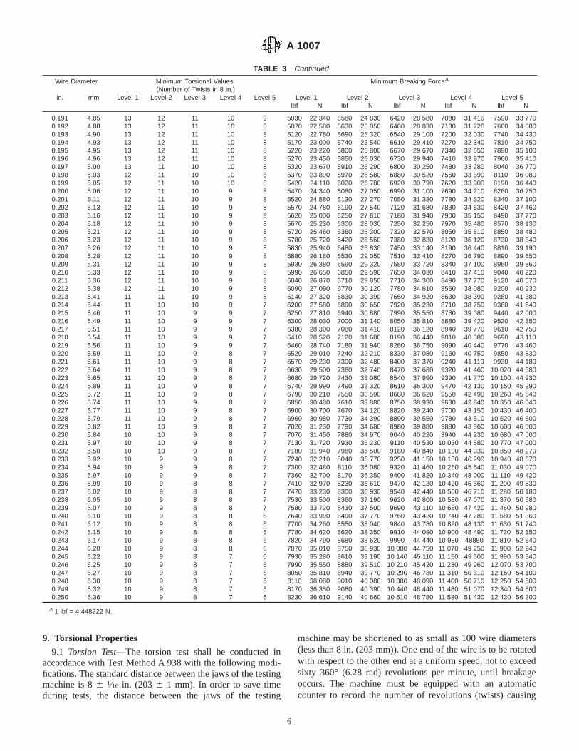
TABLE 3 Continued
Wire Diameter Minimum Torsional Values(Number of Twists in 8 in.)
Minimum Breaking ForceA
in. mm Level 1 Level 2 Level 3 Level 4 Level 5 Level 1 Level 2 Level 3 Level 4 Level 5lbf N lbf N lbf N lbf N lbf N
0.191 4.85 13 12 11 10 9 5030 22 340 5580 24 830 6420 28 580 7080 31 410 7590 33 7700.192 4.88 13 12 11 10 8 5070 22 580 5630 25 050 6480 28 830 7130 31 720 7660 34 0800.193 4.90 13 12 11 10 8 5120 22 780 5690 25 320 6540 29 100 7200 32 030 7740 34 4300.194 4.93 13 12 11 10 8 5170 23 000 5740 25 540 6610 29 410 7270 32 340 7810 34 7500.195 4.95 13 12 11 10 8 5220 23 220 5800 25 800 6670 29 670 7340 32 650 7890 35 1000.196 4.96 13 12 11 10 8 5270 23 450 5850 26 030 6730 29 940 7410 32 970 7960 35 4100.197 5.00 13 11 10 10 8 5320 23 670 5910 26 290 6800 30 250 7480 33 280 8040 36 7700.198 5.03 12 11 10 10 8 5370 23 890 5970 26 580 6880 30 520 7550 33 590 8110 36 0800.199 5.05 12 11 10 10 8 5420 24 110 6020 26 780 6920 30 790 7620 33 900 8190 36 4400.200 5.06 12 11 10 9 8 5470 24 340 6080 27 050 6990 31 100 7690 34 210 8260 36 7500.201 5.11 12 11 10 9 8 5520 24 580 6130 27 270 7050 31 380 7780 34 520 8340 37 1000.202 5.13 12 11 10 9 8 5570 24 780 6190 27 540 7120 31 680 7830 34 630 8420 37 4600.203 5.16 12 11 10 9 8 5620 25 000 6250 27 810 7180 31 940 7900 35 150 8490 37 7700.204 5.18 12 11 10 9 8 5670 25 230 6300 28 030 7250 32 250 7970 35 480 8570 38 1300.205 5.21 12 11 10 9 8 5720 25 460 6360 26 300 7320 32 570 8050 35 810 8850 38 4800.206 5.23 12 11 10 9 8 5780 25 720 6420 28 560 7380 32 830 8120 36 120 8730 38 8400.207 5.26 12 11 10 9 8 5830 25 940 6480 26 830 7450 33 140 8190 36 440 8810 39 1900.208 5.28 12 11 10 9 8 5880 26 180 6530 29 050 7510 33 410 8270 36 790 8890 39 6500.209 5.31 12 11 10 9 8 5930 26 380 6590 29 320 7580 33 720 8340 37 100 8960 39 8600.210 5.33 12 11 10 9 8 5990 26 650 6850 29 590 7650 34 030 8410 37 410 9040 40 2200.211 5.36 12 11 10 9 8 6040 26 870 6710 29 850 7710 34 300 8490 37 770 9120 40 5700.212 5.38 12 11 10 9 8 6090 27 090 6770 30 120 7780 34 610 8560 38 080 9200 40 9300.213 5.41 11 11 10 9 8 6140 27 320 6830 30 390 7650 34 920 8630 38 390 9280 41 3800.214 5.44 11 10 10 9 7 6200 27 580 6890 30 650 7920 35 230 8710 38 750 9360 41 6400.215 5.46 11 10 9 9 7 6250 27 810 6940 30 880 7990 35 550 8780 39 080 9440 42 0000.216 5.49 11 10 9 9 7 6300 28 030 7000 31 140 8050 35 810 8880 39 420 9520 42 3500.217 5.51 11 10 9 9 7 6380 28 300 7080 31 410 8120 36 120 8940 39 770 9610 42 7500.218 5.54 11 10 9 9 7 6410 28 520 7120 31 680 8190 36 440 9010 40 080 9690 43 1100.219 5.56 11 10 9 9 7 6460 28 740 7180 31 940 8260 36 750 9090 40 440 9770 43 4600.220 5.59 11 10 9 8 7 6520 29 010 7240 32 210 8330 37 080 9160 40 750 9850 43 8300.221 5.61 11 10 9 8 7 6570 29 230 7300 32 480 8400 37 370 9240 41 110 9930 44 1800.222 5.64 11 10 9 8 7 6630 29 500 7360 32 740 8470 37 680 9320 41 460 10 020 44 5800.223 5.65 11 10 9 8 7 6680 29 720 7430 33 080 8540 37 990 9390 41 770 10 100 44 9300.224 5.89 11 10 9 8 7 6740 29 990 7490 33 320 8610 36 300 9470 42 130 10 150 45 2900.225 5.72 11 10 9 8 7 6790 30 210 7550 33 590 8680 36 620 9550 42 490 10 260 45 6400.226 5.74 11 10 9 8 7 6850 30 480 7610 33 880 8750 38 930 9630 42 840 10 350 46 0400.227 5.77 11 10 9 8 7 6900 30 700 7670 34 120 8820 39 240 9700 43 150 10 430 46 4000.228 5.79 11 10 9 8 7 6960 30 980 7730 34 390 8890 39 550 9780 43 510 10 520 46 6000.229 5.82 11 10 9 8 7 7020 31 230 7790 34 680 8980 39 880 9880 43 860 10 600 46 0000.230 5.84 10 10 9 8 7 7070 31 450 7880 34 970 9040 40 220 3940 44 230 10 680 47 0000.231 5.97 10 10 9 8 7 7130 31 720 7930 36 230 9110 40 530 10 030 44 580 10 770 47 0000.232 5.50 10 10 9 8 7 7180 31 940 7980 35 500 9180 40 840 10 100 44 930 10 850 48 2700.233 5.92 10 9 9 8 7 7240 32 210 8040 35 770 9250 41 150 10 180 46 290 10 940 48 6700.234 5.94 10 9 9 8 7 7300 32 480 8110 36 080 9320 41 460 10 260 45 640 11 030 49 0700.235 5.97 10 9 9 8 7 7360 32 700 8170 36 350 9400 41 820 10 340 48 000 11 110 49 4200.236 5.99 10 9 8 8 7 7410 32 970 8230 36 610 9470 42 130 10 420 46 360 11 200 49 8300.237 6.02 10 9 8 8 7 7470 33 230 8300 36 930 9540 42 440 10 500 46 710 11 280 50 1800.238 6.05 10 9 8 8 7 7530 33 500 8360 37 190 9620 42 800 10 580 47 070 11 370 50 5800.239 6.07 10 9 8 8 7 7580 33 720 8430 37 500 9690 43 110 10 680 47 420 11 460 50 9800.240 6.10 10 9 8 8 6 7640 33 990 8490 37 770 9760 43 420 10 740 47 780 11 580 51 3600.241 6.12 10 9 8 8 6 7700 34 260 8550 38 040 9840 43 780 10 820 48 130 11 630 51 7400.242 6.15 10 9 8 8 6 7780 34 620 8620 38 350 9910 44 090 10 900 48 490 11 720 52 1500.243 6.17 10 9 8 8 6 7820 34 790 8680 38 620 9990 44 440 10 980 48850 11 810 52 5400.244 6.20 10 9 8 8 6 7870 35 010 8750 38 930 10 080 44 750 11 070 49 250 11 900 52 9400.245 6.22 10 9 8 7 6 7930 35 280 8610 39 190 10 140 45 110 11 150 49 600 11 990 53 3400.246 6.25 10 9 8 7 6 7990 35 550 8880 39 510 10 210 45 420 11 230 49 960 12 070 53 7000.247 6.27 10 9 8 7 6 8050 35 810 8940 39 770 10 290 46 780 11 310 50 310 12 160 54 1000.248 6.30 10 9 8 7 6 8110 38 080 9010 40 080 10 380 48 090 11 400 50 710 12 250 54 5000.249 6.32 10 9 8 7 6 8170 36 350 9080 40 390 10 440 48 440 11 480 51 070 12 340 54 6000.250 6.36 10 9 8 7 6 8230 36 610 9140 40 660 10 510 48 780 11 580 51 430 12 430 56 300
A 1 lbf = 4.448222 N.
9. Torsional Properties
9.1 Torsion Test—The torsion test shall be conducted inaccordance with Test Method A 938 with the following modi-fications. The standard distance between the jaws of the testingmachine is 86 1⁄16 in. (203 6 1 mm). In order to save timeduring tests, the distance between the jaws of the testing
machine may be shortened to as small as 100 wire diameters(less than 8 in. (203 mm)). One end of the wire is to be rotatedwith respect to the other end at a uniform speed, not to exceedsixty 360° (6.28 rad) revolutions per minute, until breakageoccurs. The machine must be equipped with an automaticcounter to record the number of revolutions (twists) causing
A 1007
6
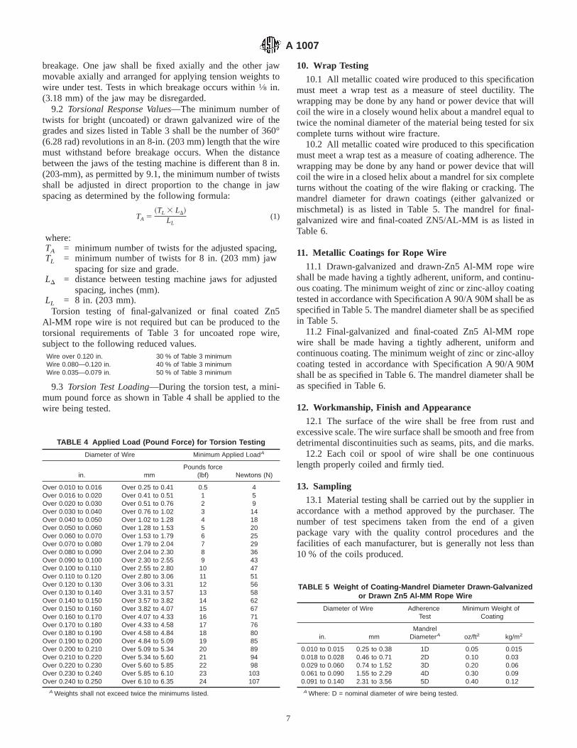
breakage. One jaw shall be fixed axially and the other jawmovable axially and arranged for applying tension weights towire under test. Tests in which breakage occurs within1⁄8 in.(3.18 mm) of the jaw may be disregarded.
9.2 Torsional Response Values—The minimum number oftwists for bright (uncoated) or drawn galvanized wire of thegrades and sizes listed in Table 3 shall be the number of 360°(6.28 rad) revolutions in an 8-in. (203 mm) length that the wiremust withstand before breakage occurs. When the distancebetween the jaws of the testing machine is different than 8 in.(203-mm), as permitted by 9.1, the minimum number of twistsshall be adjusted in direct proportion to the change in jawspacing as determined by the following formula:
TA 5~TL 3 LD!
LL(1)
where:TA = minimum number of twists for the adjusted spacing,TL = minimum number of twists for 8 in. (203 mm) jaw
spacing for size and grade.LD = distance between testing machine jaws for adjusted
spacing, inches (mm).LL = 8 in. (203 mm).
Torsion testing of final-galvanized or final coated Zn5Al-MM rope wire is not required but can be produced to thetorsional requirements of Table 3 for uncoated rope wire,subject to the following reduced values.
Wire over 0.120 in. 30 % of Table 3 minimumWire 0.080—0.120 in. 40 % of Table 3 minimumWire 0.035—0.079 in. 50 % of Table 3 minimum
9.3 Torsion Test Loading—During the torsion test, a mini-mum pound force as shown in Table 4 shall be applied to thewire being tested.
10. Wrap Testing
10.1 All metallic coated wire produced to this specificationmust meet a wrap test as a measure of steel ductility. Thewrapping may be done by any hand or power device that willcoil the wire in a closely wound helix about a mandrel equal totwice the nominal diameter of the material being tested for sixcomplete turns without wire fracture.
10.2 All metallic coated wire produced to this specificationmust meet a wrap test as a measure of coating adherence. Thewrapping may be done by any hand or power device that willcoil the wire in a closed helix about a mandrel for six completeturns without the coating of the wire flaking or cracking. Themandrel diameter for drawn coatings (either galvanized ormischmetal) is as listed in Table 5. The mandrel for final-galvanized wire and final-coated ZN5/AL-MM is as listed inTable 6.
11. Metallic Coatings for Rope Wire
11.1 Drawn-galvanized and drawn-Zn5 Al-MM rope wireshall be made having a tightly adherent, uniform, and continu-ous coating. The minimum weight of zinc or zinc-alloy coatingtested in accordance with Specification A 90/A 90M shall be asspecified in Table 5. The mandrel diameter shall be as specifiedin Table 5.
11.2 Final-galvanized and final-coated Zn5 Al-MM ropewire shall be made having a tightly adherent, uniform andcontinuous coating. The minimum weight of zinc or zinc-alloycoating tested in accordance with Specification A 90/A 90Mshall be as specified in Table 6. The mandrel diameter shall beas specified in Table 6.
12. Workmanship, Finish and Appearance
12.1 The surface of the wire shall be free from rust andexcessive scale. The wire surface shall be smooth and free fromdetrimental discontinuities such as seams, pits, and die marks.
12.2 Each coil or spool of wire shall be one continuouslength properly coiled and firmly tied.
13. Sampling
13.1 Material testing shall be carried out by the supplier inaccordance with a method approved by the purchaser. Thenumber of test specimens taken from the end of a givenpackage vary with the quality control procedures and thefacilities of each manufacturer, but is generally not less than10 % of the coils produced.
TABLE 4 Applied Load (Pound Force) for Torsion Testing
Diameter of Wire Minimum Applied LoadA
in. mmPounds force
(lbf) Newtons (N)
Over 0.010 to 0.016 Over 0.25 to 0.41 0.5 4Over 0.016 to 0.020 Over 0.41 to 0.51 1 5Over 0.020 to 0.030 Over 0.51 to 0.76 2 9Over 0.030 to 0.040 Over 0.76 to 1.02 3 14Over 0.040 to 0.050 Over 1.02 to 1.28 4 18Over 0.050 to 0.060 Over 1.28 to 1.53 5 20Over 0.060 to 0.070 Over 1.53 to 1.79 6 25Over 0.070 to 0.080 Over 1.79 to 2.04 7 29Over 0.080 to 0.090 Over 2.04 to 2.30 8 36Over 0.090 to 0.100 Over 2.30 to 2.55 9 43Over 0.100 to 0.110 Over 2.55 to 2.80 10 47Over 0.110 to 0.120 Over 2.80 to 3.06 11 51Over 0.120 to 0.130 Over 3.06 to 3.31 12 56Over 0.130 to 0.140 Over 3.31 to 3.57 13 58Over 0.140 to 0.150 Over 3.57 to 3.82 14 62Over 0.150 to 0.160 Over 3.82 to 4.07 15 67Over 0.160 to 0.170 Over 4.07 to 4.33 16 71Over 0.170 to 0.180 Over 4.33 to 4.58 17 76Over 0.180 to 0.190 Over 4.58 to 4.84 18 80Over 0.190 to 0.200 Over 4.84 to 5.09 19 85Over 0.200 to 0.210 Over 5.09 to 5.34 20 89Over 0.210 to 0.220 Over 5.34 to 5.60 21 94Over 0.220 to 0.230 Over 5.60 to 5.85 22 98Over 0.230 to 0.240 Over 5.85 to 6.10 23 103Over 0.240 to 0.250 Over 6.10 to 6.35 24 107
A Weights shall not exceed twice the minimums listed.
TABLE 5 Weight of Coating-Mandrel Diameter Drawn-Galvanizedor Drawn Zn5 Al-MM Rope Wire
Diameter of Wire AdherenceTest
Minimum Weight ofCoating
in. mmMandrel
DiameterA oz/ft2 kg/m2
0.010 to 0.015 0.25 to 0.38 1D 0.05 0.0150.018 to 0.028 0.46 to 0.71 2D 0.10 0.030.029 to 0.060 0.74 to 1.52 3D 0.20 0.060.061 to 0.090 1.55 to 2.29 4D 0.30 0.090.091 to 0.140 2.31 to 3.56 5D 0.40 0.12A Where: D = nominal diameter of wire being tested.
A 1007
7

13.2 The purchaser may elect to have incoming acceptancetesting performed. To ensure representative sampling, thesamples shall be taken at random from the coil or spool ends.
14. Retesting
14.1 If non-complying results are obtained, the purchasermay reject the entire lot, reclassify the material or perform
further testing to establish material acceptability. This addi-tional testing shall be based solely on the non-complyingcharacteristic.
15. Package Marking
15.1 The coil or spool mass, dimensions, and protectivecovering shall be agreed upon between the manufacturer andpurchaser.
15.2 The wire size, purchaser order number, ASTM speci-fication number, heat number and manufacturer identificationshall be on a tag securely attached to each package.
15.3 Bar coding of each package is acceptable as a supple-mentary identification method on the wire identification tag. Ifbar coding is used, the coding shall be consistent with theAIAG Standard 02.00, Primary Metals Identification TagApplication.
16. Keywords
16.1 metallic coated; rope; wire
APPENDIXES
(Nonmandatory Information)
X1. IMPERIAL (ENGLISH) WIRE MATERIALS (IN ACCORDANCE WITH CRITERIA SET FORTH IN EN 10264-1.2)
X1.1 Definitions of Terms Relating to Sampling and Accep-tance:
X1.1.1 batch—a defined quantity of wire of the samediameter, the same grade, and the same finish presented forinspection and manufactured in conditions assumed to beidentical and uniform.
X1.1.2 unit (wire package)—A variable or fixed quantitysupplied in a:
X1.1.2.1 coil of a single length or mass of wire, orX1.1.2.2 bobbin (reel)—A single length or mass of wire
wound on a reel, spool or bobbin, orX1.1.2.3 flat coil (spooless core)—A single length or mass
of wire wound on a cardboard center drum, orX1.1.2.4 other wire packaging as agreed between supplier
and purchaser.X1.1.3 base unit for sampling (m1)—a mass expressed in
pounds (lb) conventionally with a value equal to 100d, whered is the diameter of the wire expressed in inches.
X1.1.4 size of batch (N):number given by the followingformula:
N 5m
2.83 1022 3 m1
(X1.1)
where:m = batch mass, tons, andm1 = base unit mass, lb.
Knowing that conventionally:
m1 5 100d (X1.2)
where:
d = nominal wire diameter, in.,it follows that:
N 5m
2.83 1022 3 100d(X1.3)
or:
N 50.357m
d (X1.4)
X1.1.5 sample for testing—a sufficient length of wire formeasurement of an individual characteristic.
X1.1.6 sampling length—a sufficient length of wire toproduce the necessary samples for testing all characteristics.
X1.1.7 sampling—taking all necessary samples to supplyinformation on the batch.
X1.1.8 sample size, n—number of samples for tests.X1.1.9 non-conformance—result of a test not complying
with the requirements for a characteristic.
X1.2 Definitions of Terms Relating to Sampling and Accep-tance:
X1.2.1 batch—a defined quantity of wire of the samediameter, the same grade, and the same finish presented forinspection and manufactured in conditions assumed to beidentical and uniform.
X1.2.2 unit (wire package)—a variable or fixed quantitysupplied in a:
X1.2.2.1 coil of a single length or mass of wire, orX1.2.2.2 bobbin (reel)—A single length or mass of wire
wound on a reel, spool or bobbin, or
TABLE 6 Weight of Coating-Mandrel Diameter Final-Galvanizedor Final Coated Zn5 Al-MM Rope Wire
Diameter of Wire AdherenceTest
Minimum Weight ofCoating
in. mmMandrel
DiameterA oz/ft2 kg/m2
0.025 to 0.047 0.64 to 1.19 2D 0.20 0.060.048 to 0.054 1.22 to 1.37 2D 0.40 0.120.055 to 0.063 1.40 to 1.60 2D 0.50 0.150.064 to 0.079 1.63 to 2.01 2D 0.60 0.180.080 to 0.092 2.03 to 2.34 3D 0.70 0.210.093 to 0.192 2.36 to 4.88 3D 0.80 0.24
0.193 and larger 4.90 and larger 3D 0.90 0.27A Where: D = nominal diameter of wire being tested.
A 1007
8

X1.2.2.3 flat coil (spooless core)—A single length or massof wire wound on a cardboard center drum, or
X1.2.2.4 other wire packaging as agreed between supplierand purchaser.
X1.2.3 base unit for sampling (m1)—a mass expressed in(kilograms) conventionally with a value equal to 100d, whered is the diameter of the wire expressed in (millimetres).
X1.2.4 size of batch (N)—number given by the formula:
N 5m
103 3 m1
(X1.5)
where:m = batch mass, tonnes, andm1 = base unit mass, kg.
Knowing that conventionally:
m1 5 100d (X1.6)
where:
d = nominal wire diameter (mm),it follows that:
N 5m
1023 3 100d(X1.7)
or:
N 510m
d (X1.8)
X1.2.5 sample for testing—a sufficient length of wire formeasurement of an individual characteristic.
X1.2.6 sampling length—a sufficient length of wire toproduce the necessary samples for testing all characteristics.
X1.2.7 sampling—taking all necessary samples to supplyinformation on the batch.
X1.2.8 sample size, n—number of samples for tests.X1.2.9 non-conformance—result of a test not complying
with the requirements for a characteristic.
X2. METRIC WIRE MATERIALS (IN ACCORDANCE WITH CRITERIA SET FORTH IN eN 10264-1.2)
X2.1 Definition of Terms Relating to Sampling and Accep-tance:
X2.1.1 batch—a defined quantity of wire of the samediameter, the same grade, and the same finish presented forinspection and manufactured in conditions assumed to beidentical and uniform.
X2.1.2 unit (wire package)—a variable or fixed quanitysupplied in a:
X2.1.2.1 coil of a single length or mass of wire, orX2.1.2.2 bobbin (reel)—a single length or mass of wire
wound on a reel, spool or bobbin, orX2.1.2.3 flat coil (spooless core)—a single length or mass
of wire wound on a cardboard center drum, orX2.1.2.4 other wire packaging as agreed between supplier
and purchaser.X2.1.3 base unit for sampling (m1)—a mass expressed in
(kilograms) conventionally with a value equal to 100d, whered is the diameter of the wire expressed in (millimetres).
X2.1.4 size of batch (N):number given by the formula:
N 5m
1023 3 m1
(X2.1)
where:
m = batch mass, tonnes, andm1 = base unit mass, kg.
Knowing that conventionally:
m1 5 100d (X2.2)
where:d = nominal wire diameter, mm,
it follows that:
N 5m
1023 3 100d(X2.3)
or:
N 510m
d (X2.4)
X2.1.5 sample for testing—a sufficient length of wire formeasurement of an individual characteristic.
X2.1.6 sampling length—a sufficient length of wire toproduce the necessary samples for testing all characteristics.
X2.1.7 sampling—taking all necessary samples to supplyinformation on the batch.
X2.1.8 sample size, n,—number of samples for tests.X2.1.9 non-conformance—result of a test not complying
with the requirements for a characteristic.
ASTM International takes no position respecting the validity of any patent rights asserted in connection with any item mentionedin this standard. Users of this standard are expressly advised that determination of the validity of any such patent rights, and the riskof infringement of such rights, are entirely their own responsibility.
This standard is subject to revision at any time by the responsible technical committee and must be reviewed every five years andif not revised, either reapproved or withdrawn. Your comments are invited either for revision of this standard or for additional standardsand should be addressed to ASTM International Headquarters. Your comments will receive careful consideration at a meeting of theresponsible technical committee, which you may attend. If you feel that your comments have not received a fair hearing you shouldmake your views known to the ASTM Committee on Standards, at the address shown below.
This standard is copyrighted by ASTM International, 100 Barr Harbor Drive, PO Box C700, West Conshohocken, PA 19428-2959,United States. Individual reprints (single or multiple copies) of this standard may be obtained by contacting ASTM at the aboveaddress or at 610-832-9585 (phone), 610-832-9555 (fax), or [email protected] (e-mail); or through the ASTM website(www.astm.org).
A 1007
9

Designation: A 1008/A 1008M – 04a
Standard Specification forSteel, Sheet, Cold-Rolled, Carbon, Structural, High-StrengthLow-Alloy and High-Strength Low-Alloy with ImprovedFormability 1
This standard is issued under the fixed designation A 1008/A 1008M; the number immediately following the designation indicates theyear of original adoption or, in the case of revision, the year of last revision. A number in parentheses indicates the year of lastreapproval. A superscript epsilon (e) indicates an editorial change since the last revision or reapproval.
1. Scope*
1.1 This specification covers cold-rolled, carbon, structural, high-strength low-alloy, and high-strength low-alloy with improvedformability steel sheet, in coils and cut lengths.
1.2 Cold rolled steel sheet is available in the designations as listed in 4.1.1.3 This specification does not apply to steel strip as described in Specification A 109.1.4 The values stated in either inch-pound units or SI units are to be regarded separately as standard. Within the text, the SI units
are shown in brackets. The values stated in each system are not exact equivalents; therefore, each system must be usedindependently of the other.
1 This specification is under the jurisdiction of ASTM Committee A01 on Steel, Stainless Steel and Related Alloys and is the direct responsibility of Subcommittee A01.19on Steel Sheet and Strip.
Current edition approved Feb. April 1, 2004. Published February April 2004. Originally approved in 2000. Last previous edition approved in 20034 asA 1008/A 1008M – 034.
1
This document is not an ASTM standard and is intended only to provide the user of an ASTM standard an indication of what changes have been made to the previous version. Becauseit may not be technically possible to adequately depict all changes accurately, ASTM recommends that users consult prior editions as appropriate. Inall cases only the current versionof the standard as published by ASTM is to be considered the official document.
*A Summary of Changes section appears at the end of this standard.
Copyright © ASTM International, 100 Barr Harbor Drive, PO Box C700, West Conshohocken, PA 19428-2959, United States.
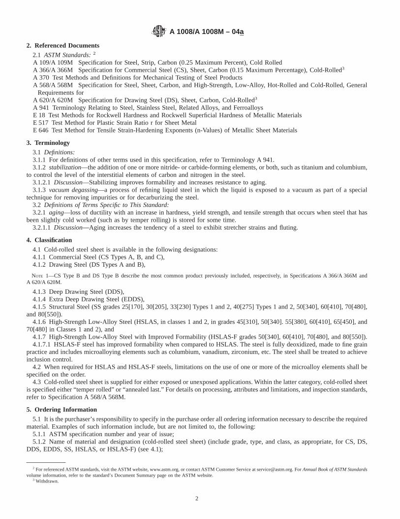
2. Referenced Documents
2.1 ASTM Standards:2
A 109/A 109M Specification for Steel, Strip, Carbon (0.25 Maximum Percent), Cold RolledA 366/A 366M Specification for Commercial Steel (CS), Sheet, Carbon (0.15 Maximum Percentage), Cold-Rolled3
A 370 Test Methods and Definitions for Mechanical Testing of Steel ProductsA 568/A 568M Specification for Steel, Sheet, Carbon, and High-Strength, Low-Alloy, Hot-Rolled and Cold-Rolled, General
Requirements forA 620/A 620M Specification for Drawing Steel (DS), Sheet, Carbon, Cold-Rolled3
A 941 Terminology Relating to Steel, Stainless Steel, Related Alloys, and FerroalloysE 18 Test Methods for Rockwell Hardness and Rockwell Superficial Hardness of Metallic MaterialsE 517 Test Method for Plastic Strain Ratio r for Sheet MetalE 646 Test Method for Tensile Strain-Hardening Exponents (n-Values) of Metallic Sheet Materials
3. Terminology
3.1 Definitions:3.1.1 For definitions of other terms used in this specification, refer to Terminology A 941.3.1.2 stabilization—the addition of one or more nitride- or carbide-forming elements, or both, such as titanium and columbium,
to control the level of the interstitial elements of carbon and nitrogen in the steel.3.1.2.1 Discussion—Stabilizing improves formability and increases resistance to aging.3.1.3 vacuum degassing—a process of refining liquid steel in which the liquid is exposed to a vacuum as part of a special
technique for removing impurities or for decarburizing the steel.3.2 Definitions of Terms Specific to This Standard:3.2.1 aging—loss of ductility with an increase in hardness, yield strength, and tensile strength that occurs when steel that has
been slightly cold worked (such as by temper rolling) is stored for some time.3.2.1.1 Discussion—Aging increases the tendency of a steel to exhibit stretcher strains and fluting.
4. Classification
4.1 Cold-rolled steel sheet is available in the following designations:4.1.1 Commercial Steel (CS Types A, B, and C),4.1.2 Drawing Steel (DS Types A and B),
NOTE 1—CS Type B and DS Type B describe the most common product previously included, respectively, in Specifications A 366/A 366M andA 620/A 620M.
4.1.3 Deep Drawing Steel (DDS),4.1.4 Extra Deep Drawing Steel (EDDS),4.1.5 Structural Steel (SS grades 25[170], 30[205], 33[230] Types 1 and 2, 40[275] Types 1 and 2, 50[340], 60[410], 70[480],
and 80[550]).4.1.6 High-Strength Low-Alloy Steel (HSLAS, in classes 1 and 2, in grades 45[310], 50[340]. 55[380], 60[410], 65[450], and
70[480] in Classes 1 and 2), and4.1.7 High-Strength Low-Alloy Steel with Improved Formability (HSLAS-F grades 50[340], 60[410], 70[480], and 80[550]).4.1.7.1 HSLAS-F steel has improved formability when compared to HSLAS. The steel is fully deoxidized, made to fine grain
practice and includes microalloying elements such as columbium, vanadium, zirconium, etc. The steel shall be treated to achieveinclusion control.
4.2 When required for HSLAS and HSLAS-F steels, limitations on the use of one or more of the microalloy elements shall bespecified on the order.
4.3 Cold-rolled steel sheet is supplied for either exposed or unexposed applications. Within the latter category, cold-rolled sheetis specified either “temper rolled” or “annealed last.” For details on processing, attributes and limitations, and inspection standards,refer to Specification A 568/A 568M.
5. Ordering Information
5.1 It is the purchaser’s responsibility to specify in the purchase order all ordering information necessary to describe the requiredmaterial. Examples of such information include, but are not limited to, the following:
5.1.1 ASTM specification number and year of issue;5.1.2 Name of material and designation (cold-rolled steel sheet) (include grade, type, and class, as appropriate, for CS, DS,
DDS, EDDS, SS, HSLAS, or HSLAS-F) (see 4.1);
2 For referenced ASTM standards, visit the ASTM website, www.astm.org, or contact ASTM Customer Service at [email protected]. ForAnnual Book of ASTM Standardsvolume information, refer to the standard’s Document Summary page on the ASTM website.
3 Withdrawn.
A 1008/A 1008M – 04a
2
5.1.2.1 When a type is not specified for CS or DS, Type B will be furnished (see 4.1);5.1.2.2 When a class is not specified for HSLAS, Class 1 will be furnished (see 4.1);5.1.2.3 When a type is not specified for SS33[230] and SS40[275], Type 1 will be furnished (see 4.1);5.1.3 Classification (either exposed, unexposed, temper rolled, or annealed last) (see 4.3);5.1.4 Finish (see 9.1);5.1.5 Oiled or not oiled, as required (see 9.2);5.1.6 Dimensions (thickness, thickness tolerance table (see 5.1.6.1), width, and whether cut lengths or coils);5.1.6.1 As agreed upon between the purchaser and the producer, material ordered to this specification will be supplied to meet
the applicable thickness tolerance table shown in Specification A 568/A 568M;
NOTE 2—Not all producers are capable of meeting all the limitations of the thickness tolerance tables in Specification A 568/A 568M. The purchasershould contact the producer regarding possible limitations prior to placing an order.
5.1.7 Coil size (must include inside diameter, outside diameter, and maximum weight);5.1.8 Copper bearing steel (if required);5.1.9 Quantity;5.1.10 Application (part identification and description);5.1.11 Special requirements (if required), and5.1.12 A report of heat analysis will be supplied, if requested, for CS, DS, DDS, and EDDS. For materials with required
mechanical properties, SS, HSLAS, and HSLAS-F, a report is required of heat analysis and mechanical properties as determinedby the tension test.
NOTE 3—A typical ordering description is as follows: ASTM A 1008-XX, cold rolled steel sheet, CS Type A, exposed, matte finish, oiled, 0.035 by30 in. by coil, ID 24 in., OD 48 in., max weight 15 000 lbs, thickness tolerance Table 18 of Specification A 568/A 568M, 100 000 lb, for part No. 4560,Door Panel.or:ASTM A 1008M-XX, cold-rolled steel sheet, SS grade 275, unexposed, matte finish, oiled, 0.88 mm by 760 mm by 2440 mm, thickness tolerance TableA1.15 of Specification A 568/A 568M, 10 000 kg, for shelf bracket.
6. General Requirements for Delivery
6.1 Material furnished under this specification shall conform to the applicable requirements of the current edition ofSpecification A 568/A 568M unless otherwise provided herein.
7. Chemical Composition
7.1 The heat analysis of the steel shall conform to the chemical composition requirements of the appropriate designation shownin Table 1 for CS, DS, DDS, and EDDS and in Table 2 for SS, HSLAS, and HSLAS-F.
7.2 Each of the elements listed in Table 1 and Table 2 shall be included in the report of the heat analysis. When the amount ofcopper, nickel, chromium, or molybdenum is less than 0.02 %, report the analysis as <0.02 % or the actual determined value. When
TABLE 1 Chemical Composition A
For Cold Rolled Steel Sheet Designations CS, DS, DDS, and EDDS
Composition, % Heat Analysis(Element Maximum Unless Otherwise Shown
Designation C Mn P S Al Si CuB NiB CrB,C MoB V Cb Ti N
CS Type AD,E,F,G 0.10 0.60 0.030 0.035 . . . . . . 0.20H 0.20 0.15 0.06 0.008 0.008 0.008I . . .CS Type BD 0.02 to
0.150.60 0.030 0.035 . . . . . . 0.20H 0.20 0.15 0.06 0.008 0.008 0.008I . . .
CS Type CD,E,F,G 0.08 0.60 0.10 0.035 . . . . . . 0.20H 0.20 0.15 0.06 0.008 0.008 0.008I . . .DS Type AE,J 0.08 0.50 0.020 0.030 0.01 min . . . 0.20 0.20 0.15 0.06 0.008 0.008 0.008I . . .DS Type B 0.02 to
0.080.50 0.020 0.030 0.02 min . . . 0.20 0.20 0.15 0.06 0.008 0.008 0.008I . . .
DDSF,G 0.06 0.50 0.020 0.025 0.01 min . . . 0.20 0.20 0.15 0.06 0.008 0.008 0.008I . . .EDDSK 0.02 0.40 0.020 0.020 0.01 min . . . 0.10 0.10 0.15 0.03 0.008 0.10 0.15 . . .
A Where an ellipsis (. . .) appears in the table, there is no requirement, but the analysis result shall be reported.B The sum of copper, nickel, chromium, and molybdenum shall not exceed 0.50 % on heat analysis. When one or more of these elements is specified by the purchaser,
the sum does not apply, in which case only the individual limits on the remaining elements shall apply.C Chromium is permitted, at the producer’s option, to 0.25 % maximum when the carbon content is less than or equal to 0.05 %. In such case the limit on the sum of
the four elements in Footnote B does not apply.D When an aluminum deoxidized steel is required for the application, it is permissible to order Commercial Steel (CS) to a minimum of 0.01 % total aluminum.E Specify Type B to avoid carbon levels below 0.02 %.F It is permissible to furnish as a vacuum degassed or chemically stabilized steel, or both, at the producer’s option.G For carbon levels less than or equal to 0.02 %, it is permissible to use columbium or titanium, or both, as stabilizing elements at the producer’s option. In such cases,
the applicable limit for columbium shall be 0.10 % max. and the limit on titanium shall be 0.15 % max.H When copper steel is specified, the copper limit is a minimum requirement. When copper steel is not specified, the copper limit is a maximum requirement.I Except for EDDS, titanium is permitted, at producer’s option, to 0.025 % provided the ratio of % titanium to % nitrogen does not exceed 3.4.J It is permissible to furnish DS Type A as a vacuum degassed steel, at the producers option.K Shall be furnished as a vacuum degassed and stabilized steel.
A 1008/A 1008M – 04a
3
the amount of vanadium, columbium, or titanium is less than 0.008 %, report the analysis as <0.008 % or the actual determinedvalue.
7.3 Sheet steel grades defined by this specification are suitable for welding if appropriate welding conditions are selected. Forcertain welding processes, if more restrictive composition limits are desirable, they shall be specified at the time of inquiry andconfirmed at the time of ordering.
8. Mechanical Properties
8.1 CS, DS, DDS, and EDDS:8.1.1 Typical nonmandatory mechanical properties for CS, DS, DDS and EDDS are shown in Table 3.8.1.2 The material shall be capable of being bent, at room temperature, in any direction through 180° flat on itself without
cracking on the outside of the bent portion (see Section 14 of Test Methods and Definitions A 370).8.1.3 Sheet of these designations except for EDDS are subject to aging dependent upon processing factors such as the method
of annealing (continuous annealing or box annealing), and chemical composition. For additional information on aging, seeAppendix X1 of Specification A 568/A 568M.
8.1.4 EDDS steel is stabilized to be nonaging and so is not subject to stretcher strains and fluting. Other steels are processedto be nonaging; please consult your supplier.
8.2 SS, HSLAS and HSLAS-F:8.2.1 The available strength grades for SS, HSLAS and HSLAS-F are shown in Table 4.8.2.2 Tension Tests:8.2.2.1 Requirements— Material as represented by the test specimen shall conform to the mechanical property requirements
specified in Table 4. These requirements do not apply to the uncropped ends of unprocessed coils.8.2.2.2 Number of Tests— Two tension tests shall be made from each heat or from each 50 tons [45 000 kg]. When the amount
of finished material from a heat is less than 50 tons [45 000 kg], one test shall be made. When material rolled from heat differs0.050 in. [1.27 mm] or more in thickness, one tension test shall be made from the thickest and thinnest material regardless of theweight represented.
TABLE 2 Chemical Composition A
For Cold Rolled Steel Sheet Designations SS, HSLAS, and HSLAS-F
% Heat Analysis, Element Maximum unless otherwise shownDesignation C Mn P S Al Si CuB,C NiB CrB MoB V Cb N
SS:Grade 25 [170] 0.20 0.60 0.035 0.035 . . . . . . 0.20 0.20 0.15 0.06 0.008 0.008 . . .Grade 30 [205] 0.20 0.60 0.035 0.035 . . . . . . 0.20 0.20 0.15 0.06 0.008 0.008 . . .Grade 33 [230] Type 1 0.20 0.60 0.035 0.035 . . . . . . 0.20 0.20 0.15 0.06 0.008 0.008 . . .Grade 33 [230] Type 2 0.15 0.60 0.20 0.035 . . . . . . 0.20 0.20 0.15 0.06 0.008 0.008 . . .Grade 40 [275] Type 1 0.20 0.90 0.035 0.035 . . . . . . 0.20 0.20 0.15 0.06 0.008 0.008 . . .Grade 40 [275] Type 2 0.15 0.60 0.20 0.035 . . . . . . 0.20 0.20 0.15 0.06 0.008 0.008 . . .Grade 50 [340] 0.20 0.70 0.035 0.035 . . . . . . 0.20 0.20 0.15 0.06 0.008 0.008 . . .Grade 60 [410] 0.20 0.70 0.035 0.035 . . . . . . 0.20 0.20 0.15 0.06 0.008 0.008 . . .Grade 70 [480] 0.20 0.70 0.035 0.035 . . . . . . 0.20 0.20 0.15 0.06 0.008 0.008 . . .Grade 80 [550] 0.20 0.60 0.035 0.035 . . . . . . 0.20 0.20 0.15 0.06 0.008 0.008 . . .
HSLAS:D
Grade 45 [310] Class 1 0.22 1.65 0.04 0.04 . . . . . . 0.20 0.20 0.15 0.06 0.01 min 0.005 min . . .Grade 45 [310] Class 2 0.15 1.65 0.04 0.04 . . . . . . 0.20 0.20 0.15 0.06 0.01 min 0.005 min . . .Grade 50 [340] Class 1 0.23 1.65 0.04 0.04 . . . . . . 0.20 0.20 0.15 0.06 0.01 min 0.005 min . . .Grade 50 [340] Class 2 0.15 1.65 0.04 0.04 . . . . . . 0.20 0.20 0.15 0.06 0.01 min 0.005 min . . .Grade 55 [380] Class 1 0.25 1.65 0.04 0.04 . . . . . . 0.20 0.20 0.15 0.06 0.01 min 0.005 min . . .Grade 55 [380] Class 2 0.15 1.65 0.04 0.04 . . . . . . 0.20 0.20 0.15 0.06 0.01 min 0.005 min . . .Grade 60 [410] Class 1 0.26 1.65 0.04 0.04 . . . . . . 0.20 0.20 0.15 0.06 0.01 min 0.005 min . . .Grade 60 [410] Class 2 0.15 1.65 0.04 0.04 . . . . . . 0.20 0.20 0.15 0.06 0.01 min 0.005 min E
Grade 65 [450] Class 1 0.26 1.65 0.04 0.04 . . . . . . 0.20 0.20 0.15 0.06 0.01 min 0.005 min E
Grade 65 [450] Class 2 0.15 1.65 0.04 0.04 . . . . . . 0.20 0.20 0.15 0.06 0.01 min 0.005 min E
Grade 70 [480] Class 1 0.26 1.65 0.04 0.04 . . . . . . 0.20 0.20 0.15 0.06 0.01 min 0.005 min E
Grade 70 [480] Class 2 0.15 1.65 0.04 0.04 . . . . . . 0.20 0.20 0.15 0.06 0.01 min 0.005 min E
HSLAS-F:F
Grade 50[340], 60[410],70[480], and 80[550] 0.15 1.65 0.020 0.025 . . . . . . 0.20 0.20 0.15 0.06 . . . . . . E
A Where an ellipsis (. . .) appears in the table, there is no requirement but, the analysis shall be reported.B The sum of copper, nickel, chromium, and molybdenum shall not exceed 0.50 %. When one or more of these elements are specified by the purchaser, the sum does
not apply, in which case, only the individual limits on the remaining unspecified elements will apply.C When copper is specified, the copper limit is a minimum requirement. When copper steel is not specified, the copper limit is a maximum requirement.D For HSLAS steels, it is permissible to add columbium and vanadium singly or in combination.E The purchaser has the option of restricting the nitrogen content. It should be noted that, depending on the microalloying scheme (for example, use of Vanadium) of
the producer, nitrogen may be a deliberate addition. Consideration should be made for the use of nitrogen binding elements (for example, Vanadium, Titanium).F These steels shall also contain one or more of the following elements: Vanadium, Titanium, and Columbium. Other alloying elements are permissible, but are not
required.
A 1008/A 1008M – 04a
4

8.2.2.3 Tension test specimens shall be taken at a point immediately adjacent to the material to be qualified.8.2.2.4 Tension test specimens shall be taken from the full thickness of the sheet.8.2.2.5 Tension test specimens shall be taken from a location approximately halfway between the center of the sheet and the
edge of the material as rolled.8.2.2.6 Tension test samples shall be taken with the lengthwise axis of the test specimen parallel to the rolling direction
(longitudinal test).8.2.2.7 Test Method— Yield strength shall be determined by either the 0.2 % offset method or the 0.5 % extension under load
method unless otherwise specified.8.2.3 Bending Properties:
TABLE 3 Typical Ranges of Mechanical Properties A
(Nonmandatory) B
For Cold Rolled Steel Sheet Designations CS, DS, DDS and EDDS
Designation Yield StrengthC Elongation in 2 in. [50mm] %C
rm ValueD n-ValueE
ksi MPa
CS Types A, B, and C 20 to 40 [140 to 275] $ 30 F F
DS Types A and B 22 to 35 [150 to 240] $ 36 1.3 to 1.7 0.17 to 0.22DDS 17 to 29 [115 to 200] $ 38 1.4 to 1.8 0.20 to 0.25EDDS 15 to 25 [105 to 170] $ 40 1.7 to 2.1 0.23 to 0.27
A These typical mechanical properties apply to the full range of steel sheet thicknesses. The yield strength tends to increase, the elongation decreases and some of theformability values tend to decrease as the sheet thickness decreases.
B The typical mechanical property values presented here are nonmandatory. They are provided to assist the purchaser in specifying a suitable steel for a givenapplication. Values outside of these ranges are to be expected.
C Yield Strength and elongation are measured in the longitudinal direction in accordance with Test Methods A 370.D Average plastic strain ratio (rm value) as determined by Test Method E 517.E The strain hardening exponent (n-value) as determined by Test Method E 646.F No typical properties have been established.
TABLE 4 Mechanical Property Requirements A
For Cold Rolled Steel Sheet Designations SS, HSLAS, and HSLAS-F
Designation Yield Strength, min Tensile Strength, min Elongation in 2 in. or50 mm, min, %
ksi [MPa] ksi [MPa]
SS:Grade 25 [170] 25 [170] 42 [290] 26Grade 30 [205] 30 [205] 45 [310] 24Grade 33 [230] Types 1
and 233 [230] 48 [330] 22
Grade 40 [275] Types 1and 2
40 [275] 52 [360] 20
Grade 50 [340] 50 [340] 65 [410] 18Grade 60 [410] 60 [410] 75 [480] 12Grade 70 [480] 70 [480] 85 [540] 6Grade 80 [550] 80B [550] 82 [565] C
HSLAS:Grade 45 [310] Class 1 45 [310] 60 [410] 22Grade 45 [310] Class 2 45 [310] 55 [380] 22Grade 50 [340] Class 1 50 [340] 65 [450] 20Grade 50 [340] Class 2 50 [340] 60 [410] 20Grade 55 [380] Class 1 55 [380] 70 [480] 18Grade 55 [380] Class 2 55 [380] 65 [450] 18Grade 60 [410] Class 1 60 [410] 75 [520] 16Grade 60 [410] Class 2 60 [410] 70 [480] 16Grade 65 [450] Class 1 65 [450] 80 [550] 15Grade 65 [450] Class 2 65 [450] 75 [520] 15Grade 70 [480] Class 1 70 [480] 85 [585] 14Grade 70 [480] Class 2 70 [480] 80 [550] 14
HSLAS-F:Grade 50 [340] 50 [340] 60 [410] 22Grade 60 [410] 60 [410] 70 [480] 18Grade 70 [480] 70 [480] 80 [550] 16Grade 80 [550] 80 [550] 90 [620] 14A For coil products, testing by the producer is limited to the end of the coil. Mechanical properties throughout the coil shall comply with the minimum values specified.B On this full-hard product, the yield strength approaches the tensile strength and since there is no halt in the gage or drop in the beam, the yield point shall be taken
as the yield stress at 0.5 % extension under load.C There is no requirement for elongation in 2 in. for SS Grade 80.
A 1008/A 1008M – 04a
5

8.2.3.1 The suggested minimum inside radii for cold bending are listed in Appendix X1 and is discussed in more detail inSpecification A 568/A 568M (Section 6). Where a tighter bend radius is required, where curved or offset bends are involved, orwhere stretching or drawing are also a consideration, the producer shall be consulted.
9. Finish and Appearance
9.1 Surface Finish:9.1.1 Unless otherwise specified, the sheet shall have a matte finish. When required, specify the appropriate surface texture and
condition. For additional information, see the “Finish and Condition” section of Specification A 568/A 568M.For additional information see “Finish and Condition” section of Specification A 568/A 568M.9.2 Oiling:9.2.1 Unless otherwise specified, the sheet shall be oiled.9.2.2 When required, specify the sheet to be furnished not oiled (dry).
10. Retests and Resamples
10.1 Retests—If the results on an original tension test specimen are within 2 ksi [14 MPa] of the required tensile strength, within1 ksi [7 MPa] of the required yield point, or within two percentage points of the required elongation, a retest shall be permittedfor which one test specimen selected at random shall be tested. If the results of this retest specimen satisfy the specified mechanicalproperties and all other requirements of the applicable specification are satisfied, the material shall be accepted. Retests arepermitted in accordance with Specification A 568/A 568M.
10.2 Resamples—Resamples are permitted in accordance with Specification A 568/A 568M.
11. Certification
11.1 A report of heat analysis shall be supplied, if requested, for CS, DS, DDS, and EDDS steels. For material with requiredmechanical properties, SS, HSLAS, and HSLAS-F, a report is required of heat analysis and mechanical properties as determinedby the tension test.
11.2 The report shall include the purchase order number, the ASTM designation number and year date, product designation,grade, type or class, as applicable, the heat number, and as required, heat analysis and mechanical properties as indicated by thetension test.
11.3 A signature is not required on the test report. However, the document shall clearly identify the organization submitting thereport. Notwithstanding the absence of a signature, the organization submitting the report is responsible for the content of thereport.
11.4 A Material Test Report, Certificate of Inspection, or similar document printed from or used in electronic form from anelectronic data interchange (EDI) transmission shall be regarded as having the same validity as a counterpart printed in thecertifier’s facility. The content of the EDI transmitted document must meet the requirements of the invoked ASTM standard(s) andconform to any existing EDI agreement between the purchaser and the supplier. Notwithstanding the absence of a signature, theorganization submitting the EDI transmission is responsible for the content of the report.
12. Product Marking
12.1 In addition to the requirements of Specification A 568/A 568M, each lift or coil shall be marked with the designationshown on the order (CS (Type A, B, or C), DS (Type A or B), DDS, EDDS, SS, HSLAS, or HSLAS-F). The designation shall belegibly stenciled on the top of each lift or shown on a tag attached to each coil or shipping unit.
13. Keywords
13.1 carbon steel sheet; cold-rolled steel sheet; steel sheet; commercial steel; drawing steel; deep drawing steel; extra deepdrawing steel; high-strength low-alloy steel; high-strength low-alloy steel with improved formability; structural steel
A 1008/A 1008M – 04a
6

APPENDIXES
(Nonmandatory Information)
X1. BENDING PROPERTIES
X2. RELATED ISO STANDARDS
The ISO standards listed below may be reviewed for comparison with this ASTM standard. The relationship between thestandards may only be approximate; therefore, the respective standards should be consulted for actual requirements. Those whouse these documents must determine which specifications address their needs.
ISO 3574 Cold-Reduced Carbon Steel Sheet of Commercial and Drawing QualitiesISO 4997 Cold-Reduced Steel Sheet of Structural QualityISO 13887 Cold-Reduced Steel Sheet of Higher Strength with Improved Formability
X3. HARDNESS PROPERTIES
TABLE X1.1 Suggested Minimum Inside Radius for Cold Bending
NOTE 1—(t) Equals a radius equivalent to the steel thickness.NOTE 2—The suggested radius should be used as a minimum for 90°
bends in actual shop practiceNOTE 3—Material which does not perform satisfactorily, when fabri-
cated in accordance with the requirements, may be subject to rejectionpending negotiation with the steel supplier.
Designation Grade Minimum Inside Radius forCold Bending
Structural Steel 25 [170] 1⁄2 t30 [205] 1 t33 [230] 11⁄2 t40 [275] 2 t50 [340] 21⁄2 t60 [410] 3 t70 [480] 4 t80 [550] not applicable
High-Strength Low-Alloy Steel Class 1 Class 245[310] 11⁄2 t 11⁄2 t50[340] 2 t 11⁄2 t55[380] 2 t 2 t60[410] 21⁄2 t 2 t65[450] 3 t 21⁄2 t70[480] 31⁄2 t 3 t
High-Strength Low-Alloy Steelwith Improved Formability 50[340] 1 t
60[410] 11⁄2 t70[480] 2 t80[550] 2 t
A 1008/A 1008M – 04a
7
SUMMARY OF CHANGES
Committee A01 has identified the location of selected changes to this standard since the last issue, A 1008/A 1008M – 04, thatmay impact the use of this standard. (Approved April 1, 2004.)
(1) The word “carbon” was added to 1.1.
Committee A01 has identified the location of selected changes to this standard since the last issue, A 1008/A 1008M – 03, thatmay impact the use of this standard. (Approved Feb. 1, 2004.)
(1) Revised Sections 4.1.5 and 4.2.
(2) Revised Section 5.1.11.
(3) Deleted S1, Supplementary Requirements.
(4) Revised Table 2 and Table 4.
(5) Revised Appendix X1.
(6) Added Test Methods E 18 to Referenced Documents.
(7) Added Appendix X3.
Committee A01 has identified the location of selected changes to this standard since the last issue, A 1008/A 1008M – 02e1,that may impact the use of this standard. (Approved April 10, 2003.)
(1) Revisions were made to Tables 1 and 2.
(2) Revisions were made to the following sections: 4.1.7.1, 7.2, 7.3, 8.1.3, 8.1.4, 8.2.3.1, 9.1.1, and 9.2.2.
ASTM International takes no position respecting the validity of any patent rights asserted in connection with any item mentionedin this standard. Users of this standard are expressly advised that determination of the validity of any such patent rights, and the riskof infringement of such rights, are entirely their own responsibility.
This standard is subject to revision at any time by the responsible technical committee and must be reviewed every five years andif not revised, either reapproved or withdrawn. Your comments are invited either for revision of this standard or for additional standardsand should be addressed to ASTM International Headquarters. Your comments will receive careful consideration at a meeting of theresponsible technical committee, which you may attend. If you feel that your comments have not received a fair hearing you shouldmake your views known to the ASTM Committee on Standards, at the address shown below.
TABLE X3.1 Typical Hardness Values
NOTE 1—The hardness values shown are at the time of shipment.NOTE 2—Test for hardness shall be conducted in accordance with the
requirements of Test Methods E 18.NOTE 3—The hardness values are Rockwell B scale as measured or
converted from the appropriate Rockwell scales.NOTE 4—The typical hardness values apply to the full range of steel
sheet thickness. Hardness tends to increase as the steel sheet thicknessdecreases.
NOTE 5—Hardness testing is commonly used to assess the relativeformability of various designations of uncoated steel sheet. This assess-ment done by many users is recognized to be only an approximation of therelative formability and therefore cannot be used as a specificationrequirement.
Designation Hardness-Rockwell B Scale
CS Type A 70 or lessCS Type B 70 or lessCS Type C 70 or lessDS Type A 60 or lessDS Type B 60 or less
DDS 55 or lessEDDS 45 or less
A 1008/A 1008M – 04a
8
This standard is copyrighted by ASTM International, 100 Barr Harbor Drive, PO Box C700, West Conshohocken, PA 19428-2959,United States. Individual reprints (single or multiple copies) of this standard may be obtained by contacting ASTM at the aboveaddress or at 610-832-9585 (phone), 610-832-9555 (fax), or [email protected] (e-mail); or through the ASTM website(www.astm.org).
A 1008/A 1008M – 04a
9

Designation: A 1010/A 1010M – 01 e1
Standard Specification forHigher-Strength Martensitic Stainless Steel Plate, Sheet, andStrip 1
This standard is issued under the fixed designation A 1010/A 1010M; the number immediately following the designation indicates theyear of original adoption or, in the case of revision, the year of last revision. A number in parentheses indicates the year of lastreapproval. A superscript epsilon (e) indicates an editorial change since the last revision or reapproval.
e1 NOTE—Editorial changes were made in August 2001.
1. Scope
1.1 This specification covers martensitic stainless steels forvarious structural, architectural, pressure vessel, and heat-resisting applications. The mechanical properties of thesesteels are customarily, but not necessarily, developed by asuitable heat treatment generally referred to as tempering.
1.2 Steel products under this specification are available intwo grades:
Grade Yield Strength, min, ksi [MPa]40 [275] 40 [275]50 [350] 50 [350]
1.3 The maximum thickness of plates is limited only by thecapacity of the composition to meet the specified mechanicalproperty requirements; however, current practice normallylimits the maximum thickness of plates furnished under thisspecification to 1 in. [25 mm].
1.4 The values stated in inch-pound or SI units are to beregarded separately as the standard. Within the text, SI units areshown in brackets. The values stated in each system are notexact equivalents; therefore, each system must be used inde-pendently of the other. Combining values from the two systemsmay result in nonconformance with the specification. Theinch-pound units shall apply unless the “M” designation of thisspecification is specified in the purchase order.
2. Referenced Documents
2.1 ASTM Standards:A 480/A 480M Specification for General Requirements for
Flat-Rolled Stainless and Heat-Resisting Steel Plate,Sheet, and Strip2
A 673/A 673M Specification for Sampling Procedure for
Impact Testing of Structural Steel3
E 527 Practice for Numbering Metals and Alloys (UNS)4
2.2 Other Document:SAE J1086 Recommended Practice for Numbering Metals
and Alloys5
3. General Requirements
3.1 The following requirements for orders for materialfurnished under this specification shall conform to the appli-cable requirements of the current edition of SpecificationA 480/A 480M.
3.1.1 Terminology,3.1.2 Ordering Information,3.1.3 Process,3.1.4 Heat Analysis,3.1.5 Product Analysis,3.1.6 Finish for Sheet,3.1.7 Finish for Strip,3.1.8 Finish for Plates,3.1.9 Test Specimens,3.1.10 Number of Tests,3.1.11 Test Methods,3.1.12 Retests and Retreatment,3.1.13 Dimensions and Permissible Variations,3.1.14 Workmanship,3.1.15 Packaging, Marking, and Loading,3.1.16 Inspection,3.1.17 Rejection and Rehearing, and3.1.18 Material Test Report and Certification.
4. Chemical Composition
4.1 The steel shall conform to the requirements as tochemical composition specified in Table 1, and shall conform
1 This specification is under the jurisdiction of ASTM Committee A01 on Steel,Stainless Steel, and Related Alloys and is the direct responsibility of SubcommitteeA01.17 on Flat-Rolled and Wrought Stainless Steel.
Current edition approved Mach 10, 2001. Published April 2001. Originallypublished as A 1010-00. Last previous edition A 1010-00.
2 Annual Book of ASTM Standards, Vol 01.03.
3 Annual Book of ASTM Standards, Vol 01.04.4 Annual Book of ASTM Standards, Vol 01.01.5 Available from Society of Automotive Engineers, 400 Commonwealth Drive,
Warrendale, PA 15096.
1
Copyright © ASTM International, 100 Barr Harbor Drive, PO Box C700, West Conshohocken, PA 19428-2959, United States.

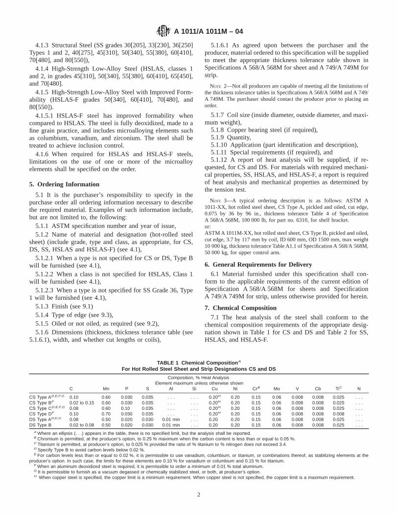
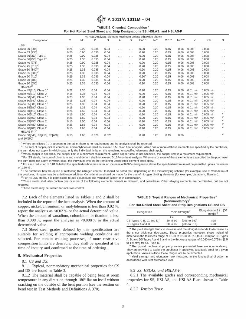


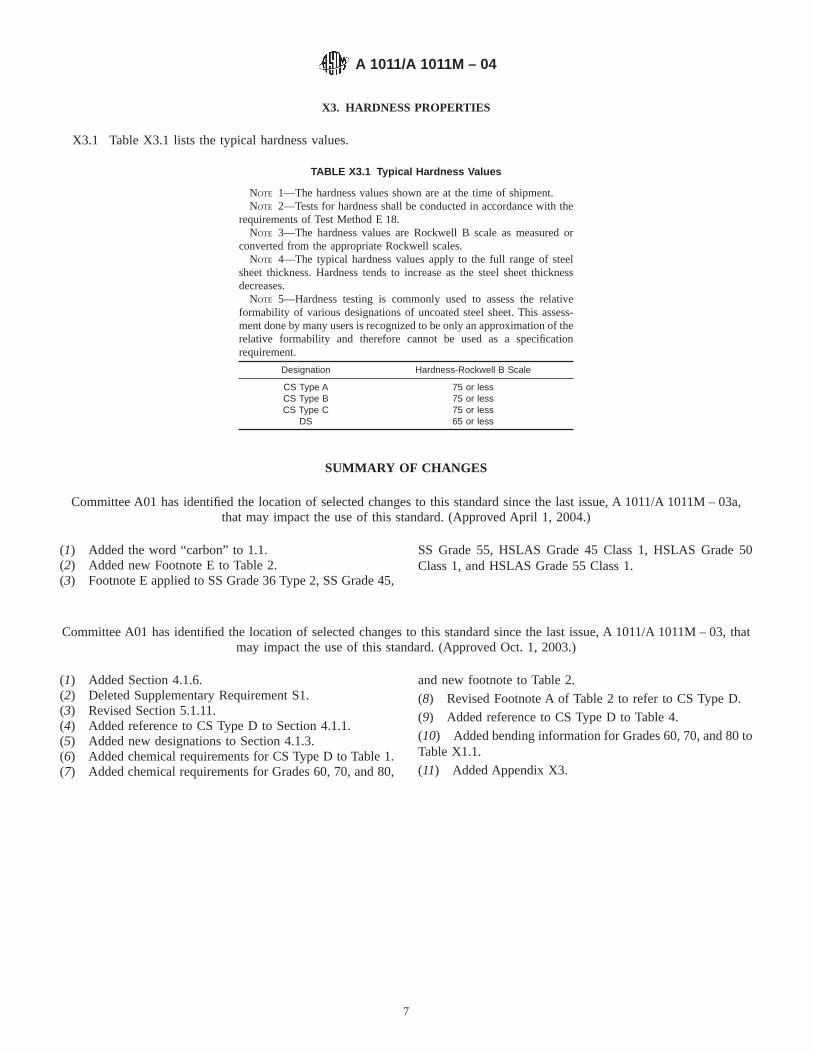

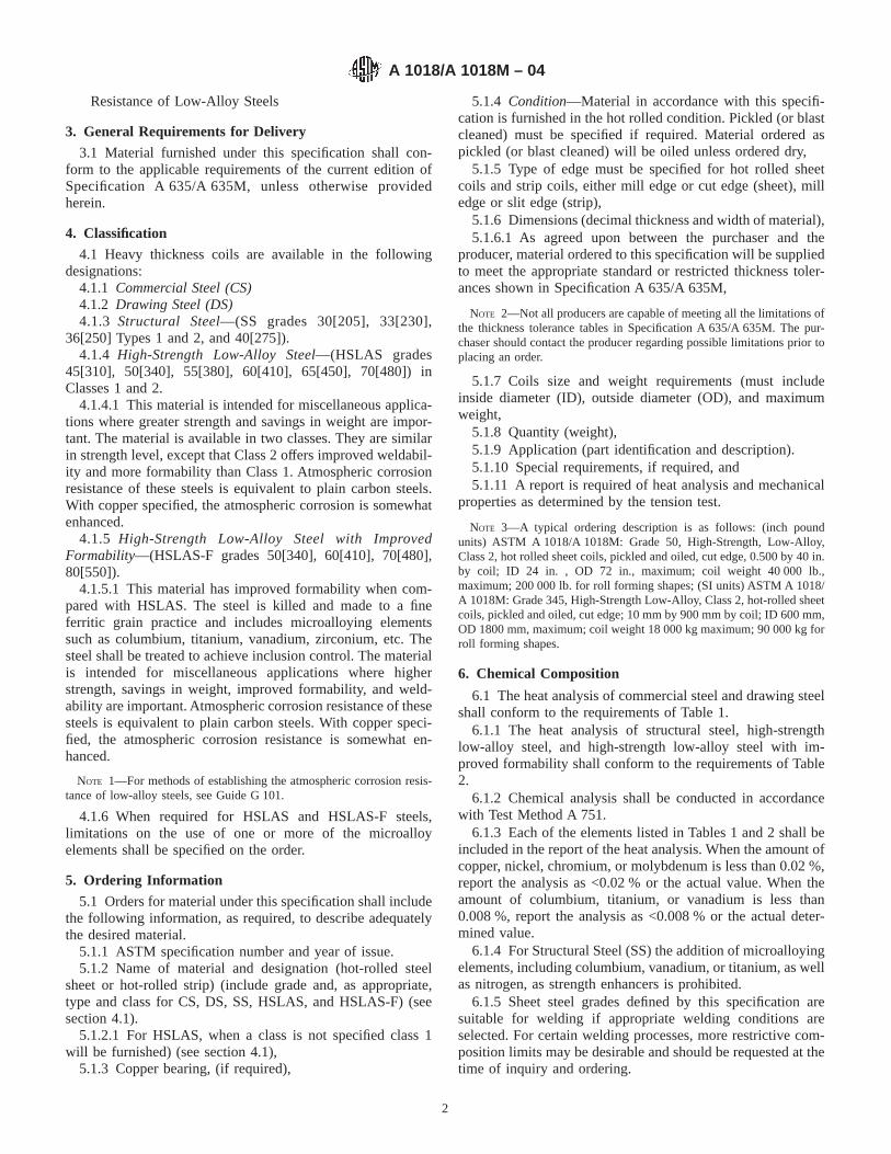

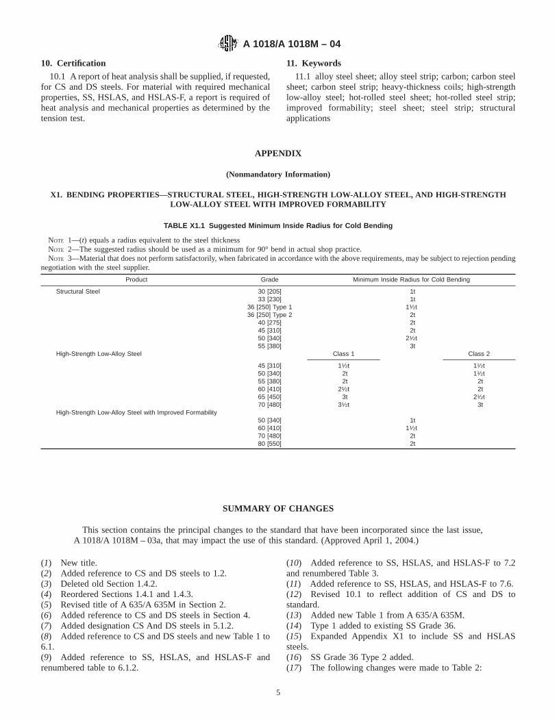


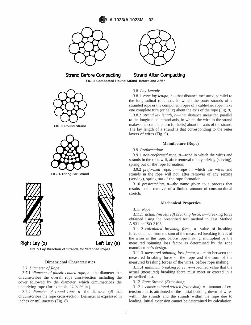

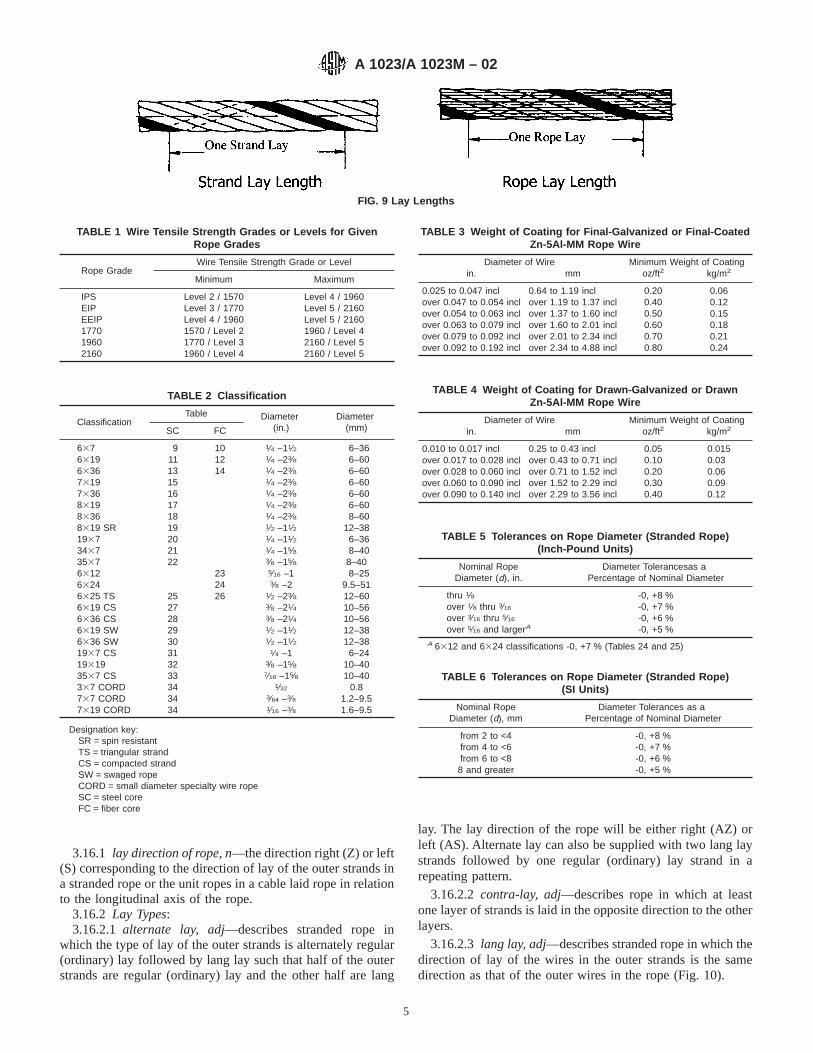


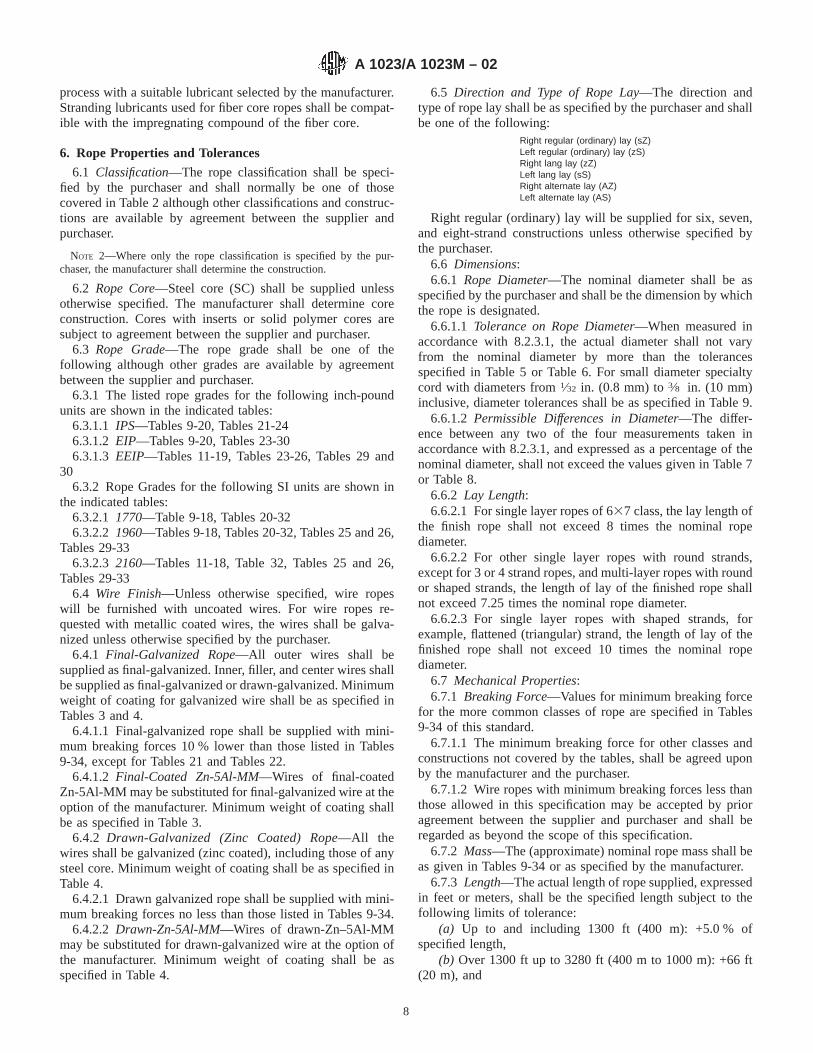


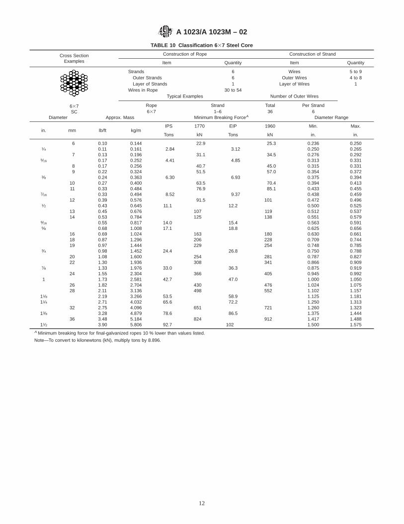

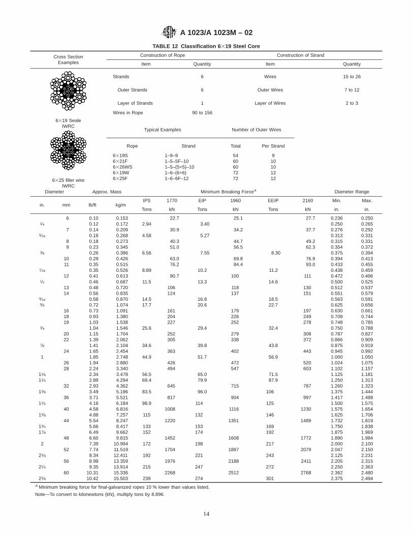
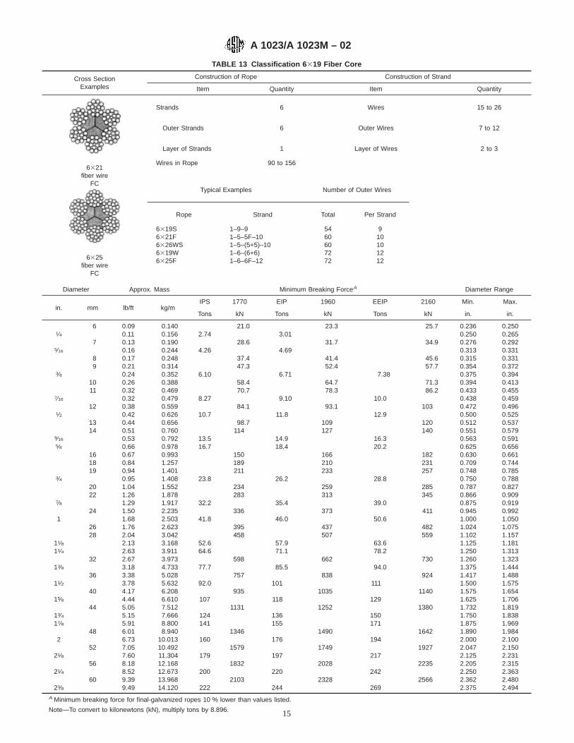


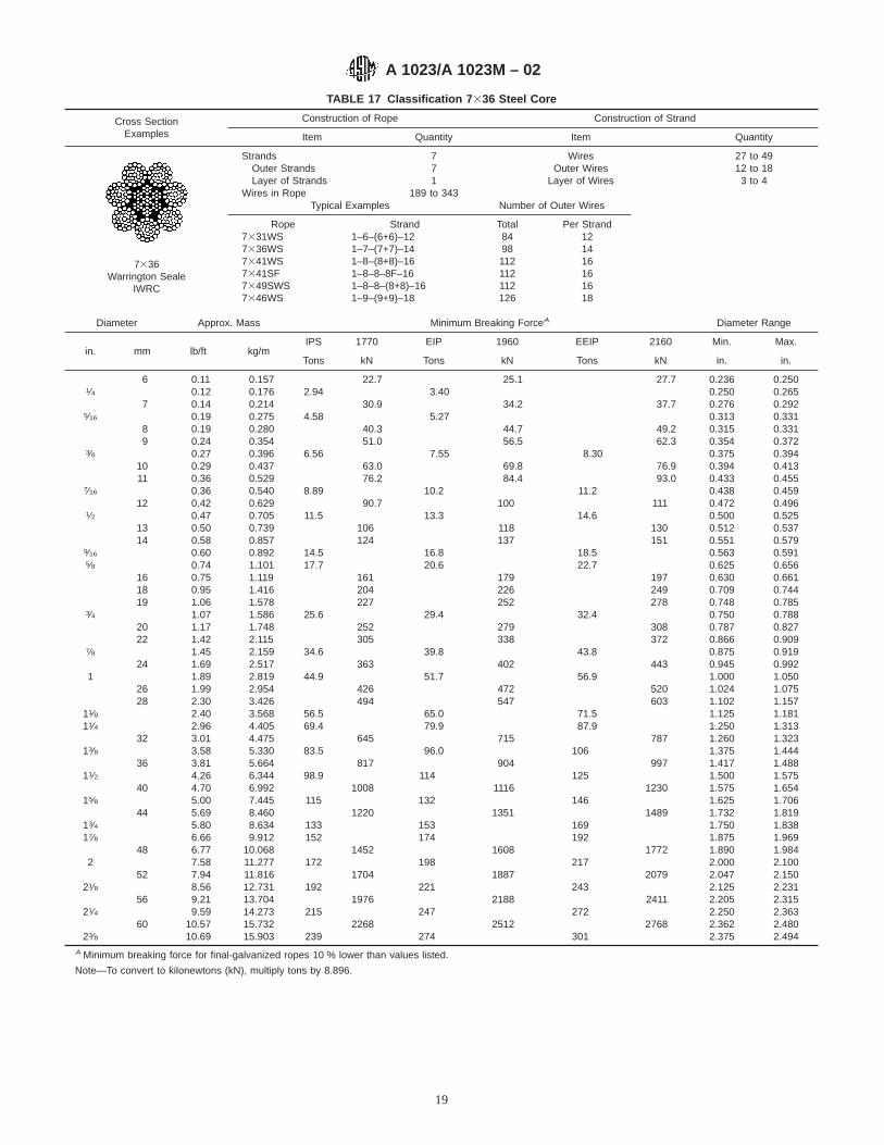
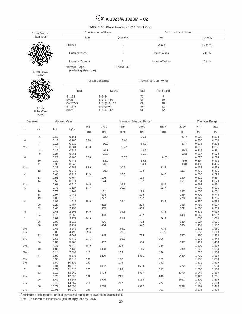

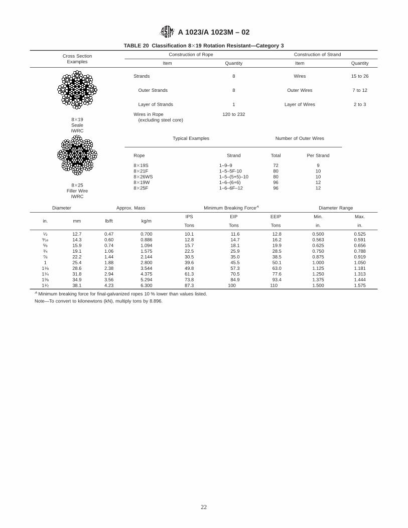

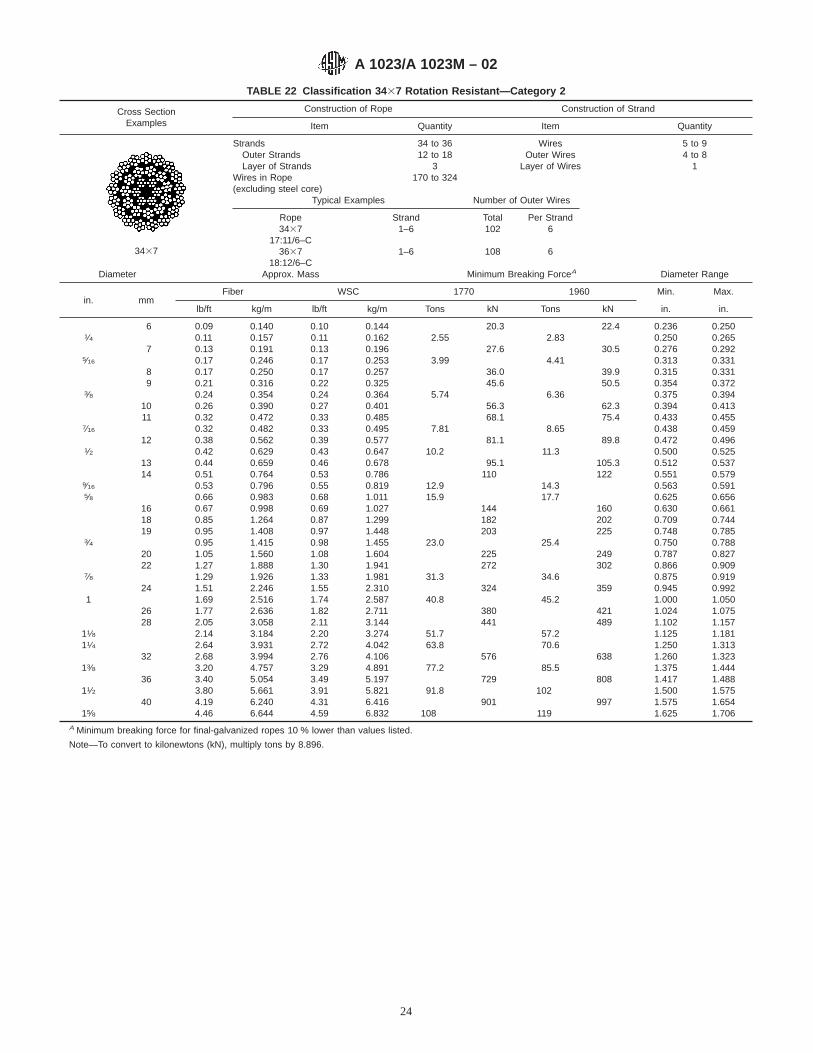


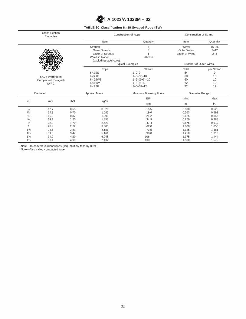


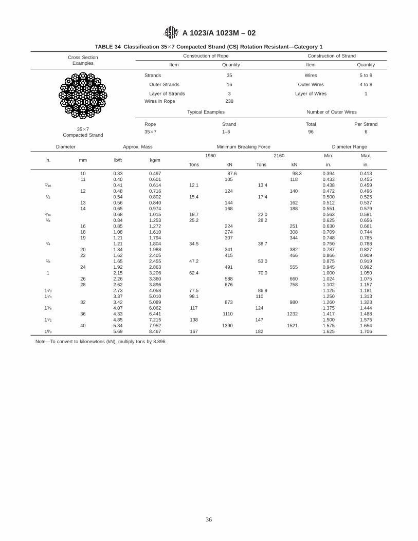


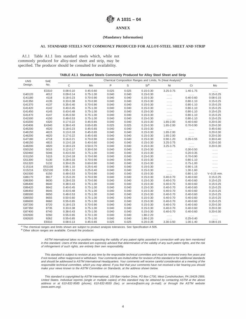


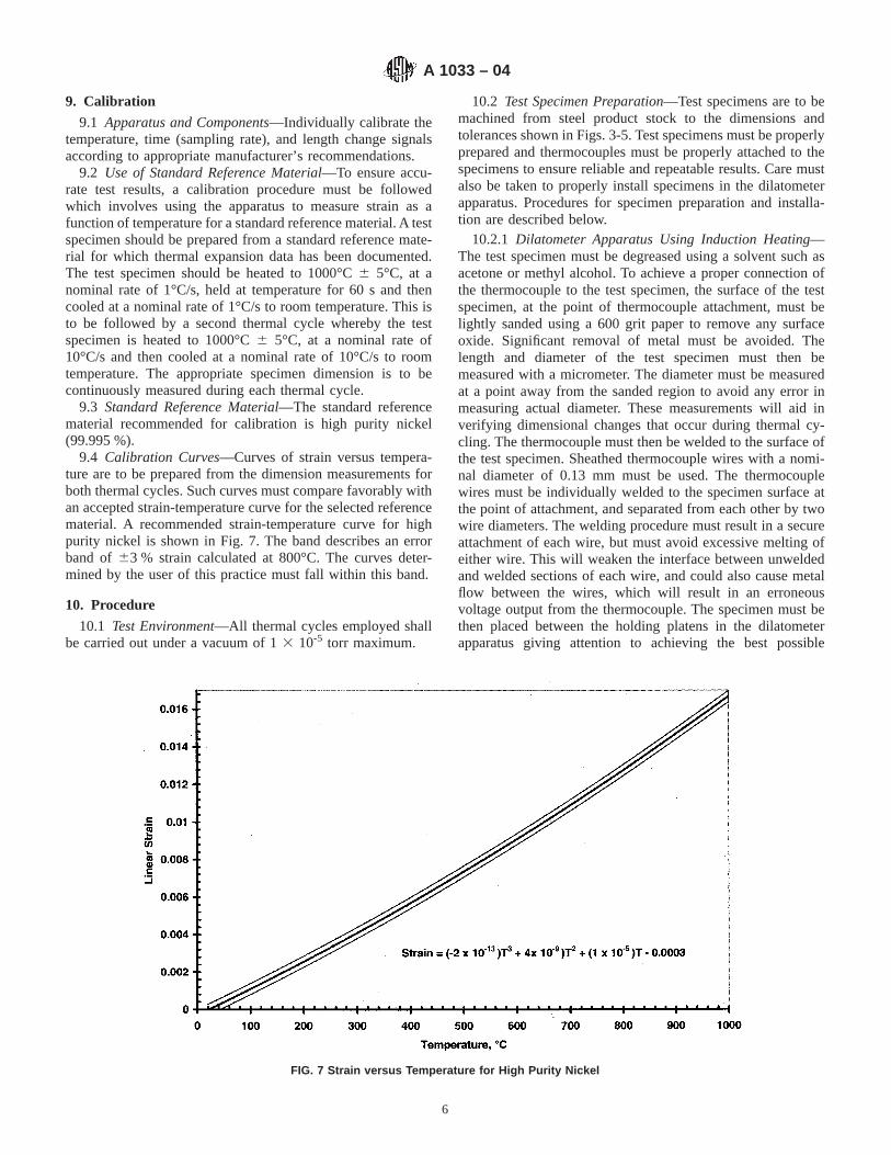

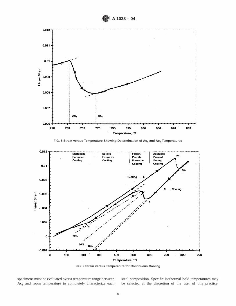


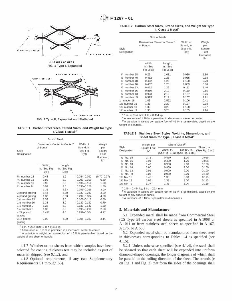


![Machine Learning Basics - archive.ece.cmu.eduece739/lectures/18739...2 =[0.25, 0.25, 0.25, 0.25] L2 penalty of w 1 =1.0 L2 penalty of w 2 =0.25 Final classifier encouraged to take](https://static.fdocuments.in/doc/165x107/5f09ebce7e708231d42924ae/machine-learning-basics-ece739lectures18739-2-025-025-025-025-l2.jpg)