Standard Parabolic Series for 5.25-5.85 GHz Frequencies - Meltec
104
T ABLE OF C ONTENTS ANTENNA CONFIGURATION 4 RADIO WAVES PLANNING TOOL 5 MICROWAVE SYSTEMS OVERVIEW 6 TYPES OF MICROWAVE ANTENNAS 7 MICROWAVE ANTENNAS: A TECHNICAL LOOK FEED ASSEMBLIES 8-9 ANTENNA TERMINOLOGY 10-11 CABLE 12 ACCESSORIES AND HARDWARE 13 ANTENNA CONSTRUCTION 14 TYPICAL USAGE TABLE & VSWR TO RETURN LOSS CONVERSION CHART 15 POWER CONVERSION TABLE 16 RECTANGULAR WAVEGUIDE REFERENCE TABLE 17 FOCAL LENGTH TO DIAMETER RATIO VS. ANGULAR APERTURE FOR P ARABOLIC REFLECTORS 18 RADIO WAVES BROADBAND FIXED WIRELESS PRODUCTS 19 SECTOR SERIES ELECTRICAL SPECIFICATIONS 20-26 OMNI ANTENNA SERIES ELECTRICAL SPECIFICATIONS 27-28 SP & HP SERIES ELECTRICAL SPECIFICATIONS - 1.3 TO 5.8 GHZ PRODUCTS 29-41 RD SERIES ELECTRICAL SPECIFICATIONS 42-43 FLAT P ANEL, XCELARATOR & GRID P ARABOLIC SERIES ELECTRICAL SPECIFICATIONS 44-47 RADIO WAVES POINT -TO-POINT P ARABOLIC ANTENNAS INTRO 48 HP AND SP SERIES ELECTRICAL SPECIFICATIONS - 5.8 TO 86 GHZ PRODUCTS 49-79 P ARABOLIC ANTENNA REGULATORY COMPLIANCES (FCC AND ETSI) 80-81 ICEGUARD TM ANTENNA HEATER SYSTEM 84-89 ANTENNA DIMENSIONS 85-90 SECTOR & PRO-VIDER SERIES 84 FLAT P ANEL AND XCELARATOR SERIES 84 GRID P ARABOLIC SERIES 85 HP SERIES 86-87 SP SERIES 88-89 ANTENNA WINDLOADS 90-92 SIDE STRUTS 93 FLANGES 94-95 FLEX TWIST WAVEGUIDE 96-97 FLEX TWIST ORDERING GUIDE 98 SHIPPING INFORMATION 99-101 TERMS AND CONDITIONS 102 WARRANTY 103 Radio Waves, Inc. http://www.radiowavesinc.com 3 978-459-8800 • 978-459-3310 Fax 299853 Text-rev1:catalog_2008_a 3/6/2012 6:55 PM Page 3
Transcript of Standard Parabolic Series for 5.25-5.85 GHz Frequencies - Meltec

TABLE OF CONTENTSANTENNA CONFIGURATION 4RADIO WAVES PLANNING TOOL 5MICROWAVE SYSTEMS OVERVIEW 6TYPES OF MICROWAVE ANTENNAS 7MICROWAVE ANTENNAS A TECHNICAL LOOK
FEED ASSEMBLIES 8-9ANTENNA TERMINOLOGY 10-11CABLE 12ACCESSORIES AND HARDWARE 13ANTENNA CONSTRUCTION 14
TYPICAL USAGE TABLE amp VSWR TO RETURN LOSS CONVERSION CHART 15POWER CONVERSION TABLE 16RECTANGULAR WAVEGUIDE REFERENCE TABLE 17FOCAL LENGTH TO DIAMETER RATIO VS ANGULAR APERTURE FOR PARABOLIC REFLECTORS 18RADIO WAVES BROADBAND FIXED WIRELESS PRODUCTS 19
SECTOR SERIES ELECTRICAL SPECIFICATIONS 20-26OMNI ANTENNA SERIES ELECTRICAL SPECIFICATIONS 27-28SP amp HP SERIES ELECTRICAL SPECIFICATIONS - 13 TO 58 GHZ PRODUCTS 29-41RD SERIES ELECTRICAL SPECIFICATIONS 42-43FLAT PANEL XCELARATOR amp GRID PARABOLIC SERIES ELECTRICAL SPECIFICATIONS 44-47
RADIO WAVES POINT-TO-POINT PARABOLIC ANTENNAS INTRO 48HP AND SP SERIES ELECTRICAL SPECIFICATIONS - 58 TO 86 GHZ PRODUCTS 49-79
PARABOLIC ANTENNA REGULATORY COMPLIANCES (FCC AND ETSI) 80-81ICEGUARDTM ANTENNA HEATER SYSTEM 84-89ANTENNA DIMENSIONS 85-90
SECTOR amp PRO-VIDER SERIES 84FLAT PANEL AND XCELARATOR SERIES 84GRID PARABOLIC SERIES 85HP SERIES 86-87SP SERIES 88-89
ANTENNAWINDLOADS 90-92SIDE STRUTS 93FLANGES 94-95FLEX TWIST WAVEGUIDE 96-97FLEX TWIST ORDERING GUIDE 98 SHIPPING INFORMATION 99-101TERMS AND CONDITIONS 102WARRANTY 103
Radio Waves Inc httpwwwradiowavesinccom 3
978-459-8800 bull 978-459-3310 Fax
299853 Text-rev1catalog_2008_a 362012 655 PM Page 3
AANNTTEENNNNAA CCOONNFFIIGGUURRAATTIIOONN MMAATTRRIIXX
Radio Wavesrsquo model number system describes 1) the antenna type 2) the diameter 3) the operating frequency band and 4) the connector1) Antenna type The prefix defines the antenna type
Use DescriptionDP Deep Dish Parabolic Plane PolarizedDPD Deep Dish Parabolic Dual PolarizedHPCPE HP DiscriminatorTM Series Plane PolarizedHPLP HP Low Profile Shielded Plane PolarizedHPLPD HP Low Profile Shielded Dual PolarizedHP HP Shielded Plane PolarizedHPD HP Shielded Dual PolarizedLPA Log Periodic ArrayOMN OmniSP SP Unshielded Plane PolarizedSPD SP Unshielded Dual PolarizedSHP Ultra High PerformanceSHPD Ultra High Performance Dual Polarized
2) Antenna Diameter The number selected will determine theantenna size in feet
Use Description1 1 ft (03m)2 2 ft (06m)3 3 ft (09m)4 4 ft (12m)6 6 ft (18m)8 8 ft (24m)
3) Frequency Band The numberselected will determine the antennaoperating frequency GHzUse Description47 44-5052 5250 - 585057 5725 - 642559 5925 - 64256 57 - 712564 6425 - 71257 7125 - 77577 7125 - 8508 775 - 85010 1015 - 1071011 105 - 11711 107 - 11712 122 - 12713 1270 - 132515 1425 - 153518 177 - 19723 212 - 23624 2425 - 252526 2425 - 265028 273 - 31331 295 - 31333 313 - 33438 370 - 40042 405 - 43560 557 - 66073 710 - 76080 710 - 86083 810 - 860
ExampleHP4-77RSHigh Performance Antenna 4-ft (12m) 7125 - 850 GHz with CPR112G Interface
Please see page 55 for more detail on flanges
Antennarsquos with OEM Direct Connect InterfacesRadio Waves with our innovative patented feed design has developed numerous OEM interfaces since 1988These direct connect antennas are available in diameters from 1 ft (03m) to 8 ft (24m) in frequency bandsranging from 59 to 86 GHz These direct connect interfaces offer an improved overall system performancewhile reducing system cost and installation time
RFID Radio Waves can supply antennas with RFID tags for a small extra feeRadio Waves Inc
4 httpwwwradiowavesinccom salesradiowavesinccom
4) Connector A Type ldquoNrdquo (Female) Connector is also available Please add Suffix ldquoNSrdquo to the modelnumber when ordering ldquoNSrdquo models are non pressurized Add suffix ldquoSMArdquo for SMA Connector
ldquoRSrdquo models will be supplied with flanges These models can be pressurized to 5 psiOther flange types are available please contact an authorized Radio Waves representative The electricalspecifications for the parabolic antennas notes which flange size is utilized
299853 Text-rev2catalog_2008_a 3152012 915 PM Page 4
RRAADDIIOO WWAAVVEESS SSYYSSTTEEMM PPLLAANNNNIINNGG TTOOOOLLRRFF IINNDDOOOORRSS
Radio Waves Inc httpwwwradiowavesinccom 5978-459-8800 bull 978-459-3310 Fax
299853 Text-rev1catalog_2008_a 362012 655 PM Page 5
MMIICCRROOWWAAVVEE SSYYSSTTEEMMSS OOVVEERRVVIIEEWWWWHHYY MMIICCRROOWWAAVVEE
Microwave communication is a cost-effective and efficient means to connect two or more wireless points together over avariety of terrains and space where continuous runs of cable or fiber type transmission lines would not be practical or evenpossible As basic as linking two wireless locations together or when used in a network combining a series of hops formingvast relays to link a nation microwave driven communication is used to connect even the far reaches of space with ground-to-space and satellite-to-satellite communications Cellular and Personal Communications Service (PCS) providers employmicrowave communication for wireless inter-connects between remote tower sites and switching centers Microwave datalinks provide wide bandwidths for multiple-mode transmissions equivalent to and even greater than two points linked withtraditional transmission line cables Broadband wireless systems that provide robust LAN and WAN solutions are beingdeployed globally due to their ease of installation high performance and cost effectiveness
Coverage AreaThe most critical element of any microwave system is the ability to focus coverage in themost useful area For long distance networking hops it is the antennarsquos ability to efficientlyfocus a signal into a narrow beam Parabolic antennas typically use a center-fed feed horndesign that is similar to a flashlight A parabolic-shaped microwave antenna is capable ofsignal beamwidths of less than a few degrees which is necessary for reliable and interfer-ence free point-to-point communication However not all communications using microwavefrequencies require such focused designs Point-to-multipoint subscriber services andLANWAN networks typically require a broad service area to be illuminated Specializedantenna designs in the form of flat panels and tuned sector arrays use a combination ofbeam steering techniques to electronically direct a wider beamwidth of microwave signalsinto the desired coverage area often referred to as a sector
ApplicationsWith the introduction of new and affordable digital technologies licensed and unlicensed(spread spectrum) microwave data links now serve many specialized markets including in-building wireless LANrsquos point-to-multi point internet regional broadcast subscriber servicesand other new and emerging modes of personal and business communications Broadbandwireless access (BWA) is the provision of broadband high-speed and high capacity fixedwireless data systems for Internet access wireless local loop and other applications utilizedby both home and business customers A wide variety of frequencies are utilized for theseservices including MDSMMDS and unlicensed spread spectrum frequencies in the 2 GHzband licensed fixed wireless spectrum in the 35 GHz band UNII band frequencies in the 5GHz band LMDS bands at the high end of the microwave frequencies such as 38 GHz andultra high capacity solutions at 80 GHz These systems are deployed in either a point-to-pointor point-to-multi point fashion
AdvantagesBroadband wireless access systems have several advantages over traditional wire line and fiber ring connections They can bedeployed and implemented faster than wired systems which reduces the time required by an operator to recoup capitalinvestments This also allows operators to deploy these systems in a scalable or as-needed basis and build-out to system tocover certain areas and customers as required which reduces the upfront capital requirements Wireless LANs WANs andWISPs (wireless Internet service provider) are providing communities around the globe cost effective access to InternetWLL and other data services Over time this will help to grow the global economy and bring better lifestyles to all
Why microwave The wide range of wireless applications are apparent and around us every day Operating seamlessly quietly and unobtrusively to provide us with the widest range of instant communications for today tomorrow andwell into the future
Radio Waves Inc 6 httpwwwradiowavesinccom salesradiowavesinccom
299853 Text-rev1catalog_2008_a 362012 655 PM Page 6
TTYYPPEESS OOFF MMIICCRROOWWAAVVEE AANNTTEENNNNAASS
Microwave Antenna TypesThere are several basic ldquotypesrdquo of microwaves antennas Each type has certain advantages anddisadvantages for particular applications in microwave and broadband wireless networks
Grid Parabolic AntennasAt lower frequencies below 3 Gigahertz a parabolic reflector can be simulated by a ldquogridrdquo of reflective elements This arrangement greatly reduces wind loading on a tower or other mounting structure Grid antennas have a lower front-to-back ratio than solid parabolic antennas They are also limited to a single polarization They are ideal in applications wherethe best performance is not required and tower and windloading are the main concern
Standard Parabolic AntennasStandard microwave antennas consist of a parabolic shaped reflector spun from a sheet ofaluminum The parabolic shape focuses energy at the feed point of the antenna These parabolic antennas have a narrow focused beam of energy and relatively high gain compared to many other types of antennas These antennas will have a mounting system to attach theantenna to a pipe tower leg andor a specific radio in some cases
High Performance AntennasHigh Performance antennas are formed of aluminum which isspun to precise tolerances Then a shroud is also fabricated ofaluminum and fitted with a planar radome to protect the feedand provide for a significant reduction in side lobes Often manufacturers will utilize absorber material to improve the pattern performance of the side lobes and front-to-back ratio The exception is the DicriminatorTM series from Radio Waves which utilizes a molded plastic reflector that is shaped foroptimum side lobe performance
Sector AntennasSector antennas are designed to provide segmented microwave coverage over a selected (sector)area sector antennas deliver a wider beamwidth than point-to-point parabolic antennas Sectorantennas are typically used for ISM WLL and MMDS band communications utilizing SpreadSpectrum data streams for wireless connections between LAN base stations wireless Internetsubscriber networks PCS and other point-to-multi point communications Antenna configura-tions can consist of flat panel micro strip and slot radiating designs as well as traditional para-bolic configurations Some common horizontal beamwidths utilized include 60 90 120 and 180degrees Radio Waves sector antennas are the best performers in the industry
Flat Panel AntennasRadio Waves offers a complete and diverse line of flat panel antennas for point-to-point and point-to-multi point terrestrial microwave applications These flat panel antennas are designed to be lightweight easy to install aligned and durable for years of reliable service All of Radio Wavesrsquo flat panel antennas are designed to be aesthetically pleasing and unobtrusive These antennas are ideal for concealment in many architectural environmentsSectorpanel antennas for multi point networks are available in a variety of sector offerings and operatingbands
The Xcelarator family of 5 GHz panels offer superior electrical performance
Radio Waves Inc httpwwwradiowavesinccom 7978-459-8800 bull 978-459-3310 Fax
299853 Text-rev1catalog_2008_a 362012 655 PM Page 7
MMIICCRROOWWAAVVEE AANNTTEENNNNAASS AA TTEECCHHNNIICCAALL LLOOOOKKFFEEEEDD AASSSSEEMMBBLLIIEESS
Feed AssembliesA basic schematic for a microwave antenna can be seen in Figure 1 A feed sys-tem is placed with its phase center at the focus of the parabola Ideally all theenergy radiated by the feed will be intercepted by the parabola and reflected inthe desired direction To achieve maximum gain this energy would be distributedsuch that the field distribution over the aperture is uniform However becausethe feed is small such control over the feed radiation is unattainable in practiceSome of the energy actually misses the reflecting area and is lost this is com-monly referred to as ldquospilloverrdquo Also the field is generally not uniform over theaperture but is tapered maximum signal at the center of the reflector less signalat the edges This ldquotaper lossrdquo reduces gain but the field taper provides reducedside lobe levels Optimum performance is generally considered to be achievedwith a ndash10 dB edge illumination taper
Dipole FeedOne of the simplest feeds for a microwave antenna is the dipole Due to its simplicity the dipole was the first to be used as afeed for reflector antennas While easy to design and implement the dipole feed has inherently unequal E and H plane radia-tion patterns which do not illuminate the dish effectively and thus reduce efficiency Another disadvantage of the dipole feedfor some applications is that due to unequal radiation patterns cross-polarization performance is not optimal Small sub-reflectors of various designs located behind the dipole will improve the feed pattern performance and gain The dipole feedmay also be utilized as feeds for non-symmetrical grid parabolas The usage of a corner reflector behind the dipole can alsoenhance pattern performance and gain in many designs The dipole feed is generally used for frequencies of less than 5 GHz
Waveguide FeedThe open-ended waveguide is another type of simple feed Like the dipole feed it has inherently unequal E and H planeradiation patterns which leads to poor radiation patterns and efficiency By flaring the waveguide opening into a horn shapethe patterns in both planes can be equalized The flare must be gradual such that the E and H plane phase centers are rea-sonably close to each other Some designs also use circular openings or various arrangements of ldquochokesrdquo or ldquobafflesrdquoattached to the outside of the feed to improve performance
Buttonhook DesignThese rectangular waveguide feeds are often designed by bending a solid wave-guide into a curve such that the waveguide input is at the vertex of the dish andthe feed is located at the focal point of the parabola The ldquobutton-hookrdquo (or J-hook) design has been a staple of commercial microwave antenna design fordecades This style of feed can provide excellent VSWR performance which wasimportant with older generation analog microwave radios However scatteringoff the waveguide and feed support structures causes radiation pattern distortionAlso bending waveguide is an expensive operation requiring highly skilled laborSpecial techniques must be used for dual linear or circular polarization
Radio Waves Hybrid DesignDuring the 1980s the need became greater for a lower profile microwave antennathat also exhibited superior pattern performance Two forces drove this require-ment One was the need to reduce the visual impact of radio communicationinstallations The other was the need to place more and more microwave ldquolinksrdquoin the same geographic area In 1988 Radio Waves introduced one of the firsthybrid-Cassegrain sub-reflector type feeds for high frequency commercialmicrowave antennas This design is a modification of the classical Cassegrain feedsystem
Defining the FD Ratio
A common way to define a parabolicdish shape is with the FD ratio whereF is the focal length and D the diame-ter of the dish the smaller the ratiothe ldquodeeperrdquo the dish Most commer-cial microwave antennas utilize anFD ratio of 25 to 38 with 32 to 36being the most common The FDratio for a reflector can be determinedby measuring the depth of the dishfrom the plane of the rim to the vertexat the center and using the basic equa-tion for a parabolic curve Typicallyonly measurement from the vertex tothe rim is required since a parabola ofrevolution consists of the same shapecurve for all radial sections
Radio Waves Inc 8 httpwwwradiowavesinccom salesradiowavesinccom
Fig 1 Schematic of Microwave Antenna
299853 Text-rev1catalog_2008_a 362012 655 PM Page 8
MMIICCRROOWWAAVVEE AANNTTEENNNNAASS AA TTEECCHHNNIICCAALL LLOOOOKKFFEEEEDD AASSSSEEMMBBLLIIEESS
Cassegrain SystemsIn a Cassegrain system a feed is mounted in the dish and energy is radiated towards a sub-reflector With a hybrid-Cassegrain system the energy is transported through a circular waveguide that radiates into a reflective surface at the focalpoint This reflected energy is then prorogated through a carefully shaped dielectric lens mounted between the sub-reflectorand waveguide tube The dielectric lens is typically made from a piece of rexolite which has a dielectric constant of 254An illustration of this feed is shown in Figure 2 At times this design is mistakenly referred to as a ldquoback-firerdquo feed systemA back-fire feed does not incorporate the dielectric lens and suffers from poor side lobe performance relative to the hybrid-Cassegrain style feed
This hybrid-Cassegrain design has several benefits over the button-hook design including higher antenna efficiency Since the hybrid-Cassegrain feed is shorter than the J-hook feed the entire antenna hasa lower profile and lower wind loading The feeds use a circularwaveguide that provides inherent dual-polarization capability This isthe feed system typically used at Radio Waves
Polarization is determined by the orientation of the input device (rectangular to circular transition or omt) that can easily be rotated to change polarization Modern electromagneticsimulation software allows the reflecting surface of the feed to be shaped to provide superior control of radiation pattern Asthese feeds are self-supporting there is no scattering off of the feed support system as in the button-hook design One slightdisadvantage of these designs is that they have higher VSWR than button-hook feed designs However with todayrsquos digitalradios this does not cause degradation in performance These ldquoback-firerdquo feeds are generally utilized for frequencies of 5GHz to 60 GHz For modern radio systems requiring high efficiency in a smaller package the hybrid-Cassegrain feed reflec-tor antenna is most applicable
In summary hybrid-Cassegrain feed antennas provide optimum mechanical and electrical performance for modernhigh frequency digital microwave radio systems Applications that still use older analog radios requiring very stringentVSWR specifications are best served by antennas using buttonhook feed systems Dipole feed systems can be used forapplications below 6 GHz that require a low-cost antenna and do not demand the most robust pattern performanceHowever for modern high frequency microwave radio systems requiring high efficiency in a smaller package the hybrid-Cassegrain feed reflector antenna is most applicable
Plane Polarized FeedsThe angular orientation of a microwave signal can be fixed in either a vertical or horizontal electrical plane A plane polar-ized microwave feed also known as a single polarized feed sends and receives signals oriented in just one of two planes Asingle polarized feed set in a vertical orientation will pass vertically polarized signals while electrically suppressing anyother microwave signals that are 90 degrees off plane in a horizontal orientation
Dual Polarized FeedsDual Polarized feeds can detect both vertical and horizontal signal polarizations separately but simultaneously while keep-ing each signal polarization isolated from the other A dual polarized antenna system performs the same function as two sep-arate single plane polarized antennas reducing infrastructure costs and tower congestion Two feed inputs are provided oneeach for the vertical and horizontal polarizations
HP and SP FeedsPlane polarized non-pressurized feeds are compact and completely sealed units designed to accommodate the insertion ofthe feed into the antenna from the back of the reflector Polarization orientation is adjustable in either a vertical or horizontalplane Feed input flange or connector type is dependent on the feed operating frequency Feeds can be pressurized to 5 psi
HPD and SPD FeedsDual polarized feeds are designed for simultaneous operation in both vertical and horizontal planes The rear-inserted feedsare sealed and watertight assemblies that feature a -30 dB cross-polarization discrimination (XPD) or better Feed inputflange or connector type is dependent upon the feed operating frequency
Radio Waves Inc httpwwwradiowavesinccom 9
Fig 2 Basic Outline of Hybrid Cassegrain Feed
Fig 1 Schematic of Microwave Antenna
978-459-8800 bull 978-459-3310 Fax
299853 Text-rev1catalog_2008_a 362012 655 PM Page 9
MMIICCRROOWWAAVVEE AANNTTEENNNNAASS AA TTEECCHHNNIICCAALL LLOOOOKKAANNTTEENNNNAA TTEERRMMIINNOOLLOOGGYY
Microwave Antenna PatternsThe antenna pattern is a graphical representation of the antennarsquos electrical performance in free space Measured andrecorded from actual test range data in two orthogonal planes such as E and H planes and Vertical and Horizontal planesthe pattern is plotted either in rectangular or polar coordinates A typical pattern will contain a main signal beam and sever-al minor side lobes of radiated signal The plotted pattern data is determined from multiple measurements taken from threefrequencies - bottom middle and top of the specified band in both co-polar and cross polar conditions horizontal and ver-tical polarizations and recorded over the full 360 degrees of antennarsquos azimuth Since an antenna pattern changes slightlywith frequency and the plotted pattern is drawn from only the highest or worst case peaks for all measured data pointsactual antenna interference rejection for signal angles other than the desired main beam will often be much better than indi-cated in the published antenna pattern Radio Waves antenna patterns are on file with Radio Waves the FCC frequencycoordination houses and other government agencies throughout the world
RPERadiation pattern envelopes are a common method of graphically displaying microwave antenna pattern information in away that is easy to use for microwave system planning RPEs represent the worst peaks in side-lobe energy and accuratelyrepresent the expected pattern performance The RPE is composed of simple straight lines that connect all the defined peaksof energy In fact our antennas will often exceed the performance outlined in the RPE At Radio Waves our highly automat-ed and accurate manufacturing process ensures that each antenna meets your expectations as well as its RPE
Antenna GainComparing the electrical field strength of an antenna to that of a reference antenna provides a gain figure measured in dBThe gain of an antenna is a measure of how well the antenna concentrates its radiated power in a given direction When thefree-space reference is an isotropic antenna the gain is expressed in dBi and when the reference antenna is a half-wavedipole the gain figure is expressed in dBd Microwave antennas are typically specified in dBi Antennas are usually meas-ured at three frequencies the bottom middle and top of the band Antenna gain is a measurement of how well an antennafocuses energy and generally the higher the gain the narrower the beamwidths
Antenna EfficiencyWhen power is input to an antenna the antenna never radiates 100 of the power Some of the power is lost and convertedinto heat Antenna efficiency is a measurement of how efficiently an antenna radiates power versus how much power isapplied to the antenna The lower distributed losses in the component of an antenna the higher the antenna efficiency andthe higher the gain for a given size
Half Power BeamWidth (HPBW)Half Power BeamWidth is the nominal angular width of the main beam between its -3 dB points (half power) Measured indegrees from the center of the main beam the value is typically nominal and stated as the minimum performance value forthe operating frequency band Beamwidth typically decreases as antenna gain increases A systemrsquos maximum beamwidth isdependent on its required coverage area while complying with system design to keep all unnecessary signal interference toa minimum from any adjacent microwave systems
Wavelength SpeedOne can easily observe how electromagnetic energy behaves by observing light energy or by observing waves generatedby a rock thrown into a pond of water The term wavelength refers to the distance the wave travels during the time ofone cycle In free space these electromagnetic waves travel 300 million meters per second which we call the ldquospeed oflightrdquo The equation for calculating this speed is c = f λ whereC = the speed of light (3 x 10⁸ meters per second)f = the frequency in hertzλ = the wavelength in metersFor high frequency systems such as microwave frequency is commonly measured in gigahertz and wavelength isexpressed in centimeters At Radio Waves we specialize in the design and manufacturing of innovative microwave andbroadband wireless antennas from 2 to 80 GHz
Radio Waves Inc 10 httpwwwradiowavesinccom salesradiowavesinccom
299853 Text-rev1catalog_2008_a 362012 655 PM Page 10
How Important is VSWR
We sometimes receive enquires asto how important antenna feedVSWR is to large diametermicrowave antennas utilized fortraditional back-haul systems Inthe past most microwave radiosystems utilized analog radios thatrequired very low VSWR of 111or better for optimum performanceNew digital microwave radios donot require this low a VSWR forproper operation While one shouldassure that the antenna has aVSWR of 151 to assure properperformance there is not a require-ment to try and achieve a signifi-cantly better VSWR in most cases As an example compare a VSWRof 111 with a VSWR of 131which are both excellent Twomethods of comparison would beto evaluate the difference in systempower loss due to the VSWR andthe percentage of reflected powerdue to the VSWR At a VSWR of131 the power loss due to thereflection is 07 dB With a VSWRof 111 the power loss is 01 dBThus the difference is 06 dB or6100 of a dB which is an imper-ceptible difference
In regards to percentage of reflect-ed power the antenna with aVSWR of 131 reflects 15 ofthe power and the antenna with 111 VSWR reflects 3 of thepower Thus if the input power is 1watt the amount reflected back intothe transmission line from theantenna with a VSWR of 131 is015 watts an amount of powerthat is not a factor for system per-formance The difference betweenthese two values of VSWR is not aperceptible factor in system per-formance and resources are betterutilized reviewing factors that canoptimize system performance
MMIICCRROOWWAAVVEE AANNTTEENNNNAASS AA TTEECCHHNNIICCAALL LLOOOOKKAANNTTEENNNNAA TTEERRMMIINNOOLLOOGGYY
VSWRVSWR is the ratio of the maximum to minimum values of the electrical standingwave pattern along a transmission line to which a resistive load is connectedVSWR value ranges from 1 (matched load) to infinity for a short or open load Astanding wave pattern is reflected energy dissipated in heat along a transmissionline typically caused by an impedance mis-match between the load (antenna) andthe transmission line VSWR is also expressed as a Return Loss value measured indB Another way of expressing VSWR is return loss which is the decibel differ-ence between the power incident on the mismatch and the power reflected from themismatch
Front-to-Back Ratio (FB)This is a value specified in dB below the peak of the main beam relative to ameasured angular zone 180 degrees from the primary point of measurement It isthe amount of energy radiated in the rear of the antenna Certain antennas designssuch as the HP style parabolic reflectors will have higher front-to-back ratios thanother antenna designs FB can be important to assure proper frequency re-use inmicrowave systems
PolarizationThe orientation of the electric field vector as measured from a distance from theantenna The propagation modes of electromagnetic waves are measured in planesVertical Horizontal Circular and Elliptical Co-Polarization the intended polar-ization for which the antenna is intended to radiate Cross-Polarization the dif-ference in dB between the peak of the co-polarized main beam and a cross-polar-ized signal typically indicated as the difference between the vertical and horizontalpolarization planes The higher the value the greater the discrimination protectionfrom a signal of perpendicular polarization
IsolationThe signal isolation between two ports of a device generally stated as ndashdB level
Frequency BandsElectromagnetic waves vary in length from the very short to the very long Themicrowave region is considered to be frequencies between 1 and 250 GHz (gigahertz) The wavelengths at these frequencies are 305 cm to 127 mm Forhigh frequency systems such as microwave frequency is commonly measured ingigahertz and wavelength is expressed in centimeters At Radio Waves we spe-cialize in the design and manufacturing of innovative microwave and broadbandwireless antennas from 2 to 80 GHz
Radio Waves Inc httpwwwradiowavesinccom 11
BeamwidthPatternsNarrow beamwidth reduces interface since it is less likely that surrounding RF clutter willcause interface A larger antenna has a narrower beamwidth and thus higher gain Largerantennas with narrower beamwidths and higher gain offer the following benefits
Increased strength of the transmit signalIncreased strength of the intended receive signalReduction of interference from outside the antennarsquos main beam
Choosing Antenna Dish SizeWhen choosing the optimum size parabolic dish for your link or network often going to alarger size dish provides a number of key benefits The narrower beamwidth associatedwith a larger diameter dish reduces interfacesince and it is less likely that surrounding RFclutter will cause interference Additionally the higher gain associated with a larger dishprovides for improved received signal strength by increasing the level of the desired signalWhen unsure always choose the larger size dish to assure optimum link performance
978-459-8800 bull 978-459-3310 Fax
299853 Text-rev1catalog_2008_a 362012 655 PM Page 11
Transmission LinesThese critical conduits guide electrical energy from one point to another When used as a connection between the antennaand the systemrsquos radio transmission lines work to provide a low-loss pathway between the antenna and radio for the trans-fer of RF signals A microwave systemrsquos radio transceiver may be directly connected on the back of an antenna requiringonly that a VHF IF frequency be carried down to the indoor unit (IDU) Considering operating frequency acceptable trans-mission line losses power handling and even physical handling the choice of the correct transmission line for the applica-tion can vary greatly
Flexible Braided Coaxial CableBraided Coaxial Cables are used as jumper assemblies (in short lengths) for an inter-connect between an antenna feed andradio transceiver or to carry IF signals from an ODU (outdoor unit) to an IDO (indoor unit) Jumper assemblies are avail-able in a wide variety of lengths They operate in frequencies below 6 GHz and in various cable diameters Characteristicimpedance is 50 ohms with a wide variety of connector interfaces available These cables can be a very cost effectivetransmission line system for applications such as broadband wireless as well as connecting an ODU to and IDO in high fre-quency point-to-point microwave systems Due to their flexibility these cables are ideal for in-building and in-structureapplications
Semi-Rigid Foam Dielectric Coaxial CableFoam Dielectric Coaxial Cable is the most commonly used cable in the cellular telecommunications industry because of itsexcellent electrical characteristics and reliability Not as flexible as braided cable and slightly heavier due to a solid coppercorrugated outer conductor this type of cable may be used in long transmission line runs with proper handling and installa-tion hardware It is available in a variety of sizes from 14-inch jumper lengths to 2-14rdquo diameters Usable operating char-acteristics are broadband up to approximately 6 GHz
Semi-Rigid Air Dielectric Coaxial CableAir Dielectric Coaxial Cable is more commonly used forhigh power handling such as broadcast installations Thistype of cable shares the same basic cable construction assemi-rigid foam dielectric coaxial cable but with a dielectrichelix supporting the inner conductor instead of a foamdielectric Air Dielectric runs of cable require dry air pressur-ization that typically consists of cylinders of nitrogen or adry air pressurized (dehydrator) system to maintain a drydielectric This type of cable is suitable for long transmissionruns with proper handling and is available in a variety ofsizes from 12 inch to over 6rdquo diameters Usable operatingcharacteristics are broadband up to approximately 6 GHz
Semi-Rigid Elliptical WaveguideSpecifically intended for microwave applications this type of transmission line is frequency-dependent with a relativelynarrow bandwidth requiring the waveguide to be properly matched to its application to achieve a low VSWR Ellipticalwaveguide is constructed from corrugated copper tube formed into an elliptical cross-section This type of transmission linerequires pressurization to prevent moisture accumulation within the waveguide Operating frequency ranges are availableup to and beyond 26 GHz
Indoor Systems with Cable (RF Indoors)Traditional microwave systems have all the RF equipment mounted indoors The equipment is mounted in 19 inch or othersize racks that are located in an enclosed shelter or building for environmental protection These systems are typically forlong haul microwave point-to-point systems that require high output power for these long ldquohopsrdquo The RF is then fed to theantenna through a run of elliptical waveguide
MMIICCRROOWWAAVVEE AANNTTEENNNNAASS AA TTEECCHHNNIICCAALL LLOOOOKKCCAABBLLEE
Radio Waves Inc 12 httpwwwradiowavesinccom salesradiowavesinccom
299853 Text-rev1catalog_2008_a 362012 655 PM Page 12
MMIICCRROOWWAAVVEE AANNTTEENNNNAASS AA TTEECCHHNNIICCAALL LLOOOOKKAACCCCEESSSSOORRIIEESS ampamp HHAARRDDWWAARREE
Waveguide or Cable SystemsSystems utilizing waveguide or coaxial cable transmission lines require proper installation for optimum network perform-ance The use of adequate hangers hoisting grips grounding kits and weather-proofing will assure uninterrupted service inthe years to come In cases where an elliptical waveguide of air dielectric cable is to be employed a system dry air pressur-ization system will need to be implemented In these cases the proper dehydrator and transmission line pressure windowsmust be used for optimum results
ODU Systems (RF Outdoors)Outdoor Units (ODU) are remotely-mounted radio transceivers arranged in a split configuration These units are generallyfound mounted on or near the antenna installation This type of antennaradio installation allows for rapid deployment ofsystems by eliminating long runs of semi-rigid foam dielectric coaxial cable or waveguide while reducing deployment costsThe signal is down-converted to an IF that is then utilized by the indoor unit (IDU) The cable carries the baseband or IFsignal in addition to power and control signals LMR cable is ideal for these applications
Accessory EquipmentAccessories abound to assist in the installa-tion and mounting of antennas to buildingsroof-tops and towers Accessories for trans-mission line systems be it coaxial cable orelliptical waveguide both require the basicinstallation items such as hoisting gripshangers grounding kits wallroof entries andcushioned entry boots
ConnectorsMany choices are available to mate yourtransmission line system to the antenna andradio It is important that you assure theproper connectors are selected and that foroutdoor applications they are properly tight-ened and sealed after installation
Grounding KitsA properly grounded system helps reduce static due to noise and reduces the probability of a lightning strike to your sys-tem It is highly recommended that a minimum of three grounding kits are utilized at each installation one at the top of thetower or vertical run one at the bottom of the run and prior to entry in the building or shelter
HangersHoisting GripsTo ensure many years of service it is important that transmission lines are installed correctly and mounted securely Thiswill assure that high winds do not damage the transmission line over time
WallRoof Feed-ThruThese devices allow the transmission line to be easily routed into the building or shelter while assuring the structure is pro-tected from moisture and other aspects of the outdoor environment
Pressurization SystemsIt is imperative that waveguide transmission line systems be protected from moisture ingression Pressurization equipmentsuch as pressure windows and dehydrators should be selected carefully to assure that your system is properly protected Thepressure window is usually placed in series between the bottom connector and the main waveguide feeder This allows theRF to pass but assures that the transmission line stays pressurized
Radio Waves Inc httpwwwradiowavesinccom 13978-459-8800 bull 978-459-3310 Fax
299853 Text-rev1catalog_2008_a 362012 655 PM Page 13
MMIICCRROOWWAAVVEE AANNTTEENNNNAASS AA TTEECCHHNNIICCAALL LLOOOOKKAANNTTEENNNNAA CCOONNSSTTRRUUCCTTIIOONN
Microwave Antenna ConstructionMicrowave antennas are often deployed in very difficult environments and must be built of the highestquality materials
Sector AntennasSector antennas are designed to provide segmented microwave coverage over a selected (sector) areasector antennas deliver a wider beamwidth than point-to-point parabolic antennas Sector antennas aretypically used for ISM WLL and MMDS band communications utilizing Spread Spectrum datastreams for wireless connections between LAN base stations wireless Internet subscriber networksPCS and other point-to-multipoint communications Antenna configurations can consist of flat panelmicro strip and slot radiating designs as well as traditional parabolic configurations Some commonhorizontal beamwidths utilized include 60 90 120 and 180 degrees
Flat Panel AntennasRadio Waves offers a complete and diverse line of flat panel antennas for point-to-point and point-to-multipoint terrestrial microwave applications These flat panel antennas are designed to be light inweight easy to install and aligned and durable for years of reliable service All of Radio Wavesrsquo flatpanel antennas are designed to be aesthetically pleasing and unobtrusive These antennas are idealfor concealment in many architectural environments Sector panel antennas for multi-point networksare available in a variety of sector offerings and operating bands
Grid Parabolic AntennasGrid parabolic antennas from Radio Waves are constructed with aluminum tube elements that arecorrosion-resistant and formed into a parabolic reflector These grid elements are welded to both anouter rim and aluminum back structure for enhanced electrical performance and mechanical integri-ty All grid tubes are manufactured with drain holes to allow condensation and rain to escape RadioWavesrsquo grid line of antennas are engineered and constructed to the same strict standards as ourProLine parabolic antennas Certain pattern specifications such as front-to-back ratio and cross-polarization are not as stringent as with solid reflector antennas However grid parabolic antennasare good for when tower loading and windloading are a concern
Standard Parabolic AntennasRadio Wavesrsquo standard parabolic reflectors are manufactured of aluminum Each parabola isdesigned with a reinforced outer edge for structural reliability The mount is a hot-dipped galvanizedsteel weldment with an azimuth and elevation adjustment mechanism These antennas are availablein diameters of 1 to 8 feet for various systems and applications
High Performance AntennasHigh Performance Antennas are formed of aluminum which is spun to precise tolerances Theparabola has an integral rim for enhanced reflector structural integrity The shroud of a HighPerformance Antenna is also fabricated of aluminum and fitted with a planar radome to protect thefeed The mount is a hot-dipped galvanized steel weldment with an azimuth and elevation adjust-ment mechanism The exception is the DiscriminatorTM series which utilizes a molded plastic reflector that is shaped for optimum side lobe performance
Radio Waves Inc 14 httpwwwradiowavesinccom salesradiowavesinccom
299853 Text-rev1catalog_2008_a 362012 655 PM Page 14
TTYYPPIICCAALL FFRREEQQUUEENNCCYY UUSSAAGGEE TTAABBLLEE AANNDDVVSSWWRR TTOO RREETTUURRNN LLOOSSSS CCOONNVVEERRSSIIOONN CCHHAARRTT
VSWR RL (dB) VSWR RL (dB) VSWR RL (dB)
100 Infinite 117 221 150 140
101 460 118 217 155 133
102 401 119 212 160 127
103 366 120 208 165 122
104 342 121 204 170 117
105 323 122 201 175 113
106 307 123 197 180 109
107 294 124 194 185 105
108 283 125 191 190 102
109 273 126 188 195 100
110 265 127 185 200 95
111 257 128 182 210 89
112 249 129 179 220 85
113 243 130 177 230 81
114 237 135 165 240 77
115 231 140 156 250 74
116 226 145 147 300 60
Band Frequency Range Typical Usage
2 GHz 24-27 GHz Unlicensed Spread Spectrum
3 GHz 34-36 GHz Fixed Wireless Access
4 GHz 38-50 GHz Typically public operator band
5 GHz 525-585 GHz Unlicensed Spread Spectrum
6 GHz 59-71 GHz Long haul medium to high capacity
78 GHz 71-85 GHz Long haul medium to high capacity
1011 GHz 1015-117 GHz Typically public operator band
13 GHz 127-1325 GHz Typically low to medium capacity
15 GHz 1425-1535 GHz Various capacities
18 GHz 177-197 GHz Low to medium capacity
23 GHz 212-236 GHz All capacities
24 GHz 2425-265 GHz All capacities PTMP
38 GHz 37-40 GHz Various capacities
60 GHz
60 GHz
557 - 660 Various capacities
VSWR to Return Loss Conversion Chart
Typical Frequency Usage Table
Radio Waves Inc httpwwwradiowavesinccom 15978-459-8800 bull 978-459-3310 Fax
80 GHz 71-86 GHz Short haul ultra high capacity
299853 Text-rev1catalog_2008_a 362012 655 PM Page 15
dBm watts dBm watts dBm watts dBm watts
270 501 mw 330 200 390 794 452 3311
272 525 mw 332 209 392 832 454 3467
274 550 mw 334 219 394 871 456 3631
276 575 mw 336 229 396 912 458 3802
278 603 mw 338 240 398 955 460 3981
280 631 mw 340 251 400 1000 462 4169
282 661 mw 342 263 402 1047 464 4365
284 692 mw 344 275 404 1096 468 4786
286 724 mw 346 288 406 1148 470 5012
288 759 mw 348 302 408 1202 472 5248
290 794 mw 350 316 410 1259 474 5495
292 832 mw 352 331 412 1318 476 5754
294 871 mw 354 347 414 1380 478 6026
296 912 mw 356 363 416 1445 480 6310
298 955 mw 358 380 418 1514 482 6607
300 100 360 398 420 1585 484 6918
302 105 362 417 422 1660 486 7244
304 110 364 437 424 1738 488 7586
306 115 366 457 426 1820 490 7943
308 120 368 479 428 1905 492 8318
310 126 370 501 430 1995 494 8710
312 132 372 525 432 2089 496 9120
314 138 374 550 434 2188 498 9550
316 145 376 575 436 2291 500 10000
318 151 378 603 438 2399 550 31600
320 158 380 631 440 2512 560 39800
322 166 382 661 442 2630 570 50100
324 174 384 692 446 2884 580 63100
326 182 386 724 448 3020 590 79400
328 191 388 759 450 3162 600 100000
PPOOWWEERR CCOONNVVEERRSSIIOONN TTAABBLLEE
Power Conversion Table
Radio Waves Inc 16 httpwwwradiowavesinccom salesradiowavesinccom
299853 Text-rev1catalog_2008_a 362012 655 PM Page 16
2300 290 032-049 9368-6118 0256 11684 168-117 1530-2120 051-031 Alum -- 23125-11625 0020 23250-11750 020 0125
2100 291 035-053 8656-5656 0281 10668 168-118 1200-1730 054-034 Alum -- 21125-10625 0020 21250-10750 020 01251800 201 041-0625 7311-4796 0328 9144 167-118 934-1319 056-038 Alum -- 18000-9000 0020 18250-9250 020 01251500 202 049-075 6118-3997 0393 7620 162-117 676-933 069-050 Alum -- 15000-7500 0015 15250-7750 015 0125
1150 203 064-096 4684-3123 0513 5842 182-118 350-538 128-075 Alum -- 11500-5750 0015 11750-6000 015 0125975 204 075-112 3995-2676 0605 4953 170-119 270-385 137-095 Alum -- 9750-4875 0010 10000-5125 010 0125
770 205 096-145 3123-2067 0766 3912 166-118 172-241 201-136 Alum -- 7700-3850 0010 7950-4100 010 0125
65069
103112-170 2676-1763 0908 3302 170-118 119-172
317-312
269-178
Brass
Alum
417A
418A6500-3250 0010 6660-3410 010 0080
510 -- 145-220 2067-1362 1157 2591 167-118 75-107 -- -- -- 5100-2550 0010 5260-2710 010 0080
430 W104
105170-260 1763-1153 1372 2184 170-118 52-75
588-385
501-330
Brass
Alum
435A
437A4300-2150 0008 4460-2310 008 0080
340112
113220-330 1363-908 1736 1727 178-122 31-45
877-572
751-492
Brass
Alum
553
5543400-1700 0005 3560-1860 005 0080
284 S48
75260-395 1153-759 2078 1443 167-117 22-32
1102-752
940-641
Brass
Alum
54B 53
585A 5842840-1340 0005 3000-1500 005 0080
229 -- 330-490 908-612 2577 1163 162-117 16-22 -- -- -- 2290-1145 0005 2418-1273 005 0064
187 C49
95395-585 759-512 3152 9510 167-119 14-20
208-144
177-112
Brass
Alum
148C 149A
406B 4071872-0872 0005 2000-1000 005 0064
159 -- 490-705 612-425 3711 0078 152-119 079-10 -- -- -- 1590-0795 0004 1718-0923 004 0064
13750
106585-820 512-366 4301 6970 148-117 056-071
287-230
245-194
Brass
Alum
343B 344
440B 4411372-0622 0004 1500-0750 004 0064
112 XL
54
68705-100 425-299 5259 5700 151-117 035-046
212-321
250-274
Brass
Alum
52B 51
137B 1381122-0497 0004 1250-0625 004 0064
90 X52
67820-1240 366-242 6557 4572 168-118 020-029
645-448
549-383
Brass
Alum
40B 39
136B 1350900-0400 0003 1000-0500 003 0050
75 -- 1000-1500 299-200 7868 3810 164-117 017-023 -- -- -- 0750-0375 0003 0850-0475 003 0050
62 Ku91107 124-180 242-166 9486 3160 155-118 012-016
951-831614-536
BrassSilver
541A 419-- 0622-0311 0002 0702-0391 003 0040
51 -- 1500-2200 200-136 11574 2590 158-118 0080-0107 -- -- -- 0510-0255 00025 0590-0335 003 0040
42 K531266
1800-2650 166-113 14047 2134 160-118 0043-0058277-198176-126133-95
BrassAlumSilver
596A 595--
598 5970420-0170 00020 0500-0250 003 0040
34 -- 2200-3300 136-091 17328 1730 162-118 0034-0048 -- Brass -- 1530 0340-0170 00020 0420-0250 003 0040
28 K^ 96 2650-4000 113-075 21081 1422 165-117 0022-0031 219-150 Silver 600A 599 0280-0140 00015 0360-0220 002 0040
22 Q 97 3300-5000 091-060 26342 1138 167-117 0014-0020 310-209 Silver -- 383 0224-0112 00010 0304-0192 002 0040
19 -- 4000-6000 075-050 31357 0956 163-116 0011-0015 -- Brass -- 1529 0188-0094 00010 0268-0174 002 0040
15 V 98 5000-7500 060-040 39863 0752 167-117 00063-00090 529-391 Silver -- 385 0148-0074 00010 0228-0154 002 0040
12 99 6000-9000 050-033 48350 0620 168-118 00042-00060 933-522 Silver -- 387 0122-0061 00005 0202-0141 002 004010 -- 7500-1100 040-027 59010 0508 161-118 00030-00041 -- Silver -- 1528 0100-0050 00005 0180-0130 002 0040
EIA WG WR ( )
MDL Band
JAN WG RG ( )
Frequency
GHz
Wavelength
(cm)
Frequency
GHz
Wavelength
(cm)
Range in λλg
Theoretical cw power
rating lowest to high-
est frequency (meg
watt)
Theoretical
Attenuation lowest to
highest frequency
(dB100 ft)
Material Alloy
Choke
UG ( )U
Cover
UG ( )U
Inside
Tol plusmn
Outside
Tol plusmn Wall
Thickness
(nom)
RecommendedOperating Range for
TE10 ModeCut-off for TE10 Mode JAN
FLANGEDIMENSIONS (Inches)
RREECCTTAANNGGUULLAARR WWAAVVEEGGUUIIDDEE RREEFFEERREENNCCEE TTAABBLLEE
Radio Waves Inc httpwwwradiowavesinccom 17978-459-8800 bull 978-459-3310 Fax
299853 Text-rev1catalog_2008_a 362012 655 PM Page 17
FFOOCCAALL LLEENNGGTTHH TTOO DDIIAAMMEETTEERR RRAATTIIOO VVSSAANNGGUULLAARR AAPPEERRTTUURREE FFOORR PPAARRAABBOOLLIICC RREEFFLLEECCTTOORRSS
Radio Waves Inc 18 httpwwwradiowavesinccom salesradiowavesinccom
299853 Text-rev1catalog_2008_a 362012 655 PM Page 18
Flat Panel amp Xcelarator
Antennas
Low profile flat panel anten-nas offer superior perform-ance in a small and aestheti-cally pleasing packageThese antennas are planepolarized The polarizationcan be changed from verticalto horizontal by simply rotat-ing the antenna 90 degreeson its mount These flat pan-els are available in the 4 and5 GHz frequency bands Thestandard mount accommodates a 1rdquo - 25rdquo pipe mast whileallowing for +- 25 degrees of elevation adjustment
Standard ParabolicAntennas
The SP-Series of standardperformance parabolicantennas from Radio Wavesare available in 1 ft through8 ft diameters These anten-nas are spun aluminumreflectors with interchange-able feeds that cover the 2435 and 5258 GHzfrequency bands The 1 and2 Ft antennas are suppliedwith a mount that can be attached to a 2rdquo - 45rdquo pipe mastand features fine adujstments of both azimuth and elevationThe 3 - 8 Ft antennas can be attached to a 45rdquo pipe mastand features fine adjustments of both azimuth and eleva-tion Optional radomes are available for reduced windload-ing Dual polarized and dual band models are also available
Grid Antennas
Radio Wavesrsquo G-Series para-bolic grid antennas feature alightweight and rugged designfor applications that requirehigh gain with a low wind-load These heavy-duty gridsare available in 3 ft 4 ft and 6ft diameters in the unlicensed13-50 GHz bands Offering40 lower windloads thansolid parabolic antennas of thesame diameter these grids arean excellent choice for high wind backhaul applications thatdonrsquot require stringent pattern performance
Sector Antennas
Radio Waves offers the widestselection of sector antennas inthe industry for point-to-multi-point base station applicationsModels are available in the 2435 amp 58 GHz frequencybands A variety of beamwidthscan be selected including 6090 120 or 180 degrees Theseantennas offer a lightweightand rugged design and are built foryears of trouble-free service Verticalor horizontal polarization models may be chosen Theseantennas include all mounting hardware and can beattached to a 175rdquo - 40rdquo diameter pipe mast
Radio Waves Inc httpwwwradiowavesinccom 19978-459-8800 bull 978-459-3310 Fax
RRAADDIIOO WWAAVVEESS BBRROOAADDBBAANNDD FFIIXXEEDD WWIIRREELLEESSSS PPRROODDUUCCTTSS
Radio Wavesrsquo line of broadband fixed wireless antennas are designed to deliver optimum performance for use with ISM Wi-Fi MMDS WCS UNII and WLL point-to-point and point-to-multi point systems Four types of antennas comprise this prod-uct line Sector antennas are used in base stations of PtMP systems Flat panels can be deployed for PtMP subscribers orutilized for PtP systems requiring less visible antennas Grid antennas are used in high gain backhaul applications and theRadio Waves SP series of solid parabolic antennas are the industryrsquos choice for a high quality PtP antenna solution All ofthese antennas are designed and manufactured by Radio Waves for superior performance and years of dependable service
High Performance Antennas
The HP-Series are also available for applications thatrequire superior pattern performance to reduce interferencepotential
299853 Text-rev1catalog_2008_a 362012 656 PM Page 19
Model Frequency Polarization Gain dBi Beamwidth-3dB X-Pol FB Ratio VSWR Max OptionalNumber GHz (nominal) Azdeg Eldeg Rej dB dB (RL dB) Downtilt
SSEECCTTOORR AANNTTEENNNNAASSDDIIMMEENNSSIIOONNSS AANNDD EELLEECCTTRRIICCAALL SSPPEECCIIFFIICCAATTIIOONNSS
EELLEECCTTRRIICCAALL SSPPEECCIIFFIICCAATTIIOONNSS (typical performance) For 215 - 270 GHz models contact the factory
24-27 GHz RangeSEC-25V-60-14 240 - 270 Vertical 145 60 16 25 gt25 151 (140) STD-15-1SEC-25H-60-14 240 - 270 Horizontal 145 60 16 25 gt25 151 (140) STD-15-1SEC-25D-60-14 240 - 270 Dual 145 60 16 25 gt25 151 (140) STD-15-2SEC-25V-60-17 240 - 270 Vertical 175 60 8 25 gt25 151 (140) STD-15-2SEC-25H-60-17 240 - 270 Horizontal 175 60 8 25 gt25 151 (140) STD-15-2SEC-2V-5H-60 240 - 250 Vertical 140 60 16 20 25 151 (140) STD-15-2
5725 - 585 Horizontal 175 60 8 20 35 151 (140) STD-15-2SEC-2H-5V-60 240 - 250 Horizontal 140 60 16 20 25 151 (140) STD-15-2
5725 - 585 Vertical 175 60 8 20 35 151 (140) STD-15-234-36 GHz Range
SEC-35V-60-17 34 - 36 Vertical 175 60 8 25 30 151 (140) STD-15-1SEC-35H-60-17 34 - 36 Horizontal 175 60 8 25 30 151 (140) STD-15-1SEC-35D-60-17 34 - 36 Dual 175 60 8 25 30 151 (140) STD-15-2
44 - 50 GHz Range SEC-47V-60-17 44 - 50 Vertical 170 60 8 25 35 151 (140) STD-15-1SEC-47H-60-17 44 - 50 Horizontal 170 60 8 25 35 151 (140) STD-15-1
525 - 585 GHz RangeSEC-55V-60-17 5250 - 5850 Vertical 170 60 8 25 gt35 151 (140) STD-15-1SEC-55H-60-17 5250 - 5850 Horizontal 170 60 8 25 gt35 151 (140) STD-15-1SEC-55D-60-17 5250 - 5850 Dual 170 60 8 25 gt35 151 (140) STD-15-2SEC-5V-60-18 5725 - 5850 Vertical 180 60 6 25 gt35 151 (140) STD-15-1
All specifications subject to change without noticeConsult factory for availability
These sector antennas will operate over 360-365 GHz If you want to assure a VSWR lt 151 or better please stateldquotune for 360-365 GHzrdquo on your purchase order
6600ordmordm SSeeccttoorr AAnntteennnnaass SSEECC SSeerriieess
4400ordmordm SSeeccttoorr AAnntteennnnaass SSEECC SSeerriieess
AANNTTEENNNNAA DDIIMMEENNSSIIOONNSS FFOORR AALLLL GGHHZZ RRAANNGGEESSSmall Package 255 x 85 x 40rdquo (65 x 216 x 10cm) 5 lbs (23kg) 14 17 and 18 dBi models
Large Package 415 x 85 x 40rdquo (105 x 216 x 10cm) 7 lbs (32kg)Dual Polarization models SEC-25V(or H)-60-17 models
EELLEECCTTRRIICCAALL SSPPEECCIIFFIICCAATTIIOONNSS (typical performance)
Model Frequency Polarization Gain dBi Beamwidth-3dB X-Pol FB Ratio VSWR Max OptionalNumber GHz (nominal) Azdeg Eldeg Rej dB dB (RL dB) Downtilt
SEC-35V-40-18 340 - 360 Vertical 180 40 8 25 gt30 1471 (144) STD-15-1SEC-35H-40-18 340 - 360 Horizontal 175 40 8 25 gt30 1471 (144) STD-15-2
salesradiowavesinccomRadio Waves Inc
20 httpwwwradiowavesinccom
299853 Text-rev1catalog_2008_a 362012 656 PM Page 20
SSEECCTTOORR AANNTTEENNNNAASSDDIIMMEENNSSIIOONNSS AANNDD EELLEECCTTRRIICCAALL SSPPEECCIIFFIICCAATTIIOONNSS
EELLEECCTTRRIICCAALL SSPPEECCIIFFIICCAATTIIOONNSS (typical performance) For 215 - 270 GHz models contact the factory
24-27 GHz amp Dual Band RangeSEC-25V-90-13 240 - 270 Vertical 130 90 16 25 gt25 151 (140) STD-15-1SEC-25H-90-13 240 - 270 Horizontal 130 90 16 25 gt25 151 (140) STD-15-1SEC-25D-90-13 240 - 270 Dual 130 90 16 25 gt25 151 (140) STD-15-2SEC-25V-90-16 240 - 270 Vertical 160 90 8 25 gt25 151 (140) STD-15-2SEC-25H-90-16 240 - 270 Horizontal 160 90 8 25 gt25 151 (140) STD-15-2SEC-25H-90-16HP 240 - 270 Horizontal 160 90 8 25 35 151 (140) STD-15-2SEC-2V-5H-90 240 - 250 Vertical 130 90 16 20 25 151 (140) STD-15-2
5725 - 585 Horizontal 160 90 8 20 35 151 (140) STD-15-2SEC-2H-5V-90 240 - 250 Horizontal 130 90 16 20 25 151 (140) STD-15-2
5725 - 585 Vertical 160 90 8 20 35 151 (140) STD-15-234-36 GHz Range
SEC-35V-90-16 34 - 36 Vertical 160 90 8 25 30 151 (140) STD-15-1SEC-35H-90-16 34 - 36 Horizontal 160 90 8 25 30 151 (140) STD-15-1SEC-35D-90-16 34 - 36 Dual 160 90 8 25 30 151 (140) STD-15-2SEC-35H-90-16HP 34 - 36 Horizontal 160 90 8 25 gt35 151 (140) STD-15-1SEC-35V-90-16HP 34 - 36 Vertical 160 90 8 25 gt35 151 (140) STD-15-1SEC-35D-90-16HP 34 - 36 Dual 160 90 8 25 gt35 151 (140) STD-15-2
44 - 50 GHz RangeSEC-47V-90-16 44 - 50 Vertical 160 90 8 25 30 151 (140) STD-15-1SEC-47H-90-16 44 - 50 Horizontal 160 90 8 25 30 151 (140) STD-15-1SEC-47D-90-16 44 - 50 Dual 160 90 8 25 30 151 (140) STD-15-1
525 - 585 GHz RangeSEC-55V-90-16 525 - 585 Vertical 160 90 8 25 gt35 151 (140) STD-15-1SEC-55H-90-16 525 - 585 Horizontal 160 90 8 25 gt35 151 (140) STD-15-1SEC-55D-90-16 525 - 585 Dual 160 90 8 25 gt35 151 (140) STD-15-2SEC-55H-90-16HP 525 - 585 Horizontal 160 90 8 25 gt35 151 (140) STD-15-1SEC-55V-90-16HP 525 - 585 Vertical 160 90 8 25 gt35 151 (140) STD-15-1SEC-55D-90-16HP 525 - 585 Dual 160 90 8 25 gt35 151 (140) STD-15-2
5725 - 585 GHz RangeSEC-5V-90-17 5725 - 585 Vertical 170 90 6 25 35 151 (140) STD-15-1SEC-5H-90-17 5725 - 585 Horizontal 170 90 6 25 35 151 (140) STD-15-1All specifications subject to change without noticeConsult factory for availability HP series of sectors is a unique design offering improved FB ratio
These sector antennas will operate over 360-365 GHz If you want to assure a VSWR lt 151 or better please stateldquotune for 360-365 GHzrdquo on your purchase order
9900ordmordm SSeeccttoorr AAnntteennnnaass SSEECC SSeerriieess
Model Frequency Polarization Gain dBi Beamwidth-3dB X-Pol FB Ratio VSWR Max OptionalNumber GHz (nominal) Azdeg Eldeg Rej dB dB (RL dB) Downtilt
AANNTTEENNNNAA DDIIMMEENNSSIIOONNSS FFOORR AALLLL GGHHZZ RRAANNGGEESSSmall Package 255 x 85 x 40rdquo (65 x 216 x 10cm) 5 lbs (23kg) 14 amp17 dBi models
Large Package 415 x 85 x 40rdquo (105 x 216 x 10cm) 7 lbs (32kg)Dual Polarization models SEC-25V(or H)-90-16 models
Radio Waves Inc httpwwwradiowavesinccom 21978-459-8800 bull 978-459-3310 Fax
299853 Text-rev1catalog_2008_a 362012 656 PM Page 21
SSEECCTTOORR AANNTTEENNNNAASSDDIIMMEENNSSIIOONNSS AANNDD EELLEECCTTRRIICCAALL SSPPEECCIIFFIICCAATTIIOONNSS
EELLEECCTTRRIICCAALL SSPPEECCIIFFIICCAATTIIOONNSS (typical performance)2244--2277 GGHHZZ RRAANNGGEE
112200ordmordm SSeeccttoorr AAnntteennnnaass SSEECC SSeerriieessAANNTTEENNNNAA DDIIMMEENNSSIIOONNSS FFOORR AALLLL GGHHZZ RRAANNGGEESSSEC-25V-120-11 255 x 85 x 40rdquo (65 x 216 x 10cm) 5 lbs (23kg)SEC-25V-120-14 415 x 85 x 40rdquo (105 x 216 x 10cm) 7 lbs (32kg)SEC-35V-120-11 255 x 85 x 40rdquo (65 x 216 x 10cm) 5 lbs (23kg)SEC-35V-120-14 255 x 85 x 40rdquo (65 x 216 x 10cm) 5 lbs (23kg)SEC-35H-120-14 255 x 85 x 40rdquo (65 x 216 x 10cm) 5 lbs (23kg)SEC-5V-120-14 (Tube) 30rdquo x 165rdquo (76 x 419cm) 5 lbs (23kg)SEC-5V-120-16 (Tube) 30rdquo x 225rdquo (76 x 572cm) 7 lbs (32kg)OMNH-5-8 (Tube) 30rdquo x 175rdquo (762 x 445cm) 5 lbs (23kg)
55772255--558855 GGHHZZ RRAANNGGEE
EELLEECCTTRRIICCAALL SSPPEECCIIFFIICCAATTIIOONNSS (typical performance)2244--2277 GGHHZZ RRAANNGGEE
118800ordmordm SSeeccttoorr AAnntteennnnaass SSEECC SSeerriieessAANNTTEENNNNAA DDIIMMEENNSSIIOONNSS FFOORR 2255 GGHHZZSEC-25V-180-10 255 x 85 x 40rdquo (65 x 216 x 10cm) 5 lbs (23kg)SEC-25V-180-13 415 x 85 x 40rdquo (105 x 216 x 10cm) 7 lbs (32kg)
Model Frequency Polarization Gain dBi Beamwidth-3dB X-Pol FB Ratio VSWR Max OptionalNumber GHz (nominal) Azdeg Eldeg Rej dB dB (RL dB) Downtilt
SEC-25V-120-11 240 - 270 Vertical 110 120 16 25 gt25 151 (140) STD-15-1SEC-25V-120-14 240 - 270 Vertical 140 120 8 25 gt25 151 (140) STD-15-2
3355 GGHHZZ RRAANNGGEE
Model Frequency Polarization Gain dBi Beamwidth-3dB X-Pol FB Ratio VSWR Max OptionalNumber GHz (nominal) Azdeg Eldeg Rej dB dB (RL dB) Downtilt
SEC-35V-120-11 340 - 360 Vertical 110 120 16 25 gt25 151 (140) STD-15-1SEC-35V-120-14 340 - 360 Vertical 140 120 8 25 gt25 151 (140) STD-15-2SEC-35H-120-14 340 - 360 Horizontal 140 120 8 25 gt25 151 (140) STD-15-2
Model Frequency Polarization Gain dBi Beamwidth-3dB X-Pol FB Ratio VSWR Max OptionalNumber GHz (nominal) Azdeg Eldeg Rej dB dB (RL dB) Downtilt
SEC-5V-120-14 5725-5850 Vertical 140 120 8 25 gt25 151 (140) DT IncludedSEC-5V-120-16 5725-5850 Vertical 160 120 4 25 gt25 151 (140) DT Included
All specifications subject to change without notice
Model Frequency Polarization Gain dBi Beamwidth-3dB X-Pol FB Ratio VSWR Max OptionalNumber GHz (nominal) Azdeg Eldeg Rej dB dB (RL dB) Downtilt
SEC-25V-180-10 240-270 Vertical 100 180 16 20 20 151 (140) STD-15-1SEC-25V-180-13 240-270 Vertical 130 180 8 20 20 151 (140) STD-15-2
All specifications subject to change without notice
These sector antennas will operate over 360-365 GHz If you want to assure a VSWR lt 151 or better please stateldquotune for 360-365 GHzrdquo on your purchase order
salesradiowavesinccomRadio Waves Inc
22 httpwwwradiowavesinccom
299853 Text-rev1catalog_2008_a 362012 656 PM Page 22
Antenna Specifications Electrical (typical)Model Frequency Polarization Gain dBi Beamwidth -3dB X-Pol FB Ratio VSWR Max OptionalNumber GHz (nominal) Azordmordm Elordmordm Rej dB dB (RL dB) Downtilt
SEC-35V-40-18 34-36 Vertical 180 40 8 25 gt30 147 (144) STD-15-1SEC-35H-40-18 34-36 Horizontal 175 40 8 25 gt30 147 (144) STD-15-2
40ordmordm Sector Antenna Series
Key Features
bull Lightweight and rugged design
bull Easily installed with our superior mounting system
bull RF Connector Type ldquoNrdquo female
bull Our industry leading 7-year warranty
bull High Isolation
bull Vertical or Horizontal polarization may be chosen
bull Can be attached to a 175-40rdquo diameter pipe mast
Radio Waves Inc bull 495 R Billerica Avenue bull N Billerica MA 01862 USA bull Tel (978) 459-8800 bull Fax (978) 459-3310 8810wwwradiowavesinccom
SEC-40 Rev A
These sector antennas will operate over 360-365 GHz If you want to assure a VSWR lt 151 or better please state ldquotune for 360-365 GHzrdquo on your purchase order
Radio Waves Inc httpwwwradiowavesinccom 23978-459-8800 bull 978-459-3310 Fax
299853 Text-rev1catalog_2008_a 362012 656 PM Page 23
salesradiowavesinccom
Antenna Specifications Electrical (typical)Model Frequency Polarization Gain dBi Beamwidth -3dB X-Pol FB Ratio VSWR Max OptionalNumber GHz (nominal) Azordmordm Elordmordm Rej dB dB (RL dB) Downtilt
24-27 GHz RangeSEC-25V-60-14 24-27 Vertical 145 60 16 25 gt25 151 (140) STD-15-1SEC-25H-60-14 24-27 Horizontal 145 60 16 25 gt25 151 (140) STD-15-1SEC-25D-60-14 24-27 Dual 145 60 16 25 gt25 151 (140) STD-15-2SEC-25V-60-17 24-27 Vertical 175 60 8 25 gt25 151 (140) STD-15-2SEC-25H-60-17 24-27 Horizontal 175 60 8 25 gt25 151 (140) STD-15-2SEC-2V-5H-60 24-27 Vertical 140 60 16 20 25 151 (140) STD-15-2
575-585 Horizontal 175 60 8 20 35 151 (140) STD-15-2SEC-2H-5V-60 24-27 Horizontal 140 60 16 20 25 151 (140) STD-15-2
575-585 Vertical 175 60 8 20 35 151 (140) STD-15-234-36 GHz Range
SEC-35V-60-17 34-36 Vertical 175 60 8 25 30 151 (140) STD-15-1SEC-35H-60-17 34-36 Horizontal 175 60 8 25 30 151 (140) STD-15-1SEC-35D-60-17 34-36 Dual 175 60 8 25 30 151 (140) STD-15-2
44-50 GHz RangeSEC-47V-60-17 44-50 Vertical 170 60 8 25 35 151 (140) STD-15-1SEC-47H-60-17 44-50 Horizontal 170 60 8 25 35 151 (140) STD-15-1
525-585 GHz RangeSEC-55V-60-17 525-585 Vertical 170 60 8 25 gt35 151 (140) STD-15-1SEC-55H-60-7 525-585 Horizontal 170 60 8 25 gt35 151 (140) STD-15-1SEC-55D-60-17 525-585 Dual 170 60 8 25 gt35 151 (140) STD-15-2SEC-5V-60-18 525-585 Vertical 180 60 8 25 gt35 151 (140) STD-15-1
60ordmordm Sector Antenna Series
Key Features
bull Single and Dual Polarization
bull Lightweight and rugged design
bull Easily installed with our superior mounting system
bull RF Connector Type ldquoNrdquo female
bull Our industry leading 7-year warranty
bull High Isolation
bull Vertical or Horizontal polarization may be chosen
bull 24 amp 58 GHz available as Dual Band
bull Can be attached to a 175-40rdquo diameter pipe mast
Radio Waves Inc bull 495 R Billerica Avenue bull N Billerica MA 01862 USA bull Tel (978) 459-8800 bull Fax (978) 459-3310 8810wwwradiowavesinccom SEC-60 Rev A
Note For frequency range 215-270 GHz or 33-38 GHz models contact the factory These sector antennas will operate over 360-365 GHz If you want to assure a VSWR lt 151 or better please state ldquotune for360-365 GHzrdquo on your purchase order
Radio Waves Inc 24 httpwwwradiowavesinccom
299853 Text-rev1catalog_2008_a 362012 656 PM Page 24
Antenna Specifications Electrical (typical)Model Frequency Polarization Gain dBi Beamwidth -3dB X-Pol FB Ratio VSWR Max OptionalNumber GHz (nominal) Azordmordm Elordmordm Rej dB dB (RL dB) Downtilt
24-27 amp Dual Band GHz RangeSEC-25V-90-13 24-27 Vertical 130 90 16 25 gt25 151 (140) STD-15-1SEC-25H-90-13 24-27 Horizontal 130 90 16 25 gt25 151 (140) STD-15-1SEC-25D-90-13 24-27 Dual 130 90 16 25 gt25 151 (140) STD-15-2SEC-25V-90-16 24-27 Vertical 160 90 8 25 gt25 151 (140) STD-15-2SEC-25H-90-16 24-27 Horizontal 160 90 8 25 gt25 151 (140) STD-15-2SEC-2V-5H-90 24-27 Vertical 130 90 16 20 25 151 (140) STD-15-2
575-585 Horizontal 160 90 8 20 35 151 (140) STD-15-2SEC-2H-5V-90 24-27 Horizontal 130 90 16 20 25 151 (140) STD-15-2
575-585 Vertical 160 90 8 20 35 151 (140) STD-15-234-36 GHz Range
SEC-35V-90-16 34-36 Vertical 160 90 8 25 30 151 (140) STD-15-1SEC-35H-90-16 34-36 Horizontal 160 90 8 25 30 151 (140) STD-15-1SEC-35D-90-16 34-36 Dual 160 90 8 25 30 151 (140) STD-15-2
44-50 GHz RangeSEC-47V-90-16 44-50 Vertical 160 90 8 25 30 151 (140) STD-15-1SEC-47H-90-16 44-50 Horizontal 160 90 8 25 30 151 (140) STD-15-1SEC-47D-90-16 44-50 Dual 160 90 8 25 30 151 (140) STD-15-1
525-585 GHz RangeSEC-55V-90-16 525-585 Vertical 160 90 8 25 gt35 151 (140) STD-15-1SEC-55H-90-16 525-585 Horizontal 160 90 8 25 gt35 151 (140) STD-15-1SEC-55D-90-16 525-585 Dual 160 90 8 25 gt35 151 (140) STD-15-2
5725-585 GHz RangeSEC-55V-90-17 5725-585 Vertical 170 90 8 25 35 151 (140) STD-15-1SEC-55H-90-17 5725-585 Horizontal 170 90 8 25 35 151 (140) STD-15-1
90ordmordm Sector Antenna Series
Key Features
bull Single and Dual Polarization
bull Lightweight and rugged design
bull Easily installed with our superior mounting system
bull RF Connector Type ldquoNrdquo female
bull Our industry leading 7-year warranty
bull High Isolation
bull Vertical or Horizontal polarizaton models may be chosen
bull Can be attached to a 175rdquo-40rdquo diameter pipe mast
SEC-90 Rev A
Note For frequency range 215-270 GHz or 33-38 GHz models contact the factory These sector antennas will operate over 360-365 GHz If you want to assure a VSWR lt 151 or better please state ldquotune for 360-365 GHzrdquo on your purchaseorder
Radio Waves Inc httpwwwradiowavesinccom 25
Radio Waves Inc bull 495 R Billerica Avenue bull N Billerica MA 01862 USA bull Tel (978) 459-8800 bull Fax (978) 459-3310 8810wwwradiowavesinccom
978-459-8800 bull 978-459-3310 Fax
299853 Text-rev1catalog_2008_a 362012 656 PM Page 25
Radio Waves Inc 26 httpwwwradiowavesinccom
salesradiowavesinccom
Antenna Specifications Electrical (typical)Model Frequency Polarization Gain dBi Beamwidth -3dB X-Pol FB Ratio VSWR Max OptionalNumber GHz (nominal) Azordmordm Elordmordm Rej dB dB (RL dB) Downtilt
24-27 GHz RangeSEC-25V-120-11 24-270 Vertical 110 120 16 25 gt25 151 (140) STD-15-1SEC-25V-120-14 24-270 Vertical 140 120 8 25 gt25 151 (140) STD-15-2
34-36 GHz RangeSEC-35V-120-11 34-36 Vertical 110 120 16 25 gt25 151 (140) STD-15-1SEC-35H-120-14 34-36 Horizontal 140 120 8 25 gt25 151 (140) STD-15-2
575-585 GHz RangeSEC-5V-120-14 5725-585 Vertical (Tubular) 140 120 8 25 gt25 151 (140) DT IncludedSEC-5V-120-16 5725-585 Vertical (Tubular) 160 120 4 25 gt25 151 (140) DT Included
24-27 GHz RangeSEC-25V-180-10 24-27 Vertical 100 180 16 20 20 151 (140) STD-15-1SEC-25V-180-13 24-27 Vertical 130 180 8 20 20 151 (140) STD-15-2
120ordmordm amp 180ordmordm Sector Antenna Series
Key Features
bull Single and Dual Polarization
bull Lightweight and rugged design
bull Easily installed with our superior mounting system
bull RF Connector Type ldquoNrdquo female
bull Our industry leading 7-year warranty
bull High Isolation
bull Vertical or Horizontal polarization may be chosen
bull Can be attached to a 175-40rdquo diameter pipe mast
Radio Waves Inc bull 495 R Billerica Avenue bull N Billerica MA 01862 USA bull Tel (978) 459-8800 bull Fax (978) 459-3310 8810wwwradiowavesinccom
SEC-120 amp 180 Rev A
These sector antennas will operate over 360-365 GHz If you want to assure a VSWR lt 151 or better please state ldquotune for360-365 GHzrdquo on your purchase order
299853 Text-rev1catalog_2008_a 362012 656 PM Page 26
Radio Waves Inc httpwwwradiowavesinccom 27978-459-8800 bull 978-459-3310 Fax
PPRROO--VVIIDDEERR SSEERRIIEESS SSEECCTTOORR AANNTTEENNNNAASS DDIIMMEENNSSIIOONNSS AANNDD EELLEECCTTRRIICCAALL SSPPEECCIIFFIICCAATTIIOONNSS
EELLEECCTTRRIICCAALL SSPPEECCIIFFIICCAATTIIOONNSS (typical performance)2244--2255 GGHHZZ RRAANNGGEE
EELLEECCTTRRIICCAALL SSPPEECCIIFFIICCAATTIIOONNSS (typical performance)2244--2255 GGHHZZ RRAANNGGEE
9900ordmordm PPrroo--VViiddeerr SSeerriieess AAnntteennnnaass PPRROO SSeerriieess
AANNTTEENNNNAA DDIIMMEENNSSIIOONNSS FFOORR AALLLL GGHHZZ RRAANNGGEESSPRO-24V-90-13 255 x 85 x 40rdquo (65 x 216 x 10cm) 5 lbs (23kg)PRO-24H-90-13 255 x 85 x 40rdquo (65 x 216 x 10cm) 5 lbs (23kg)PRO-24V-90-16 415 x 85 x 40rdquo (105 x 216 x 10cm) 7 lbs (32kg)PRO-24H-90-16 415 x 85 x 40rdquo (105 x 216 x 10cm) 7 lbs (32kg)
Model Frequency Polarization Gain dBi Beamwidth-3dB X-Pol FB Ratio VSWR Max OptionalNumber GHz (nominal) Azdeg Eldeg Rej dB dB (RL dB) Downtilt
PRO-24V-60-14 240-250 Vertical 145 60 16 20 gt25 171 (120) STD-15-1PRO-24H-60-14 240-250 Horizontal 145 60 16 20 gt25 171 (120) STD-15-1PRO-24V-60-17 240-250 Vertical 175 60 8 20 gt25 171 (120) STD-15-2PRO-24H-60-17 240-250 Horizontal 175 60 8 20 gt25 171 (120) STD-15-2All specifications subject to change without notice
Model Frequency Polarization Gain dBi Beamwidth-3dB X-Pol FB Ratio VSWR Max OptionalNumber GHz (nominal) Azdeg Eldeg Rej dB dB (RL dB) Downtilt
PRO-24V-90-13 240-250 Vertical 130 90 16 20 gt25 171 (120) STD-15-1PRO-24H-90-13 240-250 Horizontal 130 90 16 20 gt25 171 (120) STD-15-1PRO-24V-90-16 240-250 Vertical 160 90 8 20 gt25 171 (120) STD-15-2PRO-24H-90-16 240-250 Horizontal 160 90 8 20 gt25 171 (120) STD-15-2All specifications subject to change without notice
OOMMNNII AAnntteennnnaa OOMMNN SSeerriieessModel Frequency Polarization Gain Beamwidth -3dB X-Pol VSWR MaxNumber GHz dBi (nominal) Azdeg Eldeg Rejection dB (RL dB)
OMNH-5-8 5725-585 Horizontal 80 360 14 -30 171 (120)OMND-45-9 44-46 Dual Linear 9 360 9 17 151 (-14)OMND-48-9 47-50 Dual Linear 9 360 9 17 151 (-14)
6600ordmordm PPrroo--VViiddeerr SSeerriieess AAnntteennnnaass PPRROO SSeerriieessAANNTTEENNNNAA DDIIMMEENNSSIIOONNSS FFOORR AALLLL GGHHZZ RRAANNGGEESSPRO-24V-60-14 255 x 85 x 40rdquo (65 x 216 x 10cm) 5 lbs (23kg)PRO-24H-60-14 255 x 85 x 40rdquo (65 x 216 x 10cm) 5 lbs (23kg)PRO-24V-60-17 415 x 85 x 40rdquo (105 x 216 x 10cm) 7 lbs (32kg)PRO-24H-60-17 415 x 85 x 40rdquo (105 x 216 x 10cm) 7 lbs (32kg)
299853 Text-rev1catalog_2008_a 362012 656 PM Page 27
Radio Waves Inc 28 httpwwwradiowavesinccom
Radio Waves Inc bull 495 R Billerica Avenue bull N Billerica MA 01862 USA bull Tel (978) 459-8800 bull Fax (978) 459-3310 8810wwwradiowavesinccom
OMND-459 Rev A
OMND-45-9OMND-48-9
Key Features
bull 44 - 46 GHz and 47-50 GHz band coverage
bull Low profile radome
bull Superior performance
bull Our industry leading 7-year warranty
bull Supplied with heavy duty mount
bull Made in the USA
Frequency Range 44 ndash 46 GHz or 47-50 GHz
Gain 9 dBi
E-plane beamwidth 9 degrees
H-plane beamwidth 360 degrees
Pattern Ripple +- 2 dB
Isolation 25 dB
VSWR 141
Connector Type ldquoNrdquo female
Length 25 inches
Mounting 25 inch pipe mount (invertible)
Temp Range 40 to +60 degree C
Weight 165 lbs (with mount)
salesradiowavesinccom
299853 Text-rev1catalog_2008_a 362012 656 PM Page 28
Radio Waves Inc httpwwwradiowavesinccom 29
Model Frequency Polarization Gain Beamwidth X-Pol FB Ratio VSWR MaxNumber GHz dBi (nominal) -3dB Rejection dB dB (RL dB)
SSTTAANNDDAARRDD PPAARRAABBOOLLIICC AANNTTEENNNNAASSDDIIAAMMEETTEERRSS WWEEIIGGHHTTSS AANNDD EELLEECCTTRRIICCAALL SSPPEECCIIFFIICCAATTIIOONNSS
EELLEECCTTRRIICCAALL SSPPEECCIIFFIICCAATTIIOONNSS (typical performance)
13 - 15 GHz RangeSP2-13 135 - 1535 Plane 158 250 20 28 151 (140)SP3-13 135 - 1535 Plane 195 154 30 30 151 (140)SP4-13 135 - 1535 Plane 220 115 30 34 151 (140)SP6-13 135 - 1535 Plane 254 78 30 38 151 (140)SP8-13 135 - 1535 Plane 292 57 30 40 151 (140)
17 - 17 GHz RangeSP2-18 17 - 19 Plane 181 185 28 25 141 (155)SP3-18 17 - 19 Plane 216 124 30 28 141 (155)SP4-18 17 - 19 Plane 241 93 30 32 141 (155)SP6-18 17 - 19 Plane 276 62 30 36 141 (155)
19 - 23 GHz RangeSP2-21 19 - 23 Plane 205 137 28 25 151 (140) SP3-21 19 - 23 Plane 230 110 30 29 151 (140)SP4-21 19 - 23 Plane 255 83 30 33 151 (140)SP6-21 19 - 23 Plane 280 56 30 37 151 (140)SP8-21 19 - 23 Plane 315 43 30 39 151 (140)
24 - 27 GHz RangeSP1-24 240 - 250 Plane 140 280 17 25 151 (140)SP2-24 240 - 270 Plane 213 140 28 28 151 (140)SP3-24 240 - 270 Plane 243 95 30 30 151 (140)SP4-24 240 - 270 Plane 272 73 30 34 151 (140)SP6-24 240 - 270 Plane 303 48 30 38 151 (140)SP8-24 240 - 270 Plane 332 36 30 42 151 (140)
33 - 36 GHz Range SP2-35 33 - 36 Plane 242 100 28 32 151 (140)SP3-35 33 - 36 Plane 277 80 30 34 151 (140)SP4-35 33 - 36 Plane 302 50 30 38 151 (140)SP6-35 33 - 36 Plane 338 33 30 40 151 (140)SP8-35 33 - 36 Plane 363 25 30 43 151 (140)
44 - 50 GHz RangeSP1-47 44 - 50 Plane 212 131 20 28 151 (140)SP2-47 44 - 50 Plane 266 71 28 34 151 (140)SP3-47 44 - 50 Plane 300 47 30 37 151 (140)SP4-47 44 - 50 Plane 326 36 30 40 151 (140)SP6-47 44 - 50 Plane 356 26 30 43 151 (140)SP8-47 44 - 50 Plane 390 18 30 46 151 (140)
525 - 585 GHz RangeSP1-52 525 - 585 Plane 225 111 17 30 151 (140)SP2-52 525 - 585 Plane 290 61 28 38 151 (140)SP3-52 525 - 585 Plane 325 40 30 40 151 (140)SP4-52 525 - 585 Plane 349 30 30 44 151 (140)SP6-52 525 - 585 Plane 379 20 30 46 151 (140)SP8-52 525 - 585 Plane 409 15 30 52 151 (140)
SSttaannddaarrdd ppaarraabboolliicc AAnntteennnnaass SSPP SSeerriieess -- PPllaannee PPoollaarriizzeeddAANNTTEENNNNAA DDIIAAMMEETTEERRSS AANNDD WWEEIIGGHHTTSS1 ft (03m) - 15 lbs (68 kg) 6 ft (18m) - 95 lbs (428 kg)2 ft (06m) - 22 lbs (99 kg) 8 ft (24m) - 165 lbs (743 kg)3 ft (09m) - 35 lbs (158 kg)4 ft (12m) - 60 lbs (270 kg)
Note that 33 - 36 GHz parabolics can be ordered tuned to 35 - 38 GHz Note that 24-27 parabolics can be ordered tuned to 23 - 25 GHz Note that all 52 models will operate 49 - 60 GHz with slightly degraded specificationsSP1 Antennas include radome
978-459-8800 bull 978-459-3310 Fax
299853 Text-rev1catalog_2008_a 362012 656 PM Page 29
SSTTAANNDDAARRDD PPAARRAABBOOLLIICC AANNTTEENNNNAASSDDIIAAMMEETTEERRSS WWEEIIGGHHTTSS AANNDD EELLEECCTTRRIICCAALL SSPPEECCIIFFIICCAATTIIOONNSS
EELLEECCTTRRIICCAALL SSPPEECCIIFFIICCAATTIIOONNSS (typical performance)
SSttaannddaarrdd ppaarraabboolliicc AAnntteennnnaass SSPP SSeerriieess -- PPllaannee PPoollaarriizzeeddAANNTTEENNNNAA DDIIAAMMEETTEERRSS AANNDD WWEEIIGGHHTTSS1 ft (03m) - 15 lbs (68 kg)2 ft (06m) - 22 lbs (99 kg)3 ft (09m) - 35 lbs (158 kg)4 ft (12m) - 60 lbs (270 kg)6 ft (18m) - 95 lbs (428 kg)8 ft (24m) - 165 lbs (743 kg)
Model Frequency Polarization Gain Beamwidth X-Pol FB Ratio VSWR MaxNumber GHz dBi (nominal) -3dB Rejection dB dB (RL dB)
DDUUAALL BBAANNDD RRAANNGGEE -- 2244 -- 2255 ampamp 55772255 -- 558855 GGHHZZ RRAANNGGEESS
SP1-25 240 - 250 Plane 140 280 17 25 151 (140)5725 - 585 233 118 17 30 151 (140)
SP2-25 240 - 250 Plane 211 140 28 28 151 (140)5725 - 585 283 60 28 38 151 (140)
SP3-25 240 - 250 Plane 241 95 30 30 151 (140)5725 - 585 314 40 30 40 151 (140)
SP4-25 240 - 250 Plane 270 73 30 34 151 (140)5725 - 585 346 29 30 44 151 (140)
SP6-25 240 - 250 Plane 301 48 30 38 151 (140)5725 - 585 377 20 30 46 151 (140)
hhiigghh PPeerrffoorrmmaannccee ppaarraabboolliicc AAnntteennnnaass HHPP sseerriieess -- PPllaanneePPoollaarriizzeedd
24 - 27 GHz RangeHP2-24 240 - 27 Single 211 140 28 34 151 (140)HP3-24 240 - 27 Single 241 95 30 36 151 (140)HP4-24 240 - 27 Single 270 73 30 42 151 (140)HP6-24 240 - 27 Single 304 48 30 46 151 (140)HP8-24 240 - 27 Single 330 36 30 51 151 (140)
44 - 50 GHz RangeHP2-47 44 - 50 Single 264 71 28 48 151 (140)HP3-47 44 - 50 Single 298 47 30 52 151 (140)HP4-47 44 - 50 Single 324 36 30 54 151 (140)HP6-47 44 - 50 Single 354 26 30 57 151 (140)HP8-47 44 - 50 Single 388 18 30 61 151 (140)
525 - 585 GHz RangeHP2-52 525 - 585 Plane 286 61 28 44 141 (155)HP3-52 525 - 585 Plane 312 42 30 46 141 (155)HP4-52 525 - 585 Plane 347 30 30 49 141 (155) HP6-52 525 - 585 Plane 372 20 30 52 141 (155)HP8-52 525 - 585 Plane 407 15 30 55 141 (155)All specifications subject to change without notice Note that all 52 models will operate 49 - 60 GHz with slightly degraded specifications
Model Frequency Polarization Gain Beamwidth X-Pol FB Ratio VSWR MaxNumber GHz dBi (nominal) -3dB Rejection dB dB (RL dB)
Radio Waves Inc 30 httpwwwradiowavesinccom salesradiowavesinccom
299853 Text-rev1catalog_2008_a 362012 656 PM Page 30
17 - 19 GHz RangeSPD2-18 17 - 19 Dual 179 140 28 25 141 (155)SPD3-18 17 - 19 Dual 214 95 30 28 141 (155)
24 - 27 GHz RangeHPD2-24 240 - 270 Dual 209 140 28 34 151 (140)HPD3-24 240 - 270 Dual 239 95 30 36 151 (140)HPD4-24 240 - 270 Dual 268 73 30 42 151 (140)HPD6-24 240 - 270 Dual 299 48 30 46 151 (140)HPD8-24 240 - 270 Dual 323 36 30 51 151 (140)SPD2-24 240 - 270 Dual 211 140 28 28 151 (140)SPD3-24 240 - 270 Dual 241 95 30 30 151 (140)SPD4-24 240 - 270 Dual 270 73 30 34 151 (140)SPD6-24 240 - 270 Dual 301 48 30 38 151 (140)SPD8-24 240 - 270 Dual 325 36 30 39 151 (140)
33 - 36 GHz Range SPD2-35 33 - 36 Dual 242 100 28 32 151 (140)SPD3-35 33 - 36 Dual 277 80 30 34 151 (140)SPD4-35 33 - 36 Dual 302 50 30 38 151 (140)SPD6-35 33 - 36 Dual 338 33 30 40 151 (140)SPD8-35 33 - 36 Dual 363 25 30 43 151 (140)
44 - 50 GHz RangeHPLPD1-47 44 - 50 Dual 208 131 20 40 151 (140)SPD2-47 44 - 50 Dual 266 71 28 34 151 (140)HPD2-47 44 - 50 Dual 264 71 28 48 151 (140)SPD3-47 44 - 50 Dual 300 47 30 37 151 (140)HPD3-47 44 - 50 Dual 298 47 30 52 151 (140)SPD4-47 44 - 50 Dual 326 36 30 40 151 (140)HPD4-47 44 - 50 Dual 324 36 30 54 151 (140)SPD6-47 44 - 50 Dual 356 26 30 43 151 (140)HPD6-47 44 - 50 Dual 354 26 30 57 151 (140)SPD8-47 44 - 50 Dual 390 16 30 46 151 (140)HPD8-47 44 - 50 Dual 388 16 30 61151 (140)
525 - 585 GHz RangeSPT2-52 525 - 585 Tri 253 61 6 36 151 (140)SPD2-52 525 - 585 Dual 290 62 30 38 151 (140)HPD2-52 525 - 585 Dual 288 61 28 44 151 (140)SPD3-52 525 - 585 Dual 325 42 30 40 151 (140)HPD3-52 525 - 585 Dual 323 42 30 46 141 (155)SPD4-52 525 - 585 Dual 349 31 30 44 151 (140)HPD4-52 525 - 585 Dual 347 30 30 49 151 (140)SPD6-52 525 - 585 Dual 379 21 30 46 151 (140)HPD6-52 525 - 585 Dual 377 20 30 52 141 (155)SPD8-52 525 - 585 Dual 409 16 30 52 151 (140)HPD8-52 525 - 585 Dual 407 15 30 55 141 (155)
All specifications subject to change without notice
Model Frequency Polarization Gain Beamwidth X-Pol FB Ratio VSWR MaxNumber GHz dBi (nominal) -3dB Rejection dB dB (RL dB)
SSTTAANNDDAARRDD PPAARRAABBOOLLIICC AANNTTEENNNNAASS AANNDD RRAADDOOMMEESSDDIIAAMMEETTEERRSS WWEEIIGGHHTTSS AANNDD EELLEECCTTRRIICCAALL SSPPEECCIIFFIICCAATTIIOONNSS
EELLEECCTTRRIICCAALL SSPPEECCIIFFIICCAATTIIOONNSS (typical performance)
SSttaannddaarrdd ppaarraabboolliicc AAnntteennnnaass SSPP SSeerriieess -- DDuuaall PPoollaarriizzeedd
Note that 33 - 36 GHz parabolics can be ordered tuned to 35 - 38 GHz Note that all 52 models will operate 49 - 60 GHz with slightly degraded specifications
Radio Waves Inc httpwwwradiowavesinccom 31978-459-8800 bull 978-459-3310 Fax
299853 Text-rev1catalog_2008_a 362012 656 PM Page 31
Antenna Specifications Electrical (typical)Model Diameter Frequency Gain (dBi) 3dB BW X-Pol Rejection FB Ratio VSWR Max AntennaNumber ft (m) GHz Nominal degs dB dB (RL dB) Weight
SP2-13 2 (06) 135-1535 158 250 deg 20 dB 28 dB 151 (140) 15 lbs (68 kg)SP3-13 3 (09) 135-1535 195 154 deg 30 dB 30 dB 151 (140) 22 lbs (99 kg)SP4-13 4 (12) 135-1535 220 115 deg 30 dB 34 dB 151 (140) 35 lbs (158 kg)SP6-13 6 (18) 135-1535 254 78 deg 30 dB 38 dB 151 (140) 95 lbs (428 kg) SP8-13 8 (24) 135-1535 292 57 deg 30 dB 40 dB 151 (140) 165 lbs (743 kg)
SP2-21 2 (06) 19-23 205 36 deg 30 dB 25 dB 151 (140) 15 lbs (68 kg) SP3-21 3 (09) 19-23 230 36 deg 30 dB 29 dB 151 (140) 22 lbs (99 kg)SP4-21 4 (12) 19-23 255 36 deg 30 dB 33 dB 151 (140) 35 lbs (158 kg)SP6-21 6 (18) 19-23 280 36 deg 30 dB 37 dB 151 (140) 95 lbs (428 kg) SP8-21 8 (24) 19-23 315 36 deg 30 dB 39 dB 151 (140) 165 lbs (743 kg)
Standard Parabolic Series for 135-23 GHz Frequencies
Key Features
bull Lightweight and rugged design
bull Easily installed with our superior mounting system
bull RF Connector Type ldquoNrdquo female
bull Our industry leading 7-year warranty
bull High Isolation
bull 1ft amp 2 ft antennas can be attached to a 2rdquo-45rdquo pipe mast
bull 3-8 ft antennas can be attached to a 45rdquo pipe mast
bull Interchangeable feed horns that cover the 24 35 and 5258 GHz frequency band
Radio Waves Inc bull 495 R Billerica Avenue bull N Billerica MA 01862 USA bull Tel (978) 459-8800 bull Fax (978) 459-3310 8810wwwradiowavesinccom
SPX-13-23 Rev A
Note Radomes and Side Struts available from Radio Waves
Radio Waves Inc 32 httpwwwradiowavesinccom salesradiowavesinccom
299853 Text-rev1catalog_2008_a 362012 656 PM Page 32
Antenna Specifications Electrical (typical)Model Diameter Frequency Gain (dBi) 3dB BW X-Pol Rejection FB Ratio VSWR Max AntennaNumber ft (m) GHz Nominal degs dB dB (RL dB) Weight
SP1-25 1 (03) 240-250 140 280 deg 17 dB 25 dB 151 (140) 15 lbs (68 kg) 5725-585 233 118 deg 17 dB 30 dB 151 (140)
SP2-25 2 (06) 240-250 211 140 deg 28 dB 28 dB 151 (140) 22 lbs (99 kg)5725-585 283 60 deg 28 dB 28 dB 151 (140)
SP3-25 3 (09) 240-250 241 95 deg 30 dB 30 dB 151 (140) 35 lbs (158 kg)5725-585 314 40 deg 30 dB 40 dB 151 (140)
SP4-25 4 (12) 240-250 270 73 deg 30 dB 34 dB 151 (140) 60 lbs (270 kg)5725-585 346 29 deg 30 dB 44 dB 151 (140)
SP6-25 6 (18) 240-250 301 48 deg 30 dB 38 dB 151 (140) 95 lbs (428 kg) 5725-585 377 20 deg 30 dB 46 dB 151 (140)
Dual Band Standard Parabolic Series for 24-25 and 5725-585 GHz
Frequencies
Key Features
bull Plane Polarization
bull Lightweight and rugged design
bull Easily installed with our superior mounting system
bull RF Connector Type ldquoNrdquo female
bull Our industry leading 7-year warranty
bull High Isolation
bull 1ft amp 2 ft antennas can be attached to a 2rdquo-45rdquo pipe mast
bull 3-8 ft antennas can be attached to a 45rdquo pipe mast
bull Interchangeable feed horns that cover the 24 35 and 5258 GHz frequency band
Radio Waves Inc bull 495 R Billerica Avenue bull N Billerica MA 01862 USA bull Tel (978) 459-8800 bull Fax (978) 459-3310 8810wwwradiowavesinccom
SPX-25 Rev A
Note Radomes and Side Struts available from Radio Waves
Radio Waves Inc httpwwwradiowavesinccom 33978-459-8800 bull 978-459-3310 Fax
299853 Text-rev1catalog_2008_a 362012 656 PM Page 33
Antenna Specifications Electrical (typical)Model Diameter Frequency Gain (dBi) 3dB BW X-Pol Rejection FB Ratio VSWR Max AntennaNumber ft (m) GHz Nominal degs dB dB (RL dB) Weight
SP1-24 1 (03) 24-27 140 250 deg 17 dB 25 dB 151 (140) 15 lbs (68 kg)SP2-24 2 (06) 24-27 213 250 deg 28 dB 28 dB 151 (140) 22 lbs (99 kg)SP3-24 3 (09) 24-27 243 154 deg 30 dB 30 dB 151 (140) 35 lbs (158 kg)SP4-24 4 (12) 24-27 372 115 deg 30 dB 34 dB 151 (140) 60 lbs (270 kg)SP6-24 6 (18) 24-27 303 78 deg 30 dB 38 dB 151 (140) 95 lbs (428 kg) SP8-24 8 (24) 24-27 332 57 deg 30 dB 42 dB 151 (140) 165 lbs (743 kg)
SPD2-24 2 (06) 24-27 211 211 deg 28 dB 28 dB 151 (140) 22 lbs (99 kg)SPD3-24 3 (09) 24-27 241 241 deg 30 dB 30 dB 151 (140) 35 lbs (158 kg)SPD4-24 4 (12) 24-27 270 270 deg 30 dB 34 dB 151 (140) 60 lbs (270 kg)SPD6-24 6 (18) 24-27 301 301 deg 30 dB 38 dB 151 (140) 95 lbs (428 kg)SPD8-24 8 (24) 24-27 325 325 deg 30 dB 39 dB 151 (140) 165 lbs (743 kg)
Standard Parabolic Series for 24-27 GHz Frequencies
Key Features
bull Lightweight and rugged design
bull Easily installed with our superior mounting system
bull RF Connector Type ldquoNrdquo female
bull Our industry leading 7-year warranty
bull High Isolation
bull Available in either plane (SP) for Single polarization or (SPD) for Dual polarization
bull 1ft amp 2 ft antennas can be attached to a 2rdquo-45rdquo pipe mast
bull 3-8 ft antennas can be attached to a 45rdquo pipe mast
bull Interchangeable feed horns that cover the 24 35 and 5258 GHz frequency band
Radio Waves Inc bull 495 R Billerica Avenue bull N Billerica MA 01862 USA bull Tel (978) 459-8800 bull Fax (978) 459-3310 8810wwwradiowavesinccom
SPX-24 Rev A
Note Radomes and Side Struts available from Radio Waves24-27 GHz parabolics can be ordered tuned to 23-25 GHz
Radio Waves Inc 34 httpwwwradiowavesinccom salesradiowavesinccom
299853 Text-rev1catalog_2008_a 362012 656 PM Page 34
Antenna Specifications Electrical (typical)Model Diameter Frequency Gain (dBi) 3dB BW X-Pol Rejection FB Ratio VSWR Max AntennaNumber ft (m) GHz Nominal degs dB dB (RL dB) Weight
SP2-35 2 (06) 33-36 242 100 deg 28 dB 32 dB 151 (140) 22 lbs (99 kg)SP3-35 3 (09) 33-36 277 80 deg 30 dB 34 dB 151 (140) 35 lbs (158 kg)SP4-35 4 (12) 33-36 302 50 deg 30 dB 38 dB 151 (140) 60 lbs (270 kg)SP6-35 6 (18) 33-36 338 33 deg 30 dB 40 dB 151 (140) 95 lbs (428 kg) SP8-35 8 (24) 33-36 363 25 deg 30 dB 43 dB 151 (140) 165 lbs (743 kg)
SPD2-35 2 (06) 33-36 242 100 deg 28 dB 32 dB 151 (140) 22 lbs (99 kg)SPD3-35 3 (09) 33-36 277 80 deg 30 dB 34 dB 151 (140) 35 lbs (158 kg)SPD4-35 4 (12) 33-36 302 50 deg 30 dB 38 dB 151 (140) 60 lbs (270 kg)SPD6-35 6 (18) 33-36 338 33 deg 30 dB 40 dB 151 (140) 95 lbs (428 kg) SPD8-35 8 (24) 33-36 363 25 deg 30 dB 43 dB 151 (140) 165 lbs (743 kg)
Standard Parabolic Series for 33-36 GHz Frequencies
Key Features
bull Lightweight and rugged design
bull Easily installed with our superior mounting system
bull RF Connector Type ldquoNrdquo female
bull Our industry leading 7-year warranty
bull High Isolation
bull Available in either plane (SP) for Single polarization or (SPD) for Dual polarization
bull 1ft amp 2 ft antennas can be attached to a 2rdquo-45rdquo pipe mast
bull 3-8 ft antennas can be attached to a 45rdquo pipe mast
bull Interchangeable feed horns that cover the 24 35 and 5258 GHz frequency band
Radio Waves Inc bull 495 R Billerica Avenue bull N Billerica MA 01862 USA bull Tel (978) 459-8800 bull Fax (978) 459-3310 8810wwwradiowavesinccom
SPX-35 Rev A
Note Radomes and Side Struts available from Radio Waves33-36 GHz Parabolics can be ordered tuned to 35-38 GHz
Radio Waves Inc httpwwwradiowavesinccom 35978-459-8800 bull 978-459-3310 Fax
299853 Text-rev1catalog_2008_a 362012 656 PM Page 35
Antenna Specifications Electrical (typical)Model Diameter Frequency Gain (dBi) 3dB BW X-Pol Rejection FB Ratio VSWR Max AntennaNumber ft (m) GHz Nominal degs dB dB (RL dB) Weight
SP1-47 1 (03) 44-50 212 131 deg 20 dB 28 dB 151 (140) 15 lbs (68 kg)SP2-47 2 (06) 44-50 266 71 deg 28 dB 34 dB 151 (140) 22 lbs (99 kg)SP3-47 3 (09) 44-50 300 47 deg 30 dB 37 dB 151 (140) 35 lbs (158 kg)SP4-47 4 (12) 44-50 326 36 deg 30 dB 40 dB 151 (140) 60 lbs (270 kg)SP6-47 6 (18) 44-50 356 26 deg 30 dB 43 dB 151 (140) 95 lbs (428 kg) SP8-47 8 (24) 44-50 390 18 deg 30 dB 46 dB 151 (140) 165 lbs (743kg)
SPD2-47 2 (06) 44-50 266 62 deg 30 dB 38 dB 151 (140) 22 lbs (99 kg)SPD3-47 3 (09) 44-50 300 42 deg 30 dB 40 dB 151 (140) 35 lbs (158 kg)SPD4-47 4 (12) 44-50 326 31 deg 30 dB 44 dB 151 (140) 60 lbs (270 kg)SPD6-47 6 (18) 44-50 356 21 deg 30 dB 46 dB 151 (140) 95 lbs (428 kg) SPD8-47 8 (24) 44-50 398 16 deg 30 dB 52 dB 151 (140) 165 lbs (743 kg)
Standard Parabolic Series for 44-50 GHz Frequencies
Key Features
bull Lightweight and rugged design
bull Easily installed with our superior mounting system
bull RF Connector Type ldquoNrdquo female
bull Our industry leading 7-year warranty
bull High Isolation
bull Available in either plane (SP) for single or (SPD) for Dual
bull 1ft amp 2 ft antennas can be attached to a 2rdquo-45rdquo pipe mast
bull 3-8 ft antennas can be attached to a 45rdquo pipe mast
bull Interchangeable feed horns that cover the 24 35 and 5258 GHz frequency band
Radio Waves Inc bull 495 R Billerica Avenue bull N Billerica MA 01862 USA bull Tel (978) 459-8800 bull Fax (978) 459-3310 8810wwwradiowavesinccom
SPX-47 Rev A
Note Radomes and Side Struts available from Radio Waves
Radio Waves Inc 36 httpwwwradiowavesinccom salesradiowavesinccom
299853 Text-rev1catalog_2008_a 362012 656 PM Page 36
Antenna Specifications Electrical (typical)Model Diameter Frequency Gain (dBi) 3dB BW X-Pol Rejection FB Ratio VSWR Max AntennaNumber ft (m) GHz Nominal degs dB dB (RL dB) Weight
SP1-52 1 (03) 525-585 225 111 deg 17 dB 30 dB 151 (140) 15 lbs (68 kg)SP2-52 2 (06) 525-585 290 61 deg 28 dB 38 dB 151 (140) 22 lbs (99 kg)SP3-52 3 (09) 525-585 325 40 deg 30 dB 40 dB 151 (140) 35 lbs (158 kg)SP4-52 4 (12) 525-585 349 30 deg 30 dB 44 dB 151 (140) 60 lbs (270 kg)SP6-52 6 (18) 525-585 379 20 deg 30 dB 46 dB 151 (140) 95 lbs (428 kg) SP8-52 8 (24) 525-585 409 15 deg 30 dB 52 dB 151 (140) 165 lbs (743 kg)
SPD2-52 2 (06) 525-585 290 62 deg 30 dB 38 dB 151 (140) 22 lbs (99 kg)SPD3-52 3 (09) 525-585 325 42 deg 30 dB 40 dB 151 (140) 35 lbs (158 kg)SPD4-52 4 (12) 525-585 349 31 deg 30 dB 44 dB 151 (140) 60 lbs (270 kg)SPD6-52 6 (18) 525-585 379 21 deg 30 dB 46 dB 151 (140) 95 lbs (428 kg) SPD8-52 8 (24) 525-585 409 16 deg 30 dB 52 dB 151 (140) 165 lbs (743 kg)
Standard Parabolic Series for 525-585 GHz Frequencies
Key Features
bull Lightweight and rugged design
bull Easily installed with our superior mounting system
bull Our industry leading 7-year warranty
bull High Isolation
bull Available in either plane (SP) for Single polarizaion or (SPD) for Dual polarization
bull 1ft amp 2 ft antennas can be attached to a 2rdquo-45rdquo pipe mast
bull 3-8 ft antennas can be attached to a 45rdquo pipe mast
bull Interchangeable feed horns that cover the 24 35 and 5258 GHz frequency band
Radio Waves Inc bull 495 R Billerica Avenue bull N Billerica MA 01862 USA bull Tel (978) 459-8800 bull Fax (978) 459-3310 8810wwwradiowavesinccom
SPX-52 Rev A
Note Radomes and Side Struts available from Radio Waves Note that all 52 models will operate 49 - 60 GHz with slightly degraded specifications
Radio Waves Inc httpwwwradiowavesinccom 37978-459-8800 bull 978-459-3310 Fax
299853 Text-rev1catalog_2008_a 362012 656 PM Page 37
Radio Waves Inc 38 httpwwwradiowavesinccom
Antenna Specifications Electrical (typical)Model Diameter Frequency Gain (dBi) 3dB BW X-Pol Rejection FB Ratio VSWR Max AntennaNumber ft (m) GHz Nominal degs dB dB (RL dB) Weight
SPT2-52 2 (06) 525-585 253 61 deg 6 dB 36 dB 151 (140) 22 lbs (99 kg)
SPT Tri-pol MIMO Antenna 525-585 GHz Frequencies
Key Features
bull Lightweight and rugged design
bull Easily installed with our superior mounting system
bull RF connector Type ldquoNrdquo female
bull Our industry leading 7-year warranty
bull Tri-pol for ideal performance of MIMO systems
bull 1 ft and 2 ft antennas can be attached to a 2rdquo - 45rdquo pipe mast
Radio Waves Inc bull 495 R Billerica Avenue bull N Billerica MA 01862 USA bull Tel (978) 459-8800 bull Fax (978) 459-3310 8814wwwradiowavesinccom
SPT-52 Rev A
Note Radomes and Side Struts available from Radio Waves Note that all 52 models will operate 49 - 60 GHz with slightly degraded specifications
salesradiowavesinccom
299853 Text-rev1catalog_2008_a 362012 656 PM Page 38
Radio Waves Inc httpwwwradiowavesinccom 39978-459-8800 bull 978-459-3310 Fax
Antenna Specifications Electrical (typical)Model Diameter Frequency Gain (dBi) 3dB BW X-Pol Rejection FB Ratio VSWR Max Antenna Number ft (m) GHz Low Mid High degs dB dB (RL dB) Weight
HP2-24 2 (06) 24-27 206 211 216 14 deg 28 dB 34 dB 151 (140) 27 lbs (123 kg)HP3-24 3 (09) 24-27 236 241 246 95 deg 30 dB 36 dB 151 (140) 50 lbs (227 kg)HP4-24 4 (12) 24-27 265 270 275 73 deg 30 dB 42 dB 151 (140) 85 lbs (383 kg)HP6-24 6 (18) 24-27 296 301 306 48 deg 30 dB 46 dB 151 (140) 251 lbs (1130 kg)HP8-24 8 (24) 24-27 235 330 335 36 deg 30 dB 51 dB 151 (140) 424 lbs (1945 kg)
HPD2-24 2 (06) 24-27 204 209 214 14 deg 28 dB 34 dB 151 (140) 27 lbs (123 kg)HPD3-24 3 (09) 24-27 234 239 244 95 deg 30 dB 36 dB 151 (140) 50 lbs (227 kg)HPD4-24 4 (12) 24-27 263 268 273 73 deg 30 dB 42 dB 151 (140) 85 lbs (383 kg)HPD6-24 6 (18) 24-27 294 299 304 48 deg 30 dB 46 dB 151 (140) 251 lbs (1130 kg)HPD8-24 8 (24) 24-27 318 323 328 36 deg 30 dB 51 dB 151 (140) 424 lbs (1945 kg)
High Performance Series for 24-27 GHz Frequencies
Key Features
bull High Performance antennas minimize interference as they have more stringent radiation side lobe and front-to-back suppression characteristic
bull Lightweight and rugged design
bull Easily installed with our superior mountingsystem included with the antenna
bull RF connector ldquoNrdquo female connector
bull Our industry leading 7-year warranty
bull Radome is included
bull Single (HP) and Dual (HPD) polarizationare available
Radio Waves Inc bull 495 R Billerica Avenue bull N Billerica MA 01862 USA bull Tel (978) 459-8800 bull Fax (978) 459-3310 8810wwwradiowavesinccom
HPX24 Rev A
Note Side Struts available from Radio Waves
299853 Text-rev1catalog_2008_a 362012 656 PM Page 39
Antenna Specifications Electrical (typical)Model Diameter Frequency Gain (dBi) 3dB BW X-Pol Rejection FB Ratio VSWR Max Antenna Number ft (m) GHz Low Mid High degs dB dB (RL dB) Weight
HP2-47 2 (06) 44-50 258 264 296 71 deg 28 dB 48 dB 151 (140) 27 lbs (123 kg)HP3-47 3 (09) 44-50 292 298 303 47 deg 30 dB 52 dB 151 (140) 50 lbs (227 kg)HP4-47 4 (12) 44-50 318 324 329 36 deg 30 dB 54 dB 151 (140) 85 lbs (383 kg)HP6-47 6 (18) 44-50 348 354 353 26 deg 30 dB 57 dB 151 (140) 251 lbs (1130 kg)HP8-47 8 (24) 44-50 482 388 393 18 deg 30 dB 61 dB 151 (140) 424 lbs (1945 kg)
HPLPD1-47 1 (03) 44-50 202 208 211 131 deg 20 dB 40 dB 151 (140) 27 lbs (123 kg) HPD2-47 2 (06) 44-50 258 264 269 71 deg 28 dB 48 dB 151 (140) 27 lbs (123 kg)HPD3-47 3 (09) 44-50 292 298 303 47 deg 30 dB 52 dB 151 (140) 50 lbs (227 kg)HPD4-47 4 (12) 44-50 318 324 329 36 deg 30 dB 54 dB 151 (140) 85 lbs (383 kg)HPD6-47 6 (18) 44-50 348 354 359 26 deg 30 dB 57 dB 151 (140) 251 lbs (1130 kg)HPD8-47 8 (24) 44-50 382 388 393 18 deg 30 dB 61 dB 151 (140) 424 lbs (1945 kg)
High Performance Series for 44-50 GHz Frequencies
Key Features
bull High Performance antennas minimize interference as they have more stringent radiation side lobe and front-to-back suppression characteristic
bull Lightweight and rugged design
bull Easily installed with our superior mountingsystem included with the antenna
bull RF connector ldquoNrdquo female connector Some models are available with 716 DIN Connector Please call the factory for availability
bull Our industry leading 7-year warranty
bull Radome is included
bull Single (HP) and Dual (HPD) polarizationare available
Radio Waves Inc bull 495 R Billerica Avenue bull N Billerica MA 01862 USA bull Tel (978) 459-8800 bull Fax (978) 459-3310 8810wwwradiowavesinccom
HPX47 Rev A
Note Side Struts available from Radio Waves
Radio Waves Inc 40 httpwwwradiowavesinccom
salesradiowavesinccom
299853 Text-rev1catalog_2008_a 362012 656 PM Page 40
Antenna Specifications Electrical (typical)Model Diameter Frequency Gain (dBi) 3dB BW X-Pol Rejection FB Ratio VSWR Max AntennaNumber ft (m) GHz Nominal degs dB dB (RL dB) Weight
HP2-52 2 (06) 525-585 286 61 deg 30 dB 44 dB 141 (155) 27 lbs (123 kg)HPD2-52 2 (06) 525-585 288 61 deg 28 dB 44 dB 151 (140) 27 lbs (123 kg)
HP3-52 3 (09) 525-585 312 42 deg 30 dB 46 dB 141 (155) 50 lbs (227 kg)HPD3-52 3 (09) 525-585 323 42 deg 30 dB 46 dB 151 (140) 50 lbs (227 kg)
HP4-52 4 (12) 525-585 347 30 deg 30 dB 49 dB 141 (155) 85 lbs (383 kg)HPD4-52 4 (12) 525-585 347 30 deg 30 dB 49 dB 151 (140) 85 lbs (383 kg)
HP6-52 6 (18) 525-585 372 20 deg 30 dB 52 dB 141 (155) 251 lbs (1130 kg)HPD6-52 6 (18) 525-585 377 20 deg 30 dB 52 dB 151 (140) 251 lbs (1130 kg)
HP8-52 8 (24) 525-585 407 15 deg 30 dB 55 dB 141 (155) 424 lbs (1945 kg)HPD8-52 8 (24) 525-585 407 15 deg 30 dB 55 dB 151 (140) 424 lbs (1945 kg)
High Performance Series for 52 GHz Frequencies
Key Features
bull High Performance antennas minimize interference as they have more stringent radiation side lobe and front-to-back suppression characteristics
bull Lightweight and rugged design
bull Easily installed with our superior mountingsystem included with the antenna
bull RF connector ldquoNrdquo female connector
bull Our industry leading 7-year warranty
bull Radome is included
bull Single (HP) and Dual (HPD) polarizationare available
Radio Waves Inc bull 495 R Billerica Avenue bull N Billerica MA 01862 USA bull Tel (978) 459-8800 bull Fax (978) 459-3310 8810wwwradiowavesinccom
HPX-52 Rev A
Note Side Struts available from Radio Waves Note that all 52 models will operate 49 - 60 GHz with slightly degraded specifications
Radio Waves Inc httpwwwradiowavesinccom 41978-459-8800 bull 978-459-3310 Fax
299853 Text-rev1catalog_2008_a 362012 656 PM Page 41
Model Diameter Attenuation Add to antenna VSWR MaxNumber ft (m) 2 GHz 5 GHz 7GHz 10 GHz 13 GHz 2 GHz 5 GHz 7 GHz 10 GHz 13 GHz
EELLEECCTTRRIICCAALL SSPPEECCIIFFIICCAATTIIOONNSS (typical performance)
RD2 2 (06) 02 04 05 06 07 002 002 002 003 004RD3 3 (09) 02 04 05 06 07 002 002 002 003 004RD4 4 (12) 02 04 05 06 07 002 002 002 003 004RD6 6 (18) 02 04 05 06 07 002 002 002 003 004RD8 8 (24) 02 04 05 06 07 002 002 002 003 004
rraaddoommeess RRdd SSeerriieess RRaaddoommeess aarree ffaaccttoorryy aattttaacchheedd ffoorr 22 33 44 ampamp 88 fftt mmooddeellss aatt nnoo cchhaarrggee RRAADDOOMMEE DDIIAAMMEETTEERRSS AANNDD WWEEIIGGHHTTSS2 ft (06m) - 7 lbs (32 kg)3 ft (09m) - 9 lbs (40 kg)4 ft (12m) - 45 lbs (294 kg)6 ft (18m) - 95 lbs (428 kg)8 ft (24m) - 165 lbs (743 kg)
SSTTAANNDDAARRDD PPAARRAABBOOLLIICC AANNTTEENNNNAASSDDIIAAMMEETTEERRSS WWEEIIGGHHTTSS AANNDD EELLEECCTTRRIICCAALL SSPPEECCIIFFIICCAATTIIOONNSS
Radio Waves Inc 42 httpwwwradiowavesinccom salesradiowavesinccom
299853 Text-rev1catalog_2008_a 362012 656 PM Page 42
Antenna Specifications Electrical (typical)Model Diameter Attenuation Add to Antenna VSWR Max Antenna Number ft (m) 2 GHz 5 GHz 7 GHz 10 GHz 13 GHz 2 GHz 5 GHz 7 GHz 10 GHz 13 GHz Weights
RD2 2 (06) 02 04 05 06 07 002 002 002 003 004 7 lbs (32 kg)RD3 3 (09) 02 04 05 06 07 002 002 002 003 004 9 lbs (40 kg)RD4 4 (12) 02 04 05 06 07 002 002 002 003 004 45 lbs (294 kg)RD6 6 (18) 02 04 05 06 07 002 002 002 003 004 95 lbs (425 kg)RD8 8 (24) 02 04 05 06 07 002 002 002 003 004 165 lbs (743 kg)
RD Series for 2-13 GHz Frequencies
Key Features
bull Lightweight and rugged design
bull Easily installed with our superior mounting system
bull Our industry leading 7-year warranty
bull ABS Conical Radomes
bull Reduce windloading and feed assembly protection
Radio Waves Inc bull 495 R Billerica Avenue bull N Billerica MA 01862 USA bull Tel (978) 459-8800 bull Fax (978) 459-3310 8810wwwradiowavesinccom
RDX-2-13 Rev A
Note Available only for SP amp SPD parabolic antenna series
Radio Waves Inc httpwwwradiowavesinccom 43
978-459-8800 bull 978-459-3310 Fax
299853 Text-rev1catalog_2008_a 362012 657 PM Page 43
Features of the Xcelerator include
Enhanced system performance in an aesthetical-ly pleasing package
Superior VSWR of 141 across the band
Excellent front-to-back ratio of 40 db
Superior side lobe performance compared tocompeting brands
Superior design and construction for years ofreliable service
Less than 12rdquo thick
Industry leading 5 year warranty - like all RadioWaves high quality antennas
The Radio Waves Xcelarator FlatPanels for Unlicensed 5 GHzPanels for 44 - 50 GHz
XXCCEELLAARRAATTOORR
Radio Waves Xcelarator
Flat Panels for the Unlicensed 4 GHz and 5 GHz Bands
Radio Waves Xcelaratorseries of
flat panels for the 4 and 5 GHz unli-censed bands offer significant per-formance benefits over competingbrandrsquos panel antennas at a competi-tive price These antennas are idealfor point to point or any low profileantenna Wi-Fi 80211 applications
Choose from the three Xcelaratormodels to best suite your applica-tion
Radio Waves Inc 44 httpwwwradiowavesinccom salesradiowavesinccom
299853 Text-rev1catalog_2008_a 362012 657 PM Page 44
XXCCEELLAARRAATTOORR FFllaatt PPaanneell AAnntteennnnaass FFPP--SSeerriieessAANNTTEENNNNAA DDIIAAMMEETTEERRSS AANNDD WWEEIIGGHHTTSSFP5 05 ft (015m) - 3 lbs (14 kg) FP1 10 ft (03m) - 5 lbs (23 kg)FP2 20 ft (06m) - 10 lbs (45 kg)
Model Frequency Polarization Gain Beamwidth deg X-Pol FB Ratio VSWR MaxNumber GHz dBi (nominal) -3dB Rejection dB dB (RL dB)
FP5-47-17 44 - 50 Single 170 24 25 30 151 (140)FP1-47-23 44 - 50 Single 225 12 30 35 151 (140)FP2-47-27 44 - 50 Single 265 6 30 35 151 (140)FPD-47-17 44 - 50 Dual 170 24 20 30 151 (140)FPD5-47-17 44 - 50 Dual Linear 170 24 20 30 151 (140)
EELLEECCTTRRIICCAALL SSPPEECCIIFFIICCAATTIIOONNSS (typical performance)
4444--5500 GGHHZZ RRAANNGGEE XXCCEELLAARRAATTOORR SSEERRIIEESS
GGRRIIDD AANNDD FFLLAATT PPAANNEELL LLOOWW PPRROOFFIILLEE AANNTTEENNNNAASSDDIIAAMMEETTEERRSS WWEEIIGGHHTTSS AANNDD EELLEECCTTRRIICCAALL SSPPEECCIIFFIICCAATTIIOONNSS
Model Frequency Gain dBi Beamwidth X-Pol FB Ratio VSWR Max
EELLEECCTTRRIICCAALL SSPPEECCIIFFIICCAATTIIOONNSS (typical performance)
G3-13NF 135 - 1535 201 155 27 23 151 (140)G4-13NF 135 - 1535 221 116 27 25 151 (140)G6-13NF 135 - 1535 256 82 30 30 151 (140)G4-19N 170 - 210 252 88 30 26 141 (155)G4-21NF 193 - 230 260 89 30 25 151 (140)G6-21NF 193 - 230 291 58 30 28 151 (140)G3-24NF 24 - 27 245 92 25 28 151 (140)G4-24NF 24 - 27 270 71 25 30 151 (140)G6-24NF 24 - 27 303 46 25 32 151 (140)G3-47NF 44-50 298 47 30 32 151 (140)G3-47D 44 - 50 298 47 30 32 151 (140)G3-52NF 525 - 585 311 42 30 30 1 51 (140)All specifications subject to change without notice
ggrriidd ppaarraabboolliicc AAnntteennnnaass GG--SSeerriieess AANNTTEENNNNAA DDIIAAMMEETTEERRSS AANNDD WWEEIIGGHHTTSS2 ft (06m) - 15 lbs (68 kg)3 ft (09m) - 25 lbs (113 kg)4 ft (12m) - 35 lbs (158 kg)6 ft (18m) - 80 lbs (360 kg)
Model Frequency Polarization Gain Beamwidth deg X-Pol FB Ratio VSWR MaxNumber GHz dBi (nominal) -3dB Rejection dB dB (RL dB)
551155--558855 GGHHZZ RRAANNGGEE XXCCEELLAARRAATTOORR SSEERRIIEESS
Radio Waves Inc httpwwwradiowavesinccom 45
FP5-5-18 515 - 585 Single 180 20 25 35 141 (155)FP1-5-24 515 - 585 Single 240 10 30 40 141 (155)FPD1-5-24 525 - 585 Dual Linear 230 10 20 40 171 (120)FP2-5-28 515 - 585 Single 282 45 30 45 141 (155)FPD5-5-18 525 - 585 Dual 180 20 20 35 151 (140)All specifications subject to change without notice
978-459-8800 bull 978-459-3310 Fax
Model Frequency Gain dBi Beamwidth X-Pol FB Ratio VSWR MaxNumber GHz Mid -3dB Rejection dB dB (RL dB)
299853 Text-rev1catalog_2008_a 362012 657 PM Page 45
Grid Parabolic Series for 135-585 GHz Frequencies
Key Features
bull Lightweight and rugged design for applications that require high gain with low windload
bull Easily installed with our superior mounting system
bull RF Connector Type ldquoNrdquo female
bull Our industry leading 7-year warranty
bull Offering 40 lower windload than solid parabolic antennas of the same diameter
Radio Waves Inc bull 495 R Billerica Avenue bull N Billerica MA 01862 USA bull Tel (978) 459-8800 bull Fax (978) 459-3310 8810wwwradiowavesinccom
GX- 13-52 Rev A
Note Also available with 716 DIN connector Order with suffix ldquoDrdquo
Radio Waves Inc 46 httpwwwradiowavesinccom salesradiowavesinccom
Antenna Specifications Electrical (typical)Model Diameter Frequency Gain (dBi) 3dB BW X-Pol Rejection FB Ratio VSWR Max AntennaNumber ft (m) GHz Nominal degs dB dB (RL dB) Weight
G3-13NF 3 (09) 135-1535 201 153 deg 27 dB 23 dB 151 (140) 25 lbs (113 kg)G4-13NF 4 (12) 135-1535 221 116 deg 37 dB 25 dB 151 (140) 35 lbs (158 kg)G6-13NF 6 (18) 135-1535 256 82 deg 30 dB 30 dB 151 (140) 80 lbs (360 kg)
G4-19NF 4 (12) 170-210 252 88 deg 30 dB 26 dB 141 (155) 35 lbs (158 kg)
G4-21NF 4 (12) 193-230 260 89 deg 30 dB 25 dB 151 (140) 35 lbs (158 kg)G6-21NF 6 (18) 193-230 291 58 deg 30 dB 28 dB 151 (140) 80 lbs (360 kg)G3-24NF 3 (09) 24-27 245 92 deg 25 dB 28 dB 151 (140) 25 lbs (113 kg)
G6-24NF 6 (18) 24-27 303 46 deg 25 dB 32 dB 151 (140) 80 lbs (360 kg)
G2-47NF 2 (06) 44-50 264 71 deg 28 dB 28 dB 151 (140) 15 lbs (68 kg)G3-47NF 3 (09) 44-50 298 47 deg 30 dB 32 dB 151 (140) 25 lbs (113 kgG2-47NF 3 (09) 44-50 264 71 deg 28 dB 28 dB 151 (140) 15 lbs (68 kg)G3-47NF 3 (09) 44-50 298 47 deg 30 dB 32 dB 151 (140) 35 lbs (158 kg)G3-52NF 3 (09) 525-585 311 42 deg 30 dB 30 dB 151 (140) 35 lbs (158 kg)
299853 Text-rev1catalog_2008_a 362012 657 PM Page 46
Antenna Specifications Electrical (typical)Model Diameter Frequency Gain (dBi) 3dB BW X-Pol Rejection FB Ratio VSWR Max AntennaNumber ft (m) GHz Nominal degs dB dB (RL dB) Weight
FP5-47-17 05 (015) 44-50 170 200 deg 25 dB 30 dB 151 (140) 3 lbs (14 kg)FP1-47-23 1 (03) 44-50 225 100 deg 30 dB 35 dB 151 (140) 5 lbs (23 kg)FP2-47-2 0 (06) 44-50 265 45 deg 30 dB 35 dB 151 (140) 10 lbs (45 kg)FPD5-47-17 05 (015) 44-50 170 200 deg 20 dB 30 dB 151 (140) 3 lbs (14 kg)
FP5-5-18 05 (015) 515-585 180 200 deg 25 dB 35 dB 141 (155) 3 lbs (14 kg)FP1-5-24 1 (03) 515-585 240 100 deg 30 dB 40 dB 141 (155) 5 lbs (23 kg)FP2-5-28 0 (06) 515-585 282 45 deg 30 dB 45 dB 141 (155) 10 lbs (45 kg)FPD5-5-18 05 (015) 515-585 180 200 deg 20 dB 35 dB 141 (155) 3 lbs (14 kgFPD1-5-24 05 (015) 515-585 230 100 deg 20 dB 40 dB 171 (120) 5 lbs (23 kg)
Xcelaratorreg Flat Panel Series for 44-585 GHz Frequencies
Key Features
bull Enhanced system performance in an aesthetically pleasing package
bull Superior VSWR of 141 across the band
bull Excellent front-to-back ratio available
bull Single and Dual Polarization
bull Lightweight and rugged design
bull Easily installed with our superior mounting system
bull RF Connector Type ldquoNrdquo female
bull Our industry leading 7-year warranty
bull High Isolation
bull Superior design and construction for years of reliable service
bull Less than 12rdquo thick
Radio Waves Inc bull 495 R Billerica Avenue bull N Billerica MA 01862 USA bull Tel (978) 459-8800 bull Fax (978) 459-3310 8810wwwradiowavesinccom
FP47-5 Rev A
Radio Waves Inc httpwwwradiowavesinccom 47978-459-8800 bull 978-459-3310 Fax
299853 Text-rev2catalog_2008_a 3152012 915 PM Page 47
)
RRAADDIIOO WWAAVVEESS PPOOIINNTT--TTOO--PPOOIINNTT PPAARRAABBOOLLIICC AANNTTEENNNNAASS
Radio Waves ProLine parabolic microwave antennas are available in sizes of 1 to 8 feet (03 to 24 meter) in diameter andfrequency ranges from 13 to 86 GHz (Note that not all sizes are available at each frequency band) Parabolic Antennaconstruction typically consists of a single piece of spun aluminum employing a dipole waveguide or proprietary center-fedfeed design The antennarsquos mount is fabricated of cast aluminum incorporating fine azimuth and elevation adjustments forease of alignment High Performance antenna designs typically utilize an aluminum shroud and absorber material to sup-press side lobes and improve front-to-back performance Careful selection of mechanical components is required to assurelong life and corrosion-free performanceantenna is most applicable
Standard Performance (SP and SPD Series)Un-shrouded (standard) parabolic antennas are spun alu-minum reflectors that feature cast aluminum mounts andare available with either plane (SP) or dual polarized(SPD) feed assemblies Standard models utilize optionalABS conical radomes for reduced windloading and feedassembly protection Radio Wavesrsquo standard one-footantenna models are supplied with an integrated radomeOn larger Radio Waves antenna models ABS conicalradomes are an option Standard Performance non-shrouded designs provide an economical point-to-pointsolution for applications that allow relaxed side lobe andfront-to-back electrical operating characteristics
High Performance (HP and HPD Series)Shrouded (high performance) parabolic antennas arespun aluminum reflectors that feature cast aluminumor galvanized mounts These are available in eitherplane (HP) or dual polarized (HPD) feed assembliesHigh Performance shrouded antenna designs are formicrowave applications that require more stringentradiation side lobe and front-to-back suppressioncharacteristics and where frequency congestion andcoordination are demanded The
DiscriminatorTM (HPCPE) is a unique ultra high performanceone foot (1 ft 03m) parabolic design which utilizes a specially-shaped reflector The DiscriminatorTM provides for superior sidelobe performance in a lightweight and cost effective package
Radio Waves Inc 48 httpwwwradiowavesinccom salesradiowavesinccom
299853 Text-rev1catalog_2008_a 362012 657 PM Page 48
EELLEECCTTRRIICCAALL SSPPEECCIIFFIICCAATTIIOONNSS-- PPAARRAABBOOLLIICC AANNTTEENNNNAASS
Model Frequency Diameter 3dB BW Gain dBi XPD FB Ratio VSWR MaxNumber GHz ft (m) degs Low Mid High dB dB (RL dB)
High Performance - Plane PolarizedHP2-59 5925-6425 2 (06) 54 295 300 305 28 52 1371 (161)HP4-59 5925-6425 4 (12) 27 355 360 365 28 60 1371 (161)HP6-59 5925-6425 6 (18) 19 385 390 393 30 62 1371 (161)HP8-59 5925-6425 8 (24) 15 413 417 421 30 66 1371 (161)
High Performance - Dual PolarizedHPD2-59 5925-6425 2 (06) 54 293 298 303 28 52 1371 (161)HPD4-59 5925-6425 4 (12) 27 352 357 362 28 60 1371 (161)HPD6-59 5925-6425 6 (18) 19 382 387 390 30 62 1371 (161)HPD8-59 5925-6425 8 (24) 15 410 414 418 30 66 1371 (161)
Ultra High Performance - Plane PolarizedSHP6-59 5925-6425 6 (18) 19 385 390 393 30 72 1371 (161)SHP8-59 5925-6425 8 (24) 15 413 417 421 30 76 1371 (161)
Ultra High Performance - Dual PolarizedSHPD6-59 5925-6425 6 (18) 19 383 388 391 30 72 1371 (161)SHPD8-59 5925-6425 8 (24) 15 412 415 419 30 76 1371 (161)
Standard Deep Reflector - Plane PolarizedDP6-59 5925-6425 6 (18) 20 380 383 385 30 55 1221 (200)
Standard Deep Reflector - Dual PolarizedDPD6-59 5925-6425 6 (18) 20 378 381 383 30 55 1221 (200)
Standard Parabolic - Plane PolarizedSP4-59 5925-6425 4 (12) 27 357 362 367 28 42 1371 (161)SP6-59 5925-6425 6 (18) 19 387 392 395 30 46 1371 (161)SP8-59 5925-6425 8 (24) 15 415 419 423 30 48 1371 (161)
Standard Parabolic - Dual PolarizedSPD4-59 5925-6425 4 (12) 27 354 359 364 28 42 1371 (161)SPD6-59 5925-6425 6 (18) 19 384 389 391 30 46 1371 (161)
55772255--66442255 GGHHZZ ((CCPPRR113377GG))
Model Frequency Diameter 3dB BW Gain dBi XPD FB Ratio VSWR MaxNumber GHz ft (m) degs Low Mid High dB dB (RL dB)
Standard Parabolic - Plane PolarizedSP4-57 5725-6425 4 (12) 30 353 358 363 28 42 141 (155)SP6-57 5725-6425 6 (18) 20 388 393 398 30 46 141 (155)SP8-57 5725-6425 8 (24) 15 413 418 423 30 48 141 (155)
66442255--77112255 GGHHZZ ((CCPPRR113377GG))
Model Frequency Diameter 3dB BW Gain dBi XPD FB Ratio VSWR MaxNumber GHz ft (m) degs Low Mid High dB dB (RL dB)
55992255--66442255 GGHHZZ ((CCPPRR113377GG))
High Performance - Plane PolarizedHP2-64 6425-7125 2 (16) 52 295 299 303 28 54 1371 (161)HP3-64 6425-7125 4 (12) 35 330 334 338 28 57 1371 (161)HP4-64 6425-7125 4 (12) 26 355 359 363 28 60 1371 (161)HP6-64 6425-7125 6 (18) 18 389 391 394 30 64 1371 (161)HP8-64 6425-7125 8 (24) 14 419 423 428 30 66 1371 (161)
High Performance - Dual PolarizedHPD2-64 6425-7125 2 (06) 52 293 297 301 28 54 1371 (161)HPD3-64 6425-7125 3 (09) 35 328 332 336 30 57 1371 (161)HPD4-64 6425-7125 4 (12) 26 353 357 361 30 60 1371 (161)HPD6-64 6425-7125 6 (18) 18 387 389 392 30 64 1371 (161)HPD8-64 6425-7125 8 (24) 14 416 421 425 30 66 1371 (161)
Ultra High Performance - Plane PolarizedSHP6-64 6425-7125 6 (18) 18 389 391 394 30 74 1371 (161)SHP8-64 6425-7125 8 (24) 14 419 423 428 30 76 1371 (161)
Ultra High Performance - Dual PolarizedSHPD6-64 6425-7125 6 (18) 18 387 389 392 30 74 1371 (161)SHPD8-64 6425-7125 8 (24) 14 417 421 426 30 76 1371 (161)
Standard Deep Reflector - Plane PolarizedDP6-64 6425-7125 6 (18) 19 387 388 390 30 59 1221 (201)
Standard Deep Reflector - Dual PolarizedDPD6-64 6425-7125 6 (18) 19 385 386 388 30 59 1221 (201)
Radio Waves Inc httpwwwradiowavesinccom 49
Must use with RD6 radome and SST-46 side strut Operate at 575-585 GHz with 1 dB less gain and 15 dB return loss
978-459-8800 bull 978-459-3310 Fax
299853 Text-rev1catalog_2008_a 362012 657 PM Page 49
High Performance - Plane PolarizedHP2-7 7125-7750 2 (06) 46 303 307 311 30 60 1371 (161)HP3-7 7125-7750 3 (09) 30 337 339 344 30 61 1371 (161)HP4-7 7125-7750 4 (12) 23 363 367 371 30 64 1371 (161)HP6-7 7125-7750 6 (18) 15 395 399 403 30 67 1371 (161)HP8-7 7125-7750 8 (24) 11 424 428 431 30 68 1371 (161)
High Performance - Dual PolarizedHPD2-7 7125-7750 2 (06) 46 301 305 309 30 60 1371 (161)HPD3-7 7125-7750 3 (09) 30 335 337 342 30 61 1371 (161)HPD4-7 7125-7750 4 (12) 23 361 365 369 30 64 1371 (161)HPD6-7 7125-7750 6 (18) 15 393 397 401 30 67 1371 (161)HPD8-7 7125-7750 8 (24) 11 422 426 429 30 68 1371 (161)
Standard Parabolic - Plane PolarizedSP2-7 7125-7750 2 (06) 46 305 309 313 30 40 1371 (161)SP3-7 7125-7750 3 (09) 30 339 341 346 30 43 1371 (161)SP4-7 7125-7750 4 (12) 23 365 369 373 30 46 1371 (161)SP6-7 7125-7750 6 (18) 15 399 403 407 30 48 1371 (161)SP8-7 7125-7750 8 (24) 11 424 430 432 30 50 1371 (161)
Standard Parabolic - Dual PolarizedSPD2-7 7125-7750 2 (06) 46 303 307 311 30 40 1371 (161)SPD3-7 7125-7750 3 (09) 30 337 339 344 30 43 1371 (161)SPD4-7 7125-7750 4 (12) 23 363 367 371 30 46 1371 (161)SPD6-7 7125-7750 6 (18) 15 397 401 405 30 48 1371 (161)SPD8-7 7125-7750 8 (24) 11 422 428 430 30 50 1371 (161)
High Performance - Plane PolarizedHP2-77 7125-85 2 (06) 42 300 308 316 30 54 1371 (161)HP3-77 7125-85 3 (09) 33 337 344 351 30 60 1371 (161)HP4-77 7125-85 4 (12) 24 364 368 372 30 64 1371 (161)HP6-77 7125-85 6 (18) 15 395 403 407 30 67 1371 (161)HP8-77 7125-85 8 (24) 11 427 432 436 30 68 1371 (161)
High Performance - Dual PolarizedHPD2-77 7125-85 2 (06) 42 298 306 314 30 54 1371 (161)HPD3-77 7125-85 3 (09) 33 335 342 349 30 60 1371 (161)HPD4-77 7125-85 4 (12) 24 362 366 370 30 64 1371 (161)HPD6-77 7125-85 6 (18) 15 393 401 405 30 67 1371 (161)HPD8-77 7125-85 8 (24) 11 425 430 434 30 68 1371 (161)
Standard Parabolic - Plane PolarizedSP2-77 7125-85 2 (06) 42 301 309 317 30 40 1371 (161)SP3-77 7125-85 3 (09) 33 339 345 352 30 44 1371 (161)SP4-77 7125-85 4 (12) 24 366 370 374 30 45 1371 (161)SP6-77 7125-85 6 (18) 15 397 405 409 30 49 1371 (161)SP8-77 7125-85 8 (24) 11 429 434 438 30 50 1371 (161)
Standard Parabolic - Dual PolarizedSPD2-77 7125-85 2 (06) 42 301 307 315 30 40 1371 (161)SPD3-77 7125-85 3 (09) 33 337 343 350 30 44 1371 (161)SPD4-77 7125-85 4 (12) 24 364 370 372 30 45 1371 (161)SPD6-77 7125-85 6 (18) 15 395 403 407 30 49 1371 (161)SPD8-77 7125-85 8 (24) 11 420 432 436 30 50 1371 (161)
All specifications subject to change without notice
77112255--8855 GGHHZZ ((CCPPRR111122GG))
Model Frequency Diameter 3dB BW Gain dBi XPD FB Ratio VSWR MaxNumber GHz ft (m) degs Low Mid High dB dB (RL dB)
EELLEECCTTRRIICCAALL SSPPEECCIIFFIICCAATTIIOONNSS-- PPAARRAABBOOLLIICC AANNTTEENNNNAASSStandard Parabolic - Plane Polarized
SP2-64 6425-7125 2 (06) 52 297 301 305 28 37 1371 (161)SP3-64 6425-7125 3 (09) 35 332 336 340 28 40 1371 (161)SP4-64 6425-7125 4 (12) 26 359 364 369 28 43 1371 (161)SP6-64 6425-7125 6 (18) 18 390 392 395 30 47 1371 (161)SP8-64 6425-7125 8 (24) 14 419 425 429 30 49 1371 (161)
Standard Parabolic - Dual PolarizedSPD2-64 6425-7125 2 (06) 52 297 301 305 28 37 1371 (161)SPD3-64 6425-7125 3 (09) 35 332 336 340 28 40 1371 (161)SPD4-64 6425-7125 4 (12) 26 357 362 367 28 43 1371 (161)SPD6-64 6425-7125 6 (18) 18 390 392 395 30 47 1371 (161)SPD8-64 6425-7125 8 (24) 14 417 423 427 30 49 1371 (161)
Radio Waves Inc 50 httpwwwradiowavesinccom salesradiowavesinccom
299853 Text-rev1catalog_2008_a 362012 657 PM Page 50
High Performance - Plane PolarizedHPCPE-10 1015-107 1 (03) 72 268 269 270 25 42 1371 (161)HPLP1-10 1015-107 1 (03) 71 270 271 272 25 43 1371 (161)HP2-10 1015-107 2 (06) 36 338 339 340 30 54 1371 (161)HP3-10 1015-107 3 (09) 28 366 367 368 30 56 1371 (161)HP4-10 1015-107 4 (12) 19 400 401 402 30 60 1371 (161)HP6-10 1015-107 6 (18) 13 434 435 436 30 67 1371 (161)HP8-10 1015-107 8 (24) 10 457 458 459 30 70 1371 (161)
High Performance - Dual PolarizedHPD2-10 1015-107 2 (06) 36 336 337 338 30 54 1371 (161)HPD3-10 1015-107 3 (09) 28 364 365 366 30 56 1371 (161)HPD4-10 1015-107 4 (12) 19 398 399 400 30 60 1371 (161)HPD6-10 1015-107 6 (18) 13 432 433 434 30 67 1371 (161)HPD8-10 1015-107 8 (24) 10 455 456 457 30 70 1371 (161)
Standard Deep Reflector - Plane PolarizedDP6-10 1015-107 6 (18) 13 430 431 432 30 60 1371 (161)
Standard Deep Reflector - Dual PolarizedDPD6-10 1015-107 6 (18) 13 428 429 430 30 60 1371 (161)
Standard Parabolic - Plane PolarizedSP2-10 1015-107 2 (06) 36 339 340 341 30 40 1371 (161)SP3-10 1015-107 3 (09) 28 368 369 370 30 45 1371 (161)SP4-10 1015-107 4 (12) 19 402 403 404 30 46 1371 (161)SP6-10 1015-107 6 (18) 13 436 437 438 30 50 1371 (161)SP8-10 1015-107 8 (24) 10 458 459 460 30 52 1371 (161)
Standard Parabolic - Dual PolarizedSPD2-10 1015-107 2 (06) 36 337 338 339 30 40 1371 (161)SPD3-10 1015-107 3 (09) 28 366 367 368 30 45 1371 (161)SPD4-10 1015-107 4 (12) 19 400 401 402 30 46 1371 (161)SPD6-10 1015-107 6 (18) 13 434 435 436 30 50 1371 (161)SPD8-10 1015-107 8 (24) 10 456 457 458 30 52 1371 (161)
All specifications subject to change without notice
11001155--110077 GGHHZZ ((CCPPRR9900GG))
Model Frequency Diameter 3dB BW Gain dBi XPD FB Ratio VSWR MaxNumber GHz ft (m) degs Low Mid High dB dB (RL dB)
EELLEECCTTRRIICCAALL SSPPEECCIIFFIICCAATTIIOONNSS-- PPAARRAABBOOLLIICC AANNTTEENNNNAASS
High Performance - Plane PolarizedHP2-8 7750-8500 2 (06) 45 304 310 316 30 54 1371 (161)HP3-8 7750-8500 3 (09) 30 339 345 351 30 56 1371 (161)HP4-8 7750-8500 4 (12) 23 364 370 376 30 62 1371 (161)HP6-8 7750-8500 6 (18) 15 401 404 408 30 66 1371 (161)HP8-8 7750-8500 8 (24) 11 427 431 435 30 68 1371 (161)
High Performance - Dual PolarizedHPD2-8 7750-8500 2 (06) 45 302 308 314 30 54 1371 (161)HPD3-8 7750-8500 3 (09) 30 337 343 349 30 56 1371 (161)HPD4-8 7750-8500 4 (12) 23 362 368 374 30 62 1371 (161)HPD6-8 7750-8500 6 (18) 15 399 402 406 30 66 1371 (161)HPD8-8 7750-8500 8 (24) 11 425 429 433 30 68 1371 (161)
Standard Parabolic - Plane PolarizedSP2-8 7750-8500 2 (06) 45 306 311 317 30 40 1371 (161)SP3-8 7750-8500 3 (09) 30 340 346 353 30 42 1371 (161)SP4-8 7750-8500 4 (12) 23 365 371 377 30 45 1371 (161)SP6-8 7750-8500 6 (18) 15 403 406 409 30 48 1371 (161)SP8-8 7750-8500 8 (24) 11 429 433 437 30 50 1371 (161)
Standard Parabolic - Dual PolarizedSPD2-8 7750-8500 2 (06) 45 304 310 316 30 40 1371 (161)SPD3-8 7750-8500 3 (09) 30 338 344 351 30 42 1371 (161)SPD4-8 7750-8500 4 (12) 23 363 369 375 30 45 1371 (161)SPD6-8 7750-8500 6 (18) 15 400 404 407 30 48 1371 (161)SPD8-8 7750-8500 8 (24) 11 427 431 435 30 50 1371 (161)
77775500--88550000 GGHHZZ ((CCPPRR111122GG))
Model Frequency Diameter 3dB BW Gain dBi XPD FB Ratio VSWR MaxNumber GHz ft (m) degs Low Mid High dB dB (RL dB)
Radio Waves Inc httpwwwradiowavesinccom 51978-459-8800 bull 978-459-3310 Fax
299853 Text-rev1catalog_2008_a 362012 657 PM Page 51
High Performance - Plane PolarizedHPCPE-1011 1015-117 1 (03) 70 268 273 278 25 42 1371 (161)HPLP1-1011 1015-117 1 (03) 69 270 275 280 25 43 1371 (161)HP2-1011 1015-117 2 (06) 34 338 343 348 30 54 1371 (161)HP3-1011 1015-117 3 (09) 26 366 371 378 30 56 1371 (161)HP4-1011 1015-117 4 (12) 17 400 404 408 30 60 1371 (161)HP6-1011 1015-117 6 (18) 11 434 438 442 30 67 1371 (161)HP8-1011 1015-117 8 (24) 08 457 462 467 30 70 1371 (161)
High Performance - Dual PolarizedHPD2-1011 1015-117 2 (06) 34 336 341 346 30 54 1371 (161)HPD3-1011 1015-117 3 (09) 26 364 369 376 30 56 1371 (161)HPD4-1011 1015-117 4 (12) 17 398 402 406 30 60 1371 (161)HPD6-1011 1015-117 6 (18) 11 432 436 440 30 67 1371 (161)HPD8-1011 1015-117 8 (24) 08 455 460 465 30 70 1371 (161)
Standard Deep Reflector - Plane PolarizedDP6-1011 1015-117 6 (18) 12 380 383 385 30 55 1371 (161)
Standard Deep Reflector - Dual PolarizedDPD6-1011 1015-117 6 (18) 18 378 381 383 30 55 1371 (161)
Standard Parabolic - Plane PolarizedSP2-1011 1015-117 2 (06) 34 339 344 349 30 40 1371 (161)SP3-1011 1015-117 3 (09) 22 367 372 379 30 45 1371 (161)SP4-1011 1015-117 4 (12) 17 402 405 409 30 46 1371 (161)SP6-1011 1015-117 6 (18) 12 436 440 444 30 50 1371 (161)SP8-1011 1015-117 8 (24) 08 458 463 468 30 52 1371 (161)
Standard Parabolic - Dual PolarizedSPD2-1011 1015-117 2 (06) 34 337 342 349 30 40 1371 (161)SPD3-1011 1015-117 3 (09) 22 365 370 377 30 45 1371 (161)SPD4-1011 1015-117 4 (12) 17 400 403 407 30 46 1371 (161)SPD6-1011 1015-117 6 (18) 11 434 438 442 30 50 1371 (161)SPD8-1011 1015-117 8 (24) 08 456 461 466 30 52 1371 (161)
EELLEECCTTRRIICCAALL SSPPEECCIIFFIICCAATTIIOONNSS-- PPAARRAABBOOLLIICC AANNTTEENNNNAASS11001155--111177 GGHHZZ ((CCPPRR9900GG))
Model Frequency Diameter 3dB BW Gain dBi XPD FB Ratio VSWR MaxNumber GHz ft (m) degs Low Mid High dB dB (RL dB)
High Performance - Plane PolarizedHPCPE-11 107-117 1 (03) 70 272 275 278 25 42 1371 (161)HPLP1-11 107-117 1 (03) 69 273 277 280 25 43 1371 (161)HP2-11 107-117 2 (06) 34 342 345 348 30 60 1371 (161)HP3-11 107-117 3 (09) 22 374 376 378 30 62 1371 (161)HP4-11 107-117 4 (12) 17 406 410 414 30 67 1371 (161)HP6-11 107-117 6 (18) 11 431 434 438 30 68 1371 (161)HP8-11 107-117 8 (24) 08 459 462 465 30 70 1371 (161)
High Performance - Dual PolarizedHPD2-11 107-117 2 (06) 34 340 343 344 30 60 1371 (161)HPLPD-11 107-117 1 (03) 69 273 277 280 25 43 1371 (161)HPD3-11 107-117 3 (09) 22 372 374 376 30 62 1371 (161)HPD4-11 107-117 4 (12) 17 404 408 412 30 67 1371 (161)HPD6-11 107-117 6 (18) 11 429 432 436 30 68 1371 (161)HPD8-11 107-117 8 (24) 08 457 460 463 30 70 1371 (161)
Standard Deep Reflector - Plane PolarizedDP6-11 107-117 6 (18) 12 432 436 440 30 60 1371 (161)
Standard Deep Reflector - Dual PolarizedDPD6-11 107-117 6 (18) 12 430 434 438 30 55 1371 (161)
Standard Parabolic - Plane PolarizedSP2-11 107-117 2 (06) 34 343 346 349 30 40 1371 (161)SP3-11 107-117 3 (09) 22 375 377 379 30 45 1371 (161)SP4-11 107-117 4 (12) 17 407 411 415 30 46 1371 (161)SP6-11 107-117 6 (18) 11 433 436 440 30 50 1371 (161)SP8-11 107-117 8 (24) 08 461 463 467 30 52 1371 (161)All specifications subject to change without notice
110077--111177 GGHHZZ ((CCPPRR9900GG))
Model Frequency Diameter 3dB BW Gain dBi XPD FB Ratio VSWR MaxNumber GHz ft (m) degs Low Mid High dB dB (RL dB)
Radio Waves Inc 52 httpwwwradiowavesinccom salesradiowavesinccom
299853 Text-rev1catalog_2008_a 362012 657 PM Page 52
High Performance - Plane PolarizedHPLP1-13 1270-1325 1 (03) 49 295 296 297 30 52 1371 (161)HP2-13 1270-1325 2 (06) 28 358 359 361 30 62 1371 (161)HP3-13 1270-1325 3 (09) 21 386 387 389 30 66 1371 (161)HP4-13 1270-1325 4 (12) 14 418 419 420 30 70 1371 (161)HP6-13 1270-1325 6 (18) 09 443 444 446 30 70 1371 (161)HP8-13 1270-1325 8 (24) 07 472 473 475 30 71 1371 (161)
High Performance - Dual PolarizedHPD2-13 1270-1325 2 (06) 28 350 351 353 30 62 1371 (161)HPD2-13 1270-1325 2 (06) 28 350 351 353 30 62 1371 (161)HPD3-13 1270-1325 3 (09) 21 384 385 387 30 66 1371 (161)HPD4-13 1270-1325 4 (12) 14 409 410 412 30 70 1371 (161)HPD6-13 1270-1325 6 (18) 09 441 442 444 30 70 1371 (161)HPD8-13 1270-1325 8 (24) 07 470 471 473 30 71 1371 (161)
Standard Parabolic - Plane PolarizedSP2-13 1270-1325 2 (06) 28 352 353 355 30 44 1371 (161)SP3-13 1270-1325 3 (09) 21 388 389 391 30 47 1371 (161)SP4-13 1270-1325 4 (12) 14 412 413 415 30 49 1371 (161)SP6-13 1270-1325 6 (18) 09 445 446 448 30 52 1371 (161)SP8-13 1270-1325 8 (24) 07 474 475 477 30 54 1371 (161)
Standard Parabolic - Dual PolarizedSPD2-13 1270-1325 2 (06) 28 351 352 354 30 44 1371 (161)SPD3-13 1270-1325 3 (09) 21 386 387 389 30 47 1371 (161)SPD4-13 1270-1325 4 (12) 14 411 412 414 30 49 1371 (161)SPD6-13 1270-1325 6 (18) 09 443 444 446 30 52 1371 (161)SPD8-13 1270-1325 8 (24) 07 472 473 475 30 54 1371 (161)
11227700--11332255 GGHHZZ ((WWRR7755))
Model Frequency Diameter 3dB BW Gain dBi XPD FB Ratio VSWR MaxNumber GHz ft (m) degs Low Mid High dB dB (RL dB)
EELLEECCTTRRIICCAALL SSPPEECCIIFFIICCAATTIIOONNSS-- PPAARRAABBOOLLIICC AANNTTEENNNNAASS
High Performance - Plane PolarizedHPLP1-15 1425-1535 1 (03) 45 308 311 313 30 53 1371 (161)HP2-15 1425-1535 2 (06) 24 368 370 373 30 64 1371 (161)HP3-15 1425-1535 3 (09) 16 397 400 402 30 67 1371 (161)HP4-15 1425-1535 4 (12) 12 422 425 427 30 70 1371 (161)HP6-15 1425-1535 6 (18) 08 457 459 462 30 72 1371 (161)
High Performance - Dual PolarizedHPLPD1-15 1425-1535 1 (03) 45 300 309 311 30 53 1371 (161)HPD2-15 1425-1535 2 (06) 24 360 363 366 30 64 1371 (161)HPD3-15 1425-1535 3 (09) 16 395 398 400 30 67 1371 (161)HPD4-15 1425-1535 4 (12) 12 420 423 425 30 70 1371 (161)HPD6-15 1425-1535 6 (18) 08 452 455 457 30 72 1371 (161)
11442255--11553355 GGHHZZ ((WWRR6622))
Model Frequency Diameter 3dB BW Gain dBi XPD FB Ratio VSWR MaxNumber GHz ft (m) degs Low Mid High dB dB (RL dB)
110077--111177 GGHHZZ ((CCPPRR9900GG)) Model Frequency Diameter 3dB BW Gain dBi XPD FB Ratio VSWR MaxNumber GHz ft (m) degs Low Mid High dB dB (RL dB)
Standard Parabolic - Dual PolarizedSPD2-11 107-117 2 (06) 34 341 344 347 30 40 1371 (161)SPD3-11 107-117 3 (09) 22 373 375 377 30 45 1371 (161)SPD4-11 107-117 4 (12) 17 400 403 407 30 46 1371 (161)SPD6-11 107-117 6 (18) 11 431 434 438 30 50 1371 (161)SPD8-11 107-117 8 (24) 08 459 461 465 30 52 1371 (161)
Requires an RD radome
Radio Waves Inc httpwwwradiowavesinccom 53978-459-8800 bull 978-459-3310 Fax
299853 Text-rev2catalog_2008_a 3152012 915 PM Page 53
catalogtext2012_0302a7_catalog_2008_a 382012 202 PM Page 54
High Performance - Plane PolarizedHPCPE-28 273-313 1 (03) 22 358 361 363 30 64 1371 (161)HPLP1-28 273-313 1 (03) 23 360 365 370 30 62 1371 (161)HP2-28 273-313 2 (06) 13 420 425 430 30 72 1371 (161)
High Performance - Dual PolarizedHPLPD1-28 273-313 1 (03) 23 358 363 368 30 62 1371 (161)HPD2-28 273-313 2 (06) 13 418 423 428 30 72 1371 (161)
ELECTRICAL SPECIFICATIONS- PARABOLIC ANTENNAS
High Performance - Plane PolarizedHPLP1-18 177-197 1 (03) 30 335 340 344 30 61 1371 (161)HP2-18 177-197 2 (06) 20 382 386 390 30 67 1371 (161)HP3-18 177-197 3 (09) 13 416 420 424 30 69 1371 (161)HP4-18 177-197 4 (12) 10 441 445 449 30 72 1371 (161)HP6-18 177-197 6 (18) 07 475 480 485 30 74 1371 (161)
High Performance - Dual PolarizedHPLPD1-18 177-197 1 (03) 30 333 338 342 30 61 1371 (161)HPD2-18 177-197 2 (06) 20 380 384 388 30 67 1371 (161)HPD3-18 177-197 3 (09) 13 414 418 422 30 69 1371 (161)HPD4-18 177-197 4 (12) 10 439 443 447 30 72 1371 (161)HPD6-18 177-197 6 (18) 07 473 478 483 30 74 1371 (161)
177-197 GHZ (WR42) Model Frequency Diameter 3dB BW Gain dBi XPD FB Ratio VSWR Max
Number GHz ft (m) degs Low Mid High dB dB (RL dB)
High Performance - Plane PolarizedHPCPE-23 212-236 1 (03) 29 340 344 348 30 60 1371 (161)HPLP1-23 212-236 1 (03) 27 347 351 355 30 60 1371 (161)HP2-23 212-236 2 (06) 17 397 402 407 30 68 1371 (161)HP3-23 212-236 3 (09) 11 432 437 442 30 68 1371 (161)HP4-23 212-236 4 (12) 08 457 462 466 30 72 1371 (161)HP6-23 212-236 6 (18) 05 485 492 494 30 72 1371 (161)
High Performance - Dual PolarizedHPDCPE-23 212-236 1 (03) 29 338 342 346 30 60 1371 (161)HPLPD1-23 212-236 1 (03) 27 345 349 353 30 60 1371 (161)HPD2-23 212-236 2 (06) 17 395 400 405 30 68 1371 (161)HPD3-23 212-236 3 (09) 11 431 435 440 30 68 1371 (161)HPD4-23 212-236 4 (12) 08 454 460 464 30 72 1371 (161)HPD6-23 212-236 6 (18) 05 483 490 492 30 72 1371 (161)
212-236 GHZ (WR42) Model Frequency Diameter 3dB BW Gain dBi XPD FB Ratio VSWR Max
Number GHz ft (m) degs Low Mid High dB dB (RL dB)
High Performance - Plane PolarizedHPCPE-26 2425-2650 1 (03) 26 353 357 359 30 62 1371 (161)HPLP1-26 2425-2650 1 (03) 25 357 361 365 30 62 1371 (161)HP2-26 2425-2650 2 (06) 14 407 411 415 30 69 1371 (161)HP3-26 2425-2650 3 (09) 10 442 446 450 30 72 1371 (161)HP4-26 2425-2650 4 (12) 07 465 469 472 30 74 1371 (161)
High Performance - Dual PolarizedHPLPD1-26 2425-2650 1 (03) 25 355 359 363 30 62 1371 (161)HPLPD2-26 2425-2650 2 (06) 14 405 409 413 30 66 1371 (161)HPLP2-26 2425-2650 2 (06) 14 407 411 415 30 66 1371 (161)HPD2-26 2425-2650 2 (06) 14 405 409 413 30 69 1371 (161)HPD3-26 2425-2650 3 (09) 10 440 444 448 30 72 1371 (161)HPD4-26 2425-2650 4 (12) 07 463 467 470 30 74 1371 (161)
2425-2650 GHZ (WR42) Model Frequency Diameter 3dB BW Gain dBi XPD FB Ratio VSWR Max
Number GHz ft (m) degs Low Mid High dB dB (RL dB)
273-313 GHZ (WR28)
Model Frequency Diameter 3dB BW Gain dBi XPD FB Ratio VSWR MaxNumber GHz ft (m) degs Low Mid High dB dB (RL dB)
Radio Waves Inc 54 httpwwwradiowavesinccom salesradiowavesinccom
EELLEECCTTRRIICCAALL SSPPEECCIIFFIICCAATTIIOONNSS-- PPAARRAABBOOLLIICC AANNTTEENNNNAASS
High Performance - Plane PolarizedHPCPE-31 295-313 1 (03) 21 363 366 368 30 64 1371 (161)
229955--331133 GGHHZZ ((WWRR2288))
Model Frequency Diameter 3dB BW Gain dBi XPD FB Ratio VSWR MaxNumber GHz ft (m) degs Low Mid High dB dB (RL dB)
High Performance - Plane PolarizedHPCPE-38 370-400 1 (03) 18 385 387 389 30 64 131 (177)HPLP1-38 370-400 1 (03) 17 390 393 397 30 60 1371 (161)HPLPD1-38 370-400 1 (03) 17 388 391 395 30 60 1371 (161)HP2-38 370-400 2 (06) 10 440 443 447 30 72 1371 (161)HPD2-38 370-400 2 (06) 17 438 441 445 30 72 1371 (161)HP3-38 370-400 3 (09) 06 475 478 482 30 74 1371 (161)
337700--440000 GGHHZZ ((WWRR2288))
Model Frequency Diameter 3dB BW Gain dBi XPD FB Ratio VSWR MaxNumber GHz ft (m) degs Low Mid High dB dB (RL dB)
High Performance - Plane PolarizedHPCPE-60 557-660 1 (03) 12 420 427 435 30 64 1371 (161)HP2-60 557-660 2 (06) 06 475 483 490 30 67 1371 (161)
555577--666600 GGHHZZ ((WWRR1155)) Model Frequency Diameter 3dB BW Gain dBi XPD FB Ratio VSWR MaxNumber GHz ft (m) degs Low Mid High dB dB (RL dB)
771100 -- 776600 GGHHZZ ((WWRR1122))
Model Frequency Diameter 3dB BW Gain dBi XPD FB Ratio VSWR MaxNumber GHz ft (m) degs Low Mid High dB dB (RL dB)
High Performance - Plane PolarizedHPCPE-73 710 - 760 1 (03) 10 435 440 445 30 64 1371 (161)
771100 -- 886600GGHHZZ ((WWRR1122))
Model Frequency Diameter 3dB BW Gain dBi XPD FB Ratio VSWR MaxNumber GHz ft (m) degs Low Mid High dB dB (RL dB)
High Performance - Plane PolarizedHPCPE-80 710 - 860 1 (03) 09 430 438 446 30 64 1371 (161)HPLP2-80 710 - 860 2 (06) 04 500 510 520 30 66 1371 (161)
331133--333344 GGHHZZ ((WWRR2288)) Model Frequency Diameter 3dB BW Gain dBi XPD FB Ratio VSWR MaxNumber GHz ft (m) degs Low Mid High dB dB (RL dB)
High Performance - Plane PolarizedHPCPE-33 313-334 1 (03) 21 371 374 376 30 64 131 (177)HPLP1-33 313-334 1 (03) 20 376 379 381 30 60 131 (177)HPLPD1-33 313-334 1 (03) 20 374 377 379 30 60 131 (177)HP2-33 313-334 2 (06) 12 426 429 431 30 72 131 (177)HPD2-33 313-334 2 (06) 12 424 427 429 30 72 131 (177)
Radio Waves Inc httpwwwradiowavesinccom 55
High Performance - Plane PolarizedHPCPE-42 405-435 1 (03) 17 392 395 398 30 64 1371 (161)HP2-42 405-435 2 (06) 09 442 450 453 30 72 1371 (161)
440055--443355 GGHHZZ ((WWRR1155)) Model Frequency Diameter 3dB BW Gain dBi XPD FB Ratio VSWR MaxNumber GHz ft (m) degs Low Mid High dB dB (RL dB)
978-459-8800 bull 978-459-3310 Fax
299853 Text-rev1catalog_2008_a 362012 657 PM Page 55
Standard Parabolic Series for 5725-6425 GHz Frequencies
Key Features
bull Lightweight and rugged design
bull Easily installed with our superior mounting system
bull RF Connector CPR137G Flange Some models are available with type ldquoNrdquo female connector Please consult the factory for availability
bull Our industry leading 7-year warranty
bull High Isolation
bull Available in either plane (SP) for Single polarizaion or (SPD) for Dual polarization
bull 1ft amp 2 ft antennas can be attached to a 2rdquo-45rdquo pipe mast
bull 3-8 ft antennas can be attached to a 45rdquo pipe mast
Radio Waves Inc bull 495 R Billerica Avenue bull N Billerica MA 01862 USA bull Tel (978) 459-8800 bull Fax (978) 459-3310 8810wwwradiowavesinccom
SPX-57-59 Rev A
Note Flex Twist Radomes and Side Struts available from Radio Waves
Must use with RD6 radome and SST-yb side strutOperate at 575-585 GHz with 1 dB less gain and 15 dB return loss
Radio Waves Inc 56 httpwwwradiowavesinccom salesradiowavesinccom
Antenna Specifications Electrical (typical)Model Diameter Frequency Gain (dBi) 3dB BW X-Pol Rejection FB Ratio VSWR Max AntennaNumber ft (m) GHz Nominal degs dB dB (RL dB) Weight
SP4-57 1 (03) 5725-6425 358 30 deg 28 dB 42 dB 141 (155) 60 lbs (270 kg)SP6-57 2 (06) 5725-6425 393 20 deg 30 dB 46 dB 141 (155) 95 lbs (428 kg)
SP3-59 3 (09) 5925-6425 325 27 deg 28 dB 42 dB 1371 (161) 35 lbs (158 kg)SP4-59 4 (12) 5925-6425 349 19 deg 30 dB 46 dB 1371 (161) 60 lbs (270 kg) SP6-59 6 (18) 5925-6425 379 15 deg 30 dB 48 dB 1371 (161) 95 lbs (428 kg)
SPD4-59 4 (12) 5925-6425 349 27 deg 28 dB 42 dB 1371 (161) 60 lbs (270 kg) SPD6-59 6 (18) 5925-6425 379 19 deg 30 dB 46 dB 1371 (161) 95 lbs (428 kg) SPD8-59 8 (24) 5925-6425 409 15 deg 30 dB 48 dB 1371 (161) 165 lbs (743 kg)
DP6-59 6 (18) 5925-6425 383 20 deg 30 dB 55 dB 1221 (200) 95 lbs (428 kg) DPD6-59 6 (18) 5925-6425 381 20 deg 30 dB 55 dB 1221 (200) 95 lbs (428 kg)
299853 Text-rev1catalog_2008_a 362012 657 PM Page 56
Standard Parabolic Series for 6425-7125 GHz Frequencies
Key Features
bull Lightweight and rugged design
bull Easily installed with our superior mounting system
bull RF Connector CPR137G Flange Some models are available with type ldquoNrdquo female connector Please consult the factory for availability
bull Our industry leading 7-year warranty
bull High Isolation
bull Available in either plane (SP) for Single polarizaion or (SPD) for Dual polarization
bull 1ft amp 2 ft antennas can be attached to a 2rdquo-45rdquo pipe mast
bull 3-8 ft antennas can be attached to a 45rdquo pipe mast
bull Interchangeable feed horns that cover the 24 35 and 5258 GHz frequency band
Antenna Specifications Electrical (typical)Model Diameter Frequency Gain (dBi) 3dB BW X-Pol Rejection FB Ratio VSWR Max AntennaNumber ft (m) GHz Nominal degs dB dB (RL dB) Weight
SP2-64 2 (06) 6425-7125 301 52 deg 28 dB 37 dB 151 (140) 22 lbs (99 kg)SP3-64 3 (09) 6425-7125 336 35 deg 28 dB 40 dB 151 (140) 35 lbs (158 kg)SP4-64 4 (12) 6425-7125 364 26 deg 28 dB 43 dB 151 (140) 60 lbs (270 kg)SP6-64 6 (18) 6425-7125 392 18 deg 30 dB 47 dB 151 (140) 95 lbs (428 kg) SP8-64 8 (24) 6425-7125 425 14 deg 30 dB 49 dB 151 (140) 165 lbs (743 kg)
SPD2-64 2 (06) 6425-7125 301 52 deg 28 dB 37 dB 151 (140) 22 lbs (99 kg) SPD3-64 3 (09) 6425-7125 336 35 deg 28 dB 40 dB 151 (140) 35 lbs (158 kg)SPD4-64 4 (12) 6425-7125 362 26 deg 28 dB 43 dB 151 (140) 60 lbs (270 kg)SPD6-64 6 (18) 6425-7125 392 18 deg 30 dB 47 dB 151 (140) 95 lbs (428 kg) SPD8-64 8 (24) 6425-7125 423 14 deg 30 dB 49 dB 151 (140) 165 lbs (743 kg)
DPD6-64 6 (18) 6425-7125 388 19 deg 30 dB 59 dB 1221 (201) 95 lbs (428 kg)DDPD6-64 6 (18) 6425-7125 386 19 deg 30 dB 59 dB 1221 (201) 95 lbs (428 kg)
Radio Waves Inc bull 495 R Billerica Avenue bull N Billerica MA 01862 USA bull Tel (978) 459-8800 bull Fax (978) 459-3310 8810wwwradiowavesinccom
SPX-64 Rev A
Note Radomes and Side Struts available from Radio Waves
Radio Waves Inc httpwwwradiowavesinccom 57
978-459-8800 bull 978-459-3310 Fax
299853 Text-rev1catalog_2008_a 362012 657 PM Page 57
Antenna Specifications Electrical (typical)Model Diameter Frequency Gain (dBi) 3dB BW X-Pol Rejection FB Ratio VSWR Max AntennaNumber ft (m) GHz Nominal degs dB dB (RL dB) Weight
SP2-7 2 (06) 7125-7750 309 46 deg 30 dB 40 dB 1371 (161) 22 lbs (99 kg)SP3-7 3 (09) 7125-7750 341 30 deg 30 dB 44 dB 1371 (161) 35 lbs (158 kg)SP4-7 4 (12) 7125-7750 369 23 deg 30 dB 45 dB 1371 (161) 60 lbs (270 kg)SP6-7 6 (18) 7125-7750 403 15 deg 30 dB 49 dB 1371 (161) 95 lbs (428 kg) SP8-7 8 (24) 7125-7750 430 11 deg 30 dB 50 dB 1371 (161) 165 lbs (743 kg)
SPD2-7 2 (06) 7125-7750 307 46 deg 30 dB 40 dB 1371 (161) 22 lbs (99 kg)SPD3-7 3 (09) 7125-7750 339 30 deg 30 dB 44 dB 1371 (161) 35 lbs (158 kg)SPD4-7 4 (12) 7125-7750 367 23 deg 30 dB 45 dB 1371 (161) 60 lbs (270 kg)SPD6-7 6 (18) 7125-7750 401 15 deg 30 dB 49 dB 1371 (161) 95 lbs (428 kg) SPD8-7 8 (24) 7125-7750 428 11 deg 30 dB 50 dB 1371 (161) 165 lbs (743 kg)
Standard Parabolic Series for 7125-7750 GHz Frequencies
Key Features
bull Lightweight and rugged design
bull Easily installed with our superior mounting system
bull RF Connector CPR112G Flange Some models are available with type ldquoNrdquo female connector Please consult the factory for availability
bull Our industry leading 7-year warranty
bull High Isolation
bull Available in either plane (SP) for Single polarizaion or (SPD) for Dual polarization
bull 1ft amp 2 ft antennas can be attached to a 2rdquo-45rdquo pipe mast
bull 3-8 ft antennas can be attached to a 45rdquo pipe mast
bull Interchangeable feed horns that cover the 24 35 and 5258 GHz frequency band
Radio Waves Inc bull 495 R Billerica Avenue bull N Billerica MA 01862 USA bull Tel (978) 459-8800 bull Fax (978) 459-3310 8810wwwradiowavesinccom
SPX-7 Rev A
Note Flex Twist Radomes and Side Struts available from Radio Waves
Radio Waves Inc 58 httpwwwradiowavesinccom salesradiowavesinccom
299853 Text-rev1catalog_2008_a 362012 657 PM Page 58
Antenna Specifications Electrical (typical)Model Diameter Frequency Gain (dBi) 3dB BW X-Pol Rejection FB Ratio VSWR Max AntennaNumber ft (m) GHz Nominal degs dB dB (RL dB) Weight
SP2-77 2 (06) 7125-85 309 42 deg 30 dB 40 dB 1371 (161) 22 lbs (99 kg)SP3-77 3 (09) 7125-85 345 33 deg 30 dB 44 dB 1371 (161) 35 lbs (158 kg)SP4-77 4 (12) 7125-85 370 24 deg 30 dB 45 dB 1371 (161) 60 lbs (270 kg)SP6-77 6 (18) 7125-85 405 15 deg 30 dB 49 dB 1371 (161) 95 lbs (428 kg) SP8-77 8 (24) 7125-85 434 11 deg 30 dB 50 dB 1371 (161) 165 lbs (743 kg)
SPD2-77 2 (06) 7125-85 307 42 deg 30 dB 40 dB 1371 (161) 22 lbs (99 kg) SPD3-77 3 (09) 7125-85 343 33 deg 30 dB 44 dB 1371 (161) 35 lbs (158 kg)SPD4-77 4 (12) 7125-85 370 24 deg 30 dB 45 dB 1371 (161) 60 lbs (270 kg)SPD6-77 6 (18) 7125-85 403 15 deg 30 dB 49 dB 1371 (161) 95 lbs (428 kg)SPD8-77 8 (24) 7125-85 432 11 deg 30 dB 50 dB 1371 (161 165 lbs (743 kg)
Standard Parabolic Series for 7125-85 GHz Frequencies
Key Features
bull Lightweight and rugged design
bull Easily installed with our superior mounting system
bull RF Connector CPR112G Flange Some models are available with type ldquoNrdquo female connector Please consult the factory for availability
bull Our industry leading 7-year warranty
bull High Isolation
bull Available in either plane (SP) for Single polarizaion or (SPD) for Dual polarization
bull 1ft amp 2 ft antennas can be attached to a 2rdquo-45rdquo pipe mast
bull 3-8 ft antennas can be attached to a 45rdquo pipe mast
bull Interchangeable feed horns that cover the 24 35 and 5258 GHz frequency band
Radio Waves Inc bull 495 R Billerica Avenue bull N Billerica MA 01862 USA bull Tel (978) 459-8800 bull Fax (978) 459-3310 8810wwwradiowavesinccom
SPX-77 Rev A
Note Flex Twist Radomes and Side Struts available from Radio Waves
Radio Waves Inc httpwwwradiowavesinccom 59
978-459-8800 bull 978-459-3310 Fax
299853 Text-rev1catalog_2008_a 362012 657 PM Page 59
Antenna Specifications Electrical (typical)Model Diameter Frequency Gain (dBi) 3dB BW X-Pol Rejection FB Ratio VSWR Max AntennaNumber ft (m) GHz Nominal degs dB dB (RL dB) Weight
SP2-8 2 (06) 7750-8500 311 45 deg 30 dB 40 dB 1371 (161) 22 lbs (99kg)SP3-8 3 (09) 7750-8500 346 30 deg 30 dB 42 dB 1371 (161) 35 lbs (158 kg)SP4-8 4 (12) 7750-8500 371 23 deg 30 dB 45 dB 1371 (161) 60 lbs (270 kg)SP6-8 6 (18) 7750-8500 405 15 deg 30 dB 48 dB 1371 (161) 95 lbs (428 kg) SP8-8 8 (24) 7750-8500 433 11 deg 30 dB 50 dB 1371 (161) 165 lbs (743 kg)
SPD2-8 2 (06) 7750-8500 310 45 deg 30 dB 40 dB 1371 (161) 22 lbs (99kg) SPD3-8 3 (09) 7750-8500 344 30 deg 30 dB 42 dB 1371 (161) 35 lbs (158 kg)SPD4-8 4 (12) 7750-8500 369 23 deg 30 dB 45 dB 1371 (161) 60 lbs (270 kg)SPD6-8 6 (18) 7750-8500 404 15 deg 30 dB 48 dB 1371 (161) 95 lbs (428 kg) SPD8-8 8 (24) 7750-8500 431 11 deg 30 dB 50 dB 1371 (161) 165 lbs (743 kg)
Standard Parabolic Series for 7750-8500 GHz Frequencies
Key Features
bull Lightweight and rugged design
bull Easily installed with our superior mounting system
bull RF Connector CPR112G Flange Some models are available with type ldquoNrdquo female connector Please consult the factory for availability
bull Our industry leading 7-year warranty
bull High Isolation
bull Available in either plane (SP) for Single polarizaion or (SPD) for Dual polarization
bull 1ft amp 2 ft antennas can be attached to a 2rdquo-45rdquo pipe mast
bull 3-8 ft antennas can be attached to a 45rdquo pipe mast
bull Interchangeable feed horns that cover the 24 35 and 5258 GHz frequency band
Radio Waves Inc bull 495 R Billerica Avenue bull N Billerica MA 01862 USA bull Tel (978) 459-8800 bull Fax (978) 459-3310 8810wwwradiowavesinccom
SPX-8 Rev A
Note Flex Twist Radomes and Side Struts available from Radio Waves
Radio Waves Inc 60 httpwwwradiowavesinccom
salesradiowavesinccom
299853 Text-rev1catalog_2008_a 362012 657 PM Page 60
Antenna Specifications Electrical (typical)Model Diameter Frequency Gain (dBi) 3dB BW X-Pol Rejection FB Ratio VSWR Max AntennaNumber ft (m) GHz Nominal degs dB dB (RL dB) Weight
SP2-10 2 (06) 1015-107 340 36 deg 30 dB 40 dB 1371 (161) 22 lbs (99 kg)SP3-10 3 (09) 1015-107 369 28 deg 30 dB 45 dB 1371 (161) 35 lbs (158 kg)SP4-10 4 (12) 1015-107 403 19 deg 30 dB 46 dB 1371 (161) 60 lbs (270 kg)SP6-10 6 (18) 1015-107 407 13 deg 30 dB 50 dB 1371 (161) 95 lbs (428 kg) SP8-10 8 (24) 1015-107 459 10 deg 30 dB 52 dB 1371 (161) 165 lbs (743 kg)
SPD2-10 2 (06) 1015-107 338 36 deg 30 dB 40 dB 1371 (161) 22 lbs (99 kg) SPD3-10 3 (09) 1015-107 367 28 deg 30 dB 45 dB 1371 (161) 35 lbs (158 kg)SPD4-10 4 (12) 1015-107 401 19 deg 30 dB 46 dB 1371 (161) 60 lbs (270 kg)SPD6-10 6 (18) 1015-107 435 13 deg 30 dB 50 dB 1371 (161) 95 lbs (428 kg)SPD8-10 8 (24) 1015-107 457 10 deg 30 dB 52 dB 1371 (161) 165 lbs (743 kg)
Standard Parabolic Series for 1015-107 GHz Frequencies
Key Features
bull Lightweight and rugged design
bull Easily installed with our superior mounting system
bull RF Connector CPR90G Flange Some models are available with type ldquoNrdquo female connector Please consult the factory for availability
bull Our industry leading 7-year warranty
bull High Isolation
bull Available in either plane (SP) for Single polarizaion or (SPD) for Dual polarization
bull 1ft amp 2 ft antennas can be attached to a 2rdquo-45rdquo pipe mast
bull 3-8 ft antennas can be attached to a 45rdquo pipe mast
Radio Waves Inc bull 495 R Billerica Avenue bull N Billerica MA 01862 USA bull Tel (978) 459-8800 bull Fax (978) 459-3310 8810wwwradiowavesinccom
SPX-10 Rev A
Note Flex Twist Radomes and Side Struts available from Radio Waves
Radio Waves Inc httpwwwradiowavesinccom 61978-459-8800 bull 978-459-3310 Fax
299853 Text-rev1catalog_2008_a 362012 657 PM Page 61
Antenna Specifications Electrical (typical)Model Diameter Frequency Gain (dBi) 3dB BW X-Pol Rejection FB Ratio VSWR Max AntennaNumber ft (m) GHz Nominal degs dB dB (RL dB) Weight
SP2-11 2 (06) 107-117 346 34 deg 30 dB 40 dB 1371 (161) 22 lbs (68 kg)SP3-11 3 (09) 107-117 377 22 deg 30 dB 45 dB 1371 (161) 35 lbs (158 kg)SP4-11 4 (12) 107-117 405 17 deg 30 dB 46 dB 1371 (161) 60 lbs (270 kg)SP6-11 6 (18) 107-117 436 11 deg 30 dB 50 dB 1371 (161) 95 lbs (428 kg) SP8-11 8 (24) 107-117 463 08 deg 30 dB 52 dB 1371 (161) 165 lbs (743 kg)
SPD2-11 2 (06) 107-117 344 34 deg 30 dB 40 dB 1371 (161) 22 lbs (68 kg) SPD3-11 3 (09) 107-117 375 22 deg 30 dB 45 dB 1371 (161) 35 lbs (158 kg)SPD4-11 4 (12) 107-117 405 17 deg 30 dB 46 dB 1371 (161) 60 lbs (270 kg)SPD6-11 6 (18) 107-117 434 11 deg 30 dB 50 dB 1371 (161) 95 lbs (428 kg)SPD8-11 8 (24) 107-117 461 08 deg 30 dB 52 dB 1371 (161) 165 lbs (743 kg)
Standard Parabolic Series for 107-117 GHz Frequencies
Key Features
bull Lightweight and rugged design
bull Easily installed with our superior mounting system
bull RF Connector CPR90G Flange Some models are available with type ldquoNrdquo female connector Please consult the factory for availability
bull Our industry leading 7-year warranty
bull High Isolation
bull Available in either plane (SP) for Single polarizaion or (SPD) for Dual polarization
bull 1ft amp 2 ft antennas can be attached to a 2rdquo-45rdquo pipe mast
bull 3-8 ft antennas can be attached to a 45rdquo pipe mast
Radio Waves Inc bull 495 R Billerica Avenue bull N Billerica MA 01862 USA bull Tel (978) 459-8800 bull Fax (978) 459-3310 8810wwwradiowavesinccom
SPX-11 Rev B
Note Flex Twist Radomes and Side Struts available from Radio Waves
Radio Waves Inc 62 httpwwwradiowavesinccom
salesradiowavesinccom
299853 Text-rev1catalog_2008_a 362012 657 PM Page 62
Antenna Specifications Electrical (typical)Model Diameter Frequency Gain (dBi) 3dB BW X-Pol Rejection FB Ratio VSWR Max AntennaNumber ft (m) GHz Nominal degs dB dB (RL dB) Weight
SP2-13 2 (06) 1270-1325 353 28 deg 30 dB 44 dB 1371 (161) 22 lbs (99 kg)SP3-13 3 (09) 1270-1325 389 21 deg 30 dB 47 dB 1371 (161 35 lbs (158 kg)SP4-13 4 (12) 1270-1325 413 14 deg 30 dB 49 dB 1371 (161) 60 lbs (270 kg)SP6-13 6 (18) 1270-1325 446 09 deg 30 dB 52 dB 1371 (161) 95 lbs (428 kg) SP8-13 8 (24) 1270-1325 475 07 deg 30 dB 54 dB 1371 (161) 165 lbs (743 kg)
SPD2-13 2 (06) 1270-1325 352 28 deg 30 dB 44 dB 1371 (161) 22 lbs (99 kg)SPD3-13 3 (09) 1270-1325 387 21 deg 30 dB 47 dB 1371 (161) 35 lbs (158 kg)SPD4-13 4 (12) 1270-1325 412 14 deg 30 dB 49 dB 1371 (161) 60 lbs (270 kg)SPD6-13 6 (18) 1270-1325 444 19 deg 30 dB 52 dB 1371 (161) 95 lbs (428 kg) SPD8-13 8 (24) 1270-1325 473 07 deg 30 dB 54 dB 1371 (161) 165 lbs (743 kg)
Standard Parabolic Series for 127-1325 GHz Frequencies
Key Features
bull Lightweight and rugged design
bull Easily installed with our superior mounting system
bull RF Connector WR75 UG-Cover Grooved Flange
bull Our industry leading 7-year warranty
bull High Isolation
bull Available in either plane (SP) for Single polarizaion or (SPD) for Dual polarization
bull 1ft amp 2 ft antennas can be attached to a 2rdquo-45rdquo pipe mast
bull 3-8 ft antennas can be attached to a 45rdquo pipe mast
bull Interchangeable feed horns that cover the 24 35 and 5258 GHz frequency band
Radio Waves Inc bull 495 R Billerica Avenue bull N Billerica MA 01862 USA bull Tel (978) 459-8800 bull Fax (978) 459-3310 8810wwwradiowavesinccom
SPX-13 Rev A
Note Flex Twist Radomes and Side Struts available from Radio Waves
Radio Waves Inc httpwwwradiowavesinccom 63978-459-8800 bull 978-459-3310 Fax
299853 Text-rev1catalog_2008_a 362012 657 PM Page 63
Antenna Specifications Electrical (typical)Model Diameter Frequency Gain (dBi) 3dB BW X-Pol Rejection FB Ratio VSWR Max Antenna Number ft (m) GHz Low Mid High degs dB dB (RL dB) Weight
HP2-59 2 (06) 5925-6425 295 300 305 54 deg 28 dB 52 dB 1371 (161) 27 lbs (123 kg)HPD2-59 2 (06) 5925-6425 293 298 303 54 deg 28 dB 52 dB 1371 (161) 27 lbs (123 kg)
HP4-59 4 (12) 5925-6425 355 360 365 27 deg 28 dB 60 dB 1371 (161) 85 lbs (383 kg)HPD4-59 4 (12) 5925-6425 352 357 362 27 deg 28 dB 60 dB 1371 (161) 85 lbs (383 kg)
HP6-59 6 (18) 5925-6425 385 390 393 19 deg 30 dB 62 dB 1371 (161) 251 lbs (1130 kg)HPD6-59 6 (18) 5925-6425 382 387 390 19 deg 30 dB 62 dB 1371 (161) 251 lbs (1130 kg)
HP8-59 8 (24) 5925-6425 413 417 421 15 deg 30 dB 66 dB 1371 (161) 424 lbs (1945 kg)HPD8-59 8 (24) 5925-6425 410 414 418 15 deg 30 dB 66 dB 1371 (161) 424 lbs (1945 kg)
HP2-64 2 (16) 6425-7125 295 299 303 52 deg 28 dB 54 dB 1371 (161) 27 lbs (123 kg)HPD2-64 2 (16) 6425-7125 293 297 301 52 deg 28 dB 54 dB 1371 (161) 27 lbs (123 kg)
HP3-64 4 (12) 6425-7125 330 334 338 35 deg 28 dB 57 dB 1371 (161) 50 lbs (227 kg)HPD3-64 4 (12) 6425-7125 328 332 336 35 deg 28 dB 57 dB 1371 (161) 50 lbs (227 kg)
HP4-64 4 (12) 6425-7125 355 359 363 26 deg 28 dB 60 dB 1371 (161) 85 lbs (383 kg)HPD4-64 4 (12) 6425-7125 353 357 361 26 deg 28 dB 60 dB 1371 (161) 85 lbs (383 kg)
HP6-64 6 (18) 6425-7125 389 391 394 18 deg 30 dB 64 dB 1371 (161) 251 lbs (1130 kg)HPD6-64 6 (18) 6425-7125 387 389 392 18 deg 30 dB 64 dB 1371 (161) 251 lbs (1130 kg)
HP8-64 8 (24) 6425-7125 419 423 428 14 deg 30 dB 66 dB 1371 (161) 424 lbs (1945 kg)HPD8-64 8 (24) 6425-7125 416 421 425 14 deg 30 dB 66 dB 1371 (161) 424 lbs (1945 kg)
High Performance Series for 59 GHz and 64 GHz Frequencies
Key Features
bull High Performance antennas minimize interference as they have more stringent radiation side lobe and front-to-back suppression characteristic
bull Lightweight and rugged design
bull Easily installed with our superior mountingsystem included with the antenna
bull RF connector CPR137G Some models are available with a type ldquoNrdquo femaleconector Please call the factory for availability
bull Our industry leading 7-year warranty
bull Radome is included
bull Single (HP) and Dual (HPD) polarizationare available
Radio Waves Inc bull 495 R Billerica Avenue bull N Billerica MA 01862 USA bull Tel (978) 459-8800 bull Fax (978) 459-3310 8810wwwradiowavesinccom
HPX59-64 Rev A
Note Flex Twist jumpers and Side Struts available from Radio Waves
Radio Waves Inc 64 httpwwwradiowavesinccom salesradiowavesinccom
299853 Text-rev1catalog_2008_a 362012 658 PM Page 64
Radio Waves Inc httpwwwradiowavesinccom 65
Antenna Specifications Electrical (typical)Model Diameter Frequency Gain (dBi) 3dB BW X-Pol Rejection FB Ratio VSWR Max AntennaNumber ft (m) GHz Low Mid High degs dB dB (RL dB) Weight
SHP6-6 6 (18) 5725-7125 382 393 398 19 deg 30 dB 72 dB 1221 (200) 251 lbs (1130 kg)SHP8-6 8 (24) 5725-7125 410 421 432 15 deg 30 dB 76 dB 1221 (200) 424 lbs (1945 kg) SHPD6-6 6 (18) 5725-7125 380 391 396 19 deg 30 dB 72 dB 1221 (200) 251 lbs (1130 kSHPD8-6 8 (24) 5725-7125 408 419 430 15 deg 30 dB 76 dB 1221 (200) 424 lbs (1945 kg
SHP6-59 6 (18) 5925-6425 385 390 393 19 deg 30 dB 72 dB 1221 (200) 251 lbs (1130 kSHP8-59 8 (24) 5925-6425 413 417 421 15 deg 30 dB 76 dB 1221 (200) 424 lbs (1945 kg) SHPD6-59 6 (18) 5925-6425 383 388 391 19 deg 30 dB 72 dB 1221 (200) 251 lbs (1130 kg)SHPD8-59 8 (24) 5925-6425 412 415 419 15 deg 30 dB 76 dB 1221 (200) 424 lbs (1945 kg)
SHP6-64 6 (18) 6425-7125 389 391 394 18 deg 30 dB 74 dB 1301 (171) 251 lbs (1130 kg)SHP8-64 8 (24) 6425-7125 419 423 428 14 deg 30 dB 76 dB 1301 (171) 424 lbs (1945 kg) SHPD6-64 6 (18) 6425-7125 387 389 392 18 deg 30 dB 74 dB 1301 (171) 251 lbs (1130 kg)SHPD8-64 8 (24) 6425-7125 417 421 426 14 deg 30 dB 76 dB 1301 (171) 424 lbs (1945 kg))
Ultra High Performance Series for 5725-7125 GHz Frequencies
Key Features
bull New broadband design
bull Ultra High Performance antennas minimizeinterference as they have more stringentradiation side lobe and front-to-backsuppression characteristics than standard HP models
bull Superior front-to-back ratio up to 76 dB
bull Lower profile and wind loading than competitive brands
bull Easily installed with our superior mountingsystem included with the antenna
bull RF connector CPR137G flange
bull Our industry leading 7-year warranty
bull Cloth radome is included
bull Single (SHP) and Dual (SHPD) polarizationare available
Radio Waves Inc bull 495 R Billerica Avenue bull N Billerica MA 01862 USA bull Tel (978) 459-8800 bull Fax (978) 459-3310 8814wwwradiowavesinccom
SHPX-6-59-64 Rev 001
Note This model replaces the 59 and 65 seriesFlex Twist jumpers and Side Struts available from Radio Waves
978-459-8800 bull 978-459-3310 Fax
299853 Text-rev1catalog_2008_a 362012 658 PM Page 65
Antenna Specifications Electrical (typical)Model Diameter Frequency Gain (dBi) 3dB BW X-Pol Rejection FB Ratio VSWR Max AntennaNumber ft (m) GHz Low Mid High degs dB dB (RL dB) Weight
HP2-7 2 (06) 7125-775 303 307 311 46 deg 30 dB 60 dB 1371 (161) 27 lbs (123 kg)HPD2-7 2 (06) 7125-775 301 305 309 46 deg 30 dB 60 dB 1371 (161) 27 lbs (123 kg)
HP3-7 3 (09) 7125-775 337 339 344 30 deg 30 dB 61 dB 1371 (161) 50 lbs (227 kg)HPD3-7 3 (09) 7125-775 335 337 346 30 deg 30 dB 61 dB 1371 (161) 50 lbs (227 kg)
HP4-7 4 (12) 7125-775 363 367 371 23 deg 30 dB 64 dB 1371 (161) 85 lbs (383 kg)HPD4-7 4 (12) 7125-775 361 365 369 23 deg 30 dB 64 dB 1371 (161) 85 lbs (383 kg)
HP6-7 6 (18) 7125-775 395 399 403 15 deg 30 dB 67 dB 1371 (161) 251 lbs (1130 kg)HPD6-7 6 (18) 7125-775 393 397 401 15 deg 30 dB 67 dB 1371 (161) 251 lbs (1130 kg)
HP8-7 8 (24) 7125-775 424 428 431 11 deg 30 dB 68 dB 1371 (161) 424 lbs (1945 kg)HPD8-7 8 (24) 7125-775 422 426 429 11 deg 30 dB 68 dB 1371 (161) 424 lbs (1945 kg)
High Performance Series for 7125-775 GHz Frequencies
Key Features
bull High Performance antennas minimize interference as they have more stringent radiation side lobe and front-to-back suppression characteristics
bull Lightweight and rugged design
bull Easily installed with our superior mountingsystem included with the antenna
bull RF connector CPR112G flange Some models are available with a type ldquoNrdquo female connector Please call the factory for availability
bull Our industry leading 7-year warranty
bull Radome is included
bull Single (HP) and Dual (HPD) polarizationare available
Radio Waves Inc bull 495 R Billerica Avenue bull N Billerica MA 01862 USA bull Tel (978) 459-8800 bull Fax (978) 459-3310 8810wwwradiowavesinccom
HPX-7 Rev A
Note Flex Twist jumpers and Side Struts available from Radio Waves
Radio Waves Inc 66 httpwwwradiowavesinccom salesradiowavesinccom
299853 Text-rev1catalog_2008_a 362012 658 PM Page 66
Antenna Specifications Electrical (typical)Model Diameter Frequency Gain (dBi) 3dB BW X-Pol Rejection FB Ratio VSWR Max AntennaNumber ft (m) GHz Low Mid High degs dB dB (RL dB) Weight
HP2-77 2 (06) 7125-85 300 308 316 42 deg 30 dB 54 dB 1371 (161) 27 lbs (123 kg)HPD2-77 2 (06) 7125-85 301 305 309 42 deg 30 dB 54 dB 1371 (161) 27 lbs (123 kg)
HP3-77 3 (09) 7125-85 337 344 351 33 deg 30 dB 60 dB 1371 (161) 50 lbs (227 kg)HPD3-77 3 (09) 7125-85 335 337 346 33 deg 30 dB 60 dB 1371 (161) 50 lbs (227 kg)
HP4-77 4 (12) 7125-85 364 368 378 24 deg 30 dB 64 dB 1371 (161) 85 lbs (383 kg)HPD4-77 4 (12) 7125-85 362 366 370 24 deg 30 dB 64 dB 1371 (161) 85 lbs (383 kg)
HP6-77 6 (18) 7125-85 395 403 407 15 deg 30 dB 67 dB 1371 (161) 251 lbs (1130 kg)HPD6-77 6 (18) 7125-85 393 401 405 15 deg 30 dB 67 dB 1371 (161) 251 lbs (1130 kg)
HP8-77 8 (24) 7125-85 427 432 436 11 deg 30 dB 68 dB 1371 (161) 424 lbs (1945 kg)HPD8-77 8 (24) 7125-85 425 430 434 11 deg 30 dB 68 dB 1371 (161) 424 lbs (1945 kg)
High Performance Series for 7125-85 GHz Frequencies
Key Features
bull High Performance antennas minimize interference as they have more stringent radiation side lobe and front-to-back suppression characteristics
bull Lightweight and rugged design
bull Easily installed with our superior mountingsystem included with the antenna
bull RF connector CPR112G flange Some models are available with a type ldquoNrdquo female connector Please call the factory for availability
bull Our industry leading 7-year warranty
bull Radome is included
bull Single (HP) and Dual (HPD) polarizationare available
Radio Waves Inc bull 495 R Billerica Avenue bull N Billerica MA 01862 USA bull Tel (978) 459-8800 bull Fax (978) 459-3310 8810wwwradiowavesinccom
HPX-77 Rev A
Note Flex Twist jumpers and Side Struts available from Radio Waves
Radio Waves Inc httpwwwradiowavesinccom 67978-459-8800 bull 978-459-3310 Fax
299853 Text-rev1catalog_2008_a 362012 658 PM Page 67
Antenna Specifications Electrical (typical)Model Diameter Frequency Gain (dBi) 3dB BW X-Pol Rejection FB Ratio VSWR Max AntennaNumber ft (m) GHz Low Mid High degs dB dB (RL dB) Weight
HP2-8 2 (06) 775-85 304 310 316 45 deg 30 dB 54 dB 1371 (161) 27 lbs (123 kg)HPD2-8 2 (06) 775-85 308 305 314 45 deg 30 dB 54 dB 1371 (161) 27 lbs (123 kg)
HP3-8 3 (09) 775-85 339 345 351 30 deg 30 dB 56 dB 1371 (161) 50 lbs (227 kg)HPD3-8 3 (09) 775-85 337 343 349 30 deg 30 dB 56 dB 1371 (161) 50 lbs (227 kg)
HP4-8 4 (12) 775-85 364 370 376 23 deg 30 dB 62 dB 1371 (161) 85 lbs (383 kg)HPD4-8 4 (12) 775-85 362 368 374 23 deg 30 dB 62 dB 1371 (161) 85 lbs (383 kg)
HP6-8 6 (18) 775-85 401 404 408 15 deg 30 dB 66 dB 1371 (161) 251 lbs (1130 kg)HPD6-8 6 (18) 775-85 399 402 406 15 deg 30 dB 66 dB 1371 (161) 251 lbs (1130 kg)
HP8-8 8 (24) 775-85 427 431 435 11 deg 30 dB 68 dB 1371 (161) 424 lbs (1945 kg)HPD8-8 8 (24) 775-85 425 429 433 11 deg 30 dB 68 dB 1371 (161) 424 lbs (1945 kg)
High Performance Series for 775-85 GHz Frequencies
Key Features
bull High Performance antennas minimize interference as they have more stringent radiation side lobe and front-to-back suppression characteristics
bull Lightweight and rugged design
bull Easily installed with our superior mountingsystem included with the antenna
bull RF connector CPR112G flange Some models are available with a type ldquoNrdquo female connector Please call the factory for availability
bull Our industry leading 7-year warranty
bull Radome is included
bull Single (HP) and Dual (HPD) polarizationare available
Radio Waves Inc bull 495 R Billerica Avenue bull N Billerica MA 01862 USA bull Tel (978) 459-8800 bull Fax (978) 459-3310 8810wwwradiowavesinccom
HPX-8 Rev A
Note Flex Twist jumpers and Side Struts available from Radio Waves
Radio Waves Inc 68 httpwwwradiowavesinccom salesradiowavesinccom
299853 Text-rev1catalog_2008_a 362012 658 PM Page 68
Antenna Specifications Electrical (typical)Model Diameter Frequency Gain (dBi) 3dB BW X-Pol Rejection FB Ratio VSWR Max AntennaNumber ft (m) GHz Low Mid High degs dB dB (RL dB) Weight
HPCPE-10 1 (06) 1015-107 279 281 282 70 deg 30 dB 54 dB 1371 (161) 17 lbs (77 kg)HPLP1-10 1 (03) 1015-107 270 271 272 71 deg 25 dB 43 dB 1371 (161) 17 lbs (77 kg)
HP2-10 2 (06) 1015-107 338 339 340 36 deg 30 dB 54 dB 1371 (161) 27 lbs (123 kg)HPD2-10 2 (06) 1015-107 293 298 303 36 deg 30 dB 54 dB 1371 (161) 27 lbs (123 kg)
HP3-10 3 (09) 1015-107 366 367 368 28 deg 30 dB 56 dB 1371 (161) 50 lbs (227 kg)HPD3-10 3 (09) 1015-107 364 365 366 28 deg 30 dB 56 dB 1371 (161) 50 lbs (227 kg)
HP4-10 4 (12) 1015-107 400 401 402 19 deg 30 dB 60 dB 1371 (161) 85 lbs (383 kg)HPD4-10 4 (12) 1015-107 398 399 400 19 deg 30 dB 60 dB 1371 (161) 85 lbs (383 kg)
HP6-10 6 (18) 1015-107 434 435 436 13 deg 30 dB 67 dB 1371 (161) 251 lbs (1130 kg)HPD6-10 6 (18) 1015-107 432 433 434 13 deg 30 dB 67 dB 1371 (161) 251 lbs (1130 kg)
HP8-10 8 (24) 1015-107 457 458 459 10 deg 30 dB 70 dB 1371 (161) 424 lbs (1945 kg)HPD8-10 8 (24) 1015-107 455 456 457 10 deg 30 dB 70 dB 1371 (161) 424 lbs (1945 kg)
High Performance Series for 1015-107 GHz Frequencies
Key Features
bull High Performance antennas minimize interference as they have more stringent radiation side lobe and front-to-back suppression characteristics
bull Lightweight and rugged design
bull Easily installed with our superior mountingsystem included with the antenna
bull RF connector CPR90G flange Some models are available with a type ldquoNrdquo female connector Please call the factory for availability
bull Our industry leading 7-year warranty
bull Radome is included
bull Single (HP) and Dual (HPD) polarizationare available
Radio Waves Inc bull 495 R Billerica Avenue bull N Billerica MA 01862 USA bull Tel (978) 459-8800 bull Fax (978) 459-3310 8810wwwradiowavesinccom
HPX105-107 Rev A
Note Flex Twist jumpers and Side Struts available from Radio Waves
Radio Waves Inc httpwwwradiowavesinccom 69978-459-8800 bull 978-459-3310 Fax
299853 Text-rev1catalog_2008_a 362012 658 PM Page 69
Radio Waves Inc 70 httpwwwradiowavesinccom
Antenna Specifications Electrical (typical)Model Diameter Frequency Gain (dBi) 3dB BW X-Pol Rejection FB Ratio VSWR Max Antenna Number ft (m) GHz Low Mid High degs dB dB (RL dB) Weight
HPLP1-11 1 (03) 107-117 270 275 280 69 deg 25 dB 43 dB 1371 (161) 17 lbs (77 kg)
HP2-11 2 (06) 107-117 342 345 348 34 deg 30 dB 60 dB 1371 (161) 27 lbs (123 kg)HPD2-11 2 (06) 107-117 340 343 344 34 deg 30 dB 60 dB 1371 (161) 27 lbs (123 kg)
HP3-11 3 (09) 107-117 374 376 378 22 deg 30 dB 62 dB 1371 (161) 50 lbs (227 kg)HPD3-11 3 (09) 107-107 372 374 376 22 deg 30 dB 62 dB 1371 (161) 50 lbs (227 kg)
HP4-11 4 (12) 107-117 406 410 414 17 deg 30 dB 67 dB 1371 (161) 85 lbs (383 kg)HPD4-11 4 (12) 107-117 404 408 412 17 deg 30 dB 67 dB 1371 (161) 85 lbs (383 kg
HP6-11 6 (18) 107-117 431 434 438 11 deg 30 dB 68 dB 1371 (161) 251 lbs (1130kg)HPD6-11 6 (18) 107-117 429 432 436 11deg 30 dB 68 dB 1371 (161) 251 lbs (1130kg)
HP8-11 8 (24) 107-117 459 462 465 08 deg 30 dB 70 dB 1371 (161) 424 lbs (1945kg)HPD8-11 8 (24) 107-117 457 460 463 08 deg 30 dB 70 dB 1371 (161) 424 lbs (1945kg)
High Performance Series for 107-117 GHz Frequencies
Key Featuresbull High Performance antennas minimize
interference as they have more stringent radiation side lobe and front-to-back suppression characteristics
bull Lightweight and rugged design
bull Easily installed with our superior mountingsystem included with the antenna
bull RF connector CPR90G flange Some models are available with a type ldquoNrdquo female connector Please call the factory for availability
bull Our industry leading 7-year warranty
bull Radome is included
bull Single (HP) and Dual (HPD) polarizationare available
Radio Waves Inc bull 495 R Billerica Avenue bull N Billerica MA 01862 USA bull Tel (978) 459-8800 bull Fax (978) 459-3310 8810wwwradiowavesinccom
HPX11 Rev A
Note Flex Twist jumpers and Side Struts available from Radio Waves
salesradiowavesinccom
299853 Text-rev1catalog_2008_a 362012 658 PM Page 70
Radio Waves Inc httpwwwradiowavesinccom 71978-459-8800 bull 978-459-3310 Fax
Antenna Specifications Electrical (typical)
Model HP3-11 HPD3-11
Frequency GHz 107-117 107-117
Gain (dBi)Nominal 376 374
Beamwidth -3dB 22 deg 22 deg
X-Pol Rejection (dB) 30 dB 30 dB
FB Ratio (dB) 58 dB 58 dB
VSWR Max (RL dB) 1371 (161) 1371 (161)
HP3-11 3rsquo 11 GHz FCC Category A
Key Features
bull 3rsquo Dish meets FCC CAT A at 11 GHz
bull Option for dual polarization
bull Our industry leading 7-year warranty
bull High Isolation
bull Radome is included
bull Antenna Diameter3rsquo (90 cm)
bull Antenna Weight3rsquo 105 lbs (47628 kg)
Radio Waves Inc bull 495 R Billerica Avenue bull N Billerica MA 01862 USA bull Tel (978) 459-8800 bull Fax (978) 459-3310 8814wwwradiowavesinccom
HP3-11HPD3-11Rev A
299853 Text-rev1catalog_2008_a 362012 658 PM Page 71
Antenna Specifications Electrical (typical)Model Diameter Frequency Gain (dBi) 3dB BW X-Pol Rejection FB Ratio VSWR Max AntennaNumber ft (m) GHz Low Mid High degs dB dB (RL dB) Weight
HPLP1-13 1 (03) 127-1325 295 296 297 49 deg 30 dB 52 dB 1371 (161) 17 lbs (77kg)
HP2-13 2 (06) 127-1325 358 359 361 28 deg 30 dB 62 dB 1371 (161) 27 lbs (123 kg)HPD2-13 2 (06) 127-1325 350 351 353 28 deg 30 dB 62 dB 1371 (161) 27 lbs (123 kg)
HP3-13 3 (09) 127-1325 386 387 389 21 deg 30 dB 66 dB 1371 (161) 50 lbs (227 kg)HPD3-13 3 (09) 127-1325 384 385 387 21 deg 30 dB 66 dB 1371 (161) 50 lbs (227 kg)
HP4-13 4 (12) 127-1325 418 419 420 14 deg 30 dB 70 dB 1371 (161) 85 lbs (383 kg)HPD4-13 4 (12) 127-1325 409 410 412 14 deg 30 dB 70 dB 1371 (161) 85 lbs (383 kg)
HP6-13 6 (18) 127-1325 443 444 446 09 deg 30 dB 70 dB 1371 (161) 251 lbs (1130 kg)HPD6-13 6 (18) 127-1325 441 442 444 09 deg 30 dB 70 dB 1371 (161) 251 lbs (1130 kg)
HP8-13 8 (24) 127-1325 472 473 475 07 deg 30 dB 71 dB 1371 (161) 424 lbs (1945 kg)HPD8-13 8 (24) 127-1325 470 471 473 07 deg 30 dB 71 dB 1371 (161) 424 lbs (1945 kg)
High Performance Series for 127-1325 GHz Frequencies
Key Features
bull High Performance antennas minimize interference as they have more stringent radiation side lobe and front-to-back suppression characteristics
bull Lightweight and rugged design
bull Easily installed with our superior mountingsystem included with the antenna
bull RF connector WR75 UG-Cover with Groove Flange
bull Our industry leading 7-year warranty
bull Radome is included
bull Single (HP) and Dual (HPD) polarizationare available
Radio Waves Inc bull 495 R Billerica Avenue bull N Billerica MA 01862 USA bull Tel (978) 459-8800 bull Fax (978) 459-3310 8810wwwradiowavesinccom
HPX-13 Rev A
Note Flex Twist jumpers and Side Struts available from Radio Waves
Radio Waves Inc 72 httpwwwradiowavesinccom salesradiowavesinccom
299853 Text-rev1catalog_2008_a 362012 658 PM Page 72
Antenna Specifications Electrical (typical)Model Diameter Frequency Gain (dBi) 3dB BW X-Pol Rejection FB Ratio VSWR Max AntennaNumber ft (m) GHz Low Mid High degs dB dB (RL dB) Weight
HPLP1-15 1 (03) 1425-1535 308 311 313 45 deg 30 dB 53 dB 1371 (161) 17 lbs (77kg)
HP2-15 2 (06) 1425-1535 368 370 373 24 deg 30 dB 64 dB 1371 (161) 27 lbs (123 kg)HPD2-15 2 (06) 1425-1535 360 363 366 24 deg 30 dB 64 dB 1371 (161) 27 lbs (123 kg)
HP3-15 3 (09) 1425-1535 397 400 402 16 deg 30 dB 67 dB 1371 (161) 50 lbs (227 kg)HPD3-15 3 (09) 1425-1535 395 398 400 16 deg 30 dB 67 dB 1371 (161) 50 lbs (227 kg)
HP4-15 4 (12) 1425-1535 422 425 427 12 deg 30 dB 70 dB 1371 (161) 85 lbs (383 kg)HPD4-15 4 (12) 1425-1535 420 423 425 12deg 30 dB 70 dB 1371 (161) 85 lbs (383 kg)
HP6-15 6 (18) 1425-1535 443 444 446 08 deg 30 dB 72 dB 1371 (161) 251 lbs (1130 kg)HPD6-15 6 (18) 1425-1535 455 455 457 08 deg 30 dB 72 dB 1371 (161) 251 lbs (1130 kg)
High Performance Series for 1425-1535 GHz Frequencies
Key Features
bull High Performance antennas minimize interference as they have more stringent radiation side lobe and front-to-back suppression characteristics
bull Lightweight and rugged design
bull Easily installed with our superior mountingsystem included with the antenna
bull RF connector WR 62 UG-Cover with Groove Flange
bull Our industry leading 7-year warranty
bull Radome is included
bull Single (HP) and Dual (HPD) polarizationare available
Radio Waves Inc bull 495 R Billerica Avenue bull N Billerica MA 01862 USA bull Tel (978) 459-8800 bull Fax (978) 459-3310 8810wwwradiowavesinccom
HPX-15 Rev A
Note Flex Twist jumpers and Side Struts available from Radio Waves
Radio Waves Inc httpwwwradiowavesinccom 73978-459-8800 bull 978-459-3310 Fax
299853 Text-rev1catalog_2008_a 362012 658 PM Page 73
Antenna Specifications Electrical (typical)Model Diameter Frequency Gain (dBi) 3dB BW X-Pol Rejection FB Ratio VSWR Max Antenna Number ft (m) GHz Low Mid High degs dB dB (RL dB) Weights
HPLP1-18 1 (03) 177-197 335 340 344 30 deg 30 dB 61 dB 1371 (161) 17 lbs (77 kg)HPLPD1-18 1 (03) 177-197 333 338 342 30 deg 30 dB 61 dB 1371 (161) 17 lbs (77 kg)
HP2-18 2 (06) 177-197 382 386 390 20 deg 30 dB 67 dB 1371 (161) 27 lbs (123 kg)HPD2-18 2 (06) 177-197 380 384 388 20 deg 30 dB 67 dB 1371 (161) 27 lbs (123 kg)
HP3-18 3 (09) 177-197 416 420 424 13 deg 30 dB 69 dB 1371 (161) 50 lbs (227 kg)HPD3-18 3 (09) 177-197 414 418 422 13 deg 30 dB 69 dB 1371 (161) 50 lbs (227 kg)
HP4-18 4 (12) 177-197 441 445 449 10 deg 30 dB 72 dB 1371 (161) 85 lbs (383 kg)HPD4-18 4 (12) 177-197 439 443 447 10 deg 30 dB 72 dB 1371 (161) 85 lbs (383 kg)
HP6-18 6 (18) 177-197 475 480 485 07 deg 30 dB 74 dB 1371 (161) 251 lbs (1130 kg)HPD6-18 6 (18) 177-197 473 478 483 07 deg 30 dB 74 dB 1371 (161) 251 lbs (1130 kg)
High Performance Series for 177-197 GHz Frequencies
Key Featuresbull High Performance antennas minimize
interference as they have more stringent radiation side lobe and front-to-back suppression characteristics
bull Lightweight and rugged design
bull Easily installed with our superior mountingsystem included with the antenna
bull RF connector WR42 UG-Cover with Groove Flange
bull Our industry leading 7-year warranty
bull Radome is included
bull Single (HP) and Dual (HPD) polarizationare available
bull Low Profile Design HPLP2-18 availablesee individual spec sheet
Radio Waves Inc bull 495 R Billerica Avenue bull N Billerica MA 01862 USA bull Tel (978) 459-8800 bull Fax (978) 459-3310 8810wwwradiowavesinccom
HPX18 Rev A
Note Flex Twist jumpers and Side Struts available from Radio Waves
Radio Waves Inc 74 httpwwwradiowavesinccom salesradiowavesinccom
299853 Text-rev1catalog_2008_a 362012 658 PM Page 74
Antenna Specifications Electrical (typical)
Model HPLP1-18 HPLPD1-18
Frequency GHz 177-197 177-197
Gain (dBi)Nominal 340 338
Beamwidth -3dB 30 deg 30 deg
X-Pol Rejection (dB) 30 dB 30 dB
FB Ratio (dB) 61 dB 61 dB
VSWR Max (RL dB) 1371 (161) 1371 (161)
ETSI EN 302217 R2 C3 EN 302217 R2 C3
HPLP1-181rsquo 18 GHz ETSI EN 302217 R2 C3
Low Profile Antenna
Key Features
bull Low Profile Design
bull Our industry leading 7-year warranty
bull High FB ratio
bull ETSI Class 3 in low profile pakage
bull Radome is included
Radio Waves Inc bull 495 R Billerica Avenue bull N Billerica MA 01862 USA bull Tel (978) 459-8800 bull Fax (978) 459-3310 8810wwwradiowavesinccom
Radio Waves Inc httpwwwradiowavesinccom 75978-459-8800 bull 978-459-3310 Fax
299853 Text-rev1catalog_2008_a 362012 658 PM Page 75
Antenna Specifications Electrical (typical)Model Diameter Frequency Gain (dBi) 3dB BW X-Pol Rejection FB Ratio VSWR Max AntennaNumber ft (m) GHz Low Mid High degs dB dB (RL dB) Weight
HPCPE-23 1 (03) 212-236 340 344 348 29 deg 30 dB 60 dB 1371 (161) 17 lbs (77kg)HPDCPE-23 1 (03) 212-236 338 342 346 29 deg 30 dB 60 dB 1371 (161) 17 lbs (77kg)
HPLP1-23 1 (03) 212-236 347 351 355 27 deg 30 dB 60 dB 1371 (161) 17 lbs (77kg)HPLPD1-23 1 (03) 212-236 345 349 353 27 deg 30 dB 60 dB 1371 (161) 17 lbs (77kg)
HP2-23 2 (06) 212-236 397 402 407 17 deg 30 dB 68 dB 1371 (161) 27 lbs (123 kg) HPD2-23 2 (06) 212-236 395 400 405 17 deg 30 dB 68 dB 1371 (161) 27 lbs (123 kg)
HP3-23 3 (09) 212-236 432 437 442 11 deg 30 dB 68 dB 1371 (161) 50 lbs (227 kg)HPD3-23 3 (09) 212-236 431 435 440 11 deg 30 dB 68 dB 1371 (161) 50 lbs (227 kg)
HP4-23 4 (12) 212-236 457 462 466 08 deg 30 dB 72 dB 1371 (161) 85 lbs (383 kg)HPD4-23 4 (12) 212-236 454 460 464 08 deg 30 dB 72 dB 1371 (161) 85 lbs (383 kg)
HP6-23 6 (18) 212-236 485 492 494 05 deg 30 dB 72 dB 1371 (161) 251 lbs (1130 kg)HPD6-23 6 (18) 212-236 483 490 492 05 deg 30 dB 72 dB 1371 (161) 251 lbs (1130 kg)
High Performance Series for 212-236 GHz Frequencies
Key Features
bull High Performance antennas minimize interference as they have more stringent radiation side lobe and front-to-back suppression characteristics
bull Lightweight and rugged design
bull Easily installed with our superior mountingsystem included with the antenna
bull RF connector WR42 UG-Cover with Groove Flange
bull Our industry leading 7-year warranty
bull Radome is included
bull Single (HP) and Dual (HPD) polarizationare available
bull Please see individual spec sheet for our DiscriminatorTM Series
Radio Waves Inc bull 495 R Billerica Avenue bull N Billerica MA 01862 USA bull Tel (978) 459-8800 bull Fax (978) 459-3310 8810wwwradiowavesinccom
HPX-23 Rev A
Note Flex Twist jumpers and Side Struts available from Radio Waves
Radio Waves Inc 76 httpwwwradiowavesinccom salesradiowavesinccom
299853 Text-rev1catalog_2008_a 362012 658 PM Page 76
Antenna Specifications Electrical (typical)Model Diameter Frequency Gain (dBi) 3dB BW X-Pol Rejection FB Ratio VSWR Max AntennaNumber ft (m) GHz Low Mid High degs dB dB (RL dB) Weight
HPCPE-26 1 (03) 2425-265 353 357 359 26 deg 30 dB 62 dB 1371 (161) 17 lbs (77kg)HPDCPE-26 1 (03) 2425-265 355 359 363 26 deg 30 dB 62 dB 1371 (161) 17 lbs (77kg)
HPLP1-26 1 (03) 2425-265 357 361 365 25 deg 30 dB 62 dB 1371 (161) 17 lbs (77kg) HPLPD1-26 1 (03) 2425-265 405 409 413 25 deg 30 dB 62 dB 1371 (161) 17 lbs (77kg)
HP2-26 2 (06) 2425-265 407 411 415 14 deg 30 dB 69 dB 1371 (161) 27 lbs (123 kg)HPD2-26 2 (06) 2425-265 407 411 415 14 deg 30 dB 69 dB 1371 (161) 27 lbs (123 kg)
HP3-26 3 (09) 2425-265 442 446 450 10 deg 30 dB 72 dB 1371 (161) 50 lbs (227 kg)HPD3-26 3 (09) 2425-265 440 444 448 10 deg 30 dB 72 dB 1371 (161) 50 lbs (227 kg)
HP4-26 4 (12) 2425-265 465 469 472 07 deg 30 dB 74 dB 1371 (161) 85 lbs (383 kg)HPD4-26 4 (12) 2425-265 463 467 470 07 deg 30 dB 74 dB 1371 (161) 85 lbs (383 kg)
High Performance Series for 2425-265 GHz Frequencies
Key Features
bull High Performance antennas minimize interference as they have more stringent radiation side lobe and front-to-back suppression characteristics
bull Lightweight and rugged design
bull Easily installed with our superior mountingsystem included with the antenna
bull RF connector WR42 UG-Cover with Groove Flange
bull Our industry leading 7-year warranty
bull Radome is included
bull Single (HP) and Dual (HPD) polarizationare available
bull Please see individual spec sheet for our Discriminator Series
Radio Waves Inc bull 495 R Billerica Avenue bull N Billerica MA 01862 USA bull Tel (978) 459-8800 bull Fax (978) 459-3310 8810wwwradiowavesinccom
HPX-26 Rev A
Note Flex Twist jumpers and Side Struts available from Radio Waves
Radio Waves Inc httpwwwradiowavesinccom 77978-459-8800 bull 978-459-3310 Fax
299853 Text-rev2catalog_2008_a 3152012 915 PM Page 77
Antenna Specifications Electrical (typical)Model Diameter Frequency Gain (dBi) 3dB BW X-Pol Rejection FB Ratio VSWR Max AntennaNumber ft (m) GHz Low Mid High degs dB dB (RL dB) Weight
HPCPE-28 1 (03) 273-295 358 361 363 22 deg 30 dB 64 dB 1371 (161) 17 lbs (77kg)
HPLP1-28 1 (03) 273-313 360 365 370 23 deg 30 dB 62 dB 1371 (161) 17 lbs (77kg)HPLPD1-28 1 (03) 273-313 358 363 368 23 deg 30 dB 62 dB 1371 (161) 17 lbs (77kg)HP2-28 2 (06) 273-313 420 425 430 13 deg 30 dB 72 dB 1371 (161) 27 lbs (123 kg)HPD2-28 2 (06) 273-313 418 423 428 13 deg 30 dB 72 dB 1371 (161) 27 lbs (123 kg)
HPCPE-31 1 (03) 295-313 363 366 368 21 deg 30 dB 64 dB 1371 (161) 17 lbs (77kg)
HPCPE-33 1 (03) 313-334 371 374 376 21 deg 30 dB 64 dB 1371 (161) 17 lbs (77kg)HPLP1-33 1 (03) 313-334 376 379 381 20 deg 30 dB 60 dB 1371 (161) 17 lbs (77kg)HPLPD1-33 1 (03) 313-334 374 377 379 20 deg 30 dB 60 dB 1371 (161) 17 lbs (77kg)HP2-33 2 (06) 313-334 426 429 431 12 deg 30 dB 72 dB 1371 (161) 27 lbs (123 kg) HPD2-33 2 (06) 313-334 424 427 429 12 deg 30 dB 72 dB 1371 (161) 27 lbs (123 kg)
HPCPE-38 1 (03) 370-400 385 387 389 18 deg 30 dB 64 dB 1371 (161) 17 lbs (77kg)HPLP1-38 1 (03) 370-400 390 393 397 17 deg 30 dB 60 dB 1371 (161) 17 lbs (77kg)HPLPD1-38 1 (03) 370-400 388 391 395 17 deg 30 dB 60 dB 1371 (161) 17 lbs (77kg)HP2-38 2 (06) 370-400 440 443 447 10 deg 30 dB 72 dB 1371 (161) 27 lbs (123 kg)HP3-38 3 (09) 370-400 475 478 482 06 deg 30 dB 74 dB 1371 (161) 50 lbs (227 kg) HPD2-38 2 (06) 370-400 438 441 445 17 deg 30 dB 72 dB 1371 (161) 27 lbs (123 kg)HPD3-38 3 (09) 370-400 473 476 480 06 deg 30 dB 74 dB 1371 (161) 50 lbs (227 kg)
High Performance Series for 273-400 GHz Frequencies
Key Features
bull High Performance antennas minimize interference as they have more stringent radiation side lobe and front-to-back suppression characteristics
bull Lightweight and rugged design
bull Easily installed with our superior mountingsystem included with the antenna
bull RF connector WR28 UG-Cover with Groove Flange
bull Our industry leading 7-year warranty
bull Radome is included
bull Single (HP) and Dual (HPD) polarizationare available
bull Please see individual spec sheet for our DiscriminatorTM Series
Radio Waves Inc bull 495 R Billerica Avenue bull N Billerica MA 01862 USA bull Tel (978) 459-8800 bull Fax (978) 459-3310 8810wwwradiowavesinccom
HPX-28 33 38 Rev A
Note Flex Twist jumpers and Side Struts available from Radio Waves
Radio Waves Inc 78 httpwwwradiowavesinccom salesradiowavesinccom
299853 Text-rev1catalog_2008_a 362012 659 PM Page 78
Antenna Specifications Electrical (typical)Model Diameter Frequency Gain (dBi) 3dB BW X-Pol Rejection FB Ratio VSWR Max AntennaNumber ft (m) GHz Low Mid High degs dB dB (RL dB) Weight
HPCPE-60 1 (03) 557-660 420 427 435 12 deg 30 dB 64 dB 1371 (161) 17 lbs (77kg)HP2-60 2 (06) 557-660 475 483 490 06 deg 30 dB 67 dB 1371 (161) 27 lbs (123 kg)
HPCPE-73 1 (03) 710-760 435 440 490 10 deg 30 dB 64 dB 1371 (161) 17 lbs (77kg)
HPCPE-80 1 (03) 710-860 430 438 446 09 deg 30 dB 64 dB 1371 (161) 27 lbs (123 kg)HPLP2-80 2 (06) 710-860 500 510 520 04 deg 30 dB 66 dB 1371 (161) 27 lbs (123 kg)
High Performance Series for 557-860 GHz Frequencies
Key Features
bull High Performance antennas minimize interference as they have more stringent radiation side lobe and front-to-back suppression characteristics
bull Lightweight and rugged design
bull Easily installed with our superior mountingsystem included with the antenna
bull RF connector WR 15 for the 60 GHz and WR12 for the 73 amp 80 GHz UG-Cover grooved
bull Our industry leading 7-year warranty
bull Radome is included
bull Single (HP) and Dual (HPD) polarizationare available
bull Please see individual spec sheet for our DiscriminatorTM Series
Radio Waves Inc bull 495 R Billerica Avenue bull N Billerica MA 01862 USA bull Tel (978) 459-8800 bull Fax (978) 459-3310 8810wwwradiowavesinccom
HPX-607380 Rev A
Note Flex Twist jumpers and Side Struts available from Radio Waves
Radio Waves Inc httpwwwradiowavesinccom 79978-459-8800 bull 978-459-3310 Fax
299853 Text-rev2catalog_2008_a 3152012 915 PM Page 79
66442255--77112255 GGHHZZ ((CCPPRR113377GG))Antenna FCC Compliance ETSI Compliance
Antenna FCC Compliance ETSI Compliance
DP6-64 Part 101 Cat A ETS 302217 R1 C2DPD6-64 Part 101 Cat A ETS 302217 R1 C2HP4-64 ETS 302217 R1 C2HP6-64 Part 101 Cat A ETS 302217 R1 C2HP8-64 Part 101 Cat A ETS 302217 R1 C2HPD4-64 ETS 302217 R1 C2HPD6-64 Part 101 Cat A ETS 302217 R1 C2HPD8-64 Part 101 Cat A ETS 302217 R1 C2SP4-64 ETS 302217 R1 C1SP6-64 Part 101 Cat B ETS 302217 R1 C1SPD8-64 Part 101 Cat B ETS 302217 R1 C1SP8-64 Part 101 Cat B ETS 300833 R1 C1SPD4-64 ETS 300833 R1 C1SPD6-64 Part 101 Cat B ETS 300833 R1 C177112255--77775500 GGHHZZ ((CCPPRR111122GG))
HP2-7 ETS 302217 R1 C2HP3-7 ETS 302217 R1 C2HP4-7 ETS 302217 R1 C2HP6-7 ETS 302217 R1 C3HP8-7 ETS 302217 R1 C3HPD2-7 ETS 302217 R1 C2HPD3-7 ETS 302217 R1 C2HPD4-7 ETS 302217 R1 C2 HPD6-7 ETS 302217 R1 C3HPD8-7 ETS 302217 R1 C3SP2-7 ETS 302217 R1 C1SP3-7 ETS 302217 R1 C1SP4-7 ETS 302217 R1 C1SP6-7 ETS 302217 R1 C1SP8-7 ETS 302217 R1 C1SPD2-7 ETS 302217 R1 C1SPD3-7 ETS 300833 R1 C1SPD4-7 ETS 300833 R1 C1SPD6-7 ETS 300833 R1 C1SPD8-7 ETS 300833 R1 C1
Antenna FCC Compliance ETSI Compliance
77112255--8855 GGHHZZ ((CCPPRR111122GG))
HP2-77 ETS 302217 R1 C2HP3-77 ETS 302217 R1 C2HP4-77 ETS 302217 R1 C2HP6-77 ETS 302217 R1 C3HP8-77 ETS 302217 R1 C2HPD2-77 ETS 302217 R1 C2HPD3-77 ETS 302217 R1 C2HPD4-77 ETS 302217 R1 C2 HPD6-77 ETS 302217 R1 C3HPD8-77 ETS 302217 R1 C2SP2-77 ETS 302217 R1 C1SP3-77 ETS 302217 R1 C1SP4-77 ETS 302217 R1 C1SP6-77 ETS 302217 R1 C1SP8-77 ETS 302217 R1 C1SPD2-77 ETS 302217 R1 C1SPD3-77 ETS 302217 R1 C1SPD4-77 ETS 300833 R1 C1SPD6-77 ETS 300833 R1 C1SPD8-77 ETS 300833 R1 C1
PPAARRAABBOOLLIICC AANNTTEENNNNAA RREEGGUULLAATTOORRYY CCOOMMPPLLIIAANNCCEESS55992255--66442255 GGHHZZ ((CCPPRR113377GG))
Antenna FCC Compliance ETSI Compliance
DP6-59 Part 101 Cat A ETS 302217 R1 C2DPD6-59 Part 101 Cat A ETS 302217 R1 C2HP4-59 ETS 302217 R1 C2HP6-59 Part 101 Cat A ETS 302217 R1 C2HP8-59 Part 101 Cat A ETS 302217 R1 C2HPD4-59 ETS 302217R1 C2 HPD6-59 Part 101 Cat A ETS 302217 R1 C2HPD8-59 Part 101 Cat A ETS 302217 R1 C2SP4-59 ETS 302217 R1 C1SP6-59 ETS 302217 R1 C1SP8-59 Part 101 Cat B ETS 300833 R1 C1SPD4-59 ETS 300833 R1 C1SPD6-59 ETS 300833 R1 C1SPD8-59 Part 101 Cat B ETS 300833 R1 C1
Antenna FCC Compliance ETSI Compliance11001155--110077 GGHHZZ ((CCPPRR9900GG))
HPCPE-10 ETS 302217 R1 C2HPLP1-10HP2-10 Part 101 Cat A ETS 302217 R1 C2HP3-10 Part 101 Cat A ETS 302217 R1 C2HP4-10 Part 101 Cat A ETS 302217 R1 C2HP6-10 Part 101 Cat A ETS 302217 R1 C2HP8-10 Part 101 Cat A ETS 302217 R1 C3HPD2-10 Part 101 Cat A ETS 302217 R1 C2HPD3-10 Part 101 Cat A ETS 302217 R1 C2HPD4-10 Part 101 Cat A ETS 302217 R1 C2 HPD6-10 Part 101 Cat A ETS 302217 R1 C3HPD8-10 Part 101 Cat A ETS 302217 R1 C2SP2-10 ETS 302217 R1 C1SP3-10 ETS 302217 R1 C1SP4-10 Part 101 Cat B ETS 302217 R1 C1SP6-10 Part 101 Cat B ETS 302217 R1 C1SP8-10 Part 101 Cat B ETS 302217 R1 C1SPD2-10 ETS 302217 R1 C1SPD3-10 ETS 302217 R1 C1SPD4-10 Part 101 Cat B ETS 300833 R1 C1SPD6-10 Part 101 Cat B ETS 300833 R1 C1SPD8-10 Part 101 Cat B ETS 300833 R1 C1
Antenna FCC Compliance ETSI Compliance
110055--111177 GGHHZZ ((CCPPRR9900GG))
HPCPE-1011HPLP1-1011HP2-1011 Part 101 Cat A ETS 302217 R1 C2HP3-1011 Part 101 Cat A ETS 302217 R1 C3HP4-1011 Part 101 Cat A ETS 302217 R1 C2HP6-1011 Part 101 Cat A ETS 302217 R1 C2HP8-1011 Part 101 Cat A ETS 302217 R1 C3HPD2-1011 Part 101 Cat A ETS 302217 R1 C2HPD3-1011 Part 101 Cat A ETS 302217 R1 C2HPD4-1011 Part 101 Cat A ETS 302217 R1 C2 HPD6-1011 Part 101 Cat A ETS 302217 R1 C2HPD8-1011 Part 101 Cat A ETS 302217 R1 C3SP2-1011 ETS 302217 R1 C1SP3-1011 ETS 302217 R1 C1SP4-1011 Part 101 Cat B ETS 302217 R1 C1SP6-1011 Part 101 Cat B ETS 302217 R1 C1SP8-1011 Part 101 Cat B ETS 302217 R1 C1SPD2-1011 ETS 302217 R1 C1SPD3-1011 ETS 302217 R1 C1SPD4-1011 Part 101 Cat B ETS 300833 R1 C1SPD6-1011 Part 101 Cat B ETS 300833 R1 C1SPD8-1011 Part 101 Cat B ETS 300833 R1 C1 10 GHz band only
Antenna FCC Compliance ETSI Compliance
110077--111177 GGHHZZ ((CCPPRR9900GG))
HPCPE-11HPLP1-11HP2-11 Part 101 Cat B ETS 302217 R1 C2HPLP2-11 Part 101 Cat B ETS 302217 R1 C2HP3-11 Part 101 Cat A ETS 302217 R1 C3HP4-11 Part 101 Cat A ETS 302217 R1 C2HP6-11 Part 101 Cat A ETS 302217 R1 C2HP8-11 Part 101 Cat A ETS 302217 R1 C3HPD2-11 Part 101 Cat B ETS 302217 R1 C2HPLPD2-11 Part 101 Cat B ETS 302217 R1 C2HPD3-11 Part 101 Cat A ETS 302217 R1 C2HPD4-11 Part 101 Cat A ETS 302217 R1 C2 HPD6-11 Part 101 Cat A ETS 302217 R1 C2HPD8-11 Part 101 Cat A ETS 302217 R1 C3SP2-11 ETS 302217 R1 C1SP3-11 ETS 302217 R1 C1SP4-11 Part 101 Cat B ETS 302217 R1 C1SP6-11 Part 101 Cat B ETS 302217 R1 C1SP8-11 Part 101 Cat B ETS 302217 R1 C1SPD2-11 ETS 302217 R1 C1SPD3-11 ETS 300833 R1 C1SPD4-11 Part 101 Cat B ETS 300833 R1 C1SPD6-11 Part 101 Cat B ETS 300833 R1 C1SPD8-11 Part 101 Cat B ETS 300833 R1 C1
Radio Waves Inc 80 httpwwwradiowavesinccom salesradiowavesinccom
Antenna FCC Compliance ETSI Compliance
299853 Text-rev1catalog_2008_a 362012 659 PM Page 80
Antenna FCC Compliance ETSI ComplianceHPCPE-42 ETS 302217 R6 C2 HP2-42 ETS 302217 R6 C2557700--664400 GGHHZZ ((WWRR1155))Antenna FCC Compliance ETSI Compliance
HPCPE-60 ETS 302217 R6 C2 HP2-60 ETS 300833 R6 C2771100--776600 GGHHZZ ((WWRR1122))
Antenna FCC Compliance ETSI Compliance
HPCPE-73 Part 101 Cat A ETS 302217 R7 C1771100 -- 886600 GGHHZZ ((WWRR1122))
Antenna FCC Compliance ETSI Compliance
HPCPE- 80 Part 101 Cat A ETS 302217 R7 C2HPLP2-80 Part 101 Cat A ETS 302217 R7 C2
PPAARRAABBOOLLIICC AANNTTEENNNNAA RREEGGUULLAATTOORRYY CCOOMMPPLLIIAANNCCEESS11227700--11332255 GGHHZZ ((WWRR7755))
Antenna FCC Compliance ETSI Compliance
HPLP1-13 ETS 302217 R1 C2HP2-13 ETS 302217 R1 C2 HP3-13 ETS 302217 R1 C2HP4-13 Part 101 Cat B ETS 302217 R1 C2HP6-13 Part 101 Cat A ETS 302217 R1 C3HP8-13 Part 101 Cat A ETS 302217 R1 C3HPD2-13 ETS 302217 R1 C2 HPD3-13 ETS 302217 R1 C2HPD4-13 Part 101 Cat B ETS 302217 R1 C2 HPD6-13 Part 101 Cat A ETS 302217 R1 C3HPD8-13 Part 101 Cat A ETS 302217 R1 C3SP4-13 Part 101 Cat B ETS 302217 R1 C1SP6-13 Part 101 Cat B ETS 302217 R1 C1SP8-13 Part 101 Cat B ETS 302217 R1 C1SPD4-13 Part 101 Cat B ETS 300833 R1 C1SPD6-13 Part 101 Cat B ETS 300833 R1 C1SPD8-13 Part 101 Cat B ETS 300833 R1 C111442255--11553355 GGHHZZ ((WWRR6622))
Antenna FCC Compliance ETSI Compliance
HPLP1-15 ETS 302217 R2 C2HP2-15 ETS 302217 R2 C3 HP3-15 ETS 302217 R2 C2HP4-15 ETS 302217 R2 C3HP6-15 ETS 302217 R2 C2HPD2-15 ETS 302217 R2 C2 HPD3-15 ETS 302217 R2 C2HPD4-15 ETS 300833 R2 C2 117777--119977 GGHHZZ ((WWRR4422))
Antenna FCC Compliance ETSI Compliance
HPCPE-18 ETS 302217 R2 C2HPLP1-18 ETS 302217 R2 C3HP2-18 Part 101 Cat A ETS 302217 R2 C3 HP3-18 Part 101 Cat A ETS 302217 R2 C3HP4-18 Part 101 Cat A ETS 302217 R2 C3HP6-18 Part 101 Cat A ETS 302217 R2 C2HPLPD1-18 ETS 302217 R2 C3HPD2-18 Part 101 Cat A ETS 302217 R2 C3 HPD3-18 Part 101 Cat A ETS 302217 R2 C3HPD4-18 Part 101 Cat A ETS 302217 R2 C3 HPD6-18 Part 101 Cat A ETS 302217 R2 C2 HPD6-18 Part 101 Cat A ETS 300833 R2 C2
221122--223366 GGHHZZ ((WWRR4422))
Antenna FCC Compliance ETSI Compliance
HPCPE-23 Part 101 Cat A ETS 302217 R3 C3HPLP1-23 Part 101 Cat B ETS 302217 R3 C3HP2-23 Part 101 Cat A ETS 302217 R3 C3 HP3-23 Part 101 Cat A ETS 302217 R3 C3HP4-23 Part 101 Cat A ETS 302217 R3 C3HP6-23 Part 101 Cat A ETS 302217 R3 C2HPLD1-23 ETS 302217 R3 C2HPD2-23 Part 101 Cat A ETS 302217 R3 C3 HPD3-23 Part 101 Cat A ETS 302217 R3 C3HPD4-23 Part 101 Cat A ETS 302217 R3 C3 HPD6-23 Part 101 Cat A ETS 300833 R3 C2
22442255--22665500 GGHHZZ ((WWRR4422))
Antenna FCC Compliance ETSI Compliance
HPCPE-26 Part 101 Cat A ETS 302217 R4 C3HPLP1-26 Part 101 Cat A ETS 302217 R4 C3HPLP2-26 Part 101 Cat A ETS 302217 R4 C3HP2-26 Part 101 Cat A ETS 302217 R4 C3 HP3-26 Part 101 Cat A ETS 302217 R4 C3HP4-26 Part 101 Cat A ETS 302217 R4 C3HPLPD1-26 Part 101 Cat A ETS 302217 R4 C3HPD2-26 Part 101 Cat A ETS 302217 R4 C3 HPD3-26 Part 101 Cat A ETS 302217 R4 C3HPD4-26 Part 101 Cat A ETS 302217 R4 C3 2425-2525
227733--229955 GGHHZZ ((WWRR2288))
Antenna FCC Compliance ETSI Compliance
HPCPE-28 ETS 302217 R4 C3
227733--331133 GGHHZZ ((WWRR2288))
Antenna FCC Compliance ETSI Compliance
HPLP1-28 ETS 302217 R4 C3 HP2-28 ETS 302217 R4 C3 HPLPD1-28 ETS 302217 R4 C3 HPD2-28 ETS 302217 R4 C3
229955--331133 GGHHZZ ((WWRR2288))
Antenna FCC Compliance ETSI Compliance
HPCPE-31 ETS 302217 R5 C2
337700--440000 GGHHZZ ((WWRR2288))
Antenna FCC Compliance ETSI Compliance
HPCPE-38 Part 101 Cat A ETS 302217 R5 C3 HPLP1-38 Part 101 Cat A ETS 302217 R5 C3HPLPD1-38 Part 101 Cat A ETS 302217 R5 C3HP2-38 Part 101 Cat A ETS 302217 R5 C3HPD2-38 Part 101 Cat A ETS 302217 R5 C3HP3-38 Part 101 Cat A ETS 302217 R5 C3
331133 -- 333344 GGHHZZ ((WWRR2288))
Antenna FCC Compliance ETSI Compliance
HPCPE-33 ETS 302217 R5 C2HPLP1-33 ETS 302217 R5 C2HP2-33 ETS 302217 R5 C2HPLPD1-33 ETS 302217 R5 C2HPD2-33 ETS 302217 R5 C2
ETSI Class 3 Version Available
Radio Waves Inc httpwwwradiowavesinccom 81978-459-8800 bull 978-459-3310 Fax
440055--443355 GGHHZZ ((WWRR1155))
299853 Text-rev1catalog_2008_a 362012 659 PM Page 81
Radio Waves Inc 82 httpwwwradiowavesinccom
Model Number DescriptionAH1-11-G ICEGUARD antenna heater 1rsquo 11 GHzAH2-11-G ICEGUARD antenna heater 2rsquo 11 GHzAH1-18-G ICEGUARD antenna heater 1rsquo 18 GHzAH2-18-G ICEGUARD antenna heater 2rsquo 18 GHzAH1-23-G ICEGUARD antenna heater 1rsquo 23 GHzAH2-23-G ICEGUARD antenna heater 2rsquo 23 GHzAH1-80-G ICEGUARD antenna heater 1rsquo 80 GHzAH2-80-G ICEGUARD antenna heater 2rsquo 80 GHzNote that the G designates earth ground for floating ground change to -F
AHM Antenna heater monitor unit
105457-0050 7-conductor control cable 50rsquo105457-0100 7-conductor control cable 100rsquo105457-0150 7-conductor control cable 150rsquo105457-0200 7-conductor control cable 200rsquo
IIcceeGGuuaarrddtradetrade Antenna Heater System
Key Features
bull Avoids ice and snow build-up on antennas
bull Powered by -48V DC commonly available at sites
bull Hermetically sealed maintenance free controller
bull Surge protection on all powercontrol lines
bull Circuit protection to avoid damage in case of power line inversion
bull Optional AHM (Antenna Heater Monitor) allows remote switching between auto on and off modes
bull Made in the USA
Radio Waves Inc bull 495 R Billerica Avenue bull N Billerica MA 01862 USA bull Tel (978) 459-8800 bull Fax (978) 459-3310 8814wwwradiowavesinccom
IceGuard Rev Asalesradiowavesinccom
299853 Text-rev1catalog_2008_a 362012 659 PM Page 82
Radio Waves Inc httpwwwradiowavesinccom 83
IICCEEGGUUAARRDDtradetrade AANNTTEENNNNAA HHEEAATTEERR SSYYSSTTEEMMIn many geographic areas antenna radomes can get covered in snow and ice during the winter months and linkperformance can be degraded to the point where the network goes down This leads to upset customers lostrevenue and unproductive use of resources A number of less than optimal solutions have been utilized in thepast such as trying to clean the radome with a broom when accessible waiting for the snow and ice to melt orthe use of coatings which often require frequent re-application Radio Waves offers a new solution with theIIcceeGGuuaarrdd trade antenna heater system IIcceeGGuuaarrdd trade heats the antenna radome so that snow and ice are meltedand the network stays up and operational
The Radio Waves IIcceeGGuuaarrdd trade antenna heater system includes a heated radome and the advanced controller Thecontroller provides variable power to the heater radome and monitors the ambient temperature to determinewhen power should be applied thus keeping the radome at a temperature warm enough to melt ice and snowduring inclement weather conditions
Key Features Avoids ice and snow build-up on antennas Powered by -48V DC commonly available at sites Hermetically sealed maintenance free controller Surge protection on all powercontrol lines Circuit protection to avoid damage in case of power line inversion Optional AHM (Antenna Heater Monitor) allows remote switching between auto on and off modes Made in the USA
The power requirements are straight forward The system uses commonly available -48V DC 1 amp for the 1rsquo (-43V min) version and 3 amps for 2rsquo(-43V min) version Their is a power connector on the controller which usesan Amphenol PTOGE-12-125 and then the optional 7-conductor heater controller cable can be run from thepower source to the controller box which is mount just below the antenna The heater controller cable is avail-able in various lengths such as 50 100 150 and 200 feet The controller box enclosure dimensions 5125rdquo x2565rdquo x 1030rdquo and it weights only weight 13 lbs including the pole mount clamps that allow mounting to a25rdquo ndash 45rdquo pipe
The Radio Waves IIcceeGGuuaarrdd trade antenna heater system monitors ambient air temperature and as the temperatureapproaches freezing the controller automatically turns on the radome heater The unit runs at half-power oncethe temperature falls below 40 F and changes to full-power at 34 F or lower The controller has the same ldquotrig-ger-pointsrdquo as the ambient air temperature moves above freezing and the unit shuts off again once the tempera-ture rises above 40 F The radome for these antennas is also hydrophobically coated for added protection fromthe elements The optional AHM (antenna heater monitor) unit is mounted in the equipment room and is slightlylarger than a pack of cigarettes and weights only 05 lbs The AHM unit allows the technician to turn the unitoff on or in a test mode and provides operational information via LEDs The AHM also allows for a low powershutdown mode to be implemented on sites that use battery back-up where itrsquos determined that the maximumbattery back-up time is more important than the heater being operational Please contact Radio Waves technicalsupport for more information on the Radio Waves IIcceeGGuuaarrdd trade antenna heater system
978-459-8800 bull 978-459-3310 Fax
299853 Text-rev1catalog_2008_a 362012 659 PM Page 83
Dimensions = Inchescm
AANNTTEENNNNAA DDIIMMEENNSSIIOONNSS ((DDEETTAAIILL))SSEECC AANNDD PPRROO--VVIIDDEERR SSEERRIIEESS
Single and Dual Band Sector AntennasSingle and Dual Band Sector AntennasSingle and Dual Band Sector Antennas
Model A B C D1 D2 D3 E F
Dimensions = Inchescm
255 in pkg 255 (648) 235 (597) 75 (191) ___ 128 (325) ___ 85 (216) 105 (267)
415 in pkg 415 (1054) 395 (1003) 75 (191) 95 (241) 215 (546) 315 (800) 85 (216) 105 (267)
Based on 45 inches (114 cm) pipemast Mount designed to attach to pipemast between 20 (51 cm) and 45 (114 cm)
AANNTTEENNNNAA DDIIMMEENNSSIIOONNSS ((DDEETTAAIILL))FFLLAATT PPAANNEELL SSEERRIIEESS ampamp XXCCEELLEERRAATTOORR
Rear View Side View
Model A B C D E
FP5-5-18 60 (152) 05 (13) 50 (127) 47 (120) 30 (76)
FP1-3-18 120 (300) 05 (13) 50 (127) 47 (120) 60 (152)
FP1-5-24 120 (300) 05 (13) 50 (127) 47 (120) 60 (152)
FP2-5-28 240 (610) 05 (13) 50 (127) 47 (120) 120 (305)
FPD5-5-18 60 (152) 05 (13) 50 (127) 47 (120) 30 (76)
Mount designed to attach to pipemast between 20 (51 cm) and 25 (____ cm)
A
Rear View Top View Side ViewBack ViewSide View
SEC-5V-120-14SEC-5V-120-16
All other sectors
Radio Waves Inc 84 httpwwwradiowavesinccom salesradiowavesinccom
299853 Text-rev1catalog_2008_a 362012 659 PM Page 84
AANNTTEENNNNAA DDIIMMEENNSSIIOONNSS ((DDEETTAAIILL))GG33 SSEERRIIEESS 33rsquorsquo ((0099MM))
Antenna size
Grid Series 3-ft (90cm)
Rear View Side View
3 ft (09m) 370 (940) 100 (254) 93 (236) 70 (178) 60 (152) 123 (312)
Dimensions = Inchescm
Adjustment Ranges
Azimuth Coarse 360ordm Elevation Fine +-10 ordm
Based on 45 inches (114 cm) pipemast Mount designed to attach to pipemast 20rdquo (51 cm) and 45rdquo (114 cm)
Diameter A B C D E F
OA
BC
D
FE
Antenna size ft (cm) OA B C D E F
4 (120) 505 (1283) 130 (330) 122 (310) 360 (914) 70 (178) 445 (1130)
Dimensions based on 45 inches (114 cm) pipemast
Dimensions in inches (cm)
Grid Series 4-ft (120cm)
Diameter A B C D E F
4 ft (12m) 505 (1283) 130 (330) 122 (310) 360 (914) 70 (178) 445 (1130)
6 ft (18m) 745 (1892) 135 (343) 277 (704) 210 (533) 70 (178) 360 (914)
Rear View Side View
Dimensions = Inchescm
Adjustment Ranges
Azimuth Coarse 360ordm Elevation Fine +-25ordm
Fine +-10 ordm
Based on 45 inches (114 cm) pipemast Mount designed to attach to pipemast 45rdquo (114 cm)
GG44 SSEERRIIEESS 44rsquorsquo ((1122MM)) ampamp 66rsquorsquo ((1188MM))
OA
BC
D
EF
Grid Series 6-ft (180cm)
Antenna size ft (cm) OA B C D E F
6 (180) 745 (1892) 135 (343) 277 (704) 210 (533) 70 (178) 360 (914)
Dimensions based on 45 inches (114 cm) pipemast
Dimensions in inches (cm)Rear View Side View
4 ft Grid Antenna 6 ft Grid Antenna
A
A A
Radio Waves Inc httpwwwradiowavesinccom 85978-459-8800 bull 978-459-3310 Fax
299853 Text-rev1catalog_2008_a 362012 659 PM Page 85
AANNTTEENNNNAA DDIIMMEENNSSIIOONNSS ((DDEETTAAIILL))HHPP SSEERRIIEESS HHPPLLPP11rsquorsquo ((0033MM)) HHPPCCPPEE 11rsquorsquo ((0033MM)) ampamp HHPP22 ((0066MM))
Diameter A B C D E
HPLP1 (03m) 130 (330) 61 (155) 76 (193) 112 (284) 89 (226)
HPCPE (03m) 139 (353) 77 (196) 93 (236) 112 (284) (89 226)
HP2 (06m) 245 (622) 162 (411) 177 (449) 112 (284) 89 (226)
Dimensions = inches (cm)
Adjustment Ranges
Azimuth Coarse 360deg Elevation Fine +-30deg
Fine +-10 deg
Mount designed to attach to pipemast between 20rdquo (51 mm) and 45rdquo (114 mm)
HPLP1 view
HPCPE view
HP2 view
Rear View Side View
A
A
A
Radio Waves Inc 86 httpwwwradiowavesinccom salesradiowavesinccom
299853 Text-rev1catalog_2008_a 362012 659 PM Page 86
AANNTTEENNNNAA DDIIMMEENNSSIIOONNSS ((DDEETTAAIILL))HHPP SSEERRIIEESS 33rsquorsquo ((0099MM)) 44rsquorsquo ((1122MM)) 66rsquorsquo ((118800MM)) ampamp 88rsquorsquo ((224400MM))
Diameter A B C D E F G
3 ft (09m) 380 (965) 171 (434) 201 (510) 93 (236) 170 (431) NA 134 (340)
4 ft (12m) 500 (1270) 252 (640) 281 (714) 160 (406) 170 (431) NA 134 (340)
6 ft (18m) 700 (1778) 260 (660) 380 (965) 140 (355) 210 (533) 295 (749) 110 (279)
SHP6 ft (18m) NA 300 (762) 420 (1067) 180 (457) NA NA NA
8 ft (24m) 993 (2522) 460 (1168) 580 (1473) 320 (813) 443 (1125) 440 (1118) 70 (178)
Rear View Side View
Dimensions = inches (cm)
Adjustment Ranges
Azimuth Coarse 360deg Elevation Fine +-10deg (+-5 deg 8 ft model only)
Fine +-10 deg (+-5 deg 8 ft model only)
Dimensions based on 45rdquo (114 cm) pipemast Mount designed to attach to a 45rdquo (114 cm) vertical pipemast
Rear View Side View
6rsquo view 8rsquo viewG
AF
C
E
D
B
3rsquo and 4rsquo views
Rear View Side View
Radio Waves Inc httpwwwradiowavesinccom 87
SHP Side View
B
CD
978-459-8800 bull 978-459-3310 Fax
299853 Text-rev1catalog_2008_a 362012 659 PM Page 87
AANNTTEENNNNAA DDIIMMEENNSSIIOONNSS ((DDEETTAAIILL))SSPP SSEERRIIEESS 11rsquorsquo ((0033MM)) ampamp 22rsquorsquo ((0066MM))
Diameter A B C D E F
1 ft (03m) 135 (343) 54 (137) 92 (234) 32 (80) 83 (211) 38 (97)
2 ft (06m) 253 (641) 109 (277) 137 (348) 58 (147) 89 (226) 112 (284)
Rear View Side View
Dimensions = Inchescm
Adjustment Ranges
Azimuth Coarse 360deg Elevation Fine +-40deg
Fine +-10 deg
Based on 45 inches (114 cm) pipemast Mount designed to attach to pipemast between 20rdquo (508 cm) and 45rdquo (114 cm)
F
E
OA
B C
D
SP1rsquo view
SP2rsquo view
A
A
Radio Waves Inc 88 httpwwwradiowavesinccom salesradiowavesinccom
299853 Text-rev1catalog_2008_a 362012 659 PM Page 88
Diameter A B C D E F G
3 ft (09m) 380 (914) 197 (499) 309 (785) 98 (249) 211 (533) 257 (653) 70 (178)
4 ft (12m) 505 (1283) 214 (544) 356 (904) 131 (333) 211 (533) 257 (653) 70 (178)
6 ft (18m) 700 (1778) 269 (683) 411 (1044) 138 (351) 211 (53 3) 257 (653) 70 (178)
8 ft (24m) 993 (2522) 460 (1168) 580 (1473) 245 (622) 443 (1125) 440 (1118) 70 (178)
Rear View Side View
Dimensions = Inchescm
Adjustment Ranges
Azimuth Coarse 360deg Elevation Fine +-25deg (+-5 deg 8 ft model only)
Fine+-10 deg (+-5 deg 8 ft model only)
Based on 45 inches (114 cm) pipemast Mount designed to attach to a 45rdquo (114cm) vertical pipemast
AANNTTEENNNNAA DDIIMMEENNSSIIOONNSS ((DDEETTAAIILL))SSPP SSEERRIIEESS 33rsquorsquo ((0099MM)) 44rsquorsquo ((1122MM)) 66rsquorsquo ((1188MM)) ampamp 88rsquorsquo ((2244MM))
Rear View Side View
3rsquo 4rsquo 6rsquo views
8rsquo view
D
A
A
Radio Waves Inc httpwwwradiowavesinccom 89978-459-8800 bull 978-459-3310 Fax
299853 Text-rev1catalog_2008_a 362012 659 PM Page 89
AANNTTEENNNNAA WWIINNDD FFOORRCCEESS AANNDD LLOOAADDSS6600deg ampamp 9900deg SSEECCTTOORR AANNTTEENNNNAASS
Fa max 85 lbs (378N) Fa max 139 lbs (619N)
Fs max 32 lbs (142N) Fs max 48 lbs (214N)
Loading applied to tower at survival windspeed of 125 mph (210kmh)
Antenna Windloading255 in pkg 415 in pkg
FS
FA
SEC Series60 amp 90 Degrees
Top ViewDimensions = Inchescm
AANNTTEENNNNAA WWIINNDD FFOORRCCEESS AANNDD LLOOAADDSSFFLLAATT PPAANNEELL SSEERRIIEESS 55rsquorsquo ((001155MM)) 11rsquorsquo ((0033MM)) ampamp 22rsquorsquo ((0066MM))
Fa max 14 lbs (62N) MT max 0 lbs (0N)
Fs max 0 lbs (0N)
Dimensions = InchescmAntenna Windloading FP Series 5rsquo (015m)
Fa max 49 lbs (220N) MT max 0 lbs (0N)
Fs max 0 lbs (0N)
Antenna Windloading FP Series 1rsquo (03m)
Fa max 202 lbs (905N) MT max 0 lbs (0N)
Fs max 0 lbs (0N)
Antenna Windloading FP Series 2rsquo (06m)
Radio Waves Inc 90 httpwwwradiowavesinccom salesradiowavesinccom
299853 Text-rev1catalog_2008_a 362012 659 PM Page 90
Fa max 140 lbs (623N)
Fs max 43 lbs (191N)
Dimensions = Inchescm
AANNTTEENNNNAA WWIINNDD FFOORRCCEESS AANNDD LLOOAADDSSGG33 GG44 ampamp GG66 SSEERRIIEESS
Antenna Windloading G3 Series 3rsquo (09m)
Fa max 395 lbs (1758N)
Fs max 147 lbs (654N)
Antenna Windloading G4 Series 4rsquo (12m)
Fa max 701 lbs (3119N)
Fs max 303 lbs (1348N)
Loading applied to tower at survival windspeed of 125 mph (210kmh)
Antenna Windloading G6 Series 6rsquo (18m)
Radio Waves Inc httpwwwradiowavesinccom 91978-459-8800 bull 978-459-3310 Fax
299853 Text-rev1catalog_2008_a 362012 659 PM Page 91
Radio Waves Inc 92 httpwwwradiowavesinccom
Dimensions = Inchescm
AANNTTEENNNNAA WWIINNDD FFOORRCCEESS AANNDD LLOOAADDSSHHPP ampamp SSPP SSEERRIIEESS
Fa max 737 lbs (3278N) Fa max 1680 lbs (7473N) Fa max 2773 lbs (12334N)
Fs max 365 lbs (1623N) Fs max 832 lbs (3700N) Fs max 1422 lbs (6325N)
MT Max 784 ft-lbs (1063Nm) MT max 2100 ft-lbs (2847Nm) MT max 4400 ft-lbs (5965Nm)
Antenna Windloading 4rsquo (12m) 6rsquo (18m) 8rsquo (24m)
Fa Max 46 lbs (204N) Fa max 202 lbs (899N) Fa max 403 lbs (1792N)
Fs Max 13 lbs (58N) Fs max 100 lbs (445N) Fs max 200 lbs (890N)
MT Max 27 ft-lbs (36N) MT max 194 ft-lbs (263Nm) MT max 344 ft-lbs (466Nm)
Antenna Windloading 1rsquo (03m) (HPLP1 amp HPCPE) 2rsquo (06m) 3rsquo (90 cm)
SP Series Windloading
Without Radome Without Radome Without Radome
Fa max 855 lbs (3803N) Fa max 1768 lbs (7865N) Fa max 3795 lbs (16940N)
Fs max 45 lbs (200N) Fs max 98 lbs (436N) Fs max 1115 lbs (4980N)
MT Max 1120 ft-lbs (1518Nm) MT max 2270 ft-lbs (3077Nm) MT max 4800 ft-lbs (6508Nm)
With Radome With Radome With Radome
Fa max 469 lbs (2087N) Fa max 973 lbs (4329N) Fa max 2773 lbs (12334N)
Fs max 93 lbs (414N) Fs max 162 lbs (721N) Fs max 1422 lbs (6325N)
MT max 784 ft-lbs (1063Nm) MT max 2100 ft-lbs (2847Nm) MT max 4400 ft-lbs (5966Nm)
Loading applied to tower at survival windspeed of 125 mph (210kmh)
SP Series Windloading
Without Radome Without Radome
Fa Max 46 lbs (204N) Fa max 222 lbs (988N) Fa max 492 lbs (2189N)
Fs Max 13 lbs (58N) Fs max 14 lbs (62N) Fs max 40 lbs (178N)
MT max 225 lbs (305Nm) MT max 545 lbs (739Nm)
With Radome With Radome
Fa max 122 lbs (543N) Fa max 271 lbs (1206N)
Fs max 24 lbs (107N) Fs max 64 lbs (285N)
MT max 194 ft-lbs (263Nm) MT max 394 ft-lbs (534Nm)
HP Series SP Series
Please see Page 49 for information on Side Struts
salesradiowavesinccom
299853 Text-rev2catalog_2008_a 3152012 915 PM Page 92
SSIIDDEE SSTTRRUUTTSS
Antenna Size Model Number Wind Survival with extra side strut
SP2 HP2 SST-23 175 mph (282 kmh)
SP3 HP3 SST-23 155 mph (249 kmh)
SP4 HP4 SST-46 155 mph (249 kmh)
SP6 HP6 SST-46 155 mph (249 kmh)
SP8 HP8 SST-8 150 mph (241 kmh)
Side Struts are devices which help to increase antenna stability under high wind conditions Radio Waves manufacturesand highly recommends the usage of additional side struts to enhance the wind survival of microwave antennas Side strutsare an economical and efficient way to improve the wind survival rating of Radio Waves high quality microwave antennasRadio Waves standard parabolic and high performance antennas have a wind survival rating of 125 mphs (201 kmh) intheir normal configuration The SP8 HP6 and HP8 series include one side strut with the standard antenna package toachieve these levels of wind survival
To achieve a higher wind survival rating please use the appropriate side strut selection table to purchase an additional sidestrut as noted below
For extreme high wind conditions the Radio Waves SP2 series can be utilized with an RD2 conical radome and an SST-23to achieve a wind survival rating of 200 mph (332 kmh) There is an extended version of the SST-46 available TheSST-46-10 is a 10 ft long side strut
For further information or installation recommendations for Side Struts please contact Radio Waves technical support
OOPPEERRAATTIINNGG TTEEMMPPEERRAATTUURREE RRAANNGGEE FFOORR AANNTTEENNNNAASS
Radio Waves antennas are specified to operate over a temperature range of -40degc - + 60degc
Radio Waves Inc httpwwwradiowavesinccom 93978-459-8800 bull 978-459-3310 Fax
299853 Text-rev1catalog_2008_a 362012 659 PM Page 93
FFLLAANNGGEESS
Cover FlangesAre flat faced UG (MIL) and UBRUAR (IEC) flanges with clearance holes to mate with covergasket or choke flangesWhen mating two cover flanges together a special conductive seal is required for pressurization The mating of two coverflanges is not common
CoverGasket FlangesAre flat faced with gasket groove PBRPAR flanges The covergasket flanges contain clearance holes for mating withchoke cover or covergasket flanges A single gasket is required when mating with cover flange When mating with acovergasket or choke flanges a double gasket is required
Choke Flanges UG (MIL) choke flanges and CBRCAR (IEC) choke flanges contain tapped holes for mating with a cover or cover gasketflange A single gasket is required when mating a choke flange to a cover flange When mating a choke flange with acovergasket flange a double is required Two choke flanges cannot be mated
Cover CoverGasket and Choke flanges are square or round depending on waveguide size MIL and IEC flanges aredesigned to be interchangeable All waveguide flanges are supplied with proper gaskets and hardware Note that the gasketsare required to fill the groove(s) when two flanges are mated The gaskets required will equal the number of grooves in totalmating
RecmdOperatingFrequencyRange GHz
FlangeShape
WG EIASize
US MILType ChokeFlange
IEC TypeChokeFlange
US MILType CoverFlange
IEC TypeCover Flange
IEC TypeCovGasket
Flange
OutsideDimensionsIn (mm)
2650-4000 square WR-28 UG-600AU NA UG-599U NA NA 075 (190)
1800-2650 square WR-42 UG-596AU CBR220 UG-595U UBR220 PBR220 088 (224)
1240-1800 square WR-62 UG-541AU CBR140 UG-419U UBR140 PBR140 131 (333)
1000-1500 square WR-75 NA CBR120 NA UBR120 PBR120 150 (381)
8200-1240 square WR-90 UG-40BU CBR100 UG-39U UBR100 PBR100 163 (414)
7050-1000 square WR-112 UG-52BU CBR84 UG-51U UBR84 PAR84 188 (478)
5850-8200 round WR-137 UG-343BU CAR70 UG-344U UAR70 PAR70 313 (795)
Radio Waves RS models up to 11 GHz have a standard EIA flange 13 GHz and above are supplied with a tapped threadedhole pattern that mates with a IEC UBR flange The flange face includes a gasket groove Gasket is supplied with theantenna Blind tapped holes are utilized to minimize required hardware Please refer to the antenna section of the catalog todetermine the proper flange for a particular antenna model
UG UBR PBR UG CBR
UG UAR UG CARPAR
Radio Waves Inc 94 httpwwwradiowavesinccom salesradiowavesinccom
299853 Text-rev1catalog_2008_a 362012 659 PM Page 94
FFLLAANNGGEESS-- CCOONNTTIINNUUEEDD
CPR (G) FlangesAre gasket groove flanges and mate with other CPR(G) flange using the supplied half gasket and US hardware
PDR Series FlangesAre gasket groove flanges and mate with other PDR flanges using the two gaskets and metric hardware The PDR flangesrequire different gaskets than CPR becuase of the deeper gasket grooves
CPR (F) Flanges Are flat flanges and when mated with other CPR(F) flanges a special conductive seal is required When mated to aCPR(G) flange a one-half thickness gasket is required
UDR Series FlangesAre flat flanges and when mated with other UDR flanges a special conductive seal is required When mated to a PDRflange a one-half thickness gasket is required
WaveguideType EIA EIA
With GrooveMIL Type IEC EIA
WithoutGroove MIL
Type
Dimensionsinches (mm)
WR75 --- --- PDR120 --- --- 194 x 157(492 x 399)
WR90 CPR90G UG-1360U PDR100 CPR90F UG-1736U 209 x 159(531 x 404)
WR112 CPR112G UG-1358U PKD84 CPR112F UG-1734U 250 x 175(635 x 445)
WR137 CPR137G UG-1356U PDR70 CPR137F UG-1732U 269 x 194(683 x 493)
Mates with equivalent CPR series flange with 4 mm hardware only Mates with equivalent CPR series flange with US 10 hardware only
CPR (G) ampPDR SERIES FLANGE
CPR (F) FLANGEUDR SERIES FLANGE
Radio Waves Inc httpwwwradiowavesinccom 95978-459-8800 bull 978-459-3310 Fax
299853 Text-rev1catalog_2008_a 362012 659 PM Page 95
ConstructionThe basic construction of the guide irrespective of size or individual specification consists of an inner core two connectingflanges soft-soldered into position and a protective outer jacket
The CoreThe core is manufactured from pre-convoluted brass strip helically wound to extremely close tolerances around a rectangularmandrel Twistable cores (FT) are silver-clad and are locked by a plated copper sealing wire inserted into their seam duringwinding At this stage pressurization is not possible In order to hold pressure the flexible twistable waveguide must beencased in a rubber jacket
NeopreneShore Hardness 45ordm -50ordmOperating Temp -50ordmC to +100ordmC
SiliconeShore Hardness 45ordm -50ordmOperating Temp -55ordmC to +135ordmC
IEC-R EIASize
WR
Matching RigidWG InternalDimensions
(in)
OperationFrequencyBand
(GHz)
NominalTest Freq
forAttenuation
(GHz)
MaximumIL
Attenuation
(dBft)
MaximumVSWR CRCPROR CoverCover
Flanges
lt36rdquo gt36rdquo
MaximumVSWR
CPRCPR ORCoverCoverFlanges CWlt36rdquo gt36rdquo
Power RatingFT
CW(kW)
70 137 1372 x 0622 585 - 820 645 009 105 109 109 110 200
84 112 1122 x 0497 705 - 1000 940 012 107 110 110 113 126
100 90 0900 x 0400 820 - 1240 940 015 107 110 110 113 096
120 75 0750 x 0375 1000 - 1500 1370 018 108 110 110 113 075
140 62 0622 x 0311 1240 - 1800 1400 028 110 113 113 116 022
220 42 0420 x 0170 1800 - 2650 2200 070 118 123 120 125 010
320 28 0280 x 0140 2650 - 4000 3400 100 130 - 36rdquo max 130 - 36rdquo max 010
FFLLEEXX TTWWIISSTT WWAAVVEEGGUUIIDDEE FFTT SSEERRIIEESS
Electrical Specifications for Flex Twist ldquoFTrdquo Waveguide
Radio Waves Inc 96 httpwwwradiowavesinccom salesradiowavesinccom
299853 Text-rev1catalog_2008_a 362012 659 PM Page 96
FFLLEEXX TTWWIISSTT WWAAVVEEGGUUIIDDEE FFTT SSEERRIIEESS
Dash No IEC-IR () EIA Size
WR
E-planeRad (in)
H-planeRad (in)
E-planeRad (in)
H-planeRad (in)
StaticTolerance
RepeatedTwist
MaxOperatingPressure FT
psig
01 32 284 70 140 280 560 32 plusmndegft 8 plusmndegft 20
02 40 229 65 130 260 520 40 plusmndegft 10 plusmndegft 30
03 48 187 65 130 260 520 48 plusmn degft 12 plusmndegft 30
04 58 159 50 100 200 400 56 plusmndegft 14 plusmndegft 30
05 70 137 40 80 160 320 64 plusmndegft 16 plusmndegft 30
06 84 112 30 60 120 240 80 plusmndegft 20 plusmndegft 35
07 100 90 25 50 100 200 96 plusmndegft 24 plusmndegft 45
08 120 75 25 45 100 200 112 plusmndegft 28 plusmndegft 45
09 140 62 20 40 80 160 136 plusmndegft 34 plusmndegft 45
10 180 51 20 40 80 160 136 plusmndegft 34 plusmndegft 45
11 220 42 15 30 60 120 155 plusmndegft 45 plusmndegft 45
13 320 28
Mechanical Specifications for Flex Twist ldquoFTrdquo Waveguide
TWIST FT Bending RatingSTATIC REPEATED
TWIST ONLY FTTwisting Rating
Radio Waves Inc httpwwwradiowavesinccom 97978-459-8800 bull 978-459-3310 Fax
299853 Text-rev1catalog_2008_a 362012 659 PM Page 97
Table 3 Flextwist Models
FFLLEEXX TTWWIISSTT WWAAVVEEGGUUIIDDEE OORRDDEERRIINNGG GGUUIIDDEE
Flex Twist Ordering Guide - FT90FC02C
LengthProduct Waveguide F= Feet Flange 1 Flange 2 Identifer Size C=Centimeters Code Length Code
Description Flex Twist WR90 (82 - 124 GHz) Length in Feet Flange 1 is a CPR90G Length is 2 feet Flange 2 is a CPR90G
FT 90 F C 02 C
A UG-Choke Tapped Holes Gasket Groove Choke Groove Square Flange 28 42 62 75 90 amp 112 A UG-Choke Tapped Holes Gasket Groove Choke Groove Circular Flange 137B UG-Cover Through Holes No Gasket Groove or Choke Groove Square Flange 28 42 62 75 90 amp 112 B UG-Cover Through Holes No Gasket Groove or Choke Groove Circular Flange 137C CPR ( )G Through Holes Gasket Groove Rectangular Flange 90 112 amp 137D CPR ( )F Through Holes No Gasket Groove Rectangular Flange 90 112 amp 137E CMR Alternate Tapped Holes No Gasket Groove Rectangular Flange 90 112 amp 137F CMR Through All Through Holes No Gasket Groove Rectangular Flange 137G CMR Through All Tapped Holes No Gasket Groove Rectangular Flange 137H PDR Through Holes Gasket Groove Rectangular Flange 62 75 90 112 amp 137I UDR Through Holes No Gasket Groove Rectangular Flange 62 75 90 112 amp 137J PBR Through Holes Gasket Groove No Choke Square Flange 28 42 62 75 90 amp 112K UBR Through Holes No Gasket Groove No Choke Square Flange 28 42 62 75 amp 112L PAR Through Holes Gasket Groove No Choke Circular Flange 137M UG-CoverGasket Through Holes Gasket Groove No Choke Square Flange 28 42 62 75 90 amp 112 N UG-Cover Gasket Through Holes Gasket Groove No Choke Circular Flange 137 Other flange options are available on request Please contact a Radio Waves authorized representative
Available for Code Flange Type Description Waveguide Size
Table 1 Flange Codes Description and Availability
WR28 R320 28 2650 - 4000WR42 R220 42 1770 - 2650 WR62 R140 62 1240 - 1840 WR75 R120 75 1000 - 1500 WR90 R100 90 8200 - 1240 WR112 R84 112 7050 - 1000WR137 R70 137 5850 - 8200
Waveguide FrequencyEIA IEC Size Code GHz
WR137 FT137FC02C CPR137G CPR137G 2 WR137 FT137FC03C CPR137G CPR137G 3 WR137 FT137FA02C UG343 CPR137G 2WR137 FT137FA03C UG343 CPR137G 3 WR112 FT112FC02C CPR112G CPR112G 2 WR112 FT112FC03C CPR112G CPR112G 3WR112 FT112FA02B UG52B UG51 2WR112 FT112FA03B UG52B UG51 3WR112 FT112FA02A UG52B UG52B 2WR112 FT112FA03A UG52B UG52B 3WR90 FT90FA02B UG40B UG39B 2 WR90 FT90FA03B UG40B UG39B 3 WR90 FT90FC02C CPR90G CPR90G 2 WR90 FT90FC03C CPR90G CPR90G 3 WR75 FT75FA02B WR75CHOKE WR75COVER 2WR75 FT75FA03B WR75CHOKE WR75COVER 3 WR75 FT75FJ02K PBR120 UBR120 2WR75 FT75FJ03K PBR120 UBR120 3WR62 FT62FA02B WR62CHOKE WR62COVER 2WR62 FT62FA03B WR62CHOKE WR62COVER 3WR62 FT62FJ02K PBR140 UBR140 2WR62 FT62FJ03K PBR140 UBR140 3WR42 FT42FA02B UG596 UG595 2WR42 FT42FA03B UG596 UG595 3WR42 FT42FJ02K PBR220 UBR220 2WR42 FT42FJ03K PBR220 UBR220 3WR42 FT42FB02M UG cover UG595 Cover wO-ring 2WR42 FT42FB03M UG cover UG595 Cover wO-ring 3
WGSize Model Flange 1 Flange 2 Length
Table 2 Size and Frequency Codes
Radio Waves Inc 98 httpwwwradiowavesinccom salesradiowavesinccom
299853 Text-rev1catalog_2008_a 362012 659 PM Page 98
SSHHIIPPPPIINNGG IINNFFOORRMMAATTIIOONN
All Radio Waves antennas are packed in either boxes or wooden crates depending on size and shipped standard freight orby customer requested freight
Antennas up to 2-ft (06m) are shippable by UPS Antennas over 2-ft (06m) must ship via a standard freight carrier
Radio Waves can bulk crate up to four SP4 or SP6 antennarsquos and we can bulk crate up to three SP8 antennarsquos
Shipping is available either on the customerrsquos own shipping account or via pre-pay and add
Wooden Crate Packing SP3 SP4 and SP6 models SP3 SP4radomes are attached prior to shipping The SP6 radome isshipped unattached in order to minimize the diameter of crate
Cardboard boxes and crates are marked with Radio Wavesrsquo Sales order number and are shipped with a Radio Wavesrsquo pack-ing slip noting contents of shipment ship-to address as well as Radio Wavesrsquo sales order number and customer purchaseorder number Smaller parts for an antenna shipped in a wooden crate are kept in a cardboard box at the bottom of the crate
Packaging for the (l-r) SP2 withradome SP2 without radomeand the SP1
HP8 SP8 with amp withoutRadome
Radio Waves Inc httpwwwradiowavesinccom 99978-459-8800 bull 978-459-3310 Fax
299853 Text-rev1catalog_2008_a 362012 659 PM Page 99
GG SSEERRIIEESS GGRRIIDD AANNTTEENNNNAASS
G2 2 (06) Cardboard 15 (68) 16 (72)
29 x 29 x 7 (74 x 74 x 17) 34G3 3 (09) Wood Crate 25 (113) 62 (281) 40 x 17 x 44 (102 x 43 x 112) 173G4 4 (12) Wood Crate 35 (158) 112 (508) 59 x 19 x 60 (150 x 48 x 152) 389G6 6 (18) Wood Crate 80 (360) 188 (852) 78x 18 x 81 (198 x 46 x 206) 658
SSPP SSEERRIIEESS SSTTAANNDDAARRDD PPAARRAABBOOLLIICC AANNTTEENNNNAASSSP1 1 (03) Cardboard 15 (68) 18 (81) 16 x 16 x 10 (40 x 40 x 13) 102
SP2 2 (06) Cardboard 22 (99) 25 (113) 28 x 8 x 28 (71 x 20 x 71) 36
WRD2 Cardboard 26 (117) 31 (141) 28 x 28 x 15 (71 x 71 x 38) 68
RD2 Cardboard 7 (31) 8 (36) 28 x 8x 28 (71 x 20 x 71) 36
SP3 3 (09) Wood Crate 35 (158) 78 (353) 40 x 17 x 44 (101 x 43 x 140) 173
SP3 wRD3 Wood Crate 43 (194) 86 (390) 40 x 17 x 56 (102 x 43 x 140) 220
RD3 3 (09) Cardboard 7 (31) 9 (40) 37 x 37 x 13 (94 x 94 x 33) 103
SP4 4 (12) Wood Crate 60 (270) 126 (5715) 59 x 19 x 60 (150x 48 x 152) 389
SP4 wRD4 Wood Crate 80 (360) 154 (698) 59 x 35 x 60 (147 x 88 x 152) 717
RD4 4 (12) Wood Crate 45 (294) 51 (251) 52 x 18 x 53 (132 x 45 x 135) 287
SP6 6 (18) Wood Crate 95 (428) 222 (1007) 77 x 20 x 80 (195 x 501x 203) 713
SP6 wRD6 Wood Crate 125 (563) 248 (1125) 77 x 20 x 80 (195 x 51 x 203) 713
RD6 6 (18) Wood Crate 95 (428) 142 (644) 77 x 20 x 80 (195 x 51 x 203) 713
SP8 8 (24) Wood Crate 165 (743) 878 (3982) 102 x 60 x 91 (259x 152 x 231) 3223
SP8 wRD8 Wood Crate 250 (1134) 1002 (4545) 105 x 63 x 95 (259x 152 x 231) 3637
RD8 8 (24) Wood Crate 85 (385) 432 (1959) 102 x 60 x 91 (259x 152 x 231) 3223
DP6 wRD6 6 (18) Wood Crate 94 (426) 214 (969) 77 x 20 x 80 (195 x 51 x 203) 713
HHPP SSEERRIIEESS HHIIGGHH PPEERRFFOORRMMAANNCCEE AANNTTEENNNNAASS
HPCPE 1 (03) Cardboard 15 (68) 23 (104) 25 x 16 x 13 (64 x 41 33) 30
HPLP1 1 (03) Cardboard 17 (77) 24 (108) 18 x 18 x 19 (46 x 46 x 48) 36
HP2 2 (06) Cardboard 27 (123) 48 (217) 31 x 31 x 25 (79 x 79 x 64) 139
HP3 3 (09) Wood Crate 50 (123) 143 (698) 47 x 28x 48 (119 x 71 x 122) 366
HP4 4 (12) Wood Crate 85 (383) 196 (889) 59 x 35 x 60 (150 x 89 x 152) 711
HP6 6 (18) Wood Crate 251 (1130) 401 (1818) 77 x 35 x 80 (195 x 89 x 203) 1248
SHP6 6 (18) Wood Crate 251 (1130) 403 (1828) 77 x 35 x 80 (195 x 89 x 203) 1248
HP8 8 (24) Wood Crate 424 (1945) 1122 (5089) 105 x 63 x 95 (249 x 203 x 218) 3637
SSEECC SSEERRIIEESS SSEECCTTOORR AANNTTEENNNNAASSPRO-24V-60-17 ---- Cardboard 5 (23) 19 (86) 13 x 44 x 9 (33x 112 x 23) 30
SEC-25H-90-16 ---- Cardboard 5 (23) 24 (109) 13 x 44 x 9 (33x 112 x 23) 30
SEC-25V-180-10 ---- Cardboard 5 (23) 13 (59) 12 x 27 x 8 (30 x 68 x 20) 15
SEC-25V-180-13 ---- Cardboard 7 (32) 18 (82) 13 x 44 x 9 (33x 112 x 23) 30
SEC-25V-90-13 ---- Cardboard 5 (23) 13 (59) 12 x 27 x 8 (30 x 68 x 20) 15
SEC-25V-90-16 ---- Cardboard 5 (23) 19 (86) 13 x 44 x 9 (33x 112 x 23) 30
SEC-35V-120-14 ---- Cardboard 5 (23) 13 (59) 12 x 27 x 8 (30 x 68 x 20) 15
SEC-35V-90-16 ---- Cardboard 5 (23) 13 (59) 12 x 27 x 8 (30 x 68 x 20) 15
SEC-55D-60-17 ---- Cardboard 7 (32) 8 (36) 13 x 44 x 9 (33x 112 x 23) 30
SEC-55H-90-16 ---- Cardboard 5 (23) 13 (59) 12 x 27 x 8 (30 x 68 x 20) 15
SEC-55V-90-16 ---- Cardboard 5 (23) 13 (59) 12 x 27 x 8 (30 x 68 x 20) 15
SEC-5V-60-18 ---- Cardboard 5 (23) 13 (59) 12 x 27 x 8 (30 x 68 x 20) 15
SSHHIIPPPPIINNGG IINNFFOORRMMAATTIIOONN
Model Diameter Package Net Weight Gross Weight Dimensions Cubic ft (in)Number ft (cm) Type lbs (kg) lbs (kg) L x W x H Inches (cm)
Radio Waves Inc 100 httpwwwradiowavesinccom salesradiowavesinccom
299853 Text-rev1catalog_2008_a 362012 659 PM Page 100
FFPP SSEERRIIEESS FFLLAATT PPAANNEELL AANNTTEENNNNAASS
Model Diameter Package Net Weight Gross Weight Dimensions Cubic ft (in)Number ft (cm) Type lbs (kg) lbs (kg) L x W x H Inches (cm)
FP5-5-18 05 (015) Cardboard 3 (14) 4 (18) 11 x 11 x 7 (27 x 27 x 17) 05
FP1-5-24 1 (03) Cardboard 5 (23) 8 (36) 16 x 16 x 5 (40 x 40 x 12) 07
FP2-5-28 2 (06) Cardboard 10 (45) 19 (86) 28 x 28 x 6 (71 x 71 x 15) 27
SST-46 Cardboard 23 (105) 25 (113) 9 x 9 x 63 (22 x 22 x 160) 30
STD-15-1 Cardboard 1 (05) 1 (113) 8 x 8 x 8 (20 x 20 x20) 3
STD-12-2 Cardboard 2 (09) 2 (19) 8 x 8 x 8 (20 x 20 x20) 3
SSHHIIPPPPIINNGG IINNFFOORRMMAATTIIOONN
Note Net Weight = Antenna Weight (including mount)Gross Weight = Weight after crated or boxed
Radio Waves Inc httpwwwradiowavesinccom 101
978-459-8800 bull 978-459-3310 Fax
299853 Text-rev1catalog_2008_a 362012 659 PM Page 101
TTEERRMMSS AANNDD CCOONNDDIITTIIOONNSS
Acceptance Acceptance of or order resulting from proposals or quotations shall not be binding upon Radio Waves until accepted in writingat Radio Waves Billerica MA The term ldquoacceptancerdquo as used shall include an acceptance letter or Radio Waves standard acceptance form Allorders are subject to Radio Waves standard terms and conditions of sale Clerical errors are subject to correction In the event of conflictbetween unit price and extended quantity price unit prices shall govern The laws of the Commonwealth of Massachusetts shall govern anydisputes or sale
Terms of Payment All invoices are payable within thirty days after shipping date or date of services rendered unless other terms are specifi-cied by Radio Waves In all cases if shipment delay is requested by the Purchaser payment shall become due at Radio Wavesrsquo option fromthe date on which Radio Waves is prepared to make shipment If in Radio Wavesrsquo judgement the financial condition of Purchaser does notjustify continuation of production or shipment on the terms of payment specified Radio Waves shall cancel any unfilled order or part hereofunless Purchaser shall upon notice pay for all merchandise delivered
Change Order or Cancellation Any order or contract may be changed or canceled by the purchaser but only upon prior agreement withRadio Waves as to the amount of the change order or cancellation charges Upon request Radio Waves will inform Purchaser as the amount ofsuch charge
Shipment Unless otherwise specified shipment shall be made FOB shipping point either freight collect or prepaid In the event of prepay-ment Radio Waves will invoice the freight charges separately In the absence of specified shipping instructions method of shipment will bedetermined by Radio Waves Unless directed by the Purchaser full invoice value will be declared for deliveries by air freight railway expressair express or motor freight
Warranties Radio Waves warrants that all equipment of its manufacture to be free from defects caused by faulty material or poor workman-ship but its liability under said warranty is limited to the obligation to repair or at Radio Waves option to replace without charge FOB ship-ping point any part found defective under normal use and service within five years of shipment provided
a) Radio Waves is promptly notified in writing upon discovery of such defectsb) The original parts are returned to Radio Waves transportation charges prepaid andc) Radio Waves analysis shall disclose to its satisfaction that such defects have not been caused by abuse after delivery to the original freight carrier
d) All specifications are subject to change without notice Equipment not manufactured by Radio Waves is subject to the manufacturer warranty
Delays Radio Waves shall in no case incur any liability consequential or otherwise for delays or failure to deliver for any cause includingacts of God or the public enemy acts of the United States any state or territory
Taxes The prices given do not include Federal Exise Tax unless specifically noted and do not include Federal State or Local taxes upon ormeasured by sales or use Any such taxes in effect at the time of shipment will be billed separately and will be due and payable in 30 days ofshipment unless properly executed Tax Exemption Certificates are furnished to Radio Waves
Consequential Damages Radio Waves shall not be liable for consequential damages of any nature with respect to any merchandise or servicesold delivered or rendered
Return of Material Authorization (RMArsquos) Adherence to Radio Waves terms and conditions is mandatory in order to obtain proper replace-ment of warranty material repairs or credit Radio Waves assumes no responsibility nor any liability for material returned without priorauthorization RMA requests should be made to Radio Waves Inc Customer Service Department 495R Billerica Ave N Billerica MA01862 USA This request should be made prior to the shipment of any item This request should also contain the name address and telephonenumber of the returning party so that information may be submitted as required If an approval for return is approved an RMA form and num-ber with shipping instructions will be forwarded The RMA number shall be written on the outside of the packaging The material should beproperly packaged and returned to Radio Waves transportation prepaid Radio Waves assumes no responsibility no liability for any itemsreturned not complying with this procedure
Minimum Charges Minimum charge on each order will be $15000 and all orders where the quantity ordered has a total price of $15000 orless will be billed $15000
Interest Charge on Late Payment Interest shall be due and charged on all invoices remaining overdue for 10 days or more Interest shall becomputed at the rate of 15 per month (18 annum) and shall be applied to each overdue month or fraction thereof
Collections and Assignments Radio Waves shall have the right to assign to financial institution monies that are 90 days overdue and aredeemed non-collectable All fees incurred by Radio Waves are subject to collection and added to the original invoice
Radio Waves Terms amp Conditions will be followed and define the terms of any sale regardless what may be written on a purchaseorder
Radio Waves Inc 102 httpwwwradiowavesinccom salesradiowavesinccom
299853 Text-rev1catalog_2008_a 362012 659 PM Page 102
WWAARRRRAANNTTYY IINNFFOORRMMAATTIIOONN
Radio Waves Incorporated
Seven Year Warranty for Microwave Antennas
Notwithstanding different warranty provisions stated in Radio Waves Incorporated Standard Terms and Conditions the war-ranty applicable to Radio Waves-manufactured microwave antennas shall be as follows
Seller warrants that any Radio Waves microwave antenna is transferred rightfully and with good title that it is free fromany lawful security interest or other lien or encumbrance unknown to Customer and that for a period of eighty four (84)months from the date of shipment from Radio Waves factory such equipment will be free from defects in material andworkmanship which arise under proper and normal use and service Customerrsquos exclusive remedy hereunder is limited toSellerrsquos correction (either at its plant or at such other places as may be agreed upon between Seller and Customer) of anysuch defects by repair or replacement at no cost to the Customer provided that the cost of any transportation in connectionwith the return of the equipment for the purpose of repair or replacement shall be borne by Customer The provisions of thiswarranty shall be applicable with respect to any equipment which Seller repairs or replaces pursuant to it SELLERMAKES NO WARRANTY EXPRESS OR IMPLIED OTHER THAN AS IS SPECIFICALLY STATED ABOVEEXPRESSLY EXCLUDED ARE ANY IMPLIED WARRANTIES OF MERCHANTABILITY OR FITNESS FOR PUR-POSE THE FOREGOING SHALL CONSTITUTE ALL OF SELLERS LIABILITY WITH RESPECT TO THE EQUIP-MENT IN NO EVENT SHALL SELLER BE LIABLE FOR SPECIAL CONSEQUENTIAL OR INCIDENTAL DAM-AGES INSTALLATION COSTS LOST REVENUE OR PROFITS OR ANY OTHER COSTS OF ANY NATURE AS ARESULT OF THE USE OF EQUIPMENT MANUFACTURED BY THE SELLER WHETHER USED IN ACCORDANCEWITH INSTRUCTIONS OR NOT UNDER NO CIRCUMSTANCES SHALL SELLERrsquoS LIABILITY TO CUSTOMEREXCEED THE ACTUAL SALES PRICE OF THE EQUIPMENT PROVIDED HEREUNDER No representative is author-ized to assume for Seller any other liability in connection with the equipment
The Best Warranty in the Industry
Radio Waves Inc httpwwwradiowavesinccom 103978-459-8800 bull 978-459-3310 Fax
299853 Text-rev1catalog_2008_a 362012 659 PM Page 103
NNOOTTEESS
Radio Waves Inc 104 httpwwwradiowavesinccom salesradiowavesinccom
299853 Text-rev1catalog_2008_a 362012 659 PM Page 104
NNOOTTEESS
Radio Waves Inc httpwwwradiowavesinccom 105978-459-8800 bull 978-459-3310 Fax
299853 Text-rev1catalog_2008_a 362012 659 PM Page 105
NNOOTTEESS
Radio Waves Inc 106 httpwwwradiowavesinccom
salesradiowavesinccom
299853 Text-rev1catalog_2008_a 362012 659 PM Page 106
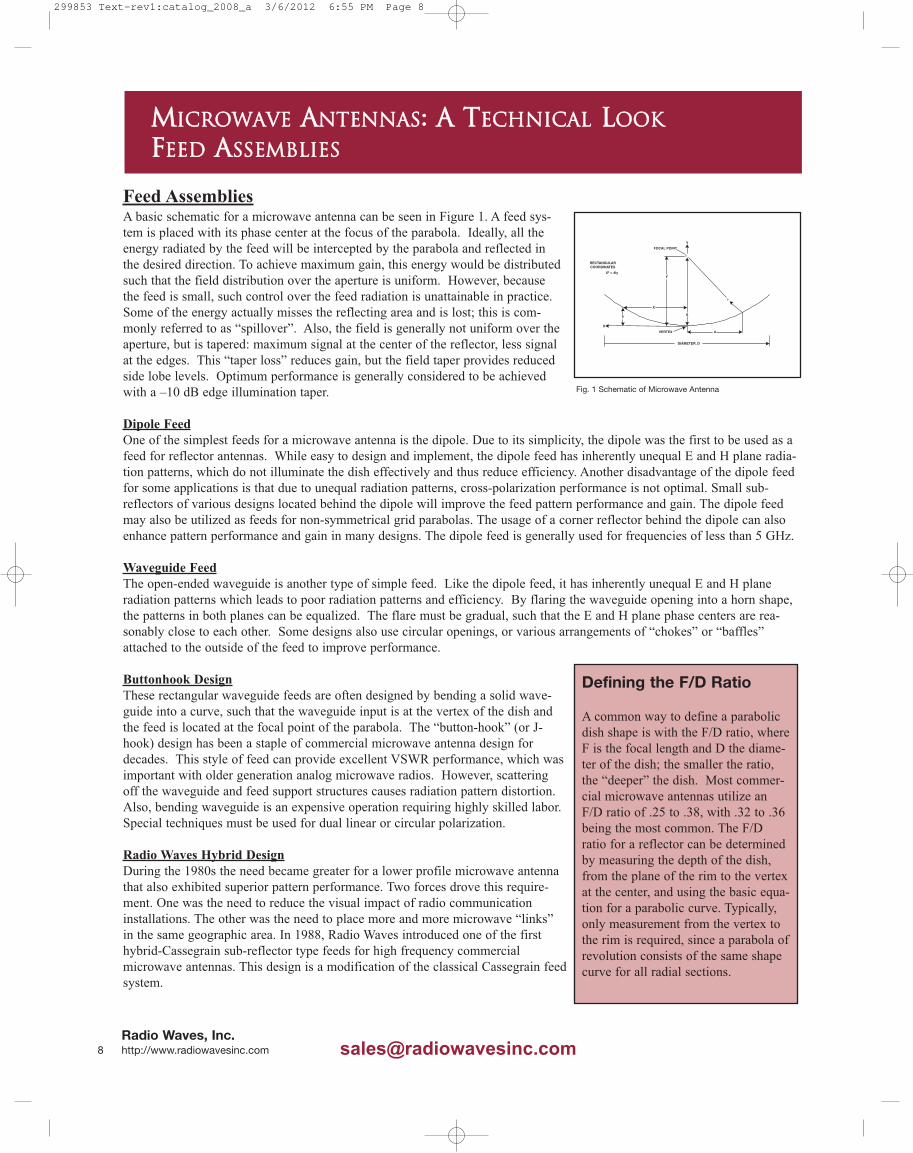
MMIICCRROOWWAAVVEE AANNTTEENNNNAASS AA TTEECCHHNNIICCAALL LLOOOOKKFFEEEEDD AASSSSEEMMBBLLIIEESS
Cassegrain SystemsIn a Cassegrain system a feed is mounted in the dish and energy is radiated towards a sub-reflector With a hybrid-Cassegrain system the energy is transported through a circular waveguide that radiates into a reflective surface at the focalpoint This reflected energy is then prorogated through a carefully shaped dielectric lens mounted between the sub-reflectorand waveguide tube The dielectric lens is typically made from a piece of rexolite which has a dielectric constant of 254An illustration of this feed is shown in Figure 2 At times this design is mistakenly referred to as a ldquoback-firerdquo feed systemA back-fire feed does not incorporate the dielectric lens and suffers from poor side lobe performance relative to the hybrid-Cassegrain style feed
This hybrid-Cassegrain design has several benefits over the button-hook design including higher antenna efficiency Since the hybrid-Cassegrain feed is shorter than the J-hook feed the entire antenna hasa lower profile and lower wind loading The feeds use a circularwaveguide that provides inherent dual-polarization capability This isthe feed system typically used at Radio Waves
Polarization is determined by the orientation of the input device (rectangular to circular transition or omt) that can easily be rotated to change polarization Modern electromagneticsimulation software allows the reflecting surface of the feed to be shaped to provide superior control of radiation pattern Asthese feeds are self-supporting there is no scattering off of the feed support system as in the button-hook design One slightdisadvantage of these designs is that they have higher VSWR than button-hook feed designs However with todayrsquos digitalradios this does not cause degradation in performance These ldquoback-firerdquo feeds are generally utilized for frequencies of 5GHz to 60 GHz For modern radio systems requiring high efficiency in a smaller package the hybrid-Cassegrain feed reflec-tor antenna is most applicable
In summary hybrid-Cassegrain feed antennas provide optimum mechanical and electrical performance for modernhigh frequency digital microwave radio systems Applications that still use older analog radios requiring very stringentVSWR specifications are best served by antennas using buttonhook feed systems Dipole feed systems can be used forapplications below 6 GHz that require a low-cost antenna and do not demand the most robust pattern performanceHowever for modern high frequency microwave radio systems requiring high efficiency in a smaller package the hybrid-Cassegrain feed reflector antenna is most applicable
Plane Polarized FeedsThe angular orientation of a microwave signal can be fixed in either a vertical or horizontal electrical plane A plane polar-ized microwave feed also known as a single polarized feed sends and receives signals oriented in just one of two planes Asingle polarized feed set in a vertical orientation will pass vertically polarized signals while electrically suppressing anyother microwave signals that are 90 degrees off plane in a horizontal orientation
Dual Polarized FeedsDual Polarized feeds can detect both vertical and horizontal signal polarizations separately but simultaneously while keep-ing each signal polarization isolated from the other A dual polarized antenna system performs the same function as two sep-arate single plane polarized antennas reducing infrastructure costs and tower congestion Two feed inputs are provided oneeach for the vertical and horizontal polarizations
HP and SP FeedsPlane polarized non-pressurized feeds are compact and completely sealed units designed to accommodate the insertion ofthe feed into the antenna from the back of the reflector Polarization orientation is adjustable in either a vertical or horizontalplane Feed input flange or connector type is dependent on the feed operating frequency Feeds can be pressurized to 5 psi
HPD and SPD FeedsDual polarized feeds are designed for simultaneous operation in both vertical and horizontal planes The rear-inserted feedsare sealed and watertight assemblies that feature a -30 dB cross-polarization discrimination (XPD) or better Feed inputflange or connector type is dependent upon the feed operating frequency
Radio Waves Inc httpwwwradiowavesinccom 9
Fig 2 Basic Outline of Hybrid Cassegrain Feed
Fig 1 Schematic of Microwave Antenna
978-459-8800 bull 978-459-3310 Fax
299853 Text-rev1catalog_2008_a 362012 655 PM Page 9
MMIICCRROOWWAAVVEE AANNTTEENNNNAASS AA TTEECCHHNNIICCAALL LLOOOOKKAANNTTEENNNNAA TTEERRMMIINNOOLLOOGGYY
Microwave Antenna PatternsThe antenna pattern is a graphical representation of the antennarsquos electrical performance in free space Measured andrecorded from actual test range data in two orthogonal planes such as E and H planes and Vertical and Horizontal planesthe pattern is plotted either in rectangular or polar coordinates A typical pattern will contain a main signal beam and sever-al minor side lobes of radiated signal The plotted pattern data is determined from multiple measurements taken from threefrequencies - bottom middle and top of the specified band in both co-polar and cross polar conditions horizontal and ver-tical polarizations and recorded over the full 360 degrees of antennarsquos azimuth Since an antenna pattern changes slightlywith frequency and the plotted pattern is drawn from only the highest or worst case peaks for all measured data pointsactual antenna interference rejection for signal angles other than the desired main beam will often be much better than indi-cated in the published antenna pattern Radio Waves antenna patterns are on file with Radio Waves the FCC frequencycoordination houses and other government agencies throughout the world
RPERadiation pattern envelopes are a common method of graphically displaying microwave antenna pattern information in away that is easy to use for microwave system planning RPEs represent the worst peaks in side-lobe energy and accuratelyrepresent the expected pattern performance The RPE is composed of simple straight lines that connect all the defined peaksof energy In fact our antennas will often exceed the performance outlined in the RPE At Radio Waves our highly automat-ed and accurate manufacturing process ensures that each antenna meets your expectations as well as its RPE
Antenna GainComparing the electrical field strength of an antenna to that of a reference antenna provides a gain figure measured in dBThe gain of an antenna is a measure of how well the antenna concentrates its radiated power in a given direction When thefree-space reference is an isotropic antenna the gain is expressed in dBi and when the reference antenna is a half-wavedipole the gain figure is expressed in dBd Microwave antennas are typically specified in dBi Antennas are usually meas-ured at three frequencies the bottom middle and top of the band Antenna gain is a measurement of how well an antennafocuses energy and generally the higher the gain the narrower the beamwidths
Antenna EfficiencyWhen power is input to an antenna the antenna never radiates 100 of the power Some of the power is lost and convertedinto heat Antenna efficiency is a measurement of how efficiently an antenna radiates power versus how much power isapplied to the antenna The lower distributed losses in the component of an antenna the higher the antenna efficiency andthe higher the gain for a given size
Half Power BeamWidth (HPBW)Half Power BeamWidth is the nominal angular width of the main beam between its -3 dB points (half power) Measured indegrees from the center of the main beam the value is typically nominal and stated as the minimum performance value forthe operating frequency band Beamwidth typically decreases as antenna gain increases A systemrsquos maximum beamwidth isdependent on its required coverage area while complying with system design to keep all unnecessary signal interference toa minimum from any adjacent microwave systems
Wavelength SpeedOne can easily observe how electromagnetic energy behaves by observing light energy or by observing waves generatedby a rock thrown into a pond of water The term wavelength refers to the distance the wave travels during the time ofone cycle In free space these electromagnetic waves travel 300 million meters per second which we call the ldquospeed oflightrdquo The equation for calculating this speed is c = f λ whereC = the speed of light (3 x 10⁸ meters per second)f = the frequency in hertzλ = the wavelength in metersFor high frequency systems such as microwave frequency is commonly measured in gigahertz and wavelength isexpressed in centimeters At Radio Waves we specialize in the design and manufacturing of innovative microwave andbroadband wireless antennas from 2 to 80 GHz
Radio Waves Inc 10 httpwwwradiowavesinccom salesradiowavesinccom
299853 Text-rev1catalog_2008_a 362012 655 PM Page 10
How Important is VSWR
We sometimes receive enquires asto how important antenna feedVSWR is to large diametermicrowave antennas utilized fortraditional back-haul systems Inthe past most microwave radiosystems utilized analog radios thatrequired very low VSWR of 111or better for optimum performanceNew digital microwave radios donot require this low a VSWR forproper operation While one shouldassure that the antenna has aVSWR of 151 to assure properperformance there is not a require-ment to try and achieve a signifi-cantly better VSWR in most cases As an example compare a VSWRof 111 with a VSWR of 131which are both excellent Twomethods of comparison would beto evaluate the difference in systempower loss due to the VSWR andthe percentage of reflected powerdue to the VSWR At a VSWR of131 the power loss due to thereflection is 07 dB With a VSWRof 111 the power loss is 01 dBThus the difference is 06 dB or6100 of a dB which is an imper-ceptible difference
In regards to percentage of reflect-ed power the antenna with aVSWR of 131 reflects 15 ofthe power and the antenna with 111 VSWR reflects 3 of thepower Thus if the input power is 1watt the amount reflected back intothe transmission line from theantenna with a VSWR of 131 is015 watts an amount of powerthat is not a factor for system per-formance The difference betweenthese two values of VSWR is not aperceptible factor in system per-formance and resources are betterutilized reviewing factors that canoptimize system performance
MMIICCRROOWWAAVVEE AANNTTEENNNNAASS AA TTEECCHHNNIICCAALL LLOOOOKKAANNTTEENNNNAA TTEERRMMIINNOOLLOOGGYY
VSWRVSWR is the ratio of the maximum to minimum values of the electrical standingwave pattern along a transmission line to which a resistive load is connectedVSWR value ranges from 1 (matched load) to infinity for a short or open load Astanding wave pattern is reflected energy dissipated in heat along a transmissionline typically caused by an impedance mis-match between the load (antenna) andthe transmission line VSWR is also expressed as a Return Loss value measured indB Another way of expressing VSWR is return loss which is the decibel differ-ence between the power incident on the mismatch and the power reflected from themismatch
Front-to-Back Ratio (FB)This is a value specified in dB below the peak of the main beam relative to ameasured angular zone 180 degrees from the primary point of measurement It isthe amount of energy radiated in the rear of the antenna Certain antennas designssuch as the HP style parabolic reflectors will have higher front-to-back ratios thanother antenna designs FB can be important to assure proper frequency re-use inmicrowave systems
PolarizationThe orientation of the electric field vector as measured from a distance from theantenna The propagation modes of electromagnetic waves are measured in planesVertical Horizontal Circular and Elliptical Co-Polarization the intended polar-ization for which the antenna is intended to radiate Cross-Polarization the dif-ference in dB between the peak of the co-polarized main beam and a cross-polar-ized signal typically indicated as the difference between the vertical and horizontalpolarization planes The higher the value the greater the discrimination protectionfrom a signal of perpendicular polarization
IsolationThe signal isolation between two ports of a device generally stated as ndashdB level
Frequency BandsElectromagnetic waves vary in length from the very short to the very long Themicrowave region is considered to be frequencies between 1 and 250 GHz (gigahertz) The wavelengths at these frequencies are 305 cm to 127 mm Forhigh frequency systems such as microwave frequency is commonly measured ingigahertz and wavelength is expressed in centimeters At Radio Waves we spe-cialize in the design and manufacturing of innovative microwave and broadbandwireless antennas from 2 to 80 GHz
Radio Waves Inc httpwwwradiowavesinccom 11
BeamwidthPatternsNarrow beamwidth reduces interface since it is less likely that surrounding RF clutter willcause interface A larger antenna has a narrower beamwidth and thus higher gain Largerantennas with narrower beamwidths and higher gain offer the following benefits
Increased strength of the transmit signalIncreased strength of the intended receive signalReduction of interference from outside the antennarsquos main beam
Choosing Antenna Dish SizeWhen choosing the optimum size parabolic dish for your link or network often going to alarger size dish provides a number of key benefits The narrower beamwidth associatedwith a larger diameter dish reduces interfacesince and it is less likely that surrounding RFclutter will cause interference Additionally the higher gain associated with a larger dishprovides for improved received signal strength by increasing the level of the desired signalWhen unsure always choose the larger size dish to assure optimum link performance
978-459-8800 bull 978-459-3310 Fax
299853 Text-rev1catalog_2008_a 362012 655 PM Page 11
Transmission LinesThese critical conduits guide electrical energy from one point to another When used as a connection between the antennaand the systemrsquos radio transmission lines work to provide a low-loss pathway between the antenna and radio for the trans-fer of RF signals A microwave systemrsquos radio transceiver may be directly connected on the back of an antenna requiringonly that a VHF IF frequency be carried down to the indoor unit (IDU) Considering operating frequency acceptable trans-mission line losses power handling and even physical handling the choice of the correct transmission line for the applica-tion can vary greatly
Flexible Braided Coaxial CableBraided Coaxial Cables are used as jumper assemblies (in short lengths) for an inter-connect between an antenna feed andradio transceiver or to carry IF signals from an ODU (outdoor unit) to an IDO (indoor unit) Jumper assemblies are avail-able in a wide variety of lengths They operate in frequencies below 6 GHz and in various cable diameters Characteristicimpedance is 50 ohms with a wide variety of connector interfaces available These cables can be a very cost effectivetransmission line system for applications such as broadband wireless as well as connecting an ODU to and IDO in high fre-quency point-to-point microwave systems Due to their flexibility these cables are ideal for in-building and in-structureapplications
Semi-Rigid Foam Dielectric Coaxial CableFoam Dielectric Coaxial Cable is the most commonly used cable in the cellular telecommunications industry because of itsexcellent electrical characteristics and reliability Not as flexible as braided cable and slightly heavier due to a solid coppercorrugated outer conductor this type of cable may be used in long transmission line runs with proper handling and installa-tion hardware It is available in a variety of sizes from 14-inch jumper lengths to 2-14rdquo diameters Usable operating char-acteristics are broadband up to approximately 6 GHz
Semi-Rigid Air Dielectric Coaxial CableAir Dielectric Coaxial Cable is more commonly used forhigh power handling such as broadcast installations Thistype of cable shares the same basic cable construction assemi-rigid foam dielectric coaxial cable but with a dielectrichelix supporting the inner conductor instead of a foamdielectric Air Dielectric runs of cable require dry air pressur-ization that typically consists of cylinders of nitrogen or adry air pressurized (dehydrator) system to maintain a drydielectric This type of cable is suitable for long transmissionruns with proper handling and is available in a variety ofsizes from 12 inch to over 6rdquo diameters Usable operatingcharacteristics are broadband up to approximately 6 GHz
Semi-Rigid Elliptical WaveguideSpecifically intended for microwave applications this type of transmission line is frequency-dependent with a relativelynarrow bandwidth requiring the waveguide to be properly matched to its application to achieve a low VSWR Ellipticalwaveguide is constructed from corrugated copper tube formed into an elliptical cross-section This type of transmission linerequires pressurization to prevent moisture accumulation within the waveguide Operating frequency ranges are availableup to and beyond 26 GHz
Indoor Systems with Cable (RF Indoors)Traditional microwave systems have all the RF equipment mounted indoors The equipment is mounted in 19 inch or othersize racks that are located in an enclosed shelter or building for environmental protection These systems are typically forlong haul microwave point-to-point systems that require high output power for these long ldquohopsrdquo The RF is then fed to theantenna through a run of elliptical waveguide
MMIICCRROOWWAAVVEE AANNTTEENNNNAASS AA TTEECCHHNNIICCAALL LLOOOOKKCCAABBLLEE
Radio Waves Inc 12 httpwwwradiowavesinccom salesradiowavesinccom
299853 Text-rev1catalog_2008_a 362012 655 PM Page 12
MMIICCRROOWWAAVVEE AANNTTEENNNNAASS AA TTEECCHHNNIICCAALL LLOOOOKKAACCCCEESSSSOORRIIEESS ampamp HHAARRDDWWAARREE
Waveguide or Cable SystemsSystems utilizing waveguide or coaxial cable transmission lines require proper installation for optimum network perform-ance The use of adequate hangers hoisting grips grounding kits and weather-proofing will assure uninterrupted service inthe years to come In cases where an elliptical waveguide of air dielectric cable is to be employed a system dry air pressur-ization system will need to be implemented In these cases the proper dehydrator and transmission line pressure windowsmust be used for optimum results
ODU Systems (RF Outdoors)Outdoor Units (ODU) are remotely-mounted radio transceivers arranged in a split configuration These units are generallyfound mounted on or near the antenna installation This type of antennaradio installation allows for rapid deployment ofsystems by eliminating long runs of semi-rigid foam dielectric coaxial cable or waveguide while reducing deployment costsThe signal is down-converted to an IF that is then utilized by the indoor unit (IDU) The cable carries the baseband or IFsignal in addition to power and control signals LMR cable is ideal for these applications
Accessory EquipmentAccessories abound to assist in the installa-tion and mounting of antennas to buildingsroof-tops and towers Accessories for trans-mission line systems be it coaxial cable orelliptical waveguide both require the basicinstallation items such as hoisting gripshangers grounding kits wallroof entries andcushioned entry boots
ConnectorsMany choices are available to mate yourtransmission line system to the antenna andradio It is important that you assure theproper connectors are selected and that foroutdoor applications they are properly tight-ened and sealed after installation
Grounding KitsA properly grounded system helps reduce static due to noise and reduces the probability of a lightning strike to your sys-tem It is highly recommended that a minimum of three grounding kits are utilized at each installation one at the top of thetower or vertical run one at the bottom of the run and prior to entry in the building or shelter
HangersHoisting GripsTo ensure many years of service it is important that transmission lines are installed correctly and mounted securely Thiswill assure that high winds do not damage the transmission line over time
WallRoof Feed-ThruThese devices allow the transmission line to be easily routed into the building or shelter while assuring the structure is pro-tected from moisture and other aspects of the outdoor environment
Pressurization SystemsIt is imperative that waveguide transmission line systems be protected from moisture ingression Pressurization equipmentsuch as pressure windows and dehydrators should be selected carefully to assure that your system is properly protected Thepressure window is usually placed in series between the bottom connector and the main waveguide feeder This allows theRF to pass but assures that the transmission line stays pressurized
Radio Waves Inc httpwwwradiowavesinccom 13978-459-8800 bull 978-459-3310 Fax
299853 Text-rev1catalog_2008_a 362012 655 PM Page 13
MMIICCRROOWWAAVVEE AANNTTEENNNNAASS AA TTEECCHHNNIICCAALL LLOOOOKKAANNTTEENNNNAA CCOONNSSTTRRUUCCTTIIOONN
Microwave Antenna ConstructionMicrowave antennas are often deployed in very difficult environments and must be built of the highestquality materials
Sector AntennasSector antennas are designed to provide segmented microwave coverage over a selected (sector) areasector antennas deliver a wider beamwidth than point-to-point parabolic antennas Sector antennas aretypically used for ISM WLL and MMDS band communications utilizing Spread Spectrum datastreams for wireless connections between LAN base stations wireless Internet subscriber networksPCS and other point-to-multipoint communications Antenna configurations can consist of flat panelmicro strip and slot radiating designs as well as traditional parabolic configurations Some commonhorizontal beamwidths utilized include 60 90 120 and 180 degrees
Flat Panel AntennasRadio Waves offers a complete and diverse line of flat panel antennas for point-to-point and point-to-multipoint terrestrial microwave applications These flat panel antennas are designed to be light inweight easy to install and aligned and durable for years of reliable service All of Radio Wavesrsquo flatpanel antennas are designed to be aesthetically pleasing and unobtrusive These antennas are idealfor concealment in many architectural environments Sector panel antennas for multi-point networksare available in a variety of sector offerings and operating bands
Grid Parabolic AntennasGrid parabolic antennas from Radio Waves are constructed with aluminum tube elements that arecorrosion-resistant and formed into a parabolic reflector These grid elements are welded to both anouter rim and aluminum back structure for enhanced electrical performance and mechanical integri-ty All grid tubes are manufactured with drain holes to allow condensation and rain to escape RadioWavesrsquo grid line of antennas are engineered and constructed to the same strict standards as ourProLine parabolic antennas Certain pattern specifications such as front-to-back ratio and cross-polarization are not as stringent as with solid reflector antennas However grid parabolic antennasare good for when tower loading and windloading are a concern
Standard Parabolic AntennasRadio Wavesrsquo standard parabolic reflectors are manufactured of aluminum Each parabola isdesigned with a reinforced outer edge for structural reliability The mount is a hot-dipped galvanizedsteel weldment with an azimuth and elevation adjustment mechanism These antennas are availablein diameters of 1 to 8 feet for various systems and applications
High Performance AntennasHigh Performance Antennas are formed of aluminum which is spun to precise tolerances Theparabola has an integral rim for enhanced reflector structural integrity The shroud of a HighPerformance Antenna is also fabricated of aluminum and fitted with a planar radome to protect thefeed The mount is a hot-dipped galvanized steel weldment with an azimuth and elevation adjust-ment mechanism The exception is the DiscriminatorTM series which utilizes a molded plastic reflector that is shaped for optimum side lobe performance
Radio Waves Inc 14 httpwwwradiowavesinccom salesradiowavesinccom
299853 Text-rev1catalog_2008_a 362012 655 PM Page 14
TTYYPPIICCAALL FFRREEQQUUEENNCCYY UUSSAAGGEE TTAABBLLEE AANNDDVVSSWWRR TTOO RREETTUURRNN LLOOSSSS CCOONNVVEERRSSIIOONN CCHHAARRTT
VSWR RL (dB) VSWR RL (dB) VSWR RL (dB)
100 Infinite 117 221 150 140
101 460 118 217 155 133
102 401 119 212 160 127
103 366 120 208 165 122
104 342 121 204 170 117
105 323 122 201 175 113
106 307 123 197 180 109
107 294 124 194 185 105
108 283 125 191 190 102
109 273 126 188 195 100
110 265 127 185 200 95
111 257 128 182 210 89
112 249 129 179 220 85
113 243 130 177 230 81
114 237 135 165 240 77
115 231 140 156 250 74
116 226 145 147 300 60
Band Frequency Range Typical Usage
2 GHz 24-27 GHz Unlicensed Spread Spectrum
3 GHz 34-36 GHz Fixed Wireless Access
4 GHz 38-50 GHz Typically public operator band
5 GHz 525-585 GHz Unlicensed Spread Spectrum
6 GHz 59-71 GHz Long haul medium to high capacity
78 GHz 71-85 GHz Long haul medium to high capacity
1011 GHz 1015-117 GHz Typically public operator band
13 GHz 127-1325 GHz Typically low to medium capacity
15 GHz 1425-1535 GHz Various capacities
18 GHz 177-197 GHz Low to medium capacity
23 GHz 212-236 GHz All capacities
24 GHz 2425-265 GHz All capacities PTMP
38 GHz 37-40 GHz Various capacities
60 GHz
60 GHz
557 - 660 Various capacities
VSWR to Return Loss Conversion Chart
Typical Frequency Usage Table
Radio Waves Inc httpwwwradiowavesinccom 15978-459-8800 bull 978-459-3310 Fax
80 GHz 71-86 GHz Short haul ultra high capacity
299853 Text-rev1catalog_2008_a 362012 655 PM Page 15
dBm watts dBm watts dBm watts dBm watts
270 501 mw 330 200 390 794 452 3311
272 525 mw 332 209 392 832 454 3467
274 550 mw 334 219 394 871 456 3631
276 575 mw 336 229 396 912 458 3802
278 603 mw 338 240 398 955 460 3981
280 631 mw 340 251 400 1000 462 4169
282 661 mw 342 263 402 1047 464 4365
284 692 mw 344 275 404 1096 468 4786
286 724 mw 346 288 406 1148 470 5012
288 759 mw 348 302 408 1202 472 5248
290 794 mw 350 316 410 1259 474 5495
292 832 mw 352 331 412 1318 476 5754
294 871 mw 354 347 414 1380 478 6026
296 912 mw 356 363 416 1445 480 6310
298 955 mw 358 380 418 1514 482 6607
300 100 360 398 420 1585 484 6918
302 105 362 417 422 1660 486 7244
304 110 364 437 424 1738 488 7586
306 115 366 457 426 1820 490 7943
308 120 368 479 428 1905 492 8318
310 126 370 501 430 1995 494 8710
312 132 372 525 432 2089 496 9120
314 138 374 550 434 2188 498 9550
316 145 376 575 436 2291 500 10000
318 151 378 603 438 2399 550 31600
320 158 380 631 440 2512 560 39800
322 166 382 661 442 2630 570 50100
324 174 384 692 446 2884 580 63100
326 182 386 724 448 3020 590 79400
328 191 388 759 450 3162 600 100000
PPOOWWEERR CCOONNVVEERRSSIIOONN TTAABBLLEE
Power Conversion Table
Radio Waves Inc 16 httpwwwradiowavesinccom salesradiowavesinccom
299853 Text-rev1catalog_2008_a 362012 655 PM Page 16
2300 290 032-049 9368-6118 0256 11684 168-117 1530-2120 051-031 Alum -- 23125-11625 0020 23250-11750 020 0125
2100 291 035-053 8656-5656 0281 10668 168-118 1200-1730 054-034 Alum -- 21125-10625 0020 21250-10750 020 01251800 201 041-0625 7311-4796 0328 9144 167-118 934-1319 056-038 Alum -- 18000-9000 0020 18250-9250 020 01251500 202 049-075 6118-3997 0393 7620 162-117 676-933 069-050 Alum -- 15000-7500 0015 15250-7750 015 0125
1150 203 064-096 4684-3123 0513 5842 182-118 350-538 128-075 Alum -- 11500-5750 0015 11750-6000 015 0125975 204 075-112 3995-2676 0605 4953 170-119 270-385 137-095 Alum -- 9750-4875 0010 10000-5125 010 0125
770 205 096-145 3123-2067 0766 3912 166-118 172-241 201-136 Alum -- 7700-3850 0010 7950-4100 010 0125
65069
103112-170 2676-1763 0908 3302 170-118 119-172
317-312
269-178
Brass
Alum
417A
418A6500-3250 0010 6660-3410 010 0080
510 -- 145-220 2067-1362 1157 2591 167-118 75-107 -- -- -- 5100-2550 0010 5260-2710 010 0080
430 W104
105170-260 1763-1153 1372 2184 170-118 52-75
588-385
501-330
Brass
Alum
435A
437A4300-2150 0008 4460-2310 008 0080
340112
113220-330 1363-908 1736 1727 178-122 31-45
877-572
751-492
Brass
Alum
553
5543400-1700 0005 3560-1860 005 0080
284 S48
75260-395 1153-759 2078 1443 167-117 22-32
1102-752
940-641
Brass
Alum
54B 53
585A 5842840-1340 0005 3000-1500 005 0080
229 -- 330-490 908-612 2577 1163 162-117 16-22 -- -- -- 2290-1145 0005 2418-1273 005 0064
187 C49
95395-585 759-512 3152 9510 167-119 14-20
208-144
177-112
Brass
Alum
148C 149A
406B 4071872-0872 0005 2000-1000 005 0064
159 -- 490-705 612-425 3711 0078 152-119 079-10 -- -- -- 1590-0795 0004 1718-0923 004 0064
13750
106585-820 512-366 4301 6970 148-117 056-071
287-230
245-194
Brass
Alum
343B 344
440B 4411372-0622 0004 1500-0750 004 0064
112 XL
54
68705-100 425-299 5259 5700 151-117 035-046
212-321
250-274
Brass
Alum
52B 51
137B 1381122-0497 0004 1250-0625 004 0064
90 X52
67820-1240 366-242 6557 4572 168-118 020-029
645-448
549-383
Brass
Alum
40B 39
136B 1350900-0400 0003 1000-0500 003 0050
75 -- 1000-1500 299-200 7868 3810 164-117 017-023 -- -- -- 0750-0375 0003 0850-0475 003 0050
62 Ku91107 124-180 242-166 9486 3160 155-118 012-016
951-831614-536
BrassSilver
541A 419-- 0622-0311 0002 0702-0391 003 0040
51 -- 1500-2200 200-136 11574 2590 158-118 0080-0107 -- -- -- 0510-0255 00025 0590-0335 003 0040
42 K531266
1800-2650 166-113 14047 2134 160-118 0043-0058277-198176-126133-95
BrassAlumSilver
596A 595--
598 5970420-0170 00020 0500-0250 003 0040
34 -- 2200-3300 136-091 17328 1730 162-118 0034-0048 -- Brass -- 1530 0340-0170 00020 0420-0250 003 0040
28 K^ 96 2650-4000 113-075 21081 1422 165-117 0022-0031 219-150 Silver 600A 599 0280-0140 00015 0360-0220 002 0040
22 Q 97 3300-5000 091-060 26342 1138 167-117 0014-0020 310-209 Silver -- 383 0224-0112 00010 0304-0192 002 0040
19 -- 4000-6000 075-050 31357 0956 163-116 0011-0015 -- Brass -- 1529 0188-0094 00010 0268-0174 002 0040
15 V 98 5000-7500 060-040 39863 0752 167-117 00063-00090 529-391 Silver -- 385 0148-0074 00010 0228-0154 002 0040
12 99 6000-9000 050-033 48350 0620 168-118 00042-00060 933-522 Silver -- 387 0122-0061 00005 0202-0141 002 004010 -- 7500-1100 040-027 59010 0508 161-118 00030-00041 -- Silver -- 1528 0100-0050 00005 0180-0130 002 0040
EIA WG WR ( )
MDL Band
JAN WG RG ( )
Frequency
GHz
Wavelength
(cm)
Frequency
GHz
Wavelength
(cm)
Range in λλg
Theoretical cw power
rating lowest to high-
est frequency (meg
watt)
Theoretical
Attenuation lowest to
highest frequency
(dB100 ft)
Material Alloy
Choke
UG ( )U
Cover
UG ( )U
Inside
Tol plusmn
Outside
Tol plusmn Wall
Thickness
(nom)
RecommendedOperating Range for
TE10 ModeCut-off for TE10 Mode JAN
FLANGEDIMENSIONS (Inches)
RREECCTTAANNGGUULLAARR WWAAVVEEGGUUIIDDEE RREEFFEERREENNCCEE TTAABBLLEE
Radio Waves Inc httpwwwradiowavesinccom 17978-459-8800 bull 978-459-3310 Fax
299853 Text-rev1catalog_2008_a 362012 655 PM Page 17
FFOOCCAALL LLEENNGGTTHH TTOO DDIIAAMMEETTEERR RRAATTIIOO VVSSAANNGGUULLAARR AAPPEERRTTUURREE FFOORR PPAARRAABBOOLLIICC RREEFFLLEECCTTOORRSS
Radio Waves Inc 18 httpwwwradiowavesinccom salesradiowavesinccom
299853 Text-rev1catalog_2008_a 362012 655 PM Page 18
Flat Panel amp Xcelarator
Antennas
Low profile flat panel anten-nas offer superior perform-ance in a small and aestheti-cally pleasing packageThese antennas are planepolarized The polarizationcan be changed from verticalto horizontal by simply rotat-ing the antenna 90 degreeson its mount These flat pan-els are available in the 4 and5 GHz frequency bands Thestandard mount accommodates a 1rdquo - 25rdquo pipe mast whileallowing for +- 25 degrees of elevation adjustment
Standard ParabolicAntennas
The SP-Series of standardperformance parabolicantennas from Radio Wavesare available in 1 ft through8 ft diameters These anten-nas are spun aluminumreflectors with interchange-able feeds that cover the 2435 and 5258 GHzfrequency bands The 1 and2 Ft antennas are suppliedwith a mount that can be attached to a 2rdquo - 45rdquo pipe mastand features fine adujstments of both azimuth and elevationThe 3 - 8 Ft antennas can be attached to a 45rdquo pipe mastand features fine adjustments of both azimuth and eleva-tion Optional radomes are available for reduced windload-ing Dual polarized and dual band models are also available
Grid Antennas
Radio Wavesrsquo G-Series para-bolic grid antennas feature alightweight and rugged designfor applications that requirehigh gain with a low wind-load These heavy-duty gridsare available in 3 ft 4 ft and 6ft diameters in the unlicensed13-50 GHz bands Offering40 lower windloads thansolid parabolic antennas of thesame diameter these grids arean excellent choice for high wind backhaul applications thatdonrsquot require stringent pattern performance
Sector Antennas
Radio Waves offers the widestselection of sector antennas inthe industry for point-to-multi-point base station applicationsModels are available in the 2435 amp 58 GHz frequencybands A variety of beamwidthscan be selected including 6090 120 or 180 degrees Theseantennas offer a lightweightand rugged design and are built foryears of trouble-free service Verticalor horizontal polarization models may be chosen Theseantennas include all mounting hardware and can beattached to a 175rdquo - 40rdquo diameter pipe mast
Radio Waves Inc httpwwwradiowavesinccom 19978-459-8800 bull 978-459-3310 Fax
RRAADDIIOO WWAAVVEESS BBRROOAADDBBAANNDD FFIIXXEEDD WWIIRREELLEESSSS PPRROODDUUCCTTSS
Radio Wavesrsquo line of broadband fixed wireless antennas are designed to deliver optimum performance for use with ISM Wi-Fi MMDS WCS UNII and WLL point-to-point and point-to-multi point systems Four types of antennas comprise this prod-uct line Sector antennas are used in base stations of PtMP systems Flat panels can be deployed for PtMP subscribers orutilized for PtP systems requiring less visible antennas Grid antennas are used in high gain backhaul applications and theRadio Waves SP series of solid parabolic antennas are the industryrsquos choice for a high quality PtP antenna solution All ofthese antennas are designed and manufactured by Radio Waves for superior performance and years of dependable service
High Performance Antennas
The HP-Series are also available for applications thatrequire superior pattern performance to reduce interferencepotential
299853 Text-rev1catalog_2008_a 362012 656 PM Page 19
Model Frequency Polarization Gain dBi Beamwidth-3dB X-Pol FB Ratio VSWR Max OptionalNumber GHz (nominal) Azdeg Eldeg Rej dB dB (RL dB) Downtilt
SSEECCTTOORR AANNTTEENNNNAASSDDIIMMEENNSSIIOONNSS AANNDD EELLEECCTTRRIICCAALL SSPPEECCIIFFIICCAATTIIOONNSS
EELLEECCTTRRIICCAALL SSPPEECCIIFFIICCAATTIIOONNSS (typical performance) For 215 - 270 GHz models contact the factory
24-27 GHz RangeSEC-25V-60-14 240 - 270 Vertical 145 60 16 25 gt25 151 (140) STD-15-1SEC-25H-60-14 240 - 270 Horizontal 145 60 16 25 gt25 151 (140) STD-15-1SEC-25D-60-14 240 - 270 Dual 145 60 16 25 gt25 151 (140) STD-15-2SEC-25V-60-17 240 - 270 Vertical 175 60 8 25 gt25 151 (140) STD-15-2SEC-25H-60-17 240 - 270 Horizontal 175 60 8 25 gt25 151 (140) STD-15-2SEC-2V-5H-60 240 - 250 Vertical 140 60 16 20 25 151 (140) STD-15-2
5725 - 585 Horizontal 175 60 8 20 35 151 (140) STD-15-2SEC-2H-5V-60 240 - 250 Horizontal 140 60 16 20 25 151 (140) STD-15-2
5725 - 585 Vertical 175 60 8 20 35 151 (140) STD-15-234-36 GHz Range
SEC-35V-60-17 34 - 36 Vertical 175 60 8 25 30 151 (140) STD-15-1SEC-35H-60-17 34 - 36 Horizontal 175 60 8 25 30 151 (140) STD-15-1SEC-35D-60-17 34 - 36 Dual 175 60 8 25 30 151 (140) STD-15-2
44 - 50 GHz Range SEC-47V-60-17 44 - 50 Vertical 170 60 8 25 35 151 (140) STD-15-1SEC-47H-60-17 44 - 50 Horizontal 170 60 8 25 35 151 (140) STD-15-1
525 - 585 GHz RangeSEC-55V-60-17 5250 - 5850 Vertical 170 60 8 25 gt35 151 (140) STD-15-1SEC-55H-60-17 5250 - 5850 Horizontal 170 60 8 25 gt35 151 (140) STD-15-1SEC-55D-60-17 5250 - 5850 Dual 170 60 8 25 gt35 151 (140) STD-15-2SEC-5V-60-18 5725 - 5850 Vertical 180 60 6 25 gt35 151 (140) STD-15-1
All specifications subject to change without noticeConsult factory for availability
These sector antennas will operate over 360-365 GHz If you want to assure a VSWR lt 151 or better please stateldquotune for 360-365 GHzrdquo on your purchase order
6600ordmordm SSeeccttoorr AAnntteennnnaass SSEECC SSeerriieess
4400ordmordm SSeeccttoorr AAnntteennnnaass SSEECC SSeerriieess
AANNTTEENNNNAA DDIIMMEENNSSIIOONNSS FFOORR AALLLL GGHHZZ RRAANNGGEESSSmall Package 255 x 85 x 40rdquo (65 x 216 x 10cm) 5 lbs (23kg) 14 17 and 18 dBi models
Large Package 415 x 85 x 40rdquo (105 x 216 x 10cm) 7 lbs (32kg)Dual Polarization models SEC-25V(or H)-60-17 models
EELLEECCTTRRIICCAALL SSPPEECCIIFFIICCAATTIIOONNSS (typical performance)
Model Frequency Polarization Gain dBi Beamwidth-3dB X-Pol FB Ratio VSWR Max OptionalNumber GHz (nominal) Azdeg Eldeg Rej dB dB (RL dB) Downtilt
SEC-35V-40-18 340 - 360 Vertical 180 40 8 25 gt30 1471 (144) STD-15-1SEC-35H-40-18 340 - 360 Horizontal 175 40 8 25 gt30 1471 (144) STD-15-2
salesradiowavesinccomRadio Waves Inc
20 httpwwwradiowavesinccom
299853 Text-rev1catalog_2008_a 362012 656 PM Page 20
SSEECCTTOORR AANNTTEENNNNAASSDDIIMMEENNSSIIOONNSS AANNDD EELLEECCTTRRIICCAALL SSPPEECCIIFFIICCAATTIIOONNSS
EELLEECCTTRRIICCAALL SSPPEECCIIFFIICCAATTIIOONNSS (typical performance) For 215 - 270 GHz models contact the factory
24-27 GHz amp Dual Band RangeSEC-25V-90-13 240 - 270 Vertical 130 90 16 25 gt25 151 (140) STD-15-1SEC-25H-90-13 240 - 270 Horizontal 130 90 16 25 gt25 151 (140) STD-15-1SEC-25D-90-13 240 - 270 Dual 130 90 16 25 gt25 151 (140) STD-15-2SEC-25V-90-16 240 - 270 Vertical 160 90 8 25 gt25 151 (140) STD-15-2SEC-25H-90-16 240 - 270 Horizontal 160 90 8 25 gt25 151 (140) STD-15-2SEC-25H-90-16HP 240 - 270 Horizontal 160 90 8 25 35 151 (140) STD-15-2SEC-2V-5H-90 240 - 250 Vertical 130 90 16 20 25 151 (140) STD-15-2
5725 - 585 Horizontal 160 90 8 20 35 151 (140) STD-15-2SEC-2H-5V-90 240 - 250 Horizontal 130 90 16 20 25 151 (140) STD-15-2
5725 - 585 Vertical 160 90 8 20 35 151 (140) STD-15-234-36 GHz Range
SEC-35V-90-16 34 - 36 Vertical 160 90 8 25 30 151 (140) STD-15-1SEC-35H-90-16 34 - 36 Horizontal 160 90 8 25 30 151 (140) STD-15-1SEC-35D-90-16 34 - 36 Dual 160 90 8 25 30 151 (140) STD-15-2SEC-35H-90-16HP 34 - 36 Horizontal 160 90 8 25 gt35 151 (140) STD-15-1SEC-35V-90-16HP 34 - 36 Vertical 160 90 8 25 gt35 151 (140) STD-15-1SEC-35D-90-16HP 34 - 36 Dual 160 90 8 25 gt35 151 (140) STD-15-2
44 - 50 GHz RangeSEC-47V-90-16 44 - 50 Vertical 160 90 8 25 30 151 (140) STD-15-1SEC-47H-90-16 44 - 50 Horizontal 160 90 8 25 30 151 (140) STD-15-1SEC-47D-90-16 44 - 50 Dual 160 90 8 25 30 151 (140) STD-15-1
525 - 585 GHz RangeSEC-55V-90-16 525 - 585 Vertical 160 90 8 25 gt35 151 (140) STD-15-1SEC-55H-90-16 525 - 585 Horizontal 160 90 8 25 gt35 151 (140) STD-15-1SEC-55D-90-16 525 - 585 Dual 160 90 8 25 gt35 151 (140) STD-15-2SEC-55H-90-16HP 525 - 585 Horizontal 160 90 8 25 gt35 151 (140) STD-15-1SEC-55V-90-16HP 525 - 585 Vertical 160 90 8 25 gt35 151 (140) STD-15-1SEC-55D-90-16HP 525 - 585 Dual 160 90 8 25 gt35 151 (140) STD-15-2
5725 - 585 GHz RangeSEC-5V-90-17 5725 - 585 Vertical 170 90 6 25 35 151 (140) STD-15-1SEC-5H-90-17 5725 - 585 Horizontal 170 90 6 25 35 151 (140) STD-15-1All specifications subject to change without noticeConsult factory for availability HP series of sectors is a unique design offering improved FB ratio
These sector antennas will operate over 360-365 GHz If you want to assure a VSWR lt 151 or better please stateldquotune for 360-365 GHzrdquo on your purchase order
9900ordmordm SSeeccttoorr AAnntteennnnaass SSEECC SSeerriieess
Model Frequency Polarization Gain dBi Beamwidth-3dB X-Pol FB Ratio VSWR Max OptionalNumber GHz (nominal) Azdeg Eldeg Rej dB dB (RL dB) Downtilt
AANNTTEENNNNAA DDIIMMEENNSSIIOONNSS FFOORR AALLLL GGHHZZ RRAANNGGEESSSmall Package 255 x 85 x 40rdquo (65 x 216 x 10cm) 5 lbs (23kg) 14 amp17 dBi models
Large Package 415 x 85 x 40rdquo (105 x 216 x 10cm) 7 lbs (32kg)Dual Polarization models SEC-25V(or H)-90-16 models
Radio Waves Inc httpwwwradiowavesinccom 21978-459-8800 bull 978-459-3310 Fax
299853 Text-rev1catalog_2008_a 362012 656 PM Page 21
SSEECCTTOORR AANNTTEENNNNAASSDDIIMMEENNSSIIOONNSS AANNDD EELLEECCTTRRIICCAALL SSPPEECCIIFFIICCAATTIIOONNSS
EELLEECCTTRRIICCAALL SSPPEECCIIFFIICCAATTIIOONNSS (typical performance)2244--2277 GGHHZZ RRAANNGGEE
112200ordmordm SSeeccttoorr AAnntteennnnaass SSEECC SSeerriieessAANNTTEENNNNAA DDIIMMEENNSSIIOONNSS FFOORR AALLLL GGHHZZ RRAANNGGEESSSEC-25V-120-11 255 x 85 x 40rdquo (65 x 216 x 10cm) 5 lbs (23kg)SEC-25V-120-14 415 x 85 x 40rdquo (105 x 216 x 10cm) 7 lbs (32kg)SEC-35V-120-11 255 x 85 x 40rdquo (65 x 216 x 10cm) 5 lbs (23kg)SEC-35V-120-14 255 x 85 x 40rdquo (65 x 216 x 10cm) 5 lbs (23kg)SEC-35H-120-14 255 x 85 x 40rdquo (65 x 216 x 10cm) 5 lbs (23kg)SEC-5V-120-14 (Tube) 30rdquo x 165rdquo (76 x 419cm) 5 lbs (23kg)SEC-5V-120-16 (Tube) 30rdquo x 225rdquo (76 x 572cm) 7 lbs (32kg)OMNH-5-8 (Tube) 30rdquo x 175rdquo (762 x 445cm) 5 lbs (23kg)
55772255--558855 GGHHZZ RRAANNGGEE
EELLEECCTTRRIICCAALL SSPPEECCIIFFIICCAATTIIOONNSS (typical performance)2244--2277 GGHHZZ RRAANNGGEE
118800ordmordm SSeeccttoorr AAnntteennnnaass SSEECC SSeerriieessAANNTTEENNNNAA DDIIMMEENNSSIIOONNSS FFOORR 2255 GGHHZZSEC-25V-180-10 255 x 85 x 40rdquo (65 x 216 x 10cm) 5 lbs (23kg)SEC-25V-180-13 415 x 85 x 40rdquo (105 x 216 x 10cm) 7 lbs (32kg)
Model Frequency Polarization Gain dBi Beamwidth-3dB X-Pol FB Ratio VSWR Max OptionalNumber GHz (nominal) Azdeg Eldeg Rej dB dB (RL dB) Downtilt
SEC-25V-120-11 240 - 270 Vertical 110 120 16 25 gt25 151 (140) STD-15-1SEC-25V-120-14 240 - 270 Vertical 140 120 8 25 gt25 151 (140) STD-15-2
3355 GGHHZZ RRAANNGGEE
Model Frequency Polarization Gain dBi Beamwidth-3dB X-Pol FB Ratio VSWR Max OptionalNumber GHz (nominal) Azdeg Eldeg Rej dB dB (RL dB) Downtilt
SEC-35V-120-11 340 - 360 Vertical 110 120 16 25 gt25 151 (140) STD-15-1SEC-35V-120-14 340 - 360 Vertical 140 120 8 25 gt25 151 (140) STD-15-2SEC-35H-120-14 340 - 360 Horizontal 140 120 8 25 gt25 151 (140) STD-15-2
Model Frequency Polarization Gain dBi Beamwidth-3dB X-Pol FB Ratio VSWR Max OptionalNumber GHz (nominal) Azdeg Eldeg Rej dB dB (RL dB) Downtilt
SEC-5V-120-14 5725-5850 Vertical 140 120 8 25 gt25 151 (140) DT IncludedSEC-5V-120-16 5725-5850 Vertical 160 120 4 25 gt25 151 (140) DT Included
All specifications subject to change without notice
Model Frequency Polarization Gain dBi Beamwidth-3dB X-Pol FB Ratio VSWR Max OptionalNumber GHz (nominal) Azdeg Eldeg Rej dB dB (RL dB) Downtilt
SEC-25V-180-10 240-270 Vertical 100 180 16 20 20 151 (140) STD-15-1SEC-25V-180-13 240-270 Vertical 130 180 8 20 20 151 (140) STD-15-2
All specifications subject to change without notice
These sector antennas will operate over 360-365 GHz If you want to assure a VSWR lt 151 or better please stateldquotune for 360-365 GHzrdquo on your purchase order
salesradiowavesinccomRadio Waves Inc
22 httpwwwradiowavesinccom
299853 Text-rev1catalog_2008_a 362012 656 PM Page 22
Antenna Specifications Electrical (typical)Model Frequency Polarization Gain dBi Beamwidth -3dB X-Pol FB Ratio VSWR Max OptionalNumber GHz (nominal) Azordmordm Elordmordm Rej dB dB (RL dB) Downtilt
SEC-35V-40-18 34-36 Vertical 180 40 8 25 gt30 147 (144) STD-15-1SEC-35H-40-18 34-36 Horizontal 175 40 8 25 gt30 147 (144) STD-15-2
40ordmordm Sector Antenna Series
Key Features
bull Lightweight and rugged design
bull Easily installed with our superior mounting system
bull RF Connector Type ldquoNrdquo female
bull Our industry leading 7-year warranty
bull High Isolation
bull Vertical or Horizontal polarization may be chosen
bull Can be attached to a 175-40rdquo diameter pipe mast
Radio Waves Inc bull 495 R Billerica Avenue bull N Billerica MA 01862 USA bull Tel (978) 459-8800 bull Fax (978) 459-3310 8810wwwradiowavesinccom
SEC-40 Rev A
These sector antennas will operate over 360-365 GHz If you want to assure a VSWR lt 151 or better please state ldquotune for 360-365 GHzrdquo on your purchase order
Radio Waves Inc httpwwwradiowavesinccom 23978-459-8800 bull 978-459-3310 Fax
299853 Text-rev1catalog_2008_a 362012 656 PM Page 23
salesradiowavesinccom
Antenna Specifications Electrical (typical)Model Frequency Polarization Gain dBi Beamwidth -3dB X-Pol FB Ratio VSWR Max OptionalNumber GHz (nominal) Azordmordm Elordmordm Rej dB dB (RL dB) Downtilt
24-27 GHz RangeSEC-25V-60-14 24-27 Vertical 145 60 16 25 gt25 151 (140) STD-15-1SEC-25H-60-14 24-27 Horizontal 145 60 16 25 gt25 151 (140) STD-15-1SEC-25D-60-14 24-27 Dual 145 60 16 25 gt25 151 (140) STD-15-2SEC-25V-60-17 24-27 Vertical 175 60 8 25 gt25 151 (140) STD-15-2SEC-25H-60-17 24-27 Horizontal 175 60 8 25 gt25 151 (140) STD-15-2SEC-2V-5H-60 24-27 Vertical 140 60 16 20 25 151 (140) STD-15-2
575-585 Horizontal 175 60 8 20 35 151 (140) STD-15-2SEC-2H-5V-60 24-27 Horizontal 140 60 16 20 25 151 (140) STD-15-2
575-585 Vertical 175 60 8 20 35 151 (140) STD-15-234-36 GHz Range
SEC-35V-60-17 34-36 Vertical 175 60 8 25 30 151 (140) STD-15-1SEC-35H-60-17 34-36 Horizontal 175 60 8 25 30 151 (140) STD-15-1SEC-35D-60-17 34-36 Dual 175 60 8 25 30 151 (140) STD-15-2
44-50 GHz RangeSEC-47V-60-17 44-50 Vertical 170 60 8 25 35 151 (140) STD-15-1SEC-47H-60-17 44-50 Horizontal 170 60 8 25 35 151 (140) STD-15-1
525-585 GHz RangeSEC-55V-60-17 525-585 Vertical 170 60 8 25 gt35 151 (140) STD-15-1SEC-55H-60-7 525-585 Horizontal 170 60 8 25 gt35 151 (140) STD-15-1SEC-55D-60-17 525-585 Dual 170 60 8 25 gt35 151 (140) STD-15-2SEC-5V-60-18 525-585 Vertical 180 60 8 25 gt35 151 (140) STD-15-1
60ordmordm Sector Antenna Series
Key Features
bull Single and Dual Polarization
bull Lightweight and rugged design
bull Easily installed with our superior mounting system
bull RF Connector Type ldquoNrdquo female
bull Our industry leading 7-year warranty
bull High Isolation
bull Vertical or Horizontal polarization may be chosen
bull 24 amp 58 GHz available as Dual Band
bull Can be attached to a 175-40rdquo diameter pipe mast
Radio Waves Inc bull 495 R Billerica Avenue bull N Billerica MA 01862 USA bull Tel (978) 459-8800 bull Fax (978) 459-3310 8810wwwradiowavesinccom SEC-60 Rev A
Note For frequency range 215-270 GHz or 33-38 GHz models contact the factory These sector antennas will operate over 360-365 GHz If you want to assure a VSWR lt 151 or better please state ldquotune for360-365 GHzrdquo on your purchase order
Radio Waves Inc 24 httpwwwradiowavesinccom
299853 Text-rev1catalog_2008_a 362012 656 PM Page 24
Antenna Specifications Electrical (typical)Model Frequency Polarization Gain dBi Beamwidth -3dB X-Pol FB Ratio VSWR Max OptionalNumber GHz (nominal) Azordmordm Elordmordm Rej dB dB (RL dB) Downtilt
24-27 amp Dual Band GHz RangeSEC-25V-90-13 24-27 Vertical 130 90 16 25 gt25 151 (140) STD-15-1SEC-25H-90-13 24-27 Horizontal 130 90 16 25 gt25 151 (140) STD-15-1SEC-25D-90-13 24-27 Dual 130 90 16 25 gt25 151 (140) STD-15-2SEC-25V-90-16 24-27 Vertical 160 90 8 25 gt25 151 (140) STD-15-2SEC-25H-90-16 24-27 Horizontal 160 90 8 25 gt25 151 (140) STD-15-2SEC-2V-5H-90 24-27 Vertical 130 90 16 20 25 151 (140) STD-15-2
575-585 Horizontal 160 90 8 20 35 151 (140) STD-15-2SEC-2H-5V-90 24-27 Horizontal 130 90 16 20 25 151 (140) STD-15-2
575-585 Vertical 160 90 8 20 35 151 (140) STD-15-234-36 GHz Range
SEC-35V-90-16 34-36 Vertical 160 90 8 25 30 151 (140) STD-15-1SEC-35H-90-16 34-36 Horizontal 160 90 8 25 30 151 (140) STD-15-1SEC-35D-90-16 34-36 Dual 160 90 8 25 30 151 (140) STD-15-2
44-50 GHz RangeSEC-47V-90-16 44-50 Vertical 160 90 8 25 30 151 (140) STD-15-1SEC-47H-90-16 44-50 Horizontal 160 90 8 25 30 151 (140) STD-15-1SEC-47D-90-16 44-50 Dual 160 90 8 25 30 151 (140) STD-15-1
525-585 GHz RangeSEC-55V-90-16 525-585 Vertical 160 90 8 25 gt35 151 (140) STD-15-1SEC-55H-90-16 525-585 Horizontal 160 90 8 25 gt35 151 (140) STD-15-1SEC-55D-90-16 525-585 Dual 160 90 8 25 gt35 151 (140) STD-15-2
5725-585 GHz RangeSEC-55V-90-17 5725-585 Vertical 170 90 8 25 35 151 (140) STD-15-1SEC-55H-90-17 5725-585 Horizontal 170 90 8 25 35 151 (140) STD-15-1
90ordmordm Sector Antenna Series
Key Features
bull Single and Dual Polarization
bull Lightweight and rugged design
bull Easily installed with our superior mounting system
bull RF Connector Type ldquoNrdquo female
bull Our industry leading 7-year warranty
bull High Isolation
bull Vertical or Horizontal polarizaton models may be chosen
bull Can be attached to a 175rdquo-40rdquo diameter pipe mast
SEC-90 Rev A
Note For frequency range 215-270 GHz or 33-38 GHz models contact the factory These sector antennas will operate over 360-365 GHz If you want to assure a VSWR lt 151 or better please state ldquotune for 360-365 GHzrdquo on your purchaseorder
Radio Waves Inc httpwwwradiowavesinccom 25
Radio Waves Inc bull 495 R Billerica Avenue bull N Billerica MA 01862 USA bull Tel (978) 459-8800 bull Fax (978) 459-3310 8810wwwradiowavesinccom
978-459-8800 bull 978-459-3310 Fax
299853 Text-rev1catalog_2008_a 362012 656 PM Page 25
Radio Waves Inc 26 httpwwwradiowavesinccom
salesradiowavesinccom
Antenna Specifications Electrical (typical)Model Frequency Polarization Gain dBi Beamwidth -3dB X-Pol FB Ratio VSWR Max OptionalNumber GHz (nominal) Azordmordm Elordmordm Rej dB dB (RL dB) Downtilt
24-27 GHz RangeSEC-25V-120-11 24-270 Vertical 110 120 16 25 gt25 151 (140) STD-15-1SEC-25V-120-14 24-270 Vertical 140 120 8 25 gt25 151 (140) STD-15-2
34-36 GHz RangeSEC-35V-120-11 34-36 Vertical 110 120 16 25 gt25 151 (140) STD-15-1SEC-35H-120-14 34-36 Horizontal 140 120 8 25 gt25 151 (140) STD-15-2
575-585 GHz RangeSEC-5V-120-14 5725-585 Vertical (Tubular) 140 120 8 25 gt25 151 (140) DT IncludedSEC-5V-120-16 5725-585 Vertical (Tubular) 160 120 4 25 gt25 151 (140) DT Included
24-27 GHz RangeSEC-25V-180-10 24-27 Vertical 100 180 16 20 20 151 (140) STD-15-1SEC-25V-180-13 24-27 Vertical 130 180 8 20 20 151 (140) STD-15-2
120ordmordm amp 180ordmordm Sector Antenna Series
Key Features
bull Single and Dual Polarization
bull Lightweight and rugged design
bull Easily installed with our superior mounting system
bull RF Connector Type ldquoNrdquo female
bull Our industry leading 7-year warranty
bull High Isolation
bull Vertical or Horizontal polarization may be chosen
bull Can be attached to a 175-40rdquo diameter pipe mast
Radio Waves Inc bull 495 R Billerica Avenue bull N Billerica MA 01862 USA bull Tel (978) 459-8800 bull Fax (978) 459-3310 8810wwwradiowavesinccom
SEC-120 amp 180 Rev A
These sector antennas will operate over 360-365 GHz If you want to assure a VSWR lt 151 or better please state ldquotune for360-365 GHzrdquo on your purchase order
299853 Text-rev1catalog_2008_a 362012 656 PM Page 26
Radio Waves Inc httpwwwradiowavesinccom 27978-459-8800 bull 978-459-3310 Fax
PPRROO--VVIIDDEERR SSEERRIIEESS SSEECCTTOORR AANNTTEENNNNAASS DDIIMMEENNSSIIOONNSS AANNDD EELLEECCTTRRIICCAALL SSPPEECCIIFFIICCAATTIIOONNSS
EELLEECCTTRRIICCAALL SSPPEECCIIFFIICCAATTIIOONNSS (typical performance)2244--2255 GGHHZZ RRAANNGGEE
EELLEECCTTRRIICCAALL SSPPEECCIIFFIICCAATTIIOONNSS (typical performance)2244--2255 GGHHZZ RRAANNGGEE
9900ordmordm PPrroo--VViiddeerr SSeerriieess AAnntteennnnaass PPRROO SSeerriieess
AANNTTEENNNNAA DDIIMMEENNSSIIOONNSS FFOORR AALLLL GGHHZZ RRAANNGGEESSPRO-24V-90-13 255 x 85 x 40rdquo (65 x 216 x 10cm) 5 lbs (23kg)PRO-24H-90-13 255 x 85 x 40rdquo (65 x 216 x 10cm) 5 lbs (23kg)PRO-24V-90-16 415 x 85 x 40rdquo (105 x 216 x 10cm) 7 lbs (32kg)PRO-24H-90-16 415 x 85 x 40rdquo (105 x 216 x 10cm) 7 lbs (32kg)
Model Frequency Polarization Gain dBi Beamwidth-3dB X-Pol FB Ratio VSWR Max OptionalNumber GHz (nominal) Azdeg Eldeg Rej dB dB (RL dB) Downtilt
PRO-24V-60-14 240-250 Vertical 145 60 16 20 gt25 171 (120) STD-15-1PRO-24H-60-14 240-250 Horizontal 145 60 16 20 gt25 171 (120) STD-15-1PRO-24V-60-17 240-250 Vertical 175 60 8 20 gt25 171 (120) STD-15-2PRO-24H-60-17 240-250 Horizontal 175 60 8 20 gt25 171 (120) STD-15-2All specifications subject to change without notice
Model Frequency Polarization Gain dBi Beamwidth-3dB X-Pol FB Ratio VSWR Max OptionalNumber GHz (nominal) Azdeg Eldeg Rej dB dB (RL dB) Downtilt
PRO-24V-90-13 240-250 Vertical 130 90 16 20 gt25 171 (120) STD-15-1PRO-24H-90-13 240-250 Horizontal 130 90 16 20 gt25 171 (120) STD-15-1PRO-24V-90-16 240-250 Vertical 160 90 8 20 gt25 171 (120) STD-15-2PRO-24H-90-16 240-250 Horizontal 160 90 8 20 gt25 171 (120) STD-15-2All specifications subject to change without notice
OOMMNNII AAnntteennnnaa OOMMNN SSeerriieessModel Frequency Polarization Gain Beamwidth -3dB X-Pol VSWR MaxNumber GHz dBi (nominal) Azdeg Eldeg Rejection dB (RL dB)
OMNH-5-8 5725-585 Horizontal 80 360 14 -30 171 (120)OMND-45-9 44-46 Dual Linear 9 360 9 17 151 (-14)OMND-48-9 47-50 Dual Linear 9 360 9 17 151 (-14)
6600ordmordm PPrroo--VViiddeerr SSeerriieess AAnntteennnnaass PPRROO SSeerriieessAANNTTEENNNNAA DDIIMMEENNSSIIOONNSS FFOORR AALLLL GGHHZZ RRAANNGGEESSPRO-24V-60-14 255 x 85 x 40rdquo (65 x 216 x 10cm) 5 lbs (23kg)PRO-24H-60-14 255 x 85 x 40rdquo (65 x 216 x 10cm) 5 lbs (23kg)PRO-24V-60-17 415 x 85 x 40rdquo (105 x 216 x 10cm) 7 lbs (32kg)PRO-24H-60-17 415 x 85 x 40rdquo (105 x 216 x 10cm) 7 lbs (32kg)
299853 Text-rev1catalog_2008_a 362012 656 PM Page 27
Radio Waves Inc 28 httpwwwradiowavesinccom
Radio Waves Inc bull 495 R Billerica Avenue bull N Billerica MA 01862 USA bull Tel (978) 459-8800 bull Fax (978) 459-3310 8810wwwradiowavesinccom
OMND-459 Rev A
OMND-45-9OMND-48-9
Key Features
bull 44 - 46 GHz and 47-50 GHz band coverage
bull Low profile radome
bull Superior performance
bull Our industry leading 7-year warranty
bull Supplied with heavy duty mount
bull Made in the USA
Frequency Range 44 ndash 46 GHz or 47-50 GHz
Gain 9 dBi
E-plane beamwidth 9 degrees
H-plane beamwidth 360 degrees
Pattern Ripple +- 2 dB
Isolation 25 dB
VSWR 141
Connector Type ldquoNrdquo female
Length 25 inches
Mounting 25 inch pipe mount (invertible)
Temp Range 40 to +60 degree C
Weight 165 lbs (with mount)
salesradiowavesinccom
299853 Text-rev1catalog_2008_a 362012 656 PM Page 28
Radio Waves Inc httpwwwradiowavesinccom 29
Model Frequency Polarization Gain Beamwidth X-Pol FB Ratio VSWR MaxNumber GHz dBi (nominal) -3dB Rejection dB dB (RL dB)
SSTTAANNDDAARRDD PPAARRAABBOOLLIICC AANNTTEENNNNAASSDDIIAAMMEETTEERRSS WWEEIIGGHHTTSS AANNDD EELLEECCTTRRIICCAALL SSPPEECCIIFFIICCAATTIIOONNSS
EELLEECCTTRRIICCAALL SSPPEECCIIFFIICCAATTIIOONNSS (typical performance)
13 - 15 GHz RangeSP2-13 135 - 1535 Plane 158 250 20 28 151 (140)SP3-13 135 - 1535 Plane 195 154 30 30 151 (140)SP4-13 135 - 1535 Plane 220 115 30 34 151 (140)SP6-13 135 - 1535 Plane 254 78 30 38 151 (140)SP8-13 135 - 1535 Plane 292 57 30 40 151 (140)
17 - 17 GHz RangeSP2-18 17 - 19 Plane 181 185 28 25 141 (155)SP3-18 17 - 19 Plane 216 124 30 28 141 (155)SP4-18 17 - 19 Plane 241 93 30 32 141 (155)SP6-18 17 - 19 Plane 276 62 30 36 141 (155)
19 - 23 GHz RangeSP2-21 19 - 23 Plane 205 137 28 25 151 (140) SP3-21 19 - 23 Plane 230 110 30 29 151 (140)SP4-21 19 - 23 Plane 255 83 30 33 151 (140)SP6-21 19 - 23 Plane 280 56 30 37 151 (140)SP8-21 19 - 23 Plane 315 43 30 39 151 (140)
24 - 27 GHz RangeSP1-24 240 - 250 Plane 140 280 17 25 151 (140)SP2-24 240 - 270 Plane 213 140 28 28 151 (140)SP3-24 240 - 270 Plane 243 95 30 30 151 (140)SP4-24 240 - 270 Plane 272 73 30 34 151 (140)SP6-24 240 - 270 Plane 303 48 30 38 151 (140)SP8-24 240 - 270 Plane 332 36 30 42 151 (140)
33 - 36 GHz Range SP2-35 33 - 36 Plane 242 100 28 32 151 (140)SP3-35 33 - 36 Plane 277 80 30 34 151 (140)SP4-35 33 - 36 Plane 302 50 30 38 151 (140)SP6-35 33 - 36 Plane 338 33 30 40 151 (140)SP8-35 33 - 36 Plane 363 25 30 43 151 (140)
44 - 50 GHz RangeSP1-47 44 - 50 Plane 212 131 20 28 151 (140)SP2-47 44 - 50 Plane 266 71 28 34 151 (140)SP3-47 44 - 50 Plane 300 47 30 37 151 (140)SP4-47 44 - 50 Plane 326 36 30 40 151 (140)SP6-47 44 - 50 Plane 356 26 30 43 151 (140)SP8-47 44 - 50 Plane 390 18 30 46 151 (140)
525 - 585 GHz RangeSP1-52 525 - 585 Plane 225 111 17 30 151 (140)SP2-52 525 - 585 Plane 290 61 28 38 151 (140)SP3-52 525 - 585 Plane 325 40 30 40 151 (140)SP4-52 525 - 585 Plane 349 30 30 44 151 (140)SP6-52 525 - 585 Plane 379 20 30 46 151 (140)SP8-52 525 - 585 Plane 409 15 30 52 151 (140)
SSttaannddaarrdd ppaarraabboolliicc AAnntteennnnaass SSPP SSeerriieess -- PPllaannee PPoollaarriizzeeddAANNTTEENNNNAA DDIIAAMMEETTEERRSS AANNDD WWEEIIGGHHTTSS1 ft (03m) - 15 lbs (68 kg) 6 ft (18m) - 95 lbs (428 kg)2 ft (06m) - 22 lbs (99 kg) 8 ft (24m) - 165 lbs (743 kg)3 ft (09m) - 35 lbs (158 kg)4 ft (12m) - 60 lbs (270 kg)
Note that 33 - 36 GHz parabolics can be ordered tuned to 35 - 38 GHz Note that 24-27 parabolics can be ordered tuned to 23 - 25 GHz Note that all 52 models will operate 49 - 60 GHz with slightly degraded specificationsSP1 Antennas include radome
978-459-8800 bull 978-459-3310 Fax
299853 Text-rev1catalog_2008_a 362012 656 PM Page 29
SSTTAANNDDAARRDD PPAARRAABBOOLLIICC AANNTTEENNNNAASSDDIIAAMMEETTEERRSS WWEEIIGGHHTTSS AANNDD EELLEECCTTRRIICCAALL SSPPEECCIIFFIICCAATTIIOONNSS
EELLEECCTTRRIICCAALL SSPPEECCIIFFIICCAATTIIOONNSS (typical performance)
SSttaannddaarrdd ppaarraabboolliicc AAnntteennnnaass SSPP SSeerriieess -- PPllaannee PPoollaarriizzeeddAANNTTEENNNNAA DDIIAAMMEETTEERRSS AANNDD WWEEIIGGHHTTSS1 ft (03m) - 15 lbs (68 kg)2 ft (06m) - 22 lbs (99 kg)3 ft (09m) - 35 lbs (158 kg)4 ft (12m) - 60 lbs (270 kg)6 ft (18m) - 95 lbs (428 kg)8 ft (24m) - 165 lbs (743 kg)
Model Frequency Polarization Gain Beamwidth X-Pol FB Ratio VSWR MaxNumber GHz dBi (nominal) -3dB Rejection dB dB (RL dB)
DDUUAALL BBAANNDD RRAANNGGEE -- 2244 -- 2255 ampamp 55772255 -- 558855 GGHHZZ RRAANNGGEESS
SP1-25 240 - 250 Plane 140 280 17 25 151 (140)5725 - 585 233 118 17 30 151 (140)
SP2-25 240 - 250 Plane 211 140 28 28 151 (140)5725 - 585 283 60 28 38 151 (140)
SP3-25 240 - 250 Plane 241 95 30 30 151 (140)5725 - 585 314 40 30 40 151 (140)
SP4-25 240 - 250 Plane 270 73 30 34 151 (140)5725 - 585 346 29 30 44 151 (140)
SP6-25 240 - 250 Plane 301 48 30 38 151 (140)5725 - 585 377 20 30 46 151 (140)
hhiigghh PPeerrffoorrmmaannccee ppaarraabboolliicc AAnntteennnnaass HHPP sseerriieess -- PPllaanneePPoollaarriizzeedd
24 - 27 GHz RangeHP2-24 240 - 27 Single 211 140 28 34 151 (140)HP3-24 240 - 27 Single 241 95 30 36 151 (140)HP4-24 240 - 27 Single 270 73 30 42 151 (140)HP6-24 240 - 27 Single 304 48 30 46 151 (140)HP8-24 240 - 27 Single 330 36 30 51 151 (140)
44 - 50 GHz RangeHP2-47 44 - 50 Single 264 71 28 48 151 (140)HP3-47 44 - 50 Single 298 47 30 52 151 (140)HP4-47 44 - 50 Single 324 36 30 54 151 (140)HP6-47 44 - 50 Single 354 26 30 57 151 (140)HP8-47 44 - 50 Single 388 18 30 61 151 (140)
525 - 585 GHz RangeHP2-52 525 - 585 Plane 286 61 28 44 141 (155)HP3-52 525 - 585 Plane 312 42 30 46 141 (155)HP4-52 525 - 585 Plane 347 30 30 49 141 (155) HP6-52 525 - 585 Plane 372 20 30 52 141 (155)HP8-52 525 - 585 Plane 407 15 30 55 141 (155)All specifications subject to change without notice Note that all 52 models will operate 49 - 60 GHz with slightly degraded specifications
Model Frequency Polarization Gain Beamwidth X-Pol FB Ratio VSWR MaxNumber GHz dBi (nominal) -3dB Rejection dB dB (RL dB)
Radio Waves Inc 30 httpwwwradiowavesinccom salesradiowavesinccom
299853 Text-rev1catalog_2008_a 362012 656 PM Page 30
17 - 19 GHz RangeSPD2-18 17 - 19 Dual 179 140 28 25 141 (155)SPD3-18 17 - 19 Dual 214 95 30 28 141 (155)
24 - 27 GHz RangeHPD2-24 240 - 270 Dual 209 140 28 34 151 (140)HPD3-24 240 - 270 Dual 239 95 30 36 151 (140)HPD4-24 240 - 270 Dual 268 73 30 42 151 (140)HPD6-24 240 - 270 Dual 299 48 30 46 151 (140)HPD8-24 240 - 270 Dual 323 36 30 51 151 (140)SPD2-24 240 - 270 Dual 211 140 28 28 151 (140)SPD3-24 240 - 270 Dual 241 95 30 30 151 (140)SPD4-24 240 - 270 Dual 270 73 30 34 151 (140)SPD6-24 240 - 270 Dual 301 48 30 38 151 (140)SPD8-24 240 - 270 Dual 325 36 30 39 151 (140)
33 - 36 GHz Range SPD2-35 33 - 36 Dual 242 100 28 32 151 (140)SPD3-35 33 - 36 Dual 277 80 30 34 151 (140)SPD4-35 33 - 36 Dual 302 50 30 38 151 (140)SPD6-35 33 - 36 Dual 338 33 30 40 151 (140)SPD8-35 33 - 36 Dual 363 25 30 43 151 (140)
44 - 50 GHz RangeHPLPD1-47 44 - 50 Dual 208 131 20 40 151 (140)SPD2-47 44 - 50 Dual 266 71 28 34 151 (140)HPD2-47 44 - 50 Dual 264 71 28 48 151 (140)SPD3-47 44 - 50 Dual 300 47 30 37 151 (140)HPD3-47 44 - 50 Dual 298 47 30 52 151 (140)SPD4-47 44 - 50 Dual 326 36 30 40 151 (140)HPD4-47 44 - 50 Dual 324 36 30 54 151 (140)SPD6-47 44 - 50 Dual 356 26 30 43 151 (140)HPD6-47 44 - 50 Dual 354 26 30 57 151 (140)SPD8-47 44 - 50 Dual 390 16 30 46 151 (140)HPD8-47 44 - 50 Dual 388 16 30 61151 (140)
525 - 585 GHz RangeSPT2-52 525 - 585 Tri 253 61 6 36 151 (140)SPD2-52 525 - 585 Dual 290 62 30 38 151 (140)HPD2-52 525 - 585 Dual 288 61 28 44 151 (140)SPD3-52 525 - 585 Dual 325 42 30 40 151 (140)HPD3-52 525 - 585 Dual 323 42 30 46 141 (155)SPD4-52 525 - 585 Dual 349 31 30 44 151 (140)HPD4-52 525 - 585 Dual 347 30 30 49 151 (140)SPD6-52 525 - 585 Dual 379 21 30 46 151 (140)HPD6-52 525 - 585 Dual 377 20 30 52 141 (155)SPD8-52 525 - 585 Dual 409 16 30 52 151 (140)HPD8-52 525 - 585 Dual 407 15 30 55 141 (155)
All specifications subject to change without notice
Model Frequency Polarization Gain Beamwidth X-Pol FB Ratio VSWR MaxNumber GHz dBi (nominal) -3dB Rejection dB dB (RL dB)
SSTTAANNDDAARRDD PPAARRAABBOOLLIICC AANNTTEENNNNAASS AANNDD RRAADDOOMMEESSDDIIAAMMEETTEERRSS WWEEIIGGHHTTSS AANNDD EELLEECCTTRRIICCAALL SSPPEECCIIFFIICCAATTIIOONNSS
EELLEECCTTRRIICCAALL SSPPEECCIIFFIICCAATTIIOONNSS (typical performance)
SSttaannddaarrdd ppaarraabboolliicc AAnntteennnnaass SSPP SSeerriieess -- DDuuaall PPoollaarriizzeedd
Note that 33 - 36 GHz parabolics can be ordered tuned to 35 - 38 GHz Note that all 52 models will operate 49 - 60 GHz with slightly degraded specifications
Radio Waves Inc httpwwwradiowavesinccom 31978-459-8800 bull 978-459-3310 Fax
299853 Text-rev1catalog_2008_a 362012 656 PM Page 31
Antenna Specifications Electrical (typical)Model Diameter Frequency Gain (dBi) 3dB BW X-Pol Rejection FB Ratio VSWR Max AntennaNumber ft (m) GHz Nominal degs dB dB (RL dB) Weight
SP2-13 2 (06) 135-1535 158 250 deg 20 dB 28 dB 151 (140) 15 lbs (68 kg)SP3-13 3 (09) 135-1535 195 154 deg 30 dB 30 dB 151 (140) 22 lbs (99 kg)SP4-13 4 (12) 135-1535 220 115 deg 30 dB 34 dB 151 (140) 35 lbs (158 kg)SP6-13 6 (18) 135-1535 254 78 deg 30 dB 38 dB 151 (140) 95 lbs (428 kg) SP8-13 8 (24) 135-1535 292 57 deg 30 dB 40 dB 151 (140) 165 lbs (743 kg)
SP2-21 2 (06) 19-23 205 36 deg 30 dB 25 dB 151 (140) 15 lbs (68 kg) SP3-21 3 (09) 19-23 230 36 deg 30 dB 29 dB 151 (140) 22 lbs (99 kg)SP4-21 4 (12) 19-23 255 36 deg 30 dB 33 dB 151 (140) 35 lbs (158 kg)SP6-21 6 (18) 19-23 280 36 deg 30 dB 37 dB 151 (140) 95 lbs (428 kg) SP8-21 8 (24) 19-23 315 36 deg 30 dB 39 dB 151 (140) 165 lbs (743 kg)
Standard Parabolic Series for 135-23 GHz Frequencies
Key Features
bull Lightweight and rugged design
bull Easily installed with our superior mounting system
bull RF Connector Type ldquoNrdquo female
bull Our industry leading 7-year warranty
bull High Isolation
bull 1ft amp 2 ft antennas can be attached to a 2rdquo-45rdquo pipe mast
bull 3-8 ft antennas can be attached to a 45rdquo pipe mast
bull Interchangeable feed horns that cover the 24 35 and 5258 GHz frequency band
Radio Waves Inc bull 495 R Billerica Avenue bull N Billerica MA 01862 USA bull Tel (978) 459-8800 bull Fax (978) 459-3310 8810wwwradiowavesinccom
SPX-13-23 Rev A
Note Radomes and Side Struts available from Radio Waves
Radio Waves Inc 32 httpwwwradiowavesinccom salesradiowavesinccom
299853 Text-rev1catalog_2008_a 362012 656 PM Page 32
Antenna Specifications Electrical (typical)Model Diameter Frequency Gain (dBi) 3dB BW X-Pol Rejection FB Ratio VSWR Max AntennaNumber ft (m) GHz Nominal degs dB dB (RL dB) Weight
SP1-25 1 (03) 240-250 140 280 deg 17 dB 25 dB 151 (140) 15 lbs (68 kg) 5725-585 233 118 deg 17 dB 30 dB 151 (140)
SP2-25 2 (06) 240-250 211 140 deg 28 dB 28 dB 151 (140) 22 lbs (99 kg)5725-585 283 60 deg 28 dB 28 dB 151 (140)
SP3-25 3 (09) 240-250 241 95 deg 30 dB 30 dB 151 (140) 35 lbs (158 kg)5725-585 314 40 deg 30 dB 40 dB 151 (140)
SP4-25 4 (12) 240-250 270 73 deg 30 dB 34 dB 151 (140) 60 lbs (270 kg)5725-585 346 29 deg 30 dB 44 dB 151 (140)
SP6-25 6 (18) 240-250 301 48 deg 30 dB 38 dB 151 (140) 95 lbs (428 kg) 5725-585 377 20 deg 30 dB 46 dB 151 (140)
Dual Band Standard Parabolic Series for 24-25 and 5725-585 GHz
Frequencies
Key Features
bull Plane Polarization
bull Lightweight and rugged design
bull Easily installed with our superior mounting system
bull RF Connector Type ldquoNrdquo female
bull Our industry leading 7-year warranty
bull High Isolation
bull 1ft amp 2 ft antennas can be attached to a 2rdquo-45rdquo pipe mast
bull 3-8 ft antennas can be attached to a 45rdquo pipe mast
bull Interchangeable feed horns that cover the 24 35 and 5258 GHz frequency band
Radio Waves Inc bull 495 R Billerica Avenue bull N Billerica MA 01862 USA bull Tel (978) 459-8800 bull Fax (978) 459-3310 8810wwwradiowavesinccom
SPX-25 Rev A
Note Radomes and Side Struts available from Radio Waves
Radio Waves Inc httpwwwradiowavesinccom 33978-459-8800 bull 978-459-3310 Fax
299853 Text-rev1catalog_2008_a 362012 656 PM Page 33
Antenna Specifications Electrical (typical)Model Diameter Frequency Gain (dBi) 3dB BW X-Pol Rejection FB Ratio VSWR Max AntennaNumber ft (m) GHz Nominal degs dB dB (RL dB) Weight
SP1-24 1 (03) 24-27 140 250 deg 17 dB 25 dB 151 (140) 15 lbs (68 kg)SP2-24 2 (06) 24-27 213 250 deg 28 dB 28 dB 151 (140) 22 lbs (99 kg)SP3-24 3 (09) 24-27 243 154 deg 30 dB 30 dB 151 (140) 35 lbs (158 kg)SP4-24 4 (12) 24-27 372 115 deg 30 dB 34 dB 151 (140) 60 lbs (270 kg)SP6-24 6 (18) 24-27 303 78 deg 30 dB 38 dB 151 (140) 95 lbs (428 kg) SP8-24 8 (24) 24-27 332 57 deg 30 dB 42 dB 151 (140) 165 lbs (743 kg)
SPD2-24 2 (06) 24-27 211 211 deg 28 dB 28 dB 151 (140) 22 lbs (99 kg)SPD3-24 3 (09) 24-27 241 241 deg 30 dB 30 dB 151 (140) 35 lbs (158 kg)SPD4-24 4 (12) 24-27 270 270 deg 30 dB 34 dB 151 (140) 60 lbs (270 kg)SPD6-24 6 (18) 24-27 301 301 deg 30 dB 38 dB 151 (140) 95 lbs (428 kg)SPD8-24 8 (24) 24-27 325 325 deg 30 dB 39 dB 151 (140) 165 lbs (743 kg)
Standard Parabolic Series for 24-27 GHz Frequencies
Key Features
bull Lightweight and rugged design
bull Easily installed with our superior mounting system
bull RF Connector Type ldquoNrdquo female
bull Our industry leading 7-year warranty
bull High Isolation
bull Available in either plane (SP) for Single polarization or (SPD) for Dual polarization
bull 1ft amp 2 ft antennas can be attached to a 2rdquo-45rdquo pipe mast
bull 3-8 ft antennas can be attached to a 45rdquo pipe mast
bull Interchangeable feed horns that cover the 24 35 and 5258 GHz frequency band
Radio Waves Inc bull 495 R Billerica Avenue bull N Billerica MA 01862 USA bull Tel (978) 459-8800 bull Fax (978) 459-3310 8810wwwradiowavesinccom
SPX-24 Rev A
Note Radomes and Side Struts available from Radio Waves24-27 GHz parabolics can be ordered tuned to 23-25 GHz
Radio Waves Inc 34 httpwwwradiowavesinccom salesradiowavesinccom
299853 Text-rev1catalog_2008_a 362012 656 PM Page 34
Antenna Specifications Electrical (typical)Model Diameter Frequency Gain (dBi) 3dB BW X-Pol Rejection FB Ratio VSWR Max AntennaNumber ft (m) GHz Nominal degs dB dB (RL dB) Weight
SP2-35 2 (06) 33-36 242 100 deg 28 dB 32 dB 151 (140) 22 lbs (99 kg)SP3-35 3 (09) 33-36 277 80 deg 30 dB 34 dB 151 (140) 35 lbs (158 kg)SP4-35 4 (12) 33-36 302 50 deg 30 dB 38 dB 151 (140) 60 lbs (270 kg)SP6-35 6 (18) 33-36 338 33 deg 30 dB 40 dB 151 (140) 95 lbs (428 kg) SP8-35 8 (24) 33-36 363 25 deg 30 dB 43 dB 151 (140) 165 lbs (743 kg)
SPD2-35 2 (06) 33-36 242 100 deg 28 dB 32 dB 151 (140) 22 lbs (99 kg)SPD3-35 3 (09) 33-36 277 80 deg 30 dB 34 dB 151 (140) 35 lbs (158 kg)SPD4-35 4 (12) 33-36 302 50 deg 30 dB 38 dB 151 (140) 60 lbs (270 kg)SPD6-35 6 (18) 33-36 338 33 deg 30 dB 40 dB 151 (140) 95 lbs (428 kg) SPD8-35 8 (24) 33-36 363 25 deg 30 dB 43 dB 151 (140) 165 lbs (743 kg)
Standard Parabolic Series for 33-36 GHz Frequencies
Key Features
bull Lightweight and rugged design
bull Easily installed with our superior mounting system
bull RF Connector Type ldquoNrdquo female
bull Our industry leading 7-year warranty
bull High Isolation
bull Available in either plane (SP) for Single polarization or (SPD) for Dual polarization
bull 1ft amp 2 ft antennas can be attached to a 2rdquo-45rdquo pipe mast
bull 3-8 ft antennas can be attached to a 45rdquo pipe mast
bull Interchangeable feed horns that cover the 24 35 and 5258 GHz frequency band
Radio Waves Inc bull 495 R Billerica Avenue bull N Billerica MA 01862 USA bull Tel (978) 459-8800 bull Fax (978) 459-3310 8810wwwradiowavesinccom
SPX-35 Rev A
Note Radomes and Side Struts available from Radio Waves33-36 GHz Parabolics can be ordered tuned to 35-38 GHz
Radio Waves Inc httpwwwradiowavesinccom 35978-459-8800 bull 978-459-3310 Fax
299853 Text-rev1catalog_2008_a 362012 656 PM Page 35
Antenna Specifications Electrical (typical)Model Diameter Frequency Gain (dBi) 3dB BW X-Pol Rejection FB Ratio VSWR Max AntennaNumber ft (m) GHz Nominal degs dB dB (RL dB) Weight
SP1-47 1 (03) 44-50 212 131 deg 20 dB 28 dB 151 (140) 15 lbs (68 kg)SP2-47 2 (06) 44-50 266 71 deg 28 dB 34 dB 151 (140) 22 lbs (99 kg)SP3-47 3 (09) 44-50 300 47 deg 30 dB 37 dB 151 (140) 35 lbs (158 kg)SP4-47 4 (12) 44-50 326 36 deg 30 dB 40 dB 151 (140) 60 lbs (270 kg)SP6-47 6 (18) 44-50 356 26 deg 30 dB 43 dB 151 (140) 95 lbs (428 kg) SP8-47 8 (24) 44-50 390 18 deg 30 dB 46 dB 151 (140) 165 lbs (743kg)
SPD2-47 2 (06) 44-50 266 62 deg 30 dB 38 dB 151 (140) 22 lbs (99 kg)SPD3-47 3 (09) 44-50 300 42 deg 30 dB 40 dB 151 (140) 35 lbs (158 kg)SPD4-47 4 (12) 44-50 326 31 deg 30 dB 44 dB 151 (140) 60 lbs (270 kg)SPD6-47 6 (18) 44-50 356 21 deg 30 dB 46 dB 151 (140) 95 lbs (428 kg) SPD8-47 8 (24) 44-50 398 16 deg 30 dB 52 dB 151 (140) 165 lbs (743 kg)
Standard Parabolic Series for 44-50 GHz Frequencies
Key Features
bull Lightweight and rugged design
bull Easily installed with our superior mounting system
bull RF Connector Type ldquoNrdquo female
bull Our industry leading 7-year warranty
bull High Isolation
bull Available in either plane (SP) for single or (SPD) for Dual
bull 1ft amp 2 ft antennas can be attached to a 2rdquo-45rdquo pipe mast
bull 3-8 ft antennas can be attached to a 45rdquo pipe mast
bull Interchangeable feed horns that cover the 24 35 and 5258 GHz frequency band
Radio Waves Inc bull 495 R Billerica Avenue bull N Billerica MA 01862 USA bull Tel (978) 459-8800 bull Fax (978) 459-3310 8810wwwradiowavesinccom
SPX-47 Rev A
Note Radomes and Side Struts available from Radio Waves
Radio Waves Inc 36 httpwwwradiowavesinccom salesradiowavesinccom
299853 Text-rev1catalog_2008_a 362012 656 PM Page 36
Antenna Specifications Electrical (typical)Model Diameter Frequency Gain (dBi) 3dB BW X-Pol Rejection FB Ratio VSWR Max AntennaNumber ft (m) GHz Nominal degs dB dB (RL dB) Weight
SP1-52 1 (03) 525-585 225 111 deg 17 dB 30 dB 151 (140) 15 lbs (68 kg)SP2-52 2 (06) 525-585 290 61 deg 28 dB 38 dB 151 (140) 22 lbs (99 kg)SP3-52 3 (09) 525-585 325 40 deg 30 dB 40 dB 151 (140) 35 lbs (158 kg)SP4-52 4 (12) 525-585 349 30 deg 30 dB 44 dB 151 (140) 60 lbs (270 kg)SP6-52 6 (18) 525-585 379 20 deg 30 dB 46 dB 151 (140) 95 lbs (428 kg) SP8-52 8 (24) 525-585 409 15 deg 30 dB 52 dB 151 (140) 165 lbs (743 kg)
SPD2-52 2 (06) 525-585 290 62 deg 30 dB 38 dB 151 (140) 22 lbs (99 kg)SPD3-52 3 (09) 525-585 325 42 deg 30 dB 40 dB 151 (140) 35 lbs (158 kg)SPD4-52 4 (12) 525-585 349 31 deg 30 dB 44 dB 151 (140) 60 lbs (270 kg)SPD6-52 6 (18) 525-585 379 21 deg 30 dB 46 dB 151 (140) 95 lbs (428 kg) SPD8-52 8 (24) 525-585 409 16 deg 30 dB 52 dB 151 (140) 165 lbs (743 kg)
Standard Parabolic Series for 525-585 GHz Frequencies
Key Features
bull Lightweight and rugged design
bull Easily installed with our superior mounting system
bull Our industry leading 7-year warranty
bull High Isolation
bull Available in either plane (SP) for Single polarizaion or (SPD) for Dual polarization
bull 1ft amp 2 ft antennas can be attached to a 2rdquo-45rdquo pipe mast
bull 3-8 ft antennas can be attached to a 45rdquo pipe mast
bull Interchangeable feed horns that cover the 24 35 and 5258 GHz frequency band
Radio Waves Inc bull 495 R Billerica Avenue bull N Billerica MA 01862 USA bull Tel (978) 459-8800 bull Fax (978) 459-3310 8810wwwradiowavesinccom
SPX-52 Rev A
Note Radomes and Side Struts available from Radio Waves Note that all 52 models will operate 49 - 60 GHz with slightly degraded specifications
Radio Waves Inc httpwwwradiowavesinccom 37978-459-8800 bull 978-459-3310 Fax
299853 Text-rev1catalog_2008_a 362012 656 PM Page 37
Radio Waves Inc 38 httpwwwradiowavesinccom
Antenna Specifications Electrical (typical)Model Diameter Frequency Gain (dBi) 3dB BW X-Pol Rejection FB Ratio VSWR Max AntennaNumber ft (m) GHz Nominal degs dB dB (RL dB) Weight
SPT2-52 2 (06) 525-585 253 61 deg 6 dB 36 dB 151 (140) 22 lbs (99 kg)
SPT Tri-pol MIMO Antenna 525-585 GHz Frequencies
Key Features
bull Lightweight and rugged design
bull Easily installed with our superior mounting system
bull RF connector Type ldquoNrdquo female
bull Our industry leading 7-year warranty
bull Tri-pol for ideal performance of MIMO systems
bull 1 ft and 2 ft antennas can be attached to a 2rdquo - 45rdquo pipe mast
Radio Waves Inc bull 495 R Billerica Avenue bull N Billerica MA 01862 USA bull Tel (978) 459-8800 bull Fax (978) 459-3310 8814wwwradiowavesinccom
SPT-52 Rev A
Note Radomes and Side Struts available from Radio Waves Note that all 52 models will operate 49 - 60 GHz with slightly degraded specifications
salesradiowavesinccom
299853 Text-rev1catalog_2008_a 362012 656 PM Page 38
Radio Waves Inc httpwwwradiowavesinccom 39978-459-8800 bull 978-459-3310 Fax
Antenna Specifications Electrical (typical)Model Diameter Frequency Gain (dBi) 3dB BW X-Pol Rejection FB Ratio VSWR Max Antenna Number ft (m) GHz Low Mid High degs dB dB (RL dB) Weight
HP2-24 2 (06) 24-27 206 211 216 14 deg 28 dB 34 dB 151 (140) 27 lbs (123 kg)HP3-24 3 (09) 24-27 236 241 246 95 deg 30 dB 36 dB 151 (140) 50 lbs (227 kg)HP4-24 4 (12) 24-27 265 270 275 73 deg 30 dB 42 dB 151 (140) 85 lbs (383 kg)HP6-24 6 (18) 24-27 296 301 306 48 deg 30 dB 46 dB 151 (140) 251 lbs (1130 kg)HP8-24 8 (24) 24-27 235 330 335 36 deg 30 dB 51 dB 151 (140) 424 lbs (1945 kg)
HPD2-24 2 (06) 24-27 204 209 214 14 deg 28 dB 34 dB 151 (140) 27 lbs (123 kg)HPD3-24 3 (09) 24-27 234 239 244 95 deg 30 dB 36 dB 151 (140) 50 lbs (227 kg)HPD4-24 4 (12) 24-27 263 268 273 73 deg 30 dB 42 dB 151 (140) 85 lbs (383 kg)HPD6-24 6 (18) 24-27 294 299 304 48 deg 30 dB 46 dB 151 (140) 251 lbs (1130 kg)HPD8-24 8 (24) 24-27 318 323 328 36 deg 30 dB 51 dB 151 (140) 424 lbs (1945 kg)
High Performance Series for 24-27 GHz Frequencies
Key Features
bull High Performance antennas minimize interference as they have more stringent radiation side lobe and front-to-back suppression characteristic
bull Lightweight and rugged design
bull Easily installed with our superior mountingsystem included with the antenna
bull RF connector ldquoNrdquo female connector
bull Our industry leading 7-year warranty
bull Radome is included
bull Single (HP) and Dual (HPD) polarizationare available
Radio Waves Inc bull 495 R Billerica Avenue bull N Billerica MA 01862 USA bull Tel (978) 459-8800 bull Fax (978) 459-3310 8810wwwradiowavesinccom
HPX24 Rev A
Note Side Struts available from Radio Waves
299853 Text-rev1catalog_2008_a 362012 656 PM Page 39
Antenna Specifications Electrical (typical)Model Diameter Frequency Gain (dBi) 3dB BW X-Pol Rejection FB Ratio VSWR Max Antenna Number ft (m) GHz Low Mid High degs dB dB (RL dB) Weight
HP2-47 2 (06) 44-50 258 264 296 71 deg 28 dB 48 dB 151 (140) 27 lbs (123 kg)HP3-47 3 (09) 44-50 292 298 303 47 deg 30 dB 52 dB 151 (140) 50 lbs (227 kg)HP4-47 4 (12) 44-50 318 324 329 36 deg 30 dB 54 dB 151 (140) 85 lbs (383 kg)HP6-47 6 (18) 44-50 348 354 353 26 deg 30 dB 57 dB 151 (140) 251 lbs (1130 kg)HP8-47 8 (24) 44-50 482 388 393 18 deg 30 dB 61 dB 151 (140) 424 lbs (1945 kg)
HPLPD1-47 1 (03) 44-50 202 208 211 131 deg 20 dB 40 dB 151 (140) 27 lbs (123 kg) HPD2-47 2 (06) 44-50 258 264 269 71 deg 28 dB 48 dB 151 (140) 27 lbs (123 kg)HPD3-47 3 (09) 44-50 292 298 303 47 deg 30 dB 52 dB 151 (140) 50 lbs (227 kg)HPD4-47 4 (12) 44-50 318 324 329 36 deg 30 dB 54 dB 151 (140) 85 lbs (383 kg)HPD6-47 6 (18) 44-50 348 354 359 26 deg 30 dB 57 dB 151 (140) 251 lbs (1130 kg)HPD8-47 8 (24) 44-50 382 388 393 18 deg 30 dB 61 dB 151 (140) 424 lbs (1945 kg)
High Performance Series for 44-50 GHz Frequencies
Key Features
bull High Performance antennas minimize interference as they have more stringent radiation side lobe and front-to-back suppression characteristic
bull Lightweight and rugged design
bull Easily installed with our superior mountingsystem included with the antenna
bull RF connector ldquoNrdquo female connector Some models are available with 716 DIN Connector Please call the factory for availability
bull Our industry leading 7-year warranty
bull Radome is included
bull Single (HP) and Dual (HPD) polarizationare available
Radio Waves Inc bull 495 R Billerica Avenue bull N Billerica MA 01862 USA bull Tel (978) 459-8800 bull Fax (978) 459-3310 8810wwwradiowavesinccom
HPX47 Rev A
Note Side Struts available from Radio Waves
Radio Waves Inc 40 httpwwwradiowavesinccom
salesradiowavesinccom
299853 Text-rev1catalog_2008_a 362012 656 PM Page 40
Antenna Specifications Electrical (typical)Model Diameter Frequency Gain (dBi) 3dB BW X-Pol Rejection FB Ratio VSWR Max AntennaNumber ft (m) GHz Nominal degs dB dB (RL dB) Weight
HP2-52 2 (06) 525-585 286 61 deg 30 dB 44 dB 141 (155) 27 lbs (123 kg)HPD2-52 2 (06) 525-585 288 61 deg 28 dB 44 dB 151 (140) 27 lbs (123 kg)
HP3-52 3 (09) 525-585 312 42 deg 30 dB 46 dB 141 (155) 50 lbs (227 kg)HPD3-52 3 (09) 525-585 323 42 deg 30 dB 46 dB 151 (140) 50 lbs (227 kg)
HP4-52 4 (12) 525-585 347 30 deg 30 dB 49 dB 141 (155) 85 lbs (383 kg)HPD4-52 4 (12) 525-585 347 30 deg 30 dB 49 dB 151 (140) 85 lbs (383 kg)
HP6-52 6 (18) 525-585 372 20 deg 30 dB 52 dB 141 (155) 251 lbs (1130 kg)HPD6-52 6 (18) 525-585 377 20 deg 30 dB 52 dB 151 (140) 251 lbs (1130 kg)
HP8-52 8 (24) 525-585 407 15 deg 30 dB 55 dB 141 (155) 424 lbs (1945 kg)HPD8-52 8 (24) 525-585 407 15 deg 30 dB 55 dB 151 (140) 424 lbs (1945 kg)
High Performance Series for 52 GHz Frequencies
Key Features
bull High Performance antennas minimize interference as they have more stringent radiation side lobe and front-to-back suppression characteristics
bull Lightweight and rugged design
bull Easily installed with our superior mountingsystem included with the antenna
bull RF connector ldquoNrdquo female connector
bull Our industry leading 7-year warranty
bull Radome is included
bull Single (HP) and Dual (HPD) polarizationare available
Radio Waves Inc bull 495 R Billerica Avenue bull N Billerica MA 01862 USA bull Tel (978) 459-8800 bull Fax (978) 459-3310 8810wwwradiowavesinccom
HPX-52 Rev A
Note Side Struts available from Radio Waves Note that all 52 models will operate 49 - 60 GHz with slightly degraded specifications
Radio Waves Inc httpwwwradiowavesinccom 41978-459-8800 bull 978-459-3310 Fax
299853 Text-rev1catalog_2008_a 362012 656 PM Page 41
Model Diameter Attenuation Add to antenna VSWR MaxNumber ft (m) 2 GHz 5 GHz 7GHz 10 GHz 13 GHz 2 GHz 5 GHz 7 GHz 10 GHz 13 GHz
EELLEECCTTRRIICCAALL SSPPEECCIIFFIICCAATTIIOONNSS (typical performance)
RD2 2 (06) 02 04 05 06 07 002 002 002 003 004RD3 3 (09) 02 04 05 06 07 002 002 002 003 004RD4 4 (12) 02 04 05 06 07 002 002 002 003 004RD6 6 (18) 02 04 05 06 07 002 002 002 003 004RD8 8 (24) 02 04 05 06 07 002 002 002 003 004
rraaddoommeess RRdd SSeerriieess RRaaddoommeess aarree ffaaccttoorryy aattttaacchheedd ffoorr 22 33 44 ampamp 88 fftt mmooddeellss aatt nnoo cchhaarrggee RRAADDOOMMEE DDIIAAMMEETTEERRSS AANNDD WWEEIIGGHHTTSS2 ft (06m) - 7 lbs (32 kg)3 ft (09m) - 9 lbs (40 kg)4 ft (12m) - 45 lbs (294 kg)6 ft (18m) - 95 lbs (428 kg)8 ft (24m) - 165 lbs (743 kg)
SSTTAANNDDAARRDD PPAARRAABBOOLLIICC AANNTTEENNNNAASSDDIIAAMMEETTEERRSS WWEEIIGGHHTTSS AANNDD EELLEECCTTRRIICCAALL SSPPEECCIIFFIICCAATTIIOONNSS
Radio Waves Inc 42 httpwwwradiowavesinccom salesradiowavesinccom
299853 Text-rev1catalog_2008_a 362012 656 PM Page 42
Antenna Specifications Electrical (typical)Model Diameter Attenuation Add to Antenna VSWR Max Antenna Number ft (m) 2 GHz 5 GHz 7 GHz 10 GHz 13 GHz 2 GHz 5 GHz 7 GHz 10 GHz 13 GHz Weights
RD2 2 (06) 02 04 05 06 07 002 002 002 003 004 7 lbs (32 kg)RD3 3 (09) 02 04 05 06 07 002 002 002 003 004 9 lbs (40 kg)RD4 4 (12) 02 04 05 06 07 002 002 002 003 004 45 lbs (294 kg)RD6 6 (18) 02 04 05 06 07 002 002 002 003 004 95 lbs (425 kg)RD8 8 (24) 02 04 05 06 07 002 002 002 003 004 165 lbs (743 kg)
RD Series for 2-13 GHz Frequencies
Key Features
bull Lightweight and rugged design
bull Easily installed with our superior mounting system
bull Our industry leading 7-year warranty
bull ABS Conical Radomes
bull Reduce windloading and feed assembly protection
Radio Waves Inc bull 495 R Billerica Avenue bull N Billerica MA 01862 USA bull Tel (978) 459-8800 bull Fax (978) 459-3310 8810wwwradiowavesinccom
RDX-2-13 Rev A
Note Available only for SP amp SPD parabolic antenna series
Radio Waves Inc httpwwwradiowavesinccom 43
978-459-8800 bull 978-459-3310 Fax
299853 Text-rev1catalog_2008_a 362012 657 PM Page 43
Features of the Xcelerator include
Enhanced system performance in an aesthetical-ly pleasing package
Superior VSWR of 141 across the band
Excellent front-to-back ratio of 40 db
Superior side lobe performance compared tocompeting brands
Superior design and construction for years ofreliable service
Less than 12rdquo thick
Industry leading 5 year warranty - like all RadioWaves high quality antennas
The Radio Waves Xcelarator FlatPanels for Unlicensed 5 GHzPanels for 44 - 50 GHz
XXCCEELLAARRAATTOORR
Radio Waves Xcelarator
Flat Panels for the Unlicensed 4 GHz and 5 GHz Bands
Radio Waves Xcelaratorseries of
flat panels for the 4 and 5 GHz unli-censed bands offer significant per-formance benefits over competingbrandrsquos panel antennas at a competi-tive price These antennas are idealfor point to point or any low profileantenna Wi-Fi 80211 applications
Choose from the three Xcelaratormodels to best suite your applica-tion
Radio Waves Inc 44 httpwwwradiowavesinccom salesradiowavesinccom
299853 Text-rev1catalog_2008_a 362012 657 PM Page 44
XXCCEELLAARRAATTOORR FFllaatt PPaanneell AAnntteennnnaass FFPP--SSeerriieessAANNTTEENNNNAA DDIIAAMMEETTEERRSS AANNDD WWEEIIGGHHTTSSFP5 05 ft (015m) - 3 lbs (14 kg) FP1 10 ft (03m) - 5 lbs (23 kg)FP2 20 ft (06m) - 10 lbs (45 kg)
Model Frequency Polarization Gain Beamwidth deg X-Pol FB Ratio VSWR MaxNumber GHz dBi (nominal) -3dB Rejection dB dB (RL dB)
FP5-47-17 44 - 50 Single 170 24 25 30 151 (140)FP1-47-23 44 - 50 Single 225 12 30 35 151 (140)FP2-47-27 44 - 50 Single 265 6 30 35 151 (140)FPD-47-17 44 - 50 Dual 170 24 20 30 151 (140)FPD5-47-17 44 - 50 Dual Linear 170 24 20 30 151 (140)
EELLEECCTTRRIICCAALL SSPPEECCIIFFIICCAATTIIOONNSS (typical performance)
4444--5500 GGHHZZ RRAANNGGEE XXCCEELLAARRAATTOORR SSEERRIIEESS
GGRRIIDD AANNDD FFLLAATT PPAANNEELL LLOOWW PPRROOFFIILLEE AANNTTEENNNNAASSDDIIAAMMEETTEERRSS WWEEIIGGHHTTSS AANNDD EELLEECCTTRRIICCAALL SSPPEECCIIFFIICCAATTIIOONNSS
Model Frequency Gain dBi Beamwidth X-Pol FB Ratio VSWR Max
EELLEECCTTRRIICCAALL SSPPEECCIIFFIICCAATTIIOONNSS (typical performance)
G3-13NF 135 - 1535 201 155 27 23 151 (140)G4-13NF 135 - 1535 221 116 27 25 151 (140)G6-13NF 135 - 1535 256 82 30 30 151 (140)G4-19N 170 - 210 252 88 30 26 141 (155)G4-21NF 193 - 230 260 89 30 25 151 (140)G6-21NF 193 - 230 291 58 30 28 151 (140)G3-24NF 24 - 27 245 92 25 28 151 (140)G4-24NF 24 - 27 270 71 25 30 151 (140)G6-24NF 24 - 27 303 46 25 32 151 (140)G3-47NF 44-50 298 47 30 32 151 (140)G3-47D 44 - 50 298 47 30 32 151 (140)G3-52NF 525 - 585 311 42 30 30 1 51 (140)All specifications subject to change without notice
ggrriidd ppaarraabboolliicc AAnntteennnnaass GG--SSeerriieess AANNTTEENNNNAA DDIIAAMMEETTEERRSS AANNDD WWEEIIGGHHTTSS2 ft (06m) - 15 lbs (68 kg)3 ft (09m) - 25 lbs (113 kg)4 ft (12m) - 35 lbs (158 kg)6 ft (18m) - 80 lbs (360 kg)
Model Frequency Polarization Gain Beamwidth deg X-Pol FB Ratio VSWR MaxNumber GHz dBi (nominal) -3dB Rejection dB dB (RL dB)
551155--558855 GGHHZZ RRAANNGGEE XXCCEELLAARRAATTOORR SSEERRIIEESS
Radio Waves Inc httpwwwradiowavesinccom 45
FP5-5-18 515 - 585 Single 180 20 25 35 141 (155)FP1-5-24 515 - 585 Single 240 10 30 40 141 (155)FPD1-5-24 525 - 585 Dual Linear 230 10 20 40 171 (120)FP2-5-28 515 - 585 Single 282 45 30 45 141 (155)FPD5-5-18 525 - 585 Dual 180 20 20 35 151 (140)All specifications subject to change without notice
978-459-8800 bull 978-459-3310 Fax
Model Frequency Gain dBi Beamwidth X-Pol FB Ratio VSWR MaxNumber GHz Mid -3dB Rejection dB dB (RL dB)
299853 Text-rev1catalog_2008_a 362012 657 PM Page 45
Grid Parabolic Series for 135-585 GHz Frequencies
Key Features
bull Lightweight and rugged design for applications that require high gain with low windload
bull Easily installed with our superior mounting system
bull RF Connector Type ldquoNrdquo female
bull Our industry leading 7-year warranty
bull Offering 40 lower windload than solid parabolic antennas of the same diameter
Radio Waves Inc bull 495 R Billerica Avenue bull N Billerica MA 01862 USA bull Tel (978) 459-8800 bull Fax (978) 459-3310 8810wwwradiowavesinccom
GX- 13-52 Rev A
Note Also available with 716 DIN connector Order with suffix ldquoDrdquo
Radio Waves Inc 46 httpwwwradiowavesinccom salesradiowavesinccom
Antenna Specifications Electrical (typical)Model Diameter Frequency Gain (dBi) 3dB BW X-Pol Rejection FB Ratio VSWR Max AntennaNumber ft (m) GHz Nominal degs dB dB (RL dB) Weight
G3-13NF 3 (09) 135-1535 201 153 deg 27 dB 23 dB 151 (140) 25 lbs (113 kg)G4-13NF 4 (12) 135-1535 221 116 deg 37 dB 25 dB 151 (140) 35 lbs (158 kg)G6-13NF 6 (18) 135-1535 256 82 deg 30 dB 30 dB 151 (140) 80 lbs (360 kg)
G4-19NF 4 (12) 170-210 252 88 deg 30 dB 26 dB 141 (155) 35 lbs (158 kg)
G4-21NF 4 (12) 193-230 260 89 deg 30 dB 25 dB 151 (140) 35 lbs (158 kg)G6-21NF 6 (18) 193-230 291 58 deg 30 dB 28 dB 151 (140) 80 lbs (360 kg)G3-24NF 3 (09) 24-27 245 92 deg 25 dB 28 dB 151 (140) 25 lbs (113 kg)
G6-24NF 6 (18) 24-27 303 46 deg 25 dB 32 dB 151 (140) 80 lbs (360 kg)
G2-47NF 2 (06) 44-50 264 71 deg 28 dB 28 dB 151 (140) 15 lbs (68 kg)G3-47NF 3 (09) 44-50 298 47 deg 30 dB 32 dB 151 (140) 25 lbs (113 kgG2-47NF 3 (09) 44-50 264 71 deg 28 dB 28 dB 151 (140) 15 lbs (68 kg)G3-47NF 3 (09) 44-50 298 47 deg 30 dB 32 dB 151 (140) 35 lbs (158 kg)G3-52NF 3 (09) 525-585 311 42 deg 30 dB 30 dB 151 (140) 35 lbs (158 kg)
299853 Text-rev1catalog_2008_a 362012 657 PM Page 46
Antenna Specifications Electrical (typical)Model Diameter Frequency Gain (dBi) 3dB BW X-Pol Rejection FB Ratio VSWR Max AntennaNumber ft (m) GHz Nominal degs dB dB (RL dB) Weight
FP5-47-17 05 (015) 44-50 170 200 deg 25 dB 30 dB 151 (140) 3 lbs (14 kg)FP1-47-23 1 (03) 44-50 225 100 deg 30 dB 35 dB 151 (140) 5 lbs (23 kg)FP2-47-2 0 (06) 44-50 265 45 deg 30 dB 35 dB 151 (140) 10 lbs (45 kg)FPD5-47-17 05 (015) 44-50 170 200 deg 20 dB 30 dB 151 (140) 3 lbs (14 kg)
FP5-5-18 05 (015) 515-585 180 200 deg 25 dB 35 dB 141 (155) 3 lbs (14 kg)FP1-5-24 1 (03) 515-585 240 100 deg 30 dB 40 dB 141 (155) 5 lbs (23 kg)FP2-5-28 0 (06) 515-585 282 45 deg 30 dB 45 dB 141 (155) 10 lbs (45 kg)FPD5-5-18 05 (015) 515-585 180 200 deg 20 dB 35 dB 141 (155) 3 lbs (14 kgFPD1-5-24 05 (015) 515-585 230 100 deg 20 dB 40 dB 171 (120) 5 lbs (23 kg)
Xcelaratorreg Flat Panel Series for 44-585 GHz Frequencies
Key Features
bull Enhanced system performance in an aesthetically pleasing package
bull Superior VSWR of 141 across the band
bull Excellent front-to-back ratio available
bull Single and Dual Polarization
bull Lightweight and rugged design
bull Easily installed with our superior mounting system
bull RF Connector Type ldquoNrdquo female
bull Our industry leading 7-year warranty
bull High Isolation
bull Superior design and construction for years of reliable service
bull Less than 12rdquo thick
Radio Waves Inc bull 495 R Billerica Avenue bull N Billerica MA 01862 USA bull Tel (978) 459-8800 bull Fax (978) 459-3310 8810wwwradiowavesinccom
FP47-5 Rev A
Radio Waves Inc httpwwwradiowavesinccom 47978-459-8800 bull 978-459-3310 Fax
299853 Text-rev2catalog_2008_a 3152012 915 PM Page 47
)
RRAADDIIOO WWAAVVEESS PPOOIINNTT--TTOO--PPOOIINNTT PPAARRAABBOOLLIICC AANNTTEENNNNAASS
Radio Waves ProLine parabolic microwave antennas are available in sizes of 1 to 8 feet (03 to 24 meter) in diameter andfrequency ranges from 13 to 86 GHz (Note that not all sizes are available at each frequency band) Parabolic Antennaconstruction typically consists of a single piece of spun aluminum employing a dipole waveguide or proprietary center-fedfeed design The antennarsquos mount is fabricated of cast aluminum incorporating fine azimuth and elevation adjustments forease of alignment High Performance antenna designs typically utilize an aluminum shroud and absorber material to sup-press side lobes and improve front-to-back performance Careful selection of mechanical components is required to assurelong life and corrosion-free performanceantenna is most applicable
Standard Performance (SP and SPD Series)Un-shrouded (standard) parabolic antennas are spun alu-minum reflectors that feature cast aluminum mounts andare available with either plane (SP) or dual polarized(SPD) feed assemblies Standard models utilize optionalABS conical radomes for reduced windloading and feedassembly protection Radio Wavesrsquo standard one-footantenna models are supplied with an integrated radomeOn larger Radio Waves antenna models ABS conicalradomes are an option Standard Performance non-shrouded designs provide an economical point-to-pointsolution for applications that allow relaxed side lobe andfront-to-back electrical operating characteristics
High Performance (HP and HPD Series)Shrouded (high performance) parabolic antennas arespun aluminum reflectors that feature cast aluminumor galvanized mounts These are available in eitherplane (HP) or dual polarized (HPD) feed assembliesHigh Performance shrouded antenna designs are formicrowave applications that require more stringentradiation side lobe and front-to-back suppressioncharacteristics and where frequency congestion andcoordination are demanded The
DiscriminatorTM (HPCPE) is a unique ultra high performanceone foot (1 ft 03m) parabolic design which utilizes a specially-shaped reflector The DiscriminatorTM provides for superior sidelobe performance in a lightweight and cost effective package
Radio Waves Inc 48 httpwwwradiowavesinccom salesradiowavesinccom
299853 Text-rev1catalog_2008_a 362012 657 PM Page 48
EELLEECCTTRRIICCAALL SSPPEECCIIFFIICCAATTIIOONNSS-- PPAARRAABBOOLLIICC AANNTTEENNNNAASS
Model Frequency Diameter 3dB BW Gain dBi XPD FB Ratio VSWR MaxNumber GHz ft (m) degs Low Mid High dB dB (RL dB)
High Performance - Plane PolarizedHP2-59 5925-6425 2 (06) 54 295 300 305 28 52 1371 (161)HP4-59 5925-6425 4 (12) 27 355 360 365 28 60 1371 (161)HP6-59 5925-6425 6 (18) 19 385 390 393 30 62 1371 (161)HP8-59 5925-6425 8 (24) 15 413 417 421 30 66 1371 (161)
High Performance - Dual PolarizedHPD2-59 5925-6425 2 (06) 54 293 298 303 28 52 1371 (161)HPD4-59 5925-6425 4 (12) 27 352 357 362 28 60 1371 (161)HPD6-59 5925-6425 6 (18) 19 382 387 390 30 62 1371 (161)HPD8-59 5925-6425 8 (24) 15 410 414 418 30 66 1371 (161)
Ultra High Performance - Plane PolarizedSHP6-59 5925-6425 6 (18) 19 385 390 393 30 72 1371 (161)SHP8-59 5925-6425 8 (24) 15 413 417 421 30 76 1371 (161)
Ultra High Performance - Dual PolarizedSHPD6-59 5925-6425 6 (18) 19 383 388 391 30 72 1371 (161)SHPD8-59 5925-6425 8 (24) 15 412 415 419 30 76 1371 (161)
Standard Deep Reflector - Plane PolarizedDP6-59 5925-6425 6 (18) 20 380 383 385 30 55 1221 (200)
Standard Deep Reflector - Dual PolarizedDPD6-59 5925-6425 6 (18) 20 378 381 383 30 55 1221 (200)
Standard Parabolic - Plane PolarizedSP4-59 5925-6425 4 (12) 27 357 362 367 28 42 1371 (161)SP6-59 5925-6425 6 (18) 19 387 392 395 30 46 1371 (161)SP8-59 5925-6425 8 (24) 15 415 419 423 30 48 1371 (161)
Standard Parabolic - Dual PolarizedSPD4-59 5925-6425 4 (12) 27 354 359 364 28 42 1371 (161)SPD6-59 5925-6425 6 (18) 19 384 389 391 30 46 1371 (161)
55772255--66442255 GGHHZZ ((CCPPRR113377GG))
Model Frequency Diameter 3dB BW Gain dBi XPD FB Ratio VSWR MaxNumber GHz ft (m) degs Low Mid High dB dB (RL dB)
Standard Parabolic - Plane PolarizedSP4-57 5725-6425 4 (12) 30 353 358 363 28 42 141 (155)SP6-57 5725-6425 6 (18) 20 388 393 398 30 46 141 (155)SP8-57 5725-6425 8 (24) 15 413 418 423 30 48 141 (155)
66442255--77112255 GGHHZZ ((CCPPRR113377GG))
Model Frequency Diameter 3dB BW Gain dBi XPD FB Ratio VSWR MaxNumber GHz ft (m) degs Low Mid High dB dB (RL dB)
55992255--66442255 GGHHZZ ((CCPPRR113377GG))
High Performance - Plane PolarizedHP2-64 6425-7125 2 (16) 52 295 299 303 28 54 1371 (161)HP3-64 6425-7125 4 (12) 35 330 334 338 28 57 1371 (161)HP4-64 6425-7125 4 (12) 26 355 359 363 28 60 1371 (161)HP6-64 6425-7125 6 (18) 18 389 391 394 30 64 1371 (161)HP8-64 6425-7125 8 (24) 14 419 423 428 30 66 1371 (161)
High Performance - Dual PolarizedHPD2-64 6425-7125 2 (06) 52 293 297 301 28 54 1371 (161)HPD3-64 6425-7125 3 (09) 35 328 332 336 30 57 1371 (161)HPD4-64 6425-7125 4 (12) 26 353 357 361 30 60 1371 (161)HPD6-64 6425-7125 6 (18) 18 387 389 392 30 64 1371 (161)HPD8-64 6425-7125 8 (24) 14 416 421 425 30 66 1371 (161)
Ultra High Performance - Plane PolarizedSHP6-64 6425-7125 6 (18) 18 389 391 394 30 74 1371 (161)SHP8-64 6425-7125 8 (24) 14 419 423 428 30 76 1371 (161)
Ultra High Performance - Dual PolarizedSHPD6-64 6425-7125 6 (18) 18 387 389 392 30 74 1371 (161)SHPD8-64 6425-7125 8 (24) 14 417 421 426 30 76 1371 (161)
Standard Deep Reflector - Plane PolarizedDP6-64 6425-7125 6 (18) 19 387 388 390 30 59 1221 (201)
Standard Deep Reflector - Dual PolarizedDPD6-64 6425-7125 6 (18) 19 385 386 388 30 59 1221 (201)
Radio Waves Inc httpwwwradiowavesinccom 49
Must use with RD6 radome and SST-46 side strut Operate at 575-585 GHz with 1 dB less gain and 15 dB return loss
978-459-8800 bull 978-459-3310 Fax
299853 Text-rev1catalog_2008_a 362012 657 PM Page 49
High Performance - Plane PolarizedHP2-7 7125-7750 2 (06) 46 303 307 311 30 60 1371 (161)HP3-7 7125-7750 3 (09) 30 337 339 344 30 61 1371 (161)HP4-7 7125-7750 4 (12) 23 363 367 371 30 64 1371 (161)HP6-7 7125-7750 6 (18) 15 395 399 403 30 67 1371 (161)HP8-7 7125-7750 8 (24) 11 424 428 431 30 68 1371 (161)
High Performance - Dual PolarizedHPD2-7 7125-7750 2 (06) 46 301 305 309 30 60 1371 (161)HPD3-7 7125-7750 3 (09) 30 335 337 342 30 61 1371 (161)HPD4-7 7125-7750 4 (12) 23 361 365 369 30 64 1371 (161)HPD6-7 7125-7750 6 (18) 15 393 397 401 30 67 1371 (161)HPD8-7 7125-7750 8 (24) 11 422 426 429 30 68 1371 (161)
Standard Parabolic - Plane PolarizedSP2-7 7125-7750 2 (06) 46 305 309 313 30 40 1371 (161)SP3-7 7125-7750 3 (09) 30 339 341 346 30 43 1371 (161)SP4-7 7125-7750 4 (12) 23 365 369 373 30 46 1371 (161)SP6-7 7125-7750 6 (18) 15 399 403 407 30 48 1371 (161)SP8-7 7125-7750 8 (24) 11 424 430 432 30 50 1371 (161)
Standard Parabolic - Dual PolarizedSPD2-7 7125-7750 2 (06) 46 303 307 311 30 40 1371 (161)SPD3-7 7125-7750 3 (09) 30 337 339 344 30 43 1371 (161)SPD4-7 7125-7750 4 (12) 23 363 367 371 30 46 1371 (161)SPD6-7 7125-7750 6 (18) 15 397 401 405 30 48 1371 (161)SPD8-7 7125-7750 8 (24) 11 422 428 430 30 50 1371 (161)
High Performance - Plane PolarizedHP2-77 7125-85 2 (06) 42 300 308 316 30 54 1371 (161)HP3-77 7125-85 3 (09) 33 337 344 351 30 60 1371 (161)HP4-77 7125-85 4 (12) 24 364 368 372 30 64 1371 (161)HP6-77 7125-85 6 (18) 15 395 403 407 30 67 1371 (161)HP8-77 7125-85 8 (24) 11 427 432 436 30 68 1371 (161)
High Performance - Dual PolarizedHPD2-77 7125-85 2 (06) 42 298 306 314 30 54 1371 (161)HPD3-77 7125-85 3 (09) 33 335 342 349 30 60 1371 (161)HPD4-77 7125-85 4 (12) 24 362 366 370 30 64 1371 (161)HPD6-77 7125-85 6 (18) 15 393 401 405 30 67 1371 (161)HPD8-77 7125-85 8 (24) 11 425 430 434 30 68 1371 (161)
Standard Parabolic - Plane PolarizedSP2-77 7125-85 2 (06) 42 301 309 317 30 40 1371 (161)SP3-77 7125-85 3 (09) 33 339 345 352 30 44 1371 (161)SP4-77 7125-85 4 (12) 24 366 370 374 30 45 1371 (161)SP6-77 7125-85 6 (18) 15 397 405 409 30 49 1371 (161)SP8-77 7125-85 8 (24) 11 429 434 438 30 50 1371 (161)
Standard Parabolic - Dual PolarizedSPD2-77 7125-85 2 (06) 42 301 307 315 30 40 1371 (161)SPD3-77 7125-85 3 (09) 33 337 343 350 30 44 1371 (161)SPD4-77 7125-85 4 (12) 24 364 370 372 30 45 1371 (161)SPD6-77 7125-85 6 (18) 15 395 403 407 30 49 1371 (161)SPD8-77 7125-85 8 (24) 11 420 432 436 30 50 1371 (161)
All specifications subject to change without notice
77112255--8855 GGHHZZ ((CCPPRR111122GG))
Model Frequency Diameter 3dB BW Gain dBi XPD FB Ratio VSWR MaxNumber GHz ft (m) degs Low Mid High dB dB (RL dB)
EELLEECCTTRRIICCAALL SSPPEECCIIFFIICCAATTIIOONNSS-- PPAARRAABBOOLLIICC AANNTTEENNNNAASSStandard Parabolic - Plane Polarized
SP2-64 6425-7125 2 (06) 52 297 301 305 28 37 1371 (161)SP3-64 6425-7125 3 (09) 35 332 336 340 28 40 1371 (161)SP4-64 6425-7125 4 (12) 26 359 364 369 28 43 1371 (161)SP6-64 6425-7125 6 (18) 18 390 392 395 30 47 1371 (161)SP8-64 6425-7125 8 (24) 14 419 425 429 30 49 1371 (161)
Standard Parabolic - Dual PolarizedSPD2-64 6425-7125 2 (06) 52 297 301 305 28 37 1371 (161)SPD3-64 6425-7125 3 (09) 35 332 336 340 28 40 1371 (161)SPD4-64 6425-7125 4 (12) 26 357 362 367 28 43 1371 (161)SPD6-64 6425-7125 6 (18) 18 390 392 395 30 47 1371 (161)SPD8-64 6425-7125 8 (24) 14 417 423 427 30 49 1371 (161)
Radio Waves Inc 50 httpwwwradiowavesinccom salesradiowavesinccom
299853 Text-rev1catalog_2008_a 362012 657 PM Page 50
High Performance - Plane PolarizedHPCPE-10 1015-107 1 (03) 72 268 269 270 25 42 1371 (161)HPLP1-10 1015-107 1 (03) 71 270 271 272 25 43 1371 (161)HP2-10 1015-107 2 (06) 36 338 339 340 30 54 1371 (161)HP3-10 1015-107 3 (09) 28 366 367 368 30 56 1371 (161)HP4-10 1015-107 4 (12) 19 400 401 402 30 60 1371 (161)HP6-10 1015-107 6 (18) 13 434 435 436 30 67 1371 (161)HP8-10 1015-107 8 (24) 10 457 458 459 30 70 1371 (161)
High Performance - Dual PolarizedHPD2-10 1015-107 2 (06) 36 336 337 338 30 54 1371 (161)HPD3-10 1015-107 3 (09) 28 364 365 366 30 56 1371 (161)HPD4-10 1015-107 4 (12) 19 398 399 400 30 60 1371 (161)HPD6-10 1015-107 6 (18) 13 432 433 434 30 67 1371 (161)HPD8-10 1015-107 8 (24) 10 455 456 457 30 70 1371 (161)
Standard Deep Reflector - Plane PolarizedDP6-10 1015-107 6 (18) 13 430 431 432 30 60 1371 (161)
Standard Deep Reflector - Dual PolarizedDPD6-10 1015-107 6 (18) 13 428 429 430 30 60 1371 (161)
Standard Parabolic - Plane PolarizedSP2-10 1015-107 2 (06) 36 339 340 341 30 40 1371 (161)SP3-10 1015-107 3 (09) 28 368 369 370 30 45 1371 (161)SP4-10 1015-107 4 (12) 19 402 403 404 30 46 1371 (161)SP6-10 1015-107 6 (18) 13 436 437 438 30 50 1371 (161)SP8-10 1015-107 8 (24) 10 458 459 460 30 52 1371 (161)
Standard Parabolic - Dual PolarizedSPD2-10 1015-107 2 (06) 36 337 338 339 30 40 1371 (161)SPD3-10 1015-107 3 (09) 28 366 367 368 30 45 1371 (161)SPD4-10 1015-107 4 (12) 19 400 401 402 30 46 1371 (161)SPD6-10 1015-107 6 (18) 13 434 435 436 30 50 1371 (161)SPD8-10 1015-107 8 (24) 10 456 457 458 30 52 1371 (161)
All specifications subject to change without notice
11001155--110077 GGHHZZ ((CCPPRR9900GG))
Model Frequency Diameter 3dB BW Gain dBi XPD FB Ratio VSWR MaxNumber GHz ft (m) degs Low Mid High dB dB (RL dB)
EELLEECCTTRRIICCAALL SSPPEECCIIFFIICCAATTIIOONNSS-- PPAARRAABBOOLLIICC AANNTTEENNNNAASS
High Performance - Plane PolarizedHP2-8 7750-8500 2 (06) 45 304 310 316 30 54 1371 (161)HP3-8 7750-8500 3 (09) 30 339 345 351 30 56 1371 (161)HP4-8 7750-8500 4 (12) 23 364 370 376 30 62 1371 (161)HP6-8 7750-8500 6 (18) 15 401 404 408 30 66 1371 (161)HP8-8 7750-8500 8 (24) 11 427 431 435 30 68 1371 (161)
High Performance - Dual PolarizedHPD2-8 7750-8500 2 (06) 45 302 308 314 30 54 1371 (161)HPD3-8 7750-8500 3 (09) 30 337 343 349 30 56 1371 (161)HPD4-8 7750-8500 4 (12) 23 362 368 374 30 62 1371 (161)HPD6-8 7750-8500 6 (18) 15 399 402 406 30 66 1371 (161)HPD8-8 7750-8500 8 (24) 11 425 429 433 30 68 1371 (161)
Standard Parabolic - Plane PolarizedSP2-8 7750-8500 2 (06) 45 306 311 317 30 40 1371 (161)SP3-8 7750-8500 3 (09) 30 340 346 353 30 42 1371 (161)SP4-8 7750-8500 4 (12) 23 365 371 377 30 45 1371 (161)SP6-8 7750-8500 6 (18) 15 403 406 409 30 48 1371 (161)SP8-8 7750-8500 8 (24) 11 429 433 437 30 50 1371 (161)
Standard Parabolic - Dual PolarizedSPD2-8 7750-8500 2 (06) 45 304 310 316 30 40 1371 (161)SPD3-8 7750-8500 3 (09) 30 338 344 351 30 42 1371 (161)SPD4-8 7750-8500 4 (12) 23 363 369 375 30 45 1371 (161)SPD6-8 7750-8500 6 (18) 15 400 404 407 30 48 1371 (161)SPD8-8 7750-8500 8 (24) 11 427 431 435 30 50 1371 (161)
77775500--88550000 GGHHZZ ((CCPPRR111122GG))
Model Frequency Diameter 3dB BW Gain dBi XPD FB Ratio VSWR MaxNumber GHz ft (m) degs Low Mid High dB dB (RL dB)
Radio Waves Inc httpwwwradiowavesinccom 51978-459-8800 bull 978-459-3310 Fax
299853 Text-rev1catalog_2008_a 362012 657 PM Page 51
High Performance - Plane PolarizedHPCPE-1011 1015-117 1 (03) 70 268 273 278 25 42 1371 (161)HPLP1-1011 1015-117 1 (03) 69 270 275 280 25 43 1371 (161)HP2-1011 1015-117 2 (06) 34 338 343 348 30 54 1371 (161)HP3-1011 1015-117 3 (09) 26 366 371 378 30 56 1371 (161)HP4-1011 1015-117 4 (12) 17 400 404 408 30 60 1371 (161)HP6-1011 1015-117 6 (18) 11 434 438 442 30 67 1371 (161)HP8-1011 1015-117 8 (24) 08 457 462 467 30 70 1371 (161)
High Performance - Dual PolarizedHPD2-1011 1015-117 2 (06) 34 336 341 346 30 54 1371 (161)HPD3-1011 1015-117 3 (09) 26 364 369 376 30 56 1371 (161)HPD4-1011 1015-117 4 (12) 17 398 402 406 30 60 1371 (161)HPD6-1011 1015-117 6 (18) 11 432 436 440 30 67 1371 (161)HPD8-1011 1015-117 8 (24) 08 455 460 465 30 70 1371 (161)
Standard Deep Reflector - Plane PolarizedDP6-1011 1015-117 6 (18) 12 380 383 385 30 55 1371 (161)
Standard Deep Reflector - Dual PolarizedDPD6-1011 1015-117 6 (18) 18 378 381 383 30 55 1371 (161)
Standard Parabolic - Plane PolarizedSP2-1011 1015-117 2 (06) 34 339 344 349 30 40 1371 (161)SP3-1011 1015-117 3 (09) 22 367 372 379 30 45 1371 (161)SP4-1011 1015-117 4 (12) 17 402 405 409 30 46 1371 (161)SP6-1011 1015-117 6 (18) 12 436 440 444 30 50 1371 (161)SP8-1011 1015-117 8 (24) 08 458 463 468 30 52 1371 (161)
Standard Parabolic - Dual PolarizedSPD2-1011 1015-117 2 (06) 34 337 342 349 30 40 1371 (161)SPD3-1011 1015-117 3 (09) 22 365 370 377 30 45 1371 (161)SPD4-1011 1015-117 4 (12) 17 400 403 407 30 46 1371 (161)SPD6-1011 1015-117 6 (18) 11 434 438 442 30 50 1371 (161)SPD8-1011 1015-117 8 (24) 08 456 461 466 30 52 1371 (161)
EELLEECCTTRRIICCAALL SSPPEECCIIFFIICCAATTIIOONNSS-- PPAARRAABBOOLLIICC AANNTTEENNNNAASS11001155--111177 GGHHZZ ((CCPPRR9900GG))
Model Frequency Diameter 3dB BW Gain dBi XPD FB Ratio VSWR MaxNumber GHz ft (m) degs Low Mid High dB dB (RL dB)
High Performance - Plane PolarizedHPCPE-11 107-117 1 (03) 70 272 275 278 25 42 1371 (161)HPLP1-11 107-117 1 (03) 69 273 277 280 25 43 1371 (161)HP2-11 107-117 2 (06) 34 342 345 348 30 60 1371 (161)HP3-11 107-117 3 (09) 22 374 376 378 30 62 1371 (161)HP4-11 107-117 4 (12) 17 406 410 414 30 67 1371 (161)HP6-11 107-117 6 (18) 11 431 434 438 30 68 1371 (161)HP8-11 107-117 8 (24) 08 459 462 465 30 70 1371 (161)
High Performance - Dual PolarizedHPD2-11 107-117 2 (06) 34 340 343 344 30 60 1371 (161)HPLPD-11 107-117 1 (03) 69 273 277 280 25 43 1371 (161)HPD3-11 107-117 3 (09) 22 372 374 376 30 62 1371 (161)HPD4-11 107-117 4 (12) 17 404 408 412 30 67 1371 (161)HPD6-11 107-117 6 (18) 11 429 432 436 30 68 1371 (161)HPD8-11 107-117 8 (24) 08 457 460 463 30 70 1371 (161)
Standard Deep Reflector - Plane PolarizedDP6-11 107-117 6 (18) 12 432 436 440 30 60 1371 (161)
Standard Deep Reflector - Dual PolarizedDPD6-11 107-117 6 (18) 12 430 434 438 30 55 1371 (161)
Standard Parabolic - Plane PolarizedSP2-11 107-117 2 (06) 34 343 346 349 30 40 1371 (161)SP3-11 107-117 3 (09) 22 375 377 379 30 45 1371 (161)SP4-11 107-117 4 (12) 17 407 411 415 30 46 1371 (161)SP6-11 107-117 6 (18) 11 433 436 440 30 50 1371 (161)SP8-11 107-117 8 (24) 08 461 463 467 30 52 1371 (161)All specifications subject to change without notice
110077--111177 GGHHZZ ((CCPPRR9900GG))
Model Frequency Diameter 3dB BW Gain dBi XPD FB Ratio VSWR MaxNumber GHz ft (m) degs Low Mid High dB dB (RL dB)
Radio Waves Inc 52 httpwwwradiowavesinccom salesradiowavesinccom
299853 Text-rev1catalog_2008_a 362012 657 PM Page 52
High Performance - Plane PolarizedHPLP1-13 1270-1325 1 (03) 49 295 296 297 30 52 1371 (161)HP2-13 1270-1325 2 (06) 28 358 359 361 30 62 1371 (161)HP3-13 1270-1325 3 (09) 21 386 387 389 30 66 1371 (161)HP4-13 1270-1325 4 (12) 14 418 419 420 30 70 1371 (161)HP6-13 1270-1325 6 (18) 09 443 444 446 30 70 1371 (161)HP8-13 1270-1325 8 (24) 07 472 473 475 30 71 1371 (161)
High Performance - Dual PolarizedHPD2-13 1270-1325 2 (06) 28 350 351 353 30 62 1371 (161)HPD2-13 1270-1325 2 (06) 28 350 351 353 30 62 1371 (161)HPD3-13 1270-1325 3 (09) 21 384 385 387 30 66 1371 (161)HPD4-13 1270-1325 4 (12) 14 409 410 412 30 70 1371 (161)HPD6-13 1270-1325 6 (18) 09 441 442 444 30 70 1371 (161)HPD8-13 1270-1325 8 (24) 07 470 471 473 30 71 1371 (161)
Standard Parabolic - Plane PolarizedSP2-13 1270-1325 2 (06) 28 352 353 355 30 44 1371 (161)SP3-13 1270-1325 3 (09) 21 388 389 391 30 47 1371 (161)SP4-13 1270-1325 4 (12) 14 412 413 415 30 49 1371 (161)SP6-13 1270-1325 6 (18) 09 445 446 448 30 52 1371 (161)SP8-13 1270-1325 8 (24) 07 474 475 477 30 54 1371 (161)
Standard Parabolic - Dual PolarizedSPD2-13 1270-1325 2 (06) 28 351 352 354 30 44 1371 (161)SPD3-13 1270-1325 3 (09) 21 386 387 389 30 47 1371 (161)SPD4-13 1270-1325 4 (12) 14 411 412 414 30 49 1371 (161)SPD6-13 1270-1325 6 (18) 09 443 444 446 30 52 1371 (161)SPD8-13 1270-1325 8 (24) 07 472 473 475 30 54 1371 (161)
11227700--11332255 GGHHZZ ((WWRR7755))
Model Frequency Diameter 3dB BW Gain dBi XPD FB Ratio VSWR MaxNumber GHz ft (m) degs Low Mid High dB dB (RL dB)
EELLEECCTTRRIICCAALL SSPPEECCIIFFIICCAATTIIOONNSS-- PPAARRAABBOOLLIICC AANNTTEENNNNAASS
High Performance - Plane PolarizedHPLP1-15 1425-1535 1 (03) 45 308 311 313 30 53 1371 (161)HP2-15 1425-1535 2 (06) 24 368 370 373 30 64 1371 (161)HP3-15 1425-1535 3 (09) 16 397 400 402 30 67 1371 (161)HP4-15 1425-1535 4 (12) 12 422 425 427 30 70 1371 (161)HP6-15 1425-1535 6 (18) 08 457 459 462 30 72 1371 (161)
High Performance - Dual PolarizedHPLPD1-15 1425-1535 1 (03) 45 300 309 311 30 53 1371 (161)HPD2-15 1425-1535 2 (06) 24 360 363 366 30 64 1371 (161)HPD3-15 1425-1535 3 (09) 16 395 398 400 30 67 1371 (161)HPD4-15 1425-1535 4 (12) 12 420 423 425 30 70 1371 (161)HPD6-15 1425-1535 6 (18) 08 452 455 457 30 72 1371 (161)
11442255--11553355 GGHHZZ ((WWRR6622))
Model Frequency Diameter 3dB BW Gain dBi XPD FB Ratio VSWR MaxNumber GHz ft (m) degs Low Mid High dB dB (RL dB)
110077--111177 GGHHZZ ((CCPPRR9900GG)) Model Frequency Diameter 3dB BW Gain dBi XPD FB Ratio VSWR MaxNumber GHz ft (m) degs Low Mid High dB dB (RL dB)
Standard Parabolic - Dual PolarizedSPD2-11 107-117 2 (06) 34 341 344 347 30 40 1371 (161)SPD3-11 107-117 3 (09) 22 373 375 377 30 45 1371 (161)SPD4-11 107-117 4 (12) 17 400 403 407 30 46 1371 (161)SPD6-11 107-117 6 (18) 11 431 434 438 30 50 1371 (161)SPD8-11 107-117 8 (24) 08 459 461 465 30 52 1371 (161)
Requires an RD radome
Radio Waves Inc httpwwwradiowavesinccom 53978-459-8800 bull 978-459-3310 Fax
299853 Text-rev2catalog_2008_a 3152012 915 PM Page 53
catalogtext2012_0302a7_catalog_2008_a 382012 202 PM Page 54
High Performance - Plane PolarizedHPCPE-28 273-313 1 (03) 22 358 361 363 30 64 1371 (161)HPLP1-28 273-313 1 (03) 23 360 365 370 30 62 1371 (161)HP2-28 273-313 2 (06) 13 420 425 430 30 72 1371 (161)
High Performance - Dual PolarizedHPLPD1-28 273-313 1 (03) 23 358 363 368 30 62 1371 (161)HPD2-28 273-313 2 (06) 13 418 423 428 30 72 1371 (161)
ELECTRICAL SPECIFICATIONS- PARABOLIC ANTENNAS
High Performance - Plane PolarizedHPLP1-18 177-197 1 (03) 30 335 340 344 30 61 1371 (161)HP2-18 177-197 2 (06) 20 382 386 390 30 67 1371 (161)HP3-18 177-197 3 (09) 13 416 420 424 30 69 1371 (161)HP4-18 177-197 4 (12) 10 441 445 449 30 72 1371 (161)HP6-18 177-197 6 (18) 07 475 480 485 30 74 1371 (161)
High Performance - Dual PolarizedHPLPD1-18 177-197 1 (03) 30 333 338 342 30 61 1371 (161)HPD2-18 177-197 2 (06) 20 380 384 388 30 67 1371 (161)HPD3-18 177-197 3 (09) 13 414 418 422 30 69 1371 (161)HPD4-18 177-197 4 (12) 10 439 443 447 30 72 1371 (161)HPD6-18 177-197 6 (18) 07 473 478 483 30 74 1371 (161)
177-197 GHZ (WR42) Model Frequency Diameter 3dB BW Gain dBi XPD FB Ratio VSWR Max
Number GHz ft (m) degs Low Mid High dB dB (RL dB)
High Performance - Plane PolarizedHPCPE-23 212-236 1 (03) 29 340 344 348 30 60 1371 (161)HPLP1-23 212-236 1 (03) 27 347 351 355 30 60 1371 (161)HP2-23 212-236 2 (06) 17 397 402 407 30 68 1371 (161)HP3-23 212-236 3 (09) 11 432 437 442 30 68 1371 (161)HP4-23 212-236 4 (12) 08 457 462 466 30 72 1371 (161)HP6-23 212-236 6 (18) 05 485 492 494 30 72 1371 (161)
High Performance - Dual PolarizedHPDCPE-23 212-236 1 (03) 29 338 342 346 30 60 1371 (161)HPLPD1-23 212-236 1 (03) 27 345 349 353 30 60 1371 (161)HPD2-23 212-236 2 (06) 17 395 400 405 30 68 1371 (161)HPD3-23 212-236 3 (09) 11 431 435 440 30 68 1371 (161)HPD4-23 212-236 4 (12) 08 454 460 464 30 72 1371 (161)HPD6-23 212-236 6 (18) 05 483 490 492 30 72 1371 (161)
212-236 GHZ (WR42) Model Frequency Diameter 3dB BW Gain dBi XPD FB Ratio VSWR Max
Number GHz ft (m) degs Low Mid High dB dB (RL dB)
High Performance - Plane PolarizedHPCPE-26 2425-2650 1 (03) 26 353 357 359 30 62 1371 (161)HPLP1-26 2425-2650 1 (03) 25 357 361 365 30 62 1371 (161)HP2-26 2425-2650 2 (06) 14 407 411 415 30 69 1371 (161)HP3-26 2425-2650 3 (09) 10 442 446 450 30 72 1371 (161)HP4-26 2425-2650 4 (12) 07 465 469 472 30 74 1371 (161)
High Performance - Dual PolarizedHPLPD1-26 2425-2650 1 (03) 25 355 359 363 30 62 1371 (161)HPLPD2-26 2425-2650 2 (06) 14 405 409 413 30 66 1371 (161)HPLP2-26 2425-2650 2 (06) 14 407 411 415 30 66 1371 (161)HPD2-26 2425-2650 2 (06) 14 405 409 413 30 69 1371 (161)HPD3-26 2425-2650 3 (09) 10 440 444 448 30 72 1371 (161)HPD4-26 2425-2650 4 (12) 07 463 467 470 30 74 1371 (161)
2425-2650 GHZ (WR42) Model Frequency Diameter 3dB BW Gain dBi XPD FB Ratio VSWR Max
Number GHz ft (m) degs Low Mid High dB dB (RL dB)
273-313 GHZ (WR28)
Model Frequency Diameter 3dB BW Gain dBi XPD FB Ratio VSWR MaxNumber GHz ft (m) degs Low Mid High dB dB (RL dB)
Radio Waves Inc 54 httpwwwradiowavesinccom salesradiowavesinccom
EELLEECCTTRRIICCAALL SSPPEECCIIFFIICCAATTIIOONNSS-- PPAARRAABBOOLLIICC AANNTTEENNNNAASS
High Performance - Plane PolarizedHPCPE-31 295-313 1 (03) 21 363 366 368 30 64 1371 (161)
229955--331133 GGHHZZ ((WWRR2288))
Model Frequency Diameter 3dB BW Gain dBi XPD FB Ratio VSWR MaxNumber GHz ft (m) degs Low Mid High dB dB (RL dB)
High Performance - Plane PolarizedHPCPE-38 370-400 1 (03) 18 385 387 389 30 64 131 (177)HPLP1-38 370-400 1 (03) 17 390 393 397 30 60 1371 (161)HPLPD1-38 370-400 1 (03) 17 388 391 395 30 60 1371 (161)HP2-38 370-400 2 (06) 10 440 443 447 30 72 1371 (161)HPD2-38 370-400 2 (06) 17 438 441 445 30 72 1371 (161)HP3-38 370-400 3 (09) 06 475 478 482 30 74 1371 (161)
337700--440000 GGHHZZ ((WWRR2288))
Model Frequency Diameter 3dB BW Gain dBi XPD FB Ratio VSWR MaxNumber GHz ft (m) degs Low Mid High dB dB (RL dB)
High Performance - Plane PolarizedHPCPE-60 557-660 1 (03) 12 420 427 435 30 64 1371 (161)HP2-60 557-660 2 (06) 06 475 483 490 30 67 1371 (161)
555577--666600 GGHHZZ ((WWRR1155)) Model Frequency Diameter 3dB BW Gain dBi XPD FB Ratio VSWR MaxNumber GHz ft (m) degs Low Mid High dB dB (RL dB)
771100 -- 776600 GGHHZZ ((WWRR1122))
Model Frequency Diameter 3dB BW Gain dBi XPD FB Ratio VSWR MaxNumber GHz ft (m) degs Low Mid High dB dB (RL dB)
High Performance - Plane PolarizedHPCPE-73 710 - 760 1 (03) 10 435 440 445 30 64 1371 (161)
771100 -- 886600GGHHZZ ((WWRR1122))
Model Frequency Diameter 3dB BW Gain dBi XPD FB Ratio VSWR MaxNumber GHz ft (m) degs Low Mid High dB dB (RL dB)
High Performance - Plane PolarizedHPCPE-80 710 - 860 1 (03) 09 430 438 446 30 64 1371 (161)HPLP2-80 710 - 860 2 (06) 04 500 510 520 30 66 1371 (161)
331133--333344 GGHHZZ ((WWRR2288)) Model Frequency Diameter 3dB BW Gain dBi XPD FB Ratio VSWR MaxNumber GHz ft (m) degs Low Mid High dB dB (RL dB)
High Performance - Plane PolarizedHPCPE-33 313-334 1 (03) 21 371 374 376 30 64 131 (177)HPLP1-33 313-334 1 (03) 20 376 379 381 30 60 131 (177)HPLPD1-33 313-334 1 (03) 20 374 377 379 30 60 131 (177)HP2-33 313-334 2 (06) 12 426 429 431 30 72 131 (177)HPD2-33 313-334 2 (06) 12 424 427 429 30 72 131 (177)
Radio Waves Inc httpwwwradiowavesinccom 55
High Performance - Plane PolarizedHPCPE-42 405-435 1 (03) 17 392 395 398 30 64 1371 (161)HP2-42 405-435 2 (06) 09 442 450 453 30 72 1371 (161)
440055--443355 GGHHZZ ((WWRR1155)) Model Frequency Diameter 3dB BW Gain dBi XPD FB Ratio VSWR MaxNumber GHz ft (m) degs Low Mid High dB dB (RL dB)
978-459-8800 bull 978-459-3310 Fax
299853 Text-rev1catalog_2008_a 362012 657 PM Page 55
Standard Parabolic Series for 5725-6425 GHz Frequencies
Key Features
bull Lightweight and rugged design
bull Easily installed with our superior mounting system
bull RF Connector CPR137G Flange Some models are available with type ldquoNrdquo female connector Please consult the factory for availability
bull Our industry leading 7-year warranty
bull High Isolation
bull Available in either plane (SP) for Single polarizaion or (SPD) for Dual polarization
bull 1ft amp 2 ft antennas can be attached to a 2rdquo-45rdquo pipe mast
bull 3-8 ft antennas can be attached to a 45rdquo pipe mast
Radio Waves Inc bull 495 R Billerica Avenue bull N Billerica MA 01862 USA bull Tel (978) 459-8800 bull Fax (978) 459-3310 8810wwwradiowavesinccom
SPX-57-59 Rev A
Note Flex Twist Radomes and Side Struts available from Radio Waves
Must use with RD6 radome and SST-yb side strutOperate at 575-585 GHz with 1 dB less gain and 15 dB return loss
Radio Waves Inc 56 httpwwwradiowavesinccom salesradiowavesinccom
Antenna Specifications Electrical (typical)Model Diameter Frequency Gain (dBi) 3dB BW X-Pol Rejection FB Ratio VSWR Max AntennaNumber ft (m) GHz Nominal degs dB dB (RL dB) Weight
SP4-57 1 (03) 5725-6425 358 30 deg 28 dB 42 dB 141 (155) 60 lbs (270 kg)SP6-57 2 (06) 5725-6425 393 20 deg 30 dB 46 dB 141 (155) 95 lbs (428 kg)
SP3-59 3 (09) 5925-6425 325 27 deg 28 dB 42 dB 1371 (161) 35 lbs (158 kg)SP4-59 4 (12) 5925-6425 349 19 deg 30 dB 46 dB 1371 (161) 60 lbs (270 kg) SP6-59 6 (18) 5925-6425 379 15 deg 30 dB 48 dB 1371 (161) 95 lbs (428 kg)
SPD4-59 4 (12) 5925-6425 349 27 deg 28 dB 42 dB 1371 (161) 60 lbs (270 kg) SPD6-59 6 (18) 5925-6425 379 19 deg 30 dB 46 dB 1371 (161) 95 lbs (428 kg) SPD8-59 8 (24) 5925-6425 409 15 deg 30 dB 48 dB 1371 (161) 165 lbs (743 kg)
DP6-59 6 (18) 5925-6425 383 20 deg 30 dB 55 dB 1221 (200) 95 lbs (428 kg) DPD6-59 6 (18) 5925-6425 381 20 deg 30 dB 55 dB 1221 (200) 95 lbs (428 kg)
299853 Text-rev1catalog_2008_a 362012 657 PM Page 56
Standard Parabolic Series for 6425-7125 GHz Frequencies
Key Features
bull Lightweight and rugged design
bull Easily installed with our superior mounting system
bull RF Connector CPR137G Flange Some models are available with type ldquoNrdquo female connector Please consult the factory for availability
bull Our industry leading 7-year warranty
bull High Isolation
bull Available in either plane (SP) for Single polarizaion or (SPD) for Dual polarization
bull 1ft amp 2 ft antennas can be attached to a 2rdquo-45rdquo pipe mast
bull 3-8 ft antennas can be attached to a 45rdquo pipe mast
bull Interchangeable feed horns that cover the 24 35 and 5258 GHz frequency band
Antenna Specifications Electrical (typical)Model Diameter Frequency Gain (dBi) 3dB BW X-Pol Rejection FB Ratio VSWR Max AntennaNumber ft (m) GHz Nominal degs dB dB (RL dB) Weight
SP2-64 2 (06) 6425-7125 301 52 deg 28 dB 37 dB 151 (140) 22 lbs (99 kg)SP3-64 3 (09) 6425-7125 336 35 deg 28 dB 40 dB 151 (140) 35 lbs (158 kg)SP4-64 4 (12) 6425-7125 364 26 deg 28 dB 43 dB 151 (140) 60 lbs (270 kg)SP6-64 6 (18) 6425-7125 392 18 deg 30 dB 47 dB 151 (140) 95 lbs (428 kg) SP8-64 8 (24) 6425-7125 425 14 deg 30 dB 49 dB 151 (140) 165 lbs (743 kg)
SPD2-64 2 (06) 6425-7125 301 52 deg 28 dB 37 dB 151 (140) 22 lbs (99 kg) SPD3-64 3 (09) 6425-7125 336 35 deg 28 dB 40 dB 151 (140) 35 lbs (158 kg)SPD4-64 4 (12) 6425-7125 362 26 deg 28 dB 43 dB 151 (140) 60 lbs (270 kg)SPD6-64 6 (18) 6425-7125 392 18 deg 30 dB 47 dB 151 (140) 95 lbs (428 kg) SPD8-64 8 (24) 6425-7125 423 14 deg 30 dB 49 dB 151 (140) 165 lbs (743 kg)
DPD6-64 6 (18) 6425-7125 388 19 deg 30 dB 59 dB 1221 (201) 95 lbs (428 kg)DDPD6-64 6 (18) 6425-7125 386 19 deg 30 dB 59 dB 1221 (201) 95 lbs (428 kg)
Radio Waves Inc bull 495 R Billerica Avenue bull N Billerica MA 01862 USA bull Tel (978) 459-8800 bull Fax (978) 459-3310 8810wwwradiowavesinccom
SPX-64 Rev A
Note Radomes and Side Struts available from Radio Waves
Radio Waves Inc httpwwwradiowavesinccom 57
978-459-8800 bull 978-459-3310 Fax
299853 Text-rev1catalog_2008_a 362012 657 PM Page 57
Antenna Specifications Electrical (typical)Model Diameter Frequency Gain (dBi) 3dB BW X-Pol Rejection FB Ratio VSWR Max AntennaNumber ft (m) GHz Nominal degs dB dB (RL dB) Weight
SP2-7 2 (06) 7125-7750 309 46 deg 30 dB 40 dB 1371 (161) 22 lbs (99 kg)SP3-7 3 (09) 7125-7750 341 30 deg 30 dB 44 dB 1371 (161) 35 lbs (158 kg)SP4-7 4 (12) 7125-7750 369 23 deg 30 dB 45 dB 1371 (161) 60 lbs (270 kg)SP6-7 6 (18) 7125-7750 403 15 deg 30 dB 49 dB 1371 (161) 95 lbs (428 kg) SP8-7 8 (24) 7125-7750 430 11 deg 30 dB 50 dB 1371 (161) 165 lbs (743 kg)
SPD2-7 2 (06) 7125-7750 307 46 deg 30 dB 40 dB 1371 (161) 22 lbs (99 kg)SPD3-7 3 (09) 7125-7750 339 30 deg 30 dB 44 dB 1371 (161) 35 lbs (158 kg)SPD4-7 4 (12) 7125-7750 367 23 deg 30 dB 45 dB 1371 (161) 60 lbs (270 kg)SPD6-7 6 (18) 7125-7750 401 15 deg 30 dB 49 dB 1371 (161) 95 lbs (428 kg) SPD8-7 8 (24) 7125-7750 428 11 deg 30 dB 50 dB 1371 (161) 165 lbs (743 kg)
Standard Parabolic Series for 7125-7750 GHz Frequencies
Key Features
bull Lightweight and rugged design
bull Easily installed with our superior mounting system
bull RF Connector CPR112G Flange Some models are available with type ldquoNrdquo female connector Please consult the factory for availability
bull Our industry leading 7-year warranty
bull High Isolation
bull Available in either plane (SP) for Single polarizaion or (SPD) for Dual polarization
bull 1ft amp 2 ft antennas can be attached to a 2rdquo-45rdquo pipe mast
bull 3-8 ft antennas can be attached to a 45rdquo pipe mast
bull Interchangeable feed horns that cover the 24 35 and 5258 GHz frequency band
Radio Waves Inc bull 495 R Billerica Avenue bull N Billerica MA 01862 USA bull Tel (978) 459-8800 bull Fax (978) 459-3310 8810wwwradiowavesinccom
SPX-7 Rev A
Note Flex Twist Radomes and Side Struts available from Radio Waves
Radio Waves Inc 58 httpwwwradiowavesinccom salesradiowavesinccom
299853 Text-rev1catalog_2008_a 362012 657 PM Page 58
Antenna Specifications Electrical (typical)Model Diameter Frequency Gain (dBi) 3dB BW X-Pol Rejection FB Ratio VSWR Max AntennaNumber ft (m) GHz Nominal degs dB dB (RL dB) Weight
SP2-77 2 (06) 7125-85 309 42 deg 30 dB 40 dB 1371 (161) 22 lbs (99 kg)SP3-77 3 (09) 7125-85 345 33 deg 30 dB 44 dB 1371 (161) 35 lbs (158 kg)SP4-77 4 (12) 7125-85 370 24 deg 30 dB 45 dB 1371 (161) 60 lbs (270 kg)SP6-77 6 (18) 7125-85 405 15 deg 30 dB 49 dB 1371 (161) 95 lbs (428 kg) SP8-77 8 (24) 7125-85 434 11 deg 30 dB 50 dB 1371 (161) 165 lbs (743 kg)
SPD2-77 2 (06) 7125-85 307 42 deg 30 dB 40 dB 1371 (161) 22 lbs (99 kg) SPD3-77 3 (09) 7125-85 343 33 deg 30 dB 44 dB 1371 (161) 35 lbs (158 kg)SPD4-77 4 (12) 7125-85 370 24 deg 30 dB 45 dB 1371 (161) 60 lbs (270 kg)SPD6-77 6 (18) 7125-85 403 15 deg 30 dB 49 dB 1371 (161) 95 lbs (428 kg)SPD8-77 8 (24) 7125-85 432 11 deg 30 dB 50 dB 1371 (161 165 lbs (743 kg)
Standard Parabolic Series for 7125-85 GHz Frequencies
Key Features
bull Lightweight and rugged design
bull Easily installed with our superior mounting system
bull RF Connector CPR112G Flange Some models are available with type ldquoNrdquo female connector Please consult the factory for availability
bull Our industry leading 7-year warranty
bull High Isolation
bull Available in either plane (SP) for Single polarizaion or (SPD) for Dual polarization
bull 1ft amp 2 ft antennas can be attached to a 2rdquo-45rdquo pipe mast
bull 3-8 ft antennas can be attached to a 45rdquo pipe mast
bull Interchangeable feed horns that cover the 24 35 and 5258 GHz frequency band
Radio Waves Inc bull 495 R Billerica Avenue bull N Billerica MA 01862 USA bull Tel (978) 459-8800 bull Fax (978) 459-3310 8810wwwradiowavesinccom
SPX-77 Rev A
Note Flex Twist Radomes and Side Struts available from Radio Waves
Radio Waves Inc httpwwwradiowavesinccom 59
978-459-8800 bull 978-459-3310 Fax
299853 Text-rev1catalog_2008_a 362012 657 PM Page 59
Antenna Specifications Electrical (typical)Model Diameter Frequency Gain (dBi) 3dB BW X-Pol Rejection FB Ratio VSWR Max AntennaNumber ft (m) GHz Nominal degs dB dB (RL dB) Weight
SP2-8 2 (06) 7750-8500 311 45 deg 30 dB 40 dB 1371 (161) 22 lbs (99kg)SP3-8 3 (09) 7750-8500 346 30 deg 30 dB 42 dB 1371 (161) 35 lbs (158 kg)SP4-8 4 (12) 7750-8500 371 23 deg 30 dB 45 dB 1371 (161) 60 lbs (270 kg)SP6-8 6 (18) 7750-8500 405 15 deg 30 dB 48 dB 1371 (161) 95 lbs (428 kg) SP8-8 8 (24) 7750-8500 433 11 deg 30 dB 50 dB 1371 (161) 165 lbs (743 kg)
SPD2-8 2 (06) 7750-8500 310 45 deg 30 dB 40 dB 1371 (161) 22 lbs (99kg) SPD3-8 3 (09) 7750-8500 344 30 deg 30 dB 42 dB 1371 (161) 35 lbs (158 kg)SPD4-8 4 (12) 7750-8500 369 23 deg 30 dB 45 dB 1371 (161) 60 lbs (270 kg)SPD6-8 6 (18) 7750-8500 404 15 deg 30 dB 48 dB 1371 (161) 95 lbs (428 kg) SPD8-8 8 (24) 7750-8500 431 11 deg 30 dB 50 dB 1371 (161) 165 lbs (743 kg)
Standard Parabolic Series for 7750-8500 GHz Frequencies
Key Features
bull Lightweight and rugged design
bull Easily installed with our superior mounting system
bull RF Connector CPR112G Flange Some models are available with type ldquoNrdquo female connector Please consult the factory for availability
bull Our industry leading 7-year warranty
bull High Isolation
bull Available in either plane (SP) for Single polarizaion or (SPD) for Dual polarization
bull 1ft amp 2 ft antennas can be attached to a 2rdquo-45rdquo pipe mast
bull 3-8 ft antennas can be attached to a 45rdquo pipe mast
bull Interchangeable feed horns that cover the 24 35 and 5258 GHz frequency band
Radio Waves Inc bull 495 R Billerica Avenue bull N Billerica MA 01862 USA bull Tel (978) 459-8800 bull Fax (978) 459-3310 8810wwwradiowavesinccom
SPX-8 Rev A
Note Flex Twist Radomes and Side Struts available from Radio Waves
Radio Waves Inc 60 httpwwwradiowavesinccom
salesradiowavesinccom
299853 Text-rev1catalog_2008_a 362012 657 PM Page 60
Antenna Specifications Electrical (typical)Model Diameter Frequency Gain (dBi) 3dB BW X-Pol Rejection FB Ratio VSWR Max AntennaNumber ft (m) GHz Nominal degs dB dB (RL dB) Weight
SP2-10 2 (06) 1015-107 340 36 deg 30 dB 40 dB 1371 (161) 22 lbs (99 kg)SP3-10 3 (09) 1015-107 369 28 deg 30 dB 45 dB 1371 (161) 35 lbs (158 kg)SP4-10 4 (12) 1015-107 403 19 deg 30 dB 46 dB 1371 (161) 60 lbs (270 kg)SP6-10 6 (18) 1015-107 407 13 deg 30 dB 50 dB 1371 (161) 95 lbs (428 kg) SP8-10 8 (24) 1015-107 459 10 deg 30 dB 52 dB 1371 (161) 165 lbs (743 kg)
SPD2-10 2 (06) 1015-107 338 36 deg 30 dB 40 dB 1371 (161) 22 lbs (99 kg) SPD3-10 3 (09) 1015-107 367 28 deg 30 dB 45 dB 1371 (161) 35 lbs (158 kg)SPD4-10 4 (12) 1015-107 401 19 deg 30 dB 46 dB 1371 (161) 60 lbs (270 kg)SPD6-10 6 (18) 1015-107 435 13 deg 30 dB 50 dB 1371 (161) 95 lbs (428 kg)SPD8-10 8 (24) 1015-107 457 10 deg 30 dB 52 dB 1371 (161) 165 lbs (743 kg)
Standard Parabolic Series for 1015-107 GHz Frequencies
Key Features
bull Lightweight and rugged design
bull Easily installed with our superior mounting system
bull RF Connector CPR90G Flange Some models are available with type ldquoNrdquo female connector Please consult the factory for availability
bull Our industry leading 7-year warranty
bull High Isolation
bull Available in either plane (SP) for Single polarizaion or (SPD) for Dual polarization
bull 1ft amp 2 ft antennas can be attached to a 2rdquo-45rdquo pipe mast
bull 3-8 ft antennas can be attached to a 45rdquo pipe mast
Radio Waves Inc bull 495 R Billerica Avenue bull N Billerica MA 01862 USA bull Tel (978) 459-8800 bull Fax (978) 459-3310 8810wwwradiowavesinccom
SPX-10 Rev A
Note Flex Twist Radomes and Side Struts available from Radio Waves
Radio Waves Inc httpwwwradiowavesinccom 61978-459-8800 bull 978-459-3310 Fax
299853 Text-rev1catalog_2008_a 362012 657 PM Page 61
Antenna Specifications Electrical (typical)Model Diameter Frequency Gain (dBi) 3dB BW X-Pol Rejection FB Ratio VSWR Max AntennaNumber ft (m) GHz Nominal degs dB dB (RL dB) Weight
SP2-11 2 (06) 107-117 346 34 deg 30 dB 40 dB 1371 (161) 22 lbs (68 kg)SP3-11 3 (09) 107-117 377 22 deg 30 dB 45 dB 1371 (161) 35 lbs (158 kg)SP4-11 4 (12) 107-117 405 17 deg 30 dB 46 dB 1371 (161) 60 lbs (270 kg)SP6-11 6 (18) 107-117 436 11 deg 30 dB 50 dB 1371 (161) 95 lbs (428 kg) SP8-11 8 (24) 107-117 463 08 deg 30 dB 52 dB 1371 (161) 165 lbs (743 kg)
SPD2-11 2 (06) 107-117 344 34 deg 30 dB 40 dB 1371 (161) 22 lbs (68 kg) SPD3-11 3 (09) 107-117 375 22 deg 30 dB 45 dB 1371 (161) 35 lbs (158 kg)SPD4-11 4 (12) 107-117 405 17 deg 30 dB 46 dB 1371 (161) 60 lbs (270 kg)SPD6-11 6 (18) 107-117 434 11 deg 30 dB 50 dB 1371 (161) 95 lbs (428 kg)SPD8-11 8 (24) 107-117 461 08 deg 30 dB 52 dB 1371 (161) 165 lbs (743 kg)
Standard Parabolic Series for 107-117 GHz Frequencies
Key Features
bull Lightweight and rugged design
bull Easily installed with our superior mounting system
bull RF Connector CPR90G Flange Some models are available with type ldquoNrdquo female connector Please consult the factory for availability
bull Our industry leading 7-year warranty
bull High Isolation
bull Available in either plane (SP) for Single polarizaion or (SPD) for Dual polarization
bull 1ft amp 2 ft antennas can be attached to a 2rdquo-45rdquo pipe mast
bull 3-8 ft antennas can be attached to a 45rdquo pipe mast
Radio Waves Inc bull 495 R Billerica Avenue bull N Billerica MA 01862 USA bull Tel (978) 459-8800 bull Fax (978) 459-3310 8810wwwradiowavesinccom
SPX-11 Rev B
Note Flex Twist Radomes and Side Struts available from Radio Waves
Radio Waves Inc 62 httpwwwradiowavesinccom
salesradiowavesinccom
299853 Text-rev1catalog_2008_a 362012 657 PM Page 62
Antenna Specifications Electrical (typical)Model Diameter Frequency Gain (dBi) 3dB BW X-Pol Rejection FB Ratio VSWR Max AntennaNumber ft (m) GHz Nominal degs dB dB (RL dB) Weight
SP2-13 2 (06) 1270-1325 353 28 deg 30 dB 44 dB 1371 (161) 22 lbs (99 kg)SP3-13 3 (09) 1270-1325 389 21 deg 30 dB 47 dB 1371 (161 35 lbs (158 kg)SP4-13 4 (12) 1270-1325 413 14 deg 30 dB 49 dB 1371 (161) 60 lbs (270 kg)SP6-13 6 (18) 1270-1325 446 09 deg 30 dB 52 dB 1371 (161) 95 lbs (428 kg) SP8-13 8 (24) 1270-1325 475 07 deg 30 dB 54 dB 1371 (161) 165 lbs (743 kg)
SPD2-13 2 (06) 1270-1325 352 28 deg 30 dB 44 dB 1371 (161) 22 lbs (99 kg)SPD3-13 3 (09) 1270-1325 387 21 deg 30 dB 47 dB 1371 (161) 35 lbs (158 kg)SPD4-13 4 (12) 1270-1325 412 14 deg 30 dB 49 dB 1371 (161) 60 lbs (270 kg)SPD6-13 6 (18) 1270-1325 444 19 deg 30 dB 52 dB 1371 (161) 95 lbs (428 kg) SPD8-13 8 (24) 1270-1325 473 07 deg 30 dB 54 dB 1371 (161) 165 lbs (743 kg)
Standard Parabolic Series for 127-1325 GHz Frequencies
Key Features
bull Lightweight and rugged design
bull Easily installed with our superior mounting system
bull RF Connector WR75 UG-Cover Grooved Flange
bull Our industry leading 7-year warranty
bull High Isolation
bull Available in either plane (SP) for Single polarizaion or (SPD) for Dual polarization
bull 1ft amp 2 ft antennas can be attached to a 2rdquo-45rdquo pipe mast
bull 3-8 ft antennas can be attached to a 45rdquo pipe mast
bull Interchangeable feed horns that cover the 24 35 and 5258 GHz frequency band
Radio Waves Inc bull 495 R Billerica Avenue bull N Billerica MA 01862 USA bull Tel (978) 459-8800 bull Fax (978) 459-3310 8810wwwradiowavesinccom
SPX-13 Rev A
Note Flex Twist Radomes and Side Struts available from Radio Waves
Radio Waves Inc httpwwwradiowavesinccom 63978-459-8800 bull 978-459-3310 Fax
299853 Text-rev1catalog_2008_a 362012 657 PM Page 63
Antenna Specifications Electrical (typical)Model Diameter Frequency Gain (dBi) 3dB BW X-Pol Rejection FB Ratio VSWR Max Antenna Number ft (m) GHz Low Mid High degs dB dB (RL dB) Weight
HP2-59 2 (06) 5925-6425 295 300 305 54 deg 28 dB 52 dB 1371 (161) 27 lbs (123 kg)HPD2-59 2 (06) 5925-6425 293 298 303 54 deg 28 dB 52 dB 1371 (161) 27 lbs (123 kg)
HP4-59 4 (12) 5925-6425 355 360 365 27 deg 28 dB 60 dB 1371 (161) 85 lbs (383 kg)HPD4-59 4 (12) 5925-6425 352 357 362 27 deg 28 dB 60 dB 1371 (161) 85 lbs (383 kg)
HP6-59 6 (18) 5925-6425 385 390 393 19 deg 30 dB 62 dB 1371 (161) 251 lbs (1130 kg)HPD6-59 6 (18) 5925-6425 382 387 390 19 deg 30 dB 62 dB 1371 (161) 251 lbs (1130 kg)
HP8-59 8 (24) 5925-6425 413 417 421 15 deg 30 dB 66 dB 1371 (161) 424 lbs (1945 kg)HPD8-59 8 (24) 5925-6425 410 414 418 15 deg 30 dB 66 dB 1371 (161) 424 lbs (1945 kg)
HP2-64 2 (16) 6425-7125 295 299 303 52 deg 28 dB 54 dB 1371 (161) 27 lbs (123 kg)HPD2-64 2 (16) 6425-7125 293 297 301 52 deg 28 dB 54 dB 1371 (161) 27 lbs (123 kg)
HP3-64 4 (12) 6425-7125 330 334 338 35 deg 28 dB 57 dB 1371 (161) 50 lbs (227 kg)HPD3-64 4 (12) 6425-7125 328 332 336 35 deg 28 dB 57 dB 1371 (161) 50 lbs (227 kg)
HP4-64 4 (12) 6425-7125 355 359 363 26 deg 28 dB 60 dB 1371 (161) 85 lbs (383 kg)HPD4-64 4 (12) 6425-7125 353 357 361 26 deg 28 dB 60 dB 1371 (161) 85 lbs (383 kg)
HP6-64 6 (18) 6425-7125 389 391 394 18 deg 30 dB 64 dB 1371 (161) 251 lbs (1130 kg)HPD6-64 6 (18) 6425-7125 387 389 392 18 deg 30 dB 64 dB 1371 (161) 251 lbs (1130 kg)
HP8-64 8 (24) 6425-7125 419 423 428 14 deg 30 dB 66 dB 1371 (161) 424 lbs (1945 kg)HPD8-64 8 (24) 6425-7125 416 421 425 14 deg 30 dB 66 dB 1371 (161) 424 lbs (1945 kg)
High Performance Series for 59 GHz and 64 GHz Frequencies
Key Features
bull High Performance antennas minimize interference as they have more stringent radiation side lobe and front-to-back suppression characteristic
bull Lightweight and rugged design
bull Easily installed with our superior mountingsystem included with the antenna
bull RF connector CPR137G Some models are available with a type ldquoNrdquo femaleconector Please call the factory for availability
bull Our industry leading 7-year warranty
bull Radome is included
bull Single (HP) and Dual (HPD) polarizationare available
Radio Waves Inc bull 495 R Billerica Avenue bull N Billerica MA 01862 USA bull Tel (978) 459-8800 bull Fax (978) 459-3310 8810wwwradiowavesinccom
HPX59-64 Rev A
Note Flex Twist jumpers and Side Struts available from Radio Waves
Radio Waves Inc 64 httpwwwradiowavesinccom salesradiowavesinccom
299853 Text-rev1catalog_2008_a 362012 658 PM Page 64
Radio Waves Inc httpwwwradiowavesinccom 65
Antenna Specifications Electrical (typical)Model Diameter Frequency Gain (dBi) 3dB BW X-Pol Rejection FB Ratio VSWR Max AntennaNumber ft (m) GHz Low Mid High degs dB dB (RL dB) Weight
SHP6-6 6 (18) 5725-7125 382 393 398 19 deg 30 dB 72 dB 1221 (200) 251 lbs (1130 kg)SHP8-6 8 (24) 5725-7125 410 421 432 15 deg 30 dB 76 dB 1221 (200) 424 lbs (1945 kg) SHPD6-6 6 (18) 5725-7125 380 391 396 19 deg 30 dB 72 dB 1221 (200) 251 lbs (1130 kSHPD8-6 8 (24) 5725-7125 408 419 430 15 deg 30 dB 76 dB 1221 (200) 424 lbs (1945 kg
SHP6-59 6 (18) 5925-6425 385 390 393 19 deg 30 dB 72 dB 1221 (200) 251 lbs (1130 kSHP8-59 8 (24) 5925-6425 413 417 421 15 deg 30 dB 76 dB 1221 (200) 424 lbs (1945 kg) SHPD6-59 6 (18) 5925-6425 383 388 391 19 deg 30 dB 72 dB 1221 (200) 251 lbs (1130 kg)SHPD8-59 8 (24) 5925-6425 412 415 419 15 deg 30 dB 76 dB 1221 (200) 424 lbs (1945 kg)
SHP6-64 6 (18) 6425-7125 389 391 394 18 deg 30 dB 74 dB 1301 (171) 251 lbs (1130 kg)SHP8-64 8 (24) 6425-7125 419 423 428 14 deg 30 dB 76 dB 1301 (171) 424 lbs (1945 kg) SHPD6-64 6 (18) 6425-7125 387 389 392 18 deg 30 dB 74 dB 1301 (171) 251 lbs (1130 kg)SHPD8-64 8 (24) 6425-7125 417 421 426 14 deg 30 dB 76 dB 1301 (171) 424 lbs (1945 kg))
Ultra High Performance Series for 5725-7125 GHz Frequencies
Key Features
bull New broadband design
bull Ultra High Performance antennas minimizeinterference as they have more stringentradiation side lobe and front-to-backsuppression characteristics than standard HP models
bull Superior front-to-back ratio up to 76 dB
bull Lower profile and wind loading than competitive brands
bull Easily installed with our superior mountingsystem included with the antenna
bull RF connector CPR137G flange
bull Our industry leading 7-year warranty
bull Cloth radome is included
bull Single (SHP) and Dual (SHPD) polarizationare available
Radio Waves Inc bull 495 R Billerica Avenue bull N Billerica MA 01862 USA bull Tel (978) 459-8800 bull Fax (978) 459-3310 8814wwwradiowavesinccom
SHPX-6-59-64 Rev 001
Note This model replaces the 59 and 65 seriesFlex Twist jumpers and Side Struts available from Radio Waves
978-459-8800 bull 978-459-3310 Fax
299853 Text-rev1catalog_2008_a 362012 658 PM Page 65
Antenna Specifications Electrical (typical)Model Diameter Frequency Gain (dBi) 3dB BW X-Pol Rejection FB Ratio VSWR Max AntennaNumber ft (m) GHz Low Mid High degs dB dB (RL dB) Weight
HP2-7 2 (06) 7125-775 303 307 311 46 deg 30 dB 60 dB 1371 (161) 27 lbs (123 kg)HPD2-7 2 (06) 7125-775 301 305 309 46 deg 30 dB 60 dB 1371 (161) 27 lbs (123 kg)
HP3-7 3 (09) 7125-775 337 339 344 30 deg 30 dB 61 dB 1371 (161) 50 lbs (227 kg)HPD3-7 3 (09) 7125-775 335 337 346 30 deg 30 dB 61 dB 1371 (161) 50 lbs (227 kg)
HP4-7 4 (12) 7125-775 363 367 371 23 deg 30 dB 64 dB 1371 (161) 85 lbs (383 kg)HPD4-7 4 (12) 7125-775 361 365 369 23 deg 30 dB 64 dB 1371 (161) 85 lbs (383 kg)
HP6-7 6 (18) 7125-775 395 399 403 15 deg 30 dB 67 dB 1371 (161) 251 lbs (1130 kg)HPD6-7 6 (18) 7125-775 393 397 401 15 deg 30 dB 67 dB 1371 (161) 251 lbs (1130 kg)
HP8-7 8 (24) 7125-775 424 428 431 11 deg 30 dB 68 dB 1371 (161) 424 lbs (1945 kg)HPD8-7 8 (24) 7125-775 422 426 429 11 deg 30 dB 68 dB 1371 (161) 424 lbs (1945 kg)
High Performance Series for 7125-775 GHz Frequencies
Key Features
bull High Performance antennas minimize interference as they have more stringent radiation side lobe and front-to-back suppression characteristics
bull Lightweight and rugged design
bull Easily installed with our superior mountingsystem included with the antenna
bull RF connector CPR112G flange Some models are available with a type ldquoNrdquo female connector Please call the factory for availability
bull Our industry leading 7-year warranty
bull Radome is included
bull Single (HP) and Dual (HPD) polarizationare available
Radio Waves Inc bull 495 R Billerica Avenue bull N Billerica MA 01862 USA bull Tel (978) 459-8800 bull Fax (978) 459-3310 8810wwwradiowavesinccom
HPX-7 Rev A
Note Flex Twist jumpers and Side Struts available from Radio Waves
Radio Waves Inc 66 httpwwwradiowavesinccom salesradiowavesinccom
299853 Text-rev1catalog_2008_a 362012 658 PM Page 66
Antenna Specifications Electrical (typical)Model Diameter Frequency Gain (dBi) 3dB BW X-Pol Rejection FB Ratio VSWR Max AntennaNumber ft (m) GHz Low Mid High degs dB dB (RL dB) Weight
HP2-77 2 (06) 7125-85 300 308 316 42 deg 30 dB 54 dB 1371 (161) 27 lbs (123 kg)HPD2-77 2 (06) 7125-85 301 305 309 42 deg 30 dB 54 dB 1371 (161) 27 lbs (123 kg)
HP3-77 3 (09) 7125-85 337 344 351 33 deg 30 dB 60 dB 1371 (161) 50 lbs (227 kg)HPD3-77 3 (09) 7125-85 335 337 346 33 deg 30 dB 60 dB 1371 (161) 50 lbs (227 kg)
HP4-77 4 (12) 7125-85 364 368 378 24 deg 30 dB 64 dB 1371 (161) 85 lbs (383 kg)HPD4-77 4 (12) 7125-85 362 366 370 24 deg 30 dB 64 dB 1371 (161) 85 lbs (383 kg)
HP6-77 6 (18) 7125-85 395 403 407 15 deg 30 dB 67 dB 1371 (161) 251 lbs (1130 kg)HPD6-77 6 (18) 7125-85 393 401 405 15 deg 30 dB 67 dB 1371 (161) 251 lbs (1130 kg)
HP8-77 8 (24) 7125-85 427 432 436 11 deg 30 dB 68 dB 1371 (161) 424 lbs (1945 kg)HPD8-77 8 (24) 7125-85 425 430 434 11 deg 30 dB 68 dB 1371 (161) 424 lbs (1945 kg)
High Performance Series for 7125-85 GHz Frequencies
Key Features
bull High Performance antennas minimize interference as they have more stringent radiation side lobe and front-to-back suppression characteristics
bull Lightweight and rugged design
bull Easily installed with our superior mountingsystem included with the antenna
bull RF connector CPR112G flange Some models are available with a type ldquoNrdquo female connector Please call the factory for availability
bull Our industry leading 7-year warranty
bull Radome is included
bull Single (HP) and Dual (HPD) polarizationare available
Radio Waves Inc bull 495 R Billerica Avenue bull N Billerica MA 01862 USA bull Tel (978) 459-8800 bull Fax (978) 459-3310 8810wwwradiowavesinccom
HPX-77 Rev A
Note Flex Twist jumpers and Side Struts available from Radio Waves
Radio Waves Inc httpwwwradiowavesinccom 67978-459-8800 bull 978-459-3310 Fax
299853 Text-rev1catalog_2008_a 362012 658 PM Page 67
Antenna Specifications Electrical (typical)Model Diameter Frequency Gain (dBi) 3dB BW X-Pol Rejection FB Ratio VSWR Max AntennaNumber ft (m) GHz Low Mid High degs dB dB (RL dB) Weight
HP2-8 2 (06) 775-85 304 310 316 45 deg 30 dB 54 dB 1371 (161) 27 lbs (123 kg)HPD2-8 2 (06) 775-85 308 305 314 45 deg 30 dB 54 dB 1371 (161) 27 lbs (123 kg)
HP3-8 3 (09) 775-85 339 345 351 30 deg 30 dB 56 dB 1371 (161) 50 lbs (227 kg)HPD3-8 3 (09) 775-85 337 343 349 30 deg 30 dB 56 dB 1371 (161) 50 lbs (227 kg)
HP4-8 4 (12) 775-85 364 370 376 23 deg 30 dB 62 dB 1371 (161) 85 lbs (383 kg)HPD4-8 4 (12) 775-85 362 368 374 23 deg 30 dB 62 dB 1371 (161) 85 lbs (383 kg)
HP6-8 6 (18) 775-85 401 404 408 15 deg 30 dB 66 dB 1371 (161) 251 lbs (1130 kg)HPD6-8 6 (18) 775-85 399 402 406 15 deg 30 dB 66 dB 1371 (161) 251 lbs (1130 kg)
HP8-8 8 (24) 775-85 427 431 435 11 deg 30 dB 68 dB 1371 (161) 424 lbs (1945 kg)HPD8-8 8 (24) 775-85 425 429 433 11 deg 30 dB 68 dB 1371 (161) 424 lbs (1945 kg)
High Performance Series for 775-85 GHz Frequencies
Key Features
bull High Performance antennas minimize interference as they have more stringent radiation side lobe and front-to-back suppression characteristics
bull Lightweight and rugged design
bull Easily installed with our superior mountingsystem included with the antenna
bull RF connector CPR112G flange Some models are available with a type ldquoNrdquo female connector Please call the factory for availability
bull Our industry leading 7-year warranty
bull Radome is included
bull Single (HP) and Dual (HPD) polarizationare available
Radio Waves Inc bull 495 R Billerica Avenue bull N Billerica MA 01862 USA bull Tel (978) 459-8800 bull Fax (978) 459-3310 8810wwwradiowavesinccom
HPX-8 Rev A
Note Flex Twist jumpers and Side Struts available from Radio Waves
Radio Waves Inc 68 httpwwwradiowavesinccom salesradiowavesinccom
299853 Text-rev1catalog_2008_a 362012 658 PM Page 68
Antenna Specifications Electrical (typical)Model Diameter Frequency Gain (dBi) 3dB BW X-Pol Rejection FB Ratio VSWR Max AntennaNumber ft (m) GHz Low Mid High degs dB dB (RL dB) Weight
HPCPE-10 1 (06) 1015-107 279 281 282 70 deg 30 dB 54 dB 1371 (161) 17 lbs (77 kg)HPLP1-10 1 (03) 1015-107 270 271 272 71 deg 25 dB 43 dB 1371 (161) 17 lbs (77 kg)
HP2-10 2 (06) 1015-107 338 339 340 36 deg 30 dB 54 dB 1371 (161) 27 lbs (123 kg)HPD2-10 2 (06) 1015-107 293 298 303 36 deg 30 dB 54 dB 1371 (161) 27 lbs (123 kg)
HP3-10 3 (09) 1015-107 366 367 368 28 deg 30 dB 56 dB 1371 (161) 50 lbs (227 kg)HPD3-10 3 (09) 1015-107 364 365 366 28 deg 30 dB 56 dB 1371 (161) 50 lbs (227 kg)
HP4-10 4 (12) 1015-107 400 401 402 19 deg 30 dB 60 dB 1371 (161) 85 lbs (383 kg)HPD4-10 4 (12) 1015-107 398 399 400 19 deg 30 dB 60 dB 1371 (161) 85 lbs (383 kg)
HP6-10 6 (18) 1015-107 434 435 436 13 deg 30 dB 67 dB 1371 (161) 251 lbs (1130 kg)HPD6-10 6 (18) 1015-107 432 433 434 13 deg 30 dB 67 dB 1371 (161) 251 lbs (1130 kg)
HP8-10 8 (24) 1015-107 457 458 459 10 deg 30 dB 70 dB 1371 (161) 424 lbs (1945 kg)HPD8-10 8 (24) 1015-107 455 456 457 10 deg 30 dB 70 dB 1371 (161) 424 lbs (1945 kg)
High Performance Series for 1015-107 GHz Frequencies
Key Features
bull High Performance antennas minimize interference as they have more stringent radiation side lobe and front-to-back suppression characteristics
bull Lightweight and rugged design
bull Easily installed with our superior mountingsystem included with the antenna
bull RF connector CPR90G flange Some models are available with a type ldquoNrdquo female connector Please call the factory for availability
bull Our industry leading 7-year warranty
bull Radome is included
bull Single (HP) and Dual (HPD) polarizationare available
Radio Waves Inc bull 495 R Billerica Avenue bull N Billerica MA 01862 USA bull Tel (978) 459-8800 bull Fax (978) 459-3310 8810wwwradiowavesinccom
HPX105-107 Rev A
Note Flex Twist jumpers and Side Struts available from Radio Waves
Radio Waves Inc httpwwwradiowavesinccom 69978-459-8800 bull 978-459-3310 Fax
299853 Text-rev1catalog_2008_a 362012 658 PM Page 69
Radio Waves Inc 70 httpwwwradiowavesinccom
Antenna Specifications Electrical (typical)Model Diameter Frequency Gain (dBi) 3dB BW X-Pol Rejection FB Ratio VSWR Max Antenna Number ft (m) GHz Low Mid High degs dB dB (RL dB) Weight
HPLP1-11 1 (03) 107-117 270 275 280 69 deg 25 dB 43 dB 1371 (161) 17 lbs (77 kg)
HP2-11 2 (06) 107-117 342 345 348 34 deg 30 dB 60 dB 1371 (161) 27 lbs (123 kg)HPD2-11 2 (06) 107-117 340 343 344 34 deg 30 dB 60 dB 1371 (161) 27 lbs (123 kg)
HP3-11 3 (09) 107-117 374 376 378 22 deg 30 dB 62 dB 1371 (161) 50 lbs (227 kg)HPD3-11 3 (09) 107-107 372 374 376 22 deg 30 dB 62 dB 1371 (161) 50 lbs (227 kg)
HP4-11 4 (12) 107-117 406 410 414 17 deg 30 dB 67 dB 1371 (161) 85 lbs (383 kg)HPD4-11 4 (12) 107-117 404 408 412 17 deg 30 dB 67 dB 1371 (161) 85 lbs (383 kg
HP6-11 6 (18) 107-117 431 434 438 11 deg 30 dB 68 dB 1371 (161) 251 lbs (1130kg)HPD6-11 6 (18) 107-117 429 432 436 11deg 30 dB 68 dB 1371 (161) 251 lbs (1130kg)
HP8-11 8 (24) 107-117 459 462 465 08 deg 30 dB 70 dB 1371 (161) 424 lbs (1945kg)HPD8-11 8 (24) 107-117 457 460 463 08 deg 30 dB 70 dB 1371 (161) 424 lbs (1945kg)
High Performance Series for 107-117 GHz Frequencies
Key Featuresbull High Performance antennas minimize
interference as they have more stringent radiation side lobe and front-to-back suppression characteristics
bull Lightweight and rugged design
bull Easily installed with our superior mountingsystem included with the antenna
bull RF connector CPR90G flange Some models are available with a type ldquoNrdquo female connector Please call the factory for availability
bull Our industry leading 7-year warranty
bull Radome is included
bull Single (HP) and Dual (HPD) polarizationare available
Radio Waves Inc bull 495 R Billerica Avenue bull N Billerica MA 01862 USA bull Tel (978) 459-8800 bull Fax (978) 459-3310 8810wwwradiowavesinccom
HPX11 Rev A
Note Flex Twist jumpers and Side Struts available from Radio Waves
salesradiowavesinccom
299853 Text-rev1catalog_2008_a 362012 658 PM Page 70
Radio Waves Inc httpwwwradiowavesinccom 71978-459-8800 bull 978-459-3310 Fax
Antenna Specifications Electrical (typical)
Model HP3-11 HPD3-11
Frequency GHz 107-117 107-117
Gain (dBi)Nominal 376 374
Beamwidth -3dB 22 deg 22 deg
X-Pol Rejection (dB) 30 dB 30 dB
FB Ratio (dB) 58 dB 58 dB
VSWR Max (RL dB) 1371 (161) 1371 (161)
HP3-11 3rsquo 11 GHz FCC Category A
Key Features
bull 3rsquo Dish meets FCC CAT A at 11 GHz
bull Option for dual polarization
bull Our industry leading 7-year warranty
bull High Isolation
bull Radome is included
bull Antenna Diameter3rsquo (90 cm)
bull Antenna Weight3rsquo 105 lbs (47628 kg)
Radio Waves Inc bull 495 R Billerica Avenue bull N Billerica MA 01862 USA bull Tel (978) 459-8800 bull Fax (978) 459-3310 8814wwwradiowavesinccom
HP3-11HPD3-11Rev A
299853 Text-rev1catalog_2008_a 362012 658 PM Page 71
Antenna Specifications Electrical (typical)Model Diameter Frequency Gain (dBi) 3dB BW X-Pol Rejection FB Ratio VSWR Max AntennaNumber ft (m) GHz Low Mid High degs dB dB (RL dB) Weight
HPLP1-13 1 (03) 127-1325 295 296 297 49 deg 30 dB 52 dB 1371 (161) 17 lbs (77kg)
HP2-13 2 (06) 127-1325 358 359 361 28 deg 30 dB 62 dB 1371 (161) 27 lbs (123 kg)HPD2-13 2 (06) 127-1325 350 351 353 28 deg 30 dB 62 dB 1371 (161) 27 lbs (123 kg)
HP3-13 3 (09) 127-1325 386 387 389 21 deg 30 dB 66 dB 1371 (161) 50 lbs (227 kg)HPD3-13 3 (09) 127-1325 384 385 387 21 deg 30 dB 66 dB 1371 (161) 50 lbs (227 kg)
HP4-13 4 (12) 127-1325 418 419 420 14 deg 30 dB 70 dB 1371 (161) 85 lbs (383 kg)HPD4-13 4 (12) 127-1325 409 410 412 14 deg 30 dB 70 dB 1371 (161) 85 lbs (383 kg)
HP6-13 6 (18) 127-1325 443 444 446 09 deg 30 dB 70 dB 1371 (161) 251 lbs (1130 kg)HPD6-13 6 (18) 127-1325 441 442 444 09 deg 30 dB 70 dB 1371 (161) 251 lbs (1130 kg)
HP8-13 8 (24) 127-1325 472 473 475 07 deg 30 dB 71 dB 1371 (161) 424 lbs (1945 kg)HPD8-13 8 (24) 127-1325 470 471 473 07 deg 30 dB 71 dB 1371 (161) 424 lbs (1945 kg)
High Performance Series for 127-1325 GHz Frequencies
Key Features
bull High Performance antennas minimize interference as they have more stringent radiation side lobe and front-to-back suppression characteristics
bull Lightweight and rugged design
bull Easily installed with our superior mountingsystem included with the antenna
bull RF connector WR75 UG-Cover with Groove Flange
bull Our industry leading 7-year warranty
bull Radome is included
bull Single (HP) and Dual (HPD) polarizationare available
Radio Waves Inc bull 495 R Billerica Avenue bull N Billerica MA 01862 USA bull Tel (978) 459-8800 bull Fax (978) 459-3310 8810wwwradiowavesinccom
HPX-13 Rev A
Note Flex Twist jumpers and Side Struts available from Radio Waves
Radio Waves Inc 72 httpwwwradiowavesinccom salesradiowavesinccom
299853 Text-rev1catalog_2008_a 362012 658 PM Page 72
Antenna Specifications Electrical (typical)Model Diameter Frequency Gain (dBi) 3dB BW X-Pol Rejection FB Ratio VSWR Max AntennaNumber ft (m) GHz Low Mid High degs dB dB (RL dB) Weight
HPLP1-15 1 (03) 1425-1535 308 311 313 45 deg 30 dB 53 dB 1371 (161) 17 lbs (77kg)
HP2-15 2 (06) 1425-1535 368 370 373 24 deg 30 dB 64 dB 1371 (161) 27 lbs (123 kg)HPD2-15 2 (06) 1425-1535 360 363 366 24 deg 30 dB 64 dB 1371 (161) 27 lbs (123 kg)
HP3-15 3 (09) 1425-1535 397 400 402 16 deg 30 dB 67 dB 1371 (161) 50 lbs (227 kg)HPD3-15 3 (09) 1425-1535 395 398 400 16 deg 30 dB 67 dB 1371 (161) 50 lbs (227 kg)
HP4-15 4 (12) 1425-1535 422 425 427 12 deg 30 dB 70 dB 1371 (161) 85 lbs (383 kg)HPD4-15 4 (12) 1425-1535 420 423 425 12deg 30 dB 70 dB 1371 (161) 85 lbs (383 kg)
HP6-15 6 (18) 1425-1535 443 444 446 08 deg 30 dB 72 dB 1371 (161) 251 lbs (1130 kg)HPD6-15 6 (18) 1425-1535 455 455 457 08 deg 30 dB 72 dB 1371 (161) 251 lbs (1130 kg)
High Performance Series for 1425-1535 GHz Frequencies
Key Features
bull High Performance antennas minimize interference as they have more stringent radiation side lobe and front-to-back suppression characteristics
bull Lightweight and rugged design
bull Easily installed with our superior mountingsystem included with the antenna
bull RF connector WR 62 UG-Cover with Groove Flange
bull Our industry leading 7-year warranty
bull Radome is included
bull Single (HP) and Dual (HPD) polarizationare available
Radio Waves Inc bull 495 R Billerica Avenue bull N Billerica MA 01862 USA bull Tel (978) 459-8800 bull Fax (978) 459-3310 8810wwwradiowavesinccom
HPX-15 Rev A
Note Flex Twist jumpers and Side Struts available from Radio Waves
Radio Waves Inc httpwwwradiowavesinccom 73978-459-8800 bull 978-459-3310 Fax
299853 Text-rev1catalog_2008_a 362012 658 PM Page 73
Antenna Specifications Electrical (typical)Model Diameter Frequency Gain (dBi) 3dB BW X-Pol Rejection FB Ratio VSWR Max Antenna Number ft (m) GHz Low Mid High degs dB dB (RL dB) Weights
HPLP1-18 1 (03) 177-197 335 340 344 30 deg 30 dB 61 dB 1371 (161) 17 lbs (77 kg)HPLPD1-18 1 (03) 177-197 333 338 342 30 deg 30 dB 61 dB 1371 (161) 17 lbs (77 kg)
HP2-18 2 (06) 177-197 382 386 390 20 deg 30 dB 67 dB 1371 (161) 27 lbs (123 kg)HPD2-18 2 (06) 177-197 380 384 388 20 deg 30 dB 67 dB 1371 (161) 27 lbs (123 kg)
HP3-18 3 (09) 177-197 416 420 424 13 deg 30 dB 69 dB 1371 (161) 50 lbs (227 kg)HPD3-18 3 (09) 177-197 414 418 422 13 deg 30 dB 69 dB 1371 (161) 50 lbs (227 kg)
HP4-18 4 (12) 177-197 441 445 449 10 deg 30 dB 72 dB 1371 (161) 85 lbs (383 kg)HPD4-18 4 (12) 177-197 439 443 447 10 deg 30 dB 72 dB 1371 (161) 85 lbs (383 kg)
HP6-18 6 (18) 177-197 475 480 485 07 deg 30 dB 74 dB 1371 (161) 251 lbs (1130 kg)HPD6-18 6 (18) 177-197 473 478 483 07 deg 30 dB 74 dB 1371 (161) 251 lbs (1130 kg)
High Performance Series for 177-197 GHz Frequencies
Key Featuresbull High Performance antennas minimize
interference as they have more stringent radiation side lobe and front-to-back suppression characteristics
bull Lightweight and rugged design
bull Easily installed with our superior mountingsystem included with the antenna
bull RF connector WR42 UG-Cover with Groove Flange
bull Our industry leading 7-year warranty
bull Radome is included
bull Single (HP) and Dual (HPD) polarizationare available
bull Low Profile Design HPLP2-18 availablesee individual spec sheet
Radio Waves Inc bull 495 R Billerica Avenue bull N Billerica MA 01862 USA bull Tel (978) 459-8800 bull Fax (978) 459-3310 8810wwwradiowavesinccom
HPX18 Rev A
Note Flex Twist jumpers and Side Struts available from Radio Waves
Radio Waves Inc 74 httpwwwradiowavesinccom salesradiowavesinccom
299853 Text-rev1catalog_2008_a 362012 658 PM Page 74
Antenna Specifications Electrical (typical)
Model HPLP1-18 HPLPD1-18
Frequency GHz 177-197 177-197
Gain (dBi)Nominal 340 338
Beamwidth -3dB 30 deg 30 deg
X-Pol Rejection (dB) 30 dB 30 dB
FB Ratio (dB) 61 dB 61 dB
VSWR Max (RL dB) 1371 (161) 1371 (161)
ETSI EN 302217 R2 C3 EN 302217 R2 C3
HPLP1-181rsquo 18 GHz ETSI EN 302217 R2 C3
Low Profile Antenna
Key Features
bull Low Profile Design
bull Our industry leading 7-year warranty
bull High FB ratio
bull ETSI Class 3 in low profile pakage
bull Radome is included
Radio Waves Inc bull 495 R Billerica Avenue bull N Billerica MA 01862 USA bull Tel (978) 459-8800 bull Fax (978) 459-3310 8810wwwradiowavesinccom
Radio Waves Inc httpwwwradiowavesinccom 75978-459-8800 bull 978-459-3310 Fax
299853 Text-rev1catalog_2008_a 362012 658 PM Page 75
Antenna Specifications Electrical (typical)Model Diameter Frequency Gain (dBi) 3dB BW X-Pol Rejection FB Ratio VSWR Max AntennaNumber ft (m) GHz Low Mid High degs dB dB (RL dB) Weight
HPCPE-23 1 (03) 212-236 340 344 348 29 deg 30 dB 60 dB 1371 (161) 17 lbs (77kg)HPDCPE-23 1 (03) 212-236 338 342 346 29 deg 30 dB 60 dB 1371 (161) 17 lbs (77kg)
HPLP1-23 1 (03) 212-236 347 351 355 27 deg 30 dB 60 dB 1371 (161) 17 lbs (77kg)HPLPD1-23 1 (03) 212-236 345 349 353 27 deg 30 dB 60 dB 1371 (161) 17 lbs (77kg)
HP2-23 2 (06) 212-236 397 402 407 17 deg 30 dB 68 dB 1371 (161) 27 lbs (123 kg) HPD2-23 2 (06) 212-236 395 400 405 17 deg 30 dB 68 dB 1371 (161) 27 lbs (123 kg)
HP3-23 3 (09) 212-236 432 437 442 11 deg 30 dB 68 dB 1371 (161) 50 lbs (227 kg)HPD3-23 3 (09) 212-236 431 435 440 11 deg 30 dB 68 dB 1371 (161) 50 lbs (227 kg)
HP4-23 4 (12) 212-236 457 462 466 08 deg 30 dB 72 dB 1371 (161) 85 lbs (383 kg)HPD4-23 4 (12) 212-236 454 460 464 08 deg 30 dB 72 dB 1371 (161) 85 lbs (383 kg)
HP6-23 6 (18) 212-236 485 492 494 05 deg 30 dB 72 dB 1371 (161) 251 lbs (1130 kg)HPD6-23 6 (18) 212-236 483 490 492 05 deg 30 dB 72 dB 1371 (161) 251 lbs (1130 kg)
High Performance Series for 212-236 GHz Frequencies
Key Features
bull High Performance antennas minimize interference as they have more stringent radiation side lobe and front-to-back suppression characteristics
bull Lightweight and rugged design
bull Easily installed with our superior mountingsystem included with the antenna
bull RF connector WR42 UG-Cover with Groove Flange
bull Our industry leading 7-year warranty
bull Radome is included
bull Single (HP) and Dual (HPD) polarizationare available
bull Please see individual spec sheet for our DiscriminatorTM Series
Radio Waves Inc bull 495 R Billerica Avenue bull N Billerica MA 01862 USA bull Tel (978) 459-8800 bull Fax (978) 459-3310 8810wwwradiowavesinccom
HPX-23 Rev A
Note Flex Twist jumpers and Side Struts available from Radio Waves
Radio Waves Inc 76 httpwwwradiowavesinccom salesradiowavesinccom
299853 Text-rev1catalog_2008_a 362012 658 PM Page 76
Antenna Specifications Electrical (typical)Model Diameter Frequency Gain (dBi) 3dB BW X-Pol Rejection FB Ratio VSWR Max AntennaNumber ft (m) GHz Low Mid High degs dB dB (RL dB) Weight
HPCPE-26 1 (03) 2425-265 353 357 359 26 deg 30 dB 62 dB 1371 (161) 17 lbs (77kg)HPDCPE-26 1 (03) 2425-265 355 359 363 26 deg 30 dB 62 dB 1371 (161) 17 lbs (77kg)
HPLP1-26 1 (03) 2425-265 357 361 365 25 deg 30 dB 62 dB 1371 (161) 17 lbs (77kg) HPLPD1-26 1 (03) 2425-265 405 409 413 25 deg 30 dB 62 dB 1371 (161) 17 lbs (77kg)
HP2-26 2 (06) 2425-265 407 411 415 14 deg 30 dB 69 dB 1371 (161) 27 lbs (123 kg)HPD2-26 2 (06) 2425-265 407 411 415 14 deg 30 dB 69 dB 1371 (161) 27 lbs (123 kg)
HP3-26 3 (09) 2425-265 442 446 450 10 deg 30 dB 72 dB 1371 (161) 50 lbs (227 kg)HPD3-26 3 (09) 2425-265 440 444 448 10 deg 30 dB 72 dB 1371 (161) 50 lbs (227 kg)
HP4-26 4 (12) 2425-265 465 469 472 07 deg 30 dB 74 dB 1371 (161) 85 lbs (383 kg)HPD4-26 4 (12) 2425-265 463 467 470 07 deg 30 dB 74 dB 1371 (161) 85 lbs (383 kg)
High Performance Series for 2425-265 GHz Frequencies
Key Features
bull High Performance antennas minimize interference as they have more stringent radiation side lobe and front-to-back suppression characteristics
bull Lightweight and rugged design
bull Easily installed with our superior mountingsystem included with the antenna
bull RF connector WR42 UG-Cover with Groove Flange
bull Our industry leading 7-year warranty
bull Radome is included
bull Single (HP) and Dual (HPD) polarizationare available
bull Please see individual spec sheet for our Discriminator Series
Radio Waves Inc bull 495 R Billerica Avenue bull N Billerica MA 01862 USA bull Tel (978) 459-8800 bull Fax (978) 459-3310 8810wwwradiowavesinccom
HPX-26 Rev A
Note Flex Twist jumpers and Side Struts available from Radio Waves
Radio Waves Inc httpwwwradiowavesinccom 77978-459-8800 bull 978-459-3310 Fax
299853 Text-rev2catalog_2008_a 3152012 915 PM Page 77
Antenna Specifications Electrical (typical)Model Diameter Frequency Gain (dBi) 3dB BW X-Pol Rejection FB Ratio VSWR Max AntennaNumber ft (m) GHz Low Mid High degs dB dB (RL dB) Weight
HPCPE-28 1 (03) 273-295 358 361 363 22 deg 30 dB 64 dB 1371 (161) 17 lbs (77kg)
HPLP1-28 1 (03) 273-313 360 365 370 23 deg 30 dB 62 dB 1371 (161) 17 lbs (77kg)HPLPD1-28 1 (03) 273-313 358 363 368 23 deg 30 dB 62 dB 1371 (161) 17 lbs (77kg)HP2-28 2 (06) 273-313 420 425 430 13 deg 30 dB 72 dB 1371 (161) 27 lbs (123 kg)HPD2-28 2 (06) 273-313 418 423 428 13 deg 30 dB 72 dB 1371 (161) 27 lbs (123 kg)
HPCPE-31 1 (03) 295-313 363 366 368 21 deg 30 dB 64 dB 1371 (161) 17 lbs (77kg)
HPCPE-33 1 (03) 313-334 371 374 376 21 deg 30 dB 64 dB 1371 (161) 17 lbs (77kg)HPLP1-33 1 (03) 313-334 376 379 381 20 deg 30 dB 60 dB 1371 (161) 17 lbs (77kg)HPLPD1-33 1 (03) 313-334 374 377 379 20 deg 30 dB 60 dB 1371 (161) 17 lbs (77kg)HP2-33 2 (06) 313-334 426 429 431 12 deg 30 dB 72 dB 1371 (161) 27 lbs (123 kg) HPD2-33 2 (06) 313-334 424 427 429 12 deg 30 dB 72 dB 1371 (161) 27 lbs (123 kg)
HPCPE-38 1 (03) 370-400 385 387 389 18 deg 30 dB 64 dB 1371 (161) 17 lbs (77kg)HPLP1-38 1 (03) 370-400 390 393 397 17 deg 30 dB 60 dB 1371 (161) 17 lbs (77kg)HPLPD1-38 1 (03) 370-400 388 391 395 17 deg 30 dB 60 dB 1371 (161) 17 lbs (77kg)HP2-38 2 (06) 370-400 440 443 447 10 deg 30 dB 72 dB 1371 (161) 27 lbs (123 kg)HP3-38 3 (09) 370-400 475 478 482 06 deg 30 dB 74 dB 1371 (161) 50 lbs (227 kg) HPD2-38 2 (06) 370-400 438 441 445 17 deg 30 dB 72 dB 1371 (161) 27 lbs (123 kg)HPD3-38 3 (09) 370-400 473 476 480 06 deg 30 dB 74 dB 1371 (161) 50 lbs (227 kg)
High Performance Series for 273-400 GHz Frequencies
Key Features
bull High Performance antennas minimize interference as they have more stringent radiation side lobe and front-to-back suppression characteristics
bull Lightweight and rugged design
bull Easily installed with our superior mountingsystem included with the antenna
bull RF connector WR28 UG-Cover with Groove Flange
bull Our industry leading 7-year warranty
bull Radome is included
bull Single (HP) and Dual (HPD) polarizationare available
bull Please see individual spec sheet for our DiscriminatorTM Series
Radio Waves Inc bull 495 R Billerica Avenue bull N Billerica MA 01862 USA bull Tel (978) 459-8800 bull Fax (978) 459-3310 8810wwwradiowavesinccom
HPX-28 33 38 Rev A
Note Flex Twist jumpers and Side Struts available from Radio Waves
Radio Waves Inc 78 httpwwwradiowavesinccom salesradiowavesinccom
299853 Text-rev1catalog_2008_a 362012 659 PM Page 78
Antenna Specifications Electrical (typical)Model Diameter Frequency Gain (dBi) 3dB BW X-Pol Rejection FB Ratio VSWR Max AntennaNumber ft (m) GHz Low Mid High degs dB dB (RL dB) Weight
HPCPE-60 1 (03) 557-660 420 427 435 12 deg 30 dB 64 dB 1371 (161) 17 lbs (77kg)HP2-60 2 (06) 557-660 475 483 490 06 deg 30 dB 67 dB 1371 (161) 27 lbs (123 kg)
HPCPE-73 1 (03) 710-760 435 440 490 10 deg 30 dB 64 dB 1371 (161) 17 lbs (77kg)
HPCPE-80 1 (03) 710-860 430 438 446 09 deg 30 dB 64 dB 1371 (161) 27 lbs (123 kg)HPLP2-80 2 (06) 710-860 500 510 520 04 deg 30 dB 66 dB 1371 (161) 27 lbs (123 kg)
High Performance Series for 557-860 GHz Frequencies
Key Features
bull High Performance antennas minimize interference as they have more stringent radiation side lobe and front-to-back suppression characteristics
bull Lightweight and rugged design
bull Easily installed with our superior mountingsystem included with the antenna
bull RF connector WR 15 for the 60 GHz and WR12 for the 73 amp 80 GHz UG-Cover grooved
bull Our industry leading 7-year warranty
bull Radome is included
bull Single (HP) and Dual (HPD) polarizationare available
bull Please see individual spec sheet for our DiscriminatorTM Series
Radio Waves Inc bull 495 R Billerica Avenue bull N Billerica MA 01862 USA bull Tel (978) 459-8800 bull Fax (978) 459-3310 8810wwwradiowavesinccom
HPX-607380 Rev A
Note Flex Twist jumpers and Side Struts available from Radio Waves
Radio Waves Inc httpwwwradiowavesinccom 79978-459-8800 bull 978-459-3310 Fax
299853 Text-rev2catalog_2008_a 3152012 915 PM Page 79
66442255--77112255 GGHHZZ ((CCPPRR113377GG))Antenna FCC Compliance ETSI Compliance
Antenna FCC Compliance ETSI Compliance
DP6-64 Part 101 Cat A ETS 302217 R1 C2DPD6-64 Part 101 Cat A ETS 302217 R1 C2HP4-64 ETS 302217 R1 C2HP6-64 Part 101 Cat A ETS 302217 R1 C2HP8-64 Part 101 Cat A ETS 302217 R1 C2HPD4-64 ETS 302217 R1 C2HPD6-64 Part 101 Cat A ETS 302217 R1 C2HPD8-64 Part 101 Cat A ETS 302217 R1 C2SP4-64 ETS 302217 R1 C1SP6-64 Part 101 Cat B ETS 302217 R1 C1SPD8-64 Part 101 Cat B ETS 302217 R1 C1SP8-64 Part 101 Cat B ETS 300833 R1 C1SPD4-64 ETS 300833 R1 C1SPD6-64 Part 101 Cat B ETS 300833 R1 C177112255--77775500 GGHHZZ ((CCPPRR111122GG))
HP2-7 ETS 302217 R1 C2HP3-7 ETS 302217 R1 C2HP4-7 ETS 302217 R1 C2HP6-7 ETS 302217 R1 C3HP8-7 ETS 302217 R1 C3HPD2-7 ETS 302217 R1 C2HPD3-7 ETS 302217 R1 C2HPD4-7 ETS 302217 R1 C2 HPD6-7 ETS 302217 R1 C3HPD8-7 ETS 302217 R1 C3SP2-7 ETS 302217 R1 C1SP3-7 ETS 302217 R1 C1SP4-7 ETS 302217 R1 C1SP6-7 ETS 302217 R1 C1SP8-7 ETS 302217 R1 C1SPD2-7 ETS 302217 R1 C1SPD3-7 ETS 300833 R1 C1SPD4-7 ETS 300833 R1 C1SPD6-7 ETS 300833 R1 C1SPD8-7 ETS 300833 R1 C1
Antenna FCC Compliance ETSI Compliance
77112255--8855 GGHHZZ ((CCPPRR111122GG))
HP2-77 ETS 302217 R1 C2HP3-77 ETS 302217 R1 C2HP4-77 ETS 302217 R1 C2HP6-77 ETS 302217 R1 C3HP8-77 ETS 302217 R1 C2HPD2-77 ETS 302217 R1 C2HPD3-77 ETS 302217 R1 C2HPD4-77 ETS 302217 R1 C2 HPD6-77 ETS 302217 R1 C3HPD8-77 ETS 302217 R1 C2SP2-77 ETS 302217 R1 C1SP3-77 ETS 302217 R1 C1SP4-77 ETS 302217 R1 C1SP6-77 ETS 302217 R1 C1SP8-77 ETS 302217 R1 C1SPD2-77 ETS 302217 R1 C1SPD3-77 ETS 302217 R1 C1SPD4-77 ETS 300833 R1 C1SPD6-77 ETS 300833 R1 C1SPD8-77 ETS 300833 R1 C1
PPAARRAABBOOLLIICC AANNTTEENNNNAA RREEGGUULLAATTOORRYY CCOOMMPPLLIIAANNCCEESS55992255--66442255 GGHHZZ ((CCPPRR113377GG))
Antenna FCC Compliance ETSI Compliance
DP6-59 Part 101 Cat A ETS 302217 R1 C2DPD6-59 Part 101 Cat A ETS 302217 R1 C2HP4-59 ETS 302217 R1 C2HP6-59 Part 101 Cat A ETS 302217 R1 C2HP8-59 Part 101 Cat A ETS 302217 R1 C2HPD4-59 ETS 302217R1 C2 HPD6-59 Part 101 Cat A ETS 302217 R1 C2HPD8-59 Part 101 Cat A ETS 302217 R1 C2SP4-59 ETS 302217 R1 C1SP6-59 ETS 302217 R1 C1SP8-59 Part 101 Cat B ETS 300833 R1 C1SPD4-59 ETS 300833 R1 C1SPD6-59 ETS 300833 R1 C1SPD8-59 Part 101 Cat B ETS 300833 R1 C1
Antenna FCC Compliance ETSI Compliance11001155--110077 GGHHZZ ((CCPPRR9900GG))
HPCPE-10 ETS 302217 R1 C2HPLP1-10HP2-10 Part 101 Cat A ETS 302217 R1 C2HP3-10 Part 101 Cat A ETS 302217 R1 C2HP4-10 Part 101 Cat A ETS 302217 R1 C2HP6-10 Part 101 Cat A ETS 302217 R1 C2HP8-10 Part 101 Cat A ETS 302217 R1 C3HPD2-10 Part 101 Cat A ETS 302217 R1 C2HPD3-10 Part 101 Cat A ETS 302217 R1 C2HPD4-10 Part 101 Cat A ETS 302217 R1 C2 HPD6-10 Part 101 Cat A ETS 302217 R1 C3HPD8-10 Part 101 Cat A ETS 302217 R1 C2SP2-10 ETS 302217 R1 C1SP3-10 ETS 302217 R1 C1SP4-10 Part 101 Cat B ETS 302217 R1 C1SP6-10 Part 101 Cat B ETS 302217 R1 C1SP8-10 Part 101 Cat B ETS 302217 R1 C1SPD2-10 ETS 302217 R1 C1SPD3-10 ETS 302217 R1 C1SPD4-10 Part 101 Cat B ETS 300833 R1 C1SPD6-10 Part 101 Cat B ETS 300833 R1 C1SPD8-10 Part 101 Cat B ETS 300833 R1 C1
Antenna FCC Compliance ETSI Compliance
110055--111177 GGHHZZ ((CCPPRR9900GG))
HPCPE-1011HPLP1-1011HP2-1011 Part 101 Cat A ETS 302217 R1 C2HP3-1011 Part 101 Cat A ETS 302217 R1 C3HP4-1011 Part 101 Cat A ETS 302217 R1 C2HP6-1011 Part 101 Cat A ETS 302217 R1 C2HP8-1011 Part 101 Cat A ETS 302217 R1 C3HPD2-1011 Part 101 Cat A ETS 302217 R1 C2HPD3-1011 Part 101 Cat A ETS 302217 R1 C2HPD4-1011 Part 101 Cat A ETS 302217 R1 C2 HPD6-1011 Part 101 Cat A ETS 302217 R1 C2HPD8-1011 Part 101 Cat A ETS 302217 R1 C3SP2-1011 ETS 302217 R1 C1SP3-1011 ETS 302217 R1 C1SP4-1011 Part 101 Cat B ETS 302217 R1 C1SP6-1011 Part 101 Cat B ETS 302217 R1 C1SP8-1011 Part 101 Cat B ETS 302217 R1 C1SPD2-1011 ETS 302217 R1 C1SPD3-1011 ETS 302217 R1 C1SPD4-1011 Part 101 Cat B ETS 300833 R1 C1SPD6-1011 Part 101 Cat B ETS 300833 R1 C1SPD8-1011 Part 101 Cat B ETS 300833 R1 C1 10 GHz band only
Antenna FCC Compliance ETSI Compliance
110077--111177 GGHHZZ ((CCPPRR9900GG))
HPCPE-11HPLP1-11HP2-11 Part 101 Cat B ETS 302217 R1 C2HPLP2-11 Part 101 Cat B ETS 302217 R1 C2HP3-11 Part 101 Cat A ETS 302217 R1 C3HP4-11 Part 101 Cat A ETS 302217 R1 C2HP6-11 Part 101 Cat A ETS 302217 R1 C2HP8-11 Part 101 Cat A ETS 302217 R1 C3HPD2-11 Part 101 Cat B ETS 302217 R1 C2HPLPD2-11 Part 101 Cat B ETS 302217 R1 C2HPD3-11 Part 101 Cat A ETS 302217 R1 C2HPD4-11 Part 101 Cat A ETS 302217 R1 C2 HPD6-11 Part 101 Cat A ETS 302217 R1 C2HPD8-11 Part 101 Cat A ETS 302217 R1 C3SP2-11 ETS 302217 R1 C1SP3-11 ETS 302217 R1 C1SP4-11 Part 101 Cat B ETS 302217 R1 C1SP6-11 Part 101 Cat B ETS 302217 R1 C1SP8-11 Part 101 Cat B ETS 302217 R1 C1SPD2-11 ETS 302217 R1 C1SPD3-11 ETS 300833 R1 C1SPD4-11 Part 101 Cat B ETS 300833 R1 C1SPD6-11 Part 101 Cat B ETS 300833 R1 C1SPD8-11 Part 101 Cat B ETS 300833 R1 C1
Radio Waves Inc 80 httpwwwradiowavesinccom salesradiowavesinccom
Antenna FCC Compliance ETSI Compliance
299853 Text-rev1catalog_2008_a 362012 659 PM Page 80
Antenna FCC Compliance ETSI ComplianceHPCPE-42 ETS 302217 R6 C2 HP2-42 ETS 302217 R6 C2557700--664400 GGHHZZ ((WWRR1155))Antenna FCC Compliance ETSI Compliance
HPCPE-60 ETS 302217 R6 C2 HP2-60 ETS 300833 R6 C2771100--776600 GGHHZZ ((WWRR1122))
Antenna FCC Compliance ETSI Compliance
HPCPE-73 Part 101 Cat A ETS 302217 R7 C1771100 -- 886600 GGHHZZ ((WWRR1122))
Antenna FCC Compliance ETSI Compliance
HPCPE- 80 Part 101 Cat A ETS 302217 R7 C2HPLP2-80 Part 101 Cat A ETS 302217 R7 C2
PPAARRAABBOOLLIICC AANNTTEENNNNAA RREEGGUULLAATTOORRYY CCOOMMPPLLIIAANNCCEESS11227700--11332255 GGHHZZ ((WWRR7755))
Antenna FCC Compliance ETSI Compliance
HPLP1-13 ETS 302217 R1 C2HP2-13 ETS 302217 R1 C2 HP3-13 ETS 302217 R1 C2HP4-13 Part 101 Cat B ETS 302217 R1 C2HP6-13 Part 101 Cat A ETS 302217 R1 C3HP8-13 Part 101 Cat A ETS 302217 R1 C3HPD2-13 ETS 302217 R1 C2 HPD3-13 ETS 302217 R1 C2HPD4-13 Part 101 Cat B ETS 302217 R1 C2 HPD6-13 Part 101 Cat A ETS 302217 R1 C3HPD8-13 Part 101 Cat A ETS 302217 R1 C3SP4-13 Part 101 Cat B ETS 302217 R1 C1SP6-13 Part 101 Cat B ETS 302217 R1 C1SP8-13 Part 101 Cat B ETS 302217 R1 C1SPD4-13 Part 101 Cat B ETS 300833 R1 C1SPD6-13 Part 101 Cat B ETS 300833 R1 C1SPD8-13 Part 101 Cat B ETS 300833 R1 C111442255--11553355 GGHHZZ ((WWRR6622))
Antenna FCC Compliance ETSI Compliance
HPLP1-15 ETS 302217 R2 C2HP2-15 ETS 302217 R2 C3 HP3-15 ETS 302217 R2 C2HP4-15 ETS 302217 R2 C3HP6-15 ETS 302217 R2 C2HPD2-15 ETS 302217 R2 C2 HPD3-15 ETS 302217 R2 C2HPD4-15 ETS 300833 R2 C2 117777--119977 GGHHZZ ((WWRR4422))
Antenna FCC Compliance ETSI Compliance
HPCPE-18 ETS 302217 R2 C2HPLP1-18 ETS 302217 R2 C3HP2-18 Part 101 Cat A ETS 302217 R2 C3 HP3-18 Part 101 Cat A ETS 302217 R2 C3HP4-18 Part 101 Cat A ETS 302217 R2 C3HP6-18 Part 101 Cat A ETS 302217 R2 C2HPLPD1-18 ETS 302217 R2 C3HPD2-18 Part 101 Cat A ETS 302217 R2 C3 HPD3-18 Part 101 Cat A ETS 302217 R2 C3HPD4-18 Part 101 Cat A ETS 302217 R2 C3 HPD6-18 Part 101 Cat A ETS 302217 R2 C2 HPD6-18 Part 101 Cat A ETS 300833 R2 C2
221122--223366 GGHHZZ ((WWRR4422))
Antenna FCC Compliance ETSI Compliance
HPCPE-23 Part 101 Cat A ETS 302217 R3 C3HPLP1-23 Part 101 Cat B ETS 302217 R3 C3HP2-23 Part 101 Cat A ETS 302217 R3 C3 HP3-23 Part 101 Cat A ETS 302217 R3 C3HP4-23 Part 101 Cat A ETS 302217 R3 C3HP6-23 Part 101 Cat A ETS 302217 R3 C2HPLD1-23 ETS 302217 R3 C2HPD2-23 Part 101 Cat A ETS 302217 R3 C3 HPD3-23 Part 101 Cat A ETS 302217 R3 C3HPD4-23 Part 101 Cat A ETS 302217 R3 C3 HPD6-23 Part 101 Cat A ETS 300833 R3 C2
22442255--22665500 GGHHZZ ((WWRR4422))
Antenna FCC Compliance ETSI Compliance
HPCPE-26 Part 101 Cat A ETS 302217 R4 C3HPLP1-26 Part 101 Cat A ETS 302217 R4 C3HPLP2-26 Part 101 Cat A ETS 302217 R4 C3HP2-26 Part 101 Cat A ETS 302217 R4 C3 HP3-26 Part 101 Cat A ETS 302217 R4 C3HP4-26 Part 101 Cat A ETS 302217 R4 C3HPLPD1-26 Part 101 Cat A ETS 302217 R4 C3HPD2-26 Part 101 Cat A ETS 302217 R4 C3 HPD3-26 Part 101 Cat A ETS 302217 R4 C3HPD4-26 Part 101 Cat A ETS 302217 R4 C3 2425-2525
227733--229955 GGHHZZ ((WWRR2288))
Antenna FCC Compliance ETSI Compliance
HPCPE-28 ETS 302217 R4 C3
227733--331133 GGHHZZ ((WWRR2288))
Antenna FCC Compliance ETSI Compliance
HPLP1-28 ETS 302217 R4 C3 HP2-28 ETS 302217 R4 C3 HPLPD1-28 ETS 302217 R4 C3 HPD2-28 ETS 302217 R4 C3
229955--331133 GGHHZZ ((WWRR2288))
Antenna FCC Compliance ETSI Compliance
HPCPE-31 ETS 302217 R5 C2
337700--440000 GGHHZZ ((WWRR2288))
Antenna FCC Compliance ETSI Compliance
HPCPE-38 Part 101 Cat A ETS 302217 R5 C3 HPLP1-38 Part 101 Cat A ETS 302217 R5 C3HPLPD1-38 Part 101 Cat A ETS 302217 R5 C3HP2-38 Part 101 Cat A ETS 302217 R5 C3HPD2-38 Part 101 Cat A ETS 302217 R5 C3HP3-38 Part 101 Cat A ETS 302217 R5 C3
331133 -- 333344 GGHHZZ ((WWRR2288))
Antenna FCC Compliance ETSI Compliance
HPCPE-33 ETS 302217 R5 C2HPLP1-33 ETS 302217 R5 C2HP2-33 ETS 302217 R5 C2HPLPD1-33 ETS 302217 R5 C2HPD2-33 ETS 302217 R5 C2
ETSI Class 3 Version Available
Radio Waves Inc httpwwwradiowavesinccom 81978-459-8800 bull 978-459-3310 Fax
440055--443355 GGHHZZ ((WWRR1155))
299853 Text-rev1catalog_2008_a 362012 659 PM Page 81
Radio Waves Inc 82 httpwwwradiowavesinccom
Model Number DescriptionAH1-11-G ICEGUARD antenna heater 1rsquo 11 GHzAH2-11-G ICEGUARD antenna heater 2rsquo 11 GHzAH1-18-G ICEGUARD antenna heater 1rsquo 18 GHzAH2-18-G ICEGUARD antenna heater 2rsquo 18 GHzAH1-23-G ICEGUARD antenna heater 1rsquo 23 GHzAH2-23-G ICEGUARD antenna heater 2rsquo 23 GHzAH1-80-G ICEGUARD antenna heater 1rsquo 80 GHzAH2-80-G ICEGUARD antenna heater 2rsquo 80 GHzNote that the G designates earth ground for floating ground change to -F
AHM Antenna heater monitor unit
105457-0050 7-conductor control cable 50rsquo105457-0100 7-conductor control cable 100rsquo105457-0150 7-conductor control cable 150rsquo105457-0200 7-conductor control cable 200rsquo
IIcceeGGuuaarrddtradetrade Antenna Heater System
Key Features
bull Avoids ice and snow build-up on antennas
bull Powered by -48V DC commonly available at sites
bull Hermetically sealed maintenance free controller
bull Surge protection on all powercontrol lines
bull Circuit protection to avoid damage in case of power line inversion
bull Optional AHM (Antenna Heater Monitor) allows remote switching between auto on and off modes
bull Made in the USA
Radio Waves Inc bull 495 R Billerica Avenue bull N Billerica MA 01862 USA bull Tel (978) 459-8800 bull Fax (978) 459-3310 8814wwwradiowavesinccom
IceGuard Rev Asalesradiowavesinccom
299853 Text-rev1catalog_2008_a 362012 659 PM Page 82
Radio Waves Inc httpwwwradiowavesinccom 83
IICCEEGGUUAARRDDtradetrade AANNTTEENNNNAA HHEEAATTEERR SSYYSSTTEEMMIn many geographic areas antenna radomes can get covered in snow and ice during the winter months and linkperformance can be degraded to the point where the network goes down This leads to upset customers lostrevenue and unproductive use of resources A number of less than optimal solutions have been utilized in thepast such as trying to clean the radome with a broom when accessible waiting for the snow and ice to melt orthe use of coatings which often require frequent re-application Radio Waves offers a new solution with theIIcceeGGuuaarrdd trade antenna heater system IIcceeGGuuaarrdd trade heats the antenna radome so that snow and ice are meltedand the network stays up and operational
The Radio Waves IIcceeGGuuaarrdd trade antenna heater system includes a heated radome and the advanced controller Thecontroller provides variable power to the heater radome and monitors the ambient temperature to determinewhen power should be applied thus keeping the radome at a temperature warm enough to melt ice and snowduring inclement weather conditions
Key Features Avoids ice and snow build-up on antennas Powered by -48V DC commonly available at sites Hermetically sealed maintenance free controller Surge protection on all powercontrol lines Circuit protection to avoid damage in case of power line inversion Optional AHM (Antenna Heater Monitor) allows remote switching between auto on and off modes Made in the USA
The power requirements are straight forward The system uses commonly available -48V DC 1 amp for the 1rsquo (-43V min) version and 3 amps for 2rsquo(-43V min) version Their is a power connector on the controller which usesan Amphenol PTOGE-12-125 and then the optional 7-conductor heater controller cable can be run from thepower source to the controller box which is mount just below the antenna The heater controller cable is avail-able in various lengths such as 50 100 150 and 200 feet The controller box enclosure dimensions 5125rdquo x2565rdquo x 1030rdquo and it weights only weight 13 lbs including the pole mount clamps that allow mounting to a25rdquo ndash 45rdquo pipe
The Radio Waves IIcceeGGuuaarrdd trade antenna heater system monitors ambient air temperature and as the temperatureapproaches freezing the controller automatically turns on the radome heater The unit runs at half-power oncethe temperature falls below 40 F and changes to full-power at 34 F or lower The controller has the same ldquotrig-ger-pointsrdquo as the ambient air temperature moves above freezing and the unit shuts off again once the tempera-ture rises above 40 F The radome for these antennas is also hydrophobically coated for added protection fromthe elements The optional AHM (antenna heater monitor) unit is mounted in the equipment room and is slightlylarger than a pack of cigarettes and weights only 05 lbs The AHM unit allows the technician to turn the unitoff on or in a test mode and provides operational information via LEDs The AHM also allows for a low powershutdown mode to be implemented on sites that use battery back-up where itrsquos determined that the maximumbattery back-up time is more important than the heater being operational Please contact Radio Waves technicalsupport for more information on the Radio Waves IIcceeGGuuaarrdd trade antenna heater system
978-459-8800 bull 978-459-3310 Fax
299853 Text-rev1catalog_2008_a 362012 659 PM Page 83
Dimensions = Inchescm
AANNTTEENNNNAA DDIIMMEENNSSIIOONNSS ((DDEETTAAIILL))SSEECC AANNDD PPRROO--VVIIDDEERR SSEERRIIEESS
Single and Dual Band Sector AntennasSingle and Dual Band Sector AntennasSingle and Dual Band Sector Antennas
Model A B C D1 D2 D3 E F
Dimensions = Inchescm
255 in pkg 255 (648) 235 (597) 75 (191) ___ 128 (325) ___ 85 (216) 105 (267)
415 in pkg 415 (1054) 395 (1003) 75 (191) 95 (241) 215 (546) 315 (800) 85 (216) 105 (267)
Based on 45 inches (114 cm) pipemast Mount designed to attach to pipemast between 20 (51 cm) and 45 (114 cm)
AANNTTEENNNNAA DDIIMMEENNSSIIOONNSS ((DDEETTAAIILL))FFLLAATT PPAANNEELL SSEERRIIEESS ampamp XXCCEELLEERRAATTOORR
Rear View Side View
Model A B C D E
FP5-5-18 60 (152) 05 (13) 50 (127) 47 (120) 30 (76)
FP1-3-18 120 (300) 05 (13) 50 (127) 47 (120) 60 (152)
FP1-5-24 120 (300) 05 (13) 50 (127) 47 (120) 60 (152)
FP2-5-28 240 (610) 05 (13) 50 (127) 47 (120) 120 (305)
FPD5-5-18 60 (152) 05 (13) 50 (127) 47 (120) 30 (76)
Mount designed to attach to pipemast between 20 (51 cm) and 25 (____ cm)
A
Rear View Top View Side ViewBack ViewSide View
SEC-5V-120-14SEC-5V-120-16
All other sectors
Radio Waves Inc 84 httpwwwradiowavesinccom salesradiowavesinccom
299853 Text-rev1catalog_2008_a 362012 659 PM Page 84
AANNTTEENNNNAA DDIIMMEENNSSIIOONNSS ((DDEETTAAIILL))GG33 SSEERRIIEESS 33rsquorsquo ((0099MM))
Antenna size
Grid Series 3-ft (90cm)
Rear View Side View
3 ft (09m) 370 (940) 100 (254) 93 (236) 70 (178) 60 (152) 123 (312)
Dimensions = Inchescm
Adjustment Ranges
Azimuth Coarse 360ordm Elevation Fine +-10 ordm
Based on 45 inches (114 cm) pipemast Mount designed to attach to pipemast 20rdquo (51 cm) and 45rdquo (114 cm)
Diameter A B C D E F
OA
BC
D
FE
Antenna size ft (cm) OA B C D E F
4 (120) 505 (1283) 130 (330) 122 (310) 360 (914) 70 (178) 445 (1130)
Dimensions based on 45 inches (114 cm) pipemast
Dimensions in inches (cm)
Grid Series 4-ft (120cm)
Diameter A B C D E F
4 ft (12m) 505 (1283) 130 (330) 122 (310) 360 (914) 70 (178) 445 (1130)
6 ft (18m) 745 (1892) 135 (343) 277 (704) 210 (533) 70 (178) 360 (914)
Rear View Side View
Dimensions = Inchescm
Adjustment Ranges
Azimuth Coarse 360ordm Elevation Fine +-25ordm
Fine +-10 ordm
Based on 45 inches (114 cm) pipemast Mount designed to attach to pipemast 45rdquo (114 cm)
GG44 SSEERRIIEESS 44rsquorsquo ((1122MM)) ampamp 66rsquorsquo ((1188MM))
OA
BC
D
EF
Grid Series 6-ft (180cm)
Antenna size ft (cm) OA B C D E F
6 (180) 745 (1892) 135 (343) 277 (704) 210 (533) 70 (178) 360 (914)
Dimensions based on 45 inches (114 cm) pipemast
Dimensions in inches (cm)Rear View Side View
4 ft Grid Antenna 6 ft Grid Antenna
A
A A
Radio Waves Inc httpwwwradiowavesinccom 85978-459-8800 bull 978-459-3310 Fax
299853 Text-rev1catalog_2008_a 362012 659 PM Page 85
AANNTTEENNNNAA DDIIMMEENNSSIIOONNSS ((DDEETTAAIILL))HHPP SSEERRIIEESS HHPPLLPP11rsquorsquo ((0033MM)) HHPPCCPPEE 11rsquorsquo ((0033MM)) ampamp HHPP22 ((0066MM))
Diameter A B C D E
HPLP1 (03m) 130 (330) 61 (155) 76 (193) 112 (284) 89 (226)
HPCPE (03m) 139 (353) 77 (196) 93 (236) 112 (284) (89 226)
HP2 (06m) 245 (622) 162 (411) 177 (449) 112 (284) 89 (226)
Dimensions = inches (cm)
Adjustment Ranges
Azimuth Coarse 360deg Elevation Fine +-30deg
Fine +-10 deg
Mount designed to attach to pipemast between 20rdquo (51 mm) and 45rdquo (114 mm)
HPLP1 view
HPCPE view
HP2 view
Rear View Side View
A
A
A
Radio Waves Inc 86 httpwwwradiowavesinccom salesradiowavesinccom
299853 Text-rev1catalog_2008_a 362012 659 PM Page 86
AANNTTEENNNNAA DDIIMMEENNSSIIOONNSS ((DDEETTAAIILL))HHPP SSEERRIIEESS 33rsquorsquo ((0099MM)) 44rsquorsquo ((1122MM)) 66rsquorsquo ((118800MM)) ampamp 88rsquorsquo ((224400MM))
Diameter A B C D E F G
3 ft (09m) 380 (965) 171 (434) 201 (510) 93 (236) 170 (431) NA 134 (340)
4 ft (12m) 500 (1270) 252 (640) 281 (714) 160 (406) 170 (431) NA 134 (340)
6 ft (18m) 700 (1778) 260 (660) 380 (965) 140 (355) 210 (533) 295 (749) 110 (279)
SHP6 ft (18m) NA 300 (762) 420 (1067) 180 (457) NA NA NA
8 ft (24m) 993 (2522) 460 (1168) 580 (1473) 320 (813) 443 (1125) 440 (1118) 70 (178)
Rear View Side View
Dimensions = inches (cm)
Adjustment Ranges
Azimuth Coarse 360deg Elevation Fine +-10deg (+-5 deg 8 ft model only)
Fine +-10 deg (+-5 deg 8 ft model only)
Dimensions based on 45rdquo (114 cm) pipemast Mount designed to attach to a 45rdquo (114 cm) vertical pipemast
Rear View Side View
6rsquo view 8rsquo viewG
AF
C
E
D
B
3rsquo and 4rsquo views
Rear View Side View
Radio Waves Inc httpwwwradiowavesinccom 87
SHP Side View
B
CD
978-459-8800 bull 978-459-3310 Fax
299853 Text-rev1catalog_2008_a 362012 659 PM Page 87
AANNTTEENNNNAA DDIIMMEENNSSIIOONNSS ((DDEETTAAIILL))SSPP SSEERRIIEESS 11rsquorsquo ((0033MM)) ampamp 22rsquorsquo ((0066MM))
Diameter A B C D E F
1 ft (03m) 135 (343) 54 (137) 92 (234) 32 (80) 83 (211) 38 (97)
2 ft (06m) 253 (641) 109 (277) 137 (348) 58 (147) 89 (226) 112 (284)
Rear View Side View
Dimensions = Inchescm
Adjustment Ranges
Azimuth Coarse 360deg Elevation Fine +-40deg
Fine +-10 deg
Based on 45 inches (114 cm) pipemast Mount designed to attach to pipemast between 20rdquo (508 cm) and 45rdquo (114 cm)
F
E
OA
B C
D
SP1rsquo view
SP2rsquo view
A
A
Radio Waves Inc 88 httpwwwradiowavesinccom salesradiowavesinccom
299853 Text-rev1catalog_2008_a 362012 659 PM Page 88
Diameter A B C D E F G
3 ft (09m) 380 (914) 197 (499) 309 (785) 98 (249) 211 (533) 257 (653) 70 (178)
4 ft (12m) 505 (1283) 214 (544) 356 (904) 131 (333) 211 (533) 257 (653) 70 (178)
6 ft (18m) 700 (1778) 269 (683) 411 (1044) 138 (351) 211 (53 3) 257 (653) 70 (178)
8 ft (24m) 993 (2522) 460 (1168) 580 (1473) 245 (622) 443 (1125) 440 (1118) 70 (178)
Rear View Side View
Dimensions = Inchescm
Adjustment Ranges
Azimuth Coarse 360deg Elevation Fine +-25deg (+-5 deg 8 ft model only)
Fine+-10 deg (+-5 deg 8 ft model only)
Based on 45 inches (114 cm) pipemast Mount designed to attach to a 45rdquo (114cm) vertical pipemast
AANNTTEENNNNAA DDIIMMEENNSSIIOONNSS ((DDEETTAAIILL))SSPP SSEERRIIEESS 33rsquorsquo ((0099MM)) 44rsquorsquo ((1122MM)) 66rsquorsquo ((1188MM)) ampamp 88rsquorsquo ((2244MM))
Rear View Side View
3rsquo 4rsquo 6rsquo views
8rsquo view
D
A
A
Radio Waves Inc httpwwwradiowavesinccom 89978-459-8800 bull 978-459-3310 Fax
299853 Text-rev1catalog_2008_a 362012 659 PM Page 89
AANNTTEENNNNAA WWIINNDD FFOORRCCEESS AANNDD LLOOAADDSS6600deg ampamp 9900deg SSEECCTTOORR AANNTTEENNNNAASS
Fa max 85 lbs (378N) Fa max 139 lbs (619N)
Fs max 32 lbs (142N) Fs max 48 lbs (214N)
Loading applied to tower at survival windspeed of 125 mph (210kmh)
Antenna Windloading255 in pkg 415 in pkg
FS
FA
SEC Series60 amp 90 Degrees
Top ViewDimensions = Inchescm
AANNTTEENNNNAA WWIINNDD FFOORRCCEESS AANNDD LLOOAADDSSFFLLAATT PPAANNEELL SSEERRIIEESS 55rsquorsquo ((001155MM)) 11rsquorsquo ((0033MM)) ampamp 22rsquorsquo ((0066MM))
Fa max 14 lbs (62N) MT max 0 lbs (0N)
Fs max 0 lbs (0N)
Dimensions = InchescmAntenna Windloading FP Series 5rsquo (015m)
Fa max 49 lbs (220N) MT max 0 lbs (0N)
Fs max 0 lbs (0N)
Antenna Windloading FP Series 1rsquo (03m)
Fa max 202 lbs (905N) MT max 0 lbs (0N)
Fs max 0 lbs (0N)
Antenna Windloading FP Series 2rsquo (06m)
Radio Waves Inc 90 httpwwwradiowavesinccom salesradiowavesinccom
299853 Text-rev1catalog_2008_a 362012 659 PM Page 90
Fa max 140 lbs (623N)
Fs max 43 lbs (191N)
Dimensions = Inchescm
AANNTTEENNNNAA WWIINNDD FFOORRCCEESS AANNDD LLOOAADDSSGG33 GG44 ampamp GG66 SSEERRIIEESS
Antenna Windloading G3 Series 3rsquo (09m)
Fa max 395 lbs (1758N)
Fs max 147 lbs (654N)
Antenna Windloading G4 Series 4rsquo (12m)
Fa max 701 lbs (3119N)
Fs max 303 lbs (1348N)
Loading applied to tower at survival windspeed of 125 mph (210kmh)
Antenna Windloading G6 Series 6rsquo (18m)
Radio Waves Inc httpwwwradiowavesinccom 91978-459-8800 bull 978-459-3310 Fax
299853 Text-rev1catalog_2008_a 362012 659 PM Page 91
Radio Waves Inc 92 httpwwwradiowavesinccom
Dimensions = Inchescm
AANNTTEENNNNAA WWIINNDD FFOORRCCEESS AANNDD LLOOAADDSSHHPP ampamp SSPP SSEERRIIEESS
Fa max 737 lbs (3278N) Fa max 1680 lbs (7473N) Fa max 2773 lbs (12334N)
Fs max 365 lbs (1623N) Fs max 832 lbs (3700N) Fs max 1422 lbs (6325N)
MT Max 784 ft-lbs (1063Nm) MT max 2100 ft-lbs (2847Nm) MT max 4400 ft-lbs (5965Nm)
Antenna Windloading 4rsquo (12m) 6rsquo (18m) 8rsquo (24m)
Fa Max 46 lbs (204N) Fa max 202 lbs (899N) Fa max 403 lbs (1792N)
Fs Max 13 lbs (58N) Fs max 100 lbs (445N) Fs max 200 lbs (890N)
MT Max 27 ft-lbs (36N) MT max 194 ft-lbs (263Nm) MT max 344 ft-lbs (466Nm)
Antenna Windloading 1rsquo (03m) (HPLP1 amp HPCPE) 2rsquo (06m) 3rsquo (90 cm)
SP Series Windloading
Without Radome Without Radome Without Radome
Fa max 855 lbs (3803N) Fa max 1768 lbs (7865N) Fa max 3795 lbs (16940N)
Fs max 45 lbs (200N) Fs max 98 lbs (436N) Fs max 1115 lbs (4980N)
MT Max 1120 ft-lbs (1518Nm) MT max 2270 ft-lbs (3077Nm) MT max 4800 ft-lbs (6508Nm)
With Radome With Radome With Radome
Fa max 469 lbs (2087N) Fa max 973 lbs (4329N) Fa max 2773 lbs (12334N)
Fs max 93 lbs (414N) Fs max 162 lbs (721N) Fs max 1422 lbs (6325N)
MT max 784 ft-lbs (1063Nm) MT max 2100 ft-lbs (2847Nm) MT max 4400 ft-lbs (5966Nm)
Loading applied to tower at survival windspeed of 125 mph (210kmh)
SP Series Windloading
Without Radome Without Radome
Fa Max 46 lbs (204N) Fa max 222 lbs (988N) Fa max 492 lbs (2189N)
Fs Max 13 lbs (58N) Fs max 14 lbs (62N) Fs max 40 lbs (178N)
MT max 225 lbs (305Nm) MT max 545 lbs (739Nm)
With Radome With Radome
Fa max 122 lbs (543N) Fa max 271 lbs (1206N)
Fs max 24 lbs (107N) Fs max 64 lbs (285N)
MT max 194 ft-lbs (263Nm) MT max 394 ft-lbs (534Nm)
HP Series SP Series
Please see Page 49 for information on Side Struts
salesradiowavesinccom
299853 Text-rev2catalog_2008_a 3152012 915 PM Page 92
SSIIDDEE SSTTRRUUTTSS
Antenna Size Model Number Wind Survival with extra side strut
SP2 HP2 SST-23 175 mph (282 kmh)
SP3 HP3 SST-23 155 mph (249 kmh)
SP4 HP4 SST-46 155 mph (249 kmh)
SP6 HP6 SST-46 155 mph (249 kmh)
SP8 HP8 SST-8 150 mph (241 kmh)
Side Struts are devices which help to increase antenna stability under high wind conditions Radio Waves manufacturesand highly recommends the usage of additional side struts to enhance the wind survival of microwave antennas Side strutsare an economical and efficient way to improve the wind survival rating of Radio Waves high quality microwave antennasRadio Waves standard parabolic and high performance antennas have a wind survival rating of 125 mphs (201 kmh) intheir normal configuration The SP8 HP6 and HP8 series include one side strut with the standard antenna package toachieve these levels of wind survival
To achieve a higher wind survival rating please use the appropriate side strut selection table to purchase an additional sidestrut as noted below
For extreme high wind conditions the Radio Waves SP2 series can be utilized with an RD2 conical radome and an SST-23to achieve a wind survival rating of 200 mph (332 kmh) There is an extended version of the SST-46 available TheSST-46-10 is a 10 ft long side strut
For further information or installation recommendations for Side Struts please contact Radio Waves technical support
OOPPEERRAATTIINNGG TTEEMMPPEERRAATTUURREE RRAANNGGEE FFOORR AANNTTEENNNNAASS
Radio Waves antennas are specified to operate over a temperature range of -40degc - + 60degc
Radio Waves Inc httpwwwradiowavesinccom 93978-459-8800 bull 978-459-3310 Fax
299853 Text-rev1catalog_2008_a 362012 659 PM Page 93
FFLLAANNGGEESS
Cover FlangesAre flat faced UG (MIL) and UBRUAR (IEC) flanges with clearance holes to mate with covergasket or choke flangesWhen mating two cover flanges together a special conductive seal is required for pressurization The mating of two coverflanges is not common
CoverGasket FlangesAre flat faced with gasket groove PBRPAR flanges The covergasket flanges contain clearance holes for mating withchoke cover or covergasket flanges A single gasket is required when mating with cover flange When mating with acovergasket or choke flanges a double gasket is required
Choke Flanges UG (MIL) choke flanges and CBRCAR (IEC) choke flanges contain tapped holes for mating with a cover or cover gasketflange A single gasket is required when mating a choke flange to a cover flange When mating a choke flange with acovergasket flange a double is required Two choke flanges cannot be mated
Cover CoverGasket and Choke flanges are square or round depending on waveguide size MIL and IEC flanges aredesigned to be interchangeable All waveguide flanges are supplied with proper gaskets and hardware Note that the gasketsare required to fill the groove(s) when two flanges are mated The gaskets required will equal the number of grooves in totalmating
RecmdOperatingFrequencyRange GHz
FlangeShape
WG EIASize
US MILType ChokeFlange
IEC TypeChokeFlange
US MILType CoverFlange
IEC TypeCover Flange
IEC TypeCovGasket
Flange
OutsideDimensionsIn (mm)
2650-4000 square WR-28 UG-600AU NA UG-599U NA NA 075 (190)
1800-2650 square WR-42 UG-596AU CBR220 UG-595U UBR220 PBR220 088 (224)
1240-1800 square WR-62 UG-541AU CBR140 UG-419U UBR140 PBR140 131 (333)
1000-1500 square WR-75 NA CBR120 NA UBR120 PBR120 150 (381)
8200-1240 square WR-90 UG-40BU CBR100 UG-39U UBR100 PBR100 163 (414)
7050-1000 square WR-112 UG-52BU CBR84 UG-51U UBR84 PAR84 188 (478)
5850-8200 round WR-137 UG-343BU CAR70 UG-344U UAR70 PAR70 313 (795)
Radio Waves RS models up to 11 GHz have a standard EIA flange 13 GHz and above are supplied with a tapped threadedhole pattern that mates with a IEC UBR flange The flange face includes a gasket groove Gasket is supplied with theantenna Blind tapped holes are utilized to minimize required hardware Please refer to the antenna section of the catalog todetermine the proper flange for a particular antenna model
UG UBR PBR UG CBR
UG UAR UG CARPAR
Radio Waves Inc 94 httpwwwradiowavesinccom salesradiowavesinccom
299853 Text-rev1catalog_2008_a 362012 659 PM Page 94
FFLLAANNGGEESS-- CCOONNTTIINNUUEEDD
CPR (G) FlangesAre gasket groove flanges and mate with other CPR(G) flange using the supplied half gasket and US hardware
PDR Series FlangesAre gasket groove flanges and mate with other PDR flanges using the two gaskets and metric hardware The PDR flangesrequire different gaskets than CPR becuase of the deeper gasket grooves
CPR (F) Flanges Are flat flanges and when mated with other CPR(F) flanges a special conductive seal is required When mated to aCPR(G) flange a one-half thickness gasket is required
UDR Series FlangesAre flat flanges and when mated with other UDR flanges a special conductive seal is required When mated to a PDRflange a one-half thickness gasket is required
WaveguideType EIA EIA
With GrooveMIL Type IEC EIA
WithoutGroove MIL
Type
Dimensionsinches (mm)
WR75 --- --- PDR120 --- --- 194 x 157(492 x 399)
WR90 CPR90G UG-1360U PDR100 CPR90F UG-1736U 209 x 159(531 x 404)
WR112 CPR112G UG-1358U PKD84 CPR112F UG-1734U 250 x 175(635 x 445)
WR137 CPR137G UG-1356U PDR70 CPR137F UG-1732U 269 x 194(683 x 493)
Mates with equivalent CPR series flange with 4 mm hardware only Mates with equivalent CPR series flange with US 10 hardware only
CPR (G) ampPDR SERIES FLANGE
CPR (F) FLANGEUDR SERIES FLANGE
Radio Waves Inc httpwwwradiowavesinccom 95978-459-8800 bull 978-459-3310 Fax
299853 Text-rev1catalog_2008_a 362012 659 PM Page 95
ConstructionThe basic construction of the guide irrespective of size or individual specification consists of an inner core two connectingflanges soft-soldered into position and a protective outer jacket
The CoreThe core is manufactured from pre-convoluted brass strip helically wound to extremely close tolerances around a rectangularmandrel Twistable cores (FT) are silver-clad and are locked by a plated copper sealing wire inserted into their seam duringwinding At this stage pressurization is not possible In order to hold pressure the flexible twistable waveguide must beencased in a rubber jacket
NeopreneShore Hardness 45ordm -50ordmOperating Temp -50ordmC to +100ordmC
SiliconeShore Hardness 45ordm -50ordmOperating Temp -55ordmC to +135ordmC
IEC-R EIASize
WR
Matching RigidWG InternalDimensions
(in)
OperationFrequencyBand
(GHz)
NominalTest Freq
forAttenuation
(GHz)
MaximumIL
Attenuation
(dBft)
MaximumVSWR CRCPROR CoverCover
Flanges
lt36rdquo gt36rdquo
MaximumVSWR
CPRCPR ORCoverCoverFlanges CWlt36rdquo gt36rdquo
Power RatingFT
CW(kW)
70 137 1372 x 0622 585 - 820 645 009 105 109 109 110 200
84 112 1122 x 0497 705 - 1000 940 012 107 110 110 113 126
100 90 0900 x 0400 820 - 1240 940 015 107 110 110 113 096
120 75 0750 x 0375 1000 - 1500 1370 018 108 110 110 113 075
140 62 0622 x 0311 1240 - 1800 1400 028 110 113 113 116 022
220 42 0420 x 0170 1800 - 2650 2200 070 118 123 120 125 010
320 28 0280 x 0140 2650 - 4000 3400 100 130 - 36rdquo max 130 - 36rdquo max 010
FFLLEEXX TTWWIISSTT WWAAVVEEGGUUIIDDEE FFTT SSEERRIIEESS
Electrical Specifications for Flex Twist ldquoFTrdquo Waveguide
Radio Waves Inc 96 httpwwwradiowavesinccom salesradiowavesinccom
299853 Text-rev1catalog_2008_a 362012 659 PM Page 96
FFLLEEXX TTWWIISSTT WWAAVVEEGGUUIIDDEE FFTT SSEERRIIEESS
Dash No IEC-IR () EIA Size
WR
E-planeRad (in)
H-planeRad (in)
E-planeRad (in)
H-planeRad (in)
StaticTolerance
RepeatedTwist
MaxOperatingPressure FT
psig
01 32 284 70 140 280 560 32 plusmndegft 8 plusmndegft 20
02 40 229 65 130 260 520 40 plusmndegft 10 plusmndegft 30
03 48 187 65 130 260 520 48 plusmn degft 12 plusmndegft 30
04 58 159 50 100 200 400 56 plusmndegft 14 plusmndegft 30
05 70 137 40 80 160 320 64 plusmndegft 16 plusmndegft 30
06 84 112 30 60 120 240 80 plusmndegft 20 plusmndegft 35
07 100 90 25 50 100 200 96 plusmndegft 24 plusmndegft 45
08 120 75 25 45 100 200 112 plusmndegft 28 plusmndegft 45
09 140 62 20 40 80 160 136 plusmndegft 34 plusmndegft 45
10 180 51 20 40 80 160 136 plusmndegft 34 plusmndegft 45
11 220 42 15 30 60 120 155 plusmndegft 45 plusmndegft 45
13 320 28
Mechanical Specifications for Flex Twist ldquoFTrdquo Waveguide
TWIST FT Bending RatingSTATIC REPEATED
TWIST ONLY FTTwisting Rating
Radio Waves Inc httpwwwradiowavesinccom 97978-459-8800 bull 978-459-3310 Fax
299853 Text-rev1catalog_2008_a 362012 659 PM Page 97
Table 3 Flextwist Models
FFLLEEXX TTWWIISSTT WWAAVVEEGGUUIIDDEE OORRDDEERRIINNGG GGUUIIDDEE
Flex Twist Ordering Guide - FT90FC02C
LengthProduct Waveguide F= Feet Flange 1 Flange 2 Identifer Size C=Centimeters Code Length Code
Description Flex Twist WR90 (82 - 124 GHz) Length in Feet Flange 1 is a CPR90G Length is 2 feet Flange 2 is a CPR90G
FT 90 F C 02 C
A UG-Choke Tapped Holes Gasket Groove Choke Groove Square Flange 28 42 62 75 90 amp 112 A UG-Choke Tapped Holes Gasket Groove Choke Groove Circular Flange 137B UG-Cover Through Holes No Gasket Groove or Choke Groove Square Flange 28 42 62 75 90 amp 112 B UG-Cover Through Holes No Gasket Groove or Choke Groove Circular Flange 137C CPR ( )G Through Holes Gasket Groove Rectangular Flange 90 112 amp 137D CPR ( )F Through Holes No Gasket Groove Rectangular Flange 90 112 amp 137E CMR Alternate Tapped Holes No Gasket Groove Rectangular Flange 90 112 amp 137F CMR Through All Through Holes No Gasket Groove Rectangular Flange 137G CMR Through All Tapped Holes No Gasket Groove Rectangular Flange 137H PDR Through Holes Gasket Groove Rectangular Flange 62 75 90 112 amp 137I UDR Through Holes No Gasket Groove Rectangular Flange 62 75 90 112 amp 137J PBR Through Holes Gasket Groove No Choke Square Flange 28 42 62 75 90 amp 112K UBR Through Holes No Gasket Groove No Choke Square Flange 28 42 62 75 amp 112L PAR Through Holes Gasket Groove No Choke Circular Flange 137M UG-CoverGasket Through Holes Gasket Groove No Choke Square Flange 28 42 62 75 90 amp 112 N UG-Cover Gasket Through Holes Gasket Groove No Choke Circular Flange 137 Other flange options are available on request Please contact a Radio Waves authorized representative
Available for Code Flange Type Description Waveguide Size
Table 1 Flange Codes Description and Availability
WR28 R320 28 2650 - 4000WR42 R220 42 1770 - 2650 WR62 R140 62 1240 - 1840 WR75 R120 75 1000 - 1500 WR90 R100 90 8200 - 1240 WR112 R84 112 7050 - 1000WR137 R70 137 5850 - 8200
Waveguide FrequencyEIA IEC Size Code GHz
WR137 FT137FC02C CPR137G CPR137G 2 WR137 FT137FC03C CPR137G CPR137G 3 WR137 FT137FA02C UG343 CPR137G 2WR137 FT137FA03C UG343 CPR137G 3 WR112 FT112FC02C CPR112G CPR112G 2 WR112 FT112FC03C CPR112G CPR112G 3WR112 FT112FA02B UG52B UG51 2WR112 FT112FA03B UG52B UG51 3WR112 FT112FA02A UG52B UG52B 2WR112 FT112FA03A UG52B UG52B 3WR90 FT90FA02B UG40B UG39B 2 WR90 FT90FA03B UG40B UG39B 3 WR90 FT90FC02C CPR90G CPR90G 2 WR90 FT90FC03C CPR90G CPR90G 3 WR75 FT75FA02B WR75CHOKE WR75COVER 2WR75 FT75FA03B WR75CHOKE WR75COVER 3 WR75 FT75FJ02K PBR120 UBR120 2WR75 FT75FJ03K PBR120 UBR120 3WR62 FT62FA02B WR62CHOKE WR62COVER 2WR62 FT62FA03B WR62CHOKE WR62COVER 3WR62 FT62FJ02K PBR140 UBR140 2WR62 FT62FJ03K PBR140 UBR140 3WR42 FT42FA02B UG596 UG595 2WR42 FT42FA03B UG596 UG595 3WR42 FT42FJ02K PBR220 UBR220 2WR42 FT42FJ03K PBR220 UBR220 3WR42 FT42FB02M UG cover UG595 Cover wO-ring 2WR42 FT42FB03M UG cover UG595 Cover wO-ring 3
WGSize Model Flange 1 Flange 2 Length
Table 2 Size and Frequency Codes
Radio Waves Inc 98 httpwwwradiowavesinccom salesradiowavesinccom
299853 Text-rev1catalog_2008_a 362012 659 PM Page 98
SSHHIIPPPPIINNGG IINNFFOORRMMAATTIIOONN
All Radio Waves antennas are packed in either boxes or wooden crates depending on size and shipped standard freight orby customer requested freight
Antennas up to 2-ft (06m) are shippable by UPS Antennas over 2-ft (06m) must ship via a standard freight carrier
Radio Waves can bulk crate up to four SP4 or SP6 antennarsquos and we can bulk crate up to three SP8 antennarsquos
Shipping is available either on the customerrsquos own shipping account or via pre-pay and add
Wooden Crate Packing SP3 SP4 and SP6 models SP3 SP4radomes are attached prior to shipping The SP6 radome isshipped unattached in order to minimize the diameter of crate
Cardboard boxes and crates are marked with Radio Wavesrsquo Sales order number and are shipped with a Radio Wavesrsquo pack-ing slip noting contents of shipment ship-to address as well as Radio Wavesrsquo sales order number and customer purchaseorder number Smaller parts for an antenna shipped in a wooden crate are kept in a cardboard box at the bottom of the crate
Packaging for the (l-r) SP2 withradome SP2 without radomeand the SP1
HP8 SP8 with amp withoutRadome
Radio Waves Inc httpwwwradiowavesinccom 99978-459-8800 bull 978-459-3310 Fax
299853 Text-rev1catalog_2008_a 362012 659 PM Page 99
GG SSEERRIIEESS GGRRIIDD AANNTTEENNNNAASS
G2 2 (06) Cardboard 15 (68) 16 (72)
29 x 29 x 7 (74 x 74 x 17) 34G3 3 (09) Wood Crate 25 (113) 62 (281) 40 x 17 x 44 (102 x 43 x 112) 173G4 4 (12) Wood Crate 35 (158) 112 (508) 59 x 19 x 60 (150 x 48 x 152) 389G6 6 (18) Wood Crate 80 (360) 188 (852) 78x 18 x 81 (198 x 46 x 206) 658
SSPP SSEERRIIEESS SSTTAANNDDAARRDD PPAARRAABBOOLLIICC AANNTTEENNNNAASSSP1 1 (03) Cardboard 15 (68) 18 (81) 16 x 16 x 10 (40 x 40 x 13) 102
SP2 2 (06) Cardboard 22 (99) 25 (113) 28 x 8 x 28 (71 x 20 x 71) 36
WRD2 Cardboard 26 (117) 31 (141) 28 x 28 x 15 (71 x 71 x 38) 68
RD2 Cardboard 7 (31) 8 (36) 28 x 8x 28 (71 x 20 x 71) 36
SP3 3 (09) Wood Crate 35 (158) 78 (353) 40 x 17 x 44 (101 x 43 x 140) 173
SP3 wRD3 Wood Crate 43 (194) 86 (390) 40 x 17 x 56 (102 x 43 x 140) 220
RD3 3 (09) Cardboard 7 (31) 9 (40) 37 x 37 x 13 (94 x 94 x 33) 103
SP4 4 (12) Wood Crate 60 (270) 126 (5715) 59 x 19 x 60 (150x 48 x 152) 389
SP4 wRD4 Wood Crate 80 (360) 154 (698) 59 x 35 x 60 (147 x 88 x 152) 717
RD4 4 (12) Wood Crate 45 (294) 51 (251) 52 x 18 x 53 (132 x 45 x 135) 287
SP6 6 (18) Wood Crate 95 (428) 222 (1007) 77 x 20 x 80 (195 x 501x 203) 713
SP6 wRD6 Wood Crate 125 (563) 248 (1125) 77 x 20 x 80 (195 x 51 x 203) 713
RD6 6 (18) Wood Crate 95 (428) 142 (644) 77 x 20 x 80 (195 x 51 x 203) 713
SP8 8 (24) Wood Crate 165 (743) 878 (3982) 102 x 60 x 91 (259x 152 x 231) 3223
SP8 wRD8 Wood Crate 250 (1134) 1002 (4545) 105 x 63 x 95 (259x 152 x 231) 3637
RD8 8 (24) Wood Crate 85 (385) 432 (1959) 102 x 60 x 91 (259x 152 x 231) 3223
DP6 wRD6 6 (18) Wood Crate 94 (426) 214 (969) 77 x 20 x 80 (195 x 51 x 203) 713
HHPP SSEERRIIEESS HHIIGGHH PPEERRFFOORRMMAANNCCEE AANNTTEENNNNAASS
HPCPE 1 (03) Cardboard 15 (68) 23 (104) 25 x 16 x 13 (64 x 41 33) 30
HPLP1 1 (03) Cardboard 17 (77) 24 (108) 18 x 18 x 19 (46 x 46 x 48) 36
HP2 2 (06) Cardboard 27 (123) 48 (217) 31 x 31 x 25 (79 x 79 x 64) 139
HP3 3 (09) Wood Crate 50 (123) 143 (698) 47 x 28x 48 (119 x 71 x 122) 366
HP4 4 (12) Wood Crate 85 (383) 196 (889) 59 x 35 x 60 (150 x 89 x 152) 711
HP6 6 (18) Wood Crate 251 (1130) 401 (1818) 77 x 35 x 80 (195 x 89 x 203) 1248
SHP6 6 (18) Wood Crate 251 (1130) 403 (1828) 77 x 35 x 80 (195 x 89 x 203) 1248
HP8 8 (24) Wood Crate 424 (1945) 1122 (5089) 105 x 63 x 95 (249 x 203 x 218) 3637
SSEECC SSEERRIIEESS SSEECCTTOORR AANNTTEENNNNAASSPRO-24V-60-17 ---- Cardboard 5 (23) 19 (86) 13 x 44 x 9 (33x 112 x 23) 30
SEC-25H-90-16 ---- Cardboard 5 (23) 24 (109) 13 x 44 x 9 (33x 112 x 23) 30
SEC-25V-180-10 ---- Cardboard 5 (23) 13 (59) 12 x 27 x 8 (30 x 68 x 20) 15
SEC-25V-180-13 ---- Cardboard 7 (32) 18 (82) 13 x 44 x 9 (33x 112 x 23) 30
SEC-25V-90-13 ---- Cardboard 5 (23) 13 (59) 12 x 27 x 8 (30 x 68 x 20) 15
SEC-25V-90-16 ---- Cardboard 5 (23) 19 (86) 13 x 44 x 9 (33x 112 x 23) 30
SEC-35V-120-14 ---- Cardboard 5 (23) 13 (59) 12 x 27 x 8 (30 x 68 x 20) 15
SEC-35V-90-16 ---- Cardboard 5 (23) 13 (59) 12 x 27 x 8 (30 x 68 x 20) 15
SEC-55D-60-17 ---- Cardboard 7 (32) 8 (36) 13 x 44 x 9 (33x 112 x 23) 30
SEC-55H-90-16 ---- Cardboard 5 (23) 13 (59) 12 x 27 x 8 (30 x 68 x 20) 15
SEC-55V-90-16 ---- Cardboard 5 (23) 13 (59) 12 x 27 x 8 (30 x 68 x 20) 15
SEC-5V-60-18 ---- Cardboard 5 (23) 13 (59) 12 x 27 x 8 (30 x 68 x 20) 15
SSHHIIPPPPIINNGG IINNFFOORRMMAATTIIOONN
Model Diameter Package Net Weight Gross Weight Dimensions Cubic ft (in)Number ft (cm) Type lbs (kg) lbs (kg) L x W x H Inches (cm)
Radio Waves Inc 100 httpwwwradiowavesinccom salesradiowavesinccom
299853 Text-rev1catalog_2008_a 362012 659 PM Page 100
FFPP SSEERRIIEESS FFLLAATT PPAANNEELL AANNTTEENNNNAASS
Model Diameter Package Net Weight Gross Weight Dimensions Cubic ft (in)Number ft (cm) Type lbs (kg) lbs (kg) L x W x H Inches (cm)
FP5-5-18 05 (015) Cardboard 3 (14) 4 (18) 11 x 11 x 7 (27 x 27 x 17) 05
FP1-5-24 1 (03) Cardboard 5 (23) 8 (36) 16 x 16 x 5 (40 x 40 x 12) 07
FP2-5-28 2 (06) Cardboard 10 (45) 19 (86) 28 x 28 x 6 (71 x 71 x 15) 27
SST-46 Cardboard 23 (105) 25 (113) 9 x 9 x 63 (22 x 22 x 160) 30
STD-15-1 Cardboard 1 (05) 1 (113) 8 x 8 x 8 (20 x 20 x20) 3
STD-12-2 Cardboard 2 (09) 2 (19) 8 x 8 x 8 (20 x 20 x20) 3
SSHHIIPPPPIINNGG IINNFFOORRMMAATTIIOONN
Note Net Weight = Antenna Weight (including mount)Gross Weight = Weight after crated or boxed
Radio Waves Inc httpwwwradiowavesinccom 101
978-459-8800 bull 978-459-3310 Fax
299853 Text-rev1catalog_2008_a 362012 659 PM Page 101
TTEERRMMSS AANNDD CCOONNDDIITTIIOONNSS
Acceptance Acceptance of or order resulting from proposals or quotations shall not be binding upon Radio Waves until accepted in writingat Radio Waves Billerica MA The term ldquoacceptancerdquo as used shall include an acceptance letter or Radio Waves standard acceptance form Allorders are subject to Radio Waves standard terms and conditions of sale Clerical errors are subject to correction In the event of conflictbetween unit price and extended quantity price unit prices shall govern The laws of the Commonwealth of Massachusetts shall govern anydisputes or sale
Terms of Payment All invoices are payable within thirty days after shipping date or date of services rendered unless other terms are specifi-cied by Radio Waves In all cases if shipment delay is requested by the Purchaser payment shall become due at Radio Wavesrsquo option fromthe date on which Radio Waves is prepared to make shipment If in Radio Wavesrsquo judgement the financial condition of Purchaser does notjustify continuation of production or shipment on the terms of payment specified Radio Waves shall cancel any unfilled order or part hereofunless Purchaser shall upon notice pay for all merchandise delivered
Change Order or Cancellation Any order or contract may be changed or canceled by the purchaser but only upon prior agreement withRadio Waves as to the amount of the change order or cancellation charges Upon request Radio Waves will inform Purchaser as the amount ofsuch charge
Shipment Unless otherwise specified shipment shall be made FOB shipping point either freight collect or prepaid In the event of prepay-ment Radio Waves will invoice the freight charges separately In the absence of specified shipping instructions method of shipment will bedetermined by Radio Waves Unless directed by the Purchaser full invoice value will be declared for deliveries by air freight railway expressair express or motor freight
Warranties Radio Waves warrants that all equipment of its manufacture to be free from defects caused by faulty material or poor workman-ship but its liability under said warranty is limited to the obligation to repair or at Radio Waves option to replace without charge FOB ship-ping point any part found defective under normal use and service within five years of shipment provided
a) Radio Waves is promptly notified in writing upon discovery of such defectsb) The original parts are returned to Radio Waves transportation charges prepaid andc) Radio Waves analysis shall disclose to its satisfaction that such defects have not been caused by abuse after delivery to the original freight carrier
d) All specifications are subject to change without notice Equipment not manufactured by Radio Waves is subject to the manufacturer warranty
Delays Radio Waves shall in no case incur any liability consequential or otherwise for delays or failure to deliver for any cause includingacts of God or the public enemy acts of the United States any state or territory
Taxes The prices given do not include Federal Exise Tax unless specifically noted and do not include Federal State or Local taxes upon ormeasured by sales or use Any such taxes in effect at the time of shipment will be billed separately and will be due and payable in 30 days ofshipment unless properly executed Tax Exemption Certificates are furnished to Radio Waves
Consequential Damages Radio Waves shall not be liable for consequential damages of any nature with respect to any merchandise or servicesold delivered or rendered
Return of Material Authorization (RMArsquos) Adherence to Radio Waves terms and conditions is mandatory in order to obtain proper replace-ment of warranty material repairs or credit Radio Waves assumes no responsibility nor any liability for material returned without priorauthorization RMA requests should be made to Radio Waves Inc Customer Service Department 495R Billerica Ave N Billerica MA01862 USA This request should be made prior to the shipment of any item This request should also contain the name address and telephonenumber of the returning party so that information may be submitted as required If an approval for return is approved an RMA form and num-ber with shipping instructions will be forwarded The RMA number shall be written on the outside of the packaging The material should beproperly packaged and returned to Radio Waves transportation prepaid Radio Waves assumes no responsibility no liability for any itemsreturned not complying with this procedure
Minimum Charges Minimum charge on each order will be $15000 and all orders where the quantity ordered has a total price of $15000 orless will be billed $15000
Interest Charge on Late Payment Interest shall be due and charged on all invoices remaining overdue for 10 days or more Interest shall becomputed at the rate of 15 per month (18 annum) and shall be applied to each overdue month or fraction thereof
Collections and Assignments Radio Waves shall have the right to assign to financial institution monies that are 90 days overdue and aredeemed non-collectable All fees incurred by Radio Waves are subject to collection and added to the original invoice
Radio Waves Terms amp Conditions will be followed and define the terms of any sale regardless what may be written on a purchaseorder
Radio Waves Inc 102 httpwwwradiowavesinccom salesradiowavesinccom
299853 Text-rev1catalog_2008_a 362012 659 PM Page 102
WWAARRRRAANNTTYY IINNFFOORRMMAATTIIOONN
Radio Waves Incorporated
Seven Year Warranty for Microwave Antennas
Notwithstanding different warranty provisions stated in Radio Waves Incorporated Standard Terms and Conditions the war-ranty applicable to Radio Waves-manufactured microwave antennas shall be as follows
Seller warrants that any Radio Waves microwave antenna is transferred rightfully and with good title that it is free fromany lawful security interest or other lien or encumbrance unknown to Customer and that for a period of eighty four (84)months from the date of shipment from Radio Waves factory such equipment will be free from defects in material andworkmanship which arise under proper and normal use and service Customerrsquos exclusive remedy hereunder is limited toSellerrsquos correction (either at its plant or at such other places as may be agreed upon between Seller and Customer) of anysuch defects by repair or replacement at no cost to the Customer provided that the cost of any transportation in connectionwith the return of the equipment for the purpose of repair or replacement shall be borne by Customer The provisions of thiswarranty shall be applicable with respect to any equipment which Seller repairs or replaces pursuant to it SELLERMAKES NO WARRANTY EXPRESS OR IMPLIED OTHER THAN AS IS SPECIFICALLY STATED ABOVEEXPRESSLY EXCLUDED ARE ANY IMPLIED WARRANTIES OF MERCHANTABILITY OR FITNESS FOR PUR-POSE THE FOREGOING SHALL CONSTITUTE ALL OF SELLERS LIABILITY WITH RESPECT TO THE EQUIP-MENT IN NO EVENT SHALL SELLER BE LIABLE FOR SPECIAL CONSEQUENTIAL OR INCIDENTAL DAM-AGES INSTALLATION COSTS LOST REVENUE OR PROFITS OR ANY OTHER COSTS OF ANY NATURE AS ARESULT OF THE USE OF EQUIPMENT MANUFACTURED BY THE SELLER WHETHER USED IN ACCORDANCEWITH INSTRUCTIONS OR NOT UNDER NO CIRCUMSTANCES SHALL SELLERrsquoS LIABILITY TO CUSTOMEREXCEED THE ACTUAL SALES PRICE OF THE EQUIPMENT PROVIDED HEREUNDER No representative is author-ized to assume for Seller any other liability in connection with the equipment
The Best Warranty in the Industry
Radio Waves Inc httpwwwradiowavesinccom 103978-459-8800 bull 978-459-3310 Fax
299853 Text-rev1catalog_2008_a 362012 659 PM Page 103
NNOOTTEESS
Radio Waves Inc 104 httpwwwradiowavesinccom salesradiowavesinccom
299853 Text-rev1catalog_2008_a 362012 659 PM Page 104
NNOOTTEESS
Radio Waves Inc httpwwwradiowavesinccom 105978-459-8800 bull 978-459-3310 Fax
299853 Text-rev1catalog_2008_a 362012 659 PM Page 105
NNOOTTEESS
Radio Waves Inc 106 httpwwwradiowavesinccom
salesradiowavesinccom
299853 Text-rev1catalog_2008_a 362012 659 PM Page 106

MMIICCRROOWWAAVVEE AANNTTEENNNNAASS AA TTEECCHHNNIICCAALL LLOOOOKKAANNTTEENNNNAA TTEERRMMIINNOOLLOOGGYY
Microwave Antenna PatternsThe antenna pattern is a graphical representation of the antennarsquos electrical performance in free space Measured andrecorded from actual test range data in two orthogonal planes such as E and H planes and Vertical and Horizontal planesthe pattern is plotted either in rectangular or polar coordinates A typical pattern will contain a main signal beam and sever-al minor side lobes of radiated signal The plotted pattern data is determined from multiple measurements taken from threefrequencies - bottom middle and top of the specified band in both co-polar and cross polar conditions horizontal and ver-tical polarizations and recorded over the full 360 degrees of antennarsquos azimuth Since an antenna pattern changes slightlywith frequency and the plotted pattern is drawn from only the highest or worst case peaks for all measured data pointsactual antenna interference rejection for signal angles other than the desired main beam will often be much better than indi-cated in the published antenna pattern Radio Waves antenna patterns are on file with Radio Waves the FCC frequencycoordination houses and other government agencies throughout the world
RPERadiation pattern envelopes are a common method of graphically displaying microwave antenna pattern information in away that is easy to use for microwave system planning RPEs represent the worst peaks in side-lobe energy and accuratelyrepresent the expected pattern performance The RPE is composed of simple straight lines that connect all the defined peaksof energy In fact our antennas will often exceed the performance outlined in the RPE At Radio Waves our highly automat-ed and accurate manufacturing process ensures that each antenna meets your expectations as well as its RPE
Antenna GainComparing the electrical field strength of an antenna to that of a reference antenna provides a gain figure measured in dBThe gain of an antenna is a measure of how well the antenna concentrates its radiated power in a given direction When thefree-space reference is an isotropic antenna the gain is expressed in dBi and when the reference antenna is a half-wavedipole the gain figure is expressed in dBd Microwave antennas are typically specified in dBi Antennas are usually meas-ured at three frequencies the bottom middle and top of the band Antenna gain is a measurement of how well an antennafocuses energy and generally the higher the gain the narrower the beamwidths
Antenna EfficiencyWhen power is input to an antenna the antenna never radiates 100 of the power Some of the power is lost and convertedinto heat Antenna efficiency is a measurement of how efficiently an antenna radiates power versus how much power isapplied to the antenna The lower distributed losses in the component of an antenna the higher the antenna efficiency andthe higher the gain for a given size
Half Power BeamWidth (HPBW)Half Power BeamWidth is the nominal angular width of the main beam between its -3 dB points (half power) Measured indegrees from the center of the main beam the value is typically nominal and stated as the minimum performance value forthe operating frequency band Beamwidth typically decreases as antenna gain increases A systemrsquos maximum beamwidth isdependent on its required coverage area while complying with system design to keep all unnecessary signal interference toa minimum from any adjacent microwave systems
Wavelength SpeedOne can easily observe how electromagnetic energy behaves by observing light energy or by observing waves generatedby a rock thrown into a pond of water The term wavelength refers to the distance the wave travels during the time ofone cycle In free space these electromagnetic waves travel 300 million meters per second which we call the ldquospeed oflightrdquo The equation for calculating this speed is c = f λ whereC = the speed of light (3 x 10⁸ meters per second)f = the frequency in hertzλ = the wavelength in metersFor high frequency systems such as microwave frequency is commonly measured in gigahertz and wavelength isexpressed in centimeters At Radio Waves we specialize in the design and manufacturing of innovative microwave andbroadband wireless antennas from 2 to 80 GHz
Radio Waves Inc 10 httpwwwradiowavesinccom salesradiowavesinccom
299853 Text-rev1catalog_2008_a 362012 655 PM Page 10
How Important is VSWR
We sometimes receive enquires asto how important antenna feedVSWR is to large diametermicrowave antennas utilized fortraditional back-haul systems Inthe past most microwave radiosystems utilized analog radios thatrequired very low VSWR of 111or better for optimum performanceNew digital microwave radios donot require this low a VSWR forproper operation While one shouldassure that the antenna has aVSWR of 151 to assure properperformance there is not a require-ment to try and achieve a signifi-cantly better VSWR in most cases As an example compare a VSWRof 111 with a VSWR of 131which are both excellent Twomethods of comparison would beto evaluate the difference in systempower loss due to the VSWR andthe percentage of reflected powerdue to the VSWR At a VSWR of131 the power loss due to thereflection is 07 dB With a VSWRof 111 the power loss is 01 dBThus the difference is 06 dB or6100 of a dB which is an imper-ceptible difference
In regards to percentage of reflect-ed power the antenna with aVSWR of 131 reflects 15 ofthe power and the antenna with 111 VSWR reflects 3 of thepower Thus if the input power is 1watt the amount reflected back intothe transmission line from theantenna with a VSWR of 131 is015 watts an amount of powerthat is not a factor for system per-formance The difference betweenthese two values of VSWR is not aperceptible factor in system per-formance and resources are betterutilized reviewing factors that canoptimize system performance
MMIICCRROOWWAAVVEE AANNTTEENNNNAASS AA TTEECCHHNNIICCAALL LLOOOOKKAANNTTEENNNNAA TTEERRMMIINNOOLLOOGGYY
VSWRVSWR is the ratio of the maximum to minimum values of the electrical standingwave pattern along a transmission line to which a resistive load is connectedVSWR value ranges from 1 (matched load) to infinity for a short or open load Astanding wave pattern is reflected energy dissipated in heat along a transmissionline typically caused by an impedance mis-match between the load (antenna) andthe transmission line VSWR is also expressed as a Return Loss value measured indB Another way of expressing VSWR is return loss which is the decibel differ-ence between the power incident on the mismatch and the power reflected from themismatch
Front-to-Back Ratio (FB)This is a value specified in dB below the peak of the main beam relative to ameasured angular zone 180 degrees from the primary point of measurement It isthe amount of energy radiated in the rear of the antenna Certain antennas designssuch as the HP style parabolic reflectors will have higher front-to-back ratios thanother antenna designs FB can be important to assure proper frequency re-use inmicrowave systems
PolarizationThe orientation of the electric field vector as measured from a distance from theantenna The propagation modes of electromagnetic waves are measured in planesVertical Horizontal Circular and Elliptical Co-Polarization the intended polar-ization for which the antenna is intended to radiate Cross-Polarization the dif-ference in dB between the peak of the co-polarized main beam and a cross-polar-ized signal typically indicated as the difference between the vertical and horizontalpolarization planes The higher the value the greater the discrimination protectionfrom a signal of perpendicular polarization
IsolationThe signal isolation between two ports of a device generally stated as ndashdB level
Frequency BandsElectromagnetic waves vary in length from the very short to the very long Themicrowave region is considered to be frequencies between 1 and 250 GHz (gigahertz) The wavelengths at these frequencies are 305 cm to 127 mm Forhigh frequency systems such as microwave frequency is commonly measured ingigahertz and wavelength is expressed in centimeters At Radio Waves we spe-cialize in the design and manufacturing of innovative microwave and broadbandwireless antennas from 2 to 80 GHz
Radio Waves Inc httpwwwradiowavesinccom 11
BeamwidthPatternsNarrow beamwidth reduces interface since it is less likely that surrounding RF clutter willcause interface A larger antenna has a narrower beamwidth and thus higher gain Largerantennas with narrower beamwidths and higher gain offer the following benefits
Increased strength of the transmit signalIncreased strength of the intended receive signalReduction of interference from outside the antennarsquos main beam
Choosing Antenna Dish SizeWhen choosing the optimum size parabolic dish for your link or network often going to alarger size dish provides a number of key benefits The narrower beamwidth associatedwith a larger diameter dish reduces interfacesince and it is less likely that surrounding RFclutter will cause interference Additionally the higher gain associated with a larger dishprovides for improved received signal strength by increasing the level of the desired signalWhen unsure always choose the larger size dish to assure optimum link performance
978-459-8800 bull 978-459-3310 Fax
299853 Text-rev1catalog_2008_a 362012 655 PM Page 11
Transmission LinesThese critical conduits guide electrical energy from one point to another When used as a connection between the antennaand the systemrsquos radio transmission lines work to provide a low-loss pathway between the antenna and radio for the trans-fer of RF signals A microwave systemrsquos radio transceiver may be directly connected on the back of an antenna requiringonly that a VHF IF frequency be carried down to the indoor unit (IDU) Considering operating frequency acceptable trans-mission line losses power handling and even physical handling the choice of the correct transmission line for the applica-tion can vary greatly
Flexible Braided Coaxial CableBraided Coaxial Cables are used as jumper assemblies (in short lengths) for an inter-connect between an antenna feed andradio transceiver or to carry IF signals from an ODU (outdoor unit) to an IDO (indoor unit) Jumper assemblies are avail-able in a wide variety of lengths They operate in frequencies below 6 GHz and in various cable diameters Characteristicimpedance is 50 ohms with a wide variety of connector interfaces available These cables can be a very cost effectivetransmission line system for applications such as broadband wireless as well as connecting an ODU to and IDO in high fre-quency point-to-point microwave systems Due to their flexibility these cables are ideal for in-building and in-structureapplications
Semi-Rigid Foam Dielectric Coaxial CableFoam Dielectric Coaxial Cable is the most commonly used cable in the cellular telecommunications industry because of itsexcellent electrical characteristics and reliability Not as flexible as braided cable and slightly heavier due to a solid coppercorrugated outer conductor this type of cable may be used in long transmission line runs with proper handling and installa-tion hardware It is available in a variety of sizes from 14-inch jumper lengths to 2-14rdquo diameters Usable operating char-acteristics are broadband up to approximately 6 GHz
Semi-Rigid Air Dielectric Coaxial CableAir Dielectric Coaxial Cable is more commonly used forhigh power handling such as broadcast installations Thistype of cable shares the same basic cable construction assemi-rigid foam dielectric coaxial cable but with a dielectrichelix supporting the inner conductor instead of a foamdielectric Air Dielectric runs of cable require dry air pressur-ization that typically consists of cylinders of nitrogen or adry air pressurized (dehydrator) system to maintain a drydielectric This type of cable is suitable for long transmissionruns with proper handling and is available in a variety ofsizes from 12 inch to over 6rdquo diameters Usable operatingcharacteristics are broadband up to approximately 6 GHz
Semi-Rigid Elliptical WaveguideSpecifically intended for microwave applications this type of transmission line is frequency-dependent with a relativelynarrow bandwidth requiring the waveguide to be properly matched to its application to achieve a low VSWR Ellipticalwaveguide is constructed from corrugated copper tube formed into an elliptical cross-section This type of transmission linerequires pressurization to prevent moisture accumulation within the waveguide Operating frequency ranges are availableup to and beyond 26 GHz
Indoor Systems with Cable (RF Indoors)Traditional microwave systems have all the RF equipment mounted indoors The equipment is mounted in 19 inch or othersize racks that are located in an enclosed shelter or building for environmental protection These systems are typically forlong haul microwave point-to-point systems that require high output power for these long ldquohopsrdquo The RF is then fed to theantenna through a run of elliptical waveguide
MMIICCRROOWWAAVVEE AANNTTEENNNNAASS AA TTEECCHHNNIICCAALL LLOOOOKKCCAABBLLEE
Radio Waves Inc 12 httpwwwradiowavesinccom salesradiowavesinccom
299853 Text-rev1catalog_2008_a 362012 655 PM Page 12
MMIICCRROOWWAAVVEE AANNTTEENNNNAASS AA TTEECCHHNNIICCAALL LLOOOOKKAACCCCEESSSSOORRIIEESS ampamp HHAARRDDWWAARREE
Waveguide or Cable SystemsSystems utilizing waveguide or coaxial cable transmission lines require proper installation for optimum network perform-ance The use of adequate hangers hoisting grips grounding kits and weather-proofing will assure uninterrupted service inthe years to come In cases where an elliptical waveguide of air dielectric cable is to be employed a system dry air pressur-ization system will need to be implemented In these cases the proper dehydrator and transmission line pressure windowsmust be used for optimum results
ODU Systems (RF Outdoors)Outdoor Units (ODU) are remotely-mounted radio transceivers arranged in a split configuration These units are generallyfound mounted on or near the antenna installation This type of antennaradio installation allows for rapid deployment ofsystems by eliminating long runs of semi-rigid foam dielectric coaxial cable or waveguide while reducing deployment costsThe signal is down-converted to an IF that is then utilized by the indoor unit (IDU) The cable carries the baseband or IFsignal in addition to power and control signals LMR cable is ideal for these applications
Accessory EquipmentAccessories abound to assist in the installa-tion and mounting of antennas to buildingsroof-tops and towers Accessories for trans-mission line systems be it coaxial cable orelliptical waveguide both require the basicinstallation items such as hoisting gripshangers grounding kits wallroof entries andcushioned entry boots
ConnectorsMany choices are available to mate yourtransmission line system to the antenna andradio It is important that you assure theproper connectors are selected and that foroutdoor applications they are properly tight-ened and sealed after installation
Grounding KitsA properly grounded system helps reduce static due to noise and reduces the probability of a lightning strike to your sys-tem It is highly recommended that a minimum of three grounding kits are utilized at each installation one at the top of thetower or vertical run one at the bottom of the run and prior to entry in the building or shelter
HangersHoisting GripsTo ensure many years of service it is important that transmission lines are installed correctly and mounted securely Thiswill assure that high winds do not damage the transmission line over time
WallRoof Feed-ThruThese devices allow the transmission line to be easily routed into the building or shelter while assuring the structure is pro-tected from moisture and other aspects of the outdoor environment
Pressurization SystemsIt is imperative that waveguide transmission line systems be protected from moisture ingression Pressurization equipmentsuch as pressure windows and dehydrators should be selected carefully to assure that your system is properly protected Thepressure window is usually placed in series between the bottom connector and the main waveguide feeder This allows theRF to pass but assures that the transmission line stays pressurized
Radio Waves Inc httpwwwradiowavesinccom 13978-459-8800 bull 978-459-3310 Fax
299853 Text-rev1catalog_2008_a 362012 655 PM Page 13
MMIICCRROOWWAAVVEE AANNTTEENNNNAASS AA TTEECCHHNNIICCAALL LLOOOOKKAANNTTEENNNNAA CCOONNSSTTRRUUCCTTIIOONN
Microwave Antenna ConstructionMicrowave antennas are often deployed in very difficult environments and must be built of the highestquality materials
Sector AntennasSector antennas are designed to provide segmented microwave coverage over a selected (sector) areasector antennas deliver a wider beamwidth than point-to-point parabolic antennas Sector antennas aretypically used for ISM WLL and MMDS band communications utilizing Spread Spectrum datastreams for wireless connections between LAN base stations wireless Internet subscriber networksPCS and other point-to-multipoint communications Antenna configurations can consist of flat panelmicro strip and slot radiating designs as well as traditional parabolic configurations Some commonhorizontal beamwidths utilized include 60 90 120 and 180 degrees
Flat Panel AntennasRadio Waves offers a complete and diverse line of flat panel antennas for point-to-point and point-to-multipoint terrestrial microwave applications These flat panel antennas are designed to be light inweight easy to install and aligned and durable for years of reliable service All of Radio Wavesrsquo flatpanel antennas are designed to be aesthetically pleasing and unobtrusive These antennas are idealfor concealment in many architectural environments Sector panel antennas for multi-point networksare available in a variety of sector offerings and operating bands
Grid Parabolic AntennasGrid parabolic antennas from Radio Waves are constructed with aluminum tube elements that arecorrosion-resistant and formed into a parabolic reflector These grid elements are welded to both anouter rim and aluminum back structure for enhanced electrical performance and mechanical integri-ty All grid tubes are manufactured with drain holes to allow condensation and rain to escape RadioWavesrsquo grid line of antennas are engineered and constructed to the same strict standards as ourProLine parabolic antennas Certain pattern specifications such as front-to-back ratio and cross-polarization are not as stringent as with solid reflector antennas However grid parabolic antennasare good for when tower loading and windloading are a concern
Standard Parabolic AntennasRadio Wavesrsquo standard parabolic reflectors are manufactured of aluminum Each parabola isdesigned with a reinforced outer edge for structural reliability The mount is a hot-dipped galvanizedsteel weldment with an azimuth and elevation adjustment mechanism These antennas are availablein diameters of 1 to 8 feet for various systems and applications
High Performance AntennasHigh Performance Antennas are formed of aluminum which is spun to precise tolerances Theparabola has an integral rim for enhanced reflector structural integrity The shroud of a HighPerformance Antenna is also fabricated of aluminum and fitted with a planar radome to protect thefeed The mount is a hot-dipped galvanized steel weldment with an azimuth and elevation adjust-ment mechanism The exception is the DiscriminatorTM series which utilizes a molded plastic reflector that is shaped for optimum side lobe performance
Radio Waves Inc 14 httpwwwradiowavesinccom salesradiowavesinccom
299853 Text-rev1catalog_2008_a 362012 655 PM Page 14
TTYYPPIICCAALL FFRREEQQUUEENNCCYY UUSSAAGGEE TTAABBLLEE AANNDDVVSSWWRR TTOO RREETTUURRNN LLOOSSSS CCOONNVVEERRSSIIOONN CCHHAARRTT
VSWR RL (dB) VSWR RL (dB) VSWR RL (dB)
100 Infinite 117 221 150 140
101 460 118 217 155 133
102 401 119 212 160 127
103 366 120 208 165 122
104 342 121 204 170 117
105 323 122 201 175 113
106 307 123 197 180 109
107 294 124 194 185 105
108 283 125 191 190 102
109 273 126 188 195 100
110 265 127 185 200 95
111 257 128 182 210 89
112 249 129 179 220 85
113 243 130 177 230 81
114 237 135 165 240 77
115 231 140 156 250 74
116 226 145 147 300 60
Band Frequency Range Typical Usage
2 GHz 24-27 GHz Unlicensed Spread Spectrum
3 GHz 34-36 GHz Fixed Wireless Access
4 GHz 38-50 GHz Typically public operator band
5 GHz 525-585 GHz Unlicensed Spread Spectrum
6 GHz 59-71 GHz Long haul medium to high capacity
78 GHz 71-85 GHz Long haul medium to high capacity
1011 GHz 1015-117 GHz Typically public operator band
13 GHz 127-1325 GHz Typically low to medium capacity
15 GHz 1425-1535 GHz Various capacities
18 GHz 177-197 GHz Low to medium capacity
23 GHz 212-236 GHz All capacities
24 GHz 2425-265 GHz All capacities PTMP
38 GHz 37-40 GHz Various capacities
60 GHz
60 GHz
557 - 660 Various capacities
VSWR to Return Loss Conversion Chart
Typical Frequency Usage Table
Radio Waves Inc httpwwwradiowavesinccom 15978-459-8800 bull 978-459-3310 Fax
80 GHz 71-86 GHz Short haul ultra high capacity
299853 Text-rev1catalog_2008_a 362012 655 PM Page 15
dBm watts dBm watts dBm watts dBm watts
270 501 mw 330 200 390 794 452 3311
272 525 mw 332 209 392 832 454 3467
274 550 mw 334 219 394 871 456 3631
276 575 mw 336 229 396 912 458 3802
278 603 mw 338 240 398 955 460 3981
280 631 mw 340 251 400 1000 462 4169
282 661 mw 342 263 402 1047 464 4365
284 692 mw 344 275 404 1096 468 4786
286 724 mw 346 288 406 1148 470 5012
288 759 mw 348 302 408 1202 472 5248
290 794 mw 350 316 410 1259 474 5495
292 832 mw 352 331 412 1318 476 5754
294 871 mw 354 347 414 1380 478 6026
296 912 mw 356 363 416 1445 480 6310
298 955 mw 358 380 418 1514 482 6607
300 100 360 398 420 1585 484 6918
302 105 362 417 422 1660 486 7244
304 110 364 437 424 1738 488 7586
306 115 366 457 426 1820 490 7943
308 120 368 479 428 1905 492 8318
310 126 370 501 430 1995 494 8710
312 132 372 525 432 2089 496 9120
314 138 374 550 434 2188 498 9550
316 145 376 575 436 2291 500 10000
318 151 378 603 438 2399 550 31600
320 158 380 631 440 2512 560 39800
322 166 382 661 442 2630 570 50100
324 174 384 692 446 2884 580 63100
326 182 386 724 448 3020 590 79400
328 191 388 759 450 3162 600 100000
PPOOWWEERR CCOONNVVEERRSSIIOONN TTAABBLLEE
Power Conversion Table
Radio Waves Inc 16 httpwwwradiowavesinccom salesradiowavesinccom
299853 Text-rev1catalog_2008_a 362012 655 PM Page 16
2300 290 032-049 9368-6118 0256 11684 168-117 1530-2120 051-031 Alum -- 23125-11625 0020 23250-11750 020 0125
2100 291 035-053 8656-5656 0281 10668 168-118 1200-1730 054-034 Alum -- 21125-10625 0020 21250-10750 020 01251800 201 041-0625 7311-4796 0328 9144 167-118 934-1319 056-038 Alum -- 18000-9000 0020 18250-9250 020 01251500 202 049-075 6118-3997 0393 7620 162-117 676-933 069-050 Alum -- 15000-7500 0015 15250-7750 015 0125
1150 203 064-096 4684-3123 0513 5842 182-118 350-538 128-075 Alum -- 11500-5750 0015 11750-6000 015 0125975 204 075-112 3995-2676 0605 4953 170-119 270-385 137-095 Alum -- 9750-4875 0010 10000-5125 010 0125
770 205 096-145 3123-2067 0766 3912 166-118 172-241 201-136 Alum -- 7700-3850 0010 7950-4100 010 0125
65069
103112-170 2676-1763 0908 3302 170-118 119-172
317-312
269-178
Brass
Alum
417A
418A6500-3250 0010 6660-3410 010 0080
510 -- 145-220 2067-1362 1157 2591 167-118 75-107 -- -- -- 5100-2550 0010 5260-2710 010 0080
430 W104
105170-260 1763-1153 1372 2184 170-118 52-75
588-385
501-330
Brass
Alum
435A
437A4300-2150 0008 4460-2310 008 0080
340112
113220-330 1363-908 1736 1727 178-122 31-45
877-572
751-492
Brass
Alum
553
5543400-1700 0005 3560-1860 005 0080
284 S48
75260-395 1153-759 2078 1443 167-117 22-32
1102-752
940-641
Brass
Alum
54B 53
585A 5842840-1340 0005 3000-1500 005 0080
229 -- 330-490 908-612 2577 1163 162-117 16-22 -- -- -- 2290-1145 0005 2418-1273 005 0064
187 C49
95395-585 759-512 3152 9510 167-119 14-20
208-144
177-112
Brass
Alum
148C 149A
406B 4071872-0872 0005 2000-1000 005 0064
159 -- 490-705 612-425 3711 0078 152-119 079-10 -- -- -- 1590-0795 0004 1718-0923 004 0064
13750
106585-820 512-366 4301 6970 148-117 056-071
287-230
245-194
Brass
Alum
343B 344
440B 4411372-0622 0004 1500-0750 004 0064
112 XL
54
68705-100 425-299 5259 5700 151-117 035-046
212-321
250-274
Brass
Alum
52B 51
137B 1381122-0497 0004 1250-0625 004 0064
90 X52
67820-1240 366-242 6557 4572 168-118 020-029
645-448
549-383
Brass
Alum
40B 39
136B 1350900-0400 0003 1000-0500 003 0050
75 -- 1000-1500 299-200 7868 3810 164-117 017-023 -- -- -- 0750-0375 0003 0850-0475 003 0050
62 Ku91107 124-180 242-166 9486 3160 155-118 012-016
951-831614-536
BrassSilver
541A 419-- 0622-0311 0002 0702-0391 003 0040
51 -- 1500-2200 200-136 11574 2590 158-118 0080-0107 -- -- -- 0510-0255 00025 0590-0335 003 0040
42 K531266
1800-2650 166-113 14047 2134 160-118 0043-0058277-198176-126133-95
BrassAlumSilver
596A 595--
598 5970420-0170 00020 0500-0250 003 0040
34 -- 2200-3300 136-091 17328 1730 162-118 0034-0048 -- Brass -- 1530 0340-0170 00020 0420-0250 003 0040
28 K^ 96 2650-4000 113-075 21081 1422 165-117 0022-0031 219-150 Silver 600A 599 0280-0140 00015 0360-0220 002 0040
22 Q 97 3300-5000 091-060 26342 1138 167-117 0014-0020 310-209 Silver -- 383 0224-0112 00010 0304-0192 002 0040
19 -- 4000-6000 075-050 31357 0956 163-116 0011-0015 -- Brass -- 1529 0188-0094 00010 0268-0174 002 0040
15 V 98 5000-7500 060-040 39863 0752 167-117 00063-00090 529-391 Silver -- 385 0148-0074 00010 0228-0154 002 0040
12 99 6000-9000 050-033 48350 0620 168-118 00042-00060 933-522 Silver -- 387 0122-0061 00005 0202-0141 002 004010 -- 7500-1100 040-027 59010 0508 161-118 00030-00041 -- Silver -- 1528 0100-0050 00005 0180-0130 002 0040
EIA WG WR ( )
MDL Band
JAN WG RG ( )
Frequency
GHz
Wavelength
(cm)
Frequency
GHz
Wavelength
(cm)
Range in λλg
Theoretical cw power
rating lowest to high-
est frequency (meg
watt)
Theoretical
Attenuation lowest to
highest frequency
(dB100 ft)
Material Alloy
Choke
UG ( )U
Cover
UG ( )U
Inside
Tol plusmn
Outside
Tol plusmn Wall
Thickness
(nom)
RecommendedOperating Range for
TE10 ModeCut-off for TE10 Mode JAN
FLANGEDIMENSIONS (Inches)
RREECCTTAANNGGUULLAARR WWAAVVEEGGUUIIDDEE RREEFFEERREENNCCEE TTAABBLLEE
Radio Waves Inc httpwwwradiowavesinccom 17978-459-8800 bull 978-459-3310 Fax
299853 Text-rev1catalog_2008_a 362012 655 PM Page 17
FFOOCCAALL LLEENNGGTTHH TTOO DDIIAAMMEETTEERR RRAATTIIOO VVSSAANNGGUULLAARR AAPPEERRTTUURREE FFOORR PPAARRAABBOOLLIICC RREEFFLLEECCTTOORRSS
Radio Waves Inc 18 httpwwwradiowavesinccom salesradiowavesinccom
299853 Text-rev1catalog_2008_a 362012 655 PM Page 18
Flat Panel amp Xcelarator
Antennas
Low profile flat panel anten-nas offer superior perform-ance in a small and aestheti-cally pleasing packageThese antennas are planepolarized The polarizationcan be changed from verticalto horizontal by simply rotat-ing the antenna 90 degreeson its mount These flat pan-els are available in the 4 and5 GHz frequency bands Thestandard mount accommodates a 1rdquo - 25rdquo pipe mast whileallowing for +- 25 degrees of elevation adjustment
Standard ParabolicAntennas
The SP-Series of standardperformance parabolicantennas from Radio Wavesare available in 1 ft through8 ft diameters These anten-nas are spun aluminumreflectors with interchange-able feeds that cover the 2435 and 5258 GHzfrequency bands The 1 and2 Ft antennas are suppliedwith a mount that can be attached to a 2rdquo - 45rdquo pipe mastand features fine adujstments of both azimuth and elevationThe 3 - 8 Ft antennas can be attached to a 45rdquo pipe mastand features fine adjustments of both azimuth and eleva-tion Optional radomes are available for reduced windload-ing Dual polarized and dual band models are also available
Grid Antennas
Radio Wavesrsquo G-Series para-bolic grid antennas feature alightweight and rugged designfor applications that requirehigh gain with a low wind-load These heavy-duty gridsare available in 3 ft 4 ft and 6ft diameters in the unlicensed13-50 GHz bands Offering40 lower windloads thansolid parabolic antennas of thesame diameter these grids arean excellent choice for high wind backhaul applications thatdonrsquot require stringent pattern performance
Sector Antennas
Radio Waves offers the widestselection of sector antennas inthe industry for point-to-multi-point base station applicationsModels are available in the 2435 amp 58 GHz frequencybands A variety of beamwidthscan be selected including 6090 120 or 180 degrees Theseantennas offer a lightweightand rugged design and are built foryears of trouble-free service Verticalor horizontal polarization models may be chosen Theseantennas include all mounting hardware and can beattached to a 175rdquo - 40rdquo diameter pipe mast
Radio Waves Inc httpwwwradiowavesinccom 19978-459-8800 bull 978-459-3310 Fax
RRAADDIIOO WWAAVVEESS BBRROOAADDBBAANNDD FFIIXXEEDD WWIIRREELLEESSSS PPRROODDUUCCTTSS
Radio Wavesrsquo line of broadband fixed wireless antennas are designed to deliver optimum performance for use with ISM Wi-Fi MMDS WCS UNII and WLL point-to-point and point-to-multi point systems Four types of antennas comprise this prod-uct line Sector antennas are used in base stations of PtMP systems Flat panels can be deployed for PtMP subscribers orutilized for PtP systems requiring less visible antennas Grid antennas are used in high gain backhaul applications and theRadio Waves SP series of solid parabolic antennas are the industryrsquos choice for a high quality PtP antenna solution All ofthese antennas are designed and manufactured by Radio Waves for superior performance and years of dependable service
High Performance Antennas
The HP-Series are also available for applications thatrequire superior pattern performance to reduce interferencepotential
299853 Text-rev1catalog_2008_a 362012 656 PM Page 19
Model Frequency Polarization Gain dBi Beamwidth-3dB X-Pol FB Ratio VSWR Max OptionalNumber GHz (nominal) Azdeg Eldeg Rej dB dB (RL dB) Downtilt
SSEECCTTOORR AANNTTEENNNNAASSDDIIMMEENNSSIIOONNSS AANNDD EELLEECCTTRRIICCAALL SSPPEECCIIFFIICCAATTIIOONNSS
EELLEECCTTRRIICCAALL SSPPEECCIIFFIICCAATTIIOONNSS (typical performance) For 215 - 270 GHz models contact the factory
24-27 GHz RangeSEC-25V-60-14 240 - 270 Vertical 145 60 16 25 gt25 151 (140) STD-15-1SEC-25H-60-14 240 - 270 Horizontal 145 60 16 25 gt25 151 (140) STD-15-1SEC-25D-60-14 240 - 270 Dual 145 60 16 25 gt25 151 (140) STD-15-2SEC-25V-60-17 240 - 270 Vertical 175 60 8 25 gt25 151 (140) STD-15-2SEC-25H-60-17 240 - 270 Horizontal 175 60 8 25 gt25 151 (140) STD-15-2SEC-2V-5H-60 240 - 250 Vertical 140 60 16 20 25 151 (140) STD-15-2
5725 - 585 Horizontal 175 60 8 20 35 151 (140) STD-15-2SEC-2H-5V-60 240 - 250 Horizontal 140 60 16 20 25 151 (140) STD-15-2
5725 - 585 Vertical 175 60 8 20 35 151 (140) STD-15-234-36 GHz Range
SEC-35V-60-17 34 - 36 Vertical 175 60 8 25 30 151 (140) STD-15-1SEC-35H-60-17 34 - 36 Horizontal 175 60 8 25 30 151 (140) STD-15-1SEC-35D-60-17 34 - 36 Dual 175 60 8 25 30 151 (140) STD-15-2
44 - 50 GHz Range SEC-47V-60-17 44 - 50 Vertical 170 60 8 25 35 151 (140) STD-15-1SEC-47H-60-17 44 - 50 Horizontal 170 60 8 25 35 151 (140) STD-15-1
525 - 585 GHz RangeSEC-55V-60-17 5250 - 5850 Vertical 170 60 8 25 gt35 151 (140) STD-15-1SEC-55H-60-17 5250 - 5850 Horizontal 170 60 8 25 gt35 151 (140) STD-15-1SEC-55D-60-17 5250 - 5850 Dual 170 60 8 25 gt35 151 (140) STD-15-2SEC-5V-60-18 5725 - 5850 Vertical 180 60 6 25 gt35 151 (140) STD-15-1
All specifications subject to change without noticeConsult factory for availability
These sector antennas will operate over 360-365 GHz If you want to assure a VSWR lt 151 or better please stateldquotune for 360-365 GHzrdquo on your purchase order
6600ordmordm SSeeccttoorr AAnntteennnnaass SSEECC SSeerriieess
4400ordmordm SSeeccttoorr AAnntteennnnaass SSEECC SSeerriieess
AANNTTEENNNNAA DDIIMMEENNSSIIOONNSS FFOORR AALLLL GGHHZZ RRAANNGGEESSSmall Package 255 x 85 x 40rdquo (65 x 216 x 10cm) 5 lbs (23kg) 14 17 and 18 dBi models
Large Package 415 x 85 x 40rdquo (105 x 216 x 10cm) 7 lbs (32kg)Dual Polarization models SEC-25V(or H)-60-17 models
EELLEECCTTRRIICCAALL SSPPEECCIIFFIICCAATTIIOONNSS (typical performance)
Model Frequency Polarization Gain dBi Beamwidth-3dB X-Pol FB Ratio VSWR Max OptionalNumber GHz (nominal) Azdeg Eldeg Rej dB dB (RL dB) Downtilt
SEC-35V-40-18 340 - 360 Vertical 180 40 8 25 gt30 1471 (144) STD-15-1SEC-35H-40-18 340 - 360 Horizontal 175 40 8 25 gt30 1471 (144) STD-15-2
salesradiowavesinccomRadio Waves Inc
20 httpwwwradiowavesinccom
299853 Text-rev1catalog_2008_a 362012 656 PM Page 20
SSEECCTTOORR AANNTTEENNNNAASSDDIIMMEENNSSIIOONNSS AANNDD EELLEECCTTRRIICCAALL SSPPEECCIIFFIICCAATTIIOONNSS
EELLEECCTTRRIICCAALL SSPPEECCIIFFIICCAATTIIOONNSS (typical performance) For 215 - 270 GHz models contact the factory
24-27 GHz amp Dual Band RangeSEC-25V-90-13 240 - 270 Vertical 130 90 16 25 gt25 151 (140) STD-15-1SEC-25H-90-13 240 - 270 Horizontal 130 90 16 25 gt25 151 (140) STD-15-1SEC-25D-90-13 240 - 270 Dual 130 90 16 25 gt25 151 (140) STD-15-2SEC-25V-90-16 240 - 270 Vertical 160 90 8 25 gt25 151 (140) STD-15-2SEC-25H-90-16 240 - 270 Horizontal 160 90 8 25 gt25 151 (140) STD-15-2SEC-25H-90-16HP 240 - 270 Horizontal 160 90 8 25 35 151 (140) STD-15-2SEC-2V-5H-90 240 - 250 Vertical 130 90 16 20 25 151 (140) STD-15-2
5725 - 585 Horizontal 160 90 8 20 35 151 (140) STD-15-2SEC-2H-5V-90 240 - 250 Horizontal 130 90 16 20 25 151 (140) STD-15-2
5725 - 585 Vertical 160 90 8 20 35 151 (140) STD-15-234-36 GHz Range
SEC-35V-90-16 34 - 36 Vertical 160 90 8 25 30 151 (140) STD-15-1SEC-35H-90-16 34 - 36 Horizontal 160 90 8 25 30 151 (140) STD-15-1SEC-35D-90-16 34 - 36 Dual 160 90 8 25 30 151 (140) STD-15-2SEC-35H-90-16HP 34 - 36 Horizontal 160 90 8 25 gt35 151 (140) STD-15-1SEC-35V-90-16HP 34 - 36 Vertical 160 90 8 25 gt35 151 (140) STD-15-1SEC-35D-90-16HP 34 - 36 Dual 160 90 8 25 gt35 151 (140) STD-15-2
44 - 50 GHz RangeSEC-47V-90-16 44 - 50 Vertical 160 90 8 25 30 151 (140) STD-15-1SEC-47H-90-16 44 - 50 Horizontal 160 90 8 25 30 151 (140) STD-15-1SEC-47D-90-16 44 - 50 Dual 160 90 8 25 30 151 (140) STD-15-1
525 - 585 GHz RangeSEC-55V-90-16 525 - 585 Vertical 160 90 8 25 gt35 151 (140) STD-15-1SEC-55H-90-16 525 - 585 Horizontal 160 90 8 25 gt35 151 (140) STD-15-1SEC-55D-90-16 525 - 585 Dual 160 90 8 25 gt35 151 (140) STD-15-2SEC-55H-90-16HP 525 - 585 Horizontal 160 90 8 25 gt35 151 (140) STD-15-1SEC-55V-90-16HP 525 - 585 Vertical 160 90 8 25 gt35 151 (140) STD-15-1SEC-55D-90-16HP 525 - 585 Dual 160 90 8 25 gt35 151 (140) STD-15-2
5725 - 585 GHz RangeSEC-5V-90-17 5725 - 585 Vertical 170 90 6 25 35 151 (140) STD-15-1SEC-5H-90-17 5725 - 585 Horizontal 170 90 6 25 35 151 (140) STD-15-1All specifications subject to change without noticeConsult factory for availability HP series of sectors is a unique design offering improved FB ratio
These sector antennas will operate over 360-365 GHz If you want to assure a VSWR lt 151 or better please stateldquotune for 360-365 GHzrdquo on your purchase order
9900ordmordm SSeeccttoorr AAnntteennnnaass SSEECC SSeerriieess
Model Frequency Polarization Gain dBi Beamwidth-3dB X-Pol FB Ratio VSWR Max OptionalNumber GHz (nominal) Azdeg Eldeg Rej dB dB (RL dB) Downtilt
AANNTTEENNNNAA DDIIMMEENNSSIIOONNSS FFOORR AALLLL GGHHZZ RRAANNGGEESSSmall Package 255 x 85 x 40rdquo (65 x 216 x 10cm) 5 lbs (23kg) 14 amp17 dBi models
Large Package 415 x 85 x 40rdquo (105 x 216 x 10cm) 7 lbs (32kg)Dual Polarization models SEC-25V(or H)-90-16 models
Radio Waves Inc httpwwwradiowavesinccom 21978-459-8800 bull 978-459-3310 Fax
299853 Text-rev1catalog_2008_a 362012 656 PM Page 21
SSEECCTTOORR AANNTTEENNNNAASSDDIIMMEENNSSIIOONNSS AANNDD EELLEECCTTRRIICCAALL SSPPEECCIIFFIICCAATTIIOONNSS
EELLEECCTTRRIICCAALL SSPPEECCIIFFIICCAATTIIOONNSS (typical performance)2244--2277 GGHHZZ RRAANNGGEE
112200ordmordm SSeeccttoorr AAnntteennnnaass SSEECC SSeerriieessAANNTTEENNNNAA DDIIMMEENNSSIIOONNSS FFOORR AALLLL GGHHZZ RRAANNGGEESSSEC-25V-120-11 255 x 85 x 40rdquo (65 x 216 x 10cm) 5 lbs (23kg)SEC-25V-120-14 415 x 85 x 40rdquo (105 x 216 x 10cm) 7 lbs (32kg)SEC-35V-120-11 255 x 85 x 40rdquo (65 x 216 x 10cm) 5 lbs (23kg)SEC-35V-120-14 255 x 85 x 40rdquo (65 x 216 x 10cm) 5 lbs (23kg)SEC-35H-120-14 255 x 85 x 40rdquo (65 x 216 x 10cm) 5 lbs (23kg)SEC-5V-120-14 (Tube) 30rdquo x 165rdquo (76 x 419cm) 5 lbs (23kg)SEC-5V-120-16 (Tube) 30rdquo x 225rdquo (76 x 572cm) 7 lbs (32kg)OMNH-5-8 (Tube) 30rdquo x 175rdquo (762 x 445cm) 5 lbs (23kg)
55772255--558855 GGHHZZ RRAANNGGEE
EELLEECCTTRRIICCAALL SSPPEECCIIFFIICCAATTIIOONNSS (typical performance)2244--2277 GGHHZZ RRAANNGGEE
118800ordmordm SSeeccttoorr AAnntteennnnaass SSEECC SSeerriieessAANNTTEENNNNAA DDIIMMEENNSSIIOONNSS FFOORR 2255 GGHHZZSEC-25V-180-10 255 x 85 x 40rdquo (65 x 216 x 10cm) 5 lbs (23kg)SEC-25V-180-13 415 x 85 x 40rdquo (105 x 216 x 10cm) 7 lbs (32kg)
Model Frequency Polarization Gain dBi Beamwidth-3dB X-Pol FB Ratio VSWR Max OptionalNumber GHz (nominal) Azdeg Eldeg Rej dB dB (RL dB) Downtilt
SEC-25V-120-11 240 - 270 Vertical 110 120 16 25 gt25 151 (140) STD-15-1SEC-25V-120-14 240 - 270 Vertical 140 120 8 25 gt25 151 (140) STD-15-2
3355 GGHHZZ RRAANNGGEE
Model Frequency Polarization Gain dBi Beamwidth-3dB X-Pol FB Ratio VSWR Max OptionalNumber GHz (nominal) Azdeg Eldeg Rej dB dB (RL dB) Downtilt
SEC-35V-120-11 340 - 360 Vertical 110 120 16 25 gt25 151 (140) STD-15-1SEC-35V-120-14 340 - 360 Vertical 140 120 8 25 gt25 151 (140) STD-15-2SEC-35H-120-14 340 - 360 Horizontal 140 120 8 25 gt25 151 (140) STD-15-2
Model Frequency Polarization Gain dBi Beamwidth-3dB X-Pol FB Ratio VSWR Max OptionalNumber GHz (nominal) Azdeg Eldeg Rej dB dB (RL dB) Downtilt
SEC-5V-120-14 5725-5850 Vertical 140 120 8 25 gt25 151 (140) DT IncludedSEC-5V-120-16 5725-5850 Vertical 160 120 4 25 gt25 151 (140) DT Included
All specifications subject to change without notice
Model Frequency Polarization Gain dBi Beamwidth-3dB X-Pol FB Ratio VSWR Max OptionalNumber GHz (nominal) Azdeg Eldeg Rej dB dB (RL dB) Downtilt
SEC-25V-180-10 240-270 Vertical 100 180 16 20 20 151 (140) STD-15-1SEC-25V-180-13 240-270 Vertical 130 180 8 20 20 151 (140) STD-15-2
All specifications subject to change without notice
These sector antennas will operate over 360-365 GHz If you want to assure a VSWR lt 151 or better please stateldquotune for 360-365 GHzrdquo on your purchase order
salesradiowavesinccomRadio Waves Inc
22 httpwwwradiowavesinccom
299853 Text-rev1catalog_2008_a 362012 656 PM Page 22
Antenna Specifications Electrical (typical)Model Frequency Polarization Gain dBi Beamwidth -3dB X-Pol FB Ratio VSWR Max OptionalNumber GHz (nominal) Azordmordm Elordmordm Rej dB dB (RL dB) Downtilt
SEC-35V-40-18 34-36 Vertical 180 40 8 25 gt30 147 (144) STD-15-1SEC-35H-40-18 34-36 Horizontal 175 40 8 25 gt30 147 (144) STD-15-2
40ordmordm Sector Antenna Series
Key Features
bull Lightweight and rugged design
bull Easily installed with our superior mounting system
bull RF Connector Type ldquoNrdquo female
bull Our industry leading 7-year warranty
bull High Isolation
bull Vertical or Horizontal polarization may be chosen
bull Can be attached to a 175-40rdquo diameter pipe mast
Radio Waves Inc bull 495 R Billerica Avenue bull N Billerica MA 01862 USA bull Tel (978) 459-8800 bull Fax (978) 459-3310 8810wwwradiowavesinccom
SEC-40 Rev A
These sector antennas will operate over 360-365 GHz If you want to assure a VSWR lt 151 or better please state ldquotune for 360-365 GHzrdquo on your purchase order
Radio Waves Inc httpwwwradiowavesinccom 23978-459-8800 bull 978-459-3310 Fax
299853 Text-rev1catalog_2008_a 362012 656 PM Page 23
salesradiowavesinccom
Antenna Specifications Electrical (typical)Model Frequency Polarization Gain dBi Beamwidth -3dB X-Pol FB Ratio VSWR Max OptionalNumber GHz (nominal) Azordmordm Elordmordm Rej dB dB (RL dB) Downtilt
24-27 GHz RangeSEC-25V-60-14 24-27 Vertical 145 60 16 25 gt25 151 (140) STD-15-1SEC-25H-60-14 24-27 Horizontal 145 60 16 25 gt25 151 (140) STD-15-1SEC-25D-60-14 24-27 Dual 145 60 16 25 gt25 151 (140) STD-15-2SEC-25V-60-17 24-27 Vertical 175 60 8 25 gt25 151 (140) STD-15-2SEC-25H-60-17 24-27 Horizontal 175 60 8 25 gt25 151 (140) STD-15-2SEC-2V-5H-60 24-27 Vertical 140 60 16 20 25 151 (140) STD-15-2
575-585 Horizontal 175 60 8 20 35 151 (140) STD-15-2SEC-2H-5V-60 24-27 Horizontal 140 60 16 20 25 151 (140) STD-15-2
575-585 Vertical 175 60 8 20 35 151 (140) STD-15-234-36 GHz Range
SEC-35V-60-17 34-36 Vertical 175 60 8 25 30 151 (140) STD-15-1SEC-35H-60-17 34-36 Horizontal 175 60 8 25 30 151 (140) STD-15-1SEC-35D-60-17 34-36 Dual 175 60 8 25 30 151 (140) STD-15-2
44-50 GHz RangeSEC-47V-60-17 44-50 Vertical 170 60 8 25 35 151 (140) STD-15-1SEC-47H-60-17 44-50 Horizontal 170 60 8 25 35 151 (140) STD-15-1
525-585 GHz RangeSEC-55V-60-17 525-585 Vertical 170 60 8 25 gt35 151 (140) STD-15-1SEC-55H-60-7 525-585 Horizontal 170 60 8 25 gt35 151 (140) STD-15-1SEC-55D-60-17 525-585 Dual 170 60 8 25 gt35 151 (140) STD-15-2SEC-5V-60-18 525-585 Vertical 180 60 8 25 gt35 151 (140) STD-15-1
60ordmordm Sector Antenna Series
Key Features
bull Single and Dual Polarization
bull Lightweight and rugged design
bull Easily installed with our superior mounting system
bull RF Connector Type ldquoNrdquo female
bull Our industry leading 7-year warranty
bull High Isolation
bull Vertical or Horizontal polarization may be chosen
bull 24 amp 58 GHz available as Dual Band
bull Can be attached to a 175-40rdquo diameter pipe mast
Radio Waves Inc bull 495 R Billerica Avenue bull N Billerica MA 01862 USA bull Tel (978) 459-8800 bull Fax (978) 459-3310 8810wwwradiowavesinccom SEC-60 Rev A
Note For frequency range 215-270 GHz or 33-38 GHz models contact the factory These sector antennas will operate over 360-365 GHz If you want to assure a VSWR lt 151 or better please state ldquotune for360-365 GHzrdquo on your purchase order
Radio Waves Inc 24 httpwwwradiowavesinccom
299853 Text-rev1catalog_2008_a 362012 656 PM Page 24
Antenna Specifications Electrical (typical)Model Frequency Polarization Gain dBi Beamwidth -3dB X-Pol FB Ratio VSWR Max OptionalNumber GHz (nominal) Azordmordm Elordmordm Rej dB dB (RL dB) Downtilt
24-27 amp Dual Band GHz RangeSEC-25V-90-13 24-27 Vertical 130 90 16 25 gt25 151 (140) STD-15-1SEC-25H-90-13 24-27 Horizontal 130 90 16 25 gt25 151 (140) STD-15-1SEC-25D-90-13 24-27 Dual 130 90 16 25 gt25 151 (140) STD-15-2SEC-25V-90-16 24-27 Vertical 160 90 8 25 gt25 151 (140) STD-15-2SEC-25H-90-16 24-27 Horizontal 160 90 8 25 gt25 151 (140) STD-15-2SEC-2V-5H-90 24-27 Vertical 130 90 16 20 25 151 (140) STD-15-2
575-585 Horizontal 160 90 8 20 35 151 (140) STD-15-2SEC-2H-5V-90 24-27 Horizontal 130 90 16 20 25 151 (140) STD-15-2
575-585 Vertical 160 90 8 20 35 151 (140) STD-15-234-36 GHz Range
SEC-35V-90-16 34-36 Vertical 160 90 8 25 30 151 (140) STD-15-1SEC-35H-90-16 34-36 Horizontal 160 90 8 25 30 151 (140) STD-15-1SEC-35D-90-16 34-36 Dual 160 90 8 25 30 151 (140) STD-15-2
44-50 GHz RangeSEC-47V-90-16 44-50 Vertical 160 90 8 25 30 151 (140) STD-15-1SEC-47H-90-16 44-50 Horizontal 160 90 8 25 30 151 (140) STD-15-1SEC-47D-90-16 44-50 Dual 160 90 8 25 30 151 (140) STD-15-1
525-585 GHz RangeSEC-55V-90-16 525-585 Vertical 160 90 8 25 gt35 151 (140) STD-15-1SEC-55H-90-16 525-585 Horizontal 160 90 8 25 gt35 151 (140) STD-15-1SEC-55D-90-16 525-585 Dual 160 90 8 25 gt35 151 (140) STD-15-2
5725-585 GHz RangeSEC-55V-90-17 5725-585 Vertical 170 90 8 25 35 151 (140) STD-15-1SEC-55H-90-17 5725-585 Horizontal 170 90 8 25 35 151 (140) STD-15-1
90ordmordm Sector Antenna Series
Key Features
bull Single and Dual Polarization
bull Lightweight and rugged design
bull Easily installed with our superior mounting system
bull RF Connector Type ldquoNrdquo female
bull Our industry leading 7-year warranty
bull High Isolation
bull Vertical or Horizontal polarizaton models may be chosen
bull Can be attached to a 175rdquo-40rdquo diameter pipe mast
SEC-90 Rev A
Note For frequency range 215-270 GHz or 33-38 GHz models contact the factory These sector antennas will operate over 360-365 GHz If you want to assure a VSWR lt 151 or better please state ldquotune for 360-365 GHzrdquo on your purchaseorder
Radio Waves Inc httpwwwradiowavesinccom 25
Radio Waves Inc bull 495 R Billerica Avenue bull N Billerica MA 01862 USA bull Tel (978) 459-8800 bull Fax (978) 459-3310 8810wwwradiowavesinccom
978-459-8800 bull 978-459-3310 Fax
299853 Text-rev1catalog_2008_a 362012 656 PM Page 25
Radio Waves Inc 26 httpwwwradiowavesinccom
salesradiowavesinccom
Antenna Specifications Electrical (typical)Model Frequency Polarization Gain dBi Beamwidth -3dB X-Pol FB Ratio VSWR Max OptionalNumber GHz (nominal) Azordmordm Elordmordm Rej dB dB (RL dB) Downtilt
24-27 GHz RangeSEC-25V-120-11 24-270 Vertical 110 120 16 25 gt25 151 (140) STD-15-1SEC-25V-120-14 24-270 Vertical 140 120 8 25 gt25 151 (140) STD-15-2
34-36 GHz RangeSEC-35V-120-11 34-36 Vertical 110 120 16 25 gt25 151 (140) STD-15-1SEC-35H-120-14 34-36 Horizontal 140 120 8 25 gt25 151 (140) STD-15-2
575-585 GHz RangeSEC-5V-120-14 5725-585 Vertical (Tubular) 140 120 8 25 gt25 151 (140) DT IncludedSEC-5V-120-16 5725-585 Vertical (Tubular) 160 120 4 25 gt25 151 (140) DT Included
24-27 GHz RangeSEC-25V-180-10 24-27 Vertical 100 180 16 20 20 151 (140) STD-15-1SEC-25V-180-13 24-27 Vertical 130 180 8 20 20 151 (140) STD-15-2
120ordmordm amp 180ordmordm Sector Antenna Series
Key Features
bull Single and Dual Polarization
bull Lightweight and rugged design
bull Easily installed with our superior mounting system
bull RF Connector Type ldquoNrdquo female
bull Our industry leading 7-year warranty
bull High Isolation
bull Vertical or Horizontal polarization may be chosen
bull Can be attached to a 175-40rdquo diameter pipe mast
Radio Waves Inc bull 495 R Billerica Avenue bull N Billerica MA 01862 USA bull Tel (978) 459-8800 bull Fax (978) 459-3310 8810wwwradiowavesinccom
SEC-120 amp 180 Rev A
These sector antennas will operate over 360-365 GHz If you want to assure a VSWR lt 151 or better please state ldquotune for360-365 GHzrdquo on your purchase order
299853 Text-rev1catalog_2008_a 362012 656 PM Page 26
Radio Waves Inc httpwwwradiowavesinccom 27978-459-8800 bull 978-459-3310 Fax
PPRROO--VVIIDDEERR SSEERRIIEESS SSEECCTTOORR AANNTTEENNNNAASS DDIIMMEENNSSIIOONNSS AANNDD EELLEECCTTRRIICCAALL SSPPEECCIIFFIICCAATTIIOONNSS
EELLEECCTTRRIICCAALL SSPPEECCIIFFIICCAATTIIOONNSS (typical performance)2244--2255 GGHHZZ RRAANNGGEE
EELLEECCTTRRIICCAALL SSPPEECCIIFFIICCAATTIIOONNSS (typical performance)2244--2255 GGHHZZ RRAANNGGEE
9900ordmordm PPrroo--VViiddeerr SSeerriieess AAnntteennnnaass PPRROO SSeerriieess
AANNTTEENNNNAA DDIIMMEENNSSIIOONNSS FFOORR AALLLL GGHHZZ RRAANNGGEESSPRO-24V-90-13 255 x 85 x 40rdquo (65 x 216 x 10cm) 5 lbs (23kg)PRO-24H-90-13 255 x 85 x 40rdquo (65 x 216 x 10cm) 5 lbs (23kg)PRO-24V-90-16 415 x 85 x 40rdquo (105 x 216 x 10cm) 7 lbs (32kg)PRO-24H-90-16 415 x 85 x 40rdquo (105 x 216 x 10cm) 7 lbs (32kg)
Model Frequency Polarization Gain dBi Beamwidth-3dB X-Pol FB Ratio VSWR Max OptionalNumber GHz (nominal) Azdeg Eldeg Rej dB dB (RL dB) Downtilt
PRO-24V-60-14 240-250 Vertical 145 60 16 20 gt25 171 (120) STD-15-1PRO-24H-60-14 240-250 Horizontal 145 60 16 20 gt25 171 (120) STD-15-1PRO-24V-60-17 240-250 Vertical 175 60 8 20 gt25 171 (120) STD-15-2PRO-24H-60-17 240-250 Horizontal 175 60 8 20 gt25 171 (120) STD-15-2All specifications subject to change without notice
Model Frequency Polarization Gain dBi Beamwidth-3dB X-Pol FB Ratio VSWR Max OptionalNumber GHz (nominal) Azdeg Eldeg Rej dB dB (RL dB) Downtilt
PRO-24V-90-13 240-250 Vertical 130 90 16 20 gt25 171 (120) STD-15-1PRO-24H-90-13 240-250 Horizontal 130 90 16 20 gt25 171 (120) STD-15-1PRO-24V-90-16 240-250 Vertical 160 90 8 20 gt25 171 (120) STD-15-2PRO-24H-90-16 240-250 Horizontal 160 90 8 20 gt25 171 (120) STD-15-2All specifications subject to change without notice
OOMMNNII AAnntteennnnaa OOMMNN SSeerriieessModel Frequency Polarization Gain Beamwidth -3dB X-Pol VSWR MaxNumber GHz dBi (nominal) Azdeg Eldeg Rejection dB (RL dB)
OMNH-5-8 5725-585 Horizontal 80 360 14 -30 171 (120)OMND-45-9 44-46 Dual Linear 9 360 9 17 151 (-14)OMND-48-9 47-50 Dual Linear 9 360 9 17 151 (-14)
6600ordmordm PPrroo--VViiddeerr SSeerriieess AAnntteennnnaass PPRROO SSeerriieessAANNTTEENNNNAA DDIIMMEENNSSIIOONNSS FFOORR AALLLL GGHHZZ RRAANNGGEESSPRO-24V-60-14 255 x 85 x 40rdquo (65 x 216 x 10cm) 5 lbs (23kg)PRO-24H-60-14 255 x 85 x 40rdquo (65 x 216 x 10cm) 5 lbs (23kg)PRO-24V-60-17 415 x 85 x 40rdquo (105 x 216 x 10cm) 7 lbs (32kg)PRO-24H-60-17 415 x 85 x 40rdquo (105 x 216 x 10cm) 7 lbs (32kg)
299853 Text-rev1catalog_2008_a 362012 656 PM Page 27
Radio Waves Inc 28 httpwwwradiowavesinccom
Radio Waves Inc bull 495 R Billerica Avenue bull N Billerica MA 01862 USA bull Tel (978) 459-8800 bull Fax (978) 459-3310 8810wwwradiowavesinccom
OMND-459 Rev A
OMND-45-9OMND-48-9
Key Features
bull 44 - 46 GHz and 47-50 GHz band coverage
bull Low profile radome
bull Superior performance
bull Our industry leading 7-year warranty
bull Supplied with heavy duty mount
bull Made in the USA
Frequency Range 44 ndash 46 GHz or 47-50 GHz
Gain 9 dBi
E-plane beamwidth 9 degrees
H-plane beamwidth 360 degrees
Pattern Ripple +- 2 dB
Isolation 25 dB
VSWR 141
Connector Type ldquoNrdquo female
Length 25 inches
Mounting 25 inch pipe mount (invertible)
Temp Range 40 to +60 degree C
Weight 165 lbs (with mount)
salesradiowavesinccom
299853 Text-rev1catalog_2008_a 362012 656 PM Page 28
Radio Waves Inc httpwwwradiowavesinccom 29
Model Frequency Polarization Gain Beamwidth X-Pol FB Ratio VSWR MaxNumber GHz dBi (nominal) -3dB Rejection dB dB (RL dB)
SSTTAANNDDAARRDD PPAARRAABBOOLLIICC AANNTTEENNNNAASSDDIIAAMMEETTEERRSS WWEEIIGGHHTTSS AANNDD EELLEECCTTRRIICCAALL SSPPEECCIIFFIICCAATTIIOONNSS
EELLEECCTTRRIICCAALL SSPPEECCIIFFIICCAATTIIOONNSS (typical performance)
13 - 15 GHz RangeSP2-13 135 - 1535 Plane 158 250 20 28 151 (140)SP3-13 135 - 1535 Plane 195 154 30 30 151 (140)SP4-13 135 - 1535 Plane 220 115 30 34 151 (140)SP6-13 135 - 1535 Plane 254 78 30 38 151 (140)SP8-13 135 - 1535 Plane 292 57 30 40 151 (140)
17 - 17 GHz RangeSP2-18 17 - 19 Plane 181 185 28 25 141 (155)SP3-18 17 - 19 Plane 216 124 30 28 141 (155)SP4-18 17 - 19 Plane 241 93 30 32 141 (155)SP6-18 17 - 19 Plane 276 62 30 36 141 (155)
19 - 23 GHz RangeSP2-21 19 - 23 Plane 205 137 28 25 151 (140) SP3-21 19 - 23 Plane 230 110 30 29 151 (140)SP4-21 19 - 23 Plane 255 83 30 33 151 (140)SP6-21 19 - 23 Plane 280 56 30 37 151 (140)SP8-21 19 - 23 Plane 315 43 30 39 151 (140)
24 - 27 GHz RangeSP1-24 240 - 250 Plane 140 280 17 25 151 (140)SP2-24 240 - 270 Plane 213 140 28 28 151 (140)SP3-24 240 - 270 Plane 243 95 30 30 151 (140)SP4-24 240 - 270 Plane 272 73 30 34 151 (140)SP6-24 240 - 270 Plane 303 48 30 38 151 (140)SP8-24 240 - 270 Plane 332 36 30 42 151 (140)
33 - 36 GHz Range SP2-35 33 - 36 Plane 242 100 28 32 151 (140)SP3-35 33 - 36 Plane 277 80 30 34 151 (140)SP4-35 33 - 36 Plane 302 50 30 38 151 (140)SP6-35 33 - 36 Plane 338 33 30 40 151 (140)SP8-35 33 - 36 Plane 363 25 30 43 151 (140)
44 - 50 GHz RangeSP1-47 44 - 50 Plane 212 131 20 28 151 (140)SP2-47 44 - 50 Plane 266 71 28 34 151 (140)SP3-47 44 - 50 Plane 300 47 30 37 151 (140)SP4-47 44 - 50 Plane 326 36 30 40 151 (140)SP6-47 44 - 50 Plane 356 26 30 43 151 (140)SP8-47 44 - 50 Plane 390 18 30 46 151 (140)
525 - 585 GHz RangeSP1-52 525 - 585 Plane 225 111 17 30 151 (140)SP2-52 525 - 585 Plane 290 61 28 38 151 (140)SP3-52 525 - 585 Plane 325 40 30 40 151 (140)SP4-52 525 - 585 Plane 349 30 30 44 151 (140)SP6-52 525 - 585 Plane 379 20 30 46 151 (140)SP8-52 525 - 585 Plane 409 15 30 52 151 (140)
SSttaannddaarrdd ppaarraabboolliicc AAnntteennnnaass SSPP SSeerriieess -- PPllaannee PPoollaarriizzeeddAANNTTEENNNNAA DDIIAAMMEETTEERRSS AANNDD WWEEIIGGHHTTSS1 ft (03m) - 15 lbs (68 kg) 6 ft (18m) - 95 lbs (428 kg)2 ft (06m) - 22 lbs (99 kg) 8 ft (24m) - 165 lbs (743 kg)3 ft (09m) - 35 lbs (158 kg)4 ft (12m) - 60 lbs (270 kg)
Note that 33 - 36 GHz parabolics can be ordered tuned to 35 - 38 GHz Note that 24-27 parabolics can be ordered tuned to 23 - 25 GHz Note that all 52 models will operate 49 - 60 GHz with slightly degraded specificationsSP1 Antennas include radome
978-459-8800 bull 978-459-3310 Fax
299853 Text-rev1catalog_2008_a 362012 656 PM Page 29
SSTTAANNDDAARRDD PPAARRAABBOOLLIICC AANNTTEENNNNAASSDDIIAAMMEETTEERRSS WWEEIIGGHHTTSS AANNDD EELLEECCTTRRIICCAALL SSPPEECCIIFFIICCAATTIIOONNSS
EELLEECCTTRRIICCAALL SSPPEECCIIFFIICCAATTIIOONNSS (typical performance)
SSttaannddaarrdd ppaarraabboolliicc AAnntteennnnaass SSPP SSeerriieess -- PPllaannee PPoollaarriizzeeddAANNTTEENNNNAA DDIIAAMMEETTEERRSS AANNDD WWEEIIGGHHTTSS1 ft (03m) - 15 lbs (68 kg)2 ft (06m) - 22 lbs (99 kg)3 ft (09m) - 35 lbs (158 kg)4 ft (12m) - 60 lbs (270 kg)6 ft (18m) - 95 lbs (428 kg)8 ft (24m) - 165 lbs (743 kg)
Model Frequency Polarization Gain Beamwidth X-Pol FB Ratio VSWR MaxNumber GHz dBi (nominal) -3dB Rejection dB dB (RL dB)
DDUUAALL BBAANNDD RRAANNGGEE -- 2244 -- 2255 ampamp 55772255 -- 558855 GGHHZZ RRAANNGGEESS
SP1-25 240 - 250 Plane 140 280 17 25 151 (140)5725 - 585 233 118 17 30 151 (140)
SP2-25 240 - 250 Plane 211 140 28 28 151 (140)5725 - 585 283 60 28 38 151 (140)
SP3-25 240 - 250 Plane 241 95 30 30 151 (140)5725 - 585 314 40 30 40 151 (140)
SP4-25 240 - 250 Plane 270 73 30 34 151 (140)5725 - 585 346 29 30 44 151 (140)
SP6-25 240 - 250 Plane 301 48 30 38 151 (140)5725 - 585 377 20 30 46 151 (140)
hhiigghh PPeerrffoorrmmaannccee ppaarraabboolliicc AAnntteennnnaass HHPP sseerriieess -- PPllaanneePPoollaarriizzeedd
24 - 27 GHz RangeHP2-24 240 - 27 Single 211 140 28 34 151 (140)HP3-24 240 - 27 Single 241 95 30 36 151 (140)HP4-24 240 - 27 Single 270 73 30 42 151 (140)HP6-24 240 - 27 Single 304 48 30 46 151 (140)HP8-24 240 - 27 Single 330 36 30 51 151 (140)
44 - 50 GHz RangeHP2-47 44 - 50 Single 264 71 28 48 151 (140)HP3-47 44 - 50 Single 298 47 30 52 151 (140)HP4-47 44 - 50 Single 324 36 30 54 151 (140)HP6-47 44 - 50 Single 354 26 30 57 151 (140)HP8-47 44 - 50 Single 388 18 30 61 151 (140)
525 - 585 GHz RangeHP2-52 525 - 585 Plane 286 61 28 44 141 (155)HP3-52 525 - 585 Plane 312 42 30 46 141 (155)HP4-52 525 - 585 Plane 347 30 30 49 141 (155) HP6-52 525 - 585 Plane 372 20 30 52 141 (155)HP8-52 525 - 585 Plane 407 15 30 55 141 (155)All specifications subject to change without notice Note that all 52 models will operate 49 - 60 GHz with slightly degraded specifications
Model Frequency Polarization Gain Beamwidth X-Pol FB Ratio VSWR MaxNumber GHz dBi (nominal) -3dB Rejection dB dB (RL dB)
Radio Waves Inc 30 httpwwwradiowavesinccom salesradiowavesinccom
299853 Text-rev1catalog_2008_a 362012 656 PM Page 30
17 - 19 GHz RangeSPD2-18 17 - 19 Dual 179 140 28 25 141 (155)SPD3-18 17 - 19 Dual 214 95 30 28 141 (155)
24 - 27 GHz RangeHPD2-24 240 - 270 Dual 209 140 28 34 151 (140)HPD3-24 240 - 270 Dual 239 95 30 36 151 (140)HPD4-24 240 - 270 Dual 268 73 30 42 151 (140)HPD6-24 240 - 270 Dual 299 48 30 46 151 (140)HPD8-24 240 - 270 Dual 323 36 30 51 151 (140)SPD2-24 240 - 270 Dual 211 140 28 28 151 (140)SPD3-24 240 - 270 Dual 241 95 30 30 151 (140)SPD4-24 240 - 270 Dual 270 73 30 34 151 (140)SPD6-24 240 - 270 Dual 301 48 30 38 151 (140)SPD8-24 240 - 270 Dual 325 36 30 39 151 (140)
33 - 36 GHz Range SPD2-35 33 - 36 Dual 242 100 28 32 151 (140)SPD3-35 33 - 36 Dual 277 80 30 34 151 (140)SPD4-35 33 - 36 Dual 302 50 30 38 151 (140)SPD6-35 33 - 36 Dual 338 33 30 40 151 (140)SPD8-35 33 - 36 Dual 363 25 30 43 151 (140)
44 - 50 GHz RangeHPLPD1-47 44 - 50 Dual 208 131 20 40 151 (140)SPD2-47 44 - 50 Dual 266 71 28 34 151 (140)HPD2-47 44 - 50 Dual 264 71 28 48 151 (140)SPD3-47 44 - 50 Dual 300 47 30 37 151 (140)HPD3-47 44 - 50 Dual 298 47 30 52 151 (140)SPD4-47 44 - 50 Dual 326 36 30 40 151 (140)HPD4-47 44 - 50 Dual 324 36 30 54 151 (140)SPD6-47 44 - 50 Dual 356 26 30 43 151 (140)HPD6-47 44 - 50 Dual 354 26 30 57 151 (140)SPD8-47 44 - 50 Dual 390 16 30 46 151 (140)HPD8-47 44 - 50 Dual 388 16 30 61151 (140)
525 - 585 GHz RangeSPT2-52 525 - 585 Tri 253 61 6 36 151 (140)SPD2-52 525 - 585 Dual 290 62 30 38 151 (140)HPD2-52 525 - 585 Dual 288 61 28 44 151 (140)SPD3-52 525 - 585 Dual 325 42 30 40 151 (140)HPD3-52 525 - 585 Dual 323 42 30 46 141 (155)SPD4-52 525 - 585 Dual 349 31 30 44 151 (140)HPD4-52 525 - 585 Dual 347 30 30 49 151 (140)SPD6-52 525 - 585 Dual 379 21 30 46 151 (140)HPD6-52 525 - 585 Dual 377 20 30 52 141 (155)SPD8-52 525 - 585 Dual 409 16 30 52 151 (140)HPD8-52 525 - 585 Dual 407 15 30 55 141 (155)
All specifications subject to change without notice
Model Frequency Polarization Gain Beamwidth X-Pol FB Ratio VSWR MaxNumber GHz dBi (nominal) -3dB Rejection dB dB (RL dB)
SSTTAANNDDAARRDD PPAARRAABBOOLLIICC AANNTTEENNNNAASS AANNDD RRAADDOOMMEESSDDIIAAMMEETTEERRSS WWEEIIGGHHTTSS AANNDD EELLEECCTTRRIICCAALL SSPPEECCIIFFIICCAATTIIOONNSS
EELLEECCTTRRIICCAALL SSPPEECCIIFFIICCAATTIIOONNSS (typical performance)
SSttaannddaarrdd ppaarraabboolliicc AAnntteennnnaass SSPP SSeerriieess -- DDuuaall PPoollaarriizzeedd
Note that 33 - 36 GHz parabolics can be ordered tuned to 35 - 38 GHz Note that all 52 models will operate 49 - 60 GHz with slightly degraded specifications
Radio Waves Inc httpwwwradiowavesinccom 31978-459-8800 bull 978-459-3310 Fax
299853 Text-rev1catalog_2008_a 362012 656 PM Page 31
Antenna Specifications Electrical (typical)Model Diameter Frequency Gain (dBi) 3dB BW X-Pol Rejection FB Ratio VSWR Max AntennaNumber ft (m) GHz Nominal degs dB dB (RL dB) Weight
SP2-13 2 (06) 135-1535 158 250 deg 20 dB 28 dB 151 (140) 15 lbs (68 kg)SP3-13 3 (09) 135-1535 195 154 deg 30 dB 30 dB 151 (140) 22 lbs (99 kg)SP4-13 4 (12) 135-1535 220 115 deg 30 dB 34 dB 151 (140) 35 lbs (158 kg)SP6-13 6 (18) 135-1535 254 78 deg 30 dB 38 dB 151 (140) 95 lbs (428 kg) SP8-13 8 (24) 135-1535 292 57 deg 30 dB 40 dB 151 (140) 165 lbs (743 kg)
SP2-21 2 (06) 19-23 205 36 deg 30 dB 25 dB 151 (140) 15 lbs (68 kg) SP3-21 3 (09) 19-23 230 36 deg 30 dB 29 dB 151 (140) 22 lbs (99 kg)SP4-21 4 (12) 19-23 255 36 deg 30 dB 33 dB 151 (140) 35 lbs (158 kg)SP6-21 6 (18) 19-23 280 36 deg 30 dB 37 dB 151 (140) 95 lbs (428 kg) SP8-21 8 (24) 19-23 315 36 deg 30 dB 39 dB 151 (140) 165 lbs (743 kg)
Standard Parabolic Series for 135-23 GHz Frequencies
Key Features
bull Lightweight and rugged design
bull Easily installed with our superior mounting system
bull RF Connector Type ldquoNrdquo female
bull Our industry leading 7-year warranty
bull High Isolation
bull 1ft amp 2 ft antennas can be attached to a 2rdquo-45rdquo pipe mast
bull 3-8 ft antennas can be attached to a 45rdquo pipe mast
bull Interchangeable feed horns that cover the 24 35 and 5258 GHz frequency band
Radio Waves Inc bull 495 R Billerica Avenue bull N Billerica MA 01862 USA bull Tel (978) 459-8800 bull Fax (978) 459-3310 8810wwwradiowavesinccom
SPX-13-23 Rev A
Note Radomes and Side Struts available from Radio Waves
Radio Waves Inc 32 httpwwwradiowavesinccom salesradiowavesinccom
299853 Text-rev1catalog_2008_a 362012 656 PM Page 32
Antenna Specifications Electrical (typical)Model Diameter Frequency Gain (dBi) 3dB BW X-Pol Rejection FB Ratio VSWR Max AntennaNumber ft (m) GHz Nominal degs dB dB (RL dB) Weight
SP1-25 1 (03) 240-250 140 280 deg 17 dB 25 dB 151 (140) 15 lbs (68 kg) 5725-585 233 118 deg 17 dB 30 dB 151 (140)
SP2-25 2 (06) 240-250 211 140 deg 28 dB 28 dB 151 (140) 22 lbs (99 kg)5725-585 283 60 deg 28 dB 28 dB 151 (140)
SP3-25 3 (09) 240-250 241 95 deg 30 dB 30 dB 151 (140) 35 lbs (158 kg)5725-585 314 40 deg 30 dB 40 dB 151 (140)
SP4-25 4 (12) 240-250 270 73 deg 30 dB 34 dB 151 (140) 60 lbs (270 kg)5725-585 346 29 deg 30 dB 44 dB 151 (140)
SP6-25 6 (18) 240-250 301 48 deg 30 dB 38 dB 151 (140) 95 lbs (428 kg) 5725-585 377 20 deg 30 dB 46 dB 151 (140)
Dual Band Standard Parabolic Series for 24-25 and 5725-585 GHz
Frequencies
Key Features
bull Plane Polarization
bull Lightweight and rugged design
bull Easily installed with our superior mounting system
bull RF Connector Type ldquoNrdquo female
bull Our industry leading 7-year warranty
bull High Isolation
bull 1ft amp 2 ft antennas can be attached to a 2rdquo-45rdquo pipe mast
bull 3-8 ft antennas can be attached to a 45rdquo pipe mast
bull Interchangeable feed horns that cover the 24 35 and 5258 GHz frequency band
Radio Waves Inc bull 495 R Billerica Avenue bull N Billerica MA 01862 USA bull Tel (978) 459-8800 bull Fax (978) 459-3310 8810wwwradiowavesinccom
SPX-25 Rev A
Note Radomes and Side Struts available from Radio Waves
Radio Waves Inc httpwwwradiowavesinccom 33978-459-8800 bull 978-459-3310 Fax
299853 Text-rev1catalog_2008_a 362012 656 PM Page 33
Antenna Specifications Electrical (typical)Model Diameter Frequency Gain (dBi) 3dB BW X-Pol Rejection FB Ratio VSWR Max AntennaNumber ft (m) GHz Nominal degs dB dB (RL dB) Weight
SP1-24 1 (03) 24-27 140 250 deg 17 dB 25 dB 151 (140) 15 lbs (68 kg)SP2-24 2 (06) 24-27 213 250 deg 28 dB 28 dB 151 (140) 22 lbs (99 kg)SP3-24 3 (09) 24-27 243 154 deg 30 dB 30 dB 151 (140) 35 lbs (158 kg)SP4-24 4 (12) 24-27 372 115 deg 30 dB 34 dB 151 (140) 60 lbs (270 kg)SP6-24 6 (18) 24-27 303 78 deg 30 dB 38 dB 151 (140) 95 lbs (428 kg) SP8-24 8 (24) 24-27 332 57 deg 30 dB 42 dB 151 (140) 165 lbs (743 kg)
SPD2-24 2 (06) 24-27 211 211 deg 28 dB 28 dB 151 (140) 22 lbs (99 kg)SPD3-24 3 (09) 24-27 241 241 deg 30 dB 30 dB 151 (140) 35 lbs (158 kg)SPD4-24 4 (12) 24-27 270 270 deg 30 dB 34 dB 151 (140) 60 lbs (270 kg)SPD6-24 6 (18) 24-27 301 301 deg 30 dB 38 dB 151 (140) 95 lbs (428 kg)SPD8-24 8 (24) 24-27 325 325 deg 30 dB 39 dB 151 (140) 165 lbs (743 kg)
Standard Parabolic Series for 24-27 GHz Frequencies
Key Features
bull Lightweight and rugged design
bull Easily installed with our superior mounting system
bull RF Connector Type ldquoNrdquo female
bull Our industry leading 7-year warranty
bull High Isolation
bull Available in either plane (SP) for Single polarization or (SPD) for Dual polarization
bull 1ft amp 2 ft antennas can be attached to a 2rdquo-45rdquo pipe mast
bull 3-8 ft antennas can be attached to a 45rdquo pipe mast
bull Interchangeable feed horns that cover the 24 35 and 5258 GHz frequency band
Radio Waves Inc bull 495 R Billerica Avenue bull N Billerica MA 01862 USA bull Tel (978) 459-8800 bull Fax (978) 459-3310 8810wwwradiowavesinccom
SPX-24 Rev A
Note Radomes and Side Struts available from Radio Waves24-27 GHz parabolics can be ordered tuned to 23-25 GHz
Radio Waves Inc 34 httpwwwradiowavesinccom salesradiowavesinccom
299853 Text-rev1catalog_2008_a 362012 656 PM Page 34
Antenna Specifications Electrical (typical)Model Diameter Frequency Gain (dBi) 3dB BW X-Pol Rejection FB Ratio VSWR Max AntennaNumber ft (m) GHz Nominal degs dB dB (RL dB) Weight
SP2-35 2 (06) 33-36 242 100 deg 28 dB 32 dB 151 (140) 22 lbs (99 kg)SP3-35 3 (09) 33-36 277 80 deg 30 dB 34 dB 151 (140) 35 lbs (158 kg)SP4-35 4 (12) 33-36 302 50 deg 30 dB 38 dB 151 (140) 60 lbs (270 kg)SP6-35 6 (18) 33-36 338 33 deg 30 dB 40 dB 151 (140) 95 lbs (428 kg) SP8-35 8 (24) 33-36 363 25 deg 30 dB 43 dB 151 (140) 165 lbs (743 kg)
SPD2-35 2 (06) 33-36 242 100 deg 28 dB 32 dB 151 (140) 22 lbs (99 kg)SPD3-35 3 (09) 33-36 277 80 deg 30 dB 34 dB 151 (140) 35 lbs (158 kg)SPD4-35 4 (12) 33-36 302 50 deg 30 dB 38 dB 151 (140) 60 lbs (270 kg)SPD6-35 6 (18) 33-36 338 33 deg 30 dB 40 dB 151 (140) 95 lbs (428 kg) SPD8-35 8 (24) 33-36 363 25 deg 30 dB 43 dB 151 (140) 165 lbs (743 kg)
Standard Parabolic Series for 33-36 GHz Frequencies
Key Features
bull Lightweight and rugged design
bull Easily installed with our superior mounting system
bull RF Connector Type ldquoNrdquo female
bull Our industry leading 7-year warranty
bull High Isolation
bull Available in either plane (SP) for Single polarization or (SPD) for Dual polarization
bull 1ft amp 2 ft antennas can be attached to a 2rdquo-45rdquo pipe mast
bull 3-8 ft antennas can be attached to a 45rdquo pipe mast
bull Interchangeable feed horns that cover the 24 35 and 5258 GHz frequency band
Radio Waves Inc bull 495 R Billerica Avenue bull N Billerica MA 01862 USA bull Tel (978) 459-8800 bull Fax (978) 459-3310 8810wwwradiowavesinccom
SPX-35 Rev A
Note Radomes and Side Struts available from Radio Waves33-36 GHz Parabolics can be ordered tuned to 35-38 GHz
Radio Waves Inc httpwwwradiowavesinccom 35978-459-8800 bull 978-459-3310 Fax
299853 Text-rev1catalog_2008_a 362012 656 PM Page 35
Antenna Specifications Electrical (typical)Model Diameter Frequency Gain (dBi) 3dB BW X-Pol Rejection FB Ratio VSWR Max AntennaNumber ft (m) GHz Nominal degs dB dB (RL dB) Weight
SP1-47 1 (03) 44-50 212 131 deg 20 dB 28 dB 151 (140) 15 lbs (68 kg)SP2-47 2 (06) 44-50 266 71 deg 28 dB 34 dB 151 (140) 22 lbs (99 kg)SP3-47 3 (09) 44-50 300 47 deg 30 dB 37 dB 151 (140) 35 lbs (158 kg)SP4-47 4 (12) 44-50 326 36 deg 30 dB 40 dB 151 (140) 60 lbs (270 kg)SP6-47 6 (18) 44-50 356 26 deg 30 dB 43 dB 151 (140) 95 lbs (428 kg) SP8-47 8 (24) 44-50 390 18 deg 30 dB 46 dB 151 (140) 165 lbs (743kg)
SPD2-47 2 (06) 44-50 266 62 deg 30 dB 38 dB 151 (140) 22 lbs (99 kg)SPD3-47 3 (09) 44-50 300 42 deg 30 dB 40 dB 151 (140) 35 lbs (158 kg)SPD4-47 4 (12) 44-50 326 31 deg 30 dB 44 dB 151 (140) 60 lbs (270 kg)SPD6-47 6 (18) 44-50 356 21 deg 30 dB 46 dB 151 (140) 95 lbs (428 kg) SPD8-47 8 (24) 44-50 398 16 deg 30 dB 52 dB 151 (140) 165 lbs (743 kg)
Standard Parabolic Series for 44-50 GHz Frequencies
Key Features
bull Lightweight and rugged design
bull Easily installed with our superior mounting system
bull RF Connector Type ldquoNrdquo female
bull Our industry leading 7-year warranty
bull High Isolation
bull Available in either plane (SP) for single or (SPD) for Dual
bull 1ft amp 2 ft antennas can be attached to a 2rdquo-45rdquo pipe mast
bull 3-8 ft antennas can be attached to a 45rdquo pipe mast
bull Interchangeable feed horns that cover the 24 35 and 5258 GHz frequency band
Radio Waves Inc bull 495 R Billerica Avenue bull N Billerica MA 01862 USA bull Tel (978) 459-8800 bull Fax (978) 459-3310 8810wwwradiowavesinccom
SPX-47 Rev A
Note Radomes and Side Struts available from Radio Waves
Radio Waves Inc 36 httpwwwradiowavesinccom salesradiowavesinccom
299853 Text-rev1catalog_2008_a 362012 656 PM Page 36
Antenna Specifications Electrical (typical)Model Diameter Frequency Gain (dBi) 3dB BW X-Pol Rejection FB Ratio VSWR Max AntennaNumber ft (m) GHz Nominal degs dB dB (RL dB) Weight
SP1-52 1 (03) 525-585 225 111 deg 17 dB 30 dB 151 (140) 15 lbs (68 kg)SP2-52 2 (06) 525-585 290 61 deg 28 dB 38 dB 151 (140) 22 lbs (99 kg)SP3-52 3 (09) 525-585 325 40 deg 30 dB 40 dB 151 (140) 35 lbs (158 kg)SP4-52 4 (12) 525-585 349 30 deg 30 dB 44 dB 151 (140) 60 lbs (270 kg)SP6-52 6 (18) 525-585 379 20 deg 30 dB 46 dB 151 (140) 95 lbs (428 kg) SP8-52 8 (24) 525-585 409 15 deg 30 dB 52 dB 151 (140) 165 lbs (743 kg)
SPD2-52 2 (06) 525-585 290 62 deg 30 dB 38 dB 151 (140) 22 lbs (99 kg)SPD3-52 3 (09) 525-585 325 42 deg 30 dB 40 dB 151 (140) 35 lbs (158 kg)SPD4-52 4 (12) 525-585 349 31 deg 30 dB 44 dB 151 (140) 60 lbs (270 kg)SPD6-52 6 (18) 525-585 379 21 deg 30 dB 46 dB 151 (140) 95 lbs (428 kg) SPD8-52 8 (24) 525-585 409 16 deg 30 dB 52 dB 151 (140) 165 lbs (743 kg)
Standard Parabolic Series for 525-585 GHz Frequencies
Key Features
bull Lightweight and rugged design
bull Easily installed with our superior mounting system
bull Our industry leading 7-year warranty
bull High Isolation
bull Available in either plane (SP) for Single polarizaion or (SPD) for Dual polarization
bull 1ft amp 2 ft antennas can be attached to a 2rdquo-45rdquo pipe mast
bull 3-8 ft antennas can be attached to a 45rdquo pipe mast
bull Interchangeable feed horns that cover the 24 35 and 5258 GHz frequency band
Radio Waves Inc bull 495 R Billerica Avenue bull N Billerica MA 01862 USA bull Tel (978) 459-8800 bull Fax (978) 459-3310 8810wwwradiowavesinccom
SPX-52 Rev A
Note Radomes and Side Struts available from Radio Waves Note that all 52 models will operate 49 - 60 GHz with slightly degraded specifications
Radio Waves Inc httpwwwradiowavesinccom 37978-459-8800 bull 978-459-3310 Fax
299853 Text-rev1catalog_2008_a 362012 656 PM Page 37
Radio Waves Inc 38 httpwwwradiowavesinccom
Antenna Specifications Electrical (typical)Model Diameter Frequency Gain (dBi) 3dB BW X-Pol Rejection FB Ratio VSWR Max AntennaNumber ft (m) GHz Nominal degs dB dB (RL dB) Weight
SPT2-52 2 (06) 525-585 253 61 deg 6 dB 36 dB 151 (140) 22 lbs (99 kg)
SPT Tri-pol MIMO Antenna 525-585 GHz Frequencies
Key Features
bull Lightweight and rugged design
bull Easily installed with our superior mounting system
bull RF connector Type ldquoNrdquo female
bull Our industry leading 7-year warranty
bull Tri-pol for ideal performance of MIMO systems
bull 1 ft and 2 ft antennas can be attached to a 2rdquo - 45rdquo pipe mast
Radio Waves Inc bull 495 R Billerica Avenue bull N Billerica MA 01862 USA bull Tel (978) 459-8800 bull Fax (978) 459-3310 8814wwwradiowavesinccom
SPT-52 Rev A
Note Radomes and Side Struts available from Radio Waves Note that all 52 models will operate 49 - 60 GHz with slightly degraded specifications
salesradiowavesinccom
299853 Text-rev1catalog_2008_a 362012 656 PM Page 38
Radio Waves Inc httpwwwradiowavesinccom 39978-459-8800 bull 978-459-3310 Fax
Antenna Specifications Electrical (typical)Model Diameter Frequency Gain (dBi) 3dB BW X-Pol Rejection FB Ratio VSWR Max Antenna Number ft (m) GHz Low Mid High degs dB dB (RL dB) Weight
HP2-24 2 (06) 24-27 206 211 216 14 deg 28 dB 34 dB 151 (140) 27 lbs (123 kg)HP3-24 3 (09) 24-27 236 241 246 95 deg 30 dB 36 dB 151 (140) 50 lbs (227 kg)HP4-24 4 (12) 24-27 265 270 275 73 deg 30 dB 42 dB 151 (140) 85 lbs (383 kg)HP6-24 6 (18) 24-27 296 301 306 48 deg 30 dB 46 dB 151 (140) 251 lbs (1130 kg)HP8-24 8 (24) 24-27 235 330 335 36 deg 30 dB 51 dB 151 (140) 424 lbs (1945 kg)
HPD2-24 2 (06) 24-27 204 209 214 14 deg 28 dB 34 dB 151 (140) 27 lbs (123 kg)HPD3-24 3 (09) 24-27 234 239 244 95 deg 30 dB 36 dB 151 (140) 50 lbs (227 kg)HPD4-24 4 (12) 24-27 263 268 273 73 deg 30 dB 42 dB 151 (140) 85 lbs (383 kg)HPD6-24 6 (18) 24-27 294 299 304 48 deg 30 dB 46 dB 151 (140) 251 lbs (1130 kg)HPD8-24 8 (24) 24-27 318 323 328 36 deg 30 dB 51 dB 151 (140) 424 lbs (1945 kg)
High Performance Series for 24-27 GHz Frequencies
Key Features
bull High Performance antennas minimize interference as they have more stringent radiation side lobe and front-to-back suppression characteristic
bull Lightweight and rugged design
bull Easily installed with our superior mountingsystem included with the antenna
bull RF connector ldquoNrdquo female connector
bull Our industry leading 7-year warranty
bull Radome is included
bull Single (HP) and Dual (HPD) polarizationare available
Radio Waves Inc bull 495 R Billerica Avenue bull N Billerica MA 01862 USA bull Tel (978) 459-8800 bull Fax (978) 459-3310 8810wwwradiowavesinccom
HPX24 Rev A
Note Side Struts available from Radio Waves
299853 Text-rev1catalog_2008_a 362012 656 PM Page 39
Antenna Specifications Electrical (typical)Model Diameter Frequency Gain (dBi) 3dB BW X-Pol Rejection FB Ratio VSWR Max Antenna Number ft (m) GHz Low Mid High degs dB dB (RL dB) Weight
HP2-47 2 (06) 44-50 258 264 296 71 deg 28 dB 48 dB 151 (140) 27 lbs (123 kg)HP3-47 3 (09) 44-50 292 298 303 47 deg 30 dB 52 dB 151 (140) 50 lbs (227 kg)HP4-47 4 (12) 44-50 318 324 329 36 deg 30 dB 54 dB 151 (140) 85 lbs (383 kg)HP6-47 6 (18) 44-50 348 354 353 26 deg 30 dB 57 dB 151 (140) 251 lbs (1130 kg)HP8-47 8 (24) 44-50 482 388 393 18 deg 30 dB 61 dB 151 (140) 424 lbs (1945 kg)
HPLPD1-47 1 (03) 44-50 202 208 211 131 deg 20 dB 40 dB 151 (140) 27 lbs (123 kg) HPD2-47 2 (06) 44-50 258 264 269 71 deg 28 dB 48 dB 151 (140) 27 lbs (123 kg)HPD3-47 3 (09) 44-50 292 298 303 47 deg 30 dB 52 dB 151 (140) 50 lbs (227 kg)HPD4-47 4 (12) 44-50 318 324 329 36 deg 30 dB 54 dB 151 (140) 85 lbs (383 kg)HPD6-47 6 (18) 44-50 348 354 359 26 deg 30 dB 57 dB 151 (140) 251 lbs (1130 kg)HPD8-47 8 (24) 44-50 382 388 393 18 deg 30 dB 61 dB 151 (140) 424 lbs (1945 kg)
High Performance Series for 44-50 GHz Frequencies
Key Features
bull High Performance antennas minimize interference as they have more stringent radiation side lobe and front-to-back suppression characteristic
bull Lightweight and rugged design
bull Easily installed with our superior mountingsystem included with the antenna
bull RF connector ldquoNrdquo female connector Some models are available with 716 DIN Connector Please call the factory for availability
bull Our industry leading 7-year warranty
bull Radome is included
bull Single (HP) and Dual (HPD) polarizationare available
Radio Waves Inc bull 495 R Billerica Avenue bull N Billerica MA 01862 USA bull Tel (978) 459-8800 bull Fax (978) 459-3310 8810wwwradiowavesinccom
HPX47 Rev A
Note Side Struts available from Radio Waves
Radio Waves Inc 40 httpwwwradiowavesinccom
salesradiowavesinccom
299853 Text-rev1catalog_2008_a 362012 656 PM Page 40
Antenna Specifications Electrical (typical)Model Diameter Frequency Gain (dBi) 3dB BW X-Pol Rejection FB Ratio VSWR Max AntennaNumber ft (m) GHz Nominal degs dB dB (RL dB) Weight
HP2-52 2 (06) 525-585 286 61 deg 30 dB 44 dB 141 (155) 27 lbs (123 kg)HPD2-52 2 (06) 525-585 288 61 deg 28 dB 44 dB 151 (140) 27 lbs (123 kg)
HP3-52 3 (09) 525-585 312 42 deg 30 dB 46 dB 141 (155) 50 lbs (227 kg)HPD3-52 3 (09) 525-585 323 42 deg 30 dB 46 dB 151 (140) 50 lbs (227 kg)
HP4-52 4 (12) 525-585 347 30 deg 30 dB 49 dB 141 (155) 85 lbs (383 kg)HPD4-52 4 (12) 525-585 347 30 deg 30 dB 49 dB 151 (140) 85 lbs (383 kg)
HP6-52 6 (18) 525-585 372 20 deg 30 dB 52 dB 141 (155) 251 lbs (1130 kg)HPD6-52 6 (18) 525-585 377 20 deg 30 dB 52 dB 151 (140) 251 lbs (1130 kg)
HP8-52 8 (24) 525-585 407 15 deg 30 dB 55 dB 141 (155) 424 lbs (1945 kg)HPD8-52 8 (24) 525-585 407 15 deg 30 dB 55 dB 151 (140) 424 lbs (1945 kg)
High Performance Series for 52 GHz Frequencies
Key Features
bull High Performance antennas minimize interference as they have more stringent radiation side lobe and front-to-back suppression characteristics
bull Lightweight and rugged design
bull Easily installed with our superior mountingsystem included with the antenna
bull RF connector ldquoNrdquo female connector
bull Our industry leading 7-year warranty
bull Radome is included
bull Single (HP) and Dual (HPD) polarizationare available
Radio Waves Inc bull 495 R Billerica Avenue bull N Billerica MA 01862 USA bull Tel (978) 459-8800 bull Fax (978) 459-3310 8810wwwradiowavesinccom
HPX-52 Rev A
Note Side Struts available from Radio Waves Note that all 52 models will operate 49 - 60 GHz with slightly degraded specifications
Radio Waves Inc httpwwwradiowavesinccom 41978-459-8800 bull 978-459-3310 Fax
299853 Text-rev1catalog_2008_a 362012 656 PM Page 41
Model Diameter Attenuation Add to antenna VSWR MaxNumber ft (m) 2 GHz 5 GHz 7GHz 10 GHz 13 GHz 2 GHz 5 GHz 7 GHz 10 GHz 13 GHz
EELLEECCTTRRIICCAALL SSPPEECCIIFFIICCAATTIIOONNSS (typical performance)
RD2 2 (06) 02 04 05 06 07 002 002 002 003 004RD3 3 (09) 02 04 05 06 07 002 002 002 003 004RD4 4 (12) 02 04 05 06 07 002 002 002 003 004RD6 6 (18) 02 04 05 06 07 002 002 002 003 004RD8 8 (24) 02 04 05 06 07 002 002 002 003 004
rraaddoommeess RRdd SSeerriieess RRaaddoommeess aarree ffaaccttoorryy aattttaacchheedd ffoorr 22 33 44 ampamp 88 fftt mmooddeellss aatt nnoo cchhaarrggee RRAADDOOMMEE DDIIAAMMEETTEERRSS AANNDD WWEEIIGGHHTTSS2 ft (06m) - 7 lbs (32 kg)3 ft (09m) - 9 lbs (40 kg)4 ft (12m) - 45 lbs (294 kg)6 ft (18m) - 95 lbs (428 kg)8 ft (24m) - 165 lbs (743 kg)
SSTTAANNDDAARRDD PPAARRAABBOOLLIICC AANNTTEENNNNAASSDDIIAAMMEETTEERRSS WWEEIIGGHHTTSS AANNDD EELLEECCTTRRIICCAALL SSPPEECCIIFFIICCAATTIIOONNSS
Radio Waves Inc 42 httpwwwradiowavesinccom salesradiowavesinccom
299853 Text-rev1catalog_2008_a 362012 656 PM Page 42
Antenna Specifications Electrical (typical)Model Diameter Attenuation Add to Antenna VSWR Max Antenna Number ft (m) 2 GHz 5 GHz 7 GHz 10 GHz 13 GHz 2 GHz 5 GHz 7 GHz 10 GHz 13 GHz Weights
RD2 2 (06) 02 04 05 06 07 002 002 002 003 004 7 lbs (32 kg)RD3 3 (09) 02 04 05 06 07 002 002 002 003 004 9 lbs (40 kg)RD4 4 (12) 02 04 05 06 07 002 002 002 003 004 45 lbs (294 kg)RD6 6 (18) 02 04 05 06 07 002 002 002 003 004 95 lbs (425 kg)RD8 8 (24) 02 04 05 06 07 002 002 002 003 004 165 lbs (743 kg)
RD Series for 2-13 GHz Frequencies
Key Features
bull Lightweight and rugged design
bull Easily installed with our superior mounting system
bull Our industry leading 7-year warranty
bull ABS Conical Radomes
bull Reduce windloading and feed assembly protection
Radio Waves Inc bull 495 R Billerica Avenue bull N Billerica MA 01862 USA bull Tel (978) 459-8800 bull Fax (978) 459-3310 8810wwwradiowavesinccom
RDX-2-13 Rev A
Note Available only for SP amp SPD parabolic antenna series
Radio Waves Inc httpwwwradiowavesinccom 43
978-459-8800 bull 978-459-3310 Fax
299853 Text-rev1catalog_2008_a 362012 657 PM Page 43
Features of the Xcelerator include
Enhanced system performance in an aesthetical-ly pleasing package
Superior VSWR of 141 across the band
Excellent front-to-back ratio of 40 db
Superior side lobe performance compared tocompeting brands
Superior design and construction for years ofreliable service
Less than 12rdquo thick
Industry leading 5 year warranty - like all RadioWaves high quality antennas
The Radio Waves Xcelarator FlatPanels for Unlicensed 5 GHzPanels for 44 - 50 GHz
XXCCEELLAARRAATTOORR
Radio Waves Xcelarator
Flat Panels for the Unlicensed 4 GHz and 5 GHz Bands
Radio Waves Xcelaratorseries of
flat panels for the 4 and 5 GHz unli-censed bands offer significant per-formance benefits over competingbrandrsquos panel antennas at a competi-tive price These antennas are idealfor point to point or any low profileantenna Wi-Fi 80211 applications
Choose from the three Xcelaratormodels to best suite your applica-tion
Radio Waves Inc 44 httpwwwradiowavesinccom salesradiowavesinccom
299853 Text-rev1catalog_2008_a 362012 657 PM Page 44
XXCCEELLAARRAATTOORR FFllaatt PPaanneell AAnntteennnnaass FFPP--SSeerriieessAANNTTEENNNNAA DDIIAAMMEETTEERRSS AANNDD WWEEIIGGHHTTSSFP5 05 ft (015m) - 3 lbs (14 kg) FP1 10 ft (03m) - 5 lbs (23 kg)FP2 20 ft (06m) - 10 lbs (45 kg)
Model Frequency Polarization Gain Beamwidth deg X-Pol FB Ratio VSWR MaxNumber GHz dBi (nominal) -3dB Rejection dB dB (RL dB)
FP5-47-17 44 - 50 Single 170 24 25 30 151 (140)FP1-47-23 44 - 50 Single 225 12 30 35 151 (140)FP2-47-27 44 - 50 Single 265 6 30 35 151 (140)FPD-47-17 44 - 50 Dual 170 24 20 30 151 (140)FPD5-47-17 44 - 50 Dual Linear 170 24 20 30 151 (140)
EELLEECCTTRRIICCAALL SSPPEECCIIFFIICCAATTIIOONNSS (typical performance)
4444--5500 GGHHZZ RRAANNGGEE XXCCEELLAARRAATTOORR SSEERRIIEESS
GGRRIIDD AANNDD FFLLAATT PPAANNEELL LLOOWW PPRROOFFIILLEE AANNTTEENNNNAASSDDIIAAMMEETTEERRSS WWEEIIGGHHTTSS AANNDD EELLEECCTTRRIICCAALL SSPPEECCIIFFIICCAATTIIOONNSS
Model Frequency Gain dBi Beamwidth X-Pol FB Ratio VSWR Max
EELLEECCTTRRIICCAALL SSPPEECCIIFFIICCAATTIIOONNSS (typical performance)
G3-13NF 135 - 1535 201 155 27 23 151 (140)G4-13NF 135 - 1535 221 116 27 25 151 (140)G6-13NF 135 - 1535 256 82 30 30 151 (140)G4-19N 170 - 210 252 88 30 26 141 (155)G4-21NF 193 - 230 260 89 30 25 151 (140)G6-21NF 193 - 230 291 58 30 28 151 (140)G3-24NF 24 - 27 245 92 25 28 151 (140)G4-24NF 24 - 27 270 71 25 30 151 (140)G6-24NF 24 - 27 303 46 25 32 151 (140)G3-47NF 44-50 298 47 30 32 151 (140)G3-47D 44 - 50 298 47 30 32 151 (140)G3-52NF 525 - 585 311 42 30 30 1 51 (140)All specifications subject to change without notice
ggrriidd ppaarraabboolliicc AAnntteennnnaass GG--SSeerriieess AANNTTEENNNNAA DDIIAAMMEETTEERRSS AANNDD WWEEIIGGHHTTSS2 ft (06m) - 15 lbs (68 kg)3 ft (09m) - 25 lbs (113 kg)4 ft (12m) - 35 lbs (158 kg)6 ft (18m) - 80 lbs (360 kg)
Model Frequency Polarization Gain Beamwidth deg X-Pol FB Ratio VSWR MaxNumber GHz dBi (nominal) -3dB Rejection dB dB (RL dB)
551155--558855 GGHHZZ RRAANNGGEE XXCCEELLAARRAATTOORR SSEERRIIEESS
Radio Waves Inc httpwwwradiowavesinccom 45
FP5-5-18 515 - 585 Single 180 20 25 35 141 (155)FP1-5-24 515 - 585 Single 240 10 30 40 141 (155)FPD1-5-24 525 - 585 Dual Linear 230 10 20 40 171 (120)FP2-5-28 515 - 585 Single 282 45 30 45 141 (155)FPD5-5-18 525 - 585 Dual 180 20 20 35 151 (140)All specifications subject to change without notice
978-459-8800 bull 978-459-3310 Fax
Model Frequency Gain dBi Beamwidth X-Pol FB Ratio VSWR MaxNumber GHz Mid -3dB Rejection dB dB (RL dB)
299853 Text-rev1catalog_2008_a 362012 657 PM Page 45
Grid Parabolic Series for 135-585 GHz Frequencies
Key Features
bull Lightweight and rugged design for applications that require high gain with low windload
bull Easily installed with our superior mounting system
bull RF Connector Type ldquoNrdquo female
bull Our industry leading 7-year warranty
bull Offering 40 lower windload than solid parabolic antennas of the same diameter
Radio Waves Inc bull 495 R Billerica Avenue bull N Billerica MA 01862 USA bull Tel (978) 459-8800 bull Fax (978) 459-3310 8810wwwradiowavesinccom
GX- 13-52 Rev A
Note Also available with 716 DIN connector Order with suffix ldquoDrdquo
Radio Waves Inc 46 httpwwwradiowavesinccom salesradiowavesinccom
Antenna Specifications Electrical (typical)Model Diameter Frequency Gain (dBi) 3dB BW X-Pol Rejection FB Ratio VSWR Max AntennaNumber ft (m) GHz Nominal degs dB dB (RL dB) Weight
G3-13NF 3 (09) 135-1535 201 153 deg 27 dB 23 dB 151 (140) 25 lbs (113 kg)G4-13NF 4 (12) 135-1535 221 116 deg 37 dB 25 dB 151 (140) 35 lbs (158 kg)G6-13NF 6 (18) 135-1535 256 82 deg 30 dB 30 dB 151 (140) 80 lbs (360 kg)
G4-19NF 4 (12) 170-210 252 88 deg 30 dB 26 dB 141 (155) 35 lbs (158 kg)
G4-21NF 4 (12) 193-230 260 89 deg 30 dB 25 dB 151 (140) 35 lbs (158 kg)G6-21NF 6 (18) 193-230 291 58 deg 30 dB 28 dB 151 (140) 80 lbs (360 kg)G3-24NF 3 (09) 24-27 245 92 deg 25 dB 28 dB 151 (140) 25 lbs (113 kg)
G6-24NF 6 (18) 24-27 303 46 deg 25 dB 32 dB 151 (140) 80 lbs (360 kg)
G2-47NF 2 (06) 44-50 264 71 deg 28 dB 28 dB 151 (140) 15 lbs (68 kg)G3-47NF 3 (09) 44-50 298 47 deg 30 dB 32 dB 151 (140) 25 lbs (113 kgG2-47NF 3 (09) 44-50 264 71 deg 28 dB 28 dB 151 (140) 15 lbs (68 kg)G3-47NF 3 (09) 44-50 298 47 deg 30 dB 32 dB 151 (140) 35 lbs (158 kg)G3-52NF 3 (09) 525-585 311 42 deg 30 dB 30 dB 151 (140) 35 lbs (158 kg)
299853 Text-rev1catalog_2008_a 362012 657 PM Page 46
Antenna Specifications Electrical (typical)Model Diameter Frequency Gain (dBi) 3dB BW X-Pol Rejection FB Ratio VSWR Max AntennaNumber ft (m) GHz Nominal degs dB dB (RL dB) Weight
FP5-47-17 05 (015) 44-50 170 200 deg 25 dB 30 dB 151 (140) 3 lbs (14 kg)FP1-47-23 1 (03) 44-50 225 100 deg 30 dB 35 dB 151 (140) 5 lbs (23 kg)FP2-47-2 0 (06) 44-50 265 45 deg 30 dB 35 dB 151 (140) 10 lbs (45 kg)FPD5-47-17 05 (015) 44-50 170 200 deg 20 dB 30 dB 151 (140) 3 lbs (14 kg)
FP5-5-18 05 (015) 515-585 180 200 deg 25 dB 35 dB 141 (155) 3 lbs (14 kg)FP1-5-24 1 (03) 515-585 240 100 deg 30 dB 40 dB 141 (155) 5 lbs (23 kg)FP2-5-28 0 (06) 515-585 282 45 deg 30 dB 45 dB 141 (155) 10 lbs (45 kg)FPD5-5-18 05 (015) 515-585 180 200 deg 20 dB 35 dB 141 (155) 3 lbs (14 kgFPD1-5-24 05 (015) 515-585 230 100 deg 20 dB 40 dB 171 (120) 5 lbs (23 kg)
Xcelaratorreg Flat Panel Series for 44-585 GHz Frequencies
Key Features
bull Enhanced system performance in an aesthetically pleasing package
bull Superior VSWR of 141 across the band
bull Excellent front-to-back ratio available
bull Single and Dual Polarization
bull Lightweight and rugged design
bull Easily installed with our superior mounting system
bull RF Connector Type ldquoNrdquo female
bull Our industry leading 7-year warranty
bull High Isolation
bull Superior design and construction for years of reliable service
bull Less than 12rdquo thick
Radio Waves Inc bull 495 R Billerica Avenue bull N Billerica MA 01862 USA bull Tel (978) 459-8800 bull Fax (978) 459-3310 8810wwwradiowavesinccom
FP47-5 Rev A
Radio Waves Inc httpwwwradiowavesinccom 47978-459-8800 bull 978-459-3310 Fax
299853 Text-rev2catalog_2008_a 3152012 915 PM Page 47
)
RRAADDIIOO WWAAVVEESS PPOOIINNTT--TTOO--PPOOIINNTT PPAARRAABBOOLLIICC AANNTTEENNNNAASS
Radio Waves ProLine parabolic microwave antennas are available in sizes of 1 to 8 feet (03 to 24 meter) in diameter andfrequency ranges from 13 to 86 GHz (Note that not all sizes are available at each frequency band) Parabolic Antennaconstruction typically consists of a single piece of spun aluminum employing a dipole waveguide or proprietary center-fedfeed design The antennarsquos mount is fabricated of cast aluminum incorporating fine azimuth and elevation adjustments forease of alignment High Performance antenna designs typically utilize an aluminum shroud and absorber material to sup-press side lobes and improve front-to-back performance Careful selection of mechanical components is required to assurelong life and corrosion-free performanceantenna is most applicable
Standard Performance (SP and SPD Series)Un-shrouded (standard) parabolic antennas are spun alu-minum reflectors that feature cast aluminum mounts andare available with either plane (SP) or dual polarized(SPD) feed assemblies Standard models utilize optionalABS conical radomes for reduced windloading and feedassembly protection Radio Wavesrsquo standard one-footantenna models are supplied with an integrated radomeOn larger Radio Waves antenna models ABS conicalradomes are an option Standard Performance non-shrouded designs provide an economical point-to-pointsolution for applications that allow relaxed side lobe andfront-to-back electrical operating characteristics
High Performance (HP and HPD Series)Shrouded (high performance) parabolic antennas arespun aluminum reflectors that feature cast aluminumor galvanized mounts These are available in eitherplane (HP) or dual polarized (HPD) feed assembliesHigh Performance shrouded antenna designs are formicrowave applications that require more stringentradiation side lobe and front-to-back suppressioncharacteristics and where frequency congestion andcoordination are demanded The
DiscriminatorTM (HPCPE) is a unique ultra high performanceone foot (1 ft 03m) parabolic design which utilizes a specially-shaped reflector The DiscriminatorTM provides for superior sidelobe performance in a lightweight and cost effective package
Radio Waves Inc 48 httpwwwradiowavesinccom salesradiowavesinccom
299853 Text-rev1catalog_2008_a 362012 657 PM Page 48
EELLEECCTTRRIICCAALL SSPPEECCIIFFIICCAATTIIOONNSS-- PPAARRAABBOOLLIICC AANNTTEENNNNAASS
Model Frequency Diameter 3dB BW Gain dBi XPD FB Ratio VSWR MaxNumber GHz ft (m) degs Low Mid High dB dB (RL dB)
High Performance - Plane PolarizedHP2-59 5925-6425 2 (06) 54 295 300 305 28 52 1371 (161)HP4-59 5925-6425 4 (12) 27 355 360 365 28 60 1371 (161)HP6-59 5925-6425 6 (18) 19 385 390 393 30 62 1371 (161)HP8-59 5925-6425 8 (24) 15 413 417 421 30 66 1371 (161)
High Performance - Dual PolarizedHPD2-59 5925-6425 2 (06) 54 293 298 303 28 52 1371 (161)HPD4-59 5925-6425 4 (12) 27 352 357 362 28 60 1371 (161)HPD6-59 5925-6425 6 (18) 19 382 387 390 30 62 1371 (161)HPD8-59 5925-6425 8 (24) 15 410 414 418 30 66 1371 (161)
Ultra High Performance - Plane PolarizedSHP6-59 5925-6425 6 (18) 19 385 390 393 30 72 1371 (161)SHP8-59 5925-6425 8 (24) 15 413 417 421 30 76 1371 (161)
Ultra High Performance - Dual PolarizedSHPD6-59 5925-6425 6 (18) 19 383 388 391 30 72 1371 (161)SHPD8-59 5925-6425 8 (24) 15 412 415 419 30 76 1371 (161)
Standard Deep Reflector - Plane PolarizedDP6-59 5925-6425 6 (18) 20 380 383 385 30 55 1221 (200)
Standard Deep Reflector - Dual PolarizedDPD6-59 5925-6425 6 (18) 20 378 381 383 30 55 1221 (200)
Standard Parabolic - Plane PolarizedSP4-59 5925-6425 4 (12) 27 357 362 367 28 42 1371 (161)SP6-59 5925-6425 6 (18) 19 387 392 395 30 46 1371 (161)SP8-59 5925-6425 8 (24) 15 415 419 423 30 48 1371 (161)
Standard Parabolic - Dual PolarizedSPD4-59 5925-6425 4 (12) 27 354 359 364 28 42 1371 (161)SPD6-59 5925-6425 6 (18) 19 384 389 391 30 46 1371 (161)
55772255--66442255 GGHHZZ ((CCPPRR113377GG))
Model Frequency Diameter 3dB BW Gain dBi XPD FB Ratio VSWR MaxNumber GHz ft (m) degs Low Mid High dB dB (RL dB)
Standard Parabolic - Plane PolarizedSP4-57 5725-6425 4 (12) 30 353 358 363 28 42 141 (155)SP6-57 5725-6425 6 (18) 20 388 393 398 30 46 141 (155)SP8-57 5725-6425 8 (24) 15 413 418 423 30 48 141 (155)
66442255--77112255 GGHHZZ ((CCPPRR113377GG))
Model Frequency Diameter 3dB BW Gain dBi XPD FB Ratio VSWR MaxNumber GHz ft (m) degs Low Mid High dB dB (RL dB)
55992255--66442255 GGHHZZ ((CCPPRR113377GG))
High Performance - Plane PolarizedHP2-64 6425-7125 2 (16) 52 295 299 303 28 54 1371 (161)HP3-64 6425-7125 4 (12) 35 330 334 338 28 57 1371 (161)HP4-64 6425-7125 4 (12) 26 355 359 363 28 60 1371 (161)HP6-64 6425-7125 6 (18) 18 389 391 394 30 64 1371 (161)HP8-64 6425-7125 8 (24) 14 419 423 428 30 66 1371 (161)
High Performance - Dual PolarizedHPD2-64 6425-7125 2 (06) 52 293 297 301 28 54 1371 (161)HPD3-64 6425-7125 3 (09) 35 328 332 336 30 57 1371 (161)HPD4-64 6425-7125 4 (12) 26 353 357 361 30 60 1371 (161)HPD6-64 6425-7125 6 (18) 18 387 389 392 30 64 1371 (161)HPD8-64 6425-7125 8 (24) 14 416 421 425 30 66 1371 (161)
Ultra High Performance - Plane PolarizedSHP6-64 6425-7125 6 (18) 18 389 391 394 30 74 1371 (161)SHP8-64 6425-7125 8 (24) 14 419 423 428 30 76 1371 (161)
Ultra High Performance - Dual PolarizedSHPD6-64 6425-7125 6 (18) 18 387 389 392 30 74 1371 (161)SHPD8-64 6425-7125 8 (24) 14 417 421 426 30 76 1371 (161)
Standard Deep Reflector - Plane PolarizedDP6-64 6425-7125 6 (18) 19 387 388 390 30 59 1221 (201)
Standard Deep Reflector - Dual PolarizedDPD6-64 6425-7125 6 (18) 19 385 386 388 30 59 1221 (201)
Radio Waves Inc httpwwwradiowavesinccom 49
Must use with RD6 radome and SST-46 side strut Operate at 575-585 GHz with 1 dB less gain and 15 dB return loss
978-459-8800 bull 978-459-3310 Fax
299853 Text-rev1catalog_2008_a 362012 657 PM Page 49
High Performance - Plane PolarizedHP2-7 7125-7750 2 (06) 46 303 307 311 30 60 1371 (161)HP3-7 7125-7750 3 (09) 30 337 339 344 30 61 1371 (161)HP4-7 7125-7750 4 (12) 23 363 367 371 30 64 1371 (161)HP6-7 7125-7750 6 (18) 15 395 399 403 30 67 1371 (161)HP8-7 7125-7750 8 (24) 11 424 428 431 30 68 1371 (161)
High Performance - Dual PolarizedHPD2-7 7125-7750 2 (06) 46 301 305 309 30 60 1371 (161)HPD3-7 7125-7750 3 (09) 30 335 337 342 30 61 1371 (161)HPD4-7 7125-7750 4 (12) 23 361 365 369 30 64 1371 (161)HPD6-7 7125-7750 6 (18) 15 393 397 401 30 67 1371 (161)HPD8-7 7125-7750 8 (24) 11 422 426 429 30 68 1371 (161)
Standard Parabolic - Plane PolarizedSP2-7 7125-7750 2 (06) 46 305 309 313 30 40 1371 (161)SP3-7 7125-7750 3 (09) 30 339 341 346 30 43 1371 (161)SP4-7 7125-7750 4 (12) 23 365 369 373 30 46 1371 (161)SP6-7 7125-7750 6 (18) 15 399 403 407 30 48 1371 (161)SP8-7 7125-7750 8 (24) 11 424 430 432 30 50 1371 (161)
Standard Parabolic - Dual PolarizedSPD2-7 7125-7750 2 (06) 46 303 307 311 30 40 1371 (161)SPD3-7 7125-7750 3 (09) 30 337 339 344 30 43 1371 (161)SPD4-7 7125-7750 4 (12) 23 363 367 371 30 46 1371 (161)SPD6-7 7125-7750 6 (18) 15 397 401 405 30 48 1371 (161)SPD8-7 7125-7750 8 (24) 11 422 428 430 30 50 1371 (161)
High Performance - Plane PolarizedHP2-77 7125-85 2 (06) 42 300 308 316 30 54 1371 (161)HP3-77 7125-85 3 (09) 33 337 344 351 30 60 1371 (161)HP4-77 7125-85 4 (12) 24 364 368 372 30 64 1371 (161)HP6-77 7125-85 6 (18) 15 395 403 407 30 67 1371 (161)HP8-77 7125-85 8 (24) 11 427 432 436 30 68 1371 (161)
High Performance - Dual PolarizedHPD2-77 7125-85 2 (06) 42 298 306 314 30 54 1371 (161)HPD3-77 7125-85 3 (09) 33 335 342 349 30 60 1371 (161)HPD4-77 7125-85 4 (12) 24 362 366 370 30 64 1371 (161)HPD6-77 7125-85 6 (18) 15 393 401 405 30 67 1371 (161)HPD8-77 7125-85 8 (24) 11 425 430 434 30 68 1371 (161)
Standard Parabolic - Plane PolarizedSP2-77 7125-85 2 (06) 42 301 309 317 30 40 1371 (161)SP3-77 7125-85 3 (09) 33 339 345 352 30 44 1371 (161)SP4-77 7125-85 4 (12) 24 366 370 374 30 45 1371 (161)SP6-77 7125-85 6 (18) 15 397 405 409 30 49 1371 (161)SP8-77 7125-85 8 (24) 11 429 434 438 30 50 1371 (161)
Standard Parabolic - Dual PolarizedSPD2-77 7125-85 2 (06) 42 301 307 315 30 40 1371 (161)SPD3-77 7125-85 3 (09) 33 337 343 350 30 44 1371 (161)SPD4-77 7125-85 4 (12) 24 364 370 372 30 45 1371 (161)SPD6-77 7125-85 6 (18) 15 395 403 407 30 49 1371 (161)SPD8-77 7125-85 8 (24) 11 420 432 436 30 50 1371 (161)
All specifications subject to change without notice
77112255--8855 GGHHZZ ((CCPPRR111122GG))
Model Frequency Diameter 3dB BW Gain dBi XPD FB Ratio VSWR MaxNumber GHz ft (m) degs Low Mid High dB dB (RL dB)
EELLEECCTTRRIICCAALL SSPPEECCIIFFIICCAATTIIOONNSS-- PPAARRAABBOOLLIICC AANNTTEENNNNAASSStandard Parabolic - Plane Polarized
SP2-64 6425-7125 2 (06) 52 297 301 305 28 37 1371 (161)SP3-64 6425-7125 3 (09) 35 332 336 340 28 40 1371 (161)SP4-64 6425-7125 4 (12) 26 359 364 369 28 43 1371 (161)SP6-64 6425-7125 6 (18) 18 390 392 395 30 47 1371 (161)SP8-64 6425-7125 8 (24) 14 419 425 429 30 49 1371 (161)
Standard Parabolic - Dual PolarizedSPD2-64 6425-7125 2 (06) 52 297 301 305 28 37 1371 (161)SPD3-64 6425-7125 3 (09) 35 332 336 340 28 40 1371 (161)SPD4-64 6425-7125 4 (12) 26 357 362 367 28 43 1371 (161)SPD6-64 6425-7125 6 (18) 18 390 392 395 30 47 1371 (161)SPD8-64 6425-7125 8 (24) 14 417 423 427 30 49 1371 (161)
Radio Waves Inc 50 httpwwwradiowavesinccom salesradiowavesinccom
299853 Text-rev1catalog_2008_a 362012 657 PM Page 50
High Performance - Plane PolarizedHPCPE-10 1015-107 1 (03) 72 268 269 270 25 42 1371 (161)HPLP1-10 1015-107 1 (03) 71 270 271 272 25 43 1371 (161)HP2-10 1015-107 2 (06) 36 338 339 340 30 54 1371 (161)HP3-10 1015-107 3 (09) 28 366 367 368 30 56 1371 (161)HP4-10 1015-107 4 (12) 19 400 401 402 30 60 1371 (161)HP6-10 1015-107 6 (18) 13 434 435 436 30 67 1371 (161)HP8-10 1015-107 8 (24) 10 457 458 459 30 70 1371 (161)
High Performance - Dual PolarizedHPD2-10 1015-107 2 (06) 36 336 337 338 30 54 1371 (161)HPD3-10 1015-107 3 (09) 28 364 365 366 30 56 1371 (161)HPD4-10 1015-107 4 (12) 19 398 399 400 30 60 1371 (161)HPD6-10 1015-107 6 (18) 13 432 433 434 30 67 1371 (161)HPD8-10 1015-107 8 (24) 10 455 456 457 30 70 1371 (161)
Standard Deep Reflector - Plane PolarizedDP6-10 1015-107 6 (18) 13 430 431 432 30 60 1371 (161)
Standard Deep Reflector - Dual PolarizedDPD6-10 1015-107 6 (18) 13 428 429 430 30 60 1371 (161)
Standard Parabolic - Plane PolarizedSP2-10 1015-107 2 (06) 36 339 340 341 30 40 1371 (161)SP3-10 1015-107 3 (09) 28 368 369 370 30 45 1371 (161)SP4-10 1015-107 4 (12) 19 402 403 404 30 46 1371 (161)SP6-10 1015-107 6 (18) 13 436 437 438 30 50 1371 (161)SP8-10 1015-107 8 (24) 10 458 459 460 30 52 1371 (161)
Standard Parabolic - Dual PolarizedSPD2-10 1015-107 2 (06) 36 337 338 339 30 40 1371 (161)SPD3-10 1015-107 3 (09) 28 366 367 368 30 45 1371 (161)SPD4-10 1015-107 4 (12) 19 400 401 402 30 46 1371 (161)SPD6-10 1015-107 6 (18) 13 434 435 436 30 50 1371 (161)SPD8-10 1015-107 8 (24) 10 456 457 458 30 52 1371 (161)
All specifications subject to change without notice
11001155--110077 GGHHZZ ((CCPPRR9900GG))
Model Frequency Diameter 3dB BW Gain dBi XPD FB Ratio VSWR MaxNumber GHz ft (m) degs Low Mid High dB dB (RL dB)
EELLEECCTTRRIICCAALL SSPPEECCIIFFIICCAATTIIOONNSS-- PPAARRAABBOOLLIICC AANNTTEENNNNAASS
High Performance - Plane PolarizedHP2-8 7750-8500 2 (06) 45 304 310 316 30 54 1371 (161)HP3-8 7750-8500 3 (09) 30 339 345 351 30 56 1371 (161)HP4-8 7750-8500 4 (12) 23 364 370 376 30 62 1371 (161)HP6-8 7750-8500 6 (18) 15 401 404 408 30 66 1371 (161)HP8-8 7750-8500 8 (24) 11 427 431 435 30 68 1371 (161)
High Performance - Dual PolarizedHPD2-8 7750-8500 2 (06) 45 302 308 314 30 54 1371 (161)HPD3-8 7750-8500 3 (09) 30 337 343 349 30 56 1371 (161)HPD4-8 7750-8500 4 (12) 23 362 368 374 30 62 1371 (161)HPD6-8 7750-8500 6 (18) 15 399 402 406 30 66 1371 (161)HPD8-8 7750-8500 8 (24) 11 425 429 433 30 68 1371 (161)
Standard Parabolic - Plane PolarizedSP2-8 7750-8500 2 (06) 45 306 311 317 30 40 1371 (161)SP3-8 7750-8500 3 (09) 30 340 346 353 30 42 1371 (161)SP4-8 7750-8500 4 (12) 23 365 371 377 30 45 1371 (161)SP6-8 7750-8500 6 (18) 15 403 406 409 30 48 1371 (161)SP8-8 7750-8500 8 (24) 11 429 433 437 30 50 1371 (161)
Standard Parabolic - Dual PolarizedSPD2-8 7750-8500 2 (06) 45 304 310 316 30 40 1371 (161)SPD3-8 7750-8500 3 (09) 30 338 344 351 30 42 1371 (161)SPD4-8 7750-8500 4 (12) 23 363 369 375 30 45 1371 (161)SPD6-8 7750-8500 6 (18) 15 400 404 407 30 48 1371 (161)SPD8-8 7750-8500 8 (24) 11 427 431 435 30 50 1371 (161)
77775500--88550000 GGHHZZ ((CCPPRR111122GG))
Model Frequency Diameter 3dB BW Gain dBi XPD FB Ratio VSWR MaxNumber GHz ft (m) degs Low Mid High dB dB (RL dB)
Radio Waves Inc httpwwwradiowavesinccom 51978-459-8800 bull 978-459-3310 Fax
299853 Text-rev1catalog_2008_a 362012 657 PM Page 51
High Performance - Plane PolarizedHPCPE-1011 1015-117 1 (03) 70 268 273 278 25 42 1371 (161)HPLP1-1011 1015-117 1 (03) 69 270 275 280 25 43 1371 (161)HP2-1011 1015-117 2 (06) 34 338 343 348 30 54 1371 (161)HP3-1011 1015-117 3 (09) 26 366 371 378 30 56 1371 (161)HP4-1011 1015-117 4 (12) 17 400 404 408 30 60 1371 (161)HP6-1011 1015-117 6 (18) 11 434 438 442 30 67 1371 (161)HP8-1011 1015-117 8 (24) 08 457 462 467 30 70 1371 (161)
High Performance - Dual PolarizedHPD2-1011 1015-117 2 (06) 34 336 341 346 30 54 1371 (161)HPD3-1011 1015-117 3 (09) 26 364 369 376 30 56 1371 (161)HPD4-1011 1015-117 4 (12) 17 398 402 406 30 60 1371 (161)HPD6-1011 1015-117 6 (18) 11 432 436 440 30 67 1371 (161)HPD8-1011 1015-117 8 (24) 08 455 460 465 30 70 1371 (161)
Standard Deep Reflector - Plane PolarizedDP6-1011 1015-117 6 (18) 12 380 383 385 30 55 1371 (161)
Standard Deep Reflector - Dual PolarizedDPD6-1011 1015-117 6 (18) 18 378 381 383 30 55 1371 (161)
Standard Parabolic - Plane PolarizedSP2-1011 1015-117 2 (06) 34 339 344 349 30 40 1371 (161)SP3-1011 1015-117 3 (09) 22 367 372 379 30 45 1371 (161)SP4-1011 1015-117 4 (12) 17 402 405 409 30 46 1371 (161)SP6-1011 1015-117 6 (18) 12 436 440 444 30 50 1371 (161)SP8-1011 1015-117 8 (24) 08 458 463 468 30 52 1371 (161)
Standard Parabolic - Dual PolarizedSPD2-1011 1015-117 2 (06) 34 337 342 349 30 40 1371 (161)SPD3-1011 1015-117 3 (09) 22 365 370 377 30 45 1371 (161)SPD4-1011 1015-117 4 (12) 17 400 403 407 30 46 1371 (161)SPD6-1011 1015-117 6 (18) 11 434 438 442 30 50 1371 (161)SPD8-1011 1015-117 8 (24) 08 456 461 466 30 52 1371 (161)
EELLEECCTTRRIICCAALL SSPPEECCIIFFIICCAATTIIOONNSS-- PPAARRAABBOOLLIICC AANNTTEENNNNAASS11001155--111177 GGHHZZ ((CCPPRR9900GG))
Model Frequency Diameter 3dB BW Gain dBi XPD FB Ratio VSWR MaxNumber GHz ft (m) degs Low Mid High dB dB (RL dB)
High Performance - Plane PolarizedHPCPE-11 107-117 1 (03) 70 272 275 278 25 42 1371 (161)HPLP1-11 107-117 1 (03) 69 273 277 280 25 43 1371 (161)HP2-11 107-117 2 (06) 34 342 345 348 30 60 1371 (161)HP3-11 107-117 3 (09) 22 374 376 378 30 62 1371 (161)HP4-11 107-117 4 (12) 17 406 410 414 30 67 1371 (161)HP6-11 107-117 6 (18) 11 431 434 438 30 68 1371 (161)HP8-11 107-117 8 (24) 08 459 462 465 30 70 1371 (161)
High Performance - Dual PolarizedHPD2-11 107-117 2 (06) 34 340 343 344 30 60 1371 (161)HPLPD-11 107-117 1 (03) 69 273 277 280 25 43 1371 (161)HPD3-11 107-117 3 (09) 22 372 374 376 30 62 1371 (161)HPD4-11 107-117 4 (12) 17 404 408 412 30 67 1371 (161)HPD6-11 107-117 6 (18) 11 429 432 436 30 68 1371 (161)HPD8-11 107-117 8 (24) 08 457 460 463 30 70 1371 (161)
Standard Deep Reflector - Plane PolarizedDP6-11 107-117 6 (18) 12 432 436 440 30 60 1371 (161)
Standard Deep Reflector - Dual PolarizedDPD6-11 107-117 6 (18) 12 430 434 438 30 55 1371 (161)
Standard Parabolic - Plane PolarizedSP2-11 107-117 2 (06) 34 343 346 349 30 40 1371 (161)SP3-11 107-117 3 (09) 22 375 377 379 30 45 1371 (161)SP4-11 107-117 4 (12) 17 407 411 415 30 46 1371 (161)SP6-11 107-117 6 (18) 11 433 436 440 30 50 1371 (161)SP8-11 107-117 8 (24) 08 461 463 467 30 52 1371 (161)All specifications subject to change without notice
110077--111177 GGHHZZ ((CCPPRR9900GG))
Model Frequency Diameter 3dB BW Gain dBi XPD FB Ratio VSWR MaxNumber GHz ft (m) degs Low Mid High dB dB (RL dB)
Radio Waves Inc 52 httpwwwradiowavesinccom salesradiowavesinccom
299853 Text-rev1catalog_2008_a 362012 657 PM Page 52
High Performance - Plane PolarizedHPLP1-13 1270-1325 1 (03) 49 295 296 297 30 52 1371 (161)HP2-13 1270-1325 2 (06) 28 358 359 361 30 62 1371 (161)HP3-13 1270-1325 3 (09) 21 386 387 389 30 66 1371 (161)HP4-13 1270-1325 4 (12) 14 418 419 420 30 70 1371 (161)HP6-13 1270-1325 6 (18) 09 443 444 446 30 70 1371 (161)HP8-13 1270-1325 8 (24) 07 472 473 475 30 71 1371 (161)
High Performance - Dual PolarizedHPD2-13 1270-1325 2 (06) 28 350 351 353 30 62 1371 (161)HPD2-13 1270-1325 2 (06) 28 350 351 353 30 62 1371 (161)HPD3-13 1270-1325 3 (09) 21 384 385 387 30 66 1371 (161)HPD4-13 1270-1325 4 (12) 14 409 410 412 30 70 1371 (161)HPD6-13 1270-1325 6 (18) 09 441 442 444 30 70 1371 (161)HPD8-13 1270-1325 8 (24) 07 470 471 473 30 71 1371 (161)
Standard Parabolic - Plane PolarizedSP2-13 1270-1325 2 (06) 28 352 353 355 30 44 1371 (161)SP3-13 1270-1325 3 (09) 21 388 389 391 30 47 1371 (161)SP4-13 1270-1325 4 (12) 14 412 413 415 30 49 1371 (161)SP6-13 1270-1325 6 (18) 09 445 446 448 30 52 1371 (161)SP8-13 1270-1325 8 (24) 07 474 475 477 30 54 1371 (161)
Standard Parabolic - Dual PolarizedSPD2-13 1270-1325 2 (06) 28 351 352 354 30 44 1371 (161)SPD3-13 1270-1325 3 (09) 21 386 387 389 30 47 1371 (161)SPD4-13 1270-1325 4 (12) 14 411 412 414 30 49 1371 (161)SPD6-13 1270-1325 6 (18) 09 443 444 446 30 52 1371 (161)SPD8-13 1270-1325 8 (24) 07 472 473 475 30 54 1371 (161)
11227700--11332255 GGHHZZ ((WWRR7755))
Model Frequency Diameter 3dB BW Gain dBi XPD FB Ratio VSWR MaxNumber GHz ft (m) degs Low Mid High dB dB (RL dB)
EELLEECCTTRRIICCAALL SSPPEECCIIFFIICCAATTIIOONNSS-- PPAARRAABBOOLLIICC AANNTTEENNNNAASS
High Performance - Plane PolarizedHPLP1-15 1425-1535 1 (03) 45 308 311 313 30 53 1371 (161)HP2-15 1425-1535 2 (06) 24 368 370 373 30 64 1371 (161)HP3-15 1425-1535 3 (09) 16 397 400 402 30 67 1371 (161)HP4-15 1425-1535 4 (12) 12 422 425 427 30 70 1371 (161)HP6-15 1425-1535 6 (18) 08 457 459 462 30 72 1371 (161)
High Performance - Dual PolarizedHPLPD1-15 1425-1535 1 (03) 45 300 309 311 30 53 1371 (161)HPD2-15 1425-1535 2 (06) 24 360 363 366 30 64 1371 (161)HPD3-15 1425-1535 3 (09) 16 395 398 400 30 67 1371 (161)HPD4-15 1425-1535 4 (12) 12 420 423 425 30 70 1371 (161)HPD6-15 1425-1535 6 (18) 08 452 455 457 30 72 1371 (161)
11442255--11553355 GGHHZZ ((WWRR6622))
Model Frequency Diameter 3dB BW Gain dBi XPD FB Ratio VSWR MaxNumber GHz ft (m) degs Low Mid High dB dB (RL dB)
110077--111177 GGHHZZ ((CCPPRR9900GG)) Model Frequency Diameter 3dB BW Gain dBi XPD FB Ratio VSWR MaxNumber GHz ft (m) degs Low Mid High dB dB (RL dB)
Standard Parabolic - Dual PolarizedSPD2-11 107-117 2 (06) 34 341 344 347 30 40 1371 (161)SPD3-11 107-117 3 (09) 22 373 375 377 30 45 1371 (161)SPD4-11 107-117 4 (12) 17 400 403 407 30 46 1371 (161)SPD6-11 107-117 6 (18) 11 431 434 438 30 50 1371 (161)SPD8-11 107-117 8 (24) 08 459 461 465 30 52 1371 (161)
Requires an RD radome
Radio Waves Inc httpwwwradiowavesinccom 53978-459-8800 bull 978-459-3310 Fax
299853 Text-rev2catalog_2008_a 3152012 915 PM Page 53
catalogtext2012_0302a7_catalog_2008_a 382012 202 PM Page 54
High Performance - Plane PolarizedHPCPE-28 273-313 1 (03) 22 358 361 363 30 64 1371 (161)HPLP1-28 273-313 1 (03) 23 360 365 370 30 62 1371 (161)HP2-28 273-313 2 (06) 13 420 425 430 30 72 1371 (161)
High Performance - Dual PolarizedHPLPD1-28 273-313 1 (03) 23 358 363 368 30 62 1371 (161)HPD2-28 273-313 2 (06) 13 418 423 428 30 72 1371 (161)
ELECTRICAL SPECIFICATIONS- PARABOLIC ANTENNAS
High Performance - Plane PolarizedHPLP1-18 177-197 1 (03) 30 335 340 344 30 61 1371 (161)HP2-18 177-197 2 (06) 20 382 386 390 30 67 1371 (161)HP3-18 177-197 3 (09) 13 416 420 424 30 69 1371 (161)HP4-18 177-197 4 (12) 10 441 445 449 30 72 1371 (161)HP6-18 177-197 6 (18) 07 475 480 485 30 74 1371 (161)
High Performance - Dual PolarizedHPLPD1-18 177-197 1 (03) 30 333 338 342 30 61 1371 (161)HPD2-18 177-197 2 (06) 20 380 384 388 30 67 1371 (161)HPD3-18 177-197 3 (09) 13 414 418 422 30 69 1371 (161)HPD4-18 177-197 4 (12) 10 439 443 447 30 72 1371 (161)HPD6-18 177-197 6 (18) 07 473 478 483 30 74 1371 (161)
177-197 GHZ (WR42) Model Frequency Diameter 3dB BW Gain dBi XPD FB Ratio VSWR Max
Number GHz ft (m) degs Low Mid High dB dB (RL dB)
High Performance - Plane PolarizedHPCPE-23 212-236 1 (03) 29 340 344 348 30 60 1371 (161)HPLP1-23 212-236 1 (03) 27 347 351 355 30 60 1371 (161)HP2-23 212-236 2 (06) 17 397 402 407 30 68 1371 (161)HP3-23 212-236 3 (09) 11 432 437 442 30 68 1371 (161)HP4-23 212-236 4 (12) 08 457 462 466 30 72 1371 (161)HP6-23 212-236 6 (18) 05 485 492 494 30 72 1371 (161)
High Performance - Dual PolarizedHPDCPE-23 212-236 1 (03) 29 338 342 346 30 60 1371 (161)HPLPD1-23 212-236 1 (03) 27 345 349 353 30 60 1371 (161)HPD2-23 212-236 2 (06) 17 395 400 405 30 68 1371 (161)HPD3-23 212-236 3 (09) 11 431 435 440 30 68 1371 (161)HPD4-23 212-236 4 (12) 08 454 460 464 30 72 1371 (161)HPD6-23 212-236 6 (18) 05 483 490 492 30 72 1371 (161)
212-236 GHZ (WR42) Model Frequency Diameter 3dB BW Gain dBi XPD FB Ratio VSWR Max
Number GHz ft (m) degs Low Mid High dB dB (RL dB)
High Performance - Plane PolarizedHPCPE-26 2425-2650 1 (03) 26 353 357 359 30 62 1371 (161)HPLP1-26 2425-2650 1 (03) 25 357 361 365 30 62 1371 (161)HP2-26 2425-2650 2 (06) 14 407 411 415 30 69 1371 (161)HP3-26 2425-2650 3 (09) 10 442 446 450 30 72 1371 (161)HP4-26 2425-2650 4 (12) 07 465 469 472 30 74 1371 (161)
High Performance - Dual PolarizedHPLPD1-26 2425-2650 1 (03) 25 355 359 363 30 62 1371 (161)HPLPD2-26 2425-2650 2 (06) 14 405 409 413 30 66 1371 (161)HPLP2-26 2425-2650 2 (06) 14 407 411 415 30 66 1371 (161)HPD2-26 2425-2650 2 (06) 14 405 409 413 30 69 1371 (161)HPD3-26 2425-2650 3 (09) 10 440 444 448 30 72 1371 (161)HPD4-26 2425-2650 4 (12) 07 463 467 470 30 74 1371 (161)
2425-2650 GHZ (WR42) Model Frequency Diameter 3dB BW Gain dBi XPD FB Ratio VSWR Max
Number GHz ft (m) degs Low Mid High dB dB (RL dB)
273-313 GHZ (WR28)
Model Frequency Diameter 3dB BW Gain dBi XPD FB Ratio VSWR MaxNumber GHz ft (m) degs Low Mid High dB dB (RL dB)
Radio Waves Inc 54 httpwwwradiowavesinccom salesradiowavesinccom
EELLEECCTTRRIICCAALL SSPPEECCIIFFIICCAATTIIOONNSS-- PPAARRAABBOOLLIICC AANNTTEENNNNAASS
High Performance - Plane PolarizedHPCPE-31 295-313 1 (03) 21 363 366 368 30 64 1371 (161)
229955--331133 GGHHZZ ((WWRR2288))
Model Frequency Diameter 3dB BW Gain dBi XPD FB Ratio VSWR MaxNumber GHz ft (m) degs Low Mid High dB dB (RL dB)
High Performance - Plane PolarizedHPCPE-38 370-400 1 (03) 18 385 387 389 30 64 131 (177)HPLP1-38 370-400 1 (03) 17 390 393 397 30 60 1371 (161)HPLPD1-38 370-400 1 (03) 17 388 391 395 30 60 1371 (161)HP2-38 370-400 2 (06) 10 440 443 447 30 72 1371 (161)HPD2-38 370-400 2 (06) 17 438 441 445 30 72 1371 (161)HP3-38 370-400 3 (09) 06 475 478 482 30 74 1371 (161)
337700--440000 GGHHZZ ((WWRR2288))
Model Frequency Diameter 3dB BW Gain dBi XPD FB Ratio VSWR MaxNumber GHz ft (m) degs Low Mid High dB dB (RL dB)
High Performance - Plane PolarizedHPCPE-60 557-660 1 (03) 12 420 427 435 30 64 1371 (161)HP2-60 557-660 2 (06) 06 475 483 490 30 67 1371 (161)
555577--666600 GGHHZZ ((WWRR1155)) Model Frequency Diameter 3dB BW Gain dBi XPD FB Ratio VSWR MaxNumber GHz ft (m) degs Low Mid High dB dB (RL dB)
771100 -- 776600 GGHHZZ ((WWRR1122))
Model Frequency Diameter 3dB BW Gain dBi XPD FB Ratio VSWR MaxNumber GHz ft (m) degs Low Mid High dB dB (RL dB)
High Performance - Plane PolarizedHPCPE-73 710 - 760 1 (03) 10 435 440 445 30 64 1371 (161)
771100 -- 886600GGHHZZ ((WWRR1122))
Model Frequency Diameter 3dB BW Gain dBi XPD FB Ratio VSWR MaxNumber GHz ft (m) degs Low Mid High dB dB (RL dB)
High Performance - Plane PolarizedHPCPE-80 710 - 860 1 (03) 09 430 438 446 30 64 1371 (161)HPLP2-80 710 - 860 2 (06) 04 500 510 520 30 66 1371 (161)
331133--333344 GGHHZZ ((WWRR2288)) Model Frequency Diameter 3dB BW Gain dBi XPD FB Ratio VSWR MaxNumber GHz ft (m) degs Low Mid High dB dB (RL dB)
High Performance - Plane PolarizedHPCPE-33 313-334 1 (03) 21 371 374 376 30 64 131 (177)HPLP1-33 313-334 1 (03) 20 376 379 381 30 60 131 (177)HPLPD1-33 313-334 1 (03) 20 374 377 379 30 60 131 (177)HP2-33 313-334 2 (06) 12 426 429 431 30 72 131 (177)HPD2-33 313-334 2 (06) 12 424 427 429 30 72 131 (177)
Radio Waves Inc httpwwwradiowavesinccom 55
High Performance - Plane PolarizedHPCPE-42 405-435 1 (03) 17 392 395 398 30 64 1371 (161)HP2-42 405-435 2 (06) 09 442 450 453 30 72 1371 (161)
440055--443355 GGHHZZ ((WWRR1155)) Model Frequency Diameter 3dB BW Gain dBi XPD FB Ratio VSWR MaxNumber GHz ft (m) degs Low Mid High dB dB (RL dB)
978-459-8800 bull 978-459-3310 Fax
299853 Text-rev1catalog_2008_a 362012 657 PM Page 55
Standard Parabolic Series for 5725-6425 GHz Frequencies
Key Features
bull Lightweight and rugged design
bull Easily installed with our superior mounting system
bull RF Connector CPR137G Flange Some models are available with type ldquoNrdquo female connector Please consult the factory for availability
bull Our industry leading 7-year warranty
bull High Isolation
bull Available in either plane (SP) for Single polarizaion or (SPD) for Dual polarization
bull 1ft amp 2 ft antennas can be attached to a 2rdquo-45rdquo pipe mast
bull 3-8 ft antennas can be attached to a 45rdquo pipe mast
Radio Waves Inc bull 495 R Billerica Avenue bull N Billerica MA 01862 USA bull Tel (978) 459-8800 bull Fax (978) 459-3310 8810wwwradiowavesinccom
SPX-57-59 Rev A
Note Flex Twist Radomes and Side Struts available from Radio Waves
Must use with RD6 radome and SST-yb side strutOperate at 575-585 GHz with 1 dB less gain and 15 dB return loss
Radio Waves Inc 56 httpwwwradiowavesinccom salesradiowavesinccom
Antenna Specifications Electrical (typical)Model Diameter Frequency Gain (dBi) 3dB BW X-Pol Rejection FB Ratio VSWR Max AntennaNumber ft (m) GHz Nominal degs dB dB (RL dB) Weight
SP4-57 1 (03) 5725-6425 358 30 deg 28 dB 42 dB 141 (155) 60 lbs (270 kg)SP6-57 2 (06) 5725-6425 393 20 deg 30 dB 46 dB 141 (155) 95 lbs (428 kg)
SP3-59 3 (09) 5925-6425 325 27 deg 28 dB 42 dB 1371 (161) 35 lbs (158 kg)SP4-59 4 (12) 5925-6425 349 19 deg 30 dB 46 dB 1371 (161) 60 lbs (270 kg) SP6-59 6 (18) 5925-6425 379 15 deg 30 dB 48 dB 1371 (161) 95 lbs (428 kg)
SPD4-59 4 (12) 5925-6425 349 27 deg 28 dB 42 dB 1371 (161) 60 lbs (270 kg) SPD6-59 6 (18) 5925-6425 379 19 deg 30 dB 46 dB 1371 (161) 95 lbs (428 kg) SPD8-59 8 (24) 5925-6425 409 15 deg 30 dB 48 dB 1371 (161) 165 lbs (743 kg)
DP6-59 6 (18) 5925-6425 383 20 deg 30 dB 55 dB 1221 (200) 95 lbs (428 kg) DPD6-59 6 (18) 5925-6425 381 20 deg 30 dB 55 dB 1221 (200) 95 lbs (428 kg)
299853 Text-rev1catalog_2008_a 362012 657 PM Page 56
Standard Parabolic Series for 6425-7125 GHz Frequencies
Key Features
bull Lightweight and rugged design
bull Easily installed with our superior mounting system
bull RF Connector CPR137G Flange Some models are available with type ldquoNrdquo female connector Please consult the factory for availability
bull Our industry leading 7-year warranty
bull High Isolation
bull Available in either plane (SP) for Single polarizaion or (SPD) for Dual polarization
bull 1ft amp 2 ft antennas can be attached to a 2rdquo-45rdquo pipe mast
bull 3-8 ft antennas can be attached to a 45rdquo pipe mast
bull Interchangeable feed horns that cover the 24 35 and 5258 GHz frequency band
Antenna Specifications Electrical (typical)Model Diameter Frequency Gain (dBi) 3dB BW X-Pol Rejection FB Ratio VSWR Max AntennaNumber ft (m) GHz Nominal degs dB dB (RL dB) Weight
SP2-64 2 (06) 6425-7125 301 52 deg 28 dB 37 dB 151 (140) 22 lbs (99 kg)SP3-64 3 (09) 6425-7125 336 35 deg 28 dB 40 dB 151 (140) 35 lbs (158 kg)SP4-64 4 (12) 6425-7125 364 26 deg 28 dB 43 dB 151 (140) 60 lbs (270 kg)SP6-64 6 (18) 6425-7125 392 18 deg 30 dB 47 dB 151 (140) 95 lbs (428 kg) SP8-64 8 (24) 6425-7125 425 14 deg 30 dB 49 dB 151 (140) 165 lbs (743 kg)
SPD2-64 2 (06) 6425-7125 301 52 deg 28 dB 37 dB 151 (140) 22 lbs (99 kg) SPD3-64 3 (09) 6425-7125 336 35 deg 28 dB 40 dB 151 (140) 35 lbs (158 kg)SPD4-64 4 (12) 6425-7125 362 26 deg 28 dB 43 dB 151 (140) 60 lbs (270 kg)SPD6-64 6 (18) 6425-7125 392 18 deg 30 dB 47 dB 151 (140) 95 lbs (428 kg) SPD8-64 8 (24) 6425-7125 423 14 deg 30 dB 49 dB 151 (140) 165 lbs (743 kg)
DPD6-64 6 (18) 6425-7125 388 19 deg 30 dB 59 dB 1221 (201) 95 lbs (428 kg)DDPD6-64 6 (18) 6425-7125 386 19 deg 30 dB 59 dB 1221 (201) 95 lbs (428 kg)
Radio Waves Inc bull 495 R Billerica Avenue bull N Billerica MA 01862 USA bull Tel (978) 459-8800 bull Fax (978) 459-3310 8810wwwradiowavesinccom
SPX-64 Rev A
Note Radomes and Side Struts available from Radio Waves
Radio Waves Inc httpwwwradiowavesinccom 57
978-459-8800 bull 978-459-3310 Fax
299853 Text-rev1catalog_2008_a 362012 657 PM Page 57
Antenna Specifications Electrical (typical)Model Diameter Frequency Gain (dBi) 3dB BW X-Pol Rejection FB Ratio VSWR Max AntennaNumber ft (m) GHz Nominal degs dB dB (RL dB) Weight
SP2-7 2 (06) 7125-7750 309 46 deg 30 dB 40 dB 1371 (161) 22 lbs (99 kg)SP3-7 3 (09) 7125-7750 341 30 deg 30 dB 44 dB 1371 (161) 35 lbs (158 kg)SP4-7 4 (12) 7125-7750 369 23 deg 30 dB 45 dB 1371 (161) 60 lbs (270 kg)SP6-7 6 (18) 7125-7750 403 15 deg 30 dB 49 dB 1371 (161) 95 lbs (428 kg) SP8-7 8 (24) 7125-7750 430 11 deg 30 dB 50 dB 1371 (161) 165 lbs (743 kg)
SPD2-7 2 (06) 7125-7750 307 46 deg 30 dB 40 dB 1371 (161) 22 lbs (99 kg)SPD3-7 3 (09) 7125-7750 339 30 deg 30 dB 44 dB 1371 (161) 35 lbs (158 kg)SPD4-7 4 (12) 7125-7750 367 23 deg 30 dB 45 dB 1371 (161) 60 lbs (270 kg)SPD6-7 6 (18) 7125-7750 401 15 deg 30 dB 49 dB 1371 (161) 95 lbs (428 kg) SPD8-7 8 (24) 7125-7750 428 11 deg 30 dB 50 dB 1371 (161) 165 lbs (743 kg)
Standard Parabolic Series for 7125-7750 GHz Frequencies
Key Features
bull Lightweight and rugged design
bull Easily installed with our superior mounting system
bull RF Connector CPR112G Flange Some models are available with type ldquoNrdquo female connector Please consult the factory for availability
bull Our industry leading 7-year warranty
bull High Isolation
bull Available in either plane (SP) for Single polarizaion or (SPD) for Dual polarization
bull 1ft amp 2 ft antennas can be attached to a 2rdquo-45rdquo pipe mast
bull 3-8 ft antennas can be attached to a 45rdquo pipe mast
bull Interchangeable feed horns that cover the 24 35 and 5258 GHz frequency band
Radio Waves Inc bull 495 R Billerica Avenue bull N Billerica MA 01862 USA bull Tel (978) 459-8800 bull Fax (978) 459-3310 8810wwwradiowavesinccom
SPX-7 Rev A
Note Flex Twist Radomes and Side Struts available from Radio Waves
Radio Waves Inc 58 httpwwwradiowavesinccom salesradiowavesinccom
299853 Text-rev1catalog_2008_a 362012 657 PM Page 58
Antenna Specifications Electrical (typical)Model Diameter Frequency Gain (dBi) 3dB BW X-Pol Rejection FB Ratio VSWR Max AntennaNumber ft (m) GHz Nominal degs dB dB (RL dB) Weight
SP2-77 2 (06) 7125-85 309 42 deg 30 dB 40 dB 1371 (161) 22 lbs (99 kg)SP3-77 3 (09) 7125-85 345 33 deg 30 dB 44 dB 1371 (161) 35 lbs (158 kg)SP4-77 4 (12) 7125-85 370 24 deg 30 dB 45 dB 1371 (161) 60 lbs (270 kg)SP6-77 6 (18) 7125-85 405 15 deg 30 dB 49 dB 1371 (161) 95 lbs (428 kg) SP8-77 8 (24) 7125-85 434 11 deg 30 dB 50 dB 1371 (161) 165 lbs (743 kg)
SPD2-77 2 (06) 7125-85 307 42 deg 30 dB 40 dB 1371 (161) 22 lbs (99 kg) SPD3-77 3 (09) 7125-85 343 33 deg 30 dB 44 dB 1371 (161) 35 lbs (158 kg)SPD4-77 4 (12) 7125-85 370 24 deg 30 dB 45 dB 1371 (161) 60 lbs (270 kg)SPD6-77 6 (18) 7125-85 403 15 deg 30 dB 49 dB 1371 (161) 95 lbs (428 kg)SPD8-77 8 (24) 7125-85 432 11 deg 30 dB 50 dB 1371 (161 165 lbs (743 kg)
Standard Parabolic Series for 7125-85 GHz Frequencies
Key Features
bull Lightweight and rugged design
bull Easily installed with our superior mounting system
bull RF Connector CPR112G Flange Some models are available with type ldquoNrdquo female connector Please consult the factory for availability
bull Our industry leading 7-year warranty
bull High Isolation
bull Available in either plane (SP) for Single polarizaion or (SPD) for Dual polarization
bull 1ft amp 2 ft antennas can be attached to a 2rdquo-45rdquo pipe mast
bull 3-8 ft antennas can be attached to a 45rdquo pipe mast
bull Interchangeable feed horns that cover the 24 35 and 5258 GHz frequency band
Radio Waves Inc bull 495 R Billerica Avenue bull N Billerica MA 01862 USA bull Tel (978) 459-8800 bull Fax (978) 459-3310 8810wwwradiowavesinccom
SPX-77 Rev A
Note Flex Twist Radomes and Side Struts available from Radio Waves
Radio Waves Inc httpwwwradiowavesinccom 59
978-459-8800 bull 978-459-3310 Fax
299853 Text-rev1catalog_2008_a 362012 657 PM Page 59
Antenna Specifications Electrical (typical)Model Diameter Frequency Gain (dBi) 3dB BW X-Pol Rejection FB Ratio VSWR Max AntennaNumber ft (m) GHz Nominal degs dB dB (RL dB) Weight
SP2-8 2 (06) 7750-8500 311 45 deg 30 dB 40 dB 1371 (161) 22 lbs (99kg)SP3-8 3 (09) 7750-8500 346 30 deg 30 dB 42 dB 1371 (161) 35 lbs (158 kg)SP4-8 4 (12) 7750-8500 371 23 deg 30 dB 45 dB 1371 (161) 60 lbs (270 kg)SP6-8 6 (18) 7750-8500 405 15 deg 30 dB 48 dB 1371 (161) 95 lbs (428 kg) SP8-8 8 (24) 7750-8500 433 11 deg 30 dB 50 dB 1371 (161) 165 lbs (743 kg)
SPD2-8 2 (06) 7750-8500 310 45 deg 30 dB 40 dB 1371 (161) 22 lbs (99kg) SPD3-8 3 (09) 7750-8500 344 30 deg 30 dB 42 dB 1371 (161) 35 lbs (158 kg)SPD4-8 4 (12) 7750-8500 369 23 deg 30 dB 45 dB 1371 (161) 60 lbs (270 kg)SPD6-8 6 (18) 7750-8500 404 15 deg 30 dB 48 dB 1371 (161) 95 lbs (428 kg) SPD8-8 8 (24) 7750-8500 431 11 deg 30 dB 50 dB 1371 (161) 165 lbs (743 kg)
Standard Parabolic Series for 7750-8500 GHz Frequencies
Key Features
bull Lightweight and rugged design
bull Easily installed with our superior mounting system
bull RF Connector CPR112G Flange Some models are available with type ldquoNrdquo female connector Please consult the factory for availability
bull Our industry leading 7-year warranty
bull High Isolation
bull Available in either plane (SP) for Single polarizaion or (SPD) for Dual polarization
bull 1ft amp 2 ft antennas can be attached to a 2rdquo-45rdquo pipe mast
bull 3-8 ft antennas can be attached to a 45rdquo pipe mast
bull Interchangeable feed horns that cover the 24 35 and 5258 GHz frequency band
Radio Waves Inc bull 495 R Billerica Avenue bull N Billerica MA 01862 USA bull Tel (978) 459-8800 bull Fax (978) 459-3310 8810wwwradiowavesinccom
SPX-8 Rev A
Note Flex Twist Radomes and Side Struts available from Radio Waves
Radio Waves Inc 60 httpwwwradiowavesinccom
salesradiowavesinccom
299853 Text-rev1catalog_2008_a 362012 657 PM Page 60
Antenna Specifications Electrical (typical)Model Diameter Frequency Gain (dBi) 3dB BW X-Pol Rejection FB Ratio VSWR Max AntennaNumber ft (m) GHz Nominal degs dB dB (RL dB) Weight
SP2-10 2 (06) 1015-107 340 36 deg 30 dB 40 dB 1371 (161) 22 lbs (99 kg)SP3-10 3 (09) 1015-107 369 28 deg 30 dB 45 dB 1371 (161) 35 lbs (158 kg)SP4-10 4 (12) 1015-107 403 19 deg 30 dB 46 dB 1371 (161) 60 lbs (270 kg)SP6-10 6 (18) 1015-107 407 13 deg 30 dB 50 dB 1371 (161) 95 lbs (428 kg) SP8-10 8 (24) 1015-107 459 10 deg 30 dB 52 dB 1371 (161) 165 lbs (743 kg)
SPD2-10 2 (06) 1015-107 338 36 deg 30 dB 40 dB 1371 (161) 22 lbs (99 kg) SPD3-10 3 (09) 1015-107 367 28 deg 30 dB 45 dB 1371 (161) 35 lbs (158 kg)SPD4-10 4 (12) 1015-107 401 19 deg 30 dB 46 dB 1371 (161) 60 lbs (270 kg)SPD6-10 6 (18) 1015-107 435 13 deg 30 dB 50 dB 1371 (161) 95 lbs (428 kg)SPD8-10 8 (24) 1015-107 457 10 deg 30 dB 52 dB 1371 (161) 165 lbs (743 kg)
Standard Parabolic Series for 1015-107 GHz Frequencies
Key Features
bull Lightweight and rugged design
bull Easily installed with our superior mounting system
bull RF Connector CPR90G Flange Some models are available with type ldquoNrdquo female connector Please consult the factory for availability
bull Our industry leading 7-year warranty
bull High Isolation
bull Available in either plane (SP) for Single polarizaion or (SPD) for Dual polarization
bull 1ft amp 2 ft antennas can be attached to a 2rdquo-45rdquo pipe mast
bull 3-8 ft antennas can be attached to a 45rdquo pipe mast
Radio Waves Inc bull 495 R Billerica Avenue bull N Billerica MA 01862 USA bull Tel (978) 459-8800 bull Fax (978) 459-3310 8810wwwradiowavesinccom
SPX-10 Rev A
Note Flex Twist Radomes and Side Struts available from Radio Waves
Radio Waves Inc httpwwwradiowavesinccom 61978-459-8800 bull 978-459-3310 Fax
299853 Text-rev1catalog_2008_a 362012 657 PM Page 61
Antenna Specifications Electrical (typical)Model Diameter Frequency Gain (dBi) 3dB BW X-Pol Rejection FB Ratio VSWR Max AntennaNumber ft (m) GHz Nominal degs dB dB (RL dB) Weight
SP2-11 2 (06) 107-117 346 34 deg 30 dB 40 dB 1371 (161) 22 lbs (68 kg)SP3-11 3 (09) 107-117 377 22 deg 30 dB 45 dB 1371 (161) 35 lbs (158 kg)SP4-11 4 (12) 107-117 405 17 deg 30 dB 46 dB 1371 (161) 60 lbs (270 kg)SP6-11 6 (18) 107-117 436 11 deg 30 dB 50 dB 1371 (161) 95 lbs (428 kg) SP8-11 8 (24) 107-117 463 08 deg 30 dB 52 dB 1371 (161) 165 lbs (743 kg)
SPD2-11 2 (06) 107-117 344 34 deg 30 dB 40 dB 1371 (161) 22 lbs (68 kg) SPD3-11 3 (09) 107-117 375 22 deg 30 dB 45 dB 1371 (161) 35 lbs (158 kg)SPD4-11 4 (12) 107-117 405 17 deg 30 dB 46 dB 1371 (161) 60 lbs (270 kg)SPD6-11 6 (18) 107-117 434 11 deg 30 dB 50 dB 1371 (161) 95 lbs (428 kg)SPD8-11 8 (24) 107-117 461 08 deg 30 dB 52 dB 1371 (161) 165 lbs (743 kg)
Standard Parabolic Series for 107-117 GHz Frequencies
Key Features
bull Lightweight and rugged design
bull Easily installed with our superior mounting system
bull RF Connector CPR90G Flange Some models are available with type ldquoNrdquo female connector Please consult the factory for availability
bull Our industry leading 7-year warranty
bull High Isolation
bull Available in either plane (SP) for Single polarizaion or (SPD) for Dual polarization
bull 1ft amp 2 ft antennas can be attached to a 2rdquo-45rdquo pipe mast
bull 3-8 ft antennas can be attached to a 45rdquo pipe mast
Radio Waves Inc bull 495 R Billerica Avenue bull N Billerica MA 01862 USA bull Tel (978) 459-8800 bull Fax (978) 459-3310 8810wwwradiowavesinccom
SPX-11 Rev B
Note Flex Twist Radomes and Side Struts available from Radio Waves
Radio Waves Inc 62 httpwwwradiowavesinccom
salesradiowavesinccom
299853 Text-rev1catalog_2008_a 362012 657 PM Page 62
Antenna Specifications Electrical (typical)Model Diameter Frequency Gain (dBi) 3dB BW X-Pol Rejection FB Ratio VSWR Max AntennaNumber ft (m) GHz Nominal degs dB dB (RL dB) Weight
SP2-13 2 (06) 1270-1325 353 28 deg 30 dB 44 dB 1371 (161) 22 lbs (99 kg)SP3-13 3 (09) 1270-1325 389 21 deg 30 dB 47 dB 1371 (161 35 lbs (158 kg)SP4-13 4 (12) 1270-1325 413 14 deg 30 dB 49 dB 1371 (161) 60 lbs (270 kg)SP6-13 6 (18) 1270-1325 446 09 deg 30 dB 52 dB 1371 (161) 95 lbs (428 kg) SP8-13 8 (24) 1270-1325 475 07 deg 30 dB 54 dB 1371 (161) 165 lbs (743 kg)
SPD2-13 2 (06) 1270-1325 352 28 deg 30 dB 44 dB 1371 (161) 22 lbs (99 kg)SPD3-13 3 (09) 1270-1325 387 21 deg 30 dB 47 dB 1371 (161) 35 lbs (158 kg)SPD4-13 4 (12) 1270-1325 412 14 deg 30 dB 49 dB 1371 (161) 60 lbs (270 kg)SPD6-13 6 (18) 1270-1325 444 19 deg 30 dB 52 dB 1371 (161) 95 lbs (428 kg) SPD8-13 8 (24) 1270-1325 473 07 deg 30 dB 54 dB 1371 (161) 165 lbs (743 kg)
Standard Parabolic Series for 127-1325 GHz Frequencies
Key Features
bull Lightweight and rugged design
bull Easily installed with our superior mounting system
bull RF Connector WR75 UG-Cover Grooved Flange
bull Our industry leading 7-year warranty
bull High Isolation
bull Available in either plane (SP) for Single polarizaion or (SPD) for Dual polarization
bull 1ft amp 2 ft antennas can be attached to a 2rdquo-45rdquo pipe mast
bull 3-8 ft antennas can be attached to a 45rdquo pipe mast
bull Interchangeable feed horns that cover the 24 35 and 5258 GHz frequency band
Radio Waves Inc bull 495 R Billerica Avenue bull N Billerica MA 01862 USA bull Tel (978) 459-8800 bull Fax (978) 459-3310 8810wwwradiowavesinccom
SPX-13 Rev A
Note Flex Twist Radomes and Side Struts available from Radio Waves
Radio Waves Inc httpwwwradiowavesinccom 63978-459-8800 bull 978-459-3310 Fax
299853 Text-rev1catalog_2008_a 362012 657 PM Page 63
Antenna Specifications Electrical (typical)Model Diameter Frequency Gain (dBi) 3dB BW X-Pol Rejection FB Ratio VSWR Max Antenna Number ft (m) GHz Low Mid High degs dB dB (RL dB) Weight
HP2-59 2 (06) 5925-6425 295 300 305 54 deg 28 dB 52 dB 1371 (161) 27 lbs (123 kg)HPD2-59 2 (06) 5925-6425 293 298 303 54 deg 28 dB 52 dB 1371 (161) 27 lbs (123 kg)
HP4-59 4 (12) 5925-6425 355 360 365 27 deg 28 dB 60 dB 1371 (161) 85 lbs (383 kg)HPD4-59 4 (12) 5925-6425 352 357 362 27 deg 28 dB 60 dB 1371 (161) 85 lbs (383 kg)
HP6-59 6 (18) 5925-6425 385 390 393 19 deg 30 dB 62 dB 1371 (161) 251 lbs (1130 kg)HPD6-59 6 (18) 5925-6425 382 387 390 19 deg 30 dB 62 dB 1371 (161) 251 lbs (1130 kg)
HP8-59 8 (24) 5925-6425 413 417 421 15 deg 30 dB 66 dB 1371 (161) 424 lbs (1945 kg)HPD8-59 8 (24) 5925-6425 410 414 418 15 deg 30 dB 66 dB 1371 (161) 424 lbs (1945 kg)
HP2-64 2 (16) 6425-7125 295 299 303 52 deg 28 dB 54 dB 1371 (161) 27 lbs (123 kg)HPD2-64 2 (16) 6425-7125 293 297 301 52 deg 28 dB 54 dB 1371 (161) 27 lbs (123 kg)
HP3-64 4 (12) 6425-7125 330 334 338 35 deg 28 dB 57 dB 1371 (161) 50 lbs (227 kg)HPD3-64 4 (12) 6425-7125 328 332 336 35 deg 28 dB 57 dB 1371 (161) 50 lbs (227 kg)
HP4-64 4 (12) 6425-7125 355 359 363 26 deg 28 dB 60 dB 1371 (161) 85 lbs (383 kg)HPD4-64 4 (12) 6425-7125 353 357 361 26 deg 28 dB 60 dB 1371 (161) 85 lbs (383 kg)
HP6-64 6 (18) 6425-7125 389 391 394 18 deg 30 dB 64 dB 1371 (161) 251 lbs (1130 kg)HPD6-64 6 (18) 6425-7125 387 389 392 18 deg 30 dB 64 dB 1371 (161) 251 lbs (1130 kg)
HP8-64 8 (24) 6425-7125 419 423 428 14 deg 30 dB 66 dB 1371 (161) 424 lbs (1945 kg)HPD8-64 8 (24) 6425-7125 416 421 425 14 deg 30 dB 66 dB 1371 (161) 424 lbs (1945 kg)
High Performance Series for 59 GHz and 64 GHz Frequencies
Key Features
bull High Performance antennas minimize interference as they have more stringent radiation side lobe and front-to-back suppression characteristic
bull Lightweight and rugged design
bull Easily installed with our superior mountingsystem included with the antenna
bull RF connector CPR137G Some models are available with a type ldquoNrdquo femaleconector Please call the factory for availability
bull Our industry leading 7-year warranty
bull Radome is included
bull Single (HP) and Dual (HPD) polarizationare available
Radio Waves Inc bull 495 R Billerica Avenue bull N Billerica MA 01862 USA bull Tel (978) 459-8800 bull Fax (978) 459-3310 8810wwwradiowavesinccom
HPX59-64 Rev A
Note Flex Twist jumpers and Side Struts available from Radio Waves
Radio Waves Inc 64 httpwwwradiowavesinccom salesradiowavesinccom
299853 Text-rev1catalog_2008_a 362012 658 PM Page 64
Radio Waves Inc httpwwwradiowavesinccom 65
Antenna Specifications Electrical (typical)Model Diameter Frequency Gain (dBi) 3dB BW X-Pol Rejection FB Ratio VSWR Max AntennaNumber ft (m) GHz Low Mid High degs dB dB (RL dB) Weight
SHP6-6 6 (18) 5725-7125 382 393 398 19 deg 30 dB 72 dB 1221 (200) 251 lbs (1130 kg)SHP8-6 8 (24) 5725-7125 410 421 432 15 deg 30 dB 76 dB 1221 (200) 424 lbs (1945 kg) SHPD6-6 6 (18) 5725-7125 380 391 396 19 deg 30 dB 72 dB 1221 (200) 251 lbs (1130 kSHPD8-6 8 (24) 5725-7125 408 419 430 15 deg 30 dB 76 dB 1221 (200) 424 lbs (1945 kg
SHP6-59 6 (18) 5925-6425 385 390 393 19 deg 30 dB 72 dB 1221 (200) 251 lbs (1130 kSHP8-59 8 (24) 5925-6425 413 417 421 15 deg 30 dB 76 dB 1221 (200) 424 lbs (1945 kg) SHPD6-59 6 (18) 5925-6425 383 388 391 19 deg 30 dB 72 dB 1221 (200) 251 lbs (1130 kg)SHPD8-59 8 (24) 5925-6425 412 415 419 15 deg 30 dB 76 dB 1221 (200) 424 lbs (1945 kg)
SHP6-64 6 (18) 6425-7125 389 391 394 18 deg 30 dB 74 dB 1301 (171) 251 lbs (1130 kg)SHP8-64 8 (24) 6425-7125 419 423 428 14 deg 30 dB 76 dB 1301 (171) 424 lbs (1945 kg) SHPD6-64 6 (18) 6425-7125 387 389 392 18 deg 30 dB 74 dB 1301 (171) 251 lbs (1130 kg)SHPD8-64 8 (24) 6425-7125 417 421 426 14 deg 30 dB 76 dB 1301 (171) 424 lbs (1945 kg))
Ultra High Performance Series for 5725-7125 GHz Frequencies
Key Features
bull New broadband design
bull Ultra High Performance antennas minimizeinterference as they have more stringentradiation side lobe and front-to-backsuppression characteristics than standard HP models
bull Superior front-to-back ratio up to 76 dB
bull Lower profile and wind loading than competitive brands
bull Easily installed with our superior mountingsystem included with the antenna
bull RF connector CPR137G flange
bull Our industry leading 7-year warranty
bull Cloth radome is included
bull Single (SHP) and Dual (SHPD) polarizationare available
Radio Waves Inc bull 495 R Billerica Avenue bull N Billerica MA 01862 USA bull Tel (978) 459-8800 bull Fax (978) 459-3310 8814wwwradiowavesinccom
SHPX-6-59-64 Rev 001
Note This model replaces the 59 and 65 seriesFlex Twist jumpers and Side Struts available from Radio Waves
978-459-8800 bull 978-459-3310 Fax
299853 Text-rev1catalog_2008_a 362012 658 PM Page 65
Antenna Specifications Electrical (typical)Model Diameter Frequency Gain (dBi) 3dB BW X-Pol Rejection FB Ratio VSWR Max AntennaNumber ft (m) GHz Low Mid High degs dB dB (RL dB) Weight
HP2-7 2 (06) 7125-775 303 307 311 46 deg 30 dB 60 dB 1371 (161) 27 lbs (123 kg)HPD2-7 2 (06) 7125-775 301 305 309 46 deg 30 dB 60 dB 1371 (161) 27 lbs (123 kg)
HP3-7 3 (09) 7125-775 337 339 344 30 deg 30 dB 61 dB 1371 (161) 50 lbs (227 kg)HPD3-7 3 (09) 7125-775 335 337 346 30 deg 30 dB 61 dB 1371 (161) 50 lbs (227 kg)
HP4-7 4 (12) 7125-775 363 367 371 23 deg 30 dB 64 dB 1371 (161) 85 lbs (383 kg)HPD4-7 4 (12) 7125-775 361 365 369 23 deg 30 dB 64 dB 1371 (161) 85 lbs (383 kg)
HP6-7 6 (18) 7125-775 395 399 403 15 deg 30 dB 67 dB 1371 (161) 251 lbs (1130 kg)HPD6-7 6 (18) 7125-775 393 397 401 15 deg 30 dB 67 dB 1371 (161) 251 lbs (1130 kg)
HP8-7 8 (24) 7125-775 424 428 431 11 deg 30 dB 68 dB 1371 (161) 424 lbs (1945 kg)HPD8-7 8 (24) 7125-775 422 426 429 11 deg 30 dB 68 dB 1371 (161) 424 lbs (1945 kg)
High Performance Series for 7125-775 GHz Frequencies
Key Features
bull High Performance antennas minimize interference as they have more stringent radiation side lobe and front-to-back suppression characteristics
bull Lightweight and rugged design
bull Easily installed with our superior mountingsystem included with the antenna
bull RF connector CPR112G flange Some models are available with a type ldquoNrdquo female connector Please call the factory for availability
bull Our industry leading 7-year warranty
bull Radome is included
bull Single (HP) and Dual (HPD) polarizationare available
Radio Waves Inc bull 495 R Billerica Avenue bull N Billerica MA 01862 USA bull Tel (978) 459-8800 bull Fax (978) 459-3310 8810wwwradiowavesinccom
HPX-7 Rev A
Note Flex Twist jumpers and Side Struts available from Radio Waves
Radio Waves Inc 66 httpwwwradiowavesinccom salesradiowavesinccom
299853 Text-rev1catalog_2008_a 362012 658 PM Page 66
Antenna Specifications Electrical (typical)Model Diameter Frequency Gain (dBi) 3dB BW X-Pol Rejection FB Ratio VSWR Max AntennaNumber ft (m) GHz Low Mid High degs dB dB (RL dB) Weight
HP2-77 2 (06) 7125-85 300 308 316 42 deg 30 dB 54 dB 1371 (161) 27 lbs (123 kg)HPD2-77 2 (06) 7125-85 301 305 309 42 deg 30 dB 54 dB 1371 (161) 27 lbs (123 kg)
HP3-77 3 (09) 7125-85 337 344 351 33 deg 30 dB 60 dB 1371 (161) 50 lbs (227 kg)HPD3-77 3 (09) 7125-85 335 337 346 33 deg 30 dB 60 dB 1371 (161) 50 lbs (227 kg)
HP4-77 4 (12) 7125-85 364 368 378 24 deg 30 dB 64 dB 1371 (161) 85 lbs (383 kg)HPD4-77 4 (12) 7125-85 362 366 370 24 deg 30 dB 64 dB 1371 (161) 85 lbs (383 kg)
HP6-77 6 (18) 7125-85 395 403 407 15 deg 30 dB 67 dB 1371 (161) 251 lbs (1130 kg)HPD6-77 6 (18) 7125-85 393 401 405 15 deg 30 dB 67 dB 1371 (161) 251 lbs (1130 kg)
HP8-77 8 (24) 7125-85 427 432 436 11 deg 30 dB 68 dB 1371 (161) 424 lbs (1945 kg)HPD8-77 8 (24) 7125-85 425 430 434 11 deg 30 dB 68 dB 1371 (161) 424 lbs (1945 kg)
High Performance Series for 7125-85 GHz Frequencies
Key Features
bull High Performance antennas minimize interference as they have more stringent radiation side lobe and front-to-back suppression characteristics
bull Lightweight and rugged design
bull Easily installed with our superior mountingsystem included with the antenna
bull RF connector CPR112G flange Some models are available with a type ldquoNrdquo female connector Please call the factory for availability
bull Our industry leading 7-year warranty
bull Radome is included
bull Single (HP) and Dual (HPD) polarizationare available
Radio Waves Inc bull 495 R Billerica Avenue bull N Billerica MA 01862 USA bull Tel (978) 459-8800 bull Fax (978) 459-3310 8810wwwradiowavesinccom
HPX-77 Rev A
Note Flex Twist jumpers and Side Struts available from Radio Waves
Radio Waves Inc httpwwwradiowavesinccom 67978-459-8800 bull 978-459-3310 Fax
299853 Text-rev1catalog_2008_a 362012 658 PM Page 67
Antenna Specifications Electrical (typical)Model Diameter Frequency Gain (dBi) 3dB BW X-Pol Rejection FB Ratio VSWR Max AntennaNumber ft (m) GHz Low Mid High degs dB dB (RL dB) Weight
HP2-8 2 (06) 775-85 304 310 316 45 deg 30 dB 54 dB 1371 (161) 27 lbs (123 kg)HPD2-8 2 (06) 775-85 308 305 314 45 deg 30 dB 54 dB 1371 (161) 27 lbs (123 kg)
HP3-8 3 (09) 775-85 339 345 351 30 deg 30 dB 56 dB 1371 (161) 50 lbs (227 kg)HPD3-8 3 (09) 775-85 337 343 349 30 deg 30 dB 56 dB 1371 (161) 50 lbs (227 kg)
HP4-8 4 (12) 775-85 364 370 376 23 deg 30 dB 62 dB 1371 (161) 85 lbs (383 kg)HPD4-8 4 (12) 775-85 362 368 374 23 deg 30 dB 62 dB 1371 (161) 85 lbs (383 kg)
HP6-8 6 (18) 775-85 401 404 408 15 deg 30 dB 66 dB 1371 (161) 251 lbs (1130 kg)HPD6-8 6 (18) 775-85 399 402 406 15 deg 30 dB 66 dB 1371 (161) 251 lbs (1130 kg)
HP8-8 8 (24) 775-85 427 431 435 11 deg 30 dB 68 dB 1371 (161) 424 lbs (1945 kg)HPD8-8 8 (24) 775-85 425 429 433 11 deg 30 dB 68 dB 1371 (161) 424 lbs (1945 kg)
High Performance Series for 775-85 GHz Frequencies
Key Features
bull High Performance antennas minimize interference as they have more stringent radiation side lobe and front-to-back suppression characteristics
bull Lightweight and rugged design
bull Easily installed with our superior mountingsystem included with the antenna
bull RF connector CPR112G flange Some models are available with a type ldquoNrdquo female connector Please call the factory for availability
bull Our industry leading 7-year warranty
bull Radome is included
bull Single (HP) and Dual (HPD) polarizationare available
Radio Waves Inc bull 495 R Billerica Avenue bull N Billerica MA 01862 USA bull Tel (978) 459-8800 bull Fax (978) 459-3310 8810wwwradiowavesinccom
HPX-8 Rev A
Note Flex Twist jumpers and Side Struts available from Radio Waves
Radio Waves Inc 68 httpwwwradiowavesinccom salesradiowavesinccom
299853 Text-rev1catalog_2008_a 362012 658 PM Page 68
Antenna Specifications Electrical (typical)Model Diameter Frequency Gain (dBi) 3dB BW X-Pol Rejection FB Ratio VSWR Max AntennaNumber ft (m) GHz Low Mid High degs dB dB (RL dB) Weight
HPCPE-10 1 (06) 1015-107 279 281 282 70 deg 30 dB 54 dB 1371 (161) 17 lbs (77 kg)HPLP1-10 1 (03) 1015-107 270 271 272 71 deg 25 dB 43 dB 1371 (161) 17 lbs (77 kg)
HP2-10 2 (06) 1015-107 338 339 340 36 deg 30 dB 54 dB 1371 (161) 27 lbs (123 kg)HPD2-10 2 (06) 1015-107 293 298 303 36 deg 30 dB 54 dB 1371 (161) 27 lbs (123 kg)
HP3-10 3 (09) 1015-107 366 367 368 28 deg 30 dB 56 dB 1371 (161) 50 lbs (227 kg)HPD3-10 3 (09) 1015-107 364 365 366 28 deg 30 dB 56 dB 1371 (161) 50 lbs (227 kg)
HP4-10 4 (12) 1015-107 400 401 402 19 deg 30 dB 60 dB 1371 (161) 85 lbs (383 kg)HPD4-10 4 (12) 1015-107 398 399 400 19 deg 30 dB 60 dB 1371 (161) 85 lbs (383 kg)
HP6-10 6 (18) 1015-107 434 435 436 13 deg 30 dB 67 dB 1371 (161) 251 lbs (1130 kg)HPD6-10 6 (18) 1015-107 432 433 434 13 deg 30 dB 67 dB 1371 (161) 251 lbs (1130 kg)
HP8-10 8 (24) 1015-107 457 458 459 10 deg 30 dB 70 dB 1371 (161) 424 lbs (1945 kg)HPD8-10 8 (24) 1015-107 455 456 457 10 deg 30 dB 70 dB 1371 (161) 424 lbs (1945 kg)
High Performance Series for 1015-107 GHz Frequencies
Key Features
bull High Performance antennas minimize interference as they have more stringent radiation side lobe and front-to-back suppression characteristics
bull Lightweight and rugged design
bull Easily installed with our superior mountingsystem included with the antenna
bull RF connector CPR90G flange Some models are available with a type ldquoNrdquo female connector Please call the factory for availability
bull Our industry leading 7-year warranty
bull Radome is included
bull Single (HP) and Dual (HPD) polarizationare available
Radio Waves Inc bull 495 R Billerica Avenue bull N Billerica MA 01862 USA bull Tel (978) 459-8800 bull Fax (978) 459-3310 8810wwwradiowavesinccom
HPX105-107 Rev A
Note Flex Twist jumpers and Side Struts available from Radio Waves
Radio Waves Inc httpwwwradiowavesinccom 69978-459-8800 bull 978-459-3310 Fax
299853 Text-rev1catalog_2008_a 362012 658 PM Page 69
Radio Waves Inc 70 httpwwwradiowavesinccom
Antenna Specifications Electrical (typical)Model Diameter Frequency Gain (dBi) 3dB BW X-Pol Rejection FB Ratio VSWR Max Antenna Number ft (m) GHz Low Mid High degs dB dB (RL dB) Weight
HPLP1-11 1 (03) 107-117 270 275 280 69 deg 25 dB 43 dB 1371 (161) 17 lbs (77 kg)
HP2-11 2 (06) 107-117 342 345 348 34 deg 30 dB 60 dB 1371 (161) 27 lbs (123 kg)HPD2-11 2 (06) 107-117 340 343 344 34 deg 30 dB 60 dB 1371 (161) 27 lbs (123 kg)
HP3-11 3 (09) 107-117 374 376 378 22 deg 30 dB 62 dB 1371 (161) 50 lbs (227 kg)HPD3-11 3 (09) 107-107 372 374 376 22 deg 30 dB 62 dB 1371 (161) 50 lbs (227 kg)
HP4-11 4 (12) 107-117 406 410 414 17 deg 30 dB 67 dB 1371 (161) 85 lbs (383 kg)HPD4-11 4 (12) 107-117 404 408 412 17 deg 30 dB 67 dB 1371 (161) 85 lbs (383 kg
HP6-11 6 (18) 107-117 431 434 438 11 deg 30 dB 68 dB 1371 (161) 251 lbs (1130kg)HPD6-11 6 (18) 107-117 429 432 436 11deg 30 dB 68 dB 1371 (161) 251 lbs (1130kg)
HP8-11 8 (24) 107-117 459 462 465 08 deg 30 dB 70 dB 1371 (161) 424 lbs (1945kg)HPD8-11 8 (24) 107-117 457 460 463 08 deg 30 dB 70 dB 1371 (161) 424 lbs (1945kg)
High Performance Series for 107-117 GHz Frequencies
Key Featuresbull High Performance antennas minimize
interference as they have more stringent radiation side lobe and front-to-back suppression characteristics
bull Lightweight and rugged design
bull Easily installed with our superior mountingsystem included with the antenna
bull RF connector CPR90G flange Some models are available with a type ldquoNrdquo female connector Please call the factory for availability
bull Our industry leading 7-year warranty
bull Radome is included
bull Single (HP) and Dual (HPD) polarizationare available
Radio Waves Inc bull 495 R Billerica Avenue bull N Billerica MA 01862 USA bull Tel (978) 459-8800 bull Fax (978) 459-3310 8810wwwradiowavesinccom
HPX11 Rev A
Note Flex Twist jumpers and Side Struts available from Radio Waves
salesradiowavesinccom
299853 Text-rev1catalog_2008_a 362012 658 PM Page 70
Radio Waves Inc httpwwwradiowavesinccom 71978-459-8800 bull 978-459-3310 Fax
Antenna Specifications Electrical (typical)
Model HP3-11 HPD3-11
Frequency GHz 107-117 107-117
Gain (dBi)Nominal 376 374
Beamwidth -3dB 22 deg 22 deg
X-Pol Rejection (dB) 30 dB 30 dB
FB Ratio (dB) 58 dB 58 dB
VSWR Max (RL dB) 1371 (161) 1371 (161)
HP3-11 3rsquo 11 GHz FCC Category A
Key Features
bull 3rsquo Dish meets FCC CAT A at 11 GHz
bull Option for dual polarization
bull Our industry leading 7-year warranty
bull High Isolation
bull Radome is included
bull Antenna Diameter3rsquo (90 cm)
bull Antenna Weight3rsquo 105 lbs (47628 kg)
Radio Waves Inc bull 495 R Billerica Avenue bull N Billerica MA 01862 USA bull Tel (978) 459-8800 bull Fax (978) 459-3310 8814wwwradiowavesinccom
HP3-11HPD3-11Rev A
299853 Text-rev1catalog_2008_a 362012 658 PM Page 71
Antenna Specifications Electrical (typical)Model Diameter Frequency Gain (dBi) 3dB BW X-Pol Rejection FB Ratio VSWR Max AntennaNumber ft (m) GHz Low Mid High degs dB dB (RL dB) Weight
HPLP1-13 1 (03) 127-1325 295 296 297 49 deg 30 dB 52 dB 1371 (161) 17 lbs (77kg)
HP2-13 2 (06) 127-1325 358 359 361 28 deg 30 dB 62 dB 1371 (161) 27 lbs (123 kg)HPD2-13 2 (06) 127-1325 350 351 353 28 deg 30 dB 62 dB 1371 (161) 27 lbs (123 kg)
HP3-13 3 (09) 127-1325 386 387 389 21 deg 30 dB 66 dB 1371 (161) 50 lbs (227 kg)HPD3-13 3 (09) 127-1325 384 385 387 21 deg 30 dB 66 dB 1371 (161) 50 lbs (227 kg)
HP4-13 4 (12) 127-1325 418 419 420 14 deg 30 dB 70 dB 1371 (161) 85 lbs (383 kg)HPD4-13 4 (12) 127-1325 409 410 412 14 deg 30 dB 70 dB 1371 (161) 85 lbs (383 kg)
HP6-13 6 (18) 127-1325 443 444 446 09 deg 30 dB 70 dB 1371 (161) 251 lbs (1130 kg)HPD6-13 6 (18) 127-1325 441 442 444 09 deg 30 dB 70 dB 1371 (161) 251 lbs (1130 kg)
HP8-13 8 (24) 127-1325 472 473 475 07 deg 30 dB 71 dB 1371 (161) 424 lbs (1945 kg)HPD8-13 8 (24) 127-1325 470 471 473 07 deg 30 dB 71 dB 1371 (161) 424 lbs (1945 kg)
High Performance Series for 127-1325 GHz Frequencies
Key Features
bull High Performance antennas minimize interference as they have more stringent radiation side lobe and front-to-back suppression characteristics
bull Lightweight and rugged design
bull Easily installed with our superior mountingsystem included with the antenna
bull RF connector WR75 UG-Cover with Groove Flange
bull Our industry leading 7-year warranty
bull Radome is included
bull Single (HP) and Dual (HPD) polarizationare available
Radio Waves Inc bull 495 R Billerica Avenue bull N Billerica MA 01862 USA bull Tel (978) 459-8800 bull Fax (978) 459-3310 8810wwwradiowavesinccom
HPX-13 Rev A
Note Flex Twist jumpers and Side Struts available from Radio Waves
Radio Waves Inc 72 httpwwwradiowavesinccom salesradiowavesinccom
299853 Text-rev1catalog_2008_a 362012 658 PM Page 72
Antenna Specifications Electrical (typical)Model Diameter Frequency Gain (dBi) 3dB BW X-Pol Rejection FB Ratio VSWR Max AntennaNumber ft (m) GHz Low Mid High degs dB dB (RL dB) Weight
HPLP1-15 1 (03) 1425-1535 308 311 313 45 deg 30 dB 53 dB 1371 (161) 17 lbs (77kg)
HP2-15 2 (06) 1425-1535 368 370 373 24 deg 30 dB 64 dB 1371 (161) 27 lbs (123 kg)HPD2-15 2 (06) 1425-1535 360 363 366 24 deg 30 dB 64 dB 1371 (161) 27 lbs (123 kg)
HP3-15 3 (09) 1425-1535 397 400 402 16 deg 30 dB 67 dB 1371 (161) 50 lbs (227 kg)HPD3-15 3 (09) 1425-1535 395 398 400 16 deg 30 dB 67 dB 1371 (161) 50 lbs (227 kg)
HP4-15 4 (12) 1425-1535 422 425 427 12 deg 30 dB 70 dB 1371 (161) 85 lbs (383 kg)HPD4-15 4 (12) 1425-1535 420 423 425 12deg 30 dB 70 dB 1371 (161) 85 lbs (383 kg)
HP6-15 6 (18) 1425-1535 443 444 446 08 deg 30 dB 72 dB 1371 (161) 251 lbs (1130 kg)HPD6-15 6 (18) 1425-1535 455 455 457 08 deg 30 dB 72 dB 1371 (161) 251 lbs (1130 kg)
High Performance Series for 1425-1535 GHz Frequencies
Key Features
bull High Performance antennas minimize interference as they have more stringent radiation side lobe and front-to-back suppression characteristics
bull Lightweight and rugged design
bull Easily installed with our superior mountingsystem included with the antenna
bull RF connector WR 62 UG-Cover with Groove Flange
bull Our industry leading 7-year warranty
bull Radome is included
bull Single (HP) and Dual (HPD) polarizationare available
Radio Waves Inc bull 495 R Billerica Avenue bull N Billerica MA 01862 USA bull Tel (978) 459-8800 bull Fax (978) 459-3310 8810wwwradiowavesinccom
HPX-15 Rev A
Note Flex Twist jumpers and Side Struts available from Radio Waves
Radio Waves Inc httpwwwradiowavesinccom 73978-459-8800 bull 978-459-3310 Fax
299853 Text-rev1catalog_2008_a 362012 658 PM Page 73
Antenna Specifications Electrical (typical)Model Diameter Frequency Gain (dBi) 3dB BW X-Pol Rejection FB Ratio VSWR Max Antenna Number ft (m) GHz Low Mid High degs dB dB (RL dB) Weights
HPLP1-18 1 (03) 177-197 335 340 344 30 deg 30 dB 61 dB 1371 (161) 17 lbs (77 kg)HPLPD1-18 1 (03) 177-197 333 338 342 30 deg 30 dB 61 dB 1371 (161) 17 lbs (77 kg)
HP2-18 2 (06) 177-197 382 386 390 20 deg 30 dB 67 dB 1371 (161) 27 lbs (123 kg)HPD2-18 2 (06) 177-197 380 384 388 20 deg 30 dB 67 dB 1371 (161) 27 lbs (123 kg)
HP3-18 3 (09) 177-197 416 420 424 13 deg 30 dB 69 dB 1371 (161) 50 lbs (227 kg)HPD3-18 3 (09) 177-197 414 418 422 13 deg 30 dB 69 dB 1371 (161) 50 lbs (227 kg)
HP4-18 4 (12) 177-197 441 445 449 10 deg 30 dB 72 dB 1371 (161) 85 lbs (383 kg)HPD4-18 4 (12) 177-197 439 443 447 10 deg 30 dB 72 dB 1371 (161) 85 lbs (383 kg)
HP6-18 6 (18) 177-197 475 480 485 07 deg 30 dB 74 dB 1371 (161) 251 lbs (1130 kg)HPD6-18 6 (18) 177-197 473 478 483 07 deg 30 dB 74 dB 1371 (161) 251 lbs (1130 kg)
High Performance Series for 177-197 GHz Frequencies
Key Featuresbull High Performance antennas minimize
interference as they have more stringent radiation side lobe and front-to-back suppression characteristics
bull Lightweight and rugged design
bull Easily installed with our superior mountingsystem included with the antenna
bull RF connector WR42 UG-Cover with Groove Flange
bull Our industry leading 7-year warranty
bull Radome is included
bull Single (HP) and Dual (HPD) polarizationare available
bull Low Profile Design HPLP2-18 availablesee individual spec sheet
Radio Waves Inc bull 495 R Billerica Avenue bull N Billerica MA 01862 USA bull Tel (978) 459-8800 bull Fax (978) 459-3310 8810wwwradiowavesinccom
HPX18 Rev A
Note Flex Twist jumpers and Side Struts available from Radio Waves
Radio Waves Inc 74 httpwwwradiowavesinccom salesradiowavesinccom
299853 Text-rev1catalog_2008_a 362012 658 PM Page 74
Antenna Specifications Electrical (typical)
Model HPLP1-18 HPLPD1-18
Frequency GHz 177-197 177-197
Gain (dBi)Nominal 340 338
Beamwidth -3dB 30 deg 30 deg
X-Pol Rejection (dB) 30 dB 30 dB
FB Ratio (dB) 61 dB 61 dB
VSWR Max (RL dB) 1371 (161) 1371 (161)
ETSI EN 302217 R2 C3 EN 302217 R2 C3
HPLP1-181rsquo 18 GHz ETSI EN 302217 R2 C3
Low Profile Antenna
Key Features
bull Low Profile Design
bull Our industry leading 7-year warranty
bull High FB ratio
bull ETSI Class 3 in low profile pakage
bull Radome is included
Radio Waves Inc bull 495 R Billerica Avenue bull N Billerica MA 01862 USA bull Tel (978) 459-8800 bull Fax (978) 459-3310 8810wwwradiowavesinccom
Radio Waves Inc httpwwwradiowavesinccom 75978-459-8800 bull 978-459-3310 Fax
299853 Text-rev1catalog_2008_a 362012 658 PM Page 75
Antenna Specifications Electrical (typical)Model Diameter Frequency Gain (dBi) 3dB BW X-Pol Rejection FB Ratio VSWR Max AntennaNumber ft (m) GHz Low Mid High degs dB dB (RL dB) Weight
HPCPE-23 1 (03) 212-236 340 344 348 29 deg 30 dB 60 dB 1371 (161) 17 lbs (77kg)HPDCPE-23 1 (03) 212-236 338 342 346 29 deg 30 dB 60 dB 1371 (161) 17 lbs (77kg)
HPLP1-23 1 (03) 212-236 347 351 355 27 deg 30 dB 60 dB 1371 (161) 17 lbs (77kg)HPLPD1-23 1 (03) 212-236 345 349 353 27 deg 30 dB 60 dB 1371 (161) 17 lbs (77kg)
HP2-23 2 (06) 212-236 397 402 407 17 deg 30 dB 68 dB 1371 (161) 27 lbs (123 kg) HPD2-23 2 (06) 212-236 395 400 405 17 deg 30 dB 68 dB 1371 (161) 27 lbs (123 kg)
HP3-23 3 (09) 212-236 432 437 442 11 deg 30 dB 68 dB 1371 (161) 50 lbs (227 kg)HPD3-23 3 (09) 212-236 431 435 440 11 deg 30 dB 68 dB 1371 (161) 50 lbs (227 kg)
HP4-23 4 (12) 212-236 457 462 466 08 deg 30 dB 72 dB 1371 (161) 85 lbs (383 kg)HPD4-23 4 (12) 212-236 454 460 464 08 deg 30 dB 72 dB 1371 (161) 85 lbs (383 kg)
HP6-23 6 (18) 212-236 485 492 494 05 deg 30 dB 72 dB 1371 (161) 251 lbs (1130 kg)HPD6-23 6 (18) 212-236 483 490 492 05 deg 30 dB 72 dB 1371 (161) 251 lbs (1130 kg)
High Performance Series for 212-236 GHz Frequencies
Key Features
bull High Performance antennas minimize interference as they have more stringent radiation side lobe and front-to-back suppression characteristics
bull Lightweight and rugged design
bull Easily installed with our superior mountingsystem included with the antenna
bull RF connector WR42 UG-Cover with Groove Flange
bull Our industry leading 7-year warranty
bull Radome is included
bull Single (HP) and Dual (HPD) polarizationare available
bull Please see individual spec sheet for our DiscriminatorTM Series
Radio Waves Inc bull 495 R Billerica Avenue bull N Billerica MA 01862 USA bull Tel (978) 459-8800 bull Fax (978) 459-3310 8810wwwradiowavesinccom
HPX-23 Rev A
Note Flex Twist jumpers and Side Struts available from Radio Waves
Radio Waves Inc 76 httpwwwradiowavesinccom salesradiowavesinccom
299853 Text-rev1catalog_2008_a 362012 658 PM Page 76
Antenna Specifications Electrical (typical)Model Diameter Frequency Gain (dBi) 3dB BW X-Pol Rejection FB Ratio VSWR Max AntennaNumber ft (m) GHz Low Mid High degs dB dB (RL dB) Weight
HPCPE-26 1 (03) 2425-265 353 357 359 26 deg 30 dB 62 dB 1371 (161) 17 lbs (77kg)HPDCPE-26 1 (03) 2425-265 355 359 363 26 deg 30 dB 62 dB 1371 (161) 17 lbs (77kg)
HPLP1-26 1 (03) 2425-265 357 361 365 25 deg 30 dB 62 dB 1371 (161) 17 lbs (77kg) HPLPD1-26 1 (03) 2425-265 405 409 413 25 deg 30 dB 62 dB 1371 (161) 17 lbs (77kg)
HP2-26 2 (06) 2425-265 407 411 415 14 deg 30 dB 69 dB 1371 (161) 27 lbs (123 kg)HPD2-26 2 (06) 2425-265 407 411 415 14 deg 30 dB 69 dB 1371 (161) 27 lbs (123 kg)
HP3-26 3 (09) 2425-265 442 446 450 10 deg 30 dB 72 dB 1371 (161) 50 lbs (227 kg)HPD3-26 3 (09) 2425-265 440 444 448 10 deg 30 dB 72 dB 1371 (161) 50 lbs (227 kg)
HP4-26 4 (12) 2425-265 465 469 472 07 deg 30 dB 74 dB 1371 (161) 85 lbs (383 kg)HPD4-26 4 (12) 2425-265 463 467 470 07 deg 30 dB 74 dB 1371 (161) 85 lbs (383 kg)
High Performance Series for 2425-265 GHz Frequencies
Key Features
bull High Performance antennas minimize interference as they have more stringent radiation side lobe and front-to-back suppression characteristics
bull Lightweight and rugged design
bull Easily installed with our superior mountingsystem included with the antenna
bull RF connector WR42 UG-Cover with Groove Flange
bull Our industry leading 7-year warranty
bull Radome is included
bull Single (HP) and Dual (HPD) polarizationare available
bull Please see individual spec sheet for our Discriminator Series
Radio Waves Inc bull 495 R Billerica Avenue bull N Billerica MA 01862 USA bull Tel (978) 459-8800 bull Fax (978) 459-3310 8810wwwradiowavesinccom
HPX-26 Rev A
Note Flex Twist jumpers and Side Struts available from Radio Waves
Radio Waves Inc httpwwwradiowavesinccom 77978-459-8800 bull 978-459-3310 Fax
299853 Text-rev2catalog_2008_a 3152012 915 PM Page 77
Antenna Specifications Electrical (typical)Model Diameter Frequency Gain (dBi) 3dB BW X-Pol Rejection FB Ratio VSWR Max AntennaNumber ft (m) GHz Low Mid High degs dB dB (RL dB) Weight
HPCPE-28 1 (03) 273-295 358 361 363 22 deg 30 dB 64 dB 1371 (161) 17 lbs (77kg)
HPLP1-28 1 (03) 273-313 360 365 370 23 deg 30 dB 62 dB 1371 (161) 17 lbs (77kg)HPLPD1-28 1 (03) 273-313 358 363 368 23 deg 30 dB 62 dB 1371 (161) 17 lbs (77kg)HP2-28 2 (06) 273-313 420 425 430 13 deg 30 dB 72 dB 1371 (161) 27 lbs (123 kg)HPD2-28 2 (06) 273-313 418 423 428 13 deg 30 dB 72 dB 1371 (161) 27 lbs (123 kg)
HPCPE-31 1 (03) 295-313 363 366 368 21 deg 30 dB 64 dB 1371 (161) 17 lbs (77kg)
HPCPE-33 1 (03) 313-334 371 374 376 21 deg 30 dB 64 dB 1371 (161) 17 lbs (77kg)HPLP1-33 1 (03) 313-334 376 379 381 20 deg 30 dB 60 dB 1371 (161) 17 lbs (77kg)HPLPD1-33 1 (03) 313-334 374 377 379 20 deg 30 dB 60 dB 1371 (161) 17 lbs (77kg)HP2-33 2 (06) 313-334 426 429 431 12 deg 30 dB 72 dB 1371 (161) 27 lbs (123 kg) HPD2-33 2 (06) 313-334 424 427 429 12 deg 30 dB 72 dB 1371 (161) 27 lbs (123 kg)
HPCPE-38 1 (03) 370-400 385 387 389 18 deg 30 dB 64 dB 1371 (161) 17 lbs (77kg)HPLP1-38 1 (03) 370-400 390 393 397 17 deg 30 dB 60 dB 1371 (161) 17 lbs (77kg)HPLPD1-38 1 (03) 370-400 388 391 395 17 deg 30 dB 60 dB 1371 (161) 17 lbs (77kg)HP2-38 2 (06) 370-400 440 443 447 10 deg 30 dB 72 dB 1371 (161) 27 lbs (123 kg)HP3-38 3 (09) 370-400 475 478 482 06 deg 30 dB 74 dB 1371 (161) 50 lbs (227 kg) HPD2-38 2 (06) 370-400 438 441 445 17 deg 30 dB 72 dB 1371 (161) 27 lbs (123 kg)HPD3-38 3 (09) 370-400 473 476 480 06 deg 30 dB 74 dB 1371 (161) 50 lbs (227 kg)
High Performance Series for 273-400 GHz Frequencies
Key Features
bull High Performance antennas minimize interference as they have more stringent radiation side lobe and front-to-back suppression characteristics
bull Lightweight and rugged design
bull Easily installed with our superior mountingsystem included with the antenna
bull RF connector WR28 UG-Cover with Groove Flange
bull Our industry leading 7-year warranty
bull Radome is included
bull Single (HP) and Dual (HPD) polarizationare available
bull Please see individual spec sheet for our DiscriminatorTM Series
Radio Waves Inc bull 495 R Billerica Avenue bull N Billerica MA 01862 USA bull Tel (978) 459-8800 bull Fax (978) 459-3310 8810wwwradiowavesinccom
HPX-28 33 38 Rev A
Note Flex Twist jumpers and Side Struts available from Radio Waves
Radio Waves Inc 78 httpwwwradiowavesinccom salesradiowavesinccom
299853 Text-rev1catalog_2008_a 362012 659 PM Page 78
Antenna Specifications Electrical (typical)Model Diameter Frequency Gain (dBi) 3dB BW X-Pol Rejection FB Ratio VSWR Max AntennaNumber ft (m) GHz Low Mid High degs dB dB (RL dB) Weight
HPCPE-60 1 (03) 557-660 420 427 435 12 deg 30 dB 64 dB 1371 (161) 17 lbs (77kg)HP2-60 2 (06) 557-660 475 483 490 06 deg 30 dB 67 dB 1371 (161) 27 lbs (123 kg)
HPCPE-73 1 (03) 710-760 435 440 490 10 deg 30 dB 64 dB 1371 (161) 17 lbs (77kg)
HPCPE-80 1 (03) 710-860 430 438 446 09 deg 30 dB 64 dB 1371 (161) 27 lbs (123 kg)HPLP2-80 2 (06) 710-860 500 510 520 04 deg 30 dB 66 dB 1371 (161) 27 lbs (123 kg)
High Performance Series for 557-860 GHz Frequencies
Key Features
bull High Performance antennas minimize interference as they have more stringent radiation side lobe and front-to-back suppression characteristics
bull Lightweight and rugged design
bull Easily installed with our superior mountingsystem included with the antenna
bull RF connector WR 15 for the 60 GHz and WR12 for the 73 amp 80 GHz UG-Cover grooved
bull Our industry leading 7-year warranty
bull Radome is included
bull Single (HP) and Dual (HPD) polarizationare available
bull Please see individual spec sheet for our DiscriminatorTM Series
Radio Waves Inc bull 495 R Billerica Avenue bull N Billerica MA 01862 USA bull Tel (978) 459-8800 bull Fax (978) 459-3310 8810wwwradiowavesinccom
HPX-607380 Rev A
Note Flex Twist jumpers and Side Struts available from Radio Waves
Radio Waves Inc httpwwwradiowavesinccom 79978-459-8800 bull 978-459-3310 Fax
299853 Text-rev2catalog_2008_a 3152012 915 PM Page 79
66442255--77112255 GGHHZZ ((CCPPRR113377GG))Antenna FCC Compliance ETSI Compliance
Antenna FCC Compliance ETSI Compliance
DP6-64 Part 101 Cat A ETS 302217 R1 C2DPD6-64 Part 101 Cat A ETS 302217 R1 C2HP4-64 ETS 302217 R1 C2HP6-64 Part 101 Cat A ETS 302217 R1 C2HP8-64 Part 101 Cat A ETS 302217 R1 C2HPD4-64 ETS 302217 R1 C2HPD6-64 Part 101 Cat A ETS 302217 R1 C2HPD8-64 Part 101 Cat A ETS 302217 R1 C2SP4-64 ETS 302217 R1 C1SP6-64 Part 101 Cat B ETS 302217 R1 C1SPD8-64 Part 101 Cat B ETS 302217 R1 C1SP8-64 Part 101 Cat B ETS 300833 R1 C1SPD4-64 ETS 300833 R1 C1SPD6-64 Part 101 Cat B ETS 300833 R1 C177112255--77775500 GGHHZZ ((CCPPRR111122GG))
HP2-7 ETS 302217 R1 C2HP3-7 ETS 302217 R1 C2HP4-7 ETS 302217 R1 C2HP6-7 ETS 302217 R1 C3HP8-7 ETS 302217 R1 C3HPD2-7 ETS 302217 R1 C2HPD3-7 ETS 302217 R1 C2HPD4-7 ETS 302217 R1 C2 HPD6-7 ETS 302217 R1 C3HPD8-7 ETS 302217 R1 C3SP2-7 ETS 302217 R1 C1SP3-7 ETS 302217 R1 C1SP4-7 ETS 302217 R1 C1SP6-7 ETS 302217 R1 C1SP8-7 ETS 302217 R1 C1SPD2-7 ETS 302217 R1 C1SPD3-7 ETS 300833 R1 C1SPD4-7 ETS 300833 R1 C1SPD6-7 ETS 300833 R1 C1SPD8-7 ETS 300833 R1 C1
Antenna FCC Compliance ETSI Compliance
77112255--8855 GGHHZZ ((CCPPRR111122GG))
HP2-77 ETS 302217 R1 C2HP3-77 ETS 302217 R1 C2HP4-77 ETS 302217 R1 C2HP6-77 ETS 302217 R1 C3HP8-77 ETS 302217 R1 C2HPD2-77 ETS 302217 R1 C2HPD3-77 ETS 302217 R1 C2HPD4-77 ETS 302217 R1 C2 HPD6-77 ETS 302217 R1 C3HPD8-77 ETS 302217 R1 C2SP2-77 ETS 302217 R1 C1SP3-77 ETS 302217 R1 C1SP4-77 ETS 302217 R1 C1SP6-77 ETS 302217 R1 C1SP8-77 ETS 302217 R1 C1SPD2-77 ETS 302217 R1 C1SPD3-77 ETS 302217 R1 C1SPD4-77 ETS 300833 R1 C1SPD6-77 ETS 300833 R1 C1SPD8-77 ETS 300833 R1 C1
PPAARRAABBOOLLIICC AANNTTEENNNNAA RREEGGUULLAATTOORRYY CCOOMMPPLLIIAANNCCEESS55992255--66442255 GGHHZZ ((CCPPRR113377GG))
Antenna FCC Compliance ETSI Compliance
DP6-59 Part 101 Cat A ETS 302217 R1 C2DPD6-59 Part 101 Cat A ETS 302217 R1 C2HP4-59 ETS 302217 R1 C2HP6-59 Part 101 Cat A ETS 302217 R1 C2HP8-59 Part 101 Cat A ETS 302217 R1 C2HPD4-59 ETS 302217R1 C2 HPD6-59 Part 101 Cat A ETS 302217 R1 C2HPD8-59 Part 101 Cat A ETS 302217 R1 C2SP4-59 ETS 302217 R1 C1SP6-59 ETS 302217 R1 C1SP8-59 Part 101 Cat B ETS 300833 R1 C1SPD4-59 ETS 300833 R1 C1SPD6-59 ETS 300833 R1 C1SPD8-59 Part 101 Cat B ETS 300833 R1 C1
Antenna FCC Compliance ETSI Compliance11001155--110077 GGHHZZ ((CCPPRR9900GG))
HPCPE-10 ETS 302217 R1 C2HPLP1-10HP2-10 Part 101 Cat A ETS 302217 R1 C2HP3-10 Part 101 Cat A ETS 302217 R1 C2HP4-10 Part 101 Cat A ETS 302217 R1 C2HP6-10 Part 101 Cat A ETS 302217 R1 C2HP8-10 Part 101 Cat A ETS 302217 R1 C3HPD2-10 Part 101 Cat A ETS 302217 R1 C2HPD3-10 Part 101 Cat A ETS 302217 R1 C2HPD4-10 Part 101 Cat A ETS 302217 R1 C2 HPD6-10 Part 101 Cat A ETS 302217 R1 C3HPD8-10 Part 101 Cat A ETS 302217 R1 C2SP2-10 ETS 302217 R1 C1SP3-10 ETS 302217 R1 C1SP4-10 Part 101 Cat B ETS 302217 R1 C1SP6-10 Part 101 Cat B ETS 302217 R1 C1SP8-10 Part 101 Cat B ETS 302217 R1 C1SPD2-10 ETS 302217 R1 C1SPD3-10 ETS 302217 R1 C1SPD4-10 Part 101 Cat B ETS 300833 R1 C1SPD6-10 Part 101 Cat B ETS 300833 R1 C1SPD8-10 Part 101 Cat B ETS 300833 R1 C1
Antenna FCC Compliance ETSI Compliance
110055--111177 GGHHZZ ((CCPPRR9900GG))
HPCPE-1011HPLP1-1011HP2-1011 Part 101 Cat A ETS 302217 R1 C2HP3-1011 Part 101 Cat A ETS 302217 R1 C3HP4-1011 Part 101 Cat A ETS 302217 R1 C2HP6-1011 Part 101 Cat A ETS 302217 R1 C2HP8-1011 Part 101 Cat A ETS 302217 R1 C3HPD2-1011 Part 101 Cat A ETS 302217 R1 C2HPD3-1011 Part 101 Cat A ETS 302217 R1 C2HPD4-1011 Part 101 Cat A ETS 302217 R1 C2 HPD6-1011 Part 101 Cat A ETS 302217 R1 C2HPD8-1011 Part 101 Cat A ETS 302217 R1 C3SP2-1011 ETS 302217 R1 C1SP3-1011 ETS 302217 R1 C1SP4-1011 Part 101 Cat B ETS 302217 R1 C1SP6-1011 Part 101 Cat B ETS 302217 R1 C1SP8-1011 Part 101 Cat B ETS 302217 R1 C1SPD2-1011 ETS 302217 R1 C1SPD3-1011 ETS 302217 R1 C1SPD4-1011 Part 101 Cat B ETS 300833 R1 C1SPD6-1011 Part 101 Cat B ETS 300833 R1 C1SPD8-1011 Part 101 Cat B ETS 300833 R1 C1 10 GHz band only
Antenna FCC Compliance ETSI Compliance
110077--111177 GGHHZZ ((CCPPRR9900GG))
HPCPE-11HPLP1-11HP2-11 Part 101 Cat B ETS 302217 R1 C2HPLP2-11 Part 101 Cat B ETS 302217 R1 C2HP3-11 Part 101 Cat A ETS 302217 R1 C3HP4-11 Part 101 Cat A ETS 302217 R1 C2HP6-11 Part 101 Cat A ETS 302217 R1 C2HP8-11 Part 101 Cat A ETS 302217 R1 C3HPD2-11 Part 101 Cat B ETS 302217 R1 C2HPLPD2-11 Part 101 Cat B ETS 302217 R1 C2HPD3-11 Part 101 Cat A ETS 302217 R1 C2HPD4-11 Part 101 Cat A ETS 302217 R1 C2 HPD6-11 Part 101 Cat A ETS 302217 R1 C2HPD8-11 Part 101 Cat A ETS 302217 R1 C3SP2-11 ETS 302217 R1 C1SP3-11 ETS 302217 R1 C1SP4-11 Part 101 Cat B ETS 302217 R1 C1SP6-11 Part 101 Cat B ETS 302217 R1 C1SP8-11 Part 101 Cat B ETS 302217 R1 C1SPD2-11 ETS 302217 R1 C1SPD3-11 ETS 300833 R1 C1SPD4-11 Part 101 Cat B ETS 300833 R1 C1SPD6-11 Part 101 Cat B ETS 300833 R1 C1SPD8-11 Part 101 Cat B ETS 300833 R1 C1
Radio Waves Inc 80 httpwwwradiowavesinccom salesradiowavesinccom
Antenna FCC Compliance ETSI Compliance
299853 Text-rev1catalog_2008_a 362012 659 PM Page 80
Antenna FCC Compliance ETSI ComplianceHPCPE-42 ETS 302217 R6 C2 HP2-42 ETS 302217 R6 C2557700--664400 GGHHZZ ((WWRR1155))Antenna FCC Compliance ETSI Compliance
HPCPE-60 ETS 302217 R6 C2 HP2-60 ETS 300833 R6 C2771100--776600 GGHHZZ ((WWRR1122))
Antenna FCC Compliance ETSI Compliance
HPCPE-73 Part 101 Cat A ETS 302217 R7 C1771100 -- 886600 GGHHZZ ((WWRR1122))
Antenna FCC Compliance ETSI Compliance
HPCPE- 80 Part 101 Cat A ETS 302217 R7 C2HPLP2-80 Part 101 Cat A ETS 302217 R7 C2
PPAARRAABBOOLLIICC AANNTTEENNNNAA RREEGGUULLAATTOORRYY CCOOMMPPLLIIAANNCCEESS11227700--11332255 GGHHZZ ((WWRR7755))
Antenna FCC Compliance ETSI Compliance
HPLP1-13 ETS 302217 R1 C2HP2-13 ETS 302217 R1 C2 HP3-13 ETS 302217 R1 C2HP4-13 Part 101 Cat B ETS 302217 R1 C2HP6-13 Part 101 Cat A ETS 302217 R1 C3HP8-13 Part 101 Cat A ETS 302217 R1 C3HPD2-13 ETS 302217 R1 C2 HPD3-13 ETS 302217 R1 C2HPD4-13 Part 101 Cat B ETS 302217 R1 C2 HPD6-13 Part 101 Cat A ETS 302217 R1 C3HPD8-13 Part 101 Cat A ETS 302217 R1 C3SP4-13 Part 101 Cat B ETS 302217 R1 C1SP6-13 Part 101 Cat B ETS 302217 R1 C1SP8-13 Part 101 Cat B ETS 302217 R1 C1SPD4-13 Part 101 Cat B ETS 300833 R1 C1SPD6-13 Part 101 Cat B ETS 300833 R1 C1SPD8-13 Part 101 Cat B ETS 300833 R1 C111442255--11553355 GGHHZZ ((WWRR6622))
Antenna FCC Compliance ETSI Compliance
HPLP1-15 ETS 302217 R2 C2HP2-15 ETS 302217 R2 C3 HP3-15 ETS 302217 R2 C2HP4-15 ETS 302217 R2 C3HP6-15 ETS 302217 R2 C2HPD2-15 ETS 302217 R2 C2 HPD3-15 ETS 302217 R2 C2HPD4-15 ETS 300833 R2 C2 117777--119977 GGHHZZ ((WWRR4422))
Antenna FCC Compliance ETSI Compliance
HPCPE-18 ETS 302217 R2 C2HPLP1-18 ETS 302217 R2 C3HP2-18 Part 101 Cat A ETS 302217 R2 C3 HP3-18 Part 101 Cat A ETS 302217 R2 C3HP4-18 Part 101 Cat A ETS 302217 R2 C3HP6-18 Part 101 Cat A ETS 302217 R2 C2HPLPD1-18 ETS 302217 R2 C3HPD2-18 Part 101 Cat A ETS 302217 R2 C3 HPD3-18 Part 101 Cat A ETS 302217 R2 C3HPD4-18 Part 101 Cat A ETS 302217 R2 C3 HPD6-18 Part 101 Cat A ETS 302217 R2 C2 HPD6-18 Part 101 Cat A ETS 300833 R2 C2
221122--223366 GGHHZZ ((WWRR4422))
Antenna FCC Compliance ETSI Compliance
HPCPE-23 Part 101 Cat A ETS 302217 R3 C3HPLP1-23 Part 101 Cat B ETS 302217 R3 C3HP2-23 Part 101 Cat A ETS 302217 R3 C3 HP3-23 Part 101 Cat A ETS 302217 R3 C3HP4-23 Part 101 Cat A ETS 302217 R3 C3HP6-23 Part 101 Cat A ETS 302217 R3 C2HPLD1-23 ETS 302217 R3 C2HPD2-23 Part 101 Cat A ETS 302217 R3 C3 HPD3-23 Part 101 Cat A ETS 302217 R3 C3HPD4-23 Part 101 Cat A ETS 302217 R3 C3 HPD6-23 Part 101 Cat A ETS 300833 R3 C2
22442255--22665500 GGHHZZ ((WWRR4422))
Antenna FCC Compliance ETSI Compliance
HPCPE-26 Part 101 Cat A ETS 302217 R4 C3HPLP1-26 Part 101 Cat A ETS 302217 R4 C3HPLP2-26 Part 101 Cat A ETS 302217 R4 C3HP2-26 Part 101 Cat A ETS 302217 R4 C3 HP3-26 Part 101 Cat A ETS 302217 R4 C3HP4-26 Part 101 Cat A ETS 302217 R4 C3HPLPD1-26 Part 101 Cat A ETS 302217 R4 C3HPD2-26 Part 101 Cat A ETS 302217 R4 C3 HPD3-26 Part 101 Cat A ETS 302217 R4 C3HPD4-26 Part 101 Cat A ETS 302217 R4 C3 2425-2525
227733--229955 GGHHZZ ((WWRR2288))
Antenna FCC Compliance ETSI Compliance
HPCPE-28 ETS 302217 R4 C3
227733--331133 GGHHZZ ((WWRR2288))
Antenna FCC Compliance ETSI Compliance
HPLP1-28 ETS 302217 R4 C3 HP2-28 ETS 302217 R4 C3 HPLPD1-28 ETS 302217 R4 C3 HPD2-28 ETS 302217 R4 C3
229955--331133 GGHHZZ ((WWRR2288))
Antenna FCC Compliance ETSI Compliance
HPCPE-31 ETS 302217 R5 C2
337700--440000 GGHHZZ ((WWRR2288))
Antenna FCC Compliance ETSI Compliance
HPCPE-38 Part 101 Cat A ETS 302217 R5 C3 HPLP1-38 Part 101 Cat A ETS 302217 R5 C3HPLPD1-38 Part 101 Cat A ETS 302217 R5 C3HP2-38 Part 101 Cat A ETS 302217 R5 C3HPD2-38 Part 101 Cat A ETS 302217 R5 C3HP3-38 Part 101 Cat A ETS 302217 R5 C3
331133 -- 333344 GGHHZZ ((WWRR2288))
Antenna FCC Compliance ETSI Compliance
HPCPE-33 ETS 302217 R5 C2HPLP1-33 ETS 302217 R5 C2HP2-33 ETS 302217 R5 C2HPLPD1-33 ETS 302217 R5 C2HPD2-33 ETS 302217 R5 C2
ETSI Class 3 Version Available
Radio Waves Inc httpwwwradiowavesinccom 81978-459-8800 bull 978-459-3310 Fax
440055--443355 GGHHZZ ((WWRR1155))
299853 Text-rev1catalog_2008_a 362012 659 PM Page 81
Radio Waves Inc 82 httpwwwradiowavesinccom
Model Number DescriptionAH1-11-G ICEGUARD antenna heater 1rsquo 11 GHzAH2-11-G ICEGUARD antenna heater 2rsquo 11 GHzAH1-18-G ICEGUARD antenna heater 1rsquo 18 GHzAH2-18-G ICEGUARD antenna heater 2rsquo 18 GHzAH1-23-G ICEGUARD antenna heater 1rsquo 23 GHzAH2-23-G ICEGUARD antenna heater 2rsquo 23 GHzAH1-80-G ICEGUARD antenna heater 1rsquo 80 GHzAH2-80-G ICEGUARD antenna heater 2rsquo 80 GHzNote that the G designates earth ground for floating ground change to -F
AHM Antenna heater monitor unit
105457-0050 7-conductor control cable 50rsquo105457-0100 7-conductor control cable 100rsquo105457-0150 7-conductor control cable 150rsquo105457-0200 7-conductor control cable 200rsquo
IIcceeGGuuaarrddtradetrade Antenna Heater System
Key Features
bull Avoids ice and snow build-up on antennas
bull Powered by -48V DC commonly available at sites
bull Hermetically sealed maintenance free controller
bull Surge protection on all powercontrol lines
bull Circuit protection to avoid damage in case of power line inversion
bull Optional AHM (Antenna Heater Monitor) allows remote switching between auto on and off modes
bull Made in the USA
Radio Waves Inc bull 495 R Billerica Avenue bull N Billerica MA 01862 USA bull Tel (978) 459-8800 bull Fax (978) 459-3310 8814wwwradiowavesinccom
IceGuard Rev Asalesradiowavesinccom
299853 Text-rev1catalog_2008_a 362012 659 PM Page 82
Radio Waves Inc httpwwwradiowavesinccom 83
IICCEEGGUUAARRDDtradetrade AANNTTEENNNNAA HHEEAATTEERR SSYYSSTTEEMMIn many geographic areas antenna radomes can get covered in snow and ice during the winter months and linkperformance can be degraded to the point where the network goes down This leads to upset customers lostrevenue and unproductive use of resources A number of less than optimal solutions have been utilized in thepast such as trying to clean the radome with a broom when accessible waiting for the snow and ice to melt orthe use of coatings which often require frequent re-application Radio Waves offers a new solution with theIIcceeGGuuaarrdd trade antenna heater system IIcceeGGuuaarrdd trade heats the antenna radome so that snow and ice are meltedand the network stays up and operational
The Radio Waves IIcceeGGuuaarrdd trade antenna heater system includes a heated radome and the advanced controller Thecontroller provides variable power to the heater radome and monitors the ambient temperature to determinewhen power should be applied thus keeping the radome at a temperature warm enough to melt ice and snowduring inclement weather conditions
Key Features Avoids ice and snow build-up on antennas Powered by -48V DC commonly available at sites Hermetically sealed maintenance free controller Surge protection on all powercontrol lines Circuit protection to avoid damage in case of power line inversion Optional AHM (Antenna Heater Monitor) allows remote switching between auto on and off modes Made in the USA
The power requirements are straight forward The system uses commonly available -48V DC 1 amp for the 1rsquo (-43V min) version and 3 amps for 2rsquo(-43V min) version Their is a power connector on the controller which usesan Amphenol PTOGE-12-125 and then the optional 7-conductor heater controller cable can be run from thepower source to the controller box which is mount just below the antenna The heater controller cable is avail-able in various lengths such as 50 100 150 and 200 feet The controller box enclosure dimensions 5125rdquo x2565rdquo x 1030rdquo and it weights only weight 13 lbs including the pole mount clamps that allow mounting to a25rdquo ndash 45rdquo pipe
The Radio Waves IIcceeGGuuaarrdd trade antenna heater system monitors ambient air temperature and as the temperatureapproaches freezing the controller automatically turns on the radome heater The unit runs at half-power oncethe temperature falls below 40 F and changes to full-power at 34 F or lower The controller has the same ldquotrig-ger-pointsrdquo as the ambient air temperature moves above freezing and the unit shuts off again once the tempera-ture rises above 40 F The radome for these antennas is also hydrophobically coated for added protection fromthe elements The optional AHM (antenna heater monitor) unit is mounted in the equipment room and is slightlylarger than a pack of cigarettes and weights only 05 lbs The AHM unit allows the technician to turn the unitoff on or in a test mode and provides operational information via LEDs The AHM also allows for a low powershutdown mode to be implemented on sites that use battery back-up where itrsquos determined that the maximumbattery back-up time is more important than the heater being operational Please contact Radio Waves technicalsupport for more information on the Radio Waves IIcceeGGuuaarrdd trade antenna heater system
978-459-8800 bull 978-459-3310 Fax
299853 Text-rev1catalog_2008_a 362012 659 PM Page 83
Dimensions = Inchescm
AANNTTEENNNNAA DDIIMMEENNSSIIOONNSS ((DDEETTAAIILL))SSEECC AANNDD PPRROO--VVIIDDEERR SSEERRIIEESS
Single and Dual Band Sector AntennasSingle and Dual Band Sector AntennasSingle and Dual Band Sector Antennas
Model A B C D1 D2 D3 E F
Dimensions = Inchescm
255 in pkg 255 (648) 235 (597) 75 (191) ___ 128 (325) ___ 85 (216) 105 (267)
415 in pkg 415 (1054) 395 (1003) 75 (191) 95 (241) 215 (546) 315 (800) 85 (216) 105 (267)
Based on 45 inches (114 cm) pipemast Mount designed to attach to pipemast between 20 (51 cm) and 45 (114 cm)
AANNTTEENNNNAA DDIIMMEENNSSIIOONNSS ((DDEETTAAIILL))FFLLAATT PPAANNEELL SSEERRIIEESS ampamp XXCCEELLEERRAATTOORR
Rear View Side View
Model A B C D E
FP5-5-18 60 (152) 05 (13) 50 (127) 47 (120) 30 (76)
FP1-3-18 120 (300) 05 (13) 50 (127) 47 (120) 60 (152)
FP1-5-24 120 (300) 05 (13) 50 (127) 47 (120) 60 (152)
FP2-5-28 240 (610) 05 (13) 50 (127) 47 (120) 120 (305)
FPD5-5-18 60 (152) 05 (13) 50 (127) 47 (120) 30 (76)
Mount designed to attach to pipemast between 20 (51 cm) and 25 (____ cm)
A
Rear View Top View Side ViewBack ViewSide View
SEC-5V-120-14SEC-5V-120-16
All other sectors
Radio Waves Inc 84 httpwwwradiowavesinccom salesradiowavesinccom
299853 Text-rev1catalog_2008_a 362012 659 PM Page 84
AANNTTEENNNNAA DDIIMMEENNSSIIOONNSS ((DDEETTAAIILL))GG33 SSEERRIIEESS 33rsquorsquo ((0099MM))
Antenna size
Grid Series 3-ft (90cm)
Rear View Side View
3 ft (09m) 370 (940) 100 (254) 93 (236) 70 (178) 60 (152) 123 (312)
Dimensions = Inchescm
Adjustment Ranges
Azimuth Coarse 360ordm Elevation Fine +-10 ordm
Based on 45 inches (114 cm) pipemast Mount designed to attach to pipemast 20rdquo (51 cm) and 45rdquo (114 cm)
Diameter A B C D E F
OA
BC
D
FE
Antenna size ft (cm) OA B C D E F
4 (120) 505 (1283) 130 (330) 122 (310) 360 (914) 70 (178) 445 (1130)
Dimensions based on 45 inches (114 cm) pipemast
Dimensions in inches (cm)
Grid Series 4-ft (120cm)
Diameter A B C D E F
4 ft (12m) 505 (1283) 130 (330) 122 (310) 360 (914) 70 (178) 445 (1130)
6 ft (18m) 745 (1892) 135 (343) 277 (704) 210 (533) 70 (178) 360 (914)
Rear View Side View
Dimensions = Inchescm
Adjustment Ranges
Azimuth Coarse 360ordm Elevation Fine +-25ordm
Fine +-10 ordm
Based on 45 inches (114 cm) pipemast Mount designed to attach to pipemast 45rdquo (114 cm)
GG44 SSEERRIIEESS 44rsquorsquo ((1122MM)) ampamp 66rsquorsquo ((1188MM))
OA
BC
D
EF
Grid Series 6-ft (180cm)
Antenna size ft (cm) OA B C D E F
6 (180) 745 (1892) 135 (343) 277 (704) 210 (533) 70 (178) 360 (914)
Dimensions based on 45 inches (114 cm) pipemast
Dimensions in inches (cm)Rear View Side View
4 ft Grid Antenna 6 ft Grid Antenna
A
A A
Radio Waves Inc httpwwwradiowavesinccom 85978-459-8800 bull 978-459-3310 Fax
299853 Text-rev1catalog_2008_a 362012 659 PM Page 85
AANNTTEENNNNAA DDIIMMEENNSSIIOONNSS ((DDEETTAAIILL))HHPP SSEERRIIEESS HHPPLLPP11rsquorsquo ((0033MM)) HHPPCCPPEE 11rsquorsquo ((0033MM)) ampamp HHPP22 ((0066MM))
Diameter A B C D E
HPLP1 (03m) 130 (330) 61 (155) 76 (193) 112 (284) 89 (226)
HPCPE (03m) 139 (353) 77 (196) 93 (236) 112 (284) (89 226)
HP2 (06m) 245 (622) 162 (411) 177 (449) 112 (284) 89 (226)
Dimensions = inches (cm)
Adjustment Ranges
Azimuth Coarse 360deg Elevation Fine +-30deg
Fine +-10 deg
Mount designed to attach to pipemast between 20rdquo (51 mm) and 45rdquo (114 mm)
HPLP1 view
HPCPE view
HP2 view
Rear View Side View
A
A
A
Radio Waves Inc 86 httpwwwradiowavesinccom salesradiowavesinccom
299853 Text-rev1catalog_2008_a 362012 659 PM Page 86
AANNTTEENNNNAA DDIIMMEENNSSIIOONNSS ((DDEETTAAIILL))HHPP SSEERRIIEESS 33rsquorsquo ((0099MM)) 44rsquorsquo ((1122MM)) 66rsquorsquo ((118800MM)) ampamp 88rsquorsquo ((224400MM))
Diameter A B C D E F G
3 ft (09m) 380 (965) 171 (434) 201 (510) 93 (236) 170 (431) NA 134 (340)
4 ft (12m) 500 (1270) 252 (640) 281 (714) 160 (406) 170 (431) NA 134 (340)
6 ft (18m) 700 (1778) 260 (660) 380 (965) 140 (355) 210 (533) 295 (749) 110 (279)
SHP6 ft (18m) NA 300 (762) 420 (1067) 180 (457) NA NA NA
8 ft (24m) 993 (2522) 460 (1168) 580 (1473) 320 (813) 443 (1125) 440 (1118) 70 (178)
Rear View Side View
Dimensions = inches (cm)
Adjustment Ranges
Azimuth Coarse 360deg Elevation Fine +-10deg (+-5 deg 8 ft model only)
Fine +-10 deg (+-5 deg 8 ft model only)
Dimensions based on 45rdquo (114 cm) pipemast Mount designed to attach to a 45rdquo (114 cm) vertical pipemast
Rear View Side View
6rsquo view 8rsquo viewG
AF
C
E
D
B
3rsquo and 4rsquo views
Rear View Side View
Radio Waves Inc httpwwwradiowavesinccom 87
SHP Side View
B
CD
978-459-8800 bull 978-459-3310 Fax
299853 Text-rev1catalog_2008_a 362012 659 PM Page 87
AANNTTEENNNNAA DDIIMMEENNSSIIOONNSS ((DDEETTAAIILL))SSPP SSEERRIIEESS 11rsquorsquo ((0033MM)) ampamp 22rsquorsquo ((0066MM))
Diameter A B C D E F
1 ft (03m) 135 (343) 54 (137) 92 (234) 32 (80) 83 (211) 38 (97)
2 ft (06m) 253 (641) 109 (277) 137 (348) 58 (147) 89 (226) 112 (284)
Rear View Side View
Dimensions = Inchescm
Adjustment Ranges
Azimuth Coarse 360deg Elevation Fine +-40deg
Fine +-10 deg
Based on 45 inches (114 cm) pipemast Mount designed to attach to pipemast between 20rdquo (508 cm) and 45rdquo (114 cm)
F
E
OA
B C
D
SP1rsquo view
SP2rsquo view
A
A
Radio Waves Inc 88 httpwwwradiowavesinccom salesradiowavesinccom
299853 Text-rev1catalog_2008_a 362012 659 PM Page 88
Diameter A B C D E F G
3 ft (09m) 380 (914) 197 (499) 309 (785) 98 (249) 211 (533) 257 (653) 70 (178)
4 ft (12m) 505 (1283) 214 (544) 356 (904) 131 (333) 211 (533) 257 (653) 70 (178)
6 ft (18m) 700 (1778) 269 (683) 411 (1044) 138 (351) 211 (53 3) 257 (653) 70 (178)
8 ft (24m) 993 (2522) 460 (1168) 580 (1473) 245 (622) 443 (1125) 440 (1118) 70 (178)
Rear View Side View
Dimensions = Inchescm
Adjustment Ranges
Azimuth Coarse 360deg Elevation Fine +-25deg (+-5 deg 8 ft model only)
Fine+-10 deg (+-5 deg 8 ft model only)
Based on 45 inches (114 cm) pipemast Mount designed to attach to a 45rdquo (114cm) vertical pipemast
AANNTTEENNNNAA DDIIMMEENNSSIIOONNSS ((DDEETTAAIILL))SSPP SSEERRIIEESS 33rsquorsquo ((0099MM)) 44rsquorsquo ((1122MM)) 66rsquorsquo ((1188MM)) ampamp 88rsquorsquo ((2244MM))
Rear View Side View
3rsquo 4rsquo 6rsquo views
8rsquo view
D
A
A
Radio Waves Inc httpwwwradiowavesinccom 89978-459-8800 bull 978-459-3310 Fax
299853 Text-rev1catalog_2008_a 362012 659 PM Page 89
AANNTTEENNNNAA WWIINNDD FFOORRCCEESS AANNDD LLOOAADDSS6600deg ampamp 9900deg SSEECCTTOORR AANNTTEENNNNAASS
Fa max 85 lbs (378N) Fa max 139 lbs (619N)
Fs max 32 lbs (142N) Fs max 48 lbs (214N)
Loading applied to tower at survival windspeed of 125 mph (210kmh)
Antenna Windloading255 in pkg 415 in pkg
FS
FA
SEC Series60 amp 90 Degrees
Top ViewDimensions = Inchescm
AANNTTEENNNNAA WWIINNDD FFOORRCCEESS AANNDD LLOOAADDSSFFLLAATT PPAANNEELL SSEERRIIEESS 55rsquorsquo ((001155MM)) 11rsquorsquo ((0033MM)) ampamp 22rsquorsquo ((0066MM))
Fa max 14 lbs (62N) MT max 0 lbs (0N)
Fs max 0 lbs (0N)
Dimensions = InchescmAntenna Windloading FP Series 5rsquo (015m)
Fa max 49 lbs (220N) MT max 0 lbs (0N)
Fs max 0 lbs (0N)
Antenna Windloading FP Series 1rsquo (03m)
Fa max 202 lbs (905N) MT max 0 lbs (0N)
Fs max 0 lbs (0N)
Antenna Windloading FP Series 2rsquo (06m)
Radio Waves Inc 90 httpwwwradiowavesinccom salesradiowavesinccom
299853 Text-rev1catalog_2008_a 362012 659 PM Page 90
Fa max 140 lbs (623N)
Fs max 43 lbs (191N)
Dimensions = Inchescm
AANNTTEENNNNAA WWIINNDD FFOORRCCEESS AANNDD LLOOAADDSSGG33 GG44 ampamp GG66 SSEERRIIEESS
Antenna Windloading G3 Series 3rsquo (09m)
Fa max 395 lbs (1758N)
Fs max 147 lbs (654N)
Antenna Windloading G4 Series 4rsquo (12m)
Fa max 701 lbs (3119N)
Fs max 303 lbs (1348N)
Loading applied to tower at survival windspeed of 125 mph (210kmh)
Antenna Windloading G6 Series 6rsquo (18m)
Radio Waves Inc httpwwwradiowavesinccom 91978-459-8800 bull 978-459-3310 Fax
299853 Text-rev1catalog_2008_a 362012 659 PM Page 91
Radio Waves Inc 92 httpwwwradiowavesinccom
Dimensions = Inchescm
AANNTTEENNNNAA WWIINNDD FFOORRCCEESS AANNDD LLOOAADDSSHHPP ampamp SSPP SSEERRIIEESS
Fa max 737 lbs (3278N) Fa max 1680 lbs (7473N) Fa max 2773 lbs (12334N)
Fs max 365 lbs (1623N) Fs max 832 lbs (3700N) Fs max 1422 lbs (6325N)
MT Max 784 ft-lbs (1063Nm) MT max 2100 ft-lbs (2847Nm) MT max 4400 ft-lbs (5965Nm)
Antenna Windloading 4rsquo (12m) 6rsquo (18m) 8rsquo (24m)
Fa Max 46 lbs (204N) Fa max 202 lbs (899N) Fa max 403 lbs (1792N)
Fs Max 13 lbs (58N) Fs max 100 lbs (445N) Fs max 200 lbs (890N)
MT Max 27 ft-lbs (36N) MT max 194 ft-lbs (263Nm) MT max 344 ft-lbs (466Nm)
Antenna Windloading 1rsquo (03m) (HPLP1 amp HPCPE) 2rsquo (06m) 3rsquo (90 cm)
SP Series Windloading
Without Radome Without Radome Without Radome
Fa max 855 lbs (3803N) Fa max 1768 lbs (7865N) Fa max 3795 lbs (16940N)
Fs max 45 lbs (200N) Fs max 98 lbs (436N) Fs max 1115 lbs (4980N)
MT Max 1120 ft-lbs (1518Nm) MT max 2270 ft-lbs (3077Nm) MT max 4800 ft-lbs (6508Nm)
With Radome With Radome With Radome
Fa max 469 lbs (2087N) Fa max 973 lbs (4329N) Fa max 2773 lbs (12334N)
Fs max 93 lbs (414N) Fs max 162 lbs (721N) Fs max 1422 lbs (6325N)
MT max 784 ft-lbs (1063Nm) MT max 2100 ft-lbs (2847Nm) MT max 4400 ft-lbs (5966Nm)
Loading applied to tower at survival windspeed of 125 mph (210kmh)
SP Series Windloading
Without Radome Without Radome
Fa Max 46 lbs (204N) Fa max 222 lbs (988N) Fa max 492 lbs (2189N)
Fs Max 13 lbs (58N) Fs max 14 lbs (62N) Fs max 40 lbs (178N)
MT max 225 lbs (305Nm) MT max 545 lbs (739Nm)
With Radome With Radome
Fa max 122 lbs (543N) Fa max 271 lbs (1206N)
Fs max 24 lbs (107N) Fs max 64 lbs (285N)
MT max 194 ft-lbs (263Nm) MT max 394 ft-lbs (534Nm)
HP Series SP Series
Please see Page 49 for information on Side Struts
salesradiowavesinccom
299853 Text-rev2catalog_2008_a 3152012 915 PM Page 92
SSIIDDEE SSTTRRUUTTSS
Antenna Size Model Number Wind Survival with extra side strut
SP2 HP2 SST-23 175 mph (282 kmh)
SP3 HP3 SST-23 155 mph (249 kmh)
SP4 HP4 SST-46 155 mph (249 kmh)
SP6 HP6 SST-46 155 mph (249 kmh)
SP8 HP8 SST-8 150 mph (241 kmh)
Side Struts are devices which help to increase antenna stability under high wind conditions Radio Waves manufacturesand highly recommends the usage of additional side struts to enhance the wind survival of microwave antennas Side strutsare an economical and efficient way to improve the wind survival rating of Radio Waves high quality microwave antennasRadio Waves standard parabolic and high performance antennas have a wind survival rating of 125 mphs (201 kmh) intheir normal configuration The SP8 HP6 and HP8 series include one side strut with the standard antenna package toachieve these levels of wind survival
To achieve a higher wind survival rating please use the appropriate side strut selection table to purchase an additional sidestrut as noted below
For extreme high wind conditions the Radio Waves SP2 series can be utilized with an RD2 conical radome and an SST-23to achieve a wind survival rating of 200 mph (332 kmh) There is an extended version of the SST-46 available TheSST-46-10 is a 10 ft long side strut
For further information or installation recommendations for Side Struts please contact Radio Waves technical support
OOPPEERRAATTIINNGG TTEEMMPPEERRAATTUURREE RRAANNGGEE FFOORR AANNTTEENNNNAASS
Radio Waves antennas are specified to operate over a temperature range of -40degc - + 60degc
Radio Waves Inc httpwwwradiowavesinccom 93978-459-8800 bull 978-459-3310 Fax
299853 Text-rev1catalog_2008_a 362012 659 PM Page 93
FFLLAANNGGEESS
Cover FlangesAre flat faced UG (MIL) and UBRUAR (IEC) flanges with clearance holes to mate with covergasket or choke flangesWhen mating two cover flanges together a special conductive seal is required for pressurization The mating of two coverflanges is not common
CoverGasket FlangesAre flat faced with gasket groove PBRPAR flanges The covergasket flanges contain clearance holes for mating withchoke cover or covergasket flanges A single gasket is required when mating with cover flange When mating with acovergasket or choke flanges a double gasket is required
Choke Flanges UG (MIL) choke flanges and CBRCAR (IEC) choke flanges contain tapped holes for mating with a cover or cover gasketflange A single gasket is required when mating a choke flange to a cover flange When mating a choke flange with acovergasket flange a double is required Two choke flanges cannot be mated
Cover CoverGasket and Choke flanges are square or round depending on waveguide size MIL and IEC flanges aredesigned to be interchangeable All waveguide flanges are supplied with proper gaskets and hardware Note that the gasketsare required to fill the groove(s) when two flanges are mated The gaskets required will equal the number of grooves in totalmating
RecmdOperatingFrequencyRange GHz
FlangeShape
WG EIASize
US MILType ChokeFlange
IEC TypeChokeFlange
US MILType CoverFlange
IEC TypeCover Flange
IEC TypeCovGasket
Flange
OutsideDimensionsIn (mm)
2650-4000 square WR-28 UG-600AU NA UG-599U NA NA 075 (190)
1800-2650 square WR-42 UG-596AU CBR220 UG-595U UBR220 PBR220 088 (224)
1240-1800 square WR-62 UG-541AU CBR140 UG-419U UBR140 PBR140 131 (333)
1000-1500 square WR-75 NA CBR120 NA UBR120 PBR120 150 (381)
8200-1240 square WR-90 UG-40BU CBR100 UG-39U UBR100 PBR100 163 (414)
7050-1000 square WR-112 UG-52BU CBR84 UG-51U UBR84 PAR84 188 (478)
5850-8200 round WR-137 UG-343BU CAR70 UG-344U UAR70 PAR70 313 (795)
Radio Waves RS models up to 11 GHz have a standard EIA flange 13 GHz and above are supplied with a tapped threadedhole pattern that mates with a IEC UBR flange The flange face includes a gasket groove Gasket is supplied with theantenna Blind tapped holes are utilized to minimize required hardware Please refer to the antenna section of the catalog todetermine the proper flange for a particular antenna model
UG UBR PBR UG CBR
UG UAR UG CARPAR
Radio Waves Inc 94 httpwwwradiowavesinccom salesradiowavesinccom
299853 Text-rev1catalog_2008_a 362012 659 PM Page 94
FFLLAANNGGEESS-- CCOONNTTIINNUUEEDD
CPR (G) FlangesAre gasket groove flanges and mate with other CPR(G) flange using the supplied half gasket and US hardware
PDR Series FlangesAre gasket groove flanges and mate with other PDR flanges using the two gaskets and metric hardware The PDR flangesrequire different gaskets than CPR becuase of the deeper gasket grooves
CPR (F) Flanges Are flat flanges and when mated with other CPR(F) flanges a special conductive seal is required When mated to aCPR(G) flange a one-half thickness gasket is required
UDR Series FlangesAre flat flanges and when mated with other UDR flanges a special conductive seal is required When mated to a PDRflange a one-half thickness gasket is required
WaveguideType EIA EIA
With GrooveMIL Type IEC EIA
WithoutGroove MIL
Type
Dimensionsinches (mm)
WR75 --- --- PDR120 --- --- 194 x 157(492 x 399)
WR90 CPR90G UG-1360U PDR100 CPR90F UG-1736U 209 x 159(531 x 404)
WR112 CPR112G UG-1358U PKD84 CPR112F UG-1734U 250 x 175(635 x 445)
WR137 CPR137G UG-1356U PDR70 CPR137F UG-1732U 269 x 194(683 x 493)
Mates with equivalent CPR series flange with 4 mm hardware only Mates with equivalent CPR series flange with US 10 hardware only
CPR (G) ampPDR SERIES FLANGE
CPR (F) FLANGEUDR SERIES FLANGE
Radio Waves Inc httpwwwradiowavesinccom 95978-459-8800 bull 978-459-3310 Fax
299853 Text-rev1catalog_2008_a 362012 659 PM Page 95
ConstructionThe basic construction of the guide irrespective of size or individual specification consists of an inner core two connectingflanges soft-soldered into position and a protective outer jacket
The CoreThe core is manufactured from pre-convoluted brass strip helically wound to extremely close tolerances around a rectangularmandrel Twistable cores (FT) are silver-clad and are locked by a plated copper sealing wire inserted into their seam duringwinding At this stage pressurization is not possible In order to hold pressure the flexible twistable waveguide must beencased in a rubber jacket
NeopreneShore Hardness 45ordm -50ordmOperating Temp -50ordmC to +100ordmC
SiliconeShore Hardness 45ordm -50ordmOperating Temp -55ordmC to +135ordmC
IEC-R EIASize
WR
Matching RigidWG InternalDimensions
(in)
OperationFrequencyBand
(GHz)
NominalTest Freq
forAttenuation
(GHz)
MaximumIL
Attenuation
(dBft)
MaximumVSWR CRCPROR CoverCover
Flanges
lt36rdquo gt36rdquo
MaximumVSWR
CPRCPR ORCoverCoverFlanges CWlt36rdquo gt36rdquo
Power RatingFT
CW(kW)
70 137 1372 x 0622 585 - 820 645 009 105 109 109 110 200
84 112 1122 x 0497 705 - 1000 940 012 107 110 110 113 126
100 90 0900 x 0400 820 - 1240 940 015 107 110 110 113 096
120 75 0750 x 0375 1000 - 1500 1370 018 108 110 110 113 075
140 62 0622 x 0311 1240 - 1800 1400 028 110 113 113 116 022
220 42 0420 x 0170 1800 - 2650 2200 070 118 123 120 125 010
320 28 0280 x 0140 2650 - 4000 3400 100 130 - 36rdquo max 130 - 36rdquo max 010
FFLLEEXX TTWWIISSTT WWAAVVEEGGUUIIDDEE FFTT SSEERRIIEESS
Electrical Specifications for Flex Twist ldquoFTrdquo Waveguide
Radio Waves Inc 96 httpwwwradiowavesinccom salesradiowavesinccom
299853 Text-rev1catalog_2008_a 362012 659 PM Page 96
FFLLEEXX TTWWIISSTT WWAAVVEEGGUUIIDDEE FFTT SSEERRIIEESS
Dash No IEC-IR () EIA Size
WR
E-planeRad (in)
H-planeRad (in)
E-planeRad (in)
H-planeRad (in)
StaticTolerance
RepeatedTwist
MaxOperatingPressure FT
psig
01 32 284 70 140 280 560 32 plusmndegft 8 plusmndegft 20
02 40 229 65 130 260 520 40 plusmndegft 10 plusmndegft 30
03 48 187 65 130 260 520 48 plusmn degft 12 plusmndegft 30
04 58 159 50 100 200 400 56 plusmndegft 14 plusmndegft 30
05 70 137 40 80 160 320 64 plusmndegft 16 plusmndegft 30
06 84 112 30 60 120 240 80 plusmndegft 20 plusmndegft 35
07 100 90 25 50 100 200 96 plusmndegft 24 plusmndegft 45
08 120 75 25 45 100 200 112 plusmndegft 28 plusmndegft 45
09 140 62 20 40 80 160 136 plusmndegft 34 plusmndegft 45
10 180 51 20 40 80 160 136 plusmndegft 34 plusmndegft 45
11 220 42 15 30 60 120 155 plusmndegft 45 plusmndegft 45
13 320 28
Mechanical Specifications for Flex Twist ldquoFTrdquo Waveguide
TWIST FT Bending RatingSTATIC REPEATED
TWIST ONLY FTTwisting Rating
Radio Waves Inc httpwwwradiowavesinccom 97978-459-8800 bull 978-459-3310 Fax
299853 Text-rev1catalog_2008_a 362012 659 PM Page 97
Table 3 Flextwist Models
FFLLEEXX TTWWIISSTT WWAAVVEEGGUUIIDDEE OORRDDEERRIINNGG GGUUIIDDEE
Flex Twist Ordering Guide - FT90FC02C
LengthProduct Waveguide F= Feet Flange 1 Flange 2 Identifer Size C=Centimeters Code Length Code
Description Flex Twist WR90 (82 - 124 GHz) Length in Feet Flange 1 is a CPR90G Length is 2 feet Flange 2 is a CPR90G
FT 90 F C 02 C
A UG-Choke Tapped Holes Gasket Groove Choke Groove Square Flange 28 42 62 75 90 amp 112 A UG-Choke Tapped Holes Gasket Groove Choke Groove Circular Flange 137B UG-Cover Through Holes No Gasket Groove or Choke Groove Square Flange 28 42 62 75 90 amp 112 B UG-Cover Through Holes No Gasket Groove or Choke Groove Circular Flange 137C CPR ( )G Through Holes Gasket Groove Rectangular Flange 90 112 amp 137D CPR ( )F Through Holes No Gasket Groove Rectangular Flange 90 112 amp 137E CMR Alternate Tapped Holes No Gasket Groove Rectangular Flange 90 112 amp 137F CMR Through All Through Holes No Gasket Groove Rectangular Flange 137G CMR Through All Tapped Holes No Gasket Groove Rectangular Flange 137H PDR Through Holes Gasket Groove Rectangular Flange 62 75 90 112 amp 137I UDR Through Holes No Gasket Groove Rectangular Flange 62 75 90 112 amp 137J PBR Through Holes Gasket Groove No Choke Square Flange 28 42 62 75 90 amp 112K UBR Through Holes No Gasket Groove No Choke Square Flange 28 42 62 75 amp 112L PAR Through Holes Gasket Groove No Choke Circular Flange 137M UG-CoverGasket Through Holes Gasket Groove No Choke Square Flange 28 42 62 75 90 amp 112 N UG-Cover Gasket Through Holes Gasket Groove No Choke Circular Flange 137 Other flange options are available on request Please contact a Radio Waves authorized representative
Available for Code Flange Type Description Waveguide Size
Table 1 Flange Codes Description and Availability
WR28 R320 28 2650 - 4000WR42 R220 42 1770 - 2650 WR62 R140 62 1240 - 1840 WR75 R120 75 1000 - 1500 WR90 R100 90 8200 - 1240 WR112 R84 112 7050 - 1000WR137 R70 137 5850 - 8200
Waveguide FrequencyEIA IEC Size Code GHz
WR137 FT137FC02C CPR137G CPR137G 2 WR137 FT137FC03C CPR137G CPR137G 3 WR137 FT137FA02C UG343 CPR137G 2WR137 FT137FA03C UG343 CPR137G 3 WR112 FT112FC02C CPR112G CPR112G 2 WR112 FT112FC03C CPR112G CPR112G 3WR112 FT112FA02B UG52B UG51 2WR112 FT112FA03B UG52B UG51 3WR112 FT112FA02A UG52B UG52B 2WR112 FT112FA03A UG52B UG52B 3WR90 FT90FA02B UG40B UG39B 2 WR90 FT90FA03B UG40B UG39B 3 WR90 FT90FC02C CPR90G CPR90G 2 WR90 FT90FC03C CPR90G CPR90G 3 WR75 FT75FA02B WR75CHOKE WR75COVER 2WR75 FT75FA03B WR75CHOKE WR75COVER 3 WR75 FT75FJ02K PBR120 UBR120 2WR75 FT75FJ03K PBR120 UBR120 3WR62 FT62FA02B WR62CHOKE WR62COVER 2WR62 FT62FA03B WR62CHOKE WR62COVER 3WR62 FT62FJ02K PBR140 UBR140 2WR62 FT62FJ03K PBR140 UBR140 3WR42 FT42FA02B UG596 UG595 2WR42 FT42FA03B UG596 UG595 3WR42 FT42FJ02K PBR220 UBR220 2WR42 FT42FJ03K PBR220 UBR220 3WR42 FT42FB02M UG cover UG595 Cover wO-ring 2WR42 FT42FB03M UG cover UG595 Cover wO-ring 3
WGSize Model Flange 1 Flange 2 Length
Table 2 Size and Frequency Codes
Radio Waves Inc 98 httpwwwradiowavesinccom salesradiowavesinccom
299853 Text-rev1catalog_2008_a 362012 659 PM Page 98
SSHHIIPPPPIINNGG IINNFFOORRMMAATTIIOONN
All Radio Waves antennas are packed in either boxes or wooden crates depending on size and shipped standard freight orby customer requested freight
Antennas up to 2-ft (06m) are shippable by UPS Antennas over 2-ft (06m) must ship via a standard freight carrier
Radio Waves can bulk crate up to four SP4 or SP6 antennarsquos and we can bulk crate up to three SP8 antennarsquos
Shipping is available either on the customerrsquos own shipping account or via pre-pay and add
Wooden Crate Packing SP3 SP4 and SP6 models SP3 SP4radomes are attached prior to shipping The SP6 radome isshipped unattached in order to minimize the diameter of crate
Cardboard boxes and crates are marked with Radio Wavesrsquo Sales order number and are shipped with a Radio Wavesrsquo pack-ing slip noting contents of shipment ship-to address as well as Radio Wavesrsquo sales order number and customer purchaseorder number Smaller parts for an antenna shipped in a wooden crate are kept in a cardboard box at the bottom of the crate
Packaging for the (l-r) SP2 withradome SP2 without radomeand the SP1
HP8 SP8 with amp withoutRadome
Radio Waves Inc httpwwwradiowavesinccom 99978-459-8800 bull 978-459-3310 Fax
299853 Text-rev1catalog_2008_a 362012 659 PM Page 99
GG SSEERRIIEESS GGRRIIDD AANNTTEENNNNAASS
G2 2 (06) Cardboard 15 (68) 16 (72)
29 x 29 x 7 (74 x 74 x 17) 34G3 3 (09) Wood Crate 25 (113) 62 (281) 40 x 17 x 44 (102 x 43 x 112) 173G4 4 (12) Wood Crate 35 (158) 112 (508) 59 x 19 x 60 (150 x 48 x 152) 389G6 6 (18) Wood Crate 80 (360) 188 (852) 78x 18 x 81 (198 x 46 x 206) 658
SSPP SSEERRIIEESS SSTTAANNDDAARRDD PPAARRAABBOOLLIICC AANNTTEENNNNAASSSP1 1 (03) Cardboard 15 (68) 18 (81) 16 x 16 x 10 (40 x 40 x 13) 102
SP2 2 (06) Cardboard 22 (99) 25 (113) 28 x 8 x 28 (71 x 20 x 71) 36
WRD2 Cardboard 26 (117) 31 (141) 28 x 28 x 15 (71 x 71 x 38) 68
RD2 Cardboard 7 (31) 8 (36) 28 x 8x 28 (71 x 20 x 71) 36
SP3 3 (09) Wood Crate 35 (158) 78 (353) 40 x 17 x 44 (101 x 43 x 140) 173
SP3 wRD3 Wood Crate 43 (194) 86 (390) 40 x 17 x 56 (102 x 43 x 140) 220
RD3 3 (09) Cardboard 7 (31) 9 (40) 37 x 37 x 13 (94 x 94 x 33) 103
SP4 4 (12) Wood Crate 60 (270) 126 (5715) 59 x 19 x 60 (150x 48 x 152) 389
SP4 wRD4 Wood Crate 80 (360) 154 (698) 59 x 35 x 60 (147 x 88 x 152) 717
RD4 4 (12) Wood Crate 45 (294) 51 (251) 52 x 18 x 53 (132 x 45 x 135) 287
SP6 6 (18) Wood Crate 95 (428) 222 (1007) 77 x 20 x 80 (195 x 501x 203) 713
SP6 wRD6 Wood Crate 125 (563) 248 (1125) 77 x 20 x 80 (195 x 51 x 203) 713
RD6 6 (18) Wood Crate 95 (428) 142 (644) 77 x 20 x 80 (195 x 51 x 203) 713
SP8 8 (24) Wood Crate 165 (743) 878 (3982) 102 x 60 x 91 (259x 152 x 231) 3223
SP8 wRD8 Wood Crate 250 (1134) 1002 (4545) 105 x 63 x 95 (259x 152 x 231) 3637
RD8 8 (24) Wood Crate 85 (385) 432 (1959) 102 x 60 x 91 (259x 152 x 231) 3223
DP6 wRD6 6 (18) Wood Crate 94 (426) 214 (969) 77 x 20 x 80 (195 x 51 x 203) 713
HHPP SSEERRIIEESS HHIIGGHH PPEERRFFOORRMMAANNCCEE AANNTTEENNNNAASS
HPCPE 1 (03) Cardboard 15 (68) 23 (104) 25 x 16 x 13 (64 x 41 33) 30
HPLP1 1 (03) Cardboard 17 (77) 24 (108) 18 x 18 x 19 (46 x 46 x 48) 36
HP2 2 (06) Cardboard 27 (123) 48 (217) 31 x 31 x 25 (79 x 79 x 64) 139
HP3 3 (09) Wood Crate 50 (123) 143 (698) 47 x 28x 48 (119 x 71 x 122) 366
HP4 4 (12) Wood Crate 85 (383) 196 (889) 59 x 35 x 60 (150 x 89 x 152) 711
HP6 6 (18) Wood Crate 251 (1130) 401 (1818) 77 x 35 x 80 (195 x 89 x 203) 1248
SHP6 6 (18) Wood Crate 251 (1130) 403 (1828) 77 x 35 x 80 (195 x 89 x 203) 1248
HP8 8 (24) Wood Crate 424 (1945) 1122 (5089) 105 x 63 x 95 (249 x 203 x 218) 3637
SSEECC SSEERRIIEESS SSEECCTTOORR AANNTTEENNNNAASSPRO-24V-60-17 ---- Cardboard 5 (23) 19 (86) 13 x 44 x 9 (33x 112 x 23) 30
SEC-25H-90-16 ---- Cardboard 5 (23) 24 (109) 13 x 44 x 9 (33x 112 x 23) 30
SEC-25V-180-10 ---- Cardboard 5 (23) 13 (59) 12 x 27 x 8 (30 x 68 x 20) 15
SEC-25V-180-13 ---- Cardboard 7 (32) 18 (82) 13 x 44 x 9 (33x 112 x 23) 30
SEC-25V-90-13 ---- Cardboard 5 (23) 13 (59) 12 x 27 x 8 (30 x 68 x 20) 15
SEC-25V-90-16 ---- Cardboard 5 (23) 19 (86) 13 x 44 x 9 (33x 112 x 23) 30
SEC-35V-120-14 ---- Cardboard 5 (23) 13 (59) 12 x 27 x 8 (30 x 68 x 20) 15
SEC-35V-90-16 ---- Cardboard 5 (23) 13 (59) 12 x 27 x 8 (30 x 68 x 20) 15
SEC-55D-60-17 ---- Cardboard 7 (32) 8 (36) 13 x 44 x 9 (33x 112 x 23) 30
SEC-55H-90-16 ---- Cardboard 5 (23) 13 (59) 12 x 27 x 8 (30 x 68 x 20) 15
SEC-55V-90-16 ---- Cardboard 5 (23) 13 (59) 12 x 27 x 8 (30 x 68 x 20) 15
SEC-5V-60-18 ---- Cardboard 5 (23) 13 (59) 12 x 27 x 8 (30 x 68 x 20) 15
SSHHIIPPPPIINNGG IINNFFOORRMMAATTIIOONN
Model Diameter Package Net Weight Gross Weight Dimensions Cubic ft (in)Number ft (cm) Type lbs (kg) lbs (kg) L x W x H Inches (cm)
Radio Waves Inc 100 httpwwwradiowavesinccom salesradiowavesinccom
299853 Text-rev1catalog_2008_a 362012 659 PM Page 100
FFPP SSEERRIIEESS FFLLAATT PPAANNEELL AANNTTEENNNNAASS
Model Diameter Package Net Weight Gross Weight Dimensions Cubic ft (in)Number ft (cm) Type lbs (kg) lbs (kg) L x W x H Inches (cm)
FP5-5-18 05 (015) Cardboard 3 (14) 4 (18) 11 x 11 x 7 (27 x 27 x 17) 05
FP1-5-24 1 (03) Cardboard 5 (23) 8 (36) 16 x 16 x 5 (40 x 40 x 12) 07
FP2-5-28 2 (06) Cardboard 10 (45) 19 (86) 28 x 28 x 6 (71 x 71 x 15) 27
SST-46 Cardboard 23 (105) 25 (113) 9 x 9 x 63 (22 x 22 x 160) 30
STD-15-1 Cardboard 1 (05) 1 (113) 8 x 8 x 8 (20 x 20 x20) 3
STD-12-2 Cardboard 2 (09) 2 (19) 8 x 8 x 8 (20 x 20 x20) 3
SSHHIIPPPPIINNGG IINNFFOORRMMAATTIIOONN
Note Net Weight = Antenna Weight (including mount)Gross Weight = Weight after crated or boxed
Radio Waves Inc httpwwwradiowavesinccom 101
978-459-8800 bull 978-459-3310 Fax
299853 Text-rev1catalog_2008_a 362012 659 PM Page 101
TTEERRMMSS AANNDD CCOONNDDIITTIIOONNSS
Acceptance Acceptance of or order resulting from proposals or quotations shall not be binding upon Radio Waves until accepted in writingat Radio Waves Billerica MA The term ldquoacceptancerdquo as used shall include an acceptance letter or Radio Waves standard acceptance form Allorders are subject to Radio Waves standard terms and conditions of sale Clerical errors are subject to correction In the event of conflictbetween unit price and extended quantity price unit prices shall govern The laws of the Commonwealth of Massachusetts shall govern anydisputes or sale
Terms of Payment All invoices are payable within thirty days after shipping date or date of services rendered unless other terms are specifi-cied by Radio Waves In all cases if shipment delay is requested by the Purchaser payment shall become due at Radio Wavesrsquo option fromthe date on which Radio Waves is prepared to make shipment If in Radio Wavesrsquo judgement the financial condition of Purchaser does notjustify continuation of production or shipment on the terms of payment specified Radio Waves shall cancel any unfilled order or part hereofunless Purchaser shall upon notice pay for all merchandise delivered
Change Order or Cancellation Any order or contract may be changed or canceled by the purchaser but only upon prior agreement withRadio Waves as to the amount of the change order or cancellation charges Upon request Radio Waves will inform Purchaser as the amount ofsuch charge
Shipment Unless otherwise specified shipment shall be made FOB shipping point either freight collect or prepaid In the event of prepay-ment Radio Waves will invoice the freight charges separately In the absence of specified shipping instructions method of shipment will bedetermined by Radio Waves Unless directed by the Purchaser full invoice value will be declared for deliveries by air freight railway expressair express or motor freight
Warranties Radio Waves warrants that all equipment of its manufacture to be free from defects caused by faulty material or poor workman-ship but its liability under said warranty is limited to the obligation to repair or at Radio Waves option to replace without charge FOB ship-ping point any part found defective under normal use and service within five years of shipment provided
a) Radio Waves is promptly notified in writing upon discovery of such defectsb) The original parts are returned to Radio Waves transportation charges prepaid andc) Radio Waves analysis shall disclose to its satisfaction that such defects have not been caused by abuse after delivery to the original freight carrier
d) All specifications are subject to change without notice Equipment not manufactured by Radio Waves is subject to the manufacturer warranty
Delays Radio Waves shall in no case incur any liability consequential or otherwise for delays or failure to deliver for any cause includingacts of God or the public enemy acts of the United States any state or territory
Taxes The prices given do not include Federal Exise Tax unless specifically noted and do not include Federal State or Local taxes upon ormeasured by sales or use Any such taxes in effect at the time of shipment will be billed separately and will be due and payable in 30 days ofshipment unless properly executed Tax Exemption Certificates are furnished to Radio Waves
Consequential Damages Radio Waves shall not be liable for consequential damages of any nature with respect to any merchandise or servicesold delivered or rendered
Return of Material Authorization (RMArsquos) Adherence to Radio Waves terms and conditions is mandatory in order to obtain proper replace-ment of warranty material repairs or credit Radio Waves assumes no responsibility nor any liability for material returned without priorauthorization RMA requests should be made to Radio Waves Inc Customer Service Department 495R Billerica Ave N Billerica MA01862 USA This request should be made prior to the shipment of any item This request should also contain the name address and telephonenumber of the returning party so that information may be submitted as required If an approval for return is approved an RMA form and num-ber with shipping instructions will be forwarded The RMA number shall be written on the outside of the packaging The material should beproperly packaged and returned to Radio Waves transportation prepaid Radio Waves assumes no responsibility no liability for any itemsreturned not complying with this procedure
Minimum Charges Minimum charge on each order will be $15000 and all orders where the quantity ordered has a total price of $15000 orless will be billed $15000
Interest Charge on Late Payment Interest shall be due and charged on all invoices remaining overdue for 10 days or more Interest shall becomputed at the rate of 15 per month (18 annum) and shall be applied to each overdue month or fraction thereof
Collections and Assignments Radio Waves shall have the right to assign to financial institution monies that are 90 days overdue and aredeemed non-collectable All fees incurred by Radio Waves are subject to collection and added to the original invoice
Radio Waves Terms amp Conditions will be followed and define the terms of any sale regardless what may be written on a purchaseorder
Radio Waves Inc 102 httpwwwradiowavesinccom salesradiowavesinccom
299853 Text-rev1catalog_2008_a 362012 659 PM Page 102
WWAARRRRAANNTTYY IINNFFOORRMMAATTIIOONN
Radio Waves Incorporated
Seven Year Warranty for Microwave Antennas
Notwithstanding different warranty provisions stated in Radio Waves Incorporated Standard Terms and Conditions the war-ranty applicable to Radio Waves-manufactured microwave antennas shall be as follows
Seller warrants that any Radio Waves microwave antenna is transferred rightfully and with good title that it is free fromany lawful security interest or other lien or encumbrance unknown to Customer and that for a period of eighty four (84)months from the date of shipment from Radio Waves factory such equipment will be free from defects in material andworkmanship which arise under proper and normal use and service Customerrsquos exclusive remedy hereunder is limited toSellerrsquos correction (either at its plant or at such other places as may be agreed upon between Seller and Customer) of anysuch defects by repair or replacement at no cost to the Customer provided that the cost of any transportation in connectionwith the return of the equipment for the purpose of repair or replacement shall be borne by Customer The provisions of thiswarranty shall be applicable with respect to any equipment which Seller repairs or replaces pursuant to it SELLERMAKES NO WARRANTY EXPRESS OR IMPLIED OTHER THAN AS IS SPECIFICALLY STATED ABOVEEXPRESSLY EXCLUDED ARE ANY IMPLIED WARRANTIES OF MERCHANTABILITY OR FITNESS FOR PUR-POSE THE FOREGOING SHALL CONSTITUTE ALL OF SELLERS LIABILITY WITH RESPECT TO THE EQUIP-MENT IN NO EVENT SHALL SELLER BE LIABLE FOR SPECIAL CONSEQUENTIAL OR INCIDENTAL DAM-AGES INSTALLATION COSTS LOST REVENUE OR PROFITS OR ANY OTHER COSTS OF ANY NATURE AS ARESULT OF THE USE OF EQUIPMENT MANUFACTURED BY THE SELLER WHETHER USED IN ACCORDANCEWITH INSTRUCTIONS OR NOT UNDER NO CIRCUMSTANCES SHALL SELLERrsquoS LIABILITY TO CUSTOMEREXCEED THE ACTUAL SALES PRICE OF THE EQUIPMENT PROVIDED HEREUNDER No representative is author-ized to assume for Seller any other liability in connection with the equipment
The Best Warranty in the Industry
Radio Waves Inc httpwwwradiowavesinccom 103978-459-8800 bull 978-459-3310 Fax
299853 Text-rev1catalog_2008_a 362012 659 PM Page 103
NNOOTTEESS
Radio Waves Inc 104 httpwwwradiowavesinccom salesradiowavesinccom
299853 Text-rev1catalog_2008_a 362012 659 PM Page 104
NNOOTTEESS
Radio Waves Inc httpwwwradiowavesinccom 105978-459-8800 bull 978-459-3310 Fax
299853 Text-rev1catalog_2008_a 362012 659 PM Page 105
NNOOTTEESS
Radio Waves Inc 106 httpwwwradiowavesinccom
salesradiowavesinccom
299853 Text-rev1catalog_2008_a 362012 659 PM Page 106
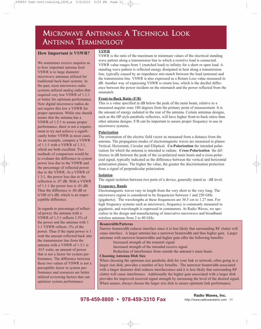


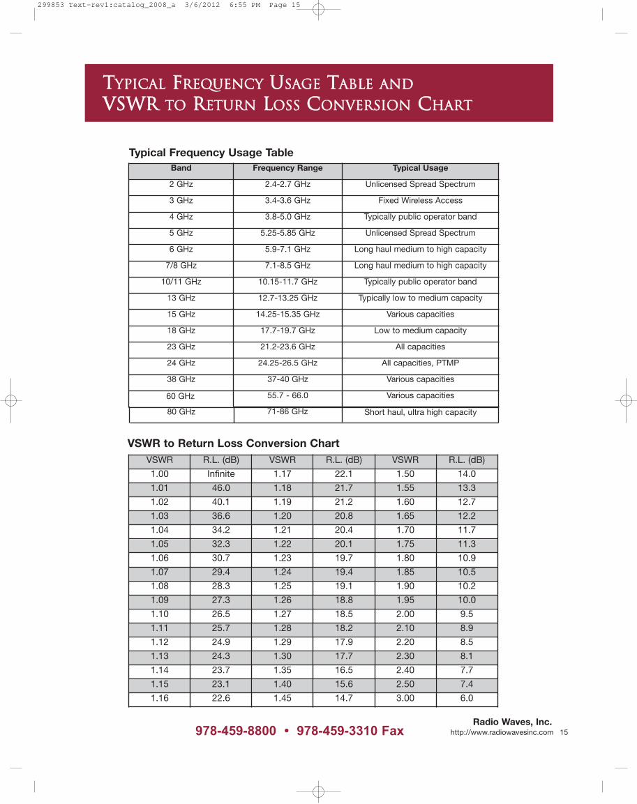

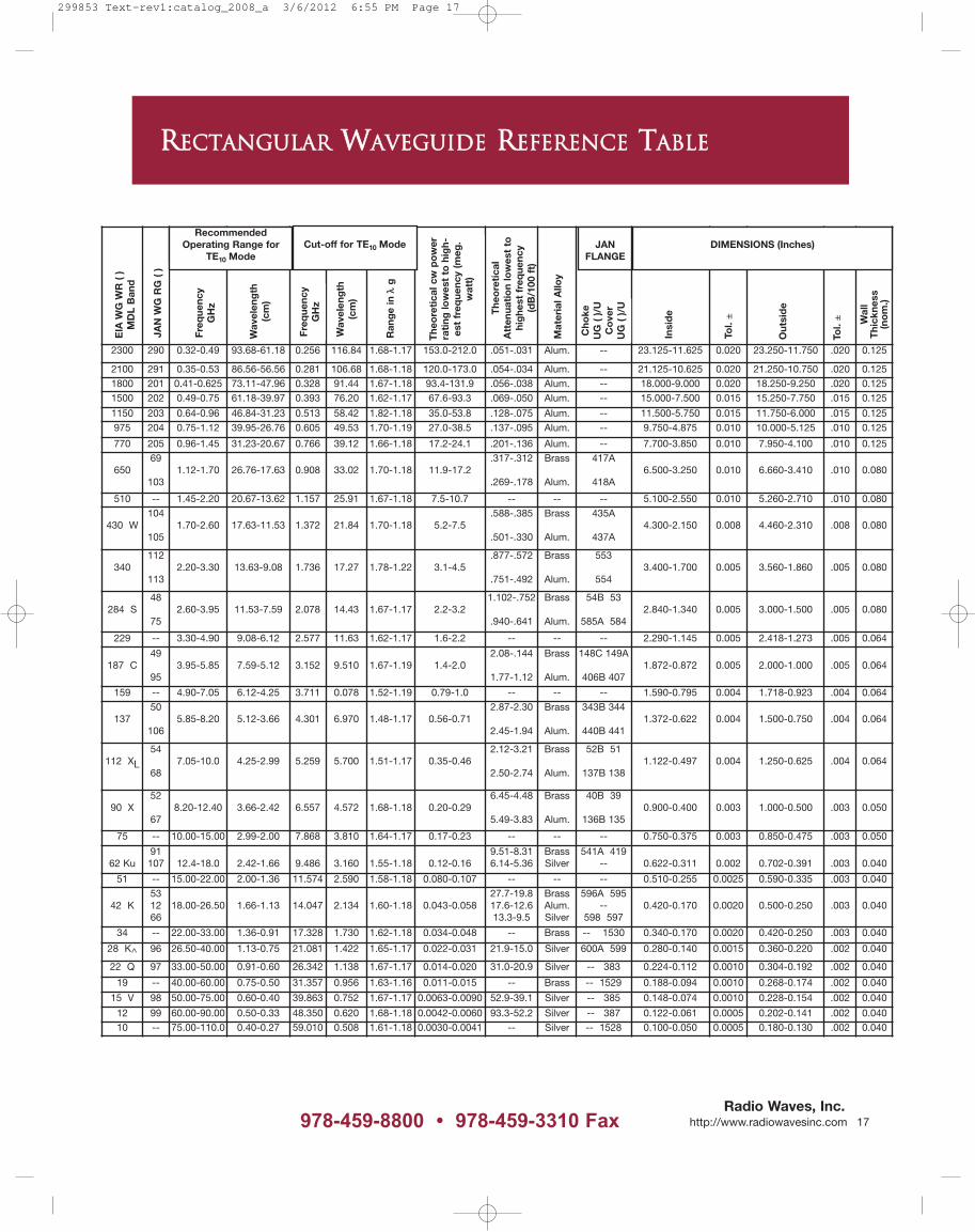
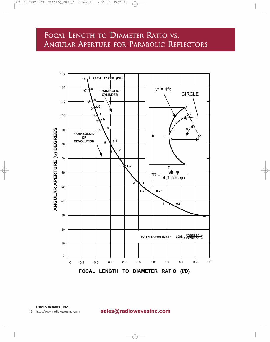

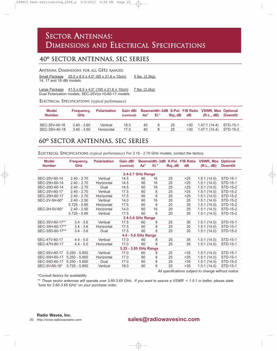
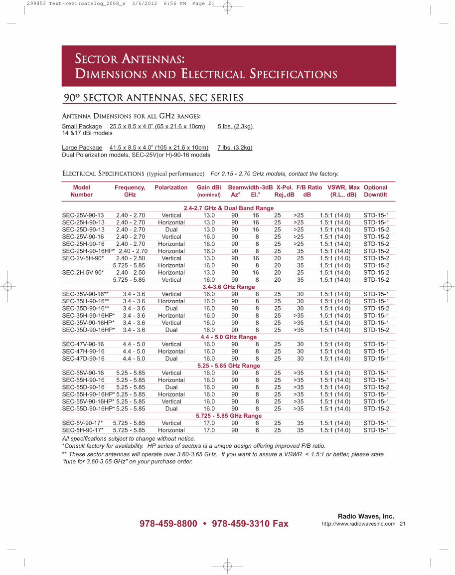
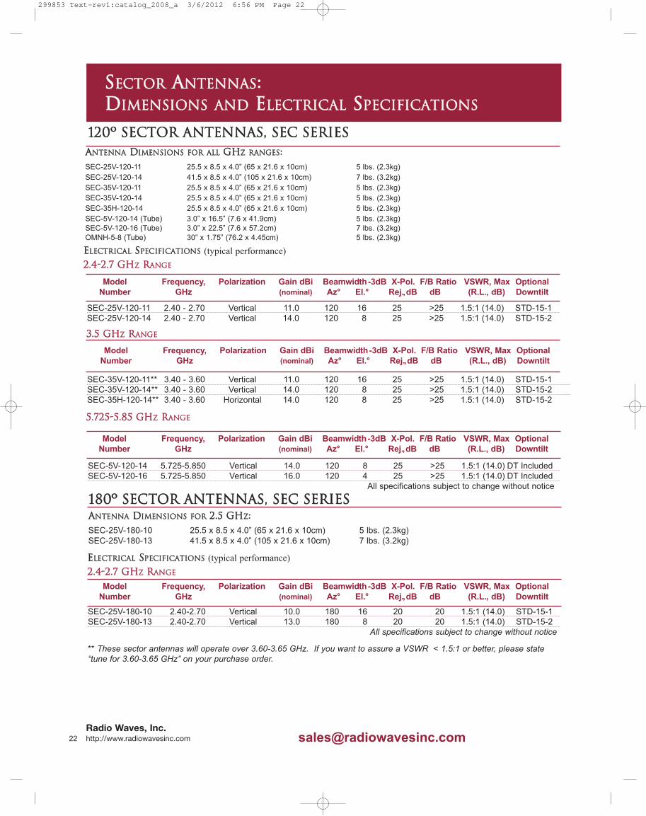


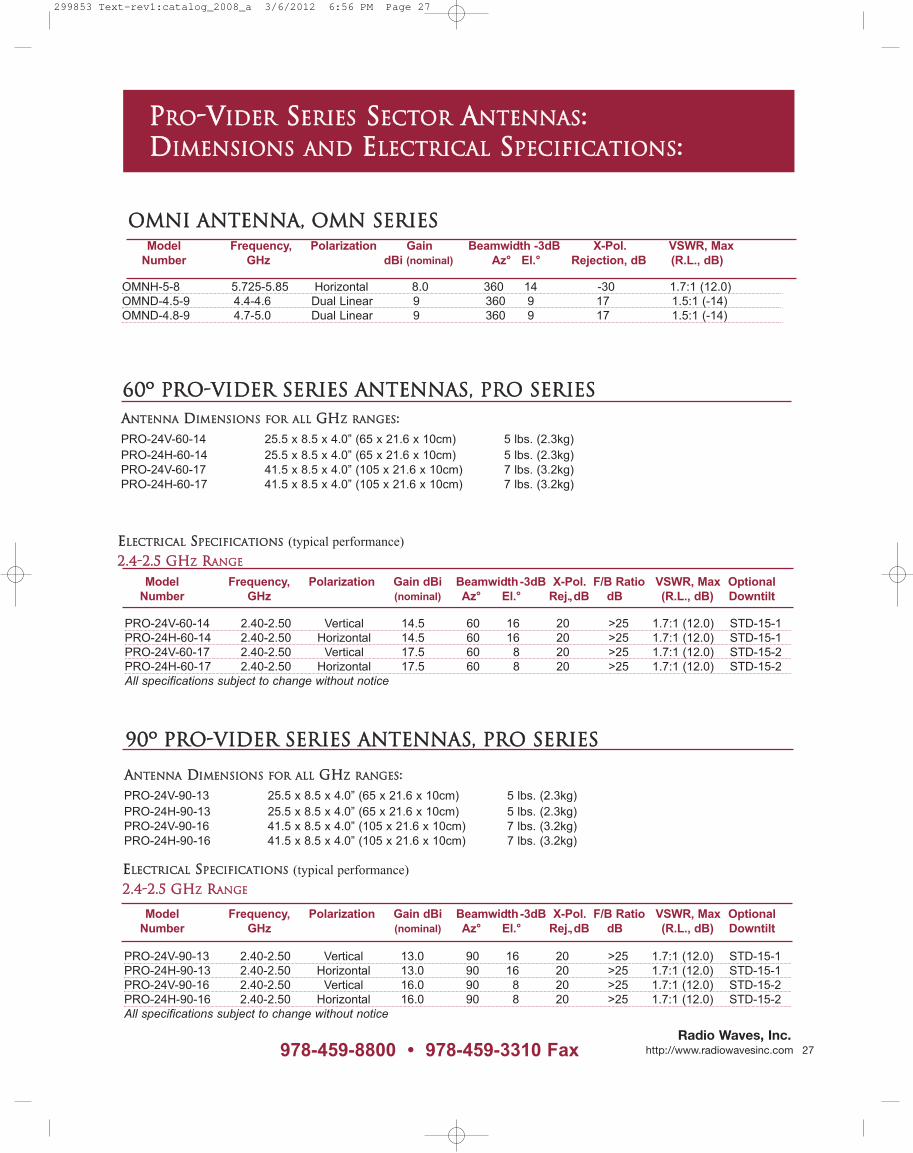
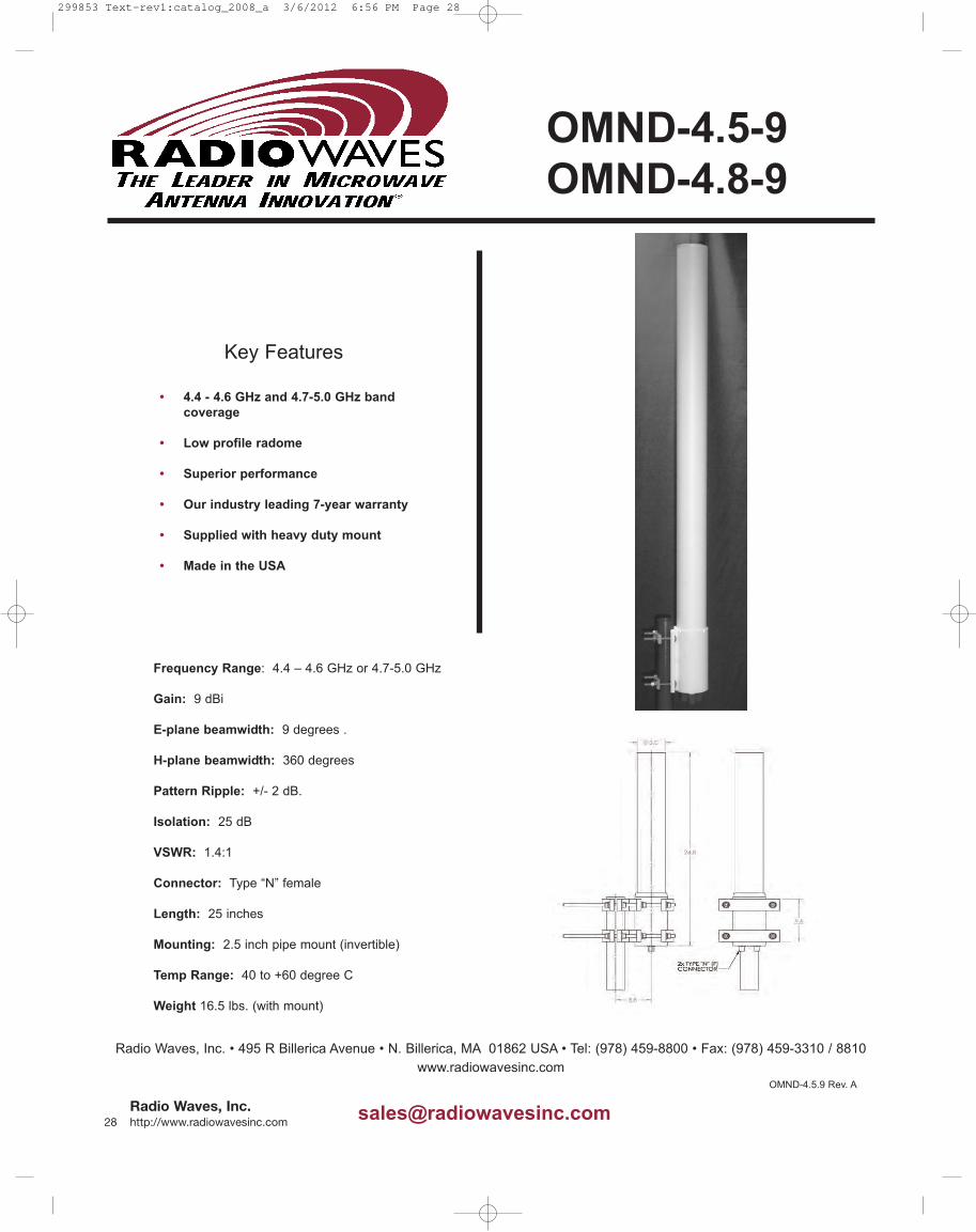
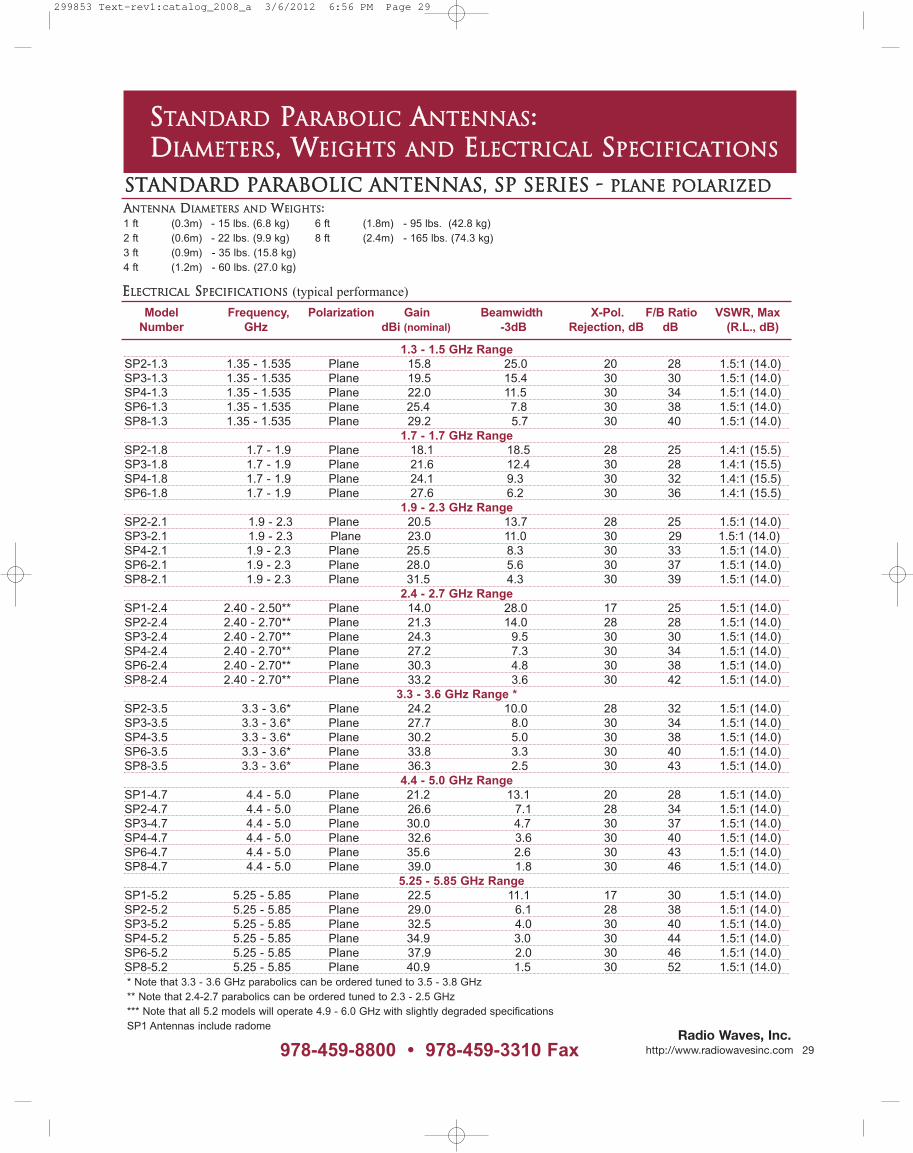

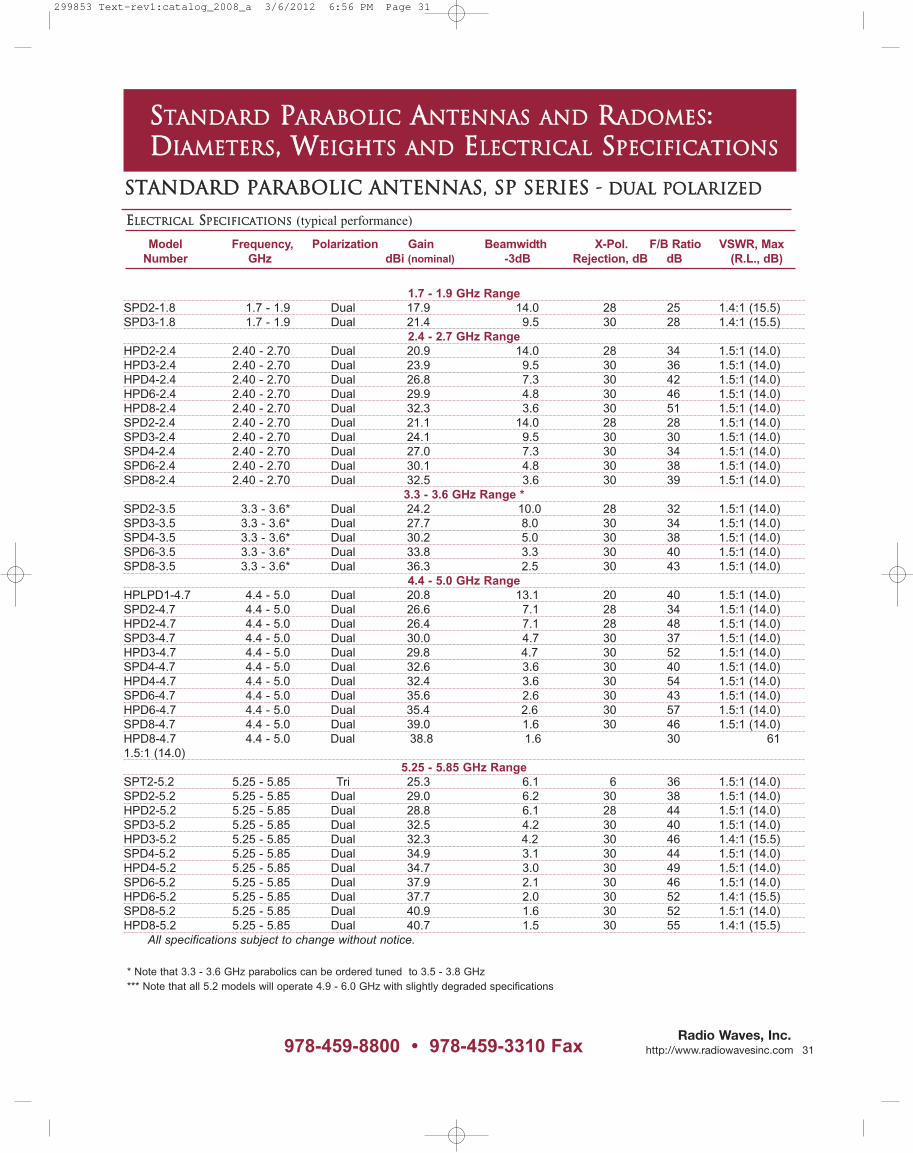
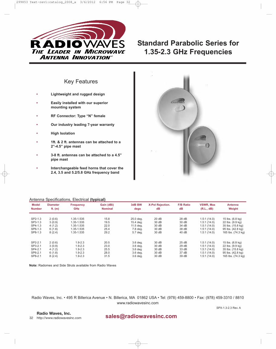
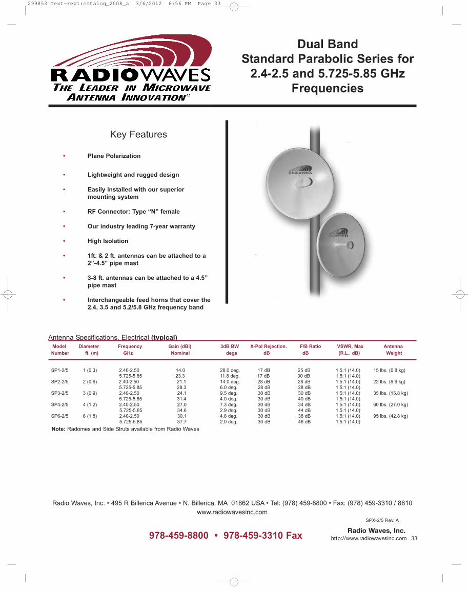

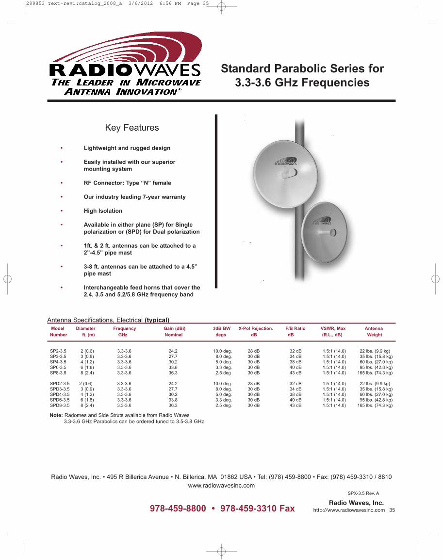


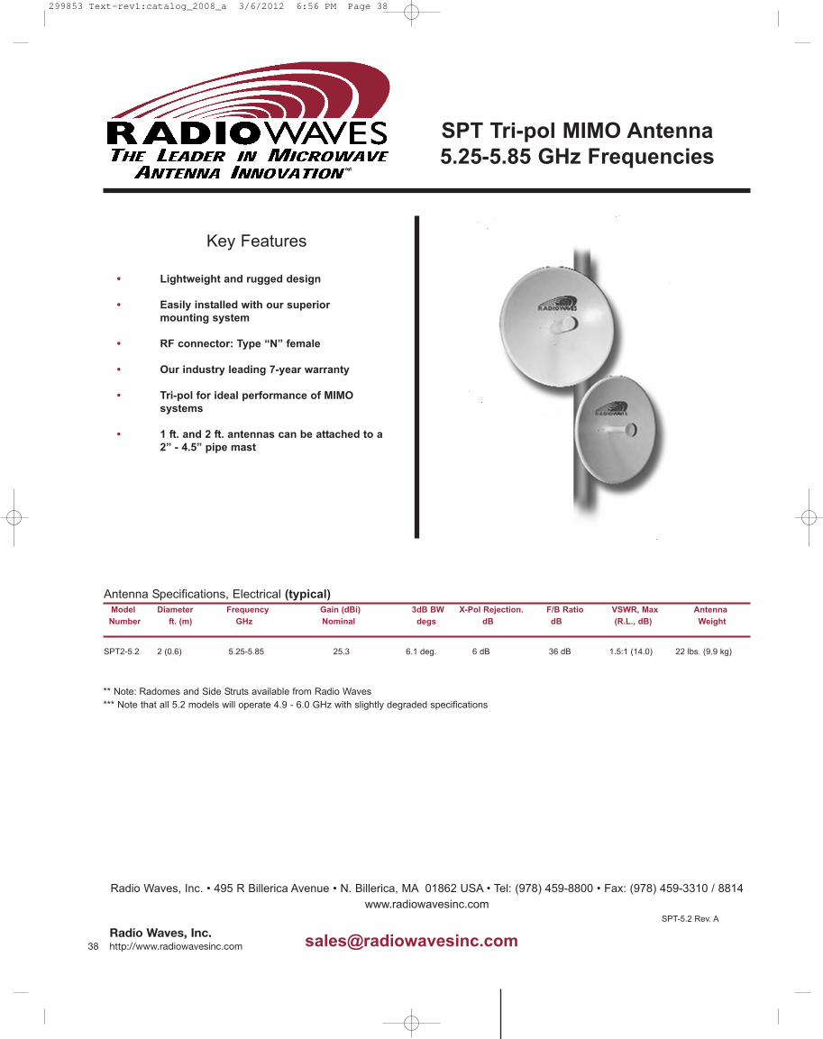


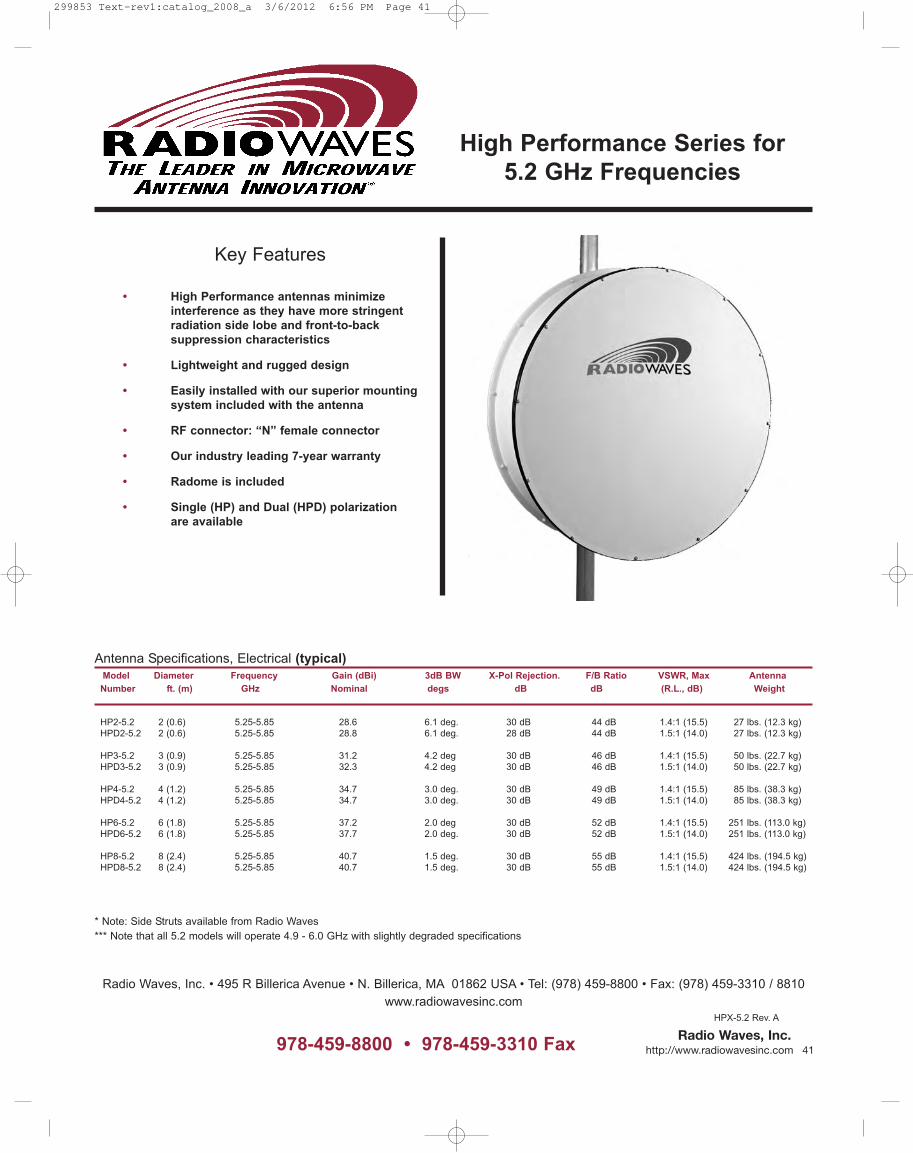


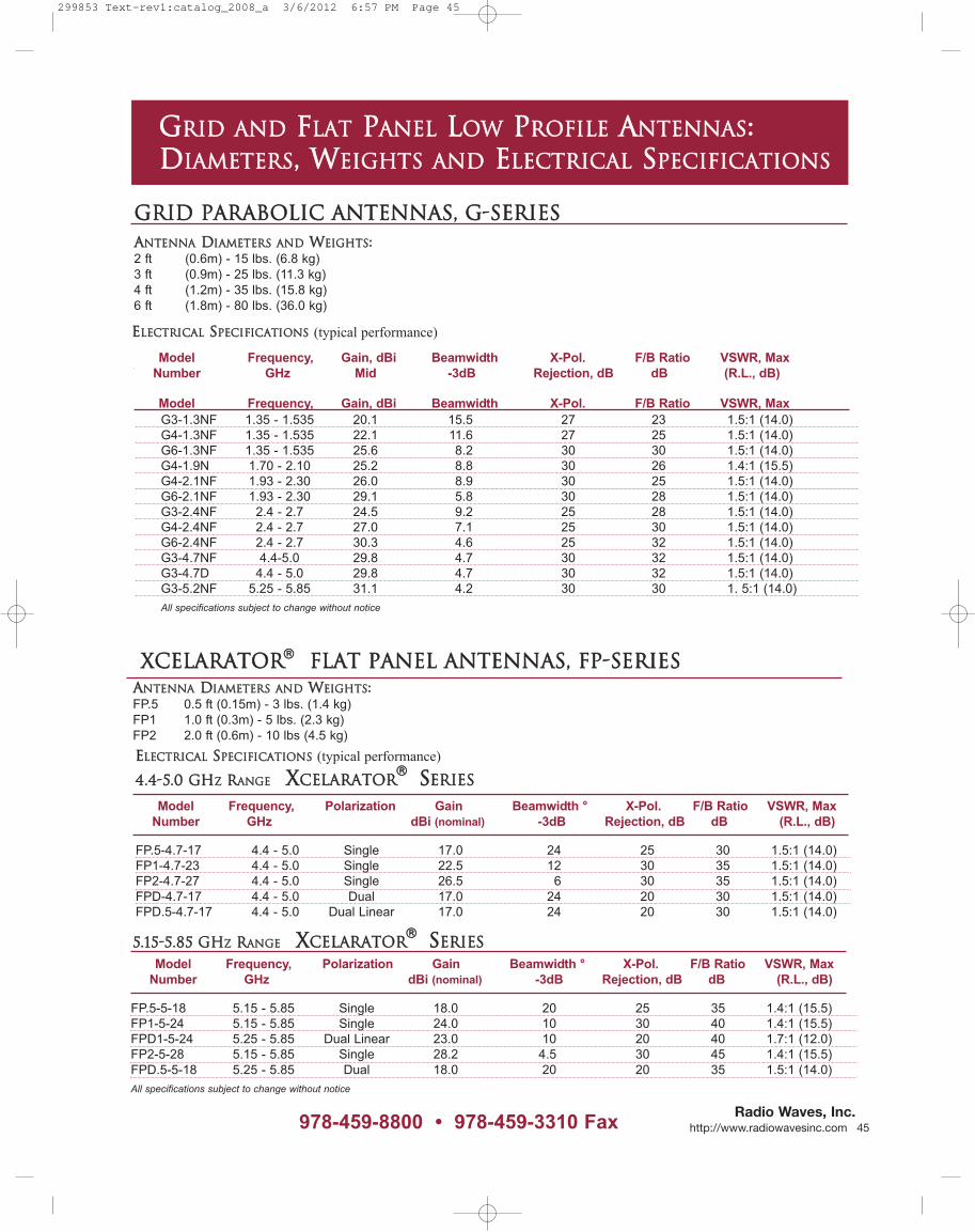

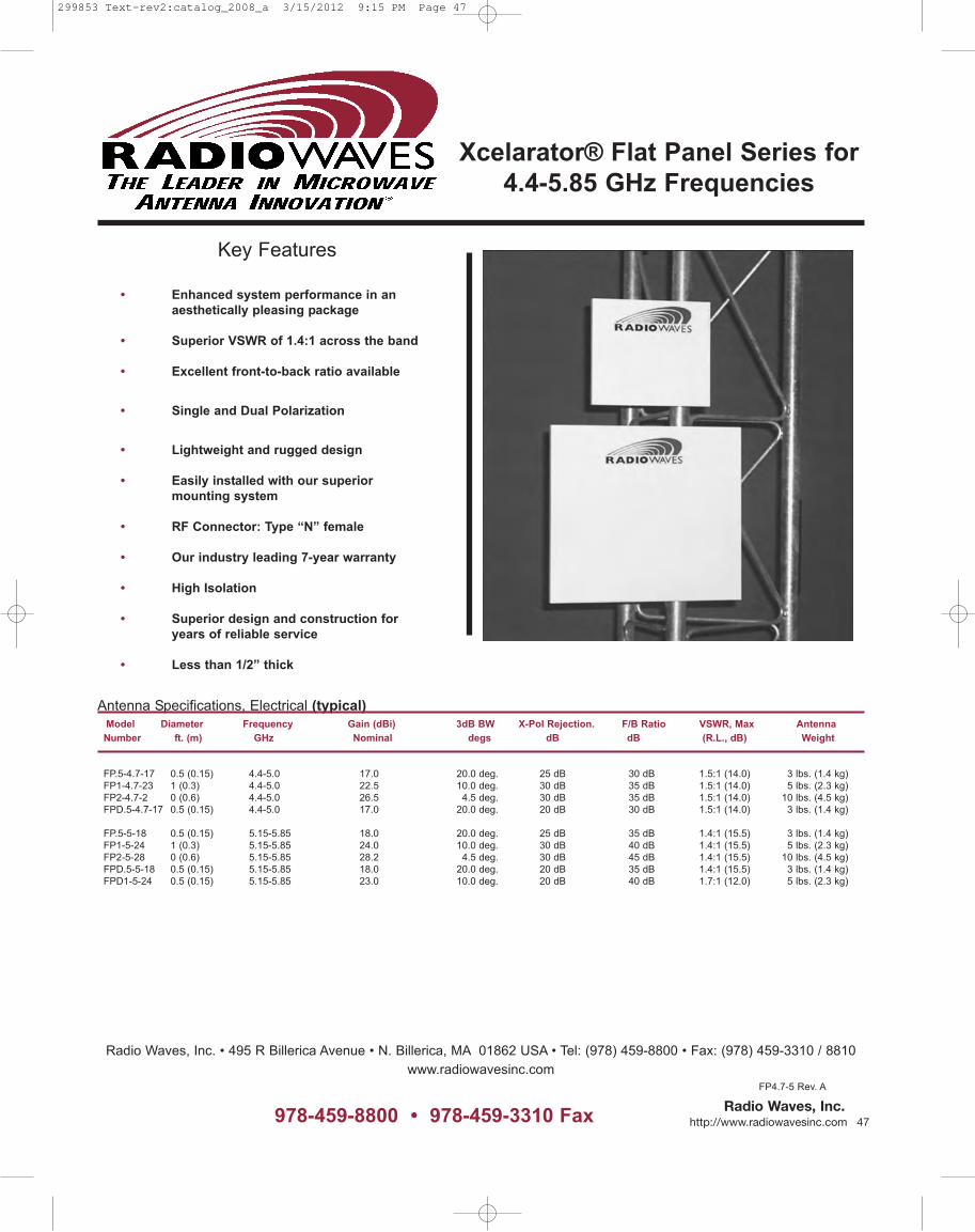


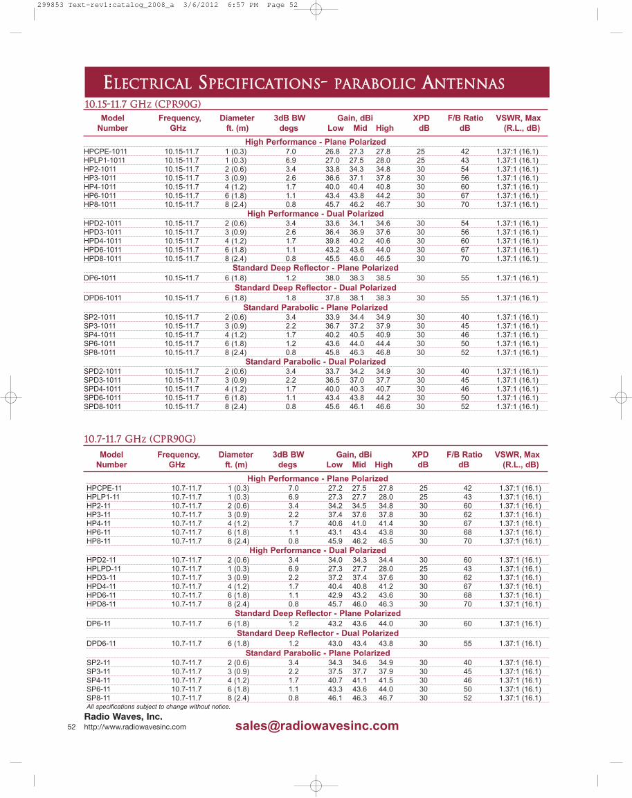


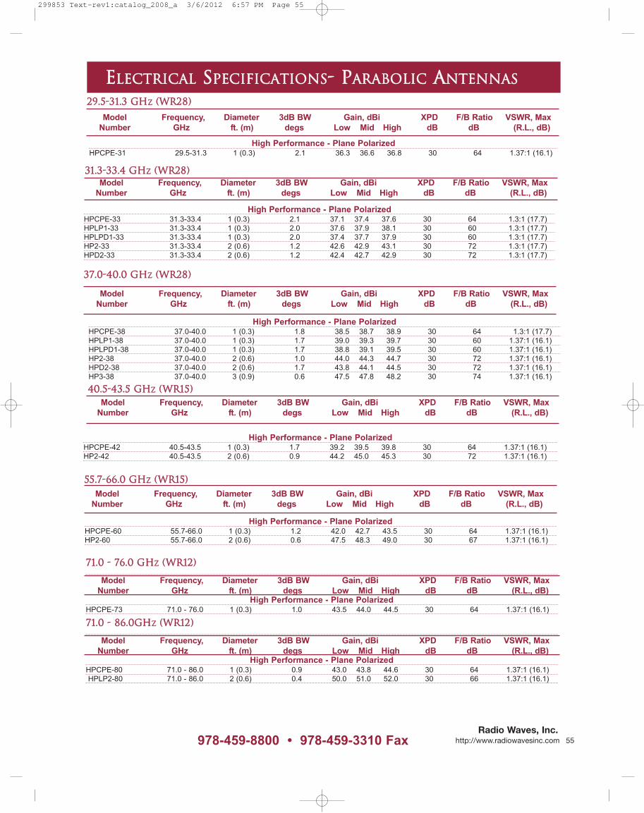

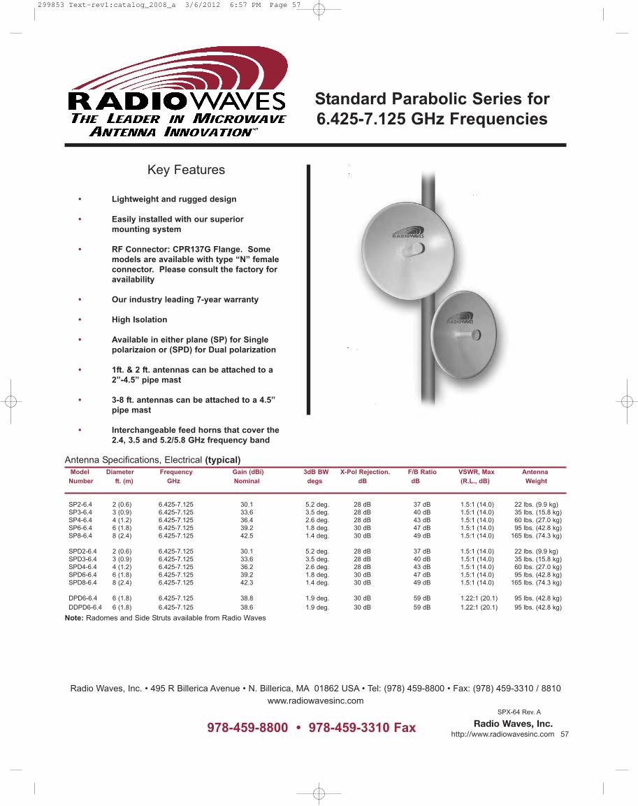


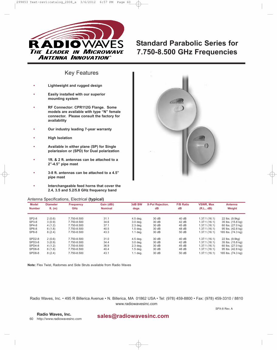
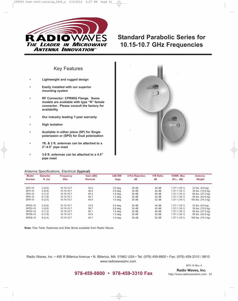
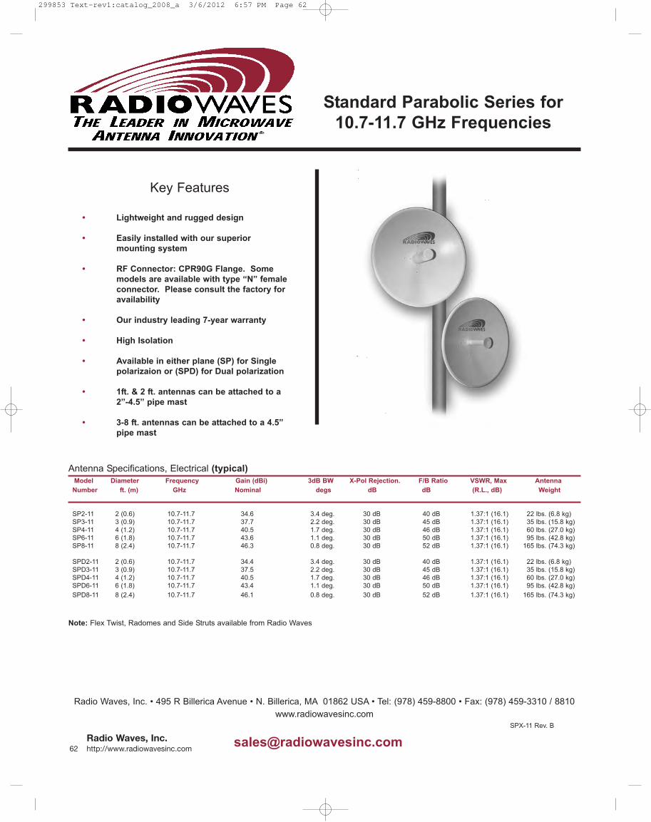

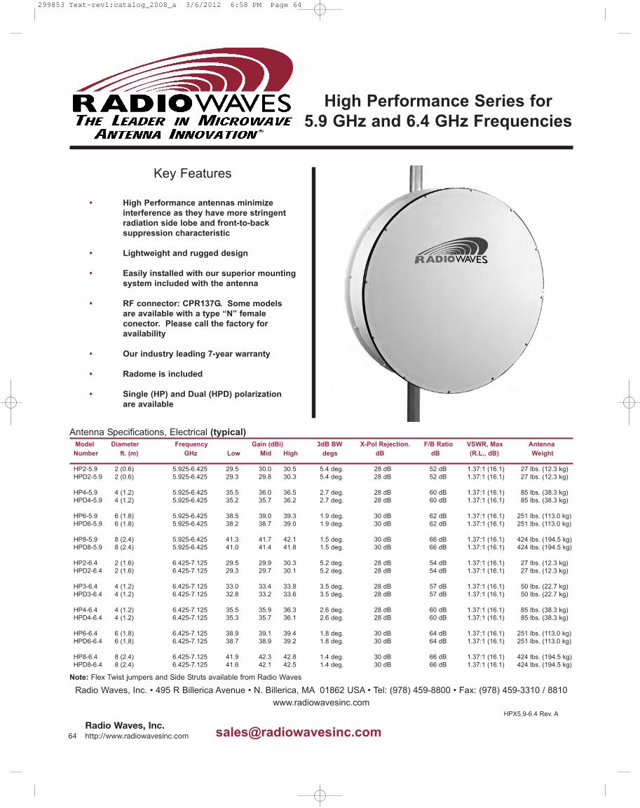


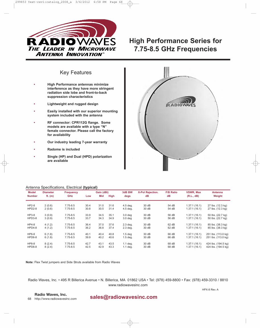


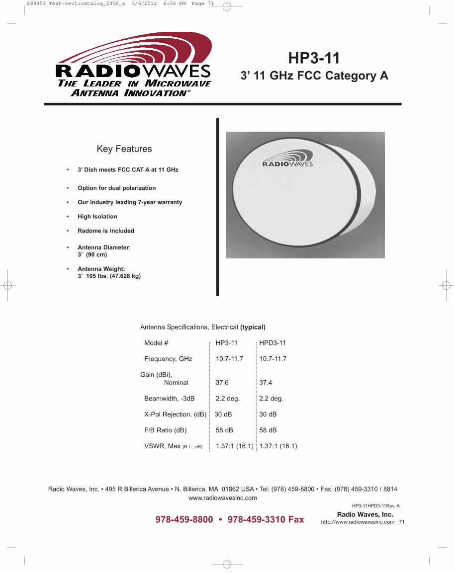

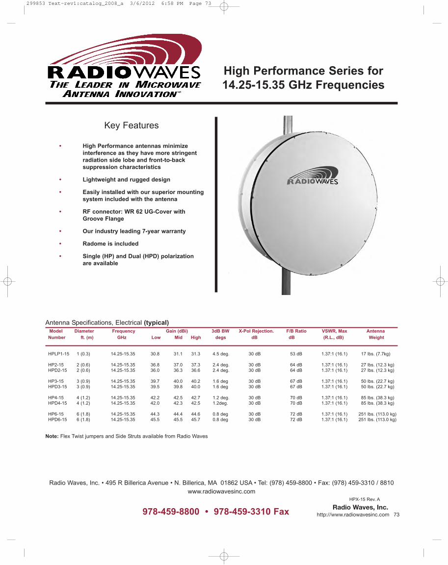
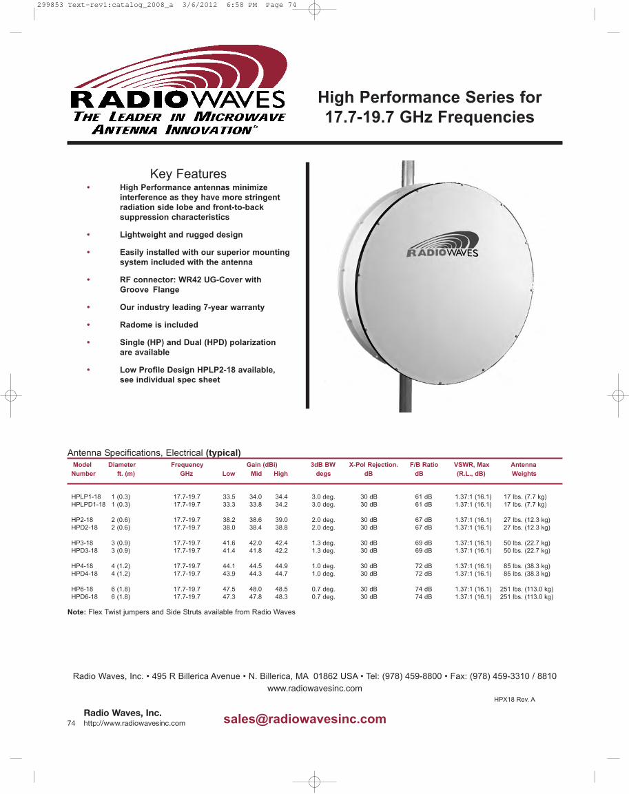
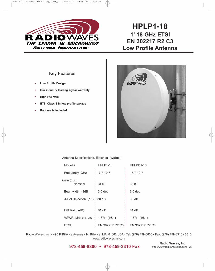


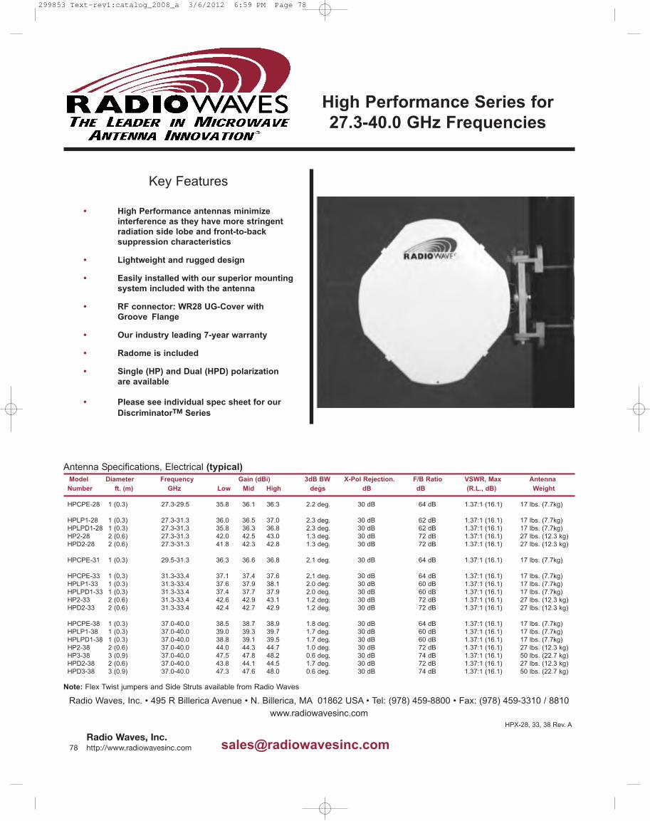


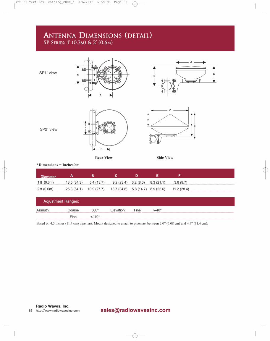
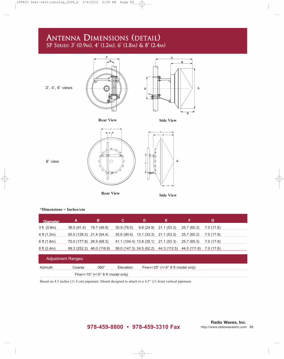

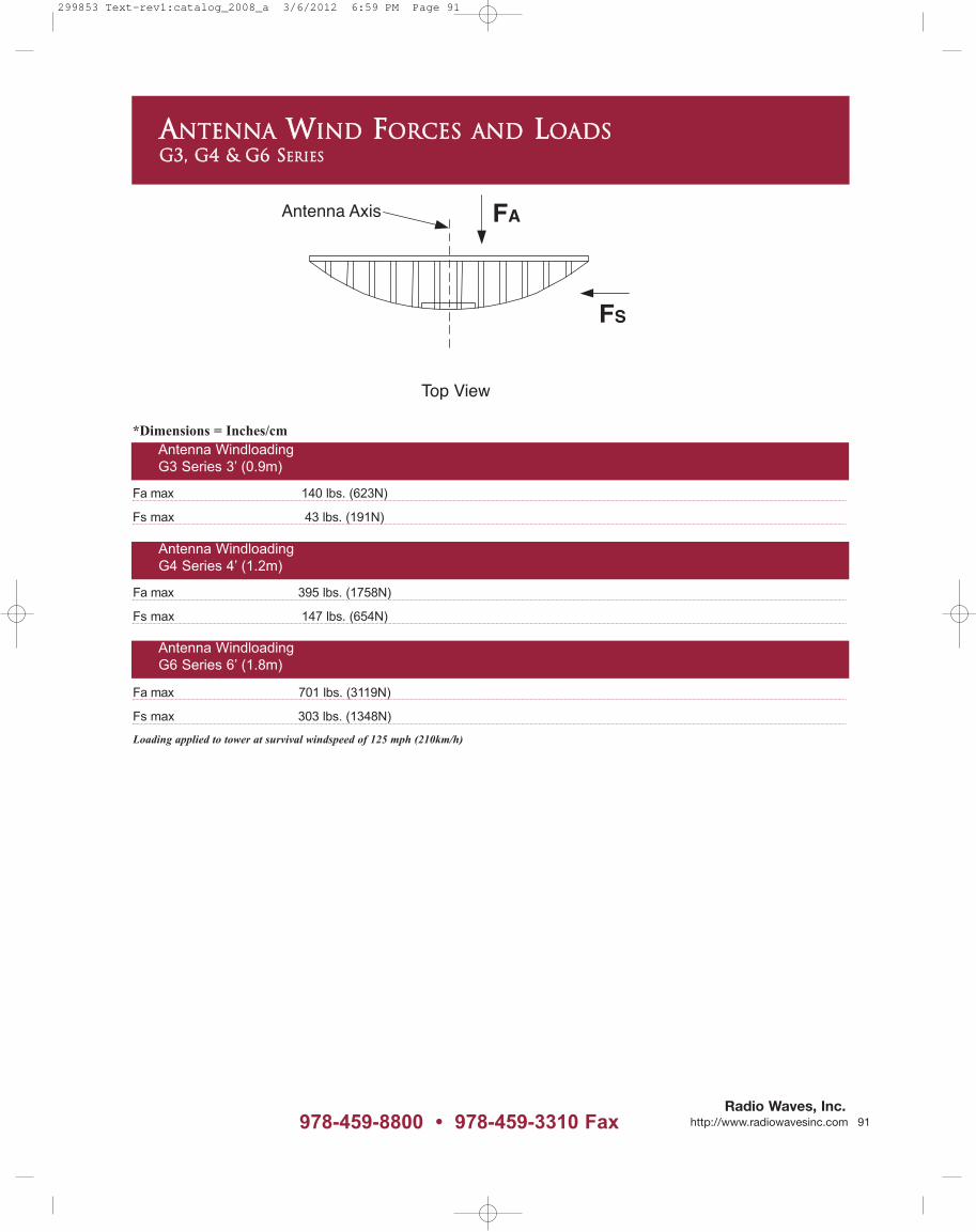
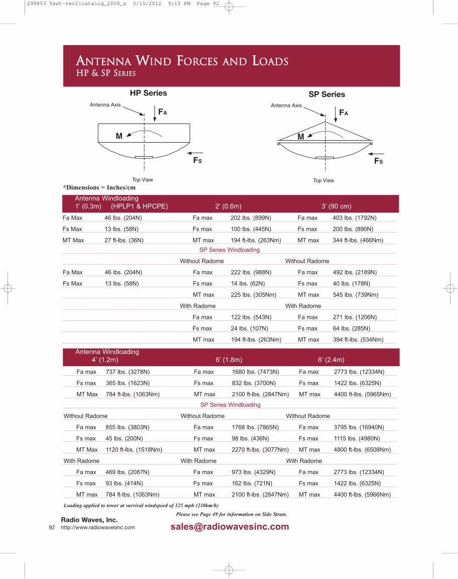


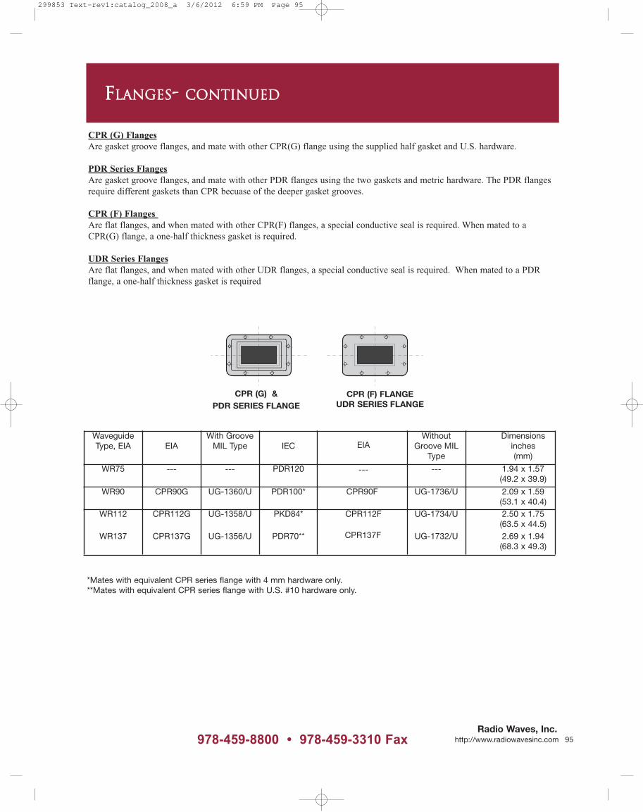


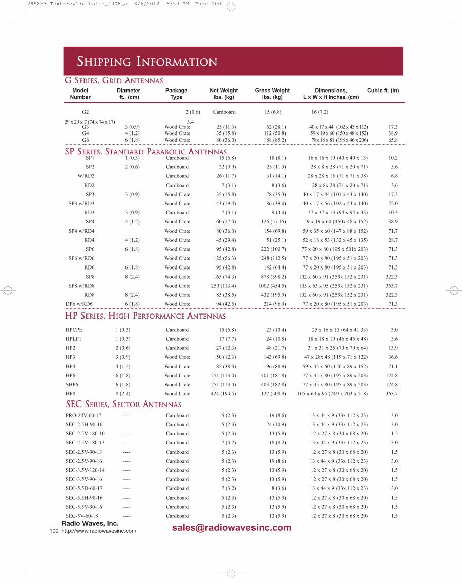


![Pageflex Server [document: D-0D045679 00001] · 2019. 8. 28. · maker s mark 4.75 woodford reserve 5.25 laphroaig 10 year old 5.25 the glenlivet 5.25 founders reserve glenmorangie](https://static.fdocuments.in/doc/165x107/610de309921a17486f258d8b/pageflex-server-document-d-0d045679-00001-2019-8-28-maker-s-mark-475-woodford.jpg)