Standard Number: 1142.23 Seattle City Light Superseding ...
17
Seattle City Light WORK PRACTICE Standard Number: Superseding: Effective Date: Page: 1142.23 October 13, 2015 April 6, 2017 1 of 17 Standards Coordinator Muneer Shetab Standards Supervisor John Shipek Unit Director Darnell Cola Vista Switchgear Condition Assessment 1. Scope This work practice outlines the inspection and maintenance procedure for manual and remote supervisory (capable) S&C Electric Company Vista switches. The inspection procedures contained herein can be performed while the switchgear is energized. Switchgear maintenance that requires de-energizing and grounding is outside the scope of this work practice. Depending on the date of manufacture, remote supervisory (capable) switches will either have a model 5800 or 6800 automatic switch control. For our purposes, these switch control models are interchangeable. 2. Application This work practice is for qualified Seattle City Light (SCL) personnel who perform preventative maintenance on Vista Switches. Section 4 defines who is qualified to perform this work. 3. Definitions Equipment (PS) Number - also known as the “PS” number, it is a number that follows the prefix “PS” assigned to each switch. To help explain how this number is used, a PS number could be considered the equivalent of a person’s social security number. No matter where a person lives, their social security number remains the same. PS labels are assigned, printed, and attached to the switchgear at the warehouse prior to receiving the equipment.
Transcript of Standard Number: 1142.23 Seattle City Light Superseding ...

Seattle City Light
WORK PRACTICE
Standard Number:
Superseding: Effective Date:
Page:
1142.23 October 13, 2015 April 6, 2017 1 of 17
Standards Coordinator Muneer Shetab
Standards Supervisor John Shipek
Unit Director Darnell Cola
Vista Switchgear Condition Assessment
1. Scope
This work practice outlines the inspection and maintenance procedure for manual and
remote supervisory (capable) S&C Electric Company Vista switches.
The inspection procedures contained herein can be performed while the switchgear is
energized. Switchgear maintenance that requires de-energizing and grounding is outside
the scope of this work practice.
Depending on the date of manufacture, remote supervisory (capable) switches will either
have a model 5800 or 6800 automatic switch control. For our purposes, these switch
control models are interchangeable.
2. Application
This work practice is for qualified Seattle City Light (SCL) personnel who perform
preventative maintenance on Vista Switches. Section 4 defines who is qualified to
perform this work.
3. Definitions
Equipment (PS) Number - also known as the “PS” number, it is a number that follows
the prefix “PS” assigned to each switch. To help explain how this number is used, a PS
number could be considered the equivalent of a person’s social security number. No
matter where a person lives, their social security number remains the same. PS labels
are assigned, printed, and attached to the switchgear at the warehouse prior to receiving
the equipment.

Seattle City Light WORK PRACTICE Vista Switchgear Condition Assessment
Standard Number:
Superseding: Effective Date:
Page:
1142.23
October 13, 2015 April 6, 2017 2 of 17
Switch (SW) Number – also known as the System Operations Center (SOC) Switch
Number, this number follows the prefix “SOC” and indicates the switch circuit location. To
help explain how this number is used, an SOC number could be considered the
equivalent of a street address. No matter who lives there, the address stays the same.
Parent Facility ID No. – this is also known as the Pad (P) Number, Underground (U)
Switch Number, or the Vault (V) Number.
Underground (U) Switch Number – this is a switch number specifically for underground
equipment. This number follows the prefix “U.”
Pad (P) Number – identifies the pad on which the switch is installed. The best practice is
to affix the pad number to the pad itself. Labeling the switch enclosures with the pad
number should be avoided.
Vault (V) Number – identifies the vault on which the switch is installed.
4. Safety
Vista switches shall only be maintained by qualified personnel who are knowledgeable in
installation, operation, and maintenance of underground electrical power distribution
equipment along with the associated hazards.
A qualified person is one who is trained and competent in:
Distinguishing exposed live parts from non-live parts of electrical equipment.
Determining the proper approach distances corresponding to the voltages to which the
qualified person will be exposed.
Properly using the special precautionary techniques, personal protective equipment
(PPE), insulating and shielding materials, and insulated tools for working on or near
exposed energized parts of electrical equipment.
Working in confined spaces such as vaults.
Using an oxygen sniffer.
This work practice is intended only for such qualified personnel. The instructions in this
work practice are not intended to be a substitute for adequate training and experience in
safety procedures for this type of equipment.
Crews shall also familiarize themselves with and follow the safety information contained
in the S&C document Instruction Sheet 681-510.
5. Required PPE
The following PPE is required to complete Vista switch preventive maintenance
procedures:
Flame-resistant (FR) clothing that is the appropriate class
Safety glasses
Gloves
Hard hat
Safety cones and yellow tape

Seattle City Light WORK PRACTICE Vista Switchgear Condition Assessment
Standard Number:
Superseding: Effective Date:
Page:
1142.23
October 13, 2015 April 6, 2017 3 of 17
6. Data Collection Sheet, Required Tools, and Reference Material
6.1 Data Collection Sheet
Personnel conducting preventative maintenance shall have on hand a blank Data
Collection Sheet on which to record ratings and comments for each part of the
assessment procedure. See Appendix A for an example.
6.2 Tools
The following tools are required to complete Vista switch preventive maintenance
procedures:
Gas detector (for vaults)
Flashlight
Infrared heat sensor gun
Digital camera
Vault key/socket
Thermometer
Black permanent marker
Digital voltmeter
6.3 Reference Material
It is recommended that the following reference materials be on hand when conducting the
condition assessment procedures:
SCL 1167.13; “Padmount Switch Signs and Labels”
S&C Instruction Sheet 1045-540; “S&C 6800 Series Automatic Switch Control
Operating Instructions”
7. Procedure
Follow all safety and clearance procedures before performing any work on the switch.
Proper PPE is required to perform this work practice. See Section 5, “Required PPE.”
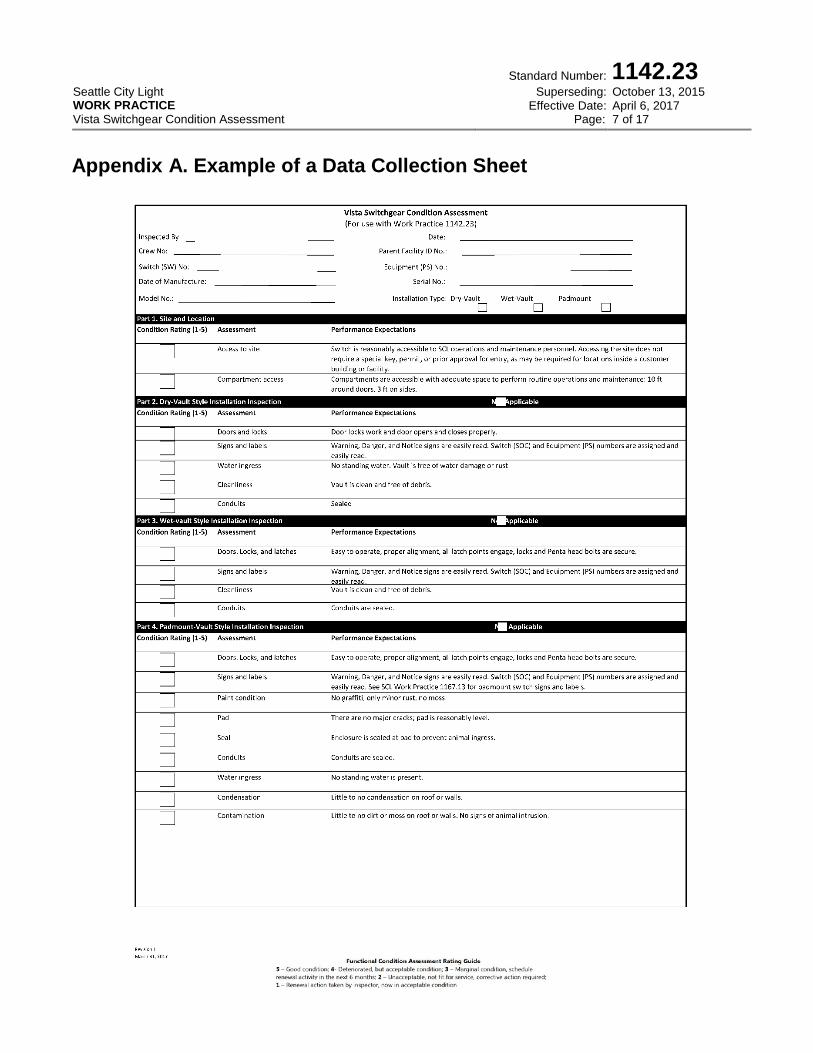
Part 1. Site and Location
Assessment Performance Expectations
Access to site Switch is reasonably accessible to SCL operations and maintenance personnel.
Accessing the site does not require a special key, permit, or prior approval for entry, as may be required for locations inside a customer building or facility.
Compartment access
Compartments are accessible with adequate space to perform routine operations and maintenance: 10 ft in front of doors, 3 ft on sides.
Part 2. Dry-Vault Style Installation Inspection
Assessment Performance Expectations
Doors and locks Door locks work and door opens and closes properly.
Signs and labels Warning, Danger, and Notice signs are easily read. Switch (SOC) and Equipment (PS) numbers are assigned and easily read.
Water ingress No standing water.
Vault is free of water damage or rust.
Cleanliness Vault is clean and free of debris.
Conduits Conduits are sealed.

Seattle City Light WORK PRACTICE Vista Switchgear Condition Assessment
Standard Number:
Superseding: Effective Date:
Page:
1142.23
October 13, 2015 April 6, 2017 4 of 17
Part 3. Wet-Vault Style Installation Inspection
Assessment Performance Expectations
Doors, locks, and latches Easy to operate, proper alignment, all latch points engage, locks and Penta head bolts are secure.
Signs and labels Warning, Danger, and Notice signs are easily read. Switch (SOC) and Equipment (PS) numbers are assigned and easily read. See SCL 1167.13 for details.
Cleanliness Vault is clean and free of debris.
Conduits Conduits are sealed.
Part 4. Padmount Style Installation Inspection
Assessment Performance Expectations
Doors, locks and latches Easy to operate, proper alignment, all latch points engage, locks and Penta head bolts are secure.
Signs and labels Warning, danger, and notice signs are easy to read. Switch (SOC) Number and Equipment (PS) numbers are assigned and easy to read. See SCL Work Practice 1167.13 for padmount switch signs and labels.
Paint condition No graffiti, only minor rust, no moss.
Pad There are no major cracks; pad is reasonably level.
Seal Enclosure is sealed at pad to prevent animal ingress.
Conduits Conduits are sealed.
Water ingress No standing water is present.
Condensation Little to no condensation on roof or walls.
Contamination Little to no dirt or moss on roof or walls. No signs of animal intrusion.
Part 5. Heat Sensor Readings
Assessment Performance Expectations
Ambient temperature Measure ambient temperature.
Highest bushing/elbow contact temperature above ambient
Temperature is less than 10 degrees Celsius above ambient.
The difference in temperature between phase and switch is less than 5 degrees Celsius.
Part 6. SF6 Gas Levels (See Appendix B for detailed instructions)
Assessment Performance Expectations
SF6 gas level (internal gauge) Needle location is within the “green” operating region.
SF6 gas level (external gauge) Gas pressure is within the acceptable range.
Part 7. Ground Connections
Assessment Performance Expectations
Fence (padmount only) All fences within 6 ft of the switch are grounded.
Enclosure (padmount only) The enclosure is properly grounded.
Frame The frame is bonded.
Ground rod A ground rod is present.

Seattle City Light WORK PRACTICE Vista Switchgear Condition Assessment
Standard Number:
Superseding: Effective Date:
Page:
1142.23
October 13, 2015 April 6, 2017 5 of 17
Part 8. Batteries (see Appendix C for detailed instructions)
Assessment Performance Expectations
Age of battery Determine date of manufacture from equipment label.
Batteries that are more than 4 years old shall be replaced, regardless of physical or electrical condition.
Physical condition No damage, deformities, cracks, leaks, rust or white powder: Battery receives a condition rating of 5.
Minor damage, deformities, cracks, leaks, rust or white powder: Battery receives a condition rating of 4.
Noticeable damage, deformities, cracks, leaks, rust, or white powder: Battery receives a condition rating of 3.
Battery is in poor physical condition and replaced at the time of inspection: Battery receives a condition rating of 1.
DC voltage The open circuit voltage is greater than 32 Vdc: Battery receives a condition rating of 5.
The open circuit voltage is less than 32 Vdc and not replaced: Battery receives a condition rating of 2.
The open circuit voltage is less than 32 Vdc and is replaced.: Battery receives a condition rating of 1.
Electrical condition, remote supervisory control
Battery operates supervisory control: battery receives a condition rating of 5.
Battery does not operate supervisory control and is not replaced: Battery receives a condition rating of 2.
Battery does not operate supervisory control and is replaced: Battery receives a condition rating of 1.
Electrical condition, motor control battery
Battery operates motor: Battery receives a condition rating of 5.
Battery does not operate motor and is not replaced: Battery receives a condition rating of 2.
Battery does not operate motor and is replaced: Battery receives a condition rating of 1.
Part 9. Voltage Indicator
Assessment Performance Expectations
Display cleanliness and functionality Display is clean and all phases function. See S&C Instruction Sheet 681-510 for instructions on how to test voltage indicators.
Part 10. Portable Motor Operator (PMO) Fit Check (see Appendix D for more information)
Assessment Performance Expectations
Mounting PMO is mounted properly. This is a one-time check. Do not fit check again if previously checked.
Part 11. Switch Operating Mechanism (performed only if switch is take out of service)
Assessment Performance Expectations
Operation Mechanism operates smoothly.
Switch fully opens and closes.
Part 12. Overall Switch Condition Assessment Rating
Assessment Performance Expectations
Overall rating of the switch Based on the above condition assessments and the expertise of the inspection team, what is an overall assessment of the complete switch?
Functional Condition Assessment Rating Guide
1 – Renewal action taken by inspector, now in acceptable condition.
2 – Unacceptable, not fit for service, immediate corrective action required. If this rating is given, contact SOC and tag appropriately.
3 – Marginal condition, schedule renewal activity in the next 6 months
4 – Deteriorated, but acceptable condition
5 - Good condition

Seattle City Light WORK PRACTICE Vista Switchgear Condition Assessment
Standard Number:
Superseding: Effective Date:
Page:
1142.23
October 13, 2015 April 6, 2017 6 of 17
Part 13. Scheduling Future Off-Line Condition-Directed Renewal Tasks
Include any out-of-service renewal tasks in this section and indicated the anticipated time frame.
Part 14. Comments
Include all comments related to Parts 1-13 in this section. With each comment provided, identify which part each
corresponds to.
8. References
S&C Instruction Sheet 681-510, “S&C Vista Underground Distribution Switchgear,
UnderCover, Vault-Mounted, and Pad-Mounted Styles, Instructions for Operation,”
March 25, 2002
S&C Instruction Sheet 1041-603; “S&C Battery Chargers BC-8-24 and BC-8-36,”
June 6, 2016
S&C Instruction Sheet 1045-540, “(S&C 6800 Series Automatic Switch Control
Operating Instructions,” October 17, 2016
SCL Design Standard 9202.17; “Vista Switch Application Guide”
SCL Work Practice 1167.13; “Padmount Switch Signs and Labels”
9. Sources
Shetab, Muneer; SCL Standards Engineer, subject matter expert, and originator of
1142.23 ([email protected])
S&C Data Bulletin 682-97; “Battery Charger and Battery Pack Specifications,”
March 2, 2011
Seattle City Light WORK PRACTICE Vista Switchgear Condition Assessment
Standard Number:
Superseding: Effective Date:
Page:
1142.23
October 13, 2015 April 6, 2017 7 of 17
Appendix A. Example of a Data Collection Sheet

Seattle City Light WORK PRACTICE Vista Switchgear Condition Assessment
Standard Number:
Superseding: Effective Date:
Page:
1142.23
October 13, 2015 April 6, 2017 8 of 17

Seattle City Light WORK PRACTICE Vista Switchgear Condition Assessment
Standard Number:
Superseding: Effective Date:
Page:
1142.23
October 13, 2015 April 6, 2017 9 of 17

Seattle City Light WORK PRACTICE Vista Switchgear Condition Assessment
Standard Number:
Superseding: Effective Date:
Page:
1142.23
October 13, 2015 April 6, 2017 10 of 17
Appendix B. SF6 Gauge Assessment Details
This information corresponds to Part 6 of the Vista Switchgear Condition Assessment
Checklist.
Each Vista switch is equipped with one SF6 gas pressure gauge. The gauge will be one
of three styles:
INTERNAL
Internal style pressure gauges are temperature compensated.
Figure B1. New SF6 gauge. Used on switches purchased after 2011.
Figure B2. Old SF6 Gauge. Used on switches purchased before 2011.
EXTERNAL
External style pressure gauges are not temperature compensated.
Figure B3. Replacement SF6 Gauge. Used on some Vista switches to replace defective internal gauges. Mounted on the SF6 fill port.

Seattle City Light WORK PRACTICE Vista Switchgear Condition Assessment
Standard Number:
Superseding: Effective Date:
Page:
1142.23
October 13, 2015 April 6, 2017 11 of 17
To check an internal gauge:
Needle Location on the SF6 Pressure Gauge
Color
Green
Green with yellow stripes
Orange with black stripes
Red with black stripes
Result Pass Pass Fail Fail
Action None Call S&C Call S&C Call S&C
The needle location shall be within the “green” operating region. Call S&C at 1-888-762-
1100 or 1-855-381-8800 if the needle is outside the “green” operating zone. A condition
rating of 1 should also result in an overall switch rating of 1.
To check an external gauge:
1. Determine the ambient temperature.
2. Read the psig from the gauge.
3. Use Figure 6e and Table 6 to determine whether that number falls in the pass range
(shown in green). For example, the pass range for 68°F is between 6.7 and 7.7 psig.
Call S&C at 1-888-762-1100 or 1-855-381-8800 if the needle is outside the pass range. A
condition rating of 1 should also result in an overall switch rating of 1.

Seattle City Light WORK PRACTICE Vista Switchgear Condition Assessment
Standard Number:
Superseding: Effective Date:
Page:
1142.23
October 13, 2015 April 6, 2017 12 of 17
Figure B4. Acceptable (Pass) Range for SF6 Gas Pressure in External Gauges
Table B1. Acceptable (Pass) Range for SF6 Gas Pressure in External Gauges
Ambient Temperature (F)
Normal Pressure (psig)
Pass Range (psig)
131 9.8 9.0 10.3
122 9.4 8.6 9.9
104 8.65 8.2 9.2
86 7.85 7.4 8.4
68 7.15 6.7 7.7
50 6.45 6.0 7.0
32 5.65 5.2 6.2
14 4.95 4.5 5.5
-4 4.25 3.8 4.8
-22 3.5 3.0 4.0
-40 2.8 2.3 3.3

Seattle City Light WORK PRACTICE Vista Switchgear Condition Assessment
Standard Number:
Superseding: Effective Date:
Page:
1142.23
October 13, 2015 April 6, 2017 13 of 17
Appendix C. Battery Inspection and Replacement
This information corresponds to Part 8 of the Vista Switchgear Condition Assessment
Checklist.
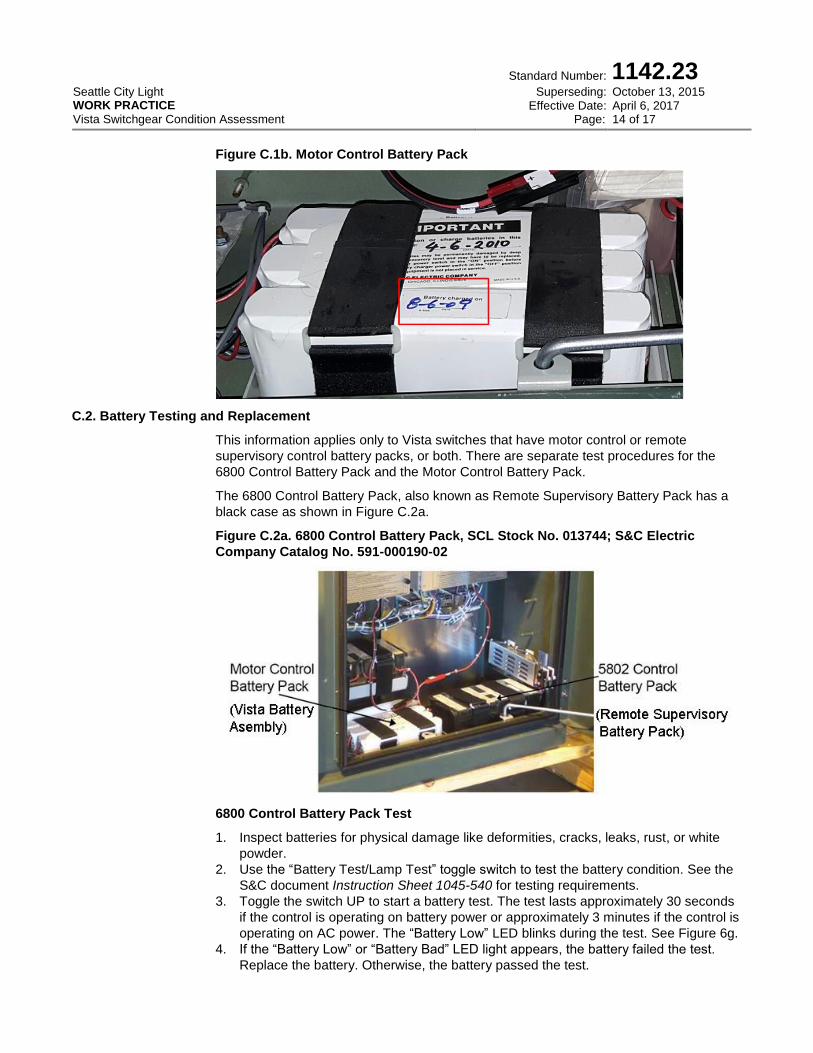
C.1. Battery Date of Manufacture
Individual 6 V and 12 V EnerSys cells shown in figures C.2d and C.2e of this appendix
are re-packaged together by S&C Electric Company to form 36 V Remote Supervisory
and Motor Control battery packs.
The Remote Supervisory Battery Packs have a sticker on them like the one shown in
Figure C.1a. In this example, “DATE 1126” means the battery was packaged together on
the 26th week of 2011. The date corresponding to the 26th week of 2011 is June 27 to
July 3, 2011. Use June 27, 2011 as the date of manufacture.
The Motor Control Battery Packs have two stickers on them like the one shown in
Figure C.1b. In this example, the two stickers are “Place in operation or charge batteries
in this equipment before: 4-6-2010” and “Battery charged on 8-6-09.” Use August 6, 2009
as the date of manufacture.
Figure C.1a. Remote Supervisory Battery Pack
Seattle City Light WORK PRACTICE Vista Switchgear Condition Assessment
Standard Number:
Superseding: Effective Date:
Page:
1142.23
October 13, 2015 April 6, 2017 14 of 17
Figure C.1b. Motor Control Battery Pack
C.2. Battery Testing and Replacement
This information applies only to Vista switches that have motor control or remote
supervisory control battery packs, or both. There are separate test procedures for the
6800 Control Battery Pack and the Motor Control Battery Pack.
The 6800 Control Battery Pack, also known as Remote Supervisory Battery Pack has a
black case as shown in Figure C.2a.
Figure C.2a. 6800 Control Battery Pack, SCL Stock No. 013744; S&C Electric
Company Catalog No. 591-000190-02
6800 Control Battery Pack Test
1. Inspect batteries for physical damage like deformities, cracks, leaks, rust, or white
powder.
2. Use the “Battery Test/Lamp Test” toggle switch to test the battery condition. See the
S&C document Instruction Sheet 1045-540 for testing requirements.
3. Toggle the switch UP to start a battery test. The test lasts approximately 30 seconds
if the control is operating on battery power or approximately 3 minutes if the control is
operating on AC power. The “Battery Low” LED blinks during the test. See Figure 6g.
4. If the “Battery Low” or “Battery Bad” LED light appears, the battery failed the test.
Replace the battery. Otherwise, the battery passed the test.

Seattle City Light WORK PRACTICE Vista Switchgear Condition Assessment
Standard Number:
Superseding: Effective Date:
Page:
1142.23
October 13, 2015 April 6, 2017 15 of 17
Fig. C.2b. Vista Battery Charger
Motor Control Battery Pack Test
The battery charger performs an automatic monthly interval impedance test to determine
the condition of the battery. There is no toggle switch to test the condition of the battery.
The LED lights on the battery charger show the test results. Replace the battery when the
“Battery Low” LED light appears. See Figure C3.
Figure C.2c. Battery Indicator LED Lights
Battery Pack Replacement
This procedure is applicable to both remote supervisory and motor control battery packs.
1. Measure the open circuit voltage of the replacement battery. It must have an output
voltage of at least 32.0 Vdc. Batteries with less than 32 Vdc open circuit voltage are
considered bad and should not be used.
2. If the remote supervisory battery has failed, indicate the switch way to which the
battery corresponds.
6800 Control Battery Pack
Also known as a Remote Supervisory Battery Pack, it consists of six (6) 6V 0859-0012,
8.0 Ah (ampere-hour) EnerSys Cyclon batteries connected in series. The combined
voltage of this battery pack is 36Vdc. The S&C Part No. for the 36 V battery pack is 591-
000190-02. These batteries are typically shipped from Alameda, California.
The quantity of control battery packs required by a remote supervisory (capable) Vista
switch varies with the number of ways and whether the switch is purchased with
SCADA-capable electronics. See SCL 9202.17.
Seattle City Light WORK PRACTICE Vista Switchgear Condition Assessment
Standard Number:
Superseding: Effective Date:
Page:
1142.23
October 13, 2015 April 6, 2017 16 of 17
Figure C.2d. 6800 Control Battery Pack
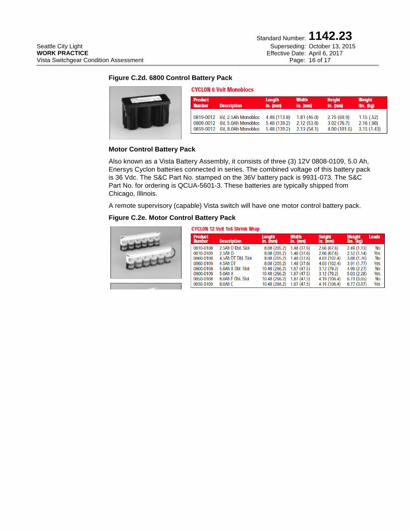
Motor Control Battery Pack
Also known as a Vista Battery Assembly, it consists of three (3) 12V 0808-0109, 5.0 Ah,
Enersys Cyclon batteries connected in series. The combined voltage of this battery pack
is 36 Vdc. The S&C Part No. stamped on the 36V battery pack is 9931-073. The S&C
Part No. for ordering is QCUA-5601-3. These batteries are typically shipped from
Chicago, Illinois.
A remote supervisory (capable) Vista switch will have one motor control battery pack.
Figure C.2e. Motor Control Battery Pack
Seattle City Light WORK PRACTICE Vista Switchgear Condition Assessment
Standard Number:
Superseding: Effective Date:
Page:
1142.23
October 13, 2015 April 6, 2017 17 of 17
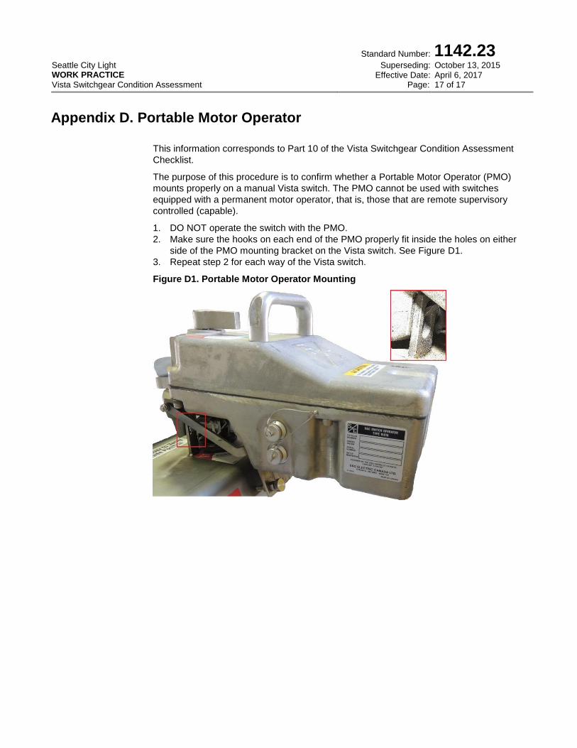
Appendix D. Portable Motor Operator
This information corresponds to Part 10 of the Vista Switchgear Condition Assessment
Checklist.
The purpose of this procedure is to confirm whether a Portable Motor Operator (PMO)
mounts properly on a manual Vista switch. The PMO cannot be used with switches
equipped with a permanent motor operator, that is, those that are remote supervisory
controlled (capable).
1. DO NOT operate the switch with the PMO.
2. Make sure the hooks on each end of the PMO properly fit inside the holes on either
side of the PMO mounting bracket on the Vista switch. See Figure D1.
3. Repeat step 2 for each way of the Vista switch.
Figure D1. Portable Motor Operator Mounting