STANDARD EQUIPMENT - Whirlwind...
25
-
Upload
phungkhuong -
Category
Documents
-
view
220 -
download
0
Transcript of STANDARD EQUIPMENT - Whirlwind...

STANDARD EQUIPMENT: • 10 HP Baldor TEFC Motor
208/ 230/ 460/ 3/ 60 • 3 Premium V-Belts • Filter, Regulator, Coalescing Filter w. Gauge • Magnetic Starter In Nema 12 Box
with Low Voltage Controls • Tempered Chrome-Maly Spindle • Heavy Steel Spindle Housing • 4" Cast Aluminum Dust Chute • Air Supply Lock-Out
OPTIONAL EQUIPMENT: • 20" A.TB. or T.C.G. Systi-Matic Blades • Spray Mist for Metal and Plastic Use • Electric Delete Credit • 15 HP Baldor TEFC Motor • 7 1/ 2 HP Single Phase Motor
ELECTRICAL (Amps) Current 230 Volts Motor Running 26 Amps Service Current 50 Amps
460 Volts 13 Amps 25 Amps
----MATERIAL FLOW
2 1 /4" cast iron table top
ACCESS DOOR WITH AUTOMATIC ELECTRIC INTERLOCK
4 INCH EXHAUST FITTING IN BACK --
SPECIFICATIONS: • Blade Size: 20" x 1" Bore • Blade Speed: Approx. 3,165 RPM • Cycle Speed: Up to 40 I Minute • Air Cylinder: 2" x 12" • C.F.M. Approx. 1.96 - SCFM 12.65 • Table Height: 36 3/ 4 Inches • Floor Space: 26" x 33 1/ 2 Inches • Made With Pride in the U.S.A.
CAPACITY: • 1 x 18, 2 x 16, 3 x 14, 4 x 12 • 5 x 10 and 6 x 8
HEIGHT ADJUSTMENT KNOB TO ADJUST CLEARANCE BETWEEN
--LUMBER AND GUARD/CLAMP (SHOULD BE 1/4 INCH)
AIR CUT-OFF VALVE W. LOCK-OUT
RECESSED TOP FOR OPERATOR'S HANDS
MAGNETIC STARTER IN NEMA 12 BOX
LOW VOLTAGE CONTROLS
ONE PIECE 1/4" STEEL PLATE: ALL 4 CORNERS BENT
AIR HOSE FOR CLEARING CHIPS
MODEL 216 LEFT HAND SAW
Whirlwind Inc. 4302 Shilling Way Dallas, TX USA 75237
(214) 330-9141 Fax (214) 337-9572 www.whirlwindsaws.com
Whirlwind Model 216 Cut-Off Saw Owner's Manual
Table of Contents
--------------------------------------------------------------------------------------------------------------------------------------------------------General Safety Rules ......................................................................................................... Page 01 Cover Page ........................................................................................................................ Page 02 Set-Up Instructions ..... ... ...... ........ ..... ................ ...... ... .... ..... ...... ... .. ....... .... ... ............. ......... Page 03 Fence Combination Guidelines .. ... ..... .... ..................... ..... .. ......... ........... ...... ............... ... .. .. Page 05 Trouble Shooting Guide ..................................................................................................... Page 06 Adjustment of Valves ......................................................................................................... Page 07 Instructions for Changing V-Belts ... .... .. ... ...... ...... ....... .... .... ............. .. ... ..... .... ..... ..... .. ..... ... Page 08 Suggested Maintenance ......... ........ ........ ...... ... ... ..... .... .. .......... ..... .... ...... ..... ........ ........ .. .... Page 08 Warranty ......................... ................... ..... .. ......... .. ........ ......... ....... ....... ... .. ..... .. ............ ... .... Page 09 Assembly Drawing ........ ... .................................................................................................. Page 10 Diagram of Cylinder ... .... ....... ..... ... ..... .. ...... .... .. ... .. .......... ........ .... ................................. ...... Page 12 Final Assembly Checklist .. ..... ... ... ...................... .. ............. ........ .... .... .......... ....... .... ... .... ..... Page 13 Brochure Model 216 Cut-Off Saw ............. ........ ............. .. ..... .......... ............ .......... ... .. ... ...... Page 15 Material Handling Equipment Flyer ....... .... .. ... ... .................... ...... ... ...... .... .. ... ....... .. ... ......... Page 16 Safety Guide for-Carbide Tipped Blades ....... .... ........ ......... ..... .... ......... ... ............ ...... ....... .. Page 17 Specifications on Compressed Air Filter I Regulators .......... ................. ....... ... .. .... .... .. ...... Page 18 Specifications on Coalescing Filters ................................................................................. Page 19 Whirlwind Return Policy .. .. .. .......... .. ... .. .................................. .... .. ....... .. .... ........ : ................ Page 20 Double Palm Button Controls ...................... .... ..... ........ .. .......... ... .... .. ...... .. ...... .. ................ Page 21
R081303

General Safety Rules for Whirlwind. Cut-Off Saws +++++++++++++++++++++++++++++++++++++++++++++++++++
1. READ AND UNDERSTAND THE OPERATING INSTRUCTIONS BEFORE OPERATING SAW.
2. If you are not THOROUGHLY familiar with the operation of the equipment you are assigned to , ask your supervisor. instructor or other qualified person for further instruction.
3. DO NOT operate any piece of equipment while under the influence of any type of medication, alcohol or drugs.
4. ALWAYS wear eye protection (safety glasses or a face shield).
5. Remove loose clothing, tie, rings, watch and other jewelry, and roll up shirt sleeves prior to operating machinery. DO NOT wear gloves while operating machinery.
6. GUARDS must be in place and used at all times.
7. CAUTION: Never put hands under yellow guard I clamp.
8. ALWAYS use a "push stick" or air gun to clear away chips and sawdust.
9. AVOID awkward operations and hand operations where a sudden slip or loss of balance could cause your hand to move into the blade area.
10. DO NOT work with lumber that is too large or too small to handle safely.
11. Make all adjustments to machine with air and electrical power OFF.
12. DISCONNECT the saw from all power sources (air and electrical) and wait for blade to come to a COMPLETE STOP before making repairs or performing routine maintenance.
13. NEVER attempt to free a stalled saw blade without first turning electrical power and air OFF.
14. SHUT OFF all power sources (air and electric ) and clean the machine before you leave it.
15. CHECK SAW prior to operation for any damaged parts. Report any problems to your supervisor.
16. NEVER LEAVE TOOL RUNNING UNATTENDED. TURN 0.FF POWER (air and electric). Don 't leave saw until it comes to a complete stop.
17. IF IN DOUBT as to what you should do, call WHIRLWIND INC. The telephone number is located on the Air Cut-Off Valve Caution Label.
SAFETY FIRST!
Cover Sheet
Whirlwind Model 216 Pneumatic Cut-Off Saw ============================================================================
Before we get started , we would like to thank you for your purchase of a Whirlwind Model 216 CutOff Saw. We realize we have a lot of competition out there and we truly appreciate your business.
In preparing this manual we've tried to provide the answers to most problems that might arise. However, if we've missed something, please give us a call. You should also be aware that an operator's manual has been provided with the machine. We encourage you to have each and every operator spend a few minutes to become familiar with it.
This machine, like every Whirlwind , was tested under power for 4-5 hours prior to shipment. Nothing but the best components and raw materials were used in its construction. Like any quality tool, it must be properly maintained to perform at its best. The operator's manual gives instructions on a few pre-operational tests. These tests should be performed at the beginning of each shift. If any malfunction is noted , it should be corrected immediately.
Numerous safety devices are installed on this machine for the protection of your operators.
These devices must not be removed or tampered with.
CAUTION: NEVER PUT FINGERS UNDER GUARD I CLAMP.
Again , we would like to thank you and welcome you to the large family of Whirlwind customers . We're confident you 'll be impressed with our products and our service. With proper maintenance, your Whirlwind Model 216 should provide many years of excellent service.
For your records, please fill in the following information :
Date machine purchased ________ _
Serial number -----------Model number - 216
Page 02 R081303
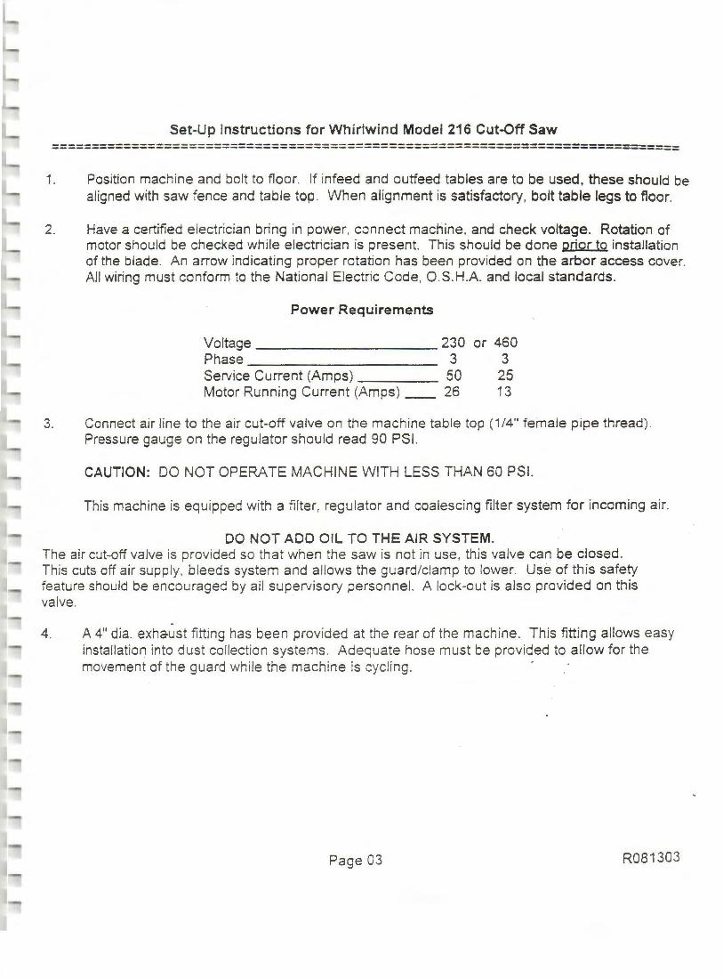
Set-Up Instructions for Whirlwind Model 216 Cut-Off Saw ============================================================================
1. Position machine and bolt to floor. If infeed and outfeed tables are to be used, these should be aligned with saw fence and table top . When alignment is satisfactory, bolt table legs to floor.
2. Have a certified electrician bring in power, connect machine, and check voltage. Rotation of motor should be checked while electrician is present. This should be done prior to installation of the blade. An arrow indicating proper rotation has been provided on the arbor access cover. All wiring must conform to the National Electric Code, O.S .H.A. and local standards.
Power Requirements
Voltage 230 Phase 3 Service Current (Amps) 50 Motor Running Current (Amps) __ 26
or 460 3
25 13
3. Connect air line to the air cut-off valve on the machine table top (1/4" female pipe thread). Pressure gauge on the regulator should read 90 PSI.
CAUTION: DO NOT OPERA TE MACHINE WITH LESS THAN 60 PSI.
This machine is equipped with a filter, regulator and coalescing filter system for incoming air.
DO NOT ADD OIL TO THE AIR SYSTEM. The air cut-off valve is provided so that when the saw is not in use, this valve can be closed. This cuts off air supp ly, bleeds system and allows the guard/clamp to lower. Use of this safety feature should be encouraged by all supervisory personnel. A lock-out is also provided on this valve. ·
4. A 4" dia. exhaust fitting has been provided at the rear of the machine. This fitting allows easy installation into dust collection systems. Adequate hose must be provided to allow for the movement of th e guard whi le the machine is cyc ling . -
Page 03 R081303
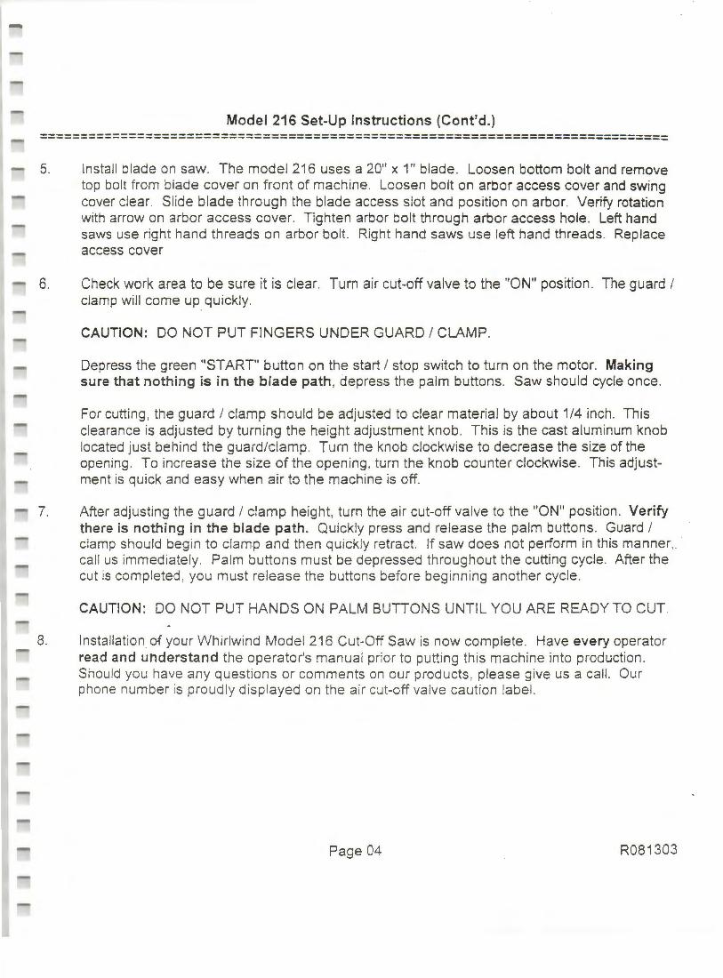
Model 216 Set-Up Instructions (Cont'd.) ============================================================================ 5. Install blade on saw. The model 216 uses a 20" x 1" blade. Loosen bottom bolt and remove
top bolt from blade cover on front of machine. Loosen bolt on arbor access cover and swing cover clear. Slide blade through the blade access slot and position on arbor. Verify rotation with arrow on arbor access cover. Tighten arbor bolt through arbor access hole. Left hand saws use right hand threads on arbor bolt. Right hand saws use left hand threads . Replace access cover
6. Check work area to be sure it is clear. Turn air cut-off valve to the "ON" position. The guard I clamp will come up quickly.
CAUTION: DO NOT PUT FINGERS UNDER GUARD I CLAMP.
Depress the green "START" button on the start I stop switch to turn on the motor. Making sure that nothing is in the blade path , depress the palm buttons. Saw should cycle once.
For cutting , the guard I clamp should be adjusted to clear material by about 1/4 inch. This clearance is adjusted by turning the height adjustment knob. This is the cast aluminum knob located just beh ind the guard/clamp. Turn the knob clockwise to decrease the size of the opening . To increase the size of the opening , turn the knob counter clockwise. This adjustment is quick and easy when air to the machine is off.
7. After adjusting the guard I clamp height, turn the air cut-off valve to the "ON" position. Verify there is nothing in the blade path. Quickly press and release the palm buttons. Guard I clamp should begin to clamp and then quickly retract. If saw does not perform in this manner. · call us immediately. Palm buttons must be depressed throughout the cutting cycle . After the cut is completed , you must release the buttons before beginning another cycle .
CAUTION: DO NOT PUT HANDS ON PALM BUTTONS UNTIL YOU ARE READY TO CUT.
8. Installation of your Whirlwind Model 216 Cut-Off Saw is now complete . Have every operator read and understand the operator's manual prior to putting this machine into production . Shou ld you have any questions or comments on our products , please give us a call. Our phone number is proud ly disp layed on the air c ~t-off valve caution label.
Page 04 R081303
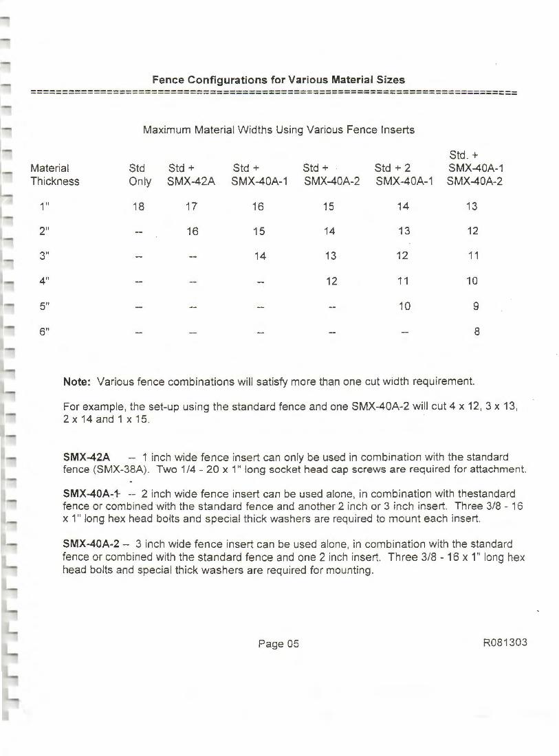
Fence Configurations for Various Material Sizes ============================================================================
Maximum Material Widths Using Various Fence Inserts
Std . + Material Std Std + Std + Std + Std + 2 SMX-40A-1 Thickness Only SMX-42A SMX-40A-1 SMX-40A-2 SMX-40A-1 SMX-40A-2
1"
2"
3"
4"
5"
6"
18 17 16 15 14 13
16 15 14 13 12
14 13 12 11
12 11 10
10 9
8
Note: Various fence combinations will satisfy more than one cut width requirement.
For example, the set-up using the standard fence and one SMX-40A-2 will cut 4 x 12, 3 x 13, . 2 x 14 and 1 x 15.
SMX-42A -- 1 inch wide fence insert can only be used in combination with the standard fence (SMX-38A) . Two 1/4 - 20 x 1" long socket head cap screws are required for attachment.
SMX-40A-1- -- 2 inch wide fence insert can be used alone, in combination with thestandard fence or combined with the standard fence and another 2 inch or 3 inch insert. Three 3/8 - 16 x 1" long hex head bolts and special thick washers are required to mount each insert.
SMX-40A-2 -- 3 inch wide fence insert can be used alone, in combination with the standard fence or combined with the standard fence and one 2 inch insert. Three 3/8 - 16 x 1" long hex head bolts and special thick washers are required for mounting.
Page 05 R081303

Troubleshooting Guide for Whirlwind Model 216 Cut-Off Saw --------------------------------------------------------------------------------------------------------------------------------------------------------
Electrical Problems --------------------------------------------------------------------------------------------------------------------------------------------------------
1. If reset button must be depressed to re-start machine:
A Check wires on magnetic starter. B. Check wires to motor. C. Check incoming wire connections and voltage. D. Verify correct heaters are installed .
2. If machine re-starts by depressing start/stop button:
A. Check wires to start/stop switch . B. Check wires to door interlock switch . C. Follow these wires to box and check connections at box.
NOTE:
1. Closely examine all rubber seals for damage while disassembling valves.
2. Repair kits are available for cylinder and pilot valve.
3. Do Not allE:lw sawdust or any foreign matter to enter valves or hoses while the machine is being serviced .
4. DO NOT REMOVE OR TAMPER WITH ANY SAFETY DEVICES.
Page 06 R081303
Adjustment of Valves for Whirlwind Model 216 Cut-Off Saw --------------------------------------------------------------------------------------------------------------------------------------------------------
Your Whirlwind model 216 cut-off saw was run-in for 4 - 5 hours and then adjusted to factory specifications. The double palm manifold requires no adjustment and all other valves should be adjusted properly. Adjustments to cycle speed may be made for various applications. This adjustment is outlined below.
CAUTION: CUT OFF ELECTRICITY & LOCK OUT DISCONNECT BOX BEFORE ADJUSTING VALVES.
Cycle speed is adjusted by two alien cap adjustment screws located on the pilot valve. The upper screw adjusts the speed of the cylinder expanding. The lower screw adjusts the speed of the cylinder contracting. The speed of this expansion and contraction should be equal. The model 216 saw should be adjusted to cycle 40 times per minute without lumber under the guard. When the saw is cutting lumber, cycle speed will increase. This is due to the fact that the guard is traveling less distance. Maximum cycle time while cutting is approximately 40 cuts per minute.
NOTE: Exceeding 40 cuts per minute may reduce the life of the machine.
Page 07 R081303

Instructions For Changing V-Belts On Whirlwind Model 216 Cut-Off Saw --------------------------------------------------------------------------------------------------------------------------------------------------------
CUT OFF ELECTRICITY AND LOCK-OUT DISCONNECT BEFORE WORKING ON SAW.
1. Loosen four bolts which mount the motor to the table top and slide the motor forward.
2. Remove clevis (1000-47) from yoke (1000-4).
3. Slide V-belts around yoke to opposite side of motor.
4. Remove two bolts which mount the left hand bearing hanger (1000-3) to the table top. Note: On a right hand saw, remove right hand bearing hanger bolts.
5. Loosen two bolts which mount the right hand bearing hanger. Note: On a right hand saw, loosen left hand bearing hanger bolts.
6. Swing left hand bearing hanger down and remove V-belts.
7. Install new V-belts and reassemble. If desired, an extra set of V-belts can be looped around the yoke and tied out of the way. This will make the next belt change much easier.
7. Pulleys must be parallel within 1/32 of an inch.
9. V-belt tightness should be 5/32 inch deflection with three (3) pounds of pressure.
10. Note: Improper alignment or tension will result in excessive wear on V-belts or bearings.
Suggested Maintenance:
1. Check filter, regulator, coalescing filter daily for moisture in bowl.
2. Lubricate moving parts with lubricating oil.
3. Check V-belts and tighten if necessary. (See item 9 above .)
4. Keep inside of machine free of excessive sawdust. Special attention should be given to keeping magnetic switch box and palm button manifold clean.
5. Keep saw blades properly sharpened . Carbide tipped blades are highly recommended . These blades may be purchased directly from Whirlwind Inc.
Page 08 R081303
August 23 , 1982
Whirlwind Inc. Limited Warranty ----------------------------------------------------------------------------------------------------------------------------------------------------------
Whirlwind Inc. hereby warrants, subject to the conditions set forth below, that it will repair or replace without charge for parts or labor, F.0.8 . our factory , any part of the product accompanied by this warranty which proves defective by reason of improper workmanship and I or material within ninety (90) days from the date of the original purchase at retail .
Conditions:
(a) This warranty is extended to the original purchaser only. (b) This warranty shall not apply to any defects or other malfunctions
caused by accident, neglect, misuse, abuse, alteration, modification, unusual physical, environmental or electrical stress, or use contrary to instructions accompanying this product.
(c) This warranty applies only where the purchaser establishes
Disclaimer:
that the product was properly installed , maintained and operated within the limits of normal usage. Any defective part shall be returned promptly to Whirlwind Inc. upon discovery of a defect.
This warranty is in lieu of all other warranties of any kind and any other representat!ons or warranties, whether expressed or impl ied, including any implied warranties of merchantability or fitness for any particular purpose shall not apply, and are disclaimed with respect to the goods sold .
Whirlwind Inc. shall not have any respons ibility for loss of use of the product, loss of time , inconvenience, incidental or consequential damages. The liability of Whirlwind Inc. is limited to the cost of repa ir or rep lacement of defective parts.
For information concerning warranty service , please contact the distributor from whom the machine was purchased or Whirlwind Inc., 4302 Shilling Way, Dallas, TX U. S.A. 75237 Phone (214) 330-9 141 FAX (214) 337-9572.
Page 09 - R061998
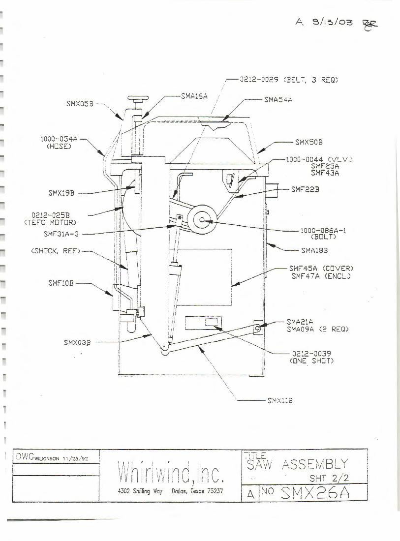
0212-025B CTEFC MOTOR)
I L)\//Gw1Li<:NSON 11/25/ 92 ! I
I ' ' ' !
·1 'I
L
l I 'I • rJ,f n If I''. I
V V I 111
'i A,· V'i
4302 Shilling 'N!J'f
f l nn j l '. l i \ .. ,! '
\ ' \
\
\ \ \
(I A i il .
Dallas, i~xcs 75237
SMA21A SMA09A C2 REQ)
~- 02:2-0039 COi'lE SHOT)
\ '---Si'-'~Xl :B
iTil.E S,~'h. r. 55c:-' ,,18 1 y /-\ '....__ \\/ ~ ~
SHT 2/ 2
A !NO Si,;lX 26A
I
I ! I I
I i
A_ 8 / 13 / 0:3 ~
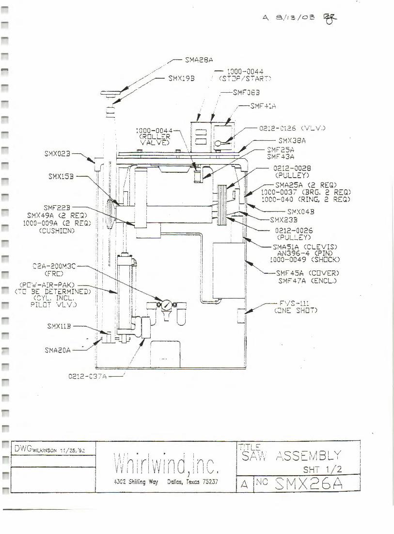
~ S~A28A
SMF22B SMX 49A <2 REQ )
1000-009A (2 REQ) <CUSHION)
:i~ lj.~ 'ltl I
i i:/1i' : ·i1 /Lf : ' tl~ i i:
·1 I : , ' I ::·,,
'I : i
:,! : ii !htil.L 1 d l
"? \ ?QQM3C I ' ' .__p,-_ I . ' ' I :1 I
CFRD :I : 'ii I! ! _sPC '->l:-AIR-EAK) I : i!I ::/ ;
( ; 0 3t. DETt:..RMIN~ ! i!I ' CCY!_. IN CL. :i . ill i! i ~
PI LCT 'VL \/ .) 11
• ;l :I · r
11 :· . H / n1 ', :;i i; (' l I i
S vx·. B : ·'! u L u •. L.L~ :~!
•)(.iL~ (~~~~ SMA20A _:_,. :,
:1 ,I
02:2 - C3 7 A--'
l .~ ; I
/ ' I
~ 1000 - 0044 <S-:-lJP / S"7" AR;~
.-SMFJ8B
"---- SMX04B S~!X23B
I:
UL - 0212-0026 ~ ~~ CPUU EY)
11 ~----"-~· i s~~3~~-~Lc~f~)S) ,1. 1 :i , 000-0049 (SHOCK)
:i ii t SMF 45A CCOVER) 11 l S~F 4 7 A CENCL.) ii I
i! L---J ~ i F' ' i "- '11
~V(~rlE __, S~Oi)
u1 it II
- 1- 1 -
i, : ; : i : ' !\ ; I r 'I ' r j i \ '\ ; f'i ! '( ~ \ I I '" a· 'I"\ '\
Vv i ii! Y'l! i : J ! i 1·v .
I :S!; f.~ ., I r.v ·i
I SHT 1/2 4302 Shiiling W1J-f Dallas, Texcs 75237 'A INO
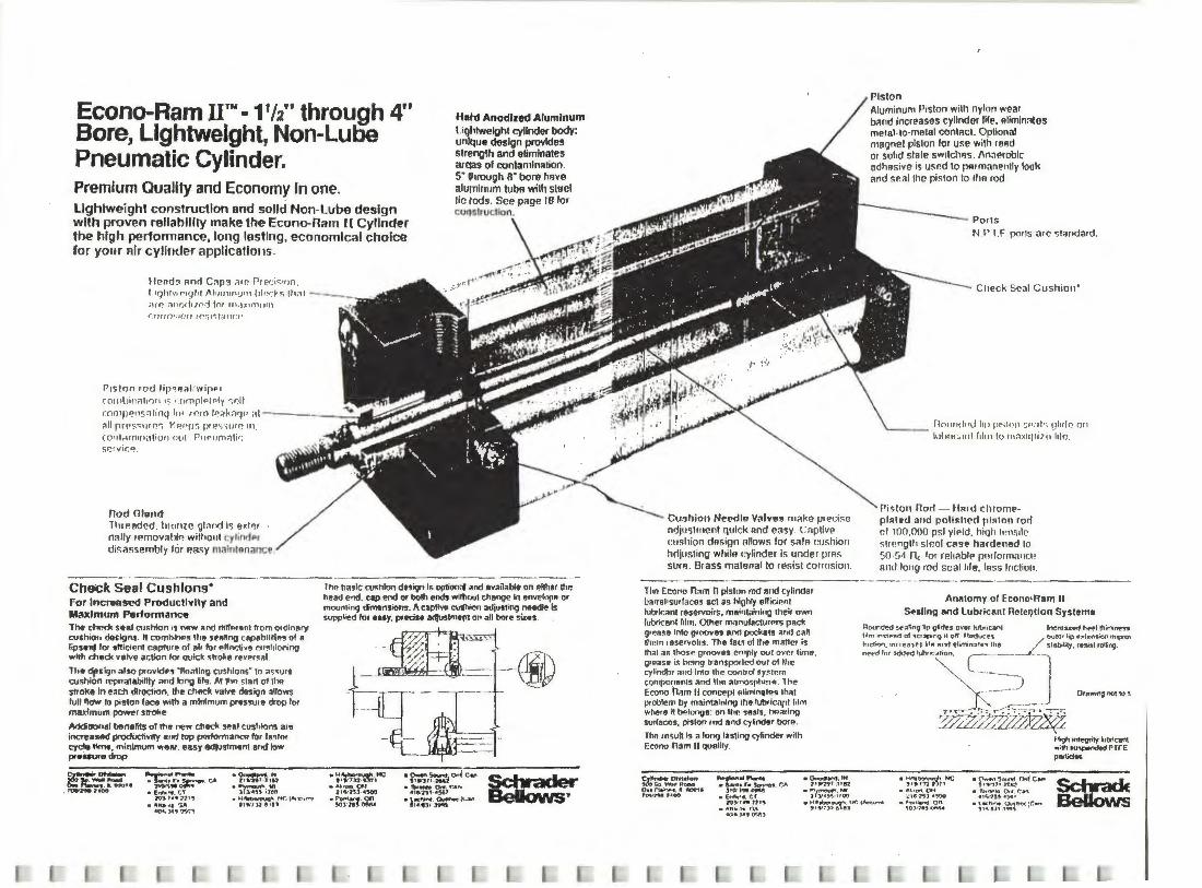
Econo-Ram II™· 11'2" through 4" Bore, Lightweight, Non-Luoo
Hatd Anodized Alumlnum 1.ightwelght cylinder body: unique design provide!! streng1h and eliminates areas or contamination. Pneumatic Cylinder.
Premium Quality and Economy In one. lightweight construction and solid Non-Lube design with proven rellablllty make the Econo-narn n Cylinder the high performance, long lasting, economical choice for your air cylinder applicallons .
s· throv9h 8" bore h11ve alu[Tllnum tubff with steel tic tods. See page Ill lor col)structlon.
lfr>nd~ oncl C"r'.I "'" r1 rcr<<•1Jn. I iqlttw,..1g l1f Al1111 11nur11 hln·. Y~ !'1 :11 -;11~ ;)n()(hJ"' 'J for 111 ;1JirTI\ llll
, nrto•.rn n rr~'.i l'", t .J 11u·
PrSf On IOrJ lip • 'l~l : wipPr
(0111Li 1nrt l10n 1$ 1.rnnplnlPly ~ri ll
r.oo1p<? 11s:i 1inq l<H rrro fP~k'1'J" ;1t _ .-..~ ;ill rrr so;1ir P.r; VJ~PP 'i JJ'f.! ~·.- 11 re 111 , (Qll l rt m1n;tfiut1 Oll l r1 IPllOJ:'ll1r :
s~rvir.~
Rod Oland lhrr.aded. hrome gtond is exl'!r · nally 1r.mov~1~,., witlto11t cylindPr dis assembly for ea~y malrr111nance .
Che;ck Seal Cushions• For lncrwased ProductlYfly and Maidmum Performanc. The cf'lcock ~•a.I cu~hion 11 n.,..,., and d\f'fP.J•nt trorn ordinftry cuchiott deciqns. rt combine• tl1t '""""II cApebilil\"" of a lipseaj for tllident capture of air lor ellnelive cu~hioning """" check valve ac6on lor quick <hoke rfver.-1.
lht dpcign also provldu "llo"11no cushions- to ;os.ure cushion repealabtllly and long ti'9. Al tlm st•rt ol !IHJ siroke In each dlroction. !lie ch8d va~ 00siqn allows lull"""" to p;9ton f3ce ¥tlth a minimum pAS!l\Jr9 drop for maximum power strol<e
Addinon.I l>flntlits of ltle new clltel< sP.•f c1r.1hlorni are ine<ea!!ed prod\Jclivrty and !Op pmforma""" lor l••tnr cyclo ~. minimum we111. easy erdiustment and low prenure drop
~ ........... -~ . ... «JIOTt
. n;,.,1't1124c.J
~~ r':9S::... CA ,,~"'°""" -
•(,..,_ff. CT IV)., •• 71•'
• ~"-" .. '1A 404.)4t?'"'.r.1
.a.-.... .. J•.-a17 •n.1 -~i~ .H,~'IP'f(':l""'-c••""I
11•1» 9 181
-------------·-------·-Thr. b~•lc c11<hion d"ign i~ option,. and 1v•il•blt on P.llhtr the head end. cap end or both ends without change In envelnp8 or mounting dimensiofl'I. I\ captlvo ~n •djusti119 n&edle Is supplied lor eaey. pr&dff ""ltJSlmt~t on all bore sins
-~~~·,tte •At.t0n. OH
21Slf'.) 4500
-~·~·~
·~1~1°"4 c.,. • 'fbronto °""· t:•"' 41e:rs1 .• ~1
• ~:~·~~.!Ut>.
®
Cu~hion Needle Valve!! make preci~c ndjuslfllent quick and easy C <iplive cushion dAsign allows for salR rnshion hcljusling while cylinder is under prn~ StHfl . Brass material lo resist corrosion.
Tho Etxino n~m 11 piston rod a11d cylinder ~~rrel • surl•ces act as hlghly eflicir.nt lubrk-A1nt n1servoi1s, mehrtahring their own lubricant film. Other m:rnufactvrers pad< grr~•• into groovH and pockets •nd c~ll them r esenmlrs. The lad ol lhe ma""' is rhat a,. thosr grooves empty out ovP.r lime. grease '' being tranSf"O'ted Dul OI lhe cylin~r and fnto the control sy~rr.rn tomponsnts ::.nrl 1he \lltrnospher9 . 1he ECQno h:im II concept elimtn,te• th•t problem by maintaining the lubric.1111 him whero ~ bf,longc: on""' s8als , llea<lf"ll/ surlac'ls, pi•lon rod 11nd cylinder bore.
Tho rnsult I• a lonq l•stlng cylinder with E«lno · n~m II QUelily.
;r,~~O:-:!:' 0•• n.i·~• . Iii ~·· 1~. ,400
~ .. ,,_.,.,. •SN'fl•r-~. CA
310.~l'Ml-()M!
·~llf'd. tH ,,.,..,.,, .118l
·~r~i,~
Pl5ton Aluminum Piston with nylon wear b11nd increases cyllnder Ille. 11limin:.Ces mefal ·IO·metal contiicl. Optional magnet piston for use with reed or solid stale swrtches . /\n~l'roblc adhesive Is usr.d to p<Jrmanenlfy look and sP.al lhe piston lo 11111 rod
Polls N.I' 1.F prnls arc ~t;indard .
Clreck Seal Cu shion'
fl rn111d11d lip p1·.Jnn ~ n;rl· ; lJli<lr.i 0 11 h1bru:.111! ftlm to 1n;)xlq 1i 111 hlr. .
Piston·noo - Hmd cflromepl~hrd and poll~hccl piRton rod of 100,000 psi yiPld, hiqli IPns<lc slrr.n9tlt sir.cl c113e hardened 10 50 · ~~ 11, tor reli;ible prnlorma<rcP. And long rod seal Irle, IAss lncliot1.
Anntomy of Econo•Ram II S.1!11111 and lubricant Rotel)tlon System•
n f)urided 5f'.lfinq lip \jiirlrs 0"'" lut)f1C<tnt lll'::r-oa~ hlf'tll l™:kfl'n' Mm ,,..011;tr-Plf1ol1c1apng •t oft f{Od1.ces out11r ltfl ~,f~ns,.on 1mpro\ fnd f)ri 1nClt't'l,l!S hht puwj tl1m1n::1ln lhfl / ,_htbla1y. f8Sf51 rolfing
"<t·d lo• >ddr<! luh•nhon c ---_.-;-] ~- Orewong not to'
,---- -.- - .-' • ..._ - r -,....-r--r-
~~Pml~
• ~·,":~~J,HC • 11'- •on. OH
:.: 1c 111 •'°° • p.....+1 $our'<d. °"' C l!lf' ,,..,.,,,x;,2
14'9'1 inteQrity h•briau'1 "'i\11 IU~ PTrE P•tidec
• £""'- •d, CT lO);r.-nt' . ""'··'• '" •~~ .. ~~·,'IC,..._....,..., • l"Ofl\m"'° Q I'\
\OJ1:nC'WW
e T\J•Ol'lo Ont. C•"' 4 14?~' '"" '
•lKt>i,... . Ou,~ •C•n ,, .. 8Jl .l .. , . '
Schrack BeUovvs
40 a..J.490"'.l\l
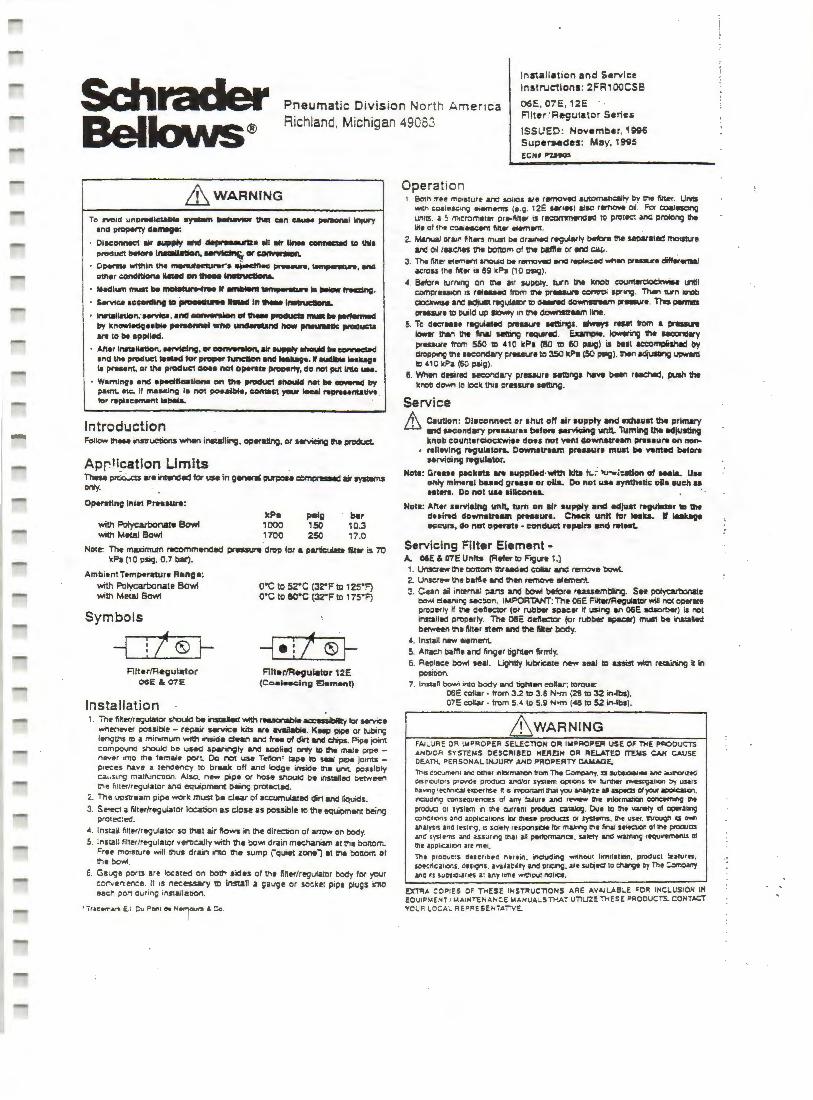
Installation and Service Instructions: 2FRiooCSB
Pneumatic Division North America Richland, Michigan 49063
06E, 07E, 12E Fllter / Regutator Series
ISSUED: No.,,ember, 1ggs SuperMdes: May, 1995 ECHI "7.t9Cl5
_&WARNING
Tc ,_,d unptwdlcublll try98m _,~can ca.- pe,_,.l Injury and propeny ll•nwgr.
• 01.c:onnKI air -.p1y .,.. ~e 911 * Unee conMCl9d IO We pl'Dducl bet.,,. lllMllllatlon, ~CK~
• Clpemo wnllln ti>• .,.,,.._.. ~- ,.,_.., lem~, •nd 1>111er condltlona 11-.d on lll9M II--. ctl•na. Medium ......t lie mol.-..e If 8INlillnl_,.,...... la.._ INclng.
SMvtca a~ng to,.._.._ -- In 111-.1-. INUllnlon;IMVlca. and --.Ion of,,,_,..,._ - lie ,..norm.el by knowlM19Hbill personnel wlto ~ i- pneum8llC ,.mucu a .. to be applllld.
Aller lrw1allatlon, NMelng, or -rslon, U- aupply llhcMllcl lie cONWdoc:I and !ht p-uct 198'eel tor proper tunc:llon and lMUgt. I auellllie leai1a9t LI p ..... m. or Iha produCI oo.a no1 oper11e property, do not put lnlo uu.
• Wamlnv• and epecltlcaU- on th• P"'duCI •'-'kl not be~ by p111nt. ttc.. II masking la not poealble, -ct ycKW loc:aJ NpreNntall\lt . tor roploc-t label&.
Introduction Follow in ... innuetions when insialling. oper81ing. or aervUig ll'la product.
Apr!i.cation Limits These i:irtici..cts are intrd-2 for use in g-.1 IMPOI• cOmpr8Aed mir sysl8mS or'iy.
O~ng Inlet PreHure:
with Polycarbonate Bowl with Metal Bow1
kP• 1000 1700
paig 150 250
bar 10.3 17.0
Note: The maximum recommenclad pressure droi;> for • par1iculate ftit11r is 70 k?a (10 psig, 0.7 bar) .
Ambient Tempereture R•no•: with Polycarbonate Sowl with Metal Bowl
Symbols
-4 !/®~ FilterfRegul•tor
06E & 07E
Installation
o·c to s2·c (32"F to , 2s•F) o·c to ao·c (32"F to 17S"F)
Filt.,/Resiulator 12E (Coal•scin; Et.m•nt)
1. The ftfter/r"9ula1or V.Ould be inslaJed with r...,.....,le aa:Miotilly to.- ......Ce wnenever possible - r~r servjee kits aro llllDilable. Kaei:> pipe er tubing lenguis to a min.mum With inside deil/1 and tr .. of cfort and chips. Pipe joint compound should oe used sparingly and aop~ed only to the male pipe -
neiv~r into the 1emaJe port. Do not use Tenonr tape tc seal pipe joints -pieces l'lave a tendency to break off and lodge inside the unit possibly ca~ i s 1 ng malf\.:nCDon. Also. new pipe or hose shouk::I be ITTs~lled between !Tie h!ler/regula1or and equipmwrt beinc; pn:t-=ted.
2. The upstream pii;>e work must be clear of accumulated dirt end 6quids.
3. Sel~ a filter/regulator location a..s close as possible to tt>e equiimient being pro1ec:ed .
• . Install filt..r/regulator so that air flows in the direction of arrow on body. S. Install filter/regulator verocally with the bow1 drain m~sm at the bottom.
Free moisture will thus drain into !tie sumi;> rciuiet zone") at !he bonom of ttie bowl .
6. Gauge ports aro located on bolti sides cf the fttt..r/regulator body for your corvenience. It 1s necessary 1D install a gauge or socket pipe plugs imo eact\ port Cluring installabort
Operation 1. Botn rree mo1Sture and sollCIS are removed auiomancally t>y !Tie tllte<. Ums
..,.,, coalesc1"9 elemerm 10.9. 12E -•es) also remo-e 011. Foe a:ialnong units. ~ 5 micrometer or•ftft81' is recommendac to proteci and pftllong the life of tne coaiescen1 finer •em..,,,_
z. Manual or81n fillen must be or .. necf regularly betore the separated rnoll!Ure and 011 reac:nes trie Doncm of tne baflla er lll"CI Ci!,..
J . The lllter element snouiO be remo,_, _,.,., r~.d wf'len ptes&Jre diffarmni&J acrou the Mer 1s 69 kf'>a (1 o P'S19) .
.t. Baler~ turning en tne air SUPPiy. turn tne knob '®n\llreiocXwW1 until comprus1on 11 rat- lrcm tne i:ir.....,. canlr'OI spring. Then un llnob dCdrWtM and lldjust r99ulalDI' ID Cl--1 do...-m pr.aura. This l*ll'ltS llt-..ut• ID build up llowly 1n uie downnum line.
5. To dac:r•H r89ut.lad i:ireuure Mllings . ~ reset flom • pr-.. tower tllan 1l'le ~nal Mfting requited. E.umple, lowering 'lh• --.:lary prtlSSUle ifom 550 ID .t 10 kF>a (80 ID 50 PllSI) is Dell acc:cmpishld by dropping the secondary ~reuure to 350 kPa (SO psig). tnen adjusling upwatd ID 410 kPa (60 psig}.
6. When desirad secondary preuure fftllngs i'la.,,. been reached, push the knoo down to lock tl'us erasure setting.
Service
.& Caution : Ol1conneet or shirt olf air supply anc:t ellllauat Ibo prlmery and ucond•ry prnaurH blloro Mrvicinv 11nlt. Tumillg t11e Mlju.Ung knob counterdoeltwia• doH not wnt downatreem prHeure on nonrell9Ying r.gul.iorL Oownatraun preuur• must bl ftntecl before HNici119 regulator.
Hota: Gruae p.c:lrets arw aupplled·wtth lclb It. ~ 1u-..<wtion of -la. UM only mineral baled groaH or oll&. Do not usa synthetic olla lllch ~ Htera. Do not uae alllconeL ·
Note: Alter Hl"Vlclng unit, tum on air supply •nd ed)uat .-gulldor "' v.. dHll'9d downstnem prn1ur1. Cheek unit tar leakL Ir laak-ve occ11ra, do not operate • condllCt repair• •nd retest.
Servicing Filter Element -A. 06E & 07E Units (Refer to F"igure 1.)
1. Unser-the bottom lhrudad collar anCI remove bowl. 2. Unscrew the baffle and than remove lalement. ~. Cean all internal !)arts and bowl beiore ru.uembling. See polyartlcnate
bowl ouning sec:ion. IMPORTANT: The 06E Filler/R19Ulatcr will not operate prooerly ff 11-.e deft~.or (or rubber spac11r ff using an 06E ads>rt>er) is not installed i;>roperty. The 06E deflectcr (or rubber spKW) must be instaAad berween !ti• filter s1em and the filter body.
.t. lns;all new element S. Anacti balfle and finger tighten firmly. 6. Rei;>lace bowl seat . lightly lubricate new seal :c assist wilh retainng it in
JX>sition. 7. Ins tan bowl imo body and tiQht.,, collar: torque:
OGE eollar • from 3.2 to 3.6 N-m (28 tc 32 in-lbs). 07E collar - from 5.-1 to 5.9 N"fTl ('8 to 52 in-lbs)_
ffiwARNING FAILURE OR IMPROPER SELECTION OR IMPq()PE,R VSE OF THE PROOVCTS J.NOIOR SYSTEMS DESCRIBED HERElN OR RELATED ITEMS CAH CAUSE CEATh. PERSONAL INJURY ANO PROPE.RTY OAMAGE_
nus c:ocumtonl ano oltler nbmaron tran The ~- u subSldra11es and a..aD"IOrlZ!'d ois rr1bu1ori prO'll"Or ptOduc uiC11or sysrem options bt h..nner n¥esu;.a1ion :r,- users h•""9 le<:Mc.aJ u;>erns.e. n s .mponan1 NI you IJ\liyle al up«2S o1 pir ~.
nouding ronsPQuences ot atty '2iurt anc r~ tnt ntormatian conc:em:ng U\t
p1oouc:1 01 s~tem ti t~e c:urren1 proWc ealllog. Due 10 1111 v.11•ry of oporatng c:oncrhons ano aophc;uons ltw 11'\es• prodvaS OI J:yS1ems . tne user. 11\tough U O'llll'I
an.iys1s and IHlf'li;I . lS sc~ty r~soonsrtH ror m&k.-.g tf'le MaJ HledlOn of U\e pttOJas .ana sys1ems MlO' usu rf'\9 ina.1 aJI pertormanet . s.1~ and ~,n.,g requ~ts ol 17\e apphatron arr me1.
The proouc:s descnb eod hete.n . i"tduc:hn9 wflhOUI limitation, product !m:atutn, soe<:n<:.1""1S. Ots'9"' · •vol•c•ir-; and pralg, •rr s.uOjtd 1c c:l\11191 O)'Tht C<imlW!Y ano o subSJCharl!S ar :lily ume wrU'tout no1ce.
EXT!'IA COPIES OF THESE INSr.:lUCTIONS Ai:IE AVAJU.BlE FOR INCLUSION IN EO UIP),(0/T / MAINTENA.NCE MANUALS THAT UTIUZE THESE PRODUCTS. CONTACT YC UP LOC AL REPRESENTATIV E
1 I I
UI
06E, 07E , 12!:: Filter / Regulator Series
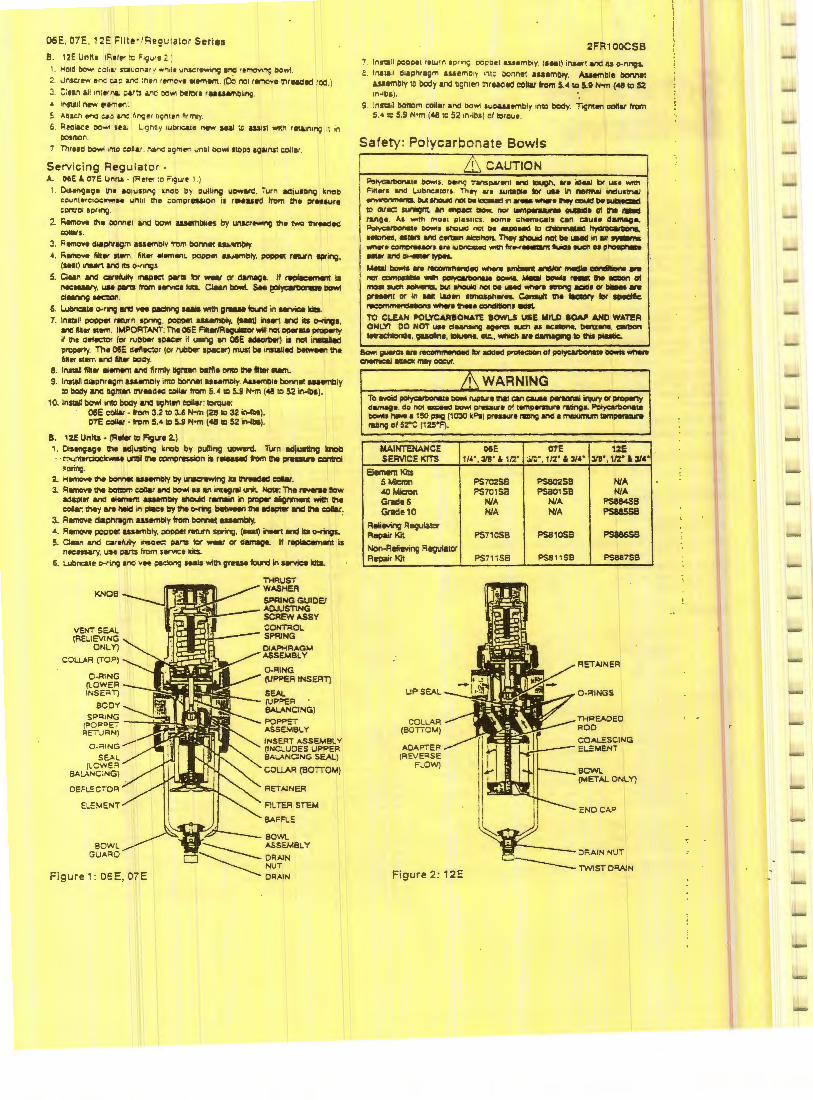
B. 12E Unrt1 ( Fiel~ :o Figure 2 ;
Molt:! ~ eoll&J S't2 l.J ona. y wnde uf\SCr.....,ng 1nd removing t>O'flri
n.a ..... enc ~P anc :ne remove •ement. (oO not remove triruotd rod .)
C:11n a ll 1n lt<n&J P&f!l i/10 001'11 ()flOll rUUMlbl•t19.
• lnNll n..,. l<IM\t<lc
Anac:J'\ 8"'1(1 c..o and fing e n9nten ,;rrrvy.
6 Reoiacr oo.., u ai L1gnny 1utvQle ,_ MAI ;o ua1S1 WTtl'I r~n1ng 11 1n ccsroon. Thrt10 OOwi into c:oll&r nar.c: 09men uncl t>owl SlCPS IQ&tl'IS1 colllr
Servicing Regulator -A. otE &, 07E Unit.I · (R ele< :o Figure 1 )
1. Di1tf\9a9• II\• ao1u1nn9 lllloo Oy pulli"'il uc:iware . Turn adjulDrlQ knob counterc1ockw'rae until ttie ~ompraa.on is r9'eued trom th• ptMsure COl1\IOI soring.
2. Remcn. lh• OOMCI and Dow! u.saml:IUtH by unw-..g ,,.,. two 1hr-ed COllAIS.
3. Remove oiapnr119m 1.ssemo1y lrOm bonnei ..... -cry. ' · Romove lllt• llll<T\. ~n ... .. ...,.,l P<>Dl>el .....,,,Dty. popp.i rau-n 1pting,
(Nltl .-n ana rts o-nn;s. 5. Clean and carelully 1n111ec:1 !*II tor - or dam8qa. If ~ i1
n«:nwy . ..... pans lrOm 1.-.c• kJtL Clan bOwl s.. polyall1)al-~ durw19 MCllOn. -
6. Lubncat• o-rin; ana "" lllldMg llMla will'! o-~ in .-vice lcils. 7. lnmn poppe! 1'91Urn 1pnng. poppet usemciy. (M91) naert ltld ils CMing1,
end Allw •em. IMPORTANT: The 06E Filtw/FlegUmlor will not opw .. ~ if ine att1ec:!Of (or rullbef 1pacer if ..-ig 111 o&E lldeorller) 11 not irmalled prapwty. Th• 06E dlfllC".or (or Nllber spacer) must be 1nstalltd ~ the aner nem and 1111• ciooy.
8. lllSllll fill• 11emen1 and firmly tigl'len battle °""' tl'le ftll8< -. 9. lnsWI ctaonr119m asHmo1y into botV\11 asH'TIOly. Auemc111 bonnml &Nembly
Ill bady and Dgi'!ten lnrMO«I eollar from 5.4 Ill 5.9 N-m (~ lC 52 in-lbl). 1 O. lnSllll tlOwl il"llO body and tJQlllen cellar: 1Drqu1:
06E c:olllr - trom 3.2 to 3.6 N-m (21 tc 32 irHlllJ, 07E c:ollet - fn:lm 5.4 to U N•m (48 ID 52 ir'Mbl).
a. , 2E Unlta • ~-ID Figll'I 2.)
i. Oisen;ag" !he 1cliusti"'i1 knob by pulling upward. Turn adjusting knob · • C":>u:'119rdoc:kwiH l.C'ltil lhe comi:irwuion is rllelsld tom Iha preu.n Ca'llrOI
•oring. 2.. 1-1.....,... Ill• bolvlec UMmllly ey urwcr-.ng llS .,.,_caller. 3. Rmmcve the bOtlDrn eolllr and i:lo'M 11 an int99ral lril. Nole: The ,........ flow
adaplt< and .. .....,. ~Illy lllcMd r.main in l"OPlt llignmWll willl the c:onar: !hey .,.. t.IO in plac:• tly Iha o-mg betwewl thl lldapw and the collar.
3. Remove dilptngm assembly from bonnet uaambly. · "· AllmOYI popp91 assembly. poppet -.rn spring, 1-1) inMrt and Ila o-rings. S. Clffll and car•lully inspec: partS tcr wear or dammga. If raplacamw is
necessary, use parts from sl<'l!C:t ld!s.
6. Lubncate o-ring ano v ... paclung IUls wiltl grnse ft>und in HNice lci!s.
Tl-IRUST
KNOB WASHER SF'RING GUIDE' AO.JUSTING SCREWASSY
VENT SE.AL CONTl'IOL S~NG (RELIEVING
ONLY) DIAPHRAGM
COLLAR (TOP) ASSEMBLY
0-RING 0-RING (IJPF'ER INSERT)
(LOWER INSC:RT) SEAL
BCOV (UPF'ER !IALANClNG)
SPCllNG F'OF'PET (P0PCET ASSEMBLY RE7\.JRN)
o. ;:,1NG _.....- INSERT ASSEMBL V (INCLUOES UF'PER
SE.AL BALANCING SEAL) (LCWE"l
COLLAR (BOTTOM) BAL.ANC;NG)
DEFLECTOR REIAINER
ELE ..... ENT FlLTEA STEM
BAFFLE
BOWL GUARD
Figure 1: 06E, 07E
2FR1 OOCSB
install po~pet f lturn spr 1nog . :x:>ocet AUemeny. (sut) ina.ert and ns o--rings.. l nsta1I 01apnragm u.se -rio1> 1n10 bonne1 as11mbly. Alaemble belnn8'!
a.ssemory to body 1nd ogn1en 011uo ed collar trom 5.4 IC 5.11 N-m (~ 1e 52 1n-IOi).
9 lnrt211 boftom collar ano t>Ow1 sut>&£nmbly into body. I.gm.,, c:cnar lrQTl 5 •to S.9 N•m (411 lo 52 1n·I05 I of torque .
Safety: Polycarbonate Bowls
CAUTION ~I• Dowis. t>eong ntls-•11 ano ICIUQl'I, 111 ldul br u.se -Filters &nd l..utmca1ors. They 111 1urtaD'• tl:w ..,. in ftOnnal W'lduatna.J _,,.,,, ... Dul.,_ l'Cll De-.C., •w-•...,,-be~
Ill Otrec:! IUf1lqll. 1111 tmpac - ""' ........... -1118 of .,. 1.-d ra"o•. As w.th moat plesucs . tom• ~nem1cal1 can caiu1a damag&.
~i. "°"'' .,,....., ""' oe -- "' c:Nannli.cl ~ ketones. ••en and c:-n llCDllOll. Th.,- lllOuld nol be UMd 1n air ~ -•• comor•aon ar1 lu""""'9d - 11r .... -.i lluift 9UOI 11 p,.....,,_ -.,,,,~~
""-' bowls .,. ,__Ml -- amlltenl llll'ldJot ................. -
-c:am---~----b-ol ,.,,,. """' -. but """'*' not oe .--. 11n1ng -· or - .,.. prnant or In 1111! laden llrTIO&jll\tltn. Con..-i tnl llclDry tor ipedllc
TC Ct..EAN ~LYCAl'l•ONATE aowu USE lllLD ~ AND WATl!R ONLY! 00 NOT .. , deanoong agena a.en u ac-. tleta-. C111M1n lelrlehlond•. guolin• • .,..,_,II:.,_,,.,. dllftllll"9 ..... plMk.
- 9"1'CI are llUlllllN- ID< I009d - Of po.,...,_ - -- allad< _, occ:vr.
WARNING To e.oid ~· - rupLtr• !NI can-~~ or Pf01*tY a.mag•. oo not -- bow4 preuure of temperature ratings. F'a~te _ ,_ • 150 psig (1 030 kF'aJ ornaur• tDng ...a a rTWXJmt.m iampermn rall"Q of 52°C (1 2S'F).
MAINT'EHANCE SERVICE KITS
Element Kits s J,liaan 'Cl Mic:rt>n Grild• 6 Grade10
RlliiMig R89'Jlalor Repair Kit
Non-Refieving Regulator Repair Kit
UP SEAL
COLLAR (BOTICM)
ADAPTER (REVE"lSE
FLOW)
DIE 11". 311' " 112'
F'S702SB F'S701SB
NIA NIA
PSilOSB
F'S711 S8
07E 12E ;;.~·. 1/2° l.3W 318", 112" • 31 ...
F'S802SB NIA F'SB01S8 NIA
NIA PS8&4SB NIA f'S885SS
F'S810SB F'S886SB
F'SS 11 SB PS887SB
RETAINER
0-RINGS
THREADED ROO
COALESCING EL:MENT
BCWl (METAL ONLY)
END CAP
Installation & Service Instructions:
2C100EP
Pneumatic Division North America Rich land . Micnigan 49083
1/6" , 1 1~· & J/S" Economy 1/4", Jte· & i12· Compact :i1s· , 1/:2" & 314~ · Standard
Coalescing Filter Pneumatic
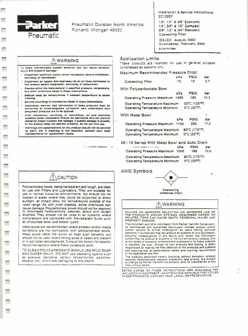
LL WARNING
To 1vo1c unpredlctabl• •v•t•m oenavlor tn11 can c•u•• persona l in1ury 1na property <11m191:
Ol1connac1 alec:trlc1I 1upply (wl'lan nacauary) t>alor• lnatall1tl1>n, ••rv1can;, or co"v•r•1an. Ol1conn1ct •Ir 1upply and <l•Pr111u'·fza all air lln11 connected 10 tn1• proouct tMtfar• '"•t•U•uon . .. rv1c1ng. or canvers1on.
Operate within the m•nutacturer' 1 •SNCill•d preaat.1r1, temperature, 1nd orner conclltion• lla&eid in th .. • lnatructlonL
M..Slum mu11 t>a moialur .. lrH It amoianr l•mpa,..tura ia below fr•e&ing.
Service 1ccordln9 10 proc:ldur•• ll•led In lhau ln11rucilonL
lnstall•tion. aerv1c1 . and converslar1 ct thne products muat b• p•rtormecs by k.nowl1dge1tU• p'ersonnal who understand haw pneumatic proClucta are ro Ila appllld.
At1er ln•Ull•tlon , ••rv~clno, or c:onYer•ion, alr and electrlcal auppl111 ~wnen necHN'Yl 1nou111 II• c:onnec1a0 and Ill• product !Hied tor ~roper !unction and IHk19a. 11 audlbl• IHilag• la pre .. nt, or 11'1• product do11 no1 opa,..11 properly, eta no1 pul inlc u ...
Warning• and 1paciflcstl1>na on tll• product al'lculd ncl b• covered by paint. tic. II m11kln9 la nol pPHlbl1, ccn11e1 your toc:1I r•presantatiYt for r•placemant labels.
&cAUTlON
Polycarbonate bowls, being transparent and tough. are ideal for use with Filters and Lubricators . They are suitable for use in normal industrial environments, but should not be located in areas where they could be subjected to direct sunlight. an impact blow, nor temperatures outside of the rated range . .A.s with most plastics, some chemicals can cause damage. Polycarbonate bowls should not be exposed to chlorinated hydrocarbons, ketones. esters and certain alcohols. They should not be used in air sys.terns where compressors are lubric.:ited with fire-resistant fluics such as ohos;::nate ester and diester types.
Metal bcwls are recommended where arr:bient ar.dlcr media conditicns are not compatit: le with polycar::onate bowls. Metal bowls resist the ac:icn of most such solvents . but should net :ie c:sec 'Nnere stror.g ac:ds or bases are present or in salt laden atmospheres . Consult the fac:ory for specific recommendations where these conditicns exist.
TO CLEAN POLYCARBONATE BOWLS USE MILD SOAP AND WATER ONLY! DO NOT use cleansing agents such as acetone. ben::ene . ca rbcn tetrachloride. gasoline. toluene. e!c. which are ::ama~ ;ng to this plas:ic.
ISSUED: August. 2000 Supersedes: February, 2000
ECHI ?27llO!
Application Limits These products are intended fo r use in genera l purpose c:impressed air systems onl y.
Maximum Recommended Pressure Drop:
kPa PSIG
Coalescing Filter 70 10
With Polycarbonate Bowl
kPa PSIG
bar 0.7
bar
Operating ?ressure Maximum 1000 150 10.:l
Operating Temperature Maximum s2•c (12s•F) Operating Temperature Minimum o·c (32°FJ
With Metal Bowl
kP-a PSIG bar
Operating Pressure Maximum 1700 250 17.0
Operating Temperature Maximum eo·c (17S'F) Operating Temperature Minimum o·c (32"FJ
05 / 15 Series With Metal- Bowl and Auto Drain kPa
Operating Pressure Maximum 1000
PSIG 150
Operating Temperature Maximum Operating Temperature Minimum
ANSI Symbols
Coalescing w/Manual Dl"ilin
so•c ci 75'F) o·c (32"F)
L:hWARNING
bar 10.3
FAILURE 01< IMPROPER SEL!:Ci10N OR IMPRO?ER USE OF THE PRODUCTS AND.OR SYSTEMS DESCRIBED HEREIN OR FIEU.TED ITE!>.!S C.O.N CAUSE DE .... TH, PERSONAL INJURY AND PFIOPEi'ffY OAMAGE. .
This c:cc:.Jment and ::Hr~l!' r infcrmaucn trcrn ?arker Hannifin C::irporation , its su~s1diar1es anc aulhOflZf!'d d istnCL.:tcrs ;:>rov1de produr:: and/o r syst~m :iptrcns fer ~r:~er inves111;3ucn b;r' users having :e-c:imcal exc:er:1se. II 1s 1mpcrtan1 tha1 you analy:! ail asoec:1s ol ·(Cur acc:licauon. i r.c~L.:d1r.; c::inst!ouence-s of any tailur~ anc revi~ the intcrmaticn :::ncerr.in9 :he prcc~c: or sysrems 1n ~ne C:.Jrr!'!nt ~roduc: c..atalcg. Due :c !ne ·"anery of opera.ur.; ::onditions -.nc: •~ptu::.ations for these produos or sys1ems . !he user. inrough 1ls own analysis a.nd !!!Sling. is solely rescons1ble for making :he tina l selec::1cn ol the products and systems a.no assuring lh•U ail ?er.ormanc~ . s•t~!'y and warning r~u1rements c f :rie ai:plica11on are met. Thi! ;:irc~ucts desc:~11:ec: herein . inclu~ir.g without limitation. product fea tures . spec: :fic.ar1ons . oes1gns. a .... a11a.~1hty and pric:ng . are sub1ec.1 to c~ar.;I! :::,y Parker ~ann1fin Cor;iorat:cn a.nd its subsidiar ies a t any lime ·..,i1:-iout no1u::e .
EX'7;<A COPIES OF THESE I NSTFIUCTIONS ARE AVAILABLE FOR INCLUS ION IN EQU I PMENT / MA INTENANC!O MANUALS THAT UTILIZE THESE P"IODUCTS. CONT.O.CTYOUFI LOCAL REPRESENTATIVE.
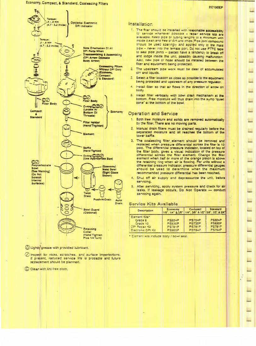
Economy, Compact, & Standard, Coalescing Filters
lorqu• :
~./s~;"1 ... 1~~i · ; "b -
Not• O"anution Of .I.I I CPI Pana When Oi•HNfTlllllng At A&Mmblin; !CPI Ar"11W Opl'Uil• Body...,._, ~ ~r
0 I I Co-n11 Fllt•rs
I• I e @WltnoutOP!Onty . e . ~ $i • fE&:clftOmy, 9 I '-e' - / CompaC1
~Q0c.-.:~. -· ~i (J . - · ~ , lStanoard)
-· · ( . / .. · -····.. ~· -
t oo 0 · ~Body
Compac:t
' Standud
Filler Body · ---1 O..l'ift9~
(L.ogta Al · Bollom 01 Tllr•ad•)
r---._ 1 Fitter Holclar M_ (HandThghten)
U---- Element
~~
~---1 s.m. .
0-nn;~
Economy
CD-{MandT191tt•n)
. (tJ•• Appropriate Sin)
©:Zl Potyearbcnate Bowl (SHWaming) (Do Not Scratch Internal SLOr1aCts)
I
~ ~~,___ FloLaining ~ C.:illar
I (Hand TiglHan PILOI 1/<I Turn)
@ UghtJy:grease with provided lubricant.
,7 '. lnspec fer nicks . sc~atc~es , and surface imperfecticns. "-' If present. reduced service life is prooat:le and future
replacement should t:e planned.
© c:ean witlJ lint-free c!oth .
Installation 1. 1'1e nite r snoul C: t:>e instal led w1tn. reuonable accessibility
rcr se rvice wneneve r pcss1ble - repair service kits are ava11ao1e Keeo p1oe or tuc 1 n~ lengths to a minimum with
s1oe : 1ean and ~ee of d111 ana cn1ps . Pipe joint comoouno sri ou1c :ie usea soaring ly anc apclred only to trie male 01pe - never ~ nto tne female i;:er:. Do not use PTFE !3pe to sea1 p1oe 101nts - 01eces have a tenoency to break oft ;ar.o lodge 1ns1oe the unrt. possibly causing maltvnct1on. Alsc new p1oe er nose should be rnstaJled betw~n trie filter and equipment oe1ng protec:ed.
<- . The upstream p1ce work must be dear of ac:eumulated c1n and liquids.
:; . Selec: a lilter locauon as dcse as possible to the equipment being proteeted and upstream of any pressure regulator.
4 . Install filter so :nat air nows in !tie direc:ion of arrow on tlcdy.
• . Install filter vertcally with bowl drain mechanism at the bottom. Free moisrure will thus drain into the sump '.quiet zone· at tne bonom of the bowl. I ·
Operation and Service 1. Seth tree moisture and solids are removed automatically
t:y !he filter. There are no moving par.s.
2. Manual drain filters must be drained regularly before the separated moisture and oil reaches the bottom of the lower baffle.
3. Tne coalescing filter .. element should be removed and replaced when press.ure dif:erential ai;ross the filter 'i$ 1 O psid. The differential pressure indicator, located on top of tne filter bedy. gives a visual indication of the pressure dir.erential across the filter element. Ct-.ange the filter element when half or more cf the orange piston is a.bove the retaining ring when air is 11owing. For units without a differential pressure indicator. pressure differential gauges should be used to determine when the maximum r1PCommended pressure differential has been reached.
~ . Shut or. air supply and depressurize the unit, before servicing.
5. At:er ser1icing. apply system pressure and check for air leaks. It leakage occurs, Do Not Operate - conduct servicing again.
Service Kits Available
Cescriplion Economy Compact Standard 1;s· . 114 • &. :i:s· 1/4·. 318" a. i12· :li!" . 112" AtJW
: :ement '<its• Grace 5 Ps;24P PS724P PS824P Grace ~ O I PS3:00P PS7::!0F PSBJOP
:;;: 1 :=2::a1r \(i t PS781P PS781P ?5781 p :O·ec:c:nic O Pi Kit PS365? PS75~? PS75-iP
• :0 ". eT er:: ~ It s :r.c!wce ~::;cy / bowl seal.
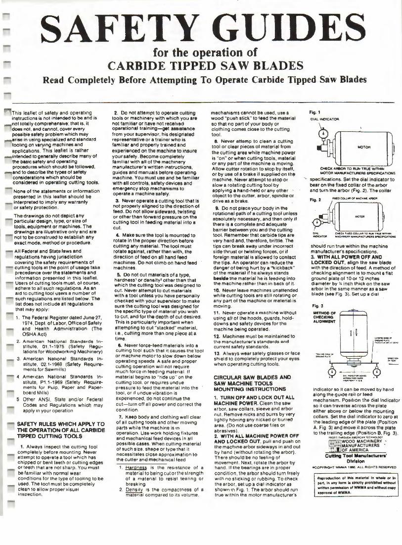
SAFETY GUIDES for the operation of
CARBIDE TIPPED SAW BLADES Read Completely Before Attempting To Operate Carbide Tipped Saw Blades
This leaflet of safety and operating instructions is not intended to be and is not totally comprehensive: that is. it does not, and cannot. cover every possible safety problem which m11y arise in using specialized and standard tooling on varying machines and applications . This leaflet is rather intended to generally describe many of the basic safety and operating procedures which should be followed , and to describe the types of safety considerations which should be considered in operating cutting tools.
None of the statements or information presented in this leaflet should be interpreted to imply any warranty or safety protection.
The drawings do not depict any particular design, type, or size of tools. equipment or machines. The drawings are illustrative only and are not to be construed to establish any exact mode, method or procedure.
All Federal and State laws and regulations having jurisdiction covering the safety requirements of cutting tools at the point of usage take precedence over the statements and information presented in this leaflet. Users of cutting toots must, of course, adhere to all such regulations. As an aid to cutting tool users a number of such regulations are listed below. The list does not include all regulations that may apply :
1. The Federal Register dated June 27, 1974, Dept. of Labor, Office of Safety and Health Administration (The OSHA Act)
2. American National Standards Institute, 01 .1-1975 (Safety Regulations for Woodworking Machinery)
3. American National Standards Institute, 02.1-1969 (Safety Requirements for Sawmills)
4. American National Standards Institute, P1 .1-1969 (Safety Requirements for Pulp, Paper and Paperboard Mills)
5. Other ANSI , State and/or Federal Codes and Regulations which may apply in your operation
SAFETY RULES WHICH APPLY TO THE OPERATION OF ALL CARBIDE TIPPED CUTTING TOOLS
1. Always inspect the cutting tool completely before mounting . Never attempt to operate a tool which has chipped or bent teeth or cutting edges or teeth that are not sharp . You must be famil iar with normal wear conditions for the type of tooling to be used. The tool must be completely clean to allow proper visual inspection .
2. Do not attempt to operate cuttfng tools or machinery with which you are not familiar or have not received operational training-get assistance from your supervisor. his designated representative or a trainer who is familiar and properly trained and eKperienced on the machine to insure your safety . Become completely familiar with all of the machinery manufacturer's written instructions, guides and manuals before operating machine. You must use and be familiar with all controls , safety devices and emergency stop mechanisms to operate a machine safely.
3. Never operate a cutting tool that is not properly aligned to the direction of feed . Do not allow sideward, twisting or other than forward pressure on the cutting tool in feeding material into a cut.
c. Make sure the tool is mounted to rotate in the proper direction before cutting any material. The tool must rotate against. rather than with, the direction of feed on all hand feed machines . Do not climb on hand feed machines.
5. Do not cut materials of a type, hardness' or density' other than that which the cutting tool was designed to cut. Never attempt to cut materials with a tool unless you have personally checked with your supervisor to make sure the cutting tool was designed for the specific type of material you wish to cut, and for the depth of cut desired. This is particularly important when attempting to cut "stacked" material, i.e ., cutting more than one piece at a time.
6. Never force-feed materials into a cutting tool such that it causes the toot or machine motor to slow down below operating speeds. A safe and proper cutting operation will not require much force in feeding material . If material begins to "ride up" on the cutting tool , or requires undue pressure to feed the material into the tool , or if undue vibration is experienced . do not cont inue the cut-turn off all power and correct the condition .
7. l<.eep body and clothing well clear of all cutting tools and other moving parts while the machine is in operation . Use work holding fixtures and mechanical feed devices in all possible cases. When cutting material of such size. shape or type that it necessitates close approximation to the cutter and mechanical feed
1. Hardness is the resistance of a material to bein g cul or the strength of a mater ial to res ist tearing or break ing .
2. Density is the compactness of a material compared to its volume .
mechanisms cannot be used , use a wood "push stick" to feed the material so that no part of your body or clothing comes close to the cutting tool . a. Never attemp to clean a cutting
tool or clear pieces of material from the cutting area while machine power is "on" or when cutting tools, material or any part of the machine is moving . Allow cutter rotation to stop by itself, or by use of a brake if supplied on th!! machine . Never attempt to stop or slow a rotating cutting tool by applying a hand-held or any other object to the cutter . arbor, spindle or drive as a brake.
I . Do not ptace your body in the rotational path of a cutting tool unless absolutely necessary, and then only ii there is a complete and adequate barrier between you and the cutting tool. Remember that carbide tips are very hard and, therefore, brittle. The tips can break away under incorrect side thrust or twisting forces, or if foreign material is allowed to contact the tips. An operator can reduce the danger of being hurt by a "kickback" of the material if he always stands bealde the material he is feeding into the machine rather than in back of it.
10. Never leave machines unattended while cutting tools are still rotating or any part of the machine or material is · moving. 11. Never operate a machine without using all of the hoods, guards, holddowns and safety devices for the machine being operated .
12. Machines must be maintained to the manufacturer's standards and current safety standards. 13. Always wear safety glasses or face sh ield to completely protect your eyes when operating cutting tools.
CIRCULAR SAW BLADES AND SAW MACHINE TOOLS MOUNTING INSTRUCTIONS
1. TURN OFF AND LOCK OUT ALL MACHINE POWER. Clean the saw arbor, saw collars , sleeve and arbor nut. Remove nicks and burrs by very lightly honing any nicked or burred area . (Do not use coarse files or abrasives). 2. WITH ALL MACHINE POWER OFF AND LOCKED OUT, pull and push on the machine arbor sideways in and out by hand (without rotating the arbor) . There should be no feeling of movement . Next. rotate the arbor by hand. If the bearings are in proper cond ition . the arbor should turn freely with no sticking or rubbing . To check the arbor, set up a dial indicator as shown in Fig. 1. The arbor should run true with in the motor manufacturer's
Fig. 1
0 1._l INDICATOR
MOTOR
CHECK ._RllOR TO RUN TRUE WITHIN MOTOR MANUF•CTUAERS SPECIFICATIONS
. ., specifications . Set the dial indicator to bear on the fixed collar of the arbor and turn the arbor (Fig . 2). The collar
Fig. 2 flXfO cou ... ui OJ MACHN. ~
I MO TOO
OIAl CHI.CK FIXED COll,.Att 'TO RUN TlllU( WITMIN INOtCATOfll MACMIN£R'T MAHUfACT'-""CRS IW'EO'ICATIC>Mi
should run true within the machine manufacturer's specifications. 3. WITH All POWER OFF AND LOCKED OUT, align the saw blade with the direction of feed . A method of checking alignment is to mount a flat ground plate of 10 or 12 inches diameter by V. inch thick on the saw arbor in the same manner as a saw blade (see Fig . 3). Set up a dial
Fig. 3
METHOD 0, CHECKING ALIGNMENT
~l aootC. lOGt 00 GlllCIUe"Votl -...~-~ .. • nOC>
indicator so it can be moved by hand along the guide rail or feed mechanism. Position the dial indicator so it can traverse across the plate either above or below the mounting collars. Set the dial indicator to zero at the leading edge of the plate (Position A. Fig . 3) and move it across the plate to the trailing edge (Position B, Fig 3) .
PROFll THROUGH AMERICA,,. TlCHNOlOG'I'
WOOD MACHINERY • MANUFACTURERS ' OF AMERICA
Cutting Tool Manufacturers' Dlvlalon
•COPYRIGHT WMMA HBO. ALL RIGHTS RESERVED
A•productlon ol tttt. m•tertal In whole or In port, In ony torm 11 1lrtctly prohlbtto•f without wrlHon pormlsalon ol WMMA and without copy approwel of WMMA.

_ • .,,. ,, ,_,._ ... U:t ' ............ 'W .......... OUlU t..17
hand so that point A is moved to point B when readi~ the indicator. Any deviation in angularity between the saw blade and the direction of feed should be maintained within the rnachine manufacturer's recommendations. On double cut-off and panel trim machines any slight angularity in ai iQnment should be controlled so that the trailing edge of the saw blades do nor re-cut the material.
4. WITH ALL MACHINE POWER OFF AND LOCKED OUT, inspect the saw bMlde before mounting . The bore (center hole) must be the correct size and fit snugly. Do not force a saw or other type of too l on an arbor. Do not tighten mounting screws uneQually, or use Incorrectly fitted keys . Incorrect mounting of saws or other tools can cause tool breakage and create dangerous operating conditions. Never mount a saw blade with a damaged (deeply scored or out of roun.d) bore or arbor. Inspect the teeth carefully. Do not mount blades with damge'd-bodies, dull or damaged (bent or chipped) teeth. Never use 11nything other than accurate metal shim&. or spacers if saw blades have to be positioned on the arbor. Never use shims to "wobble" a saw blade.' Be sure that all saw collars used match exactly in diameter. Closely check to see that the arbor nut threads are not worn and the wrench surfaces of the arbor nut are not rounded off.
5. WITH ALL MACHINE POWER OFF AND LOCKED OUT, mount the saw blade on the arbor making sure that the saw blade is turning in the correct rotation and that the arbor nut tightens in a directivn opposite to the blade rotation (See Fig . 4A & 48). Unless the
Fig. 4A
~- f'FYv:::._ =-"-~~--JM DI'~ .... ~) .y- ~-~- ~
'-==--·-c __ c_----==--s!•lD fOQ.llDT•'ffa.DotiMT..-cTIQllor...C
Fig. 48
nachine is specifically designed for ;uch cutting;never mount saw nachine tools to "climb cut" (teeth :utting in the same direction of feed) >n manually led machines. Never use aw blades on operations for which hey were not designed; for example, !o nol .use rip design blades to cut cross the grain, etc.
;tRCULAR SAW BLADES AND :.AW MACHINE TOOLS :TART•UP,PROCEDURES . TURN OFF M•D LOCK OUT ALL tACHINE POWER. Never assume reviously set machine or tool onditions to be correct. Be sure that
3. Mounting .a .saw blade to "wobble" means to shim the blade body unequ.ally on one side, throwing the saw ~~t of alignment with the arbor. This causes the saw to make a wider cul and dangerously increases pressures on the tool.
1oc~eo on ine arbor (See Fig . 4A & 46), turns freely (no foreign objects in tool rotation path) and is properly positioned for the cutting operation reQuired (See Fig. 3) . Check to see that the cutt ing tool is not dull or damaged. '::"leek to see that the body of the saw blade is not cracked .' Take special precaut ion to check "stacked cutters" to be sure that all bolts. pins and threaded parts are not worn or damaged, and are proper ly mounted . Be sure tha t hubs on a l! "split" circular tools are properly fitted and pinned and that the locking collars are in place and lit properly . Do not use locking collars that are not matched to the "split tool ." Split collars on split tools are not recommended.
2. WITH ALL MACHINE POWER OFF ANO LOCKED OUT insure that you are not attempling to operate tools that do not conform to the machine manufacturer's machine load specifications in either size or weight, or that do not mount according to the machine design limitations. Operate saw machine toots only on the type of materials, cutting loads and operation applications for which the tools were designed (II you don't know this information. ask your supervisor.) Do not operate saw blades or saw machine tools in excess of the machine or tool manufacturer's specifications, or current applicable OSHA standards, or in excess of 18,000 sfm (surface feet per minute).' (See Charts A and B following) .
3. WITH ALL MACHINE POWER OFF ANO LOCKED OUT position the cutting tool, material guides and material hold-downs so that the material to be cut is fully supported. This will insure there will be minimal material vibration. Next, follow the machine manufacturer's instructions to mount all guards over the toots such that the guards are close to. but properly clear. the material being cut. Mount and activate all of the machine safety devices such as anti-kickback mechanisms, spreaders. dust hoods and safety switches. Make sure all personnel and all loose or foreign objects are clear of the machine and cutting tools.
4. TURN ON MACHINE POWER, start the tool rotation slowly before feeding material. This is done by "jogging" (that is, pressing the start button and immediately after that pressing the stop button) . At a safe distance. observe the operating condition of the tools (by sight and sound) as they rotate slowly. Next. TURN ALL MACHINE POWER OFF AND LOCKED OUT, wait LJntil all cutting tools stop rotating by themselves (do not attempt to stop their rotation yourself unless a brake is specifically provided for that purpose on the machine), and make any necessary COl'rections. Go through a111teps noted in paragraph 3, just above, before you TURN THE MACHINE POWER ON. Press the start button and allow the machine to operate at
4. "All cracked saws shall be removed from service," Department of Labor OSHA Standards, Federal Register 29 CFR Part 1910.213(5) (7) .
5. The term "surface feet per minute" refers to the peripheral or rim speed of a cutting tool. See "Operating Speeds for Carbide Tipped' Rotary Cuttir;ig Tools" below.
before feeding material.
OPERATING SPEEDS FOR CARBll>E TIPPED CIRCULAR SAW BLADES Carbide t ipped circular saw blades of the types commonly used in the machining of materials typical of the toughness and density range of most wood species , composi tion boards medium hard plastics . and the sof1~r non-ferrous metals must never be operated in excess of the machinery or tool manufacturer's recommendations, or current applicable OSHA standards, or in excess of 16.000 slm (surface feet per minute) whichever is lowest. Surface feet per minute (sfm) refers to the peripheral or rim speed of a cutting tool, that is. the speed at which the outer cutting teeth are rotating when the tool is at full speed . This speed increases as the tool d iameter and /or motor arbor or spindle rpm increase. The maximum speed of 18,000 slm is allowable only when the machinery being used is in excellent operating condition and is excellently maintained. When using older or worn machinery, or when cuttin!i materials of an unusual toughness• or density' the surface feet per minute or material feed rate, or both. should be reduced to speeds where the tool cuts easily and freely without excessive vibration or high tooth impact shock. Most woods, plastics and the medium-hard nonferrous metals will cut better with longer tool life at surface feet per minute ranging from 8,000 sfm to
6. Toughness is the resistance of a material to being cut or the strength of a material to resist tearing or breaking .
7. Density is the compactness of a material compared to its volume.
CHART A
ha~dness a'nd machining characteristics of the material being cut. A~ the rim speed (aur1ace feet per minute) of a circular uw blade is decreased, feed rates must be dec~eased accordingly to prevent the forcing of material Into the cutting tool and overloading of the cutting teeth .
The method of determin ing the surface feet per minute (Sim) of 1
rotary cutting tool is as fo llows:
.26 • 0 a "PW • SFM
_,. D • ctl•metor ot U.. lool In lnchn RPM 1: rot•tlng aprlll9Cf, k\ '"Otutk)n1
,.., """"'• SFM • r1m ap.M, In aur1ace f .. t
pe-t minute
.2' • Ihle numl>Of 11 uMCI lo conYert thit tool cltcumfefence from fnchea lo tfft (1. tt ...-... by 121
Remember that changing to a larger diameter cutting tool at the same machine spindle or arbo r speed increases the surface feet per minute rim speed of the tool. Never make assumptions as to any machine motor rpm since machines and individual motors can be modified. WITHOUT ANY CUTTING TOOLS MOUNTED ON THE MACHINE, check the rpm ol each motor using an rpm tachometer. Once the cutting tool diameter and motor rpm are known. you can chec'k Chart A (following) to see if a saw blade will be operating w ithin the 18,000 surface feet per minute. maximum rim speed specified. For diameters not covered by Chart A, use the sfm (surface feet per minute) formula above. For the c ircular sawing of magnesium; copper, lead, brass, or bronze. note the LOWER surface speed limitations on Chart B. For harder or more difficult to cut materials, consult the tool manufacturer.
11,000 SFM !SURFACE FEET PER MINUTE! MAXIMUM RPM ROTATING 6PEEDS FOR CARBIDE TIPPEO CIRCULAR SAW BLADES
TYPICAL OF COMMERCIAL OESIGN, THICKNESS AND GRADE STANOAR OS
100 NOT OPERATE CARBIOE TIPPEO CIRCULAR SAW BLADES ABOVE THE RPM ROTATING SPEEDS SHOWN)
SAW OIA. MAXIMUM SAW DIA. MAXIMUM SAW DIA. MAXIMUM UNCHESI RPM UNCH ES) RPM UNCHESI Rl'M
6 11538' 24 2885 44 1573
7 9590· 26 2663 I 46 1506
8 8654· 28 2473 48 1442
10 6923. 30 2308 50 1315
12 5769' 32 2163 52 1331
14 4945• 34 2036 54 1212
16 4327• 36 1923 !>6 n36 18 3945• 38 1822 58 11 94
20 3461 40 1731 60 115"4
22 3147 42 1648
•Operation ot uw bl•d•• in exc:ns ot 3600 "PM is not ,•commended and will t•"H• lly '"""It in poor tool life •nd cvt Quallt¥' .
Nolt : Mon materials oNill cut b•tttr with lon9ar 1001 life at IP•«:t• well below th• maa1mum APM rotatir't9 IO*-d .
CHART B
Mlt.XIM\JM 'RIM SPEEDS, IN SURFACE FEET PER M1NVTE tSFMI, FOR CARBIDE Tll'PED CIRCULAR SAW &LADES CVTTING THE
MATERIALS LISTED BELOW
MAGNESIUM COPPER LEAO UNDER 150 UNDER 150 aRINELL eRASS BRINELL BllONZE
15,000 SFM 10,000 SFM 14,000SFM 10.000 SFM 12.000 SFM
SOPT 8 MEDIUM· HARO, ANOOIZED Note: Most m•t•I• , lm;t"dint 1J\D ..
HARD ALUMINUM ALUMINUM litt9d , wlll c1.1t b•n•r wlrtt lonter tool Iii• et N>Hd• b•low th• ma•imvm
I .._.rt.c• feet~' minut• html rim 18.000 SFM 12,000 SFM a.p .. a •.

Whirlwind Inc. Return Authorization Policy ----------------------------------------------------------------------------
No returns will be accepted by Whirlwind Inc. without a return authorization number. A return number will be assigned by the Inside Sales Desk. No other person is to issue return authorization numbers. This number MUST appear on the shipping label and all associated paperwork. Shipments which do not have a Return Authorization Number will be refused.
After a Return Authorization Number has been issued. the customer may return the defective part for warranty consideration. Just because a part is returned does not guarantee that it will be replaced under warranty. A credit will only be "issued after the item is examined and the Plant Superintendent or a company official approves the credit.
Any parts which are sent out as warranty replacements will be billed at the normal rate. Price of the part will be credited to the customer when the part is returned to Whirlwind Inc. and if the part is deemed as being under warranty. All freight costs are the responsibility of the customer. Any signs of abuse, misuse etc. will void any warranty claim. If parts are not returned within 30 days from date of return authorization, Whirlwind Inc. will require the invoice to be paid in full. There will be no exceptions.
Failure to pay an invoice for warranty claims which have been denied, when parts were not returned, or for freight will result in a shipping hold on future orders. We are extremely liberal on our warranty and will appreciate your cooperation with this policy.
Page 20 - R011998
Catalog 0600P-5/USA
Modular Push Button Valves
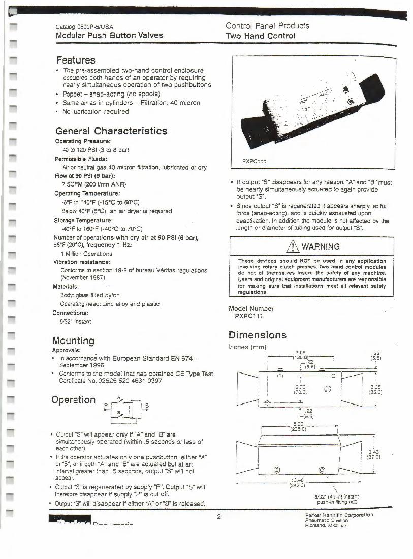
Features • The pre-assembled two-hand control enclosure
occupies both hands of an operator by requiring nearly simultaneous operation of two pushbuttons
Poppet - snap-acting (no spools)
Same air as in cylinders - Filtration: 40 micron
No lubrication required
General Characteristics Operating Pressure:
40 to 120 PSI (3 to 8 bar)
Permissible Fluids:
Air or neutral gas 40 micron filtration, lubricated or dry Flow at 90 PSI (6 bar): ·
7 SCFM (200 Vmn ANR)
Operating Temperature:
-5°F to 140°F {· 1 S'C to 60°C)
Below 4Q°F (S'C), an air dryer is required
Storage Temperature:
-40°F to 1so°F (-40°C to 70°C)
Number of operations with dry air at 90 PSI (6 bar}, 68°F (20°C), frequency 1 Hz:
1 Million Operations Vibration resistance:
Conforms to sac:ion 19·2 of bureau Veritas regulations (November 1987)
Materials:
Boey: glass filled nylon
Operating head: zinc alloy and plastic
Connections:
5i32" instant
Mounting Approvals:
• In accordance with European Standard EN 574 -September 1 996
• Coniorms to the model that has obtained CE Type Test Certificate No. 02526 520 4631 0397
Operation
• Output "S" will appear only if "A" and "B" are simultar.eously operated (within .5 seconds or less of each other).
• If '.he operator actuates only one pushbutton, either "A" or ·'S", or if ooth ·A" and ·'B" are actuated but at an in'.a;·;al greater tl;ar. .5 seccncs, output "S" will not appear.
• Output 'S" is regenerated by supply "P". Output "S" will therefore disappear if supply "P" is cut off.
• Output 'S" will disappear if either "A" or "B" is released.
~,....,--··~-·;- 2
Control Panel Products Two Hand Control
--· ;;;-::.~ . ~ ~.~-~ .--
PXPC 111
• If output "S" disappears for any reason, "A" and "B" must be nearly simultaneously actuated to c:gain provide output "S".
• Since output "S" is regenerated it appears sharply, at full force (snap-acting). and is quickly exhausted upon deactivation. In addition the module is not affected by the length er diameter of tubing used fer output "S".
f!\ WARNING
These devices should NOT be used in any application involving rotary clutch presses. Two hand control modules do not of themselves insure the safety of any machine. Users and original ~quipment manufacturers are responsible tor making sure that installations meet all relevant safety regulations.
Model Number PXPC111
Dimensions Inches {mm)
-II ( ~ )
u -8-
7.09 (1 30.0)
_22 ! (5 5) . - -I
2.76 0 (:"IJ.0)
.. . 22 - (5.5)
.---- 8.30 ---(225.0)
.22 (5 5)
3.35 (S5 .0)
r----..... w· I i g, L--J @ @. I
'-'--=------=->-\-.~
13 . .l6 -------------- (3<!2.0) . \
5/32" (4mm) instant push-in fining (x2)
Parker Hannifin Corporation Pneumatic Division Rich land. M;chiaan
I
L
L
L
L
L
L
L
L
L
L
L
L
L
L
L
L
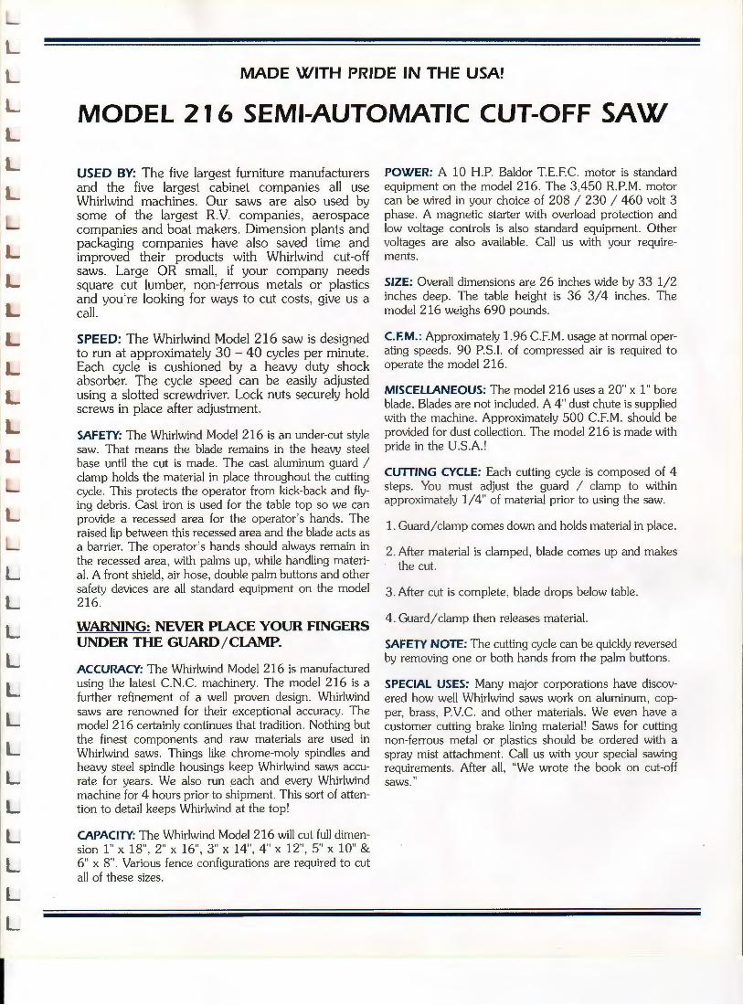
MADE WITH PRIDE IN THE USA!
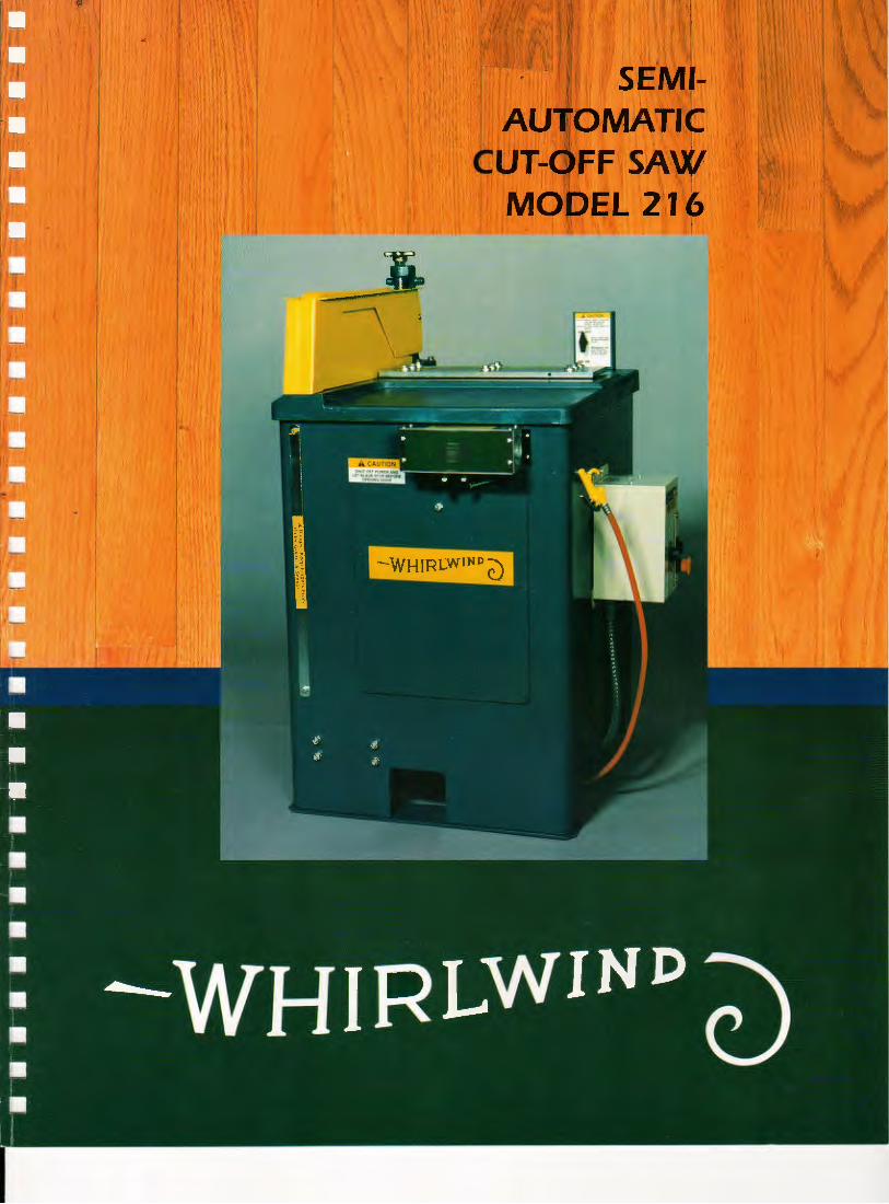
MODEL 216 SEMI-AUTOMATIC CUT-OFF SAW
USED BY: The five largest furniture manufacturers and the five largest cabinet companies all use Whirlwind machines. Our saws are also used by some of the largest R.V. companies, aerospace companies and boat makers. Dimension plants and packaging companies have also saved time and improved their products with Whirlwind cut-off saws. Large OR small, if your company needs square cut lumber, non-ferrous metals or plastics and you're looking for ways to cut costs, give us a call.
SPEED: The Whirlwind Model 216 saw is designed to run at approximately 30 - 40 cycles per minute. Each cycle is cushioned by a heavy duty shock absorber. The cycle speed can be easily adjusted using a slotted screwdriver. Lock nuts securely hold screws in place after adjustment.
SAFETY: The Whirlwind Model 216 is an under-cut style saw. That means the blade remains in the heavy steel base until the cut is made . The cast aluminum guard I clamp holds the material in place throughout the cutting cycle. This protects the operator from kick-back and flying debris . Cast iron is used for the table top so we can provide a recessed area for the operator's hands. The raised lip between this recessed area and the blade acts as a barrier. The operator's hands should always remain in the recessed area , with palms up, while handling material. A front shield, air hose, double palm buttons and other safety devices are all standard equipment on the model 216.
WARNING: NEVER PIACE YOUR FINGERS UNDER THE GUARD /CIAMP.
ACCURACY: The Whirlwind Model 216 is manufactured using the latest C.N.C. machinery. The model 216 is a further refinement of a well proven design. Whirlwind saws are renowned for their exceptional accuracy. The model 216 certainly continues that tradition . Nothing but the finest components and raw materials are used in Whirlwind saws. Things like chrome-moly spindles and heavy steel spindle housings keep Whirlwind saws accurate for years . We also run .each and every Whirlwind machine for 4 hours prior to shipment. This sort of attention to detail keeps Whirlwind at the top!
CAPACITY: The Whirlwind Model 216 will cut full dimension 1" x 18", 2" x 16'', 3" x 14", 4" x 12", 5" x 10" & 6" x 8''. Various fence configurations are required to cut all of these sizes.
POWER: A 10 H.P. Baldor T.E.FC. motor is standard equipment on the model 216. The 3,450 R.P.M. motor can be wired in your choice of 208 I 230 I 460 volt 3 phase. A magnetic starter with overload protection and low voltage controls is also standard equipment. Other voltages are also available. Call us with your requirements.
SIZE: Overall dimensions are 26 inches wide by 33 1/2 inches deep . The table height is 36 3/4 inches. The model 216 weighs 690 pounds.
C.F.M.: Approximately 1.96 C.F.M. usage at normal operating speeds. 90 P.S.I. of compressed air is required to operate the model 216.
MISCELLANEOUS: The model 216 uses a 20" x 1" bore blade. Blades are not included. A 4" dust chute is supplied with the machine. Approximately 500 C.F.M. should be provided for dust collection. The model 216 is made with pride in the U.S.A.!
CUTTING CYCLE: Each cutting cycle is composed of 4 steps . You must adjust the guard I clamp to within approximately 1/4" of material prior to using the saw.
1. Guard / clamp comes down and holds material in place.
2. After material is clamped, blade comes up and makes the cut.
3. After cut is complete, blade drops below table.
4. Guard / clamp then releases material.
SAFETY NOTE: The cutting cycle can be quickly reversed by removing one or both hands from the palm buttons.
SPECIAL USES: Many major corporations have discovered how well Whirlwind saws work on aluminum, copper, brass, P.V.C. and other materials. We even have a customer cutting brake lining material! Saws for cutting non-ferrous metal or plastics should be ordered with a spray mist attachment. Call us with your special sawing requirements. After all, "We wrote the book on cut-off saws."

I I
I l
r
'1
I
t 1
cf
I. i I } '
~ I '· 1
I
\''j
! I