Standard Equipment Optional Equipment - oregontractor.com · Hyundai engineering helps to keep...
10
NEW 7A SERIES CRAWLER EXCAVATOR Applied Tier 3 Engine Some of the photos may include optional equipment. www.hyundai-ce.com 2003. 6 Rev 1. Standard Equipment Optional Equipment ISO standard cabin All-weather steel cab with all-around visibility Safety glass windows Rise-up type windshield wiper Sliding fold-in front window Sliding side window Lockable door Hot & cool box Accessory box & Ashtray Computer Aided Power Optimization (New CAPO) system 2-power mode, 3-work mode, 2-user mode Auto deceleration & one touch deceleration system Auto warm up system Auto overheat prevention system Heater & Defroster (7500 Kcal/hr, 30000 BTU/hr) Self diagnostic system Starting Aid (air grid heater), cold weather Centralized monitoring LCD display Engine speed Clock & Error code Gauges Fuel level gauge Engine coolant temperature gauge Hyd. oil temperature gauge Warning Fuel level CPU Engine oil pressure Engine coolant temperature Hyd. oil temperature Low battery Air cleaner clogging Indicator Power max Preheat & Engine warming-up One touch decel Door and cab locks, one key AM/FM radio and cassette Radio remote switch Two outside rearview mirrors Fully adjustable suspension seat with seat belt Slidable joystick, pilot-operated Console box tilting system(LH.) Three frontal working lights Electric horn Batteries (2 x 12V x 100 AH) Battery master switch Removable clean out screen for oil cooler Automatic swing brake Removable reservoir tank Fuel pre-filter with fuel warmer Boom holding system Arm holding system Counterweight (3800kg, 8380lb) Mono boom (5.68m, 18’ 8”) Arm (2.92m, 9’ 7”) Track shoes (600m, 24”) Track rail guard Air-conditioner (5,000 kcal/hr, 20,000 BTU/hr) FATC (Full Automatic Temperature Control) Sun visor for cabin inside Fuel filler pump (35 /min, 9.5 US gpm) Beacon lamp Safety lock valve for boom cylinder with overload warning device Safety lock valve for arm cylinder Single acting piping kit (breaker, etc) Double acting piping kit (clamshell, etc) Quick coupler Accumulator, work equipment lowering 12 volt power outlet (24V DC to 12V DC converter) Electric transducer CD Player Travel alarm Various optional Arms Super short arm (2.00 m, 6’ 7”) Short arm (2.40 m, 7’ 10”) Long arm (3.90 m, 12’ 10”) Various optional Buckets (SAE heaped) Standard bucket (0.92 m 3 , 1.20 yd 3 ) Narrow bucket (0.51 m 3 , 0.67 yd 3 ) Narrow bucket (0.80 m 3 , 1.05 yd 3 ) Light duty bucket (1.10 m 3 , 1.44 yd 3 ) Light duty bucket (1.20 m 3 , 1.57 yd 3 ) Light duty bucket (1.34 m 3 , 1.75 yd 3 ) Heavy duty bucket (0.74 m 3 , 0.97 yd 3 ) Heavy duty bucket (0.90 m 3 , 1.18 yd 3 ) Heavy duty bucket (1.05 m 3 , 1.37 yd 3 ) Rock bucket (0.87 m 3 , 1.14 yd 3 ) Rock bucket (1.20 m 3 , 1.57 yd 3 ) Slope fishing bucket (0.75 m 3 , 0.98 yd 3 ) Cabin FOPS/FOG(ISO/DIS 10262) FOPS(Falling Object Protective Structure) FOG(Falling Object Guard) Cabin Roof-cover Transparent Cabin lights Track shoes Triple grousers shoe (700 mm, 28 ) Triple grousers shoe (800 mm, 32 ) Triple grousers shoe (900 mm, 35.4 ) Double grousers shoe (710 mm, 28 ) Lower frame under cover Pre heating system, coolant Tool kit Operator suit Low noise kit Engine emergency control cable Seat Adjustable air suspension seat Mechanical suspension seat with heater Robex 210LC-7A PLEASE CONTACT www.hyundai-ce.com 2007. 05 Rev 0 Standard and optional equipment may vary. Contact your Hyundai dealer for more information. The machine shown may vary according to International standards. All US measurement rounded off to nearest pounds or inches.
Transcript of Standard Equipment Optional Equipment - oregontractor.com · Hyundai engineering helps to keep...

NEW 7A SERIESCRAWLER EXCAVATOR Applied Tier 3 Engine
Some of the photos may include optional equipment.www.hyundai-ce.com 2003. 6 Rev 1.
Standard Equipment Optional Equipment
ISO standard cabinAll-weather steel cab with all-around visibilitySafety glass windowsRise-up type windshield wiperSliding fold-in front windowSliding side windowLockable doorHot & cool boxAccessory box & Ashtray
Computer Aided Power Optimization(New CAPO) system
2-power mode, 3-work mode, 2-user modeAuto deceleration & one touch deceleration systemAuto warm up systemAuto overheat prevention system
Heater & Defroster (7500 Kcal/hr, 30000 BTU/hr)Self diagnostic systemStarting Aid (air grid heater), cold weatherCentralized monitoring
LCD displayEngine speedClock & Error code
GaugesFuel level gaugeEngine coolant temperature gaugeHyd. oil temperature gauge
WarningFuel levelCPUEngine oil pressureEngine coolant temperatureHyd. oil temperature Low batteryAir cleaner clogging
IndicatorPower maxPreheat & Engine warming-up One touch decel
Door and cab locks, one keyAM/FM radio and cassette
Radio remote switchTwo outside rearview mirrorsFully adjustable suspension seat with seat beltSlidable joystick, pilot-operatedConsole box tilting system(LH.)Three frontal working lightsElectric hornBatteries (2 x 12V x 100 AH)Battery master switchRemovable clean out screen for oil coolerAutomatic swing brakeRemovable reservoir tankFuel pre-filter with fuel warmerBoom holding systemArm holding systemCounterweight (3800kg, 8380lb)Mono boom (5.68m, 18’ 8”)Arm (2.92m, 9’ 7”)Track shoes (600m, 24”)Track rail guard
Air-conditioner (5,000 kcal/hr, 20,000 BTU/hr)FATC (Full Automatic Temperature Control)Sun visor for cabin insideFuel filler pump (35 /min, 9.5 US gpm) Beacon lampSafety lock valve for boom cylinderwith overload warning device
Safety lock valve for arm cylinderSingle acting piping kit (breaker, etc)Double acting piping kit (clamshell, etc)Quick couplerAccumulator, work equipment lowering12 volt power outlet (24V DC to 12V DC converter)Electric transducerCD PlayerTravel alarmVarious optional Arms
Super short arm (2.00 m, 6’ 7”)Short arm (2.40 m, 7’ 10”)Long arm (3.90 m, 12’ 10”)
Various optional Buckets (SAE heaped)Standard bucket (0.92 m3, 1.20 yd3)Narrow bucket (0.51 m3, 0.67 yd3)Narrow bucket (0.80 m3, 1.05 yd3)Light duty bucket (1.10 m3, 1.44 yd3)Light duty bucket (1.20 m3, 1.57 yd3)Light duty bucket (1.34 m3, 1.75 yd3)Heavy duty bucket (0.74 m3, 0.97 yd3)Heavy duty bucket (0.90 m3, 1.18 yd3)Heavy duty bucket (1.05 m3, 1.37 yd3)Rock bucket (0.87 m3, 1.14 yd3)Rock bucket (1.20 m3, 1.57 yd3)Slope fishing bucket (0.75 m3, 0.98 yd3)
Cabin FOPS/FOG(ISO/DIS 10262)FOPS(Falling Object Protective Structure)FOG(Falling Object Guard)
Cabin Roof-cover TransparentCabin lightsTrack shoes
Triple grousers shoe (700 mm, 28 ) Triple grousers shoe (800 mm, 32 )Triple grousers shoe (900 mm, 35.4 )Double grousers shoe (710 mm, 28 )
Lower frame under coverPre heating system, coolantTool kitOperator suit
Low noise kitEngine emergency control cable
SeatAdjustable air suspension seatMechanical suspension seat with heater
Robex 210LC-7A
PLEASE CONTACT
www.hyundai-ce.com 2007. 05 Rev 0
Standard and optional equipment may vary. Contact your Hyundai dealer for more information. The machine shown may vary according to International standards.All US measurement rounded off to nearest pounds or inches.

Built for Maximum Power, Performance, Reliability.A new chapter in construction equipment has now begun. Making the dream a reality.
Robex 210LC-7A
HYUNDAI CONSTRUCTION EQUIPMENT 02 / 03
Some of the photos may include optional equipment.

Technology in Cab Design
Operator’s Comfort is Foremost.Wide Cab Exceeds Industry Standards.
Visibility. Even more visibility than before, for safer, more efficient
operating.
Excellent Ventilation. Ventilation has been improved by the addition of the larger fresh
air intake system, and by providing additional air flow throughout the cab.
. Sliding front and side windows provide improved ventilation.
. A large sunroof offers upward visibility and additional ventilation.
Comfortable Operator Environment. The control levers and seat can be adjusted to provide maximum
operator comfort. . The seat is fully adjustable for optimum operating position,
reducing operator fatigue. . Console boxes slide forward and backward for improved
accessibility. . The proportional pressure controls reduce unnecessary exertion
while ensuring precise operation.. Large windows allow excellent visibility in all directions.
Low noise design. The Robex new 7A series was designed with low operation
noise in mind.. Hyundai engineering helps to keep interior and exterior
noise levels to a minimum. . The cab's noise levels have been additionally reduced by
improving the door seals for the cab and engine compartments. . An insulated diesel engine compartment with sound-damping
material also reduces noise.
12 3
Wide, Comfortable Operating SpaceSteel Cover SunroofDial Type Engine Speed Switch and / Key Switch
123
Remote Radio Control and Deluxe Cassette
HYUNDAI CONSTRUCTION EQUIPMENT 04 / 05
Robex 210LC-7A

Operating Environment
CAB
CAB
Highly Sensitive Joystickand Easy EntranceNew joystick grips for precisecontrol have been equipped withdouble switches.
Easy-to-Reach ControlPanelsSwitches and other essentialcontrols are located near theoperator. This helps keep operator move-ment to a minimum, enhancingcontrol with less operatorfatigue.
Centralized control panel
Horn button
Option button
Remote Radio control
Travel lever
Cluster
One touch decel button
Hour meter
Travel pedal
Fully adjustable suspension seat
Safety lever
Power boost button
Joystick control lever
Air Conditioner and Heater controller
Rear Emergency ExitWindowRear Exit Window is designedwith easy exit for operator'ssafety.
Raise-up Wiper and CabinLightsRaise-up wiper has enhanced forthe better front view. Cabin Lightsenhances safety by brightlylighting the surroundings duringnight work(optional)Left
Right
Power boostOne touch decelerationHorn/Optional
Smooth Travel Pedal and Foot Rests
Wide Cab with Excellent VisibilityThe cab is roomy and ergonomically designed with low noise leveland good visibility. A full view front window and large rear and sidewindows provide excellent visibility in all directions.
The best working conditions in a pleasant environment.
Minimization of Shock and Vibration through CabMounting SystemThe application of Viscous Mounting to the cabin support provides theoperator with a much improved ride. The operator work efficiency willincrease as the shock and noise level in the cabin decreases.
Improved Intelligent DisplayInstrument Panel is installed in front of RHconsole box. It is easy to check all critical systems witheasy-to-read indicators.
Storage box and Cup HolderAn Additional storage box and cup holder are locatedbehind operator’s seat, and it keeps food andbeverages cool or hot.
Wide, Comfortable Operating SpaceAll the controls are designed and positionedaccording to the latest ergonomic research.Reinforced pillars have also been added forgreater cab rigidity.
Maximum Protection
HYUNDAI CONSTRUCTION EQUIPMENT 06 / 07
Robex 210LC-7A

The six cylinder 4 cycleTurbo Charged Engine withCharged Air Cooling, HasHigh Power output,Reliability, economical,and low emission.This engine meets TierIII emissionsregulations.
CUMMINS QSB6.7 Engine
The Definition of ProgressThe Quantum System B Series 6.7-liter enginecombines full-authority electronic controls withthe reliable performance.The electronics with the QSB6.7 have beenproven with our high-horsepower products-working in the harshest, most demandingenvironments-search as dusty, non-stop miningoperations while meeting emissions regulationsworldwide.The QSB6.7 features 24 valve designed withcentered injectors and symmetrical piston bowl. The combination of improved airflow and evenlydispersed fuel results in increased power,improved transient reponse and reduced fuelconsumption.
Track Rail Guide & AdjustersDurable track rail guides keep track links in place. Track adjustment is made easy with standard greasecylinder track adjusters and shock absorbing springs. (Full Track Guide : Option)
Strong and Stable Lower FrameReinforced box-section frame is all welded, low-stress, high-strength steel. It guarantees safety and resistance against external impact when driving on rough ground and workingon wet sites through high tensile strength steel panels, with highly durable upper and lower rollers andtrack guards. Long undercarriage incorporates heavy duty excavator style components.X-leg type center frame is integrally welded for maximum strength and durability. Powerful and Preciser Swing Control
Improved shock absorbing characteristics makestopping a precise and smooth action
Reinforced Bucket and BucketLinkageSealed and adjustable bucket linkage providesless wear of pins and bushes as well as silentoperation.The design includes bucket linkdurability and anti wear characteristics.Additional reinforcement plates on cutting edgesection. Reinforced bucket is made with thickersteel and additional lateral plate.
Self Diagnosis SystemThe CPU controller diagnoses problems in theCAPO system caused by electric and hydraulicmalfunctions and displays them on the LCDmonitor of the cluster through error codes. Thiscontroller has the capacity to identify 48 distincttypes of errors. As the information from thisdevice, such as engine rpm, main pump deliverypressure, battery voltage, hyd. temperature, andthe state of all types of electric switches,provides the operator with a much more exactstate of machine operating condition. This makes the machine easier to troubleshootwhen anything does go wrong.
One Touch Decel SystemWhen the one touch decel switch is pressed, CPUcontroller controls the accel actuator to reduceengine speed to 800 rpm. And then the one touchdecel switch is pressed again, the engine speedrecovers.
Pump Flow Control SystemIn neutral position: Pump flow is reduced to aminimum to eliminate power loss. In operation: Maximum pump flow is delivered tothe actuator to increase the speed. Withmovement of the control lever, pump flow isautomatically adjusted and the actuator speed canbe proportionally controlled.
Boom & Arm Holding System The Holding valves in the main control valveprevents the boom & arm from dropping over anextended period in neutral position.
Arm Flow Regeneration SystemArm flow regeneration valve provides smootharm-in operation without cavitation.
Hydraulic Damper in Travel PedalImproved travel controllability & feeling by shockreducing when starting and stopping.
Auto Deceleration SystemWhen remote-controlvalves are in neutralposition more than 4seconds, CPU con-troller instructs theaccel actuator toreduce engine speed
to 1100rpm. This decreases fuel consumption andreduces cab noise levels.
Max. Flow Cut-off SystemFor precise control and finishing work, the Max.Flow Cut-off System reduces pump flow, thusallowing smooth operation.
ADVANCED CAPO SYSTEM
NEW MODE CONTROL SYSTEM
Power boost control SystemWhen the power boost system isactivated, digging power increasesabout 10%. It is especially useful when extrapower is temporarily needed, forinstance, when digging hard earthand rock, or if the bucket teeth arestopped by a stubborn tree root.
Automatic Engine OverheatPreventionIf the engine coolant temperaturegets too high, the CPU controllerlowers the engine speed and coolsthe engine.
Automatic Warming-up SystemAfter the engine is started, if theengine coolant temperature is low,the CPU controller increases theengine speed and automaticallyincreases the pump flow rate towarm up the engine more effectively.
Anti Restart SystemThe new system protects the starterfrom re-starting during engineoperation, even if the operatoraccidentally turns the start key again.
Advanced Hydraulic System
Increased Higher PerformanceThe advanced CAPO(ComputerAided Power Optimization)system maintains engine andmutual pump power at optimumlevels. Mode selections aredesigned for various work loadsand maintaining highperformance while reducing fuelconsumption. Features such as autodeceleration and power boostare included in the system. Thesystem monitors engine speed,coolant temperature, andhydraulic oil temperature.Contained within the system areself diagnostic capabilitieswhich are displayed by errorcodes on the cluster.
POWER MODEH mode: High power S mode: Standard powerWORK MODE
Heavy duty work General work BreakerUSER MODEM mode: Maximum PowerU mode : Memorizing Operator’s Preferable Power Setting
1
2
3
12
3
HYUNDAI CONSTRUCTION EQUIPMENT 08 / 09

Reliability & Serviceability
Centralized Electric Control Box andEasy to Change Air Cleaner AssemblyElectric control box and Air cleaner are centralized in one or the samecompartment for easy service.
Highly efficient Hydraulic PumpPump output capacity has been increased.
Large tool box for extra storage
Full open doors and master key systemprovide easy access for servicing.
Side Cover with Left & Right Swing Open TypeEasy access to vital components gives unrestricted view ofcomponent allows easy maintenance and repair.
Easy to maintain engine componentsThe cooling and preheating system are provided for optimum andimmediate operation, guaranteeing longer life for the engine andhydraulic components. Servicing of the engine and hydraulics is considerably simplifieddue to total accessibility.
Durability of structure proven throughFEM(Finite Element Method) analysisand long term durability test.
HYUNDAI CONSTRUCTION EQUIPMENT 10 / 11
Robex 210LC-7A

HYUNDAI CONSTRUCTION EQUIPMENT 12 / 13
0.51(0.67 )
0.80(1.05)
0.92(1.20)
1.10(1.44)
1.20(1.57)
1.34(1.75)
0.74(0.97)
0.90(1.18)
1.05(1.37)
0.87(1.14)
1.20(1.57)
0.75(0.98)
0.45(0.59)
0.70(0.92)
0.80(1.05)
0.96(1.26)
1.00(1.31)
1.15 (1.50)
0.65(0.85)
0.80(1.05)
0.92(1.20)
0.75(0.98)
1.00(1.31)
0.65(0.85)
700(27.6)
1000(39.4)
1150(45.3)
1320(52.0)
1400(55.1)
1550(61.0)
985(38.8)
1070(42.0)
1290(50.8)
1140(44.9)
1410(55.5)
1790(70.5)
570(1260)
700(1540)
770(1700)
830(1830)
850(1870)
920(2030)
770(1700)
810(1790)
890(1960)
900(1980)
1030(2270)
880(1940)
820(32.3)
1120(44.1)
1270(50.0)
1440(56.7)
1520(59.8)
1670(65.7)
-
-
-
-
-
-
SAEheaped
2,000(6’ 7”)
2,400(7’ 10”)
2,920(9’ 7”)
3,900(12’ 10”)
CECEheaped
Weightkg(lb)Without
side cuttersWith
side cutters
0.51(0.67) 0.80(1.05)0.92(1.20)
1.10(1.44)1.20(1.57)
1.34(1.75) 0.75(0.98)
2.0 m (6’ 7”) 2.40 m (7’ 10”) 2.92 m (9’ 7”) 3.90 m (12’ 10”)
Capacitym3 (yd3)
Widthmm (in)
Recommendation mm(ft.in)
2,000 (6’ 7”)860 (1,890)
2,400 (7’ 10”)950 (2,090)
2,920 (9’ 7”)990 (2,180)
Bucket digging force
Arm crowdforce
133.4 [145.5]13600 [14840]29980 [32710]
152.0 [165.8]15500 [16910]34170 [37280]
135.3 [147.6]13800 [15050]30420 [33190]
142.2[155.1]14500[15820]31970 [34880]
133.4 [145.5]13600 [14840]29980 [32710]
152.0 [165.8] 15500 [16910]34170 [37280]
112.8 [123.1]11500 [12550]25350 [27650]
117.7 [128.4]12000 [13090]26460 [28870]
3,900 (12’ 10”)1,200 (2,650)
133.4 [145.5]13600 [14840]29980 [32710]
152.0 [165.8] 15500 [16910]34170 [37280]
79.4 [86.6]8100 [8840]
17860 [19480]
85.3 [93.0]8700 [9490]
19180 [20920]
133.4 [145.5]13600 [14840]29980 [32710]
152.0 [165.8]15500 [16910]34170 [37280]
97.1 [105.9]9900 [10800]
21830 [23810]
101.0 [110.2]10300 [11240] 22710 [24770]
: Standard backhoe bucket: Heavy-duty : Rock bucket-Heavy duty: Slope finishing bucket
Arm Length Weight
mm(ft.in)kg(lb)
kNkgflbf
SAE
ISO
SAE
ISO
Applicable for materials with density of 2,000 kg /m3 (3,370 lb/yd3) or lessApplicable for materials with density of 1,600 kg /m3 (2,700 lb/yd3) or lessApplicable for materials with density of 1,100 kg /m3 (1,850 lb/ yd3) or less
5,680 (18’ 8”)
0.74(0.97)0.90(1.18)1.05(1.37)
Boom
Arm
kNkgflbf
kNkgflbfkNkgflbf
Remark
[ ]:Power Boost
SAE heapedm3 (yd3)
0.87(1.14)1.20(1.57)
Buckets
Backhoe attachmentBoom and arms are of all-welded, low-stress, full-box section design. 5.68m(18’ 8”) mono boom and 2.0m(6’ 7”), 2.4m (7’ 10”), 2.92m (9’ 7”), 3.90m (12’ 10”) armare available. Buckets are all-welded, high-strength steel implements.
Note : Arm weight including bucket cylinder and linkage. Standard arm
Digging force
Engine
Water cooled, 4 cycle Diesel,6-Cylinders in line, direct injection,Turbocharged, charge air cooled,Low emission
Type
Ratedflywheel
horse power
J1995 (gross) 151HP (113kW) / 1,900rpm143HP (107kW) / 1,900rpm153PS (113kW) / 1,900rpm145PS (107kW) / 1,900rpm
63.0kgf.m (456lbf.ft) / 1,500rpm104mm (4.1in) 132mm(5.2in)
6,700cc (409 in3)
Max. torqueBore strokePiston displacementBatteriesStarting motorAlternator
2 x 12V 100AH24V, 4.5kw
24V, 50Amp
J1349 (net)6271/1 (gross)6271/1 (net)
SAE
DIN
Model
Main pump
Hydraulic motors
Relief valve setting
Hydraulic cylinders
TypeMax. flowSub-pump for pilot circuit
Two variable displacement piston pumps2 222 /min (58.1 US gpm / 48.4 UK gpm)Gear pump
Cummins QSB6.7
Swing system
Swing motorSwing reductionSwing bearing lubricationSwing brakeSwing speed
Axial piston motorPlanetary gear reductionGrease-bathedMulti wet disc12 rpm
Coolant & Lubricant capacity
Undercarriage
Operating weight (approximate)
(refilling)Fuel tankEngine coolant Engine oilSwing deviceFinal drive(each)Hydraulic system(including tank)Hydraulic tank
liter34035245
5.8290180
US gal89.89.26.31.3
276.647.6
UK gal74.87.75.31.1
163.839.6
Center frameTrack frameNo. of shoes on each sideNo. of carrier roller on each sideNo. of track roller on each sideNo. of rail guard on each side
X - leg typePentagonal box type49292
Drives & Brakes
Drive methodDrive motorReduction systemMax. drawbar pullMax. travel speed(high) / (low)GradeabilityParking brake
Pilot pressure operated joysticks and pedals with detachable leverprovide almost effortless and fatigueless operation.
X-leg type center frame is integrally welded with reinforced box-sectiontrack frames. The undercarriage includes lubricated rollers, idlers, trackadjusters with shock absorbing spring and sprockets, and track chainwith double or triple grouser shoes.
Operating weight
Major component weight
Operating weight, including 5680mm (18’ 8”) boom, 2920m (9’ 7”) arm,SAE heaped 0.92m3 (1.20 yd3) backhoe bucket, lubricant, coolant, full fueltank, hydraulic tank and the standard equipment.
Hydraulic system
Two speed axial piston motorwith brake valve and parking brake
Axial piston motor with automatic brake
330 kgf/cm2 (4,690 psi)330 kgf/cm2 (4,690 psi)360 kgf/cm2 (5,120 psi)240 kgf/cm2 (3,410 psi)35 kgf/cm2 (500 psi)Installed
Boom: 2-120 85 1290 mm (4.7” 3.3” 50.8”)Arm: 1-140 100 1510 mm (5.5” 3.9” 59.4”)
Bucket: 1-125 85 1055 mm (4.9” 3.3” 41.5”)
Cross-sensing and fuel saving pump system
Travel
Swing
Implement circuitsTravelPower boost (boom, arm, bucket)Swing circuitPilot circuitService valve
No. of cylinder-bore rod stroke
Fully hydrostatic typeAxial piston motor, in-shoe designPlanetary reduction gear21,100 kgf (46,500 lbf)5.3 km/hr (3.3 mph) / 3.4 km/hr (2.1 mph)35 (70 %)Multi wet disc
Traveling and steeringEngine throttleLights
Pilot control Two joysticks with one safety lever(LH): Swing and arm, (RH): Boom and bucket(ISO)
Two levers with pedalsElectric, Dial typeTwo lights mounted on the boom and one in the battery box
Control
UpperstructureCounterweightBoom (with Arm cylinder)
5,850kg (12,900lb)3,800kg (8,380lb)1,950kg (4,300lb)
600 mm(24”)
700 mm(28”)
800 mm(32”)
900 mm(35.4”)
Shoes Operating weight Ground pressure
Triple grouser
Type Width mm(in) kg(lb) kgf/cm2(psi)
R210LC-7A
R210LC-7A H/C
R210LC-7A
R210LC-7A H/C
R210LC-7A
R210LC-7A H/C
21,700 (47,800)
23,160 (51,060)
21,980 (48,460)
23,440 (57,680)
22,270 (49,070)
23,730(52,320)
0.46 (6.54)
0.49 (6.97)
0.40 (5.69)
0.43 (6.12)
0.35 (4.98)
0.38 (5.40)
R210LC-7A 22,560 (49,740) 0.32 (4.55)
710 mm(28”)
Double grouser R210LC-7A H/C 23,770 (52,400) 0.43 (6.12)
Standard equipment
STD/HC
STD/HC
Specifications Backhoe attachment
A
11 10 9
9
8
8
7
7
6
6
6
5
5
5
4
4
4
3
3
3
2
2
2
1
1
1
0
0
(meters)
(meters)
F
D
E
B B' C
A'
210LC-7210LC-7
35
30
25
20
15
10
5
0
5
10
15
20
25
05101520253035 (ft)
(ft)
R210LC-7A
R210LC-7A
E
KH
L
D, D'
A
B
I
J
C
G
F
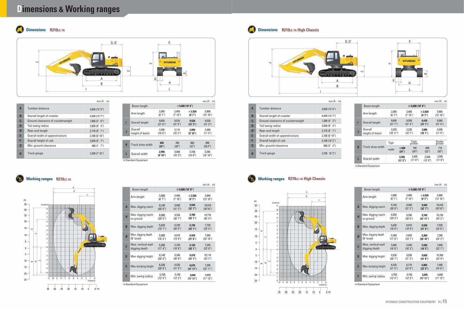
Dimensions
Working ranges
B
C
D
D’
E
F
G
H
A Tumbler distance
Overall length of crawler
Ground clearance of counterweight
Tail swing radius
Rear-end length
Overall width of upperstructure
Overall height of cab
Min. ground clearance
Track gauge
mm (ft in)
I
J
K
L
Boom length
Arm length
5,680 (18’ 8”)
Overall length
Overallheight of boom
mm (ft in)
Track shoe width
Overall width
A
A’
B
B’
C
D
E
F
Boom length
Arm length
5,680 (18’ 8”)
Max. digging reach
Max. digging reachon ground
mm (ft in)
Max. digging depth
Max. digging depth(8' level)
Max. vertical walldigging depth
Max. digging height
Max. dumping height
Min. swing radius
Standard Equipment
Standard Equipment
3,650 (12’ 0”)
4,440 (14’ 7”)
1,060 (3’ 6”)
2,830 (9’ 3”)
2,770 (9’ 1”)
2,700 (8’ 10”)
2,920 (9’ 7”)
480 (1’ 7”)
2,390 (7’ 10”)
2,000(6’ 7”)
9,650(31’ 8”)
3,200(10’ 6”)
2,400(7’ 10”)
9,570 (31’ 5”)
3,110(10’ 2”)
3,900(12’ 10”)
9,520 (31’ 3”)
3,480(11’ 5”)
2,920(9’ 7”)
9,520(31’ 3”)
2,990(9’ 10”)
600(24”)
2,990(9’ 10”)
700(28”)
3,090 (10’ 2”)
800(32”)
3,190(10’ 6”)
900(35.4”)
3,290(10’ 10”)
2,000(6’ 7”)
9,140(30’ 0”)
8,960(29’ 5”)
5,820(19’ 1”)
5,580(18’ 4”)
5,280(17’ 4”)
9,140(30’ 0”)
6,330(20’ 9”)
3,750(12’ 4”)
2,400(7’ 10”)
9,500 (31’ 2”)
9,330(30’ 7”)
6,220(20’ 5”)
6,010(19’ 9”)
5,720(18’ 9”)
9,340(30’ 8”)
6,520(21’ 5”)
3,740(12’ 3”)
3,900(12’ 10”)
10,910 (35’10”)
10,770(35’ 4”)
7,720(25’ 4”)
7,580(24’ 10”)
7,240(23’ 9”)
10,110(33’ 2”)
7,290(23’ 11”)
3,650(11’ 12”)
2,920(9’ 7”)
9,940(32’ 7”)
9,780(32’ 1”)
6,740(22’ 1”)
6,550(21’ 6”)
6,120(20’ 1”)
9,470(31’ 1”)
6,670(21’ 11”)
3,640(11’ 11”)
Dimensions & Working ranges
HYUNDAI CONSTRUCTION EQUIPMENT 14 / 15
11
11
A
A'
F
DB
EB'
C
12 10
10
9
9
8
8
87
7
7
6
6
6
5
5
5
4
4
4
3
3
3
2
2
2
1
1
1
0
0
(meters)
(meters)
R210LC-7A High Chassis
R210LC-7A High Chassis
35
30
25
20
15
10
5
0
5
10
15
20
25
05101520253035 (ft)
(ft)
E
KH
L
D, D'
A
B
I
J
C
F
G
Dimensions
Working ranges
B
C
D
D’
E
F
G
H
A Tumbler distance
Overall length of crawler
Ground clearance of counterweight
Tail swing radius
Rear-end length
Overall width of upperstructure
Overall height of cab
Min. ground clearance
Track gauge
3,650 (12’ 0”)
4,440 (14’ 7”)
1,260 (4’ 2”)
2,830 (9’ 3”)
2,770 (9’ 1”)
2,700 (8’ 10”)
3,100 (10’ 2”)
660 (2’ 2”)
2,795 (9’ 2”)
mm (ft in)
I
J
K
L
Boom length
Arm length
5,680 (18’ 8”)
Overall length
Overallheight of boom
mm (ft in)
Track shoe width
Overall width
A
A’
B
B’
C
D
E
F
Boom length
Arm length
5,680 (18’ 8”)
Max. digging reach
Max. digging reachon ground
mm (ft in)
Max. digging depth
Max. digging depth(8' level)
Max. vertical walldigging depth
Max. digging height
Max. dumping height
Min. swing radius
Standard Equipment
Standard Equipment
2,000(6’ 7”)
9,640(31’ 7”)
3,320(10’ 11”)
2,400(7’ 10”)
9,550 (31’ 4”)
3,220(10’ 7”)
3,900(12’ 10”)
9,560 (31’ 4”)
3,490(11’ 5”)
2,920(9’ 7”)
9,470(31’ 1”)
3,080(10’ 1”)
600(24”)
3,395(11’ 2”)
700(28”)
3,495 (11’ 6”)
710(28”)
3,505 (11’ 6”)
800(32”)
3,595(12’ 0”)
Triple grouser
Double grouserType
width
2,000(6’ 7”)
9,140(30’ 0”)
8,920(29’ 3”)
5,630(18’ 6”)
5,390(17’ 8”)
5,090(16’ 8”)
9,330(30’ 7”)
6,520(21’ 5”)
3,750(12’ 4”)
2,400(7’ 10”)
9,500 (31’ 2”)
9,290(30’ 6”)
6,010(19’ 9”)
5,820(19’ 1”)
5,530(18’ 2”)
9,530(31’ 3”)
6,710(22’ 0”)
3,740(12’ 3”)
3,900(12’ 10”)
10,910 (35’10”)
10,730(35’ 2”)
7,530(24’ 8”)
7,390(24’ 3”)
7,050(23’ 1”)
10,300(33’ 9”)
7,480(24’ 6”)
3,650(11’ 12”)
2,920(9’ 7”)
9,940(32’ 7”)
9,740(31’ 11”)
6,550(21’ 6”)
6,360(20’ 10”)
5,930(19’ 5”)
9,660(31’ 8”)
6,860(22’ 6”)
3,640(11’ 11”)

7.5 m(25.0 ft)6.0 m
(20.0 ft)4.5 m
(15.0 ft)3.0 m
(10.0 ft)1.5 m(5.0 ft)
GroundLine
-1.5 m(-5.0 ft)-3.0 m
(-10.0 ft)-4.5 m
(-15.0 ft)
kglbkglbkglbkglbkglbkglbkglbkglbkglb
*13020*28700*11620*25620*8770*19330
1251027580
*11620*25620*8770
*19330
*5360*11820*6970
*15370*8380
*18470*9020
*19890*8960
*19750*8210
*18100
*5360*11820*6970*15370
6480142906250
137806220
137106330
13960
*4150*9150*4540
*10010*5240
*11550*5950
*13120*6430
*14180*6510
*14350*5910
*13030
*4150*9150*4540*10010
4490990042409350408089904030888041109060
*4500*9920*4820*10630*5040*11110
311068602990659029106420
*3750*8270*3800*8380*3910*8620*4050*89304120908043409570*4550
*10030*4510*9940
*3750*827031406920264058202410531023605200248054702850628037608290
6.64(21.8)7.78
(25.5)8.43
(27.7)8.74
(28.7)8.73
(28.6)8.42
(27.6)7.76
(25.5)6.61
(21.7)
Boom : 5.68m (18’ 8”) Arm : 2.0 m (6’ 7”) Bucket : 0.92 m3 (1.20 yd3) SAE heaped Shoe : 800mm(32”) triple grouser with 3,800kg (8,380 lb) counterweight
Load point heightm(ft)
3.0 m (10.0 ft) 4.5 m (15.0 ft) 6.0 m (20.0 ft) 7.5 m (25.0 ft) Capacity Reach
m (ft )
At max. reachLoad radius
7.5 m(25.0 ft)6.0 m
(20.0 ft)4.5 m
(15.0 ft)3.0 m
(10.0 ft)1.5 m(5.0 ft)
GroundLine
-1.5 m(-5.0 ft)-3.0 m
(-10.0 ft)-4.5 m
(-15.0 ft)
kglbkglbkglbkglbkglbkglbkglbkglbkglb
*9220*20330*13340*29410
*9220*20330*13340*29410
*8300*18300*12750*28110*12280*27070*9840*21690
*8300*183001228027070*12280*27070*9840*21690
*6420*14150*7960*17550*8820*19440*8970*19780*8430*18580*6850*15100
*6420*14150653014400622013710614013540621013690647014260
*3750*8270*4190*9240*4920
*10850*5690
*12540*6260
*13800*6460
*14240*6110
*13470
*3750*8270*4190*92404520996042409350405089303960873040008820
*3940*8690*4240*9350*4620*10190*4920*10850
32207100311068602980657028706330
*3450*7610*3520*7760*3630*8000*3780*83303830844040108840*4300*9480*4360*9610
*3450*761028606310243053602220489021704780227050002570567032907250
7.15(23.5)8.20
(26.9)8.82
(28.9)9.11
(29.9)9.10
(29.9)8.81
(28.9)8.18
(26.8)7.12
(23.4)
Boom : 5.68m (18’ 8”) Arm : 2.4 m (7’ 10”) Bucket : 0.92 m3 (1.20 yd3) SAE heaped Shoe : 800mm(32”) triple grouser with 3,800kg (8,380 lb) counterweight
Load point heightm(ft)
1.5 m (5.0 ft) 3.0 m (10.0 ft) 4.5 m (15.0 ft) 6.0 m (20.0 ft) 7.5 m (25.0 ft) Capacity Reach
m (ft )
At max. reachLoad radius
9.0 m(30.0 ft)7.5 m
(25.0 ft)6.0 m
(20.0 ft)4.5 m
(15.0 ft)3.0 m
(10.0 ft)1.5 m(5.0 ft)
GroundLine
-1.5 m(-5.0 ft)-3.0 m
(-10.0 ft)-4.5 m
(-15.0 ft)6.0 m
(20.0 ft)
*4950*10910*7060*15560*9410*20750*12210*26920
*4950*10910*7060
*15560*9410
*20750*12210*26920
*10430*22990*9990*22020*10980*24210*13520*29810*12480*27510*9890*21800
*10430*22990*9990*22020*10980*2421011550254601179025990*9890*21800
*6230*13730*7720
*17020*8560
*18870*8760
*19310*8250
*18190*6620
*14590
*6230*13730
6170136005860
129205760
127005830
128506110
13470
*3710*8180*4640*10230*5490*12100*6070*13380*6270*13820*5920*13050
*3710*81804270941039608730375082703670809037208200
*1870*4120*2670*5890*2910*6420*3340*7360*3860*8510*4360*9610*4710*10380475010470
*1870*4120*2670*5890*2910*64203130690029306460276060802640582026005730
*1930*4250*2750*6060*3260*7190*3340*7360*2240*4940
*1930*425021904830209046102000441019504300
*2590*5710*2640*5820*2720*6000*2830*624029406480289063702970655032207100*3650*8050*3770*8310
*2590*5710247054502010443017503860161035501570346016103550176038802080459027706110
7.66(25.1)8.94
(29.3)9.77
(32.1)10.28(33.7)10.52(34.5)10.52(34.5)10.27(33.7)9.75
(32.0)8.91
(29.2)7.62
(25.0)
kglbkglbkglbkglbkglbkglbkglbkglbkglbkglbkglb
Boom : 5.68m (18’ 8”) Arm : 3.9 m (12’ 9”) Bucket : 0.92 m3 (1.20 yd3) SAE heaped Shoe : 600mm(24”) triple grouser with 3,800kg (8,380 lb) counterweight
1. Lifting capacity is based on SAE J1097, ISO 10567.2. Lifting capacity of the Robex Series does not exceed 75% of tipping load with the machine on firm, level ground or 87% of full hydraulic capacity.3. The load point is a hook (standard equipment) located on the back of the bucket.4. (*) indicates load limited by hydraulic capacity.
Load point heightm(ft)
3.0 m (10.0 ft)1.5 m (5.0 ft) 4.5 m (15.0 ft) 6.0 m (20.0 ft) 7.5 m (25.0 ft) 9.0 m (30.0 ft) Capacity Reach
m (ft )
At max. reachLoad radius
Lifting Capacities
HYUNDAI CONSTRUCTION EQUIPMENT 16 / 17
Lifting capacities R210LC-7A Rating over-side or 360 degreeRating over-front
7.5 m(25.0 ft)6.0 m
(20.0 ft)4.5 m
(15.0 ft)3.0 m
(10.0 ft)1.5 m(5.0 ft)
GroundLine
-1.5 m(-5.0 ft)-3.0 m
(-10.0 ft)-4.5 m
(-15.0 ft)
kglbkglbkglbkglbkglbkglbkglbkglbkglb
*13020*28700*11620*25620*8770
*19330
1219026870*11620*25620*8770*19330
*5360*11820*6970*15370*8380*18470*9020*19890*8960*19750*8210*18100
*5360*11820
683015060631013910608013400605013340616013580
*4150*9150*4540*10010*5240*11550*5950*13120*6430*14180*6510*14350*5910*13030
*4150*9150*4540*100104380966041209080396087303910862039908800
*4500*9920*4820
*10630498010980
302066602900639028306240
*3750*8270*3800*8380*3910*8620*4050*89304000882042109280
*4550*10030*4510*9940
*3750*827030606750256056402340516022805030240052902770611036608070
6.64(21.8)7.78
(25.5)8.43
(27.7)8.74
(28.7)8.73
(28.6)8.42
(27.6)7.76
(25.5)6.61
(21.7)
Boom : 5.68m (18’ 8”) Arm : 2.0 m (6’ 7”) Bucket : 0.92 m3 (1.20 yd3) SAE heaped Shoe : 600mm(24”) triple grouser with 3,800kg (8,380 lb) counterweight
Load point heightm(ft)
3.0 m (10.0 ft) 4.5 m (15.0 ft) 6.0 m (20.0 ft) 7.5 m (25.0 ft) Capacity Reach
m (ft )
At max. reachLoad radius
7.5 m(25.0 ft)6.0 m
(20.0 ft)4.5 m
(15.0 ft)3.0 m
(10.0 ft)1.5 m(5.0 ft)
GroundLine
-1.5 m(-5.0 ft)-3.0 m
(-10.0 ft)-4.5 m
(-15.0 ft)
kglbkglbkglbkglbkglbkglbkglbkglbkglb
*9220*20330*13340*29410
*9220*20330*13340*29410
*8300*18300*12750*28110*12280*27070*9840*21690
*8300*1830011960263701218026850*9840
*21690
*6420*14150*7960*17550*8820*19440*8970*19780*8430*18580*6850*15100
*6420*14150
6360140206050
133405970
131606040
133206300
13890
*3750*8270*4190*9240*4920*10850*5690*12540*6260*13800*6460*14240*6110*13470
*3750*8270*4190*92404400970041309110393086603850849038908580
*3940*8690*4240*9350*4620*10190*4920*10850
31406920302066602890637027906150
*3630*8000*3520*7760*3450*7610377083103720820038908580
*4300*9480*4360*9610
31907030249054902200485021004630215047402350518027806130*3450*7610
7.15(23.5)8.20
(26.9)8.82
(28.9)9.11
(29.9)9.10
(29.9)8.81
(28.9)8.18
(26.8)7.12
(23.4)
Boom : 5.68m (18’ 8”) Arm : 2.4 m (7’ 10”) Bucket : 0.92 m3 (1.20 yd3) SAE heaped Shoe : 600mm(24”) triple grouser with 3,800kg (8,380 lb) counterweight
Load point heightm(ft)
1.5 m (5.0 ft) 3.0 m (10.0 ft) 4.5 m (15.0 ft) 6.0 m (20.0 ft) 7.5 m (25.0 ft) Capacity Reach
m (ft )
At max. reachLoad radius
7.5 m(25.0 ft)6.0 m
(20.0 ft)4.5 m
(15.0 ft)3.0 m
(10.0 ft)1.5 m(5.0 ft)
GroundLine
-1.5 m(-5.0 ft)-3.0 m
(-10.0 ft)-4.5 m
(-15.0 ft)
kglbkglbkglbkglbkglbkglbkglbkglbkglb
*8550*18850*11700*25790
*8550*18850*11700*25790
*9160*20190*8660*19090*9310*20530*12160*26810*13020*28700*11040*24340
*9160*20190*8660
*19090*9310
*2053011830260801199026430
*11040*24340
*5760*12700*7430*16380*8550*18850*8950*19730*8680*19140*7560*16670
*5760*12700
6550143306100
134505940
131005960
131406130
13510
*3770*8310*4530*9990*5380*11860*6060*13360*6400*14110*6280*13850
*3770*83104490990041809220395087103820842038208420
*3590*7910*3950*8710*4390*9680*4770
*1055204870
10740
3210708030706770291064202780613027206000
*3120*6880*3210*7080*3340*7360*3490*7690344075803580789039708750
*4230*9330*4140*9130
*3120*688025305580217047801980437019304250200044102230492027706110*4140*9130
7.72(25.3)8.69
(28.5)9.27
(30.4)9.55
(31.3)9.54
(31.3)9.26
(30.4)8.67
(28.4)7.69
(25.2)6.09
(20.0)
Boom : 5.68m (18’ 8”) Arm : 2.92 m (9’ 7”) Bucket : 0.92 m3 (1.20 yd3) SAE heaped Shoe : 600mm(24”) triple grouser with 3,800kg (8,380 lb) counterweight
Load point heightm(ft)
1.5 m (5.0 ft) 3.0 m (10.0 ft) 4.5 m (15.0 ft) 6.0 m (20.0 ft) 7.5 m (25.0 ft) Capacity Reach
m (ft )
At max. reachLoad radius
1. Lifting capacity is based on SAE J1097, ISO 10567.2. Lifting capacity of the Robex Series does not exceed 75% of tipping load with the machine on firm, level ground or 87% of full hydraulic capacity.3. The load point is a hook (standard equipment) located on the back of the bucket.4. (*) indicates load limited by hydraulic capacity.

1. Lifting capacity is based on SAE J1097, ISO 10567.2. Lifting capacity of the Robex Series does not exceed 75% of tipping load with the machine on firm, level ground or 87% of full hydraulic capacity.3. The load point is a hook (standard equipment) located on the back of the bucket.4. (*) indicates load limited by hydraulic capacity.
9.0 m(30.0 ft)7.5 m
(25.0 ft)6.0 m
(20.0 ft)4.5 m
(15.0 ft)3.0 m
(10.0 ft)1.5 m(5.0 ft)
GroundLine
-1.5 m(-5.0 ft)-3.0 m
(-10.0 ft)-4.5 m
(-15.0 ft)6.0 m
(20.0 ft)
*4950*10910*7060*15560*9410*20750*12210*26920
*4950*10910*7060*15560*9410*20750*12210*26920
*10430*22990*9990*22020*10980*24210*13520*29810*12480*27510*9890*21800
*10430*22990*9990
*22020*10980*2421011870261701210026680*9890
*21800
*6230*13730*7720*17020*8560*18870*8760*19310*8250*18190*6620*14590
*6230*13730634013980603013290593013070600013230628013850
*3710*8180*4640*10230*5490*12100*6070*13380*6270*13820*5920*13050
*3710*81804390968040708970387085303790836038308440
*1870*4120*2670*5890*2910*6420*3340*7360*3860*8510*4360*9610*4710
*10380*4780
*10540
*1870*4120*2670*5890*2910*64203220710030206660285062802730602026805910
*1930*4250*2750*6060*3260*7190*3340*7360*2240*4940
*1930*425022705000216047602070456020204450
*2590*5710*2640*5820*2720*6000*2830*6240*2960*6530299065903070677033307340*3650*8050*3770*8310
*2590*5710255056202080459018103990167036801620357016703680182040102150474028606310
7.66(25.1)8.94
(29.3)9.77
(32.1)10.28(33.7)10.52(34.5)10.52(34.5)10.27(33.7)9.75
(32.0)8.91
(29.2)7.62
(25.0)
kglbkglbkglbkglbkglbkglbkglbkglbkglbkglbkglb
Boom : 5.68m (18’ 8”) Arm : 3.9 m (12’ 9”) Bucket : 0.92 m3 (1.20 yd3) SAE heaped Shoe : 800mm(32”) triple grouser with 3,800kg (8,380 lb) counterweight
Load point heightm(ft)
3.0 m (10.0 ft)1.5 m (5.0 ft) 4.5 m (15.0 ft) 6.0 m (20.0 ft) 7.5 m (25.0 ft) 9.0 m (30.0 ft) Capacity Reach
m (ft )
At max. reachLoad radius
7.5 m(25.0 ft)6.0 m
(20.0 ft)4.5 m
(15.0 ft)3.0 m
(10.0 ft)1.5 m(5.0 ft)
GroundLine
-1.5 m(-5.0 ft)-3.0 m
(-10.0 ft)-4.5 m
(-15.0 ft)
kglbkglbkglbkglbkglbkglbkglbkglbkglb
*8550*18850*11700*25790
*8550*18850*11700*25790
*9160*20190*8660*19090*9310*20530*12160*26810*13020*28700*11040*24340
*9160*20190*8660
*19090*9310
*2053012150267901231027140
*11040*24340
*5760*12700*7430*16380*8550*18850*8950*19730*8680*19140*7560*16670
*5760*12700
6670147006270
138206110
134706130
135106300
13890
*3770*8310*4530*9990*5380*11860*6060*13360*6400*14110*6280*13850
*3770*8310*4530*999043009480406089503940869039308660
*3590*7910*3950*8710*4390*9680*4770*10520*4940*10890
3300728031606970300066102870633028106190
*3120*6880*3210*7080*3340*7360*3490*76903550783036908140
*4070*8970*4230*9330*4140*9130
*3120*688026005730223049202050452020004410207045602310509028506280*4140*9130
7.72(25.3)8.69
(28.5)9.27
(30.4)9.55
(31.3)9.54
(31.3)9.26
(30.4)8.67
(28.4)7.69
(25.2)6.09
(20.0)
Boom : 5.68m (18’ 8”) Arm : 2.92 m (9’ 7”) Bucket : 0.92 m3 (1.20 yd3) SAE heaped Shoe : 800mm(32”) triple grouser with 3,800kg (8,380 lb) counterweight
Load point heightm(ft)
1.5 m (5.0 ft) 3.0 m (10.0 ft) 4.5 m (15.0 ft) 6.0 m (20.0 ft) 7.5 m (25.0 ft) Capacity Reach
m (ft )
At max. reachLoad radius
Lifting Capacities
Lifting capacities R210LC-7A High Chassis Rating over-side or 360 degreeRating over-front
7.5 m(25.0 ft)6.0 m
(20.0 ft)4.5 m
(15.0 ft)3.0 m
(10.0 ft)1.5 m(5.0 ft)
GroundLine
-1.5 m(-5.0 ft)-3.0 m
(-10.0 ft)
kglbkglbkglbkglbkglbkglbkglbkglb
*8080*17810
*12900*28440*11370*25070
*8080*17810
*12900*28440*11370*25070
*5550*12240*7170*15810*8510*18760*9050*19950*8910*19640*8040*17730
*5550*12240*7170
*15810829018280808017810807017790*8040
*17730
*4170*9190*4620*10190*5330*11750*6030*13290*6470*14260*6480*14290
*4170*9190*4620*10190*5330*11750535011790519011440515011350
*4540*10010*4860
*10710*5050
*11130
390086003790836037208200
*3750*8270*3810*8400*3920*8640*4070*8970*4250*9370*4430*9770*4560*10050*4470*9850
*3750*8270*3810*84003280723030506720302066603210708037108180
*4470*9850
6.82(22.4)7.88
(25.9)8.49
(27.9)8.75
(28.7)8.71
(28.6)8.36
(27.4)7.64
(25.1)6.41
(21.0)
Boom : 5.68m (18’ 8”) Arm : 2.0 m (6’ 7”) Bucket : 0.92 m3 (1.20 yd3) SAE heaped Shoe : 600mm(24”) triple grouser with 3,800kg (8,380 lb) counterweight
Load point heightm(ft)
3.0 m (10.0 ft) 4.5 m (15.0 ft) 6.0 m (20.0 ft) 7.5 m (25.0 ft) Capacity Reach
m (ft )
At max. reachLoad radius 9.0 m(30.0 ft)7.5 m
(25.0 ft)6.0 m
(20.0 ft)4.5 m
(15.0 ft)3.0 m
(10.0 ft)1.5 m(5.0 ft)
GroundLine
-1.5 m(-5.0 ft)-3.0 m
(-10.0 ft)-4.5 m
(-15.0 ft)6.0 m
(20.0 ft)
*5210*11490*7340
*16180*9730
*21450*12610*27800
*5210*11490*7340*16180*9730*21450*12610*27800
*10900*24030*9980*22000*11230*24760*13580*29940*12250*27010*9410*20750
*10900*24030*9980*22000*11230*24760*13580*29940*12250*27010*9410*20750
*6450*14220*7870
*17350*8620
*19000*8730
*19250*8120
*17900*6270
*13820
*6450*14220*7870*17350
7840172807760
171107860
17330*6270*13820
*3820*8420*4760*10490*5580*12300*6120*13490*6260*13800*5820*13830
*3820*8420*4760
*10490518011420498010980491010820498010980
*2100*4630*2690*5930*2960*6530*3410*7520*3930*8660*4410*9720*4740*10450*4760*10490
*2100*4630*2690*5930*2960*6530*3410*752038208420364080203520776034907690
*2060*4540*2830*6240*3300*7280*3280*7230
*2060*4540*2830*62402780613026905930
*2590*5710*2650*5840*2730*6020*2850*6280*2980*6570*3120*6880*3230*7120*3490*7690*3670*8090*3770*8310
*2590*5710*2650*58402600573023205110217047802140472022104870242053402860631037708310
7.85(25.8)9.06
(29.7)9.85
(32.3)10.32(33.9)10.54(34.6)10.50(34.4)10.22(33.5)9.67
(31.7)8.78
(28.8)7.41
(24.3)
kglbkglbkglbkglbkglbkglbkglbkglbkglbkglbkglb
Boom : 5.68m (18’ 8”) Arm : 3.9 m (12’ 9”) Bucket : 0.92 m3 (1.20 yd3) SAE heaped Shoe : 600mm(24”) triple grouser with 3,800kg (8,380 lb) counterweight
Load point heightm(ft)
3.0 m (10.0 ft)1.5 m (5.0 ft) 4.5 m (15.0 ft) 6.0 m (20.0 ft) 7.5 m (25.0 ft) 9.0 m (30.0 ft) Capacity Reach
m (ft )
At max. reachLoad radius
7.5 m(25.0 ft)6.0 m
(20.0 ft)4.5 m
(15.0 ft)3.0 m
(10.0 ft)1.5 m(5.0 ft)
GroundLine
-1.5 m(-5.0 ft)-3.0 m
(-10.0 ft)-4.5 m
(-15.0 ft)
kglbkglbkglbkglbkglbkglbkglbkglbkglb
*8930*19690*12130*26740
*8930*19690*12130*26740
*9770*21540*8460*18650*9600*21160*12600*27780*12840*28310*10670*23520
*9770*21540*8460*18650*9600*21160*12600*27780*12840*28310*10670*23520
*5990*13210*7610
*16780*8640
*19050*8950
*19730*8600
*18960*7320
*16140
*5990*13210*7610
*16780808017810794017500798017590*7320
*16140
*3850*8490*4640*10230*5470*12060*6120*13490*6420*14150*6220*13710
*3850*8490*4640*10230
5400119005170
114005060
111605070
11180
*2390*5270*3620*7980*4010*8840*4450*9810*4810*10600*4940*10890
*2390*5270*3620*798039508710379083603670809036107960
*3130*6900*3230*7120*3360*7410*3510*7740*3690*8140*3880*8550*4090*9020*4240*9350
*3130*690032007050281061902620578025805690270059503030668037708310
7.87(25.8)8.79
(28.8)9.32
(30.6)9.56
(31.4)9.52
(31.2)9.21
(30.2)8.57
(28.1)7.53
(24.7)
Boom : 5.68m (18’ 8”) Arm : 2.92 m (9’ 7”) Bucket : 0.92 m3 (1.20 yd3) SAE heaped Shoe : 600mm(24”) triple grouser with 3,800kg (8,380 lb) counterweight
Load point heightm(ft)
1.5 m (5.0 ft) 3.0 m (10.0 ft) 4.5 m (15.0 ft) 6.0 m (20.0 ft) 7.5 m (25.0 ft) Capacity Reach
m (ft )
At max. reachLoad radius
7.5 m(25.0 ft)6.0 m
(20.0 ft)4.5 m
(15.0 ft)3.0 m
(10.0 ft)1.5 m(5.0 ft)
GroundLine
-1.5 m(-5.0 ft)-3.0 m
(-10.0 ft)-4.5 m
(-15.0 ft)
kglbkglbkglbkglbkglbkglbkglbkglbkglb
*9710*21410*13920*30690
*9710*21410*13920*30690
*8830*19470*13370*29480*12060*26590*9390*20700
*8830*19470*13370*29480*12060*26590*9390
*20700v
*5010*11050*6640
*14640*8110
*17880*8870
*19550*8940
*19710*8310
*18320*6500
*14330
*5010*11050*6640
*14640*8110
*17880804017730797017570807017790*6500
*14330
*3780*8330*4270*9410*5020*11070*5780*12740*6310*13910*6460*14240*6000*13230
*3780*8330*4270*9410*5020*11070
5350117905160
113805090
112205150
11350
*3960*8730*4290*9460*4670*10300*4940*10890
*3960*8730391086203770831036708090
*3650*8050*3530*7780*3460*7630*3800*8380*3970*8750*4150*9150*4320*9520*4350*9590
43509590336074102950650027906150283062403040670035007720*3460*7630
6.94(22.8)8.07
(26.5)8.75
(28.7)9.08
(29.8)9.12
(29.9)8.87
(29.1)8.30
(27.2)7.31
(24.0)
Boom : 5.68m (18’ 8”) Arm : 2.4 m (7’ 10”) Bucket : 0.92 m3 (1.20 yd3) SAE heaped Shoe : 600mm(24”) triple grouser with 3,800kg (8,380 lb) counterweight
Load point heightm(ft)
1.5 m (5.0 ft) 3.0 m (10.0 ft) 4.5 m (15.0 ft) 6.0 m (20.0 ft) 7.5 m (25.0 ft) Capacity Reach
m (ft )
At max. reachLoad radius
1. Lifting capacity is based on SAE J1097, ISO 10567.2. Lifting capacity of the Robex Series does not exceed 75% of tipping load with the machine on firm, level ground or 87% of full hydraulic capacity.3. The load point is a hook (standard equipment) located on the back of the bucket.4. (*) indicates load limited by hydraulic capacity. HYUNDAI CONSTRUCTION EQUIPMENT 18 / 19