TouchDAW_1.3 — DAW controller and MIDI utilities for Android™
PEDSCAN rev. C
standalone micro MIDI controllerUSER MANUAL
www.midi-hardware.comRoman Sowa 2016

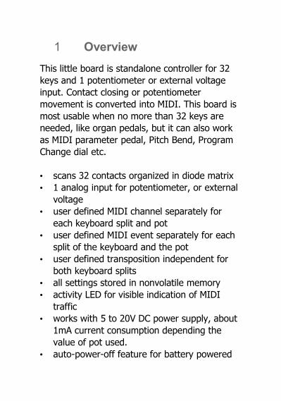
1 Overview
This little board is standalone controller for 32 keys and 1 potentiometer or external voltage input. Contact closing or potentiometer movement is converted into MIDI. This board is most usable when no more than 32 keys are needed, like organ pedals, but it can also work as MIDI parameter pedal, Pitch Bend, Program Change dial etc.
• scans 32 contacts organized in diode matrix• 1 analog input for potentiometer, or external
voltage• user defined MIDI channel separately for
each keyboard split and pot • user defined MIDI event separately for each
split of the keyboard and the pot • user defined transposition independent for
both keyboard splits • all settings stored in nonvolatile memory • activity LED for visible indication of MIDI
traffic• works with 5 to 20V DC power supply, about
1mA current consumption depending the value of pot used.
• auto-power-off feature for battery powered

system, years of standby operation on a single 9V battery or better – 4x AA.
2 Power supply
Recommended power supply range is between 5.5 and 12V DC. It is possible to run this board from lower voltage, but MIDI reception is not guaranteed then. Current consumption is about 1mA so it can be used with batteries for many hours. Connecting power in reverse will permanently damage the board, and will void the warranty. When using potentiometer, additional current will add to overall current drain. If e.g. 10k pot is used, current consumption will rise by 0.5mA. Potentiometer does not cause additional current draw when in power-off mode. Power input is located at the bottom, at 2 rectangular solder pads as shown above. Positive terminal (+) is closer to the edge, while negative terminal (-) is closer to 2 other similar looking rectangular pads. Use thin stranded wires to connect the power. This is delicate device and power pads may get damaged by soldering them multiple times. Try to do it right the first time.
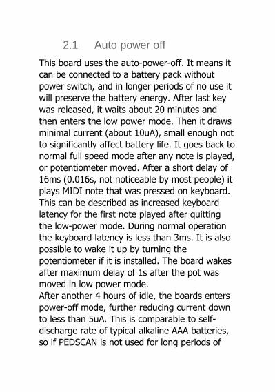
2.1 Auto power off
This board uses the auto-power-off. It means it can be connected to a battery pack without power switch, and in longer periods of no use it will preserve the battery energy. After last key was released, it waits about 20 minutes and then enters the low power mode. Then it draws minimal current (about 10uA), small enough not to significantly affect battery life. It goes back to normal full speed mode after any note is played, or potentiometer moved. After a short delay of 16ms (0.016s, not noticeable by most people) it plays MIDI note that was pressed on keyboard. This can be described as increased keyboard latency for the first note played after quitting the low-power mode. During normal operation the keyboard latency is less than 3ms. It is also possible to wake it up by turning the potentiometer if it is installed. The board wakes after maximum delay of 1s after the pot was moved in low power mode. After another 4 hours of idle, the boards enters power-off mode, further reducing current down to less than 5uA. This is comparable to self-discharge rate of typical alkaline AAA batteries, so if PEDSCAN is not used for long periods of

time, you don't need to bother taking the power off. In this state it does not react to potentiometer movement at all, and to wake it up you must play any note and keep the key pressed for at least half a second. A MIDI note will play, and PEDSCAN is fully up again.
3 Connecting keyboard
Keyboard switches are connected via diode matrix organized in 8 rows and 4 columns. The board itself is only a matrix driver and can be used with bare contact only if it's to be used as monophonic keyboard, or some kind of selector (like Program Change buttons). If the board will be used polyphonic, with possibility of more than 1 key pressed at any time, proper diode matrix is required, otherwise you'll get more notes on MIDI than you'd expect.

3.1 What is a "diode matrix"?
PEDSCAN can be used if the keyboard has “scanning diode matrix", that's special kind of very simple circuit, made of diodes forming electric XY array of 8 rows and 4 columns. It's easy to make the matrix on your own, if you know how to solder, and follow electrical schematic. It works best if it's built directly on contacts, then the overall length of wires used is the shortest. That also improves keyboard performance. The schematics on the right show compatible diode matrix. Wire numbers at the top (from 12 down to 1) must match the PEDSCAN board pinout.
4 Connecting potentiometer
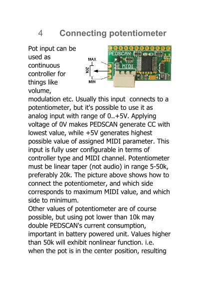
Pot input can be used as continuous controller for things like volume, modulation etc. Usually this input connects to a potentiometer, but it's possible to use it as analog input with range of 0..+5V. Applying voltage of 0V makes PEDSCAN generate CC with lowest value, while +5V generates highest possible value of assigned MIDI parameter. This input is fully user configurable in terms of controller type and MIDI channel. Potentiometer must be linear taper (not audio) in range 5-50k, preferably 20k. The picture above shows how to connect the potentiometer, and which side corresponds to maximum MIDI value, and which side to minimum.Other values of potentiometer are of course possible, but using pot lower than 10k may double PEDSCAN's current consumption, important in battery powered unit. Values higher than 50k will exhibit nonlinear function. i.e. when the pot is in the center position, resulting

MIDI parameter value will not be half of maximum, but slightly more. The bigger pot value, the more non-linear position/value behavior is apparent. Connections longer than 20cm must be made with shielded cable, just like you'd normally do with a microphone.
4.1 Analog input update rate
The analog input of PEDSCAN translates input voltages, or potentiometer position into MIDI. Actual pot position is updated via MIDI every time it changes. The update is however not immediate - this is common to any MIDI knob box. The fastest response for potentiometer movement is about 2.5ms. It means that when you constantly move the pot, PEDSCAN will update MIDI every 2.5ms. This is faster than enough for most of uses. In some instruments, either hardware, or virtual, some problem may occur when there is a lot of MIDI traffic. It is also sometimes desirable to limit MIDI traffic e.g. to minimize the size of MIDI file recorded on a sequencer. It is possible to change this setting using command "#98n", where "n" determines update rate according to the table

below. Default factory setting is 9.5ms. See chapter 5 for general info about using numeric commands.
setup sequence
#980
#981
#982
#983
#984
#985
#986
#987
#988
#989
minimum response [ms]
2.5 3.5 4.5 6.5 9.5 14 20 30 50 66
update rate [Hz]
400 290 220 150 105 70 50 33 20 15
4.2 Bit resolution of analog input
Usually all MIDI parameters have 128 possible levels, determined by 7 bit nature of standard MIDI values. In some cases it may be useful to reduce the number of possible levels, or in another words - number of information bits. In case you want to use MIDI channel rotary selector, described in chapter 5.2.10, it's better to reduce resolution to 4 bits, and have 16 levels in full pot rotation. In some software synthesizers you can select its parameters using only a fraction of the full CC range. And in organ emulators it's also desirable to have only a few steps in full pedal travel if used for crescendo.
Bit resolution is user adjustable in a similar way as update rate described above. It is done by using command #96x, where "x" is desired bit resolution. For example #967 makes the pot input 7-bits wide (128 levels), this is default mode of operation, and e.g. #963 turns it to 3-bit resolution, allowing for only 8 levels per full pot rotation.

5 MIDI settings and special functions
All settings are performed from connected keyboard. There is one special input on the board (2 pads marked on first page as SET/EDIT button input) for entering the EDIT mode, and all parameters can be changed then. In this manual EDIT button is referred as "#". To change any settings, you have to enter new value of given parameter. To do so, use lowest 10 keys of the keyboard as numeric entry. Lowest key is digit "0", while 10th key is digit "9". As a general rule, any change on a controller requires selecting this controller first before making change. For example, if you want to change MIDI channel of potentiometer, move it a bit, and go into MIDI channel settings mode. Or to change the split point – first play a note on the keyboard, and enter split-point change mode. It helps to add a sticker over lowest 10 keys with numbers if musical keyboard is used.In this chapter, describing how to set all parameters, whenever „#” sign is mentioned, it means the "SET/EDIT" key, connected to 2 pads at the bottom side of the board, marked "SET".
5.1 Transposition of keyboards
Transposition of keyboards connected to PEDSCAN is unlimited, that means any key can generate any MIDI note from range of over 10 octaves. There are two ways of using it. Typical one is by selecting “new middle C” position. First you have to select the keyboard by playing any note. Enter „#” then „1" on the keyboard. Now, whatever key you press, it will become the new position of the middle C MIDI note afterwards. You can select new position of middle C note anywhere between 3rd and top key of the keyboard.Another option is to use lowest 2 keys of the keyboard, or in another words numbers "0" and "1". It doesn't matter if keyboard starts with key C or F or whatever, those are always two lowest keys. The 1st one shifts the keyboard one semitone down with each sequence (#10), the 2nd shifts the keyboard one semitone up (#11). This is useful when you want to shift the keyboard in range not available by the first method. Both methods require first selecting the keyboard by playing a note, then entering "# 1", and selecting transposition.

5.2 MIDI event assignment for keyboard and analog input
MIDI event assigned to potentiometer or keyboard split can be easily changed. To perform this, turn a bit the knob, or play a key on the keyboard split you want to assign, and then select the controller type by entering # then 2 and then appropriate number from the list described later in this chapter. You need to enter 2 or 3 digits for each input controller depending on entered number. Possible MIDI event codes are from number 000 to 149. Standard setting for keyboard is: "# 2 131" - single notes, and for analog input: "# 2 007" - that's MIDI volume. This is factory default. Possible settings described as follows.
5.2.1 Control Change - #2 CC
where "CC" means any MIDI Control Change number in range from "000" till "127". Numbers above 127 are used to generate MIDI events other than Control Change, or turn them into other functions, what is described next.
5.2.2 Pitch Bend - #2128
The potentiometer will work then as pitch bender. If assigned to a keyboard, each key will set pitch bender in 1/128 steps across the keyboard. Range can be adjusted with transposition settings.
5.2.3 Program Change - #2129
Although this is rather unusual usage, pot will then generate MIDI Program Change messages with every move. Program Change can be also entered from the keyboard, by using sequence "# 4 <number>" – this is described in chapter 5.4. If assigned to a keyboard, pressing each key will generate MIDI Program Change message with different patch number. Starting number can be adjusted with transposition setting. This is useful for organ emulators, where bank of Program Change buttons can be used to work as pistons (sets of registers)
5.2.4 Channel After Touch - #2130
Turning pot will cause Channel After Touch messages to be sent out. If assigned to a
keyboard, each key will set After Touch in 1/128 steps across the keyboard. Range can be adjusted with transposition settings.
5.2.5 Standard keyboard action – single notes - #2131
Whenever MIDI event 131 is assigned to a keyboard, it works as typical MIDI keyboard, playing MIDI notes. It is also possible to generate notes played in glissando, when this event is assigned to a pot. Select the pot to be edited, enter "# 2 131". This knob becomes then a note generator resembling quantized Theremin. Move the knob and a series of notes will be played. There's only one note played at a time (with velocity set like described later) and it is released just before new note is about to play. Whole knob slow rotation plays 128 notes from entire MIDI range.
5.2.6 Note on - #2132
This mode is somehow similar to the mode described above, but only "note-on" messages are generated, that means whenever you move this pot, new notes will be played, and they will stay on forever unless proper note-off message
will be issued by another means. If assigned to a keyboard, only note-on messages will be sent. It will work like with constantly depressed sustain pedal.
5.2.7 Note off - #2133
This is like "note-on" mode described above, but instead it sends out only note-off messages. It can be used to mute part of notes already played, or as some kind of panic button – slow full rotation mutes all notes in assigned channel. If assigned to a keyboard, it will send only note-offs, so it may be used to quiet some notes played earlier.
5.2.8 One-touch Patch Recall - #2134
Keyboard in this mode serves as an array of favorite patches buttons. Each key recalls Program Change (or in another words - selects a patch/preset) that was earlier programmed. There's 32 memory locations, as many as keys. For example you can program key 1 to send Program Change 37, key 2 as PC#76, key 3 as PC#20 etc. Assigning Program Change numbers to a specific key is described in paragraph 6.6 - Favorite Patches.
5.2.9 CC keyboard - #2135
This feature has no effect on a pot, i.e. the pot will not send any MIDI if it has been assigned this way. For keyboard in this mode you can use contacts as toggle switches selecting min/max values of range of CCs. All keys have assigned increasing numbers of MIDI Continuous Controller. Pressed key sends CC with max value (127), while key release generates the same CC but with minimum value (0). CCs are ordered just like there would be MIDI notes, i.e. typically they start from CC#36 at the lowest key, next key is CC#37 etc. Use transposition settings to set different starting CC.
5.2.10 MIDI channel selector for all controls - #2136
To use this feature with potentiometer you should first reduce its resolution to 4 or less bits (see chapter 4.2). In case of keyboard, first 16 keys work like MIDI channel selector for all controllers. After one of the keys is hit, notes played on the other split are played on changed channel. Individual channel settings for every keyboard split and potentiometer described in chapter 5.3 work together with this setting. For
example if one split was set to channel 3, and you change the channel using this feature to +4 (by hitting 5th key), resulting channel is 7 (3+4). If all controllers are set to channel 1, then all 16 keys assigned to this feature are direct channel selectors from 1 to 16.
5.2.11 Small Transposer - #2137
Select the pot, enter "# 2 137". Turning pot will shift all notes played on both splits by number of semitones determined by pot position. In the middle it gives no shift, and full rotation has range from -4 to +4 semitones. It's most useful when pot is replaced by 9-position switch with 8 resistors of equal value connected between switch leads. Assigning this to a keyboard is unusable.
5.2.12 Big Transposer - #2138
Turning pot will shift all notes played on both splits by number of semitones determined by pot position. In the middle it gives no shift, and full rotation has range from -8 to +8 semitones. Assigning this to a keyboard is unusable.

5.2.13 Velocity - #2139
Position of the pot in this mode determines velocity parameter of all MIDI notes generated by this board. If assigned to a keyboard, each key will set velocity of all notes in 1/128 steps across the keyboard. Range can be adjusted with transposition settings.
5.2.14 Native Instruments B4 chorus/vibrato - #2140
Position of this pot will be then reflected in B4 as "chorus/vibrato" switch position. It has only 6 positions, and appropriate command will be sent to B4 every time the potentiometer crosses each position representing another switch position.
5.2.15 MidiTzer stops control - #2141When assigned to a keyboard, each key becomes specific stop controller. When a key is pressed, MIDI controller 81 (51H) is sent, and when it is released, MIDI controller 80 (50H). Value of the controller is determined by the button pressed. This is default way of controlling stops in MidiTzer organ software.
5.2.16 Ahlborn Archive module stops control - #2142
When assigned to a keyboard, each key becomes specific stop controller in Ahlborn Archive organ sound-module. When a key is pressed, MIDI controller 73 (49H) is sent, and when it is released, MIDI controller 74 (4AH). Value of the controller is determined by the button pressed. This is default way of controlling stops in Ahlborn Archive module.
5.2.17 Ahlborn Organs stops control - #2143
When assigned to a keyboard, each key becomes specific stop controller in Ahlborn Organs. When a key is pressed, MIDI controller 70 (46H) is sent with bit 6 of the value set, and when it is released, the same MIDI controller but with bit 6 of the value cleared. Other bits of the value are determined by the button pressed. In another words, pressing the button sends CC 70 with value range 0-63, and releasing a button - CC 70 with value range 64-127. This is default way of controlling stops in Ahlborn Organs.

5.2.18 Ahlborn Common Functions - #2146
This is yet another mode customized for Ahlborn sound modules. It is useful for common functions, namely: general cancel, tutti, reeds cancel, etc. It sends MIDI controller 71 (47H) with value determining what Ahlborn parameter is changed, and if it is on or off, according to Ahlborn Archive modules MIDI implementation.
5.2.19 One time Velocity setup - #2149
This is similar to velocity settings described in 6.2.13, but in addition, it saves last used velocity settings in nonvolatile memory. This should be used only during installation, when you want to set default velocity of notes after each power up. For expression and frequent usage, control the velocity by assigning #2139 instead.
5.3 MIDI Channel
Channel of each keyboard split and potentiometer can be set individually. To change MIDI channel of the potentiometer select it by simply turning a bit. Then select the MIDI channel with the following sequence: "# 3 <channel number>". The channel number must be in range 1-16. Channels from 2 to 9 require only 1 key stroke, while 1 needs to be entered as 2 digits – namely "01". Channel 10 and above of course need 2 keystrokes too. To change MIDI channel of the keyboard, first select it by playing a note, and enter mentioned sequence with channel number.
5.4 Program Change
This device allows to send Program Change MIDI messages, or in another words – change patches. Three ways are available. Two were mentioned in Knob Assignment chapter, where you could program the potentiometer to act like 128-position patch rotary switch, or use keyboard assigned to Program Change to have an array of single touch patch select buttons.

To change the patch/program on the keyboard directly to specific number, play any note and enter the sequence: "# 4 <program number>". The Program Change MIDI message is sent directly after last digit of entered patch number. This may happen after 2nd or 3rd digit. You only need to enter 2 digit, when the patch number is in range 13-99. Programs lower than 13 require 3 digits, with 0s in front, for example 012, or 003. Obviously, programs with numbers higher than 99 also need 3 digits. The range of Program Change is from 000 to 127.
5.5 Keyboard split
It is possible to split keyboard into 2 independent parts. The split point can be anywhere on the keyboard, and both parts can work with independently adjusted MIDI channel, type of event and starting note (transposition) or range of other controllers if something else than notes is assigned to a keyboard. To set up the split point, you have to select the keyboard by playing a note in it, and then enter sequence „# 5” followed by stroke of the key that you want to be the last one of the lower part.

Since then lower part remains on the same channel that was used for whole keyboard, while upper part takes new settings, which by default is 1 MIDI channel higher. To change MIDI channel, type of event, transposition, or send a Program Change for split part, follow directions described before, regarding non-split keyboard, but now changes are made to this split part, which was selected by playing a note prior entering the edit mode (pressing „SET”).
5.6 Favorite patches: one-touch-patch-recall programming
Whenever a MIDI program/patch/instrument selected from this controller is often used, it is worth to memorize for fast recall in the future. There can be 32 such favorite patches, selected for each key in PEDSCAN matrix. To select a patch, first you need to turn the keyboard in "one-touch patch recall" mode, described in chapter 5.2.8. Then each contact of the keyboard becomes a patch select button. To memorize any patch for recall in this way, you have to first select this patch in any way
possible – either by entering „# 4 <patch number>”, or by turning „Program Change” knob if one is assigned. Then simply press "# 6", followed by the key where the patch should be stored and it's done. Next time whenever you press that key you just programmed, the MIDI Program Change message will be sent, setting the patch number that was programmed into that switch.It is more logical to set a split first, to have a number of notes, and the rest as Program Change buttons. For example to have 13 keys and 19 Program Changes, use the following commands: #5, 13th key, then any key in top split, followed by #2134 (chapter 5.2.8.). Then you may select the MIDI channel for Program Change split by using #3 and channel number (chapter 5.3.) e.g #301 for channel 1, the same as default channel of the notes in lower split.
MIDECO board described here is a product of:"MIDI-hardware" Roman Sowa, ul. Azotowa 15B, 41-503 Chorzów, Polandphone +48 532 425 835, email [email protected]© 2016, Roman Sowa made in Poland, EU