Standalone DVR Quick Start Guide - ASMnet! -...
84
Network Video Alarm Controller User’s Manual
Transcript of Standalone DVR Quick Start Guide - ASMnet! -...
Network Video Alarm Controller User’s Manual
Version 1.0.0

Table of Contents1 FEATURES AND SPECIFICATIONS.......................................................................1
1.1 Overview........................................................................................................11.2 Features.........................................................................................................11.3 System Composition......................................................................................1
2 INSTALLATION........................................................................................................32.1 Device Appearance........................................................................................32.2 Battery and HDD Installation..........................................................................32.3 Wall Mount.....................................................................................................42.4 Wiring.............................................................................................................5
3 WEB Login and Logout..........................................................................................103.1 Login............................................................................................................103.2 Logout..........................................................................................................10
4 Arm/Disarm............................................................................................................114.1 Arm/Disarm..................................................................................................11
5 Parameter Configuration........................................................................................155.1 Add and Delete Wireless Device..................................................................155.2 Zone Config.................................................................................................155.3 Emergency Alarm Config.............................................................................185.4 Siren and Alarm Output Config....................................................................195.5 Failure Config...............................................................................................215.6 Video Alarm Config......................................................................................225.7 Event Report Config.....................................................................................245.8 Network Config............................................................................................265.9 Camera Config.............................................................................................385.10 Storage Config...........................................................................................435.11 System Configuration.................................................................................465.12 User Management.....................................................................................52
6 Channel Live Preview............................................................................................556.1 Live Preview.................................................................................................556.2 Monitor Window...........................................................................................556.3 Display Mode...............................................................................................566.4 Playback......................................................................................................57
7 Record Playback and Process...............................................................................597.1 Playback Interface.......................................................................................597.2 Playback Record..........................................................................................607.3 Cut and Save Record...................................................................................607.4 File List.........................................................................................................60
8 View Event Info......................................................................................................638.1 View Overall Status Info...............................................................................638.2 View Zone Event Info...................................................................................638.3 View Channel Event Info..............................................................................648.4 View Local Status Info..................................................................................64
9 View WEB Info.......................................................................................................669.1 Version.........................................................................................................66
i
9.2 Log...............................................................................................................669.3 Online User..................................................................................................669.4 HDD Info......................................................................................................67
ii
WelcomeThank you for purchasing our network video alarm controller!This quick start guide will help you become familiar with our network video alarm controller in a very short time.Before installation and operation, please read the following safeguard and warning carefully!
Important Safeguard and Warning
1.Electrical safety
All installation and operation here should conform to your local electrical safety codes. The product must be grounded to reduce the risk of electric shock.We assume no liability or responsibility for all the fires or electric shock caused by improper handling or installation.
2.Transportation security
Heavy stress, violent vibration or water splash are not allowed during transportation, storage and installation.
3.Installation
Keep upwards. Handle with care. Do not apply power to the alarm controller before completing installation. Do not place objects on the alarm controller.
4.Qualified engineers needed
All the examination and repair work should be done by the qualified service engineers. We are not liable for any problems caused by unauthorized modifications or attempted repair.
5.Environment
The alarm controller should be installed in a cool, dry place away from direct sunlight, inflammable, explosive substances and etc.This series product shall be transported, storage and used in the environment ranging from -10 to 55 .℃ ℃
6. AccessoriesBe sure to use all the accessories recommended by manufacturer.Before installation, please open the package and check all the components are included.Contact your local retailer ASAP if something is broken in your package.
Before Start
About Alarm System
i

For the alarm system consists of the network alarm controller, though it has stable and reliable performance, it may become null in the following situations: The protection zone the intruder entering has not enabled the arm function or the intruder
has enough knowledge to disable the system. The siren device installation position is not right; it does not have the warning function. The detector is null when there is an alarm outage and etc. The detector is not in the proper position and can not detect the corresponding zone. System can not generate an alarm when there is something wrong with the alarm signal
transmission system (the service is disabled, there is malicious attack and etc). The device is null resulting from non-schedule maintenance of the alarm system. About Installation Notice The installation engineers are recommended to check the system regularly such as once a
month. It is to guarantee system long-term stable operation. The installation engineers are recommended to test the system regularly such as once a
week. Please arrange some training classes for the end-user. It is to keep them familiar with the
system. System Test Notice After the installation, you can connect to the AC/DC power to test. You can test the all functions of the alarm controller after you complete all programming
work.
ii
1 Features and Specifications
1.1 OverviewThis series product integrates on-off alarm input and output, and video processing as one multi-functional video alarm controller. It supports protection zone alarm, wireless remote arm/disarm, keyboard arm/disarm, emergency alarm, video preview authority management, alarm can trigger pop-up video for you to recheck, video alarm and etc. It can be used in many environments such as bank, school, store, residential district. It can perfectly work with the alarm and surveillance solutions when there is an alarm operation and management platform.
1.2 FeaturesThis series product has the following features: 8-channel on-off alarm input. 1-ch relay output and 8-ch extensible output 1-channel siren (DC12V 500MA) output. 433M wireless module, max support 32 wireless sensor and 16 wireless remote control. PSTN module, and support PSTN anti-cut detection. Main power down detection, detection of battery in place, down and voltage low. 1-ch audio input, 1-ch talk input and audio input reuse, 1-ch audio output and talk output
reuse. 4-ch HDCVI input and 1-ch VGA output. 2-ch RS485, 1-ch extension alarm output, 1-ch alarm programming keyboard. Alarm event and failure event record up to 1024, adopts CID format, other logs up to 512. 100 web users, 23 keyboard users, 3-level right management: installer, operator and user. Video motion detection, video loss, video tampering intelligent analysis. 720P/D1/HD1/2CIF/CIF and more resolutions, frame rate and bit stream may be
customized. 1-ch USB and 1-ch HDD port. Three data transmission methods: network, 3G and telephone wire. WEB operation and AOMS alarm platform.
1.3 System CompositionNetwork Video Alarm Controller and camera, detector, keyboard, siren, audio device, PSTN and monitor, WEB client form a comprehensive linkage alarm system. The system basic connection figure is in Figure 1- 1.
1
Figure 1- 1
2
2 Installation
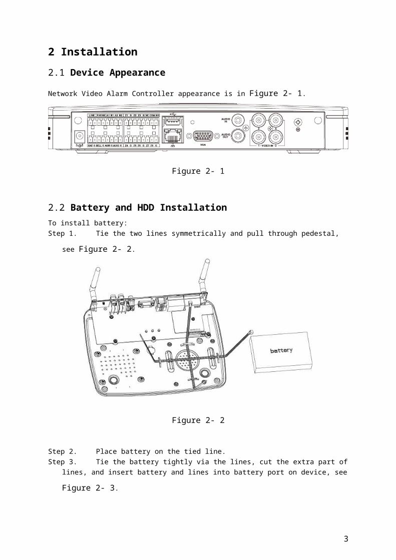
2.1 Device AppearanceNetwork Video Alarm Controller appearance is in Figure 2- 1.
Figure 2- 1
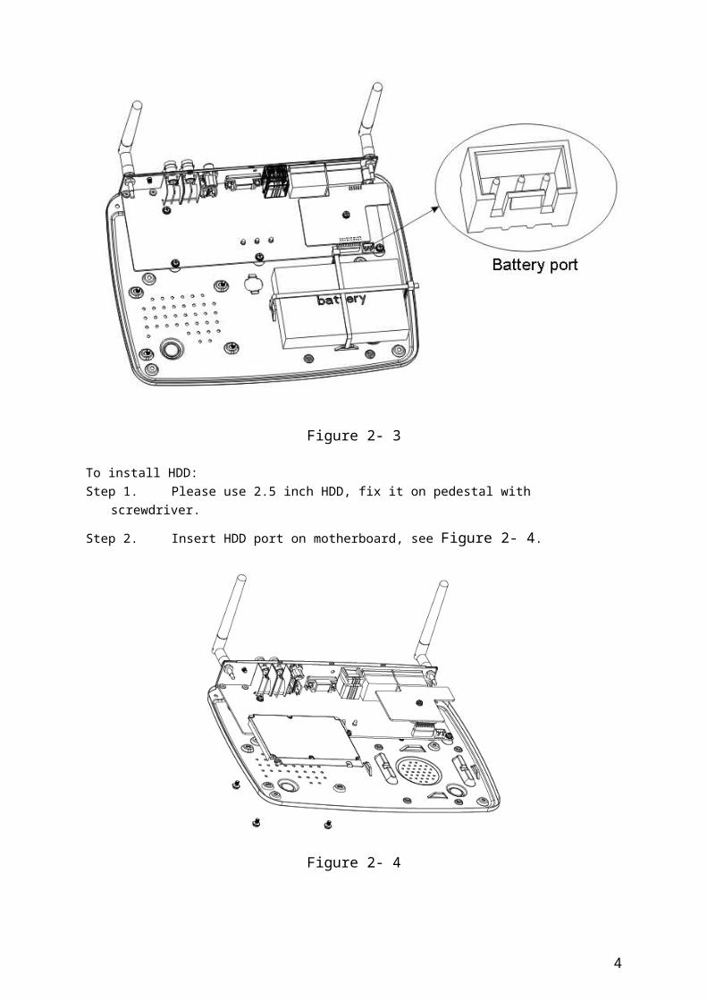
2.2 Battery and HDD InstallationTo install battery:Step 1. Tie the two lines symmetrically and pull through pedestal, see Figure 2- 2.
Figure 2- 2
Step 2. Place battery on the tied line.Step 3. Tie the battery tightly via the lines, cut the extra part of lines, and insert battery and lines
into battery port on device, see Figure 2- 3.
3
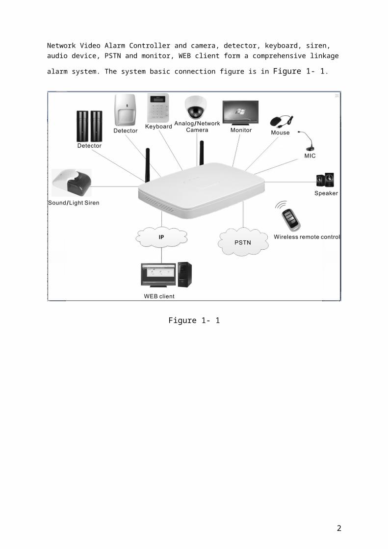
Figure 2- 3
To install HDD:Step 1. Please use 2.5 inch HDD, fix it on pedestal with screwdriver. Step 2. Insert HDD port on motherboard, see Figure 2- 4.
Figure 2- 4
2.3 Wall MountThe device supports wall mount and desktop placement. To mount on wall:Step 1. Open device package, take out plastic expansion bolt and self-tapping screw.
4
Step 2. Dig two holes on wall with distance of 184mm in between. Insert the plastic expansion bolt and fasten self-tapping screw.
Step 3. Hand the device on the screw.
Figure 2- 5
2.4 Wiring2.4.1 Port
Figure 2- 6
No. Name Note
Power port 14.5V power supply
Battery portConnect to 12V DC 7AH , lead-acid battery
Siren port Connect to siren
AUX power output AUX1 connect to 12V 1A AUX
5
No. Name Note
power;AUX2 connect to 12V 500mA AUX power, used for detector or alarm keyboard power supply
Sensor port Support 5-ch sensor connection
LAN Ethernet port
VGA port Connect to VGA display
Audio output port RCA audio output, talk output
Video input port 4-ch video input
GND Grounding
Audio input port 4-ch audio input
USB port Mouse
Alarm output port 1-ch relay output
Sensor port 3-ch sensor connection
RS485 portA1B1 to alarm programming keyboardA2B2 to extension alarm output
Telephone port To user phone
User line port To resident phone line
2.4.2 Remote Control KeySee Figure 2- 7.
6
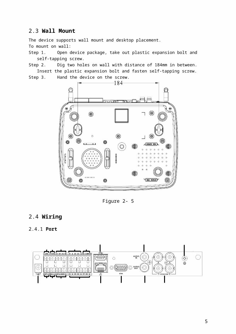
Figure 2- 7
Note: Press all arm button, after indicator is OFF immediately press emergency alarm button, to
out alarm. Press home arm button, after indicator is OFF immediately press emergency alarm button,
to instantly arm.
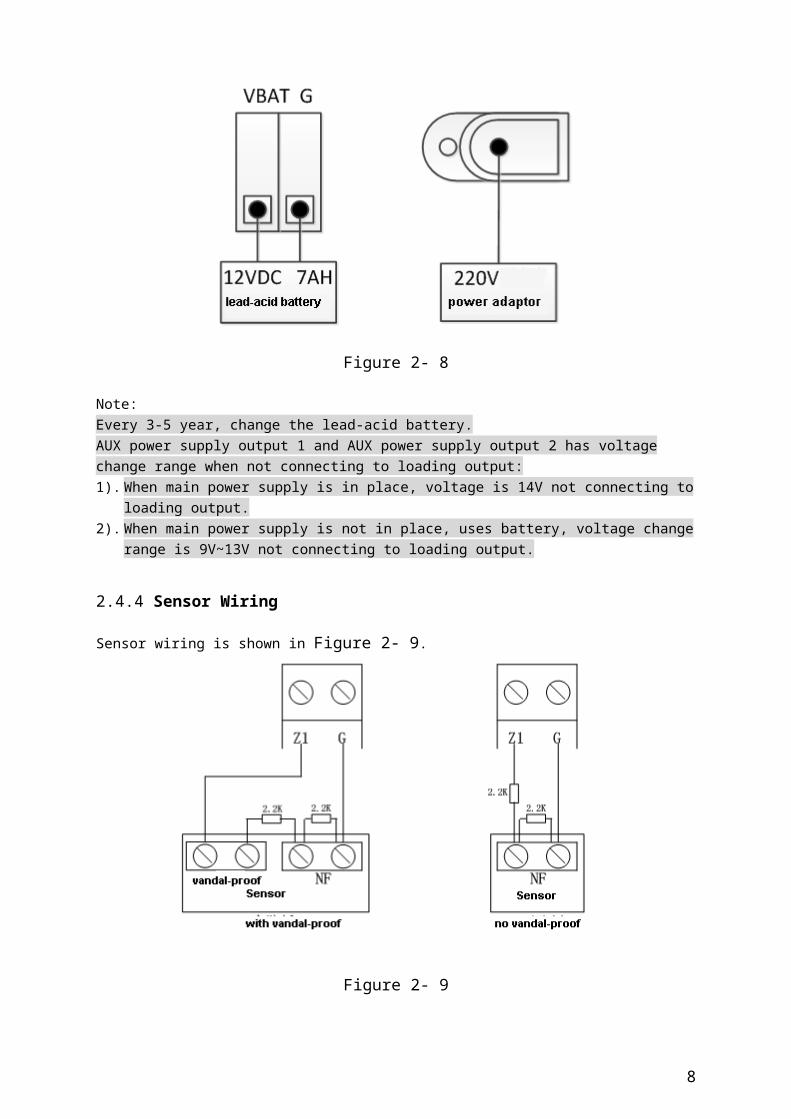
2.4.3 Power LineBattery and DC power supply wirings are shown in Figure 2- 8.
7
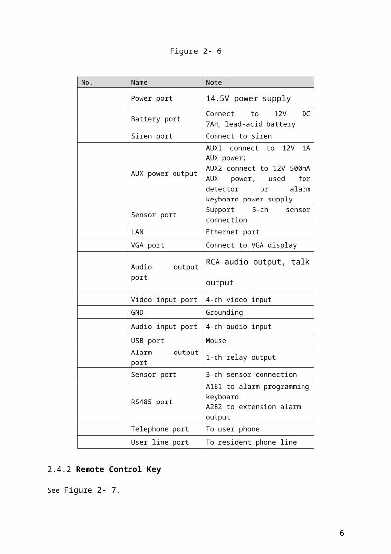
Figure 2- 8
Note:Every 3-5 year, change the lead-acid battery. AUX power supply output 1 and AUX power supply output 2 has voltage change range when not connecting to loading output:1). When main power supply is in place, voltage is 14V not connecting to loading output. 2). When main power supply is not in place, uses battery, voltage change range is 9V~13V not
connecting to loading output.
2.4.4 Sensor WiringSensor wiring is shown in Figure 2- 9.
Figure 2- 9
Note:Tail wire resistance is connection close to sensor end. Before arming, you must configure sensor type in zone setup, as NO and NC, see Ch 4.3.1.
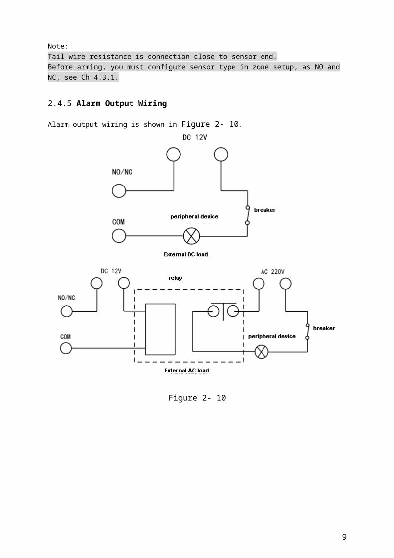
2.4.5 Alarm Output WiringAlarm output wiring is shown in Figure 2- 10.
8
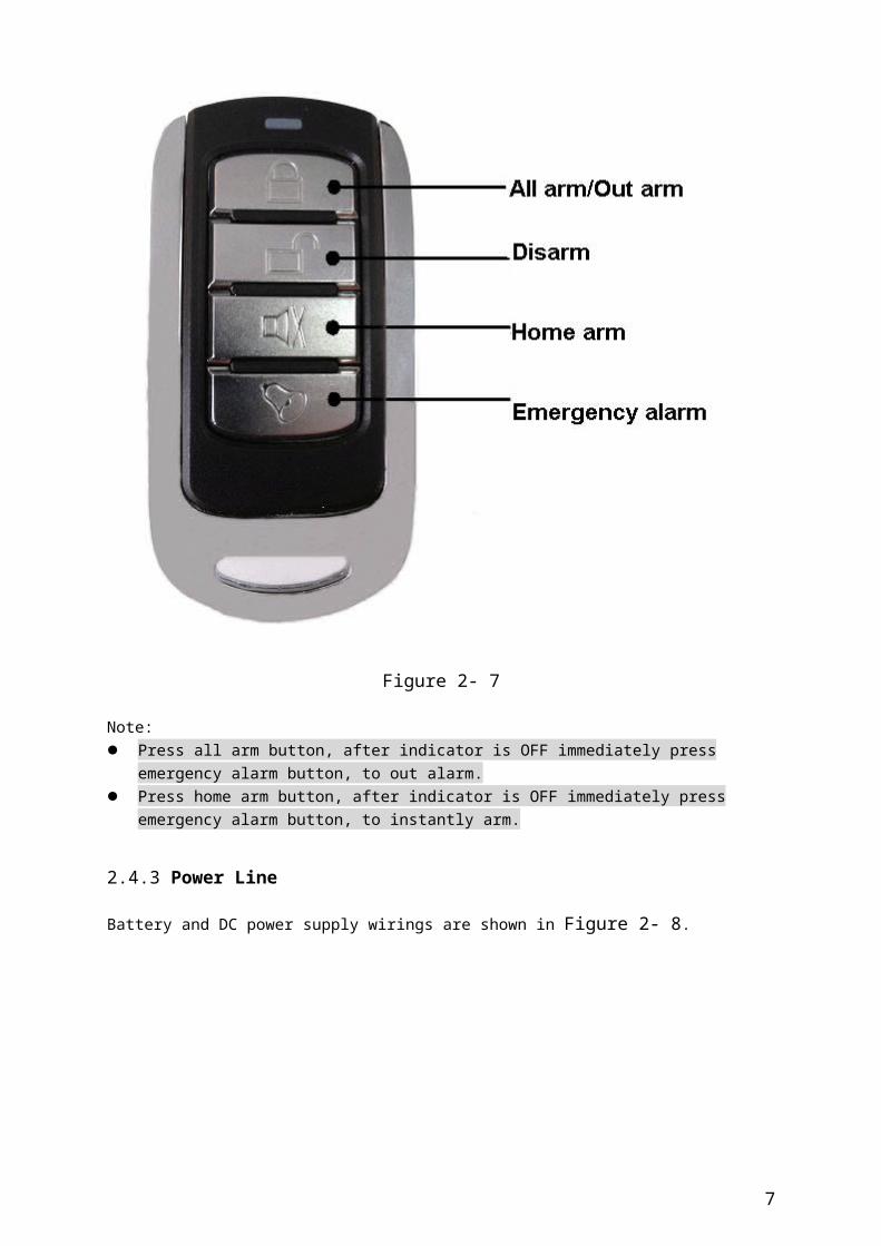
Figure 2- 10
9
3 WEB Login and Logout
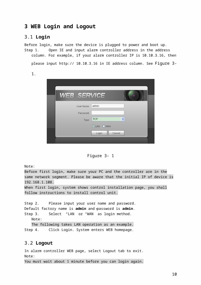
3.1 Login Before login, make sure the device is plugged to power and boot up.Step 1. Open IE and input alarm controller address in the address column. For example, if your
alarm controller IP is 10.10.3.16, then please input http:// 10.10.3.16 in IE address column. See Figure 3- 1.
Figure 3- 1
Note:Before first login, make sure your PC and the controller are in the same network segment. Please be aware that the initial IP of device is 192.168.1.108.When first login, system shows control installation page, you shall follow instructions to install control unit.
Step 2. Please input your user name and password. Default factory name is admin and password is admin. Step 3. Select “LAN” or “WAN” as login method.
Note:The following takes LAN operation as an example.
Step 4. Click Login. System enters WEB homepage.
3.2 LogoutIn alarm controller WEB page, select Logout tab to exit. Note:You must wait about 1 minute before you can login again.
10
4 Arm/Disarm
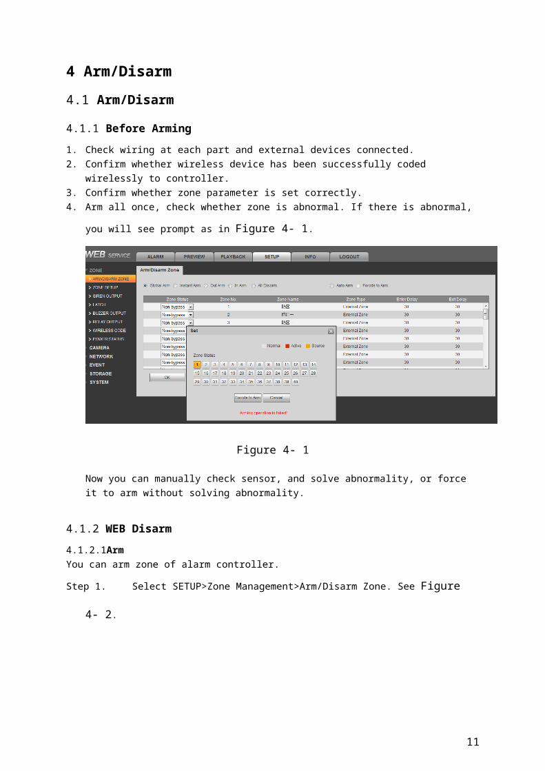
4.1 Arm/Disarm4.1.1 Before Arming1. Check wiring at each part and external devices connected. 2. Confirm whether wireless device has been successfully coded wirelessly to controller. 3. Confirm whether zone parameter is set correctly.4. Arm all once, check whether zone is abnormal. If there is abnormal, you will see prompt as
in Figure 4- 1.
Figure 4- 1
Now you can manually check sensor, and solve abnormality, or force it to arm without solving abnormality.
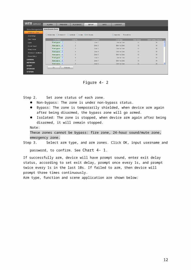
4.1.2 WEB Disarm4.1.2.1ArmYou can arm zone of alarm controller. Step 1. Select SETUP>Zone Management>Arm/Disarm Zone. See Figure 4- 2.
Figure 4- 2
11
Step 2. Set zone status of each zone. Non-bypass: The zone is under non-bypass status. Bypass: The zone is temporarily shielded, when device arm again after being disarmed,
the bypass zone will go armed. Isolated: The zone is stopped, when device arm again after being disarmed, it will
remain stopped. Note:These zones cannot be bypass: fire zone, 24-hour sound/mute zone, emergency zone.
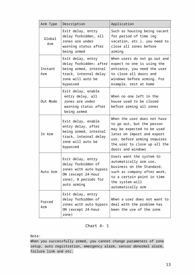
Step 3. Select arm type, and arm zones. Click OK, input username and password, to confirm. See Chart 4- 1.
If successfully arm, device will have prompt sound, enter exit delay status, according to set exit delay, prompt once every 1s, and prompt twice every 1s in the last 10s. If failed to arm, then device will prompt three times continuously. Arm type, function and scene application are shown below:
Arm Type Description Application
Global Arm
Exit delay, entry delay forbidden, all zones are under warning status after being armed
Such as housing being vacant for period of time (eg vacation, etc.), you need to close all zones before arming
Instant Arm
Exit delay, entry delay forbidden; after being armed, internal track, internal delay zone will auto be bypassed
When users do not go out and expect no one is using the entrance, you need the user to close all doors and windows before arming. For example, rest at home
Out ModeExit delay, enable entry delay, all zones are under warning status after being armed
When no one left in the house used to be closed before arming all zones
In Arm
Exit delay, enable entry delay, after being armed, internal track, internal delay zone will auto be bypassed
When the user does not have to go out, but the person may be expected to be used later on import and export use, before arming requires the user to close up all the doors and windows
Auto Arm
Exit delay, entry delay forbidden of zones with auto bypass ON (except 24-hour zone), 8 periods for auto arming
Users want the system to automatically arm use, business on the Standard, such as company after work, to a certain point in time the system will automatically arm
Forced Arm
Exit delay, entry delay forbidden of zones with auto bypass ON (except 24-hour zone)
When a user does not want to deal with the problem has been the use of the zone
Chart 4- 1
12
Note:When you successfully armed, you cannot change parameters of zone setup, auto registration, emergency alarm, sensor abnormal alarm, failure link and etc.
4.1.2.2 DisarmYou can disarm arming of alarm controller. Step 1. Select SETUP>Zone Management>Arm/Disarm Zone. Step 2. Set zone type to Global Arm, click OK. Input username and password, confirm. Device
has two tone prompt as successfully disarmed.
4.1.3 Alarm Program Keyboard Arm/Disarm4.1.3.1ArmVia keyboard, arm the zone, alarm controller will response alarm signal in the zone.
Step 1. Press key, to next level menu.
Step 2. By pressing or , select arm/disarm, press .
Step 3. By pressing or , select arm, press .
Step 4. Input arm type no., press key.
Note:1 Global arm2 Instant arm3 Out arm
4 In arm
Step 5. Input main user password, press key.
If successfully arm, device buzzer has tone prompt, and enter exit delay status, according to set exit dekay, buzzer once per 1s, and buzzer twice per 1s for last 10s. If failed, then dvice will buzzer three times continuously.
Quick Arm: In keyboard homepage, input user password, device has tone prompt, and enter exit delay status, according to set exit dekay, buzzer once per 1s, and buzzer twice per 1s for last 10s. If failed, then dvice will buzzer three times continuously.Note:Quick arm will only arm globally.
4.1.3.2Disarm
Step 1. Press key, to next level menu.
Step 2. By pressing or , select arm/disarm, press .
Step 3. By pressing or , select arm, press .
13
Step 4. Input user password, press .
Device has buzzer for twice, means successfully arm. Quick Arm: In keyboard homepage, input user password, device has buzzer, means successfully arm.
4.1.4 Wireless Remote Control Disarm4.1.4.1ArmVia wireless remote control to arm the zone, alarm controller will response alarm signal in the zone. Step 1. Press arm key on wireless remote control. Step 2. Alarm controller has tone prompt, as successfully armed, enter exit count down status,
according to set exit delay, beep once every 1s, and beep twice every 1s during the last 10s; if failed to arm, device will have tone prompt 3 times.
Note:Wireless remote control must successfully coded before arming/disarming. Press all arm button, after indicator is OFF immediately press emergency alarm button, to out alarm. Press home arm button, after indicator is OFF immediately press emergency alarm button, to instantly arm.
4.1.4.2DisarmUnder arming status, press disarm key on wireless remote control, device beeps twice, as successfully disarmed.
14
5 Parameter Configuration
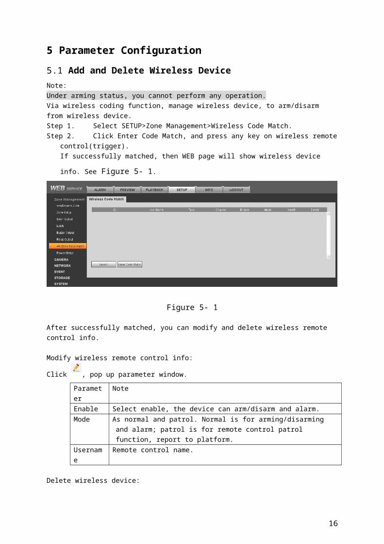
5.1 Add and Delete Wireless Device Note:Under arming status, you cannot perform any operation.Via wireless coding function, manage wireless device, to arm/disarm from wireless device. Step 1. Select SETUP>Zone Management>Wireless Code Match. Step 2. Click Enter Code Match, and press any key on wireless remote control(trigger).
If successfully matched, then WEB page will show wireless device info. See Figure 5- 1.
Figure 5- 1
After successfully matched, you can modify and delete wireless remote control info.
Modify wireless remote control info:
Click , pop up parameter window.
Parameter NoteEnable Select enable, the device can arm/disarm and alarm. Mode As normal and patrol. Normal is for arming/disarming and alarm; patrol is
for remote control patrol function, report to platform. Username Remote control name.
Delete wireless device:
Click , and confirm, delete the wireless remote control from system, as you cannot
arm/disarm or alarm.
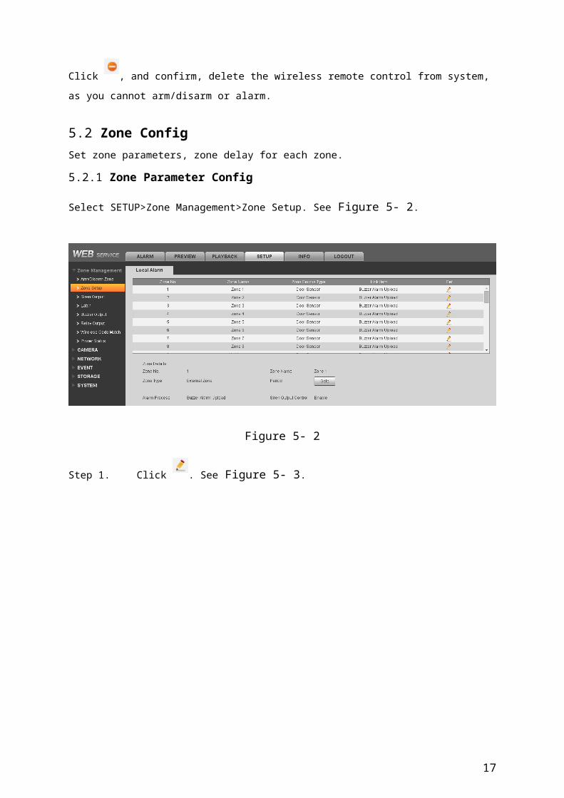
5.2 Zone ConfigSet zone parameters, zone delay for each zone.5.2.1 Zone Parameter ConfigSelect SETUP>Zone Management>Zone Setup. See Figure 5- 2.
15
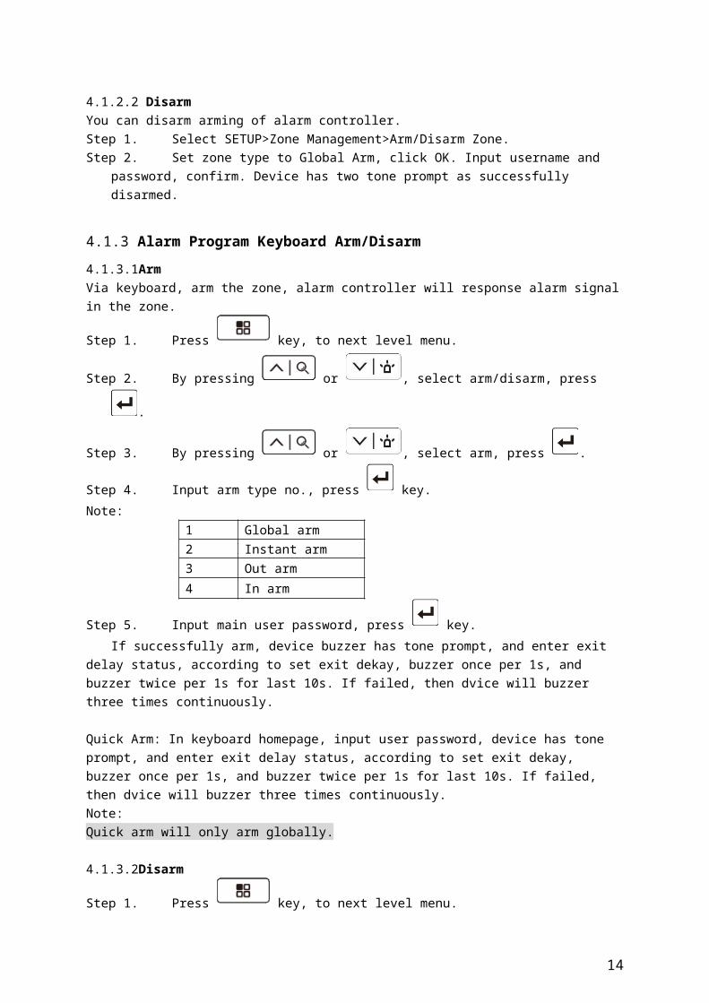
Figure 5- 2
Step 1. Click . See Figure 5- 3.
Figure 5- 3
Parameter Note
Enable alarm input
Alarm input channel, as zone no.
Alarm Name Customize zone name. Zone Type Click setup, select zone type (see below), and zone source type. Arm/Disarm Period
Click setup, in dropdown list, select day, set period.
16
Parameter Note
Device Type NO and NC, set according to device.Record Channel Select corresponding record channel no., can re-select. When alarm occurs,
system turns on corresponding channel to record. Record Delay Set delay, when alarm ends, alarm record will continue for a certain period. Alarm Output Alarm link output channelSnapshot When alarm occurs, trigger and snapshot the selected channelAlarm Upload Upload alarm infoBuzzer When alarm, enable buzzer to alarmSMS When alarm, send SMS to set numberAudio Play When abnormality occurs, play the selected audio fileSiren Output Control
When alarm occurs, enable siren.
Call Center When alarm occurs, report to call center.
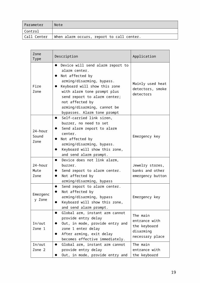
Zone Type Description Application
Fire Zone
Device will send alarm report to alarm center.
Not affected by arming/disarming, bypass. Keyboard will show this zone with alarm
tone prompt plus send report to alarm center; not affected by arming/disarming, cannot be bypasses. Alarm tone prompt
Mainly used heat detectors, smoke detectors
24-hour Sound Zone
Self-carried link siren, buzzer, no need to set
Send alarm report to alarm center. Not affected by arming/disarming, bypass. Keyboard will show this zone, and send
alarm prompt.
Emergency key
24-hour Mute Zone
Device does not link alarm, buzzer. Send report to alarm center. Not affected by arming/disarming, bypass
Jewelry stores, banks and other emergency button
Emergency Zone
Send report to alarm center. Not affected by arming/disarming, bypass Keyboard will show this zone, and send
alarm prompt.
Emergency key
In/out Zone 1
Global arm, instant arm cannot provide entry delay
Out, in mode, provide entry and zone 1 enter delay
After arming, exit delay becomes effective immediately.
The main entrance with the keyboard disarming necessary place
In/out Zone Global arm, instant arm cannot provide The main entrance
17
Zone Type Description Application
2
entry delay Out, in mode, provide entry and zone 2
enter delay After arming, exit delay becomes effective
immediately.
with the keyboard disarming necessary place
Internal Zone
In arm and instant arm, internal zone will be bypassed.
When out arm, provide entry zone 1 entry delay and exit delay.
Global arm, no entry delay, but has exit delay.
Hall, lounge detectors can be installed indoors
External Zone
After arming takes effect, no entry or exit delay to trigger alarm.
Windows, fences, gates and other outdoor periphery
Step 2. Depends on condition, config parameter. Click OK to save.
5.2.2 Zone Delay ConfigSystem provides entry zone 1 entry delay, entry zone 2 entry delay and exit delay setup. Entry zone 1 entry delay is for entry of zone 1 and internal zone. Entry zone 2 entry delay is for entry of zone 2. Entry delay: If entry delay time is set to 10s, after user set arming, delay zone arming will take effect in 10s. Exit delay: If exit delay time is set to 10s, after delay zone alarm is triggered, user has 10s to disarm. If user successfully disarms within 10s, it will not link to alarm. If user fails to disarm within 10s, it will link to alarm.
Step 1. Select SETUP>Zone Management>Latch. See Figure 5- 4.
Figure 5- 4
Step 2. Input entry delay and exit delay time, click OK to save.
18
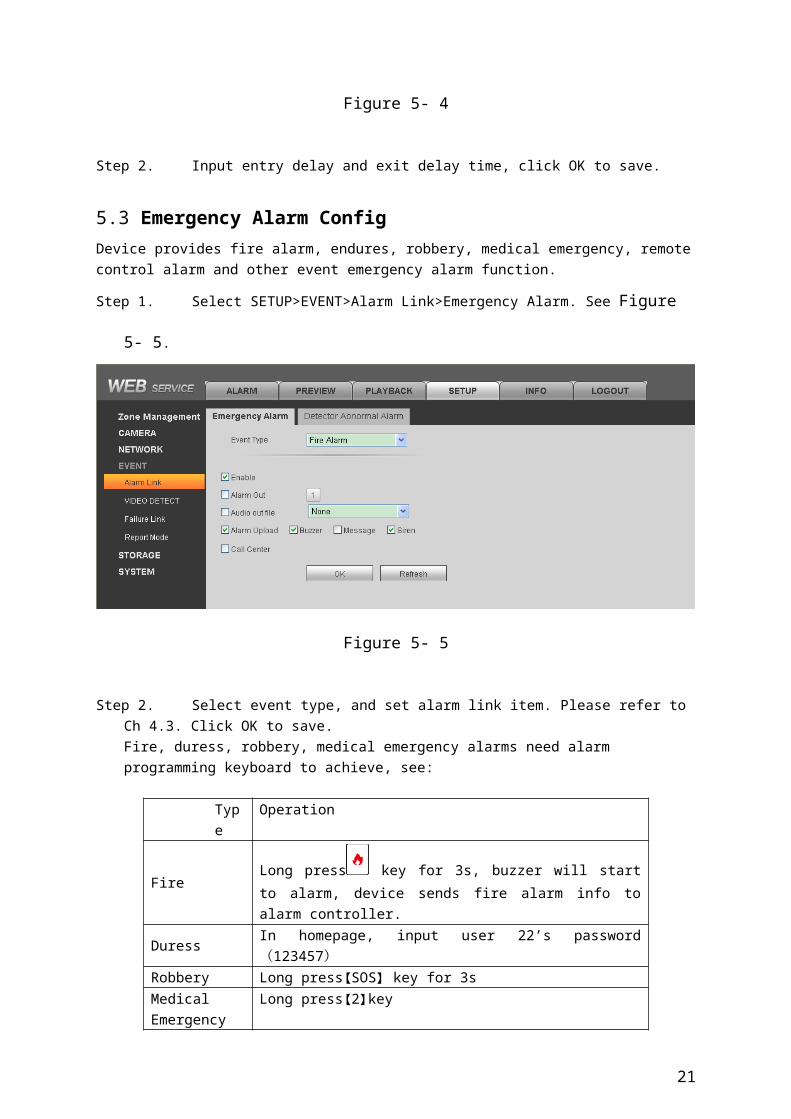
5.3 Emergency Alarm ConfigDevice provides fire alarm, endures, robbery, medical emergency, remote control alarm and other event emergency alarm function. Step 1. Select SETUP>EVENT>Alarm Link>Emergency Alarm. See Figure 5- 5.
Figure 5- 5
Step 2. Select event type, and set alarm link item. Please refer to Ch 4.3. Click OK to save. Fire, duress, robbery, medical emergency alarms need alarm programming keyboard to achieve, see:
Type
Operation
Fire Long press key for 3s, buzzer will start to alarm, device sends fire alarm info to alarm controller.
Duress In homepage, input user 22’s password (123457)Robbery Long press【SOS】 key for 3sMedical Emergency
Long press【2】key
5.4 Siren and Alarm Output Config5.4.1 Siren Output ConfigSet siren output duration when alarm occurs. Step 1. Select SETUP>Zone Management>Siren Output.
See Figure 5- 6.
19
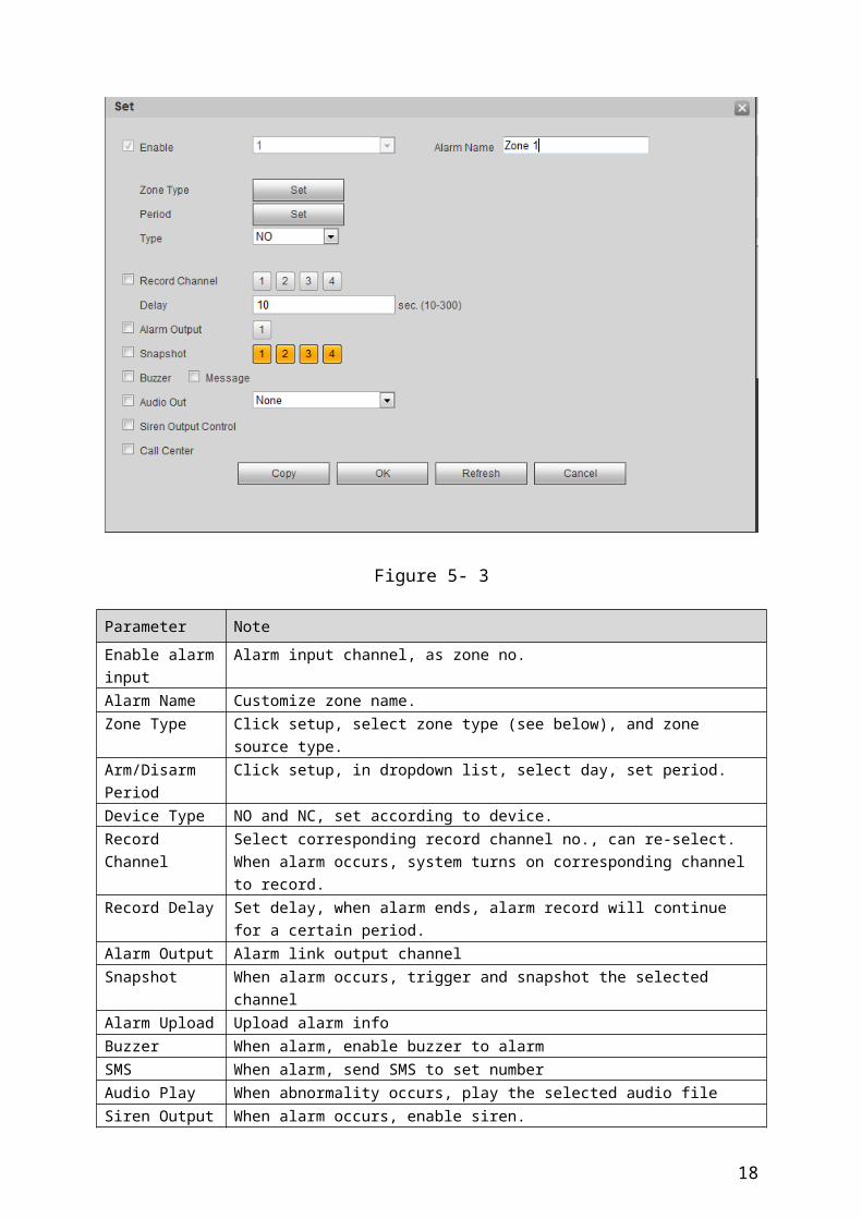
Figure 5- 6
Step 2. Input siren output duration (default is 5min), click OK.
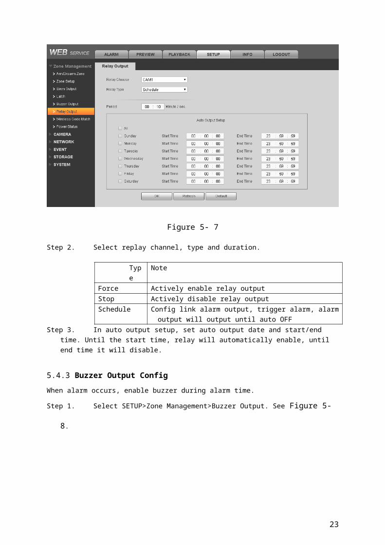
5.4.2 Relay Output ConfigSet relay output channel, type and period. Step 1. Select SETUP>Zone Management>Relay Output. See Figure 5- 7.
Figure 5- 7
Step 2. Select replay channel, type and duration.
Typ Note
20
eForce Actively enable relay outputStop Actively disable relay outputSchedule Config link alarm output, trigger alarm, alarm output will output
until auto OFF Step 3. In auto output setup, set auto output date and start/end time. Until the start time, relay will
automatically enable, until end time it will disable.
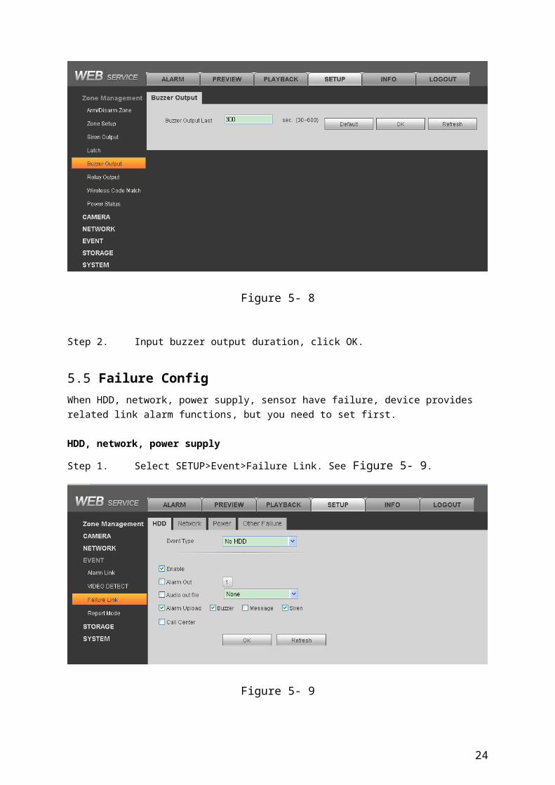
5.4.3 Buzzer Output ConfigWhen alarm occurs, enable buzzer during alarm time. Step 1. Select SETUP>Zone Management>Buzzer Output. See Figure 5- 8.
Figure 5- 8
Step 2. Input buzzer output duration, click OK.
5.5 Failure ConfigWhen HDD, network, power supply, sensor have failure, device provides related link alarm functions, but you need to set first.
HDD, network, power supplyStep 1. Select SETUP>Event>Failure Link. See Figure 5- 9.
21
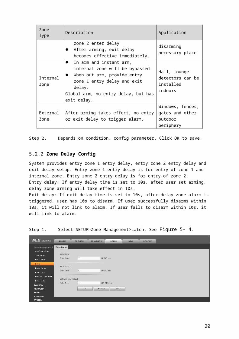
Figure 5- 9
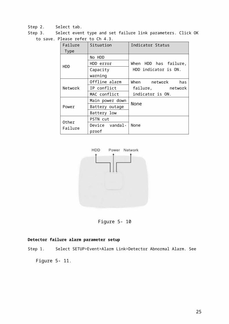
Step 2. Select tab. Step 3. Select event type and set failure link parameters. Click OK to save. Please refer to Ch
4.3. Failure Type Situation Indicator Status
HDDNo HDD
When HDD has failure, HDD indicator is ON.
HDD errorCapacity warning
NetworkOffline alarm
When network has failure, network indicator is ON.
IP conflictMAC conflict
PowerMain power down
NoneBattery outageBattery low
Other Failure
PSTN cutNone
Device vandal-proof
Figure 5- 10
22
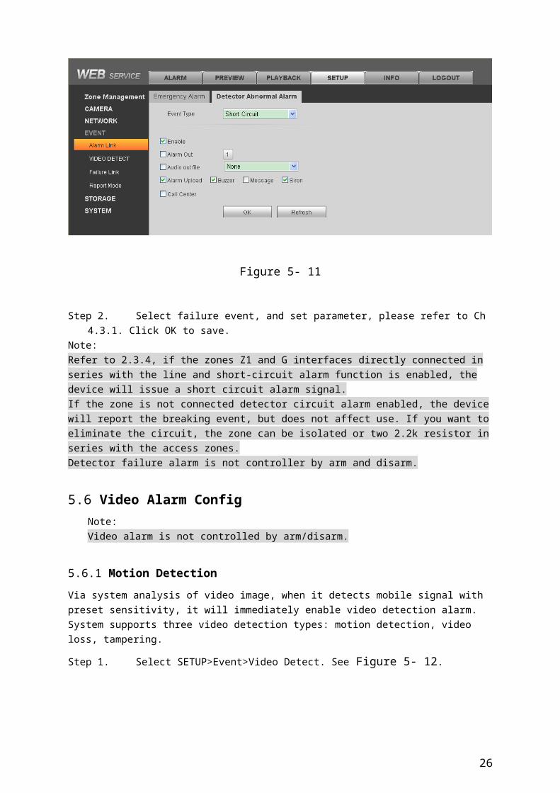
Detector failure alarm parameter setupStep 1. Select SETUP>Event>Alarm Link>Detector Abnormal Alarm. See Figure 5- 11.
Figure 5- 11
Step 2. Select failure event, and set parameter, please refer to Ch 4.3.1. Click OK to save. Note:Refer to 2.3.4, if the zones Z1 and G interfaces directly connected in series with the line and short-circuit alarm function is enabled, the device will issue a short circuit alarm signal.If the zone is not connected detector circuit alarm enabled, the device will report the breaking event, but does not affect use. If you want to eliminate the circuit, the zone can be isolated or two 2.2k resistor in series with the access zones.Detector failure alarm is not controller by arm and disarm.
5.6 Video Alarm ConfigNote:Video alarm is not controlled by arm/disarm.
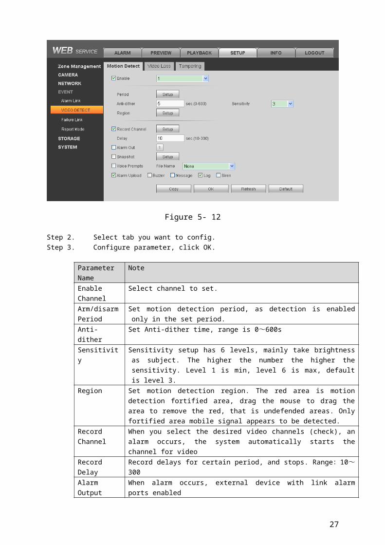
5.6.1 Motion DetectionVia system analysis of video image, when it detects mobile signal with preset sensitivity, it will immediately enable video detection alarm. System supports three video detection types: motion detection, video loss, tampering. Step 1. Select SETUP>Event>Video Detect. See Figure 5- 12.
23
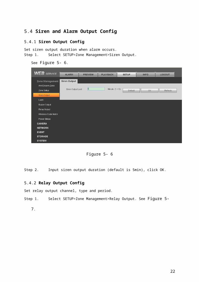
Figure 5- 12
Step 2. Select tab you want to config. Step 3. Configure parameter, click OK.
Parameter Name
Note
Enable Channel
Select channel to set.
Arm/disarm Period
Set motion detection period, as detection is enabled only in the set period.
Anti-dither Set Anti-dither time, range is 0~600sSensitivity Sensitivity setup has 6 levels, mainly take brightness as subject. The higher
the number the higher the sensitivity. Level 1 is min, level 6 is max, default is level 3.
Region Set motion detection region. The red area is motion detection fortified area, drag the mouse to drag the area to remove the red, that is undefended areas. Only fortified area mobile signal appears to be detected.
Record Channel
When you select the desired video channels (check), an alarm occurs, the system automatically starts the channel for video
Record Delay Record delays for certain period, and stops. Range:10~300Alarm Output When alarm occurs, external device with link alarm ports enabledSnapshot When motion detection occurs, snapshot the selected channel. Audio Prompt Play the selected audio file when motion detection. Buzzer When alarm is enabled, enable buzzer.SMS When alarm is enabled, send SMS to specific number.Log In system log, record motion detection log info. Siren Enable siren when alarm occurs.
24
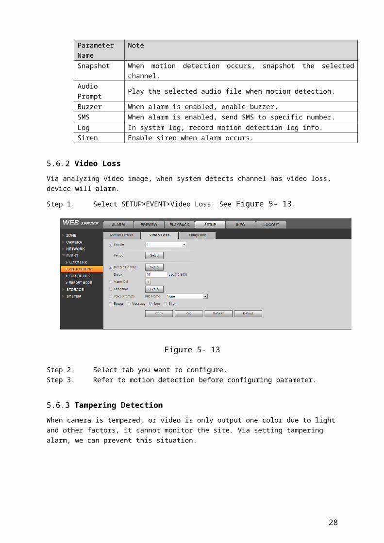
5.6.2 Video LossVia analyzing video image, when system detects channel has video loss, device will alarm. Step 1. Select SETUP>EVENT>Video Loss. See Figure 5- 13.
Figure 5- 13
Step 2. Select tab you want to configure. Step 3. Refer to motion detection before configuring parameter.
5.6.3 Tampering DetectionWhen camera is tempered, or video is only output one color due to light and other factors, it cannot monitor the site. Via setting tampering alarm, we can prevent this situation. Step 1. Select SETUP>EVENT>Tampering. See Figure 5- 14.
Figure 5- 14
Step 2. Select tab you want to configure. Step 3. Refer to motion detection before configuring parameter.
5.7 Event Report ConfigYou can select network priority and report mode when alarm occurs. When alarm occurs, you can view alarm info via WEB or keyboard.
25
Step 1. Select SETUP>Event>Report Mode. See Figure 5- 15.
Figure 5- 15
Step 2. Select network priority and report mode, click OK to save. PRIORITY: apply to TCP/IP protocol transmission, by setting network priority; you can select to transmit via wired Ethernet or 3G/4G wireless network transmission.
Setup NoteWired only Event via wired Ethernet network transmit to alarm
center3G/4G network Event via 3G/4 wireless network transmit to alarm
centerWired network priority, failed convert to 3G/4G network
Event priority through a wired Ethernet transmission to the central station, if the cable network failure, switching to 3G / 4G network transmission; if a wired network is restored, then the next alarm event switches to the wired network.
Report mode: Via report mode config, you can select transmit event via Ethernet or telephone line.
Setup NoteNot report Under this mode, event will not be reported to
network and call centerReport to network center 1 only
Evert will be reported to network center 1(auto register, direct connect IP, SDKDemo, WEB)
Dial call center 1 only Event will be reported to call center 1(center config see Ch 4.10.1)
Dial call center 1 and if Event will be reported to call center 1, if failed,
26
Setup Notefailed, dial 2 dial call center 2Dial call center 1 and 2 at the same time
Event will be reported to call center 1 and 2
Sent to network center 1, if failed, send to call center 1
Event will be reported to network center 1, if failed, event will be sent to call center 1
Send to network center 1 and call center 1
Event will be reported to both network center 1 and call center 1
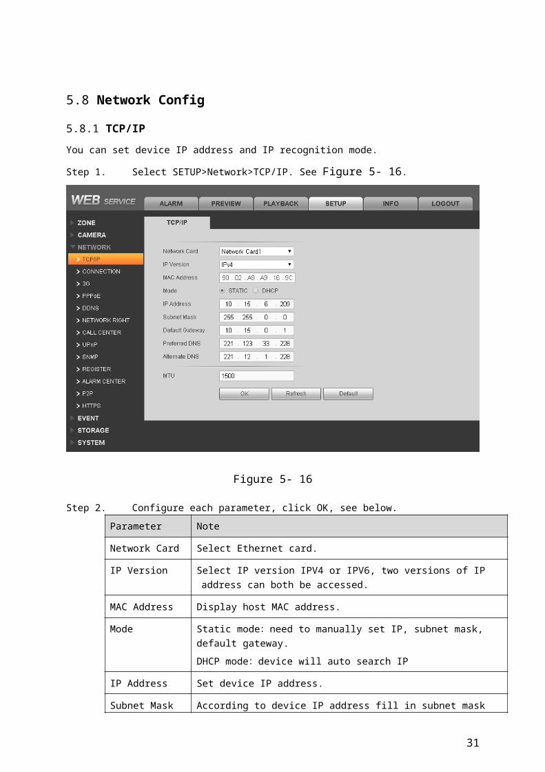
5.8 Network Config5.8.1 TCP/IPYou can set device IP address and IP recognition mode. Step 1. Select SETUP>Network>TCP/IP. See Figure 5- 16.
Figure 5- 16
Step 2. Configure each parameter, click OK, see below.
Parameter Note
Network Card Select Ethernet card.
IP Version Select IP version IPV4 or IPV6, two versions of IP address can both be accessed.
MAC Address Display host MAC address.
Mode Static mode:need to manually set IP, subnet mask, default gateway.
27
Parameter Note
DHCP mode:device will auto search IP
IP Address Set device IP address.
Subnet Mask According to device IP address fill in subnet mask
Default Gateway According to device IP address fill in default gateway
Preferred DNS Server
Fill in DNS server IP address
Alternate DNS Server
Fill in alternate DNS server IP address
MTU Set Ethernet card max transmission unit, range is 1280~7200 byte,default is 1500 byte
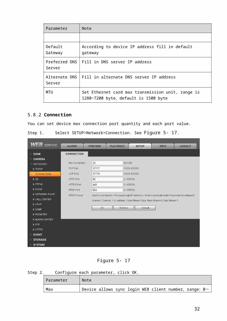
5.8.2 ConnectionYou can set device max connection port quantity and each port value. Step 1. Select SETUP>Network>Connection. See Figure 5- 17.
Figure 5- 17
Step 2. Configure each parameter, click OK.
Parameter Note
Max Connection Device allows sync login WEB client number,range:0~128,default value is 20.
28
Parameter Note
TCP Port Set according to user actual need, range is 1025~65535,default is 37777
UDP Port Set according to user actual need, range is 1025~65535,default is 37778
HTTP Port Default is 80
HTTPS Port Default is 443.
RSTP Port Default is 554.
5.8.3 3GYou can set and view 3G dial info. CDMA/GPRS:Step 1. Select>SETUP>Network>3G. See Figure 5- 18.w
Figure 5- 18
Step 2. Configure each parameter, click OK.
Parameter Note
WLWAN Type Select WLAN type, used to distinguish different supplier’s 3G module, such as WCDMA, ECDO and etc.
Boot up Activate 3G dial setup function
29
AUTH May select PAP, CHAP, NO_AUTH
IP Address After successfully dial, auto recognize IP address.
Wireless Signal Display wireless signal intensity
Mobile:Before setting mobile phone, you must check “Dial/SMS Activate” to enable mobile function. Step 1. Select SETUP>Network>3G>Mobile. See Figure 5- 19.
Figure 5- 19
Step 2. According to need, check “Send SMS/SMS Activate/Tel Activate”.
Step 3. Set user mobile phone number. Input receiver/sender/caller mobile numbers, click .
Add mobile phone user into the list; in list, select one number, click to delete the
number. Send SMS: After send sms is enabled, each type of alarm can link system to send alarm
SMS to receiver. SMS Activate: Set mobile phone number, the user can send SMS to 3G user, to activate or
close 3G module. Tel Activate: Set mobile phone number, the user can call 3G user, to activate or close 3G
module.Step 4. Click OK.
5.8.4 PPPoEYou can get device IP address via PPPoE dial, thus to connect the device. Step 1. Select SETUP>Network>PPPoE. See Figure 5- 20.
30
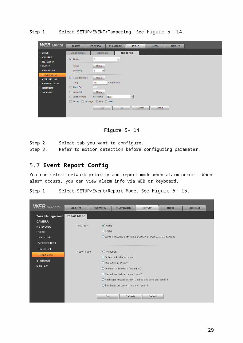
Figure 5- 20
Step 2. Check “Enable”. Step 3. Input ISP provided PPPoE username and password. Step 4. Click OK to save. Step 5. If successfully dial, you can select “SETUP>Network>TCP/IP” to view device IP address,
and use this IP address to access WEB end.
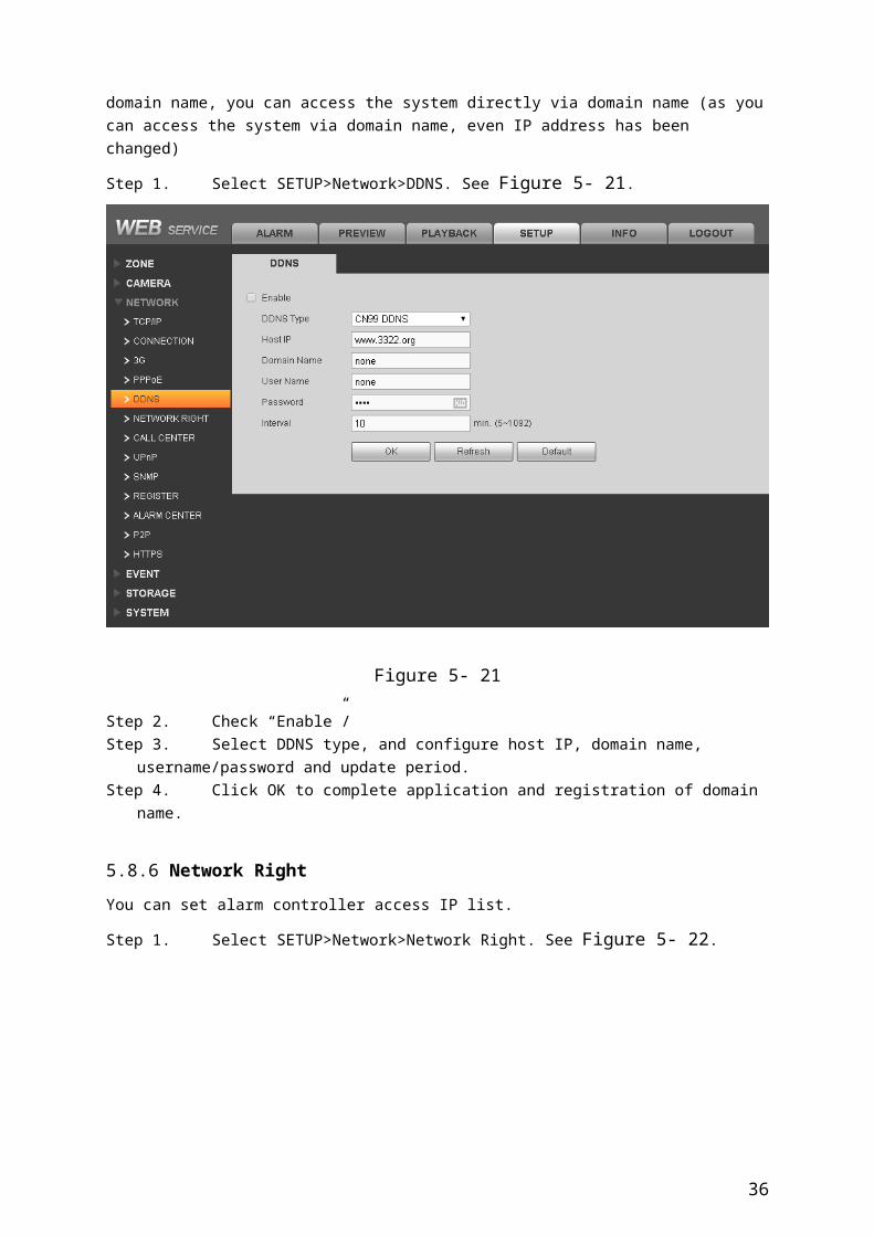
5.8.5 DDNSDDNS is to set connection to different types of server, so user can access the system via server. After each server website apply for domain name, you can access the system directly via domain name (as you can access the system via domain name, even IP address has been changed)Step 1. Select SETUP>Network>DDNS. See Figure 5- 21.
31
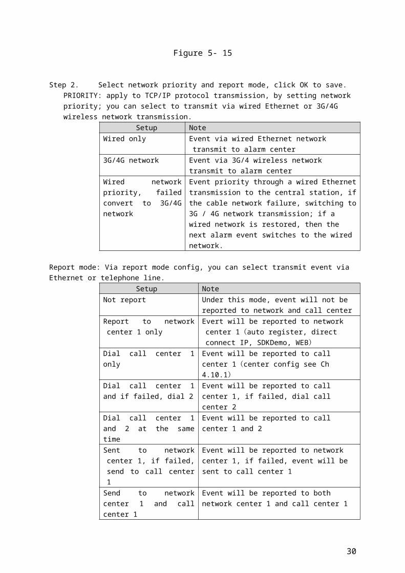
Figure 5- 21
Step 2. Check “Enable”/Step 3. Select DDNS type, and configure host IP, domain name, username/password and update
period. Step 4. Click OK to complete application and registration of domain name.
5.8.6 Network RightYou can set alarm controller access IP list. Step 1. Select SETUP>Network>Network Right. See Figure 5- 22.
Figure 5- 22
Step 2. Check “Enable”, enable trusted sites or blocked sites. Step 3. Select trusted sites or blocked sites, click “Add” button to add IP address.
32
Step 4. Click OK. Note:When select trusted sites, only IP in the list can connect to this alarm controller, support 64 IP addresses. If not check this option, you cannot access IP address of this device.
5.8.7 Call CenterYou can set call center parameter, when alarm occurs, system will send alarm info to call center. Step 1. Select SETUP>Network>Call Center. See Figure 5- 23.
Figure 5- 23
Step 2. Configure parameters, click OK. See
Parameter Note
Call Group By default there are two groups of call, you can select in the dropdown list.
Center Name Customize center name.
Center Number Call center number.
Protocol Type Use default value, default is CID
Signal Transmission Mode
Use default, default is DTMF 5/S
Dial Attempts If call center does not pick up call, it will try this number of times, range is 1~9
Dial Delay Time interval between two attempts
33
User Code Call center provided user code, default is 0000
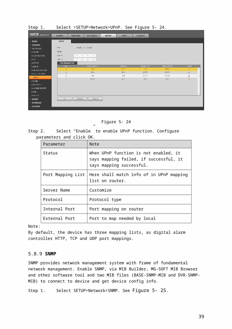
5.8.8 UPnPYou can enable UPnP mapping function, to create mapping relationship for device between LAN and WAN. Step 1. Select >SETUP>Network>UPnP. See Figure 5- 24.
Figure 5- 24
Step 2. Select “Enable” to enable UPnP function. Configure parameters and click OK.
Parameter Note
Status When UPnP function is not enabled, it says mapping failed, if successful, it says mapping successful.
Port Mapping List Here shall match info of in UPnP mapping list on router.
Server Name Customize
Protocol Protocol type
Internal Port Port mapping on router
External Port Port to map needed by local
Note:By default, the device has three mapping lists, as digital alarm controller HTTP, TCP and UDP port mappings.
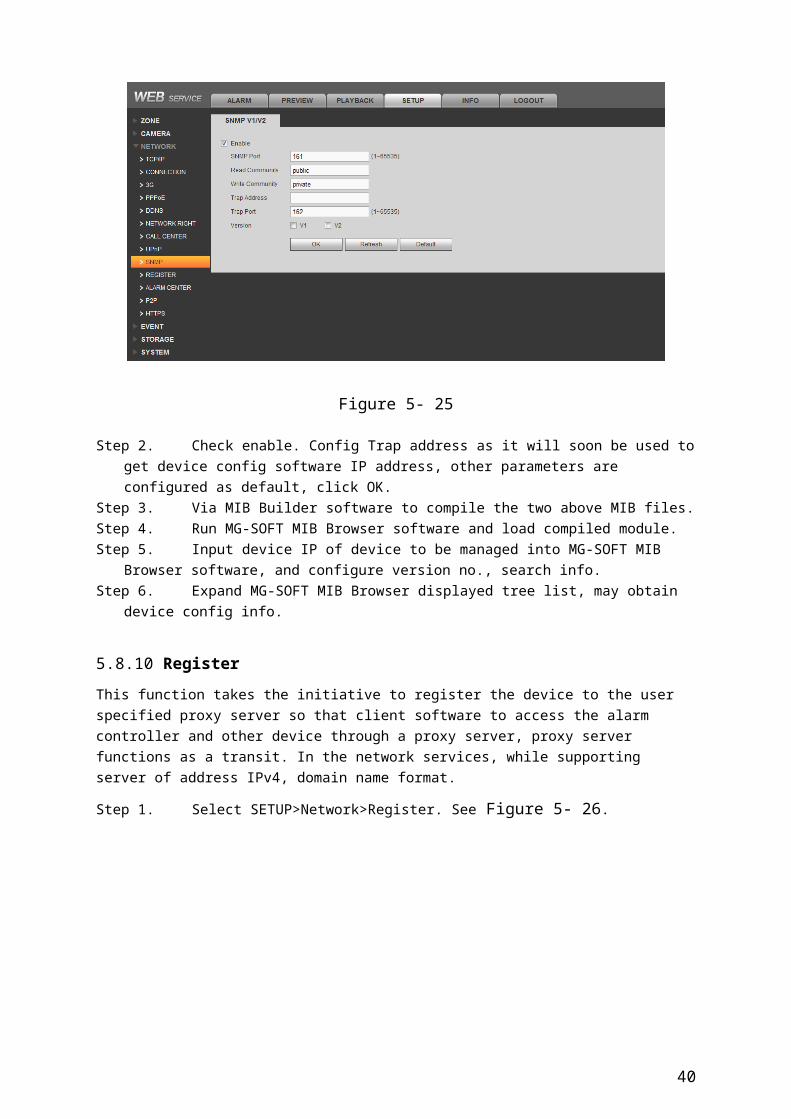
5.8.9 SNMPSNMP provides network management system with frame of fundamental network management. Enable SNMP, via MIB Builder, MG-SOFT MIB Browser and other software tool and two MIB files (BASE-SNMP-MIB and DVR-SNMP-MIB) to connect to device and get device config info. Step 1. Select SETUP>Network>SNMP. See Figure 5- 25.
34
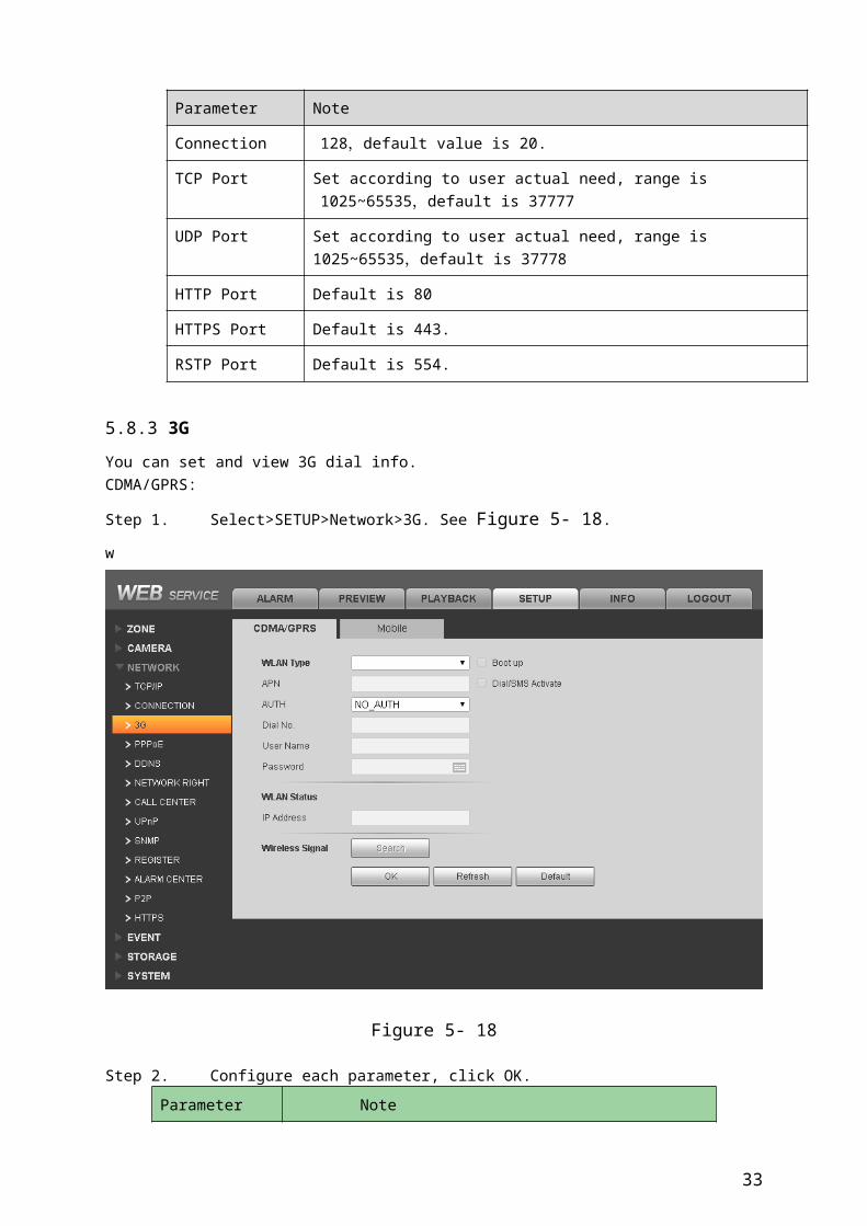
Figure 5- 25
Step 2. Check enable. Config Trap address as it will soon be used to get device config software IP address, other parameters are configured as default, click OK.
Step 3. Via MIB Builder software to compile the two above MIB files. Step 4. Run MG-SOFT MIB Browser software and load compiled module. Step 5. Input device IP of device to be managed into MG-SOFT MIB Browser software, and
configure version no., search info. Step 6. Expand MG-SOFT MIB Browser displayed tree list, may obtain device config info.
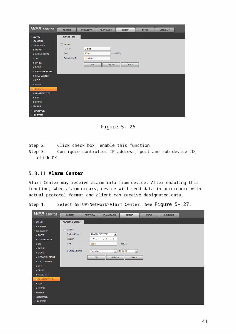
5.8.10 RegisterThis function takes the initiative to register the device to the user specified proxy server so that client software to access the alarm controller and other device through a proxy server, proxy server functions as a transit. In the network services, while supporting server of address IPv4, domain name format.Step 1. Select SETUP>Network>Register. See Figure 5- 26.
35
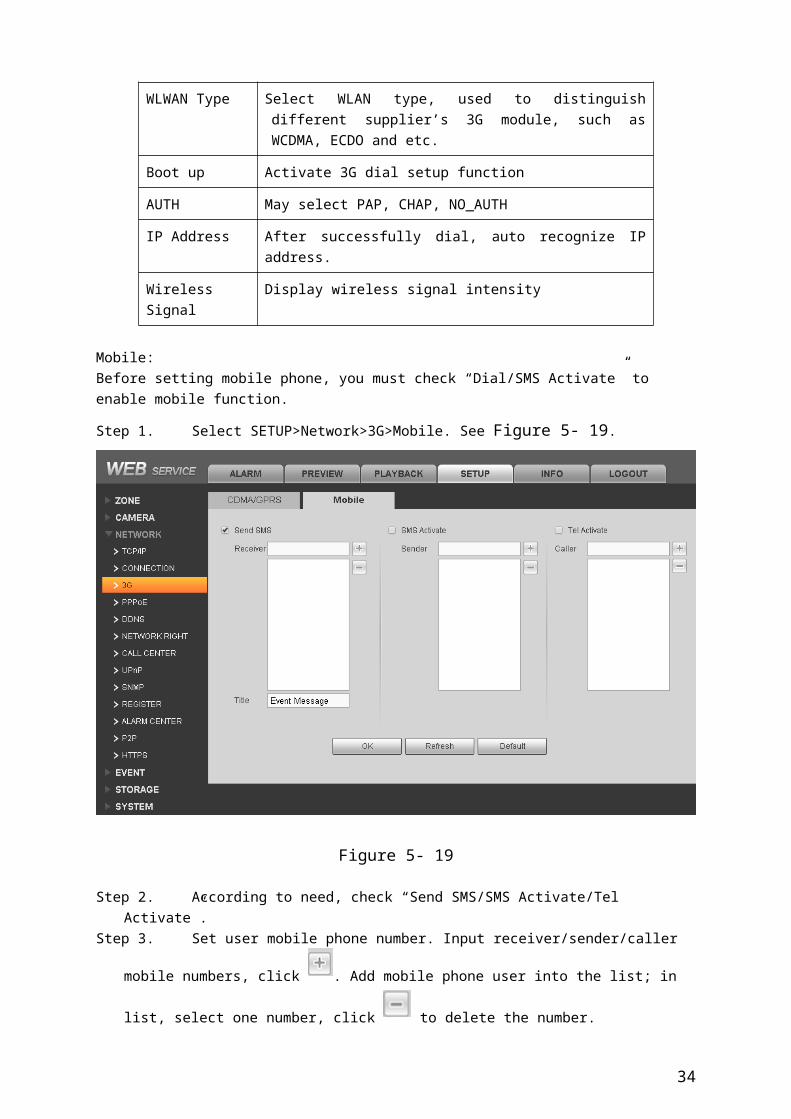
Figure 5- 26
Step 2. Click check box, enable this function. Step 3. Configure controller IP address, port and sub device ID, click OK.
5.8.11 Alarm CenterAlarm Center may receive alarm info from device. After enabling this function, when alarm occurs, device will send data in accordance with actual protocol format and client can receive designated data. Step 1. Select SETUP>Network>Alarm Center. See Figure 5- 27.
Figure 5- 27
Step 2. Click selection box, to enable. Step 3. Configure alarm center IP address, port and schedule report time, click OK. Note:After schedule report time is set, device will auto report alarm status on time at the set time.
5.8.12 P2PAfter P2P function is enabled, open mobile client software, directly input SN or scan the two-dimension code, save setup. Step 1. Select SETUP>Network>P2P. See Figure 5- 28.
36
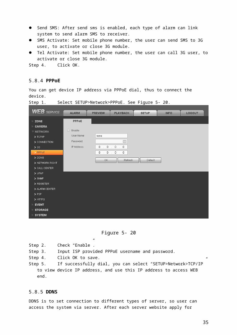
Figure 5- 28
Step 2. Click check box to enable. Step 3. Click Save.
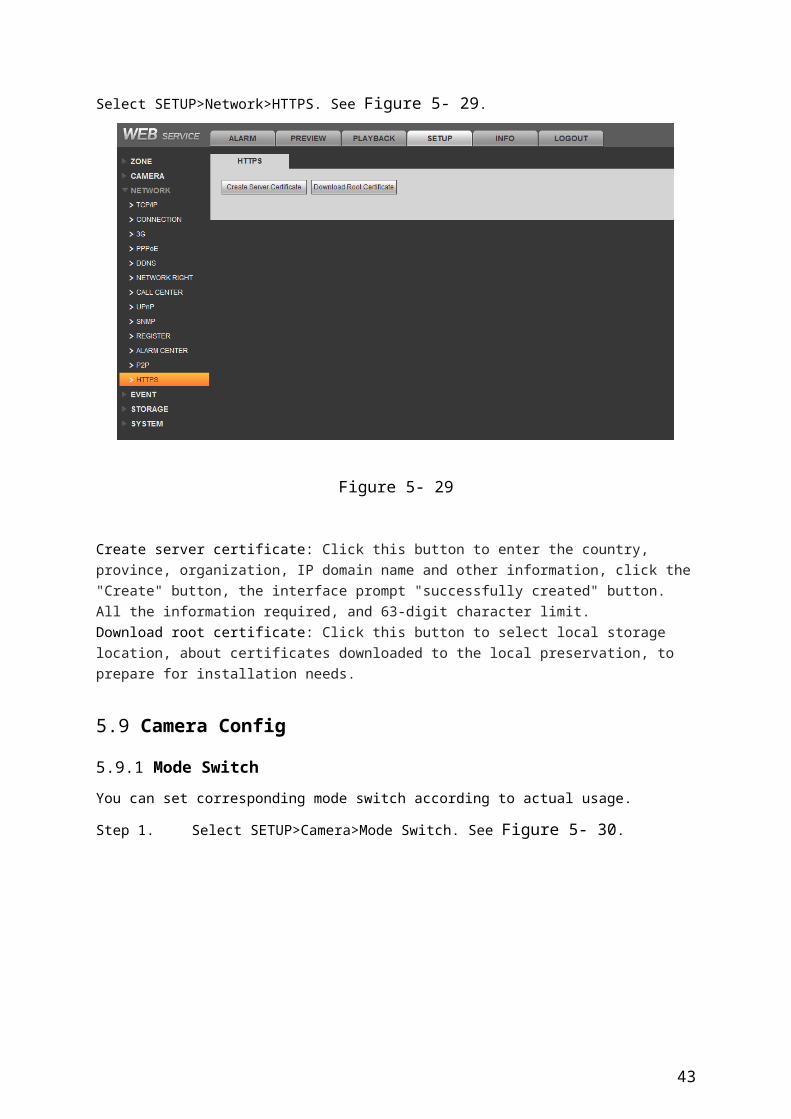
5.8.13 HTTPSVia HTTPS access website, need to install digital certificate, thus improve security of data communication. You can download certificate here, and create server certificate. Select SETUP>Network>HTTPS. See Figure 5- 29.
Figure 5- 29
37
Create server certificate: Click this button to enter the country, province, organization, IP domain name and other information, click the "Create" button, the interface prompt "successfully created" button. All the information required, and 63-digit character limit.Download root certificate: Click this button to select local storage location, about certificates downloaded to the local preservation, to prepare for installation needs.
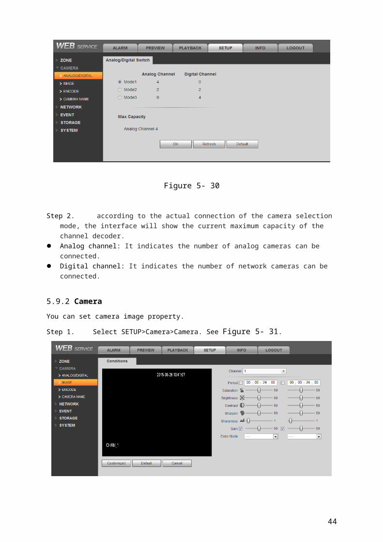
5.9 Camera Config5.9.1 Mode SwitchYou can set corresponding mode switch according to actual usage. Step 1. Select SETUP>Camera>Mode Switch. See Figure 5- 30.
Figure 5- 30
Step 2. according to the actual connection of the camera selection mode, the interface will show the current maximum capacity of the channel decoder.
Analog channel: It indicates the number of analog cameras can be connected. Digital channel: It indicates the number of network cameras can be connected.
5.9.2 CameraYou can set camera image property. Step 1. Select SETUP>Camera>Camera. See Figure 5- 31.
38
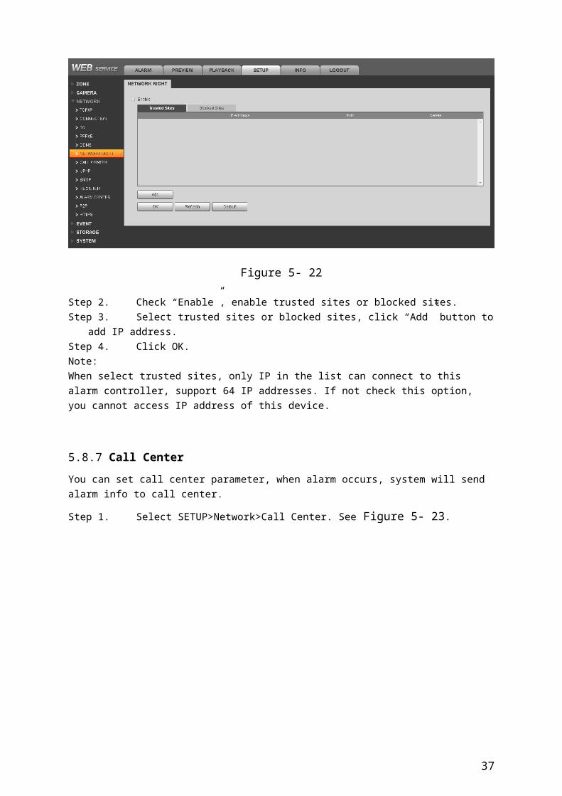
Figure 5- 31
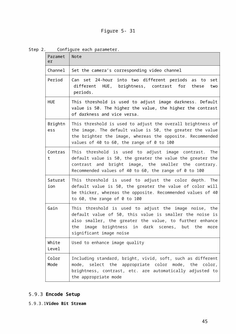
Step 2. Configure each parameter.
Parameter Note
Channel Set the camera’s corresponding video channel
Period Can set 24-hour into two different periods as to set different HUE, brightness, contrast for these two periods.
HUE This threshold is used to adjust image darkness. Default value is 50. The higher the value, the higher the contrast of darkness and vice versa.
Brightness This threshold is used to adjust the overall brightness of the image. The default value is 50, the greater the value the brighter the image, whereas the opposite. Recommended values of 40 to 60, the range of 0 to 100
Contrast This threshold is used to adjust image contrast. The default value is 50, the greater the value the greater the contrast and bright image, the smaller the contrary. Recommended values of 40 to 60, the range of 0 to 100
Saturation This threshold is used to adjust the color depth. The default value is 50, the greater the value of color will be thicker, whereas the opposite. Recommended values of 40 to 60, the range of 0 to 100
Gain This threshold is used to adjust the image noise, the default value of 50, this value is smaller the noise is also smaller, the greater the value, to further enhance the image brightness in dark scenes, but the more significant image noise
White Level
Used to enhance image quality
Color Mode
Including standard, bright, vivid, soft, such as different mode, select the appropriate color mode, the color, brightness, contrast, etc. are automatically
39

Parameter Note
adjusted to the appropriate mode
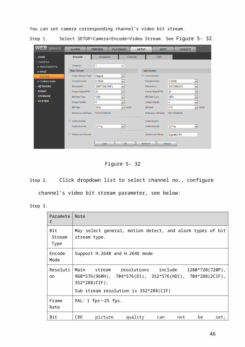
5.9.3 Encode Setup5.9.3.1Video Bit StreamYou can set camera corresponding channel’s video bit stream. Step 1. Select SETUP>Camera>Encode>Video Stream. See Figure 5- 32.
Figure 5- 32
Step 2. Click dropdown list to select channel no., configure channel’s video bit stream parameter, see below:
Step 3.
Parameter Note
Bit Stream Type
May select general, motion detect, and alarm types of bit stream type.
Encode Mode
Support H.264B and H.264E mode
Resolution Main stream resolutions include 1280*720(720P), 960*576(960H), 704*576(D1), 352*576(HD1), 704*288(2CIF), 352*288(CIF);Sub stream resolution is 352*288(CIF)
Frame Rate
PAL:1 fps~25 fps.
Bit Stream Control
CBR picture quality can not be set;Variable code stream can be set picture quality. The system supports
40
Parameter Note
adjustable from 1 to 6, the larger the number, the sharper the picture
Stream Value
Main stream: Set the code stream value to change the quality of quality, code stream value the better the bigger picture. Reference stream to provide the best value reference range.sub stream: In the fixed stream mode, which is the upper limit value stream stream; in dynamic images, if necessary, by lowering the frame rate and image quality will be to ensure that the stream does not exceed the value; in VBR mode next, the value is meaningless.
Reference Provide best reference range.
Enable Audio
System supports three types of audio:G711a, PCM, G711μ
Note:
Before sub stream enables audio, you must check “enable audio”.
Watermark
By checking the watermark character, you can check whether the video was tampered with. Select the Enable item to enable the watermark feature. Watermark characters can only be numbers, letters, underscores, and a maximum of 85 characters
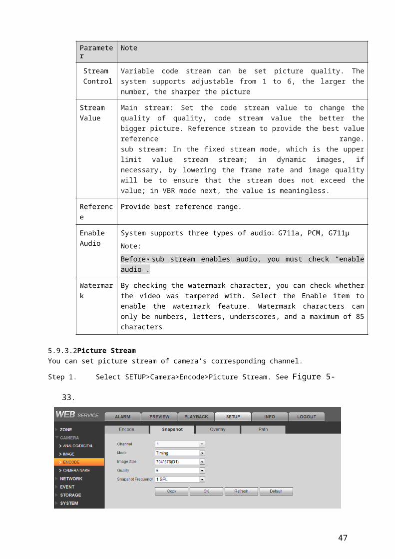
5.9.3.2Picture StreamYou can set picture stream of camera’s corresponding channel. Step 1. Select SETUP>Camera>Encode>Picture Stream. See Figure 5- 33.
Figure 5- 33
Step 2. Click dropdown list to select channel no., configure the channel picture stream parameter, see below:
Parameter Note
Snapshot Type
Divided into timed events and alarms. Timing refers to the capture shots within the time schedule set; refers to the capture event capture is triggered when the video block; shots are shots of the alarm is triggered after alarm linkage
41
Parameter Note
Picture Size
System supports two types of picture size:704*576(D1) and 352*288(CIF)
Picture Quality
Set snapshot picture quality,there are 6 levels available.
Snapshot Speed
Set snapshot frequency
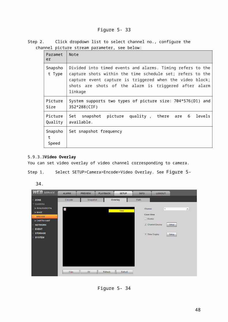
5.9.3.3Video OverlayYou can set video overlay of video channel corresponding to camera. Step 1. Select SETUP>Camera>Encode>Video Overlay. See Figure 5- 34.
Figure 5- 34
Step 2. Select channel no., set shield area of the channel, and whether display channel title and time or not, see below:
Parameter Note
Monitor Check and click the "Settings", you can draw the mask area left of the screen with the right mouse button, the system supports up to four regional draw.
Channel Title
When checked and click the "Settings", the draggable channel title to the appropriate location, click "OK" to display the channel information on the WEB screen real-time monitoring and video file playback screen.
Time Title Check and click the "Settings", the time after dragging the title to the appropriate location, click "OK" to display the time information on the WEB screen real-time monitoring and video file playback screen.
42
5.9.3.4PathIn WEB interface, select SETUP>Camera>Encode>Path, see Figure 5- 35. You can setup snapshot path and record path, default path is PictureDownload and RecordDownload under system disk.
Figure 5- 35
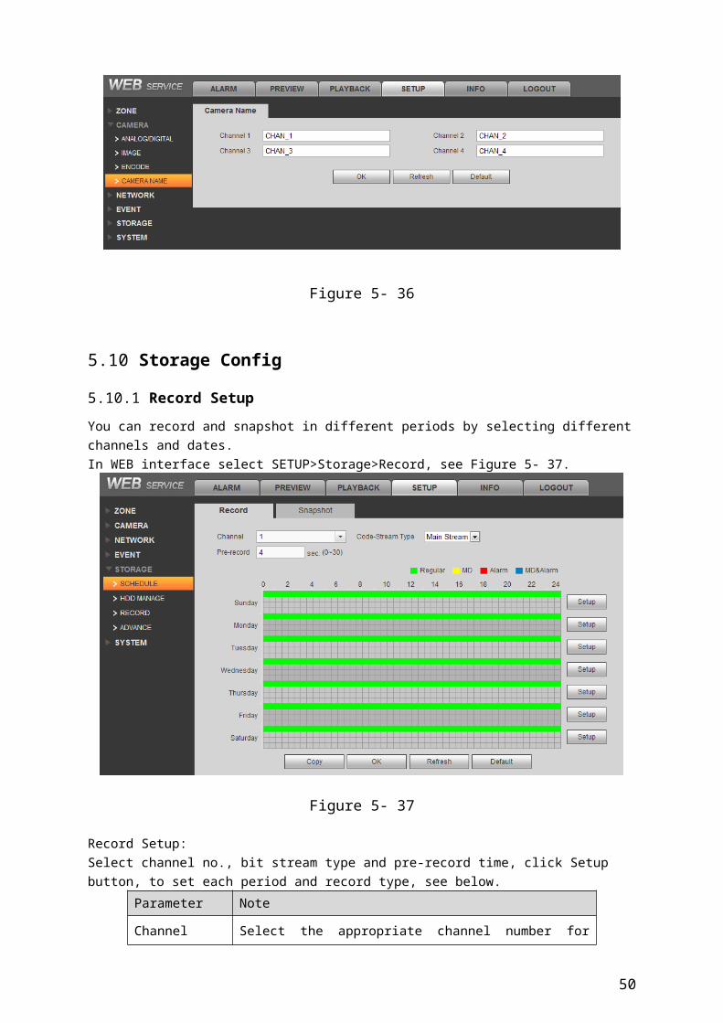
5.9.4 Channel NameIn WEB interface, select SETUP>Camera>Channel Name, see Figure 5- 36. You can set channel name.
Figure 5- 36
5.10 Storage Config5.10.1 Record SetupYou can record and snapshot in different periods by selecting different channels and dates. In WEB interface select SETUP>Storage>Record, see Figure 5- 37.
43
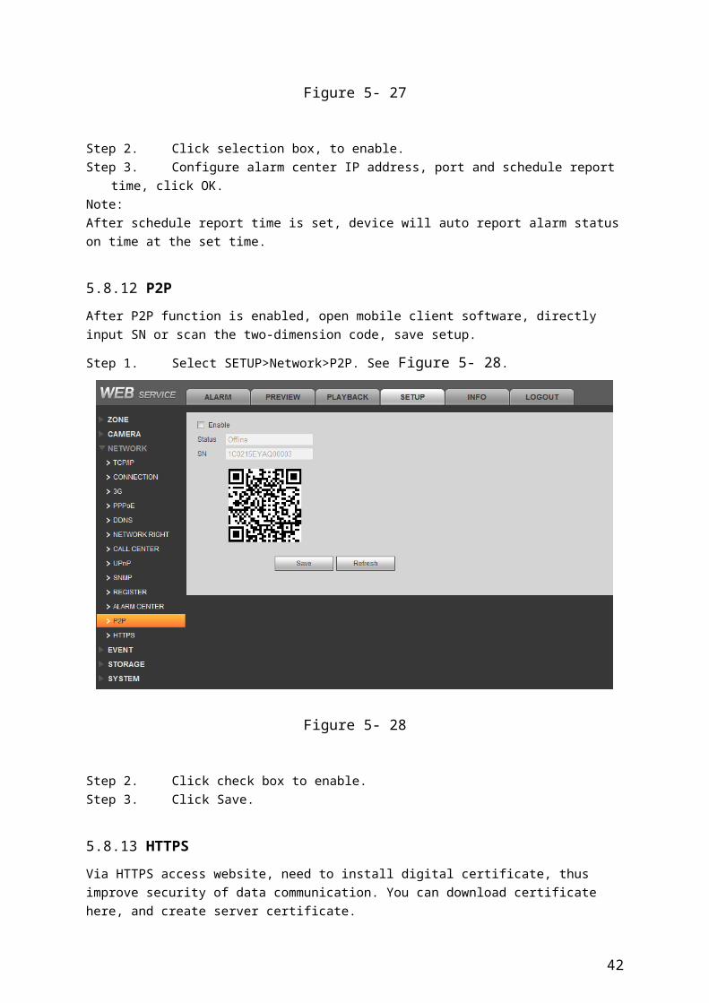
Figure 5- 37
Record Setup:Select channel no., bit stream type and pre-record time, click Setup button, to set each period and record type, see below.
Parameter Note
Channel Select the appropriate channel number for video settings
Bit Stream Type Select “main stream” or “ sub stream”
Pre-record Pre-record time prior to start of recording(time depends on size and status of stream)
Period A weekly cycle, every day is divided into six time periods
Record Type Including general record, motion detection record, alarm record and motion detection & alarm record, motion detection & alarm including motion detection record and alarm record
Snapshot Setup:Select channel no., click Setup button, set period and snapshot type, see below:
Parameter Note
Channel Select corresponding channel no. to record
Period A weekly cycle, every day is divided into six time periods
Snapshot Type Including general snapshot, motion detection snapshot, alarm snapshot and motion detection & alarm snapshot, motion detection & alarm including motion detection snapshot and alarm snapshot
44
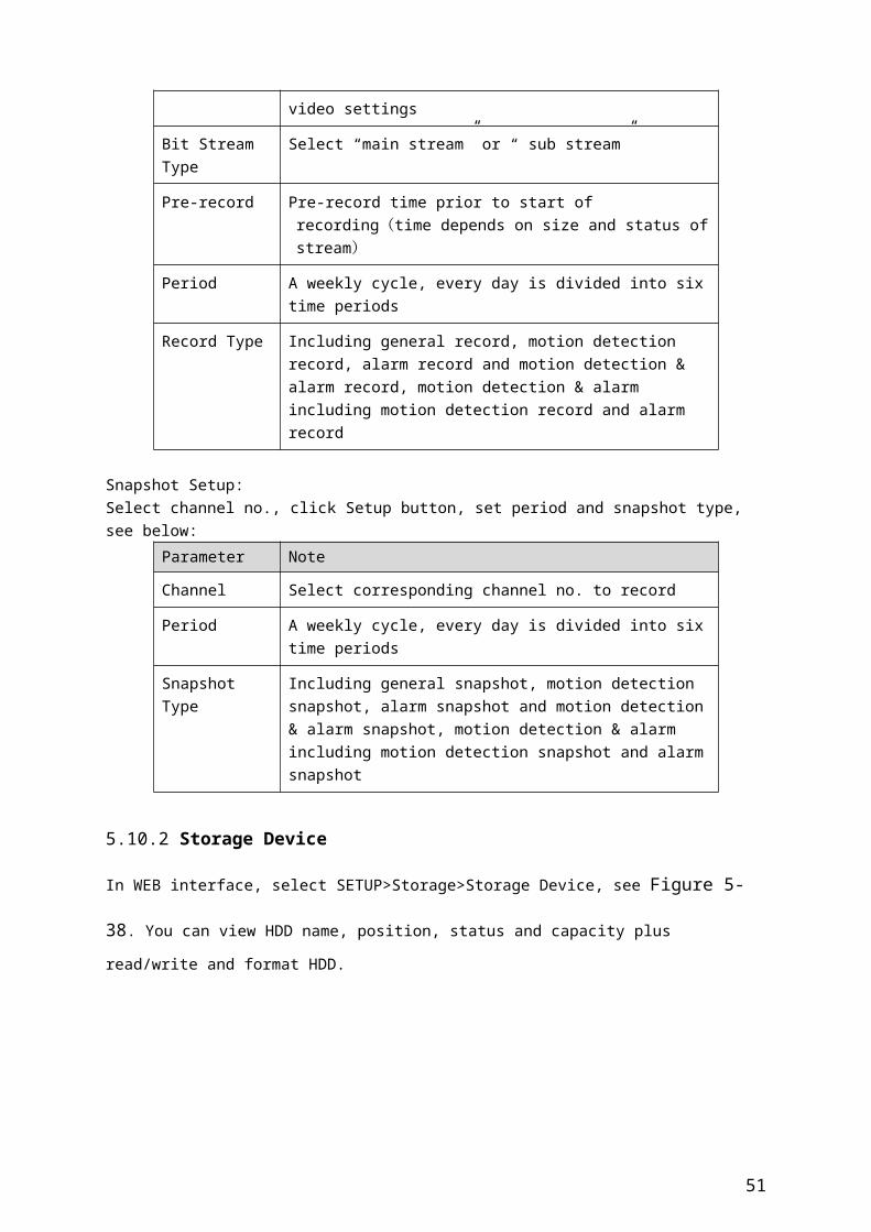
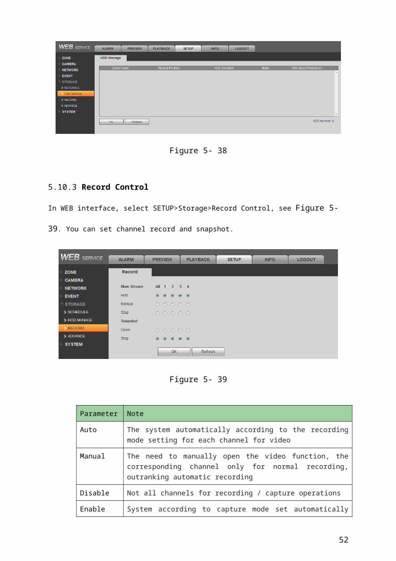
5.10.2 Storage DeviceIn WEB interface, select SETUP>Storage>Storage Device, see Figure 5- 38. You can view HDD name, position, status and capacity plus read/write and format HDD.
Figure 5- 38
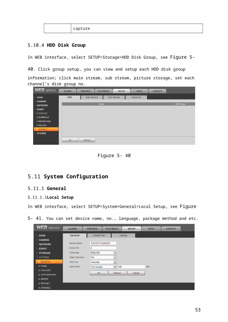
5.10.3 Record ControlIn WEB interface, select SETUP>Storage>Record Control, see Figure 5- 39. You can set channel record and snapshot.
Figure 5- 39
Parameter Note
Auto The system automatically according to the recording mode setting for each channel for video
Manual The need to manually open the video function, the corresponding channel only for normal recording, outranking automatic recording
Disable Not all channels for recording / capture operations
Enable System according to capture mode set automatically capture
45
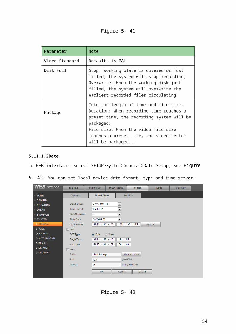
5.10.4 HDD Disk GroupIn WEB interface, select SETUP>Storage>HDD Disk Group, see Figure 5- 40. Click group setup, you can view and setup each HDD disk group information; click main stream, sub stream, picture storage, set each channel’s disk group no.
Figure 5- 40
5.11 System Configuration5.11.1 General5.11.1.1Local SetupIn WEB interface, select SETUP>System>General>Local Setup, see Figure 5- 41. You can set device name, no., language, package method and etc.
Figure 5- 41
Parameter Note
Video Standard Defaults is PAL
Disk Full Stop: Working plate is covered or just filled, the system will stop recording;Overwrite: When the working disk just filled, the system will overwrite the earliest recorded files circulating
46
Package
Into the length of time and file size.Duration: When recording time reaches a preset time, the recording system will be packaged;File size: When the video file size reaches a preset size, the video system will be packaged...
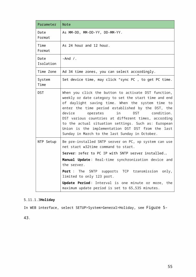
5.11.1.2DateIn WEB interface, select SETUP>System>General>Date Setup, see Figure 5- 42. You can set local device date format, type and time server.
Figure 5- 42
Parameter Note
Date Format As MM-DD, MM-DD-YY, DD-MM-YY.
Time Format As 24 hour and 12 hour.
Date Isolation -And /.
Time Zone Ad 34 time zones, you can select accordingly.
System Time Set device time, may click “sync PC”, to get PC time.
DST When you click the button to activate DST function, weekly or date category to set the start time and end of daylight saving time. When the system time to enter the time period established by the DST, the device operates in DST condition.DST various countries at different times, according to the actual situation settings. Such as: European Union is the implementation DST DST from the last Sunday in March to the last Sunday in October.
47
NTP Setup Be pre-installed SNTP server on PC, xp system can use net start w32time command to start.
Server:refer to PC IP with SNTP server installed.。Manual Update:Real-time synchronization device and the server.
Port:The SNTP supports TCP transmission only, limited to only 123 port.
Update Period:Interval is one minute or more, the maximum update period is set to 65,535 minutes.
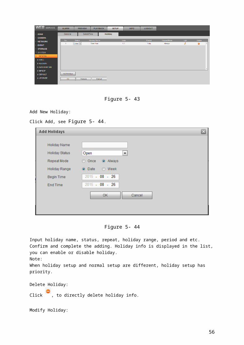
5.11.1.3HolidayIn WEB interface, select SETUP>System>General>Holiday, see Figure 5- 43.
Figure 5- 43
Add New Holiday:Click Add, see Figure 5- 44.
Figure 5- 44
Input holiday name, status, repeat, holiday range, period and etc. Confirm and complete the adding. Holiday info is displayed in the list, you can enable or disable holiday. Note:
48
When holiday setup and normal setup are different, holiday setup has priority.
Delete Holiday:
Click , to directly delete holiday info.
Modify Holiday:
Click , to enter holiday info modification interface, you can modify this item of holiday info.
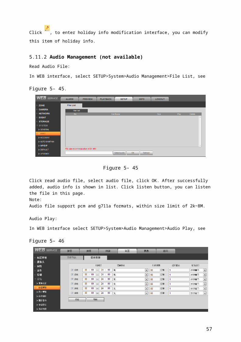
5.11.2 Audio Management (not available)Read Audio File:In WEB interface, select SETUP>System>Audio Management>File List, see Figure 5- 45.
Figure 5- 45
Click read audio file, select audio file, click OK. After successfully added, audio info is shown in list. Click listen button, you can listen the file in this page. Note:Audio file support pcm and g711a formats, within size limit of 2k~8M.
Audio Play:In WEB interface select SETUP>System>Audio Management>Audio Play, see Figure 5- 46
Figure 5- 46
49
Check enable, set period, audio file to play, play time interval, loop play times and audio output port, click OK to save. System till play the audio content in set period. Note:Audio file is the audio file read into file list.
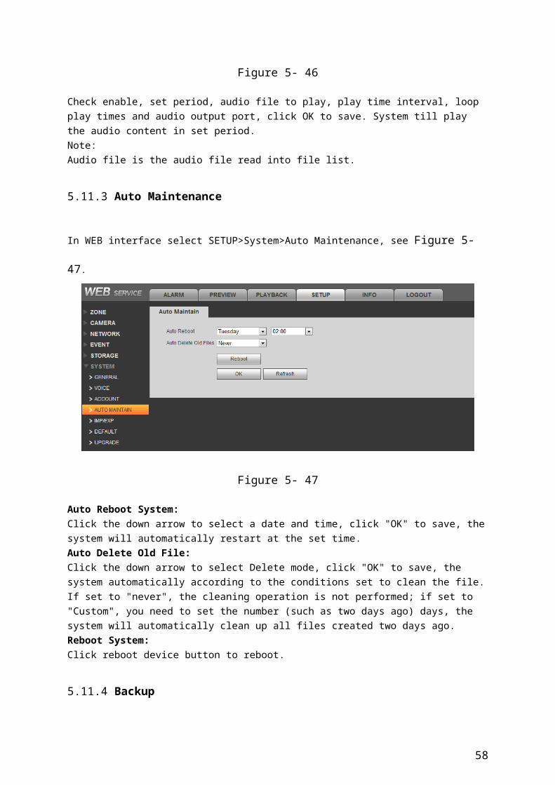
5.11.3 Auto Maintenance
In WEB interface select SETUP>System>Auto Maintenance, see Figure 5- 47.
Figure 5- 47
Auto Reboot System:Click the down arrow to select a date and time, click "OK" to save, the system will automatically restart at the set time.Auto Delete Old File:Click the down arrow to select Delete mode, click "OK" to save, the system automatically according to the conditions set to clean the file.If set to "never", the cleaning operation is not performed; if set to "Custom", you need to set the number (such as two days ago) days, the system will automatically clean up all files created two days ago.Reboot System:Click reboot device button to reboot.
5.11.4 BackupIn WEB interface, select SETUP>System>Backup, see Figure 5- 48.
50
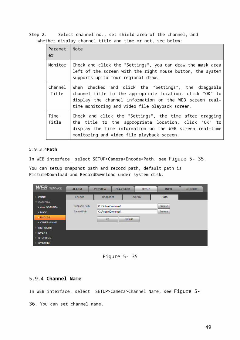
Figure 5- 48
Export:Click config export button, select storage position and backup current config info. Import:Click browse button, select config file, and click config import again button, confirm system reboot, as to import config file into the system.
Note:When multiple devices require the same set of parameters, you can use the configuration backup function.
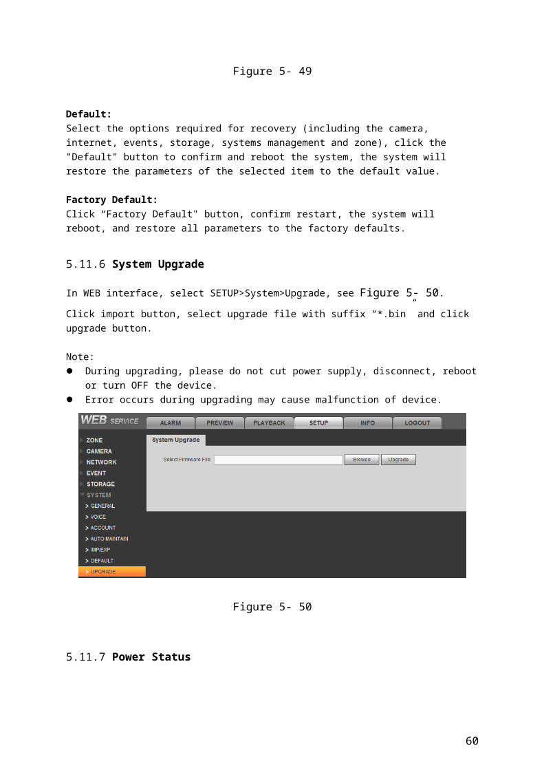
5.11.5 DefaultIn WEB interface, select SETUP>System>Default, see Figure 5- 49.
Figure 5- 49
Default:Select the options required for recovery (including the camera, internet, events, storage, systems management and zone), click the "Default" button to confirm and reboot the system, the system will restore the parameters of the selected item to the default value.
Factory Default:
51
Click “Factory Default" button, confirm restart, the system will reboot, and restore all parameters to the factory defaults.
5.11.6 System UpgradeIn WEB interface, select SETUP>System>Upgrade, see Figure 5- 50. Click import button, select upgrade file with suffix “*.bin” and click upgrade button.
Note: During upgrading, please do not cut power supply, disconnect, reboot or turn OFF the
device. Error occurs during upgrading may cause malfunction of device.
Figure 5- 50
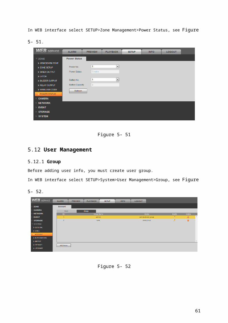
5.11.7 Power StatusIn WEB interface select SETUP>Zone Management>Power Status, see Figure 5- 51.
Figure 5- 51
5.12 User Management
52
5.12.1 GroupBefore adding user info, you must create user group. In WEB interface select SETUP>System>User Management>Group, see Figure 5- 52.
Figure 5- 52
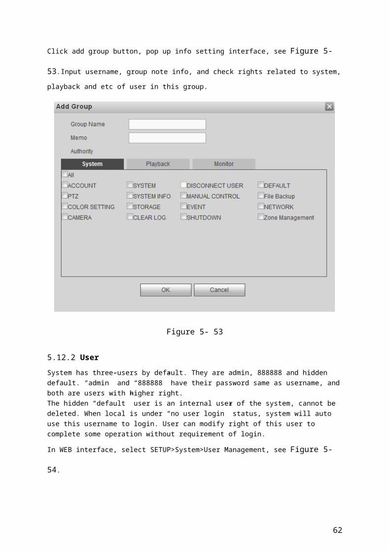
Click add group button, pop up info setting interface, see Figure 5- 53.Input username, group note info, and check rights related to system, playback and etc of user in this group.
Figure 5- 53
5.12.2 UserSystem has three users by default. They are admin, 888888 and hidden default. “admin” and “888888” have their password same as username, and both are users with higher right.
53
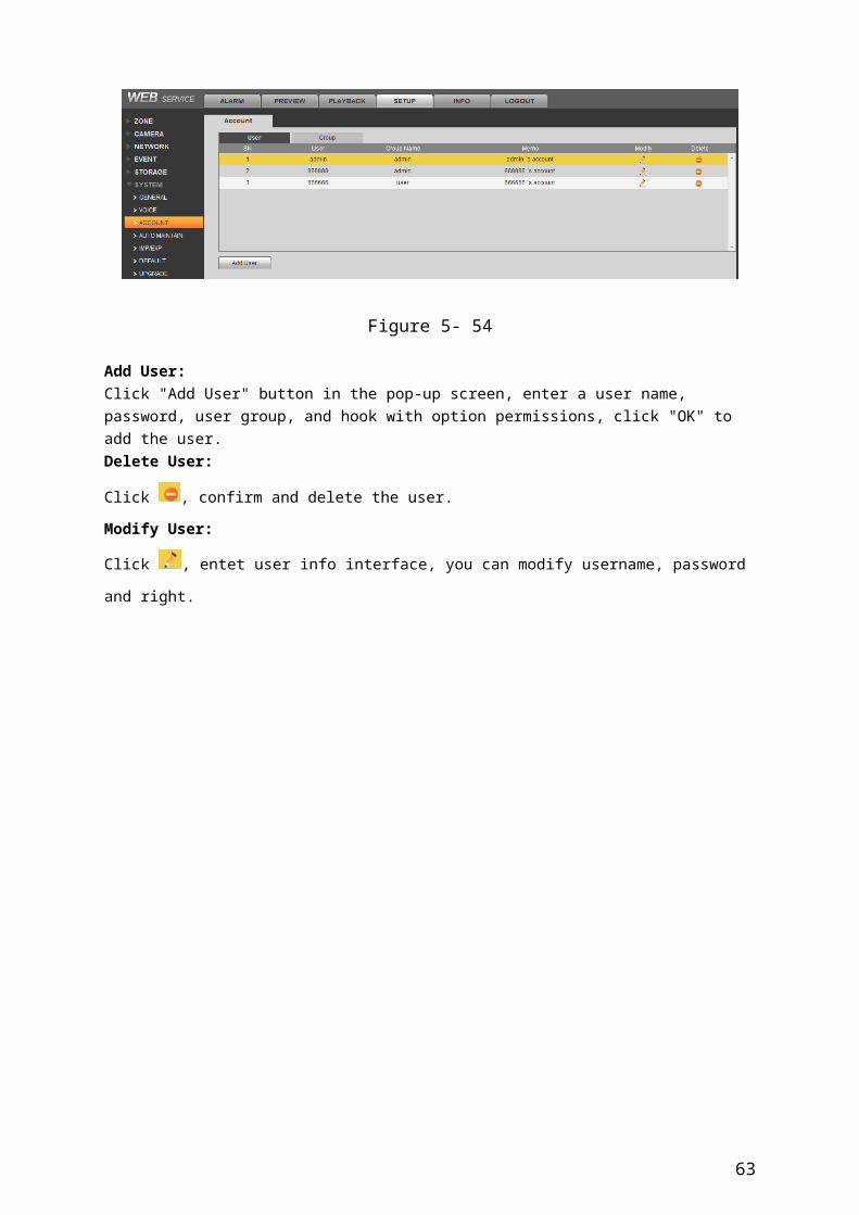
The hidden “default” user is an internal user of the system, cannot be deleted. When local is under “no user login” status, system will auto use this username to login. User can modify right of this user to complete some operation without requirement of login. In WEB interface, select SETUP>System>User Management, see Figure 5- 54.
Figure 5- 54
Add User:Click "Add User" button in the pop-up screen, enter a user name, password, user group, and hook with option permissions, click "OK" to add the user.Delete User:
Click , confirm and delete the user.
Modify User:
Click , entet user info interface, you can modify username, password and right.
54
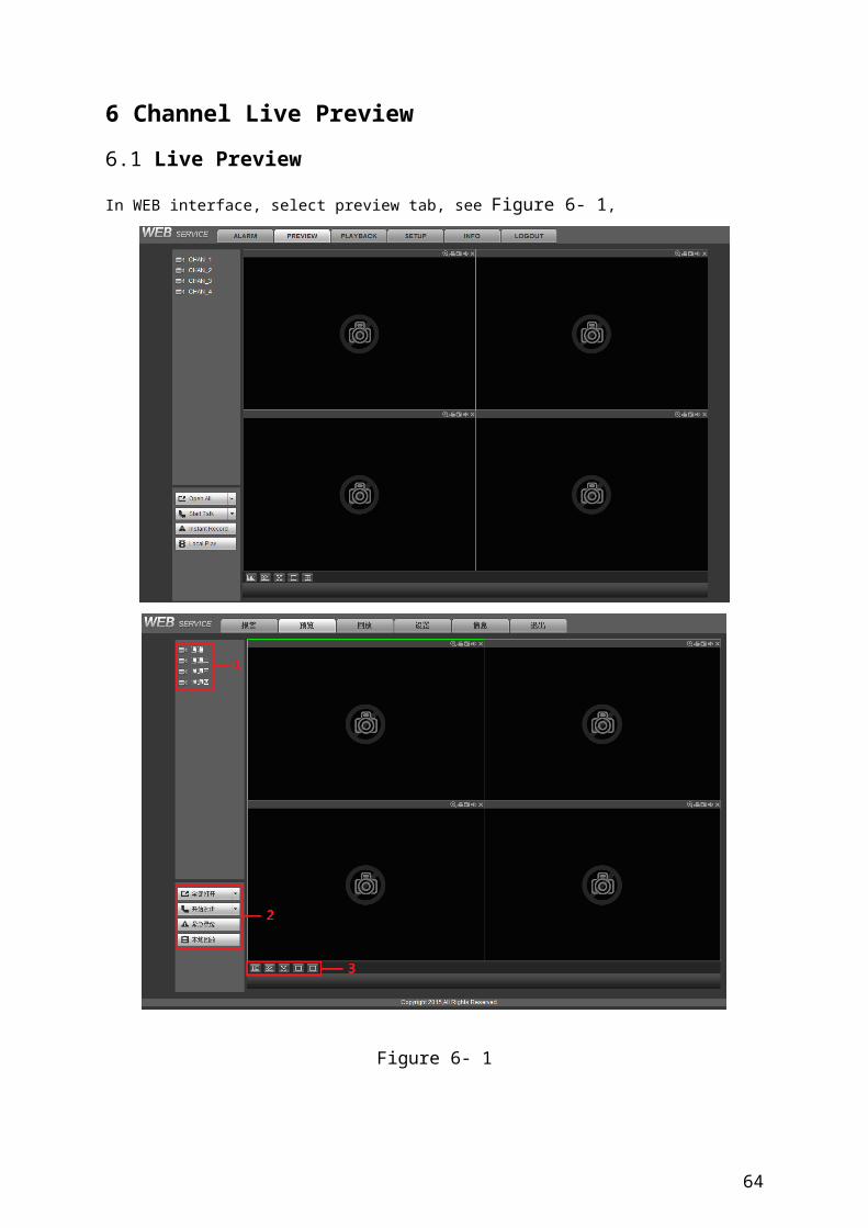
6 Channel Live Preview
6.1 Live PreviewIn WEB interface, select preview tab, see Figure 6- 1,
Figure 6- 1
No. Name Note
1 Channel Device video channel list, see Ch Error: Reference source not found.
55
1
2
43
No. Name Note
2
All Open Open or close all channels’ video play
Start Talk
Video talk function device and the client to achieve two-way communication. Click start talk to start and end the video talk device. Click the drop-down box to select a talk mode, including DEFAULT, G711a, G711μ, PCM mode IV.
Click stop talk to end this video talk.
Emergency Record Enable manual record in all channels.
Local Playback Playback local video, see Ch 6.4.
3 Display Mode See Ch 6.3.
6.2 Monitor WindowIn live preview interface, click channel no. in channel list, system will auto select idle window to display the channel’s video info, see Figure 6- 2. System select main stream by default, if to select sub stream, then click dropdown arrow on the channel no. to select. Main stream (M): larger stream, high definition, high occupancy of bandwidth, suitable for
local storage. Sub stream (S): under main stream image environment, lower image format, definition,
suitable for transmission under low band width.
Figure 6- 2
No. Parameter Note
1 Channel Info content composition : device IPaddress_chanenl no._network
56
No. Parameter Note
Info monitoring stream_main/sub stream,as 172.10.2.63_1_119Kbps_M
2Channel Name
Display name of selected channel
3Date and Time
Display current system date and time.
4
Zoon In
Click this button, drag mouse and left click to select any area, the area will be zoomed in. Right click to resume original status.
Tips:
You can double click the video window to zoom in the entire image, and double click to resume.
Local Record
Click the button, and the file system for video recording in the system tray by default save folder RecordDownload
SnapshotClick the button, you can grab the current video screen, the picture stored in the system disk by default folders PictureDownload
Audio Switch
Open or close record play sound.
Close Close video info of the window.
6.3 Display ModeIn live preview interface, you can set display mode of window to have different video effects.
Icon Definition Note
Quality Click this button to set the video picture clarity, into high-quality and low-quality
Fluency and Real-time
Click this button to adjust priority of video image fluency or real-time.
It emphasizes fluency smooth video images, real-time video images in real time to emphasize, to meet the different needs of users.
Full Screen Click this button to watch full-screen video information of each channel
Single Window
Click this button, the entire preview screen shows only one channel of video information
Four Window Click this button to preview junction will simultaneously display four channels of video information
6.4 Playback
57
Local playback interface is to store dav record file on local PC. In live preview interface, click playback button, select record file to playback, see Figure 6- 3.
Figure 6- 3
No. Icon Name Note
1Playback Speed
System supports 3 types of quick speed:×2, ×4, ×8, 3 types of slow play:×1/2, ×1/4, ×1/8
2Progress Bar
Via mouse drag progress bar to forward o backward
3Play Control Button
From left to right are : play. Pause, stop, slow play and quick play
58
7 Record Playback and Process
7.1 Playback InterfaceIn WEB interface select playback tab, see Figure 7- 1.
Figure 7- 1
No. Product Function
Description
1Playback Window
Display playback video.
2Playback Control
From left to right are:play/pause, stop, previous frame, next frame, playback speed, volume.
3 Time Axis
Display current record type and its period.
Under four-window playback mode, it can display the 4 selected channels’ four corresponding playback time axis, under other mode, only display 1 playback time axis.
Use mouse to click one point as playback starts from this point of time.
Green is general type of record, red is alarm record.
4 Record Type Currently support record type of:general, motion detection, alarm.
59
No. Product Function
Description
Check record type, time axis displays corresponding type of record file
5 Time Aix Unit May adjust accurately time point on time axis back and forth to play record
6 Cut and Save See Ch 7.3
7 File List See Ch 7.4.
8
Window Mode and Channel Selection
Click window mode button, select single window, four window or full screen.
Click dropdown arrow to select each window’s corresponding video channel.
Note:After window mode and channel are changed, time axis will sync update.
9 Calendar Click date, on time axis it shows record info of that day.
7.2 Playback RecordPlayback record has the following three modes, before operation, you must set date via the calendar: In playback control area, click play button. In time axis, click record valid range. Open file list, double click file to play.
7.3 Cut and Save RecordYou can cut a certain playback and save to local PC:Step 1. In calendar, select date, and select channel. All needed record file info will be in time
axis. Step 2. Click to activate video cut function. Step 3. Use the mouse to drag the arrow across the timeline of the channel, or enter the required
time period taken video clip and save the region;
Step 4. Click , pop up a box, save.
Tips:Click stop, to cancel this operation.
7.4 File ListIn calendar, select date and set each window’s corresponding video channel, click file list, see Figure 7- 2. You can search record file within a certain period on this date.
60
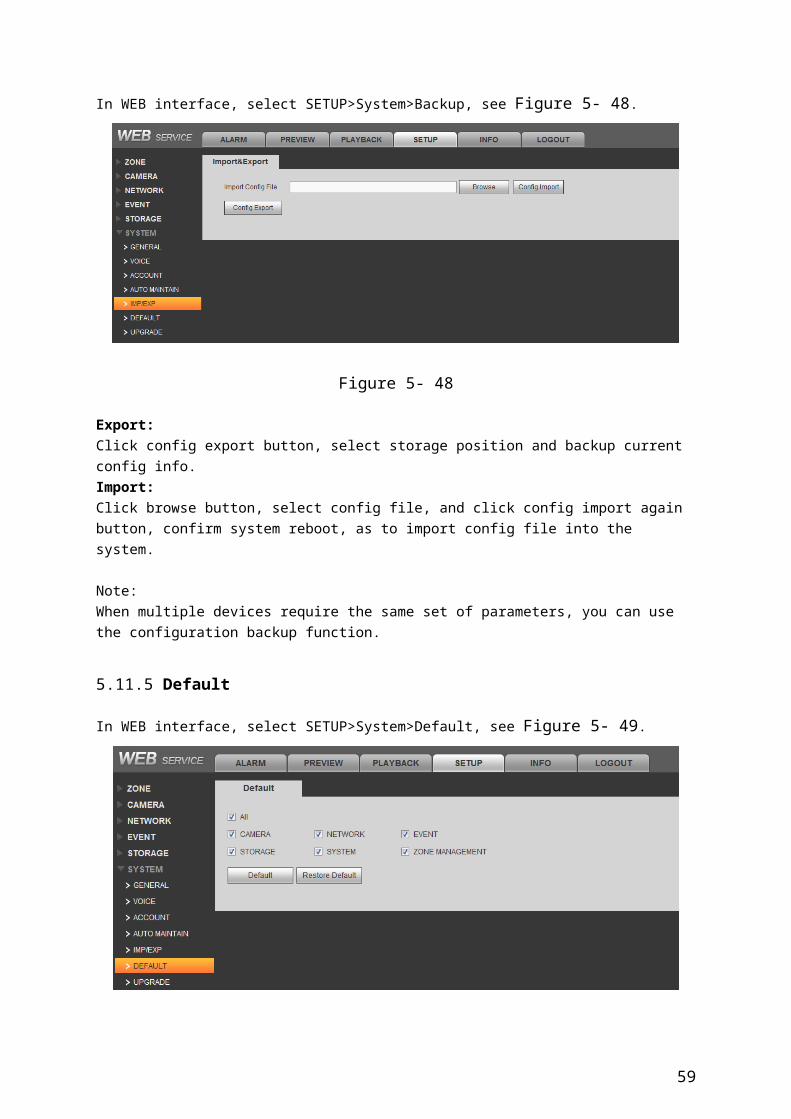
Figure 7- 2
No. Function
1 In this search box, input time and you can accurately search all records on this day.
2 Display all selected video channels.
3 Display each channel recorded record file info at this point of time.
4 Select the backup file information in the list of files, click "download" to the video file on your local PC, the system default is the system disk RecordDownload folder.
Tips:
You can select file to backup in max of 4 channels.
5 Click back button, to return to previous interface.
6 Click download more, to enter download interface, including download by file, by time, and watermark.
By file
61
No. Function
After setting the search conditions, click the "Search" button search the desired file, select the downloaded file in the file list, click download to local to confirm the video format and storage path, the interface displays the download progress bar reaches 100 %, or download was successful.
By timeSet the channel number, stream type, time period, click download to local,
confirmed the video format and store the Road King, the interface displays the download progress bar reaches 100%, or the download was successful.
WatermarkClick local file, select the watermark verification file, click check button, the system begins to check, if the fault is displayed in the watermark tamper message list.
62
8 View Event Info
8.1 View Overall Status InfoIn WEB interface, select alarm>overall status, to view the alarm controller’s detector zone, channel and device overall statuses, see Figure 8- 1.
Figure 8- 1
8.2 View Zone Event InfoYou can view alarm info via WEB or alarm programming keyboard. Via WEB:Select Alarm>Zone Event, to view each zone’s arming/disarming info and detector abnormality info.
Figure 8- 2
Via Alarm Programming Keyboard:
Long press button, dsplay zone 1 to zone alarm 10. 00 * 1234567890 from 1 to 10 of 00 groups within the zone, to see 11 to 20 zones alarm information please enter 01 in this interface, and so on, is 21 to 30 zones to 40 zones 02,31 is 03. See Figure 8- 3.
63
When check box is empty, the zone is normal; when the check box is black, the zone in alarm; when the check box is black and white, the zone is active but no alarm output triggered.
Figure 8- 3
8.3 View Channel Event InfoIn WEB interface, select Alarm>Channel Event, or in overall status interface click channel icon, to view detailed channel abnormality info, including report time, alarm type, record playback and etc, see Figure 8- 4.
Figure 8- 4
8.4 View Local Status InfoIn WEB interface, select Alarm>Local Status, or in overall status interface click local status icon, to view HDD, power, chassis and other abnormality info, see Figure 8- 5.
Figure 8- 5
HDD status: If the device is installed on the hard disk, you can view the hard drive alarms. Power status: View power status, main power fails, backup power-down, the battery voltage
and remaining battery information. Chassis intrusion: Check whether the chassis is normal.
64
9 View WEB Info
9.1 VersionIn WEB interface, select Info>Version, see Figure 9- 1. You can view device type, channel quantity, alarm input/output, system and WEB version.
Figure 9- 1
9.2 LogIn WEB interface, select Info>Log to view system log. Step 1. Select start time, end time and log type. Step 2. Click Search. See Figure 9- 2. Click backup to save log to local.
Figure 9- 2
9.3 Online UserIn WEB interface, select Info>Online User, to view system online user info.
9.4 HDD Info
65
In WEB interface, select Info>HDD Info, to view HDD name, status, capacity and etc.
Note For detailed operation introduction, please refer to our resource CD included in your
package for electronic version of the User’s Manual. Slight difference may be found in user interface. All the designs and software here are subject to change without prior written notice. All trademarks and registered trademarks mentioned are the properties of their
respective owners. If there is any uncertainty or controversy, please refer to the final explanation of us. Please visit our website for more information.
66