

Stainless steels - Nickel Institute...347 (UNS S34700); the grade with Ti is Type 321 (UNS S32100)....
144
Stainless steels and specialty alloys for pulp, paper and biomass conversion A PRACTICAL GUIDE FOR MILL ENGINEERS Nickel Institute Technical Series N o 11 025 KNOWLEDGE FOR A BRIGHTER FUTURE
Transcript of Stainless steels - Nickel Institute...347 (UNS S34700); the grade with Ti is Type 321 (UNS S32100)....

Stainless steels and specialty alloys for pulp, paper and
biomass conversion
A PRACTICAL GUIDE FOR MILL ENGINEERS
Nickel Institute Technical Series No 11 025
KNOWLEDGEFOR A BRIGHTERFUTURE
2. Characteristics of stainless steels and other corrosion resistant alloys
2
Stainless steels and specialty alloys for pulp, paper and biomass conversion
A PRACTICAL GUIDE FOR MILL ENGINEERS
2nd Edition Published 2017
The material presented in this publication has been prepared for the general information of the reader and should not be used or relied on for specific applications without first securing competent advice. The Nickel Institute, its members, staff and consultants do not represent or warrant its suitability for any general or specific use and assume no liability or responsibility of any kind in connection with the information herein.
Prepared by a Task Force of the Metals Subcommittee of the Corrosion and Materials Engineering Committee of the Technical Association of the Pulp and Paper Industry and the Nickel Institute.
Senior Editor: Andrew Garner, P.Eng.
3
1. Introduction . . . . . . . . . . . . . . . . . . . . . . . . . . . . . . . . . . . . . . 5
2. Characteristics of stainless steels and other corrosion resistant alloys . . . . . . . . . . . . . . . . . 7
3. Digesters. . . . . . . . . . . . . . . . . . . . . . . . . . . . . . . . . . . . . . . . 19
4. Oxygen delignification and brown stock washing . . . . . . . . . . . . . . . . . . . . . . . . . 33
5. Chemical recovery . . . . . . . . . . . . . . . . . . . . . . . . . . . . . . . . 37
6. Tall oil manufacture . . . . . . . . . . . . . . . . . . . . . . . . . . . . . . 49
7. Sulphite process . . . . . . . . . . . . . . . . . . . . . . . . . . . . . . . . . 55
8. Neutral sulphite semichemical pulping. . . . . . . . . . . . . . 61
9. High yield mechanical pulping . . . . . . . . . . . . . . . . . . . . . 65
10. Fiber recycling . . . . . . . . . . . . . . . . . . . . . . . . . . . . . . . . . . . 69
11. Bleach plant and pulp/paper stock preparation. . . . . . . . . . . . . . . . . . . . . . . . . . . . . . . . . 71
12. Paper machine . . . . . . . . . . . . . . . . . . . . . . . . . . . . . . . . . . . 79
13. Suction rolls . . . . . . . . . . . . . . . . . . . . . . . . . . . . . . . . . . . . . 87
14. Threaded fasteners . . . . . . . . . . . . . . . . . . . . . . . . . . . . . . . 93
15. Welding. . . . . . . . . . . . . . . . . . . . . . . . . . . . . . . . . . . . . . . . 103
16. Abrasion . . . . . . . . . . . . . . . . . . . . . . . . . . . . . . . . . . . . . . . 113
17. Corrosion . . . . . . . . . . . . . . . . . . . . . . . . . . . . . . . . . . . . . . 117
18. Risk based inspection (RBI). . . . . . . . . . . . . . . . . . . . . . . 123
19. Biomass conversion and biorefineries . . . . . . . . . . . . . . 127
20. Appendix tips . . . . . . . . . . . . . . . . . . . . . . . . . . . . . . . . . . . 139
21. Abbreviations . . . . . . . . . . . . . . . . . . . . . . . . . . . . . . . . . . . 141
Contents

Stainless steels and specialty alloys for pulp, paper and biomass conversion mills
4

5
1. Introduction
This Nickel Institute Reference Book is a major update of the first edition which was published in 2000 and edited by Art Tuthill. The first edition described the use of stainless steels and other corrosion resistant alloys in pulp and paper mill equipment. Since then there have been two major trends from a corrosion and materials perspective: almost every new pulp mill has been constructed in South America and Asia; and the family of commercially available duplex stainless steels has expanded significantly, now including several lower cost lean grades with lower Cr, Ni and Mo content.
Another notable industry trend is the use of advanced automation and improved sensor technology to operate mills with much better control of the process and with fewer personnel. At the end of the 20th Century the focus was on controlling effluents to minimize pollution and water usage. Now the focus has shifted to controlling product quality and improving the cost effectiveness of manufacturing and maintenance. Safety and reliability are the principle drivers for maintenance of fixed and rotating equipment, and there is now a much more systematic attempt to identify the critical damage mechanism, particularly the corrosion mechanisms which are covered extensively in this reference book.
The 21st century also marks the initial development of the bio-economy and new types of products that can be made from trees. Processes are being introduced to make new materials such as cellulose nanocrystals, cellulose fibrils and new products from lignin. New thermo-chemical technologies such as pyrolysis, torrefaction and gasification are coming to the fore as the environment-friendly capability of the forest sector comes of age. Consumer concern about global warming
is driving this transformation. The use of trees grown in sustainable forests is considered carbon-neutral because any net carbon release is recaptured after replanting.
Stainless steel equipment is used to make many of the new green products: choosing the right grade saves capital and maintenance costs. A main objective of this revision is to describe where newer alloys should be considered. Notable examples are the excellent resistance of lean duplex grades in alkaline pulping and recovery environments, and good resistance of super-duplex grades in acidic oxidizing chloride containing environments.
In summary, this reference book spans changes in materials of construction driven by three recent drivers: ecological clean-up, cost efficiency, and new bioeconomy products.
1. Introductionby Andrew Garner

6
Stainless steels and specialty alloys for pulp, paper and biomass conversion mills

7
2. Characteristics of stainless steels and other corrosion resistant alloys
2.1 DESIGNATIONS, PROPERTIES AND SPECIFICATIONS
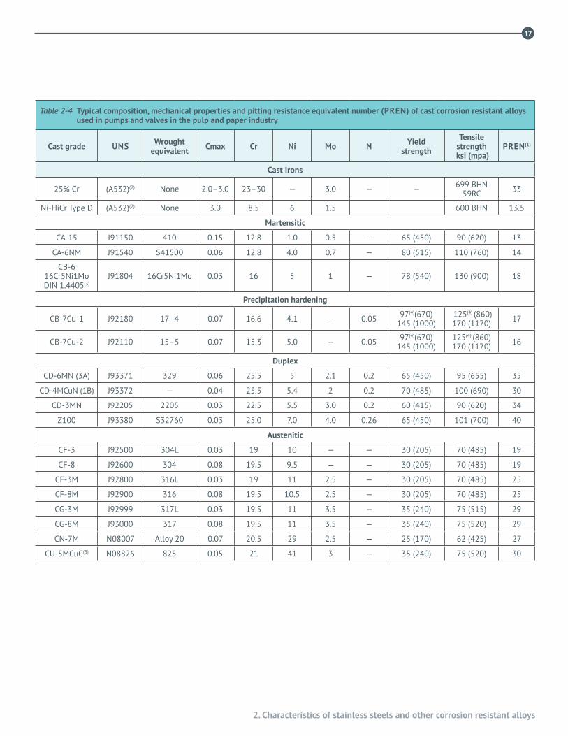
This section acquaints mill engineers with the principal characteristics of the different families of stainless steels and other corrosion resistant alloys used in the pulp and paper industry. Alloy tables in the back of this section give the common name, the Unified Numbering System (UNS), and the European Number (EN), which is similar to the German (DIN) designation, for the alloys used. These tables help in identifying and specifying the alloys regardless of where the equipment was made. The compositions and properties of wrought alloys are shown in Tables 2-1 and 2-2, and of cast alloys in Table 2-4, which also shows the wrought equivalent of the less familiar cast alloys. The common designation of the wrought alloys and the cast grade of the cast alloys is used throughout the text, followed by the UNS designation in parentheses ( ) on first mention in each section of the reference book.
The composition of special-purpose alloys used in rolls, fasteners, welding filler metals, and special applications are given in the individual sections of this bulletin.
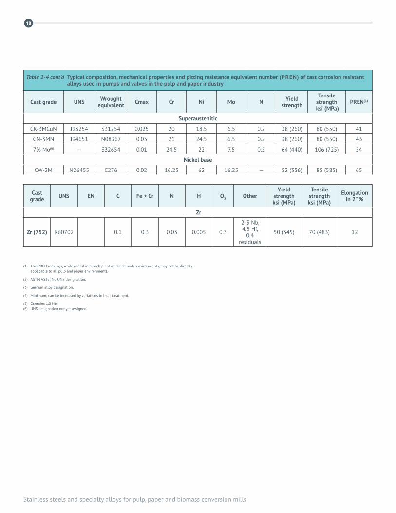
The pitting resistance equivalent number (PREN) for wrought alloys is shown in Table 2-2 and for the cast alloys in Table 2-4. Generally speaking, a higher PREN means the alloy is more resistant to pitting corrosion in oxidizing acid chloride environments.
For any given stainless steel, the mechanical properties, weldability, corrosion resistance, and wear and abrasion resistance depend to a large extent upon its microstructure, which in turn depends upon the alloy composition, the steel making or casting practice, the thermal history, and
the finishing treatment. Stainless steels are subdivided into four different groups, based on their microstructure: austenitic, ferritic, martensitic, and duplex. Each group’s distinctive characteristics are discussed below to provide a better understanding of these terms and general properties as they are encountered in the literature and discussions on corrosion.
2.2 AUSTENITIC STAINLESS STEELSMost stainless steels traditionally used in pulp and paper equipment are austenitic grades. Austenitic alloys, which have a face-centred cubic (FCC) crystal lattice, are non-magnetic, tough, ductile and easily welded because the weld and heat-affected zone microstructures are not greatly affected by welding. Austenitic alloys are hardened by cold work, not by heat treatment. Their corrosion resistance is due primarily to an extremely thin chromium oxide surface film. Molybdenum (Mo) and Nitrogen (N) additions enhance the resistance of these alloys to localized corrosion in chloride-containing solutions.
Stainless steels are normally produced in the “annealed” condition. The term anneal, also solution anneal, used for stainless steels means heat to 1040˚C or higher and water quench to optimize the microstructure. [Annealing a carbon steel involves heating above 750˚C and slow cooling in the furnace to produce its softest condition.]
The basic 18-8 austenitic grade, Type 304 (UNS S30400), has 18% Cr, 8% Ni and up to 0.08% C. Type 316 (UNS S31600) is Type 304 with more nickel, and >2% Mo to improve resistance to localized corrosion, especially by chlorides. More than 0.03% C in Type 304 and 316 makes them vulnerable
2. Characteristics of stainless steels and other corrosion resistant alloys
by Arthur H. Tuthill

8
Stainless steels and specialty alloys for pulp, paper and biomass conversion mills
on welding to “sensitization”, which reduces the corrosion resistance of the grain boundaries, making intergranular corrosion possible. Heat of welding causes chromium to combine with carbon and precipitate chromium carbide at grain boundaries, depleting chromium from the general microstructure in the weld’s heat affected zone (HAZ). This makes the affected zone susceptible to intergranular corrosion, or intergranular attack (IGA).
Adding Nb or Ti to the base composition to combine with carbon prevents IGA. The “stabilized” grade with Nb is Type 347 (UNS S34700); the grade with Ti is Type 321 (UNS S32100). Type 316Ti (UNS S31635) is a stabilized grade of Type 316. Stabilized grades are suitable for welded fabrication and resist IGA under most circumstances.
Modern steel-making processes produce stainless steels with a carbon content low enough to resist chromium carbide formation during normal welding. Low carbon, “L” grades, with a maximum of 0.03 or 0.035% carbon, are standard worldwide for fabricated products. The “L” suffix in the common designation, as in 304L (UNS S30403), 316L (UNS S31603) and, 317L (UNS S31703), designates the low carbon grade suitable for welded fabrication without susceptibility to IGA.
Scandinavian alloy standards include a 0.05% max. C grade. Their designation for <0.05%C Type 304 is 2333 (EN/DIN 1.4301) and for <0.05%C Type 316 is 2347 (EN/DIN 1.4401). There are no UNS designations for the <0.05%C grades. In mixed stainless steel and carbon steel assemblies where the carbon steel must be stress relieved, specifying the 0.03%C, L grade guards against sensitization from prolonged heating and resulting IGA during service.
Austenitic stainless steels are susceptible to localized corrosion in neutral and acidic, oxidizing environments containing chlorides and in other aggressive environments. Localized corrosion occurs at weak spots in the passive film. Embedded iron, rust deposits, burrs, scratches, and other fabrication-related defects can weaken the passive film locally. Restoration of the passive film is a prime objective of post-welding and post-fabrication cleaning. (See 15.6 and 17.4).
Basic austenitic grades are highly susceptible to chloride stress corrosion cracking in chloride-containing environments that cause localized corrosion, above 60˚C. They also are
susceptible to caustic stress corrosion cracking in hot caustic environments above about 120˚C, depending on the tensile stress level.
Austenitic grades with higher Mo, e.g., Type 317L (UNS S31703) with >3% Mo, and Type 317LMN (UNS S31726) with >4% Mo, resist localized corrosion better than 316L. The 6% Mo, super-austenitic alloys are even higher on the ‘ladder of resistance to localized corrosion’, as indicated by their higher PREN. Superaustenitics, especially grades with 1–2% Cu, have higher resistance than regular grades to reducing acid conditions. Nitrogen is a standard addition in 6% Mo super-austenitic, duplex, and other alloys to enhance resistance to localized corrosion and strengthen the alloy.
The 6% Mo grades, which see wide use in bleach plant environments, have no single designation. They are divided into two groups, the older 6% Mo alloys and the newer 7% Mo alloys. The 7% Mo alloys have 0.4–0.5% N, as shown in Tables 2-1, 2-2 and 2-3 Nitrogen level >0.20% increases localized corrosion resistance over the grades with <0.20% N. The family tree of alloys evolved from the original 18Cr-8Ni composition is shown in Figure 2-1.
2.3 FERRITIC GRADES Ferritic stainless steels have a body-centred cubic (BCC) atomic lattice, are magnetic and are hardened by cold work. Ferritic grades have no nickel: Type 430 (UNS S43000), with 16 – 18% Cr, and Type 446 (UNS S44600) are common grades. Ferritic grades are less expensive, stronger and have lower resistance to localized corrosion than Type 304. Type 444 (UNS S44400), with 18Cr and 2Mo is used for Yankee drier hoods.
Ferritic grades have substantially higher resistance to chloride and caustic stress corrosion cracking than austenitic grades. Ferritic stainless steels are subject to 475˚C embrittlement when exposed in the 325–650˚C range for a prolonged period – this must be considered when welding these grades.
A low carbon, weldable, 12% chromium ferritic stainless steel, UNS S41003, unpainted, is a good alternative to carbon steel for tanks, chutes and structures in many water and alkaline environments.

9
2. Characteristics of stainless steels and other corrosion resistant alloys
2.4 MARTENSITIC STAINLESS STEELS Martensitic stainless steels, with a body-centred tetragonal atomic lattice elongated along one axis are hardened by heat treatment. High hardenability severely limits their weldability except under carefully controlled conditions. Low Cr content limits resistance to uniform and localized corrosion. High hardness gives good resistance to wear and abrasion.
Hardened martensitic grades resist chloride stress corrosion cracking but are susceptible to hydrogen cracking. This limits their usefulness in equipment where hydrogen may be generated in acidic corrosion reactions. Martensitic stainless steels are subject to 475˚C embrittlement when exposed to temperatures in the 325-650˚C range during heat treatment.
Low carbon, cast martensitic stainless steel, CB6 (UNS J91804) and CA-6NM (UNS J91540) are weldable, like low-carbon ferritic grade S41003, and are used for high strength and abrasion resistance.
2.5 PRECIPITATION HARDENING GRADES
Low Cr, ferritic stainless steels can be deliberately hardened adding small amounts of alloying elements that form solid-state precipitates in the microstructure when the alloy is heated between 500–900˚C. Common grades 17-4 PH (UNS S17400) and 15-5 PH (UNS S15500), with corrosion resistance comparable to Type 304L, are used for high strength shafts and fasteners.
Compositions and properties of these alloys are listed in Tables 2-1 and 2-2. Precipitation-hardening stainless steels, like martensitic grades, pose special problems for welding.
2.6 DUPLEX STAINLESS STEELS Duplex stainless steels get their name from a roughly 50-50, austenite-ferrite microstructure. Combining the two microstructures increases the alloy’s strength and hardness, which improves wear and erosion resistance. Duplex grades resist chloride stress corrosion cracking at much higher temperatures than austenitic grades like Types 304L and
316L. High Cr content of duplex grades provides excellent corrosion resistance in alkaline pulping and recovery environments.
Modern duplex stainless steels have evolved into three groups:
• Lean grades have low Ni and little or no Mo, good mechanical properties, but low resistance to chloride localized corrosion (lowest pitting resistance). Examples are 2304 (UNS S32304), 2101 (UNS S32101) and 2002 (UNS S32002)—first two digits are Cr content, last two are Ni content.
• Regular grades have >4% Ni and >2.5% Mo, similar mechanical properties and substantially better resistance to localized corrosion than lean grades. Classic regular grades are 2205 (UNS S32205/S31803) and 3RE60 (UNS S31500).
• Super grades have >5% Ni and > 3% Mo, higher strength than regular duplex grades and very high resistance to localized corrosion.
• [Specialized “hyper-duplex” grades that resist chloride localized corrosion in all marine applications are available in limited product forms.]
Cast duplex stainless steels are used in pumps, screws and rolls, and duplex grades are the standard for suction roll shells. Wrought lean duplex stainless steels, with the lowest Ni and Mo contents, are recommended for alkaline batch and continuous digesters, liquor tanks and other equipment for alkaline pulping, liquor recovery and extractive bleaching processes.
Welding of duplex grades is similar to austenitic grades but requires more precise control of total time at welding temperature, as discussed elsewhere in this book.
2.7 NICKEL ALLOYSNickel alloys are austenitic, with face-centered cubic atomic structure, non-magnetic, and like all austenitic alloys, are readily welded.
High cost limits these alloys to special applications, for example Alloy G30 (UNS N06030), G35 (UNS N06035) and Alloy C276 (UNS N10276) are used as filler metal for welding 6% Mo super-austenitic alloys, and Hastelloy C-22

10
Stainless steels and specialty alloys for pulp, paper and biomass conversion mills
(UNS N06022) and cast CW-2M (UNS N26455) are used in high-shear mixers and in other D-stage bleaching process equipment. High nickel alloys are susceptible to transpassive corrosion in D-stage environments with pH >4.
2.8 OTHER ALLOYSTitanium and zirconium have useful applications in pulp and paper. Zirconium has been found useful in the high shear mixers in hydrogen peroxide bleaching.
Welding Grades Precipitation Hardening
Duplex Grades
Machining Grades
Add Mo to Increase Corrosion Resistance
Prevention of IGA(Intergranular Attack)
After Welding
Increase Strength andCorrosion Resistance
High Strength
321
347
304L
303
303Se
17-4
15-5
2304
2205
2507
316L 317L904L
317LMN7% MoFamily
Ni Cr MoAlloys
6% MoFamily
Add 2-3%Mo
Add 3-4%Mo
Add 4-5%Mo
Add 6%Mo
Add 7%Mo
Add MoreMo + Ni
304(18-8)
Add Ti
Add S or Se
Add Cu, Ti, AlReduce Ni
Increase CrReduce Ni
Add N
Increase CrReduce Ni
Add NAdd Mo
Add Nb
Reduce C
Figure 2-1 Family of alloys derived from Type 304 (S30400 or “18-8”) stainless steels

11
2. Characteristics of stainless steels and other corrosion resistant alloys
Table 2-1 Typical composition of wrought corrosion resistant alloys for the pulp and paper industry
Common UNS EN(1)Typical composition in weight percent
Cmax Cr Ni Mo N Cu Other
Austenitic
303 S30300 1.4305 0.15 18 9 — — — 0.20 max P 0.15 min S
304 S30400 1.4301 0.08 18 9 — — — —
304L S30403 1.4306 0.03 18 10 — — — —
321 S32100 1.4541 0.08 18 10.5 — — — Ti 5x (C + N) min, 0.70 max
347 S34700 1.4550 0.08 18 11 — — — (Nb + Ta) 10xC min, 1.0 max
N60 S21800 — 0.10 17 8.5 — 0.15 — 8 Mn, 4 Si
316 S31600 1.4401 0.08 17 11 2.1 — — —
316L S31603 1.4404 0.03 17 11 2.1 — — —
316L-2.5% min Mo S31603 1.4435 0.03 17 12 2.6 — — —
317 S31700 — 0.08 19 12 3.1 — — —
317L S31703 1.4438 0.03 19 12 3.1 — — —
317LMN S31726 1.4439 0.025 18.5 14.5 4.1 0.15 — —
Alloy 20 N08020 (2.4660) 0.07 20 34 2.1 — 3.5 Nb 8 x C min, 1.00 min
Alloy 825 N08825 (2.4858) 0.05 21.5 42 3.1 — 2 0.9 Ti
Alloy 904L N08904 1.4539 0.02 20 25 4.1 — 1.5 —
4565 S34565 1.4565 .03 24 17 4.5 0.40 — 5.5 Mn
6% Mo
N08367 — 0.03 20.5 24.5 6.1 0.20 0.1 —
S31254 1.4547 0.02 20 18 6.1 0.20 0.8 —
N08926 1.4529 0.02 20 25 6.1 0.20 1.0 —
N08026 — 0.03 24 35 6.1 0.13 3 —
7% Mo
S32654 1.4652 0.02 24.5 22 7.2 0.50 0.5 3.5 Mn
S31266 1.4659 0.03 24 22.5 6 0.45 1.5 2.0 W 3.0 Mn
N08031 1.4562 0.02 27 31 6.1 0.20 1.2 —

12
Stainless steels and specialty alloys for pulp, paper and biomass conversion mills
Table 2-1 cont’d Typical composition of wrought corrosion resistant alloys for the pulp and paper industry, in weight percent
Common UNS EN(1)Typical composition
Cmax Cr Ni Mo N Cu Other
Ferritic
430 S43000 1.4016 0.12 17.0 — — — — —
12 Cr S41003 1.4003 0.03 11.5 0.65 — — — —
Martensitic
410 S41000 1.4006 0.15 12.5 — — — — —
416 S41600 1.4005 0.15 13 — — — — 0.15 min S
420 S42000 1.4021 >0.15 13 — — — — —
440C S44004 1.4125 1.20 17 — 0.75 — — —
16Cr 5Ni 1Mo — 1.4418 0.05 16 5 1.00 — — —
Precipitation hardening
15-5 S15500 1.4545 0.07 14.7 4.5 — — 3.5 0.30 (Nb + Ta)
17-4 S17400 1.4542 0.07 16.5 4.0 — — 4.0 0.30 (Nb + Ta)
Duplex
ATI 2102® S82011 — 0.03 21.0 1.5 0.5 0.20 — 2.5 Mn
URANUS® 2202 S32202 1.4062 0.03 22.0 2.0 0.2 0.2 —
LDX2101® S32101 1.4162 0.04 21.5 1.5 0.5 0.22 0.5 5.0 Mn
2304 S32304 1.4362 0.03 23.0 4.5 0.5 0.10 0.5 —
ATI 2003® S32003 — 0.03 21.0 3.5 1.8 0.17 —
3RE60 S31500 1.4417 0.03 18.5 4.5 2.6 0.08 — 1.5 Si
LDX2404® S82441 1.4662 0.03 24.0 3.6 1.6 0.27 — 3 Mn
2205 S31803 1.4462 0.03 22.0 5.5 3.0 0.12 — —
2205 S32205(2) — 0.03 22.5 5.5 3.25 0.17 — —
329 S32900 1.4460 0.08 25.0 4.0 1.5 — — —
2507 S32750 1.4410 0.03 25.0 7.0 4.0 0.28 — —
Z100 S32760 1.4501 0.03 25.0 7.0 4.0 0.26 0.5 0.06 W
13
2. Characteristics of stainless steels and other corrosion resistant alloys
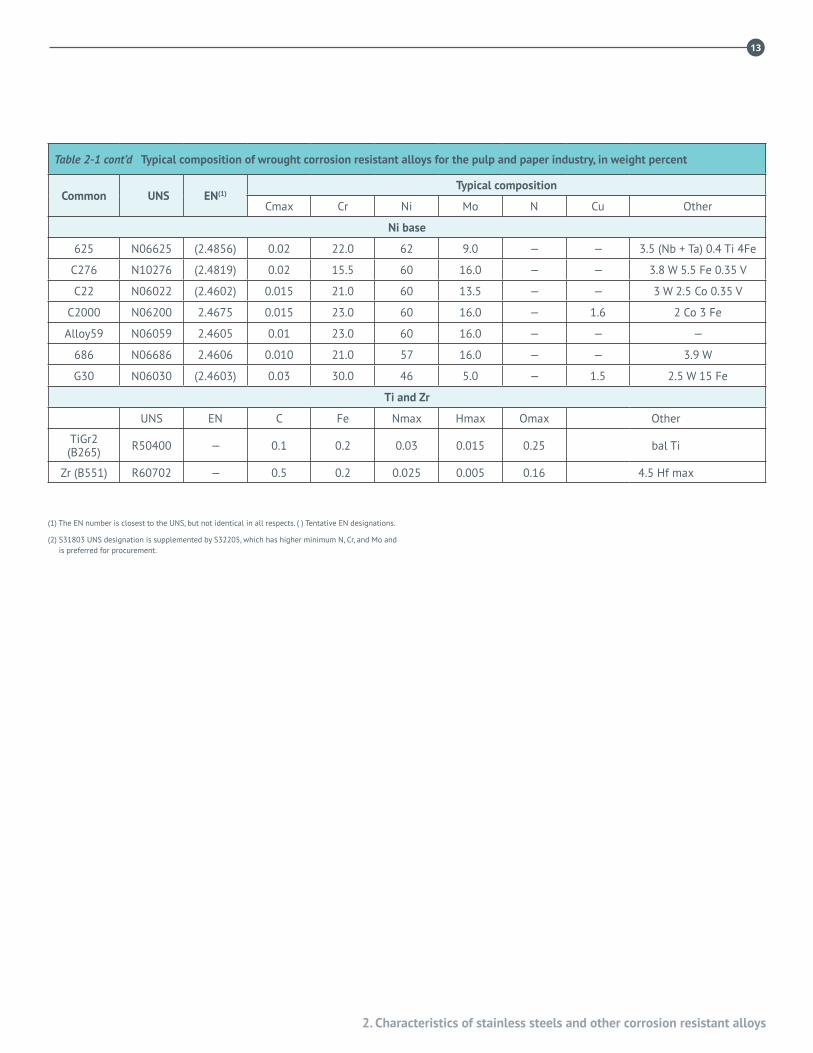
Table 2-1 cont’d Typical composition of wrought corrosion resistant alloys for the pulp and paper industry, in weight percent
Common UNS EN(1)Typical composition
Cmax Cr Ni Mo N Cu Other
Ni base
625 N06625 (2.4856) 0.02 22.0 62 9.0 — — 3.5 (Nb + Ta) 0.4 Ti 4Fe
C276 N10276 (2.4819) 0.02 15.5 60 16.0 — — 3.8 W 5.5 Fe 0.35 V
C22 N06022 (2.4602) 0.015 21.0 60 13.5 — — 3 W 2.5 Co 0.35 V
C2000 N06200 2.4675 0.015 23.0 60 16.0 — 1.6 2 Co 3 Fe
Alloy59 N06059 2.4605 0.01 23.0 60 16.0 — — —
686 N06686 2.4606 0.010 21.0 57 16.0 — — 3.9 W
G30 N06030 (2.4603) 0.03 30.0 46 5.0 — 1.5 2.5 W 15 Fe
Ti and Zr
UNS EN C Fe Nmax Hmax Omax Other
TiGr2 (B265) R50400 — 0.1 0.2 0.03 0.015 0.25 bal Ti
Zr (B551) R60702 — 0.5 0.2 0.025 0.005 0.16 4.5 Hf max
(1) The EN number is closest to the UNS, but not identical in all respects. ( ) Tentative EN designations.
(2) S31803 UNS designation is supplemented by S32205, which has higher minimum N, Cr, and Mo and is preferred for procurement.
14
Stainless steels and specialty alloys for pulp, paper and biomass conversion mills
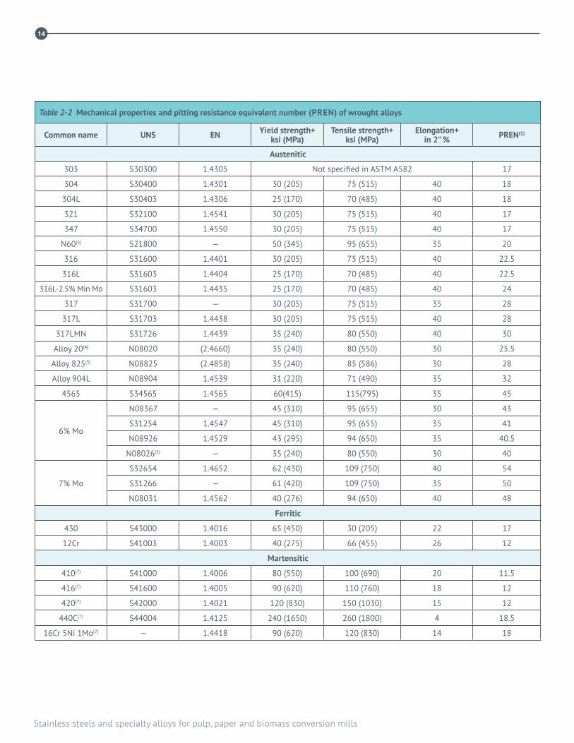
Table 2-2 Mechanical properties and pitting resistance equivalent number (PREN) of wrought alloys
Common name UNS EN Yield strength+ ksi (MPa)
Tensile strength+ ksi (MPa)
Elongation+ in 2” % PREN(1)
Austenitic
303 S30300 1.4305 Not specified in ASTM A582 17
304 S30400 1.4301 30 (205) 75 (515) 40 18
304L S30403 1.4306 25 (170) 70 (485) 40 18
321 S32100 1.4541 30 (205) 75 (515) 40 17
347 S34700 1.4550 30 (205) 75 (515) 40 17
N60(3) S21800 — 50 (345) 95 (655) 35 20
316 S31600 1.4401 30 (205) 75 (515) 40 22.5
316L S31603 1.4404 25 (170) 70 (485) 40 22.5
316L-2.5% Min Mo S31603 1.4435 25 (170) 70 (485) 40 24
317 S31700 — 30 (205) 75 (515) 35 28
317L S31703 1.4438 30 (205) 75 (515) 40 28
317LMN S31726 1.4439 35 (240) 80 (550) 40 30
Alloy 20(4) N08020 (2.4660) 35 (240) 80 (550) 30 25.5
Alloy 825(5) N08825 (2.4858) 35 (240) 85 (586) 30 28
Alloy 904L N08904 1.4539 31 (220) 71 (490) 35 32
4565 S34565 1.4565 60(415) 115(795) 35 45
6% Mo
N08367 — 45 (310) 95 (655) 30 43
S31254 1.4547 45 (310) 95 (655) 35 41
N08926 1.4529 43 (295) 94 (650) 35 40.5
N08026(5) — 35 (240) 80 (550) 30 40
7% Mo
S32654 1.4652 62 (430) 109 (750) 40 54
S31266 — 61 (420) 109 (750) 35 50
N08031 1.4562 40 (276) 94 (650) 40 48
Ferritic
430 S43000 1.4016 65 (450) 30 (205) 22 17
12Cr S41003 1.4003 40 (275) 66 (455) 26 12
Martensitic
410(7) S41000 1.4006 80 (550) 100 (690) 20 11.5
416(7) S41600 1.4005 90 (620) 110 (760) 18 12
420(7) S42000 1.4021 120 (830) 150 (1030) 15 12
440C(7) S44004 1.4125 240 (1650) 260 (1800) 4 18.5
16Cr 5Ni 1Mo(7) — 1.4418 90 (620) 120 (830) 14 18

15
2. Characteristics of stainless steels and other corrosion resistant alloys
Table 2-2 cont’d Mechanical properties and pitting resistance equivalent number (PREN) of wrought alloys
Common name UNS EN Yield strength+ ksi (MPa)
Tensile strength+ ksi (MPa)
Elongation+ in 2” % PREN(1)
Precipitation hardening
15-5 PH(8) S15500 1.4545 105 (725) 135 (930) 16 14
17-4 PH(8) S17400 1.4542 105 (725) 135 (930) 16 15
Duplex
ATI 2102® S82011 — 65 (450) 95 (655) 30 26
URANUS® 2202 S32202 1.4602 65 (450) 95 (655) 30 26
LDX2101® S32101 1.4162 65 (450) 94 (650) 25 27
2304 S32304 1.4362 58 (400) 87 (600) 25 27
ATI 2003® S32003 — 65 (450) 95 (655) 30 30
3RE60(6) S31500 1.4417 64 (440) 92 (630) 30 30
LDX 2404® S82441 1.4662 70 (480) 99 (680) 25 34
2205S31803(2) 1.4462 65 (450) 90 (620) 25 34
S32205 —
329 S32900 1.4460 70 (485) 90 (620) 15 30
2507 S32750 1.4410 80 (550) 116 (795) 15 38
Z100 S32760 1.4501 80 (550) 109 (750) 25 40
Ni base
625(9) N06625 (2.4856) 55 (379) 110 (758) 30 46.5
C276(10) N10276 (2.4819) 41 (283) 100 (690) 40 64
C22(10) N06022 (2.4602) 45 (310) 100 (690) 45 61
C2000(10) N08200 2.4675 41(283) 100(690) 45 68
Alloy59(10) N08059 2.4605 45(310) 100(690) 45 68
686(10) N08686 2.4606 45(310) 100(690) 45 70
G30(11) N06030 (2.4603) 35 (240) 85 (586) 30 41
Ti and Zr
TiGr2(13) R50400 — 40 (275) 50 (345) 20 —
Zr(14) R60702 — 50 (205) 55 (379) 16 —
+ Minimum values for hot rolled plate per ASTM A240 unless otherwise indicated.
(1) Pitting Resistance Equivalent Number % Cr + 3.3% Mo + 16% N based on minimum composition. The PREN rankings, while useful in bleach plant acidic chloride environments, may not be applicable to other pulp and paper environments.
(2) The original S31803 UNS designation has been supplemented by S32205 which has higher minimum N, Cr, and Mo. S32205 is often preferred for procurement.
(3) ASTM A479
(4) ASTM B463
(5) ASTM B424
(6) ASTM A790
(7) Typical for hardened and tempered condition
(8) ASTM A564 H1150 condition
(9) ASTM B443
(10) ASTM B575
(11) ASTM B582
(12) ASTM F468
(13) ASTM B265
(14) ASTM B551

16
Stainless steels and specialty alloys for pulp, paper and biomass conversion mills
Table 2-3 Producers of 6% and 7% MO austenitic stainless steels
Producer designation UNS designation Producer
254 SMO® S31254 Outokumpu
AL-6XN® N08367 ATI
1925hMO™ N08926 VDM
25–6MO™ N08926 Special Metals
654 SMO® S32654 Outokumpu
UR B66™ S31266 Industeel
3127™ N08031 VDM
™ & ® Trademark or Registered Trademark, as indicated, of producer shown.
* Prior to the year 2000, B specifications were used for procurement of plate, sheet, strip and pipe of several of the 6% Mo alloys. As of 2000, these product forms are found in A312, A358 and A240.
See footnote below.
In about 1990, the ASTM sought to harmonize its definitions with those of the rest of the world. One result was that alloys in which iron is the largest element by weight percent (with low carbon content) were defined as steels, and steels with more than 10.5% chromium were defined as stainless steels. Previously the ASTM had required that an alloy have at least 50% iron to be treated as stainless steel. Therefore, most but not quite all of the existing grades with UNS designations of N08xxx became eligible for inclusion in the ASTM A-specifications covering steels. It was agreed that these grades would be individually qualified for inclusion in the A-specifications. Those grades already having a UNS designation in the form N08xxx would retain that designation as an indication of their history. New grades that would previously have been “nickel-base alloys” designated N08xxx are now designated as stainless steels with an appropriate S3xxxx designation. It was agreed that the B-specifications for the existing N08xxx stainless steels would eventually be terminated, but that there would be no great hurry to do so because users have drawings and qualified procedures for these grades as nickel-base alloys. Examples of grades that are now in the A-specifications are 904L (UNS N08904), Alloy 20 (UNS N08020), and two of the 6% Mo grades (UNS N08367 and UNS N08926).
17
2. Characteristics of stainless steels and other corrosion resistant alloys
Table 2-4 Typical composition, mechanical properties and pitting resistance equivalent number (PREN) of cast corrosion resistant alloys used in pumps and valves in the pulp and paper industry
Cast grade UNS Wrought equivalent Cmax Cr Ni Mo N Yield
strength
Tensile strength
ksi (mpa)PREN(1)
Cast Irons
25% Cr (A532)(2) None 2.0–3.0 23–30 — 3.0 — — 699 BHN 59RC 33
Ni-HiCr Type D (A532)(2) None 3.0 8.5 6 1.5 600 BHN 13.5
Martensitic
CA-15 J91150 410 0.15 12.8 1.0 0.5 — 65 (450) 90 (620) 13
CA-6NM J91540 S41500 0.06 12.8 4.0 0.7 — 80 (515) 110 (760) 14
CB-6 16Cr5Ni1Mo DIN 1.4405(3)
J91804 16Cr5Ni1Mo 0.03 16 5 1 — 78 (540) 130 (900) 18
Precipitation hardening
CB-7Cu-1 J92180 17–4 0.07 16.6 4.1 — 0.05 97(4)(670) 145 (1000)
125(4) (860) 170 (1170) 17
CB-7Cu-2 J92110 15–5 0.07 15.3 5.0 — 0.05 97(4)(670) 145 (1000)
125(4) (860) 170 (1170) 16
Duplex
CD-6MN (3A) J93371 329 0.06 25.5 5 2.1 0.2 65 (450) 95 (655) 35
CD-4MCuN (1B) J93372 — 0.04 25.5 5.4 2 0.2 70 (485) 100 (690) 30
CD-3MN J92205 2205 0.03 22.5 5.5 3.0 0.2 60 (415) 90 (620) 34
Z100 J93380 S32760 0.03 25.0 7.0 4.0 0.26 65 (450) 101 (700) 40
Austenitic
CF-3 J92500 304L 0.03 19 10 — — 30 (205) 70 (485) 19
CF-8 J92600 304 0.08 19.5 9.5 — — 30 (205) 70 (485) 19
CF-3M J92800 316L 0.03 19 11 2.5 — 30 (205) 70 (485) 25
CF-8M J92900 316 0.08 19.5 10.5 2.5 — 30 (205) 70 (485) 25
CG-3M J92999 317L 0.03 19.5 11 3.5 — 35 (240) 75 (515) 29
CG-8M J93000 317 0.08 19.5 11 3.5 — 35 (240) 75 (520) 29
CN-7M N08007 Alloy 20 0.07 20.5 29 2.5 — 25 (170) 62 (425) 27
CU-5MCuC(5) N08826 825 0.05 21 41 3 — 35 (240) 75 (520) 30
18
Stainless steels and specialty alloys for pulp, paper and biomass conversion mills
Table 2-4 cont’d Typical composition, mechanical properties and pitting resistance equivalent number (PREN) of cast corrosion resistant alloys used in pumps and valves in the pulp and paper industry
Cast grade UNS Wrought equivalent Cmax Cr Ni Mo N Yield
strength
Tensile strength
ksi (MPa)PREN(1)
Superaustenitic
CK-3MCuN J93254 S31254 0.025 20 18.5 6.5 0.2 38 (260) 80 (550) 41
CN-3MN J94651 N08367 0.03 21 24.5 6.5 0.2 38 (260) 80 (550) 43
7% Mo(6) — S32654 0.01 24.5 22 7.5 0.5 64 (440) 106 (725) 54
Nickel base
CW-2M N26455 C276 0.02 16.25 62 16.25 — 52 (356) 85 (585) 65
Cast grade UNS EN C Fe + Cr N H O2 Other
Yield strength ksi (MPa)
Tensile strength ksi (MPa)
Elongation in 2” %
Zr
Zr (752) R60702 0.1 0.3 0.03 0.005 0.3
2-3 Nb, 4.5 Hf,
0.4 residuals
50 (345) 70 (483) 12
(1) The PREN rankings, while useful in bleach plant acidic chloride environments, may not be directly applicable to all pulp and paper environments.
(2) ASTM A532; No UNS designation.
(3) German alloy designation.
(4) Minimum; can be increased by variations in heat treatment.
(5) Contains 1.0 Nb. (6) UNS designation not yet assigned.
3. Digesters
1919
There are two kinds of chemical pulping processes: batch cooking and continuous cooking. Originally, there was only batch cooking. Continuous cooking arrived in the late 1950s. Mills having batch cooking typically have several batch digesters, while mills with continuous cooking may have only one or two continuous digesters. Batch digesters are typically much smaller than continuous digesters. Materials of construction for both batch and continuous digesters have evolved in parallel, from carbon steel, to austenitic stainless steels (both solid and clad), and finally to solid duplex stainless steels.
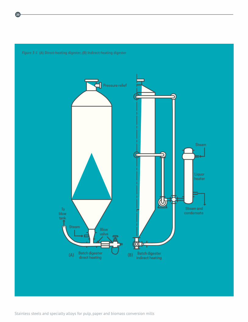
3.1 BATCH DIGESTERS A typical batch digester consists of a vertical cylindrical shell with a hemispherical or ellipsoidal top head and a conical bottom, as shown in cross-sectional view in Figure 3-1. Batch digesters are typically 2.4 to 4.0 m in diameter and up to 18 m high. Softwood or hardwood chips are fed into the top of the vessel, along with hot cooking liquor, which helps pack the chips in the vessel. The cooking liquor consists of a mixture of white and black liquors in various volume ratios depending on the pulp product being manufactured.
Batch cooking can be either truly batch where the empty digester is filled, pressurized, and blown empty, or some form of displacement process where the batch digester is always pressurized and never empty. In conventional batch cooking, after filling the vessel with wood chips and liquor, the batch digester is closed and cooking begins, with heat supplied either by direct injection of steam (Figure 3-1(A)) or by indirect steam heating (Figure 3-1(B)) using an external heat exchanger. A typical batch cook lasts about 2 hours. The cooking temperature of approximately 170˚C is reached
after about 1 hour. At this time, direct steaming is usually stopped. At the end of the cook, the pulp is normally blown out the bottom of the vessel into a blow tank. From there the pulp goes to brown stock washers where the spent cooking liquor is separated from the pulp. Steam from the blow tank is removed for heat recovery and condensed in brown stock wash water. In some mills the liquors and pulp are removed by displacement instead of by blowing.
Over the years, there has been a trend to increase production by decreasing batch cook times. This requires the use of higher ratios of white-to-black liquor and higher temperatures. Both practices cause increased corrosion rates of both carbon and stainless steels in batch digesters.
Materials of construction
Most batch digesters have been constructed from carbon steel with generous corrosion allowances (19 mm, or more), such that they can remain in service for perhaps 10 years before some means of protection must be used. In the 1950s and 1960s digesters in North America were constructed using a modified low-silicon (0.02% Si max) grade of ASTM A285 carbon steel, with low-silicon welds on the process side. Later, batch digesters were made from ASTM A516-Grade 70 carbon steel, a higher-strength pressure vessel steel in which the silicon content is controlled in the range 0.15% to 0.30% Si, and without low-silicon weld caps. Higher silicon content carbon steels corrode more rapidly in alkaline pulping liquors than do low-silicon content carbon steels.
Numerous batch digesters have been constructed using clad plate (either roll or explosion-bonded) with austenitic stainless steel on the inside and carbon steel on the outside. Types 304L (UNS S30403) and 316L (UNS S31603) stainless steels can both experience significant corrosion in batch
3. Digestersby Angela Wensley, Angela Wensley Engineering
20
Stainless steels and specialty alloys for pulp, paper and biomass conversion mills
Pressure relief
Liquorheater
Steam andcondensate
Steam
Steam
Batch digesterindirect heating
Batch digesterdirect heating
Toblowtank
Blowvalve
(A) (B)
Figure 3-1 (A) Direct-heating digester, (B) Indirect-heating digester
3. Digesters
21
digesters. Nonetheless, both alloys have been used in the form of clad plate where the service life is limited by the thickness of the cladding. Some batch digesters have been constructed with a stainless steel weld overlay lining, although this practice is not common. Stainless steel weld overlays are discussed in some depth later in this chapter under “Protection of Batch Digesters.” Some batch digesters have been constructed using cold stretched Type 304 (UNS S30400) stainless steel in accordance with the Swedish cold stretching code.
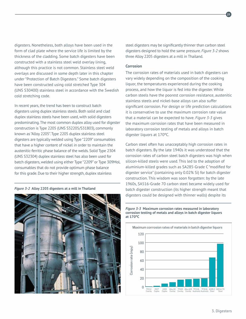
In recent years, the trend has been to construct batch digesters using duplex stainless steels. Both solid and clad duplex stainless steels have been used, with solid digesters predominating. The most common duplex alloy used for digester construction is Type 2205 (UNS S32205/S31803), commonly known as “Alloy 2205”. Type 2205 duplex stainless steel digesters are typically welded using Type “2209” consumables that have a higher content of nickel in order to maintain the austenitic-ferritic phase balance of the welds. Solid Type 2304 (UNS S32304) duplex stainless steel has also been used for batch digesters, welded using either Type “2209” or Type 309MoL consumables that do not provide optimum phase balance for this grade. Due to their higher strength, duplex stainless
steel digesters may be significantly thinner than carbon steel digesters designed to hold the same pressure. Figure 3-2 shows three Alloy 2205 digesters at a mill in Thailand.
Corrosion
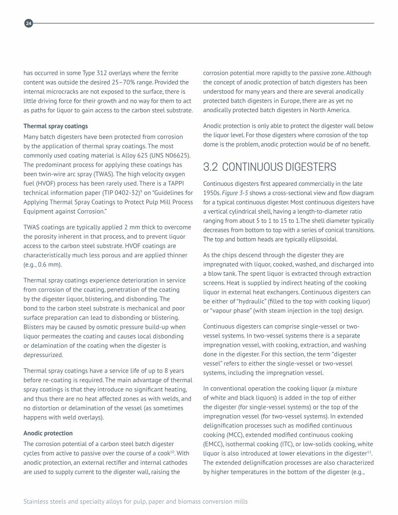
The corrosion rates of materials used in batch digesters can vary widely depending on the composition of the cooking liquor, the temperatures experienced during the cooking process, and how the liquor is fed into the digester. While carbon steels have the poorest corrosion resistance, austenitic stainless steels and nickel-base alloys can also suffer significant corrosion. For design or life prediction calculations it is conservative to use the maximum corrosion rate value that a material can be expected to have. Figure 3-3 gives the maximum corrosion rates that have been measured in laboratory corrosion testing of metals and alloys in batch digester liquors at 170ºC.
Carbon steel often has unacceptably high corrosion rates in batch digesters. By the late 1940s it was understood that the corrosion rates of carbon steel batch digesters was high when silicon-killed steels were used. This led to the adoption of aluminium-killed grades such as SA285-Grade C “modified for digester service” (containing only 0.02% Si) for batch digester construction. This wisdom was soon forgotten: by the late 1960s, SA516-Grade 70 carbon steel became widely used for batch digester construction (its higher strength meant that digesters could be designed with thinner walls) despite its
Figure 3-2 Alloy 2205 digesters at a mill in Thailand
0
20
40
60
80
100
120
Maximum corrrosion rates of materials in batch digester liquors
TP312Overlay
TP309Overlay
TP318LAustinetic
TP304LAustinetic
A285-CSteel
A8916-70Steel
Alloy 625Overlay
2507Duplex
2205Duplex
Alloy 82Overlay
Cor
rosi
on ra
te (m
py)
Figure 3-3 Maximum corrosion rates measured in laboratory corrosion testing of metals and alloys in batch digester liquors at 170ºC

22
Stainless steels and specialty alloys for pulp, paper and biomass conversion mills
higher content of silicon (0.15 – 0.30% Si) that gave more rapid corrosion rates.
The zone of most severe corrosion in a batch digester varies from mill to mill, and sometimes from digester to digester within the same mill. Usually, the corrosion is most pronounced in the cylindrical section. In other digesters it is worst in the bottom cone; in yet others, in the top dome. Carbon steel batch digesters often experience corrosion in a large inverted horseshoe-shaped pattern where the liquor contacts the wall during filling1. Over time, the area of most severe corrosion will extend around the digester circumference and also to higher and lower elevations in the digester.
Conventional austenitic stainless steels can also undergo rapid corrosion in batch digesters. Corrosion of stainless steels in batch digester liquors is primarily a function of the chromium content of the alloy. Type 316L has 16–18% Cr and Type 304L has 18–20% Cr. Research by Audouard2 on corrosion rates experienced during the phenomenon of “hot plate boiling” revealed that duplex stainless steels resist corrosion better than conventional austenitic grades. This is due to the higher chromium content of the duplex grades (22% Cr in Type 2205, 23% Cr in Type 2305, and 25% Cr in Type 2507).
Stainless steel weld overlays can experience rapid corrosion if the dilution of the filler metal with the carbon steel substrate reduces the chromium content of the weld metal below approximately 20%3. Depending on the dilution with the carbon steel substrate, conventional single-pass Type 309L (UNS S30980) stainless steel weld overlays may have as-deposited chromium content as low as 16%, an amount that is insufficient for corrosion resistance in most batch digester liquor environments. Corrosion testing in several batch digester liquors has revealed that at least 24% Cr content is required for stainless steel weld overlays to have acceptable corrosion resistance in aggressive digester environments. Depending on the welding process, duplex stainless steel weld overlays such as Type 312 (UNS S31200) can have 22–28% Cr content when applied over a carbon steel substrate.
Low chromium content can also result in poor weld microstructures that are susceptible to corrosion. TAPPI guidelines give minimum as-deposited chemistry
requirements for stainless steel weld overlays, along with criteria for soundness and structural uniformity4. An additional problem with stainless steel weld overlays in batch digesters is the formation of large cavities beneath locations of pinholes or hot cracks in the overlays. The effective thickness of the overlay at a pinhole or hot crack may be very small or even zero. Once the overlay is completely penetrated and liquor gains access to the underlying carbon steel, the substrate can corrode rapidly, producing a large semi-circular cavity that can quickly grow completely through the digester wall. The liquor inside the cavity remains aggressive since it is refreshed during each liquor filling cycle.
The modern trend is to construct new batch digesters using duplex stainless steels5. Type 2205 duplex stainless steel contains sufficient chromium to resist rapid corrosion in batch digesters. The molybdenum in Type 2205 is not beneficial for corrosion resistance in alkaline liquors. The higher strength and lower corrosion allowance for duplex steels permit thinner digester walls that offset much of the higher cost of duplex digesters, as compared with carbon steel. Although duplex stainless steels resist corrosion in digesters better than conventional austenitic stainless steels, duplex stainless
Figure 3-4 Selective leaching corrosion of Type 2205 duplex stainless steel in batch digester liquor at 170ºC, by preferential dissolution of the austenite phase

3. Digesters
23
steels can experience selective attack of the austenite phase in the microstructure because the austenite phase is lower in chromium content than is the ferrite phase (Figure 3-4)6. Olsson reports a very low corrosion rate, approximately 0.1 mm after 3 years in service, where selective phase corrosion has occurred7. There have also been rare reports of cracking in duplex stainless steel welds8. The cracking mechanism is unknown but may be solidification cracking from original construction or stress corrosion cracking (SCC) in service. Welds having ferrite contents outside the range of 30% to 70% are considered to be more susceptible to both solidification cracking and SCC.
Protection of batch digesters
Thinned carbon steel batch digesters are most commonly protected by application of a layer of stainless steel weld overlay. Weld overlay has also been applied to extend the service life of digesters with corroded stainless steel cladding or with corroded overlay. Other protective measures include the application of thermal spray coatings or anodic protection systems. Applying build-up with carbon steel weld metal is not considered to be a protective option, since such build-up (e.g., E7018) characteristically has a high content of silicon and typically corrodes much faster than the original digester wall. However, build-up to restore the thickness of very thin sections of carbon steel before applying a stainless steel overlay or thermal spray coating is good practice.
Stainless steel weld overlays
Stainless steel weld overlays are best applied before the corrosion allowance has been completely consumed. TAPPI TIP 0402-03 “Guidelines for Corrosion Resistant Weld Metal Overlay of Digester Vessels in Alkaline Pulping Service” provides much useful information. Overlays in batch digesters are typically applied automatically using either the submerged arc welding (SAW) process or the gas metal arc welding (GMAW) process. Other welding processes may be used for pickup repairs or for smaller areas of overlay, such as around projecting nozzles where automatic equipment does not work.
SAW overlay is typically applied horizontally, with twin electrodes travelling around the circumference of the digester; the second electrode follows behind the first, completely remelting the deposit. GMAW overlay can be
applied either horizontally (“conventional” overlay with a single electrode) or vertically over lengths up to 4 m, using either single or dual torches.
Horizontal weld overlay has been the “conventional” overlay mode in batch digesters for nearly 50 years. Horizontal overlay applied using either the SAW or GMAW processes typically provide a thickness of 6 mm. The minimum applied thickness of a horizontal overlay should be at least 4.8 mm. The vertical down mode typically provides an overlay with a nominal thickness of 4.8 mm and a minimum thickness of 2.5 mm. Vertical overlay may be suitable in certain batch digesters if it can be established (either by corrosion testing or by service experience) that the overlay alloy does not corrode rapidly in the particular liquor environment; otherwise, vertical overlays should be avoided in batch digesters.
The as-deposited composition of a weld overlay is a result of the dilution of the filler metal with the substrate. For overlay on carbon steel, dilution with the carbon steel results in a lower alloy content than that of the wire or electrode. For overlay on stainless steel (or for two-layer overlay) the as-deposited composition may be close to that of the wire or electrode.
Prior to the 1990’s, most stainless steel weld overlays in batch digesters were “Type 309” applied using the SAW process. The wire and flux were specially manufactured to provide the desired as-deposited weld chemistry of 20–23% Cr and 10–12% Ni. The SAW overlays typically had high contents of ferrite that gave good resistance to hot cracking of weld metal on cooling. By the 1990s, the GMAW overlay process became widely used. Type ER309LSi (UNS S30988) wire gave an as-deposited weld chemistry of 16–22% Cr and 9–12.5% Ni. If the wire composition is not well selected, Type 309 GMAW overlays may deposit without ferrite. Fully austenitic overlays are susceptible to hot cracking. In service hot cracks can provide paths for the batch digester liquor to penetrate through the overlay to the underlying carbon steel substrate.
Since the late 1990’s, Type 312 duplex stainless steel weld overlays have predominated in batch digesters. SAW wire and flux chemistries are available that give as-deposited compositions resembling Type 312 stainless steel. GMAW overlay can be done using ER312 wire. Internal microcracking
24
Stainless steels and specialty alloys for pulp, paper and biomass conversion mills
has occurred in some Type 312 overlays where the ferrite content was outside the desired 25–70% range. Provided the internal microcracks are not exposed to the surface, there is little driving force for their growth and no way for them to act as paths for liquor to gain access to the carbon steel substrate.
Thermal spray coatings
Many batch digesters have been protected from corrosion by the application of thermal spray coatings. The most commonly used coating material is Alloy 625 (UNS N06625). The predominant process for applying these coatings has been twin-wire arc spray (TWAS). The high velocity oxygen fuel (HVOF) process has been rarely used. There is a TAPPI technical information paper (TIP 0402-32)9 on “Guidelines for Applying Thermal Spray Coatings to Protect Pulp Mill Process Equipment against Corrosion.”
TWAS coatings are typically applied 2 mm thick to overcome the porosity inherent in that process, and to prevent liquor access to the carbon steel substrate. HVOF coatings are characteristically much less porous and are applied thinner (e.g., 0.6 mm).
Thermal spray coatings experience deterioration in service from corrosion of the coating, penetration of the coating by the digester liquor, blistering, and disbonding. The bond to the carbon steel substrate is mechanical and poor surface preparation can lead to disbonding or blistering. Blisters may be caused by osmotic pressure build-up when liquor permeates the coating and causes local disbonding or delamination of the coating when the digester is depressurized.
Thermal spray coatings have a service life of up to 8 years before re-coating is required. The main advantage of thermal spray coatings is that they introduce no significant heating, and thus there are no heat affected zones as with welds, and no distortion or delamination of the vessel (as sometimes happens with weld overlays).
Anodic protection
The corrosion potential of a carbon steel batch digester cycles from active to passive over the course of a cook10. With anodic protection, an external rectifier and internal cathodes are used to supply current to the digester wall, raising the
corrosion potential more rapidly to the passive zone. Although the concept of anodic protection of batch digesters has been understood for many years and there are several anodically protected batch digesters in Europe, there are as yet no anodically protected batch digesters in North America.
Anodic protection is only able to protect the digester wall below the liquor level. For those digesters where corrosion of the top dome is the problem, anodic protection would be of no benefit.
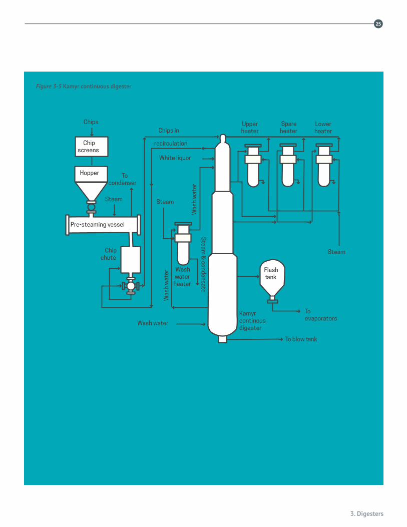
3.2 CONTINUOUS DIGESTERS Continuous digesters first appeared commercially in the late 1950s. Figure 3-5 shows a cross-sectional view and flow diagram for a typical continuous digester. Most continuous digesters have a vertical cylindrical shell, having a length-to-diameter ratio ranging from about 5 to 1 to 15 to 1.The shell diameter typically decreases from bottom to top with a series of conical transitions. The top and bottom heads are typically ellipsoidal.
As the chips descend through the digester they are impregnated with liquor, cooked, washed, and discharged into a blow tank. The spent liquor is extracted through extraction screens. Heat is supplied by indirect heating of the cooking liquor in external heat exchangers. Continuous digesters can be either of “hydraulic” (filled to the top with cooking liquor) or “vapour phase” (with steam injection in the top) design.
Continuous digesters can comprise single-vessel or two-vessel systems. In two-vessel systems there is a separate impregnation vessel, with cooking, extraction, and washing done in the digester. For this section, the term “digester vessel” refers to either the single-vessel or two-vessel systems, including the impregnation vessel.
In conventional operation the cooking liquor (a mixture of white and black liquors) is added in the top of either the digester (for single-vessel systems) or the top of the impregnation vessel (for two-vessel systems). In extended delignification processes such as modified continuous cooking (MCC), extended modified continuous cooking (EMCC), isothermal cooking (ITC), or low-solids cooking, white liquor is also introduced at lower elevations in the digester11. The extended delignification processes are also characterized by higher temperatures in the bottom of the digester (e.g.,
3. Digesters
25
Steam
Flashtank
Toevaporators
Kamyrcontinousdigester
To blow tank
Wash water
Upperheater
Spareheater
Lowerheater
SteamSteam
Chips inChips
Chipscreens
Hopper
recirculation
White liquor
Washwater
heater
Tocondenser
Pre-steaming vessel
Was
h w
ater
Was
h w
ater
Steam
& condensate
Chipchute
Figure 3-5 Kamyr continuous digester
26
Stainless steels and specialty alloys for pulp, paper and biomass conversion mills
below the extraction screens). On the other hand, in “compact cooking” the central pipe is dispensed with altogether.
Materials of construction
The pressure shells of the earliest continuous digesters were built using low-Si A285-Grade C carbon steel “modified for digester service,” together with low-silicon caps for the process-side welds. In the late 1960s, higher-silicon steels such as A516-Grade 70 became the predominant material of construction for continuous digesters and the use of low-silicon weld metal was discontinued.
Some of the non-pressurized internal equipment in continuous digesters has traditionally been constructed using Type 304L stainless steel. This includes the central pipes, screens, and internal cone. Many of the nozzles in carbon steel digesters are also Type 304L stainless steel. Corroded original carbon steel blank plates and header cover plates are replaced with Type 304L stainless plates having Type 304L stand-off rods on the back.
Several continuous digesters have been constructed using roll-clad plate with Type 304L stainless steel on the process side and A516-Grade 70 carbon steel on the outside. The top sections of many continuous digesters have been constructed with Type 304L stainless-clad plate.
Since the 1990s, most continuous digesters have been built using Type 2205 duplex stainless steel. This alloy is quite resistant to corrosion in continuous digester environments. Duplex stainless steel has also been used for partial shell replacements12.
Corrosion
Carbon steel continuous digesters may experience both corrosion thinning and caustic SCC. Caustic SCC13-15 has resulted in the catastrophic failure of one continuous digester and leaking in several others. Caustic SCC occurs under the influence of residual welding stresses in weld seams that were not subsequently stress relieved, especially in the impregnation zone of many single-vessel digesters and in the impregnation vessel in two-vessel systems. Section VIII Division 1 of the ASME Boiler and Pressure Vessel Code does not require post weld stress relief treatment for carbon steel wall thicknesses less than 32 mm, which often is the case at
the top of continuous digesters. Since the early 1980s most, if not all new carbon steel continuous digesters have been fully post weld heat treated, even though stress relief is still not mandated by the ASME Code for carbon steel pressure vessels having wall thicknesses less than 32 mm.
Corrosion rates of carbon steel continuous digesters operating with conventional cooking are typically no greater than 0.25 mm/y except in unusual cases where corrosive wood species such as western red cedar were being pulped16. Earlier research had identified wood extractives such as catechol as being very corrosive to carbon steel under conditions of alkaline pulping. More recently, it has been established that softwood extracts are typically much more corrosive than hardwood extracts to carbon steels in digester liquors17.
Preferential corrosion of carbon steel welds is often observed in continuous digesters and is the result of (1) the higher content of silicon in the weld metal compared with that of the digester plates, and (2) the poorer corrosion resistance of the weld metal that has a coarse grained structure similar to a casting when compared with the finer microstructure of the parent metal plate. Restored carbon steel welds often have a very high content of silicon (on the order of 0.6% Si) and corrode at a much higher rate than the original welds. Stress relief is not necessary for weld restorations below the impregnation zone. If welds in the impregnation zone are restored, however, there is a high risk of caustic SCC if the welds are not subsequently stress relieved.
By the late 1980s it became apparent that many carbon steel continuous digesters were also susceptible to rapid corrosion thinning, especially in digesters where extended delignification processes were adopted. The greatest corrosion at rates approaching 6 mm/y was observed in locations where the temperature was high (above approximately 165 °C) and the residual hydroxide in the liquor was low (below approximately 3 g/L NaOH). These conditions are liable to occur between the wash screens and the cooking screens, and between the cooking screens and the extraction screens in digesters built for extended delignification, or between the wash screens and the
3. Digesters
27
extraction screens in conventional digesters that were converted to extended delignification.
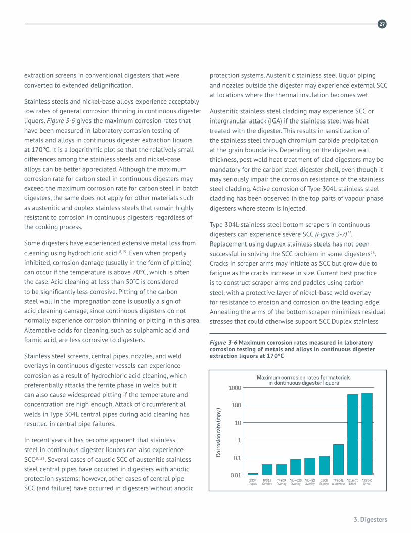
Stainless steels and nickel-base alloys experience acceptably low rates of general corrosion thinning in continuous digester liquors. Figure 3-6 gives the maximum corrosion rates that have been measured in laboratory corrosion testing of metals and alloys in continuous digester extraction liquors at 170ºC. It is a logarithmic plot so that the relatively small differences among the stainless steels and nickel-base alloys can be better appreciated. Although the maximum corrosion rate for carbon steel in continuous digesters may exceed the maximum corrosion rate for carbon steel in batch digesters, the same does not apply for other materials such as austenitic and duplex stainless steels that remain highly resistant to corrosion in continuous digesters regardless of the cooking process.
Some digesters have experienced extensive metal loss from cleaning using hydrochloric acid18,19. Even when properly inhibited, corrosion damage (usually in the form of pitting) can occur if the temperature is above 70ºC, which is often the case. Acid cleaning at less than 50˚C is considered to be significantly less corrosive. Pitting of the carbon steel wall in the impregnation zone is usually a sign of acid cleaning damage, since continuous digesters do not normally experience corrosion thinning or pitting in this area. Alternative acids for cleaning, such as sulphamic acid and formic acid, are less corrosive to digesters.
Stainless steel screens, central pipes, nozzles, and weld overlays in continuous digester vessels can experience corrosion as a result of hydrochloric acid cleaning, which preferentially attacks the ferrite phase in welds but it can also cause widespread pitting if the temperature and concentration are high enough. Attack of circumferential welds in Type 304L central pipes during acid cleaning has resulted in central pipe failures.
In recent years it has become apparent that stainless steel in continuous digester liquors can also experience SCC20,21. Several cases of caustic SCC of austenitic stainless steel central pipes have occurred in digesters with anodic protection systems; however, other cases of central pipe SCC (and failure) have occurred in digesters without anodic
protection systems. Austenitic stainless steel liquor piping and nozzles outside the digester may experience external SCC at locations where the thermal insulation becomes wet.
Austenitic stainless steel cladding may experience SCC or intergranular attack (IGA) if the stainless steel was heat treated with the digester. This results in sensitization of the stainless steel through chromium carbide precipitation at the grain boundaries. Depending on the digester wall thickness, post weld heat treatment of clad digesters may be mandatory for the carbon steel digester shell, even though it may seriously impair the corrosion resistance of the stainless steel cladding. Active corrosion of Type 304L stainless steel cladding has been observed in the top parts of vapour phase digesters where steam is injected.
Type 304L stainless steel bottom scrapers in continuous digesters can experience severe SCC (Figure 3-7)22. Replacement using duplex stainless steels has not been successful in solving the SCC problem in some digesters23. Cracks in scraper arms may initiate as SCC but grow due to fatigue as the cracks increase in size. Current best practice is to construct scraper arms and paddles using carbon steel, with a protective layer of nickel-base weld overlay for resistance to erosion and corrosion on the leading edge. Annealing the arms of the bottom scraper minimizes residual stresses that could otherwise support SCC.Duplex stainless
0
20
40
60
80
100
120
Maximum corrrosion rates for materialsin dontinuous digester liquors
2304Duplex
TP304LAustinetic
A285-CSteel
A516-70Steel
2205Duplex
TP309Overlay
TP312Overlay
Alloy 625Overlay
Alloy 82Overlay
Cor
rosi
on ra
te (m
py)
0.01
0.1
1
10
100
1000
Figure 3-6 Maximum corrosion rates measured in laboratory corrosion testing of metals and alloys in continuous digester extraction liquors at 170ºC

28
Stainless steels and specialty alloys for pulp, paper and biomass conversion mills
steel continuous digesters have so far been free of any appreciable corrosion or cracking of the pressure shell. As mentioned in the previous paragraph, there has been SCC of duplex stainless steel scraper arms. One application where corrosion of duplex stainless steel has occurred at rates up to 3 mm/y is the inserts in the steam injectors in vapour-phase continuous digesters.
Protection of continuous digesters
The three most used protective measures used for continuous digesters are corrosion-resistant weld overlay, thermal spray coatings, and anodic protection systems. Carbon steel weld build-up to restore the thickness of a corroded shell is not a permanent protective measure since it is susceptible to high corrosion rates in the wash and extraction zones and to caustic SCC in the impregnation zone.
Stainless steel weld overlay
Stainless steel weld overlays are applied to protect the carbon steel shell of continuous digesters from corrosion thinning. Service experience and corrosion testing have shown that Type 309 stainless steel weld overlays (applied using either the SAW or GMAW processes) have good corrosion resistance, even under non-conventional cooking operation24. An 18% minimum Cr content as suggested in the TAPPI guidelines is likely adequate for good corrosion resistance in continuous digesters. A minimum of 20% Cr may
be a better target for weld overlay that will be exposed to the most aggressive continuous digester environments.
Depending on the extent of thinning of the carbon steel wall, overlay may be required in one area (e.g., the wash zone) or may be required over a much larger area. Since continuous digesters are so large, it is often not practical to overlay large areas in one shutdown; so overlay is typically done over a period of years. For digesters thinned to near minimum, stainless steel weld overlay of digester walls is sometimes done in combination with anodic protection.
While stainless steel weld overlay may eliminate the problem of corrosion thinning of the carbon steel wall, it may also introduce new corrosion problems. Preferential corrosion or “fingernailing” is often seen in the carbon steel adjacent to the edges of stainless steel weld overlay, most often in the impregnation and cooking zones. While fingernailing resembles galvanic corrosion, it is simply the preferential corrosion of the heat affected zone in the carbon steel, which has poorer corrosion resistance than the parent metal. Caustic SCC may begin at the bottom of a fingernailing crevice.
Protection of carbon steel weld seams susceptible to caustic SCC (in the impregnation zone) with bands of stainless weld overlay has not been successful. The residual tensile stresses in the carbon steel at the termination of the overlay are high enough to promote caustic SCC25,26. However, an anodic protection system can prevent caustic SCC in the heat affected zones adjacent to the overlay. Bands of thermal spray coating have been used to protect the carbon steel from SCC at the edges of stainless steel weld overlay bands.
Thermal spray coating
Thermal spray coatings, both TWAS and HVOF, have been applied in continuous digesters to protect large areas from corrosion thinning. The thermal spray coatings applied in continuous digesters are the same as those applied in batch digesters, i.e., predominantly Alloy 625 nickel-base alloy. Since thermal spray coatings do not produce a heat affected zone, they can also protect weld seams from caustic SCC. Laboratory testing has demonstrated that thermal spray coatings can effectively protect carbon steel digesters against both caustic SCC and corrosion thinning. Service experience has been mixed. With good surface preparation, coatings
Figure 3-7 SCC of a solid Type 304L stainless steel scraper arm and end paddle after 11 months service
Cour
tesy
Ang
ela
Wen
sley

3. Digesters
29
adhere well and can provide several years of corrosion protection. Problems such as blistering and disbonding have been attributed to improper surface preparation27.
Anodic protection
Anodic protection has been successfully used to protect continuous digesters from both caustic SCC and corrosion thinning 28, 29. Anodic protection of continuous digesters requires installation of external rectifiers, internal cathodes, and reference electrodes. This work can usually be accomplished during a standard maintenance outage. There are two main cathode designs: centrally mounted (on standoffs from the central pipe) and wall-mounted. Anodic protection for thinning can reduce corrosion rates significantly, but may not necessarily reduce them to zero.
Anodic protection cannot restore wall thickness so it is important to install an anodic protection system before the corrosion allowance is consumed. Anodic protection systems must be turned off during acid cleaning to prevent serious damage to the digester. Anodic protection systems may experience hardware failures (cracking or corrosion of cathodes, corrosion of reference electrodes) so must be diligently maintained. The frames of wall-mounted cathodes can corrode in service due to transpassivation. Corrosion of the frames can be minimized by using Type 304L stainless steel for the frames in the lower zones and carbon steel frames in the upper zones of the digester.
3.3 ANCILLARY EQUIPMENTStainless steels have been used as materials of construction for much of the equipment ancillary to digesters. This includes piping, valves, and pumps. Some of the major ancillary equipment is discussed below.
Liquor heaters
External heat exchangers are used for indirect heating of the digester, most of which today are a two-pass shell and tube construction. Batch digesters usually have one heat exchanger, while Kamyr units usually have three, Figure 3-4. With continuous cooking, two exchangers are in service while the third is being cleaned or in a standby mode. Tubing is 25 to 37 mm in outer diameter (OD), and from 3 to 4.6 m in length. Cooking liquor circulates through the tubes, with
saturated steam on the shell side. Shell side temperature is approximately 200˚C, while the liquor is 150ºC to 170˚C.
For many years welded Type 304L stainless steel tubes were the “standard” material of construction in liquor heaters. Unfortunately, austenitic stainless steels Types 304L and 316L are susceptible to both chloride and caustic SCC, which has caused many tube failures30. SCC of liquor heater tubes can occur from either the steam side or the liquor side. Inadvertent introduction of superheated steam has caused rapid SCC of Type 304 tubing. Type 304L stainless steel tubes are also susceptible to rapid liquor-side thinning, which eventually leads to tube rupture. Thinning in batch digester liquor heaters is believed to be due to high temperature operation. In continuous digester liquor heaters, thinning may be due to HCl cleaning. HCl cleaning is detrimental to the welds in Type 304L stainless steel welded tubing, unless the manufacturer of the welded tubing has cold worked and annealed (”full finished”) the tube weld to reduce the ferrite content.
Type 304L tubes are normally used for new construction – where cost often controls material selection – and they are replaced when SCC or thinning causes unacceptable amounts of downtime. Duplex stainless steels such as 3RE60 (UNS S31500), Alloy 2205, and Alloy 2507 (UNS S32750) are resistant to SCC in liquor heater service but are also susceptible to thinning, especially at higher temperatures. High nickel alloys such as Alloy 600 (UNS N06600) and Alloy 800 (UNS N08800) are resistant to SCC and have improved resistance to acid cleaning damage.
Chip conveyors and feeders
Chip conveyors, which bring chips from the wood yard to the chip feeders, use Type 304 for bends and other components subject to chip abrasion. Chip feeders for continuous digesters are typically made from centrifugally cast, precipitation hardened stainless steel Alloy CB-7Cu-1 (UNS J92180), in the solution annealed and aged (H925) condition for best abrasion resistance. Rotors are manufactured from cast martensitic Alloy CA-6MN (UNS J91540) or from Alloy CB-6 (UNS J91804). Rotors are quenched and tempered to BHN (Brinell hardness number) 240-302. Modified versions of Alloy CA-6NM have been used to enhance weldability. Rotor cracking problems have been experienced, and have been

30
Stainless steels and specialty alloys for pulp, paper and biomass conversion mills
largely due to casting shrinkage. Manufacturers and users have begun to specify radiographic (X-ray) testing of rotors to ensure quality of the casting. Worn rotors are typically rebuilt by welding with modified Type 410 (UNS S41000) stainless steel applied by the SAW method. Corrosion of carbon steel feeder housings beneath the liner is a common problem and can result in cracking of the liner. Significant corrosion must be repaired by removal of the liner and welding a stainless steel overlay onto the housing. This is then precision machined to accept the liner.
Steaming vessels
Chips are usually pre-steamed in a steaming vessel prior to introduction into the cooking vessel by a rotary Type high-pressure feeder. The steaming vessel is a horizontal cylindrical vessel which has conventionally been constructed from carbon steel with a partial cladding of Type 304L stainless steel on the inside31. A wear plate of Type 304L stainless steel is usually installed along the bottom of the vessel to protect the carbon steel wall from wear by the chips as they pass through the vessel. A Type 304L wear plate usually erodes rapidly and needs to be replaced every few years. The steaming nozzles, if constructed from Type 304L, may also experience SCC from the process side.
Many steaming vessels have been constructed from solid Type 304L stainless steel. Most of these vessels experienced external SCC beneath the insulation when the insulation became wet, either from seal water leaking from the low pressure feeder or from liquor spills.
Duplex stainless steels such as Alloy 2304 and Alloy 2205 have superior resistance to SCC and wear and are the preferred material of construction for the shell, steam nozzles, and wear plate. There have been some cases of cracking of duplex stainless steel screws, evidently the result of Type 2209 welds having very low ferrite content.
Flash tanks, blow tanks, valves, and pumps
In the continuous cooking process, there are typically two or three flash tanks (or cyclones) that receive the liquor extracted from the digester. Most flash tanks were of carbon steel construction but new or replacement flash tanks are now being made using duplex stainless steel. There have been many cases of severe corrosion or erosion-corrosion of
carbon steel flash tanks32,33. High rates of flash tank corrosion usually occur when the digester is also experiencing rapid corrosion thinning. Corrosion was attributed to the presence of organic acids in the flash tank environment. Even Types 304L and 316L stainless steels were rated as marginal and duplex Alloy 2205 was preferred.Thermal spray coating or lining with Type 304L stainless steel has extended the life of corroding flash tanks. Replacement of flash tanks with solid duplex Alloy 2205 is a solution to the corrosion problem.
The blow tank for batch digesters may be of carbon steel, Type 304L, or for larger tanks, Alloy 2205 construction. Target plates of Alloy 2205 duplex stainless steel may experience erosion corrosion. Blow valves are usually CF-3 (UNS J92500) cast stainless steel, CD-4MCuN (UNS J93372), or CD-6MN (UNS 93371). Cast duplex stainless steels are preferred for pumps due to abrasion from sand and grit loadings.
3. Digesters
31
REFERENCES
1. Wegerif, J. J., “Alkaline digester corrosion,” Pulp Paper Mag. Can. 59: 104-108(1958).
2. Audouard, J.-P., Desestret, A., Vallier, G., Chevassut,J., Mader, J.-P., “Study and development of special austenitic-ferritic stainless steel linings for Kraft pulp batch digesters,” Proc. 3rd
Intl. Symp. on Corrosion in the
Pulp and Paper Ind., (1980), pp. 30–39.
3. Wensley, A., “Corrosion of weld overlay in batch digesters,” Proc. TAPPI Eng. Conf., (1998), pp. 1193–1200.
4. TAPPI Technical Information Paper TIP 0402-03, “Guidelines for corrosion resistant weld metal overlay of digester vessels in alkaline pulping service,” latest revision.
5. Moskal, M., Cheetham, G., Paultre, J., Wilton, W., “Quality requirements for duplex stainless steel digester fabrication,” Proc. 9th
Intl. Symp. on Corrosion in the
Pulp and Paper Ind., (1998), pp. 67-73.
6. Wensley, A., “Corrosion in digester liquors,” Proc. 8th Intl.
Symp. on Corrosion in the Pulp and Paper Ind., (1995), pp. 26-37.
7. Olsson, J., Leffler, B., Jorgensen, C., “Experiences of 2205 for pulp digesters and other pressure vessels,” Proc. 5th
World Congress and Exposition on Duplex Stainless
Steels, (1997).
8. Leinonen, H.T., “Corrosion Resistance of Duplex Stainless Steel and its Welds in Modern Batch Cooking,” Proc. 11th Intl. Symp. on Corrosion in the Pulp and Paper Ind., Paper No. ISC 0407 (2004).
9. TAPPI Technical Information Paper TIP 0402-32, “Guidelines for applying thermal spray coatings to protect pulp mill process equipment against corrosion,” latest revision.
10. Östlund, S., Ernerfeldt, B., Sandberg, B., Linder, M., “Investigations regarding corrosion in batch digesters,” Proc. 6th
Intl. Symp. on Corrosion in the Pulp and Paper Ind., (1989), pp. 48-59.
11. Kiessling, L., “A study of the influence of modified continuous cooking processes on the corrosion of continuous digester shells,” Proc. 8th
Intl. Symp. on
Corrosion in the Pulp and Paper Ind., (1995), pp. 12-19.
12. Wensley, A., “Experience with duplex stainless steel digesters,” NACE Corrosion 2004 Conf., Paper No. 04249.
13. Singbeil, D., Tromans, D., “Stress corrosion cracking of mild steel in alkaline sulphide solutions,” Proc. 3rd
Intl.
Symp. on Corrosion in the Pulp and paper Ind., (1980), pp. 40-46.
14. Bennett, D.C., “Cracking of continuous digesters – Review of history, corrosion engineering, aspects and factors affecting cracking,” Proc. 4th
Intl. Symp. on
Corrosion in the Pulp and Paper Ind., (1983), pp. 2-7.
15. Singbeil, D., “Kraft continuous digester cracking: A critical review,” Proc. 5th
Intl. Symp. on Corrosion in the
Pulp and Paper Ind., (1986), pp. 267-271.
16. Christiansen, C. B., Lathrop, J. B., “Field investigation of corrosion in alkaline pulping equipment,” Pulp Pap. Mag. Can. 55: 113-119 (1954).
17. Hazlewood, P., Singh, P., and Hsieh, P., “Pulp Mill Corrosion and Wood Chip Extractives.” TAPPI Engineering Conf., Atlanta, GA (2006).
18. Crowe, D.C., “Corrosion in acid cleaning solutions for Kraft digesters,” Proc. 7th
Intl. Symp. on Corrosion in the
Pulp and Paper Ind., (1992), pp. 33-40.
19. Perdomo, J.J., Conde, P.R., Singh, P.M., and Wekesa, M., “Corrosion Prevention during Acid Cleaning of Pulping Equipment,” Proc. 11th Intl. Symp. on Corrosion in the Pulp and Paper Ind., Paper No. ISC 0427 (2004).
20. Bhattacharya, A., Leinonen, H., and Singh, P., “Stress Corrosion Cracking of Different Duplex Stainless Steel Grades in Pulping Liquor.” TAPPI Engineering Conf., Atlanta, GA (2006).
32
Stainless steels and specialty alloys for pulp, paper and biomass conversion mills
21. Wensley, A., Leavitt, A., and Paoliello, F., “Stress Corrosion Cracking of Stainless Steel in Continuous Digesters,” TAPPI Engineering Conf., Portland, OR (2008).
22. Wensley, A., “Corrosion and Cracking of Bottom Scrapers in Continuous Digesters,” NACE Corrosion 2005 Conf., Paper No. 05199.
23. Gorog, M., “Digester Outlet Device Scraper Arm Cracking,” TAPPI Engineering Conf., Atlanta, GA (2006).
24. Wensley, A., “Weld Overlay for Corrosion Protection of Continuous Digesters.” TAPPI Engineering Conf., San Diego, CA (2002).
25. Moskal, M.D., “Residual stresses in digester weld overlays,” Proc 5th Intl. Symp. on Corrosion in the Pulp and Paper Ind., (1986), pp. l 7-19.
26. Singbeil, D. and Garner, A., “Potential-dependent cracking of kraft contiuous digesters,” Tappi Journal 68(4) 1985.
27. Wensley, A., “Thermal Spray Coatings for Corrosion Protection of Continuous Digesters and Flash Tanks,” TAPPI Engineering Conf., San Antonio, TX (2001).
28. Singbeil, D. and Garner, A., “Anodic protection to prevent the stress corrosion cracking of pressure vessel steels in alkaline sulphide solutions,” Mat. Perf., 26(4): 3136(1987).
29. Wensley, A., “Anodic Protection against Corrosion and Cracking of Digester Vessels.” TAPPI Engineering Conf., Chicago, IL (2003).
30. Wensley, D.A., “Corrosion of liquor heater tubes,” Proc. TAPPI Eng. Conf., (1990), pp. 219-230.
31. Wensley, A. and Kaiser, W., “Inspection and repair of kraft steaming vessels,” TAPPI Eng. Conf. (2006).
32. Clarke, S. J. and Stead, N. J. ,“Corrosion testing in flash tanks of Kraft pulp mills,” Mat. Perf., 38(11): 62-66(1999).
33. Wensley, A., “Corrosion of Flash Tanks,” Proc. 10th Intl. Symp. On Corrosion in the Pulp and Paper Indus

4. Oxygen delignification and brown stock washing
33
4.1 OXYGEN DELINGNIFICATIONPulp leaving a batch or continuous, alkaline pulping digester goes to a blow tank in which the pulp solution ‘flashes’ to atmospheric pressure. The pulp is washed to remove cooking chemicals, wood chemicals and the lignins which produce the characteristic brown color. The amount of lignin in the pulp, which depends on the cooking process parameters, governs the amount of bleaching chemicals required to produce bright cellulose fiber. In the 1970s use of pressurized oxygen to “pre-bleach” pulp by chemically increasing lignin solubility was widely implemented to make bleaching with chlorine dioxide more efficient.
The oxygen delignification stage after the Blow Tank is positioned before or after the brown stock is washed in a series of brown stock washers, at least one of which typically is after the pressurized oxygen delignification reactor.
Chemical conditions in the oxygen reactor are alkaline – pH around 10.5 at the inlet decreases to 9.5 at the outlet – and around 100 °C. Chlorides may be present, especially
if the mill recycles bleaching extraction stage filtrates to minimize color in the mill effluent, but pH >10 prevents chloride localized corrosion of stainless steel. Early oxygen delignification reactors made from Type 316L (UNS S31603) stainless steel showed how benign the process conditions are, but after some 316L reactors experienced external chloride stress corrosion cracking under the insulation, the industry migrated to standard and lean duplex grades. A Type 2205 (UNS S32205/S31803) duplex grade oxygen delignification reactor in shipment is shown in Figure 4-1.
The blow tank for an oxygen delignification reactor also operates hot and is made from 316L or a lean duplex grade. 316L (UNS CF-3M) and duplex SS castings are acceptable for the oxygen delignification stage. Since chloride-related localized corrosion is not feasible, upgrading weld filler as recommended in TAPPI TIP 0402-26 is not required.
4.2 BROWN STOCK WASHINGUnbleached pulp (brown stock) is washed in a counter-current filtrate flow system to separate as many organic compounds and cooking chemicals from the cellulose fibers with the least amount of fresh water—better washing reduces the quantity of bleaching chemicals required in the subsequent bleaching processes. A conventional brown stock washing system is illustrated in Figure 4-2 and a counter-current system is shown in Figure 4-3. Brown stock washing systems normally include knotters (2 stages), a series of vacuum or pressurized rotary drum washers and/or counter-rotating press-roll washers; foam breaker(s), centrifugal pumps, refiners, thick stock pumps, and agitators in seal tanks and storage towers. Some mills have one or more pressure diffusion washers in the blow tank.
4. Oxygen delignification and brown stock washing
by David C. Bennett, Corrosion Probe, Inc.
Figure 4-1 Alloy 2205 oxygen delignification vessel – Canada
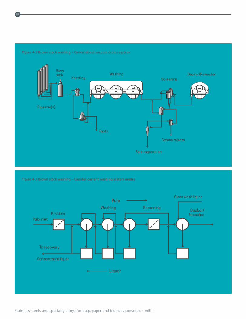
Stainless steels and specialty alloys for pulp, paper and biomass conversion mills
34
KnottingWashing
Screening
Sand separation
Screen rejects
Decker/Rewasher
Digester(s)
Blowtank
Knots
To recovery
Concentrated liquor
Decker/Rewasher
Pulp inlet
Liquor
Pulp
Knotting
Washing Screening
Clean wash liquor
Figure 4-2 Brown stock washing – Conventional vacuum drums system
Figure 4-3 Brown stock washing – Counter-current washing system model

4. Oxygen delignification and brown stock washing
35
Knotters remove wood knots, shives and other lumpy material from the brown stock stream. Washers wash de-knotted stock, minimizing water use by using washing filtrates counter-current to the stock flow. Brown stock washers made from carbon steel passivate in the hotter, more alkaline conditions in the earlier washer stages, but stainless steel is required in later stages where pH is low enough for carbon steel to experience oxygen-driven corrosion.
Even the lowest grades of stainless steel, e.g., utility ferritic 12Cr grades, resist oxygen-driven pitting corrosion in brown stock filtrates. Brown stock leaving the last brown stock washer may be acidified with sulphuric or carbonic acid to lower its pH for bleaching. 316L and lean duplex grades are standard materials for brown stock washing equipment. Duplex grades and precipitation hardening (PH) grades resist erosion corrosion, in pumps for example, better than austenitic stainless steel grades.
36
Stainless steels and specialty alloys for pulp, paper and biomass conversion mills
REFERENCES1. Yeske, R.A., Measuring corrosion rates of carbon steels
exposed to alkaline sulphide environments, Corrosion 84, New Orleans, April, Paper 245, 1984, NACE-International, Houston, TX
2. Bennett, D.C., Stress corrosion cracking of 316L oxygen reactor pressure vessels, Ninth Intl. Symposium on Corrosion in the Pulp & Paper Industry, Ottawa, 1998, TAPPI Press, Atlanta, GA
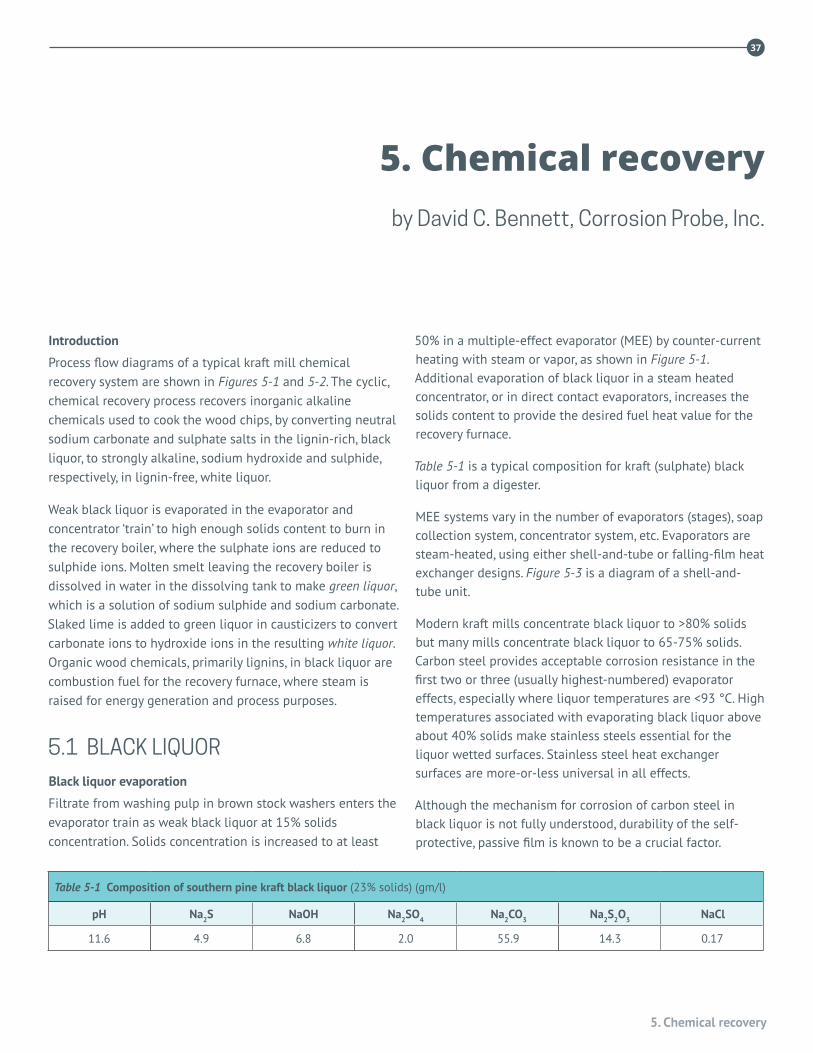
5. Chemical recovery
37
Introduction
Process flow diagrams of a typical kraft mill chemical recovery system are shown in Figures 5-1 and 5-2. The cyclic, chemical recovery process recovers inorganic alkaline chemicals used to cook the wood chips, by converting neutral sodium carbonate and sulphate salts in the lignin-rich, black liquor, to strongly alkaline, sodium hydroxide and sulphide, respectively, in lignin-free, white liquor.
Weak black liquor is evaporated in the evaporator and concentrator ‘train’ to high enough solids content to burn in the recovery boiler, where the sulphate ions are reduced to sulphide ions. Molten smelt leaving the recovery boiler is dissolved in water in the dissolving tank to make green liquor, which is a solution of sodium sulphide and sodium carbonate. Slaked lime is added to green liquor in causticizers to convert carbonate ions to hydroxide ions in the resulting white liquor. Organic wood chemicals, primarily lignins, in black liquor are combustion fuel for the recovery furnace, where steam is raised for energy generation and process purposes.
5.1 BLACK LIQUORBlack liquor evaporation
Filtrate from washing pulp in brown stock washers enters the evaporator train as weak black liquor at 15% solids concentration. Solids concentration is increased to at least
50% in a multiple-effect evaporator (MEE) by counter-current heating with steam or vapor, as shown in Figure 5-1. Additional evaporation of black liquor in a steam heated concentrator, or in direct contact evaporators, increases the solids content to provide the desired fuel heat value for the recovery furnace.
Table 5-1 is a typical composition for kraft (sulphate) black liquor from a digester.
MEE systems vary in the number of evaporators (stages), soap collection system, concentrator system, etc. Evaporators are steam-heated, using either shell-and-tube or falling-film heat exchanger designs. Figure 5-3 is a diagram of a shell-and-tube unit.
Modern kraft mills concentrate black liquor to >80% solids but many mills concentrate black liquor to 65-75% solids. Carbon steel provides acceptable corrosion resistance in the first two or three (usually highest-numbered) evaporator effects, especially where liquor temperatures are <93 °C. High temperatures associated with evaporating black liquor above about 40% solids make stainless steels essential for the liquor wetted surfaces. Stainless steel heat exchanger surfaces are more-or-less universal in all effects.
Although the mechanism for corrosion of carbon steel in black liquor is not fully understood, durability of the self-protective, passive film is known to be a crucial factor.
Table 5-1 Composition of southern pine kraft black liquor (23% solids) (gm/l)
pH Na2S NaOH Na2SO4 Na2CO3 Na2S2O3 NaCl
11.6 4.9 6.8 2.0 55.9 14.3 0.17
5. Chemical recovery by David C. Bennett, Corrosion Probe, Inc.
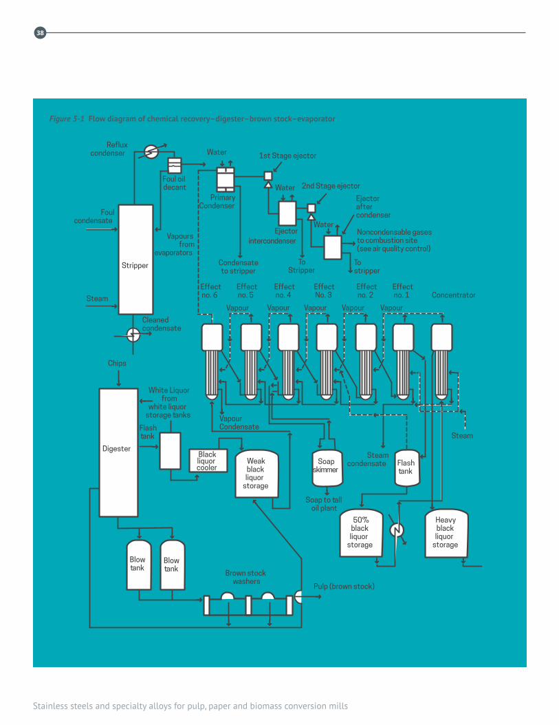
38
Stainless steels and specialty alloys for pulp, paper and biomass conversion mills
Steam
Steamcondensate Flash
tank
Heavyblackliquor
storage
50%blackliquor
storage
Weakblackliquor
storage
Digester
Blowtank
Blowtank Brown stock
washersPulp (brown stock)
Soapskimmer
Soap to talloil plant
Blackliquorcooler
Flashtank
Chips
Steam
Foulcondensate
Refluxcondenser
White Liquorfrom
white liquorstorage tanks Vapour
Condensate
Vapour Vapour Vapour Vapour Vapour
Effectno. 6
Effectno. 5
Effectno. 4
EffectNo. 3
Effectno. 2
Effectno. 1 Concentrator
Vapoursfrom
evaporatorsCondensateto stripper
ToStripper
Tostripper
Ejectorintercondenser
PrimaryCondenser
Foul oildecant
Water 1st Stage ejector
2nd Stage ejector
Ejectoraftercondenser
Noncondensable gasesto combustion site(see air quality control)
Water
Water
Cleanedcondensate
Stripper
Figure 5-1 Flow diagram of chemical recovery–digester–brown stock–evaporator

5. Chemical recovery
39
Limekiln
scrubber
Limemud
storage
Limemudfilter
Limemud
washer
Lime mud
Limerocksilo
Whiteliquortodigester
Lime
Kilnchains Lime
kiln
White liquorstorage tank
White liquorstorage tank
Lime
Slaker
Clarifierwhite liquor
No. 1No. 3 No. 2
Causticizers
Filter
Clarified green liquor
Green liquorclarified*
*Rake arms
Greenliquor
tank
Unclarified green liquor
Precipitatordry bottom ±
Duct
Saltcakemix
tank
Heavy black liquor
Heavy black liquor
Saltcake
Spent acidfrom CLO 2generator
Maindissolving
tank
Compositewall tubesfor burners
Ventstack
Scrubber
Recovery boiler
Mainstack
±Troughs in wet-bottomprecipitators are lined
with stainless steel.
Seal water lines andcondensate lines throughoutcan be stainless steel.
Figure 5-2 Flow diagram of black liquor recovery boiler–liquor tanks–lime kiln
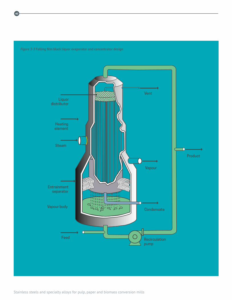
40
Stainless steels and specialty alloys for pulp, paper and biomass conversion mills
Vent
Product
Vapour
Condensate
Recirculationpump
Liquordistributor
Heatingelement
Steam
Entrainmentseparator
Vapour body
Feed
Figure 5-3 Falling film black liquor evaporator and concentrator design

5. Chemical recovery
41
Stainless steels, by forming a durable passive film due to chromium oxide content, resist corrosion in black liquor environments: alloys with higher Cr and no molybdenum (Mo) have the highest corrosion resistance to the strongest/hottest black liquors.
MEEs hotter than the third (or fourth) effect and the liquor concentrator normally are made with stainless steel liquor-contacted surfaces, most often Type 304L (UNS S30403) but increasingly lean duplex grades. Sheet linings of duplex or austenitic stainless steel are widely used to cover corroding carbon steel and to shield carbon steel against liquor corrosion.
In MEEs, it often is necessary to use stainless steel to protect carbon steel tube-sheets and vapor zone surfaces subjected to vapor impingement and to condensate flow with sheet linings of stainless steel (ferritic and duplex versions are better). Thermal spray coatings and high-performance organic coatings provide less reliable protection.
Heat-exchanger tubes and plates in high-solids MEE effects increasingly are made of duplex grades to benefit from their superior corrosion resistance and higher thermal conductivity compared to Type 304L. Falling-film heat-exchanger elements are made by spot welding thin sheets of Type 304L, Type 2205 (UNS S32205/S31803) or 6Mo super-austenitic stainless steel, and pressurizing the space between the sheets to form them. Figure 5-4 shows dimpled heat exchanger elements ready for installation in an evaporator, and Figure 5-5 shows a full evaporator train and condensate stripper .In black liquor with >75% solids, Types 304/304L and 316/316L tubing is subject to both general corrosion and to caustic stress corrosion cracking (CSCC). Tubes made from duplex 2205 and ferritic grades are more resistant to general corrosion and caustic stress corrosion cracking in high solids concentrators than Type 304/304L, and Type 316/316L is the least resistant of these grades. 26Cr ferritic stainless steel has the greatest resistance to hot liquor corrosion and resists stress corrosion cracking (SCC) by the vapor.
There are reports of SCC in the wet/dry, ‘tidal’ zone of Type 304L tanks storing 72% solids black liquor; lean duplex grades resist this temperature dependent mechanism. Pumps and piping, tube-sheets, liquor boxes, etc., made from Type 304L and duplex grades resist corrosion by black liquor flow, turbulence and splashing. These grades resist corrosion by foul condensate in piping, vapor bodies, heat-exchanger shells and condenser tubes.
Acidic sulphate-rich waste streams, e.g., salt-cake effluent from the tall oil plant and sodium sesqui-sulphate from the chlorine dioxide generator, typically are introduced into the black liquor stream ahead of the first effect or concentrator to maintain the liquor’s sulphur level. These additions increase liquor corrosiveness to carbon steel and stainless steel, especially if the main liquor stream has no residual active alkalinity. Type 2205 and Type 2507 (UNS S32750) duplex
Figure 5-5 Evaporator train with foul condensate stripper and soap skim tanks
Figure 5-4 Dimpled stainless steel plates – falling film evaporator
cour
tesy
ahl
stro
mco
urte
sy rc
c
42
Stainless steels and specialty alloys for pulp, paper and biomass conversion mills
grades and 6Mo super-austenitic grades resist these aggressive liquor environments.
This discussion covers sulphate (kraft) and soda (i.e., alkaline) pulping liquors. Evaporators for acidic, i.e., sulphite, liquors require Types 316L or 317L (UNS S31703) stainless steel for liquor and vapor-contacted surfaces. Evaporators for neutral sulphite semi-chemical (NSSC), in which the liquors have low alkalinity and high sulphite ion concentration, use Type 316 stainless steel heat-exchanger tubing and Type 316L for other liquor-contacted surfaces. Lean duplex grades with PREN higher than 316 stainless steel outperform it, usually at lower cost.
Black liquor oxidation
Black liquor is oxidized in many mills as an environmental/odor-control measure. Oxidizing black liquor before or during evaporation reduces levels of hydrogen sulphide (H2S) and organic sulphide (e.g., methyl mercaptan) levels in evaporator condensate and in the non-condensible gases. Oxidizing to convert sulphides in heavy black liquor to thiosulphate reduces the total reduced sulphur (TRS) content of the boiler flue gas from burning black liquor.
Carbon steel tanks, piping and other components for black liquor oxidation are susceptible to corrosion, which is mitigated with a wide variety of affordable stainless steels, including 12Cr ferritic grades, lean duplex grades and 304 stainless steel.
Black liquor tanks
Black liquor enters the evaporator train at 15% solids; 30% solids is a common level for soap separation, and concentrated “strong black liquor” with at least 50% solids is stored before or after the liquor concentrator. Strong black liquor is heated to lower its viscosity for pumping but hotter, flowing and agitated liquor accelerate corrosion of carbon steel. Stainless steels, including 12Cr ferritic, Type 304L and lean duplex grades, resist corrosion in black liquor, even around agitators, in pumps and piping, and in liquor splash zones in liquor flash tanks.
Properly installed stainless steel sheet linings, especially with 12Cr and lean duplex grades, are successful. A design criterion for controlling lining stability is to limit the maximum dimension of the lining “panes”. A design rule for this type of
sheet lining is that every point on a sheet “pane” in a Type 304L lining shall be within 300 mm (12 in) of the nearest weld joining the lining to the steel substrate. For sheet linings made from a lean duplex and ferritic grades, whose thermal expansion coefficients are close to carbon steel, points on the ‘pane’ should be within 600 mm of the nearest weld. Welds are made with 309L (AWS E309L/ER309L) or 312 (AWS E312/ER312).
A theoretical drawback of sheet linings is that the steel surface behind the lining cannot be seen. However liquor behind a sheet lining corrodes steel only if liquor behind a lining ‘pumps’ due to lining movement, which is far more likely to be caused by hydraulic pulses of green liquor from smelt ‘bumping’ in a dissolving tank.
For a new black liquor tank, solid lean duplex stainless steel is more economical than clad material or sheet lining a carbon steel tank because the sheet thickness involved is < 12 mm. As mentioned earlier, strong black liquor tanks in mills with high chloride levels in the black liquor have experienced SCC and pitting in wet-dry region of the walls. Testing showed that Type 2205 duplex and 6% Mo stainless steel resist these environments.
[Alkali-resistant inorganic linings resist black liquor in all concentrations and temperatures.]
5.2 RECOVERY BOILERHigh temperature reducing conditions in the char bed in the bottom of the recovery furnace reduce sulphate ions to the sulphide form. Reducing combustion gas corrodes carbon steel but does not affect stainless steel. Higher in the furnace combustion conditions oxidizing enough to fully combust the lignin-rich fuel do not corrode carbon steel or stainless steel.Black liquor combustion produces a red-hot, molten, inorganic smelt rich in sodium sulphide and sodium carbonate. The molten smelt flows through the smelt spouts and dissolves in water in a fairly violent reaction in the dissolving tank to produce green liquor, which contains sodium carbonate and a lot more sodium sulphide than sulphate. Sodium sulphide contributes alkalinity, green liquor normally is < 90 °C, and green liquor in the dissolving tank contains very high levels of suspended solids and grit.
5. Chemical recovery
43
Recovery boiler tubing
Stainless steels resist corrosion in hot, sulphidic gas environments in the recovery boiler. As already discussed, hot, reducing, sulphide rich combustion gases in the lower furnace becomes oxidizing as more air is added through the air ports in the boiler walls. Oxidizing hot flue gas does not corrode carbon steel and stainless steel.
Corrosion of carbon steel in reducing gases, especially in recovery boilers operating > 1,000 psi (due to higher tube temperatures) is mitigated by protecting the steel tube with a layer of stainless steel or another corrosion resistant alloy with at least 18Cr. The most common protective barrier is a 1.5 mm thick, co-extruded,
“composite” layer of Type 304L stainless steel. Alloys with higher levels of chromium, such as Alloy 825 (UNS N08825), Alloy 690 (UNS 06690) and Alloy 625 (UNS 06690) are also available as the protective layer of composite tubes, and are used in applications where 304L has proven susceptible to corrosion or cracking in-service. Alternatively the protective barrier can be a weld overlay, or a thermal spray coating on the fire side surface. Weld overlay and thermal sprayed barriers can be field installed. Steel corrosion also can be mitigated by producing a Cr-rich, ‘chromized’ diffusion layer with properties and corrosion resistance similar to Type 430 (UNS S43000) ferritic stainless steel on the tubes.
Corrosion resistant barriers that resist attack by reducing gases at normal tube temperatures are increasingly susceptible to attack at higher tube temperatures >320 °C. Location-specific damage mechanisms, namely local metal loss (‘balding’), affects the alloy layer on composite tubes at corners of air port openings in the lower furnace. Type 304L is more susceptible to balding corrosion than other austenitic alloys typically used in the composite layer. (Balding matters only if carbon steel exposed by loss of the alloy layer corrodes, which typically is not the case because the local gas environment is oxidizing.)
Type 304L composite layers are susceptible to thermal fatigue cracking, especially at bends and welds in primary air port and smelt spout openings. Stainless steel composite layers also experience stress corrosion cracking (SCC), especially in floor
tubes. Nickel alloys, including Alloy 825 and Alloy 625, resist SCC better than Type 304L; SCC typically does not extend from the composite layer into the steel core.
On the other hand, because thermal fatigue cracks can propagate into the carbon steel core they are of greater concern. TAPPI TIP 0402-28, Inspection for cracking of composite tubes in black liquor recovery boilers describes how to test for and deal with cracks in composite tubes.
Thermal sprayed coatings of 316 stainless steel or Alloy 625, especially dense coatings obtained with high velocity oxygen fuel (HVOF) or high velocity air fuel (HVAF) spraying processes, resist corrosion and are not susceptible to SCC or thermal fatigue cracking.
Solid tubes of high-nickel alloys or Type 310 (UNS S31000) stainless steel, or composite tubes with these materials as the outer layer are used for the hottest superheater tubes in boilers in which the outlet steam exceeds 480 °C.
Recovery boiler precipitators
Most recovery boilers remove particulates from the flue gases in electrostatic precipitators; some old boilers have direct contact evaporators or cyclones. Carbon steel precipitator body shell, collection plates and inlet and outlet ducts do not corrode if they remain dry. i.e., are kept above the dewpoint, but carbon steel corrodes rapidly where acidic flue gas condensation forms.
Acid condensate corrosion, especially at the bottom of wet-bottom precipitators, is mitigated by building or lining troughs and hoppers with stainless steel. Type 304L resists corrosion and stress corrosion cracking but lean duplex grades or 2205 may be required. Lean and regular duplex grades resist dewpoint corrosion in recovery boiler stacks. 12Cr stainless steel is a good economic alternative to carbon steel in flue gas ducts and equipment.
Stainless steel resists abrasive conditions in Salt cake Mix tanks from slurrying boiler salt-cake ash or dust in strong black liquor. Salt cake mix tanks are increasingly made from Type 304L or lean duplex stainless steel. Duplex grades resist abrasion-accelerated corrosion in liquor system pumps and piping better than Type 304/304L stainless steel.
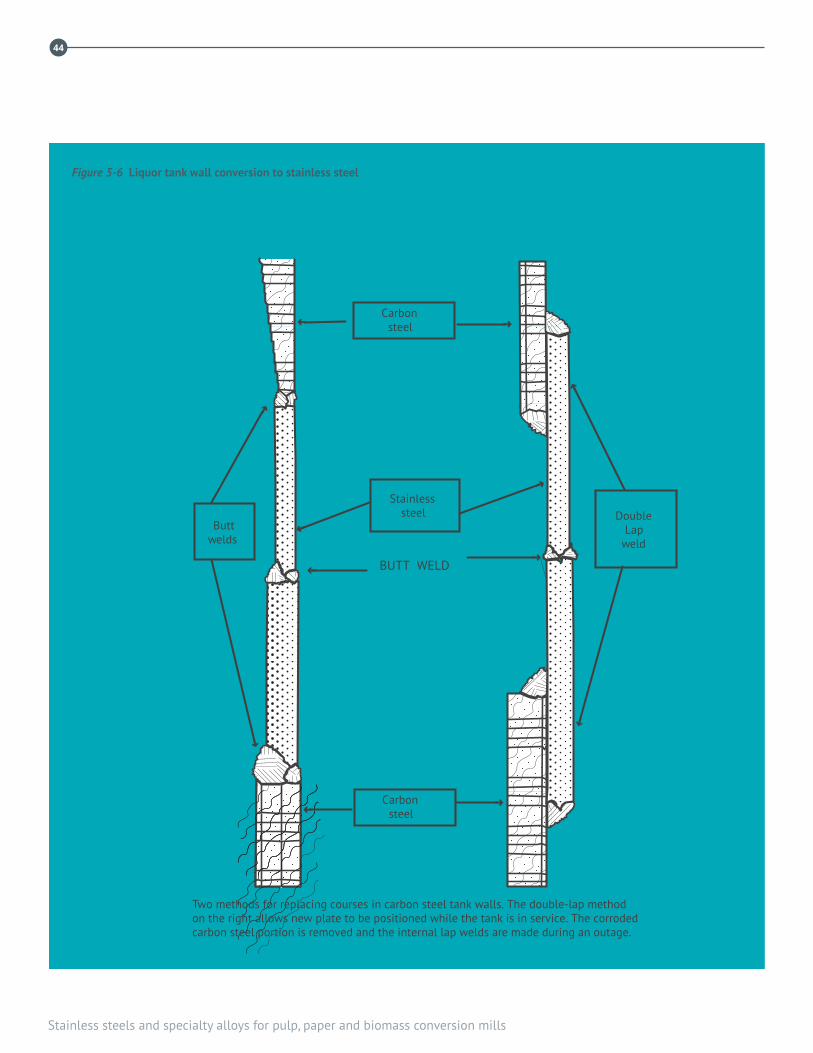
44
Stainless steels and specialty alloys for pulp, paper and biomass conversion mills
➜
➜
➜
➜
➜
➜
➜
➜
➜
➜
Stainlesssteel
Carbonsteel
Carbonsteel
DoubleLap
weldButt
welds
BUTT WELD
Two methods for replacing courses in carbon steel tank walls. The double-lap methodon the right allows new plate to be positioned while the tank is in service. The corrodedcarbon steel portion is removed and the internal lap welds are made during an outage.
➜
➜
Figure 5-6 Liquor tank wall conversion to stainless steel

5. Chemical recovery
45
Smelt spouts and dog-houses
Molten salt (smelt), consisting mostly of sodium carbonate and sulphide and melting around 800 °C, runs out of the recovery boiler via the smelt spouts, into water in the dissolving tank. Spouts are steel or stainless steel, water-cooled troughs with cooling water around 80 °C. Damage mechanisms are thought to result from a combination of thermal cycles due to flow variations and corrosion by acidic condensation of vapors and spray from the dissolving tank.
Spouts come in several different designs: some are made from carbon steel; modern designs are stainless steel. Steel spout corrosion can be mitigated by changing the metal to, or with weld overlay of, Type 309 stainless steel, Alloy 625 or Type 446 (UNS S44600) stainless steel . “Dry spouts” made from 50Cr-50Ni alloy have had mixed results.
Type 304L shrouds (‘dog-houses’) around each spout and piping used to jet steam or weak white liquor (“weak wash”) onto the smelt stream to “shatter” them into drops can experience SCC where weak wash concentrates on the surface. Type 2205 and other duplex grades resists this cracking.
5.3 CHEMICAL RECOVERY TANKS
Smelt dissolving tanksMolten smelt dissolves in a large tank with internal agitators—the dissolving tank—to produce green liquor. The tank rumbles continuously, sometimes violently, due to hydraulic pulses produced by molten smelt inflows. Dissolving tanks typically have extra-thick walls to make them more robust. All stainless steels resist corrosion and erosion corrosion from agitated green liquor with abrasive, suspended solids.
Three general ways to prevent corrosion in dissolving tanks are:
• Make the tank from solid stainless steel: 12Cr ferritic, Type 304L or lean dupleJ57x stainless steel
• Line the tank, using good lining design, with Type 430 or lean duplex alloy
• Line the tank with a gunned, inorganic cementitious material.
Lean duplex and ferritic stainless steels resist SCC from thiosulphate rich condensate above the green liquor level better than Types 304L or 316L. Pumps, agitators and nozzles subject to flow must be stainless steel: duplex grades resist erosion-corrosion better than austenitic grades.
Green liquor tanksCarbon steel green liquor tanks corrode most rapidly where aeration introduces oxygen into the liquor producing thiosulphate ions: typically within half a meter immediately below the liquor level; fluctuating levels in storage tanks spread the corrosion over a wider zone.
12Cr, Type 304L and lean duplex stainless steel resist corrosion in all green liquor applications, including pumps, nozzles and piping. Steel clarifiers and tanks can be internally lined with stainless steel sheet or corroded steel can be replaced with stainless steel, using either of two methods illustrated in Figure 5-6. Stainless steel clarifier rakes do not corrode.
Slakers and causticizersSlakers are tanks in which calcined lime is converted to a
“milk of lime” lime solution. Adding lime solution to green liquor in causticizer tanks converts sodium carbonate to sodium hydroxide, producing white liquor. Strongly alkaline slaker and causticizer environments are do not corrode stainless steels, but high levels of suspended lime particles cause abrasion-erosion of carbon steel and “polish” stainless steels. Duplex grades and hardened austenitic grades are more resistant to erosion corrosion.
Slaker and causticizer tanks are made from stainless steel or from carbon steel lined with stainless steel or with gunned, sulphate-resistant, inorganic material. Stainless steel pumps, piping and agitators resist the abrasive conditions.
White liquor tanksLime mud is clarified or filtered from white liquor before it is stored in a tank. Carbon steel corrosion rates in white liquor are unpredictable because they depend on stability of the passive film. As in green liquor, air contact with white liquor creates oxidized sulfur species, e.g., thiosulphate or polysulphide, which affect the passive film stability and increase corrosion, although >2% polysulphide stabilizes the passive layer and reduces carbon steel corrosion.
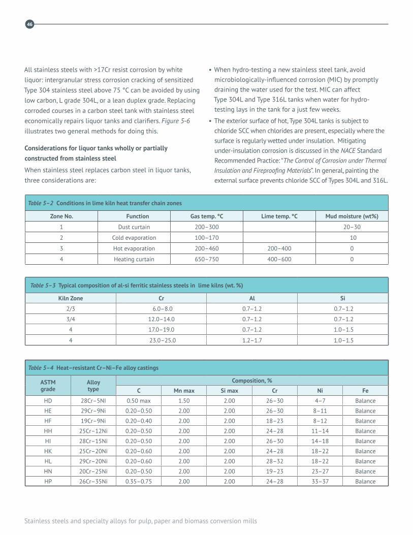
46
Stainless steels and specialty alloys for pulp, paper and biomass conversion mills
All stainless steels with >17Cr resist corrosion by white liquor: intergranular stress corrosion cracking of sensitized Type 304 stainless steel above 75 °C can be avoided by using low carbon, L grade 304L, or a lean duplex grade. Replacing corroded courses in a carbon steel tank with stainless steel economically repairs liquor tanks and clarifiers. Figure 5-6 illustrates two general methods for doing this.
Considerations for liquor tanks wholly or partially constructed from stainless steel
When stainless steel replaces carbon steel in liquor tanks, three considerations are:
• When hydro-testing a new stainless steel tank, avoid microbiologically-influenced corrosion (MIC) by promptly draining the water used for the test. MIC can affect Type 304L and Type 316L tanks when water for hydro-testing lays in the tank for a just few weeks.
• The exterior surface of hot, Type 304L tanks is subject to chloride SCC when chlorides are present, especially where the surface is regularly wetted under insulation. Mitigating under-insulation corrosion is discussed in the NACE Standard Recommended Practice: “The Control of Corrosion under Thermal Insulation and Fireproofing Materials”. In general, painting the external surface prevents chloride SCC of Types 304L and 316L.
Table 5–4 Heat–resistant Cr–Ni–Fe alloy castings
ASTM grade
Alloy type
Composition, %
C Mn max Si max Cr Ni Fe
HD 28Cr–5NI 0.50 max 1.50 2.00 26–30 4–7 Balance
HE 29Cr–9Ni 0.20–0.50 2.00 2.00 26–30 8–11 Balance
HF 19Cr–9Ni 0.20–0.40 2.00 2.00 18–23 8–12 Balance
HH 25Cr–12Ni 0.20–0.50 2.00 2.00 24–28 11–14 Balance
HI 28Cr–15Ni 0.20–0.50 2.00 2.00 26–30 14–18 Balance
HK 25Cr–20Ni 0.20–0.60 2.00 2.00 24–28 18–22 Balance
HL 29Cr–20Ni 0.20–0.60 2.00 2.00 28–32 18–22 Balance
HN 20Cr–25Ni 0.20–0.50 2.00 2.00 19–23 23–27 Balance
HP 26Cr–35Ni 0.35–0.75 2.00 2.00 24–28 33–37 Balance
Table 5–3 Typical composition of al-si ferritic stainless steels in lime kilns (wt. %)
Kiln Zone Cr Al Si
2/3 6.0–8.0 0.7–1.2 0.7–1.2
3/4 12.0–14.0 0.7–1.2 0.7–1.2
4 17.0–19.0 0.7–1.2 1.0–1.5
4 23.0–25.0 1.2–1.7 1.0–1.5
Table 5–2 Conditions in lime kiln heat transfer chain zones
Zone No. Function Gas temp. °C Lime temp. °C Mud moisture (wt%)
1 Dust curtain 200–300 20–30
2 Cold evaporation 100–170 10
3 Hot evaporation 200–460 200–400 0
4 Heating curtain 650–750 400–600 0

5. Chemical recovery
47
• Welds in stainless steel tanks for liquor service do not
require post weld cleaning to remove heat scales and smoke
staining. Post weld cleaning restores resistance to localized
corrosion in neutral and acidic chloride-containing
environments and thus is not required for alkaline liquors.
• Molybdenum-containing grades like Types 316L and 317L
have notably poorer corrosion resistance than Type 304L in
hot, alkaline solutions, including white liquor. Higher Cr
content of lean and regular duplex stainless steels makes
them significantly more corrosion resistant than 304L. Their
higher hardness also makes duplex grades significantly
more resistant than austenitic grades to abrasive erosion
conditions.
• Clarifier rakes, piping, pumps, etc., for white liquor service
are typically Type 304L or duplex grades; CF-3 (UNS J92500)
or CD-4MCuN (UNS J93372) castings. As with wrought
materials, higher hardness lets duplex alloy castings resist
erosion corrosion better than austenitic grade castings.
White liquor heater tubes
For white liquor heat exchanger tubes, Ni alloy 600, 2205
duplex and 26Cr, e.g., Type S44660 (UNS S44660), ferritic
grade are more resistant than Type 304 (UNS S30400)
stainless steel, in order of increasing resistance. As discussed
for green liquor piping, acid cleaning austenitic stainless steel
tubes in liquor heaters with hydrochloric or muriatic acid
causes pitting and SCC, even with only brief exposure to
inhibited acid. The risk of damage increases with higher acid
temperature.
6.4 LIME KILN
Lime mud from white liquor clarifiers is washed and fed to
the lime kiln, where it is dried and calcined to produce hot
lime. Slaked lime is used to convert green liquor to white
liquor. Lime mud is conveyed from the cold end of the kiln
to the chain section by spiral flights welded to the kiln
shell. Duplex stainless steel resists abrasive corrosion
better than Type 304L.
Lime kiln chain
Large-link chains in the cold end of the kiln transfer heat from the hot gases to the lime mud to dry the mud. The chain section can be 15 m or so long. Progressing into the kiln from the feed end, four zones of the chain section can be defined as in Table 5-2.
Carbon steel and low alloy steels can be used for the first two zones of chain if the metal does not exceed 450˚C. Cast or wrought stainless steel chain is required in the hotter zones, where chain life is determined more by scaling than by wear. Austenitic and ferritic stainless steels are used: selection is based on experience in a particular kiln and cost.
Austenitic stainless steels are stronger than ferritic stainless steels above 500˚C. Type 304 stainless steel (or cast equiva-lent CF-8 (UNS J92600)) is used in Zones 2, 3 or 4, while spe-cial, heat-resisting alloys often are used for Zone 4. Aluminum and silicon-alloyed ferritic stainless steels also are used, as indicated in Table 5-3.
Calcined lime leaves the kiln at about 1,200 °C through lump-crushers and grizzlies. It is carried away from the lime kiln by a drag conveyor. Heat-resistant stainless steel is used for parts handling hot lime: cast HH (UNS J93503) and HN (UNS J94213) stainless steel is used for grizzlies and chain links; Type 310, 330 (UNS N03300) and Type 304 are used for chain and chain pins. Cast grades used for chain are listed in Table 5-4.

48
Stainless steels and specialty alloys for pulp, paper and biomass conversion mills
48
REFERENCES
1. Odelstam T., Tran H. N., Barham D., Reeve D., Hupa M., Backman R., Air port corrosion of composite tubing in Kraft recovery boilers, TAPPI Eng. Conf., New Orleans, 1987.
2. Tran H. N., Barham D. and Hupa M., Fireside corrosion in Kraft recovery boilers – an overview, Mat. Perf. 37(7): 40-46(1988).
3. Crowe D. C., On-line corrosion monitoring in Kraft white liquor clarifiers, TAPPI Eng. Conf., Dallas, TX, 1995, p. 203.
4. Tran H. N., Mapara N. and Barham D., The effect of H20 on acidic sulphate corrosion in kraft recovery boilers, TAPPI J. 79(11): 155-160 (1996).
5. Singbeil D., Prescott R., Keiser J., Swinderman R., Composite tube cracking in Kraft recovery boilers – a state of the art review, TAPPI Eng. Conf., Nashville, TN, 1997
6. Wensley A. and Champagne P., Effect of sulphidity on the corrosivity of white, green and black liquors, NACE Corrosion 99 Conf., San Antonio, TX, April 26-29, 1999.
7. Taljat A., Zacharia T., Keiser J. R. and Wang, X., Modeling studies of a composite tube floor in black liquor recovery boiler, TAPPI Journal 82(12): 99-108(1999).
8. Bennett D. and Meiley S, Corrosion Monitoring and Condition Evaluation in Liquor Tanks, Proc. 7th Intl. Symp. on Corrosion in the Pulp & Paper Industry, Orlando FL, TAPPI,1992
9. Beckitt C., Bennett D. C., 12Cr ferritic stainless steel: a cost-effective alternative to carbon steel in several pulp and paper mill environments, 11th Intl. Symp. on Corrosion in the Pulp & Paper Industry, Charleston NC, TAPPI, 2004
10. Bennett D.C., Dobis J., Damage mechanisms Affecting Fixed Equipment in the Pulp and Paper Industry, WRB 488, Welding Res. Council, New York, 2004. ISBN:1-58145-4953
11. High Performance Stainless Steels, Publication NiDI 11021, Nickel Institute (www.nickelinstitute.org)
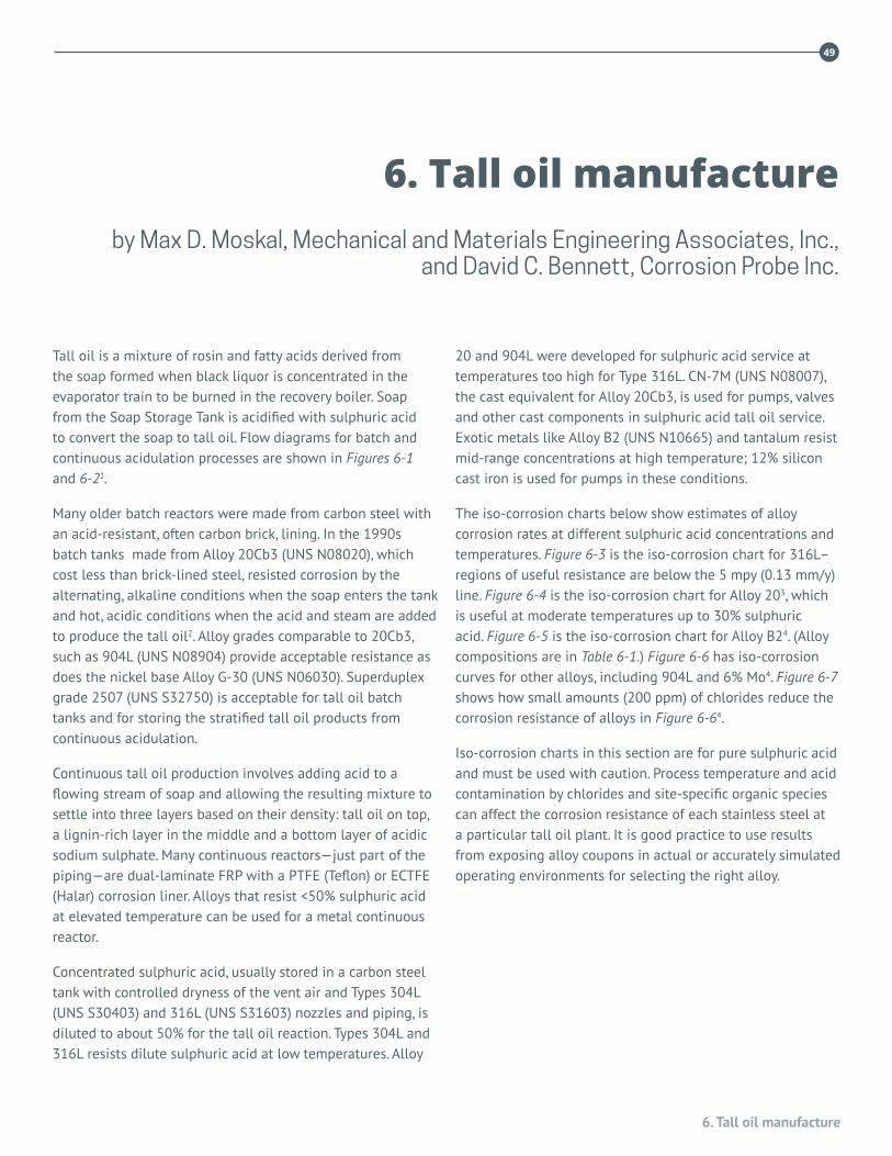
6. Tall oil manufacture
49
Tall oil is a mixture of rosin and fatty acids derived from the soap formed when black liquor is concentrated in the evaporator train to be burned in the recovery boiler. Soap from the Soap Storage Tank is acidified with sulphuric acid to convert the soap to tall oil. Flow diagrams for batch and continuous acidulation processes are shown in Figures 6-1 and 6-21.
Many older batch reactors were made from carbon steel with an acid-resistant, often carbon brick, lining. In the 1990s batch tanks made from Alloy 20Cb3 (UNS N08020), which cost less than brick-lined steel, resisted corrosion by the alternating, alkaline conditions when the soap enters the tank and hot, acidic conditions when the acid and steam are added to produce the tall oil2. Alloy grades comparable to 20Cb3, such as 904L (UNS N08904) provide acceptable resistance as does the nickel base Alloy G-30 (UNS N06030). Superduplex grade 2507 (UNS S32750) is acceptable for tall oil batch tanks and for storing the stratified tall oil products from continuous acidulation.
Continuous tall oil production involves adding acid to a flowing stream of soap and allowing the resulting mixture to settle into three layers based on their density: tall oil on top, a lignin-rich layer in the middle and a bottom layer of acidic sodium sulphate. Many continuous reactors—just part of the piping—are dual-laminate FRP with a PTFE (Teflon) or ECTFE (Halar) corrosion liner. Alloys that resist <50% sulphuric acid at elevated temperature can be used for a metal continuous reactor.
Concentrated sulphuric acid, usually stored in a carbon steel tank with controlled dryness of the vent air and Types 304L (UNS S30403) and 316L (UNS S31603) nozzles and piping, is diluted to about 50% for the tall oil reaction. Types 304L and 316L resists dilute sulphuric acid at low temperatures. Alloy
20 and 904L were developed for sulphuric acid service at temperatures too high for Type 316L. CN-7M (UNS N08007), the cast equivalent for Alloy 20Cb3, is used for pumps, valves and other cast components in sulphuric acid tall oil service. Exotic metals like Alloy B2 (UNS N10665) and tantalum resist mid-range concentrations at high temperature; 12% silicon cast iron is used for pumps in these conditions.
The iso-corrosion charts below show estimates of alloy corrosion rates at different sulphuric acid concentrations and temperatures. Figure 6-3 is the iso-corrosion chart for 316L–regions of useful resistance are below the 5 mpy (0.13 mm/y) line. Figure 6-4 is the iso-corrosion chart for Alloy 203, which is useful at moderate temperatures up to 30% sulphuric acid. Figure 6-5 is the iso-corrosion chart for Alloy B24. (Alloy compositions are in Table 6-1.) Figure 6-6 has iso-corrosion curves for other alloys, including 904L and 6% Mo4. Figure 6-7 shows how small amounts (200 ppm) of chlorides reduce the corrosion resistance of alloys in Figure 6-64.
Iso-corrosion charts in this section are for pure sulphuric acid and must be used with caution. Process temperature and acid contamination by chlorides and site-specific organic species can affect the corrosion resistance of each stainless steel at a particular tall oil plant. It is good practice to use results from exposing alloy coupons in actual or accurately simulated operating environments for selecting the right alloy.
6. Tall oil manufacture by Max D. Moskal, Mechanical and Materials Engineering Associates, Inc.,
and David C. Bennett, Corrosion Probe Inc.
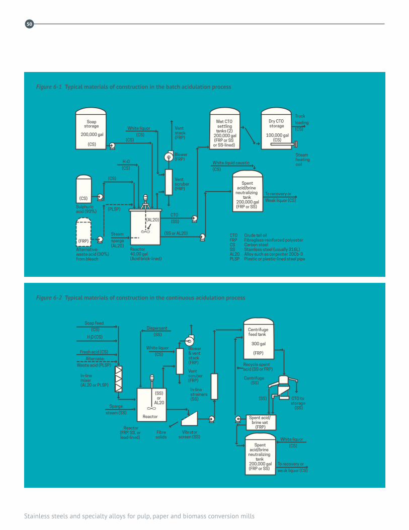
50
Stainless steels and specialty alloys for pulp, paper and biomass conversion mills
➜
➜
➜
➜
➜
➜
➜
➜
➜
➜
➜
➜
➜
➜
➜
➜
➜
➜
➜
➜
➜
➜
➜
➜
➜
➜
➜
➜ ➜
➜
➜
➜
➜
➜
Spentacid/brine
neutralizingtank
200,000 gal(FRP or SS)
(SS)or
AL20
White liquor
(CS)Fresh acid (CS)
Soap feed
(CS)
Alternate:
Waste acid (PLSP)
Sparge
steam (SS)
CTO tostorage
(SS)
(SS)
Centrifuge(SS)
White liquor
(CS)
Blower& ventstack(FRP)
In-linemixer(AL20 or PLSP)
Ventscruber(FRP)
Dispersant
(SS)Centrifugefeed tank
300 gal
(FRP)
Reactor
Reactor(FRP, SS, orlead-lined)
Fibresolids
Vibratorscreen (SS)
In-linestrainers(SS)
To recovery or
weak liquor (CS)
Recycle spentacid (SS or FRP)
Spent acid/brine vat
(FRP)
➜
H O (CS)2
➜
➜
➜
➜
➜➜
➜
➜
➜
➜
➜
➜
➜
➜➜➜
➜
➜
➜
➜
➜
➜
➜
➜
➜
➜
➜
➜
➜
➜
➜
➜Soap
storage
200,000 gal
(CS)
(CS)
(FRP)
(CS)
(PLSP)Sulphuricacid (93%)
Alternative:waste acid (30%)from bleach
Reactor40,00 gal(Acid brick-lined)
Steam
sparge(AL20)
(AL20)
H 20
(CS)
(CS)
White liquor
(CS)
Ventstack(FRP)
Blower(FRP)
Ventscruber(FRP)
CTO
(SS)
(SS or AL20)
White liquid caustic
(CS)
To recovery or
Weak liquor (CS)
Truck
loading
(CS)
Steamheatingcoil
Wet CTOsettling
tanks (2)200,000 gal(FRP or SS
or SS-lined)
Dry CTOstorage
100,000 gal(CS)
Spentacid/brine
neutralizingtank
200,000 gal(FRP or SS)
Crude tall oilFibreglass-reinforced polyesterCarbon steelStainless steel (usually 316L)Alloy such as carpenter 20Cb-3Plastic or plastic-lined steel pipe
CTOFRPCSSSAL20PLSP
➜
➜
➜
➜
➜
➜
➜
➜
➜
➜
➜
➜
➜
➜
➜
➜
➜
➜
➜
➜
➜
➜
➜
➜
➜
➜
➜
➜ ➜
➜
➜
➜
➜
➜
Spentacid/brine
neutralizingtank
200,000 gal(FRP or SS)
(SS)or
AL20
White liquor
(CS)Fresh acid (CS)
Soap feed
(CS)
Alternate:
Waste acid (PLSP)
Sparge
steam (SS)
CTO tostorage
(SS)
(SS)
Centrifuge(SS)
White liquor
(CS)
Blower& ventstack(FRP)
In-linemixer(AL20 or PLSP)
Ventscruber(FRP)
Dispersant
(SS)Centrifugefeed tank
300 gal
(FRP)
Reactor
Reactor(FRP, SS, orlead-lined)
Fibresolids
Vibratorscreen (SS)
In-linestrainers(SS)
To recovery or
weak liquor (CS)
Recycle spentacid (SS or FRP)
Spent acid/brine vat
(FRP)
➜
H O (CS)2
➜
➜
➜
➜
➜➜
➜
➜
➜
➜
➜
➜
➜
➜➜➜
➜
➜
➜
➜
➜
➜
➜
➜
➜
➜
➜
➜
➜
➜➜
➜Soap
storage
200,000 gal
(CS)
(CS)
(FRP)
(CS)
(PLSP)Sulphuricacid (93%)
Alternative:waste acid (30%)from bleach
Reactor40,00 gal(Acid brick-lined)
Steam
sparge(AL20)
(AL20)
H 20
(CS)
(CS)
White liquor
(CS)
Ventstack(FRP)
Blower(FRP)
Ventscruber(FRP)
CTO
(SS)
(SS or AL20)
White liquid caustic
(CS)
To recovery or
Weak liquor (CS)
Truck
loading
(CS)
Steamheatingcoil
Wet CTOsettling
tanks (2)200,000 gal(FRP or SS
or SS-lined)
Dry CTOstorage
100,000 gal(CS)
Spentacid/brine
neutralizingtank
200,000 gal(FRP or SS)
Crude tall oilFibreglass-reinforced polyesterCarbon steelStainless steel (usually 316L)Alloy such as carpenter 20Cb-3Plastic or plastic-lined steel pipe
CTOFRPCSSSAL20PLSP
Figure 6-1 Typical materials of construction in the batch acidulation process
Figure 6-2 Typical materials of construction in the continuous acidulation process

6. Tall oil manufacture
51
Sulphuric acid, Wt. %
Boiling point curve
Tem
pera
ture
, ̊C
Tem
pera
ture
, ̊F
Corrosion rates in parentheses are in mils per year
1.02 mm/y (40)3.05 mm/y (120)
.51 mm/y (20)
.10 mm/y (4)
Sulphuric acid, Wt. %
Tem
pera
ture
, ̊C
Tem
pera
ture
, ̊F
Corrosion rates in parentheses are in mils per year
Boiling point curve
Boiling point curve
Sulphuric acid, Wt. %
Boiling point curve
Tem
pera
ture
, ̊C
Tem
pera
ture
, ̊F
Corrosion rates in parentheses are in mils per year
1.02 mm/y (40)3.05 mm/y (120)
.51 mm/y (20)
.10 mm/y (4)
Sulphuric acid, Wt. %
Tem
pera
ture
, ̊C
Tem
pera
ture
, ̊F
Corrosion rates in parentheses are in mils per year
Boiling point curve
Boiling point curve
Figure 6-3 Sulphuric acid isocorrosion chart – S31603
Figure 6-4 Sulphuric acid isocorrosion chart – N08020

52
Stainless steels and specialty alloys for pulp, paper and biomass conversion mills
1.27 mm/y (50)
0.13 mm/y (5)
0.13 mm/y (5)
1.27 mm/y(50)0.13 mm/y (5)
0.13 mm/y (5)
Sulphuric acidSulphuric acid +200 ppm CI - as NaCI
Sulphuric acid, Wt. %
Tem
pera
ture
, C̊
Tem
pera
ture
, F̊
Corrosion rates in parentheses are in mils per year
140
120
100
80
60
40
20
Tem
pera
ture
, ˚C
18-10(304)
254 SMO
904L
254 SMO
904L
17-12-2.5(316)
H SO , Weight-%2 4
17-12-2.5(316)
18-10(304)
Boiling point curve
Table 6–1 Composition of alloys used for sulphuric acid service
Alloy UNS EN C Cr Ni Mo Cu Other
316L S31603 1.4404 0.03 17 11 2.2 —
Alloy 20 N08020 2.4660 0.06 20 34 2.5 3.5
Alloy 904L N08904 1.4539 0.02 21 26.5 4.5 1.5
Alloy 926 N08926 1.4529 0.02 20 25 6.1 0.6 0.15 N
Alloy B2 N10655 — 0.01 1.0 70 26 — 1.0 Co 2.0 Fe
Figure 6-5 Sulphuric acid isocorrosion chart - N10665

6. Tall oil manufacture
53
100
80
60
40
20
Tem
pera
ture
, C̊
904L
254 SMO
904L
254 SMO
904L
17-12-2.5(316)
H SO , Weight-%2 4
1.27 mm/y (50)
0.13 mm/y (5)
0.13 mm/y (5)
1.27 mm/y(50)0.13 mm/y (5)
0.13 mm/y (5)
Sulphuric acidSulphuric acid +200 ppm CI - as NaCI
Sulphuric acid, Wt. %
Tem
pera
ture
, C̊
Tem
pera
ture
, F̊
Corrosion rates in parentheses are in mils per year
140
120
100
80
60
40
20
Tem
pera
ture
, ˚C
18-10(304)
254 SMO
904L
254 SMO
904L
17-12-2.5(316)
H SO , Weight-%2 4
17-12-2.5(316)
18-10(304)
Boiling point curve
Figure 6-6 Sulphuric acid Iso-corrosion diagram, 0.1 mm/year, for austenitic stainless steels in naturally aerated sulphuric acid of chemical purity. Broken-line curve represents the boiling point
Figure 6-7 Sulphuric acid with chlorides Iso-corrosion diagram, 0.1 mm/year, in sulphuric acid with an addition of 200 ppm chlorides

54
Stainless steels and specialty alloys for pulp, paper and biomass conversion mills
REFERENCES
1. Mappin, F. H., “Construction materials and corrosion in tall oil production,” TAPPI J. 70(1): 59 (1987).
2. Ketchum, M., “Black Liquor Soap Separation and Acidulation: Changing Some Old Habits,” TAPPI J. 73(2): 107 (1990).
3. “Corrosion Resistance of Nickel-Containing Alloys in Sulfuric Acid and Related Compounds,” INCO CEB No. 1, Bulletin No.1318, available from the Nickel Institute, Toronto, ON, 1983.
4. “Corrosion Handbook”, Outokumpu Oyj, 2009

7. Sulphite process
5555
Once the principal method for producing chemical pulp, the sulphite process has lost ground to the kraft and chemical-mechanical pulping methods. Nevertheless, sulphite pulping remains an important process.
Many similarities can be seen between Kraft and sulphite mills, although chemistries are quite different. Each has batch or continuous digestion, and some sulphite operations have chemical recovery. After digestion the processes for washing, bleaching and papermaking can be identical. Consequently, the following discussion is limited to liquor preparation, digestion and chemical recovery. Figure 7-1 is a flow diagram of a typical magnesium base pulping and recovery operation.
7.1 THE ENVIRONMENTSulphite cooking liquor consists of free sulphur dioxide dissolved in water together with sulphur dioxide in the form of bisulphite. Until about 1950, sulphite pulping was an acid process using calcium as the cation. Because the calcium process was limited to only certain wood species, other types of sulphite were introduced, namely sodium, magnesium and ammonium sulphite processes, and their use has broadened sulphite pulping for all wood species. Subsequent to the introduction and application of magnesium and sodium bases, several two-stage sulphite pulping methods using these bases have been developed and utilized commercially. These methods are generally characterized by a dramatic change in cooking pH between the initial stage (for penetration and sulphonation) and the second stage (for dissolution and removal of the lignin).1
Depending upon the process, the pH of the cooking liquor can range from acid to neutral to alkaline. In acid bisulphite pulping, any pH within the range of 1.5 to 4.0 can be
achieved by controlling the ratio of free and combined SO2.True bisulphite pulping, with equal amounts of free and combined SO2, would be carried out at a pH of 4.0 to 5.0. Another important sulphite pulping process is neutral sulphite semichemical pulping discussed in the following section.
Sulphuric acid is the principal aggressor in an acid sulphite mill. It can be generated in any number of unit operations. The environment usually contains chlorides that are often present in other chemicals used and are always present in logs that have been floated to coastal mills. Chlorides increase the aggressiveness of sulphuric acid. Refer to Figures 6-6 and 6-7 in the Tall Oil Chapter 6.
7.2 CONSTRUCTION MATERIALSIt can be said that stainless steels and sulphite pulping grew up together. In fact many new alloys were tested in acid sulphite mills. Type 316L (UNS S31603) stainless steel became the principal material of construction for sulphite mills, although more highly alloyed materials are required in a number of applications. Type 317L (UNS S31703) and the higher molybdenum stainless steels are finding wider application, especially in the higher chloride environments. More recently, duplex stainless steels have been specified, due to their excellent resistance to pitting and stress corrosion cracking. There are also a number of applications where specialty alloys such as Alloy 20 (UNS N08020), 6% Mo alloys, G30 (UNS N06030), and C276 (UNS N10276) are advantageous.
7.3 SULPHUR DIOXDE PRODUCTIONThe principal method for producing sulphur dioxide is the
7. Sulphite processby Max D. Moskal, Mechanical and Materials Engineering Associates, Inc.

56
Stainless steels and specialty alloys for pulp, paper and biomass conversion mills
56
Mg(OH) 2MakeupMg(OH) 2
MgO
Weakred
liquorstorage
Weakredliquor
Unbleachstoragestock
3-Stagewashers
Makeupsulphur
Strongredliquorwtorage
MulitipleeffectevaporatorsSulphur burner-
gas cooler
Directcontactevaporator
Mechanicaldust collector
Recoveryfurnace
Steam
Condensate
Screens
Clarifier
Water
Chips
Digester
Stack
AbsorptionFortification
tower
Acidfilter
Liquorheater
Blowtank
Cookingacid
storage
SO 2
Figure 7-1 Flow diagram of magnesium base mill and recovery system
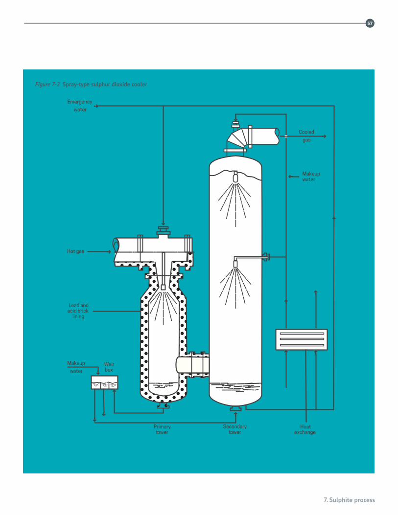
7. Sulphite process
5757
Heatexchange
Secondarytower
Primarytower
Lead andacid brick
lining
Makeupwater
Cooled
gas
Hot gas
Makeup
water
Emergency
water
Weirbox
Figure 7-2 Spray-type sulphur dioxide cooler

58
Stainless steels and specialty alloys for pulp, paper and biomass conversion mills
58
burning of elemental sulphur, although some Canadian mills roast iron pyrites. The steps for preparing sulphite cooking liquor are as follows:
1. Burning of sulphur.
2. Rapid cooling (to prevent sulphur trioxide formation).
3. Absorption of sulphur dioxide in a weak alkaline solution.
4. Fortifying the raw acid.
Mild steel is satisfactory for sulphur burners and combustion chambers.2 However, this is not a good environment for austenitic stainless steels because of the formation of low-melting-point nickel sulphide scale.
The hot sulphur dioxide is cooled rapidly in either heat exchangers or direct-contact water spray towers. The heat exchangers, or pond coolers, are lead lined steel pipe. Cooling towers are commonly acid brick lined but are occasionally Type 316L stainless steel. When stainless steel is used, walls should receive a constant supply of wash water. Figure 7-2 shows one design for a sulphur dioxide cooler. In this case the first section is lead or acid-brick lined, and the second section is stainless steel. Emergency water is available in case there is an excursion in temperature.
Piping from the cooling tower to the absorption tower can be exposed to sulphuric acid. Piping has been Type 316L or 317L, although some mills use FRP.
The sulphur dioxide compressors can be lined with lead or rubber, or more commonly Type 316L or 317L. Sometimes a more acid-resistant, copper-containing Alloy 20 stainless steel would be preferred.3
The SO2 fans and compressors can be lined with lead or rubber (Alloy 20), or more commonly, with Type 316L or 317L construction. A better choice would be Alloy 20 or 904L (UNS N08904), as this equipment is prone to accumulation of carry-over sulphur and attack by the small amounts of sulphuric acid which is inadvertently formed in the burner.3
Atmospheric absorption towers can be Type 316L or 317L or FRP.
With FRP construction, all internals would be Type 316L or 317L stainless. Both the body and internals of pressure towers can be of stainless steel construction.
Acid tanks are usually acid-brick lined, although Types 316L and Type 2205 (UNS S32205/S31803) duplex stainless steel have been used. However, sulphuric acid can be present, and if the temperature exceeds 85 °C, acid-brick lined tanks are preferred.
7.4 DIGESTERSOlder batch digesters were acid-brick lined. However, digesters have more recently been constructed from Types 317L, 904L, 317LMN (UNS S31726), and 2205 duplex stainless steels. Duplex stainless steel alloys offer better protection against chloride stress corrosion cracking compared to austenitic stainless steels. In brick-lined digesters, most fittings, screens, sleeves, and man-way hatches are Type 316L or 317L stainless steel.
Continuous digesters for sulphite pulping are very similar to kraft continuous digesters in design. For the sulphite process, continuous digesters are all stainless steel construction using Type 316L (with a minimum of 2.75% molybdenum) or 317L.4 Duplex stainless steel has also been used in several continuous digesters.
7.5 WASHING AND SCREENINGPumps, piping, screens, knotters, washers and deckers may all be exposed to small amounts of bisulphite in the spent liquor, so stainless steel construction is still necessary for corrosion protec-tion. Type 316L stainless is almost standard. However, crevice corrosion may occur under pulp deposits; so the choice may be for Types 317L, 2205 duplex or higher alloyed materials.
7.6 CHEMICAL RECOVERYA number of sulphite mills operate liquor recovery systems. However, there appears to be considerable variation in operating conditions. Sulphite recovery boilers are primarily of carbon steel construction, with significant corrosion allowances in critical areas such as screens, superheaters, and waterwall tubes. More recent construction has incorporated composite Type 304L (UNS S30403) with SA210 steel tubes in the lower furnace waterwalls. Carbon steel remains the choice for floor tubes. The SO2 content of sulphite recovery flue gas is much higher than in kraft systems, increasing the potential for SO3 formation.

7. Sulphite process
5959
Scrubbing systems are usually of FRP and/or Type 316L/317L stainless steel. Where high levels of chlorides and/or SO3 are present, high molybdenum stainless steels or nickel base alloys give better service3. The magnesium sulphite operation presents a special case in scrubber corrosion, where the MgO slurry in water is combined with hot SO2 gas. In this case the SO2 gas enters the top of one leg of the scrubber and is combined with the MgO slurry shower. Problems of severe stress corrosion cracking and crevice corrosion under wet salt have occurred in Type 317L stainless steel scrubber walls. One solution has been to replace the affected components with Ni-Cr-Mo-W (e.g. C-276) alloy. Consideration could be given to use of duplex stainless steels in this application given those alloys’ excellent resistance to pitting and stress corrosion cracking.
Jonsson reported that a steel corresponding to Type 316L is suitable material for all components in the evaporators such as tubes, vapour bodies, liquid flash tanks, vapour pipes, condenser pipes, liquor pipes, valves, pumps, and condensers where calcium bisulphite is evaporated4. For evaporation of magnesium base cooking liquor, Type 316L with 2.75% molybdenum or Type 317L is often prescribed, since the corrosive conditions are considered to be somewhat more severe than for calcium bisulphite. For sodium base cooking liquor, the conditions are not so corrosive and therefore Type 316L is used for the first effect and Type 304L or mild steel for the weak liquor effects in the evaporator train. Carbon steels in the weak liquor stages have sometimes been replaced by stainless steels, primarily to reduce fouling and secondarily to reduce corrosion. The corrosion problems are less severe for cooking liquor using ammonium base.
7.7 CHLORIDE CONTROLChloride ions entering the pulp mill cycle from salt water wood storage can cause serious corrosion of stainless steel equip-ment throughout the liquor cycle. A control system conceived for the magnesium oxide recovery process can greatly reduce corrosion by maintaining a low chloride ion level. The system is based on the knowledge that the chlorides leave the recovery boiler as hydrochloric acid and can be readily removed from the flue gas by a venturi absorber.5
60
Stainless steels and specialty alloys for pulp, paper and biomass conversion mills
6060
REFERENCES
1. Smook, GA, Handbook for Pulp and Paper Technologists, Third Edition Aug 2002, TAPPI.
2. McGovern, S. D., “A review of corrosion in the sulphite pulping industry,” Pulp and Paper Industry Corrosion Problems, Vol. 3, NACE, 1980.
3. Jonsson, K.-E., “Stainless steels in the pulp and paper industry,” Handbook of Stainless Steels, McGraw-Hill, 1977.
4. “Pulp and Paper Manufacture,” Vol. 1, 2nd edition, McGraw-Hill, NY, 1969
5. McIlroy, R. A., “The control of chloride ions in the MgO recovery system,” Tappi J. 56(9): (1973).

8. Neutral sulphite semichemical pulping
6161
In neutral sulphite semichemical (NSSC) pulping, hardwood chips are cooked in a liquor solution consisting of sodium sulphite with a small quantity of sodium carbonate, bicarbonate, or hydroxide. A typical strong liquor contains 120–200 g/l of sodium sulphite and 30–50 g/l of sodium carbonate. The liquor is generally prepared by burning sulphur to form sulphur dioxide, and then absorbing the gas in a solution of sodium carbonate (soda ash), although small mills may purchase chemicals if readily available from a nearby source1,2.
Cooking is done in digesters similar to those used in the kraft process, except that the continuous digesters are of a different design. Typical continuous digesters include horizontal multiple-tube units or inclined tube digesters.
The cooking occurs in either the liquid or the vapour phase. For vapour phase cooking the chips must pass through a press impregnator before entering the digester. The flow diagram for a typical NSSC mill is illustrated in Figure 8-1.1 Cooking temperatures range from approximately 180–195 °C; the pH range is from 7.2 to 9. Heating is either directly by steam injection or indirectly with an external heat exchanger.
A number of mills are combined kraft/NSSC operations because both are used in the manufacture of corrugated cardboard. Consequently the sulphur and soda obtained from NSSC spent cooking liquors are introduced into the kraft chemical recovery system to replace the salt cake lost in the kraft mill. During carbonation of the smelt, hydrogen sulphide is released. This is burned to sulphur dioxide in a separate reactor or in the oxidation zone of the recovery boiler.
Because NSSC spent liquors are more corrosive than kraft liquors, stainless steels are generally used in all equipment. While Type 304 (UNS S30400) has been used successfully,
Type 316 (UNS S31600) is generally preferred because of its better resistance to corrosion. When welding is involved, the low carbon Types 304L (UNS S30403) and 316L (UNS S31603) are used to prevent problems with intergranular corrosion. While NSSC pulp can be bleached using chlorine dioxide, caustic soda, or hypochlorite, bleaching is not usually required.
In a related process, pulping is done at more acidic pH levels, using bisulphite rather than sulphite as the active chemical. In some instances, this has caused rapid attack of the vapour phase region of the digester, due to the formation of sulphuric acid vapour2. The conditions that promote the formation of acid vapours are the presence of air and a low cooking liquor pH. Digesters for use in semichemical bisulphite pulping have been made from a range of materials, including carbon steel and austenitic stainless steels. The accelerated corrosion of a Type 317L (UNS S31703) continuous bisulphite semichemical digester has been described by Murarka3. Formation of acid vapours was minimized by raising the liquor pH from 4 to 6, and by using a plug screw feeder to reduce the entry of oxygen with the incoming chips. Additional precautions taken were feeding the chips into the digester below the liquor level, and preheating the water in the blow tank to lower its dissolved oxygen content. The vapour space of the digester was clad in 904L (UNS N08904) stainless steel. Presteaming the chips and replacing the air in the digester with steam prior to startup have also been advocated to minimize the possibility of acidic corrosion.4
8. Neutral sulphite semichemical pulping
by Chris Thompson, FPInnovations
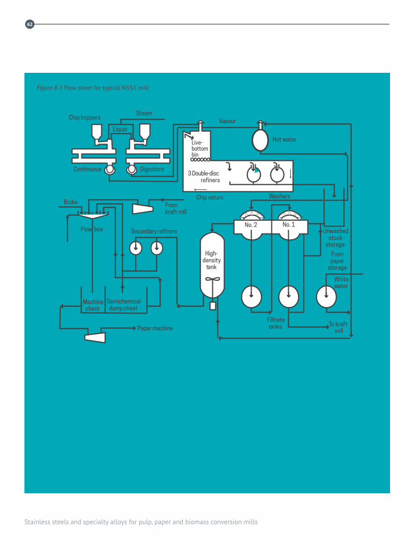
62
Stainless steels and specialty alloys for pulp, paper and biomass conversion mills
62
High-density
tank
Hot water
SteamVapour
Chip return
Paper machine
Flow box
Broke
Continuous Digesters
Chip hoppers
Liquor
Secondary refiners
Washers
Machinechest
Semichemicaldump chest
Fromkraft mill
To kraftmill
Whitewater
Filtratetanks
Frompaper
storage
Unwashedstock
storage
3 Double-discrefiners
Live-bottombin
No. 2 No. 1
Figure 8-1 Flow sheet for typical NSSC mill
8. Neutral sulphite semichemical pulping
6363
REFERENCES1. Tappi J., 41(12): (1958).
2. Smook, GA, Handbook for Pulp and Paper Technologists, Third Edition Aug 2002, TAPPI.
3. Murarka, S. K., Dwars, W.T. A. and Langlois, J. F., “Potential formation of corrosive acidic condensate and its monitoring in a continuous vapour phase bisulphite chemi-mechanical (BCMP) process,” Pulp and Paper Industry Corrosion Problems, Vol. 5, Canadian Pulp and Paper Assoc., Montreal, Canada, 1986, p. 187.
4. Metals Handbook, 9th Edition, Vol. 13, Corrosion, ASM Intl., Materials Park, Ohio, 1987, pp. 1198 and 1218.

64
Stainless steels and specialty alloys for pulp, paper and biomass conversion mills
64

9. High yield mechanical pulping
65
High yield mechanical pulping is the generic name for producing pulps mechanically, using either disc refiners or grindstones (also called “pulpstones”). Today, high yield mechanical pulping is dominated by disc refiner technology and, in North America, stone groundwood technology has virtually disappeared from the scene. Newsprint typically contains high amounts of refiner pulps, up to 100%. Other applications for mechanical pulps include wood-containing printing and writing grades, multi-ply board, specialty papers, and as a partial substitute for hardwood kraft pulp in printing paper. One emerging application for disc refiners is to make cellulose filaments, a new super-reinforcing material.
A large number of refiner pulping processes have been developed, primarily as a result of the need to produce tailor-made pulps and to manage energy requirements. The simplest process is refiner mechanical pulping (RMP) in which the chips are refined at atmospheric pressure with no prior use of heat or chemical action. For newsprint production, the dominant methods of refiner pulping are thermo-mechanical pulping (TMP) in which the chips are softened by heating in a steaming tube before entry into the primary refiner, and chemi-thermo mechanical pulping (CTMP) in which the chips are also impregnated with a cooking chemical such as sodium sulphite. Bleached chemi-thermo mechanical pulp (BCTMP) is another variant for high bulk and brightness applications. In this case, the pulp is typically bleached with hydrogen peroxide in a separate bleach plant.
In both TMP and CTMP systems, atmospheric chip steaming removes air, thaws chips in winter and brings the chip mass to a warm condition. Atmospheric steaming is followed by pressurized steaming (often referred as pre-heating) typically within the range of 80 to 160 kPa for approximately 60 seconds. This process softens the chips
such that subsequent refining can liberate fibers intact, thus reducing fiber shortening. Refining takes place at elevated temperatures and pressures, normally within the range of 350 kPa to 600 kPa in one, two or three stages of refining. The pressurized environment facilitates the recovery of heat from the “dirty” steam in a reboiler. In older systems, secondary and tertiary refining stages could be completed under atmospheric conditions without the benefit of efficient heat recovery.
The distinction between TMP and CTMP can be blurred, as TMP facilities sometimes add sulphite solution to the chips before refining. Some operations add sodium hydrosulphite bleach solution into the refiner. This can reportedly reduce the service life of bearings and seals, but there have been no documented instances of significant corrosion from the practice. A schematic illustration of a TMP system is shown in Figure 9-1.
Modern refiners are large and powerful, with disc diameters up to 1.8 m and motor powers as high as 32 MW (40,000 HP). In operation, pulping is achieved by passing wood chips between two or more closely spaced sets of serrated refiner plates, at least one set of which is rotating. Each set of plates is made by bolting individual plates onto a backing disc. Refiner plates are made from abrasion resistant cast irons, such as 25% Cr, Ni-HiCr Type D (ASTM specification A532) or high carbon cast stainless steels, and are treated as consumables. For low consistency refining, the plates can also be made from rolled and welded steel bars. For more information on the wear and corrosion of refiner plates, see Reference 1.
Relatively little information exists in the literature regarding corrosion in high yield pulping environments. A review is
9. High yield mechanical pulpingby Chris Thompson, FPInnovations

66
Stainless steels and specialty alloys for pulp, paper and biomass conversion mills
SteamAtmosphericpresteamingbin
Steaming tube
Screw press
Reject refinerRejectscreen
Refined reject chest
Unrefinedreject chest
Secondaryscreens
Primaryscreens
Topapermill
Main line refinersRotaryvalve
Figure 9-1 Flow diagram for a TMP mill

9. High yield mechanical pulping
67
given in Reference 2. A survey of materials problems and inspection procedures for refiner systems is reported in Reference 3. One concern in the past has been for stress corrosion and corrosion fatigue, particularly with regard to pressurized steaming tubes, refiner discs, and refiner drive shafts. Similar issues have not been reported in recent years. Many of these problems occurred in coastal mills, where high chloride levels were encountered. However, it should be born in mind that chlorides can be a problem for inland mills as well. For example, caustic used in the mill often contains chlorides. Even if chlorides are low, they can concentrate in crevices, under deposits, and just above the waterline in the vapour phase.2 Mills reducing their fresh water usage can also be vulnerable to unexpected attack, as contaminated white water from the paper mill may be fed back to the mechanical pulp mill.
The combination of the presence of chloride ions, the use of chemical pulping or bleaching agents, and the release of volatile wood acids can result in the localized buildup of highly aggressive conditions, even when nominal white water conditions are considered to be innocuous. In some of the cases mentioned in Reference 2, corrosion was initiated under deposits or in dead zones where the local environment was considerably more aggressive than the nominal environment. For example, deposit analyses from a coastal presteaming vessel showed pH values of 1.9 and chloride levels of about 13,000 ppm (compared to a nominal chloride level in the TMP white water of about 200 ppm). One mill reported replacement of two Type 904L (UNS N08904) steaming vessels with Alloy C276 (UNS N10276) and Alloy C22 (UNS N06022) because of serious chloride stress corrosion cracking (SCC) of the 904L, an alloy that is normally resistant to such attack.4 Corrosion within TMP reboilers (where dirty steam from the refiners is used to generate clean process steam) can also occur, and is likely due to the localized buildup of aggressive ions. One instance of such attack is given in Reference 5.
Type 316L (UNS S31603) is the standard alloy used by manufacturers for the major components of refiner systems.2 Exceptions are where high strength is required (e.g., for drive shafts and refiner backing disks) and in areas where corrosion (and particularly chloride SCC4) is considered to be a particular concern. Upgrading to 904L or Type
2205 (UNS S32205) has been suggested for high chloride environments. Alloy C276 or Alloy C22 has been used for particularly aggressive and acidic conditions in steaming tubes. For cavitation resistance, Type 2205 clad plate has been suggested for some applications. The metallurgy used for refiner backing discs, drive shafts, and casings varies with the manufacturer and specific process conditions. Alloys that have been used include forged 15-5PH (UNS S15500), CA-6NM (UNS J91540) and 16Cr 5Ni 1Mo (CB-6, UNS designation J91804). Refiner casing alloys include Type 316L, 904L, CA-15 (UNS J91150), CA-6NM, and Type 2205 clad carbon steel, the exact choice depending on the anticipated service conditions. Chloride SCC of CB-6 refiner cases in less than two years has been reported.4 Drive shafts are not designed to be exposed to the process, and have typically been made from alloy steels such as AISI 4140 or 4340; some use of martensitic stainless steel and the duplex stainless steel 2507 (UNS S32750) has been reported.

68
Stainless steels and specialty alloys for pulp, paper and biomass conversion mills
REFERENCES1. Metals Handbook, 9th Edition, Vol. 13, Corrosion, ASM Intl.,
Materials Park, Ohio, 1987, p. 1215.
2. Clarke, P. H., Singbeil, D. L., and Thompson, C. B., “System closure and corrosion in high yield pulping processes,” 9th Intl. Symp. on Corrosion in the Pulp and Paper Industry, Technical Section, Canadian Pulp and Paper Assoc., Ottawa, Canada, 1998, p. 131.
3. Thompson, C. B., “A survey of inspection procedures and materials problems in chip refiner systems,” Pulp and Paper Canada 94(7):T199–T203 (1993).
4. Reid, C. and Lawn, S., “Macmillan Bloedell experience with stress corrosion cracking in CTMP equipment,” TAPPI Eng. Conf. Proc., Book 3, TAPPI, Boston, 1992, pp.1001–1014.
5. Laitinen, T., Thompson, C. B., and Clarke, S. J., “Unexpected corrosion problems in white water systems: can we avoid them?” 10th Int. Symposium on Corrosion in the Pulp and Paper Industry, Vol. 1, pp. 292-293, VTT, Finland, 2001.

10. Fibre recycling
6969
Paper recycling is a major part of the pulp and paper industry and is constantly undergoing changes in process and equipment. In the recycle process, recovered paper fibre is introduced into large rotary drum or tub pulpers where the paper is shredded and an alkaline water recycle stream is introduced, resulting in a 5-8% consistency pulp. After screening and washing, the pulp is sent to a single-stage or two-stage bleaching operation. Hydrogen peroxide (primarily) or hypochlorite are the usual bleaching agents. After bleaching, the pulp is washed and sent on to pulp preparation. The filtrate is recycled to the holding tanks ahead of the screens. A typical recycle flow diagram is shown in Figure 10-1. There are many variations in flow details depending on the recycle fibre sources and mill equipment preferences.
Type 316L (UNS S31603) and its cast counterpart CF-3M (UNS J92800) are the principal materials of construction for the equipment. The alkaline environment in the repulper
is conducive to microbiological influenced corrosion (MIC) beneath the pulp pads that adhere to the stainless steel lifter plates in the repulper and other stagnant flow regions. In a few cases, upgrading lifter plates to 6% molybdenum stainless steel has been used to resist the most aggressive conditions. Type 316L stainless steel is standard for piping, except where MIC cannot be controlled, and 6% molybdenum or FRP are used.
Recycling challenges include higher equipment abrasive wear and tear in handling increasing amounts of trash (metal, glass, rocks, plastic). To counter abrasive wear, duplex stainless steels, especially the lower-cost lean grades, may provide increased abrasion resistance compared to austenitic grades. Another challenge to recycling mills is the demand to maintain and increase product brightness. Type 316L and CF-3M are satisfactory for hydrogen peroxide bleaching, but higher alloys are needed if other bleaching sequences are introduced (see Chapter 11).
10. Fibre recyclingby Max D. Moskal, Mechanical and Materials Engineering Associates, Inc.

Stainless steels and specialty alloys for pulp, paper and biomass conversion mills
7070
Pulperbatchccale
Stacker
Deinking chemicals
Coarse hole screensContaminex
Heavy-dutycleaners
PULPER
Acid discfilters
Primary flotation cellsCoarse slot screens
Bleachingagent
Forwardcleaners
SulphuricacidAlkaline disc filters
ALKALINE LOOP
ACID LOOP
Reversecleaners Decker disc
filters
RAW MATERIAL – ALKALINE LOOP ACID LOOP – FINISHING LINE
Post floatation cell
Fine slot screens
Disperser
Sodiumhydrosulphite
Bleachtowers
Screw presses
ONPOMG
SHIPPINGStrapper
Balepress
De-wateringpresses
Cutter layboys
Peroxidebleachtower
Figure 10-1 Flow diagram for fiber recycling
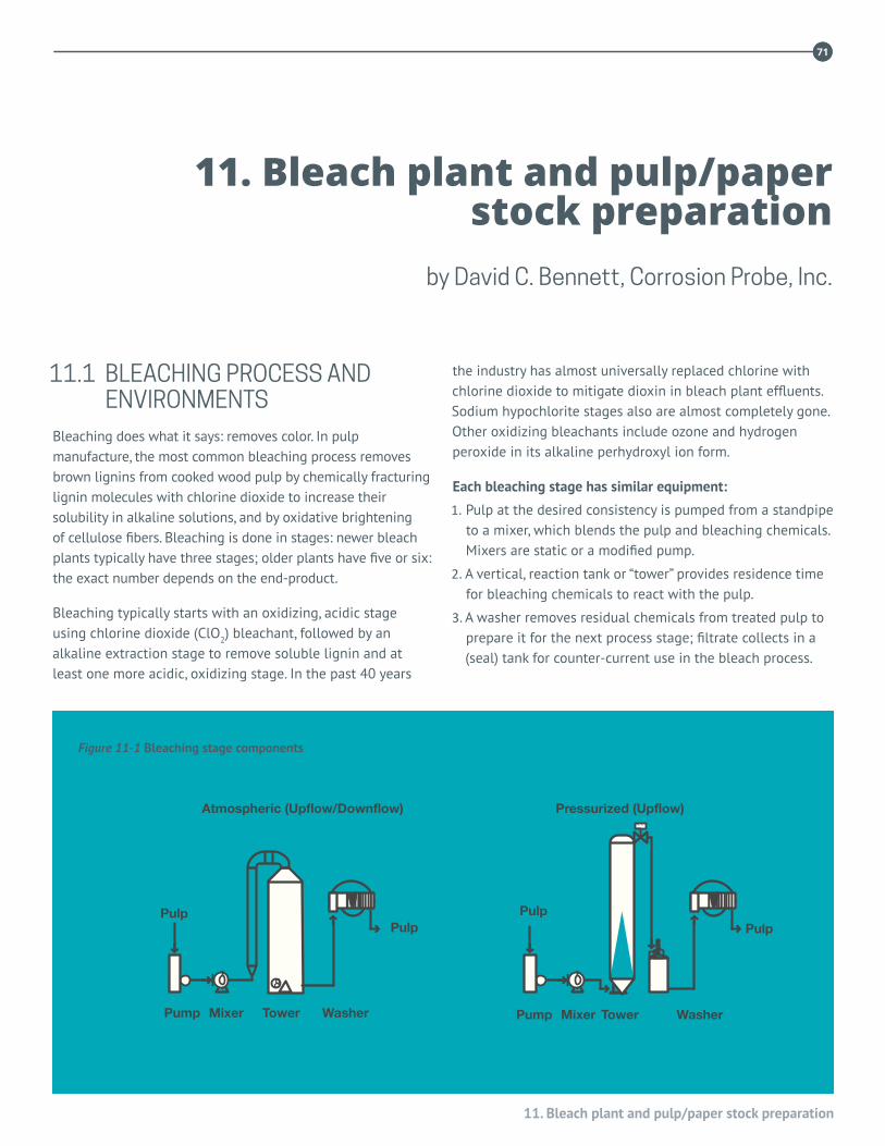
11. Bleach plant and pulp/paper stock preparation
7171
Pump Mixer Tower Washer
Pressurized (Upflow)Atmospheric (Upflow/Downflow)
PulpPulp
PulpPulp
Pump Mixer Tower Washer
11.1 BLEACHING PROCESS AND ENVIRONMENTS
Bleaching does what it says: removes color. In pulp manufacture, the most common bleaching process removes brown lignins from cooked wood pulp by chemically fracturing lignin molecules with chlorine dioxide to increase their solubility in alkaline solutions, and by oxidative brightening of cellulose fibers. Bleaching is done in stages: newer bleach plants typically have three stages; older plants have five or six: the exact number depends on the end-product.
Bleaching typically starts with an oxidizing, acidic stage using chlorine dioxide (ClO2) bleachant, followed by an alkaline extraction stage to remove soluble lignin and at least one more acidic, oxidizing stage. In the past 40 years
the industry has almost universally replaced chlorine with chlorine dioxide to mitigate dioxin in bleach plant effluents. Sodium hypochlorite stages also are almost completely gone. Other oxidizing bleachants include ozone and hydrogen peroxide in its alkaline perhydroxyl ion form.
Each bleaching stage has similar equipment:
1. Pulp at the desired consistency is pumped from a standpipe to a mixer, which blends the pulp and bleaching chemicals. Mixers are static or a modified pump.
2. A vertical, reaction tank or “tower” provides residence time for bleaching chemicals to react with the pulp.
3. A washer removes residual chemicals from treated pulp to prepare it for the next process stage; filtrate collects in a (seal) tank for counter-current use in the bleach process.
11. Bleach plant and pulp/paper stock preparation
by David C. Bennett, Corrosion Probe, Inc.
Figure 11-1 Bleaching stage components
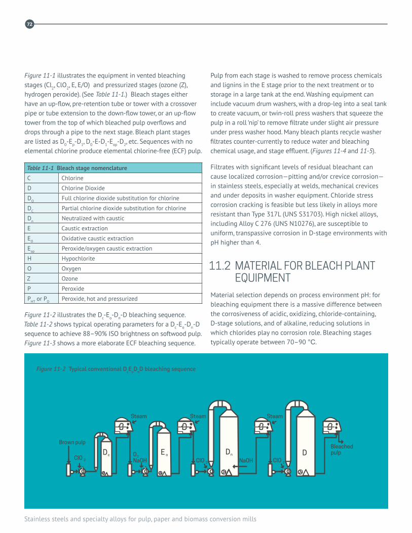
72
Stainless steels and specialty alloys for pulp, paper and biomass conversion mills
72
Figure 11-1 illustrates the equipment in vented bleaching stages (Cl2, ClO2, E, E/O) and pressurized stages (ozone (Z), hydrogen peroxide). (See Table 11-1.) Bleach stages either have an up-flow, pre-retention tube or tower with a crossover pipe or tube extension to the down-flow tower, or an up-flow tower from the top of which bleached pulp overflows and drops through a pipe to the next stage. Bleach plant stages are listed as D0-Ep-D1, D0-E-D1-Eop-D2, etc. Sequences with no elemental chlorine produce elemental chlorine-free (ECF) pulp.
Table 11-1 Bleach stage nomenclature
C Chlorine
D Chlorine Dioxide
DO Full chlorine dioxide substitution for chlorine
DC Partial chlorine dioxide substitution for chlorine
Dn Neutralized with caustic
E Caustic extraction
EO Oxidative caustic extraction
Eop Peroxide/oxygen caustic extraction
H Hypochlorite
O Oxygen
Z Ozone
P Peroxide
PHT or PO Peroxide, hot and pressurized
Figure 11-2 illustrates the Dc-Eo-Dn-D bleaching sequence. Table 11-2 shows typical operating parameters for a Dc-Eo-Dn-D sequence to achieve 88–90% ISO brightness on softwood pulp. Figure 11-3 shows a more elaborate ECF bleaching sequence.
Pulp from each stage is washed to remove process chemicals and lignins in the E stage prior to the next treatment or to storage in a large tank at the end. Washing equipment can include vacuum drum washers, with a drop-leg into a seal tank to create vacuum, or twin-roll press washers that squeeze the pulp in a roll ‘nip’ to remove filtrate under slight air pressure under press washer hood. Many bleach plants recycle washer filtrates counter-currently to reduce water and bleaching chemical usage, and stage effluent. (Figures 11-4 and 11-5).
Filtrates with significant levels of residual bleachant can cause localized corrosion—pitting and/or crevice corrosion—in stainless steels, especially at welds, mechanical crevices and under deposits in washer equipment. Chloride stress corrosion cracking is feasible but less likely in alloys more resistant than Type 317L (UNS S31703). High nickel alloys, including Alloy C 276 (UNS N10276), are susceptible to uniform, transpassive corrosion in D-stage environments with pH higher than 4.
11.2 MATERIAL FOR BLEACH PLANT EQUIPMENT
Material selection depends on process environment pH: for bleaching equipment there is a massive difference between the corrosiveness of acidic, oxidizing, chloride-containing, D-stage solutions, and of alkaline, reducing solutions in which chlorides play no corrosion role. Bleaching stages typically operate between 70–90 °C.
Steam
BleachedpulpD
SteamSteam
NaOH
Brown pulp
CIO 2 NaOHO2
CIO 2
Dc E o Dn
CIO 2
Figure 11-2 Typical conventional DcEoDnD bleaching sequence

11. Bleach plant and pulp/paper stock preparation
7373
Table 11-2 Typical operating and design parameters for for conventional and ECF bleaching sequences
Conventional ECF
Bleaching sequenceBrown stock kappa#Target brightness (%ISO)
DCEODnD30
88-90
OD(Eop)D30
85-88
Stage%NaOH (on pulp)%O2
TemperatureFinal pHBleach tower
Retention time
NANANANANANA
NA
Oxygen1.5-2.01.5-2.0
185-210 °F(85-99 °C)10-12
Cone top & bottom (100 psig at bottom, pressurized)
60
Stage%ClO2 substitution%Active Cl2 (on pulp)TemperatureFinal pHConsistency, %Bleach towerRetention time (min)
DC
506.0-7.8
90-120 °F(32-49 °C)1.5-2.0
3-4Upflow (atm)/Downflow
60 (15/45)
D100
3.6-4.7120-150 °F(49-65 °C)
2.5-3.53-12
Upflow (atm)/Downflow45 (15/30)
Stage%O2 (on pulp)%H2O2 (on pulp)Final phTemperatureBleach towerRetention time
EO
0.5NA
10.5-12.0165-185 °F(74-85 °C)
Upflow (atm)/Downflow45 (5 min at 20 psig/40 min)
Eop
0.50.5
10.5-12.0165-195 °F(74-90 °C)
Upflow (pressurized)/Downflow45 (15 min at 60 psig/30 min)
Stage%ClO2 (on pulp)Ph
Consistency, %TemperatureBleach towerRetention time (min)Brightness (%ISO)
Dn
0.8-1.23.5-4.5
(dilution zone is neutralized to 7-9 pH)10-12
160-175 °F(70-80 °C)Upflow (atm)/Downflow
180 (45/135)87-88
D1.0-1.43.0-4.5
10-12160-175 °F(70-80 °C)
Upflow (atm)/Downflow240 (45/195)
85-88
Stage%ClO2 (on pulp)PhTemperatureConsistency, %Bleach towerRetention time (min)Brightness (%ISO)
D2
0.1-0.34.5-5.0
160-175 °F(70-80 °C)10-12
Upflow (atm)/Downflow180 (45/135)
88-90
--------

74
Stainless steels and specialty alloys for pulp, paper and biomass conversion mills
Acidic, D-stagesComprehensive industry research programs in the 1970s and 80s showed the controlling parameters for chloride-related, localized corrosion of a particular alloy in D-stage environments are, in order of decreasing effect, max residual chlorine dioxide concentration; max solution temperature, max chloride concentration and min. pH. Stainless steels resist localized corrosion based on their alloying content. Pitting resistance correlates with Cr, Mo and N contents according to
the following formula: Pitting resistance equivalent (PRE) = Cr + 3.3Mo + 16N.
In general, alloys with PREN ≥ 35 resist localized corrosion in D-stage environments < 75 °C with max residual chlorine dioxide content < 50ppm. Stainless steels with PREN ≥ 42, including 6Mo, super-austenitic grades and super-duplex grades, resist localized corrosion in more corrosive conditions. Stainless alloys can be used as solid plate or as clad plate or as a sheet lining welded to a steel substrate.
74
D100 Eop Dn D
Hot water
White water
Acidfiltrate
Alkalinefiltrate
D Eop D
Hot water
White water
Acidfiltrate
Alkalinefiltrate
Z
Steam
D
SteamBrownpulp
SteamBleachedpulp
NaOHONaOHH O
2
2 2
CIO 2
D0
O3
EopPHT
OH O
2
2 2CIO 2
(ZE )op
*Stages in parentheses ( ) denotes no wash between stages. In some instances a chelation or acid rinse step followed by a washer may be required prior to the PHT and Po stages.
Figure 11-3 D0 (ZEop)DPHT* for ECF bleaching sequence
Figure 11-4 Process Water Reuse for D100EopDnD bleaching sequence
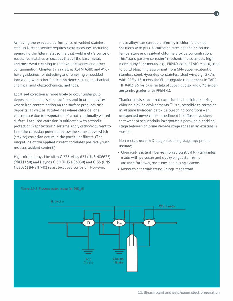
11. Bleach plant and pulp/paper stock preparation
75
D100 Eop Dn D
Hot water
White water
Acidfiltrate
Alkalinefiltrate
D Eop D
Hot water
White water
Acidfiltrate
Alkalinefiltrate
75
Achieving the expected performance of welded stainless steel in D-stage service requires extra measures, including upgrading the filler metal so the cast weld metal’s corrosion resistance matches or exceeds that of the base metal, and post-weld cleaning to remove heat scales and other contamination. Chapter 17 as well as ASTM A380 and A967 have guidelines for detecting and removing embedded iron along with other fabrication defects using mechanical, chemical, and electrochemical methods.
Localized corrosion is more likely to occur under pulp deposits on stainless steel surfaces and in other crevices; where iron contamination on the surface produces rust deposits; as well as at tide-lines where chloride ions concentrate due to evaporation of a hot, continually wetted surface. Localized corrosion is mitigated with cathodic protection: Papritection™ systems apply cathodic current to keep the corrosion potential below the value above which (crevice) corrosion occurs in the particular filtrate. (The magnitude of the applied current correlates positively with residual oxidant content.)
High-nickel alloys like Alloy C-276, Alloy 625 (UNS N06625) (PREN >50) and Haynes G-30 (UNS N06030) and G-35 (UNS N06035) (PREN >40) resist localized corrosion. However,
these alloys can corrode uniformly in chlorine dioxide solutions with pH > 4, corrosion rates depending on the temperature and residual chlorine dioxide concentration. This “trans-passive corrosion” mechanism also affects high-nickel alloy filler metals, e.g., ERNiCrMo-4, ERNiCrMo-10, used to build bleaching equipment from 6Mo super-austenitic stainless steel. Hyperduplex stainless steel wire, e.g., 27.7.5, with PREN 48, meets the filler upgrade requirement in TAPPI TIP 0402-26 for base metals of super-duplex and 6Mo super-austenitic grades with PREN 42.
Titanium resists localized corrosion in all acidic, oxidizing chlorine dioxide environments. Ti is susceptible to corrosion in alkaline hydrogen peroxide bleaching conditions—an unexpected unwelcome impediment in diffusion washers that want to sequentially incorporate a peroxide bleaching stage between chlorine dioxide stage zones in an existing Ti washer.
Non-metals used in D-stage bleaching stage equipment include;
• Chemical-resistant fiber-reinforced plastic (FRP) laminates made with polyester and epoxy vinyl ester resins are used for tower, pre-tubes and piping systems
• Monolithic thermosetting linings made from
Figure 11-5 Process water reuse for D(Eop)D

76
Stainless steels and specialty alloys for pulp, paper and biomass conversion mills
76
filled vinyl ester resin are installed over steel concrete and existing brick substrates.
• Acid-resistant masonry linings with resin mortar are used to protect steel and concrete substrates in towers, tanks, washer vats, etc. This is an old-fashioned and very expensive way to protect a steel or concrete substrate, especially compared to using a sheet lining of superduplex stainless steel to protect steel.
• CPVC (<90 °C) and all commercial fluoro-polymers, including ECTFE (Halar™), PVDF (Kynar™), PFA and PTFE (Teflon™) resist attack by chlorine dioxide and D-stage solutions. CPVC, Halar™ and Kynar™ sheet linings are used in dual-laminate FRP equipment and can be installed on a steel substrate.
• Acid-resistant potassium silicate concrete—used as mortar or as a gunned lining
Alkaline, E-stages
Brown stock coming to the bleach plant typically has pH > 9.5 and extraction (E) stages operate at pH > 10. These are benign environments for carbon steel and for regular stainless steel grades, including Type 304L (UNS S30403) and Type 316L (UNS S31603), and lean duplex grades, including 2101 (UNS S32101), 2304 (UNS S32304) and 2202 (UNS 32202), even at process temperatures above 70 °C. Because stainless steels are not susceptible to chloride-induced localized corrosion at pH >10, welds do not require alloy upgrading and post-weld cleaning of welds and imbedded iron removal can be waived. The notion of PREN does not apply for alkaline bleaching stages. In fact, higher Mo reduces the corrosion resistance of stainless steels in hot alkaline environments.
Type 316L (cast equivalent CF-3M (UNS J92800)) is widely used for E-stage towers, pumps and mixers. Type 304L and 316L pre-retention tubes and towers in E-stage service above 60 °C are susceptible to external chloride stress corrosion cracking (CSCC) from fugitive chloride ions in the ambient atmosphere. This type of CSCC is more likely under insulation due to concealed wetness and is mitigated by painting the stainless steel or preventing trapped wetness.
Lean and regular duplex stainless steel grades are increasingly used in E-stage pre-retention tubes, towers, washers and piping due to their higher strength than austenitic stainless steels (Type 304L/316L), excellent corrosion resistance to E-stage environments and resistance
to external CSCC. Super-duplex grades resist cavitation corrosion in chemical mixers better than softer, austenitic grades.
Weld heat scale and iron contamination do not decrease the corrosion resistance of stainless steel in regular alkaline environments. However, iron contamination must be removed from stainless steel (and aluminum) handling hydrogen peroxide, which decomposes in contact with iron and other heavy metal ions.
Non-metals used in alkaline (extraction) stage equipment include:
• Alkali-resistant brick and gunned linings (silica-rich bricks and tiles dissolve in E-stage solutions).
• Epoxy coatings and linings on steel and concrete substrates.
Practical considerations
Because conditions influencing corrosion in acid bleaching stages differ in every mill and vary over time from process interruptions, alloys for each stage should be determined from published corrosion test information; by conducting short-term laboratory corrosion tests in actual or simulated process environments and from in situ coupon tests. PREN values guide alloy selection but corrosion testing is recommended, especially when there is no reported field experience, and also to confirm the correct welding filler is specified.
Developing process trends include recycling and reuse of bleach washer filtrates in the bleach plant and elsewhere in the mill, which increases chloride loading and temperatures of many process streams. There also is a general trend to reduce chlorine dioxide usage per ton through improved process control and by increasing D-stage pH and decreasing stage temperature. These parameter shifts decrease corrosiveness of D-stage environments. Better process control of oxidant level decreases residual levels and corrosive oxidizing power in D-stage towers and washers.
On the materials side, continuing development of super and hyper duplex stainless steel grades, with superior corrosion resistance and mechanical properties compared to austenitic grades of the same cost per pound or kilogram is an important trend. For example, Type 2205 (UNS S32205) can
11. Bleach plant and pulp/paper stock preparation
7777
cost less per pound and resists crevice corrosion and CSCC better than Type 317L and Type 317LMN (UNS S31726); 2507 (UNS S32750) resists crevice corrosion slightly better than 6Mo super-austenitic grades at substantially lower cost.
For structural components and some tanks in the bleach plant and chemical preparation areas, 12Cr ferritic stainless steel can be more cost effective and durable than carbon steel by resisting chloride SCC and not requiring external painting. For cast equipment like pumps and valves, CG-3M (UNS J92999) (cast 317L), duplex CD-3MN (UNS J92205) and CN-3MN (UNS J94651) and CK-3MCuN (UNS J93254) (6-Mo grades) are used for acidic C and D stage filtrates. CF-3M and cast duplex grades are used for alkaline stage filtrates. (Duplex grades are harder and generally more abrasion and erosion resistant than austenitic grades.)
Titanium, which is used in diffusion washers and top scrapers in many up-flow D-stage towers, resists localized corrosion and CSCC but is susceptible to corrosion fatigue, partly because of its low strength.
11.3 STOCK PREPARATIONPulpers and macerators
A pulper blends dry pulp into a low consistency stock solution, like a giant kitchen blender. Most bleached pulp pulpers use stainless steel blades to resist erosion and abrasion: with Types 304L or 316L tanks and hardened martensitic or 17-4PH (UNS S17400) stainless steel, or a duplex grade for rotors, impellers and grates. Many rotors and stators made from CB-7Cu-1 (UNS J92180) (cast 17-4 PH). Wear surfaces typically are protected with cobalt alloy (e.g., Stellite 6™ and Ultimet™) and hard stainless overlay. Deflakers, which separate fiber bundles leaving a pulper to improve refining efficiency, are made from cast and wrought Type 316 (UNS S31600).
Refiners
In double-disc refiners, rotating heads, casing connections and packing boxes typically are either Type 304 (UNS S30400) or Type 316, depending upon process chemistry. Wear-resistant refining discs (‘tackle’) are proprietary, high carbon alloys like Ni-HiCr Type D (ASTM A532) or 17-4PH or 15-5PH precipitation-hardening stainless steel.
Screens and save-allsA wide variety of screens includes pressure and vibrating screens. Traditionally they are made from Type 316 wetted parts, including rotors with hydrofoils to produce pulsation critical for screen operation. The slotted or drilled screen usually is Type 316 or Type 317 (UNS S31700), with duplex grades a recent trend, depending upon stock properties. Vibrating screens and associated hardware conventionally are Type 316 and duplex grades a logical alternative here too
Cleaners
Most cleaners today are a cyclone design and are made from a polymeric material, but some cleaner cones and other parts are made from Type 316, usually cold-worked and polished to increase its resistance to wet abrasion. Ceramic cones are used in the most abrasive conditions. Cleaner support frames often are stainless steel.
Tanks
Stock tanks are made from Type 316L and lean duplex grades with PREN >24. Agitator shafts and impellers typically are Type 316L. Localized corrosion of stainless steel in white water environments is less likely at welds and surfaces that are properly cleaned after welding as described in TAPPI TIP 0402-35.
78
Stainless steels and specialty alloys for pulp, paper and biomass conversion mills
78
REFERENCESTAPPI Technical Information Papers (TIP)
0402-24, Guide to Stainless Steel Pipe Specifications
0402-25, Guidelines for Procurement of Cast Stainless Steels for Large Pumps and Valves
0402-26, Guidelines for Welding and Inspection of Stainless Alloy Piping
0402-32, Guidelines for Applying Thermal Spray Coatings to Protect Process Equipment Against Corrosion
0402-35, Post-Fabrication Cleaning of Stainless Steels
Nickel Institute Reprints
14013 Crowe, D. C., Tuthill, A. H., “Corrosion of metallic and nonmetallic piping for bleach plant D stage filtrate,” TAPPI Eng. Conf. Proc., Sept. 25, 1990.
14026 Tuthill, A. H., Avery, R. E. and Garner, A., “Corrosion behavior of stainless steel, nickel base alloy and titanium welds in chlorination and chlorine dioxide bleaching,” TAPPI 7th ISCPPI, Orlando, FL, 1992.
14014 Tuthill, A. H., Bardsley, D. E., “Performance of highly alloyed materials in chlorine dioxide bleaching,” TAPPI Eng. Conf. Proc., Sept. 25, 1990.
Technical papers
1. Bardsley, D. E., “Compatible metallurgies for today’s new bleach plant washing processes,” TAPPI 8th Intl. Symp. on Corrosion in the Pulp and Paper Industry, Stockholm, Sweden, May 16–19, 1995.
2. Wensley, A. et al., “Corrosion of stainless steel alloys in a chlorine dioxide bleached pulp washer,”TAPPI Engineering Conf. Proc., 1991, pp. 499–509.
3. Schutz, R. W. and Xiao, M., “Practical windows and inhibitors for titanium use in alkaline peroxide bleach solutions,” NACE Corrosion 94 Conf., 1994, Paper 427.

79
12. Paper machine
79
12.1 INTRODUCTIONWet environments such as the stock approach piping, and headbox, and forming section are usually manufactured out of Types 316 (UNS S31600) and 316L (UNS S31603) stainless steel. Heavy strength components are fabricated out of mild steel and clad or wrapped in Type 316L stainless steel.
The press section of the machine is primarily fabricated out of steel and either painted or clad in Type 316L stainless steel for corrosion protection. The remainder of the machine frame is manufactured primarily from painted steel components, with the exception of specialized component applications.
Paper machine environments are as diverse as the paper products made. Some generalizations can be made with respect to paper product and machine environment. Table 12-1 lists three general categories of paper production and typical
environments. The extent of mill closure, pulping, bleaching, and brightening processes will affect the presence and concentrations of corrosive ions. Duplex stainless steel usage has increased because of the higher strength and corrosion resistance of these materials. A few mills have upgraded building roofing to Types 304 (UNS S30400) and 316.
The remainder of this section will walk through a typical twin wire paper machine, from stock approach piping to the reel, covering typical and exceptional materials of construction and, where appropriate, surface finish requirements. Discussion of tissue machines will be interjected where appropriate. Paper machine rolls will be covered in Chapter 13.
12.2 THE WET ENDThe wet end starts with the approach piping carrying the treated pulp to the paper machine and continues to the dryer section, Figure 12-1.
Stock approach system
The typical material used for all types of paper production is Type 316L stainless steel. Occasionally in highly closed or poorly controlled process mills, Type 317L (UNS S31703) stainless steel is used. Type 304L stainless steel can be used with success in open mills, with reduced chemical usage and concentration.
Outside surfaces have the usual pipe cold finish. Inside surfaces are at a minimum 0.75 micrometre RA. (RA = Arithmetic mean of peak to valley height of surface roughness.) This finish will pass a cotton ball test (a simple test where a cotton ball is dragged across the surface—to pass means no cotton fibres are left on the metal surface). More highly polished finishes of 0.25 RA are sometimes
12. Paper machineby Paul Glogowski, Metso Paper USA, Inc.
Figure 12-1 Refiner section leading to headbox approach piping
Cour
tesy
Bel
oit C
orpo
ratio
n

80
Stainless steels and specialty alloys for pulp, paper and biomass conversion mills
80
specified. The inside surfaces are normally electropolished to reduce deposits and fibre buildup.
Electropolishing, which is the controlled dissolution of metal from the surface, is the reverse of electroplating. A current is applied to the surface through a suitable conducting medium. The stainless steel is made the anode. The current concentrates at high points on the surface, resulting in selective dissolution of the high points. An extremely smooth surface results. Even fine mechanical polishing results in torn and raised metal. Electropolishing also removes common metal inclusions such as calcium and manganese sulphides which are not removed by the best mechanical polishing. Sufficient electropolishing time can remove work hardened surfaces. This results in an extremely clean and corrosion resistant surface, in an excellent “passive” condition.
Headbox
Modern headboxes are hydraulic in design with the elimination of air pads and other components as shown in Figure 12-2. Since air-water interfaces are eliminated, the associated corrosion problems are also attenuated. Common headbox construction is of Type 316L or 316L with a specified minimum 2.5% molybdenum. Headbox orientation can lead to specific corrosion problems. Horizontally positioned headboxes for Fourdriniers and horizontal twin wire formers can have stock deposits on the apron. This can promote crevice attack. Higher alloyed stainless steels are applied to prevent or reduce crevice
attack. Typically, the 6% molybdenum austenitic alloys are used. Nickel based alloys such as Alloy C276 (UNS N10276) or Alloy C22 (UNS N06022) have also been used in a few cases. In vertically oriented headboxes, the apron tip and slice lip can be subject to stock deposits and concentration of corrosives due to continued wet/dry operation of the deposit. The above materials have been applied to both the apron tip and slice lip. The remaining parts of the headbox are designed to reduce or eliminate the horizontal surfaces that are prone to stock deposits.
Type 317L stainless steel and more highly alloyed materials have been used occasionally in headboxes to reduce or eliminate potential corrosion problems in more corrosive mills.
The paper machine atmospheric environment is summarized below:
1. Temperature 25 to 50 °C.
2. Very high humidity.
3. Traces of residual chlorine dioxide and other oxidants from bleaching stages.
4. 1035 kPa water and chemical spray cleaning.
5. Unintentional but occasional release of white water, usually as a spray.
6. Buildup of pulp pads between shutdown cleanings.
Carbon steel and galvanized steel bolting and ferritic stainless steel components rust readily in the high humidity
Figure 12-2 Fourdrinier wet end showing headbox Figure 12-3 Typical modern press section
Cour
tesy
Bel
oit C
orpo
ratio
n
Cour
tesy
Bel
oit C
orpo
ratio
n

81
12. Paper machine
81
paper machine environment. Types 304 and 316 will develop rust spots and rust streaks unless they have been thoroughly cleaned and are free of embedded iron. Electropolishing is a good means of cleaning and deburring bolt threads, reducing the tendency to gall.
Former
The forming zone or wet end of the paper machine is generally constructed of solid Type 316L stainless steel. For large sections, such as the framework, mild steel is used and Type 316L sheet is applied as a cladding to protect the steel from the environment. Due to mist and spray acting to concentrate corrosives, all materials are stainless steel Type 316 or more highly alloyed materials. Duplex stainless steels are useful where higher strengths are necessary.
Doctor blades which level the pulp on the Fourdrinier screen must retain a clean, straight edge. They are made from NiCu Alloy K500 (UNS N05500).
Press
The press section tends to be a gray area of materials selection, Figure 12-3. Less corrosive mills employ painted steel framework and lower alloyed martensitic and ferritic stainless steels where some corrosion resistance and higher strength is required. Successful application of coatings and electroplating as well as aluminum alloys are common in the press section, even when premature failure of these materials
occurs in the forming section. Increased use of recycled fibre sources and reduced mill effluent have led to increased use of harsh chemical cleaners on the press felts. These harsh cleaners can attack the paint protecting the steel. Type 316L stainless steel cladding is increasingly used in press sections.
Roll journals
Wet end paper roll journals are being made increasingly from Types 17-4 PH (UNS S17400) and Type 2205 (UNSS32205) duplex stainless steel. These materials replace carbon steel, low alloy steel, cast iron, and 304L/316L journals. Type 17-4 PH is readily pitted in most paper machine wet end environments, leading to corrosion fatigue; so, the trend is toward the pit-resistant duplex stainless alloys for journals. Large heads with integral journals, such as for press rolls, continue to be cast from ductile (spheroidal graphite) and gray (flake graphite) cast iron. These heads are painted to resist corrosion.
12.3 THE DRY ENDAs the wet paper leaves the Fourdrinier wire moisture is removed over suction rolls, which are discussed in the next section, and over drying rolls, Figure 12-4.
Dryer
The common materials in the dryer section are painted steel and bare cast iron. Copper based alloys are also used in this
Figure 12-4 Typical modern press section to dryer section Figure 12-5 Soft nip calender
Cour
tesy
Bel
oit C
orpo
ratio
n
Cour
tesy
Bel
oit C
orpo
ratio
n

82
Stainless steels and specialty alloys for pulp, paper and biomass conversion mills
section. The environment is considerably dryer than previous sections of the machine. High humidity can lead to corrosion of unprotected steel. Zinc coatings (galvanized) are not recommended due to temperature reversal of the iron and zinc galvanic couple above about 190F (90C). (Iron corrodes to protect zinc instead of zinc corroding to protect iron.) Typical dryer environments are as follows:
1. Temperature range = 25 to 120 °C.
2. High humidity.
3. Equipment collects paper dust between cleaning intervals.
Calender
Calenders consist almost exclusively of painted mild steel, Figure 12-5. Cast spheroidal and flake graphite irons are commonly used. Unique to the calender section is the use of chilled and white irons, along with hard ceramic coatings. Materials of construction are not limited by any possible corrosive considerations. Typical calender environments are as follows:
1. Temperature 25 to 65 °C.
2. Equipment cleaned with water spray = at 1035 kPa.
3. Relative humidity = 75%.
Coater
Modern on and off machine coaters are generally constructed of stainless steels as shown in Figure 12-6. The environmental
issue is one primarily of coating formulations that contain sodium and ammonium chlorides. Harsh cleaners contribute to the requirement for non-corroding materials. Chromium and nickel plated components have been used successfully. Copper based alloys are not recommended due to possible stress corrosion cracking from ammoniacal compounds. Typical coater environments are as follows:
1. Temperature 25 to 120 °C.
2. Equipment cleaned with water spray = at 1035 kPa and with caustic boil-out solutions.
3. Relative Humidity = 75%
4. Equipment collects paper coating chemicals between cleaning intervals.
Size press
Conditions and materials selection are the same as for coaters, above. Typical size press environments (Figure 12-7) are as follows:
1. Temperature 25 to 65 °C.
2. Equipment cleaned with water spray = at 1035 kPa.
3. Relative humidity = 75%.
4. Equipment collects starch solution, made up of salts which are used for static control and are corrosive between cleaning intervals.
Figure 12-7 Typical size press
82
Figure 12-6 Modern machine coater
Cour
tesy
Bel
oit C
orpo
ratio
n
Cour
tesy
Bel
oit C
orpo
ratio
n

83
12. Paper machine
83
Reel
Materials of construction are not limited by corrosive considerations. Galvanized steel and Type 304 are commonly used. Typical reel environments (Figure 12-8) are as follows:
1. Temperature 20 to 40 °C.
2. Equipment cleaned with water spray = at 1035 kPa.
3. Relative humidity = 75%.
4. Equipment collects paper dust between cleaning intervals.
Hydraulic systems
Material recommendations should be based on the section of machine where equipment will be placed. Possible ingress of water based fluids such as in the press may require stainless steel alloys to prevent internal corrosion and contamination of the hydraulic system.
12.4 WHITE WATER CORROSION AND CLEANING
Showers and piping
Piping and showers on modern papermaking machines are typically Type 316L stainless steel in the wet end (from the stock approach piping to end of former) and press sections. Type 316L stainless steel has the proven corrosion resistance and necessary strength to meet the needs of this application.
White water return
The white water return system on modern paper machines is constructed of cold rolled stainless steel Type 316L sheet. Thickness depends upon the required strength of the white water collection device. Most white water is then collected in a ceramic tile lined wire pit (seen beneath the Fourdrinier section in Figure 12-2). Many modern paper machines avoid tiles by using stainless steels for these applications. Piping in the white water return sections of the machine are commonly constructed of Type 316L stainless steel. The pumps are CF-8M (UNS J92900), the cast equivalent of Type 316.
Auxiliary equipment
Auxiliary equipment such as electrical boxes, electrical conduit, cable trays and fire protection equipment operate in the high humidity and corrosive atmospheric environment near the paper machine. Some newer lead-free solders for electronic connections are very susceptible to atmospheric corrosion. Type 304/304L stainless steel is usually adequate, although many contemporary machines specify Type 316/316L stainless steel. Paper machine fasteners, a special problem, are discussed in Chapter 14, Threaded Fasteners.
Figure 12-8 Paper machine reel
Figure 12-9 Vacuum pump – Stainless steel body
Cour
tesy
Bel
oit C
orpo
ratio
n

84
Stainless steels and specialty alloys for pulp, paper and biomass conversion mills
84
Dewatering pumps
The large vacuum pumps used for dewatering the sheet downstream of the paper machine are either cast iron or cast iron case with CB-6 [16Cr 5Ni 1Mo (UNS J91804)] internals. Figure 12-9 is a cutaway of a vacuum pump. The cast iron cases are frequently lined with stainless steel.
Common chemical solutions to which papermaking machines are exposed
The following is an outline of some common chemicals used in the paper industry. These include chemicals used in the process of making paper and in the cleaning of the equipment.
White water/tray water environments
The following chemical concentrations represent some of the worst-case sampling of the paper industry’s “White Water/Tray Water” conditions. (In other words, what the components are exposed to at the headbox, formers and press sections of the papermaking machines).
Table 12-1 Typical corrosive white water compositions
Typical grade
Paper making environments
Acid-alum with sulphur
Acid-alum Alkaline
Newsprint, linerboard, sc
Fine paper, bleached board, wood free grades
Fine paper, bleached board,
pH 4.0 4.0 8.0
Temperature (°C) 65 60 55
Temperature (°F) 150 140 130
Conductivity(micro-siemens) 4300 2100 1100
Chloride ion (mg/L) 200 250 250
Sulphate ion (mg/L) 4000 800 750
Thiosulphate ion (mg/L) 30 ----- -----
Sulphite ion (mg/L) 50 ----- -----
White water corrosivity
Slightly acidic white water is not corrosive to Type 304 stainless steel. Before recycling of mill process waters became common and before the change from zinc hydrosulphite to sodium hydrosulphite as a brightening agent, Type 304 stainless steel gave reasonably good service in white water in many mills. Bennett,1 Wensley2 and Garner3 all studied the effects of pH and concluded that pH levels below 4.5 became increasingly corrosive to Types 304/304L and 316/316L stainless steels. Wensley and others have reported the beneficial effects of sulphates, in the absence of sulphate reducing bacteria, noting that white water became increasingly corrosive to stainless steel when the chloride ion concentration exceeded the sulphate ion concentration, and less corrosive when sulphate ion concentration exceeded chloride ion concentration.2 Wensley also found that corrosion resistance increased with the percent molybdenum within the 2.0 to 3.0% range for Type 316 stainless steel.
Garner studied the effect of thiosulphate and concluded that it readily corroded bronze and that Type 304 was especially sensitive to even low thiosulphate concentrations, whereas Types 316, 317 and the duplex grades were more resistant.3 These studies and field experience indicate that Type 316/316L is the minimum alloy that has useful resistance in current white water environments. The 2.5% minimum molybdenum version of the standard Type 316 is more corrosion resistant than the standard grade currently produced at 2.1 to 2.2% molybdenum. The trend is toward even higher molybdenum content alloys such as Type 317L (UNS S31703), 904L (UNS N08904) and duplex Type 2205 (S32205).
The white-water environment is also conducive to microbiological influenced corrosion (MIC). The rich organic nature of the white water leads to MIC, particularly in stagnant and low flow areas of the paper machine. All the alloys mentioned in this chapter are subject to MIC. Prevention of MIC requires regularly scheduled cleaning along with biocide application. Only the 6% molybdenum and nickel base alloys containing chromium are resistant to MIC in the as-welded condition.
Residual oxidants can be corrosive to paper machines. They can come from water treatment or from the bleach plant in

85
12. Paper machine
85
integrated fine paper machines. Strong oxidizers like chlorine dioxide can cause rust stains and pits on Type 316L, and can crack rubber covers on press rolls. Hydrogen peroxide residuals do not corrode stainless steel machine components, but can embrittle nylon 6 wires on forming fabrics or press felts. Peroxide-resistant machine clothing is available. Stainless steel pitting is generally inhibited by bicarbonate, bisulphite and hydroxide ions.
Machine cleaning solutions
Acid based or caustic based foam cleaners can be used to clean pulp stock etc. from the machine. Generally, caustic based cleaners are used with a pH range of 10 to 13. Acid cleaners are generally phosphoric acid based with a pH range of 1 to 6. Both are used at room temperature.
Passivation
During fabrication, stainless steel is subject to fabricating defects, heat tint alongside welds and on the side opposite of welds that are not full penetration, iron embedded from contact with steel layout tables and steel tools, weld spatter, scratches, etc. The surface at these local defects is no longer passive and is subject to localized corrosion. These defects are usually removed during post fabrication cleanup, mechanically with flapper wheels or aluminum oxide grinding discs, chemically by pickling or by application of pickle paste, or by hand-held electropolishing tools. Passivity is restored as the defects are removed. Once the surface is clean, further passivation by the nitric acid treatments (described in ASTM A380) will enhance the passivity and corrosion resistance of the cleaned surface. The nitric acid treatments alone, however, are seldom adequate for the heavy cleaning required after fabrication. Unless defects are thoroughly removed after fabrication, it may be necessary to clean in place with pickle paste or citric-EDTA (ethylenediamine tetra-acetic acid) chelants to remove all embedded iron.
Caustic boil-out
Many mills regularly schedule caustic boil-out of the headbox and forming section. A solution of sodium hydroxide at a pH of approximately 13 is used. Temperature is about 120 °F (50 °C). Chelants such as the sodium or disodium salt of EDTA are often used to enhance the cleaning properties of the boil-out solution. Frequency can be less than once a month and duration is 2 to 5 hours per operation. Caustic boil-out
solutions are used to dissolve and remove accumulated organic compounds. Certain polymeric materials such as polycarbonate are susceptible to severe attack. High strength steels are susceptible to stress corrosion cracking (SCC), and copper based alloys are susceptible to corrosion and dealloying during caustic boil-outs.
86
Stainless steels and specialty alloys for pulp, paper and biomass conversion mills
86
REFERENCES
1. Bennett, D. C. and Federowicz, D. C., “Prediction of localized corrosion of stainless steels in white water,” Mat. Perf. 21(4): 39–43(1982).
2. Wensley, D. A., “Localized corrosion resistance of stainless steels in white water,” Mat. Perf. 28(11): 68–71(1989).
3. Garner, A., “Thiosulphate corrosion in paper machine white water,” NACE Corrosion 85 Conf., Boston, MA, March 25–29, 1985, Paper No. 170.
4. Yeske, R. A. and Wahren, D., “Materials for pulping and papermaking applications,” NACE Conf. Proc., 1984.
5. Moller, G. E., “Guidelines for use of stainless steels for pulp and paper mills,” Pulp and Paper Canada 82(12): 139–180.

13. Suction rolls
87
Suction rolls are part of the paper machine but deserve their own chapter and discussion. Usually drilled to about 20% open area, suction rolls are used to remove water from paper at the wet end of the paper machine. Prior to 1950, suction shells were cast from copper alloy C83600, 85Cu 5Sn 5Pb 5Zn. As paper machine width, speed, and nip pressure increased, stronger alloys were introduced: nickel aluminum bronze, forged Type 410 (UNS S41000), and centrifugally cast stainless steels Type CA-15 (UNS J91150), Type CF-3M (UNS J92800) and CF-8M (UNS J92900).1
As roll speeds and nip pressures increased further, more roll failures led to development of shells made from special grades of cast and wrought duplex stainless steel. Tables 13-1 and 13-2 show currently available suction roll alloys. Table 13-3 shows alloys which may still be in service but are not available from roll manufacturers. Corrosion resistance and fatigue strength in paper machine white water of suction roll materials, nip pressure, roll width and residual stress levels all play important roles in the roll’s reliability, as discussed in more detail below.
13.2 CORROSIONThe white water composition is largely predetermined by the product but some dissolved solids levels can be modified to decrease the corrosivity, especially for localized corrosion by chlorides. Wrought and cast duplex stainless steels with > 3% Mo resist localized corrosion, especially crevice corrosion under deposits, in almost all white waters and also have acceptable resistance to corrosion fatigue, the corrosion mechanism of primary concern.
The papermaker should avoid the use of harsh acidic cleaning
chemicals, especially those containing hydrochloric acid and hydrofluoric acid which are known to damage shell alloys and roll covers. Residual chlorine dioxide carryover from the bleach plant also will damage roll covers and can increase the likelihood of localized corrosion of stainless steels, producing characteristic rust deposits.
13.3 OPERATING AND RESIDUAL STRESSES
Both the applied stress and residual stresses produced in the shell from suction roll manufacture contribute to the stress in an operating suction roll. The shell is designed and manufactured to minimize the cyclic operating stress levels to maximize the roll’s fatigue life.
The drilled hole pattern and how the holes are made both influence the stress levels in the shell. Residual stresses are reduced by heat-treating the shell, ideally after all welds and other manufacturing processes are completed. Gun-drilled or reamed holes for improved surface finish will reduce corrosion and improve the cleanliness of drilled holes in service. (Gun-drilling or reaming rarely is done on bronze shells.)
13.4 MATERIAL SELECTIONMaterial selection for a new suction roll shell should start by evaluating the condition of the shell it will replace and reviewing the chemical and stress conditions the new shell will experience. Duplex stainless steel grades, both in wrought (in a rolled-and-welded shell) and cast form, are the most common alloys for suction rolls in regular white water environments.
13. Suction rollsby Max D. Moskal, Mechanical and Materials Engineering Associates, Inc.

Stainless steels and specialty alloys for pulp, paper and biomass conversion mills
88
Table 13-1 Nominal composition of copper-base suction shell alloys
Material designation(s)
Composition(a), %
Cu Sn Pb Zn Al Ni Fe Mn
C836001N bronze(b)
GC-CuSn5ZnPb84-86 4-6 4-6 4-6 1.0 max.
C95810 (mod.)GC-CuAl9.5Ni(c, d) 81.5-83.5 9.0-9.5 4.0-4.5 3.0-3.5 0.5-1.0
C90500GC-CuSn10Zn(c) 86-89 9-11 1.5 max. 1-3 1.0 max.
GC-CuSn10(e) 88-90 9-11 1.0 max.
(a) Composition range, wt%; additional elements may be added or present in minor amounts
(b) Trade name Sandusky International
(c) Trade name Kabelmetre Alloys
(d) Size currently limited to 3,500 mm max length
(e) Discontinued
Most older suction roll vacuum boxes were manufactured from epoxy painted cast iron or steel. More recently, roll manufacturers have used weld-fabricated Type 316L (UNS S31603) stainless steel to better resist corrosion and deterioration. Nowadays duplex stainless steels with PREN > 24 are used for suction boxes and other roll components.
13.5 MANUFACTURING QUALITYCast shells typically are tested 100% with liquid penetrant prior to drilling to detect flaws such as porosity, slag, and cracks4. Skillful control of melting and casting procedures can minimize casting defects, which can be repaired under careful control. Weld repairs of casting defects should be made before shell heat treatment. Careful attention should be given to drilling and machining quality and dimensional control. Shells made by joining cylinders of rolled-and-welded plate are tested for the quality of the axial and circumferential welds. This is a very common method for making suction roll shells today.
13.6 IN-SERVICE INSPECTION
Periodic inspection of the suction roll shell for fatigue cracks and other damage helps avoid unexpected shell failure. Rolls should be removed from the machine, disassembled, thoroughly cleaned and inspected. The inspection interval is determined by local experience with that roll and normally is annual. Inspections typically include testing for fatigue cracking of the shell and looking for rubber cover deterioration or detachment. Water-washable liquid penetrant usually is used to test for cracks on the inside and outside surfaces. A careful visual examination is made for corrosion and cracks.
When cracks are found, immediate assessment of the damage is required because of the long lead-time for shell procurement. Consideration should be given to inspecting the shell more often than once per year to trend crack growth. A careful record must be made whenever cracks are observed. TAPPI TIP 0402-19, Reference 5, provides guidelines for suction roll inspection. TAPPI TIP 0402-01, Reference 6, provides a standard form for documenting inspection results and roll failures.

13. Suction rolls
89
Table 13-2 Nominal composition of stainless steel suction shell alloys currently available Materials are categorized according to structure
Material Composition(a), %
C Cr Ni Mo Cu Mn Si
Austenitic
CF-3M 0.02 17.7 13.8 2.3 — 1.3 0.8
Martensitic
CA-15, C-169 0.07 12.4 0.6 0.5 — 0.5 0.6
PM-4-1300M 0.1 13.0 1.0 2.1 — 0.9 0.7
Duplex-centrifugally cast
Alloy 86,0.02 26.0 6.8 — 2.0 0.8 0.7
Alloy EPV
ACX-100(b) 0.02 24.0 5.7 2.4 0.5 0.8 0.8
ACL-105,
KRC-A8940.02 22.5 4.5 1.5 — 0.6 0.6
KCR-110 0.02 21.0 3.2 0.7 — 0.8 1.0
Duplex-rolled and welded
3RE60 SRG(c) 0.02 18.5 4.9 2.8 0.2 1.5 1.5
2205 SRG(c) 0.02 22.0 5.7 2.9 0.1 1.5 0.6
2304 SRG(c) 0.02 22.7 4.7 0.3 — 1.5 0.6
LDX 2101®(e) 0.03 21.5 1.5 0.3 0.2 5.0 0.7
Duplex-powder metallurgy
Duplok 27(d) 0.02 26.5 6.5 3.0 — 0.7 0.4
Duplex-forged
PM-2-2106MC 0.06 21.5 5.0 0.5 1.0 0.5 0.6
(a) Typical composition, wt%; balance of composition is iron; other elements may be added or present in minor amounts
(b) Contains nitrogen and cobalt
(c) Contains nitrogen
(d) Hot isostatic pressed; contains 0.3% nitrogen
(e) LDX 2101® is an Outokumpu registered trade mark

Stainless steels and specialty alloys for pulp, paper and biomass conversion mills
90
Table 13-3 Nominal composition of stainless steel suction shell alloys discontinued by the manufacturer
Material Composition, %(a)
C Cr Ni Mo Cu Mn Si
Austenitic
CF8M 0.05 17.7 13.8 2.3 — 1.3 0.8
PM-3-1811-MN 0.015 16.5 13.5 2.1 — 1.6 0.5
Martensitic
DSS-69 0.04 12.4 4.0 0.7 — 0.7 0.6
A-70 0.03 11.9 4.0 1.5 — 0.8 0.5
Duplex–centrifugally cast
A-63 0.05 21.8 9.4 2.7 — 0.8 1.3
A-75 0.02 26.0 6.8 — — 0.8 0.5
VK-A170 0.07 23.3 10.7 2.1 — 0.7 1.5
VK-A171 0.07 22.2 8.3 1.2 — 0.8 1.1
VK-A271 0.06 24.6 4.3 0.7 — 0.7 1.3
VK-A378(b) 0.05 20.0 5.0 2.0 3.0 0.7 1.0
KCR-A682(c) 0.06 18.0 5.5 2.3 3.2 0.7 0.7
Duplex–forged
PM-3-1804M 0.06 17.9 4.0 2.0 — 0.6 0.6
PM-3-1808N 0.08 18.0 9.0 — — 2.0 1.0
PM-2-2205 0.07 26.0 4.0 0.8 — 1.2 1.3
(a) Typical composition, wt%, balance of composition is iron: other elements may be added or present in minor amounts
(b) Contains nitrogen and tungsten
(c) Contains niobium (columbium)

REFERENCES
1. S.D. Cramer and B.S. Covino, Jr., Volume Editors, ASM Handbook, Corrosion: Environments and Industries, Vol. 13C (Metals Park, Ohio: ASM International, 2006), pp. 779-780.
2. A. Garner, “Suction roll failures in Canada,” Pulp and Paper Canada /86(3): 81–89(1985).
3. TAPPI TIP 0402-10 “Guide for evaluation of paper machine suction roll shells.”
4. TAPPI TIP 0402-11 “Liquid penetrant testing of new suction roll shells.”
5. TAPPI TIP 0402-19 “Guidelines for nondestructive examination of suction roll shells.”
6. TAPPI TIP 0402-01 “Suction roll shell report.”
7. TAPPI TIP 0402-17 “Weld repairs on new suction roll shells.”
8. http://www.outokumpu.com/SiteCollectionDocuments/Special-issue-Fatigue-and-corrosion-fatigue-Acom.pdf (Mar. 2010).
13. Suction rolls
91

Stainless steels and specialty alloys for pulp, paper and biomass conversion mills
92
14. Threaded fasteners
93
Threaded fasteners are probably the best and most cost effective choice to apply a clamping load used to assemble a joint with the option of disassembly, if and when required. The simplicity of a bolted joint to provide a clamping force has made it one of the most accepted and utilized engineering products. Threaded fasteners are used in three types of connections to transmit tensile loads, resist shear loads and to clamp and seal flexible gasket joints. The term threaded fasteners is used in the following sections of this paper to indicate all forms of fasteners including bolts(1),
studs(2), screws(3), cap screws, nuts and washers.
Although fasteners are low cost items, when fastener failures occur they can have a severe impact on the economics of pulp, paper and other industrial operations. It is increasingly important to deal effectively with materials and corrosion problems even for low cost items such as threaded fasteners due to: changes such as equipment upgrades; higher capital costs; water recycling; and, more aggressive process conditions.
Failure of a fastener costing less than a dollar on a paper machine can result in huge losses due to equipment damage and production downtime. As an example, if a failed fastener passes through a press roll nip, the roll cover will likely have to be replaced or in the worst-case scenario the roll may be damaged beyond repair.
(1) Bolt is the term used for a headed threaded fastener that is designed to be used with a nut.(2) Stud is the term used for a threaded fastener which is threaded on both ends.(3) Screw is the term used for a headed threaded fastener which is used with a tapped hole.
14.1 THREADED FASTENER DESIGN & MANUFACTURE
The screw thread is typically described as an inclined plane wrapped around a cylinder, but it is not that simple since there are numerous standards and over 100 separate geometrical features and dimensional characteristics that relate to the design and manufacture of threaded fasteners, including the following which are discussed in more detail in Reference 1.
The ASME/ANSI Unified Thread Standard (UTS) defines a standard thread form and series, together with allowances, tolerances and designations, for screw threads used in North America. There are three standard thread series in the UTS system: UNC (coarse), UNF (Fine), and the 8-UN (8 threads per inch, applicable to fasteners greater than one inch).
The basic profile of the UTS series threads and ISO metric screw threads are defined by their major diameter, Dmaj, and the pitch, P. Allowances and tolerances are applied to the basic profile. For most symmetrical V-threads including UTS, ISO and National Pipe Thread (NPT), the thread angle is standardized as 60°.
The thread pitch (P) is the distance from a point on one thread to the corresponding point on the adjacent thread measured parallel to the thread axis. UTS threads are designated in threads per inch, the number of complete threads occurring in one inch of threaded length, while metric thread pitch is designated as the distance between adjacent threads in millimeters.
14. Threaded fastenersby R.S. (Bob) Charlton, Riverside Engineering Inc

Stainless steels and specialty alloys for pulp, paper and biomass conversion mills
94
The standard designation for a UTS thread is a number indicating the nominal or major diameter (Dmaj,) in inches or fractions of an inches followed by the threads per inch while metric threads are designated with a capital M followed by their nominal major diameter and their pitch. For example, a UTS 3/4-10 bolt would indicate a 3/4-inch diameter fastener with 10 threads per inch and a metric M20 x 2.5 bolt would indicate a 20mm diameter fastener with a pitch of 2.5mm.
The allowance is an intentional clearance added to the basic profile to insure that when both the internal and external threads are manufactured, there will be a positive space between them. For threaded fasteners, the allowance is generally only applied to the external thread.
Tolerances are the specified amounts that the dimensions of threads are allowed to vary for ease of manufacture. The tolerance is the difference between the maximum and minimum dimension limits.
Thread fit is the combination of allowances and tolerances and is a measure of tightness or looseness between the male and female threads. The Unified Thread Standard has six classes of fit: 1A, 2A and 3A for external threads and 1B, 2B and 3B for internal threads. The higher the class number, the tighter the fit. Approximately 90% of all commercial and industrial fasteners that are produced in North America have a 2A and 2B class of thread fit.2
Threads for fasteners are manufactured by cutting, rolling and grinding with the highest strength and quality fasteners having rolled threads. Rolled threads: are more accurate and uniform in threads dimensions; have smoother surfaces and thus, have fewer tendencies for galling, seizing and crack initiation; and have higher strength due to the thread rolling cold work.
Nut and bolt considerations
The purpose of any nut is to properly load the bolted assembly. A nut should be no harder than is necessary to fully load the fastener assembly and in almost all cases should have lower hardness than the bolt or stud. The nut must be plastic enough to allow the threads to deform upon tightening and adjust to distribute the load over the threads rather than just the first few. A tough non-heat treated nut can do this while a hardened heat treated nut cannot since
it will not conform to the bolt threads. Hardened nuts can actually damage the bolt threads to which they are applied, resulting in low preload and low clamping force(4) or holding power which is vital to fastener performance.
Nut thickness standards have been designed on the basis that the bolt or stud will always fracture in tension before the nut will strip. When nuts and bolts or studs are specified, it is imperative that the appropriate grade of nut be matched to the bolt or stud grade. It is preferable to use a lower strength nut so that the threads distort to conform to the bolt threads.
The distribution of stress on the threads of a nut is not uniform since the threads distort under load. Experimental studies and finite element analysis has shown that: the first thread takes approximately one third of the load; the first three threads take approximately three-quarters of the load; and, the first six threads take essentially the complete load2,3.
If a threaded fastener is threaded into a tapped hole in a weaker material, such as cast iron or stainless steel, the torque, preload and clamping load need to be de-rated appropriately or the depth of the tapped hole has to be increased. Waisted bolts and studs(5) are a commonly used method to prevent overloading tapped thread.
Tensile strength
Stainless steel and many other types of corrosion resistant alloy fasteners can be supplied either hot finished or cold finished if higher strength is required. For example, hot finished Types 304 (UNS S30400) and 316 (UNS S31600) stainless steel bolts have an ultimate tensile strength of 516 MPa (75 ksi), versus 620 MPa (90 ksi) for cold finished.
Hot finished bolting is normally supplied unless cold finished bolting is specifically requested on the purchase order. It should be noted that in most cases, cold finished fasteners are not “off-the-shelf” items and thus, can have long delivery times.
(4) Clamping force is the compressive force that a fastener exerts on the joint.(5) Waisted bolts and studs are threaded fasteners with a shank diameter less than the minor diameter
of the thread. Frequently the shank diameter is 0.9 times the thread root diameter.
14. Threaded fasteners
95
14.2 FRICTION AND LUBRICATION EFFECTS
Torque
One of the most common terms involving the installation of threaded fastener is torque. There are many tables of torque values for the installation of threaded fasteners but caution must be exercised in their use since there are many variables that may not be factored in, including: method of threading; condition of threads; surface contamination; lubricants if used; and, friction factor. It is important to note that the torque values do not indicate the bolt tension directly but are only an indirect indication of the desired tension.
The preload(6) stress is related to the applied torque by the friction that is present under the bolt head or nut face and in the threads. The torque value depends primarily on the values of the friction under the bolt head or nut face and in the engaged threads. Only approximately 10 to 15% of the torque actually results in bolt tension.4
Torque-tension relationship
The required tightening torque for a fastener can be estimated from the relationship between the torque applied and the tension created in the fastener by the torque. This relationship is relatively linear and can be calculated from the following relatively simple empirical expression: T = KDPi, where: T = Tightening torque in Nm (lb-in); K = Friction Factor (Empirical constant); D = Nominal fastener diameter in meters (inches), and; Pi = Preload in kilograms (pounds), typically 65% to 75% of proof strength. For most fastener materials, the values of D and Pi are well defined but unfortunately the value of the friction factor K is imprecise due to the many variables.
Friction factor
The friction factor K is an empirical constant that takes into account the friction and the variable diameters and contact surfaces under the head and nut and in the threads. It is not the coefficient of friction but is related to it and varies from approximately 0.50 to 3.5 for metric and 0.05 to 0.35 for Imperial fasteners.
(6) Preload is the tension created in a fastener when first tightened. The preload reduces after a period of time due to embedding and other elastic interaction factors.
The friction factor is affected by many properties of the threaded connection, including: whether dry or lubricated; type and amount of lubricant, if used; surface finish; surface contamination; thread allowances and tolerances; speed of tightening; etc. All of these properties can cause significant variations in the absolute value of the friction factor.
There are many published tables for the value of K, but it is unfortunate that they are only nominal values which can vary significantly even from publication to publication. Since K can vary widely from the published values depending on the specific configuration, in critical applications it is desirable or even mandatory to determine the friction factor experimentally by testing bolting using torque-tension load cells.
The friction factor for threaded fasteners needs to be predictable within a narrow range to ensure reliable installation if tightening is to be by torque control. Approximate K constants for metric (Imperial) fasteners are as follows:
• 1.0 (0.10) to 1.5 (0.15) for lubricated carbon and alloy steel fasteners;
• 2.0 (0.20) for dry carbon and alloy steel fasteners;
• 3.0 (0.30) for dry austenitic stainless steel fasteners.
Lubricants
The use of a thread lubricant frequently causes failures of fasteners since lubricants such as greases, oils and special thread lubricants can reduce the amount of friction in the fastener assembly by up to 50%.5 Using a lubricant reduces the amount of friction in the fastener assembly and thus, the standard tabulated torque values, if applied, will significantly increase the tension stresses in the fastener and in many cases may cause failure due to overload stresses.
If a lubricant is going to be used, tests should be conducted to determine the torque requirement and to evaluate the compatibility of the lubricant to the environment and the fastener materials. Popular lubricants are those which contain substantial amounts of molybdenum disulphide, graphite, mica, talc, copper or zinc fines, or zinc oxide. Anti-seize lubricants containing copper or zinc are not suitable for use in threaded assemblies of stainless steel or many of the other corrosion resistant alloys.

Stainless steels and specialty alloys for pulp, paper and biomass conversion mills
96
Galling and seizing
Thread galling (cold welding or adhesion) is a common problem that can be encountered with most metals and alloys. Stainless steel fasteners such as Types 304 and 316 are especially prone to thread galling due to their self-generating oxide surface film. Prevention of galling and seizing also requires care in handling to prevent damage to the threads.
Galling is difficult to successfully control but the likelihood of galling or seizing can be minimized by using: fasteners with rolled threads, rather than cut threads; coarse threads instead of fine threads; a calibrated torque wrench or the “turn-of-nut” method for tightening; proper installation torque; lubricants; dissimilar alloys having different degrees of hardness; and, nuts fabricated from a stainless steel with high silicon and manganese (ASTM A 194 Grade 8S (UNS S21800)).
14.3 THREADED FASTENER INSTALLATION
Proof strength/load
The proof strength of a fastener is the largest tensile load that can be applied to a bolt, screw or stud without permanent set (e.g. elongating the fastener beyond the elastic limit (yield strength)) while the proof load of a nut is the axially applied load that a nut must withstand without thread stripping or rupture. Tables of proof strength for fasteners are available but the proof load can also be calculated using the formulas listed in Reference 1.
Preload/clamping force
The clamping force or residual tension in a tightened bolt is an important component of the strength of the whole assembly. A bolt torqued to its proper load level resists a maximum amount of external load without loosening. The more highly a bolt is stressed, within its elastic limit, the greater it is able to stay tight and provide a strong assembly. There is normally no harm in over tightening a threaded fastener and in most cases it is the recommended procedure for permanent connections. It is better to “over tighten” within reason than to “under tighten”. Failure to tighten fastener assemblies up to their proper working loads accounts for over 75% of all fasteners failures.5
For a given clamping force, a smaller diameter fastener tightened to a higher preload is more failure resistant than a larger one tightened to a lower percentage of its proof load. The smaller diameter more highly stressed fastener stays tighter and resists fatigue failure.
Measurement of the preload has many inaccuracies and there is significant divergence of opinion of how much preload should be applied. Some authorities state that the bolting should be preloaded to 100% of proof load while others specify the older and more widely used preload value of 75% of proof load. One of the points in favor of the 75% limit is that it is inherently more conservative and it allows for substantial inaccuracies in assemblies.
Application of preload
There are no inexpensive and effective ways to accurately and consistently tighten a threaded fastener. If high accuracy is required, there are a number of tightening methods that can be used but they are more complicated and expensive than the traditional methods such as feel or the use of a torque wrench.
There are basically six methods used to control the tightness or preload of threaded fasteners and they are listed in Table 14-1 in order of increasing accuracy and cost, and are described in detail in reference 1.
The most common method to manage preload is by controlling the torque using a torque wrench. The major problem with the use of a torque wrench for the installation of threaded fasteners is that small shifts in frictional conditions can result in large changes in the bolt preload. Some authorities suggest that the accuracy using a torque wrench is +/-200%.7
Angle controlled tightening is a superior method of preloading a threaded fastener to using a torque wrench. The nut and bolt are tightened to a snugging torque, match marked and then rotated through an angle that corresponds to the required preload. Typical turn-of-nut guidelines are provided by the Research Council on Structural Connections (RCSC) for structural steel bolting with flat surfaces under the bolt head and nut surfaces8. Since the fasteners are typically tightened beyond yield by the turn-of-nut method they should never be reused.

14. Threaded fasteners
97
The choice of preload method depends primarily on the requirements of the joint. Normally, the more critical a metal to metal joint, the more need for greater accuracy. Few installations allow the inaccuracy of the “feel” method, while the use of strain gages with their high cost will be used infrequently. Gasketed joints, except for O-ring seals will normally always be assembled by feel.
14.4 THREADED FASTENER GUIDELINES
Coarse threads versus fine threads
The load and stress concentration on threads are lower in coarse thread fasteners than in fine thread fasteners and, thus, they have greater resistance to stripping, shearing or galling and consequently can be more highly torqued to make a stronger assembly.
Reuse of fasteners
The Industrial Fastener Institute has made exhaustive studies of the deterioration of loading that occurs in threaded fasteners when they are used more than once. The most dangerous component of a fastener assembly to reuse is the nut. The first two or three threads of the nut experience the greatest stress because of the deformation of the threads. When a nut is reused, the previously distorted threads will create more friction when torque is applied to tighten it. Since a higher percentage of torque is consumed by this increased friction, less twisting force will be left to apply tension, or preload, to the bolt and the assembly will actually be loose. For maximum safety and performance, nuts should be discarded when they are removed. Nuts should never be reused.
14.5 FAILURE MODES OF THREADED FASTENERS
Fastener failures
Failure of fasteners in industrial applications costs the industries and the public billions of dollars every year in downtime, lost production, injuries and death. It is estimated that 85% of industrial fastener failures are caused by fatigue.9
In most cases the majority of fatigue failures are due to under tightening with the balance due to incorrect specifications, design and materials.
Fatigue failures of threaded fasteners typically occur in the three main areas of stress concentration: approximately 65% at the first loaded thread; approximately 15% at the head to shank radius; and, approximately 20% in the thread run-out.10,11
Corrosion fatigue is one of the most common modes of failure for carbon and low alloy steels as well as most of the common corrosion resistant alloy fasteners used in the chemical process industries. Unfortunately, there is no true endurance limit for corrosion fatigue as there is with mechanical fatigue. Thus, with sufficient time, even very low cyclic stresses can result in corrosion fatigue of stainless steel and other corrosion resistant fasteners.
Corrosion resistant alloy fasteners behave similarly to carbon and low alloy steels in that their fatigue resistance decreases if corrosion is present. Corrosion fatigue tests of typical austenitic stainless steels, such as Types 304 and 316, show a marked reduction in the fatigue endurance limit even when tested in ambient temperature water. If corrodants are present in the water, e.g., chlorides, or if the temperature is elevated, the reduction in fatigue strength is even greater.
Table 14-1 Relative accuracy and cost of preload measurement methods 6
Method Accuracy % Relative Cost
Feel +/- 35 1
Torque wrench +/- 25 1.5
Angle control or turn-of-nut +/- 15 3
Direct tension indicator washers +/- 10 7
Bolt elongation +/- 3 to 5 15
Strain gages +/- 1 20

Stainless steels and specialty alloys for pulp, paper and biomass conversion mills
98
14.6 PULP AND PAPER MILL APPLICATIONS
General
There are two principle applications for corrosion resistant fasteners in the Pulp and Paper Industries: flange joints; and machinery and process equipment internal component bolting.
• The first principal application; fasteners for flange bolting are normally the same material as the corrosion resistant equipment and piping materials if the flanges are also the same corrosion resistant alloy. If the backing flanges are carbon steel on the corrosion resistant equipment and piping and the operation is at elevated temperatures, the bolting should be ferritic or martensitic steels since the clamping force can relax during operation due to the differential thermal expansion between austenitic stainless steel equipment and the carbon steels backing flanges.
• The second principal application; corrosion resistant fasteners for machinery and process equipment internal component bolting where vibration, in addition to strength and corrosion resistance, is a primary consideration.
Failure modes of fasteners in Pulp and Paper mills have been discussed in considerable detail in prior papers by the author.1,12,13,14 Some of the key points are summarized below.
Designing for corrosion protection
Threaded fasteners are a critical and integral part of the overall design of any joint and should not be considered as an afterthought. The threaded connection is typically the section that has the highest stresses and most often is the location where failures occur. A designer of bolted connections should select the best fastener for the connection and then design the joint for that fastener. They should not base the design on the components that are to be joined and then try to find a fastener that is suitable.
Corrosion protection for threaded fastener joints requires more than a consideration of the corrosion resistance of the fastener itself. By their very nature, fastener systems have inherent crevices where corrosion can initiate and notches where mechanical fatigue and corrosion fatigue can initiate, if not designed or specified correctly for the conditions of operation.
Since corrosion resistance is an important aspect of product reliability, any attempt to prevent corrosion requires the careful selection of fastener material. A common practice in industry is to use fasteners made of metal or alloys that are more corrosion resistant than the materials they join.
Corrosion upgrading
When corrosion indicates that upgrading is required, care must be taken to insure that the more corrosion resistant alloys under consideration for upgrading have mechanical properties equal to or better than the fasteners that have failed. When Types 304 or 316 are to be replaced, strength seldom limits the alloy for upgrading, as most alternatives have higher strength.
Since bolted connections are designed, alloy upgrading for improved corrosion resistance is limited to alloys that have equal or higher mechanical strength properties. As an example, if the joint was originally designed for ASTM A193 Grade B7 steel fasteners and bolting with improved corrosion resistance is required, austenitic stainless steels cannot be used due to their lower tensile strength without redesigning the joint by increasing the bolt hole diameter for larger bolts or increasing the number of bolts. Suitable alternatives for B7 fasteners would be ASTM Grades F593S (431 (UNS S41300)) and F593U (630 (UNS S17400)) and ASTM F468 Grades F468GN & F468HN (Alloy 59 (UNS N06059)) and F468CN & F468DN (Alloy 686(UNS N06686)) since they have equivalent or higher strength.
Paper machines
Paper machine fasteners are dynamically loaded and subject to vibration, overload, fatigue, stress corrosion cracking, hydrogen embrittlement, pitting, crevice corrosion and galvanic corrosion. Loosening is a common failure mode for dynamically loaded bolting and must be guarded against due to the likelihood of fatigue failures.
Most paper machines now operate in a moist, near neutral environment with chlorides, residual oxidants such as chlorine dioxide, and other chemical species frequently present. Carbon and low alloy steel bolting are subject to significant corrosion in the paper machine environment, which usually makes unbolting difficult or impossible.

14. Threaded fasteners
99
Galvanized bolting is little better than carbon and low alloy steels in paper machine service. The galvanizing does initially provide protection for the steel beneath, but lasts only a short time in the humid paper machine environment. Hydrogen, released at the cathodic surface by galvanic action of the zinc corroding to protect the underlying steel, can embrittle the higher strength steels and result in hydrogen induced cracking (HIC). In addition, if the operating temperature is above approximately 40º C there is a potential reversal and the zinc becomes protected by the steel.
Corrosion fatigue is a common mode of paper machine fastener failures. The precipitation hardening stainless steel 17-4 PH (UNS S17400) is often the best option for upgrading fasteners when fatigue failures occur. A few paper machine environments are so corrosive that it has been necessary to upgrade to Alloy C-276 (UNS N10276), Alloy 625 (UNS N06625), duplex stainless steel Type 2205 (UNS S32205) or Alloy 400 (UNS N04400) fasteners.
Chloride stress corrosion cracking
Austenitic stainless steel fasteners such as Types 304 and 316, as well as other austenitic alloys, which have good general corrosion resistance in most paper machine environments, are sometimes subject to chloride stress corrosion cracking (SCC) in the hot moist atmosphere. When chloride SCC does occur, Type 410 (UNS S41000) can be used or other more resistant alloys, such as duplex stainless steel Type 2205, Alloy 400 and 17-4 PH. 17-4 PH should be age hardened above 595 °C (1100 °F) to improve resistance to chloride SCC.
14.7 SAE & ASTM THREADED FASTENERS
Standards & specifications
Nuts, bolts and screws are the basis of nearly all mechanical assemblies. The safety and performance of the various assemblies depends on the strength, quality and composition of the threaded fasteners that are used. The individual pieces are held together by these vital components.
In North America threaded fasteners are normally manufactured to Society of Automotive Engineers (SAE) and/or American Society for Testing and Materials (ASTM) standards and specifications.
In addition, there are numerous manufacturers that produce fasteners using corrosion resistant alloys that are not specified in the ASTM Specifications for threaded fasteners. These alloys include numerous proprietary nickel alloys and exotic metals.
SAE Standards only cover the mechanical and material requirements of low and medium carbon steel threaded fasteners. The dimensional requirements for SAE fasteners are referenced to American Society of Mechanical Engineers (ASME) Standards.
SAE threaded fasteners are typically used to assemble machinery that does not require corrosion protection. The SAE Standards that apply to threaded fasteners are as follows:
• SAE J429: Mechanical and Material Requirements for Externally Threaded Fasteners
• SAE J995: Mechanical and Material Requirements for Steel Nuts
ASTM Specifications for threaded fasteners are much more extensive than the SAE Standards and cover a very wide range of materials, strength levels and dimensional tolerances. Materials include carbon steels, low alloy steels, stainless steels and nonferrous metals such as copper and copper alloys, nickel and nickel alloys, aluminum alloys and titanium and titanium alloys.
Threaded fasteners manufactured to ASTM specifications are used primarily for structural steel, pressure containing equipment and piping and where corrosion resistant threaded fasteners are required.
Threaded fastener markings
The quality and material used to manufacture threaded fasteners can normally be identified by markings on the bolt heads and surfaces of nuts and washers. These markings according to the established SAE and ASTM Standards and Specifications indicate the specific alloy used and its strength level.
Bolts manufactured to SAE J429 utilize radial lines on the bolt head for higher strength grades while nuts manufactured to SAE J995 utilize dash marks on the surface for grade identification.

Stainless steels and specialty alloys for pulp, paper and biomass conversion mills
100
The markings on threaded fasteners manufactured to ASTM Standard Specifications are much more specific than SAE Standards and vary from specification to specification. Generally, ASTM Specifications require marking symbols identifying the manufacturer and the alloy/mechanical property specified in the specific ASTM Standard Specification for threaded fastener identification.
It should be noted that there are no ASTM specifications that apply to austenitic stainless steel washers. Washers for use with austenitic stainless steel are fabricated from austenitic stainless steels as agreed upon between the manufacturer and the purchaser.
ASTM Standard specifications for threaded fasteners
The most common ASTM Specifications for threaded fasteners that are likely to be encountered in the pulp and paper industries can be classified into four general groups as follows with the respective ASTM Standard Specifications listed in Tables 14-2 to 14-5:
• Structural and general purpose carbon and low alloy steel.
• Alloy steel and stainless steel threaded fasteners for pressure vessels, valves, flanges or other special purpose applications.
• Stainless steel threaded fasteners for general corrosion resistance.
• Nonferrous threaded fasteners in common use and intended for general service applications.

14. Threaded fasteners
101
Table 14-2 Structural and general purpose carbon and low alloy steel
ASTM A307: Standard specification for carbon steel bolts and studs, 60 000 psi tensile strength
ASTM A325: Standard specification for structural bolts, steel, heat treated, 120/105 ksi minimum tensile strength
ASTM A325M: Standard specification for structural bolts, steel, heat treated 830 mpa minimum tensile strength [metric]
ASTM A354: Standard specification for quenched and tempered alloy steel bolts, studs, and other externally threaded fasteners
ASTM A449: Standard specification for hex cap screws, bolts and studs, steel, heat treated, 120/105/90 ksi minimum tensile strength, general use
ASTM A490: Standard specification for structural bolts, alloy steel, heat treated, 150 ksi minimum tensile strength
ASTM A490M: Standard specification for high-strength steel bolts, classes 10.9 And 10.9.3, For structural steel joints (metric)
ASTM A563: Standard specification for carbon and alloy steel nuts
ASTM A563M: Standard specification for carbon and alloy steel nuts [metric]
ASTM F436: Standard specification for hardened steel washers
ASTM F436M: Standard specification for hardened steel washers [metric]
ASTM F1554: Standard specification for anchor bolts, steel, 36, 55, and 105-ksi yield strength
ASTM F568M: Standard specification for carbon and alloy steel externally threaded metric fasteners
Table 14-3 Alloy steel and stainless steel threaded fasteners for pressure vessels, valves, flanges or other special purpose applications
ASTM A193 / A193M: Standard specification for alloy-steel and stainless steel bolting materials for high temperature or high pressure service and other special purpose applications
ASTM A194 / A194M: Standard specification for carbon and alloy steel nuts for bolts for high pressure or high temperature service, or both
ASTM A320 / A320M: Standard specification for alloy-steel and stainless steel bolting materials for low-temperature service
Table 14-4 Stainless steel threaded fasteners for general corrosion resistance
ASTM F593: Standard specification for stainless steel bolts, hex cap screws, and studs
ASTM F594: Standard specification for stainless steel nuts
ASTM F738M: Standard specification for stainless steel metric bolts, screws, and studs
ASTM F836M: Standard specification for style 1 stainless steel metric nuts
ASTM A1082: Standard specification for high strength precipitation hardening and duplex stainless steel bolting for special purpose applications
ASTM A1082M: Standard specification for high strength precipitation hardening and duplex stainless steel bolting for special purpose applications (metric)
Table 14-5 Nonferrous threaded fasteners in common use and intended for general service applications
ASTM F467: Standard specification for nonferrous nuts for general use
ASTM F467M: Standard specification for nonferrous nuts for general use (metric)
ASTM F468: Standard specification for nonferrous bolts, hex cap screws, and studs for general use
ASTM F468M: Standard specification for nonferrous bolts, hex cap screws, and studs for general use [metric]
Stainless steels and specialty alloys for pulp, paper and biomass conversion mills
102
REFERENCES
1. R.S. Charlton, “Threaded Fasteners: Part 2 – Fundamentals of Threaded Fasteners, Friction and Lubrication Effects, Installation Methods, Guidelines and Corrosion Upgrading”, CORROSION 2012, March 11 to 15, 2012, Salt Lake City, NACE International, Houston, TX (2012)
2. “Screw Thread Design”, Fastenal Company, Winona, MN, Rev. 3-4-09
3. A.S. Grewal, M. Sabbaghian, “Load Distribution Between Threads in Threaded Connections”, Journal of Pressure Vessel Technology, Vol. 119, Feb. (1997), pp. 91-95
4. Girard S. Haviland, “Designing with Threaded Fasteners”, Mechanical Engineering, Vol. 105, No. 10 October (1983), pp. 17-31
5. “Premier Fastener Handbook”, Premier Industrial Corporation, Cleveland, Ohio. (Undated)
6. “Fastener Handbook – Bolt Products”, Ajax Building and Industrial Fasteners, Braeside, Australia (2005)
7. “Frequently Asked Questions”, Bolt Science Limited, Lancashire, UK. (Undated)
8. “Specification for Structural Joints Using High-Strength Bolts”, Research Council on Structural Connections, Chicago, IL (2009)
9. The Cause and Prevention of Fastener Fatigue Failure”, Unbrako N.A., SPS Technologies, Cleveland, OH, Undated, pp. 1-4
10. E. Dragoni, “Effect of Nut Compliance on Screw Thread Load Compliance”, Journal of Strain Analysis, Vol. 25, No. 3 (1990), pp. 147-150
11. L. Martinaglia, “Schraubenverbindungen – Stand der Technik”, Schweizerische Bauzeitung, 119, (1942) pp. 107-112; 122-126
12. R.S. Charlton, “Failures of Paper Machine Fasteners”, TAPPI Eng. Conf. Proc., Book 2, Nashville, TN, Oct. 6-9,1997, pp 785-802
13. R.S. Charlton, “Threaded Fasteners – Use and Misuse”, NACE Northern Area Western Conference, Victoria, BC, Feb. 15-18, 1998
14. R.S. Charlton, “Threaded Fasteners: Part 1 – Failure Modes and Design Criteria of Connections”, CORROSION 2011 Conference, March 13 to 17, 2011, Houston, TX, NACE International, Houston, TX (2011)
15. Welding
103
The stainless steels most widely used in pulp and paper mills are the austenitic nickel-containing stainless steels, while the austenitic-ferritic duplex stainless steels are finding increased use. Both types are easily welded using the same arc welding processes, i.e., shielded metal arc (SMAW or stick), gas tungsten arc (GTAW or TIG), gas metal arc (GMAW or MIG) or flux cored arc (FCAW) welding used for joining carbon and low alloy steels. The welding procedures for stainless steels will vary in some respects from the ordinary steels. These differences should be recognized to obtain high quality welds for optimum corrosion performance. This chapter highlights proven stainless steel welding practices.
15.1 PREPARATION FOR WELDINGQuality welds for optimum corrosion performance start with proper preparation before the arc is struck. The first consideration is proper design for corrosion service. Two cardinal rules are:
• Design for complete and free drainage, and
• Eliminate or seal weld crevices.
Butt welds should have complete joint penetration unless specifically exempt by the design engineer. Examples of poor and good design are illustrated in Reference 1.
An essential, but often overlooked, preparation step is to communicate welding details to the welder and verify that the welder has the proper training and qualifications for the particular job. Even though the welds in question may not legally require detailed specifications and qualifications, the mill should provide the welder with documents describing the welding details. Also it is essential that the welder has
the proper training and ability to perform the type of welding required. Reference 2 is a widely used document for welding and performance qualification.
The weld joints should be tack welded to maintain a uniform root opening and alignment along the entire length. Tack welds in stainless steel must be spaced closer than would be needed for ordinary steel to minimize distortion. A common guide is to use about half the spacing between stainless tacks as for carbon steel when distortion is a factor. When tack welds are to be incorporated into the final weld, they should be free of surface oxides and cracks. They should be of a size and shape suitable to become a part of the final weld.
The weld area requiring cleaning before welding includes the joint edges and two or three inches of the adjacent surfaces. Grinding or other mechanical means should be used to remove all paint, scale, oxides and dirt. A suitable solvent should be used to remove any oil or grease in the weld area. In addition to removing oil and grease, the solvent should not leave a residue or be harmful to the welder or to the component being welded. In weldments containing crevices, non-chlorinated solvents should be used to safeguard against crevice corrosion or stress corrosion cracking in service.
An essential pre-welding step in pipe and tube welding is establishing an internal inert gas purge. Purging will be discussed in the pipe welding section.
15.2 WELDING PROCESSESEngineering and maintenance personnel in pulp and paper mills who are associated with welding are familiar with the
15. Weldingby Richard E. Avery, Nickel Institute

Stainless steels and specialty alloys for pulp, paper and biomass conversion mills
104
commonly used arc welding processes of SMAW, GTAW, GMAW and FCAW for welding ordinary steels – so descriptions of each process will not be given. The following remarks are limited to areas significant to stainless steel welding with each process.
Shielded metal arc welding (smaw)
The commonly used specification for stainless steel covered electrodes in North America is ANSI/AWS (American National Standard Institute/American Welding Society) A5.4.The operability, including the applicable welding position, is determined by the particular coating formula. A5.4 recognizes five different classifications. The two classifications most applicable to paper mills are the –15 (lime) and –16 (basic-titania) types where all-position operability is often needed.
Stainless steel electrodes operate rather like the carbon and low alloy steel electrodes of the –15 and –16 type. Welders can use similar arc starting and stopping techniques to prevent porosity, crater cracks and similar defects. The electrodes must be properly stored in heated cabinets after opening the original package as a safeguard against weld metal porosity. After over-exposure to moisture, the electrodes should receive a recondition bake. Lacking specific manufacturers’ recommendations, commonly used baking temperatures are:
• Storage of opened electrodes: 110 °C
• Recondition bake: 260 °C
Maintaining a low moisture level is particularly critical for the duplex stainless steel electrodes to avoid underbead cracking.
After the weld is complete, it is essential that all welding slag be removed. Normally the slag is easily detached from the weld bead, but in some instances it may be necessary to use a stainless steel wire brush or light grinding. Any remaining slag particles are a potential spot for crevice corrosion.
Gas tungsten arc welding (GTAW)
Essentially all the root pass pipe or tubing welds in paper mills should be made by GTAW to produce a root pass with optimum corrosion and service performance. In addition, the process can be used to weld in all positions and is a good process to use for welding thin material. For stainless steels, the shielding gas is pure argon, helium, or mixtures of the two.
Helpful equipment features include: high frequency starting or lift starting, a provision for current decay and a gas lens torch feature to provide better gas shielding protection to the weld.
Gas metal arc welding (GMAW)
The type of GMAW metal transfer has a profound influence on the process characteristics to the extent that it is often misleading to make general statements about GMAW without indicating the arc transfer mode. The three modes most used in welding stainless steel are spray, short circuiting, and pulsed arc. Even here with some of the new power sources, the distinction between short circuiting and pulsed arc has become less clear. However, all three have the advantage of higher deposition rates than manual GTAW and no slag to remove as with SMAW.
Briefly, some features of each of the arc transfer modes are:
Spray arc (GMAW)
• Usually used to weld 1/4 in. (6.4 mm) and thicker material
• Limited to flat or horizontal welding
• Highest deposition rate of three transfer modes
• Shielding gas: argon with 1% O2 or argon with 2% O2
Short circuiting arc (GMAW-S)
• Usually for thickness of 1/16 in. (1.6 mm) up to about 1/4 in. (6.4 mm),but best for single pass welding
• Used in all-position welding
• Lowest deposition rate of three transfer modes
• Shielding gas: 90% Ar, 7.5% He, 2.5% CO2 or 90% He, 7.5% Ar, 2.5% CO2
Pulsed arc (GMAW-P)
• For thickness of 1/16 in. (1.6 mm) or thicker
• Excellent for all-position welding
• Intermediate in deposition rate
• Shielding gas: same as for short circuiting, or argon with 1% O2
There are shielding gases used other than indicated above for short circuiting and pulsed arc; however, the accepted practice is that the mixture contain at least 97.5% inert gas, i.e., argon, helium or a mixture of the two. Additionally, plastic liners in the wire feed conduit are helpful in reducing drag with stainless steel wire.

15. Welding
105
Flux cored arc welding (FCAW) Flux cored welding is similar to GMAW except the continuous filler metal is a cored wire rather than a solid wire. The weld metal shielding is obtained from the flux contained within the tubular electrode and supplemental gas shielding may or may not be used. The deposition rate of FCAW is normally higher than that of SMAW and the process can be used out-of-position as well as in the flat welding position depending on the particular cored wire. It is also easier to manufacture cored wires of special composition for particular ferrite levels than to melt large heats for a solid wire. The cored wire electrodes are available in all alloy compositions normally used in paper mills.
Other welding processes
Stainless steels can be welded by most of the other commercial welding process in addition to the above mentioned. The submerged arc welding (SMAW) process is used to weld stainless steel principally by equipment manufacturers rather than by the mills.
15.3 STAINLESS STEEL WELD FILLER METALS
It is often said that the stainless steel base metals are welded with a “matching composition” filler metal. Actually, filler metal compositions are slightly different from the base metal to insure comparable mechanical properties, desired welding characteristics, and about 4–10% ferrite in the welds of the standard austenitic grades. Table 15-1 identifies the filler metals used for the principal alloys used in paper mills.
Ferrite in austenitic stainless steel welds
Types 308/308L (UNS S30880/S30883), 316/316L (UNS S31680/S31683) and 317/317L (UNS S31780/S31783) weld metal contain small amounts of ferrite in the austenitic matrix. This small amount of ferrite is very beneficial in reducing the strong tendency for cracking or for fissures in fully austenitic welds. Ferrite is also helpful when the welds are restrained or of heavy sections. Ferrite is magnetic; so stainless steel welds are slightly magnetic, which can be detected with a small magnet. Some more highly alloyed stainless steels and the Ni-Cr-Mo compositions do not contain ferrite; so it can not be concluded that ferrite is
essential for sound welds in all grades of stainless steels, simply that 4–10% ferrite makes it easier to obtain sound welds in the basic austenitic grades.
There is one application in mills were weld metal ferrite can present a problem. The ferrite phase is readily corroded during inhibited hydrochloric acid cleaning, which has led to corrosion of heat exchanger tubing and partially lined or partially weld overlaid digesters. Remedial measures and alternative acids are discussed in the Chapter 17 on “Corrosion.”
Duplex stainless steels (DSS)
Duplex stainless steels are two phase alloys containing nominally 50% ferrite and 50% austenite although in practice the lesser alloy can be acceptable as low as 25% for some applications. The most widely used duplex alloy is Type 2205 (UNS S32205) containing approximately 22% chromium, 5% nickel and 3% molybdenum. Two other duplex families are identified as the lean duplex (lower nickel and molybdenum) and the higher alloyed superduplex or 25% chromium alloys. The following welding comments are applicable to Type 2205 unless otherwise noted.
Weld metal cracking or fissures in DSS are not a concern as they may be with an austenitic stainless steel. However, there are two different concerns in welding DSS, namely; maintaining an acceptable ferrite-austenite balance, in particularly avoiding high ferrite levels and second avoiding detrimental intermetallic phases that can develop in the 600-980 °C temperature range. Regarding the ferrite-austenite balance, welds made without filler metal addition tend to have high levels of ferrite which in turn results in welds of lower ductility, toughness and possibly lower corrosion resistance. This is corrected by increasing the nickel content in the filler metal to 9% as is done in the standard “matching” composition filler metal Type 2209 (UNS S39209) compared to the nominal 5% in the base metal.
While there are more than one intermetallic phases that may form at elevated temperatures, the common practice is to lump them together and use the term “sigma phase”. Sigma forms when ever the alloy is in the temperature range of 700-980oC and there is an accumulative effect including even the exposure time at the steel mill. A more complete discussion
Stainless steels and specialty alloys for pulp, paper and biomass conversion mills
106
on intermetallic phases is beyond the scope of this document, but for those interested it is covered in References 6 and 11. However two important rules for DSS welding in paper mills are:
• Do not preheat prior to welding except to avoid moisture when the metal is at a low temperature prior to welding
• Avoid postweld stress relief or any heat treatment in the temperature range of 300-1000 °C. Any heat treatment should be a full solution anneal at 1040 °C followed by a water quench.
As a general rule, the foregoing comments on Type 2205 can be relaxed a bit in welding the lean DSS and made more stringent in welding the superduplex stainless steels.
Filler metals for 6% Mo stainless steels
Due to molybdenum segregation in the as-deposited weld metal, it is necessary to fabricate 6% molybdenum stainless steels with higher molybdenum content filler metals containing 9%, 11% and 16% molybdenum. In the bleach plant ENiCrMo-4 (UNS W80276) and ERNiCrMo-4 (UNS N10276) became widely used for bleach plant applications. Welds made with these higher molybdenum content had equal or superior corrosion resistance to the 6% Mo base metal with one notable exception.
In mills that used caustic to neutralize chlorine dioxide stage to 6-7 pH, the nickel base filler metals were subject to transpassive corrosion, as reported in the Bleach Plant chapter (Chapter 11) of this bulletin. It was found that higher chromium, lower molybdenum filler metals, ENiCrMo-11 (W86030) and ERNiCrMo-11 (UNS N06030), nickel base alloy G30 (UNS N06030) in Table 15-1, would resist this transpassive corrosion and approximate base metal resistance in this near neutral chlorine dioxide environment. It has become standard practice to use the NiCrMo-11 filler metals to fabricate washers for mills that use caustic to neutralize their chlorine dioxide stage environment. For mills that do not neutralize chlorine dioxide stage with caustic, the standard higher molybdenum content filler metals are used.
15.4 PIPE AND TUBE WELDINGPulp and paper mills often have thousands of feet of stainless steel pipe or tubing, most of which is joined by welding rather
than by mechanical means. Mill personnel often become involved in piping system changes or in piping maintenance work.
A detailed discussion on stainless steel pipe welding techniques and procedures is beyond the scope of this document, but some of the essential points are cited, along with a list of references for more detailed information. The most widely used weld joint for stainless steel and high alloy piping is a butt weld made with a GTAW root pass and an open root or consumable insert. Socket welds and backing ring welds have inherent crevices, which in some services may result in crevice corrosion. Most often piping in paper mills is manually welded; however, for large projects, automatic orbital welding is finding increased use and produces welds with more consistent internal root surface than is obtainable by manual welding.
Additional pipe welding guidelines follow:
• In manual welding, both the open root with hand-fed filler metal and the use of consumable inserts can provide good root pass welds in the hands of capable welders. The choice is often made based on past experience.
• The same previously mentioned weld preparations, such as cleaning described earlier, also apply to pipe welding. Accurate joint fit-up is particularly important to obtain a consistent root contour.
• All stainless steel and high alloy pipe welds should be made with internal inert gas backing. The one exception could be pipes of large diameter that allow welding from both sides. Argon is the preferred backing gas, with nitrogen sometimes used for cost savings. The backing gas protects the molten weld metal from oxidation and prevents heat tint oxides from forming next to the weld in the heat affected zone, provided oxygen is kept preferably below 0.01% or 100 ppm in the backing gas. The effect of heat tint oxides on corrosion is discussed under “Post-Fabrication Cleaning” below. In multiple pass welds, the inert backing gas should be maintained for two or three passes after the root weld. Details of gas purging procedures are discussed in the references.
• There are flux cored rods available for GTAW pipe root pass welding that are designed to omit the inert gas backing. The flux in the core melts and covers both the face and back side of the root, and the slag formed must be removed

15. Welding
107
after the weld cools. It should be recognized that the heat affected zone next to the weld is exposed to air and a heavy heat tint oxide scale will be developed on the base metal. There are many mill service applications where the heat tint oxide could cause product contamination or environments where the reduced corrosion resistance as a result of the heat tint could be detrimental.
Pipe welding references
There are a number of excellent articles and documents on stainless steel pipe welding, including publications by the American Welding Society, TAPPI, and the Nickel Institute (NI). Brief comments on specific references follow.
1. References 1 and 3 cover the basic elements of manual GTAW pipe welding stainless steel and nickel alloys. The publications may be obtained free of charge from: Nickel Institute, www.nickelinstitute.org
2. References 4, 5 and 6 are a good source of pipe welding information for mills engaged in the manual welding of stainless steel pipe. They may be obtained from: American Welding Society, 550 N.W. LeJeune Rd., Miami, FL 33126.
3. Reference 7 explains the automatic orbital tube welding process and cites stainless steel welding applications. It is a good source for those interested in learning the basics of the automatic process and may be obtained from NI, at the address given above.
4. Reference 8 outlines considerations for fit-up, welding and inspection of circumferential butt welds made during shop spooling and field installation of austenitic and duplex stainless steels and nickel base alloys.
5. Specific information for pulp and paper welding issues is given in the TAPPI TIPS after the list of references.
15.5 DISSIMILAR METAL WELDING (DMW)
There are many instances where dissimilar metals need to be joined together. Fortunately, stainless steels and nickel alloys are compatible with each other and with a wide range of ferrous alloys. Some of the basic DMW guides follow.
Preheat and post weld heat treatments (PWHT)
A preheat or PWHT is not required for austenitic stainless steels or nickel alloys, but may be necessary in a DMW when the other metal to be joined requires preheat and/or PWHT. An example of alloys often requiring a preheat and/or PWHT are low alloy steels, such as the chromium-molybdenum alloys, and martensitic stainless steels. The rule is to use the preheat and/or PWHT prescribed for the alloy requiring the control.
Filler metal selection
A cardinal rule in DMW is to “use a higher alloy filler metal.” For example in a weld between carbon steel and stainless steel, a stainless steel or a nickel alloy filler metal should be used. NEVER use an ordinary steel filler metal to join stainless steel or a nickel alloy to a carbon or low alloy steel. Such a weld would be hard, brittle and prone to cracking.
In welds made to carbon or low alloy steels, the corrosion resistance of the filler metal is seldom a concern. In most applications, the steel side would have much lower corrosion resistance than any of the higher alloy filler metals that might be used.
Austenitic stainless steels to ferritic steels
The standard filler metals for DMW with a service temperature not over 425 °C are Type 309 (UNS S30900) or Type 312 (UNS S31200) for temperature not over 315 °C. For temperatures over 425 °C, a nickel alloy filler metal such as ENiCrFe-2 (UNS W86133) covered electrode or ERNiCr-3 (UNS N06082) bare wire should be used. The coefficient of thermal expansion of the nickel alloy weld is a closer match to that of the carbon steel, which minimizes the thermal stress on the weaker side of the joint.
Nickel alloy dissimilar metal welds
The NiCrFe and NiCrMo nickel alloys may be welded to each other, to stainless steels, and to carbon or low alloy steels, using the nickel alloy filler metal used to weld to themselves. Filler metal selection is not as straight forward for some of the other nickel alloy combinations; more detailed sources, such as Reference 3, should be consulted.

108
Stainless steels and specialty alloys for pulp, paper and biomass conversion mills
Table 15-1 Suggested filler metals for welding stainless steels and high alloys
Base metal Casting Shielded metal arc welding electrode
Bare welding electrodes & rods
Flux cored arc welding electrodes
AISI (UNS) ACI Type (UNS) ANSI/AWS A5.4 (UNS) ANSI/AWSA5.9 (UNS) AISI/AWSA5.22 (UNS)
Austenitic
304L(1)
(S30403)CF-3(1)
(J92500)E308L
(W30813)ER308L
(S30883)E308LTX-X (W30835)
316L(1)
(S31603)CF-3M(1)
(J92800)E316L
(W31613)ER316L
(W31683)E316LTX-X (W31635)
317L (S31703)
CG-3M (J92999)
E317L (W31713)
ER317L (S31783)
E317LTX-X (W31735)
317LMN (S31726) — (2) (2)
904L (N08904) — E385
(W88904) or (2)ER385
(N08904) or (2)
6% Mo Grades
(S31254) (N08367) (N08926)
CN-3MN (J94651)
CK-3MCuN (J93254)
(2) (2)
DMW & overlay
Austenitic SS to carbon or low alloy steels
E309 (W30910)
ER309 (S30980)
E309LTX-X (W30935)
Overlays on Steel E312 (W31310)
ER312 (S31380)
E312TX-X (W31331)
Martensitic
410 (S41000)
CA-15 (J91150)
E410 (W41010)
ER410 (S41080)
E410TX-X (W41031)
— CA-6MN (J91540)
E410 NiMo (W41016)
ER410 NiMo (S41086)
E410NiMoTX-X (W41036)
Precipitation hardening
17-4 PH (S17400)
CB7Cu-1 (J92180)
E630 (W37410)
ER630 (S17480)
Duplex (3)
Lean duplex (S32101) (S32003) (S32304) (S32202)
(3) (3)
2205 (S31803)
ASTM A890-4A (J92205)
E2209 (W39209)
ER2209 (S39209)
E2209TO-X (W39239)
2507 (S32750)
ASTM A890-5A (J93404)
E2553 (W39553)
ER2553 (S39553)
E2553TO-X (W39533)
329 (S32900) — E2553
(W39553)ER2553 (S39553)
E2553TO-X (W39533)

15. Welding
109
Welding processes
SMAW is often the preferred process for DMW, since the dilution is more predictable (about 25 to 30%). In GMAW, the dilution may vary from 10 to 50%; in GTAW, it may vary from 20 to 100%. It is difficult to predict weld serviceability when dilution varies widely.
15.6 POST-FABRICATION CLEANINGPost-fabrication cleaning may be as important as any of the fabrication steps previously discussed. The surface condition of stainless steels is critical when the stainless must resist aggressive environments, such as exist in paper mills. The corrosion of the chromium containing nickel alloys are not affected to the same degree, but it is still good practice to observe the cleaning rules for stainless steels. Surface conditions that can reduce corrosion resistance may include surface contamination, embedded iron, heat tint oxides, and mechanical damage. Figure 15-1 illustrates some of the common conditions. Reference 12 discusses post-fabrication cleaning of stainless steels for bleach plant service.
Surface contaminants
In aggressive environments, organic contaminants on
stainless steel surfaces can foster crevice corrosion. Such contaminants include grease, oil, crayon marks, paint, adhesive tape and other sticky deposits.
Surfaces to be pickled or acid-treated must be free of organic contaminants if the acid is to be effective in removing free iron, surface oxides, or similar conditions. Because little can be done during fabrication to reduce organic contamination, it must be removed during the final cleanup.
Visual inspection is usually effective in spotting organic contamination. Wiping with a cloth or paper is effective in finding oil or grease contamination. Degreasing with a nonchlorinated solvent is effective for removing contamination. A chlorinated solvent is not recommended because residual chlorides may remain in crevices and cause crevice corrosion or chloride stress corrosion cracking later when the unit is placed in service.
Embedded iron
Sometimes, new corrosion resistant alloy tanks, vessels, and piping rust shortly after fabrication. This is often due to iron embedded in the surface during fabrication. The iron particles corrode in moist air or when wetted, leaving telltale rust streaks. In addition to being unsightly as they corrode,
(1) The low carbon (L) grades are preferred when welding is involved. The standard grades, i.e., 304/CF-8 (S30400/J92600) and 316/CF-8M (S31600/J92900) with a maximum of 0.08% carbon can be welded with the low carbon grade of filler metals. The E316L or ER316L filler metals have also been used and are acceptable to join 304L/CF-3 (S30403/J92500) stainless steel for pulp and paper mill environments.
(2) The filler metals shown to the right are most commonly used to weld 6% molybdenum stainless steels for bleach plant service. As discussed in Section 15.3, ENiCrMo-11 and ERNiCrMo-11 filler metals are used to fabricate washers for those mills that neutralize D stage with caustic.
(3) The lean duplex stainless steels are usually welded with E2209 or ER2209 filler metals. Proprietary filler metals may also be available from the base metal producers. The duplex grades, 2205, 2507 and 329 may also be welded with C-22, ENiCrMo-10 and ERNiCrMo-10 filler metals, recognizing that the mechanical properties are somewhat lower.
Covered electrodeAWS A5.11
(UNS)
Bare welding electrodes and rodsAWS 5.14
(UNS)
ENiCrMo-4(W80276)
ERNiCrMo-4(N10276)
ENiCrMo-11(W86030)
ERNiCrMo-11(N106030)
ENiCrMo-10(W86022)
ERNiCrMo-10(N06022)
High alloys
ANSI/AWS A5.11 ANSI/AWS A5.14 ANSI/AWS A5.34
625 (N06625)
CW-6MC (N26625)
ENiCrMo-3 (W86112)
ERNiCrMo-3 (N06625)
ENiCrMo3Tx-y (W86625)
C-22/622 (NO6022)
CX2MW (N26022)
ENiCrMo-10 (W86022)
ERNiCrMo-10 (NO6022)
ECrNiMo10Tx-y (W86022)
C-276 (N10276)
CW-2M (N26455)
ENiCrMo-4 (W80276)
ERNiCrMo-4 (N10276)
ENiCrMo4Tx-y (W80276)
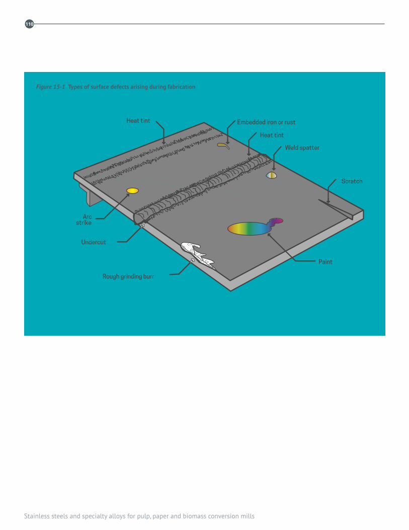
Stainless steels and specialty alloys for pulp, paper and biomass conversion mills
110
Scratch
Paint
Rough grinding burr
Undercut
Arcstrike
Heat tint
Heat tint
Weld spatter
Embedded iron or rust
Figure 15-1 Types of surface defects arising during fabrication

15. Welding
111
the larger particles of embedded iron may initiate crevice corrosion in the underlying stainless steel, which would otherwise not occur.
A simple test for embedded free iron is the “Water-Wetting and Drying” test described in Reference 10. Upon completion of the test, there should be no evidence of rust stain or corrosion products on the surface.
Pickling, which is carried out after degreasing, is the most effective method for removing embedded iron. A commonly used pickling treatment is a 10% nitric–2% hydrofluoric acid bath at 50 °C. Pickling not only removes embedded iron and other metallic contamination, but also leaves the surface bright, clean, and in its most corrosion-resistant condition. Because pickling is aggressive, it will destroy a polished or high-lustre surface. (Use with extreme care!)
Small objects are best pickled by immersion in pickling baths. For larger sized components, there are commercially available nitric-hydrofluoric acid pickling pastes that are easy to apply and are very effective in cleaning and removing free iron. With either method, it is essential to completely remove the acid by thorough rinsing in clean water.
Embedded iron can also be removed by citric acid plus EDTA or other proprietary chelating agents, which are very effective in removing embedded iron. These chelating agents will not remove heat tint oxide scale, which must be removed by other means.
When pickling is not practical, blasting can be used, but not all abrasives yield good results. Glass bead blasting produces good results, but before blasting, a test should be made to determine that it will remove the surface contamination. Also, periodic tests should be made to see how much reuse of beads can be tolerated before they begin to recontaminate the surface. Walnut shells have also performed well as an abrasive.
Abrasive blasting with steel shot or grit leaves a rough smeared surface layer that is prone to corrosion in even mild atmospheric environments. Sandblasting also leaves a rough smeared surface layer prone to corrosion, but is sometimes the only practical method of removing oxide scale from stress relief treatments or severely abused surfaces of
unprotected, field-erected tank bottoms. Even clean sand will leave a rough smeared surface with some iron embedded in the surface. Pickling and electropolishing after sandblasting will restore base metal corrosion resistance. Citric acid with chelating agents will remove embedded iron residues.
Heat tint
When stainless steels are heated to moderately high temperatures in air, a dark, thicker-than-normal oxide develops on the surface. Heat tint normally occurs on the face and often on the root side of welds unless special precautions are taken to effectively exclude oxygen while the metal is at elevated temperatures. The heat tint colour varies from black to blue, violet, and straw colour. The thicker oxide reduces the passivity of the surface. The chromium content of the metal just below the oxide is reduced, resulting is an area of lower corrosion resistance. In some rather corrosive aqueous environments, areas not cleaned of heat tint often develop pits, while the adjacent clean stainless steel surface is free of attack. The obvious action is to prevent heat tint oxides from developing by exclusion of oxygen from the areas heated by welding. If heat tint does develop, it should be removed by pickling or mechanical means.
Mechanical damage
When the surface has been damaged and reconditioning is needed, the repair is usually made by grinding or by welding and grinding. Shallow defects are first removed by grinding, preferably with a clean, fine-grit abrasive disc, a flapper wheel, or a pencil-type grinder. The maximum grinding depth to remove defects is often specified by the fabrication specification and may vary from 10 to 25% of the total thickness. When weld repair is needed, it can be made by any of the arc processes, but GTAW is often used because of the greater ease in making small repair welds. Filler metal should always be added. Wash passes or cosmetic welds should not be allowed because of the risk of weld cracking and reduced corrosion resistance.
Stainless steels and specialty alloys for pulp, paper and biomass conversion mills
112
REFERENCES
1. Avery, R. E. and Tuthill, A. H., “Guidelines for the welded fabrication of nickel-containing stainless steels for corrosion resistant services,” Nickel Institute, NiDI Ref. Book, Series No. 11 007 www.nickelinstitute.org
2. “Welding and Brazing Qualifications,” ASME Boiler and Pressure Vessel Code, Section IX, Amer. Soc. Mech. Eng., Three Park Ave., New York, NY 10016-5990
3. Avery, R. E. and Tuthill, A. H., “Guidelines for the welded fabrication of nickel alloys for corrosion-resistant services,” NiDI Reference Book, Series No. 11 012.
4. “Recommended practices for welding austenitic chromium-nickel stainless steel piping and tubing,” ANSI/AWS D10.4, Amer. Welding Soc., 550 N.W. LeJeune Rd. Miami, FL 33126
5. “Recommended practices for root pass welding of pipe without backing,” ANSI/AWS D10.11, American Welding Soc., Miami, FL.
6. “Guide for Welding Ferritic/Austenitic Duplex Stainless Steel Piping and Tubing” AWS D10.18M/D10.18:2008, American Welding Society, Miami, FL
7. Henon, B. K., “Fabrication techniques for successful orbital tube weld ing,” NiDI Reprint Series No. 14 040 www.nickelinstitute.org
8. TAPPI TIP 0402-29 “Guidelines for welding and inspection of stainless alloy piping,” 1999. www.tappi.org
9. Tuthill, A. H. and Avery, R. E., “Specifying stainless steel surface treat ments,” NiDI Technical Series No. 10 068 www.nickleinstitute.org
10. “Standard practice for cleaning, descaling, and passivation of stainless steel parts, equipment, and systems,” ASTM A380, ASTM, 100 Barr Harbor Drive, West Conshohocken, PA 19428-2959
11. “Practical guidelines for the fabrication of duplex stainless steels,” International Molybdenum Association, Unit 7, Hackford Walk, 119 123 Hackford Rd., London, England SW9 0QT. Also available from the Nickel Institute www.nickelinstitute.org
12. Christie, D. W., “Effect of Post-Weld Cleaning on Corrosion Resistance of Austenitic and Duplex Stainless Steel Weldments in Bleach Plant Service,” 7th International Symposium on Corrosion in the Pulp and Paper Industry, Orlando, FL, 1992.
TAPPI TIPs
0402-23 Welding of Duplex Stainless Steels
0402-26 Guidelines for Welding and Inspection of Stainless Alloy Piping
0402-35 Post-Fabrication Cleaning of Stainless Steels

16. Abrasion
113
16.1 GENERAL CONSIDERATIONSAbrasion is the most common type of wear; its destructive effects are widespread throughout most industries, including the pulp and paper industry. Abrasion is due to hard particles or protrusions being forced against, and moving along, a solid surface. It becomes more severe the harder the particles are, compared to the surface they are moving against. This chapter gives an overview of abrasion processes, and briefly reviews guidelines for materials selection, with a focus on stainless steels compared to other ferrous alloys. References 1 and 2 give a more thorough treatment of abrasion mechanisms. References 3 and 4 give useful information on the various options available for managing abrasion. Of the other types of wear that occur in the pulp and paper industry, erosion is also commonly encountered, due to the necessity of handling large volumes of process liquids through pipes and tanks. Unlike abrasion, erosive wear requires the flow of a liquid or gas stream past a surface. Its effects can be made worse if the stream contains abrasive particles. For materials options for controlling erosion, see Reference 3.
Abrasion is often classified as being low-stress, high-stress, or gouging abrasion. These are qualitative descriptors, but they can be useful for a first characterization of an abrasive situation. In low-stress abrasion, the amount of plastic deformation and work hardening of the abraded surface would be expected to be relatively low; damage occurs mainly by cutting and the abrading particles generally remain intact. In high-stress abrasion, imposed loads are greater, so that a higher proportion of surface plastic deformation and work hardening may be expected. At the same time, the amount of surface cutting also increases due to the creation
of fresh abradant by fracture of existing abrading particles. Plastic deformation and work hardening predominate in gouging abrasion, where imposed loads are highest of all.
Examples of low-stress abrasion can be found on many pieces of pulp or paper mill equipment, such as pumps, chutes, screens, and hoppers. Instances of high-stress abrasion can occur in feed screws and valves, and in wood-handling operations. Gouging abrasion is most common in mining and mineral processing, where imposed working loads are typically higher than in the pulp and paper industry.
16.2 MATERIALS SELECTIONAbrasion rates depend on many metallurgical and environmental factors. Therefore, it is important to realize that materials do not have an intrinsic level of abrasion resistance. Metallurgical factors that influence abrasion include hardness, microstructure (e.g., the presence of ferrite, austenite, pearlite or martensite in steels), alloy content, and the presence of second phase particles in the microstructure (e.g. carbides). Environmental factors include the nature of the abrasive (e.g., size, hardness, angularity) the presence of a corrosive liquid or gas, the temperature, load, sliding speed and humidity. For more details about the relative importance of these factors, see Reference 1.
Because of the complexity of abrasion processes, materials selection is not an exact science and, for every example of a successful application, there often seems to be a counter example.1 Having said this, it is possible to provide some general guidelines.
16. Abrasionby Chris Thompson, FPInnovations

Stainless steels and specialty alloys for pulp, paper and biomass conversion mills
114
For situations where corrosion is not a factor, the abrasion resistance of steels and cast irons will be largely dependent on their hardness, carbon content and microstructure. Generally, increased hardness and carbon content give increased levels of abrasion resistance, through the formation of martensite and carbides in the microstructure.5 At the high end of the carbon range (e.g., with alloys such as the white cast irons), factors such as toughness and impact resistance become increasingly important. While hardness is a readily available guide to abrasion resistance, it must be remembered that there are many exceptions to the rule. This is because the true measure of abrasive wear resistance is the maximum hardness of the work hardened, abraded surface, and not the initial bulk hardness. Alloys that rapidly work harden as a result of abrasion can thus also give good performance.
This helps explain why austenitic stainless steels, which readily work harden but do not contain either martensite or carbides, can give acceptable performance in some abrasive wear conditions.6 Increasing alloy content in austenitic stainless steels decreases their work hardening rate.7 Type 304L (UNS S30403) and the proprietary alloy Nitronic 30 (UNS S20400) have been shown to resist some abrasive conditions better than Type 316L (UNS S31603), because of their higher work hardening. Duplex stainless steels, such as 2205 (UNS S32205), with their combination of work hardening capacity and improved strength and toughness, can be expected to outperform the austenitic stainless steels in terms of abrasion resistance. For the mill engineer, the practical problem is how to predict if a given abrasion situation will cause a sufficient amount of work hardening. In this respect, prior field experience is probably the best guide.8
In the pulp and paper industry, most abrasion problems will involve at least some amount of corrosion, and it is important to remember that the presence of a corrosive environment can significantly change the overall abrasion performance of many ferrous materials. This is especially true for alloy steels and white cast irons, which are often the first choice for combating “pure” abrasion.9 Examples of mill equipment where a combination of abrasion and corrosion can occur include beaters, deflakers, stock refiners, chip refiners, pumps, storage bins, and chutes. In beaters, deflakers and stock refiners, abrasion-resistant cast irons [25% Cr and Ni-HiCr
Type D (ASTM A532)] and precipitation hardening stainless steels [such as 17-4PH (UNS S17400)] are used in situations where abrasion resistance is the overriding consideration. The 17-4PH alloy would normally only be used for light abrasion duty; 25% Cr and Ni-HiCr Type D would be selected for more abrasive service. When both abrasion and corrosion are significant, the 25% Cr white cast irons or high carbon cast stainless steels are used, e.g., for refiner plates. In pumps, abrasion from sand and grit has led to widespread replacement of the standard CF-3 (UNS J92500) and CF-3M (UNS J92800) grades with the cast duplex grades, CD-6MN (UNS J93371) and CD-4MCuN (UNS J93372). These two cast duplex grades have much improved resistance to sand and grit erosion as well as better corrosion resistance. For storage bins and chutes, where a smooth surface must be maintained to allow easy flow of bulk solids, Types 409 (UNS S40900) and 304 (UNS S30400)10 have replaced abrasion resistant (“AR”) carbon steels, which rapidly corrode in mill process waters.11 Duplex stainless steels are also increasingly used for these applications.
In each case, it is necessary to balance the amount of abrasive wear resistance needed with the appropriate level of corrosion resistance. This tends to make local site experience with good record keeping the most reliable materials selection guide.
Other materials used in the industry to control abrasive wear include tungsten carbide cermets, ceramics, and hard chromium. Cermets and ceramics are used in either the bulk form (e.g., as inserts, tiles and plates) or as coatings (e.g., as weld overlays or thermal sprays). Hard chromium is used as an electroplated coating. Unlike the stainless steels and cast irons, which are typically used for large items of process equipment, these materials are often found in niche applications where the need to manage particularly demanding conditions justifies their higher cost. Some larger-scale applications of these materials also exist, such as thermal sprayed tungsten carbide cermet coatings for thermorolls on supercalenders, and hard chromium coatings on screen baskets.
16. Abrasion
115
REFERENCES
1. Tylczak, J. H., “Abrasive Wear” in Friction, Lubrication and Wear Technology, ASM Handbook, Volume 18, ASM Intl., Materials Park, Ohio 1992, pp. 184–190.
2. Zum Gahr, K. H., “Grooving Wear,” Chap. 5 in Microstructure and Wear of Materials, Tribology Series, No. 10, Elsevier, New York, 1987.
3. Budinski , K. G., Surface Engineering for Wear Resistance, Prentice Hall, Englewood Cliffs, NJ, 1988.
4. Peterson, M. B. and Winer, W. O., Eds., Wear Control Handbook, American Soc. of Mechanical Engineers (ASME), New York, 1980.
5. Borik, F. in Wear Control Handbook, ASME, New York, 1980, pp. 327–342.
6. Crook, P., “Practical guide to wear for corrosion resistance,” Mat. Perf. 30(2): 64–66(1991).
7. Magee, J. H., “Wear of Stainless Steels” in Friction, Lubrication and Wear Technology, ASM Handbook, Volume 18, ASM Intl., Materials Park, Ohio 1992, p. 712.
8. Tuthill, A. H. and Castillo, A. P., “Selecting correct valve/pump depends on right match of alloy and application,” Pulp and Paper, Feb. 1999, pp. 71–79.
9. Jones, M. and Llewellyn, R. J., “Erosion –corrosion assessment of materials for use in the resources industry,” Wear, 267, pp. 2003-2009 (2009).
10. Magee, J. H., “Wear of Stainless Steels” in Friction, Lubrication and Wear Technology, ASM Handbook, Volume 18, ASM Intl., Materials Park, Ohio 1992, p. 715.
11. Thompson, C. B., Thomson, J. M. and Ko, P. L., TAPPI J., 77(9): 85–94(1994).

Stainless steels and specialty alloys for pulp, paper and biomass conversion mills
116

13. Suction rolls
117
17.1 GENERAL ALLOY APPLICATION Thoughtful specification of the right stainless steels for almost every piece of process and conveying equipment, structure, stack and protective barrier can substantially lower annual maintenance costs in a pulp and paper mill. Types 304L (UNS S30403), 316L (UNS S31603), 317L (UNS S31703) and 6% Mo super-austenitic stainless steel, along with lean duplex grades, including 2304 (UNS S32304), 2003 (UNS S32003) and 2101 (UNS S32101); 2205 (UNS S32205) regular duplex; and 2507 (UNS S32750), 255 (UNS S32550), or Zeron 100 (UNS S32760) superduplex alloys accomplish this for the majority of wrought stainless steel components in the pulp and paper industry. (Each wrought or rolled grade has a cast counterpart.)
Composition and properties of wrought alloys are shown in Tables 2-1 and 2-2 in Chapter 2. Table 2-3 shows the composition and properties of the principal cast alloys.
Corrosion resistance of ferritic, austenitic and duplex grades in alkaline environments correlates positively with increasing chromium content in the alloy. Conversely, higher molybdenum content reduces corrosion resistance of these alloys to hot alkaline solutions. Alkaline environments include oxygen delignification and bleaching extraction stages.
Type 317L is a traditional alloy for acidic and neutral sulphite pulping process equipment; Type 2205 duplex is a typical modern choice. Type 316L is a standard alloy for whitewater service and paper-making equipment: tidelines and hotter equipment require Type 317L and Type 2205. Type 317L, 6% Mo grades and 2205 and 2507/255/Zeron 100 duplex grades, resist localized corrosion in acidic bleach plant
environments. 6% Mo alloys and superduplex grades resist D-stage environments, which also are resisted by high nickel and molybdenum alloys and by titanium alloys (See Chapter 11 for bleach plant materials).
12Cr ferritic stainless steel is a cost-effective alternative to painted carbon steel for tanks for water and mildly corrosive environments and structures. Usage of duplex grades continues to increase as more mills recognize its favorable combination of strength corrosion resistance and affordability. Cast duplex grades have long been the preferred alloys for pumps and for suction press rolls.
17.2 AVOIDING INTERGRANULAR ATTACK (IGA)
Low carbon, “L” grades, e.g., 316L, 317L are standard for welded construction to avoid intergranular attack (IGA) at grain boundaries in the weld’s heat affected zones (HAZ). The low carbon content of “L” grades avoids formation of chromium carbide precipitates at the grain boundaries that
“sensitize” the HAZ by depleting the Cr content available for corrosion resistance. Low carbon grades in the clad layer on carbon steel have been sensitized by migrated carbon from the carbon steel after prolonged heating to temperatures in the stress relieving range, around 600°C.
17.3 PASSIVATIONPassivation refers to the enhancement of the protective passive film on stainless steel accompanied by removal of iron contamination on the alloy surface. The oxide film that gives stainless steel its non-staining corrosion resistance in
17. Corrosionby Arthur H. Tuthill
Stainless steels and specialty alloys for pulp, paper and biomass conversion mills
118
atmospheric exposure and many media is a thin, adherent, chromium-iron-nickel oxide film.
Passivating involves degreasing and cleaning in one or more of the nitric acids treatments described in ASTM A380 Table A2.1 Part II Cleaning-passivation with Nitric Acid Solution. Cleaning and removal of surface contamination which many engineers think of as “passivation” is discussed in the Welding chapter of this bulletin and below.
17.4 POST FABRICATION CLEANINGMost of the commonly encountered corrosion problems in environments where a grade of stainless steel normally should perform well are due to inadequate cleaning of the surface following fabrication. For best performance it is essential to eliminate fabrication related defects such as arc strikes, weld spatter, scratches, gouges, heat tint scale, and embedded iron from all wetted surfaces after fabrication. Heavy cleaning required after fabrication may be done by blasting with various abrasives, by power brushing with aluminum oxide discs or flapper wheels, by pickling or by electropolishing.
Pickling is covered in ASTM A380, Standard Practice for Cleaning, Descaling and Passivation of Stainless Steel Parts, Equipment and Systems, Table A2.1 Part 1. Citric acid–EDTA chelating treatments to remove iron are covered in Table A2.1 Part III. Electropolishing, which is covered in ASTM A967, Standard Specification for Chemical Passivation Treatments for Stainless Steel Parts and is not mentioned in ASTM A380. Both specifications state that the nitric acid passivating treatments are not acceptable for the heavy cleaning required after welding fabrication.
Sandblasting is an acceptable method of post-fabrication cleaning when chemical pickling is too complicated or restricted by environmental regulations. Sandblasting is effective in removing oxide scale left from annealing or stress relief treatments and heat tint oxide scale left from welding. Embedded iron left by sandblasting is easy to detect by a water wetting test or the ferroxyl test both described in ASTM A380. Embedded iron and its residue after passivating treatment are not necessarily harmful in services where the liquid being handled corrodes away the residual iron
and cleans the surface, and in alkaline environments, in which localized corrosion is not feasible. However, iron may have to be removed to avoid process contamination. For example, residual iron is not acceptable on the surface of hydrogen peroxide bleaching or storage equipment because it accelerates decomposition of hydrogen peroxide.
Other abrasive blasting media for removing heat scale leave no iron embedded in the surface; glass beads, walnut shells and similar materials.
To summarize:
1. Sandblasting removes scale from stress relieving treatments and from welding but can leave a residue of embedded iron.
2. Nitric acid cleaning treatments are useful in removing free iron that is lightly attached iron, and other foreign matter, but will not remove all embedded iron.
3. Pickling and electropolishing are very effective in cleaning the surface and removing embedded iron.
4. Citric acid – EDTA chelating treatment removes embedded iron but does not remove heat tint scale.
5. Nitric acid passivating treatments enhance the normal protective film on clean stainless steel surfaces.
6. Blasting with media such as glass beads and walnut shells may remove heat tint scale and embedded iron without the need for pickling. The water test shows how effectively embedded iron is removed by these blasting media.
TAPPI TIP 0402-35, Post-fabrication cleaning of stainless steel in the pulp and paper industry, is an essential reference document on post weld cleaning of equipment for pulp and paper process applications.
17.5 CREVICE CORROSION, PITTING AND PREN
Crevice corrosion, a form of localized corrosion, occurs on stainless steel surfaces shielded from the main environment by contact with deposits, corrosion products from iron contamination or another surface. Crevice corrosion in chloride-containing neutral and acidic environments always initiates sooner or at a lower temperature than pitting initiates on the bold surface.

17. Corrosion
119
Crevice corrosion occurs in tight stationary crevices, under gaskets at flanged joints, under washers at bolted joints, under O-rings, paint, crayon markings, adhesive tape and deposits. Crevice corrosion is more aggressive in solutions with low pH, high temperatures and containing strong oxidizing chemicals, such as residual chlorine dioxide. In alkaline solutions chloride content does not affect the severity of crevice corrosion or rates of uniform corrosion. Sulphate ions can inhibit localized corrosion, especially when the sulphate level exceeds the chloride level.
Relative pitting resistance in acidic chloride environments can be ranked fairly reliably from an alloy’s composition, using the formula: %Cr + (3.3%Mo) + (16%N) = PREN, the pitting resistance equivalent number. PREN for Type 316L is 24 for the minimum Cr and Mo required by specifications. PRENs for stainless and nickel-chromium alloys are in Table 2.2 in Chapter 2 for wrought alloys and in Table 2.3 for cast alloys.
ASTM G48, Standard Test Methods for Pitting and Corrosion Resistance of Stainless Steels and Related Alloys by Use of Ferric Chloride Solution, provides a method of estimating relative resistance to localized corrosion in acidic chloride environments. The results are reported as critical pitting temperature (CPT), the temperature above which pits appear on a boldly exposed surface, and critical crevice temperature (CCT), the temperature above which crevice corrosion starts, in 6% ferric chloride solution. CCT is inevitably lower than CPT and the alloy rankings are similar to PREN rankings.
17.6 CORROSION TESTS AND DATACorrosion of carbon steel and copper-base alloys is conveniently measured by determining the weight loss after exposure for a number of days. The weight loss is assumed to occur uniformly over the whole specimen and is reported as millimeters (mm) per year, or mils per year (mpy). For stainless steel, however, corrosion is so localized and total weight loss so low in most exposures that corrosion rates calculated by assuming the weight loss occurred uniformly over the whole surface gives meaningless results. Corrosion data for stainless steel coupon tests therefore is reported as the maximum depth of crevice corrosion, if that corrosion occurred, or as the average and maximum depth of pitting, if pitting affects boldly exposed surface. This
characteristic corrosion behaviour of stainless steel, which is also true of nickel base alloys, titanium and zirconium, makes comparative resistance to localized corrosion in field coupon tests difficult to assess, leading to increased use of electrochemical corrosion testing methods. Electrochemical methods of evaluating corrosion resistance are covered in a number of texts. For further information see Reference 4, Chapter 3, pp. 66-121.
When the current material of construction experiences worse corrosion than normal or expected, it is common practice to compare coupons of the current material and candidate replacement alloys on a test rack. Exposure periods of at least 30 days, preferably more than 90 days, in the plant environment where unusual corrosion is occurring often gives useful corrosion test results. The environment should be monitored during the test period as it is often upset conditions that lead to greater than usual corrosion. It is common practice to include Type 316 in all test rack exposures because its performance provides a good indicator of the corrosiveness of the environment. It is good practice to test duplicate specimens of each alloy—alloys normally considered for upgrading in 5 primary mill environments are listed in Table 17-1.
17.7 STRESS CORROSION CRACKINGChloride stress corrosion cracking (chloride SCC) is a problem for Types 304L, 316L, and even 317L. Chloride SCC is most likely to occur above 60–70 °C and in surfaces under high tensile residual stress, e.g. at welds and bends. The chloride concentration in the bulk solution is of little significance, as most chloride SCC occurs in locations where conditions favour concentration of chlorides present in the bulk environment. Type 904L (UNS N08904), Alloy 20 (UNS N08020), duplex and 6Mo austenitic stainless steels, and nickel base alloys are significantly more resistant to chloride SCC.
Insulated stainless steel vessels, tanks, and piping out-of-doors may be subject to external chloride SCC under insulation if the insulation becomes wet and chlorides are present. Sealing the insulation to exclude wetness mitigates under-insulation chloride SCC. Painting the exterior of the stainless steel tank with an appropriate coating can mitigate under-insulation SCC. Indoor insulated stainless steel

Stainless steels and specialty alloys for pulp, paper and biomass conversion mills
120
tanks, vessels and piping are subject to chloride SCC under insulation if chloride-containing leaks wet the insulation. Preventive measures are described in NACE Standard SP0198-2010, Control of Corrosion Under Thermal Insulation and Fireproofing Materials—A Systems Approach, available from www.nace.org.
17.8 INHIBITED HCL CLEANINGIt is common practice to acid clean digesters, liquor heater tubing and liquor piping to remove carbonate and other deposited scales. Inhibited hydrochloric acid is commonly used by chemical cleaning contractors because it readily dissolves most carbonate and other scales. Even when inhibited, hydrochloric acid is quite corrosive to stainless steels. Two problems have been reported from using inhibited hydrochloric acid. In standard Types 304 and 316 heat exchanger tubing inhibited hydrochloric acid nevertheless corrodes the small amounts of ferrite phase normally present in the longitudinal welds, unless the tubes are specified to be cold worked and annealed to convert the ferrite to austenite after the seam weld is made. Cold working the weld is a supplementary requirement that can be included specified by the purchaser, usually at extra cost.
Although Type 304 tubing is the normal choice for new liquor heaters tubes, upgrading to Alloy 825 (UNS N08825), Alloy 600 (UNS N06600), 6% Mo alloys, duplex and other more costly tubing materials that resist preferential weld corrosion and stress corrosion cracking during hydrochloric acid cleaning can be prudent despite the higher cost.
The second problem with inhibited hydrochloric acid cleaning
of heat exchangers arises from incomplete removal of hydrochloric acid residues from crevices so crevice corrosion and stress corrosion cracking occur when the heat-exchanger is returned to service and brought up to temperature.
When continuous digesters are acid-cleaned to remove internal scale and inhibited hydrochloric acid is used, the inhibitor usually inhibits corrosion of carbon steel but does not inhibit pitting and stress corrosion cracking damage to stainless steel parts of the digester. Formic acid and sulphamic acids do not harm stainless steel in acid-cleaned digesters, as discussed in Reference 3.
17.9 MICROBIOLOGICALLY INFLUENCED CORROSION (MIC)
Paper machine white waters are an ideal warm environment full of nutrients for bacterial growth and thus for microbiologically influenced corrosion (MIC). There are two approaches to mitigating MIC.
1. Design and Post Fabrication Treatment: Electropolishing of the headboxes and approach piping reduces slime and hang-up of pulp fibres and attachment of pulp pads. Reduc-ing recesses and requiring welds to be smooth enough to pass the cotton ball test in all parts of the white water circuit is very helpful. Frequent cleaning to remove pulp pads from dead areas is also helpful.
2. Biocide Addition: The addition of biocides to limit bacterial activity is useful in controlling bacterial activity in the bulk environment. However, scheduled cleaning is still necessary to remove pulp pads from dead areas, as bacterial activity
Table 17-1 Alloys usually evaluated in addition to type 316l
Service Alloys usually included in field tests
Alkaline Section of Kraft Mills Alloys with higher chromium content such as Type 304L, 2304, 2205, and 2507
Bleach Plant (Acid Chloride) Alloys with a higher molybdenum content such as Type 317L, 904L, 6 Mo alloys
Tall Oil (Sulphuric Acid) Alloy 20, 904L, 6% Mo, and B2
Stress Corrosion Cracking
Alloys with higher or lower nickel content Higher nickel – Alloy 20, 904L, 6% Mo Alloys and Ni base alloys; Lower nickel – Duplex & ferritic alloys
MIC – Microbiologically Influenced Corrosion Type 316L free of heat tint scale, 6% Mo& NiCrMo alloys

17. Corrosion
121
may continue beneath adherent pulp pads even though the bulk environment is benign.
MIC can also occur during new construction when water used for hydrotesting tanks and piping is not drained promptly. Draining promptly after hydrotesting is the obvious remedial measure.
17.10 CAST ALLOYSCast alloys have corrosion resistance roughly equivalent to that of their wrought counterparts but there are some exceptions.
1. Because ASTM A743, Standard Specification for Castings, Iron-Chromium, Iron-Chromium-Nickel, Corrosion Resistant, for General Application, the specification normally used to procure stainless steel castings, does not require heat treatment after foundry weld repairs, places where routine weld repairs were made may be more susceptible to corrosion than elsewhere. Castings should be specified per ASTM A744, Standard Specification for Castings, Iron-Chromium-Nickel, Corrosion Resistant, for Severe Service, which requires heat treatment after all foundry weld repairs, when the application is in an aggressive environment that causes localized corrosion near foundry weld repairs.
2. ASTM A743 allows common molybdenum-containing austenitic grades to be heat treated at 1040 °C, which is too low to homogenize molybdenum and optimize the corrosion resistance. When common Mo-containing grades experience unexpected corrosion, or when the corrosion resistance of the casting must equal that of the wrought form, it helps to specify that CF-3M (UNS J92800), CF-8M (UNS J92900), CG-3M (UNS J92999), and CG-8M (UNS J93000) castings be heat treated at 2,050 °F (1,120 °C) minimum, as required for CN-7M (UNS J94650), with a similar molybdenum content.
3. The standard ASTM specifications for cast alloys do not specify where on the specimen to measure carbon content. In some environments in which higher carbon at the surface is known to decrease corrosion resistance, Supplementary Specification S23 in ASTM A744 requires taking the specimen for carbon testing within 0.01 in.(0.25 mm) of the surface after scale removal.
4. Because the scale formed during heat treatment is less corrosion resistant than base metal and has led to unnecessary corrosion, scale removal should be specified when purchasing stainless steel castings.
More detailed information on procuring and corrosion behaviour of stainless steel castings is provided by Jonsson in Reference 2, by Aromaa and Klarin in Reference 4 and in Reference 6.
Stainless steels and specialty alloys for pulp, paper and biomass conversion mills
122
REFERENCES
1. Tuthill, A. H. and Avery, R. E., “Specifying stainless steel surface treatments,” Advanced Materials and Processes, Vol. 142, No. 6,Technical Series No. 10,068, Nickel Institute, Canada, 1992. (www.nickelinstitute.org)
2. Jonsson, Karl-Erik, “Stainless steels in the pulp and paper industry,” Chapter 43 in Handbook of Stainless Steels, McGraw-Hill, New York, NY, 1977.
3. Crowe, D. C., “Corrosion in acid cleaning solutions for Kraft digesters,” Proc. of the 7th International Symp. on Corrosion in the Pulp and Paper Industry, Nov. 16–20, 1992,TAPPI, Atlanta, GA. (www.tappi.org)
4. Aromaa, J. and Klarin, A. “Materials, Corrosion Prevention and Maintenance,” Book 15, Papermaking Science and Technology, Fapet Oy, Helsinki, Finland, 1999, distributed by TAPPI Press, Atlanta, GA (www.tappi.org).
5. Reid, C., “Stress corrosion cracking of austenitic and duplex stainless steels in the pulp and paper industry,” TAPPI Engineering Conference Proceedings, 1999, pp. 1315-1357. (www.tappi.org)
6. TIP 0402-25, “Guidelines for procurement of cast stainless steels for large pumps and valves for the pulp and paper industry,” TAPPI, Atlanta, GA 1998. (www.tappi.org)
18. Risk based inspection (RBI)
123
18.1 GENERAL PRINCIPLESRBI is a proven technology that pulp and paper mills and plants in other industries can employ to improve the reliability of fixed equipment, especially pressure vessels, boilers, tanks, piping and stacks, all through the plant. The RBI process methodically ranks the equipment based on the perceived risks its failure or inability to function poses to people in and around the plant, and to the plant’s reliability and economic viability. “Risk” in RBI assessments is defined as the combination (multiple) of two separate factors: the likelihood the equipment or part will fail as a result of each damage mechanism that can affect the equipment’s components, and the safety, environmental and economic consequences of that failure.
The likelihood the equipment will fail depends on which damage mechanisms are affecting the equipment, and their rates, which often are manifested by the equipment’s repair history. Consequences typically are defined by the highest estimated cost for repair, and greatest estimated health, safety and environmental consequences for mill personnel and plant neighbors. Costs for remediating environmental spills and leaks may be the highest consequence in some instances, such as when a liquor tank or buried effluent pipe leaks its contents into a river. The risk rankings are used to prioritize equipment inspections.
Figure 18-1 shows a typical risk matrix widely used in the refining and petrochemical industries, where RBI is routinely used because the risks associated with equipment leaks and failure are substantially higher than in the pulp and paper industry, in which the main toxic threats are chlorine dioxide and non-condensable organic gases (NCGs) created in the pulping process; the main flammability threat is from
methanol and NCGs, and the highest explosive risk is from a smelt-water reaction in the recovery boiler.
Each piece of equipment is methodically assessed for risks posed by every damage mechanism that could compromise the equipment or component’s function and safe operation. The RBI assessment for each piece of equipment uses the matrix “steps” to assess how likely each damage mechanism is—corrosion, cracking, wear, erosion, overheating, etc., depending on the material of construction, service environments and stresses—and the consequences thereof, in order to focus inspection activities on mitigating the highest risk.
The systematically designed inspection plan, which deliberately matches the inspection and nondestructive testing (NDT) method to the type of damage symptoms and focuses first where the equipment will be most severely affected by each damage mechanism, is continuously improved based on the results of each inspection.
For predictable damage mechanisms, the inspection interval depends on the amount of existing damage and the projected rate of damage. For unpredictable damage mechanisms, e.g., fatigue cracking, overheating, impact damage from falling material, etc., it generally is good practice to mitigate or eliminate the conditions causing them precisely because they are not predictable.
18. Risk based inspection (RBI)by David C. Bennett, Corrosion Probe, Inc.
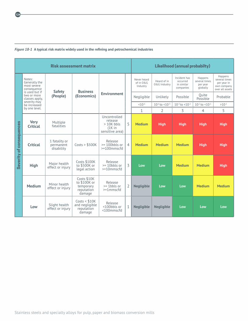
Stainless steels and specialty alloys for pulp, paper and biomass conversion mills
124
Figure 18-1 A typical risk matrix widely used in the refining and petrochemical industries
Risk assessment matrix Likelihood (annual probabilty)
Sev
erit
y of
con
sequ
ence
s
Notes: Generally the most severe consequence is used but if two or more classes apply, severity may be increased by one level.
Safety (People)
Business (Economics) Environment
Never heard of in O&G Industry
Heard of in O&G Industry
Incident has occurred in similar
companies
Happens several times
per year globally
Happens several times
per year in own company over all assets
Negligible Unlikely Possible QuitePossible Probable
<10-6 10-6 to <10-3 10-3 to <10-2 10-2 to <10-1 >10-1
1 2 3 4 5
Very Critical
Multiple fatalities
Uncontrolled release
> 10K bbls(1K in
sensitive area)
5 Medium High High High High
Critical1 fatality or permanent disability
Costs > $500KRelease
>= 100bbls or >=100mmscfd
4 Medium Medium Medium High High
High Major health effect or injury
Costs $100K to $500K or legal action
Release >= 10bbls or >=10mmscfd
3 Low Low Medium Medium High
Medium Minor health effect or injury
Costs $10K to $100K or temporary reputation damage
Release >= 1bbls or >=1mmscfd
2 Negligible Low Low Medium Medium
Low Slight health effect or injury
Costs < $10K and negligible
reputation damage
Release <100bbls or <100mmscfd
1 Negligible Negligible Low Low Low
18. Risk based inspection (RBI)
125
18.2 PULP AND PAPER MILL EQUIPMENT
In pulp and paper mill process environments stainless steels offer countless opportunities to eliminate damage mechanisms affecting carbon steel and low alloy steels, as described throughout this publication. Examples include all alkaline process environments for producing and washing pulp, and alkaline (extractive) bleaching stages, in which reliable passivity of stainless steels with as little as 12Cr may eliminate internal and external corrosion and stress corrosion cracking.
Stainless steels are standard in neutral and acidic environments containing chlorides, in which the damage mechanisms, localized corrosion and stress corrosion cracking, are mitigated by selecting the correct grade of stainless steel. Stainless steels also mitigate carbon and low alloy steel damage mechanisms where abrasion combines with corrosion, such as in chip, sludge and bark conveyors, and in high temperature service—a classic example is the stainless steel layer on composite tubes to resist hot corrosion of carbon steel by reducing flue gas in the recovery boiler.
This publication and Welding Research Council Bulletin 4881, are important resources for mills implementing RBI methods and practices. Many TAPPI Technical Information Papers (TIP) issued by the Corrosion and Materials Engineering committee (they have 0402- prefix) describe damage mechanisms and inspection guidelines for major equipment. These TAPPI TIPS are listed in Chapter 20.
Successful implementation of an RBI process at a mill requires two associated practices. First, the inspection plan and interval may need to be modified if the process conditions spend significant time outside the parameter limits—called the “integrity operating window” (IOW) in a formal RBI program—used to design the prevailing inspection scope and interval. Analyzing the consequences of changes requires a formal and effective, “management of change” process, the same process OSHA requires in the US for hazardous, Process Safety Management (PSM) systems. WRCB 488 describes the controlling parameters for most damage mechanisms, or corrosion and materials expertise should be sought from experienced consultants.
Secondly, the reliability of (confidence in) NDT data used to predict corrosion and damage rates, such as ultrasonic thickness measurements and crack dimensions, must be deliberately accounted for in projecting the remaining life, which in turn defines the inspection interval. Less reliable data (of dubious accuracy and repeatability) should decrease the inspection interval. The beneficial effect of reliable data in maximizing the inspection interval for a part or component provides an important reason to qualify the (written) NDT procedure, which is recommended practice anyway, and determine its accuracy whenever this is feasible.

Stainless steels and specialty alloys for pulp, paper and biomass conversion mills
126
REFERENCES
1. Welding Research Council (WRC) Bulletin 488, Damage Mechanisms Affecting Fixed Equipment in the Pulp and Paper Industry (www.forengineers.org

19. Biomass conversion and biorefineries
127
Development of conversion pathways from woody biomass to specialty chemicals, fuels and materials is proceeding rapidly and deployment of pilot and demonstration scale plants around many product families is in progress1. Some of these products can be made directly from process streams in pulp and paper mills. For the rest, existing pulp and paper facilities also offer advantages as good hosting sites to demonstrate new technologies because they can provide the necessary infrastructure, such as biomass handling, heat and power, access to skilled tradespeople and logistics. Follow-up commercial plants are anticipated.
For the most part, some guidance on materials selection for these new processing plants can be drawn from experience in conventional pulp and paper, beverage/food and biochemical industries. However, not all experience is transferrable and there are some unique environments and pathways that require careful consideration for materials of construction. This chapter outlines some of the processing routes to products that appear likely to materialize, and highlights some of the unique process environments that might be faced in operation.
19.1 FEEDSTOCK CHARACTERISTICSWoody biomass is a wet, bulky material that differs in very significant ways from petroleum-based feedstock that is currently used to make chemicals, liquid fuels and materials. When viewed on the basis of energy throughput, delivering 1 GWth of wood to a plant requires moving 5.3 times as much volume and 2.5 times as much mass (on a dry basis) than for petroleum feedstocks. In addition, green biomass typically contains significant amounts of water, ranging from about 20 wt% for air-dried material to more than 60 wt%
when obtained from piles saturated by rain or snow. These numbers have significant implications for both the scale and economic viability of processing plants. These issues are very familiar for operators of pulp and paper mills, but less so for entrepreneurs developing technologies for conversion of woody biomass to fuel and chemical products.
Wood is a natural composite material made up of varying amounts of cellulose, hemicellulose and lignin. All three possess attributes that make them valuable for use as feedstock for conversion to other products. The proportions of cellulose, hemicellulose and lignin depend on the type of plant. Grasses and agricultural residues contain much less lignin and correspondingly more cellulose than woody biomass, Table 19-12.
Cellulose is a strong, crystalline polymer composed of very long linear chains of linked glucose molecules (C6H10O5)n that form the structural cell walls of plants. Hemicellulose is a more amorphous polymer that is composed of shorter branched chains of many (mostly pentose) sugars like xylose and mannose. Hemicellulose is intertwined with cellulose in the plant structure, but is more easily hydrolyzed and removed than cellulose. Both are polysaccharides and are seen as valuable sources of monomeric sugars that can be fermented into a number of valuable chemicals.
Lignin is a heterogeneous, three dimensional, highly aromatic biopolymer that acts as the glue that binds these two components together and provides strength to support the plant. Lignins possess attributes that make them useful in the manufacture of many products, such as a replacement for phenols in phenol-formaldehyde resins and polyols in polyurethanes, manufacture of carbon black, production of BTX (benzene, toluene, xylene) and as a precursor for the manufacture of carbon fibre.
19. Biomass conversion and biorefineries
by Douglas Singbeil, FPInnovations, James R Keiser, Oak Ridge National Laboratory
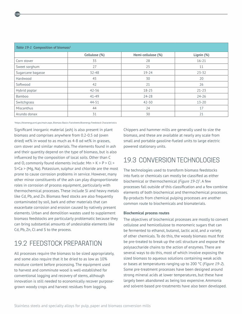
Stainless steels and specialty alloys for pulp, paper and biomass conversion mills
128
Significant inorganic material (ash) is also present in plant biomass and comprises anywhere from 0.2-0.5 od (oven dried) wt% in wood to as much as 4-8 od wt% in grasses, corn stover and similar materials. The elements found in ash and their quantity depend on the type of biomass, but is also influenced by the composition of local soils. Other than C and O, commonly found elements include: Mn > K > P > Cl > S>Ca > (Mg, Na). Potassium, sulphur and chloride are the most prone to cause corrosion problems in service. However, many other minor constituents of the ash can play disproportionate roles in corrosion of process equipment, particularly with thermochemical processes. These include Si and heavy metals like Cd, Pb, and Zn. Biomass feed stocks are also frequently contaminated by soil, bark and other materials that can exacerbate corrosion and erosion caused by natively present elements. Urban and demolition wastes used to supplement biomass feedstocks are particularly problematic because they can bring substantial amounts of undesirable elements like Cd, Pb, Zn, Cl and S to the process.
19.2 FEEDSTOCK PREPARATIONAll processes require the biomass to be sized appropriately, and some also require that it be dried to as low as 10% moisture content before processing. The equipment used to harvest and comminute wood is well-established for conventional logging and recovery of stems, although innovation is still needed to economically recover purpose-grown woody crops and harvest residues from logging.
Chippers and hammer mills are generally used to size the biomass, and these are available at nearly any scale from small and portable gasoline-fueled units to large electric powered stationary units.
19.3 CONVERSION TECHNOLOGIESThe technologies used to transform biomass feedstocks into fuels or chemicals can mostly be classified as either biochemical or thermochemical (Figure 19-1)3. A few processes fall outside of this classification and a few combine elements of both biochemical and thermochemical processes. By-products from chemical pulping processes are another common route to biochemicals and biomaterials.
Biochemical process routes
The objectives of biochemical processes are mostly to convert cellulose and hemicellulose to monomeric sugars that can be fermented to ethanol, butanol, lactic acid, and a variety of other chemicals. To do this, the woody biomass must first be pre-treated to break up the cell structure and expose the polysaccharide chains to the action of enzymes. There are several ways to do this, most of which involve exposing the sized biomass to aqueous solutions containing weak acids or bases at temperatures ranging up to 200 °C (Figure 19-2). Some pre-treatment processes have been designed around strong mineral acids at lower temperatures, but these have largely been abandoned as being too expensive. Ammonia and solvent-based pre-treatments have also been developed.
Table 19-1 Composition of biomass1
Cellulose (%) Hemi-cellulose (%) Lignin (%)
Corn stover 35 28 16-21
Sweet sorghum 27 25 11
Sugarcane bagasse 32-48 19-24 23-32
Hardwood 45 30 20
Softwood 42 21 26
Hybrid poplar 42-56 18-25 21-23
Bamboo 41-49 24-28 24-26
Switchgrass 44-51 42-50 13-20
Miscanthus 44 24 17
Arundo donax 31 30 21
1https://bioenergy.ornl.gov/main.aspx, Biomass Basics Factsheets:Bioenergy Feedstock Characteristics
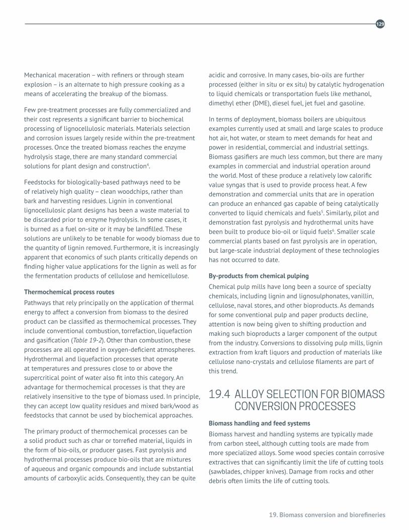
19. Biomass conversion and biorefineries
129
Mechanical maceration – with refiners or through steam explosion – is an alternate to high pressure cooking as a means of accelerating the breakup of the biomass.
Few pre-treatment processes are fully commercialized and their cost represents a significant barrier to biochemical processing of lignocellulosic materials. Materials selection and corrosion issues largely reside within the pre-treatment processes. Once the treated biomass reaches the enzyme hydrolysis stage, there are many standard commercial solutions for plant design and construction4.
Feedstocks for biologically-based pathways need to be of relatively high quality – clean woodchips, rather than bark and harvesting residues. Lignin in conventional lignocellulosic plant designs has been a waste material to be discarded prior to enzyme hydrolysis. In some cases, it is burned as a fuel on-site or it may be landfilled. These solutions are unlikely to be tenable for woody biomass due to the quantity of lignin removed. Furthermore, it is increasingly apparent that economics of such plants critically depends on finding higher value applications for the lignin as well as for the fermentation products of cellulose and hemicellulose.
Thermochemical process routes
Pathways that rely principally on the application of thermal energy to affect a conversion from biomass to the desired product can be classified as thermochemical processes. They include conventional combustion, torrefaction, liquefaction and gasification (Table 19-2). Other than combustion, these processes are all operated in oxygen-deficient atmospheres. Hydrothermal and liquefaction processes that operate at temperatures and pressures close to or above the supercritical point of water also fit into this category. An advantage for thermochemical processes is that they are relatively insensitive to the type of biomass used. In principle, they can accept low quality residues and mixed bark/wood as feedstocks that cannot be used by biochemical approaches.
The primary product of thermochemical processes can be a solid product such as char or torrefied material, liquids in the form of bio-oils, or producer gases. Fast pyrolysis and hydrothermal processes produce bio-oils that are mixtures of aqueous and organic compounds and include substantial amounts of carboxylic acids. Consequently, they can be quite
acidic and corrosive. In many cases, bio-oils are further processed (either in situ or ex situ) by catalytic hydrogenation to liquid chemicals or transportation fuels like methanol, dimethyl ether (DME), diesel fuel, jet fuel and gasoline.
In terms of deployment, biomass boilers are ubiquitous examples currently used at small and large scales to produce hot air, hot water, or steam to meet demands for heat and power in residential, commercial and industrial settings. Biomass gasifiers are much less common, but there are many examples in commercial and industrial operation around the world. Most of these produce a relatively low calorific value syngas that is used to provide process heat. A few demonstration and commercial units that are in operation can produce an enhanced gas capable of being catalytically converted to liquid chemicals and fuels5. Similarly, pilot and demonstration fast pyrolysis and hydrothermal units have been built to produce bio-oil or liquid fuels6. Smaller scale commercial plants based on fast pyrolysis are in operation, but large-scale industrial deployment of these technologies has not occurred to date.
By-products from chemical pulping
Chemical pulp mills have long been a source of specialty chemicals, including lignin and lignosulphonates, vanillin, cellulose, naval stores, and other bioproducts. As demands for some conventional pulp and paper products decline, attention is now being given to shifting production and making such bioproducts a larger component of the output from the industry. Conversions to dissolving pulp mills, lignin extraction from kraft liquors and production of materials like cellulose nano-crystals and cellulose filaments are part of this trend.
19.4 ALLOY SELECTION FOR BIOMASS CONVERSION PROCESSES
Biomass handling and feed systems
Biomass harvest and handling systems are typically made from carbon steel, although cutting tools are made from more specialized alloys. Some wood species contain corrosive extractives that can significantly limit the life of cutting tools (sawblades, chipper knives). Damage from rocks and other debris often limits the life of cutting tools.

130
Stainless steels and specialty alloys for pulp, paper and biomass conversion mills
Â
¿¿¿¿¿ ¿¿¿¿¿¿
± ±±±±±±±±±±±
Â
æ
æ
Å
V V V V V¥¥¥¥ ¥
VVV
Å Å Å
æ æ æ
æ æ æ
ÂAgricultural biomass
Dedicatedcrops
Primaryproducts
Recoveredbiomass
Harvesting
Processing /Recovery
Biomass
Pretreatment
Fractionation
Hydrolysis
Fermentation
Product recovery
Product decisionBioproducts Bioenergy Biofuels
Residues (2)
Residues (2)
e.g. Sugarcanebeet pulp
Hexose sugars
Hexose sugars
Pentosesugars
e.g. Stalks,chaff, cobs, stover
SUGAR-BASED
StarchCellulose
Extractives /Oils
Lignin /Extractives
Hemicellulose
STARCH-BASED LIGNOCELLULOSIC-BASED
Dedicatedtrees
Forest biomass Urban biomass Legend
(a) Thermochemical routes
{
Figure 19-1 Pathways from biomass to products

19. Biomass conversion and biorefineries
131
Â
¿ ¿¿¿¿¿¿
± ±±±±±±
Â
æ
V
V
VÅ
ß
Å
æ æ æ
ÂAgricultural biomass
Dedicatedcrops
Primaryproducts
Recoveredbiomass
Harvesting
Processing /Recovery
Biomass
Primaryprocessing
Secondaryprocessing
Tertiaryprocessing
Fractionation
Product recovery
Product decisionChemicals Heat Bio-oil H2OElectricity Biosyn fuels*
Residues (2)
Residues (2)
Upgrade
Fast pyrolysis
Boiler
Reform
Gasify
Synthesis
Engine /Turbine
LIGNOCELLULOSIC-BASED
Dedicatedtrees
Forest biomass Urban biomass Legend
{
(b) Biochemical routes2
Figure 19-1 Pathways from biomass to products

132
Stainless steels and specialty alloys for pulp, paper and biomass conversion mills
Table 19-2 Thermochemical processes for converting biomass to products
Pelletizing briquetting Torrefaction Pyrolysis Gasification
Process temp: 80-120 °C 200 – 350 °C 350 – 550 °C > 600 °C
Primary product: dense, easily handled wood
water-resistant “black” wood bio-oil, char Syn-gas
(H2, CO, CH4, CO2, N2)
Value-added product: biocarbon, biochar “drop-in” crude oil MeOH, DME, EtOH, diesel
Heating value of primary product: 14-17 MJ/kg 18-21 MJ/kg 17 MJ/kg 4 MJ/kg – 15 MJ/kg
Yield/bdt wood: ~850-950 kg max 700 kg or 625 L max 750 kg variable depending on gasifier design
cellulose size & fractionate
pre-treatment
hydrolysis
fermentation
distillation
chemicalsheat
enzymes
yeast
acetic acid
ethanol
AFEX
ARP
heat products(ethanol, butanol)
hot waterstrong acidweak acidsteam explosionammonialimesolvent-based
(wood, stover, straw, grass)
Figure 19-2 Process steps in biochemical pathways Many pre-treatment options have been evaluated, using a variety of chemicals Technologies using steam explosion and weak acids are most common.

19. Biomass conversion and biorefineries
133
Although feed conveyors and chutes are sometimes retrofitted with abrasion resistant (AR) steels in an attempt to enhance wear resistance, these are not substantially more corrosion resistant than the carbon steels they replace and can also fail rapidly. When problems are encountered handling wet and debris-contaminated biomass, experience has shown that ferritic, duplex and austenitic grades of stainless steels can be resistant to both abrasive and corrosive environments when corrosion is the primary damage mechanism.
Biochemical pre-treatment
At present, there is no consensus on which commercial pre-treatment processes will prevail. Considerable time and effort have been expended on weak acid systems that use solutions of sulphuric acid at approximately 0.5–4% by volume at 130–200 °C to hydrolyse the biomass. At these concentrations, sulphuric acid is reducing and alloys that rely on weak passive films for corrosion resistance may be at risk. However, surprisingly little data are available on resistance of alloy materials to corrosion in such environments4,7. At ambient pressure, when temperatures are less than 100 °C, some duplex stainless steels and superaustenitic stainless steels may provide adequate service. At higher temperatures, nickel-base alloys like C-276 are suggested. Until broader and longer duration experience is gained with materials in operating plants, careful engineering judgement should be applied when selecting materials for this application.
Enzyme hydrolysis and fermentation
Most austenitic and duplex stainless steels will be resistant to corrosion in these process conditions, and there is considerable operational data from corn and sugarcane ethanol plants to support alloy selection4.
Combustion
Hog fuel and sludge from effluent treatment plants are frequently burned as fuels in pulp and paper mill boilers to produce process steam and generate electricity. Many stand-alone boilers also produce steam from the combustion of biomass. Most components of these boilers are made from carbon steel and perform adequately. However, the presence of chlorine, potassium, sulphur and other contaminants in the fuel cause sufficient corrosion to limit the operational
efficiency of the boiler or require replacement of carbon steel components with more resistant alloys.
Due to the risk of corrosion in superheater tubes, wood-fired utility boilers are often designed to operate at low superheated steam temperatures (typically less than 450 °C), and thus operate less efficiently than comparable coal-, natural gas- and petroleum-fired boilers. When corrosion of superheater tubes was evident, tubes made from alloys like Type 310H (UNS S31009), 347H (UNS S34709) and Esshete 1250 have been substituted for those made from carbon and low-alloy steels8. Effort is being applied toward finding materials and alloys that would allow operation of biomass boilers with superheater steam temperatures higher than 550 °C.
Waste-to-energy boilers often experience corrosion of wall and superheater tubes because of formation of low-melting heavy metal chlorides. Similar damage might be expected in biomass boilers using large amounts of urban and demolition waste as fuel, which is often contaminated with lead, zinc, cadmium, and other elements that can form compounds with very low melting points.
Flue gas exiting the boiler is often used as a source of heat to preheat combustion air or to produce hot water for process use. The heat exchanger tubes are at risk when the metal temperature is lower than the dewpoint of the acid in the flue gas. SO3, Cl and NO2 will all condense to form acids on the surface of sufficiently cool metallic surfaces (Figure 19-3)9. Although common in coal-fired boilers, condensation of sulphuric acid is seldom observed in biomass boilers because the sulphur content of the fuel is quite low. The water dewpoint will be the limiting temperature for most other acids. For biomass boilers, hydrochloric acid (HCl) condensation at the water dewpoint is an often-overlooked problem that can cause substantial damage to components exposed to flue gases, such as combustion air pre-heaters. In such cases, substitution of austenitic stainless steels for carbon steel is not advised, due to the risk of chloride-induced stress corrosion cracking (SCC). Alternative alloys should be evaluated for resistance to relatively concentrated HCl at the operating temperature before their selection is confirmed for the application. In the extreme, fluorocarbon-lined austenitic stainless steel tubes have been employed in condensing heat exchangers.
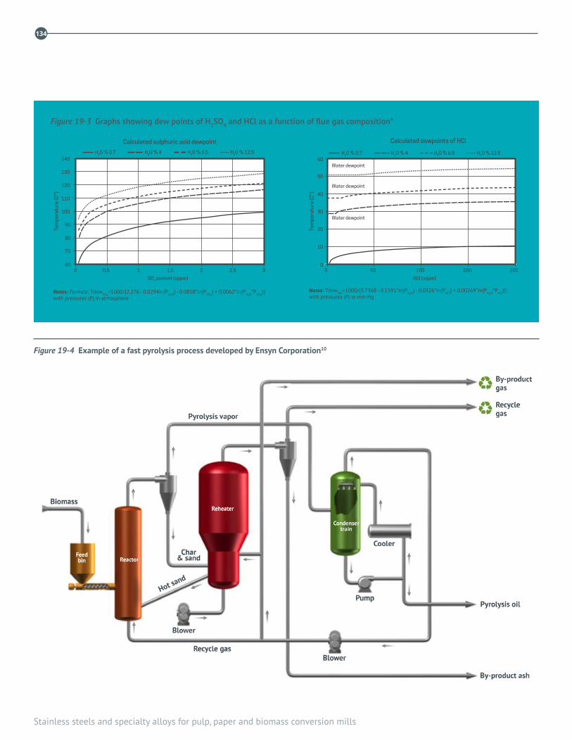
134
Stainless steels and specialty alloys for pulp, paper and biomass conversion mills
Figure 19-4 Example of a fast pyrolysis process developed by Ensyn Corporation10
100
110
120
130
140
80
90
60
70
40
50
60
20
30
10
0 0 0 0.5
SO3 content (vppm) HCI (vppm)
Water dewpoint
Water dewpoint
Water dewpoint
1.5 2 2.5 31 50 100 150 200
Tem
pera
ture
(C°)
Tem
pera
ture
(C°)
Calculated dewpoints of HCICalculated sulphuric acid dewpoint
Notes: Formula: TdewSO3=1000/{2.276 - 0.0294In(PH2O) - 0.0858*In(PSO3
) + 0.0062*In(PH2O*PSO3)}
with pressures (P) in atmosphere Notes: TdewHCI=1000/{3.7368 - 0.1591*In(PH2O) - 0.0326*In(PHCI) + 0.00269*In(PH2O*PHCI)};with pressures (P) in mm Hg
H2O % 0.7 H2O % 4 H2O % 6.5 H2O % 12.5H2O % 0.7 H2O % 4 H2O % 6.5 H2O % 12.5
Figure 19-3 Graphs showing dew points of H2SO4 and HCl as a function of flue gas composition9
19. Biomass conversion and biorefineries
135
Fast pyrolysis
A typical fast pyrolysis plant is shown in Figure 19-410. It includes a pyrolysis reactor that operates at about 500 °C, a cyclone and char collector with associated piping at process temperatures; and a quench system and bio oil storage tank at less than 80 °C. The pyrolysis oil produced by these reactors is a complex multiphase blend of a very wide range of organic chemicals and water. Carboxylic acids are a major component of the oil. Consequently, the pH or total acid number (TAN) of the oil is very low and it has been shown to be corrosive to carbon steels and some stainless steels11. Other organic compounds—most likely ketones—cause swelling and loss of mechanical properties in many of the polymeric and elastomeric materials that would be required for lower temperature bio-oil containment and pumping systems.
For most laboratory and pilot scale fast pyrolysis systems where the containment vessel is at process temperature and in contact with the pyrolysis products, Type 316L (UNS S31603) has been used for the process vessels. Larger fluid bed reactors are refractory-lined to minimize erosion by the sand bed and this provides some protection from corrosion for the metallic containment vessel. The vapour zone and the balance of the plant components that are exposed to the high temperature organic gases will require stainless steels or more resistant alloys to handle the carboxylic acids that are a product of pyrolysis. Stainless steels are required for transport and extended-term storage of biomass derived oils, and also in the combustion systems.
It is generally impractical to conduct laboratory corrosion tests in fast pyrolysis environments, because the as-produced bio-oils tend to polymerize at temperatures above about 80-90 °C. Consequently, data on materials performance is mostly drawn from examination of components from pilot or demonstration systems with limited operating time. Examination of Type 316L components exposed for times up to a few hundred hours have consistently shown evidence of shallow but preferential internal oxidation, generally along grain boundaries11. Components from systems operated for thousands of hours have become available from disassembled systems, and these show some evidence of more extensive internal oxidation. It is not clear if this internal oxidation is extensive enough to be considered a
serious issue for long-term use of Type 316L at the highest temperatures in biomass liquefaction systems, but it is an indication that further investigation is warranted.
Another materials compatibility concern associated with the thermochemical processing is the effect of a high carbon activity and the potential for carburization and metal dusting. These damage mechanisms occur in carbon supersaturated atmospheres at temperatures between 400-900 °C, and can cause significant loss of thickness and degradation of mechanical properties in low grade austenitic stainless steels. In such circumstances, alloys with higher levels of nickel and chromium should offer better resistance.
Hydrothermal and other liquefaction processes
Hydrothermal processes operate at elevated pressures and temperatures close to or above the critical point of water. As with fast pyrolysis, little information exists on material selection for these processes. Data from supercritical water (SCW) reactors suggest that such environments can be extremely corrosive12. In particular, sub-critical conditions (below the critical point) have been found substantially more corrosive than above the critical point. Nearly all materials or alloys have failed in SCW service – even highly alloyed nickel-base alloys. Consequently, selection of materials for hydrothermal liquefaction processes will require good engineering judgement as well as careful process design that minimizes the risk of generating corrosive conditions.
Gasification
Many reactor designs are used to gasify biomass; the type chosen often depends on the thermal capacity of the plant and the desired syngas composition13. Fixed bed, fluidized bed and even entrained flow reactors have been used. The syngas composition varies by reactor type and reaction gas (air, oxygen or steam). In most cases, the syngas is burned to produce energy for steam generation or process heating, but with an appropriate composition, can be converted to chemicals or fuels. A wide range of organic compounds is produced along with the syngas, and the resulting carboxylic acids can be corrosive to a containment vessel, while the organic compounds can produce a carbon activity sufficiently high to cause degradation of a containment vessel by carburization, metal dusting or even deposition of coke.

Stainless steels and specialty alloys for pulp, paper and biomass conversion mills
136
All gasification systems utilize a metallic vessel with an internal refractory lining. The refractory lining is intended to protect the metallic shell from the gasification temperature as well as the gasification environment. However, there have been cases where the refractory is degraded by the environment or the gaseous environment reaches the shell and causes damage. In particular, one system that used a 300 series stainless steel shell suffered extensive chloride stress corrosion cracking because of chlorides that got into the gasifier either through the biomass or during refractory insulation14.
In some cases, the refractories have not been resistant to biomass gasification environments15. In particular, alumina refractory specified for a black liquor gasifier reacted with sodium oxide in the environment, resulting in the formation of sodium aluminate, and a consequent volume increase. The increased volume of the refractory caused spalling and rapid degradation. This was resolved by switching to a fusion cast (i.e. high density) magnesia-alumina refractory which increased the lifetime of the lining by a very significant factor.
The high carbon activity that was developed in one gasifier that operated with the metallic components at a temperature expected to be at least 675 °C resulted in extensive carburization of the metallic material. Even though Type 321 (UNS S32100) was used in an effort to avoid sensitization of the metallic components, carburization was so extensive that Type 321 did not provide sufficient resistance. One solution that was proposed for this situation was use of an alumina forming alloy, which would be expected to be more resistant to carbon effects. Even though metal dusting was not observed in the 300 series stainless steel, the operating temperature was near the range where metal dusting becomes a concern. Operating times were not very long, so it is possible metal dusting would have become a concern if exposure times had been longer.

19. Biomass conversion and biorefineries
137
REFERENCES
1. The New Face of the Canadian Forest Industry: The Emerging Bio-revolution, The Bio-pathways Project, Forest Products Association of Canada, Ottawa, ON, (2011)
2. https://bioenergy.ornl.gov/main.aspx, Biomass Basics Factsheets: Bioenergy Feedstock Characteristics
3. Mabee WE and Saddler JN; IEA Task 39 Report T39-P4 30 April 2006
4. http://www.nickelinstitute.org/en/TechnicalLiterature/Technical Series/StainlessSteels_CostEfficientMaterials ForTheGlobalBiofuelsIndustry_10090.aspx (2/13/2013)
5. http://www.ieabioenergy.com/publications/ws13-thermal-pre-treatment-of-biomass-for-large-scale-applications-2/ ExCo66 P3 Overview of fullscale gasification process
6. http://www.ieabioenergy.com/publications/ws13-thermal-pre-treatment-of-biomass-for-large-scale-applications-2/ ExCo66 P2 Biomass Pyrolysis
7. John F Grubb, “Resistance of Stainless Steels to Dilute Sulphuric Acid”, paper 11166, CORROSION/2011, NACE International, Houston, TX, (2011)
8. W. B. A. Sharp, D. L. Singbeil, and J. R. Keiser, “Superheater Corrosion Produced by Biomass Fuels,” paper C2012-0001308, CORROSION/2012, NACE International, Houston, TX, (2012)
9. W.M.M. Huijbregts R.G.I. Leferink, (2004),”Latest advances in the understanding of acid dewpoint corrosion: corrosion and stress corrosion cracking in combustion gas condensates”, Anti-Corrosion Methods and Materials, Vol. 51 Issue 3, pp. 173 – 188
10. http://www.ensyn.com/wp-content/uploads/2011/04/EC-Corp-PPT-April-2011.pdf
11. James R Keiser, Michael P Brady, Samuel A Lewis, Sr, Raynella M Connatser, Jeffery K Thomson and Donovan N Leonard, “Corrosion Considerations In Selection Of Structural Materials For Thermochemical Processing Of Biomass”, 2014 International Chemical Recovery Conference, Tampere, FI, pg 234-251
12. Philip A. Marrone and Glenn T. Hong, “Corrosion Control Methods in Supercritical Water Oxidation and Gasifcation Processes”, paper 08422, CORROSION/2008, NACE International, Houston, TX, (2008)
13. M. Worley and J. Yale, “Biomass Gasification Technology Assessment – Consolidated Report”, National Renewable Energy Laboratory, NREL/SR-5100-57085, Golden, CO, (2012)
14. J.R. Keiser, R.A. Peascoe, C.R. Hubbard, J. P. Gorog, “Corrosion Issues in Black Liquor Gasifiers” Collquium on Black Liquor Combustion and Gasification, May 13-16, (2003)
15. J.R. Keiser, J.G. Hemrick, J.P. Gorog, and R. Leary, “Improved Materials for High-Temperature Black Liquor Gasification”, ORNL/TM-2006/71, Oak Ridge National Laboratory, Oak Ridge, TN, (2006)

Stainless steels and specialty alloys for pulp, paper and biomass conversion mills
138

20. Appendix tips
139
TECHNICAL ASSOCIATION FOR THE PULP AND PAPER INDUSTRY TAPPI: CORROSION AND MATERIALS ENGINEERING COMMITTEE TIPS
TIP 0402-03 Corrosion resistant weld metal overlay of digester vessels in alkaline pulping service
TIP 0402-11 Liquid penetrant testing of new suction roll shells
TIP 0402-13 Guidelines for specification and inspection of electric resistance welded (ERW) and seamless boiler tube for critical and noncritical service
TIP 0402-15 Field welding of pin studs in black liquor recovery boilers
TIP 0402-16 Guidelines for inspection and nondestructive testing of paper machine dryers
TIP 0402-17 Weld repairs on new suction roll shells
TIP 0402-18 Ultrasonic testing (UT) for tube thickness in black liquor recovery boilers: Part I - Guidelines for accurate tube thickness testing; Part II - Default layouts for tube thickness surveys in various boiler zones
TIP 0402-19 Guidelines for nondestructive examination of suction roll shells
TIP 0402-21 Ultrasonic technician performance test for boiler tube inspection
TIP 0402-22 Guidelines for inspecting batch digesters
TIP 0402-23 Welding of duplex stainless steels
TIP 0402-24 Guide to the use of stainless steel pipe specifications
TIP 0402-25 Guidelines for procurement of cast stainless steels for large pumps and valves for the pulp and paper industry (no review required)
TIP 0402-27 Guidelines for inspection of continuous digesters and impregnation vessels
TIP 0402-28 Best practice for inspecting used fiber-reinforced plastics (FRP) equipment
TIP 0402-30 Inspection for cracking of composite tubes in black liquor recovery boilers
TIP 0402-31 Guidelines for evaluating quality of boiler tube butt welds with ultrasonic testing (no review required)
TIP 0402-32 Guidelines for thermal spray coatings installed to prevent corrosion in pulp mill process equipment
TIP 0402-33 Guideline for obtaining high quality radiographic testing of butt welds in boiler tubes (no review required)
20. Appendix tipsuseful reference documents

Stainless steels and specialty alloys for pulp, paper and biomass conversion mills
140
TIP 0402-34 Paper machine reel-spool journals: guidelines for crack testing and repair or replacement
TIP 0402-35 Post fabrication cleaning of stainless steel
TIP 0402-36 Guidelines for detection, monitoring and prevention of flow accelerated corrosion (FAC) in the pulp and paper mill
TIP 0402-37 Fluoropolymer properties and applications in pulp and paper mills
INTERNATIONAL MOLYBDENUM ASSOCIATION (IMOA)Practical Guidelines for the Fabrication of Duplex Stainless Steels
http://www.imoa/download_files/stainless-steel/Duplex_Stainless_Steel_3rd_Edition.pdf (available in 8 languages).
Duplex stainless steel shop sheets
http://www.imoa.info/molybdenum-media-centre/downloads/practical-guidelines/fabrication-series.php
Practical Guidelines for the Fabrication of High Performance Austenitic Stainless Steel
http://www.imoa.info/download_files/stainless-steel/Austenitics.pdf (available in English and Italian)
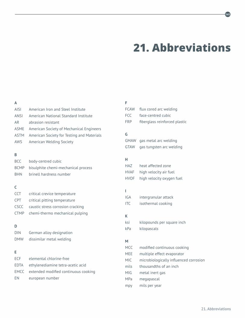
21. Abbreviations
141
A
AISI American Iron and Steel Institute
ANSI American National Standard Institute
AR abrasion resistant
ASME American Society of Mechanical Engineers
ASTM American Society for Testing and Materials
AWS American Welding Society
B
BCC body-centred cubic
BCMP bisulphite chemi-mechanical process
BHN brinell hardness number
C
CCT critical crevice temperature
CPT critical pitting temperature
CSCC caustic stress corrosion cracking
CTMP chemi-thermo mechanical pulping
D
DIN German alloy designation
DMW dissimilar metal welding
E
ECF elemental chlorine-free
EDTA ethylenediamine tetra-acetic acid
EMCC extended modified continuous cooking
EN european number
F
FCAW flux cored arc welding
FCC face-centred cubic
FRP fiberglass reinforced plastic
G
GMAW gas metal arc welding
GTAW gas tungsten arc welding
H
HAZ heat affected zone
HVAF high velocity air fuel
HVOF high velocity oxygen fuel
I IGA intergranular attack
ITC isothermal cooking
K
ksi kilopounds per square inch
kPa kilopascals
M
MCC modified continuous cooking
MEE multiple effect evaporator
MIC microbiologically influenced corrosion
mils thousandths of an inch
MIG metal inert gas
MPa megapascal
mpy mils per year
21. Abbreviations
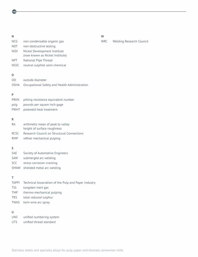
Stainless steels and specialty alloys for pulp, paper and biomass conversion mills
142
N NCG non-condensable organic gasNDT non-destructive testingNiDI Nickel Development Institute
(now known as Nickel Institute)NPT National Pipe ThreadNSSC neutral sulphite semi-chemical
O OD outside diameterOSHA Occupational Safety and Health Administration P PREN pitting resistance equivalent numberpsig pounds per square inch gagePWHT postweld heat treatment R RA arithmetic mean of peak to valley
height of surface roughnessRCSC Research Council on Structural ConnectionsRMP refiner mechanical pulping S SAE Society of Automotive EngineersSAW submerged arc weldingSCC stress corrosion crackingSMAW shielded metal arc welding T TAPPI Technical Association of the Pulp and Paper IndustryTIG tungsten inert gasTMP thermo-mechanical pulpingTRS total reduced sulphurTWAS twin-wire arc spray U UNS unified numbering systemUTS unified thread standard
W WRC Welding Research Council

Stainless steels and specialty alloys for pulp, paper and biomass conversion
143
Stainless steels and specialty alloys for pulp, paper and biomass conversion
143
ACKNOWLEDGMENTS
In addition to the named chapter authors, contributions and advice from the following members of the TAPPI C&ME Metals Subcommittee Task Group for this book are gratefully acknowledged:
Chris Baxter, Pauline Boillot, Dave Crowe, Ralph Davison, Urban Forsberg, Margaret Gorog, Brian Greenwood, John Grocki, John Grubb, Nancy Hoffman, Wendi Kaiser, Michael Lykens, Randy Nixon, Jack Porter, Craig Reid, Sandy Sharp, Doug Sherman, Preet Singh, Neville Stead, Elisabeth Torsner, Matt Tunnicliffe, Jim Willis, and Paul Whitcraft